Embed Size (px)
Citation preview

Bit error rate of optical logic: fan-in, threshold,and contrast
Charles W. Stirk
Bit error rates are calculated in the presence of shot noise for threshold optical logic devices that employdirect detection and intensity modulation. The device parameters considered are fan-in, contrast ratio,and light output. With given values for these parameters, the paper derives expressions for the devicethresholds that generate the optimal bit error rates. In addition, it examines the fundamental quantumlimit on reliability. Finally, the paper finds a bound on the device reliability that is sufficient toguarantee correct system operation with high probability.
Key words: Optical logic, digital optical computing, bit error rate, fundamental limits, contrast,threshold, fan-in.
1. Introduction
Optical logic devices can serve as direct replacementsfor electronic logic devices in digital systems; it ishoped that the communication advantages offered byoptics will lead to optical systems with lower cost orhigher performance than their purely electronic coun-terparts.' This paper measures an often neglectedperformance metric for optical logic devices: reliabil-ity. The reliability of computation as measured bythe bit error rate (BER) is important because fixingBER, contrast, and light level determines the accept-able fan-in and switching energy of optical logicdevices.
This paper's objective is to analyze the effects ofcontrast ratio, fan-in, and light output on the reliabil-ity of quantum-noise-limited optical logic devices thatemploy direct detection and intensity modulation.We choose this type of device because it is the mostcommon in the literature. The methods we use tomeasure reliability, however, can be modified for anytype of device. Where appropriate, the results aresimplified to the classical results for detection.Earlier work in this area addressed the practicalconsiderations in building digital optical computers2 3
and tolerancing studies of optical logic devices. 7
The following abstract model is more general, and,hence, the results apply to many types of device.
The author is with the University of Colorado, Campus Box 425,Boulder, Colorado 80309-0425.
Received 17 June 1991.0003-6935/92/265632-10$05.00/0.e 1992 Optical Society of America.
The device model covers direct detection of lightfrom a stable incoherent external source whose inten-sity is indirectly modulated, as shown in Fig. 1. Inaddition, the communication channels between thedevices are ideal: lossless, noiseless, and dispersion-less. Hence the model represents the behavior ofseveral classes of optical logic devices, including liquid-crystal light modulators and electroabsorption modu-lators.8 Real devices in this class can have lowerreliability than our abstract devices. However, theadditional noise sources and nonidealities of realdevices and circuits imply that their reliability isbounded above by that of our abstract devices.
The rest of the paper begins with a detailed descrip-tion of an optical logic device model and shows how tocompute the BER for shot-noise-limited intensitymodulation and direct detection. Section 3 calcu-lates the BER dependence on fan-in for two commonoptical logic devices, the OR and the AND. The higherreliability of the OR is significant for reliable circuitoperation. Section 4 uses Bayes's decision theory toderive an expression for the threshold that generatesthe lowest BER. The optimum threshold is impor-tant to device designers for making sure that theirdevices achieve the highest possible reliability.Section 5 calculates the optimal BER as a function ofcontrast and fan-in. Thus, given contrast for adevice, one can determine the maximum allowablefan-in for achieving a certain reliability. Section 6expresses the fundamental quantum limit on theBER in the presence of infinite contrast devices. Nomatter what the contrast of a real device, it cannothave better reliability than that given by the funda-mental quantum limit. Section 7 describes how
5632 APPLIED OPTICS / Vol. 31, No. 26 / 10 September 1992

Focusing Lens
Modulator 1
PumpLight
Modulator N
I~~
Detector Comparator
Threshold
InputsFig. 1. Incoherent optical modulator logic with intensity modulation and direct detection.
much device reliability is sufficient to ensure systemreliability with high probability. Thus, given devicereliability, we can bound the system reliability. Thepaper concludes with a discussion of general issuesand the significance of the results.
2. Optical Logic Device Model
As shown in Fig. 1, the abstract optical logic devicesums the intensities of the input light. The result ofthe summation passes through a nonlinearity with astep function response, as shown in Fig. 2. Thefollowing discussion defines what we mean by reliabil-ity and illustrates how to compute the reliability forsuch a device.
Reliability is defined as one minus the bit errorprobability. The bit error probability is defined to bethe probability that the system produces an incorrectoutput given a valid input. The BER is the same asthe bit error probability when time is measured in
Output Photons
mH -
mL -_
terms of bit periods. For the rest of the paper wecalculate BER and allow the reader to transform thatinto reliability.
The BER is the probability that the device willmisclassify a configuration of the input symbols withan erroneous output symbol; it is, among otherthings, dependent on the value of the transfer func-tion's threshold T. At each threshold, the opticallogic devices' BER can be expressed as
BER(T) = z P(y Iz, x, T)P(x),xEinput set
(1)
where P denotes a probability, x is an input symbol,and z is the correct output symbol, which is differentfrom the actual output symbol y. By the propertiesof a probability measure,
xEinput setP(x) = 1. (2)
For Boolean devices, there are only two output sym-bols, so summing over the possible y's is not neces-sary.
Now that we have a model for the optical logicdevice and a way to calculate its BER, we need todescribe some of the properties of the device inputs.The remainder of the paper proceeds with the assump-tion that the input symbols 1 and 0 occur withprobability p and q, respectively, independently oftime. Furthermore, we assume that the input chan-nels are independent. The contrast ratio of theinput light is defined as the mean photon number fora logic 1, mH, divided by the mean photon number fora logic 0, mL. The intensity of the detected light isPoisson distributed9:
Threshold Input PhotonsFig. 2. Optical logic device transfer function. mH, mean photonnumber of logic 1; mL, mean photon for logic 0.
Pr (detects k photons when mean is m) = Pm(k)
= - exp(-m).
10 September 1992 / Vol. 31, No. 26 / APPLIED OPTICS 5633
Output
(3)
-
I-

The detailed procedure of calculating the BER be-comes clear with a simple example. Consider thethresholding detector, also known as the 1-input ORor AND. The conditional probabilities in Eq. (1) areactually cumulative conditional probabilities or theircomplements. For example, P(0 I 1, 1, T) is the prob-ability that we detect fewer than T photons, giventhat we want to send a 1 symbol:
T-1 mH kP(0I1, 1, T) = k! exp(-mH)
k=O k
F(T, mH)
(T) = 1 - P(T, mH). (4)
The incomplete gamma function F(T, m) (see Refs. 10and 11) has series and continued fraction expansionsthat numerically evaluate to any desired precision.
Given that we want to send a 0 symbol, one canshow that the probability we detect more than Tphotons is
P(110, 0, T) = exp(-ML)kT kxP(mL= P(T, mH)
probability x 3anew 60¶I
160.O
120.00-
100.001-
80.00
60.0C
40.00;
20.
0.00
probability x
120.01
100.60
(5)
Figure 3 graphically depicts how the threshold orswitching energy determines an optical detector'sBER. The random variable representing the num-ber of detected photons is discrete, so the verticallines signify weighted delta functions whose heightrepresents the probability mass at that point. Fig-ure 3(a) depicts the case in which a logic 0 has a meanof 5 photons. When the threshold is between 6 and 7photons, the cumulative error probability, given thata logic 0 was sent, is the sum of the probability massto the right of the threshold, as indicated by the solidlines. Figure 3(b) depicts the case in which a logic 1has a mean of 10 photons. Given that a logic 1 wassent, the cumulative error probability is the sum ofthe probability mass to the left of the threshold.Because of the discreteness of the detected photonnumber, the BER versus T curves that we show in thefollowing sections are discontinuous; a thresholdbetween two integers is equivalent to a threshold atthe next largest integer.
Now that we have reviewed how to compute thereliability of a detector, Section 3 extends the methodto include devices with fan-in. The basic principlesillustrated in this section apply: calculating thecumulative conditional probability of error, given aninput configuration; multiplying by the probability ofthe input configuration; and summing over all possi-ble input configurations.
3. Fan-In
Two common multi-input logic devices are AND's andOR's. The purpose of this section is to determine,given a contrast ratio, light level, and reliability, how
80.00
60.00
40.00
20.00.
0.00
0.1
5.00 ;
Threshold
10.00 151.00 |photons
(a)
l0 -3
5.600-
Threshold
10.60 15.60 20.60 25.00 pIluulvs
(b)
Fig. 3. Calculation of the BER of a detector in the presence of shotnoise: (a) logic 0 with a mean photon number equal to 5, (b) logic1 with mean photon number equal to 10. The sum of the height ofthe thick lines represents the BER at a threshold between 6 and 7.
large a fan-in is allowable for each device. We alsoinvestigate how the BER varies with the threshold.
AND's and OR's are interesting because a designercan implement any Boolean logic function with themin a combinatorial circuit with inverters. For somefunctions, algorithms exist that use fewer devicesthan a combinatorial circuit at the possible expense ofincreased gate delays. A single device type, NOR orNAND, is sufficient to implement any Boolean func-tion, and is sometimes preferred because of fabrica-tion simplifications. For reliable circuit design, it isimportant to know which type of device is the morereliable. At least for combinatorial circuits, the de-signer can choose the device that leads to the mostreliable circuit while satisfying any other constraints.
5634 APPLIED OPTICS / Vol. 31, No. 26 / 10 September 1992
mL= 5
I _ I
I1 I : I I I I
Be-1 ~~~~-mH=10 1
I II I I.
180.00
140.00r,.
, 0I

The reliability of circuits is beyond the scope of thispaper. However, we calculate a device reliabilitythat can be used in subsequent circuit-based compar-isons. We begin by examining the BER of the OR.
An OR gate with a fan-in of N assigns the output 0to the input with all 0 symbols and the output 1 to allthe other possible inputs. In other words, if theinput contains a 1, the output is 1. The NOR gate isthe logical complement of the OR; if the input containsa 1, the output is 0. Because of the inversionsymmetry of these functions' truth tables, theirtransfer functions are mirror reflections of one an-other about the vertical line with the x intercept atthe threshold. Hence their BER's at a given thresh-old are the same.
For the optical OR gate with fan-in N, the BER atthreshold T is
BEROR(T) = qNP(T, LL)
+ E (ipNiqiP i - P(T, P.H)]. (6)
The first term is the probablity that an output low isincorrectly classified as a high and the second term isthe probablity that output highs are incorrectly classi-fied as lows. Since the inputs are independent andPoisson, their sum is Poisson with a mean that isequal to the sum of the individual means, and, thus,AIL = NmL and AiH = imL + (N - i)mH. The combina-torial choosing counts how many different configura-tions of the inputs have i 0's.
With a given contrast ratio and light output level,Fig. 4 illustrates the dependence of the OR's BER onthe threshold for several values of fan-in. To con-vert the number of photons to energy, recall that onephoton at a I-hm wavelength corresponds to 2 x10-19 J. The optimum threshold, that which pro-duces the lowest BER, appears at larger photon
0.0
-10.0
-20.0
-30.0
-40.0
2 -50.0
-60.0
-70.0
-80.0
-90.0
-100.0
-110.0
Log[BER] vs threshold for ORmL = 1 00, mH = 1000, variousfan-ins
. . . . . . . . . .
0.0 500.0 1000.0 1500.0 2000.0
Threshold [photons]
Fig. 4. Loglo[BER] versus threshold for an OR gate with a meanphoton number for a logic 1 mH of 1000 and a mean photon numberfor a logic 0 mL of 100 for fan-ins N of 1, 2, 4, 8, and 16.
numbers with increasing fan-in because of the increas-ing mean photon number for the all logic low case; theoptimum threshold exceeds the mean photon numberfor a logic 1 input when the fan-in is 8 or more.More importantly, the BER at the threshold optimumincreases at larger fan-ins because of the higher noiselevels. It is interesting to see how the OR's reliabilitycharacteristics compare to the AND'S.
The optical AND has the same transfer function asan optical OR but with different assignments of inputsto outputs. The AND assigns the input with all 1symbols to the output 1 and all other inputs to theoutput 0. The truth table inversion symmetry of theOR and NOR also occurs with the AND and NAND. Thusthe optical NAND has the same BER as the AND at agiven threshold.
For the optical AND gate with fan-in N, the BER atthreshold T is
BERAND(T) = pN[l - P(T, pH)]
+ I (f)PiqNip(T, PL), (7)
where 11L = iH + (N - i)mL and ALH = NmH. Here irepresents the number of l's in the input. The firstterm is the probability that an output high is incor-rectly classified as a low and the second term is theprobability that an output low is incorrectly classifiedas a high.
Figure 5 illustrates BERAND for various fan-ins (N)and thresholds (T). The graph has the same y-axisscaling as Fig. 4 and includes the detector in order toshow that the BER for the AND is much higher thanfor the OR. The reason for this is that the AND mustdistinguish between the input with (N - 1) l's andone 0 and the input with all 's. This situation haslarger Poisson tails than the OR, which must distin-guish between only none and one 1 symbol. All
0.0-
-10.0
-20.0
-30.0
-40.0
a: -50.0
-60.0
-70.0
-80.0
-90.0
-100.0
-110.0 -0.0
Log[BER] vs threshold for ANDmL = 100, m. = 1 000, various fan-ins
5000.0 10000.0 15000.0 20000.0
Threshold [photons]
Fig. 5. Logl[BER] versus threshold for an AND gate with a meanphoton number for a logic 1 mH of 1000 and a mean photon numberfor a logic 0 mL of 100 for fan-ins N of 1, 2, 4, 8, and 16.
10 September 1992 / Vol. 31, No. 26 / APPLIED OPTICS 5635
_ _.5 v/ e _ - - __ ___
\~ ~ ' / -
: V '~~~~~~~~~'
. . . . . . . . . . . . . . . . . .
other things being equal, a circuit design with reliabil-ity in mind will make more effective use of OR and NORinstead of AND and NAND.
The AND'S optimum threshold lies below the ex-pected photon number for a logic high. Moreoverthe optimum threshold gets closer to the expectedphoton number for a logic high as fan-in increases.This is due to the exponential increase in the numberof terms in the sum of Eq. (7), in which logic lowconditions erroneously produce a logic high output.
To summarize, OR's have lower BER than AND's
under similar conditions. The OR also has a widerpeak in the BER curve relative to the value of thethreshold, which leads to a lower average BER whenthe threshold are nonuniform.12 Below we ignorethe distribution of the BER as a function of thethreshold, and consider the BER of devices at theiroptimum thresholds. Section 4 shows how to findthese optimum thresholds.
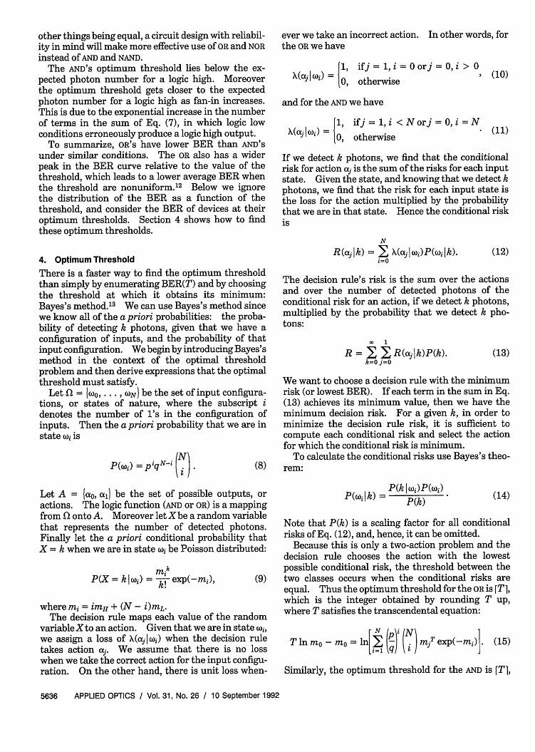
4. Optimum Threshold
There is a faster way to find the optimum thresholdthan simply by enumerating BER(T) and by choosingthe threshold at which it obtains its minimum:Bayes's method.' 3 We can use Bayes's method sincewe know all of the a priori probabilities: the proba-bility of detecting k photons, given that we have aconfiguration of inputs, and the probability of thatinput configuration. We begin by introducing Bayes'smethod in the context of the optimal thresholdproblem and then derive expressions that the optimalthreshold must satisfy.
Let Q = Wo,.... , ON be the set of input configura-tions, or states of nature, where the subscript idenotes the number of l's in the configuration ofinputs. Then the a priori probability that we are instate (oi is
P(oUj) = piqN i ). (8)
Let A = {lao, all be the set of possible outputs, oractions. The logic function (AND or OR) is a mappingfrom 0 onto A. Moreover let Xbe a random variablethat represents the number of detected photons.Finally let the a priori conditional probability thatX = k when we are in state xi be Poisson distributed:
P(X= kli) = kexp(-mi), (9)
where mi = imH + (N - )mL.The decision rule maps each value of the random
variable Xto an action. Given that we are in state wi,we assign a loss of (aj I wi) when the decision ruletakes action aj. We assume that there is no losswhen we take the correct action for the input configu-ration. On the other hand, there is unit loss when-
ever we take an incorrect action. In other words, forthe OR we have
X~oj () 1, ifj = 1, i= orj =0, i > 0(00, otherwise (10)
and for the AND we have
X(cIwi)=1, ifj = ,i < Norj=0,i=N (11)A~ay~)F)0O otherwise *(1
If we detect k photons, we find that the conditionalrisk for action OL; is the sum of the risks for each inputstate. Given the state, and knowing that we detect kphotons, we find that the risk for each input state isthe loss for the action multiplied by the probabilitythat we are in that state. Hence the conditional riskis
N
R(ajlk) = EX X(ctjjwj)P(wijk).i=O
(12)
The decision rule's risk is the sum over the actionsand over the number of detected photons of theconditional risk for an action, if we detect k photons,multiplied by the probability that we detect k pho-tons:
. 1
R = IX IX R(ajlk)P(k).k=Oj=O
(13)
We want to choose a decision rule with the minimumrisk (or lowest BER). If each term in the sum in Eq.(13) achieves its minimum value, then we have theminimum decision risk. For a given k, in order tominimize the decision rule risk, it is sufficient tocompute each conditional risk and select the actionfor which the conditional risk is minimum.
To calculate the conditional risks use Bayes's theo-rem:
P(wIk) = P(k z)P(j) (14)
Note that P(k) is a scaling factor for all conditionalrisks of Eq. (12), and, hence, it can be omitted.
Because this is only a two-action problem and thedecision rule chooses the action with the lowestpossible conditional risk, the threshold between thetwo classes occurs when the conditional risks areequal. Thus the optimum threshold for the OR is [T],which is the integer obtained by rounding T up,where T satisfies the transcendental equation:
T In mO - m = ln[2 () .) miT exp(-mi)j. (15)
Similarly, the optimum threshold for the AND is [T],
5636 APPLIED OPTICS / Vol. 31, No. 26 / 10 September 1992

where T satisfies the transcendental equation
T In mN - mN = ln[ (N) (P)miT exp(-mi)1.
(16)
There is only one minimum in BER(T), so Newton'smethod, when applied to the transcendental equa-tions, will find the numerical value of T that yieldsthe minimum BER.
To verify the results for the case in which N = 1andp = q = /2, we reduce Eq. (15) to the classic resultfor a detector:
MH - mL
MnL
log[BER] vs mH at fixed contrast for OR
0.0
-50.0
-100.0
X -150.0
-200.0
-250.0
(17)
Besides simplifying the calculations in this paper,knowing how to compute the threshold optimum isuseful. For instance, if a device designer knows thedistribution of inputs and the fan-in, then she or hecan design a device that gives the highest reliabilityfor a given contrast and light level. Moreover, if adevice must work in circuits with different light levelsand fan-ins, it may be worthwhile to have an adjust-able threshold so that the device always operates withoptimal reliability.
5. Contrast
The BER depends on many factors besides the thresh-old. In this section we explore the relationshipbetween BER and two additional factors: light leveland contrast. For some devices like modulators, thecontrast is fixed but the light level can be varied bycontrolling the power in the pump beam. The nexttwo plots illustrate the effect of increasing the pumppower.
Figure 6 plots the optimum BEROR versus the meanphoton number for a logic high mH for various fan-insN with the contrast ratio fixed at 10. It demon-strates that the logarithm of device reliability in-creases linearly with the power of the external lightsource. As expected, the BER increases with fan-in.
Figure 7 plots the optimum BERAND versus themean photon number for a logic high mH for variousfan-ins (N) with the contrast ratio fixed at 10. Inthis case the BER is much higher than that for the OR,although the general linear dependence of logl0 [BER]versus external light intensity is preserved.
Increasing the power of the external light source, asin Figs. 6 and 7, to obtain a lower BER may not be anoption for several reasons. High optical power trans-lates into high power dissipation requirements. Inaddition, some devices' responses eventually saturatewith increasing power.
Other devices, like sources, do not have a fixedcontrast. For instance, laser diodes' contrast de-pends on the drive current. In the next set of plotswe investigate the dependence of BER on fan-in and
-300.0 _-0.0 2000.0 4000.0 6000.0 8000.0 10000.0
m, photoosJ
Fig. 6. Optimum loglo[BER] versus the mean photon number fora logic 1 (mH) for an OR gate with contrast = 10 and fan-ins N of 2,4, 8, and 16.
contrast when the light level for a logic high is fixed.We compare the results to that of a device thatguesses what it output should be.
With knowledge of only the device type and theequiprobability of input symbols, it is worthwhile toknow what the BER would be if one simply guessedthe output symbol by using optimal strategy. Underthese conditions, the optimal strategy assigns theprobability of guessing an output symbol to be equalto the probability that the logic device produces it.The probability that the optimal guessing strategyproduces an error is
BERgveSS = P(O)P(g = 1) + P(1)P(g = 0), (18)
where g is the guess. For both the OR and the AND
0.0
-50.0
-100.0
cm -150.0
-200.0
-250.0
-300.0 -0.0
log[BER] vs mH at fixed contrast for ANDcontr-st - 10, various fcn-ins
2000.0 4000.0 6000.0
m. [photons]
8000.0 10000.0
Fig. 7. Loglo[BER] versus the mean photon number for a logichigh (mH) for an AND gate with contrast = 10 for fan-ins N of 2, 4, 8,and 16.
10 September 1992 / Vol. 31, No. 26 / APPLIED OPTICS 5637

the previous equation reduces to0.0
1 2N- 1 2 N- 1 1 2N- 1BERgi2ess = N 2 + 2 N 2N 2 (19)
Figure 8 plots the optimum BEROR as a function offan-in for several contrasts. As expected, for a givenfan-in, increasing the contrast decreases the BER.The optimum BER initially increases with fan-in butreaches a maximum and eventually decreases. Re-gardless of contrast, for high fan-ins the BERORapproaches the BER of guessing. Figure 9 plots theoptimum BERAND as a function of fan-in for severalcontrasts. The AND displays the same qualitativecharacteristics as the OR, but the scales of the y axisare different, so the reliability of the AND is muchlower.
By comparing guessing to Figs. 4 and 5, note thatfor low thresholds the BEROR is slightly better thanguessing, but at high thresholds it can be worse.Thus a guessing device can perform more reliablythan a deterministic device if the latter has a particu-larly bad choice of threshold with respect to the fan-inand contrast.
6. Fundamental Quantum Limits
It is interesting to discover the ultimate limits on theBER of optical logic. So far our device has beenrelatively ideal: it is limited by shot noise and has astep function response. Now we take ideality to theextreme and examine the fundamental quantum limiton reliability.
The fundamental quantum limit of the BER (FBER)for an incoherent optical logic device occurs when theinput light has infinite contrast. In this instance,the mean photon number for a logic low is 0 and,
0.0
-50.0
-100.0
-1 50.0
log[BER] vs fan-in for various contrastsm- 1000 photons
-200.0 0.0 10.0 20.0 30.0 40.0
fan-In [N]
-10.0
a -20.0
-30.0
-40.0-0.0
log[BER] vs fan-in for various contrastsMu, = 000 photons
10.0fan-in [NJ
Fig. 9. Optimum loglo[BER] versus fan-in N of an optical ANDwith the mean photon number for a logic high mH of 1000 andcontrast = 2, 4, 8, 16, and 32.
thus, Eq. (6) for the OR reduces to
BEROR(T) = I ()pq (Tq - 1)! (20)
If the threshold is 0, everything is classified as a logichigh, producing a BER of 1/2. Thus the lowest BERfor the optical OR is achieved when the threshold isequal to 1, thereby minimizing Eq. (20) and satisfyingEq. (15). When k = 0, substitution of Eq. (4) intoEq. (20) and application of the binomial theorem yieldan optical OR's FBER:
N
FBEROR = .p iqN-i exp(-iMH)
= [p exp(-mH) + q]N - qN.
Ifp = q = 1/2, expansion in terms of N yields
FBERoR = 2 -N [N exp(-mH) + N(N- 1)
(21)
x exp(-2mH) + * * + exp(-NmH)].
(22)
Because of the exponential, for sufficiently large mH
the first term of the sum dominates:
FBEROR= 2-NN exp(-mH).
50.0
Fig. 8. Optimum loglo[BER] versus fan-in N of an optical OR withthe mean photon number for a logic high mH of 1000 and con-.trast = 2, 4, 8, 16, and 32.
(23)
Figure 10 plots the FBEROR as a function of m inEq. (21) for several fan-ins and equiprobable inputsymbols. It demonstrates that the photon numberper bit needed to obtain a given BER decreases withincreasing fan-in. This result is due to the dominantexponential, which makes the OR a potentially reliablelogic device at high fan-in. The finite-contrast prob-lems shown above in Section 3, however, must first beovercome before advantage can be taken of this effect.
5638 APPLIED OPTICS / Vol. 31, No. 26 / 10 September 1992
*2.4*8
P.16.132
-- 9uess
1'.
I
IF

0.0
-5.0
EUIaI
-10.0
-1 5.0
log[FBER] vs mH for optical ORfor various fun-ins
0.0
-10.0
-20.0
-30.0
-40.0
-50.0
-60.0
-70.0
-80.0
-90.0
-20.0 . . . .. -0.0 5.0 10.0 15.0 20.0 25.0 30.0 35.0 40.0 45.0 50.0
m. [photon.]
Fig. 10. Exact loglo[FBER] of an optical OR gate versus the meanphoton number per channel for a logic high mH for fan-ins N of 2, 4,16, and 32.
As a further verification, note that when N = 1 andp = q = 1/2 the BER in Eq. (21) reduces to the fun-damental quantum limit of a detector:
FBERdetert = /2 exp(-MH). (24)
For a BER of 10-9, which is typically desired incommunication, this corresponds to 20 photons fora 1 symbol, which is an average of 10 photons per bit.
By using the same procedure for the AND, we reduceEq. (7) to
BERAND(T) = pN[l - P(T, NmH)]
+ I (NpiqN-i[l -P(T, imH)],i=o
(25)
which further reduces to Eq. (24) when N = 1.Setting mL = 0 in Eq. (16) yields
T n NmH - NmH;N- 1 N p IP N
=in[ (j:ST (-.)iNUM) exp(-jmH)]. (26)
The ceiling of the T that satisfies this equationminimizes BERAND.
The FBER for a given N and mH is shown in Fig. 11.For the AND, the minimum photon number necessaryfor a given BER increases with fan-in (the oppositecharacteristic of the OR). For instance, when N = 2the AND requires over 200 photons, whereas the ORrequires fewer than 20.
The FBER can be observed only for logic devicesthat have infinite contrast on their inputs. Infinitecontrast is possible for light emitters like light-emitting diodes or laser diodes, in which the drivecurrent can be reduced to 0. For absorption modula-tors, infinite contrast may be difficult to achieve.In practice, background light levels in free-space
fog[FBER] vs mH for ANDvnrious fun-in
-1 00.0 ... . .... ....
0.0 50.0 100.0 150.0 200.0 250.0 300.0 350.0 400.0 450.0 500.0
mu Iphutuns]
Fig. 11. Loglo[FBER] of an optical AND versus the mean photonnumber for a logic high mH at several fan-ins.
optical systems from scattering, diffraction, and aber-rations will limit the contrast to finite values for logicdevices that share the same optics.
7. Reliable Systems
The maximum desired BER for a device depends onthe systems' characteristics and organization. Nev-ertheless we can consider the worst system in order todetermine a bound on the BER that is sufficient toproduce a specific level of system reliability.
Suppose we have N identical devices in a system,each switching every T seconds. Let us build M ofthese systems, each operating for a Y-year lifetime.Let us assume further that any device error producesa system failure, and that device errors are indepen-dent. Then the distribution of system failures isbinomial, and we can approximate the probability ofrealizing exactly zero system failures with
Pr (zero system failures) exp[-BER(NMY/T)],
(27)
with equality in the limit when BER - 0 andNMYIT in such a way that BER(NMY/T)remains a constant.
If the probability (1 - a) of zero system failures isnearly one, then BER(NMY/T) < land
8 BER(NMYIT). (28)
For example, if we have 10,000 systems, each with1,000,000 devices operating at 1 GHz for a 5-yearlifetime, and if we choose 8 = 10-6, then according toapproximation (28) a BER 10-30 is sufficient. Foran OR with a fan-in of 16 and a contrast of 10, fromFig. 6 we see that this corresponds to 1750 photonsfor a logic high. For a similar AND, from Fig. 7 we seethat this corresponds to 9000 photons.
Because of their size, computational systems with-out error correction or fault tolerance require higher
10 September 1992 / Vol. 31, No. 26 / APPLIED OPTICS 5639

reliability from their components than communica-tion systems. This places tighter constraints on theproperties of devices like light output and thresholdaccuracy.
8. Discussion
The BER of optical logic devices depends on fan-in,contrast ratio, light output, and shot noise. Theoptical devices examined in this paper are those withdirect detection and indirect intensity modulation.Thus the results do not necessarily apply to lightemitters, coherent detection, differential detection, orsoliton switches. The assumptions of the model alsodo not cover the use of modulators in logic devices inwhich the channels are not independent.
On the other hand, the model covers a number ofinteresting devices. The BER for threshold logicdevices other than OR, NOR, AND, and NAND can beexpressed by using the procedure contained herein.It is even extensible to multivalued logic and thresh-olding neurons. For brevity, the numerical exam-ples use the equiprobable-inputs assumption. How-ever, the procedure is valid for any distribution ofinputs that a device might observe in a circuit.
There are several potential uses for the results ofthis paper, as the trade-off between optical power andBER is now transparent. When designing a systemto have a certain reliability, one knows the opticalpower levels sufficient for a device type. On theother hand, in optical-power-limited systems design,one can design devices with the appropriate thresh-olds to generate the optimum BER.
Although the device model may be useful, it is notperfect. However, it is useful for placing bounds onthe reliability of optical logic devices. Real devices ofthis class cannot have better reliability than ourabstract devices. A more realistic model would in-clude loss, cross talk, and dispersion in transmission,thermal noise, and dark current, and detailed param-eters of device nonuniformities. Since most circuitshave different possible implementations, it is alsoimportant to compare their reliability while compen-sating for variations in cost, delay, and optical power.One cannot directly compare the reliability of logicdevices with different fan-ins by using the simplemethods of this paper because such devices performdifferent computations. Such a comparison is be-yond the scope of this paper.
What is within the scope of this paper are deviceswith low switching energies. Because an integratedcircuit yield'5 measures manufacturing costs in termsof area and defect density, the individual logic devicecost decreases as the device density increases.Thermal power dissipation limitations, however, re-strict the device density at a given duty cycle andswitching speed.16
Other limits on device density include lithographiclinewidth and coupling light into small devices.Therefore, for low-cost, high-speed systems, opticallogic devices with small switching energies are desir-able.
A small switching energy has some drawbacks.Since the energy (or, equivalently, the photon num-ber) required for switching the device is quite small,statistical fluctuations in the detected photon num-ber that are due to shot noise can make the deviceswitch when it should not. Similarly the device maynot switch when it should. Such events are undesir-able and are known as bit errors.
While most currently available devices have switch-ing energies greater than 1 pJ, in the future theswitching energy should scale down to femtojoules.Some devices, like bistable laser diodes,16 alreadyhave switching energies in the femtojoule range.For these devices, contrast, background, threshold,and shot noise are currently a real concern. Thispaper shows that decreases in switching energy mustbe compensated by increases in contrast for reliabilityto remain constant, an instance of reliability andpower-density invariant scaling.
9. Conclusions
The lower limit on optical logic's BER is most severewhen the contrast and light levels are low and thefan-in of the devices is high. Thus, for high-reliability, low-power circuits made with devices offixed contrast it is imperative that the devices beuniform, with the fan-in restricted to low values.In this instance, fan-in is not exclusively limited byfabrication considerations but by reliability. Simi-larly, bandwidth is not limited only be device parasit-ics, but also by error rates.
I thank Demetri Psaltis and Frank Tooley fordiscussions, Dan Stirk for editing the manuscript,and the reviewers for helpful suggestions. This workwas partially supported by funding from the U.S. AirForce iffice of Scientific Research, the Defense Ad-vanced Research Projects Agency, and a TRW Foun-dation fellowship while I was at Caltech and from aDepartment of Education fellowship from the Univer-sity of Colorado, Boulder, Colorado.
References1. W. T. Cathey, K. Wagner, and W. J. Miceli, "Digital computing
with optics," Proc. IEEE 77, 1558-1572 (1989).2. P. Wheatley and J. E. Midwinter, "Operating curves for optical
bistable devices," Proc. Inst. Electr. Eng. Part J 134, 345-350(1987).
3. M. E. Prise, N. Streibl, and M. M. Downs, "Optical consider-ations in the design of digital optical computers," Opt. Quan-tum Electron. 20, 49-77 (1988).
4. K. Wagner, R. T. Weverka, and D. Psaltis, "Threshold devicetolerance requirements in digital optical computers," in Opti-cal Bistability III, Vol. 8 of Springer Proceedings in Physics,H. M. Gibbs, ed. (Springer, New York, 1986), pp. 16-20.
5. P. Filipowicz, J. C. Garrison, P. Meystre, and E. M. Wright,"Noise-induced switching of photonic logic elements," Phys.Rev. A 35, 1172-1180 (1987).
6. G. W. Gigioli, Jr., "Optimization and tolerancing of nonlinearFabry-Perot talons for optical computing systems," Ph.D.dissertation (University of Arizona, Tucson, Ariz., 1988).
7. B. S. Wherrett and J. F. Snowden, "Tolerance studies fordigital optical computing circuitry, with application to nonlin-ear interference filters," Int. J. Opt. Comput. 1, 41-70 (1990).
5640 APPLIED OPTICS / Vol. 31, No. 26 / 10 September 1992

8. J. A. Neff, R. A. Athale, and S. H. Lee, "2-Dimensional spatiallight modulators," Proc. IEEE 78, 826-855 (1990).
9. C. W. Helstrom, Quantum Detection and Estimation Theory(Academic, New York, 1976), pp. 216-217.
10. M. Abramowitz and I. A. Stegun, eds., Handbook of Mathemat-ical Functions (U.S. Government Printing Office, Washington,D.C., 1972), pp. 260-263.
11. G. Arfken, Mathematical Methods for Physicists, 3rd ed.(Academic, New York, 1985), pp. 565-569.
12. C. W. Stirk and D. Psaltis, "The reliability of optical logic," inOptical Computing, Vol. 6 of 1991 OSA Technical Digest
Series (Optical Society of America, Washington, D.C., 1991),pp. 14-17.
13. C. W. Helstrom, Quantum Detection and Estimation Theory(Academic, New York, 1976), pp. 7-13.
14. W. J. Bertram, "Yield and reliability," in VLSI Technology,S. M. Sze, ed. (McGraw-Hill, New York, 1983), pp. 599-637.
15. R. W. Keyes, "Physical Limits in Digital Electronics," Proc.IEEE 63, 740-767 (1975).
16. Z. Q. Pan and M. Dagenais, "Switching power dependence ondetuning and current in bistable diode-laser amplifiers," Appl.Phys. Lett. 58, 687-689 (1991).
10 September 1992 / Vol. 31, No. 26 / APPLIED OPTICS 5641


![Characterizing SRAM and FF Soft Error Rates with ......down to near-threshold voltage can achieve a significant re-duction in power dissipation [3]. Therefore, near-threshold circuits](https://img.pdfslide.us/doc/110x75/604d8c0b9527f23c262bffb3/characterizing-sram-and-ff-soft-error-rates-with-down-to-near-threshold.jpg)