Embed Size (px)
Citation preview

L854301904/2013 rev 0
BISON 35 OTI
UNIONE NAZIONALE COSTRUTTORI
AUTOMATISMI PER CANCELLI, PORTE
SERRANDE ED AFFINI
2
1
2
458
470
250
270
645
477
195
156
70
13 ±
5
A
B
F
C
3
3
D1
T
D2
R
4
I
D2
5
D
W
H
R
F
K
I
Q
M
G
4
G
7
MIN = 161mm
MAX = 171mm
MIN = 8mm
MAX = 18mm
K
6
9≈2 mm
8
P
S
M
5
10
11
AS
1÷3 cm
G
ø 5,5 mm
F
6
8
7
4
1
2
3
3
4 x 1,5 min
2 x 1,5
RG
585
4 x 0,35
400V
4
6
5
2 x 0,35
3 x 0,35
H
13
12
GND
10
EC Declaration of Conformity
Directive 2004/108/EC(EMC); 2006/95/EC (LVD)
Manufacturer:
Automatismi Benincà SpA.
Address:
Via Capitello, 45 - 36066 Sandrigo (VI) – Italy
It is hereby stated that the product
automatic system 230 Vac for sliding gates
BISON 35 OTI
is compliant with provisions set forth in the following EC Directives:
- DIRECTIVE 2004/108/EC OF THE EUROPEAN PARLIAMENT AND OF THE COUNCIL of 15 December 2004, on the harmonisa-
tion of the laws of Member States relating to electromagnetic compatibility and which cancels Directive 89/336/EEC, according to the following
harmonised regulations: EN 61000-6-2:2005, EN 61000-6-3:2007.
- DIRECTIVE 2006/95/EC OF THE EUROPEAN PARLIAMENT AND OF THE COUNCIL of 12 December 2006, on the harmonisation
of the laws of Member States relating to electrical equipment designed for use with certain voltage limits, according to the following harmonised
regulations: EN 60335-1:2002 + A1:2004 + A11:2004 + A12:2006 + A2:2006 + A13:2008; EN 60335-2-103:2003.
- DIRECTIVE 2006/42/EC OF THE EUROPEAN PARLIAMENT AND OF THE COUNCIL of 17 May 2006, on machinery, which amends
Directive 95/16/EC, and complies with the requisites for the “partly completed machinery (almost machinery)” set forth in the EN13241-1:2003
regulation.
• Moreover, Automatismi Benincà SpA declares that the pertaining technical documentation has been drawn up in compliance with Attach-
ment VII B of the 2006/42/ EC Directive and that the following requirements have been complied with: 1.1.1 - 1.1.2 - 1.1.3 - 1.1.5 - 1.2.1 - 1.2.3
- 1.2.6 - 1.3.1 - 1.3.2 - 1.3.3 - 1.3.4 - 1.3.7 - 1.3.9 - 1.5.1 - 1.5.2 - 1.5.4 - 1.5.5 - 1.5.6 - 1.5.7 - 1.5.8 - 1.5.10 - 1.5.11 - 1.5.13 - 1.6.1 - 1.6.2 - 1.6.4
- 1.7.2 - 1.7.4 - 1.7.4.1 - 1.7.4.2 - 1.7.4.3.
• The manufacturer undertakes that information on the “partly completed machinery” will be sent to domestic authorities. Transmission ways
are also included in the undertaking, and the Manufacturer’s intellectual property rights of the “almost machinery” are respected.
• It is highlighted that commissioning of the “partly completed machinery” shall not be provided until the final machinery, in which it should
be incorporated, is declared compliant, if applicable, with provisions set forth in the Directive 2006/42/EC on Machinery.
• Moreover, the product, as applicable, is compliant with the following regulations:
EN 12445:2002, EN 12453:2002, EN 12978:2003.
Benincà Luigi, Legal Officer.
Sandrigo, 04/03/2013..
The product shall not be used for purposes or in ways
other than those for which the product is intended for and
as described in this manual. Incorrect uses can damage
the product and cause injuries and damages.
The company shall not be deemed responsible for the
non-compliance with a good manufacture technique of
gates as well as for any deformation, which might occur
during use.
Keep this manual for further use.
Qualified personnel, in compliance with regulations in force,
shall install the system.
Packaging must be kept out of reach of children, as it can
be hazardous. For disposal, packaging must be divided
the various types of waste (e.g. carton board, polystyrene)
in compliance with regulations in force.
The installer must supply all information on the automatic,
manual and emergency operation of the automatic system
and supply the end user with instructions for use.
WARNING
An omnipolar switch/section switch with remote
contact opening equal to, or higher than 3mm
must be provided on the power supply mains..
Make sure that before wiring an adequate differential
switch and an overcurrent protection is provided.
Pursuant to safety regulations in force, some types of in-
stallation require that the gate connection be earthed.
During installation, maintenance and repair, cut off power
supply before accessing to live parts.
Descriptions and figures in this manual are not binding.
While leaving the essential characteristics of the product
unchanged, the manufacturer reserves the right to modify
the same under the technical, design or commercial point
of view without necessarily update this manual.
11
INTRODUCTIONCongratulations on your choice of a BISON gear motor.
All items included in Benincà’s wide product range stem
from twenty year of our experience in the sector of automatic
systems, always striving to find new materials and advanced
technologies.
For this reason, nowadays we are able to offer you extremely
reliable products that, thanks to their power, efficiency and
long-lasting features, entirely meet the end user’s require-
ments.
All our products are covered by a guarantee.
Furthermore, an R.C. insurance policy signed with a primary
insurance company, covers any injuries or damages caused
by manufacturing faults.
GENERAL INFORMATIONAutomatic system with 230 Vac, single-phase power supply,
for industrial use sliding gates of 3500 kg max weight.
BISON 35 OTI is equipped with:
- anti-crash electronic device (encoder)
- electronic braking.
- three-phase inverter, which allows to achieve the perfor-
mance of a three-phase motor, while maintaining the sim-
plicity of a single-phase connection.
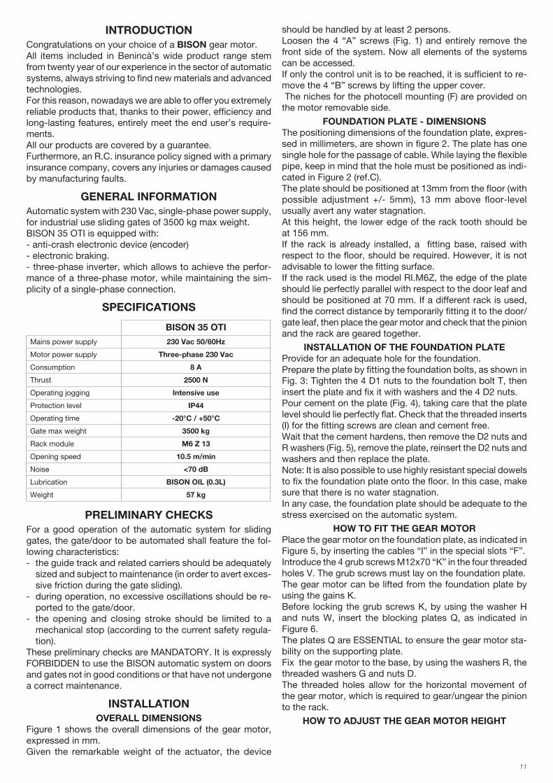
SPECIFICATIONS
BISON 35 OTI
Mains power supply 230 Vac 50/60Hz
Motor power supply Three-phase 230 Vac
Consumption 8 A
Thrust 2500 N
Operating jogging Intensive use
Protection level IP44
Operating time -20°C / +50°C
Gate max weight 3500 kg
Rack module M6 Z 13
Opening speed 10.5 m/min
Noise <70 dB
Lubrication BISON OIL (0.3L)
Weight 57 kg
PRELIMINARY CHECKSFor a good operation of the automatic system for sliding
gates, the gate/door to be automated shall feature the fol-
lowing characteristics:
- the guide track and related carriers should be adequately
sized and subject to maintenance (in order to avert exces-
sive friction during the gate sliding).
- during operation, no excessive oscillations should be re-
ported to the gate/door.
- the opening and closing stroke should be limited to a
mechanical stop (according to the current safety regula-
tion).
These preliminary checks are MANDATORY. It is expressly
FORBIDDEN to use the BISON automatic system on doors
and gates not in good conditions or that have not undergone
a correct maintenance.
INSTALLATIONOVERALL DIMENSIONS
Figure 1 shows the overall dimensions of the gear motor,
expressed in mm.
Given the remarkable weight of the actuator, the device
should be handled by at least 2 persons.
Loosen the 4 “A” screws (Fig. 1) and entirely remove the
front side of the system. Now all elements of the systems
can be accessed.
If only the control unit is to be reached, it is sufficient to re-
move the 4 “B” screws by lifting the upper cover.
The niches for the photocell mounting (F) are provided on
the motor removable side.
FOUNDATION PLATE - DIMENSIONSThe positioning dimensions of the foundation plate, expres-
sed in millimeters, are shown in figure 2. The plate has one
single hole for the passage of cable. While laying the flexible
pipe, keep in mind that the hole must be positioned as indi-
cated in Figure 2 (ref.C).
The plate should be positioned at 13mm from the floor (with
possible adjustment +/- 5mm), 13 mm above floor-level
usually avert any water stagnation.
At this height, the lower edge of the rack tooth should be
at 156 mm.
If the rack is already installed, a fitting base, raised with
respect to the floor, should be required. However, it is not
advisable to lower the fitting surface.
If the rack used is the model RI.M6Z, the edge of the plate
should lie perfectly parallel with respect to the door leaf and
should be positioned at 70 mm. If a different rack is used,
find the correct distance by temporarily fitting it to the door/
gate leaf, then place the gear motor and check that the pinion
and the rack are geared together.
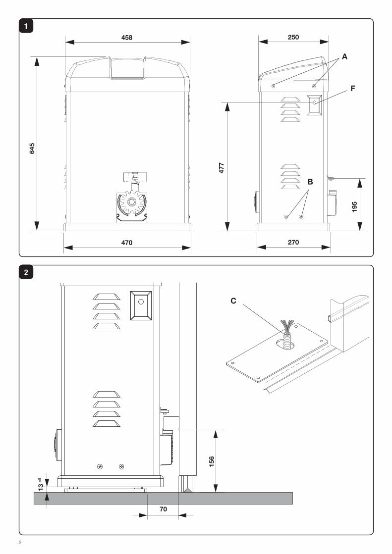
INSTALLATION OF THE FOUNDATION PLATEProvide for an adequate hole for the foundation.
Prepare the plate by fitting the foundation bolts, as shown in
Fig. 3: Tighten the 4 D1 nuts to the foundation bolt T, then
insert the plate and fix it with washers and the 4 D2 nuts.
Pour cement on the plate (Fig. 4), taking care that the plate
level should lie perfectly flat. Check that the threaded inserts
(I) for the fitting screws are clean and cement free.
Wait that the cement hardens, then remove the D2 nuts and
R washers (Fig. 5), remove the plate, reinsert the D2 nuts and
washers and then replace the plate.
Note: It is also possible to use highly resistant special dowels
to fix the foundation plate onto the floor. In this case, make
sure that there is no water stagnation.
In any case, the foundation plate should be adequate to the
stress exercised on the automatic system.
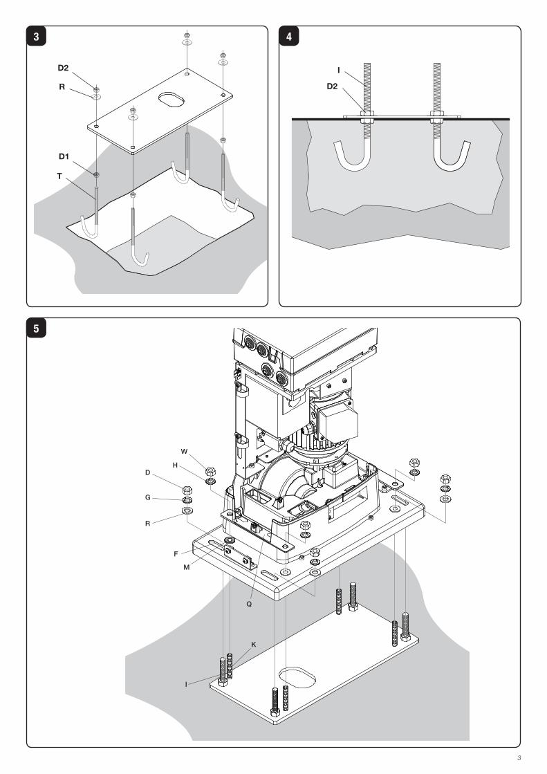
HOW TO FIT THE GEAR MOTORPlace the gear motor on the foundation plate, as indicated in
Figure 5, by inserting the cables “I” in the special slots “F”.
Introduce the 4 grub screws M12x70 “K” in the four threaded
holes V. The grub screws must lay on the foundation plate.
The gear motor can be lifted from the foundation plate by
using the gains K.
Before locking the grub screws K, by using the washer H
and nuts W, insert the blocking plates Q, as indicated in
Figure 6.
The plates Q are ESSENTIAL to ensure the gear motor sta-
bility on the supporting plate.
Fix the gear motor to the base, by using the washers R, the
threaded washers G and nuts D.
The threaded holes allow for the horizontal movement of
the gear motor, which is required to gear/ungear the pinion
to the rack.
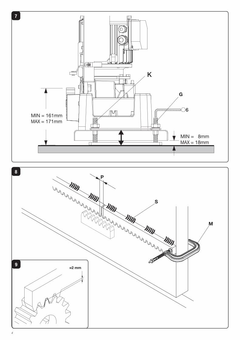
HOW TO ADJUST THE GEAR MOTOR HEIGHT
12
As indicated in the previous paragraph, height is adjusted
by using grub screws K which are placed on the plate.
Should the gear motor height must be adjusted, proceed
as follows:
- back-off nuts D
- back-off nuts W
- adjust the 4 grub screws K by using a 6mm hexagon key.
- once the correct height of the geared motor is obtained,
fix nuts W and K again.
Do not raise the plate for more than 18 mm in order not to
exercise excessive stress onto the foundation bolts (Fig.7).
HOW TO FIT THE RACKTemporarily fit the rack by using clamps, for example. Check
that the system is perfectly flat, then fit the rack to the gate
with various welding points of by using adequate screws.
Keep to the tooth pitch P, even from the rack spaces. To this
purpose, it might be useful to match another piece of rack
(Fig. 8 - Detail C).
Lastly fix the rack with screws V, making sure that, once the
actuator is installed, around 2 mm backlash is left between
the rack and the drive wheel (see Fig. 9).
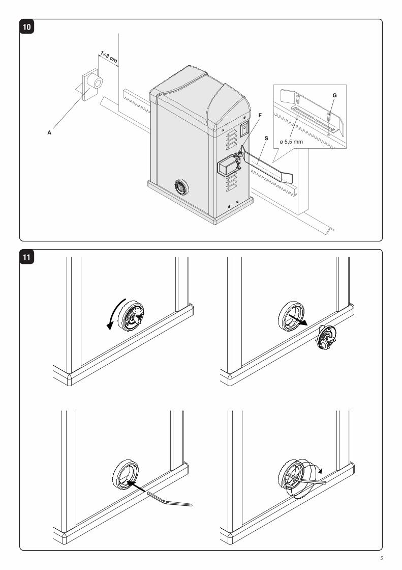
HOW TO POSITION THE LIMIT SWITCH BRACKETSManually open the gate, leaving 1 – 3 cm space, according
to the weight of the gate, between the gate/door and the
mechanical stopper A (Fig. 10).
Then fix the bracket of the limit switch S in order that the
micro-switch F of the limit switch is kept pressed.
After drilling two holes of ø 5.5mm, use the two screws G
supplied.
Repeat this operation with closed gate/door.
NOTE: The limit switch bracket should be positioned in order
to allow that the gate/door stops its movement without hitting
the mechanical stopper.
MANUAL OPERATIONIn the event of power failure or faults, the gate can be ma-
nually operated as follows (Fig.10):
- Open the protective cap from the lock, introduce the cu-
stomized key supplied and turn it by 90° anti-clockwise.
- Remove the lock group, introduce the hexagonal key
supplied, and repeatedly turn clockwise the system until
it reaches its limit switches.
- The gear motor is released and the gate can be manually
opened or closed.
- To reset the normal operation, introduce the hexagonal key
once again, and turn it repeatedly anti-clockwise, until it
stops.
- Apply the lock group again, making sure that the anti-
rotation pin be introduced in the hole on the gear group.
- Turn the key clockwise, then remove it and close the pro-
tection cap again.
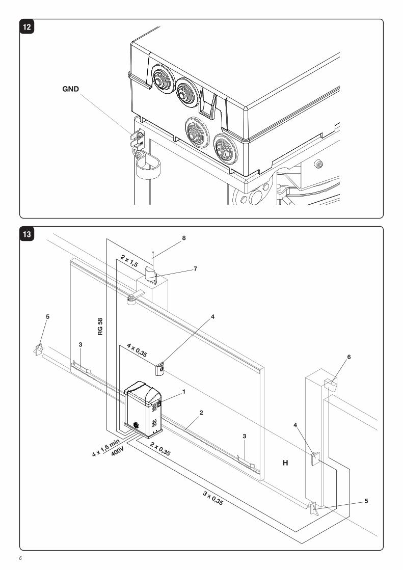
CONNECTION TO GROUND (EARTH)As regards the COMPULSORY earthing, a special Faston
4-pin connector fitted onto the central support (Fig. 12 –
GND) is supplied. Ground connections of the mains, the
upper removable side and the lower side can be connected
to this Faston.
To allow an easy removal of the sides, they are not supplied
pre-cabled to the connector. The installer shall provide for
their connection, by using the already equipped with Faston
terminal.
As regards the ground connection of the power supply line
refer to instructions in the control unit.
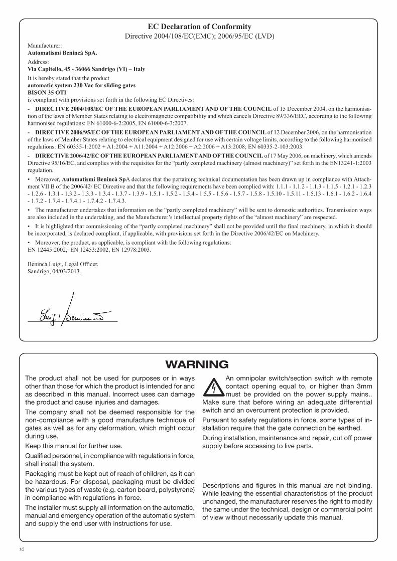
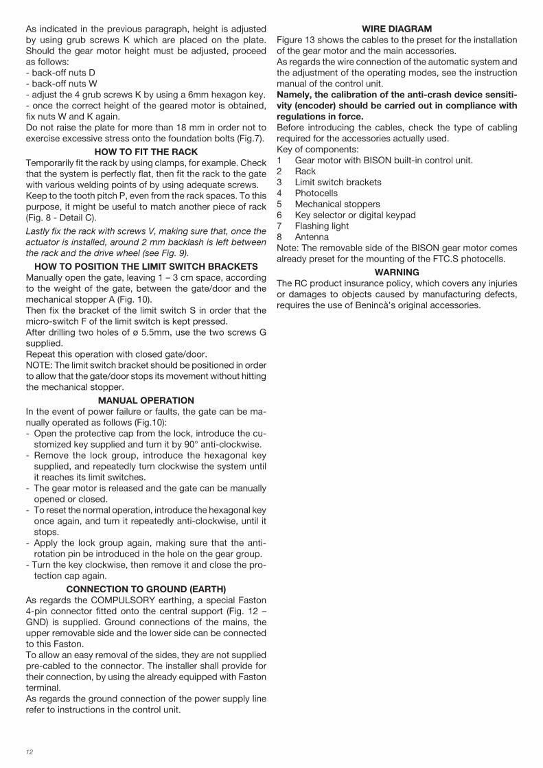
WIRE DIAGRAMFigure 13 shows the cables to the preset for the installation
of the gear motor and the main accessories.
As regards the wire connection of the automatic system and
the adjustment of the operating modes, see the instruction
manual of the control unit.
Namely, the calibration of the anti-crash device sensiti-vity (encoder) should be carried out in compliance with regulations in force.Before introducing the cables, check the type of cabling
required for the accessories actually used.
Key of components:
1 Gear motor with BISON built-in control unit.
2 Rack
3 Limit switch brackets
4 Photocells
5 Mechanical stoppers
6 Key selector or digital keypad
7 Flashing light
8 Antenna
Note: The removable side of the BISON gear motor comes
already preset for the mounting of the FTC.S photocells.
WARNING The RC product insurance policy, which covers any injuries
or damages to objects caused by manufacturing defects,
requires the use of Benincà’s original accessories.
26
BISON USER’S HANDBOOK
SAFETY MEASURES
failure but contact the specialised personnel.
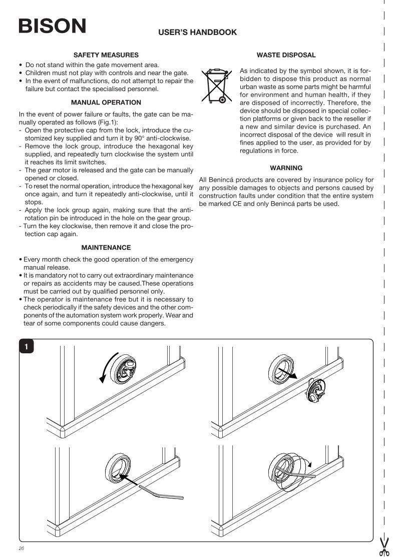
MANUAL OPERATION
In the event of power failure or faults, the gate can be ma-
nually operated as follows (Fig.1):
- Open the protective cap from the lock, introduce the cu-
stomized key supplied and turn it by 90° anti-clockwise.
- Remove the lock group, introduce the hexagonal key
supplied, and repeatedly turn clockwise the system until
it reaches its limit switches.
- The gear motor is released and the gate can be manually
opened or closed.
- To reset the normal operation, introduce the hexagonal key
once again, and turn it repeatedly anti-clockwise, until it
stops.
- Apply the lock group again, making sure that the anti-
rotation pin be introduced in the hole on the gear group.
- Turn the key clockwise, then remove it and close the pro-
tection cap again.
MAINTENANCE
manual release.
or repairs as accidents may be caused.These operations
must be carried out by qualified personnel only.
check periodically if the safety devices and the other com-
ponents of the automation system work properly. Wear and
tear of some components could cause dangers.
WASTE DISPOSAL
As indicated by the symbol shown, it is for-
bidden to dispose this product as normal
urban waste as some parts might be harmful
for environment and human health, if they
are disposed of incorrectly. Therefore, the
device should be disposed in special collec-
tion platforms or given back to the reseller if
a new and similar device is purchased. An
incorrect disposal of the device will result in
fines applied to the user, as provided for by
regulations in force.
WARNING
All Benincá products are covered by insurance policy for
any possible damages to objects and persons caused by
construction faults under condition that the entire system
be marked CE and only Benincá parts be used.
1
31
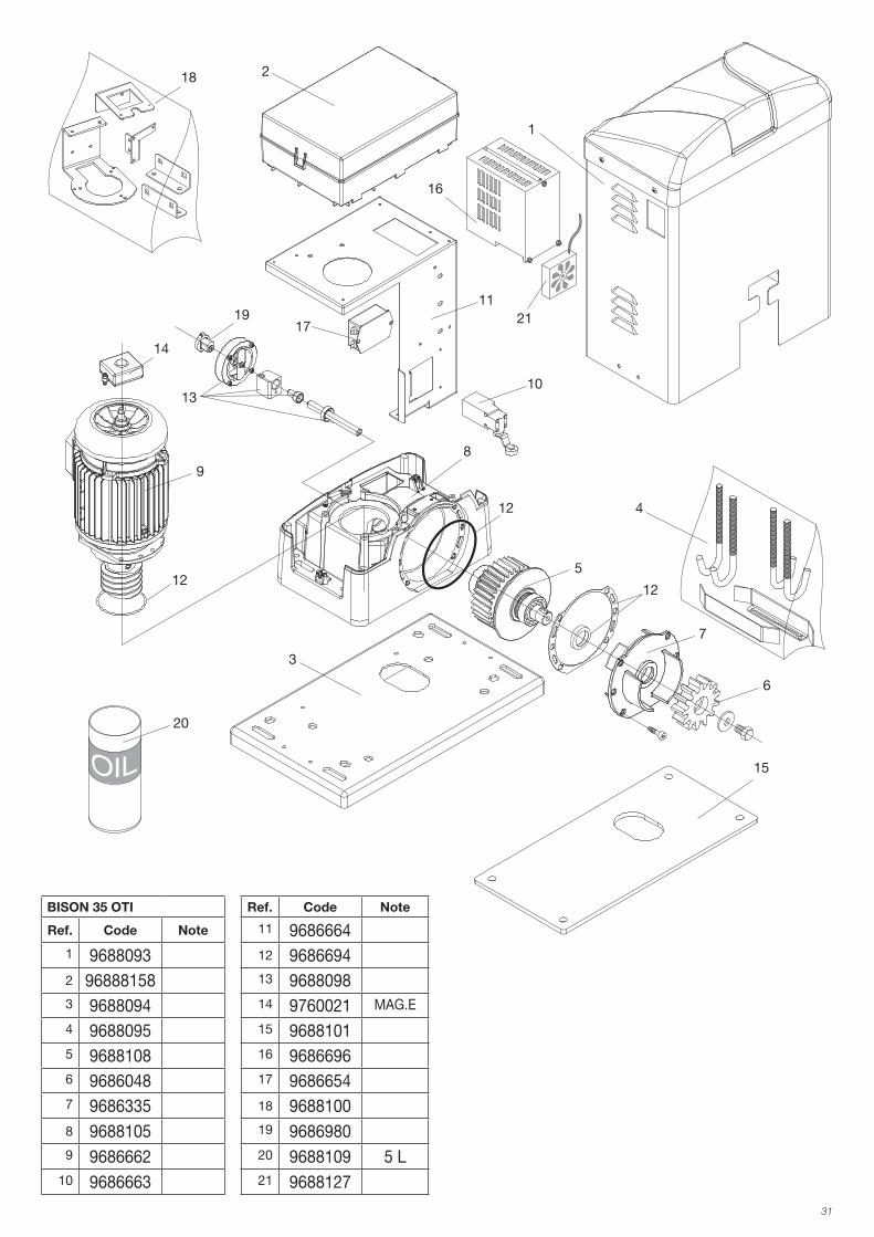
BISON 35 OTI Ref. Code Note
Ref. Code Note 11 9686664
1 9688093 12 9686694
2 96888158 13 9688098
3 9688094 14 9760021 MAG.E
4 9688095 15 9688101
5 9688108 16 9686696
6 9686048 17 9686654
7 9686335 18 9688100
8 9688105 19 9686980
9 9686662 20 9688109 5 L
10 9686663 21 9688127
1
2
3
4
6
16
7
12
12
125
9
13
19
18
14
15
10
20
21
11
17
8

AUTOMATISMI BENINCÀ SpA - Via Capitello, 45 - 36066 Sandrigo (VI) - Tel. 0444 751030 r.a. - Fax 0444 759728