Embed Size (px)
Citation preview

1
• World’s Largest In-Stock Selection• Frequency-Specific Formulations• Flexible Mounting Options
The Leading Edge in EMI Shielding Technology
BISECTED & SOLID BEAD STYLES FOR ROUND AND FLAT CABLES & WIRES
FerriShield FerriteS
Shielded enclosures, even the most robust designs, will permit electromagnetic energy to enter or exit along the main cabling. FerriShield Ferrites are one of the most versatile and cost-effective cable shielding methods available today. Our ferrites attack unwanted RF right on the circuit wiring, eliminating the need for more costly forms of RFI control. Available in solid and bisected designs, each style can make the task of regulatory compliance quicker and less troublesome.
Our bisected styles use FerriShield’s innovative, quick-snap clamshell enclosures. This unique design concept offers engineers the ultimate in adaptability and easy installation. The RF absorbing core material interacts directly with unwanted high-frequency energy and dissipates it effectively while allowing data signals to pass unimpeded.
Welcome to FerriShield
For more than 25 years, FerriShield ferrites have been the preferred cable shielding solution for many of the world’s leading EMI Shielding Distributors, Sales Representatives and OEM’s. Since acquiring the company in 2006, Leader Tech has embraced the FerriShield philosophy of maintaining the world’s largest in-stock selection of bisected and solid core ferrites.
The addition of cable mounted ferrites to Leader Tech’s existing EMI shielding product line has significantly increased value for our customers. Backed by unparalleled service and engineering support, Leader Tech now offers the market’s most reliable selection of board, enclosure and cable shielding solutions.
2
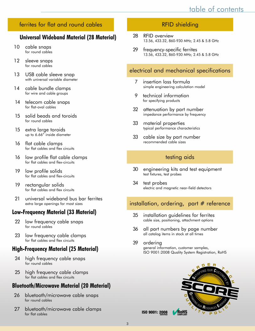
table of contents
ferrites for flat and round cables RFID shielding
testing aids
electrical and mechanical specifications
installation, ordering, part # reference
Universal Wideband Material (28 Material) 10 cable snaps for round cables
12 sleeve snaps for round cables
13 USB cable sleeve snap with universal variable diameter
14 cable bundle clamps for wire and cable groups
14 telecom cable snaps for flat-oval cables
15 solid beads and toroids for round cables
15 extra large toroids up to 6.66” inside diameter
16 flat cable clamps for flat cables and flex circuits
16 low profile flat cable clamps for flat cables and flex-circuits
19 low profile solids for flat cables and flex-circuits
19 rectangular solids for flat cables and flex circuits
21 universal wideband bus bar ferrites extra large openings for most sizes
Low-Frequency Material (33 Material) 22 low frequency cable snaps for round cables
23 low frequency cable clamps for flat cables and flex circuits
High-Frequency Material (25 Material) 24 high frequency cable snaps for round cables
25 high frequency cable clamps for flat cables and flex circuits
Bluetooth/Microwave Material (20 Material) 26 bluetooth/microwave cable snaps for round cables
27 bluetooth/microwave cable clamps for flat cables
28 RFID overview 13.56, 433.32, 860-930 MHz; 2.45 & 5.8 GHz
29 frequency-specific ferrites 13.56, 433.32, 860-930 MHz; 2.45 & 5.8 GHz
7 insertion loss formula simple engineering calculation model 9 technical information for specifying products
32 attenuation by part number impedance performance by frequency
33 material properties typical performance characteristics
33 cable size by part number recommended cable sizes
30 engineering kits and test equipment test fixtures, test probes
34 test probes electric and magnetic near-field detectors
35 installation guidelines for ferrites cable size, positioning, attachment options
36 all part numbers by page number all catalog items in stock at all times
39 ordering general information, customer samples, ISO 9001:2008 Quality System Registration, RoHS
3
ISO 9001: 2008 CERTIFIED ✔RoHS
COMPLIANT
FerriShield Ferrites
Simply one of the most flexible and cost-effective cable shielding
solutions on the market
4 Frequency-Specific Ferrite Formulations• 28 Material Wideband Ferrite (Most Popular)• 33 Material Low-Frequency Ferrite• 25 Material High-Frequency Ferrite• 20 Material Bluetooth/Microwave Ferrite
1,000s of Styles and Sizes• Solid and Bisected Styles • I.D.’s from .034” to 6.6” • Round, Square & Flat Shapes• Special application designs
10 Flexible, Quick Mounting OptionsIntegrated Mounting Options:
• Snug Cable-Fit • Button Mount • Adhesive Mount• Screw Mount• Flexible-Grip End Ports
2-Piece Mounting Options:
• Cable Tie Base• Press Fit Base• Adhesive Mount Base• Screw Mount Base• Screw Mount Strap
www.leadertechinc.comISO 9001:2008 registered
PRODUCT OVERVIEW:
4
HOW TO select a FerriShield Ferrite for your application
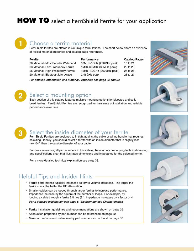
Choose a ferrite materialFerriShield ferrites are offered in (4) unique formulations. The chart below offers an overview of typical material properties and catalog page references. Ferrite Performance Catalog Pages28 Material- Most Popular Wideband 10MHz-1GHz (250MHz peak) 10 to 2133 Material- Low-Frequency Ferrite 1MHz-60MHz (30MHz peak) 22 to 2325 Material- High-Frequency Ferrite 1MHz-1.2GHz (700MHz peak) 24 to 2520 Material- Bluetooth/Microwave 2.45GHz peak 26 to 27
For detailed Attenuation and Material Properties see page 32 and 33
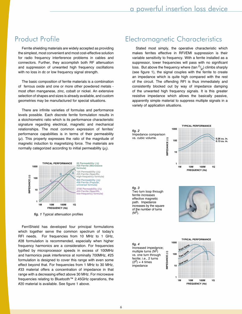
Select a mounting optionEach section of this catalog features multiple mounting options for bisected and solid bead ferrites. FerriShield Ferrites are recognized for their ease of installation and reliable performance over time.
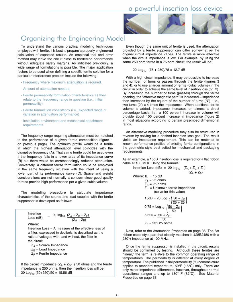
Select the inside diameter of your ferriteFerriShield Ferrites are designed to fit tight against the cable or wiring bundle that requires shielding. Ideally, you should select a ferrite with an inside diameter that is slightly less (+/- .04”) than the outside diameter of your cable.
For quick reference, all part numbers in this catalog have an accompanying technical drawing and specifications chart that illustrates dimensions and impedance for the selected ferrite. For a more detailed technical explanation see page 33.
1
2
3
• Ferrite performance typically increases as ferrite volume increases. The larger the ferrite mass, the better the RF attenuation.
• Smaller cables can be looped through larger ferrites to increase performance. Impedance increase by the square of the number of loops. For example, by looping a cable through a ferrite 2 times (22), impedance increases by a factor of 4.
For a detailed explanation see page 6- Electromagnetic Characteristics
• Ferrite installation guidelines and recommendations are shown on page 35• Attenuation properties by part number can be referenced on page 32• Maximum recommend cable size by part number can be found on page 33
Helpful Tips and Insider Hints
5
a powerful insertion loss device
Ferrite shielding materials are widely accepted as providing the simplest, most convenient and most cost-effective solution for radio frequency interference problems in cables and connectors. Further, they accomplish both RF attenuation and suppression of unwanted high frequency oscillations with no loss in dc or low frequency signal strength.
The basic composition of ferrite materials is a combination of ferrous oxide and one or more other powdered metals - most often manganese, zinc, cobalt or nickel. An extensive selection of shapes and sizes is already available, and custom geometries may be manufactured for special situations.
There are infinite varieties of formulas and performance levels possible. Each discrete ferrite formulation results in a stoichiometric ratio which is its performance characteristic signature regarding electrical, magnetic and mechanical relationships. The most common expression of ferrites’ performance capabilities is in terms of their permeability (µ). This property expresses the ratio of the magnitude of magnetic induction to magnetizing force. The materials are normally categorized according to initial permeability (µi).
FerriShield has developed four principal formulations which together serve the common spectrum of today’s RFI needs. For frequencies from 10 MHz to 1 GHz, #28 formulation is recommended, especially when higher frequency harmonics are a consideration. For frequencies typified by microprocessor speeds in excess of 100MHz and harmonics peak interference at nominally 700MHz, #25 formulation is designed to cover this range with even some effect beyond that. For frequencies from 1 MHz to 30 MHz, #33 material offers a concentration of impedance in that range with a decreasing effect above 30 MHz. For microwave frequencies relating to Bluetooth™ 2.45GHz operations, the #20 material is available. See figure 1 above.
Stated most simply, the operative characteristic which makes ferrites effective in RFI/EMI suppression is their variable sensitivity to frequency. With a ferrite installed as a suppressor, lower frequencies will pass with no significant loss. But above the frequency where (tan d/µ) climbs sharply (see figure 1), the signal couples with the ferrite to create an impedance which is quite high compared with the rest of the circuit. The offending RFI is thus immediately and consistently blocked out by way of impedance damping of the unwanted high frequency signals. It is this greater resistive impedance which allows the basically passive, apparently simple material to suppress multiple signals in a variety of application situations.
Electromagnetic Characteristics
fig. 3Two turn loop through ferrite increases effective magnetic path. Impedance increases by the square of the number of turns (N2).
fig. 2Impedance comparison vs. cubic volume.
fig. 4 Increased impedance; multiple turns (N2) vs. one turn through ferrite; i.e., 2 turns (22) = 4 times impedance
TYPICAL PERFORMANCE
FREQUENCY (Hz)1M 10M 100M 1G
1000
100
10
1
850 Permeability ( i)#28 Ferrite (Popular,universal formula)
125 Permeability ( i)#25 Ferrite (Specific,high-frequency formula)
20 Permeability ( i)#20 Ferrite (Microwaveformula)
2700 Permeability ( i)#33 Ferrite (Specific,low-frequency formula)
fig. 1 Typical attenuation profiles
B A
C
Product Profile
6
a powerful insertion loss device
To understand the various practical modeling techniques employed with ferrite, it is best to prepare a properly engineered calculation of expected results. An empirical trial and error method may leave the circuit close to borderline performance without adequate safety margins. As indicated previously, a wide range of formulations is possible. The major application factors to be used when defining a specific ferrite solution for a particular interference problem include the following:
- Frequency where maximum attenuation is required. - Amount of attenuation needed. - Ferrite permeability formulation characteristics as they relate to the frequency range in question (i.e., initial permeability) - Ferrite formulation consistency (i.e., expected range of variation in attenuation performance) - Installation environment and mechanical attachment requirements.
The frequency range requiring attenuation must be matched to the performance of a given ferrite composition (figure 1 on previous page). The optimum profile would be a ferrite in which the highest attenuation level coincides with the disruptive frequency (A). That same ferrite could be used even if the frequency falls in a lower area of its impedance curve (B) but there would be correspondingly reduced attenuation. Conversely, a different ferrite formulation could be employed in the same frequency situation with the intent of using a lower part of its performance curve (C). Space and weight considerations are not normally a concern since good quality ferrites provide high performance per a given cubic volume.
The modeling procedure to calculate impedance characteristics of the source and load coupled with the ferrite suppressor is developed as follows:
Insertion 20 log10 (ZA + ZB + ZF) Loss (dB) (ZA + ZB) Where: Insertion Loss = A measure of the effectiveness of a filter, expressed in decibels, is described as the ratio of voltages with, and without, the filter in the circuit. ZA = Source Impedance ZB = Load Impedance ZF = Ferrite Impedance
If the circuit impedance (ZA + ZB) is 50 ohms and the ferrite impedance is 250 ohms, then the insertion loss will be: 20 Log10 (50+250)/50 = 15.56 dB
Even though the same unit of ferrite is used, the attenuation provided by a ferrite suppressor can differ somewhat as the original circuit impedance varies. The ferrite is more effective when the circuit impedance is low. For example, by using the same 250 ohm ferrite in a 75 ohm circuit, the result will be:
20 Log10 (75 + 250)/75 = 12.7 dB
With a high circuit impedance, it may be possible to increase the number of turns or passes through the ferrite (figures 3 and 4), or to use a larger amount of ferrite (cubic volume) in the circuit in order to achieve the same level of insertion loss (fig. 2). By increasing the number of turns (passes) through the ferrite opening, the “effective magnetic path” is increased _ impedance then increases by the square of the number of turns (N2) ; i.e., two turns (22) = 4 times the impedance. When additional ferrite volume is added, impedance increases on almost a direct percentage basis; i.e., a 100 percent increase in volume will provide about 100 percent increase in impedance (figure 2) in most situations according to certain prescribed dimensional ratios.
An alternative modeling procedure may also be structured in reverse by solving for a desired insertion loss goal. The result yields an impedance requirement. This can be matched to known performance profiles of existing ferrite configurations in the geometric style best suited for mechanical and packaging requirements. As an example, a 15dB insertion loss is required for a flat ribbon cable at 100 MHz. Using the formula: Insertion Loss (dB) = 20 log10 (ZA + ZB + ZF) (ZA + ZB) Where: IL = 15 dB ZA = 25 ohms ZB = 25 ohms ZF = Unknown ferrite impedance (solve for this value)
15dB = 20 Log10 50 + ZF 25 + 25 0.75 = Log10 50 + ZF 50 5.625 = 50 + ZF 50 ZF = 231.25 ohms
Next, refer to the Attenuation Properties on page 36. The flat ribbon cable style part that closely matches is #28B2480 with a 250½ impedance at 100 MHz.
Once the ferrite suppressor is installed in the circuit, results should be confirmed by testing. Although these ferrites are “linear,” the term is relative to the common operating range of temperatures. The permeability is different at every degree of temperature. The published initial permeability (µi) nomenclature applies to standard temperature, 59°F (15°C) only. There are only minor impedance differences, however, throughout normal operational ranges and up to 180° F (82°C). See Material Properties on page 33.
=
Organizing the Engineering Model
((
))
7
ferrites for interference control
SHIELDING EFFECTIVENESS (dB)
PER
CEN
T A
TTEN
UA
TIO
N ATTEN
UA
TION
RA
TIO
0 20 40 60 80 100 120
99.9999
99.999
99.99
99.9
99.0
90.0
1,000,000:1
100,000:1
10,000:1
1,000:1
100:1
10:1
Any device used to block an RFI signal between its source and a receiver is an electromagnetic interference (EMI) shield.
The measure of this ability to attenuate RFI is Shielding Effectiveness, SE, which is expressed in decibels, dB, the ratio of field strength on one side of the shield to the other side. The figure above shows the relationship between shielding effectiveness (in dB), the amount of attenuation, and attenuation percentage.
The concept of bisected ferrites has been developed to address a number of industry needs in the area of Electromagnetic Compatibility, EMC.
• engineering adaptability • risk-free engineering: - tight tolerance performance - easy to upgrade attenuation by changing size or number of turns. • easy retrofitting • convenient installation • integral mounting features • cost-effectiveness • extended resistance to core saturation under Direct Current loads. • consistent performance
Engineering assistance is always available. We will be pleased to help with applications, cross-referencing or complete insertion loss calculations when a custom suppressor is required.
Design Support
FerriShield Advantages
Typical FerriShield RFI suppressor.
I/O cable with RFI suppressor.
UL recognizedplastic case
Bisected ferriteRFI absorber
Cable grippingentry/exit port
The technical air gap in bisected ferrites actually extends current carrying capability with only an imperceptible reduction in impedance versus solid ferrites of the same size. The gap is magnetically insignificant while it is electrically significant as a discontinuation, thereby accommodating more current.
Gap effect of ferrite subjected to direct current.
Controlling RFI/EMI
For attenuation properties by frequency, see page 32 8

A A
CC
B
B
Advantages
Electronic cabling and wires, by virtue of their length-to-width ratios, are perfect natural antennas. In the presence of high speed microprocessor signals, cables will conduct, radiate and/or receive unwanted high frequency interfering signals. Control of radio frequency interference can be assured by proper placement of an insertion loss device, such as a ferrite suppressor.
Compared to other alternatives, ferrites’ high resistivity per cubic volume stands out as the most important advantage. Prior to the development of bisected ferrites, suppression engineering was restricted to the costly addition of filters, cable shielding, and less versatile solid core (not bisected) ferrites. While these methods offer a degree of suppression, they are often awkward to install and, in many cases, are not completely effective. Bisected ferrites have a concentrated, homogeneous magnetic structure with high permeability. They are consistently stable versus time and temperature, and provide RF suppression without high eddy current losses.
Anywhere There is an Antenna-Like Structure
Application Points FerriShield installation locations.
A. Data signals and high frequency interference signals absorbed and conductedB. All high frequency interference absorbed by ferrite suppressor and thermally dissipatedC. Low frequency data signals pass unimpeded
Just snap over circuit wiring to be controlled - even after wiring has been terminated Radio interference sources usually radiate their RFI power at frequencies above 30 MHz by way of the main cabling, which acts as an antenna.
Installation is simple
CABLING RFI suppressor functions
BUS BARS RFI suppressor functions: bus bars
ferrites for interference control
A. Power distribution and high frequency interference signals a b s o r b e d a n d conductedB. All high frequency interference absorbed by ferrite suppressor and thermally dissipatedC. Power distribution characteristics pass unimpeded
For attenuation properties by frequency, see page 32 9
For attenuation properties by frequency, see page 32
28 material wideband ferrites- up to 1GHz applications
ADE
C
F
B
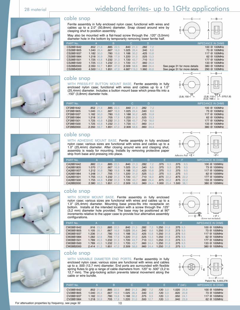
Ferrite assembly in fully enclosed nylon case; functional with wires and cables up to a 2.0” (50,8mm) diameter. Snap closed around wire by clasping shut to position assembly.May also be mounted with a flat-head screw through the .120” (3,0mm) diameter hole in the bottom by temporarily removing lower ferrite half.
WITH ADHESIVE MOUNT BASE. Ferrite assembly in fully enclosed nylon case; various sizes are functional with wires and cables up to a 1.0” (25,4mm) diameter. After closing around wire and clasping shut, assembly is ready for mounting. Installs by removing protective paper strip from base and pressing into place.
WITH SCREW MOUNT BASE. Ferrite assembly in fully enclosed nylon case; various sizes are functional with wires and cables up to a 1.0” (25,4mm) diameter. Mounting base press-fits into receptacle on bottom. Installs at the intended location with a screw through the .125” (3,2 mm) diameter hole provided. The base may be positioned at 90º increments relative to the upper case to provide four alternative assembly configurations.
WITH VARIABLE DIAMETER END PORTS. Ferrite assembly in fully enclosed nylon case; various sizes are functional with wires and cables up to a .500 (12,7 mm) diameter. End ports are surrounded with flexible spring flutes to grip a range of cable diameters from .120” to .500” (3,2 to 12,7 mm). The grip-locking action prevents lateral movement along the cable or wire bundle.
WITH PRESS-FIT BUTTON MOUNT BASE. Ferrite assembly in fully enclosed nylon case; functional with wires and cables up to a 1.0” (25,4mm) diameter. Includes a button mount base which press-fits into a .150” (3,8mm) diameter hole.
AD
C B
AD
C
.070 (1,8).110(2,8).168(4,3)
B
.150(3,8)
AD
C B
E FAdhesive Pad
AD
C B
E F(Screw not included)
PART No. A B C D IMPEDANCE IN OHMS CS28B1642 .852 21,6 .885 22,5 .840 21,3 .282 7,2 100 @ 100MHz CS28B1805 1.040 26,4 .667 16,9 1.025 26,4 .340 8,6 73 @ 100MHz CS28B1937 1.182 30,0 .780 19,8 1.188 30,2 .425 10,8 117 @ 100MHz CS28B1984 1.218 30,9 .705 17,9 1.220 31,0 .525 13,3 62 @ 100MHz CS28B1501 1.725 43,8 1.232 31,3 1.720 43,7 .710 18,0 177 @ 100MHz CS28B1500 1.725 43,8 1.232 31,3 1.720 43,7 .960 24,4 133 @ 100MHz CS28B2000 2.350 59,7 1.851 47,0 2.309 58,6 .960 24,4 See page 31 for more details 380 @ 100MHz CS28B4000 4.500 114,2 1.851 47,0 4.687 119,0 1.960 49,8 See page 31 for more details 290 @ 100MHz
PART No. A B C D IMPEDANCE IN OHMS CF28B1642 .852 21,6 .885 22,5 .840 21,3 .282 7,2 100 @ 100MHz CF28B1805 1.040 26,4 .667 16,9 1.025 26,4 .340 8,6 73 @ 100MHz CF28B1937 1.182 30,0 .780 19,8 1.188 30,2 .425 10,8 117 @ 100MHz CF28B1984 1.218 30,9 .705 17,9 1.220 31,0 .525 13,3 62 @ 100MHz CF28B1501 1.725 43,8 1.232 31,3 1.720 43,7 .710 18,0 177 @ 100MHz CF28B1500 1.725 43,8 1.232 31,3 1.720 43,7 .960 24,4 133 @ 100MHz CF28B2000 2.350 59,7 1.851 47,0 2.309 58,6 .960 24,4 380 @ 100MHz
PART No. A B C D E F IMPEDANCE IN OHMS CW28B1642 .916 23,3 .885 22,5 .840 21,3 .282 7,2 1.250 31,8 .375 9,5 100 @ 100MHz CW28B1805 1.105 28,1 .667 16,9 1.025 26,4 .340 8,6 1.250 31,8 .375 9,5 73 @ 100MHz CW28B1937 1.236 31,4 .780 19,8 1.188 30,2 .425 10,8 1.250 31,8 .375 9,5 117 @ 100MHz CW28B1984 1.282 32,6 .705 17,9 1.220 31,0 .525 13,3 1.250 31,8 .375 9,5 62 @ 100MHz CW28B1501 1.789 45,5 1.232 31,3 1.720 43,7 .710 18,0 1.250 31,8 .375 9,5 177 @ 100MHz CW28B1500 1.789 45,5 1.232 31,3 1.720 43,7 .960 24,4 1.250 31,8 .375 9,5 133 @ 100MHz CW28B2000 2.414 61,3 1.851 47,0 2.309 58,6 .960 24,4 1.250 31,8 .375 9,5 380 @ 100MHz
Patent No. 5,003,278 PART No. A B C D E F (ref.) IMPEDANCE IN OHMS CV28B1642 .852 21,6 .885 22,5 .840 21,3 .282 7,2 .120 3,0 1.020 25,9 100 @ 100MHz CV28B1805 1.040 26,4 .667 16,9 1.025 26,4 .340 8,6 .120 3,0 .820 20,8 73 @ 100MHz CV28B1937 1.182 30,0 .780 19,8 1.188 30,2 .375 9,5 .120 3,0 .950 24,1 117 @ 100MHz CV28B1984 1.218 30,9 .705 17,9 1.220 31,0 .500 12,7 .120 3,0 .940 23,9 62 @ 100MHz
PART No. A B C D E F IMPEDANCE IN OHMS CA28B1642 .882 22,4 .885 22,5 .840 21,3 .282 7,2 .375 9,5 .375 9,5 100 @ 100MHz CA28B1805 1.070 27,2 .667 16,9 1.025 26,4 .340 8,6 .375 9,5 .375 9,5 73 @ 100MHz CA28B1937 1.212 30,8 .780 19,8 1.188 30,2 .425 10,8 .375 9,5 .375 9,5 117 @ 100MHz CA28B1984 1.248 31,7 .705 17,9 1.220 31,0 .525 13,3 .375 9,5 .375 9,5 62 @ 100MHz CA28B1501 1.755 44,6 1.232 31,3 1.720 43,7 .710 18,0 .875 22,2 .875 22,2 177 @ 100MHz CA28B1500 1.755 44,6 1.232 31,3 1.720 43,7 .960 24,4 .875 22,2 .875 22,2 133 @ 100MHz CA28B2000 2.380 60,5 1.851 47,0 2.309 58,6 .960 24,4 1.000 25,4 1.500 38,1 380 @ 100MHz
cable snap
cable snap
cable snap
cable snap
cable snap
10
For attenuation properties by frequency, see page 32
28 material wideband ferrites- up to 1GHz applications
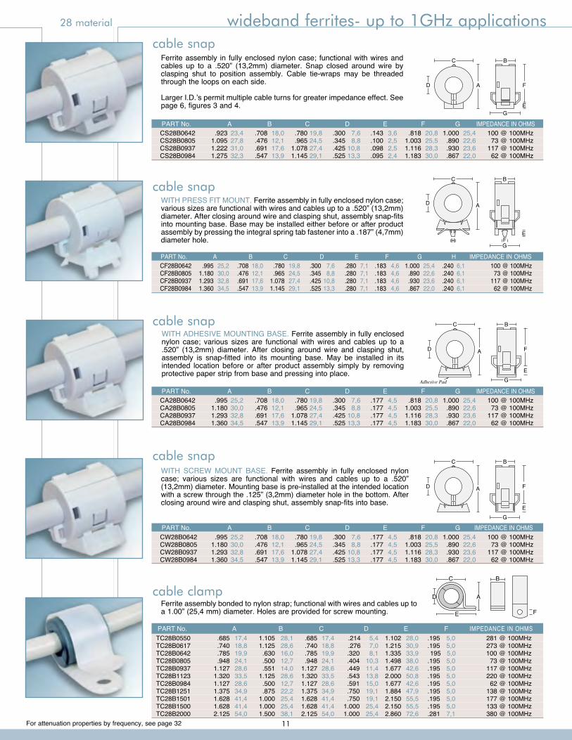
WITH SCREW MOUNT BASE. Ferrite assembly in fully enclosed nylon case; various sizes are functional with wires and cables up to a .520” (13,2mm) diameter. Mounting base is pre-installed at the intended location with a screw through the .125” (3,2mm) diameter hole in the bottom. After closing around wire and clasping shut, assembly snap-fits into base.
A F
E
D
C B
G
cable snap
CW28B0642 .995 25,2 .708 18,0 .780 19,8 .300 7,6 .177 4,5 .818 20,8 1.000 25,4 100 @ 100MHz CW28B0805 1.180 30,0 .476 12,1 .965 24,5 .345 8,8 .177 4,5 1.003 25,5 .890 22,6 73 @ 100MHz CW28B0937 1.293 32,8 .691 17,6 1.078 27,4 .425 10,8 .177 4,5 1.116 28,3 .930 23,6 117 @ 100MHz CW28B0984 1.360 34,5 .547 13,9 1.145 29,1 .525 13,3 .177 4,5 1.183 30,0 .867 22,0 62 @ 100MHz
PART No. A B C D E F G IMPEDANCE IN OHMS
WITH ADHESIVE MOUNTING BASE. Ferrite assembly in fully enclosed nylon case; various sizes are functional with wires and cables up to a .520” (13,2mm) diameter. After closing around wire and clasping shut, assembly is snap-fitted into its mounting base. May be installed in its intended location before or after product assembly simply by removing protective paper strip from base and pressing into place.
A F
E
D
C B
GAdhesive Pad
cable snap
CA28B0642 .995 25,2 .708 18,0 .780 19,8 .300 7,6 .177 4,5 .818 20,8 1.000 25,4 100 @ 100MHz CA28B0805 1.180 30,0 .476 12,1 .965 24,5 .345 8,8 .177 4,5 1.003 25,5 .890 22,6 73 @ 100MHz CA28B0937 1.293 32,8 .691 17,6 1.078 27,4 .425 10,8 .177 4,5 1.116 28,3 .930 23,6 117 @ 100MHz CA28B0984 1.360 34,5 .547 13,9 1.145 29,1 .525 13,3 .177 4,5 1.183 30,0 .867 22,0 62 @ 100MHz
PART No. A B C D E F G IMPEDANCE IN OHMS
WITH PRESS FIT MOUNT. Ferrite assembly in fully enclosed nylon case; various sizes are functional with wires and cables up to a .520” (13,2mm) diameter. After closing around wire and clasping shut, assembly snap-fits into mounting base. Base may be installed either before or after product assembly by pressing the integral spring tab fastener into a .187” (4,7mm) diameter hole.
A
FE
D
C
H
B
G
cable snap
CF28B0642 .995 25,2 .708 18,0 .780 19,8 .300 7,6 .280 7,1 .183 4,6 1.000 25,4 .240 6,1 100 @ 100MHz CF28B0805 1.180 30,0 .476 12,1 .965 24,5 .345 8,8 .280 7,1 .183 4,6 .890 22,6 .240 6,1 73 @ 100MHz CF28B0937 1.293 32,8 .691 17,6 1.078 27,4 .425 10,8 .280 7,1 .183 4,6 .930 23,6 .240 6,1 117 @ 100MHz CF28B0984 1.360 34,5 .547 13,9 1.145 29,1 .525 13,3 .280 7,1 .183 4,6 .867 22,0 .240 6,1 62 @ 100MHz
PART No. A B C D E F G H IMPEDANCE IN OHMS
Ferrite assembly bonded to nylon strap; functional with wires and cables up to a 1.00” (25,4 mm) diameter. Holes are provided for screw mounting.
AD
F
C B
E
PART No. A B C D E F IMPEDANCE IN OHMS TC28B0550 .685 17,4 1.105 28,1 .685 17,4 .214 5,4 1.102 28,0 .195 5,0 281 @ 100MHz TC28B0617 .740 18,8 1.125 28,6 .740 18,8 .276 7,0 1.215 30,9 .195 5,0 273 @ 100MHz TC28B0642 .785 19,9 .630 16,0 .785 19,9 .320 8,1 1.335 33,9 195 5,0 100 @ 100MHz TC28B0805 .948 24,1 .500 12,7 .948 24,1 .404 10,3 1.498 38,0 .195 5,0 73 @ 100MHz TC28B0937 1.127 28,6 .551 14,0 1.127 28,6 .449 11,4 1.677 42,6 .195 5,0 117 @ 100MHz TC28B1123 1.320 33,5 1.125 28,6 1.320 33,5 .543 13,8 2.000 50,8 .195 5,0 220 @ 100MHz TC28B0984 1.127 28,6 .500 12,7 1.127 28,6 .591 15,0 1.677 42,6 .195 5,0 62 @ 100MHz TC28B1251 1.375 34,9 .875 22,2 1.375 34,9 .750 19,1 1.884 47,9 .195 5,0 138 @ 100MHz TC28B1501 1.628 41,4 1.000 25,4 1.628 41,4 .750 19,1 2.150 55,5 .195 5,0 177 @ 100MHz TC28B1500 1.628 41,4 1.000 25,4 1.628 41,4 1.000 25,4 2.150 55,5 .195 5,0 133 @ 100MHz TC28B2000 2.125 54,0 1.500 38,1 2.125 54,0 1.000 25,4 2.860 72,6 .281 7,1 380 @ 100MHz
cable clamp
Ferrite assembly in fully enclosed nylon case; functional with wires and cables up to a .520” (13,2mm) diameter. Snap closed around wire by clasping shut to position assembly. Cable tie-wraps may be threaded through the loops on each side.
Larger I.D.’s permit multiple cable turns for greater impedance effect. See page 6, figures 3 and 4.
A F
E
D
C B
G
cable snap
CS28B0642 .923 23,4 .708 18,0 .780 19,8 .300 7,6 .143 3,6 .818 20,8 1.000 25,4 100 @ 100MHz CS28B0805 1.095 27,8 .476 12,1 .965 24,5 .345 8,8 .100 2,5 1.003 25,5 .890 22,6 73 @ 100MHz CS28B0937 1.222 31,0 .691 17,6 1.078 27,4 .425 10,8 .098 2,5 1.116 28,3 .930 23,6 117 @ 100MHz CS28B0984 1.275 32,3 .547 13,9 1.145 29,1 .525 13,3 .095 2,4 1.183 30,0 .867 22,0 62 @ 100MHz
PART No. A B C D E F G IMPEDANCE IN OHMS
CS28B1642 .852 21,6 .885 22,5 .840 21,3 .282 7,2 100 @ 100MHz CS28B1805 1.040 26,4 .667 16,9 1.025 26,4 .340 8,6 73 @ 100MHz CS28B1937 1.182 30,0 .780 19,8 1.188 30,2 .425 10,8 117 @ 100MHz CS28B1984 1.218 30,9 .705 17,9 1.220 31,0 .525 13,3 62 @ 100MHz CS28B1501 1.725 43,8 1.232 31,3 1.720 43,7 .710 18,0 177 @ 100MHz CS28B1500 1.725 43,8 1.232 31,3 1.720 43,7 .960 24,4 133 @ 100MHz CS28B2000 2.350 59,7 1.851 47,0 2.309 58,6 .960 24,4 See page 31 for more details 380 @ 100MHz CS28B4000 4.500 114,2 1.851 47,0 4.687 119,0 1.960 49,8 See page 31 for more details 290 @ 100MHz
11
For attenuation properties by frequency, see page 32
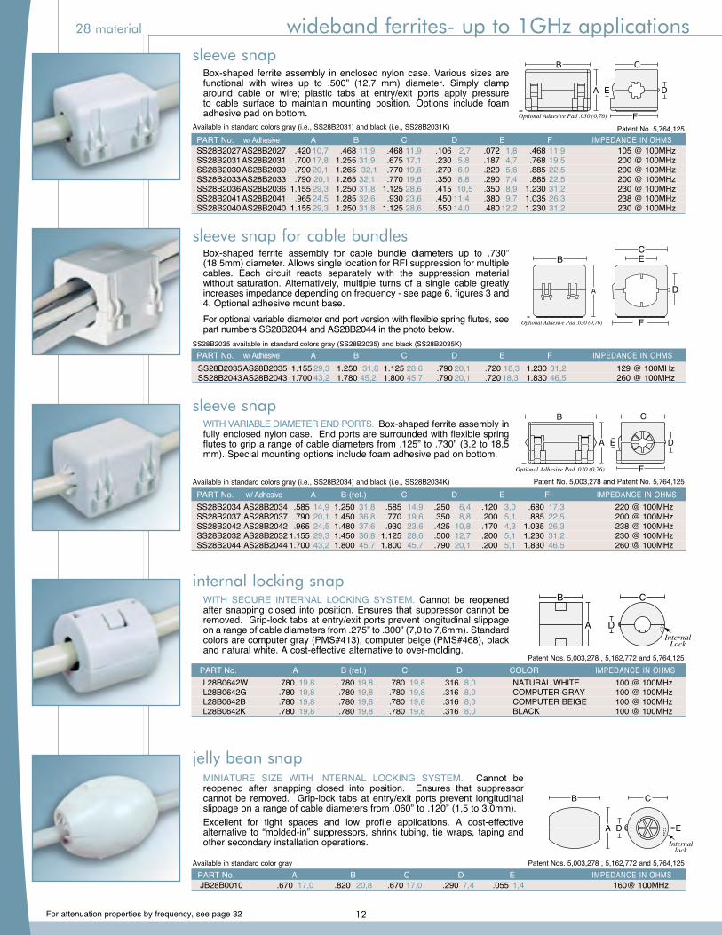
Box-shaped ferrite assembly in enclosed nylon case. Various sizes are functional with wires up to .500” (12,7 mm) diameter. Simply clamp around cable or wire; plastic tabs at entry/exit ports apply pressure to cable surface to maintain mounting position. Options include foam adhesive pad on bottom. Optional Adhesive Pad .030 (0,76)
B C
F
A E D
Available in standard colors gray (i.e., SS28B2031) and black (i.e., SS28B2031K) Patent No. 5,764,125 PART No. w/ Adhesive A B C D E F IMPEDANCE IN OHMS SS28B2027 AS28B2027 .420 10,7 .468 11,9 .468 11,9 .106 2,7 .072 1,8 .468 11,9 105 @ 100MHz SS28B2031 AS28B2031 .700 17,8 1.255 31,9 .675 17,1 .230 5,8 .187 4,7 .768 19,5 200 @ 100MHz SS28B2030 AS28B2030 .790 20,1 1.265 32,1 .770 19,6 .270 6,9 .220 5,6 .885 22,5 200 @ 100MHz SS28B2033 AS28B2033 .790 20,1 1.265 32,1 .770 19,6 .350 8,8 .290 7,4 .885 22,5 200 @ 100MHz SS28B2036 AS28B2036 1.155 29,3 1.250 31,8 1.125 28,6 .415 10,5 .350 8,9 1.230 31,2 230 @ 100MHz SS28B2041 AS28B2041 .965 24,5 1.285 32,6 .930 23,6 .450 11,4 .380 9,7 1.035 26,3 238 @ 100MHz SS28B2040 AS28B2040 1.155 29,3 1.250 31,8 1.125 28,6 .550 14,0 .480 12,2 1.230 31,2 230 @ 100MHz
sleeve snap
WITH VARIABLE DIAMETER END PORTS. Box-shaped ferrite assembly in fully enclosed nylon case. End ports are surrounded with flexible spring flutes to grip a range of cable diameters from .125” to .730” (3,2 to 18,5 mm). Special mounting options include foam adhesive pad on bottom.
B C
F
A E D
Optional Adhesive Pad .030 (0,76)
Patent No. 5,003,278 and Patent No. 5,764,125Available in standard colors gray (i.e., SS28B2034) and black (i.e., SS28B2034K)
PART No. w/ Adhesive A B (ref.) C D E F IMPEDANCE IN OHMS SS28B2034 AS28B2034 .585 14,9 1.250 31,8 .585 14,9 .250 6,4 .120 3,0 .680 17,3 220 @ 100MHz SS28B2037 AS28B2037 .790 20,1 1.450 36,8 .770 19,6 .350 8,8 .200 5,1 .885 22,5 200 @ 100MHz SS28B2042 AS28B2042 .965 24,5 1.480 37,6 .930 23,6 .425 10,8 .170 4,3 1.035 26,3 238 @ 100MHz SS28B2032 AS28B2032 1.155 29,3 1.450 36,8 1.125 28,6 .500 12,7 .200 5,1 1.230 31,2 230 @ 100MHz SS28B2044 AS28B2044 1.700 43,2 1.800 45,7 1.800 45,7 .790 20,1 .200 5,1 1.830 46,5 260 @ 100MHz
sleeve snap
WITH SECURE INTERNAL LOCKING SYSTEM. Cannot be reopened after snapping closed into position. Ensures that suppressor cannot be removed. Grip-lock tabs at entry/exit ports prevent longitudinal slippage on a range of cable diameters from .275” to .300” (7,0 to 7,6mm). Standard colors are computer gray (PMS#413), computer beige (PMS#468), black and natural white. A cost-effective alternative to over-molding.
Patent Nos. 5,003,278 , 5,162,772 and 5,764,125
IL28B0642W .780 19,8 .780 19,8 .780 19,8 .316 8,0 NATURAL WHITE 100 @ 100MHz IL28B0642G .780 19,8 .780 19,8 .780 19,8 .316 8,0 COMPUTER GRAY 100 @ 100MHz IL28B0642B .780 19,8 .780 19,8 .780 19,8 .316 8,0 COMPUTER BEIGE 100 @ 100MHz IL28B0642K .780 19,8 .780 19,8 .780 19,8 .316 8,0 BLACK 100 @ 100MHz
PART No. A B (ref.) C D COLOR IMPEDANCE IN OHMS
internal locking snap
MINIATURE SIZE WITH INTERNAL LOCKING SYSTEM. Cannot be reopened after snapping closed into position. Ensures that suppressor cannot be removed. Grip-lock tabs at entry/exit ports prevent longitudinal slippage on a range of cable diameters from .060” to .120” (1,5 to 3,0mm).Excellent for tight spaces and low profile applications. A cost-effective alternative to “molded-in” suppressors, shrink tubing, tie wraps, taping and other secondary installation operations.
jelly bean snap
Patent Nos. 5,003,278 , 5,162,772 and 5,764,125Available in standard color gray PART No. A B C D E IMPEDANCE IN OHMS JB28B0010 .670 17,0 .820 20,8 .670 17,0 .290 7,4 .055 1,4 160@ 100MHz
Box-shaped ferrite assembly for cable bundle diameters up to .730” (18,5mm) diameter. Allows single location for RFI suppression for multiple cables. Each circuit reacts separately with the suppression material without saturation. Alternatively, multiple turns of a single cable greatly increases impedance depending on frequency - see page 6, figures 3 and 4. Optional adhesive mount base.For optional variable diameter end port version with flexible spring flutes, see part numbers SS28B2044 and AS28B2044 in the photo below.
sleeve snap for cable bundles
B
A D
E
C
SS28B2035 1-hole
B
A
E
C
SS28B2035-2 2-holes
B
A
E
C
SS28B2035-3 3-holes
D
D
Optional Adhesive Pad .030 (0,76)
Optional Adhesive Pad .030 (0,76)
Optional Adhesive Pad .030 (0,76)
Optional Adhesive Pad .030 (0,76)
B
A D
F
C E
SS28B2035 AS28B2035 1.155 29,3 1.250 31,8 1.125 28,6 .790 20,1 .720 18,3 1.230 31,2 129 @ 100MHz SS28B2043 AS28B2043 1.700 43,2 1.780 45,2 1.800 45,7 .790 20,1 .720 18,3 1.830 46,5 260 @ 100MHz
PART No. w/ Adhesive A B C D E F IMPEDANCE IN OHMSSS28B2035 available in standard colors gray (SS28B2035) and black (SS28B2035K)
28 material wideband ferrites- up to 1GHz applications
12
For attenuation properties by frequency, see page 32
B C
A D
E
1.70 (43,2)
.032 (0,81)
OPTIONAL ADHESIVE MOUNT BASE(Preassembled)
OPTIONAL HARDWARE MOUNT BASE(To be assembled during installation)
OPTIONAL BUTTON MOUNT BASE(Preassembled)
1.25 (31,8)
.375 (9,52)
.060 (1,52) .125 (3,18)
.070 (1,78).168
(4,26).150 (3,81)
.275 (6,94)
Mounting receptaclefor button and hardwaremount bases.
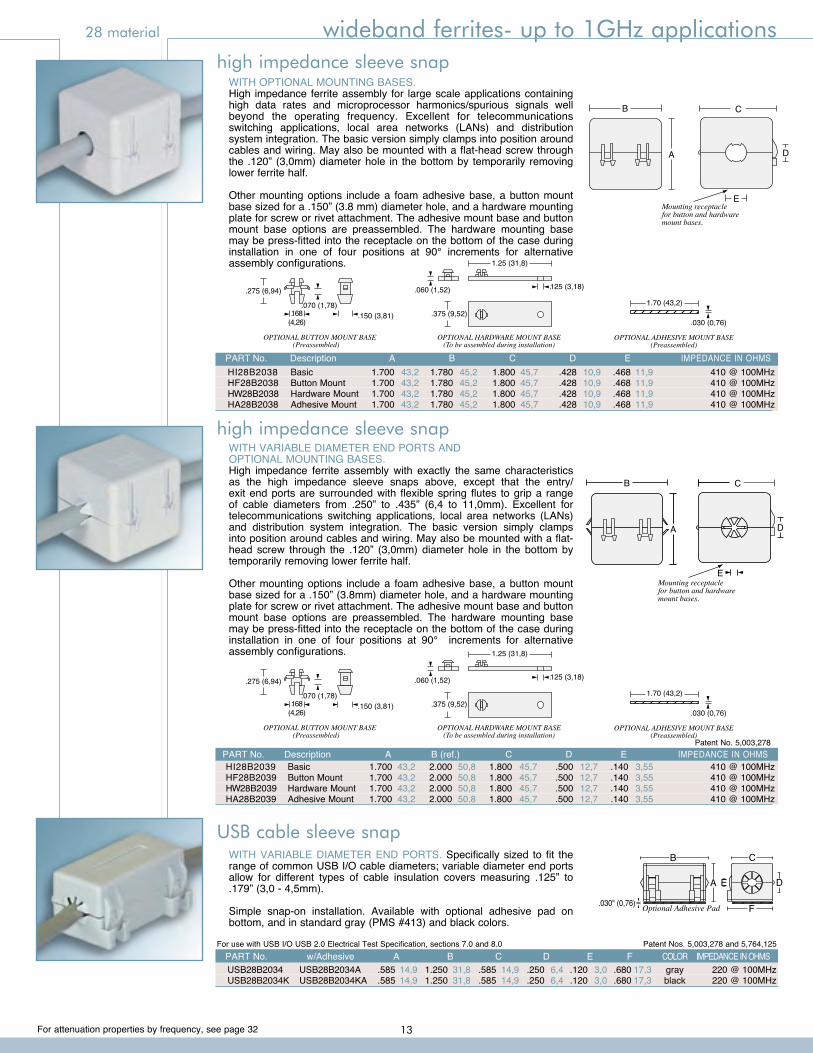
PART No. Description A B (ref.) C D E IMPEDANCE IN OHMS HI28B2039 Basic 1.700 43,2 2.000 50,8 1.800 45,7 .500 12,7 .140 3,55 410 @ 100MHz HF28B2039 Button Mount 1.700 43,2 2.000 50,8 1.800 45,7 .500 12,7 .140 3,55 410 @ 100MHz HW28B2039 Hardware Mount 1.700 43,2 2.000 50,8 1.800 45,7 .500 12,7 .140 3,55 410 @ 100MHz HA28B2039 Adhesive Mount 1.700 43,2 2.000 50,8 1.800 45,7 .500 12,7 .140 3,55 410 @ 100MHz
Patent No. 5,003,278
WITH VARIABLE DIAMETER END PORTS ANDOPTIONAL MOUNTING BASES.High impedance ferrite assembly with exactly the same characteristics as the high impedance sleeve snaps above, except that the entry/exit end ports are surrounded with flexible spring flutes to grip a range of cable diameters from .250” to .435” (6,4 to 11,0mm). Excellent for telecommunications switching applications, local area networks (LANs) and distribution system integration. The basic version simply clamps into position around cables and wiring. May also be mounted with a flat-head screw through the .120” (3,0mm) diameter hole in the bottom by temporarily removing lower ferrite half.
Other mounting options include a foam adhesive base, a button mount base sized for a .150” (3.8mm) diameter hole, and a hardware mounting plate for screw or rivet attachment. The adhesive mount base and button mount base options are preassembled. The hardware mounting base may be press-fitted into the receptacle on the bottom of the case during installation in one of four positions at 90° increments for alternative assembly configurations.
B C
A D
1.70 (43,2)
.030 (0,76)
OPTIONAL ADHESIVE MOUNT BASE(Preassembled)
OPTIONAL HARDWARE MOUNT BASE(To be assembled during installation)
OPTIONAL BUTTON MOUNT BASE(Preassembled)
1.25 (31,8)
.375 (9,52)
.060 (1,52) .125 (3,18)
.070 (1,78).168
(4,26).150 (3,81)
.275 (6,94)
EMounting receptaclefor button and hardwaremount bases.
WITH OPTIONAL MOUNTING BASES.High impedance ferrite assembly for large scale applications containing high data rates and microprocessor harmonics/spurious signals well beyond the operating frequency. Excellent for telecommunications switching applications, local area networks (LANs) and distribution system integration. The basic version simply clamps into position around cables and wiring. May also be mounted with a flat-head screw through the .120” (3,0mm) diameter hole in the bottom by temporarily removing lower ferrite half.
Other mounting options include a foam adhesive base, a button mount base sized for a .150” (3.8 mm) diameter hole, and a hardware mounting plate for screw or rivet attachment. The adhesive mount base and button mount base options are preassembled. The hardware mounting base may be press-fitted into the receptacle on the bottom of the case during installation in one of four positions at 90° increments for alternative assembly configurations.
B C
A D
1.70 (43,2)
.030 (0,76)
OPTIONAL ADHESIVE MOUNT BASE(Preassembled)
OPTIONAL HARDWARE MOUNT BASE(To be assembled during installation)
OPTIONAL BUTTON MOUNT BASE(Preassembled)
1.25 (31,8)
.375 (9,52)
.060 (1,52) .125 (3,18)
.070 (1,78).168
(4,26).150 (3,81)
.275 (6,94)
EMounting receptaclefor button and hardwaremount bases.
PART No. Description A B C D E IMPEDANCE IN OHMS HI28B2038 Basic 1.700 43,2 1.780 45,2 1.800 45,7 .428 10,9 .468 11,9 410 @ 100MHz HF28B2038 Button Mount 1.700 43,2 1.780 45,2 1.800 45,7 .428 10,9 .468 11,9 410 @ 100MHz HW28B2038 Hardware Mount 1.700 43,2 1.780 45,2 1.800 45,7 .428 10,9 .468 11,9 410 @ 100MHz HA28B2038 Adhesive Mount 1.700 43,2 1.780 45,2 1.800 45,7 .428 10,9 .468 11,9 410 @ 100MHz
high impedance sleeve snap
high impedance sleeve snap
WITH VARIABLE DIAMETER END PORTS. Specifically sized to fit the range of common USB I/O cable diameters; variable diameter end ports allow for different types of cable insulation covers measuring .125” to .179” (3,0 - 4,5mm).
Simple snap-on installation. Available with optional adhesive pad on bottom, and in standard gray (PMS #413) and black colors.
.030" (0,76) Optional Adhesive Pad F
B C
A E D
Patent Nos. 5,003,278 and 5,764,125For use with USB I/O USB 2.0 Electrical Test Specification, sections 7.0 and 8.0
USB cable sleeve snap
USB28B2034 USB28B2034A .585 14,9 1.250 31,8 .585 14,9 .250 6,4 .120 3,0 .680 17,3 gray 220 @ 100MHz USB28B2034K USB28B2034KA .585 14,9 1.250 31,8 .585 14,9 .250 6,4 .120 3,0 .680 17,3 black 220 @ 100MHz
PART No. w/Adhesive A B C D E F COLOR IMPEDANCE IN OHMS
28 material wideband ferrites- up to 1GHz applications
13
For attenuation properties by frequency, see page 32
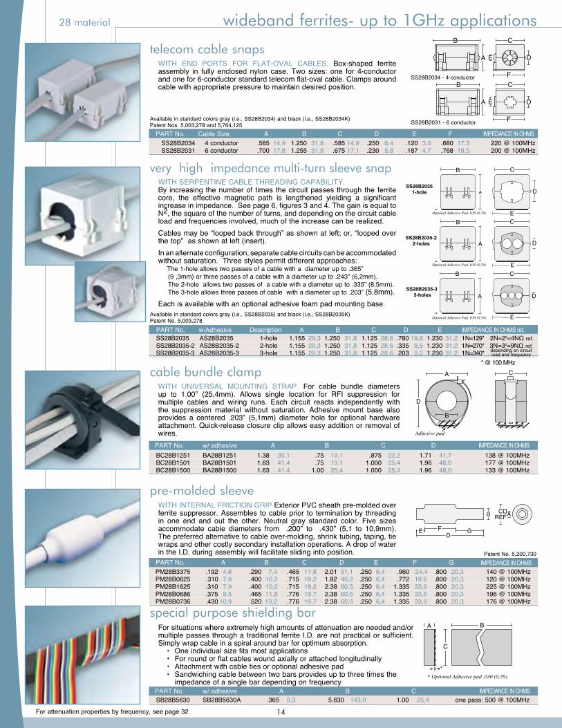
WITH SERPENTINE CABLE THREADING CAPABILITY.By increasing the number of times the circuit passes through the ferrite core, the effective magnetic path is lengthened yielding a significant increase in impedance. See page 6, figures 3 and 4. The gain is equal to N2, the square of the number of turns, and depending on the circuit cable load and frequencies involved, much of the increase can be realized.Cables may be “looped back through” as shown at left; or, “looped over the top” as shown at left (insert).In an alternate configuration, separate cable circuits can be accommodated without saturation. Three styles permit different approaches: The 1-hole allows two passes of a cable with a diameter up to .365” (9 ,3mm) or three passes of a cable with a diameter up to .243” (6,2mm). The 2-hole allows two passes of a cable with a diameter up to .335” (8,5mm). The 3-hole allows three passes of cable with a diameter up to .203” (5,8mm).Each is available with an optional adhesive foam pad mounting base.
B
A D
E
C
SS28B2035 1-hole
B
A
E
C
SS28B2035-2 2-holes
B
A
E
C
SS28B2035-3 3-holes
D
D
Optional Adhesive Pad .030 (0,76)
Optional Adhesive Pad .030 (0,76)
Optional Adhesive Pad .030 (0,76)
Optional Adhesive Pad .030 (0,76)
B
A D
F
C E
WITH UNIVERSAL MOUNTING STRAP. For cable bundle diameters up to 1.00” (25,4mm). Allows single location for RFI suppression for multiple cables and wiring runs. Each circuit reacts independently with the suppression material without saturation. Adhesive mount base also provides a centered .203” (5,1mm) diameter hole for optional hardware attachment. Quick-release closure clip allows easy addition or removal of wires.
WITH END PORTS FOR FLAT-OVAL CABLES. Box-shaped ferrite assembly in fully enclosed nylon case. Two sizes: one for 4-conductor and one for 6-conductor standard telecom flat-oval cable. Clamps around cable with appropriate pressure to maintain desired position.
WITH INTERNAL FRICTION GRIP Exterior PVC sheath pre-molded over ferrite suppressor. Assembles to cable prior to termination by threading in one end and out the other. Neutral gray standard color. Five sizes accommodate cable diameters from .200” to .430” (5,1 to 10,9mm). The preferred alternative to cable over-molding, shrink tubing, taping, tie wraps and other costly secondary installation operations. A drop of water in the I.D. during assembly will facilitate sliding into position.
F
A
DGE
C�REFB
A
D
B
C
Adhesive pad
B C
F
A E D
B C
F
A E D
SS28B2031 - 6 conductor
SS28B2034 - 4-conductor
Available in standard colors gray (i.e., SS28B2034) and black (i.e., SS28B2034K)Patent Nos. 5,003,278 and 5,764,125
BC28B1251 BA28B1251 1.38 35,1 .75 19,1 .875 22,2 1.71 41,7 138 @ 100MHz BC28B1501 BA28B1501 1.63 41,4 .75 19,1 1.000 25,4 1.96 48,0 177 @ 100MHz BC28B1500 BA28B1500 1.63 41,4 1.00 25,4 1.000 25,4 1.96 48,0 133 @ 100MHz
PART No. w/ adhesive A B C D IMPEDANCE IN OHMS
Patent No. 5,200,730 PART No. A B C D E F G IMPEDANCE IN OHMS PM28B3375 .192 4,8 .290 7,4 .465 11,8 2.01 51,1 .250 6,4 .960 24,4 .800 20,3 140 @ 100MHz PM28B0625 .310 7,9 .400 10,2 .715 18,2 1.82 46,2 .250 6,4 .772 19,6 .800 20,3 120 @ 100MHz PM28B1625 .310 7,9 .400 10,2 .715 18,2 2.38 60,5 .250 6,4 1.335 33,9 .800 20,3 225 @ 100MHz PM28B0686 .375 9,5 .465 11,8 .776 19,7 2.38 60,5 .250 6,4 1.335 33,9 .800 20,3 196 @ 100MHz PM28B0736 .430 10,9 .520 13,2 .776 19,7 2.38 60,5 .250 6,4 1.335 33,9 .800 20,3 176 @ 100MHz
PART No. Cable Size A B C D E F IMPEDANCE IN OHMS SS28B2034 4 conductor .585 14,9 1.250 31,8 .585 14,9 .250 6,4 .120 3,0 .680 17,3 220 @ 100MHz SS28B2031 6 conductor .700 17,8 1.255 31,9 .675 17,1 .230 5,8 .187 4,7 .768 19,5 200 @ 100MHz
very high impedance multi-turn sleeve snap
cable bundle clamp
telecom cable snaps
pre-molded sleeve
For situations where extremely high amounts of attenuation are needed and/or multiple passes through a traditional ferrite I.D. are not practical or sufficient. Simply wrap cable in a spiral around bar for optimum absorption. • One individual size fits most applications • For round or flat cables wound axially or attached longitudinally • Attachment with cable ties or optional adhesive pad • Sandwiching cable between two bars provides up to three times the impedance of a single bar depending on frequency
B
C
A
* Optional Adhesive pad .030 (0,76)*
SB28B5630 SB28B5630A .365 9,3 5.630 143,0 1.00 25,4 one pass: 500 @ 100MHz PART No. w/ adhesive A B C IMPEDANCE IN OHMS
special purpose shielding bar
Available in standard colors gray (i.e., SS28B2035) and black (i.e., SS28B2035K)Patent No. 5,003,278 PART No. w/Adhesive Description A B C D E IMPEDANCE IN OHMS ref. SS28B2035 AS28B2035 1-hole 1.155 29,3 1.250 31,8 1.125 28,6 .780 19,8 1.230 31,2 1N=129* 2N=22=4NΩ ref. SS28B2035-2 AS28B2035-2 2-hole 1.155 29,3 1.250 31,8 1.125 28,6 .335 8,5 1.230 31,2 1N=270* 3N=32=9NΩ ref. SS28B2035-3 AS28B2035-3 3-hole 1.155 29,3 1.250 31,8 1.125 28,6 .203 5,2 1.230 31,2 1N=340* depending on circuit
load and frequency
* @ 100 MHz
28 material wideband ferrites- up to 1GHz applications
14
For attenuation properties by frequency, see page 32
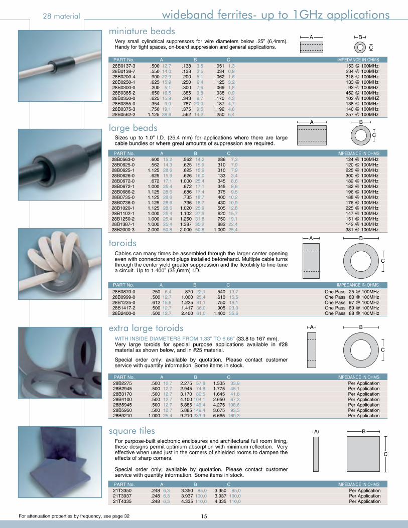
toroidsCables can many times be assembled through the larger center opening even with connectors and plugs installed beforehand. Multiple cable turns through the center yield greater suppression and the flexibility to fine-tune a circuit. Up to 1.400” (35,6mm) I.D.
C
BA
extra large toroids
square tilesFor purpose-built electronic enclosures and architectural full room lining, these designs permit optimum absorption with minimum reflection. Very effective when used just in the corners of shielded rooms to dampen the effects of sharp corners.
Special order only; available by quotation. Please contact customer service with quantity information. Some items in stock.
WITH INSIDE DIAMETERS FROM 1.33” TO 6.66” (33.8 to 167 mm). Very large toroids for special purpose applications available in #28 material as shown below, and in #25 material.
Special order only: available by quotation. Please contact customer service with quantity information. Some items in stock.
C
BA
large beadsSizes up to 1.0” I.D. (25,4 mm) for applications where there are large cable bundles or where great amounts of suppression are required.
miniature beadsA B
C
A
C
B
Very small cylindrical suppressors for wire diameters below .25” (6,4mm). Handy for tight spaces, on-board suppression and general applications.
PART No. A B C IMPEDANCE IN OHMS 28B0137-3 .500 12,7 .138 3,5 .051 1,3 153 @ 100MHz 28B0138-7 .550 14,0 .138 3,5 .034 0,9 234 @ 100MHz 28B0200-4 .900 22,9 .200 5,1 .062 1,6 318 @ 100MHz 28B0250-1 .625 15,9 .250 6,4 .125 3,2 133 @ 100MHz 28B0300-0 .200 5,1 .300 7,6 .069 1,8 93 @ 100MHz 28B0385-2 .650 16,5 .385 9,8 .038 0,9 452 @ 100MHz 28B0350-0 .625 15,9 .343 8,7 .170 4,3 102 @ 100MHZ 28B0355-0 .354 9,0 .787 20,0 .187 4,7 138 @ 100MHz 28B0375-3 .750 19,1 .375 9,5 .192 4,8 140 @ 100MHz 28B0562-2 1.125 28,6 .562 14,2 .250 6,4 257 @ 100MHz
PART No. A B C IMPEDANCE IN OHMS 28B0563-0 .600 15,2 .562 14,2 .286 7,3 124 @ 100MHz 28B0625-0 .562 14,3 .625 15,9 .310 7,9 120 @ 100MHz 28B0625-1 1.125 28,6 .625 15,9 .310 7,9 225 @ 100MHz 28B0626-0 .625 15,9 .626 16,0 .133 3,4 300 @ 100MHz 28B0672-0 .672 17,1 1.000 25,4 .345 8,6 182 @ 100MHz 28B0672-1 1.000 25,4 .672 17,1 .345 8,6 182 @ 100MHz 28B0686-2 1.125 28,6 .686 17,4 .375 9,5 196 @ 100MHz 28B0735-0 1.125 28,6 .735 18,7 .400 10,2 188 @ 100MHz 28B0736-0 1.125 28,6 .736 18,7 .430 10,9 176 @ 100MHz 28B1020-1 1.125 28,6 1.020 25,9 .505 12,8 225 @ 100MHz 28B1102-1 1.000 25,4 1.102 27,9 .620 15,7 147 @ 100MHz 28B1250-2 1.000 25,4 1.250 31,8 .750 19,1 151 @ 100MHz 28B1387-1 1.000 25,4 1.387 35,2 .882 22,4 142 @ 100MHz 28B2000-3 2.000 50,8 2.000 50,8 1.000 25,4 381 @ 100MHz
PART No. A B C IMPEDANCE IN OHMS 28B0870-0 .250 6,4 .870 22,1 .540 13,7 One Pass 25 @ 100MHz 28B0999-0 .500 12,7 1.000 25,4 .610 15,5 One Pass 83 @ 100MHz 28B1225-0 .612 15,5 1.225 31,1 .750 19,1 One Pass 97 @ 100MHz 28B1417-2 .500 12,7 1.417 36,0 .905 23,0 One Pass 89 @ 100MHz 28B2400-0 .500 12,7 2.400 61,0 1.400 35,6 One Pass 88 @ 100MHz
28B2275 .500 12,7 2.275 57,8 1.335 33,9 Per Application 28B2945 .500 12,7 2.945 74,8 1.775 45,1 Per Application 28B3170 .500 12,7 3.170 80,5 1.645 41,8 Per Application 28B4100 .500 12,7 4.100 104,1 2.650 67,3 Per Application 28B5945 .500 12,7 5.885 149,4 4.275 108,6 Per Application 28B5950 .500 12,7 5.885 149,4 3.675 93,3 Per Application 28B9210 1.000 25,4 9.210 233.9 6.665 169,3 Per Application
PART No. A B C IMPEDANCE IN OHMS
PART No. A B C IMPEDANCE IN OHMS 21T3350 .248 6,3 3.350 85,0 3.350 85,0 Per Application 21T3937 .248 6,3 3.937 100,0 3.937 100,0 Per Application 21T4335 .248 6,3 4.335 110,0 4.335 110,0 Per Application
SS28B2035 AS28B2035 1-hole 1.155 29,3 1.250 31,8 1.125 28,6 .780 19,8 1.230 31,2 1N=129* 2N=22=4NΩ ref. SS28B2035-2 AS28B2035-2 2-hole 1.155 29,3 1.250 31,8 1.125 28,6 .335 8,5 1.230 31,2 1N=270* 3N=32=9NΩ ref. SS28B2035-3 AS28B2035-3 3-hole 1.155 29,3 1.250 31,8 1.125 28,6 .203 5,2 1.230 31,2 1N=340*
28 material wideband ferrites- up to 1GHz applications
15
For attenuation properties by frequency, see page 32
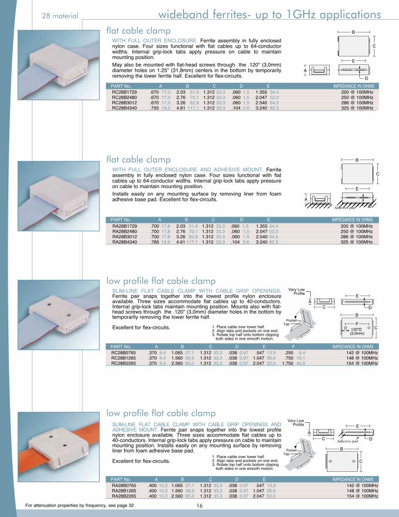
flat cable clampWITH FULL OUTER ENCLOSURE. Ferrite assembly in fully enclosed nylon case. Four sizes functional with flat cables up to 64-conductor widths. Internal grip-lock tabs apply pressure on cable to maintain mounting position.May also be mounted with flat-head screws through the .120” (3,0mm) diameter holes on 1.25” (31,8mm) centers in the bottom by temporarily removing the lower ferrite half. Excellent for flex-circuits.
flat cable clampWITH FULL OUTER ENCLOSURE AND ADHESIVE MOUNT. Ferrite assembly in fully enclosed nylon case. Four sizes functional with flat cables up to 64-conductor widths. Internal grip-lock tabs apply pressure on cable to maintain mounting position.Installs easily on any mounting surface by removing liner from foam adhesive base pad. Excellent for flex-circuits.
B
C
D
E
A
B
C
D
E
A
A
Adhesive pad
B
C
D
E
A
Adhesive pad
B
C
D
E
PART No. A B C D E IMPEDANCE IN OHMS RA28B1729 .700 17,8 2.03 51,6 1.312 33,3 .060 1,5 1.355 34,4 200 @ 100MHz RA28B2480 .700 17,8 2.76 70,1 1.312 33,3 .060 1,5 2.047 52,0 250 @ 100MHz RA28B3012 .700 17,8 3.26 82,8 1.312 33,3 .060 1,5 2.540 64,5 286 @ 100MHz RA28B4340 .785 19,9 4.61 117,1 1.312 33,3 .104 2,6 3.240 82,3 325 @ 100MHz
PART No. A B C D E IMPEDANCE IN OHMS RC28B1729 .670 17,0 2.03 51,6 1.312 33,3 .060 1,5 1.355 34,4 200 @ 100MHz RC28B2480 .670 17,0 2.76 70,1 1.312 33,3 .060 1,5 2.047 52,0 250 @ 100MHz RC28B3012 .670 17,0 3.26 82,8 1.312 33,3 .060 1,5 2.540 64,5 286 @ 100MHz RC28B4340 .755 19,2 4.61 117,1 1.312 33,3 .104 2,6 3.240 82,3 325 @ 100MHz
low profile flat cable clampSLIM-LINE FLAT CABLE CLAMP WITH CABLE GRIP OPENINGS AND ADHESIVE MOUNT. Ferrite pair snaps together into the lowest profile nylon enclosure available. Three sizes accommodate flat cables up to 40-conductors. Internal grip-lock tabs apply pressure on cable to maintain mounting position. Installs easily on any mounting surface by removing liner from foam adhesive base pad.
Excellent for flex-circuits.
PART No. A B C D E IMPEDANCE IN OHMS RA28B0765 .400 10,2 1.065 27,1 1.312 33,3 .038 0,97 .547 13,9 142 @ 100MHz RA28B1265 .400 10,2 1.560 39,6 1.312 33,3 .038 0,97 1.047 26,6 148 @ 100MHz RA28B2265 .400 10,2 2.560 65,0 1.312 33,3 .038 0,97 2.047 52,0 154 @ 100MHz
C
D
EA
Adhesive pad
B
C
C
D
EA
Adhesive pad
B
C
C
D
EA
Adhesive pad
B
C
low profile flat cable clampSLIM-LINE FLAT CABLE CLAMP WITH CABLE GRIP OPENINGS. Ferrite pair snaps together into the lowest profile nylon enclosure available. Three sizes accommodate flat cables up to 40-conductors. Internal grip-lock tabs maintain mounting position. Mounts also with flat-head screws through the .120” (3,0mm) diameter holes in the bottom by temporarily removing the lower ferrite half.
Excellent for flex-circuits.
RC28B0765 .370 9,4 1.065 27,1 1.312 33,3 .038 0,97 .547 13,9 .250 6,4 142 @ 100MHz RC28B1265 .370 9,4 1.560 39,6 1.312 33,3 .038 0,97 1.047 26,6 .750 19,1 148 @ 100MHz RC28B2265 .370 9,4 2.560 65,0 1.312 33,3 .038 0,97 2.047 52,0 1.750 44,5 154 @ 100MHz
PART No. A B C D E F IMPEDANCE IN OHMS
B
C
D
EA
F
C
.120"�(3,0mm)
B
C
D
EA
F
C
.120"�(3,0mm)
B
C
D
EA
F
C
.120"�(3,0mm)
1. Place cable over lower half.2. Align tabs and pockets on one end.3. Rotate top half onto bottom clipping both sides in one smooth motion.
TabPocket
1. Place cable over lower half.2. Align tabs and pockets on one end.3. Rotate top half onto bottom clipping both sides in one smooth motion.
TabPocket
Very LowProfile
Very LowProfile
28 material wideband ferrites- up to 1GHz applications
16
For attenuation properties by frequency, see page 32
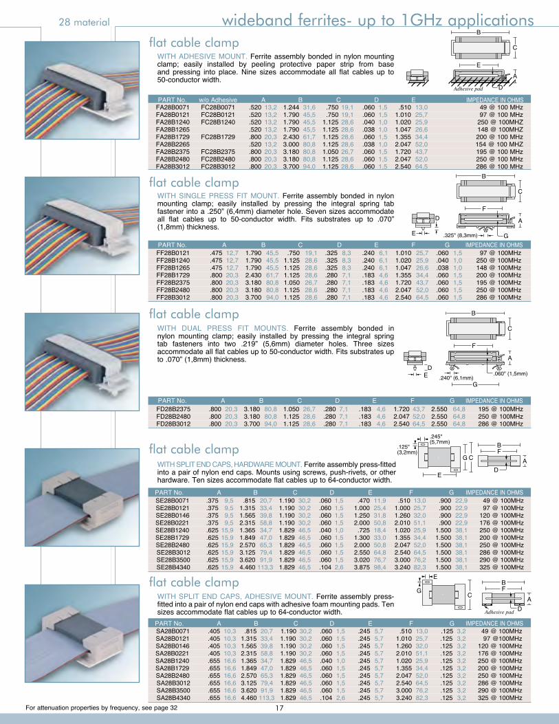
WITH SINGLE PRESS FIT MOUNT. Ferrite assembly bonded in nylon mounting clamp; easily installed by pressing the integral spring tab fastener into a .250” (6,4mm) diameter hole. Seven sizes accommodate all flat cables up to 50-conductor width. Fits substrates up to .070” (1,8mm) thickness.
WITH DUAL PRESS FIT MOUNTS. Ferrite assembly bonded in nylon mounting clamp; easily installed by pressing the integral spring tab fasteners into two .219” (5,6mm) diameter holes. Three sizes accommodate all flat cables up to 50-conductor width. Fits substrates up to .070” (1,8mm) thickness.
WITH ADHESIVE MOUNT. Ferrite assembly bonded in nylon mounting clamp; easily installed by peeling protective paper strip from base and pressing into place. Nine sizes accommodate all flat cables up to 50-conductor width.
B
C
A
E
DAdhesive pad
FD28B2375 .800 20,3 3.180 80,8 1.050 26,7 .280 7,1 .183 4,6 1.720 43,7 2.550 64,8 195 @ 100MHz FD28B2480 .800 20,3 3.180 80,8 1.125 28,6 .280 7,1 .183 4,6 2.047 52,0 2.550 64,8 250 @ 100MHz FD28B3012 .800 20,3 3.700 94,0 1.125 28,6 .280 7,1 .183 4,6 2.540 64,5 2.550 64,8 286 @ 100MHz
PART No. A B C D E F G IMPEDANCE IN OHMS
WITH SPLIT END CAPS, ADHESIVE MOUNT. Ferrite assembly press-fitted into a pair of nylon end caps with adhesive foam mounting pads. Ten sizes accommodate flat cables up to 64-conductor width.
WITH SPLIT END CAPS, HARDWARE MOUNT. Ferrite assembly press-fitted into a pair of nylon end caps. Mounts using screws, push-rivets, or other hardware. Ten sizes accommodate flat cables up to 64-conductor width.
C
.245"(5,7mm)
ED
AG
BF
.125"(3,2mm)
C
E
G
DA
BF
Adhesive pad
PART No. A B C D E F G IMPEDANCE IN OHMS SE28B0071 .375 9,5 .815 20,7 1.190 30,2 .060 1,5 .470 11,9 .510 13,0 .900 22,9 49 @ 100MHz SE28B0121 .375 9,5 1.315 33,4 1.190 30,2 .060 1,5 1.000 25,4 1.000 25,7 .900 22,9 97 @ 100MHz SE28B0146 .375 9,5 1.565 39,8 1.190 30,2 .060 1,5 1.250 31,8 1.260 32,0 .900 22,9 120 @ 100MHz SE28B0221 .375 9,5 2.315 58,8 1.190 30,2 .060 1,5 2.000 50,8 2.010 51,1 .900 22,9 176 @ 100MHz SE28B1240 .625 15,9 1.365 34,7 1.829 46,5 .040 1,0 .725 18,4 1.020 25,9 1.500 38,1 250 @ 100MHz SE28B1729 .625 15,9 1.849 47,0 1.829 46,5 .060 1,5 1.300 33,0 1.355 34,4 1.500 38,1 200 @ 100MHz SE28B2480 .625 15,9 2.570 65,3 1.829 46,5 .060 1,5 2.000 50,8 2.047 52,0 1.500 38,1 250 @ 100MHz SE28B3012 .625 15,9 3.125 79,4 1.829 46,5 .060 1,5 2.550 64,8 2.540 64,5 1.500 38,1 286 @ 100MHz SE28B3500 .625 15,9 3.620 91,9 1.829 46,5 .060 1,5 3.020 76,7 3.000 76,2 1.500 38,1 290 @ 100MHz SE28B4340 .625 15,9 4.460 113,3 1.829 46,5 .104 2,6 3.875 98,4 3.240 82,3 1.500 38,1 325 @ 100MHz
flat cable clamp
flat cable clamp
flat cable clamp
flat cable clamp
flat cable clamp
FA28B0071 FC28B0071 .520 13,2 1.244 31,6 .750 19,1 .060 1,5 .510 13,0 49 @ 100 MHz FA28B0121 FC28B0121 .520 13,2 1.790 45,5 .750 19,1 .060 1,5 1.010 25,7 97 @ 100 MHz FA28B1240 FC28B1240 .520 13,2 1.790 45,5 1.125 28,6 .040 1,0 1.020 25,9 250 @ 100MHZ FA28B1265 .520 13,2 1.790 45,5 1.125 28,6 .038 1,0 1.047 26,6 148 @ 100MHZ FA28B1729 FC28B1729 .800 20,3 2.430 61,7 1.125 28,6 .060 1,5 1.355 34,4 200 @ 100 MHz FA28B2265 .520 13,2 3.000 80,8 1.125 28,6 .038 1,0 2.047 52,0 154 @ 100 MHZ FA28B2375 FC28B2375 .800 20,3 3.180 80,8 1.050 26,7 .060 1,5 1.720 43,7 195 @ 100 MHz FA28B2480 FC28B2480 .800 20,3 3.180 80,8 1.125 28,6 .060 1,5 2.047 52,0 250 @ 100 MHz FA28B3012 FC28B3012 .800 20,3 3.700 94,0 1.125 28,6 .060 1,5 2.540 64,5 286 @ 100 MHz
PART No. w/o Adhesive A B C D E IMPEDANCE IN OHMS
FF28B0121 .475 12,7 1.790 45,5 .750 19,1 .325 8,3 .240 6,1 1.010 25,7 .060 1,5 97 @ 100MHz FF28B1240 .475 12,7 1.790 45,5 1.125 28,6 .325 8,3 .240 6,1 1.020 25,9 .040 1,0 250 @ 100MHz FF28B1265 .475 12,7 1.790 45,5 1.125 28,6 .325 8,3 .240 6,1 1.047 26,6 .038 1,0 148 @ 100MHz FF28B1729 .800 20,3 2.430 61,7 1.125 28,6 .280 7,1 .183 4,6 1.355 34,4 .060 1,5 200 @ 100MHz FF28B2375 .800 20,3 3.180 80,8 1.050 26,7 .280 7,1 .183 4,6 1.720 43,7 .060 1,5 195 @ 100MHz FF28B2480 .800 20,3 3.180 80,8 1.125 28,6 .280 7,1 .183 4,6 2.047 52,0 .060 1,5 250 @ 100MHz FF28B3012 .800 20,3 3.700 94,0 1.125 28,6 .280 7,1 .183 4,6 2.540 64,5 .060 1,5 286 @ 100MHz
PART No. A B C D E F G IMPEDANCE IN OHMS
SA28B0071 .405 10,3 .815 20,7 1.190 30,2 .060 1,5 .245 5,7 .510 13,0 .125 3,2 49 @ 100MHz SA28B0121 .405 10,3 1.315 33,4 1.190 30,2 .060 1,5 .245 5,7 1.010 25,7 .125 3,2 97 @100MHz SA28B0146 .405 10,3 1.565 39,8 1.190 30,2 .060 1,5 .245 5,7 1.260 32,0 .125 3,2 120 @ 100MHz SA28B0221 .405 10,3 2.315 58,8 1.190 30,2 .060 1,5 .245 5,7 2.010 51,1 .125 3,2 176 @ 100MHz SA28B1240 .655 16,6 1.365 34,7 1.829 46,5 .040 1,0 .245 5,7 1.020 25,9 .125 3,2 250 @ 100MHz SA28B1729 .655 16,6 1.849 47,0 1.829 46,5 .060 1,5 .245 5,7 1.355 34,4 .125 3,2 200 @ 100MHz SA28B2480 .655 16,6 2.570 65,3 1.829 46,5 .060 1,5 .245 5,7 2.047 52,0 .125 3,2 250 @ 100MHz SA28B3012 .655 16,6 3.125 79,4 1.829 46,5 .060 1,5 .245 5,7 2.540 64,5 .125 3,2 286 @ 100MHz SA28B3500 .655 16,6 3.620 91,9 1.829 46,5 .060 1,5 .245 5,7 3.000 76,2 .125 3,2 290 @ 100MHz SA28B4340 .655 16,6 4.460 113,3 1.829 46,5 .104 2,6 .245 5,7 3.240 82,3 .125 3,2 325 @ 100MHz
PART No. A B C D E F G IMPEDANCE IN OHMS
B
C
A
.325" (8,3mm)
F
GE
D
B
C
A
G
D.060" (1,5mm)
F
.240" (6,1mm)E
28 material wideband ferrites- up to 1GHz applications
17
For attenuation properties by frequency, see page 32
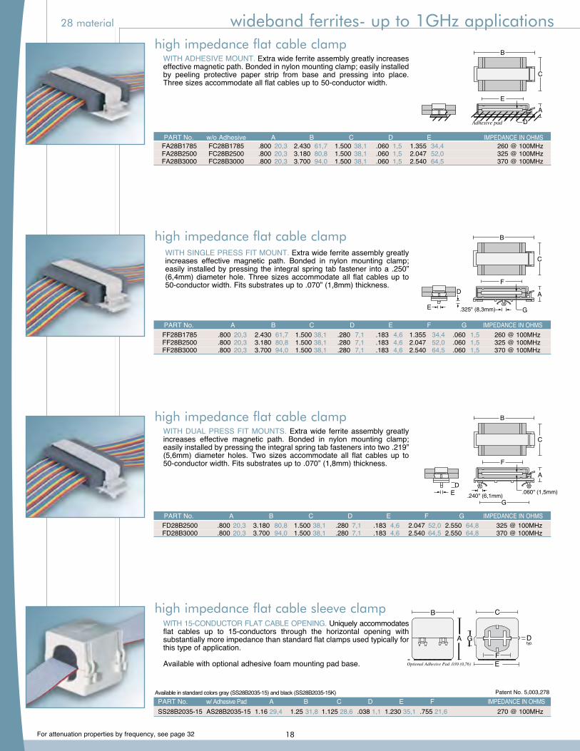
high impedance flat cable clamp
high impedance flat cable clamp
high impedance flat cable clamp
WITH SINGLE PRESS FIT MOUNT. Extra wide ferrite assembly greatly increases effective magnetic path. Bonded in nylon mounting clamp; easily installed by pressing the integral spring tab fastener into a .250” (6,4mm) diameter hole. Three sizes accommodate all flat cables up to 50-conductor width. Fits substrates up to .070” (1,8mm) thickness.
WITH DUAL PRESS FIT MOUNTS. Extra wide ferrite assembly greatly increases effective magnetic path. Bonded in nylon mounting clamp; easily installed by pressing the integral spring tab fasteners into two .219” (5,6mm) diameter holes. Two sizes accommodate all flat cables up to 50-conductor width. Fits substrates up to .070” (1,8mm) thickness.
WITH ADHESIVE MOUNT. Extra wide ferrite assembly greatly increases effective magnetic path. Bonded in nylon mounting clamp; easily installed by peeling protective paper strip from base and pressing into place. Three sizes accommodate all flat cables up to 50-conductor width.
B
C
A
E
DAdhesive pad
PART No. w/o Adhesive A B C D E IMPEDANCE IN OHMS FA28B1785 FC28B1785 .800 20,3 2.430 61,7 1.500 38,1 .060 1,5 1.355 34,4 260 @ 100MHz FA28B2500 FC28B2500 .800 20,3 3.180 80,8 1.500 38,1 .060 1,5 2.047 52,0 325 @ 100MHz FA28B3000 FC28B3000 .800 20,3 3.700 94,0 1.500 38,1 .060 1,5 2.540 64,5 370 @ 100MHz
FF28B1785 .800 20,3 2.430 61,7 1.500 38,1 .280 7,1 .183 4,6 1.355 34,4 .060 1,5 260 @ 100MHz FF28B2500 .800 20,3 3.180 80,8 1.500 38,1 .280 7,1 .183 4,6 2.047 52,0 .060 1,5 325 @ 100MHz FF28B3000 .800 20,3 3.700 94,0 1.500 38,1 .280 7,1 .183 4,6 2.540 64,5 .060 1,5 370 @ 100MHz
high impedance flat cable sleeve clampWITH 15-CONDUCTOR FLAT CABLE OPENING. Uniquely accommodates flat cables up to 15-conductors through the horizontal opening with substantially more impedance than standard flat clamps used typically for this type of application.
Available with optional adhesive foam mounting pad base.
PART No. w/ Adhesive Pad A B C D E F IMPEDANCE IN OHMS SS28B2035-15 AS28B2035-15 1.16 29,4 1.25 31,8 1.125 28,6 .038 1,1 1.230 35,1 .755 21,6 270 @ 100MHz
B
D
E
C
F
GAtyp.
B
D
E
C
Optional Adhesive Pad .030 (0,76)
Optional Adhesive Pad .030 (0,76)
F
GA
Patent No. 5,003,278
FD28B2500 .800 20,3 3.180 80,8 1.500 38,1 .280 7,1 .183 4,6 2.047 52,0 2.550 64,8 325 @ 100MHz FD28B3000 .800 20,3 3.700 94,0 1.500 38,1 .280 7,1 .183 4,6 2.540 64,5 2.550 64,8 370 @ 100MHz
PART No. A B C D E F G IMPEDANCE IN OHMS
PART No. A B C D E F G IMPEDANCE IN OHMS
Available in standard colors gray (SS28B2035-15) and black (SS28B2035-15K)
B
C
A
G
D.060" (1,5mm)
F
.240" (6,1mm)E
B
C
A
.325" (8,3mm)
F
GE
D
28 material wideband ferrites- up to 1GHz applications
18
For attenuation properties by frequency, see page 32
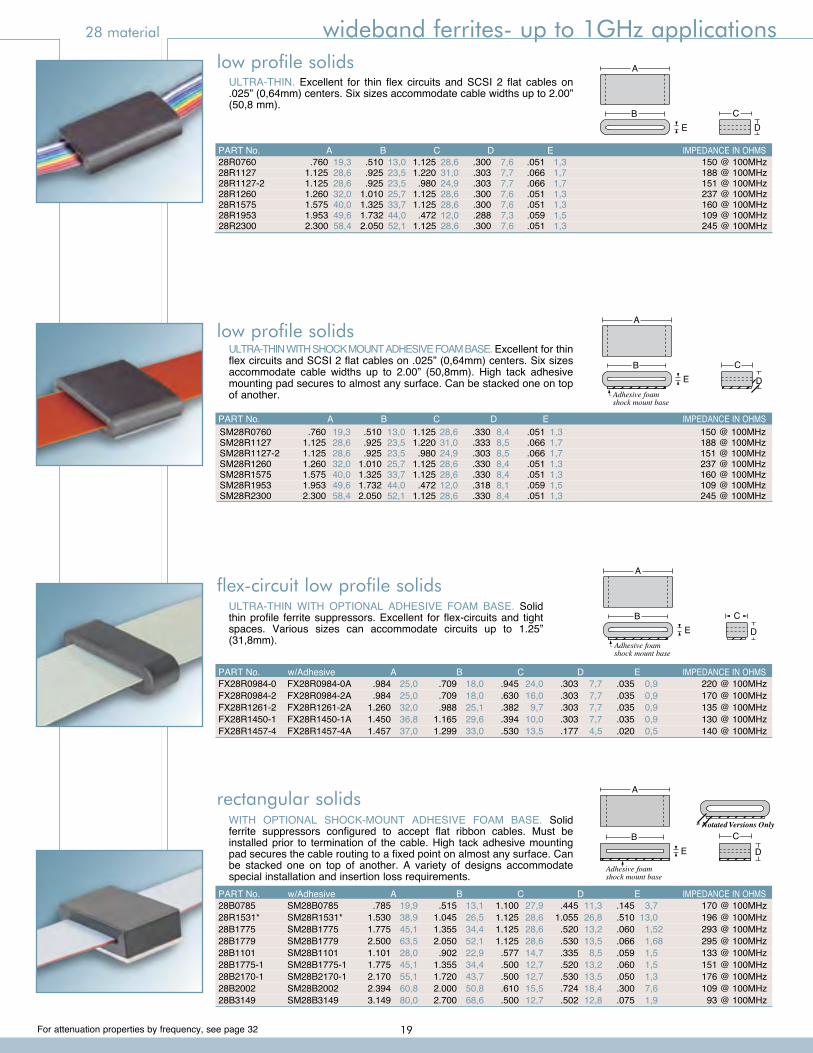
flex-circuit low profile solidsULTRA-THIN WITH OPTIONAL ADHESIVE FOAM BASE. Solid thin profile ferrite suppressors. Excellent for flex-circuits and tight spaces. Various sizes can accommodate circuits up to 1.25” (31,8mm). Adhesive foam
shock mount base
A
B C
DE
A
B CDE
low profile solidsULTRA-THIN. Excellent for thin flex circuits and SCSI 2 flat cables on .025” (0,64mm) centers. Six sizes accommodate cable widths up to 2.00” (50,8 mm).
28R0760 .760 19,3 .510 13,0 1.125 28,6 .300 7,6 .051 1,3 150 @ 100MHz 28R1127 1.125 28,6 .925 23,5 1.220 31,0 .303 7,7 .066 1,7 188 @ 100MHz 28R1127-2 1.125 28,6 .925 23,5 .980 24,9 .303 7,7 .066 1,7 151 @ 100MHz 28R1260 1.260 32,0 1.010 25,7 1.125 28,6 .300 7,6 .051 1,3 237 @ 100MHz 28R1575 1.575 40,0 1.325 33,7 1.125 28,6 .300 7,6 .051 1,3 160 @ 100MHz 28R1953 1.953 49,6 1.732 44,0 .472 12,0 .288 7,3 .059 1,5 109 @ 100MHz 28R2300 2.300 58,4 2.050 52,1 1.125 28,6 .300 7,6 .051 1,3 245 @ 100MHz
PART No. A B C D E IMPEDANCE IN OHMS
rectangular solidsWITH OPTIONAL SHOCK-MOUNT ADHESIVE FOAM BASE. Solid ferrite suppressors configured to accept flat ribbon cables. Must be installed prior to termination of the cable. High tack adhesive mounting pad secures the cable routing to a fixed point on almost any surface. Can be stacked one on top of another. A variety of designs accommodate special installation and insertion loss requirements.
A
B C
DE
Adhesive foamshock mount base
* Notated Versions Only
Adhesive foamshock mount base
A
B C
DE
28B0785 SM28B0785 .785 19,9 .515 13,1 1.100 27,9 .445 11,3 .145 3,7 170 @ 100MHz 28R1531* SM28R1531* 1.530 38,9 1.045 26,5 1.125 28,6 1.055 26,8 .510 13,0 196 @ 100MHz 28B1775 SM28B1775 1.775 45,1 1.355 34,4 1.125 28,6 .520 13,2 .060 1,52 293 @ 100MHz 28B1779 SM28B1779 2.500 63,5 2.050 52,1 1.125 28,6 .530 13,5 .066 1,68 295 @ 100MHz 28B1101 SM28B1101 1.101 28,0 .902 22,9 .577 14,7 .335 8,5 .059 1,5 133 @ 100MHz 28B1775-1 SM28B1775-1 1.775 45,1 1.355 34,4 .500 12,7 .520 13,2 .060 1,5 151 @ 100MHz 28B2170-1 SM28B2170-1 2.170 55,1 1.720 43,7 .500 12,7 .530 13,5 .050 1,3 176 @ 100MHz 28B2002 SM28B2002 2.394 60,8 2.000 50,8 .610 15,5 .724 18,4 .300 7,6 109 @ 100MHz 28B3149 SM28B3149 3.149 80,0 2.700 68,6 .500 12,7 .502 12,8 .075 1,9 93 @ 100MHz
PART No. w/Adhesive A B C D E IMPEDANCE IN OHMS
FX28R0984-0 FX28R0984-0A .984 25,0 .709 18,0 .945 24,0 .303 7,7 .035 0,9 220 @ 100MHz FX28R0984-2 FX28R0984-2A .984 25,0 .709 18,0 .630 16,0 .303 7,7 .035 0,9 170 @ 100MHz FX28R1261-2 FX28R1261-2A 1.260 32,0 .988 25,1 .382 9,7 .303 7,7 .035 0,9 135 @ 100MHz FX28R1450-1 FX28R1450-1A 1.450 36,8 1.165 29,6 .394 10,0 .303 7,7 .035 0,9 130 @ 100MHz FX28R1457-4 FX28R1457-4A 1.457 37,0 1.299 33,0 .530 13,5 .177 4,5 .020 0,5 140 @ 100MHz
PART No. w/Adhesive A B C D E IMPEDANCE IN OHMS
SM28R0760 .760 19,3 .510 13,0 1.125 28,6 .330 8,4 .051 1,3 150 @ 100MHz SM28R1127 1.125 28,6 .925 23,5 1.220 31,0 .333 8,5 .066 1,7 188 @ 100MHz SM28R1127-2 1.125 28,6 .925 23,5 .980 24,9 .303 8,5 .066 1,7 151 @ 100MHz SM28R1260 1.260 32,0 1.010 25,7 1.125 28,6 .330 8,4 .051 1,3 237 @ 100MHz SM28R1575 1.575 40,0 1.325 33,7 1.125 28,6 .330 8,4 .051 1,3 160 @ 100MHz SM28R1953 1.953 49,6 1.732 44,0 .472 12,0 .318 8,1 .059 1,5 109 @ 100MHz SM28R2300 2.300 58,4 2.050 52,1 1.125 28,6 .330 8,4 .051 1,3 245 @ 100MHz
PART No. A B C D E IMPEDANCE IN OHMS
ULTRA-THIN WITH SHOCK MOUNT ADHESIVE FOAM BASE. Excellent for thin flex circuits and SCSI 2 flat cables on .025” (0,64mm) centers. Six sizes accommodate cable widths up to 2.00” (50,8mm). High tack adhesive mounting pad secures to almost any surface. Can be stacked one on top of another.
low profile solids
28 material wideband ferrites- up to 1GHz applications
19
For attenuation properties by frequency, see page 32
28 material universal wideband up to 1GHz for PCB’s
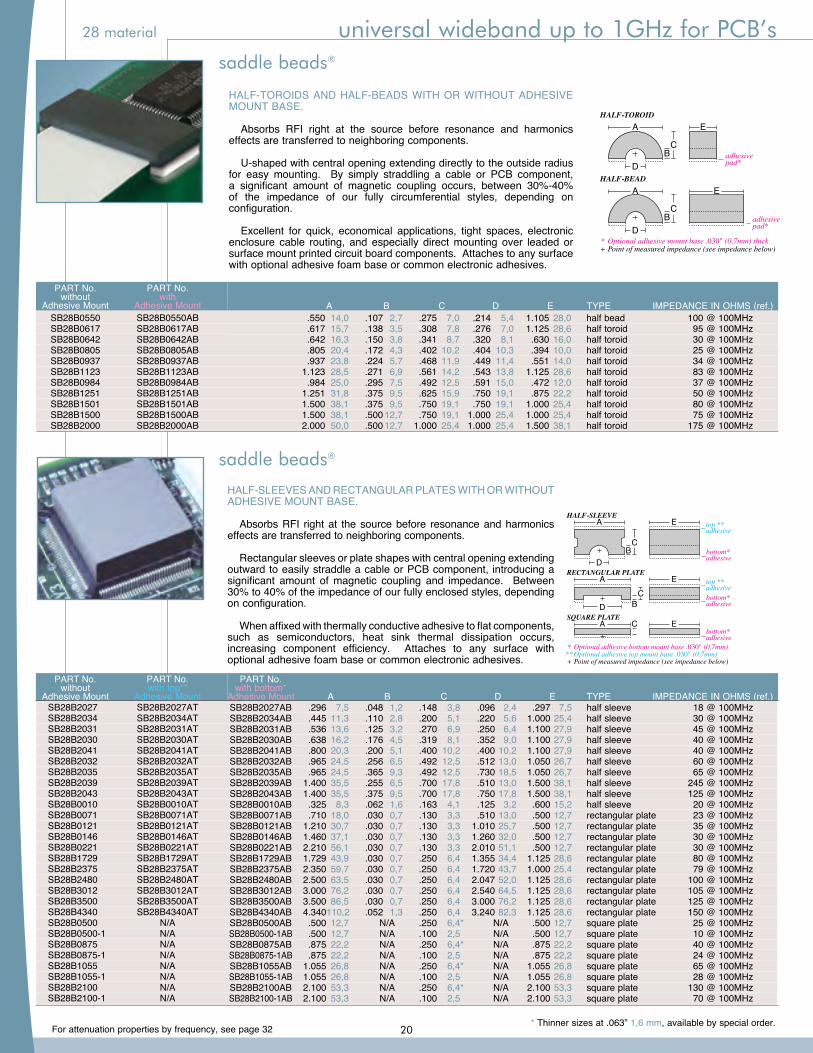
HALF-TOROIDS AND HALF-BEADS WITH OR WITHOUT ADHESIVE MOUNT BASE.
Absorbs RFI right at the source before resonance and harmonics effects are transferred to neighboring components.
U-shaped with central opening extending directly to the outside radius for easy mounting. By simply straddling a cable or PCB component, a significant amount of magnetic coupling occurs, between 30%-40% of the impedance of our fully circumferential styles, depending on configuration.
Excellent for quick, economical applications, tight spaces, electronic enclosure cable routing, and especially direct mounting over leaded or surface mount printed circuit board components. Attaches to any surface with optional adhesive foam base or common electronic adhesives.
*+
Optional adhesive mount base .030" (0,7mm) thick Point of measured impedance (see impedance below)
HALF-TOROIDA
BC
E
D adhesive pad*
HALF-BEADA
BC
E
D adhesive pad*
PART No. PART No. without with Adhesive Mount Adhesive Mount SB28B0550 SB28B0550AB SB28B0617 SB28B0617AB SB28B0642 SB28B0642AB SB28B0805 SB28B0805AB SB28B0937 SB28B0937AB SB28B1123 SB28B1123AB SB28B0984 SB28B0984AB SB28B1251 SB28B1251AB SB28B1501 SB28B1501AB SB28B1500 SB28B1500AB SB28B2000 SB28B2000AB
A B C D E TYPE IMPEDANCE IN OHMS (ref.) .550 14,0 .107 2,7 .275 7,0 .214 5,4 1.105 28,0 half bead 100 @ 100MHz .617 15,7 .138 3,5 .308 7,8 .276 7,0 1.125 28,6 half toroid 95 @ 100MHz .642 16,3 .150 3,8 .341 8,7 .320 8,1 .630 16,0 half toroid 30 @ 100MHz .805 20,4 .172 4,3 .402 10,2 .404 10,3 .394 10,0 half toroid 25 @ 100MHz .937 23,8 .224 5,7 .468 11,9 .449 11,4 .551 14,0 half toroid 34 @ 100MHz 1.123 28,5 .271 6,9 .561 14,2 .543 13,8 1.125 28,6 half toroid 83 @ 100MHz .984 25,0 .295 7,5 .492 12,5 .591 15,0 .472 12,0 half toroid 37 @ 100MHz 1.251 31,8 .375 9,5 .625 15,9 .750 19,1 .875 22,2 half toroid 50 @ 100MHz 1.500 38,1 .375 9,5 .750 19,1 .750 19,1 1.000 25,4 half toroid 80 @ 100MHz 1.500 38,1 .500 12,7 .750 19,1 1.000 25,4 1.000 25,4 half toroid 75 @ 100MHz 2.000 50,0 .500 12,7 1.000 25,4 1.000 25,4 1.500 38,1 half toroid 175 @ 100MHz
***+
Optional adhesive bottom mount base .030" (0,7mm) Optional adhesive top mount base .030" (0,7mm) Point of measured impedance (see impedance below)
HALF-SLEEVEA
BC
E
D
top **adhesive
bottom*adhesive
RECTANGULAR PLATE
BC
EA
D
top **adhesivebottom*adhesive
SQUARE PLATEC EA
bottom*adhesive
HALF-SLEEVES AND RECTANGULAR PLATES WITH OR WITHOUT ADHESIVE MOUNT BASE.
Absorbs RFI right at the source before resonance and harmonics effects are transferred to neighboring components.
Rectangular sleeves or plate shapes with central opening extending outward to easily straddle a cable or PCB component, introducing a significant amount of magnetic coupling and impedance. Between 30% to 40% of the impedance of our fully enclosed styles, depending on configuration.
When affixed with thermally conductive adhesive to flat components, such as semiconductors, heat sink thermal dissipation occurs, increasing component efficiency. Attaches to any surface with optional adhesive foam base or common electronic adhesives.
SB28B2027AB .296 7,5 .048 1,2 .148 3,8 .096 2,4 .297 7,5 half sleeve 18 @ 100MHz SB28B2034AB .445 11,3 .110 2,8 .200 5,1 .220 5,6 1.000 25,4 half sleeve 30 @ 100MHz SB28B2031AB .536 13,6 .125 3,2 .270 6,9 .250 6,4 1.100 27,9 half sleeve 45 @ 100MHz SB28B2030AB .638 16,2 .176 4,5 .319 8,1 .352 9,0 1.100 27,9 half sleeve 40 @ 100MHz SB28B2041AB .800 20,3 .200 5,1 .400 10,2 .400 10,2 1.100 27,9 half sleeve 40 @ 100MHz SB28B2032AB .965 24,5 .256 6,5 .492 12,5 .512 13,0 1.050 26,7 half sleeve 60 @ 100MHz SB28B2035AB .965 24,5 .365 9,3 .492 12,5 .730 18,5 1.050 26,7 half sleeve 65 @ 100MHz SB28B2039AB 1.400 35,5 .255 6,5 .700 17,8 .510 13,0 1.500 38,1 half sleeve 245 @ 100MHz SB28B2043AB 1.400 35,5 .375 9,5 .700 17,8 .750 17,8 1.500 38,1 half sleeve 125 @ 100MHz SB28B0010AB .325 8,3 .062 1,6 .163 4,1 .125 3,2 .600 15,2 half sleeve 20 @ 100MHz SB28B0071AB .710 18,0 .030 0,7 .130 3,3 .510 13,0 .500 12,7 rectangular plate 23 @ 100MHz SB28B0121AB 1.210 30,7 .030 0,7 .130 3,3 1.010 25,7 .500 12,7 rectangular plate 35 @ 100MHz SB28B0146AB 1.460 37,1 .030 0,7 .130 3,3 1.260 32,0 .500 12,7 rectangular plate 30 @ 100MHz SB28B0221AB 2.210 56,1 .030 0,7 .130 3,3 2.010 51,1 .500 12,7 rectangular plate 30 @ 100MHz SB28B1729AB 1.729 43,9 .030 0,7 .250 6,4 1.355 34,4 1.125 28,6 rectangular plate 80 @ 100MHz SB28B2375AB 2.350 59,7 .030 0,7 .250 6,4 1.720 43,7 1.000 25,4 rectangular plate 79 @ 100MHz SB28B2480AB 2.500 63,5 .030 0,7 .250 6,4 2.047 52,0 1.125 28,6 rectangular plate 100 @ 100MHz SB28B3012AB 3.000 76,2 .030 0,7 .250 6,4 2.540 64,5 1.125 28,6 rectangular plate 105 @ 100MHz SB28B3500AB 3.500 86,5 .030 0,7 .250 6,4 3.000 76,2 1.125 28,6 rectangular plate 125 @ 100MHz SB28B4340AB 4.340 110,2 .052 1,3 .250 6,4 3.240 82,3 1.125 28,6 rectangular plate 150 @ 100MHz SB28B0500AB .500 12,7 N/A .250 6,4* N/A .500 12,7 square plate 25 @ 100MHz SB28B0500-1AB .500 12,7 N/A .100 2,5 N/A .500 12,7 square plate 10 @ 100MHz SB28B0875AB .875 22,2 N/A .250 6,4* N/A .875 22,2 square plate 40 @ 100MHz SB28B0875-1AB .875 22,2 N/A .100 2,5 N/A .875 22,2 square plate 24 @ 100MHz SB28B1055AB 1.055 26,8 N/A .250 6,4* N/A 1.055 26,8 square plate 65 @ 100MHz SB28B1055-1AB 1.055 26,8 N/A .100 2,5 N/A 1.055 26,8 square plate 28 @ 100MHz SB28B2100AB 2.100 53,3 N/A .250 6,4* N/A 2.100 53,3 square plate 130 @ 100MHz SB28B2100-1AB 2.100 53,3 N/A .100 2,5 N/A 2.100 53,3 square plate 70 @ 100MHz
SB28B2027 SB28B2027AT SB28B2034 SB28B2034AT SB28B2031 SB28B2031AT SB28B2030 SB28B2030AT SB28B2041 SB28B2041AT SB28B2032 SB28B2032AT SB28B2035 SB28B2035AT SB28B2039 SB28B2039AT SB28B2043 SB28B2043AT SB28B0010 SB28B0010AT SB28B0071 SB28B0071AT SB28B0121 SB28B0121AT SB28B0146 SB28B0146AT SB28B0221 SB28B0221AT SB28B1729 SB28B1729AT SB28B2375 SB28B2375AT SB28B2480 SB28B2480AT SB28B3012 SB28B3012AT SB28B3500 SB28B3500AT SB28B4340 SB28B4340AT SB28B0500 N/A SB28B0500-1 N/A SB28B0875 N/A SB28B0875-1 N/A SB28B1055 N/A SB28B1055-1 N/A SB28B2100 N/A SB28B2100-1 N/A
PART No. with bottom* Adhesive Mount A B C D E TYPE IMPEDANCE IN OHMS (ref.)
PART No. PART No. without with top** Adhesive Mount Adhesive Mount
* Thinner sizes at .063” 1,6 mm, available by special order.
®saddle beads
saddle beads®
®saddle beads
saddle beads®
20
For attenuation properties by frequency, see page 32
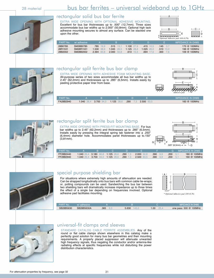
28 material bus bar ferrites – universal wideband up to 1GHz
EXTRA WIDE OPENING WITH ADHESIVE FOAM MOUNTING BASE. All-purpose series of two sizes accommodate all bus bar widths up to 2.45” (62,2mm) and thicknesses up to .285” (6,5mm). Installs easily by peeling protective paper liner from base.
EXTRA WIDE OPENING WITH OPTIONAL ADHESIVE MOUNTING. Excellent for bus bar thicknesses up to .500” (12,7mm). Three sizes accommodate bus bar widths up to 2.000” (50,8mm). Optional high tack adhesive mounting secures to almost any surface. Can be stacked one upon the other.
A
B C
DE
Optional Adhesive pad .030 (0,76)
B
C
A
E
DAdhesive pad
EXTRA WIDE OPENING WITH PRESS-FIT MOUNTING BASE. For bus bar widths up to 2.45” (62,2mm) and thicknesses up to .285” (6,5mm). Installs easily by pressing the integral spring tab fastener into a .250” (6,4mm) diameter hole. Accommodates panel thicknesses up to.150” (3,81mm).
B
C
A
.325" (8,3mm)
E
DG F
rectangular solid bus bar ferrite
rectangular split ferrite bus bar clamp
rectangular split ferrite bus bar clamp
PART No. w/ adhesive A B C D E IMPEDANCE IN OHMS 28B0785 SM28B0785 .785 19,9 .515 13,1 1.100 27,9 .415 10,5 .145 3,7 170 @ 100MHz 28R1531 SM28R1531 1.530 38,9 1.045 26,5 1.125 28,6 1.025 26,0 .510 13,0 196 @ 100MHz 28B2002 SM28B2002 2.394 60,8 2.000 50,8 .610 15,5 .694 17,6 .300 7,6 109 @ 100MHz
PART No. A B C D E IMPEDANCE IN OHMS FA28B2940 1.040 26,4 3.700 94,0 1.125 28,6 .290 7,3 2.500 63,5 160 @ 100MHz
PART No. A B C D E F G IMPEDANCE IN OHMS FF28B2440 1.040 26,4 3.180 80,8 1.125 28,6 .290 7,3 2.000 50,8 .390 9,9 .200 5,1 180 @ 100MHz FF28B2940 1.040 26,4 3.700 94,0 1.125 28,6 .290 7,3 2.500 63,5 .390 9,9 .200 5,1 160 @ 100MHz
STANDARD CATALOG CABLE FERRITE ASSEMBLIES. Any of the round or flat cable clamps shown elsewhere in this catalog make a perfectly good solution for many bus bar geometries and their mounting requirements. A properly placed suppressor will attenuate unwanted high frequency signals, thus negating the conductor and/or antenna-like radiating effects at specific frequencies while not disturbing the power distribution characteristics.
universal-fit clamps and sleeves
For situations where extremely high amounts of attenuation are needed. Can be strapped longitudinally onto bus bars with common cable tie-wraps; or, potting compounds can be used. Sandwiching the bus bar between two shielding bars will dramatically increase impedance up to three times the effect of a single bar depending on frequencies involved. Optional adhesive pad facilitates mounting.
B
C
A
* Optional Adhesive pad .030 (0,76)*
SB28B5630 SB28B5630A .365 9,3 5.630 143,0 1.00 25,4 one pass: 500 @ 100MHz PART No. w/ adhesive A B C IMPEDANCE IN OHMS
special purpose shielding bar
21
For attenuation properties by frequency, see page 32
33 material low frequency ferrites- up to 60MHz applications
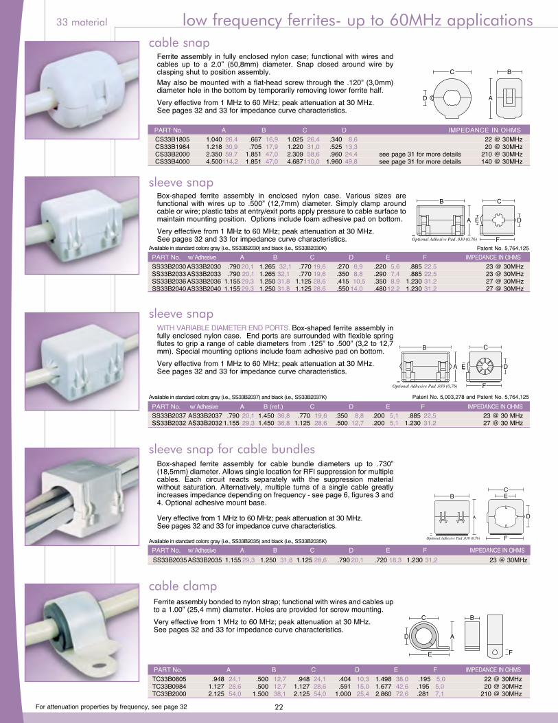
Ferrite assembly in fully enclosed nylon case; functional with wires and cables up to a 2.0” (50,8mm) diameter. Snap closed around wire by clasping shut to position assembly.May also be mounted with a flat-head screw through the .120” (3,0mm) diameter hole in the bottom by temporarily removing lower ferrite half.Very effective from 1 MHz to 60 MHz; peak attenuation at 30 MHz.See pages 32 and 33 for impedance curve characteristics.
AD
C B
cable snap
Box-shaped ferrite assembly in enclosed nylon case. Various sizes are functional with wires up to .500” (12,7mm) diameter. Simply clamp around cable or wire; plastic tabs at entry/exit ports apply pressure to cable surface to maintain mounting position. Options include foam adhesive pad on bottom.Very effective from 1 MHz to 60 MHz; peak attenuation at 30 MHz.See pages 32 and 33 for impedance curve characteristics. Optional Adhesive Pad .030 (0,76)
B C
F
A E D
Available in standard colors gray (i.e., SS33B2030) and black (i.e., SS33B2030K) Patent No. 5,764,125 PART No. w/ Adhesive A B C D E F IMPEDANCE IN OHMS SS33B2030 AS33B2030 .790 20,1 1.265 32,1 .770 19,6 .270 6,9 .220 5,6 .885 22,5 23 @ 30MHz SS33B2033 AS33B2033 .790 20,1 1.265 32,1 .770 19,6 .350 8,8 .290 7,4 .885 22,5 23 @ 30MHz SS33B2036 AS33B2036 1.155 29,3 1.250 31,8 1.125 28,6 .415 10,5 .350 8,9 1.230 31,2 27 @ 30MHz SS33B2040 AS33B2040 1.155 29,3 1.250 31,8 1.125 28,6 .550 14,0 .480 12,2 1.230 31,2 27 @ 30MHz
sleeve snap
WITH VARIABLE DIAMETER END PORTS. Box-shaped ferrite assembly in fully enclosed nylon case. End ports are surrounded with flexible spring flutes to grip a range of cable diameters from .125” to .500” (3,2 to 12,7 mm). Special mounting options include foam adhesive pad on bottom.Very effective from 1 MHz to 60 MHz; peak attenuation at 30 MHz.See pages 32 and 33 for impedance curve characteristics.
Box-shaped ferrite assembly for cable bundle diameters up to .730” (18,5mm) diameter. Allows single location for RFI suppression for multiple cables. Each circuit reacts separately with the suppression material without saturation. Alternatively, multiple turns of a single cable greatly increases impedance depending on frequency - see page 6, figures 3 and 4. Optional adhesive mount base.
Very effective from 1 MHz to 60 MHz; peak attenuation at 30 MHz.See pages 32 and 33 for impedance curve characteristics.
B C
F
A E D
Optional Adhesive Pad .030 (0,76)
Patent No. 5,003,278 and Patent No. 5,764,125Available in standard colors gray (i.e., SS33B2037) and black (i.e., SS33B2037K) PART No. w/ Adhesive A B (ref.) C D E F IMPEDANCE IN OHMS SS33B2037 AS33B2037 .790 20,1 1.450 36,8 .770 19,6 .350 8,8 .200 5,1 .885 22,5 23 @ 30 MHz SS33B2032 AS33B2032 1.155 29,3 1.450 36,8 1.125 28,6 .500 12,7 .200 5,1 1.230 31,2 27 @ 30 MHz
sleeve snap
sleeve snap for cable bundles
Ferrite assembly bonded to nylon strap; functional with wires and cables up to a 1.00” (25,4 mm) diameter. Holes are provided for screw mounting.Very effective from 1 MHz to 60 MHz; peak attenuation at 30 MHz.See pages 32 and 33 for impedance curve characteristics.
AD
F
C B
E
PART No. A B C D E F IMPEDANCE IN OHMS TC33B0805 .948 24,1 .500 12,7 .948 24,1 .404 10,3 1.498 38,0 .195 5,0 22 @ 30MHz TC33B0984 1.127 28,6 .500 12,7 1.127 28,6 .591 15,0 1.677 42,6 .195 5,0 20 @ 30MHz TC33B2000 2.125 54,0 1.500 38,1 2.125 54,0 1.000 25,4 2.860 72,6 .281 7,1 210 @ 30MHz
cable clamp
B
A D
E
C
SS28B2035 1-hole
B
A
E
C
SS28B2035-2 2-holes
B
A
E
C
SS28B2035-3 3-holes
D
D
Optional Adhesive Pad .030 (0,76)
Optional Adhesive Pad .030 (0,76)
Optional Adhesive Pad .030 (0,76)
Optional Adhesive Pad .030 (0,76)
B
A D
F
C E
SS33B2035 AS33B2035 1.155 29,3 1.250 31,8 1.125 28,6 .790 20,1 .720 18,3 1.230 31,2 23 @ 30MHz PART No. w/ Adhesive A B C D E F IMPEDANCE IN OHMSAvailable in standard colors gray (i.e., SS33B2035) and black (i.e., SS33B2035K)
PART No. A B C D IMPEDANCE IN OHMS CS33B1805 1.040 26,4 .667 16,9 1.025 26,4 .340 8,6 22 @ 30MHz CS33B1984 1.218 30,9 .705 17,9 1.220 31,0 .525 13,3 20 @ 30MHz CS33B2000 2.350 59,7 1.851 47,0 2.309 58,6 .960 24,4 see page 31 for more details 210 @ 30MHz CS33B4000 4.500 114,2 1.851 47,0 4.687 110,0 1.960 49,8 see page 31 for more details 140 @ 30MHz
22
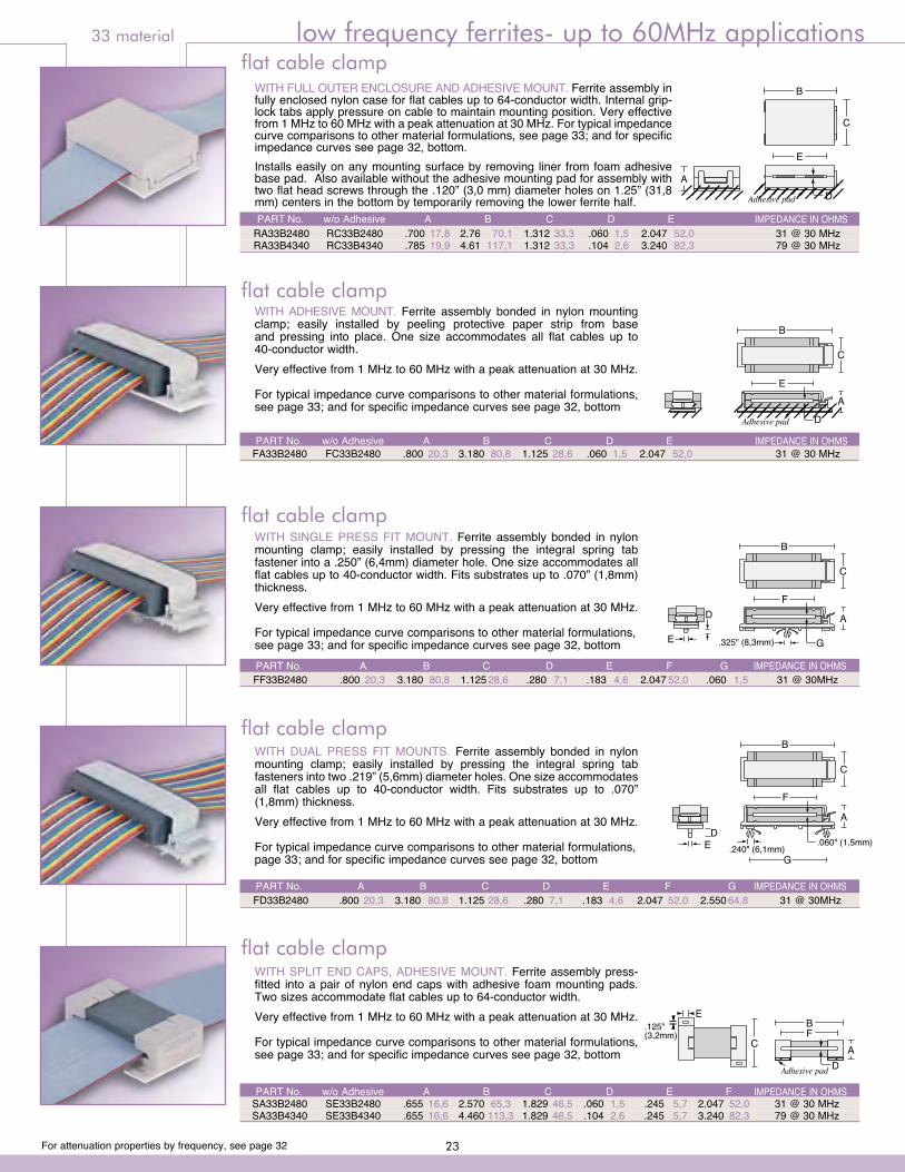
For attenuation properties by frequency, see page 32
33 material low frequency ferrites- up to 60MHz applications
WITH ADHESIVE MOUNT. Ferrite assembly bonded in nylon mounting clamp; easily installed by peeling protective paper strip from base and pressing into place. One size accommodates all flat cables up to 40-conductor width.Very effective from 1 MHz to 60 MHz with a peak attenuation at 30 MHz.
For typical impedance curve comparisons to other material formulations, see page 33; and for specific impedance curves see page 32, bottom
B
C
A
E
DAdhesive pad
flat cable clamp
FA33B2480 FC33B2480 .800 20,3 3.180 80,8 1.125 28,6 .060 1,5 2.047 52,0 31 @ 30 MHz PART No. w/o Adhesive A B C D E IMPEDANCE IN OHMS
WITH SINGLE PRESS FIT MOUNT. Ferrite assembly bonded in nylon mounting clamp; easily installed by pressing the integral spring tab fastener into a .250” (6,4mm) diameter hole. One size accommodates all flat cables up to 40-conductor width. Fits substrates up to .070” (1,8mm) thickness.Very effective from 1 MHz to 60 MHz with a peak attenuation at 30 MHz.
For typical impedance curve comparisons to other material formulations,see page 33; and for specific impedance curves see page 32, bottom
WITH DUAL PRESS FIT MOUNTS. Ferrite assembly bonded in nylon mounting clamp; easily installed by pressing the integral spring tab fasteners into two .219” (5,6mm) diameter holes. One size accommodates all flat cables up to 40-conductor width. Fits substrates up to .070” (1,8mm) thickness.Very effective from 1 MHz to 60 MHz with a peak attenuation at 30 MHz.
For typical impedance curve comparisons to other material formulations,page 33; and for specific impedance curves see page 32, bottom
flat cable clamp
flat cable clamp
FF33B2480 .800 20,3 3.180 80,8 1.125 28,6 .280 7,1 .183 4,6 2.047 52,0 .060 1,5 31 @ 30MHz PART No. A B C D E F G IMPEDANCE IN OHMS
flat cable clampWITH FULL OUTER ENCLOSURE AND ADHESIVE MOUNT. Ferrite assembly in fully enclosed nylon case for flat cables up to 64-conductor width. Internal grip-lock tabs apply pressure on cable to maintain mounting position. Very effective from 1 MHz to 60 MHz with a peak attenuation at 30 MHz. For typical impedance curve comparisons to other material formulations, see page 33; and for specific impedance curves see page 32, bottom.Installs easily on any mounting surface by removing liner from foam adhesive base pad. Also available without the adhesive mounting pad for assembly with two flat head screws through the .120” (3,0 mm) diameter holes on 1.25” (31,8 mm) centers in the bottom by temporarily removing the lower ferrite half.
A
Adhesive pad
B
C
D
E
A
Adhesive pad
B
C
D
E
PART No. w/o Adhesive A B C D E IMPEDANCE IN OHMS RA33B2480 RC33B2480 .700 17,8 2.76 70,1 1.312 33,3 .060 1,5 2.047 52,0 31 @ 30 MHz RA33B4340 RC33B4340 .785 19,9 4.61 117,1 1.312 33,3 .104 2,6 3.240 82,3 79 @ 30 MHz
WITH SPLIT END CAPS, ADHESIVE MOUNT. Ferrite assembly press-fitted into a pair of nylon end caps with adhesive foam mounting pads. Two sizes accommodate flat cables up to 64-conductor width.Very effective from 1 MHz to 60 MHz with a peak attenuation at 30 MHz.
For typical impedance curve comparisons to other material formulations, see page 33; and for specific impedance curves see page 32, bottom
C
E
DA
BF
Adhesive pad
flat cable clamp
FD33B2480 .800 20,3 3.180 80,8 1.125 28,6 .280 7,1 .183 4,6 2.047 52,0 2.550 64,8 31 @ 30MHz PART No. A B C D E F G IMPEDANCE IN OHMS
SA33B2480 SE33B2480 .655 16,6 2.570 65,3 1.829 46,5 .060 1,5 .245 5,7 2.047 52,0 31 @ 30 MHz SA33B4340 SE33B4340 .655 16,6 4.460 113,3 1.829 46,5 .104 2,6 .245 5,7 3.240 82,3 79 @ 30 MHz
PART No. w/o Adhesive A B C D E F IMPEDANCE IN OHMS
B
C
A
.325" (8,3mm)
F
GE
D
B
C
A
G
D.060" (1,5mm)
F
.240" (6,1mm)E
CS33B1805 1.040 26,4 .667 16,9 1.025 26,4 .340 8,6 22 @ 30MHz CS33B1984 1.218 30,9 .705 17,9 1.220 31,0 .525 13,3 20 @ 30MHz CS33B2000 2.350 59,7 1.851 47,0 2.309 58,6 .960 24,4 see page 31 for more details 210 @ 30MHz CS33B4000 4.500 114,2 1.851 47,0 4.687 110,0 1.960 49,8 see page 31 for more details 140 @ 30MHz
23
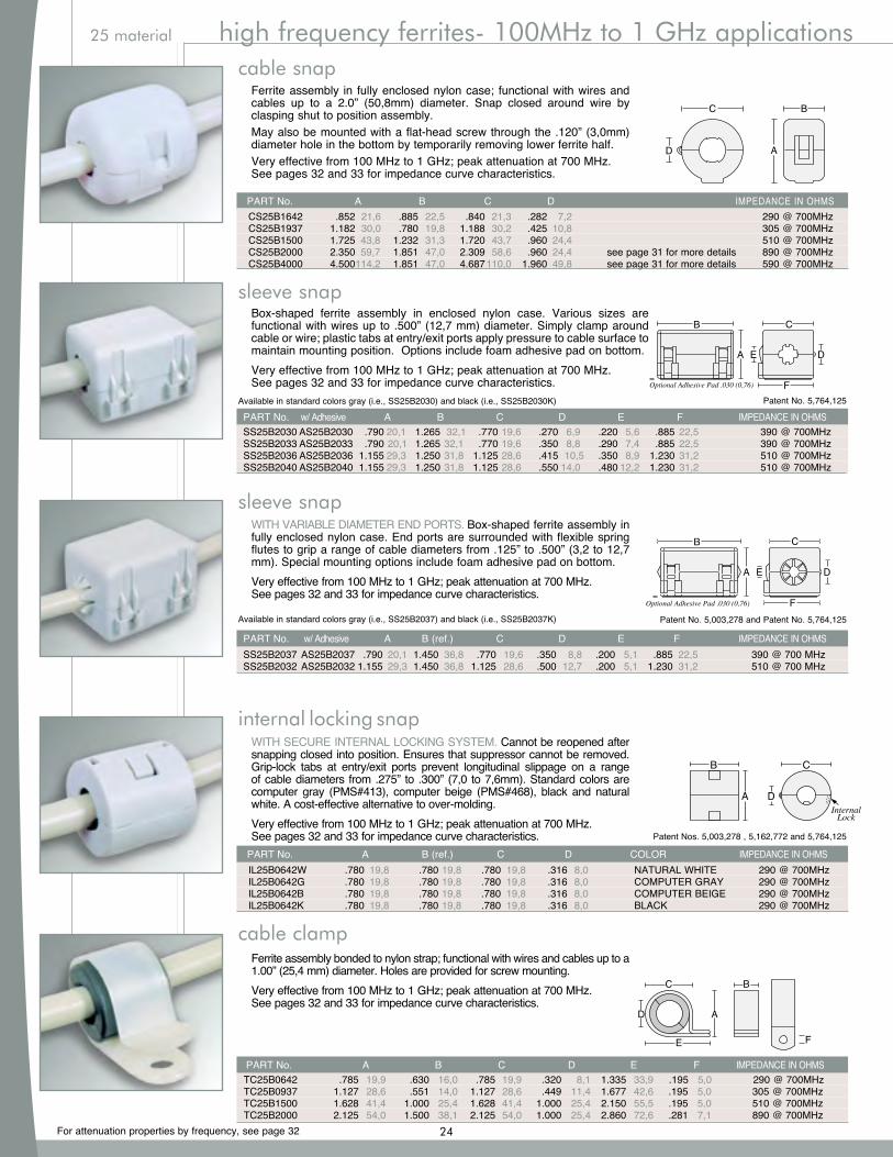
For attenuation properties by frequency, see page 32
25 material high frequency ferrites- 100MHz to 1 GHz applications
Ferrite assembly in fully enclosed nylon case; functional with wires and cables up to a 2.0” (50,8mm) diameter. Snap closed around wire by clasping shut to position assembly.May also be mounted with a flat-head screw through the .120” (3,0mm) diameter hole in the bottom by temporarily removing lower ferrite half.Very effective from 100 MHz to 1 GHz; peak attenuation at 700 MHz.See pages 32 and 33 for impedance curve characteristics.
AD
C B
cable snap
Box-shaped ferrite assembly in enclosed nylon case. Various sizes are functional with wires up to .500” (12,7 mm) diameter. Simply clamp around cable or wire; plastic tabs at entry/exit ports apply pressure to cable surface to maintain mounting position. Options include foam adhesive pad on bottom.Very effective from 100 MHz to 1 GHz; peak attenuation at 700 MHz.See pages 32 and 33 for impedance curve characteristics. Optional Adhesive Pad .030 (0,76)
B C
F
A E D
Available in standard colors gray (i.e., SS25B2030) and black (i.e., SS25B2030K) Patent No. 5,764,125
PART No. w/ Adhesive A B C D E F IMPEDANCE IN OHMS SS25B2030 AS25B2030 .790 20,1 1.265 32,1 .770 19,6 .270 6,9 .220 5,6 .885 22,5 390 @ 700MHz SS25B2033 AS25B2033 .790 20,1 1.265 32,1 .770 19,6 .350 8,8 .290 7,4 .885 22,5 390 @ 700MHz SS25B2036 AS25B2036 1.155 29,3 1.250 31,8 1.125 28,6 .415 10,5 .350 8,9 1.230 31,2 510 @ 700MHz SS25B2040 AS25B2040 1.155 29,3 1.250 31,8 1.125 28,6 .550 14,0 .480 12,2 1.230 31,2 510 @ 700MHz
sleeve snap
WITH VARIABLE DIAMETER END PORTS. Box-shaped ferrite assembly in fully enclosed nylon case. End ports are surrounded with flexible spring flutes to grip a range of cable diameters from .125” to .500” (3,2 to 12,7 mm). Special mounting options include foam adhesive pad on bottom.Very effective from 100 MHz to 1 GHz; peak attenuation at 700 MHz.See pages 32 and 33 for impedance curve characteristics.
WITH SECURE INTERNAL LOCKING SYSTEM. Cannot be reopened after snapping closed into position. Ensures that suppressor cannot be removed. Grip-lock tabs at entry/exit ports prevent longitudinal slippage on a range of cable diameters from .275” to .300” (7,0 to 7,6mm). Standard colors are computer gray (PMS#413), computer beige (PMS#468), black and natural white. A cost-effective alternative to over-molding.Very effective from 100 MHz to 1 GHz; peak attenuation at 700 MHz.See pages 32 and 33 for impedance curve characteristics.
B C
F
A E D
Optional Adhesive Pad .030 (0,76)
Patent Nos. 5,003,278 , 5,162,772 and 5,764,125
IL25B0642W .780 19,8 .780 19,8 .780 19,8 .316 8,0 NATURAL WHITE 290 @ 700MHz IL25B0642G .780 19,8 .780 19,8 .780 19,8 .316 8,0 COMPUTER GRAY 290 @ 700MHz IL25B0642B .780 19,8 .780 19,8 .780 19,8 .316 8,0 COMPUTER BEIGE 290 @ 700MHz IL25B0642K .780 19,8 .780 19,8 .780 19,8 .316 8,0 BLACK 290 @ 700MHz
PART No. A B (ref.) C D COLOR IMPEDANCE IN OHMS
Patent No. 5,003,278 and Patent No. 5,764,125Available in standard colors gray (i.e., SS25B2037) and black (i.e., SS25B2037K)
PART No. w/ Adhesive A B (ref.) C D E F IMPEDANCE IN OHMS SS25B2037 AS25B2037 .790 20,1 1.450 36,8 .770 19,6 .350 8,8 .200 5,1 .885 22,5 390 @ 700 MHz SS25B2032 AS25B2032 1.155 29,3 1.450 36,8 1.125 28,6 .500 12,7 .200 5,1 1.230 31,2 510 @ 700 MHz
sleeve snap
internal locking snap
Ferrite assembly bonded to nylon strap; functional with wires and cables up to a 1.00” (25,4 mm) diameter. Holes are provided for screw mounting.Very effective from 100 MHz to 1 GHz; peak attenuation at 700 MHz.See pages 32 and 33 for impedance curve characteristics.
AD
F
C B
E
cable clamp
PART No. A B C D IMPEDANCE IN OHMS CS25B1642 .852 21,6 .885 22,5 .840 21,3 .282 7,2 290 @ 700MHz CS25B1937 1.182 30,0 .780 19,8 1.188 30,2 .425 10,8 305 @ 700MHz CS25B1500 1.725 43,8 1.232 31,3 1.720 43,7 .960 24,4 510 @ 700MHz CS25B2000 2.350 59,7 1.851 47,0 2.309 58,6 .960 24,4 see page 31 for more details 890 @ 700MHz CS25B4000 4.500 114,2 1.851 47,0 4.687 110,0 1.960 49,8 see page 31 for more details 590 @ 700MHz
PART No. A B C D E F IMPEDANCE IN OHMS TC25B0642 .785 19,9 .630 16,0 .785 19,9 .320 8,1 1.335 33,9 .195 5,0 290 @ 700MHz TC25B0937 1.127 28,6 .551 14,0 1.127 28,6 .449 11,4 1.677 42,6 .195 5,0 305 @ 700MHz TC25B1500 1.628 41,4 1.000 25,4 1.628 41,4 1.000 25,4 2.150 55,5 .195 5,0 510 @ 700MHz TC25B2000 2.125 54,0 1.500 38,1 2.125 54,0 1.000 25,4 2.860 72,6 .281 7,1 890 @ 700MHz
24
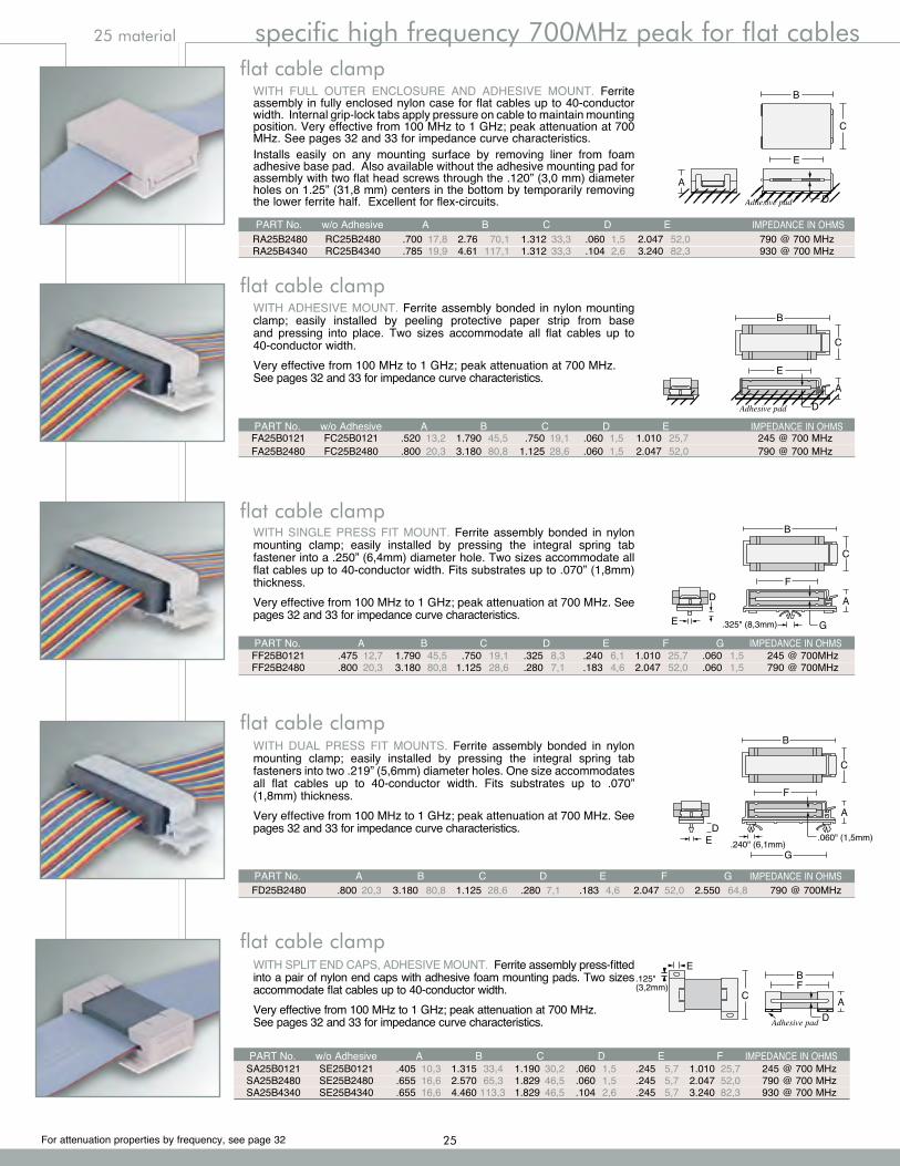
For attenuation properties by frequency, see page 32
25 material specific high frequency 700MHz peak for flat cables
WITH ADHESIVE MOUNT. Ferrite assembly bonded in nylon mounting clamp; easily installed by peeling protective paper strip from base and pressing into place. Two sizes accommodate all flat cables up to 40-conductor width.Very effective from 100 MHz to 1 GHz; peak attenuation at 700 MHz.See pages 32 and 33 for impedance curve characteristics.
B
C
A
E
DAdhesive pad
flat cable clamp
FA25B0121 FC25B0121 .520 13,2 1.790 45,5 .750 19,1 .060 1,5 1.010 25,7 245 @ 700 MHz FA25B2480 FC25B2480 .800 20,3 3.180 80,8 1.125 28,6 .060 1,5 2.047 52,0 790 @ 700 MHz
PART No. w/o Adhesive A B C D E IMPEDANCE IN OHMS
WITH SINGLE PRESS FIT MOUNT. Ferrite assembly bonded in nylon mounting clamp; easily installed by pressing the integral spring tab fastener into a .250” (6,4mm) diameter hole. Two sizes accommodate all flat cables up to 40-conductor width. Fits substrates up to .070” (1,8mm) thickness.Very effective from 100 MHz to 1 GHz; peak attenuation at 700 MHz. See pages 32 and 33 for impedance curve characteristics.
WITH DUAL PRESS FIT MOUNTS. Ferrite assembly bonded in nylon mounting clamp; easily installed by pressing the integral spring tab fasteners into two .219” (5,6mm) diameter holes. One size accommodates all flat cables up to 40-conductor width. Fits substrates up to .070” (1,8mm) thickness.Very effective from 100 MHz to 1 GHz; peak attenuation at 700 MHz. See pages 32 and 33 for impedance curve characteristics.
flat cable clamp
flat cable clamp
FF25B0121 .475 12,7 1.790 45,5 .750 19,1 .325 8,3 .240 6,1 1.010 25,7 .060 1,5 245 @ 700MHz FF25B2480 .800 20,3 3.180 80,8 1.125 28,6 .280 7,1 .183 4,6 2.047 52,0 .060 1,5 790 @ 700MHz
PART No. A B C D E F G IMPEDANCE IN OHMS
flat cable clampWITH FULL OUTER ENCLOSURE AND ADHESIVE MOUNT. Ferrite assembly in fully enclosed nylon case for flat cables up to 40-conductor width. Internal grip-lock tabs apply pressure on cable to maintain mounting position. Very effective from 100 MHz to 1 GHz; peak attenuation at 700 MHz. See pages 32 and 33 for impedance curve characteristics. Installs easily on any mounting surface by removing liner from foam adhesive base pad. Also available without the adhesive mounting pad for assembly with two flat head screws through the .120” (3,0 mm) diameter holes on 1.25” (31,8 mm) centers in the bottom by temporarily removing the lower ferrite half. Excellent for flex-circuits.
A
Adhesive pad
B
C
D
E
A
Adhesive pad
B
C
D
E
PART No. w/o Adhesive A B C D E IMPEDANCE IN OHMS RA25B2480 RC25B2480 .700 17,8 2.76 70,1 1.312 33,3 .060 1,5 2.047 52,0 790 @ 700 MHz RA25B4340 RC25B4340 .785 19,9 4.61 117,1 1.312 33,3 .104 2,6 3.240 82,3 930 @ 700 MHz
WITH SPLIT END CAPS, ADHESIVE MOUNT. Ferrite assembly press-fitted into a pair of nylon end caps with adhesive foam mounting pads. Two sizes accommodate flat cables up to 40-conductor width.Very effective from 100 MHz to 1 GHz; peak attenuation at 700 MHz.See pages 32 and 33 for impedance curve characteristics.
C
E
DA
BF
Adhesive pad
flat cable clamp
FD25B2480 .800 20,3 3.180 80,8 1.125 28,6 .280 7,1 .183 4,6 2.047 52,0 2.550 64,8 790 @ 700MHz PART No. A B C D E F G IMPEDANCE IN OHMS
SA25B0121 SE25B0121 .405 10,3 1.315 33,4 1.190 30,2 .060 1,5 .245 5,7 1.010 25,7 245 @ 700 MHz SA25B2480 SE25B2480 .655 16,6 2.570 65,3 1.829 46,5 .060 1,5 .245 5,7 2.047 52,0 790 @ 700 MHz SA25B4340 SE25B4340 .655 16,6 4.460 113,3 1.829 46,5 .104 2,6 .245 5,7 3.240 82,3 930 @ 700 MHz
PART No. w/o Adhesive A B C D E F IMPEDANCE IN OHMS
B
C
A
.325" (8,3mm)
F
GE
D
B
C
A
G
D.060" (1,5mm)
F
.240" (6,1mm)E
25
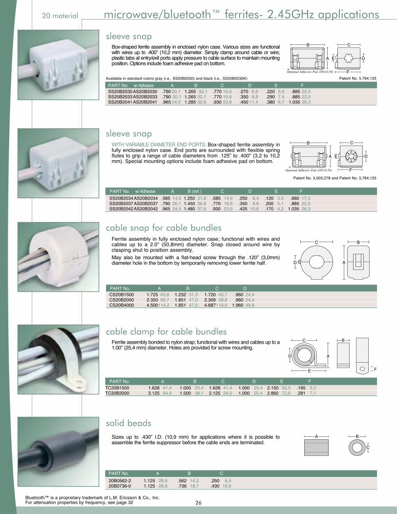
For attenuation properties by frequency, see page 32
20 material microwave/bluetooth™ ferrites- 2.45GHz applications
Box-shaped ferrite assembly in enclosed nylon case. Various sizes are functional with wires up to .400” (10,2 mm) diameter. Simply clamp around cable or wire; plastic tabs at entry/exit ports apply pressure to cable surface to maintain mounting position. Options include foam adhesive pad on bottom.
Optional Adhesive Pad .030 (0,76)
B C
F
A E D
Available in standard colors gray (i.e., SS20B2030) and black (i.e., SS20B2030K) Patent No. 5,764,125
PART No. w/ Adhesive A B C D E F SS20B2030 AS20B2030 .790 20,1 1.265 32,1 .770 19,6 .270 6,9 .220 5,6 .885 22,5 SS20B2033 AS20B2033 .790 20,1 1.265 32,1 .770 19,6 .350 8,8 .290 7,4 .885 22,5 SS20B2041 AS20B2041 .965 24,5 1.285 32,6 .930 23,6 .450 11,4 .380 9,7 1.035 26,3
sleeve snap
WITH VARIABLE DIAMETER END PORTS. Box-shaped ferrite assembly in fully enclosed nylon case. End ports are surrounded with flexible spring flutes to grip a range of cable diameters from .125” to .400” (3,2 to 10,2 mm). Special mounting options include foam adhesive pad on bottom.
B C
F
A E D
Optional Adhesive Pad .030 (0,76)
Patent No. 5,003,278 and Patent No. 5,764,125
Available in standard colors gray (i.e., SS28B2034) and black (i.e., SS28B2034K)
PART No. w/ Adhesive A B (ref.) C D E F SS20B2034 AS20B2034 .585 14,9 1.250 31,8 .585 14,9 .250 6,4 .120 3,0 .680 17,3 SS20B2037 AS20B2037 .790 20,1 1.450 36,8 .770 19,6 .350 8,8 .200 5,1 .885 22,5 SS20B2042 AS20B2042 .965 24,5 1.480 37,6 .930 23,6 .425 10,8 .170 4,3 1.035 26,3
sleeve snap
solid beadsSizes up to .430” I.D. (10,9 mm) for applications where it is possible to assemble the ferrite suppressor before the cable ends are terminated.
A
C
B
PART No. A B C 20B0562-2 1.125 28,6 .562 14,2 .250 6,4 20B0736-0 1.125 28,6 .736 18,7 .430 10,9
Ferrite assembly in fully enclosed nylon case; functional with wires and cables up to a 2.0” (50,8mm) diameter. Snap closed around wire by clasping shut to position assembly.May also be mounted with a flat-head screw through the .120” (3,0mm) diameter hole in the bottom by temporarily removing lower ferrite half.
cable snap for cable bundles
PART No. A B C D CS20B1500 1.725 43,8 1.232 31,3 1.720 43,7 .960 24,4 CS20B2000 2.350 59,7 1.851 47,0 2.309 58,6 .960 24,4 CS20B4000 4.500 114,2 1.851 47,0 4.687 119,0 1.960 49,8
Ferrite assembly bonded to nylon strap; functional with wires and cables up to a 1.00” (25,4 mm) diameter. Holes are provided for screw mounting.
TC20B1500 1.628 41,4 1.000 25,4 1.628 41,4 1.000 25,4 2.150 55,5 .195 5,0TC20B2000 2.125 54,0 1.500 38,1 2.125 54,0 1.000 25,4 2.860 72,6 .281 7,1
PART No. A B C D E F
cable clamp for cable bundles
AD
C B
AD
F
C B
E
Bluetooth™ is a proprietary trademark of L.M. Ericsson & Co., Inc.26
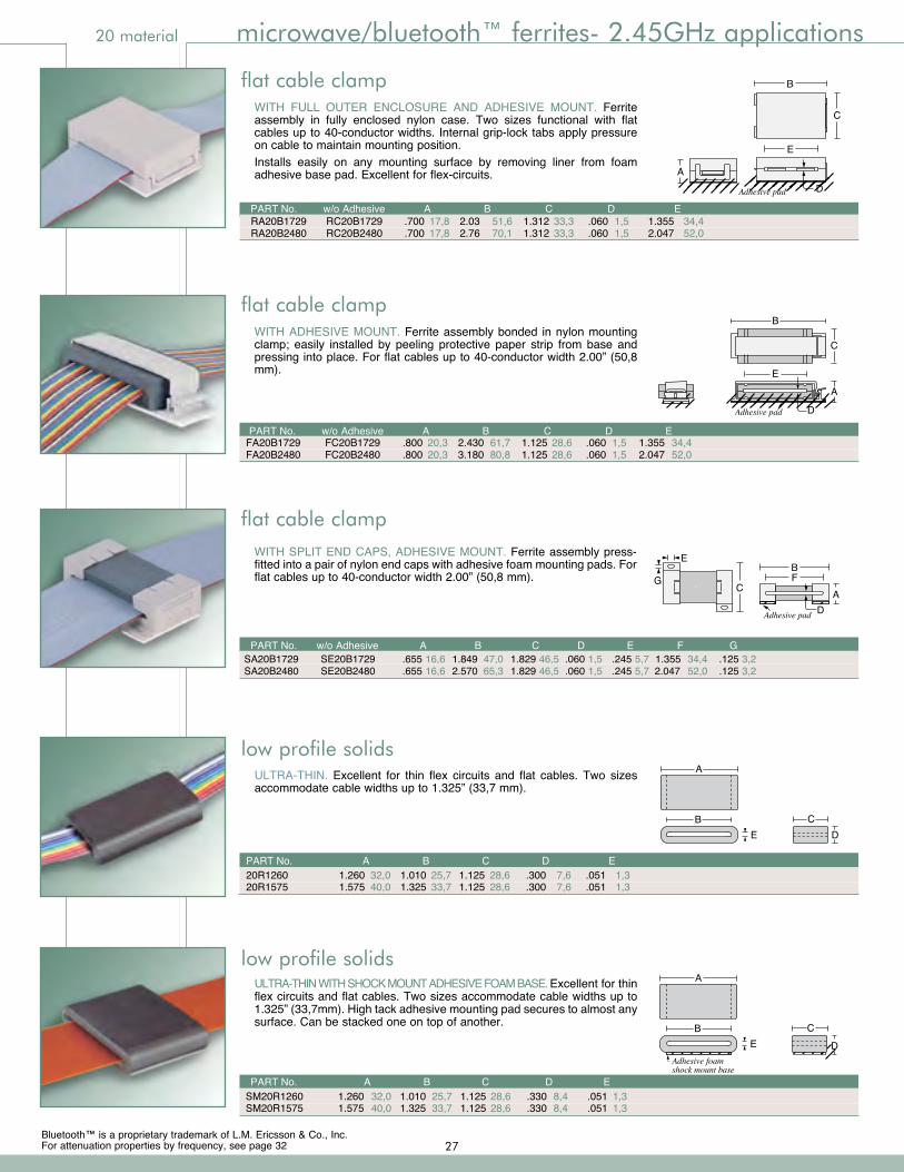
For attenuation properties by frequency, see page 32
20 material microwave/bluetooth™ ferrites- 2.45GHz applications
WITH ADHESIVE MOUNT. Ferrite assembly bonded in nylon mounting clamp; easily installed by peeling protective paper strip from base and pressing into place. For flat cables up to 40-conductor width 2.00” (50,8 mm).
B
C
A
E
DAdhesive pad
flat cable clamp
FA20B1729 FC20B1729 .800 20,3 2.430 61,7 1.125 28,6 .060 1,5 1.355 34,4 FA20B2480 FC20B2480 .800 20,3 3.180 80,8 1.125 28,6 .060 1,5 2.047 52,0
PART No. w/o Adhesive A B C D E
WITH SPLIT END CAPS, ADHESIVE MOUNT. Ferrite assembly press-fitted into a pair of nylon end caps with adhesive foam mounting pads. For flat cables up to 40-conductor width 2.00” (50,8 mm).
C
E
G
DA
BF
Adhesive pad
PART No. w/o Adhesive A B C D E F G SA20B1729 SE20B1729 .655 16,6 1.849 47,0 1.829 46,5 .060 1,5 .245 5,7 1.355 34,4 .125 3,2 SA20B2480 SE20B2480 .655 16,6 2.570 65,3 1.829 46,5 .060 1,5 .245 5,7 2.047 52,0 .125 3,2
flat cable clamp
flat cable clampWITH FULL OUTER ENCLOSURE AND ADHESIVE MOUNT. Ferrite assembly in fully enclosed nylon case. Two sizes functional with flat cables up to 40-conductor widths. Internal grip-lock tabs apply pressure on cable to maintain mounting position.Installs easily on any mounting surface by removing liner from foam adhesive base pad. Excellent for flex-circuits. A
Adhesive pad
B
C
D
E
A
Adhesive pad
B
C
D
E
PART No. w/o Adhesive A B C D E RA20B1729 RC20B1729 .700 17,8 2.03 51,6 1.312 33,3 .060 1,5 1.355 34,4 RA20B2480 RC20B2480 .700 17,8 2.76 70,1 1.312 33,3 .060 1,5 2.047 52,0
Adhesive foamshock mount base
A
B C
DE
SM20R1260 1.260 32,0 1.010 25,7 1.125 28,6 .330 8,4 .051 1,3 SM20R1575 1.575 40,0 1.325 33,7 1.125 28,6 .330 8,4 .051 1,3
PART No. A B C D E
ULTRA-THIN WITH SHOCK MOUNT ADHESIVE FOAM BASE. Excellent for thin flex circuits and flat cables. Two sizes accommodate cable widths up to 1.325” (33,7mm). High tack adhesive mounting pad secures to almost any surface. Can be stacked one on top of another.
low profile solids
A
B CDE
low profile solidsULTRA-THIN. Excellent for thin flex circuits and flat cables. Two sizes accommodate cable widths up to 1.325” (33,7 mm).
PART No. A B C D E 20R1260 1.260 32,0 1.010 25,7 1.125 28,6 .300 7,6 .051 1,3 20R1575 1.575 40,0 1.325 33,7 1.125 28,6 .300 7,6 .051 1,3
Bluetooth™ is a proprietary trademark of L.M. Ericsson & Co., Inc.27

For attenuation properties by frequency, see page 32
RFID frequency-specific shielding
Parameters CTM030 CTM032 Fields Electric Magnetic Frequency Response 2MHz - 2GHz 1MHz - 1GHz RF Output Yes Yes DC Output to a multimeter Yes Yes Sensitivity (typical) -10dBm/(V/m) -20dBm/mA Connector SMB/BNC SMB/BNC Dimensions (approx.) 6.18” x 1.21” x 0.76” (157 x 31 x 20mm) 6.18” x 1.21” x 0.76” (157 x 31 x 20mm) Weight (approx.) 2.25oz (65g) 2.25oz (65g) Battery (included) 2 x AAA 2 x AAA LED Bar Graph 5 LED color bar 5 LED color bar Audio Indication Speaker (tone pitch proportional to the field strength)
CTK031 W/ BOTH PROBES PROBE PROBE
CTK031 – SCAN EM-C PROBE SET WITH DEMO FIXTUREContains both CTM030 electric and CTM032 magnetic near-field probes along with a step-by-step guide, an EMC Demo Fixture, and cables with adapters for spectrum analyzer, oscilloscope or multimeter. Free ferrite engineering kit included. See information at lower right.
FREE #EK28B0032 FERRITE ENGINEERING KIT WITH EITHER ScanEM PROBE KIT PURCHASEOur popular, wideband assortment of 32 unique configurations for RFID EMI cable suppression.
3-Steps to Reducing RFID InterferenceRadio Frequency Identification (RFID) is a rapidly expanding technology with new applications emerging at a remarkable rate. From management of warehouse inventory to identification of patients in a medical setting, proper deployment and unimpeded communication between RFID readers and tags is paramount to successful operation.
One of the major considerations when implementing an RFID system is the effect of unwanted RF interference between Readers and Tags. Most workplaces have hundreds if not thousands of electronic devices that create unwanted interference, including computers, Bluetooth networks, wireless networks, motors, conveyors and robots. Actually, any device with a microchip and power cord or cable will emit RF energy which can interfere with the ability of the reader to receive a clean signal.
Leader Tech offers a simple “first-step” approach to reducing unwanted RF interference. We recommend the following:
Identify Sources of RFID InterferencesThe FerriShield CTK031 hand-held probe (see below) is one of the easiest ways to identify unwanted electro-magnetic interference. All you need to do is pass the probe over suspect sources. If the device detects RF emissions it alerts with an audible tone that intensifies as interference increases.
Attach a Frequency-Specific RFID Ferrite to the Suspect DeviceSamplings of our most popular RFID ferrites are shown on the following page. In addition, a free 32-piece engineering kit is provided with the purchase of any CTK031 Probe.
Check If Interference Has Been EliminatedAfter you have attached the cable-mounted ferrite, simply use the hand-held RF probe to confirm that the ferrite has eliminated the unwanted interference.
28
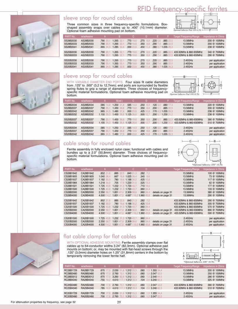
For attenuation properties by frequency, see page 32
RFID frequency-specific ferrites
SS28B2030 AS28B2030 .790 20,1 1.265 32,1 .770 19,6 .270 6,9 .220 5,6 .885 22,5 13.56MHz 200 @ 100MHz SS28B2033 AS28B2033 .790 20,1 1.265 32,1 .770 19,6 .350 8,8 .290 7,4 .885 22,5 13.56MHz 200 @ 100MHz SS28B2041 AS28B2041 .965 24,5 1.285 32,6 .930 23,6 .450 11,4 .380 9,7 1.035 26,3 13.50MHz 238 @ 100MHz
SS25B2030 AS25B2030 .790 20,1 1.265 32,1 .770 19,6 .270 6,9 .220 5,6 .885 22,5 433.92MHz & 860-930MHz 340 @ 700MHz SS25B2033 AS25B2033 .790 20,1 1.265 32,1 .770 19,6 .350 8,8 .290 7,4 .885 22,5 433.92MHz & 860-930MHz 290 @ 700MHz
SS20B2030 AS20B2030 .790 20,1 1.265 32,1 .770 19,6 .270 6,9 .220 5,6 .885 22,5 2.45GHz per application SS20B2033 AS20B2033 .790 20,1 1.265 32,1 .770 19,6 .350 8,8 .290 7,4 .885 22,5 2.45GHz per application SS20B2041 AS20B2041 .965 24,5 1.285 32,6 .930 23,6 .450 11,4 .380 9,7 1.035 26,3 2.45GHz per application
PART No. w/adhesive A B C D E F Target Frequency/Range Impedance in Ohms
SS28B2034 AS28B2034 .585 14,9 1.250 31,8 .585 14,9 .250 6,4 .120 3,0 .680 17,3 13.56MHz 220 @ 100MHz SS28B2037 AS28B2037 .790 20,1 1.450 36,8 .770 19,6 .350 8,8 .200 5,1 .885 22,5 13.56MHz 200 @ 100MHz SS28B2042 AS28B2042 .965 24,5 1.480 37,6 .930 23,6 .425 10,8 .170 4,3 1.035 26,3 13.56MHz 238 @ 100MHz SS28B2032 AS28B2032 1.155 29,3 1.450 36,8 1.125 28,6 .500 12,7 .200 5,1 1.230 31,2 13.56MHz 238 @ 100MHz
SS25B2037 AS25B2037 .790 20,1 1.450 36,8 .770 19,6 .350 8,8 .200 5,1 .885 22,5 433.92MHz & 860-930MHz 390 @ 700MHz SS25B2032 AS25B2032 1.155 29,3 1.450 36,8 1.125 28,6 .500 12,7 .200 5,1 1.230 31,2 433.92MHz & 860-930MHz 510 @ 700MHz
SS20B2034 AS20B2034 .585 14,9 1.250 31,8 .585 14,9 .250 6,4 .120 3,0 .680 17,3 2.45GHz per application SS20B2037 AS20B2037 .790 20,1 1.450 36,8 .770 19,6 .350 8,8 .200 5,1 .885 22,5 2.45GHz per application SS20B2042 AS20B2042 .965 24,5 1.480 37,6 .930 23,6 .425 10,8 .170 4,3 1.035 26,3 2.45GHz per application
PART No. w/adhesive A B(ref.) C D E F Target Frequency/Range Impedance in Ohms
RC28B1729 RA28B1729 .670 17,0 2.030 51,6 1.312 33,3 .060 1,5 1.355 34,4 13.56MHz 200 @ 100MHz RC28B2480 RA28B2480 .670 17,0 2.760 70,1 1.312 33,3 .060 1,5 2.047 52,0 13.56MHz 250 @ 100MHz RC28B3012 RA28B3012 .670 17,0 3.260 82,8 1.312 33,3 .060 1,5 2.540 64,5 13.56MHz 286 @ 100MHz RC28B4340 RA28B4340 .755 19,2 4.610 117,1 1.312 33,3 .104 2,6 3.240 82,3 13.56MHz 325 @ 100MHz
RC25B2480 RA25B2480 .700 17,8 2.760 70,1 1.312 33,3 .060 1,5 2.047 52,0 433.92MHz & 860-930MHz 390 @ 700MHz RC25B4340 RA25B4340 .785 19,9 4.610 117,1 1.312 33,3 .104 2,6 3.240 82,3 433.92MHz & 860-930MHz 510 @ 700MHz
RC20B1729 RA20B1729 .700 17,8 2.030 51,6 1.312 33,3 .060 1,5 1.355 34,4 2.45GHz per application RC20B2480 RA20B2480 .700 17,8 2.760 70,1 1.312 33,3 .060 1,5 2.047 52,0 2.45GHz per application
PART No. w/adhesive A B C D E Target Frequency/Range Impedance in Ohms
CS28B1642 CA28B1642 .852 21,6 .885 22,5 .840 21,3 .282 7,2 13.56MHz 100 @ 100MHz CS28B1805 CA28B1805 1.040 26,4 .667 16,9 1.025 26,4 .340 8,6 13.56MHz 73 @ 100MHz CS28B1937 CA28B1937 1.182 30,0 .780 19,6 1.188 30,2 .425 10,8 13.56MHz 117 @ 100MHz CS28B1984 CA28B1984 1.218 30,9 .705 17,9 1.220 31,0 .525 13,3 13.56MHz 62 @ 100MHz CS28B1501 CA28B1501 1.725 43,8 1.232 31,3 1.720 43,7 .710 18,0 13.56MHz 177 @ 100MHz CS28B1500 CA28B1500 1.725 43,8 1.232 31,3 1.720 43,7 .960 24,4 13.56MHz 133 @ 100MHz CS28B2000 CA28B2000 2.350 59,7 1.851 47,0 2.309 58,6 .960 24,4 details on page 31 13.56MHz 380 @ 100MHz CS28B4000 CA28B4000 4.500 114,2 1.851 47,0 4.687 119,0 1.960 49,8 details on page 31 13.56MHz 290 @ 100MHz
CS25B1642 CA25B1642 .852 21,6 .885 22,5 .840 21,3 .282 7,2 433.92MHz & 860-930MHz 290 @ 700MHz CS25B1937 CA25B1937 1.182 30,0 .780 19,6 1.188 30,2 .425 10,8 433.92MHz & 860-930MHz 305 @ 700MHz CS25B1500 CA25B1500 1.725 43,8 1.232 31,3 1.720 43,7 .960 24,4 433.92MHz & 860-930MHz 570 @ 700MHz CS25B2000 CA25B2000 2.350 59,7 1.851 47,0 2.309 58,6 .960 24,4 details on page 31 433.92MHz & 860-930MHz 890 @ 700MHz CS25B4000 CA25B4000 4.500 114,2 1.851 47,0 4.687 119,0 1.960 49,8 details on page 31 433.92MHz & 860-930MHz 590 @ 700MHz
CS20B1500 CA20B1500 1.725 43,8 1.232 31,3 1.720 43,7 .960 24,4 2.45GHz per application CS20B2000 CA20B2000 2.350 59,7 1.851 47,0 2.309 58,6 .960 24,4 details on page 31 2.45GHz per application CS20B4000 CA20B4000 4.500 114,2 1.851 47,0 4.687 119,0 1.960 49,8 details on page 31 2.45GHz per application
PART No. w/adhesive A B C D Target Frequency/Range Impedance in Ohms
Three common sizes in three frequency-specific formulations. Box-shaped assembly snaps over cables up to .400” (10,1mm) diameter. Optional foam adhesive mounting pad on bottom. Optional Adhesive Pad .030 (0,76)
B C
F
A E D
WITH VARIABLE DIAMETER END PORTS. Four sizes fit cable diameters from .125” to .500” (3,2 to 12,7mm); end ports are surrounded by flexible spring flutes to grip a range of diameters. Three choices of frequency-specific material formulations. Optional foam adhesive mounting pad on bottom.
B C
F
A E D
Optional Adhesive Pad .030 (0,76)
sleeve snap for round cables
sleeve snap for round cables
Ferrite assembly in fully enclosed nylon case; functional with cables and bundles up to a 2.0” (50,8mm) diameter. Three choices of frequency-specific material formulations. Optional foam adhesive mounting pad on bottom.
AD
C B
*Optional Adhesive .030” (0,76)
cable snap for round cables
flat cable clamp for flat cablesWITH OPTIONAL ADHESIVE MOUNTING. Ferrite assembly clamps over flat cables up to 64-conductor widths 3.24” (82,3mm). Optional adhesive pad mounts on bottom; or, may be mounted with flat-head screws through the .120” (3,0mm) diameter holes on 1.25” (31,8mm) centers in the bottom by temporarily removing the lower ferrite half. A
B
C
D
E
*Optional Adhesive .030” (0,76)
29
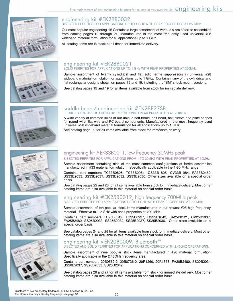
For attenuation properties by frequency, see page 32
®saddle beads
engineering kits
engineering kit #EK25B0012, high frequency 700MHz peakBISECTED FERRITES FOR APPLICATIONS UP TO 1 GHz WITH PEAK PROPERTIES AT 700MHz.Sample assortment of ten popular stock items manufactured in our newest #25 high frequency material. Effective to 1.2 GHz with peak properties at 700 MHz.Contains part numbers TC25B0642, TC25B0937, CS25B1642, SA25B0121, CV25B1937, FA25B2480, SS25B2033, SS25B2032, SS25B2037, SS25B2036. Other sizes available on a special order basis.
See catalog pages 24 and 25 for all items available from stock for immediate delivery. Most other catalog items are also available in this material on special order basis.
saddle beads® engineering kit #EK28B27SBFERRITES FOR APPLICATIONS UP TO 1 GHz WITH PEAK PROPERTIES AT 250MHz.A wide variety of common sizes of our unique half-toroid, half-bead, half-sleeve and plate shapes for round wire, flat wire and PC board components. Manufactured in the most frequently used universal #28 wideband material formulation for all applications up to 1 GHz.See catalog page 20 for all items available from stock for immediate delivery.
engineering kit #EK28B0032BISECTED FERRITES FOR APPLICATIONS UP TO 1 GHz WITH PEAK PROPERTIES AT 250MHz.Our most popular engineering kit! Contains a large assortment of various sizes of ferrite assemblies from catalog pages 10 through 21. Manufactured in the most frequently used universal #28 wideband material formulation for all applications up to 1 GHz.All catalog items are in stock at all times for immediate delivery.
engineering kit #EK28B0021SOLID FERRITES FOR APPLICATIONS UP TO 1 GHz WITH PEAK PROPERTIES AT 250MHz.Sample assortment of twenty cylindrical and flat solid ferrite suppressors in universal #28 wideband material formulation for applications up to 1 GHz. Contains many of the cylindrical and flat rectangular designs shown on pages 15 and 19, including the “SM” shock mount versions.See catalog pages 15 and 19 for all items available from stock for immediate delivery.
engineering kit #EK33B0011, low frequency 30MHz peakBISECTED FERRITES FOR APPLICATIONS FROM 1 TO 30MHZ WITH PEAK PROPERTIES AT 30MHz.Sample assortment containing nine of the most common configurations of ferrite assemblies manufactured in #33 material formulation. Specifically applicable in the 1-30 MHz range.Contains part numbers TC33B0805, TC33B0984, CS33B1805, CV33B1984, FA33B2480, SS33B2033, SS33B2037, SS33B2032, SS33B2036. Other sizes available on a special order basis.See catalog pages 22 and 23 for all items available from stock for immediate delivery. Most other catalog items are also available in this material on special order basis.
Free replacement of any engineering kit parts for as long as you own the kit.
Bluetooth™ is a proprietary trademark of L.M. Ericsson & Co., Inc.
engineering kit #EK20B0009, Bluetooth™BISECTED AND SOLID FERRITES FOR APPLICATIONS CONCERNED WITH 2.45GHZ OPERATIONS.Sample assortment of nine popular stock items manufactured in #20 material formulation. Specifically applicable in the 2.45GHz frequency area.Contains part numbers 20B0562-2, 20B0736-0, 20R1260, 20R1575, FA20B2480, SS20B2034, SS20B2037, SS20B2033, SS20B2042.
See catalog pages 26 and 27 for all items available from stock for immediate delivery. Most other catalog items are also available in this material on special order basis.
30
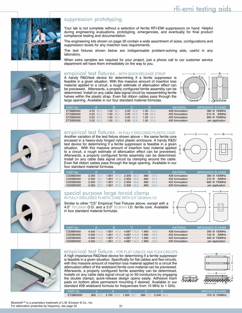
For attenuation properties by frequency, see page 32
CS28B2000 2.350 59,7 1.851 47,0 2.309 58,6 .960 24,4 #28 formulation 380 @ 100MHz CS33B2000 2.350 59,7 1.851 47,0 2.309 58,6 .960 24,4 #33 formulation 210 @ 30MHz CS25B2000 2.350 59,7 1.851 47,0 2.309 58,6 .960 24,4 #25 formulation 890 @ 700MHz CS20B2000 2.350 59,7 1.851 47,0 2.309 58,6 .960 24,4 #20 formulation per application
PART No. A B C D MATERIAL IMPEDANCE IN OHMS
rfi-emi testing aidssuppression prototyping
Your lab is not complete without a selection of ferrite RFI-EMI suppressors on hand. Helpful during engineering evaluations, prototyping, emergencies, and eventually for final product compliance testing and documentation.The engineering kits shown on page 30 contain a wide assortment of sizes, configurations and suppression levels for any insertion loss requirements.The test fixtures shown below are indispensable problem-solving aids, useful in any laboratory.When extra samples are required for your project, just a phone call to our customer service department will have them immediately on the way to you.
empirical test fixtures – WITH QUICK-RELEASE STRAPA handy R&D/test device for determining if a ferrite suppressor is feasible in a given situation. With this massive amount of insertion loss material applied to a circuit, a rough estimate of attenuation effect can be previewed. Afterwards, a properly configured ferrite assembly can be determined. Install on any cable data signal circuit by reassembling ferrite halves within the plastic strap. Even flat ribbon cables pass through the large opening. Available in our four standard material formulas.
AD
C B
C
AD
B
empirical test fixtures – IN FULLY ENCLOSED PLASTIC CASEAnother variation of the test fixture shown above – the same ferrite core encased in a heavy-duty hinged nylon plastic enclosure. A handy R&D/test device for determining if a ferrite suppressor is feasible in a given situation. With this massive amount of insertion loss material applied to a circuit, a rough estimate of attenuation effect can be previewed. Afterwards, a properly configured ferrite assembly can be determined. Install on any cable data signal circuit by clamping around the cable. Even flat ribbon cables pass through the large opening. Available in our four standard material formulas.
ET28B2000 2.53 64,3 1.50 38,1 2.00 50,8 1.00 25,4 #28 formulation 380 @ 100MHz ET33B2000 2.53 64,3 1.50 38,1 2.00 50,8 1.00 25,4 #33 formulation 210 @ 30MHz ET25B2000 2.53 64,3 1.50 38,1 2.00 50,8 1.00 25,4 #25 formulation 890 @ 700MHz ET20B2000 2.53 64,3 1.50 38,1 2.00 50,8 1.00 25,4 #20 formulation per application
PART No. A B C D MATERIAL IMPEDANCE IN OHMS
empirical test fixture – FOR FLAT CABLES AND FLEX-CIRCUITSA high impedance R&D/test device for determining if a ferrite suppressor is feasible in a given situation. Specifically for flat cables and flex-circuits, with this massive amount of insertion loss material applied to a circuit the attenuation effect of the wideband ferrite core material can be previewed. Afterwards, a properly configured ferrite assembly can be determined. Installs on any cable data signal circuit up to 50-conductors by engaging the double clamps; quick-release design opens easily. Adhesive foam pads on bottom allow permanent mounting if desired. Available in our standard #28 wideband formula for frequencies from 10 MHz to 1 GHz.
B
C
A
E
DAdhesive pad
ET28B3000 .800 20,3 3.700 94,0 1.500 38,1 .060 1,5 2.540 64,5 370 @ 100MHz PART No. A B C D E IMPEDANCE IN OHMS
Bluetooth™ is a proprietary trademark of L.M. Ericsson & Co., Inc.
CS28B4000 4.500 114,2 1.851 47,0 4.687 119,0 1.960 49,8 #28 formulation 290 @ 100MHz CS33B4000 4.500 114,2 1.851 47,0 4.687 119,0 1.960 49,8 #33 formulation 140 @ 30MHz CS25B4000 4.500 114,2 1.851 47,0 4.687 119,0 1.960 49,8 #25 formulation 590 @ 700MHz CS20B4000 4.500 114,2 1.851 47,0 4.687 119,0 1.960 49,8 #20 formulation per application
PART No. A B C D MATERIAL IMPEDANCE IN OHMS
AD
C Bspecial purpose large toroid clampIN FULLY ENCLOSED PLASTIC CASE WITH 2.0” (50,8mm) I.D.Similar to other “CS” Empirical Test Fixtures above, except with a 4.0” 101,6mm O.D. and a 2.0” 50,8mm I.D. ferrite core. Available in four standard material formulas.
31
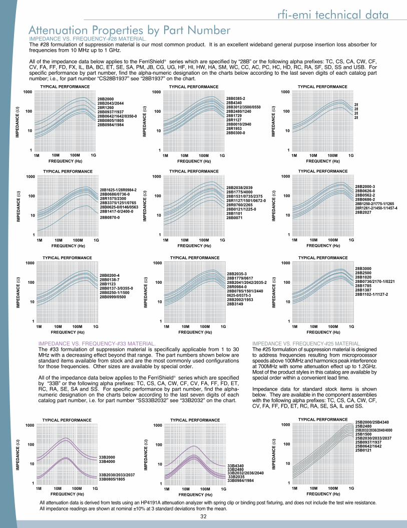
rfi-emi technical data
IMPEDANCE VS. FREQUENCY-#28 MATERIAL.The #28 formulation of suppression material is our most common product. It is an excellent wideband general purpose insertion loss absorber for frequencies from 10 MHz up to 1 GHz.
All of the impedance data below applies to the FerriShield® series which are specified by “28B” or the following alpha prefixes: TC, CS, CA, CW, CF, CV, FA, FF, FD, FX, IL, BA, BC, ET, SE, SA, PM, JB, CG, UG, HF, HI, HW, HA, SM, WC, CC, AC, PC, HC, HD, RC, RA, SF, SD, SS and USB. For specific performance by part number, find the alpha-numeric designation on the charts below according to the last seven digits of each catalog part number; i.e., for part number “CS28B1937” see “28B1937” on the chart.
IMPEDANCE VS. FREQUENCY-#33 MATERIAL.The #33 formulation of suppression material is specifically applicable from 1 to 30 MHz with a decreasing effect beyond that range. The part numbers shown below are standard items available from stock and are the most commonly used configurations for those frequencies. Other sizes are available by special order.
All of the impedance data below applies to the FerriShield® series which are specified by “33B” or the following alpha prefixes: TC, CS, CA, CW, CF, CV, FA, FF, FD, ET, RC, RA, SE, SA and SS. For specific performance by part number, find the alpha-numeric designation on the charts below according to the last seven digits of each catalog part number, i.e. for part number “SS33B2032” see “33B2032” on the chart.
TYPICAL PERFORMANCE
FREQUENCY (Hz)1M 10M 100M 1G
1000
100
10
1
28B2035-1528B2032/2036/2040/203428B2030/2033/2037/203128B2035
TYPICAL PERFORMANCE
FREQUENCY (Hz)1M 10M 100M 1G
1000
100
10
1
28B0385-228B434028B3012/3500/055028B2480/124028B172928R112728B0010/294028R195328B0300-0
TYPICAL PERFORMANCE
FREQUENCY (Hz)1M 10M 100M 1G
1000
100
10
1
28B200028B2043/204428R126028B0937/193728B0642/1642/0350-028B0805/180528B0984/1984
TYPICAL PERFORMANCE
FREQUENCY (Hz)1M 10M 100M 1G
1000
100
10
1
28B0200-428B0138-728B112328B0137-3/0355-028B0250-1/150028B0999/0500
TYPICAL PERFORMANCE
FREQUENCY (Hz)1M 10M 100M 1G
1000
100
10
1
28B1625-1/28R0984-228B0686/0736-028R1575/230028B3375/1251/076528B0625-0/0146/056328B1417-0/2400-028B0870-0
TYPICAL PERFORMANCE
FREQUENCY (Hz)1M 10M 100M 1G
1000
100
10
1
28B2000-328B0626-028B0562-228B0686-228B1250-2/1775-1/126528R1261-2/1450-1/1457-428B2027
TYPICAL PERFORMANCE
FREQUENCY (Hz)1M 10M 100M 1G
1000
100
10
1
28B2038/203928B1775/400028B1531/0735/237528R1127/1501/0672-028R0760/226528B0121/1225-028B110128B0071
TYPICAL PERFORMANCE
FREQUENCY (Hz)1M 10M 100M 1G
1000
100
10
1
28B300028B250028B102028B0736/2170-1/022128B178528B138728B1102-1/1127-2
TYPICAL PERFORMANCE
FREQUENCY (Hz)1M 10M 100M 1G
1000
100
10
1
28B1779/061728B2041/2042/2035-228R0984-028B0785/1501/24400625-0/0375-328B2002/195328B3149
28B2035-3
TYPICAL PERFORMANCE
FREQUENCY (Hz)1M 10M 100M 1G
1000
100
10
1
33B200033B4000
33B2030/2033/203733B0805/1805
TYPICAL PERFORMANCE
FREQUENCY (Hz)1M 10M 100M 1G
1000
100
10
1
33B2032/2036/2040
33B4340
33B0984/1984�33B2035
33B2480
TYPICAL PERFORMANCE
FREQUENCY (Hz)1M 10M 100M 1G
1000
100
10
1
25B2000/25B434025B248025B2032/2036/2040/400025B150025B2030/2033/203725B0937/193725B0642/164225B0121
IMPEDANCE VS. FREQUENCY-#25 MATERIAL.The #25 formulation of suppression material is designed to address frequencies resulting from microprocessor speeds above 100MHz and harmonics peak interference at 700MHz with some attenuation effect up to 1.2GHz. Most of the product styles in this catalog are available by special order within a convenient lead time.
Impedance data for standard stock items is shown below. They are available in the component assemblies with the following alpha prefixes: TC, CS, CA, CW, CF, CV, FA, FF, FD, ET, RC, RA, SE, SA, IL and SS.
All attenuation data is derived from tests using an HP4191A attenuation analyzer with spring clip or binding post fixturing, and does not include the test wire resistance.All impedance readings are shown at nominal ±10% at 3 standard deviations from the mean.
Attenuation Properties by Part Number
32
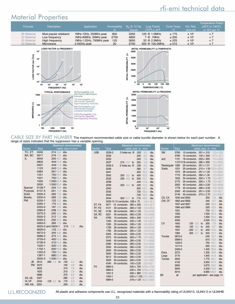
rfi-emi technical data
INITIAL PERMEABILITY vs TEMPERATURE5000
4000
3000
2000
1000
0
33
28
2520
LOSS FACTOR vs FREQUENCY
FREQUENCY (Hz)104
10-1
10-2
10-3
10-4
10-5
108105 106 107 109
25
20
28
33
INITIAL PERMEABILITY vs FREQUENCY
FREQUENCY (Hz)104 105 106 107
3000
2500
2000
1500
1000
500
0
33
2520
28
TYPICAL PERFORMANCE
FREQUENCY (Hz)1M 10M 100M 1G
1000
100
10
1
850 Permeability ( i)#28 Ferrite (Popular,universal formula)
125 Permeability ( i)#25 Ferrite (Specific,high-frequency formula)
20 Permeability ( i)#20 Ferrite (Microwaveformula)
2700 Permeability ( i)#33 Ferrite (Specific,low-frequency formula)
Material Properties
CABLE SIZE BY PART NUMBER The maximum recommended cable size or cable bundle diameter is shown below for each part number. A range of sizes indicates that the suppressor has a variable opening.
U.L.RECOGNIZED All plastic and adhesive components use U.L. recognized materials with a flammability rating of UL94V-0, UL94V-2 or UL94HB.
USB 2035-3 3 holes ea. @ .203 5,2 dia. 2030 .235 6,0 dia. 2033 .300 7,6 dia. 2037 .210 5,3 to .300 7,6 dia. 2035-2 2 holes ea. @ .335 8,5 dia. 2036 .380 9,7 dia. 2041 .400 10,2 dia. 2042 .250 6,3 to .400 10,2 dia. 2032 .250 6,3 to .500 12,7 dia. 2038 .440 11,3 dia. 2039 .250 6,3 to .435 11,0 dia. 2040 .500 12,7 dia. 2035 .730 18,5 dia. 2043 .730 18,5 dia. 2044 .500 12,7 to .710 18,0 dia. 2035-15 15 conductor, .038 x .75 1,0 x 19,1. ET, FA 0071 10 conductor, .060 x .500 1,5 x 12,7 FF, FD 0121 20 conductor, .060 x 1.00 1,5 x 25,4 FC, SE 0146 26 conductor, .060 x 1.25 1,5 x 31,8 SA, RC 0221 40 conductor, .060 x 2.00 1,5 x 50,8 RA 0765 10 conductor, .038 x .500 1,0 x 12,7 1240 20 conductor, .040 x 1.00 1,0 x 25,4 1265 20 conductor, .038 x 1.00 1,0 x 25,4 1729 26 conductor, .060 x 1.25 1,5 x 31,8 1785 26 conductor .060 x 1.25 1,5 x 31,8 2265 40 conductor, .038 x 2.00 1,0 x 50,8 2375 34 conductor, .060 x 1.70 1,5 x 43,2 2440 40 conductor, .280 x 2.00 7,1 x 50,8 2480 40 conductor, .060 x 2.00 1,5 x 50,8 2500 40 conductor, .060 x 2.00 1,5 x 50,8 2940 50 conductor, .280 x 2.50 7,1 x 63,5 3000 50 conductor, .060 x 2.50 1,5 x 63,5 3012 50 conductor, .060 x 2.50 1,5 x 63,5 3500 60 conductor, .060 x 3.00 1,5 x 76,2 4340 64 conductor, .100 x 3.20 2,5 x 8,2 FX 0984-0 .030 x .700 0,76 x 17,8 0984-2 .030 x .700 0,76 x 17,8 1261-2 .030 x .980 0,76 x 24,9 1450-1 .030 x 1.155 0,76 x 29,3 0984-0 .018 x 1.29 95,0 x 32,8
Maximum recommended Series Size cable size- in. mm
Maximum recommended Series Size cable size-in.mm TC, ET 0550 .214 5,4 dia. BA, BC 0617 .276 7,0 dia. IL 0642 .320 8,1 dia. 0805 .404 10,3 dia. 0937 .449 11,4 dia. 1123 .543 13,8 dia. 0984 .591 15,0 dia. 1251 .750 19,1 dia. 1501 .750 19,1 dia. 1500 1.000 25,4 dia. 2000 1.000 25,4 dia. Special 0138-7 .034 0,8 dia. Purpose 0137-3 .051 1,3 dia. Solid 0200-4 .062 1,6 dia. Beads, 0300-0 .069 1,8 dia. PM 0250-1 .125 3,2 dia. 0350-1 .170 4,3 dia. 0355-0 .187 4,8 dia. 0385-2 .038 0,9 dia. 0375-3 .200 5,0 dia. 0500-3 .312 7,9 dia. 0562-2 .250 6,3 dia. 0563-0 .285 7,3 dia. 0625-0 and 0625-1 .310 7,9 dia. 0626-0 .133 3,4 dia. 0672-0 .345 8,8 dia. 0686-2 .375 9,5 dia. 0735-0 .400 10,2 dia. 0736-0 .410 10,4 dia. 1020-1 .505 12,8 dia. 1102-1 .630 16,0 dia. 1250-2 .750 19,0 dia. 1387-1 .880 22,4 dia. 2000-3 1.000 25,4 dia. JB 0010 .060 1,5 to .120 3,1 dia. PM 3375 .192 4,8 dia. 0625 .310 7,9 dia. 1625 .310 7,9 dia. 0686 .375 9,5 dia. SS, AS 2027 .085 2,2 dia. HI, HF 2034 .125 3,2 to .170 4,3 dia. HW, HA, 2031 .200 5,1 dia.
Maximum recommended Series Size cable size- in. mm SM 0760 10 conductor, .051 x .510 1,3 x 13,0 0785 10 conductor, .145 x .500 3,7 x 12,7 and 1101 18 conductor, .059 x .900 1,5 x 22,8 1127/-2 18 conductor, .060 x .900 1,5 x 22,8 Rectangular 1260 20 conductor, .051 x 1.01 1,3 x 25,7 Solids 1531 20 conductor, .210 x 1.00 12,9 x 25,4 1575 26 conductor, .051 x 1.30 1,3 x 33,0 1775 26 conductor, .060 x 1.30 1,5 x 33,0 1953 34 conductor, .059 x 1.70 1,5 x 43,1 2170 35 conductor, .050 x 1.72 1,2 x 43,7 2002 40 conductor, .300 x 2.00 7,6 x 50,8 1779 40 conductor, .066 x 2.00 1,6 x 50,8 2300 40 conductor, .051 x 2.05 1,3 x 52,1 3149 50 conductor, .075 x 2.70 1,9 x 68,5 CS, CA 1642 and 0642 .300 7,6 dia. CW, CF 1805 and 0805 .345 8,7 dia. 1937 and 0937 .400 10,2 dia. 1984 and 0984 .520 13,2 dia. 1501 .750 19,1 dia. 1500 1.000 25,4 dia. 2000 1.000 25,4 dia 4000 2.000 50,8 dia.. CV 1642 .120 3,0 to .300 7,6 dia. 1805 .120 3,0 to .345 8,7 dia. 1937 .200 5,1 to .400 10,2 dia. 1984 .200 5,1 to .500 12,7 dia. Toroids 0870-0 .540 13,7 dia. 0999-0 .610 15,5 dia. 1225-0 .750 19,1 dia. 1417-0 .905 23,0 dia. 2400-0 1.400 35,6 dia. Extra 2275 1.335 33,9 dia. Large 3170 1.645 41,8 dia. Toroids 2945 1.775 45,1 dia. 4100 2.650 67,3 dia. 5950 3.675 93,3 dia. 5945 4.330 110,0 dia. 9210 6.665 169,3 dia.SB all per application - see page 14
Temperature Factor Formula Description Application Permeability Bs @ 10 Oe Loss Factor Curie Temp. Vol. Res. (20ºC to 100ºC) µi Gauss (1µiQ) x 10-6 ºC ohm-cm (x 106) per ºC 28 Material Most popular wideband 1MHz-1GHz, 250MHz peak 850 3350 120 @ 1.0MHz ≥ 175 x 105 < 7 33 Material Low frequency 1MHz-60MHz, 30MHz peak 2700 4800 7 @ .1MHz ≥ 200 x 102 < 7 25 Material High frequency 1MHz-1.2GHz, 700MHz peak 125 3650 32 @ 2.5MHz ≥ 225 x 108 < 7 20 Material Microwave 2.45GHz peak 20 2700 500 @ 100.0MHz ≥ 510 x 108 < 7
33
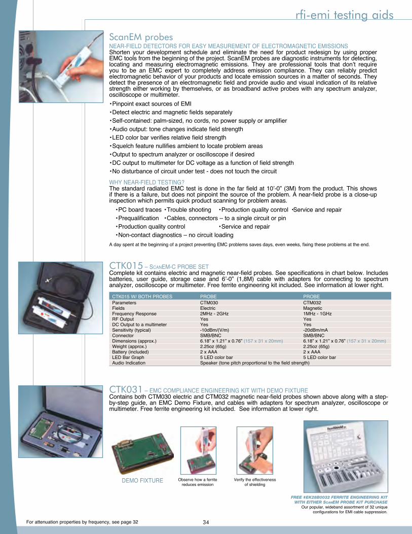
For attenuation properties by frequency, see page 32
Parameters CTM030 CTM032 Fields Electric Magnetic Frequency Response 2MHz - 2GHz 1MHz - 1GHz RF Output Yes Yes DC Output to a multimeter Yes Yes Sensitivity (typical) -10dBm/(V/m) -20dBm/mA Connector SMB/BNC SMB/BNC Dimensions (approx.) 6.18” x 1.21” x 0.76” (157 x 31 x 20mm) 6.18” x 1.21” x 0.76” (157 x 31 x 20mm) Weight (approx.) 2.25oz (65g) 2.25oz (65g) Battery (included) 2 x AAA 2 x AAA LED Bar Graph 5 LED color bar 5 LED color bar Audio Indication Speaker (tone pitch proportional to the field strength)
CTK015 W/ BOTH PROBES PROBE PROBE
rfi-emi testing aids
ScanEM probesNEAR-FIELD DETECTORS FOR EASY MEASUREMENT OF ELECTROMAGNETIC EMISSIONSShorten your development schedule and eliminate the need for product redesign by using proper EMC tools from the beginning of the project. ScanEM probes are diagnostic instruments for detecting, locating and measuring electromagnetic emissions. They are professional tools that don’t require you to be an EMC expert to completely address emission compliance. They can reliably predict electromagnetic behavior of your products and locate emission sources in a matter of seconds. They detect the presence of an electromagnetic field and provide audio and visual indication of its relative strength either working by themselves, or as broadband active probes with any spectrum analyzer, oscilloscope or multimeter.• Pinpoint exact sources of EMI• Detect electric and magnetic fields separately• Self-contained: palm-sized, no cords, no power supply or amplifier• Audio output: tone changes indicate field strength• LED color bar verifies relative field strength• Squelch feature nullifies ambient to locate problem areas• Output to spectrum analyzer or oscilloscope if desired• DC output to multimeter for DC voltage as a function of field strength• No disturbance of circuit under test - does not touch the circuit
WHY NEAR-FIELD TESTING?The standard radiated EMC test is done in the far field at 10’-0” (3M) from the product. This shows if there is a failure, but does not pinpoint the source of the problem. A near-field probe is a close-up inspection which permits quick product scanning for problem areas. • PC board traces • Trouble shooting • Production quality control •Service and repair • Prequalification • Cables, connectors – to a single circuit or pin • Production quality control • Service and repair • Non-contact diagnostics – no circuit loadingA day spent at the beginning of a project preventing EMC problems saves days, even weeks, fixing these problems at the end.
CTK015 – ScanEM-C PROBE SETComplete kit contains electric and magnetic near-field probes. See specifications in chart below. Includes batteries, user guide, storage case and 6’-0” (1,8M) cable with adapters for connecting to spectrum analyzer, oscilloscope or multimeter. Free ferrite engineering kit included. See information at lower right.
CTK031 – EMC COMPLIANCE ENGINEERING KIT WITH DEMO FIXTUREContains both CTM030 electric and CTM032 magnetic near-field probes shown above along with a step-by-step guide, an EMC Demo Fixture, and cables with adapters for spectrum analyzer, oscilloscope or multimeter. Free ferrite engineering kit included. See information at lower right.
Observe how a ferrite reduces emission
Verify the effectivenessof shielding
DEMO FIXTURE
FREE #EK28B0032 FERRITE ENGINEERING KITWITH EITHER ScanEM PROBE KIT PURCHASE
Our popular, wideband assortment of 32 uniqueconfigurations for EMI cable suppression.
34
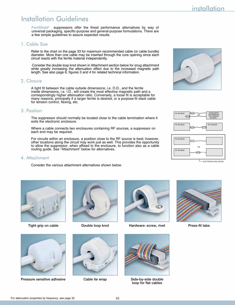
For attenuation properties by frequency, see page 32
installation
1. Cable Size
Refer to the chart on the page 33 for maximum recommended cable (or cable bundle) diameter. More than one cable may be inserted through the core opening since each circuit reacts with the ferrite material independently.
Consider the double loop knot shown in Attachment section below for snug attachment while greatly increasing the attenuation effect due to the increased magnetic path length. See also page 6, figures 3 and 4 for related technical information.
2. Closure
A tight fit between the cable outside dimensions; i.e. O.D., and the ferrite inside dimensions, i.e. I.D., will create the most effective magnetic path and a correspondingly higher attenuation ratio. Conversely, a loose fit is acceptable for many reasons, principally if a larger ferrite is desired, or a purpose-fit slack cable for tension control, flexing, etc.
3. Position
The suppressor should normally be located close to the cable termination where it exits the electronic enclosure.
Where a cable connects two enclosures containing RF sources, a suppressor on each end may be required.
For circuits within an enclosure, a position close to the RF source is best; however, other locations along the circuit may work just as well. This provides the opportunity to allow the suppressor, when affixed to the enclosure, to function also as a cable routing guide. See “Attachment” below for alternatives.
4. Attachment
Consider the various attachment alternatives shown below.
RF SOURCE
RF SOURCE
RF SOURCE
RF SOURCE
RF SOURCE
ORAUXILIARY�
EQUIPMENT�OR POWER�
SOURCE
OR
ELECTRONIC ENCLOSURE
Installation GuidelinesFerriShield® suppressors offer the finest performance alternatives by way of universal packaging, specific-purpose and general-purpose formulations. There are a few simple guidelines to assure expected results.
Tight grip on cable Double loop knot Hardware: screw, rivet Press-fit tabs
Pressure sensitive adhesive Cable tie wrap Side-by-side double loop for flat cables
35
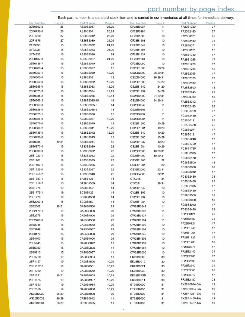
part number by page indexEach part number is a standard stock item and is carried in our inventories at all times for immediate delivery.
20B0562-2 2620B0736-0 2620R1260 2720R1575 2721T3350 1521T3937 1521T4335 1528B0137-3 1528B0138-7 1528B0200-4 1528B0250-1 1528B0300-0 1528B0350-0 1528B0355-0 1528B0375-3 1528B0385-2 1528B0562-2 1528B0563-0 1528B0625-0 1528B0625-1 1528B0626-0 1528B0672-0 1528B0686-2 1528B0735-0 1528B0736-0 1528B0785 19,2128B0870-0 1528B0999-0 1528B1020-1 1528B1101 1928B1102-1 1528B1225-0 1528B1250-2 1528B1387-1 1528B1417-2 1528B1775 1928B1775-1 1928B1779 1928B2000-3 1528B2002 19,2128B2170-1 1928B2275 1528B2400-0 1528B2945 1528B3149 1928B3170 1528B4100 1528B5945 1528B5950 1528B9210 1528R0760 1928R1127 1928R1127-2 1928R1260 1928R1531 19,2128R1575 1928R1953 1928R2300 19AS20B2030 26,29AS20B2033 26,29AS20B2034 26,29
AS20B2037 26,29AS20B2041 26,29AS20B2042 26,29AS25B2030 24,29AS25B2032 24,29AS25B2033 24,29AS25B2036 24AS25B2037 24,29AS25B2040 24AS28B2027 12AS28B2030 12,29AS28B2031 12AS28B2032 12,29AS28B2033 12,29AS28B2034 12,29AS28B2035 12,14AS28B2035-15 18AS28B2035-2 14AS28B2035-3 14AS28B2036 12AS28B2037 12,29AS28B2040 12AS28B2041 12,29AS28B2042 12,29AS28B2043 12AS28B2044 12AS33B2030 22AS33B2032 22AS33B2033 22AS33B2035 22AS33B2036 22AS33B2037 22AS33B2040 22BA28B1251 14BA28B1500 14BA28B1501 14BC28B1251 14BC28B1500 14BC28B1501 14CA20B1500 29CA20B2000 29CA20B4000 29CA25B1500 29CA25B1642 29CA25B1937 29CA25B2000 29CA25B4000 29CA28B0642 11CA28B0805 11CA28B0937 11CA28B0984 11CA28B1500 10,29CA28B1501 10,29CA28B1642 10,29CA28B1805 10,29CA28B1937 10,29CA28B1984 10,29CA28B2000 10,29CA28B4000 29CF28B0642 11CF28B0805 11
Part Number Page # Part Number Page #CF28B0937 11CF28B0984 11CF28B1500 10CF28B1501 10CF28B1642 10CF28B1805 10CF28B1937 10CF28B1984 10CF28B2000 10CS20B1500 26,29CS20B2000 26,29,31CS20B4000 26,29,31CS25B1500 24,29CS25B1642 24,29CS25B1937 24,29CS25B2000 24,29,31CS25B4000 24,29,31CS28B0642 11CS28B0805 11CS28B0937 11CS28B0984 11CS28B1500 10,29CS28B1501 10,29CS28B1642 10,29CS28B1805 10,29CS28B1937 10,29CS28B1984 10,29CS28B2000 10,29,31CS28B4000 10,29,31CS33B1805 22CS33B1984 22CS33B2000 22,31CS33B4000 22,31CTK015 34CTK031 28,34CV28B1642 10CV28B1805 10CV28B1937 10CV28B1984 10CW28B0642 11CW28B0805 11CW28B0937 11CW28B0984 11CW28B1500 10CW28B1501 10CW28B1642 10CW28B1805 10CW28B1937 10CW28B1984 10CW28B2000 10EK20B0009 30EK25B0012 30EK28B0021 30EK28B0032 30EK28B27SB 30EK33B0011 30ET20B2000 31ET25B2000 31ET28B2000 31ET28B3000 31ET33B2000 31
Part Number Page #FA20B1729 27FA20B2480 27FA25B0121 25FA25B2480 25FA28B0071 17FA28B0121 17FA28B1240 17FA28B1265 17FA28B1729 17FA28B1785 18FA28B2265 17FA28B2375 17FA28B2480 17FA28B2500 18FA28B2940 21FA28B3000 18FA28B3012 17FA33B2480 23FC20B1729 27FC20B2480 27FC25B0121 25FC25B2480 25FC28B0071 17FC28B0121 17FC28B1240 17FC28B1729 17FC28B1785 18FC28B2375 17FC28B2480 17FC28B2500 18FC28B3000 18FC28B3012 17FC33B2480 23FD25B2480 25FD28B2375 17FD28B2480 17FD28B2500 18FD28B3000 18FD28B3012 17FD33B2480 23FF25B0121 25FF25B2480 25FF28B0121 17FF28B1240 17FF28B1265 17FF28B1729 17FF28B1785 18FF28B2375 17FF28B2440 21FF28B2480 17FF28B2500 18FF28B2940 21FF28B3000 18FF28B3012 17FF33B2480 23FX28R0984-0/A 19FX28R0984-2/A 19FX28R1261-2/A 19FX28R1450-1/A 19FX28R1457-4/A 19
Part Number Page #
36
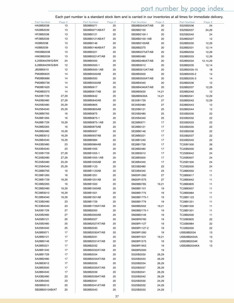
part number by page index
HA28B2038 13HA28B2039 13HF28B2038 13HF28B2039 13HI28B2038 13HI28B2039 13HW28B2038 13HW28B2039 13IL25B0642W/G/B/K 24IL28B0642W/G/B/K 12JB28B0010 12PM28B0625 14PM28B0686 14PM28B0736 14PM28B1625 14PM28B3375 14RA20B1729 27,29RA20B2480 27,29RA25B2480 25,29RA25B4340 25,29RA28B0765 16RA28B1265 16RA28B1729 16,29RA28B2265 16RA28B2480 16,29RA28B3012 16,29RA28B4340 16,29RA33B2480 23RA33B4340 23RC20B1729 27,29RC20B2480 27,29RC25B2480 25,29RC25B4340 25,29RC28B0765 16RC28B1265 16RC28B1729 16,29RC28B2265 16RC28B2480 16,29RC28B3012 16,29RC28B4340 16,29RC33B2480 23RC33B4340 23SA20B1729 27SA20B2480 27SA25B0121 25SA25B2480 25SA25B4340 25SA28B0071 17SA28B0121 17SA28B0146 17SA28B0221 17SA28B1240 17SA28B1729 17SA28B2480 17SA28B3012 17SA28B3500 17SA28B4340 17SA33B2480 23SA33B4340 23SB28B0010 20SB28B0010AB/AT 20
SB28B0071 20SB28B0071AB/AT 20SB28B0121 20SB28B0121AB/AT 20SB28B0146 20SB28B0146AB/AT 20SB28B0221 20SB28B0221AT/AB 20SB28B0500 20SB28B0500-1 20SB28B0500-1AB 20SB28B0500AB 20SB28B0550 20SB28B0550AB 20SB28B0617 20SB28B0617AB 20SB28B0642 20SB28B0642AB 20SB28B0805 20SB28B0805AB 20SB28B0875 20SB28B0875-1 20SB28B0875-1AB 20SB28B0875AB 20SB28B0937 20SB28B0937AB 20SB28B0984 20SB28B0984AB 20SB28B1055 20SB28B1055-1 20SB28B1055-1AB 20SB28B1055AB 20SB28B1123 20SB28B1123AB 20SB28B1251 20SB28B1251AB 20SB28B1500 20SB28B1500AB 20SB28B1501 20SB28B1501AB 20SB28B1729 20SB28B1729AT/AB 20SB28B2000 20SB28B2000AB 20SB28B2027 20SB28B2027AT/AB 20SB28B2030 20SB28B2030AT/AB 20SB28B2031 20SB28B2031AT/AB 20SB28B2032 20SB28B2032AT/AB 20SB28B2034 20SB28B2034AT/AB 20SB28B2035 20SB28B2035AT/AB 20SB28B2039 20SB28B2039AT/AB 20SB28B2041 20SB28B2041AT/AB 20SB28B2043 20
SB28B2043AT/AB 20SB28B2100 20SB28B2100-1 20SB28B2100-1AB 20SB28B2100AB 20SB28B2375 20SB28B2375AT/AB 20SB28B2480 20SB28B2480AT/AB 20SB28B3012 20SB28B3012AT/AB 20SB28B3500 20SB28B3500AT/AB 20SB28B4340 20SB28B4340AT/AB 20SB28B5630 14,21SB28B5630A 14,21SE20B1729 27SE20B2480 27SE25B0121 25SE25B2480 25SE25B4340 25SE28B0071 17SE28B0121 17SE28B0146 17SE28B0221 17SE28B1240 17SE28B1729 17SE28B2480 17SE28B3012 17SE28B3500 17SE28B4340 17SE33B2480 23SE33B4340 23SM20R1260 27SM20R1575 27SM28B0785 19,21SM28B1101 19SM28B1775 19SM28B1775-1 19SM28B1779 19SM28B2002 19,21SM28B2170-1 19SM28B3149 19SM28R0760 19SM28R1127 19SM28R1127-2 19SM28R1260 19SM28R1531 19,21SM28R1575 19SM28R1953 19SM28R2300 19SS20B2030 26,29SS20B2033 26,29SS20B2034 26,29SS20B2037 26,29SS20B2041 26,29SS20B2042 26,29SS25B2030 24,29SS25B2032 24,29SS25B2033 24,29
SS25B2036 24SS25B2037 24,29SS25B2040 24SS28B2027 12SS28B2030 12,29SS28B2031 12,14SS28B2032 12,29SS28B2033 12,29SS28B2034 12,14,29SS28B2035 12,14SS28B2035-15 18SS28B2035-2 14SS28B2035-3 14SS28B2036 12SS28B2037 12,29SS28B2040 12SS28B2041 12,29SS28B2042 12,29SS28B2043 12SS28B2044 12SS33B2030 22SS33B2032 22SS33B2033 22SS33B2035 22SS33B2036 22SS33B2037 22SS33B2040 22TC20B1500 26TC20B2000 26TC25B0642 24TC25B0937 24TC25B1500 24TC25B2000 24TC28B0550 11TC28B0617 11TC28B0642 11TC28B0805 11TC28B0937 11TC28B0984 11TC28B1123 11TC28B1251 11TC28B1500 11TC28B1501 11TC28B2000 11TC33B0805 22TC33B0984 22TC33B2000 22USB28B2034 13USB28B2034A 13USB28B2034K 13USB28B2034KA 13
Part Number Page # Part Number Page # Part Number Page # Part Number Page #
Each part number is a standard stock item and is carried in our inventories at all times for immediate delivery.
37

Board Level Shielding• Standard and Multi-Cavity CBS• Modified Standard Options• Custom Circuit Board Shields
FerriShield Ferrites• Snap-On Bisected & Solid Bead Ferrites• Round & Flat Styles for Cables, Wires and Flex Circuits• Low, High, Microwave and Wideband Frequency-Specific
Material
Enclosure Shielding• BeCu Fingerstock Gaskets• TechSIL 5000 Conductive Elastomers• Conductive Fabric Shielding Gaskets• TechSIL 8000 Oriented Wire Gaskets• TechMESH Knitted Wire Gaskets• TechMESH Combo Strip & Gaskets• TechVent Honeycomb Shielding Panels
EMI Enclosure Solutions Catalog CBS Circuit Board
Shielding Catalog
EMI PROBLEM?Our sales engineers are waiting for your call: 866-TECH-EMI (866-832-4364)
Visit our web site today to browse our complete product line, download literature and find your local sales engineer or sales representative! www.leadertechinc.com
we’ve got you covered
Leader Tech is a world-leading innovator and US-based manufacturer of EMI shielding products for circuit boards, enclosures and cables. In addition to our best selling standard, modified standard and custom CBS shields, Leader Tech offers an expansive line of beryllium copper fingerstock gaskets, conductive elastomers, advanced RF absorber materials and EMI/RFI ferrites.
WE’VE GOT YOU COVEREDReliable Board, Enclosure and Cable Shielding Solutions
LEADERTECH SHIELDING PRODUCTS
38

ordering information
12420 Race Track Road, Tampa, Florida 33626www.leadertechinc.com • [email protected] (866.832.4364) • Local: 813.855.6921Fax: 813.855.3291
STANDARD PRODUCTSPart Number Explanation Part Material Ferrite Ferrite Special Style Type Shape Size Option
SS 28 B 2031 K
Color All plastic components are supplied in PMS #413 computer gray unless shown in photos as natural white or black. Black is optional where indicated.
Custom Products Engineering support is always available for special designs and evaluations.
Samples Most items on catalog pages 10 through 27 are available from stock on a complimentary basis.
Commercial and Government Entity Code (CAGE CODE): 4J674
Quality System ISO 9001:2008 certified.
Delivery All items are normally available from stock at all times for immediate delivery.
RoHS Directive All FerriShield products are in compliance with the European Commission RoHS Directive, Restriction of use of
certain Hazardous Substances, dated July, 1 2006. FerriShield products do not contain any of the six restricted substances; namely, lead, cadmium, mercury, hexavalent chromium, PBB or PBDE flame retardant.
Customer Service For quotes, technical information or personal assistance, contact:
STATEMENT OF LIEU OF WARRANTY: All technical information and data in this document is based on tests and is believed to be accurate and reliable. Nevertheless, since the products described herein are not provided to conform with mutually accepted specifications and the use thereof is unknown, the manufacturer and seller of the products do not guarantee results, freedom from patent infringement, or suitability of the products for any application thereof. The manufacturer and seller of the products described in this document will provide all possible technical assistance and will replace any products proven defective. No statement or recommendations made by the manufacturer or seller not contained herein shall have any force of effect unless in conformity with an agreement signed by an officer of the seller and manufacturer. Product testing by the purchaser is recommended in order to confirm expected results.
copyright© Leader Tech, Inc. 2009
39
ISO 9001: 2008 CERTIFIED ✔RoHS
COMPLIANT

40F071
12420 Race Track Rd.Tampa, Florida 33626
866.TECH.EMI (866.832.4364)
Tel: 813.855.6921Fax: 813.855.3291
www.leadertechinc.com
A passion in all we do
ISO 9001: 2008 CERTIFIED ✔RoHS
COMPLIANT
WWW.LEADERTECHINC.COM