Embed Size (px)
Citation preview

EPA Wood-Burning FireplaceP/N 506128-16 REV. L 10/2012
BISTRAD
MODEL
BIS® TRADITION
This installation manual will enable you to obtain a safe, efficient and dependable installation of your fireplace system. Please read and understand these instructions before beginning your installation.
Do not alter or modify the fireplace or its components under any circum-stances. Any modification or alteration of the fireplace system, including but not limited to the fireplace, chimney components and accessories, may void the warranty, listings and approvals of this system and could result in an unsafe and potentially dangerous installation.
Security™ wood-burning fireplaces are designed for use as a supple-mental heater. They are not intended for continuous use as a primary heat source.
INSTALLATION AND OPERATION INSTRUCTIONS
SAVE THESE INSTRUCTIONSFOR FUTURE REFERENCE
Listed to standards:ULC-S610 and UL-127Report No. 304-7213EPA Cert. No. 609
WARNING• Hot! Do not touch! The glass and
surfaces of this appliance will be hot during operation and will retain heat for a while after shutting off the appli-ance. Severe burns may result.
• Carefully supervise children in the same room as appliance.
• If small children are present in the home, it is recommended that this appliance be fitted with an adjustable safety gate or barrier screen.
PIBISTRAD REV. 11 10/2012
WARNING• The fireplace cannot be operated without a door
or firescreen. Consult your dealer to select the correct replacement door or firescreen.
• The fireplace is equipped with a blower, electri-cal connection must be made prior to fireplace installation
• Important! To assure proper alignment of glass doors: Install this fireplace in a square and plumb condition, using shims as necessary at sides and/or bottom.
• Install the fireplace only as described in these instructions.
DRAFT10
/29/20
12
WARNINGTo avoid the risk of damaging fireplace materials and increas-ing the risk of fire, do not use the fireplace to cook or warm food.
WARNINGNEVER use gasoline, gasoline-type lantern fuel, kerosene, charcoal lighter fluid, naphtha, engine oil or similar liquids to start or “freshen up” a fire in this fireplace. Keep any flammable liquids a safe distance from the fireplace at all times.
WARNINGBe careful adding wood fuel to the fire or handling fireplace tools such as shovels, tongs or pokers.
WARNINGThe bottom refractory can be cracked by excessive abuse such as tossing heavy logs onto the grate or gouging with fireplace tools. Exercise caution when adding wood to your fireplace.
WARNINGAlways ensure that the air inlet to the fireplace is free from debris and any other obstructions that can block the entrance of air.
WARNINGNeither the manufacturer nor the seller warrants “smoke free” operation nor are we responsible for inadequate system draft caused by mechanical systems, general construction conditions, inadequate chimney heights, adverse wind conditions and/or unusual environmental factors or conditions beyond our control.
WARNINGUse care when selecting window treatments for windows located near the fireplace. Avoid using combustible flowing window treatments such as curtains on nearby windows that are of sufficient length to be blown in front of an open flame when the window is opened.Keep any combustible furniture, materials or decorative pillows at least 48" (1219 mm) from the front fireplace opening.
WARNINGThe BIS® Tradition fireplace must be installed with an outside air kit, which is included with fireplace.
WARNINGNever leave children unattended when there is a fire burning in the fireplace.
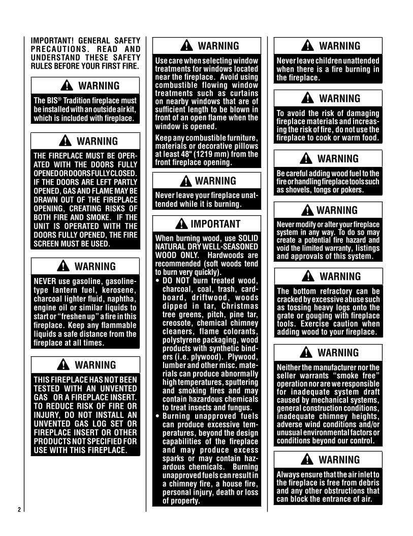
IMPORTANT! GENERAL SAFETY PRECAUTIONS. READ AND UNDERSTAND THESE SAFETY RULES BEFORE YOUR FIRST FIRE.
WARNING Never leave your fireplace unat-tended while it is burning.
WARNINGTHE FIREPLACE MUST BE OPER-ATED WITH THE DOORS FULLY OPENED OR DOORS FULLY CLOSED. IF THE DOORS ARE LEFT PARTLY OPENED, GAS AND FLAME MAY BE DRAWN OUT OF THE FIREPLACE OPENING, CREATING RISKS OF BOTH FIRE AND SMOKE. IF THE UNIT IS OPERATED WITH THE DOORS FULLY OPENED, THE FIRE SCREEN MUST BE USED.
WARNINGTHIS FIREPLACE HAS NOT BEEN TESTED WITH AN UNVENTED GAS OR A FIREPLACE INSERT. TO REDUCE RISK OF FIRE OR INJURY, DO NOT INSTALL AN UNVENTED GAS LOG SET OR FIREPLACE INSERT OR OTHER PRODUCTS NOT SPECIFIED FOR USE WITH THIS FIREPLACE.
IMPORTANT When burning wood, use SOLID NATURAL DRY WELL-SEASONED WOOD ONLY. Hardwoods are recommended (soft woods tend to burn very quickly). • DO NOT burn treated wood,
charcoal, coal, trash, card-board, driftwood, woods dipped in tar, Christmas tree greens, pitch, pine tar, creosote, chemical chimney cleaners, flame colorants, polystyrene packaging, wood products with synthetic bind-ers (i.e. plywood). Plywood, lumber and other misc. mate-rials can produce abnormally high temperatures, sputtering and smoking fires and may contain hazardous chemicals to treat insects and fungus.
• Burning unapproved fuels can produce excessive tem-peratures, beyond the design capabilities of the fireplace and may produce excess sparks or may contain haz-ardous chemicals. Burning unapproved fuels can result in a chimney fire, a house fire, personal injury, death or loss of property.
WARNING Never modify or alter your fireplace system in any way. To do so may create a potential fire hazard and void the limited warranty, listings and approvals of this system.
2

TABLE OF CONTENTS
Safety Rules ......................................Page 2 Introduction ......................................Page 3Parts Required .................................Page 3Optional Equipment ...........................Page 3Operating The Fireplace .....................Page 3Fuel ...................................................Page 3Combustion Control .........................Page 4Refueling For Best Performance .......Page 5Smoking – Causes And Troubleshooting ..............................Page 5Important Cautions ...........................Page 5Maintaining Your Fireplace ...............Page 5Creosote ............................................Page 5Chimney Maintenance .......................Page 6Dealing With A Chimney Fire .............Page 6Door Frame Finish Care .....................Page 6Disposing of Ashes ...........................Page 6Refractory Replacement ....................Page 6Door Installation ...............................Page 6Door Adjustment ...............................Page 6Glass Care - Replacement .................Page 7Glass Care - Cleaning ........................Page 7Gasket Replacement ........................Page 7Fireplace Installation ........................Page 7Locating The Fireplace ......................Page 7Facade Installation ............................Page 9Framing, Facing And Mantel ..............Page 9Hearth Extension Requirements .......Page 9Cold Climate Installations ..................Page 9Nailing Flanges ..................................Page 11Mantel and Facing .............................Page 11Fireplace Blower ................................Page 12Hot Air Ducting Installation ..............Page 12Gravity Kit .........................................Page 10Outside Air Kit ..................................Page 13Chimney System ...............................Page 14Chimney Installation Notes ...............Page 14Chimney Installation Instructions ......Page 15Offset Chimney Installation ...............Page 16Angled Wall Radiation Shield ............Page 19Chimney Support Installation ............Page 19Chimney Chase And Multiple Terminations......................Page 19Masonry Application Instructions .....Page 20Installation Accessories ....................Page 21Chimney Components Lists ..............Page 22Replacement Parts ............................Page 24Specifications ....................................Page 24Clearances ........................................Page 24Product Reference Information .........Page 26
CONGRATULATIONS!
When you purchased your new fireplace, you joined the ranks of thousands of individuals whose answer to their home heating needs reflects their concern for aesthetics, efficiency and our environment. We extend our continued support to help you achieve the maximum benefit and enjoyment available from your new fireplace.
Thank you for selecting a Security Chimneys International fireplace as the answer to your home supplemental heating needs.
THE FIREPLACEINTRODUCTION
The BIS® Tradition wood-burning fireplace is an energy efficient, heat circulating, closed combustion fireplace. You will receive a lifetime of comfort and enjoyment from your fireplace provided it is installed, maintained and oper-ated properly.• Please read these instructions and retain
this manual for future reference.• Before beginning the fireplace installation,
consult the local authorities to obtain your building permit and check your local building codes. Install the fireplace only as described in these instructions and using only Security Chimneys International components.
• This fireplace has been tested for CAN/ULC S610-M87 and ANSI/UL 127 under report number 304-7213. It has also been tested for EPA 40 C.F.R Part 60, section 60.532(b). Certificate number 609.
• The BIS Tradition fireplace is not intended for use with a gas log set. Do not use a fireplace insert or any other product with this fireplace unless it is specified by Security Chimneys International for use with this ap-pliance. Failure to follow these instructions will void the certification and the warranty of the fireplace and may result in an unsafe installation.
• These appliances are designed to provide supplemental heat to the immediate area only. Therefore, it is advisable to have an alternate heat source when installed in a dwelling.
• These appliances are not approved for Manufactured Home installations.
PARTS REqUIREDFireplace model: BISTRAD• 7” diameter chimney - Model Secure Temp®
S-2100+, Nova Temp® HT6000+, Secure Temp GX (U.S. only) or ACBI manufactured by Security Chimneys International only, including:
- Chimney lengths- Elbows (where necessary)- Associated components as per these
installation instructions• ..Decorative Doors - Required ....(Order Separately - SeePage21)• Front Facade kit - Required...(Order Separately - SeePage21)• UZY7 Blower (included in the fireplace).• VRUW Blower Speed Control (included)• Outside air kit (Included w/Fireplace)
OPTIONAL EqUIPMENT
- AC Chimney Adaptor (required if using AC Chimney) - AC Chimney Outside Air Kit - Gravity Venting System - Rigid Firescreen
Additional Equipment (optional) - Forced Air Kit u - Gravity Venting System
- TUBINOX™ chimney (or PROJET® SS), 7” diameter with adaptor for installation in a masonry chimney.
uNot testedunderEPAcertification. If in-stalled,thisappliancenolongerqualifiesforEPAcertification.
OPERATING THE BIS TRADITION FIREPLACE
Fuel - USE SOLID NATURAL WOOD FUEL ONLY. The BIS Tradition fireplace is designed to work best when fueled with dry seasoned natural wood only. Hardwoods are preferred to softwoods since the energy content of wood is relative to its density. Hardwoods will result in a longer burning fire and less frequent refueling. A moisture content of 15% to 20% (seasoned) is recommended. Wood that has been cut and split and let to dry under a cover for a period of one year will usually meet that criteria. The required drying time will vary depending on the climate. Wood that is packed tight together will take longer to dry. Seasoned wood is darker in color than wet wood and will have visible cracks in the grain on the ends. Excessively wet wood will be difficult to burn and will result in lower efficiency, increased creosoting and deposits on the glass and in the chimney. Excessively dry wood will burn well but will also have higher emissions and shorter burning time.
Do not burn scrap or garbage, treated wood or wood such as driftwood from the ocean which has been exposed to salt or other chemicals. Salt or chemicals can corrode the firebox and chimney. Do not burn large amounts of paper, cardboard, Christmas tree branches or building construction materials. Intense firing with these materials may overheat the fireplace, causing damage to the unit, a fire or even possibly ignit-ing a chimney fire if the chimney is creosoted. Burning unapproved fuel, resulting in excessive pollutants being emitted, may be prohibited and subject to a fine or other penalty by the authority having jurisdiction in your area.
Processed firelogs can be used. Although, do not poke or stir the logs while they are burning. Use only firelogs that have been evaluated for the application of fireplace and refer to firelog warnings and caution markings on packaging prior to use.
3

Closed
Closed
Open
Open
Combustion Air Register
Time DelayAir-Boost Control
(T.D.A.B.)
Medium Combustion
This is the recommended mode of operating the BIS Tradition fireplace and should be the one normally used since it will deposit the least amount of creosote on the glass and in the chimney. The combustion air control must be 3/4 closed. The precise setting will depend on many factors, including chimney length and the moisture content of the wood.
For instance, a long chimney will necessitate closing the damper more. To obtain the proper combustion, close the damper completely, then open it about 1/2” to 3/4”. Three medium size pieces of cord wood-burning on a bed of hot coals will generate an approximate heat output will of 35,000 BTU per hour and the loading time will be about every 3-4 hours. Softwoods may be burned using this method but the combustion time will be substantially reduced.
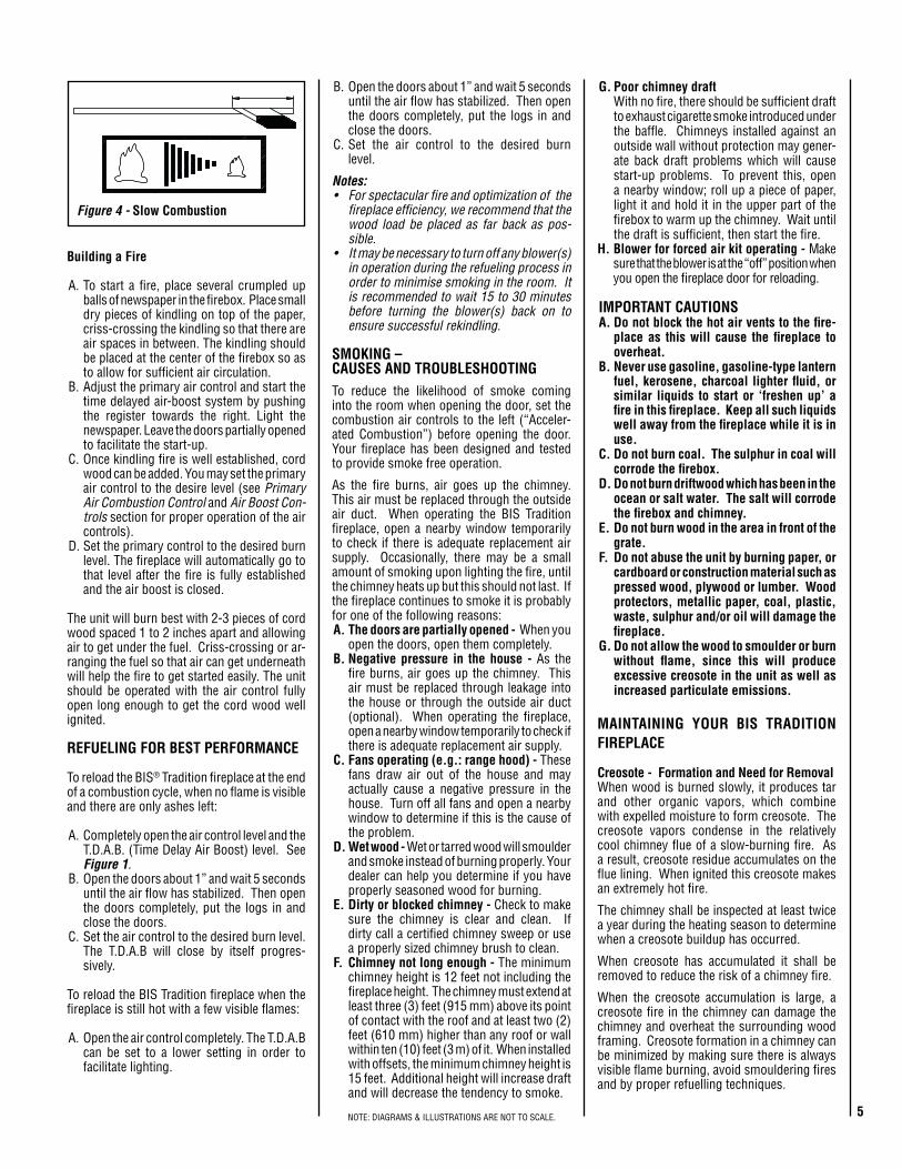
Slow Combustion
When the air combustion control is completely closed, the fireplace is in a slow combustion phase. If the hearth is hot enough, slow com-bustion will not extinguish the fire, but there will be a noticeable change in the flame pattern. The flames will be slow and may appear dirty if the wood is too wet (moisture content of 20% and more).
Do not allow the wood to burn without flame, since this will produce excessive creosote in the unit. Creosote may accumulate on the glass door. This method of burning should be used only after operating the BIS Tradition fireplace with the air control opened to produce a hot fire for about an hour or at medium pace for at least three (3) hours. Slow combustion can be used at night in order to reduce the heat output and to prolong the burn. The loading time will be between 6-8 hours and at this combustion rate, the level of BTU’s is at its lowest.
Figure2-Accelerated Combustion
Figure3-Medium Combustion
(A)
(B)
First FiresBefore using the fireplace make sure to remove the plastic wrapping and EPA label on plated door. Remove any glue residue left by the label using mild soap.
Make sure the doors are properly adjusted, thus avoiding color change to finish due to overheating.
The first five or six fires should be small fires of short duration (about 30 to 60 minutes). This will help cure the refractory bricks. During the first few fires of this appliance there may be some odor and smoke due to the curing of the paint, dust accumulation and burning off of lubricants used in the manufacturing process. It may set off a smoke alarm located in the same room. For this reason the room should be well ventilated for the first few fires.
HEAT OUTPUTThe BIS® Tradition fireplace is the largest member of the Security Chimneys high efficiency fire-places. The heat generated from its fire is more efficiently captured and distributed. In spite of the large amount of heat that the BIS Tradition fireplace can deliver, it should not replace the main source of heat in your home. This fireplace will bring extra warmth and ambiance to your home by distributing its heat as described further in the manual.
COMBUSTION CONTROLSPrimary Air and Air Boost ControlsThere is no flue damper in the BIS Tradition fireplace. As is common with air tight appli-ance, the combustion air control sets the flow of air entering the firebox. This allows for a more precise control of the fire. The combus-tion air control is located below the door on the left side. The main source of air (primary air) entering the firebox can be diminished by moving the air combustion control from left to
Figure1
right. The primary air is fully opened when the air control is completely moved to the left. This air combustion control should be in the closed position when the fireplace is not in operation. This will minimize air leakage up the chimney.
The combustion air control should be opened before opening the doors to minimize the possi-bility of back draft coming into the room (Figure1-A) More details are available in Refueling For Best Performance on Page5.
Time Delayed Air Boost SystemThe time delayed air-boost system register is located underneath the door handles. Placed in the fully opened position, a timer with a maxi-mum duration of 2 hours is engaged.
The register gradually reduces the amount of air injected, allowing for a better start of the fire, whatever the conditions (See sections Building a Fire and Refueling For Best Performance for proper sequence of operation). This allows you to start the fire, set the primary air control to the desired burn level and the fireplace will automatically adjust itself to that level once the fire is fully established (Figure1-B).
Accelerated CombustionThe maximum heat output for the BIS Tradi-tion fireplace is achieved by burning with the door closed and the combustion air opened and pulled out. Through this method, the BIS Tradition fireplace can produce up to 80,000 BTU of heat per hour. However, it will be necessary to reload with wood every one or two hours. This is the least efficient method of burning the BIS Tradition fireplace.Use caution when firing with the combustion air control wide open. Only burn cord wood in this manner. Small dry pieces of softwood and construction scraps will burn very intensely us-ing this method and may damage the firebox.
4NOTE: DIAGRAMS & ILLUSTRATIONS ARE NOT TO SCALE.
B. Open the doors about 1” and wait 5 seconds until the air flow has stabilized. Then open the doors completely, put the logs in and close the doors.
C. Set the air control to the desired burn level.
Notes:• For spectacular fire and optimization of the
fireplace efficiency, we recommend that the wood load be placed as far back as pos-sible.
• It may be necessary to turn off any blower(s) in operation during the refueling process in order to minimise smoking in the room. It is recommended to wait 15 to 30 minutes before turning the blower(s) back on to ensure successful rekindling.
SMOKING – CAUSES AND TROUBLESHOOTINGTo reduce the likelihood of smoke coming into the room when opening the door, set the combustion air controls to the left (“Acceler-ated Combustion”) before opening the door. Your fireplace has been designed and tested to provide smoke free operation.
As the fire burns, air goes up the chimney. This air must be replaced through the outside air duct. When operating the BIS Tradition fireplace, open a nearby window temporarily to check if there is adequate replacement air supply. Occasionally, there may be a small amount of smoking upon lighting the fire, until the chimney heats up but this should not last. If the fireplace continues to smoke it is probably for one of the following reasons:A. The doors are partially opened - When you
open the doors, open them completely.B. Negative pressure in the house - As the
fire burns, air goes up the chimney. This air must be replaced through leakage into the house or through the outside air duct (optional). When operating the fireplace, open a nearby window temporarily to check if there is adequate replacement air supply.
C. Fans operating (e.g.: range hood) - These fans draw air out of the house and may actually cause a negative pressure in the house. Turn off all fans and open a nearby window to determine if this is the cause of the problem.
D. Wet wood - Wet or tarred wood will smoulder and smoke instead of burning properly. Your dealer can help you determine if you have properly seasoned wood for burning.
E. Dirty or blocked chimney - Check to make sure the chimney is clear and clean. If dirty call a certified chimney sweep or use a properly sized chimney brush to clean.
F. Chimney not long enough - The minimum chimney height is 12 feet not including the fireplace height. The chimney must extend at least three (3) feet (915 mm) above its point of contact with the roof and at least two (2) feet (610 mm) higher than any roof or wall within ten (10) feet (3 m) of it. When installed with offsets, the minimum chimney height is 15 feet. Additional height will increase draft and will decrease the tendency to smoke.
Building a Fire
A. To start a fire, place several crumpled up balls of newspaper in the firebox. Place small dry pieces of kindling on top of the paper, criss-crossing the kindling so that there are air spaces in between. The kindling should be placed at the center of the firebox so as to allow for sufficient air circulation.
B. Adjust the primary air control and start the time delayed air-boost system by pushing the register towards the right. Light the newspaper. Leave the doors partially opened to facilitate the start-up.
C. Once kindling fire is well established, cord wood can be added. You may set the primary air control to the desire level (see Primary Air Combustion Control and Air Boost Con-trols section for proper operation of the air controls).
D. Set the primary control to the desired burn level. The fireplace will automatically go to that level after the fire is fully established and the air boost is closed.
The unit will burn best with 2-3 pieces of cord wood spaced 1 to 2 inches apart and allowing air to get under the fuel. Criss-crossing or ar-ranging the fuel so that air can get underneath will help the fire to get started easily. The unit should be operated with the air control fully open long enough to get the cord wood well ignited.
REFUELING FOR BEST PERFORMANCE
To reload the BIS® Tradition fireplace at the end of a combustion cycle, when no flame is visible and there are only ashes left:
A. Completely open the air control level and the T.D.A.B. (Time Delay Air Boost) level. See Figure1.
B. Open the doors about 1” and wait 5 seconds until the air flow has stabilized. Then open the doors completely, put the logs in and close the doors.
C. Set the air control to the desired burn level. The T.D.A.B will close by itself progres-sively.
To reload the BIS Tradition fireplace when the fireplace is still hot with a few visible flames:
A. Open the air control completely. The T.D.A.B can be set to a lower setting in order to facilitate lighting.
G. Poor chimney draft With no fire, there should be sufficient draft
to exhaust cigarette smoke introduced under the baffle. Chimneys installed against an outside wall without protection may gener-ate back draft problems which will cause start-up problems. To prevent this, open a nearby window; roll up a piece of paper, light it and hold it in the upper part of the firebox to warm up the chimney. Wait until the draft is sufficient, then start the fire.
H. Blower for forced air kit operating - Make sure that the blower is at the “off” position when you open the fireplace door for reloading.
IMPORTANT CAUTIONSA. Do not block the hot air vents to the fire-
place as this will cause the fireplace to overheat.
B. Never use gasoline, gasoline-type lantern fuel, kerosene, charcoal lighter fluid, or similar liquids to start or ‘freshen up’ a fire in this fireplace. Keep all such liquids well away from the fireplace while it is in use.
C. Do not burn coal. The sulphur in coal will corrode the firebox.
D. Do not burn driftwood which has been in the ocean or salt water. The salt will corrode the firebox and chimney.
E. Do not burn wood in the area in front of the grate.
F. Do not abuse the unit by burning paper, or cardboard or construction material such as pressed wood, plywood or lumber. Wood protectors, metallic paper, coal, plastic, waste, sulphur and/or oil will damage the fireplace.
G. Do not allow the wood to smoulder or burn without flame, since this will produce excessive creosote in the unit as well as increased particulate emissions.
MAINTAINING YOUR BIS TRADITION FIREPLACE
Creosote - Formation and Need for RemovalWhen wood is burned slowly, it produces tar and other organic vapors, which combine with expelled moisture to form creosote. The creosote vapors condense in the relatively cool chimney flue of a slow-burning fire. As a result, creosote residue accumulates on the flue lining. When ignited this creosote makes an extremely hot fire.
The chimney shall be inspected at least twice a year during the heating season to determine when a creosote buildup has occurred.
When creosote has accumulated it shall be removed to reduce the risk of a chimney fire.
When the creosote accumulation is large, a creosote fire in the chimney can damage the chimney and overheat the surrounding wood framing. Creosote formation in a chimney can be minimized by making sure there is always visible flame burning, avoid smouldering fires and by proper refuelling techniques.
Figure4-Slow Combustion
5NOTE: DIAGRAMS & ILLUSTRATIONS ARE NOT TO SCALE.
DOOR INSTALLATION
The doors must be put in place only when the installation of the BIS® Tradition fireplace is completed. All you have to do is fit the male part of the hinge, already on the door, to the female part, which is on the fireplace. To remove the doors, simply pull them up from the hinges. The door adjustment has been set at the factory. If the fit is still not perfect, you can adjust the door using the hinge screws (See Figure7-1)
Figure5
Figure6-Door Installation
DOOR ADJUSTMENT
The doors may need to be adjusted to be com-pletely airtight. The gaskets’ air-tightness can be adjusted using the adjustment screw located on the right side of the fireplace facade (An Allen key #1/8 – not supplied - will be necessary for this adjustment) (see Figure7-2).
Checking Door SealA one-inch strip of paper may be used to perform a test of the integrity of the door seal. Close the door on the paper in at least eight points. It is normal to feel only a slight amount of friction. The door gasket does not need to be “tight” in all areas, since a small amount of leakage is not hazardous or detrimental to the performance of your fireplace.
Chimney Maintenance
Regular chimney inspection and maintenance combined with proper operation will prevent chimney fires. Keep your chimney clean. Do not allow more than 1/16” (1.6 mm) creosote build up in your chimney. The amount of creosote will depend on variables such as frequency of use and type of fire. We recommend that you:A. Initially inspect the chimney system weekly.
From this, you will learn how often it will be necessary to clean your chimney.
B. Have your chimney cleaned by a qualified chimney sweep. If you wish to clean it yourself, we recommend using a stiff plastic or non-metallic brush. If a metal brush is used, its size should be slightly smaller than the flue to avoid damaging the chimney. Do not use a brush that will scratch the stainless steel interior of the chimney.
C. Do not expect chemical cleaners to keep your chimney clean. The rain cap can be removed for inspection and/or cleaning of the chimney.
Caution: It is necessary to remove the deflec-tor from the top of the firebox before cleaning the chimney.
Dealing With a Chimney Fire
Regular chimney maintenance and inspection can prevent chimney fires. If you have a chimney fire, follow these steps:1. IMPORTANT: Close the fireplace door and
the combustion air controls; this will stifle the fire.
2. Alert your family of the possible danger.3. If you require assistance, alert your fire
department.4. If possible, use a dry chemical fire extin-
guisher, baking soda or sand to control the fire. Do not use water as it may cause a dangerous steam explosion.
5. Ensure that sparks and hot embers com-ing out of the chimney are not igniting the roof.
6. Do not use the fireplace again until your chimney and fireplace have been inspected by a qualified chimney sweep or a fire depart-ment inspector.
Door Frame Finish CareUse a glass cleaner and a soft cloth to polish the casing. Do not use abrasives such as steel wool, steel pads or an abrasive polish for they may scratch the frame’s finish.
DISPOSING OF ASHES
Remove ashes only when the fire is out and the ashes are cold (24 to 48 hours after the fire is out).
Do not leave the ashes in the house as they give off carbon monoxide and other toxic gases.
1
2
345
6
7
6
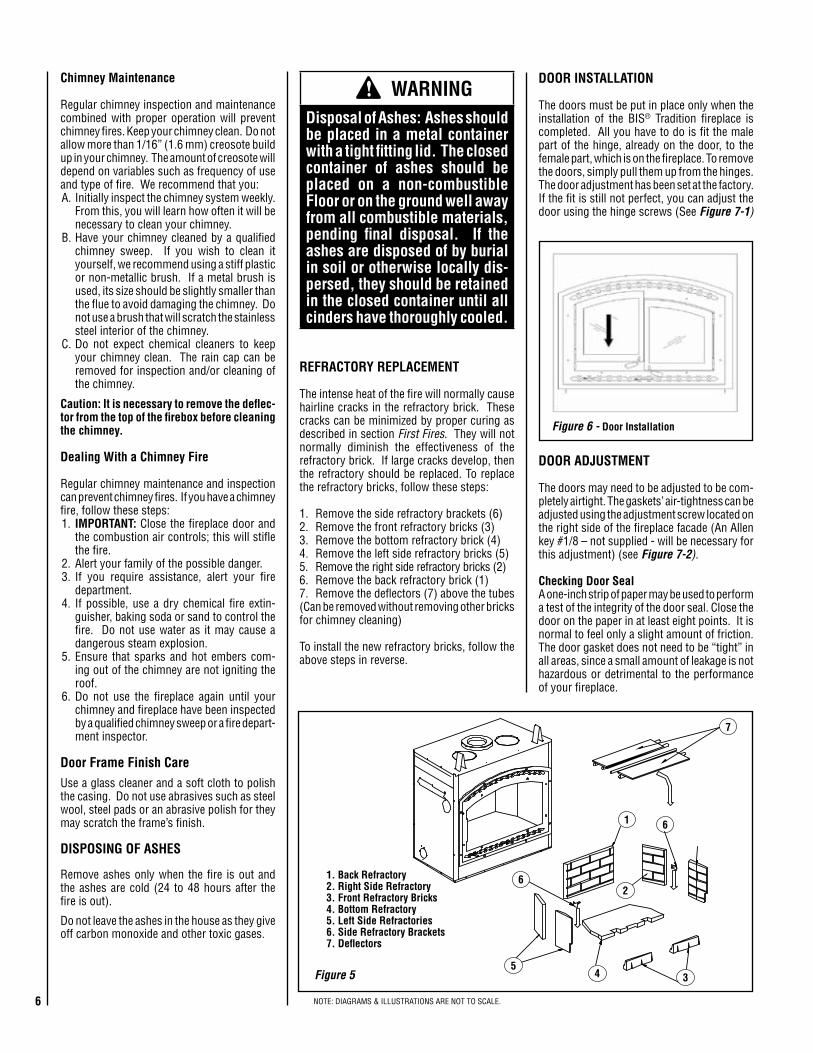
REFRACTORY REPLACEMENT
The intense heat of the fire will normally cause hairline cracks in the refractory brick. These cracks can be minimized by proper curing as described in section First Fires. They will not normally diminish the effectiveness of the refractory brick. If large cracks develop, then the refractory should be replaced. To replace the refractory bricks, follow these steps:
1. Remove the side refractory brackets (6)2. Remove the front refractory bricks (3)3. Remove the bottom refractory brick (4)4. Remove the left side refractory bricks (5)5. Remove the right side refractory bricks (2)6. Remove the back refractory brick (1)7. Remove the deflectors (7) above the tubes (Can be removed without removing other bricks for chimney cleaning)
To install the new refractory bricks, follow the above steps in reverse.
1. Back Refractory2. Right Side Refractory3. Front Refractory Bricks4. Bottom Refractory5. Left Side Refractories6. Side Refractory Brackets7. Deflectors
WARNINGDisposal of Ashes: Ashes should be placed in a metal container with a tight fitting lid. The closed container of ashes should be placed on a non-combustible Floor or on the ground well away from all combustible materials, pending final disposal. If the ashes are disposed of by burial in soil or otherwise locally dis-persed, they should be retained in the closed container until all cinders have thoroughly cooled.
6 NOTE: DIAGRAMS & ILLUSTRATIONS ARE NOT TO SCALE.

WARNING• Use only a Security Chimneys International glass
doors, specifically designed for the BIS® Tradition fireplace.
• The fireplace cannot be operated without door or firescreen. Consult your dealer to select the correct replacement door or firescreen.
• Important! To assure proper alignment of glass doors: Install this fireplace in a square and plumb condition, using shims as necessary at sides and/or bottom.
2Figure7
DO NOT USE CHEMICAL GLASS CLEANERS ON PAINTED SURFACES AS IT MAY CAUSE THE PAINT TO PEEL.
CAUTION : DO NOT ALLOW WINDOW CLEANER TO GET IN CONTACT WITH DOOR GASKET OR PAINT ON FACADE OR DOOR. ONCE CLOSED, CONTACT OF GLASS CLEANER WITH THE FIREPLACE FACADE CAN PROVOKE PAINT PEELING OFF.
Gasket Replacement
Remove the doors from the unit (see section Door Installation) and lay them on a clean nonabrasive surface. To replace the gasket, first remove all of the old gasket and gasket cement. Make sure that the surface is totally clean before applying new cement (a high temperature silicone caulking rated at 500° F (260° C), is suitable) or adhesion problems may result. Apply gasket cement to the gasket channel and install the new gasket. This replacement part is available from your Security Chimneys International Dealer in the following dimensions:
Gasket Part # Length qty Dimensions
Around the glass
PR-SR1685C 61-3/4”(1569 mm)
2 1” width x 3/16” thick(26 mm x 5 mm)
On the door frame
PR-SR1823I 48-3/8”(1229 mm)
2 3/4” diameter(19 mm)
Between the doors
PR-SR1823J 17-5/8”(448 mm)
2 5/8” diameter(16 mm)
Table1
1
GLASS CARE
Glass ReplacementThe glass used for the BIS Tradition fireplace is a high temperature ceramic glass (1,400° F). If the glass breaks or cracks, it must be replaced with an identical ceramic glass. Tempered glass or ordinary glass will not withstand the high temperatures of the BIS Tradition fireplace . Replace-ment glass should be purchased from a Security Chimneys International dealer (see “Replacement Parts” on Page23).
DO NOT OPERATE THE UNIT WITH CRACKED OR BROKEN GLASS.
Glass CleaningThe BIS Tradition fireplace is designed to keep the glass clean under normal operating conditions. If the BIS Tradition fireplace is operated continuously with the combustion air controls closed, the glass will tend to get dirty unless the fuel, firebox and glass are maintained at hot temperatures (see section Refueling For Best Performance). To clean the glass, there are a number of specially designed cleaners to remove creosote. Your Security Chimneys Dealer can recommend a suitable cleaner. Regular household glass cleaners will not clean creosote. Do not use abrasives such as steel pads, steel wool or oven cleaner as they will scratch the glass.
FIREPLACE INSTALLATION
Locating The BIS Tradition FireplaceThe best location to install your fireplace is determined by considering the location of windows, doors, and the traffic flow in the room where the fireplace is located, allowing space in front of the unit for the hearth extension and the mantel, and taking into consideration the location of the hot air ducts (optional), outside air kit and chimney. If possible, you should choose a location where the chimney will pass through the house without cutting floor or roof joists (see fireplace dimensions on Pages9and10).
Usually, no additional floor support is needed for the fireplace. The ad-equacy of the floor can be checked by first estimating the weight of the fireplace system. Weights are given in the appendix. Next, measure the area occupied by the fireplace. Note the floor construction and consult your local building code to determine if additional support is needed.
The BIS Tradition fireplace may be installed directly on the floor or on a raised base and a minimum of 80” measured from the base of the appli-ance to the ceiling is required.
7NOTE: DIAGRAMS & ILLUSTRATIONS ARE NOT TO SCALE.

Marginal Location
Wind Direction
LocationNotRecommended
Outside Air IntakeFacing the Wind
LocationNot Recommended
Location Recommended
Figure8 NOTE: DIAGRAMS & ILLUSTRATIONS ARE NOT TO SCALE.
When selecting the location, the chimney outlet position and the direction of the wind are important factor affecting the chimney performance. To allow a maximum draft and to reduce wind turbulence, the chimney must:
• Penetrate the highest part of the roof.• Be installed as far as possible of roof offsets, trees or any other obstructions that may cause wind turbulence and back drafts in the chimney.• The least amount of offsets (elbows) possible. Note: A maximum of 2 offsets is allowed.
NOTE: DIAGRAMS & ILLUSTRATIONS ARE NOT TO SCALE.8

If this fireplace is being installed in a cold climate, it is especially important to seal all cracks around the fireplace and wherever cold air could enter the room with noncombustible material. Also, the outside air inlet duct should be wrapped with noncombustible insulation to minimize the formation of condensation. Do not place insulation materials directly against the chimney sections. We recommend that you use the insulated wall radiation shield since it will maintain the home’s thermal barrier. AC chimney is NOT recommended in very cold climates (in areas with temperatures below 0°C (32°F).
WARNING: THE HEARTH EXTENSION IS TO BE INSTALLED ONLY AS IL-LUSTRATED.
Safety Metal Strip Floor
Hearth ExtensionNon-CombustibleFinish Material (i.e. Tile or Marble)
Minimum 1”Cement Board
Figure9b Non-Combustible Material
46-5/16”
16”
24”
45 Deg.
Area where wood Mantelcan be installed
4”
Figure9a
(102mm)(406mm)
56” (1422mm)
Min.
(1176mm)
24” (610mm)
(610mm)
HearthExtension
Mantel
u Elevated fireplace installations require a special “Z” Metal Safety Strips (field provided), in place of the safety metal strip shown above. The safety strip should extend the full width of the fireplace. When more than one safety strip is used they must overlap by a minimum of 1”.
Platform
2”
FireplaceElevated Fireplaces
u
Fireplace
The crack between the fireplace and the hearth extension must be sealed with a non-combustible material such as sand-cement grout.
v
v
12” Max.(305mm)
9
Facade InstallationInstall the Facade per instructions provided in Facade Kit (ordered separately - see Page21).Framing, Facing And MantelThe construction of the framing, facing, and mantel must be in accordance with the stan-dards and the following illustrations (Figures10and11):A. Frame the fireplace using 2” x 3” or heavier
lumber.B. WARNING: Combustible materials can-
not be used in the space directly above the fireplace, except for the studs above the facade that support the facing and mantel. This area must remain empty for a height of 80” (2,032 mm) mea-sured from the base of the appliance.
C. Frame the fireplace with vertical studs at the sides of the fireplace running from floor to ceiling (see Figure10). If combustible facing is to be used, position the studs back, from the front edge of the fireplace (a space that is the thickness of the facing material, so that the facing can be installed flush with the fireplace facing). Frame headers between the vertical studs only as follows:
- Place 2” x 3” or 2” x 4” headers, only along the upper part of the front, side and back faces (some codes may require a 2” x 6” on an outside bearing wall). Do not put wood or any combustible material within the area above the fireplace except on the front facing.
- Place headers only as required to sup-port the facing and mantel.
D. WARNING: The fireplace must not be in contact with any insulation or loose fill-ing material. Cover the insulation with Drywall panels around the fireplace.
Hearth Extension RequirementsThe BIS® Tradition fireplace may be installed directly on a combustible floor. The supplied safety metal strip must be positioned as follows: One half under the front of the fireplace and the other half must extend on the floor over which the hearth extension will be built (see Figure9a).
* The safety metal strip must cover the entire width of the fireplace
The combustible floor in front of the fireplace must be covered with a non-combustible mate-rial (tile, marble, stone, etc). See Figure9b.
COLD CLIMATE INSTALLATIONS
Climateswheretemperatureswillfallbelow0°C(32°F).
The heating performance of the appliance will vary depending upon the level of insulation, house design, how the appliance is operated, etc.
NOTE: DIAGRAMS & ILLUSTRATIONS ARE NOT TO SCALE.

FRAMING DIMENSIONSFireplace Opening Width
A u 46-1/4” 1175 mm
B 49-3/8” 1254 mm
C 42-3/4” 1086 mm
D 20-7/8” 530 mm
E 93-7/8” 2384 mm
F 47” 1194 mm
G 27-3/4” 705 mm
H 26-3/4” 680 mm
J 66-3/8” 1686 mm
K 8” 203 mm
L 1” 25 mm
NotesDiagrams,illustrationsandphotographsarenottoscale–consultinstallationinstructions.Productdesigns,materials,dimensions,specifications,colorsandpricesaresubjecttochangeordiscontinuancewithoutnotice.
All framingdimensionscalculated for1/2"drywallat thefireplace face. Ifsheathing thechaseorfinishingwithother thicknessmaterials,calculationswillneedtobemade.
*Thefireplacemustnotbeincontactwithanyinsulationorloosefillingmaterial.CovertheinsulationwithDrywallpanelsaroundthefireplace.
Fireplace Framing
Header
B
A
7/8”
11-1/8”16-1/4”
26-1/8”
1”
1-5/32”
26-1/4”
10-1/4”41-3/4”
47” �
49-3/8”
46-1/4”
43-1/4”
37”
31”
15”
7” 4-1/4”
28-1/2”
5-5/8” 20-1/8”
28-1/2”
5-5/8”
10-3/8”
3”
29-1/2”
23-3/4”
F
DJ
E
CORNERINSTALLATION
Figure10
* Total depth is 25 inches including the back spacer minus 1/2 inch for drywall to be flush with the facing.
7’Min.
B
G
2” x 3” Min.
K
Combustion Air Kit
1. Combustible material must be installed flush with the fireplace. It may not project in front of and on the fireplace (i.e. the steel facade of the fireplace) (Figure14).
2. Non-combustible materials such as brick, stone or ceramic tile may project in front of and onto the fireplace facing (Figure12).
IMPORTANTThe facade must be removable once installed. The facade is designed to overlap any facing material installed on the front of the fireplace. If thicker material is installed, use the facade as a template and make sure it can be easily removed for servicing.
FACING
Rough Framing Face(dimension includes finish
material inside framing, if any)
OUTSIDE CHASE
G
C
H
L*
Back Wall of Chase/EnclosureIncluding Finising Materials if any
Rough Framing Face (Unfinished Shown)A
* Zero Clearance From Back Spacer to Wall
Lv
v
uThe front framing width (A= 46-1/4”) will need to be 47” before pushing the fireplace into framing.
Plywood 1/2”
Combustible materials can NOT be used in the space directly above the fireplace. Do not fill the space above the fireplace with any material (Except the wood framing)
10 NOTE: DIAGRAMS & ILLUSTRATIONS ARE NOT TO SCALE.

Figure11
Insulated Chase Construction
7 Ft. Min.
Attic RadiationShield
Roof SupportStorm Collar
Flashing
Drywall or Any Rigid Material
2” x 4”1/2” Plywood
6’ 8” Min.
Firestop
* Floor Ceiling
Wall
* Floor Ceiling
Wall
Firep
lace
Insulate JoistsSame As Ceiling
Draft Stops
Firestop
CTDTTermination
Note: Non-CombustibleChaseFlashingMust BeUsed ToCoverChaseOpening
OptionalInsulationIn OutsideWalls OfChase
SolidContinuousSurface
OutsideBase
Insulation(Thermal Barrier)
8'Level
NOTE:Itisrecommend-edthatthechasewallsandfloorbeinsulatedinthesamemanner,usingthesameinsulation,astherestofthebuilding,belowtheattic.
• Musthavethesamefirestoppingresistanceasadjacentwall.
• Musthavethesameinsulationasadjacentceiling.
• Followlocalrulesregardingfram-ingconstruction.
1 3
45
62
1
27
34
1. Fireplace2. Front of fireplace3. Wood frame (2” x 3” min)4. Drywall 5. Tiles6. Rock board or other7. Brick
Fireplace Frame Section(Top View)
Figure12
Only non-combustible material should be superposed or project-ing over the front of the fireplace.
Figure14
50”Min.
SEE NOTE
MANTEL and FACINGThe mantel must be installed at least 56” (1143 mm) above the base of the fireplace (Figure13).
Nailing Flanges
Four nailing flanges are provided to secure the fireplace to the floor (see figure below). Bend the nailing flanges down so that each flange is flush with the floor, then using nails or screws, secure the fireplace to the floor (2 places each side). The heads of the screws or nails must be large enough to completely cover the holes in the nailing flanges.
Nailing Flange(2 places each side)
Unbend to floor and nail/screw
Fireplace Side
7 Ft. Min.
Attic RadiationShield
Roof SupportStorm Collar
Flashing
Drywall or Any Rigid Material
2” x 4”1/2” Plywood
6’ 8” Min.
Firestop
* Floor Ceiling
Wall
* Floor Ceiling
Wall
Firep
lace
Figure13
... .. ... .. ... .. ... .. ... .. ... .. ... .. ... .. ... .. ... .. ... .. ... .. ... .. ... .. ... .. ... .. ... .. ... .. ... .. ... .. ... .. ... .. ... .. ... .. ... .. ... .. ... .. ... .. ... .. ... .. ... .. ... .. ... .. ... .. ... .. ... .. ... .. ... .. ... .. ... .. ... .. ... .. ... .. ... .. ... .. ... .. ... .. ... .. ... .. ... .. ... .. ... .. ... .. ... .. ... .. ... .. ... .. ... .. ... .. ... .. ... .. ... ..
Mantel
Noncombus-tible Facing
56”
Drywall2” X 3” Min.
Spacer
Mantel and Facing(Side View)
......................................................................................................................................................................................................................................................................................................................
Rock Board or Other NoncombustibleMaterial
Noncombustible Facing
Drywall
Rock Board or Other Noncom-bustible Material
11NOTE: DIAGRAMS & ILLUSTRATIONS ARE NOT TO SCALE.

Figure16
Rain Cap
Flashing Collar
Flashing
Roof SupportAtticRadiation Shield
Non-CombustibleFlameproofFacing
Figure17
Figure15
When installing the double outlet system, the hot air outlets can be installed in the same room as the fireplace, or one or both of the outlets can be installed in adjacent or upper rooms. Installing the ducts at dif-ferent elevations will tend to exhaust more heat out of the higher outlet (Figure16).
Frame
Grill
Maintainatleast6-1/2”(160mm)clearancefromtheoutletgrillframingtoa combustible ceiling,sidewallormantel.
OutletGrill
OutletGrill
WARNING: The outlet grills should not be installed facing up-ward through a floor. Danger of burns can result if grills in floor are stepped on.
6-1/2” (165mm) Min. (to ceiling)
Firestop
10’ (3.1m)Max.13” x 13”
(330mm x 330mm)
10’ (3.1m)Max.
68” Min.(1727mm)
56” Min.(1422mm)
Fireplace BlowerThe fireplace comes equipped with a heat activated blower. It is located in the bottom of the fireplace, towards the back. It uses 120 V and must be connected to the main electrical circuit by a qualified electrician. For connection, use the electrical box supplied with the unit located on the bottom right corner of the fireplace.If you wish to adjust the blower speed, the variable speed control (VRUW) provided must be installed in line with the wiring. Again, use a qualified electrician for installation.If the blower requires servicing,1- Remove the doors and decorative facade.2- Remove the screw located below the blower motor that holds it to the
back of fireplace.3- Pull the blower out of the unit through the square hole located in the
front bottom right corner.
HOT AIR DUCTING INSTALLATIONThe BIS® Tradition fireplace is approved for use with a Gravity Kit:
Gravity KitThe gravity kit is designed for double hot air outlets and includes: (See Figure15) - 2 telescopic lengths 8” I.D. - 2 90º elbows 8” I.D. - 2 hot air outlet kits (grill and frames) - 2 adaptorsSee Gravity Kit Accessories on Page21.
Only the blower available with the fireplace can be used with the gravity kit. For safe installation, the gravity kit must meet the following require-ments: Minimumheight* 68” (1,727 mm) Maximumlength See Figure16* The height of the louver must be measured from the base of the BIS
Tradition fireplace to the middle point of the louver.
WARNING: Both pipes of the double hot air outlet must be installed. Any oth-er installation may cause fire and void warranty.
12 NOTE: DIAGRAMS & ILLUSTRATIONS ARE NOT TO SCALE.

The duct system must be installed respecting the following:
1. Remove the plates closing up the 8” diameter holes on top of the fireplace. Then, cut the insulation in order to obtain two 8” dia. open-ings. Fix the adaptors on the fireplace openings by turning clockwise (Figure15).
2. Maintain at least a 2” (50 mm) clearance between the ducts and any combustible material; the required hole size is 13” x 13” (330 mm x 330 mm).
Exception #1: For the grills, the framing can be 10-3/4” x 10-3/4” (275 mm x 275 mm) to provide the clearance as required by the integral spacers on the double outlet duct system.
3. The maximum number of elbows in a run of duct is two.4. Maintain at least 6-1/2” (160 mm) clearance from the outlet grill
framing to a combustible ceiling, side wall or mantel.5. When traversing a combustible wall or floor, a firestop must be installed
at the wall or floor penetration. The hole size must be 13” x 13” (330 mm x 330 mm)
6. Do not connect the hot air ducts to a central heating system. Malfunc-tion of the heating system’s blower will cause the fireplace to overheat. A furnace duct is only single wall and not double wall as is required for the BIS® Tradition fireplace hot air exhaust.
7. Use only Security Chimneys International grills and components as described in this manual. Other grills or registers may be too restric-tive and may overheat the fireplace or ceiling.
8. Do not use insulated flexible ducts as they will overheat.9. Do not use tees or any other components than the ones specifically
listed here.10. Never allow the ducting to pitch down as hot air will be trapped creat-
ing a fire hazard. Never route the ducting downwards.11. The hot air outlet grills must be installed with the louvers pointing
downwards in order to prevent overheating adjacent ceilings.
OUTSIDE AIR KIT
It is mandatory to install an outside air connection to the BIS Tradition fireplace. The following components are required and are included with the fireplace:
• Outside air kit (includes 4 inch flex that goes up to ten (10) feet long)• 4” Adaptor for fireplace connection
Outside Air Installation
The outside air assembly may be installed according to the following requirements:
A) Duct length should be kept to a minimum. The maximum length of a 4” interior diameter (100 mm) insulated flexible duct is 20 feet (6.1 m). The duct can be extended to a maximum of 40 feet (12 m) using a 6” interior diameter (150 mm) insulated flexible duct (See note below).
B) The air intake register must not be installed more than ten (10) feet (3050 mm) above the base of the fireplace.
C) The fresh air must come from outside the house. The air intake must not draw air from the attic, basement or garage.
D) The air intake should be installed where it is not likely to be blocked by snow or exposed to extreme wind and away from automobile exhaust fumes, gas meters and other vents.
E) The duct and register may be installed above or below floor level.
NOTE: We recommend not to exceed 20 feet of 4” flexible pipe. If you require a longer length we recommend that you use a 5” diameter flex-ible pipe for the complete run up to 30 feet and a 6” diameter pipe for a run of up to 40 feet.
Figure18
OUTSIDE CONNECTION
OutsideIntake
Screw
OpeningFacingDown
Wall
Aluminum Tape
Plastic Cover
InsulationFlexible Pipe
Aluminum Tape
Figure19
Aluminum Tape
Aluminum Tape
FireplaceConnection
PlasticCover
Insulation
Flexible Pipe
Fireplace
OUTSIDE AIR CONNECTION TO THE FIREPLACE
Make a 4-1/4” (110 mm) hole in the outside wall of the house at the chosen location. From outside, place the outside air register in the hole (open side down) and fasten the register to the wall with screws as shown (see Figure18). Slip the pipe into the insulated sleeve. Place the insulated pipe over the register tube and over the fireplace’s outside air connector (see Figure19). At each end, carefully pull back the insulation and plastic cover exposing the flexible pipe. Using the aluminium tape provided, wrap the tape around the joint between the flexible pipe and the air inlets. Carefully push the insulation and plastic cover back over the pipe. Using aluminium tape, fasten the plastic cover in place.
NOTE: DIAGRAMS & ILLUSTRATIONS ARE NOT TO SCALE. 13

THE CHIMNEY SYSTEM
Chimney Installation Notes
1. If possible, install an interior chimney as it will provide better perfor-mance. In areas with continuous temperatures below 0°F (-18°C), the use of an exterior chimney increases the likelihood of operating problems such as low draft, high rate of creosoting, and poor start-up characteristics. Exterior chimneys are also prone to down-drafting and flow reversal. Installations which are located on lower floors in the house, such as in a basement, in combination with an outside chimney, are especially prone to flow reversal.
2. The fireplace model BISTRAD may be installed only with Security Chimneys International Ltd 7” diameter chimney systems model Secure Temp® S2100+ / Nova Temp® HT6000 / Secure Temp GX (U.S. only) or ACBI.
3. A chimney venting a fireplace shall not vent any other appliance.4. The minimum chimney height is 12 feet (3.7 m) excluding the fire-
place.5. All chimney installations must include at least one support in order to
be able to take any lateral load. The maximum chimney length that can be supported by the fireplace is nine (9) feet (2.75 m) for Secure Temp S2100+ / Nova Temp HT6000+ / Secure Temp GX and 26 feet (8m) for ACBI chimney. In altitude, add 18” (450 mm) to the chimney for every 2,000 feet (600 m) above sea level.
6. The chimney must extend at least three (3) feet (915 mm) above its point of contact with the roof and at least two (2) feet (610 mm) higher than any wall, roof or building within ten (10) feet (3 m) of it (Figure20).
7. If the chimney extends higher than five (5) feet (1,500 mm) above its point of contact with the roof, it must be secured using a roof brace.
8. A rain cap must be installed on top of the chimney. Failure to install a rain cap may cause corrosion problems.
9. Cut and frame square holes in all floors, ceilings, and roof that the chimney will go through to provide a 2” (51mm) clearance between the chimney and any combustible materials. At the point of penetra-tion through the floors, ceilings or roof, a 1” (25mm) clearance is acceptable for AC chimney only (see Table2). Do not fill the required clearance spaces with insulation or any other combustible material.
10. Portions of the chimney which may extend through accessible spaces must be enclosed to avoid contact with combustible materials or damage to the chimney.
11.When offsets are used, the pipe may not penetrate a ceiling or floor unless it is running vertical (no 30° offsets).
CHIMNEY MODEL SqUARE HOLESIZE OPENING
Secure Temp® S2100+ Nova Temp®
HT6000+ Secure Temp GX15 in (380 mm)
ACBI: Ceiling, Floor and Roof (1” clearance *)
15 in (380 mm)
Wall 17 in (432 mm)
Note:SeeTable3forSlopedRoofFramingTable2-FlatRoofFraming
*Thefollowingexceptionhasbeenapprovedforthisappliance;Therequired2”pipeclearancemaybereducedtoa1”clearanceattheceiling,floorandroof penetrationpoints forAC chimneyonly.All other locations require2”clearance.
Note: 2" clearance to combustibles around chimney components re-quired.
Note: Blown or fill type insulation materials must not be in contact with the fireplace or in the enclosure frame as described in ‘’Enclosure’’ section.
Note: Local codes may not require firestopping at the ceiling levels for outside chase installations. However, it is recommended for safety and the reduction of heat loss.
CHIMNEY INSTALLATION INSTRUCTIONS
1. Cut and frame the holes in the ceiling, floor and roof where the chimney will pass (see Figure21). Use a plumb-bob to line up the center of the holes. The sizes are indicated in Table2 for the floor and ceiling holes and Table3 (Page16) for the roof holes.
Figure20
two (2) feet Min.
three (3) feet Min.ten (10) feet
NOTE: DIAGRAMS & ILLUSTRATIONS ARE NOT TO SCALE.14

2. From below, install a firestop in each ceiling/floor separation through which the chimney will pass. At the attic level, install an attic radiation shield from above (Figures22aand22b).
3. For Secure Temp® S2100+ / Nova Temp® HT6000+ / Secure Temp GX chimneys, place the first chimney length on the fireplace. To lock it in place, turn 1/4 of a turn clock-wise. With the ACBI chimney, you must use a starter section before installing the first chimney length (Figure23). Continue installing chimney lengths making sure to lock each length in place.
4. Every time the chimney passes through a ceiling or a wall, install the appropriate firestop. When you reach the desired height, install the roof support. When installing a support, slightly lift the chimney system so the weight will lie on the support, not on the fireplace to reduce expansion noises (Refer to instructions included with the support). For an ACBI chimney use an universal sup-port AC10SU.
5. Put the roof flashing in place and seal the joint between the roof and the flashing with roofing pitch (seeFigures24and25). For sloping roofs, place the flashing under the upper shingles and on top of the lower shingles. Nail the flashing to the roof, using roofing nails.
6. Place the storm collar over the flashing, and tighten it with the bolt supplied. Finally, seal the joint between the storm collar and the chimney, using silicone caulking.
7. Install the chimney cap. Once the chimney cap is in place, the roof flashing can be washed with a solvent or vinegar and then painted with rust-proof paint.
Figure21-RoofFraming
Figure22a
S2100 / HT6000+Solid Packed Pipe
ACBIAir Cooled Pipe
Figure22b
Figure23
CHIMNEY INSTALLATION
MODEL ACBI Rain Cap
Collar
Flashing
Attic RadiationShield
Firestop
Universal Support
ACBI Starter Section ACBI7SB or ACBI7SB30
Note:OutsideairkitsmustbeinstalledforbothfireplaceandACBIchimney.
Outside Combustion Air Kit
Chimney Outside Air Intake(required when using AC chimney)
Attic Radiation Shield
Attic Radiation Shield
Radiation ShieldFirestop
NOTE: DIAGRAMS & ILLUSTRATIONS ARE NOT TO SCALE. 15

Roof Down Slope Hole SizeDEGREE OF SLOPE Secure Temp® S2100+
Nova Temp® HT6000+ Secure Temp GX
ACBI
Roof Pitch 7” 7”
0 * 15” (380 mm) 15” (380 mm)
2/12 15-3/8” (390 mm) 15-3/8” (390 mm)
4/12 16-1/8” (410 mm) 16-1/8” (410 mm)
6/12 16-7/8” (430 mm) 16-7/8” (430 mm)
8/12 18-1/4” (465 mm) 18-1/4” (465 mm)
10/12 19-5/8” (500 mm) 19-5/8” (500 mm)
12/12 21-3/8” (545 mm) 21-3/8” (545 mm)
*CrossSlopeHoleSize Putthechimneycapintoplace.Washtheroofflashingwithasolventorvinegar,thenpaintitwithrust-proofpaint.Table3
After reaching the location requiring the elbow, proceed as follows:
Secure Temp® S2100+ / Nova Temp® HT6000+ / Secure Temp GX Chimneys
1. Install the first elbow; turn it in the required direction. Fasten it to the chimney with the three (3) 1/2” (12 mm) metal screws provided with the elbow.
2. Install the necessary chimney lengths to achieve the required offset. Lock the chimney lengths together: it is recommended to use three (3) 1/2” (12 mm) screws. If the offset length is made of two (2) chimney lengths or more, use an offset support halfway up the offset. If penetrating a wall, install a wall radiation shield (see Figures27and28).
3. Use another elbow to turn the chimney vertically. Secure the elbow, using three (3) 1/2” (12 mm) screws (provided with the elbow).
4. Use a plumb-bob to line up the center of the hole. Cut a hole for the chimney in the ceiling/floor. Frame this hole as described previously (refer to Chimney Installation Instructions on Page15).
5. From below, install a firestop (See Figure22a).
6. A support (XST+ or XSO+) must be used on the first 15’ section (5 m).
7. Continue with the regular installation.
ACBI Chimney
1. Install the first elbow. Turn it in the required direction. To lock it in place, turn 1/8 of a turn. Fasten the straps attached to the elbow to the surrounding frame, using nails or drywall screws (Figure27).
2. Install the necessary chimney lengths to achieve the required offset. Lock the chimney lengths together. If penetrating a wall, use a wall radiation shield.
3. Use another elbow to turn the chimney vertically. Lock it to the chimney. Fasten the straps attached to the elbow to the surrounding framing using nails or drywall screws.
4. Use a plumb-bob to line up the center of the hole. Cut a hole for the chimney in the ceiling. Frame this hole as described previously.
5. From below, install a firestop (see Figure22b).
6. Continue with the regular installation.
Note:WhenusingACBIchimney,anACBI7SBstartersectionmustbeusedbeforeinstallinganelbow.Whenanoffsetisneededimme-diatelyoffthetopofthefireplace,anelbowstartersection(ACBI7SB30)isavailable.
CHIMNEY MODEL ACBI
Collar
Chimney
Flashing
Figure24 Figure25
Minimum Chimney Height When Using Elbows
Fireplace Model BISTRAD
Chimney Model Secure Temp S-2100+ / Nova Temp HT6000+ / Secure Temp GX / ACBI
Vertical Installation 3.66 m (12’)
Two (2) Elbows 4.57 m (15’)
Four (4) Elbows 5.18 m (17’)
Table4
OFFSET CHIMNEY INSTALLATION
After reaching the location requiring the elbow, proceed as follows. The minimum chimney height when using elbows is:
Notes:•Must return to vertical before penetrating ceiling or floor.•A maximum of 2 offsets are allowed.
NOTE: DIAGRAMS & ILLUSTRATIONS ARE NOT TO SCALE.16

Chimney Elbow Offset & Height
Two Lengths Between Elbows
8” 12” 18” 24” 36” 8” & 36” 12” & 36” 18” & 36” 24” & 36” 36” & 36”
GXS2100+
HT6000+7”
15ºA 3”
(76 mm)4-1/4”
(108 mm)5-3/4”
(146 mm)7-1/4”
(184 mm)10-1/4”
(260 mm)12-1/4”
(311 mm)13-1/4”
(337 mm)14-3/4”
(375 mm)16-1/4”
(413 mm)19-1/2”
(495 mm)
B 20-3/4”(527 mm)
24-1/4”(616 mm)
29-1/2”(749 mm)
34-3/4”(883 mm)
45”(1143 mm)
51-1/4”(1302 mm)
54-3/4”(1391 mm)
60”(1524 mm)
65-1/4”(1657 mm)
75-1/2”(1918 mm)
30ºA 7-1/2”
(191 mm)9-1/2”
(241 mm)12-1/2”
(318 mm)15-1/2”
(394 mm)21-1/2”
(546 mm)25”
(635 mm)27”
(686 mm)30”
(762 mm)33”
(838 mm)39”
(991 mm)
B 16-1/2”(419 mm)
20-1/4”(514 mm)
26-1/4”(667 mm)
32”(813 mm)
43-1/2”(1105 mm)
50-1/2”(1383 mm)
54-1/4”(1378 mm)
60”(1524 mm)
65-3/4”(1670 mm)
77-1/2”(1969 mm)
45ºCanada
Only
A 10”(254 mm)
12-3/4”(324 mm)
17”(432 mm)
21-1/4”(540 mm)
29-3/4”(755 mm)
34-11/32”(872 mm)
37-5/32”(949 mm)
41-13/32”(1052 mm)
45-21/32”(1160 mm)
54-1/8”(1375 mm)
B 17-9/16”(446 mm)
20-7/16”(519 mm)
24-5/8”(625 mm)
28-7/8”(733mm)
37-3/8”(949 mm)
42”(1067 mm)
44-3/4”(1137 mm)
49”(1245 mm)
59-9/32”(1353 mm)
61-3/4”(1568 mm)
Chimney
Elbow Offset & Height
One Length Between Elbows Two Lengths Between Elbows
--- 12” 18” 36” 48” --- 12” & 48” 18” & 48” 36” & 48” 48” & 48”
ACBI7”
15ºA ----
----5-1/2”
(140 mm)7”
(178 mm)11-1/2”
(292 mm)14-3/4”
(375 mm)--------
17-1/2”(445 mm)
19”(483 mm)
23-5/8”(600 mm)
26-3/4”(679 mm)
B --------
32-1/4”(819 mm)
38”(965 mm)
55-1/2”(1410 mm)
67”(1702 mm)
--------
77-1/8”(1959 mm)
82-7/8”(2105 mm)
100-1/4”(2318 mm)
111-1/8”(2823 mm)
30ºA ----
----10-1/2”
(267 mm)13-1/2”
(343 mm)22-1/2”
(543 mm)28-1/2”
(724 mm)--------
33-3/4”(857 mm)
36-3/4”(933 mm)
45-3/4”(1162 mm)
51-3/4”(1314 mm)
B --------
30-1/8”(765 mm)
35-3/8”(899 mm)
51”(1295 mm)
61-3/8”(1559 mm)
--------
70-1/2”(1791 mm)
75-5/8”(1921 mm)
91-1/4”(2318 mm)
101-5/8”(2581 mm)
Note:WiththeACBIchimney,astartinglengthof6”highmustbeusedontopofthefireplacebeforeinstallinganelbow.
Figure26
Horizontal Offset
Total Height
Offset Dimensions
A
B
NOTE: DIAGRAMS & ILLUSTRATIONS ARE NOT TO SCALE. 17

Figure27
OFFSET CHIMNEY INSTALLATION
Rain Cap
Collar
Roof Flashing
Offset Support
Insulated WallRadiation Shield
Framing2” x 3”
Figure28
Roof Support
Note: Incoldareasit isrecommendedtoprotectthechimneyinainsulatedchase.
Straps
Chimney ACBI
ACBI Starter Section
Straps
Outside Wall
OFFSET CHIMNEY INSTALLATION WITH WALL PENETRATION
Support
Note:Thisillustrationisnottoscale.Itrepresentshowthechimneymustbesupported.A30degreeoffsetonlyisallowedintheUSAanda45degreemaximumoffsetisallowedinCanada.
NOTE: DIAGRAMS & ILLUSTRATIONS ARE NOT TO SCALE.18

ANGLED WALL RADIATION SHIELD(XRSMI30 and AC10RSMI30)
When traversing a combustible wall with the chimney at a 30º or 45º angle, an angled firestop or wall radiation shield must be installed. Only one is required.
Note:45ºangleforCanadaonly(XRSMI45).
In cold climate locations (climates where temperatures will fall below 32º F / 0º C), we recommend that you use the insulated wall radiation shield since it will maintain the home’s thermal barrier.
XRSMI30 and AC10RSMI30 (XRSMI45 - Canada Only)
Chimney Model (7” dia). Angle Hole Size
Secure Temp® S2100+ Nova Temp® HT6000+
Secure Temp GX (US only)
30º15” x 38-1/4”
(380 mm x 972 mm)
Secure Temp S2100+ Nova Temp HT6000+
45ºCanada only
15” x 25-7/8”(380 mm x 657 mm)
ACBI 30º17 x 42-1/2”
(432 mm x 1080 mm)
Table5
Figure29
Drywall
Insulated Wall
Insulated WallRadiation Shield
CHIMNEY SUPPORT INSTALLATION
Universal Roof SupportWhen installing a support, slightly lift the chimney system so the weight will lie on the support, not on the fireplace to reduce expansion noises.This support has three possible uses:1. For Secure Temp® S2100+ / Nova Temp® HT6000+ / Secure Temp GX,
it must be used on a roof to support the chimney.2. It may be used on a floor, ceiling or roof above an offset to support
the chimney above the offset.3. It may be used on a floor, ceiling or roof as a supplementary support
when the chimney height exceeds 15 feet (4.6 m).
Table6 gives maximum height of supported chimney.
NOTE: For the ACBI chimney, a support section (ACBI7SL) must be used every 30 feet (9m) or an universal support every 20 feet (6m) instead of the universal roof support (ST).
CHIMNEY MAXIMUM HEIGHT OF SUPPORTED CHIMNEY
7” Diameter Offset Support Roof Support
Secure Temp S2100+ Nova Temp HT6000+
Secure Temp GX16 feet (5.49 m). 18 feet (6.1 m).
ACBI 40 feet (12.19 m). 50 feet (15.20 m).
Table6
CHIMNEY CHASE AND MULTIPLE TERMINATIONS
For the purpose of this manual, a chimney chase is considered a part of the chimney system rather than part of a building. The termination must be placed a minimum of 18” (460 mm) above the chase.
For installations where more than one chimney is located in the same chase or within the same area, we suggest that their terminations be separated by at least 16” (410 mm) horizontally, and 18” (460 mm) verti-cally. This separation is to prevent smoke migrating from one chimney to another (see Figure30).
Figure30
18” (460 mm)
16” (410 mm)
18” (460 mm)
18” (460 mm)16” (410 mm)
For roof support installation, refer to the instructions provided with the support.
UNIVERSAL OFFSET SUPPORT
This support is used to support the chimney above an offset. When the chimney offset is used to traverse a wall this support may be used on the wall to support the chimney. The maximum heights are given in Table6. For offset support installation, refer to the instructions provided with the support.
NOTE: DIAGRAMS & ILLUSTRATIONS ARE NOT TO SCALE. 19

INSTALLATION INSTRUCTIONS FOR MASONRY APPLICATION
WARNING: Before starting the installation, the masonry chimney must be inspected by a qualified chimney sweep.
The following requirements must be respected:1. The chimney must be absolutely clear of any soot residue or creosote.
Check for cracks, loose or missing bricks that could inhibit correct installation of the liner.
2. The clearance to combustible must be a minimum of 1” between the outside of the masonry and any wood framing or loose insulation.
3. The chimney must be built in accordance with the current building code.
4. No other appliance can be connected to the same chimney. 5. The clearances to combustible for the BISTMA30 connectors are 2”
on the side and bottom and 16” at the top.6. The connector parts are not necessary if the connection between the
insulated length and the stainless steel liner is done within the masonry chimney.
Installation:
The chimney must be relined with a stainless steel liner model TUBINOX™ or Projet SS of the same diameter as the outlet of the fireplace.
For connection at 30º angle, a special connector (BISTMA30) must be used to connect the liner to the insulated chimney.
* IMPORTANT NOTE - The use of a 45º connector (BISTMA) is ap-proved for use in Canada ONLY. Installations in the USA must use the 30º connector (BISTMA30).
Follow these steps:
1- Position the fireplace in its location. Temporarily install the S2100+ elbow on the top of the fireplace and, using a level, mark with an oval the location where the flue liner will enter the masonry chimney.
2- In the middle of the oval, drill a hole in the masonry chimney at 30º.3- Increase the size of the hole until a 30º TUBINOX liner elbow can be
easily slipped through.4- Slide the liner down from the top of the masonry chimney until you
reach the hole level.5- Slip through the hole a 30º liner elbow and connect it to the liner.6- Add a small liner section to the liner elbow which will allow the liner to
extend at least 12” (measured at the top of the liner) from the masonry chimney.
7- Seal the opening around the liner with high temperature refractory cement.
8- The next steps must be done in the following order:
See typical installation illustrated below. A. Select the S2100+ length that will fit between the elbow and the liner
so that it will slide at least 2” over the liner section (You may need to cut the liner for a better fit).
B. Take that section and the BISTMA30 cover and slide it over the liner. Make sure you have enough opening to be able to install the S2100+ elbow without difficulty.
C. Install the 30º elbow on the fireplace.D. Slide the length section back down on the elbow and twist lock the
two together. E. Pull the cover down over the length and install the insulation pad over
the liner; be careful to cover the liner completely.F. Slide back the cover over the insulation and fix it in place using the 3
metal screws supplied.
Figure31
1” Clearance
Firestop
TUBINOX or Projet SS Stainless Steel Liner
TUBINOX or Projet SS Liner Must Slide at Least 2” Inside Length
InsulatedLength
Masonry Chimney, New or Existing
High-Temp. Cement
Insulation Pad and Cover (BISTMA or BISTMA3U)
3 Screws* 30° S2100+ / GX Insulated Elbow
6’ 8”
NOTE: DIAGRAMS & ILLUSTRATIONS ARE NOT TO SCALE.20

Installation Accessories
Description Cat./Part No.
Facades(Required-OrderSeparately)
BIS® Tradition Facade Black, BTFBK BTFBK
BIS Tradition Facade Gold Plated, BTFG BTFG
BIS Tradition Facade Brushed Nickel, BTFBN BTFBN
BIS Tradition Facade Hammered Steel, BTFMC BTFMC
Doors - (Required-OrderSeparately)
BIS Tradition Doors Black, BTCBK BTCBK
BIS Tradition Doors Gold Plated, BTCG BTCG
BIS Tradition Doors Brushed Nickel, BTCBN BTCBN
BIS Tradition Doors Hammered Steel, BTCMC BTCMC
Outside Air Kit (includedwithfireplace)
Outside Air Coupler To Connect Outside Air (UZI) To Fireplace, UZIAD
UZIAD
Outside Air Ducting - includes 4” insulated flex x 10’ long, UZI UZI
Gravity Kit
Gravity kit: Complete double duct system includes: 2 elbows 90º, 2 telescopic lengths, 2 grill supports and 2 black grills, 2 fireplace adaptors.
7B30ZK-1
Gravity Kit Accessories
Black Grill With Support (set of 2) , 7B30ZO 7B30ZO
Brass Grill (for 7B30ZK-1) (set of 2), 7B30ZGB 7B30ZGB
Elbow 90º, 8” dia. I.D., 7B26ZE90 7B26ZE90
Elbow 45º, 8” dia. I.D., 7B26ZE45 7B26ZE45
Telescopic length, 8” dia. I.D. (15” to 26”), 7B26ZLA 7B26ZLA
Adjustable length, 8” dia. I.D. (2” - 5”), 7B26ZL2A 7B26ZL2A
Length five (5) feet, 8KL5 8KL5
Length four (4) feet, 8KL4 8KL4
Length three (3) feet, 8KL3 8KL3
Length two (2) feet, 8KL2 8KL2
Length one (1) feet, 8KL1 8KL1
OPTIONAL INSTALLATION ACCESSORIES
Fireplace Kits
Description Cat./Part No.
Rigid firescreen, BTZN BTZN
Masonry Chimney Adaptor, 45º, BISTMA(for use with TUBINOX™ liner) (not approved for use in U.S.A.)
BISTMA
Masonry Chimney Adaptor, 30º, BISTMA30(for use with TUBINOX liner)
BISTMA30
Central Forced Air Kit Accessories u
Central forced air kit including: blower (BISZY), flex adaptor (BISAF), 2 clamps, variable speed control (VRUW), thermo-disk (VTU), fan to flexible pipe adapter (BISAVF), back draft damper (BISBD), aluminium tape, BISFWK-1
BISFWK-1
Fireplace to Flex adaptor and 2 clamps, BISAF BISAF
Flexible pipe 5” I.D. x 15 ft. Long, 5FLEX15 5FLEX15
Flexible pipe 5” I.D. x 30 ft. Long, 5FLEX25 5FLEX25
Blower 250 CFM for central forced air kit, BISZY BISZY
Blower variable speed control with decorative wall plate for (BISZY), VRUW
VRUW
Thermo-disk, on/off blower control (for BISZY), VTU VTU
Blower to flexible pipe adaptor, BISAVF BISAVF
Heating and cooling thermostat, 24V, HCTW HCTW
Backdraft damper, BISBD BISBD
uNottestedunderEPAcertification.Ifinstalled,thisappliancenolongerqualifiesforEPAcertification.
21

CHIMNEY - PARTS AND COMPONENTS LISTS
Secure Temp® GX - 2” Insulated Galvanized Chimney System (Recommended Insulated System)Galvanized (7” ID and 11” OD) U.S.A. ONLY
Description Cat./Part No.
Lengths and Misc. Chimney Components
Length 8”, 7GXL8 7GXL8
Length 12”, 7GXL12 7GXL12
Length 18”, 7GXL18 7GXL18
Length 24”, 7GXL24 7GXL24
Length 24” (stainless steel exterior flue), 7XL24 7XL24
Length 36”, 7GXL36 7GXL36
Length 36” (stainless steel exterior flue), 7XL36 7XL36
Length 48”, 7GXL48 7GXL48
Length 48” (stainless steel exterior flue), 7XL48 7XL48
15º Elbow, 7GXE15 7GXE15
30º Elbow, 7GXE30 7GXE30
Rain Termination Cap, 7CC (stainless steel) 7CC
Wall Band, XBM XBM
Supports
Offset Support, XSO XSO
Roof / Floor support, XST XST
Roof Brace, XBS2 XBS2
Roof Flashings
Roof Flashing, Flat (includes spacer and collar), 7XF 7XF
Roof Flashing, Adjustable (5º to 30º) (includes spacer and collar), 7XFA
7XFA
Roof Flashing, Adjustable (30º to 45º) (includes spacer and collar), 7XFB
7XFB
Storm Collar (spacer included), 7XFC 7XFC
Firestops and Braces
Firestop, 7XBF 7XBF
Radiation shield, 7XRS 7XRS
Insulated attic radiation shield, 7XRSA 7XRSA2
30º Insulated wall radiation shield, 7XRSMI30 7XRSMI30
Wall Band, XBM XBM
Fireplace Model BISTRAD - Approved Venting Components manufac-tured by Security Chimneys International only.
• 7” diameter chimney - ACBI (air cooled), Secure Temp® GX (U.S. only) and Secure Temp S-2100+ (or Nova Temp® HT6000+).
• 7” diameter chimney for relining masonry chimneys - TUBINOX™ chimney (or PROJET® SS), 7” diameter with adaptor for installation in a masonry chimney.
Notes:jNova Temp HT6000+ is equivalent to S-2100+k Chimney Adaptor (S-2100+ / HT6000+) for CANADA ONLY - If you want to
install a S-2100+ / HT6000+ chimney, an adaptor is available (6UCA).lACBI Chimney is NOT recommended at elevations above 4,000 feet or in cold
climates (climates where temperatures will fall below 32° F / 0° C). When us-ing ACBI chimney, an ACBI7SB starter section must be used before installing an elbow. When an offset is needed immediately off the top of the fireplace, an elbow starter section (ACBI7SB30) is available.
22

ACBI Chimney*(7” I.D., 13” O.D. AC - Air Cooled)
* AC Chimney is NOT recommended at elevations above 4,000 feet or in cold climates (climates where temperatures will fall below 32° F / 0° C).
Description Cat./Part No.
One of the following adaptors is required if installing an AC chimney system
Starter Section w/ air intake, 7” Dia., ACBI7SB H3258
Offset Starter Section 30º, 7” Dia., ACBI7SB30 H3259
ThefollowingoutsideairkitisrequiredifinstallinganACchimneysystem
Outside Air Kit (Chimney) (4” ID Flex X 10’ Long, Insula-tion, Outside Register And Coupling), ACZI
H1967
Lengths and Misc. Chimney Components
12” Length, 7” Dia., ACBI7L12 H3252
18” Length, 7” Dia., ACBI7L18 H3253
36” Length, 7” Dia., ACBI7L36 H3254
48” Length, 7” Dia., ACBI7L48 H3255
15º Elbow, 7” Dia., ACBI7E15 H3256
30º Elbow, 7” Dia., ACBI7E30 H3257
Rain Termination Cap (regular), 7” Dia., ACBI7CPR H3260
Spark Arrester Screen (universal spark arrester band), PE PE
Wall Band, XBM XBM
Supports
Support section (10” long), ACBI7SL H3263
Universal support, AC10SU H3265
Roof Flashings
Flat roof flashing (includes spacer and collar), ACBI7FR H3275
Roof Flashing, Adjustable, 5º - 30º (includes spacer and collar), ACBI7FAR
H3276
Roof Flashing, Adjustable, 30º - 45º (includes spacer and collar), ACBI7FBR
H3277
Misc.
Firestop, ACBI7BF H3268
Radiation Shield, ACBI7RS H3269
Attic Radiation Shield, ACBI7RSA H3270
Telescopic Attic Radiation Shield, ACBI7RST H3271
Insulated Wall Radiation Shield 30º, AC10RSMI30 H3272
Storm Collar, AC10FC H3278
CHIMNEY - PARTS AND COMPONENTS LISTS
TUBINOX™ LL Chimney Lining SystemRigid Stainless Steel Liner For Relining A Masonry Chimney, 7” Diameter
Listed to ULC-S635M, UL-1777 and ULC-S640M at 2100º F
Description Cat./Part No.
6” Length, 7” Dia., 7LL6 7LL6
12” Length, 7” Dia., 7LL12 7LL12
24” Length, 7” Dia., 7LL24 7LL24
36” Length, 7” Dia., 7LL36 7LL36
48” Length, 7” Dia., 7LL48 7LL48
Adjustable Length (7” to 11”), 7” Dia., 7L7A 7L7A
Split Base Tee, 7” Dia., 7LT 7LT
Tee Cap, 7” Dia., 7TCS 7TCS
Twist Lock Tee Cap, 7” Dia., 7LTC 7LTC
Elbow 30º, 7” Dia., 7LE30 7LE30
Elbow 45º, 7” Dia., 7LE45 7LE45
Elbow 90º, 7” Dia., 7LE90 7LE90
Rain Termination Cap (regular), 7” Dia., 7LCS 7LCS
Rain Termination Cap (deluxe), 7” Dia., 7LCC 7LCC
Supports
Top Support, Part# 7LST 7LST
Support Assembly, 7LSA 7LSA
Interior Support, Part# 7LSB 7LSB
Adaptor Flexible Pipe (male), 7LAAM 7LAAM
Adaptor Flexible Pipe (female), 7LAAF 7LAAF
Stainless Steel Flex - five (5) feet Long, 7LLFLEX 7LLFLEX
Adj. Insulated Wall Radiation Shield 6” to 12”, 7LRSMI 7LRSMI
Adaptors to Masonry Chimney
Masonry Chimney Adaptor, 45º, BISUMA (for use with TUBINOX liner) CANADA ONLY
BISUMA
Masonry Chimney Adaptor, 30º, BISTMA30(for use with TUBINOX liner)
BISTMA30
23

CLEARANCE TO COMBUSTIBLES
The following clearances meet the minimum requirements for a safe installation:
Side wall (fireplace front): 24” (457 mm) measured from the fireplace side.
Ceiling: 6’ 8” (2,032 mm) measured from the base of the fireplace
Fireplace enclosure: Bottom: 0” Side: 0” to spacer Back: 0” to spacer Top: Do not fill the space above the fireplace with any material (Except the wood framing. See Figure10)
Chimney: 2” (50 mm), except for through ceiling application, ACBI chimney, 1’’ (25 mm) clearance.
Mantel: 56” (1422 mm) measured from the base of the fireplace.
BIS® Tradition - Replacement Parts
Description Cat./Part No.
Fireplace Blower UZY7
Blower Motor Speed Control VRUW
Snap Disc, Blower VTU
Baffle refractory (2 pieces) (top of firebox) PR-ISO2205
Top Hearth Insulation PR-ISO2521
Front Refractory Bricks PR-SR2421
Back Refractory Brick PR-SR2415
Right Side Refractory Bricks - Back PR-SR2417
Right Side Refractory Bricks - Front PR-SR2419
Left Side Refractory Bricks - Back PR-SR2416
Left Side Refractory Bricks - Front PR-SR2418
Bottom Refractory Brick PR-SR2422
Wooden Door Handle PR-SR1787
Door Latch (top and bottom) PR-SR2543
Hinge Assembly, Fireplace and Door PR-SR1800T
Decorative Screw Caps, Black (2) PR-SACMEFBK
Decorative Screw Caps, Brushed Nickel (2) PR-SACMEFBN
Timer PR-SR2425
Ceramic Glass Left PR-SR2356G
Ceramic Glass Right PR-SR2356D
Secondary Air Tube (4) PR-SR2379
Log Retainers (2) PR-B2CH
Around the Glass Gasket (61-3/4”) PR-SR1685C
On the Door Frame Gasket (48-3/8”) PR-SR1823I
Between the Doors Gasket (17-5/8”) PR-SR1823J
Door Radiation Shield Kit PR-SR2401KIT
Touch-up Paint, Aerosol, Black Metallic SBMB6309 SBMB6309
Touch-up Paint, Charcoal (for hammered steel facade)
PR-P6201
Outside Air Coupler For AC Chimney 4” ID, UACZI H3274
Outside Air Coupler To Connect Outside Air (UZI) To Fireplace, UZIAD
UZIAD
SPECIFICATIONSREPLACEMENT PARTS LIST
Cat.No. Model
BISTRAD BISTRAD
Product Reference Information
Weight 450 lbs
Height 49-3/8”
Width 46-1/4”
Depth 27”
Firebox W x H x D measured in front 31” x 14-1/2” x 14”
Chimney weight - Secure Temp® GX (7” dia)
9.5 lb/ft.
Chimney weight - ACBI 3.75 lb/ft.
Contact an Security Chimneys International dealer to obtain any of these parts. Never use substitute materials not approved by Security. Use of non-approved parts can result in poor performance and safety hazards.
24

NOTES
25

Printed in Canada © 2008 Security Chimneys International Limited
P/N 506128-16 REV. L 10/2012
Your Fireplace's Model Number ________________________________________
Your Fireplace's Serial Number ________________________________________
The Date On Which Your Fireplace Was Installed ___________________________
Your Dealer's Name _________________________________________________
Your Dealer's Phone Number __________________________________________
WARRANTY
Your fireplace is covered by a limited warranty. Please read the warranty to be familiar with its coverage.
Retain this manual. File it with your other documents for future reference.
PRODUCT REFERENCE INFORMATION
We recommend that you record the following important information about your fireplace. Please contact your Security Chimneys International dealer for any questions or concerns. For the number of your nearest Security Chimneys International dealer, please call (450) 973-9999.
REPLACEMENT PARTS
See Page24 for a complete replacement parts list. Use only parts sup-plied from the manufacturer.
Normally, all parts should be ordered through your Security Chimneys International distributor or dealer. Parts will be shipped at prevailing prices at time of order.
When ordering repair parts, always give the following information:
1. The model number of the appliance.2. The serial number of the appliance.3. The part number.4. The description of the part.5. The quantity required.6. The installation date of the appliance.
If you encounter any problems or have any questions concerning the installation or application of this system, please contact your dealer.
SECURITY CHIMNEYS INTERNATIONAL LIMITED2125 Monterey street Laval, québec, Canada, H7L 3T6(450) 973-9999Visit us at www.securitychimneys.com
Security Chimneys International Limited reserves the right to make changes at any time, without notice, in design, materials, specifications, prices and also to discontinue colors, styles and products. Consult your local distributor for fireplace code information.
2125 Monterey Laval, québec • Canada, H7L 3T626


![Tris(ethylenediammonium) bis[(2-aminoethyl)ammonium] bis ...journals.iucr.org/e/issues/2010/05/00/wm2326/wm2326.pdf · Tris(ethylenediammonium) bis[(2-amino-ethyl)ammonium] bis[bis(l](https://img.pdfslide.us/doc/110x75/5e49e7fe0e042522d772f14a/trisethylenediammonium-bis2-aminoethylammonium-bis-trisethylenediammonium.jpg)