Embed Size (px)
Citation preview

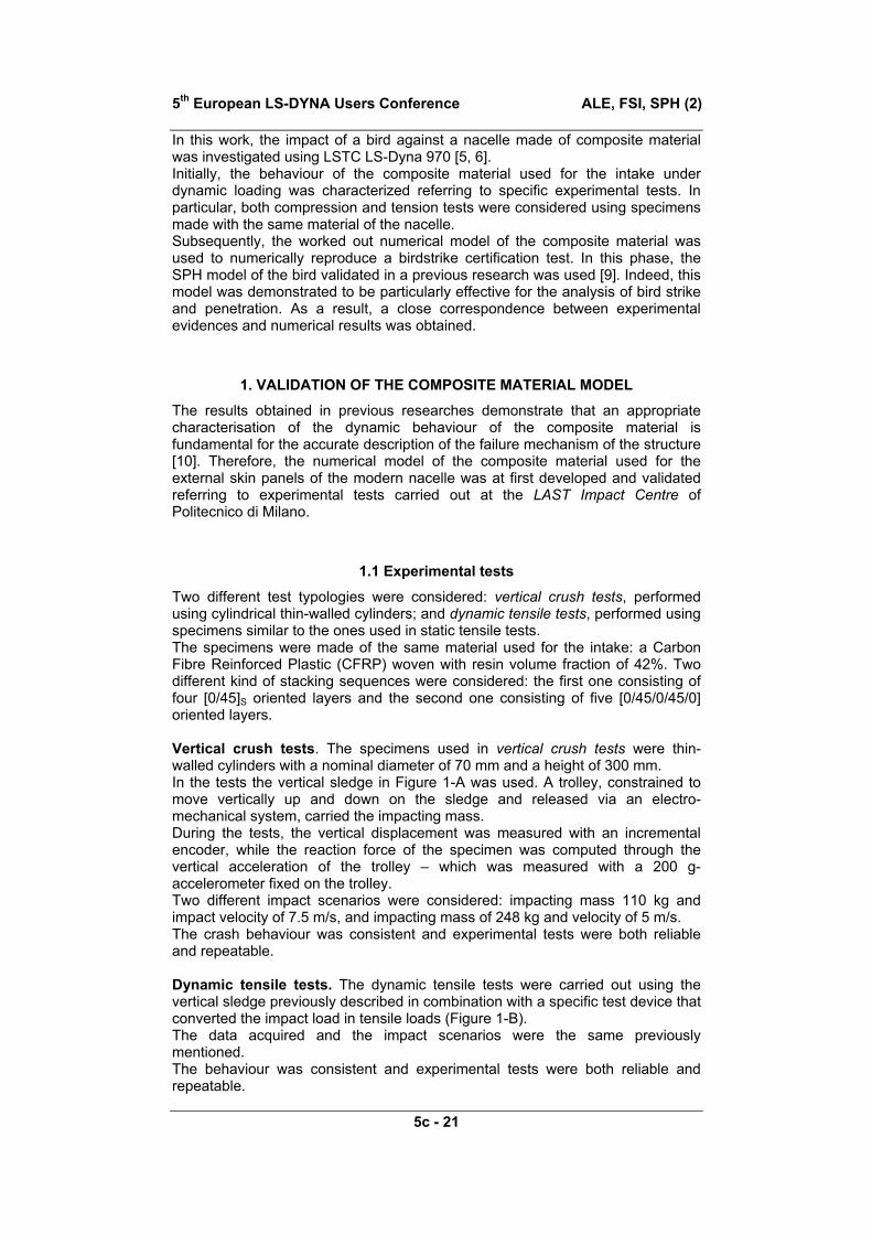
5th European LS-DYNA Users Conference ALE, FSI, SPH (2)
5c - 21
Birdstrike onto the Composite Intake of a Turbofan Engine
Authors:
Marco ANGHILERI* Luigi-M L CASTELLETTI*
Fabio INVERNIZZI* Marco MASCHERONI*
Affiliation for all the authors: Department of Aerospace Engineering Politecnico di Milano
via La Masa 34, 20156 Milano, Italy
Correspondence:
Luigi-M L CASTELLETTI
Telephone: 00 39 02 2399 7155 Fax: 00 39 02 2399 7153
E-mail address: [email protected]
Keywords:
Bird Strike, Composite Material, Explicit Finite Element Codes, Smoothed Particle Hydrodynamics

ALE, FSI, SPH (2) 5th European LS-DYNA Users Conference
5c - 21
ABSTRACT
Birdstrike is a menace for flight safety likely to have tragic consequences. In view of that, the efforts provided to design high-efficiency bird-proof structures are fully justified. In this work the impact of a standard 4-lb bird onto a nacelle made of composite material required for the certification of the component has been investigated using LS-Dyna 970. Initially, the dynamic behaviour of the composite material used in the manufacturing of the external skin panels of the intake was achieved by referring to specific experimental tests. It was observed, in fact, that the dynamic behaviour of the composite material has a deep influence on the failure mechanism of the structure. Subsequently, the numerical model worked out for the composite material was used to numerically reproduce a bird impact certification test. A SPH model of the bird validated in previous research was used. A good numerical-experimental correlation between experimental data and numerical results was obtained.
INTRODUCTION
Statistics [1, 2] report that collisions between aircraft and birds still represents an actual menace for flight safety as these are likely to cause consequences that can be tragic especially for the small airplanes of the general aviation. Therefore, it is not surprising that aircraft before being put into operational service have to be certified for a proven level of bird impact resistance. Indeed, a completely bird-proof structure is not achievable (it would be too heavy to fly) and, therefore, it is important to guarantee that the aircraft were able to land in safety after the impact with a bird [3]. In that, since the experimental tests are expensive and difficult to perform, computer modelling turns into being an irreplaceable design tool in the development of bird-proof structures. Nonlinear explicit codes based on Finite Element Method (FEM), in particular, are currently successfully used to develop high efficiency (i.e. high-resistance, low-weight) bird-proof structures [4-10]. The front parts of the aircraft are the most exposed to the risk of a bird-strike. Among these, in particular, the intakes of turbofan engines are called to withstand the impact avoiding those damages that could compromise the fly-home capability - such as the damages of the equipment that controls the engine that is usually placed behind the aft bulkhead of the intake. The external skin panels of the nacelles are made of composite materials, which allow the manufacturing of light structures with high stiffness-to-weight and strength-to-weight ratios. The crash behaviour of composite materials is characterised by complex failure events (lamina bending, transverse shear and local fibre buckling) and progressive damage modes, such as inter-laminar or intra-laminar cracks [5, 11-12]. Therefore, it comes to be extremely difficult to accurately model the failure mechanism of a structure made of composite materials. In view of that, appropriate analytical models and specific constitutive laws have to be defined and tuned to predict failure/damage mechanisms and their evolution.
5th European LS-DYNA Users Conference ALE, FSI, SPH (2)
5c - 21
In this work, the impact of a bird against a nacelle made of composite material was investigated using LSTC LS-Dyna 970 [5, 6]. Initially, the behaviour of the composite material used for the intake under dynamic loading was characterized referring to specific experimental tests. In particular, both compression and tension tests were considered using specimens made with the same material of the nacelle. Subsequently, the worked out numerical model of the composite material was used to numerically reproduce a birdstrike certification test. In this phase, the SPH model of the bird validated in a previous research was used [9]. Indeed, this model was demonstrated to be particularly effective for the analysis of bird strike and penetration. As a result, a close correspondence between experimental evidences and numerical results was obtained.
1. VALIDATION OF THE COMPOSITE MATERIAL MODEL
The results obtained in previous researches demonstrate that an appropriate characterisation of the dynamic behaviour of the composite material is fundamental for the accurate description of the failure mechanism of the structure [10]. Therefore, the numerical model of the composite material used for the external skin panels of the modern nacelle was at first developed and validated referring to experimental tests carried out at the LAST Impact Centre of Politecnico di Milano.
1.1 Experimental tests
Two different test typologies were considered: vertical crush tests, performed using cylindrical thin-walled cylinders; and dynamic tensile tests, performed using specimens similar to the ones used in static tensile tests. The specimens were made of the same material used for the intake: a Carbon Fibre Reinforced Plastic (CFRP) woven with resin volume fraction of 42%. Two different kind of stacking sequences were considered: the first one consisting of four [0/45]S oriented layers and the second one consisting of five [0/45/0/45/0] oriented layers. Vertical crush tests. The specimens used in vertical crush tests were thin-walled cylinders with a nominal diameter of 70 mm and a height of 300 mm. In the tests the vertical sledge in Figure 1-A was used. A trolley, constrained to move vertically up and down on the sledge and released via an electro-mechanical system, carried the impacting mass. During the tests, the vertical displacement was measured with an incremental encoder, while the reaction force of the specimen was computed through the vertical acceleration of the trolley – which was measured with a 200 g-accelerometer fixed on the trolley. Two different impact scenarios were considered: impacting mass 110 kg and impact velocity of 7.5 m/s, and impacting mass of 248 kg and velocity of 5 m/s. The crash behaviour was consistent and experimental tests were both reliable and repeatable. Dynamic tensile tests. The dynamic tensile tests were carried out using the vertical sledge previously described in combination with a specific test device that converted the impact load in tensile loads (Figure 1-B). The data acquired and the impact scenarios were the same previously mentioned. The behaviour was consistent and experimental tests were both reliable and repeatable.

ALE, FSI, SPH (2) 5th European LS-DYNA Users Conference
5c - 21
(A) (B)
Figure 1 – Test facility: (A) the vertical sledge and (B) the device to perform dynamic tensile stress.
1.2 FE models
The experimental tests previously described were reproduced in detail in order to develop and validate the numerical model of the composite material. Vertical crush tests (Figure 2-A). The cylindrical shells were modelled with four-node shell elements. A single integration point was defined for each ply throughout the thickness. A sensitivity analysis on the element size was carried out to avoid mesh effects on the numerical results and different element formulations were considered. The final FE model had a characteristic length of 3 mm and consisted of over three thousands shell elements. Initial and boundary conditions were carefully considered and reproduced according to the experimental tests. Dynamic tensile tests (Figure 2-B). The specimens used in the dynamic tensile tests were modelled with 1900 four-node shell elements. A single integration point was defined for each ply throughout the thickness. Initial and boundary conditions (the specimen clamping, in particular) were carefully considered and reproduced according to the experimental tests.

5th European LS-DYNA Users Conference ALE, FSI, SPH (2)
5c - 21
(A) (B)
Figure 2 – Stress distribution in the first ply of the specimen used for (A) the compressive crush test and (B) for the dynamic tensile test.
1.3 Material model
Initially, moving from the results of previous researches [10], a material that showed to be particularly appropriate to model crash behaviour of composite materials was used: i.e. MAT LAMINATED COMPOSITE FABRIC, MAT_58 [5, 6]. Indeed, this material model has been developed specifically for laminated composite material [11-12]: basically, that is an elastic-damage model developed around the idea that damages introduce micro-cracks and cavities into materials and that these defects cause a stiffness degradation with small permanent deformation – unless material undergoes rather high loading and is not close to deterioration. A non-smooth failure surface is assumed and, in order to allow an almost uncoupled failure of an arbitrary composite, all failure criteria are taken to be independent from each other. Subsequently, the benefit coming from the improvement to this material, MAT RATE SENSITIVE COMPOSITE FABRIC, MAT_158 [7], was investigated. The basic idea is the same of MAT_58: in addition, this material takes into account the strain-rate effects. Indeed, a viscous tensor, based on an isotropic Maxwell model with up to six terms in the Prony series expansion [13], is superimposed on the rate independent stress tensor of the MAT_58.

ALE, FSI, SPH (2) 5th European LS-DYNA Users Conference
5c - 21
1.4 Numerical-experimental correlation
For both the tests typologies and for both the impact scenarios, the comparison between the load-shortening curves experimentally measured and numerically calculated showed a good correlation in terms of loads and absorbed energies as well as in terms of the curve shape. In particular, it was observed that the MAT 158, with properly calibrated parameters, allowed obtaining a first acceleration peak very close to the experimental one.
2. BIRDSTRIKE TEST ONTO A TURBOFAN INTAKE
The numerical model of the composite material was developed and validated in order to improve the representation of the failure mechanism of a turbofan intake. Nevertheless, the good numerical-experimental correlation obtained in the first phase of the work is a result that goes beyond the limits of the present analysis and it is feasible to be applied in other similar problems.
2.1 Experimental birdstrike test
Experimental full-scale birdstrike tests are extremely expensive and difficult to perform. Therefore, in the design development phase, using structure prototypes, it is a common practise to carry out a second test after the test with the impact velocity required for the certification. In particular, in this second test, the impact velocity is higher in order to evaluate the actual resistance level of the structure. Such a test carried out was here considered: the bird impacted the intake with a velocity of about 330 kts (TAS) penetrating inside the airframe through the outer barrel that collapsed after the impact (Figure 4).
2.2 FE of the intake
The numerical model of the intake reproduced in detail an actual intake. The FE mesh (Figure 3), built on the actual geometry of a 1.60 m-diameter intake, consisted of over sixty thousands four-nodes shell-elements. The intake consisted of sixteen parts. Five of these parts were manufactured with composite material, and one, the inner barrel, using the sandwich technology (composite materials and Aluminium honeycomb) to obtain a high flexural-strength/weight ratios and a good noise control. Four parts were made of Titanium alloy Ti-6Al-4V and the remaining of two distinct Aluminium alloys: Al 2219-T62, the nose-lip, and Al 2024-T6, the other parts. The numerical model worked out in the first stage of the work was used for the parts manufactured with composite material. The materials used for the remaining parts were modelled as an elastic material with a piecewise (isotropic) linear plasticity and using for the mechanical properties the typical values. Appropriate Cowper-Symonds coefficients were introduced to model the strain-rate effects. In order to reproduce the actual constraint that the airframe of the engine imposes to the intake, the inner and outer flanges of the aft part of the intake (in the FE model) were fixed. The riveted junctions were modelled in detailed. Contacts among the parts were carefully modelled.

5th European LS-DYNA Users Conference ALE, FSI, SPH (2)
5c - 21
Figure 3 – FE model of the intake
2.3 Numerical model of the bird
The birdstrike test is actually one of the most severe certification tests for a nacelle. The failure of the intake and a subsequent penetration are allowed. However, it is fundamental to preserve the fly-home capability of the aircraft. In view of that, the analysis of this event is extremely troublesome and customary FE approach is not recommendable. Indeed, a reliable SPH model was used [9]. The bird, weighting 4 lb, had the shape of a rugby ball and consisted of about 1500 SPH particles. The distance among the particles (the same in the three directions for all the particles) was a trade-off between accuracy and required CPU-time. The interaction between the bird and the intake was defined using a nodes to surface contact algorithm.
2.4 Obtained results and numerical-experimental correlation
The accuracy of the simulations results was (qualitatively) evaluated referring to the after-impact damages documented in the photographic report and the dynamics of the events captured with the high-speed movies. After-impact damages (Figure 5-A). In view of the photographic documentation of the after-test damages (Figure 4), the numerical simulations gave a quite accurate description of the event and, in particular, of damages reported by the intake after the impact. Dynamics of the event (Figure 5-B). With regard to the dynamics of the events, the results of the simulations and the high-speed movie of the test were close. In particular, the numerical model succeeded in reproducing the failure mechanism of the intake. This fact demonstrated demonstrated that the validated composite

ALE, FSI, SPH (2) 5th European LS-DYNA Users Conference
5c - 21
material model could be proficiently used to analyse high velocity impacts such as bird impacts. Furthermore, it is worth noticing that the SPH bird model allowed to describe the event with a certain accuracy – also when the structure collapsed and the bird penetrated into the airframe. In view of the results obtained, the design of the intake was further modified. In that, the numerical model demonstrated to be a powerful tool – able to accelerate the design phase and the development of high efficiency bird-proof structures.
Figure 4 –After-test damages
SUMMARY AND CONCLUSIONS
Bird impact is one of the most dangerous events for the safety of modern aircraft and, therefore, it is very important to develop numerical tools to support the design of high-efficiency bird-proof structures. In particular, the intake of a turbofan engine is one of the most exposed parts of an aircraft. The failure of the intake structure is admissible – though the fly-home capability of the aircraft must be guaranteed. In this work, the impact of a bird onto a turbofan intake was analysed using LSTC LS-Dyna 970. The external skin panels of an intake are customarily manufactured using composite materials. These materials exhibit a complicated failure mechanism that requires a numerical model to be analysed in detail. Consequently, in the first part of the research, the behaviour of composite materials under dynamic loading conditions was characterised referring to vertical crush tests and dynamic tensile tests. Subsequently, the worked out model was used to reproduce a birdstrike post-certification test. As a result, the dynamics of the event was accurately reproduced and the proficiency of the proposed approach was demonstrated.

5th European LS-DYNA Users Conference ALE, FSI, SPH (2)
5c - 21
(A)
(B)
Figure 5 – Numerical results: (A) after-impact damages and (B) dynamics of the event

ALE, FSI, SPH (2) 5th European LS-DYNA Users Conference
5c - 21
REFERENCES
1. E. C. Cleary, R. A. Dolbeer, S. E. Wright: “Wildlife strikes to civil aircraft in the united states 1990–2002”. Federal Aviation Administration, National Wildlife Strike Database. Serial report number 9. Washington, DC. June 2003.
2. W. J. Richardson, T. West: “Serious birdstrike accidents to military aircraft: updated list and summary”. International Bird Strike Committee – 25th Meeting. Amsterdam, the Netherlands, 17-20 April 2000
3. R. A. Brockman, T. W. Held: “Explicit finite element method for transparency impact analysis”. Dayton University, OH – Final technical report, Sep.1988-Sep.1990
4. M. Anghileri, C. Bisagni: "New model of bird strike against aircraft turbofan inlet". Proceedings of 3rd International KRASH Conference, Arizona State University, Tempe (USA), 2001, p. 8.3.1-8.3.11
5. J. O. Hallquist: “LS-DYNA Theoretical Manual” Livermore Software Technology Corporation (1998)
6. J. O. Hallquist: “LS-DYNA Keyword User’s Manual”, Livermore Software Technology Corporation, Apr. 2003
7. J. O. Hallquist: “Release Note for Version 970”, Livermore Software Technology Corporation, Aug. 2004
8. Schweizerhof K, Weimar K, Munz T, Rottner T.: “Crashworthiness analysis with enhanced composite material models in LS-DYNA - Merits and Limits”. Proceedings of the 5th International LS-DYNA Users Conference, Southfield, 21-22 September 1998
9. Anghileri M, Castelletti L-M L, and Mazza V: “Birdstrike: Approaches to the Analysis of Impacts with Penetration”. International Conference on Impact Loading of Lightweight Structures. Florianópolis, Brazil. 7-8 May 2004
10. Anghileri M, Castelletti L-M L, Mentuccia F, and Lanzi L: “Composite Materials and Bird-Strike Analysis Using Explicit Finite Element Commercial Codes”. SUSI 2004. Crete, Greece. 2004
11. Schweizerhof K, Weimar K, Munz T, Rottner T: “Crashworthiness analysis with enhanced composite material models in LS-DYNA - Merits and Limits”. Proceedings of the 5th International LS-DYNA Users Conference, Southfield, 21-22 September 1998
12. Matzenmiller, A.; Lubliner, J.; and Taylor, R.L.: “A Constitutive Model for Anisotropic Damage in Fiber-Composites”, Vol. 20, p. 125-152, Mechanics of Materials (1995).
13. Tzikang Chen: “Determining a Prony Series for a Viscoelastic Material From Time Varying Strain Data”. U.S. Army Research Laboratory, Vehicle Technology Directorate, Langley Research Center, Hampton, Virginia


![Birdstrike involving SAAB 340B, VH-OLM, Moruya Airport, New … · ATSB Transport Safety Report [Insert Mode] Occurrence Investigation XX-YYYY-#### Final Investigation Birdstrike](https://img.pdfslide.us/doc/110x75/5f33754d6c705f42b77f441f/birdstrike-involving-saab-340b-vh-olm-moruya-airport-new-atsb-transport-safety.jpg)