Embed Size (px)
Citation preview
Loughborough UniversityInstitutional Repository
Bipolar modulation of theoutput of a 10-GW pulsed
power generator
This item was submitted to Loughborough University's Institutional Repositoryby the/an author.
Citation: WANG, M. ... et al, 2016. Bipolar modulation of the output of a10-GW pulsed power generator. IEEE Transactions on Plasma Science, 44 (10),pp.1971-1977.
Additional Information:
• c© IEEE. Personal use of this material is permitted. Permission fromIEEE must be obtained for all other uses, in any current or future media,including reprinting/republishing this material for advertising or promo-tional purposes, creating new collective works, for resale or redistributionto servers or lists, or reuse of any copyrighted component of this work inother works.
Metadata Record: https://dspace.lboro.ac.uk/2134/21928
Version: Accepted for publication
Publisher: c© IEEE
Please cite the published version.
IEEE P
roof
IEEE TRANSACTIONS ON PLASMA SCIENCE 1
Bipolar Modulation of the Output of a10-GW Pulsed Power Generator
Meng Wang, Student Member, IEEE, Bucur M. Novac, Senior Member, IEEE, Laurent Pécastaing,and Ivor R. Smith, Senior Member, IEEE
Abstract— A bipolar Blumlein former has been designedand successfully implemented as an extension to an existing10-GW-Tesla-driven Blumlein pulsed power generator. The newsystem is capable of generating a voltage impulse with a peak-to-peak value reaching 650 kV and having a high-frequency limit ofthe bandwidth well in excess of 1 GHz. Constructional details areprovided, together with experimental results and analysis usingthe 3-D software modeling of the bipolar former that providesthe results in good agreement with experimental data.
Index Terms— Pulse compression circuits, pulse modulation,pulsed power systems, transient propagation.
I. INTRODUCTION
ABROAD range of modern pulsed power applications,including plasma physics, lasers, particle accelerators,
aeronautics, outer space science, food industry pulsed-electric-field (PEF) sterilization, bioelectric studies, medical cancertreatment, and the defense industry, require the generationof very fast high-voltage (HV) pulses. The development of acompact Tesla-transformer Blumlein pulse forming line (PFL)pulsed power generator capable of producing a monopolar0.6 MV voltage impulse with a rise time close to 2 ns andproviding a peak electrical power of 10 GW when connectedto a 30 � load was reported previously [1]. The first intendedapplication is to use the generator for noninvasive medicalcancer treatment, by attaching to its output an antenna togenerate intense PEFs. However, it is straightforward to showthat a monopolar voltage impulse is not well suited to feedingan antenna and that a bipolar signal will have the followingadvantages [2].
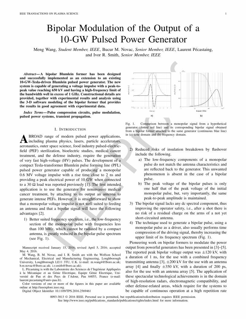
1) Better suited frequency spectrum, i.e., the low-frequencysection of the monopolar pulse with frequencies lessthan 100 MHz, which cannot be radiated by a compactantenna, is greatly reduced in the bipolar pulse spectrum(see Fig. 1).
Manuscript received January 15, 2016; revised April 5, 2016; acceptedMay 4, 2016.
M. Wang, B. M. Novac, and I. R. Smith are with the Wolfson Schoolof Mechanical, Electrical and Manufacturing Engineering, LoughboroughUniversity, Loughborough LE11 3TU, U.K. (e-mail: [email protected];[email protected]; [email protected]).
L. Pécastaing is with the Laboratoire des Sciences de l’Ingénieur Appliquéesà la Mécanique et au Génie Electrique, Equipe Génie Electrique, Uni-versité de Pau et des Pays de l’Adour, Pau 64053, France (e-mail:[email protected]).
Color versions of one or more of the figures in this paper are availableonline at http://ieeexplore.ieee.org.
Digital Object Identifier 10.1109/TPS.2016.2569461
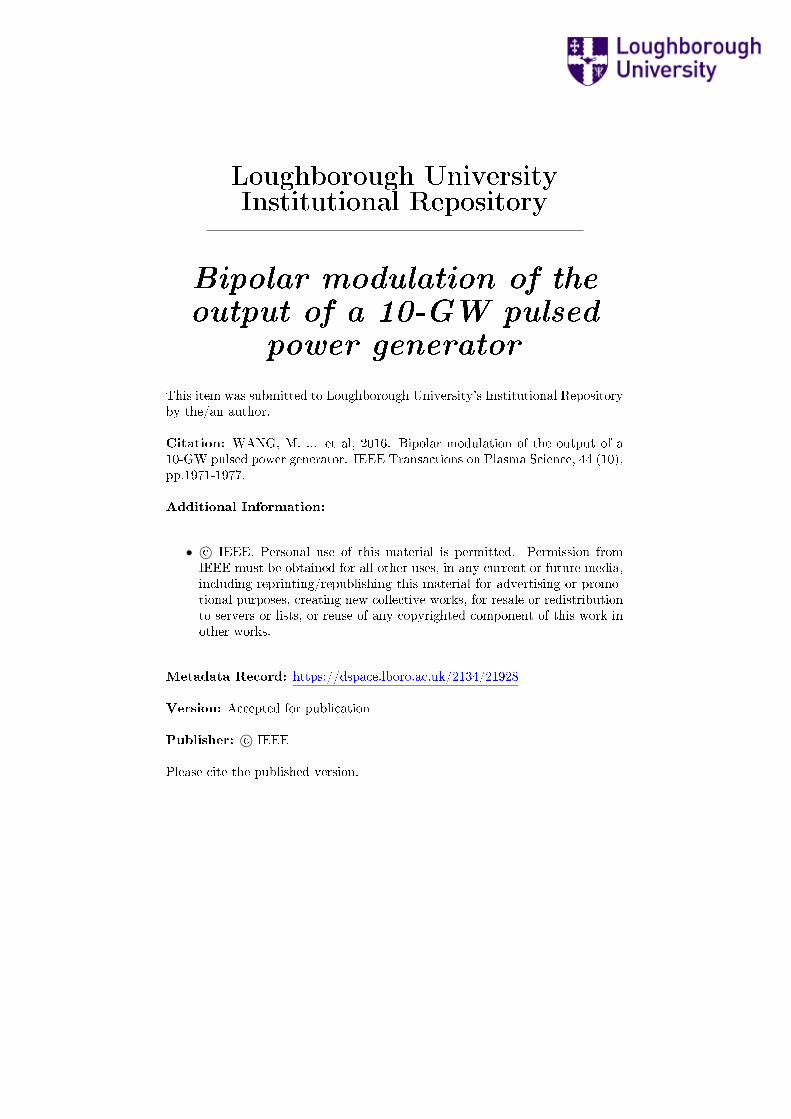
Fig. 1. Comparison between a monopolar signal from a hypotheticalgenerator (dotted red line) and its corresponding bipolar signal obtainedfrom a bipolar former attached to the same generator (continuous blue line)in (a) time domain and (b) frequency domain.
2) Reduced risks of insulation breakdown by flashoverinclude the following.
a) The low-frequency components of a monopolarpulse do not match the antenna characteristics andare reflected back to the generator. This unwantedphenomenon is absent in the case of a bipolarpulse.
b) The peak voltage of the bipolar pulses is onlyone half that of the peak voltage of the initialmonopolar pulse, but, very importantly, the samepeak-to-peak amplitude is maintained.
3) The bipolar signal lacks any dc spectral component, thusimproving the operator safety, i.e., after a shot there isno risk of a residual charge on the arms of a not yetshort-circuited antenna.
4) The technique used to generate a bipolar pulse, using amonopolar pulse as a driver, also usually performs timecompression of the driving signal, thereby increasing theupper limit of its frequency spectrum (Fig. 1).
Pioneering work on bipolar formers to modulate the poweroutput from powerful generators has been presented in [3]–[5].The reported peak bipolar voltage output was ±120 kV, witha duration of 1 ns, for the use with a combined frequencytransmitting antenna [3], ±200 kV for the use with an antennaarray [4] and finally ±350 kV, with a duration of 200 ps,also for the use with an antenna array [5]. The application ofthese spectacular technological achievements is in the domainof high-resolution radars, electromagnetic compatibility, andother defense-related areas, which require for the systems tobe capable of continuous operation at a high repetition rate
0093-3813 © 2016 IEEE. Personal use is permitted, but republication/redistribution requires IEEE permission.See http://www.ieee.org/publications_standards/publications/rights/index.html for more information.
IEEE P
roof
2 IEEE TRANSACTIONS ON PLASMA SCIENCE
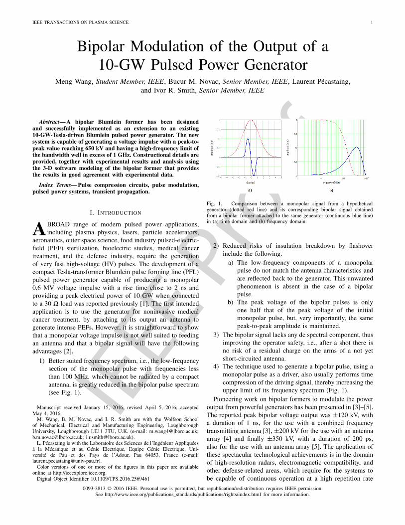
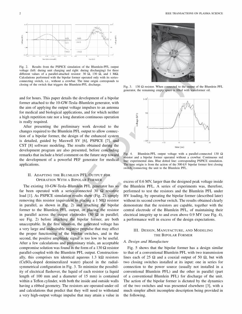
Fig. 2. Results from the PSPICE simulation of the Blumlein-PFL outputvoltage (left: during unit charging and right: during discharging) for threedifferent values of a parallel-attached resistor: 30 �, 130 �, and 1 M�.Calculations performed with the bipolar former operated only with its series-connecting switch, i.e., without a crowbar. The time origin corresponds toclosing of the switch that triggers the Blumlein-PFL discharge.
and for hours. This paper details the development of a bipolarformer attached to the 10-GW-Tesla–Blumlein generator, withthe aim of applying the output voltage impulses to an antennafor medical and biological applications, and for which neithera high repetition rate nor a long duration continuous operationis really required.
After presenting the preliminary work devoted to thechanges required to the Blumlein PFL output to allow connec-tion of a bipolar former, the design of the enhanced systemis detailed, guided by Maxwell SV [6], PSPICE [7], andCST [8] software modeling. The results obtained during thedevelopment program are also presented, before concludingremarks that include a brief comment on the future step towardthe development of a powerful PEF generator for medicalapplications.
II. ADAPTING THE BLUMLEIN PFL OUTPUT FOR
OPERATION WITH A BIPOLAR FORMER
The existing 10-GW-Tesla–Blumlein PFL generator has sofar been operated with a series-connected 30 � resistiveload [1]. As PSPICE simulation results show (Fig. 2), simplyremoving this resistor (equivalent to placing a 1 M� resistorin parallel, as shown in Fig. 2) and attaching the bipolarformer to the Blumlein PFL output, or placing the resistorin parallel across the output electrodes (30 � in parallel;see Fig. 2) before attaching the bipolar former, are bothunacceptable. In the first situation, the generated voltage hasa very large and undesirable negative prepulse that may affectthe proper functioning of the bipolar switches, and in thesecond, the positive amplitude signal is too low to be useful.After a few calculations and preliminary trials, an acceptablecompromise solution was found in the form of a 130 � resistorparallel-coupled with the Blumlein PFL output. Construction-ally, this comprises ten identical aqueous 1.3 k� resistors(CuSO4-doped demineralized water) placed in the radial-symmetrical configuration in Fig. 3. To minimize the possibil-ity of electrical flashover, the liquid of each resistor (a liquidlength of 100 mm and a diameter of 15 mm) is containedwithin a Teflon cylinder, with both the inside and outside wallshaving a ribbed geometry. The resistors are operated under oiland calculations that predict that they will need to withstanda very high-output voltage impulse that may attain a value in
Fig. 3. 130 � resistor. When connected to the output of the Blumlein PFLgenerator, the remaining empty space is filled with transformer oil.
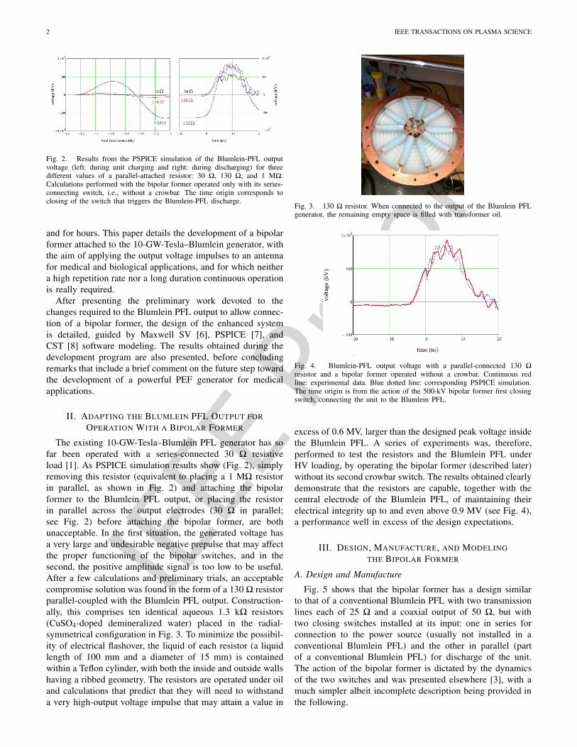
Fig. 4. Blumlein-PFL output voltage with a parallel-connected 130 �resistor and a bipolar former operated without a crowbar. Continuous redline: experimental data. Blue dotted line: corresponding PSPICE simulation.The time origin is from the action of the 500-kV bipolar former first closingswitch, connecting the unit to the Blumlein PFL.
excess of 0.6 MV, larger than the designed peak voltage insidethe Blumlein PFL. A series of experiments was, therefore,performed to test the resistors and the Blumlein PFL underHV loading, by operating the bipolar former (described later)without its second crowbar switch. The results obtained clearlydemonstrate that the resistors are capable, together with thecentral electrode of the Blumlein PFL, of maintaining theirelectrical integrity up to and even above 0.9 MV (see Fig. 4),a performance well in excess of the design expectations.
III. DESIGN, MANUFACTURE, AND MODELING
THE BIPOLAR FORMER
A. Design and Manufacture
Fig. 5 shows that the bipolar former has a design similarto that of a conventional Blumlein PFL with two transmissionlines each of 25 � and a coaxial output of 50 �, but withtwo closing switches installed at its input: one in series forconnection to the power source (usually not installed in aconventional Blumlein PFL) and the other in parallel (partof a conventional Blumlein PFL) for discharge of the unit.The action of the bipolar former is dictated by the dynamicsof the two switches and was presented elsewhere [3], with amuch simpler albeit incomplete description being provided inthe following.
IEEE P
roof
WANG et al.: BIPOLAR MODULATION OF THE OUTPUT OF A 10-GW PULSED POWER GENERATOR 3
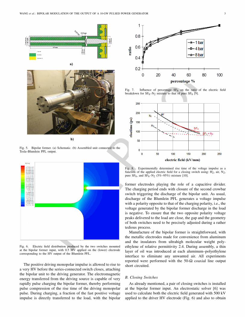
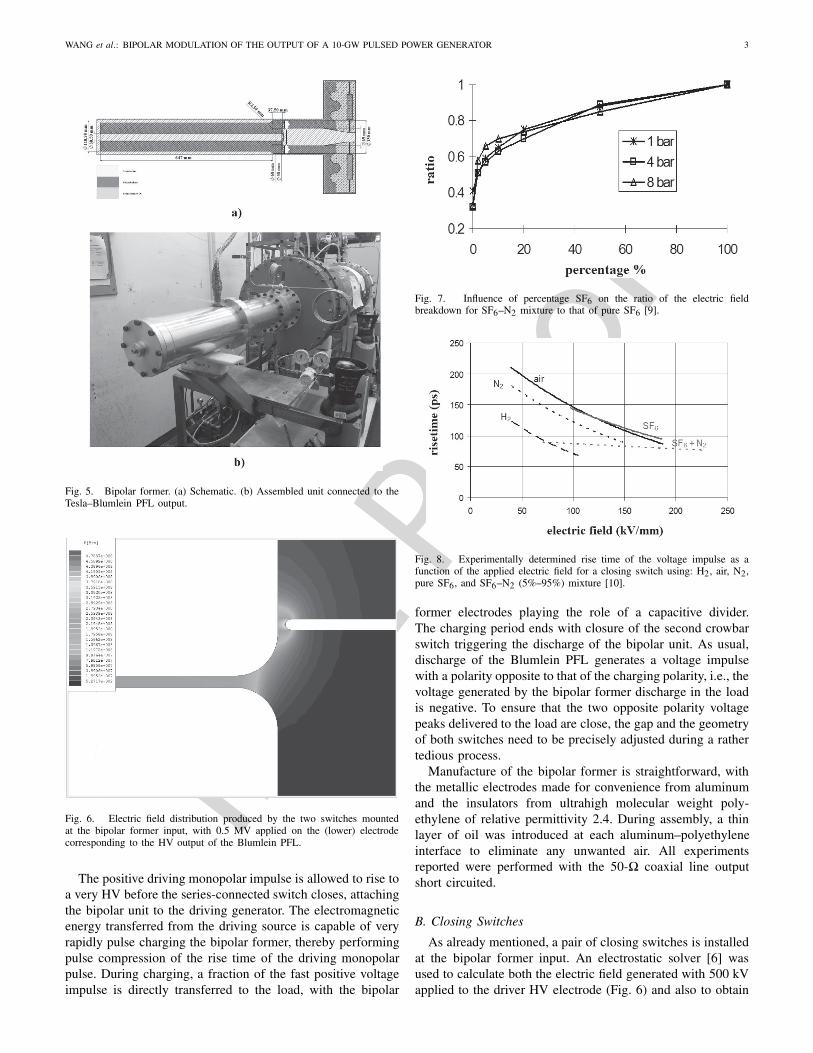
Fig. 5. Bipolar former. (a) Schematic. (b) Assembled unit connected to theTesla–Blumlein PFL output.
Fig. 6. Electric field distribution produced by the two switches mountedat the bipolar former input, with 0.5 MV applied on the (lower) electrodecorresponding to the HV output of the Blumlein PFL.
The positive driving monopolar impulse is allowed to rise toa very HV before the series-connected switch closes, attachingthe bipolar unit to the driving generator. The electromagneticenergy transferred from the driving source is capable of veryrapidly pulse charging the bipolar former, thereby performingpulse compression of the rise time of the driving monopolarpulse. During charging, a fraction of the fast positive voltageimpulse is directly transferred to the load, with the bipolar
Fig. 7. Influence of percentage SF6 on the ratio of the electric fieldbreakdown for SF6–N2 mixture to that of pure SF6 [9].
Fig. 8. Experimentally determined rise time of the voltage impulse as afunction of the applied electric field for a closing switch using: H2, air, N2,pure SF6, and SF6–N2 (5%–95%) mixture [10].
former electrodes playing the role of a capacitive divider.The charging period ends with closure of the second crowbarswitch triggering the discharge of the bipolar unit. As usual,discharge of the Blumlein PFL generates a voltage impulsewith a polarity opposite to that of the charging polarity, i.e., thevoltage generated by the bipolar former discharge in the loadis negative. To ensure that the two opposite polarity voltagepeaks delivered to the load are close, the gap and the geometryof both switches need to be precisely adjusted during a rathertedious process.
Manufacture of the bipolar former is straightforward, withthe metallic electrodes made for convenience from aluminumand the insulators from ultrahigh molecular weight poly-ethylene of relative permittivity 2.4. During assembly, a thinlayer of oil was introduced at each aluminum–polyethyleneinterface to eliminate any unwanted air. All experimentsreported were performed with the 50-� coaxial line outputshort circuited.
B. Closing Switches
As already mentioned, a pair of closing switches is installedat the bipolar former input. An electrostatic solver [6] wasused to calculate both the electric field generated with 500 kVapplied to the driver HV electrode (Fig. 6) and also to obtain
IEEE P
roof
4 IEEE TRANSACTIONS ON PLASMA SCIENCE
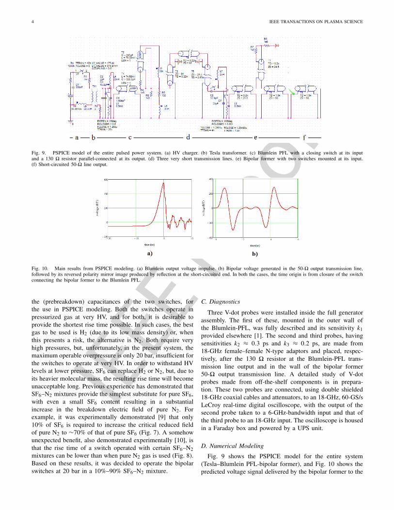
Fig. 9. PSPICE model of the entire pulsed power system. (a) HV charger. (b) Tesla transformer. (c) Blumlein PFL with a closing switch at its inputand a 130 � resistor parallel-connected at its output. (d) Three very short transmission lines. (e) Bipolar former with two switches mounted at its input.(f) Short-circuited 50-� line output.
Fig. 10. Main results from PSPICE modeling. (a) Blumlein output voltage impulse. (b) Bipolar voltage generated in the 50-� output transmission line,followed by its reversed polarity mirror image produced by reflection at the short-circuited end. In both the cases, the time origin is from closure of the switchconnecting the bipolar former to the Blumlein PFL.
the (prebreakdown) capacitances of the two switches, forthe use in PSPICE modeling. Both the switches operate inpressurized gas at very HV, and for both, it is desirable toprovide the shortest rise time possible. In such cases, the bestgas to be used is H2 (due to its low mass density) or, whenthis presents a risk, the alternative is N2. Both require veryhigh pressures, but, unfortunately, in the present system, themaximum operable overpressure is only 20 bar, insufficient forthe switches to operate at very HV. In order to withstand HVlevels at lower pressure, SF6 can replace H2 or N2, but, due toits heavier molecular mass, the resulting rise time will becomeunacceptable long. Previous experience has demonstrated thatSF6–N2 mixtures provide the simplest substitute for pure SF6,with even a small SF6 content resulting in a substantialincrease in the breakdown electric field of pure N2. Forexample, it was experimentally demonstrated [9] that only10% of SF6 is required to increase the critical reduced fieldof pure N2 to ∼70% of that of pure SF6 (Fig. 7). A somehowunexpected benefit, also demonstrated experimentally [10], isthat the rise time of a switch operated with certain SF6–N2mixtures can be lower than when pure N2 gas is used (Fig. 8).Based on these results, it was decided to operate the bipolarswitches at 20 bar in a 10%–90% SF6–N2 mixture.
C. Diagnostics
Three V-dot probes were installed inside the full generatorassembly. The first of these, mounted in the outer wall ofthe Blumlein-PFL, was fully described and its sensitivity k1provided elsewhere [1]. The second and third probes, havingsensitivities k2 ≈ 0.3 ps and k3 ≈ 0.2 ps, are made from18-GHz female–female N-type adaptors and placed, respec-tively, after the 130 � resistor at the Blumlein-PFL trans-mission line output and in the wall of the bipolar former50-� output transmission line. A detailed study of V-dotprobes made from off-the-shelf components is in prepara-tion. These two probes are connected, using double shielded18-GHz coaxial cables and attenuators, to an 18-GHz, 60-GS/sLeCroy real-time digital oscilloscope, with the output of thesecond probe taken to a 6-GHz-bandwidth input and that ofthe third probe to an 18-GHz input. The oscilloscope is housedin a Faraday box and powered by a UPS unit.
D. Numerical Modeling
Fig. 9 shows the PSPICE model for the entire system(Tesla–Blumlein PFL-bipolar former), and Fig. 10 shows thepredicted voltage signal delivered by the bipolar former to the
IEEE P
roof
WANG et al.: BIPOLAR MODULATION OF THE OUTPUT OF A 10-GW PULSED POWER GENERATOR 5
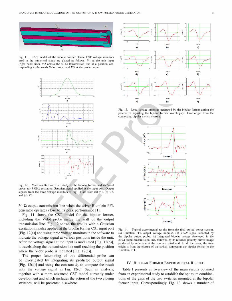
Fig. 11. CST model of the bipolar former. Three CST voltage monitorsused in the numerical study are placed as follows: V 1 at the unit input(right hand side), V 2 across the 50-� transmission line at a position cor-responding to the (real) V-dot probe, and V 3 at the probe output.
Fig. 12. Main results from CST study of the bipolar former and its V-dotprobe. (a) 3-GHz excitation Gaussian signal applied at the input port. Outputsignals from the three voltage monitors of Fig. 11 are from (b) V 1, (c) V 2,and (d) V 3.
50-� output transmission line when the driver Blumlein-PFLgenerator operates close to its peak performance [1].
Fig. 11 shows the CST model for the bipolar former,including the V-dot probe inside the wall of the outputtransmission line. Fig. 12 shows the results with a Gaussianexcitation impulse applied at the bipolar former CST input port[Fig. 12(a)] and using three voltage monitors in the software toindicate the voltage signal at various positions inside the unit.After the voltage signal at the input is modulated [Fig. 12(b)],it travels along the transmission line until reaching the positionwhere the V-dot probe is mounted [Fig. 12(c)].
The proper functioning of this differential probe canbe investigated by integrating its predicted output signal[Fig. 12(d)] and using the constant k3 to compare the resultwith the voltage signal in Fig. 12(c). Such an analysis,together with a more advanced CST model currently underdevelopment and which includes the action of the two closingswitches, will be presented elsewhere.
Fig. 13. Load voltage impulses generated by the bipolar former during theprocess of adjusting the bipolar former switch gaps. Time origin from theconnecting bipolar switch closure.
Fig. 14. Typical experimental results from the final pulsed power system.(a) Blumlein PFL output voltage impulse. (b) dV /dt signal recorded bythe bipolar output probe. (c) Integrated bipolar voltage developed in the50-� output transmission line, followed by its reversed polarity mirror imageproduced by reflection at the short-circuited end. In all the cases, the timeorigin is from the closure of the switch connecting the bipolar former to theBlumlein PFL.
IV. BIPOLAR FORMER EXPERIMENTAL RESULTS
Table I presents an overview of the main results obtainedfrom an experimental study to establish the optimum combina-tions of the gaps of the two switches mounted at the bipolarformer input. Correspondingly, Fig. 13 shows a number of
IEEE P
roof
6 IEEE TRANSACTIONS ON PLASMA SCIENCE
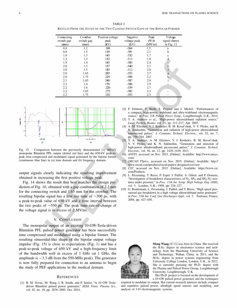
TABLE I
RESULTS FROM THE STUDY OF THE TWO CLOSING SWITCH GAPS OF THE BIPOLAR FORMER
Fig. 15. Comparison between the previously demonstrated [1] 600-kVmonopolar Blumlein PFL output (dotted red line) and the 650-kV peak-to-peak time-compressed and modulated signal generated by the bipolar former(continuous blue line) in (a) time domain and (b) frequency domain.
output signals clearly indicating the resulting improvementobtained in increasing the first positive voltage peak.
Fig. 14 shows the result that best matches the design pre-diction of Fig. 10, obtained with a gap combination of 2.2 mmfor the connecting switch and 1.65 mm for the crowbar. Theresulting bipolar signal has a first rise time of ∼300 ps, witha peak-to-peak value of 650 kV and a time interval betweenthe two peaks of ∼550 ps. The peak time rate-of-change ofthe voltage signal is in excess of 2 MV/ns.
V. CONCLUSION
The monopolar output of an existing 10-GW-Tesla-drivenBlumlein PFL pulsed power generator has been successfullytime compressed and modulated using a bipolar former. Theresulting sinusoidal-like shape of the bipolar output voltageimpulse (Fig. 15) is close to expectations (Fig. 1) and has apeak-to-peak voltage of 650 kV and a high-frequency limitof the bandwidth well in excess of 1 GHz (at 1 GHz, theamplitude is −3.3 dB from the 550-MHz peak). The generatoris now fully prepared for connection to an antenna to beginthe study of PEF applications in the medical domain.
REFERENCES
[1] B. M. Novac, M. Wang, I. R. Smith, and P. Senior, “A 10 GW Tesla-driven Blumlein pulsed power generator,” IEEE Trans. Plasma Sci.,vol. 42, no. 10, pp. 2876–2885, Oct. 2014.
[2] P. Delmote, F. Bieth, S. Pinguet and J. Michel, “Performances ofa compact, high-power, wideband and ultra-wideband electromagneticsource,” in Proc. UK Pulsed Power Symp., Loughborough, U.K., 2014.
[3] Y. A. Andreev et al., “High-power ultrawideband radiation source,”Laser Particle Beams, vol. 21, pp. 211–217, Apr. 2003.
[4] A. M. Efremov, V. I. Koshelev, B. M. Koval’chuk, V. V. Plisko, and K.N. Sukhushin, “Generation and radiation of high-power ultrawidebandnanosecond pulses,” J. Commun. Technol. Electron., vol. 52, no. 7,pp. 756–764, 2007.
[5] Y. A. Andreev, A. M. Efremov, V. I. Koshelev, B. M. Koval’chuk,V. V. Plisko, and K. N. Sukhushin, “Generation and emission ofhigh-power ultrabroadband picosecond pulses,” J. Commun. Technol.Electron., vol. 56, no. 12, pp. 1429–1439, 2011.
[6] ANSYS, accessed on Nov. 2015. [Online]. Available: http://www.ansys.com/
[7] ORCAD PSpice, accessed on Nov. 2015. [Online]. Available: http://www.orcad.com/products/orcad-pspice-designer/overview
[8] CST, accessed on Nov. 2015. [Online]. Available: https://www.cst.com/Products
[9] L. Pécastaing, T. Reess, P. Espel, J. Paillol, A. Gibert, and P. Domens,“Investigation of breakdown characteristics of N2, SF6 and SF6-N2 mix-tures under pressure,” in Proc. 11th Int. Symp. High Voltage Eng. (ISH),vol. 3. London, U.K., 1999, pp. 224–227.
[10] G. Bouttemant, L. Pecastaing, J. Paillol, and T. Reess, “High speed pres-surised gas breakdown in a high voltage ultrawideband pulse generator,”in Proc. 15th Int. Conf. Gas Discharges Appl., vol. 1. Toulouse, France,2004, pp. 427–430.
Meng Wang (S’13) was born in China. She receivedthe B.Sc. degree in electronics science and tech-nology from the Huazhong University of Scienceand Technology, Wuhan, China, in 2011, and theM.Sc. degree in power systems engineering fromUniversity College London, London, U.K., in 2012.She is currently pursuing the Ph.D. degree withthe Plasma and Pulsed Power Group, LoughboroughUniversity, Loughborough, U.K.
Her Ph.D. project is focused on the development ofa 10 GW pulsed power generator and the techniques
required to modulate its output. Her current research interests include compactand repetitive pulsed power, ultrahigh speed sensors and modeling, andanalysis of 3-D electromagnetic systems.
IEEE P
roof
WANG et al.: BIPOLAR MODULATION OF THE OUTPUT OF A 10-GW PULSED POWER GENERATOR 7
Bucur M. Novac (M’06–SM’08) received theM.Sc. and Ph.D. degrees from the University ofBucharest, Bucharest, Romania, in 1977 and 1989,respectively.
He joined the Loughborough University, Lough-borough, U.K., in 1998, where he is currently aProfessor of Pulsed Power. He has co-authored twobooks on explosive pulsed power and has authoredover 200 refereed papers and conference contribu-tions. His current research interests include compactand repetitive high-power systems, explosively and
electromagnetically driven magnetic flux compression generators and theirapplications, electromagnetic launchers, ultrafast magneto and electro-opticsensors, and 2-D modeling of pulsed-power systems.
Dr. Novac is a Voting Member of the Pulsed Power Science and TechnologyCommittee in the IEEE Nuclear and Plasma Science Society. He is alsoa member of the International Steering Committees for the MEGAGAUSSConferences and the Euro-Asian Pulsed Power Conferences. He is alsomember of the Organizing Committee of the IEEE International PowerModulator and High Voltage Conference and Co-Chairman of the U.K. PulsedPower Symposium. He is a Chartered Engineer and a fellow of The Institutionof Engineering and Technology, U.K.
Laurent Pécastaing was born in Bayonne, France,in 1974. He received the Ph.D. degree from theUniversité de Pau et des Pays de l’Adour, Pau,France, in 2001.
He is currently a Lecturer with the LaboratoireSIAME, Université de Pau et des Pays de l’Adour.His current research interests include high-powermicrowave sources, compact pulsed power devices,including pulse-forming lines or Marx generators,and ultrafast transient probes.
Dr. Pécastaing received the Research DirectorshipHabilitation in electrical engineering from the Université de Pau et des Paysde l’Adour, Pau, France, in 2010.
Ivor R. Smith (M’05–SM’11) received the B.Sc.,Ph.D., and D.Sc. degrees from the University ofBristol, Bristol, U.K.
He completed the Indentured Student Apprentice-ship with General Electric Company Works, Witton,U.K. He became a Lecturer with the University ofBirmingham, Birmingham, U.K., subsequently beingpromoted to Senior Lecturer and Reader. He thenmoved to Loughborough University, Loughborough,U.K., to become a Professor of Electrical PowerEngineering, and served as the Head of Department,
the Dean of Engineering and a Pro-Vice Chancellor. For more than 25 years,he has been active in research in many aspects of the production, conditioningand utilization of large pulses of electrical energy.
Dr. Smith is a Chartered Engineer and a fellow of the Institution ofEngineering and Technology and the Royal Academy of Engineering.
IEEE P
roof
IEEE TRANSACTIONS ON PLASMA SCIENCE 1
Bipolar Modulation of the Output of a10-GW Pulsed Power Generator
Meng Wang, Student Member, IEEE, Bucur M. Novac, Senior Member, IEEE, Laurent Pécastaing,and Ivor R. Smith, Senior Member, IEEE
Abstract— A bipolar Blumlein former has been designedand successfully implemented as an extension to an existing10-GW-Tesla-driven Blumlein pulsed power generator. The newsystem is capable of generating a voltage impulse with a peak-to-peak value reaching 650 kV and having a high-frequency limit ofthe bandwidth well in excess of 1 GHz. Constructional details areprovided, together with experimental results and analysis usingthe 3-D software modeling of the bipolar former that providesthe results in good agreement with experimental data.
Index Terms— Pulse compression circuits, pulse modulation,pulsed power systems, transient propagation.
I. INTRODUCTION
ABROAD range of modern pulsed power applications,including plasma physics, lasers, particle accelerators,
aeronautics, outer space science, food industry pulsed-electric-field (PEF) sterilization, bioelectric studies, medical cancertreatment, and the defense industry, require the generationof very fast high-voltage (HV) pulses. The development of acompact Tesla-transformer Blumlein pulse forming line (PFL)pulsed power generator capable of producing a monopolar0.6 MV voltage impulse with a rise time close to 2 ns andproviding a peak electrical power of 10 GW when connectedto a 30 � load was reported previously [1]. The first intendedapplication is to use the generator for noninvasive medicalcancer treatment, by attaching to its output an antenna togenerate intense PEFs. However, it is straightforward to showthat a monopolar voltage impulse is not well suited to feedingan antenna and that a bipolar signal will have the followingadvantages [2].
1) Better suited frequency spectrum, i.e., the low-frequencysection of the monopolar pulse with frequencies lessthan 100 MHz, which cannot be radiated by a compactantenna, is greatly reduced in the bipolar pulse spectrum(see Fig. 1).
Manuscript received January 15, 2016; revised April 5, 2016; acceptedMay 4, 2016.
M. Wang, B. M. Novac, and I. R. Smith are with the Wolfson Schoolof Mechanical, Electrical and Manufacturing Engineering, LoughboroughUniversity, Loughborough LE11 3TU, U.K. (e-mail: [email protected];[email protected]; [email protected]).
L. Pécastaing is with the Laboratoire des Sciences de l’Ingénieur Appliquéesà la Mécanique et au Génie Electrique, Equipe Génie Electrique, Uni-versité de Pau et des Pays de l’Adour, Pau 64053, France (e-mail:[email protected]).
Color versions of one or more of the figures in this paper are availableonline at http://ieeexplore.ieee.org.
Digital Object Identifier 10.1109/TPS.2016.2569461
Fig. 1. Comparison between a monopolar signal from a hypotheticalgenerator (dotted red line) and its corresponding bipolar signal obtainedfrom a bipolar former attached to the same generator (continuous blue line)in (a) time domain and (b) frequency domain.
2) Reduced risks of insulation breakdown by flashoverinclude the following.
a) The low-frequency components of a monopolarpulse do not match the antenna characteristics andare reflected back to the generator. This unwantedphenomenon is absent in the case of a bipolarpulse.
b) The peak voltage of the bipolar pulses is onlyone half that of the peak voltage of the initialmonopolar pulse, but, very importantly, the samepeak-to-peak amplitude is maintained.
3) The bipolar signal lacks any dc spectral component, thusimproving the operator safety, i.e., after a shot there isno risk of a residual charge on the arms of a not yetshort-circuited antenna.
4) The technique used to generate a bipolar pulse, using amonopolar pulse as a driver, also usually performs timecompression of the driving signal, thereby increasing theupper limit of its frequency spectrum (Fig. 1).
Pioneering work on bipolar formers to modulate the poweroutput from powerful generators has been presented in [3]–[5].The reported peak bipolar voltage output was ±120 kV, witha duration of 1 ns, for the use with a combined frequencytransmitting antenna [3], ±200 kV for the use with an antennaarray [4] and finally ±350 kV, with a duration of 200 ps,also for the use with an antenna array [5]. The application ofthese spectacular technological achievements is in the domainof high-resolution radars, electromagnetic compatibility, andother defense-related areas, which require for the systems tobe capable of continuous operation at a high repetition rate
0093-3813 © 2016 IEEE. Personal use is permitted, but republication/redistribution requires IEEE permission.See http://www.ieee.org/publications_standards/publications/rights/index.html for more information.
IEEE P
roof
2 IEEE TRANSACTIONS ON PLASMA SCIENCE
Fig. 2. Results from the PSPICE simulation of the Blumlein-PFL outputvoltage (left: during unit charging and right: during discharging) for threedifferent values of a parallel-attached resistor: 30 �, 130 �, and 1 M�.Calculations performed with the bipolar former operated only with its series-connecting switch, i.e., without a crowbar. The time origin corresponds toclosing of the switch that triggers the Blumlein-PFL discharge.
and for hours. This paper details the development of a bipolarformer attached to the 10-GW-Tesla–Blumlein generator, withthe aim of applying the output voltage impulses to an antennafor medical and biological applications, and for which neithera high repetition rate nor a long duration continuous operationis really required.
After presenting the preliminary work devoted to thechanges required to the Blumlein PFL output to allow connec-tion of a bipolar former, the design of the enhanced systemis detailed, guided by Maxwell SV [6], PSPICE [7], andCST [8] software modeling. The results obtained during thedevelopment program are also presented, before concludingremarks that include a brief comment on the future step towardthe development of a powerful PEF generator for medicalapplications.
II. ADAPTING THE BLUMLEIN PFL OUTPUT FOR
OPERATION WITH A BIPOLAR FORMER
The existing 10-GW-Tesla–Blumlein PFL generator has sofar been operated with a series-connected 30 � resistiveload [1]. As PSPICE simulation results show (Fig. 2), simplyremoving this resistor (equivalent to placing a 1 M� resistorin parallel, as shown in Fig. 2) and attaching the bipolarformer to the Blumlein PFL output, or placing the resistorin parallel across the output electrodes (30 � in parallel;see Fig. 2) before attaching the bipolar former, are bothunacceptable. In the first situation, the generated voltage hasa very large and undesirable negative prepulse that may affectthe proper functioning of the bipolar switches, and in thesecond, the positive amplitude signal is too low to be useful.After a few calculations and preliminary trials, an acceptablecompromise solution was found in the form of a 130 � resistorparallel-coupled with the Blumlein PFL output. Construction-ally, this comprises ten identical aqueous 1.3 k� resistors(CuSO4-doped demineralized water) placed in the radial-symmetrical configuration in Fig. 3. To minimize the possibil-ity of electrical flashover, the liquid of each resistor (a liquidlength of 100 mm and a diameter of 15 mm) is containedwithin a Teflon cylinder, with both the inside and outside wallshaving a ribbed geometry. The resistors are operated under oiland calculations that predict that they will need to withstanda very high-output voltage impulse that may attain a value in
Fig. 3. 130 � resistor. When connected to the output of the Blumlein PFLgenerator, the remaining empty space is filled with transformer oil.
Fig. 4. Blumlein-PFL output voltage with a parallel-connected 130 �resistor and a bipolar former operated without a crowbar. Continuous redline: experimental data. Blue dotted line: corresponding PSPICE simulation.The time origin is from the action of the 500-kV bipolar former first closingswitch, connecting the unit to the Blumlein PFL.
excess of 0.6 MV, larger than the designed peak voltage insidethe Blumlein PFL. A series of experiments was, therefore,performed to test the resistors and the Blumlein PFL underHV loading, by operating the bipolar former (described later)without its second crowbar switch. The results obtained clearlydemonstrate that the resistors are capable, together with thecentral electrode of the Blumlein PFL, of maintaining theirelectrical integrity up to and even above 0.9 MV (see Fig. 4),a performance well in excess of the design expectations.
III. DESIGN, MANUFACTURE, AND MODELING
THE BIPOLAR FORMER
A. Design and Manufacture
Fig. 5 shows that the bipolar former has a design similarto that of a conventional Blumlein PFL with two transmissionlines each of 25 � and a coaxial output of 50 �, but withtwo closing switches installed at its input: one in series forconnection to the power source (usually not installed in aconventional Blumlein PFL) and the other in parallel (partof a conventional Blumlein PFL) for discharge of the unit.The action of the bipolar former is dictated by the dynamicsof the two switches and was presented elsewhere [3], with amuch simpler albeit incomplete description being provided inthe following.
IEEE P
roof
WANG et al.: BIPOLAR MODULATION OF THE OUTPUT OF A 10-GW PULSED POWER GENERATOR 3
Fig. 5. Bipolar former. (a) Schematic. (b) Assembled unit connected to theTesla–Blumlein PFL output.
Fig. 6. Electric field distribution produced by the two switches mountedat the bipolar former input, with 0.5 MV applied on the (lower) electrodecorresponding to the HV output of the Blumlein PFL.
The positive driving monopolar impulse is allowed to rise toa very HV before the series-connected switch closes, attachingthe bipolar unit to the driving generator. The electromagneticenergy transferred from the driving source is capable of veryrapidly pulse charging the bipolar former, thereby performingpulse compression of the rise time of the driving monopolarpulse. During charging, a fraction of the fast positive voltageimpulse is directly transferred to the load, with the bipolar
Fig. 7. Influence of percentage SF6 on the ratio of the electric fieldbreakdown for SF6–N2 mixture to that of pure SF6 [9].
Fig. 8. Experimentally determined rise time of the voltage impulse as afunction of the applied electric field for a closing switch using: H2, air, N2,pure SF6, and SF6–N2 (5%–95%) mixture [10].
former electrodes playing the role of a capacitive divider.The charging period ends with closure of the second crowbarswitch triggering the discharge of the bipolar unit. As usual,discharge of the Blumlein PFL generates a voltage impulsewith a polarity opposite to that of the charging polarity, i.e., thevoltage generated by the bipolar former discharge in the loadis negative. To ensure that the two opposite polarity voltagepeaks delivered to the load are close, the gap and the geometryof both switches need to be precisely adjusted during a rathertedious process.
Manufacture of the bipolar former is straightforward, withthe metallic electrodes made for convenience from aluminumand the insulators from ultrahigh molecular weight poly-ethylene of relative permittivity 2.4. During assembly, a thinlayer of oil was introduced at each aluminum–polyethyleneinterface to eliminate any unwanted air. All experimentsreported were performed with the 50-� coaxial line outputshort circuited.
B. Closing Switches
As already mentioned, a pair of closing switches is installedat the bipolar former input. An electrostatic solver [6] wasused to calculate both the electric field generated with 500 kVapplied to the driver HV electrode (Fig. 6) and also to obtain
IEEE P
roof
4 IEEE TRANSACTIONS ON PLASMA SCIENCE
Fig. 9. PSPICE model of the entire pulsed power system. (a) HV charger. (b) Tesla transformer. (c) Blumlein PFL with a closing switch at its inputand a 130 � resistor parallel-connected at its output. (d) Three very short transmission lines. (e) Bipolar former with two switches mounted at its input.(f) Short-circuited 50-� line output.
Fig. 10. Main results from PSPICE modeling. (a) Blumlein output voltage impulse. (b) Bipolar voltage generated in the 50-� output transmission line,followed by its reversed polarity mirror image produced by reflection at the short-circuited end. In both the cases, the time origin is from closure of the switchconnecting the bipolar former to the Blumlein PFL.
the (prebreakdown) capacitances of the two switches, forthe use in PSPICE modeling. Both the switches operate inpressurized gas at very HV, and for both, it is desirable toprovide the shortest rise time possible. In such cases, the bestgas to be used is H2 (due to its low mass density) or, whenthis presents a risk, the alternative is N2. Both require veryhigh pressures, but, unfortunately, in the present system, themaximum operable overpressure is only 20 bar, insufficient forthe switches to operate at very HV. In order to withstand HVlevels at lower pressure, SF6 can replace H2 or N2, but, due toits heavier molecular mass, the resulting rise time will becomeunacceptable long. Previous experience has demonstrated thatSF6–N2 mixtures provide the simplest substitute for pure SF6,with even a small SF6 content resulting in a substantialincrease in the breakdown electric field of pure N2. Forexample, it was experimentally demonstrated [9] that only10% of SF6 is required to increase the critical reduced fieldof pure N2 to ∼70% of that of pure SF6 (Fig. 7). A somehowunexpected benefit, also demonstrated experimentally [10], isthat the rise time of a switch operated with certain SF6–N2mixtures can be lower than when pure N2 gas is used (Fig. 8).Based on these results, it was decided to operate the bipolarswitches at 20 bar in a 10%–90% SF6–N2 mixture.
C. Diagnostics
Three V-dot probes were installed inside the full generatorassembly. The first of these, mounted in the outer wall ofthe Blumlein-PFL, was fully described and its sensitivity k1provided elsewhere [1]. The second and third probes, havingsensitivities k2 ≈ 0.3 ps and k3 ≈ 0.2 ps, are made from18-GHz female–female N-type adaptors and placed, respec-tively, after the 130 � resistor at the Blumlein-PFL trans-mission line output and in the wall of the bipolar former50-� output transmission line. A detailed study of V-dotprobes made from off-the-shelf components is in prepara-tion. These two probes are connected, using double shielded18-GHz coaxial cables and attenuators, to an 18-GHz, 60-GS/sLeCroy real-time digital oscilloscope, with the output of thesecond probe taken to a 6-GHz-bandwidth input and that ofthe third probe to an 18-GHz input. The oscilloscope is housedin a Faraday box and powered by a UPS unit.
D. Numerical Modeling
Fig. 9 shows the PSPICE model for the entire system(Tesla–Blumlein PFL-bipolar former), and Fig. 10 shows thepredicted voltage signal delivered by the bipolar former to the
IEEE P
roof
WANG et al.: BIPOLAR MODULATION OF THE OUTPUT OF A 10-GW PULSED POWER GENERATOR 5
Fig. 11. CST model of the bipolar former. Three CST voltage monitorsused in the numerical study are placed as follows: V 1 at the unit input(right hand side), V 2 across the 50-� transmission line at a position cor-responding to the (real) V-dot probe, and V 3 at the probe output.
Fig. 12. Main results from CST study of the bipolar former and its V-dotprobe. (a) 3-GHz excitation Gaussian signal applied at the input port. Outputsignals from the three voltage monitors of Fig. 11 are from (b) V 1, (c) V 2,and (d) V 3.
50-� output transmission line when the driver Blumlein-PFLgenerator operates close to its peak performance [1].
Fig. 11 shows the CST model for the bipolar former,including the V-dot probe inside the wall of the outputtransmission line. Fig. 12 shows the results with a Gaussianexcitation impulse applied at the bipolar former CST input port[Fig. 12(a)] and using three voltage monitors in the software toindicate the voltage signal at various positions inside the unit.After the voltage signal at the input is modulated [Fig. 12(b)],it travels along the transmission line until reaching the positionwhere the V-dot probe is mounted [Fig. 12(c)].
The proper functioning of this differential probe canbe investigated by integrating its predicted output signal[Fig. 12(d)] and using the constant k3 to compare the resultwith the voltage signal in Fig. 12(c). Such an analysis,together with a more advanced CST model currently underdevelopment and which includes the action of the two closingswitches, will be presented elsewhere.
Fig. 13. Load voltage impulses generated by the bipolar former during theprocess of adjusting the bipolar former switch gaps. Time origin from theconnecting bipolar switch closure.
Fig. 14. Typical experimental results from the final pulsed power system.(a) Blumlein PFL output voltage impulse. (b) dV /dt signal recorded bythe bipolar output probe. (c) Integrated bipolar voltage developed in the50-� output transmission line, followed by its reversed polarity mirror imageproduced by reflection at the short-circuited end. In all the cases, the timeorigin is from the closure of the switch connecting the bipolar former to theBlumlein PFL.
IV. BIPOLAR FORMER EXPERIMENTAL RESULTS
Table I presents an overview of the main results obtainedfrom an experimental study to establish the optimum combina-tions of the gaps of the two switches mounted at the bipolarformer input. Correspondingly, Fig. 13 shows a number of
IEEE P
roof
6 IEEE TRANSACTIONS ON PLASMA SCIENCE
TABLE I
RESULTS FROM THE STUDY OF THE TWO CLOSING SWITCH GAPS OF THE BIPOLAR FORMER
Fig. 15. Comparison between the previously demonstrated [1] 600-kVmonopolar Blumlein PFL output (dotted red line) and the 650-kV peak-to-peak time-compressed and modulated signal generated by the bipolar former(continuous blue line) in (a) time domain and (b) frequency domain.
output signals clearly indicating the resulting improvementobtained in increasing the first positive voltage peak.
Fig. 14 shows the result that best matches the design pre-diction of Fig. 10, obtained with a gap combination of 2.2 mmfor the connecting switch and 1.65 mm for the crowbar. Theresulting bipolar signal has a first rise time of ∼300 ps, witha peak-to-peak value of 650 kV and a time interval betweenthe two peaks of ∼550 ps. The peak time rate-of-change ofthe voltage signal is in excess of 2 MV/ns.
V. CONCLUSION
The monopolar output of an existing 10-GW-Tesla-drivenBlumlein PFL pulsed power generator has been successfullytime compressed and modulated using a bipolar former. Theresulting sinusoidal-like shape of the bipolar output voltageimpulse (Fig. 15) is close to expectations (Fig. 1) and has apeak-to-peak voltage of 650 kV and a high-frequency limitof the bandwidth well in excess of 1 GHz (at 1 GHz, theamplitude is −3.3 dB from the 550-MHz peak). The generatoris now fully prepared for connection to an antenna to beginthe study of PEF applications in the medical domain.
REFERENCES
[1] B. M. Novac, M. Wang, I. R. Smith, and P. Senior, “A 10 GW Tesla-driven Blumlein pulsed power generator,” IEEE Trans. Plasma Sci.,vol. 42, no. 10, pp. 2876–2885, Oct. 2014.
[2] P. Delmote, F. Bieth, S. Pinguet and J. Michel, “Performances ofa compact, high-power, wideband and ultra-wideband electromagneticsource,” in Proc. UK Pulsed Power Symp., Loughborough, U.K., 2014.
[3] Y. A. Andreev et al., “High-power ultrawideband radiation source,”Laser Particle Beams, vol. 21, pp. 211–217, Apr. 2003.
[4] A. M. Efremov, V. I. Koshelev, B. M. Koval’chuk, V. V. Plisko, and K.N. Sukhushin, “Generation and radiation of high-power ultrawidebandnanosecond pulses,” J. Commun. Technol. Electron., vol. 52, no. 7,pp. 756–764, 2007.
[5] Y. A. Andreev, A. M. Efremov, V. I. Koshelev, B. M. Koval’chuk,V. V. Plisko, and K. N. Sukhushin, “Generation and emission ofhigh-power ultrabroadband picosecond pulses,” J. Commun. Technol.Electron., vol. 56, no. 12, pp. 1429–1439, 2011.
[6] ANSYS, accessed on Nov. 2015. [Online]. Available: http://www.ansys.com/
[7] ORCAD PSpice, accessed on Nov. 2015. [Online]. Available: http://www.orcad.com/products/orcad-pspice-designer/overview
[8] CST, accessed on Nov. 2015. [Online]. Available: https://www.cst.com/Products
[9] L. Pécastaing, T. Reess, P. Espel, J. Paillol, A. Gibert, and P. Domens,“Investigation of breakdown characteristics of N2, SF6 and SF6-N2 mix-tures under pressure,” in Proc. 11th Int. Symp. High Voltage Eng. (ISH),vol. 3. London, U.K., 1999, pp. 224–227.
[10] G. Bouttemant, L. Pecastaing, J. Paillol, and T. Reess, “High speed pres-surised gas breakdown in a high voltage ultrawideband pulse generator,”in Proc. 15th Int. Conf. Gas Discharges Appl., vol. 1. Toulouse, France,2004, pp. 427–430.
Meng Wang (S’13) was born in China. She receivedthe B.Sc. degree in electronics science and tech-nology from the Huazhong University of Scienceand Technology, Wuhan, China, in 2011, and theM.Sc. degree in power systems engineering fromUniversity College London, London, U.K., in 2012.She is currently pursuing the Ph.D. degree withthe Plasma and Pulsed Power Group, LoughboroughUniversity, Loughborough, U.K.
Her Ph.D. project is focused on the development ofa 10 GW pulsed power generator and the techniques
required to modulate its output. Her current research interests include compactand repetitive pulsed power, ultrahigh speed sensors and modeling, andanalysis of 3-D electromagnetic systems.
IEEE P
roof
WANG et al.: BIPOLAR MODULATION OF THE OUTPUT OF A 10-GW PULSED POWER GENERATOR 7
Bucur M. Novac (M’06–SM’08) received theM.Sc. and Ph.D. degrees from the University ofBucharest, Bucharest, Romania, in 1977 and 1989,respectively.
He joined the Loughborough University, Lough-borough, U.K., in 1998, where he is currently aProfessor of Pulsed Power. He has co-authored twobooks on explosive pulsed power and has authoredover 200 refereed papers and conference contribu-tions. His current research interests include compactand repetitive high-power systems, explosively and
electromagnetically driven magnetic flux compression generators and theirapplications, electromagnetic launchers, ultrafast magneto and electro-opticsensors, and 2-D modeling of pulsed-power systems.
Dr. Novac is a Voting Member of the Pulsed Power Science and TechnologyCommittee in the IEEE Nuclear and Plasma Science Society. He is alsoa member of the International Steering Committees for the MEGAGAUSSConferences and the Euro-Asian Pulsed Power Conferences. He is alsomember of the Organizing Committee of the IEEE International PowerModulator and High Voltage Conference and Co-Chairman of the U.K. PulsedPower Symposium. He is a Chartered Engineer and a fellow of The Institutionof Engineering and Technology, U.K.
Laurent Pécastaing was born in Bayonne, France,in 1974. He received the Ph.D. degree from theUniversité de Pau et des Pays de l’Adour, Pau,France, in 2001.
He is currently a Lecturer with the LaboratoireSIAME, Université de Pau et des Pays de l’Adour.His current research interests include high-powermicrowave sources, compact pulsed power devices,including pulse-forming lines or Marx generators,and ultrafast transient probes.
Dr. Pécastaing received the Research DirectorshipHabilitation in electrical engineering from the Université de Pau et des Paysde l’Adour, Pau, France, in 2010.
Ivor R. Smith (M’05–SM’11) received the B.Sc.,Ph.D., and D.Sc. degrees from the University ofBristol, Bristol, U.K.
He completed the Indentured Student Apprentice-ship with General Electric Company Works, Witton,U.K. He became a Lecturer with the University ofBirmingham, Birmingham, U.K., subsequently beingpromoted to Senior Lecturer and Reader. He thenmoved to Loughborough University, Loughborough,U.K., to become a Professor of Electrical PowerEngineering, and served as the Head of Department,
the Dean of Engineering and a Pro-Vice Chancellor. For more than 25 years,he has been active in research in many aspects of the production, conditioningand utilization of large pulses of electrical energy.
Dr. Smith is a Chartered Engineer and a fellow of the Institution ofEngineering and Technology and the Royal Academy of Engineering.