Embed Size (px)
Citation preview
Bipolar Electrodes: A Useful Tool forConcentration, Separation, and Detection ofAnalytes in Microelectrochemical Systems
Francois Mavre
Universite Paris Diderot (France)
Robbyn K. Anand, Derek R. Laws, Kwok-Fan Chow, Byoung-Yong Chang, John A. Crooks, andRichard M. Crooks
The University of Texas at Austin
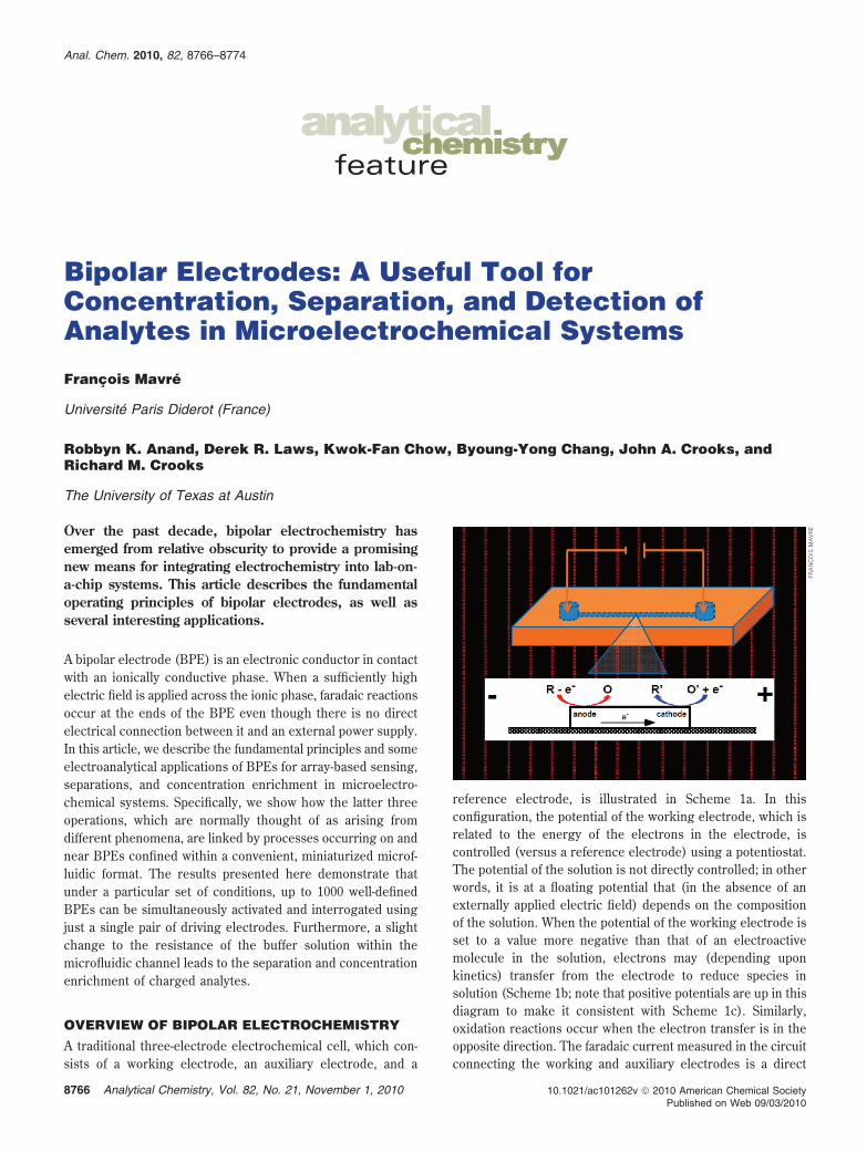
Over the past decade, bipolar electrochemistry hasemerged from relative obscurity to provide a promisingnew means for integrating electrochemistry into lab-on-a-chip systems. This article describes the fundamentaloperating principles of bipolar electrodes, as well asseveral interesting applications.
A bipolar electrode (BPE) is an electronic conductor in contactwith an ionically conductive phase. When a sufficiently highelectric field is applied across the ionic phase, faradaic reactionsoccur at the ends of the BPE even though there is no directelectrical connection between it and an external power supply.In this article, we describe the fundamental principles and someelectroanalytical applications of BPEs for array-based sensing,separations, and concentration enrichment in microelectro-chemical systems. Specifically, we show how the latter threeoperations, which are normally thought of as arising fromdifferent phenomena, are linked by processes occurring on andnear BPEs confined within a convenient, miniaturized microf-luidic format. The results presented here demonstrate thatunder a particular set of conditions, up to 1000 well-definedBPEs can be simultaneously activated and interrogated usingjust a single pair of driving electrodes. Furthermore, a slightchange to the resistance of the buffer solution within themicrofluidic channel leads to the separation and concentrationenrichment of charged analytes.
OVERVIEW OF BIPOLAR ELECTROCHEMISTRY
A traditional three-electrode electrochemical cell, which con-sists of a working electrode, an auxiliary electrode, and a
reference electrode, is illustrated in Scheme 1a. In thisconfiguration, the potential of the working electrode, which isrelated to the energy of the electrons in the electrode, iscontrolled (versus a reference electrode) using a potentiostat.The potential of the solution is not directly controlled; in otherwords, it is at a floating potential that (in the absence of anexternally applied electric field) depends on the compositionof the solution. When the potential of the working electrode isset to a value more negative than that of an electroactivemolecule in the solution, electrons may (depending uponkinetics) transfer from the electrode to reduce species insolution (Scheme 1b; note that positive potentials are up in thisdiagram to make it consistent with Scheme 1c). Similarly,oxidation reactions occur when the electron transfer is in theopposite direction. The faradaic current measured in the circuitconnecting the working and auxiliary electrodes is a direct
FRA
NC
OIS
MA
VR
E
Anal. Chem. 2010, 82, 8766–8774
10.1021/ac101262v 2010 American Chemical Society8766 Analytical Chemistry, Vol. 82, No. 21, November 1, 2010Published on Web 09/03/2010
measure of the rate of this electrochemical reaction. The keypoint is that the interfacial potential difference between theelectrode and the solution, rather than the absolute potentialof either, is the driving force for electron transfer.1
A BPE has a configuration somewhat opposite to that of aconventional system; that is, the potential difference between theelectrode and the solution is determined by the electric field insolution. Despite the reversed roles of the solution and electrodein a BPE experiment, control is still maintained over the interfacialpotential difference. The experimental configuration of BPEs isillustrated in Scheme 1c. A conductive material, which has noexternal electrical connection, is located inside a microchannelwhose dimensions are generally small enough to ensure a highresistance to current flow. For example, in most of our experi-ments the channel is 1 cm long, 20 µm high, and 1 mm wide.The BPE is typically 0.5-1.0 mm in length. A simple power supplyapplies a potential difference, Etot, between two driving electrodessituated in reservoirs at both ends of the channel. Because thechannel resistance is high, most of Etot is dropped linearly alongthe channel length. Depending upon the experimental condi-tions, ∼10-15% of Etot is lost at the driving electrode/solutioninterface (Scheme 1c).2
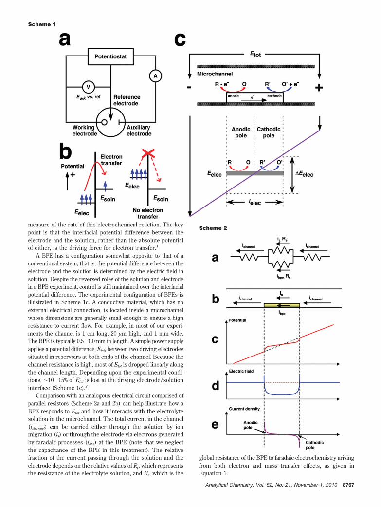
Comparison with an analogous electrical circuit comprised ofparallel resistors (Scheme 2a and 2b) can help illustrate how aBPE responds to Etot and how it interacts with the electrolytesolution in the microchannel. The total current in the channel(ichannel) can be carried either through the solution by ionmigration (is) or through the electrode via electrons generatedby faradaic processes (ibpe) at the BPE (note that we neglectthe capacitance of the BPE in this treatment). The relativefraction of the current passing through the solution and theelectrode depends on the relative values of Rs, which representsthe resistance of the electrolyte solution, and Re, which is the
global resistance of the BPE to faradaic electrochemistry arisingfrom both electron and mass transfer effects, as given inEquation 1.
Scheme 1
Scheme 2
8767Analytical Chemistry, Vol. 82, No. 21, November 1, 2010
ibpe
ichannel) 1 -
is
ichannel)
Rs
Re + Rs(1)
The potential difference between the solution and the two endsof the BPE (∆Eelec, Scheme 1c), which is roughly a function ofEtot and the length of the electrode (lelec), strongly influencesRe: if the current is kinetically controlled, then a higher valueof ∆Eelec results in a lower Re. Likewise, Equation 1 predictsthat higher Rs results in more current passing through the BPE.At the extreme, as Rs becomes very high, most of the channelcurrent (ichannel) passes through the BPE.
Faradaic Reactions at Bipolar Electrodes. The bipolar effectcan be understood more completely if one considers the variationof the potential difference at the electrode/solution interface alongthe entire length of the electrode. Scheme 1c shows that a lateralpotential drop in the electrolyte solution results in the potentialof the electrode floating to an equilibrium value, Eelec, thatseparates the BPE into two poles: the cathodic pole, where thesolution potential is higher than Eelec, and the anodic pole,where the solution potential is lower than Eelec. Accordingly,there is a potential difference at each lateral position of theelectrode/solution interface that may or may not be sufficientto drive an electrochemical reaction. These cathodic and anodicelectrochemical processes are coupled electrically via theelectrode, and they must occur simultaneously and at the samerate to ensure that electroneutrality is maintained within theconductive BPE. This relationship means that the total currentflowing through each pole of the BPE is the integrated sum ofthe current at every location in that pole (Scheme 2e).
Excluding mass transfer effects, the current density at the BPEmainly depends on two parameters: the overpotential available atevery location at the electrode/solution interface and the kineticcharacteristics of the redox couples involved in the faradaicprocesses. As mentioned earlier, ∆Eelec is the fraction of Etot thatis dropped across the BPE (Scheme 1c), and it represents thetotal driving force available to couple the two faradaic reactionsat the poles of the BPE. For these two redox processes to occursimultaneously, the value of ∆Eelec has to be higher than thedifference in the formal potentials for the two reactions.2 The∆Eelec available in the system can be approximated by Equation2 when Rs , Re (that is, when most of the current flowing inthe microchannel is ionic).
∆Eelec )Etot
lchannellelec (2)
It follows that for a given electric field (∼Etot/lchannel), longerelectrodes yield a higher value of ∆Eelec, resulting in a largervalue of ibpe. Consequently, the value of Etot required to inducefaradaic reactions varies depending both on the species presentin solution and on the ratio of electrode length to channellength. For most of the results reported by our group, Etot isin the range of 20-30 V and never >100 V. Therefore,inexpensive power supplies are sufficient to carry out manydifferent kinds of interesting experiments with BPEs.
Modulation of the Local Electric Field in the Channel.When a portion of ichannel is carried through the BPE, thepotential drop above the electrode might deviate from linearity(Scheme 2c). That is, faradaic current results in a local decrease
of the electric field above the electrode (Scheme 2d) caused by areduction in is. Duval and coworkers call this phenomenon“faradaic depolarization”.3,4
When the BPE and the channel have the same width, Duvalhas shown that faradaic reactions alter the electric field over theelectrode according to Equation 3:3
∂V(x, t)∂x
) j(x, t)hKS
(3)
Here, V(x,t) is the electric field strength, j(x,t) is the currentdensity, h is the height of the channel, and KS is the conductivityof the solution.
According to Equation 3, the variation of the electric field isdirectly proportional to the current density and depends on twoadditional parameters: the height of the channel and the conduc-tivity of the solution. The extent of depolarization may be easilyprobed through the ibpe/ichannel ratio. Clearly, smaller channelheights and lower solution conductivities (e.g., lower electrolyteconcentration) favor a higher degree of faradaic depolarization.Consequently, applications involving concentration enrichment,which are discussed at the end of the next section and whichrely on faradaic depolarization, typically employ small channelheights and low electrolyte concentrations.
APPLICATIONS OF BIPOLAR ELECTRODESBackground. Although BPEs have not been widely adopted
for electroanalytical purposes, they have been used for many yearsin battery technologies, for electrosynthesis,5,6 as photoelectrodesfor solar cells,7-9 and as seeds to generate nanowires alongelectric field lines.10 More recently, Sen, Mallouk, and coworkershave shown that bipolar electrochemistry can lead to self-propulsion of freely suspended nanorods.11 In this experiment, abimetallic Pt/Au nanorod electrocatalyzes the oxidation andreduction of H2O2 at the Pt and Au sites, respectively, and thisleads to predictable motion of the nanorods. Bipolar electro-chemistry has also been used to prepare surfaces modified withgradients of various materials. This application relies on theaxial gradient in the potential difference between the solutionand BPE discussed earlier (Scheme 1c). Using this principle,molecular gradients of self-assembled monolayers have beenprepared on Au surfaces,12,13 Au has been electrodeposited ontothe ends of carbon nanotubes,14 and graded compositions of CdShave been synthesized.15
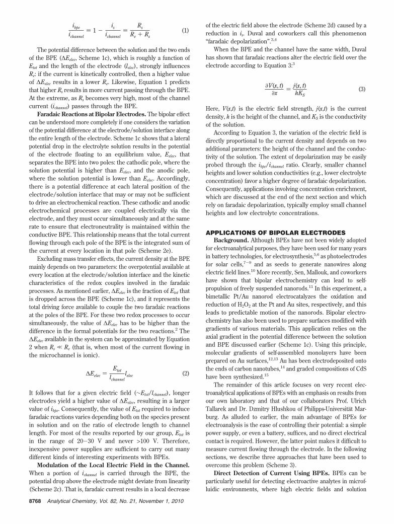
The remainder of this article focuses on very recent elec-troanalytical applications of BPEs with an emphasis on results fromour own laboratory and that of our collaborators Prof. UlrichTallarek and Dr. Dzmitry Hlushkou of Philipps-Universitat Mar-burg. As alluded to earlier, the main advantage of BPEs forelectroanalysis is the ease of controlling their potential: a simplepower supply, or even a battery, suffices, and no direct electricalcontact is required. However, the latter point makes it difficult tomeasure current flowing through the electrode. In the followingsections, we describe three approaches that have been used toovercome this problem (Scheme 3).
Direct Detection of Current Using BPEs. BPEs can beparticularly useful for detecting electroactive analytes in microf-luidic environments, where high electric fields and solution
8768 Analytical Chemistry, Vol. 82, No. 21, November 1, 2010
resistances can lead to difficulties controlling the potential of aworking electrode configured in a standard three-electrode cellarrangement.16 For example, Nyholm and coworkers have usedBPEs to detect electroactive molecules in a capillary17 and in anon-chip microfluidic device18 by taking advantage of the electricfield used for electrophoresis to induce bipolar behavior betweentwo Au microbands that were connected externally through anammeter (Scheme 3a). This kind of split electrode design makesit possible to directly measure the current passing through theBPE, but at the cost of complicating the system with an externalelectrical connection.
Detection of Electroactive Molecules Using Electrogen-erated Chemiluminescence (ECL) Reporting. An alternativestrategy for detecting faradaic processes at BPEs is to use ECLas an indirect reporter of the current (Scheme 3b).19,20 Thisapproach eliminates the need for a direct external connection tothe electrode and opens up the possibility of using optical detectionto simultaneously detect faradaic current at many BPEs. BecauseECL does not require an excitation light source, it is generallysuperior to fluorescence for low-cost and portable sensor sys-tems.21
One of the best known ECL systems uses Ru(bpy)32+ as the
light-emitting species and an amine, such as tri-n-propylamine(TPrA), as a co-reactant.21 Using this approach, Manz andcoworkers demonstrated ECL generation at the anodic poleof a Pt BPE.19 Specifically, they showed that the reaction ofRu(bpy)3
2+ with different amines or amino acids provides ameans for signaling the presence of analytes electrophoreticallyseparated in a microfluidic system. However, this detectionscheme was limited to just the detection of ECL co-reactants,although other analytes could be detected if they interferedwith the ECL reaction and thereby reduced light emission fromthe BPE.
The Manz approach to ECL-based detection only took advan-tage of the anodic pole of the BPE, and therefore it was limitedto detection of analytes that specifically interacted with the ECLprocess. Shortly after their report, however, we demonstrated thatthe presence of any electroactive analyte could be detected bytaking advantage of both poles (Scheme 3b). Here, the analyte ofinterest is reduced at the cathodic pole, and this faradaic reactiontriggers light emission at the anodic pole by the correspondingoxidation of Ru(bpy)3
2+ and TPrA.20 This finding opened theway for detection of a much larger variety of compounds,22,23
including large biomolecules such as DNA.24
The BPE experiment illustrated in Scheme 3b is usually carriedout in a microfluidic device, which provides a means for controllingthe electric field in the microchannel and providing for flow of analytesolutions. Microfluidic devices used in our lab are usually comprisedof a PDMS block that is irreversibly attached to a glass slide ontowhich one or more Au BPEs have been microfabricated (Scheme
1c).2 The Au electrodes, situated in the middle of the channel, aretypically 0.5-1.0 mm long. At the two ends of the channel,macroscopic reservoirs allow for channel filling and serve as thelocations of the driving electrodes used to apply Etot. For ECLreporting experiments, the solution filling the channel containsRu(bpy)3
2+, TPrA, an electrolyte or buffer, and the analyte ofinterest. Upon application of a sufficiently high value of Etot,Ru(bpy)3
2+ and TPrA are both oxidized at the anode and theanalyte is reduced at the cathode (Scheme 3b). Several years ago,we demonstrated the principle of this double-pole ECL reportingscheme by detecting benzyl viologen (BV2+) at an indium tin oxide(ITO) BPE.20 The relationship between BV2+ concentration in thechannel and ECL intensity was shown to increase linearly untilcomplications arising from quenching occurred. Later, using asplit BPE, we demonstrated a linear correspondence between theECL emission intensity and the rate of the cathode reaction.2
Finally, measured ECL intensity and bipolar current were foundto be in good agreement with calculated values based on thekinetics of the electrochemical processes.2
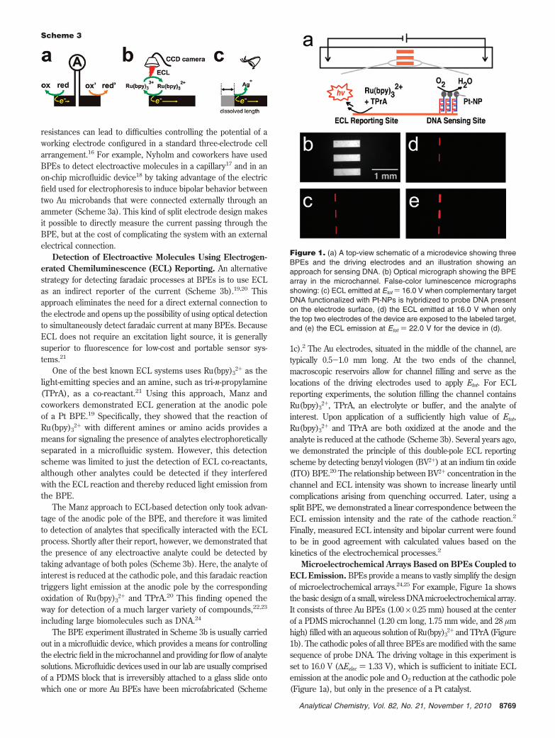
Microelectrochemical Arrays Based on BPEs Coupled toECL Emission. BPEs provide a means to vastly simplify the designof microelectrochemical arrays.24,25 For example, Figure 1a showsthe basic design of a small, wireless DNA microelectrochemical array.It consists of three Au BPEs (1.00 × 0.25 mm) housed at the centerof a PDMS microchannel (1.20 cm long, 1.75 mm wide, and 28 µmhigh) filled with an aqueous solution of Ru(bpy)3
2+ and TPrA (Figure1b). The cathodic poles of all three BPEs are modified with the samesequence of probe DNA. The driving voltage in this experiment isset to 16.0 V (∆Eelec ) 1.33 V), which is sufficient to initiate ECLemission at the anodic pole and O2 reduction at the cathodic pole(Figure 1a), but only in the presence of a Pt catalyst.
Scheme 3
Figure 1. (a) A top-view schematic of a microdevice showing threeBPEs and the driving electrodes and an illustration showing anapproach for sensing DNA. (b) Optical micrograph showing the BPEarray in the microchannel. False-color luminescence micrographsshowing: (c) ECL emitted at Etot ) 16.0 V when complementary targetDNA functionalized with Pt-NPs is hybridized to probe DNA presenton the electrode surface, (d) the ECL emitted at 16.0 V when onlythe top two electrodes of the device are exposed to the labeled target,and (e) the ECL emission at Etot ) 22.0 V for the device in (d).
8769Analytical Chemistry, Vol. 82, No. 21, November 1, 2010
DNA is detected by exposing the array to a complementarytarget bearing a 4-nm Pt nanoparticle label. Upon hybridization,the label catalyzes O2 reduction; the electrons required for thisreaction originate from oxidation of Ru(bpy)3
2+ and TrPA.Hence, ECL is emitted from the anodic poles of the BPEs(Figure 1c). When the same experiment is carried out with onlythe top two electrodes exposed to the labeled target, the bottomelectrode remains dark (Figure 1d). However, when Etot isincreased to 22.0 V (∆Eelec ) 1.83 V), O2 can be reduced directlyon the Au BPE, and therefore ECL is now observed on thebottom electrode (Figure 1e). Note, however, that under theseconditions, the emission intensity is still higher on the upper pairof electrodes, indicating that raising Etot increases the rate of O2
reduction when the label is present.The BPE approach is inherently scalable, and there should
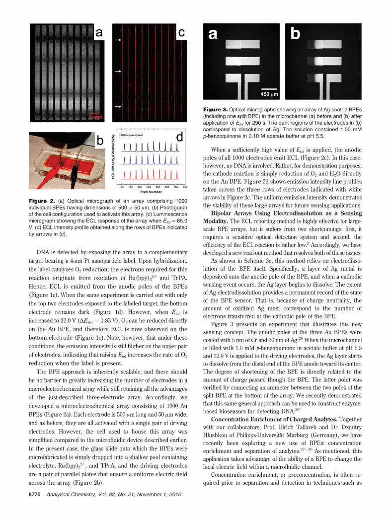
be no barrier to greatly increasing the number of electrodes in amicroelectrochemical array while still retaining all the advantagesof the just-described three-electrode array. Accordingly, wedeveloped a microelectrochemical array consisting of 1000 AuBPEs (Figure 2a). Each electrode is 500 µm long and 50 µm wide,and as before, they are all activated with a single pair of drivingelectrodes. However, the cell used to house this array wassimplified compared to the microfluidic device described earlier.In the present case, the glass slide onto which the BPEs weremicrofabricated is simply dropped into a shallow pool containingelectrolyte, Ru(bpy)3
2+, and TPrA, and the driving electrodesare a pair of parallel plates that ensure a uniform electric fieldacross the array (Figure 2b).
When a sufficiently high value of Etot is applied, the anodicpoles of all 1000 electrodes emit ECL (Figure 2c). In this case,however, no DNA is involved. Rather, for demonstration purposes,the cathode reaction is simply reduction of O2 and H2O directlyon the Au BPE. Figure 2d shows emission intensity line profilestaken across the three rows of electrodes indicated with whitearrows in Figure 2c. The uniform emission intensity demonstratesthe viability of these large arrays for future sensing applications.
Bipolar Arrays Using Electrodissolution as a SensingModality. The ECL reporting method is highly effective for large-scale BPE arrays, but it suffers from two shortcomings: first, itrequires a sensitive optical detection system and second, theefficiency of the ECL reaction is rather low.2 Accordingly, we havedeveloped a new read-out method that resolves both of these issues.
As shown in Scheme 3c, this method relies on electrodisso-lution of the BPE itself. Specifically, a layer of Ag metal isdeposited onto the anodic pole of the BPE, and when a cathodicsensing event occurs, the Ag layer begins to dissolve. The extentof Ag electrodissolution provides a permanent record of the stateof the BPE sensor. That is, because of charge neutrality, theamount of oxidized Ag must correspond to the number ofelectrons transferred at the cathodic pole of the BPE.
Figure 3 presents an experiment that illustrates this newsensing concept. The anodic poles of the three Au BPEs werecoated with 5 nm of Cr and 20 nm of Ag.26 When the microchannelis filled with 1.0 mM p-benzoquinone in acetate buffer at pH 5.5and 12.0 V is applied to the driving electrodes, the Ag layer startsto dissolve from the distal end of the BPE anode toward its center.The degree of shortening of the BPE is directly related to theamount of charge passed though the BPE. The latter point wasverified by connecting an ammeter between the two poles of thesplit BPE at the bottom of the array. We recently demonstratedthat this same general approach can be used to construct enzyme-based biosensors for detecting DNA.26
Concentration Enrichment of Charged Analytes. Togetherwith our collaborators, Prof. Ulrich Tallarek and Dr. DzmitryHlushkou of Philipps-Universitat Marburg (Germany), we haverecently been exploring a new use of BPEs: concentrationenrichment and separation of analytes.27-30 As mentioned, thisapplication takes advantage of the ability of a BPE to change thelocal electric field within a microfluidic channel.
Concentration enrichment, or preconcentration, is often re-quired prior to separation and detection in techniques such as
Figure 2. (a) Optical micrograph of an array comprising 1000individual BPEs having dimensions of 500 × 50 µm. (b) Photographof the cell configuration used to activate this array. (c) Luminescencemicrograph showing the ECL response of the array when Etot ) 85.0V. (d) ECL intensity profile obtained along the rows of BPEs indicatedby arrows in (c).
Figure 3. Optical micrographs showing an array of Ag-coated BPEs(including one split BPE) in the microchannel (a) before and (b) afterapplication of Etot for 290 s. The dark regions of the electrodes in (b)correspond to dissolution of Ag. The solution contained 1.00 mMp-benzoquinone in 0.10 M acetate buffer at pH 5.5.
8770 Analytical Chemistry, Vol. 82, No. 21, November 1, 2010
capillary or microchip electrophoresis. The majority of onlineconcentration enrichment methods in electrophoresis employ adiscontinuity in the buffer concentration or composition to inducean electric field gradient. This imparts a change in the migrationvelocity of charged analytes and can lead to sample stacking.31-34
Such methods can result in enrichment factors (EFs) of100-1000.34 However, all of these methods require preparationand precise injection of different buffers and solutions. Further-more, they do not provide a practical means for both concentrationenrichment and separation. Other preconcentration methods relyon the acid-base chemistry of the analyte, but in this case,resolution is limited by the steepness of the pH gradient. In areport that is more closely related to our recent findings, Yeungand coworkers used a BPE confined to a capillary to generate apH gradient suitable for isoelectric focusing.35
The method of concentration enrichment we have beenexploring takes advantage of the extended electric field gradientformed at the edge of a BPE in a low ionic strength buffer.Although still in the early days of development, this method hassome desirable characteristics: it is exceedingly simple to imple-ment (indeed, we discovered it by accident) and can not onlyenrich the concentration of the analyte, but also separate anddetect solutions containing multiple analytes.
With one key exception, the experimental design required forthis experiment is essentially identical to that used for the sensingexperiments described earlier. The difference is that the concen-tration of the buffer must be lower for concentration enrichment:in the sensing experiments, it was typically 0.1 M, but here it isusually 1-5 mM. The higher resistance of the buffer solutionshunts more current through the BPE (Scheme 2a), and this inturn leads to a greater degree of faradaic depolarization and hencethe necessary distortion of the local electric field within themicrochannel. The results presented here were obtained usingmicrochannels with lengths, widths, and heights of 6 mm × 100µm × 21 µm, respectively, and 1 or 5 mM Tris buffer.27-30
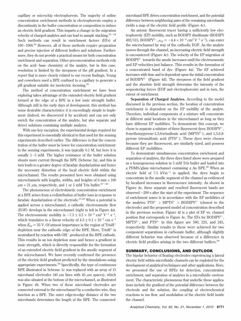
The phenomenon of electrokinetic concentration enrichmentat a BPE arises from a redistribution of buffer ions in response tofaradaic depolarization of the electrode.27,28 When a potential isapplied across a microchannel, a cathodic electroosmotic flow(EOF) develops in the microchannel (right to left in Figure 4a).The electroosmotic mobility is ∼7.3 ± 0.2 × 10⁻⁴ cm2 V-1 s-1,which translates to a linear velocity of 4.3 ± 0.1 × 10⁻² cm s-1
when Etot ) 35 V. Of utmost importance is the region of TrisH+
depletion near the cathodic edge of the BPE. Here, TrisH+ isneutralized by reaction with OH- produced at the BPE cathode.This results in an ion depletion zone and hence a gradient inionic strength, which is directly responsible for the formationof an extended electric field gradient in the anodic segment ofthe microchannel. We have recently confirmed the presenceof the electric field gradient predicted by the simulations usingappropriate experiments.30 Specifically, the type of continuousBPE illustrated in Scheme 1c was replaced with an array of 15microband electrodes (40 µm lines with 40 µm spaces), whichwas also situated at the bottom of the microchannel, as illustratedin Figure 4b. When two of these microband electrodes areconnected external to the microchannel by a conductive wire, theyfunction as a BPE. The outer edge-to-edge distance of the twomicrobands determines the length of the BPE. The connected-
microband BPE drives concentration enrichment, and the potentialdifference between neighboring pairs of the remaining microbandsyields a map of the electric field profile (Figure 4c).
An anionic fluorescent tracer having a sufficiently low elec-trophoretic (EP) mobility, such as BODIPY disulfonate (BODIPY492/515, BODIPY2-, µep ) -4.4 × 10⁻⁴ cm2 V-1 s-1), can enterthe microchannel by way of the cathodic EOF. As the analytemoves through the channel, an increasing electric field strengthis encountered (Figure 4c). The velocity of the EP migration ofBODIPY2- towards the anode increases until the electroosmoticand EP velocities just balance. This results in the formation ofa concentrated band of dye (Figure 4a). The EF achievedincreases with time and is dependent upon the initial concentrationof BODIPY2- (Figure 4d). The steepness of the field gradientand the absolute field strength determine the intensity of thesequestering forces (EOF and electrophoresis) and in turn, theextent of enrichment.
Separation of Charged Analytes. According to the modeldiscussed in the previous section, the location of concentrationenrichment is dependent on the EP mobility of the analyte.Therefore, individual components of a mixture will concentrateat different axial locations in the microchannel as long as theyhave different EP mobilities. To demonstrate this concept, wechose to separate a mixture of three fluorescent dyes: BODIPY2-,8-methoxypyrene-1,3,6-trisulfonic acid (MPTS3-), and 1,3,6,8-pyrene tetrasulfonic acid (PTS4-). These dyes were chosenbecause they are fluorescent, are similarly sized, and possessdifferent EP mobilities.
To demonstrate simultaneous concentration enrichment andseparation of analytes, the three dyes listed above were preparedas a homogeneous solution in 5 mM Tris buffer and loaded intoa PDMS/glass microchannel containing a Au BPE.29 When anelectric field of 7.5 kVm-1 is applied, the dyes begin toconcentrate in the anodic segment of the channel as evidencedby localized increases in fluorescence intensity. As shown inFigure 4e, three separate and resolved fluorescent bands areobserved ∼200 s after the start of the experiment. The sequenceof enrichment zones is in accordance with the EP mobilities ofthe analytes: PTS4- > MPTS3- > BODIPY2- (closest to theelectrode) and the proposed model of concentration describedin the previous section. Figure 4f is a plot of EF vs. channelposition that corresponds to Figure 4e. The EFs for BODIPY2-,MPTS3-, and PTS4- in this figure are 560, 225, and 245,respectively. Similar results to these were achieved for twocomponent separations in carbonate buffer, although slightlydifferent behavior was observed because of a difference inelectric field profiles arising in the two different buffers.29
SUMMARY, CONCLUSIONS, AND OUTLOOKThe bipolar behavior of floating electrodes experiencing a lateralelectric field within microfluidic channels can be exploited for thedevelopment of analytical techniques and other applications. Here,we presented the use of BPEs for detection, concentrationenrichment, and separation of analytes in a microfluidic environ-ment. The characteristic phenomena that underlie these applica-tions include the gradient of the potential difference between theelectrode and the solution, the coupling of electrochemicalreactions to ion flow, and modulation of the electric field insidethe channel.
8771Analytical Chemistry, Vol. 82, No. 21, November 1, 2010
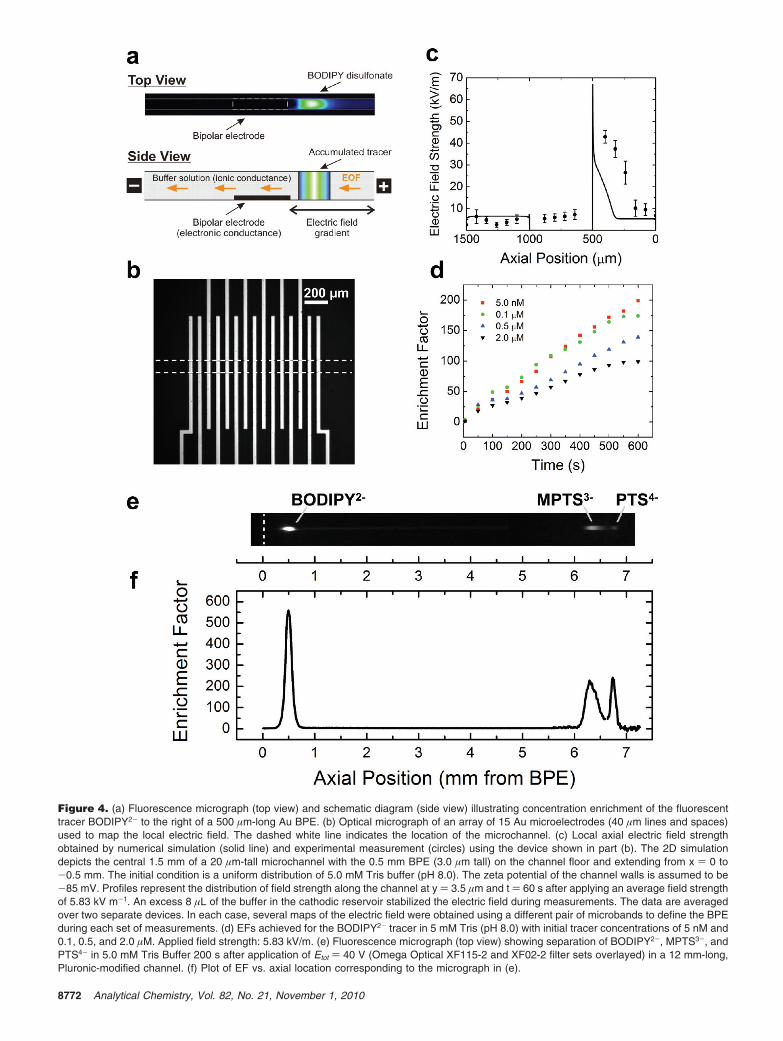
Figure 4. (a) Fluorescence micrograph (top view) and schematic diagram (side view) illustrating concentration enrichment of the fluorescenttracer BODIPY2- to the right of a 500 µm-long Au BPE. (b) Optical micrograph of an array of 15 Au microelectrodes (40 µm lines and spaces)used to map the local electric field. The dashed white line indicates the location of the microchannel. (c) Local axial electric field strengthobtained by numerical simulation (solid line) and experimental measurement (circles) using the device shown in part (b). The 2D simulationdepicts the central 1.5 mm of a 20 µm-tall microchannel with the 0.5 mm BPE (3.0 µm tall) on the channel floor and extending from x ) 0 to-0.5 mm. The initial condition is a uniform distribution of 5.0 mM Tris buffer (pH 8.0). The zeta potential of the channel walls is assumed to be-85 mV. Profiles represent the distribution of field strength along the channel at y ) 3.5 µm and t ) 60 s after applying an average field strengthof 5.83 kV m-1. An excess 8 µL of the buffer in the cathodic reservoir stabilized the electric field during measurements. The data are averagedover two separate devices. In each case, several maps of the electric field were obtained using a different pair of microbands to define the BPEduring each set of measurements. (d) EFs achieved for the BODIPY2- tracer in 5 mM Tris (pH 8.0) with initial tracer concentrations of 5 nM and0.1, 0.5, and 2.0 µM. Applied field strength: 5.83 kV/m. (e) Fluorescence micrograph (top view) showing separation of BODIPY2-, MPTS3-, andPTS4- in 5.0 mM Tris Buffer 200 s after application of Etot ) 40 V (Omega Optical XF115-2 and XF02-2 filter sets overlayed) in a 12 mm-long,Pluronic-modified channel. (f) Plot of EF vs. axial location corresponding to the micrograph in (e).
8772 Analytical Chemistry, Vol. 82, No. 21, November 1, 2010
When the buffer concentration in the microchannel is high,most of the current moves through the solution and only ∼0.1%passes through the BPE. Under these conditions, the electric fieldis approximately linear throughout the channel, and therefore, itis possible to simultaneously control the potential of at least 1000BPEs. Because the rates of the faradaic processes at the anodicand cathodic poles of a BPE must be equal, we showed that thecurrent flowing through the BPE can be related to ECL intensity.This makes it possible to simultaneously read out the state of eachelectrode. A simpler and more sensitive detection method involveselectrodissolution of Ag. The key points are that the potential ofan arbitrarily large number of electrodes can be controlled usingthis general method and the current flowing through each BPEcan be determined simultaneously.
When the electrolyte concentration in the microchannel is low(1-5 mM), more of the current is shunted through the BPE. Thisresults in a local electric field gradient within the channel, andthis can, in turn, lead to concentration enrichment. Analytesconcentrate where their EP velocity exactly opposes their elec-troosmotic velocity. The former is a function of locationsbecauseof an extended field gradientsbut because fluids are incompress-ible, the electroosmotic velocity is independent of local inhomo-geneities in the field and only depends on the total applied voltage(Etot). Therefore, mixtures of analytes having different EPmobilities concentrate at different locations along the fieldgradient, and this method can be used to both concentrate andseparate analytes.
This method is incredibly simple: it requires a battery or simplepower supply, microfabricated electrodes, and an appropriateelectrochemical cell that can even be just a petri dish (Figure 2b).Because of this simplicity, BPEs likely could be profitablyintegrated intosand provide interesting functionality tosa broadrange of lab-on-a-chip applications. Indeed, we have already shownthat BPEs can be used to construct optoelectrochemical logicgates36 and to obtain voltammograms without the need for apotentiostat.37 Although not discussed here, we have also shownthat BPEs can be placed at the intersection of two fluidic channelsand that this enables a whole new range of interesting functions.38
Perhaps the most exciting potential application of BPEs isintegration into nanofluidic systems. The advantage is that theycan be controlled without the need for a direct electrical connec-tion, which is often a major obstacle for nanosystems.
ACKNOWLEDGMENTWe gratefully acknowledge financial support from the Chemical
Sciences, Geosciences, and Biosciences Division, Office of BasicEnergy Sciences, Office of Science, U.S. Department of Energy(Contract No. DE-FG02-06ER15758). We also acknowledge sup-port from the U.S. Army Research Office (grant no. W911NF-07-1-0330) and the U.S. Defense Threat Reduction Agency. TheRobert A. Welch Foundation (Grant F-0032) provides sustainedsupport for our research. We also acknowledge major contribu-tions to our studies of BPEs by our long-time collaborators Prof.Ulrich Tallarek and Dr. Dzmitry Hlushkou (Philipps-UniversitatMarburg). Finally, we thank three former colleagues who initiatedour studies of BPEs a decade ago: Prof. Julio Alvarez (VirginiaCommonwealth University), Dr. Li Sun (Pine Instruments), andProf. Wei Zhan (Auburn University).
Richard M. Crooks is a professor of chemistry and holder of the Robert A.Welch Chair in Materials Chemistry at The University of Texas at Austin.Research in the Crooks lab focuses on electrochemistry, analyticalmicrosystems, nanomaterials, and catalysis. Dr. Francois Mavre was apost-doctoral associate in the Crooks group for two years and now is anassistant professor of chemistry at Paris Diderot University. His researchwithin the Laboratoire d’Electrochimie Moleculaire is focused on thedevelopment of electroanalytical strategies, including bioelectrochemicalenzyme sensors, electrochemical real-time PCR, and aptasensors, for thedetection of biomolecules. Robbyn K. Anand is a graduate student in theCrooks research group, but she will soon be moving to a posdoctoralposition at the University of Washington. Her research interests includeinvestigation of electrokinetic transport and electrochemistry in microf-luidic devices. Dr. Derek Laws was a postdoctoral fellow in the Crookslab for two years, and he is currently employed as an R&D scientist atSiemens Water Technologies. His research interests include electroana-lytical chemistry, bipolar electrochemistry, and electrochemistry of orga-nometallic species. Dr. Kwok-Fan Chow received his Ph.D. from TheUniversity of Texas at Austin under the guidance of Prof. Richard M.Crooks. He is currently a postdoctoral research associate in Prof. RoyceW. Murray’s group at the University of North Carolina Chapel Hill. Hisresearch interests include analytical/physical electrochemistry and elec-trochemical properties of nanoparticles. Dr. Byoung-Yong Chang was apostdoctoral associate in the Crooks group for two years, and he just beganhis independent career as an assistant professor of chemistry at PukyongNational University in South Korea. His research interests are in the fieldof electrochemistry. John A. Crooks is currently working as a researcherin Dr. Amy Tang’s lab at Eastern Virginia Medical School. His workfocuses on cancer signaling pathways and locating novel therapeutic targetswithin the cell. Address correspondence to Crooks at Department ofChemistry and Biochemistry and the Center for Electrochemistry, TheUniversity of Texas at Austin, 1 University Station, A5300, Austin, Texas78712-0165. Email: [email protected]. Telephone: 512-475-8674.
REFERENCES(1) Bard, A. J.; Faulkner, L. R. Electrochemical Methods: Fundamentals and
Applications, 2nd ed.; John Wiley & Sons, Inc.: New York, 2001.(2) Mavre, F.; Chow, K.-F.; Sheridan, E.; Chang, B.-Y.; Crooks, J. A.; Crooks,
R. M. Anal. Chem. 2009, 81, 6218–6225.(3) Duval, J. F. L.; Minor, M.; Cecilia, J.; van Leeuwen, H. P. J. Phys. Chem. B
2003, 107, 4143–4155.(4) Duval, J.; Kleijn, J. M.; van Leeuwen, H. P. J. Electroanal. Chem. 2001,
505, 1–11.(5) Fleischmann, M.; Ghoroghchian, J.; Rolison, D.; Pons, S. J. Phys. Chem.
1986, 90, 6392–6400.(6) Ghoroghchian, J.; Pons, S.; Fleischmann, M. J. Electroanal. Chem. 1991,
317, 101–108.(7) Smotkin, E.; Bard, A. J.; Campion, A.; Fox, M. A.; Mallouk, T.; Webber,
S. E.; White, J. M. J. Phys. Chem. 1986, 90, 4604–4607.(8) Smotkin, E. S.; Cerveramarch, S.; Bard, A. J.; Campion, A.; Fox, M. A.;
Mallouk, T.; Webber, S. E. J. Phys. Chem. 1987, 91, 6–8.(9) Cerveramarch, S.; Smotkin, E. S.; Bard, A. J.; Campion, A.; Fox, M. A.;
Mallouk, T.; Webber, S. E.; White, J. M. J. Electrochem. Soc. 1988, 135,567–573.
(10) Bradley, J.-C.; Chen, H.-M.; Crawford, J.; Eckert, J.; Ernazarova, K.; Kurzeja,T.; Lin, M.; McGee, M.; Nadler, W.; Stephens, S. G. Nature 1997, 389,268–271.
(11) Wang, Y.; Hernandez, R. M.; Bartlett, D. J.; Bingham, J. M.; Kline, T. R.;Sen, A.; Mallouk, T. E. Langmuir 2006, 22, 10,451–10,456.
(12) Ulrich, C.; Andersson, O.; Nyholm, L.; Bjorefors, F. Angew. Chem.-Int. Edit.2008, 47, 3034–3036.
(13) Ulrich, C.; Andersson, O.; Nyholm, L.; Bjorefors, F. Anal. Chem. 2009,81, 453–459.
(14) Warakulwit, C.; Nguyen, T.; Majimel, J.; Delville, M. H.; Lapeyre, V.;Garrigue, P.; Ravaine, V.; Limtrakul, J.; Kuhn, A. Nano Lett. 2008, 8, 500–504.
(15) Ramakrishnan, S.; Shannon, C. Langmuir , 26, 4602–4606.(16) Nyholm, L. Analyst 2005, 130, 599–605.(17) Klett, O.; Nyholm, L. Anal. Chem. 2003, 75, 1245–1250.(18) Ordeig, O.; Godino, N.; del Campo, J.; Munoz, F. X.; Nikolajeff, F.; Nyholm,
L. Anal. Chem. 2008, 80, 3622–3632.(19) Arora, A.; Eijkel, J. C. T.; Morf, W. E.; Manz, A. Anal. Chem. 2001, 73,
3282–3288.(20) Zhan, W.; Alvarez, J.; Crooks, R. M. J. Am. Chem. Soc. 2002, 124, 13,265–
13,270.(21) Miao, W. J. Chem. Rev. 2008, 108, 2506–2553.(22) Zhan, W.; Alvarez, J.; Crooks, R. M. Anal. Chem. 2003, 75, 313–318.
8773Analytical Chemistry, Vol. 82, No. 21, November 1, 2010
(23) Zhan, W.; Alvarez, J.; Sun, L.; Crooks, R. M. Anal. Chem. 2003, 75, 1233–1238.
(24) Chow, K.-F.; Mavre, F.; Crooks, R. M. J. Am. Chem. Soc. 2008, 130, 7544–7545.
(25) Chow, K.-F.; Mavre, F.; Crooks, J. A.; Chang, B.-Y.; Crooks, R. M. J. Am.Chem. Soc. 2009, 131, 8364–8365.
(26) Chow, K.-F.; Chang, B.-Y.; Zaccheo, B.; Mavre, F.; Crooks, R. M. J. Am.Chem. Soc. 2010, 132, 9228–9229.
(27) Dhopeshwarkar, R.; Hlushkou, D.; Nguyen, M.; Tallarek, U.; Crooks, R. M.J. Am. Chem. Soc. 2008, 130, 10,480–10,481.
(28) Hlushkou, D.; Perdue, R. K.; Dhopeshwarkar, R.; Crooks, R. M.; Tallarek,U. Lab on aChip 2009, 9, 1903–1913.
(29) Laws, D. R.; Hlushkou, D.; Perdue, R. K.; Tallarek, U.; Crooks, R. M. Anal.Chem. 2009, 81, 8923–8929.
(30) Perdue, R. K.; Laws, D. R.; Hlushkou, D.; Tallarek, U.; Crooks, R. M. Anal.Chem. 2009, 81, 10,149–10,155.
(31) Gebauer, P.; Bocek, P. Electrophoresis 2000, 21, 3898–3904.(32) Jung, B.; Bharadwaj, R.; Santiago, J. G. Electrophoresis 2003, 24, 3476–
3483.(33) Ring-Ling, C. Electrophoresis 2003, 24, 486–497.(34) Cheng-Huang, L.; Takashi, K. Electrophoresis 2004, 25, 4058–4073.(35) Wei, W.; Xue, G.; Yeung, E. S. Anal. Chem. 2002, 74, 934–940.(36) Zhan, W.; Crooks, R. M. J. Am. Chem. Soc. 2003, 125, 9934–9935.(37) Chang, B.-Y.; Mavre, F.; Chow, K.-F.; Crooks, J. A.; Crooks, R. M. Anal.
Chem. 2010, 82, 5317–5322.(38) Fosdick, S. E.; Crooks, J. A.; Chang, B.-Y.; Crooks, R. M. J. Am. Chem.
Soc. 2010, 132, 9226–9227.
AC101262V
8774 Analytical Chemistry, Vol. 82, No. 21, November 1, 2010