Embed Size (px)
Citation preview
Operator’s Manual
Multi-Mode Microplate Reader
Synergy™ HT


Synergy™ HT
Multi-Mode Microplate Reader Operator’s Guide
November 2008 © 2008 Part Number 7091000 Revision I BioTek® Instruments, Inc.
ii | Preface
BioTek Instruments
Notices
BioTek® Instruments, Inc.
Highland Park, P.O. Box 998
Winooski, Vermont 05404-0998 USA
All Rights Reserved
© 2008, BioTek® Instruments, Incorporated. No part of this publication may be reproduced, transcribed, or transmitted in any form, or by any means electronic or mechanical, including photocopying and recording, for any purpose other than the purchaser’s use without written permission of BioTek Instruments, Inc.
Trademarks
BioTek® is a registered trademark, and Synergy™ HT, Gen5™, KC4™, and BioStack™ are trademarks of BioTek Instruments, Inc. All other trademarks are the property of their respective holders.
Restrictions and Liabilities
Information in this document is subject to change and does not represent a commitment by BioTek Instruments, Inc. Changes made to the information in this document will be incorporated in new editions of the publication. No responsibility is assumed by BioTek for the use or reliability of software or equipment that is not supplied by BioTek or its affiliated dealers.
Contents | iii
Synergy HT Operator’s Manual
Contents
Notices ...........................................................................................ii Contact Information ....................................................................... vii Revision History ............................................................................ viii Document Conventions .................................................................. viii Intended Use Statement ................................................................ xiii Quality Control ............................................................................. xiii Warranty & Product Registration...................................................... xiii Warnings ..................................................................................... xiv Hazards and Precautions ................................................................ xiv Directives..................................................................................... xvi Electromagnetic Interference and Susceptibility ................................ xvii User Safety ................................................................................. xvii Safety Symbols............................................................................xviii
Chapter 1: Introduction.......................................................................1
Synergy™ HT Multi-Mode Microplate Reader........................................ 2 Features ........................................................................................ 3 Package Contents............................................................................ 4 Optional Accessories ........................................................................ 5 Product Support & Service................................................................ 6
Technical Assistance Center (TAC) ................................................ 6 Returning Instruments for Service/Repair ...................................... 6 Contacting BioTek for Applications Support .................................... 6
Chapter 2: Installation ........................................................................7
1: Unpack and Inspect the Reader .................................................... 8 2: Remove the Shipping Panel ........................................................10 3: Remove the Microplate Carrier Shipping Screw ..............................12 4: Install the Fluorescence Lamp Assembly .......................................13 5: Select an Appropriate Location ....................................................14 6: Connect the Power Supply ..........................................................15 7: Unpack and Inspect the Dispense Module .....................................16 8: Install the Dispense Module ........................................................19 9: Connect the Host Computer ........................................................23 10: Install Software on the Host Computer .......................................24 11: Turn on the Reader..................................................................24 12: Establish Communication ..........................................................25
Using Gen5 ..............................................................................26 Using KC4 ................................................................................26
13: Run a System Test ..................................................................27 14: Test the Injector System ..........................................................28 Register with BioTek.......................................................................30
iv | Preface
BioTek Instruments
Operational/Performance Qualification...............................................30 Repackaging and Shipping Instructions .............................................31
Chapter 3: Getting Started ................................................................35
Key Components............................................................................36 Power Switch, Carrier Eject Button, Microplate Carrier ....................36 Lamp Assembly and Filter Wheel Access .......................................37 Excitation and Emission Filter Wheels ...........................................38 Installing the Time-Resolved Fluorescence Cartridge ......................41 Configuring the System for Luminescence Measurements................42 The External Dispense Module.....................................................43
Gen5 Software...............................................................................46 Viewing/Updating the Filter and Wavelengths Tables ......................46 Creating Protocols and Experiments .............................................47 Controlling the Dispense Module..................................................50
KC4 Software ................................................................................52 Viewing/Updating the Filter and Wavelengths Tables ......................52 Creating Protocols .....................................................................53 Reading Plates ..........................................................................55 Controlling the Dispense Module..................................................56
Recommendations for Achieving Optimum Performance .......................59 Chapter 4: Instrument Qualification..................................................61
Overview ......................................................................................62 IQ/OQ/PQ .....................................................................................62 Recommended Qualification Schedule ...............................................64 System Test ..................................................................................65
Description...............................................................................65 Procedure ................................................................................66
Absorbance Plate Test.....................................................................70 Description...............................................................................70 Test Plate Certificates ................................................................71 Setup: Gen5.............................................................................72 Procedure: Gen5 .......................................................................73 Setup: KC4 ..............................................................................74 Procedure: KC4.........................................................................74 Results & Troubleshooting Tips....................................................78
Absorbance Liquid Tests..................................................................80 Stock Solution Formulation ..............................................................81
Liquid Test 1.............................................................................82 Liquid Test 2.............................................................................83 Liquid Test 3.............................................................................86
Fluorescence Tests .........................................................................89 Required Materials.....................................................................90 Test Solutions...........................................................................91
Contents | v
Synergy HT Operator’s Manual
Procedure ................................................................................92 Results Analysis ........................................................................92 Troubleshooting ........................................................................93 Pipette Map ..............................................................................94 Gen5 Protocol Reading Parameters ..............................................95 KC4 Protocol Reading Parameters ................................................96 Fluorescence Tests Using Methylumbelliferone...............................98
Dispense Module Tests.................................................................. 102 Required Materials................................................................... 103 Test Solution Recipes............................................................... 104 Test Setup: Gen5 .................................................................... 105 Test Setup: KC4...................................................................... 105 Test Procedure: Gen5 .............................................................. 106 Test Procedure: KC4................................................................ 108 Results Analysis ...................................................................... 109 Creating Test Protocols Using Gen5............................................ 110 Creating Test Protocols Using KC4 ............................................. 115
Dispense Accuracy & Precision Test Worksheet ................................. 121 Chapter 5: Preventive Maintenance.................................................123
Recommended Maintenance Schedule ............................................. 124 Overview ............................................................................... 124 Dispense Module ..................................................................... 124 Schedule................................................................................ 126
Warnings & Precautions ................................................................ 126 Cleaning Exposed Surfaces ............................................................ 127 Inspecting/Cleaning Excitation and Emission Filters........................... 128 Flushing/Purging the Fluid Path ...................................................... 129 Running a Dispense Protocol (Optional) ........................................... 130 Emptying/Cleaning the Tip Priming Trough....................................... 132 Cleaning the Priming Plate............................................................. 132 Cleaning the Internal Components.................................................. 133
Required Materials................................................................... 134 Removing the Reader’s Shroud.................................................. 135 Removing the Internal Tubes and Injector Heads ......................... 137 Cleaning the Internal Tubes and Injector Heads........................... 140 Cleaning the Optical Probes ...................................................... 141 Cleaning the Reader’s Internal Surface ....................................... 149 Reassembling the Components.................................................. 150 Performance Check.................................................................. 151
Appendix A: Decontamination .........................................................153
Purpose ...................................................................................... 154 Required Materials........................................................................ 155 Procedure for Models without Injectors............................................ 156
vi | Preface
BioTek Instruments
Routine Procedure for Models with Injectors..................................... 157 Clean Exposed Surfaces ........................................................... 157 Decontaminate the Fluid Lines................................................... 158 Rinse the Fluid Lines................................................................ 159 Clean the Internal Tubing and Injector Heads.............................. 159 Clean the Tip Prime Trough and Priming Plate ............................. 160
Alternate Procedure for Models with Injectors................................... 161 Appendix B: Computer Control ........................................................163 Appendix C: Error Codes..................................................................165 Appendix D: Specifications..............................................................207 Appendix E: Instrument Dimensions for Robotic Interface..............215
Contact Information | vii
Synergy HT Operator’s Manual
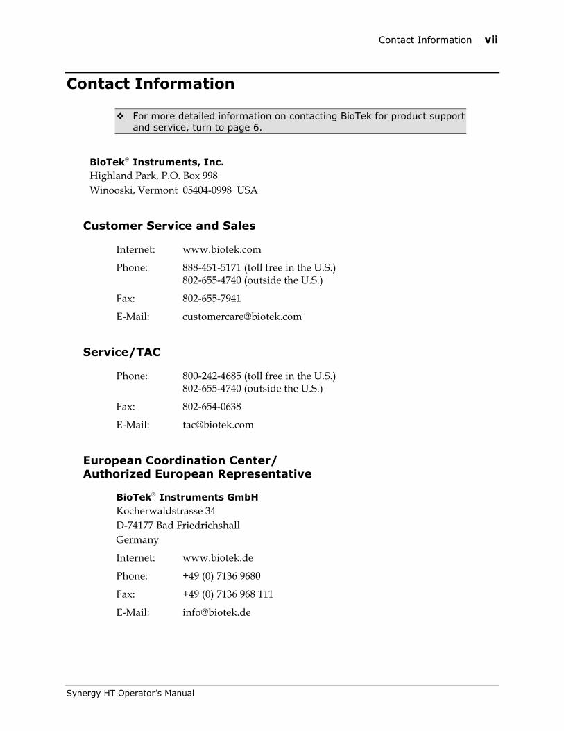
Contact Information
For more detailed information on contacting BioTek for product support and service, turn to page 6.
BioTek® Instruments, Inc. Highland Park, P.O. Box 998 Winooski, Vermont 05404-0998 USA
Customer Service and Sales
Internet: www.biotek.com
Phone: 888-451-5171 (toll free in the U.S.) 802-655-4740 (outside the U.S.)
Fax: 802-655-7941
E-Mail: [email protected]
Service/TAC
Phone: 800-242-4685 (toll free in the U.S.) 802-655-4740 (outside the U.S.)
Fax: 802-654-0638
E-Mail: [email protected]
European Coordination Center/ Authorized European Representative
BioTek® Instruments GmbH Kocherwaldstrasse 34 D-74177 Bad Friedrichshall Germany
Internet: www.biotek.de
Phone: +49 (0) 7136 9680
Fax: +49 (0) 7136 968 111
E-Mail: [email protected]
viii | Preface
BioTek Instruments
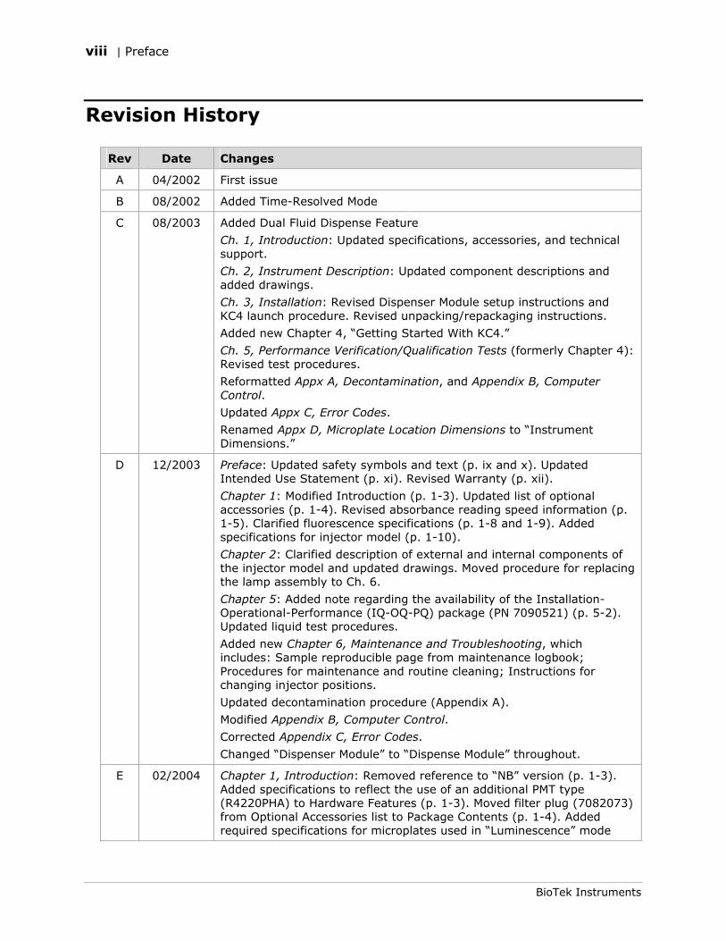
Revision History
Rev Date Changes
A 04/2002 First issue
B 08/2002 Added Time-Resolved Mode
C 08/2003 Added Dual Fluid Dispense Feature
Ch. 1, Introduction: Updated specifications, accessories, and technical support.
Ch. 2, Instrument Description: Updated component descriptions and added drawings.
Ch. 3, Installation: Revised Dispenser Module setup instructions and KC4 launch procedure. Revised unpacking/repackaging instructions.
Added new Chapter 4, “Getting Started With KC4.”
Ch. 5, Performance Verification/Qualification Tests (formerly Chapter 4): Revised test procedures.
Reformatted Appx A, Decontamination, and Appendix B, Computer Control.
Updated Appx C, Error Codes.
Renamed Appx D, Microplate Location Dimensions to “Instrument Dimensions.”
D 12/2003 Preface: Updated safety symbols and text (p. ix and x). Updated Intended Use Statement (p. xi). Revised Warranty (p. xii).
Chapter 1: Modified Introduction (p. 1-3). Updated list of optional accessories (p. 1-4). Revised absorbance reading speed information (p. 1-5). Clarified fluorescence specifications (p. 1-8 and 1-9). Added specifications for injector model (p. 1-10).
Chapter 2: Clarified description of external and internal components of the injector model and updated drawings. Moved procedure for replacing the lamp assembly to Ch. 6.
Chapter 5: Added note regarding the availability of the Installation-Operational-Performance (IQ-OQ-PQ) package (PN 7090521) (p. 5-2). Updated liquid test procedures.
Added new Chapter 6, Maintenance and Troubleshooting, which includes: Sample reproducible page from maintenance logbook; Procedures for maintenance and routine cleaning; Instructions for changing injector positions.
Updated decontamination procedure (Appendix A).
Modified Appendix B, Computer Control.
Corrected Appendix C, Error Codes.
Changed “Dispenser Module” to “Dispense Module” throughout.
E 02/2004 Chapter 1, Introduction: Removed reference to “NB” version (p. 1-3). Added specifications to reflect the use of an additional PMT type (R4220PHA) to Hardware Features (p. 1-3). Moved filter plug (7082073) from Optional Accessories list to Package Contents (p. 1-4). Added required specifications for microplates used in “Luminescence” mode
Revision History | ix
Synergy HT Operator’s Manual
Rev Date Changes
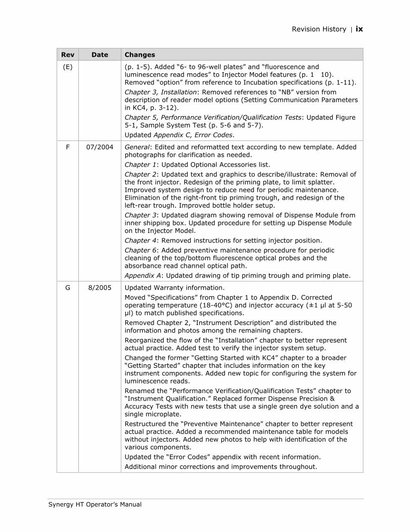
(E) (p. 1-5). Added “6- to 96-well plates” and “fluorescence and luminescence read modes” to Injector Model features (p. 1�10). Removed “option” from reference to Incubation specifications (p. 1-11).
Chapter 3, Installation: Removed references to “NB” version from description of reader model options (Setting Communication Parameters in KC4, p. 3-12).
Chapter 5, Performance Verification/Qualification Tests: Updated Figure 5-1, Sample System Test (p. 5-6 and 5-7).
Updated Appendix C, Error Codes.
F 07/2004 General: Edited and reformatted text according to new template. Added photographs for clarification as needed.
Chapter 1: Updated Optional Accessories list.
Chapter 2: Updated text and graphics to describe/illustrate: Removal of the front injector. Redesign of the priming plate, to limit splatter. Improved system design to reduce need for periodic maintenance. Elimination of the right-front tip priming trough, and redesign of the left-rear trough. Improved bottle holder setup.
Chapter 3: Updated diagram showing removal of Dispense Module from inner shipping box. Updated procedure for setting up Dispense Module on the Injector Model.
Chapter 4: Removed instructions for setting injector position.
Chapter 6: Added preventive maintenance procedure for periodic cleaning of the top/bottom fluorescence optical probes and the absorbance read channel optical path.
Appendix A: Updated drawing of tip priming trough and priming plate.
G 8/2005 Updated Warranty information.
Moved “Specifications” from Chapter 1 to Appendix D. Corrected operating temperature (18-40°C) and injector accuracy (±1 µl at 5-50 µl) to match published specifications.
Removed Chapter 2, “Instrument Description” and distributed the information and photos among the remaining chapters.
Reorganized the flow of the “Installation” chapter to better represent actual practice. Added test to verify the injector system setup.
Changed the former “Getting Started with KC4” chapter to a broader “Getting Started” chapter that includes information on the key instrument components. Added new topic for configuring the system for luminescence reads.
Renamed the “Performance Verification/Qualification Tests” chapter to “Instrument Qualification.” Replaced former Dispense Precision & Accuracy Tests with new tests that use a single green dye solution and a single microplate.
Restructured the “Preventive Maintenance” chapter to better represent actual practice. Added a recommended maintenance table for models without injectors. Added new photos to help with identification of the various components.
Updated the “Error Codes” appendix with recent information.
Additional minor corrections and improvements throughout.
x | Preface
BioTek Instruments
Rev Date Changes
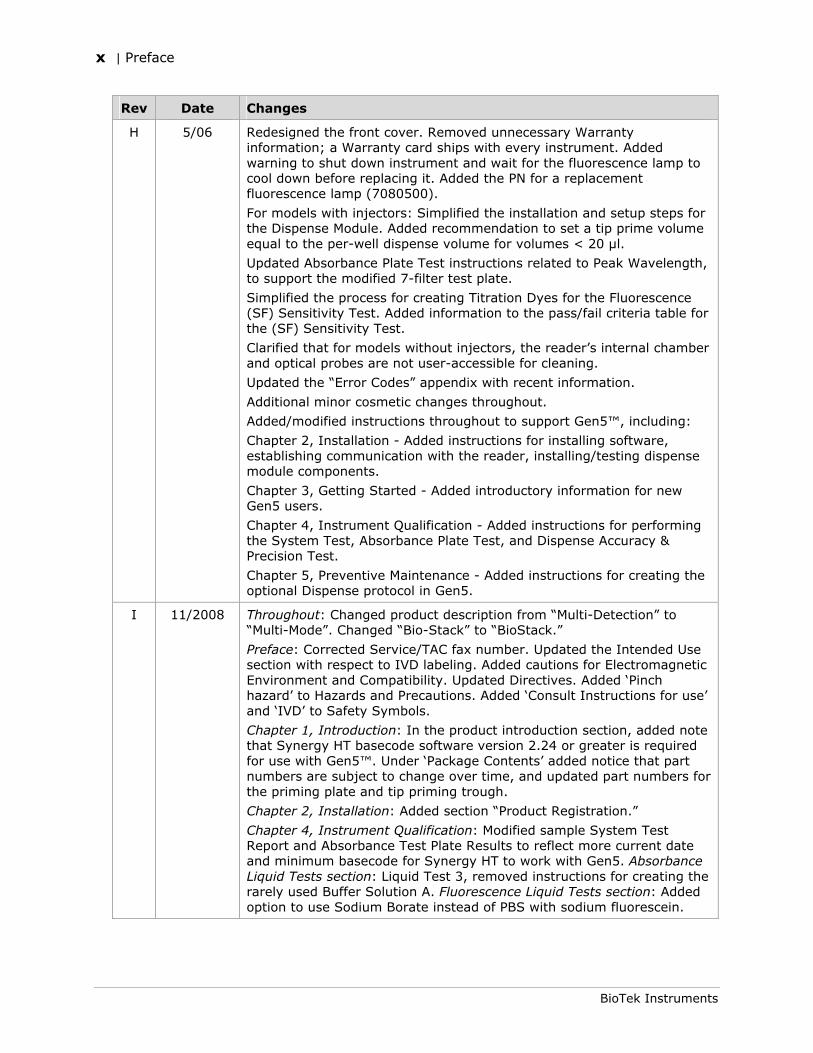
H 5/06 Redesigned the front cover. Removed unnecessary Warranty information; a Warranty card ships with every instrument. Added warning to shut down instrument and wait for the fluorescence lamp to cool down before replacing it. Added the PN for a replacement fluorescence lamp (7080500).
For models with injectors: Simplified the installation and setup steps for the Dispense Module. Added recommendation to set a tip prime volume equal to the per-well dispense volume for volumes < 20 µl.
Updated Absorbance Plate Test instructions related to Peak Wavelength, to support the modified 7-filter test plate.
Simplified the process for creating Titration Dyes for the Fluorescence (SF) Sensitivity Test. Added information to the pass/fail criteria table for the (SF) Sensitivity Test.
Clarified that for models without injectors, the reader’s internal chamber and optical probes are not user-accessible for cleaning.
Updated the “Error Codes” appendix with recent information.
Additional minor cosmetic changes throughout.
Added/modified instructions throughout to support Gen5™, including:
Chapter 2, Installation - Added instructions for installing software, establishing communication with the reader, installing/testing dispense module components.
Chapter 3, Getting Started - Added introductory information for new Gen5 users.
Chapter 4, Instrument Qualification - Added instructions for performing the System Test, Absorbance Plate Test, and Dispense Accuracy & Precision Test.
Chapter 5, Preventive Maintenance - Added instructions for creating the optional Dispense protocol in Gen5.
I 11/2008 Throughout: Changed product description from “Multi-Detection” to “Multi-Mode”. Changed “Bio-Stack” to “BioStack.”
Preface: Corrected Service/TAC fax number. Updated the Intended Use section with respect to IVD labeling. Added cautions for Electromagnetic Environment and Compatibility. Updated Directives. Added ‘Pinch hazard’ to Hazards and Precautions. Added ‘Consult Instructions for use’ and ‘IVD’ to Safety Symbols.
Chapter 1, Introduction: In the product introduction section, added note that Synergy HT basecode software version 2.24 or greater is required for use with Gen5™. Under ‘Package Contents’ added notice that part numbers are subject to change over time, and updated part numbers for the priming plate and tip priming trough.
Chapter 2, Installation: Added section “Product Registration.”
Chapter 4, Instrument Qualification: Modified sample System Test Report and Absorbance Test Plate Results to reflect more current date and minimum basecode for Synergy HT to work with Gen5. Absorbance Liquid Tests section: Liquid Test 3, removed instructions for creating the rarely used Buffer Solution A. Fluorescence Liquid Tests section: Added option to use Sodium Borate instead of PBS with sodium fluorescein.
Revision History | xi
Synergy HT Operator’s Manual
Rev Date Changes
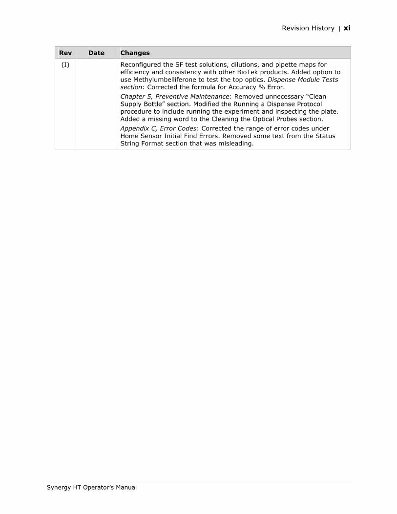
(I) Reconfigured the SF test solutions, dilutions, and pipette maps for efficiency and consistency with other BioTek products. Added option to use Methylumbelliferone to test the top optics. Dispense Module Tests section: Corrected the formula for Accuracy % Error.
Chapter 5, Preventive Maintenance: Removed unnecessary “Clean Supply Bottle” section. Modified the Running a Dispense Protocol procedure to include running the experiment and inspecting the plate. Added a missing word to the Cleaning the Optical Probes section.
Appendix C, Error Codes: Corrected the range of error codes under Home Sensor Initial Find Errors. Removed some text from the Status String Format section that was misleading.
xii | Preface
BioTek Instruments
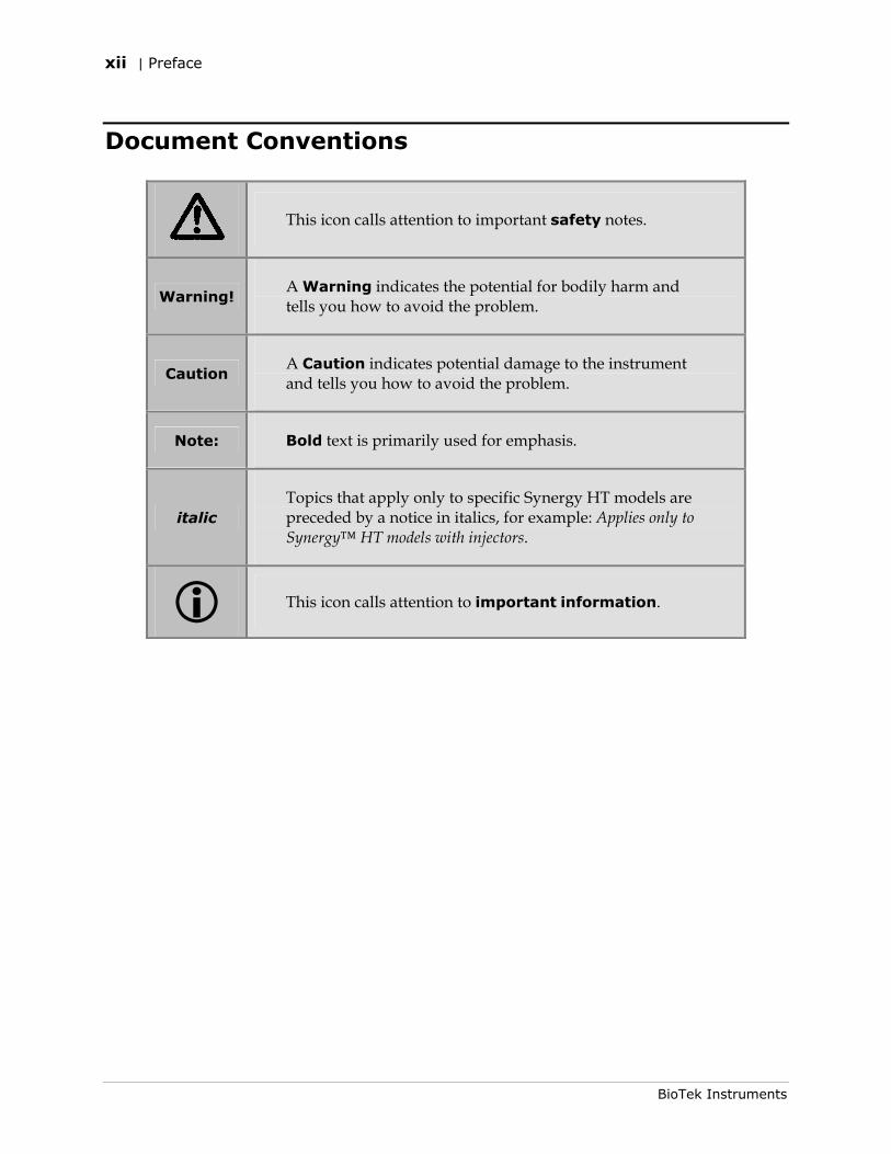
Document Conventions
This icon calls attention to important safety notes.
Warning! A Warning indicates the potential for bodily harm and tells you how to avoid the problem.
Caution A Caution indicates potential damage to the instrument and tells you how to avoid the problem.
Note: Bold text is primarily used for emphasis.
italic Topics that apply only to specific Synergy HT models are preceded by a notice in italics, for example: Applies only to Synergy™ HT models with injectors.
This icon calls attention to important information.
Intended Use Statement | xiii
Synergy HT Operator’s Manual
Intended Use Statement
The Synergy™ HT is a single-channel absorbance, fluorescence, and luminescence micro-plate reader that uses a dual-optics design to perform measurements of samples in a microplate format. The performance characteristics of the data reduction software have not been established with any laboratory diagnostic assay. The user must evaluate this instrument and PC-based software in conjunction with the specific assay. This evaluation must include the confirmation that performance characteristics for the specific assay are met.
• This system is designed for use with PC-based software only. BioTek’s software packages, Gen5™ and KC4™, provide the user with instrument control.
• The Synergy HT can operate with standard robotic systems, such as BioTek’s BioStack™ Microplate Stacker.
• The intended use of this instrument is dependent on the instrument’s labeling. If there is an IVD label, then the instrument may be used for clinical, research and development, or other non-clinical purposes. If there is no such label, then the instrument may only be used for research and development, or for other non-clinical purposes.
Quality Control
It is considered good laboratory practice to run laboratory samples according to instructions and specific recommendations included in the assay package insert for the test to be conducted. Failure to conduct Quality Control checks could result in erroneous test data.
Warranty & Product Registration
Please take a moment to review the Warranty information that shipped with your product. Please also register your product with BioTek to ensure that you receive important information and updates about the product(s) you have purchased.
You can register online through the Customer Care Center at www.biotek.com or by calling 888/451-5171 or 802/655-4740.
xiv | Preface
BioTek Instruments
Warnings
Operate the instrument on a flat surface away from excessive humidity.
Bright sunlight or strong incandescent light can reduce the linear performance range of the instrument.
Measurement values may be affected by extraneous particles (such as dust) in the microplate wells. A clean work area is necessary to ensure accurate readings.
When operated in a safe environment according to the instructions in this document, there are no known hazards associated with the instrument. However, the operator should be aware of certain situations that could result in serious injury; these may vary depending on the instrument model. See Hazards and Precautions.
Hazards and Precautions
Hazards
Warning! Power Rating. The instrument’s power supply or power cord must be connected to a power receptacle that provides voltage and current within the specified rating for the system. Use of an incompatible power receptacle may produce electrical shock and fire hazards.
Warning! Electrical Grounding. Never use a two-prong plug adapter to connect primary power to the external power supply. Use of a two-prong adapter disconnects the utility ground, creating a severe shock hazard. Always connect the power cord directly to a three-prong receptacle with a functional ground.
Warning! Internal Voltage. Always turn off the power switch and unplug the power supply before cleaning the outer surface of the instrument.
Warning! Liquids. Avoid spilling liquids on the instrument; fluid seepage into internal components creates a potential shock hazard. Wipe up all spills immediately. Do not operate the instrument if internal components have been exposed to fluid.
Warning! Potential Biohazards. Some assays or specimens may pose a biohazard. Adequate safety precautions should be taken as outlined in the assay’s package insert. Always wear safety glasses and appropriate protective equipment, such as chemically resistant rubber gloves and apron.
Warning! Hot Surface. The fluorescence lamp assembly is hot when the instrument is turned on. Turn off the reader and allow the lamp to cool down before attempting to replace it.
Warning! Unspecified Use. Failure to operate this equipment according to the guidelines and safeguards specified in this manual could result in a hazardous condition.
Hazards and Precautions | xv
Synergy HT Operator’s Manual
Warning! Software Quality Control. The operator must follow the manufacturer’s assay package insert when modifying software parameters and establishing reading methods. Failure to conduct quality control checks could result in erroneous test data.
Warning! Pinch Hazard. Some areas of the Dispense Module can present pinch hazards when the instrument is operating. These areas are marked with the symbol shown here. Keep hands/fingers clear of these areas when the instrument is operating.
Precautions
The following precautions are provided to help avoid damage to the instrument:
Caution: Service. The Synergy™ HT should be serviced by BioTek authorized service personnel. Only qualified technical personnel should perform troubleshooting and service procedures on internal components.
Caution: Environmental Conditions. Do not expose the system to temperature extremes. For proper operation, ambient temperatures should remain between 18°-40°C. Performance may be adversely affected if temperatures fluctuate above or below this range. Storage temperature limits are broader.
Caution: Sodium Hypochlorite. Do not expose any part of the instrument to the recommended diluted sodium hypochlorite solution (bleach) for more than 20 minutes. Prolonged contact may damage the instrument surfaces. Be certain to rinse and thoroughly wipe all surfaces.
Caution: Power Supply. Only use the power supply shipped with the instrument. Operate this power supply within the range of line voltages listed on it.
Caution: Shipping Panel and Carrier Shipping Screw. The shipping panel and carrier shipping screw must be removed before operating the reader. They must be reinstalled before repackaging the reader for shipment. See Chapter 2, Installation.
Caution: Disposal. This instrument contains printed circuit boards and wiring with lead solder. Dispose of the instrument according to Directive 2002/96/EC, “on waste electrical and electronic equipment (WEEE).”
Caution: Electromagnetic Environment. Per IEC 61326-2-6 it is the user’s responsibility to ensure that a compatible electromagnetic environment for this instrument is provided and maintained in order that the device will perform as intended.
Caution: Electromagnetic Compatibility. Do not use this device in close proximity to sources of strong electromagnetic radiation (e.g. unshielded intentional RF sources), as these may interfere with the proper operation.
Caution: Warranty. Failure to follow preventive maintenance protocols may void the warranty. See Chapter 5, Preventive Maintenance.
xvi | Preface
BioTek Instruments
Based on the testing described below and information contained herein, this instrument bears the CE mark
Directive 2004/108/EC: Electromagnetic Compatibility
Emissions - Class A
The system has been type tested by an independent, accredited testing laboratory and found to meet the requirements of EN 61326-1 for Radiated Emissions and Line Conducted Emissions. Verification of compliance was conducted to the limits and methods of the following: CISPR 16-1, CISPR 16-2, and EN 55022.
This equipment has been designed and tested to CISPR 11 Class A. In a domestic environment it may cause radio interference, in which case, you may need to mitigate the interference.
Immunity
The system has been type tested by an independent, accredited testing laboratory and found to meet the requirements of EN 61326-1 for Immunity. Verification of compliance was conducted to the limits and methods of the following:
EN 61000-4-2 Electrostatic Discharge EN 61000-4-3 Radiated EM Fields EN 61000-4-4 Electrical Fast Transient/Burst EN 61000-4-5 Surge Immunity EN 61000-4-6 Conducted Disturbances EN 61000-4-11 Voltage Dips, Short Interruptions and Variations
Directive 73/23/EEC Low Voltage (Safety)
The system has been type tested by an independent testing laboratory and was found to meet the requirements of EC Directive 73/23/EEC for Low Voltage. Verification of compliance was conducted to the limits and methods of the following:
EN 61010-1. “Safety requirement for electrical equipment for measurement, control and laboratory use. Part 1, General requirements.”
Directive 2002/96/EC: Waste Electrical and Electronic Equipment
Disposal Notice. This instrument contains printed circuit boards and wiring with lead solder. Dispose of the instrument according to Directive 2002/96/EC, “on waste electrical and electronic equipment (WEEE)” or local ordinances.
Directive 98/79/EC: In Vitro Diagnostics (if labeled for this use)
• Product registration with competent authorities
• Traceability to the U.S. National Institute of Standards and Technology (NIST): Optical density measurementsare traceable to NIST.
Electromagnetic Interference and Susceptibility | xvii
Synergy HT Operator’s Manual
Electromagnetic Interference and Susceptibility
USA FCC CLASS A
Warning: Changes or modifications to this unit not expressly approved by the manufacturer could void the user's authority to operate the equipment.
This equipment has been tested and found to comply with the limits for a Class A digital device, pursuant to Part 15 of the FCC Rules.
These limits are designed to provide reasonable protection against harmful interference when the equipment is operated in a commercial environment. Like all similar equipment, this equipment generates, uses, and can radiate radio frequency energy and, if not installed and used in accordance with the instruction manual, may cause harmful interference to radio communications. Operation of this equipment in a residential area is likely to cause interference, in which case the user will be required to correct the interference at his own expense.
Canadian Department of Communications Class A
This digital apparatus does not exceed Class A limits for radio emissions from digital apparatus set out in the Radio Interference Regulations of the Canadian Department of Communications.
Le present appareil numerique n'met pas du bruits radioelectriques depassant les limites applicables aux appareils numerique de la Class A prescrites dans le Reglement sur le brouillage radioelectrique edicte par le ministere des Communications du Canada.
User Safety
This device has been type tested by an independent laboratory and found to meet the requirements of the following:
• Underwriters Laboratories UL 61010A-1, 1st edition, 2002
“Electrical Equipment for Laboratory Use; Part 1: General Requirements”
• Canadian Standards Association CAN/CSA C22.2 No. 1010.1-1992
“Safety requirements for electrical equipment for measurement, control and laboratory use; part 1: general requirements”

xviii | Preface
BioTek Instruments
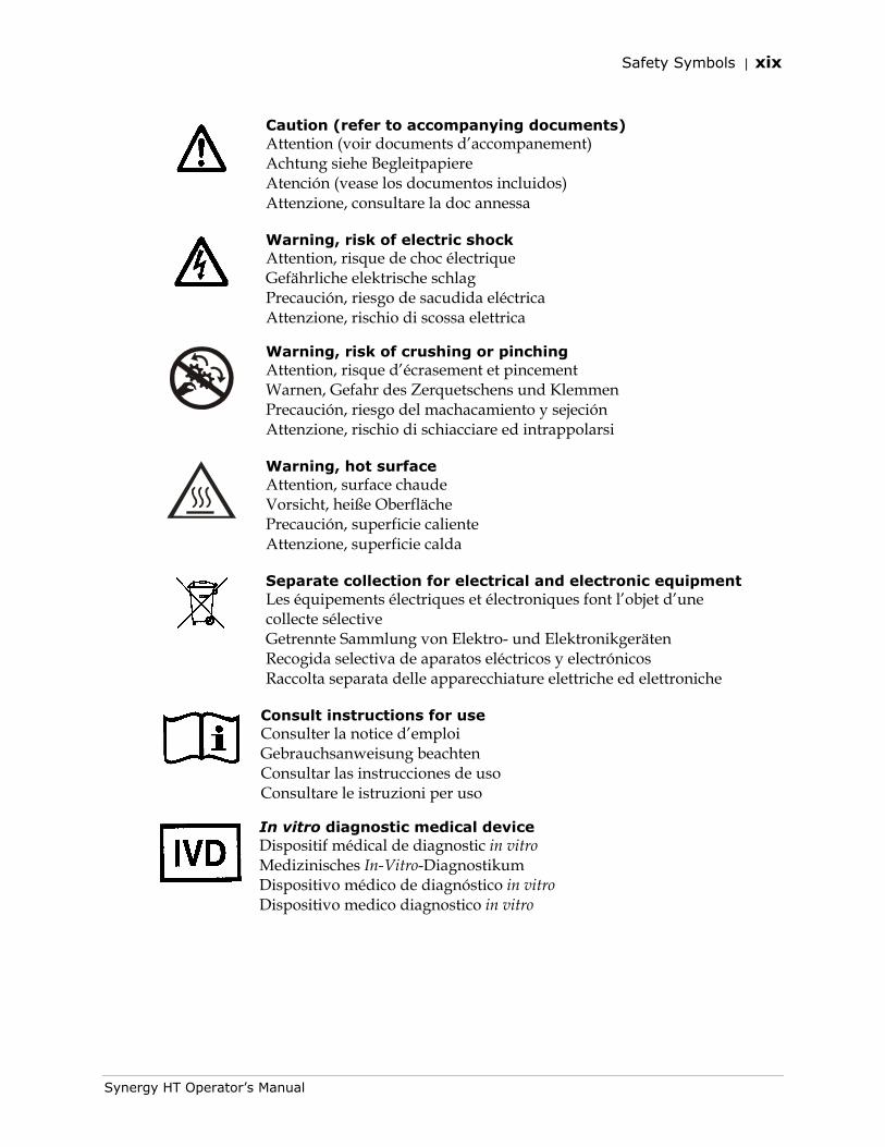
Safety Symbols
Some of the following symbols may appear on the instrument.
Alternating current Courant alternatif Wechselstrom Corriente alterna Corrente alternata
Direct current Courant continu Gleichstrom Corriente continua Corrente continua
Both direct and alternating current Courant continu et courant alternatif Gleich - und Wechselstrom Corriente continua y corriente alterna Corrente continua e corrente alternata
Earth ground terminal Borne de terre Erde (Betriebserde) Borne de tierra Terra (di funzionamento)
Protective conductor terminal Borne de terre de protection Schutzleiteranschluss Borne de tierra de protección Terra di protezione
On (Supply) Marche (alimentation) Ein (Verbindung mit dem Netz) Conectado Chiuso
Off (Supply) Arrêt (alimentation) Aus (Trennung vom Netz) Desconectado Aperto (sconnessione dalla rete di alimentazione)
Safety Symbols | xix
Synergy HT Operator’s Manual
Caution (refer to accompanying documents) Attention (voir documents d’accompanement) Achtung siehe Begleitpapiere Atención (vease los documentos incluidos) Attenzione, consultare la doc annessa
Warning, risk of electric shock Attention, risque de choc électrique Gefährliche elektrische schlag Precaución, riesgo de sacudida eléctrica Attenzione, rischio di scossa elettrica
Warning, risk of crushing or pinching Attention, risque d’écrasement et pincement Warnen, Gefahr des Zerquetschens und Klemmen Precaución, riesgo del machacamiento y sejeción Attenzione, rischio di schiacciare ed intrappolarsi
Warning, hot surface Attention, surface chaude Vorsicht, heiße Oberfläche Precaución, superficie caliente Attenzione, superficie calda
Separate collection for electrical and electronic equipment Les équipements électriques et électroniques font l’objet d’une collecte sélective Getrennte Sammlung von Elektro- und Elektronikgeräten Recogida selectiva de aparatos eléctricos y electrónicos Raccolta separata delle apparecchiature elettriche ed elettroniche
Consult instructions for use Consulter la notice d’emploi Gebrauchsanweisung beachten Consultar las instrucciones de uso Consultare le istruzioni per uso
In vitro diagnostic medical device Dispositif médical de diagnostic in vitro Medizinisches In-Vitro-Diagnostikum Dispositivo médico de diagnóstico in vitro Dispositivo medico diagnostico in vitro

xx | Preface
BioTek Instruments
Chapter 1
Introduction
This chapter introduces the Synergy™ HT, describes its key features, and lists its package contents. Page 6 contains information on contacting BioTek® Instruments, Inc. for product support and service.
Synergy™ HT Multi-Mode Microplate Reader............................... 2 Features ............................................................................... 3 Package Contents................................................................... 4 Optional Accessories ............................................................... 5 Product Support & Service....................................................... 6
Technical Assistance Center (TAC)........................................ 6 Returning Instruments for Service/Repair.............................. 6 Contacting BioTek for Applications Support............................ 6
2 | Chapter 1: Introduction
BioTek Instruments, Inc.
Synergy™ HT Multi-Mode Microplate Reader
The Synergy HT is a single-channel absorbance, fluorescence, and luminescence microplate reader. It is computer-controlled using BioTek’s Gen5™ or KC4™ PC software for all operations including data reduction and analysis. Note: Synergy HT basecode software version 2.24 or greater is required for use with Gen5. The Synergy HT is robot accessible and compatible with BioTek’s BioStack™ Microplate Stacker.
When making fluorescence determinations, the Synergy HT uses a tungsten quartz halogen lamp with interference filters for wavelength specificity in conjunction with a photomultiplier (PMT) tube detector. The Synergy HT has both top and bottom probes for fluorescence measurements. The top probe can be adjusted vertically for the correct reading height, via Gen5’s/KC4’s Top Probe Vertical Offset reading parameter (see Chapter 3, Getting Started).
Luminescence is measured by the low-noise PMT detector through an empty filter position in the Emission filter wheel. A filter can also be left in place if light filtering is necessary.
Absorbance measurements are made by switching to a xenon flash lamp and a monochromator for wavelength selection. The use of a xenon flash lamp allows for both UV and visible light absorbance measurements. The monochromator provides wavelength selection from 200 to 999 nm in 1-nm increments.
The Synergy HT has a 4-Zone™ temperature control from 4°C over ambient to 50°C that ensures superior temperature uniformity necessary for kinetic assays. Internal plate shaking is also supported.
All Synergy HT models support the reading of 6-, 12-, 24-, 48-, 96-, and 384-well microplates with standard 128 x 86 mm geometry. Absorbance mode reads plates up to 0.8” (20.3 mm) in height; fluorescence mode reads plates up to 1.25” (31.75 mm). Polymerase Chain Reaction (PCR) tubes up to 1.25” (31.75 mm) are also readable with the use of existing adapter plates.
The Time-Resolved (TR) option allows time-resolved fluorescence measurements by using the xenon flash light source in conjunction with the PMT measurement detector. A special cartridge installed in the Excitation filter wheel location is required.
Models with injectors support dual-reagent dispensing to 6-, 12-, 24-, 48-, and 96-well microplates with standard 128 x 86 mm geometry. An external dispense module pumps fluid from the supply bottles to the two injectors located inside the instrument. Both injectors are positioned directly above the bottom probe, and fluid is injected into one well at a time.
Features | 3
Synergy HT Operator’s Manual
Features
• Operated using BioTek’s Gen5™ or KC4™ Data Analysis Software
• Dual-optics design, with separate fluorescence and absorbance channels
• 3 mm top and 5 mm bottom fluorescence probes (standard configuration)
• Optional 1.5 mm top/bottom, 3 mm bottom fluorescence probes (custom configurations)
• Optional Time-Resolved Fluorescence (TRF) capability (“T” models, e.g., SIAFRT)
• Fluorescence ranges:
Standard low-noise PMT
Excitation: 300 to 650 nm (200 to 700 nm with “T” models)
Emission: 300 to 700 nm
Optional red-extended PMT
Excitation: 300 to 650 nm (200 to 800 nm with “T” models)
Emission: 300 to 800 nm
• Absorbance range of 200 to 999 nm
• Absorbance OD range from 0.000 to 4.000 OD
• Low, Medium, High and Variable plate-shaking speeds with adjustable durations
• All models read 6-, 12-, 24-, 48-, 96- and 384-well microplates
• Injector models dispense to 6-, 12-, 24-, 48-, and 96-well microplates
• Operates from 100 to 240 V~ (± 10%) @ 50 to 60 Hz
• One serial COM port (9-pin female connector)
• One USB port
• 4-Zone™ incubation to 50ºC
• Optional dual-reagent dispensing capability
4 | Chapter 1: Introduction
BioTek Instruments, Inc.
Package Contents
Part numbers are subject to change over time. Please contact BioTek Customer Care with any questions.
• Microplate reader with Excitation and Emission filter wheels installed
• Operator’s Manual (PN 7091000)
• Documents, including (but not limited to): Warranty Statement, Certificate of Compliance and Calibration, Unpacking/Packing Instructions
• Power supply (PN 76061, models with injectors or PN 76053, all other models)
• Power cord set (specific to installation environment):
PN 75010 (Schuko) (Europe) PN 75012 (UK)
PN 75011 (USA/International) PN 75013 (Australia/New Zealand)
• RS-232 serial cable (PN 75034)
• USB cable (PN 75108) with Virtual COM Driver Software (PN 7090204)
• Wrench (PN 48576)
• Fluorescence lamp assembly (PN 7080501) Note: The part number for a replacement lamp is 7080500.
• Filter “plugs” (2) (PN 7082073) (also referred to as “dummy filters”)
• Plastic storage bag and Velcro strips
• Time-Resolved Fluorescence cartridge assembly (PN 7090523) (“T” models only)
• Models with injectors (SIAFRTD, SIAFRTD-CUSTOM), an external dispense module (PN 7090568), with the following accessories:
Outlet tubes (2, plus 2 spare) from dispense module to instrument (PN 7082120)
Inlet tubes (2) from supply bottles to syringe drives (PN 7082121)
250 µL syringes (2) (PN 7083000)
Syringe thumbscrews (2) (PN 19511)
Priming plate (PN 7132158) and injector tip priming trough (PN 7132169)
Dispense module communication cable (PN 75107)
Dispense module front cover (PN 7082137)
Supply bottles (2, 30 mL, PN 7122609) and holder assemblies (2, PN 7090564)
Injector tip cleaning stylus (PN 2872304)
Optional Accessories | 5
Synergy HT Operator’s Manual
Optional Accessories
Part numbers are subject to change over time. Please contact BioTek Customer Care with any questions.
• 7-filter Absorbance Test Plate (PN 7260522) for absorbance measurement testing
• Fluorescence Test Plate (PN 7092092) for fluorescence measurement testing
• Product Qualification (IQ-OQ-PQ) package (PN 7090521)
• PCR Tube Adapter Plates (PNs 6002072 and 6002076)
• Terasaki Adapter Plate (PN 7330531)
• BioCell™ Quartz Vessel (PN 7272051) and Adapter Plate (PN 7270512)
• Additional Fluorescence Filters (contact BioTek for part numbers and availability)
• Absorbance Liquid Test Solutions:
BioTek Wetting Agent Solution (PN 7773002)
BioTek QC Check Solution No. 1 (PN 7120779, 25 ml; or PN 7120782, 125 ml)
• BioTek Sodium Fluorescein Powder (PN 98155)
• (Models with injectors) Dispense Module Liquid Test Solutions:
BioTek Green Test Dye Solution (PN 7773003)
BioTek Blue Test Dye Solution (PN 7773001)
BioTek QC (Yellow) Solution (PN 7120782)
The Synergy HT is compatible with BioTek’s BioStack Microplate Stacker. The BioStack rapidly and systematically transfers microplates (up to 30 per “stack”), to and from the Synergy HT’s microplate carrier. Contact BioTek or visit our website to learn more.
6 | Chapter 1: Introduction
BioTek Instruments, Inc.
Product Support & Service
Technical Assistance Center (TAC)
If your instrument(s) or software fails to function properly, if you have questions about how to use or maintain our products, or if you need to send an instrument to BioTek for service or repair, please contact our Technical Assistance Center. BioTek’s “TAC” is open from 8:30 AM to 5:30 PM (EST), Monday through Friday, excluding standard U.S. holidays. You can send a fax or an e-mail any time. You can also request technical assistance via our website: www.biotek.com.
Phone: (800) 242-4685 or Fax: (802) 654-0638 E-Mail: [email protected] (802) 655-4740
Please be prepared to provide the following information:
• Your name and company information, along with a daytime phone or fax number, and/or an e-mail address
• The product name, model, and serial number
• The software part number (available at Help > About Gen5 or Help > About KC4) and basecode version (available via Gen5™ or KC4™ for the Synergy™ HT by selecting System > Reader Control)
• For troubleshooting assistance or instruments needing repair, the specific steps that produce your problem and any error codes displayed in Gen5/KC4 (see also Appendix C, Error Codes)
Returning Instruments for Service/Repair
If you need to return an instrument to BioTek for service or repair, please contact the TAC for a Return Materials Authorization (RMA) number before shipping the instrument. Repackage the instrument properly (see Chapter 2, Installation), write the RMA number on the shipping box, and ship to this address:
BioTek Instruments, Inc. ATTN: RMA# xxxxx 100 Tigan Street Highland Park Winooski, Vermont 05404 USA
Contacting BioTek for Applications Support
BioTek’s fully equipped Application Laboratory provides our on-staff scientists with the means to assist you with the integration of our instrumentation and software with your unique scientific applications. If you are having difficulty with optimizing fluorescence sensitivity or integrating a unique data reduction transformation, or you are just looking for a recommendation on an appropriate fluorophore, contact us.
Phone: (888) 451-5171 E-Mail: [email protected]
Chapter 2
Installation
This chapter includes instructions for unpacking and setting up the Synergy™ HT and, if applicable, the external dispense module. Instructions are also included for repackaging the reader and dispense module for shipment.
Product Registration ............................................................... 8 1: Unpack and Inspect the Reader ........................................... 9 2: Remove the Shipping Panel .............................................. 11 3: Remove the Microplate Carrier Shipping Screw .................... 13 4: Install the Fluorescence Lamp Assembly ............................. 14 5: Select an Appropriate Location .......................................... 15 6: Connect the Power Supply ................................................ 16 7: Unpack and Inspect the Dispense Module ........................... 17 8: Install the Dispense Module .............................................. 20 9: Connect the Host Computer .............................................. 24 10: Install the Software on the Host Computer ........................ 24 11: Turn on the Reader........................................................ 25 12: Establish Communication ................................................ 26 13: Run a System Test......................................................... 28 14: Test the Injector System ................................................ 29 Operational/Performance Qualification..................................... 31 Repackaging and Shipping Instructions ................................... 32
8 | Chapter 2: Installation
BioTek Instruments, Inc.
Product Registration
If you have not already done so, please register your product(s) with BioTek to ensure that you receive important information and updates about the product(s) you have purchased.
Register online through BioTek’s Customer Resource Center at www.biotek.com or by contacting BioTek Customer Care.
Once registered, you can log into the Customer Resource Center and:
• Register your product warranty
• Manage your equipment inventory
• Access documentation on your products
• Download user manuals and software
• Check the status of your instrument’s service
• Track your order
1: Unpack and Inspect the Reader | 9
Synergy HT Operator's Manual
1: Unpack and Inspect the Reader
Important! Save all packaging materials. If you need to ship the reader to BioTek for repair or replacement, you must use the original materials. Using other forms of commercially available packaging, or failing to follow the repackaging instructions, may void your warranty.
During the unpacking process, inspect the packaging, reader, and accessories for shipping damage. If the reader is damaged, notify the carrier and your BioTek representative. Keep the shipping boxes and the packaging materials for the carrier’s inspection. BioTek will arrange for repair or replacement of your reader immediately, before the shipping-related claim is settled.
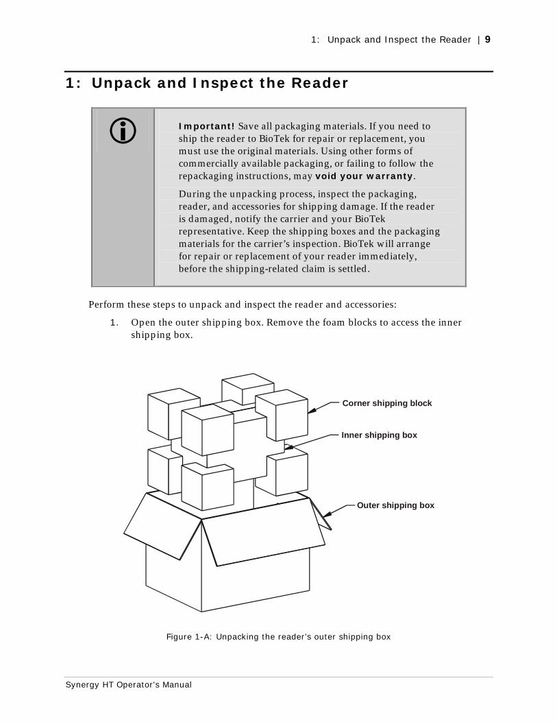
Perform these steps to unpack and inspect the reader and accessories:
1. Open the outer shipping box. Remove the foam blocks to access the inner shipping box.
Corner shipping block
Outer shipping box
Inner shipping box
Figure 1-A: Unpacking the reader’s outer shipping box
10 | Chapter 2: Installation
BioTek Instruments, Inc.
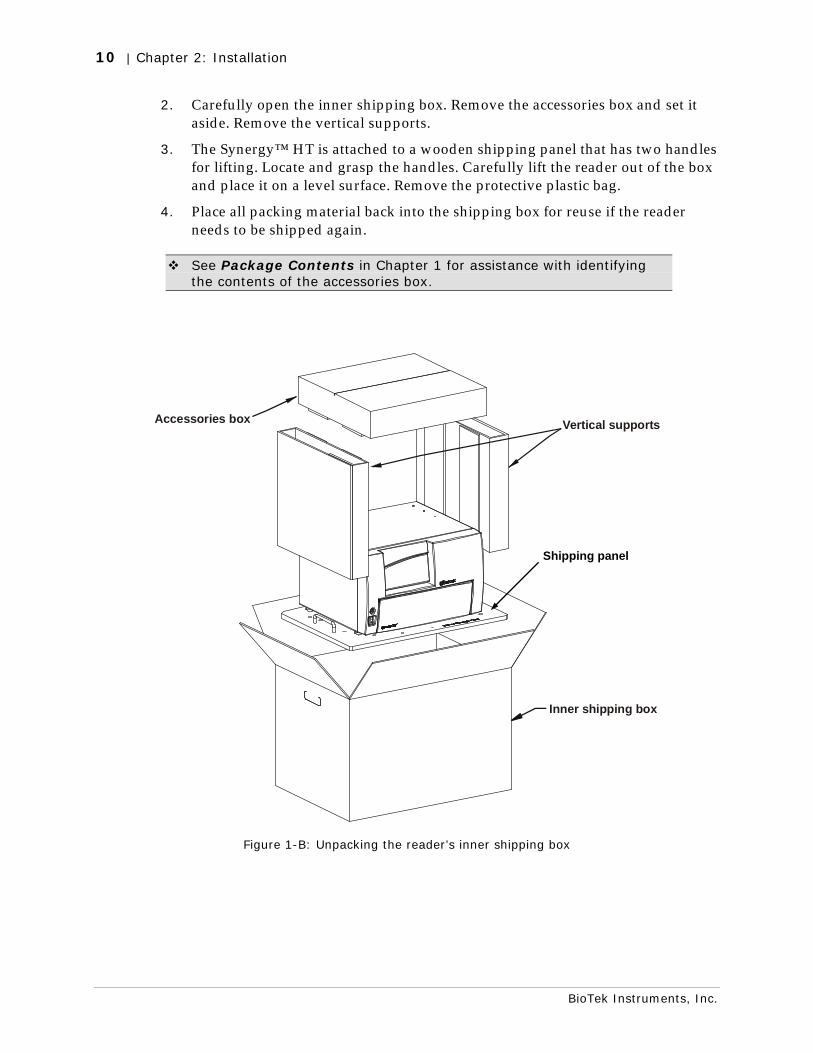
2. Carefully open the inner shipping box. Remove the accessories box and set it aside. Remove the vertical supports.
3. The Synergy™ HT is attached to a wooden shipping panel that has two handles for lifting. Locate and grasp the handles. Carefully lift the reader out of the box and place it on a level surface. Remove the protective plastic bag.
4. Place all packing material back into the shipping box for reuse if the reader needs to be shipped again.
See Package Contents in Chapter 1 for assistance with identifying the contents of the accessories box.
Accessories box
Inner shipping box
Vertical supports
Figure 1-B: Unpacking the reader’s inner shipping box
Shipping panel
2: Remove the Shipping Panel | 11
Synergy HT Operator's Manual
2: Remove the Shipping Panel
Perform these steps to remove the shipping panel from the bottom of the reader:
1. Carefully tip the reader onto its back.
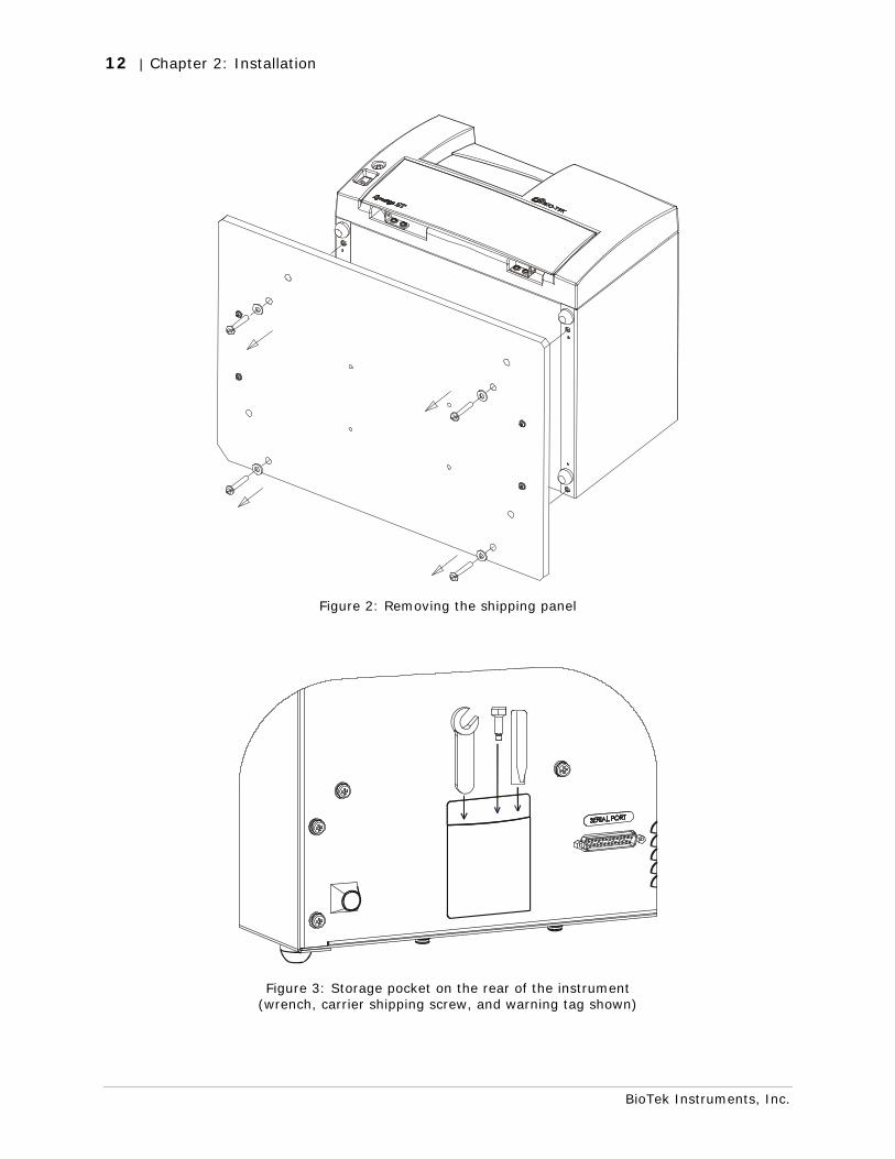
2. Using a slotted screwdriver, remove the four screws and washers attaching the shipping panel to the bottom of the reader. See Figure 2 on the next page.
3. Carefully set the reader upright.
4. Locate the supplied plastic tool storage pocket. Place the screws and washers inside the bag. Use the supplied Velcro strips to attach the pocket to the back of the reader for storage. Do not block any air vents. See Figure 3 on the next page.
5. Place the panel back into the inner shipping box for storage.
Important: Reattach the shipping panel before repackaging the Synergy™ HT for shipment.
12 | Chapter 2: Installation
BioTek Instruments, Inc.
Figure 2: Removing the shipping panel
Figure 3: Storage pocket on the rear of the instrument (wrench, carrier shipping screw, and warning tag shown)
3: Remove the Microplate Carrier Shipping Screw | 13
Synergy HT Operator's Manual
3: Remove the Microplate Carrier Shipping Screw
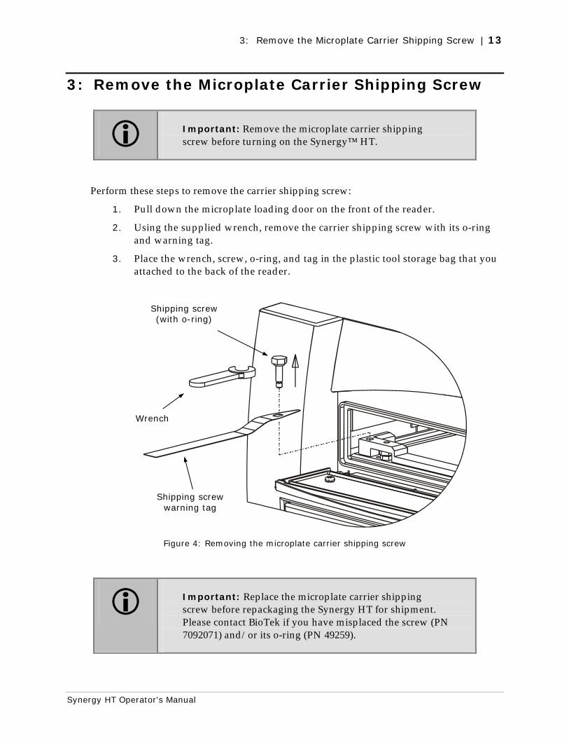
Important: Remove the microplate carrier shipping screw before turning on the Synergy™ HT.
Perform these steps to remove the carrier shipping screw:
1. Pull down the microplate loading door on the front of the reader.
2. Using the supplied wrench, remove the carrier shipping screw with its o-ring and warning tag.
3. Place the wrench, screw, o-ring, and tag in the plastic tool storage bag that you attached to the back of the reader.
Figure 4: Removing the microplate carrier shipping screw
Important: Replace the microplate carrier shipping screw before repackaging the Synergy HT for shipment. Please contact BioTek if you have misplaced the screw (PN 7092071) and/or its o-ring (PN 49259).
Shipping screw (with o-ring)
Wrench
Shipping screw warning tag
14 | Chapter 2: Installation
BioTek Instruments, Inc.
4: Install the Fluorescence Lamp Assembly
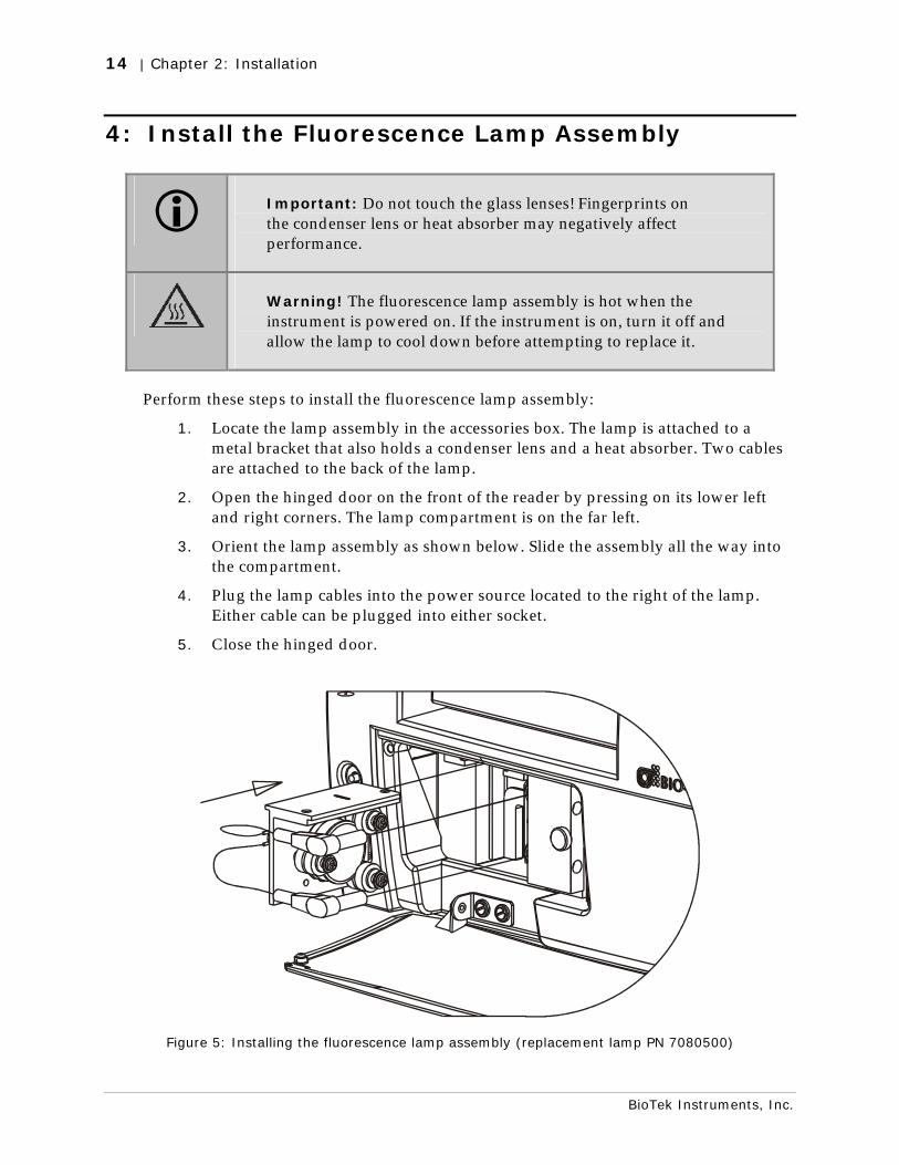
Important: Do not touch the glass lenses! Fingerprints on the condenser lens or heat absorber may negatively affect performance.
Warning! The fluorescence lamp assembly is hot when the instrument is powered on. If the instrument is on, turn it off and allow the lamp to cool down before attempting to replace it.
Perform these steps to install the fluorescence lamp assembly:
1. Locate the lamp assembly in the accessories box. The lamp is attached to a metal bracket that also holds a condenser lens and a heat absorber. Two cables are attached to the back of the lamp.
2. Open the hinged door on the front of the reader by pressing on its lower left and right corners. The lamp compartment is on the far left.
3. Orient the lamp assembly as shown below. Slide the assembly all the way into the compartment.
4. Plug the lamp cables into the power source located to the right of the lamp. Either cable can be plugged into either socket.
5. Close the hinged door.
Figure 5: Installing the fluorescence lamp assembly (replacement lamp PN 7080500)
5: Select an Appropriate Location | 15
Synergy HT Operator's Manual
5: Select an Appropriate Location
Install the Synergy™ HT on a level surface in an area where ambient temperatures between 18º and 40ºC can be maintained.
The reader is sensitive to extreme environmental conditions. Avoid the following:
• Excessive humidity: Condensation directly on the sensitive electronic circuits can cause the reader to fail internal self-checks. The specified relative humidity range for this reader is from 10% to 85% (non-condensing).
• Excessive ambient light: Bright sunlight or strong incandescent light may affect the reader’s optics and readings, reducing its linear performance range.
• Dust: Readings may be affected by extraneous particles (such as dust) in the microplate wells. A clean work area is necessary to ensure accurate readings.
Note: If you will be installing BioTek’s BioStack™ Microplate Stacker for operation with the Synergy HT, you may wish to seat the BioStack and the reader in their aligning plates at this time. Refer to the Installation chapter in the BioStack Operator’s Manual for more information.
16 | Chapter 2: Installation
BioTek Instruments, Inc.
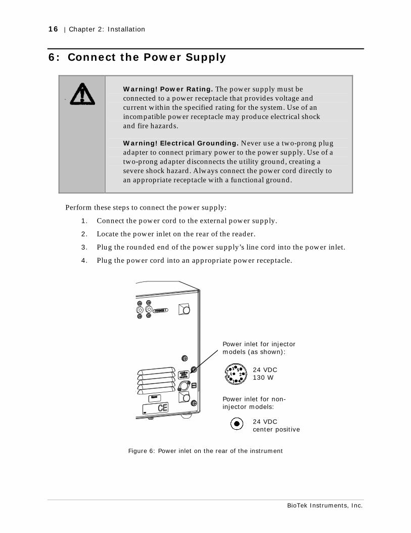
6: Connect the Power Supply
Warning! Power Rating. The power supply must be connected to a power receptacle that provides voltage and current within the specified rating for the system. Use of an incompatible power receptacle may produce electrical shock and fire hazards.
Warning! Electrical Grounding. Never use a two-prong plug adapter to connect primary power to the power supply. Use of a two-prong adapter disconnects the utility ground, creating a severe shock hazard. Always connect the power cord directly to an appropriate receptacle with a functional ground.
Perform these steps to connect the power supply:
1. Connect the power cord to the external power supply.
2. Locate the power inlet on the rear of the reader.
3. Plug the rounded end of the power supply’s line cord into the power inlet.
4. Plug the power cord into an appropriate power receptacle.
Figure 6: Power inlet on the rear of the instrument
Power inlet for injector models (as shown):
Power inlet for non-injector models:
24 VDC 130 W
24 VDC center positive
7: Unpack and Inspect the Dispense Module | 17
Synergy HT Operator's Manual
7: Unpack and Inspect the Dispense Module
This section applies to Synergy™ HT models with injectors only.
Important! Save all packaging materials. If you need to ship the dispense module to BioTek for repair or replacement, you must use the original materials. Using other forms of commercially available packaging, or failing to follow the repackaging instructions, may void your warranty.
During the unpacking process, inspect the packaging, module, and accessories for shipping damage. If the reader is damaged, notify the carrier and your BioTek representative. Keep the shipping boxes and the packaging materials for the carrier’s inspection. BioTek will arrange for repair or replacement of your reader immediately, before the shipping-related claim is settled.
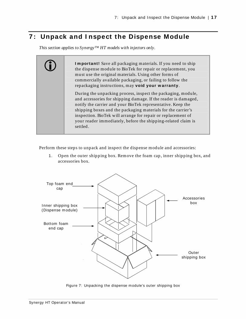
Perform these steps to unpack and inspect the dispense module and accessories:
1. Open the outer shipping box. Remove the foam cap, inner shipping box, and accessories box.
Figure 7: Unpacking the dispense module’s outer shipping box
Outer shipping box
Accessories box
Bottom foam end cap
Top foam end cap
Inner shipping box (Dispense module)
18 | Chapter 2: Installation
BioTek Instruments, Inc.
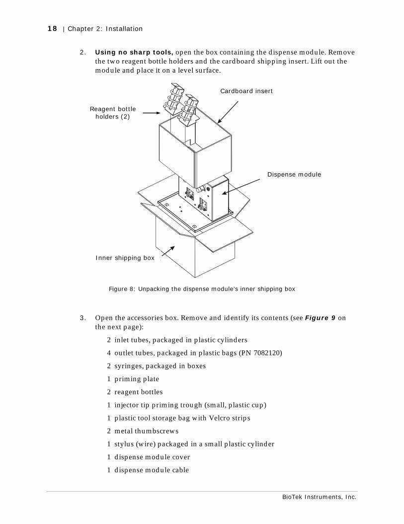
2. Using no sharp tools, open the box containing the dispense module. Remove the two reagent bottle holders and the cardboard shipping insert. Lift out the module and place it on a level surface.
Shipping insert
Innershipping box
Dispensemodule
Figure 8: Unpacking the dispense module’s inner shipping box
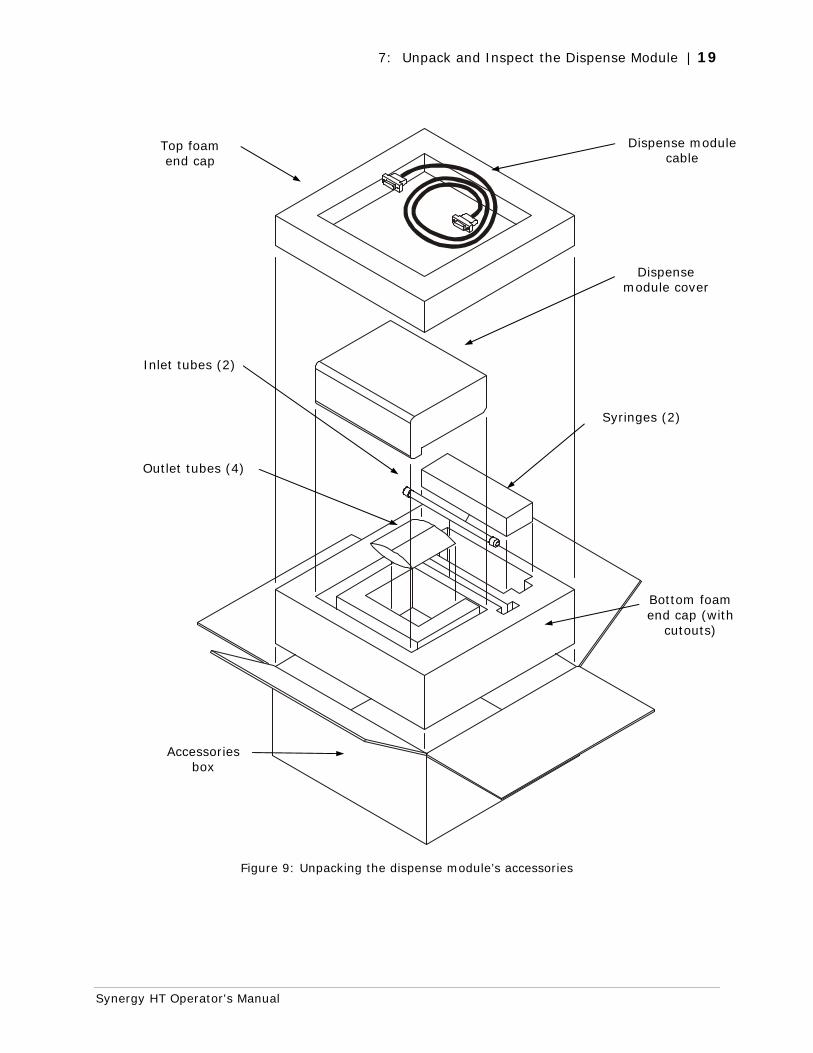
3. Open the accessories box. Remove and identify its contents (see Figure 9 on the next page):
2 inlet tubes, packaged in plastic cylinders
4 outlet tubes, packaged in plastic bags (PN 7082120)
2 syringes, packaged in boxes
1 priming plate
2 reagent bottles
1 injector tip priming trough (small, plastic cup)
1 plastic tool storage bag with Velcro strips
2 metal thumbscrews
1 stylus (wire) packaged in a small plastic cylinder
1 dispense module cover
1 dispense module cable
Reagent bottle holders (2)
Dispense module
Cardboard insert
Inner shipping box
7: Unpack and Inspect the Dispense Module | 19
Synergy HT Operator's Manual
Figure 9: Unpacking the dispense module’s accessories
Accessories box
Bottom foam end cap (with
cutouts)
Syringes (2)
Dispense module cover
Outlet tubes (4)
Inlet tubes (2)
Top foam end cap
Dispense module cable
20 | Chapter 2: Installation
BioTek Instruments, Inc.
8: Install the Dispense Module
This section applies to Synergy™ HT models with injectors only.
Refer to the figures on the next two pages for guidance while performing these steps.
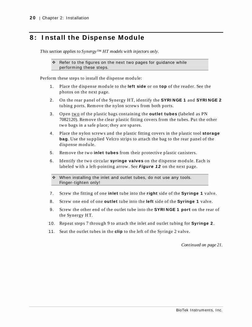
Perform these steps to install the dispense module:
1. Place the dispense module to the left side or on top of the reader. See the photos on the next page.
2. On the rear panel of the Synergy HT, identify the SYRINGE 1 and SYRINGE 2 tubing ports. Remove the nylon screws from both ports.
3. Open two of the plastic bags containing the outlet tubes (labeled as PN 7082120). Remove the clear plastic fitting covers from the tubes. Put the other two bags in a safe place; they are spares.
4. Place the nylon screws and the plastic fitting covers in the plastic tool storage bag. Use the supplied Velcro strips to attach the bag to the rear panel of the dispense module.
5. Remove the two inlet tubes from their protective plastic canisters.
6. Identify the two circular syringe valves on the dispense module. Each is labeled with a left-pointing arrow. See Figure 12 on the next page.
When installing the inlet and outlet tubes, do not use any tools. Finger-tighten only!
7. Screw the fitting of one inlet tube into the right side of the Syringe 1 valve.
8. Screw one end of one outlet tube into the left side of the Syringe 1 valve.
9. Screw the other end of the outlet tube into the SYRINGE 1 port on the rear of the Synergy HT.
10. Repeat steps 7 through 9 to attach the inlet and outlet tubing for Syringe 2.
11. Seat the outlet tubes in the clip to the left of the Syringe 2 valve.
Continued on page 21.
8: Install the Dispense Module | 21
Synergy HT Operator's Manual
Figures 10 and 11: Possible locations for the dispense module, to the left or on top of the instrument.
Figure 12: Initial setup of the dispense module
Inlet tubes
Outlet tubes
Syringe valves
22 | Chapter 2: Installation
BioTek Instruments, Inc.
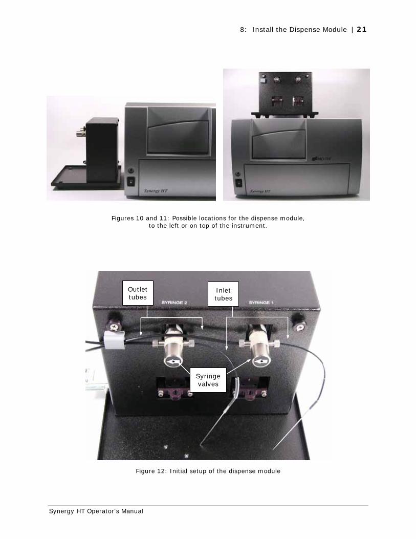
12. Remove the two syringes from their protective boxes. They are identical and interchangeable. Each syringe should already be assembled in one piece, but if for some reason there are two separate pieces, assemble them now: insert the white tip of the syringe plunger into the barrel of the syringe and gently push it all the way into the barrel.
13. Install both syringes:
• Hold the syringe vertically with the threaded end at the top and the knurled steel end at the bottom.
• Screw the threaded end of the syringe into the bottom of the syringe valve. Finger-tighten only.
• Carefully pull down the knurled steel end of the syringe until it is resting inside the hole in the bracket.
• Pass a metal thumbscrew up through this hole and thread it into the bottom of the syringe. Hold the syringe from rotating while tightening the thumbscrew. Finger-tighten only.
The installed syringes should resemble the following:
Figure 13: The dispense module with the syringes installed
Continued on the next page.
Thumbscrews
Syringe brackets
Syringes
8: Install the Dispense Module | 23
Synergy HT Operator's Manual
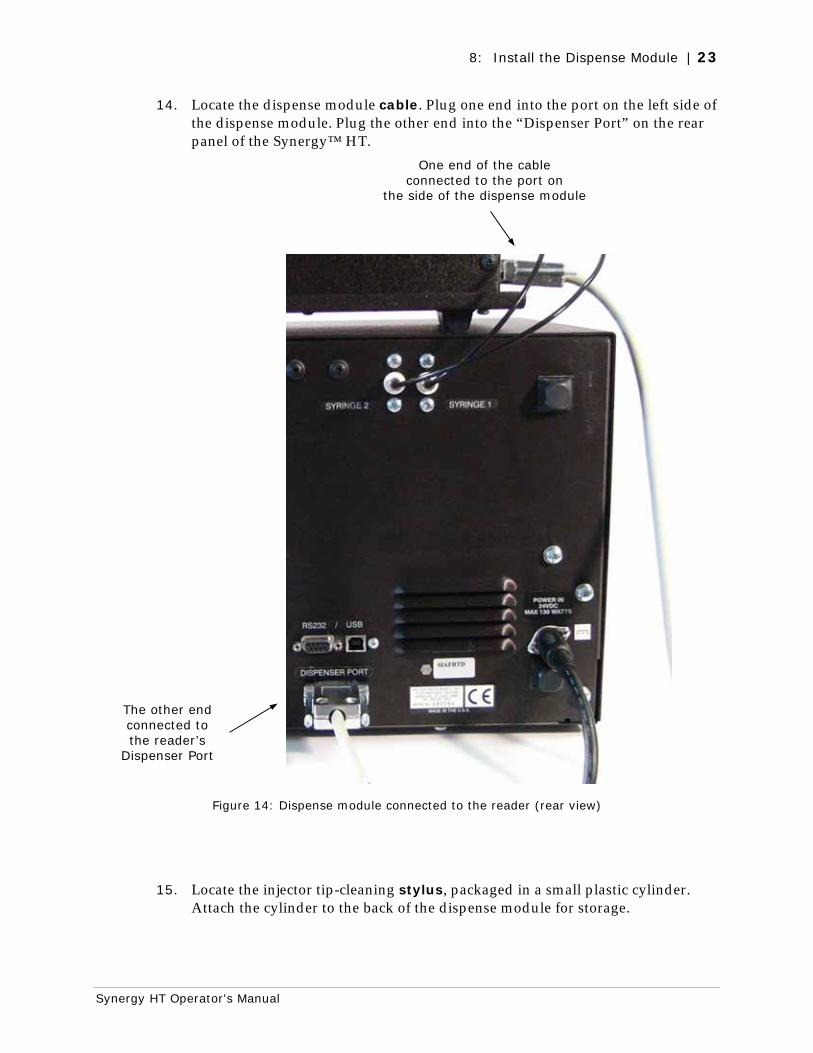
14. Locate the dispense module cable. Plug one end into the port on the left side of the dispense module. Plug the other end into the “Dispenser Port” on the rear panel of the Synergy™ HT.
Figure 14: Dispense module connected to the reader (rear view)
15. Locate the injector tip-cleaning stylus, packaged in a small plastic cylinder. Attach the cylinder to the back of the dispense module for storage.
One end of the cable connected to the port on
the side of the dispense module
The other end connected to the reader’s
Dispenser Port
24 | Chapter 2: Installation
BioTek Instruments, Inc.
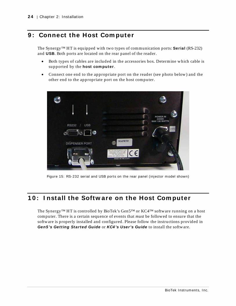
9: Connect the Host Computer
The Synergy™ HT is equipped with two types of communication ports: Serial (RS-232) and USB. Both ports are located on the rear panel of the reader.
• Both types of cables are included in the accessories box. Determine which cable is supported by the host computer.
• Connect one end to the appropriate port on the reader (see photo below) and the other end to the appropriate port on the host computer.
Figure 15: RS-232 serial and USB ports on the rear panel (injector model shown)
10: Install the Software on the Host Computer
The Synergy™ HT is controlled by BioTek’s Gen5™ or KC4™ software running on a host computer. There is a certain sequence of events that must be followed to ensure that the software is properly installed and configured. Please follow the instructions provided in Gen5’s Getting Started Guide or KC4’s User’s Guide to install the software.
11: Turn on the Reader | 25
Synergy HT Operator's Manual
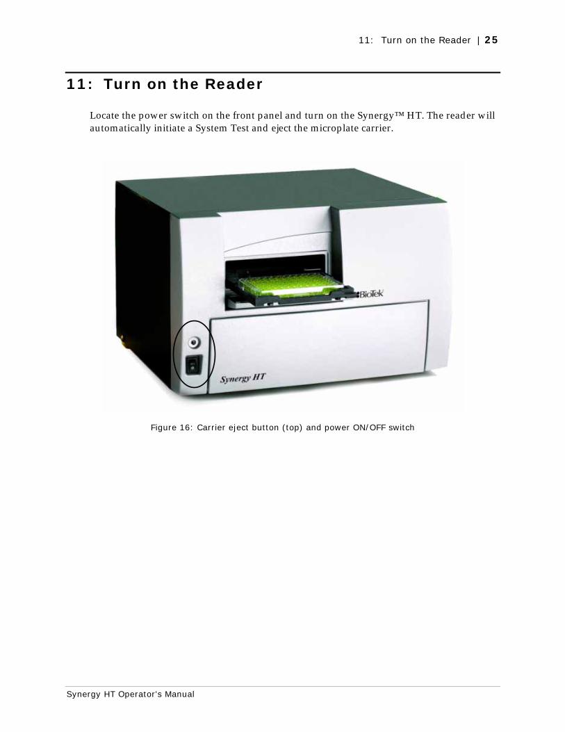
11: Turn on the Reader
Locate the power switch on the front panel and turn on the Synergy™ HT. The reader will automatically initiate a System Test and eject the microplate carrier.
Figure 16: Carrier eject button (top) and power ON/OFF switch
26 | Chapter 2: Installation
BioTek Instruments, Inc.
12: Establish Communication
Important: If you are using the USB cable, refer to the instructions that shipped with the “USB Virtual COM Driver Software” CD to install the necessary drivers and identify the Com Port number.
Using Gen5™
Perform these steps to set and test the communication parameters:
1. Start Gen5.
2. Login if prompted. The default System Administrator password is “admin”.
3. When the “Welcome to Gen5” screen appears, select System Menu.
4. Select System|Reader Configuration and click Add.
5. Set the Reader Type to Synergy.
6. Set the Com Port to the computer’s COM port to which the reader is connected.
• If using the USB cable, the information can be found via the Windows® Control Panel, under Ports in the Hardware/Device Manager area of System Properties (e.g., USB Serial Port (COM5)).
7. Click the Test Comm button. Gen5 will attempt to communicate with the reader.
• If the communication attempt is successful, return to Gen5’s main screen.
• If the communication attempt is not successful, try the following:
Is the reader connected to the power supply and turned on?
Is the communication cable firmly attached to both the reader and the computer?
Did you select the correct Reader Type in step 4?
Choose a different COM port.
If using the USB cable, did you install the driver software? (See 9: Connect the Host Computer.)
If you remain unable to get Gen5 and the reader to communicate with each other, contact BioTek’s Technical Assistance Center. See page 6.
12: Establish Communication | 27
Synergy HT Operator's Manual
Using KC4™
Perform these steps to set and test the communication parameters:
1. Start KC4.
2. Login if prompted. The default System Administrator password is “admin”.
3. Close any warning messages that appear until KC4’s main screen appears.
4. Select System|Readers. Scroll through the list of Available Readers until you see your model. Highlight (click once on) the model name.
• Synergy HT-I (SIAFR, SIAFR-Custom)
• Synergy HTTR-I (SIAFRT, SIAFRT-Custom)
• Synergy HTTR w/Injectors (SIAFRTD, SIAFRTD-Custom)
5. Click the Port button and then click Setup. Set the Transmission Rate to 9600 and click OK. Select the computer’s COM port to which the reader is connected, and then click OK.
• If using the USB cable, the information can be found via the Windows® Control Panel, under Ports in the Hardware/Device Manager area of System Properties (e.g., USB Serial Port (COM5)).
6. Click the Current Reader button. KC4 will attempt to communicate with the reader.
If a message appears stating that the software wavelength table does not match the reader filter table, this means that communication has been established and KC4 just needs to update its wavelength table. Click Yes.
• If the communication attempt is successful, click Close to return to KC4’s main screen.
• If the communication attempt is not successful (i.e., an error message appears in KC4), try the following:
Is the reader connected to the power supply and turned on?
Is the communication cable firmly attached to both the reader and the computer?
Did you select the correct model in step 4?
Choose a different COM port.
If using the USB cable, did you install the driver software? (See 9: Connect the Host Computer.)
If you remain unable to get KC4 and the reader to communicate with each other, contact BioTek’s Technical Assistance Center. See page 6.
28 | Chapter 2: Installation
BioTek Instruments, Inc.
13: Run a System Test
Running a System Test will confirm that the reader is set up and running properly, or will provide an error code if a problem has been detected.
Perform these steps to run the test:
1. Gen5: Select System|Diagnostics|Run System Test. If prompted to select a reader, select the Synergy HT and click OK.
KC4: Select System|Diagnostics|Run Optics Test. When the Run Optics Test dialog appears, click Start.
2. When the test is complete, a dialog will appear to request additional information. Enter the information (if desired) and click OK.
3. The results report will appear. Scroll down toward the bottom, the text should read “SYSTEM TEST PASS.”
• You may wish to print the report and store it with your Installation records.
• The software stores system test information in its database; you can retrieve it at any time.
If an error code is returned, turn to Appendix C, Error Codes and look up the code. If the problem is something you can fix, do so now and run another System Test. If the problem is something you cannot fix, or if the test continues to fail, contact BioTek’s Technical Assistance Center. See page 6 for contact information.
4. Models with injectors: Keep the software open and proceed to 14: Test Injector System.
All other models: The installation and setup process is complete! Close the software and turn to page 31 to read about Product Registration and Operational/ Performance Qualification.
14: Test the Injector System | 29
Synergy HT Operator's Manual
14: Test the Injector System
This section applies to Synergy™ HT models with injectors only.
Perform these steps to test the injector system:
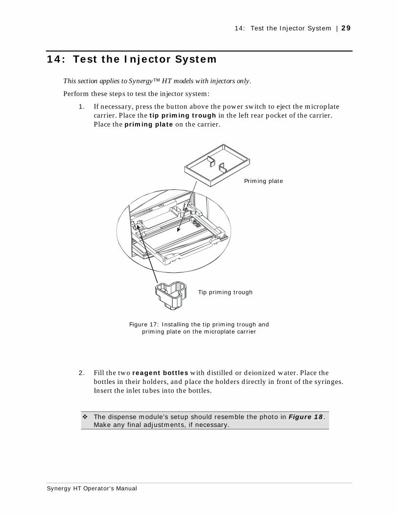
1. If necessary, press the button above the power switch to eject the microplate carrier. Place the tip priming trough in the left rear pocket of the carrier. Place the priming plate on the carrier.
Figure 17: Installing the tip priming trough and priming plate on the microplate carrier
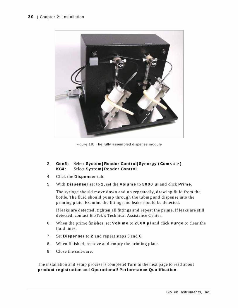
2. Fill the two reagent bottles with distilled or deionized water. Place the bottles in their holders, and place the holders directly in front of the syringes. Insert the inlet tubes into the bottles.
The dispense module’s setup should resemble the photo in Figure 18. Make any final adjustments, if necessary.
Priming plate
Tip priming trough
30 | Chapter 2: Installation
BioTek Instruments, Inc.
Figure 18: The fully assembled dispense module
3. Gen5: Select System|Reader Control|Synergy (Com<#>) KC4: Select System|Reader Control
4. Click the Dispenser tab.
5. With Dispenser set to 1, set the Volume to 5000 µl and click Prime.
The syringe should move down and up repeatedly, drawing fluid from the bottle. The fluid should pump through the tubing and dispense into the priming plate. Examine the fittings; no leaks should be detected.
If leaks are detected, tighten all fittings and repeat the prime. If leaks are still detected, contact BioTek’s Technical Assistance Center.
6. When the prime finishes, set Volume to 2000 µl and click Purge to clear the fluid lines.
7. Set Dispenser to 2 and repeat steps 5 and 6.
8. When finished, remove and empty the priming plate.
9. Close the software.
The installation and setup process is complete! Turn to the next page to read about product registration and Operational/Performance Qualification.
Operational/Performance Qualification | 31
Synergy HT Operator's Manual
Operational/Performance Qualification
Your Synergy™ HT Multi-Detection Microplate Reader was fully tested at BioTek prior to shipment and should operate properly following the successful completion of the installation and setup procedures described throughout this chapter.
If you suspect that problems occurred during shipment, if you received the reader back from BioTek following service or repair, and/or if regulatory requirements dictate that Operational/Performance Qualification is necessary, turn to Chapter 4, Instrument Qualification now to learn about BioTek’s recommended OQ/PQ procedures for the Synergy HT.
Note: An Installation-Operational-Performance (IQ/OQ/PQ) package for the Synergy HT is available for purchase (PN 7090521). Contact your local BioTek dealer for more information.
32 | Chapter 2: Installation
BioTek Instruments, Inc.
Repackaging and Shipping Instructions
Warning! If the reader and/or dispense module has been exposed to potentially hazardous material, decontaminate it to minimize the risk to all who come in contact with the reader during shipping, handling and servicing. Decontamination prior to shipping is required by the U.S. Department of Transportation regulations. See Appendix A for decontamination instructions.
Caution! Remove the microplate and tip prime trough (if equipped) from the carrier before shipment. Spilled fluids can contaminate the optics and damage the instrument.
Important!
The instrument’s packaging design is subject to change over time. If the instructions in this section do not appear to apply to the packaging materials you are using, please contact BioTek’s Technical Assistance Center for guidance.
Replace the microplate carrier shipping screw and the shipping panel before repackaging the reader for shipment. Please contact BioTek if you have misplaced either of these items.
If you need to ship the Synergy HT and/or the dispense module to BioTek for service or repair, be sure to use the original packaging materials. Other forms of commercially available packaging are not recommended and can void the warranty.
The shipping materials are designed to be used no more than five times. If the original materials have been damaged, lost, or used more than five times, contact BioTek to order replacements (PN 7093001 for the reader, PN 7083001 for the dispense module). See page 6 for contact information..
Perform these steps to prepare the reader for shipment:
1. Contact BioTek’s Technical Assistance Center for an RMA (Return Materials Authorization) number before returning equipment for service. See page 6 for contact information.
2. Decontaminate the reader and, if attached, the dispense module, according to the instructions provided in Appendix A.
Repackaging and Shipping Instructions | 33
Synergy HT Operator's Manual
3. If you will also be shipping the dispense module, perform these steps now:
If using Gen5™: If using KC4™:
a With the reader on, start Gen5 and select System|Reader Control|Synergy (Com<#>).
a With the reader on, start KC4 and select System|Readers.
b Click the Dispenser tab. Ensure that ‘Dispenser’ is set to 1.
b Click the Configuration button and select the Dispenser #1 tab.
c Click the Maintenance button. c Click the Move Syringe to maintenance position button.
d The Syringe 1 bracket will lower. Remove the thumbscrew from underneath the bracket. Carefully unscrew the top of the syringe from the syringe valve. Lift out the syringe and store it in its original box.
e Set the Dispenser number to 2. Repeat steps c and d for Syringe 2.
f Fully detach the dispense module from the reader. Replace the two nylon screws into the Syringe 1 and 2 tubing ports on the rear of the reader. (The screws should be stored in the plastic bag attached to the back of the module.) Set the module aside for the moment.
4. If you have not already done so, retract the microplate carrier and then turn off and unplug the reader.
5. Remove the lamp assembly and pack it in bubble wrap (see p. 14).
6. Replace the microplate carrier shipping screw (see p. 13).
7. Tip the reader onto its back feet. Attach the shipping panel to the bottom of the reader using the four flat-head screws and washers (see p. 11 and 11).
8. Wrap the plastic bag around the reader and shipping panel.
9. Locate the original outer shipping box. Place four foam blocks in the four bottom corners of the box. Place the inner shipping box inside the outer box (see p. 8 and 9).
10. Grasp the handles on the shipping panel and carefully lower the reader into the inner shipping box.
11. Slide the foam vertical supports into place around the reader. Place the accessories box on top.
12. Close and seal the inner box with tape.
13. Place four foam corner blocks around the inner shipping box. Close and seal the outer box with tape.
14. Write the RMA number in large clear numbers on the outside of the box. Ship the box to BioTek (see page 6 for the address).
34 | Chapter 2: Installation
BioTek Instruments, Inc.
Perform these steps to prepare the dispense module for shipment:
1. If you have not already done so:
a Contact BioTek’s Technical Assistance Center for an RMA (Return Materials Authorization) number before returning equipment for service. See page 6 for contact information.
b Decontaminate the module according to the instructions in Appendix A.
c Remove the two syringes (see step 3 on the previous page) and store them in their original boxes.
d Detach the dispense module outlet tubes and communication cable from the reader. Replace the two nylon screws into the Syringe 1 and 2 tubing ports on the rear of the reader.
Refer to the illustrations in 7: Unpack and Inspect the Dispense Module starting on page 17 when performing these steps.
2. Remove the two inlet tubes from the syringe valves and store them in their plastic canisters.
3. Remove the two outlet tubes from the syringe valves. Attach the clear plastic fitting covers to the fittings of the outlet tubes. Place the tubes in a plastic bag.
4. Place the dispense module inside the inner shipping box. Slide the cardboard shipping insert down around the module. Pack the reagent bottle holders in bubble wrap and place them on top of the module. Seal the box with tape.
5. Locate the original accessories shipping box and foam end caps. Place the bottom foam end cap into the box.
6. Place the syringes, the inlet tubes, and the outlet tubes inside the cutouts of the bottom foam end cap in the accessories box. Place the dispense module cover on top of the accessories.
7. Cover the accessories with the top foam end cap, place the dispense module cable inside the top of the end cap, and seal the box with tape.
8. Locate the original outer shipping box and foam end caps. Insert the bottom foam end cap. Lower the dispense module box into the end cap.
9. Insert the accessories box alongside the dispense module box.
10. Insert the top foam end cap. Close and seal the outer box with tape.
11. Write the RMA number in large clear numbers on the outside of the box. Ship the box to BioTek (see page 6 for the address).
Chapter 3
Getting Started
This chapter describes some of the Synergy™ HT’s key components and provides an introduction to using Gen5™ or KC4™ to control the instrument.
Key Components .................................................................. 36 Power Switch, Carrier Eject Button, Microplate Carrier........... 36 Lamp Assembly and Filter Wheel Access.............................. 37 Excitation and Emission Filter Wheels ................................. 38 Installing the Time-Resolved Fluorescence Cartridge............. 41 Configuring the System for Luminescence Measurements ...... 42 The External Dispense Module ........................................... 43
Gen5™ Software .................................................................. 46 Viewing/Updating the Filter and Wavelengths Tables............. 46 Creating Protocols and Experiments.................................... 47 Controlling the Dispense Module ........................................ 50
KC4™ Software.................................................................... 52 Viewing/Updating the Filter and Wavelengths Tables............. 52 Creating Protocols............................................................ 53 Reading Plates ................................................................ 55 Controlling the Dispense Module ........................................ 56
Recommendations for Achieving Optimum Performance ............. 59
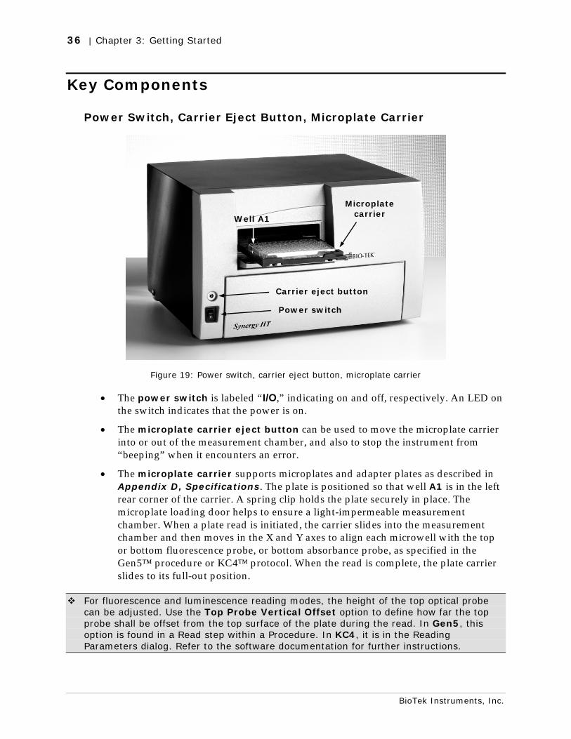
36 | Chapter 3: Getting Started
BioTek Instruments, Inc.
Key Components
Power Switch, Carrier Eject Button, Microplate Carrier
Figure 19: Power switch, carrier eject button, microplate carrier
• The power switch is labeled “I/O,” indicating on and off, respectively. An LED on the switch indicates that the power is on.
• The microplate carrier eject button can be used to move the microplate carrier into or out of the measurement chamber, and also to stop the instrument from “beeping” when it encounters an error.
• The microplate carrier supports microplates and adapter plates as described in Appendix D, Specifications. The plate is positioned so that well A1 is in the left rear corner of the carrier. A spring clip holds the plate securely in place. The microplate loading door helps to ensure a light-impermeable measurement chamber. When a plate read is initiated, the carrier slides into the measurement chamber and then moves in the X and Y axes to align each microwell with the top or bottom fluorescence probe, or bottom absorbance probe, as specified in the Gen5™ procedure or KC4™ protocol. When the read is complete, the plate carrier slides to its full-out position.
For fluorescence and luminescence reading modes, the height of the top optical probe can be adjusted. Use the Top Probe Vertical Offset option to define how far the top probe shall be offset from the top surface of the plate during the read. In Gen5, this option is found in a Read step within a Procedure. In KC4, it is in the Reading Parameters dialog. Refer to the software documentation for further instructions.
Carrier eject button
Power switch
Well A1
Microplate carrier
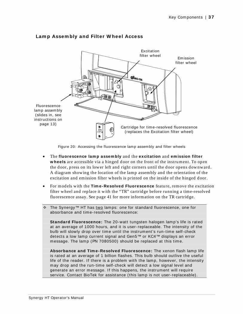
Key Components | 37
Synergy HT Operator's Manual
Lamp Assembly and Filter Wheel Access
Figure 20: Accessing the fluorescence lamp assembly and filter wheels
• The fluorescence lamp assembly and the excitation and emission filter wheels are accessible via a hinged door on the front of the instrument. To open the door, press on its lower left and right corners until the door opens downward. A diagram showing the location of the lamp assembly and the orientation of the excitation and emission filter wheels is printed on the inside of the hinged door.
• For models with the Time-Resolved Fluorescence feature, remove the excitation filter wheel and replace it with the “TR” cartridge before running a time-resolved fluorescence assay. See page 41 for more information on the TR cartridge.
The Synergy™ HT has two lamps: one for standard fluorescence, one for absorbance and time-resolved fluorescence: Standard Fluorescence: The 20-watt tungsten halogen lamp’s life is rated at an average of 1000 hours, and it is user-replaceable. The intensity of the bulb will slowly drop over time until the instrument’s run-time self-check detects a low lamp current signal and Gen5™ or KC4™ displays an error message. The lamp (PN 7080500) should be replaced at this time. Absorbance and Time-Resolved Fluorescence: The xenon flash lamp life is rated at an average of 1 billion flashes. This bulb should outlive the useful life of the reader. If there is a problem with the lamp, however, the intensity may drop and the run-time self-check will detect a low signal level and generate an error message. If this happens, the instrument will require service. Contact BioTek for assistance (this lamp is not user-replaceable).
Excitation filter wheel
Emission filter wheel
Cartridge for time-resolved fluorescence (replaces the Excitation filter wheel)
Fluorescence lamp assembly (slides in, see instructions on
page 13)
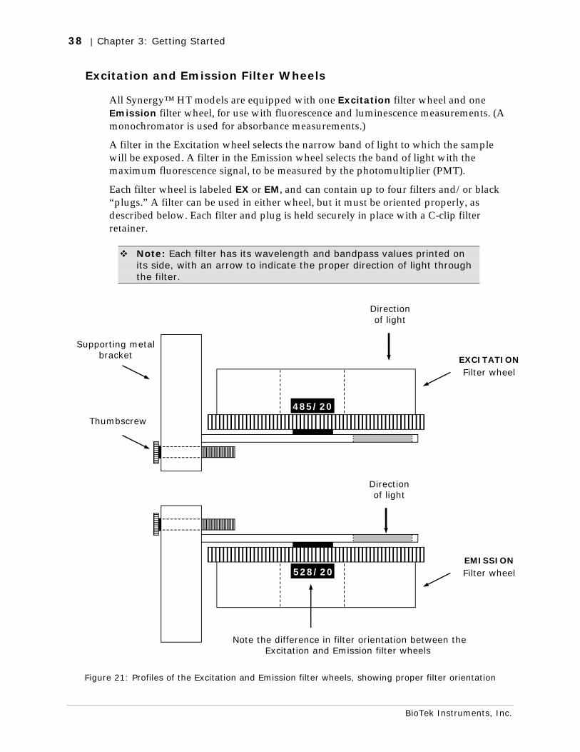
38 | Chapter 3: Getting Started
BioTek Instruments, Inc.
Excitation and Emission Filter Wheels
All Synergy™ HT models are equipped with one Excitation filter wheel and one Emission filter wheel, for use with fluorescence and luminescence measurements. (A monochromator is used for absorbance measurements.)
A filter in the Excitation wheel selects the narrow band of light to which the sample will be exposed. A filter in the Emission wheel selects the band of light with the maximum fluorescence signal, to be measured by the photomultiplier (PMT).
Each filter wheel is labeled EX or EM, and can contain up to four filters and/or black “plugs.” A filter can be used in either wheel, but it must be oriented properly, as described below. Each filter and plug is held securely in place with a C-clip filter retainer.
Note: Each filter has its wavelength and bandpass values printed on its side, with an arrow to indicate the proper direction of light through the filter.
Figure 21: Profiles of the Excitation and Emission filter wheels, showing proper filter orientation
485/20
Supporting metal bracket
Thumbscrew
EXCITATION Filter wheel
Direction of light
528/20
Note the difference in filter orientation between the Excitation and Emission filter wheels
Direction of light
EMISSION Filter wheel
Key Components | 39
Synergy HT Operator's Manual
Important! The Synergy™ HT is shipped with a set of Excitation and Emission filters installed, and the Synergy’s onboard software is pre-configured with the filter values and their locations.
If you change the contents of a filter wheel, you must update Gen5’s or KC4’s filter table and then download the information to the reader. The Synergy does not automatically detect which filters are installed.
See page 46 for information on updating Gen5’s filter table.
See page 52 for information on updating KC4’s filter table.
Removing the Filter Wheels
The filter wheels can be removed if their contents need to be changed. It is important to note that:
• The Excitation and Emission filter wheels are not interchangeable and are labeled as follows: EX = Excitation, EM = Emission. (TR = Time-Resolved Cartridge; see page 41.)
• Filter direction within a filter wheel is important, and the direction differs depending on the filter wheel. There is a diagram on the inside of the front panel door indicating this.
• Each filter is marked with an arrow indicating the proper direction of light. Refer to the figures on the previous page for proper filter orientation.
To remove a filter wheel:
1. Important! Turn off the instrument.
2. Using your thumbs, push down on the bottom corners of the hinged door on the front of the instrument.
3. Observe the two thumbscrews within the compartment. The left thumbscrew holds the Excitation filter wheel in place; the right secures the Emission filter wheel.
4. Remove the thumbscrew and slide the filter wheel’s supporting metal bracket straight out of the compartment. Note: The Emission filter wheel will “spring” out when removed. (This is because a shutter behind the wheel closes quickly to protect the PMT.)
40 | Chapter 3: Getting Started
BioTek Instruments, Inc.
Important! When removing or replacing a filter or C-clip filter retainer, do not use a sharp instrument! Use several layers of lens paper and your finger to remove and replace filters and clips. Using a sharp instrument, such as a flat screwdriver, will scratch the filter surface and make it unusable.
Do not touch the filters with your bare fingers!.
To remove a filter or plug:
1. Turn the filter wheel to align the desired filter with the hole in the supporting bracket.
2. Place the bracket on a flat surface, with the filter wheel facing down.
3. Prepare a multi-layered “cushion” of lens paper. Using your finger covered with the lens paper, gently push against the filter and its C-clip retainer until they pop out.
To replace a filter or plug:
1. Hold the metal bracket with the filter wheel facing up.
2. Properly orient the filter or plug (see page 38), and then drop it into the desired filter wheel location.
3. Using your fingers, squeeze the sides of the C-clip filter retainer, and then insert it into the top of the hole containing the new filter. Cover your finger with several layers of lens paper, and then push down on all sides of the C-clip until it sits flush against the filter.
4. Clean both sides of the filter with lens paper.
To reinstall a filter wheel:
1. Ensure that all filters and/or plugs are inserted properly (see above).
2. Slide the filter wheel back into its chamber.
3. Replace the thumbscrew.
4. Close the front door.
5. Turn on the instrument.
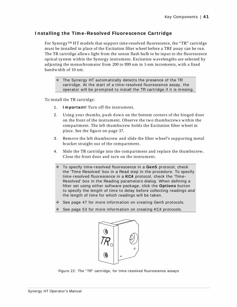
Key Components | 41
Synergy HT Operator's Manual
Installing the Time-Resolved Fluorescence Cartridge
For Synergy™ HT models that support time-resolved fluorescence, the “TR” cartridge must be installed in place of the Excitation filter wheel before a TRF assay can be run. The TR cartridge allows light from the xenon flash bulb to be input to the fluorescence optical system within the Synergy instrument. Excitation wavelengths are selected by adjusting the monochromator from 200 to 999 nm in 1-nm increments, with a fixed bandwidth of 10 nm.
The Synergy HT automatically detects the presence of the TR cartridge. At the start of a time-resolved fluorescence assay, the operator will be prompted to install the TR cartridge if it is missing.
To install the TR cartridge:
1. Important! Turn off the instrument.
2. Using your thumbs, push down on the bottom corners of the hinged door on the front of the instrument. Observe the two thumbscrews within the compartment. The left thumbscrew holds the Excitation filter wheel in place. See the figure on page 37.
3. Remove the left thumbscrew and slide the filter wheel’s supporting metal bracket straight out of the compartment.
4. Slide the TR cartridge into the compartment and replace the thumbscrew. Close the front door and turn on the instrument.
To specify time-resolved fluorescence in a Gen5 protocol, check the ‘Time Resolved’ box in a Read step in the procedure. To specify time-resolved fluorescence in a KC4 protocol, check the ‘Time-Resolved’ box in the Reading parameters dialog. When defining a filter set using either software package, click the Options button to specify the length of time to delay before collecting readings and the length of time for which readings will be taken.
See page 47 for more information on creating Gen5 protocols.
See page 53 for more information on creating KC4 protocols.
Figure 22: The “TR” cartridge, for time-resolved fluorescence assays
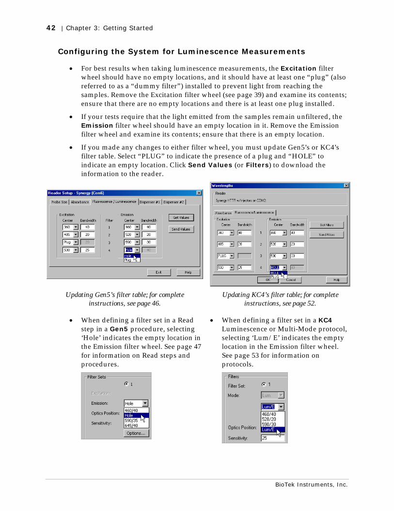
42 | Chapter 3: Getting Started
BioTek Instruments, Inc.
Configuring the System for Luminescence Measurements
• For best results when taking luminescence measurements, the Excitation filter wheel should have no empty locations, and it should have at least one “plug” (also referred to as a “dummy filter”) installed to prevent light from reaching the samples. Remove the Excitation filter wheel (see page 39) and examine its contents; ensure that there are no empty locations and there is at least one plug installed.
• If your tests require that the light emitted from the samples remain unfiltered, the Emission filter wheel should have an empty location in it. Remove the Emission filter wheel and examine its contents; ensure that there is an empty location.
• If you made any changes to either filter wheel, you must update Gen5’s or KC4’s filter table. Select “PLUG” to indicate the presence of a plug and “HOLE” to indicate an empty location. Click Send Values (or Filters) to download the information to the reader.
Updating Gen5’s filter table; for complete instructions, see page 46.
Updating KC4’s filter table; for complete instructions, see page 52.
• When defining a filter set in a Read step in a Gen5 procedure, selecting ‘Hole’ indicates the empty location in the Emission filter wheel. See page 47 for information on Read steps and procedures.
• When defining a filter set in a KC4 Luminescence or Multi-Mode protocol, selecting ‘Lum/E’ indicates the empty location in the Emission filter wheel. See page 53 for information on protocols.
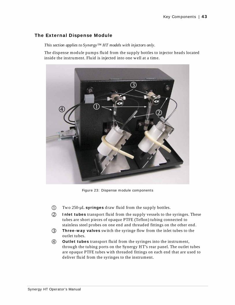
Key Components | 43
Synergy HT Operator's Manual
The External Dispense Module
This section applies to Synergy™ HT models with injectors only.
The dispense module pumps fluid from the supply bottles to injector heads located inside the instrument. Fluid is injected into one well at a time.
Figure 23: Dispense module components
Two 250-µL syringes draw fluid from the supply bottles.
Inlet tubes transport fluid from the supply vessels to the syringes. These tubes are short pieces of opaque PTFE (Teflon) tubing connected to stainless steel probes on one end and threaded fittings on the other end.
Three-way valves switch the syringe flow from the inlet tubes to the outlet tubes.
Outlet tubes transport fluid from the syringes into the instrument, through the tubing ports on the Synergy HT’s rear panel. The outlet tubes are opaque PTFE tubes with threaded fittings on each end that are used to deliver fluid from the syringes to the instrument.
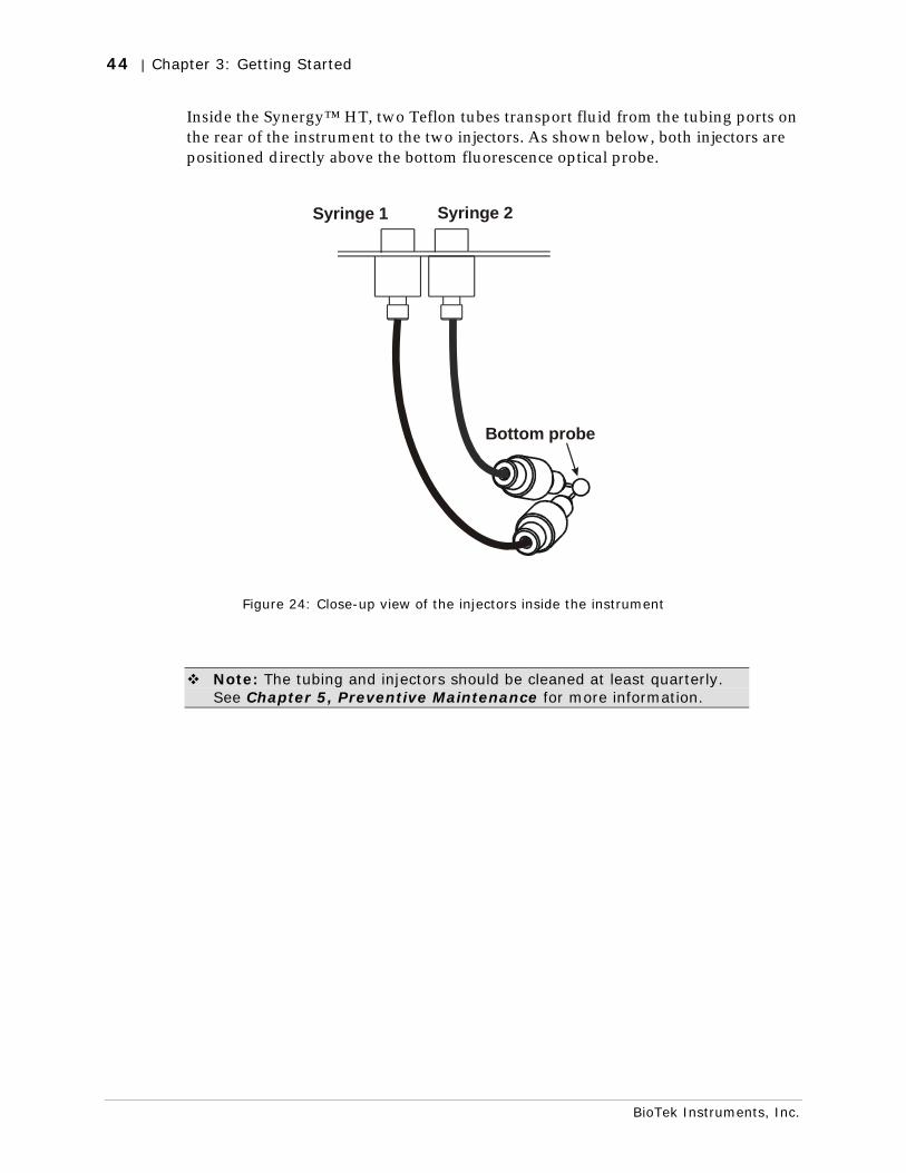
44 | Chapter 3: Getting Started
BioTek Instruments, Inc.
Inside the Synergy™ HT, two Teflon tubes transport fluid from the tubing ports on the rear of the instrument to the two injectors. As shown below, both injectors are positioned directly above the bottom fluorescence optical probe.
Syringe 1 Syringe 2
Bottom probe
Figure 24: Close-up view of the injectors inside the instrument
Note: The tubing and injectors should be cleaned at least quarterly. See Chapter 5, Preventive Maintenance for more information.
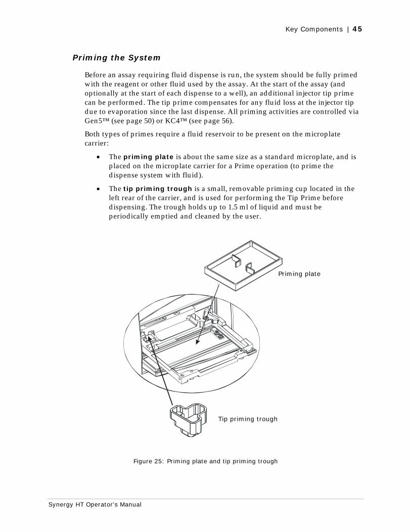
Key Components | 45
Synergy HT Operator's Manual
Priming the System
Before an assay requiring fluid dispense is run, the system should be fully primed with the reagent or other fluid used by the assay. At the start of the assay (and optionally at the start of each dispense to a well), an additional injector tip prime can be performed. The tip prime compensates for any fluid loss at the injector tip due to evaporation since the last dispense. All priming activities are controlled via Gen5™ (see page 50) or KC4™ (see page 56).
Both types of primes require a fluid reservoir to be present on the microplate carrier:
• The priming plate is about the same size as a standard microplate, and is placed on the microplate carrier for a Prime operation (to prime the dispense system with fluid).
• The tip priming trough is a small, removable priming cup located in the left rear of the carrier, and is used for performing the Tip Prime before dispensing. The trough holds up to 1.5 ml of liquid and must be periodically emptied and cleaned by the user.
Figure 25: Priming plate and tip priming trough
Priming plate
Tip priming trough
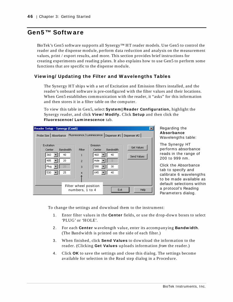
46 | Chapter 3: Getting Started
BioTek Instruments, Inc.
Gen5™ Software
BioTek’s Gen5 software supports all Synergy™ HT reader models. Use Gen5 to control the reader and the dispense module, perform data reduction and analysis on the measurement values, print /export results, and more. This section provides brief instructions for creating experiments and reading plates. It also explains how to use Gen5 to perform some functions that are specific to the dispense module.
Viewing/Updating the Filter and Wavelengths Tables
The Synergy HT ships with a set of Excitation and Emission filters installed, and the reader’s onboard software is pre-configured with the filter values and their locations. When Gen5 establishes communication with the reader, it “asks” for this information and then stores it in a filter table on the computer.
To view this table in Gen5, select System|Reader Configuration, highlight the Synergy reader, and click View/Modify. Click Setup and then click the Fluorescence/Luminescence tab.
Regarding the Absorbance Wavelengths table:
The Synergy HT performs absorbance reads in the range of 200 to 999 nm.
Click the Absorbance tab to specify and calibrate 6 wavelengths to be made available as default selections within a protocol’s Reading Parameters dialog.
To change the settings and download them to the instrument:
1. Enter filter values in the Center fields, or use the drop-down boxes to select ‘PLUG’ or ‘HOLE’.
2. For each Center wavelength value, enter its accompanying Bandwidth. (The Bandwidth is printed on the side of each filter.)
3. When finished, click Send Values to download the information to the reader. (Clicking Get Values uploads information from the reader.)
4. Click OK to save the settings and close this dialog. The settings become available for selection in the Read step dialog in a Procedure.
Filter wheel position numbers, 1 to 4
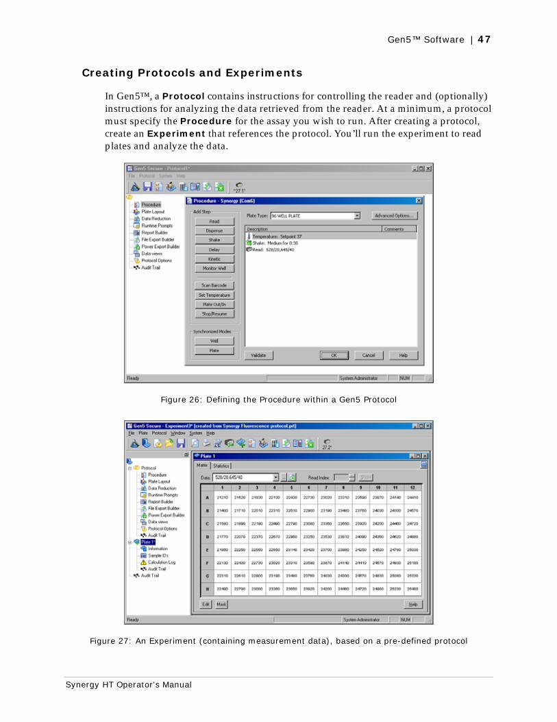
Gen5™ Software | 47
Synergy HT Operator's Manual
Creating Protocols and Experiments
In Gen5™, a Protocol contains instructions for controlling the reader and (optionally) instructions for analyzing the data retrieved from the reader. At a minimum, a protocol must specify the Procedure for the assay you wish to run. After creating a protocol, create an Experiment that references the protocol. You’ll run the experiment to read plates and analyze the data.
Figure 26: Defining the Procedure within a Gen5 Protocol
Figure 27: An Experiment (containing measurement data), based on a pre-defined protocol
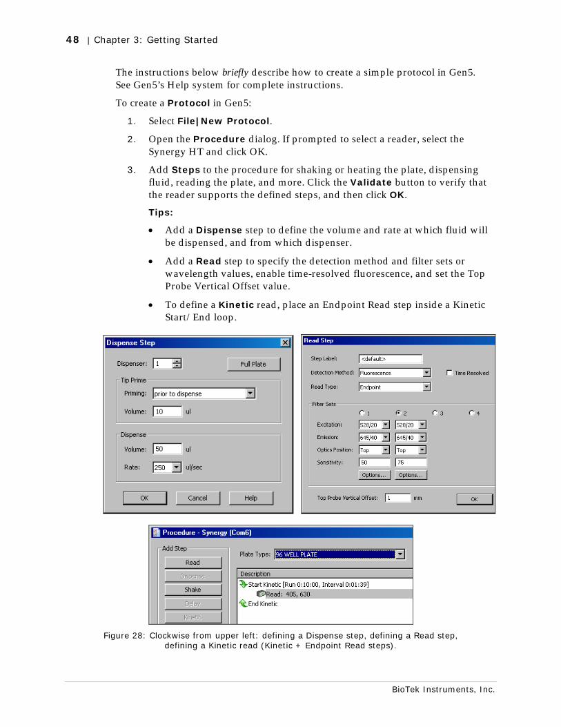
48 | Chapter 3: Getting Started
BioTek Instruments, Inc.
The instructions below briefly describe how to create a simple protocol in Gen5. See Gen5’s Help system for complete instructions.
To create a Protocol in Gen5:
1. Select File|New Protocol.
2. Open the Procedure dialog. If prompted to select a reader, select the Synergy HT and click OK.
3. Add Steps to the procedure for shaking or heating the plate, dispensing fluid, reading the plate, and more. Click the Validate button to verify that the reader supports the defined steps, and then click OK.
Tips:
• Add a Dispense step to define the volume and rate at which fluid will be dispensed, and from which dispenser.
• Add a Read step to specify the detection method and filter sets or wavelength values, enable time-resolved fluorescence, and set the Top Probe Vertical Offset value.
• To define a Kinetic read, place an Endpoint Read step inside a Kinetic Start/End loop.
Figure 28: Clockwise from upper left: defining a Dispense step, defining a Read step,
defining a Kinetic read (Kinetic + Endpoint Read steps).

Gen5™ Software | 49
Synergy HT Operator's Manual
4. Open the Plate Layout dialog and assign blanks, samples, controls, and/or standards to the plate.
5. Open the Data Reduction dialog to add data reduction steps. Categories include Transformation, Well Analysis, Curve Analysis, Cutoff, and Validation.
6. Create a report or export template, via the Report Builder, File Export Builder, or Power Export Builder options.
7. Select File|Save As and give the file an identifying name.
The instructions below briefly describe how to create a simple Experiment and then read a plate in Gen5. See Gen5’s Help system for complete instructions.
To create an Experiment and read a plate using Gen5:
1. Select File|New Experiment.
2. Select the desired protocol and click OK.
3. Highlight a plate in the menu “tree” and select Plate|Read. The Plate Reading dialog will appear.
4. Click READ. The door will open and the carrier will extend (if it is not already extended).
5. Place the plate on the carrier and click OK to begin the read.
6. When the read is complete, measurement values will appear in Gen5. To view them, select the desired data set (e.g., “528/20,645/40”) from the Data drop-down list.
7. Select File|Save As and give the file an identifying name.
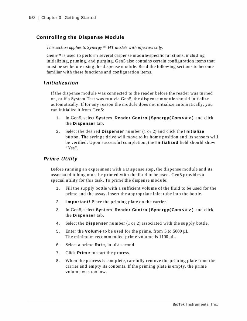
50 | Chapter 3: Getting Started
BioTek Instruments, Inc.
Controlling the Dispense Module
This section applies to Synergy™ HT models with injectors only.
Gen5™ is used to perform several dispense module-specific functions, including initializing, priming, and purging. Gen5 also contains certain configuration items that must be set before using the dispense module. Read the following sections to become familiar with these functions and configuration items.
Initialization
If the dispense module was connected to the reader before the reader was turned on, or if a System Test was run via Gen5, the dispense module should initialize automatically. If for any reason the module does not initialize automatically, you can initialize it from Gen5:
1. In Gen5, select System|Reader Control|Synergy(Com<#>) and click the Dispenser tab.
2. Select the desired Dispenser number (1 or 2) and click the Initialize button. The syringe drive will move to its home position and its sensors will be verified. Upon successful completion, the Initialized field should show “Yes”.
Prime Utility
Before running an experiment with a Dispense step, the dispense module and its associated tubing must be primed with the fluid to be used. Gen5 provides a special utility for this task. To prime the dispense module:
1. Fill the supply bottle with a sufficient volume of the fluid to be used for the prime and the assay. Insert the appropriate inlet tube into the bottle.
2. Important! Place the priming plate on the carrier.
3. In Gen5, select System|Reader Control|Synergy(Com<#>) and click the Dispenser tab.
4. Select the Dispenser number (1 or 2) associated with the supply bottle.
5. Enter the Volume to be used for the prime, from 5 to 5000 µL. The minimum recommended prime volume is 1100 µL.
6. Select a prime Rate, in µL/second.
7. Click Prime to start the process.
8. When the process is complete, carefully remove the priming plate from the carrier and empty its contents. If the priming plate is empty, the prime volume was too low.
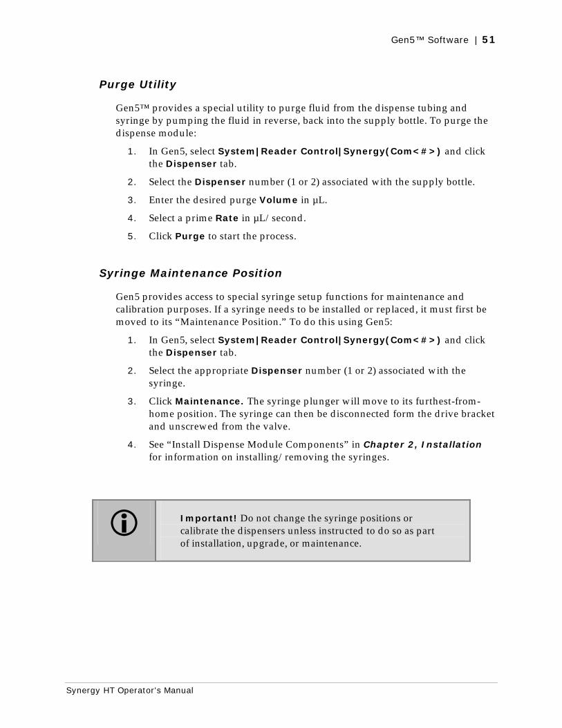
Gen5™ Software | 51
Synergy HT Operator's Manual
Purge Utility
Gen5™ provides a special utility to purge fluid from the dispense tubing and syringe by pumping the fluid in reverse, back into the supply bottle. To purge the dispense module:
1. In Gen5, select System|Reader Control|Synergy(Com<#>) and click the Dispenser tab.
2. Select the Dispenser number (1 or 2) associated with the supply bottle.
3. Enter the desired purge Volume in µL.
4. Select a prime Rate in µL/second.
5. Click Purge to start the process.
Syringe Maintenance Position
Gen5 provides access to special syringe setup functions for maintenance and calibration purposes. If a syringe needs to be installed or replaced, it must first be moved to its “Maintenance Position.” To do this using Gen5:
1. In Gen5, select System|Reader Control|Synergy(Com<#>) and click the Dispenser tab.
2. Select the appropriate Dispenser number (1 or 2) associated with the syringe.
3. Click Maintenance. The syringe plunger will move to its furthest-from-home position. The syringe can then be disconnected form the drive bracket and unscrewed from the valve.
4. See “Install Dispense Module Components” in Chapter 2, Installation for information on installing/removing the syringes.
Important! Do not change the syringe positions or calibrate the dispensers unless instructed to do so as part of installation, upgrade, or maintenance.
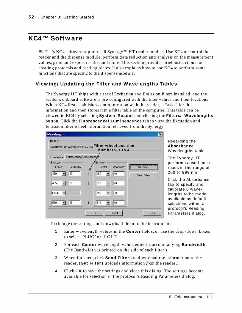
52 | Chapter 3: Getting Started
BioTek Instruments, Inc.
KC4™ Software
BioTek’s KC4 software supports all Synergy™ HT reader models. Use KC4 to control the reader and the dispense module; perform data reduction and analysis on the measurement values; print and export results; and more. This section provides brief instructions for creating protocols and reading plates. It also explains how to use KC4 to perform some functions that are specific to the dispense module.
Viewing/Updating the Filter and Wavelengths Tables
The Synergy HT ships with a set of Excitation and Emission filters installed, and the reader’s onboard software is pre-configured with the filter values and their locations. When KC4 first establishes communication with the reader, it “asks” for this information and then stores it in a filter table on the computer. This table can be viewed in KC4 by selecting System|Reader and clicking the Filters/ Wavelengths button. Click the Fluorescence/Luminescence tab to view the Excitation and Emission filter wheel information retrieved from the Synergy:
Regarding the Absorbance Wavelengths table:
The Synergy HT performs absorbance reads in the range of 200 to 999 nm.
Click the Absorbance tab to specify and calibrate 6 wave-lengths to be made available as default selections within a protocol’s Reading Parameters dialog.
To change the settings and download them to the instrument:
1. Enter wavelength values in the Center fields, or use the drop-down boxes to select ‘PLUG’ or ‘HOLE’.
2. For each Center wavelength value, enter its accompanying Bandwidth. (The Bandwidth is printed on the side of each filter.)
3. When finished, click Send Filters to download the information to the reader. (Get Filters uploads information from the reader.)
4. Click OK to save the settings and close this dialog. The settings become available for selection in the protocol’s Reading Parameters dialog.
Filter wheel position numbers, 1 to 4
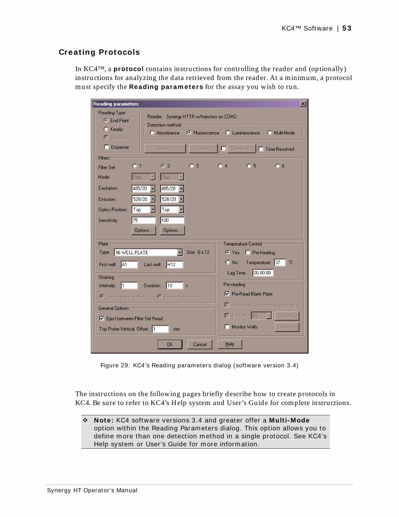
KC4™ Software | 53
Synergy HT Operator's Manual
Creating Protocols
In KC4™, a protocol contains instructions for controlling the reader and (optionally) instructions for analyzing the data retrieved from the reader. At a minimum, a protocol must specify the Reading parameters for the assay you wish to run.
Figure 29: KC4’s Reading parameters dialog (software version 3.4)
The instructions on the following pages briefly describe how to create protocols in KC4. Be sure to refer to KC4’s Help system and User’s Guide for complete instructions.
Note: KC4 software versions 3.4 and greater offer a Multi-Mode option within the Reading Parameters dialog. This option allows you to define more than one detection method in a single protocol. See KC4’s Help system or User’s Guide for more information.
54 | Chapter 3: Getting Started
BioTek Instruments, Inc.
To create an Absorbance protocol in KC4™:
1. Select Data|New Plate. If prompted to select a protocol, select “Empty Protocol” and click OK. If not prompted, select Protocol|New.
2. Select Protocol|Reading. The Reading parameters dialog will appear.
3. Set Detection Method to Absorbance.
4. Select a Reading Type of Endpoint, Kinetic, or Spectrum. For a Kinetic protocol, click the Kinetic button to define the Run Time and Interval.
5. Select or specify the Wavelengths at which the plate will be read.
6. Select a Plate Type.
7. Enable Temperature Control and/or Shaking if necessary. Select any Pre-Reading parameters.
8. Click OK to verify the parameters and return to the main screen.
9. Select Protocol|Save As and give the protocol an identifying name.
To create a Fluorescence or Luminescence (non-Dispense) protocol in KC4:
1. Select Data|New Plate. If prompted to select a protocol, select “Empty Protocol” and click OK. If not prompted, select Protocol|New.
2. Select Protocol|Reading. The Reading parameters dialog will appear.
3. Set Detection Method to Fluorescence or Luminescence.
4. Select a Reading Type of Endpoint or Kinetic. For a Kinetic protocol, click the Kinetic button to define the Run Time and Interval.
5. If supported by the current Synergy™ HT model, checking Time-Resolved enables the Time Resolved Fluorescence feature.
6. Define the Filter Sets by selecting the filter(s), Optics Position, and Sensitivity.
7. Select a Plate Type.
8. Enable Temperature Control and/or Shaking if necessary. Select any Pre-Reading parameters.
9. Click OK to verify the parameters and return to the main screen.
10. Select Protocol|Save As and give the protocol an identifying name.
KC4™ Software | 55
Synergy HT Operator's Manual
To create a Fluorescence or Luminescence Dispense protocol in KC4™ (for the Synergy™ HTTR w/Injectors):
1. Select Data|New Plate. If prompted to select a protocol, select “Empty Protocol” and click OK. If not prompted, select Protocol|New.
2. Select Protocol|Reading. The Reading parameters dialog will appear.
3. Set Detection Method to Fluorescence or Luminescence.
4. Check the Dispense box.
5. Select a Reading Type of Endpoint or Kinetic.
6. Define the Filter Sets (up to 2) by selecting the filter(s), Optics Position, and Sensitivity.
7. Select a Plate Type.
8. Enable Temperature Control if necessary. Select any Pre-Reading parameters.
9. Click the Read & Dispense button. The Read & Dispense dialog will appear.
Select a Read Mode of Well or Plate.
Click the Dispense, Shake, and Read buttons to add steps to the protocol.
When finished, click OK to return to the Reading parameters dialog.
10. Click OK to verify the parameters and return to the main screen.
11. Select Protocol|Save As and give the protocol an identifying name.
Reading Plates
To read a plate using KC4:
1. Select Data|New Plate.
2. If prompted to select a protocol, select a protocol and click OK. If not prompted, select Protocol|Open and select a protocol.
3. Select Data|Read Plate. The Plate Reading dialog will appear.
4. Click Start Reading. The door will open and the plate carrier will extend.
5. Place the plate on the carrier and click START READING to begin the read.
6. When the read is complete, the measurement values will appear in KC4.
7. Select Data|Save As and give the file an identifying name.
56 | Chapter 3: Getting Started
BioTek Instruments, Inc.
Controlling the Dispense Module
This section applies to Synergy™ HT models with injectors only.
KC4™ is used to perform several dispense module-specific functions, including initializing, priming, and purging. KC4 also contains certain configuration items that must be set before using the dispense module. Read the following sections to become familiar with these functions and configuration items.
Initialization
If the dispense module was connected to the reader before the reader was turned on, or if an Optics Test was run via KC4, the dispense module should initialize automatically. If for any reason the module does not initialize automatically, you can initialize it from KC4:
1. In KC4, select System|Readers, click the Configuration button, and then click the appropriate Dispenser tab (#1 or #2).
2. Click the Initialize button.
3. The syringe drive will move to its home position and its sensors will be verified. Upon successful completion, the Status should show “Initialized.”
4. Repeat for the other syringe (Dispenser #2).
Prime Utility
Before running a Read & Dispense protocol, the dispense module and its associated tubing must be primed with the fluid to be used. KC4 provides a special utility for this task. To prime the dispense module:
1. Fill the supply bottle with a sufficient volume of the fluid to be used for the prime and the assay. Insert the appropriate inlet tube into the bottle.
2. Important! Place the priming plate on the carrier.
3. In KC4, select System|Reader Control and click the Dispenser tab.
4. Select the Dispenser (1 or 2) associated with the supply bottle.
5. Enter the Volume to be used for the prime, from 5 to 5000 µL. The minimum recommended prime volume is 1100 µL.
6. Select a prime Rate, in µL/second.
7. Click Prime to start the process.
8. When the process is complete, carefully remove the priming plate from the carrier and empty its contents. If the priming plate is empty, the prime volume was too low.
KC4™ Software | 57
Synergy HT Operator's Manual
Purge Utility
KC4 provides a special utility to purge fluid from the dispense tubing and syringe by pumping the fluid in reverse, back into the supply bottle. To purge the dispense module:
1. In KC4™, select System|Reader Control and click the Dispenser tab.
2. Select the Dispenser (1 or 2) associated with the supply bottle.
3. Enter the desired purge Volume from 5 to 5000 µL.
4. Select a prime Rate in µL/second.
5. Click Purge to start the process.
Emptying the Tip Priming Trough
Read & Dispense protocols can specify a tip prime to compensate for any fluid loss at the dispense tip due to evaporation since the last dispense. Tip priming is performed in a small, removable priming trough located in the left rear of the carrier (see page 45). The trough holds up to 1.5 ml of liquid and must be periodically emptied and cleaned by the user.
If the Tip Priming Trough overflows, you should clean the microplate carrier and possibly the internal surface beneath the carrier. See Chapter 5, Preventive Maintenance for instructions. See also Appendix A for decontamination instructions.
KC4 must be “told” when the trough has been emptied. To empty the tip priming trough:
1. If the microplate carrier is inside the reader, press the carrier eject button.
2. Carefully remove the trough from the carrier and empty it. Clean or decontaminate the trough if necessary.
3. In KC4, select System|Reader Control and click the Dispenser tab. The Tip Prime Trough value shows KC4’s estimate of how much fluid is in the trough.
4. Click Dump all Tip Prime Trough(s). The Tip Prime Trough value will reset to ‘1500 µL remaining’ meaning the trough is empty.
Note: When running a Read & Dispense protocol, KC4 may prompt you to empty the tip prime trough. In this case, KC4 will automatically open the System|Reader Control, Dispenser dialog.
58 | Chapter 3: Getting Started
BioTek Instruments, Inc.
Syringe Maintenance Position
KC4 provides access to special syringe setup functions for maintenance and calibration purposes. If a syringe needs to be installed or replaced, it must first be moved to its “Maintenance Position.” To do this using KC4:
1. In KC4, select System|Readers, click the Configuration button, and then click the appropriate Dispenser tab (#1 or #2).
2. Click Move Syringe to maintenance position.
The syringe plunger will move to its furthest-from-home position. The syringe can then be disconnected form the drive bracket and unscrewed from the valve. See “Install Dispense Module Components” in Chapter 2, Installation for information on installing/removing the syringes.
3. Click OK to close the dialog.
Important! Do not change the syringe positions or calibrate the dispensers unless instructed to do so as part of installation, upgrade, or maintenance.
Recommendations for Achieving Optimum Performance | 59
Synergy HT Operator's Manual
Recommendations for Achieving Optimum Performance
• Microplates should be perfectly clean and free of dust or bottom scratches. Use new microplates from sealed packages. Do not allow dust to settle on the surface of the solution; use microplate covers or seals when not reading the plate. Filter solutions to remove particulates that could cause erroneous readings.
• Before preparing your microplates, make sure the instrument is on and successfully communicating with the controlling software. You may want to run a System Test if the instrument has not been turned off/on in a few days. Design your Gen5 or KC4 protocol in advance as well, to ensure that the intended reading parameters are used and to avoid any last-minute corrections.
• Although the Synergy™ HT supports standard flat, U-bottom, and V-bottom microplates, the reader achieves optimum performance with optically clear, flat-bottomed wells. See Appendix D, Specifications for more information on the supported plates.
• Non-uniformity in the optical density of the well bottoms can cause loss of accuracy, especially with U- and V-bottom polyvinyl microplates. Check for this by reading an empty microplate. Dual wavelength readings can eliminate this problem, or bring the variation in density readings to within acceptable limits for most measurements.
• Inaccuracy in pipetting has a large effect on measurements, especially if smaller volumes of liquid are used. For best results, use at least 100 μl per well in a 96-well plate and 25 µL in a 384-well plate.
• Dispensing solution into 384-well plates often traps air bubbles in the wells, which may result in inaccurate readings. A dual-wavelength reading method usually eliminates these inaccuracies; however, for best results, remove the air bubbles by degassing the plate in a vacuum chamber before reading.
• The inclination of the meniscus can cause loss of accuracy in some solutions, especially with small volumes. Agitate the microplate before reading to help bring this problem within acceptable limits. Use Tween® 20, if possible (or some other wetting agent) to normalize the meniscus for absorbance measurements. Some solutions develop menisci over a period of several minutes. This effect varies with the brand of microplate and the solution composition. As the center of the meniscus drops and shortens the light path, the density readings change. The meniscus shape will stabilize over time.
60 | Chapter 3: Getting Started
BioTek Instruments, Inc.
• To keep the dispense system in top condition, flush and purge the fluid lines with deionized (DI) water every day or upon completion of an assay run, whichever is more frequent. Some reagents may crystallize or harden after use, clogging the fluid passageways. Flushing the tubing at the end of each day, letting the DI water soak them overnight, and then purging the lines at the beginning of each day ensures optimal performance of the dispense system. See Chapter 5, Preventive Maintenance for more information.
• For models with injectors: When dispensing volumes less than or equal to 20 µL/well, we recommend specifying a tip prime volume that is equal to the dispense volume. For dispense volumes greater than 20 µL/well, we recommend a tip prime volume of 20 µL.
Chapter 4
Instrument Qualification
This chapter contains procedures for qualifying the initial and ongoing performance of the Synergy™ HT and the external dispense module (if used).
Overview ............................................................................ 62 IQ/OQ/PQ ........................................................................... 62 Recommended Qualification Schedule ..................................... 64 System Test ........................................................................ 65 Absorbance Plate Test........................................................... 70 Absorbance Liquid Tests ........................................................ 80 Fluorescence Tests ............................................................... 89 Dispense Module Tests.........................................................102 Dispense Accuracy & Precision Tests Worksheet.......................121
62 | Chapter 4: Instrument Qualification
BioTek Instruments, Inc.
Overview
Every Synergy™ HT reader and external dispense module is fully tested at BioTek prior to shipment and they should operate properly upon initial setup. If you suspect that a problem occurred during shipment, if you have received the equipment after returning it to the factory for service, and/or if regulatory requirements dictate that you qualify the equipment on a routine basis, you should perform the procedures outlined in this chapter.
This chapter contains BioTek Instruments’ recommended Installation Qualification (IQ), Operational Qualification (OQ), and Performance Qualification (PQ) procedures for all models of the Synergy HT Multi-Mode Microplate Reader.
A Product Qualification Package (PN 7090521) for the Synergy HT is available for purchase. The package contains complete procedures for performing Installation Qualification, Operational Qualification, Performance Qualification, and Preventive Maintenance procedures. Microsoft® Excel spreadsheets are provided for performing the calculations, and checklists, data sheets, and logbooks are provided for recording results. Contact your local BioTek dealer for more information.
IQ/OQ/PQ
Installation Qualification confirms that the reader and its components have been supplied as ordered and ensures that they are assembled and configured properly for your lab environment.
• The recommended IQ procedure consists of setting up the instrument and its components as described in Chapter 2, Installation and performing the System Test. For models with injectors, a quick “Injector Test” is also performed, to ensure that the dispense module is properly installed and there are no leaks.
• The IQ procedure should be performed initially (before the reader is used for the first time).
• The successful completion of the IQ procedure verifies that the instrument is installed correctly. The Operational Qualification procedure should be performed immediately following the successful IQ (see next page).
IQ/OQ/PQ | 63
Synergy HT Operator's Manual
Operational Qualification confirms that the equipment operates according to specification initially and over time.
• The recommended OQ procedure consists of performing the System Test, Absorbance Plate Test, a series of Liquid Tests, and, if the external dispense module is used, the Dispense Accuracy and Precision Tests.
• Your facility’s operating policies may also require that you perform an actual assay prior to accepting the reader for routine use. If this is the case, you should not use the data obtained from the first assay run on the reader until you have confirmed that the package insert criteria have been met.
• The OQ procedure should be performed initially (before first use) and then routinely; the recommended interval is annually. It should also be performed after any major repair or upgrade to the hardware or software.
• Although out-of-tolerance failures will be detected by the OQ tests, results should be compared with those from the routine Performance Qualification tests and previous OQ tests to monitor for trends.
• The successful completion of the OQ procedure, in combination with results that are comparable to previous PQ and OQ tests, confirms that the equipment is operating according to specification initially and over time.
Performance Qualification confirms that the reader consistently meets the requirements of the tests performed at your laboratory.
• The recommended PQ procedure consists of performing the System Test, Absorbance Plate Test, a series of Liquid Tests, and, if the external dispense module is used, the Dispense Accuracy and Precision Tests.
• Your facility’s operating policies may also require that you routinely perform an actual assay, to confirm that the reader will consistently give adequate results for the assays to be run on it.
• These tests should be performed routinely; the recommended interval is monthly or quarterly, depending on the test. This frequency may be adjusted depending on the trends observed over time.
• The successful completion of the PQ procedure confirms that the equipment is performing consistently under normal operating conditions.
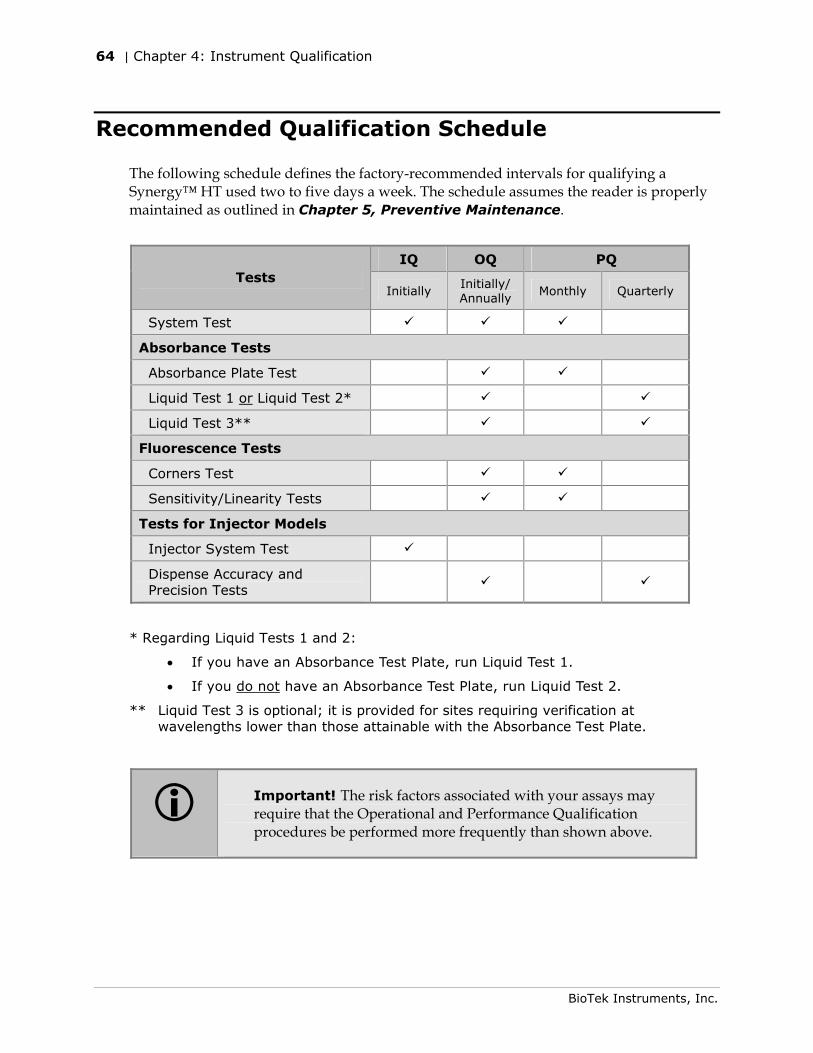
64 | Chapter 4: Instrument Qualification
BioTek Instruments, Inc.
Recommended Qualification Schedule
The following schedule defines the factory-recommended intervals for qualifying a Synergy™ HT used two to five days a week. The schedule assumes the reader is properly maintained as outlined in Chapter 5, Preventive Maintenance.
IQ OQ PQ
Tests Initially
Initially/ Annually
Monthly Quarterly
System Test
Absorbance Tests
Absorbance Plate Test
Liquid Test 1 or Liquid Test 2*
Liquid Test 3**
Fluorescence Tests
Corners Test
Sensitivity/Linearity Tests
Tests for Injector Models
Injector System Test
Dispense Accuracy and Precision Tests
* Regarding Liquid Tests 1 and 2:
• If you have an Absorbance Test Plate, run Liquid Test 1.
• If you do not have an Absorbance Test Plate, run Liquid Test 2.
** Liquid Test 3 is optional; it is provided for sites requiring verification at wavelengths lower than those attainable with the Absorbance Test Plate.
Important! The risk factors associated with your assays may require that the Operational and Performance Qualification procedures be performed more frequently than shown above.
System Test | 65
Synergy HT Operator's Manual
System Test
Description
The System Test begins with a check of the stepper motor-driven transmission axes within the instrument; each is sequentially homed and verified. The two measurement systems (Absorbance and Fluorescence) are checked for noise and signal levels. The incubation system is monitored to make sure all zones have thermistor readings within expected ranges. The analog power supply levels are measured to make sure all are within expected limits. A configuration data area in memory is tested to make sure all of the calibration information is present and checksums correctly.
If any area tests outside of programmed limits, the reader will “beep” and the failure will be indicated on the test report (generated via Gen5™ or KC4™). The report also contains the reader’s serial number and the part number and version number of the basecode software. When the instrument is turned on the System Test automatically runs, but no report is generated. To run the test and generate a report, you must use Gen5 or KC4.
The absorbance measurement system is checked using the six wavelengths specified in the reader’s internal absorbance wavelength table. Before running the test, set these wavelengths to the ones you most frequently use (if they are not already set). To view/modify the wavelength table via Gen5/KC4, see the instructions in the Getting Started chapter.
Note: The System Test runs automatically when the instrument is turned on. If this “power-up” System Test fails, the instrument will “beep” repeatedly. If this happens, press the carrier eject button to stop the beeping and then initiate a System Test through Gen5 or KC4 to retrieve the error code.
66 | Chapter 4: Instrument Qualification
BioTek Instruments, Inc.
Procedure
To run the System Test:
1. Turn on the reader and launch Gen5™ or KC4™.
2. If necessary, set Gen5’s or KC4’s wavelength table to the six wavelengths you most frequently use. See the Getting Started chapter for instructions.
3. If your assays use incubation, we recommend enabling Temperature Control and allowing the incubator to reach its set point before running the System Test. To access this feature, select System|Reader Control and click the Pre-Heating tab.
4. Gen5: Select System|Diagnostics|Run System Test.
KC4: Select System|Diagnostics|Run Optics Test. When the Run Optics Test dialog appears, click Start.
If the test fails during execution, a message box will appear in the software. Close the box; the test report will contain the error code that was generated by the failure.
5. When the test is complete, a dialog will appear, requesting additional information. Enter the information (if desired) and then click OK.
6. The test report will appear. Scroll down toward the bottom of the report; it will show either “SYSTEM TEST PASS” or “SYSTEM TEST FAIL *** ERROR (error code) DETECTED.”
7. Print the report if desired.
A sample test report is shown on the next few pages.
Gen5 and KC4 store the results in a database, so the results can be retrieved/printed at any time. We recommend that you print and save the reports to document that the test was performed.
8. If the test failed, look up the error code in Appendix C, Error Codes to determine its cause. If the cause is something you can fix, turn off the reader, fix the problem, and then turn the reader back on and retry the test.
If the test continues to fail, or if the cause is not something you can fix, contact BioTek’s Technical Assistance Center (see page 6 for contact information.)
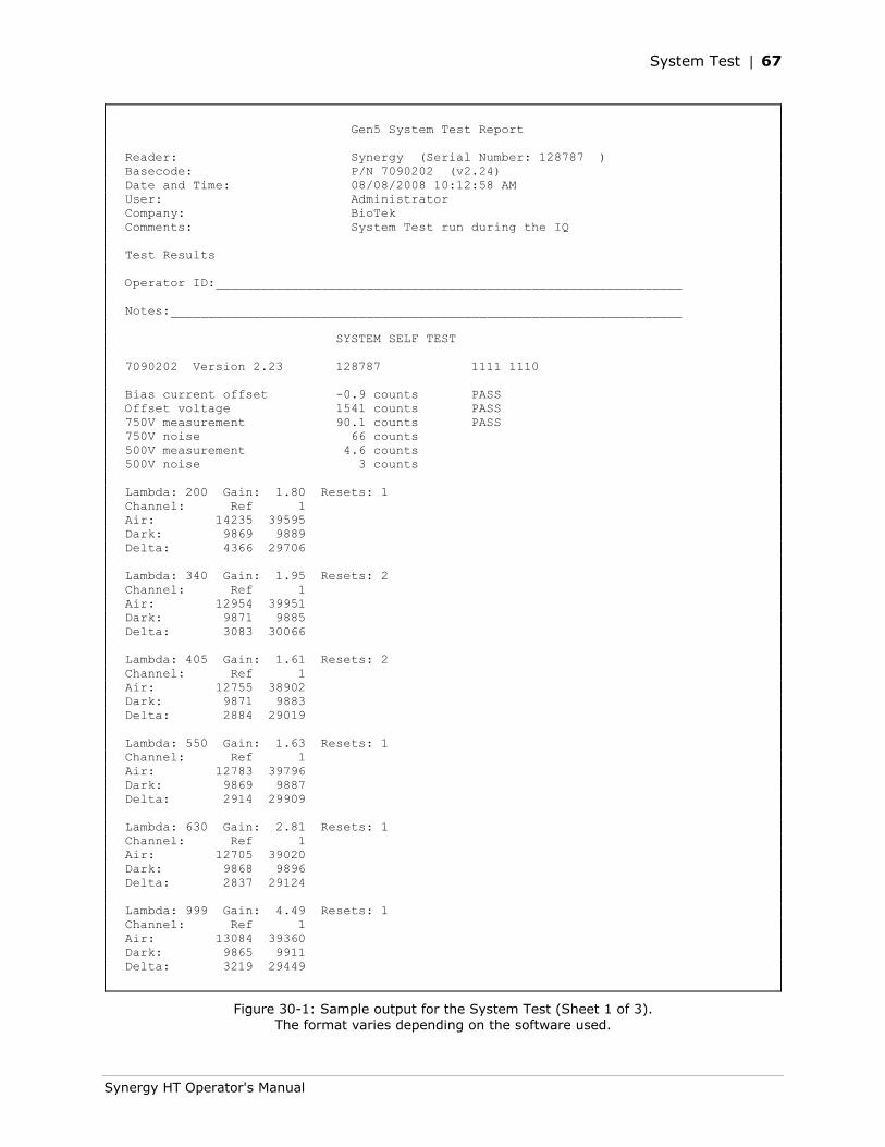
System Test | 67
Synergy HT Operator's Manual
Gen5 System Test Report Reader: Synergy (Serial Number: 128787 ) Basecode: P/N 7090202 (v2.24) Date and Time: 08/08/2008 10:12:58 AM User: Administrator Company: BioTek Comments: System Test run during the IQ Test Results Operator ID:______________________________________________________________ Notes:____________________________________________________________________ SYSTEM SELF TEST 7090202 Version 2.23 128787 1111 1110 Bias current offset -0.9 counts PASS Offset voltage 1541 counts PASS 750V measurement 90.1 counts PASS 750V noise 66 counts 500V measurement 4.6 counts 500V noise 3 counts Lambda: 200 Gain: 1.80 Resets: 1 Channel: Ref 1 Air: 14235 39595 Dark: 9869 9889 Delta: 4366 29706 Lambda: 340 Gain: 1.95 Resets: 2 Channel: Ref 1 Air: 12954 39951 Dark: 9871 9885 Delta: 3083 30066 Lambda: 405 Gain: 1.61 Resets: 2 Channel: Ref 1 Air: 12755 38902 Dark: 9871 9883 Delta: 2884 29019 Lambda: 550 Gain: 1.63 Resets: 1 Channel: Ref 1 Air: 12783 39796 Dark: 9869 9887 Delta: 2914 29909 Lambda: 630 Gain: 2.81 Resets: 1 Channel: Ref 1 Air: 12705 39020 Dark: 9868 9896 Delta: 2837 29124 Lambda: 999 Gain: 4.49 Resets: 1 Channel: Ref 1 Air: 13084 39360 Dark: 9865 9911 Delta: 3219 29449
Figure 30-1: Sample output for the System Test (Sheet 1 of 3). The format varies depending on the software used.
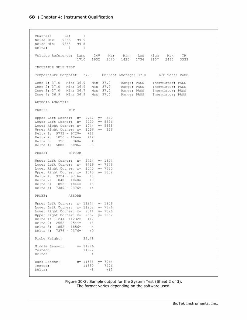
68 | Chapter 4: Instrument Qualification
BioTek Instruments, Inc.
Channel: Ref 1 Noise Max: 9866 9919 Noise Min: 9865 9918 Delta: 1 1 Voltage Reference: Lamp 24V Mtr Min Low High Max TR 1710 1932 2045 1425 1734 2157 2465 3333 INCUBATOR SELF TEST Temperature Setpoint: 37.0 Current Average: 37.0 A/D Test: PASS Zone 1: 37.0 Min: 36.9 Max: 37.0 Range: PASS Thermistor: PASS Zone 2: 37.0 Min: 36.9 Max: 37.0 Range: PASS Thermistor: PASS Zone 3: 37.0 Min: 36.7 Max: 37.0 Range: PASS Thermistor: PASS Zone 4: 36.9 Min: 36.9 Max: 37.0 Range: PASS Thermistor: PASS AUTOCAL ANALYSIS PROBE: TOP Upper Left Corner: x= 9732 y= 360 Lower Left Corner: x= 9720 y= 5896 Lower Right Corner: x= 1044 y= 5888 Upper Right Corner: x= 1056 y= 356 Delta 1: 9732 - 9720= +12 Delta 2: 1056 - 1044= +12 Delta 3: 356 - 360= -4 Delta 4: 5888 - 5896= -8 PROBE: BOTTOM Upper Left Corner: x= 9724 y= 1844 Lower Left Corner: x= 9716 y= 7376 Lower Right Corner: x= 1040 y= 7380 Upper Right Corner: x= 1040 y= 1852 Delta 1: 9724 - 9716= +8 Delta 2: 1040 - 1040= +0 Delta 3: 1852 - 1844= +8 Delta 4: 7380 - 7376= +4 PROBE: ABSORB Upper Left Corner: x= 11244 y= 1856 Lower Left Corner: x= 11232 y= 7376 Lower Right Corner: x= 2544 y= 7376 Upper Right Corner: x= 2552 y= 1852 Delta 1: 11244 -11232= +12 Delta 2: 2552 - 2544= +8 Delta 3: 1852 - 1856= -4 Delta 4: 7376 - 7376= +0 Probe Height: 32.48 Middle Sensor: y= 11976 Tested: 11972 Delta: -4 Back Sensor: x= 11588 y= 7964 Tested: 11580 7976 Delta: -8 +12
Figure 30-2: Sample output for the System Test (Sheet 2 of 3). The format varies depending on the software used.
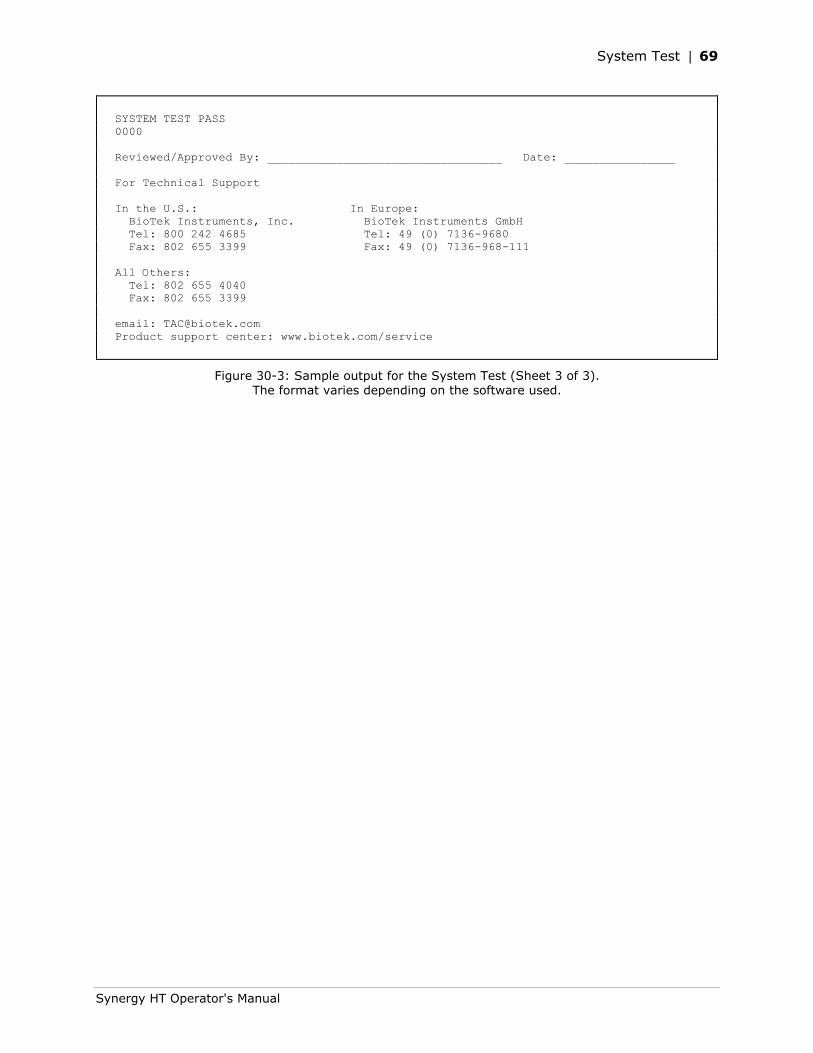
System Test | 69
Synergy HT Operator's Manual
SYSTEM TEST PASS 0000 Reviewed/Approved By: __________________________________ Date: ________________ For Technical Support In the U.S.: In Europe: BioTek Instruments, Inc. BioTek Instruments GmbH Tel: 800 242 4685 Tel: 49 (0) 7136-9680 Fax: 802 655 3399 Fax: 49 (0) 7136-968-111 All Others: Tel: 802 655 4040 Fax: 802 655 3399 email: [email protected] Product support center: www.biotek.com/service
Figure 30-3: Sample output for the System Test (Sheet 3 of 3). The format varies depending on the software used.
70 | Chapter 4: Instrument Qualification
BioTek Instruments, Inc.
Absorbance Plate Test
Description
This test uses BioTek’s Absorbance Test Plate (PN 7260522) to confirm the mechanical alignment; optical density accuracy, linearity, and repeatability; and wavelength accuracy of the Synergy™ HT. The Absorbance Plate Test compares the reader’s optical density and wavelength measurements to NIST-traceable values.
An alternate method that may be used to determine accuracy, linearity, and repeatability is Liquid Test 2, described on page 83.
The Absorbance Plate Test confirms the following:
• Mechanical Alignment: The Test Plate has precisely machined holes in its four corners. The amount of light that shines through these holes is an indication of how well the reader is aligned. A reading of more than 0.015 OD for any of the designated alignment holes indicates that the light is being “clipped” and the reader may be out of alignment.
• Accuracy/Linearity: The Test Plate contains neutral-density glass filters of known OD values at several wavelengths. Actual measurements are compared against the expected values provided in the Test Plate’s Standards Certificate. Since there are several filters with differing OD values, the accuracy across a range of ODs can be established. Once it is proven that the reader is accurate at these OD values, the reader is also considered to be linear.
• Repeatability: This test ensures the reader meets its repeatability specification by reading each neutral-density filter on the Test Plate twice with the filter in the same location.
• Wavelength Accuracy: BioTek’s Absorbance Test Plate with the part number 7260522 contains a glass filter in position C6. This filter is used to check the wavelength accuracy of the reader. The filter is scanned across a specified wavelength range in 1-nm increments. The wavelength of maximum absorbance is compared to the expected peak wavelength supplied on the Test Plate’s certificate.
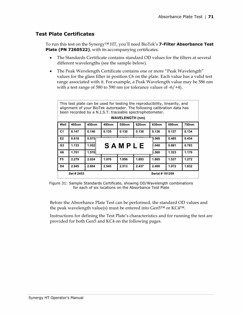
Absorbance Plate Test | 71
Synergy HT Operator's Manual
Test Plate Certificates
To run this test on the Synergy™ HT, you’ll need BioTek’s 7-Filter Absorbance Test Plate (PN 7260522), with its accompanying certificates.
• The Standards Certificate contains standard OD values for the filters at several different wavelengths (see the sample below).
• The Peak Wavelength Certificate contains one or more “Peak Wavelength” values for the glass filter in position C6 on the plate. Each value has a valid test range associated with it. For example, a Peak Wavelength value may be 586 nm with a test range of 580 to 590 nm (or tolerance values of -6/+4).
This test plate can be used for testing the reproducibility, linearity, and alignment of your BioTek autoreader. The following calibration data has been recorded by a N.I.S.T. traceable spectrophotometer.
WAVELENGTH (nm)
Well 405nm 450nm 490nm 550nm 620nm 630nm 690nm 750nm
C1 0.147 0.140 0.135 0.130 0.136 0.136 0.127 0.134
E2 0.618 0.575 0.574 0.568 0.573 0.568 0.485 0.434
G3 1.133 1.052 1.051 1.040 1.050 1.040 0.881 0.783
H6 1.701 1.578 1.577 1.560 1.575 1.560 1.323 1.179
F5 2.279 2.024 1.976 1.956 1.893 1.865 1.537 1.272
D4 2.945 2.604 2.545 2.513 2.437 2.400 1.972 1.632
Set # 2453 Serial # 161259
Figure 31: Sample Standards Certificate, showing OD/Wavelength combinations for each of six locations on the Absorbance Test Plate
Before the Absorbance Plate Test can be performed, the standard OD values and the peak wavelength value(s) must be entered into Gen5™ or KC4™.
Instructions for defining the Test Plate’s characteristics and for running the test are provided for both Gen5 and KC4 on the following pages.
S A M P L E
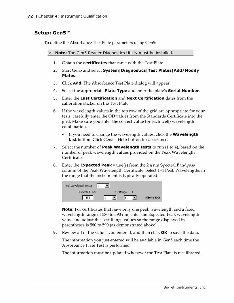
72 | Chapter 4: Instrument Qualification
BioTek Instruments, Inc.
Setup: Gen5™
To define the Absorbance Test Plate parameters using Gen5:
Note: The Gen5 Reader Diagnostics Utility must be installed.
1. Obtain the certificates that came with the Test Plate.
2. Start Gen5 and select System|Diagnostics|Test Plates|Add/Modify Plates.
3. Click Add. The Absorbance Test Plate dialog will appear.
4. Select the appropriate Plate Type and enter the plate’s Serial Number.
5. Enter the Last Certification and Next Certification dates from the calibration sticker on the Test Plate.
6. If the wavelength values in the top row of the grid are appropriate for your tests, carefully enter the OD values from the Standards Certificate into the grid. Make sure you enter the correct value for each well/wavelength combination.
• If you need to change the wavelength values, click the Wavelength List button. Click Gen5’s Help button for assistance.
7. Select the number of Peak Wavelength tests to run (1 to 4), based on the number of peak wavelength values provided on the Peak Wavelength Certificate.
8. Enter the Expected Peak value(s) from the 2.4 nm Spectral Bandpass column of the Peak Wavelength Certificate. Select 1–4 Peak Wavelengths in the range that the instrument is typically operated.
Note: For certificates that have only one peak wavelength and a fixed wavelength range of 580 to 590 nm, enter the Expected Peak wavelength value and adjust the Test Range values so the range displayed in parentheses is 580 to 590 (as demonstrated above).
9. Review all of the values you entered, and then click OK to save the data.
The information you just entered will be available in Gen5 each time the Absorbance Plate Test is performed.
The information must be updated whenever the Test Plate is recalibrated.
Absorbance Plate Test | 73
Synergy HT Operator's Manual
Procedure: Gen5™
To run the Absorbance Plate Test using Gen5:
1. In Gen5, select System|Diagnostics|Test Plates|Run.
2. If prompted, select the desired Test Plate and click OK.
3. When the Absorbance Test Plate Options dialog appears, check Perform Peak Wavelength Test if it is not already checked.
4. Highlight the wavelength(s) to be included in this test.
• Note: You need to select only those wavelengths most appropriate for your use of the reader.
5. (Optional) Enter any Comments.
6. Click Start Test.
7. Place the Test Plate in the microplate carrier so that well A1 is in the left rear corner of the carrier (as you are facing the carrier).
8. Click OK to run the test.
9. When the test completes, the results report will appear. Scroll down through the report; every result should show ‘PASS’. See page 78 for information on results and troubleshooting tips in the event of failures.
• A sample test report is shown on pages 76 and 77.
• Gen5 stores the results in a database; they can be retrieved and printed at any time. We recommend you print and save the report to document that the test was performed.
74 | Chapter 4: Instrument Qualification
BioTek Instruments, Inc.
Setup: KC4™
To define the Absorbance Test Plate parameters using KC4:
1. Obtain the certificates that came with the Test Plate.
2. Launch KC4 and select System|Diagnostics|Define Universal Plates.
Note: The terms “Universal Plate” and “Absorbance Plate” are equivalent.
3. Click Add. The Edit Universal Plate dialog will appear.
4. Select the appropriate Plate Type and enter the plate’s Serial Number.
5. If the wavelength values in the top row of the grid are appropriate for your tests, carefully enter the standard OD values from the Standards Certificate into the grid. Be sure to enter the correct value for each well/wavelength combination.
• If you need to change the wavelength values, click the Wavelength List button. Click KC4’s Help button for assistance.
6. Enter the Peak Wavelength value from the Peak Wavelength Certificate.
• Note: If the certificate specifies multiple peak wavelength values, you will need to run an independent test using spectral scan reads. KC4 supports the entry of only one Peak Wavelength value, and it must be in the range of 580 to 590 nm. See the special instructions on the next page.
7. Review all of the values you entered, and then click OK to save the data.
The information you just entered will be available in KC4 each time the Absorbance Plate Test is performed.
Procedure: KC4™
To run the Absorbance Plate Test using KC4:
1. Place the Test Plate in the carrier so the well A1 is in the left rear corner of the carrier (as you are facing the carrier).
2. In KC4, select System|Diagnostics|Run Universal Plate Test.
3. Enter or select the instrument’s Serial Number.
4. Select the desired Test Plate.
5. Check Peak Absorbance Search.
• Note: If the Test Plate’s Peak Wavelength Certificate specifies multiple peak wavelength values, do not check ‘Peak Absorbance Search’. Run an independent test using spectral scan reads instead; see the special instructions on the next page.
Absorbance Plate Test | 75
Synergy HT Operator's Manual
6. Select the Wavelength(s) to be included in this test by clicking in the Test column to toggle Yes/No.
• Note: You need to select only those wavelengths most appropriate for your use of the reader.
• If “N/A” appears for a wavelength you wish to test, update KC4’s Wavelengths table to include it (System|Readers|Filters/ Wavelengths).
7. Enter or select the Operator, and enter any Comments.
8. Click Run Test to begin.
• A sample test report is shown on the next two pages.
• KC4 stores the results in a database, and they can be retrieved and printed at any time. We recommend you print and save the reports to document that the test was performed.
Performing Peak Absorbance Tests Using Spectral Scan Reads
To create and run a KC4 spectral scan protocol to perform an independent Peak Absorbance Test:
Note: Create one protocol per Peak Wavelength value to be tested.
1. Open the Reading Parameters dialog and select the Spectrum Reading Type and the Absorbance Detection Method.
2. Set the Start and Stop wavelength values to define the test range specified in the Test Plate’s Peak Wavelength certificate (e.g., perform the scan from 580 to 590 nm).
3. Set the Step (increment) value to 1 nm.
4. Set the Plate Type to 96 WELL PLATE and read well C6.
5. Save the protocol.
6. Perform a read of the Absorbance Test Plate using this protocol.
7. Locate the peak wavelength on the graph (the wavelength value with the highest OD). Verify that it is within the allowed tolerance; see “Results & Troubleshooting Tips” on page 78.
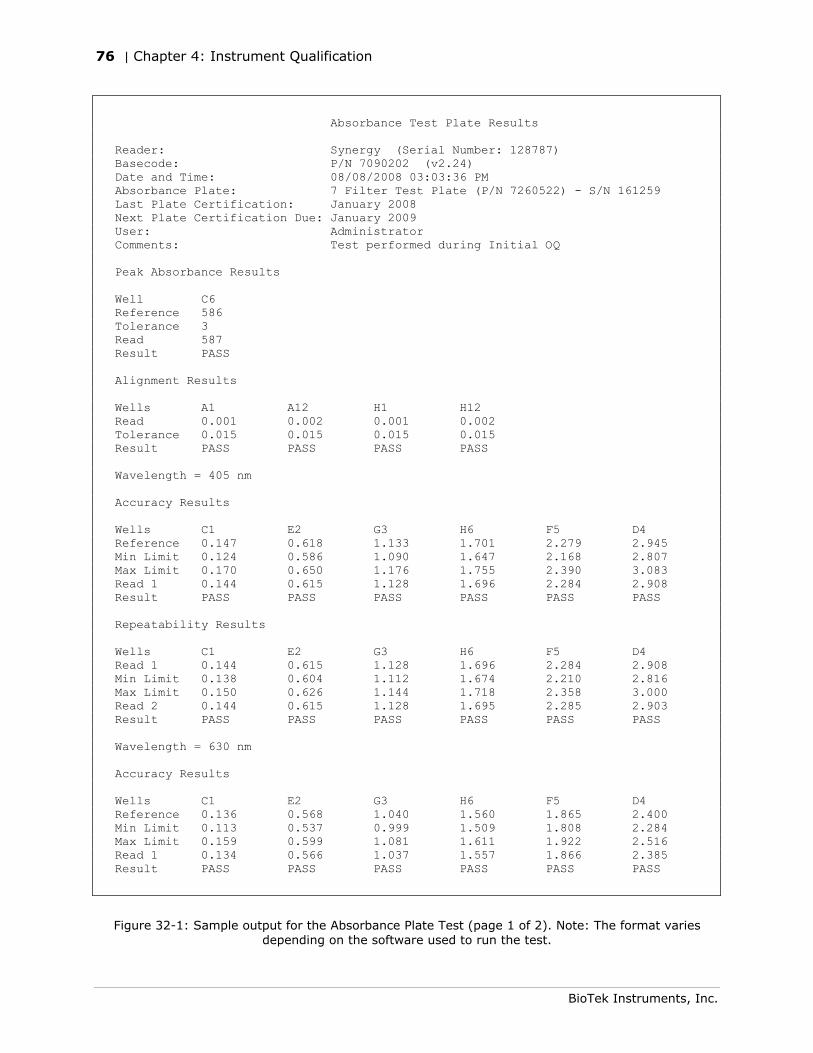
76 | Chapter 4: Instrument Qualification
BioTek Instruments, Inc.
Absorbance Test Plate Results Reader: Synergy (Serial Number: 128787) Basecode: P/N 7090202 (v2.24) Date and Time: 08/08/2008 03:03:36 PM Absorbance Plate: 7 Filter Test Plate (P/N 7260522) - S/N 161259 Last Plate Certification: January 2008 Next Plate Certification Due: January 2009 User: Administrator Comments: Test performed during Initial OQ Peak Absorbance Results Well C6 Reference 586 Tolerance 3 Read 587 Result PASS Alignment Results Wells A1 A12 H1 H12 Read 0.001 0.002 0.001 0.002 Tolerance 0.015 0.015 0.015 0.015 Result PASS PASS PASS PASS Wavelength = 405 nm Accuracy Results Wells C1 E2 G3 H6 F5 D4 Reference 0.147 0.618 1.133 1.701 2.279 2.945 Min Limit 0.124 0.586 1.090 1.647 2.168 2.807 Max Limit 0.170 0.650 1.176 1.755 2.390 3.083 Read 1 0.144 0.615 1.128 1.696 2.284 2.908 Result PASS PASS PASS PASS PASS PASS Repeatability Results Wells C1 E2 G3 H6 F5 D4 Read 1 0.144 0.615 1.128 1.696 2.284 2.908 Min Limit 0.138 0.604 1.112 1.674 2.210 2.816 Max Limit 0.150 0.626 1.144 1.718 2.358 3.000 Read 2 0.144 0.615 1.128 1.695 2.285 2.903 Result PASS PASS PASS PASS PASS PASS Wavelength = 630 nm Accuracy Results Wells C1 E2 G3 H6 F5 D4 Reference 0.136 0.568 1.040 1.560 1.865 2.400 Min Limit 0.113 0.537 0.999 1.509 1.808 2.284 Max Limit 0.159 0.599 1.081 1.611 1.922 2.516 Read 1 0.134 0.566 1.037 1.557 1.866 2.385 Result PASS PASS PASS PASS PASS PASS
Figure 32-1: Sample output for the Absorbance Plate Test (page 1 of 2). Note: The format varies depending on the software used to run the test.
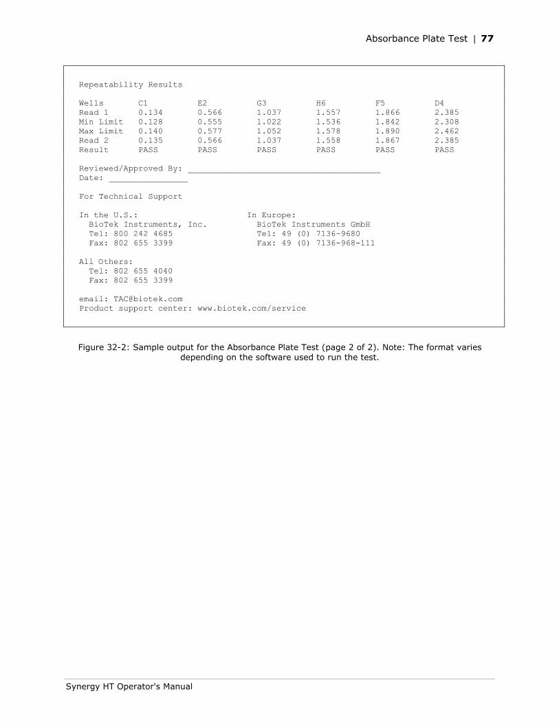
Absorbance Plate Test | 77
Synergy HT Operator's Manual
Repeatability Results Wells C1 E2 G3 H6 F5 D4 Read 1 0.134 0.566 1.037 1.557 1.866 2.385 Min Limit 0.128 0.555 1.022 1.536 1.842 2.308 Max Limit 0.140 0.577 1.052 1.578 1.890 2.462 Read 2 0.135 0.566 1.037 1.558 1.867 2.385 Result PASS PASS PASS PASS PASS PASS Reviewed/Approved By: _______________________________________ Date: ________________ For Technical Support In the U.S.: In Europe: BioTek Instruments, Inc. BioTek Instruments GmbH Tel: 800 242 4685 Tel: 49 (0) 7136-9680 Fax: 802 655 3399 Fax: 49 (0) 7136-968-111 All Others: Tel: 802 655 4040 Fax: 802 655 3399 email: [email protected] Product support center: www.biotek.com/service
Figure 32-2: Sample output for the Absorbance Plate Test (page 2 of 2). Note: The format varies depending on the software used to run the test.
78 | Chapter 4: Instrument Qualification
BioTek Instruments, Inc.
Results & Troubleshooting Tips
The Absorbance Test Plate Report contains results for the following:
• Peak Absorbance: When the test is performed, the C6 filter is scanned at the test range(s) defined by the user in the Absorbance Test Plate dialog. To verify wavelength accuracy, the wavelength of the maximum absorbance is compared with the peak wavelength value entered in the software, which comes from the Peak Wavelength Certificate supplied with the Test Plate. The accuracy of the wavelength should be ± 3 nm (± 2 nm instrument, ± 1 nm filter allowance).
If the reader fails this test, review the following possible problems and solutions:
Verify that the Test Plate actually has a filter in location C6. (Test Plates with the part number 9000547 do not have this filter.)
Check the C6 filter to make sure it is clean. If needed, clean it with lens paper. Important! Do not remove the filter from the Test Plate, and do not use alcohol or other cleaning agents.
Make sure the information entered into Gen5™ or KC4™ matches the information on the Test Plate’s Peak Wavelength Certificate.
Make sure the Test Plate is within its calibration certification period. The calibration sticker is affixed directly to the plate. If it is out of date, contact BioTek to schedule a recertification.
Check the microplate carrier to ensure it is clear of debris.
• Alignment: This portion of the test measures the alignment of the microplate carrier with the optical path. A reading greater than 0.015 OD represents an out-of-alignment condition. Wells A01, A12, H01, and H12 are the only valid alignment holes for the reader on the PN 7260522 Test Plate.
If the reader fails this test, review the following possible problems and solutions:
Ensure that the Test Plate is correctly seated in the microplate carrier.
Check the four alignment holes (A01, A12, H01, H12) to ensure they are clear of debris.
Check the microplate carrier to ensure it is clear of debris.
• Accuracy: Accuracy is a measure of the optical density of Test Plate wells C01, D04, E02, F05, G03, and H06 as compared with known standard values contained in the Standards Certificate that accompanies each Test Plate.
If the reader fails this test, review the following possible problems and solutions:
Check the neutral-density filters on the Test Plate to ensure they are clean. If necessary, clean them with lens paper. Do not remove the filters from the test plate, and do not use alcohol or other cleaning agents.
Absorbance Plate Test | 79
Synergy HT Operator's Manual
Verify that the filter calibration values entered in Gen5™ or KC4™ are the same as those on the Test Plate’s Standards Certificate.
Verify that the Test Plate is within its calibration certification period. The calibration sticker is affixed directly to the plate. If it is out of date, contact BioTek to schedule a recertification.
• Repeatability: Repeatability is a measure of the instrument’s ability to read the same well with minimum variation between two reads with the well in the same location.
If the reader fails this test, review the following possible problems and solutions:
Check the neutral-density filters on the Test Plate to ensure there is no debris that may have shifted between readings and caused changes.
Check the microplate carrier to ensure it is clear of debris.
Linearity of the optical density readings is confirmed by default if the optical density readings are accurate. To further verify this, perform a regression analysis on the Test Plate OD values in a program such as Microsoft® Excel as follows:
1. Launch Excel.
2. Create a spreadsheet and label one column “Assigned” and the next column “Observed.”
3. Enter the Assigned OD data for each glass filter in the first column from the Standards Certificate provided with the Test Plate. (Analyze one wavelength at a time.)
4. Enter the Observed OD values for the same glass filters in the adjacent column.
5. Under Tools, select Data Analysis and then Regression. Define the Assigned values as the “Input Y Range” and the Observed OD as the “Input X Range.”
Note: If the Data Analysis command is not available on the Tools menu, you may need to install the Analysis ToolPak in Microsoft Excel. Consult Microsoft Excel Help for assistance.
6. Click OK and the Summary Output sheet will be displayed. An R Square value of at least 0.990 is expected.
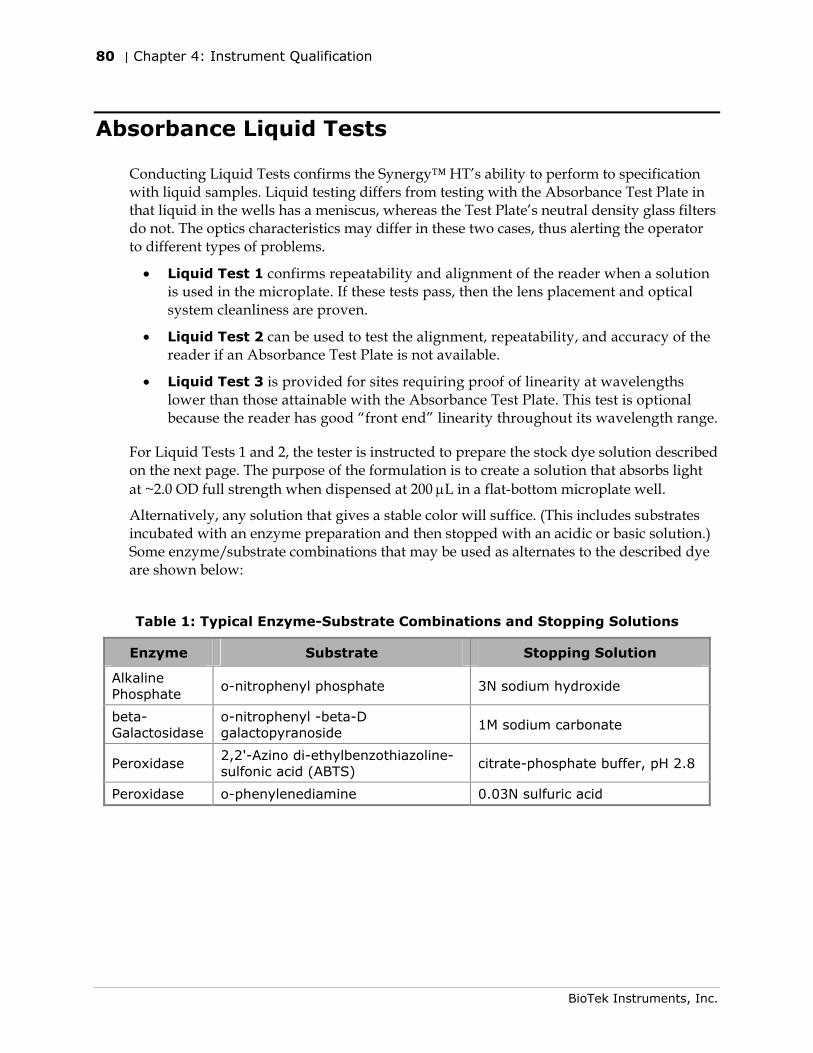
80 | Chapter 4: Instrument Qualification
BioTek Instruments, Inc.
Absorbance Liquid Tests
Conducting Liquid Tests confirms the Synergy™ HT’s ability to perform to specification with liquid samples. Liquid testing differs from testing with the Absorbance Test Plate in that liquid in the wells has a meniscus, whereas the Test Plate’s neutral density glass filters do not. The optics characteristics may differ in these two cases, thus alerting the operator to different types of problems.
• Liquid Test 1 confirms repeatability and alignment of the reader when a solution is used in the microplate. If these tests pass, then the lens placement and optical system cleanliness are proven.
• Liquid Test 2 can be used to test the alignment, repeatability, and accuracy of the reader if an Absorbance Test Plate is not available.
• Liquid Test 3 is provided for sites requiring proof of linearity at wavelengths lower than those attainable with the Absorbance Test Plate. This test is optional because the reader has good “front end” linearity throughout its wavelength range.
For Liquid Tests 1 and 2, the tester is instructed to prepare the stock dye solution described on the next page. The purpose of the formulation is to create a solution that absorbs light at ~2.0 OD full strength when dispensed at 200 μL in a flat-bottom microplate well.
Alternatively, any solution that gives a stable color will suffice. (This includes substrates incubated with an enzyme preparation and then stopped with an acidic or basic solution.) Some enzyme/substrate combinations that may be used as alternates to the described dye are shown below:
Table 1: Typical Enzyme-Substrate Combinations and Stopping Solutions
Enzyme Substrate Stopping Solution
Alkaline Phosphate
o-nitrophenyl phosphate 3N sodium hydroxide
beta-Galactosidase
o-nitrophenyl -beta-D galactopyranoside
1M sodium carbonate
Peroxidase 2,2'-Azino di-ethylbenzothiazoline-sulfonic acid (ABTS)
citrate-phosphate buffer, pH 2.8
Peroxidase o-phenylenediamine 0.03N sulfuric acid
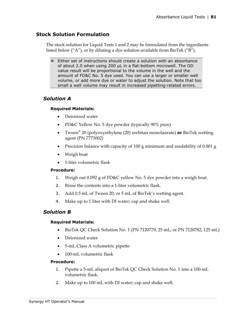
Absorbance Liquid Tests | 81
Synergy HT Operator's Manual
Stock Solution Formulation
The stock solution for Liquid Tests 1 and 2 may be formulated from the ingredients listed below (“A”), or by diluting a dye solution available from BioTek (“B”).
Either set of instructions should create a solution with an absorbance of about 2.0 when using 200 µL in a flat-bottom microwell. The OD value result will be proportional to the volume in the well and the amount of FD&C No. 5 dye used. You can use a larger or smaller well volume, or add more dye or water to adjust the solution. Note that too small a well volume may result in increased pipetting-related errors.
Solution A
Required Materials:
• Deionized water
• FD&C Yellow No. 5 dye powder (typically 90% pure)
• Tween® 20 (polyoxyethylene (20) sorbitan monolaurate) or BioTek wetting agent (PN 7773002)
• Precision balance with capacity of 100 g minimum and readability of 0.001 g
• Weigh boat
• 1-liter volumetric flask
Procedure:
1. Weigh out 0.092 g of FD&C yellow No. 5 dye powder into a weigh boat.
2. Rinse the contents into a 1-liter volumetric flask.
3. Add 0.5 mL of Tween 20, or 5 mL of BioTek’s wetting agent.
4. Make up to 1 liter with DI water; cap and shake well.
Solution B
Required Materials:
• BioTek QC Check Solution No. 1 (PN 7120779, 25 mL; or PN 7120782, 125 mL)
• Deionized water
• 5-mL Class A volumetric pipette
• 100-mL volumetric flask
Procedure:
1. Pipette a 5-mL aliquot of BioTek QC Check Solution No. 1 into a 100-mL volumetric flask.
2. Make up to 100 mL with DI water; cap and shake well.
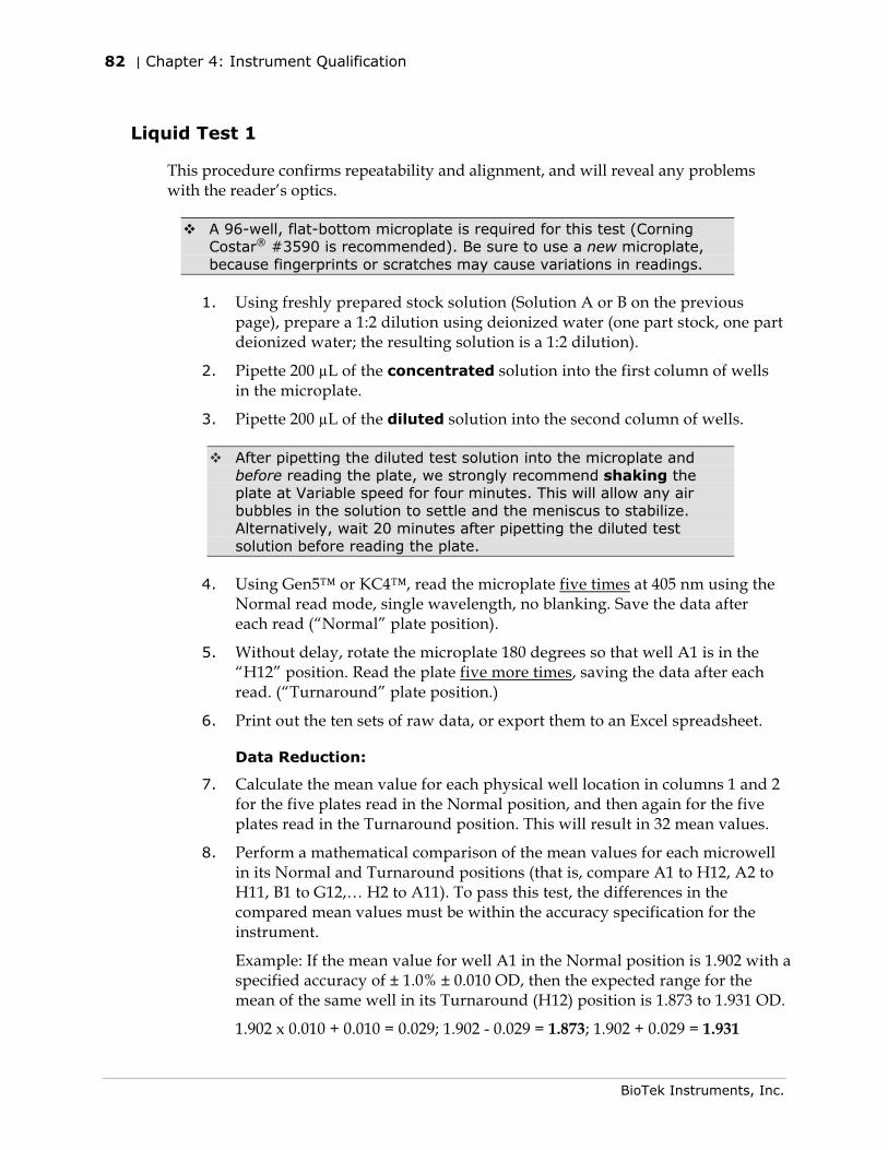
82 | Chapter 4: Instrument Qualification
BioTek Instruments, Inc.
Liquid Test 1
This procedure confirms repeatability and alignment, and will reveal any problems with the reader’s optics.
A 96-well, flat-bottom microplate is required for this test (Corning Costar® #3590 is recommended). Be sure to use a new microplate, because fingerprints or scratches may cause variations in readings.
1. Using freshly prepared stock solution (Solution A or B on the previous page), prepare a 1:2 dilution using deionized water (one part stock, one part deionized water; the resulting solution is a 1:2 dilution).
2. Pipette 200 µL of the concentrated solution into the first column of wells in the microplate.
3. Pipette 200 µL of the diluted solution into the second column of wells.
After pipetting the diluted test solution into the microplate and before reading the plate, we strongly recommend shaking the plate at Variable speed for four minutes. This will allow any air bubbles in the solution to settle and the meniscus to stabilize. Alternatively, wait 20 minutes after pipetting the diluted test solution before reading the plate.
4. Using Gen5™ or KC4™, read the microplate five times at 405 nm using the Normal read mode, single wavelength, no blanking. Save the data after each read (“Normal” plate position).
5. Without delay, rotate the microplate 180 degrees so that well A1 is in the “H12” position. Read the plate five more times, saving the data after each read. (“Turnaround” plate position.)
6. Print out the ten sets of raw data, or export them to an Excel spreadsheet.
Data Reduction:
7. Calculate the mean value for each physical well location in columns 1 and 2 for the five plates read in the Normal position, and then again for the five plates read in the Turnaround position. This will result in 32 mean values.
8. Perform a mathematical comparison of the mean values for each microwell in its Normal and Turnaround positions (that is, compare A1 to H12, A2 to H11, B1 to G12,… H2 to A11). To pass this test, the differences in the compared mean values must be within the accuracy specification for the instrument.
Example: If the mean value for well A1 in the Normal position is 1.902 with a specified accuracy of ± 1.0% ± 0.010 OD, then the expected range for the mean of the same well in its Turnaround (H12) position is 1.873 to 1.931 OD.
1.902 x 0.010 + 0.010 = 0.029; 1.902 - 0.029 = 1.873; 1.902 + 0.029 = 1.931
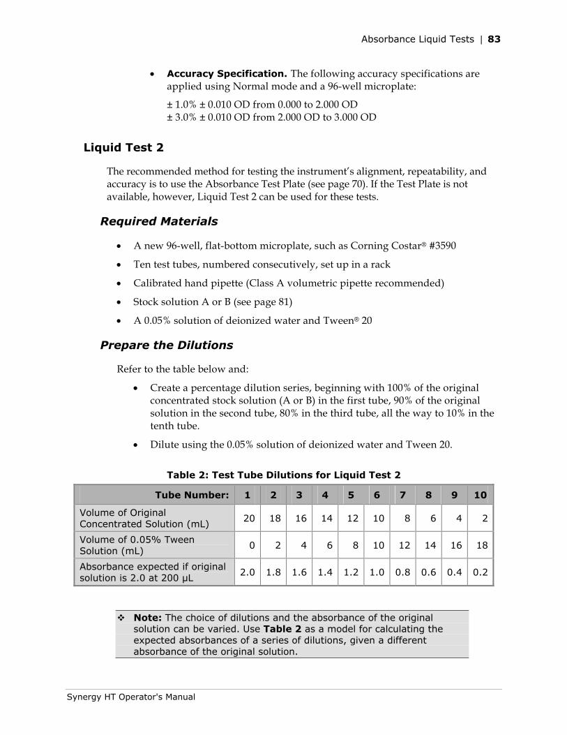
Absorbance Liquid Tests | 83
Synergy HT Operator's Manual
• Accuracy Specification. The following accuracy specifications are applied using Normal mode and a 96-well microplate:
± 1.0% ± 0.010 OD from 0.000 to 2.000 OD ± 3.0% ± 0.010 OD from 2.000 OD to 3.000 OD
Liquid Test 2
The recommended method for testing the instrument’s alignment, repeatability, and accuracy is to use the Absorbance Test Plate (see page 70). If the Test Plate is not available, however, Liquid Test 2 can be used for these tests.
Required Materials
• A new 96-well, flat-bottom microplate, such as Corning Costar® #3590
• Ten test tubes, numbered consecutively, set up in a rack
• Calibrated hand pipette (Class A volumetric pipette recommended)
• Stock solution A or B (see page 81)
• A 0.05% solution of deionized water and Tween® 20
Prepare the Dilutions
Refer to the table below and:
• Create a percentage dilution series, beginning with 100% of the original concentrated stock solution (A or B) in the first tube, 90% of the original solution in the second tube, 80% in the third tube, all the way to 10% in the tenth tube.
• Dilute using the 0.05% solution of deionized water and Tween 20.
Table 2: Test Tube Dilutions for Liquid Test 2
Tube Number: 1 2 3 4 5 6 7 8 9 10
Volume of Original Concentrated Solution (mL)
20 18 16 14 12 10 8 6 4 2
Volume of 0.05% Tween Solution (mL)
0 2 4 6 8 10 12 14 16 18
Absorbance expected if original solution is 2.0 at 200 µL
2.0 1.8 1.6 1.4 1.2 1.0 0.8 0.6 0.4 0.2
Note: The choice of dilutions and the absorbance of the original solution can be varied. Use Table 2 as a model for calculating the expected absorbances of a series of dilutions, given a different absorbance of the original solution.
84 | Chapter 4: Instrument Qualification
BioTek Instruments, Inc.
Prepare the Plate
• Pipette 200 µL of the concentrated solution from Tube 1 into each well of the first column, A1 to H1, of a new flat-bottom microplate.
• Pipette 200 µL from each of the remaining tubes into the wells of the corresponding column of the microplate (Tube 2 into wells A2 to H2, Tube 3 into wells A3 to H3, and so on).
Linearity & Repeatability Tests
1. Using Gen5™ or KC4™, read the microplate prepared above five times using Normal mode, dual wavelength at 450/630 nm. Save the data after each read.
Tip: When you create a dual wavelength protocol in KC4, KC4 automatically generates a multi-plate transformation for calculating the delta OD. The name of the resulting data set is ‘Delta OD’.
Do not discard the plate; you will use it for the Alignment test.
2. Print out the five sets of Delta OD data, or export them to an Excel spreadsheet.
Data Reduction for Linearity:
3. Calculate the mean absorbance for each well, and average the means for each concentration.
4. Perform a regression analysis on the data to determine if there is adequate linearity. For example, using Microsoft® Excel:
In a spreadsheet, create two columns labeled ‘X’ and ‘Y’. Reference Table 2 on the previous page; enter the actual absorbance values in column X, and enter the expected absorbance values in column Y.
Select Tools|Data Analysis|Regression. Identify column X as the ‘Input X Range’ and column Y as the ‘Input Y Range.’
Click OK to perform the analysis, the results of which will be output in a separate sheet.
Note: If the Data Analysis command is not available on the Tools menu, you may need to install the Analysis ToolPak in Excel. Consult Excel’s help system for assistance.
Since it is somewhat difficult to achieve high pipetting accuracy when conducting linear dilutions, an R Square value of at least 0.99 is considered adequate.
Absorbance Liquid Tests | 85
Synergy HT Operator's Manual
Data Reduction for Repeatability:
5. Calculate the mean and standard deviation for the five readings taken above at each concentration. Only one row of data needs to be analyzed.
6. For each mean below 2.000 OD, calculate the allowed deviation using the repeatability specification for a 96-well plate of ± 1.0% ± 0.005 OD. If above 2.000 OD, apply the ± 3.0% ± 0.005 specification.
7. The standard deviation for each set of readings should be less than the allowed deviation.
Example: Absorbance readings of 1.950, 1.948, 1.955, 1.952, and 1.950 will result in a mean of 1.951, and a standard deviation of 0.0026. The mean (1.951) multiplied by 1.0% (1.951 x 0.010) = 0.0195, which, when added to the 0.005 (0.0195 + 0.005) = 0.0245 OD, which is the allowable deviation. Since the standard deviation is less than this value, the reader meets the test criteria.
• Repeatability Specification:
± 1.0% ± 0.005 OD from 0.000 to 2.000 OD
± 3.0% ± 0.005 OD from 2.000 OD to 3.000 OD
Alignment Test
1. Using the plate prepared for the Linearity Test on the previous page, conduct a Turnaround test by reading the plate five times with the A1 well in the H12 position. Save the data after each read.
This test results in values for the four corner wells that can be used to determine alignment.
2. Calculate the means of the wells A1 and H1 in the Normal plate position (data from Linearity Test) and in the Turnaround position (from Step 1 above).
3. Compare the mean reading for well A1 to its mean reading when in the H12 position. Next, compare the mean values for the H1 well to the same well in the A12 position. The difference in the values for any two corresponding wells should be within the accuracy specification for the instrument.
Example: If the mean of well A1 in the normal position is 1.902, where the specified accuracy is ± 1.0% ± 0.010 OD, then the expected range for the mean of the same well in the H12 position is 1.873 to 1.931 OD. (1.902 x 1.0% = 0.019 + 0.010 = 0.029, which is added and subtracted from 1.902 for the range.)
If the four corner wells are within the accuracy range, the reader is in alignment.
86 | Chapter 4: Instrument Qualification
BioTek Instruments, Inc.
Liquid Test 3
This procedure verifies operation of the Synergy™ HT at 340 nm, and is provided for sites requiring proof of linearity at wavelengths lower than those attainable with the Absorbance Test Plate. This test is optional because the reader has good “front end” linearity throughout its wavelength range.
Required Materials
• New 96-well, flat-bottom microplate (Corning Costar® #3590 is recommended)
• Calibrated hand-pipette(s)
• Beakers and graduated cylinder
• Precision balance with readability to 0.01 g
• Buffer Solution below
Read a sample of the buffer solution at 340 nm. This solution should have an optical density of approximately 0.700 to 1.000. This value is not critical, but it should be within this range.
If low, adjust up by adding β-NADH powder until the solution is at least at the lower end of this range. Do not adjust if slightly high.
Buffer Solution (Sigma PBS Solution)
• Deionized water
• Phosphate-Buffered Saline (PBS), pH 7.2–7.6, Sigma® tablets, #P4417 (or equivalent)
• β-NADH Powder (β-Nicotinamide Adenine Dinucleotide, Reduced Form) Sigma® bulk catalog number N 8129, or preweighed 10-mg vials, Sigma number N6785-10VL (or BioTek PN 98233). Note: Manufacturer part numbers are subject to change over time.
Store the β-NADH Powder according to the guidelines on its packaging.
1. Prepare a PBS solution from the Sigma tablets.
2. In a beaker, mix 50 mL of the PBS solution with 10 mg of the β-NADH powder and mix thoroughly. This is the Sigma PBS Solution.
Absorbance Liquid Tests | 87
Synergy HT Operator's Manual
Procedure
In this procedure, the prepared stock buffer solution B is referred to as the 100% Test Solution.
1. Carefully prepare a 75% Test Solution by diluting 15 mL of the 100% Test Solution:
• If using the Sigma PBS Solution, use 5 mL as the diluent.
2. Carefully prepare a 50% Test Solution by diluting 10 mL of the 100% Test Solution:
• If using the Sigma PBS Solution, use 10 mL as the diluent.
3. Carefully pipette the three solutions into a new 96-well microplate:
• 150 µL of the 100% Test Solution into all wells of columns 1 and 2
• 150 µL of the 75% Test Solution into all wells of columns 3 and 4
• 150 µL of the 50% Test Solution into all wells of column 5 and 6
4. Using Gen5™ or KC4™, read the microplate five times using Normal mode, single wavelength at 340 nm, no blanking. Save the data after each read.
5. Print out the five sets of raw data, or export them to an Excel spreadsheet.
Data Reduction for Repeatability:
6. For each well, calculate the mean and standard deviation of the five readings.
7. For each mean calculated in step 6, calculate the allowed deviation using the repeatability specification for a 96-well plate of ±1.0% ± 0.005 OD (Mean x 0.010 ± 0.005).
8. For each well, compare the standard deviation calculated in step 6 with the allowed deviation calculated in step 7. The standard deviation should be less than the allowed deviation.
Example: Five readings in well A1 of 0.802, 0.802, 0.799, 0.798, and 0.801 will result in a mean of 0.8004 and a standard deviation of 0.0018. The mean multiplied by 1.0% (0.8004 * 0.010) equals 0.008, and when added to the 0.005 (0.008 + 0.005) equals 0.013, which is the allowed deviation for well A1. Since the standard deviation for well A1 is less than 0.013, the well meets the test criteria.
• Repeatability Specification:
± 1.0% ± 0.005 OD from 0.000 to 2.000 OD ± 3.0% ± 0.005 OD from 2.000 OD to 3.000 OD
88 | Chapter 4: Instrument Qualification
BioTek Instruments, Inc.
Data Reduction for Linearity:
9. For each of the three Test Solutions, calculate the mean absorbance for the wells containing that solution (mean of wells A1 to H2, A3 to H4, and A5 to H6).
10. Perform a regression analysis on the data to determine if there is adequate linearity. For example, using Microsoft® Excel:
In a spreadsheet, enter the three mean values in ascending order and label the column as the ‘Y’ values. Enter 0.50, 0.75, and 1.00 and label the column as the ‘X’ values.
Select Tools|Data Analysis|Regression to open the Regression dialog. Set “Input Y Range” to reference the above-mentioned Y values, and set “Input X Range” to reference the above-mentioned X values.
Click OK to perform the analysis, the results of which will be output in a separate sheet.
Note: If the Data Analysis command is not available on the Tools menu, you may need to install the Analysis ToolPak in Excel. Consult Excel’s help system for assistance.
Since it is somewhat difficult to achieve high pipetting accuracy when conducting linear dilutions, an R Square value of at least 0.99 is considered adequate.
Fluorescence Tests | 89
Synergy HT Operator's Manual
Fluorescence Tests
The Corners Test uses fluorescent compounds to verify that the plate carrier is properly aligned in relation to the optical probe(s). (Because the Synergy™ HT’s fluorescence optics are different from the absorbance optics, the Corners Test is also required.) We recommend running the test for both the top and bottom probes (if equipped).
The Sensitivity Test uses fluorescent compounds of varying concentrations to test the fluorescence reading capability of the reader. The ability to detect specific compounds at low concentrations ensures that the filters, optical path, and PMT are all in working order. This test verifies that the difference between the means of wells with known lower limits of concentration of the substance under investigation is statistically distinguishable from the mean of wells with pure diluent.
The Linearity Test verifies that the system is linear; that is, signal changes proportionally with changes in concentration. Proving that the system is linear allows the Sensitivity Test to be run on two points instead of using serial dilutions.
Important! The tests presented in this section require specific microplates, solutions, and EX/EM filters. Your laboratory may require a deviation from some of these tests. For example, you may wish to use a different fluorescing solution and/or microplate.
If deviation from the tests as presented in this section is required, the following steps should be taken the first time each test is run (e.g., during the Initial OQ):
1. Perform the tests exactly as described on the following pages.
2. Rerun the tests using your particular solutions, filters, microplates, etc. If results are comparable, then the results from these tests will be your baseline for future tests.
3. Be sure to document your new test procedure(s), and save all test results.
90 | Chapter 4: Instrument Qualification
BioTek Instruments, Inc.
Required Materials
Microplates should be perfectly clean and free of dust or bottom scratches. Use new microplates from sealed packages.
Manufacturer part numbers are subject to change over time.
Methylumbelliferone can be used as an alternative or supplemental method for performing these tests for the top probe. See the instructions starting on page 98.
• Buffer:
NIST-traceable Sodium Borate Reference Standard (pH 9.18) (e.g., Fisher-Scientific 1 L Sodium Borate Mfr. #159532, or equivalent), OR
Phosphate-Buffered Saline (PBS), pH 7.2-7.6 (e.g., Sigma® tablets, Mfr. #P4417, or equivalent) and pH meter or pH indicator strips with pH range 4 to 10
• Sodium Fluorescein Powder (1 mg vial, BioTek PN 98155)
• Bottom optics: A clean Hellma® Quartz 96-well titration plate (Mfr. #730.009.QG), or equivalent, such as the 96-well glass-bottom Greiner SensoPlate™ (Mfr. #655892).
• Top optics: A new, clean, 96-well solid black microplate, such as Corning® Costar Mfr. #3915. The Hellma Quartz plate described above can also be used.
• Excitation filter 485/20 nm and Emission filter 528/20 nm installed
• Deionized or distilled water
• Various beakers, graduated cylinders, and pipettes
• pH meter or pH indicator strips with pH range 4 to 10
• 95% Ethanol (for cleaning the bottoms of the plates)
• Aluminum foil
• (Optional, but recommended) 0.45 micron filter
• (Optional) Black polyethylene bag(s) to temporarily store plate(s)
• Gen5™ users: ‘Synergy HT FI_B.prt’ and ‘Synergy HT FI_T.prt’ protocols described on page 95
• KC4™ users: ‘Synergy HT FI_B.prt’ and ‘Synergy HT FI_T.prt’ protocols described on page 96
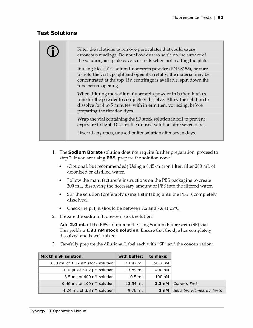
Fluorescence Tests | 91
Synergy HT Operator's Manual
Test Solutions
Filter the solutions to remove particulates that could cause erroneous readings. Do not allow dust to settle on the surface of the solution; use plate covers or seals when not reading the plate.
If using BioTek’s sodium fluorescein powder (PN 98155), be sure to hold the vial upright and open it carefully; the material may be concentrated at the top. If a centrifuge is available, spin down the tube before opening.
When diluting the sodium fluorescein powder in buffer, it takes time for the powder to completely dissolve. Allow the solution to dissolve for 4 to 5 minutes, with intermittent vortexing, before preparing the titration dyes.
Wrap the vial containing the SF stock solution in foil to prevent exposure to light. Discard the unused solution after seven days.
Discard any open, unused buffer solution after seven days.
1. The Sodium Borate solution does not require further preparation; proceed to step 2. If you are using PBS, prepare the solution now:
• (Optional, but recommended) Using a 0.45-micron filter, filter 200 mL of deionized or distilled water.
• Follow the manufacturer’s instructions on the PBS packaging to create 200 mL, dissolving the necessary amount of PBS into the filtered water.
• Stir the solution (preferably using a stir table) until the PBS is completely dissolved.
• Check the pH; it should be between 7.2 and 7.6 at 25°C.
2. Prepare the sodium fluorescein stock solution:
Add 2.0 mL of the PBS solution to the 1 mg Sodium Fluorescein (SF) vial. This yields a 1.32 nM stock solution. Ensure that the dye has completely dissolved and is well mixed.
3. Carefully prepare the dilutions. Label each with “SF” and the concentration: Mix this SF solution: with buffer: to make:
0.53 mL of 1.32 nM stock solution 13.47 mL 50.2 μM
110 µL of 50.2 μM solution 13.89 mL 400 nM
3.5 mL of 400 nM solution 10.5 mL 100 nM
0.46 mL of 100 nM solution 13.54 mL 3.3 nM Corners Test
4.24 mL of 3.3 nM solution 9.76 mL 1 nM Sensitivity/Linearity Tests
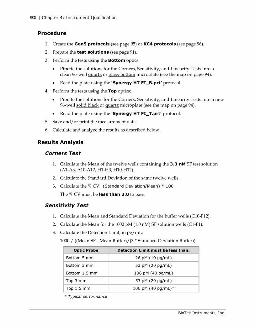
92 | Chapter 4: Instrument Qualification
BioTek Instruments, Inc.
Procedure
1. Create the Gen5 protocols (see page 95) or KC4 protocols (see page 96).
2. Prepare the test solutions (see page 91).
3. Perform the tests using the Bottom optics:
• Pipette the solutions for the Corners, Sensitivity, and Linearity Tests into a clean 96-well quartz or glass-bottom microplate (see the map on page 94).
• Read the plate using the ‘Synergy HT FI_B.prt’ protocol.
4. Perform the tests using the Top optics:
• Pipette the solutions for the Corners, Sensitivity, and Linearity Tests into a new 96-well solid black or quartz microplate (see the map on page 94).
• Read the plate using the ‘Synergy HT FI_T.prt’ protocol.
5. Save and/or print the measurement data.
6. Calculate and analyze the results as described below.
Results Analysis
Corners Test
1. Calculate the Mean of the twelve wells containing the 3.3 nM SF test solution (A1-A3, A10-A12, H1-H3, H10-H12).
2. Calculate the Standard Deviation of the same twelve wells.
3. Calculate the % CV: (Standard Deviation/Mean) * 100
The % CV must be less than 3.0 to pass.
Sensitivity Test
1. Calculate the Mean and Standard Deviation for the buffer wells (C10-F12).
2. Calculate the Mean for the 1000 pM (1.0 nM) SF solution wells (C1-F1).
3. Calculate the Detection Limit, in pg/mL:
1000 / ((Mean SF - Mean Buffer)/(3 * Standard Deviation Buffer))
Optic Probe Detection Limit must be less than:
Bottom 5 mm 26 pM (10 pg/mL)
Bottom 3 mm 53 pM (20 pg/mL)
Bottom 1.5 mm 106 pM (40 pg/mL)
Top 3 mm 53 pM (20 pg/mL)
Top 1.5 mm 106 pM (40 pg/mL)*
* Typical performance
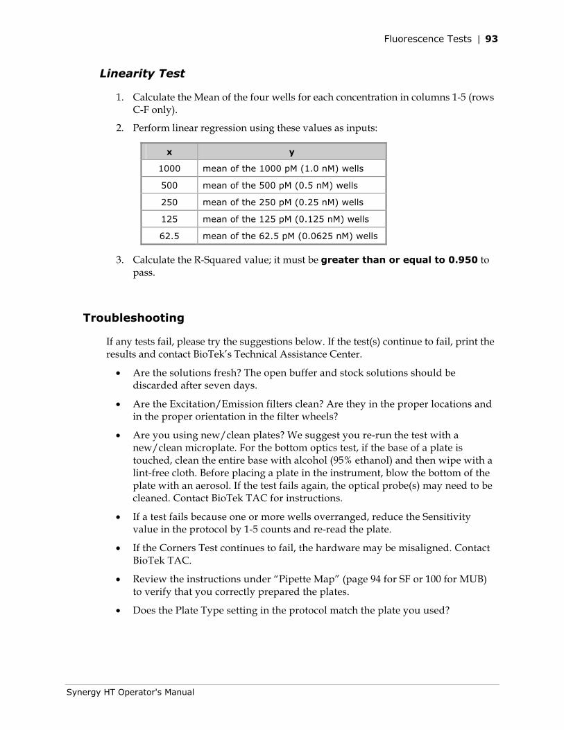
Fluorescence Tests | 93
Synergy HT Operator's Manual
Linearity Test
1. Calculate the Mean of the four wells for each concentration in columns 1-5 (rows C-F only).
2. Perform linear regression using these values as inputs:
x y
1000 mean of the 1000 pM (1.0 nM) wells
500 mean of the 500 pM (0.5 nM) wells
250 mean of the 250 pM (0.25 nM) wells
125 mean of the 125 pM (0.125 nM) wells
62.5 mean of the 62.5 pM (0.0625 nM) wells
3. Calculate the R-Squared value; it must be greater than or equal to 0.950 to pass.
Troubleshooting
If any tests fail, please try the suggestions below. If the test(s) continue to fail, print the results and contact BioTek’s Technical Assistance Center.
• Are the solutions fresh? The open buffer and stock solutions should be discarded after seven days.
• Are the Excitation/Emission filters clean? Are they in the proper locations and in the proper orientation in the filter wheels?
• Are you using new/clean plates? We suggest you re-run the test with a new/clean microplate. For the bottom optics test, if the base of a plate is touched, clean the entire base with alcohol (95% ethanol) and then wipe with a lint-free cloth. Before placing a plate in the instrument, blow the bottom of the plate with an aerosol. If the test fails again, the optical probe(s) may need to be cleaned. Contact BioTek TAC for instructions.
• If a test fails because one or more wells overranged, reduce the Sensitivity value in the protocol by 1-5 counts and re-read the plate.
• If the Corners Test continues to fail, the hardware may be misaligned. Contact BioTek TAC.
• Review the instructions under “Pipette Map” (page 94 for SF or 100 for MUB) to verify that you correctly prepared the plates.
• Does the Plate Type setting in the protocol match the plate you used?
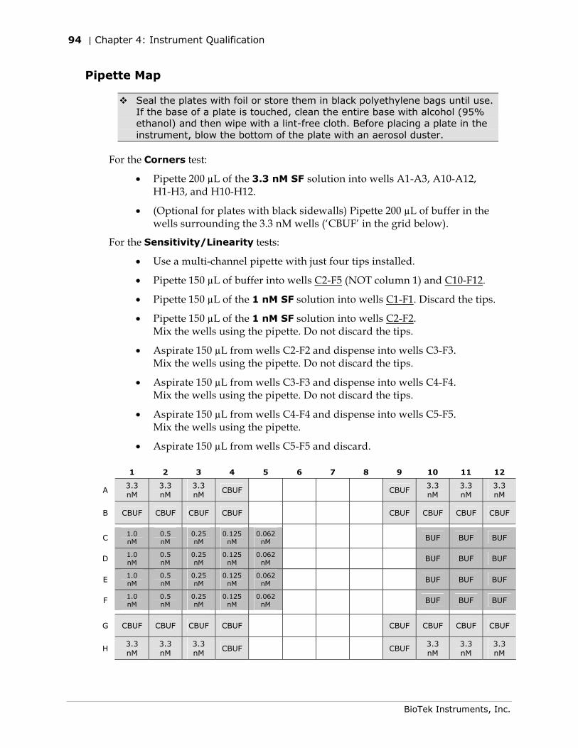
94 | Chapter 4: Instrument Qualification
BioTek Instruments, Inc.
Pipette Map
Seal the plates with foil or store them in black polyethylene bags until use. If the base of a plate is touched, clean the entire base with alcohol (95% ethanol) and then wipe with a lint-free cloth. Before placing a plate in the instrument, blow the bottom of the plate with an aerosol duster.
For the Corners test:
• Pipette 200 µL of the 3.3 nM SF solution into wells A1-A3, A10-A12, H1-H3, and H10-H12.
• (Optional for plates with black sidewalls) Pipette 200 µL of buffer in the wells surrounding the 3.3 nM wells (‘CBUF’ in the grid below).
For the Sensitivity/Linearity tests:
• Use a multi-channel pipette with just four tips installed.
• Pipette 150 µL of buffer into wells C2-F5 (NOT column 1) and C10-F12.
• Pipette 150 µL of the 1 nM SF solution into wells C1-F1. Discard the tips.
• Pipette 150 µL of the 1 nM SF solution into wells C2-F2. Mix the wells using the pipette. Do not discard the tips.
• Aspirate 150 µL from wells C2-F2 and dispense into wells C3-F3. Mix the wells using the pipette. Do not discard the tips.
• Aspirate 150 µL from wells C3-F3 and dispense into wells C4-F4. Mix the wells using the pipette. Do not discard the tips.
• Aspirate 150 µL from wells C4-F4 and dispense into wells C5-F5. Mix the wells using the pipette.
• Aspirate 150 µL from wells C5-F5 and discard.
1 2 3 4 5 6 7 8 9 10 11 12
A 3.3 nM
3.3 nM
3.3 nM
CBUF CBUF 3.3 nM
3.3 nM
3.3 nM
B CBUF CBUF CBUF CBUF CBUF CBUF CBUF CBUF
C 1.0 nM
0.5 nM
0.25 nM
0.125 nM
0.062 nM BUF BUF BUF
D 1.0 nM
0.5 nM
0.25 nM
0.125 nM
0.062 nM BUF BUF BUF
E 1.0 nM
0.5 nM
0.25 nM
0.125 nM
0.062 nM BUF BUF BUF
F 1.0 nM
0.5 nM
0.25 nM
0.125 nM
0.062 nM BUF BUF BUF
G CBUF CBUF CBUF CBUF CBUF CBUF CBUF CBUF
H 3.3 nM
3.3 nM
3.3 nM
CBUF CBUF 3.3 nM
3.3 nM
3.3 nM
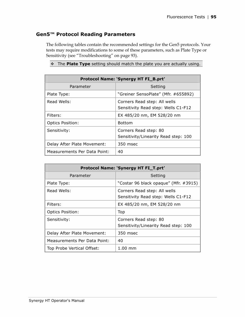
Fluorescence Tests | 95
Synergy HT Operator's Manual
Gen5™ Protocol Reading Parameters
The following tables contain the recommended settings for the Gen5 protocols. Your tests may require modifications to some of these parameters, such as Plate Type or Sensitivity (see “Troubleshooting” on page 93).
The Plate Type setting should match the plate you are actually using.
Protocol Name: ‘Synergy HT FI_B.prt’
Parameter Setting
Plate Type: “Greiner SensoPlate” (Mfr. #655892)
Read Wells: Corners Read step: All wells
Sensitivity Read step: Wells C1-F12
Filters: EX 485/20 nm, EM 528/20 nm
Optics Position: Bottom
Sensitivity: Corners Read step: 80
Sensitivity/Linearity Read step: 100
Delay After Plate Movement: 350 msec
Measurements Per Data Point: 40
Protocol Name: ‘Synergy HT FI_T.prt’
Parameter Setting
Plate Type: “Costar 96 black opaque” (Mfr. #3915)
Read Wells: Corners Read step: All wells
Sensitivity Read step: Wells C1-F12
Filters: EX 485/20 nm, EM 528/20 nm
Optics Position: Top
Sensitivity: Corners Read step: 80
Sensitivity/Linearity Read step: 100
Delay After Plate Movement: 350 msec
Measurements Per Data Point: 40
Top Probe Vertical Offset: 1.00 mm
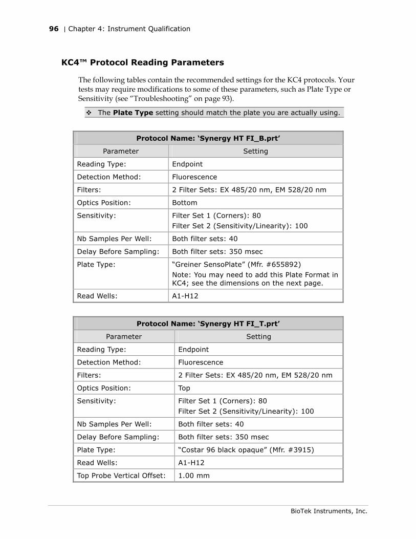
96 | Chapter 4: Instrument Qualification
BioTek Instruments, Inc.
KC4™ Protocol Reading Parameters
The following tables contain the recommended settings for the KC4 protocols. Your tests may require modifications to some of these parameters, such as Plate Type or Sensitivity (see “Troubleshooting” on page 93).
The Plate Type setting should match the plate you are actually using.
Protocol Name: ‘Synergy HT FI_B.prt’
Parameter Setting
Reading Type: Endpoint
Detection Method: Fluorescence
Filters: 2 Filter Sets: EX 485/20 nm, EM 528/20 nm
Optics Position: Bottom
Sensitivity: Filter Set 1 (Corners): 80
Filter Set 2 (Sensitivity/Linearity): 100
Nb Samples Per Well: Both filter sets: 40
Delay Before Sampling: Both filter sets: 350 msec
Plate Type: “Greiner SensoPlate” (Mfr. #655892)
Note: You may need to add this Plate Format in KC4; see the dimensions on the next page.
Read Wells: A1-H12
Protocol Name: ‘Synergy HT FI_T.prt’
Parameter Setting
Reading Type: Endpoint
Detection Method: Fluorescence
Filters: 2 Filter Sets: EX 485/20 nm, EM 528/20 nm
Optics Position: Top
Sensitivity: Filter Set 1 (Corners): 80
Filter Set 2 (Sensitivity/Linearity): 100
Nb Samples Per Well: Both filter sets: 40
Delay Before Sampling: Both filter sets: 350 msec
Plate Type: “Costar 96 black opaque” (Mfr. #3915)
Read Wells: A1-H12
Top Probe Vertical Offset: 1.00 mm
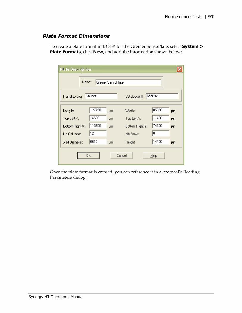
Fluorescence Tests | 97
Synergy HT Operator's Manual
Plate Format Dimensions
To create a plate format in KC4™ for the Greiner SensoPlate, select System > Plate Formats, click New, and add the information shown below:
Once the plate format is created, you can reference it in a protocol’s Reading Parameters dialog.
98 | Chapter 4: Instrument Qualification
BioTek Instruments, Inc.
Fluorescence Tests Using Methylumbelliferone
As an alternative to using Sodium Fluorescein, Methylumbelliferone (“MUB”) can be used to test the top optics for the fluorescence system.
Required Materials
• A new, clean, 96-well solid black plate, such as Corning® Costar Mfr. #3915
• Excitation filter 360/40 nm, Emission filter 460/40 nm
• Deionized or distilled water
• Carbonate-Bicarbonate buffer (“CBB”) capsules (BioTek PN 98158)
• 10 mg vial of Methylumbelliferone (MUB) (BioTek PN 98156)
• 100% methanol (BioTek PN 98161)
• Aluminum foil
• Various beakers, graduated cylinders, and pipettes
• (Optional, but recommended) 0.45 micron filter
• Gen5™ or KC4™ ‘Synergy HT FI_MUB.prt’ protocol described on page 101
Test Solutions
1. Prepare the buffer (CBB) solution:
• (Optional, but recommended) Using a 0.45-micron filter, filter 200 mL of deionized or distilled water.
• Open and dissolve the contents of 2 CBB capsules (do not dissolve the outer gelatin capsule) into 200 mL of the water.
• Stir the solution (preferably using a stir table) until the CBB is completely dissolved.
2. Prepare the MUB stock solution:
• Add 1 mL of 100% methanol to the 10 mg vial of MUB.
• Make sure all of the dye has completely dissolved and is well mixed. This yields a 10 mg/mL stock solution.
• Wrap the solution in aluminum foil to prevent exposure to light.
Fluorescence Tests | 99
Synergy HT Operator's Manual
3. Prepare the dilutions. Label each with “MUB” and the concentration.
Mix this MUB solution: with: to make:
0.5 mL of 10 mg/mL stock solution 4.5 mL of 100%
methanol 1 mg/mL
0.88 mL of 1 mg/mL solution 4.12 mL of CBB 176 μg/mL
0.1 mL of 176 μg/mL solution 9.9 mL of CBB 1.76 μg/mL
0.5 mL of 1.76 μg/mL solution 4.5 mL of CBB 176 ng/mL
1 mL of 176 ng/mL solution 9 mL of CBB 17.6 ng/mL
(100 nM)
Procedure
1. Create the Gen5 or KC4 protocol (see page 101).
2. If you have not already done so, prepare the test solutions (see page 98).
3. Refer to the Pipette Map on page 100 and pipette the solutions into a clean, 96-well solid black plate.
4. Read the plate using the ‘Synergy HT FI_MUB.prt’ protocol.
5. Save and/or print the measurement data.
6. Calculate and analyze the results as described below.
Results Analysis
Sensitivity Test
1. Calculate the Mean and Standard Deviation for the buffer wells (C10-F12).
2. Calculate the Mean for the 17.6 ng/mL (100 nM) MUB solution wells (C1-F1).
3. Calculate the Detection Limit, in ng/mL:
17.6 / ((Mean MUB - Mean Buffer)/(3 * Standard Deviation Buffer))
Optic Probe Detection Limit must
be less than:
Top 3 mm 0.16 ng/mL
Top 1.5 mm 0.31 ng/mL
Linearity Test
1. Calculate the Mean of the four wells for each concentration in columns 1-5.
2. Perform linear regression using these values as inputs:
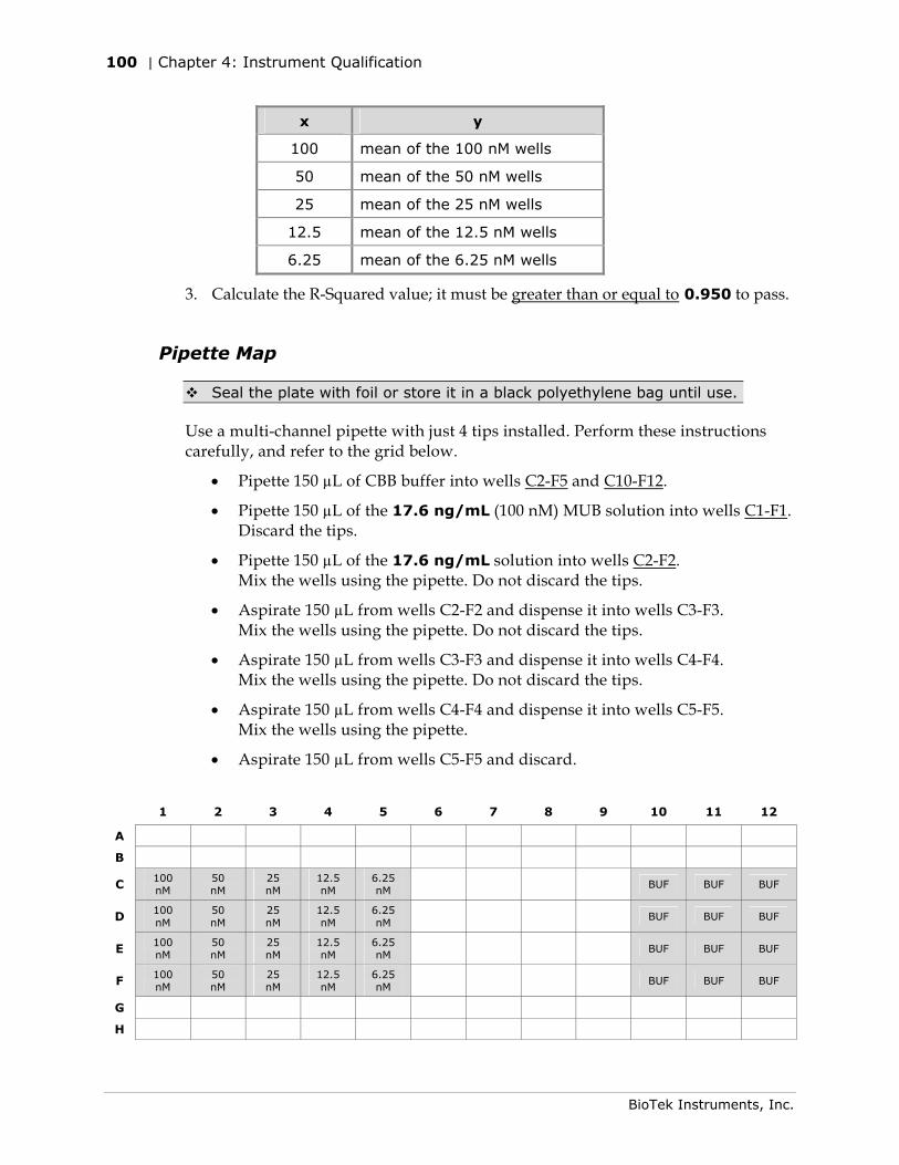
100 | Chapter 4: Instrument Qualification
BioTek Instruments, Inc.
x y
100 mean of the 100 nM wells
50 mean of the 50 nM wells
25 mean of the 25 nM wells
12.5 mean of the 12.5 nM wells
6.25 mean of the 6.25 nM wells
3. Calculate the R-Squared value; it must be greater than or equal to 0.950 to pass.
Pipette Map
Seal the plate with foil or store it in a black polyethylene bag until use.
Use a multi-channel pipette with just 4 tips installed. Perform these instructions carefully, and refer to the grid below.
• Pipette 150 µL of CBB buffer into wells C2-F5 and C10-F12.
• Pipette 150 µL of the 17.6 ng/mL (100 nM) MUB solution into wells C1-F1. Discard the tips.
• Pipette 150 µL of the 17.6 ng/mL solution into wells C2-F2. Mix the wells using the pipette. Do not discard the tips.
• Aspirate 150 µL from wells C2-F2 and dispense it into wells C3-F3. Mix the wells using the pipette. Do not discard the tips.
• Aspirate 150 µL from wells C3-F3 and dispense it into wells C4-F4. Mix the wells using the pipette. Do not discard the tips.
• Aspirate 150 µL from wells C4-F4 and dispense it into wells C5-F5. Mix the wells using the pipette.
• Aspirate 150 µL from wells C5-F5 and discard.
1 2 3 4 5 6 7 8 9 10 11 12
A
B
C 100 nM
50 nM
25 nM
12.5 nM
6.25 nM
BUF BUF BUF
D 100 nM
50 nM
25 nM
12.5 nM
6.25 nM
BUF BUF BUF
E 100 nM
50 nM
25 nM
12.5 nM
6.25 nM
BUF BUF BUF
F 100 nM
50 nM
25 nM
12.5 nM
6.25 nM
BUF BUF BUF
G
H
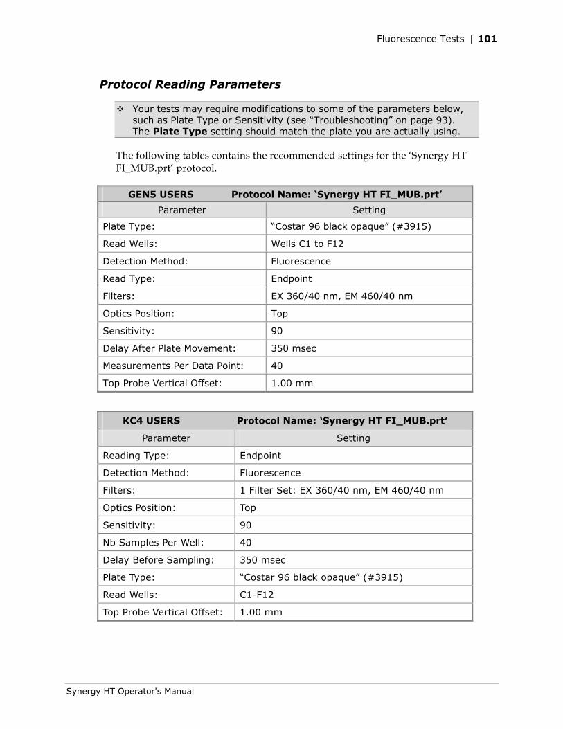
Fluorescence Tests | 101
Synergy HT Operator's Manual
Protocol Reading Parameters
Your tests may require modifications to some of the parameters below, such as Plate Type or Sensitivity (see “Troubleshooting” on page 93). The Plate Type setting should match the plate you are actually using.
The following tables contains the recommended settings for the ‘Synergy HT FI_MUB.prt’ protocol.
GEN5 USERS Protocol Name: ‘Synergy HT FI_MUB.prt’
Parameter Setting
Plate Type: “Costar 96 black opaque” (#3915)
Read Wells: Wells C1 to F12
Detection Method: Fluorescence
Read Type: Endpoint
Filters: EX 360/40 nm, EM 460/40 nm
Optics Position: Top
Sensitivity: 90
Delay After Plate Movement: 350 msec
Measurements Per Data Point: 40
Top Probe Vertical Offset: 1.00 mm
KC4 USERS Protocol Name: ‘Synergy HT FI_MUB.prt’
Parameter Setting
Reading Type: Endpoint
Detection Method: Fluorescence
Filters: 1 Filter Set: EX 360/40 nm, EM 460/40 nm
Optics Position: Top
Sensitivity: 90
Nb Samples Per Well: 40
Delay Before Sampling: 350 msec
Plate Type: “Costar 96 black opaque” (#3915)
Read Wells: C1-F12
Top Probe Vertical Offset: 1.00 mm
102 | Chapter 4: Instrument Qualification
BioTek Instruments, Inc.
Dispense Module Tests
This section applies to Synergy™ HT models with injectors only.
BioTek Instruments, Inc. has developed a set of tests that you can perform to ensure that the dispense module performs to specification initially and over time. We recommend that you perform these tests before first use (e.g., during the Initial OQ), and then every three months.
• The Accuracy Test is a measure of the mean volume per well for multiple dispenses. The actual weight of the dispensed fluid is compared to the expected weight and must be within a certain percentage to pass. Pass/Fail criteria depends on the per-well volume dispensed: 2.0% for 80 µL, 5.0% for 20 µL, and 20.0% for 5 µL. It is assumed that one gram is equal to one milliliter.
The test uses a single green dye test solution and one 96-well microplate (per injector) to test the three different volumes. The balance is tared with the empty plate, and then the 80 µL dispense is performed for columns 1–4. The fluid is weighed and the balance is tared again (with the plate on the balance). This process is repeated for the 20 µL and 5 µL dispenses. It is assumed that the solutions used are at room temperature. A precision balance (3 place) is used to weigh the plate.
• The Precision Test is a measure of the variation among volumes dispensed to multiple wells. For each volume dispensed (80 µL, 20 µL, and 5 µL) to four columns, the %CV (coefficient of variation) of 32 absorbance readings is calculated. Pass/Fail criteria depends on the per-well volume dispensed: 2.0% for 80 µL, 7.0% for 20 µL, and 10.0% for 5 µL. The plate is read in an absorbance reader at 405/750 nm for columns 1–4 and at 630/750 nm for columns 5–12.
The two tests are performed simultaneously and use the same plate. Data reduction can be performed automatically or manually, depending on the test setup.
Dispense Module Tests | 103
Synergy HT Operator's Manual
Required Materials
• Absorbance reader with 405, 630, and 750 nm filters. The reader must have an accuracy specification of ± 1.0% ± 0.010 OD or better and a repeatability specification of ± 1.0% ± 0.005 OD or better.
Note: The Synergy HT reader may be used if it has passed the Absorbance Plate Test and the Absorbance Liquid Tests described earlier in this chapter.
• Shaker (if the absorbance reader does not support shaking)
• Precision balance with capacity of 100 g minimum and readability of 0.001 g
• 50–200 μl hand pipette and disposable tips
• Deionized water
• Supply bottles
• 250 mL beaker
• New 96-well, flat-bottom microplates
• BioTek’s Green Test Dye Solution (PN 7773003) undiluted, or one of the alternate test solutions provided on the next page
• 100 mL graduated cylinder and 10 mL pipettes (if not using BioTek’s Green Test Dye Solution)
• Gen5™ or KC4™ software installed on the host PC
• Calculation worksheet on the last page of this chapter
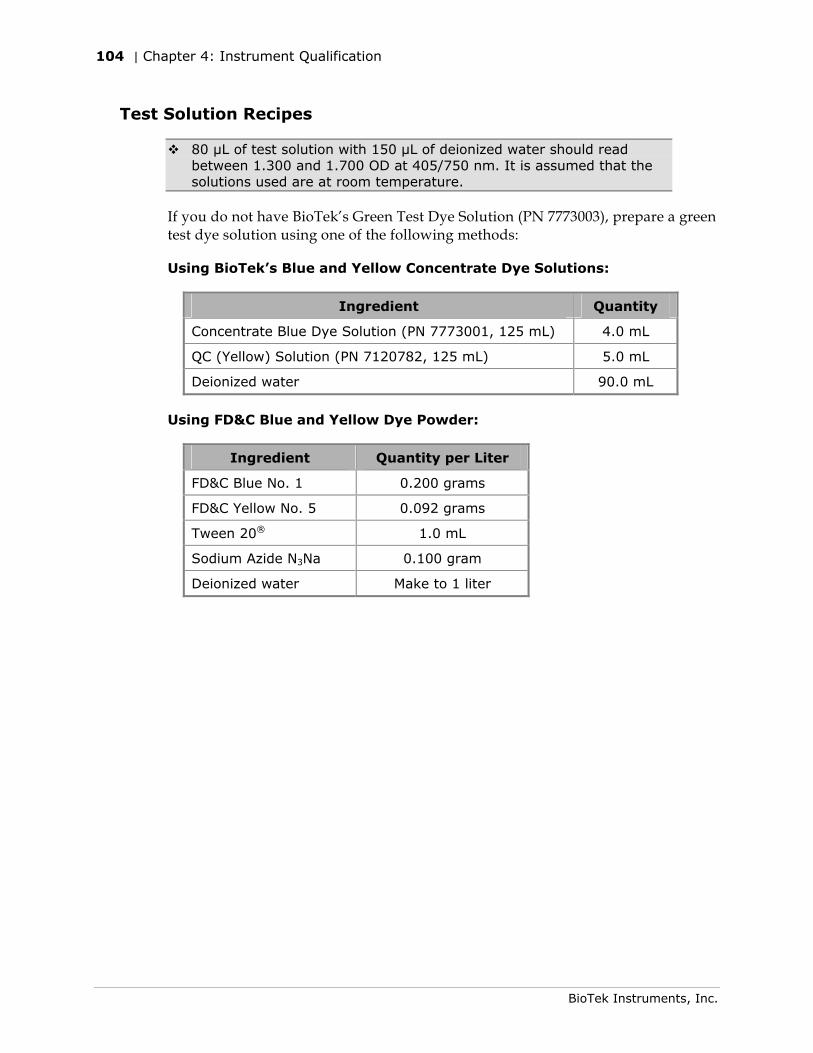
104 | Chapter 4: Instrument Qualification
BioTek Instruments, Inc.
Test Solution Recipes
80 µL of test solution with 150 µL of deionized water should read between 1.300 and 1.700 OD at 405/750 nm. It is assumed that the solutions used are at room temperature.
If you do not have BioTek’s Green Test Dye Solution (PN 7773003), prepare a green test dye solution using one of the following methods:
Using BioTek’s Blue and Yellow Concentrate Dye Solutions:
Ingredient Quantity
Concentrate Blue Dye Solution (PN 7773001, 125 mL) 4.0 mL
QC (Yellow) Solution (PN 7120782, 125 mL) 5.0 mL
Deionized water 90.0 mL
Using FD&C Blue and Yellow Dye Powder:
Ingredient Quantity per Liter
FD&C Blue No. 1 0.200 grams
FD&C Yellow No. 5 0.092 grams
Tween 20® 1.0 mL
Sodium Azide N3Na 0.100 gram
Deionized water Make to 1 liter
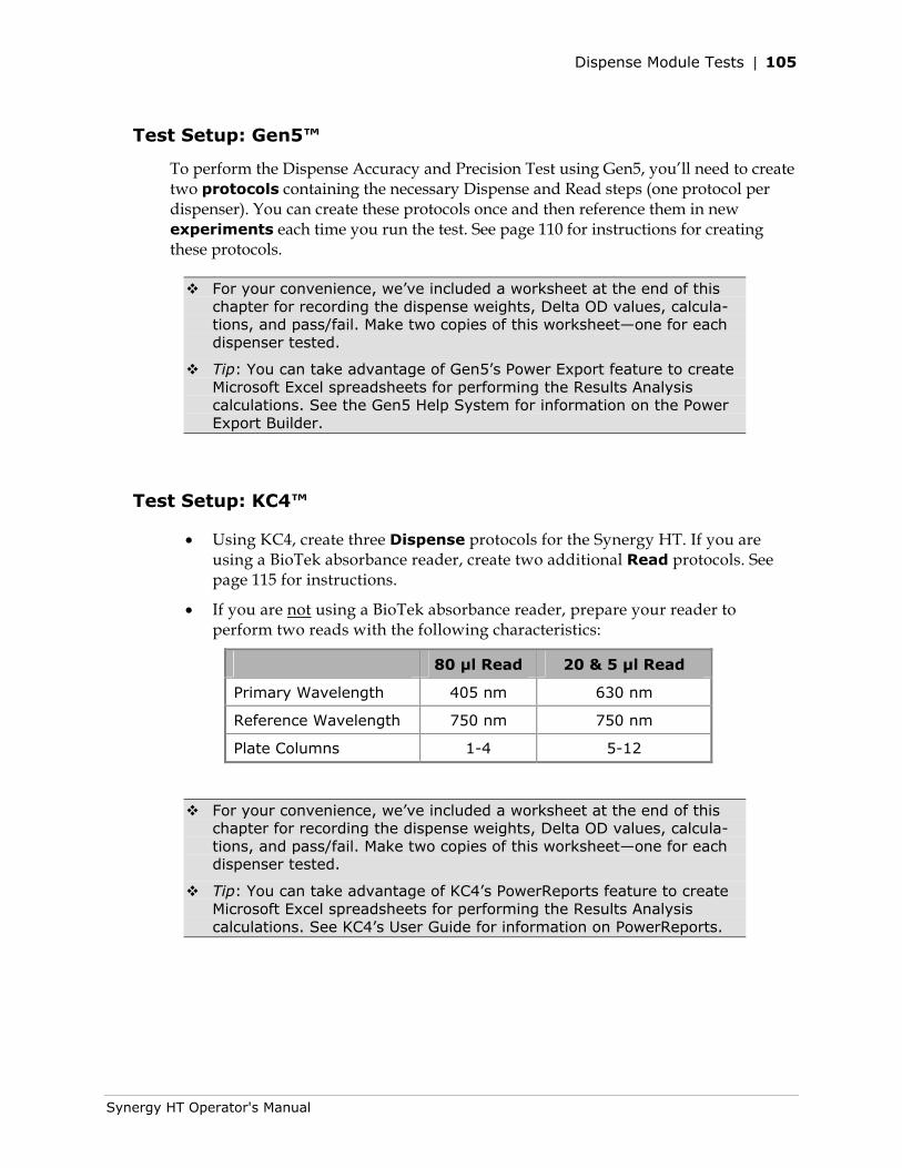
Dispense Module Tests | 105
Synergy HT Operator's Manual
Test Setup: Gen5™
To perform the Dispense Accuracy and Precision Test using Gen5, you’ll need to create two protocols containing the necessary Dispense and Read steps (one protocol per dispenser). You can create these protocols once and then reference them in new experiments each time you run the test. See page 110 for instructions for creating these protocols.
For your convenience, we’ve included a worksheet at the end of this chapter for recording the dispense weights, Delta OD values, calcula-tions, and pass/fail. Make two copies of this worksheet—one for each dispenser tested.
Tip: You can take advantage of Gen5’s Power Export feature to create Microsoft Excel spreadsheets for performing the Results Analysis calculations. See the Gen5 Help System for information on the Power Export Builder.
Test Setup: KC4™
• Using KC4, create three Dispense protocols for the Synergy HT. If you are using a BioTek absorbance reader, create two additional Read protocols. See page 115 for instructions.
• If you are not using a BioTek absorbance reader, prepare your reader to perform two reads with the following characteristics:
80 μl Read 20 & 5 μl Read
Primary Wavelength 405 nm 630 nm
Reference Wavelength 750 nm 750 nm
Plate Columns 1-4 5-12
For your convenience, we’ve included a worksheet at the end of this chapter for recording the dispense weights, Delta OD values, calcula-tions, and pass/fail. Make two copies of this worksheet—one for each dispenser tested.
Tip: You can take advantage of KC4’s PowerReports feature to create Microsoft Excel spreadsheets for performing the Results Analysis calculations. See KC4’s User Guide for information on PowerReports.
106 | Chapter 4: Instrument Qualification
BioTek Instruments, Inc.
Test Procedure: Gen5™
1. Prime both dispensers with deionized or distilled water.
• Ensure that the tip priming trough (BioTek PN 7082118) is installed in the microplate carrier.
• Place a clean priming plate (BioTek PN 7132158 or 7092135) on the carrier.
• Fill a supply bottle with deionized or distilled water and insert the inlet tube.
• In Gen5, select System > Reader Control. If prompted, select the reader under test.
• Click the Dispenser tab. Select Dispenser 1 or 2. If the ‘Initialized’ status is “No” click Initialize.
• Enter a prime Volume of 4000 µL and click Prime.
• When finished remove the priming plate, empty it, and put it back on the carrier.
2. Remove the inlet tubes from the supply bottles. Prime both dispensers with the Volume set to 2000 µL. This prevents the water from diluting the dye.
3. Fill a beaker with at least 20 mL of the green dye solution. Prime both dispensers with 2000 µL of the solution. When finished, remove the priming plate from the carrier.
4. Create a new experiment based on the Synergy HT Dispense 1.prt file described on page 110.
5. Place a new 96-well microplate on the balance and tare the balance.
6. Place the plate on the microplate carrier.
Important: Gen5 will provide prompts and instructions for processing the plates; follow the steps carefully. When each dispense step is finished, you will weigh the plate, record the weight, tare the balance with the plate on it, and then place the plate back on the carrier for the next step.
7. Select Plate|Read and click READ. Gen5 will prompt you to empty the tip priming trough.
8. When ready, click OK at the Load Plate dialog to begin the experiment. Follow the prompts displayed on the screen; the sequence is as follows:
• Dispense 80 µL/well to columns 1–4.
• Remove the plate and weigh it. Record the weight and tare the balance.
• Place the plate on the carrier, dispense 20 µL/well to columns 5–8.
• Remove the plate and weigh it. Record the weight and tare the balance.
• Place the plate on the carrier, dispense 5 µL/well to columns 9–12.
Dispense Module Tests | 107
Synergy HT Operator's Manual
• Remove the plate and weigh it. Record the weight.
• Manually pipette 150 µL of deionized or distilled water into all 12 columns, on top of the green test dye solution.
• Place the plate on the carrier for a 15-second shake, the ’80 µL’ read at 405/750 nm, and the ’20 and 5 µL’ read at 630/750 nm.
9. When processing is complete, select File|Save As and save the experiment using an identifying file name.
10. Repeat steps 4–9 using the Synergy HT Dispenser 2.prt protocol.
11. See page 109 for instructions for analyzing the results.
12. When all tests are complete, prime both dispensers with at least 5000 µL of deionized or distilled water, to flush out the green dye solution.
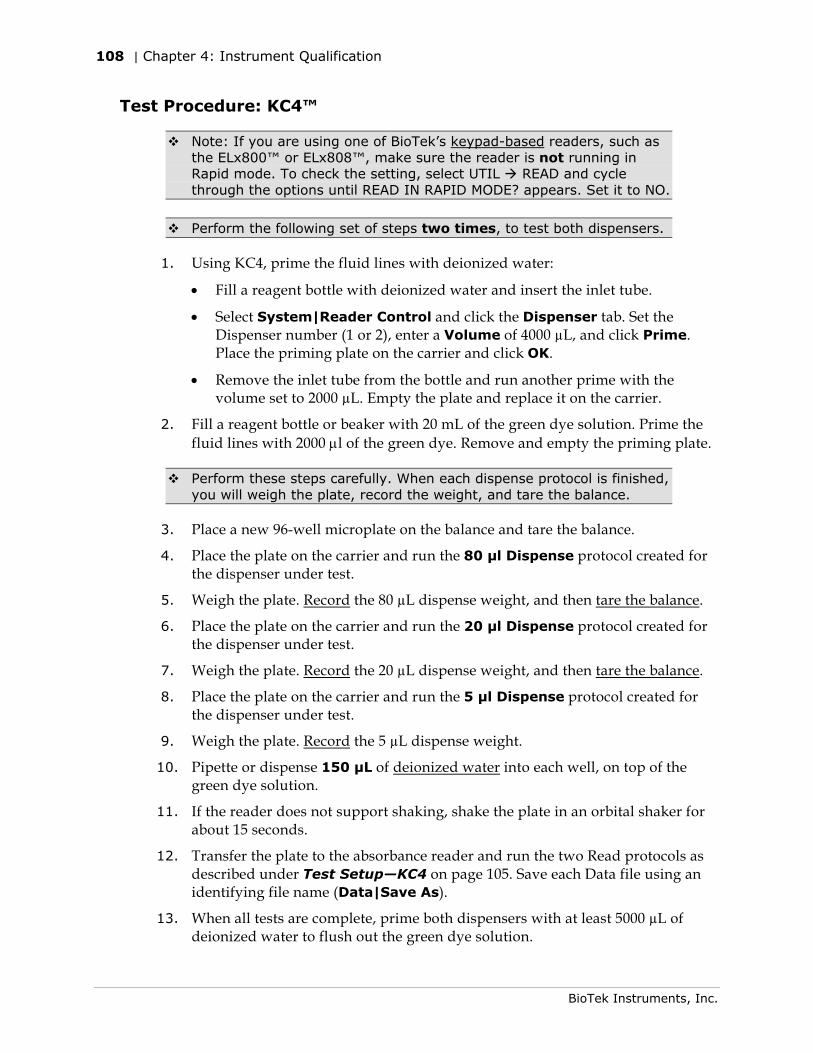
108 | Chapter 4: Instrument Qualification
BioTek Instruments, Inc.
Test Procedure: KC4™
Note: If you are using one of BioTek’s keypad-based readers, such as the ELx800™ or ELx808™, make sure the reader is not running in Rapid mode. To check the setting, select UTIL READ and cycle through the options until READ IN RAPID MODE? appears. Set it to NO.
Perform the following set of steps two times, to test both dispensers.
1. Using KC4, prime the fluid lines with deionized water:
• Fill a reagent bottle with deionized water and insert the inlet tube.
• Select System|Reader Control and click the Dispenser tab. Set the Dispenser number (1 or 2), enter a Volume of 4000 µL, and click Prime. Place the priming plate on the carrier and click OK.
• Remove the inlet tube from the bottle and run another prime with the volume set to 2000 µL. Empty the plate and replace it on the carrier.
2. Fill a reagent bottle or beaker with 20 mL of the green dye solution. Prime the fluid lines with 2000 μl of the green dye. Remove and empty the priming plate.
Perform these steps carefully. When each dispense protocol is finished, you will weigh the plate, record the weight, and tare the balance.
3. Place a new 96-well microplate on the balance and tare the balance.
4. Place the plate on the carrier and run the 80 μl Dispense protocol created for the dispenser under test.
5. Weigh the plate. Record the 80 µL dispense weight, and then tare the balance.
6. Place the plate on the carrier and run the 20 μl Dispense protocol created for the dispenser under test.
7. Weigh the plate. Record the 20 µL dispense weight, and then tare the balance.
8. Place the plate on the carrier and run the 5 μl Dispense protocol created for the dispenser under test.
9. Weigh the plate. Record the 5 µL dispense weight.
10. Pipette or dispense 150 µL of deionized water into each well, on top of the green dye solution.
11. If the reader does not support shaking, shake the plate in an orbital shaker for about 15 seconds.
12. Transfer the plate to the absorbance reader and run the two Read protocols as described under Test Setup—KC4 on page 105. Save each Data file using an identifying file name (Data|Save As).
13. When all tests are complete, prime both dispensers with at least 5000 µL of deionized water to flush out the green dye solution.
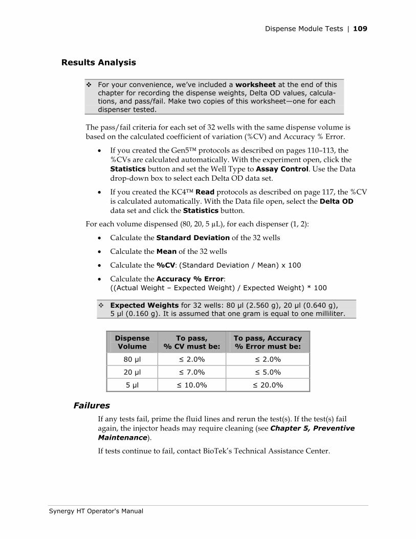
Dispense Module Tests | 109
Synergy HT Operator's Manual
Results Analysis
For your convenience, we’ve included a worksheet at the end of this chapter for recording the dispense weights, Delta OD values, calcula-tions, and pass/fail. Make two copies of this worksheet—one for each dispenser tested.
The pass/fail criteria for each set of 32 wells with the same dispense volume is based on the calculated coefficient of variation (%CV) and Accuracy % Error.
• If you created the Gen5™ protocols as described on pages 110–113, the %CVs are calculated automatically. With the experiment open, click the Statistics button and set the Well Type to Assay Control. Use the Data drop-down box to select each Delta OD data set.
• If you created the KC4™ Read protocols as described on page 117, the %CV is calculated automatically. With the Data file open, select the Delta OD data set and click the Statistics button.
For each volume dispensed (80, 20, 5 µL), for each dispenser (1, 2):
• Calculate the Standard Deviation of the 32 wells
• Calculate the Mean of the 32 wells
• Calculate the %CV: (Standard Deviation / Mean) x 100
• Calculate the Accuracy % Error: ((Actual Weight – Expected Weight) / Expected Weight) * 100
Expected Weights for 32 wells: 80 μl (2.560 g), 20 μl (0.640 g), 5 μl (0.160 g). It is assumed that one gram is equal to one milliliter.
Dispense Volume
To pass, % CV must be:
To pass, Accuracy % Error must be:
80 μl ≤ 2.0% ≤ 2.0%
20 μl ≤ 7.0% ≤ 5.0%
5 μl ≤ 10.0% ≤ 20.0%
Failures
If any tests fail, prime the fluid lines and rerun the test(s). If the test(s) fail again, the injector heads may require cleaning (see Chapter 5, Preventive Maintenance).
If tests continue to fail, contact BioTek’s Technical Assistance Center.
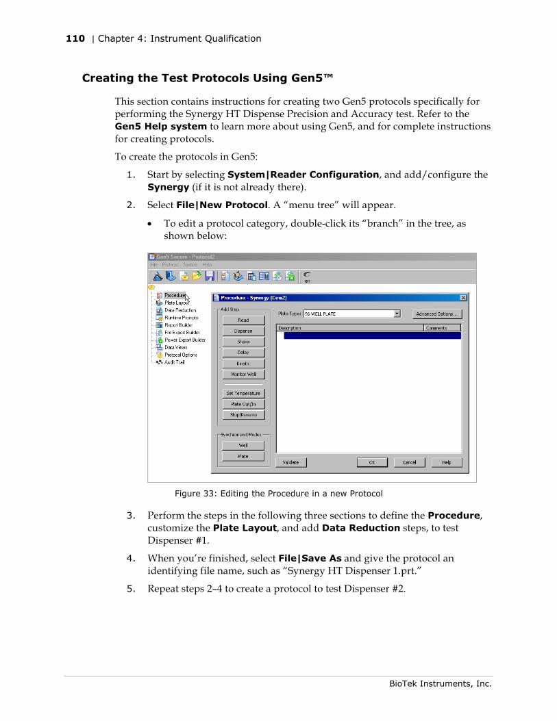
110 | Chapter 4: Instrument Qualification
BioTek Instruments, Inc.
Creating the Test Protocols Using Gen5™
This section contains instructions for creating two Gen5 protocols specifically for performing the Synergy HT Dispense Precision and Accuracy test. Refer to the Gen5 Help system to learn more about using Gen5, and for complete instructions for creating protocols.
To create the protocols in Gen5:
1. Start by selecting System|Reader Configuration, and add/configure the Synergy (if it is not already there).
2. Select File|New Protocol. A “menu tree” will appear.
• To edit a protocol category, double-click its “branch” in the tree, as shown below:
Figure 33: Editing the Procedure in a new Protocol
3. Perform the steps in the following three sections to define the Procedure, customize the Plate Layout, and add Data Reduction steps, to test Dispenser #1.
4. When you’re finished, select File|Save As and give the protocol an identifying file name, such as “Synergy HT Dispenser 1.prt.”
5. Repeat steps 2–4 to create a protocol to test Dispenser #2.
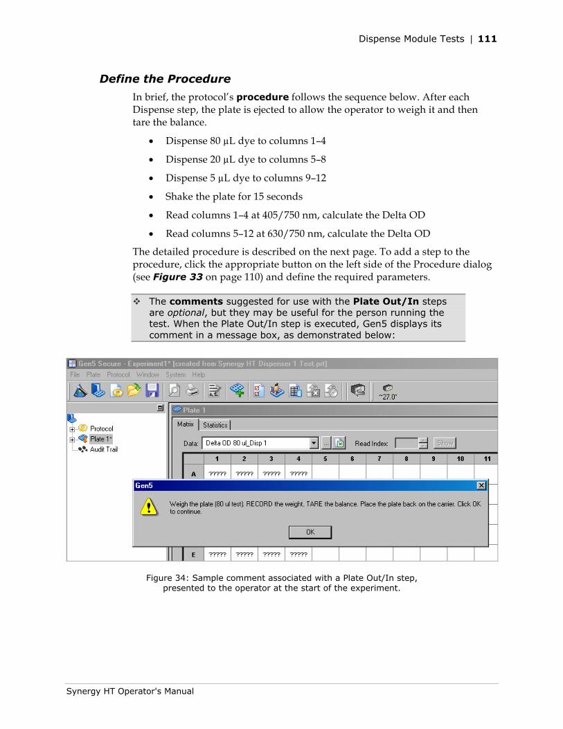
Dispense Module Tests | 111
Synergy HT Operator's Manual
Define the Procedure
In brief, the protocol’s procedure follows the sequence below. After each Dispense step, the plate is ejected to allow the operator to weigh it and then tare the balance.
• Dispense 80 µL dye to columns 1–4
• Dispense 20 µL dye to columns 5–8
• Dispense 5 µL dye to columns 9–12
• Shake the plate for 15 seconds
• Read columns 1–4 at 405/750 nm, calculate the Delta OD
• Read columns 5–12 at 630/750 nm, calculate the Delta OD
The detailed procedure is described on the next page. To add a step to the procedure, click the appropriate button on the left side of the Procedure dialog (see Figure 33 on page 110) and define the required parameters.
The comments suggested for use with the Plate Out/In steps are optional, but they may be useful for the person running the test. When the Plate Out/In step is executed, Gen5 displays its comment in a message box, as demonstrated below:
Figure 34: Sample comment associated with a Plate Out/In step, presented to the operator at the start of the experiment.
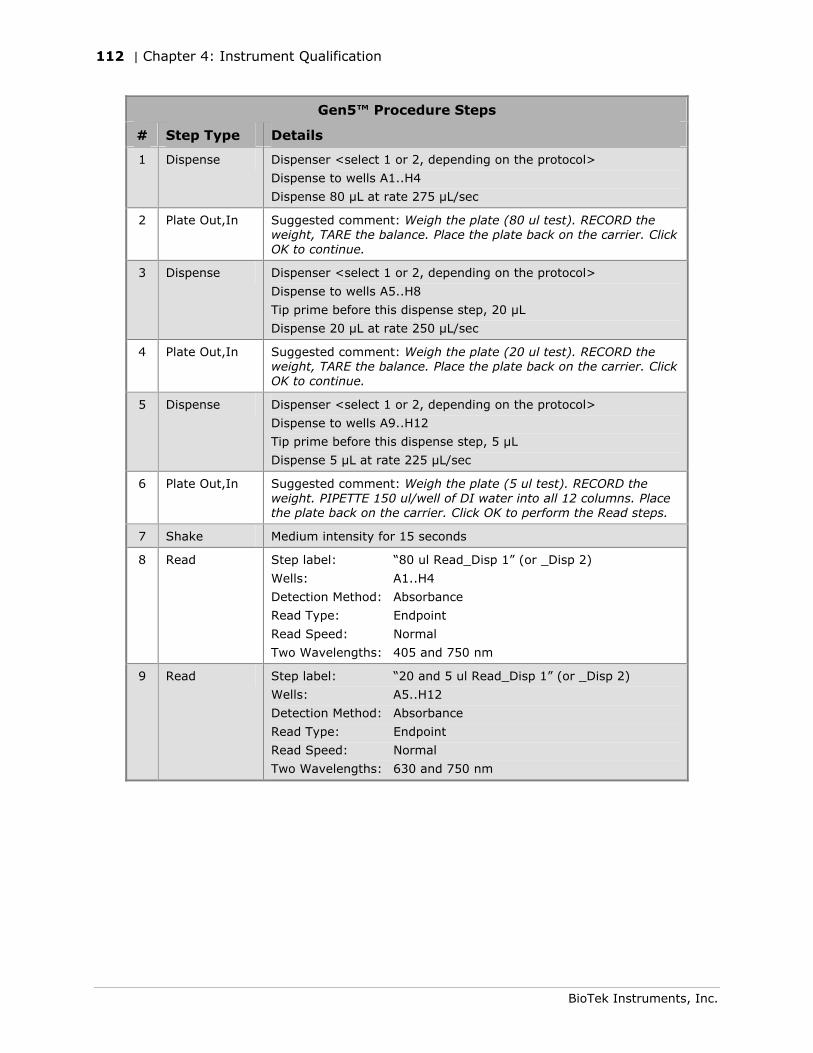
112 | Chapter 4: Instrument Qualification
BioTek Instruments, Inc.
Gen5™ Procedure Steps
# Step Type Details
1 Dispense Dispenser <select 1 or 2, depending on the protocol>
Dispense to wells A1..H4
Dispense 80 µL at rate 275 µL/sec
2 Plate Out,In Suggested comment: Weigh the plate (80 ul test). RECORD the weight, TARE the balance. Place the plate back on the carrier. Click OK to continue.
3 Dispense Dispenser <select 1 or 2, depending on the protocol>
Dispense to wells A5..H8
Tip prime before this dispense step, 20 µL
Dispense 20 µL at rate 250 µL/sec
4 Plate Out,In Suggested comment: Weigh the plate (20 ul test). RECORD the weight, TARE the balance. Place the plate back on the carrier. Click OK to continue.
5 Dispense Dispenser <select 1 or 2, depending on the protocol>
Dispense to wells A9..H12
Tip prime before this dispense step, 5 µL
Dispense 5 µL at rate 225 µL/sec
6 Plate Out,In Suggested comment: Weigh the plate (5 ul test). RECORD the weight. PIPETTE 150 ul/well of DI water into all 12 columns. Place the plate back on the carrier. Click OK to perform the Read steps.
7 Shake Medium intensity for 15 seconds
8 Read Step label: “80 ul Read_Disp 1” (or _Disp 2)
Wells: A1..H4
Detection Method: Absorbance
Read Type: Endpoint
Read Speed: Normal
Two Wavelengths: 405 and 750 nm
9 Read Step label: “20 and 5 ul Read_Disp 1” (or _Disp 2)
Wells: A5..H12
Detection Method: Absorbance
Read Type: Endpoint
Read Speed: Normal
Two Wavelengths: 630 and 750 nm
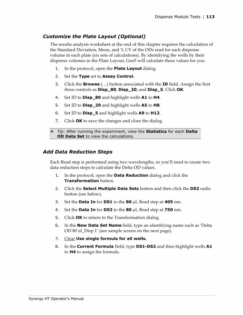
Dispense Module Tests | 113
Synergy HT Operator's Manual
Customize the Plate Layout (Optional)
The results analysis worksheet at the end of this chapter requires the calculation of the Standard Deviation, Mean, and % CV of the ODs read for each dispense volume in each plate (six sets of calculations). By identifying the wells by their dispense volumes in the Plate Layout, Gen5 will calculate these values for you.
1. In the protocol, open the Plate Layout dialog.
2. Set the Type set to Assay Control.
3. Click the Browse (…) button associated with the ID field. Assign the first three controls as Disp_80, Disp_20, and Disp_5. Click OK.
4. Set ID to Disp_80 and highlight wells A1 to H4.
5. Set ID to Disp_20 and highlight wells A5 to H8.
6. Set ID to Disp_5 and highlight wells A9 to H12.
7. Click OK to save the changes and close the dialog.
Tip: After running the experiment, view the Statistics for each Delta OD Data Set to view the calculations.
Add Data Reduction Steps
Each Read step is performed using two wavelengths, so you’ll need to create two data reduction steps to calculate the Delta OD values.
1. In the protocol, open the Data Reduction dialog and click the Transformation button.
2. Click the Select Multiple Data Sets button and then click the DS2 radio button (see below).
3. Set the Data In for DS1 to the 80 µL Read step at 405 nm.
4. Set the Data In for DS2 to the 80 µL Read step at 750 nm.
5. Click OK to return to the Transformation dialog.
6. In the New Data Set Name field, type an identifying name such as ‘Delta OD 80 ul_Disp 1’ (see sample screen on the next page).
7. Clear Use single formula for all wells.
8. In the Current Formula field, type DS1-DS2 and then highlight wells A1 to H4 to assign the formula.
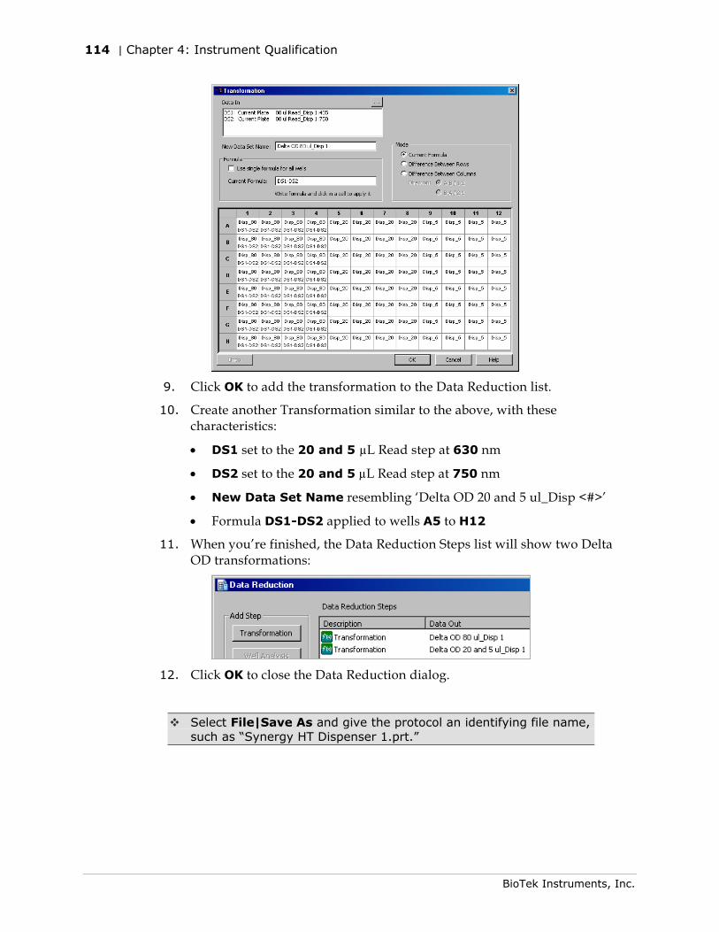
114 | Chapter 4: Instrument Qualification
BioTek Instruments, Inc.
9. Click OK to add the transformation to the Data Reduction list.
10. Create another Transformation similar to the above, with these characteristics:
• DS1 set to the 20 and 5 µL Read step at 630 nm
• DS2 set to the 20 and 5 µL Read step at 750 nm
• New Data Set Name resembling ‘Delta OD 20 and 5 ul_Disp <#>’
• Formula DS1-DS2 applied to wells A5 to H12
11. When you’re finished, the Data Reduction Steps list will show two Delta OD transformations:
12. Click OK to close the Data Reduction dialog.
Select File|Save As and give the protocol an identifying file name, such as “Synergy HT Dispenser 1.prt.”
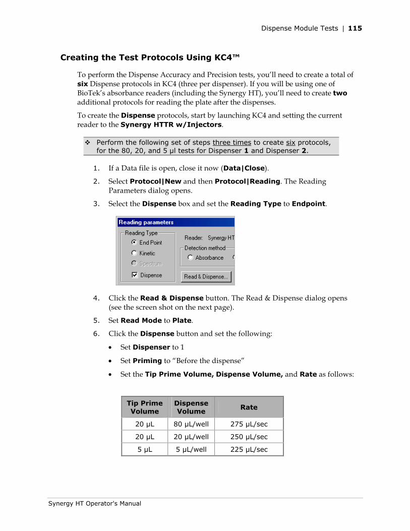
Dispense Module Tests | 115
Synergy HT Operator's Manual
Creating the Test Protocols Using KC4™
To perform the Dispense Accuracy and Precision tests, you’ll need to create a total of six Dispense protocols in KC4 (three per dispenser). If you will be using one of BioTek’s absorbance readers (including the Synergy HT), you’ll need to create two additional protocols for reading the plate after the dispenses.
To create the Dispense protocols, start by launching KC4 and setting the current reader to the Synergy HTTR w/Injectors.
Perform the following set of steps three times to create six protocols, for the 80, 20, and 5 μl tests for Dispenser 1 and Dispenser 2.
1. If a Data file is open, close it now (Data|Close).
2. Select Protocol|New and then Protocol|Reading. The Reading Parameters dialog opens.
3. Select the Dispense box and set the Reading Type to Endpoint.
4. Click the Read & Dispense button. The Read & Dispense dialog opens (see the screen shot on the next page).
5. Set Read Mode to Plate.
6. Click the Dispense button and set the following:
• Set Dispenser to 1
• Set Priming to “Before the dispense”
• Set the Tip Prime Volume, Dispense Volume, and Rate as follows:
Tip Prime Volume
Dispense Volume
Rate
20 µL 80 µL/well 275 µL/sec
20 µL 20 µL/well 250 µL/sec
5 µL 5 µL/well 225 µL/sec
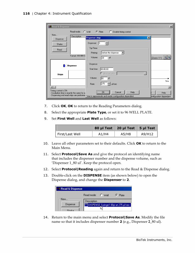
116 | Chapter 4: Instrument Qualification
BioTek Instruments, Inc.
7. Click OK, OK to return to the Reading Parameters dialog.
8. Select the appropriate Plate Type, or set it to 96 WELL PLATE.
9. Set First Well and Last Well as follows:
80 μl Test 20 μl Test 5 μl Test
First/Last Well A1/H4 A5/H8 A9/H12
10. Leave all other parameters set to their defaults. Click OK to return to the Main Menu.
11. Select Protocol|Save As and give the protocol an identifying name that includes the dispenser number and the dispense volume, such as ‘Dispenser 1_80 ul’. Keep the protocol open.
12. Select Protocol|Reading again and return to the Read & Dispense dialog.
13. Double-click on the DISPENSE item (as shown below) to open the Dispense dialog, and change the Dispenser to 2.
14. Return to the main menu and select Protocol|Save As. Modify the file name so that it includes dispenser number 2 (e.g., Dispenser 2_80 ul).
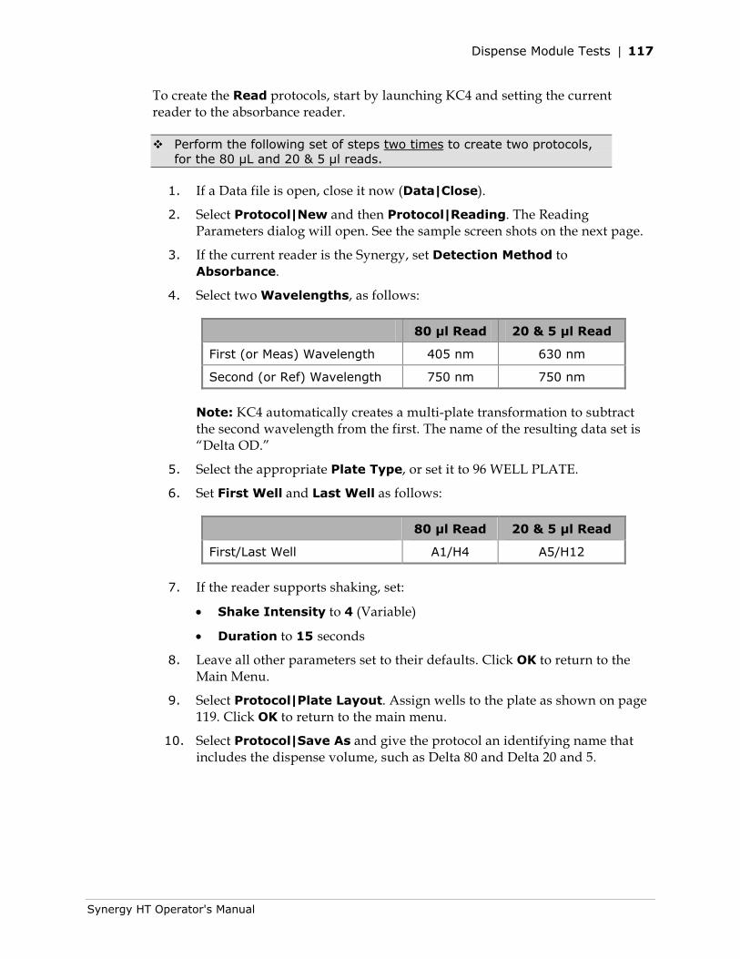
Dispense Module Tests | 117
Synergy HT Operator's Manual
To create the Read protocols, start by launching KC4 and setting the current reader to the absorbance reader.
Perform the following set of steps two times to create two protocols, for the 80 µL and 20 & 5 μl reads.
1. If a Data file is open, close it now (Data|Close).
2. Select Protocol|New and then Protocol|Reading. The Reading Parameters dialog will open. See the sample screen shots on the next page.
3. If the current reader is the Synergy, set Detection Method to Absorbance.
4. Select two Wavelengths, as follows:
80 μl Read 20 & 5 μl Read
First (or Meas) Wavelength 405 nm 630 nm
Second (or Ref) Wavelength 750 nm 750 nm
Note: KC4 automatically creates a multi-plate transformation to subtract the second wavelength from the first. The name of the resulting data set is “Delta OD.”
5. Select the appropriate Plate Type, or set it to 96 WELL PLATE.
6. Set First Well and Last Well as follows:
80 μl Read 20 & 5 μl Read
First/Last Well A1/H4 A5/H12
7. If the reader supports shaking, set:
• Shake Intensity to 4 (Variable)
• Duration to 15 seconds
8. Leave all other parameters set to their defaults. Click OK to return to the Main Menu.
9. Select Protocol|Plate Layout. Assign wells to the plate as shown on page 119. Click OK to return to the main menu.
10. Select Protocol|Save As and give the protocol an identifying name that includes the dispense volume, such as Delta 80 and Delta 20 and 5.
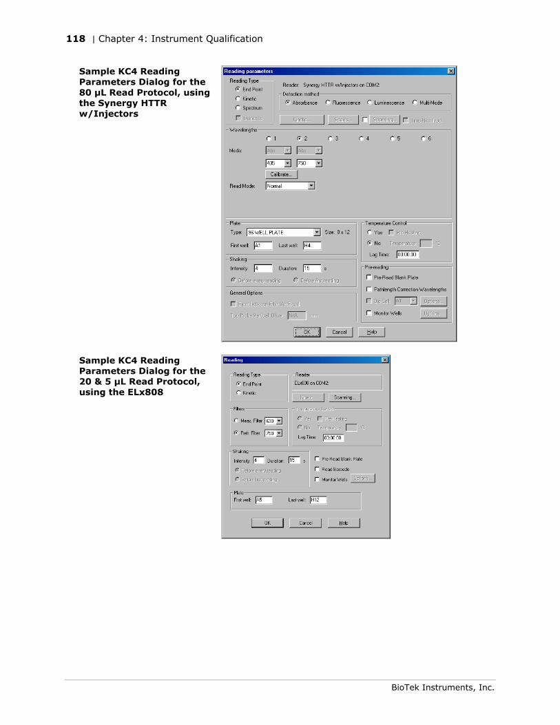
118 | Chapter 4: Instrument Qualification
BioTek Instruments, Inc.
Sample KC4 Reading Parameters Dialog for the 80 µL Read Protocol, using the Synergy HTTR w/Injectors
Sample KC4 Reading Parameters Dialog for the 20 & 5 µL Read Protocol, using the ELx808
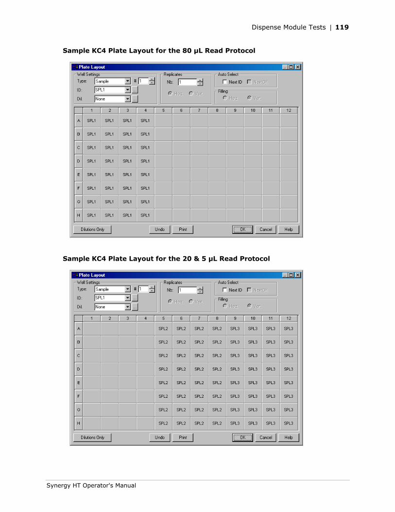
Dispense Module Tests | 119
Synergy HT Operator's Manual
Sample KC4 Plate Layout for the 80 µL Read Protocol
Sample KC4 Plate Layout for the 20 & 5 µL Read Protocol

120 | Chapter 4: Instrument Qualification
BioTek Instruments, Inc.
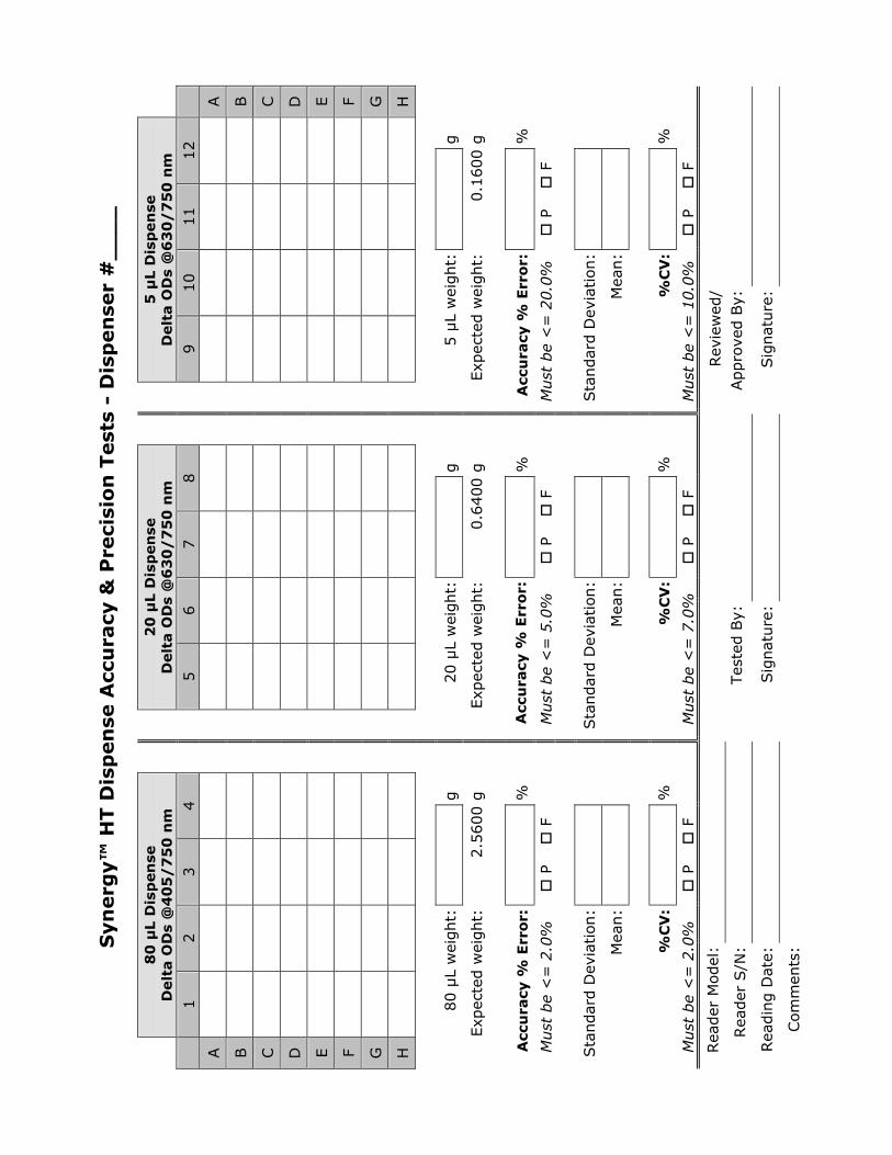
Syn
erg
y™
HT D
isp
en
se A
ccu
racy
& P
reci
sio
n T
est
s -
Dis
pen
ser
#_
__
_
8
0 µ
L D
isp
en
se
Delt
a O
Ds
@4
05
/7
50
nm
2
0 µ
L D
isp
en
se
Delt
a O
Ds
@6
30
/7
50
nm
5
µL D
isp
en
se
Delt
a O
Ds
@6
30
/7
50
nm
1
2
3
4
5
6
7
8
9
10
11
12
A
A
B
B
C
C
D
D
E
E
F
F
G
G
H
H
80 µ
L w
eight:
g
20 µ
L w
eight:
g
5 µ
L w
eight:
g
Exp
ecte
d w
eight:
2.5
600 g
Exp
ecte
d w
eight:
0.6
400 g
Exp
ecte
d w
eight:
0.1
600 g
Acc
ura
cy %
Err
or:
%
Acc
ura
cy %
Err
or:
%
Acc
ura
cy %
Err
or:
%
Must
be
<=
2.0
%
P
F
M
ust
be
<=
5.0
%
P
F
M
ust
be
<=
20.0
%
P
F
Sta
ndar
d D
evia
tion:
Sta
ndar
d D
evia
tion:
Sta
ndar
d D
evia
tion:
Mea
n:
Mea
n:
Mea
n:
%C
V:
%
%
CV
: %
%C
V:
%
Must
be
<=
2.0
%
P
F
M
ust
be
<=
7.0
%
P
F
M
ust
be
<=
10.0
%
P
F
Rea
der
Model
:
Rea
der
S/N
:
Tes
ted B
y:
Rev
iew
ed/
Appro
ved B
y:
Rea
din
g D
ate:
Sig
nat
ure
:
Sig
nat
ure
:
Com
men
ts:

122 | Chapter 4: Instrument Qualification
BioTek Instruments, Inc.
Chapter 5
Preventive Maintenance
This chapter provides step-by-step instructions for maintaining the Synergy™ HT and external dispense module (if used) in top condition, to ensure that they continue to perform to specification.
Recommended Maintenance Schedule ....................................124 Overview.......................................................................124 Dispense Module.............................................................124 Schedule .......................................................................124
Warnings & Precautions .......................................................126 Cleaning Exposed Surfaces ...................................................127 Inspecting/Cleaning Excitation and Emission Filters..................128 Flushing/Purging the Fluid Path .............................................129 Running a Dispense Protocol (Optional) ..................................130 Emptying/Cleaning the Tip Priming Trough..............................132 Cleaning the Priming Plate....................................................132 Cleaning the Internal Components .........................................133
Required Materials ..........................................................134 Removing the Reader’s Shroud .........................................135 Removing the Internal Tubes and Injector Heads ................137 Cleaning the Internal Tubes and Injector Heads ..................140 Cleaning the Optical Probes..............................................141 Cleaning the Reader’s Internal Surface ..............................149 Reassembling the Components .........................................150 Performance Check .........................................................151
124 | Chapter 5: Preventive Maintenance
BioTek Instruments, Inc.
Recommended Maintenance Schedule
Overview
A general Preventive Maintenance (PM) regimen for all Synergy™ HT models includes periodically cleaning all exposed surfaces and inspecting/cleaning the Excitation and Emission filters. For models with the external dispense module, additional tasks include flushing/purging the fluid path and cleaning the tip prime trough, priming plate, supply bottles, internal dispense tubing, and injector heads.
Dispense Module
To keep the dispense module and injectors in top condition, flush and purge the fluid lines with deionized (DI) water every day or upon completion of an assay run, whichever is more frequent. Some reagents may crystallize or harden after use, clogging the fluid passageways. Flushing the tubing at the end of each day, letting the DI water soak them overnight, and then purging the lines at the beginning of each day ensures optimal performance of the dispense system. Perform a visual inspection of the dispensing accuracy before conducting an assay that requires dispense to verify instrument performance.
It is important to keep the dispensing lines scrupulously clean at all times. Take special care when using molecules active at very low concentrations (e.g., enzymes, inhibitors). Remove any residual reagent in the dispensing lines using a suitable cleaning solution (review the reagent’s package insert for specific recommendations).
A daily cleaning regimen is the best way to ensure accurate performance and a long-life for your instrument and dispense module. BioTek also recommends flushing the module with DI water before conducting the decontamination procedure described in Appendix A.
Schedule
The following charts recommend Preventive Maintenance tasks and the frequency with which each task should be performed.
It is important to note that the risk and performance factors associated with your assays may require that some or all of the procedures be performed more frequently than presented in the schedule.
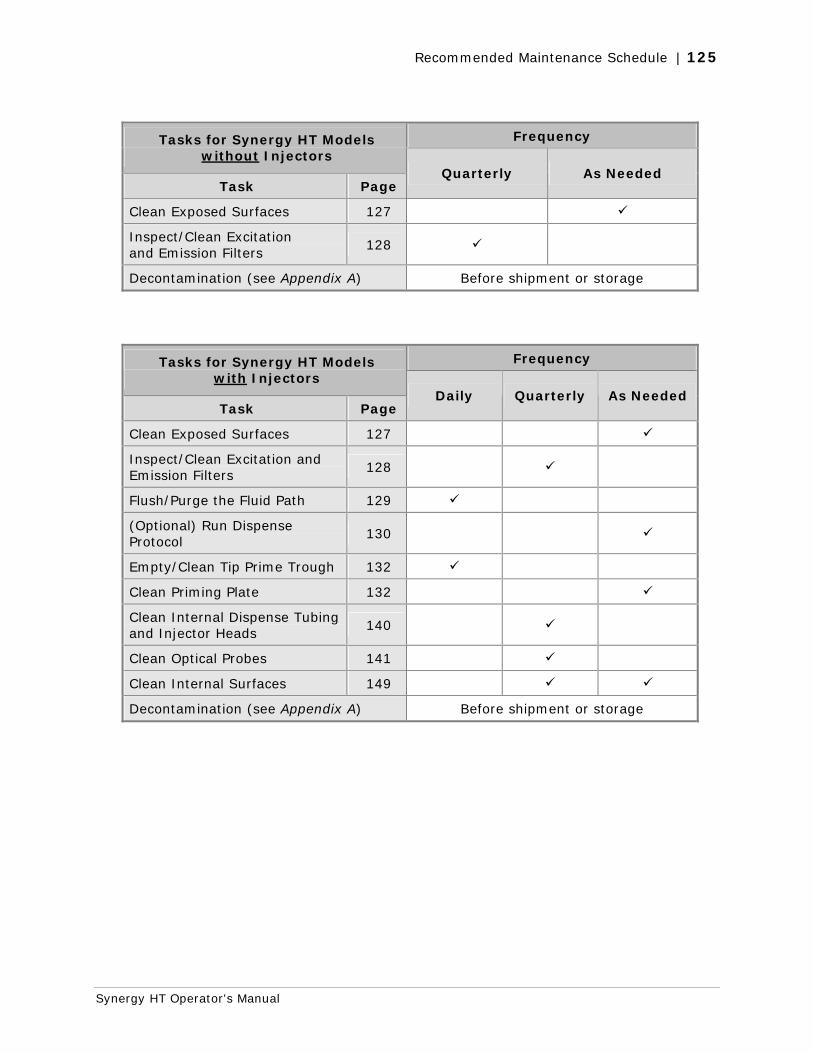
Recommended Maintenance Schedule | 125
Synergy HT Operator's Manual
Frequency Tasks for Synergy HT Models without Injectors
Task Page Quarterly As Needed
Clean Exposed Surfaces 127
Inspect/Clean Excitation and Emission Filters
128
Decontamination (see Appendix A) Before shipment or storage
Frequency Tasks for Synergy HT Models with Injectors
Task Page Daily Quarterly As Needed
Clean Exposed Surfaces 127
Inspect/Clean Excitation and Emission Filters
128
Flush/Purge the Fluid Path 129
(Optional) Run Dispense Protocol
130
Empty/Clean Tip Prime Trough 132
Clean Priming Plate 132
Clean Internal Dispense Tubing and Injector Heads
140
Clean Optical Probes 141
Clean Internal Surfaces 149
Decontamination (see Appendix A) Before shipment or storage
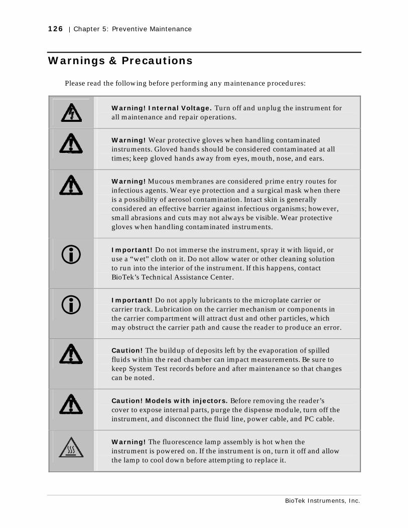
126 | Chapter 5: Preventive Maintenance
BioTek Instruments, Inc.
Warnings & Precautions
Please read the following before performing any maintenance procedures:
Warning! Internal Voltage. Turn off and unplug the instrument for all maintenance and repair operations.
Warning! Wear protective gloves when handling contaminated instruments. Gloved hands should be considered contaminated at all times; keep gloved hands away from eyes, mouth, nose, and ears.
Warning! Mucous membranes are considered prime entry routes for infectious agents. Wear eye protection and a surgical mask when there is a possibility of aerosol contamination. Intact skin is generally considered an effective barrier against infectious organisms; however, small abrasions and cuts may not always be visible. Wear protective gloves when handling contaminated instruments.
Important! Do not immerse the instrument, spray it with liquid, or use a “wet” cloth on it. Do not allow water or other cleaning solution to run into the interior of the instrument. If this happens, contact BioTek’s Technical Assistance Center.
Important! Do not apply lubricants to the microplate carrier or carrier track. Lubrication on the carrier mechanism or components in the carrier compartment will attract dust and other particles, which may obstruct the carrier path and cause the reader to produce an error.
Caution! The buildup of deposits left by the evaporation of spilled fluids within the read chamber can impact measurements. Be sure to keep System Test records before and after maintenance so that changes can be noted.
Caution! Models with injectors. Before removing the reader’s cover to expose internal parts, purge the dispense module, turn off the instrument, and disconnect the fluid line, power cable, and PC cable.
Warning! The fluorescence lamp assembly is hot when the instrument is powered on. If the instrument is on, turn it off and allow the lamp to cool down before attempting to replace it.
Cleaning Exposed Surfaces | 127
Synergy HT Operator's Manual
Cleaning Exposed Surfaces
Important! Turn off and unplug the instrument for all cleaning operations.
Important! Do not immerse the instrument, spray it with liquid, or use a “wet” cloth. Do not allow the cleaning solution to run into the interior of the instrument. If this happens, contact BioTek’s Service Department.
Exposed surfaces may be cleaned (not decontaminated) with a cloth moistened (not soaked) with water or water and a mild detergent. You’ll need:
• Deionized or distilled water
• Clean, lint-free cotton cloths
• Mild detergent (optional)
To clean the exposed surfaces:
1. Turn off and unplug the instrument.
2. Moisten a clean cotton cloth with water, or with water and mild detergent. Do not soak the cloth.
3. Wipe the plate carrier and all exposed surfaces of the instrument.
4. Wipe all exposed surfaces of the dispense module (if used).
5. If detergent was used, wipe all surfaces with a cloth moistened with water.
6. Use a clean, dry cloth to dry all wet surfaces.
7. Reassemble the instrument as necessary.
Models with injectors: If the Tip Priming Trough overflows, wipe the carrier and the surface beneath the carrier with a dry cotton cloth. If overflow is significant, you may have to remove the shroud of the instrument to better access the surface beneath the carrier.
See page 135 for instructions on removing the shroud.
See page 149 for instructions for cleaning the surface beneath the carrier.
128 | Chapter 5: Preventive Maintenance
BioTek Instruments, Inc.
Inspecting/Cleaning Excitation and Emission Filters
Laboratory air is used to cool the lamp, and the filters can become dusty as a result. The filters should be inspected and cleaned at least every three months. You’ll need:
• Isopropyl, ethyl, or methyl alcohol
• Lens-cleaning tissue
Do not touch the filters with your bare fingers!
To inspect and clean the Excitation and Emission filters:
1. Turn off and unplug the instrument.
2. Pull down the hinged door on the front of the instrument. Observe the two thumbscrews within the compartment. The left thumbscrew holds the excitation (EX) filter wheel in place; the right secures the emission (EM) filter wheel. Remove each thumbscrew and slide the filter wheel’s supporting metal bracket straight out of the compartment.
Chapter 3, Getting Started contains illustrations for identifying the filter wheels and their unique characteristics. This chapter also contains instructions for replacing filters if necessary.
3. Inspect the glass filters for speckled surfaces or a halo effect. This may indicate deterioration due to moisture exposure over a long period of time.
• If you have any concerns about the quality of the filters, contact your BioTek representative.
4. Clean the filters using lens-cleaning tissue moistened with a small amount of isopropyl, ethyl, or methyl alcohol. Ensure that the filters remain in their current locations.
5. Replace the filter wheel brackets in their respective positions and replace the thumbscrews. Close the hinged door.
Flushing/Purging the Fluid Path | 129
Synergy HT Operator's Manual
Flushing/Purging the Fluid Path
Applies only to Synergy™ HT models with injectors.
At the end of each day that the dispense module is in use, flush the fluid path using Gen5’s or KC4’s priming utility. Leave the fluid to soak overnight or over a weekend, and then purge the fluid before using the instrument again.
Note: This flushing and purging routine is also recommended before disconnecting the outlet tubes from the rear of the reader, and before decontamination to remove any assay residue prior to applying isopropyl alcohol or sodium hypochlorite.
To flush the fluid path:
1. Fill two supply bottles with deionized or distilled water. Insert the supply (inlet) tubes into the bottles.
2. Place the priming plate on the carrier.
3. Gen5: Select System|Reader Control|Synergy(Com<#>).
KC4: Select System|Reader Control.
4. Click the Dispenser tab and select Dispenser 1.
5. Set the Volume to 5000 µL. Keep the default prime Rate.
6. Click Prime to start the process. When the process is complete, carefully remove the priming plate from the carrier and empty it.
7. Repeat the process for Dispenser 2.
Leave the water in the system overnight or until the instrument will be used again. Purge the fluid from the system (see below) and then prime with the dispense reagent before running an assay.
To purge the fluid from the system:
1. Place the inlet tubes in empty supply bottles or a beaker.
2. Gen5: Select System|Reader Control|Synergy(Com<#>).
KC4: Select System|Reader Control.
3. Click the Dispenser tab and select Dispenser 1.
4. Set the Volume to 2000 µL.
5. Click Purge to start the process.
6. When the purge is complete, repeat the process for Dispenser 2.
After purging the system, you may wish to run a quick Dispense protocol to visually verify the dispense accuracy. See the next page for instructions for creating the protocol.
130 | Chapter 5: Preventive Maintenance
BioTek Instruments, Inc.
Running a Dispense Protocol (Optional)
Applies only to Synergy™ HT models with injectors.
After flushing/purging the system (page 129) and before running an assay that requires dispense, take a moment to visually inspect the dispensing accuracy.
Use a DI H2O-Tween solution to check for dispense accuracy following maintenance: e.g., add 1 ml Tween® 20 to 1000 ml of deionized water.
To create the Dispense protocol in Gen5™:
1. Select File|New Protocol and then Protocol|Procedure.
2. Add a Dispense step with the following parameters:
• Select Dispenser 1
• Set Tip Priming to Before this dispense step and Volume to 10 µL.
• Set the Dispense Volume to 100 µL (or an amount to match your assay protocol).
• Select a Rate (adjust the rate to support the dispensing volume).
• Click OK to close the dialog and add the Dispense step to the list.
3. Add another Dispense step with the same parameters, selecting Dispenser 2.
4. Add a quick Read step with the following parameters (Gen5 requires that a Read step follow the Dispense step):
• Define a partial plate read on just one well (e.g., A1)
• Set the Detection Method to Absorbance
• Set the Read Type to Endpoint
• Set the Read Speed to Normal
• Select any wavelength
5. Click OK to close the dialog and add the Read step to the list.
6. Click OK to close the Procedure.
7. Select File|Save As and give the protocol an identifying name, such as “Dispense Observation.”
8. Select File|New Experiment to run the Dispense Observation protocol.
9. Click the Read button and follow the prompts.
Running a Dispense Protocol (Optional) | 131
Synergy HT Operator's Manual
10. When the procedure is complete, visually assess the fluid level in the wells for accuracy. If the well volume appears to be unevenly distributed, clean the internal dispense tubes and injector heads as described in Cleaning Internal Components on page 133.
To create the Dispense protocol in KC4™:
1. If a Data file is open, close it now (Data|Close).
2. Select Protocol|New and then Protocol|Reading.
3. In the Reading parameters dialog:
• Check the Dispense box and set the Reading Type to Endpoint.
• Select a Plate Type of 96 WELL PLATE or select a custom format that exactly matches the plate being used for this test.
• Leave all other parameters set to their default values.
4. Next to the Dispense check box, click the Read & Dispense button.
5. In the Read & Dispense dialog, set Read Mode to Plate.
6. Click the Dispense button. In the Dispense Step dialog:
• Select Dispenser 1
• Set Priming to Before the process and Volume to 5 µL.
• Leave Start Time set to 00:00:00.
• Set the Volume to 100 µL (or an amount to match your assay protocol).
• Select a Rate (adjust the rate to support the dispensing volume).
• Click OK to close the dialog and add the Dispense step to the list.
7. Click OK to close the dialog and return to the Reading parameters dialog.
8. Click OK to save the settings and return to the main menu.
9. Select Protocol|Save As and give the protocol an identifying name, such as “Dispenser 1 Observation.”
10. Repeat these steps to create a protocol for Dispenser 2.
11. Run the two protocols on two different plates. When finished, visually assess the fluid level in the wells for accuracy. If the well volume appears to be unevenly distributed, clean the internal dispense tubes and injector heads as described in Cleaning Internal Components on page 133.
132 | Chapter 5: Preventive Maintenance
BioTek Instruments, Inc.
Emptying/Cleaning the Tip Priming Trough
Applies only to Synergy™ HT models with injectors.
The tip priming trough is a small, removable priming cup located in the left rear of the microplate carrier, used for performing the Tip Prime. The trough holds about 1.5 mL of liquid and must be periodically emptied and cleaned by the user.
To empty/clean the tip prime trough:
1. Extend the microplate carrier and carefully remove the tip priming trough from its pocket in the left rear of the carrier.
2. Wash the trough in hot, soapy water. Use a small brush to clean in the corners.
3. Rinse the trough thoroughly and allow it to dry completely.
4. Replace the trough in the microplate carrier.
When starting a Gen5™ Experiment that includes dispensing, Gen5 will prompt you to empty the tip prime trough. Follow the instructions provided.
When starting a KC4™ Read & Dispense protocol, KC4 may prompt you to empty the tip priming trough. In this case, KC4 will automatically open the System|Reader Control, Dispenser dialog. Empty the trough and then click the Dump Tip Prime Trough(s) button. The Tip Prime Trough value will reset to ‘1500 µl remaining’.
Cleaning the Priming Plate
Applies only to Synergy™ HT models with injectors.
Clean the priming plate regularly to prevent bacteria growth and residue buildup. Wash the plate in hot soapy water, using a small brush to clean in the corners if necessary. Rinse thoroughly and allow it to dry completely.
Cleaning the Internal Components | 133
Synergy HT Operator's Manual
Cleaning the Internal Components
Applies only to Synergy™ HT models with injectors.
The Synergy HT’s internal components that require routine cleaning include:
• Optical probes
• Surface beneath the microplate carrier
• Internal dispense tubes and injector heads
The internal components should be cleaned at least quarterly. In addition, if fluid has spilled inside the instrument and/or if an unusually high background signal has been flagged by the assay controls (typically blanks or negative controls), the optical probes and the surface beneath the microplate carrier should be cleaned.
The procedures in this section should be performed in succession. Start with Removing the Reader’s Shroud and execute the procedures that meet your needs, in the order in which they are presented. Finish with Reassembling the Components.
We recommend running a System Test (via Gen5™ or KC4™) before and after performing these cleaning procedures. This will verify that all systems are functioning properly and allow you to compare results before and after maintenance.
Caution! The buildup of deposits left by the evaporation of spilled fluids within the read chamber can impact performance of both the fluorescence and absorbance functions. Be sure to perform a System Test before and after maintenance so that any changes in performance can be noted.
134 | Chapter 5: Preventive Maintenance
BioTek Instruments, Inc.
Required Materials
Warning! Always wear protective gloves and safety glasses when performing cleaning/maintenance procedures.
For all tasks:
• Protective gloves
• Safety glasses
For removing the shroud and some of the internal components:
• Phillips-head screwdriver
• 1/8” Allen wrench
• 3/32” Allen wrench
For cleaning the internal dispense tubes and injector heads, as well as for wiping the surface under the plate carrier:
• Mild detergent
• Clean, lint-free cotton cloths
• Deionized or distilled water
• Stylus (stored in a plastic cylinder affixed to the rear of the dispense module or reader) (PN 2872304)
For cleaning the optical probes:
• Clean cotton swabs
• Isopropyl alcohol
• Lens-cleaning tissue
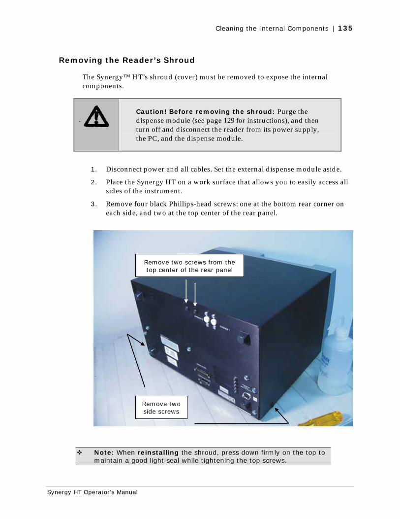
Cleaning the Internal Components | 135
Synergy HT Operator's Manual
Removing the Reader’s Shroud
The Synergy™ HT’s shroud (cover) must be removed to expose the internal components.
Caution! Before removing the shroud: Purge the dispense module (see page 129 for instructions), and then turn off and disconnect the reader from its power supply, the PC, and the dispense module.
1. Disconnect power and all cables. Set the external dispense module aside.
2. Place the Synergy HT on a work surface that allows you to easily access all sides of the instrument.
3. Remove four black Phillips-head screws: one at the bottom rear corner on each side, and two at the top center of the rear panel.
Note: When reinstalling the shroud, press down firmly on the top to maintain a good light seal while tightening the top screws.
Remove two side screws
Remove two screws from the top center of the rear panel
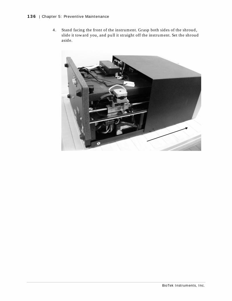
136 | Chapter 5: Preventive Maintenance
BioTek Instruments, Inc.
4. Stand facing the front of the instrument. Grasp both sides of the shroud, slide it toward you, and pull it straight off the instrument. Set the shroud aside.
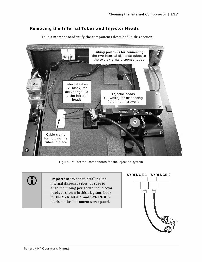
Cleaning the Internal Components | 137
Synergy HT Operator's Manual
Removing the Internal Tubes and Injector Heads
Take a moment to identify the components described in this section:
Figure 37: Internal components for the injection system
Important! When reinstalling the internal dispense tubes, be sure to align the tubing ports with the injector heads as shown in this diagram. Look for the SYRINGE 1 and SYRINGE 2 labels on the instrument’s rear panel.
SYRINGE 1 SYRINGE 2
Injector heads (2, white) for dispensing
fluid into microwells
Internal tubes (2, black) for
delivering fluid to the injector
heads
Tubing ports (2) for connecting the two internal dispense tubes to the two external dispense tubes
Cable clamp for holding the tubes in place
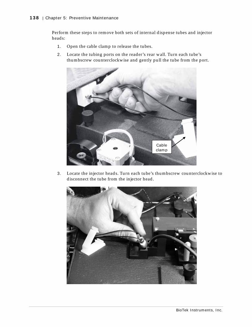
138 | Chapter 5: Preventive Maintenance
BioTek Instruments, Inc.
Perform these steps to remove both sets of internal dispense tubes and injector heads:
1. Open the cable clamp to release the tubes.
2. Locate the tubing ports on the reader’s rear wall. Turn each tube’s thumbscrew counterclockwise and gently pull the tube from the port.
3. Locate the injector heads. Turn each tube’s thumbscrew counterclockwise to disconnect the tube from the injector head.
Cable clamp
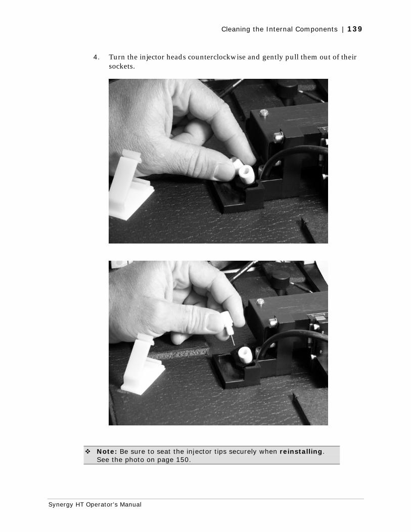
Cleaning the Internal Components | 139
Synergy HT Operator's Manual
4. Turn the injector heads counterclockwise and gently pull them out of their sockets.
Note: Be sure to seat the injector tips securely when reinstalling. See the photo on page 150.
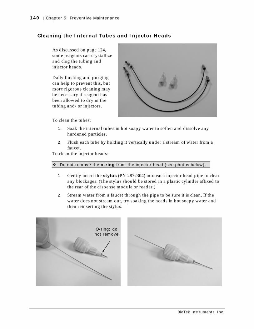
140 | Chapter 5: Preventive Maintenance
BioTek Instruments, Inc.
Cleaning the Internal Tubes and Injector Heads
As discussed on page 124, some reagents can crystallize and clog the tubing and injector heads.
Daily flushing and purging can help to prevent this, but more rigorous cleaning may be necessary if reagent has been allowed to dry in the tubing and/or injectors.
To clean the tubes:
1. Soak the internal tubes in hot soapy water to soften and dissolve any hardened particles.
2. Flush each tube by holding it vertically under a stream of water from a faucet.
To clean the injector heads:
Do not remove the o-ring from the injector head (see photos below).
1. Gently insert the stylus (PN 2872304) into each injector head pipe to clear any blockages. (The stylus should be stored in a plastic cylinder affixed to the rear of the dispense module or reader.)
2. Stream water from a faucet through the pipe to be sure it is clean. If the water does not stream out, try soaking the heads in hot soapy water and then reinserting the stylus.
O-ring; do not remove
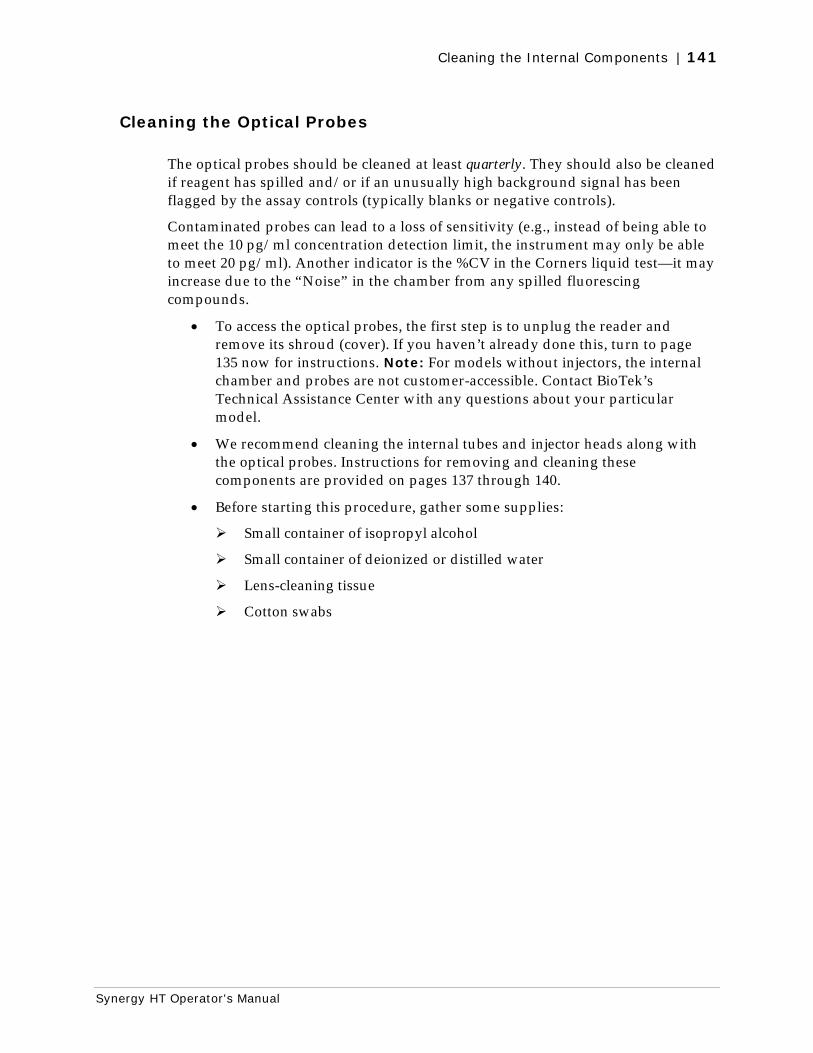
Cleaning the Internal Components | 141
Synergy HT Operator's Manual
Cleaning the Optical Probes
The optical probes should be cleaned at least quarterly. They should also be cleaned if reagent has spilled and/or if an unusually high background signal has been flagged by the assay controls (typically blanks or negative controls).
Contaminated probes can lead to a loss of sensitivity (e.g., instead of being able to meet the 10 pg/ml concentration detection limit, the instrument may only be able to meet 20 pg/ml). Another indicator is the %CV in the Corners liquid test—it may increase due to the “Noise” in the chamber from any spilled fluorescing compounds.
• To access the optical probes, the first step is to unplug the reader and remove its shroud (cover). If you haven’t already done this, turn to page 135 now for instructions. Note: For models without injectors, the internal chamber and probes are not customer-accessible. Contact BioTek’s Technical Assistance Center with any questions about your particular model.
• We recommend cleaning the internal tubes and injector heads along with the optical probes. Instructions for removing and cleaning these components are provided on pages 137 through 140.
• Before starting this procedure, gather some supplies:
Small container of isopropyl alcohol
Small container of deionized or distilled water
Lens-cleaning tissue
Cotton swabs
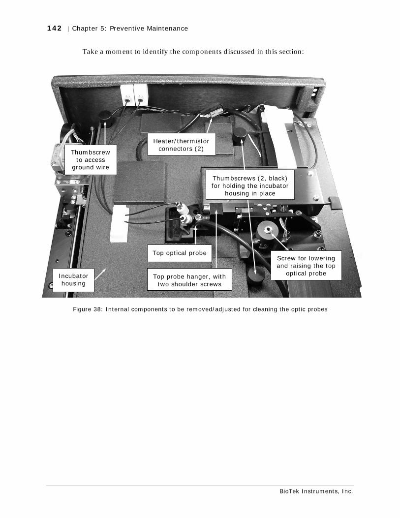
142 | Chapter 5: Preventive Maintenance
BioTek Instruments, Inc.
Take a moment to identify the components discussed in this section:
Figure 38: Internal components to be removed/adjusted for cleaning the optic probes
Heater/thermistor connectors (2)
Top optical probe
Thumbscrew to access
ground wire
Incubator housing
Screw for lowering and raising the top
optical probe
Thumbscrews (2, black) for holding the incubator
housing in place
Top probe hanger, with two shoulder screws
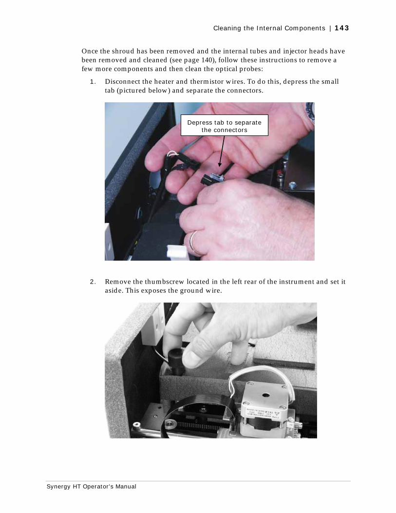
Cleaning the Internal Components | 143
Synergy HT Operator's Manual
Once the shroud has been removed and the internal tubes and injector heads have been removed and cleaned (see page 140), follow these instructions to remove a few more components and then clean the optical probes:
1. Disconnect the heater and thermistor wires. To do this, depress the small tab (pictured below) and separate the connectors.
2. Remove the thumbscrew located in the left rear of the instrument and set it aside. This exposes the ground wire.
Depress tab to separate the connectors
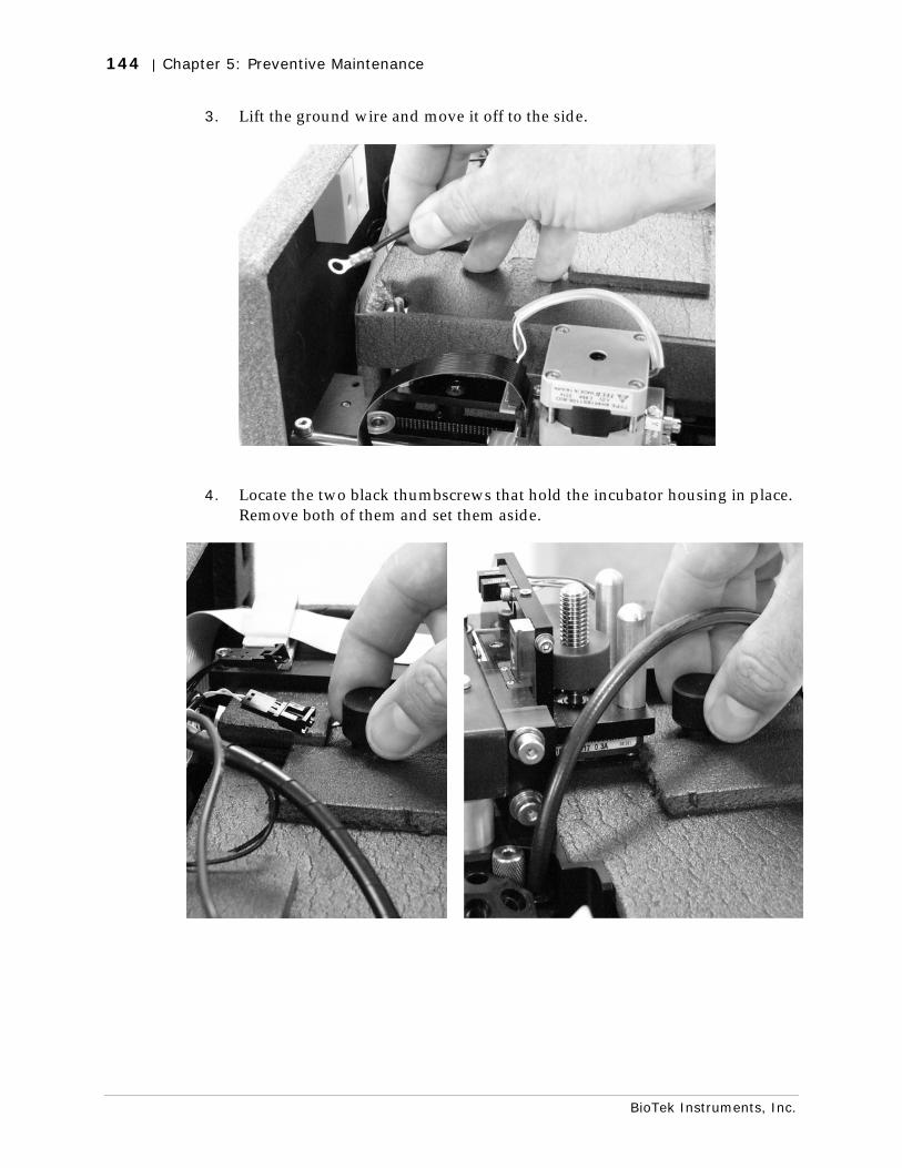
144 | Chapter 5: Preventive Maintenance
BioTek Instruments, Inc.
3. Lift the ground wire and move it off to the side.
4. Locate the two black thumbscrews that hold the incubator housing in place. Remove both of them and set them aside.
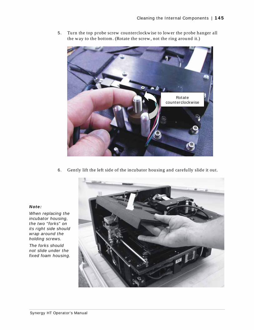
Cleaning the Internal Components | 145
Synergy HT Operator's Manual
5. Turn the top probe screw counterclockwise to lower the probe hanger all the way to the bottom. (Rotate the screw, not the ring around it.)
6. Gently lift the left side of the incubator housing and carefully slide it out.
Rotate counterclockwise
Note:
When replacing the incubator housing, the two “forks” on its right side should wrap around the holding screws.
The forks should not slide under the fixed foam housing.
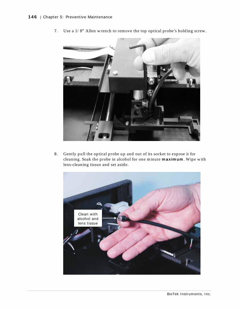
146 | Chapter 5: Preventive Maintenance
BioTek Instruments, Inc.
7. Use a 1/8” Allen wrench to remove the top optical probe’s holding screw.
8. Gently pull the optical probe up and out of its socket to expose it for cleaning. Soak the probe in alcohol for one minute maximum. Wipe with lens-cleaning tissue and set aside.
Clean with alcohol and lens tissue
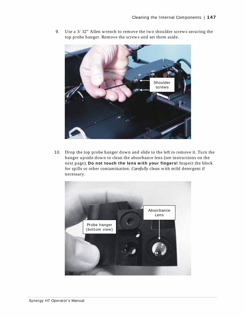
Cleaning the Internal Components | 147
Synergy HT Operator's Manual
9. Use a 3/32” Allen wrench to remove the two shoulder screws securing the top probe hanger. Remove the screws and set them aside.
10. Drop the top probe hanger down and slide to the left to remove it. Turn the hanger upside down to clean the absorbance lens (see instructions on the next page). Do not touch the lens with your fingers! Inspect the block for spills or other contamination. Carefully clean with mild detergent if necessary.
Shoulder screws
Absorbance Lens
Probe hanger (bottom view)
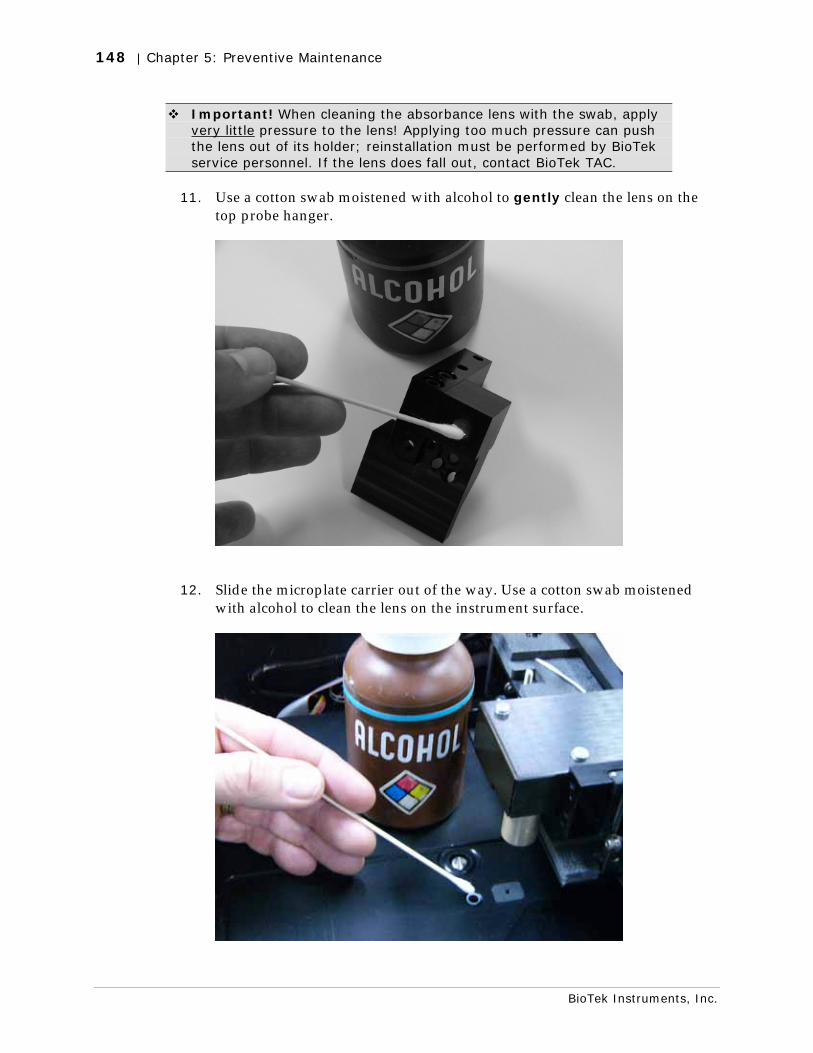
148 | Chapter 5: Preventive Maintenance
BioTek Instruments, Inc.
Important! When cleaning the absorbance lens with the swab, apply very little pressure to the lens! Applying too much pressure can push the lens out of its holder; reinstallation must be performed by BioTek service personnel. If the lens does fall out, contact BioTek TAC.
11. Use a cotton swab moistened with alcohol to gently clean the lens on the top probe hanger.
12. Slide the microplate carrier out of the way. Use a cotton swab moistened with alcohol to clean the lens on the instrument surface.
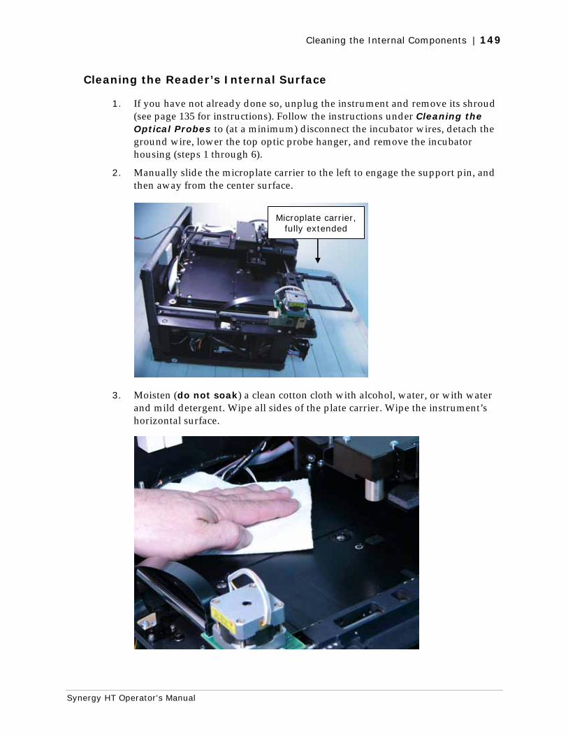
Cleaning the Internal Components | 149
Synergy HT Operator's Manual
Cleaning the Reader’s Internal Surface
1. If you have not already done so, unplug the instrument and remove its shroud (see page 135 for instructions). Follow the instructions under Cleaning the Optical Probes to (at a minimum) disconnect the incubator wires, detach the ground wire, lower the top optic probe hanger, and remove the incubator housing (steps 1 through 6).
2. Manually slide the microplate carrier to the left to engage the support pin, and then away from the center surface.
3. Moisten (do not soak) a clean cotton cloth with alcohol, water, or with water and mild detergent. Wipe all sides of the plate carrier. Wipe the instrument’s horizontal surface.
Microplate carrier, fully extended
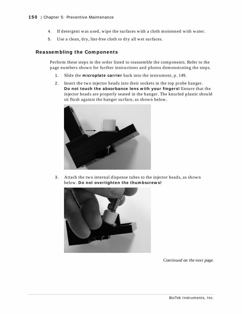
150 | Chapter 5: Preventive Maintenance
BioTek Instruments, Inc.
4. If detergent was used, wipe the surfaces with a cloth moistened with water.
5. Use a clean, dry, lint-free cloth to dry all wet surfaces.
Reassembling the Components
Perform these steps in the order listed to reassemble the components. Refer to the page numbers shown for further instructions and photos demonstrating the steps.
1. Slide the microplate carrier back into the instrument, p. 149.
2. Insert the two injector heads into their sockets in the top probe hanger. Do not touch the absorbance lens with your fingers! Ensure that the injector heads are properly seated in the hanger. The knurled plastic should sit flush against the hanger surface, as shown below.
3. Attach the two internal dispense tubes to the injector heads, as shown below. Do not overtighten the thumbscrews!
Continued on the next page.
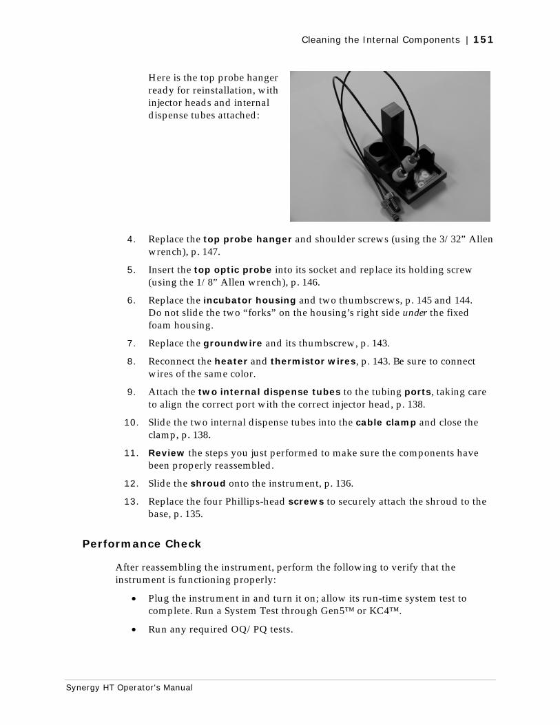
Cleaning the Internal Components | 151
Synergy HT Operator's Manual
Here is the top probe hanger ready for reinstallation, with injector heads and internal dispense tubes attached:
4. Replace the top probe hanger and shoulder screws (using the 3/32” Allen wrench), p. 147.
5. Insert the top optic probe into its socket and replace its holding screw (using the 1/8” Allen wrench), p. 146.
6. Replace the incubator housing and two thumbscrews, p. 145 and 144. Do not slide the two “forks” on the housing’s right side under the fixed foam housing.
7. Replace the groundwire and its thumbscrew, p. 143.
8. Reconnect the heater and thermistor wires, p. 143. Be sure to connect wires of the same color.
9. Attach the two internal dispense tubes to the tubing ports, taking care to align the correct port with the correct injector head, p. 138.
10. Slide the two internal dispense tubes into the cable clamp and close the clamp, p. 138.
11. Review the steps you just performed to make sure the components have been properly reassembled.
12. Slide the shroud onto the instrument, p. 136.
13. Replace the four Phillips-head screws to securely attach the shroud to the base, p. 135.
Performance Check
After reassembling the instrument, perform the following to verify that the instrument is functioning properly:
• Plug the instrument in and turn it on; allow its run-time system test to complete. Run a System Test through Gen5™ or KC4™.
• Run any required OQ/PQ tests.

152 | Chapter 5: Preventive Maintenance
BioTek Instruments, Inc.
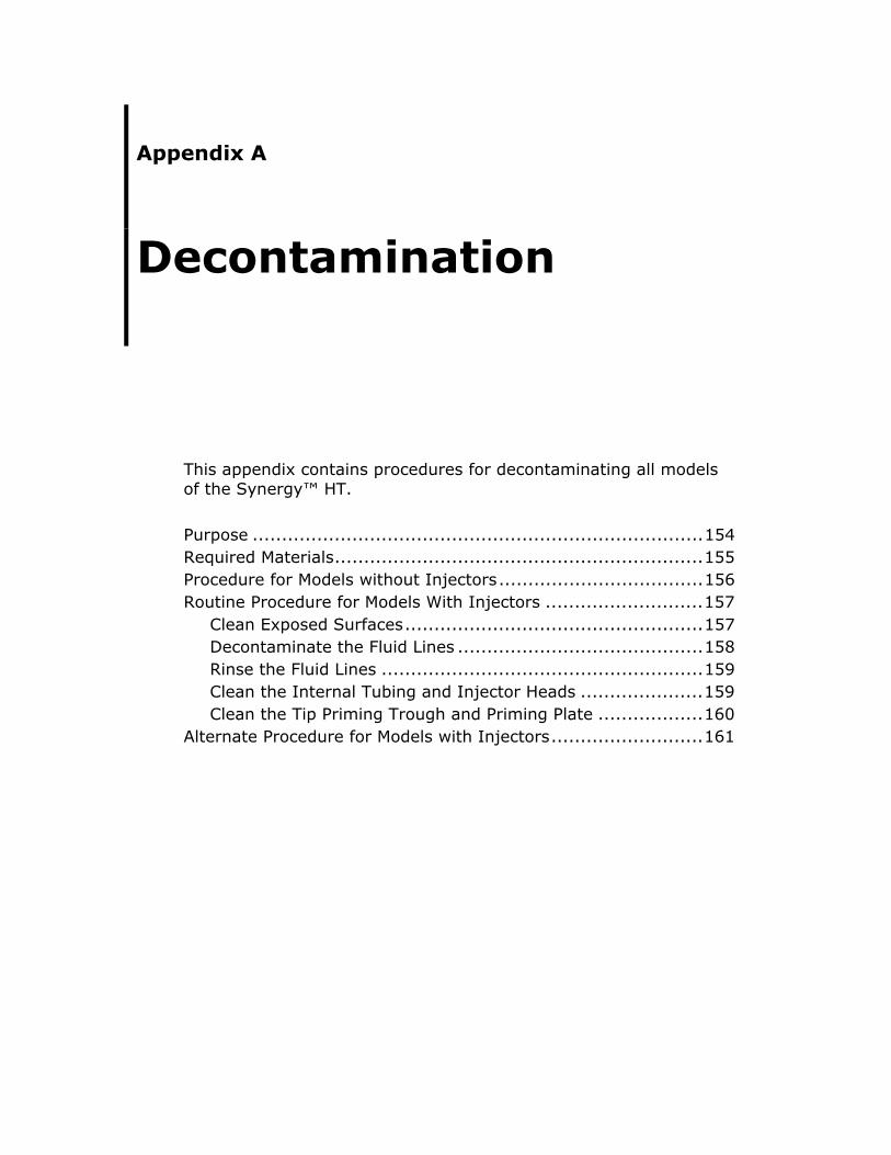
Appendix A
Decontamination
This appendix contains procedures for decontaminating all models of the Synergy™ HT.
Purpose .............................................................................154 Required Materials...............................................................155 Procedure for Models without Injectors...................................156 Routine Procedure for Models With Injectors ...........................157
Clean Exposed Surfaces...................................................157 Decontaminate the Fluid Lines ..........................................158 Rinse the Fluid Lines .......................................................159 Clean the Internal Tubing and Injector Heads .....................159 Clean the Tip Priming Trough and Priming Plate ..................160
Alternate Procedure for Models with Injectors..........................161
154 | Appendix A: Decontamination
BioTek Instruments, Inc.
Purpose
Any laboratory instrument that has been used for research or clinical analysis is considered a biohazard and requires decontamination prior to handling.
Decontamination minimizes the risk to all who come into contact with the instrument during shipping, handling, and servicing. Decontamination is required by the U.S. Department of Transportation regulations.
Persons performing the decontamination process must be familiar with the basic setup and operation of the instrument.
BioTek Instruments, Inc. recommends the use of the following decontamination solutions and methods based on our knowledge of the instrument and recommendations of the Centers for Disease Control and Prevention (CDC). Neither BioTek nor the CDC assumes any liability for the adequacy of these solutions and methods. Each laboratory must ensure that decontamination procedures are adequate for the Biohazard(s) they handle.
Wear prophylactic gloves when handling contaminated instruments. Gloved hands should be considered contaminated at all times; keep gloved hands away from eyes, mouth, and nose. Eating and drinking while decontaminating instruments is not advised.
Mucous membranes are considered prime entry routes for infectious agents. Wear eye protection and a surgical mask when there is a possibility of aerosol contamination. Intact skin is generally considered an effective barrier against infectious organisms; however, small abrasions and cuts may not always be visible. Wear protective gloves when performing the decontamination procedure.
Required Materials | 155
Synergy HT Operator's Manual
Required Materials
For all Synergy™ HT models:
• Sodium hypochlorite (NaClO, or bleach)
• 70% isopropyl alcohol (as an alternative to bleach)
• Deionized or distilled water
• Safety glasses
• Surgical mask
• Protective gloves
• Lab coat
• Biohazard trash bags
• 125 ml beakers
• Clean, lint-free cotton cloths
Additional materials for models with injectors:
• Phillips-head screwdriver
• Small brush for cleaning the tip priming trough and priming plate
• (Optional) Mild detergent
156 | Appendix A: Decontamination
BioTek Instruments, Inc.
Procedure for Models without Injectors
The sodium hypochlorite (bleach) solution is caustic; wear gloves and eye protection when handling the solution.
Do not immerse the instrument, spray it with liquid, or use a “wet” cloth. Do not allow the cleaning solution to run into the interior of the instrument. If this happens, contact the BioTek Service Department.
Important! Turn off and unplug the instrument for all decontamination and cleaning operations.
1. Turn off and unplug the instrument.
2. Prepare an aqueous solution of 0.50% sodium hypochlorite (bleach). As an alternative, 70% isopropyl alcohol may be used if the effects of bleach are a concern.
Be sure to check the percent NaClO of the bleach you are using; this information is printed on the side of the bottle. Commercial bleach is typically 10.0% NaClO; if this is the case, prepare a 1:20 dilution. Household bleach is typically 5.0% NaClO; if this is the case, prepare a 1:10 dilution.
3. Moisten a cloth with the bleach solution or alcohol. Do not soak the cloth.
4. Manually open the plate carrier door; slide out the plate carrier.
5. Wipe the plate carrier and all exposed surfaces of the instrument.
6. Wait 20 minutes. Moisten a cloth with deionized (DI) or distilled water and wipe all surfaces of the instrument that have been cleaned with the bleach solution or alcohol.
7. Use a clean, dry cloth to dry all wet surfaces.
8. Reassemble the instrument as necessary.
9. Discard the used gloves and cloths using a Biohazard trash bag and an approved Biohazard container.
Routine Procedure for Models With Injectors | 157
Synergy HT Operator's Manual
Routine Procedure for Models With Injectors
Note: Perform this Routine Procedure when all systems are functioning normally on the Synergy™ HT with Injectors. If you are unable to prime the Synergy HT due to a system failure, perform the Alternate Procedure described on page 161.
If disinfecting with sodium hypochlorite (bleach), be sure to flush repeatedly with deionized water to ensure that no bleach is carried over. After disinfecting with sodium hypochlorite, perform the rinse procedure provided on page 159.
If disinfecting with alcohol, do not immediately prime with deionized water, because the drying effect of the alcohol is an important aspect of its disinfectant properties.
Clean Exposed Surfaces
1. Turn off and unplug the instrument.
2. Prepare an aqueous solution of 0.50% sodium hypochlorite (bleach). As an alternative, 70% isopropyl alcohol may be used if the effects of bleach are a concern.
Be sure to check the percent NaClO of the bleach you are using; this information is printed on the side of the bottle. Commercial bleach is typically 10.0% NaClO; if this is the case, prepare a 1:20 dilution. Household bleach is typically 5.0% NaClO; if this is the case, prepare a 1:10 dilution.
3. Manually open the plate carrier door; slide out the plate carrier.
4. Moisten a cloth with the bleach solution or alcohol. Do not soak the cloth.
5. Wipe the plate carrier and the exposed surfaces of the external dispense module.
6. Wait 20 minutes. Moisten a cloth with deionized (DI) or distilled water and wipe all surfaces that have been cleaned with the bleach solution or alcohol.
7. Use a clean, dry cloth to dry all wet surfaces.
Continued on the next page.
158 | Appendix A: Decontamination
BioTek Instruments, Inc.
8. Reassemble the instrument as necessary.
9. If the dispense module is installed, detach the outlet tubes from the rear panel of the instrument. If it is not installed, attach just the dispense module’s communication cable to the instrument. Remove the supply bottles and their holders.
10. Perform the procedures described below through page 160 to decontaminate the fluid lines in the dispense module, the internal tubing and injector heads, and the tip priming trough and priming plate.
Decontaminate the Fluid Lines
1. Place a beaker with 20 ml of 0.5% sodium hypochlorite solution or 70% isopropyl alcohol near SYRINGE 1 on the dispense module.
2. Place the SYRINGE 1 inlet tube in the beaker.
3. If you have not already done so, detach the dispense module’s outlet tubes from the instrument’s rear panel. Place the ends of the outlet tubes in an empty beaker and set the beaker on the work surface.
4. Launch Gen5™ or KC4™, select System|Reader Control, and click the Dispenser tab.
5. Select Dispenser 1, enter a Volume of 5000 µl, and keep the default dispense Rate.
6. Place the priming plate on the carrier (it is not used, but the reader requires its presence).
7. Run two prime cycles, for a total of 10000 µl.
8. Pause for 20 to 30 minutes to allow the solution to disinfect the tubing.
9. Remove the inlet tube from the beaker of disinfectant solution.
10. From the Reader Control dialog, change the Volume to 1000 µl.
11. Run one prime cycle, to flush the disinfectant out of the fluid lines.
12. Empty the beaker containing the outlet tubes. Put the tubes back in.
13. Important! If sodium hypochlorite (bleach) was used, perform Rinse the Fluid Lines on the next page.
Otherwise, (or after performing the Rinse procedure), repeat steps 1-13 for SYRINGE 2 / Dispenser 2.
Routine Procedure for Models With Injectors | 159
Synergy HT Operator's Manual
Rinse the Fluid Lines
Perform this procedure only if decontamination was performed using sodium hypochlorite.
1. Place a beaker containing at least 30 ml of deionized water on the dispense module.
2. Place the SYRINGE 1 or 2 inlet tube in the beaker.
3. If you have not already done so, place the outlet tubes in an empty beaker.
4. From the Reader Control dialog, select Dispenser 1 or 2, set the Volume to 5000 µl, and keep the default dispense Rate.
5. Run five prime cycles, for a total of 25000 μl.
6. Pause for 10 minutes and then run one prime cycle with 5000 µl. This delay will allow any residual sodium hypochlorite to diffuse into the solution and be flushed out with the next prime.
7. Empty the beaker containing the outlet tubes.
8. Wipe all surfaces with deionized water.
9. Discard the used gloves and cloths using a Biohazard trash bag and an approved Biohazard container.
Clean the Internal Tubing and Injector Heads
Turn to Chapter 5, Preventive Maintenance and perform the following procedures to access, remove, and clean the internal tubing and injector heads:
• Required Materials • Removing the Reader’s Shroud • Removing the Internal Tubes and Injector Heads
• Cleaning the Internal Tubes and Injector Heads
When finished, replace the internal components and the reader’s shroud.
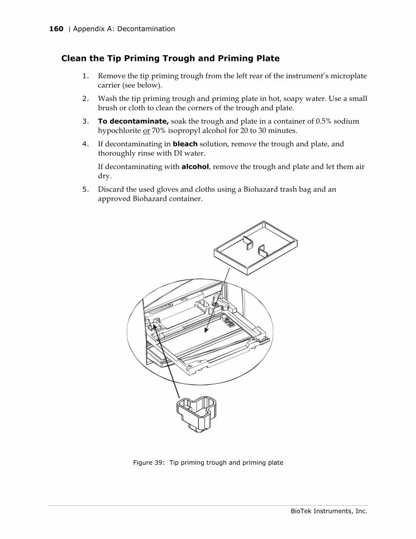
160 | Appendix A: Decontamination
BioTek Instruments, Inc.
Clean the Tip Priming Trough and Priming Plate
1. Remove the tip priming trough from the left rear of the instrument’s microplate carrier (see below).
2. Wash the tip priming trough and priming plate in hot, soapy water. Use a small brush or cloth to clean the corners of the trough and plate.
3. To decontaminate, soak the trough and plate in a container of 0.5% sodium hypochlorite or 70% isopropyl alcohol for 20 to 30 minutes.
4. If decontaminating in bleach solution, remove the trough and plate, and thoroughly rinse with DI water.
If decontaminating with alcohol, remove the trough and plate and let them air dry.
5. Discard the used gloves and cloths using a Biohazard trash bag and an approved Biohazard container.
Figure 39: Tip priming trough and priming plate
Alternate Procedure for Models with Injectors | 161
Synergy HT Operator's Manual
Alternate Procedure for Models with Injectors
If you are unable to prime the Synergy™ HT due to a system failure, decontaminate the instrument and the Dispense Module as follows:
1. Turn to Chapter 5, Preventive Maintenance and perform the following procedures to remove the shroud and remove/clean the internal tubes and injector heads. When finished, leave the shroud off the reader and proceed to step 2 below.
• Required Materials
• Removing the Reader’s Shroud • Removing the Internal Tubes and Injector Heads
• Cleaning the Internal Tubes and Injector Heads
2. Prepare an aqueous solution of 0.50% sodium hypochlorite (bleach). As an alternative, 70% isopropyl alcohol may be used if the effects of bleach are a concern.
Be sure to check the percent NaClO of the bleach you are using; this information is printed on the side of the bottle. Commercial bleach is typically 10.0% NaClO; if this is the case, prepare a 1:20 dilution. Household bleach is typically 5.0% NaClO; if this is the case, prepare a 1:10 dilution.
3. Slide the microplate carrier out of the instrument.
4. Moisten a cloth with the bleach solution or alcohol. Do not soak the cloth.
5. Use the cloth to wipe:
• All surfaces of the shroud
• All surfaces of the plate carrier
• The instrument’s rear panel
• The exposed surfaces of the dispense module, including the syringe valves
Continued on the next page.
162 | Appendix A: Decontamination
BioTek Instruments, Inc.
6. Remove the external tubing and the syringes from the dispense module and soak them in the bleach or alcohol solution. Wait for 20 minutes.
To remove the syringes: Pull down the syringe bracket until it stops. Remove the metal thumbscrew from underneath the bracket. Unscrew the top of the syringe from the bottom of the syringe drive. Gently remove the syringe and store it in its original packaging (see Chapter 2, Installation).
7. Moisten a cloth with DI or distilled water and wipe all surfaces that have been cleaned with the bleach solution or alcohol.
8. Rinse all tubing and the syringes with DI water.
9. Use a clean, dry cloth to dry all wet surfaces on the instrument and the Dispense module.
10. Reassemble the instrument and dispense module as necessary.
11. Discard the used gloves and cloths using a Biohazard trash bag and an approved Biohazard container.

Appendix B
Computer Control
The Synergy™ HT is completely computer-controlled; it is not equipped with a keypad or its own user interface. BioTek’s Gen5™ and KC4™ software packages support all Synergy HT models and are used for both instrument control and data reduction.
For information on serial protocol commands and/or system integration, please contact your BioTek sales representative or BioTek Instruments, Inc.

164 | Appendix B: Computer Control
BioTek Instruments, Inc.

Appendix C
Error Codes
This section lists and describes the possible error codes that may appear on the controlling PC.
Error Codes ........................................................................166 Fatal Errors....................................................................167 Non-Fatal Errors .............................................................168
Home Sensor Initial Find Errors (0100-0307) .................168 Home Sensor Verification Errors (0400-0409) ................172 Saturation Errors (0500-0616) .....................................174 Absorbance Reader Noise Errors (0700-0A16) ................180 Internal Self-Test Errors (0D00-2918)...........................184 Other Errors (2A00-4000) ...........................................196
Status String Format ...........................................................202
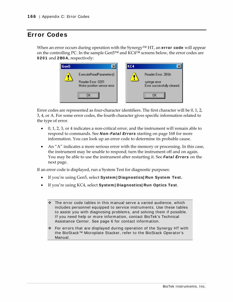
166 | Appendix C: Error Codes
BioTek Instruments, Inc.
Error Codes
When an error occurs during operation with the Synergy™ HT, an error code will appear on the controlling PC. In the sample Gen5™ and KC4™ screens below, the error codes are 0201 and 2B0A, respectively:
Error codes are represented as four-character identifiers. The first character will be 0, 1, 2, 3, 4, or A. For some error codes, the fourth character gives specific information related to the type of error.
• 0, 1, 2, 3, or 4 indicates a non-critical error, and the instrument will remain able to respond to commands. See Non-Fatal Errors starting on page 168 for more information. You can look up an error code to determine its probable cause.
• An “A” indicates a more serious error with the memory or processing. In this case, the instrument may be unable to respond; turn the instrument off and on again. You may be able to use the instrument after restarting it. See Fatal Errors on the next page.
If an error code is displayed, run a System Test for diagnostic purposes:
• If you’re using Gen5, select System|Diagnostics|Run System Test.
• If you’re using KC4, select System|Diagnostics|Run Optics Test.
The error code tables in this manual serve a varied audience, which includes personnel equipped to service instruments. Use these tables to assist you with diagnosing problems, and solving them if possible. If you need help or more information, contact BioTek’s Technical Assistance Center. See page 6 for contact information.
For errors that are displayed during operation of the Synergy HT with the BioStack™ Microplate Stacker, refer to the BioStack Operator’s Manual.
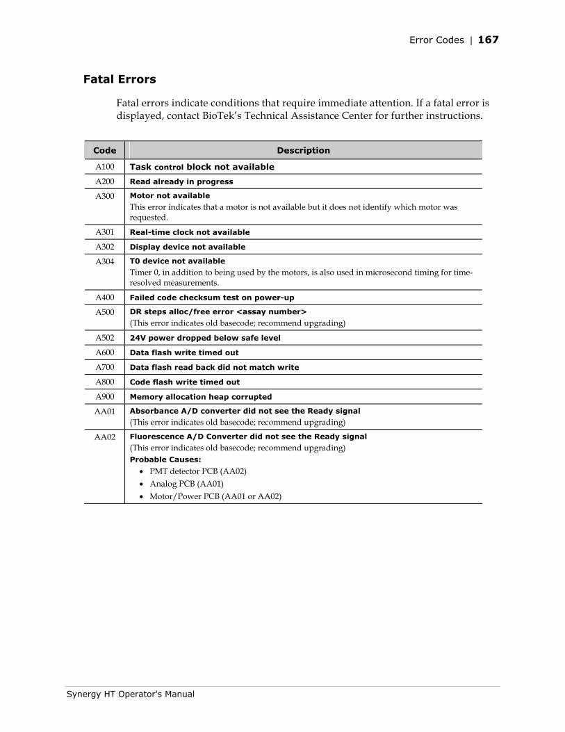
Error Codes | 167
Synergy HT Operator's Manual
Fatal Errors
Fatal errors indicate conditions that require immediate attention. If a fatal error is displayed, contact BioTek’s Technical Assistance Center for further instructions.
Code Description
A100 Task control block not available
A200 Read already in progress
A300 Motor not available
This error indicates that a motor is not available but it does not identify which motor was requested.
A301 Real-time clock not available
A302 Display device not available
A304 T0 device not available
Timer 0, in addition to being used by the motors, is also used in microsecond timing for time-resolved measurements.
A400 Failed code checksum test on power-up
A500 DR steps alloc/free error <assay number>
(This error indicates old basecode; recommend upgrading)
A502 24V power dropped below safe level
A600 Data flash write timed out
A700 Data flash read back did not match write
A800 Code flash write timed out
A900 Memory allocation heap corrupted
AA01 Absorbance A/D converter did not see the Ready signal
(This error indicates old basecode; recommend upgrading)
AA02 Fluorescence A/D Converter did not see the Ready signal
(This error indicates old basecode; recommend upgrading) Probable Causes:
• PMT detector PCB (AA02) • Analog PCB (AA01) • Motor/Power PCB (AA01 or AA02)
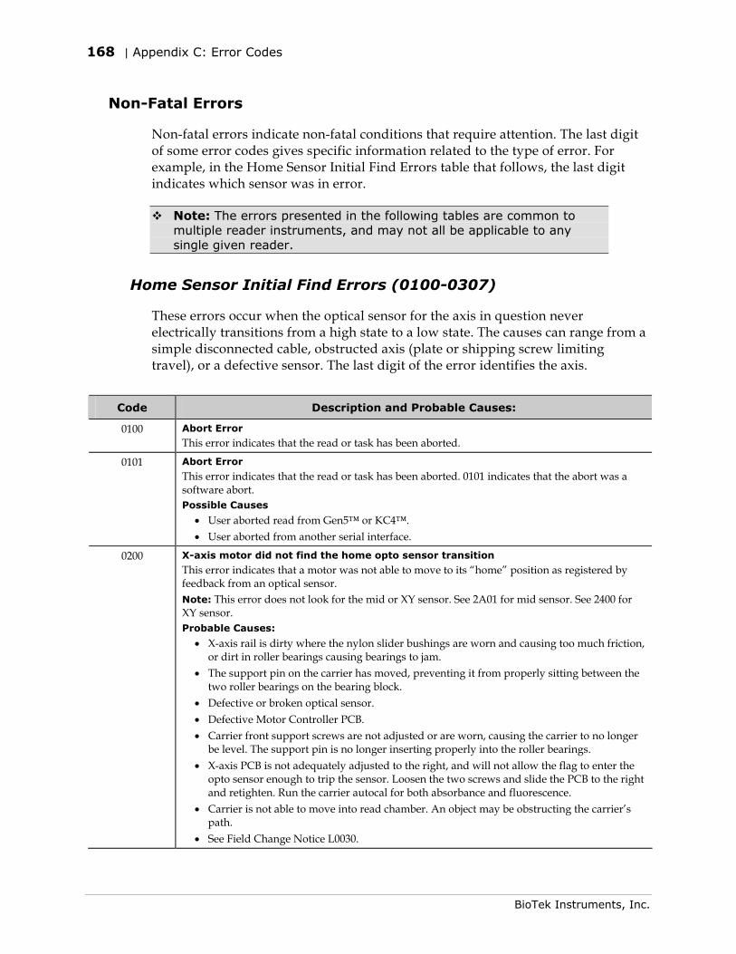
168 | Appendix C: Error Codes
BioTek Instruments, Inc.
Non-Fatal Errors
Non-fatal errors indicate non-fatal conditions that require attention. The last digit of some error codes gives specific information related to the type of error. For example, in the Home Sensor Initial Find Errors table that follows, the last digit indicates which sensor was in error.
Note: The errors presented in the following tables are common to multiple reader instruments, and may not all be applicable to any single given reader.
Home Sensor Initial Find Errors (0100-0307)
These errors occur when the optical sensor for the axis in question never electrically transitions from a high state to a low state. The causes can range from a simple disconnected cable, obstructed axis (plate or shipping screw limiting travel), or a defective sensor. The last digit of the error identifies the axis.
Code Description and Probable Causes:
0100 Abort Error
This error indicates that the read or task has been aborted.
0101 Abort Error
This error indicates that the read or task has been aborted. 0101 indicates that the abort was a software abort. Possible Causes
• User aborted read from Gen5™ or KC4™. • User aborted from another serial interface.
0200 X-axis motor did not find the home opto sensor transition
This error indicates that a motor was not able to move to its “home” position as registered by feedback from an optical sensor. Note: This error does not look for the mid or XY sensor. See 2A01 for mid sensor. See 2400 for XY sensor. Probable Causes:
• X-axis rail is dirty where the nylon slider bushings are worn and causing too much friction, or dirt in roller bearings causing bearings to jam.
• The support pin on the carrier has moved, preventing it from properly sitting between the two roller bearings on the bearing block.
• Defective or broken optical sensor. • Defective Motor Controller PCB. • Carrier front support screws are not adjusted or are worn, causing the carrier to no longer
be level. The support pin is no longer inserting properly into the roller bearings. • X-axis PCB is not adequately adjusted to the right, and will not allow the flag to enter the
opto sensor enough to trip the sensor. Loosen the two screws and slide the PCB to the right and retighten. Run the carrier autocal for both absorbance and fluorescence.
• Carrier is not able to move into read chamber. An object may be obstructing the carrier’s path.
• See Field Change Notice L0030.
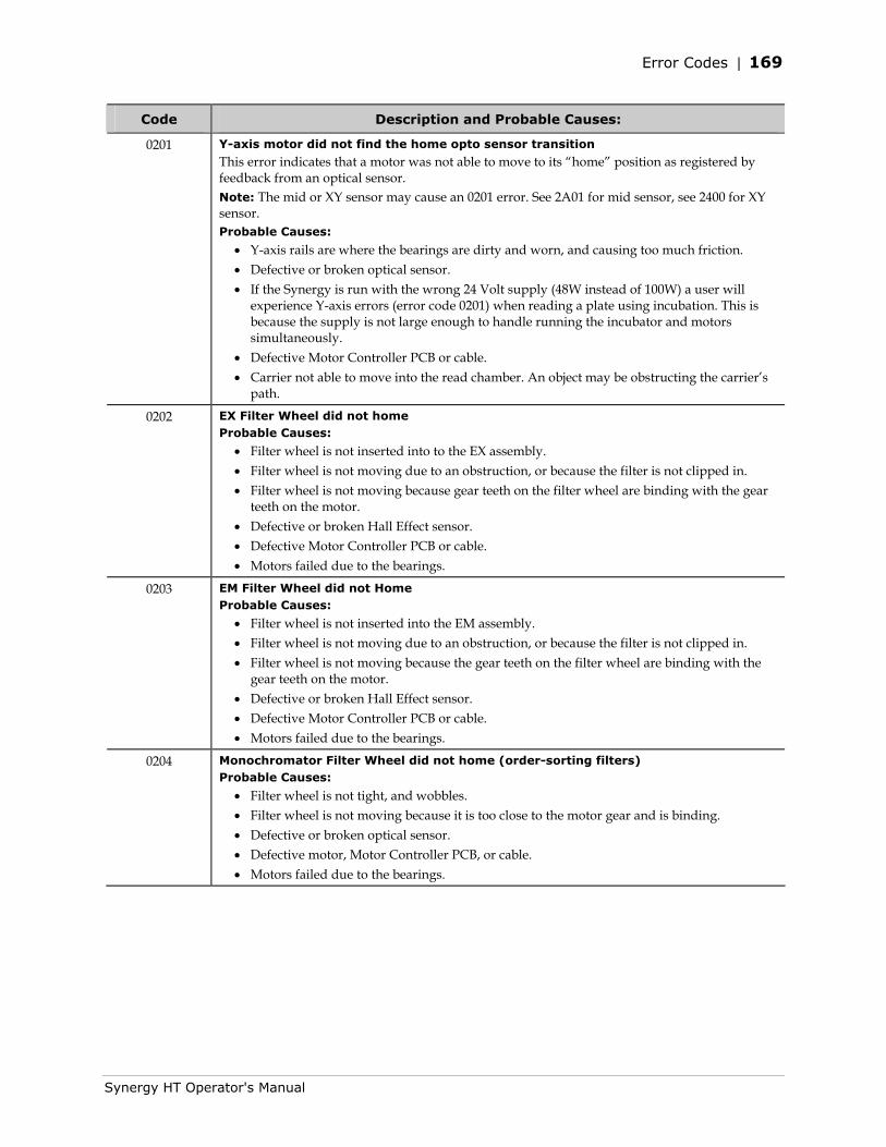
Error Codes | 169
Synergy HT Operator's Manual
Code Description and Probable Causes:
0201 Y-axis motor did not find the home opto sensor transition
This error indicates that a motor was not able to move to its “home” position as registered by feedback from an optical sensor. Note: The mid or XY sensor may cause an 0201 error. See 2A01 for mid sensor, see 2400 for XY sensor. Probable Causes:
• Y-axis rails are where the bearings are dirty and worn, and causing too much friction. • Defective or broken optical sensor. • If the Synergy is run with the wrong 24 Volt supply (48W instead of 100W) a user will
experience Y-axis errors (error code 0201) when reading a plate using incubation. This is because the supply is not large enough to handle running the incubator and motors simultaneously.
• Defective Motor Controller PCB or cable. • Carrier not able to move into the read chamber. An object may be obstructing the carrier’s
path.
0202 EX Filter Wheel did not home Probable Causes:
• Filter wheel is not inserted into to the EX assembly. • Filter wheel is not moving due to an obstruction, or because the filter is not clipped in. • Filter wheel is not moving because gear teeth on the filter wheel are binding with the gear
teeth on the motor. • Defective or broken Hall Effect sensor. • Defective Motor Controller PCB or cable. • Motors failed due to the bearings.
0203 EM Filter Wheel did not Home Probable Causes:
• Filter wheel is not inserted into the EM assembly. • Filter wheel is not moving due to an obstruction, or because the filter is not clipped in. • Filter wheel is not moving because the gear teeth on the filter wheel are binding with the
gear teeth on the motor. • Defective or broken Hall Effect sensor. • Defective Motor Controller PCB or cable. • Motors failed due to the bearings.
0204 Monochromator Filter Wheel did not home (order-sorting filters) Probable Causes:
• Filter wheel is not tight, and wobbles. • Filter wheel is not moving because it is too close to the motor gear and is binding. • Defective or broken optical sensor. • Defective motor, Motor Controller PCB, or cable. • Motors failed due to the bearings.
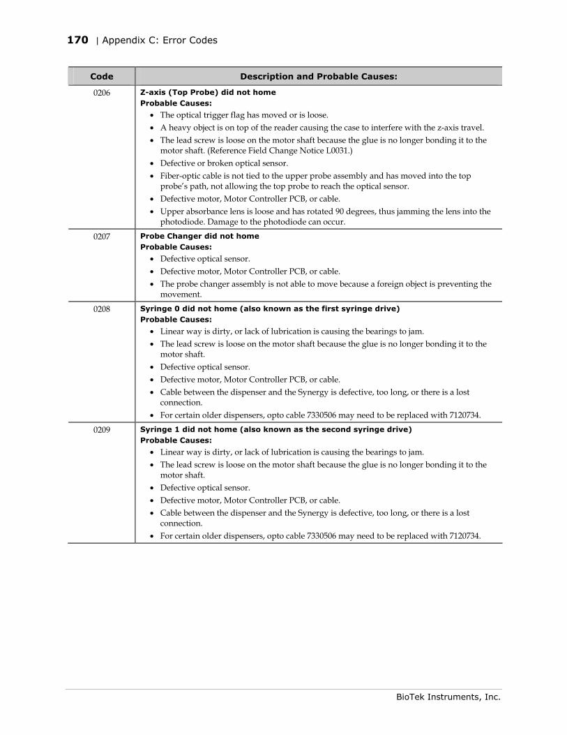
170 | Appendix C: Error Codes
BioTek Instruments, Inc.
Code Description and Probable Causes:
0206 Z-axis (Top Probe) did not home Probable Causes:
• The optical trigger flag has moved or is loose. • A heavy object is on top of the reader causing the case to interfere with the z-axis travel. • The lead screw is loose on the motor shaft because the glue is no longer bonding it to the
motor shaft. (Reference Field Change Notice L0031.) • Defective or broken optical sensor. • Fiber-optic cable is not tied to the upper probe assembly and has moved into the top
probe’s path, not allowing the top probe to reach the optical sensor. • Defective motor, Motor Controller PCB, or cable. • Upper absorbance lens is loose and has rotated 90 degrees, thus jamming the lens into the
photodiode. Damage to the photodiode can occur.
0207 Probe Changer did not home Probable Causes:
• Defective optical sensor. • Defective motor, Motor Controller PCB, or cable. • The probe changer assembly is not able to move because a foreign object is preventing the
movement.
0208 Syringe 0 did not home (also known as the first syringe drive) Probable Causes:
• Linear way is dirty, or lack of lubrication is causing the bearings to jam. • The lead screw is loose on the motor shaft because the glue is no longer bonding it to the
motor shaft. • Defective optical sensor. • Defective motor, Motor Controller PCB, or cable. • Cable between the dispenser and the Synergy is defective, too long, or there is a lost
connection. • For certain older dispensers, opto cable 7330506 may need to be replaced with 7120734.
0209 Syringe 1 did not home (also known as the second syringe drive) Probable Causes:
• Linear way is dirty, or lack of lubrication is causing the bearings to jam. • The lead screw is loose on the motor shaft because the glue is no longer bonding it to the
motor shaft. • Defective optical sensor. • Defective motor, Motor Controller PCB, or cable. • Cable between the dispenser and the Synergy is defective, too long, or there is a lost
connection. • For certain older dispensers, opto cable 7330506 may need to be replaced with 7120734.
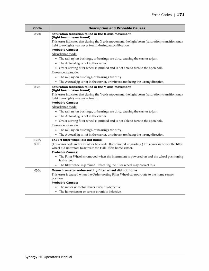
Error Codes | 171
Synergy HT Operator's Manual
Code Description and Probable Causes:
0300 Saturation transition failed in the X-axis movement (light beam never found)
This error indicates that during the X-axis movement, the light beam (saturation) transition (max light to no light) was never found during autocalibration. Probable Causes:
Absorbance mode: • The rail, nylon bushings, or bearings are dirty, causing the carrier to jam. • The Autocal jig is not in the carrier. • Order-sorting filter wheel is jammed and is not able to turn to the open hole.
Fluorescence mode: • The rail, nylon bushings, or bearings are dirty. • The Autocal jig is not in the carrier, or mirrors are facing the wrong direction.
0301 Saturation transition failed in the Y-axis movement (light beam never found)
This error indicates that during the Y-axis movement, the light beam (saturation) transition (max light to no light) was never found. Probable Causes:
Absorbance mode: • The rail, nylon bushings, or bearings are dirty, causing the carrier to jam. • The Autocal jig is not in the carrier. • Order-sorting filter wheel is jammed and is not able to turn to the open hole.
Fluorescence mode: • The rail, nylon bushings, or bearings are dirty. • The Autocal jig is not in the carrier, or mirrors are facing the wrong direction.
0302/ 0303
EX/EM filter wheel did not home
(This error code indicates older basecode. Recommend upgrading.) This error indicates the filter wheel did not rotate to activate the Hall Effect home sensor. Probable Causes:
• The Filter Wheel is removed when the instrument is powered on and the wheel positioning is changed.
• The filter wheel is jammed. Reseating the filter wheel may correct this.
0304 Monochromator order-sorting filter wheel did not home
This error is caused when the Order-sorting Filter Wheel cannot rotate to the home sensor position. Probable Causes:
• The motor or motor driver circuit is defective. • The home sensor or sensor circuit is defective.
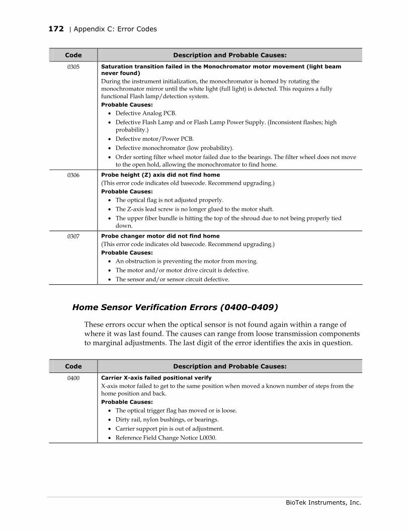
172 | Appendix C: Error Codes
BioTek Instruments, Inc.
Code Description and Probable Causes:
0305 Saturation transition failed in the Monochromator motor movement (light beam never found)
During the instrument initialization, the monochromator is homed by rotating the monochromator mirror until the white light (full light) is detected. This requires a fully functional Flash lamp/detection system. Probable Causes:
• Defective Analog PCB. • Defective Flash Lamp and or Flash Lamp Power Supply. (Inconsistent flashes; high
probability.) • Defective motor/Power PCB. • Defective monochromator (low probability). • Order sorting filter wheel motor failed due to the bearings. The filter wheel does not move
to the open hold, allowing the monochromator to find home.
0306 Probe height (Z) axis did not find home
(This error code indicates old basecode. Recommend upgrading.) Probable Causes:
• The optical flag is not adjusted properly. • The Z-axis lead screw is no longer glued to the motor shaft. • The upper fiber bundle is hitting the top of the shroud due to not being properly tied
down.
0307 Probe changer motor did not find home
(This error code indicates old basecode. Recommend upgrading.) Probable Causes:
• An obstruction is preventing the motor from moving. • The motor and/or motor drive circuit is defective. • The sensor and/or sensor circuit defective.
Home Sensor Verification Errors (0400-0409)
These errors occur when the optical sensor is not found again within a range of where it was last found. The causes can range from loose transmission components to marginal adjustments. The last digit of the error identifies the axis in question.
Code Description and Probable Causes:
0400 Carrier X-axis failed positional verify
X-axis motor failed to get to the same position when moved a known number of steps from the home position and back. Probable Causes:
• The optical trigger flag has moved or is loose. • Dirty rail, nylon bushings, or bearings. • Carrier support pin is out of adjustment. • Reference Field Change Notice L0030.
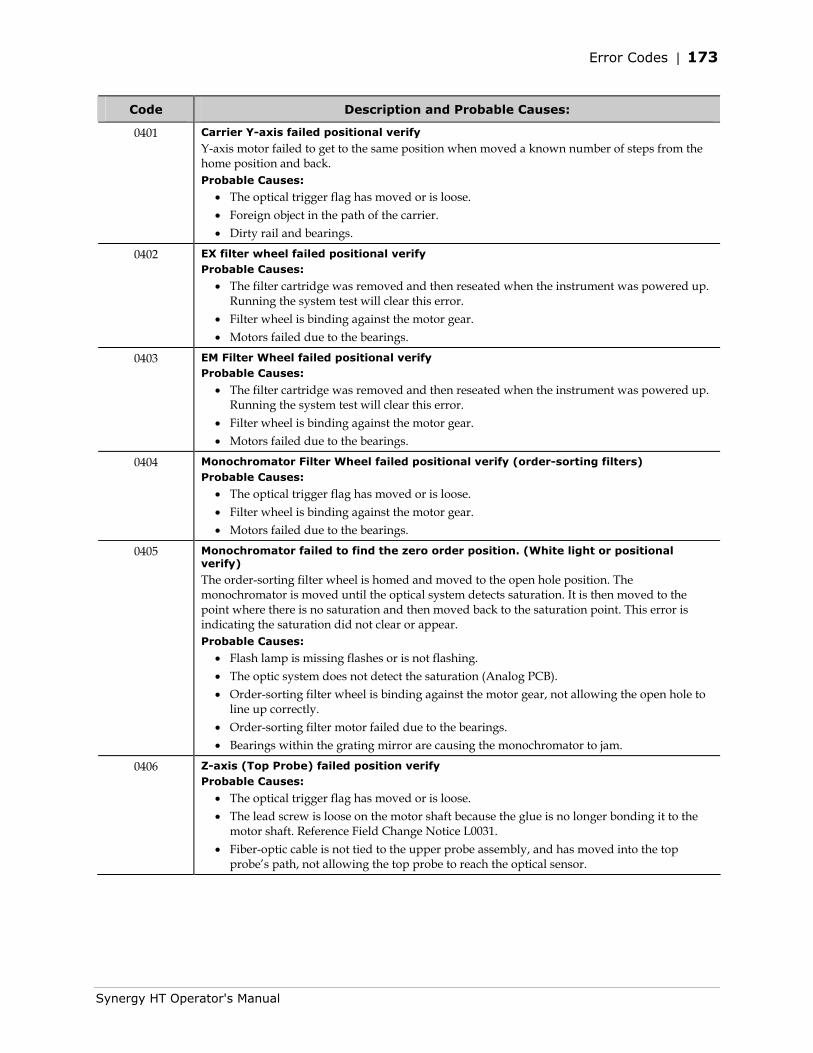
Error Codes | 173
Synergy HT Operator's Manual
Code Description and Probable Causes:
0401 Carrier Y-axis failed positional verify
Y-axis motor failed to get to the same position when moved a known number of steps from the home position and back. Probable Causes:
• The optical trigger flag has moved or is loose. • Foreign object in the path of the carrier. • Dirty rail and bearings.
0402 EX filter wheel failed positional verify Probable Causes:
• The filter cartridge was removed and then reseated when the instrument was powered up. Running the system test will clear this error.
• Filter wheel is binding against the motor gear. • Motors failed due to the bearings.
0403 EM Filter Wheel failed positional verify Probable Causes:
• The filter cartridge was removed and then reseated when the instrument was powered up. Running the system test will clear this error.
• Filter wheel is binding against the motor gear. • Motors failed due to the bearings.
0404 Monochromator Filter Wheel failed positional verify (order-sorting filters) Probable Causes:
• The optical trigger flag has moved or is loose. • Filter wheel is binding against the motor gear. • Motors failed due to the bearings.
0405 Monochromator failed to find the zero order position. (White light or positional verify)
The order-sorting filter wheel is homed and moved to the open hole position. The monochromator is moved until the optical system detects saturation. It is then moved to the point where there is no saturation and then moved back to the saturation point. This error is indicating the saturation did not clear or appear. Probable Causes:
• Flash lamp is missing flashes or is not flashing. • The optic system does not detect the saturation (Analog PCB). • Order-sorting filter wheel is binding against the motor gear, not allowing the open hole to
line up correctly. • Order-sorting filter motor failed due to the bearings. • Bearings within the grating mirror are causing the monochromator to jam.
0406 Z-axis (Top Probe) failed position verify Probable Causes:
• The optical trigger flag has moved or is loose. • The lead screw is loose on the motor shaft because the glue is no longer bonding it to the
motor shaft. Reference Field Change Notice L0031. • Fiber-optic cable is not tied to the upper probe assembly, and has moved into the top
probe’s path, not allowing the top probe to reach the optical sensor.
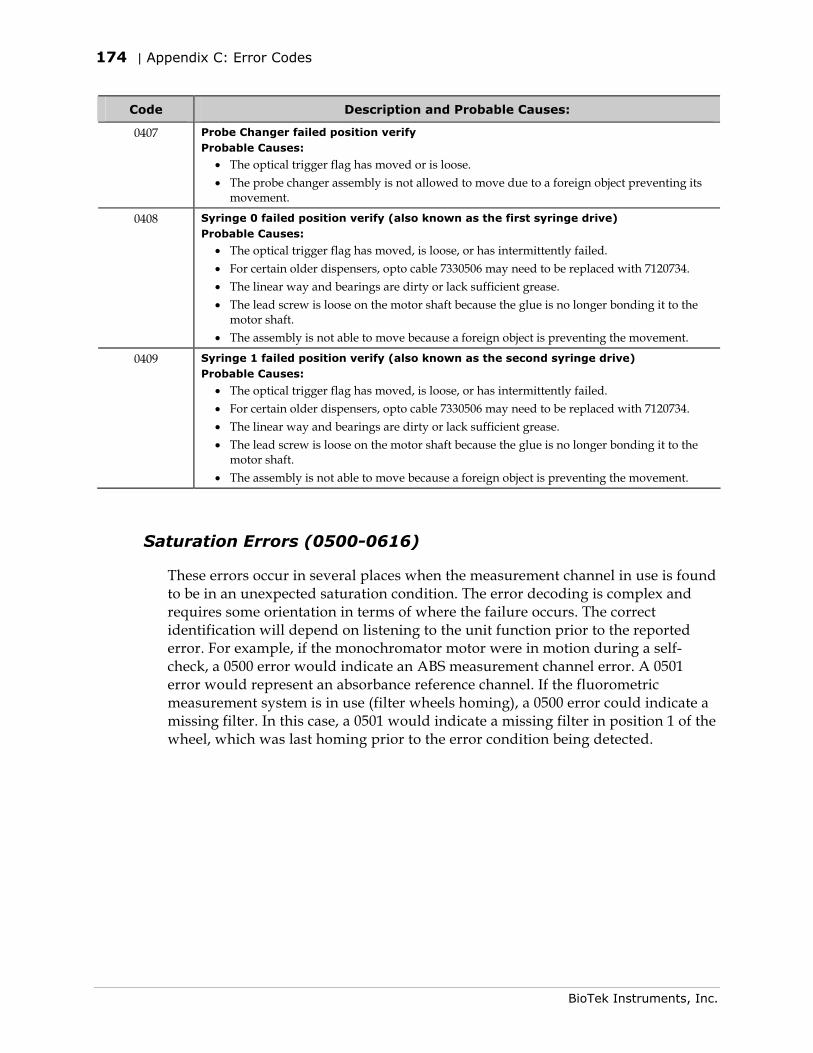
174 | Appendix C: Error Codes
BioTek Instruments, Inc.
Code Description and Probable Causes:
0407 Probe Changer failed position verify Probable Causes:
• The optical trigger flag has moved or is loose. • The probe changer assembly is not allowed to move due to a foreign object preventing its
movement.
0408 Syringe 0 failed position verify (also known as the first syringe drive) Probable Causes:
• The optical trigger flag has moved, is loose, or has intermittently failed. • For certain older dispensers, opto cable 7330506 may need to be replaced with 7120734. • The linear way and bearings are dirty or lack sufficient grease. • The lead screw is loose on the motor shaft because the glue is no longer bonding it to the
motor shaft. • The assembly is not able to move because a foreign object is preventing the movement.
0409 Syringe 1 failed position verify (also known as the second syringe drive) Probable Causes:
• The optical trigger flag has moved, is loose, or has intermittently failed. • For certain older dispensers, opto cable 7330506 may need to be replaced with 7120734. • The linear way and bearings are dirty or lack sufficient grease. • The lead screw is loose on the motor shaft because the glue is no longer bonding it to the
motor shaft. • The assembly is not able to move because a foreign object is preventing the movement.
Saturation Errors (0500-0616)
These errors occur in several places when the measurement channel in use is found to be in an unexpected saturation condition. The error decoding is complex and requires some orientation in terms of where the failure occurs. The correct identification will depend on listening to the unit function prior to the reported error. For example, if the monochromator motor were in motion during a self-check, a 0500 error would indicate an ABS measurement channel error. A 0501 error would represent an absorbance reference channel. If the fluorometric measurement system is in use (filter wheels homing), a 0500 error could indicate a missing filter. In this case, a 0501 would indicate a missing filter in position 1 of the wheel, which was last homing prior to the error condition being detected.
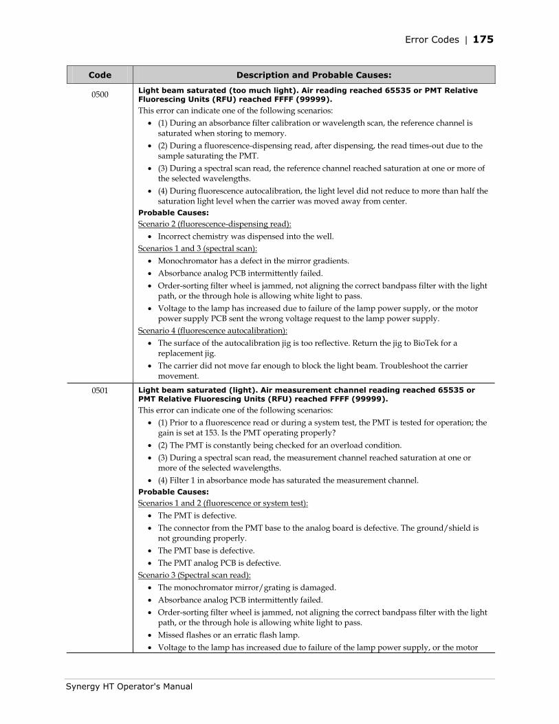
Error Codes | 175
Synergy HT Operator's Manual
Code Description and Probable Causes:
0500 Light beam saturated (too much light). Air reading reached 65535 or PMT Relative Fluorescing Units (RFU) reached FFFF (99999).
This error can indicate one of the following scenarios: • (1) During an absorbance filter calibration or wavelength scan, the reference channel is
saturated when storing to memory. • (2) During a fluorescence-dispensing read, after dispensing, the read times-out due to the
sample saturating the PMT. • (3) During a spectral scan read, the reference channel reached saturation at one or more of
the selected wavelengths. • (4) During fluorescence autocalibration, the light level did not reduce to more than half the
saturation light level when the carrier was moved away from center. Probable Causes:
Scenario 2 (fluorescence-dispensing read): • Incorrect chemistry was dispensed into the well.
Scenarios 1 and 3 (spectral scan): • Monochromator has a defect in the mirror gradients. • Absorbance analog PCB intermittently failed. • Order-sorting filter wheel is jammed, not aligning the correct bandpass filter with the light
path, or the through hole is allowing white light to pass. • Voltage to the lamp has increased due to failure of the lamp power supply, or the motor
power supply PCB sent the wrong voltage request to the lamp power supply. Scenario 4 (fluorescence autocalibration):
• The surface of the autocalibration jig is too reflective. Return the jig to BioTek for a replacement jig.
• The carrier did not move far enough to block the light beam. Troubleshoot the carrier movement.
0501 Light beam saturated (light). Air measurement channel reading reached 65535 or PMT Relative Fluorescing Units (RFU) reached FFFF (99999).
This error can indicate one of the following scenarios: • (1) Prior to a fluorescence read or during a system test, the PMT is tested for operation; the
gain is set at 153. Is the PMT operating properly? • (2) The PMT is constantly being checked for an overload condition. • (3) During a spectral scan read, the measurement channel reached saturation at one or
more of the selected wavelengths. • (4) Filter 1 in absorbance mode has saturated the measurement channel.
Probable Causes:
Scenarios 1 and 2 (fluorescence or system test): • The PMT is defective. • The connector from the PMT base to the analog board is defective. The ground/shield is
not grounding properly. • The PMT base is defective. • The PMT analog PCB is defective.
Scenario 3 (Spectral scan read): • The monochromator mirror/grating is damaged. • Absorbance analog PCB intermittently failed. • Order-sorting filter wheel is jammed, not aligning the correct bandpass filter with the light
path, or the through hole is allowing white light to pass. • Missed flashes or an erratic flash lamp. • Voltage to the lamp has increased due to failure of the lamp power supply, or the motor
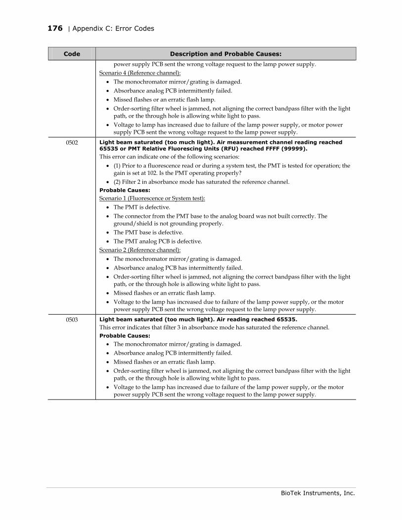
176 | Appendix C: Error Codes
BioTek Instruments, Inc.
Code Description and Probable Causes:
power supply PCB sent the wrong voltage request to the lamp power supply. Scenario 4 (Reference channel):
• The monochromator mirror/grating is damaged. • Absorbance analog PCB intermittently failed. • Missed flashes or an erratic flash lamp. • Order-sorting filter wheel is jammed, not aligning the correct bandpass filter with the light
path, or the through hole is allowing white light to pass. • Voltage to lamp has increased due to failure of the lamp power supply, or motor power
supply PCB sent the wrong voltage request to the lamp power supply.
0502 Light beam saturated (too much light). Air measurement channel reading reached 65535 or PMT Relative Fluorescing Units (RFU) reached FFFF (99999).
This error can indicate one of the following scenarios: • (1) Prior to a fluorescence read or during a system test, the PMT is tested for operation; the
gain is set at 102. Is the PMT operating properly? • (2) Filter 2 in absorbance mode has saturated the reference channel.
Probable Causes:
Scenario 1 (Fluorescence or System test): • The PMT is defective. • The connector from the PMT base to the analog board was not built correctly. The
ground/shield is not grounding properly. • The PMT base is defective. • The PMT analog PCB is defective.
Scenario 2 (Reference channel): • The monochromator mirror/grating is damaged. • Absorbance analog PCB has intermittently failed. • Order-sorting filter wheel is jammed, not aligning the correct bandpass filter with the light
path, or the through hole is allowing white light to pass. • Missed flashes or an erratic flash lamp. • Voltage to the lamp has increased due to failure of the lamp power supply, or the motor
power supply PCB sent the wrong voltage request to the lamp power supply.
0503 Light beam saturated (too much light). Air reading reached 65535.
This error indicates that filter 3 in absorbance mode has saturated the reference channel. Probable Causes:
• The monochromator mirror/grating is damaged. • Absorbance analog PCB intermittently failed. • Missed flashes or an erratic flash lamp. • Order-sorting filter wheel is jammed, not aligning the correct bandpass filter with the light
path, or the through hole is allowing white light to pass. • Voltage to the lamp has increased due to failure of the lamp power supply, or the motor
power supply PCB sent the wrong voltage request to the lamp power supply.
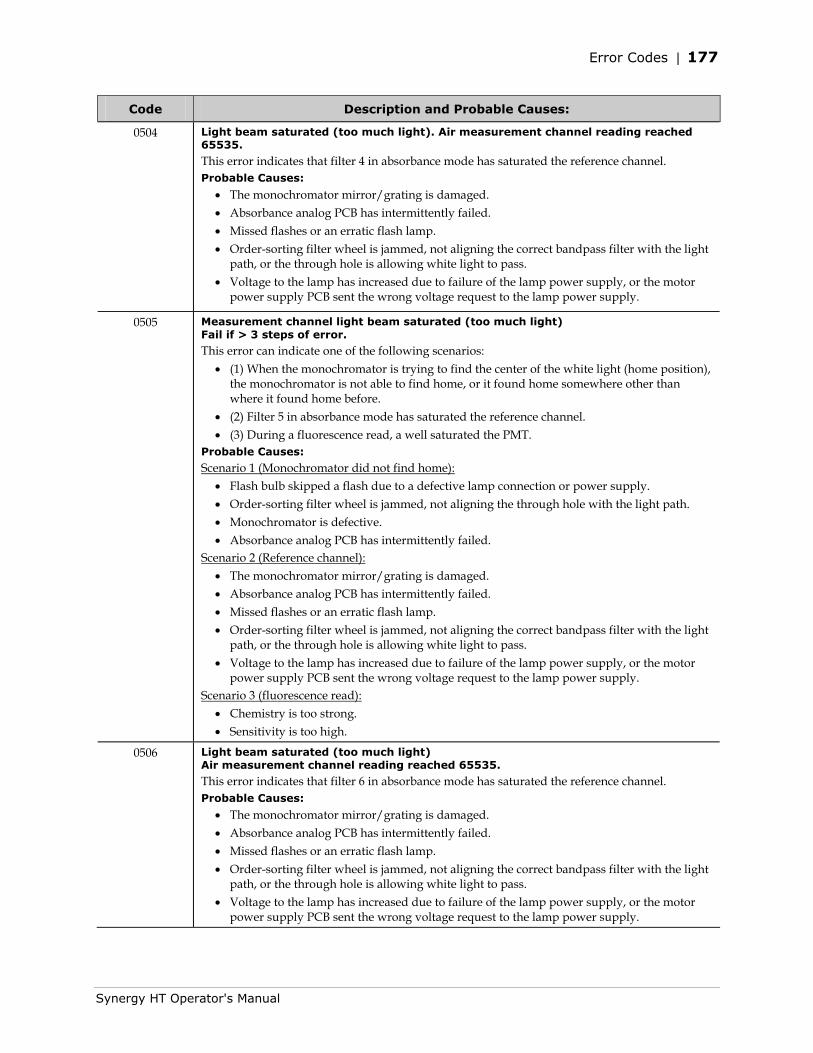
Error Codes | 177
Synergy HT Operator's Manual
Code Description and Probable Causes:
0504 Light beam saturated (too much light). Air measurement channel reading reached 65535.
This error indicates that filter 4 in absorbance mode has saturated the reference channel. Probable Causes:
• The monochromator mirror/grating is damaged. • Absorbance analog PCB has intermittently failed. • Missed flashes or an erratic flash lamp. • Order-sorting filter wheel is jammed, not aligning the correct bandpass filter with the light
path, or the through hole is allowing white light to pass. • Voltage to the lamp has increased due to failure of the lamp power supply, or the motor
power supply PCB sent the wrong voltage request to the lamp power supply.
0505 Measurement channel light beam saturated (too much light) Fail if > 3 steps of error.
This error can indicate one of the following scenarios: • (1) When the monochromator is trying to find the center of the white light (home position),
the monochromator is not able to find home, or it found home somewhere other than where it found home before.
• (2) Filter 5 in absorbance mode has saturated the reference channel. • (3) During a fluorescence read, a well saturated the PMT.
Probable Causes:
Scenario 1 (Monochromator did not find home): • Flash bulb skipped a flash due to a defective lamp connection or power supply. • Order-sorting filter wheel is jammed, not aligning the through hole with the light path. • Monochromator is defective. • Absorbance analog PCB has intermittently failed.
Scenario 2 (Reference channel): • The monochromator mirror/grating is damaged. • Absorbance analog PCB has intermittently failed. • Missed flashes or an erratic flash lamp. • Order-sorting filter wheel is jammed, not aligning the correct bandpass filter with the light
path, or the through hole is allowing white light to pass. • Voltage to the lamp has increased due to failure of the lamp power supply, or the motor
power supply PCB sent the wrong voltage request to the lamp power supply. Scenario 3 (fluorescence read):
• Chemistry is too strong. • Sensitivity is too high.
0506 Light beam saturated (too much light) Air measurement channel reading reached 65535.
This error indicates that filter 6 in absorbance mode has saturated the reference channel. Probable Causes:
• The monochromator mirror/grating is damaged. • Absorbance analog PCB has intermittently failed. • Missed flashes or an erratic flash lamp. • Order-sorting filter wheel is jammed, not aligning the correct bandpass filter with the light
path, or the through hole is allowing white light to pass. • Voltage to the lamp has increased due to failure of the lamp power supply, or the motor
power supply PCB sent the wrong voltage request to the lamp power supply.
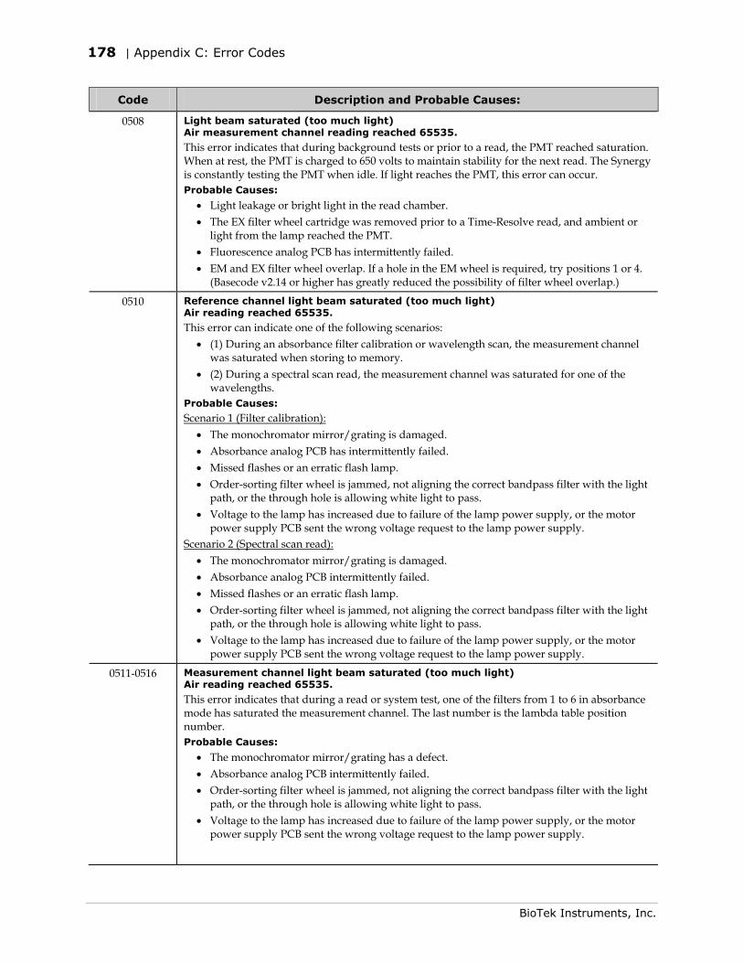
178 | Appendix C: Error Codes
BioTek Instruments, Inc.
Code Description and Probable Causes:
0508 Light beam saturated (too much light) Air measurement channel reading reached 65535.
This error indicates that during background tests or prior to a read, the PMT reached saturation. When at rest, the PMT is charged to 650 volts to maintain stability for the next read. The Synergy is constantly testing the PMT when idle. If light reaches the PMT, this error can occur. Probable Causes:
• Light leakage or bright light in the read chamber. • The EX filter wheel cartridge was removed prior to a Time-Resolve read, and ambient or
light from the lamp reached the PMT. • Fluorescence analog PCB has intermittently failed. • EM and EX filter wheel overlap. If a hole in the EM wheel is required, try positions 1 or 4.
(Basecode v2.14 or higher has greatly reduced the possibility of filter wheel overlap.)
0510 Reference channel light beam saturated (too much light) Air reading reached 65535.
This error can indicate one of the following scenarios: • (1) During an absorbance filter calibration or wavelength scan, the measurement channel
was saturated when storing to memory. • (2) During a spectral scan read, the measurement channel was saturated for one of the
wavelengths. Probable Causes:
Scenario 1 (Filter calibration): • The monochromator mirror/grating is damaged. • Absorbance analog PCB has intermittently failed. • Missed flashes or an erratic flash lamp. • Order-sorting filter wheel is jammed, not aligning the correct bandpass filter with the light
path, or the through hole is allowing white light to pass. • Voltage to the lamp has increased due to failure of the lamp power supply, or the motor
power supply PCB sent the wrong voltage request to the lamp power supply. Scenario 2 (Spectral scan read):
• The monochromator mirror/grating is damaged. • Absorbance analog PCB intermittently failed. • Missed flashes or an erratic flash lamp. • Order-sorting filter wheel is jammed, not aligning the correct bandpass filter with the light
path, or the through hole is allowing white light to pass. • Voltage to the lamp has increased due to failure of the lamp power supply, or the motor
power supply PCB sent the wrong voltage request to the lamp power supply.
0511-0516 Measurement channel light beam saturated (too much light) Air reading reached 65535.
This error indicates that during a read or system test, one of the filters from 1 to 6 in absorbance mode has saturated the measurement channel. The last number is the lambda table position number. Probable Causes:
• The monochromator mirror/grating has a defect. • Absorbance analog PCB intermittently failed. • Order-sorting filter wheel is jammed, not aligning the correct bandpass filter with the light
path, or the through hole is allowing white light to pass. • Voltage to the lamp has increased due to failure of the lamp power supply, or the motor
power supply PCB sent the wrong voltage request to the lamp power supply.
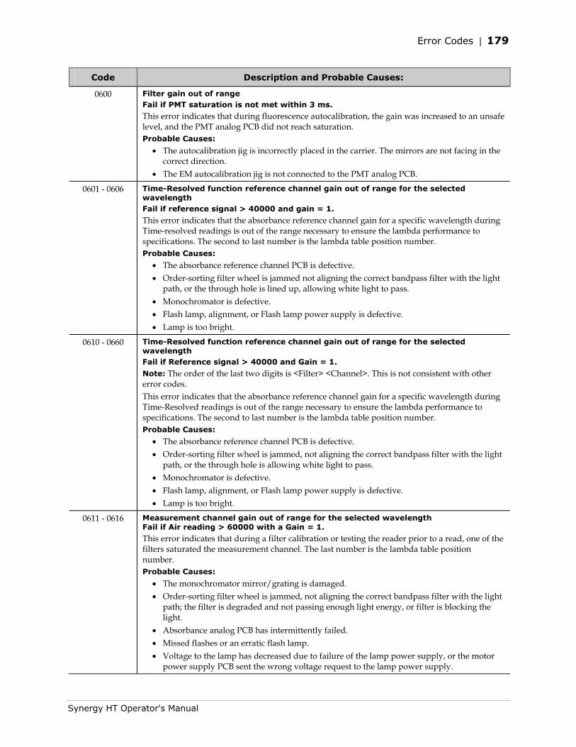
Error Codes | 179
Synergy HT Operator's Manual
Code Description and Probable Causes:
0600 Filter gain out of range Fail if PMT saturation is not met within 3 ms.
This error indicates that during fluorescence autocalibration, the gain was increased to an unsafe level, and the PMT analog PCB did not reach saturation. Probable Causes:
• The autocalibration jig is incorrectly placed in the carrier. The mirrors are not facing in the correct direction.
• The EM autocalibration jig is not connected to the PMT analog PCB.
0601 - 0606 Time-Resolved function reference channel gain out of range for the selected wavelength Fail if reference signal > 40000 and gain = 1.
This error indicates that the absorbance reference channel gain for a specific wavelength during Time-resolved readings is out of the range necessary to ensure the lambda performance to specifications. The second to last number is the lambda table position number. Probable Causes:
• The absorbance reference channel PCB is defective. • Order-sorting filter wheel is jammed not aligning the correct bandpass filter with the light
path, or the through hole is lined up, allowing white light to pass. • Monochromator is defective. • Flash lamp, alignment, or Flash lamp power supply is defective. • Lamp is too bright.
0610 - 0660 Time-Resolved function reference channel gain out of range for the selected wavelength Fail if Reference signal > 40000 and Gain = 1.
Note: The order of the last two digits is <Filter> <Channel>. This is not consistent with other error codes. This error indicates that the absorbance reference channel gain for a specific wavelength during Time-Resolved readings is out of the range necessary to ensure the lambda performance to specifications. The second to last number is the lambda table position number. Probable Causes:
• The absorbance reference channel PCB is defective. • Order-sorting filter wheel is jammed, not aligning the correct bandpass filter with the light
path, or the through hole is allowing white light to pass. • Monochromator is defective. • Flash lamp, alignment, or Flash lamp power supply is defective. • Lamp is too bright.
0611 - 0616 Measurement channel gain out of range for the selected wavelength Fail if Air reading > 60000 with a Gain = 1.
This error indicates that during a filter calibration or testing the reader prior to a read, one of the filters saturated the measurement channel. The last number is the lambda table position number. Probable Causes:
• The monochromator mirror/grating is damaged. • Order-sorting filter wheel is jammed, not aligning the correct bandpass filter with the light
path; the filter is degraded and not passing enough light energy, or filter is blocking the light.
• Absorbance analog PCB has intermittently failed. • Missed flashes or an erratic flash lamp. • Voltage to the lamp has decreased due to failure of the lamp power supply, or the motor
power supply PCB sent the wrong voltage request to the lamp power supply.
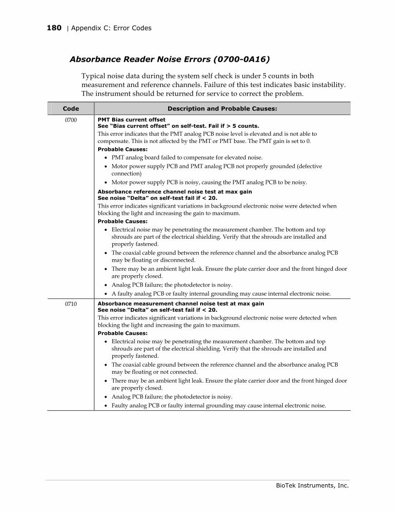
180 | Appendix C: Error Codes
BioTek Instruments, Inc.
Absorbance Reader Noise Errors (0700-0A16)
Typical noise data during the system self check is under 5 counts in both measurement and reference channels. Failure of this test indicates basic instability. The instrument should be returned for service to correct the problem.
Code Description and Probable Causes:
0700 PMT Bias current offset See “Bias current offset” on self-test. Fail if > 5 counts.
This error indicates that the PMT analog PCB noise level is elevated and is not able to compensate. This is not affected by the PMT or PMT base. The PMT gain is set to 0. Probable Causes:
• PMT analog board failed to compensate for elevated noise. • Motor power supply PCB and PMT analog PCB not properly grounded (defective
connection) • Motor power supply PCB is noisy, causing the PMT analog PCB to be noisy.
Absorbance reference channel noise test at max gain See noise “Delta” on self-test fail if < 20.
This error indicates significant variations in background electronic noise were detected when blocking the light and increasing the gain to maximum. Probable Causes:
• Electrical noise may be penetrating the measurement chamber. The bottom and top shrouds are part of the electrical shielding. Verify that the shrouds are installed and properly fastened.
• The coaxial cable ground between the reference channel and the absorbance analog PCB may be floating or disconnected.
• There may be an ambient light leak. Ensure the plate carrier door and the front hinged door are properly closed.
• Analog PCB failure; the photodetector is noisy. • A faulty analog PCB or faulty internal grounding may cause internal electronic noise.
0710 Absorbance measurement channel noise test at max gain See noise “Delta” on self-test fail if < 20.
This error indicates significant variations in background electronic noise were detected when blocking the light and increasing the gain to maximum. Probable Causes:
• Electrical noise may be penetrating the measurement chamber. The bottom and top shrouds are part of the electrical shielding. Verify that the shrouds are installed and properly fastened.
• The coaxial cable ground between the reference channel and the absorbance analog PCB may be floating or not connected.
• There may be an ambient light leak. Ensure the plate carrier door and the front hinged door are properly closed.
• Analog PCB failure; the photodetector is noisy. • Faulty analog PCB or faulty internal grounding may cause internal electronic noise.
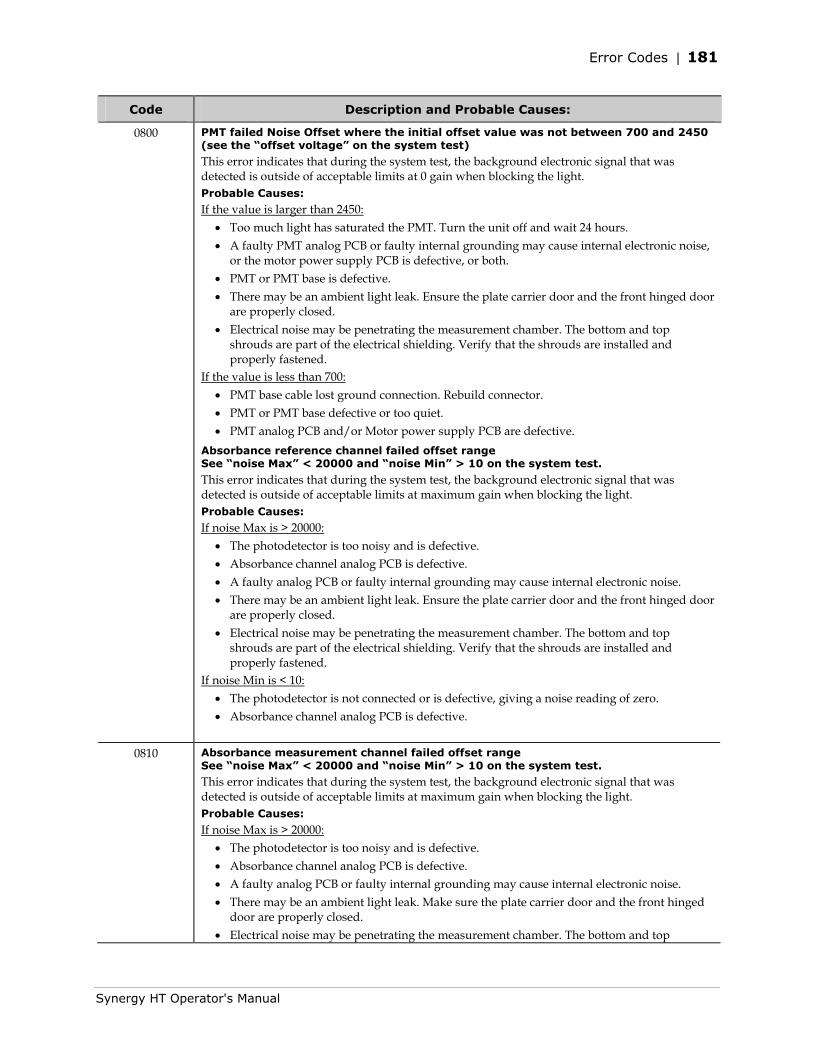
Error Codes | 181
Synergy HT Operator's Manual
Code Description and Probable Causes:
0800 PMT failed Noise Offset where the initial offset value was not between 700 and 2450 (see the “offset voltage” on the system test)
This error indicates that during the system test, the background electronic signal that was detected is outside of acceptable limits at 0 gain when blocking the light. Probable Causes:
If the value is larger than 2450: • Too much light has saturated the PMT. Turn the unit off and wait 24 hours. • A faulty PMT analog PCB or faulty internal grounding may cause internal electronic noise,
or the motor power supply PCB is defective, or both. • PMT or PMT base is defective. • There may be an ambient light leak. Ensure the plate carrier door and the front hinged door
are properly closed. • Electrical noise may be penetrating the measurement chamber. The bottom and top
shrouds are part of the electrical shielding. Verify that the shrouds are installed and properly fastened.
If the value is less than 700: • PMT base cable lost ground connection. Rebuild connector. • PMT or PMT base defective or too quiet. • PMT analog PCB and/or Motor power supply PCB are defective.
Absorbance reference channel failed offset range See “noise Max” < 20000 and “noise Min” > 10 on the system test.
This error indicates that during the system test, the background electronic signal that was detected is outside of acceptable limits at maximum gain when blocking the light. Probable Causes:
If noise Max is > 20000: • The photodetector is too noisy and is defective. • Absorbance channel analog PCB is defective. • A faulty analog PCB or faulty internal grounding may cause internal electronic noise. • There may be an ambient light leak. Ensure the plate carrier door and the front hinged door
are properly closed. • Electrical noise may be penetrating the measurement chamber. The bottom and top
shrouds are part of the electrical shielding. Verify that the shrouds are installed and properly fastened.
If noise Min is < 10: • The photodetector is not connected or is defective, giving a noise reading of zero. • Absorbance channel analog PCB is defective.
0810 Absorbance measurement channel failed offset range See “noise Max” < 20000 and “noise Min” > 10 on the system test.
This error indicates that during the system test, the background electronic signal that was detected is outside of acceptable limits at maximum gain when blocking the light. Probable Causes:
If noise Max is > 20000: • The photodetector is too noisy and is defective. • Absorbance channel analog PCB is defective. • A faulty analog PCB or faulty internal grounding may cause internal electronic noise. • There may be an ambient light leak. Make sure the plate carrier door and the front hinged
door are properly closed. • Electrical noise may be penetrating the measurement chamber. The bottom and top
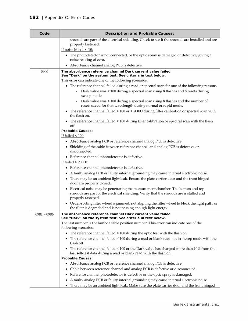
182 | Appendix C: Error Codes
BioTek Instruments, Inc.
Code Description and Probable Causes:
shrouds are part of the electrical shielding. Check to see if the shrouds are installed and are properly fastened.
If noise Min is < 10: • The photodetector is not connected, or the optic spray is damaged or defective, giving a
noise reading of zero. • Absorbance channel analog PCB is defective.
0900 The absorbance reference channel Dark current value failed See “Dark” on the system test. See criteria in text below.
This error can indicate one of the following scenarios: • The reference channel failed during a read or spectral scan for one of the following reasons:
- Dark value was < 100 during a spectral scan using 8 flashes and 8 resets during sweep mode.
- Dark value was < 100 during a spectral scan using 8 flashes and the number of resets saved for that wavelength during normal or rapid mode.
• The reference channel failed < 100 or > 20000 during filter calibration or spectral scan with the flash on.
• The reference channel failed < 100 during filter calibration or spectral scan with the flash off.
Probable Causes:
If failed < 100: • Absorbance analog PCB or reference channel analog PCB is defective. • Shielding of the cable between reference channel and analog PCB is defective or
disconnected. • Reference channel photodetector is defective.
If failed > 20000: • Reference channel photodetector is defective. • A faulty analog PCB or faulty internal grounding may cause internal electronic noise. • There may be an ambient light leak. Ensure the plate carrier door and the front hinged
door are properly closed. • Electrical noise may be penetrating the measurement chamber. The bottom and top
shrouds are part of the electrical shielding. Verify that the shrouds are installed and properly fastened.
• Order-sorting filter wheel is jammed, not aligning the filter wheel to block the light path, or the filter is degraded and is not passing enough light energy.
0901 – 0906 The absorbance reference channel Dark current value failed See “Dark” on the system test. See criteria in text below.
The last number is the lambda table position number. This error can indicate one of the following scenarios:
• The reference channel failed < 100 during the optic test with the flash on. • The reference channel failed < 100 during a read or blank read not in sweep mode with the
flash off. • The reference channel failed < 100 or the Dark value has changed more than 10% from the
last self-test data during a read or blank read with the flash on. Probable Causes:
• Absorbance analog PCB or reference channel analog PCB is defective. • Cable between reference channel and analog PCB is defective or disconnected. • Reference channel photodetector is defective or the optic spray is damaged. • A faulty analog PCB or faulty internal grounding may cause internal electronic noise. • There may be an ambient light leak. Make sure the plate carrier door and the front hinged
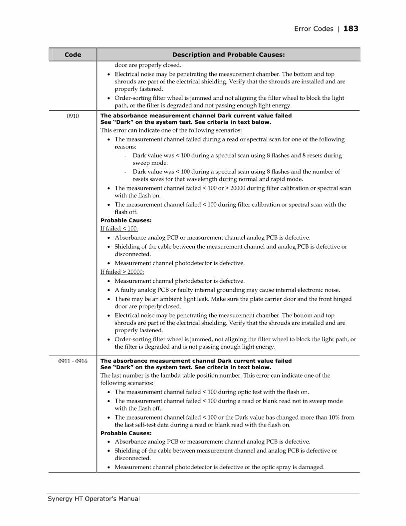
Error Codes | 183
Synergy HT Operator's Manual
Code Description and Probable Causes:
door are properly closed. • Electrical noise may be penetrating the measurement chamber. The bottom and top
shrouds are part of the electrical shielding. Verify that the shrouds are installed and are properly fastened.
• Order-sorting filter wheel is jammed and not aligning the filter wheel to block the light path, or the filter is degraded and not passing enough light energy.
0910 The absorbance measurement channel Dark current value failed See “Dark” on the system test. See criteria in text below.
This error can indicate one of the following scenarios: • The measurement channel failed during a read or spectral scan for one of the following
reasons: - Dark value was < 100 during a spectral scan using 8 flashes and 8 resets during
sweep mode. - Dark value was < 100 during a spectral scan using 8 flashes and the number of
resets saves for that wavelength during normal and rapid mode. • The measurement channel failed < 100 or > 20000 during filter calibration or spectral scan
with the flash on. • The measurement channel failed < 100 during filter calibration or spectral scan with the
flash off. Probable Causes:
If failed < 100: • Absorbance analog PCB or measurement channel analog PCB is defective. • Shielding of the cable between the measurement channel and analog PCB is defective or
disconnected. • Measurement channel photodetector is defective.
If failed > 20000: • Measurement channel photodetector is defective. • A faulty analog PCB or faulty internal grounding may cause internal electronic noise. • There may be an ambient light leak. Make sure the plate carrier door and the front hinged
door are properly closed. • Electrical noise may be penetrating the measurement chamber. The bottom and top
shrouds are part of the electrical shielding. Verify that the shrouds are installed and are properly fastened.
• Order-sorting filter wheel is jammed, not aligning the filter wheel to block the light path, or the filter is degraded and is not passing enough light energy.
0911 - 0916 The absorbance measurement channel Dark current value failed See “Dark” on the system test. See criteria in text below.
The last number is the lambda table position number. This error can indicate one of the following scenarios:
• The measurement channel failed < 100 during optic test with the flash on. • The measurement channel failed < 100 during a read or blank read not in sweep mode
with the flash off. • The measurement channel failed < 100 or the Dark value has changed more than 10% from
the last self-test data during a read or blank read with the flash on. Probable Causes:
• Absorbance analog PCB or measurement channel analog PCB is defective. • Shielding of the cable between measurement channel and analog PCB is defective or
disconnected. • Measurement channel photodetector is defective or the optic spray is damaged.
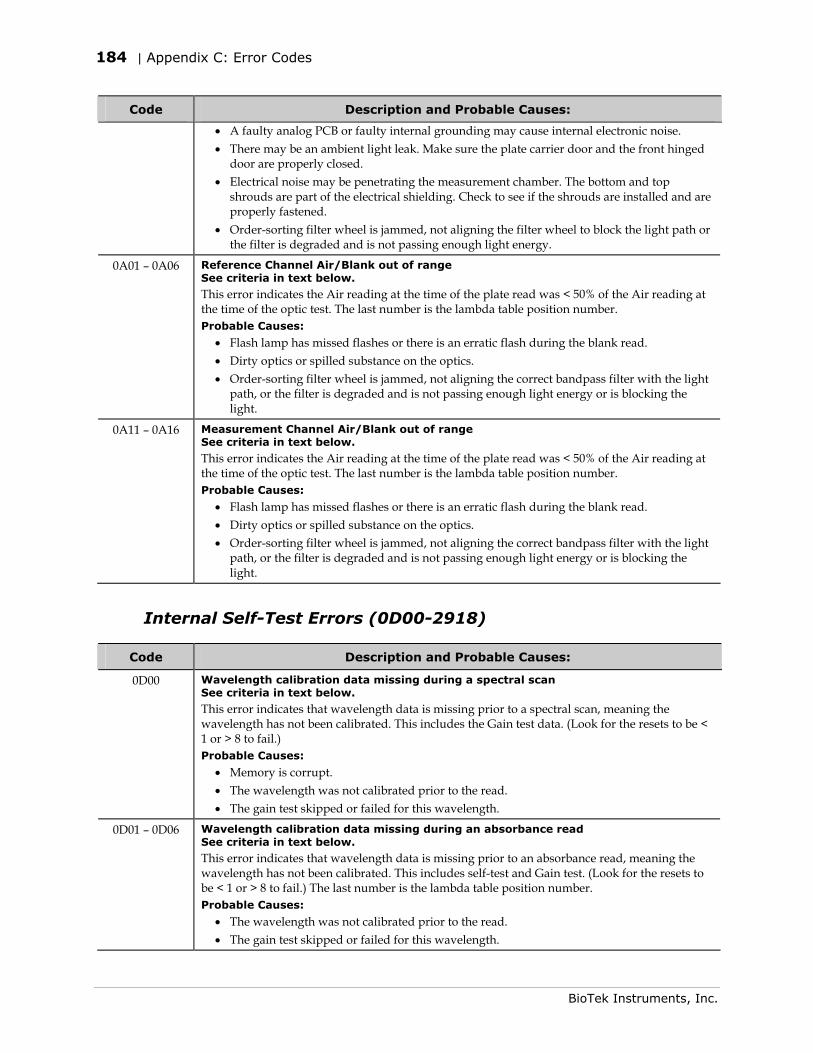
184 | Appendix C: Error Codes
BioTek Instruments, Inc.
Code Description and Probable Causes:
• A faulty analog PCB or faulty internal grounding may cause internal electronic noise. • There may be an ambient light leak. Make sure the plate carrier door and the front hinged
door are properly closed. • Electrical noise may be penetrating the measurement chamber. The bottom and top
shrouds are part of the electrical shielding. Check to see if the shrouds are installed and are properly fastened.
• Order-sorting filter wheel is jammed, not aligning the filter wheel to block the light path or the filter is degraded and is not passing enough light energy.
0A01 – 0A06 Reference Channel Air/Blank out of range See criteria in text below.
This error indicates the Air reading at the time of the plate read was < 50% of the Air reading at the time of the optic test. The last number is the lambda table position number. Probable Causes:
• Flash lamp has missed flashes or there is an erratic flash during the blank read. • Dirty optics or spilled substance on the optics. • Order-sorting filter wheel is jammed, not aligning the correct bandpass filter with the light
path, or the filter is degraded and is not passing enough light energy or is blocking the light.
0A11 – 0A16 Measurement Channel Air/Blank out of range See criteria in text below.
This error indicates the Air reading at the time of the plate read was < 50% of the Air reading at the time of the optic test. The last number is the lambda table position number. Probable Causes:
• Flash lamp has missed flashes or there is an erratic flash during the blank read. • Dirty optics or spilled substance on the optics. • Order-sorting filter wheel is jammed, not aligning the correct bandpass filter with the light
path, or the filter is degraded and is not passing enough light energy or is blocking the light.
Internal Self-Test Errors (0D00-2918)
Code Description and Probable Causes:
0D00 Wavelength calibration data missing during a spectral scan See criteria in text below.
This error indicates that wavelength data is missing prior to a spectral scan, meaning the wavelength has not been calibrated. This includes the Gain test data. (Look for the resets to be < 1 or > 8 to fail.) Probable Causes:
• Memory is corrupt. • The wavelength was not calibrated prior to the read. • The gain test skipped or failed for this wavelength.
0D01 – 0D06 Wavelength calibration data missing during an absorbance read See criteria in text below.
This error indicates that wavelength data is missing prior to an absorbance read, meaning the wavelength has not been calibrated. This includes self-test and Gain test. (Look for the resets to be < 1 or > 8 to fail.) The last number is the lambda table position number. Probable Causes:
• The wavelength was not calibrated prior to the read. • The gain test skipped or failed for this wavelength.
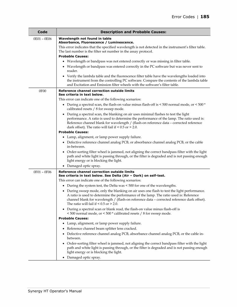
Error Codes | 185
Synergy HT Operator's Manual
Code Description and Probable Causes:
0E01 – 0E06 Wavelength not found in table Absorbance, Fluorescence / Luminescence.
This error indicates that the specified wavelength is not detected in the instrument’s filter table. The last number is the filter set number in the assay protocol. Probable Causes:
• Wavelength or bandpass was not entered correctly or was missing in filter table. • Wavelength or bandpass was entered correctly in the PC software but was never sent to
reader. • Verify the lambda table and the fluorescence filter table have the wavelengths loaded into
the instrument from the controlling PC software. Compare the contents of the lambda table and Excitation and Emission filter wheels with the software’s filter table.
0F00 Reference channel correction outside limits See criteria in text below.
This error can indicate one of the following scenarios: • During a spectral scan, the flash-on value minus flash-off is < 500 normal mode, or < 500 *
calibrated resets / 8 for sweep mode. • During a spectral scan, the blanking on air uses minimal flashes to test the light
performance. A ratio is used to determine the performance of the lamp. The ratio used is: Reference channel blank for wavelength / (flash-on reference data – corrected reference dark offset). The ratio will fail if < 0.5 or > 2.0.
Probable Causes:
• Lamp, alignment, or lamp power supply failure. • Defective reference channel analog PCB, or absorbance channel analog PCB, or the cable
in-between. • Order-sorting filter wheel is jammed, not aligning the correct bandpass filter with the light
path and white light is passing through, or the filter is degraded and is not passing enough light energy or is blocking the light.
• Damaged optic spray.
0F01 – 0F06 Reference channel correction outside limits See criteria in text below. See Delta (Air – Dark) on self-test.
This error can indicate one of the following scenarios: • During the system test, the Delta was < 500 for one of the wavelengths. • During sweep mode, only the blanking on air uses one flash to test the light performance.
A ratio is used to determine the performance of the lamp. The ratio used is: Reference channel blank for wavelength / (flash-on reference data – corrected reference dark offset). The ratio will fail if < 0.5 or > 2.0.
• During a spectral scan or blank read, the flash-on value minus flash-off is < 500 normal mode, or < 500 * calibrated resets / 8 for sweep mode.
Probable Causes:
• Lamp, alignment, or lamp power supply failure. • Reference channel beam splitter lens cracked. • Defective reference channel analog PCB, absorbance channel analog PCB, or the cable in-
between. • Order-sorting filter wheel is jammed, not aligning the correct bandpass filter with the light
path and white light is passing through, or the filter is degraded and is not passing enough light energy or is blocking the light.
• Damaged optic spray.
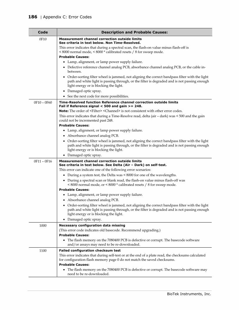
186 | Appendix C: Error Codes
BioTek Instruments, Inc.
Code Description and Probable Causes:
0F10 Measurement channel correction outside limits See criteria in text below. Non Time-Resolved.
This error indicates that during a spectral scan, the flash-on value minus flash-off is < 8000 normal mode, < 8000 * calibrated resets / 8 for sweep mode. Probable Causes:
• Lamp, alignment, or lamp power supply failure. • Defective reference channel analog PCB, absorbance channel analog PCB, or the cable in-
between. • Order-sorting filter wheel is jammed, not aligning the correct bandpass filter with the light
path and white light is passing through, or the filter is degraded and is not passing enough light energy or is blocking the light.
• Damaged optic spray. • See the next code for more possibilities.
0F10 – 0F60 Time-Resolved function Reference channel correction outside limits Fail if Reference signal < 500 and gain >= 248.
Note: The order of <Filter> <Channel> is not consistent with other error codes. This error indicates that during a Time-Resolve read, delta (air – dark) was < 500 and the gain could not be incremented past 248. Probable Causes:
• Lamp, alignment, or lamp power supply failure. • Absorbance channel analog PCB. • Order-sorting filter wheel is jammed, not aligning the correct bandpass filter with the light
path and white light is passing through, or the filter is degraded and is not passing enough light energy or is blocking the light.
• Damaged optic spray.
0F11 – 0F16 Measurement channel correction outside limits See criteria in text below. See Delta (Air – Dark) on self-test.
This error can indicate one of the following error scenarios: • During a system test, the Delta was < 8000 for one of the wavelengths. • During a spectral scan or blank read, the flash-on value minus flash-off was
< 8000 normal mode, or < 8000 * calibrated resets / 8 for sweep mode. Probable Causes:
• Lamp, alignment, or lamp power supply failure. • Absorbance channel analog PCB. • Order-sorting filter wheel is jammed, not aligning the correct bandpass filter with the light
path and white light is passing through, or the filter is degraded and is not passing enough light energy or is blocking the light.
• Damaged optic spray.
1000 Necessary configuration data missing
(This error code indicates old basecode. Recommend upgrading.) Probable Causes:
• The flash memory on the 7080400 PCB is defective or corrupt. The basecode software and/or assays may need to be re-downloaded.
1100 Failed configuration checksum test
This error indicates that during self-test or at the end of a plate read, the checksums calculated for configuration flash memory page 0 do not match the saved checksums. Probable Causes:
• The flash memory on the 7080400 PCB is defective or corrupt. The basecode software may need to be re-downloaded.
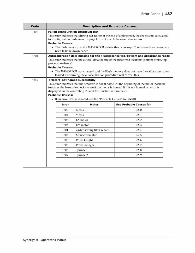
Error Codes | 187
Synergy HT Operator's Manual
Code Description and Probable Causes:
1101 Failed configuration checksum test
This error indicates that during self-test or at the end of a plate read, the checksums calculated for configuration flash memory page 1 do not match the saved checksums. Probable Causes:
• The flash memory on the 7080400 PCB is defective or corrupt. The basecode software may need to be re-downloaded.
1200 Autocalibration data missing for the Fluorescence top/bottom and absorbance reads
This error indicates that no autocal data for any of the three read locations (bottom probe, top probe, absorbance). Probable Causes:
• The 7080400 PCB was changed and the Flash memory does not have the calibration values loaded. Performing the autocalibration procedure will correct this.
130x <Motor> not homed successfully
This error indicates that the <motor> is not at home. At the beginning of the motor_position function, the basecode checks to see if the motor is homed. If it is not homed, an error is displayed on the controlling PC and the function is terminated. Probable Causes:
• If an error 0200 is ignored, see the “Probable Causes” for 0200.
Error Motor See Probable Causes for
1300 X-axis 0200
1301 Y-axis 0201
1302 EX motor 0202
1303 EM motor 0203
1304 Order-sorting filter wheel 0204
1305 Monochromator 0405
1306 Probe Height 0206
1307 Probe changer 0207
1308 Syringe 1 0208
1309 Syringe 2 0209
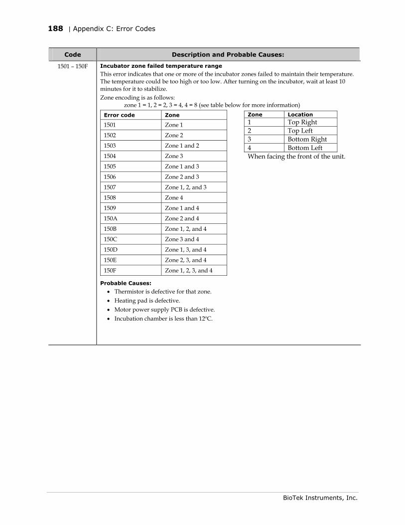
188 | Appendix C: Error Codes
BioTek Instruments, Inc.
Code Description and Probable Causes:
1501 – 150F Incubator zone failed temperature range
This error indicates that one or more of the incubator zones failed to maintain their temperature. The temperature could be too high or too low. After turning on the incubator, wait at least 10 minutes for it to stabilize. Zone encoding is as follows: zone 1 = 1, 2 = 2, 3 = 4, 4 = 8 (see table below for more information)
Error code Zone
1501 Zone 1
1502 Zone 2
1503 Zone 1 and 2
1504 Zone 3
1505 Zone 1 and 3
1506 Zone 2 and 3
1507 Zone 1, 2, and 3
1508 Zone 4
1509 Zone 1 and 4
150A Zone 2 and 4
150B Zone 1, 2, and 4
150C Zone 3 and 4
150D Zone 1, 3, and 4
150E Zone 2, 3, and 4
150F Zone 1, 2, 3, and 4
Probable Causes:
• Thermistor is defective for that zone. • Heating pad is defective. • Motor power supply PCB is defective. • Incubation chamber is less than 12ºC.
Zone Location 1 Top Right 2 Top Left 3 Bottom Right 4 Bottom Left When facing the front of the unit.
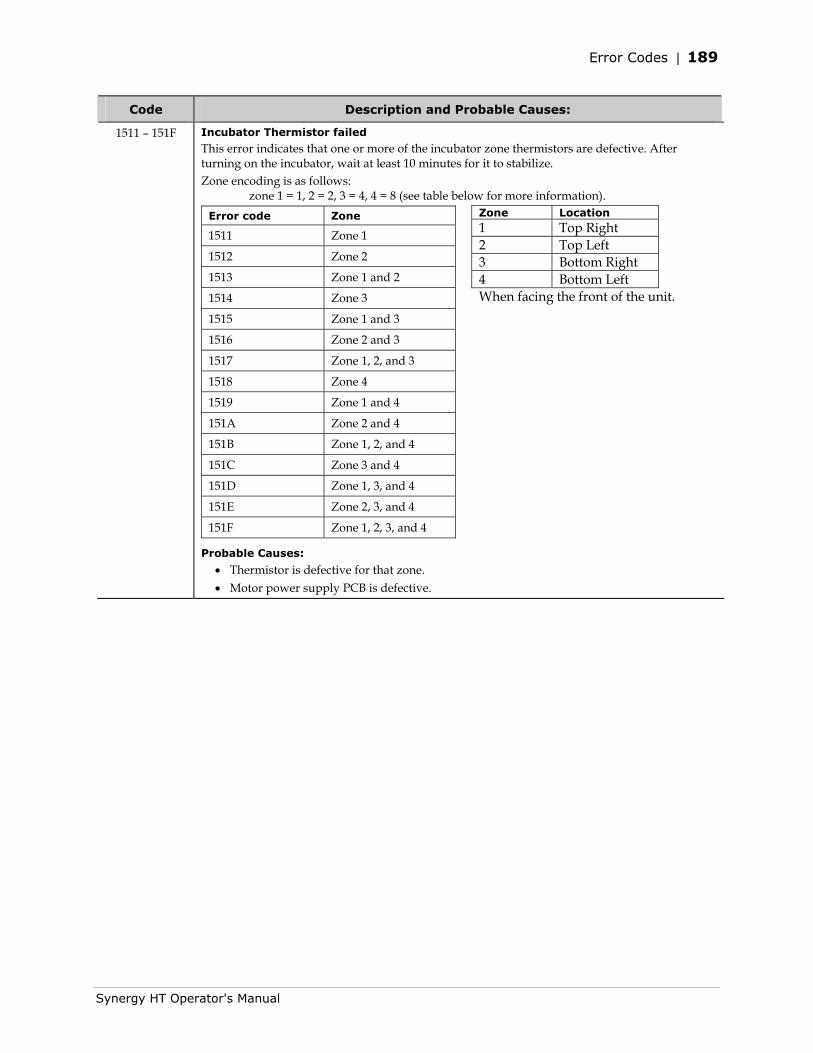
Error Codes | 189
Synergy HT Operator's Manual
Code Description and Probable Causes:
1511 – 151F Incubator Thermistor failed
This error indicates that one or more of the incubator zone thermistors are defective. After turning on the incubator, wait at least 10 minutes for it to stabilize. Zone encoding is as follows: zone 1 = 1, 2 = 2, 3 = 4, 4 = 8 (see table below for more information).
Error code Zone
1511 Zone 1
1512 Zone 2
1513 Zone 1 and 2
1514 Zone 3
1515 Zone 1 and 3
1516 Zone 2 and 3
1517 Zone 1, 2, and 3
1518 Zone 4
1519 Zone 1 and 4
151A Zone 2 and 4
151B Zone 1, 2, and 4
151C Zone 3 and 4
151D Zone 1, 3, and 4
151E Zone 2, 3, and 4
151F Zone 1, 2, 3, and 4
Probable Causes:
• Thermistor is defective for that zone. • Motor power supply PCB is defective.
Zone Location 1 Top Right 2 Top Left 3 Bottom Right 4 Bottom Left When facing the front of the unit.
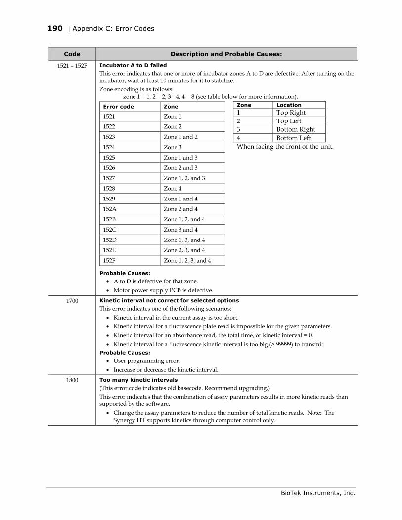
190 | Appendix C: Error Codes
BioTek Instruments, Inc.
Code Description and Probable Causes:
1521 – 152F Incubator A to D failed
This error indicates that one or more of incubator zones A to D are defective. After turning on the incubator, wait at least 10 minutes for it to stabilize. Zone encoding is as follows: zone 1 = 1, 2 = 2, 3= 4, 4 = 8 (see table below for more information).
Error code Zone
1521 Zone 1
1522 Zone 2
1523 Zone 1 and 2
1524 Zone 3
1525 Zone 1 and 3
1526 Zone 2 and 3
1527 Zone 1, 2, and 3
1528 Zone 4
1529 Zone 1 and 4
152A Zone 2 and 4
152B Zone 1, 2, and 4
152C Zone 3 and 4
152D Zone 1, 3, and 4
152E Zone 2, 3, and 4
152F Zone 1, 2, 3, and 4
Probable Causes:
• A to D is defective for that zone. • Motor power supply PCB is defective.
1700 Kinetic interval not correct for selected options
This error indicates one of the following scenarios: • Kinetic interval in the current assay is too short. • Kinetic interval for a fluorescence plate read is impossible for the given parameters. • Kinetic interval for an absorbance read, the total time, or kinetic interval = 0. • Kinetic interval for a fluorescence kinetic interval is too big (> 99999) to transmit.
Probable Causes:
• User programming error. • Increase or decrease the kinetic interval.
1800 Too many kinetic intervals
(This error code indicates old basecode. Recommend upgrading.) This error indicates that the combination of assay parameters results in more kinetic reads than supported by the software.
• Change the assay parameters to reduce the number of total kinetic reads. Note: The Synergy HT supports kinetics through computer control only.
Zone Location 1 Top Right 2 Top Left 3 Bottom Right 4 Bottom Left When facing the front of the unit.
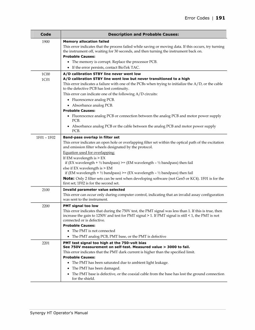
Error Codes | 191
Synergy HT Operator's Manual
Code Description and Probable Causes:
1900 Memory allocation failed
This error indicates that the process failed while saving or moving data. If this occurs, try turning the instrument off, waiting for 30 seconds, and then turning the instrument back on. Probable Causes:
• The memory is corrupt. Replace the processor PCB. • If the error persists, contact BioTek TAC.
1C00 1C01
A/D calibration STBY line never went low A/D calibration STBY line went low but never transitioned to a high This error indicates a failure with one of the PCBs when trying to initialize the A/D, or the cable to the defective PCB has lost continuity. This error can indicate one of the following A/D circuits:
• Fluorescence analog PCB. • Absorbance analog PCB.
Probable Causes:
• Fluorescence analog PCB or connection between the analog PCB and motor power supply PCB.
• Absorbance analog PCB or the cable between the analog PCB and motor power supply PCB.
1F01 – 1F02 Band-pass overlap in filter set
This error indicates an open hole or overlapping filter set within the optical path of the excitation and emission filter wheels designated by the protocol. Equation used for overlapping: If EM wavelength is > EX if (EX wavelength + ½ bandpass) >= (EM wavelength – ½ bandpass) then fail else if EX wavelength is > EM if (EM wavelength + ½ bandpass) >= (EX wavelength – ½ bandpass) then fail Note: Only 2 filter sets can be sent when developing software (not Gen5 or KC4). 1F01 is for the first set; 1F02 is for the second set.
2100 Invalid parameter value selected
This error can occur only during computer control, indicating that an invalid assay configuration was sent to the instrument.
2200 PMT signal too low
This error indicates that during the 750V test, the PMT signal was less than 1. If this is true, then increase the gain to 1250V and test for PMT signal > 1. If PMT signal is still < 1, the PMT is not connected or is defective. Probable Causes:
• The PMT is not connected • The PMT analog PCB, PMT base, or the PMT is defective
2201 PMT test signal too high at the 750-volt bias See 750V measurement on self-test. Measured value > 3000 to fail.
This error indicates that the PMT dark current is higher than the specified limit. Probable Causes:
• The PMT has been saturated due to ambient light leakage. • The PMT has been damaged. • The PMT base is defective, or the coaxial cable from the base has lost the ground connection
for the shield.
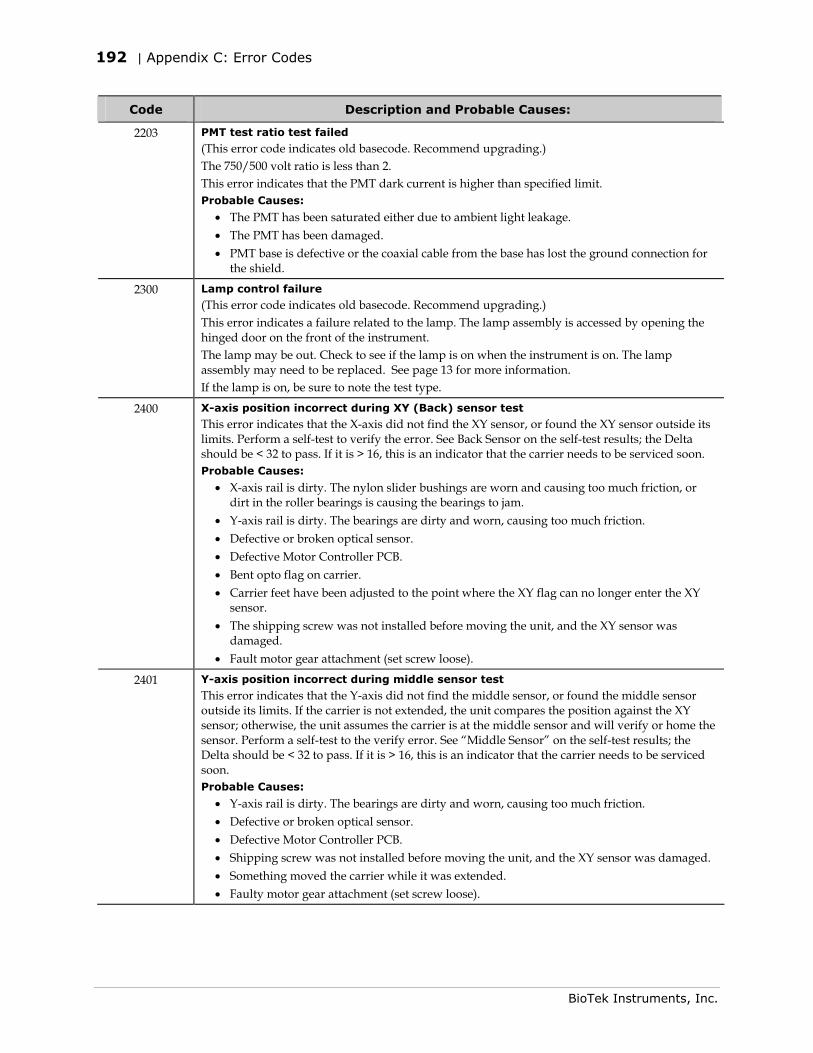
192 | Appendix C: Error Codes
BioTek Instruments, Inc.
Code Description and Probable Causes:
2203 PMT test ratio test failed
(This error code indicates old basecode. Recommend upgrading.) The 750/500 volt ratio is less than 2. This error indicates that the PMT dark current is higher than specified limit. Probable Causes:
• The PMT has been saturated either due to ambient light leakage. • The PMT has been damaged. • PMT base is defective or the coaxial cable from the base has lost the ground connection for
the shield.
2300 Lamp control failure
(This error code indicates old basecode. Recommend upgrading.) This error indicates a failure related to the lamp. The lamp assembly is accessed by opening the hinged door on the front of the instrument. The lamp may be out. Check to see if the lamp is on when the instrument is on. The lamp assembly may need to be replaced. See page 13 for more information. If the lamp is on, be sure to note the test type.
2400 X-axis position incorrect during XY (Back) sensor test
This error indicates that the X-axis did not find the XY sensor, or found the XY sensor outside its limits. Perform a self-test to verify the error. See Back Sensor on the self-test results; the Delta should be < 32 to pass. If it is > 16, this is an indicator that the carrier needs to be serviced soon. Probable Causes:
• X-axis rail is dirty. The nylon slider bushings are worn and causing too much friction, or dirt in the roller bearings is causing the bearings to jam.
• Y-axis rail is dirty. The bearings are dirty and worn, causing too much friction. • Defective or broken optical sensor. • Defective Motor Controller PCB. • Bent opto flag on carrier. • Carrier feet have been adjusted to the point where the XY flag can no longer enter the XY
sensor. • The shipping screw was not installed before moving the unit, and the XY sensor was
damaged. • Fault motor gear attachment (set screw loose).
2401 Y-axis position incorrect during middle sensor test
This error indicates that the Y-axis did not find the middle sensor, or found the middle sensor outside its limits. If the carrier is not extended, the unit compares the position against the XY sensor; otherwise, the unit assumes the carrier is at the middle sensor and will verify or home the sensor. Perform a self-test to the verify error. See “Middle Sensor” on the self-test results; the Delta should be < 32 to pass. If it is > 16, this is an indicator that the carrier needs to be serviced soon. Probable Causes:
• Y-axis rail is dirty. The bearings are dirty and worn, causing too much friction. • Defective or broken optical sensor. • Defective Motor Controller PCB. • Shipping screw was not installed before moving the unit, and the XY sensor was damaged. • Something moved the carrier while it was extended. • Faulty motor gear attachment (set screw loose).
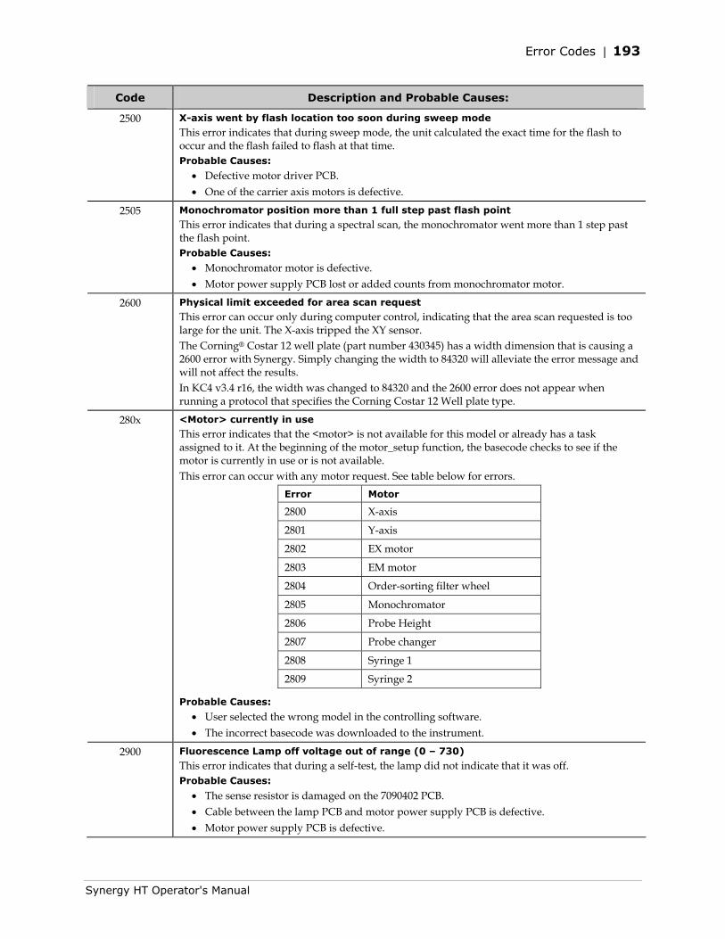
Error Codes | 193
Synergy HT Operator's Manual
Code Description and Probable Causes:
2500 X-axis went by flash location too soon during sweep mode
This error indicates that during sweep mode, the unit calculated the exact time for the flash to occur and the flash failed to flash at that time. Probable Causes:
• Defective motor driver PCB. • One of the carrier axis motors is defective.
2505 Monochromator position more than 1 full step past flash point
This error indicates that during a spectral scan, the monochromator went more than 1 step past the flash point. Probable Causes:
• Monochromator motor is defective. • Motor power supply PCB lost or added counts from monochromator motor.
2600 Physical limit exceeded for area scan request
This error can occur only during computer control, indicating that the area scan requested is too large for the unit. The X-axis tripped the XY sensor. The Corning® Costar 12 well plate (part number 430345) has a width dimension that is causing a 2600 error with Synergy. Simply changing the width to 84320 will alleviate the error message and will not affect the results. In KC4 v3.4 r16, the width was changed to 84320 and the 2600 error does not appear when running a protocol that specifies the Corning Costar 12 Well plate type.
280x <Motor> currently in use
This error indicates that the <motor> is not available for this model or already has a task assigned to it. At the beginning of the motor_setup function, the basecode checks to see if the motor is currently in use or is not available. This error can occur with any motor request. See table below for errors.
Error Motor
2800 X-axis
2801 Y-axis
2802 EX motor
2803 EM motor
2804 Order-sorting filter wheel
2805 Monochromator
2806 Probe Height
2807 Probe changer
2808 Syringe 1
2809 Syringe 2
Probable Causes:
• User selected the wrong model in the controlling software. • The incorrect basecode was downloaded to the instrument.
2900 Fluorescence Lamp off voltage out of range (0 – 730)
This error indicates that during a self-test, the lamp did not indicate that it was off. Probable Causes:
• The sense resistor is damaged on the 7090402 PCB. • Cable between the lamp PCB and motor power supply PCB is defective. • Motor power supply PCB is defective.
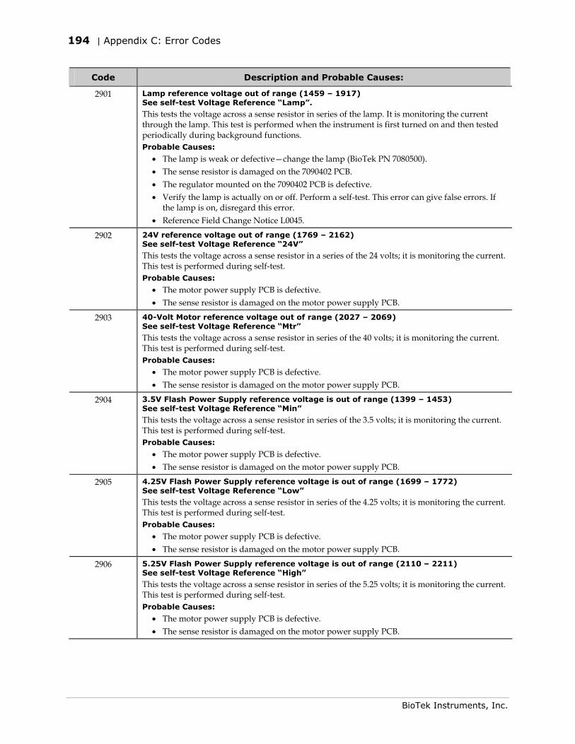
194 | Appendix C: Error Codes
BioTek Instruments, Inc.
Code Description and Probable Causes:
2901 Lamp reference voltage out of range (1459 – 1917) See self-test Voltage Reference “Lamp”.
This tests the voltage across a sense resistor in series of the lamp. It is monitoring the current through the lamp. This test is performed when the instrument is first turned on and then tested periodically during background functions. Probable Causes:
• The lamp is weak or defective—change the lamp (BioTek PN 7080500). • The sense resistor is damaged on the 7090402 PCB. • The regulator mounted on the 7090402 PCB is defective. • Verify the lamp is actually on or off. Perform a self-test. This error can give false errors. If
the lamp is on, disregard this error. • Reference Field Change Notice L0045.
2902 24V reference voltage out of range (1769 – 2162) See self-test Voltage Reference “24V”
This tests the voltage across a sense resistor in a series of the 24 volts; it is monitoring the current. This test is performed during self-test. Probable Causes:
• The motor power supply PCB is defective. • The sense resistor is damaged on the motor power supply PCB.
2903 40-Volt Motor reference voltage out of range (2027 – 2069) See self-test Voltage Reference “Mtr”
This tests the voltage across a sense resistor in series of the 40 volts; it is monitoring the current. This test is performed during self-test. Probable Causes:
• The motor power supply PCB is defective. • The sense resistor is damaged on the motor power supply PCB.
2904 3.5V Flash Power Supply reference voltage is out of range (1399 – 1453) See self-test Voltage Reference “Min”
This tests the voltage across a sense resistor in series of the 3.5 volts; it is monitoring the current. This test is performed during self-test. Probable Causes:
• The motor power supply PCB is defective. • The sense resistor is damaged on the motor power supply PCB.
2905 4.25V Flash Power Supply reference voltage is out of range (1699 – 1772) See self-test Voltage Reference “Low”
This tests the voltage across a sense resistor in series of the 4.25 volts; it is monitoring the current. This test is performed during self-test. Probable Causes:
• The motor power supply PCB is defective. • The sense resistor is damaged on the motor power supply PCB.
2906 5.25V Flash Power Supply reference voltage is out of range (2110 – 2211) See self-test Voltage Reference “High”
This tests the voltage across a sense resistor in series of the 5.25 volts; it is monitoring the current. This test is performed during self-test. Probable Causes:
• The motor power supply PCB is defective. • The sense resistor is damaged on the motor power supply PCB.
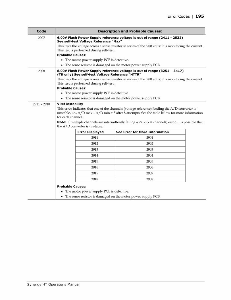
Error Codes | 195
Synergy HT Operator's Manual
Code Description and Probable Causes:
2907 6.00V Flash Power Supply reference voltage is out of range (2411 - 2532) See self-test Voltage Reference “Max”
This tests the voltage across a sense resistor in series of the 6.00 volts; it is monitoring the current. This test is performed during self-test. Probable Causes:
• The motor power supply PCB is defective. • The sense resistor is damaged on the motor power supply PCB.
2908 8.00V Flash Power Supply reference voltage is out of range (3251 – 3417) (TR only) See self-test Voltage Reference “HTTR”
This tests the voltage across a sense resistor in series of the 8.00 volts; it is monitoring the current. This test is performed during self-test. Probable Causes:
• The motor power supply PCB is defective. • The sense resistor is damaged on the motor power supply PCB.
2911 – 2918 VRef instability
This error indicates that one of the channels (voltage reference) feeding the A/D converter is unstable, i.e., A/D max – A/D min > 8 after 8 attempts. See the table below for more information for each channel. Note: If multiple channels are intermittently failing a 291x (x = channels) error, it is possible that the A/D converter is unstable.
Error Displayed See Error for More Information
2911 2901
2912 2902
2913 2903
2914 2904
2915 2905
2916 2906
2917 2907
2918 2908
Probable Causes:
• The motor power supply PCB is defective. • The sense resistor is damaged on the motor power supply PCB.
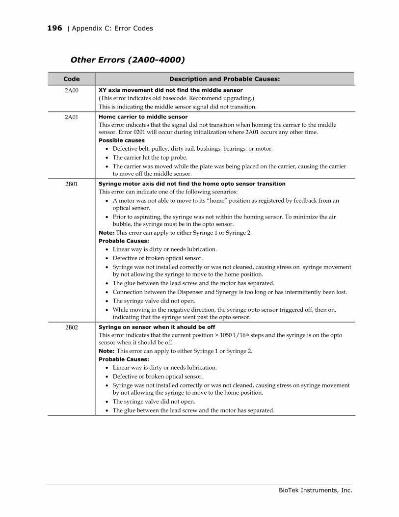
196 | Appendix C: Error Codes
BioTek Instruments, Inc.
Other Errors (2A00-4000)
Code Description and Probable Causes:
2A00 XY axis movement did not find the middle sensor
(This error indicates old basecode. Recommend upgrading.) This is indicating the middle sensor signal did not transition.
2A01 Home carrier to middle sensor
This error indicates that the signal did not transition when homing the carrier to the middle sensor. Error 0201 will occur during initialization where 2A01 occurs any other time. Possible causes
• Defective belt, pulley, dirty rail, bushings, bearings, or motor. • The carrier hit the top probe. • The carrier was moved while the plate was being placed on the carrier, causing the carrier
to move off the middle sensor.
2B01 Syringe motor axis did not find the home opto sensor transition
This error can indicate one of the following scenarios: • A motor was not able to move to its “home” position as registered by feedback from an
optical sensor. • Prior to aspirating, the syringe was not within the homing sensor. To minimize the air
bubble, the syringe must be in the opto sensor. Note: This error can apply to either Syringe 1 or Syringe 2. Probable Causes:
• Linear way is dirty or needs lubrication. • Defective or broken optical sensor. • Syringe was not installed correctly or was not cleaned, causing stress on syringe movement
by not allowing the syringe to move to the home position. • The glue between the lead screw and the motor has separated. • Connection between the Dispenser and Synergy is too long or has intermittently been lost. • The syringe valve did not open. • While moving in the negative direction, the syringe opto sensor triggered off, then on,
indicating that the syringe went past the opto sensor.
2B02 Syringe on sensor when it should be off
This error indicates that the current position > 1050 1/16th steps and the syringe is on the opto sensor when it should be off. Note: This error can apply to either Syringe 1 or Syringe 2. Probable Causes:
• Linear way is dirty or needs lubrication. • Defective or broken optical sensor. • Syringe was not installed correctly or was not cleaned, causing stress on syringe movement
by not allowing the syringe to move to the home position. • The syringe valve did not open. • The glue between the lead screw and the motor has separated.
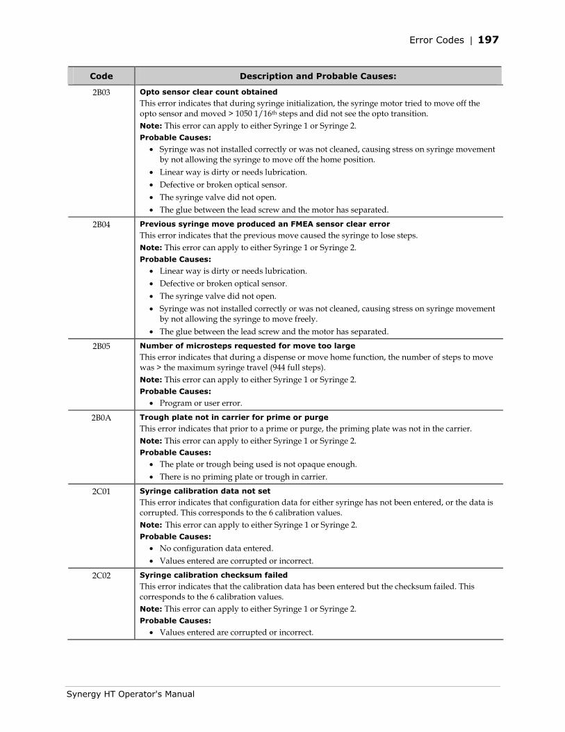
Error Codes | 197
Synergy HT Operator's Manual
Code Description and Probable Causes:
2B03 Opto sensor clear count obtained
This error indicates that during syringe initialization, the syringe motor tried to move off the opto sensor and moved > 1050 1/16th steps and did not see the opto transition. Note: This error can apply to either Syringe 1 or Syringe 2. Probable Causes:
• Syringe was not installed correctly or was not cleaned, causing stress on syringe movement by not allowing the syringe to move off the home position.
• Linear way is dirty or needs lubrication. • Defective or broken optical sensor. • The syringe valve did not open. • The glue between the lead screw and the motor has separated.
2B04 Previous syringe move produced an FMEA sensor clear error
This error indicates that the previous move caused the syringe to lose steps. Note: This error can apply to either Syringe 1 or Syringe 2. Probable Causes:
• Linear way is dirty or needs lubrication. • Defective or broken optical sensor. • The syringe valve did not open. • Syringe was not installed correctly or was not cleaned, causing stress on syringe movement
by not allowing the syringe to move freely. • The glue between the lead screw and the motor has separated.
2B05 Number of microsteps requested for move too large
This error indicates that during a dispense or move home function, the number of steps to move was > the maximum syringe travel (944 full steps). Note: This error can apply to either Syringe 1 or Syringe 2. Probable Causes:
• Program or user error.
2B0A Trough plate not in carrier for prime or purge
This error indicates that prior to a prime or purge, the priming plate was not in the carrier. Note: This error can apply to either Syringe 1 or Syringe 2. Probable Causes:
• The plate or trough being used is not opaque enough. • There is no priming plate or trough in carrier.
2C01 Syringe calibration data not set
This error indicates that configuration data for either syringe has not been entered, or the data is corrupted. This corresponds to the 6 calibration values. Note: This error can apply to either Syringe 1 or Syringe 2. Probable Causes:
• No configuration data entered. • Values entered are corrupted or incorrect.
2C02 Syringe calibration checksum failed
This error indicates that the calibration data has been entered but the checksum failed. This corresponds to the 6 calibration values. Note: This error can apply to either Syringe 1 or Syringe 2. Probable Causes:
• Values entered are corrupted or incorrect.
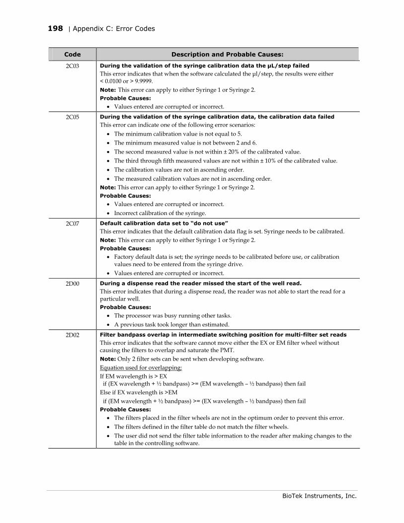
198 | Appendix C: Error Codes
BioTek Instruments, Inc.
Code Description and Probable Causes:
2C03 During the validation of the syringe calibration data the μL/step failed
This error indicates that when the software calculated the μl/step, the results were either < 0.0100 or > 9.9999. Note: This error can apply to either Syringe 1 or Syringe 2. Probable Causes:
• Values entered are corrupted or incorrect.
2C05 During the validation of the syringe calibration data, the calibration data failed
This error can indicate one of the following error scenarios: • The minimum calibration value is not equal to 5. • The minimum measured value is not between 2 and 6. • The second measured value is not within ± 20% of the calibrated value. • The third through fifth measured values are not within ± 10% of the calibrated value. • The calibration values are not in ascending order. • The measured calibration values are not in ascending order.
Note: This error can apply to either Syringe 1 or Syringe 2. Probable Causes:
• Values entered are corrupted or incorrect. • Incorrect calibration of the syringe.
2C07 Default calibration data set to “do not use”
This error indicates that the default calibration data flag is set. Syringe needs to be calibrated. Note: This error can apply to either Syringe 1 or Syringe 2. Probable Causes:
• Factory default data is set; the syringe needs to be calibrated before use, or calibration values need to be entered from the syringe drive.
• Values entered are corrupted or incorrect.
2D00 During a dispense read the reader missed the start of the well read.
This error indicates that during a dispense read, the reader was not able to start the read for a particular well. Probable Causes:
• The processor was busy running other tasks. • A previous task took longer than estimated.
2D02 Filter bandpass overlap in intermediate switching position for multi-filter set reads
This error indicates that the software cannot move either the EX or EM filter wheel without causing the filters to overlap and saturate the PMT. Note: Only 2 filter sets can be sent when developing software. Equation used for overlapping: If EM wavelength is > EX if (EX wavelength + ½ bandpass) >= (EM wavelength – ½ bandpass) then fail Else if EX wavelength is >EM if (EM wavelength + ½ bandpass) >= (EX wavelength – ½ bandpass) then fail Probable Causes:
• The filters placed in the filter wheels are not in the optimum order to prevent this error. • The filters defined in the filter table do not match the filter wheels. • The user did not send the filter table information to the reader after making changes to the
table in the controlling software.
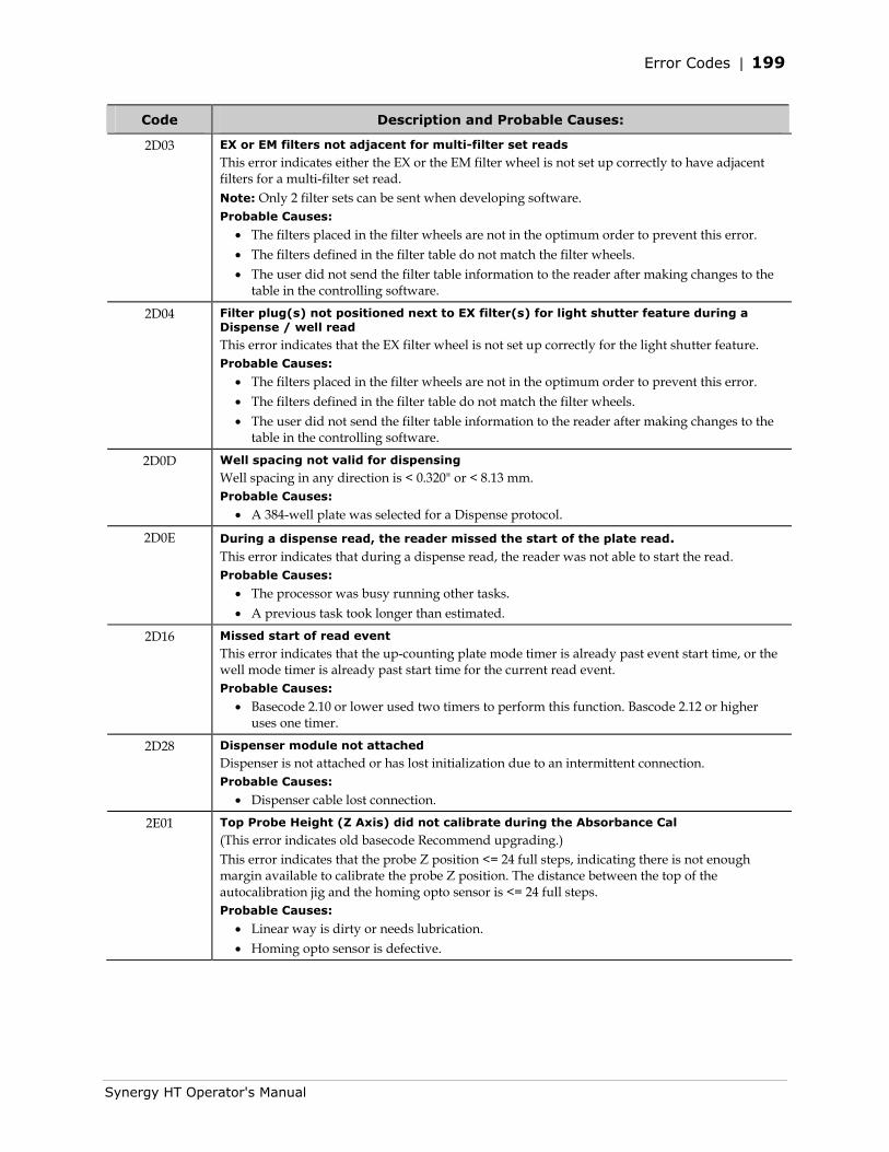
Error Codes | 199
Synergy HT Operator's Manual
Code Description and Probable Causes:
2D03 EX or EM filters not adjacent for multi-filter set reads
This error indicates either the EX or the EM filter wheel is not set up correctly to have adjacent filters for a multi-filter set read. Note: Only 2 filter sets can be sent when developing software. Probable Causes:
• The filters placed in the filter wheels are not in the optimum order to prevent this error. • The filters defined in the filter table do not match the filter wheels. • The user did not send the filter table information to the reader after making changes to the
table in the controlling software.
2D04 Filter plug(s) not positioned next to EX filter(s) for light shutter feature during a Dispense / well read
This error indicates that the EX filter wheel is not set up correctly for the light shutter feature. Probable Causes:
• The filters placed in the filter wheels are not in the optimum order to prevent this error. • The filters defined in the filter table do not match the filter wheels. • The user did not send the filter table information to the reader after making changes to the
table in the controlling software.
2D0D Well spacing not valid for dispensing
Well spacing in any direction is < 0.320" or < 8.13 mm. Probable Causes:
• A 384-well plate was selected for a Dispense protocol.
2D0E During a dispense read, the reader missed the start of the plate read. This error indicates that during a dispense read, the reader was not able to start the read. Probable Causes:
• The processor was busy running other tasks. • A previous task took longer than estimated.
2D16 Missed start of read event
This error indicates that the up-counting plate mode timer is already past event start time, or the well mode timer is already past start time for the current read event. Probable Causes:
• Basecode 2.10 or lower used two timers to perform this function. Bascode 2.12 or higher uses one timer.
2D28 Dispenser module not attached
Dispenser is not attached or has lost initialization due to an intermittent connection. Probable Causes:
• Dispenser cable lost connection.
2E01 Top Probe Height (Z Axis) did not calibrate during the Absorbance Cal
(This error indicates old basecode Recommend upgrading.) This error indicates that the probe Z position <= 24 full steps, indicating there is not enough margin available to calibrate the probe Z position. The distance between the top of the autocalibration jig and the homing opto sensor is <= 24 full steps. Probable Causes:
• Linear way is dirty or needs lubrication. • Homing opto sensor is defective.
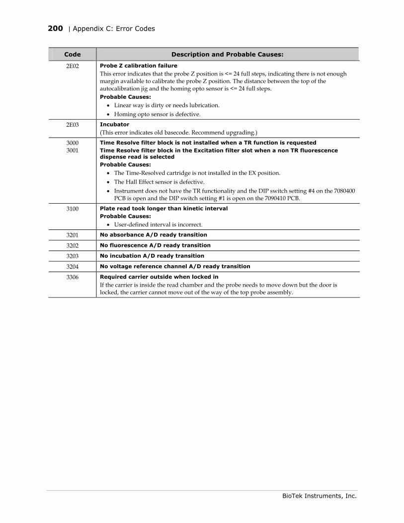
200 | Appendix C: Error Codes
BioTek Instruments, Inc.
Code Description and Probable Causes:
2E02 Probe Z calibration failure
This error indicates that the probe Z position is <= 24 full steps, indicating there is not enough margin available to calibrate the probe Z position. The distance between the top of the autocalibration jig and the homing opto sensor is <= 24 full steps. Probable Causes:
• Linear way is dirty or needs lubrication. • Homing opto sensor is defective.
2E03 Incubator
(This error indicates old basecode. Recommend upgrading.)
3000 3001
Time Resolve filter block is not installed when a TR function is requested Time Resolve filter block in the Excitation filter slot when a non TR fluorescence dispense read is selected Probable Causes:
• The Time-Resolved cartridge is not installed in the EX position. • The Hall Effect sensor is defective. • Instrument does not have the TR functionality and the DIP switch setting #4 on the 7080400
PCB is open and the DIP switch setting #1 is open on the 7090410 PCB.
3100 Plate read took longer than kinetic interval Probable Causes:
• User-defined interval is incorrect.
3201 No absorbance A/D ready transition
3202 No fluorescence A/D ready transition
3203 No incubation A/D ready transition
3204 No voltage reference channel A/D ready transition
3306 Required carrier outside when locked in
If the carrier is inside the read chamber and the probe needs to move down but the door is locked, the carrier cannot move out of the way of the top probe assembly.
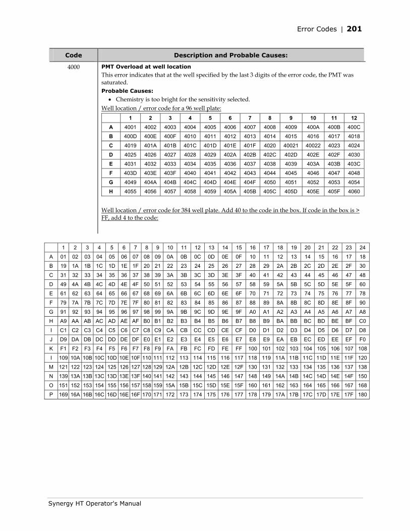
Error Codes | 201
Synergy HT Operator's Manual
Code Description and Probable Causes:
4000 PMT Overload at well location
This error indicates that at the well specified by the last 3 digits of the error code, the PMT was saturated. Probable Causes:
• Chemistry is too bright for the sensitivity selected. Well location / error code for a 96 well plate:
1 2 3 4 5 6 7 8 9 10 11 12 A 4001 4002 4003 4004 4005 4006 4007 4008 4009 400A 400B 400C
B 400D 400E 400F 4010 4011 4012 4013 4014 4015 4016 4017 4018
C 4019 401A 401B 401C 401D 401E 401F 4020 40021 40022 4023 4024
D 4025 4026 4027 4028 4029 402A 402B 402C 402D 402E 402F 4030
E 4031 4032 4033 4034 4035 4036 4037 4038 4039 403A 403B 403C
F 403D 403E 403F 4040 4041 4042 4043 4044 4045 4046 4047 4048
G 4049 404A 404B 404C 404D 404E 404F 4050 4051 4052 4053 4054
H 4055 4056 4057 4058 4059 405A 405B 405C 405D 405E 405F 4060
Well location / error code for 384 well plate. Add 40 to the code in the box. If code in the box is > FF, add 4 to the code:
1 2 3 4 5 6 7 8 9 10 11 12 13 14 15 16 17 18 19 20 21 22 23 24
A 01 02 03 04 05 06 07 08 09 0A 0B 0C 0D 0E 0F 10 11 12 13 14 15 16 17 18
B 19 1A 1B 1C 1D 1E 1F 20 21 22 23 24 25 26 27 28 29 2A 2B 2C 2D 2E 2F 30
C 31 32 33 34 35 36 37 38 39 3A 3B 3C 3D 3E 3F 40 41 42 43 44 45 46 47 48
D 49 4A 4B 4C 4D 4E 4F 50 51 52 53 54 55 56 57 58 59 5A 5B 5C 5D 5E 5F 60
E 61 62 63 64 65 66 67 68 69 6A 6B 6C 6D 6E 6F 70 71 72 73 74 75 76 77 78
F 79 7A 7B 7C 7D 7E 7F 80 81 82 83 84 85 86 87 88 89 8A 8B 8C 8D 8E 8F 90
G 91 92 93 94 95 96 97 98 99 9A 9B 9C 9D 9E 9F A0 A1 A2 A3 A4 A5 A6 A7 A8
H A9 AA AB AC AD AE AF B0 B1 B2 B3 B4 B5 B6 B7 B8 B9 BA BB BC BD BE BF C0
I C1 C2 C3 C4 C5 C6 C7 C8 C9 CA CB CC CD CE CF D0 D1 D2 D3 D4 D5 D6 D7 D8
J D9 DA DB DC DD DE DF E0 E1 E2 E3 E4 E5 E6 E7 E8 E9 EA EB EC ED EE EF F0
K F1 F2 F3 F4 F5 F6 F7 F8 F9 FA FB FC FD FE FF 100 101 102 103 104 105 106 107 108
I 109 10A 10B 10C 10D 10E 10F 110 111 112 113 114 115 116 117 118 119 11A 11B 11C 11D 11E 11F 120
M 121 122 123 124 125 126 127 128 129 12A 12B 12C 12D 12E 12F 130 131 132 133 134 135 136 137 138
N 139 13A 13B 13C 13D 13E 13F 140 141 142 143 144 145 146 147 148 149 14A 14B 14C 14D 14E 14F 150
O 151 152 153 154 155 156 157 158 159 15A 15B 15C 15D 15E 15F 160 161 162 163 164 165 166 167 168
P 169 16A 16B 16C 16D 16E 16F 170 171 172 173 174 175 176 177 178 179 17A 17B 17C 17D 17E 17F 180
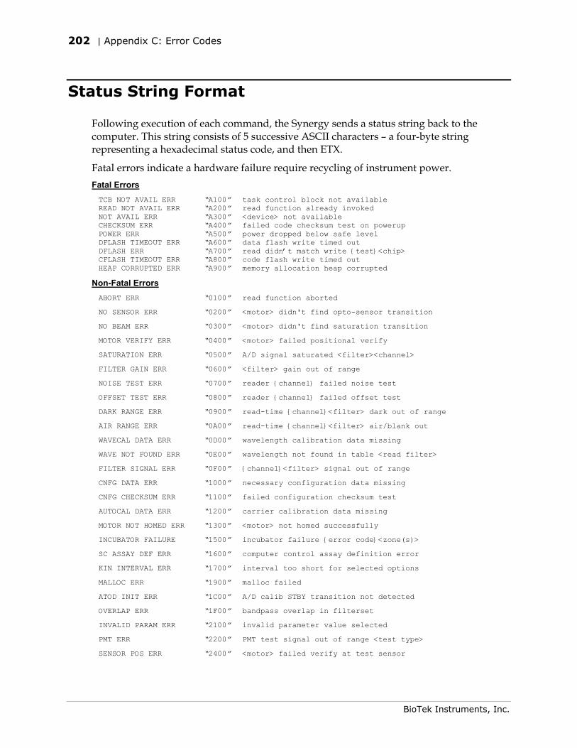
202 | Appendix C: Error Codes
BioTek Instruments, Inc.
Status String Format
Following execution of each command, the Synergy sends a status string back to the computer. This string consists of 5 successive ASCII characters – a four-byte string representing a hexadecimal status code, and then ETX.
Fatal errors indicate a hardware failure require recycling of instrument power. Fatal Errors TCB NOT AVAIL ERR “A100” task control block not available READ NOT AVAIL ERR “A200” read function already invoked NOT AVAIL ERR “A300” <device> not available CHECKSUM ERR “A400” failed code checksum test on powerup POWER ERR “A500” power dropped below safe level DFLASH TIMEOUT ERR “A600” data flash write timed out DFLASH ERR “A700” read didn’t match write {test}<chip> CFLASH TIMEOUT ERR “A800” code flash write timed out HEAP CORRUPTED ERR “A900” memory allocation heap corrupted
Non-Fatal Errors ABORT ERR “0100” read function aborted
NO SENSOR ERR “0200” <motor> didn't find opto-sensor transition
NO BEAM ERR “0300” <motor> didn't find saturation transition
MOTOR VERIFY ERR “0400” <motor> failed positional verify
SATURATION ERR “0500” A/D signal saturated <filter><channel>
FILTER GAIN ERR “0600” <filter> gain out of range
NOISE TEST ERR “0700” reader {channel} failed noise test
OFFSET TEST ERR “0800” reader {channel} failed offset test
DARK RANGE ERR “0900” read-time {channel}<filter> dark out of range
AIR RANGE ERR “0A00” read-time {channel}<filter> air/blank out
WAVECAL DATA ERR “0D00” wavelength calibration data missing
WAVE NOT FOUND ERR “0E00” wavelength not found in table <read filter>
FILTER SIGNAL ERR “0F00” {channel}<filter> signal out of range
CNFG DATA ERR “1000” necessary configuration data missing
CNFG CHECKSUM ERR “1100” failed configuration checksum test
AUTOCAL DATA ERR “1200” carrier calibration data missing
MOTOR NOT HOMED ERR “1300” <motor> not homed successfully
INCUBATOR FAILURE “1500” incubator failure {error code}<zone(s)>
SC ASSAY DEF ERR “1600” computer control assay definition error
KIN INTERVAL ERR “1700” interval too short for selected options
MALLOC ERR “1900” malloc failed
ATOD INIT ERR “1C00” A/D calib STBY transition not detected
OVERLAP ERR “1F00” bandpass overlap in filterset
INVALID PARAM ERR “2100” invalid parameter value selected
PMT ERR “2200” PMT test signal out of range <test type>
SENSOR POS ERR “2400” <motor> failed verify at test sensor
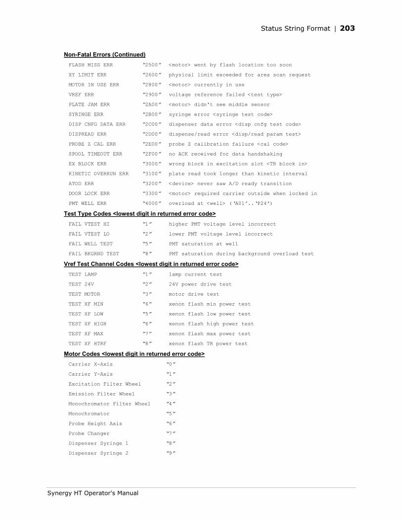
Status String Format | 203
Synergy HT Operator's Manual
Non-Fatal Errors (Continued) FLASH MISS ERR “2500” <motor> went by flash location too soon
XY LIMIT ERR “2600” physical limit exceeded for area scan request
MOTOR IN USE ERR “2800” <motor> currently in use
VREF ERR “2900” voltage reference failed <test type>
PLATE JAM ERR “2A00” <motor> didn't see middle sensor
SYRINGE ERR “2B00” syringe error <syringe test code>
DISP CNFG DATA ERR “2C00” dispenser data error <disp cnfg test code>
DISPREAD ERR “2D00” dispense/read error <disp/read param test>
PROBE Z CAL ERR “2E00” probe Z calibration failure <cal code>
SPOOL TIMEOUT ERR “2F00” no ACK received for data handshaking
EX BLOCK ERR “3000” wrong block in excitation slot <TR block in>
KINETIC OVERRUN ERR “3100” plate read took longer than kinetic interval
ATOD ERR “3200” <device> never saw A/D ready transition
DOOR LOCK ERR “3300” <motor> required carrier outside when locked in
PMT WELL ERR “4000” overload at <well> (‘A01’..‘P24’)
Test Type Codes <lowest digit in returned error code> FAIL VTEST HI “1” higher PMT voltage level incorrect
FAIL VTEST LO “2” lower PMT voltage level incorrect
FAIL WELL TEST “5” PMT saturation at well
FAIL BKGRND TEST “8” PMT saturation during background overload test
Vref Test Channel Codes <lowest digit in returned error code> TEST LAMP “1” lamp current test
TEST 24V “2” 24V power drive test
TEST MOTOR “3” motor drive test
TEST XF MIN “4” xenon flash min power test
TEST XF LOW “5” xenon flash low power test
TEST XF HIGH “6” xenon flash high power test
TEST XF MAX “7” xenon flash max power test
TEST XF HTRF “8” xenon flash TR power test
Motor Codes <lowest digit in returned error code> Carrier X-Axis “0”
Carrier Y-Axis “1”
Excitation Filter Wheel “2”
Emission Filter Wheel “3”
Monochromator Filter Wheel “4”
Monochromator “5”
Probe Height Axis “6”
Probe Changer “7”
Dispenser Syringe 1 “8”
Dispenser Syringe 2 “9”
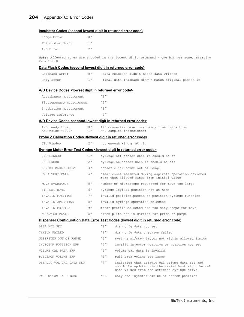
204 | Appendix C: Error Codes
BioTek Instruments, Inc.
Incubator Codes {second lowest digit in returned error code} Range Error “0”
Thermistor Error “1”
A/D Error “2”
Note: Affected zones are encoded in the lowest digit returned – one bit per zone, starting from bit 0.
Data Flash Codes {second lowest digit in returned error code} Readback Error “0” data readback didn’t match data written
Copy Error “1” final data readback didn’t match original passed in
A/D Device Codes <lowest digit in returned error code> Absorbance measurement “1”
Fluorescence measurement “2”
Incubation measurement “3”
Voltage reference ‘4”
A/D Device Codes <second-lowest digit in returned error code> A/D ready line “0” A/D converter never saw ready line transition A/D noise “3200” “1” A/D samples inconsistent
Probe Z Calibration Codes <lowest digit in returned error code> Jig Windup “2” not enough windup at jig
Syringe Motor Error Test Codes <lowest digit in returned error code> OFF SENSOR “1” syringe off sensor when it should be on
ON SENSOR “2” syringe on sensor when it should be off
SENSOR CLEAR COUNT “3” sensor clear count out of range
FMEA TEST FAIL “4” clear count measured during aspirate operation deviated more than allowed range from initial value
MOVE OVERRANGE “5” number of microsteps requested for move too large
SYR NOT HOME “6” syringe logical position not at home
INVALID POSITION “7” invalid position passed to position syringe function
INVALID OPERATION “8” invalid syringe operation selected
INVALID PROFILE “9” motor profile selected has too many steps for move
NO CATCH PLATE “A” catch plate not in carrier for prime or purge
Dispenser Configuration Data Error Test Codes (lowest digit in returned error code) DATA NOT SET “1” disp cnfg data not set
CHKSUM FAILED “2” disp cnfg data checksum failed
ULPERSTEP OUT OF RANGE “3” syringe µl/step factor not within allowed limits
INJECTOR POSITION ERR “4” invalid injector position or position not set
VOLUME CAL DATA ERR “5” volume cal data is invalid
PULLBACK VOLUME ERR “6” pull back volume too large
DEFAULT VOL CAL DATA SET “7” indicates that default cal volume data set and should be updated via the serial host with the cal data values from the attached syringe drive
TWO BOTTOM INJECTORS “8” only one injector can be at bottom position
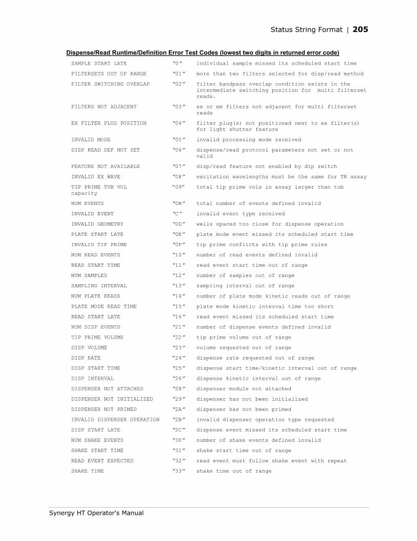
Status String Format | 205
Synergy HT Operator's Manual
Dispense/Read Runtime/Definition Error Test Codes (lowest two digits in returned error code) SAMPLE START LATE “0” individual sample missed its scheduled start time
FILTERSETS OUT OF RANGE “01” more than two filters selected for disp/read method
FILTER SWITCHING OVERLAP “02” filter bandpass overlap condition exists in the intermediate switching position for multi filterset reads.
FILTERS NOT ADJACENT “03” ex or em filters not adjacent for multi filterset reads
EX FILTER PLUG POSITION “04” filter plug(s) not positioned next to ex filter(s) for light shutter feature
INVALID MODE “05” invalid processing mode received
DISP READ DEF NOT SET “06” dispense/read protocol parameters not set or not valid
FEATURE NOT AVAILABLE “07” disp/read feature not enabled by dip switch
INVALID EX WAVE “08” excitation wavelengths must be the same for TR assay
TIP PRIME TUB VOL “09” total tip prime vols in assay larger than tub capacity
NUM EVENTS “0B” total number of events defined invalid
INVALID EVENT “C” invalid event type received
INVALID GEOMETRY “0D” wells spaced too close for dispense operation
PLATE START LATE “0E” plate mode event missed its scheduled start time
INVALID TIP PRIME “0F” tip prime conflicts with tip prime rules
NUM READ EVENTS “10” number of read events defined invalid
READ START TIME “11” read event start time out of range
NUM SAMPLES “12” number of samples out of range
SAMPLING INTERVAL “13” sampling interval out of range
NUM PLATE READS “14” number of plate mode kinetic reads out of range
PLATE MODE READ TIME “15” plate mode kinetic interval time too short
READ START LATE “16” read event missed its scheduled start time
NUM DISP EVENTS “21” number of dispense events defined invalid
TIP PRIME VOLUME “22” tip prime volume out of range
DISP VOLUME “23” volume requested out of range
DISP RATE “24” dispense rate requested out of range
DISP START TIME “25” dispense start time/kinetic interval out of range
DISP INTERVAL “26” dispense kinetic interval out of range
DISPENSER NOT ATTACHED “28” dispenser module not attached
DISPENSER NOT INITIALIZED “29” dispenser has not been initialized
DISPENSER NOT PRIMED “2A” dispenser has not been primed
INVALID DISPENSER OPERATION “2B” invalid dispenser operation type requested
DISP START LATE “2C” dispense event missed its scheduled start time
NUM SHAKE EVENTS “30” number of shake events defined invalid
SHAKE START TIME “31” shake start time out of range
READ EVENT EXPECTED “32” read event must follow shake event with repeat
SHAKE TIME “33” shake time out of range
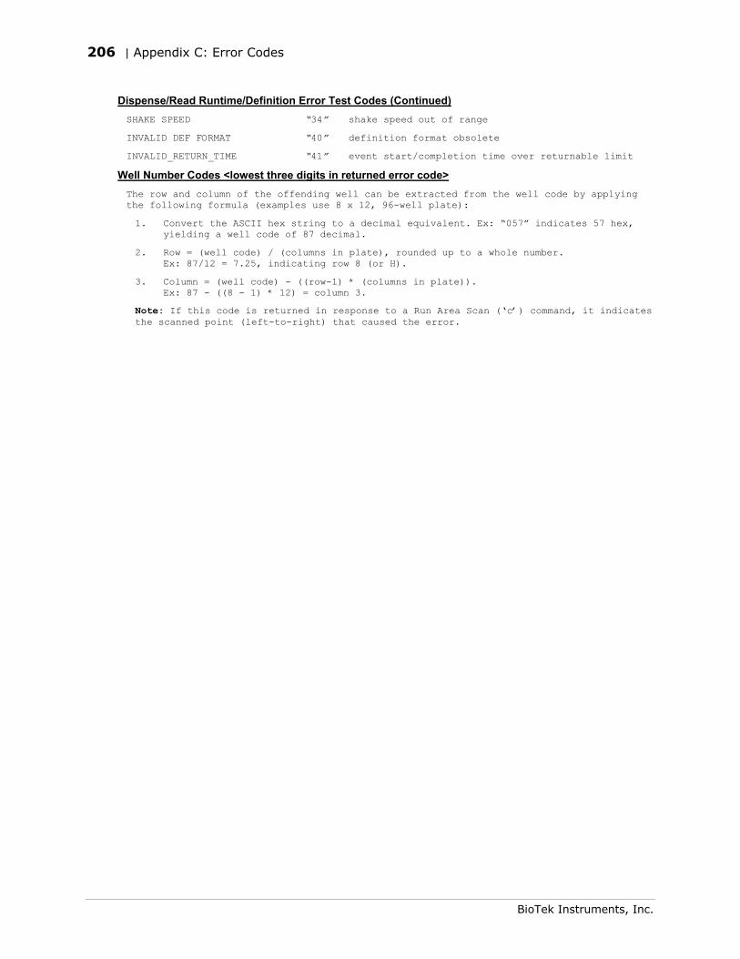
206 | Appendix C: Error Codes
BioTek Instruments, Inc.
Dispense/Read Runtime/Definition Error Test Codes (Continued) SHAKE SPEED “34” shake speed out of range
INVALID DEF FORMAT “40” definition format obsolete
INVALID_RETURN_TIME “41” event start/completion time over returnable limit
Well Number Codes <lowest three digits in returned error code> The row and column of the offending well can be extracted from the well code by applying the following formula (examples use 8 x 12, 96-well plate):
1. Convert the ASCII hex string to a decimal equivalent. Ex: “057” indicates 57 hex, yielding a well code of 87 decimal.
2. Row = (well code) / (columns in plate), rounded up to a whole number. Ex: 87/12 = 7.25, indicating row 8 (or H).
3. Column = (well code) - ((row-1) * (columns in plate)). Ex: 87 - ((8 - 1) * 12) = column 3.
Note: If this code is returned in response to a Run Area Scan (‘c’) command, it indicates the scanned point (left-to-right) that caused the error.

Appendix D
Specifications
This appendix contains BioTek’s published specifications for the Synergy™ HT.
Specifications .....................................................................208 Microplates.........................................................................208 Hardware and Environmental ................................................208 Absorbance ........................................................................209 Fluorescence ......................................................................211 Incubation..........................................................................213 Shake................................................................................213 Injector Model ....................................................................213
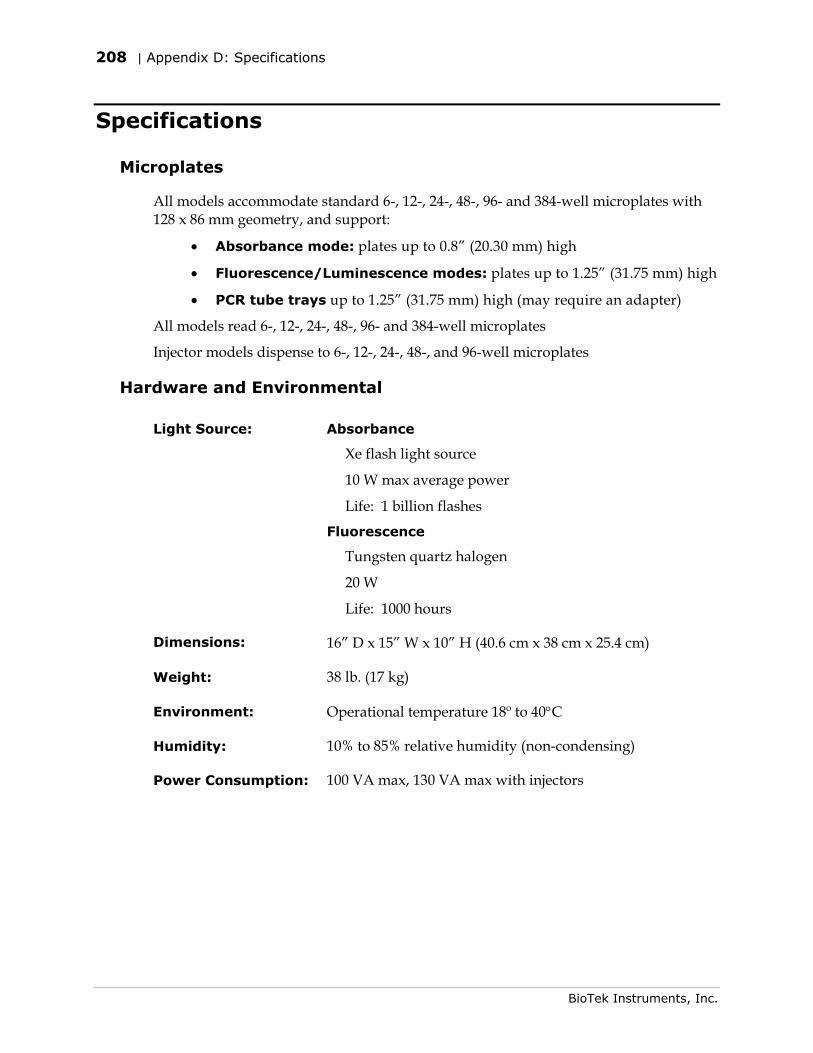
208 | Appendix D: Specifications
BioTek Instruments, Inc.
Specifications
Microplates
All models accommodate standard 6-, 12-, 24-, 48-, 96- and 384-well microplates with 128 x 86 mm geometry, and support:
• Absorbance mode: plates up to 0.8” (20.30 mm) high
• Fluorescence/Luminescence modes: plates up to 1.25” (31.75 mm) high
• PCR tube trays up to 1.25” (31.75 mm) high (may require an adapter)
All models read 6-, 12-, 24-, 48-, 96- and 384-well microplates
Injector models dispense to 6-, 12-, 24-, 48-, and 96-well microplates
Hardware and Environmental
Light Source: Absorbance
Xe flash light source
10 W max average power
Life: 1 billion flashes
Fluorescence
Tungsten quartz halogen
20 W
Life: 1000 hours
Dimensions: 16” D x 15” W x 10” H (40.6 cm x 38 cm x 25.4 cm)
Weight: 38 lb. (17 kg)
Environment: Operational temperature 18º to 40°C
Humidity: 10% to 85% relative humidity (non-condensing)
Power Consumption: 100 VA max, 130 VA max with injectors
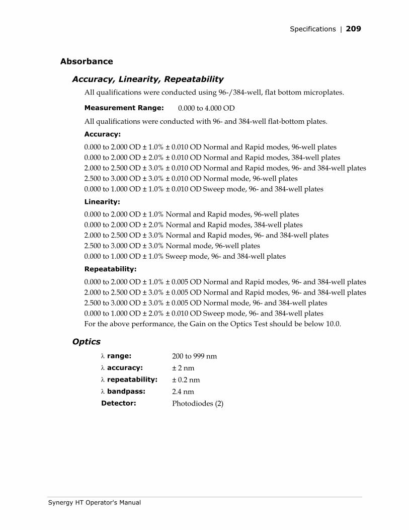
Specifications | 209
Synergy HT Operator's Manual
Absorbance
Accuracy, Linearity, Repeatability
All qualifications were conducted using 96-/384-well, flat bottom microplates.
Measurement Range: 0.000 to 4.000 OD
All qualifications were conducted with 96- and 384-well flat-bottom plates.
Accuracy:
0.000 to 2.000 OD ± 1.0% ± 0.010 OD Normal and Rapid modes, 96-well plates 0.000 to 2.000 OD ± 2.0% ± 0.010 OD Normal and Rapid modes, 384-well plates 2.000 to 2.500 OD ± 3.0% ± 0.010 OD Normal and Rapid modes, 96- and 384-well plates 2.500 to 3.000 OD ± 3.0% ± 0.010 OD Normal mode, 96-well plates 0.000 to 1.000 OD ± 1.0% ± 0.010 OD Sweep mode, 96- and 384-well plates
Linearity: 0.000 to 2.000 OD ± 1.0% Normal and Rapid modes, 96-well plates 0.000 to 2.000 OD ± 2.0% Normal and Rapid modes, 384-well plates 2.000 to 2.500 OD ± 3.0% Normal and Rapid modes, 96- and 384-well plates 2.500 to 3.000 OD ± 3.0% Normal mode, 96-well plates 0.000 to 1.000 OD ± 1.0% Sweep mode, 96- and 384-well plates
Repeatability:
0.000 to 2.000 OD ± 1.0% ± 0.005 OD Normal and Rapid modes, 96- and 384-well plates 2.000 to 2.500 OD ± 3.0% ± 0.005 OD Normal and Rapid modes, 96- and 384-well plates 2.500 to 3.000 OD ± 3.0% ± 0.005 OD Normal mode, 96- and 384-well plates 0.000 to 1.000 OD ± 2.0% ± 0.010 OD Sweep mode, 96- and 384-well plates For the above performance, the Gain on the Optics Test should be below 10.0.
Optics
λ range: 200 to 999 nm λ accuracy: ± 2 nm λ repeatability: ± 0.2 nm λ bandpass: 2.4 nm Detector: Photodiodes (2)
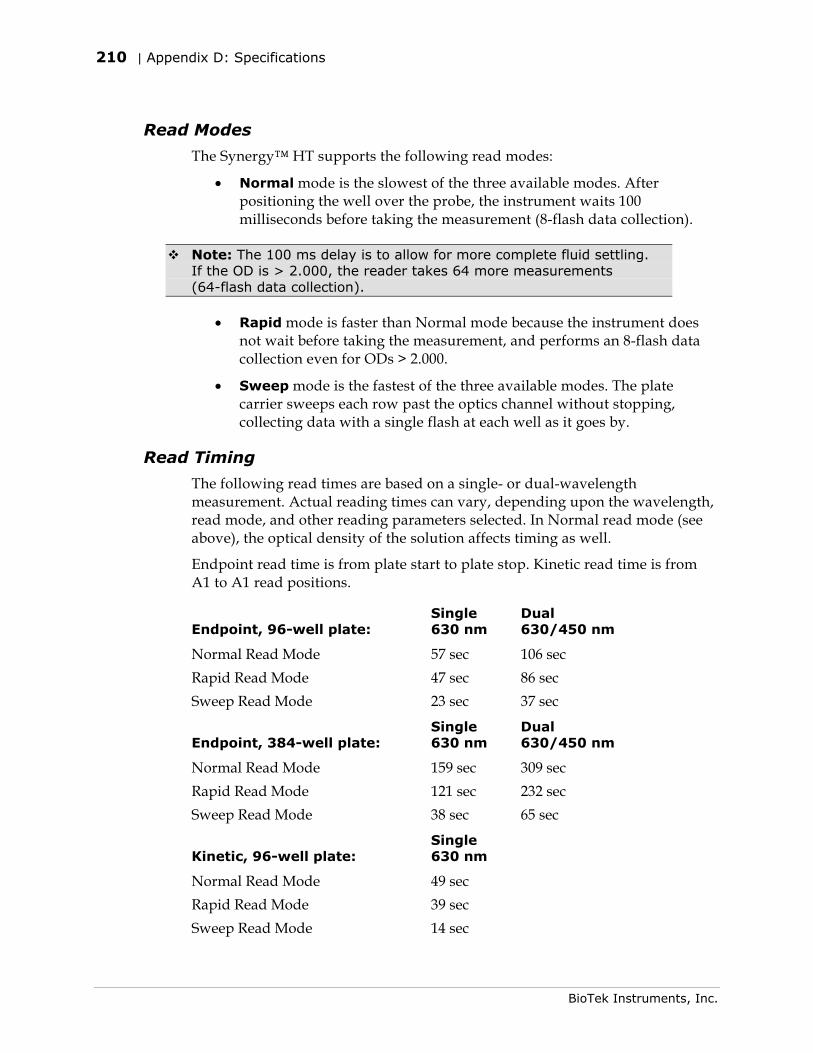
210 | Appendix D: Specifications
BioTek Instruments, Inc.
Read Modes
The Synergy™ HT supports the following read modes:
• Normal mode is the slowest of the three available modes. After positioning the well over the probe, the instrument waits 100 milliseconds before taking the measurement (8-flash data collection).
Note: The 100 ms delay is to allow for more complete fluid settling. If the OD is > 2.000, the reader takes 64 more measurements (64-flash data collection).
• Rapid mode is faster than Normal mode because the instrument does not wait before taking the measurement, and performs an 8-flash data collection even for ODs > 2.000.
• Sweep mode is the fastest of the three available modes. The plate carrier sweeps each row past the optics channel without stopping, collecting data with a single flash at each well as it goes by.
Read Timing
The following read times are based on a single- or dual-wavelength measurement. Actual reading times can vary, depending upon the wavelength, read mode, and other reading parameters selected. In Normal read mode (see above), the optical density of the solution affects timing as well.
Endpoint read time is from plate start to plate stop. Kinetic read time is from A1 to A1 read positions.
Endpoint, 96-well plate: Single 630 nm
Dual 630/450 nm
Normal Read Mode 57 sec 106 sec Rapid Read Mode 47 sec 86 sec Sweep Read Mode 23 sec 37 sec
Endpoint, 384-well plate: Single 630 nm
Dual 630/450 nm
Normal Read Mode 159 sec 309 sec Rapid Read Mode 121 sec 232 sec Sweep Read Mode 38 sec 65 sec
Kinetic, 96-well plate: Single 630 nm
Normal Read Mode 49 sec Rapid Read Mode 39 sec Sweep Read Mode 14 sec
Specifications | 211
Synergy HT Operator's Manual
Kinetic, 384-well plate: Single 630 nm
Normal Read Mode 150 sec Rapid Read Mode 111 sec Sweep Read Mode 26 sec
Fluorescence
Read Timing
Because of the possible wide variations in setup, the following benchmark conditions are specified:
Excitation Filter: 485/20 nm Emission Filter: 528/20 nm Samples per well: 10 Delay before sampling: 350 ms Delay between samples: 1 ms 96-well read: 89 sec 384-well read: 275 sec
Optical Probes
The Synergy HT is configured with a variety of probe sizes: 1.5 and 3 mm probes can be installed in either the top or bottom positions; the 5 mm probe can only be installed in the bottom position.
Sensitivity
5 mm probe:
Sodium Fluorescein (SF) (Bottom reading):
10 pg/ml solution of Sodium Fluorescein in PBS 150 µL per well signal-to-noise ratio greater than 2.0 Excitation 485/20, Emission 530/25 Hellma 96-well quartz plate
Propidium Iodide (PI) (Bottom reading):
62.5 ng/ml solution of Propidium Iodide in PBS 50 µL per well signal-to-noise ratio greater than 2.0 Excitation 485/20, Emission 645/40 Corning Costar® 96-well, black-sided, clear bottom plate
212 | Appendix D: Specifications
BioTek Instruments, Inc.
3 mm probe:
Sodium Fluorescein (SF) (Bottom reading):
20 pg/ml solution of Sodium Fluorescein in PBS 150 µL per well signal-to-noise ratio greater than 2.0 Excitation 485/20, Emission 530/25 Hellma 96 well quartz plate
Propidium Iodide (PI) (Bottom reading):
125 ng/ml solution of Propidium Iodide in PBS 50 µL per well signal-to-noise ratio greater than 2.0 Excitation 485/20, Emission 645/40 Corning Costar® 96-well, black-sided, clear bottom plate
Methylumbelliferone (MUB) (Top reading):
0.16 ng/ml solution of Methylumbelliferone in CBB 300 µL per well signal-to-noise ratio greater than 2.0 Excitation 360/40, Emission 460/40 Corning Costar® black strips
1.5 mm probe:
Sodium Fluorescein (SF) (Bottom reading):
40 pg/ml solution of Sodium Fluorescein in PBS 150 µL per well signal-to-noise ratio greater than 2.0 Excitation 485/20, Emission 530/25 Hellma 96-well quartz plate
Propidium Iodide (PI) (Bottom reading):
250 ng/ml solution of Propidium Iodide in PBS 50 µL per well signal-to-noise ratio greater than 2.0 Excitation 485/20, Emission 645/40 Corning Costar® 96-well, black-sided, clear bottom plate
Methylumbelliferone (MUB) (Top reading):
0.31 ng/ml solution of Methylumbelliferone in CBB 300 µL per well signal-to-noise ratio greater than 2.0 Excitation 360/40, Emission 460/40 Corning Costar® black strips
Optional Time-Resolved Fluorescence
• Delay 0 or 20 µs to 16000 µs
• Integration interval 20 to 16000 µs
• Times adjustable in 10 µs increments
Specifications | 213
Synergy HT Operator's Manual
Incubation
• Temperature control range from 4º over ambient to 50ºC
• Temperature variation ± 0.50°C across the plate @ 37°C (250 µL per well with the plate sealed)
Shake
• Low, Medium, High and Variable shaking speeds
• Shake duration is programmable by the user
Injector Model
The following specifications apply to Synergy™ HT models with injectors:
Plate Type: Dispenses to standard 6-, 12-, 24-, 48-, and 96-well microplates with 128 x 86 mm geometry
Dispense Volume Range: 5-1000 µL with a 5-20 µL tip prime
Accuracy: Dispensing deionized water with 0.1% Tween® 20 at room temperature:
± 1 µL at 5-50 µL ± 2% at 51-1000 µL
Precision: Dispensing a 200 µL solution of deionized water, 0.1% Tween 20, and dye at room temperature:
< 2.0% for volumes of 50-200 µL < 4.0% for volumes of 25-49 µL < 7.0% for volumes of 10-24 µL < 10.0% for volumes of 5-9 µL

214 | Appendix D: Specifications
BioTek Instruments, Inc.

Appendix E
Instrument Dimensions for Robotic Interface
Figure 40 shows the location of the microplate carrier in reference to the exterior surfaces of the Synergy™ HT and the mounting holes on the bottom. The illustration should facilitate system setup with a robotic instrument, such as the BioStack™ Microplate Stacker.

216 | Appendix E: Instrument Dimensions for Robotic Interface
BioTek Instruments, Inc.
Instrument Dimensions for Robotic Interface
If you have purchased the BioStack™ to operate with the Synergy™ HT, special alignment hardware is included in the BioStack alignment kit for correct positioning of the Synergy HT with the BioStack. Refer to the Installation chapter in the BioStack Operator’s Manual for instructions.
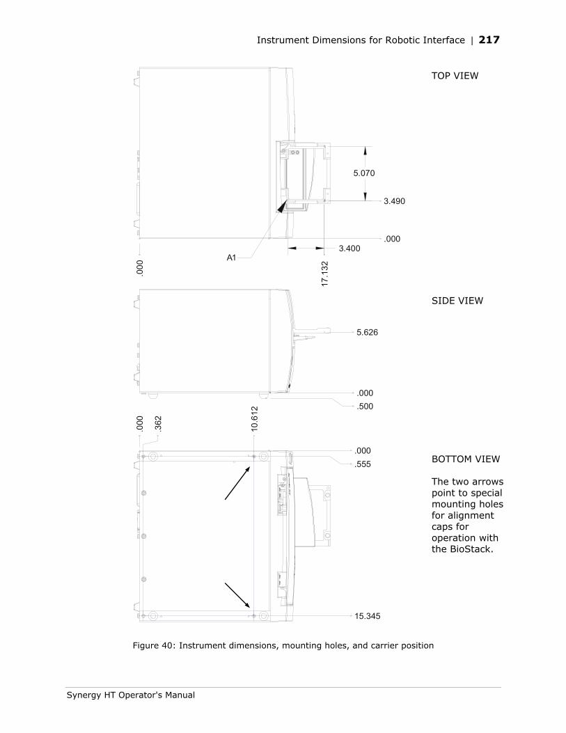
Instrument Dimensions for Robotic Interface | 217
Synergy HT Operator's Manual
.000
17.1
32
.000
3.490
3.400
5.070
A1
.000
.500
5.626
.000
.362
10.6
12
.000
.555
15.345
Figure 40: Instrument dimensions, mounting holes, and carrier position
TOP VIEW
SIDE VIEW
BOTTOM VIEW The two arrows point to special mounting holes for alignment caps for operation with the BioStack.

218 | Appendix E: Instrument Dimensions for Robotic Interface
BioTek Instruments, Inc.