Embed Size (px)
Citation preview
BIOSUN-340_(Anglais) - DOC012466 - Ind. B03 - 21/06/2017
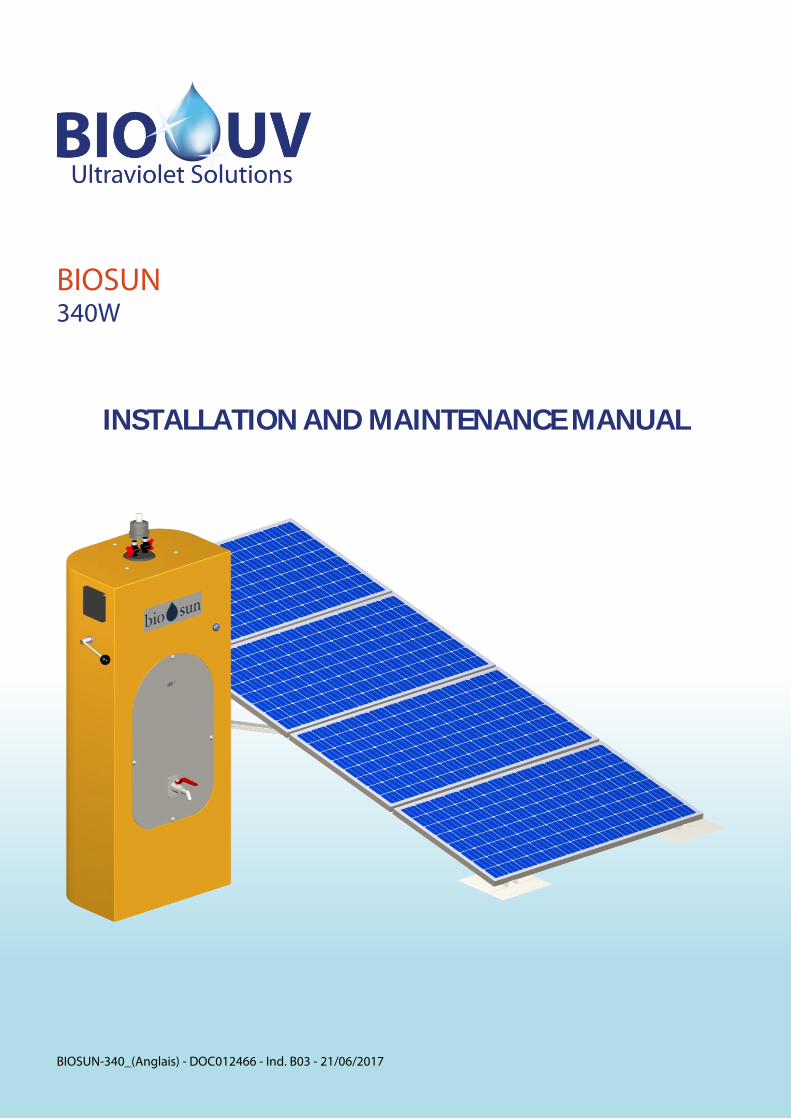
BIOSUN 340W
INSTALLATION AND MAINTENANCE MANUAL

BIOSUN-340_(Anglais) - DOC012466 - Ind. B03 - 21/06/2017 Copyright BIO-UV Marque, Modèles et Brevets déposés - Produits exclusifs Page 2
We thank you for choosing BIOSUN. Our equipment has been designed to give you reliable and safe operation for many years to come. The BIOSUN terminals have been designed for speed and ease of installation. Their design also makes them easy to maintain. Read these instructions carefully in order to optimize the operation of your device. TABLE OF CONTENTS: Pages
A. Technical characteristics ................................................................................................................................................. 3 B. Safety Warnings ............................................................................................................................................................... 4
C. BIOSUN terminal description .......................................................................................................................................... 5 1. Overview ......................................................................................................................................................................................................................... 5 2. Hydraulic diagram ....................................................................................................................................................................................................... 6
D. Installation guide ............................................................................................................................................................ 7 1. Foreword ........................................................................................................................................................................................................................ 7 2. Detail of provided elements.................................................................................................................................................................................... 7 3. Mounting of photovoltaic panels ......................................................................................................................................................................... 8
a.) Preparation ............................................................................................................................................................................................................. 8 b.) Assembly .............................................................................................................................................................................................................. 10
4. Wiring of photovoltaic panels ............................................................................................................................................................................. 22 5. Instruction to mount the BIOSUN 340 terminal ........................................................................................................................................... 23
E. Instructions for the first commossioning of the BIOSUN 340 terminal ..................................................................... 25
F. Instructions to use the BIOSUN 340 terminal .............................................................................................................. 26 1. Production................................................................................................................................................................................................................... 26 2. Start-up the terminal ............................................................................................................................................................................................... 26
G. Instructions for servicing of the BIOSUN 340 terminal .............................................................................................. 27 1. Backwashing the filter ............................................................................................................................................................................................ 27 2. Tank draining ............................................................................................................................................................................................................. 27 3. Solar panel cleanliness ........................................................................................................................................................................................... 28 4. Preventive disinfection .......................................................................................................................................................................................... 28 5. Functional check of the photovoltaic power supply .................................................................................................................................. 28
H. Procedure for lap, quartz sleeve or seals replacement .............................................................................................. 29 I. Replacement of the filter cartridges (option)............................................................................................................... 32
J. Maintenance file ............................................................................................................................................................ 33 K. Electrical description .................................................................................................................................................... 34
L. Blown up view ............................................................................................................................................................... 35
M. Errors and remedial action: regulator ........................................................................................................................ 36 N. Frequently asked questions ........................................................................................................................................ 38
O. Warranty terms ............................................................................................................................................................. 39 ANNEX 1: Clearance dimensions, Blown up view, Designation .................................................................................... 41
ANNEX 2: Electrical diagrams .......................................................................................................................................... 43

BIOSUN-340_(Anglais) - DOC012466 - Ind. B03 - 21/06/2017 Copyright BIO-UV Marque, Modèles et Brevets déposés - Produits exclusifs Page 3
A. TECHNICAL CHARACTERISTICS
BIOSUN RANGE UNIT BIOSUN 340 FUNCTIONAL CHARACTERISTICS
Flow rate l/h 500 Number of hours of production per day h 4 Volume produced per day m3 2 Standalone operating time day 3 Draw-off - Standalone operating time Volume meter - Draw-off UV reactor ON/OFF switch - Yes, with integrated LED
WATER SUPPLY Tank volume l 21 tank materials - 304L stainless steel Supply type - Manual or gravity filling < 1 bar Max. pressure bar 1 Pump Vdc 24 (with a built-in pressure switch)
FILTERING Filtering media - Zeolite filter volume l 7 filtering threshold µm <10 backwashing - With manual handle cartridge size (optional) inch 10 Filter cartridge type (optional) - 10µm, activated carbon
UV REACTOR UV lamp power W 14 UV power delivered W 4.6 UV operating light - Yes Dose delivered mJ/cm² 40 Ballast - Electronic (24VDC) Supply voltage Vdc 24 Average life expectancy for one stop/start per day year 1
FRAME Dimensions mm 1400 x 600 x 400
Material - Fiberglass + polyester complex: special for outdoor use
PHOTOVOLTAIC POWER SUPPLY Panel size (unit) mm 1200 x 600 Number of solar panels - 4 Panel power W 85 Panel voltage V 12 Panel attachment - Remote support (roof, floor, etc.) Number of batteries - 2 Battery type - 70Ah(C100), 60Ah(C20), 12V
OPTION WITHOUT PHOTOVOLTAÏC PANELS Recommended spare parts list to be provided by the customer
Solar panel - 4 Number of batteries - 2 Battery type - 70Ah(C100), 60Ah(C20), 12V Controller - According to panel model specified by the customer Converter - 24Vdc 100W
BIOSUN-340_(Anglais) - DOC012466 - Ind. B03 - 21/06/2017 Copyright BIO-UV Marque, Modèles et Brevets déposés - Produits exclusifs Page 4
B. SAFETY WARNINGS
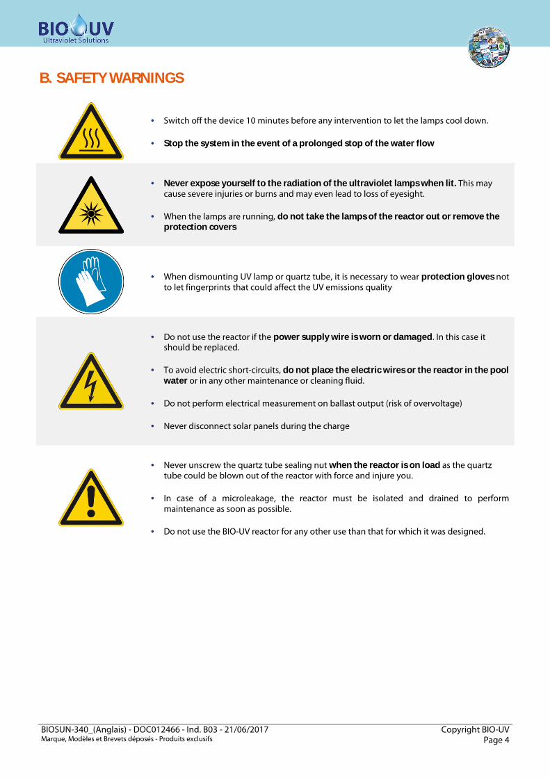
· Switch off the device 10 minutes before any intervention to let the lamps cool down.
· Stop the system in the event of a prolonged stop of the water flow
· Never expose yourself to the radiation of the ultraviolet lamps when lit. This may cause severe injuries or burns and may even lead to loss of eyesight.
· When the lamps are running, do not take the lamps of the reactor out or remove the protection covers
· When dismounting UV lamp or quartz tube, it is necessary to wear protection gloves not to let fingerprints that could affect the UV emissions quality
· Do not use the reactor if the power supply wire is worn or damaged. In this case it should be replaced.
· To avoid electric short-circuits, do not place the electric wires or the reactor in the pool water or in any other maintenance or cleaning fluid.
· Do not perform electrical measurement on ballast output (risk of overvoltage)
· Never disconnect solar panels during the charge
· Never unscrew the quartz tube sealing nut when the reactor is on load as the quartz tube could be blown out of the reactor with force and injure you.
· In case of a microleakage, the reactor must be isolated and drained to perform maintenance as soon as possible.
· Do not use the BIO-UV reactor for any other use than that for which it was designed.
BIOSUN-340_(Anglais) - DOC012466 - Ind. B03 - 21/06/2017 Copyright BIO-UV Marque, Modèles et Brevets déposés - Produits exclusifs Page 5
C. BIOSUN TERMINAL DESCRIPTION
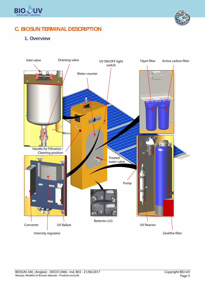
1. Overview
Handle for Filtration / Cleaning position
Inlet valve
Intensity regulator
UV Ballast Converter
UV ON/OFF light switch
Zeolithe filter
UV Reactor Batteries (x2)
Water counter
Treated water valve
Pump
Draining valve 10µm filter Active carbon filter
BIOSUN-340_(Anglais) - DOC012466 - Ind. B03 - 21/06/2017 Copyright BIO-UV Marque, Modèles et Brevets déposés - Produits exclusifs Page 6
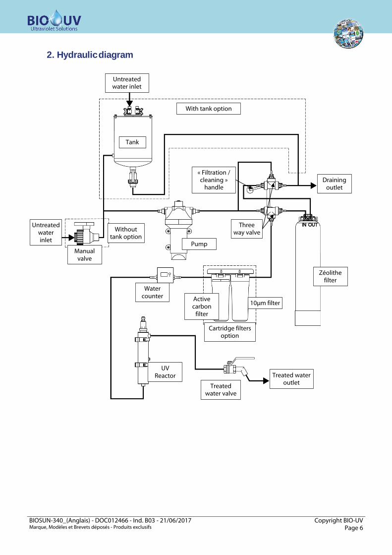
2. Hydraulic diagram
With tank option
Without tank option
Untreated water inlet
Untreated water inlet
Draining outlet
Treated water outlet
Tank
Three way valve
« Filtration / cleaning »
handle
Zéolithe filter
Pump Manual
valve
10µm filter Active carbon
filter
Water counter
UV Reactor
Treated water valve
Cartridge filters option
BIOSUN-340_(Anglais) - DOC012466 - Ind. B03 - 21/06/2017 Copyright BIO-UV Marque, Modèles et Brevets déposés - Produits exclusifs Page 7
D. INSTALLATION GUIDE
1. Foreword
Read all the instructions in this manual before switching on the reactor.
IMPORTANT: BIOSUN 340 is designed to be connected to a low pressure system (< 1 bar) If the operating pressure exceeds 1 bar, the BIOSUN 85 model must be used
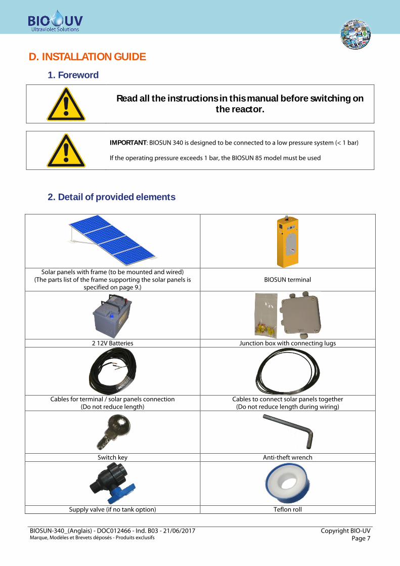
2. Detail of provided elements
Solar panels with frame (to be mounted and wired)
(The parts list of the frame supporting the solar panels is specified on page 9.)
BIOSUN terminal
2 12V Batteries Junction box with connecting lugs
Cables for terminal / solar panels connection
(Do not reduce length) Cables to connect solar panels together
(Do not reduce length during wiring)
Switch key Anti-theft wrench
Supply valve (if no tank option) Teflon roll
BIOSUN-340_(Anglais) - DOC012466 - Ind. B03 - 21/06/2017 Copyright BIO-UV Marque, Modèles et Brevets déposés - Produits exclusifs Page 8
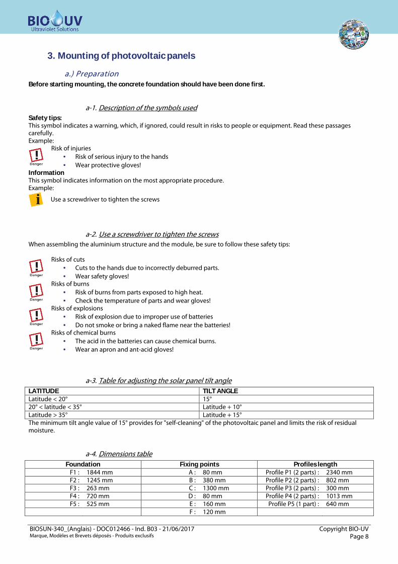
3. Mounting of photovoltaic panels
a.) Preparation Before starting mounting, the concrete foundation should have been done first.
a-1. Description of the symbols used Safety tips: This symbol indicates a warning, which, if ignored, could result in risks to people or equipment. Read these passages carefully. Example:
Risk of injuries · Risk of serious injury to the hands · Wear protective gloves!
Information This symbol indicates information on the most appropriate procedure. Example:
Use a screwdriver to tighten the screws
a-2. Use a screwdriver to tighten the screws When assembling the aluminium structure and the module, be sure to follow these safety tips:
Risks of cuts · Cuts to the hands due to incorrectly deburred parts. · Wear safety gloves!
Risks of burns · Risk of burns from parts exposed to high heat. · Check the temperature of parts and wear gloves!
Risks of explosions · Risk of explosion due to improper use of batteries · Do not smoke or bring a naked flame near the batteries!
Risks of chemical burns · The acid in the batteries can cause chemical burns. · Wear an apron and ant-acid gloves!
a-3. Table for adjusting the solar panel tilt angle LATITUDE TILT ANGLE Latitude < 20° 15° 20° < latitude < 35° Latitude + 10° Latitude > 35° Latitude + 15° The minimum tilt angle value of 15° provides for "self-cleaning" of the photovoltaic panel and limits the risk of residual moisture.
a-4. Dimensions table Foundation Fixing points Profiles length
F1 : 1844 mm A : 80 mm Profile P1 (2 parts) : 2340 mm F2 : 1245 mm B : 380 mm Profile P2 (2 parts) : 802 mm F3 : 263 mm C : 1300 mm Profile P3 (2 parts) : 300 mm F4 : 720 mm D : 80 mm Profile P4 (2 parts) : 1013 mm F5 : 525 mm E : 160 mm Profile P5 (1 part) : 640 mm
F : 120 mm

BIOSUN-340_(Anglais) - DOC012466 - Ind. B03 - 21/06/2017 Copyright BIO-UV Marque, Modèles et Brevets déposés - Produits exclusifs Page 9
a-5. Parts list You will find the various parts of the structure supporting the modules
Rope clamp Clamping bolt Ring bolt Thimble Short screw
(20mm)
Short screw (30mm)
Nut HU M8 Flat washer L d=8 Tensioner Shackle
Large U profile Small U Profile I-module fixation T-module fixation Flat washer M
d=8
P1 type formed section
P1 type formed
section
P1 type formed section
P1 type formed
section
P1 type formed section
a-6. Required tools The tools required to assemble the module support structure are indicated below
Spirit level Flat wrench (Size 13, Size 10)
Cutting pliers Folding meter rule Allen wrench (Size 6)

BIOSUN-340_(Anglais) - DOC012466 - Ind. B03 - 21/06/2017 Copyright BIO-UV Marque, Modèles et Brevets déposés - Produits exclusifs Page 10
b.) Assembly
b-1. Foundations for the aluminium support structure
Pre-tighten the screws during the assembly period and firmly tighten only after assembling the whole structure with its modules.
Risks of cuts · Cuts to the hands due to structural parts not deburred. · Wear safety gloves!
When the concrete foundation is completely dry, drill the attaching holes in the floor.
· Using figure 01, measure and make marks on the concrete · Drill the concrete with a hammer drill using a 12 mm diameter drill bit.
b-2. Assembling the aluminium support structure
b-2.1. Mounting the base For this step, you will need four anchoring studs, two narrow U formed sections (3 holes) and two wide U formed sections (5 holes).
Before attaching, make sure you have properly positioned the wide U formed sections for the part pointing towards the foundations pole and the narrow U formed sections for the part pointing towards the equator (see Figure 01, red circles).
· Fit the four anchoring bolts in the four holes drilled in step 2.1, and make sure to attach them the right way round! · Fit the U formed sections to the threaded rods (see figure 02) of the anchoring studs and then bolt the whole
assembly together. Ä The bolts are now attached in the holes.
Foundation
Concrete foundation
U TYPE PROFILE Clamping screw Nut
Foundation

BIOSUN-340_(Anglais) - DOC012466 - Ind. B03 - 21/06/2017 Copyright BIO-UV Marque, Modèles et Brevets déposés - Produits exclusifs Page 11
b-2.2. Installing the two P2 type formed sections In the next steps, install the P2 and P5 type formed sections. Figure 03 provides an overview of the structure showing the use of the formed sections (red circles).
First assemble the three formed sections together on the floor. Then attach them to the foundations, otherwise the screws cannot be tighten!
b-2.3. Fitting the eye nuts to the P2 type formed sections For this step, you will need four eye nuts (see figure 04, red circles), four L 8 mm dia plain washers, eight HU M8 nuts and two P2 type formed sections.
Option: If you have the version with the GCB support (support for junction box), you also need to fit the support in this step! (see next paragraph)
The following figure shows you what the structure should look like after this step.
· If you do not fit the GCB support - assemble the eye nuts (see figure 04).
Side view
Rear view
Rear view Cross-section view Large washer
Eye nut
Base plan for P2 type formed P2 type
Profile
Support for GCB (optional)

BIOSUN-340_(Anglais) - DOC012466 - Ind. B03 - 21/06/2017 Copyright BIO-UV Marque, Modèles et Brevets déposés - Produits exclusifs Page 12
b-2.4. Fitting the eye nuts and the GCB support The eye nuts are fitted in the same way as in the previous step! But make sure to fit the support between the eye nuts on the outside (rear view) How to install the GCB support:
· Prepare two narrow U formed sections as shown in figure 05 (below).
· Fit the GCB support to the two U formed sections as shown in the following diagram (figure 06)
· After fitting the first eye nut, fit the GCB support with the two U formed sections to the two P2 type
formed sections (rear view) (see figure 07)
Nut Small washer
Short screw
U type Profile
U type formed section (side view)
U type formed section (side view)
GCB Support
Cross-sectional view from above
Floor plan for P2 type formed section
Floor plan for U type formed section
GCB plate support

BIOSUN-340_(Anglais) - DOC012466 - Ind. B03 - 21/06/2017 Copyright BIO-UV Marque, Modèles et Brevets déposés - Produits exclusifs Page 13
b-2.5. Fitting the P5 type formed section For this step you need the P5 type formed section, two narrow U formed sections, six short screws, six M plain washers d= 8 and six HU M8 nuts. Figure 03 shows you where the formed sections are located in the overall construction (red circles)
· Prepare two narrow U formed sections as shown in the following figure (figure 08)
Do not tighten nuts at this point, as you will have to handle the formed sections in the next step!
· Fit the two U formed sections prepared with the two P2 type formed sections, as shown in figure 09.
· Attach the P5 type formed section to one of the U formed sections (see figure 10 below) - the attachment
is similar to the attachment you performed previously.
· Tighten the nuts of the U formed section, in which you attached the P5 type formed section · Attach the P5 type formed section to the second U formed section, which is itself already attached to the
second P2 type formed section
Nut Flat washer M d=8
Short screw
U type formed section
P2 formed section
P2 formed section
U formed section
U formed section
P2 formed section
P2 formed section
U formed section
U formed section
P5 formed section
P2 formed section
P2 formed section
U formed section
U formed section
P5 formed section

BIOSUN-340_(Anglais) - DOC012466 - Ind. B03 - 21/06/2017 Copyright BIO-UV Marque, Modèles et Brevets déposés - Produits exclusifs Page 14
· Tighten the nuts of the U formed section, in which you attached the P5 type formed section Ä Your structure should look as shown in the diagram below!
b-2.6. Fitting the P2/P5 constructions to the foundations
Fit the screws, the nuts and the plain washers in the holes in the opposite direction to the equator of the wide U formed sections!!! See figure below (figure 13)
· Fit the two short screws (20mm) in the "Pole" holes of one of the wide U formed sections that you have
already fitted to the foundations. You will need a nut and an M 8 mm dia plain washer for each screw. Figure 14 shows how to assemble the bolts.
Do not tighten the screws at this point, as you will need to handle the formed sections in the next step!
· Repeat this procedure for the other U formed section! · Attach the screws to the two sides of the P2 type formed section, as indicated in figure 15
· Make sure that the construction makes a right angle (90) relative to the foundation · Tighten the screws on both sides
Ä Both P2 formed sections are now firmly secured to the base (floor).
Rear view
GCB support (optional)
Equator Pole It is the hole on the right
HU M8 nut Flat washer M8
20mm short screw
U formed section
Foundation
Cross-sectional view Front view
Base plan for the formed section P2 type
P2 type formed section
Foundation
BIOSUN-340_(Anglais) - DOC012466 - Ind. B03 - 21/06/2017 Copyright BIO-UV Marque, Modèles et Brevets déposés - Produits exclusifs Page 15
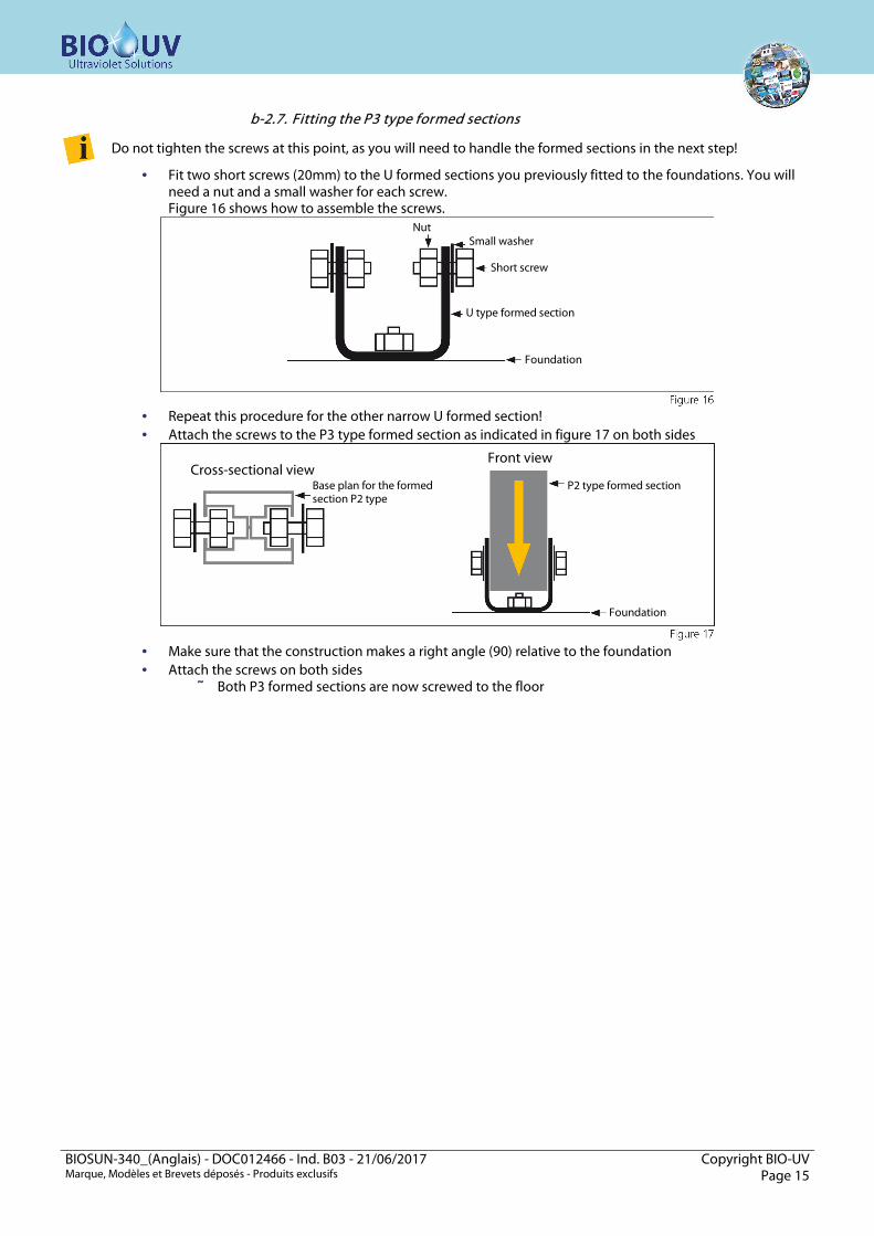
b-2.7. Fitting the P3 type formed sections
Do not tighten the screws at this point, as you will need to handle the formed sections in the next step!
· Fit two short screws (20mm) to the U formed sections you previously fitted to the foundations. You will need a nut and a small washer for each screw. Figure 16 shows how to assemble the screws.
· Repeat this procedure for the other narrow U formed section! · Attach the screws to the P3 type formed section as indicated in figure 17 on both sides
· Make sure that the construction makes a right angle (90) relative to the foundation · Attach the screws on both sides
Ä Both P3 formed sections are now screwed to the floor
Nut Small washer
Short screw
U type formed section
Foundation
Cross-sectional view Front view
Base plan for the formed section P2 type
P2 type formed section
Foundation

BIOSUN-340_(Anglais) - DOC012466 - Ind. B03 - 21/06/2017 Copyright BIO-UV Marque, Modèles et Brevets déposés - Produits exclusifs Page 16
b-2.8. Preparing the P1 type formed sections For this step, you will need P1 type formed sections, six narrow U formed sections, 18 short screws and 18 small washers. Figure 18 shows you where the formed sections should be installed in the overall structure (red circles).
· Prepare six narrow U formed sections as shown in figure 19.
Do not tighten the screws at this point, as you will need to handle the formed sections in the next step!
· Install three of the prepared U formed sections to the first P1 type formed section (see figure 20) - Make
sure to comply with the distances A, B and C (see figure 21).
· Repeat this procedure with the other P1 type formed section · Tighten the screws fitted to the P1 type formed sections
Ä Both P1 type formed sections are now ready to be assembled to the P3 and P2/P5 type formed section
Side view
Nut
Small washer
Short screw
U type formed section
P1 type formed section
U type formed section
U type formed section
U type formed section
U type formed section
P1 type formed section
BIOSUN-340_(Anglais) - DOC012466 - Ind. B03 - 21/06/2017 Copyright BIO-UV Marque, Modèles et Brevets déposés - Produits exclusifs Page 17
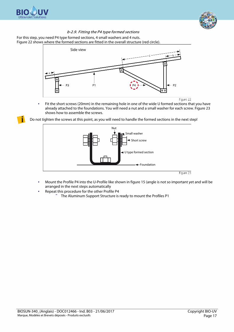
b-2.9. Fitting the P4 type formed sections For this step, you need P4 type formed sections, 4 small washers and 4 nuts. Figure 22 shows where the formed sections are fitted in the overall structure (red circle).
· Fit the short screws (20mm) in the remaining hole in one of the wide U formed sections that you have
already attached to the foundations. You will need a nut and a small washer for each screw. Figure 23 shows how to assemble the screws.
Do not tighten the screws at this point, as you will need to handle the formed sections in the next step!
· Mount the Profile P4 into the U-Profile like shown in figure 15 (angle is not so important yet and will be arranged in the next steps automatically
· Repeat this procedure for the other Profile P4 Ä The Aluminum Support Structure is ready to mount the Profiles P1
Side view
Nut
Small washer
Short screw
U type formed section
Foundation

BIOSUN-340_(Anglais) - DOC012466 - Ind. B03 - 21/06/2017 Copyright BIO-UV Marque, Modèles et Brevets déposés - Produits exclusifs Page 18
b-2.10. Fitting the P1 type formed sections For this step, you will need the previously prepared P1 type formed sections.
· Fit the P1 type formed sections to the P4, P2 and P3 formed sections as shown in figure 24 below.
Slight differences can be balanced by adjusting the U formed sections. But make sure that the parts are fitted the right way round!

BIOSUN-340_(Anglais) - DOC012466 - Ind. B03 - 21/06/2017 Copyright BIO-UV Marque, Modèles et Brevets déposés - Produits exclusifs Page 19
b-2.11. Fitting the safety cables For this step, you need four shackles, four core lugs, eight cable clamps, two turnbuckles and steel cable.
· Check the length between the eye nuts (diagonally), (see figure 25 - red lines)
· Assemble the wiring as shown in Figure 26, and make sure that they are the right length.
· Attach both cables as shown in figure 25 (red dashed lines) and tighten the cables using the tensioners
Rear view
Core terminal lug
Core terminal lug Cable clamp Cable clamp
Shackles Shackles Tensioner Steel cable

BIOSUN-340_(Anglais) - DOC012466 - Ind. B03 - 21/06/2017 Copyright BIO-UV Marque, Modèles et Brevets déposés - Produits exclusifs Page 20
b-2.12. Fitting the photovoltaic modules For this step, you will need fasteners for T and L type modules. Make sure that you have screws and nuts - long screws for attaching T modules and short screws for attaching L modules.
· Prepare two L fasteners as shown in figure 27.
· Screw the L fasteners into each of the two P1 type formed sections as shown in figure 28.
· Fit the photovoltaic module to the two P1 type formed sections and tighten the L attaching screws (see
figure 29)
· Prepare two T fasteners (see figure 30)
Short screw
L module attachment
Nut
Solar panel
T module fastener
Long screw
Nut

BIOSUN-340_(Anglais) - DOC012466 - Ind. B03 - 21/06/2017 Copyright BIO-UV Marque, Modèles et Brevets déposés - Produits exclusifs Page 21
· Fit a T fastener to each of the two P1 formed sections (see figure 31)
· Fit the second photovoltaic module to the two P1 type formed sections and tighten the T fasteners as
shown in figure 32.
· Continue this procedure until all the modules have been fitted (see figure 33)
High risk of injury · Injury and damage may be caused by structural parts during high winds · Firmly tighten all the screws to stiffen the whole structure!
Solar panel
Solar panel Solar panel
Solar panel
Solar panel Solar panel
Solar panel

BIOSUN-340_(Anglais) - DOC012466 - Ind. B03 - 21/06/2017 Copyright BIO-UV Marque, Modèles et Brevets déposés - Produits exclusifs Page 22
4. Wiring of photovoltaic panels
Junction box under each panel
Use 2 round lugs
Junction box under the support
Use crimping end wire these terminals
Connecting cable between panels and
terminal (4m max)
Connecting cable between modules

BIOSUN-340_(Anglais) - DOC012466 - Ind. B03 - 21/06/2017 Copyright BIO-UV Marque, Modèles et Brevets déposés - Produits exclusifs Page 23
5. Instruction to mount the BIOSUN 340 terminal Before starting the installation of the BIOSUN terminal, a concrete foundation must be provided corresponding to the dimensions of the terminal (see template below)
1
Carefully remove the BIOSUN module front panel with the profided anti-theft Allen wrench , taking care not to damage the hydraulic connections and wiring.
2
Attach the BIOSUN terminal to the floor: for example, use the 16 mm threaded rod sealed in the floor.
3
Place the battery inside the terminal Remove the connection covers of the batteries Connect the batteries in series observing the polarities indicated on the batteries connections. Mount back the covers on each connection.
BIOSUN-340_(Anglais) - DOC012466 - Ind. B03 - 21/06/2017 Copyright BIO-UV Marque, Modèles et Brevets déposés - Produits exclusifs Page 24
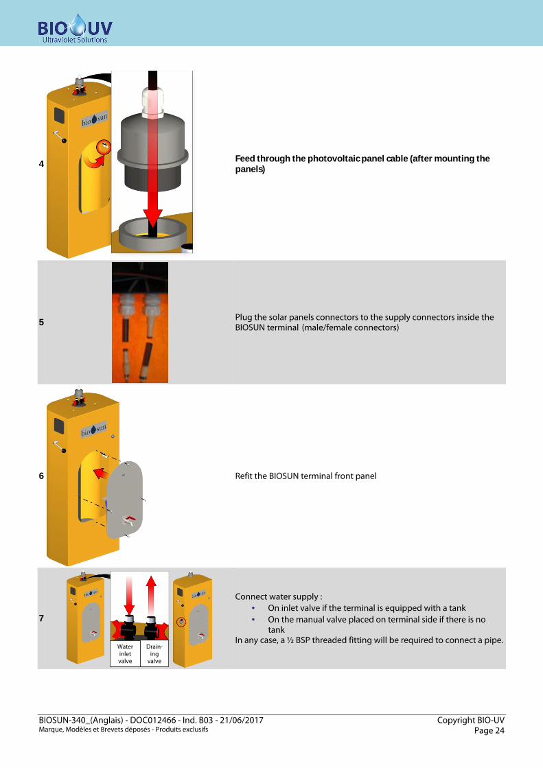
4
Feed through the photovoltaic panel cable (after mounting the panels)
5
Plug the solar panels connectors to the supply connectors inside the BIOSUN terminal (male/female connectors)
6
Refit the BIOSUN terminal front panel
7
Connect water supply : · On inlet valve if the terminal is equipped with a tank · On the manual valve placed on terminal side if there is no
tank In any case, a ½ BSP threaded fitting will be required to connect a pipe.
Water inlet valve
Drain-ing
valve
BIOSUN-340_(Anglais) - DOC012466 - Ind. B03 - 21/06/2017 Copyright BIO-UV Marque, Modèles et Brevets déposés - Produits exclusifs Page 25
E. INSTRUCTIONS FOR THE FIRST COMMOSSIONING OF THE BIOSUN 340 TERMINAL
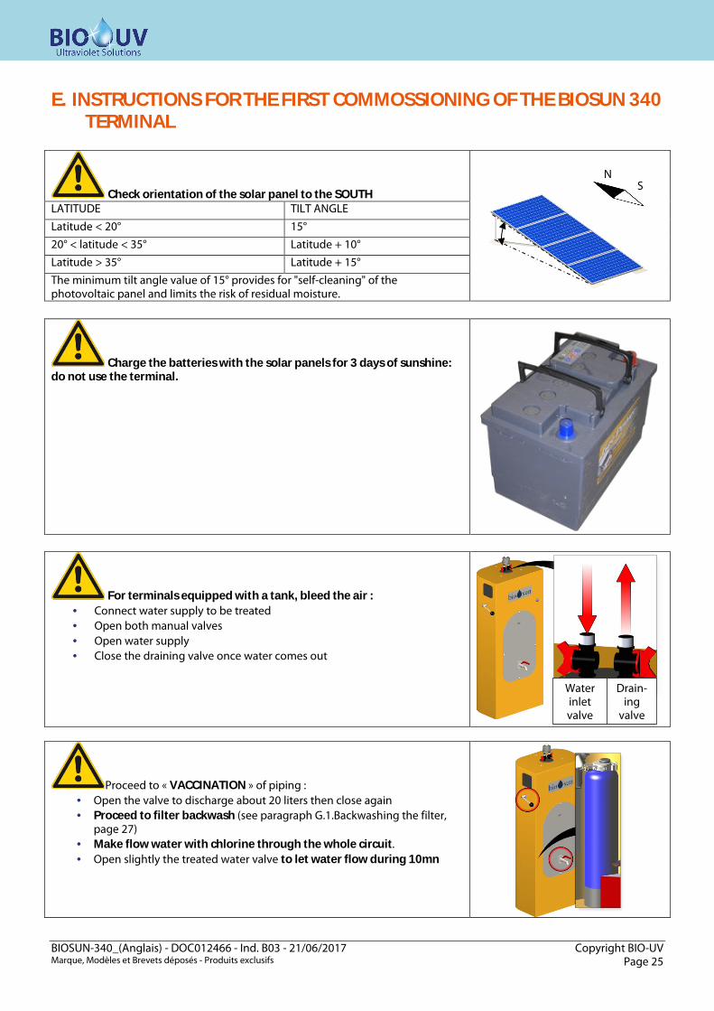
Check orientation of the solar panel to the SOUTH
LATITUDE TILT ANGLE
Latitude < 20° 15°
20° < latitude < 35° Latitude + 10°
Latitude > 35° Latitude + 15°
The minimum tilt angle value of 15° provides for "self-cleaning" of the photovoltaic panel and limits the risk of residual moisture.
Charge the batteries with the solar panels for 3 days of sunshine: do not use the terminal.
For terminals equipped with a tank, bleed the air : · Connect water supply to be treated · Open both manual valves · Open water supply · Close the draining valve once water comes out
Proceed to « VACCINATION » of piping : · Open the valve to discharge about 20 liters then close again · Proceed to filter backwash (see paragraph G.1.Backwashing the filter,
page 27) · Make flow water with chlorine through the whole circuit. · Open slightly the treated water valve to let water flow during 10mn
N S
Water inlet valve
Drain-ing
valve
BIOSUN-340_(Anglais) - DOC012466 - Ind. B03 - 21/06/2017 Copyright BIO-UV Marque, Modèles et Brevets déposés - Produits exclusifs Page 26
F. INSTRUCTIONS TO USE THE BIOSUN 340 TERMINAL
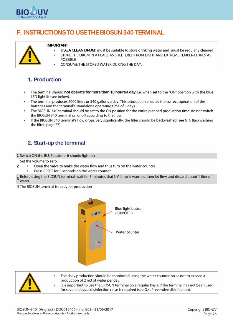
IMPORTANT · USE A CLEAN DRUM: must be suitable to store drinking water and must be regularly cleaned · STORE THE DRUM IN A PLACE AS SHELTERED FROM LIGHT AND EXTREME TEMPERATURES AS
POSSIBLE · CONSUME THE STORED WATER DURING THE DAY.
1. Production
· The terminal should not operate for more than 10 hours a day, i.e. when set to the "ON" position with the blue LED light lit (see below).
· The terminal produces 2000 liters or 540 gallons a day: This production ensures the correct operation of the batteries and the terminal's standalone operating time of 3 days.
· The BIOSUN 340 terminal should be set to the ON position for the entire planned production time: do not switch the BIOSUN 340 terminal on or off according to the flow.
· If the BIOSUN 340 terminal's flow drops very significantly, the filter should be backwashed (see G.1. Backwashing the filter, page 27).
2. Start-up the terminal 1 Switch ON the BLUE button : it should light on
2 Set the volume to zero:
· Open the valve to make the water flow and thus turn on the water counter · Press RESET for 5 seconds on the water counter
3 Before using the BIOSUN terminal, wait for 5 minutes that UV lamp is warmed then let flow and discard about 1 liter of water
4 The BIOSUN terminal is ready for production
· The daily production should be monitored using the water counter, so as not to exceed a production of 2 m3 of water per day.
· It is important to use the BIOSUN terminal on a regular basis. If the terminal has not been used for several days, a disinfection rinse is required (see G.4. Preventive disinfection).
Blue light button « ON/OFF »
Water counter

BIOSUN-340_(Anglais) - DOC012466 - Ind. B03 - 21/06/2017 Copyright BIO-UV Marque, Modèles et Brevets déposés - Produits exclusifs Page 27
G. INSTRUCTIONS FOR SERVICING OF THE BIOSUN 340 TERMINAL
1. Backwashing the filter It is recommended that a filter backwashing operation be performed once a week as a preventive measure. When the flow rate of BIOSUN terminal decreases, this means that the filter is clogged: A filter backwashing operation should be carried out. During operation, the two valves should be set to the "filtered" position.
To backwash, lower the handle to the "Cleaning" position for a few seconds until water comes out clear. During this operation, the water exits through the drain hole at the rear of the terminal.
2. Tank draining When suspended solids have settled at the bottom of the tank, they must be removed using the draining valve
The tank draining valve should always remain closed when the terminal is in normal operation
Cleaning position : for filter backwashing
Filtration position : for water treatement (Normal operation)
Tank draining valve Here, in draining position
Drain d32mm located on the rear of the BIOSUN frame Possibility to connect a d20mm draining pipe
BIOSUN-340_(Anglais) - DOC012466 - Ind. B03 - 21/06/2017 Copyright BIO-UV Marque, Modèles et Brevets déposés - Produits exclusifs Page 28
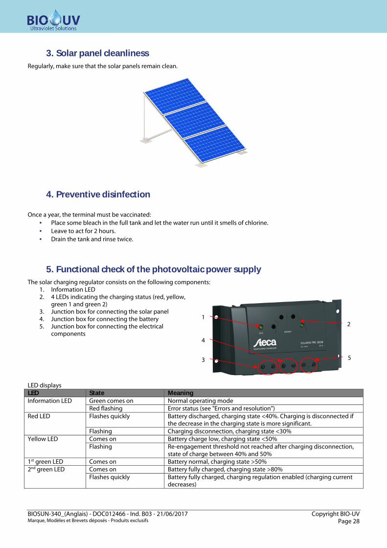
3. Solar panel cleanliness Regularly, make sure that the solar panels remain clean.
4. Preventive disinfection Once a year, the terminal must be vaccinated:
· Place some bleach in the full tank and let the water run until it smells of chlorine. · Leave to act for 2 hours. · Drain the tank and rinse twice.
5. Functional check of the photovoltaic power supply The solar charging regulator consists on the following components:
1. Information LED 2. 4 LEDs indicating the charging status (red, yellow,
green 1 and green 2) 3. Junction box for connecting the solar panel 4. Junction box for connecting the battery 5. Junction box for connecting the electrical
components LED displays LED State Meaning Information LED Green comes on Normal operating mode
Red flashing Error status (see "Errors and resolution") Red LED Flashes quickly Battery discharged, charging state <40%. Charging is disconnected if
the decrease in the charging state is more significant. Flashing Charging disconnection, charging state <30%
Yellow LED Comes on Battery charge low, charging state <50% Flashing Re-engagement threshold not reached after charging disconnection,
state of charge between 40% and 50% 1st green LED Comes on Battery normal, charging state >50% 2nd green LED Comes on Battery fully charged, charging state >80%
Flashes quickly Battery fully charged, charging regulation enabled (charging current decreases)
1
4
3
2
5

BIOSUN-340_(Anglais) - DOC012466 - Ind. B03 - 21/06/2017 Copyright BIO-UV Marque, Modèles et Brevets déposés - Produits exclusifs Page 29
H. PROCEDURE FOR LAP, QUARTZ SLEEVE OR SEALS REPLACEMENT These operations should be done at least once a year and:
· At each replacement of lamp (once a year), quartz sleeve or seal · To check/clean the quart sleeve
1
The terminal must be POWERED OFF, with the WATER SUPPLY CLOSED and DRAINED (treated water valve open).
2
Remove the front plate to access inside of the terminal
3
Unscrew the gland to release the lamp cable Remove the reactor cover
4
Grasp the 4-pin connector and pull the lamp gently upwards. When the lamp has been withdrawn by a few centimeters, remove the connector, grasp the socket and disengage the lamp from the quartz sleeve remaining well aligned with the axis.
Carry out this operation carefully without touching the glass of the lamp with the hands
Do not let the lamp fall into the quartz sleeve, it could break off into the quartz sleeve and damage the quartz
5
Unscrew the stainless steel nut. Remove the flat washer.
BIOSUN-340_(Anglais) - DOC012466 - Ind. B03 - 21/06/2017 Copyright BIO-UV Marque, Modèles et Brevets déposés - Produits exclusifs Page 30
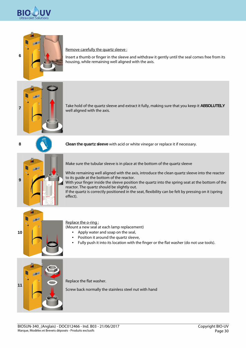
6
Remove carefully the quartz sleeve :
Insert a thumb or finger in the sleeve and withdraw it gently until the seal comes free from its housing, while remaining well aligned with the axis.
7
Take hold of the quartz sleeve and extract it fully, making sure that you keep it ABSOLUTELY well aligned with the axis.
8
Clean the quartz sleeve with acid or white vinegar or replace it if necessary.
9
Make sure the tubular sleeve is in place at the bottom of the quartz sleeve While remaining well aligned with the axis, introduce the clean quartz sleeve into the reactor to its guide at the bottom of the reactor. With your finger inside the sleeve position the quartz into the spring seat at the bottom of the reactor. The quartz should be slightly out. If the quartz is correctly positioned in the seat, flexibility can be felt by pressing on it (spring effect).
10
Replace the o-ring : (Mount a new seal at each lamp replacement)
· Apply water and soap on the seal, · Position it around the quartz sleeve, · Fully push it into its location with the finger or the flat washer (do not use tools).
11
Replace the flat washer. Screw back normally the stainless steel nut with hand

BIOSUN-340_(Anglais) - DOC012466 - Ind. B03 - 21/06/2017 Copyright BIO-UV Marque, Modèles et Brevets déposés - Produits exclusifs Page 31
12
Put the installation back in pressure before the reassembly of the lamp and check that there is no leakage in the quartz sleeve.
13
Take hold of the new lamp taking care not to place your fingers outside the cap. (if you do, clean the lamp with a soft cloth and some methylated spirits). Insert carefully to the three quarters of the new lamp into the quartz sleeve.
14
After engaging the lamp to the three quarters, plug again the connectos on the lamp. Do not force (there is a way to plug it). Engage fully the lamp into the quartz sleeve.
15
Mount the cover. Fully push the cable and tight the gland.
16
Mount the front cover on the terminal
17
The device is ready for operation.

BIOSUN-340_(Anglais) - DOC012466 - Ind. B03 - 21/06/2017 Copyright BIO-UV Marque, Modèles et Brevets déposés - Produits exclusifs Page 32
I. REPLACEMENT OF THE FILTER CARTRIDGES (OPTION)
1
Unscrew the transparent filter bowl. It is a good idea to place an empty bucket under the filter before removing it. Recover the water.
2
Replace the cartridge. Do not invert the cartridges !
1. Active carbon cartridge 2. 10µ Cartridge
3
Place the cartridge in the transparent filter bowl and screw the bowl back onto the filter head.

BIOSUN-340_(Anglais) - DOC012466 - Ind. B03 - 21/06/2017 Copyright BIO-UV Marque, Modèles et Brevets déposés - Produits exclusifs Page 33
J. MAINTENANCE FILE
AUTION: This sheet must be kept up to date.
It provides a record of the reactor’s operating cycle.
Date Counter Carried out action Done by

BIOSUN-340_(Anglais) - DOC012466 - Ind. B03 - 21/06/2017 Copyright BIO-UV Marque, Modèles et Brevets déposés - Produits exclusifs Page 34
K. ELECTRICAL DESCRIPTION
TAG DESIGNATION REFERENCES QUANTITY 1 Photovoltaic power supply 15A ELE006460 1 2 Converter 19-36VDC/24VDC ELE006742 1 3 Ballast BAL005248 1
4 On/Off lamp button ELE006352 1 NO Contact ELE000275 1 Blue light ELE006353 1
5 Battery ELE006462 2
BIOSUN-340_(Anglais) - DOC012466 - Ind. B03 - 21/06/2017 Copyright BIO-UV Marque, Modèles et Brevets déposés - Produits exclusifs Page 35
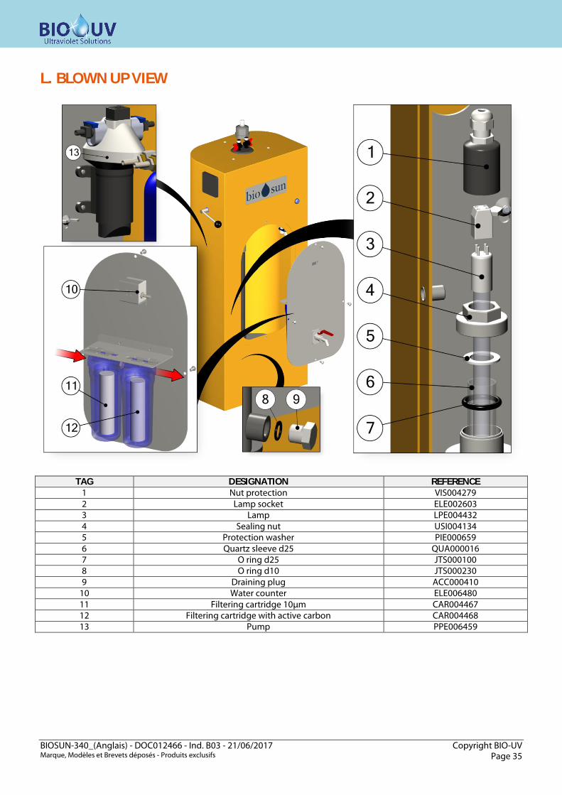
L. BLOWN UP VIEW
TAG DESIGNATION REFERENCE 1 Nut protection VIS004279 2 Lamp socket ELE002603 3 Lamp LPE004432 4 Sealing nut USI004134 5 Protection washer PIE000659 6 Quartz sleeve d25 QUA000016 7 O ring d25 JTS000100 8 O ring d10 JTS000230 9 Draining plug ACC000410
10 Water counter ELE006480 11 Filtering cartridge 10µm CAR004467 12 Filtering cartridge with active carbon CAR004468 13 Pump PPE006459

BIOSUN-340_(Anglais) - DOC012466 - Ind. B03 - 21/06/2017 Copyright BIO-UV Marque, Modèles et Brevets déposés - Produits exclusifs Page 36
M. ERRORS AND REMEDIAL ACTION: REGULATOR Error Cause Remedial action
No display
Battery voltage too low Precharge the battery Blowing of the external fuse in the battery connecting cable
Replace the external fuse
The battery is not connected Connect the battery observing the polarities the right way round Battery connection polarities reversed
Faulty battery
1.Disconnect all the connections 2.Re-connect the (new) battery with the polarities the right way round 3.Reconnect the solar panel and electrical components
Information LED flashing red
Charging interrupted due to the charging current being too high
Charging continues automatically when the charging current has reached an authorized level again
Electrical components cannot operate or are inhibited for a short period + Information LED flashing red
The output of the electrical components is disconnected due to high current consumption
¶Decrease the current consumption and disconnect or unplug the electrical components if necessary. ¶Check the electrical components.
The output of the electrical components is disconnected due to a short-circuit at this level.
1. Disconnect the electrical components. 2. Eliminate the short-circuit cause. 3. Reconnect the electrical components.
The output of the electrical components is disconnected due to overheating of the solar charging regulator.
The output of electrical components reconnects automatically when the solar charging regulator has cooled down. ¶Improve the air flow for cooling. ¶Prevent any influence from other heat sources. ¶Check the operating terms and the installation site.
Consumer operation not possible + Information LED flashing red + The battery red LED light flashes
The output of the electrical components is disconnected due to the battery voltage being too low.
The output of electrical components reconnects automatically as soon as the battery voltage reaches the threshold value. ¶Precharge the battery. ¶Fit any electrical components connected directly to the battery with a system providing protection against deep discharges. ¶Check the battery and replace it if necessary.
Electrical components cannot operate + info LED flashes red + 2nd LED flashes green
The output of the electrical components is disconnected due to the battery voltage being too high.
The output of electrical components reconnects automatically when the battery voltage reaches an authorized level.
Faulty grounding. ¶ Check the grounding.
No voltage limitation for external charging sources.
¶ Check the external charging sources. ¶ Disconnect any external charging sources, if applicable.
Electrical components cannot operate + Green information LED
Faulty consumer or faulty installation. ¶ Connect the consumer correctly. ¶ Replace the consumer.
The battery is not charged
The solar panel is not connected ¶Connect the solar panel Solar panel connection polarity reversed
¶Re-connect the solar panel with the polarities the right way round
Solar panel input short-circuited ¶Eliminate the short-circuit cause Solar panel voltage incorrect ¶Use the solar panel with the required voltage Faulty solar panel ¶Replace the solar panel
The battery display jumps quickly
High pulse current ¶Adjust the absorbed current to the battery's capacity Faulty battery ¶Replace the battery
The terminal's flow rate decreases
Filter clogged
The filter should be backwashed (see page 27) With the cartridge filter option: if filter backwashing does not solve the problem, the filter cartridges must then be renewed or cleaned if they are cleanable.

BIOSUN-340_(Anglais) - DOC012466 - Ind. B03 - 21/06/2017 Copyright BIO-UV Marque, Modèles et Brevets déposés - Produits exclusifs Page 37
The front panel blue light does not come on
Problem on regulator, UV lamp or ballast power supply
Check the battery charging light
Make sure that the voltage across the DC/DC converter terminals is 24V +/- 1V. ¶ If the voltage is too low, refer to the next question. ¶ If the battery is charged, replace the UV lamp ¶ If replacing the UV lamp does not solve the problem, then replace the ballast.
The converter output voltage is low: it must be 24 V +/- 1V
Bad wiring Check the wiring; all connectors must be properly tightened.
Battery charging in progress Check the battery charging level: If it is low (red LED), then let the battery charge without using the BIOSUN terminal until the battery charging indicator is green.
Converter out of order If the two previous operations have no effect, the converter must then be replaced.
Red LED: Charge Low
Green LED: charge OK
BIOSUN-340_(Anglais) - DOC012466 - Ind. B03 - 21/06/2017 Copyright BIO-UV Marque, Modèles et Brevets déposés - Produits exclusifs Page 38
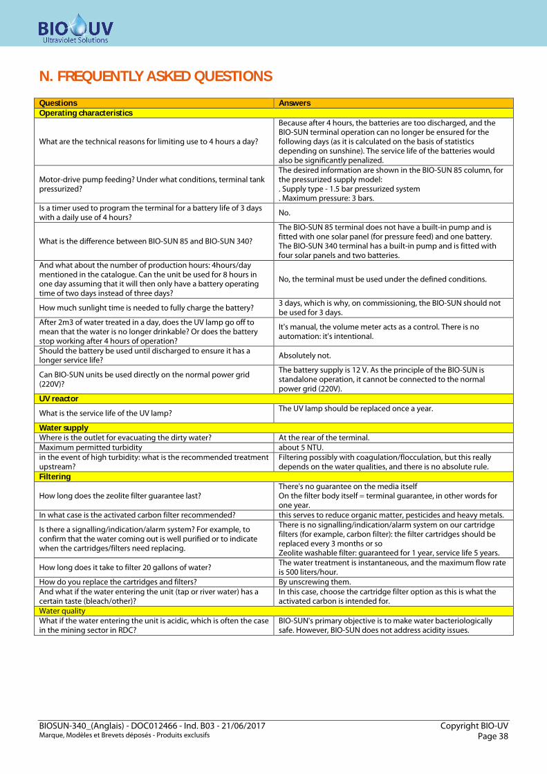
N. FREQUENTLY ASKED QUESTIONS Questions Answers Operating characteristics
What are the technical reasons for limiting use to 4 hours a day?
Because after 4 hours, the batteries are too discharged, and the BIO-SUN terminal operation can no longer be ensured for the following days (as it is calculated on the basis of statistics depending on sunshine). The service life of the batteries would also be significantly penalized.
Motor-drive pump feeding? Under what conditions, terminal tank pressurized?
The desired information are shown in the BIO-SUN 85 column, for the pressurized supply model: . Supply type - 1.5 bar pressurized system . Maximum pressure: 3 bars.
Is a timer used to program the terminal for a battery life of 3 days with a daily use of 4 hours? No.
What is the difference between BIO-SUN 85 and BIO-SUN 340?
The BIO-SUN 85 terminal does not have a built-in pump and is fitted with one solar panel (for pressure feed) and one battery. The BIO-SUN 340 terminal has a built-in pump and is fitted with four solar panels and two batteries.
And what about the number of production hours: 4hours/day mentioned in the catalogue. Can the unit be used for 8 hours in one day assuming that it will then only have a battery operating time of two days instead of three days?
No, the terminal must be used under the defined conditions.
How much sunlight time is needed to fully charge the battery? 3 days, which is why, on commissioning, the BIO-SUN should not be used for 3 days.
After 2m3 of water treated in a day, does the UV lamp go off to mean that the water is no longer drinkable? Or does the battery stop working after 4 hours of operation?
It's manual, the volume meter acts as a control. There is no automation: it's intentional.
Should the battery be used until discharged to ensure it has a longer service life? Absolutely not.
Can BIO-SUN units be used directly on the normal power grid (220V)?
The battery supply is 12 V. As the principle of the BIO-SUN is standalone operation, it cannot be connected to the normal power grid (220V).
UV reactor
What is the service life of the UV lamp? The UV lamp should be replaced once a year.
Water supply Where is the outlet for evacuating the dirty water? At the rear of the terminal. Maximum permitted turbidity about 5 NTU. in the event of high turbidity: what is the recommended treatment upstream?
Filtering possibly with coagulation/flocculation, but this really depends on the water qualities, and there is no absolute rule.
Filtering
How long does the zeolite filter guarantee last? There's no guarantee on the media itself On the filter body itself = terminal guarantee, in other words for one year.
In what case is the activated carbon filter recommended? this serves to reduce organic matter, pesticides and heavy metals.
Is there a signalling/indication/alarm system? For example, to confirm that the water coming out is well purified or to indicate when the cartridges/filters need replacing.
There is no signalling/indication/alarm system on our cartridge filters (for example, carbon filter): the filter cartridges should be replaced every 3 months or so Zeolite washable filter: guaranteed for 1 year, service life 5 years.
How long does it take to filter 20 gallons of water? The water treatment is instantaneous, and the maximum flow rate is 500 liters/hour.
How do you replace the cartridges and filters? By unscrewing them. And what if the water entering the unit (tap or river water) has a certain taste (bleach/other)?
In this case, choose the cartridge filter option as this is what the activated carbon is intended for.
Water quality What if the water entering the unit is acidic, which is often the case in the mining sector in RDC?
BIO-SUN's primary objective is to make water bacteriologically safe. However, BIO-SUN does not address acidity issues.
BIOSUN-340_(Anglais) - DOC012466 - Ind. B03 - 21/06/2017 Copyright BIO-UV Marque, Modèles et Brevets déposés - Produits exclusifs Page 39
O. WARRANTY TERMS The terms of guarantee for the equipment in the BIO-UV range are as follows:
- 2 years for all components with the exception of the UV lamp (consumable). Exclusions:
The electrical components are not guaranteed against overvoltage or lightning strikes. Modification and addition of components in the electrical cabinets Use of spare parts that do not originate from BIO-UV Non-compliance with the installation instructions Reactor having been operated without being full Non-compliance with the operating and maintenance instructions.
Note: the housing, the quartz sleeve and the lamp are not guaranteed against breakage.
- Faulty parts must be sent back to BIO-UV with details of the type and the equipment serial number. BIO-UV
will replace them after carrying out a technical survey. - The cost of shipping will be shared between the retailer and BIO-UV. - The guarantee takes effect on the day of the installation of the equipment: this date must be communicated to
BIO-UV by sending the guarantee validation by post or by fax.
Note: If the guarantee validation is not sent back in the month following purchase of the equipment, BIO-UV will take the date of effect of the guarantee as being the month and the year the equipment was manufactured.
- If the installation rules and instructions for use are not complied with, BIO-UV cannot be held liable and the
guarantee cannot be invoked.
The BIO-UV team, at your service.
Company BIO-UV SA 850, Avenue Louis Médard
34400 LUNEL France Phone : +33 4 99 13 39 11
www.bio-uv.com Email : [email protected]

BIOSUN-340_(Anglais) - DOC012466 - Ind. B03 - 21/06/2017 Copyright BIO-UV Marque, Modèles et Brevets déposés - Produits exclusifs Page 41
ANNEX 1: Clearance dimensions,
Blown up view, Designation

BIOSUN-340_(Anglais) - DOC012466 - Ind. B03 - 21/06/2017 Copyright BIO-UV Marque, Modèles et Brevets déposés - Produits exclusifs Page 43
ANNEX 2: Electrical diagrams