Embed Size (px)
Citation preview

Corresponding author: Yuying Yan E-mail: [email protected]
Journal of Bionic Engineering 11 (2014) 469–480
Biomimetic Capillary Inspired Heat Pipe Wicks
Qian Wang, Jiaju Hong, Yuying Yan Energy & Sustainability Research Division of Faculty of Engineering, University of Nottingham,
University Park, Nottingham NG7 2RD, UK
Abstract The possibility of mimicking desirable properties from nature accelerates material improvement and generates commercial
interests. For heat pipe development, many attempts have been made in heat pipe wicks to enhance its capillary performance by mimicking biology. Constructing biporous, composite, or nanopillar wicks with aim of achieving hierarchical structure has beenfound in many studies. Mimicking beetle shell surface to obtain hybrid wettability shows biomimetic potential in heat pipe wicks. This paper firstly reviews some fundamental studies in biomimetics, establishing a general idea of surface wetting and capillary effect. MRI scanning of two live plants (Musa X Paradisiaca and Salix Flamingo) provides the possibility of visual-ising internal structures in vivo and obtaining rates of water transport in xylem vessels. In addition, by investigating the work inspired directly or indirectly from biomimetics, the role that biomimetics plays in modern heat pipe technology is revealed. Our innovation which syntheses a low level of hierarchical structure and integrates integral wicks for different heat pipe sections including evaporator, adiabatic, and condenser is introduced. Mathematical modelling in terms of capillary pressure and cap-illary rise rate to characterise such new structure is provided.
Keywords: biomimetics, heat pipe, surface wetting, capillary effect, wick structure Copyright © 2014, Jilin University. Published by Elsevier Limited and Science Press. All rights reserved. doi: 10.1016/S1672-6529(14)60059-7
Nomenclature
Aw Cross-sectional area of the wick (m2) D Wick pore diameter (µm) g Gravitational acceleration (ms−2) h Capillary rise distance (mm) Jv The rate of water transport (mm·s−1) K Wick permeability (m−2) L Horizontal length (m) Pc Capillary pressure (Pa) Δpc
Capillary pressure drop along the heat pipe (Pa)
Δpevap Capillary pressure drop at evaporator (Pa)
Δpl Liquid pressure drop (Pa)
Δpv Vapour pressure drop (Pa)
reff Effective pore radius (µm) rh Hydraulic radius (m) S Specific surface area (m2) θ Contact angle θc Contact angle at condenser θe Contact angle at evaporator ε Porosity
λ Particle shape factor μ Water dynamic viscosity (kg·ms−1) ρ Density of water (kg·m−3) ρs Density of the solid (kg·m−3) ρw Density of the wick (kg·m−3) σ Surface tension (kg·m·s−2) τ Tortuosity (m) Δψp Pressure drop (Pa)
Subscripts
c Capillary or condenser e Effective or evaporator eff Effective h Hydraulic l Liquid s Solid w Wick
1 Introduction
The diversity and adaptability of the natural world fascinate mankind and enable human revolution. Our attempt in developing new manufacture methods to

Journal of Bionic Engineering (2014) Vol.11 No.3 470
synthesize an isolated function in nature is encouraged, and the necessity to fully understand such natural proc-ess avoiding blindly copying nature is demanded. For heat pipe improvement, a change in wick structure can help generate effective results. With provision of the wick, a heat pipe can work in any orientation. The wick serves the function of further complicating the boiling process, offering additional nucleation sites beneficial for bubble formation, and modifying the movement of liquid and vapour towards or from the heated surface[1]. The associated capillary force created by the wick, no-tably, forms the main criteria in evaluating heat pipe performance that helps achieve the passive operation, i.e. pulling back the condensed liquid from the condenser to the evaporator without any external force. Therefore, it is desired to investigate some nature generated capillary effects from plants, insects and aquatic animals in terms of cell or surface structures.
Many biomimetic studies towards superhydropho-bic or superhydrophilic effects[2–5] have been conducted in recent years, offering a convenient path for engineers to extract relevant details (e.g. surface structure, contact angles/wettability, materials in contact) for current technology development. In mimicking biology, capil-lary effect is always accompanied by adopting hierar-chical structure for microscale or nanoscale applications, which is the response to various mechanisms including dissipation, friction and wetting[6]. It is the hierarchical structure that helps the species to achieve adaptability in diverse forms of functions based on various character-istic length scales. If such hierarchical structures help plants and creatures establish their adaptable mecha-nisms of energy dissipation and transition, it is possible that engineers can follow the principles in order to de-velop improved environment-friendly technologies. Examples can be found in heat pipe development, such as constructing biporous or bidisperse[7–10], composite (e.g. sintered-grooved)[11–17], micro- or nano-pillar wicks[18–20] to achieve high evaporative heat flux, high capillary pressure and relatively high vapour perme-ability. The hierarchical structures help overcome common deficiencies brought by single structure as well as identifying the potential of high capillary pressure and maximised thin-film evaporation. In addition, Zhao et al.[21] proposed a beetle inspired superhydrophobic condenser with hydrophilic bumps to accumulate con-densate to achieve hybrid wettability.
This paper tries to elaborate hierarchical structure obtained from nature in terms of wetting phenomena and capillary effect, so that the fundamental parameters that characterise surface wettability and capillary effect can be recognised. A recent study performed by our research group introduces MRI scanning of live plants. This aims to visualise how plant has the ability to transport water upwards, to find possible biomimetic solutions to im-prove fluid flow in porous structures, and to form a better understanding of capillary effect in porous media. Reviews on biporous or bidisperse, multi-structured/ composite and nanopillar wick are made, and our inno-vation in heat pipe integral wick structure is proposed. Mathematical modelling of wick capillary pressure and capillary speed is provided in order to characterise such new wick structure.
2 Hierarchical structure from nature
2.1 Wetting phenomena
Many biological structures at micro- and nano-scale in both plants and animals have demon-strated their interaction with water and hence the wet-tability. For instance, surface structure or roughness of the xylem in trees varies among species and differs with climates[22]. In hot and dry climate, xylem with small warts shows superhydrophilicity, where the contact angle of water within xylem is extremely low. The water collecting ability of the capture silk of the cribellate spider[23], in particular, gives light to surface wettability. With periodic spindle-knots and joints, continuous condensation and directional water drops collection can be achieved. The unique system of cactus[24], which is composed of well-distributed clusters of conical spines and trichomes on the cactus stem, and multi-level grooves from microgrooves to submicorgrooves on the spine, intrigues the investigation of structure-function relationship and wetting mechanism. Moreover, desert beetles[25,26] which use multi-functional elytra surface structure (hydrophilic bumps on hydrophobic base) to capture water from humid air. A systematic structure of spikes, scales and channels involved in moisture har-vesting lizard’s skin[27–29] indicates the level of hierar-chical order influencing surface properties. 2.2 Capillary effect
A cohesion-tension theory has often been applied

Wang et al.: Biomimetic Capillary Inspired Heat Pipe Wicks 471
into trees, despite the fact that the exact mechanism of water transport has not been fully understood[30]. It is said that the water can be transported by tension forces, which are caused by capillary force and leaf transpira-tion. The capillarity increases when xylem diameter is smaller, and branching of the xylem increases capil-larity[31]. In addition to the surface properties of certain lizards mentioned earlier, they employ capillary trans-port over their skin to assist drinking. In the case of moloch horridus, the spikes[28] encourage water to run over the skin. The micro-structured scales[27] covered in a honeycomb structure of walls increase surface wet-tability. The channels, which are inter-scalar and differ from 10 µm[27] to 100 µm – 150 µm[28], form inter-scalar capillary system and capillary connections for moisture harvest. A gradient of capillary sizes to passively lift water can vary according to the distance from the mouth,
with smaller capillaries near the mouth and larger cap-illaries far away from it.
An initial study of capillary effect in plant by MRI scanning has been carried out by our research group. We used a Philip 3T Achieva machine (with resolution of 0.3 mm×0.3 mm and 3 mm layer gap) to scan two cho-sen plants: Musa X Paradisiaca and Salix Flamingo (Figs. 1a and 1b). MRI provides the possibility of visu-alising internal structures of plants occurring in vivo. The major aims are to study how plants move water upwards, to find potential biomimetic solutions to im-prove fluid flow in porous structures, and to form a better understanding of capillary effect in porous media.
Figs. 1c and 1d show the water flow distribution in 3D and Figs. 1e and 1f display the magnetic signal in-tensity reported by MRI that reflects the degree of water concentration from both cross-sectional and longitudinal
Fig. 1 MRI scanning of live plants. (a) Musa X Paradisiaca. (b) Salix Flamingo. (c–d) 3D water flow distribution in xylem vessels ob-tained from (c) Musa X Paradisiaca and (d) Salix Flamingo. (e)–(f) Cross-sectional and longitudinal view of water distribution of (e) Musa X Paradisiaca and (f) Salix Flamingo (Note: signal intensity level helps reflect water distribution, blue indicates low intensity, i.e. less water; red indicates high intensity, i.e. more water). (g) MRI scanned rate of water transport Jv (mm·s−1) in the xylem vessel of Salix Flamingo (an average peak velocity of 0.2 mm·s−1 was obtained).

Journal of Bionic Engineering (2014) Vol.11 No.3 472
view. Results indicate that water flow through the xylem is very efficient, as considerable amount of water dis-tribution in xylem vessels was observed throughout the entire plant (from the bottom to the top). However, due to machine resolution limit, the precise structure of xy-lem vessel and water molecule movement are hard to be observed. Further work on exploring xylem cell contact angle and capillarity are desired, and they can be possi-bly done by adding tracer to the stem.
Fig. 1g shows the rate of transport Jv (mm·s−1) in the xylem obtained from Salix Flamingo, which sug-gests an average of peak velocity of 0.2 mm·s−1. Usually, for wide xylem vessel which has radius ranging from 100µm to 200 µm, the highest peak water transport ve-locity is from 4 mm·s−1 to13 mm·s−1; for smaller one which varies from 25 µm to 75 µm, a lower average peak velocity of 0.3 m·s−1 – 1.7 m·s−1 can be resulted[32]. This implies that for Salix Flamingo, it has smaller vessels which tend to result in lower peak velocity. According to Poiseuille’s equation (Eq. (1)), the pressure gradient Δψp/Δx to overcome the viscous drag that arises as water moves through an ideal xylem vessel (with a radius of 25 µm) at this velocity Jv (0.2 mm·s−1) can be estimated. If assuming µ (µ = 8.9×10⁻⁴ Pa·s at 25ºC) is the water viscosity of xylem sap, the pressure gradient Δψp/Δx required is 2278 Pa·m−1. To note, for real vessels, where irregular inner wall surface and constrictions are at present, they often have large resistance to water flow.
2
( ).8vrJ
xψ
μΔ
=Δ
(1)
2.3 Theory behind
The concept of hierarchy can be defined as two or more levels created by combinations of structures of different dimensions, and the number of levels or so-called hierarchical order is related to a particular function of each level of material structure[33]. This translates to surface roughness, and if small roughness superimposes onto a smooth surface, such as the men-tioned surfaces of cactus, beetles and lizards, changes in system behaviour can be resulted. One of the many system behaviours is the phenomenon of wetting, which indicates how well the liquid moves to expose its fresh surface and to wet the surface of the solid in turn. No-tably, the fundamental parameter that characterises sur-face wettability is the Contact Angle (CA)[34]. The CA is
defined as the angle formed by the intersection of the liquid-solid interface and the liquid-vapour interface, and is determined by a combination of surface tension and external forces such as gravity[35]. Favourable sur-face wetting has a CA less than 90˚, while unfavourable wetting has the angle greater than 90˚. In various ranges of CA degrees, hydrophilic/hydrophobic (solid in con-tact with water, 0˚ < CA ≤ 90˚ for hydrophilic and 90˚ < CA ≤ 180˚ for hydrophobic) and superhydropho-bicity (150˚ < CA ≤ 180˚)/superhydrophilicity (almost 0˚) can be introduced.
Another classic element of wetting of liquid drop-lets in systems from centimetre to micro- or nano-meter scales is Contact Angle Hysteresis (CAH)[36]. CAH was firstly explained by Cassie and Baxter[37], and it is the difference between the advancing and receding CAs. In heat pipe application for example, such occurrences can be seen during heating process where evaporation takes place or cooling process when condensation appears. A low CAH is a measure of dissipation, while a high CAH is a measure of wetting[38]. CAH intrigues the relation-ship of the surface texture and solid surface energy, and it occurs when the CA is not a fixed value, i.e. can have any value between the advancing and receding CA val-ues[39,40]. Significantly, CAH is believed to complicate the wetting cycle changing the behaviour from reversi-ble to irreversible qualitatively.
As mentioned by Nosonovsky and Bhushan[38], a small adjustment in surface structure/roughness may lead to a significant change in capillary force. This is because small-scale roughness produces new energy equilibriums, and it changes the shape of water meniscus and hence, the meniscus force. The capillary effect is created due to the tendency of a liquid to minimise its free surface en-ergy, which can be defined as the work energy input to the change of surface area. Molecules at a curvature surface have fewer bonds thus higher energy that leads to surface tension. Hierarchical structure provides a plat-form for such energy to be spent on breaking, generating cohesive force among the liquid molecules and adhesive force among molecules of other adjacent substances. It has been pointed out that capillarity depends on scale, and a range of length-scales in hierarchical structure help to respond to different mechanisms such as wetting. Surface with only one scale of roughness cannot perform well[41], therefore it is desired to have large-scale details that offer structural strength while small-scale, desired

Wang et al.: Biomimetic Capillary Inspired Heat Pipe Wicks 473
wetting properties and capillary effects.
3 Hierarchical structure from heat pipe wicks
3.1 Heat pipe basic mechanism
The heat pipe can be originated from Perkins tube, a two phase thermosyphon invented in 1836[42]. It was not until 1944 did the heat pipe form its unique feature, which uses capillary structured wicks to help the return of the condensed liquid. Three sections namely evapo-rator, adiabatic, and condenser can be used to describe how a heat pipe functions (Fig. 2). The heat transfer starts at the evaporator where heat fluxes are inputted. By conduction and partly by natural convection, the heat flows through the pipe wall and in contact with the fluids inside to form evaporation. As the heat flux increases, the working liquid at the wall becomes superheated, and bubble formation appears inside the wicks. Subsequently, the bubble becomes the carrier in the form of vapour to transport energy through latent heat of vaporisation. A driving force is created due to the difference of vapour pressure between the evaporator and the condenser, pushing the mass transfer of vapour to the condenser releasing latent heat. The condensed fluid will then flow back to the evaporator by capillary forces generated from surface tension of the wick thus repeating the above cycle passively. To note, a heat pipe should be able to work in any orientations if the wick is provided. Gravity plays a vital role in heat pipe performance, and the heat transport capacity would be decreased if the angle of operation against gravity increases.
Areas of heat pipe applications cover broadly and dynamically, from aerospace, nuclear industry, phar-macy, machinery, to electronics and renewable energy. In today’s high tech industries, where portability and
Fig. 2 Heat pipe mechanism.
lightweight become crucial in most cooling system re-quirements, adopting new strategy to downsize heat pipes meanwhile improving its heat transfer perform-ance is necessary. Developments of lightweight and high performance heat pipes has been reviewed by Yang et al.[43], and advanced technologies developed in heat pipe wicks to achieve high heat flux and high cap-illary limit will be discussed below.
3.2 Hierarchical structure in wicks 3.2.1 Biporous wicks
Biporous wicks are aimed to enhance heat transfer efficiency in the evaporator and they can be fabricated by constructing a low level of hierarchy structure: clus-ters of particles. Many works have been conducted in exploring the benefits[7–10] and a good agreement on producing both high capillary pressure and high vapour permeability is established.
Two levels of pore sizes can be found in this par-ticular wick: small solid particles (small pore) within a bigger porous particle. This results in a special per-formance in vaporisation because it increases the num-ber of small evaporating menisci with high heat transfer ability in second level pores. The bubbles can easily escape from large pores eliminating the chances of blocking the condensate return. The capillary forces developed in smaller pores are larger than those in big-ger pores, so if increasing the evaporative heat flux, bigger particles will be filled by vapour but smaller pores filled with liquid can still allow more evaporation. Very little variation in temperature drop, in addition, can be seen when heat flux increases because the additional heat can be taken away by evaporation in smaller pores. A recent study[8] found that the effectiveness of biporous wicks subjects to an optimal ratio of particle to cluster size. The ratio should allow full wetting of both in-ter-cluster and inter-particle pores thus achieving maximum volume flow and capillary force. This again indicates the importance of multi-scale in hierarchy structure, at which desirable properties can be obtained.
3.2.2 Composite wicks Composite wick is known as a combination of two
types of single structure such as metal fibres and axial grooves, screen mesh and axial groove, and sin-tered-groove[11]. It is often designed to decouple capil-

Journal of Bionic Engineering (2014) Vol.11 No.3 474
lary pumping from flow resistance in heat pipes. It pro-vides larger capillary force while maintaining high permeability. A plurality of documented benefits of in-tegrating groove and sintered wicks suggest a great role hierarchy structure plays. The combination of groove and sintered wicks can be found in many works, with either longitudinal grooves lining inside the casing covered by sintered powders[11–14], or sintered powders forming groove structures[15–17]. Both configurations tend to utilise the advantages of grooves, which provide high longitudinal capillary pumping, and sintered wicks that provide high capillary pressure and the ability in dealing with anti-gravity. Grooved structure gives lands or channels to help the formation of continuous layer of longitudinal liquid[15], while the sintered wicks eliminate the chances of non-uniform circumferential liquid dis-tribution[16]. Non-uniform circumferential liquid distri-bution has always been found in groove wicks, both in evaporator and condenser, driving the imbalance of some grooves carrying excess liquid or none, i.e. dry-out[15]. Therefore, exploiting advantages of both struc-tures may help to overcome the common deficiency brought by single structure, thus enhancing heat pipe performance efficiently. 3.2.3 Mirco- or nano-pillar wicks
The advantages of micro- or nano-pillar wicks are that they sustain higher thermal conductivity compared to sintered wicks, and exhibit high permeability with low liquid pressure drop[19]. For a given wick morphology, the capillary effect can be improved by an order of magnitude if thin nanostructured layer formation was found on the post surface[46]. Pillar structure may always be constructed in microchannels to enhance the surface to volume ratio while increasing capillary flow. Ding et al.[20] studied the wetting behaviour of the titanium micropillars numerically and experimentally. Zhang and Hidrovo[18] investigated the wicking principles given by nanopillar. Ranjan et al.[19] analysed wicking and ther-mal performance for the use in passive heat spreaders. They pointed out that different pillar geometries such as cylindrical, conical and pyramidal structures being compared at a fixed porosity and permeability, have the potential of producing high capillary pressure and maximising thin-film evaporation. These again indicate the function of micro- or nanostructures generating de-sired wetting properties and capillary effects.
3.2.4 ‘Beetle shell’ wicks A new type of vapour chamber with beetle mim-
icking condenser wicks was proposed by Zhao et al.[21]. They fabricated a hybrid surface that has hy-drophilic pillars (185 μm in height) on a superhydro-phobic base. Unlike normal heat pipes which eliminate the external forces for liquid return, electrostatic force is applied to drive the accumulated water drops attached on the hydrophilic bumps back to the evaporator. The overall concept of such design is to eliminate the use of conventional wicks so as to reduce the thermal resis-tance of the heat pipe.
4 Novel heat pipe wick
4.1 Potential mechanism The heat pipe wick inspiration comes from altering
the surface roughness which enhances surface wetting and obtaining a gradient of capillarity sizes that im-proves the capillary limit. The wick structure incorpo-rates with a low level of hierarchy structure and the intention has been explained in Ref. [45]. Other works with regard to hierarchy structure can also be found in author’s previous work[46–48]. By varying surface roughness and wick pore sizes at each section of the heat pipe, surface wetting at the evaporator and the capillary pumping force will be presumably improved. A two-scale sintered powder (small pores on the top and larger pores at the bottom) in a grooved form at the evaporator is shown, and a slope is created along the heat pipe (three sections with different stack heights) en-hancing the ability of creating excellent capillary pumping force (Fig. 3). As mentioned earlier, grooved structure provides sites for continuous layer of longitu-dinal liquid, and the sintered wicks minimise the chances of non-uniform circumferential liquid distribution.
Fig. 3 Novel integral wick design for evaporator, adiabatic and condenser in flat heat pipes.

Wang et al.: Biomimetic Capillary Inspired Heat Pipe Wicks 475
It is the subject of the present invention to charac-terise corresponding wick structures for each section namely evaporator, adiabatic and condenser to (1) achieve expected individual functionality, to (2) maxi-mise the overall heat pipe performance in dealing with limited space or anti-gravity, to (3) optimise the balance of gravity, liquid and vapour pressure drops, and to (4) compromise the resultant counter effects in terms of wicks pore size, structure and thickness. Fig. 4 shows the morphology of the fabricated wick sample at the evaporator and the condenser by using the Philips scan-ning electron microscope (FW6800/70) at an accelerat-ing voltage of 20 kV.
For evaporator wicks, distributed liquid supply, effective vapour removal and a short conduction path are considered for optimal design. Limited high flux heat removal is often found in liquid-filled evaporator (large thermal resistance) unless it is very thin[17,49]. In this evaporator (Fig. 5), larger pores are constructed along the pipe wall with smaller pores on top forming groove structure. Those grooves provide short heat conduction paths, and the arrayed wick structure establishes several acute-angle portions where capillary forces are at large. This helps induce larger capillary pressure drop along the pipe. Fig. 6 illustrates how the liquid forming me-niscus bridges at those acute-angles, which develop a negative pressure inducing an intrinsic attractive force.
These menisci help the evaporator achieving maximum wetting ability. The layer which consists of larger pores benefits liquid return and distribution, and decreases the chances of nucleate boiling; whereas the layer on the top, which has smaller pores, enhances the ability of lifting the liquid, i.e. maximised wetting.
EvaporationLiquid flow path
Short heat conduction pathHeat flow path
Fig. 5 Heat and liquid flow path in the evaporator.
Fig. 6 Liquid forming meniscus bridges at acute-angles among wick pores.
Fig. 4 SEM micrographs showing the fabricated wick sample at the evaporator (100 µm – 200 µm dendritic powder sintered at 960˚C) (a) planar view (b) profile view; and at the condenser (200 µm dendritic powder sintered at 960˚C) (c) planar view (d) profile view.
Journal of Bionic Engineering (2014) Vol.11 No.3 476
For the adiabatic section, uniform sintered powder size is distributed with medium stack height. Only larger sintered powders are formed with no grooves. This is to provide a transitional path for liquid return from the condenser to the evaporator. As to the condenser, rela-tively larger pores are needed with groove structure to increase surface area, obtaining great ability in absorb-ing latent heat of vaporisation. Compared to the evapo-rator, the pore size should be larger, and the channels created ought to be smooth to reduce wetting and pres-sure drop, both from the returning liquid and from the vapour liquid shear forces. Additionally, space for va-pour flow passage are maximised in each section, eliminating the concern of clogged vapour space after flattening. A slope is created along the heat pipe from the evaporator to the condenser to enhance the ability of creating excellent capillary pumping force especially in anti-gravity condition.
4.2 Mathematical modelling
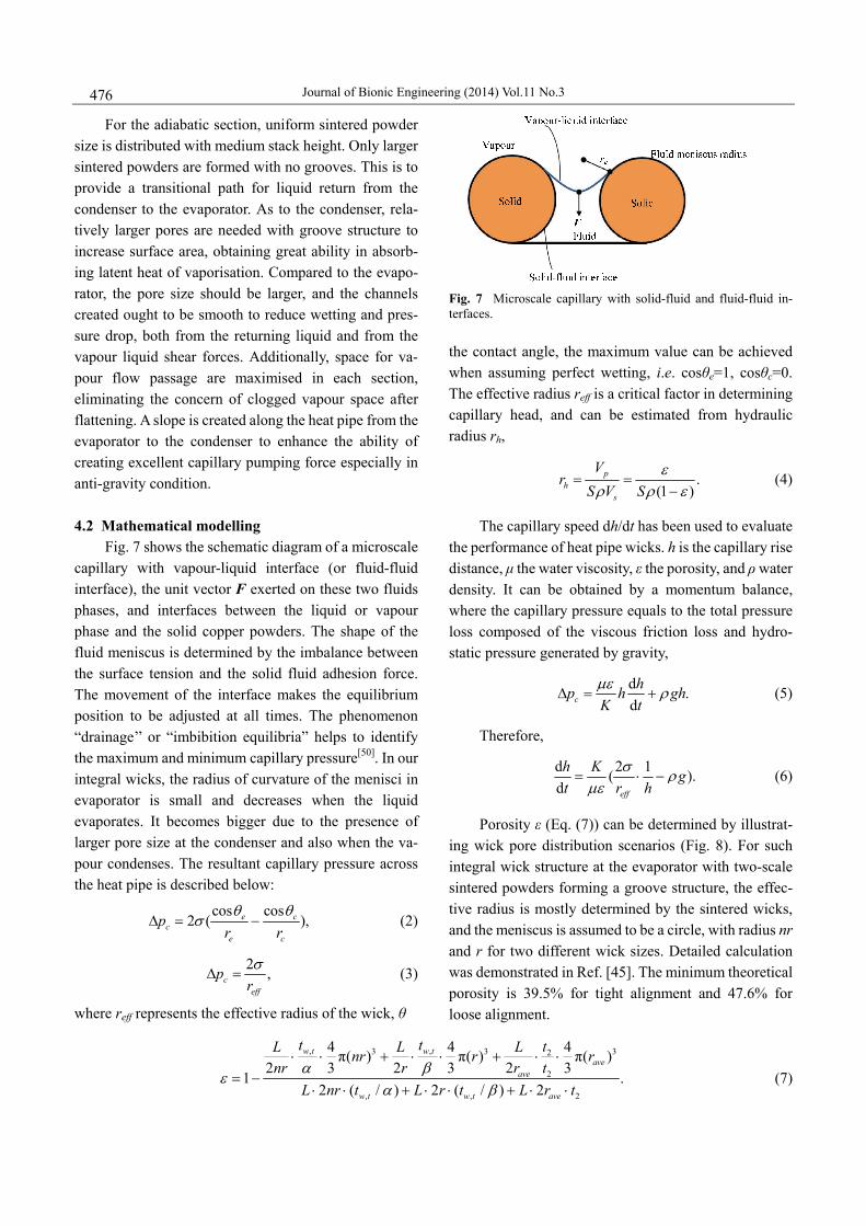
Fig. 7 shows the schematic diagram of a microscale capillary with vapour-liquid interface (or fluid-fluid interface), the unit vector F exerted on these two fluids phases, and interfaces between the liquid or vapour phase and the solid copper powders. The shape of the fluid meniscus is determined by the imbalance between the surface tension and the solid fluid adhesion force. The movement of the interface makes the equilibrium position to be adjusted at all times. The phenomenon “drainage’’ or “imbibition equilibria” helps to identify the maximum and minimum capillary pressure[50]. In our integral wicks, the radius of curvature of the menisci in evaporator is small and decreases when the liquid evaporates. It becomes bigger due to the presence of larger pore size at the condenser and also when the va-pour condenses. The resultant capillary pressure across the heat pipe is described below:
cos cos2 ( ),e c
ce c
pr rθ θ
σΔ = − (2)
2 ,ceff
prσ
Δ = (3)
where reff represents the effective radius of the wick, θ
Fig. 7 Microscale capillary with solid-fluid and fluid-fluid in-terfaces. the contact angle, the maximum value can be achieved when assuming perfect wetting, i.e. cosθe=1, cosθc=0. The effective radius reff is a critical factor in determining capillary head, and can be estimated from hydraulic radius rh,
.(1 )
ph
s
Vr
S V Sε
ρ ρ ε= =
−
(4)
The capillary speed dh/dt has been used to evaluate the performance of heat pipe wicks. h is the capillary rise distance, μ the water viscosity, ε the porosity, and ρ water density. It can be obtained by a momentum balance, where the capillary pressure equals to the total pressure loss composed of the viscous friction loss and hydro-static pressure generated by gravity,
d .dchp h gh
K tμε ρΔ = +
(5)
Therefore,
d 2 1( ).d eff
h K gt r h
σ ρμε
= ⋅ −
(6)
Porosity ε (Eq. (7)) can be determined by illustrat-ing wick pore distribution scenarios (Fig. 8). For such integral wick structure at the evaporator with two-scale sintered powders forming a groove structure, the effec-tive radius is mostly determined by the sintered wicks, and the meniscus is assumed to be a circle, with radius nr and r for two different wick sizes. Detailed calculation was demonstrated in Ref. [45]. The minimum theoretical porosity is 39.5% for tight alignment and 47.6% for loose alignment.
, ,3 3 32
2
, , 2
4 4 4π( ) π( ) π( )2 3 2 3 2 3
1 .2 ( / ) 2 ( / ) 2
w t w tave
ave
w t w t ave
t t tL L Lnr r rnr r r t
L nr t L r t L r tα β
εα β
⋅ ⋅ + ⋅ ⋅ + ⋅ ⋅= −
⋅ ⋅ + ⋅ ⋅ + ⋅ ⋅ (7)

Wang et al.: Biomimetic Capillary Inspired Heat Pipe Wicks 477
Fig. 8 Illustrating wick pore distribution scenarios.
The capillary pressure can also be obtained when
taking porosity ε into consideration:
1cos( ) ( ),c sP S εσ θ ρε−
=
(8)
where σ is the surface tension at the liquid-vapour in-terface, θ the contact angle, S the specific surface area which can be approximated by S=6λ/ρD
(λ is a particle
shape factor, λ=1 for spherical powder, 1<λ<2 for ir-regular powders[51]; D the wick powder diameter), and ρs the density of the solid. Thus for spherical powder, the effective radius is:
.6(1 )eff
Dr rh εε
= =−
(9)
Therefore,
d 12 (1 ) 1( ).dh K gt D h
σ ε ρμε ε
−= ⋅ − (10)
5 Results and discussions
Adopting hierarchical structure in evaporator which is a two-scale wick pore distribution causes low volume porosity, although grooved structure tends to increase the overall porosity and permeability. In this analysis, a range of effective wick pore radius from 25 µm to 200 µm will be considered. Fig. 9 presents capillary pressure Pc versus effective radius at two as-sumed porosities, ε1 = 0.4 (based on previous calculation, Eq. (7)) for the evaporator and ε2 = 0.75 for the con-denser (largest porosity expected to get for sintered power wicks[51]). To note, the actual porosity is much more complicated and it depends on several factors in-cluding wick size and properties, sintering temperature
and time, and fabricating methods. Large wick pore size makes capillary pressure in-
significant, and bigger porosity results in low capillary pressure. At a lower range of wick pore size, capillary pressure varies significantly especially under low po-rosities; whereas at a higher range, the value of capillary pressure does not change dramatically no matter how big the porosity is. The capillary pressure drop across the heat pipe can be obtained if the effective pore radii in both evaporator and condenser are known. To quantify the effect, the effective pore radius in the evaporator due to two-scale pore size distribution can be taken as 40 µm, and for the condenser, 100 µm. The resultant capillary pressure drop is 7,175 Pa. If reducing the pore size in the evaporator to 25 µm while maintaining at the same po-rosity, the total pressure drop increases 4,725 Pa. If in-creasing the pore radius in the condenser to 200 µm, only 350 Pa is increased. This indicates the dominant role the evaporator plays and two-scale pore size dis-tribution, which determines the overall porosity and permeability, should be carefully optimised.
In order to evaluate the capillary speed, Figs. 10–12 demonstrate the calculated capillary speed dh/dt versus height h with suggested parameters under three condi-tions (gravity-assisted, horizontal, and anti-gravity con-dition). Particle size and porosity under similar pore morphology (same tortuosity factor τ, same shape factor λ, and same density of sintered powders ρ) were inves-tigated. The effective radius in evaporator r1 with two-scale pore size is taken as 25 µm, and the uniform pore size in condenser r2 is 50 µm. Results imply that
Fig. 9 Capillary pressure Pc versus wick pore radius r (25 µm – 200 µm) at two volume porosities ε1 = 0.4 and ε2 = 0.75, η = 8.94×10⁻⁴ Pa·s, σ = 0.07 N·m−1, λ = 1, ρ = 5.61×10³ kg·m−3 (for sintered copper powder density[52]).

Journal of Bionic Engineering (2014) Vol.11 No.3 478
Fig. 10 Calculated capillary speed dh/dt versus height h (gravity-assisted) at r1 = 25 µm, ε1 = 0.4, r2 = 50 µm, ε2 = 0.75, η = 8.94×10⁻⁴ Pa·s, σ = 0.07 N·m−1, λ = 1, τ = 2 .
Fig. 11 Calculated capillary speed dh/dt versus height h (horizontal) at r1 = 25 µm, ε1 = 0.4, r2 = 50 µm, ε2 = 0.75, η = 8.94×10⁻⁴ Pa·s, σ = 0.07 N·m−1, λ = 1, τ = 2 .
Fig. 12 Calculated capillary speed dh/dt versus height h (anti-gravity) at r1 = 25 µm, ε1 = 0.4, r2 = 50 µm, ε2 = 0.75, η = 8.94×10⁻⁴ Pa·s, σ = 0.07 N·m−1, λ = 1, τ = 2 . coarse or big powders are favourable for capillary speed. A particle size of 50 µm has a much faster capillary rise
rate than that with a mean dimension of 25 µm. In-creasing porosity enhances the capillary rising rate at lower height, and maintains at a high rate of capillary rise under gravity-assisted condition even at high range of height. A dramatic drop can be seen under anti-gravity condition from 40 mm to 80 mm, indicating the sig-nificant role played by gravity. Additionally, for anti-gravity condition, large pores result in high speed of capillary rise from 24 mm·s−1 to 4 mm·s−1 over the height range of 20 mm to 60 mm, while for smaller pores with low porosity, capillary speed maintains steady, at 2 mm·s−1 to 3 mm·s−1 over the range of 20 mm to 80 mm.
6 Conclusions
This paper introduces a novel heat pipe wick structure inspired by biomimetic capillary in hierarchical structure. Some fundamental studies of surface wetting and capillary effect from nature were reviewed. It is the hierarchical structure that helps the species to capture water from humid air based on various characteristic length scales. Contact angle and capillary effect associ-ated with hierarchical structure were discussed, and a recent study of MRI scanning of live plants was intro-duced. This method provides the possibility of visual-ising how plants move water upwards through the inner structure of vascular system in vivo, and obtain the rate of water transport in the xylem vessel. Significantly, the idea of applying hierarchical structure to heat pipe wicks was recognised and a novel integral wick structure in-spired by such structure was demonstrated in detail. With provision of analysed numerical results in terms of capillary pressure and capillary rise rate, the funda-mental behaviour of the biomimetic inspired wick can be identified to reflect the role that biomimetics plays in modern heat pipe technology.
References
[1] Grover G M. Evaporation-Condensation Heat Transfer Device, US Patent, 1966, 3229759.
[2] Koch K, Barthlott W. Superhydrophobic and superhydrophilic plant surfaces: An inspiration for biomimetic materials. Philosophical Transactions of the Royal Society A: Mathematical Physical & Engineering Sciences, 2009, 367, 1487–1509.
[3] Bhushan B. Biomimetics inspired surfaces for drag reduction and oleophobicity/philicity. Beilstein Journal of Nanotechnology, 2011, 2, 66–84.

Wang et al.: Biomimetic Capillary Inspired Heat Pipe Wicks 479
[4] Nosonovsky M, Bhushan B. Green Tribology, Biomimetics, Energy Conservation and Sustainability, Springer, Berlin, Germany, 2012.
[5] Ensikat H J, Ditsche-Kuru P, Neinhuis C, Barthlott W. Superhydrophobicity in perfection: The outstanding properties of the lotus leaf. Beilstein Journal of Nanotechnology, 2011, 2, 152–161.
[6] Nosonovsky M. Model for solid-liquid and solid-solid driction for rough surfaces in nano- and bio-tribology. Journal of Chemical Physics, 2007, 126, 224701–224706.
[7] Wang J L, Catton I. Biporous heat pipes for high power electronic device cooling. 17th Annual IEEE Semiconductor Thermal Measurement and Management Symposium, San Jose, USA, 2001, 211–218.
[8] Chan B, Kim S J. Capillary performance of bi-porous sintered metal wicks. International Journal of Heat and Mass Transfer, 2012, 55, 4096–4103.
[9] Xiao H, Franchi G. Design and fabrication of hybrid bi-model wick structure for heat pipe. Applied Journal of Porous Material, 2008, 15, 635–642.
[10] Semenic T, Catton I. Experimental study of biporous wicks for high heat flux applications. International Journal of Heat and Mass Transfer, 2009, 52, 5113-5121.
[11] Li Y, He H F, Zeng Z X. Evaporation and condensation heat transfer in a heat pipe with a sintered-grooved composite wick. Applied Thermal Engineering, 2013, 50, 342–351.
[12] Wang J, Catton I. Enhanced evaporation heat transfer in triangular grooves covered with a thin fine porous layer. Applied Thermal Engineering, 2001, 21, 1721–1737.
[13] Tang Y, Deng D, Lu L, Pan M, Wang Q. Exerpiemntal investigation on capillary force of composite wick structure by IR thermal imaging camera. Experimental Thermal and Fluid Science, 2010, 34, 190–196.
[14] Li X B, Wang J J, Hu Q M, Bao L, Zhang H J, Wang Q. Capillary limit of micro heat pipe with compound structure of a sintered wick on trapezium-grooved substrate. Electrical Review, 2012, 141–144.
[15] Eastman G Y. Sintered Grooved Wicks, US Patent, 1981, 424478.
[16] Garner S D, Lindemuth J E, Toth J E, Rosenfeld J H, Minnerly K G. Sintered Grooved Wick with Particle Web, US Patent, 2006, 7013958 B2.
[17] Hwang G S, Kaviany M, Anderson W G, Zuo J. Modulated wick heat pipe. International Journal of Heat and Mass Transfer, 2007, 50, 1420–1434.
[18] Zhang C, Hidrovo C H. Investigation of nanopillar wicking capabilities for heat pipes applications. Proceedings of the ASME 2nd Micro/Nanoscale Heat & Mass Transfer
International Conference, Shanghai, China, 2009, 18484. [19] Ranjan R, Patel A, Garimella S V, Murthy J Y. Wicking and
thermal characteristics of micropillared structures for use in passive heat spreaders. International Journal of Heat and Mass Transfer, 2012, 55, 586–596.
[20] Ding C, Meinhart C D, MacDonald N C. Surface modifications of bulk micromachined titanium pillar arrays - a wicking material for thin flat het pipes. Proceedings of the ASME 2nd Micro/Nanoscale Heat & Mass Transfer International Conference, Shanghai, China, 2009, 18195.
[21] Zhao Y J, Boreyko J B, Chiang M H, Baker C H, Chen C H. Beetle inspired electrospray vapor chamber. Proceedings of the ASME 2nd International Conference on Micro/ Nanoscale Heat & Mass Transfer, Shanghai, China, 2009, 18498.
[22] Kohonen M M. Engineered wettability in tree capillaries. Langmuir, 2006, 22, 3148–3153.
[23] Zheng Y M, Bai H, Huang Z B, Tian X L, Nie F Q, Zhao Y, Zhai J, Jiang L. Directional water collection on wetted spider silk. Nature, 2010, 463, 640–643.
[24] Ju J, Bai H, Zheng Y M, Zhao T Y, Fang R C, Jiang L. A multi-structural and multi-functional integrated fog collection system in cactus. Nature Communications, 2012, 3, 1247–1252.
[25] Parker A R, Lawrence C R. Water capture by a desert beetle. Nature, 2001, 414, 33–34.
[26] Nørgaard T, Dacke M. Fog-basking behaviour and water collection efficiency in Namib desert darkling beetles. Frontiers in Zoology, 2010, 7, 23–30.
[27] Carl G, Merlin R, Blumer W F C. The water-collecting mechanism of molochhorridus re-examined. Amphibia- Reptilia, 1982, 3, 57–64.
[28] Sherbrooke W C, Scardino A J, Nys R, Schwarzkopf L. Functional morphology of scale hinges used to transport water: convergent drinking adaptations in desert lizards (Moloch horridus and Phrynosoma cornutum). Zoomorphology, 2007, 126, 89–102.
[29] Comanns P, Effertz C, Hischen F, Staudt K, Böhme W, Baumgartner W. Moisture harvesting and water transport through specialized micro-structures on the integument of lizards. Beilstein Journal of Nanotechnology, 2011, 2, 204–214.
[30] Hodson M J, Bryant J A. Functional Biology of Plants, John Wiley & Sons, Chichester, UK, 2012.
[31] Denny M. Tree hydraulics: how sap rises. European Journal of Physics, 2012, 33, 43–53.
[32] Taiz L, Zeiger E. Plant Phsiology, Sinauer Associates Inc., Massachusetts, USA, 2010.

Journal of Bionic Engineering (2014) Vol.11 No.3 480
[33] Lakes R. Materials with structural hierarchy. Nature, 1993, 361, 511–515.
[34] Nosonovsky M, Bhushan B. Hierarchical roughness optimization for biomimetic superhydrophobic surfaces. Ultramicroscopy, 2007, 107, 969–979.
[35] Yuan Y H, Lee T R. Chapter 1: Contact angle and wetting properties. in Surface Science Techniques, Bracco G, Holst B eds., Springer, New York, USA, 2013.
[36] Eral H B, Mannetje D J C M t, Oh J M. Contact angle hysteresis: A review of fundamentals and applications. Colloid and Polymer Science, 2013, 291, 247–260.
[37] Cassie A B D, Baxter S. Wettability of porous surfaces. Transactions of the Faraday Society, 1944, 40, 546–551.
[38] Nosonovsky M, Bhushan B. Multiscale effects and capillary interactions in functional biomimetic surfaces for energy conversion and green engineering. Philosophical Transactions of the Royal Society A: Mathematical Physical & Engineering Sciences, 2009, 367, 1511–1539.
[39] Nosonovsky M. On the range of applicability of the Wenzel and Cassie equations. Langmuir, 2007, 23, 9919–9920.
[40] Nosonovsky M, Bhushan B. Patterned non-adhesive surfaces: superhydrophobicity and wetting regime transitions. Langmuir, 2008, 24, 1525–1533.
[41] Furstner R, Barthlott W, Neinhuis C, Walzel P. Wetting and self-cleaning properties of artificial superhydrophobic surfaces. Langmuir, 2005, 21, 956–961.
[42] Reay D A, Kew P A. Heat Pipes: Theory, Design and Applications. 5ed, Elsevier Science Ltd, Oxford, UK, 2006.
[43] Yang X, Yan Y Y, Mullen D. Recent developments of lightweight, high performance heat pipes. Applied Thermal Engineering, 2012, 33-34, 1–14.
[44] Nam Y S, Sarratt S, Byon C, Kim S J, Ju Y S. Fabrication and characterization of the capillary performance of
superhydrophilic Cu micropost arrays. Journal of Microelectromechanical Systems, 2010, 19, 581–588.
[45] Wang Q, Yan Y Y. A novel integral wick structure for ultra-thin flat heat pipes. The Proceedings of 11th International Heat Pipe Symposium, Beijing, China, 2013, 138–145.
[46] Yan Y Y, Gao N, Barthlott W. Mimicking natural superhydrophobic surfaces and grasping the wetting process: A receive on progress in preparing superdrophobic surfaces. Advances in Colloid and Interface Science, 2011, 169, 80–105.
[47] Gao N, Yan Y Y, Chen X Y, Mee D J. Superhydrophobic surfaces with hierarchical structure. Materials Letters, 2011, 65, 2902–2905.
[48] Gao N, Yan Y Y, Chen X Y, Zheng X F, 2010. Superhydrophobic composite films based on THS and nanoparticles. Journal of Bionic Engineering, 2010, 7, s59–s66.
[49] Hwang G S, Nam Y S, Fleming E, Dussinger P, Ju Y S, Kaviany, M. Multi-artery heat pipe spreader: Experiment. International Journal of Heat and Mass Transfer, 2010, 53, 2662–2669.
[50] Hassanizadeh S M, Gray W G. Thermodynamics basis of capillary pressure in porous media. Water Resources Research, 1993, 29, 3389–3405.
[51] Linwang L, Zou Y, Cheng L, Singh R, Akbarzadeh A. Effect of fabricating parameters on properties of sintered porous wicks for loop heat pipe. Powder Technology, 2010, 204, 241–248.
[52] Lin Y J, Hwang K S. Effects of poweder shape and processing parameters on heat dissipation of heat pipes with sintered porous wicks. Materials Transactions, 2009, 50, 2427–2434.


![Capillary thermostatting in capillary electrophoresis · Capillary thermostatting in capillary electrophoresis ... 75 µm BF 3 Injection: ... 25-µm id BF 5 capillary. Voltage [kV]](https://img.pdfslide.us/doc/110x75/5c176ff509d3f27a578bf33a/capillary-thermostatting-in-capillary-electrophoresis-capillary-thermostatting.jpg)