Embed Size (px)
Citation preview
Contourlet transform based efficient shape extraction technique for forensicodontology.
Jaffino G1*, Banumathi A1, Ulaganathan G2, Vijayakumari B3
1Department of Electronics and Communication and Engineering, Thiagarajar College of Engineering, Madurai, TamilNadu, India2Best Dental Science College, Madurai, Tamil Nadu, India3Kamaraj College of Engineering and Technolgy, Virudhunagar, Tamil Nadu, India
Abstract
Owing to the evaluation of information technology and an urge to investigate more cases by forensicexperts, it is necessary to automate the victim identification system. For designing an automated dentalidentification system, dental shape extraction is a prime process. This work explains the contour basedshape extraction approach applied for both ante mortem and post mortem dental images usingContourlet Transform (CT). For individual identification, contour information has been proven as auseful measure. In automatic dental identification system, contour extraction is a challenging one andthe results obtained proved that contourlet transform based shape extraction techniques give a bettershape extraction compared to existing fast connected component approach. In order to extract the moreaccurate contour, double filter bank is used in Contourlet transform. The Euclidean distance basedmatching was performed to compare both ante mortem and post mortem dental images. It is observedthat 98% of similarity can be obtained by using contourlet transform.
Keywords: Dental radiographs, Biometrics, Forensic odontology, Laplacian pyramid, Directional filter bank.Accepted on June 8, 2016
IntroductionBiometric means life measurement but this term is usually usedfor unique characteristics to identify an individual. Biometricsrecognition can be used to identify the individual based onphysiological or behavioural characteristics of a person eitherin a fully automated or semi-automated manner. Forensicodontology or Forensic dentistry is a branch of forensicscience. In this the identification deals with a treatment of anydental evidence system. Forensic dentistry is the application ofvarious sciences to those criminal and civil laws that areenforced by police agencies in a criminal justice system. DavidSenn et al. [1] explained that identification of a person fromdental records by a qualified forensic dentist has beenestablished and accepted by courts to prove the identity of anindividual. In some critical situations, if the body is completelydecomposed then all the other biometric information isunavailable to identify the individual. Dental identification ismore often accomplished by comparing post mortem (PM)dental radiographs of an unidentified person with ante mortem(AM) radiograph of known individuals. In person identificationwith dental images teeth are hardest and robust tissue in ourhuman body and it can withstand decomposition level oftemperature up to 12000ºC. As per survey, Petjua et al. [2],2004 Tsunami and 2005 Thailand Tsunami attack has proved
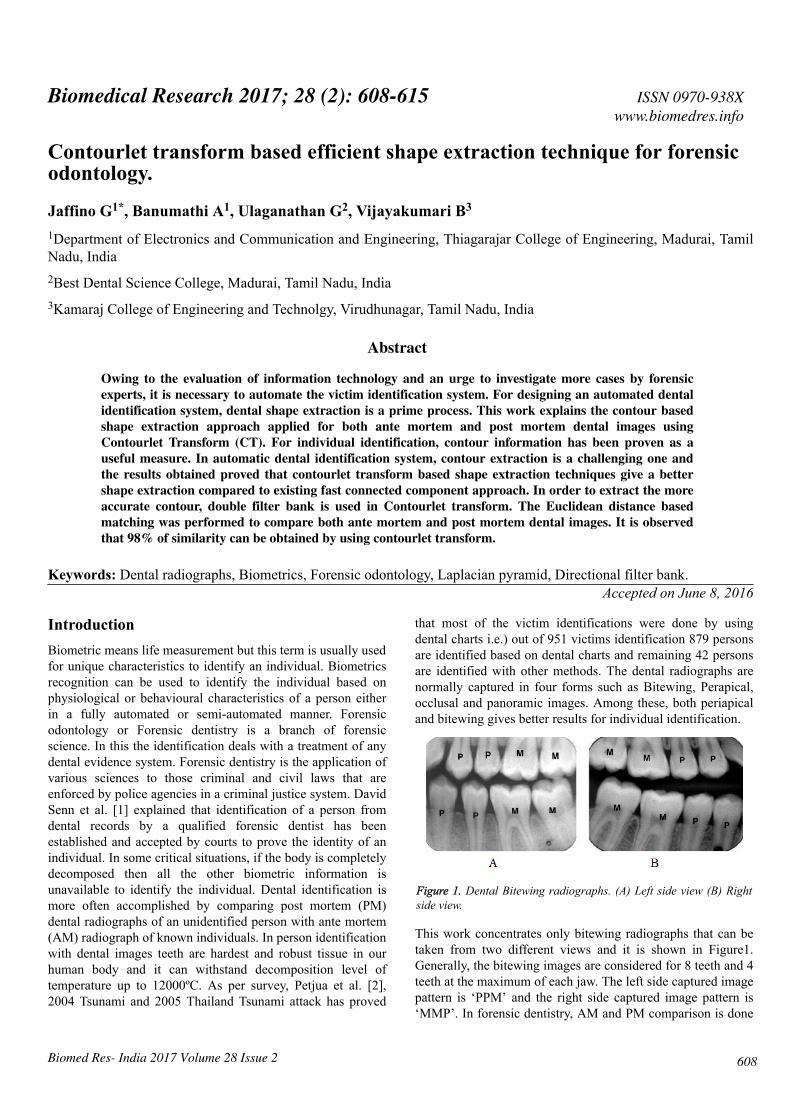
that most of the victim identifications were done by usingdental charts i.e.) out of 951 victims identification 879 personsare identified based on dental charts and remaining 42 personsare identified with other methods. The dental radiographs arenormally captured in four forms such as Bitewing, Perapical,occlusal and panoramic images. Among these, both periapicaland bitewing gives better results for individual identification.
Figure 1. Dental Bitewing radiographs. (A) Left side view (B) Rightside view.
This work concentrates only bitewing radiographs that can betaken from two different views and it is shown in Figure1.Generally, the bitewing images are considered for 8 teeth and 4teeth at the maximum of each jaw. The left side captured imagepattern is ‘PPM’ and the right side captured image pattern is‘MMP’. In forensic dentistry, AM and PM comparison is done
ISSN 0970-938Xwww.biomedres.info
608
Biomedical Research 2017; 28 (2): 608-615
Biomed Res- India 2017 Volume 28 Issue 2
manually, which may take long time and it does not yield moreaccurate results in all cases.
Related workAnil Jain [3] initially projected the semi-automatic contourextraction technique. The problem is fuzzy tooth contourscaused by poor image quality. Omaima Nomir et al. [4]proposed edge and morphological operation based contourextraction technique but in this paper they failed to explainoccluded and obscured quality images. Hong Chen et al. [5]explained the contour extraction technique from the dentalwork and they are not explained evidently feeble quality ofimages. Extracting dental work alone may not be sufficient forbetter matching. In addition to the tooth contour, dental workcan also be considered. The poor quality image tooth contoursare indiscernible. Gradient based contour extraction techniquehas been proposed by Hong Chen et al. [6]. The maindrawback of this method is not able to discriminate edges inmultiple objects. But in this technique, the result shows theedges overlie on boundary of the object. The basic idea ofactive contour model is to start with a curve around the objectis to be detected, and the curve moves towards its interiornormal and stops on the true boundary of the objects based onan energy-minimising model. Many methods have beenintroduced to improve the active contour model but Osher et al.[7] has proposed the most important one. Level set method isbased on active contour model and particularly designed to usedeformable curve for approximating the boundary of an object.Matching is improved by fusion technique as explained byNomir et al. [8]. Human identification using shape andappearance of tooth is also explained by Nomir et al. [9].Vijayakumari et al. [10] explained the concept of Fastconnected component based contour shape extraction and thenmatching by Mahalanobis distance. Fast connected componentlabelling is used to connect the edges but the edges may showsdiscontinuity in the outer contour and then matching wasperformed. Hierarchical distance [11] based matching of dentalrecords proves to be an efficient one in terms of retrieval time.Contour feature extraction based on classification andnumbering approach is used to classify the teeth in to molars orpremolars are explained by Mohammed Mahoor [12].Numbering of teeth is based on universal numbering systemand Bayesian classifier has been used to classify the teeth. Lin[13] explained the concept of classification and numberingbased contour extraction. Based on universal numberingsystem the numbers are assigned to each individual tooth andthen contours are extracted from the tooth. The concept, thatnon-separable contourlet filter bank gives the multi resolutionand multi direction smooth contours have been proved byMinh [14]. In this paper, they proved that contourlet transformgives better multi resolution and multi direction compared towavelet filters. In order to improve the multi directionalinformation from the filter bank Truong Nguyen [15] proposeda uniform and non-uniform directional filter bank. The non-uniform directional filter bank gives high magnitudecoefficients in the sub bands of the filter bank that correspondsto extract more geometrical features like edges and textures of
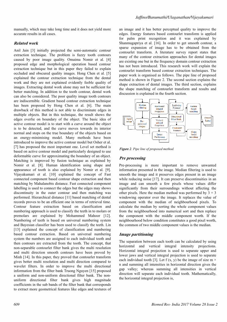
an image and it has better perceptual quality to improve theedges. Energy features based contourlet transform is appliedfor palm print recognition and it was explained byShanmugapriya et al. [16]. In order to get smooth contour, asparse expansion of image has to be obtained from thecontourlet transform. A literature survey report states thatmany of the contour extraction approaches for dental imagesare existing one but in the frequency domain contour extractionhas not been introduced. This research work will explain thecontourlet transform based contour extraction techniques. Thepaper work is organised as follows. The pipe line of proposedmethod is shown in Figure 2. The second section explains theshape extraction of dental images. The third section, explainsthe shape matching of contourlet transform and results anddiscussion is explained in the fourth section.
Figure 2. Pipe line of proposed method.
Pre processingPre-processing is more important to remove unwantedinformation presented in the image. Median filtering is used tosmooth the image and it preserves edges present in an imagewhile reducing noise [17]. It can preserve discontinuities in animage and can smooth a few pixels whose values differsignificantly from their surroundings without affecting theother pixels. Here the median method was performed by 3 × 3windowing operator over the image. It replaces the value ofcomponent with the median of neighbourhood pixels. Tocalculate the median by sorting the whole component valuesfrom the neighbourhood into numerical sort and then replacethe component with the middle component worth. If theneighbourhood below condition constitutes a good pixel worth,the common of two middle component values is the median.
Image partitioningThe separation between each tooth can be calculated by usinghorizontal and vertical integral intensity projections.Horizontal integral projection is used to separate upper andlower jaws and vertical integral projection is used to separateeach individual tooth [3]. Let f (x, y) be the image of size m ×n and summing all intensities in horizontal direction gives thegap valley; whereas summing all intensities in verticaldirection will separate each individual tooth. Mathematically,the horizontal integral projection is,
Jaffino/Banumathi/Ulaganathan/Vijayakumari
609 Biomed Res- India 2017 Volume 28 Issue 2
�(�) = ∑� = 0� �(�,�) (1)Since the teeth usually have a higher gray level intensity thanthe jaws, due to their higher intensity, the gap between upperand lower teeth will form a y-axis projection histogram whichis called gap valley. After finding the gap valley, the verticalline will be drawn to form a vertical integral intensity. Thevertical projections of {V (x0), V (x1).....V (xn)} will form agraph of integral intensity and mathematically it can beexpressed as,
�(�) = ∑� = 0�� �(�,�) (2)
Where, nx is the intersecting point of each column and thehorizontal separating line of upper and lower jaws.
Shape extractionIn this paper, the shape extraction is done by using contourlettransform. This work proposed double filter bank structure,named pyramidal directional filter bank by combininglaplacian pyramid with directional filter bank is used to extractcontour features. The contourlet transform offers a flexiblemulti resolution and directional decomposition for images, as itallows for a different number of directions at each scale.Pseudo code for laplacian pyramid is as follows.
G{0}=Original image
{
Choose w{K}
G{K}=REDUCE (G{K-1}
G{k}* w{K}
If G{K} ≥ G{N} (N-Maximum reduction of the originalimage)
G{N} ≥ Max reduction (Gaussian pyramid output)
Stop
G{N}=input of laplacian pyramid
G’{K}=EXPAND (G{K+1})
L{K}=G{K}-G’{K}
}
Gaussian pyramidThe first step of laplacian pyramid is to low-pass filter theoriginal image of G, to obtain G0. Then low pass filtering G0to obtain G1 and so on. Filtering is performed by convolving aweighting function with low-pass filtered image. Suppose theimage is initially represented by an array G which contains Cnumber of rows and R number of columns. Each pixel isrepresented by a light intensity at a corresponding image pointbetween 0 and k-1. This image becomes the bottom or zero
level Gaussian pyramid [18]. Pyramid level 1 contains theimage G0, which is reduced or low-pass filtered image of G.Each value within level 1 is computed as a weighted average ofvalues in level 0 within a 5-by-5 window. The weightingfunction is not unique for all levels. Each level of process canbe generated by a function REDUCE written as,
G {K} =REDUCE (G {K-1}) → (3)
Which means that levels are represented as 0<l<N and thepixel values i, j, 0<I<Cl and 0<j<Rl
��(�, �) = ∑� = − 22 ∑� = − 22 �(�,�)�� − 1(2�+�, 2�+ �) (4)Where, N is the number of levels in the pyramid, Cl and Rl arethe dimensions of lth level and w is the weighting factor.
Generation of weighting factorEach level for the Gaussian pyramid can be taken as 5-by-5window, since the same 5-by-5 pattern of weights w is used togenerate each pyramid array from its predecessor. Theweighting factor w is separable and symmetric.
w (i, j) = w (i) w (j) → (5)
w (i) = w (-i) for i = 0,1 ,2 → (6)
For one dimensional signal, length 5 and the function isnormalised as,∑� = − 22 �(�) = 1 (7)The convolution weights are symmetric, separable, normalisedand have equal contribution i.e.) all nodes at a given levelcontribute the same total weight (=1/4) to the nodes at the nexthigher level. Convolution weights are given by,
w (2) = w (-2) = 1/4-a/2
w (1) = w (-1) = 1/4 → (8)
w (0) = a
Here, parameter is chosen to be 0.4 because it is used to createa Gaussian- like weight function. Iterative pyramid generationis equivalent to convolving the image with equivalentweighting function.�1 = �⊗�0 (9)For 2-D, first convolution takes place across rows and thencolumns. Up to the maximum reduction of image sizeconvolution operation was performed. Gaussian pyramid isobtained from the final reduction level.
Laplacian pyramidThe final reduction level of Gaussian pyramid is given as inputto the laplacian pyramid and then operation is performed for
Contourlet transform based efficient shape extraction technique for forensic odontology
610Biomed Res- India 2017 Volume 28 Issue 2
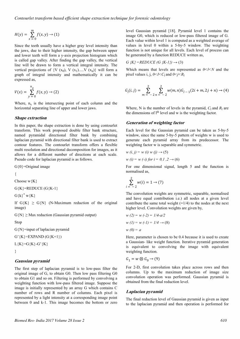
each level. Laplacian Pyramid (LP) is the prediction error forthe pixel values between original image and the construction oflaplacian pyramid for a single level is shown in Figure 3. TheEXPAND image for each level is G’0, G’1 and so on. Theequation is given as,
G’ {K} = EXPAND (G {K+1}) → (10)
Which means that levels are represented as 0<l<N and thepixel values i, j, l 0<I<Cl and 0<j<Rl
�′�(�, �) = ∑� = − 22 ∑� = − 22 �(�,�)��+ 1 � − �2 , � − �2 (11)The different level of laplacian pyramid can be represented as,
L {K} = G’ {K} → (12)
Where L {K} the prediction error and the difference for eachlevel are the laplacian pyramid values.
Figure 3. Construction of laplacian pyramid for single level.
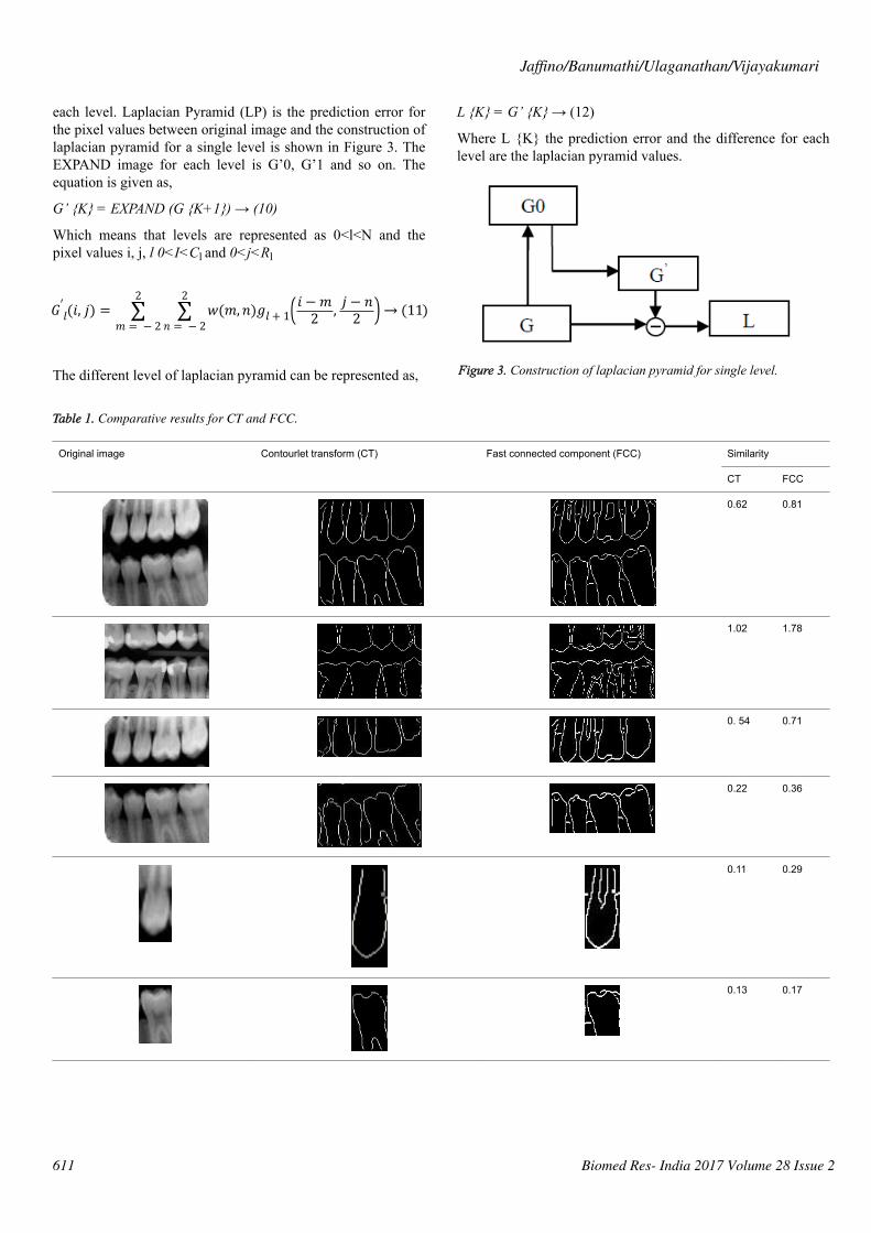
Table 1. Comparative results for CT and FCC.
Original image
Contourlet transform (CT) Fast connected component (FCC) Similarity
CT FCC
0.62 0.81
1.02 1.78
0. 54 0.71
0.22 0.36
0.11 0.29
0.13 0.17
Jaffino/Banumathi/Ulaganathan/Vijayakumari
611 Biomed Res- India 2017 Volume 28 Issue 2
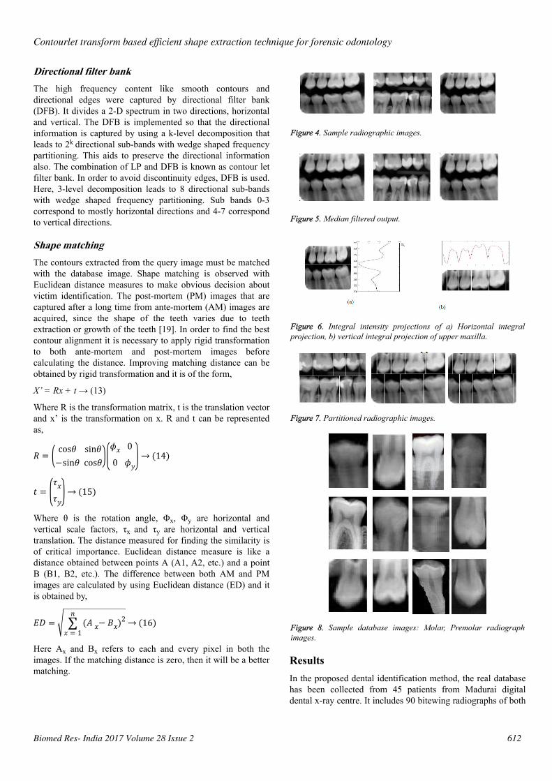
Directional filter bankThe high frequency content like smooth contours anddirectional edges were captured by directional filter bank(DFB). It divides a 2-D spectrum in two directions, horizontaland vertical. The DFB is implemented so that the directionalinformation is captured by using a k-level decomposition thatleads to 2k directional sub-bands with wedge shaped frequencypartitioning. This aids to preserve the directional informationalso. The combination of LP and DFB is known as contour letfilter bank. In order to avoid discontinuity edges, DFB is used.Here, 3-level decomposition leads to 8 directional sub-bandswith wedge shaped frequency partitioning. Sub bands 0-3correspond to mostly horizontal directions and 4-7 correspondto vertical directions.
Shape matchingThe contours extracted from the query image must be matchedwith the database image. Shape matching is observed withEuclidean distance measures to make obvious decision aboutvictim identification. The post-mortem (PM) images that arecaptured after a long time from ante-mortem (AM) images areacquired, since the shape of the teeth varies due to teethextraction or growth of the teeth [19]. In order to find the bestcontour alignment it is necessary to apply rigid transformationto both ante-mortem and post-mortem images beforecalculating the distance. Improving matching distance can beobtained by rigid transformation and it is of the form,
X’ = Rx + t → (13)
Where R is the transformation matrix, t is the translation vectorand x’ is the transformation on x. R and t can be representedas,
� = cos� sin�−sin� cos� �� 00 �� (14)� = ���� (15)Where θ is the rotation angle, Φx, Φy are horizontal andvertical scale factors, τx and τy are horizontal and verticaltranslation. The distance measured for finding the similarity isof critical importance. Euclidean distance measure is like adistance obtained between points A (A1, A2, etc.) and a pointB (B1, B2, etc.). The difference between both AM and PMimages are calculated by using Euclidean distance (ED) and itis obtained by,
�� = ∑� = 1� (� −� ��)2 (16)Here Ax and Bx refers to each and every pixel in both theimages. If the matching distance is zero, then it will be a bettermatching.
Figure 4. Sample radiographic images.
Figure 5. Median filtered output.
Figure 6. Integral intensity projections of a) Horizontal integralprojection, b) vertical integral projection of upper maxilla.
Figure 7. Partitioned radiographic images.
Figure 8. Sample database images: Molar, Premolar radiographimages.
ResultsIn the proposed dental identification method, the real databasehas been collected from 45 patients from Madurai digitaldental x-ray centre. It includes 90 bitewing radiographs of both
Contourlet transform based efficient shape extraction technique for forensic odontology
612Biomed Res- India 2017 Volume 28 Issue 2
left and right views. Out of that 75 radiographs are consideredas anti-mortem images and 25 are post mortem images. Someof the sample input images taken for analysis are shown inFigure 4.
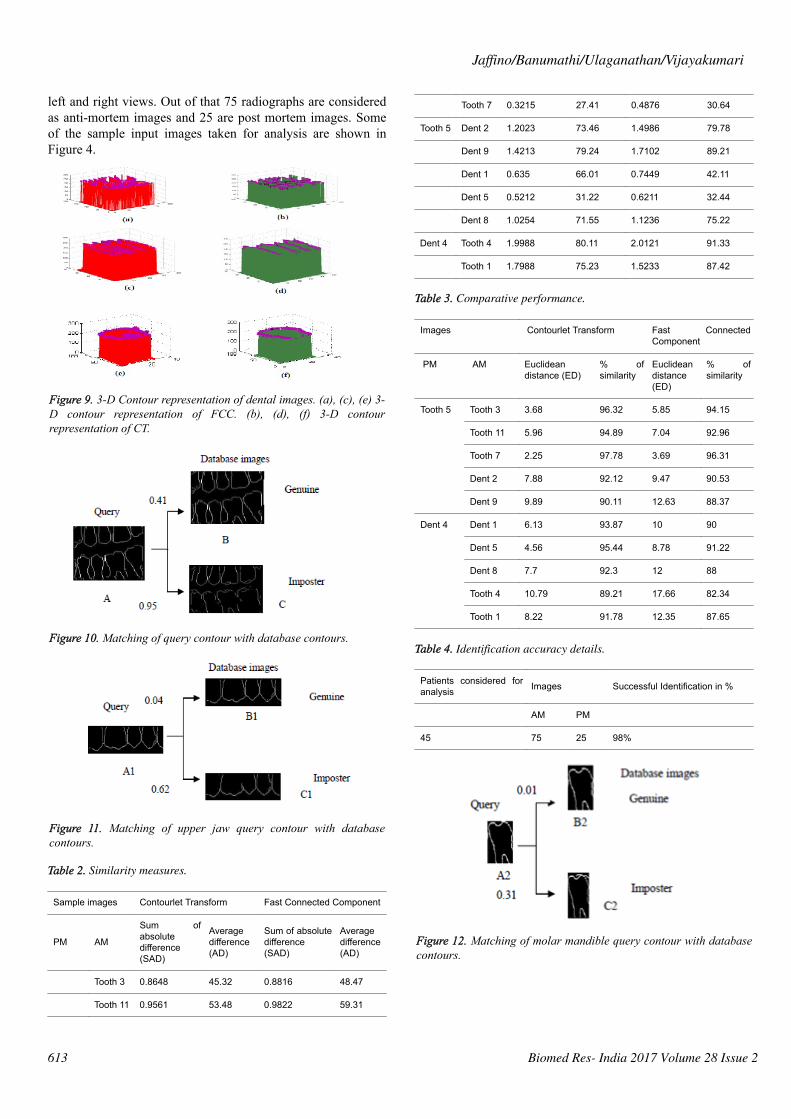
Figure 9. 3-D Contour representation of dental images. (a), (c), (e) 3-D contour representation of FCC. (b), (d), (f) 3-D contourrepresentation of CT.
Figure 10. Matching of query contour with database contours.
Figure 11. Matching of upper jaw query contour with databasecontours.
Table 2. Similarity measures.
Sample images Contourlet Transform Fast Connected Component
PM AM
Sum ofabsolutedifference(SAD)
Averagedifference(AD)
Sum of absolutedifference(SAD)
Averagedifference(AD)
Tooth 3 0.8648 45.32 0.8816 48.47
Tooth 11 0.9561 53.48 0.9822 59.31
Tooth 7 0.3215 27.41 0.4876 30.64
Tooth 5 Dent 2 1.2023 73.46 1.4986 79.78
Dent 9 1.4213 79.24 1.7102 89.21
Dent 1 0.635 66.01 0.7449 42.11
Dent 5 0.5212 31.22 0.6211 32.44
Dent 8 1.0254 71.55 1.1236 75.22
Dent 4 Tooth 4 1.9988 80.11 2.0121 91.33
Tooth 1 1.7988 75.23 1.5233 87.42
Table 3. Comparative performance.
Images Contourlet Transform Fast ConnectedComponent
PM AM Euclideandistance (ED)
% ofsimilarity
Euclideandistance(ED)
% ofsimilarity
Tooth 5
Tooth 3 3.68 96.32 5.85 94.15
Tooth 11 5.96 94.89 7.04 92.96
Tooth 7 2.25 97.78 3.69 96.31
Dent 2 7.88 92.12 9.47 90.53
Dent 9 9.89 90.11 12.63 88.37
Dent 4
Dent 1 6.13 93.87 10 90
Dent 5 4.56 95.44 8.78 91.22
Dent 8 7.7 92.3 12 88
Tooth 4 10.79 89.21 17.66 82.34
Tooth 1 8.22 91.78 12.35 87.65
Table 4. Identification accuracy details.
Patients considered foranalysis Images Successful Identification in %
AM PM
45 75 25 98%
Figure 12. Matching of molar mandible query contour with databasecontours.
Jaffino/Banumathi/Ulaganathan/Vijayakumari
613 Biomed Res- India 2017 Volume 28 Issue 2
DiscussionThis algorithm is evaluated with database of dental imagewhich includes radiographic images. The proposed frequencydomain contour based approach was developed in Matlab R2010a and it was tested for few database images. In order topreserve edges and smoothed the median filtering operationwas applied in the original image and corresponding pre-processed results are shown in Figure 5. It increases thebrightness and uniform intensity can be obtained for the pre-processed result. Victim identification can be made perfect byconsidering each individual tooth separately rather than thewhole image. Hence horizontal and vertical integral projectionsare used to separate each and every individual tooth. Thehorizontal and vertical integral intensity projection of an imageis shown in Figure 6. Figure 6a shows the horizontal integralprojection output and Figure 6b shows the vertical integralprojection of upper maxilla teeth. The partitioned result appliedfor pre-processed image is shown in Figure 7.
This work can also be implemented with each individual toothimage such as molar and pre molar radiographic tooth. Thiswork proves that better matching will be obtained forindividual tooth rather than the whole image. Some of thesample radiographic individual tooth images are shown inFigure 8. The partition of each image clearly depicts that firsthorizontal integral projection was obtained for each image toget the gap valley and then vertical integral projections wereobtained for individual partitioning of teeth. The proposedwork consists of both laplacian pyramid and directional filterbank. In the existing techniques, the contourlet transform hasnot yet been discussed for dental images. Even though fastconnected component approach is an automatic dentalidentification system used in the contours obtained are notconvincing. The comparative result analysis for both contourlettransform and fast connected component analysis are tabulatedin Table 1.
In this proposed method, the result of laplacian pyramid givesdiscontinuities in the contour and the directional filter bankremoves all the discontinuities present in the contour. Forperson identification while matching both post-mortem andante mortem images, instead of matching the whole images, ifa single part like either a jaw or single tooth may be comparedand that leads to better results. Result of the contour for bothFCC and CT was compared with the 3-D plot analysis and it isshown in Figure 9. The result of the query image contour ismatched to the database contours by Euclidean distancematching. The minimum distance between query and databaseimage is taken as best matching, because lesser the matchingdistance, better will be the matching. In Figure 10 Euclideandistance is considered as a distance metric. Here, the image Bwith matching distance of 0.41 is the genuine image and theimage C with matching distance of 0.95 is an imposter image.For individual identification, instead of the whole image asingle tooth image can be used for better matching. Thematching of maxilla and molar mandible of query contour withdatabase contours are shown in Figure 11 and Figure 12. InFigure 11, upper jaw of the query image was compared to the
database images and it is observed that the matching of 0.04 inthe B1 image is genuine image and the distance of 0.62 C1 isan imposter image. In Figure 12 the molar mandible tooth isdiscussed, and it is observed that the matching of 0.01 in theB2 image is genuine image and the distance of 0.31 C2 is animposter image. The performance analysis of this algorithm isvalidated and compared with Fast connected componentanalysis. Contourlet transform uses a double filter bankstructure to get the smooth contours of images. The extractedcontour result gives no discontinuity than FCC.
Performance evaluationAM and PM images can be compared using similaritymeasures. Sum of absolute difference is one of the simplestmethods and it is calculated by subtracting pixels within asquare neighbourhood between the database tooth image andquery tooth image followed by the aggregation of absolutedifferences within a square window. If both the images exactlymatch then the resultant will be zero. Sum of AbsoluteDifference (SAD) is calculated by using,��� = ∑� ∑� �(�, �)− �(�, �)max(�(�, �),�(�, �)) (17)Where, A and B are two different images. And additionallyanother measure, Average Difference (AD) is used to find thedifference between two images as,
�� = ∑�, �∑�, ��(�, �)− �(�, �)�� (18)Where, M and N are the size of image. The SAD and ADbetween contourlet transform and FCC output is observed andit is given in Table 2. While matching it is observed that thematching performance with the single tooth yields betterresults than comparing as a whole image. From this Table, it isclear that both of the measures are related (i.e.) the lowestEuclidean distance of 2.25 is observed for the image tooth 7and the SAD obtained is also least for the same image.Similarly, dent 9 has the highest values in both. Also forconsidering other image the lowest Euclidean distance of 4.56is observed for the image dent 5 and the SAD obtained is alsoleast for the same image. The tooth 4 has highest values inboth.
It is observed that, the Euclidean distance between the entirequery and database image values are less for contourlettransform. It is also inferred from Table 3, that the Euclideandistance obtained with contourlet transform is yielding lesservalues than the fast connected component analysis. Databaseincludes 90 bitewing radiographs of both left and right views.Out of that 75 radiographs are considered as anti-mortemimages, 25 are post mortem images and the identificationaccuracy details are tabulated in Table 4.
ConclusionIn this paper, an automated dental identification system wasdemonstrated and it facilitates to provide an aid for forensic
Contourlet transform based efficient shape extraction technique for forensic odontology
614Biomed Res- India 2017 Volume 28 Issue 2
law enforcement with the help of radiographic dental images.This work is mainly focused on frequency domain basedcontourlet transform for tooth shape extraction and Euclideandistance based matching technique to identify a person. Itinvolves pre-processing, integral intensity projection, featureextraction by contourlet transform and finally matching isperformed with Euclidean distance. This will be mainly helpfulfor forensic dentistry to identify the missing persons in somecritical mass disasters. After analysis it is observed that, thisalgorithm proved to be an automatic, less complex andproduces satisfied results. This work elaborates the importanceof contourlet transform in dental radiographic images. Theexperimental results clearly show that, single tooth radiographimage yields better result than the whole images. In addition tothis, the contourlet transform gives clear contour informationthan the previous techniques. The proposed method gives 98%of successful identification accuracy while comparing with theexisting algorithm.
AcknowledgementThe authors would like to thank University GrantsCommission, New Delhi, India with F.No:42-116/2013 (SR)dated 12 March 2013 for funding this project. We would alsolike to thank Department of ECE, Thiagarajar College ofEngineering, Madurai, and Tamilnadu, India for providing allthe facilities to carry out this work.
References1. David RS, Paul GS. Forensic Dentistry. CRC Press 2010.2. Petjua M, Suteerayongprasertb A, Thongpudc R, Hassirid
K. Importance of dental records for victim identificationfollowing the Indian Ocean tsunami disaster in Thailand.Public Health 2007; 121: 251-257.
3. Anil KJ, Hong C. Matching of dental X-ray images forhuman identification. J Patrn recogn 2003; 1519-1532.
4. Omaima N, Mohamed AM. A System for HumanIdentification from X-ray Dental Radiographs. J Patternrecogn 2005; 38: 1295-1305.
5. Hong C, Anil KJ. Dental bimetrics: Alignment andMatching of Dental Radiographs, IEEE Trans Pattern AnalM Intel 2005; 27: 1319-1326.
6. Hong Ch, Anil KJ. Tooth Contour Extraction for MatchingDental Radiographs. IEEE Pattern Recogn 2004;2128-2132.
7. Osher S, Sethian J. Fronts propagating with curvaturedependent speed: algorithms based on Hamilton Jacobiformulations. J Comp Phys 1988; 79: 12-49.
8. Nomir O, Mohamed AM. Fusion of matching algorithmsfor human identification using dental X- ray radiographs.IEEE Trans Info Secur 2008; 3: 223-233
9. Nomir O, Mohamed AM. Human Identification from dentalX-ray images based on shape and appearance of the teeth.IEEE Trans Info Secur 2007; 2: 188-197.
10. Vijayakumari P, Ulaganathan G, Banumathi A. AnEffective shape extraction algorithm using contourinformation and Matching by Mahalanobis distance. JDigital Imaging 2012; 26: 1-8.
11. Nomir O, Mohamed AM. Hierarchical contour matchingfor dental X-ray radiographs. Pattern Recogn 2008; 41:30-138.
12. Mohamed HM, Mohamed AM. Classification andNumbering of teeth in dental bitewing images. J patternRecogn 2005; 38: 577-586.
13. Lin PL, Lai YH, Huang PW. An Effective Classificationand Numbering system for dental bitewing radiographsusing teeth region and contour information. J patternRecogn 2010; 43: 1380-1392.
14. Do MN, Martin V. The contourlet transform: an efficientdirectional multiresolution image representation. IEEETrans Image Proc 2005; 14: 2091-2106.
15. Truong TN, Soontorn O. Multi resolution Direction filterbanks: Theory, Design and Applications. IEEE TransSignal Proc 2005; 53: 3895-3905.
16. Shanmugapriya K, Karthiga M, Valarmathi S, ArunkumarM. Performance Evaluation of contourlet transform basedPalmprint Recognition using Nearest Neighbour Classifier.Int J Emerg Technol adv Eng 2013; 3: 294-299.
17. Subbuthai P, Kavithabharathi K, Muruganand S. Reductionof types of noises in dental images. Int J Comp ApplTechnol Res 2013; 2: 436-442.
18. Peter JB, Edward HA. The laplacian pyramid as a compactcode. IEEE Transactions on Commun 1983; 31: 532-540.
19. Banumathi A, Vijayakumari B, Geetha A, ShanmugavadivuN, Raju S. Performance analysis of various techniquesapplied in human identification using dental images. J Medsyst 2007; 31: 210-218.
*Correspondence toJaffino G
Department of Electronics and Communication andEngineering
Thiagarajar College of Engineering
India
Jaffino/Banumathi/Ulaganathan/Vijayakumari
615 Biomed Res- India 2017 Volume 28 Issue 2