Embed Size (px)
Citation preview
Salman Bin AbdulAziz University
College of Applied Medical Sciences
Pr Ridha BenSalah 1 BMIS 471 Biomedical Electronic Instruments - 1
Biomedical Electronic
Instrumentation I: BMIS 471
Prof. Ridha Ben Salah
Biomedical Electronic Instruments 1: BMIS 471
Pr R. Ben Salah 2
Programme
Chapter 1: Electro-physiology and biomedical signals
Chapter 2: Biomedical electronic circuits
Chapter 3: Electrocardiography
Chapter 4: Electroencephalography
Chapter 5: Electronic Filter Design
BMIS 471 Biomedical Electronic Instruments - 1
Biomedical Electronic Instruments 1
Pr R. Ben Salah 3
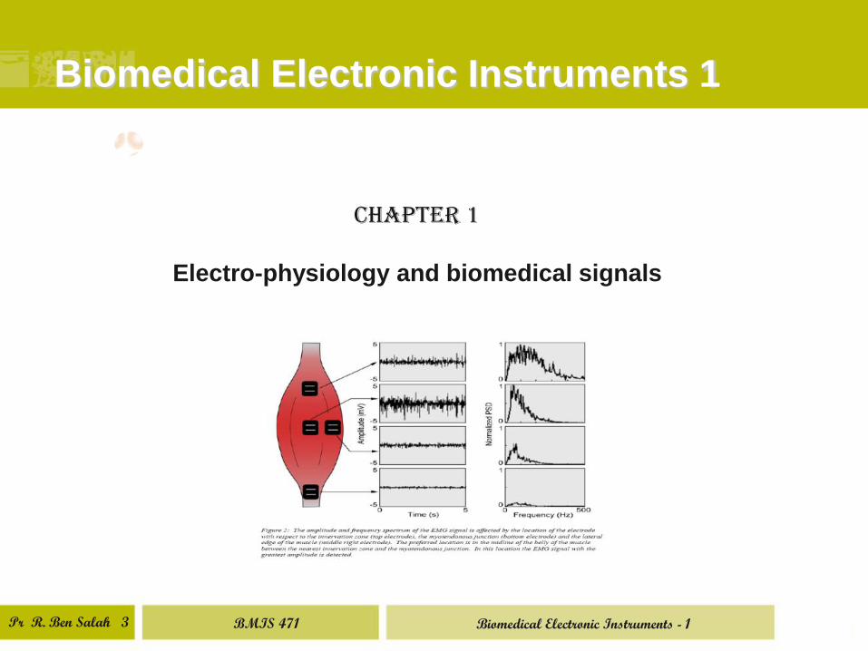
Chapter 1
Electro-physiology and biomedical signals
BMIS 471 Biomedical Electronic Instruments - 1
Pr R. Ben Salah 4
Chapter 1. Electrophysiology and
bioemedical signal
1. Electric dipole
2. Nernst potential
3. Rest potential and action potential
4. Biomedical signals
Bioelectric signals represent often the majority of biomedical signals. These
signals proceed from electric activity of cells which may be on activity or one
pause state.
1. Electric dipole
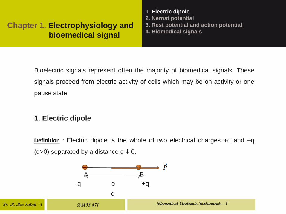
Definition : Electric dipole is the whole of two electrical charges +q and –q
(q>0) separated by a distance d ǂ 0.
A B
-q o +q
d
BMIS 471 Biomedical Electronic Instruments - 1
Pr R. Ben Salah 5
1. Electric dipole
2. Nernst potential
3. Rest potential and action potential
4. Biomedical signals
Chapter 1. Electrophysiology and
bioemedical signal
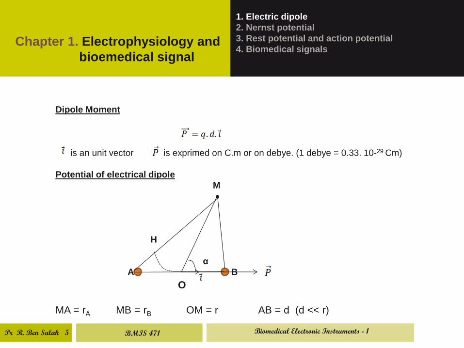
Dipole Moment
is an unit vector is exprimed on C.m or on debye. (1 debye = 0.33. 10-29 Cm)
Potential of electrical dipole
M
H
α
A B
O
MA = rA MB = rB OM = r AB = d (d << r)
BMIS 471 Biomedical Electronic Instruments - 1
Pr R. Ben Salah 6
Chapter 1. Electrophysiology and
bioemedical signal
1. Electric dipole
2. Nernst potential
3. Rest potential and action potential
4. Biomedical signals
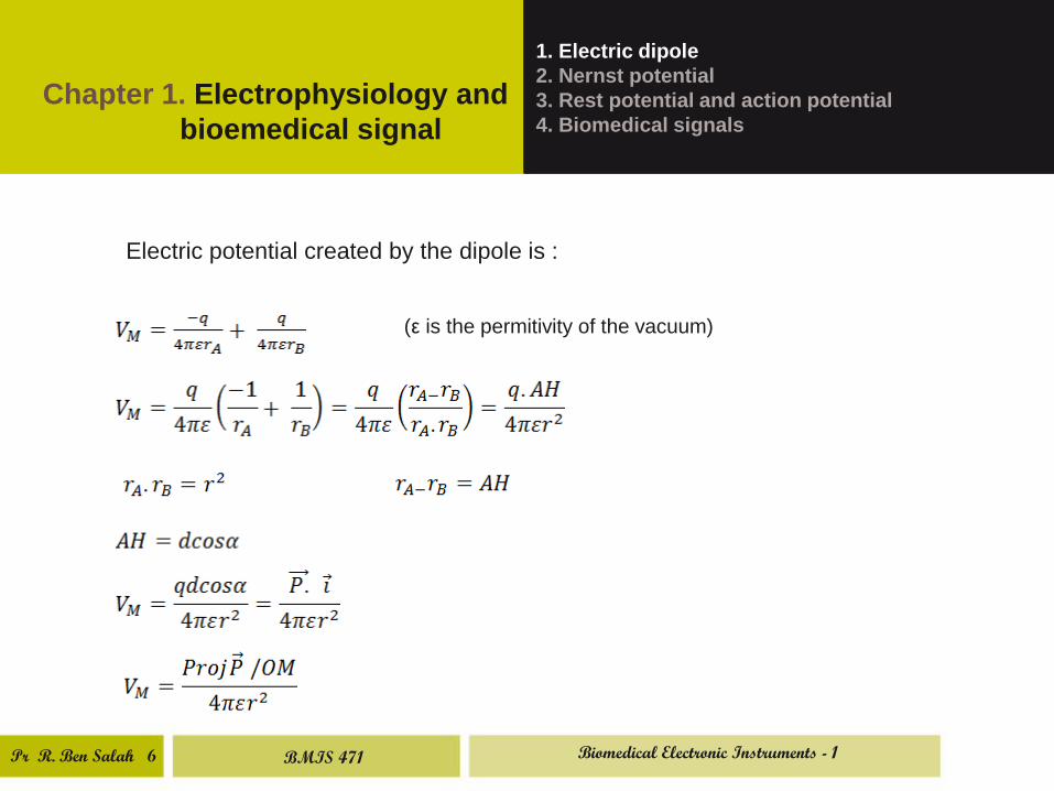
Electric potential created by the dipole is :
(ε is the permitivity of the vacuum)
BMIS 471 Biomedical Electronic Instruments - 1
Pr R. Ben Salah 7
Chapter 1. Electrophysiology and
bioemedical signal
1. Electric dipole
2. Nernst potentiel
3. Rest potentiel and action potentiel
4. Biomedical signals
2. Nernst potential
Let us consider the following experiences :
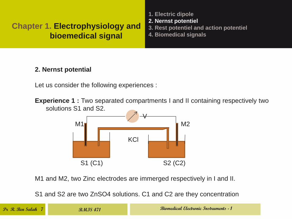
Experience 1 : Two separated compartments I and II containing respectively two
solutions S1 and S2.
V
M1 M2
KCl
S1 (C1) S2 (C2)
M1 and M2, two Zinc electrodes are immerged respectively in I and II.
S1 and S2 are two ZnSO4 solutions. C1 and C2 are they concentration
BMIS 471 Biomedical Electronic Instruments - 1
Pr R. Ben Salah 8
Chapter 1 Electrophysiology and
bioemedical signal
1. Electric dipole
2. Nernst potential
3. Rest potential and action potential
4. Biomedical signals
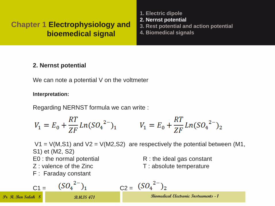
2. Nernst potential
We can note a potential V on the voltmeter
Interpretation:
Regarding NERNST formula we can write :
V1 = V(M,S1) and V2 = V(M2,S2) are respectively the potential between (M1,
S1) et (M2, S2)
E0 : the normal potential R : the ideal gas constant
Z : valence of the Zinc T : absolute temperature
F : Faraday constant
C1 = C2 =
BMIS 471 Biomedical Electronic Instruments - 1
Pr R. Ben Salah 9
Chapter 1. Electrophysiology and
bioemedical signal
1. Electric dipole
2. Nernst potential
3. Rest potential and action potential
4. Biomedical signals
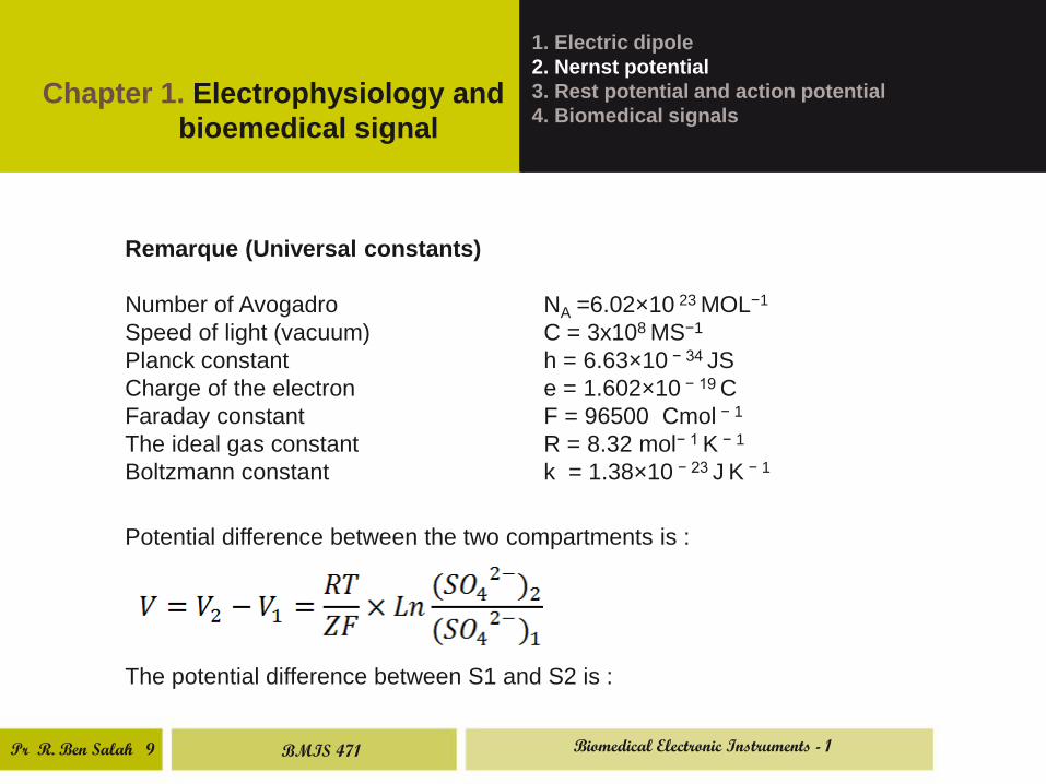
Remarque (Universal constants)
Number of Avogadro NA =6.02×10 23 MOL−1
Speed of light (vacuum) C = 3x10⁸ MS−1
Planck constant h = 6.63×10 − 34 JS
Charge of the electron e = 1.602×10 − 19 C
Faraday constant F = 96500 Cmol − 1
The ideal gas constant R = 8.32 mol− 1 K − 1
Boltzmann constant k = 1.38×10 − 23 J K − 1
Potential difference between the two compartments is :
The potential difference between S1 and S2 is :
BMIS 471 Biomedical Electronic Instruments - 1
Pr R. Ben Salah 10
Chapter 1. Electrophysiology and
bioemedical signal
1. Electric dipole
2. Nernst potentiel
3. Rest potentiel and action potentiel
4. Biomedical signals
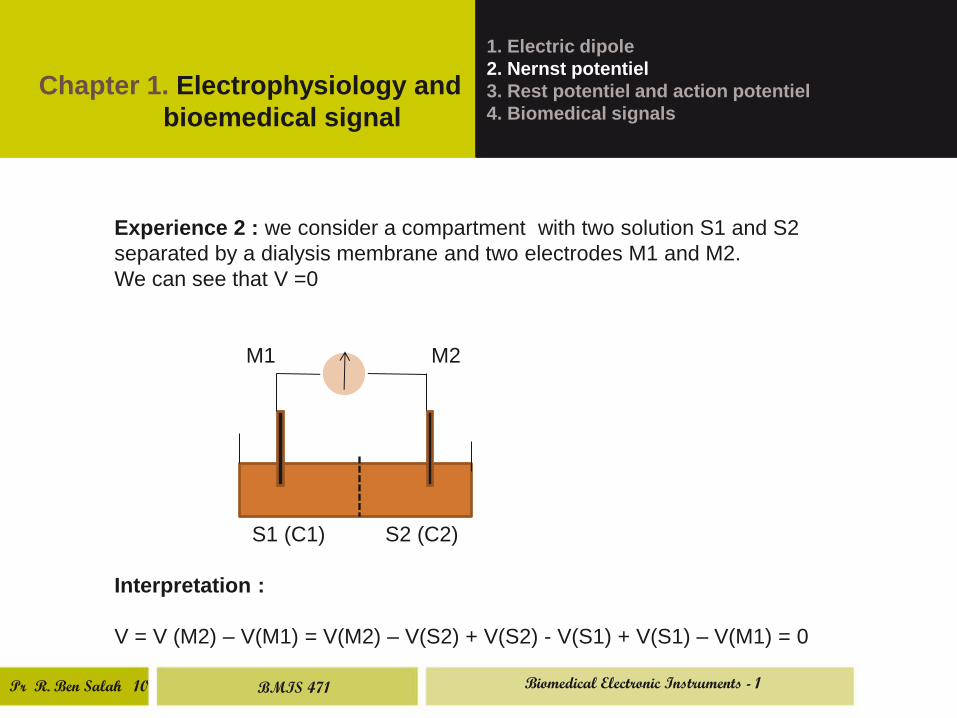
Experience 2 : we consider a compartment with two solution S1 and S2
separated by a dialysis membrane and two electrodes M1 and M2.
We can see that V =0
M1 M2
S1 (C1) S2 (C2)
Interpretation :
V = V (M2) – V(M1) = V(M2) – V(S2) + V(S2) - V(S1) + V(S1) – V(M1) = 0
BMIS 471 Biomedical Electronic Instruments - 1
Pr R. Ben Salah 11
Chapter 1. Electrophysiology and
bioemedical signal
1. Electric dipole
2. Nernst potential
3. Rest potential and action potential
4. Biomedical signals
V = V (M1) – V(M2) = [V(M2) – V(S2)] + [V(S2) – V(S1)] – [V(M1) – V(S1)] = 0
V = V2 + [V(S2) – V(S1)] – V1 = 0
V(S2) – V(S1) = - (V2 – V1) = - =
Vm = V(S2) – V(S1) =
Vm is called membrane potential or DONNAN potential
BMIS 471 Biomedical Electronic Instruments - 1
Pr R. Ben Salah 12
Chapter 1. Electrophysiology and
bioemedical signal
1. Electric dipole
2. Nernst potential
3. Rest potential and action potential
4. Biomedical signals
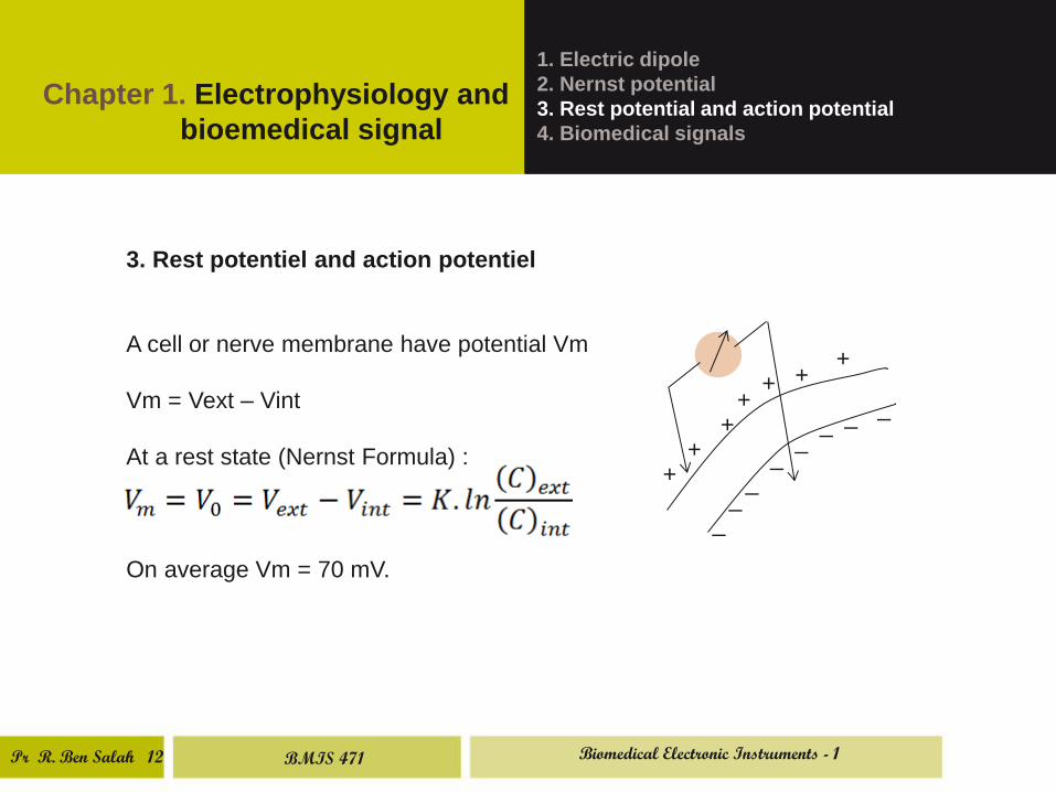
3. Rest potentiel and action potentiel
A cell or nerve membrane have potential Vm
Vm = Vext – Vint
At a rest state (Nernst Formula) :
On average Vm = 70 mV.
+
+
+ +
+
+ +
_ _
_
_ _
_ _ _
BMIS 471 Biomedical Electronic Instruments - 1
Pr R. Ben Salah 13
Chapter 1. Electrophysiology and
bioemedical signal
1. Electric dipole
2. Nernst potential
3. Rest potential and action potential
4. Biomedical signals
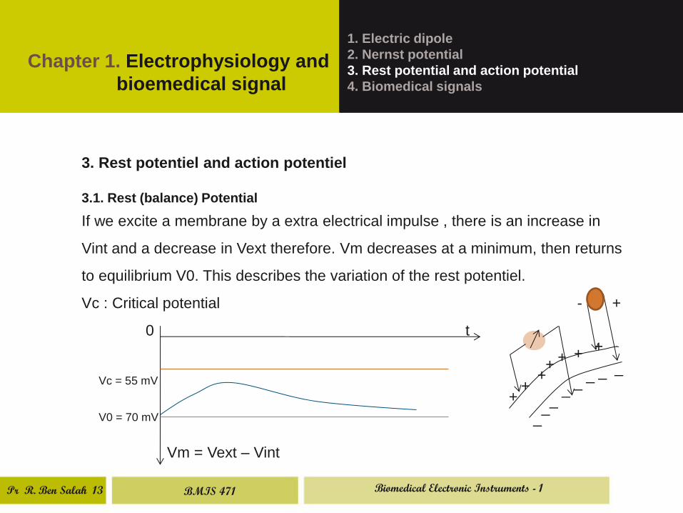
3. Rest potentiel and action potentiel
3.1. Rest (balance) Potential
If we excite a membrane by a extra electrical impulse , there is an increase in
Vint and a decrease in Vext therefore. Vm decreases at a minimum, then returns
to equilibrium V0. This describes the variation of the rest potentiel.
Vc : Critical potential - +
0 t
Vc = 55 mV
V0 = 70 mV
Vm = Vext – Vint
+
+
+ +
+
+ +
_ _
_
_ _
_ _ _
BMIS 471 Biomedical Electronic Instruments - 1
Pr R. Ben Salah 14
Chapter 1. Electrophysiology and
bioemedical signal
1. Electric dipole
2. Nernst potential
3. Rest potential and action potential
4. Biomedical signals
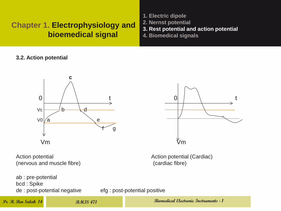
3.2. Action potential
c
0 t 0 t
Vc b d
V0 a e
f g
Vm Vm
Action potential Action potential (Cardiac)
(nervous and muscle fibre) (cardiac fibre)
ab : pre-potential
bcd : Spike
de : post-potential negative efg : post-potential positive
BMIS 471 Biomedical Electronic Instruments - 1
Pr R. Ben Salah
15
Chapter 1. Electrophysiology and
bioemedical signal
1. Electric dipole
2. Nernst potential
3. Rest potential and action potential
4. Biomedical signals
4. Biomedical signals
4.1 Introduction
Acquisition and processing of biomedical signals is not very easy
because of the weakness of the BS amplitude (some mv and even
some microvolt). Frecency spectral is often very limited (very low
frequency signals). For the design of BS we have to observe some
precaution.
It is very essential to take care to the electrical security of the
patient and the medical personnel during the acquisition of biomedical
signals
BMIS 471 Biomedical Electronic Instruments - 1
Pr R. Ben Salah
16
Chapter 1. Electrophysiology and
bioemedical signal
1. Electric dipole
2. Nernst potential
3. Rest potential and action potential
4. Biomedical signals
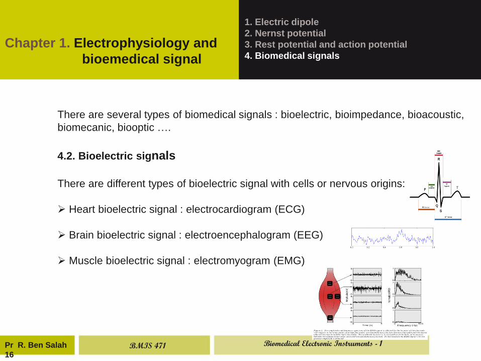
There are several types of biomedical signals : bioelectric, bioimpedance, bioacoustic,
biomecanic, biooptic ….
4.2. Bioelectric signals
There are different types of bioelectric signal with cells or nervous origins:
Heart bioelectric signal : electrocardiogram (ECG)
Brain bioelectric signal : electroencephalogram (EEG)
Muscle bioelectric signal : electromyogram (EMG)
BMIS 471 Biomedical Electronic Instruments - 1
Pr R. Ben Salah
17
Chapter 1. Electrophysiology and
bioemedical signal
1. Electric dipole
2. Nernst potential
3. Rest potential and action potential
4. Biomedical signals
4.3. Bioimpedance signals
Bioimpedance signal is detected as following :
Biomedical impedance is generated by the injection of an electric courant
within high frequency (3 khz to 1 Mhz) and low amplitude (1 mA) by the
means of two electrodes. The acquisition of biomedical signal is performed
using two other electrodes. This bioimpedance signal called also elecrtical
plethysmogram shows impedance variation of explored corporel segment.
BMIS 471 Biomedical Electronic Instruments - 1
Pr R. Ben Salah 5
Chapter 1. Electrophysiology and
bioemedical signal
1. Electric dipole
2. Nernst potential
3. Rest potential and action potential
4. Biomedical signals
4.4. Bioacoustic signals
The activity of many organs creates some acoustic sounds which may be
detected by the mean of piezoelectric sensors. For example :
The phonocardiogram (PCG) : linked to cardiac sounds
The Doppler signal : due to the pulsatil circulation of the blood in the big
vessels
The microphonic signal : detected at the level of the cochlea (inner ear)
The flow of air can involve sounds which may be stored.
BMIS 471 Biomedical Electronic Instruments - 1
Pr R. Ben Salah
19
Chapter 1. Electrophysiology and
bioemedical signal
1. Electric dipole
2. Nernst potential
3. Rest potential and action potential
4. Biomedical signals
4.5. Biomechanic signals
Biomechanic signals are generated by mechanical action of the fluid
circulation. And specially the blood when going through cardiac cavities and
circulatory system. For example : Aortic pression, ventricular pression …
These signals are often detected by invasive (or blooding) methods because
we must be very near of the organ which created these signals (in situ)
BMIS 471 Biomedical Electronic Instruments - 1
Pr R. Ben Salah 7
Chapter 1. Electrophysiology and
bioemedical signal
1. Electric dipole
2. Nernst potential
3. Rest potential and action potential
4. Biomedical signals
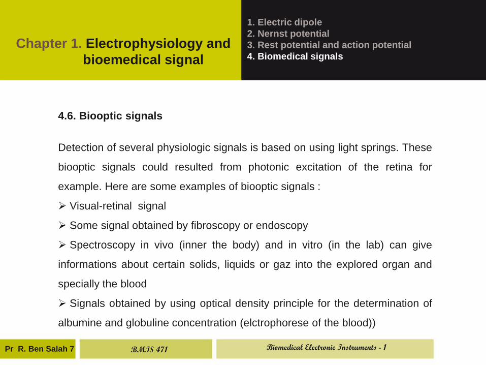
4.6. Biooptic signals
Detection of several physiologic signals is based on using light springs. These
biooptic signals could resulted from photonic excitation of the retina for
example. Here are some examples of biooptic signals :
Visual-retinal signal
Some signal obtained by fibroscopy or endoscopy
Spectroscopy in vivo (inner the body) and in vitro (in the lab) can give
informations about certain solids, liquids or gaz into the explored organ and
specially the blood
Signals obtained by using optical density principle for the determination of
albumine and globuline concentration (elctrophorese of the blood))
BMIS 471 Biomedical Electronic Instruments - 1
Pr R. Ben Salah 21
Chapter 1. Electrophysiology and
bioemedical signal
1. Electric dipole
2. Nernst potential
3. Rest potential and action potential
4. Biomedical signals
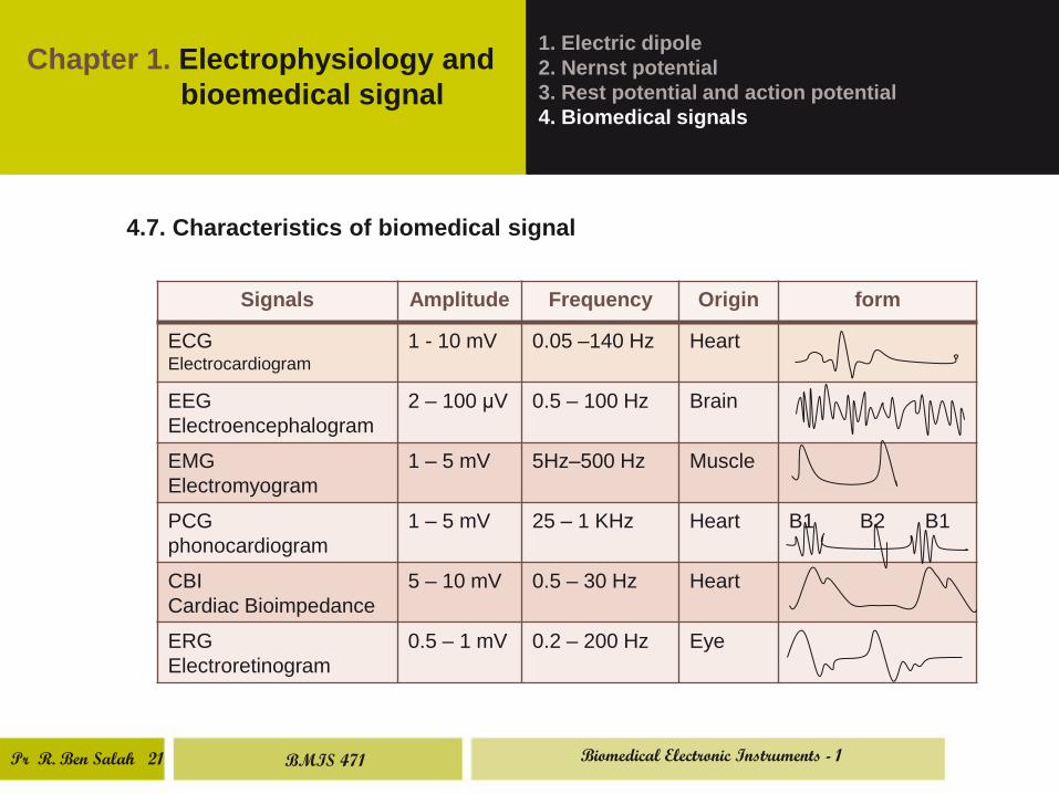
4.7. Characteristics of biomedical signal
Signals Amplitude Frequency Origin form
ECG Electrocardiogram
1 - 10 mV 0.05 –140 Hz Heart
EEG
Electroencephalogram
2 – 100 μV 0.5 – 100 Hz Brain
EMG
Electromyogram
1 – 5 mV 5Hz–500 Hz Muscle
PCG
phonocardiogram
1 – 5 mV 25 – 1 KHz Heart B1 B2 B1
CBI
Cardiac Bioimpedance
5 – 10 mV 0.5 – 30 Hz Heart
ERG
Electroretinogram
0.5 – 1 mV 0.2 – 200 Hz Eye
BMIS 471 Biomedical Electronic Instruments - 1


![Questionsassets.openstudy.com/updates/attachments/52d1dbebe... · The action potential is a propagated change in the [ membrane | Nernst | equilibrium ] potential of a neuron that](https://img.pdfslide.us/doc/110x75/5f6cca9cbca8ee6b993b3bef/the-action-potential-is-a-propagated-change-in-the-membrane-nernst-equilibrium.jpg)


![Chapter 4 The Action Potential. Nernst Relation [ion] out [ion] in E = 61.54 mV log 10](https://img.pdfslide.us/doc/110x75/551a7f4c5503466b3a8b46cd/chapter-4-the-action-potential-nernst-relation-ion-out-ion-in-e-6154-mv-log-10.jpg)