Embed Size (px)
Citation preview
1
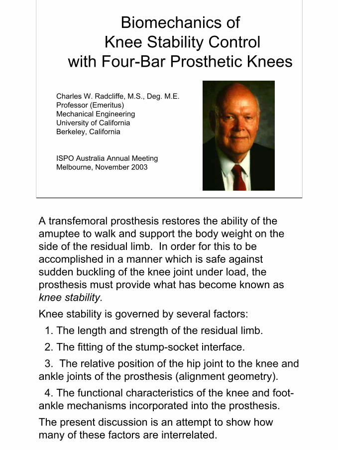
Biomechanics of Knee Stability Control
with Four-Bar Prosthetic Knees
Charles W. Radcliffe, M.S., Deg. M.E.Professor (Emeritus)Mechanical EngineeringUniversity of CaliforniaBerkeley, California
ISPO Australia Annual MeetingMelbourne, November 2003
A transfemoral prosthesis restores the ability of the amuptee to walk and support the body weight on the side of the residual limb. In order for this to be accomplished in a manner which is safe against sudden buckling of the knee joint under load, the prosthesis must provide what has become known asknee stability.Knee stability is governed by several factors:
1. The length and strength of the residual limb.2. The fitting of the stump-socket interface.3. The relative position of the hip joint to the knee and
ankle joints of the prosthesis (alignment geometry).4. The functional characteristics of the knee and foot-
ankle mechanisms incorporated into the prosthesis.The present discussion is an attempt to show how many of these factors are interrelated.
2
Equivalent Single Force
Zone of voluntarycontrol consistentwith available hipmoments
(A) Heel Contact (B) Push Off
F F F F
FFFF
F
M
F
M
USE OF HIP EXTENSION-FLEXION MOMENTS FOR VOLUNTARY CONTROLOF KNEE STABILITY AT BOTH HEEL CONTACT AND PUSH OFF
(C) Superimposed
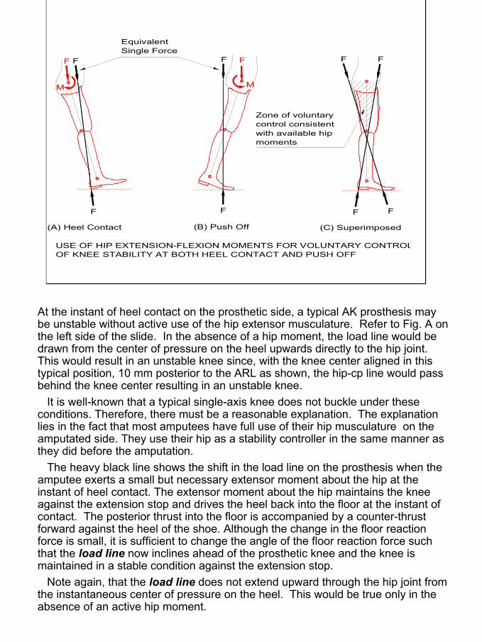
At the instant of heel contact on the prosthetic side, a typical AK prosthesis may be unstable without active use of the hip extensor musculature. Refer to Fig. A on the left side of the slide. In the absence of a hip moment, the load line would be drawn from the center of pressure on the heel upwards directly to the hip joint. This would result in an unstable knee since, with the knee center aligned in this typical position, 10 mm posterior to the ARL as shown, the hip-cp line would pass behind the knee center resulting in an unstable knee.
It is well-known that a typical single-axis knee does not buckle under these conditions. Therefore, there must be a reasonable explanation. The explanation lies in the fact that most amputees have full use of their hip musculature on the amputated side. They use their hip as a stability controller in the same manner as they did before the amputation.
The heavy black line shows the shift in the load line on the prosthesis when the amputee exerts a small but necessary extensor moment about the hip at the instant of heel contact. The extensor moment about the hip maintains the knee against the extension stop and drives the heel back into the floor at the instant of contact. The posterior thrust into the floor is accompanied by a counter-thrust forward against the heel of the shoe. Although the change in the floor reaction force is small, it is sufficient to change the angle of the floor reaction force such that the load line now inclines ahead of the prosthetic knee and the knee is maintained in a stable condition against the extension stop.
Note again, that the load line does not extend upward through the hip joint from the instantaneous center of pressure on the heel. This would be true only in the absence of an active hip moment.
3
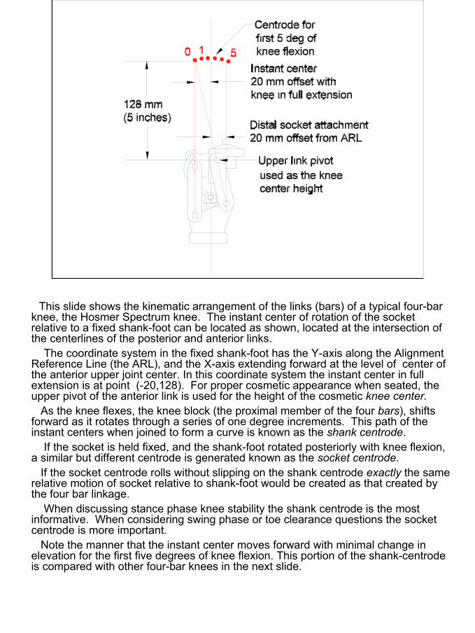
This slide shows the kinematic arrangement of the links (bars) of a typical four-bar knee, the Hosmer Spectrum knee. The instant center of rotation of the socket relative to a fixed shank-foot can be located as shown, located at the intersection of the centerlines of the posterior and anterior links.
The coordinate system in the fixed shank-foot has the Y-axis along the Alignment Reference Line (the ARL), and the X-axis extending forward at the level of center of the anterior upper joint center. In this coordinate system the instant center in full extension is at point (-20,128). For proper cosmetic appearance when seated, the upper pivot of the anterior link is used for the height of the cosmetic knee center.
As the knee flexes, the knee block (the proximal member of the four bars), shifts forward as it rotates through a series of one degree increments. This path of the instant centers when joined to form a curve is known as the shank centrode.
If the socket is held fixed, and the shank-foot rotated posteriorly with knee flexion, a similar but different centrode is generated known as the socket centrode.
If the socket centrode rolls without slipping on the shank centrode exactly the same relative motion of socket relative to shank-foot would be created as that created by the four bar linkage.
When discussing stance phase knee stability the shank centrode is the most informative. When considering swing phase or toe clearance questions the socket centrode is more important.
Note the manner that the instant center moves forward with minimal change in elevation for the first five degrees of knee flexion. This portion of the shank-centrode is compared with other four-bar knees in the next slide.
4
Otto Bock 3R70Hosmer Spectrum
Proteval (Pendulum)
Teh Lin Knee Disarticulation
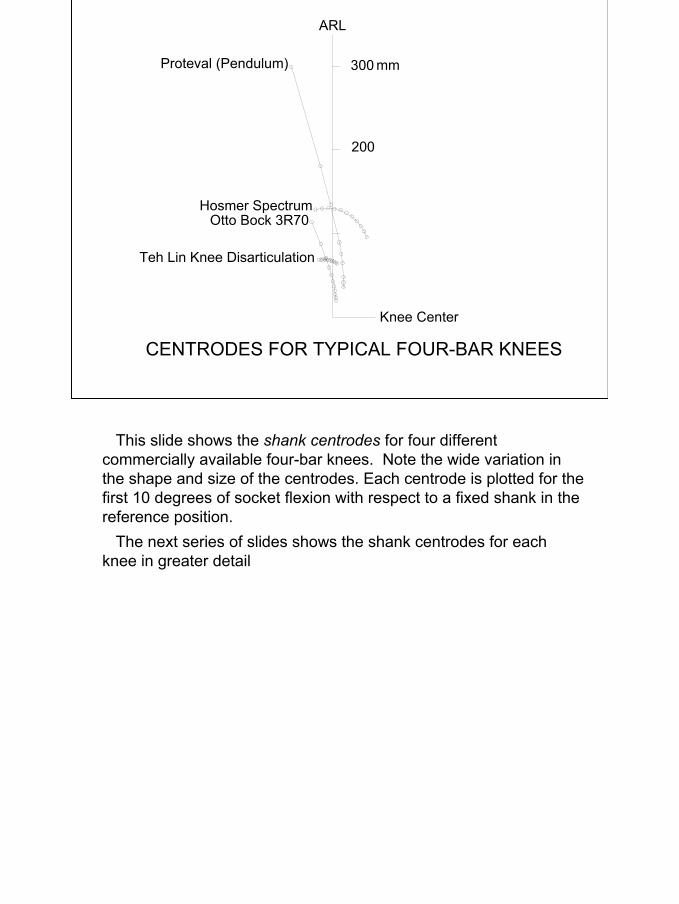
CENTRODES FOR TYPICAL FOUR-BAR KNEES
300
200
mm
ARL
Knee Center
This slide shows the shank centrodes for four different commercially available four-bar knees. Note the wide variation in the shape and size of the centrodes. Each centrode is plotted for the first 10 degrees of socket flexion with respect to a fixed shank in the reference position.
The next series of slides shows the shank centrodes for each knee in greater detail
5
ARL
300 mm
200 mm
100 mm
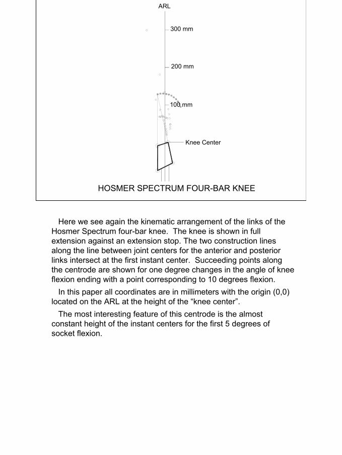
HOSMER SPECTRUM FOUR-BAR KNEE
Knee Center
Here we see again the kinematic arrangement of the links of the Hosmer Spectrum four-bar knee. The knee is shown in full extension against an extension stop. The two construction lines along the line between joint centers for the anterior and posterior links intersect at the first instant center. Succeeding points along the centrode are shown for one degree changes in the angle of knee flexion ending with a point corresponding to 10 degrees flexion.
In this paper all coordinates are in millimeters with the origin (0,0) located on the ARL at the height of the “knee center”.
The most interesting feature of this centrode is the almost constant height of the instant centers for the first 5 degrees of socket flexion.
6
Proteval (Pendulum)
Knee Center
ARL
300 mm
200 mm
100 mm
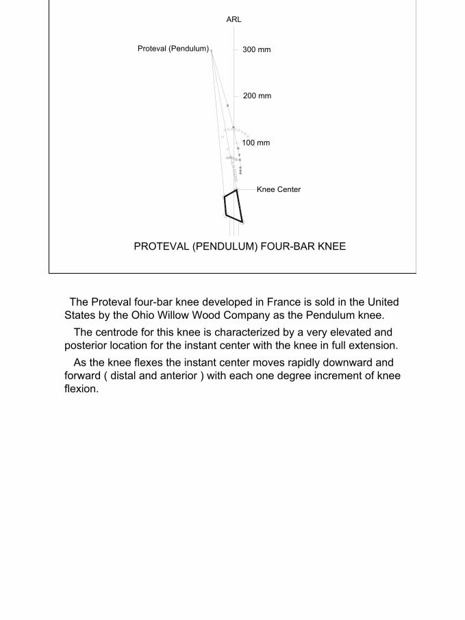
PROTEVAL (PENDULUM) FOUR-BAR KNEE
The Proteval four-bar knee developed in France is sold in the United States by the Ohio Willow Wood Company as the Pendulum knee.
The centrode for this knee is characterized by a very elevated and posterior location for the instant center with the knee in full extension.
As the knee flexes the instant center moves rapidly downward and forward ( distal and anterior ) with each one degree increment of knee flexion.
7
Otto Bock 3R70
300 mm
200 mm
100 mm
Knee Center
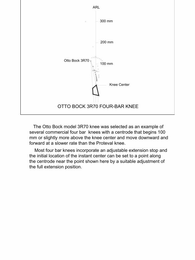
OTTO BOCK 3R70 FOUR-BAR KNEE
ARL
The Otto Bock model 3R70 knee was selected as an example of several commercial four bar knees with a centrode that begins 100 mm or slightly more above the knee center and move downward and forward at a slower rate than the Proteval knee.
Most four bar knees incorporate an adjustable extension stop and the initial location of the instant center can be set to a point along the centrode near the point shown here by a suitable adjustment of the full extension position.
8
ARL
Knee Center
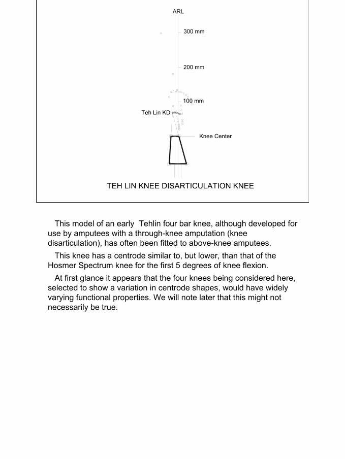
TEH LIN KNEE DISARTICULATION KNEE
Teh Lin KD
300 mm
200 mm
100 mm
This model of an early Tehlin four bar knee, although developed for use by amputees with a through-knee amputation (knee disarticulation), has often been fitted to above-knee amputees.
This knee has a centrode similar to, but lower, than that of the Hosmer Spectrum knee for the first 5 degrees of knee flexion.
At first glance it appears that the four knees being considered here, selected to show a variation in centrode shapes, would have widely varying functional properties. We will note later that this might not necessarily be true.
9
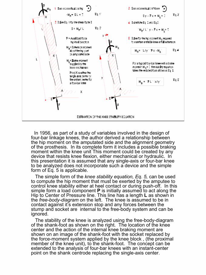
In 1956, as part of a study of variables involved in the design of four-bar linkage knees, the author derived a relationship between the hip moment on the amputated side and the alignment geometry of the prosthesis. In its complete form it includes a possible braking moment within the knee unit This moment could be created by any device that resists knee flexion, either mechanical or hydraulic. In this presentation it is assumed that any single-axis or four-bar knee to be analyzed does not incorporate such a device and the simpleform of Eq. 5 is applicable.
The simple form of the knee stability equation, Eq. 5, can be used to compute the hip moment that must be exerted by the amputee tocontrol knee stability either at heel contact or during push-off. In this simple form a load component P is initially assumed to act along the Hip to Center of Pressure line. This line has a length L as shown in the free-body-diagram on the left. The knee is assumed to be in contact against it’s extension stop and any forces between the stump and socket are internal to the free-body system and can be ignored.
The stability of the knee is analyzed using the free-body-diagram of the shank-foot as shown on the right. The location of the knee center and the action of the internal knee braking moment are shown on an image of the shank-foot with the socket replaced by the force-moment system applied by the knee block , (the proximal member of the knee unit), to the shank-foot. The concept can be extended to the analysis of four-bar knees with an instant-center point on the shank centrode replacing the single-axis center.
10
.
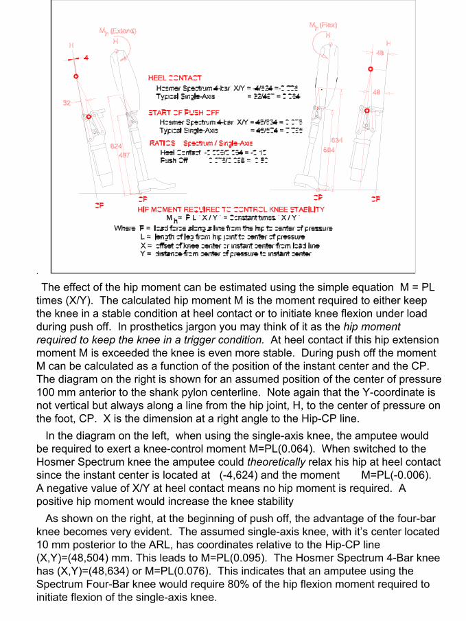
The effect of the hip moment can be estimated using the simple equation M = PL times (X/Y). The calculated hip moment M is the moment required to either keep the knee in a stable condition at heel contact or to initiate knee flexion under load during push off. In prosthetics jargon you may think of it as the hip moment required to keep the knee in a trigger condition. At heel contact if this hip extension moment M is exceeded the knee is even more stable. During push off the moment M can be calculated as a function of the position of the instant center and the CP. The diagram on the right is shown for an assumed position of the center of pressure 100 mm anterior to the shank pylon centerline. Note again that the Y-coordinate is not vertical but always along a line from the hip joint, H, to the center of pressure on the foot, CP. X is the dimension at a right angle to the Hip-CP line.
In the diagram on the left, when using the single-axis knee, the amputee would be required to exert a knee-control moment M=PL(0.064). When switched to the Hosmer Spectrum knee the amputee could theoretically relax his hip at heel contact since the instant center is located at (-4,624) and the moment M=PL(-0.006). A negative value of X/Y at heel contact means no hip moment is required. A positive hip moment would increase the knee stability
As shown on the right, at the beginning of push off, the advantage of the four-bar knee becomes very evident. The assumed single-axis knee, with it’s center located 10 mm posterior to the ARL, has coordinates relative to the Hip-CP line (X,Y)=(48,504) mm. This leads to M=PL(0.095). The Hosmer Spectrum 4-Bar knee has (X,Y)=(48,634) or M=PL(0.076). This indicates that an amputee using the Spectrum Four-Bar knee would require 80% of the hip flexion moment required toinitiate flexion of the single-axis knee.
11
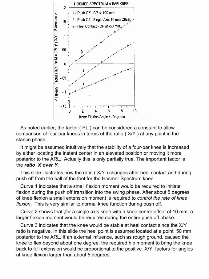
As noted earlier, the factor ( PL ) can be considered a constant to allow comparison of four-bar knees in terms of the ratio ( X/Y ) at any point in the stance phase.
It might be assumed intuitively that the stability of a four-bar knee is increased by either locating the instant center in an elevated position or moving it more posterior to the ARL. Actually this is only partially true. The important factor is the ratio X over Y.
This slide illustrates how the ratio ( X/Y ) changes after heel contact and during push off from the ball of the foot for the Hosmer Spectrum knee.
Curve 1 indicates that a small flexion moment would be required to initiate flexion during the push off transition into the swing phase. After about 5 degrees of knee flexion a small extension moment is required to control the rate of knee flexion. This is very similar to normal knee function during push off.
Curve 2 shows that ,for a single axis knee with a knee center offset of 10 mm, a larger flexion moment would be required during the entire push off phase.
Curve 3 indicates that the knee would be stable at heel contact since the X/Y ratio is negative. In this slide the heel point is assumed located at a point 50 mm posterior to the ARL. If an external influence, such as rough ground, caused the knee to flex beyond about one degree, the required hip moment to bring the knee back to full extension would be proportional to the positive X/Y factors for angles of knee flexion larger than about 5 degrees.
12
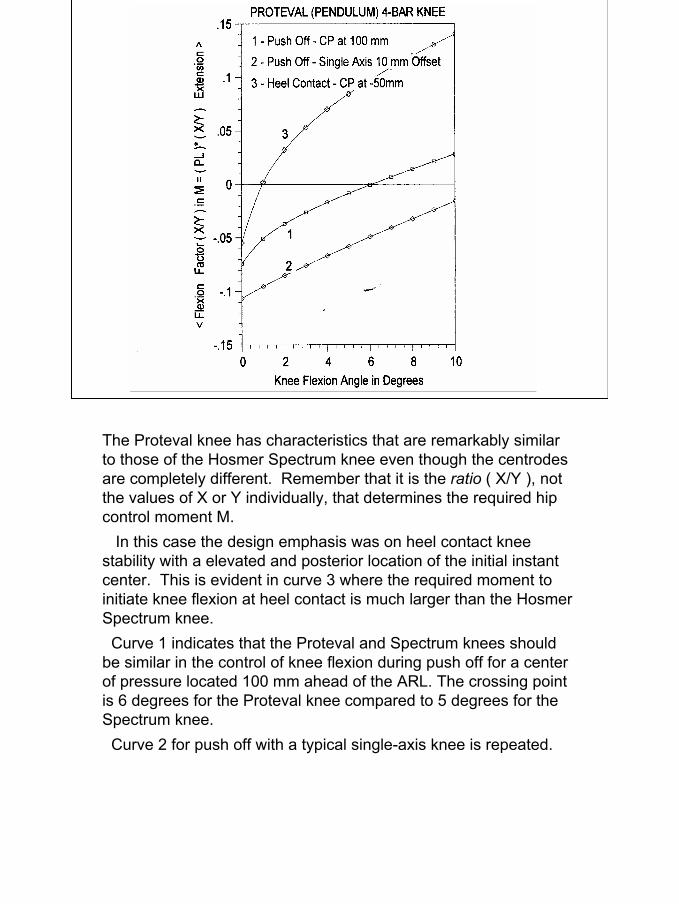
The Proteval knee has characteristics that are remarkably similar to those of the Hosmer Spectrum knee even though the centrodes are completely different. Remember that it is the ratio ( X/Y ), not the values of X or Y individually, that determines the required hip control moment M.
In this case the design emphasis was on heel contact knee stability with a elevated and posterior location of the initial instant center. This is evident in curve 3 where the required moment toinitiate knee flexion at heel contact is much larger than the Hosmer Spectrum knee.
Curve 1 indicates that the Proteval and Spectrum knees should be similar in the control of knee flexion during push off for a center of pressure located 100 mm ahead of the ARL. The crossing point is 6 degrees for the Proteval knee compared to 5 degrees for the Spectrum knee.
Curve 2 for push off with a typical single-axis knee is repeated.
13
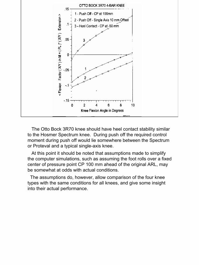
The Otto Bock 3R70 knee should have heel contact stability similar to the Hosmer Spectrum knee. During push off the required control moment during push off would lie somewhere between the Spectrum or Proteval and a typical single-axis knee.
At this point it should be noted that assumptions made to simplify the computer simulations, such as assuming the foot rolls over a fixed center of pressure point CP 100 mm ahead of the original ARL, may be somewhat at odds with actual conditions.
The assumptions do, however, allow comparison of the four kneetypes with the same conditions for all knees, and give some insight into their actual performance.
14
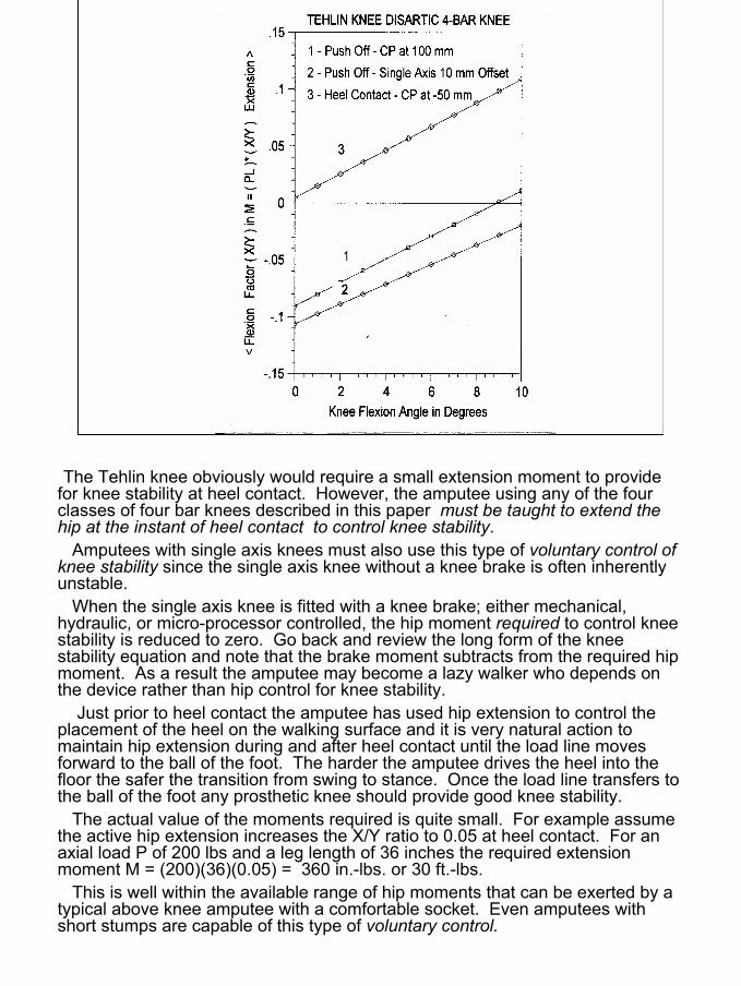
The Tehlin knee obviously would require a small extension moment to provide for knee stability at heel contact. However, the amputee using any of the four classes of four bar knees described in this paper must be taught to extend the hip at the instant of heel contact to control knee stability.
Amputees with single axis knees must also use this type of voluntary control of knee stability since the single axis knee without a knee brake is often inherently unstable.
When the single axis knee is fitted with a knee brake; either mechanical, hydraulic, or micro-processor controlled, the hip moment required to control knee stability is reduced to zero. Go back and review the long form of the knee stability equation and note that the brake moment subtracts from the required hip moment. As a result the amputee may become a lazy walker who depends on the device rather than hip control for knee stability.
Just prior to heel contact the amputee has used hip extension to control the placement of the heel on the walking surface and it is very natural action to maintain hip extension during and after heel contact until the load line moves forward to the ball of the foot. The harder the amputee drives the heel into the floor the safer the transition from swing to stance. Once the load line transfers to the ball of the foot any prosthetic knee should provide good knee stability.
The actual value of the moments required is quite small. For example assume the active hip extension increases the X/Y ratio to 0.05 at heel contact. For an axial load P of 200 lbs and a leg length of 36 inches the required extension moment M = (200)(36)(0.05) = 360 in.-lbs. or 30 ft.-lbs.
This is well within the available range of hip moments that can be exerted by a typical above knee amputee with a comfortable socket. Even amputees with short stumps are capable of this type of voluntary control.
15
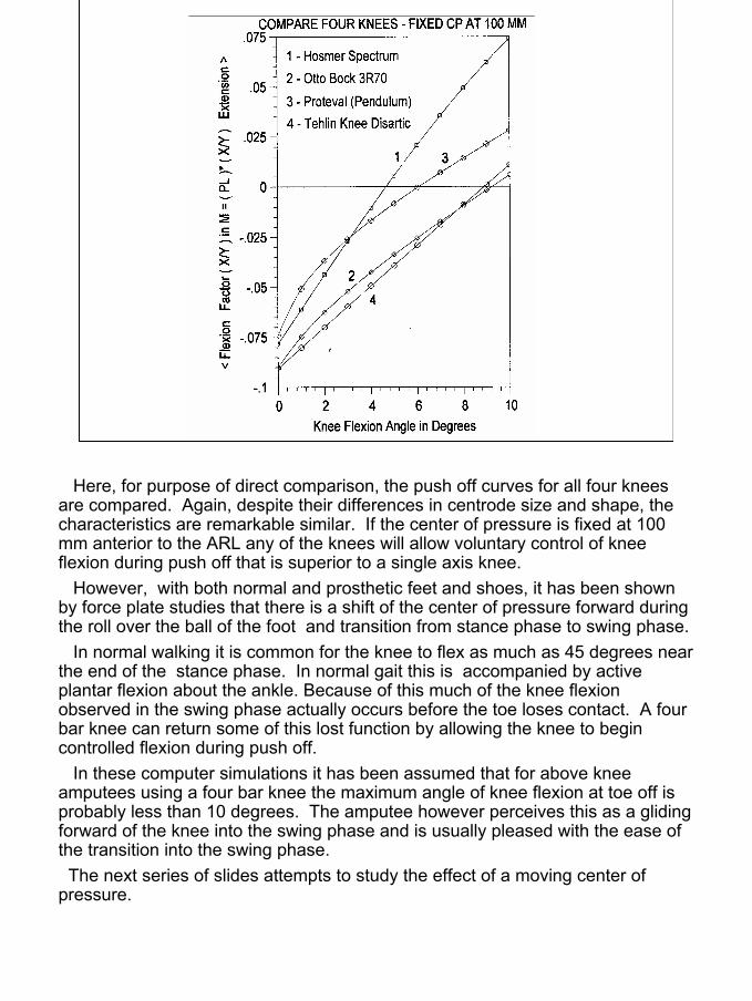
Here, for purpose of direct comparison, the push off curves for all four knees are compared. Again, despite their differences in centrode size and shape, the characteristics are remarkable similar. If the center of pressure is fixed at 100 mm anterior to the ARL any of the knees will allow voluntary control of knee flexion during push off that is superior to a single axis knee.
However, with both normal and prosthetic feet and shoes, it has been shown by force plate studies that there is a shift of the center of pressure forward during the roll over the ball of the foot and transition from stance phase to swing phase.
In normal walking it is common for the knee to flex as much as 45 degrees near the end of the stance phase. In normal gait this is accompanied by active plantar flexion about the ankle. Because of this much of the knee flexion observed in the swing phase actually occurs before the toe loses contact. A four bar knee can return some of this lost function by allowing the knee to begin controlled flexion during push off.
In these computer simulations it has been assumed that for above knee amputees using a four bar knee the maximum angle of knee flexion at toe off is probably less than 10 degrees. The amputee however perceives this as a gliding forward of the knee into the swing phase and is usually pleased with the ease of the transition into the swing phase.
The next series of slides attempts to study the effect of a moving center of pressure.
16
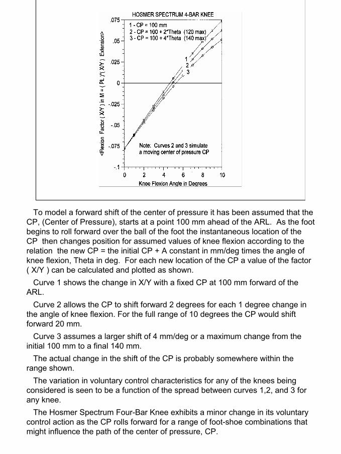
To model a forward shift of the center of pressure it has been assumed that the CP, (Center of Pressure), starts at a point 100 mm ahead of the ARL. As the foot begins to roll forward over the ball of the foot the instantaneous location of the CP then changes position for assumed values of knee flexion according to the relation the new CP = the initial CP + A constant in mm/deg times the angle of knee flexion, Theta in deg. For each new location of the CP a value of the factor ( X/Y ) can be calculated and plotted as shown.
Curve 1 shows the change in X/Y with a fixed CP at 100 mm forward of the ARL.
Curve 2 allows the CP to shift forward 2 degrees for each 1 degree change in the angle of knee flexion. For the full range of 10 degrees the CP would shift forward 20 mm.
Curve 3 assumes a larger shift of 4 mm/deg or a maximum change from the initial 100 mm to a final 140 mm.
The actual change in the shift of the CP is probably somewhere within the range shown.
The variation in voluntary control characteristics for any of the knees being considered is seen to be a function of the spread between curves 1,2, and 3 for any knee.
The Hosmer Spectrum Four-Bar Knee exhibits a minor change in its voluntary control action as the CP rolls forward for a range of foot-shoe combinations that might influence the path of the center of pressure, CP.
17
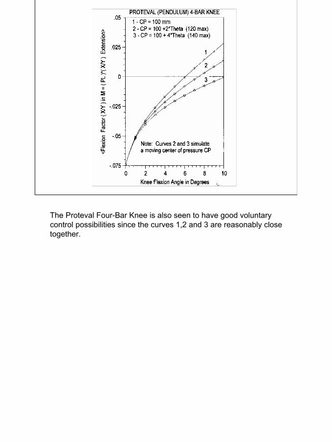
The Proteval Four-Bar Knee is also seen to have good voluntary control possibilities since the curves 1,2 and 3 are reasonably close together.
18
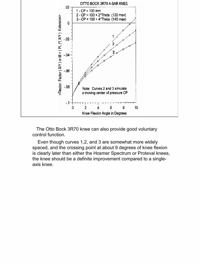
The Otto Bock 3R70 knee can also provide good voluntary control function.
Even though curves 1,2, and 3 are somewhat more widely spaced, and the crossing point at about 9 degrees of knee flexion is clearly later than either the Hosmer Spectrum or Proteval knees, the knee should be a definite improvement compared to a single-axis knee.
19
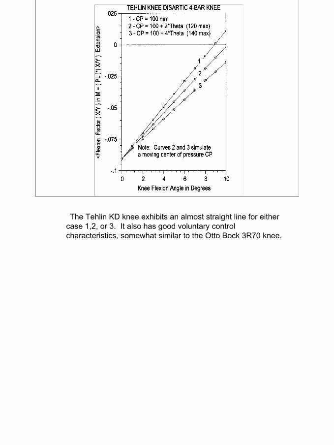
The Tehlin KD knee exhibits an almost straight line for either case 1,2, or 3. It also has good voluntary control characteristics, somewhat similar to the Otto Bock 3R70 knee.

20
In conclusion it may be noted that:
1. The four knees analyzed in this paper had markedly different designs and centrode shapes.
2. Each knee has certain distinct properties that allow improved knee stability control as compared to a single axis knee without a knee brake.
3. An important difference in the function of the four knees was the sensitivity to a forward shift of the center of pressure.
4. The forward shift of the center of pressure is dependent upon:a. The kinematic design of the four-bar linkageb. The design and flexibility of the “keel” of the foot.c. The influence of the stiffness of the shoe being used.d. The alignment of the foot in plantar flexion at bench alignment. This determines the “air space” or “safety factor” as reported in the German prosthetic literature more than 50 years ago.
5. Four-Bar knees are not just a “safe” knee with improved security at heel contact. Their most unique feature, when properly applied, is the ability to provide conservation of energy by improved voluntary control of knee flexion during push-off. The author, in his design of the Hosmer Spectrum Four-Bar Knee, has tried to optimize these “Glide–Flex” features.
21
COMPARISON OF THE UC-BERKELEY AND GERMANBENCH ALIGNMENT SYSTEMS - MEDIAL VIEW
5 deg flexionof socket
6-10 mmposterior offsetof knee axis
6-10 mmair space under heelof shoe
Minimal flexionof socket inbench alignment
Knee center offset varieswith knee used
Alignment ref lineis plumb line fromthe hip center
Ankle center offsetvaries with foot used
Alignment ref lineis centerline ofvertical shank pylon
(A) UC-Berkeley system (B) German system
Increase inair spaceunder heel
Proximal referencepoint at bisectorof the medial brim
Proximal referencepoint at the centerof the hip joint
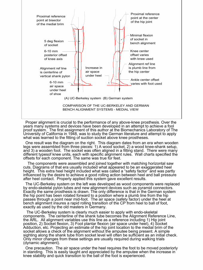
Proper alignment is crucial to the performance of any above-knee prosthesis. Over the years many systems and devices have been developed in an attempt to achieve a fool proof system. The first assignment of this author at the Biomechanics Laboratory of The University of California in 1948, was to study the German literature and attempt to apply what was learned to the fitting of suction socket above knee prostheses. One result was the diagram on the right. This diagram dates from an era when wooden
legs were assembled from three pieces: 1) A wood socket, 2) a wood knee-shank setup, and 3) a wooden foot. The socket was often aligned in a fitting stand. There were many different typesof knee units, each with specific alignment rules. Wall charts specified the offsets for each component. The same was true for feet.
The components were assembled and joined together with matching horizontal saw cuts. Diagrams of that era usually included what appeared to be an exaggerated heel height. This extra heel height included what was called a “safety factor” and was partly influenced by the desire to achieve a good rolling action between heel and ball pressure after heel contact. Properly applied this system gave excellent results.The UC-Berkeley system on the left was developed as wood components were replaced
by endo-skeletal pylon tubes and new alignment devices such as pyramid connectors. Exactly the same prosthesis is drawn. The only difference is that in the German system the hip point has been rotated forward to a position where a plumb line from the hip passes through a point near mid-foot. The air space (safety factor) under the heel at bench alignment insures a rapid rolling transition of the CP from heel to ball of foot, exactly as used by the old masters in Germany.
The UC-Berkeley system is clearly much easier to apply with endo-skeletal components. The centerline of the shank tube becomes the Alignment Reference Line, the ARL. All alignment variables use this line as a reference including 1) Hip joint position, 2) Socket flexion, 3) Foot plantar flexion (air space under heel), 4) Socket Adduction, etc. Projecting an estimate of the hip joint location to the medial brim of the socket allows a check of the alignment without the amputee being present. A simple sighting along the shank tube from socket level will often be sufficient as an initial check. Only minor changes from these settings are usually required during walking trials (dynamic alignment).One precaution. The air space under the heel requires the foot to be moved posteriorly
in standing. This is easily taught and appreciated by the amputee when the increase in knee stability and quick transition to the ball of the foot is experienced.
22
LM
S
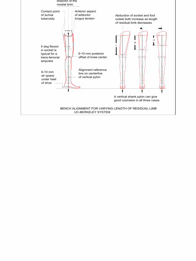
BENCH ALIGNMENT FOR VARYING LENGTH OF RESIDUAL LIMB UC-BERKELEY SYSTEM
Contact pointof ischialtuberosity
Anterior aspectof adductorlongus tendon
Bisector of themedial brim
A vertical shank pylon can givegood cosmesis in all three cases
6-10 mm posterioroffset of knee center
Alignment referenceline on centerlineof vertical pylon
5 deg flexionin socket istypical for atrans-femoralamputee
6-10 mmair spaceunder heelof shoe
Abduction of socket and footoutset both increase as lengthof residual limb decreases
23
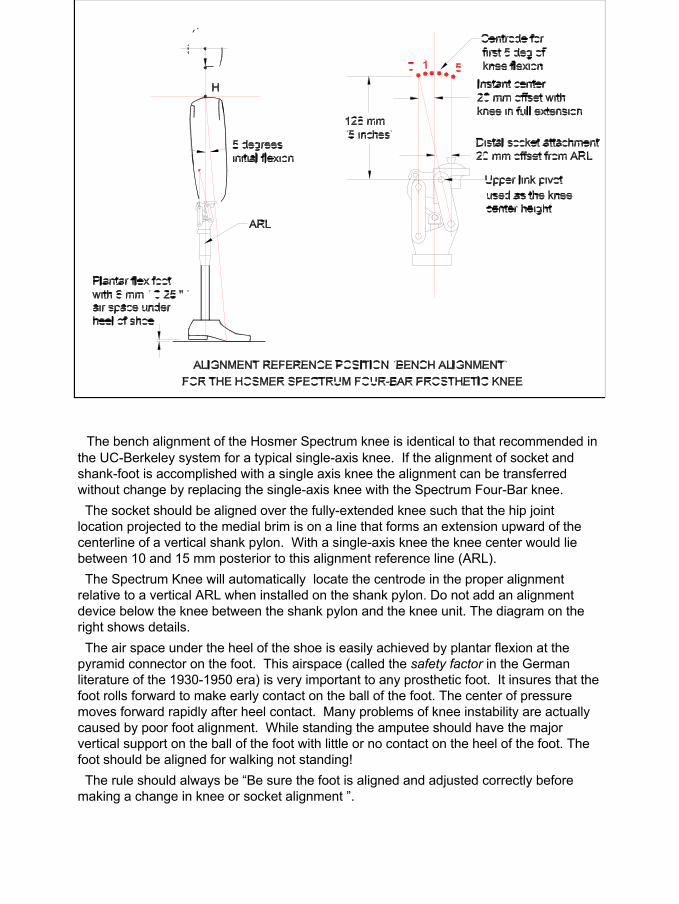
The bench alignment of the Hosmer Spectrum knee is identical to that recommended in the UC-Berkeley system for a typical single-axis knee. If the alignment of socket and shank-foot is accomplished with a single axis knee the alignment can be transferred without change by replacing the single-axis knee with the Spectrum Four-Bar knee.The socket should be aligned over the fully-extended knee such that the hip joint
location projected to the medial brim is on a line that forms an extension upward of the centerline of a vertical shank pylon. With a single-axis knee the knee center would lie between 10 and 15 mm posterior to this alignment reference line (ARL). The Spectrum Knee will automatically locate the centrode in the proper alignment
relative to a vertical ARL when installed on the shank pylon. Do not add an alignment device below the knee between the shank pylon and the knee unit. The diagram on the right shows details.The air space under the heel of the shoe is easily achieved by plantar flexion at the
pyramid connector on the foot. This airspace (called the safety factor in the German literature of the 1930-1950 era) is very important to any prosthetic foot. It insures that the foot rolls forward to make early contact on the ball of the foot. The center of pressure moves forward rapidly after heel contact. Many problems of knee instability are actually caused by poor foot alignment. While standing the amputee should have the major vertical support on the ball of the foot with little or no contact on the heel of the foot. The foot should be aligned for walking not standing!The rule should always be “Be sure the foot is aligned and adjusted correctly before
making a change in knee or socket alignment ”.
24
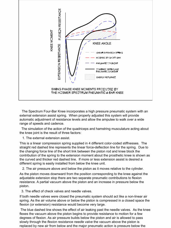
The Spectrum Four-Bar Knee incorporates a high pressure pneumatic system with an external extension assist spring. When properly adjusted this system will provide automatic adjustment of resistance levels and allow the amputee to walk over a wide range of speeds and cadence.The simulation of the action of the quadriceps and hamstring musculature acting about
the knee joint is the result of three factors:1. The external extension assist.
This is a linear compression spring supplied in 4 different color-coded stiffnesses. The straight red dashed line represents the linear force-deflection line for the spring. Due to the changing force line of the short link between the piston rod and knee block the contribution of the spring to the extension moment about the prosthetic knee is shown as the curved and thicker red dashed line. If more or less extension assist is desired a different spring is easily installed from below the knee unit.
2. The air pressure above and below the piston as it moves relative to the cylinder.As the piston moves downward from the position corresponding to the knee against the adjustable extension stop there are two separate pneumatic contributions to flexion resistance. A partial vacuum above the piston and an increase in pressure below the piston.3. The effect of check valves and needle valves.
If both needle valves were closed the pneumatic system should act like a non-linear air spring. As the air volume above or below the piston is compressed in a closed space the flexion (or extension) resistance would become very large.The blue dashed line shows the effect of air leaking past the needle valves. As the knee flexes the vacuum above the piston begins to provide resistance to motion for a few degrees of flexion. As air pressure builds below the piston and air is allowed to pass slowly through the flexion resistance needle valve the vacuum above the piston is replaced by new air from below and the major pneumatic action is pressure below the piston.
25
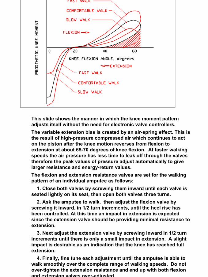
This slide shows the manner in which the knee moment pattern adjusts itself without the need for electronic valve controllers.The variable extension bias is created by an air-spring effect. This is the result of high-pressure compressed air which continues to act on the piston after the knee motion reverses from flexion to extension at about 65-70 degrees of knee flexion. At faster walking speeds the air pressure has less time to leak off through the valves therefore the peak values of pressure adjust automatically to give larger resistance and energy-return values.The flexion and extension resistance valves are set for the walking pattern of an individual amputee as follows:
1. Close both valves by screwing them inward until each valve is seated lightly on its seat, then open both valves three turns.
2. Ask the amputee to walk, then adjust the flexion valve by screwing it inward, in 1/2 turn increments, until the heel rise has been controlled. At this time an impact in extension is expectedsince the extension valve should be providing minimal resistance to extension.
3. Next adjust the extension valve by screwing inward in 1/2 turn increments until there is only a small impact in extension. A slight impact is desirable as an indication that the knee has reached full extension.
4. Finally, fine tune each adjustment until the amputee is able to walk smoothly over the complete range of walking speeds. Do notover-tighten the extension resistance and end up with both flexion and extension valves over-adjusted.


![CURRICULUM VITAE JOHN B. BRUNSKI · 1. Nobel Biocare AB ... Biomechanics of," in Encyclopedia of Medical Devices and Instrumentation, Vol. 4 (J ... [Invited] J.B. Brunski, "Prosthetic](https://img.pdfslide.us/doc/110x75/5add02c07f8b9a595f8c5279/curriculum-vitae-john-b-nobel-biocare-ab-biomechanics-of-in-encyclopedia.jpg)