Embed Size (px)
Citation preview

Prepared by:
August 2006
Electrification of Village Bod
Category Remote Hilly Area (40 HH)
District : Betul, Madhya Pradesh
Biomass Gasifier Based Electric Power Project (1x10 kW)
Alternate Hydro Energy CentreIndian Institute of TechnologyRoorkee-247 667
Govt. of India, New Delhi
Road from Kuppa

Prepared by:
August 2006
Alternate Hydro Energy CentreIndian Institute of TechnologyRoorkee-247 667
Govt. of India, New DelhiGovt. of India, New Delhi
Electrification of Village Bod
Category Remote Hilly Area (40 HH)
District : Betul, Madhya Pradesh
Biomass Gasifier Based Electric Power Project (1x10 kW)

TABLE OF CONTENTS
Page No. i. Foreword ii. Executive Summary iii. Salient Features S1-S3 iv. Photographs P1-P4 CHAPTER – 1 BACKGROUND AND BASIC DATA 1.1 Introduction 1 1.2 Project Sponsor 1 1.3 Nodal Agency & Associated Organizations 1 1.4 Selection of Village for Model DPR 2 1.5 About Village Bod (Distt.-Betul, M.P.) 2 CHAPTER – 2 POWER/ENERGY REQUIREMENT AND INSTALLED
CAPACITY
2.1 General 5 2.2 Power / Energy Requirement 6 2.3 Resource Availability 7 2.4 Nodal Agency for Installation of the Plant 8 2.5 O & M Activities 8 CHAPTER – 3 BIO-MASS MANAGEMENT FOR THE PLANT 3.1 General 9 3.2 Biomass Resource 9 3.3 Requirement of Subabul Plants & the Land for Growing 9 3.4 Methodology For Continuous Availability Of Biomass 10 3.5 Biomass Management 10 3.5.1 Future Vision 11
CHAPTER – 4 CIVIL WORKS
4.1 Introduction 12 4.2 Components of Civil Works 12 4.3 Construction 12 4.4 Water Supply System and Room 13 4.5 Miscellaneous 13 4.6 Materials, Construction, Finishing, Testing and Commissioning 14 4.7 Mild Steel or Iron Work in Small Sizes and Sections 14 CHAPTER – 5 ELECTROMECHANICAL WORKS 5.1 Gasifier and Gas Engine 15 5.2 Electro-Mechanical Equipment 18 5.3 Maintenance Manual and Log Book 21 5.4 Proposed Spares 21

CHAPTER – 6 POWER DISTRIBUTION WORKS 6.1 Consumer Voltage Variation and Power Factor 22 6.2 Generator Neutral Earthing 22 6.3 Provision of ELCBs and Load Limitors 22 6.4 Lightning Protection 22 6.5 Earthing 22 6.6 Distribution Plan 23 6.7 Isolators / Fuses / ELCBs 23 6.8 Load Limiters 23 6.9 Cables 23 6.10 Type of Poles 24 6.11 House Wiring 24 6.12 Temper Proofing 25 6.13 Maintenance Manual 25 6.14 Labels and Notices 25 6.15 Line Distribution System 25 6.16 Selection of Cable 25 CHAPTER – 7 TESTING & COMMISSIONING 7.1 Testing 26 7.2 Commissioning 26 7.3 Acceptance Tests at Site 26 CHAPTER – 8 PROJECT IMPLEMENTATION STRATEGY 8.1 General 27 8.2 Arrangement 27 CHAPTER – 9 CONSTRUCTION PROGRAMME 9.1 Pre-Construction Activities 28 9.2 Construction Activities 28 9.3 Bio Mass Supply for the Plant 29 9.4 Contractual Period of O & M 29 CHAPTER – 10 ESTIMATES AND FINANCIAL ANALYSIS 10.1 Estimated Cost of Plant and the System 30 10.2 Funding for Construction 33 10.3 Financial Analysis 33
CHAPTER – 11 OPERATION AND MAINTENANCE OF PLANT 11.1 General 36 11.2 Supervision and Monitoring of O & M 36
CHAPTER – 12 ENVIRONMENTAL IMPACT AND BENEFITS 12.1 General 38 12.2 Supervision and Monitoring of O & M 39
LIST OF PERSONNEL INVOLVED DRAWINGS:
i. Maps of Village Bod (District Betul) Fig. 1.1 ii. Map of Village Bod C-336-1 iii. Plant layout of Power Generation Plant C-336-2 iv. Schematic diagram of Power Generation Plant C-336-3 v. Layout Plan and sectional Elevation of Power Generation Plant C-336-4 vi. Biomass Store Shed & Open Yard C-336-5 vii. Single Line Diagram E-336-1

AHEC/ Model DPR/ Hilly 40 HH/BEP
FOREWORD
(This Foreword is not part of the Model DPR) The Ministry of Non-Conventional Energy Sources, Government of India (MNES) have identified over 24,000 remote villages which are proposed to be electrified through small renewable energy sources e.g. Small Hydro Power, Biomass Gasification and Solar Photovoltaic Technology, so as to improve the well being of population living in the far flung isolated areas.
To make the Remote Village Electrification (RVE) programme successful, it is necessary that the planning, design, execution and operation and maintenance of RVE projects is efficient and reliable and also economical in the long run. MNES, vide letters number 13/5/2005 – 06 RVE dated 23.12.2005 and even number dated 09.03.2006 has asked the alternate Hydro Energy Centre, IIT, Roorkee (AHEC) to prepare model detailed project reports (DPRs) for the following four categories :
1. Category “A – 1” Village with 40 households in the hilly area. 2. Category “A – 2” Village with 40 households in the plain area. 3. Category “B – 1” Village with 200 households in the hilly area. 4. Category “B – 2” Village with 200 households in the plain area.
The villages are to be selected from the States of Madhya Pradesh, West Bengal, Jharkhand and Uttaranchal to make the DPRs more versatile and practical so that these model DPRs can be used with slight site specific changes by even those users who may not have much technical expertise.
This Document has been prepared for RVE through Biomass gasification based electric Power Plant for the Category “A-1” village: Bod (Block: Shahpur, Distt.: Betul, State: Madhya Pradesh) and also to serve as a Model Document recommended for use as a guide for RVE of similar category villages (including those ones having some variation in number of house holds) with plant and site specific modification. Any suggestions from institutions, organizations, users and interested individuals are welcome. Suggestions should be addressed to: Head, Alternate Hydro Energy Centre, Indian Institute of Technology, Roorkee – 247667, Uttaranchal, India. E-mail: [email protected] Fax: +91 – 1332 – 273517.

EXECUTIVE SUMMARY
With the rapid changing scenario of fast depleting conventional energy sources, the future of conventional electric power system is getting uncertain. This has led to world wide thrust on development and use of non-conventional energy sources for electric power generation & use. This coupled with almost no chances of extending the electric power grids to the remote hilly villages and particularly those located deep in the forest due to problems associated with drawing power lines through it and their O & M, use of non-conventional energy sources remains the only alternative for providing reliable electricity to such remote villages. Bod (Distt. Betul, M.P.) is a hilly tribal village situated in the deep forests of Satpura range. The habitants are poor. Only a few families own plots of agriculture land. The production of food grains from these plots of agriculture land is low and therefore, they also have to buy the required balance quantity of food grains from the market. Most of the village people are below poverty line. Some of them are jobless. The Biomass Gasifier Based Electric Power Plant (BEP) proposed for this village will be helpful for:
i. Improving the living conditions of the village people. ii. Generating new opportunities for over all upliftment. iii. Providing light for study and promote education amongst children promising them
better future. iv. Providing required drinking water facility in the village. v. Creating awareness about the renewable sources of energy and using them for
entrepreneurship like micro-cottage industries etc. there by improving economic conditions.
vi. Saving Kerosine and forest wood presently being used for lighting. vii. Creating environmental awareness amongst the people and help control avoidable
destruction of the forest.
The project is envisaged to be constructed in a period of 12 months from the date of signing the contract agreement. The proposed period takes care of the adverse conditions e.g. monsoon season, transport problems and afford required time for better construction management and quality of works, etc.
There being almost no paying capacity of most of the villagers, a low one time contribution of Rs. 1000 per house hold has been proposed towards initial construction of the plant (which, though insignificant, will create a sense of belongingness thereby help make the scheme successful and send good message to others to follow suit) and a monthly payment of Rs. 50/- per month towards O&M (which they will be able to pay as they will have a monthly saving on cost of kerosene). The balance cost of O & M will have to be managed by the Nodal Agency source of funding for construction of plant & the system is proposed to be as:
i. In centive subsidy by MNES : Rs. 4.240 lacs. ii. One time contribution by villager : Rs. 0.40 lac. iii. Balance to be paid by Nodal Agency : Rs. 14.346 lacs.
The estimated cost of the proposed 10 kW electric power project works out to Rs. 18.986 lacs. The cost of generation works out to Rs. 18.037 per kWh & Rs. 24.049 per kWh without subsidy at 80% and 60% LF respectively and Rs. 15.465 & Rs. 20.620 per kWh with subsidy at 80% & 60% LF respectively which is reasonable.

AHEC/ Model DPR/ Hilly 40 HH/BEP
S-1
SALIENT FEATURES
1.1 GENERAL
i. Name of the Project : Biomass based Project, for Bod Village
ii. Location a. Village : Bod b. Block : Shahpur c. District : Betul d. State : Madhya Pradesh
iii. Access a. Rail : Itarasi Jn. (C R) b. Road : 8.5 km forest road (hilly and non-
metalled) taking off to right from village Kuppa situated at about 15 km from town of Bhonra ( located at about 19 km before Shahpur on Itarasi-Shahpur- Betul road.
iii. Geographical Co-ordinates a. Latitude : Approx. 220 16’ North b. Longitude : Approx. 770 43.5’East
iv. Climatic Conditions a. Temperature (ºC) : 440C Max.-0.20C Min.
b. Humidity (%) : 92% Max. 31% Min. c. Period of Rainfall : June 20 to September 15 d. Rainfall : Approx. 1177.80 mm
v. Land for Project Construction a. At Biomass source Site : To be earmarked by State Forest Department
b. At proposed plant site near : Village. the Village
vi. Approximate distance of a. Biomass Source from Village : Surrounding the village:- 2 to 3 km b. Proposed Plant site : Close to the Village.
1.2 Details of Biomass Available in the Forest in the Surrounding Area The details are given in Table below:
Sl. No.
Type % Availability Average Height (m)
Average Girth (cm)
1. 2. 3. 4. 5. 1. Main i. Sagaun 68 20 95 ii. Saz 25 18 85 iii. Haldu 25 18 90 iv. Tinsa 15 15 100 v. Karai 10 15 80
vi. Leindia 10 18 65 vii. Tendu 10 25 65 viii. Bans 20 10 12

AHEC/ Model DPR/ Hilly 40 HH/BEP
S-2
Sl. No.
Type % Availability Average Height (m)
Average Girth (cm)
1. 2. 3. 4. 5. ix. Sheesham 5 12 70 2. Proposed for
Gasifier Plant
i.
Subabool To be grown by rotation on 3 year basis as per requirement
To be grown to 2.5 (Approx.)
20 for use in the plant
1.3 CIVIL STRUCTURES (Date given here are Tentative only) Proposed Land for:
i. Biomass store shed with open yard : 5.0 m x 3.0 m ii. Cooling Pond : 2.50 m x 2.0 m iii. Gasifier shed : 9.0 m x 7.5 m iv. Power Plant Building : 9.0 m x 7.0 m v. Control Room : 3.50 m x 3.0 m
1.4 POWER HOUSE (Date given here are Tentative only) i. Gassifier Type : Down Draft ii. Gas Engine
a. Nos. : 1 b. Rating : 11 kW Approx. as required for
10 kW generator terminal output c. Rated Speed : 1500 rpm
iii. Generator
a. Type & Nos. : Synchronous, 1 b. Power Output Rating : 10 kW Each, 3 Ø c. Nominal Voltage of Generation : 415 V + 5% d. Frequency : 50 Hz + 3% e. Power Factor : 0.8 lag f. Cooling : Natural / Open 1.5 POWER EVACUATION AND DISTRIBUTION SYSTEM
Distribution System shall be made as per the site conditions and location of various house holds and other user points. a. No. of House Holds : 40 b. L.T. Distribution Line
• No. of Lines : 3 • Voltage : 230 V, 1 Ø • Length of Line : 5 km (Approx.)
c. No. of Street Light Points : 20 (Approx.)

AHEC/ Model DPR/ Hilly 40 HH/BEP
S-3
1.6 ESTIMATED COST OF THE PROJECT i. Power and System Plant : Rs. 18.986 Lacs
1.7 ESTIMATED COST OF GENERATION
i. Without Subsidy At 80% of LF : Rs. 18.037/ kWh. At 60% of LF : Rs. 24.049/ kWh.
ii. With Subsidy
At 80% of LF : Rs. 15.465 / kWh. At 60% of LF : Rs. 20.620 / kWh.
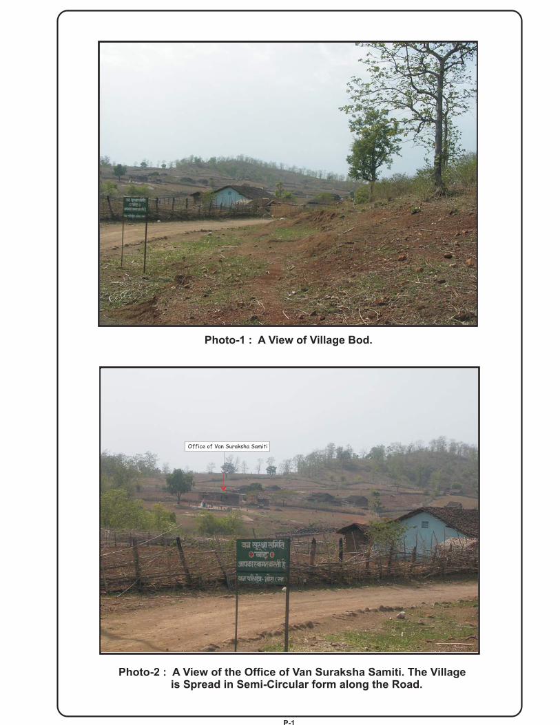
Photo-1 : A View of Village Bod.
Photo-2 : A View of the Office of Van Suraksha Samiti. The Villageis Spread in Semi-Circular form along the Road.
Office of Van Suraksha Samiti
P-1

Photo-3 : Another View of Village Bod.
: A View of The Central Part of the Village Bod.Photo-4
P 2

Photo-5 : Right Side View of the Village Bod.
Photo-6 : Well Near the Rivulet - Water Occurs (on June 07, 2006)At About 3 m Depth from Ground Level.
Road from Kuppa
P-3

P-4
Photo-7 : Primary School, Village Bod.

AHEC/ Model DPR/ Hilly 40 HH/BEP
1
CHAPTER – 1
BACK GROUND AND BASIC DATA 1.1 INTRODUCTION
There is acute shortage of electric power generation in the country so much so that the areas already connected to the power grids are subjected to frequent power cuts. The available fuel resources being used for electricity generation are getting fast depleted. This problem and sensitivity coupled with drawing the Electric Power lines through deep forest, the cost involved in extending the power grids, cost and problems in O & M of such line etc. make it almost impossible to make grid the electricity reach the remote village Bod (Distt.Betul, M.P.). The economic and social conditions of the inhabitants of village Bod are poor. Electricity being one of the basic infrastructural requirements for development and progress, the only hope in the above scenario is the use of renewable energy sources to generate and supply electricity to the remote villages. In an effort towards this end, this project has been conceived for immediate implementation.
1.2 PROJECT SPONSOR
MNES, GOI has come up to subsidize the cost of RVE project to a large extent. The balance cost is to be met by the Nodal Agency and the people of the village.
1.3 NODAL AGENCY & ASSOCIATED ORGANIZATIONS
M.P. Urja Vikas Nigam , Bhopal has been assigned to carry out energy development work through non-conventional energy sources by the Government of Madhya Pradesh. For remote villages located in the forest, co-operation of the Department of Forest, M.P. is also required. Discussions were held with the following officers and staff of the above departments: I. M.P. Urja Vikas Nigam Ltd.
1. Sri B.P.Gupta, S.E., Bhopal 2. Sri Surendra Bajpai, E.E., Bhopal 3. Sri Y.P.Joshi, E.E., Bhopal. 4. Sri Vijay Gaikwad, E.E., Hoshangabad. 5. Sri Ram Narain Chauhan, Field Officer, Hoshangabad. 6. Sri R.K.Patil, Field Assistant, Hoshangabad.
II. M.P. Forest Department 1. Sri R,K,Dave, Addl. Principal Chief Conservator of Forest, Bhopal 2. Sri C.K.Patil, Conservator of Forest, Bhopal 3. Sri P.S.Champawat, DFO, Hoshangabad 4. Sri Pankaj Agarwal, DFO, Betul 5. Sri Baghel, SDO (F), Siwni Malwa 6. Sri Anil Misra, SDO (F), Shahpur 7. Sri MH.Khan, Range Assitt., Shahpur 8. Sri R.K.Lede, Range Assitt., Shahpur
AHEC/ Model DPR/ Hilly 40 HH/BEP
2
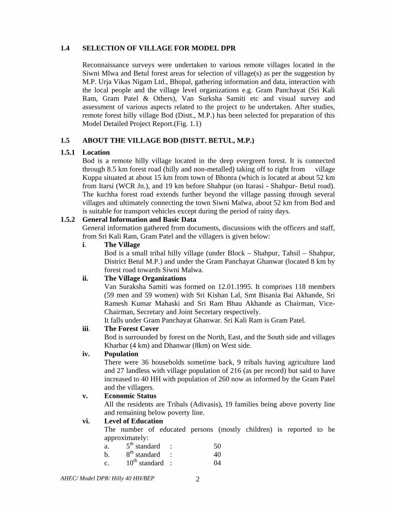
1.4 SELECTION OF VILLAGE FOR MODEL DPR Reconnaissance surveys were undertaken to various remote villages located in the Siwni Mlwa and Betul forest areas for selection of village(s) as per the suggestion by M.P. Urja Vikas Nigam Ltd., Bhopal, gathering information and data, interaction with the local people and the village level organizations e.g. Gram Panchayat (Sri Kali Ram, Gram Patel & Others), Van Surksha Samiti etc and visual survey and assessment of various aspects related to the project to be undertaken. After studies, remote forest hilly village Bod (Distt., M.P.) has been selected for preparation of this Model Detailed Project Report.(Fig. 1.1)
1.5 ABOUT THE VILLAGE BOD (DISTT. BETUL, M.P.)
1.5.1 Location Bod is a remote hilly village located in the deep evergreen forest. It is connected through 8.5 km forest road (hilly and non-metalled) taking off to right from village Kuppa situated at about 15 km from town of Bhonra (which is located at about 52 km from Itarsi (WCR Jn.), and 19 km before Shahpur (on Itarasi - Shahpur- Betul road). The kuchha forest road extends further beyond the village passing through several villages and ultimately connecting the town Siwni Malwa, about 52 km from Bod and is suitable for transport vehicles except during the period of rainy days.
1.5.2 General Information and Basic Data General information gathered from documents, discussions with the officers and staff, from Sri Kali Ram, Gram Patel and the villagers is given below: i. The Village
Bod is a small tribal hilly village (under Block – Shahpur, Tahsil – Shahpur, District Betul M.P.) and under the Gram Panchayat Ghanwar (located 8 km by forest road towards Siwni Malwa.
ii. The Village Organizations Van Suraksha Samiti was formed on 12.01.1995. It comprises 118 members (59 men and 59 women) with Sri Kishan Lal, Smt Bisania Bai Akhande, Sri Ramesh Kumar Mahaski and Sri Ram Bhau Akhande as Chairman, Vice-Chairman, Secretary and Joint Secretary respectively. It falls under Gram Panchayat Ghanwar. Sri Kali Ram is Gram Patel.
iii. The Forest Cover Bod is surrounded by forest on the North, East, and the South side and villages Kharbar (4 km) and Dhanwar (8km) on West side.
iv. Population There were 36 households sometime back, 9 tribals having agriculture land and 27 landless with village population of 216 (as per record) but said to have increased to 40 HH with population of 260 now as informed by the Gram Patel and the villagers.
v. Economic Status All the residents are Tribals (Adivasis), 19 families being above poverty line and remaining below poverty line.
vi. Level of Education The number of educated persons (mostly children) is reported to be approximately:
a. 5th standard : 50 b. 8th standard : 40 c. 10th standard : 04

AHEC/ Model DPR/ Hilly 40 HH/BEP
3
vii. Profession It includes agriculture, collection of Tendu leaves for selling to Forest Department, collection of Marod Falli & Amla for selling to market, casual labour in various departments and neighboring towns.
viii. Domestic Animals Some families keep domestic animals. There are 76 Cows, 70 Female Buffalos, 86 Buffalos, 37 Goats in the village. The said animals are not getting required feed and therefore, these are weak and milk production is low.
ix. Agriculture Production There is 172.5 Ha agriculture land out of which 30 Ha is irrigated and 142.5
un-irrigated. The agriculture production include Wheat, Paddy, Jwar, and Maize in more quantity and Pulses, Soyabean, Buller, Kodon, Kutki in less quantity. The produce is not sufficient to meet their own requirement and some families have to buy food grains from market.
x. Water Availability There are 13 rivulets – 1 bigger and 12 smaller ones, 12 kachcha wells and 1 Pakka one, 1 big stop-dam and 3 hand-pumps. There are 45 locations where stop-dams can be built.
xi. Animal fodder The requirement is met from the forest (about 6000 Quintals per annum) and from agriculture (approximately 1700 Quintals per annum).
xii. Items being Sold/ Purchased by the Villagers A weakly bazaar/ haat is held at village Dodra Mahu – about 5 km from Bod – in which Soyabean is sold (about 5 quintals at about Rs. 8,000 /- ), and Wheat (about 50 quintals – at Rs. 35,000/-), Pulses (about 10 Quintals – at Rs. 24,000/-) items used in cooking (at about Rs.11,000/-) and vegetables (worth about Rs. 4,000/-) are purchased by the villagers in a year. They have to make payment in cash.
xiii. Institutions there is 1 Primary School, 1 Middle School (running in temporary building and 1 Anganwadi. A new building is under construction where the Middle School will be shifted.
xiv. Roads & Means of Transport The village is connected by means of 8.5 km long kachcha forest road to the village Kuppa on one side and through 52 km long kachcha forest road to the town Siwni Malwa via Pet Tokra (25 km), Mor Ghat (13 km), Lokhat Lai (14 km). There are 13 bicycles, 20 bullock carts, 1 motorcycle and 4 chhagde in the village. This is insufficient and people have to walk long distances on foot.
xv. Forest Area Assigned to Bod Bod has been assigned low-density forest area of 1038.8 Ha by the M.P.
Forest Department for their use. It has natural and unnatural forest both extending to 1 km in the North, 2 km in the East, 1.5 km in the West and 1 km in the South.
xvi. Lighting The villagers get about 2 litres of Kerosine per month at subsidized rates, which is used by them for lighting for an hour or so per day. Since the quantity of Kerosine falls short of requirement, they also use fire wood, which they bring from the forest, for lighting purpose..

AHEC/ Model DPR/ Hilly 40 HH/BEP
4
xvii. Use of Wood The villagers get Bamboos and Ballies (Logs) from the Forest Department and
collect 3000 head loads of wood for own use in a year. About 5 Quintals of cow-dung (cakes) and 5 quintals of agriculture waste is also used annually for home use.
xviii. Forest Produce in the Assigned Forest Area The produce comprises Sagon, Haldu, Bans, and Tinsa in large number and
Ladia, Tendu and Mahua in less number. Sheesham is also available in large number. The villagers get some income from collection of Tendu leaves which is paid for by the Forest Department. The villagers also collect Marod Falli (about 1 Quintal) and Amla (about 10 Quintals) annually and sell to the market for use in Ayurvedic medicines.

AHEC/ Model DPR/ Hilly 40 HH/BEP
5
CHAPTER – 2
POWER / ENERGY REQUIREMENT AND INSTALLED
CAPACITY 2.1 GENERAL 2.1.1 Vocation of Remote Electrification
The electrification of remote village is intended here to use of limited quantity of electricity to the isolated area not connected with electrical power grid.
2.1.2 The type of use of Electricity The use of electric power is proposed for: i. Domestic Uses ii. Public Lighting iii. Drinking Water Pumping iv. Multi-purpose Uses v. Meet out future expansion/growth in the next 10 years’ period.
2.1.3 Use Requirement The use of electricity is proposed to be limited to:
i. 1 kWh of electricity per household per day (up to a period of 7 hours per day say, 3 hours in the morning and 4 hours in the evening).
ii. Public lighting up to 20 points @ 18 watts (CFL) per point for up to 4 hours in the evening.
iii. Drinking water pumping. iv. Multipurpose uses e.g. meeting out the irrigation needs, lighting of public
buildings - school & Anganwadi, lighting of community centre, needs of agro- based cottage industries, lighting of places of worship, battery charging, needs of shops, clinics etc. which may come up in later get motivated/educated on realization of benefits of electric power availability.
v. Future expansion: assumed as 20% during the period of ten years. 2.2 POWER / ENERGY REQUIREMENT
The requirement has been worked out as per the consideration above and the criteria discussed below and summarized in Table 2.1 : typical power supply programme (Future Vision) shown in Fig. 2.1. i. Domestic Uses
a. Connected load per H.H- 200 watts (assumed: 2 Nos. 11 W CFLs, 1 No. 60 W Fan, any other load up to 118 W)
b. Diversity factor: • CFL: 100% (some CFLs may fuse and some households may use more
numbers). • Other load: 200% (Diversity factor may be higher initially but will
decrease in due course due to change in attitude and habits of the people – particularly the younger ones).

AHEC/ Model DPR/ Hilly 40 HH/BEP
6
c. Actual load per HH. : 2x11 + 178/2 =111 Watts. d. Supply hours : 7/day (3 in morning, 4 in evening). e. Energy consumption per H.H. / day : up to 111 x 7 Watts = 777 Watts
or say, 0.80 kWh / day. f. Total power needed for 40 H.H. : 111 x 40 = 4440 W = 4.44 kW. g. Total energy consumption / day for 40 H.H. = 0.80 x 40 kWh
= 32 kWh. ii. Public Lighting
It is proposed that public lighting may be only for 4 hours in the evening initially. The final operation and maintenance is conceived to be in the hands of the local body of the village when public lighting and other loads will be managed by them as per their choice, may be for more number of hours. a. No. of light points : Up to 20. b. Type of lighting : 18 Watts CFL. c. Lighting hours : 4 hours in the evening. d. Power required : Up to 18 x 20 = 360 W or 0.36 kW. e. Energy consumption : Up to 0.36 x 4 W hrs. or 1.44 kWh.
iii. Drinking Water Pumping a. Water requirement per HH : Up to 180 liters (Assuming 30 liters/
person and 6 persons/ house hold). b. Total water pumping required: 180 x 40 = 7200 liters or 7.2 cu m. c. Pumping power needed (assuming pumping height of 50 m & pump
efficiency as 60% : 9.81 x (7.2 / 3600) x 50 x 0.60 = 0.5886 kW, Say, 1 HP or 0.746 kW.
d. Pumping period : Assumed up to 1 hour. e. Energy consumption : up to 1 x 0.746 = 0.746 kWh.
iv. Multipurpose Uses Depending on requirement and willingness of the people, the plant can be operated for the required number of hours between 9 a.m. to 5 p.m. The power availability for multipurpose use will be limited to about 8 kW only. Presently, power can be used upto 2.50 kW only and energy consumption as 2.50 x7 = 17.50 kWh
v. PH Installation Capacity Assuming power house consumption and system @ 10 % and the future growth @ 20 % in next 10 years, the PH installation capacity is worked out below: a. Domestic load = 4.44kW b. Public Lighting = 0.36 kW c. Drinking Water Pumping = 0.746 kW d. Multipurpose Use = 2.50kW e. Future Growth = 0.2 x 4.44
= 0.888 kW Sub-Total (a to e) = 8.934 kW f. P.H. consumption/system losses = 0.1 x (8.934) = 0.8934 kW
Total = 9.8274 kW Say = 10 kW

AHEC/ Model DPR/ Hilly 40 HH/BEP
7
vi. Energy Consumption per Day a. Domestic load = 32.00 kWh b. Public lighting = 1.44 kWh c. Water pumping = 0.746 kWh d. PH consumption = 6.2538 kWh e. Multiple Use = 17.50 Total = 57.9398 kWh Say, = 58 kWh
The consumption in respect of multipurpose uses has not been considered here as the same may take some time to come up. However, depending upon the number of hours of running of this load additional energy consumption will be there. The proposed daily use requirement of power and energy consumption is summarized in Table 2.1 below:
Table : 2.1 – Proposed Daily Use Requirement
Sl. No.
Use Daily Use requirement of Power (kW) Energy (kWh)
1 2 3 4 1. Domestic Use 4.44 32.00 2. Public Lighting 0.36 1.44 3. Drinking Water Pumping (Hilly Region) 0.746 0.746 4. Multipurpose Use: assumed 7 hour working &
Diversity Factor of 200% 2.50 17.50
Sub Total (Item 1 to 4) 8.046 51.686 5. Future Expansion @20% 0.888 Not added. 6. PH Consumption, Losses etc. @ 10% 0.8934 6.2538
Total 9.8274 57.9398 Say 10.00 58.00
2.3 RESOURCE AVAILABILITY 2.3.1 Biomass
i. The above remote electrification scheme requires a suitable, continuous and reliable source of Biomass.
ii. The biomass source should be within about 2 to 3 km each from the main part of the village to be electrified.
2.3.2 Access
i. It should have a simple workable access or possibility of making such access at low cost.
ii. The area should be safe for the people to work at site. iii. There should be availability of suitable raw material for construction of civil
works.

AHEC/ Model DPR/ Hilly 40 HH/BEP
8
2.3.3 Operation and Maintenance i. Availability of local persons/persons from nearby area having reasonable reading
and writing skills, suitable intellectual capacity and willingness to work as operator/ maintenance staff.
ii. Required facility to provide an on situ training to the above persons. iii. Required tools and plants, gadgets, safety equipment, etc. as required for
maintaining the micro-hydro plant and distribution system. iv. Availability of spare parts for successful operation of the system for 10 years
period. 2.3.4 Availability of Monetary Resource
The scheme is to be funded: i. Partially by the MNES, ii. By initial lump sum contribution by the village people iii. The rest by the Nodal Agency.
2.4 NODAL AGENCY FOR INSTALLTION OF THE PLANT
Supervision, Planning, Designing, Processing the purchase case, Placement of order, Supervising construction, Liaison etc. is to be carried out by the nodal agency i.e. the M.P. Urja Vikas Nigam Ltd., Bhopal
2.5 O & M ACTIVITIES
The management, operation and maintenance of the plant (including distribution system) is to be carried out by the contractor for initial 5 years period and thereafter by the Van Suraksha Samiti and the other villagers of the village Bod.

INDEXDL-
DW- Drinking water pumpingMU-
Domestic Load Lighting,Fan, Radio, T.V. etc.
Multipurpose uses(cottage industries,Agricultural value-adding industries, Loads
men
t (kW
)
7
9
10
6
8
use
Hol
ds)
Power House Consumption & System Losses (PC & SL)
Future Load Growth (FG)
BC- DC Battery ChargingAN
PC- & SL
FG - Future Load Growth
0Note:
Fig. 2.1:-
8(a)
Typical Power Supply Programme (Future Vision)-Timings are Adjustable on Seasonal Basis andother Requirements, if any.
2421 22
DW
Power houseConsumption & Systemlosses
of community centre,School, Clinics, Shopsetc.)
Agricultural Needs eg.Water Pumping forIrrigation
237 8 20196 13 14 15
Day Time (hr)
5
Pow
er R
equi
rem
4
2
1
3
2 3 181716
6
5
12
Cat
egor
y -'A
' (40
Ho
41 9 10 11
To enable Power supplyas per requirementshown in the figurearrangement foradditional Biomass etc.will have to be made.
Multipurpose Uses (MU) (Future Vision)
Domestic Load (DL)Domestic Load (DL)
BC & AN(Future Vision)
BC & AN(Future Vision)

AHEC/ Model DPR/ Hilly 40 HH/BEP
9
CHAPTER – 3
BIOMASS MANAGEMENT FOR THE PLANT 3.1 GENERAL
The Biomass based electric power plant is tentatively proposed to be located on one side of the land having building of Anganwadi. This has been proposed keeping in view of the various related aspects e.g. availability of non- agricultural land in the vicinity of the village, cost of the distribution system, ease of operation and maintenance, ease of approach, safety of the plant, nearness for supply of Biomass, nearness to the office of the Van Suraksha Samiti for supervision etc.
3.2 BIOMASS RESOURCE 3.2.1 The State Forest Department maintains the forest surrounding the village Bod through
own staff and the Van Suraksha Samiti formed of the village people by them. The Forest Department also guides and helps the people in the various forest based activities/ needs.
3.2.2 The matter of availability of biomass continuously on daily basis for running of the
proposed Biomass Gassifier Power Plant was discussed with the Forest Department officers at Sioni Malwa, Shahpur etc. on 06.06.06 and 07.06.06, wherein, following were present:
At Siwni Malwa At Shahpur
1. Sri Baghel, SDO Forest, M. P. 1. Sri Anil Misra, SDO Forest, M. P. 2. Sri Y. S. Jadaun, Consulting Engineer,
AHEC, IIT, Roorkee 2. Sri M.H.Khan, Range Asstt. , M. P.
3. Sri Vijay Saini, Senior Research Fellow AHEC, IIT, Roorkee
3. Sri R.K.Lade, Range Asstt., M. P.
4. Sri Y. S. Jadaun, Consulting Engineer, AHEC, IIT, Roorkee
5. Sri Vijay Saini, Senior Research Fellow, AHEC, IIT, Roorkee
After discussion, it was decided that use of Subabul plant shall be very much suitable in this region for running of the plant for which planned plantation of Subabul shall be good. While the plant would shall be used for the Gassifier, the leaves, which are favorite of domestic animals, shall be made use of as animal feed and this will encourage the villagers to help wood management and supply to the plant.
3.3 REQUIREMENT OF SUBABUL PLNTS & THE LAND FOR GROWING
The requirement of the biomass has been worked out below:
i. Energy consumption per day on 8 hours working basis: 80 kWh.

AHEC/ Model DPR/ Hilly 40 HH/BEP
10
ii. Biomass consumption / kWh of electricity : 1.5 kg. iii. Daily requirement of Subabul : 80 x 1.5 = 120 kg. iv. Size of Subabul log to be used : Girth : 20 cm, Length : 2.5 m. v. Approximate weight of 1 log : 10 kg. vi. Number of logs required per day : 12. vii. Number of trees required per year : 12 x 365 = 4380 viii. Spacing required between the plants : 2 x 2 m. ix. Area required for growing 4380 Subabul plants : 17520 sq. m. for use in one year Say : 1.8 Ha.
3.4 METHODOLOGY FOR CONTINUOUS AVAILABILITY OF BIOMASS 3.4.1 Area Required for Plantation and Nursery
It was informed that it will require 4 years period for the Subabul plants to grow to the size needed for above use. It was suggested that 3 separate areas of the size 1.8 Ha. each will be ear marked on 3 sides of the village and close to it and a small area will be ear marked for the nursery. The first area will be used to supply the logs for the first year and so on and the plantation of the 3 areas will be utilized by rotation on yearly basis. Fresh plantation shall be made in the 3 areas on space availability basis.
3.4.2 The Management will be carried out as follows:
i. The plantation shall be done by the villagers managed through the Van Suraksha Samiti of the village in a manner that continuous supply of biomass shall be afforded for the Gassifier plant as per the requirement.
ii. The households will manage the supply of the biomass to the Gassifier plant by rotation. The arrangement of the transport will be through carts as the distance will not be much.
iii. Collection of biomass will be made in advance and stocked in the sheds meant for it so as to ensure reliability.
iv. The nursery will also be managed by the people of the village where the seeds will be sown as per the requirement, plants shall be grown and maintained for about a year and then transplanted in the earmarked areas.
v. Arrangement of seeds, manure etc will be managed by the Forest Department / Nodal agency.
vi. A tube-well will be made for watering the plants in the nursery. vii. Watering will not be needed in the 3 areas ear marked for the plantation as the Subabul
plant will grow on the rain water during monsoon period and seepage water through the surrounding hills during the remaining period.
viii. The growth rate of the plant being very good, sufficient amount of biomass shall be available from the said plantation for continuous, successful and reliable working of the Gassifier plant.
3.5 BIOMASS MANAGEMENT
The management of the Biomass is proposed to be done by the Van Suraksha Samiti of the village and the villagers with the help of the M. P. Urja Nigam and under the

AHEC/ Model DPR/ Hilly 40 HH/BEP
11
guidance of the M. P. Forest Department finally i.e. after the expiry of the 5 years operation and maintenance contractual period.
3.6 FUTURE VISION More land area will be required depending upon the number of working shifts of 8 hours or so each. This has not been taken in to consideration at the present. Arrangement will
have to be made for the extra land needed for such working and the management of the Biomass etc. accordingly as and when so required in future.

AHEC/ Model DPR/ Hilly 40 HH/BEP
12
CHAPTER - 4
CIVIL WORKS 4.1 INTRODUCTION
The civil structures related to the Biomass based Electric Power Plant (BEP)are proposed to comprise: i. Biomass Store shed with Open yard. ii. Cooling Pond. iii. Gasifier shed. iv. Power House Building. v. Control Room. vi. Water supply System (including room). vii. Construction of boundary wall, fencing etc. viii. Any other facility as may be required.
4.2 COMPONENTS OF CIVIL WORKS
The main structures are described below. Any other structure required is also to be made. The dimensions stated are approximate and tentative only.
4.2.1 Biomass Store Shed with Open Yard A 5.0 m x 3.0 m store shed is required. It is proposed to have CGI sheet wall on wooden frame & CGI sheet cover on tubular truss. An open yard for drying of biomass is proposed to be located near the shed. (Drg. No. AHEC/C-340 – 5)
4.2.2 Cooling Pond A 2.0 m x 1.50 m cooling pond is proposed to be constructed in open area having CGI sheet roofing on tubular truss (Drg. No. AHEC/C-340 – 2)
4.2.3 Gasifier Shed A gasifier shed of size 3.0 m x 2.5 m having CGI sheet roofing on tubular truss but without surrounding walls is proposed to be constructed for housing the biomass gasifier of the plant. (Drg. No. AHEC/C-340 – 3)
4.2.4 Power House Building A power house building of size 3.0 m x 2.0 m is recommended to be constructed to house the gas engines, the generators and their auxiliaries. This building may be constructed with 250 mm thick stone or brick walls and covered with CGI sheet (Drg. No. AHEC/C-340 – 4)
4.2.5 Control Room The control room may have a size of 3.0 m x 3.0 m and located by the side of the P.H. building, It may be constructed with 250 mm thick brick walls and RCC roofing. (Drg. No. AHEC/C-340 – 4)
4.2.6 Any Other Building / Structure : As may be required.
4.3 CONSTRUCTION
i. Minimum clear height of the sheds and buildings is to be as below: a. Biomass Store : 3.60 m b. Gasifier shed : 5.00 m c. P. H. Building : 4.57 m d. Control Room : 3.60 m

AHEC/ Model DPR/ Hilly 40 HH/BEP
13
ii. The foundation bed of the generator shall be at least 200mm above the floor
level and have provision for grouting of bolts, studs and anti-vibration dampers. Arrangement shall be made for water proofing and foam layer to damp vibrations.
iii. The foundation shall be located at least 300 mm away from the column footings and plinth beam to avoid transmission of vibrations caused by the generating sets.
iv. Adequate arrangement for proper ventilation shall be provided. It shall include exhaust fans and smoke exhaust pipe located in a manner to ensure removal of smoke in direction away from the building.
v. The control room shall be made of good quality mosaic with best quality white cement and marble chips.
vi. Inside brick wall shall be plastered and white wash distempered. vii. Windows/ventilators shall be fixed to ensure natural lighting inside the
buildings. viii. Proper equipment fitting facility shall be provided. ix. Proper lighting arrangement shall be made both inside and outside the
buildings / sheds and approach road. x. The construction is to be done as per the Approved drawings. xi. The structural design shall be done based on soil test, stability and safety etc. xii. The construction is to be carried out as per the National Building Code of
India, unless otherwise approved. xiii. Foundation for holding and grouting the gasifier etc. shall be made in 1:2:4
RCC or as Approved. xiv. Any other arrangement required as per site condition shall be made to ensure
proper functioning of the plant and the system.
4.4 WATER SUPPLY SYSTEM AND ROOM 4.4.1 Setting up of water supply system
i. Installation of a 1 HP submersible type motor-pump unit, the motor being of Siemens /NGEF / Cromton / Jyoti / Kirloskar make operable on 230 V, 50 Hz, 0.8 PF AC supply.
ii. Boring and installation of tube well. iii. Water piping system including bends, sockets, valves, clamps, civil works etc. iv. Room for the above system.
4.4.2 Boring etc. Boring of tube well up to required depth and of required diameter by water jet system through any type of soil strata and including scaffolding, lowering of pipes, strainers, blind pipes including bucket washing, T&P etc.
4.4.3 Storage Tank Making a 3000 litres PVC water storage tank of Sintex /Palton or equivalent Approved make to be installed on a fabricated platform of height of 6.0 m.
4.5 MISCELLANEOUS
4.5.1 Gate The main gate is proposed to be 4 m (wide) x 1.80 m (high) comprising 2 panels made of MS angle frame and rods with guide Track etc. supported on 2 numbers 400 mm x

AHEC/ Model DPR/ Hilly 40 HH/BEP
14
400 mm RCC pillars on both sides.
4.5.2 Fencing Pre-cast RCC posts, 2 m high with 0.3 m bend at the top, is to be erected and chain link fencing (50 mm x 50 mm x 8 SWG size) fixed with the RCC posts by means of galvanized clips to a grid of horizontal strands of galvanized high tensile spring 12 SWG steel wire.
4.5.3 General Facilities Drinking water supply system, Toilets etc. are to shall be provided in the P.H. building etc. as Approved.
4.5.4 Approach Road Suitable approach road shall be provided for the required services.
4.5.6 Environmental Provisions Necessary provisions are to be made as per the requirement of environmental rules and regulations in force.
4.6 MATERIALS, CONSTRUCTION, FINISHING, TESTING AND
COMMISSIONING
These are recommended to be as per the relevant Indian Standards and the construction etc. in accordance with approved drawings.
4.7 MILD STEEL OR IRON WORK IN SMALL SIZES AND SECTIONS 4.7.1 General
The materials to be used and fabrication and construction method should supplying and fixing mild steel or iron work in small sizes and sections such as holding down bolts, holdfasts, tie rods, gratings etc. be as per relevant Indian Standards.
4.7.2 Main Shell of the Gasifier Main shell of the Gasifier is recommended to be made of stainless steel and Critical sections of the nozzles and throats in the reaction zone from SS-310. Other structural sections / components e.g. support structure, load taking cones, feeder door, hopper top, etc. should be made of sufficiently thick MS plates with effective processing and painting.
4.7.3 Painting Steel work is to shall be thoroughly cleaned of rust, loose scales, dust etc. as per latest edition of IS: 1477-part-I and given one coat of red oxide paint conforming to IS: 2074 applied as per IS: 1477-part-II. Over surface inaccessible after placing in position, two coats of red oxide paint should be applied.

AHEC/ Model DPR/ Hilly 40 HH/BEP
15
CHAPTER -5
POWER GENERATION EQUIPMENT
5.1 GASIFIER AND GAS ENGINE
5.1.1 Type of Gasifier Various designs and types of gassifiers are available, the mains types being: i. Down Draught or Co-Current ii. Updraft or Counter-Current iii. Cross Draught iv. Fluidized Bed System. The down draught type of gasifiers are in majority use (about 75%) in the world due to the advantages associated with it e.g. simplicity, high charcoal burn out & internal heat exchange leading to low gas exit temperature and high equipment efficiency, possibility of producing almost tar free gas suitable for use in engines. Down draught type gasifier (Fig. 5.1) is recommended for the plant.
5.1.2 Capacity of Gasifier The capacity of the gasifier should be suitable for supply of adequate amount of fuel gas to the gas engines to generate required shaft power corresponding to terminal output of 2 Units of 5kW each synchronous generators.
5.1.3 Process i. The biomass is fed through the feed door and stored in the hopper. Limited and
controlled amount of air for partial combustion enters through air nozzles. The throat (or hearth) ensures relatively clean and good quality gas production. The reactor holds charcoal for reduction of partial combustion products while allowing the ash the escape through perforated sheet provided in reactor. It is then turn taken out through manual ash collection cone after one shift of 8 hours of operation.
ii. The gas passes through the annulus area of reactor from upper portion of the perforated sheet. The gas outlet is connected with the various downstream system viz venture scrubber, water junction box, fine filter, safety filter, flare with valve and gas control valve. Gas produced in gasifier is scrubbed and cooled in scrubber with re-circulating cooling water in cooling pond with the help of DC scrubber pump.
iii. Gas is separated from water in water junction box and introduced in fine filter and a safety fabric filter.
iv. Cool and clean gas and air is then sucked into the engine through a gas train consisting of piping and valves arrangement.
v. The gasifier is started with a battery or auxiliary genset, which initially provide auxiliaries power to DC scrubber pump, to start the gasifier system
vi. The producer gas then starts engine on gas mode. vii. Governor linked control butterfly is provided to vary the gas quantity as per
electrical load on the generator, keeping frequency within limits. viii. Engine gasifier control panel provides for all switching, indications and safety of
operation. ix. An electric driven biomass cutter and engine hot exhaust based wood pieces drying
arrangement is also provided to make the system self-sufficient. 5.1.4 Bio-mass Feeding Mode and Frequency
The biomass is proposed to be fed manually on hourly basis.

AHEC/ Model DPR/ Hilly 40 HH/BEP
16
5.15 Woody Biomass Fuel Size The following size of the biomass fuel is to be used: i. Maximum diameter and length : 75 mm and 100 mm respectively. ii. Minimum diameter and length : 10 mm and 10 mm respectively.
5.16 Ash Removal The ash is recommended to be removed continuously through proper control and water seal.
5.1.5 Starting Up Starting up should be through DC Battery, which initially will provide auxiliary power to DC scrubber pump to start gasifier system.
5.1.6 Reduction Bed Control Automatic system control is proposed to be used to ensure reasonable constant rate of gas flow and gasifier pressure drop without manual intervention for extended period.
5.1.7 Gasification Temperature and Temperature at Gasifier Outlet These will be in the range of 1050C – 11000C and 3000C – 5000C approximately.
5.1.8 Gas Cleaning and Cooling System Following is recommended for use: i. Life of filter material : Minimum 1000 Hours ii. Type of filter material : Non-woven fabric filter iii. Cleaning interval : Minimum 50 Hours iv. Max. permissible tar content : 50 mgm /m³ v. Max. permissible particulate content : 50 mgm /m³ vi. Gas quality : > 4.5 MJ/ m³ vii. Cooling system : Gas temp. at the engine inlet should
not exceed ambient temp. ± 5 ºC or 40 ºC, whichever is less
5.1.9 Blower i. The blower should be of suitable rating and quantity as per the Standard
Specifications followed. ii. The body and the impeller shall be made of SS-316 having thickness not less
than 2.5 mm and 2 mm respectively and suitable for the required flow rate and pressure.
iii. The blower is required to be suitable for regulating the gas flow and its flaring as and when necessary.
5.1.10 Pumps Pumps of suitable rating and quality as per the Standard Specifications to be followed and having preferably rotational speed of 1500 rpm should be provided for: i. Cleaning and cooling of the producer gas, separately for each gasifier unit. ii. Cleaning of ash pond(s).
5.1.11 Gasifier Control Panels Control panels of suitable dimensions, quality material and thickness mounted with protection equipment for required degree of protection and necessary indicators related to the operation of vibrators, motors, blowers, pumps etc and sensing devices e.g. temperature etc. as per relevant Standards are to be provided at appropriate locations as per Approved drawings.
5.1.12 Technical Specifications 5.1.14.1Gas Engine (With Auxiliaries)
i. Rating 2 Nos. gas engines are recommended for installation, each engine rated for approximately 5.5 kW but not less than the power corresponding to 5 kW generator terminal output .

AHEC/ Model DPR/ Hilly 40 HH/BEP
17
ii. Access a. Sufficient access space should be provided for easy inspection and dismantling
of the Gas Engine in- situ. b. Access must be allowed to all sides of the gas engine and also the space to
dismantle it, for lubrication and O&M work. iii. Balancing
Gas Engines should be statically and dynamically balanced before commissioning. 5.1.14.2 Gas Engine/Generator Base Frame
i. Gas Engine and the Generator is proposed to be mounted on a single steel base frame fabricated from angle iron or channel, which should be set into or fixed to the P.H. floor (separate fixing should be avoided in order to avoid tension stresses occurring in the concrete floor). If the Gas Engine and the Generator are closely coupled (i.e. their own frames are rigidly connected to each other), then the base frame may be omitted.
ii. The Gas Engine and the Generator are proposed be fixed securely to the base frame in a workshop before installation so that correct positioning may be achieved. This shall avoid problems of bearing alignment and belt tensions during operations.
5.1.14.3Bearings i. Position
The Gas Engine is proposed to be centrally mounted. ii. Service Life
A 5 years’ service life may be acceptable for the bearings. iii. Alignment
Bearings must be properly aligned. There should not be more than 2 bearings on one shaft.
iv. Housing With the bearing housing open, the housing should be 1/3rd full of clean grease.
v. Commissioning test a. The bearing must turn freely and should not rattle. It should be possible to check
with a feeler gauge that the rolling element clearance is within the tolerances recommended by the manufacturer.
b. There should be no heating of the bearing housing when the turbine has run for some minutes.
c. The temperature of the bearing should not be over 60 ˚C when the gas engine has run for 2 hours.
5.1.14.4Pressure Gauges / Other Instruments i. Pressure Gauges
A pressure gauge is recommended to be provided in the P.H. to read the pressure of Gas just before it enters the Gas Engine. It should have scale to read approximately half- scale at gross head.
ii. Other Instruments Other instruments of Standard make and quality should to be provided as per requirement at appropriate locations.
5.1.14.5Safety Guards All moving parts should be shielded by a strong and durable wire mesh. The size of the wire mesh should be small enough to prevent the entry of hands and arms of the children. The guards should be electrically earthed and kept permanently secured by locks.

AHEC/ Model DPR/ Hilly 40 HH/BEP
18
5.1.14.6Spare Parts A set of recommended spare parts in respect of gasifier and gas engine for five years’ successful operation should be provided.
5.1.14.7 Tools i. Set of Tools
A set of tools is recommended to be provided. The set should include tools to test alignment and case tolerances e.g. string, steel rule, measuring tape, square, feeler gauge, dial gauge, sprit level etc.
ii. Tool Display Board Tool locations should be silhouetted on a tool display board so as to immediately make it apparent if a tool is in use or missing.
iii. Lifting hoists Suitable lifting hoists be provided in the power house.
iv. Re-chargeable Lantern A re-chargeable battery-powered lantern is proposed to be provided in the power house.
5.1.14.8Type Tests The type tests should be performed as per the relevant Standards followed. The equipment offered should with stand these tests successfully or as per the recommendations / methodology of Gasifier Action Research Projects (GARP) carried out under the Ministry of Non-Conventional Energy Sources (MNES), Govt. of India.
5.2 ELECTRO-MECHANICAL EQUIPMENT 5.2.1 Type of Generator
Single phase, A.C. Synchronous generators are recommended to be provided.
5.2.2 Technical Specification 5.2.2.1 Generator (with Auxiliaries)
i. Nos. and Power Rating 2 Nos. synchronous generators, each rated at 5 kW terminal output, are to be provided.
ii. Nominal Voltage of Generation, Frequency, and Power factor a. The nominal voltage of generation with no load on the generator terminals
should be between 100% and 110% of 230 volts. b. The operating frequency should be between 48.5 and 51.5 Hz. c. The power factor rating is recommended to be 0.8 when an ELC is in use
except where all loads and the ELC present unity power factor. d. Voltage regulation of ± 3% is proposed to be provided.
iii. Excitation System Brush-less excitation system is recommended to be provided.
iv. Run-away Speed With-Stand Capability of Generator The generator should be capable to continuously with-stand the run- away speed of gas engine.
5.2.2.2 Protection System i. Over Current and Earth Fault Protection
a. Over Current Protection Miniature Circuit Breaker (MCB) or Molded Case Circuit Breaker (MCCB) of suitable rating should be used for the purpose. These should be placed as close to the generator terminals as possible.

AHEC/ Model DPR/ Hilly 40 HH/BEP
19
b. Earth Fault Protection An earth leakage circuit breaker (ELCB), also known as Residual current device (RCD), of suitable rating is recommended to be provided as close to the generator terminals as possible.
c. Ratings of above Protection The maximum rating of the above protections should not be more than 10 % of the current rating of the generator.
d. Location The over current and the earth fault protection may be placed in the same box with each one clearly labeled but the mounting should not be on the generator body (so as to avoid vibration damage). These should be placed at least 1m above the floor level and as close to the generator as possible with properly fixed and sealed conduit protecting the cable to the generator. The ELCB should be connected to the generator and then the over current trip should be connected to the ELCB.
ii. Voltage and Frequency Trips These are proposed to be provided to protect consumer loads from un-acceptable voltages and frequency conditions. Over Voltage, Under Voltage, Over Frequency and Under Frequency Trips are recommended to be provided:
5.2.2.3 Lightning Protection To protect the power house and the consumers, lightning arrestors are proposed to be provided on each phase as below: i. 1 arrestor on the first pole out side the P.H. and 1 arrestor per km of distribution line, ii. An additional arrestor, if a consumer is more than 500 m away from the arrestor.
5.2.2.4 Instrumentation i. Placement
These, except the kWh meter, may be included on the controller box. The height should be at the eye level or 1.5 m above the floor level.
ii. Meters Voltmeter, Ammeter, Frequency meter, Wattmeter, Ballast meter (in ELC system, 3 ballast meters- 1 per phase) shall be provided.
5.2.2.5 Controllers, Governors and Flow Regulators An Electronic Load Controller (ELC) or a combined electronic and flow governor should be provided. The controller must be located in the P.H. together with the ballast to ensure that the ballast is never disconnected.
5.2.2.6 Consumer Isolation Switch A switch, rated at current equal to or higher than that of O/C trip, should be provided in the P.H. to isolate the distribution system from the generator.
5.2.2.7D.C. Battery and Charging Dynamo 2 Sets (1 for each Unit) of Ni- Cad , 48 V, 50 Ah (approx.) D.C. Batteries with automatic charging dynamo are proposed to be provided.
5.2.2.8 Earthing i. The following should be effectively earthed:
a. The neutral of the generator. b. All the metal casings of the electrical equipment etc.
ii. Precaution should be taken to prevent corrosion due to electrochemical effects, which can be done by using copper conductor/ electrode for earthing, avoiding bi-metal joints, or by maintaining air and water exclusion from bi-metal joints.
iii. ELCB (RCD) should be used for electrical safety.

AHEC/ Model DPR/ Hilly 40 HH/BEP
20
iv. The earth conductor (connection from the earth terminal to the earth electrode) should have a minimum cross-sectional area of not less than 25 sq. mm. A permanent level “Safety Electrical Connection – DO NOT REMOVE” should be provided.
5.2.2.9 Lighting i. The P.H. is proposed be provided with adequate safe illumination: minimum 10
watts / sq. m. of floor area, if incandescent, or 3 watts / sq. m., if fluorescent. ii. A battery-charged type lantern (emergency light) should be provided on display
board. iii. A weather proof HPSV flood light should be provided out side, above the door, on
suitable fixtures providing 20 Lux illumination. iv. Street lighting/Road should be provided with 20 Lux illumination using Approved
type lighting equipment & fixure (s). 5.2.2.10Conduits and Cables
i. Strong conduits, physically secured to all enclosures by means of threaded connectors, should be used to protect all cables.
ii. The conduits should be sealed to the enclosure entrances. iii. Since the cable inside the conduit from generator to over current- trip / ELCB box is
not protected from over currents and earth faults, adequate physical strength of conduit should be ensured,
iv. The current carrying capacities of the cables, after taking in to account the de-rating required for use of conduit and multiple cables, should not be less than 140% of the rating of the over current protection device(s),
v. If the cables are felt over- warm on touching, it is an indication of these being under-sized. The cables should be doubled or replaced in such cases.
5.2.2.11 Sockets Two or more sockets (outlets) should be provided for use of electrical appliances. The sockets should be placed at least 1 m above the floor.
5.2.2.12 Shielding i. Cables and their connections to Units is proposed to be shielded both by conduit and
by their insulation. The connections should be with in the closed casings. ii. All live surfaces and points should be fully and reliably shielded from human
contact. iii. Door interlock isolators should hall be provided on control gear with voltages above
50 V so as to ensure safe working. 5.2.2.13 Hazards and Safety Provisions
The producer gas being a mixture of Carbon Monoxide, Hydrogen, Methane etc., toxic, explosion and fire hazards are associated with it. Proper design, construction, operational methodology etc. should be used to safe guard against the hazards e.g. : i. To avoid gas leakage during start and closing operation. ii. To avoid air leakage into cooled gasifier still containing gas. iii. To avoid penetration during refueling. iv. To avoid air leakage into the gas system. v. Taking up precautions against:
a. Flames through gasifier. b. High surface temperature. c. Spark during refueling. d. Providing suitable, adequate and approved fire protection equipment/system
for indoor and outdoor installations comprising; * Foam Type Fire Extinguishers * Carbon-Di-Oxide Type Fire Extinguishers
• Sand and water bucket Type Fire Extinguishers (including

AHEC/ Model DPR/ Hilly 40 HH/BEP
21
a pit of adequate size located centrally and filled with dry sand). 5.2.2.14Safety Guards Appropriate and approved safety guards are recommended to be provided. 5.2.2.15Tools
i. Required number and type of tools should be provided as per Operator’s Manual. ii. The tools should be suitably located on tool display board.
5.3 MAINTENANCE MANUAL AND LOG BOOK
Three (3) copies of maintenance manual should be provided. A logbook, in the format as per the Maintenance-Training Manual, should be provided.
5.4 PROPOSED SPARES Following spares are recommended to be provided in the power house:
i. Instruments (Voltmeter, Ammeter, Pressure gauge,etc.), AVR, Digital Multi-meter, Emergency rechargeable lights. etc.
ii. Lubricants like multipurpose grease and oils in dust free containers. iii. Bearings, Bolts and nuts. iv. Fuses, MCBs and ELCBs. v. Cable connectors. vi. Lightning arrestors. vii. Ballast heaters. viii. Rubber washers for the flange joints. ix. Two lengths of penstock. x. V-belts and couplings. xi. A set of open-ended spanners, Flat and cross-head screwdrivers, Grease gun,
Bearing puller. xii. Tool rack to neatly place the tools xiii. Special tools like chain-pulleys, etc. xiv. Spares required for the gasifier system. xv. Spares required for the gas engine.


AHEC/ Model DPR/ Hilly 40 HH/BEP
22
CHAPTER - 6
POWER EVACUATION AND DISTRIBUTION SYSTEM 6.1 CONSUMER VOLTAGE VARIATION AND POWER FACTOR
The consumer voltage shall be within ± 10% of 230 V and the P.F. shall not below 0.8 lag.
6.2 GENERATOR NEUTRAL EARTHING The neutral of the generator and all the exposed bodies of the system are proposed to be earthed.
6.3 PROVISION OF ELCBs AND LOAD LIMITORS
ELCBs (also known as RCDs) are to be provided as required. MCBs of proper size (0.5A for 100 W and 1.0 A for 200 W) are recommended to be installed at the load points.
6.4 LIGHTNING PROTECTION
Suitable LAs are to be provided. The earth electrode resistance is recommended to be less than 1Ω.
6.5 EARTHING
i. Earthing in the powerhouse should be as per the specifications of the Earth Leakage Circuit Breaker (ELCB).
ii. It is not compulsory to draw an earth line in the distribution circuit. iii. Earthing is proposed to be done as per the REC (Rural Electrification
Corporation) standard and in line with Indian Electricity Rules. iv. No earthing is required other than the powerhouse earthing where consumer loads
are simple appliances e.g. lights, double insulated non-metal items like radios but where the consumer loads may include metal appliances irons, water heaters etc and earth connection must be installed for each consumer likely to use such loads.
6.6 DISTRIBUTION PLAN
i. LT distribution links are to be drawn as per the requirement keeping in mind the location of house holds, their density, requirement of public (street) lighting, cost of line, O & M requirement etc.
ii. A distribution diagram should be provided showing key line distribution information: a. Position of lightning arresters. b. Voltage at powerhouse. c. Positions of isolation switches and ELCBs. d. Cross-sectional areas and the materials of the conductors. e. Number of phases for each section. f. Cable lengths. g. Maximum load demands at the load centers (in Amp.).

AHEC/ Model DPR/ Hilly 40 HH/BEP
23
h. Minimum expected voltages at all nodes and load centers. iii. Load distribution design so as to enable proper balancing of load on all the links.
6.7 ISOLATORS / FUSES / ELCBs
i. All the consumer circuits should be provided with isolation switches and fuses or MCBs and labeled in local language. A well-illustrated electrical book-let is to be provided for each house hold.
ii. If the number of consumers is large, isolation switches shall be provided to cluster of consumers.
iii. Where the number of consumers is large and spurious triggering of a single ELCB in the power house poses a problem, it is recommended that clusters are protected by ELCBs. These can be located in side the power house or out side in water proof housing. In the later case, it is recommended that the power house is also fitted with an ELCB having reduced sensitivity and response time.
iv. The earth faults are required to be located with out undue delay. This can be provided by an ELCB. If the P.H. ELCB trips, the first step is to isolate the P.H. and then restart the generator. If the P.H. ELCB stays un-tripped, the fault is in the distribution system. Then isolate clusters of consumers or all individual consumers. Progressive switching in of consumers will reveal the location of fault.
v. It is recommended to install a single ELCB of 150 m A rating or less at the P.H. to protect each circuit. A single 30 m A ELCB is recommended for the load points using loads more than 1 kW.
6.8 LOAD LIMITERS
MCBs of appropriate size (0.5 A for 100W and 1 A for 200 W) are recommended to be at load points and PVC insulated cables of 1mm sq. for house wiring for maximum load of less than 200 W.
6.9 CABLES
i. Aluminium, copper, ACSR and high strength aluminium alloy overhead cables are recommended for use (under ground cables, being costly, may not be used).
ii. Minimum ground clearances for overhead lines are 5.8m across motorable roads, 5.5m by the side of motorable roads and 3 m over open ground. The minimum horizontal top clearance is 1.5 m.
iv. In heavily vegetated or forested areas, insulated cables are recommended for use. v. Sags and tensions of cables, size of poles, types of insulators etc. are to be used as
per the REC construction Standards. vi. Selection of conductors shall be as per the REC construction standards. vii. The spacing shall be 300mm between conductors for a vertical arrangement of
overhead lines and the neutral conductor shall be at the lowest. viii. The joints must be durable, strong, adequate for their purpose and visible. Bi-
metallic clamps should be used for joints, which connect dissimilar metals.

AHEC/ Model DPR/ Hilly 40 HH/BEP
24
6.10 TYPE OF POLES 6.10.1 Materials
This could be hard wood, reinforced or pre-stressed concrete or galvanized pipe. The wooden poles should be treated / painted and the steel poles painted for longer life. If care for safety can be ensured, the trees may be used for laying the cables.
6.10.2 Height of Poles i. 7m high poles for insulated cable network, up to 10 sq. mm cable size. ii. For cable size of 10 sq. mm and up to 35 sq. mm, 9 poles are to be used. iii. For un-insulated cables and bundled cables, the height of poles should be 9 m and
13 m respectively. 6.10.3 Span of Poles Following span is recommended for distribution system for houses. The span length for the distribution line running cross country may be taken as 60 to 90 m as per the site requirement. The span length may be higher for the line through hilly areas.
i. For single phase system: a. Up to 16 sq. mm insulated wire : 2 core, maximum span should be of 30 m. b. Above 16 sq. mm and up to 35 sq. mm: maximum span should be 25 m.
ii. For three phase system: REC national Standards shall be followed for span and length for AAC or ACSR bare conductors.
6.10.4 Insulators i. For bare cables, LT insulators are recommended for use. ii. For insulated cables, nylon bobbins or telecom insulators may be used as partial
insulators. iii. The connections are to be carried out as per REC Standards.
6.10.5 Stays Stays must be used at the first and the last poles of the straight lines and also at any turns.
6.10.5 Span and Sag Span and sag shall be provided as the REC Standards.
6.11 HOUSE WIRING
i. MCBs shall be used as load limiters as incoming protection device (0.5A for 100 W and 1 A for 200 W). Appropriate MCBs are to be installed as the main incomers for other loads.
ii. One circuit with 1 sq. mm cable can be used for installations up to 1kW. The wire shall be of 600 V grade insulation.
iii. Standard switches designed for 230 V AC shall be used. v. Conduits shall be used wherever mechanical protection is needed and the wires
can be clipped onto the wooden parts for running on the roof section.

AHEC/ Model DPR/ Hilly 40 HH/BEP
25
6.12 TEMPER PROOFING
Individual units, e.g. controller box, shall be provided with temper proofing or be sealed to ensure assess by the specialist service technicians only.
6.13 MAINTENANCE MANUAL
Maintenance manual should be provided and kept in place for use during O & M of PH. 6.14 LABELS AND NOTICES
i. Al electrical components; particularly switches, protection trips, circuit breakers, fuses etc.; shall carry labels describing their functions.
ii. H.V. winding labels shall be placed on all cabinet doors, terminal covers etc. iii. A circuit diagram shall be provided in each individual unit such as the controller. iv. A block diagram showing overall electrical lay out shall be provided in the P.H.
and it shall be durable and accessible. v. An illustrated notice, in local language, shall be provided to warn the people of
the danger of electrocution. It shall be durable, within easy view and contain practical information on preventing and coping with electrocution and electric shock.
6.15 LINE DISTRIBUTION SYSTEM
i. Generator neutral earthing and all the exposed metal bodies of the installation shall be earthed at the installation.
ii. Use of ELCBs: residual current devices (RCD) shall be provided. iii. Size and class of wire: the wire shall be 600 V grade. Appropriate size of the
cable shall be provided taking into consideration voltage drop requirement and length of the circuit – 1 sq. mm cable can be used for circuit length of 30 m (with voltage drop provision of 4 % from the origin of the installation)
6.16 SELECTION OF CABLE
Selection of cables should be made keeping in view the basic requirements, cost effectiveness and the environmental etc.

AHEC/ Model DPR/ Hilly 40 HH/BEP
26
CHAPTER – 7
TESTING AND COMMISSIONING
7.1 TESTING
Testing of equipment and works are recommended to be carried out as per the relevant I.S./ I.E.C. / any other equivalent Standards/recommendations of the Gasifier Action Research Projects (GARP) under MNES, Govt. of India.
7.2 COMMISSIONING
After the erection and testing of the equipment/works as per above, commissioning of the plant and works should be carried out to ensure activities of functional testing of the complete system after erection and testing, including tuning or adjustment of the equipment for optimum performance and demonstrating to the Purchaser that the equipment performance meets the requirements of the specifications.
7.3 ACCEPTANCE TESTS AT SITE
It is proposed to carry out tests to obtain the guaranteed out put and efficiency at the site as per the recommendations of the standards.

AHEC/ Model DPR/ Hilly 40 HH/BEP
27
CHAPTER – 8 PROJECT IMPLIMENTATION STRATAGY
8.1 GENERAL
A three-tier arrangement is proposed for project implementation as discussed below.
8.2 ARRANGEMENT
8.2.1 Nodal Agency M.P. Urja Vikas Nigam Ltd., Bhopal will be the nodal agency. The nodal agency is proposed to have the following functions: i. Obtaining project approval form MNES, Government of India. ii. Receiving funds from MNES and disbursement thereof as required. iii. Coordination with the M.P. Forest Department at various levels. iv. Arrangement of land for installation of the plant & the system and for the
plantation of Subabool. v. Preparation of Bid document as per the model specifications to be issued by
the MNES, floating tender, receiving Bids & processing it, placing order, checking design, drawings etc., overall supervision of the project implementation, testing & commissioning etc.
vi.. Overall coordination for project implementation and its Operation and Maintenance during 5 year’s contractual period and there-after.
vii. Arrangement for funding of project etc. 8.2.2 M.P. Forest Department
Following functions are proposed to be carried put by the M.P. Forest Department: i. Motivation and formation of Village Energy Committee (VEC) or motivating
the existing Van Suraksha Samiti to serve as or make VEC. ii. Creating awareness and interest amongst the villagers. iii. Providing 4 plots,1 for the Nursery, 3 for growing Subabul, and 1 plot for
location of the gasifier & the power plant. iv. Monitoring and coordination as required for project success.
8.2.3 Village Energy Committee The VEC is proposed to carry out the following functions:
i. Motivation and creating interest amongst the villagers for success of the project.
ii. Collection of initial contribution from the villagers towards installation of the Plant and the System.
iii. Collection of monthly payment from the users. iv. Arrangement for plantation for continuous availability of Biomass (in
cooperation and coordination with the M.P. Forest Department): a. Preparation of ground, sowing the seeds, watering, fertilizer input, use of
pesticide if required etc. b. Transplantation in the plots ear-marked for Subabul plantation. c. Watering, routine after-care. d. Watch and ward. e. Annual cleaning of the area. f. Harvesting by rotation. g. Supplying of the plants logs to the Biomass store shed.
v. Arrangement and supervision of the record. vi. Arrangement / appointment of manager, operators etc. for running of the plant
and system as required. vii. Operation of Bank Account.
AHEC/ Model DPR/ Hilly 40 HH/BEP
28
CHAPTER – 9 CONSTRUCTION PROGRAMME
9.1 PRE-CONSTRUCTION ACTIVITIES
Pre-construction activities, viz: preparation of bid-document, purchase of bid-document by prospective bidders, study and submission of bid will take some time. It will be followed by opening of bid, its finalization, and placement of order and signing of contract. A period of 3 months is considered sufficient for these activities and provided in the Bar Chart.
9.2 CONSTRUCTION ACTIVITIES / PERIOD
9.2.1 Construction Activities
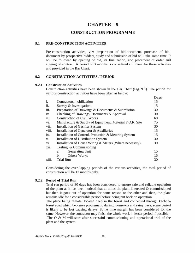
Construction activities have been shown in the Bar Chart (Fig. 9.1). The period for various construction activities have been taken as below: Days i. Contractors mobilization 15 ii. Survey & Investigation 15 iii. Preparation of Drawings & Documents & Submission 30 iv. Checking of Drawings, Documents & Approval 30 v. Construction of Civil Works 60 vi. Manufacture & Supply of Equipment, Material F.O.R. Site 75 vii. Installation of Gasifier System 30 viii. Installation of Generator & Auxiliaries 15 ix. Installation of Control, Protection & Metering System 15 x. Installation of Distribution System 30 xi. Installation of House Wiring & Meters (Where necessary) 30 xii. Testing & Commissioning
a. Generating Unit 15 b. Others Works 15
xiii. Trial Run 30
Considering the over lapping periods of the various activities, the total period of construction will be 12 months only.
9.2.2 Period of Trial Run Trial run period of 30 days has been considered to ensure safe and reliable operation of the plant as it has been noticed that at times the plant is erected & commissioned but then it goes out of operation for some reason or the other and then, the plant remains idle for a considerable period before being put back on operation. The place being remote, located deep in the forest and connected through kachcha forest road which becomes problematic during monsoons and rainy days, some period is likely to be lost causing delays. Some time margin has been considered for the same. However, the contractor may finish the whole work in lesser period if possible. The O & M will start after successful commissioning and operational trial of the plant and the system.
AHEC/ Model DPR/ Hilly 40 HH/BEP
29
9.3 BIOMASS SUPPLY FOR THE PLANT The Subabool plantation is going to take some time and additional period is required for the growth to the size enough for use. It is proposed that plantation be made immediately after the survey and investigation work is over. During the period of initial run of the plant, part supply may be taken from the Subabool plots and balance from the forest. Thereafter, the Subabool plots will have sufficient quantity of Subabool and no Biomass will be required to be taken from the forest.
9.4 CONTRACTUAL PERIOD OF O & M
The O & M is proposed to be carried out by the contractor for initial 5 years and thereafter the plant will be run by the villagers.


AHEC/ Model DPR/Hilly 40 HH/BEP
30
CHAPTER -10 ESTIMATE AND FINANCIAL ANALYSIS
10.1 COST OF THE PLANT AND SYSTEM
The cost of the civil works, plant and the system, is shown in Tables – 10.2, 10.3, 10.4, 10.5 & 10.6 the over all cost estimate in Table – 10.1.
TABLE 10.1 : COST ESTIMATE
Sl. No.
Items Cost (Rs. in Lacs)
1 2 3 I Works A Preliminary 0.250 B Land (as per Table 10.2) 0.00
C Civil Works (as per Table 10.3) 3.643
J Power Plant System (as per Table 10.4) 8.000
H Distribution System (as per Table 10.5) 5.600
K Buildings 0.000
M Plantation (Subabul Plantation for Biomass) 0.940
O Miscellaneous 0.000
Total I – Woks 18.433
I Establishment (2% of I works excluding Buildings) 0.369
II Suspense Nil
III Receipts and recoveries (-) Nil
IV Indirect Charges (1% of I – works for Audits Accounts) 0.184
Total Project Cost 18.986

AHEC/ Model DPR/Hilly 40 HH/BEP
31
TABLE – 10.2: COST OF LAND
Sl. No.
Item Unit Qty. Rate (Rs.
Lacs)
Amount (Rs. Lacs)
1 2 3 4 5 6 1. Land for Biomass
Power Plant Sq. m 300 0.001 0.00
To be provide by villagers 2. Land for Subabul
Plantation Ha 5.4 0.200 0.00
To be provide by van samiti and forest department
Total 0.00
TABLE – 10.3: COST OF CIVIL WORKS
Sl. No.
Item Unit Qty. Rate (Rs. Lacs)
Amount (Rs. Lacs)
1 2 3 4 5 6 1. 5.0 m x 3.0 m Biomass store shed with open
yard (5.0 m x 4.0 m) Sq. m 15 0.05 0.750
2. Gasifier Shed with foundation of gassifier unit 3.0 m x 2.5 m gasifier shed (as per drg.)
Sq. m 7.5 0.015 0.113
3. 3.0 m x 2.0 m power house building (As per drg.)
Sq. m 6 0.08 0.480
4. 3.50 m x 3.0 m control room (as per drg.) Sq. m 10.5 0.08 0.840 5. Toilet (1.5m X 3.0m) Sq. m 4.5 0.10 0.360 6. Water Supply System LS 0.500 7. Over head water storage (3000 l, PVC Tank) at
a height of 6 m on fabricated platform LS - - 0.200
8. Approach Road LS 0.200 9. Cooling Pond LS - - 0.100 10. Miscellaneous works 2.0 m x 1.50 m x 1.50 m LS 0.100
Total 3.643

AHEC/ Model DPR/Hilly 40 HH/BEP
32
TABLE – 10.4: COST OF THE PLANT
Sl. No.
Item Unit Qty. Rate (Rs. Lacs)
Amount (Rs. Lacs)
1 2 3 4 5 6 1. Woody biomass gassifier along with 100%
producer gas based engine along with generator to give net generator terminal output 10 kW along with basic Gassifier accessories & auxiliaries with a double valve assembly for online ash charcoal removal system, Gassifier & engine control panel along with Ampere, volt, frequency and kWh meter as well as load panel for load distribution, and complete gas piping along with valves from gassifier to gas engine.
Set 1 6.20 6.200
2. Wood drying arrangement (Based on Engine Exhaust)
Set 1 0.105 0.105
3. Cooling System Complete pump, piping etc. LS - - 0.250 4. Biomass Cutter No. 1 0.17 0.170 5. Moisture Meter No. 1 0.05 0.050 6. Earthing Kit Set 1 0.115 0.115 7. Chain Pulley Block Set 1 0.115 0.115 8. Miscellaneous LS - - 0.500 9. Installation, Commissioning Training of
staff including Service Tax LS - - 0.500
Total 8.000
TABLE – 10.5: COST OF DISTRIBUTION SYSTEM
Sl. No.
Item Unit Qty. Rate (Rs. Lacs)
Amount (Rs. Lacs)
1 2 3 4 5 6 1. L T Distribution Line, km 5 1.00 5.00 2. Service Connections Nos. 40 0.01 0.40 3. Street Lights Nos. 20 0.01 0.20 Total 5.60

AHEC/ Model DPR/Hilly 40 HH/BEP
33
TABLE – 10.6 : COST OF THE BIOMASS DEVELOPMENT PLAN
Sl. No.
Item Unit Qty. Rate (Rs. Lacs)
Amount (Rs. Lacs)
1 2 3 4 5 6 1. Plantation of saplings No. 5.4 Ha 0.10 0.540 2. Training Etc. LS - - 0.200 3. Miscellaneous including Subabul Nursery
etc. LS - - 0.200
Total 0.940 10.2 FUNDING FOR CONSTRUCTION OF PLANT Rs. Lacs
i. By Grant From MNES : 4.24 ii. Contribution by Villagers @ Rs. 1000/per HH : 0.400 iii. Contribution by Nodal Agency : 14.346
Total 18.986 10.3 FINANCIAL ANALYSIS
The financial analysis has been carried out as per Tables –10.7, 10.8, 10.9 & 10.10. The cost of generation and the results are given below:
10.3.1 Cost Of Generation
i. Without Subsidy Rs./kWh a. At 80% LF : 18.037 b. At 60% LF : 24.049
ii. With Subsidy Rs./kWh a. At 80% LF : 15.465
b. At 60% LF : 20.620

AHEC/ Model DPR/Hilly 40 HH/BEP
34
TABLE 10.7 : COST OF GENERATION WITHOUT SUBSIDY
Sl. No. Items Rs. In Lacs
1 2 3 1 Project Cost 18.986 2 Annual Interest during Construction 0.627
3 Total Project Cost 19.613
4 Annual working expenses (as per table 10.9) 1.333 5 Interest @ 12 % on total project cost 2.354 6 Total annual expenses 3.687 7 Annual generation at power house (Million Units) i. At 80% Load Factor 0.0204 ii. At 60% Load Factor 0.0153 8 Cost of generation per kWh (in Rs) i. At 80 % Load Factor Rs. 18.037 ii. At 60% Load Factor Rs. 24.049
TABLE 10.8 : COST OF GENERATION WITH SUBSIDY
Sl. No. Items Rs. in Lacs 1 2 3 1 Project Cost 18.986 2 Capital Subsidy As per MNES 4.240 3 Balance Project Cost 14.746 4 Annual Interest during Construction 0.487
5 Total Project Cost 15.233
6 Interest @ 12 % on total project cost 1.828 7 Annual working expenses ( as per table 10.9) 1.333 8 Total annual expenses 3.161 9 Annual generation at power house (Million Units) i. At 80% Load Factor 0.0204 ii. At 60% Load Factor 0.0153 10 Cost of generation per kWh (in Rs.) i. At 80 % Load Factor 15.465 ii. At 60% Load Factor 20.620

AHEC/ Model DPR/Hilly 40 HH/BEP
35
TABLE 10.9 : STATEMENT OF YEARLY WORKING EXPENSES Sl. No.
Items Cost (Rs. In Lacs)
1 2 3 1 Operation cost @ 1% of works cost 0.190
2 Maintenance cost of C-works @ 1% 0.036
3 Maintenance of E&M works @ 2% 0.272
4 Annual depreciation charges (as per Table – 10.10) 0.835
Total 1.333
TABLE 10.10: ANNUAL DEPRECIATION OF ASSETS
Sl. No.
Items Life in years
Cost (Rs. Lacs) Rate of Depreciation in %
Depreciation Rs. Lacs
1 2 3 4 5 6 1 Land Infinity 0.00 NIL NIL 2 Civil Works 35 3.64 3.40 0.124 3 Plant & System 35 8.00 3.40 0.272 4 LT Distribution
System 25 5.60 7.84 0.439
Total 0.835
TABLE 10.11 CALCULATION OF SUBSIDY FROM MNES
Sl. No.
Items Cost (Rs. In Lacs)
1 For Biomass Gasifier System 2.700 2 For internal wiring house hold @ Rs. 1500/HH for 40 HH 0.600 3. From regular supply of biomass 0.940 Total 4.240

AHEC/ Model DPR/ Hilly 40 HH/BEP
36
CHAPTER -11 OPERATION AND MAINTENANCE OF PLANT & SYSTEM
11.1 GENERAL
After the plant and system is tested commissioned and the trial period is over, the operation and maintenance for 5 years period will be the responsibility of the contractor who has supplied, erected tested and commissioned the plant and the system. The contractor may net use100% of his own staff and may require certain number of additional persons for managing O&M under the guidance of his limited staff. The Village Energy Committee (VEC) may arrange for the above mentioned additional persons from amongst the people of the village, depending on the age, physical & mental health, willingness and the educational qualifications. An executive committee (EC) may be formed by the VEC for regular supervision and monitoring of O&M of the plant and the system with the help the staff to be appointed by the VEC.
11.2 SUPERVISION AND MONITORING OF O&M
i. Executive Committee The VEC will make an Executive Committee of 5 persons which will supervise and monitor: a. Day to day functioning of the plant & system. b. Day to collection of revenue & Expenditure.
ii. Staff Following Staff is proposed to be appointed by the VEC from amongst the villagers: a. Manager : 1 No. b. Operational Staff : 6 Nos.
iii. Record Keeping Following record is suggested to be kept and maintained by the EC.
a. Daily wood stock receipt indicating: Sl. No., Date Name of Villager and Quantity (kg)/Rate/Value.
b. Stock Register recording : Sl. No., Date, Quantity Received. c. Issue Register: Recording Sl. No., Date, Quantity issued and signatures of
the receiver. d. Ledger showing daily receipt and issue of wood. e. Cash receipt register. f. Cash book. g. Ledger. h. Bank Pass Book & Cheque Book.
i. General Stock & Issue Register. j. Register for Consumables.

AHEC/ Model DPR/ Hilly 40 HH/BEP
37
iv. Supervision & Maintenance of Record a. The manager will keep maintain the record, write cash book & maintain
the account. b. VEC executive will check the accounts monthly. c. General Meeting of VEC will be held every quarter in which manager will
place before it the records, accounts and status of the plant. d. An annual audit of accounts assets and liabilities will be got carried out by
a competent chartered Account appointed for the purpose by the Nodal Agency.
e. Appropriate action will be taken by the Nodal Agency after careful examination .

AHEC/ Model DPR/ Hilly 40 HH/BEP 38
CHAPTER – 12
ENVIRONMENTAL IMPACT AND BENEFITS 12.1 ENVIRONMENTAL IMPACT
i. There are no harmful effluents from gasifier. Water is re-circulated in closed loop from cooling pond to gasifier scrubber. One has to replenish water pond to compensate evaporation losses and that depends upon number of units generated in a day, Usually, ½ liter of water per unit of electricity generated is to be added as make up water.
ii. Any mud free water can be used for gasifi9er cooling pond and hence, it does not require any special water treatment but occasionally pH of water is to be maintained.
iii. The other discharges from gasifier are charcoal and ash. Both are of biological nature and biodegradable. 10% dry charcoal can be used again in gasifier while rest can be used as cooking fuel or as an activated carbon in air dryer or as earthing material in electrical towers/connections. As may be used as filling materials in large pits or briquettes of ash can be made and sold as fuel cake.
iv. Gas from gasifier is fed directly into engine without any atmospheric discharge while flare is given to occasionally check the quality of gas generated in gasifier and during the stoppage of the system.
v. The major gaseous emission from the power pack is from engine exhaust only. Exhaust from gas e4ngine using producer gas is cleaner than conventional fuel due to absence of sulphur in biomass.
vi. Gasifier being a renewable source of energy equipment is considered greener technology free from any major environmentally adverse effects.
vii. Gasifier does not have any noise making components except motors. viii. The requirement of cooling and cleaning water being very small (since the same
water will be circulated), the impact on environment will be negligible. ix. The CO2 released will be absorbed by the growing plants during photosynthesis
keeping the CO2 level low and therefore, the plant will hardly cause any air pollution.
x. The ash produced by the gasifier is not due to its woody origin and will not cause appreciable environmental pollution and the ash can be safely disposed off.
xi. The land required for the plant machinery is low and there will hardly be any adverse impact.
xii. The land required for plantation will be made available from the area where natural biomass is already growing but in low density. Therefore it will not cause any harmful impact. Instead, the plantation grown will be good for further improvement
xiii. The noise generated by the plant will be less than 65 db near the entrance of the plant thus causing negligible impact on the enviroment.

AHEC/ Model DPR/ Hilly 40 HH/BEP 39
12.2 BENEFITS
i. There will be saving of 2 to 3 litres of Kerosene per HH per month i.e. 1 kilolitre per annum.
ii. The villager use wood also for lighting as the equipment of kerosene received by them is not enough for lighting of about half an hour one an hour or so. There will be saving of this wood also.
iii. There will be awareness amongst the villagers about use and misuse of forest which will ultimately result in saving of forest from unintentional destriction (at present the village cause fire to clear the way in the forest for getting wood and do no care to ensure that the fire is not left as such to cause unintentional damage of forest.
iv. The plant will help increase employment generation directly and indirectly. v. The children will be able to study better due to availability of light for good
number of hours in the late evenings. vi. Availability of power will help micro-enterpreneurs in achieving better economy.
LIST OF PERSONNEL INVOLVED
AHEC, IIT, RORKEE 1. Shri Arun Kumar, Head, AHEC. 2. Shri M. K. Singhal, SSO, AHEC. 3. Shri Vijay Saini, SRF, AHEC.
CONSULTANT Shri Y. S. Jadaun, Former Chief Engineer (UPSEB). ASSISTANTS
1. Shri R. K. Singhal, Technical Assistant. 2. Shri Chandra Pal Singh, Senior Attendant.


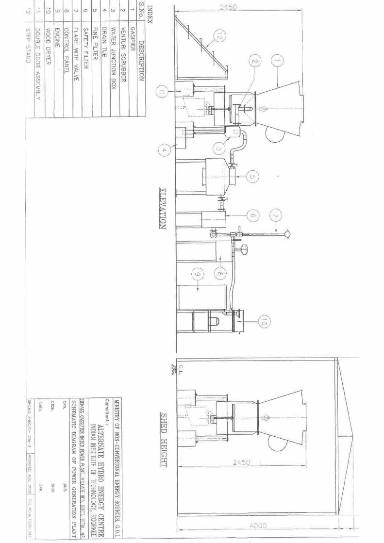


![FLEX FUEL GASIFIER SIMULATION MODEL [FFGSM]mypages.iit.edu/~abbasian/documents/ffgsm_user_manual.pdf · 6) Gasifier Tab: This tab opens the Gasifier Panel where the gasifier input](https://img.pdfslide.us/doc/110x75/5eb664fad746ec31aa42c957/flex-fuel-gasifier-simulation-model-ffgsm-abbasiandocumentsffgsmusermanualpdf.jpg)