Embed Size (px)
Citation preview
PENN Center for Sensor Technologies1Fort Collins – 7/27/05
Biologically Inspired CMOS Vision Sensors
Jan Van der [email protected]
University of PennsylvaniaDepartment of Electrical and Systems Engineering
Philadelphia, PA 19104
SSCS Fort Collins Chapter, Colorado (Denver Section)July 27, 2005
PENN Center for Sensor Technologies2Fort Collins – 7/27/05
Overview
• Why biologically inspired sensors?• Biological visual system
� Computational strategies, Neural circuits
• Neuromorphic Vision Sensors:� Sensor for the detection of image features
(spatial) � Tracking sensor (spatio-temporal)
• Conclusions
PENN Center for Sensor Technologies3Fort Collins – 7/27/05
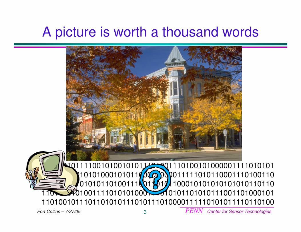
A picture is worth a thousand words
01001010111100101001010111010011101001010000011110101010111010101010100010101100001000011111010110001110100110111010101010101101001110011010110001010101010101011011011010101010011110101010001110101011010101110011010001011101001011101101010111010111010000111110101011110110100
PENN Center for Sensor Technologies4Fort Collins – 7/27/05
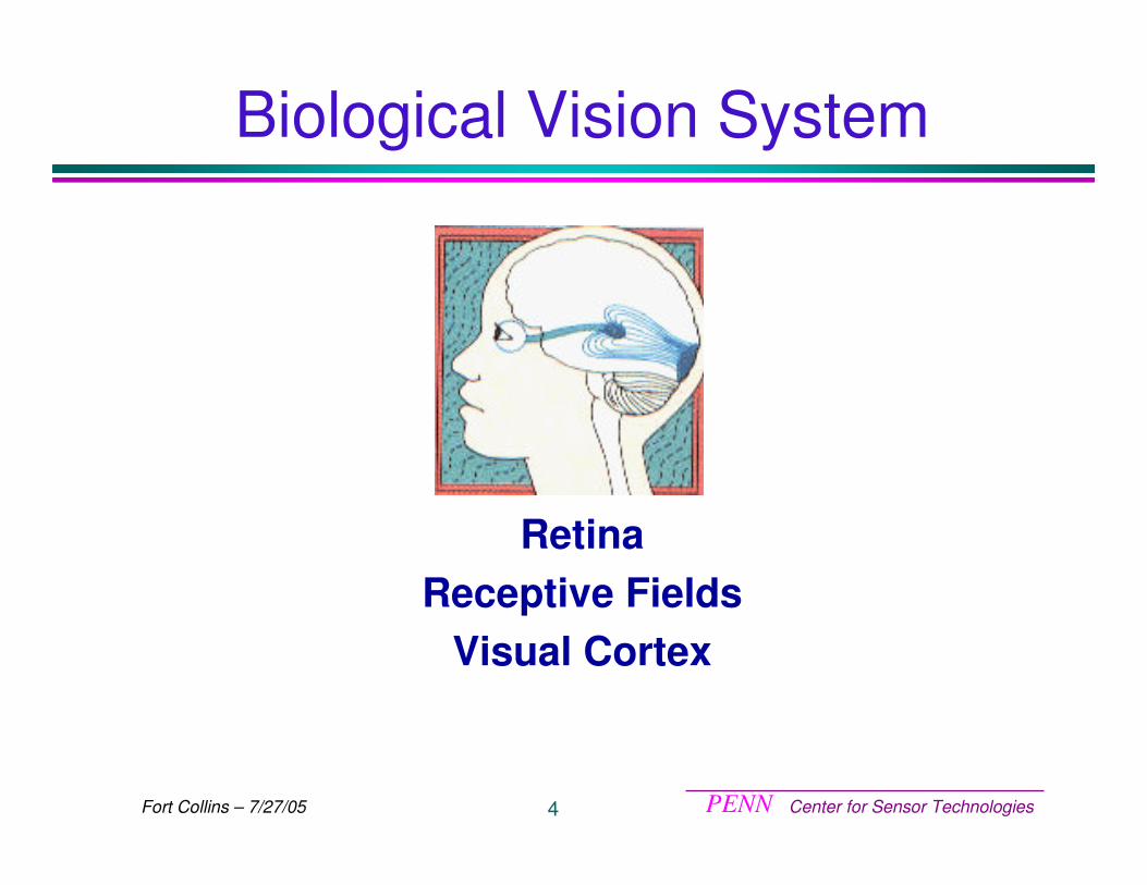
Biological Vision System
RetinaReceptive Fields
Visual Cortex
PENN Center for Sensor Technologies5Fort Collins – 7/27/05
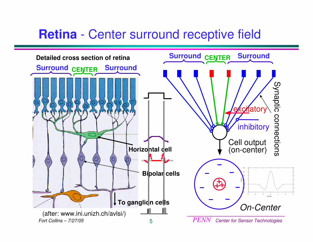
Retina - Center surround receptive field
Cell output (on-center)
Synaptic connections
excitatory
inhibitory
CENTER SurroundSurround
On-Center
-2.0
-1.0
0.0
1.0
2.0
3.0
4.0
-3 -2 -1 0 1 2 3
Out
put
Position
(after: www.ini.unizh.ch/avlsi/)
Horizontal cell
Bipolar cells
To ganglion cells
CENTER SurroundSurroundDetailed cross section of retina
PENN Center for Sensor Technologies6Fort Collins – 7/27/05
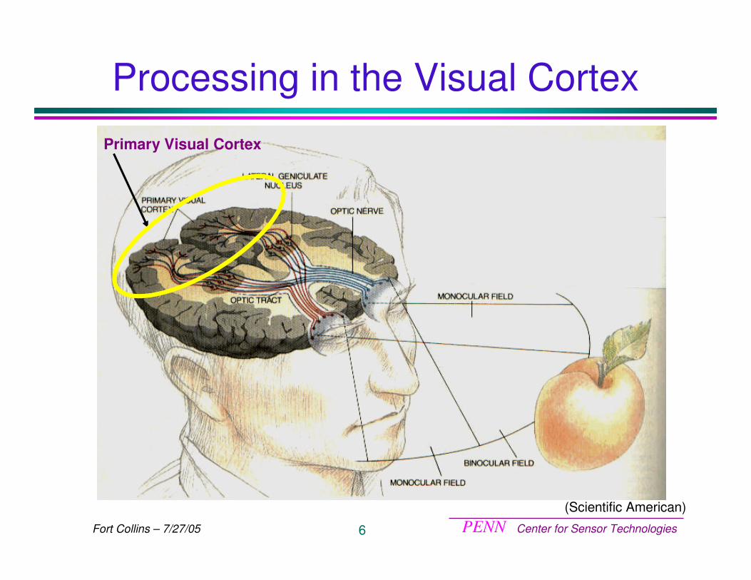
Processing in the Visual Cortex
Primary Visual Cortex
(Scientific American)
PENN Center for Sensor Technologies7Fort Collins – 7/27/05
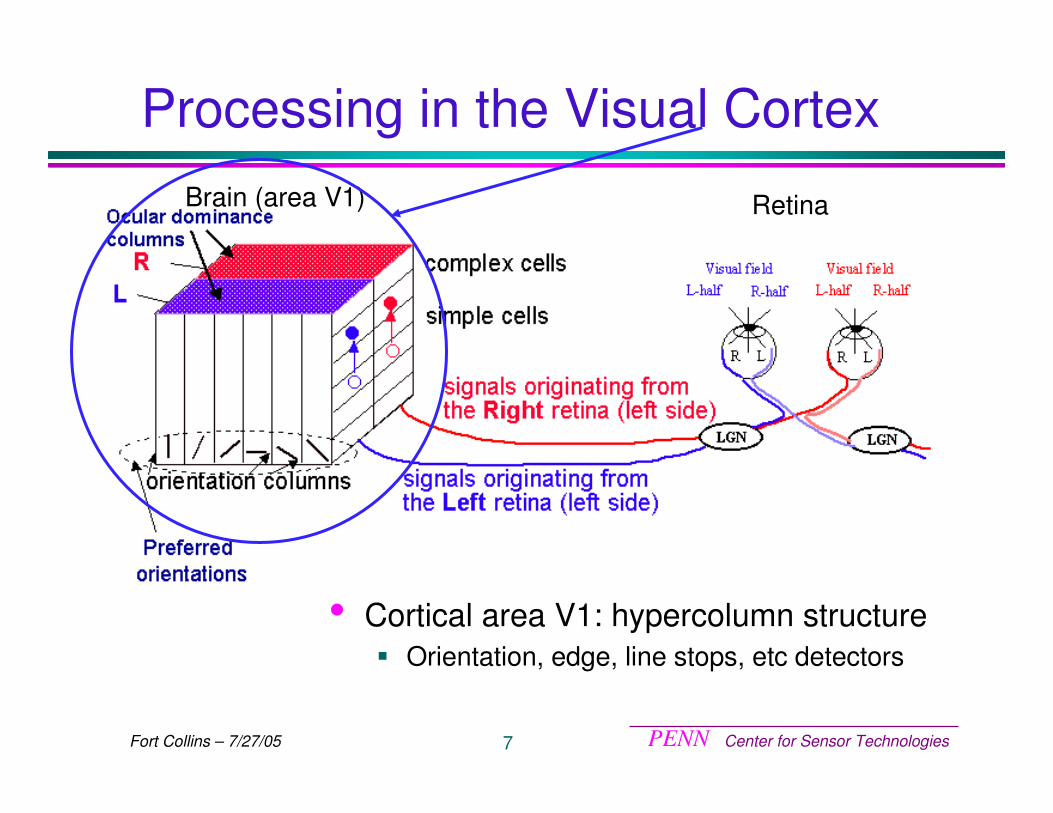
Brain (area V1) Retina
Processing in the Visual Cortex
• Cortical area V1: hypercolumn structure� Orientation, edge, line stops, etc detectors
PENN Center for Sensor Technologies8Fort Collins – 7/27/05
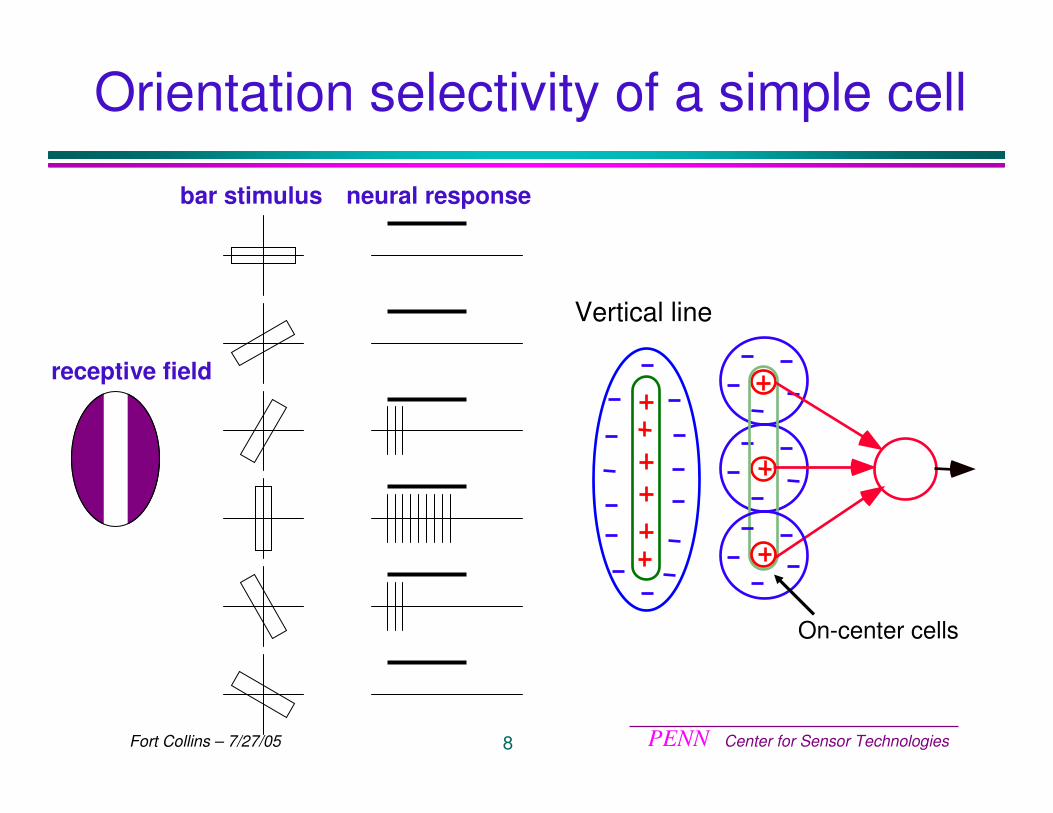
Orientation selectivity of a simple cell
receptive field
bar stimulus neural response
Vertical line
On-center cells
PENN Center for Sensor Technologies9Fort Collins – 7/27/05
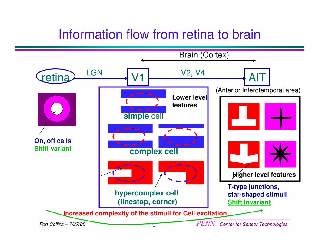
Information flow from retina to brain
On, off cellsShift variant
retina AITV2, V4V1LGN
Brain (Cortex)
(Anterior Inferotemporal area)
simple cell
complex cell
hypercomplex cell (linestop, corner)
Lower levelfeatures
T-type junctions, star-shaped stimuliShift Invariant
Increased complexity of the stimuli for Cell excitation
Higher level features
PENN Center for Sensor Technologies10Fort Collins – 7/27/05
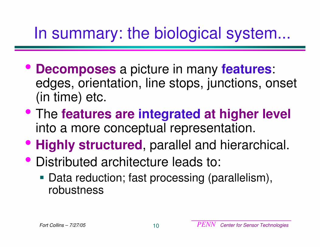
In summary: the biological system...
• Decomposes a picture in many features: edges, orientation, line stops, junctions, onset (in time) etc.
• The features are integrated at higher levelinto a more conceptual representation.
• Highly structured, parallel and hierarchical. • Distributed architecture leads to:
� Data reduction; fast processing (parallelism), robustness
PENN Center for Sensor Technologies11Fort Collins – 7/27/05
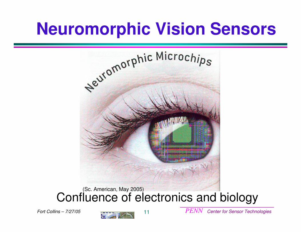
Neuromorphic Vision Sensors
Confluence of electronics and biology(Sc. American, May 2005)
PENN Center for Sensor Technologies12Fort Collins – 7/27/05
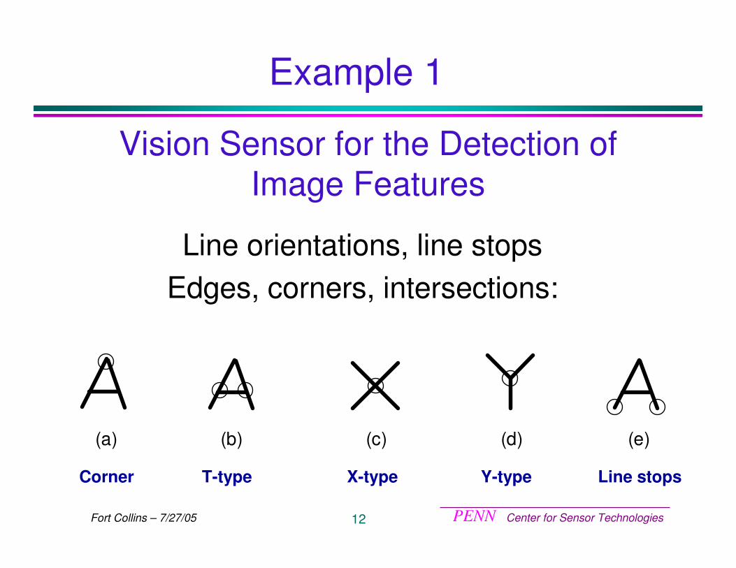
Vision Sensor for the Detection of Image Features
Line orientations, line stopsEdges, corners, intersections:
(a) (b) (c) (d) (e)
Corner T-type X-type Y-type Line stops
Example 1
PENN Center for Sensor Technologies13Fort Collins – 7/27/05
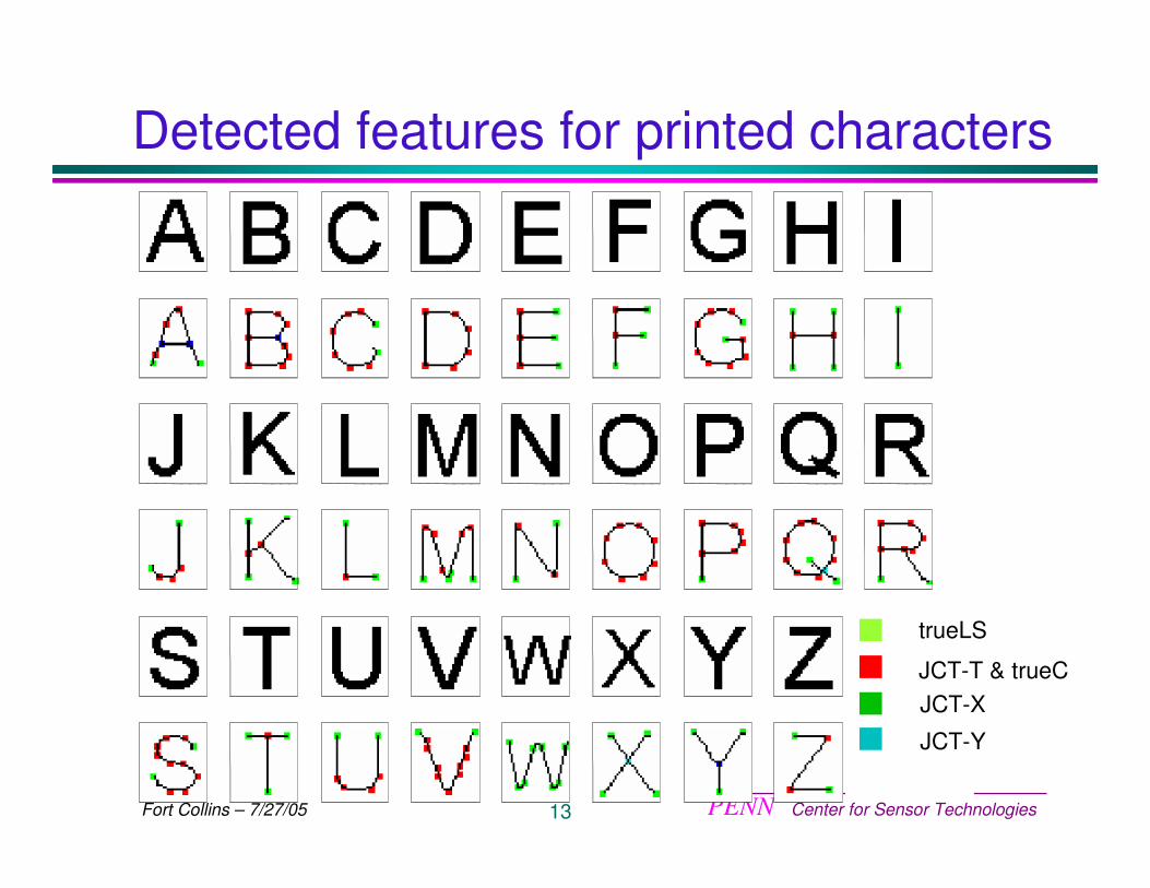
Detected features for printed characters
trueLS
JCT-T & trueCJCT-X
JCT-Y
PENN Center for Sensor Technologies14Fort Collins – 7/27/05
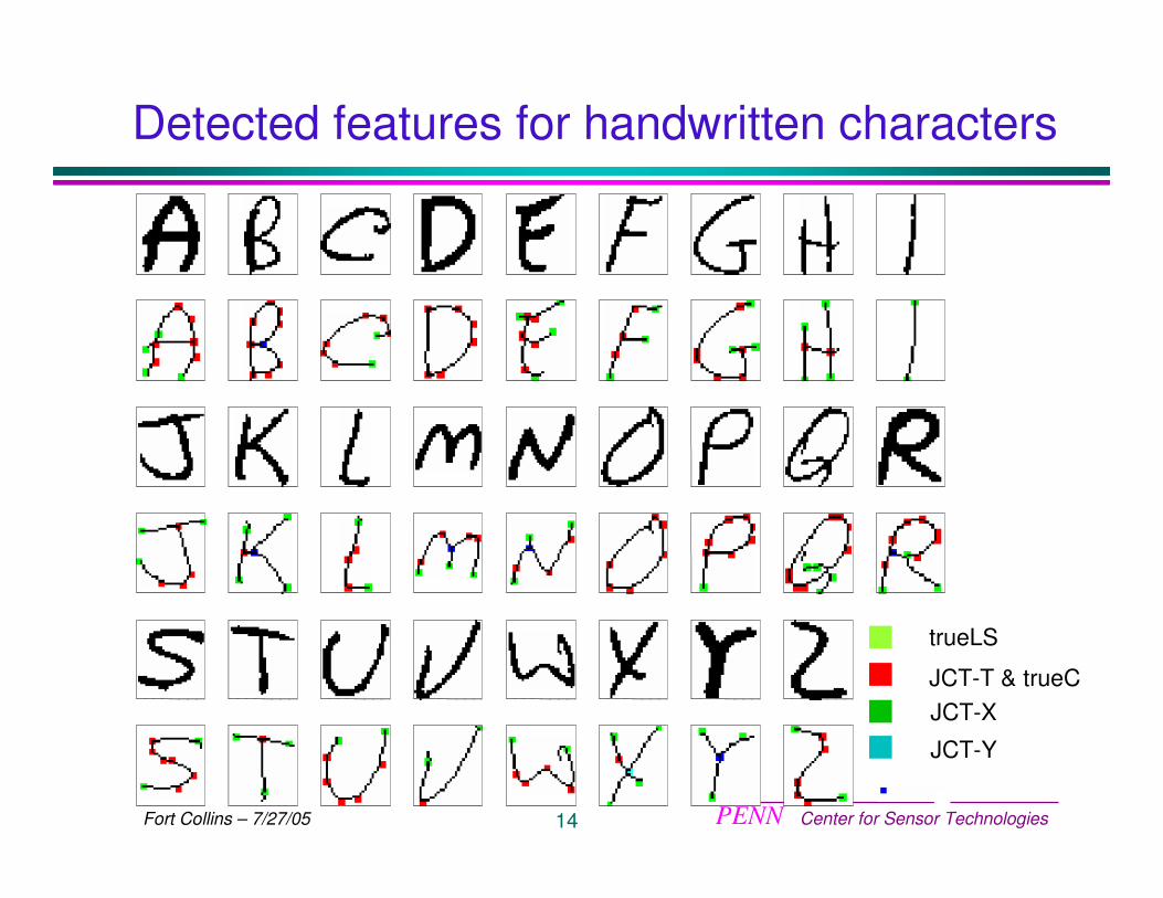
Detected features for handwritten characters
trueLS
JCT-T & trueCJCT-X
JCT-Y
PENN Center for Sensor Technologies15Fort Collins – 7/27/05
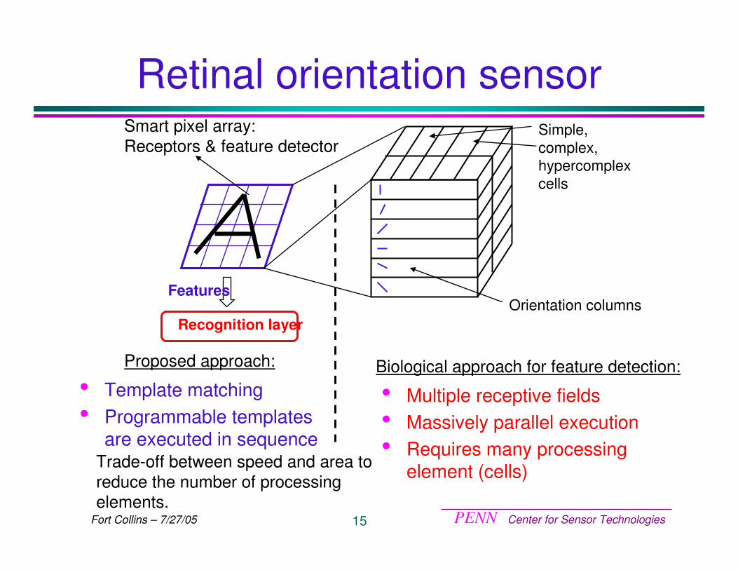
Retinal orientation sensorSmart pixel array:Receptors & feature detector
Orientation columns
Simple, complex, hypercomplexcells
Recognition layer
Features
• Template matching • Programmable templates
are executed in sequence
Proposed approach:
• Multiple receptive fields • Massively parallel execution• Requires many processing
element (cells)
Biological approach for feature detection:
Trade-off between speed and area to reduce the number of processing elements.
PENN Center for Sensor Technologies16Fort Collins – 7/27/05
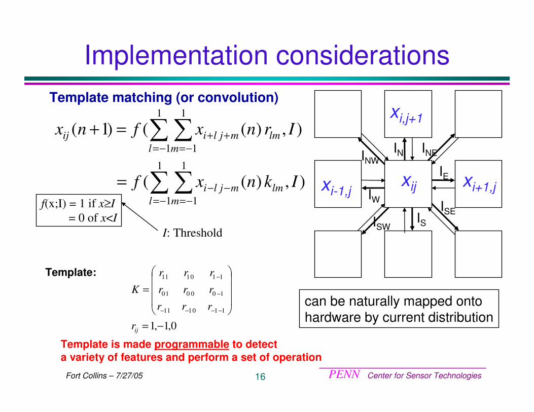
Implementation considerations
),)((
),)(()1(
1
1
1
1
1
1
1
1
Iknxf
Irnxfnx
l mlmmjli
l mlmmjliij
��
��
−= −=−−
−= −=++
=
=+
0,1,1110111
100010
110111
−=
���
�
�
���
�
�
=
−−−−
−
−
ijr
rrr
rrr
rrr
K
Template matching (or convolution)
Template is made programmable to detecta variety of features and perform a set of operation
f(x;I) = 1 if x≥I= 0 of x<I
I: Threshold
Template:
can be naturally mapped onto hardware by current distribution
IN INE
IE
ISEISISW
IW
INW
xij xi+1,jxi-1,j
xi,j+1
PENN Center for Sensor Technologies17Fort Collins – 7/27/05
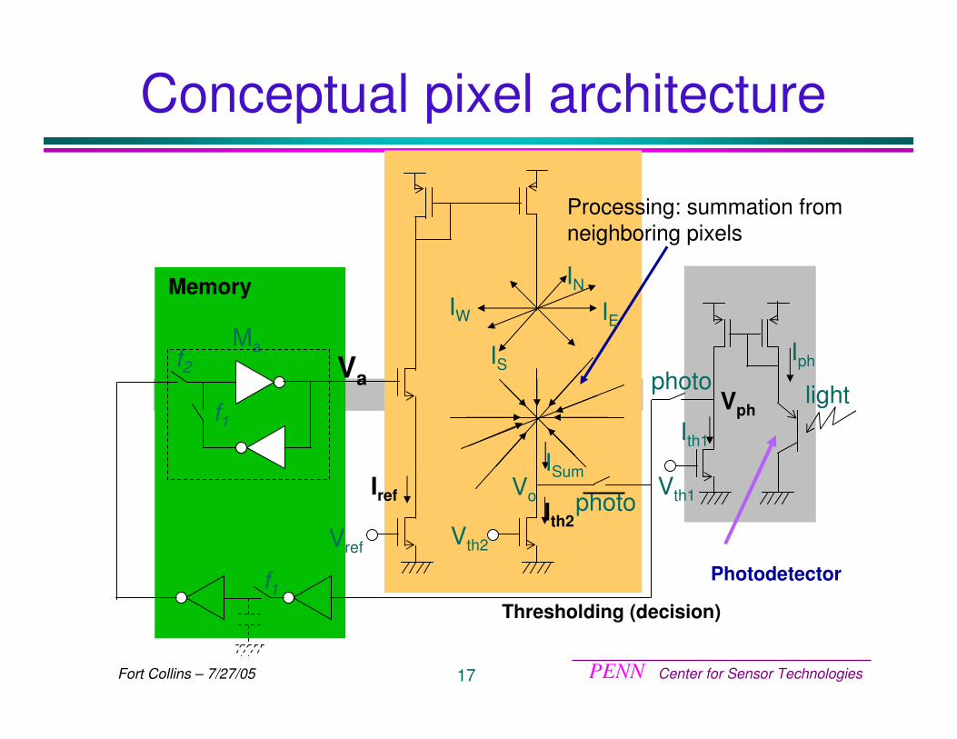
Photodetector
Conceptual pixel architecture
Processing: summation fromneighboring pixels
Thresholding (decision)
Memory
Iphf2
f1
Va
Ma IS
IEIW
ISum
Ith2
IN
f1
Vth2
VoIref
lightIth1
photo
photoVph
Vth1
Vref
PENN Center for Sensor Technologies18Fort Collins – 7/27/05
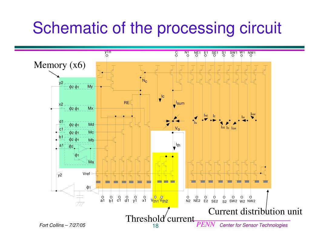
Schematic of the processing circuit
Vref
Ith
IW
IS
IE
IN
a1 b1 c1 d1
φ1
φ2
y2
Md
Mc
Mb
Ma
My
N1
N2
NE1 E1 SE1 S1 SW1 W1
W2
NW1
INE
ISE ISW
INW
NE2 SW2 NW2
x2Mx
a1
b1
c1
d1
y2
C
φ2
φ2
φ2
φ1
φ1
φ1
RE
φ2 φ1
φ2 φ1
x1
φ1
y1
Nc
IcIsum
Vo
Vth1 Vth2 E2 SE2 S2
y1n
Memory (x6)
Current distribution unitThreshold current

PENN Center for Sensor Technologies19Fort Collins – 7/27/05
Design procedure based on transistor mismatch analysis
Current variation is function of:• design parameters (W,L,Iref)•mirroring operation•summation and subtraction operations
specification 1: error rate (yield)
specification 2: speed (power)
required current accuracy
1
determination of design parameters (W,L, Iref)
2a
2b
PENN Center for Sensor Technologies20Fort Collins – 7/27/05
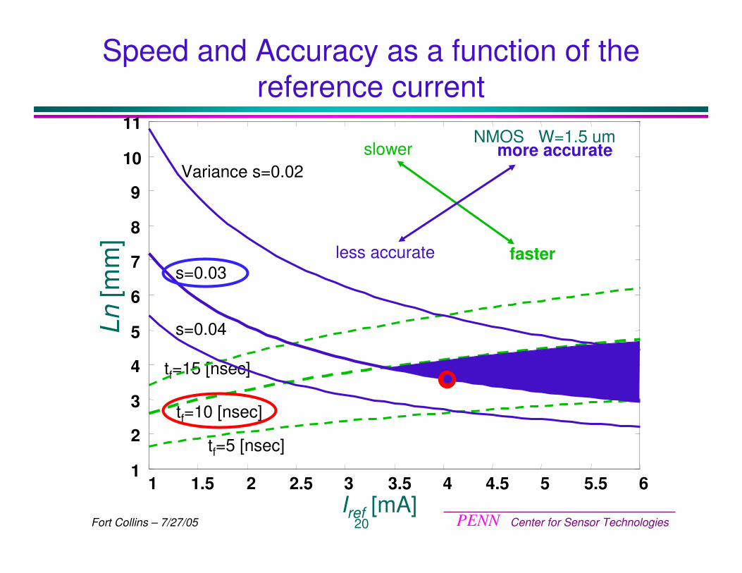
tf=10 [nsec]
tf=5 [nsec]
tf=15 [nsec]
faster
slower
s=0.03
s=0.04
Variance s=0.02more accurate
less accurate
Speed and Accuracy as a function of the reference current
Iref [mA]
Ln[m
m]
1 1.5 2 2.5 3 3.5 4 4.5 5 5.5 61
2
3
4
5
6
7
8
9
10
11NMOS W=1.5 um
PENN Center for Sensor Technologies21Fort Collins – 7/27/05
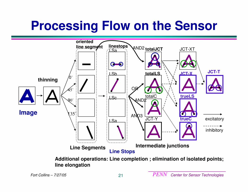
Processing Flow on the Sensor
thinning
oriented line segment
�0
�54
�09
�351
Line Segments
linestopsLSa
LSb
LSa
LSc
Line Stops
Image
Additional operations: Line completion ; elimination of isolated points; line elongation
OR
totalLS
totalCAND2
AND3JCT-Y
Intermediate junctions
AND2 totalJCT
JCT-X
trueLS
trueC
JCT-T
excitatory
inhibitory
JCT-XT
PENN Center for Sensor Technologies22Fort Collins – 7/27/05
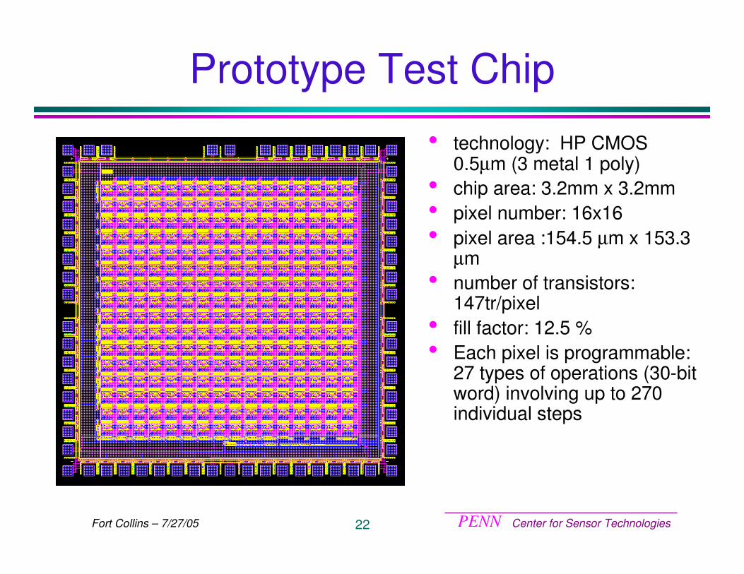
Prototype Test Chip
• technology: HP CMOS 0.5µm (3 metal 1 poly)
• chip area: 3.2mm x 3.2mm• pixel number: 16x16• pixel area :154.5 µm x 153.3
µm• number of transistors:
147tr/pixel• fill factor: 12.5 %• Each pixel is programmable:
27 types of operations (30-bit word) involving up to 270 individual steps
PENN Center for Sensor Technologies23Fort Collins – 7/27/05
Results
PENN Center for Sensor Technologies24Fort Collins – 7/27/05
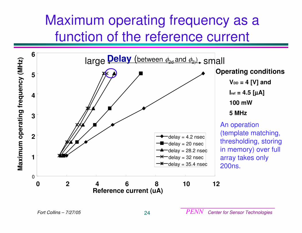
Maximum operating frequency as a function of the reference current
0
1
2
3
4
5
6
0 2 4 6 8 10 12Reference current (uA)
Max
imum
ope
ratin
g fr
eque
ncy
(MH
z)
delay = 4.2 nsecdelay = 20 nsecdelay = 28.2 nsecdelay = 32 nsecdelay = 35.4 nsec
Delay (between φ2d and φ2))large smallOperating conditions
VDD = 4 [V] and
Iref = 4.5 [µµµµA]
100 mW
5 MHz
An operation (template matching, thresholding, storing in memory) over full array takes only 200ns.
PENN Center for Sensor Technologies25Fort Collins – 7/27/05
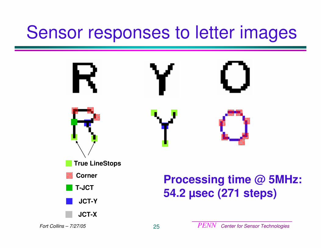
Sensor responses to letter images
True LineStops
Corner
JCT-Y
T-JCT
JCT-X
Processing time @ 5MHz: 54.2 µsec (271 steps)
PENN Center for Sensor Technologies26Fort Collins – 7/27/05
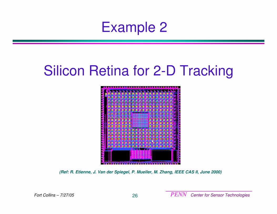
Silicon Retina for 2-D Tracking
(Ref: R. Etienne, J. Van der Spiegel, P. Mueller, M. Zhang, IEEE CAS II, June 2000)
Example 2
PENN Center for Sensor Technologies27Fort Collins – 7/27/05
Proposed approach
• Loosely modeled after the primate oculomotor system:
– Retinal photoreceptor organization– Retinal photosensing and early processing– Visual cortex for smooth pursuit
• Superior colliculus for saccadic generation• Capture the functions found in biology and
use the most efficient way to implement it using hardware (vs. wet ware)
PENN Center for Sensor Technologies28Fort Collins – 7/27/05
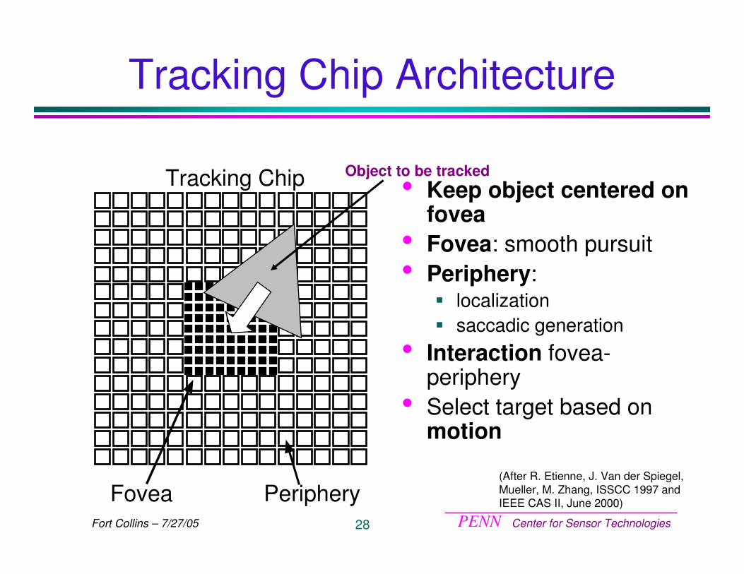
Tracking Chip Architecture
• Keep object centered on fovea
• Fovea: smooth pursuit• Periphery:
� localization� saccadic generation
• Interaction fovea-periphery
• Select target based on motion
(After R. Etienne, J. Van der Spiegel, Mueller, M. Zhang, ISSCC 1997 and IEEE CAS II, June 2000)Fovea Periphery
Tracking Chip Object to be tracked
PENN Center for Sensor Technologies29Fort Collins – 7/27/05
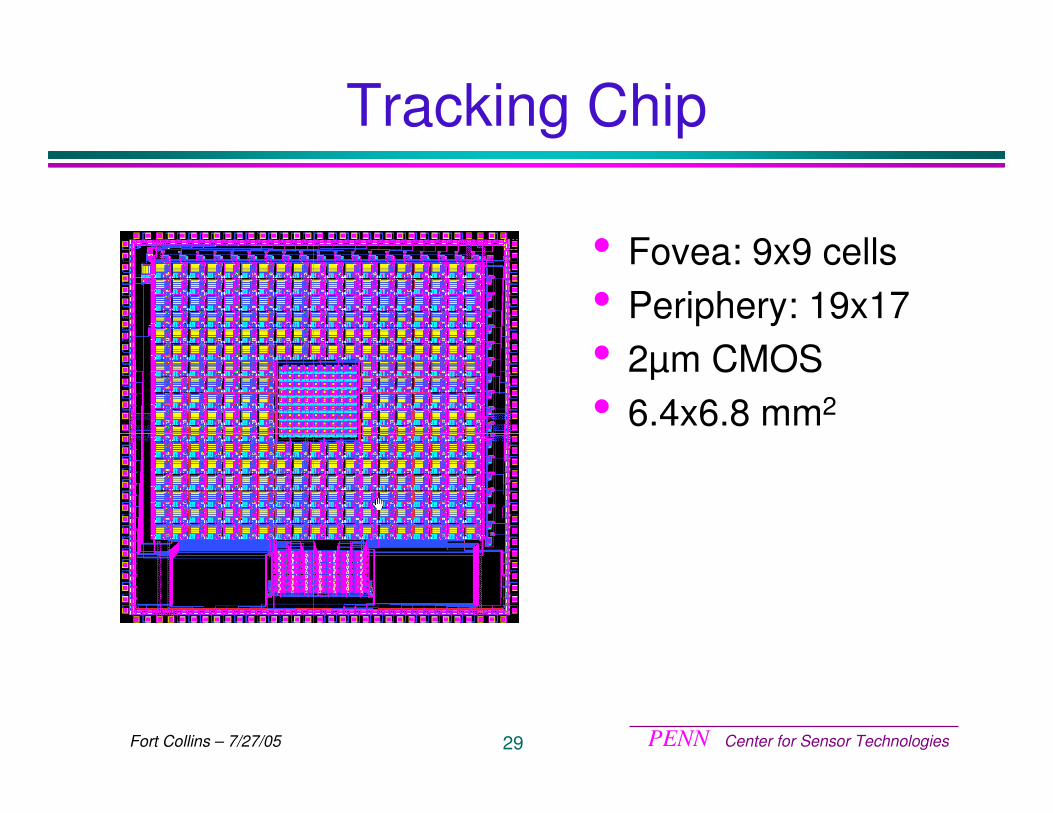
Tracking Chip
• Fovea: 9x9 cells• Periphery: 19x17• 2µm CMOS• 6.4x6.8 mm2
PENN Center for Sensor Technologies30Fort Collins – 7/27/05
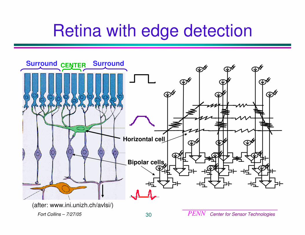
Retina with edge detection
CENTER SurroundSurround
(after: www.ini.unizh.ch/avlsi/)
Horizontal cell
Bipolar cells
PENN Center for Sensor Technologies31Fort Collins – 7/27/05
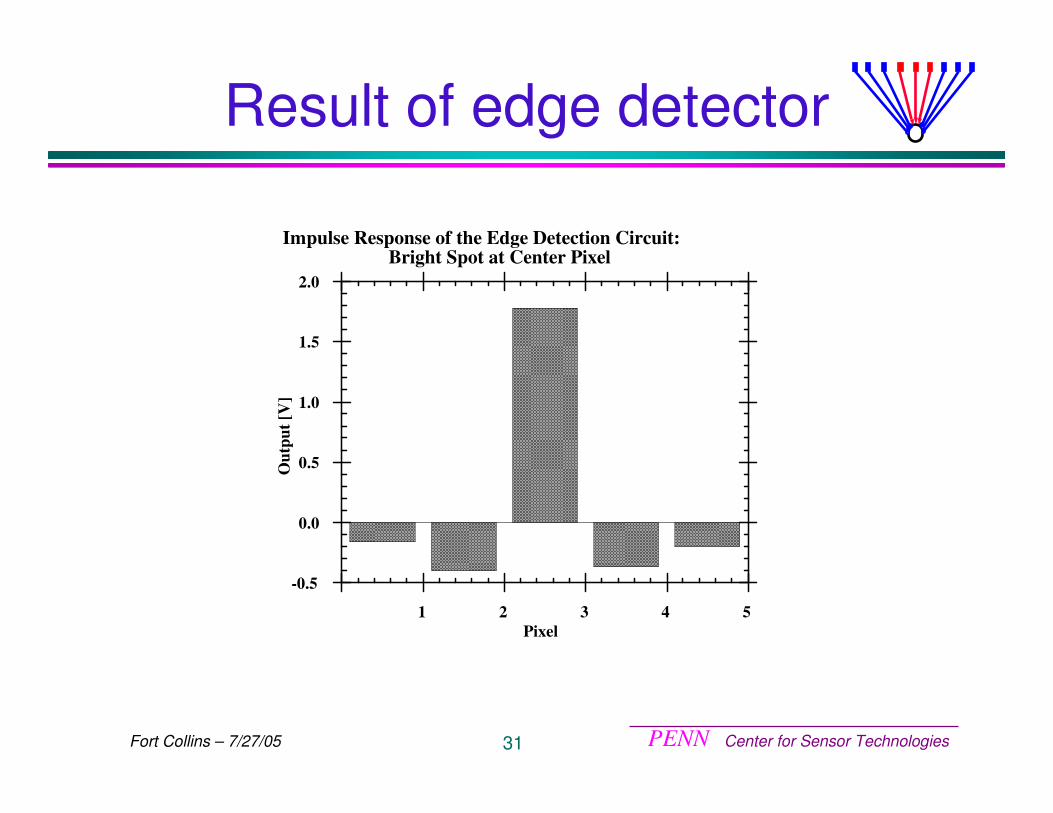
Result of edge detector
-0.5
0.0
0.5
1.0
1.5
2.0
1 2 3 4 5
Impulse Response of the Edge Detection Circuit:Bright Spot at Center Pixel
Out
put [
V]
Pixel
PENN Center for Sensor Technologies32Fort Collins – 7/27/05
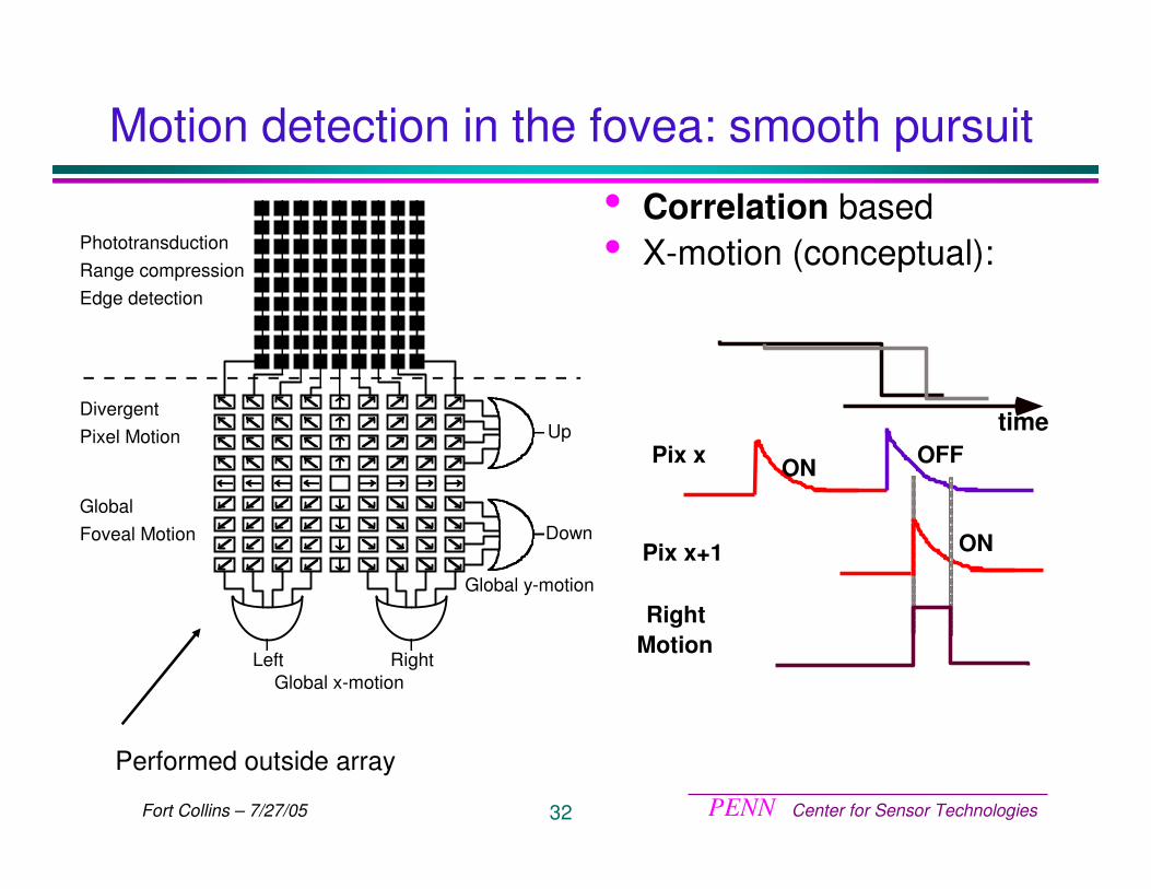
Motion detection in the fovea: smooth pursuit
Left Right
Down
Up
Global x-motion
Global y-motion
PhototransductionRange compressionEdge detection
DivergentPixel Motion
GlobalFoveal Motion
Performed outside array
• Correlation based• X-motion (conceptual):
timePix x
Pix x+1
ON OFF
ON
Right Motion
PENN Center for Sensor Technologies33Fort Collins – 7/27/05
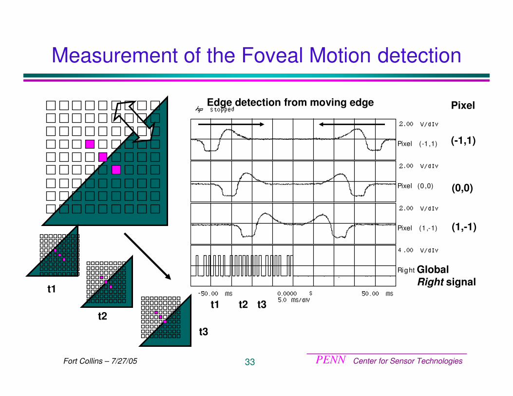
Measurement of the Foveal Motion detection
Pixel (-1,1)
Pixel (0 ,0)
Pixel (1 ,-1)
Right
4
GlobalRight signal
(-1,1)
(0,0)
(1,-1)
PixelEdge detection from moving edge
t1 t2 t3t1
t2t3
PENN Center for Sensor Technologies34Fort Collins – 7/27/05
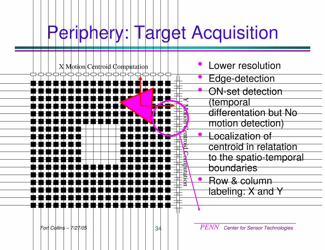
Periphery: Target Acquisition
• Lower resolution• Edge-detection• ON-set detection
(temporal differentation but No motion detection)
• Localization of centroid in relatationto the spatio-temporal boundaries
• Row & column labeling: X and Y
X Motion Centroid Computation
Y M
otion Centroid C
omputation
PENN Center for Sensor Technologies35Fort Collins – 7/27/05
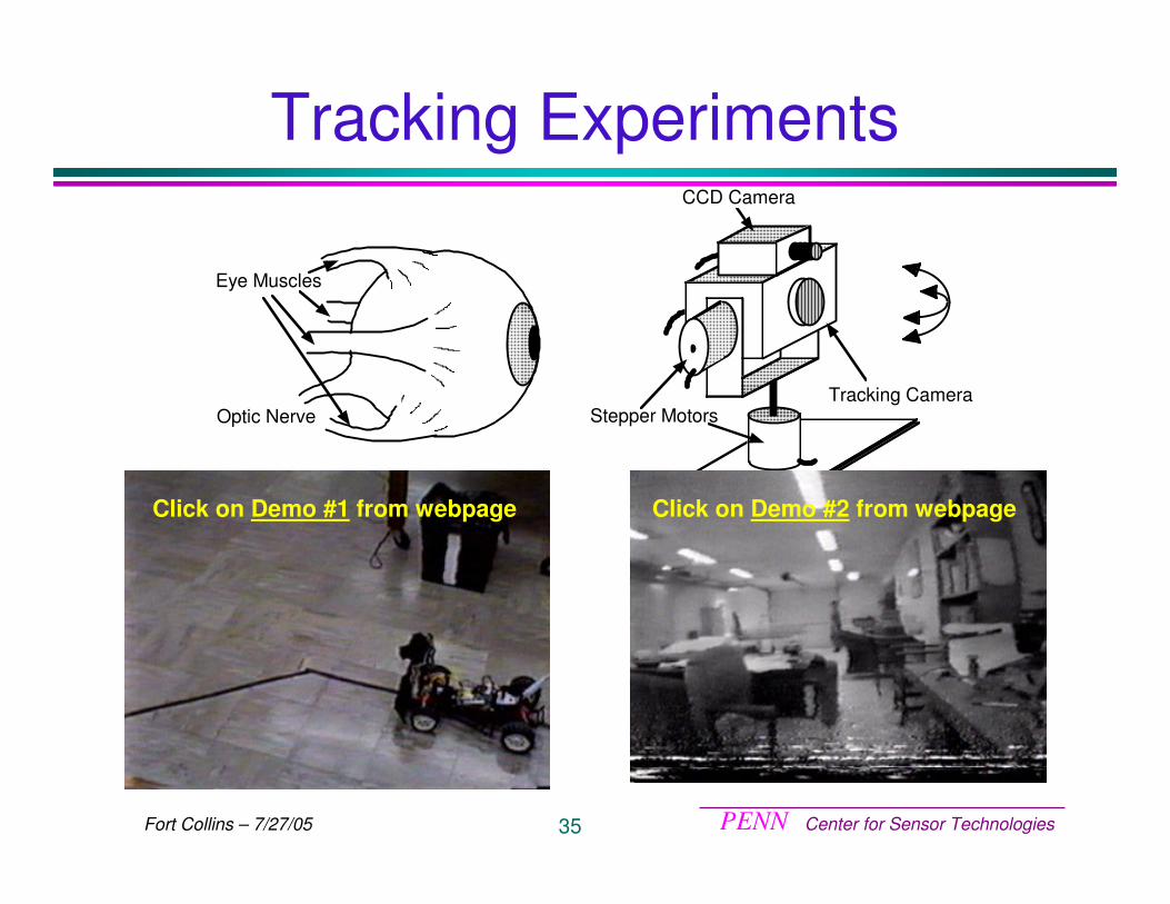
Tracking Experiments
Stepper Motors
CCD Camera
Tracking Camera
Eye Muscles
Optic Nerve
Click on Demo #1 from webpage Click on Demo #2 from webpage
PENN Center for Sensor Technologies36Fort Collins – 7/27/05
Conclusions
PENN Center for Sensor Technologies37Fort Collins – 7/27/05
Summary• Biological systems provide a viable paradigm
for building vision sensors:� Compact, low power, robust under different conditions� Massively parallel pixel-level processing
• Two Vision sensors:� Higher level features (X-, Y, and T-type) : Incorporates
processing functions found in area V1� Target tracking: space variant (foveal and periphery) for
smooth pursuit and saccadic motion generation� Implements the functions and algorithms of biology.� Optimized for information extraction, not image
rendering� Limitations: limited resolution, large pixel size and small
fill factor.
PENN Center for Sensor Technologies38Fort Collins – 7/27/05
Thank you


![digital pll dallas - IEEEewh.ieee.org/r5/dallas/sscs/slides/digital_pll_dallas_perrott.pdf · 32 div(t) Reg D Q Delay Reg D Q Reg D Q Delay Delay ref(t) Delay2 Delay2 Delay2 e[k]](https://img.pdfslide.us/doc/110x75/5c05097a09d3f2183a8cd457/digital-pll-dallas-32-divt-reg-d-q-delay-reg-d-q-reg-d-q-delay-delay-reft.jpg)