Embed Size (px)
Citation preview
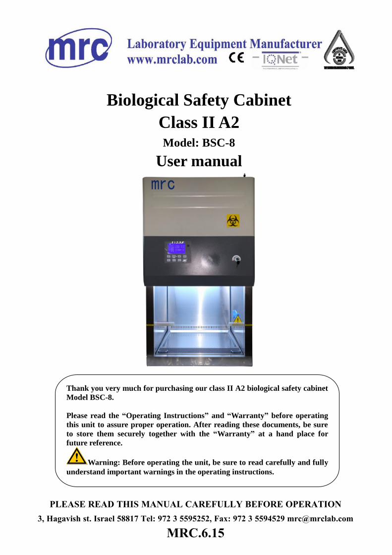
Biological Safety Cabinet
Class II A2 Model: BSC-8
User manual
PLEASE READ THIS MANUAL CAREFULLY BEFORE OPERATION3, Hagavish st. Israel 58817 Tel: 972 3 5595252, Fax: 972 3 5594529 [email protected]
MRC.6.15
Thank you very much for purchasing our class II A2 biological safety cabinet
Model BSC-8.
Please read the “Operating Instructions” and “Warranty” before operating
this unit to assure proper operation. After reading these documents, be sure
to store them securely together with the “Warranty” at a hand place for
future reference.
Warning: Before operating the unit, be sure to read carefully and fully
understand important warnings in the operating instructions.
1
CONTENT
1. Preface .................................................................................................................................... 3
2. Application Range .................................................................................................................. 4
3. Unpacking, Installation, Technical Parameters ...................................................................... 5
3.1 Unpacking .................................................................................................................. 5
3.2 Installation .................................................................................................................. 7
3.2.1 Location ............................................................................................................... 7
3.2.2. The pretreatment before installation ................................................................... 8
3.2.3. Installation of base stand(optional)..................................................................... 9
3.2.4. Connect base stand and body............................................................................ 10
3.3 Technical Parameters ............................................................................................... 11
4. Performance Index ................................................................................................................ 12
4.1 Biological safety performance .................................................................................. 12
4.2 Air tightness test ....................................................................................................... 12
4.3 Integrity of High efficiency filter ............................................................................. 12
4.4 Vibration amplitude .................................................................................................. 12
4.5 Illumination .............................................................................................................. 12
4.6 Mechanical capacity ................................................................................................. 12
4.7 Electrical performance .............................................................................................. 12
5. Product Characteristics ......................................................................................................... 12
5.1 LCD Crystal display ................................................................................................. 12
5.2 Remote Control ........................................................................................................ 13
5.3 Control of Front Window ......................................................................................... 14
5.4 Application of Reservation Timing ............................................................................. 14
5.4.1 Reserve Procedure: ......................................................................................... 14
5.4.2 Install Timer Procedure .................................................................................. 15
5.5 Product Characteristics ........................................................................................... 15
5.6 Caution and Warning .............................................................................................. 15
5.6.1 Over Safety Height Alarm for Front Window ................................................ 15
5.6.2 HEPA Filter Pressure Difference Alarm ......................................................... 15
6.Structure .....................................................................................................................................
6.1 Driving System of Front Window ............................................................................ 17
2
6.2 Air Filtration System ................................................................................................ 17
6.3 UV Light ................................................................................................................... 18
6.4 Fluorescent Light ...................................................................................................... 18
6.5 Foot Switch ............................................................................................................... 18
6.6 Control panel ............................................................................................................ 18
6.6.1 Touch-button ...................................................................................................... 20
6.7 Air pipe ..................................................................................................................... 21
6.8 Power lock ................................................................................................................ 21
6.9 Water proof Socket ................................................................................................... 21
6.10 Fuse protector ......................................................................................................... 21
7.Airflow Velocity Adjustment ................................................................................................. 23
8.Operation ............................................................................................................................... 26
9.Maintenance........................................................................................................................... 27
9.1 Clean the cabinet surface ............................................................................................. 27
9.1.1. Clean the operating area surface ....................................................................... 27
9.1.2 Clean the the external surface and glass door. ................................................ 27
9.2 Comprehensive maintenance period ............................................................................ 27
9.3 Maintenance methods .................................................................................................. 27
9.3.1Daily or weekly maintenance ............................................................................. 27
9.3.2 Monthly maintenance ........................................................................................ 27
9.3.3 Annual maintenance .......................................................................................... 28
9.4 Analysis of Common Failures ..................................................................................... 28
9.5 Storage conditions ....................................................................................................... 29
10. Notice ................................................................................................................................. 30
11. Label Description................................................................................................................ 32
11.1 Corporate logo (Picture 7) ...................................................................................... 32
11.2 Biological hazard label (Picture 8) ......................................................................... 32
11.3 Fuse label (Picture 9) .............................................................................................. 32
12. Warranty ............................................................................................................................. 34
Appendix A Circuit diagram .................................................................................................. 35
Appendix B Air Flow Chart .................................................................................................. 36
Appendix C Packing list ........................................................................................................ 37
3
1. Preface
1.1 Introduction
Biological safety cabinets (BSCs) are designed to protect the operator, the laboratory
environment and work materials from exposure to infectious aerosols and splashes that may
be generated when manipulating materials containing infectious agents, such as primary
cultures, stocks and diagnostic specimens.
4
2. Application Range
Aerosol particles are created by any activity that imparts energy into a liquid or semi-liquid
material, such as shaking, pouring, stirring or dropping liquid onto a surface or into another
liquid. Other laboratory activities, such as streaking agar plates, inoculating cell culture flasks
with a pipette, using a multi-channel pipette to dispense liquid suspensions of infectious
agents into micro-culture plates, homogenizing and vortexing infectious materials, and
centrifugation of infectious liquids, or working with animals, can generate infectious aerosols.
Aerosol particles of less than 5 µm in diameter and small droplets of 5–100 µm in diameter
are not visible to the naked eye. The laboratory worker is generally not aware that such
particles are being generated and may be inhaled or may cross contaminate work surface
materials. BSCs, when properly used, have been shown to be highly effective in reducing
laboratory-acquired infections and cross-contaminations of cultures due to aerosol exposures.
BSCs also protect the environment.
2.1 Working environment:
1. Only used in indoor;
2. Environment temperature 15~35;
3. Relative humidity ≤75%;
4. Pressure Range 70kPa~106kPa;
5. Power Supply AC 110V±10% , 50Hz±1 Hz ;
AC 220V±10% , 60Hz±1 Hz
5
3.Unpacking, Installation, Technical Parameters
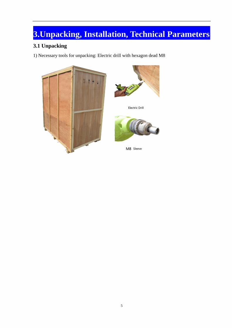
3.1 Unpacking
1) Necessary tools for unpacking: Electric drill with hexagon dead M8
6
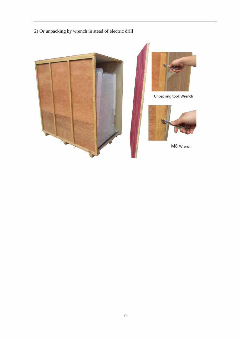
2) Or unpacking by wrench in stead of electric drill
7
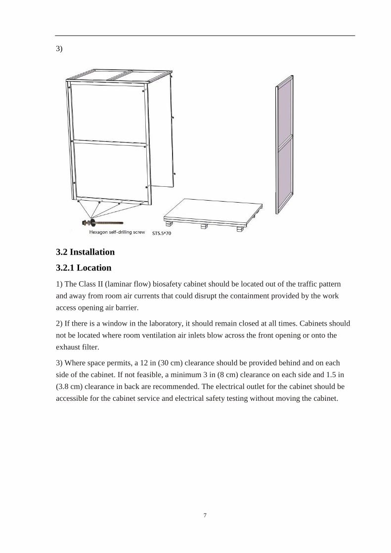
3)
3.2 Installation
3.2.1 Location
1) The Class II (laminar flow) biosafety cabinet should be located out of the traffic pattern
and away from room air currents that could disrupt the containment provided by the work
access opening air barrier.
2) If there is a window in the laboratory, it should remain closed at all times. Cabinets should
not be located where room ventilation air inlets blow across the front opening or onto the
exhaust filter.
3) Where space permits, a 12 in (30 cm) clearance should be provided behind and on each
side of the cabinet. If not feasible, a minimum 3 in (8 cm) clearance on each side and 1.5 in
(3.8 cm) clearance in back are recommended. The electrical outlet for the cabinet should be
accessible for the cabinet service and electrical safety testing without moving the cabinet.
8
3.2.2. The pretreatment before installation
1) Inspecting the package carefully to see whether it have been broken.
2) If transport in cold weather, the cabinet should be placed on the heating receiving area for
24 hours before installation.
3) Before unpacking, the cabinet should be moved to the place near the using point.
3). Move to destination, in front of the door
4). Unpack and Transportation
The base stand is on the top of the cabinet when packing, it should be taken out firstly
before installation. The cabinet must not be inversion during transportation. Forbid to topple
over and dismantle the cabinet.
5). Installation Check and adjustment
Installation, Check and Adjustment should be completed by after-sales engineer.
6). Training
After installation, after-sales engineer will tell operator the basic functions, operate
steps and notices etc.
The person who is not qualified by training can not operate the cabinet.
9
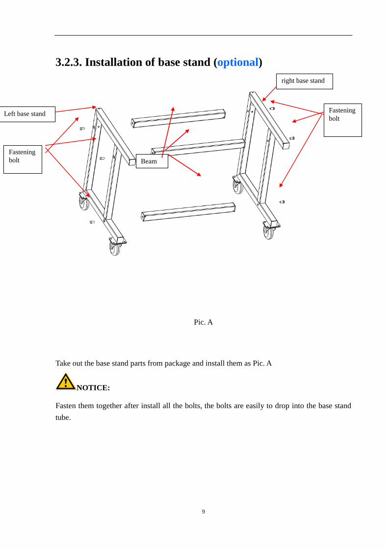
3.2.3. Installation of base stand (optional)
Pic A
Pic. A
Take out the base stand parts from package and install them as Pic. A
NOTICE:
Fasten them together after install all the bolts, the bolts are easily to drop into the base stand
tube.
Left base stand
Fastening
bolt
right base stand
Fastening
bolt
Beam
10
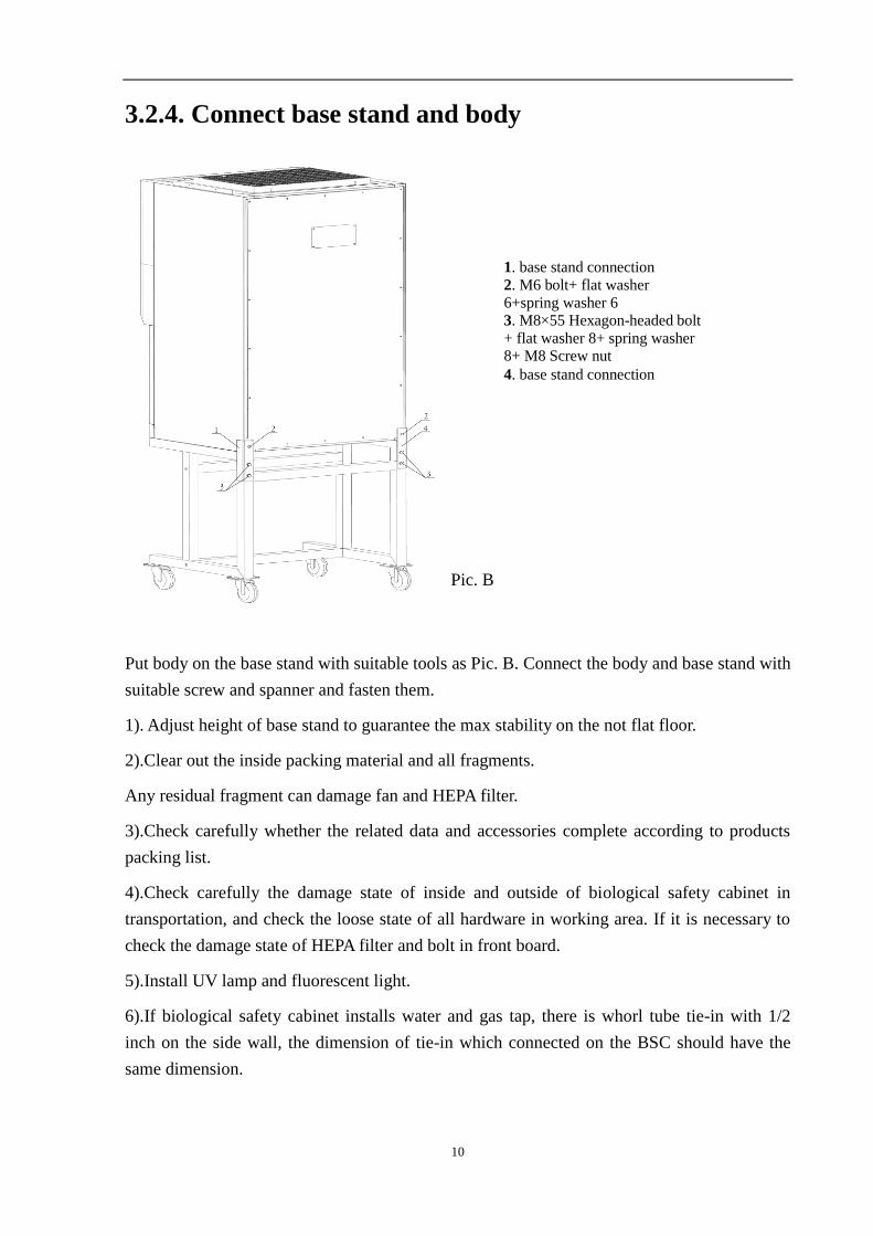
3.2.4. Connect base stand and body
Pic. B
Put body on the base stand with suitable tools as Pic. B. Connect the body and base stand with
suitable screw and spanner and fasten them.
1). Adjust height of base stand to guarantee the max stability on the not flat floor.
2).Clear out the inside packing material and all fragments.
Any residual fragment can damage fan and HEPA filter.
3).Check carefully whether the related data and accessories complete according to products
packing list.
4).Check carefully the damage state of inside and outside of biological safety cabinet in
transportation, and check the loose state of all hardware in working area. If it is necessary to
check the damage state of HEPA filter and bolt in front board.
5).Install UV lamp and fluorescent light.
6).If biological safety cabinet installs water and gas tap, there is whorl tube tie-in with 1/2
inch on the side wall, the dimension of tie-in which connected on the BSC should have the
same dimension.
1. base stand connection
2. M6 bolt+ flat washer
6+spring washer 6
3. M8×55 Hexagon-headed bolt
+ flat washer 8+ spring washer
8+ M8 Screw nut
4. base stand connection
11
7).Connect draining valve. And check it in the off place--- that is in the parallel position with
the ground.
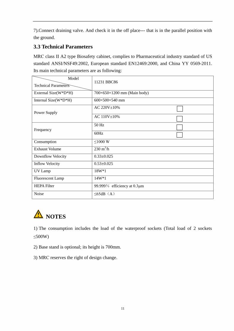
3.3 Technical Parameters
MRC class II A2 type Biosafety cabinet, complies to Pharmaceutical industry standard of US
standard ANSI/NSF49:2002, European standard EN12469:2000, and China YY 0569-2011.
Its main technical parameters are as following:
Model
Technical Parameters 11231 BBC86
External Size(W*D*H) 700×650×1200 mm (Main body)
Internal Size(W*D*H) 600×500×540 mm
Power Supply
AC 220V±10%
AC 110V±10%
Frequency
50 Hz
60Hz
Consumption ≤1000 W
Exhaust Volume 230 m3/h
Downflow Velocity 0.33±0.025
Inflow Velocity 0.53±0.025
UV Lamp 18W*1
Fluorescent Lamp 14W*1
HEPA Filter 99.999% efficiency at 0.3μm
Noise ≤65dB(A)
NOTES
1) The consumption includes the load of the waterproof sockets (Total load of 2 sockets
≤500W)
2) Base stand is optional; its height is 700mm.
3) MRC reserves the right of design change.
12
4. Performance Index
4.1 Biological safety performance
Personnel protection, microbial colony count ≤5CFU;
Sample protection, microbial colony count ≤5CFU;
Cross contamination protection, microbial colony count ≤2CFU.
4.2 Air tightness test
Good air tightness standard: biosafety cabinet pressured to 500Pa, the pressure is no less than
450 Pa after remaining 30 minutes.
4.3 Integrity of High efficiency filter
Scanning for detecting filter on any point ever Mach rate not more than0.01%
4.4 Vibration amplitude
The net amplitude is no more than 5μm(rms)when the frequency from 10Hz to 10kHz
4.5 Illumination
Average illuminance of safety cabinet is no less than 650 lx, each measured illuminance value
is no less than 430lx.
4.6 Mechanical capacity
Biological Safety cabinet is designed and structured to resist overturning or distortion caused
by outside force, and deflexibility caused by overloading on the operation panel and tipping
caused by overworking. If the weight is over 23kg on the work table, it will not make
permanent deformation.
4.7 Electrical performance
Withstand voltage 1390VDC direct voltage without breakdown for 5 seconds.
Grounding resistance ≤0.1Ω
5. Product Characteristics
5.1 LCD display
Liquid Crystal Display: Place liquid crystal among two parallel glasses, there are many
13
vertical and horizontal tiny wires among the two glasses. The principle is mainly through
power on or not to control the crystal molecules to change directions so as to reflect the light
and create images. The LCD display is low power consumption, no electromagnetic radiation
and its working life could reach 100,000 hours.
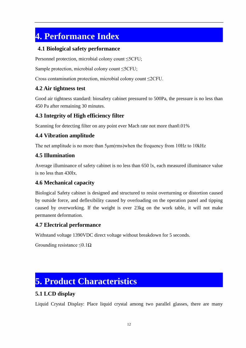
Pic 1
Adopting LCD display technology, it can real-time display and reflect the equipment working
condition, such as effective working state of the filter. Make the operator had more intuitive
feel.
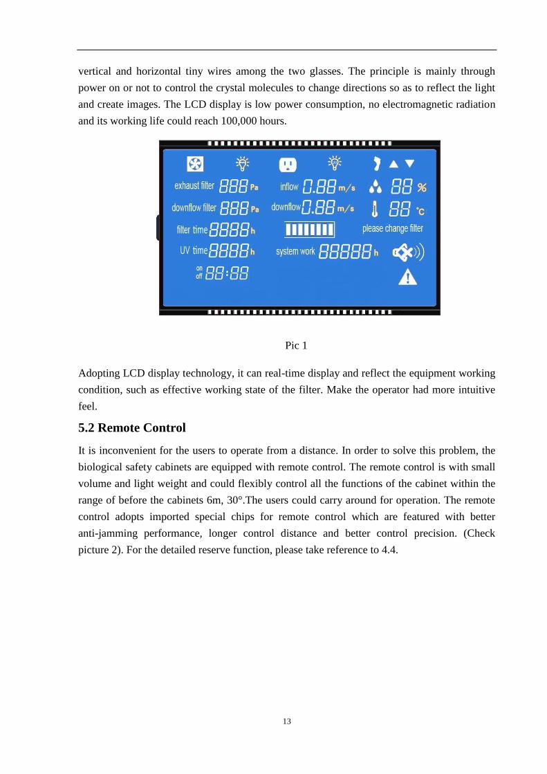
5.2 Remote Control
It is inconvenient for the users to operate from a distance. In order to solve this problem, the
biological safety cabinets are equipped with remote control. The remote control is with small
volume and light weight and could flexibly control all the functions of the cabinet within the
range of before the cabinets 6m, 30°.The users could carry around for operation. The remote
control adopts imported special chips for remote control which are featured with better
anti-jamming performance, longer control distance and better control precision. (Check
picture 2). For the detailed reserve function, please take reference to 4.4.
14
picture 2
Functions of Remote Control:
1. POWER
2. SUB
3. INSTALL TIMER
4. CONFIRM
5. CANCEL
6. +
7. -
8. FAN
9. UV
10. LIGHT
11. SOCKET
12. MUTE
13. UP
14. DOWN
5.3 Control of Front Window
Front window is motorized. It could be controlled by remote control, foot switch and control
panel. There is no need to touch front sash. The front window control motor running steadily.
5.4 Application of Reservation Timing
This function could only be realized by remote control)
Biological Safety Cabinet is equipped with UV lamp for sterilization. The UV lamp should
sterilize more than 30 minutes when turn on or turn off the cabinet. So in order to save the
waiting time, BSC has added reservation timing function. The cabinet could automatic turn on
or turn off after sterilization. Reservation time range is from 0 to 99 hours and 59minutes.
This function will improve efficiency obviously .
5.4.1 Reserve Procedure:
a. Connect the power, open the power lock and then press the reservation key (SUB)
b. Adjust the time (minutes) by „+‟, „-‟ button. Press the confirmation key(CONFIRM) to
confirm;and then adjust the minutes and hours with the same way;
15
c. After the time is confirmed, make the corresponding display spot light by selecting
function keys (e.g. UV)
d. Press the POWER button, and the reservation function starts. The time starts count down.
The corresponding function starts when the time is 0.
5.4.2 Install Timer Procedure
a. Connect the power, open the power lock, and then press the POWER button The
corresponding function starts when selecting function keys (e.g. UV)
b. Press INSTALL TIMER. Adjust the time (minutes) by„+‟, „-‟. Press the confirmation
button (CONFIRM) to confirm;and then adjust the minutes and hours with the same
way;
c. After the time is confirmed, the reservation function starts. All the function will be closed
and the equipment will remain stand by when the time is 0.
5.5 Product Characteristics
5.5.1 Biological Safety Cabinet‟s both sides and back is are negative pressure air channel
which quarantines work area and environment by air curtain and cabinet body. Same
time the negative pressure keeps work area from contamination.
5.5.2 Cabinet body is built with 1.5mm cold-rolled steel with anti powder coating. This
strength the structure and make the cabinet more steady.
5.5.3 Work area is made of 304 stainless steel, beautiful and corrosion resistance.
5.5.4 Base stand is made of anti powder coating cold-rolled steel.
5.5.5 Control panel is soft touch type, easy to handle and makes cabinet more beautiful.
5.6 Caution and Warning
Digital display of pressure difference and air velocity, audible and visual alarm system.
5.6.1 Over Safety Height Alarm for Front Window
It will alarm when front window is over safety height. Same time LCD display will twinkle
exclamation mark. Now we need to adjust front window to safety height.(Safety height is
200mm)
5.6.2 HEPA Filter Pressure Difference Alarm
NOTES
HEPA filter differential pressure is superior to air velocity sensor, because it is
monitoring the airflow velocity for a whole surface, while air velocity sensor is just
16
monitoring the airflow velocity for a point.
It will start audio and visual alarm if pressure of air supply filter and exhaust filter can‟t meet
preset value, at the same time LCD display will twinkle exclamation mark. Please pay
attention to this situation, because the HEPA filter might to be changed by now in order to
protect operators.
17
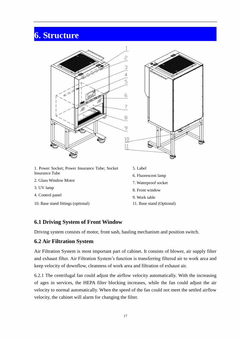
6. Structure
1. Power Socket; Power Insurance Tube; Socket
Insurance Tube
2. Glass Window Motor
3. UV lamp
4. Control panel
5. Label
6. Fluorescent lamp
7. Waterproof socket
8. Front window
9. Work table
10. Base stand fittings (optional) 11. Base stand (Optional)
6.1 Driving System of Front Window
Driving system consists of motor, front sash, hauling mechanism and position switch.
6.2 Air Filtration System
Air Filtration System is most important part of cabinet. It consists of blower, air supply filter
and exhaust filter. Air Filtration System‟s function is transferring filtered air to work area and
keep velocity of downflow, cleanness of work area and filtration of exhaust air.
6.2.1 The centrifugal fan could adjust the airflow velocity automatically. With the increasing
of ages in services, the HEPA filter blocking increases, while the fan could adjust the air
velocity to normal automatically. When the speed of the fan could not meet the settled airflow
velocity, the cabinet will alarm for changing the filter.
18
6.3 UV Light
UV lamp is inside work area. This keeps UV lamp could sterilize well all space of work area.
UV lamp is interlock with fluorescent lamp, blower and front window. When UV lamp is on,
the fluorescent lamp, blower and front window could not be opened.
6.4 Fluorescent Light
Lamp is straight tube type energy-saving fluorescent lamp. It can make sure average
illumination inside work area meets standard requirements. Fluorescent lamp has interlock
function with UV lamp. When fluorescent lamp is on, UV lamp could not be opend.
6.5 Foot Switch
Foot switch could control front window conveniently.
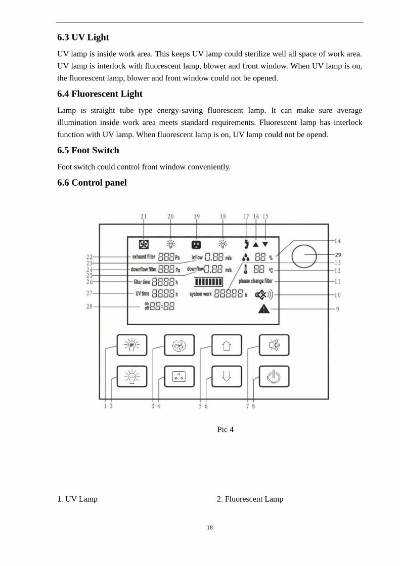
6.6 Control panel
Pic 4
1. UV Lamp 2. Fluorescent Lamp
19
3. Blower
4. Socket
5. Glass Window Up
6. Glass Window Down
7. Mute
8. Power
9. Alarm Status
10. Mute Status
11. Filter Changing Status
12. Temperature
13. System Working Time
14. Humidity
15. Glass Window Down Status
16. Glass Window Up Status
17. Foot Switch Status
18. UV Status
19. Socket Status
20. Fluorescent Lamp Status
21. Blower Status
22. Exhaust Filter
23. Inflow Velocity
24. Supply Filter Differential pressure
25. Downflow Velocity
26. Filter working time
27. UV Lamp working time
28. Reservation timing
29. Remote control receiver
20
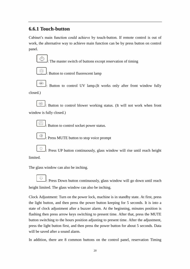
6.6.1 Touch-button
Cabinet‟s main function could achieve by touch-button. If remote control is out of
work, the alternative way to achieve main function can be by press button on control
panel.
: The master switch of buttons except reservation of timing
: Button to control fluorescent lamp
: Button to control UV lamp.(It works only after front window fully
closed.)
: Button to control blower working status. (It will not work when front
window is fully closed.)
: Button to control socket power status.
: Press MUTE button to stop voice prompt
: Press UP button continuously, glass window will rise until reach height
limited.
The glass window can also be inching.
: Press Down button continuously, glass window will go down until reach
height limited. The glass window can also be inching.
Clock Adjustment: Turn on the power lock, machine is in standby state. At first, press
the light button, and then press the power button keeping for 5 seconds. It is into a
state of clock adjustment after a buzzer alarm. At the beginning, minutes position is
flashing then press arrow keys switching to present time. After that, press the MUTE
button switching to the hours position adjusting to present time. After the adjustment,
press the light button first, and then press the power button for about 5 seconds. Data
will be saved after a sound alarm.
In addition, there are 8 common buttons on the control panel, reservation Timing
21
should be achieved by remote control.
The same icon button in control and remote control will achieve same function.
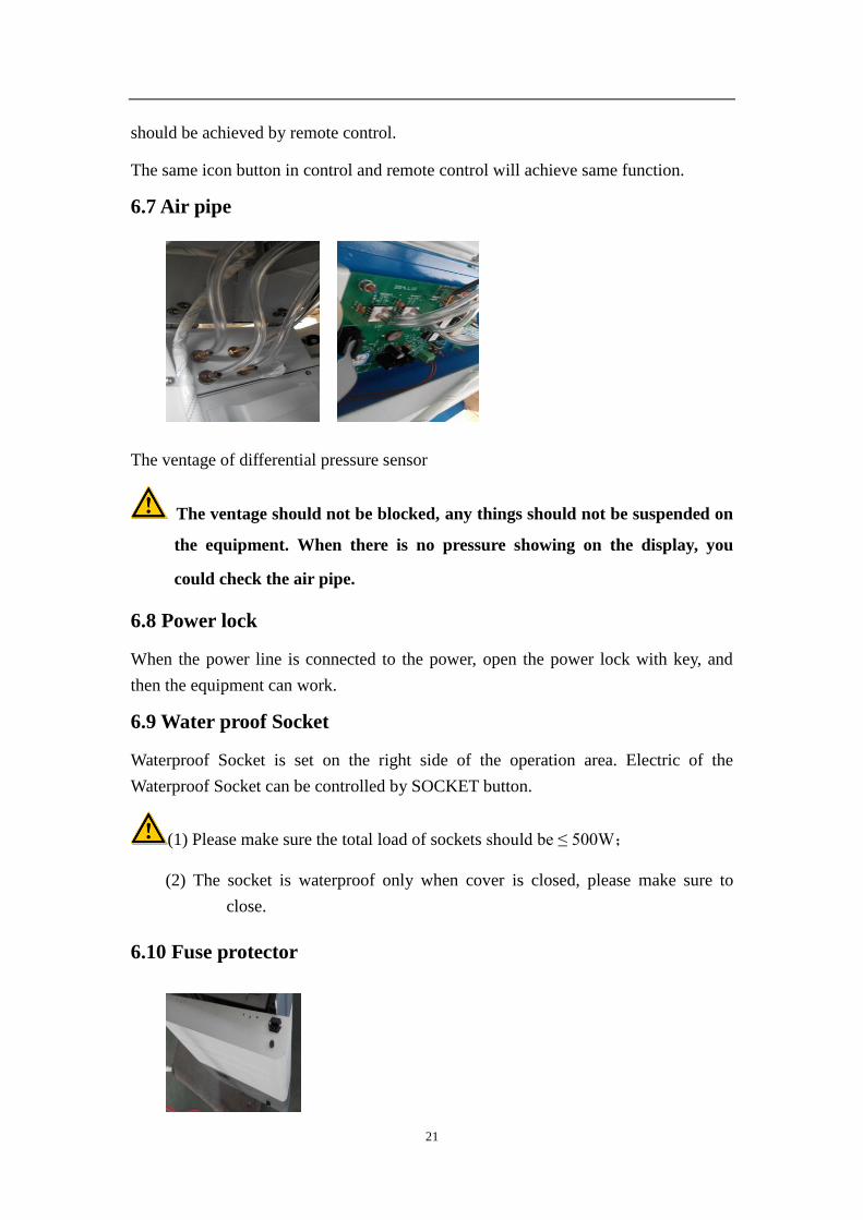
6.7 Air pipe
The ventage of differential pressure sensor
The ventage should not be blocked, any things should not be suspended on
the equipment. When there is no pressure showing on the display, you
could check the air pipe.
6.8 Power lock
When the power line is connected to the power, open the power lock with key, and
then the equipment can work.
6.9 Water proof Socket
Waterproof Socket is set on the right side of the operation area. Electric of the
Waterproof Socket can be controlled by SOCKET button.
(1) Please make sure the total load of sockets should be ≤ 500W;
(2) The socket is waterproof only when cover is closed, please make sure to
close.
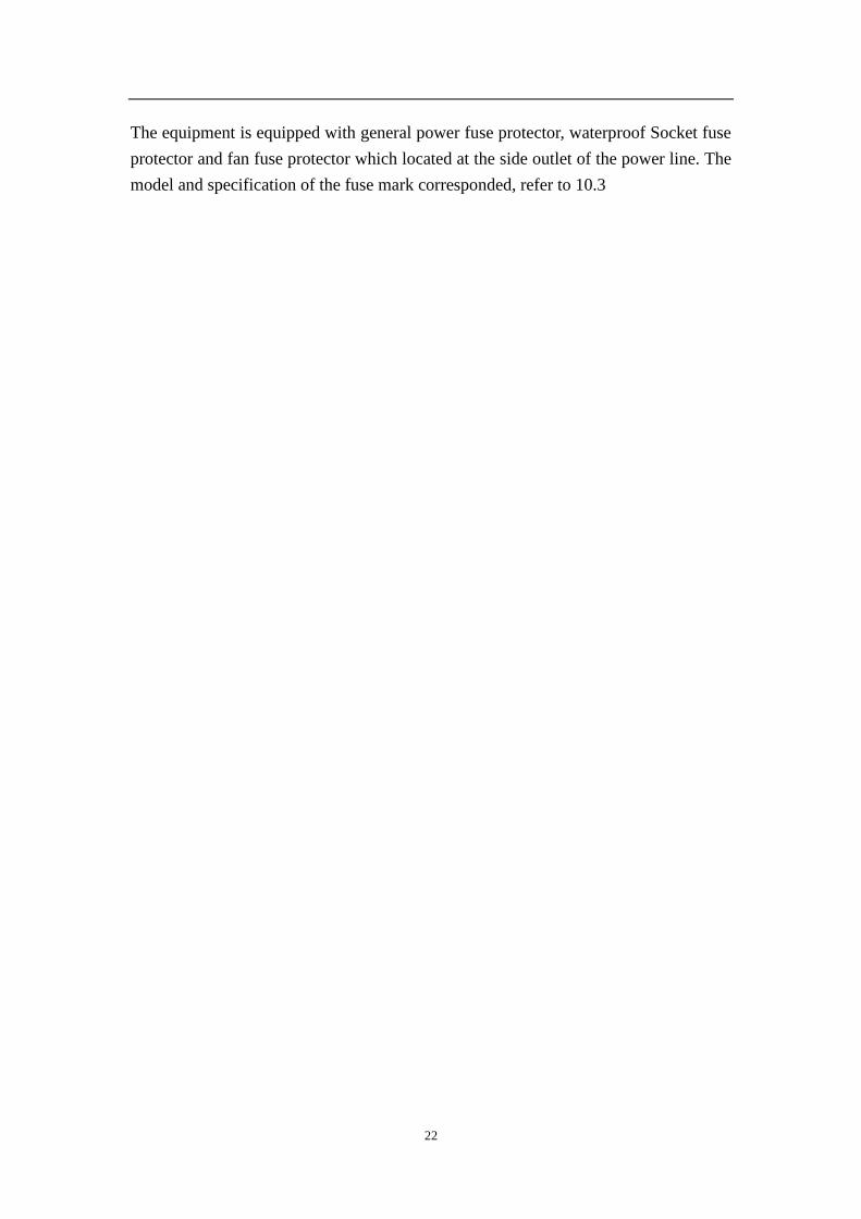
6.10 Fuse protector
22
The equipment is equipped with general power fuse protector, waterproof Socket fuse
protector and fan fuse protector which located at the side outlet of the power line. The
model and specification of the fuse mark corresponded, refer to 10.3
23
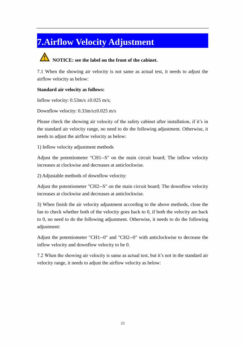
7.Airflow Velocity Adjustment
NOTICE: see the label on the front of the cabinet.
7.1 When the showing air velocity is not same as actual test, it needs to adjust the
airflow velocity as below:
Standard air velocity as follows:
Inflow velocity: 0.53m/s ±0.025 m/s;
Downflow velocity: 0.33m/s±0.025 m/s
Please check the showing air velocity of the safety cabinet after installation, if it‟s in
the standard air velocity range, no need to do the following adjustment. Otherwise, it
needs to adjust the airflow velocity as below:
1) Inflow velocity adjustment methods
Adjust the potentiometer "CH1--S" on the main circuit board; The inflow velocity
increases at clockwise and decreases at anticlockwise.
2) Adjustable methods of downflow velocity:
Adjust the potentiometer "CH2--S" on the main circuit board; The downflow velocity
increases at clockwise and decreases at anticlockwise.
3) When finish the air velocity adjustment according to the above methods, close the
fan to check whether both of the velocity goes back to 0, if both the velocity are back
to 0, no need to do the following adjustment. Otherwise, it needs to do the following
adjustment:
Adjust the potentiometer "CH1--0" and "CH2--0" with anticlockwise to decrease the
inflow velocity and downflow velocity to be 0.
7.2 When the showing air velocity is same as actual test, but it‟s not in the standard air
velocity range, it needs to adjust the airflow velocity as below:
24
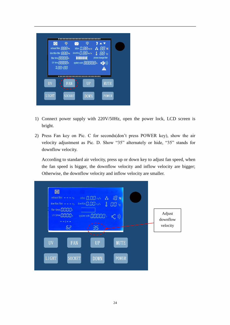
1) Connect power supply with 220V/50Hz, open the power lock, LCD screen is
bright.
2) Press Fan key on Pic. C for seconds(don‟t press POWER key), show the air
velocity adjustment as Pic. D. Show “35” alternately or hide, “35” stands for
downflow velocity.
According to standard air velocity, press up or down key to adjust fan speed, when
the fan speed is bigger, the downflow velocity and inflow velocity are bigger;
Otherwise, the downflow velocity and inflow velocity are smaller.
Adjust
downflow
velocity
25
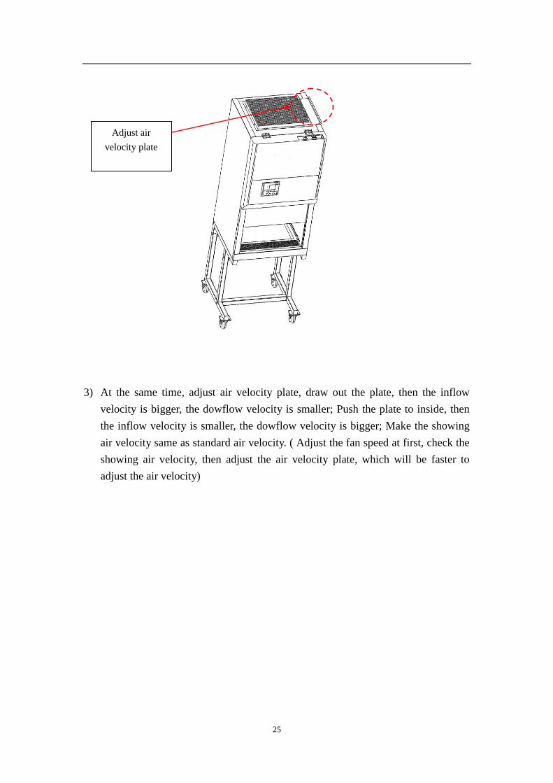
3) At the same time, adjust air velocity plate, draw out the plate, then the inflow
velocity is bigger, the dowflow velocity is smaller; Push the plate to inside, then
the inflow velocity is smaller, the dowflow velocity is bigger; Make the showing
air velocity same as standard air velocity. ( Adjust the fan speed at first, check the
showing air velocity, then adjust the air velocity plate, which will be faster to
adjust the air velocity)
Adjust air
velocity plate
26
8.Operation
a. Connect power
b. Open power lock, LCD display light up and alarm at the same time, then the
machine turns into standby status. The operator can start to use.
c. Press power button, the following functions are available: Fluorescent lamp. UV
lamp, Fan, Mute, Sockets, Glass window up and down, Reservation timing
(Related buttons, function and operation, please refer to items 5.8 and 5.11);
a) The UV lamp works only when glass window is completely closed
and other function not work.
d. Please sterilize the cabinet before using. Close glass widow completely and have
UV lamp work for half an hour to sterilize.
e. (1) When sterilizing, person should leave room, for protect eyes and
skin, avoiding damage from expose carelessly.
(2) UV light strength should be tested at regular intervals according to
supplier’s description. Test quarterly is suggested. Change new one when
disqualification.
f. Pls make sure the experiment should be started after fan working for at least half
an hour.
g. For guarantee operating safety, pls put in testing materials ahead of time
inside the cabinet, and keep electrical door rail at the 200mm height of
operating surface when testing.
h. Pls make sure to sterilize the cabinet by UV lamp after finishing operation.
27
9.Maintenance
Because the statistics of operating time will directly affect the judgment of
maintenance needs, we recommend preparing a detailed record of operating time for
reference and inquiry when using!
9.1 Clean the cabinet surface
9.1.1. Clean the operating area surface
Rub the entire surface with a soft cotton cloth soaked in concentrated liquid soap,
wipe up soap with the cotton cloth or towel soaked in clean hot water or warm water,
and then dry the surface with another cotton cloth or towel rapidly.
For the contaminated or traces of the work surface, fluid tank, etc., use medical
alcohol or other disinfectant to wipe.
Disinfectants can not damage for 304 stainless steel.
9.1.2 Clean the external surface and glass door.
As to any of the non-abrasive household cleanser, use a soft cotton cloth or towel to
wipe.
9.2 Comprehensive maintenance period
We suggest comprehensive maintenance period is one year or 1000 hours of work.
9.3 Maintenance methods
9.3.1Daily or weekly maintenance
a. Disinfect and clean operating area (see 7.1.1);
b. Clean the external surface and glass door around the operating area (see 7.1.2);
c. Check the various functions of equipment;
d. Record this maintenance result;
9.3.2 Monthly maintenance
a. Clean the external surface and glass door. (See 7.1.2);
b. Wipe the worktop surfaces, wall surface of operating area (excluding the well air
28
net of the top of operating area), and the inner surface of glass door with 70﹪
medical alcohol or household bleach diluted 1:100 (ie, 0.05% sodium
hypochlorite); Then use the sterile water to wipe again in order to eliminate the
rest chlorine.
c. Check the various functions of equipment;
d. Record this maintenance result;
9.3.3 Annual maintenance
a. Check the two conveyor belts of front glass door drive unit, and ensure that their
tightness is coincident.
b. Check the UV lamp and fluorescent lamps.
c. Apply for testing the overall performance of cabinet on an annual basis to ensure
the performance safety. User is responsible for testing costs.
d. Record this maintenance result.
9.4 Analysis of Common Failures
1) The preparation work before repairing.
Make sure the equipment connect to the ground well in order to secure the safety
during work. Check whether there are any cable disconnect, short circuit or
damage, if any mentioned condition occurred, solve the problem one by one.
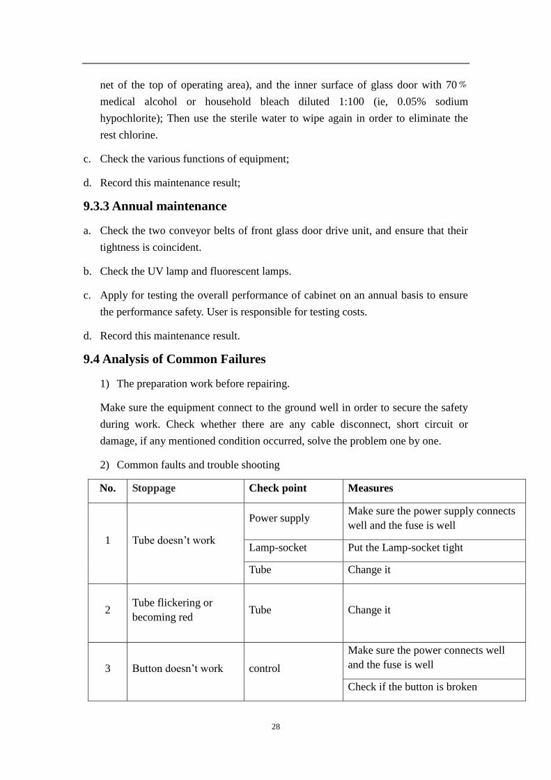
2) Common faults and trouble shooting
No. Stoppage Check point Measures
1 Tube doesn‟t work
Power supply Make sure the power supply connects
well and the fuse is well
Lamp-socket Put the Lamp-socket tight
Tube Change it
2 Tube flickering or
becoming red Tube Change it
3 Button doesn‟t work control
Make sure the power connects well
and the fuse is well
Check if the button is broken
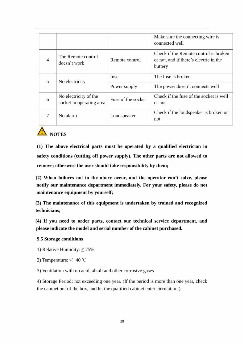
29
Make sure the connecting wire is
connected well
4 The Remote control
doesn‟t work Remote control
Check if the Remote control is broken
or not, and if there‟s electric in the
buttery
5 No electricity fuse The fuse is broken
Power supply The power doesn‟t connects well
6 No electricity of the
socket in operating area Fuse of the socket
Check if the fuse of the socket is well
or not
7 No alarm Loudspeaker Check if the loudspeaker is broken or
not
NOTES
(1) The above electrical parts must be operated by a qualified electrician in
safety conditions (cutting off power supply). The other parts are not allowed to
remove; otherwise the user should take responsibility by them;
(2) When failures not in the above occur, and the operator can’t solve, please
notify our maintenance department immediately. For your safety, please do not
maintenance equipment by yourself;
(3) The maintenance of this equipment is undertaken by trained and recognized
technicians;
(4) If you need to order parts, contact our technical service department, and
please indicate the model and serial number of the cabinet purchased.
9.5 Storage conditions
1) Relative Humidity: ≤ 75%,
2) Temperature:< 40
3) Ventilation with no acid, alkali and other corrosive gases
4) Storage Period: not exceeding one year. (If the period is more than one year, check
the cabinet out of the box, and let the qualified cabinet enter circulation.)
30
10.Notice
(1) Make sure input voltage is correct and stable. The rated load of main power
socket should be higher than cabinet consumption. Plug must be well
grounded.
(2) In order to avoid air turbulence, the operator should slightly move his arms
during experiment. Hands should stay inside the working area at least 1
minute before operating. In order to decrease the times of arms moving into
and out of the working area, prepare all the necessary items inside the
cabinet before starting experiment;
(3) Moving principles of different samples inside cabinet: When two or more
samples need to be moved, be sure that low-polluting samples move to
high-polluting samples. Movement of items should also follow the principles
of slow-moving.
(4) Samples placed in parallel: Samples should be placed in the cabinet parallel
to avoid cross-contamination between samples and blocking back air grille.
(5) In order to avoid samples being sucked into the negative passage or the
blower, do not place soft and slight samples (for example: soft tissue) on the
surface during experiment;
(6) The weight of items placed in the cabinet should be no more than
23Kg/25×25cm2;
(7) Avoid vibration: avoid using vibration equipment (eg centrifuges, vortex
oscillator, etc.) inside the cabinet. Vibration would cause lower cleanliness of
operating area and affect operator protection.
(8) No flame: No flame is allowed inside the cabinet. Using of fire will lead to
airflow disorder, and filter damage. If sterilization is required during the
experiment, infrared sterilizer is highly recommended.
(9) HEPA filter life: With the usage time increasing, dust and bacteria
accumulate inside HEPA filter. Filter Resistance is getting bigger, when it
reaches the maximum point, there will be audible and visual alarm. Please
replace new HEPA filter, otherwise it will affect the safety performance of
the equipment. The used filter should be processed as medical waste.
31
(10)There is a negative passage surrounding the work area, which is sealed
strictly in the factory. The operator is not allowed to remove or loose screws
of those parts. If necessary, please contact service personal.
(11)Front Grille is used for air intake and drain. Do not block it, otherwise it will
affect airflow. Armrest is recommended to solve this problem and reducing
the operator's wrist fatigue.
(12)Long-term use of biological safety cabinets will inevitably cause pollution
(e.g. HEPA filters, corner cabinets, etc.). In order to sterilize thoroughly
every 500 hours, formalin (formaldehyde) fumigation sterilizer is
recommended. After sterilization, neutralize formaldehyde gas with
ammonium hydrogen carbonate. Make sure no sterilization gas escapes
during the whole process.
(13)The maximum storage period is one year. If the period is more than one year,
performance test should be done .
Serious declaration: we will take no responsibility for risks caused by
improper operation and man-made damages!
32
11. Label Description
11.1 Corporate logo (Picture 7)
Picture 7
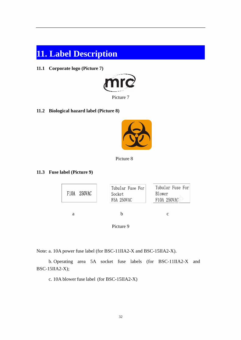
11.2 Biological hazard label (Picture 8)
Picture 8
11.3 Fuse label (Picture 9)
a b c
Picture 9
Note: a. 10A power fuse label (for BSC-11IIA2-X and BSC-15IIA2-X).
b. Operating area 5A socket fuse labels (for BSC-11IIA2-X and
BSC-15IIA2-X);
c. 10A blower fuse label (for BSC-15IIA2-X)
33
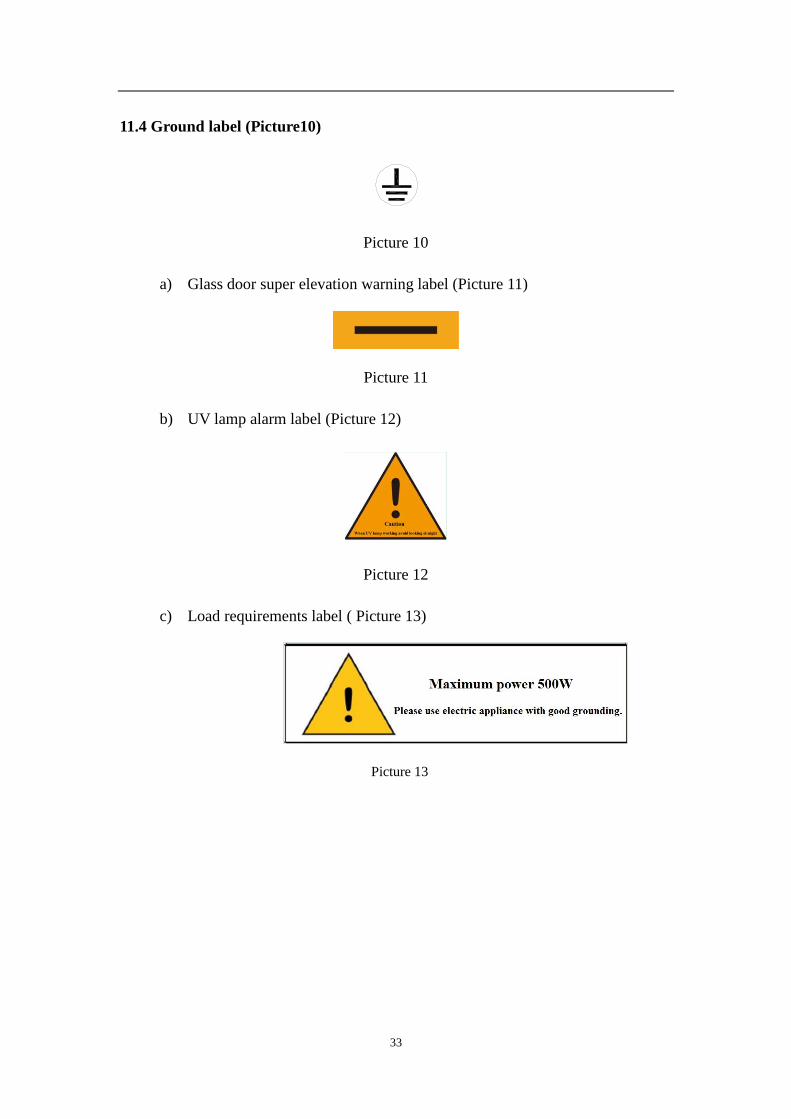
11.4 Ground label (Picture10)
Picture 10
a) Glass door super elevation warning label (Picture 11)
Picture 11
b) UV lamp alarm label (Picture 12)
Picture 12
c) Load requirements label ( Picture 13)
Picture 13
34
12. Warranty
1) Warranty is 18 months from EX-factory date (excluding consumable accessories,
UV and Fluorescent lamp, filter).
2) We will take no responsibility for risks caused by improper operation and
man-made damages.
3) According to international standards, life time of biosafety cabinet is 10 years.
4) Training can be provided if necessary.
5) Accessories are available for at least 10 years
35
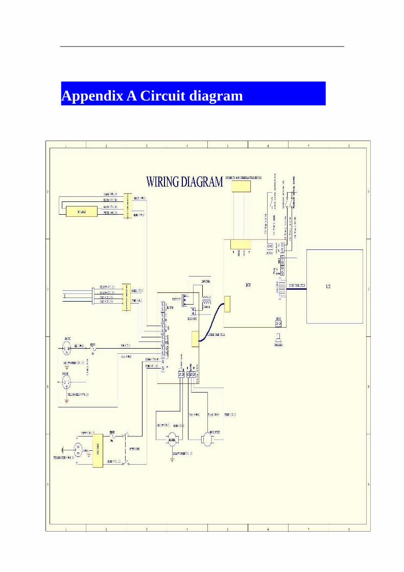
Appendix A Circuit diagram
36
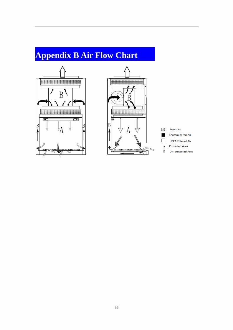
Appendix B Air Flow Chart
37
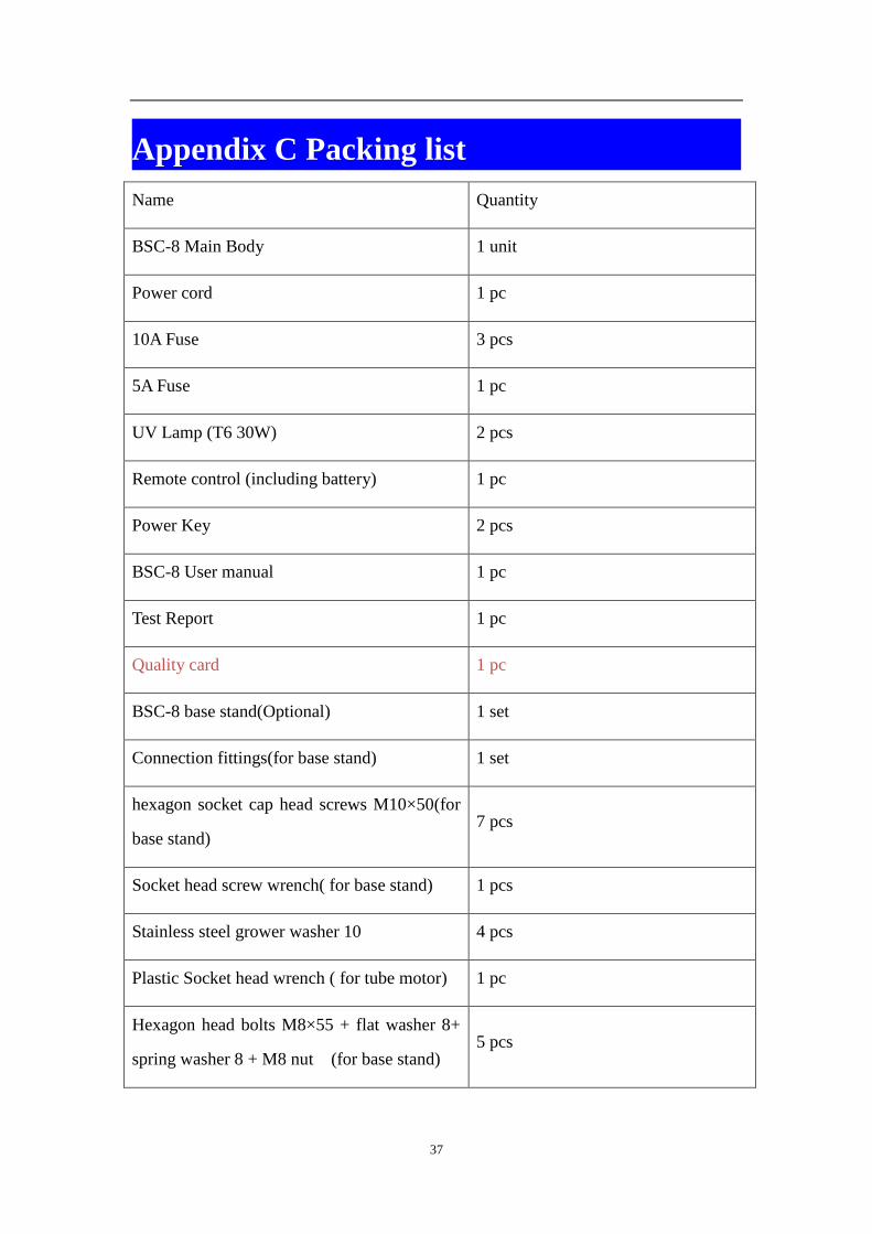
Appendix C Packing list
Name Quantity
BSC-8 Main Body 1 unit
Power cord 1 pc
10A Fuse 3 pcs
5A Fuse 1 pc
UV Lamp (T6 30W) 2 pcs
Remote control (including battery) 1 pc
Power Key 2 pcs
BSC-8 User manual 1 pc
Test Report 1 pc
Quality card 1 pc
BSC-8 base stand(Optional) 1 set
Connection fittings(for base stand) 1 set
hexagon socket cap head screws M10×50(for
base stand) 7 pcs
Socket head screw wrench( for base stand) 1 pcs
Stainless steel grower washer 10 4 pcs
Plastic Socket head wrench ( for tube motor) 1 pc
Hexagon head bolts M8×55 + flat washer 8+
spring washer 8 + M8 nut (for base stand) 5 pcs
38
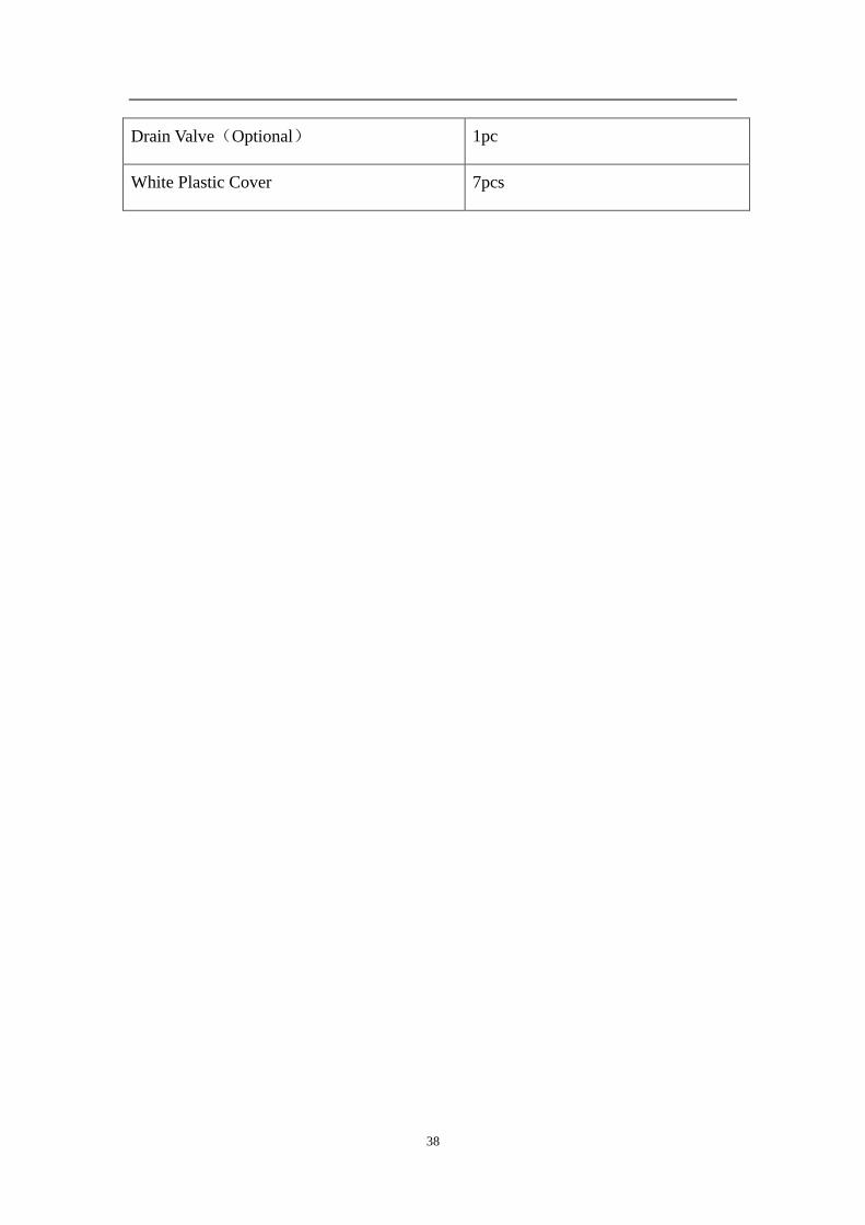
Drain Valve(Optional) 1pc
White Plastic Cover 7pcs