Embed Size (px)
Citation preview

36 IEEEA&ESYSTEMSMAGAZINE DECEMBER2013
INTRODUCTION
An unmanned flying vehicle (UFV) is generally used to search for and track an adversary and even designed to go down with the adversary’s vehicle under the extreme con-ditions of modern wars [1]. The precision of a UFV’s elec-tromagnetic sensors generally influences the accuracy of its guidance. To improve the accuracy of the UFV’s guidance system, advanced guidance technologies based on bionic vi-sion have been studied in recent years. Some developments based on bioinspired intelligence [2], [3] have also been in-vestigated for aerial systems. Bionic vision, such as that in-spired by the vision of Limulus species (i.e., horseshoe crabs), fruit flies, birds, and humans [4], has become a hot research field, and some of these new technologies have been applied to missile homing guidance.
In the bird kingdom, the eagle is renowned for its excel-lent eyesight, a trait that is produced by to its distinct vi-sual principle. An eagle’s eye is almost the same size as a human’s eye but is at least four times sharper than that of a person with perfect vision. An eagle flying at an altitude of 1,000 ft can spot prey over an area of almost 3 mi2 from a fixed position [5]. It has two fovea areas with one central fo-vea in the middle. Figure 1 shows the physiological structure of the eagle’s eye. Both fovea and the center of the pupil in each eye are on a plane, as is the line of sight of every point on the surfaces of the retina cut by the plane. This physi-ological structure helps it see forward and to the sides at the same time. This broadens its visual field [6]. Its wider view can be imitated with a system of binocular stereo vision and can be applied to the imaging guidance by using the image mosaic to splice the two images from different vision sensors on a UFV.
Lateral inhibition widely exists in some living things. In a retinal image, the intensively excited receptors in illumi-
natingly light areas inhibit the receptors in illuminatingly dark areas more strongly than the latter inhibit the former, which enhances the contrast and distortion of the sensory information. This electrophysiological phenomenon is called lateral inhibition. Another important characteristic of eagle-eye vision is that the vision scene and the intensity gradient (i.e., the image’s edge) are both strengthened [7]. Image seg-mentation [8] and visual attention [9] are two sophisticated image-processing technologies that are included in the pro-cessing of visual information and exist in eagle-eye visual processing.
In this article, we present our work’s main focus, devel-oping a bionic vision imaging guidance simulation platform for UFVs, which is a creative and an interesting endeavor.
EAGLE-EYE VISUAL PRINCIPLE
The eagle-eye visual principle contains four well-established paradigms: image mosaic, lateral inhibition, image segmen-tation-based on an intersecting cortical model (ICM) algo-rithm, and visual attention.
IMAGEMOSAICPARADIGM
Image mosaic is defined as a technique for combining two or more images into a larger one [10]. The construction and
Authors’ current address: H. Duan, Y. Deng, X. Wang, F. Liu, State Key Laboratory of Virtual Reality Technology and Sys-tems, School of Automation Science and Electrical Engineer-ing, Beihang University (BUAA) Beijing 100191, P.R. China. (E-mail: [email protected]), Tel: 86-10-82317318. Manuscript received April 18, 2011, revised August 16, 2012, December 30, 2012, and April 13, 2012, and ready for publication April 22, 2013. Review handled by H. Liu. 0885/8985/13 $26.00 © 2013 IEEE
Biological Eagle-Eye–Based Visual Imaging Guidance Simulation Platform for Unmanned Flying VehiclesHaibin Duan, Yimin Deng, Xiaohua Wang, Fang Liu Beihang University (BUAA), Beijing, People’s Republic of China
Figure 1. Frontal section through an ideal eagle’s head at the foveal plane.
DECEMBER2013 IEEEA&ESYSTEMSMAGAZINE 37
application of mosaic images have been active areas of re-search in recent years. There are two common methods of image mosaics: one based on grayscale and the other based on phase correlation [11]. In our developed platform, an im-age mosaic method based on both grayscale and phase cor-relation is proposed. Our method combines the advantages of the two common methods, with less computation than the method based on grayscale and stronger anti-interference ability than the one based on phase correlation.
Our method can be simply described with two techno-logical processes. First, fast Fourier transform is used to cal-culate a rough position for the image alignment. Then the gray correlation algorithm is applied to search for a precise position locally. The detailed procedures are as follows:
1. Input images f1 and f2.
2. Transform two input images by two-dimensional Fourier transform.
3. Calculate the mutual power spectrum of the two input images.
4. Transform the mutual power spectrum by two-dimen-sional inverse Fourier transform.
5. Find the maximum amplitude values (i.e., the translation of the two images).
6. Fuse the transformed images using the biological image fusion algorithm.
LATERALINHIBITIONPARADIGM
Lateral inhibition is one of the biological information-pro-cessing principles in neural systems. This mechanism plays an important role in the eagle-eye visual principle, which was discovered and verified by Hartline and his research team when they carried out an electrophysiology experi-ment on Limulus vision [12]. They found that every microph-thalmia of a Limulus ommateum (i.e., an individual photo-receptor unit of the Limulus compound eye) is regarded as a receptor, which is inhibited by its adjacent receptors. The inhibited effect is mutual and spatially summed. That is to say, a receptor inhibits its adjacent receptors and at the same time is inhibited by them. The nearer the adjacent receptors are to one another, the more strongly they inhibit mutually. In this way, the important characteristics of vision scene and
intensity gradient in a retinal image (i.e., the image’s edge) are both strengthened.
Lateral inhibition can be used widely in many fields, such as image processing, pattern recognition, artificial in-telligence, and imaging navigation [7], [13]. This mechanism can be applied to preprocessing of the original and template images to stress the spatial resolution, which can increase the accuracy of image matching. Lateral inhibition increases the contrast and sharpness in visual response. It occurs in the mammalian retina. For example, in the dark, a small light stimulus is enhanced by the different photoreceptors (rod cells). The rods in the center of the stimulus transduce the “light” signal to the brain, whereas different rods on the outside of the stimulus send a “dark” signal to the brain. This contrast between the light and the dark creates a sharp-er image.
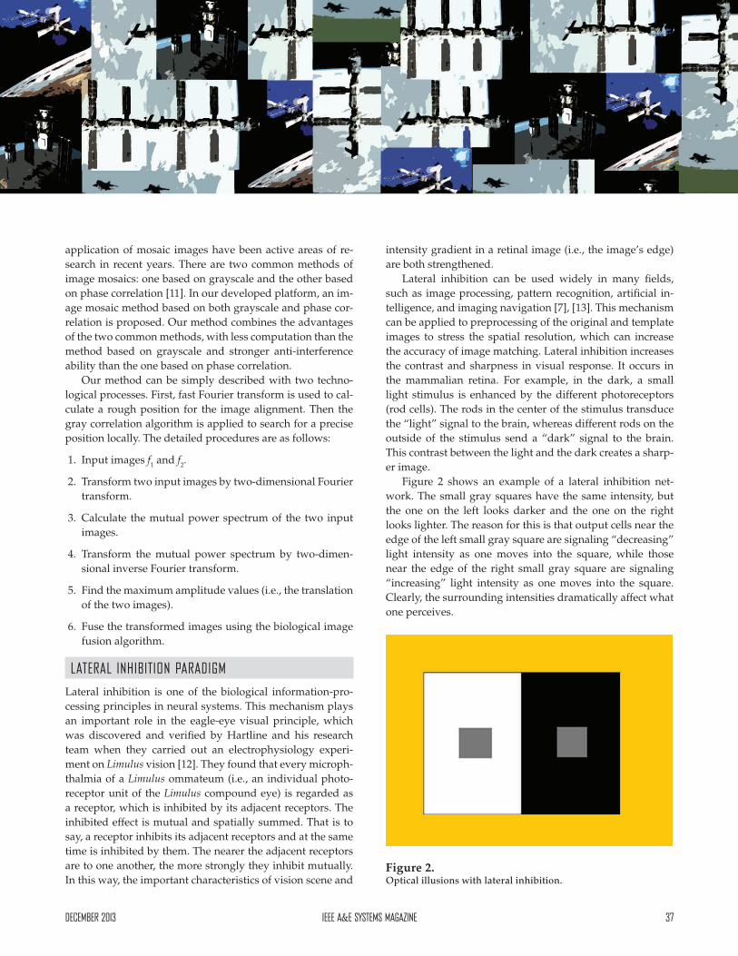
Figure 2 shows an example of a lateral inhibition net-work. The small gray squares have the same intensity, but the one on the left looks darker and the one on the right looks lighter. The reason for this is that output cells near the edge of the left small gray square are signaling “decreasing” light intensity as one moves into the square, while those near the edge of the right small gray square are signaling “increasing” light intensity as one moves into the square. Clearly, the surrounding intensities dramatically affect what one perceives.
Figure 2. Optical illusions with lateral inhibition.

38 IEEEA&ESYSTEMSMAGAZINE DECEMBER2013
Eagle-Eye–Based Visual Imaging Simulat ion
We choose the following matrix as the lateral inhibition modulus [14]:
(1)
The matrix to process the image can be described with
(2)
where is the convolution operator and Pic is the gray value of the image. If the gray value of the pixel of the image goes beyond the limit of [0, 255], it needs normalization.
ICMSEGMENTATIONPARADIGM
Image segmentation is the process of assigning a label to every pixel in an image so that pixels with the same label share certain visual characteristics [15]. The goal of image segmentation is to cluster pixels into salient image regions (i.e., regions corresponding to individual surfaces, objects, or natural parts of objects) by turning a grayscale image into a binary image. The simplest method of image segmenta-tion is called the thresholding method. However, the key to, and the difficulty of, this method is selecting a best thresh-old value (or values when multiple levels are selected). In our developed platform, ICM is introduced to help select the threshold value. In this article, the term “ICM segmentation” is short for “image segmentation based on ICM.”
The ICM is a simplified model of a pulse-coupled neural network (PCNN) model, which is based on the Eckhorn’s anatomic research result of the cat vision cortex in the 1970s [16]. It is a single-layer, two-dimensional neural network and has great potential to perform pixel grouping. It is based on neural network techniques and derived from sev-
eral visual cortex models. ICM is computationally faster than the full PCNN model as a tool for image processing. It enhanc-es features in images that lack sharp edges or straight lines. Figure 3 shows the architecture of the ICM neuron. ICM consists of neurons that communicate through dynamic connections and doesn’t need training in the image segmentation. In image-processing application, a pixel of a two-dimensional input im-age corresponds to a neuron. After a number of neural pulse iterations, output of the ICM is obtained with binary pulse im-
ages, which can be used for image segmentation.In our method, mutual information (MI) is adopted as
the objective function for ICM segmentation. That is, the largest MI value is selected by calculating and retaining the MI between the objective region and the original region in the ICM each time. The MI between the objective region and the original region is defined by the Shannon entropy [17].
VISUALATTENTIONPARADIGM
Psychologists have found that the eagle can make deep analysis for selecting a specific area of interest by visual at-tention. Furthermore, this specific area can be transferred to a high-resolution foveal area, where further analysis and processing are conducted. In this way, the vision system can simultaneously process massive information and make the punctual response to the environment.
Visual attention is a mechanism that filters out redun-dant information and detects the most relevant parts of a visual field. Automatic determination of the most visually relevant areas would be useful in many applications, such as image and video coding, watermarking, video browsing, and quality assessment [18].
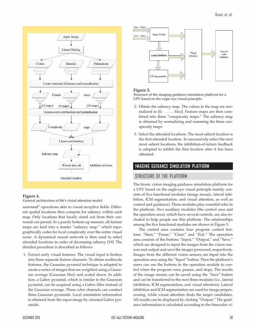
Among the kinds of visual attention models, Itti [9] pro-posed a data-based bottom-up implicit visual attention mod-el that builds on a second biologically plausible architecture on the basis of several other models. The visual attention model breaks down the complex problem of scene under-standing using rapid selection in a computationally efficient way. The framework, as illustrated in Figure 4, provides a massively parallel method for fast selection of a number of interesting image locations. These attention locations can then be analyzed by more complex and time-consuming ob-ject recognition processes.
In the visual attention model, the input is first decom-posed into a set of topographic feature maps from three separate yet parallel channels (i.e., color, intensity, and ori-entation). Each feature is computed by a set of linear “center-
Figure 3. Architecture of the ICM neuron.
DECEMBER2013 IEEEA&ESYSTEMSMAGAZINE 39
Duan et al .
surround” operations akin to visual receptive fields. Differ-ent spatial locations then compete for saliency within each map. Only locations that locally stand out from their sur-round can persist. In a purely bottom-up manner, all feature maps are feed into a master “saliency map,” which topo-graphically codes for local conspicuity over the entire visual scene. A dynamical neural network is then used to select attended locations in order of decreasing saliency [19]. The detailed procedure is described as follows:
1. Extract early visual features. The visual input is broken into three separate feature channels. To obtain multiscale features, the Gaussian pyramid technique is adopted to create a series of images that are weighted using a Gauss-ian average (Gaussian blur) and scaled down. In addi-tion, a Gabor pyramid, which is similar to the Gaussian pyramid, can be acquired using a Gabor filter instead of the Gaussian average. These color channels can conduct three Gaussian pyramids. Local orientation information is obtained from the input image by oriented Gabor pyr-amids.
2. Obtain the saliency map. The values in the map are nor-malized to [0, . . . , Max]. Feature maps are then com-bined into three “conspicuity maps.” The saliency map is obtained by normalizing and summing the three con-spicuity maps.
3. Select the attended locations. The most salient location is the first attended location. To successively select the next most salient locations, the inhibition-of-return feedback is adopted to inhibit the first location after it has been obtained.
IMAGING GUIDANCE SIMULATION PLATFORM
STRUCTUREOFTHEPLATFORM
The bionic vision imaging guidance simulation platform for a UFV based on the eagle-eye visual principle mainly con-sists of five functional modules (image mosaic, lateral inhi-bition, ICM segmentation, and visual attention, as well as control and guidance). These modules play essential roles in the platform. Two auxiliary modules (the control area and the operation area), which have several controls, are also in-cluded to help people use this platform. The relationships among the five functional modules are shown in Figure 5.
The control area contains four program control but-tons: “Start,” “Pause,” “Clear,” and “Exit.” The operation area consists of the buttons “Input,” “Output,” and “Save,” which are designed to input the images from the vision sen-sors and output and save the images processed, respectively. Images from the different vision sensors are input into the operation area using the “Input” button. Then the platform’s users can use the buttons in the operation module to con-trol when the program runs, pauses, and stops. The results of the image mosaic can be saved using the “Save” button and can be transferred to the next three modules (i.e., lateral inhibition, ICM segmentation, and visual attention). Lateral inhibition and ICM segmentation are used for image prepro-cessing, while visual attention finds the target candidates. All results can be displayed by clicking “Output.” The guid-ance information is calculated according to the binocular vi-
Figure 4. General architecture of Itti’s visual attention model.
Figure 5. Structure of the imaging guidance simulation platform for a UFV based on the eagle-eye visual principle.
40 IEEEA&ESYSTEMSMAGAZINE DECEMBER2013
Eagle-Eye–Based Visual Imaging Simulat ion
sion principle. In the last module, control and guidance, the platform’s users can call the algorithm to control and guide a UFV to intercept a moving object “Target.”
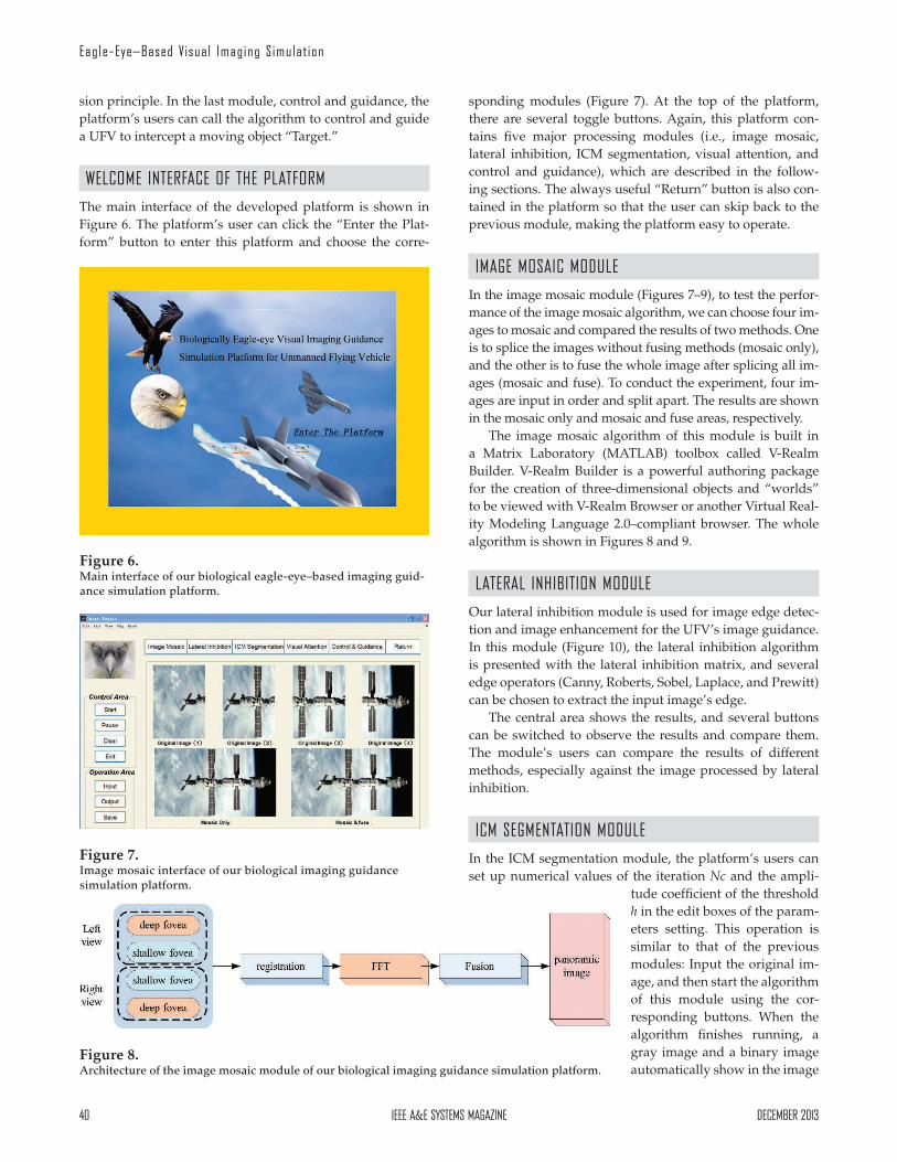
WELCOMEINTERFACEOFTHEPLATFORM
The main interface of the developed platform is shown in Figure 6. The platform’s user can click the “Enter the Plat-form” button to enter this platform and choose the corre-
sponding modules (Figure 7). At the top of the platform, there are several toggle buttons. Again, this platform con-tains five major processing modules (i.e., image mosaic, lateral inhibition, ICM segmentation, visual attention, and control and guidance), which are described in the follow-ing sections. The always useful “Return” button is also con-tained in the platform so that the user can skip back to the previous module, making the platform easy to operate.
IMAGEMOSAICMODULE
In the image mosaic module (Figures 7–9), to test the perfor-mance of the image mosaic algorithm, we can choose four im-ages to mosaic and compared the results of two methods. One is to splice the images without fusing methods (mosaic only), and the other is to fuse the whole image after splicing all im-ages (mosaic and fuse). To conduct the experiment, four im-ages are input in order and split apart. The results are shown in the mosaic only and mosaic and fuse areas, respectively.
The image mosaic algorithm of this module is built in a Matrix Laboratory (MATLAB) toolbox called V-Realm Builder. V-Realm Builder is a powerful authoring package for the creation of three-dimensional objects and “worlds” to be viewed with V-Realm Browser or another Virtual Real-ity Modeling Language 2.0–compliant browser. The whole algorithm is shown in Figures 8 and 9.
LATERALINHIBITIONMODULE
Our lateral inhibition module is used for image edge detec-tion and image enhancement for the UFV’s image guidance. In this module (Figure 10), the lateral inhibition algorithm is presented with the lateral inhibition matrix, and several edge operators (Canny, Roberts, Sobel, Laplace, and Prewitt) can be chosen to extract the input image’s edge.
The central area shows the results, and several buttons can be switched to observe the results and compare them. The module’s users can compare the results of different methods, especially against the image processed by lateral inhibition.
ICMSEGMENTATIONMODULE
In the ICM segmentation module, the platform’s users can set up numerical values of the iteration Nc and the ampli-
tude coefficient of the threshold h in the edit boxes of the param-eters setting. This operation is similar to that of the previous modules: Input the original im-age, and then start the algorithm of this module using the cor-responding buttons. When the algorithm finishes running, a gray image and a binary image automatically show in the image
Figure 7. Image mosaic interface of our biological imaging guidance simulation platform.
Figure 6. Main interface of our biological eagle-eye–based imaging guid-ance simulation platform.
Figure 8. Architecture of the image mosaic module of our biological imaging guidance simulation platform.

DECEMBER2013 IEEEA&ESYSTEMSMAGAZINE 41
Duan et al .
areas labeled “Gray Image” and “ICM Segmentated Image,” respectively. The gray image is the input image converted from a red–green–blue color model image to a gray image, and the binary image is the result of ICM segmentation. The original image and the results of ICM segmentation are also shown in Figure 11.
VISUALATTENTIONMODULE
The visual attention module is the fourth module of the plat-form to get the object candidates out of the input image. In this algorithm, the first three attractive areas are selected as object candidates.
As shown in Figure 12, an image is input to test this visual attention module. “Original image” shows the input image, while “consistent map” shows the map normalized by the
Figure 9. Image mosaic algorithm built in V-Realm Builder.
Figure 10. Lateral inhibition interface of our biological imaging guidance simulation platform.
Figure 11. ICM segmentation interface of our biological imaging guidance simulation platform.
Figure 12. Visual attention interface of our biological imaging guidance simulation platform.

42 IEEEA&ESYSTEMSMAGAZINE DECEMBER2013
Eagle-Eye–Based Visual Imaging Simulat ion
three conspicuity maps (i.e., the color map, intensity map, and orientation map). The saliency map is also shown in the lower-left image area. The results of the first three segmenta-tions and first three candidates can be shown by clicking the buttons “Segm.1,” “Segm.2,” “Segm.3,” “Result 1,” “Result 2,” and “Result 3,” respectively. The original image and first
segmentation share an image area. When the “Segm.1” but-ton is clicked, the upper-left image area shows the result of the first segmentation, and when “Original image” is clicked, the input image is displayed in this image area. The same function design is used in the other image areas.
WHOLEEAGLE-EYEVISIONSYSTEMOFTHEDEVELOPED
PLATFORM
The whole eagle-eye vision system, including the preceding four modules, was built in V-Realm Builder. A diagram of our developed platform is shown in Figure 13.
Figure 14 shows the detailed module in MATLAB Simu-link. Simulink is a block diagram environment for modeling that was developed by MathWorks. It can be efficiently used for simulating and analyzing multidomain dynamic sys-tems. Its primary interface is a graphical block diagramming tool, along with a customizable set of block libraries. Simu-link is integrated with the rest of the MATLAB environment, allowing us to incorporate MATLAB algorithms into models and export simulation results to MATLAB for further analy-sis and even to drive MATLAB and script from it.
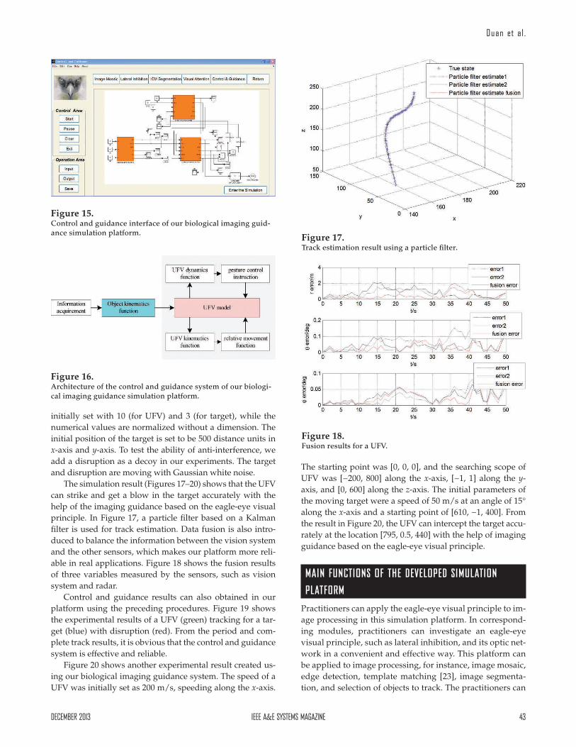
CONTROLANDGUIDANCEMODULE
In the control and guidance module, the control and guid-ance system is built (Figures 15 and 16), according to [20]–[22]. In our experiments, for simplification, the velocities are
Figure 13. Structure of the whole biological eagle-eye vision–based plat-form.
Figure 14. Whole vision system developed in V-Realm Builder and shown in MATLAB Simulink.
DECEMBER2013 IEEEA&ESYSTEMSMAGAZINE 43
Duan et al .
initially set with 10 (for UFV) and 3 (for target), while the numerical values are normalized without a dimension. The initial position of the target is set to be 500 distance units in x-axis and y-axis. To test the ability of anti-interference, we add a disruption as a decoy in our experiments. The target and disruption are moving with Gaussian white noise.
The simulation result (Figures 17–20) shows that the UFV can strike and get a blow in the target accurately with the help of the imaging guidance based on the eagle-eye visual principle. In Figure 17, a particle filter based on a Kalman filter is used for track estimation. Data fusion is also intro-duced to balance the information between the vision system and the other sensors, which makes our platform more reli-able in real applications. Figure 18 shows the fusion results of three variables measured by the sensors, such as vision system and radar.
Control and guidance results can also obtained in our platform using the preceding procedures. Figure 19 shows the experimental results of a UFV (green) tracking for a tar-get (blue) with disruption (red). From the period and com-plete track results, it is obvious that the control and guidance system is effective and reliable.
Figure 20 shows another experimental result created us-ing our biological imaging guidance system. The speed of a UFV was initially set as 200 m/s, speeding along the x-axis.
The starting point was [0, 0, 0], and the searching scope of UFV was [−200, 800] along the x-axis, [−1, 1] along the y-axis, and [0, 600] along the z-axis. The initial parameters of the moving target were a speed of 50 m/s at an angle of 15° along the x-axis and a starting point of [610, −1, 400]. From the result in Figure 20, the UFV can intercept the target accu-rately at the location [795, 0.5, 440] with the help of imaging guidance based on the eagle-eye visual principle.
MAIN FUNCTIONS OF THE DEVELOPED SIMULATION
PLATFORM
Practitioners can apply the eagle-eye visual principle to im-age processing in this simulation platform. In correspond-ing modules, practitioners can investigate an eagle-eye visual principle, such as lateral inhibition, and its optic net-work in a convenient and effective way. This platform can be applied to image processing, for instance, image mosaic, edge detection, template matching [23], image segmenta-tion, and selection of objects to track. The practitioners can
Figure 15. Control and guidance interface of our biological imaging guid-ance simulation platform.
Figure 16. Architecture of the control and guidance system of our biologi-cal imaging guidance simulation platform.
Figure 17. Track estimation result using a particle filter.
Figure 18. Fusion results for a UFV.

44 IEEEA&ESYSTEMSMAGAZINE DECEMBER2013
Eagle-Eye–Based Visual Imaging Simulat ion
input images, observe the performance of the algorithms, and learn the whole vision system of image guidance si-multaneously.
Practitioners also can observe the performance of this guidance and control system. Our system is built in MAT-LAB, Simulink, and V-Realm Builder. It consists of image-processing modules and control and guidance modules. Its users can change the parameters in the platform and ob-serve the performance through the intermediate images or the simulation curves. In this way, the optimal parameters in the practical issue can be obtained. Satisfactory improve-ments can be achieved through more detailed and exact modeling.
Finally, this platform can be expanded and applied to carrying out different tasks. In this platform, we developed a guidance and control system based on eagle-eye visual image guidance. It can help guide the UFV to search, track, and strike the adversary’s vehicles, even in the complicated battlefield environments of modern wars. Practitioners can also apply it to different types of UFVs by modifying some parts of this platform.
CONCLUSIONS
In this article, we have developed a bionic vision imaging guidance simulation platform for UFVs in a MATLAB envi-ronment, which is based on the biological eagle-eye–based visual principle. The practitioners can investigate the eagle-eye visual principle and apply our platform to image guid-ance for a UFV. Our biological imaging guidance simulation platform is easy to operate.
ACKNOWLEDGMENTS
This work was partially supported by the Natural Sci-ence Foundation of China under Grants No. 61273054, No. 60975072, and No. 61333004, the National Key Basic Re-search Program of China under Grant No. 2013CB035503, and No. 2014CB046401, the Program for New Century Excel-lent Talents in University of China under Grant No. NCET-10-0021, the Top-Notch Young Talents Program of China, the Innovation Foundation of Beijing University of Aeronautics and Astronautics for PhD Graduates, and the Aeronautical Foundation of China under Grant No. 20115151019. The au-thors also thank the anonymous referees for their comments
Figure 20. Experimental result of guidance for a UFV.
Figure 19. Guidance and track results for a UFV.

DECEMBER2013 IEEEA&ESYSTEMSMAGAZINE 45
Duan et al .
and suggestions, which led to the better presentation of this work.
REFERENCES
[1] Duan, H. B., and Liu, S. Q. Unmanned air/ground vehicles heterogeneous cooperative techniques: current status and pros-pects. Science China Technological Sciences, Vol. 53, 5 (May 2010), 1349–1355.
[2] Duan, H. B., Zhang, X. Y., and Xu, CF. Bio-inspired Computing. Beijing, China: Science Press, 2011.
[3] Duan, H. B., Shao, S., Su, B. W., and Zhang, L. New develop-ment thoughts on the bio-inspired intelligence based control for unmanned combat aerial vehicle. Science China Technological Sci-
ences, Vol. 53, 8 (Aug. 2010), 2025–2031.[4] Li, Y. J., and Zhang, K. Vision Bionics Image Guidance Technique
and Application. Beijing, National Defense Industry Press, 2006.
[5] American Bald Eagle Information. A bald eagle’s eyesight and hearing, http://www.baldeagleinfo.com/eagle/eagle2.html, last access December 2012.
[6] Tucker, V. A. The deep fovea, sideways vision and spiral flight paths in raptors. Journal of Experimental Biology, Vol. 203, 24 (Dec. 2000), 3745–3754.
[7] Liu, F., Duan, H. B., and Deng, Y. M. A chaotic quantum-be-haved particle swarm optimization based on lateral inhibition for image matching. Optik—International Journal for Light and
Electron Optics, Vol. 123, 21 (Nov. 2012), 1955–1960.[8] Shi, J. B., and Malik, J. Normalized cuts and image segmenta-
tion. IEEE Transactions on Pattern Analysis and Machine Intelli-
gence, Vol. 22, 8 (Aug. 2000), 888–905.[9] Itti, L., Koch, C., and Niebur, E. A model of saliency-based
visual attention for rapid scene analysis. IEEE Transactions on
Pattern Analysis and Machine Intelligence, Vol. 20, 11 (Nov. 1998), 1254–1259.
[10] Burt, P. J., and Adelson, E. H. A multiresolution spline with ap-plication to image mosaics. ACM Transactions on Graphics, Vol. 2, 4 (Oct. 1983), 217–236.
[11] Tian, G. Y., Gledhill, D., and Taylor, D. Comprehensive interest points based imaging mosaic. Pattern Recognition Letters, Vol. 24, 9–10 (Jun. 2003), 1171–1179.
[12] Hartline, H. K. The response of single optic nerve fibers of the vertebrate eye to illumination of the retina. American Journal of
Physiology, Vol. 121, 2 (Jan. 1938), 400–415.
[13] Mao, Z. H., and Massaquoi, S. G. Dynamics of winner-take-all competition in recurrent neural networks with lateral inhibi-tion. IEEE Transactions on Neural Networks, Vol. 18, 1 (Jan. 2007), 55–69.
[14] Xie, X., Hahnloser R. H., and Seung H. S. Selectively grouping neurons in recurrent networks of lateral inhibition. Neural Com-
putation, Vol. 14, 11 (Nov. 2002), 2627–2646.[15] Wikipedia. Image segmentation, http://en.wikipedia.org/
wiki/Segmentation_(image_processing), last access December 2012.
[16] Ekblad, U., and Kinser, J. M. Theoretical foundation of the in-tersecting cortical model and its use for change detection of air-craft, cars, and nuclear explosion tests. Signal Processing, Vol. 84, 7 (Jul. 2004), 1131–1146.
[17] Zhang, X. G. A new kind of super-resolution reconstruction algorithm based on the ICM and the bicubic interpolation. In Proceedings of International Symposium on Intelligent Information
Technology Application Workshops, Qingdao, China, Dec. 21–22, 2008, 817–820.
[18] Le Meur, O., Le Callet, P., Barba, and D., Thoreau, D. A coherent computational approach to model bottom-up visual attention. IEEE Transactions on Pattern Analysis and Machine Intelligence, Vol. 28, 5 (May 2006), 802–817.
[19] Greenspan, H., Belongie, S., Goodman, R., Perona, P., Rakshit, S., and Anderson, C. H. Overcomplete steerable pyramid filters and rotation invariance. In Proceedings of IEEE Computer Society
Conference on Computer Vision and Pattern Recognition, Pasadena, CA, June 21–23, 1994, 222–228.
[20] Taur, D. R. Composite guidance and navigation strategy for a SAM against high-speed target. In Proceedings of AIAA Guidance,
Navigation, and Control Conference and Exhibit, Austin, Texas, Aug. 11–14, 2003, AIAA 2003-5720.
[21] Tetlow, M. R., Evans, M. E., and Schneider, G. M. Monte Carlo analysis for a booster flyback guidance system. In Proceedings of
43rd AIAA Aerospace Sciences Meeting and Exhibit, Reno, NV, Jan. 10–13, 2005, AIAA 2005-819.
[22] Pollini, L., Mati, R., and Innocenti, M. Experimental evaluation of vision algorithms for formation flight and aerial refueling. In Proceedings of AIAA Modeling and Simulation Technologies Confer-
ence and Exhibit, Providence, RI, Aug. 16–19, 2004, AIAA 2004-4918.
[23] Duan, H. B., Xu, CF., Liu, S. Q., Shao, S. Template matching us-ing chaotic imperialist competitive algorithm. Pattern Recogni-
tion Letters, Vol. 31, 13 (Oct. 2010), 1868–1875.