Embed Size (px)
Citation preview
BIO-FUELS Technology Status and Future Trends,
Technology Assessment and Decision Support Tools
prepared by
Sivasamy Arumugam 1, Sergey Zinoviev1, Paolo Foransiero1,
Stanislav Miertus1, Franziska Müller-Langer2, Martin
Kaltschmitt2, Alexander Vogel2, Daniela Thraen2
1 ICS-UNIDO, Trieste, Italy
2 IEE, Leipzig, Germany
International Centre for Science and High Technology
United Nations Industrial Development Organization
Pure & Applied Chemistry Area
2007

ICS-UNIDO Publication: Prepared within the ICS-UNIDO Work program of 2007, Pure &
Applied Chemistry Area
This text can be used for non-commercial needs only. No selling, distribution, modification,
reproduction, transmission, publication, broadcasting, posting or other use of its contents can
be made without prior permission from the ICS-UNIDO
3
Preface
One of the key issues of sustainable industrial development is the conversion from fossil feedstocks to
renewable feedstocks in various sectors such as energy production, fuel production, chemical and related
industries.
Such a conversion is driven by several factors (fossil feedstock depletion, need of diversification of
feedstocks-fossil and renewable, abundance of renewable resources in many countries of the world, CO2
“neutrality” of renewable feedstocks, concerted potential development of both industry and agriculture,
new openings for green chemistry and related industries development, etc.
Obviously, there are several problems to be solved in the development of this sector. Among those, there
is a need of further development of suitable technologies including 2nd and 3rd generation of bio-fuels,
availability of feedstocks, uncertainty of bio-feedstocks supply and their prices, risk of misconception in
designing of bio-fuels strategies, etc. Therefore, further development and assessment of various
technological options and of various scenarios of bio-fuels exploitation is highly needed.
The International Centre of Science and High Technology of the United Nations Industrial Development
Organization (ICS-UNIDO) has been promoting a programme on the knowledge transfer and capacity
building to developing countries in selected priority sectors including the use of renewable resources.
Due to the importance of bio-feedstocks exploitation and bio-fuels production, especially as a potentially
important sector for developing countries, UNIDO has recently elaborated “UNIDO Bio-fuels Strategy”.
In synergy with this effort, ICS-UNIDO has been implementing a technical expertise programme on bio-
fuel production technologies, focusing on the survey and assessment of technologies, especially those
belonging to 2nd and 3rd generation technologies.
The present publication provides a survey of current technologies for the production of bio-fuels and bio-
based products, and briefly describes various feedstocks and indicates also trends of further development
toward bio-refineries and integrated production of a variety of products (bio-fuels, chemicals, materials,
…) in a sustainable way.
The final part is dedicated to the assessment of various technologies and their comparison together with a
brief description of the concept of decision support tools for technology assessment and preparation of
various scenarios for bio-feedstocks exploitation.
4
The present publication can be used as a technical guideline and expertise document in the preparation,
development and implementation of various initiatives with specific focus on UNIDO initiatives in
developing countries.
We also enclosed in the Annex a preliminary survey of selected initiatives and programmes in this sector
in various parts of the world. In the present version this is limited to bio-diesel issues, however this part is
being further developed to cover other bio-fuels and bio-based products as well as to offer a more
comprehensive survey in other countries with the focus on developing countries.
This document has been prepared within the ICS-UNIDO Work Programme 2006-2007 in the Area of
Pure and Applied Chemistry by experts and fellows of ICS-UNIDO in tight cooperation with a group of
experts of the Institute for Energy and Environment of Leipzig, Germany, who agreed to participate in
this ICS-UNIDO initiative.
Therefore the valuable expertise contribution of Sivasamy Arumugam, Paolo Fornasiero, Sergei Zinoviev
as well as of Franziska Mueller-Langer, A. Vogel and Daniela Thraen is appreciated.
We are aware that this working document could contain possible errors, therefore we would appreciate if
readers could give us such indications or further suggestions, which will be taken into account when
preparing next version of this document.
Stanislav Miertus
Area Chief
Pure & Applied Chemistry, ICS-UNIDO
Trieste, 28 June 2007
5
Table of Contents
PART 1. INTRODUCTION............................................................................................................8 Biomass ...........................................................................................................................................8 Biomass to energy conversion technologies....................................................................................9 Biofuels types and generations ......................................................................................................10 Bibliography ..................................................................................................................................14 PART 2. FIRST GENERATION OF BIOFUELS ........................................................................15 Biodiesel from vegetable oils ........................................................................................................15
FAME production technology...................................................................................................15 Transesterification process technological arrangement.............................................................18
Feedstock issues ....................................................................................................................20 By-products issues.................................................................................................................21 Effect of free fatty acid and moisture ....................................................................................22 Catalyst type and concentration.............................................................................................24 Molar ratio of alcohol to oil and type of alcohol...................................................................26 Effect of reaction time and temperature ................................................................................26 Mixing intensity.....................................................................................................................27 Effect of using organic cosolvents.........................................................................................27
Product properties and quality...................................................................................................29 Cetane number.......................................................................................................................29 Flashpoint ..............................................................................................................................30 Lubricity ................................................................................................................................30 Cold flow ...............................................................................................................................31 Fuel stability ..........................................................................................................................31 Fuel energy content ...............................................................................................................31 Material compatibility ...........................................................................................................32 Equipment benefits ................................................................................................................32 Precautions ............................................................................................................................32 Biodegradability ....................................................................................................................33 NOx emission ........................................................................................................................33 Global warming and pollution reduction...............................................................................35 Safety .....................................................................................................................................35 Concerns/barriers...................................................................................................................35
Biodiesel production via transesterification in supercritical medium .......................................35 Direct use of vegetable oils and their blends as fuels................................................................36 Mixing biodiesel with conventional diesel fuels .......................................................................38 Production of biodiesel by pyrolysis and hydroprocessing of oils and fats ..............................39
Market and economic aspects of biodiesel production..................................................................43 Final price ..................................................................................................................................43 Production costs.........................................................................................................................43 Feedstock costs ..........................................................................................................................43 Tax incentives............................................................................................................................44
Bioethanol from sugar crops .........................................................................................................45 Bioethanol from sugar feedstocks .............................................................................................45 Bioethanol from starch: .............................................................................................................45 Wet Milling Processes ...............................................................................................................46 Dry milling process ...................................................................................................................46 Sugar fermentation process .......................................................................................................46 Fractional Distillation Process...................................................................................................47 Advantages of bioethanol as fuel...............................................................................................47
6
Disadvantages of bioethanol as fuel ..........................................................................................48 Biogas by anaerobic digestion.......................................................................................................49
Biomethane by anaerobic digestion (via biogas).......................................................................49 The process of anaerobic digestion .......................................................................................50 Digester Technology..............................................................................................................50 Types of Anaerobic Digesters ...............................................................................................52 Biogas from wastes................................................................................................................54 Landfill Gas ...........................................................................................................................54 Biogas upgrading to biomethane ...........................................................................................55
Water scrubbing.................................................................................................................56 Pressure swing adsorption .................................................................................................56 Chemical adsorption ..........................................................................................................57 Membrane technologies.....................................................................................................57 Cryogenic upgrading .........................................................................................................57
Bibliography ..................................................................................................................................59 PART 3. SECOND GENERATION OF BIOFUELS AND BIOREFINERIES...........................62 Pyrolysis and gasification of biomass ...........................................................................................62 Synthetic biofuels ..........................................................................................................................64
Bio-SNG ....................................................................................................................................65 Fischer-Tropsch fuels ................................................................................................................67 Biomethanol ..............................................................................................................................68 Dimethylether (DME) ...............................................................................................................68 Hydro Thermal Upgrading (HTU) diesel ..................................................................................69
Cellulosic bioethanol .....................................................................................................................71 Process description ....................................................................................................................71 Hydrolysis by dilute acid...........................................................................................................72 Hydrolysis by concentrated acid................................................................................................73 Enzymatic hydrolysis ................................................................................................................74 Bioethanol production from hydrolysed cellulosic biomass: ....................................................74 Hybrid and thermochemical processes for ethanol production from cellulosic biomass ..........75
Bio-hydrogen.................................................................................................................................76 Thermo-chemical gasification coupled with water gas shift .....................................................78 Fast pyrolysis followed by reforming of carbohydrate fraction of bio-oil ................................78 Direct solar gasification.............................................................................................................79 Miscellaneous novel gasification processes ..............................................................................79 Biomass derived syn-gas conversion.........................................................................................80 Supercritical conversion of biomass..........................................................................................80 Microbial conversion of biomass ..............................................................................................81 Comparative analysis.................................................................................................................82
Biorefineries ..................................................................................................................................84 Bibliography ..................................................................................................................................92 PART 4. TECHNOLOGY EVALUATION ASPECTS ...............................................................96 General aspects of future biofuel production options....................................................................96
Lignocellulosic bioethanol ........................................................................................................97 Synthetic biofuels ......................................................................................................................98 Biohydrogen ..............................................................................................................................99 Biogas ........................................................................................................................................99
Technology aspects .....................................................................................................................100 Economic aspects ........................................................................................................................101 Environmental aspects.................................................................................................................103

7
Bibliography ................................................................................................................................106 PART 5. DECISION SUPPORT TOOLS FOR BIOFUELS AND BIOFUELS TECHNOLOGY ASSESSMENT............................................................................................................................107 The concept of decision support tool for assessment of scenarios of biofuel production and bio-feedstock exploitation..................................................................................................................108 BioAs: A Decision Support Tool for Biofuel Assessment and Selection ...................................114
Criteria .....................................................................................................................................114 Technical information .............................................................................................................115
Biliography ..................................................................................................................................117 ANNEX BIOFUELS AROUND THE WORLD.........................................................................118
A.1 Europe...............................................................................................................................118 A. 2 Belgium ...........................................................................................................................120 A. 3 Czech Republic................................................................................................................121 A. 4 Estonia .............................................................................................................................122 A. 5 France ..............................................................................................................................122 A. 6 Finland .............................................................................................................................124 A. 7 Italy ..................................................................................................................................124 A. 8 Germany ..........................................................................................................................125 A. 9 Slovakia ...........................................................................................................................126 A. 10 Switzerland ....................................................................................................................127 A. 11 Norway ..........................................................................................................................128 A. 12 Spain ..............................................................................................................................128 A. 13 Austria ...........................................................................................................................129 A. 14 United Kingdom ............................................................................................................130 A. 15 China..............................................................................................................................131 A. 16 Singapore .......................................................................................................................132 A. 17 Thailand .........................................................................................................................132 A. 18 Malaysia.........................................................................................................................133 A. 19 India ...............................................................................................................................134 A. 20 Israel ..............................................................................................................................134 A. 21 Australia.........................................................................................................................134 A. 22 Brazil .............................................................................................................................136 A. 23 United States..................................................................................................................137 A. 24 Canada ...........................................................................................................................139 A. 25 Costa Rica......................................................................................................................140
WEB SITES: ...............................................................................................................................141
8
Part 1. Introduction
Biomass
Biomass refers to material of biological origin excluding material embedded in geological
formations and transformed to fossil. Biomass can directly or indirectly be converted to biofuels
which can be of solid, liquid or gaseous forms. Major sources of biomass for energy purposes are
various types of woody and herbaceous biomass, biomass from fruits and seeds (e.g. energy
crops) as well as biomass mixtures like animal or horticultural by products etc. Within these
products solar energy directly or indirectly (in terms of biomass of animal by-products) by the
process of photosynthesis is stored which enables the plants to produce biomass. Biomass is
available in abundance and is cheap and its better utilization is to convert it to energy rich
products using suitable processes.
Biomass has been the most important energy source for humans since the discovery of fire, and
today it is still the main source for almost half of the world’s population. The need to increase
the use of renewable energy is fundamental to make the world energy matrix more sustainable.
The total use of biomass energy is inherently difficult to measure, especially because much of it
does not involve commercial transactions. Globally, the primary energy use of biomass in 2000
was about 52 EJ. Of this total, roughly 45 EJ was consumed as traditional household fuel in
developing countries, with some of this converted to charcoal for urban and industrial uses. This
is why biomass is only a small percentage of primary energy in industrialized countries but is 42
% of primary energy in India and up to 90% in the world’s poorest countries in Africa and Asia.
Modern uses of biomass comprise the remaining 7 EJ, mostly in the production of electricity and
steam in industrialized and developing countries, such as in the pulp and paper industry, but also
in some production of biofuels, as with ethanol in Brazil.
Combustion to produce thermal energy is the traditional way of using biomass, which is what
humans have been doing since they discovered fire. The positive benefits of wood combustion to
human well-being and longevity were undoubtedly enormous, but there were also costs.
Archaeologists tell that cave walls of our ancestors were coated with residues from the thick
smoke that would have filled the air and clogged the lungs of cave dwellers. Smoke-filled
interior spaces are still the norm for the one third of humanity that continues to rely on wood as
its primary energy source, and the particulates and noxious fumes from cooking with open fires
and inefficient and poorly ventilated stoves fuelled by wood and crop residues have substantial
9
health impacts. The transition in developing regions of the world from traditional technologies
using biomass to more efficient technologies using fossil fuels (propane, butane) results in a
dramatic improvement in indoor air quality and increased life expectancy.
Biomass to energy conversion technologies
Advanced technologies are now under development to convert biomass into various forms of
secondary energy including electricity, gaseous and liquid biofuels, and even hydrogen. The
purpose of biomass conversion is to provide fuels with clearly defined fuel characteristics that
meet given fuel quality standards. To ensure that these fuel quality standards are met and these
biomass based fuels can be used with a high efficiency in conversion devices (like engines,
turbines) upgrading is needed. In general, there are various options to produce alternative
transportation fuels based on biomass. Biogenous energy sources can be converted by means of
highly different supply chains into gaseous and liquid biofuels that can be used for transportation
purposes. This treatment leads to an upgrading of energy sources in terms of one or more
properties named as follows:
∗ Energy density,
∗ Handling,
∗ Storage and transport,
∗ Environmental compatibility,
∗ Utilising of by-products and residues.
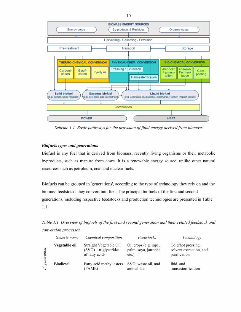
Depending on the conversion of biomass in principal three main pathways come into
consideration (Scheme 1.1): (i) the thermo-chemical pathway, (ii) the physical-chemical
conversion pathway, (iii) the bio-chemical conversion pathway. Those processes provide
biofuels in the form of solids (mainly charcoal), liquids (mainly biodiesel and alcohols), or
gases (mainly mixtures with methane or carbon monoxide), which can be used for a wide range
of applications, including transport and high-temperature industrial processes. These pathways
are introduced as follows.
10
Scheme 1.1. Basic pathways for the provision of final energy derived from biomass
Biofuels types and generations
Biofuel is any fuel that is derived from biomass, recently living organisms or their metabolic
byproducts, such as manure from cows. It is a renewable energy source, unlike other natural
resources such as petroleum, coal and nuclear fuels.
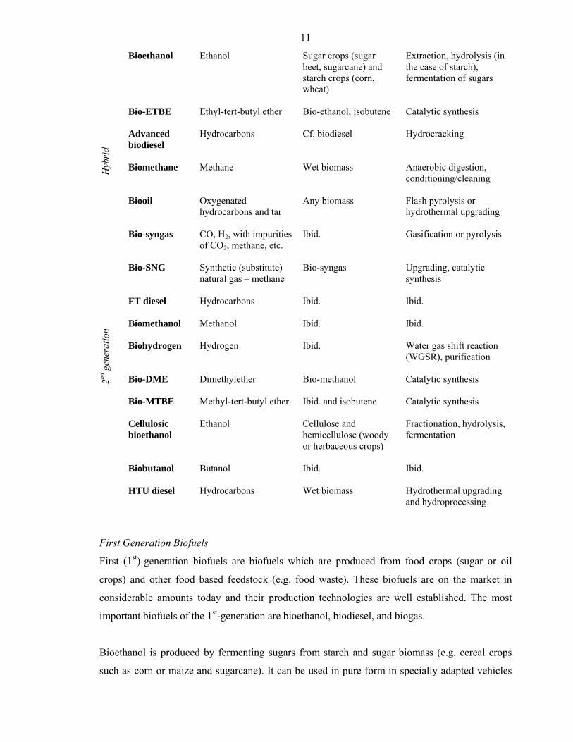
Biofuels can be grouped in 'generations', according to the type of technology they rely on and the
biomass feedstocks they convert into fuel. The principal biofuels of the first and second
generations, including respective feedstocks and production technologies are presented in Table
1.1.
Table 1.1. Overview of biofuels of the first and second generation and their related feedstock and
conversion processes
Generic name Chemical composition Feedstocks Technology
Vegetable oil
Straight Vegetable Oil (SVO) – triglycerides of fatty acids
Oil crops (e.g. rape, palm, soya, jatropha, etc.)
Cold/hot pressing, solvent extraction, and purification
1st g
ener
atio
n
Biodiesel
Fatty acid methyl esters (FAME)
SVO, waste oil, and animal fats
Ibid. and transesterification
11
Bioethanol
Ethanol Sugar crops (sugar beet, sugarcane) and starch crops (corn, wheat)
Extraction, hydrolysis (in the case of starch), fermentation of sugars
Bio-ETBE Ethyl-tert-butyl ether Bio-ethanol, isobutene
Catalytic synthesis
Advanced biodiesel
Hydrocarbons Cf. biodiesel Hydrocracking
Hyb
rid
Biomethane
Methane
Wet biomass Anaerobic digestion, conditioning/cleaning
Biooil Oxygenated hydrocarbons and tar
Any biomass Flash pyrolysis or hydrothermal upgrading
Bio-syngas CO, H2, with impurities of CO2, methane, etc.
Ibid. Gasification or pyrolysis
Bio-SNG
Synthetic (substitute) natural gas – methane
Bio-syngas Upgrading, catalytic synthesis
FT diesel Hydrocarbons
Ibid. Ibid.
Biomethanol Methanol
Ibid. Ibid.
Biohydrogen
Hydrogen Ibid. Water gas shift reaction (WGSR), purification
Bio-DME Dimethylether
Bio-methanol Catalytic synthesis
Bio-MTBE
Methyl-tert-butyl ether Ibid. and isobutene Catalytic synthesis
Cellulosic bioethanol
Ethanol Cellulose and hemicellulose (woody or herbaceous crops)
Fractionation, hydrolysis, fermentation
Biobutanol
Butanol Ibid. Ibid.
2nd g
ener
atio
n
HTU diesel Hydrocarbons
Wet biomass Hydrothermal upgrading and hydroprocessing
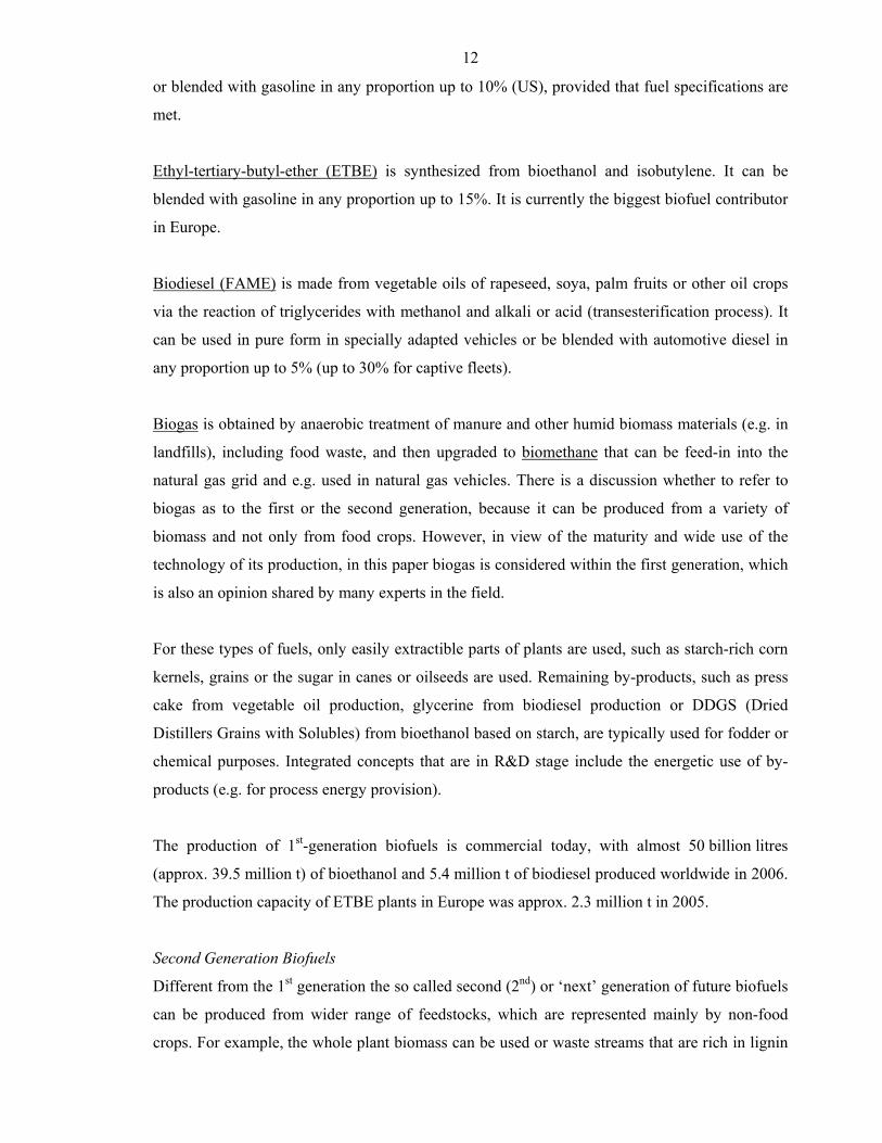
First Generation Biofuels
First (1st)-generation biofuels are biofuels which are produced from food crops (sugar or oil
crops) and other food based feedstock (e.g. food waste). These biofuels are on the market in
considerable amounts today and their production technologies are well established. The most
important biofuels of the 1st-generation are bioethanol, biodiesel, and biogas.
Bioethanol is produced by fermenting sugars from starch and sugar biomass (e.g. cereal crops
such as corn or maize and sugarcane). It can be used in pure form in specially adapted vehicles
12
or blended with gasoline in any proportion up to 10% (US), provided that fuel specifications are
met.
Ethyl-tertiary-butyl-ether (ETBE) is synthesized from bioethanol and isobutylene. It can be
blended with gasoline in any proportion up to 15%. It is currently the biggest biofuel contributor
in Europe.
Biodiesel (FAME) is made from vegetable oils of rapeseed, soya, palm fruits or other oil crops
via the reaction of triglycerides with methanol and alkali or acid (transesterification process). It
can be used in pure form in specially adapted vehicles or be blended with automotive diesel in
any proportion up to 5% (up to 30% for captive fleets).
Biogas is obtained by anaerobic treatment of manure and other humid biomass materials (e.g. in
landfills), including food waste, and then upgraded to biomethane that can be feed-in into the
natural gas grid and e.g. used in natural gas vehicles. There is a discussion whether to refer to
biogas as to the first or the second generation, because it can be produced from a variety of
biomass and not only from food crops. However, in view of the maturity and wide use of the
technology of its production, in this paper biogas is considered within the first generation, which
is also an opinion shared by many experts in the field.
For these types of fuels, only easily extractible parts of plants are used, such as starch-rich corn
kernels, grains or the sugar in canes or oilseeds are used. Remaining by-products, such as press
cake from vegetable oil production, glycerine from biodiesel production or DDGS (Dried
Distillers Grains with Solubles) from bioethanol based on starch, are typically used for fodder or
chemical purposes. Integrated concepts that are in R&D stage include the energetic use of by-
products (e.g. for process energy provision).
The production of 1st-generation biofuels is commercial today, with almost 50 billion litres
(approx. 39.5 million t) of bioethanol and 5.4 million t of biodiesel produced worldwide in 2006.
The production capacity of ETBE plants in Europe was approx. 2.3 million t in 2005.
Second Generation Biofuels
Different from the 1st generation the so called second (2nd) or ‘next’ generation of future biofuels
can be produced from wider range of feedstocks, which are represented mainly by non-food
crops. For example, the whole plant biomass can be used or waste streams that are rich in lignin
13
and cellulose, such as wheat straw, grass, or wood. In order to breakdown this biomass, two main
conversion pathways come into consideration: 1) hydrolysis (can be done via chemical and bio-
chemical pathways) of ligno-cellulose into sugars, which can then be fermented into alcohol -
this technology is best known as 'cellulosic bioethanol' and is still in development; 2) thermo-
chemical processes (use of high temperatures to pyrolyse or gasify biomass) of lignocelluloses to
a raw gas or oil. The resulting gas is then treated and conditioned into synthesis gas (syngas),
consisting mainly of carbon monoxide and hydrogen. This gas can further be processed into
different types of liquid and gaseous fuels via different fuel syntheses. Fuels from this route are
then called 'synthetic biofuels'. Most promising liquid synthetic biofuels, also called BtL:
biomass-to-liquids, are biomethanol and Fischer-Tropsch fuels. Gaseous synthetic biofuels are
e.g. dimethylether (DME) and Bio-SNG, which is also a form of biomethane and can be
similarly used as natural gas substitute like biogas. Alternatively, the cleaned and conditioned
product gas can be converted into hydrogen. Bio-oil obtained from biomass via pyrolysis or
hydrothermal treatment can also be converted into high quality liquid fuels by deoxygenation
(e.g. HTU diesel).
Third Generation Biofuels
Third generation biofuels rely on biotechnological interventions in the feedstocks themselves.
Plants are engineered in such a way that the structural building blocks of their cells (lignin,
cellulose, hemicellulose), can be managed according to a specific task they are required to
perform. For example, plant scientists are working on developing trees that grow normally, but
that can be triggered to change the strength of the cell walls so that breaking them down to
release sugars is easier. In third generation biofuels, a synergy between this kind of interventions
and processing steps is then created: plants with special properties are broken down by
functionally engineered enzymes. Notably, this latter generation of biofuels is only gradually
being explored.

14
Bibliography
Boyle G. 2003, Renewable Energy, Oxford, Oxford University Press.
Dincer I. 2000, Renewable and Sustainable Energy Reviews, 4, 157.
Jaccard M. 2006, Sustainable Fossil Fuels - The Unusual Suspect in the Quest for Clean and
Enduring Energy, Cambridge University Press.
Kaltschmitt M. 2001, Energie aus Biomasse – Grundlagen, Techniken und Verfahren. Springer-
Verlag, Berlin, Heidelberg.
15
Part 2. First generation of biofuels
Biodiesel from vegetable oils
The first generation biodiesel is usually referred to as the mixture if fatty acid methyl esters
(FAME) produced from vegetable oils and animal fats via their transesterification reaction.
Several production methodologies are available, which employ the use of homogeneous,
heterogeneous, or bio-catalysts. The mostly used commercial technology for biodiesel
production is the transesterification reaction of the triglyceride of the fatty acid with methanol
under the basic conditions (e.g. sodium hydroxide as the catalyst) to yield the methyl ester of the
fatty acid (biodiesel).
In addition, other types of biofuels can be produced from vegetable oils and fats. Such include,
fur example, direct use of straight vegetable oils (SVO) as fuels. This application is less common
and is not considered promising due to inferior properties of SVO with respect to the diesel fuels.
In addition to the commonly used FAME diesel, a biodiesel can be obtained from vegetable oils
via their hydrocracking. Such a diesel is mainly composed of alkanes and is similar to petroleum
diesel or the next generation FT diesel. However, since it is obtained from the food crops (oil) it
is, however, considered as the first generation of biodiesel. Its production technology is less
developed but is believed by some to be in the next future a competitive option to the FAME
diesel.
Feedstocks for first generation of biodiesel basically include vegetable oil obtained from oil
(energy) crops, as well as recycled oil, animal fats, algae, etc. Different feedstocks may require
different conditions of treatment and different pretreatment technology to be adopted,
consecutively, the cost and complexity of the process and the quality of the product can vary.
This chapter is dedicated to the issues related to the production technologies for biodiesel of the
first generation, including biodiesel produced by vegetable oil hydrocracking. The use of straight
vegetable oils (SVO) as fuels, directly or as blends, is also described. Production of other types
of biodiesel, e.g. second generation synthetic biodiesel from bio-SNG (synthetic natural gas),
will be considered in the next chapters.
FAME production technology
Generally speaking, there are three basic ways for the production of methyl esters from oils and
fats:
16
• Base catalysed transesterification of the oil (triglycerides) with methanol;
• Direct acid catalyzed esterification of the free fatty acids (FFA) with methanol;
• Conversion of the oil to FFA followed their esterification as described above.
The majority of the methyl esters are produced using the base catalyzed reaction because it is the
most economic for several reasons:
• low temperature and pressure;
• high yields and short reaction times;
• direct conversion process.
• Simple in operation and environmentally benign.
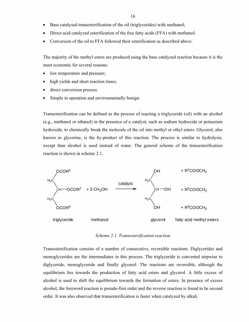
Transesterification can be defined as the process of reacting a triglyceride (oil) with an alcohol
(e.g., methanol or ethanol) in the presence of a catalyst, such as sodium hydroxide or potassium
hydroxide, to chemically break the molecule of the oil into methyl or ethyl esters. Glycerol, also
known as glycerine, is the by-product of this reaction. The process is similar to hydrolysis,
except than alcohol is used instead of water. The general scheme of the transesterification
reaction is shown in scheme 2.1.
OCOR3
H2C
CH
H2C
OCOR1
OCOR2 + 3 CH3OH
OH
H2C
CH
H2C
OH
OH
+ R1COOCH3
+ R2COOCH3
+ R3COOCH3
catalyst
triglyceride methanol glycerol fatty acid methyl esters
Scheme 2.1. Transesterification reaction
Transesterification consists of a number of consecutive, reversible reactions. Diglycerides and
monoglycerides are the intermediates in this process. The triglyceride is converted stepwise to
diglyceride, monoglyceride and finally glycerol. The reactions are reversible, although the
equilibrium lies towards the production of fatty acid esters and glycerol. A little excess of
alcohol is used to shift the equilibrium towards the formation of esters. In presence of excess
alcohol, the foreword reaction is pseudo-first order and the reverse reaction is found to be second
order. It was also observed that transesterification is faster when catalyzed by alkali.
17
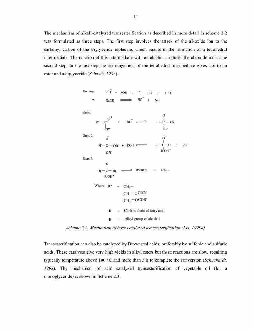
The mechanism of alkali-catalyzed transesterification as described in more detail in scheme 2.2
was formulated as three steps. The first step involves the attack of the alkoxide ion to the
carbonyl carbon of the triglyceride molecule, which results in the formation of a tetrahedral
intermediate. The reaction of this intermediate with an alcohol produces the alkoxide ion in the
second step. In the last step the rearrangement of the tetrahedral intermediate gives rise to an
ester and a diglyceride (Schwab, 1987).
Scheme 2.2. Mechanism of base catalyzed transesterification (Ma, 1999a)
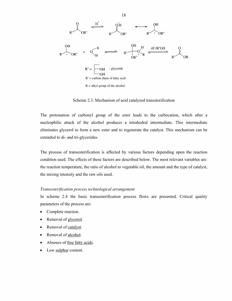
Transesterification can also be catalyzed by Brownsted acids, preferably by sulfonic and sulfuric
acids. These catalysts give very high yields in alkyl esters but these reactions are slow, requiring
typically temperature above 100 °C and more than 3 h to complete the conversion (Schuchardt,
1998). The mechanism of acid catalyzed transesterification of vegetable oil (for a
monoglyceride) is shown in Scheme 2.3.
18
Scheme 2.3. Mechanism of acid catalyzed trasesterification
The protonation of carbonyl group of the ester leads to the carbocation, which after a
nucleophilic attack of the alcohol produces a tetrahedral intermediate. This intermediate
eliminates glycerol to form a new ester and to regenerate the catalyst. This mechanism can be
extended to di- and tri-glycerides.
The process of transesterification is affected by various factors depending upon the reaction
condition used. The effects of these factors are described below. The most relevant variables are:
the reaction temperature, the ratio of alcohol to vegetable oil, the amount and the type of catalyst,
the mixing intensity and the raw oils used.
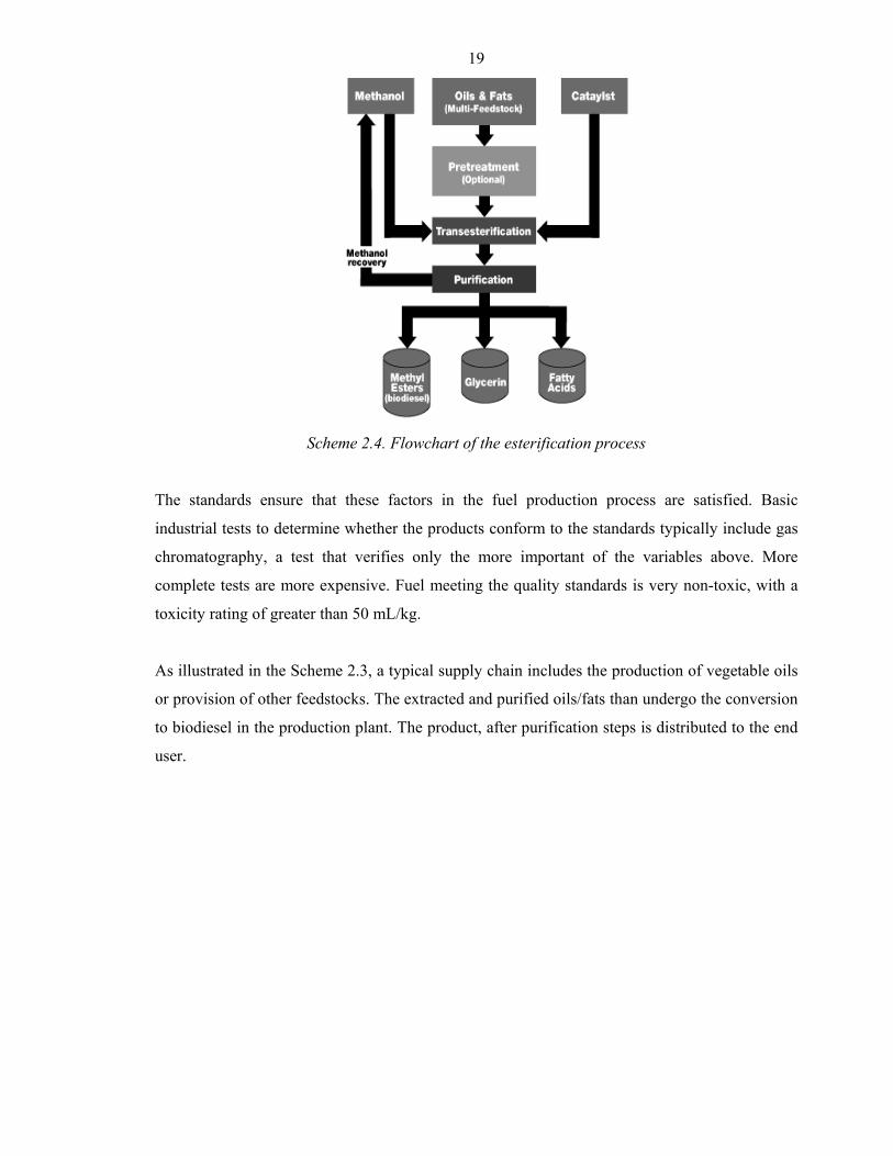
Transesterification process technological arrangement
In scheme 2.4 the basic transesterification process flows are presented. Critical quality
parameters of the process are:
• Complete reaction.
• Removal of glycerol.
• Removal of catalyst.
• Removal of alcohol.
• Absence of free fatty acids.
• Low sulphur content.
19
Scheme 2.4. Flowchart of the esterification process
The standards ensure that these factors in the fuel production process are satisfied. Basic
industrial tests to determine whether the products conform to the standards typically include gas
chromatography, a test that verifies only the more important of the variables above. More
complete tests are more expensive. Fuel meeting the quality standards is very non-toxic, with a
toxicity rating of greater than 50 mL/kg.
As illustrated in the Scheme 2.3, a typical supply chain includes the production of vegetable oils
or provision of other feedstocks. The extracted and purified oils/fats than undergo the conversion
to biodiesel in the production plant. The product, after purification steps is distributed to the end
user.
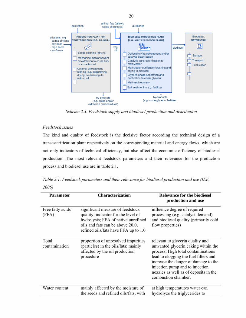
20
Scheme 2.3. Feedstock supply and biodiesel production and distribution
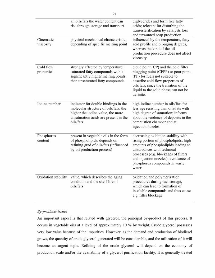
Feedstock issues
The kind and quality of feedstock is the decisive factor according the technical design of a
transesterification plant respectively on the corresponding material and energy flows, which are
not only indicators of technical efficiency, but also affect the economic efficiency of biodiesel
production. The most relevant feedstock parameters and their relevance for the production
process and biodiesel use are in table 2.1.
Table 2.1. Feedstock parameters and their relevance for biodiesel production and use (IEE,
2006)
Parameter Characterization Relevance for the biodiesel production and use
Free fatty acids (FFA)
significant measure of feedstock quality, indicator for the level of hydrolysis; FFA of native unrefined oils and fats can be above 20.0, refined oils/fats have FFA up to 1.0
influence degree of required processing (e.g. catalyst demand) and biodiesel quality (primarily cold flow properties)
Total contamination
proportion of unresolved impurities (particles) in the oils/fats; mainly affected by the oil production procedure
relevant to glycerin quality and unwanted glycerin caking within the process; High total contaminations lead to clogging the fuel filters and increase the danger of damage to the injection pump and to injection nozzles as well as of deposits in the combustion chamber.
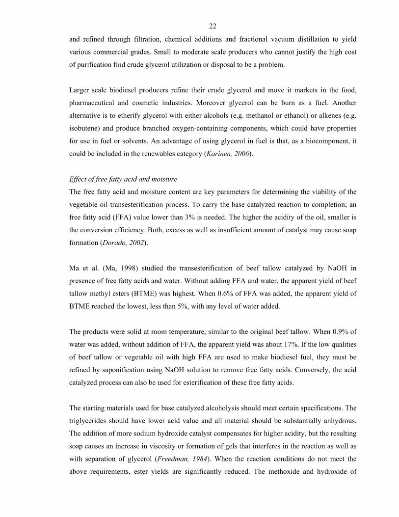
Water content mainly affected by the moisture of the seeds and refined oils/fats; with
at high temperatures water can hydrolyze the triglycerides to
21
all oils/fats the water content can rise through storage and transport
diglycerides and form free fatty acids; relevant for disturbing the transesterification by catalysts loss and unwanted soap production
Cinematic viscosity
physical-mechanical characteristic, depending of specific melting point
influenced by the temperature, fatty acid profile and oil-aging degrees, whereas the kind of the oil production procedure does not affect viscosity
Cold flow properties
strongly affected by temperature; saturated fatty compounds with a significantly higher melting points than unsaturated fatty compounds
cloud point (CP) and the cold filter plugging point (CFPP) or pour point (PP) for fuels not suitable to describe cold flow properties of oils/fats, since the transition of the liquid to the solid phase can not be definite.
Iodine number indicator for double bindings in the molecular structure of oils/fats. the higher the iodine value, the more unsaturation acids are present in the oils/fats
high iodine number in oils/fats for less age resisting than oils/fats with high degree of saturation; informs about the tendency of deposits in the combustion chamber and at injection nozzles.
Phosphorus content
present in vegetable oils in the form of phospholipids; depends on refining grad of oils/fats (influenced by oil production process)
decreasing oxidation stability with rising portion of phospholipids; high amounts of phospholipids leading to disturbances with technical processes (e.g. blockages of filters and injection nozzles); avoidance of phosphorus compounds in waste water
Oxidation stability value, which describes the aging condition and the shelf-life of oils/fats
oxidation and polymerization procedures during fuel storage, which can lead to formation of insoluble compounds and thus cause e.g. filter blockage
By-products issues
An important aspect is that related with glycerol, the principal by-product of this process. It
occurs in vegetable oils at a level of approximately 10 % by weight. Crude glycerol possesses
very low value because of the impurities. However, as the demand and production of biodiesel
grows, the quantity of crude glycerol generated will be considerable, and the utilization of it will
become an urgent topic. Refining of the crude glycerol will depend on the economy of
production scale and/or the availability of a glycerol purification facility. It is generally treated
22
and refined through filtration, chemical additions and fractional vacuum distillation to yield
various commercial grades. Small to moderate scale producers who cannot justify the high cost
of purification find crude glycerol utilization or disposal to be a problem.
Larger scale biodiesel producers refine their crude glycerol and move it markets in the food,
pharmaceutical and cosmetic industries. Moreover glycerol can be burn as a fuel. Another
alternative is to etherify glycerol with either alcohols (e.g. methanol or ethanol) or alkenes (e.g.
isobutene) and produce branched oxygen-containing components, which could have properties
for use in fuel or solvents. An advantage of using glycerol in fuel is that, as a biocomponent, it
could be included in the renewables category (Karinen, 2006).
Effect of free fatty acid and moisture
The free fatty acid and moisture content are key parameters for determining the viability of the
vegetable oil transesterification process. To carry the base catalyzed reaction to completion; an
free fatty acid (FFA) value lower than 3% is needed. The higher the acidity of the oil, smaller is
the conversion efficiency. Both, excess as well as insufficient amount of catalyst may cause soap
formation (Dorado, 2002).
Ma et al. (Ma, 1998) studied the transesterification of beef tallow catalyzed by NaOH in
presence of free fatty acids and water. Without adding FFA and water, the apparent yield of beef
tallow methyl esters (BTME) was highest. When 0.6% of FFA was added, the apparent yield of
BTME reached the lowest, less than 5%, with any level of water added.
The products were solid at room temperature, similar to the original beef tallow. When 0.9% of
water was added, without addition of FFA, the apparent yield was about 17%. If the low qualities
of beef tallow or vegetable oil with high FFA are used to make biodiesel fuel, they must be
refined by saponification using NaOH solution to remove free fatty acids. Conversely, the acid
catalyzed process can also be used for esterification of these free fatty acids.
The starting materials used for base catalyzed alcoholysis should meet certain specifications. The
triglycerides should have lower acid value and all material should be substantially anhydrous.
The addition of more sodium hydroxide catalyst compensates for higher acidity, but the resulting
soap causes an increase in viscosity or formation of gels that interferes in the reaction as well as
with separation of glycerol (Freedman, 1984). When the reaction conditions do not meet the
above requirements, ester yields are significantly reduced. The methoxide and hydroxide of
23
sodium or potassium should be maintained in anhydrous state. Prolonged contact with air will
diminish the effectiveness of these catalysts through interaction with moisture and carbon
dioxide.
Most of the biodiesel is currently made from edible oils by using methanol and alkaline catalyst.
However, there are large amounts of low cost oils and fats that could be converted to biodiesel.
The problems with processing these low cost oils and fats are that they often contain large
amounts of free fatty acids that cannot be converted to biodiesel using alkaline catalyst.
Therefore, two-step esterification process is required for these feed stocks. Initially the FFA of
these can be converted to fatty acid methyl esters by an acid catalyzed pretreatment and in the
second step transesterification is completed by using alkaline catalyst to complete the reaction
(Canakci, 2001). Initial process development was performed with synthetic mixture containing
20 and 40% free fatty acid prepared by using palmitic acid. Process parameters such as molar
ratio of alcohol to oil, type of alcohol, amount of acid catalyst, reaction time, free fatty acid level
were investigated to determine the best strategy for converting the free fatty acids to usable
esters. The work showed that the acid level of the high free fatty acids feed stocks could be
reduced to less than 1% with a two step pretreatment reaction. The reaction mixture was allowed
to settle between steps so that the water containing phase could be removed. The two-step
pretreatment reaction was demonstrated with actual feedstocks, including yellow grease with
12% free fatty acid and brown grease with 33% free fatty acids. After reducing the acid levels of
these feedstocks to less than 1%, the transesterification reaction was completed with an alkaline
catalyst to produce fuel grade biodiesel. Turck et al. (Turck, 2002) have investigated the negative
influence of base catalyzed transesterification of triglycerides containing substantial amount of
free fatty acid. Free fatty acids react with the basic catalyst added for the reaction and give rise to
soap, as a result of which, one part of the catalyst is neutralized and is therefore no longer
available for transesterification. These high FFA content oils/fats are processed with an
immiscible basic glycerol phase so as to neutralize the free fatty acids and cause them to pass
over into the glycerol phase by means of monovalent alcohols. The triglycerides are subjected to
transesterification, using a base as catalyst, to form fatty acid alkyl esters, characterized in that
after its separation; the basic glycerol phase produced during transesterification of the
triglycerides is used for processing the oils/fats for removal of free fatty acids. The minimum
amount of catalyst required for this process was calculated, relative to 1000 g of the oil to be
processed, as a function of the acid value and the mean molar mass of the oil/fat.
24
Catalyst type and concentration
Catalysts used for the transesterification of triglycerides are classified as alkali, acid, enzyme or
heterogeneous catalysts, among which alkali catalysts like sodium hydroxide, sodium methoxide,
potassium hydroxide, potassium methoxide are more effective (Ma, 1999a). If the oil has high
free fatty acid content and more water, acid catalyzed transesterification is suitable. The acids
could be sulfuric acid, phosphoric acid, hydrochloric acid or organic sulfonic acid. Methanolysis
of beef tallow was studied with catalysts NaOH and NaOMe.
Comparing the two catalysts, NaOH was significantly better than NaOMe (Ma, 1998). The
catalysts NaOH and NaOMe reached their maximum activity at 0.3% and 0.5% w/w of the beef
tallow, respectively. Sodium methoxide causes formation of several by-products mainly sodium
salts, which are to be treated as waste. In addition, high quality oil is required with this catalyst
(Ahn, 1995). This was different from the previous reports (Freedman, 1984) in which ester
conversion at the 6:1 molar ratio of alcohol/oil for 1% NaOH and 0.5% NaOMe were almost the
same after 60 min. Part of the difference may be attributed to the differences in the reaction
system used.
As a catalyst in the process of alkaline methanolysis, mostly sodium hydroxide or potassium
hydroxide have been used, both in concentration from 0.4 to 2% w/w of oil. Refined and crude
oils with 1% either sodium hydroxide or potassium hydroxide catalyst resulted successful
conversion. Methanolysis of soybean oil with the catalyst 1% potassium hydroxide has given the
best yields and viscosities of the esters (Tomasevic, 2003).
Attempts have been made to use basic alkaline-earth metal compounds in the transesterification
of rapeseed oil for production of fatty acid methyl esters. The reaction proceeds if methoxide
ions are present in the reaction medium. The alkaline-earth metal hydroxides, alkoxides and
oxides catalyzed reaction proceeds slowly as the reaction mixture constitutes a three-phase
system oil–methanol-catalyst, which for diffusion reason inhibits the reaction (Gryglewicz,
1999). The catalytic activity of magnesium oxide, calcium hydroxide, calcium oxide, calcium
methoxide, barium hydroxide, and for comparison, sodium hydroxide during the
transesterification of rapeseed oil was investigated. Sodium hydroxide exhibited the highest
catalytic activity in this process. The degree to which the substrates were reacted reached 85%
after 30 min of the process and 95% after 1.5 h, which represented a close value to the
equilibrium. Barium hydroxide was slightly less active with a conversion of 75% after 30 min.
Calcium methoxide was medially active. The degree to which the substrates were reacted was
25
55% after 30 min. Eighty percents after 1 h and state of reaction equilibrium (93%) was reached
after 2.5 h. The rate of reaction was slowest when catalyzed by CaO. Magnesium oxide and
calcium hydroxide showed no catalytic activity in rapeseed oil methanolysis. Acid catalyzed
transesterification was studied with waste vegetable oil. The reaction was conducted at four
different catalyst concentrations, 0.5, 1.0, 1.5 and 2.25 M HCl in presence of 100% excess
alcohol and the result was compared with 2.25 M H2SO4 and the decrease in viscosity was
observed. H2SO4 has superior catalytic activity in the range of 1.5–2.25 M concentration
(Mohamad, 2002).
Although chemical transesterification using an alkaline catalysis process gives high conversion
levels of triglycerides to their corresponding methyl esters in short reaction times, the reaction
has several drawbacks: it is energy intensive, recovery of glycerol is difficult, the acidic or
alkaline catalyst has to be removed from the product, alkaline waste water require treatment, and
free fatty acid and water interfere the reaction.
Enzymatic catalysts like lipases are able to effectively catalyze the transesterification of
triglycerides in either aqueous or non-aqueous systems, which can overcome the problems
mentioned above (Fuduka, 2001). In particular, the by-products, glycerol can be easily removed
without any complex process, and also that free fatty acids contained in waste oils and fats can
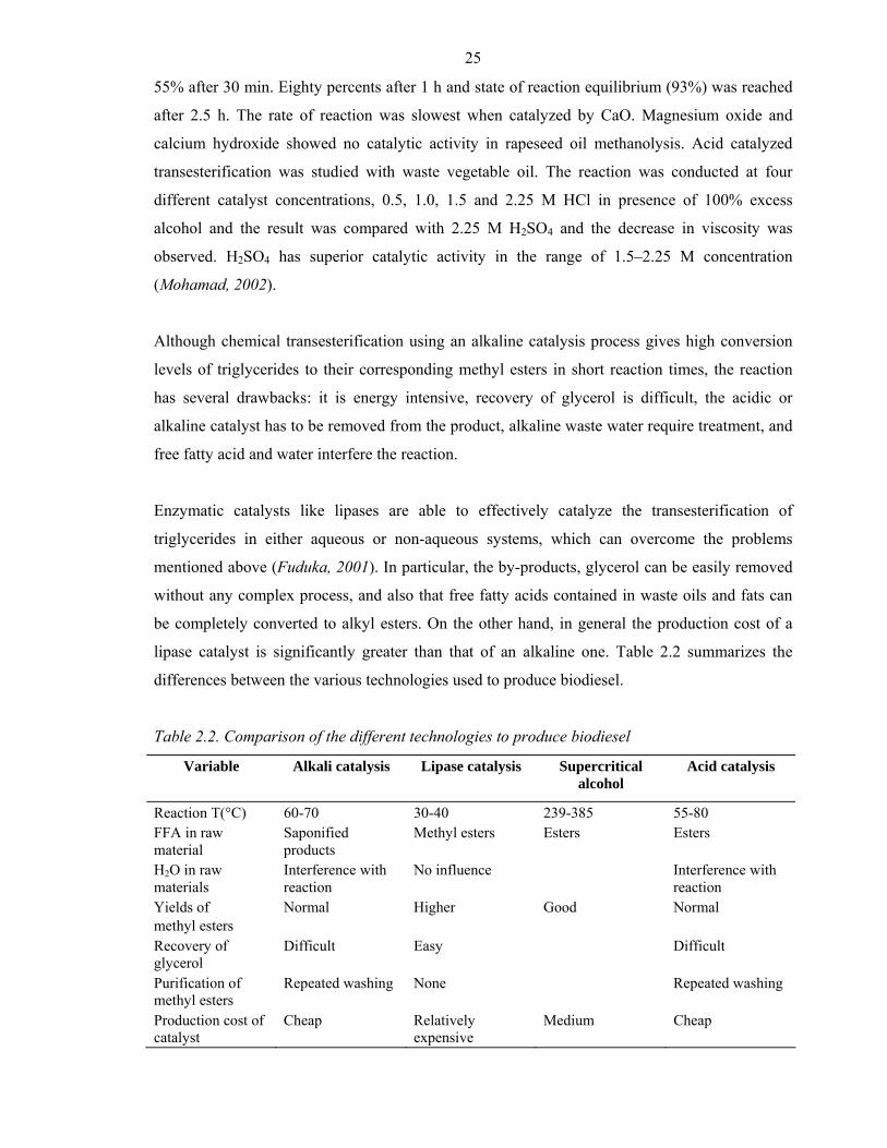
be completely converted to alkyl esters. On the other hand, in general the production cost of a
lipase catalyst is significantly greater than that of an alkaline one. Table 2.2 summarizes the
differences between the various technologies used to produce biodiesel.
Table 2.2. Comparison of the different technologies to produce biodiesel
Variable Alkali catalysis Lipase catalysis Supercritical alcohol
Acid catalysis
Reaction T(°C) 60-70 30-40 239-385 55-80 FFA in raw material
Saponified products
Methyl esters Esters Esters
H2O in raw materials
Interference with reaction
No influence Interference with reaction
Yields of methyl esters
Normal Higher Good Normal
Recovery of glycerol
Difficult Easy Difficult
Purification of methyl esters
Repeated washing None Repeated washing
Production cost of catalyst
Cheap Relatively expensive
Medium Cheap
26
Molar ratio of alcohol to oil and type of alcohol
One of the most important variables affecting the yield of ester is the molar ratio of alcohol to
triglyceride. The stoichiometric ratio for transesterification requires three moles of alcohol and
one mole of triglyceride to yield three moles of fatty acid alkyl esters and one mole of glycerol.
However, transesterification is an equilibrium reaction in which a large excess of alcohol is
required to drive the reaction to the right. For maximum conversion to the ester, a molar ratio of
6:1 should be used. The molar ratio has no effect on acid, peroxide, saponification and iodine
value of methyl esters (Tomasevic, 2003). However, the high molar ratio of alcohol to vegetable
oil interferes with the separation of glycerin because there is an increase in solubility. When
glycerin remains in solution, it helps drive the equilibrium to back to the left, lowering the yield
of esters.
The base catalyzed formation of ethyl ester is difficult compared to the formation of methyl
esters. Specifically the formation of stable emulsion during ethanolysis is a problem. Methanol
and ethanol are not miscible with triglycerides at ambient temperature, and the reaction mixtures
are usually mechanically stirred to enhance mass transfer. During the course of reaction,
emulsions usually form. With methanol these emulsions quickly and easily break down to form a
lower glycerol rich layer and upper methyl ester rich layer. Instead with ethanol these emulsions
are more stable and severely complicate the separation and purification of esters (Zhou, 2003).
The emulsions are caused in part by formation of the intermediates monoglycerides and
diglycerides, which have both polar hydroxyl groups and non-polar hydrocarbon chains. These
intermediates are strongsurface active agents. In the process of alcoholysis, the catalyst, either
sodium hydroxide or potassium hydroxide is dissolved in polar alcohol phase, in which
triglycerides must transfer in order to react. The reaction is initially mass-transfer controlled and
does not conform to expected homogeneous kinetics. When the concentrations of these
intermediates reach a critical level, emulsions form. The larger non-polar group in ethanol,
relative to methanol, is assumed to be the critical factor in stabilizing the emulsions. However,
the concentrations of mono- and di-glycerides are very low, and then the emulsions become
unstable. This emphasizes the necessity for the reaction to be as complete as possible, thereby
reducing the concentrations of mono- and di-glycerides.
Effect of reaction time and temperature
The conversion rate increases with reaction time. Freedman et al. (Freedman, 1984)
transesterified peanut, cotton-seed, sunflower and soybean oil under the condition of methanol–
oil molar ratio 6:1, 0.5% sodium methoxide catalyst and 60 °C. An approximate yield of 80%
27
was observed after 1 min for soybean and sunflower oils. After 1 h, the conversion was almost
the same for all four oils (93–98%). Ma et al. (Ma, 1999b) studied the effect of reaction time on
transesterification of beef tallow with methanol. The reaction was very slow during the first
minute due to mixing and dispersion of methanol into beef tallow. From one to 5 min, the
reaction proceeds very fast. The production of beef tallow methyl esters reached the maximum
value at about 15 min.
Transesterification can occur at different temperatures, depending on the oil used. For the
transesterification of refined oil with methanol (6:1) and 1% NaOH, the reaction was studied
with three different temperatures (Ma, 1999a). After 0.1 h, ester yields were 94, 87 and 64% for
60, 45 and 32 °C, respectively. After 1 h, ester formation was identical for 60 and 45 °C runs and
only slightly lower for the 32 °C run. Temperature clearly influenced the reaction rate and yield
of esters (Ma, 1999a).
Mixing intensity
Mixing is very important in the transesterification reaction, as oils or fats are immiscible with
sodium hydroxide–methanol solution. Once the two phases are mixed and the reaction is started,
stirring is no longer needed. Initially the effect of mixing on transesterification of beef tallow
was study by Ma et al. (Ma, 1990b). No reaction was observed without mixing and when NaOH–
MeOH was added to the melted beef tallow in the reactor while stirring, stirring speed was
insignificant. Reaction time was the controlling factor in determining the yield of methyl esters.
This suggested that the stirring speeds investigated exceeded the threshold requirement of
mixing.
Effect of using organic cosolvents
The methoxide base catalyzed methanolysis of soybean oil at 40 °C (methanol–oil molar ratio
6:1) shows that to form methyl esters proceeds approximately more slowly than butanolysis at 30
°C. This is interpreted to be the result of a two phase reaction in which methanolysis occurs only
in the methanol phase. Low oil concentration in methanol causes the slow reaction rate; a slow
dissolving rate of the oil in methanol causes an initiation period. Intermediate mono- and di-
glycerides preferentially remain in the methanol, and react further, thus explaining the deviation
from second order kinetics.
The same explanations apply for hydroxide ion catalyzed methanolysis. In order to conduct the
reaction in a single phase, cosolvents like tetrahydrofuran (THF), 1,4-dioxane and diethyl ether
28
were tested. Although, there are other cosolvents, initial study was conducted with
tetrahydrofuran. At the 6:1 methanol–oil molar ratio the addition of 1.25 volume of
tetrahydrofuran per volume of methanol produces an oil dominant one phase system in which
methanolysis speeds up dramatically and occurs as fast as butanolysis. In particular, THF is
chosen because its boiling point of 67 °C is only two degrees higher than that of methanol.
Therefore at the end of the reaction the unreacted methanol and THF can be co-distilled and
recycled (Boocock, 1996a).
Using tetrahydrofuran, transesterification of soybean oil was carried out with methanol at
different concentrations of sodium hydroxide. The ester contents after 1 min for 1.1, 1.3, 1.4 and
2.0% sodium hydroxide were 82.5, 85, 87 and 96.2%, respectively. Results indicated that the
hydroxide concentration could be increased up to 1.3 wt%, resulting in 95% methyl ester after 15
min. (Boocock, 1998). Similarly for transesterification of coconut oil using THF/MeOH volume
ratio 0.87 with 1% NaOH catalyst, the conversion was 99% in 1 min.
A single-phase process for the esterification of a mixture of fatty acids and triglycerides were
investigated. The process comprises forming a single-phase solution of fatty acids and
triglyceride in an alcohol selected from methanol and ethanol, the ratio of said alcohol to
triglyceride being 15:1–35:1. The solution further comprises a cosolvent in an amount to form
the single phase. In a first step, an acid catalyst for the esterification of fatty acid is added. After
a period of time, the acid catalyst is neutralized and a base catalyst for the transesterification of
triglycerides is added. After a further period of time, esters are separated from the solution
(Boocock, 2001).
An improved process was investigated for methanolysis and ethanolysis of fatty acid glycerides
such as those found in naturally occurring fats and oils derived from plant and animals. The
processes comprise solubilizing oil or fat in methanol or ethanol by addition of a cosolvent in
order to form a one-phase reaction mixture, and adding an esterification catalyst. The processes
proceed quickly, usually in less than 20 min, at ambient temperatures, atmospheric pressure and
without agitation. The co-solvent increases the rate of reaction by making the oil soluble in
methanol, thus increasing contact of the reactants. The lower alkyl fatty acid monoesters
produced by the process can be used as biofuels and are suitable as diesel fuel replacements or
additives (Boocock, 1996b).
29
Product properties and quality
While the suitability of any material as fuel, including biodiesel, can be influenced by
contaminants arising from production or other sources, the nature of the fuel components
ultimately determines the fuel properties. Some of the properties included as specifications in
standards can be traced to the structure of the fatty esters comprising biodiesel. However, as
biodiesel consists of fatty acids esters, not only the structure of the fatty acids but also that of the
ester moiety derived from the alcohol can influence the fuel properties of biodiesel. Since the
transesterification reaction of oil or fat leads to a biodiesel fuel corresponding in its fatty acid
profiles with that of the parent oil or fat, biodiesel is a mixture of fatty esters with each ester
component contributing to the properties of the fuel. The properties of a biodiesel fuel that are
determined by the structure of its component fatty esters include ignition quality, heat of
combustion, cold flow, oxidative stability, viscosity and lubricity.
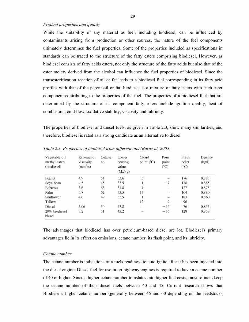
The properties of biodiesel and diesel fuels, as given in Table 2.3, show many similarities, and
therefore, biodiesel is rated as a strong candidate as an alternative to diesel.
Table 2.3. Properties of biodiesel from different oils (Barnwal, 2005)
The advantages that biodiesel has over petroleum-based diesel are lot. Biodiesel's primary
advantages lie in its effect on emissions, cetane number, its flash point, and its lubricity.
Cetane number
The cetane number is indications of a fuels readiness to auto ignite after it has been injected into
the diesel engine. Diesel fuel for use in on-highway engines is required to have a cetane number
of 40 or higher. Since a higher cetane number translates into higher fuel costs, most refiners keep
the cetane number of their diesel fuels between 40 and 45. Current research shows that
Biodiesel's higher cetane number (generally between 46 and 60 depending on the feedstocks
30
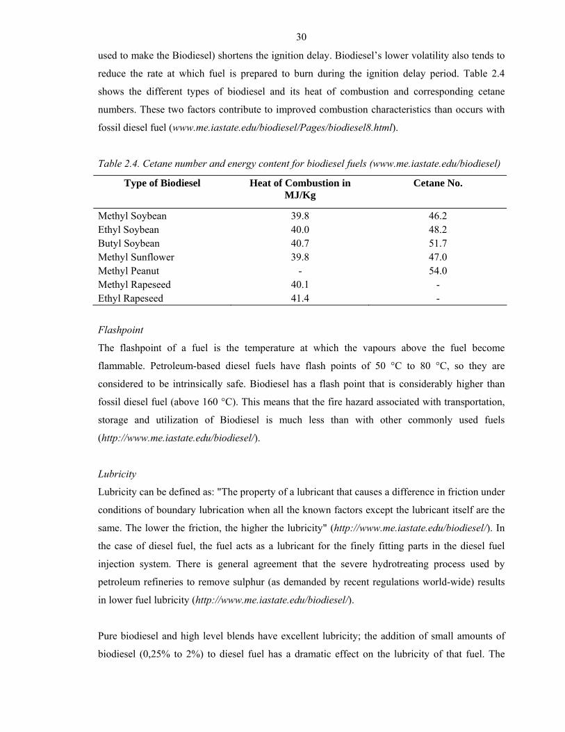
used to make the Biodiesel) shortens the ignition delay. Biodiesel’s lower volatility also tends to
reduce the rate at which fuel is prepared to burn during the ignition delay period. Table 2.4
shows the different types of biodiesel and its heat of combustion and corresponding cetane
numbers. These two factors contribute to improved combustion characteristics than occurs with
fossil diesel fuel (www.me.iastate.edu/biodiesel/Pages/biodiesel8.html).
Table 2.4. Cetane number and energy content for biodiesel fuels (www.me.iastate.edu/biodiesel)
Type of Biodiesel Heat of Combustion in MJ/Kg
Cetane No.
Methyl Soybean 39.8 46.2 Ethyl Soybean 40.0 48.2 Butyl Soybean 40.7 51.7 Methyl Sunflower 39.8 47.0 Methyl Peanut - 54.0 Methyl Rapeseed 40.1 - Ethyl Rapeseed 41.4 -
Flashpoint
The flashpoint of a fuel is the temperature at which the vapours above the fuel become
flammable. Petroleum-based diesel fuels have flash points of 50 °C to 80 °C, so they are
considered to be intrinsically safe. Biodiesel has a flash point that is considerably higher than
fossil diesel fuel (above 160 °C). This means that the fire hazard associated with transportation,
storage and utilization of Biodiesel is much less than with other commonly used fuels
(http://www.me.iastate.edu/biodiesel/).
Lubricity
Lubricity can be defined as: "The property of a lubricant that causes a difference in friction under
conditions of boundary lubrication when all the known factors except the lubricant itself are the
same. The lower the friction, the higher the lubricity" (http://www.me.iastate.edu/biodiesel/). In
the case of diesel fuel, the fuel acts as a lubricant for the finely fitting parts in the diesel fuel
injection system. There is general agreement that the severe hydrotreating process used by
petroleum refineries to remove sulphur (as demanded by recent regulations world-wide) results
in lower fuel lubricity (http://www.me.iastate.edu/biodiesel/).
Pure biodiesel and high level blends have excellent lubricity; the addition of small amounts of
biodiesel (0,25% to 2%) to diesel fuel has a dramatic effect on the lubricity of that fuel. The
31
higher the number the better the fuel lubricity. As little as 1% biodiesel could change the diesel
fuel from an unacceptable level to an acceptable one.
Cold flow
At low temperatures, Biodiesel will gel or crystallize into a solid mass that cannot be filtered or
pumped. The engine cannot run at these temperatures. This is not a new problem for diesel
engine operators. Petroleum-based diesel fuel also gels but at temperatures that are lower than
for Biodiesel (http://www.me.iastate.edu/biodiesel/Pages/biodiesel16.html).
The cloud point is the temperature at which crystals first start to form in the fuel and the pour
point is the lowest temperature at which the fuel will still pour from a container. The cold filter
plugging point (CFPP) is the lowest temperature at which a certain volume of fuel can be drawn
through a metal screen filter. It usually correlates well with the lowest temperature that an engine
can operate at (http://www.me.iastate.edu/biodiesel/Pages/biodiesel9.html).
Fuel stability
A fuel is considered unstable when it undergoes chemical changes that produce undesirable
consequences such as deposits, acidity or a bad smell. There are three different types of stability
commonly described in technical literature: thermal stability, oxidative stability and storage
stability. Vegetable oils are generally more susceptible to oxidative attack because they are less
saturated, that is, they contain more carbon-carbon double bonds. The short chain acids can be
volatile thus causing a foul smell and a lowering of the flashpoint. Polymerization can cause an
increase in viscosity and the formation of insoluble sediments and varnish deposits. Highly
saturated fuels, such as those made from tallow, are very resistant to oxidation and have high
Cetane numbers. However, they tend to have poor cold flow properties, often starting to
crystallize at temperatures as high as 10-15 °C. Unsaturated fuels, such as those made from
soybean oil will generally stay liquid at temperatures down to 0 °C
(http://www.me.iastate.edu/biodiesel/).
Fuel energy content
As can be seen in the Table 2.5, Biodiesel has lower energy content (lower heating value) than
fossil diesel fuel. On a weight basis, the energy level is 13% less. Since Biodiesel is denser than
fossil diesel fuel, the energy content is only 8% less. Since diesel engines will inject equal
volumes of fuel, most diesel engine operators see a power loss of about 8%. In some cases, the
32
power loss may be even less than this. Biodiesel's higher viscosity can decrease the amount of
fuel that leaks past the plungers in the diesel fuel injection pump.
Table 2.5. Comparison of diesel/biodiesel energy content and energy efficiency
Fuel Density g/cm3
Caloric value MJ/Kg MJ/dm3
Energy efficiency %
Diesel 0.83 42.90 35.60 38.20 Biodiesel 0.88 37.20 32.90 40.70 Variation -13 % -8 % + 7%
Material compatibility
Biodiesel interacts differently with materials than diesel fuel. Some metals have a catalytic effect
on the Biodiesel oxidation process. Contact with these materials should be avoided, particularly
in long-term storage. Copper and copper-containing alloys such as brass and bronze should be
avoided. Lead, tin, and zinc are also cited as having some incompatibility with Biodiesel (Tyson,
2001; http://www.nrel.gov/docs/fy06osti/40555.pdf).
Blends of B20 or less do not seem to cause problems within a reasonable time period. With
higher level blends, users should be aware of the elastomer materials that are used in their diesel
engine fuel system. While most modern diesel engines use steel lines for the entire fuel
distribution system, older engines may contain incompatible materials. Older pumps may also
contain elastomer diaphragms, seals and o-rings. These are usually made from viton but if they
are made from nitrile or natural rubbers, they will deteriorate on contact with high levels of
biodiesel (http://www.me.iastate.edu/biodiesel/Pages/bio25.html).
Equipment benefits
Biodiesel has much more lubricity than diesel fuel, and thus allows the engine to wear less and
last longer. Because of its solvent and lubricating properties, mechanics have reported that
engines running biodiesel look like new. The lubricating properties of biodiesel may play an
important role. When diesel fuel has its sulphur removed (scheduled for this summer and fall-
see below), the diesel fuel becomes very dry and that lubricity must be restored with an additive
(like biodiesel).
Precautions
There are a couple things to be aware of when starting to use biodiesel. Biodiesel is a good
solvent and will clean out the soot and other junk left in your engine and lines by regular diesel
33
fuel. This junk will eventually clog up your vehicle’s fuel filter. So it is routinely suggested that
you change the fuel filter of your vehicle after running a couple of tankfulls of biodiesel. Also,
biodiesel tends to degrade rubber. This usually isn’t a problem in newer vehicles because they
use synthetics instead of rubber, but in pre-1993 vehicles, some of the hoses and seals may be
made out of rubber, and should be watched for signs of swelling or degrading. If so, they can be
replaced with the synthetic lines, made out of a material called Viton. The final thing to be aware
of is that biodiesel will begin to cloud up and gel (crystallize) at higher temperatures than
petrodiesel. It depends on the type of oil the biodiesel was made from, but most commercial
biodiesel is made from soybean oil, and begins to crystallize and cloud up at around freezing. If
you are driving your vehicle every day, the fuel should stay warm enough that it won’t gel up
even if temperatures are a little below freezing. But when we get a “hard freeze” with
temperatures in the 20’s for several days, then you should add some petrodiesel to your tank. The
colder it is, the higher the percentage of petrodiesel you will need to add to keep your fuel from
gelling. It might be a good idea to keep a clear plastic container of your biodiesel on the front
seat of your car, so you can see if it is starting to gel. If so, it is time to let go of your purist ethics
a little and add some petrodiesel. Unfortunately, the anti-gel additives made for diesel do not
really work for B100; they only work well for mixtures containing petrodiesel. (One additive
known as Arctic Express is supposed to reduce the gel point of B100 by a few degrees). Of
course if you are only using B50 or B20, this won’t even be an issue in the northwest, given
relatively mild climate.
Biodegradability
The degradation of a compound through microbial activity in soils is called the biodegradability.
According to the standard test the result for biodiesel is that more than 95% are degraded after 21
days, fossil Diesel about 72% after 21 days (ABI, 2002). Dextrose (a test sugar used as the
positive control when testing biodegradability) degraded at the same rate. Blending biodiesel
with diesel fuel accelerates its biodegradability. For example, blends of 20% biodiesel and 80%
diesel fuel degrade twice as fast as fossil diesel alone (Levelton Engineering, 2002).
NOx emission
As described before about 11 percent of the weight of B100 is oxygen. The presence of oxygen
in biodiesel improves combustion and therefore reduces hydrocarbon, carbon monoxide, and
particulate emissions; but oxygenated fuels also tend to increase nitrogen oxide emissions
(Szybist, 2005). Engine tests have confirmed the expected increases and decreases of each
exhaust component from engines without emissions controls.
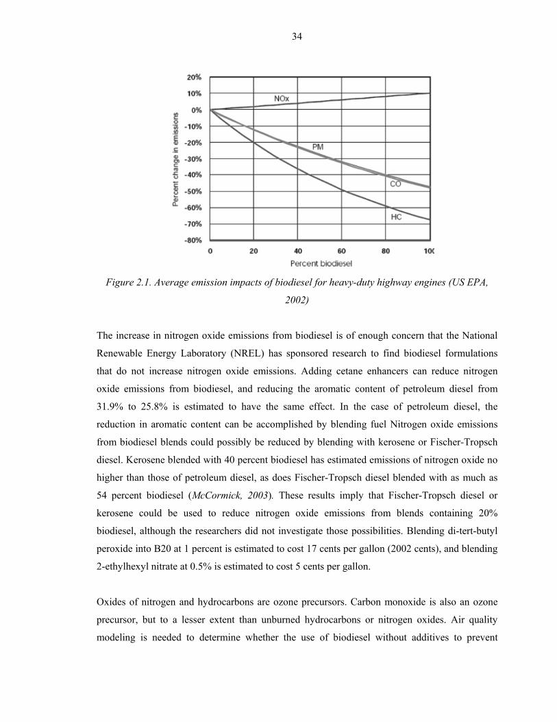
34
Figure 2.1. Average emission impacts of biodiesel for heavy-duty highway engines (US EPA,
2002)
The increase in nitrogen oxide emissions from biodiesel is of enough concern that the National
Renewable Energy Laboratory (NREL) has sponsored research to find biodiesel formulations
that do not increase nitrogen oxide emissions. Adding cetane enhancers can reduce nitrogen
oxide emissions from biodiesel, and reducing the aromatic content of petroleum diesel from
31.9% to 25.8% is estimated to have the same effect. In the case of petroleum diesel, the
reduction in aromatic content can be accomplished by blending fuel Nitrogen oxide emissions
from biodiesel blends could possibly be reduced by blending with kerosene or Fischer-Tropsch
diesel. Kerosene blended with 40 percent biodiesel has estimated emissions of nitrogen oxide no
higher than those of petroleum diesel, as does Fischer-Tropsch diesel blended with as much as
54 percent biodiesel (McCormick, 2003). These results imply that Fischer-Tropsch diesel or
kerosene could be used to reduce nitrogen oxide emissions from blends containing 20%
biodiesel, although the researchers did not investigate those possibilities. Blending di-tert-butyl
peroxide into B20 at 1 percent is estimated to cost 17 cents per gallon (2002 cents), and blending
2-ethylhexyl nitrate at 0.5% is estimated to cost 5 cents per gallon.
Oxides of nitrogen and hydrocarbons are ozone precursors. Carbon monoxide is also an ozone
precursor, but to a lesser extent than unburned hydrocarbons or nitrogen oxides. Air quality
modeling is needed to determine whether the use of biodiesel without additives to prevent
35
increases in nitrogen oxide emissions will increase or decrease ground-level ozone on balance
(US EPA, 2002).
Global warming and pollution reduction
When biodiesel displaces petroleum, it reduces levels of global warming gases such as CO2. As
plants like soybeans grow, they take CO2 from the air to make the stems, roots, leaves and seeds.
After the oil is extracted from soybeans, it is refined into biodiesel and, when burned, produces
CO2 and other emissions, which are returned to the atmosphere.
However, this cycle does not add to the CO2 level in the air because the next soybean crop will
reuse the CO2 to grow. Another important environmental factor is that biodiesel reduces tailpipe
particulate matter (PM), HC and CO emissions. These benefits occur because biodiesel contains
11% oxygen (O2) by weight. The presence of O2 allows the fuel to burn more completely,
resulting in fewer emissions from unburned fuel. This same principle also reduces air toxicity,
which is associated with the unburned or partially burned HC and PM emissions. Testing has
shown that PM, HC and CO reductions are independent of the vegetable oil used to make
biodiesel.
Safety
Another advantage of biodiesel is that not only it is non-toxic, but in its liquid form it is almost
not flammable. The fuel has to be heated up to over 150 °C before it will combust. The only
reason it works in the diesel engine is because diesels compress the vaporized fuel and air
mixture so much that it combusts (without the need for spark plugs). Thus, if a biodiesel
powered car, truck or boat is in an accident, the resulting spill won’t require a hazmat team to
clean up, and will very likely not result in a fire.
Concerns/barriers
Biodiesel lowers emissions, raises the fuel’s cetane number and flashpoint, and has excellent
lubricity. It also has the attractive advantage that it can be used directly in diesel engines without
modifications. However, Biodiesel has some drawbacks as well. There are other issues that
consumers should be aware of. These include cold flow properties, stability, energy content,
elevated NOx levels and material compatibility.
Biodiesel production via transesterification in supercritical medium
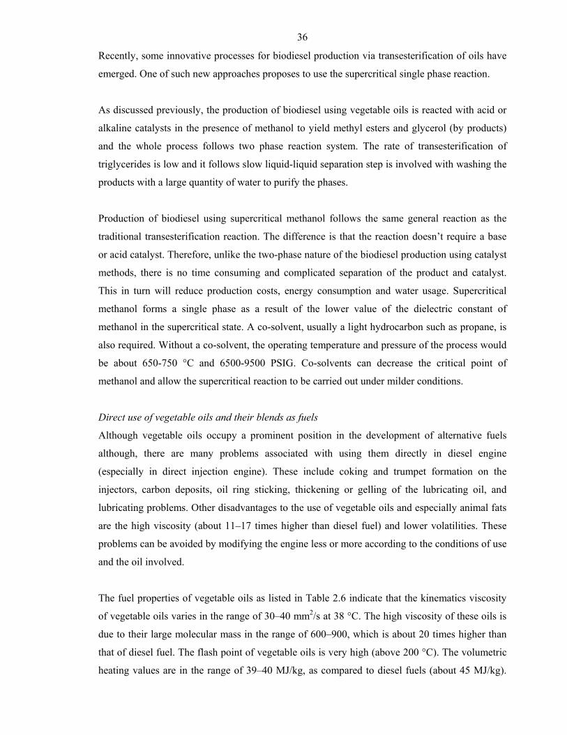
36
Recently, some innovative processes for biodiesel production via transesterification of oils have
emerged. One of such new approaches proposes to use the supercritical single phase reaction.
As discussed previously, the production of biodiesel using vegetable oils is reacted with acid or
alkaline catalysts in the presence of methanol to yield methyl esters and glycerol (by products)
and the whole process follows two phase reaction system. The rate of transesterification of
triglycerides is low and it follows slow liquid-liquid separation step is involved with washing the
products with a large quantity of water to purify the phases.
Production of biodiesel using supercritical methanol follows the same general reaction as the
traditional transesterification reaction. The difference is that the reaction doesn’t require a base
or acid catalyst. Therefore, unlike the two-phase nature of the biodiesel production using catalyst
methods, there is no time consuming and complicated separation of the product and catalyst.
This in turn will reduce production costs, energy consumption and water usage. Supercritical
methanol forms a single phase as a result of the lower value of the dielectric constant of
methanol in the supercritical state. A co-solvent, usually a light hydrocarbon such as propane, is
also required. Without a co-solvent, the operating temperature and pressure of the process would
be about 650-750 °C and 6500-9500 PSIG. Co-solvents can decrease the critical point of
methanol and allow the supercritical reaction to be carried out under milder conditions.
Direct use of vegetable oils and their blends as fuels
Although vegetable oils occupy a prominent position in the development of alternative fuels
although, there are many problems associated with using them directly in diesel engine
(especially in direct injection engine). These include coking and trumpet formation on the
injectors, carbon deposits, oil ring sticking, thickening or gelling of the lubricating oil, and
lubricating problems. Other disadvantages to the use of vegetable oils and especially animal fats
are the high viscosity (about 11–17 times higher than diesel fuel) and lower volatilities. These
problems can be avoided by modifying the engine less or more according to the conditions of use
and the oil involved.
The fuel properties of vegetable oils as listed in Table 2.6 indicate that the kinematics viscosity
of vegetable oils varies in the range of 30–40 mm2/s at 38 °C. The high viscosity of these oils is
due to their large molecular mass in the range of 600–900, which is about 20 times higher than
that of diesel fuel. The flash point of vegetable oils is very high (above 200 °C). The volumetric
heating values are in the range of 39–40 MJ/kg, as compared to diesel fuels (about 45 MJ/kg).
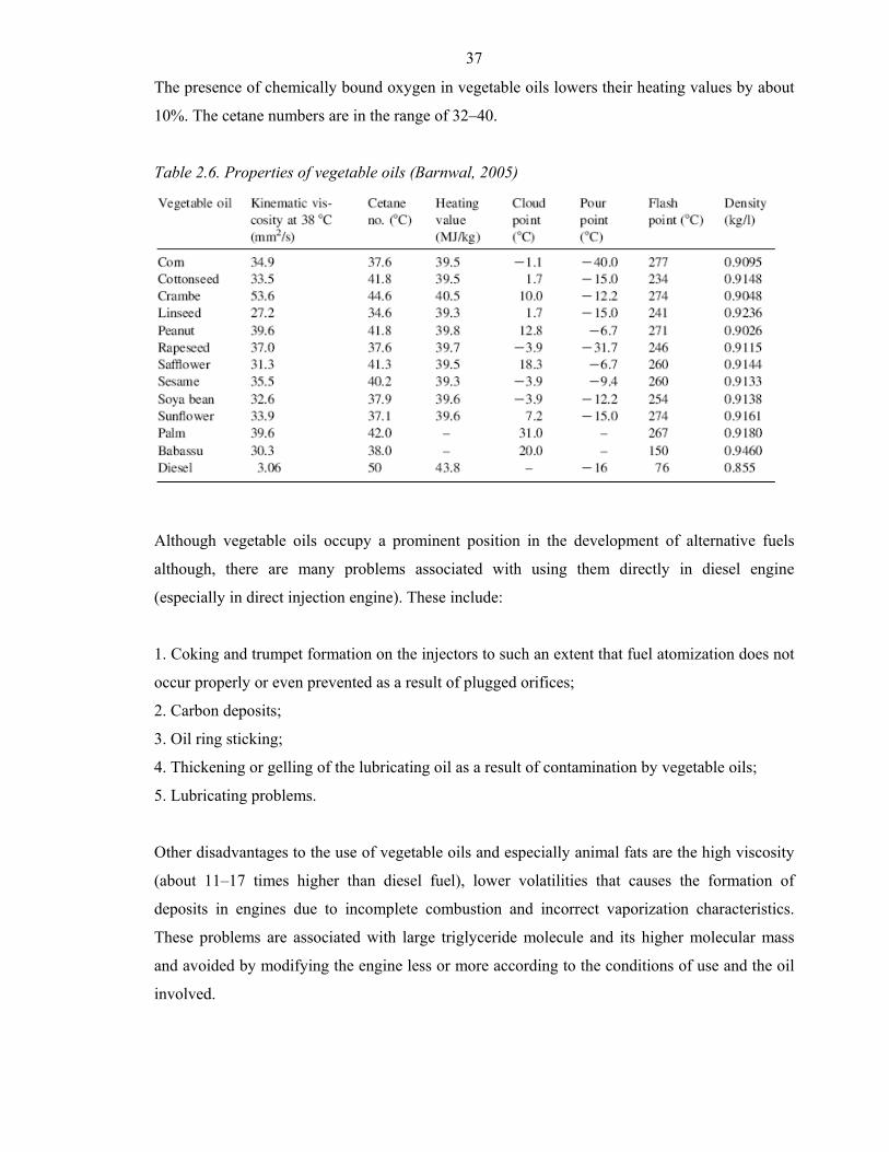
37
The presence of chemically bound oxygen in vegetable oils lowers their heating values by about
10%. The cetane numbers are in the range of 32–40.
Table 2.6. Properties of vegetable oils (Barnwal, 2005)
Although vegetable oils occupy a prominent position in the development of alternative fuels
although, there are many problems associated with using them directly in diesel engine
(especially in direct injection engine). These include:
1. Coking and trumpet formation on the injectors to such an extent that fuel atomization does not
occur properly or even prevented as a result of plugged orifices;
2. Carbon deposits;
3. Oil ring sticking;
4. Thickening or gelling of the lubricating oil as a result of contamination by vegetable oils;
5. Lubricating problems.
Other disadvantages to the use of vegetable oils and especially animal fats are the high viscosity
(about 11–17 times higher than diesel fuel), lower volatilities that causes the formation of
deposits in engines due to incomplete combustion and incorrect vaporization characteristics.
These problems are associated with large triglyceride molecule and its higher molecular mass
and avoided by modifying the engine less or more according to the conditions of use and the oil
involved.
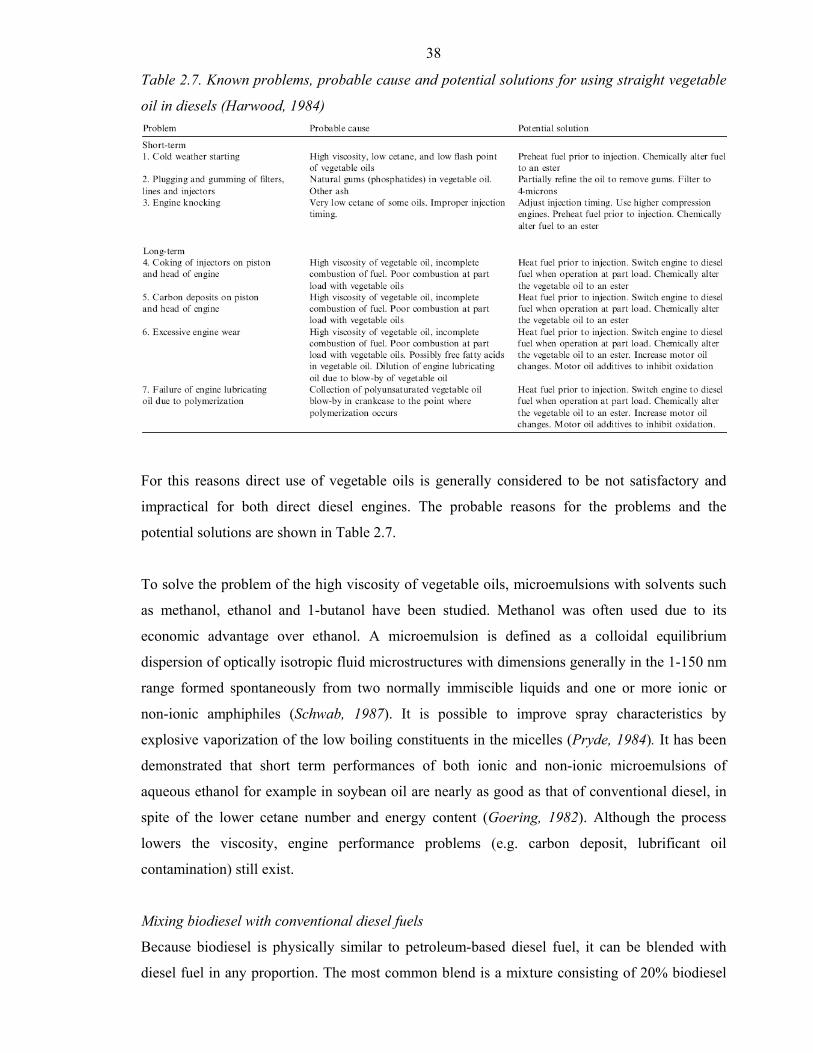
38
Table 2.7. Known problems, probable cause and potential solutions for using straight vegetable
oil in diesels (Harwood, 1984)
For this reasons direct use of vegetable oils is generally considered to be not satisfactory and
impractical for both direct diesel engines. The probable reasons for the problems and the
potential solutions are shown in Table 2.7.
To solve the problem of the high viscosity of vegetable oils, microemulsions with solvents such
as methanol, ethanol and 1-butanol have been studied. Methanol was often used due to its
economic advantage over ethanol. A microemulsion is defined as a colloidal equilibrium
dispersion of optically isotropic fluid microstructures with dimensions generally in the 1-150 nm
range formed spontaneously from two normally immiscible liquids and one or more ionic or
non-ionic amphiphiles (Schwab, 1987). It is possible to improve spray characteristics by
explosive vaporization of the low boiling constituents in the micelles (Pryde, 1984). It has been
demonstrated that short term performances of both ionic and non-ionic microemulsions of
aqueous ethanol for example in soybean oil are nearly as good as that of conventional diesel, in
spite of the lower cetane number and energy content (Goering, 1982). Although the process
lowers the viscosity, engine performance problems (e.g. carbon deposit, lubrificant oil
contamination) still exist.
Mixing biodiesel with conventional diesel fuels
Because biodiesel is physically similar to petroleum-based diesel fuel, it can be blended with
diesel fuel in any proportion. The most common blend is a mixture consisting of 20% biodiesel
39
and 80% petroleum diesel, called B20. The motive for blending the fuels is to gain some of the
advantages of biodiesel while avoiding higher costs. Biodiesel is currently higher in price than
conventional diesel fuel. The environmental benefits of using biodiesel scales with the percent of
biodiesel contained in the blend.
• B100 (100% biodiesel) offers the most overall environmental benefits. Use of B100 may
require engine or fuel system component modification and can cause operating problems,
especially in cold weather.
• B20 (20% biodiesel) offers about one fifth of the environmental benefits of B100, but can be
more broadly applied to existing engines with little or no modification.
• B2 (2% biodiesel) offers little environmental or petroleum dependence benefit and could be
potentially used an environmental marketing tool.
Production of biodiesel by pyrolysis and hydroprocessing of oils and fats
Pyrolysis, strictly defined, is the conversion of one substance into another by means of heat or by
heat with the aid of a catalyst in the absence of oxygen or in the reductive environment, e.g.
using molecular hydrogen. It involves cleavage of chemical bonds of organic molecules to yield
low molecular weight hydrocarbons. Pyrolysis chemistry is difficult to characterize because of
the variety of reaction paths and the variety of products that may be obtained. The pyrolyzed
material can be any type of biomass, such as vegetable oils, animal fats, wood, bio-waste, etc.
Different types of pyrolysis exist, depending on the temperature, reaction time, pressure,
reagents, and catalysts involved. For example, in the case of the use of pyrolytic technologies for
biomass conversion, fast or flash pyrolysis technology is utilized for conversion of solid biomass
into bio-oil (pyrolysis oil) - the process also known as liquefaction. Other types of pyrolysis for
liquefaction of biomass include direct hydrothermal liquefaction, where biomass is undergone
heating and pressurizing in contact with water in the presence of alkali. Slow pyrolysis results in
predominantly gaseous products (bio-syngas). The use of pyrolysis for conversion of solid
biomass into fuels is discussed in the second generation biofuels technologies (chapter 2).
The pyrolysis of oils and fats has been investigated for more than 100 years, especially in those
areas of the world that lack deposits of petroleum. Such pyrolysis (also called cracking) can be
carried out directly (direct thermal cracking) or in the presence of catalysts. Cracking of oils in
the presence of hydrogen (used to remove oxygen from oil molecules) can be also called
hydrocracking (terms like hydroprocessing, hydrogenation, hydrogenolysis or hydrotreatment
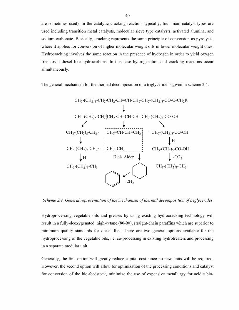
40
are sometimes used). In the catalytic cracking reaction, typically, four main catalyst types are
used including transition metal catalysts, molecular sieve type catalysts, activated alumina, and
sodium carbonate. Basically, cracking represents the same principle of conversion as pyrolysis,
where it applies for conversion of higher molecular weight oils in lower molecular weight ones.
Hydrocracking involves the same reaction in the presence of hydrogen in order to yield oxygen
free fossil diesel like hydrocarbons. In this case hydrogenation and cracking reactions occur
simultaneously.
The general mechanism for the thermal decomposition of a triglyceride is given in scheme 2.4.
CH3-(CH2)5-CH2-CH2-CH=CH-CH2-CH2-(CH2)5-CO-O-CH2R
CH3-(CH2)5-CH2-CH2-CH=CH-CH2-CH2-(CH2)5-CO-OH
CH2=CH-CH=CH2CH3-(CH2)5-CH2 CH2-(CH2)5-CO-OH
CH3-(CH2)3-CH2 CH2=CH2+
Diels Alder
-2H2
CH3-(CH2)3-CH3
H
H
CH3-(CH2)5-CO-OH
CH3-(CH2)4-CH3
-CO2
Scheme 2.4. General representation of the mechanism of thermal decomposition of triglycerides
Hydroprocessing vegetable oils and greases by using existing hydrocracking technology will
result in a fully-deoxygenated, high-cetane (80-90), straight-chain paraffins which are superior to
minimum quality standards for diesel fuel. There are two general options available for the
hydroprocessing of the vegetable oils, i.e. co-processing in existing hydrotreaters and processing
in a separate modular unit.
Generally, the first option will greatly reduce capital cost since no new units will be required.
However, the second option will allow for optimization of the processing conditions and catalyst
for conversion of the bio-feedstock, minimize the use of expensive metallurgy for acidic bio-
41
feedstocks and products and allow for the removal of products such as carbon oxides and H2O
which interfere with the hydroprocessing catalyst.
The reactor uses a conventional commercial refinery hydrotreating catalyst and hydrogen.
Several reactions occur in the reactor: hydrocracking (breaking apart of large molecules),
hydrotreating (removal of oxygen) and hydrogenation (saturation of double bonds). The
hydrotreating options can be successfully implemented to the number of feedstocks for example,
canola oil, soya oil, yellow grease, animal tallow and tall oil (a by-product of the Kraft pulping
process).
The co-products can be easily integrated into a pre-existing refinery infrastructure. The
hydrocarbon liquid can be distilled into three basic fractions: naphtha middle distillate (CETC
SuperCetane) waxy residues. When yellow grease, animal tallow and vegetable oils are used as
feedstocks, negligible amounts of naphtha and small volumes of waxy residues are produced.
Since the naphtha fraction is so small it is usually not necessary to remove it from the
SuperCetane. The waxy residue is paraffin-rich and can be used as refinery feedstock or power
boiler fuel.
The middle distillate (SuperCetane) is the primary liquid product where yields of 70-80% were
achieved for yellow grease and tallow. It consists mainly of straight chain hydrocarbons in the
diesel fuel boiling range with a cetane number of about 100. The high cetane diesel fuel is a
means of reducing emissions of engine pollutants and improving fuel economy. CETC
SuperCetane also resembles conventional diesel fuel when analyzed by GC/MS, is miscible in all
proportions with diesel fuel and the sulphur content is less than 10 ppm.16
As shown in scheme 2.5 the general set up uses a hydrotreating process with conventional
petroleum refinery units this same can be used for hydrotreating of different types of biomass
feedstocks to produce good quality of biodiesel.
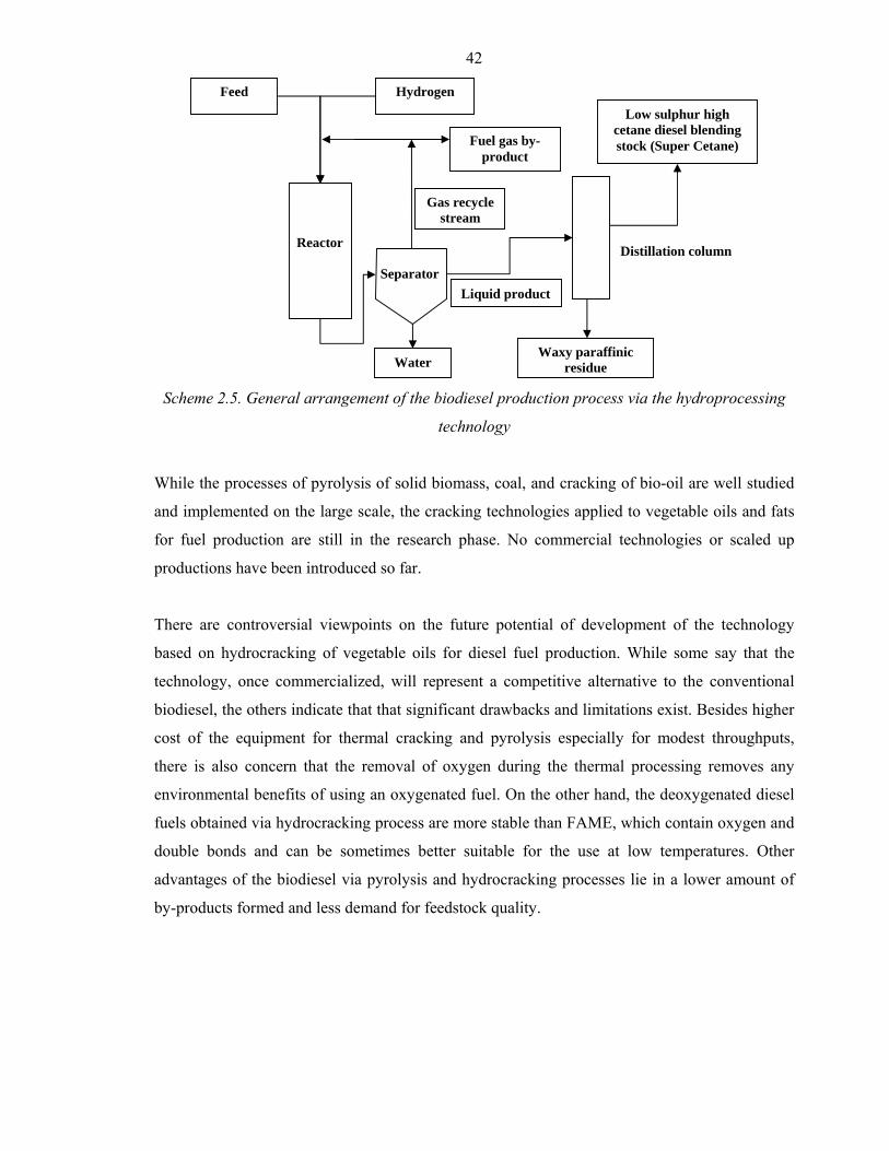
42
Scheme 2.5. General arrangement of the biodiesel production process via the hydroprocessing
technology
While the processes of pyrolysis of solid biomass, coal, and cracking of bio-oil are well studied
and implemented on the large scale, the cracking technologies applied to vegetable oils and fats
for fuel production are still in the research phase. No commercial technologies or scaled up
productions have been introduced so far.
There are controversial viewpoints on the future potential of development of the technology
based on hydrocracking of vegetable oils for diesel fuel production. While some say that the
technology, once commercialized, will represent a competitive alternative to the conventional
biodiesel, the others indicate that that significant drawbacks and limitations exist. Besides higher
cost of the equipment for thermal cracking and pyrolysis especially for modest throughputs,
there is also concern that the removal of oxygen during the thermal processing removes any
environmental benefits of using an oxygenated fuel. On the other hand, the deoxygenated diesel
fuels obtained via hydrocracking process are more stable than FAME, which contain oxygen and
double bonds and can be sometimes better suitable for the use at low temperatures. Other
advantages of the biodiesel via pyrolysis and hydrocracking processes lie in a lower amount of
by-products formed and less demand for feedstock quality.
Feed Hydrogen
Fuel gas by-product
Water
Liquid product
Low sulphur high cetane diesel blending stock (Super Cetane)
Distillation column
Gas recycle stream
Waxy paraffinic residue
Reactor
Separator
43
Market and economic aspects of biodiesel production
Although the use of Biodiesel may provide significant environmental advantages (pollutant
emissions) when compared to the combustion of fossil fuels, the effective use of Biodiesel will
depend on a large extent on its economic feasibility.
Final price
The diesel price is a critical factor in the feasibility of Biodiesel. It basically depends on three
parameters: VAT(value added tax), mineral oil taxes and production price (http://www.liquid-
biofuels.com/FinalReport1.html).
Alternate uses for soybean oil and even animal fats and recycled frying oils keep their price at a
level where they cannot compete directly against fossil diesel fuel. Some type of government
subsidies are necessary for the industry to develop. These subsidies, primarily in the form of tax
waivers, have been responsible for the rapid growth of Biodiesel use in Europe. In various
European countries, the price of Biodiesel is actually less than for petroleum diesel fuel.
A state mandate requiring the use of a minimum Biodiesel blend in all fuels sold for use is
another type of subsidy: it removes price as an issue since the fuel suppliers will have to pay
whatever is necessary to get the Biodiesel they need for blending
(http://www.me.iastate.edu/biodiesel/).
Production costs
In the early days, Biodiesel producers were satisfied when achieving a transesterification rate
(yield) of approx. 85 - 95 % thus leaving quite a volume of potential feedstock as waste in the
glycerine phase. However, yield is the second biggest factor affecting profitability, i.e. a 10%
decline of yield reduces profitability by approx. 25 %. It is therefore crucial to transfer any
potential molecule into a fatty-acidmethyl-ester; this includes all the triglycerides and Free-Fatty-
Acids (FFA). A modern and profitable process technology today is able to achieve a 100 % yield
without any expensive losses (Austrian Biofuels Institute, 2000).
Feedstock costs
The high price of Biodiesel’s oil feedstock is the major obstacle to market development. As the
selling price of Biodiesel must exceed the feedstock cost to cover processing, packaging,
transportation, distribution and profit, it is highly sensitive to any widening of the fossil oil-
vegetable oil price gap (Körbitz, 2002).
44
The most promising approach to lowering the price is to use other, less expensive feedstocks to
provide a portion of the Biodiesel supply. These other feedstocks could include spoiled
soybeans, beef and pork tallow, recycled restaurant frying oils and byproducts , such as
soapstock, from other processes involving vegetable oils. While the quantities of these
feedstocks are not sufficient to supply a large market, they can be used as blending agents to
lower the overall costs (Levelton, 2002).
Tax incentives
Tax relief or subsidies are essential for commercial production of biodiesel due to present
processing costs to produce biodiesel, which are much higher than those for petroleum diesel.
These incentives are being used in several countries (Pramanik, 2005):
• US Federal Governament introduced a legislation providing for a 1 % vol reduction in diesel
fuel tax over three year period (until December 2005) for every percent of biodiesel blended
with diesel to 20 %.
• Germany does not levy excise tax on biodiesel.
• France offers a tax incentive of 0.35 Euro/l for VOME (Vegetable oil methyl ester) blended
with diesel.
• UK has a 20 % lower tax.
• Austrian tax law on Tax Reform 2000 exempts to 2 % biodiesel blend from mineral oil taxes.
• Finland has adopted a tax incentive for reformulated diesel fuel.
It should be mentioned that technical, economic and environmental factors are not sufficient to
fully explain the use or non-use of a given fuel; other factors such as:
• Sociological and cultural aspects
• Organisational aspects
• Institutional, structural and political aspects would have to be investigated, but they were
partly neglected as this would have gone beyond the scope of this work.
45
Bioethanol from sugar crops
Bioethanol is mainly produced by fermentation process using different sugar materials as
feedstocks. Ethanol also is produced through chemical reactions using ethylene and steam as
reactants. Ethanol is a colourless, biodegradable and low toxicity liquid. Ethanol low
environmental pollution compared to other chemicals. The usage of ethanol as an alternative
transport fuel has been ever increasing all over the world due to dependence of petroleum fuel,
reduce air pollution, mitigation of global climate change and create more jobs in rural area in
particular transition, developing and least developed countries. In general ethanol unlike gasoline
it contains 35% of oxygen which reduces the emissions of NOx and particulate matters from
combustion. The most common blend is 10% ethanol and 90% petrol (E10). Vehicle engines
require no modifications to run on E10 and vehicle warranties are unaffected also. Only flexible
fuel vehicles can run on up to 85% ethanol and 15% petrol blends (E85).
Ethanol could be produced through chemical reactions or by conversion of biomass materials by
fermentation processes followed three major steps: the formation of a solution of fermentable
sugars; the fermentation of these sugars to ethanol; and the separation and purification of the
ethanol, usually by distillation.
Bioethanol from sugar feedstocks
Easiest way to produce ethanol is from C6 sugars using fermentation process. The most
common sugar is glucose (C6) or biomasses containing higher levels of glucose or precursors to
glucose are the easiest to convert to ethanol. Many microorganisms like fungi, bacteria, and yeast
can be used for fermentation of sugars but Saccharomyces cerevisiae also known as Bakers yeast
is frequently used to ferment sugar to ethanol. Sugarcane is a typical example for sugar
feedstock. Brazil is one of the highest producers in the of bioethanol world for fuel which is use
as sugarcane as feedstock. Other sugar rich biomass feedstocks are sweet sorghum, sugar beet,
and also different types of fruits. However, all these materials are in the human food chain, these
materials are usually too expensive to use for ethanol production but these waste residues can be
used for alternative feedstock for the production of bioethanol.
Bioethanol from starch:
Starch is another feedstock which available plenty and it made up of long chains of glucose
molecules these can be fragmented into simple sugars before fermentation to produce ethanol.
Starch biomass feedstocks are include tubers like sweet potato, potato, cassava and cereal grains
etc., Starchy feedstocks undergo hydrolysis to breakdown the starch into fermentable sugars i.e.,
46
saccharification. The hydrolysis of starch can be carried out by mixing water with the feedstocks
to form slurry which is then heated to rupture of cell walls and different specific enzymes are
added during hydrolysis to break chemical bonds present in the starch materials.
Wet Milling Processes
Cereals can be processed into ethanol by either the dry milling or the wet milling process. In the
wet milling process, for example, cereal like corn kernel is steeped in warm water, this helps to
break down the proteins and release the starch present in the corn and helps to soften the kernel
for the milling process. The corn is then milled to produce germ, fibre and starch products. The
germ is extracted to produce corn oil and the starch fraction undergoes centrifugation and
saccharification to produce gluten wet cake. The ethanol is then extracted by the distillation
process. The wet milling process is normally used in factories producing several hundred million
gallons of ethanol every year.
Dry milling process
The dry milling process involves cleaning and breaking down the cereals kernel into fine
particles using a hammer mill process. This creates a powder with a course flour type
consistency. The powder contains the cereals germ, starch and fibre. In order to produce a sugar
solution the mixture is then hydrolysed or broken down into sucrose sugars using enzymes or a
dilute acid. The mixture is then cooled and yeast is added in order to ferment the mixture into
ethanol. The dry milling process is normally used in factories producing less than 50 million
gallons of ethanol every year.
Sugar fermentation process
The hydrolysis process breaks down the cellulosic part of the biomass or corn into sugar
solutions that can then be fermented into ethanol. Yeast is added to the solution, which is then
heated. The yeast contains an enzyme called invertase, which acts as a catalyst and helps to
convert the sucrose sugars into glucose and fructose (both C6H12O6). Table … shows that
different types of enzymes used for various types of feedstocks for the production of bioethanol.
The chemical reactions are shown below:
C12H22O11 + H2O C6H12O6 + C6H12O6
Sucrose Fructose Glucose
Invertase
47
The fructose and glucose sugars then react with another enzyme called zymase, which is also
contained in the yeast to produce ethanol and carbon dioxide. The chemical reaction is shown
below:
C2H5OH + 2CO2
Fructose/Glucose Ethanol
ZymaseC6H12O6
The fermentation process takes around three days to complete and is carried out at a temperature
of between 250 °C and 300 °C. Table 2.8 shows that different types of carbohydrate feedstocks
and corresponding enzymes used for the production of bioethanol.
Table 2.8. Feedstocks and enzymes used for production of bioethanol
Carbohydrate Feedstock
Main carbohydrate to be converted
Process utilizing added enzymes
Required enzyme
Sugar cane or molasses
Sucrose Dextran hydrolysis Dextranase
Grains and tubers Starch (α-1,4 linked glucose molecules)
Starch, beta glucan and pentosan hydrolysis
Amylase, glucoamylase, betagulcanase, xylanase
Fractional Distillation Process
The ethanol, which is produced from the fermentation process, still contains a significant
quantity of water, which must be removed. This is achieved by using the fractional distillation
process. The distillation process works by boiling the water and ethanol mixture. Since ethanol
has a lower boiling point (78.3 °C) compared to that of water (100 °C), the ethanol turns into the
vapour state before the water and can be condensed and separated.
Advantages of bioethanol as fuel
Bioethanol has a number benefits over conventional fuels. It is a renewable resources and it
reduces the green gas emissions. By encouraging bioethanol use, the rural economy would also
receive a boost from growing the necessary crops. Bioethanol is also biodegradable and far less
toxic that fossil fuels. In addition, by using bioethanol in older engines can help reduce the
amount of carbon monoxide produced by the vehicle thus improving air quality. Another
advantage of bioethanol is the ease with which it can be easily integrated into the existing road
transport fuel system. In quantities up to 5%, bioethanol can be blended with conventional fuel

48
without the need of engine modifications. Bioethanol is produced using familiar methods, such
as fermentation, and it can be distributed using the same petrol forecourts and transportation
systems as before.
Disadvantages of bioethanol as fuel
Though ethanol based fuels has many advantages over fossil fuels but it is not compatible with
some fuel system components. It may corrode ferrous components, jelly-like deposits on fuel
strainer screens and salt deposits etc. Water content in ethanol should be less than 1.0%
otherwise, phase separation occur during blending with gasoline and moreover, ethanol will mix
either water or gasoline but not in both. Ethanol blended gasoline can also affect in electric fuel
pumps by causing internal wear and undesirable spark generation.
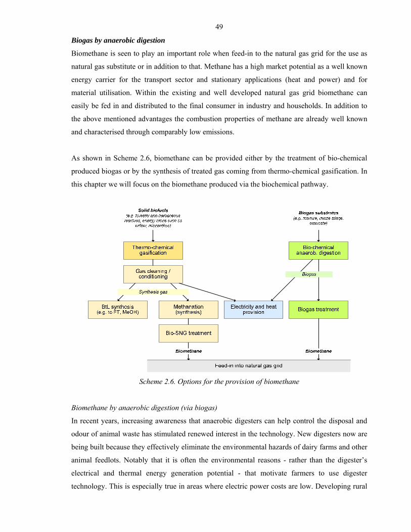
49
Biogas by anaerobic digestion
Biomethane is seen to play an important role when feed-in to the natural gas grid for the use as
natural gas substitute or in addition to that. Methane has a high market potential as a well known
energy carrier for the transport sector and stationary applications (heat and power) and for
material utilisation. Within the existing and well developed natural gas grid biomethane can
easily be fed in and distributed to the final consumer in industry and households. In addition to
the above mentioned advantages the combustion properties of methane are already well known
and characterised through comparably low emissions.
As shown in Scheme 2.6, biomethane can be provided either by the treatment of bio-chemical
produced biogas or by the synthesis of treated gas coming from thermo-chemical gasification. In
this chapter we will focus on the biomethane produced via the biochemical pathway.
Scheme 2.6. Options for the provision of biomethane
Biomethane by anaerobic digestion (via biogas)
In recent years, increasing awareness that anaerobic digesters can help control the disposal and
odour of animal waste has stimulated renewed interest in the technology. New digesters now are
being built because they effectively eliminate the environmental hazards of dairy farms and other
animal feedlots. Notably that it is often the environmental reasons - rather than the digester’s
electrical and thermal energy generation potential - that motivate farmers to use digester
technology. This is especially true in areas where electric power costs are low. Developing rural
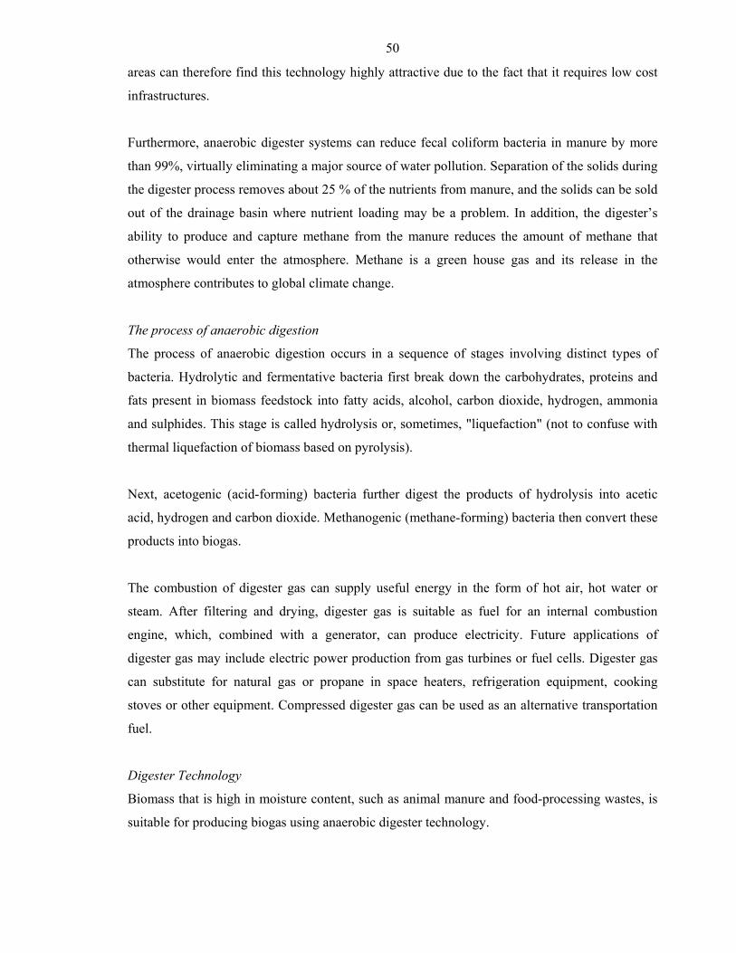
50
areas can therefore find this technology highly attractive due to the fact that it requires low cost
infrastructures.
Furthermore, anaerobic digester systems can reduce fecal coliform bacteria in manure by more
than 99%, virtually eliminating a major source of water pollution. Separation of the solids during
the digester process removes about 25 % of the nutrients from manure, and the solids can be sold
out of the drainage basin where nutrient loading may be a problem. In addition, the digester’s
ability to produce and capture methane from the manure reduces the amount of methane that
otherwise would enter the atmosphere. Methane is a green house gas and its release in the
atmosphere contributes to global climate change.
The process of anaerobic digestion
The process of anaerobic digestion occurs in a sequence of stages involving distinct types of
bacteria. Hydrolytic and fermentative bacteria first break down the carbohydrates, proteins and
fats present in biomass feedstock into fatty acids, alcohol, carbon dioxide, hydrogen, ammonia
and sulphides. This stage is called hydrolysis or, sometimes, "liquefaction" (not to confuse with
thermal liquefaction of biomass based on pyrolysis).
Next, acetogenic (acid-forming) bacteria further digest the products of hydrolysis into acetic
acid, hydrogen and carbon dioxide. Methanogenic (methane-forming) bacteria then convert these
products into biogas.
The combustion of digester gas can supply useful energy in the form of hot air, hot water or
steam. After filtering and drying, digester gas is suitable as fuel for an internal combustion
engine, which, combined with a generator, can produce electricity. Future applications of
digester gas may include electric power production from gas turbines or fuel cells. Digester gas
can substitute for natural gas or propane in space heaters, refrigeration equipment, cooking
stoves or other equipment. Compressed digester gas can be used as an alternative transportation
fuel.
Digester Technology
Biomass that is high in moisture content, such as animal manure and food-processing wastes, is
suitable for producing biogas using anaerobic digester technology.
51
During anaerobic digestion, bacteria digest biomass in an oxygen-free environment. Symbiotic
groups of bacteria perform different functions at different stages of the digestion process.
Scheme 2.7. Anaerobic digestion
There are four basic types of microorganisms involved. Hydrolytic bacteria break down complex
organic wastes into sugars and amino acids. Fermentative bacteria then convert those products
into organic acids. Acidogenic microorganisms convert the acids into hydrogen, carbon dioxide
and acetate. Finally, the methanogenic bacteria produce biogas from acetic acid, hydrogen and
carbon dioxide.
Controlled anaerobic digestion requires an airtight chamber, called a digester. To promote
bacterial activity, the digester must maintain a temperature of at least 18 °C. Using higher
temperatures, up to 65 °C, shortens processing time and reduces the required volume of the tank
by 25 to 40%. However, there are more species of anaerobic bacteria that thrive in the
temperature range of a standard design (mesophilic bacteria) than there are species that thrive at
higher temperatures (thermophilic bacteria). High-temperature digesters also are more prone to
upset because of temperature fluctuations and their successful operation requires close
monitoring and diligent maintenance.
The biogas produced in a digester (also known as “digester gas”) is actually a mixture of gases,
with methane and carbon dioxide making up more than 90 % of the total. Biogas typically
52
contains smaller amounts of hydrogen sulphide, nitrogen, hydrogen, methylmercaptans and
oxygen.
Methane is a combustible gas. The energy content of digester gas depends on the amount of
methane it contains. Methane content varies from about 55 to 80 %. Typical digester gas, with a
methane concentration of 65%, contains about 600 Btu of energy per cubic foot.
For individual farms, small-scale plug-flow or covered lagoon digesters of simple design can
produce biogas for on-site electricity and heat generation. For example, a plug-flow digester
could process 8,000 gallons of manure per day, the amount produced by a herd of 500 dairy
cows. By using digester gas to fuel an engine-generator, a digester of this size would produce
more electricity and hot water than the dairy consumes.
Larger scale digesters are suitable for manure volumes of 25,000 to 100,000 gallons per day. In
Denmark and in several other European countries, central digester facilities use manure and
other organic wastes collected from individual farms and transported to the facility.
Types of Anaerobic Digesters
There are three basic digester designs. All of them can trap methane and reduce fecal coli form
bacteria, but they differ in cost, climate suitability and the concentration of manure solids they
can digest.
A covered lagoon digester, as the name suggests, consists of a manure storage lagoon with a
cover. The cover traps gas produced during decomposition of the manure. This type of digester is
the least expensive of the three. Covering a manure storage lagoon is a simple form of digester
technology suitable for liquid manure with less than 3-percent solids. For this type of digester, an
impermeable floating cover of industrial fabric covers all or part of the lagoon. A concrete
footing along the edge of the lagoon holds the cover in place with an airtight seal. Methane
produced in the lagoon collects under the cover. A suction pipe extracts the gas for use. Covered
lagoon digesters require large lagoon volumes and a warm climate. Covered lagoons have low
capital cost, but these systems are not suitable for locations in cooler climates or locations where
a high water table exists.
53
A complete mix digester converts organic waste to biogas in a heated tank above or below
ground. A mechanical or gas mixer keeps the solids in suspension. Complete mix digesters are
expensive to construct and cost more than plug-flow digesters to operate and maintain.
Complete mix digesters are suitable for larger manure volumes having solids concentration of 3
percent to 10 percent. The reactor is a circular steel or poured concrete container. During the
digestion process, the manure slurry is continuously mixed to keep the solids in suspension.
Biogas accumulates at the top of the digester. The biogas can be used as fuel for an engine-
generator to produce electricity or as boiler fuel to produce steam. Using waste heat from the
engine or boiler to warm the slurry in the digester reduces retention time to less than 20 days.
Plug-flow digesters are suitable for ruminant animal manure that has a solids concentration of 11
percent to 13 percent. A typical design for a plug-flow system includes a manure collection
system, a mixing pit and the digester itself. In the mixing pit, the addition of water adjusts the
proportion of solids in the manure slurry to the optimal consistency. The digester is a long,
rectangular container, usually built below-grade, with an airtight, expandable cover.
New material added to the tank at one end pushes older material to the opposite end. Coarse
solids in ruminant manure form a viscous material as they are digested, limiting solids separation
in the digester tank. As a result, the material flows through the tank in a "plug." Average
retention time (the time a manure “plug” remains in the digester) is 20 to 30 days.
Anaerobic digestion of the manure slurry releases biogas as the material flows through the
digester. A flexible, impermeable cover on the digester traps the gas. Pipes beneath the cover
carry the biogas from the digester to an engine-generator set.
A plug-flow digester requires minimal maintenance. Waste heat from the engine-generator can
be used to heat the digester. Inside the digester, suspended heating pipes allow hot water to
circulate. The hot water heats the digester to keep the slurry at 25°C to 40°C, a temperature range
suitable for methane-producing bacteria. The hot water can come from recovered waste heat
from an engine generator fuelled with digester gas or from burning digester gas directly in a
boiler.
54
Biogas from wastes
Municipal sewage contains organic biomass solids, and many wastewater treatment plants use
anaerobic digestion to reduce the volume of these solids. Anaerobic digestion stabilizes sewage
sludge and destroys pathogens. Sludge digestion produces biogas containing 60 to 70% methane,
with an energy content of about 600 Btu per cubic foot.
Most wastewater treatment plants that use anaerobic digesters burn the gas for heat to maintain
digester temperatures and to heat building space. Unused gas is burned off as waste but could be
used for fuel in an engine-generator or fuel cell to produce electric power. Before use, the gas is
cleaned to remove impurities. These are principally hydrogen sulphide, halogens (fluorine,
chlorine and bromine), moisture, bacteria and solids. Biogas also contains carbon dioxide, which
cannot be removed easily.
Landfill Gas
Underground decomposition of cellulose contained in municipal and industrial solid waste
produces biogas. The digestion occurring in landfills is an uncontrolled process of biomass
decay.
The efficiency of the process depends on the waste composition and moisture content of the
landfill, cover material, temperature and other factors. The biogas released from landfills,
commonly called "landfill gas," is typically 50% methane, 45% carbon dioxide and 5% other
gases. The energy content of landfill gas is 400 to 550 Btu per cubic foot.
Capturing landfill gas before it escapes to the atmosphere allows for conversion to useful energy.
A landfill must be at least 40 feet deep and have at least one million tons of waste in place for
landfill gas collection and power production to be technically feasible. Notably that by capturing
landfill gas will contribute to the reduction of green house gas emissions.
A landfill gas-to-energy system consists of a series of wells drilled into the landfill. A piping
system connects the wells and collects the gas. Dryers remove moisture from the gas, and filters
remove impurities. The gas typically fuels an engine-generator set or gas turbine to produce
electricity. The gas also can fuel a boiler to produce heat or steam. Further gas cleanup improves
biogas to pipeline quality, the equivalent of natural gas. Reforming the gas to hydrogen would
make possible the production of electricity using fuel cell technology.
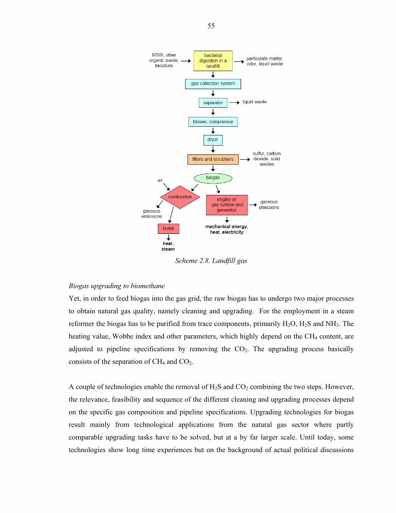
55
Scheme 2.8. Landfill gas
Biogas upgrading to biomethane
Yet, in order to feed biogas into the gas grid, the raw biogas has to undergo two major processes
to obtain natural gas quality, namely cleaning and upgrading. For the employment in a steam
reformer the biogas has to be purified from trace components, primarily H2O, H2S and NH3. The
heating value, Wobbe index and other parameters, which highly depend on the CH4 content, are
adjusted to pipeline specifications by removing the CO2. The upgrading process basically
consists of the separation of CH4 and CO2.
A couple of technologies enable the removal of H2S and CO2 combining the two steps. However,
the relevance, feasibility and sequence of the different cleaning and upgrading processes depend
on the specific gas composition and pipeline specifications. Upgrading technologies for biogas
result mainly from technological applications from the natural gas sector where partly
comparable upgrading tasks have to be solved, but at a by far larger scale. Until today, some
technologies show long time experiences but on the background of actual political discussions
56
and decisions not only companies change the owner - also lots of research is done in this field.
Thus, the main technologies will be characterized in the following.
Generally it has to be stated that all companies offering upgrading plants pledge to reach a
biomethane quality of more than 96% methane content and a methane loss with less than 3%.
Additionally a very high availability for all technologies is promised and confirmed in practice
with at most plants about 95 %. Practical measurements in Sweden have shown different results,
but more or less independent on the used technology. Especially it seems to be necessary to care
about the methane losses which are reported with up to 10%, because they influence ecological
and economical parameters of such plants very strongly.
Water scrubbing
One of the mainly used technologies for biogas upgrading is the water scrubbing process which
is very common in Sweden and shows a very long history of experiences. The process is based
on sorption of carbon dioxide in water at high pressures at about 10 bar and desorption of carbon
dioxide at lower pressures in another vessel to separate carbon dioxide and methane. At the same
time most trace gases as for example H2S are separated during this process. As water source
circulated fresh water or cleaned waste water without circulation can be used. Advantages of
waste water use are compensated by bio fouling in the scrubbers due to the relatively high
organics content.
Due to the long research and development period the technology has reached a very high level of
development and is proven in practice. Thus, it has to be expected, that the technology has to
compete with other technologies in economical questions but is seen as technological state of the
art.
Pressure swing adsorption
A lot of upgrading plants install pressure swing absorption technologies for biomethane
production. The technology is based on high pressure absorption of carbon dioxide at molecular
sieves or activated charcoal in at least two steps. Other trace gases have to be separated e. g. in
filter systems before carbon dioxide absorption. Absorption materials have long operation
durations but have to be exchanged from time to time. This technology shows long time
experiences and is well established and competes as solid and reliable technology.
57
Chemical adsorption
Chemical absorption is possible with a number of substances (e.g. Selexol, MEA, DEA and
others), which are capable to absorb carbon dioxide at ambient pressure combined with heat
demand or at raised pressure. Available information about efficiencies of the processes are very
different, but a lot of experiences exist and research is going on. The advantage of chemical
absorption is that used substances are selective for carbon dioxide (and sometimes for H2S too,
most times H2S-separation is done before upgrading) and thus no methane will be absorbed what
results in high methane concentrations in the purified gas. Absorption processes under pressure
seem to be of comparable behaviour as water scrubbing processes but ambient pressure systems
(where only pilot plants are known) promise less electrical energy demand for the continuous
process and could be of high interest for applications where only low pressure is required after
upgrading and heat is available. Summarizing it can be stated that some chemical absorption
technologies are reliable and well established and others are under development.
Membrane technologies
Due to the different molecule size of methane and carbon dioxide it is generally possible to
separate both gases through membranes. The smaller methane molecules can pass a membrane
and a gas with very high methane content and a gas with very high carbon dioxide content can be
produced. Technologies were developed for dry separation (transport through the membrane is
forced by very high pressure) and for wet separation (transport is forced by a very low
concentration of methane in a fluid where methane is absorbed in). Both technologies are only
known from pilot plants and efficiencies regarding methane losses and energy demand are not
known from continuously practiced processes.
Cryogenic upgrading
Additionally it is possible to use the differences in dew and condensation point of methane and
carbon dioxide. Therefore it has been shown in small scale that both gas components can be
separated by cooling down of biogas to less than -45 °C at about 80 bar pressure. Applications of
this process, called cryogenic upgrading, are under research in Sweden and Germany but not
available at the market.
For safety reasons the treated biogas has to be odorised prior to being injected into public natural
gas grid. Concerning the different biogas treatment options, further technical equipment is
required, including an appropriate periphery to the gas grid, compressors adjusting required grid
pressure specifications as well as gas counter and measurement of the injected gas composition.

58
If biogas is injected into the nearest low-pressure gas grid (e.g. 4 to 5 bar) additional gas
compression is not required. Most of the upgrading technologies (e. g. water scrubbing and PSA)
are appropriate to provide biogas at this pressure level. In addition, a gas mixer might be
necessary to add high-calorific gas (e.g. propane or butane). This addition is an option aimed at
maximising the methane yield if biogas is upgraded to a lower gas quality as required.
59
Bibliography
Ahn E. et al. 1995, Sep. Sci. Technol., 30, 2021.
ABI (Austrian Biofuels Institute) 2000, World-wide Trends in Production and Marketing of
Biodiesel; presented at the ALTENER – Seminar “New Markets for Biodiesel in Modern
Common Rail Diesel Engines”, University for Technology in Graz, Graz.
ABI (Austrian Biofuels Institute) 2002, Statement on the situation of the Biodiesel sector,
Vienna, 2.
Barnwal B.K. et al. 2005, Renewable and Sustainable Energy Reviews, 9, 363.
Boocock D.G.B. et al. 1996a, Biomass Bioenergy, 11, 43.
Boocock D.G.B. 1996b, Process of producing lower alkyl fatty acid esters CA 0112581.
Boocock D.G.B. et al. 1998, Journal of the American Oil Chemical Society, 75, 1167.
Boocock D.G.B. 2001, Single phase process for production of fatty acid methyl esters from
mixtures of triglycerides and fatty acids WO 0112581.
Canakci M. et al. 2001, Transactions of the American Society of Agricultural Engineers, 44,
1429.
CANMET Energy Technology Centre (CETC), NRCan, SuperCetane Technology.
Cao et al. 2005, Preparation of biodiesel from soybean oil using supercritical methanol and
co-solvent. Fuel, 84, 347-351.
Chang C.C. et al. 1947, Industrial and Engineering Chemistry, 39, 1543.
Dorado M.P. et al. 2002, Transactions of the American Society of Agricultural Engineers, 45,
525
Farrelli A. et al. 2006, Science, 311, 506.
Freedman B. et al. 1984, Journal of the American Oil Chemical Society, 61, 1638.
Fuduka H. et al. 2001, Journal of Bioscience and Bioengineering, 92, 405.
Goering et al. 1982, Journal of the American Society of Agricultural Engineers, 25, 1472.
Gryglewicz S. 1999, Bioresource Technolology, 70, 249.
HART Ethanol & Biodiesel News 2006, Vol XVIII, Issue 47, November 13.
Harwood H.J. 1984, Journal of the American Oil Chemical Society, 61, 353
Hofmann F. Et al. 2005, Evaluierung der Möglichkeiten zur Einspeisung von Biogas in das
Erdgasnetz, Forschungsvorhaben im Auftrag der Fachagentur für Nachwachsende
Rohstoffe.
Knothe G. 2005, Fuel Processing Technology, 86, 1059.
Kononova M.M. 1961, Soil Organic Matter, Its Nature, Its role in Soil Formation and in Soil
Fertility.
60
Körbitz W., 8 key trends in the production of Biodiesel world-wide, presentation, Vienna 2002.
Levelton Engineering 2002, Assessment of Biodiesel and Ethanol diesel blends, greenhouse gas
emissions, exhaust emissions and policy issues, Ottawa.
Ma F. et al. 1998, Transactions of the American Society of Agricultural Engineers, 41, 1261.
Ma F. 1999a, Bioresource Technology, 70, 1.
Ma F. et al. 1999b, Bioresource Technology, 69, 289.
McCormick R.L. et al. 2003, NOx Solutions for Biodiesel, NREL/SR-510-31465, Golden, CO:
National Renewable Energy Laboratory.
Mohamad I.A.W. et al. 2002, Bioresource Technolology, 85, 25.
Natural Resources Canada 2004, Office of Energy Efficiency, The Addition of NRCan’s
SuperCetance and ROBYS Processes to GHGenius.
NBB (National Biodiesel Board) 2004, Biodiesel Production Technology Overview, Genuary.
Niehaus R.A. et al. 1986, Journal of the American Society of Agricultural Engineers, 29, 683.
Pryde E.H. 1984, Journal of the American Oil Chemical Society, 61, 1609.
Scholwin F. 2007, Biomethane from Biogas: Expectations from Established vs. new
Technologies, in Lechner (Hrsg.): Waste matters. Integrating Views, Proceedings of 2nd
BOKU Waste Conference 17-19.04.2007, Vienna, ISBN 978-3-7089-0060-5, 185-194.
Schwab A.W. et al. 1988, Journal of the American Oil Chemical Society, 65, 1781.
Schwab A.W. et al. 1987, Fuel, 66.
Sonntag N.O.V. 1979, Reactions of fats and fatty acids. Bailey's industrial oil and fat products,
vol. 1, 4th edition, ed. Swern, D., John Wiley & Sons, New York, 99.
Srivastava A. et al. 2000, Renewable and Sustainable Energy Reviews, 4, 111.
Szybist J.P. et al. 2005, Fuel Processing Technology, 86, 1109.
Thompson J.C. et al. 2006, Applied Engineering in Agriculture, 22, 261.
Tomasevic A.V. et al. 2003, Fuel Processing Technology, 81, 1.
Turck R. 2002, Method for producing fatty acid esters of monovalent alkyl alcohols and use
thereof. USP 0156305.
Tyson K.S. 2001, Biodiesel Handling and Use Guidelines, in: NREL - National Renewable
Energy Laboratory, Report No. TP-580-30004 (Golden CO USA).
UOP, A Honeywell Company 2006, Technology & More Newsletter, Winter.
US EPA 2002, A Comprehensive Analysis of Biodiesel Impacts on Exhaust Emissions. Draft
technical report. EPA 420-P-02-001, www.epa.gov/otaq/models/analysis/biodsl/p02001.pdf.
Wang M. et al. 1999, Effects of fuel ethanol use on fuel-cycle energy and greenhouse gas
emissions, Report, Center for Transportation Research Argonne National Laboratory.
Weisz P.B. et al. 1979, Science, 206, 57.

61
Zhou W. et al. 2003, Journal of the American Oil Chemical Society, 80, 367.
See also: http://en.wikipedia.org/wiki/Biodiesel
http://www.me.iastate.edu/biodiesel/
http://www.liquid-biofuels.com/FinalReport1.html
http://www.energy.gov/news/
http://ethanol.org/howethanol.html
http://www.biodiesel.org
62
Part 3. Second generation of biofuels and biorefineries
Pyrolysis and gasification of biomass
The use of biomass as liquid fuels has attracted significant interest on pyrolysis during the past
two decades. The main advantage that pyrolysis offers over gasification is a wide range of
products that can potentially be obtained, ranging from transportation fuel to chemical feedstock.
Considerable amount of research has gone into pyrolysis in the past decade in many countries.
Any form of biomass can be used (over 100 different biomass types have been tested in labs
around the world).
Pyrolysis is a process that generally occurs under temperatures that vary from 400 °C up to
650 °C in total or partial absence of oxygen. Gases, liquids and solids are generated in
proportions that depend on the parameters considered, that is, the temperature and pressure of the
reactor, the residence time of the solid, liquids and gaseous phases inside the reactor, the time
and the rate of heating of the biomass particles, the reactor internal environment, and initial
conditions of the biomass.
Fast pyrolysis is one of the most recently emerging technologies used to convert biomass
feedstock into maximum bio-oil. The main characteristics of the fast pyrolysis process are: short
heating time for carbonaceous particles and for vapours formed within the reactor; high heating
rates and mass-transfer coefficients; and moderate temperature from the heating source. In
general, the residence time for vapours should be lower then 1 minute. Bio-oil is formed from
successive decomposition reactions, isomerisation, cracking (split), and recombination by
condensation, polymerization, depolymerisation and fragmentation of biomass and also has high
water content in its composition.
Tar and bio-oil produced in pyrolysis is a liquid containing more than 200 components, like
acetic acid, methanol, acetic aldehyde, acetone, ethyl acetate, etc. Some components have a
value as raw material in the chemical industry. Resultants produced in biomass pyrolysis mainly
contain gases such as CO2, CO, CH4, C2H4, H2, etc., with a lower heat value is between 15 and
20 MJ/m3, therefore belonging to combustible gases of medium heat value. It is also a gas of
high quality because it doesn’t contain any sulphide and nitride, and can be used directly as civil
combustible gas.
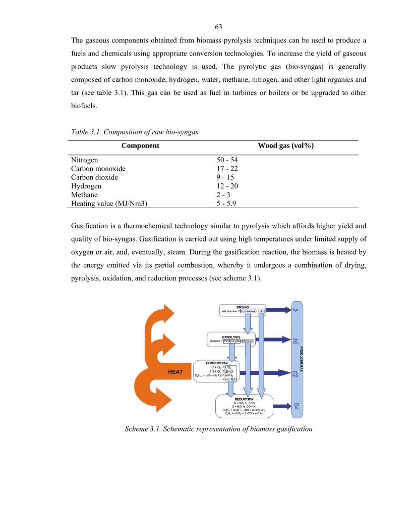
63
The gaseous components obtained from biomass pyrolysis techniques can be used to produce a
fuels and chemicals using appropriate conversion technologies. To increase the yield of gaseous
products slow pyrolysis technology is used. The pyrolytic gas (bio-syngas) is generally
composed of carbon monoxide, hydrogen, water, methane, nitrogen, and other light organics and
tar (see table 3.1). This gas can be used as fuel in turbines or boilers or be upgraded to other
biofuels.
Table 3.1. Composition of raw bio-syngas
Component Wood gas (vol%)
Nitrogen 50 - 54 Carbon monoxide 17 - 22 Carbon dioxide 9 - 15 Hydrogen 12 - 20 Methane 2 - 3 Heating value (MJ/Nm3) 5 - 5.9
Gasification is a thermochemical technology similar to pyrolysis which affords higher yield and
quality of bio-syngas. Gasification is carried out using high temperatures under limited supply of
oxygen or air, and, eventually, steam. During the gasification reaction, the biomass is heated by
the energy emitted via its partial combustion, whereby it undergoes a combination of drying,
pyrolysis, oxidation, and reduction processes (see scheme 3.1).
Scheme 3.1. Schematic representation of biomass gasification
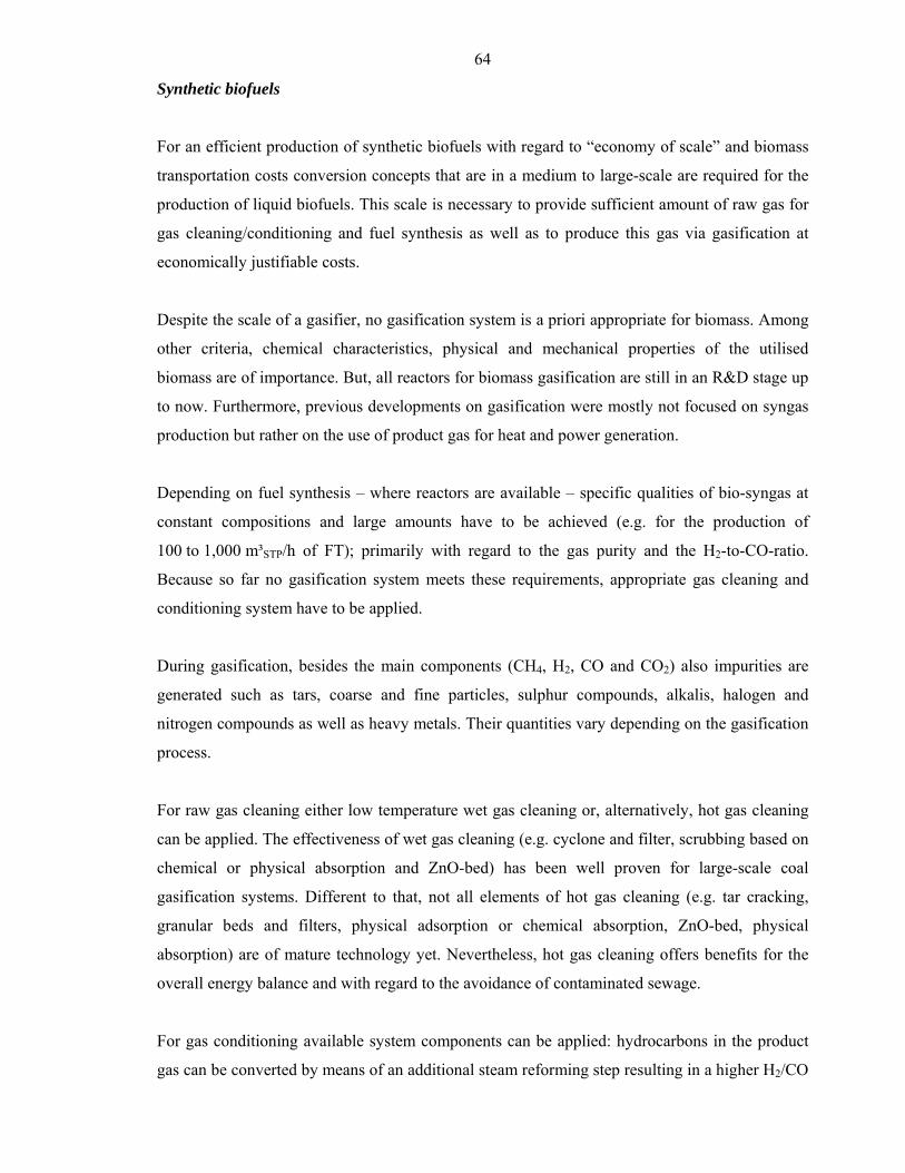
64
Synthetic biofuels
For an efficient production of synthetic biofuels with regard to “economy of scale” and biomass
transportation costs conversion concepts that are in a medium to large-scale are required for the
production of liquid biofuels. This scale is necessary to provide sufficient amount of raw gas for
gas cleaning/conditioning and fuel synthesis as well as to produce this gas via gasification at
economically justifiable costs.
Despite the scale of a gasifier, no gasification system is a priori appropriate for biomass. Among
other criteria, chemical characteristics, physical and mechanical properties of the utilised
biomass are of importance. But, all reactors for biomass gasification are still in an R&D stage up
to now. Furthermore, previous developments on gasification were mostly not focused on syngas
production but rather on the use of product gas for heat and power generation.
Depending on fuel synthesis – where reactors are available – specific qualities of bio-syngas at
constant compositions and large amounts have to be achieved (e.g. for the production of
100 to 1,000 m³STP/h of FT); primarily with regard to the gas purity and the H2-to-CO-ratio.
Because so far no gasification system meets these requirements, appropriate gas cleaning and
conditioning system have to be applied.
During gasification, besides the main components (CH4, H2, CO and CO2) also impurities are
generated such as tars, coarse and fine particles, sulphur compounds, alkalis, halogen and
nitrogen compounds as well as heavy metals. Their quantities vary depending on the gasification
process.
For raw gas cleaning either low temperature wet gas cleaning or, alternatively, hot gas cleaning
can be applied. The effectiveness of wet gas cleaning (e.g. cyclone and filter, scrubbing based on
chemical or physical absorption and ZnO-bed) has been well proven for large-scale coal
gasification systems. Different to that, not all elements of hot gas cleaning (e.g. tar cracking,
granular beds and filters, physical adsorption or chemical absorption, ZnO-bed, physical
absorption) are of mature technology yet. Nevertheless, hot gas cleaning offers benefits for the
overall energy balance and with regard to the avoidance of contaminated sewage.
For gas conditioning available system components can be applied: hydrocarbons in the product
gas can be converted by means of an additional steam reforming step resulting in a higher H2/CO
65
ratio. To achieve the required quality for fuel synthesis the water-gas CO conversion is
conducted as final step of bio-syngas production.
Based on these and further aspects the following overall concepts for liquid biofuel production
seem to be promising (Scheme 3.2). Thereby the technological performance of FT synthesis can
be carried out in low temperature solid bed reactors or slurry reactors followed by fractioning
and hydrocracking of FT products to diesel. For the production of MeOH synthesis low pressure
synthesis is used in commercial practise by means of solid bed reactors. MeOH is also applied as
feedstock for indirect DME synthesis that is matured. In general, the complexity of an overall
system for production of synthetic biofuels strongly depends on the necessary gas cleaning and
gas conditioning. For a high efficient production the efficiency of bio-syngas production is
crucial.
Scheme 3.2. Concepts for liquid synthetic biofuels
With regard to that overall concept, the technologies for liquid synthetic biofuels (BtL) can be
briefly characterised as follows:
Bio-SNG
The bio-SNG (synthetic natural gas) production is characterised through the possibility that
relatively small conversion units with capacities in a range of 10 up to 100 MWth biomass input

66
can be used. Thus, the conversion of locally available lignocellulosic biomass is possible. The
production of synthetic biofuel, electricity and heat (so called tri-generation) allows high overall
efficiencies (e.g. high CO2 mitigation potential) within the entire production process. In
comparison to the production of BtL-fuels (like Fischer-Tropsch-fuels) is the SNG production
system marked through lower technical and financial risks due to a technology that is less
complex (e.g. synthesis and fuel treatment) and basically smaller units can be used. Based on
these circumstances a rapid and easy market entrance seems to be possible.
The production of SNG can occur within a very promising concept via the steam gasification of
woody biomass with water as gasification agent, gas cleaning, subsequent methanation and up-
grading. One promising concept is shown in Scheme 3.3.
Scheme 3.3. System concept of the Bio-SNG production
For example, the steam gasification using a fast internal circulating fluidised bed gasifier
(FICFB) and the gas cleaning have been demonstrated successfully in a full technical scale
(8 MW thermal capacity) at the biomass combined heat and power (CHP) gasification plant in
Güssing/Austria whereas during the last years experiences in commercial use for more than
30,000 hours have been achieved. Steam gasification leads to a producer gas with a relatively
high content of hydrogen and methane as well as a low content of nitrogen. These properties are
necessary for an efficient SNG production.
67
The gas cleaning of the producer gas from biomass gasification for application in gas engines
and turbines can be considered as state of the art. Additionally for the methanation process acid
components such as H2S, HCl and organic sulphur that could damage the catalyst have to be
removed (e.g. a rapeseed-methyl-ester (RME) scrubber). For the conversion of the producer gas
(also called bio-syngas as it is close by composition to the synthesis gas) into biomethane a
fluidized bed methanation reactor will be constructed at the demonstration plant in
Güssing/Austria. Therewith biomethane can be derived from woody biomass with an overall
efficiency of 60 to 65 % depending on the biomass assortment.
Beside the production of SNG as a biofuel for the transport sector, additionally electricity can be
generated in a gas engine as well as through the use of rejected heat in the ORC process. The
arising heat can be provided for district heating purposes as well. Currently the methanation
reactor is within a laboratory scale in operation (thermal capacity 10 kW), fed by a slipstream at
the biomass CHP gasification plant in Güssing/Austria to find out the optimal operation
conditions.
The biomass gasification for example has to be further developed, upscaled to larger scales and
improved to secure the production of a favourable bio-syngas (i.e. optimisation of the
gasification regarding the composition of the gas (primarily regarding the H2/CO ratio). The
optimisation and the extension of the gas cleaning and conditioning is a premise for the
production of an appropriate bio-syngas that can fulfil the necessary requirements with regard to
the gas properties. With regard to the arising problem in the field of the methanation catalyst, gas
impurities like sulphur and chlorine compounds have to be removed more intensive whereas the
gas cleaning has to be further developed. The already demonstrated methanation process has to
be scaled up on the MW range. Concerning the utilized catalyst further optimization has to be
performed to ensure a long term performance of the catalyst.
Within the overall SNG conversion system the single interactions between the different system
components (like gasification, gas cleaning, methanation and upgrading) have to be optimised.
Additionally, the availability and reliability of the entire facility have to be demonstrated and
improved.
Fischer-Tropsch fuels
In addition to the presented concept, there are many other different concepts to produce FT-fuels
that are characterised by the typical by-products waxes, naphtha and electricity. Basically the
68
technology is more complex (e.g. when compared to Bio-SNG), whereby mechanical-thermal
biomass treatment (e.g. chipping and drying of solid biofuels) is matured. The pyrolysis and
transport of pyrolysis products (e.g. slurry) is in an R&D stage. Biomass gasification is
demonstrated in small-scale. Basically, the synthesis and fuel treatment of the FT raw products
(refinery technology required) are commercial available for fossil material. The expected overall
efficiency is between 40 to 45%. Particularly in Europe, the FT-technology is in view of many
technology developers and mineral oil industries. The first commercial demonstration plant with
a capacity of approx. 15 kt/a FT-diesel (45 MWth biomass input) is currently built by Choren
Industries in Freiberg/Germany and will start its operation end of 2007. However, for a broad
market implementation existing techno-economic barriers have to be overcome in the years to
come. This is expected to after 2010. Until then, several R&D demand is required, e.g. with
regard to (i) further development of pyrolysis and gasification (e.g. upscale, operation under
pressure), (ii) efficient and economic gas treatment technologies, (iii) treatment of FT-raw
products (e.g. downsizing hydrocracking, use in refineries) as well as the successful
demonstration of plants availability and reliability for the use of approved system components.
Biomethanol
Methanol synthesis and fuel treatment are not that complex as FT-fuel production. Thus, higher
overall efficiencies of up to 55% can be expected. Currently, the R&D activities are with regard
to produce an intermediate product for further fuel production (e.g. gasoline). The required R&D
demand is quite similar to FT-fuels for gasification and gas treatment. Moreover, the adaptation
of methanol synthesis units has to be carried out. This is also true for the demonstration of
biomethanol plants in pilot scale.
Dimethylether (DME)
The synthetic biofuel DME can be applied similar to LPG (liquefied petroleum gas) in adapted
diesel engines. However, DME might potentially be used for non-transport energy purposes.
While the processes of gasification of solid biofuels and the gas cleaning and conditioning to
bio-syngas are similar, significant differences exists with regard to the catalytic synthesis.
For DME production synthesis can either be realised via the previous step of methanol synthesis
(so called indirect synthesis) or directly. The most common types for methanol synthesis and
catalytic dehydration of methanol (DME synthesis) are presented in the following.
69
A typical reactor type for methanol production is the so called adiabatic quench reactor. The
cooling is done by an internal quench (fast cooling by injection of condensate) with fresh syngas.
The reaction heat is withdrawn at the exit of the reactor, which is at the bottom. The conversion
of methanol to DME where water is chemically separated is done in a DME reactor. Usually,
fixed bed reactors are used for this purpose. First, methanol is heated to a temperature of about
250 °C (e.g. by a heat exchanger) before entering the reactor, where an exothermic reaction takes
place at temperatures of 250 to 300 °C and DME is formed. Afterwards, the reactor effluents are
cooled down and DME is separated from unconverted methanol and water. The conversion rate
of raw methanol to DME ranges from 86 to 88 %. Raw DME contains some water, dissolved
gases and little amounts of higher ethers, which have to be withdrawn by distillation.
Hydro Thermal Upgrading (HTU) diesel
Another basic approach to convert various types of solid biomass into fuels lies in the principle
to obtain the bio-oil as an intermediate. Bio-oil, also named “bio-crude” can be obtained via flash
pyrolysis or via hydrothermal treatment or upgrading - HTU. In the later case, the thermal
pyrolytic process is carried out in the aqueous medium under elevated pressures (sub-critical
water) which improves yield and quality of the product oil, as large amount of O2 is removed as
CO2 during the HTU process. The HTU process is therefore advantageous for biomass
containing high water content, since drying of the biomass is not necessary.
The HTU technology uses pressures in the range of 120 – 180 bars, and temperature range of
300 – 350°C. Under these conditions, the biomass is depolymerised to a hydrophobic liquid (bio-
crude), which separates from the water. Some gases such as CO, H2, CO
2 (90 weight %) and
methane is produced, along with water and organic compounds. The main product of this
reaction is a liquid (oil) consisting of various kinds of hydrocarbon. The lighter fractions of this
oil can be upgraded to diesel fuel components. HTU diesel is produced by means of a catalytic
process called “hydrodeoxygenation” (HDO) which is intrinsically similar to the
hydroprocessing technology discussed above for the diesel via hydrocracking of vegetable oils.
Oxygen is removed from the biocrude by treatment with hydrogen at elevated temperatures. The
upgrading of the biocrude to diesel fuel may be done at the same location as the production of
the biocrude or the biocrude may be transported to other locations, followed by local upgrading
to HTU diesel. It can be blended with fossil diesel in any proportion without the necessity of
engine or infrastructure modifications.

70
Presently, HTU technology is only researched in the Netherlands, where the only HTU pilot
plant is located as well. Research activities focus on the complex chemical properties of the
reactions of the HTU process, the feeding pump to achieve the required pressure, and testing of
several feedstock types. It will probably take a few more years before the process has been tested
and developed sufficiently before a commercial diesel equivalent can be produced
71
Cellulosic bioethanol
Since sugar and starchy materials are expensive and interfere in human food chain and divert
them to transport fuel production not advisable. Alternative cellulosic materials are better option
to solve these problems. Examples of cellulosic feedstocks are agricultural residues like stalks,
leaves and husks of food crops; forestry wastes such sawdust and chips from timber mills, dead
trees, and tree branches; municipal solid wastes cardboard, paper and house hold garbage
products; food processing and other industrial wastes such as liquor, a by-product from paper
and pulp manufacturing industries and also energy crops, fast growing tress and grasses
developed just for this purpose. Cellulosic resources are in general very widespread and
abundant. For example, forests comprise about 80% of the world’s biomass. Being abundant and
outside the human food chain makes cellulosic materials relatively inexpensive feedstocks for
ethanol production.
Cellulose molecules consist of long chains of glucose molecules as do starch molecules, but have
a different structural configuration. These structural characteristics plus the encapsulation by
lignin makes cellulosic materials more difficult to hydrolyze than starchy materials.
Thus, in general, trees have higher lignin contents then grasses. Unfortunately, lignin which
contains no sugars encloses the cellulose and hemicellulose molecules, making them difficult to
reach. Hemicellulose is also comprised of long chains of sugar molecules; but contains, in
addition to glucose (a 6-carbon or hexose sugar), contains pentoses (5-carbon sugars). To
complicate matters, the exact sugar composition of hemicellulose can vary depending on the type
of plant. Since 5-carbon sugars comprise a high percentage of the available sugars, the ability to
recover and ferment them into ethanol is important for the efficiency and economics of the
process. Recently, special microorganisms have been genetically engineered which can ferment
5-carbon sugars into ethanol with relatively high efficiency.
Process description
Ethanol can be manufactured from cellulosic biomass feedstocks using acid hydrolysis,
enzymatic hydrolysis and also by thermo chemical treatment. The most commonly used process
is acid hydrolysis with sulphuric acid. Virtually any acid can be used; however, sulfuric acid is
most commonly used since it is usually the least expensive.
Scheme 3.4 illustrates the different steps involving in conversion of the biomass to bioethanol
production.
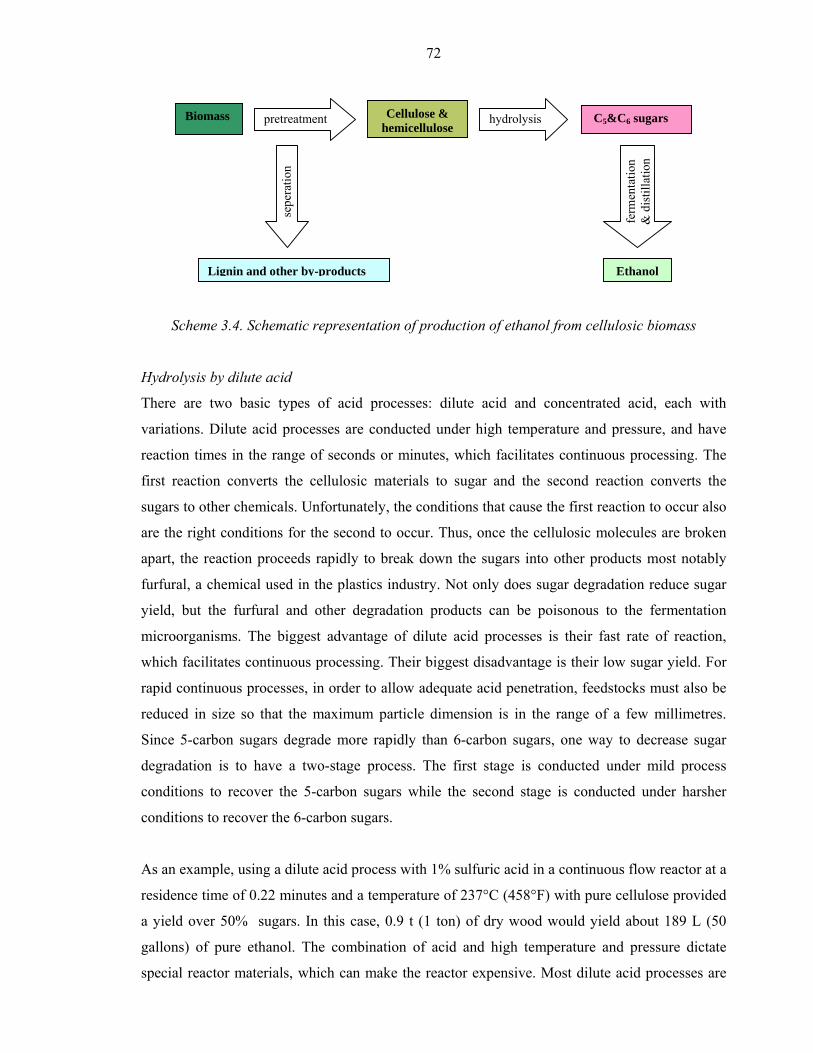
72
Scheme 3.4. Schematic representation of production of ethanol from cellulosic biomass
Hydrolysis by dilute acid
There are two basic types of acid processes: dilute acid and concentrated acid, each with
variations. Dilute acid processes are conducted under high temperature and pressure, and have
reaction times in the range of seconds or minutes, which facilitates continuous processing. The
first reaction converts the cellulosic materials to sugar and the second reaction converts the
sugars to other chemicals. Unfortunately, the conditions that cause the first reaction to occur also
are the right conditions for the second to occur. Thus, once the cellulosic molecules are broken
apart, the reaction proceeds rapidly to break down the sugars into other products most notably
furfural, a chemical used in the plastics industry. Not only does sugar degradation reduce sugar
yield, but the furfural and other degradation products can be poisonous to the fermentation
microorganisms. The biggest advantage of dilute acid processes is their fast rate of reaction,
which facilitates continuous processing. Their biggest disadvantage is their low sugar yield. For
rapid continuous processes, in order to allow adequate acid penetration, feedstocks must also be
reduced in size so that the maximum particle dimension is in the range of a few millimetres.
Since 5-carbon sugars degrade more rapidly than 6-carbon sugars, one way to decrease sugar
degradation is to have a two-stage process. The first stage is conducted under mild process
conditions to recover the 5-carbon sugars while the second stage is conducted under harsher
conditions to recover the 6-carbon sugars.
As an example, using a dilute acid process with 1% sulfuric acid in a continuous flow reactor at a
residence time of 0.22 minutes and a temperature of 237°C (458°F) with pure cellulose provided
a yield over 50% sugars. In this case, 0.9 t (1 ton) of dry wood would yield about 189 L (50
gallons) of pure ethanol. The combination of acid and high temperature and pressure dictate
special reactor materials, which can make the reactor expensive. Most dilute acid processes are
Biomass Cellulose & hemicellulose
EthanolLignin and other by-products
pretreatment hydrolysis
ferm
enta
tion
& d
istil
latio
n
C5&C6 sugars
sepe
ratio
n
73
limited to a sugar recovery efficiency of around 50%. The reason for this is that at least two
reactions are part of this process. Unfortunately, sugar degradation is still a problem and yields
are limited to around 272 L/t (80 gallons of ethanol/ton) of dry wood.
Hydrolysis by concentrated acid
The concentrated acid process uses relatively mild temperatures and the only pressures involved
are usually only those created by pumping materials from vessel to vessel. In the TVA
concentrated acid process, corn stover is mixed with dilute (10%) sulfuric acid, and heated to
100ºC for 2 to 6 hours in the first (or hemicellulose) hydrolysis reactor. The low temperatures
and pressures minimize the degradation of sugars. To recover the sugars, the hydrolyzed material
in the first reactor is soaked in water and drained several times. The solid residue from the first
stage is then dewatered and soaked in a 30% to 40% concentration of sulfuric acid for 1 to 4 hrs
as a pre-cellulose hydrolysis step. This material is then dewatered and dried with the effect that
the acid concentration in the material is increased to about 70%. After reacting in another vessel
for 1 to 4 hr at 100ºC, the reactor contents are filtered to remove solids and recover the sugar and
acid. The sugar/acid solution from the second stage is recycled to the first stage to provide the
acid for the first stage hydrolysis. The sugars from the second stage hydrolysis are thus
recovered in the liquid from the first stage hydrolysis. The primary advantage of the concentrated
process is the high sugar recovery efficiency, which can be on the order of over 90% of both
hemicellulose and cellulose sugars. The low temperatures and pressures employed also allow the
use of relatively low cost materials such as fibre glass tanks and piping. Unfortunately, it is a
relatively slow process and cost effective acid recovery systems have been difficult to develop.
Without acid recovery, large quantities of lime must be used to neutralize the acid in the sugar
solution. This neutralization forms large quantities of calcium sulfate, which requires disposal
and creates additional expense. Using some assumed cellulose conversion and fermentation
efficiencies, ethanol yields from glucose can be calculated for corn stover (the above-ground part
of the corn plant less the ears) as shown in Table 3.3 showing ethanol yield from glucose.
Similarly, ethanol yields from the xylose can be calculated as shown in Table 3.4.
Thus, in this example, the total yield/t of dry stover is about 227 L (60 gallons) of ethanol. These
numbers also show how critical sugar conversion and recovery efficiencies and fermentation
efficiencies are. If one could attain 95% for both efficiencies, then the yield would be
approximately 350 L/t (103 gallons of
ethanol/ton).
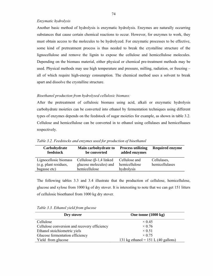
74
Enzymatic hydrolysis
Another basic method of hydrolysis is enzymatic hydrolysis. Enzymes are naturally occurring
substances that cause certain chemical reactions to occur. However, for enzymes to work, they
must obtain access to the molecules to be hydrolyzed. For enzymatic processes to be effective,
some kind of pretreatment process is thus needed to break the crystalline structure of the
lignocellulose and remove the lignin to expose the cellulose and hemicellulose molecules.
Depending on the biomass material, either physical or chemical pre-treatment methods may be
used. Physical methods may use high temperature and pressure, milling, radiation, or freezing –
all of which require high-energy consumption. The chemical method uses a solvent to break
apart and dissolve the crystalline structure.
Bioethanol production from hydrolysed cellulosic biomass:
After the pretreatment of cellulosic biomass using acid, alkali or enzymatic hydrolysis
carbohydrate moieties can be converted into ethanol by fermentation techniques using different
types of enzymes depends on the feedstock of sugar moieties for example, as shown in table 3.2.
Cellulose and hemicellulose can be converted in to ethanol using cellulases and hemicelluases
respectively.
Table 3.2. Feedstocks and enzymes used for production of bioethanol
Carbohydrate feedstock
Main carbohydrate to be converted
Process utilizing added enzymes
Required enzyme
Lignocellosic biomass (e.g. plant residues, bagasse etc)
Cellulose (β-1,4 linked glucose molecules) and hemicellulose
Cellulose and hemicellulose hydrolysis
Cellulases, hemicellulases
The following tables 3.3 and 3.4 illustrate that the production of cellulose, hemicellulose,
glucose and xylose from 1000 kg of dry stover. It is interesting to note that we can get 151 litters
of cellulosic bioethanol from 1000 kg dry stover.
Table 3.3. Ethanol yield from glucose
Dry stover One tonne (1000 kg)
Cellulose Cellulose conversion and recovery efficiency Ethanol stoichiometric yiels Glucose fermentation efficiency Yield from glucose
× 0.45 × 0.76 × 0.51 × 0.75
131 kg ethanol = 151 L (40 gallons)
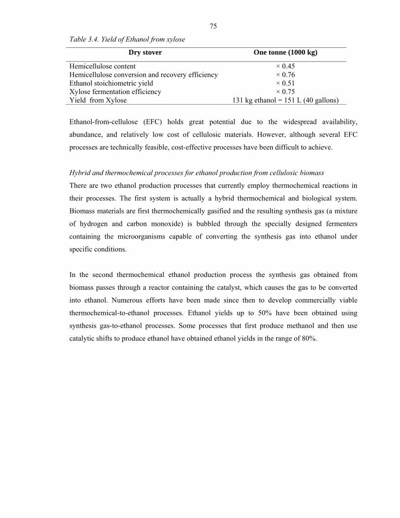
75
Table 3.4. Yield of Ethanol from xylose
Dry stover One tonne (1000 kg)
Hemicellulose content Hemicellulose conversion and recovery efficiency Ethanol stoichiometric yield Xylose fermentation efficiency Yield from Xylose
× 0.45 × 0.76 × 0.51 × 0.75
131 kg ethanol = 151 L (40 gallons)
Ethanol-from-cellulose (EFC) holds great potential due to the widespread availability,
abundance, and relatively low cost of cellulosic materials. However, although several EFC
processes are technically feasible, cost-effective processes have been difficult to achieve.
Hybrid and thermochemical processes for ethanol production from cellulosic biomass
There are two ethanol production processes that currently employ thermochemical reactions in
their processes. The first system is actually a hybrid thermochemical and biological system.
Biomass materials are first thermochemically gasified and the resulting synthesis gas (a mixture
of hydrogen and carbon monoxide) is bubbled through the specially designed fermenters
containing the microorganisms capable of converting the synthesis gas into ethanol under
specific conditions.
In the second thermochemical ethanol production process the synthesis gas obtained from
biomass passes through a reactor containing the catalyst, which causes the gas to be converted
into ethanol. Numerous efforts have been made since then to develop commercially viable
thermochemical-to-ethanol processes. Ethanol yields up to 50% have been obtained using
synthesis gas-to-ethanol processes. Some processes that first produce methanol and then use
catalytic shifts to produce ethanol have obtained ethanol yields in the range of 80%.
76
Bio-hydrogen
It is widely acknowledged that hydrogen is an attractive energy source to replace conventional
fossil fuels, both from the environmental and economic standpoint. It is often cited as a potential
source of unlimited clean power (Hoffman, 2002).
When hydrogen is used as a fuel it generates no pollutants, but produces water which can be
recycled to make more hydrogen. Apart from its use as a clean energy resource, hydrogen can be
used for various other purposes in chemical process industries. It is used as a reactant in
hydrogenation process to produce lower molecular weight compounds. It can also be used to
saturate compounds, crack hydrocarbons or remove sulphur and nitrogen compounds. It is a
good oxygen scavenger and can therefore be used to remove traces of oxygen to prevent
oxidative corrosion. In the manufacturing of ammonia, methanol and syngas, the use of
hydrogen is well known. The future widespread use of hydrogen is likely to be in the
transportation sector, where it will help reduce pollution. Vehicles can be powered with
hydrogen fuel cells, which are three times more efficient than a gasoline-powered engine. As of
today, all these areas of hydrogen utilization are equivalent to 3% of the energy consumption, but
it is expected to grow significantly in the years to come.
The commercially usable hydrogen currently being produced is extracted mostly from natural
gas. Nearly 90% of hydrogen is obtained by steam reformation of naphtha or natural gas.
Gasification of coal and electrolysis of water are the other industrial methods for hydrogen
production.
However, these processes are highly energy intensive and not always environment-friendly.
Moreover, the fossil-fuel (mainly petroleum) reserves of the world are depleting at an alarming
rate. So, production of hydrogen by exploiting alternative sources seems imperative in this
perspective.
Biomass, as a product of photosynthesis, is the most versatile non-petroleum renewable resource
that can be utilized for sustainable production of hydrogen (Cole, 1992).
Therefore, a cost-effective energy-production process could be achieved in which agricultural
wastes and various other biomasses are recycled to produce hydrogen economically.
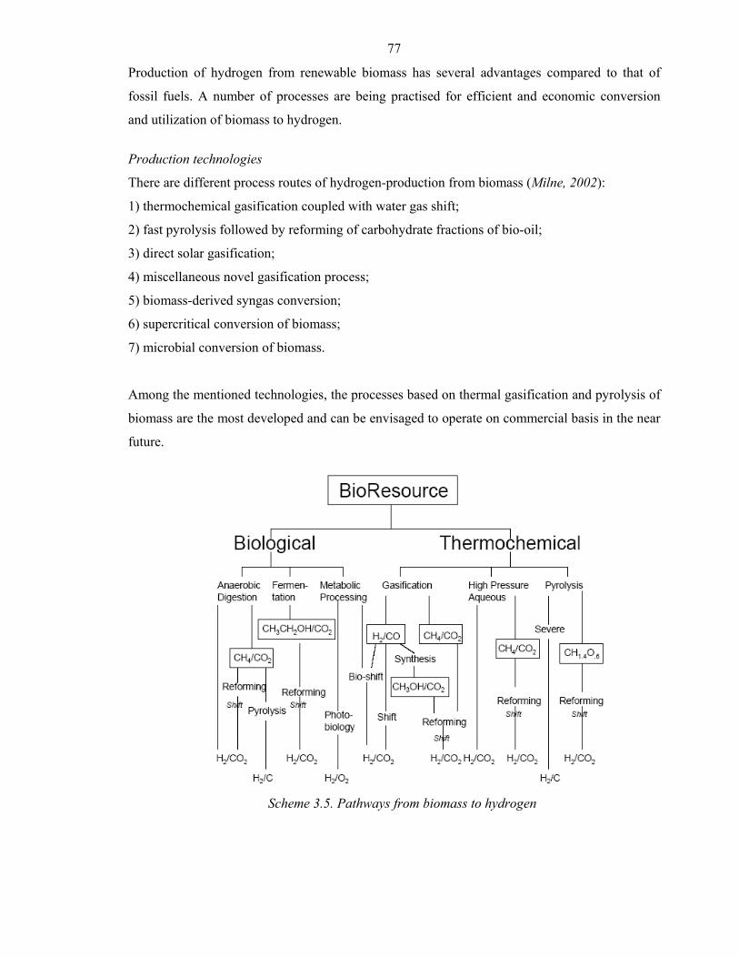
77
Production of hydrogen from renewable biomass has several advantages compared to that of
fossil fuels. A number of processes are being practised for efficient and economic conversion
and utilization of biomass to hydrogen.
Production technologies
There are different process routes of hydrogen-production from biomass (Milne, 2002):
1) thermochemical gasification coupled with water gas shift;
2) fast pyrolysis followed by reforming of carbohydrate fractions of bio-oil;
3) direct solar gasification;
4) miscellaneous novel gasification process;
5) biomass-derived syngas conversion;
6) supercritical conversion of biomass;
7) microbial conversion of biomass.
Among the mentioned technologies, the processes based on thermal gasification and pyrolysis of
biomass are the most developed and can be envisaged to operate on commercial basis in the near
future.
Scheme 3.5. Pathways from biomass to hydrogen
78
Thermo-chemical gasification coupled with water gas shift
Gasification coupled with water gas shift is the most widely practised process route for biomass
to hydrogen (Milne, 2002). Thermal, steam and partial oxidation gasification technologies are
under development around the world. Feedstock include agricultural and forest product residues
of hard wood, soft wood and herbaceous species. Thermal gasification is essentially high-rate
pyrolysis carried out in the temperature range of 600–1000 °C in fluidized bed gasifiers. The
reaction is as follows:
Biomass + O2 CO + H2 + CO2 + Energy
Other relevant gasifier types are bubbling fluid beds and the high-pressure high-temperature
slurry-fed entrained flow gasifier. However, all these gasifiers need to include significant gas
conditioning along with the removal of tars and inorganic impurities and the subsequent
conversion of CO to H2 by water gas shift reaction.
CO + H2O CO2 + H2
Fast pyrolysis followed by reforming of carbohydrate fraction of bio-oil
Pyrolysis produces a liquid product called bio-oil, which is the basis of several processes for the
development of fuel chemicals and materials. The reaction is endothermic:
Biomass + Energy Bio-oil + Char + Gas
Catalytic steam reforming of bio-oil at 750–850 °C over a nickel-based catalyst is a two-step
process that includes the shift reaction:
Bio-oil + H2O CO + H2
CO + H2O CO2 + H2
The overall stoichiometry gives a maximum yield of 0.172 g H2/g bio-oil (11.2% based on
wood).
CH1.9O0.7 + 1.26H2O CO2 + 2.21H2
79
The first step in pyrolysis is to use heat to dissociate complex molecules into simple units. Next,
reactive vapours which are generated during the first step convert to hydrogen. The Waterloo
fast-pyrolysis process technology carried out at 700 °C is used for the steam gasification of pine
sawdust using Ni–Al catalyst at a molar ratio 1:2. It has revealed that catalytic reactivation and
high steam to biomass ratios diminish the rate of deactivation (García, 2002).
Methanol and ethanol can also be produced from biomass by a variety of technologies and used
on board reforming for transportation. Caglar and Demirbas (Caglar, 2001) have used pyrolysis
of tea waste to produce hydrogen, while Abedi et al. (Abedi, 1988) have studied hydrogen and
carbon production from peanut shells.
Direct solar gasification
In 1974, Antal et al. examined the feasibility of using solar process heat for the gasification of
organic solid wastes and the production of hydrogen (Yogev, 1998). With a credit for the wastes
used, the economic projections were thought to be surprisingly favorable. Shahbazov and
Usubov (Shahbazov, 1996) show good hydrogen yields from agricultural wastes using a
parabolic mirror reflector. Thermal decomposition samples were studied by the method of
derivative chromatographic analysis. In 1998, Rustamov et al. (Rustamov, 1998) studied the
thermo-catalytic reforming of cellulose and wood pulp using concentrated solar energy. The
possibility of obtaining hydrogen and carbon monoxide with temperatures of 700-750 ºC on a
Pt/Al2O3 catalyst is shown.
Midilli et al. (Midilli, 2000) present results of the use of a palladium diaphragm to achieve solar
assisted hydrogen separations from the gases generated by pyrolysis of hazelnut shells at 500-
700 ºC. It was concluded that pure hydrogen gas could be efficiently separated at membrane
temperatures between 180-250 ºC. Walcher et al. (Walcher, 1996) mention a plan to utilize
agricultural wastes in a heliothermic gasifier.
Miscellaneous novel gasification processes
Several novel heat sources and chemistries have also been explored for hydrogen from organic
biomass. Safrany (Safrany, 1971) has proposed the use of a thermonuclear device to vapourize
waste organic materials in an underground, large-scale plasma process. In the 1980s, two novel
processes for hydrogen from carbonaceous materials were presented. Thakur (Thakur, 1980)
tested the production of hydrogen by the electrolysis of a mixture of coal, lime and water. In
80
1981, an open-cycle two-step process was tested involving the reduction of In2O3 by carbon
(chars) and its reoxidation by water to produce hydrogen (Thakur, 1981).
In2O3 + C (or 2C) In2O +CO2 (or 2CO), T>873K
In2O + 2H2O In2O3 + 2H2, T<673K
A set of biochemical reactions have been proposed to describe decomposition of water into
hydrogen and oxygen using nuclear heat and a carbon cycle (Antal, 1974). Municipal waste is
suggested as a possible source of carbon. Algae can be a by-product. Coughlin and Farooque
(Coughlin, 1979) have showed that coals and other forms of solid carbonaceous fossil fuels
could be oxidized to oxides of carbon at the anode of an electrochemical cell and hydrogen
produced at the cathode. Gases produced are discussed as function of coal slurry concentration
and electrode potential.
Biomass derived syn-gas conversion
Hydrogen production from gasified biomass by sponge-iron reactor is also reported (Hacker,
1998). The sponge-iron process (or steam-iron process) offers a simple possibility to store the
energy of synthesis gas. A number of recent studies have looked into the classical steam-iron
process for upgrading synthesis gas (mainly CO and H2) to pure H2 for use in fuel cells and other
energy devices. Some authors worked on the purification of nitrogen containing reduction gas
from a biomass gasifier using wood and wood waste. The process involves two steps:
(1) cleaning of gas from solid biomass or coal or methane, and
(2) energy storage in sponge-iron.
This study investigates woody biomass and commercially available sponge-iron. The reactions
are:
Fe3O4 + 4CO 3Fe + 4CO2 (coal, biomass or natural gas)
3Fe + 4H2O Fe3O4 +4H2
Supercritical conversion of biomass
Many researchers have investigated the aqueous conversion of whole biomass to hydrogen under
low temperature but supercritical conditions. The earliest report of supercritical gasification of
wood is by Modell (Modell, 1985). He studied the effect of temperature and concentration on the
gasification of glucose and maple sawdust in water, in the vicinity of its critical state (374 °C, 22
81
MPa). No solid residue or char is produced. Hydrogen gas concentration up to 18% (v/v) is
reported. The first report of extensive work on supercritical conversion of biomass-related
organics was given by Manarungson et al. (Manarungson, 1990), where glucose at 550 °C has
been converted largely into hydrogen and carbon dioxide. This was followed by a study of the
uncatalysed solvolysis of whole biomass and hemicellulose in hot compressed liquid water
(Mok, 1992). The first study showed that complete gasification of glucose can occur at 600°C,
34.5 MPa and 30 s residence time.
Following this work, a flow reactor has been used with newly discovered carbon-base catalysts
to convert water hyacinth, algae, pithed bagasse, liquid extract, glycerol, cellobiose, whole
biomass feedstock and sewage sludge to hydrogen. Wood sawdust, dry sewage sludge or other
particulate biomass can be mixed with a corn-starch gel to form a viscous paste. This paste can
be delivered to a supercritical flow reactor with a pump. Ongoing work indicates that the starch
can be reduced to 3% (w/w) and the particulate biomass increased to 10% (w/w). At the critical
pressure of water (22 MPa), the paste vapourizes without the formation of char. A packed bed of
carbon catalyst, at 650°C, causes the tarry vapours to react with water to produce hydrogen,
carbon dioxide, some methane and only a trace of carbon monoxide (Antal, 1997).
Microbial conversion of biomass
Highly concentrated organic waste water is one of the most abundantly available biomass which
can be exploited for microbial conversion into hydrogen. A new and unique process has been
developed when substrates such as carbohydrates are fermented by a consortium of bacteria; they
produce hydrogen and carbon dioxide.
Municipal solid wastes and digested sewage sludge have the potential to produce large amount
of hydrogen by suppressing the production of methane by introducing low voltage electricity into
the sewage sludge. Some authors (Fascetti, 1995) have reported on the photosynthetic hydrogen
evolution from municipal solid wastes. Batch-wise and continuous experiments show that the
acidic aqueous stream obtained from such refuse is a good substrate for the growth of R.
sphaeroides RV. The substrate from the acidogenesis of fruit and vegetable market wastes gives
higher hydrogen evolution rates (about threefold) compared to synthetic medium. Mixed culture
of photosynthetic anaerobic bacteria provides a method of utilization of a variety of resources for
hydrogen-production (Miyake, 1990).
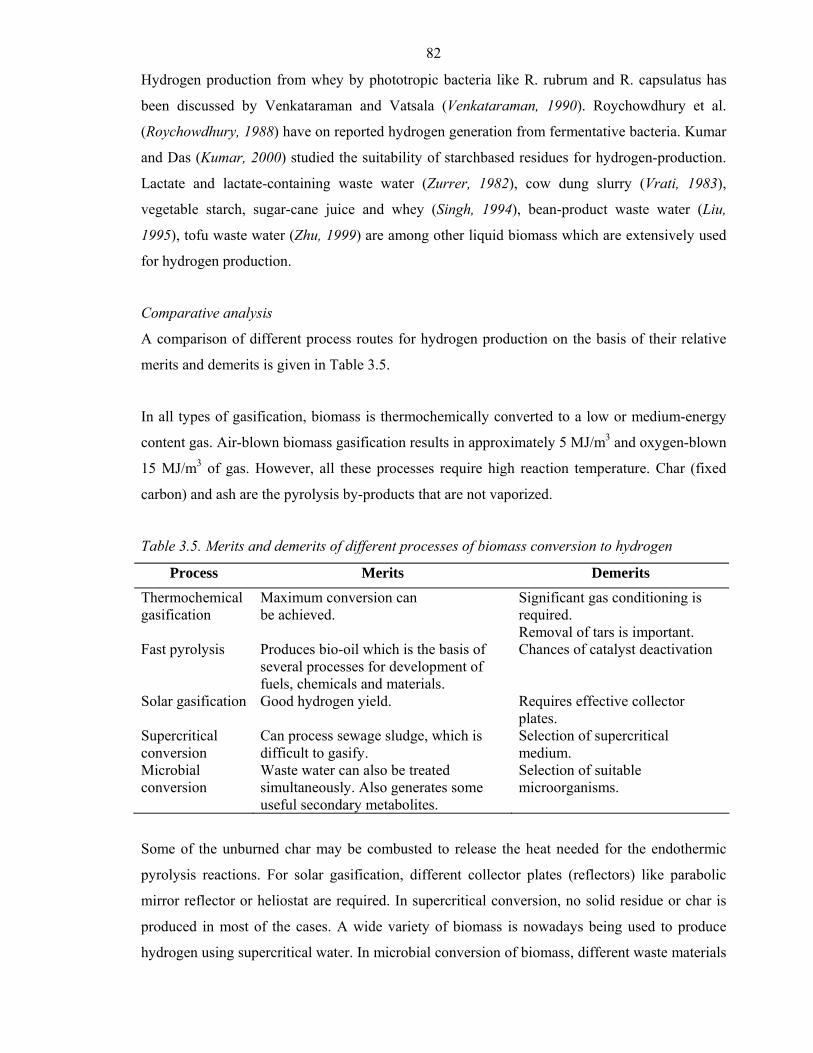
82
Hydrogen production from whey by phototropic bacteria like R. rubrum and R. capsulatus has
been discussed by Venkataraman and Vatsala (Venkataraman, 1990). Roychowdhury et al.
(Roychowdhury, 1988) have on reported hydrogen generation from fermentative bacteria. Kumar
and Das (Kumar, 2000) studied the suitability of starchbased residues for hydrogen-production.
Lactate and lactate-containing waste water (Zurrer, 1982), cow dung slurry (Vrati, 1983),
vegetable starch, sugar-cane juice and whey (Singh, 1994), bean-product waste water (Liu,
1995), tofu waste water (Zhu, 1999) are among other liquid biomass which are extensively used
for hydrogen production.
Comparative analysis
A comparison of different process routes for hydrogen production on the basis of their relative
merits and demerits is given in Table 3.5.
In all types of gasification, biomass is thermochemically converted to a low or medium-energy
content gas. Air-blown biomass gasification results in approximately 5 MJ/m3 and oxygen-blown
15 MJ/m3 of gas. However, all these processes require high reaction temperature. Char (fixed
carbon) and ash are the pyrolysis by-products that are not vaporized.
Table 3.5. Merits and demerits of different processes of biomass conversion to hydrogen
Process Merits Demerits
Thermochemical gasification
Maximum conversion can be achieved.
Significant gas conditioning is required. Removal of tars is important.
Fast pyrolysis Produces bio-oil which is the basis of several processes for development of fuels, chemicals and materials.
Chances of catalyst deactivation
Solar gasification Good hydrogen yield. Requires effective collector plates.
Supercritical conversion
Can process sewage sludge, which is difficult to gasify.
Selection of supercritical medium.
Microbial conversion
Waste water can also be treated simultaneously. Also generates some useful secondary metabolites.
Selection of suitable microorganisms.
Some of the unburned char may be combusted to release the heat needed for the endothermic
pyrolysis reactions. For solar gasification, different collector plates (reflectors) like parabolic
mirror reflector or heliostat are required. In supercritical conversion, no solid residue or char is
produced in most of the cases. A wide variety of biomass is nowadays being used to produce
hydrogen using supercritical water. In microbial conversion of biomass, different waste materials
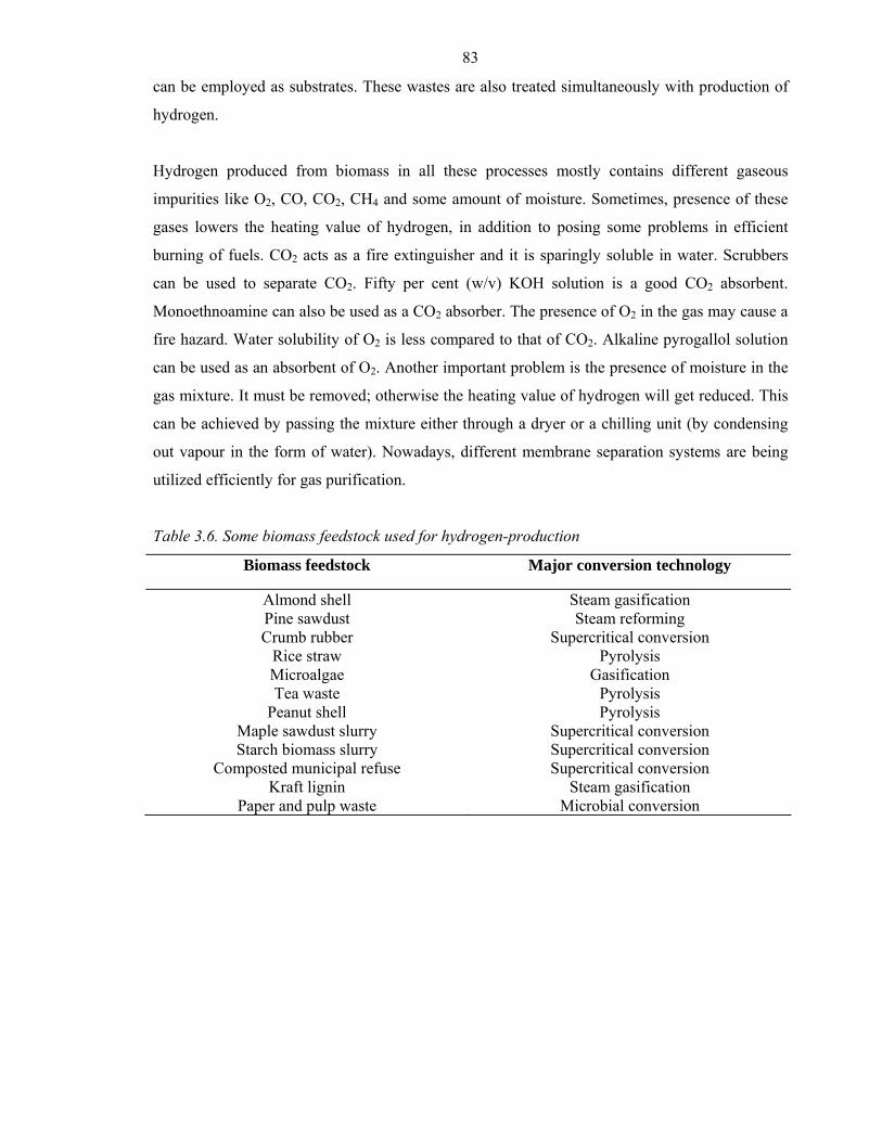
83
can be employed as substrates. These wastes are also treated simultaneously with production of
hydrogen.
Hydrogen produced from biomass in all these processes mostly contains different gaseous
impurities like O2, CO, CO2, CH4 and some amount of moisture. Sometimes, presence of these
gases lowers the heating value of hydrogen, in addition to posing some problems in efficient
burning of fuels. CO2 acts as a fire extinguisher and it is sparingly soluble in water. Scrubbers
can be used to separate CO2. Fifty per cent (w/v) KOH solution is a good CO2 absorbent.
Monoethnoamine can also be used as a CO2 absorber. The presence of O2 in the gas may cause a
fire hazard. Water solubility of O2 is less compared to that of CO2. Alkaline pyrogallol solution
can be used as an absorbent of O2. Another important problem is the presence of moisture in the
gas mixture. It must be removed; otherwise the heating value of hydrogen will get reduced. This
can be achieved by passing the mixture either through a dryer or a chilling unit (by condensing
out vapour in the form of water). Nowadays, different membrane separation systems are being
utilized efficiently for gas purification.
Table 3.6. Some biomass feedstock used for hydrogen-production
Biomass feedstock Major conversion technology
Almond shell Steam gasification Pine sawdust Steam reforming Crumb rubber Supercritical conversion
Rice straw Pyrolysis Microalgae Gasification Tea waste Pyrolysis
Peanut shell Pyrolysis Maple sawdust slurry Supercritical conversion Starch biomass slurry Supercritical conversion
Composted municipal refuse Supercritical conversion Kraft lignin Steam gasification
Paper and pulp waste Microbial conversion
84
Biorefineries
Definition for Biorefinery
Biorefinery is a facility that integrates biomass conversion processes and equipment to produce
fuels, power, and chemicals from biomass. The biorefinery concept is analogous to today's
petroleum refineries, which produce multiple fuels and products from petroleum. Industrial
biorefineries have been identified as the most promising route to the creation of a new domestic
bio-based industry.
By producing multiple products, a biorefinery can take advantage of the differences in biomass
components and intermediates and maximize the value derived from the biomass feedstock. A
biorefinery might, for example, produce one or several low-volume, but high-value, chemical
products and a low-value, but high-volume liquid transportation fuel, while generating electricity
and process heat for its own use and perhaps enough for sale of electricity. The high-value
products enhance profitability, the high-volume fuel helps meet national energy needs, and the
power production reduces costs and avoids greenhouse-gas emissions.
Biorefinery Concept
Although a number of new bioprocesses have been commercialized it is clear that economic and
technical barriers still exist before the full potential of this area can be realized. One concept
gaining considerable momentum is the biorefinery. The biorefinery concept could significantly
reduce production costs of plant-based chemicals and facilitate their substitution into existing
markets. This concept is analogous to that of a modern oil refinery in that the biorefinery is a
highly integrated complex that will efficiently separate biomass raw materials into individual
components and convert these into marketable products such as energy, fuels and chemicals. By
analogy with crude oil; every element of the plant feedstock will be utilized including the low
value lignin components. However, the different compositional nature of the biomass feedstock,
compared to crude oil, will require the application of a wider variety of processing tools in the
biorefinery. Processing of the individual components will utilize conventional thermochemical
operations and state-of-the-art bioprocessing techniques. The production of biofuels in the
biorefinery complex will service existing high volume markets, providing economy-of-scale
benefits and large volumes of by-product streams at minimal cost for upgrading to valuable
chemicals. A pertinent example of this is the glycerol by-product produced in biodiesel plants.
Glycerol has high functionality and is a potential platform chemical for conversion into a range
of higher value chemicals. The high volume product streams in a biorefinery need not
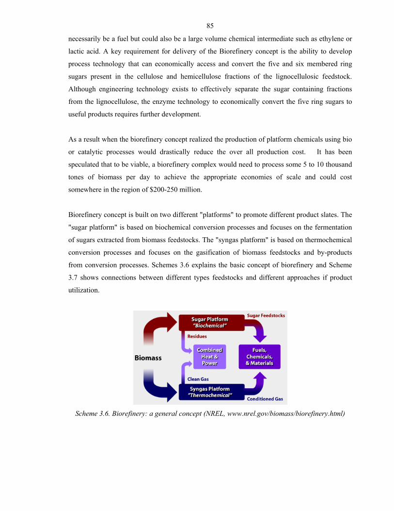
85
necessarily be a fuel but could also be a large volume chemical intermediate such as ethylene or
lactic acid. A key requirement for delivery of the Biorefinery concept is the ability to develop
process technology that can economically access and convert the five and six membered ring
sugars present in the cellulose and hemicellulose fractions of the lignocellulosic feedstock.
Although engineering technology exists to effectively separate the sugar containing fractions
from the lignocellulose, the enzyme technology to economically convert the five ring sugars to
useful products requires further development.
As a result when the biorefinery concept realized the production of platform chemicals using bio
or catalytic processes would drastically reduce the over all production cost. It has been
speculated that to be viable, a biorefinery complex would need to process some 5 to 10 thousand
tones of biomass per day to achieve the appropriate economies of scale and could cost
somewhere in the region of $200-250 million.
Biorefinery concept is built on two different "platforms" to promote different product slates. The
"sugar platform" is based on biochemical conversion processes and focuses on the fermentation
of sugars extracted from biomass feedstocks. The "syngas platform" is based on thermochemical
conversion processes and focuses on the gasification of biomass feedstocks and by-products
from conversion processes. Schemes 3.6 explains the basic concept of biorefinery and Scheme
3.7 shows connections between different types feedstocks and different approaches if product
utilization.
Scheme 3.6. Biorefinery: a general concept (NREL, www.nrel.gov/biomass/biorefinery.html)
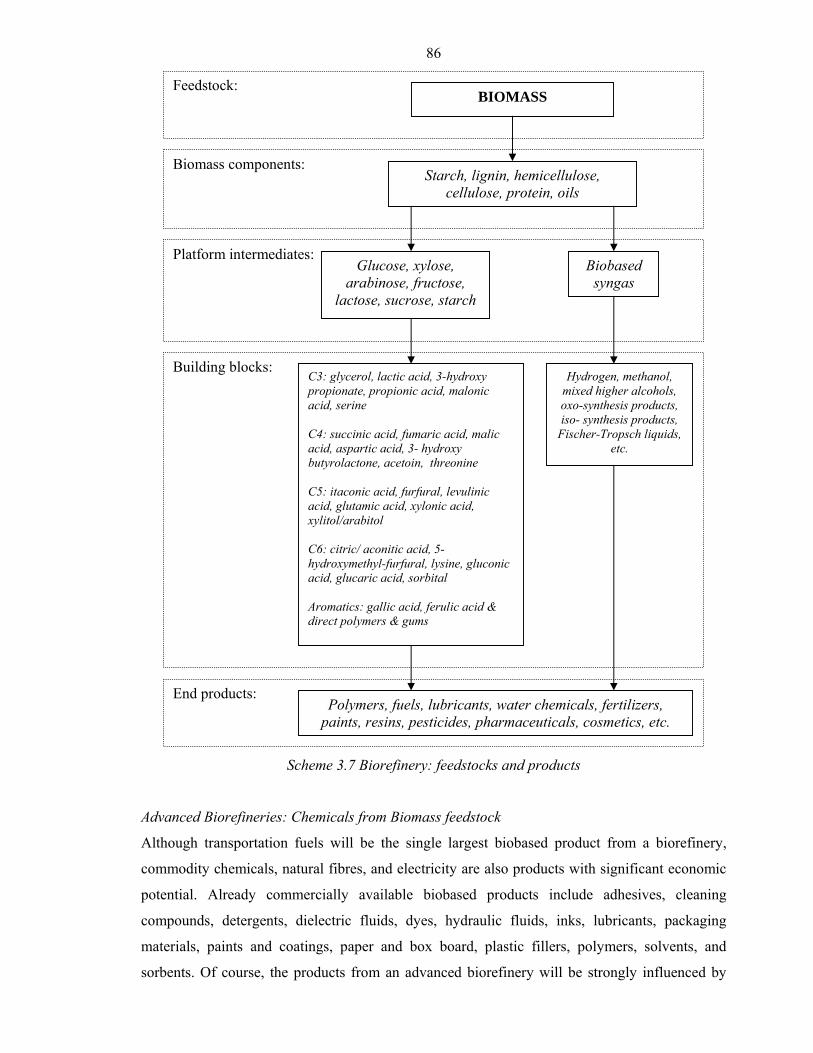
86
Scheme 3.7 Biorefinery: feedstocks and products
Advanced Biorefineries: Chemicals from Biomass feedstock
Although transportation fuels will be the single largest biobased product from a biorefinery,
commodity chemicals, natural fibres, and electricity are also products with significant economic
potential. Already commercially available biobased products include adhesives, cleaning
compounds, detergents, dielectric fluids, dyes, hydraulic fluids, inks, lubricants, packaging
materials, paints and coatings, paper and box board, plastic fillers, polymers, solvents, and
sorbents. Of course, the products from an advanced biorefinery will be strongly influenced by
BIOMASS
Starch, lignin, hemicellulose, cellulose, protein, oils
Glucose, xylose, arabinose, fructose,
lactose, sucrose, starch
Biobased syngas
Hydrogen, methanol, mixed higher alcohols, oxo-synthesis products, iso- synthesis products,
Fischer-Tropsch liquids, etc.
C3: glycerol, lactic acid, 3-hydroxy propionate, propionic acid, malonic acid, serine C4: succinic acid, fumaric acid, malic acid, aspartic acid, 3- hydroxy butyrolactone, acetoin, threonine C5: itaconic acid, furfural, levulinic acid, glutamic acid, xylonic acid, xylitol/arabitol C6: citric/ aconitic acid, 5-hydroxymethyl-furfural, lysine, gluconic acid, glucaric acid, sorbital Aromatics: gallic acid, ferulic acid & direct polymers & gums
Polymers, fuels, lubricants, water chemicals, fertilizers, paints, resins, pesticides, pharmaceuticals, cosmetics, etc.
Biomass components:
Platform intermediates:
Building blocks:
End products:
Feedstock:
87
the feedstock processed by the facility. Much attention has been paid to the corn-based
biorefinery, which produces predominately starch and carbohydrate derivatives from it, but also
smaller amounts of oil, protein, and fibre. Commercially significant carbohydrate derivatives
from starch are currently limited to ethanol, nutritive sweetener, and lactic acid (used in the
production of polylactate). A number of carbohydrate derivatives are possible, list of “top
twelve” building block molecules from sugars, these include three diacids (succinic, fumaric, and
malic acids), seven carboxylic acids with additional functionality (2,5-furan dicarboxylic acid, 3-
hydroxy propionic acid, aspartic acid, glucaric acid, glutamic acid, itaconic acid, and levulinic
acid), one ketone (3-hydroxybutyrolactone), and three polyols (glycerol, sorbitol, and
xylitol/arabinitol). Other groups have suggested 1,3-propanediol as an attractive building block
molecule from carbohydrate. Biorefineries using fibrous (lignocellulosic) biomass as feedstock
will produce C6 sugar (glucose), C5 sugars (predominately xylose and arabinose), and lignin.
These sugars can be fermented to produce so-called “cellulosic” ethanol although the same
carbohydrate derivatives contemplated for corn-based biorefineries are also appropriate
secondary products for a fiberbased biorefinery. Lignin, a phenylpropane-based polymer, is not
fermentable but has potential as a urea-formaldehyde substitute or even the starting point for the
production of hydrocarbon fuels. First generation biorefineries, however, are expected to simply
use lignin as boiler fuel.
A fundamentally different approach to lignocellulosic biorefineries thermochemically breaks
down plant material into a mixture of carbon monoxide (CO) and hydrogen (H2) known as
syngas. This simple gas mixture can be catalytically upgraded to a wide variety of compounds,
including alcohols, carboxylic acids, and hydrocarbons. It is the process proposed for the
production of “green” diesel in Europe. Another kind of biorefinery is based on plant oils or
animal fats and is commonly known as an oleochemical plant. For such a plant based on oilseed
crops such as soybeans the primary products are oil (triglyceride) and meal, the later of which
contains significant quantities of protein and fibre and some residual oil. The oil can be either
hydrolyzed to fatty acids and glycerol or converted into methyl (or ethyl) esters and glycerol by
the process of transesterification the fatty acids and esters are potential platform chemicals for
the production of a vast array of derivative chemicals used in high value products. Much of the
focus on methyl esters today has been on their use as biodiesel but there has also been limited
diversification into ester-based solvents and lubricants. The industry has shown only limited
interest in upgrading the glycerol byproduct although technologies are rapidly emerging for its
conversion to 1,3-propanediol, a precursor in the production of plastics. Similarly, although the
protein in the meal as potential to replace urea-formaldehyde in adhesives, commercialization
88
has been slow to emerge. Biobased transportation fuels, also known as biofuels, are currently
dominated by ethanol and biodiesel. However, there are other candidate liquid biofuels including
methanol, mixed alcohols, and Fisher-Tropsch liquids, as well as gaseous biofuels including
hydrogen (H2), methane (CH4), ammonia (NH3), and dimethyl ether (CH3OCH3).
Types of advanced biorefineries
Modern wet corn milling plants and pulp and paper mills can rightly claim to be biorefineries.
Advanced biorefineries, however, should be able to process all components of the biomass
feedstock into high-value biobased products. Corn fibre as cattle feed additive and lignin as
boiler fuel from corn milling plants and pulp and paper mills, respectively, would be of relatively
low economic value in a greatly expanded biofuels market. Kamm and Kamm have defined three
kinds of biorefineries that would meet this requirement: whole grain biorefineries that make
better use of such byproducts as distillers dried grains and solubles (DDGS) and protein meal
during the processing of conventional starch and oil crops; lignocellulosic biorefineries that
efficiently convert cellulose, hemicellulose, and lignin to products; and so-called “green”
biorefineries that convert high moisture biomass, such as silage corn or kelp, into products via
ensiling or anaerobic digestion. The whole grain biorefinery, which is an outgrowth of existing
grain ethanol manufacturing, is illustrated in Scheme 3.8 (a). The grain, assumed in the scheme
to be corn grain for illustrative purposes, is brought from the field and milled (or pressed, in the
case of oil seeds) to separate economically recoverable plant components, which might include
sugar, starch, oil, protein, and fibre. In Scheme 3.8 (a) an advanced dry grind operation is
assumed, which recovers oil from the germ while fibre and protein remain mixed with the starch
(in a wet milling operation, the oil, protein, and fibre are separately recovered, leaving nearly
pure starch for further processing). One or more of these components is subjected to
fermentation. In the case of corn grain, this component is either starch-rich mash from a dry
grind operation or pure starch from a wet milling operation, after it has been treated with
enzymes and the starch hydrolyzed to glucose. Since the fermentation products, such as ethanol
and lactic acid, are usually produced in the fermentation broth at concentrations typically less
than 150 g/L, distillation is required to recover these products. At this point the unfermented
constituents of the mash from the dry grind operation known as distillers dried grains and
solubles (DDGS) is also separated and dewatered.
Although some of the DDGS from a whole grain biorefinery may be sold as animal feed, the
large quantities that will be generated in a greatly expanded grain ethanol industry suggest its use
in higher value applications. In Scheme 3.8 (a) it is assumed that the DDGS is gasified to CO
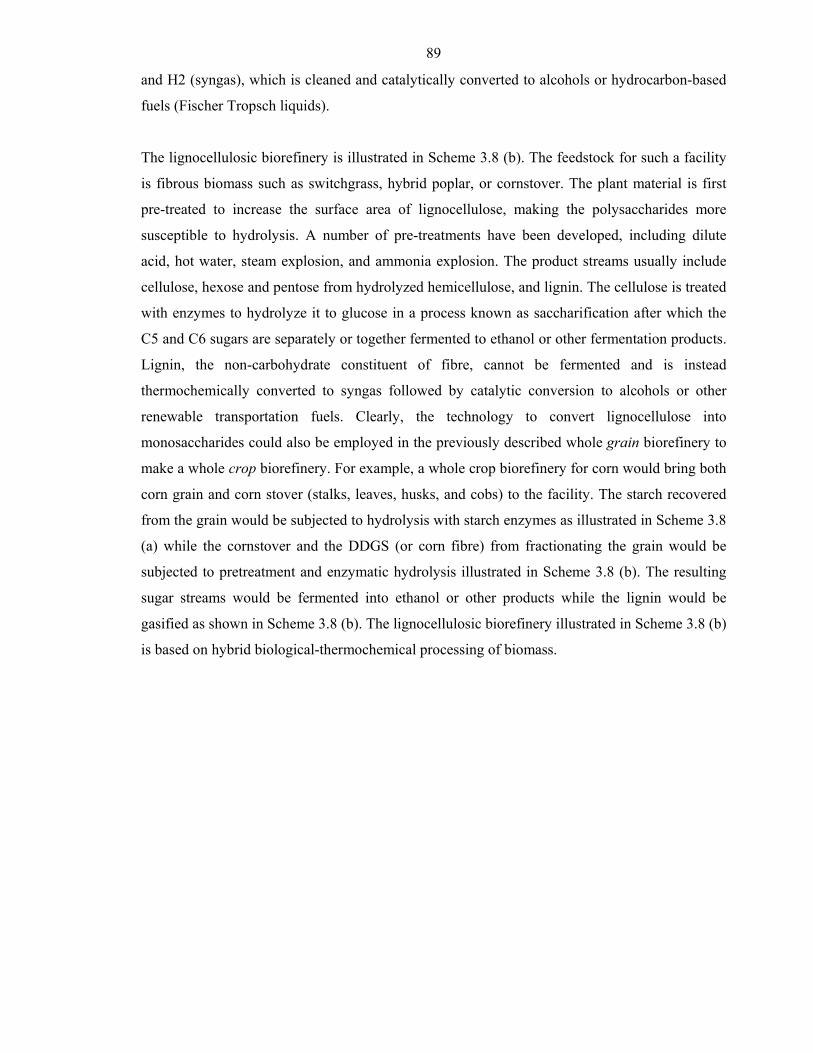
89
and H2 (syngas), which is cleaned and catalytically converted to alcohols or hydrocarbon-based
fuels (Fischer Tropsch liquids).
The lignocellulosic biorefinery is illustrated in Scheme 3.8 (b). The feedstock for such a facility
is fibrous biomass such as switchgrass, hybrid poplar, or cornstover. The plant material is first
pre-treated to increase the surface area of lignocellulose, making the polysaccharides more
susceptible to hydrolysis. A number of pre-treatments have been developed, including dilute
acid, hot water, steam explosion, and ammonia explosion. The product streams usually include
cellulose, hexose and pentose from hydrolyzed hemicellulose, and lignin. The cellulose is treated
with enzymes to hydrolyze it to glucose in a process known as saccharification after which the
C5 and C6 sugars are separately or together fermented to ethanol or other fermentation products.
Lignin, the non-carbohydrate constituent of fibre, cannot be fermented and is instead
thermochemically converted to syngas followed by catalytic conversion to alcohols or other
renewable transportation fuels. Clearly, the technology to convert lignocellulose into
monosaccharides could also be employed in the previously described whole grain biorefinery to
make a whole crop biorefinery. For example, a whole crop biorefinery for corn would bring both
corn grain and corn stover (stalks, leaves, husks, and cobs) to the facility. The starch recovered
from the grain would be subjected to hydrolysis with starch enzymes as illustrated in Scheme 3.8
(a) while the cornstover and the DDGS (or corn fibre) from fractionating the grain would be
subjected to pretreatment and enzymatic hydrolysis illustrated in Scheme 3.8 (b). The resulting
sugar streams would be fermented into ethanol or other products while the lignin would be
gasified as shown in Scheme 3.8 (b). The lignocellulosic biorefinery illustrated in Scheme 3.8 (b)
is based on hybrid biological-thermochemical processing of biomass.
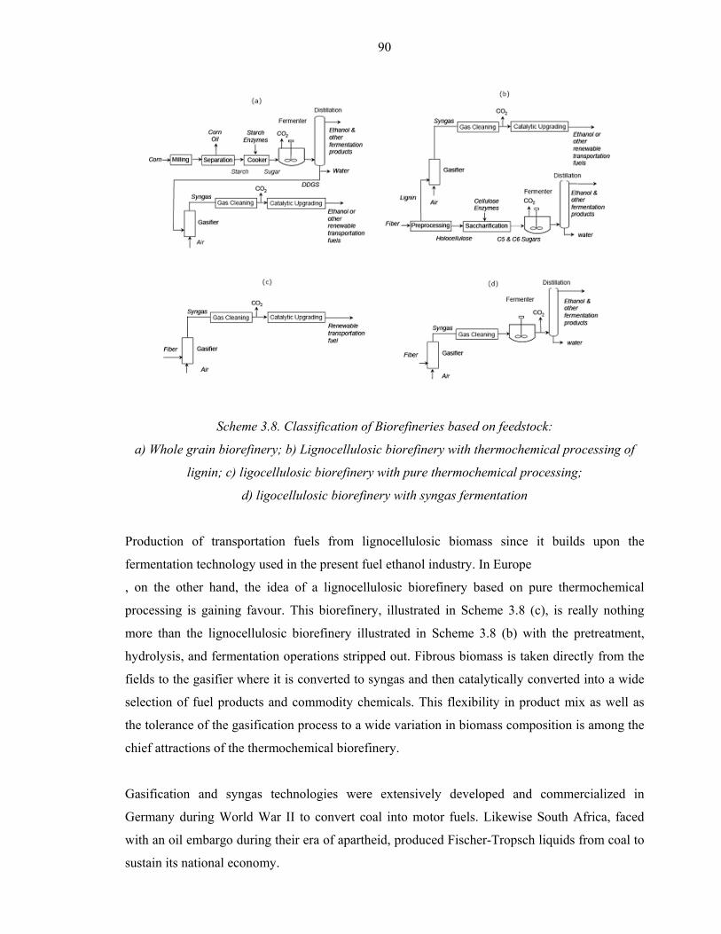
90
Scheme 3.8. Classification of Biorefineries based on feedstock:
a) Whole grain biorefinery; b) Lignocellulosic biorefinery with thermochemical processing of
lignin; c) ligocellulosic biorefinery with pure thermochemical processing;
d) ligocellulosic biorefinery with syngas fermentation
Production of transportation fuels from lignocellulosic biomass since it builds upon the
fermentation technology used in the present fuel ethanol industry. In Europe
, on the other hand, the idea of a lignocellulosic biorefinery based on pure thermochemical
processing is gaining favour. This biorefinery, illustrated in Scheme 3.8 (c), is really nothing
more than the lignocellulosic biorefinery illustrated in Scheme 3.8 (b) with the pretreatment,
hydrolysis, and fermentation operations stripped out. Fibrous biomass is taken directly from the
fields to the gasifier where it is converted to syngas and then catalytically converted into a wide
selection of fuel products and commodity chemicals. This flexibility in product mix as well as
the tolerance of the gasification process to a wide variation in biomass composition is among the
chief attractions of the thermochemical biorefinery.
Gasification and syngas technologies were extensively developed and commercialized in
Germany during World War II to convert coal into motor fuels. Likewise South Africa, faced
with an oil embargo during their era of apartheid, produced Fischer-Tropsch liquids from coal to
sustain its national economy.
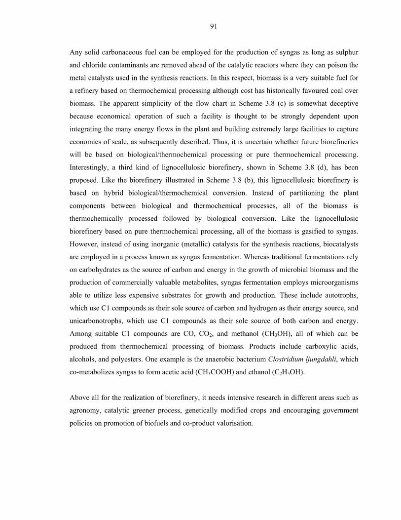
91
Any solid carbonaceous fuel can be employed for the production of syngas as long as sulphur
and chloride contaminants are removed ahead of the catalytic reactors where they can poison the
metal catalysts used in the synthesis reactions. In this respect, biomass is a very suitable fuel for
a refinery based on thermochemical processing although cost has historically favoured coal over
biomass. The apparent simplicity of the flow chart in Scheme 3.8 (c) is somewhat deceptive
because economical operation of such a facility is thought to be strongly dependent upon
integrating the many energy flows in the plant and building extremely large facilities to capture
economies of scale, as subsequently described. Thus, it is uncertain whether future biorefineries
will be based on biological/thermochemical processing or pure thermochemical processing.
Interestingly, a third kind of lignocellulosic biorefinery, shown in Scheme 3.8 (d), has been
proposed. Like the biorefinery illustrated in Scheme 3.8 (b), this lignocellulosic biorefinery is
based on hybrid biological/thermochemical conversion. Instead of partitioning the plant
components between biological and thermochemical processes, all of the biomass is
thermochemically processed followed by biological conversion. Like the lignocellulosic
biorefinery based on pure thermochemical processing, all of the biomass is gasified to syngas.
However, instead of using inorganic (metallic) catalysts for the synthesis reactions, biocatalysts
are employed in a process known as syngas fermentation. Whereas traditional fermentations rely
on carbohydrates as the source of carbon and energy in the growth of microbial biomass and the
production of commercially valuable metabolites, syngas fermentation employs microorganisms
able to utilize less expensive substrates for growth and production. These include autotrophs,
which use C1 compounds as their sole source of carbon and hydrogen as their energy source, and
unicarbonotrophs, which use C1 compounds as their sole source of both carbon and energy.
Among suitable C1 compounds are CO, CO2, and methanol (CH3OH), all of which can be
produced from thermochemical processing of biomass. Products include carboxylic acids,
alcohols, and polyesters. One example is the anaerobic bacterium Clostridium ljungdahli, which
co-metabolizes syngas to form acetic acid (CH3COOH) and ethanol (C2H5OH).
Above all for the realization of biorefinery, it needs intensive research in different areas such as
agronomy, catalytic greener process, genetically modified crops and encouraging government
policies on promotion of biofuels and co-product valorisation.
92
Bibliography
Abedi J. et al. 1988, Production of primary pyrolysis oils in a vortex reactor. in Pyrolysis Oils
from Biomass: Producing, Analysing & Upgrading (eds: Soltes E.J. and Milne T.A.),
American Chemical Society, Washington DC, 31.
Aden A. et al. 2002, Lignocellulosic Biomass to Ethanol Process Design and Economics
Utilizing Co-Current Dilute Acid Prehydrolysis and Enzymatic Hydrolysis for Corn
Stover, National Renewable Energy Lab, Golden, CO, NREL Report No. TP-510-32438.
Anon 2002, NCGA Retaliates Against Ethanol Attacks, National Corn Growers Association
News, 9, May 24, http://www.ncga.com/news/CC/volume9/ccVol9n19.html.
Antal Jr. et al. 1997, Total catalytic supercritical steam reforming of biomass, Proceedings of the
1997 US DOE Hydrogen Programme Review, Herndon, Virginia.
Antal M.J. et al. 1974, Hydrogen and food production from nuclear heat and municipal waste,
Hydrogen Energy (Part A) (ed. Veziroglu, T. N.), Plenum, NY, 331.
Arbige M.V. 2004, Bioprocess converts glycerol to propanediol. Industrial Bioprocessing
26(11), 3.
Boerrigter H. et al. 2002, Green Diesel from Biomass via Fischer- Tropsch Synthesis, Pyrolysis
and Gasification of Biomass and Waste, Expert Meeting, Strasbourg, France, Sept 30 -
Oct 1.
Brown R.C. 2003, Biorenewable Resources: Engineering New Products from Agriculture, Iowa
State Press, Ames, IA, 169-172.
Brown R.C. 2005, Biomass Refineries based on Hybrid thermochemical/Biological Processing –
An Overview, in Biorefineries, Biobased Industrial Processes and Products (Eds: Kamm
B., Gruber P.R., and Kamm M.), Wiley-VCH Verlag, Weinheim, Germany.
Caglar A. et al. 2001, Energy Sources, 23, 739.
Cole H. et al. 1992, Energy World, 199, 15.
Coughlin R.W. et al. 1979, Nature, 279, 301.
Ekbom T. et al. 2005, Black liquor gasification with motor fuel production – BLGMF II, A
techno-economic feasibility study on catalytic Fischer-Tropsch synthesis for synthetic
diesel production in comparison with methanol and DME as transport fuels. Nykomb
Synergetics AB, STFi-Packforsk, KTH Royal Institute of Technology, Statoil, Structor
Hulthén Stråth, Final Report.
Ekbom T. et al. 2003, Technical and Commercial Feasibility Study of Black Liquor Gasification
with Methanol/DME Production as Motor Fuels for Automotive Uses – BLGMF.
93
Nykomb Synergetics AB, Chemrec, Volvo, Ecotraffic, OKQ8, STFi, Methanex, Final
Report, Altener Programme.
Faaij A. et al. 2001, Future prospects for production of methanol and hydrogen from biomass,
Utrecht.
Fascetti E. et al. 1995, Applied Microbiology and Biotechnology, 44, p.300.
Feng W. et al. 2004, Phase equilibria for biomass conversion processes in subcritical and
supercritical water, Chemical Engineering Journal, 98, 105-113.
García L. et al. 2002, Energy Fuels, 16, 1222.
Hacker V. et al. 2000, Journal of Power Sources, 86, 531.
Hacker V. et al. 1998, Journal of Power Sources, 71, 226.
Hoffmann P. 2002, Tomorrow’s energy. Hydrogen, fuel cells and the prospect for cleaner planet.
Rifkin J. 2002, The hydrogen economy.
Kamm B. et al. 2004, Biorefinery - systems. Chemical and Biochemical Engineering Quarterly,
18(1), 1-6.
Kumar N. et al. 2000, Bioprocess Eng., 23, 205.
Liu S.J. et al. 1995, Environmental Science, 16, 42.
Mabee W.E. et al. 2003, Ethanol from Lignocellulosics: Views to Implementation, Report to
IEA Bioenergy Task 39, Vancouver, Canada.
Manarungson S. et al. 1990, Advances in hydrogen energy. Hydrogen Energy Progress VIII,
International Association for Hydrogen Energy, 1, 345.
Midilli A. et al. 2000, International Journal of Hydrogen Energy, 25, 723.
Milne T.A. et al. 2002, Hydrogen from Biomass. State of the Art and Research Challenges,
National Renewable Energy Laboratory Golden, CO USA.
Mitchell D. 2005, What’s Online, The New York Times, July 23, Section C, Column, 1, 5,
http://www.nytimes.com.
Miyake J. et al. 1990, Hydrogen energy progress VIII, Proceedings 8th WHEC, Hawaii,
Pergamon Press, New York, 755.
Modell M. 1985, Gasification and liquefaction of forest products in supercritical water.
Fundamentals of Thermochemical Biomass Conversion (eds Overend, R. P., Milne, T. A.
and Mudge, L. R.), Elsevier Applied Science.
Mok W.S.L. et al. 1992, Industrial & Engineering Chemistry Research, 31, 1157.
Müller-Langer F. et al. 2005, Synthetic transportation fuels based on biomass – liquid versus
gaseous fuel production: an assessment of technical, economic and environmental
aspects, 14th European Biomass Conference & Exhibition Biomass for Energy, Industry
and Climate Protection, Paris, October.
94
Otsuka, K. et al. 1981, Chemistry Letters, 23, 347.
Robinson J. Et al. 2003, Enzyme Microb. Technol. 33, 757–765.
Hahn-Hagerdal B. et al. 2006, Bio-ethanol--the fuel of tomorrow from the residues of today.
Trends Biotechnol, 24(12), 549-56.
Roychowdhury S. et al. 1998, International Journal of Hydrogen Energy, 13, 407.
Rustamov V.R. et al. 1998, International Journal of Hydrogen Energy, 23, 649.
Safrany D.R. 1971, Chemical Engineering Progress Symposium Series, 67, p.103.
Seiffert M. 2007, Demonstration of the production and utilization of synthetic natural gas (SNG)
from solid biofuels – presentation of the European project "Bio-SNG", 15th European
Biomass Conference & Exhibition - From Research to Market Development, Berlin,
May.
Shahbazov Sh.S. et al. 1996, Heliothermic Unit for Gasification Agricultural Product Wastes,
Hydrogen Energy Progress XI, Proceedings of the 11th World Hydrogen Energy
Conference, 1, 951.
Singh S.P. et al. 1994, International Journal of Hydrogen Energy, 19, 37.
Spath P.L. et al. 2003, Preliminary Screening - Technical and Economic Assessment of
Synthesis Gas to Fuels and Chemicals with Emphasis on the Potential for Biomass-
Derived Syngas, National Renewable Energy Laboratory Report NREL/TP-510- 34929.
Sun Y. et al. 2002, Hydrolysis of lignocellulosic materials for ethanol production: a review.
Bioresource Technol., 83:1, 11.
Thakur L. 1980, Advances in hydrogen energy. Hydrogen Energy Progress, International
Association for Hydrogen Energy, 3, 1725.
Thuijl E.V. et al. 2003, An overview of biofuel technologies, markets and policies in Europe,
ECN-C--03-008, Amsterdam.
Van Gerpen J. 2005, Biodiesel Processing and Production, Fuel Processing Technology, 86,
1097-1107.
van Thuijl E. et al. 2001, Biofuel production chains, Background document for modelling the
EU biofuel market using the BIOTRANS model, European commission supported
project: Clear Views on Clean Fuels, NNE5-2001-00619.
Venkataraman C. et al. 1990, Hydrogen Energy Progress VIII, 2, 781.
Vrati S. et al. 1983, Journal of Fermentation Technology, 61, 157.
Walcher G. et al. 1996, Hydrogen Project Bad Brückenau, Hydrogen Energy Progress XI,
Proceedings of the 11th World Hydrogen Energy Conference, Stuttgart, Germany, 1, 413.
Yogev A. et al. 1998, International Journal of Hydrogen Energy, 23, 239.

95
Zhong Ch. et al. 2002, Thermodynamic modelling of biomass conversion processes, Fluid Phase
Equilibria, 194-197, 805-815
Zhu H. et al. 1999, International Journal of Hydrogen Energy, 24, 305.
Zurrer H. et al. 1982, Studies in environmental science, 9, 31.
96
Part 4. Technology evaluation aspects
Biomass is of particular interest within the ongoing discussion on sustainable mobility due to its
advantages concerning e.g. climate relevance and security of supply. Within the framework of
sustainability main superior targets relating biofuels are e.g. (i) efficiency regarding system
technology and economics, (ii) environmental and climate protection regarding ecology (e.g.
greenhouse gas emissions) and (iii) energy supply security regarding biofuel potentials and
available resources. Further energy policy targets for biofuels are committed within the European
biofuels directive (2003/03/EG) up to the year 2010 and the roadmap for renewable energies
(COM (2006) 848) up to 2020. Accordingly, the share of biofuels within the transport sector has
to be increased to 5.75% (energy related) in 2010 and 10% in 2020. Besides, there is e.g. a
commitment of German gas suppliers to reach a share of biomethane as natural gas substitute for
transportation purposes of 10% in 2010 and 20% in 2020.
Moreover, technical targets on biofuels have to be achieved. Therefore, future biofuel production
systems should be integrated into existing technical biomass potentials. Only a reasonable mix of
promising biofuels should be implemented into the energy system under consideration of the
existing infrastructure of fuel distribution and use. These biofuels have to achieve current and
future exhaust emission standards (e.g. EURO 5/6) as well as have to be produced technical and
economic efficient (i.e. high conversion rates and competitive costs).
To meet these future targets, there are many several promising biofuel options of the so called
2nd generation under discussion (i.e. bioethanol based on lingocelluloses, synthetic liquid and
gaseous biofuels, biogas and biohydrogen). These options will be evaluated in the following. The
different technologies for future biofuels options have been assessed in terms of (i) technology
aspects, (ii) economic, and (iii) environmental aspects. For that not only the production of
biofuels is considered but also their distribution and use.
General aspects of future biofuel production options
Biofuels of the future generation are currently at R&D stage, but – different to the commercial
available 1st generation (i.e. vegetable oils, biodiesel as well as bioethanol based on sugar and
starch) – whole crops can be used for their production. Thus, they offer benefits regarding use of
area land for crop production and GHG mitigation. A simplified scheme of the whole fuel supply
chain from well to wheel (i.e. biomass production and provision, their conversion into biofuels
and the distribution and use) is shown in Scheme 4.1.
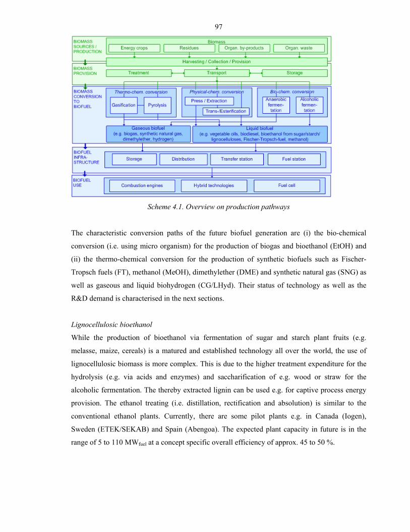
97
Scheme 4.1. Overview on production pathways
The characteristic conversion paths of the future biofuel generation are (i) the bio-chemical
conversion (i.e. using micro organism) for the production of biogas and bioethanol (EtOH) and
(ii) the thermo-chemical conversion for the production of synthetic biofuels such as Fischer-
Tropsch fuels (FT), methanol (MeOH), dimethylether (DME) and synthetic natural gas (SNG) as
well as gaseous and liquid biohydrogen (CG/LHyd). Their status of technology as well as the
R&D demand is characterised in the next sections.
Lignocellulosic bioethanol
While the production of bioethanol via fermentation of sugar and starch plant fruits (e.g.
melasse, maize, cereals) is a matured and established technology all over the world, the use of
lignocellulosic biomass is more complex. This is due to the higher treatment expenditure for the
hydrolysis (e.g. via acids and enzymes) and saccharification of e.g. wood or straw for the
alcoholic fermentation. The thereby extracted lignin can be used e.g. for captive process energy
provision. The ethanol treating (i.e. distillation, rectification and absolution) is similar to the
conventional ethanol plants. Currently, there are some pilot plants e.g. in Canada (Iogen),
Sweden (ETEK/SEKAB) and Spain (Abengoa). The expected plant capacity in future is in the
range of 5 to 110 MWfuel at a concept specific overall efficiency of approx. 45 to 50 %.
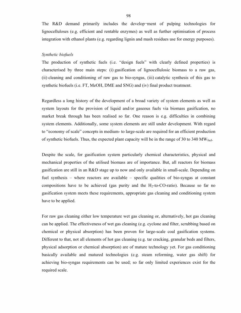
98
The R&D demand primarily includes the develop¬ment of pulping technologies for
lignocelluloses (e.g. efficient and rentable enzymes) as well as further optimisation of process
integration with ethanol plants (e.g. regarding lignin and mash residues use for energy purposes).
Synthetic biofuels
The production of synthetic fuels (i.e. “design fuels” with clearly defined properties) is
characterised by three main steps: (i) gasification of lignocellulosic biomass to a raw gas,
(ii) cleaning and conditioning of raw gas to bio-syngas, (iii) catalytic synthesis of this gas to
synthetic biofuels (i.e. FT, MeOH, DME and SNG) and (iv) final product treatment.
Regardless a long history of the development of a broad variety of system elements as well as
system layouts for the provision of liquid and/or gaseous fuels via biomass gasification, no
market break through has been realised so far. One reason is e.g. difficulties in combining
system elements. Additionally, some system elements are still under development. With regard
to “economy of scale” concepts in medium- to large-scale are required for an efficient production
of synthetic biofuels. Thus, the expected plant capacity will be in the range of 30 to 340 MWfuel.
Despite the scale, for gasification system particularly chemical characteristics, physical and
mechanical properties of the utilised biomass are of importance. But, all reactors for biomass
gasification are still in an R&D stage up to now and only available in small-scale. Depending on
fuel synthesis – where reactors are available – specific qualities of bio-syngas at constant
compositions have to be achieved (gas purity and the H2-to-CO-ratio). Because so far no
gasification system meets these requirements, appropriate gas cleaning and conditioning system
have to be applied.
For raw gas cleaning either low temperature wet gas cleaning or, alternatively, hot gas cleaning
can be applied. The effectiveness of wet gas cleaning (e.g. cyclone and filter, scrubbing based on
chemical or physical absorption) has been proven for large-scale coal gasification systems.
Different to that, not all elements of hot gas cleaning (e.g. tar cracking, granular beds and filters,
physical adsorption or chemical absorption) are of mature technology yet. For gas conditioning
basically available and matured technologies (e.g. steam reforming, water gas shift) for
achieving bio-syngas requirements can be used; so far only limited experiences exist for the
required scale.
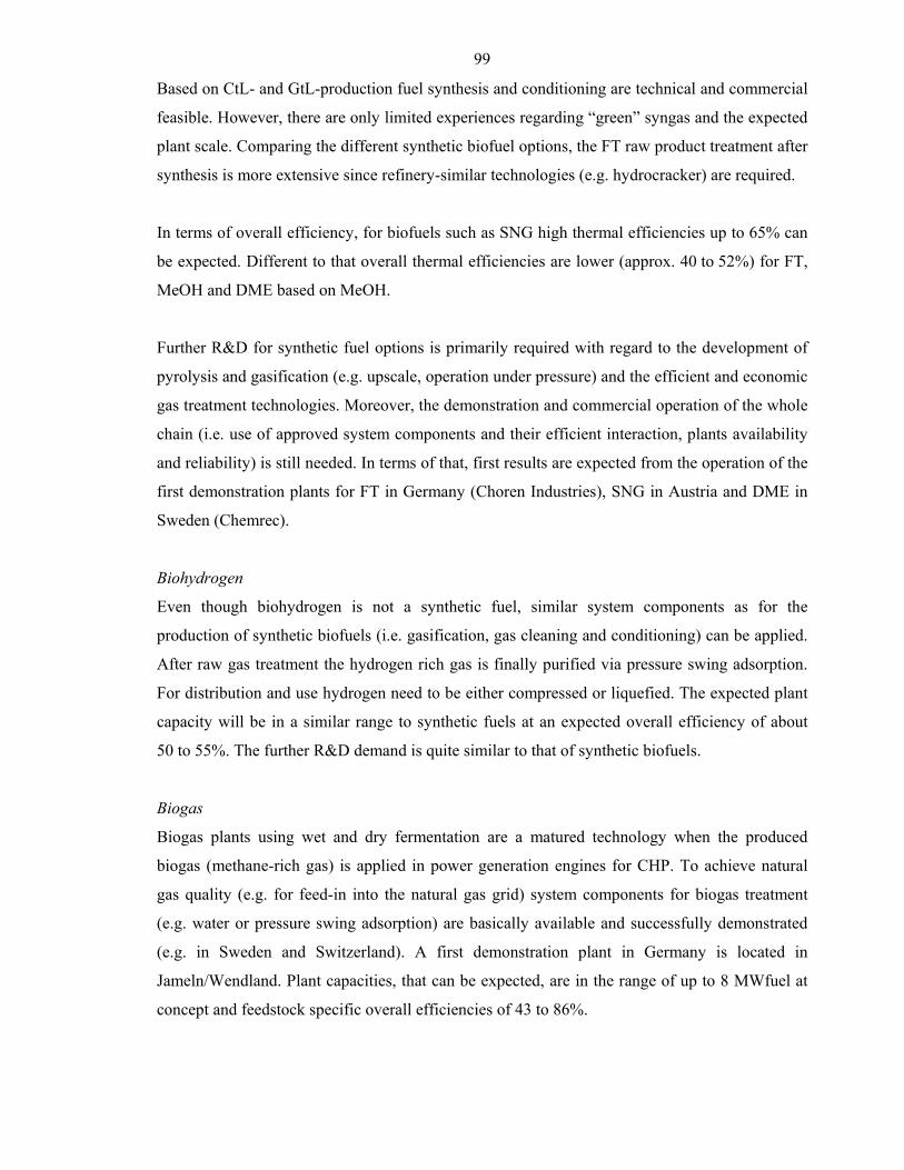
99
Based on CtL- and GtL-production fuel synthesis and conditioning are technical and commercial
feasible. However, there are only limited experiences regarding “green” syngas and the expected
plant scale. Comparing the different synthetic biofuel options, the FT raw product treatment after
synthesis is more extensive since refinery-similar technologies (e.g. hydrocracker) are required.
In terms of overall efficiency, for biofuels such as SNG high thermal efficiencies up to 65% can
be expected. Different to that overall thermal efficiencies are lower (approx. 40 to 52%) for FT,
MeOH and DME based on MeOH.
Further R&D for synthetic fuel options is primarily required with regard to the development of
pyrolysis and gasification (e.g. upscale, operation under pressure) and the efficient and economic
gas treatment technologies. Moreover, the demonstration and commercial operation of the whole
chain (i.e. use of approved system components and their efficient interaction, plants availability
and reliability) is still needed. In terms of that, first results are expected from the operation of the
first demonstration plants for FT in Germany (Choren Industries), SNG in Austria and DME in
Sweden (Chemrec).
Biohydrogen
Even though biohydrogen is not a synthetic fuel, similar system components as for the
production of synthetic biofuels (i.e. gasification, gas cleaning and conditioning) can be applied.
After raw gas treatment the hydrogen rich gas is finally purified via pressure swing adsorption.
For distribution and use hydrogen need to be either compressed or liquefied. The expected plant
capacity will be in a similar range to synthetic fuels at an expected overall efficiency of about
50 to 55%. The further R&D demand is quite similar to that of synthetic biofuels.
Biogas
Biogas plants using wet and dry fermentation are a matured technology when the produced
biogas (methane-rich gas) is applied in power generation engines for CHP. To achieve natural
gas quality (e.g. for feed-in into the natural gas grid) system components for biogas treatment
(e.g. water or pressure swing adsorption) are basically available and successfully demonstrated
(e.g. in Sweden and Switzerland). A first demonstration plant in Germany is located in
Jameln/Wendland. Plant capacities, that can be expected, are in the range of up to 8 MWfuel at
concept and feedstock specific overall efficiencies of 43 to 86%.
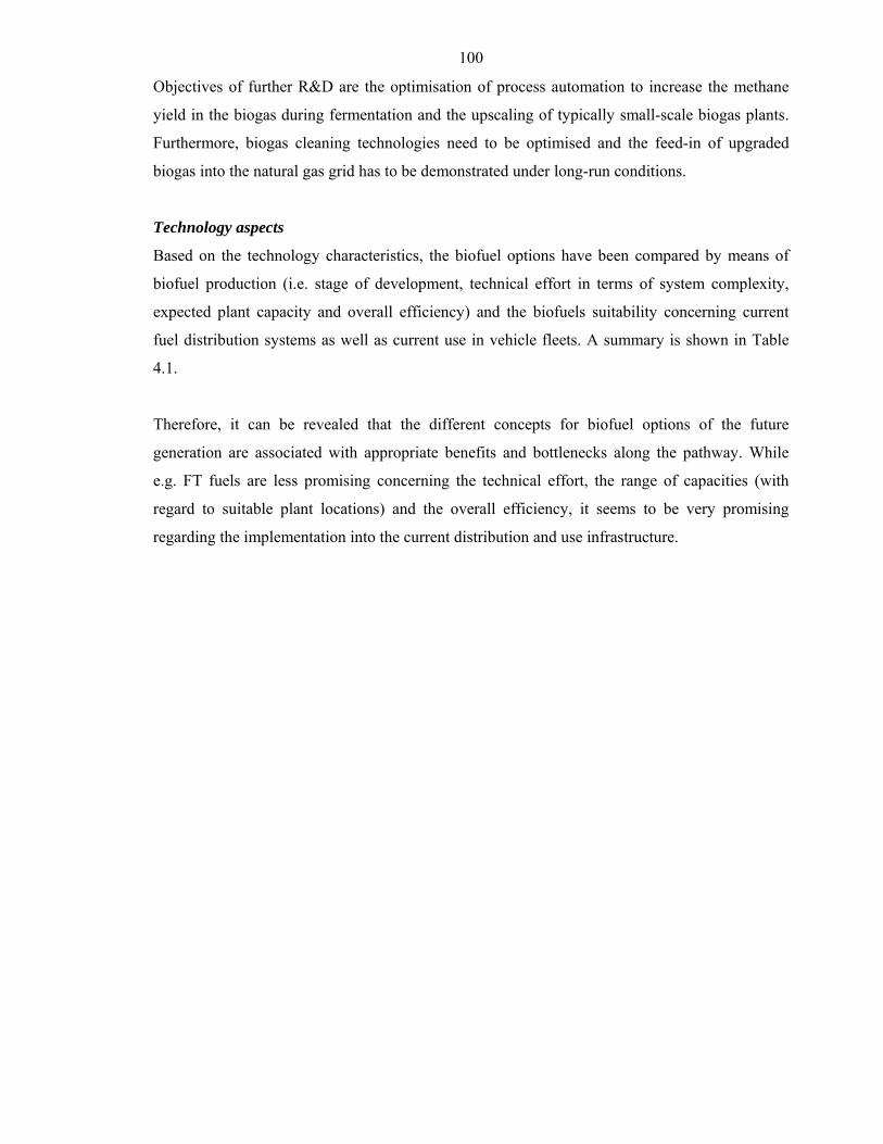
100
Objectives of further R&D are the optimisation of process automation to increase the methane
yield in the biogas during fermentation and the upscaling of typically small-scale biogas plants.
Furthermore, biogas cleaning technologies need to be optimised and the feed-in of upgraded
biogas into the natural gas grid has to be demonstrated under long-run conditions.
Technology aspects
Based on the technology characteristics, the biofuel options have been compared by means of
biofuel production (i.e. stage of development, technical effort in terms of system complexity,
expected plant capacity and overall efficiency) and the biofuels suitability concerning current
fuel distribution systems as well as current use in vehicle fleets. A summary is shown in Table
4.1.
Therefore, it can be revealed that the different concepts for biofuel options of the future
generation are associated with appropriate benefits and bottlenecks along the pathway. While
e.g. FT fuels are less promising concerning the technical effort, the range of capacities (with
regard to suitable plant locations) and the overall efficiency, it seems to be very promising
regarding the implementation into the current distribution and use infrastructure.
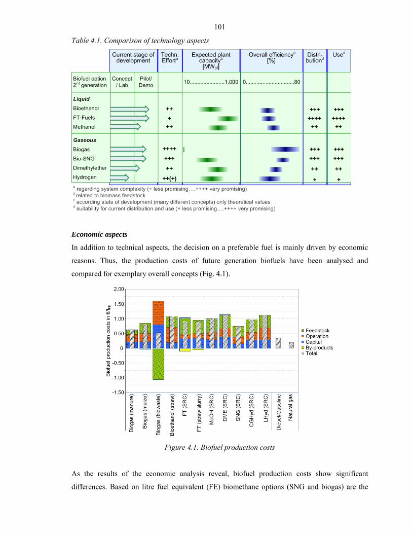
101
Table 4.1. Comparison of technology aspects
Economic aspects
In addition to technical aspects, the decision on a preferable fuel is mainly driven by economic
reasons. Thus, the production costs of future generation biofuels have been analysed and
compared for exemplary overall concepts (Fig. 4.1).
Figure 4.1. Biofuel production costs
As the results of the economic analysis reveal, biofuel production costs show significant
differences. Based on litre fuel equivalent (FE) biomethane options (SNG and biogas) are the
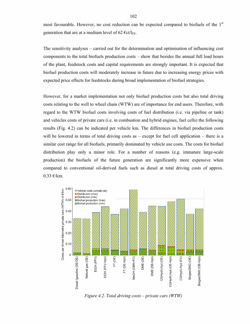
102
most favourable. However, no cost reduction can be expected compared to biofuels of the 1st
generation that are at a medium level of 62 €ct/lFE.
The sensitivity analyses – carried out for the determination and optimisation of influencing cost
components to the total biofuels production costs – show that besides the annual full load hours
of the plant, feedstock costs and capital requirements are strongly important. It is expected that
biofuel production costs will moderately increase in future due to increasing energy prices with
expected price effects for feedstocks during broad implementation of biofuel strategies.
However, for a market implementation not only biofuel production costs but also total driving
costs relating to the well to wheel chain (WTW) are of importance for end users. Therefore, with
regard to the WTW biofuel costs involving costs of fuel distribution (i.e. via pipeline or tank)
and vehicles costs of private cars (i.e. in combustion and hybrid engines, fuel cells) the following
results (Fig. 4.2) can be indicated per vehicle km. The differences in biofuel production costs
will be lowered in terms of total driving costs as – except for fuel cell application – there is a
similar cost range for all biofuels, primarily dominated by vehicle use costs. The costs for biofuel
distribution play only a minor role. For a number of reasons (e.g. immature large-scale
production) the biofuels of the future generation are significantly more expensive when
compared to conventional oil-derived fuels such as diesel at total driving costs of approx.
0.33 €/km.
Figure 4.2. Total driving costs – private cars (WTW)
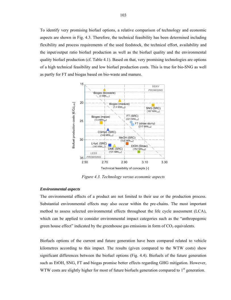
103
To identify very promising biofuel options, a relative comparison of technology and economic
aspects are shown in Fig. 4.3. Therefore, the technical feasibility has been determined including
flexibility and process requirements of the used feedstock, the technical effort, availability and
the input/output ratio biofuel production as well as the biofuel quality and the environmental
quality biofuel production (cf. Table 4.1). Based on that, very promising technologies are options
of a high technical feasibility and low biofuel production costs. This is true for bio-SNG as well
as partly for FT and biogas based on bio-waste and manure.
Figure 4.3. Technology versus economic aspects
Environmental aspects
The environmental effects of a product are not limited to their use or the production process.
Substantial environmental effects may also occur within the pre-chains. The most important
method to assess selected environmental effects throughout the life cycle assessment (LCA),
which can be applied to consider environmental impact categories such as the “anthropogenic
green house effect” indicated by the greenhouse gas emissions in form of CO2 equivalents.
Biofuels options of the current and future generation have been compared related to vehicle
kilometres according to this impact. The results (given compared to the WTW costs) show
significant differences between the biofuel options (Fig. 4.4). Biofuels of the future generation
such as EtOH, SNG, FT and biogas promise better effects regarding GHG mitigation. However,
WTW costs are slightly higher for most of future biofuels generation compared to 1st generation.
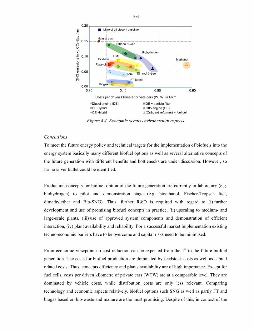
104
Figure 4.4. Economic versus environmental aspects
Conclusions
To meet the future energy policy and technical targets for the implementation of biofuels into the
energy system basically many different biofuel options as well as several alternative concepts of
the future generation with different benefits and bottlenecks are under discussion. However, so
far no silver bullet could be identified.
Production concepts for biofuel option of the future generation are currently in laboratory (e.g.
biohydrogen) to pilot and demonstration stage (e.g. bioethanol, Fischer-Tropsch fuel,
dimethylether and Bio-SNG). Thus, further R&D is required with regard to (i) further
development and use of promising biofuel concepts in practice, (ii) upscaling to medium- and
large-scale plants, (iii) use of approved system components and demonstration of efficient
interaction, (iv) plant availability and reliability. For a successful market implementation existing
techno-economic barriers have to be overcome and capital risks need to be minimised.
From economic viewpoint no cost reduction can be expected from the 1st to the future biofuel
generation. The costs for biofuel production are dominated by feedstock costs as well as capital
related costs. Thus, concepts efficiency and plants availability are of high importance. Except for
fuel cells, costs per driven kilometre of private cars (WTW) are at a comparable level. They are
dominated by vehicle costs, while distribution costs are only less relevant. Comparing
technology and economic aspects relatively, biofuel options such SNG as well as partly FT and
biogas based on bio-waste and manure are the most promising. Despite of this, in context of the

105
entire supply chain of transportation fuels synthetic biofuels can be seen as a bridge into the
future hydrogen including economy in the long term.

106
Bibliography
Müller-Langer F. 2007, Analysis and evaluation of the 2nd generation of transportation biofuels,
15th European Biomass Conference & Exhibition - From Research to Market
Development, Berlin, May.
Müller-Langer F. et al. 2007, Analyse und Evaluierung von Anlagen und Techniken zur
Produktion von Biokraftstoffen. Final report for the Energiestiftung Baden-Württemberg,
Leipzig.
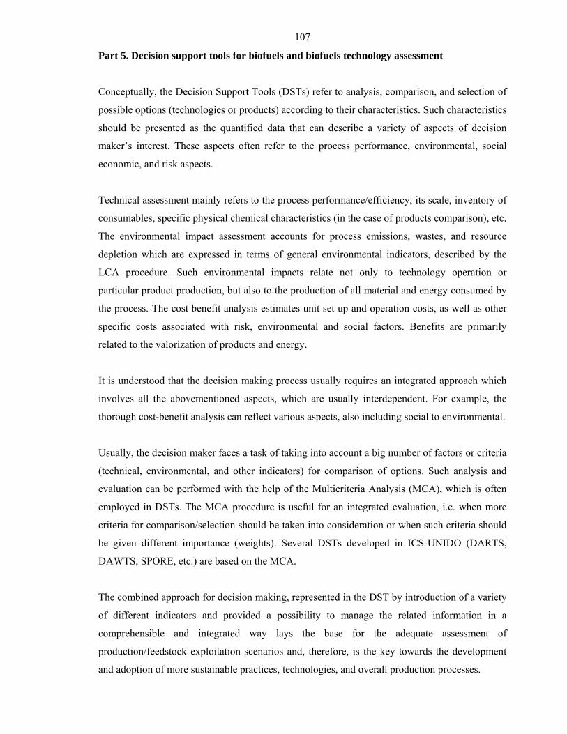
107
Part 5. Decision support tools for biofuels and biofuels technology assessment
Conceptually, the Decision Support Tools (DSTs) refer to analysis, comparison, and selection of
possible options (technologies or products) according to their characteristics. Such characteristics
should be presented as the quantified data that can describe a variety of aspects of decision
maker’s interest. These aspects often refer to the process performance, environmental, social
economic, and risk aspects.
Technical assessment mainly refers to the process performance/efficiency, its scale, inventory of
consumables, specific physical chemical characteristics (in the case of products comparison), etc.
The environmental impact assessment accounts for process emissions, wastes, and resource
depletion which are expressed in terms of general environmental indicators, described by the
LCA procedure. Such environmental impacts relate not only to technology operation or
particular product production, but also to the production of all material and energy consumed by
the process. The cost benefit analysis estimates unit set up and operation costs, as well as other
specific costs associated with risk, environmental and social factors. Benefits are primarily
related to the valorization of products and energy.
It is understood that the decision making process usually requires an integrated approach which
involves all the abovementioned aspects, which are usually interdependent. For example, the
thorough cost-benefit analysis can reflect various aspects, also including social to environmental.
Usually, the decision maker faces a task of taking into account a big number of factors or criteria
(technical, environmental, and other indicators) for comparison of options. Such analysis and
evaluation can be performed with the help of the Multicriteria Analysis (MCA), which is often
employed in DSTs. The MCA procedure is useful for an integrated evaluation, i.e. when more
criteria for comparison/selection should be taken into consideration or when such criteria should
be given different importance (weights). Several DSTs developed in ICS-UNIDO (DARTS,
DAWTS, SPORE, etc.) are based on the MCA.
The combined approach for decision making, represented in the DST by introduction of a variety
of different indicators and provided a possibility to manage the related information in a
comprehensible and integrated way lays the base for the adequate assessment of
production/feedstock exploitation scenarios and, therefore, is the key towards the development
and adoption of more sustainable practices, technologies, and overall production processes.
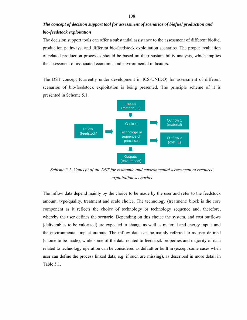
108
The concept of decision support tool for assessment of scenarios of biofuel production and
bio-feedstock exploitation
The decision support tools can offer a substantial assistance to the assessment of different biofuel
production pathways, and different bio-feedstock exploitation scenarios. The proper evaluation
of related production processes should be based on their sustainability analysis, which implies
the assessment of associated economic and environmental indicators.
The DST concept (currently under development in ICS-UNIDO) for assessment of different
scenarios of bio-feedstock exploitation is being presented. The principle scheme of it is
presented in Scheme 5.1.
Choice :
Technology or sequence of
processes
Inflow (feedstock)
Outflow 1(material)
Inputs (material, E)
Outputs (env. impact)
Outflow 2(cost, E)
Choice :
Technology or sequence of
processes
Inflow (feedstock)
Outflow 1(material)
Inputs (material, E)
Outputs (env. impact)
Outflow 2(cost, E)
Scheme 5.1. Concept of the DST for economic and environmental assessment of resource
exploitation scenarios
The inflow data depend mainly by the choice to be made by the user and refer to the feedstock
amount, type/quality, treatment and scale choice. The technology (treatment) block is the core
component as it reflects the choice of technology or technology sequence and, therefore,
whereby the user defines the scenario. Depending on this choice the system, and cost outflows
(deliverables to be valorized) are expected to change as well as material and energy inputs and
the environmental impact outputs. The inflow data can be mainly referred to as user defined
(choice to be made), while some of the data related to feedstock properties and majority of data
related to technology operation can be considered as default or built in (except some cases when
user can define the process linked data, e.g. if such are missing), as described in more detail in
Table 5.1.
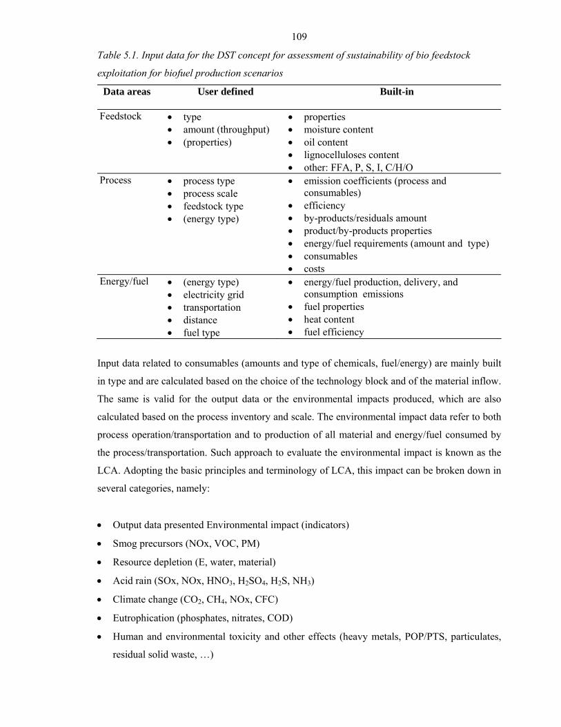
109
Table 5.1. Input data for the DST concept for assessment of sustainability of bio feedstock
exploitation for biofuel production scenarios
Data areas User defined Built-in
Feedstock • type • amount (throughput) • (properties)
• properties • moisture content • oil content • lignocelluloses content • other: FFA, P, S, I, C/H/O
Process • process type • process scale • feedstock type • (energy type)
• emission coefficients (process and consumables)
• efficiency • by-products/residuals amount • product/by-products properties • energy/fuel requirements (amount and type) • consumables • costs
Energy/fuel • (energy type) • electricity grid • transportation • distance • fuel type
• energy/fuel production, delivery, and consumption emissions
• fuel properties • heat content • fuel efficiency
Input data related to consumables (amounts and type of chemicals, fuel/energy) are mainly built
in type and are calculated based on the choice of the technology block and of the material inflow.
The same is valid for the output data or the environmental impacts produced, which are also
calculated based on the process inventory and scale. The environmental impact data refer to both
process operation/transportation and to production of all material and energy/fuel consumed by
the process/transportation. Such approach to evaluate the environmental impact is known as the
LCA. Adopting the basic principles and terminology of LCA, this impact can be broken down in
several categories, namely:
• Output data presented Environmental impact (indicators)
• Smog precursors (NOx, VOC, PM)
• Resource depletion (E, water, material)
• Acid rain (SOx, NOx, HNO3, H2SO4, H2S, NH3)
• Climate change (CO2, CH4, NOx, CFC)
• Eutrophication (phosphates, nitrates, COD)
• Human and environmental toxicity and other effects (heavy metals, POP/PTS, particulates,
residual solid waste, …)
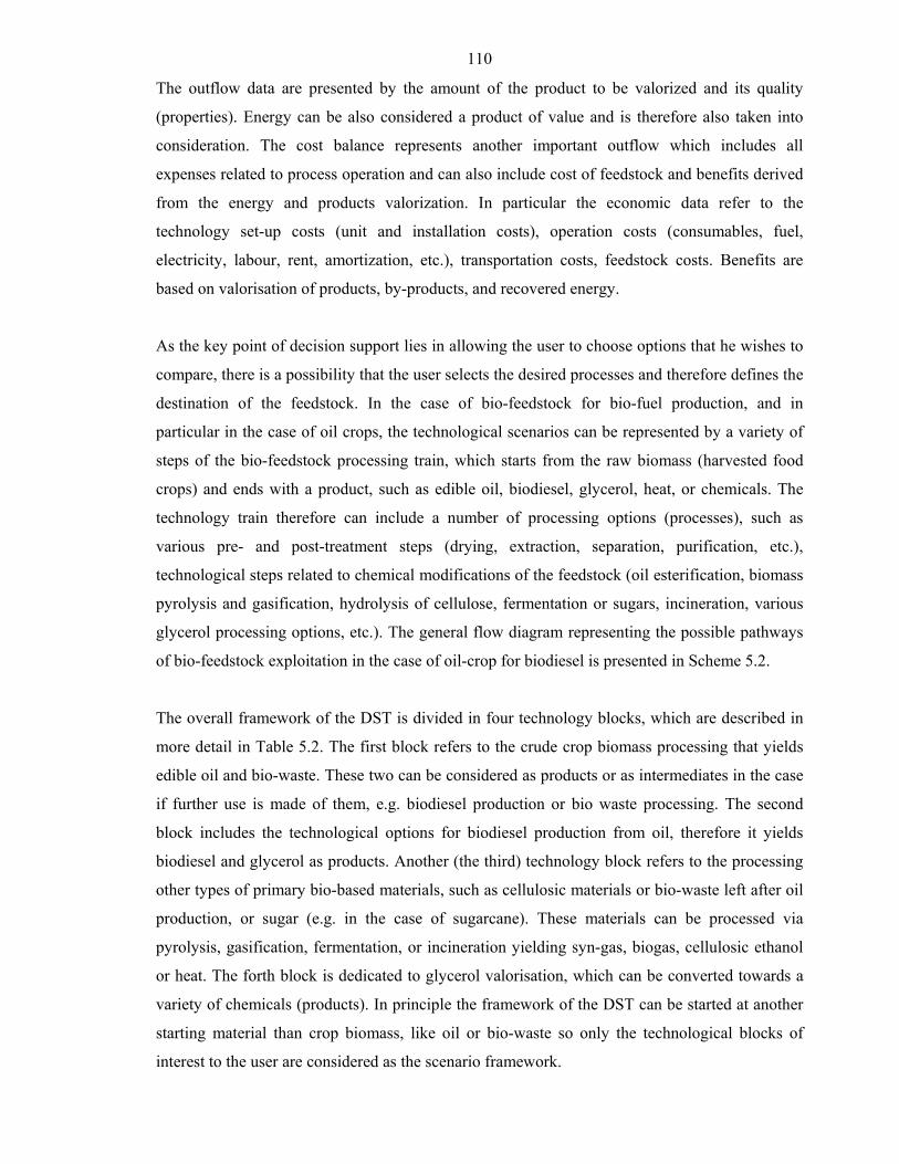
110
The outflow data are presented by the amount of the product to be valorized and its quality
(properties). Energy can be also considered a product of value and is therefore also taken into
consideration. The cost balance represents another important outflow which includes all
expenses related to process operation and can also include cost of feedstock and benefits derived
from the energy and products valorization. In particular the economic data refer to the
technology set-up costs (unit and installation costs), operation costs (consumables, fuel,
electricity, labour, rent, amortization, etc.), transportation costs, feedstock costs. Benefits are
based on valorisation of products, by-products, and recovered energy.
As the key point of decision support lies in allowing the user to choose options that he wishes to
compare, there is a possibility that the user selects the desired processes and therefore defines the
destination of the feedstock. In the case of bio-feedstock for bio-fuel production, and in
particular in the case of oil crops, the technological scenarios can be represented by a variety of
steps of the bio-feedstock processing train, which starts from the raw biomass (harvested food
crops) and ends with a product, such as edible oil, biodiesel, glycerol, heat, or chemicals. The
technology train therefore can include a number of processing options (processes), such as
various pre- and post-treatment steps (drying, extraction, separation, purification, etc.),
technological steps related to chemical modifications of the feedstock (oil esterification, biomass
pyrolysis and gasification, hydrolysis of cellulose, fermentation or sugars, incineration, various
glycerol processing options, etc.). The general flow diagram representing the possible pathways
of bio-feedstock exploitation in the case of oil-crop for biodiesel is presented in Scheme 5.2.
The overall framework of the DST is divided in four technology blocks, which are described in
more detail in Table 5.2. The first block refers to the crude crop biomass processing that yields
edible oil and bio-waste. These two can be considered as products or as intermediates in the case
if further use is made of them, e.g. biodiesel production or bio waste processing. The second
block includes the technological options for biodiesel production from oil, therefore it yields
biodiesel and glycerol as products. Another (the third) technology block refers to the processing
other types of primary bio-based materials, such as cellulosic materials or bio-waste left after oil
production, or sugar (e.g. in the case of sugarcane). These materials can be processed via
pyrolysis, gasification, fermentation, or incineration yielding syn-gas, biogas, cellulosic ethanol
or heat. The forth block is dedicated to glycerol valorisation, which can be converted towards a
variety of chemicals (products). In principle the framework of the DST can be started at another
starting material than crop biomass, like oil or bio-waste so only the technological blocks of
interest to the user are considered as the scenario framework.
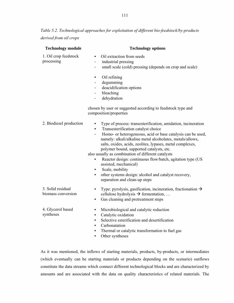
111
Table 5.2. Technological approaches for exploitation of different bio-feedstock/by-products
derived from oil crops
Technology module Technology options
1. Oil crop feedstock processing
• Oil extraction from seeds - industrial pressing - small scale (cold) pressing (depends on crop and scale)
• Oil refining - degumming - deacidification options - bleaching - dehydration
chosen by user or suggested according to feedstock type and composition/properties
2. Biodiesel production • Type of process: transesterification, amidation, incineration • Transesterification catalyst choice - Homo- or heterogeneous, acid or base catalysis can be used,
namely: alkali/alkaline metal alcoholates, metals/allows, salts, oxides, acids, zeolites, lypases, metal complexes, polymer bound, supported catalysts, etc.
also usually as combination of different catalysts • Reactor design: continuous flow/batch, agitation type (US
assisted, mechanical) • Scale, mobility • other systems design: alcohol and catalyst recovery,
separation and clean-up steps
3. Solid residual biomass conversion
• Type: pyrolysis, gasification, incineration, fractionation cellulose hydrolysis fermentation, …
• Gas cleaning and pretreatment steps
4. Glycerol based syntheses
• Microbiological and catalytic reduction • Catalytic oxidation • Selective esterification and desertification • Carbonatation • Thermal or catalytic transformation to fuel gas • Other syntheses
As it was mentioned, the inflows of starting materials, products, by-products, or intermediates
(which eventually can be starting materials or products depending on the scenario) outflows
constitute the data streams which connect different technological blocks and are characterized by
amounts and are associated with the data on quality characteristics of related materials. The

112
quality mainly refers to a set of chemical physical properties and composition of the substance
which can be either defined by the user, like in the case of the starting material (seeds,
unrefined/waste oil, fat) - moisture, sulphur, phosphorous, iodine, elementary content, FFA, etc.
or, in the case of products, result from the processes involved and of type/quality of the
feedstock.
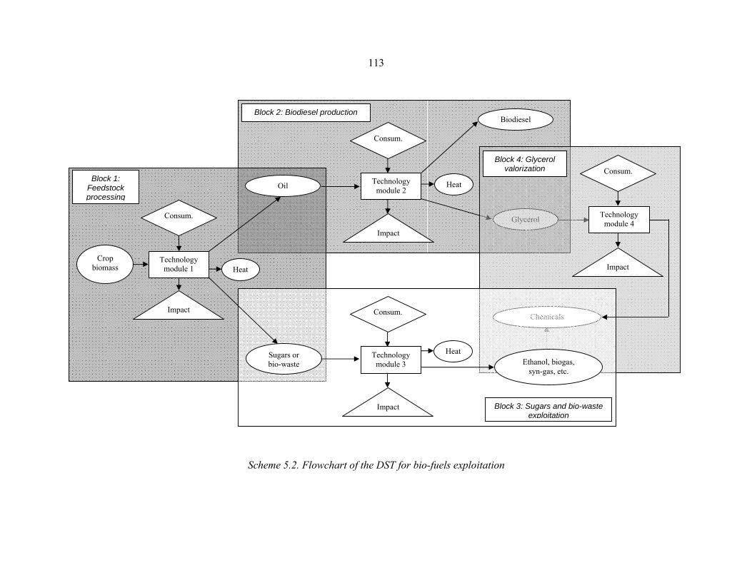
113
Scheme 5.2. Flowchart of the DST for bio-fuels exploitation
Glycerol
Chemicals
Biodiesel
Ethanol, biogas, syn-gas, etc.
Consum.
Impact
Technology module 4
Crop biomass
Consum.
Impact
Oil
Sugars or bio-waste
Technology module 2
Consum.
Impact
Technology module 3
Consum.
Impact
Heat Block 1:
Feedstock processing
Block 2: Biodiesel production
Block 3: Sugars and bio-waste exploitation
Block 4: Glycerol valorization
Heat
Heat
Technology module 1
114
BioAs: A Decision Support Tool for Biofuel Assessment and Selection
Within the ICS-UNIDO work programme there was an international collaboration project on
the development of a specific DST aimed at helping decision-makers to make a desirable
choice among different liquid and gaseous biofuels using multiple criteria. This system
provides decision support in biofuel selection using the PROMETHEE II and ELECTRE III
algorithms as its basis (Stanojević, 2006a).
The biofuels and criteria are hierarchically organized using tree structures. A user is free to
define the tree structures by adding/deleting/ modifying biofuel groups, biofuels, criterion
groups and criteria. The initial template used in Multi-Criteria Analysis contains 6 liquid and
gaseous biofuels for Combined Heat and Power (CHP) production and 44 technological,
financial, socio-economic and environmental criteria.
The template supports the comparison of the following liquid biofuels used in CHP
production:
• rape-seed vegetable oil
• rape-seed methyl ester (RME)
• flash pyrolysis oil and the following processes using gaseous biofuels:
• slow pyrolysis (EDITTh process)
• waste methanization
• gasification from wood
Criteria
The technological criteria include: energy content, non-renewable energy consumed,
availability, carbon residue, sulphur content, viscosity and density. The financial criteria are
grouped into static, dynamic and risk criteria. Static criteria include standard financial and
efficiency criteria: levelized cost of biofuel, net profit plus interest to investment, long-term
debt to net worth, net cash flow to total sales, etc. Dynamic criteria are: net present value
(NPV), internal rate of return (IRR), normal and dynamic payback period, etc. Some
statistical indicators are used as risk measure: mean values for NPV and IRR, standard
deviations, intervals of variation, zero risk equivalent, etc. The socio-economic criteria
include quality of life, avoided rural depopulation, rural diversification and land
management, economic gain, incomes, economic activity, related industry support, and
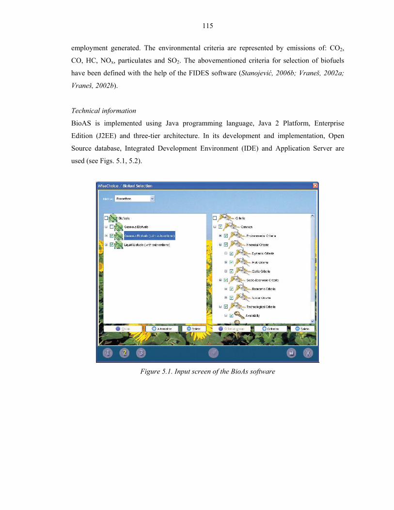
115
employment generated. The environmental criteria are represented by emissions of: CO2,
CO, HC, NOx, particulates and SO2. The abovementioned criteria for selection of biofuels
have been defined with the help of the FIDES software (Stanojević, 2006b; Vraneš, 2002a;
Vraneš, 2002b).
Technical information
BioAS is implemented using Java programming language, Java 2 Platform, Enterprise
Edition (J2EE) and three-tier architecture. In its development and implementation, Open
Source database, Integrated Development Environment (IDE) and Application Server are
used (see Figs. 5.1, 5.2).
Figure 5.1. Input screen of the BioAs software
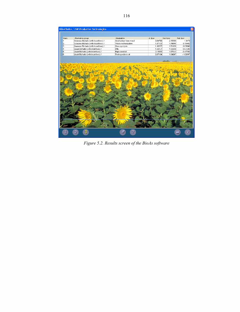
116
Figure 5.2. Results screen of the BioAs software
117
Biliography
Stanojević M. et al. 2006a, „Initial Results of Socio-Economic Analysis for Biofuel
Production in Europe“, WSEAS Transactions on Environment and Development, Vol.
2, No. 1, ISSN 1790-5079, 38-46.
Stanojević M. et al. 2006b, “Integration Platform for Investment Projects” in Goran D.
Putnik , Maria Manuela Cunha; (Eds..), Knowledge and Technology Management in
Virtual Organizations: Issues, Trends, Opportunities and Solutions, IDEA Group
Publishing, ISBN: 1-59904-165-0, 263-281;
Vraneš S. et al. 2002a, “Investment Decision Making”, in Cornelius Leonides (Ed.) Expert
Systems Techniques and Applications, Volume 4, Chapter 31, Investment Decision
Making, Academic Press, 1107-1135;
Vraneš S. et al. 2002b, “Financial decision aid based on heuristics and fuzzy logic” in E.
Daimiani et al. (Eds.) Knowledge based Intelligent Information Engineering systems
and allied technologies , IOS Press, ISBN 1 58603 280 1, Netherlands, 381-387.
118
ANNEX
Biofuels around the world
This part is dedicated to a preliminary survey on the situation in the sector of biofuels
(technology development, production, use) in various counties/regions around the world.
First part (A) is a draft version focused on biodiesel situation.
Other parts (not included here) are under preparation within the present ICS programme and
will include surveys on status on other biofuels (including updates on biodiesel) around the
world with the focus on developing and emerging countries. Here, cooperation with several
institutions in these countries, active in the field is foreseen. It will be then published
separately in the second part of 2007.
A.1 Europe
In Europe, consumer interest in passenger cars with diesel engines strongly increased after
the oil shortages of 1973 and 1979. The industry in Germany, France and Italy developed
energy-saving, highly efficient engines. The first research activities regarding the
development of alternative and renewable fuels were started. Commercially motivated
Biodiesel-initiatives in Europe could be observed as early as 1988 predominantly in Austria
and also in France, where the first industrial scale Biodiesel production plants went into
operation in 1990/1991.
In 1992, reform of the Common Agricultural Policy addressed European agricultural
surpluses by idling some land used for food production through a set-aside policy. This
policy stimulated the use of set-aside land for non-food purposes. Low oil prices in the
second half of the 90s have resulted in reduced interest of industry and politics in liquid
biofuels. In 1998, the very disappointing contribution of 452.000 t coming from biofuels
reflects the situation that specific policies had been adopted in four member states only:
France contributed 58%, Germany 21%, Italy 18% and Austria 3%.
In June of the same year, as a consequence of the 1997 Kyoto Conference on Climate
Change, the EU-member states decided on a reduction of 8,1 % on the basis of 1990
emissions for 2012, a goal which can only be realised with an important share of by using a
considerable amount of renewable energy sources including liquid biofuels. This urgent need
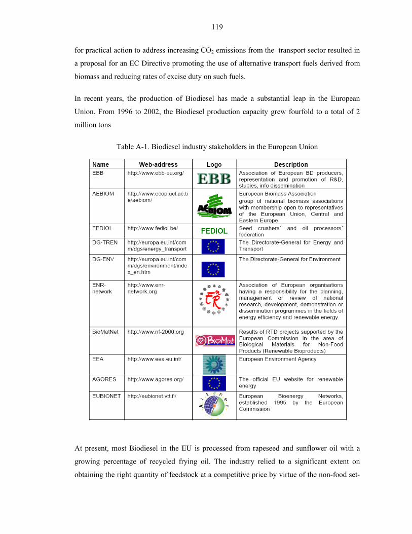
119
for practical action to address increasing CO2 emissions from the transport sector resulted in
a proposal for an EC Directive promoting the use of alternative transport fuels derived from
biomass and reducing rates of excise duty on such fuels.
In recent years, the production of Biodiesel has made a substantial leap in the European
Union. From 1996 to 2002, the Biodiesel production capacity grew fourfold to a total of 2
million tons
Table A-1. Biodiesel industry stakeholders in the European Union
At present, most Biodiesel in the EU is processed from rapeseed and sunflower oil with a
growing percentage of recycled frying oil. The industry relied to a significant extent on
obtaining the right quantity of feedstock at a competitive price by virtue of the non-food set-
120
aside scheme, which resulted from the MacSharry Common Agricultural Policy (CAP)
Reforms introduced in 1992.
Although the CAP Reforms -agreed upon within the framework of Agenda 2000 at the Berlin
Summit of March 1999- provided for a reference rate for obligatory set-aside of 10% for the
period 2000/2006, the variable nature of set-aside rates actually applied from year to year did
not always offer a sustainable base for Biodiesel production.
It seems that the main possibilities for the production of conventional feedstock for liquid
biofuels production under the studied conditions will be in northern and central EU countries,
and will be reduced in Mediterranean countries because the yields are rather low in these
areas. Recycled vegetable oils and fats offer some possibilities as alternative low-cost
Biodiesel feedstock whose availability is not affected by EU land use policies.
Based on the estimate from eight countries, a total of about 0,4 million t were collected in the
EU in 1999, mainly from the catering industry. The amount that could be collected is
estimated as being considerably higher, possibly from 0,7 to 1 million t. Its price is variable,
but in general about half of that of virgin oil. The countries with most practical experience on
this subject are Austria and Germany (with two new Biodiesel plants of 100.000 t/a capacity
using recycling oil as the sole feedstock). Even with this alternative, the supply of feedstock
will be the limiting factor for further development of the Biodiesel economy. Given the
existing production facilities, it cannot be anticipated that over 10 % of diesel fuel
consumption can be replaced by Biodiesel.
The European Commission has acknowledged the importance of Biodiesel by including it in
its "Campaign for Take-Off" and has defined it as a "Key Sector Action". The trend set by
future projects makes it possible to situate European production in 2003 for all types of
biofuels (relatively in phase with European Union objectives) at about 4,8 million tons. A
simple projection of the present rate shows that the goal of reaching a 7% share of
consumption represented by renewable origin fuel by 2010 will not be met (11,7 million tons
vs. 17 million tons) without additional efforts.
A. 2 Belgium
Interest in liquid biofuels started at the beginning of the 90s with the set-aside regulation
allowing non-food crops. Since 1991, several trials on commercial buses have been made to
121
promote the Biodiesel utilization. A transesterification pilot plant was installed in 1994. In
1994, 9.500 ha of oilseed rape were grown on set-aside land and Biodiesel was used in
several trials (busses in Mons (15 busses running with 20% Biodiesel, 740.000 km, technical
survey, favourable results), municipal vehicles in Charleroi and Philippeville, vehicles of
AVEVE and cars in Mol (5 cars, 100% Biodiesel, 300.000 km, technical survey, no major
technical problems).
In 1998 almost 5% of the Biodiesel in Europe was produced in Belgium by Pantochim
(19.000 out of 390.000 t produced).
Belgium had taken Biodiesel to the research, development and demonstration stage, but there
was no considerable progress to the deployment stage because of the reservations on the
overall economic and environmental performance of the fuel.
After these projects, the use of Biodiesel stopped and actually there is no usage of Biodiesel
as a transport fuel in Belgium.In Belgium, there are refineries in Ertvelde (belonging to the
company Oléon) and at Feluy.
Table A-2. Biodiesel industry stakeholders in Belgium
A. 3 Czech Republic
Czech production of biodiesel was already above 60,000 m³ per year by the early 1990s and
is now even larger. Many of the plants are very large, including one in Olomouc which
produces almost 40,000 m³ per year. From the summer of 2004, Czech producers of biodiesel
for blend receive a subsidy of roughly CEK 9.50/kg. All Škoda diesels built since 1996 are
warranted for biodiesel use.
122
Table A-3. Biodiesel industry stakeholders in Czech Republic
A. 4 Estonia
Biodiesel is available at Favora fuel stations.
After 10 years of research Tomson formed Biothompson OÜ. Biothompson factory produces
biodiesel using rapeseed and alternative oils with a capacity soon 100000 T/y.
A. 5 France
It was in the mid-80s that France’s oilproducing and –processing industry was looking for
new markets in order to promote oil of colza that was heavily underrepresented in the food-
market at the European level.
From 1991 to 1995, a test program with the participation of all stakeholders involved
(vehicle industry - Renault, Peugeot; oil-processing industry, petrol-industry - Elf, Total;
Ministries of Agriculture and Industry; energy agencies and public transport companies) tried
to figure out the most favourable way to produce, distribute and use Biodiesel. The result was
to incorporate a 5% blend with fossil diesel and commercial production started.
From the first unit pilot in the Compiegne area to the opening of the Rouen/Dico unit with
150.000 t/a of RME, the specificity of the French Biodiesel activity has been to move toward
big transesterification units.
• 1993 : demonstration plant initiation in Compiègne
• 1994 : Novaol adapting two sites for Biodiesel production
123
• 1995 : start-up of the Grand Couronne- site
• 1997 : 250.000 t/a production
• 1998 : downturn of Biodiesel consumption due to the reduction of mandatory set- aside
land
• 2000: 317.500 t/a authorized state quota230
Today, Biodiesel is known under the trademark and common name “Diester”, the contraction
of Diesel and Ester.
Table A-4. Biodiesel industry stakeholders in France
124
A. 6 Finland
Neste Oil will begin production of alkyl biodiesel using the NExBTL process in summer
2007 in Finland, with a capacity of 170000 tons/year. A contract has been signed with the
French Total, to begin production in some Total refineries in 2008.
NExBTL diesel, in contrast to rapeseed methyl ester, is a clear and colorless paraffin, and
contains no oxygen. It is used to improve the quality of petro-diesel; its' quality is higher
since it has a homogenous source, namely plant-synthesized fatty acids. It doesn't require any
special engine repairs and it doesn't foul systems like ester biodiesel. It is produced by direct
hydrogenation of the plant oil (chemically, triglyceride) into alkane, water and carbon oxides
on a nickel-molybdenum catalyst. The total CO2 produced in the entire lifecycle is only 0.45
to 1.33 kg CO2/kg oil, in contrast to transesterified fuel with 1.4-2.0 kg CO2/kg oil, or
mineral diesel with 3.4 kg CO2/kg oil. Therefore, it's not only an "oil derivative" like ester.
A. 7 Italy
Biodiesel production in Italy started in 1992 after a joint venture project co-financed by the
European Commission.
In 1995, the Italian government provided the detaxation of 125.000t in order to make the
selling cost of Biodiesel comparable to that of fossil diesel. Nevertheless, production in 1998
was still less than 90.000 t/a. However, an increasing trend has been recorded in the last four
years.
Overall activities in Italy have been limited so far to utilise Biodiesel mainly in the heating
oil segment and not in transportation as exercised in all other European countries. With the
new Directives of the European Commission in place the well established and experienced
125
Italian Biodiesel producers will have to reconsider their marketing philosophy in order to
fully exploit the new market opportunities in the transport sector.
Table A-5. Biodiesel industry stakeholders in Italy
A. 8 Germany
According to the Union zur Förderung von Öl- und Proteinpflanzen UFOP (Union to
promote oil- and protein plants), in 2004 the sale of biodiesel through German gas stations
rose to 375,000 m³, although it was only available at a limited number of outlets. In 2004,
45% of all biodiesel sales went directly to large end users, such as trucking companies.
Production capacity for biodiesel, for the most part produced from rapeseed, is expected to
rise to over 2,000,000 m³ per year in 2006. Sales in Germany have doubled to 376.6 million
litres (about 99 million US gallons) from 2002 to 2004. This amount is sufficient to meet the
average yearly consumption of well over 300,000 automobiles. Diesel engines have become
increasingly popular in Germany and almost half of all newly manufactured cars are diesel
powered. This is in part due to the greater efficiency of diesel engines, the desire by
consumers to use environmentally friendlier technologies and lower taxes on diesel fuel that
make it cheaper than gasoline. With 1,900 sales points, equal to one in every ten public gas
stations, biodiesel is the first alternative fuel to be available nationwide. The industry is
expecting a surge in demand since the authorisation at the beginning of 2004, through
126
European Union legislation, of a maximum 5% biodiesel addition to conventional diesel fuel.
In Germany biodiesel is also sold at a lower price than fossil diesel fuel.
Table A-6. Biodiesel industry stakeholders in Germany
A. 9 Slovakia
In 1991, under the former federal system of the ČSFR government, an oleoprogramme was
launched, supported by initiatives for process development and quality control at the
127
University of Bratislava. The first small-scale plant went into operation in 1992 followed by
additional facilities for the rapeseed oil methyl ester (ROME) production developed by small
and medium entrepreneurs. In 2001, total production capacity amounted to more than
120.000 t RME. Changes in subsidy legislation paralyzed Biodiesel production at the end of
2001.
Table A-7. Biodiesel industry stakeholders in Slovakia
A. 10 Switzerland
After initial research activities in the early 90s by various Swiss institutes (FAT,
EMPA), a small but steady production was realised.
Table A-8. Biodiesel industry stakeholders in Switzerland
128
A. 11 Norway
Biodiesel is not in common use in Norway. The three biodiesel pumps in Norway at
Lillehammer, Hadeland and Oslo are managed by the Norwegian oil-company Hydro-
Texaco. Biodiesel is also available in Bergen and supplied by Milvenn AS.
A. 12 Spain
The raw materials to produce biodiesel in Spain include traditional vegetable seed oils
(sunflower and rapeseed), alternative vegetable oils (Brassica carinata), genetically modified
vegetable oils (high oleic sunflower), and used frying oils. The traditional raw materials are
the surplus production of seed oils (sunflower and rapeseed). The use of these vegetable oils
for biodiesel production has been extensively studied.
In Spain average sunflower oil production (834 k/ha) is less favorable than in other European
countries. Therefore, it is not very profitable to use this oil in the production of biofuels.
Likewise, the yield per hectare for rapeseed oil is only a little higher than that for sunflower
oil in Spain.
Conversely, the cultivation of B. carinata as an oilseed crop for biodiesel production in the
south of Spain has been of special interest, since it allows the use of set-aside lands, giving
higher yields per hectare than the traditional crops. The vegetable oil obtained from B.
carinata is characterized by the presence of a high concentration of erucic acid, which is
considered harmful for human consumption. Attempts to modify this crop have resulted in
the elimination of erucic acid from the oil.8,9 In this sense, there are two sorts of B. carinata
oil, low erucic and high erucic, based on its erucic acid composition. Thus far, there have
been a few references that describe the use of this vegetable oil as a raw material for
biodiesel production.
Spain is a major consumer of vegetable oils, mainly olive and sunflower oil, and they are not
reused many times. Consequently, the quality of the oils is not significantly affected, making
them very suitable for the production of biofuels (Energy & Fuels, 2006, 20, p. 395).
129
It is possible to buy biodiesel, mixed with diesel fuel, in more than 250 petrol stations around
the country. Besides, B100 is sold in two petrol stations around Pamplona, in Navarre.
A. 13 Austria
The shortage of mineral oil supply in the early 70s led to two major biofuel projects after
1979. The construction of an 80.000 t/year bioethanol plant (not realized) and the
development of the Biodiesel technology were planned.
In 1982, the first production of rapeseed oil methyl esters (RME) by transesterification of
rapeseed oil and engine tests in diesel engines were carried out in Austria. One year later first
trials with recycled frying oil were conducted. In 1985, the first pilot plant world-wide for the
production of Biodiesel for use in agriculture was installed in Silberberg, Styria. In 1990, the
construction of the first industrial scale Biodiesel-plant was started in Aschach.
In 1992, simultaneous to the first specifications for RME in Austria (standard ONC 1190),
the first first modern farmers’ cooperative production plant for Biodiesel was put into
operation in Mureck. A short time later, a second commercial and so far the biggest plant was
opened in Bruck.
The year 1995 saw the first international conference on standardisation and assessment of
Biodiesel in Vienna. In the same year 10 buses from the public fleet of Graz switched to
100% Biodiesel produced from recycled frying oil.
In June 1999, the drafts of two regulations were signed by the Austrian Minister of the
Environment. These regulated the quality of transportation fuels (maximum of 5% Biodiesel
in fossil diesel fuel) and including a regulation for a mandatory adding of 2% Biodiesel in
fossil diesel fuel. Consent could not be found on the latter point, so the mandatory adding
was rejected. The blending level was limited to 3%. An amendment of the fuel regulation
was published in December 1999 creating the possibility of using Biodiesel as a sole diesel
fuel and as a blending component to fossil diesel fuel.
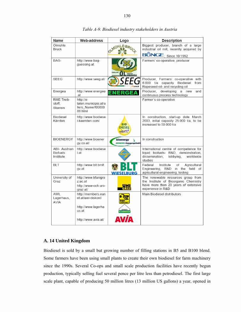
130
Table A-9. Biodiesel industry stakeholders in Austria
A. 14 United Kingdom
Biodiesel is sold by a small but growing number of filling stations in B5 and B100 blend.
Some farmers have been using small plants to create their own biodiesel for farm machinery
since the 1990s. Several Co-ops and small scale production facilities have recently begun
production, typically selling fuel several pence per litre less than petrodiesel. The first large
scale plant, capable of producing 50 million litres (13 million US gallons) a year, opened in
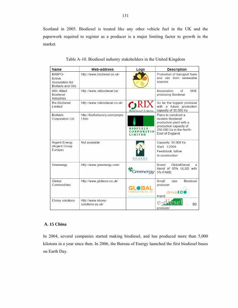
131
Scotland in 2005. Biodiesel is treated like any other vehicle fuel in the UK and the
paperwork required to register as a producer is a major limiting factor to growth in the
market.
Table A-10. Biodiesel industry stakeholders in the United Kingdom
A. 15 China
In 2004, several companies started making biodiesel, and has produced more than 5,000
kilotons in a year since then. In 2006, the Bureau of Energy launched the first biodiesel buses
on Earth Day.

132
Table A-11. Biodiesel industry stakeholders in China
A. 16 Singapore
Two biodiesel plants will be built on Jurong Island, Singapore's petrochemicals hub. The first
plant, by Peter Cremer (S) GMBH, will have a capacity of 200,000 tons/year and it is
expected to be ready by early 2007, while the second is a joint venture between Wilmar
Holdings and Archer Daniels Midland Company, to be operational by end 2006 with an
initial capacity of 150,000 tons/year.
Singapore was selected for both companies' first biodiesel plant in Asia because of its
excellent connectivity. There is easy access to abundant palm oil feedstock from the
neighbouring countries of Malaysia and Indonesia. Also, Singapore has terminalling facilities
which allow the biodiesel to be shipped to markets around the world.
A. 17 Thailand
Thailand was the first country to launch biodiesel as a national program on July 10th 2001. It
was reported that the work was initiated by the Royal Chitralada Project, a royal -sponsored
project to help rural farmers. International co-operation among ASEAN country was also
starting by the Renewable Energy Institute of Thailand and Asia-Pacific Roundtable for
Sustainable consumption and Production. The primary aims of the project in Thailand are:
• an alternative output for excess agricultural produce
133
• substituting diesel imports
In 2006, several biodiesel plants are operating in Thailand using the excess palm oil/palm
stearin and in some cases, waste vegetable oil as raw materials. About 15 petrol stations are
now distributing B5 (5% biodiesel with 95% diesel) in Chiangmai and Bangkok. The
national biodiesel standard has been developed based on the European standard. The target of
the Government is to mandate B5 by 2011 which will require almost 4 Million litres/day of
biodiesel.
The raw material will most likely come from palm oil, coconut oil, Jatropha Curcas Linn, and
tallow. Several pilot plants are now operating such as the Royal Chitralada Projects,
Rajabiodiesel in Surattani, Department of Alternative Energy Development and Efficiency,
Royal Naval Dockyard, and Tistr (www.tistr.or.th).
A. 18 Malaysia
Biodiesel called the Envo Diesel was launched by the Prime Minister Datuk Seri Abdullah
Ahmad Badawi on Tuesday 22 March 2006. Malaysia currently produces 500,000 tonnes of
biofuel annually and the government hopes to increase this number this year. Envo diesel
blends 5% processed palm oil (vegetable oil) with 95% petrodiesel. In contrast, EU's B5
blends 5% methyl ester with 95% petrodiesel. Diesel engine manufacturers prefer the use of
palm oil methyl ester blends as diesel engines are designed to handle 5% methyl esters
meeting the EN14214 biodiesel standard, which palm oil cannot meet.
Malaysian Palm Oil Board (MPOB) established in 2000 is the leading government agency
entrusted to serve the country’s oil palm industry, which promotes and develops national
objectives, policies and priorities for the development of the Malaysian oil palm industry. As
the major producer of palm oil, Malaysia has provided the lead in the development of
biofuels in Asia and MPOB is promoting various biodiesel/biofuel programmes in Malaysia
as well as internationally. MPOB has played an active role in developing new technologies
which have contributed to the advancement of the Malaysian oil palm industry. A remarkable
number of more than 340 technologies including new products and services have been
launched for commercialization and adoption by industry.
134
A. 19 India
Biodiesel is now being produced locally in India for use in three-wheeler motor rickshaws.
These engines actually run on regular diesel fuel or CNG, but in the past kerosene was used
because it was far cheaper, and worked just as well. However, kerosene was dirty and wasn't
as clean-burning. Biodiesel is rapidly replacing both kerosene and diesel as a more efficient,
cheap, and clean alternative. Today plans are being chalked out to cultivate Jatropha plants
on barren land to use its oil for biodiesel production. Now it is used for Railway engines and
the plantations are recommended to plant these plants everywhere in unused areas through
government sectors. Biodiesel is being used experimentally to run state transport corporation
buses in Karnataka. University of Agriculture Sciences at Bangalore has identified many elite
lines of Jatropha Curcas and Pongamia pinnata. Large scale activities have been initiated
quite recently. For example, large-scale plantations have been initiated in North-East India
and Jharkhand through an Memorandum of Understanding signed between D1 Oils and
Williamson Magor. The hilly areas of the North-East are ideal for growing this hardy, low-
maintenance plant.
A. 20 Israel
Biodiesel is not yet sold on the market, things start to change and biodiesel is been produced
in two small-scale experiments. The amounts produced in these experiments are up to 10,000
liters a month. The lack of production of biodiesel in Israel is in contrary with the Research
and Development abilities of the country, for Israel is a center of development for agriculture
technologies. The Israel North Recycle Group (INRG) is forecasting much progress in the
next year, including consumption agreements with municipal bodies, as part of the wider
view of the municipalities on the subject.
A. 21 Australia
The Fuel Standard (Biodiesel) Determination 2003 was signed by the Minister for the
Environment and Heritage on 18 September. The determination sets out the physical and
chemical parameters of the Biodiesel standard. It also sets out the associated test methods
that the Government will use to determine compliance. Biodiesel subsidies are to be phased
out by 2011, after the passing of the Fuel Tax Bill 2006. Australian Farmers Fuel (SAFF) has
been retailing B100 to the public in South Australia since 2001 and now also sells B20
135
(marketed as "Premium Diesel") at some 52 service stations across 4 states. All of the
metropolitan trains and most of the metropolitan buses in Adelaide (capital of South
Australia) operate on a B5 blend. The South Australian Government has stated that it will
soon move to B20 or possibly higher blends. Several councils (local Governments) across
Australia are using B20 (including Townsville City Council, Adelaide City Council, Sydney
City Council and Newcastle City Council). In February of 2005 the first retail outlet for
Biodiesel opened in the Sydney suburb of Marrickville. It offers B20 and B50 blends to the
general public, and caters to qualified fleets wishing to utilize B100. 2006 saw the first
rollout of Biodiesel by a service station network. Gull, a Western Australian based company,
introduced B20 Biodiesel to several Gull service stations on April 3 which has since
expanded to a total of 21 sites of purchase. In addition, pure Biodiesel (B100) along with
other blends can be purchased in bulk. Gull is also involved with the Western Australian
Government to provide B5 Biodiesel for use in Transperth buses. Eventually the fleet will be
provided with B10 or B20 blends. Currently seven percent of Transperth's bus fleet is
running Biodiesel. More recent news is the launch of reeFUEL biodiesel in Sustainable
Townsville, North Queensland. reeFUEL sells only B100 and at time of writing, September,
2006, was selling 50,000 litres per week into a community of about 160,000. This is believed
to be the highest penetration of biodiesel per capita in Australia (www.reefuel.com).
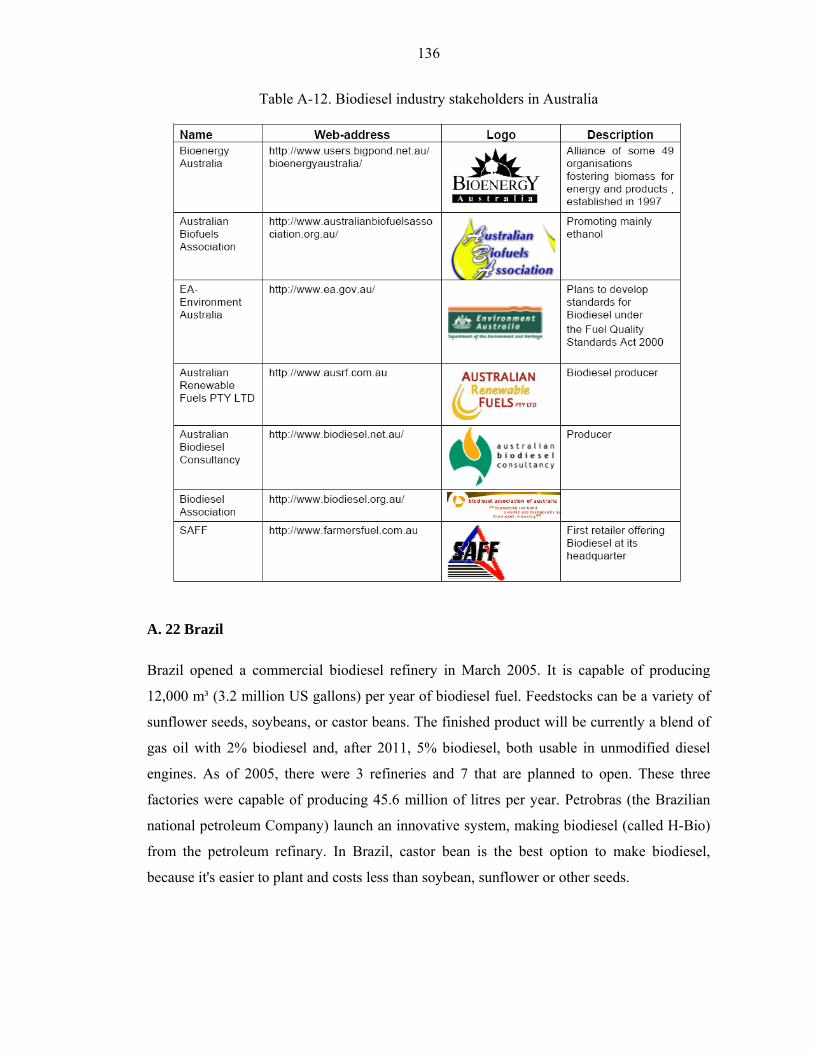
136
Table A-12. Biodiesel industry stakeholders in Australia
A. 22 Brazil
Brazil opened a commercial biodiesel refinery in March 2005. It is capable of producing
12,000 m³ (3.2 million US gallons) per year of biodiesel fuel. Feedstocks can be a variety of
sunflower seeds, soybeans, or castor beans. The finished product will be currently a blend of
gas oil with 2% biodiesel and, after 2011, 5% biodiesel, both usable in unmodified diesel
engines. As of 2005, there were 3 refineries and 7 that are planned to open. These three
factories were capable of producing 45.6 million of litres per year. Petrobras (the Brazilian
national petroleum Company) launch an innovative system, making biodiesel (called H-Bio)
from the petroleum refinary. In Brazil, castor bean is the best option to make biodiesel,
because it's easier to plant and costs less than soybean, sunflower or other seeds.
137
A. 23 United States
Biodiesel is commercially available in most oilseed-producing states in the United States. As
of 2005, it is somewhat more expensive than fossil diesel, though it is still commonly
produced in relatively small quantities (in comparison to petroleum products and ethanol).
Many farmers who raise oilseeds use a biodiesel blend in tractors and equipment as a matter
of policy, to foster production of biodiesel and raise public awareness. It is sometimes easier
to find biodiesel in rural areas than in cities. Similarly, some agribusinesses and others with
ties to oilseed farming use biodiesel for public relations reasons. As of 2003 some tax credits
are available in the U.S. for using biodiesel. In 2004 almost 30 million US gallons (110,000
m³) of commercially produced biodiesel were sold in the U.S., up from less than 0.1 million
US gallons (380 m³) in 1998. Projections for 2005 were 75 million gallons produced from 45
factories and 150 million gallons (570 million liters). Due to increasing pollution control
requirements and tax relief, the U.S. market is expected to grow to 1 or 2 billion US gallons
(4,000,000 to 8,000,000 m³) by 2010. The price of biodiesel in the United States has come
down from an average $3.50 per US gallon ($0.92/l) in 1997 to $1.85 per US gallon ($0.49/l)
in 2002. This appears economically viable with current petrodiesel prices, which as of
09/19/05 varied from $2.648 to $3.06.
Soybeans are not a very efficient crop solely for the production of biodiesel, but their
common use in the United States for food products has led to soybean biodiesel becoming
the primary source for biodiesel in that country. Soybean producers have lobbied to increase
awareness of soybean biodiesel, expanding the market for their product. A pilot project in
Unalaska/Dutch Harbor, Alaska is producing fish oil biodiesel from the local fish processing
industry in conjunction with the University of Alaska Fairbanks. It is rarely economic to ship
the fish oil elsewhere and Alaskan communities are heavily dependent on diesel power
generation. The local factories project 3.5 million tonnes of fish oil annually. In March 2002,
the Minnesota State Legislature passed a bill which mandated that all diesel sold in the state
must contain at least 2% biodiesel. The requirement took effect on June 30, 2005.
In March 2006, Washington State became the second state to pass a 2% biodiesel mandate,
with a start-date set for December 1, 2008. In 2005, U.S. entertainer Willie Nelson was
selling B20 Biodiesel in four states under the name BioWillie. By late 2005 it was available
at 13 gas stations and truck stops (mainly in Texas). Most purchasers were truck drivers. It
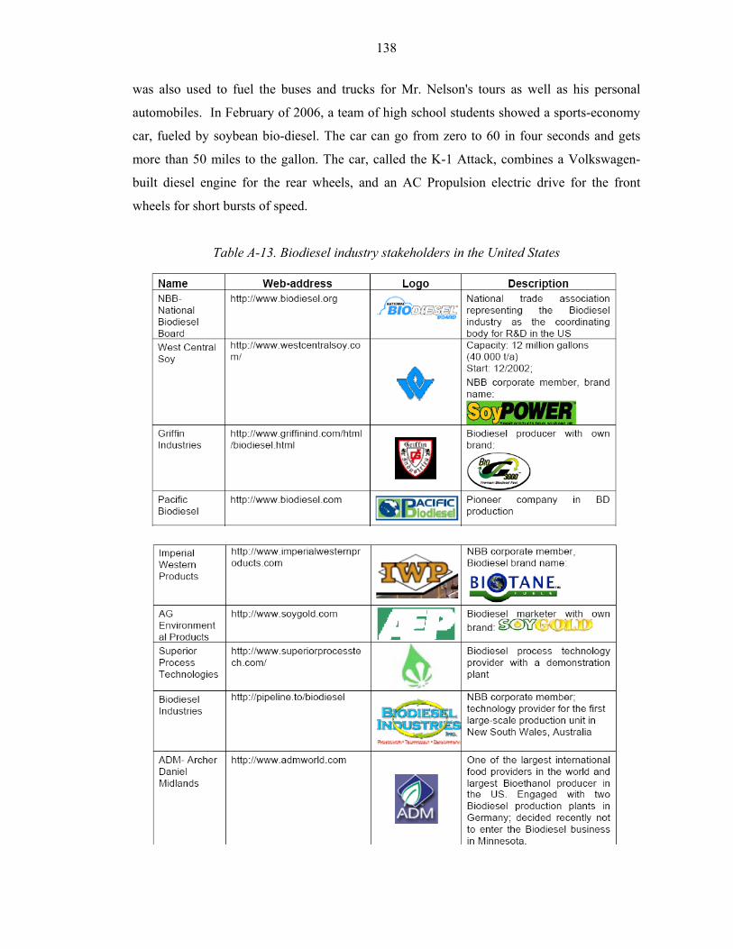
138
was also used to fuel the buses and trucks for Mr. Nelson's tours as well as his personal
automobiles. In February of 2006, a team of high school students showed a sports-economy
car, fueled by soybean bio-diesel. The car can go from zero to 60 in four seconds and gets
more than 50 miles to the gallon. The car, called the K-1 Attack, combines a Volkswagen-
built diesel engine for the rear wheels, and an AC Propulsion electric drive for the front
wheels for short bursts of speed.
Table A-13. Biodiesel industry stakeholders in the United States
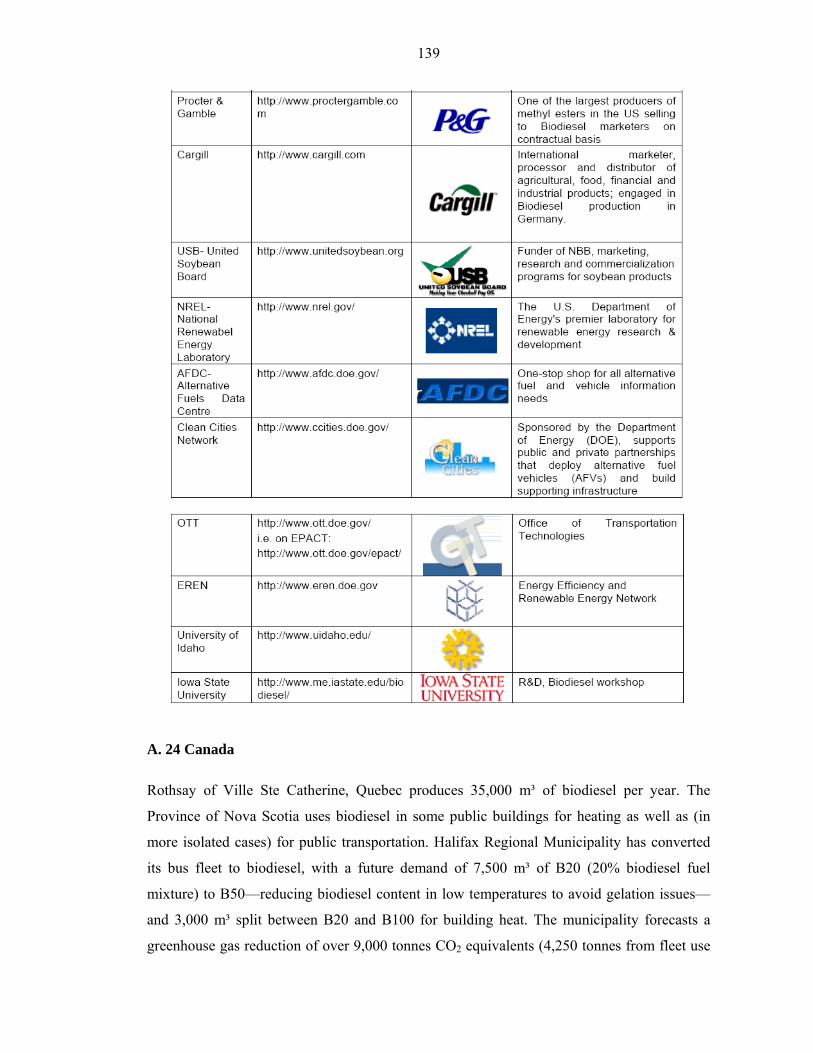
139
A. 24 Canada
Rothsay of Ville Ste Catherine, Quebec produces 35,000 m³ of biodiesel per year. The
Province of Nova Scotia uses biodiesel in some public buildings for heating as well as (in
more isolated cases) for public transportation. Halifax Regional Municipality has converted
its bus fleet to biodiesel, with a future demand of 7,500 m³ of B20 (20% biodiesel fuel
mixture) to B50—reducing biodiesel content in low temperatures to avoid gelation issues—
and 3,000 m³ split between B20 and B100 for building heat. The municipality forecasts a
greenhouse gas reduction of over 9,000 tonnes CO2 equivalents (4,250 tonnes from fleet use
140
and 5,000 tonnes from building heating) if fully implemented. Private sector uptake is slower
but not unheard of possibly due to a lack of price differential with petroleum fuel and a lack
of federal and provincial tax rebating. Ocean Nutrition Canada produces 6 million gallons
(23,000 m³) of fatty acid ethyl esters annually as a byproduct of its Omega-3 fatty acid
processing. This surplus is used by Wilson Fuels to produce blended biodiesel for use as
transportation and heating fuel. Wilson Fuels have also opened a biodiesel station in
Moncton, New Brunswick. In Ontario, Biox Corporation of Oakville is building a biodiesel
processing plant in the Hamilton harbour industrial lands, due for completion in the first half
of 2006. There are also a few retail filling stations selling biodiesel to motorists in Toronto
and Unionville. Manitoba has seen a rush of building in biodiesel plants in 2005 and 2006,
starting in June 2005 with Bifrost Bio-Diesel in Arborg, Manitoba. In addition, biodiesel is
made by individuals and farmers for personal use. BioFuel Canada Ltd has small scale
affordable plants for farmers and off-road users. Along Canada's western-most coast, in
British Columbia the cooperative association proves a successful structure for micro-
economy-of-scale biodiesel production reaching the end-user. Vancouver Biodiesel Co-op,
WISE Energy and Island Biodiesel Co-op are notable examples.
A. 25 Costa Rica
Costa Rica is a large producer of crude palm oil and this has spurred interest in biodiesel.
Currently several small biodiesel production projects are starting in the country. There are
also biodiesel reactor manufacturers in Costa Rica which provide equipment to the Central
American and Caribbean region.

141
Web sites:
journeytoforever.org
www.veggieavenger.com
www.biodieselnow.com
Europe
www.ebb-eu.org
www.koal2.cop.fi/leonardo/
http://ec.europa.eu/energy/res/sectors/bioenergy_en.htm
Austria
www.biodiesel.at
France
www.villediester.asso.fr
Germany
www.ufop.de
Italia
www.assobiodiesel.it
UK
www.biofuels.fsnet.co.uk/biobiz.htm
www.biodiesel.co.uk
Canada
www.greenfuels.org
USA
www.eere.energy.gov/cleancities/afdc/
www.biodiesel.org
www.nrel.gov
www.veggieoilcoop.org

142
www.buolderbiodiesel.com
www.grease-works.com
www.gobiodiesel.com
www.biodieselamerica.org
Australia
www.biodiesel.org.au
Malaysia
www.mpob.gov.my