Embed Size (px)
Citation preview
Caltrans Storm Water Quality Handbook Biofiltration Swale Design Guidance
Biofiltration Swale Design Guidance
June 2011
California Department of Transportation Division of Environmental Analysis Storm Water Program 1120 N Street Sacramento, California http://www.dot.ca.gov/hq/env/stormwater/index.htm
Caltrans Storm Water Quality Handbook Biofiltration Swale Design Guidance
For individuals with sensory disabilities, this document is available in alternate
formats upon request. Please call or write to Storm Water Liaison, Caltrans
Division of Environmental Analysis, P.O. Box 942874, MS-27, Sacramento, CA
94274-0001. (916) 653-8896 Voice, or dial 711 to use a relay service.
Table of Contents
Caltrans Storm Water Quality Handbook i Biofiltration Swale Design Guidance
1. INTRODUCTION............................................................................................................................... 1
1.1. OVERVIEW ..................................................................................................................................... 1 1.2. BIOFILTRATION SWALES – A BRIEF DESCRIPTION ......................................................................... 1
2. BASIS OF BIOFILTRATION SWALE DESIGN ........................................................................... 3
2.1. DESIGN CRITERIA .......................................................................................................................... 3 2.2. RESTRICTIONS ............................................................................................................................... 4
3. GETTING STARTED ........................................................................................................................ 5
3.1. PRELIMINARY DESIGN PARAMETERS ............................................................................................. 5 3.2. PRELIMINARY CALCULATIONS ....................................................................................................... 6 3.3. OTHER COMMENTS ........................................................................................................................ 8
4. BMP LAYOUT AND DESIGN ........................................................................................................ 11
4.1. LAYOUT ....................................................................................................................................... 11 4.2. SITE SPECIFIC DESIGN ELEMENTS................................................................................................ 11
5. PS&E PREPARATION .................................................................................................................... 13
5.1. PS&E DRAWINGS ........................................................................................................................ 13 5.2. SPECIFICATIONS ..................................................................................................................... 14 5.3. PROJECT COST ESTIMATES .......................................................................................................... 15
6. REFERENCES .................................................................................................................................. 17
A. BIOFILTRATION GUIDANCE-VEGETATION ......................................................................... 18
A.1 OVERVIEW ................................................................................................................................... 18 A.2 SOIL TESTING & INVESTIGATION ................................................................................................. 18 A.3 SOIL AND PLANTING BED PREPARATION ..................................................................................... 19 A.4 IRRIGATION STRATEGIES ............................................................................................................. 20 A.5 PLANTING STRATEGIES ................................................................................................................ 20 A.6 RESTRICTIONS FOR PLANT SELECTION ........................................................................................ 22 A.7 DRAINAGE FACILITIES ................................................................................................................. 22 A.8 PLANT ESTABLISHMENT PERIOD (PEP) ....................................................................................... 22 A.9 DEFINITIONS: ............................................................................................................................... 23 A.10 ADDITIONAL RESOURCES ............................................................................................................ 23
Table of Contents
Caltrans Storm Water Quality Handbook ii Biofiltration Swale Design Guidance
LIST OF TABLES
TABLE 2-1 BIOFILTRATION SWALE DESIGN CRITERIA .................................................................................... 3 TABLE 3-1 MANNING’S EQUATION SOLVED FOR PARTICULAR CONDITIONS BY ASSUMING DEPTH VALUES ..... 7
LIST OF FIGURES
FIGURE 1-1 SCHEMATIC OF BIOFILTRATION SWALE AND STRIP ...................................................................... 2 FIGURE 1-2 TYPICAL SWALE (SR-78/MELROSE DRIVE) .................................................................................. 2 FIGURE 3-1 TYPICAL BIOFILTRATION SWALE CROSS-SECTION ...................................................................... 6
LIST OF ACRONYMS
BMP Best Management Practice ft feet HDM Highway Design Manual HRT Hydraulic Residence Time HSG Hydrologic Soil Group in inches MEP maximum extent practicable max maximum min minimum NPDES National Pollutant Discharge Elimination System PPDG Project Planning and Design Guide – Storm Water Quality Handbook PS&E Plans, Specifications and Estimate RWQCB Regional Water Quality Control Board sec second USCS Unified soil classification system WQF Water Quality Flow

SECTIONONE Introduction
Caltrans Storm Water Quality Handbook 1 Biofiltration Swale Design Guidance
1. Introduction
1.1. Overview This document provides guidance to Caltrans Project Engineers and Landscape Architects for incorporating Biofiltration Swale Treatment Best Management Practices (BMPs) into projects during the planning and design phases of Caltrans highways and facilities. The primary functions of this document are to:
• Describe the design criteria of Biofiltration Swales (“Bioswales”); • Present detailing standards and siting limitations; • Present the formulas used to design Bioswales; and • Review the required elements for implementing Bioswales into PS&E
packages. The Project Engineer and the District Landscape Architect have different perspectives and responsibilities during the design of Biofiltration Swales. In this document, guidance addressed to the Project Engineer is provided in the numbered sections, while guidance to the Landscape Architect is provided in the Appendix (separate attachment); the latter guidance is considered the best available at this time, but the Headquarters Office of Roadside Management will develop and issue additional guidance as needed.
1.2. Biofiltration Swales – A Brief Description Biofiltration Swales are one of several BMPs for treatment of stormwater runoff from project areas that are anticipated to produce pollutants of concern (e.g., roadways, parking lots, maintenance facilities, etc.). Bioswales are vegetated, typically trapezoidal channels, which receive and convey storm water flows while meeting water quality criteria and other flow criteria. Pollutants are removed by filtration through the vegetation, uptake by plant biomass, sedimentation, adsorption to soil particles, and infiltration through the soil. Pollutant removal capability is related to channel dimensions, longitudinal slope, and type of vegetation. Bioswales are effective at trapping litter, Total Suspended Solids (soil particles), and particulate metals (Caltrans, 2007). The following list demonstrates some advantages of utilizing a Bioswale as a Treatment Control BMP.
1. When properly implemented, Bioswales are aesthetically pleasing. Due to the presence of its vegetation, the public views Bioswales as a “landscaped roadside” which would make placement more acceptable than other Treatment BMPs using concrete vaults.
2. Bioswales were determined to be an effective Treatment BMP in reducing sediment and heavy metals, as described in the BMP Retrofit Pilot Program Final Report (Caltrans, 2004).
SECTIONONE Introduction
Caltrans Storm Water Quality Handbook 2 Biofiltration Swale Design Guidance
3. In that same report Bioswales were determined to be cost effective and, together with Biofiltration Strips, were among the least expensive Treatment BMP per volume of runoff treated.
4. Bioswales also are well suited to being part of a “treatment-train” system of BMPs and should be considered whenever siting other BMPs that could benefit from pretreatment, especially Biostrips, Infiltration Basins, Infiltration Trenches, and Wet Basins.
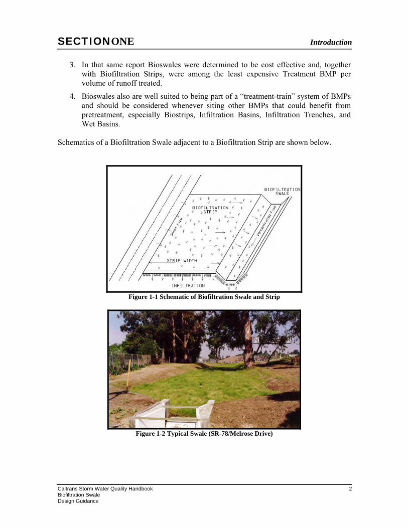
Schematics of a Biofiltration Swale adjacent to a Biofiltration Strip are shown below.
Figure 1-1 Schematic of Biofiltration Swale and Strip
Figure 1-2 Typical Swale (SR-78/Melrose Drive)
SECTIONTWO Basis of Biofiltration Swale Design
Caltrans Storm Water Quality Handbook 3 Biofiltration Swale Design Guidance
2. Basis of Biofiltration Swale Design
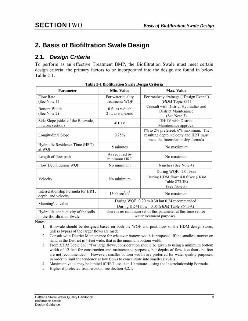
2.1. Design Criteria To perform as an effective Treatment BMP, the Biofiltration Swale must meet certain design criteria; the primary factors to be incorporated into the design are found in below Table 2-1.
Table 2-1 Biofiltration Swale Design Criteria Parameter Min. Value Max. Value
Flow Rate (See Note 1)
For water quality treatment: WQF
For roadway drainage (“Design Event”) (HDM Topic 831)
Bottom Width (See Note 2)
0 ft, as v-ditch 2 ft, as trapezoid
Consult with District Hydraulics and District Maintenance
(See Note 3) Side Slope (sides of the Bioswale, in cross section) 4H:1V 3H:1V with District
Maintenance approval
Longitudinal Slope 0.25% 1% to 2% preferred. 6% maximum. The resulting depth, velocity and HRT must
meet the Interrelationship formula Hydraulic Residence Time (HRT) at WQF 5 minutes No maximum
Length of flow path As required by minimum HRT No maximum
Flow Depth during WQF No minimum 6 inches (See Note 4)
Velocity No minimum
During WQF: 1.0 ft/sec During HDM flow: 4.0 ft/sec (HDM
Table 873.3E) (See Note 5)
Interrelationship Formula for HRT, depth, and velocity 1300 sec2/ft2 No maximum
Manning's n value During WQF: 0.20 to 0.30 but 0.24 recommended
During HDM flow: 0.05 (HDM Table 864.3A) Hydraulic conductivity of the soils in the Biofiltration Swale
There is no minimum set of this parameter at this time set for water treatment purposes.
Notes: 1. Bioswale should be designed based on both the WQF and peak flow of the HDM design storm,
unless bypass of the larger flows are made. 2. Consult with District Maintenance for whatever bottom width is proposed. If the smallest mower on
hand in the District is 4-feet wide, that is the minimum bottom width. 3. From HDM Topic 863: “For large flows, consideration should be given to using a minimum bottom
width of 12 feet for construction and maintenance purposes, but depths of flow less than one foot are not recommended.” However, smaller bottom widths are preferred for water quality purposes, in order to limit the tendency at low flows to concentrate into smaller rivulets.
4. Maximum value may be limited if HRT less than 10 minutes, using the Interrelationship Formula. 5. Higher if protected from erosion; see Section 4.2.1.

SECTIONTWO Basis of Biofiltration Swale Design
Caltrans Storm Water Quality Handbook 4 Biofiltration Swale Design Guidance
2.2. Restrictions Successful implementation and utilization of a Bioswale as a Treatment BMP will require proper siting of the Bioswale by coordinating with District Hydraulics and District Landscape Architect. Therefore, it is important to take note of siting restrictions when designing the Bioswale. Bioswales should not be designated as a Treatment BMP if design is outside the range of values presented in Table 2-1, without the approval of the District Design NPDES Coordinator.
• Bioswales in arid regions will require installation of a temporary (or permanent) irrigation system to ensure approximately 70 percent vegetative coverage, and/or must be planted with vegetation that will go dormant outside of the rainy season; consult with the District Landscape Architect to verify that water is available for irrigation. Also assess feasibility. Refer to Section 2.4.2.1 of the PPDG. A permanent irrigation system for a Bioswale should only be recommended if the planting that requires it is specified for aesthetic reasons as part of a landscape plan and there are other irrigated elements in the plan.
• In extremely arid places where permanent irrigation would be required,
Bioswales would not be recommended.
• Consult with District Design NPDES Coordinator if Bioswales are proposed at locations having contaminated soils or above contaminated groundwater plumes.
• Bioswales can be used to effectively attenuate some flows depending on the site conditions and site hydrology. Amended soils and vegetation seeding, with correctly designed Bioswales, help in the attenuation of flows.
• Bioswales are not generally subject to setback restrictions as an Infiltration Device is; however, if unusual geotechnical conditions exist, or if a Bioswale is proposed above a retaining wall and the soils are known to be especially erodible or permeable, consult with Geotechnical Design.
SECTIONTHREE Getting Started
Caltrans Storm Water Quality Handbook 5 Biofiltration Swale Design Guidance
3. Getting Started This section presents the process and parameters incorporated into the design of a Bioswale. Before selecting, sizing, and laying out the Biofiltration Swale, existing site conditions are evaluated to obtain and assess the necessary design parameters that will be used to determine if a Bioswale is applicable and later in the design process. It is assumed that the proposed site has already met the requirements in PPDG Checklists T-1, Parts 1 and 2, and that PPDG Appendix B-2 has been reviewed.
3.1. Preliminary Design Parameters 3.1.1. Rainfall Characteristics
Obtain site Water Quality Flow information for the Bioswale; other hydrologic data such as the event intensity, duration, and frequency should also be obtained for the design of the Bioswale when it is used for the conveyance of the larger events from the tributary area.
A. Flow in the Bioswale under the WQF intensity: QWQF The Biofiltration Swale is a flow-based Treatment BMP that is designed to convey and treat the runoff during WQF intensity events, as long as the flow depth, velocity, HRT, and the Interrelationship Formula all met. The WQF intensity for the project area may be found in the PPDG, Section 2.4.2.2, or by referring to the Basin Sizer program that has been created for Caltrans use, at this link:
http://stormwater.water-programs.com/BasinSizer/Basinsizer.htm
The Rational Formula should be used to calculate the runoff entering the bioswale, as shown below:
QWQF = C x I x A See Footnote 1
Where QWQF = Water Quality Flow rate (cfs) C = runoff coefficient I = WQF rainfall intensity (in/hr) A = tributary area to the Bioswale (acres)
B. Flow in the Bioswale during the Design Event: Q The Bioswale must be designed to convey larger during rainfall intensities greater than the WQF, and in fact must handle the peak drainage from the roadway unless an upstream
1 In metric units: QWQF = 0.28 C x I x A where QWQF is m3/sec, C as above, intensity I as mm/hr, and area A as square kilometers.
SECTIONTHREE Getting Started
Caltrans Storm Water Quality Handbook 6 Biofiltration Swale Design Guidance
bypass for the larger events is provided. Absent such diversion, the “Design Event” for the Bioswale must be consistent with the intensity, duration, and frequency of the rainfall event used in the roadway drainage design for that tributary area contributing runoff to the Treatment BMP, as discussed in HDM Topic 831.2 Additionally, the placement of the Bioswale must not impede the effective drainage of the roadway upstream. Lastly, if the Bioswale is placed with a curve rather than a linear alignment, and is carrying the Design Event, consult HDM Topic 866, Freeboard Considerations. Note that, notwithstanding the above, there is no overflow release device from the Bioswale, as must be considered for volume-based Treatment BMPs.
3.2. Preliminary Calculations In order to utilize the Bioswale, the following calculations/analyses need to be performed:
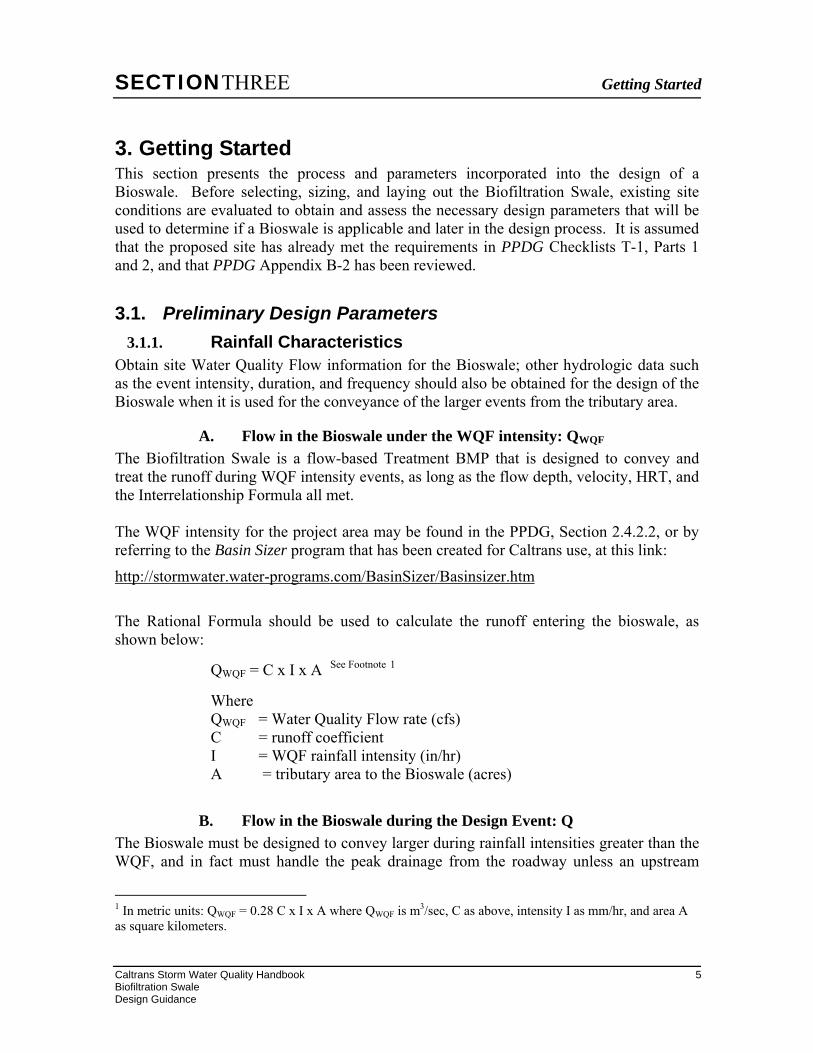
A. Flow depths and velocities at WQF and during Design Event The flow depth during WQF and the Design Event can be calculated using Manning’s Equation, as shown below. Refer to Figure 3-1 for an illustration of the variables used in the equation.
Q = (1.486/n) x A x R2/3 x S1/2
where Q = flow at defined event (QWQF or Q25) n = Manning’s coefficient; recommend using “n” = 0.24 for QWQF and 0.05
for the Design Event Q25 A = Cross-sectional area of the flow in the channel R = Hydraulic Radius = “A” / Wetted Perimeter (“P”) See Footnote 3 S = longitudinal slope, length drop per unit length run
Figure 3-1 Schematic for Manning’s Equation terms
2 For convenience in this document, this flow will be referred to as Q25, although other recurrence intervals might have been used, as described in HDM 830, Roadway Drainage; confer with District Hydraulics. 3 The depth of flow is shown in various sources as “y” or “d”, but with no difference in meaning.
SECTIONTHREE Getting Started
Caltrans Storm Water Quality Handbook 7 Biofiltration Swale Design Guidance
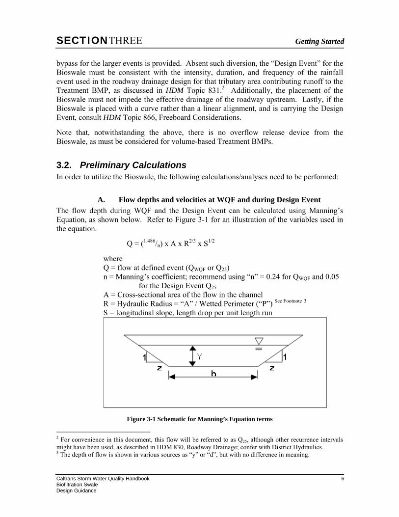
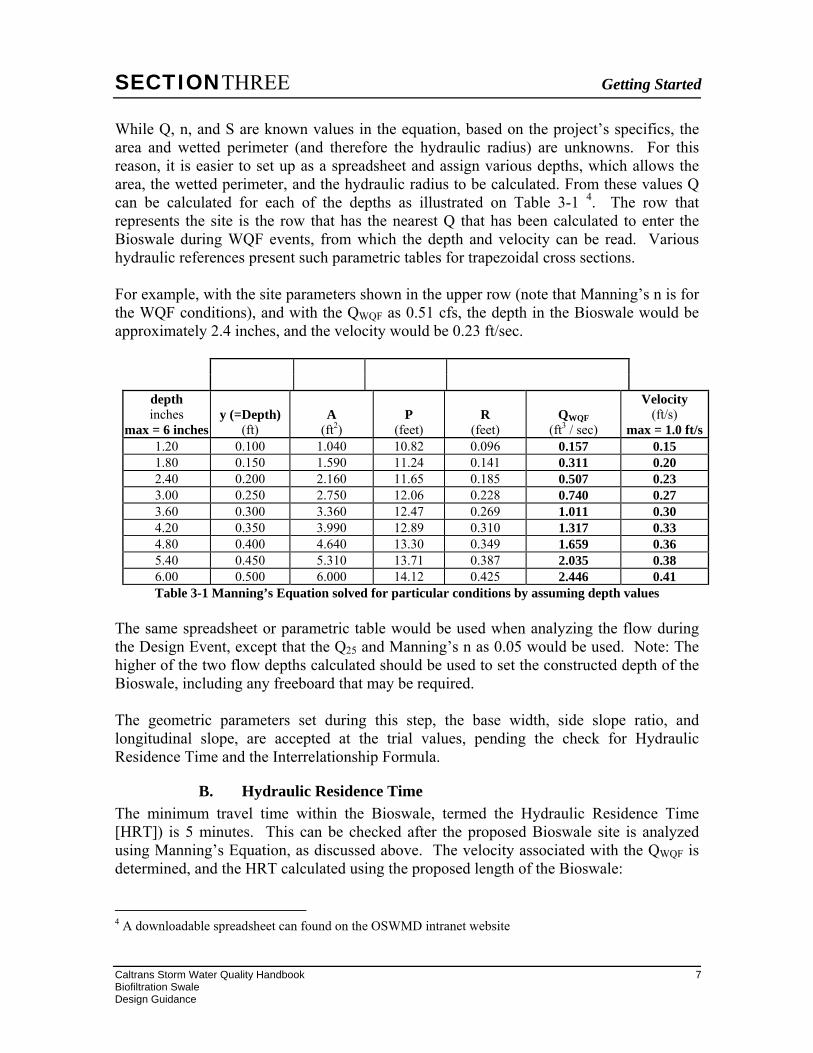
While Q, n, and S are known values in the equation, based on the project’s specifics, the area and wetted perimeter (and therefore the hydraulic radius) are unknowns. For this reason, it is easier to set up as a spreadsheet and assign various depths, which allows the area, the wetted perimeter, and the hydraulic radius to be calculated. From these values Q can be calculated for each of the depths as illustrated on Table 3-1 4. The row that represents the site is the row that has the nearest Q that has been calculated to enter the Bioswale during WQF events, from which the depth and velocity can be read. Various hydraulic references present such parametric tables for trapezoidal cross sections. For example, with the site parameters shown in the upper row (note that Manning’s n is for the WQF conditions), and with the QWQF as 0.51 cfs, the depth in the Bioswale would be approximately 2.4 inches, and the velocity would be 0.23 ft/sec.
depth inches
max = 6 inches y (=Depth)
(ft) A
(ft2) P
(feet) R
(feet) QWQF
(ft3 / sec)
Velocity (ft/s)
max = 1.0 ft/s1.20 0.100 1.040 10.82 0.096 0.157 0.15 1.80 0.150 1.590 11.24 0.141 0.311 0.20 2.40 0.200 2.160 11.65 0.185 0.507 0.23 3.00 0.250 2.750 12.06 0.228 0.740 0.27 3.60 0.300 3.360 12.47 0.269 1.011 0.30 4.20 0.350 3.990 12.89 0.310 1.317 0.33 4.80 0.400 4.640 13.30 0.349 1.659 0.36 5.40 0.450 5.310 13.71 0.387 2.035 0.38 6.00 0.500 6.000 14.12 0.425 2.446 0.41 Table 3-1 Manning’s Equation solved for particular conditions by assuming depth values
The same spreadsheet or parametric table would be used when analyzing the flow during the Design Event, except that the Q25 and Manning’s n as 0.05 would be used. Note: The higher of the two flow depths calculated should be used to set the constructed depth of the Bioswale, including any freeboard that may be required. The geometric parameters set during this step, the base width, side slope ratio, and longitudinal slope, are accepted at the trial values, pending the check for Hydraulic Residence Time and the Interrelationship Formula.
B. Hydraulic Residence Time The minimum travel time within the Bioswale, termed the Hydraulic Residence Time [HRT]) is 5 minutes. This can be checked after the proposed Bioswale site is analyzed using Manning’s Equation, as discussed above. The velocity associated with the QWQF is determined, and the HRT calculated using the proposed length of the Bioswale: 4 A downloadable spreadsheet can found on the OSWMD intranet website
SECTIONTHREE Getting Started
Caltrans Storm Water Quality Handbook 8 Biofiltration Swale Design Guidance
HRT = L / (60 x VWQF) where L = proposed length of the Bioswale (ft) HRT = Hydraulic Residence Time (minutes) VWQF = velocity at QWQF (ft/sec) 60 = conversion from seconds to minutes
If the HRT is less than 5 minutes, then the length of the Bioswale should be increased, or the velocity at QWQF should be decreased by increasing the width of the Bioswale or by decreasing the slope.
C. Interrelationship Formula during WQF Upon determining that the HRT, dWQF, and VWQF meet their respective design criteria, the Interrelationship Formula shown below also must be satisfied, as the maximum allowed depth of flow and velocity may be restricted if the HRT is less than 5 minutes.
(HRT x 60)/(dWQF x VWQF ) ≥ C where: HRT = Hydraulic Residence Time during QWQF (minutes) 60 = conversion factor from minutes to seconds dWQF = depth of flow at QWQF (ft) VWQF = velocity of flow at QWQF (fps) C = constant: 1,300 (sec2/ft2)
3.3. Other Comments 1 The Bioswale should be designed with the maximum length (in direction of flow)
as allowed by the site. In general, the flatter the slope, the shorter the Bioswale length required to meet Treatment BMP requirements.
2 The width of the Bioswale is often the most easily changed site variable if the
original proposed dimensions do not satisfy depth, velocity and Hydraulic Residence Time (HRT) criteria at WQF, but sometimes the slope may be reduced.
3 The tributary area upstream of Bioswales is usually not as large as the tributary
areas for volume-based Treatment BMPs.
4 Calculations for the Bioswale, especially the HRT, are easier if most or all of the QWQF enters at a discrete location at the upstream, rather than at distributed locations along the length of the Bioswale. However, if the flow enters the Biofiltration Swale continuously along the length of the swale or at multiple discrete locations, other rational methods should be employed. In the case of
SECTIONTHREE Getting Started
Caltrans Storm Water Quality Handbook 9 Biofiltration Swale Design Guidance
continuous flow entering the swale, the PE may wish to initially calculate the depths and velocities at selected points along the swale to verify that the depth or velocity has not exceeded the maximum allowed values. This same calculation could also be used if there is a change of grade. The length of the swale that would qualify as a Biofiltration Treatment BMP must be upstream of the location where either the maximum depth or velocity was exceeded. The calculation of the HRT when the WQF enters at multiple (actual entry points or discretized from continuous flow) entry points could be done by calculating the HRT for the flow from each of the discrete entry points, and then taking a weighted average of the HRTs for the entire flow over the length that qualifies as a Biofiltration Treatment BMP; velocity and depth criteria would still need to be met.
5 To provide adequate hydraulic function, a swale should also be sized as a
conveyance system calculated according to criteria and procedures for conveyance of design storm flows and scour associated with the peak drainage facility design event.
6 Check dams within the Bioswale may be considered if the HDM criteria are met, but the HRT, velocity, or length requirements are not met due to the steepness of the proposed Bioswale. Follow the guidance for Temporary Check Dams located in the Caltrans Construction Site BMP Manual. Additionally, check dams should be constructed of soil, placed a maximum of 20 ft apart, have 4H:1V slopes, be a maximum height of 9 inches and be vegetated. Placement should not impede the flow of the HDM Design Event. Check dams must be maintained.
7 Fiber roll check dams within the Bioswale may be considered. An Interim Guidance on Permanent Fiber Roll Check Dam is available. Consultants should contact OSWMD. Caltrans employees can download the guidance on the Design HQ intranet site at http://onramp.dot.ca.gov/hq/design/stormwater/guidance/FRCD_Guidance_040110.zip. Permanent fiber roll check dams are sometimes specified as an erosion control measure. The dams are used in final channels with non-erosive flows to slow the water and create a series of micro-pools to promote vegetative growth. However, the check dams have the potential to create erosion if the permitted flow velocities are exceeded or scour prevention is not installed. While check dams can be beneficial in promoting vegetation and minimizing erosion, their use must coordinated with Maintenance. Mowing or grading will interfere with the dam operation. Consult your project Landscape Architect or Design Stormwater Coordinator for more information.
8 If the criteria for the Bioswale cannot be met, then several options are available:
i) the proposed swale could be considered as a Design Pollution Prevention (DPP) BMP – Concentrated Conveyance System rather than as a Treatment BMP;
SECTIONTHREE Getting Started
Caltrans Storm Water Quality Handbook 10 Biofiltration Swale Design Guidance
ii) an alternative Treatment BMP could be considered at that location; iii) the RWQCB could be petitioned for reduced WQF intensity (see PPDG Section 2.4.2.2) if the Bioswale criteria could be met at a lower QWQF.
SECTIONFOUR BMP Layout and Design
Caltrans Storm Water Quality Handbook 11 Biofiltration Swale Design Guidance
4. BMP Layout and Design
4.1. Layout 4.1.1. Location
Biofiltration Swales, and the related Biofiltration Strips, are probably the least expensive Treatment BMPs for an area, if the proposed location is suitable. They can be placed as a stand-alone device in order to meet MEP treatment requirements, or can be placed usually as the first BMP encountered in a “treatment train” and should be considered upstream of other Treatment BMPs that benefit from pretreatment to reduce sediment loading, such as Infiltration Devices, Detention Devices, and Wet Basins. However, to provide effective treatment of runoff, the proposed location must be able to support the chosen vegetation; locations should be sought that have sufficient open space, adequate sunlight for vegetation growth, and topography to meet the hydraulic requirements. Entry of runoff into a Bioswale may enter as sheet flow along its length, and/or from a concentrated conveyance. If the latter, it may require energy dissipation to prevent erosion. One location that should receive special consideration is at the end of a bridge structure. Refer to Section 4.2.2.
4.1.2. Maintenance Bioswales need sufficient space for various maintenance activities, including enough space for maintenance vehicles and during cleaning, repair, or inspections. District Maintenance should concur with the proposed Bioswale location.
4.2. Site Specific Design Elements
4.2.1. Turf Reinforcement Mat (TRM) When the flow velocity exceeds 4 ft/sec for the design storm, a geotextile, such as turf reinforcement mat (TRM), may be used to prevent scour within the swale. The use of a TRM within the swale for velocities higher than 4 ft/sec during design storm events does not negate the need to meet all the design criteria during Water Quality events as presented in section 2.2. A nonstandard special provision for use of a TRM in a Bioswale has been developed and is available for use. If the flow characteristics do not require a TRM, a temporary erosion control blanket or RECP (Rolled Erosion Control Product) may still be needed to protect the soil from concentrated flow that may occur the first winter before vegetation can be established. Hydroseeding is not recommended for areas that will receive concentrated flows.

SECTIONFOUR BMP Layout and Design
Caltrans Storm Water Quality Handbook 12 Biofiltration Swale Design Guidance
4.2.2. Inflow Detailing Consider detailing such as flared end sections where concentrated flow enters a Bioswale to prevent erosion.
SECTIONFIVE PS&E Preparation
Caltrans Storm Water Quality Handbook 13 Biofiltration Swale Design Guidance
5. PS&E Preparation This section provides guidance for incorporating Bioswales into the PS&E package, discusses the typical specifications, and presents information about estimating the construction costs.
5.1. PS&E Drawings Bioswale Treatment BMPs do not have standard drawings for the device as a complete feature, but there are several sheets that could be placed in the PS&E package. The PS&E drawings for most projects having Bioswales will include:
1 Layout(s): Show location(s) of the Bioswales; this is a recommended option, as its use will help verify to the RWQCB or to a third party that this Treatment BMP was placed.
2 Contour Grading(s): As Bioswales are primarily earthwork features they should be shown on Contour Grading sheets. Any other associated grading surrounding the Bioswale should be shown on these sheet(s).
3 Construction Details: Inflow and outflow detailing should be shown (if, for example, a lined channel is at the upstream or downstream end of the Bioswale). These sheets may be shown in the Drainage Detail sheets, at the option of the Project Engineer.
Final grade should maintain sheet flow across the top hinge point of a Bioswale (e.g. when Bioswale is adjacent to a roadway shoulder). To avoid mulch and plant material from blocking the sheet flow into the Bioswale, a construction detail showing the final grade including mulch may be required.
4 Drainage Plan(s), Profiles, Details, and Quantities:
a) Drainage Plan sheets should show each Bioswale in plan view, along with other existing (or proposed) drainage conveyance devices that direct the runoff into the device.
b) Drainage Profile sheets should show the Bioswale in profile within the drainage conveyance system. These sheets should also call out the specific Bioswale inlet and outlet flow line (surface) elevations.
c) Drainage Detail sheets should show any other structural detailing needed for the construction of the Bioswale not provided elsewhere in the contract plans, but see also the comments for the Landscape Plans.

SECTIONFIVE PS&E Preparation
Caltrans Storm Water Quality Handbook 14 Biofiltration Swale Design Guidance
d) Drainage Quantity sheets should include all pay and non-pay items associated with the construction of the Bioswales, except for those items that will be placed on the Summary of Quantities sheets.
5 Landscape Plans and/or Erosion Control Plan: these items should be prepared for the interior of the Bioswale and nearby areas, for soil amendments, planting, and similar items (prepared by the District Landscape Architect).
6 Other Sheets: Water Pollution Control, Construction Staging, Utility Plans, Irrigation Plans (if permanent irrigation will be placed, or the existing system modified), and other sheets should be considered as appropriate for the construction of Bioswales on a project-specific basis.
If Bioswales will be constructed at multiple locations, a “Locations of Construction” table could be considered. This table could present the stationing and other location information could be considered. This table may be incorporated into an existing drawing if there is room (such as a Title, Layout or Construction Detail), or may be developed as a separate drawing if necessary. While every effort has been made to provide accurate information here, the Project Engineer is responsible for incorporating all design aspects of Bioswales into the PS&E in accordance with the requirements of Section 5 of the Department’s Plans, Specifications And Estimates Guide.
5.2. SPECIFICATIONS Contract specifications for Bioswale Treatment BMP projects will include Standard Specifications, Standard Special Provisions (SSPs), and non-Standard Special Provisions (nSSPs).5 Where indicated below, specific nSSPs have been developed by the HQ Office of Storm Water Management. The special provisions for the various items of work directly needed to construct the Bioswale could be organized under the blanket heading of ‘Bioswale’ (with some or all of these items listed as subheadings, and payment would be made for by ‘each’ Bioswale), or separate listings could be made for each contract item of work (with separate measurement and payment). The Project Engineer and the District Office Engineer should consider which method would better serve the particular project.
5.2.1. Standard Special Provisions Listed below are SSPs that would typically be used for a project that constructs a Bioswale Treatment BMP; the Project Engineer should consider the construction of Bioswales in the
5 Standard Specifications will not be included but merely referenced in the contract’s special provisions.

SECTIONFIVE PS&E Preparation
Caltrans Storm Water Quality Handbook 15 Biofiltration Swale Design Guidance
context of the entire project to determine if other SSPs may be required.
1 Order of Work6 (SSP 05-010) 2 Water Pollution Control (SSP 07-340 or 07-345) 3 Clearing and Grubbing (SSPs 16-050, or 16-060, or 16-070) 4 Earthwork (SSP 19-010; and/or Miscellaneous Earthwork Clauses, SSP 19-040;
and/or Measurement And Payment (Earthwork), SSP 19-590) 5 Erosion Control (Erosion Control (Type C), SSP 20-030; or Erosion
Control (Type D), SSP 20-040) 6 Temporary Irrigation (as Plant Establishment Work, SSP 20-550) 7 Highway Planting (SSP 20-350) 8 Slope Protection (SSP 72-010)
5.2.2. Non-Standard Special Provisions Typical placement of BioSwales will not require any nSSPs. However, the Project Engineer and the District Landscape Architect must ensure that non-Standard Special Provisions, if needed, have been developed based on site-specific requirements. HQ Landscape will most likely be the approval group for any Bioswale nSSPs developed.
5.3. Project Cost Estimates Project Cost Estimates (PCEs) are required at every phase of the project, as discussed below. Section 7 of the Ready-to-List and Construction Contract Award Guide (RTL Guide) should be consulted for more details on preparing construction cost estimates.
5.3.1. PID and PA/ED Phases At the PID phase of the project, the construction cost could be estimated based on the findings of the BMP Retrofit Pilot Program Final Report, which was $21/ft3 of WQV treated, exclusive of right of way.7 To determine an initial cost estimate using this value simply use the following equation:
Initial construction cost = ($21/ft3 x run-up factor) x tributary area x 0.75/12
This estimate will need to be modified as the project progresses. If some design is conducted during the PA/Ed phase of the project, it is possible that a more refined estimate
6 The Order of Work should indicate that no runoff from construction should be allowed to flow into the Bioswale until all upstream areas contributing runoff are stabilized and Bioswale vegetation established. 7 In 1999 dollars; contact District Office Engineer for appropriate run-up factors based on local experience. Note that costs were given in units more appropriate for a volume-based Treatment BMP, for the comparison purposes within that report. The formula shown has been modified slightly to account for the otherwise incorrect units, and should only be used for estimating purposes in these phases of the project.

SECTIONFIVE PS&E Preparation
Caltrans Storm Water Quality Handbook 16 Biofiltration Swale Design Guidance
could be made using the methods in Section 5.3.2. A cost escalation should be added for projects that are anticipated to advertise more than a year after the date of the estimate.
5.3.2. PS&E Phase As the design process proceeds into the PS&E phase, unit quantities would be available, and the associated units costs would need to be obtained, as accurate costs are critical. When developing costs based on unit quantities, the cost estimates should be based upon the Department’s Contract Cost Data Book or recent, similar projects in the District, as appropriate. The Project Engineer should use SSPs and nSSPs from Sections 5.2.1 and 5.2.2 of this document, as well as those added on a project-specific basis, to develop a list of items for which item costs should be developed. The Project Engineer should carefully check that all items of work are accounted for either as pay or non-pay items.
SECTIONSIX References
Caltrans Storm Water Quality Handbook 17 Biofiltration Swale Design Guidance
6. References 1. California Department of Transportation (Caltrans), Current Edition. Storm Water
Quality Handbooks: Project Planning and Design Guide, (PPDG)
2. California Department of Transportation (Caltrans), 2004. BMP Retrofit Pilot
Program Final Report, CTSW – RT – 01 – 050
3. California Department of Transportation (Caltrans), 2004. Roadside Vegetated Treatment Study (RVTS), CTSW – RT - 03 – 028; with additional data published as: Roadside Vegetative Treatment Sites (RVTS) Study Monitoring Season 2005-2006 Post- Storm Technical Memorandum No. 1, CTSW– TM– 06– 157.06.1
4. WERF. 2004. Post-Project Monitoring of BMPs/SUDS to determine Performance
and Whole Life Costs
5. CASQA. 2004. California Stormwater BMP Handbook
6. California Department of Transportation (Caltrans), Current Edition. Highway Design Manual
7. King County 2005. Surface Water Design Manual
8. California Department of Transportation (Caltrans). Storm Water Quality
Handbooks: Wet Basins Design Guidance handbook (under development at time of printing)
9. California Department of Transportation (Caltrans). Storm Water Quality
Handbooks: Supplemental Design Guidance handbook (under development at time of printing)
10. FHWA, 2nd ed. August 2001. Hydraulic Engineering Circular (HEC) No. 22 Urban
Drainage Design Manual
11. USDA, May 1998. Forest Service, Natural Resources Conservation Service, Ecological Subregions of California Section and Subsection Descriptions, (online at: http://www.fs.fed.us/r5/projects/ecoregions/)
APPENDIX A Biofiltration Guidance - Vegetation
Caltrans Storm Water Quality Handbook 18 Biofiltration Swale Design Guidance
A. Biofiltration Guidance-Vegetation
A.1 Overview This Appendix provides design guidance for the vegetative cover component of Biofiltration BMPs. For Biofiltration BMPs, District Landscape Architecture is responsible for selecting vegetation, and developing the appropriate plans, specifications, details, and estimates for contract documents. Incorporation of other improvements such as soil amendment and irrigation may be required to satisfy site conditions. For Biofiltration BMPs to be effective, it is necessary to establish a healthy, sustainable vegetative cover. The District Landscape Architect or delegated representative is to verify that specific project requirements, necessary to provide vegetative cover for the Biofiltration BMPs, are documented in the Storm Water Data Report (SWDR) and prepared for PS&E.
A.2 Soil Testing & Investigation It is important to identify soil characteristics of a site to determine its erosion potential and planting requirements.
The following should be considered when analyzing soils information for biofiltration BMPs:
1) Information on soils should be requested as part of the Geotechnical Investigation. Soils characteristics such as USDA Soil Group, USDA-NRCS particle distribution (soil texture), organic matter percentage, and infiltration rate (conductivity) should be requested.
2) If the Geotechnical Report has been completed without a discussion of near-surface soils information, or if no Geotech Report is prepared for the project, then the Landscape Architect should make arrangements to collect soil samples and submit them to a soils testing lab for processing. In addition to soils characteristics listed above under item 1, the soil test should also report the following:
• pH • Salinity • Sodium • Boron • Nitrogen • Potassium • Phosphorus

APPENDIX A Biofiltration Guidance - Vegetation
Caltrans Storm Water Quality Handbook 19 Biofiltration Swale Design Guidance
3) If soils information cannot be obtained for the project site, then soils information from a reference site should be evaluated. To be valid, the reference site must have characteristics similar to the project site such as slope aspect (e.g., north-facing, etc.) topography (cut or fill slopes), climate, geology, and existing vegetation.
A.3 Soil and Planting Bed Preparation Roadway construction that requires excavation or embankment work typically results in soils unable to support desirable vegetation. Grading operations, including compaction, produce soils of pulverized parent material with inverted soil horizons that lack nutrients, organic matter, rooting depth, and pore space. When these site conditions are anticipated, an assessment should be made by District Landscape Architecture to determine the level of treatment necessary to support vegetation.
Soil nutrients are critical to establishing and sustaining healthy vegetation. Without adequate levels of nutrients, particularly nitrogen, initial plant health and density will decline after a few years. In general, disturbed sites that have been successfully revegetated show a correlation between percent plant cover and soil nitrogen. On certain sites, plant communities with greater than 40 percent vegetative cover are associated with soil containing an average of 1100 lb total N/acre. Studies show a correlation between plant growth and the addition of nitrogen with best results occurring when nitrogen is distributed throughout the top 12-inches of soil.
Research has shown that compost and slow release fertilizers provide a better method to provide nutrients for desirable plant species than conventional commercial fertilizer. Because the nutrients provided by commercial fertilizer are readily available, the germination and growth of invasive weeds is encouraged over slower growing desirable species. Incorporating compost and applying slow-release fertilizer releases nutrients gradually, thereby promoting the germination and establishment of perennial grasses and woody shrubs. In addition to providing long-term nutritional benefits as a soil amendment, compost can be used as a 1” to 2” mulch layer to prevent the germination of most invasive annual weed species. When a compost mulch layer is specified, apply the seed on top of the compost layer to ensure that desirable seed species will germinate.
The following should be considered when preparing soil for biofiltration BMPs:
1) The soils in areas designated for biofiltration should be ripped and cultivated to a minimum depth of 12-inches to relieve surface compaction.
2) Compost should be incorporated at a minimum rate of 400 cuyd/acre (equivalent to a 3-inch layer) to a minimum depth of 12-inches in all areas designated for biofiltration to restore soil organics, rooting depth, porosity and nutrients (carbon and nitrogen).

APPENDIX A Biofiltration Guidance - Vegetation
Caltrans Storm Water Quality Handbook 20 Biofiltration Swale Design Guidance
3) Compost incorporation is typically recommended for slopes less than or equal to 4:1 H:V. For slopes steeper than 4:1, coordinate your work with your geotechnical engineer and District NPDES Coordinator.
4) Compost incorporation is not suggested for areas where harvested topsoil will be placed. Designate topsoil harvest and stockpile locations on the plans. Include details for re-application and placement of topsoil.
A.4 Irrigation Strategies California’s diverse microclimates make establishing vegetation difficult and sometimes impossible without supplemental irrigation. Harsh site conditions often limit the ability of the plantings to survive and thrive to the extent necessary for successful treatment. Under these conditions, irrigation should be provided.
The following criteria should be considered when designing biofiltration BMPs:
1) If vegetative cover goals (minimum 65%) are not achievable under normal rainfall, then a temporary or permanent irrigation system is recommended.
2) If it’s anticipated that the first storms of the rainy season will wash away the seedbed of the biofiltration BMPs, then the use of a temporary irrigation system to establish the vegetation prior to the rainy season is recommended. Temporary flow diversion to direct concentrated flow around newly seeded areas until vegetation is established.
3) If the proposed biofiltration BMP is adjacent to or within an irrigated landscape then utilization of the existing water service for irrigation is recommended. A bioswale or biostrip located within a landscaped urban interchange should be designed to complement the adjacent existing highway planting.
A.5 Planting Strategies The following criteria should be used as a general measure of successful Biofiltration BMP installation:
1) Within the first year, a minimum of 65 percent vegetative cover is achieved. 2) Within three years, 75 to 85 percent vegetative cover is achieved. 3) The Biofiltration BMP does not exhibit rills, gullies, or visible erosion that is
contributing to the export of sediment. California’s diverse microclimates require equally diverse strategies for successfully establishing vegetation. The following planting strategies have been successfully used for roadside revegetation and should be considered for biofiltration BMPs where appropriate:
1) Temporary cover with sufficient longevity should be provided until the desired percentage cover of vegetation is achieved. For challenging sites, it may take more then one growing season to establish adequate vegetative cover. This is especially true for shrubs and woody perennials on harsh sites. Temporary cover is usually
APPENDIX A Biofiltration Guidance - Vegetation
Caltrans Storm Water Quality Handbook 21 Biofiltration Swale Design Guidance
provided through the use of short-term, degradable erosion control products such as rolled erosion control products (RECPs), wood chips and compost, straw, and hydromulchs. These products vary in how long they will last. For example, straw can be expected to last through a single rainy season while a woven coconut fiber netting will usually persist for 3 years.
2) Strive for cost effective solutions. In most cases, the temporary cover product with the greatest longevity will also be the most expensive. While plant performance, slope steepness, slope inclination, slope aspect, and soil characteristics must be considered, avoid over-design. Specify different materials when warranted by diverse project conditions. For example, a cost-effective project design may include the use of blown straw and hydroseed on areas of good soil and gentle slopes whereas compost and coir netting are reserved for steep, cut slopes.
3) Specify drought tolerant grasses, with a goal to use as many appropriate native species as possible. Species that become dormant during the dry season are acceptable as long as this doesn’t affect biofiltration performance. In Southern California, it is preferable to select plant species that are not dormant during the winter and spring (wet season).
4) Combine hydroseeding and direct planting. Some plant species favor particular planting methods, so allowances have to be made if these species are to be used. Many plant species can be applied by hydroseeding. Other plants are better established as liner, container, or plug plant material and can be installed in previously seeded areas, following germination. This method can be effective for bioswales when the upland zone on the banks is hydroseeded and the hydrophilic zone in the bed is planted with sedge, grass, and rush liners.
5) Specify pre-germination or include mulch for weed control. Pre-germination is a very effective method for killing weeds that germinate from an existing seed bank. Planting by hydroseeding or other methods should be done after one or more pre-germination cycles. Pre-germination is only practical when temporary irrigation is employed. A 1”-2” layer of compost used as mulch is also an effective method to prevent germination and competition from annual weeds.
6) Specify erosion control blankets or other RECPs in areas that will receive concentrated flow. Although hydroseeding may be appropriate for planting portions of bioswales, it should not be used in locations that will receive concentrated runoff. Liner, container or plug plant material is a better choice in these areas.
7) Incorporate amended soil as part of slope construction when specifying Mechanically Stabilized Embankments (MSE) for steep embankments and consult with Geotech Services. Placing amended soil at the proposed slope face can be done as part of placing each geotextile reinforced lift. An open weave erosion control blanket should be used to contain the material at the slope face by using a “wrap-back” method. The slope can be hydroseeded upon completion of the MSE.
8) Specify “stepped-slope” construction for grading cut slopes. Cut slopes are difficult to vegetate for different reasons such as rocky subsoil, compaction, removal of topsoil and organic material, and steepness. Using a “stepped-slope”
APPENDIX A Biofiltration Guidance - Vegetation
Caltrans Storm Water Quality Handbook 22 Biofiltration Swale Design Guidance
method can enhance vegetation establishment. This method involves making a series of cuts, or small benches, starting at the top of the proposed cut slope and working down. The final slope has a “stair step” appearance rather than a smooth, scraped slope. Each step should be between 2 to 6 feet wide. By allowing approximately 50 percent of the loose, excavated material to remain on each step, a planting bed is created. This planting be can be further enhanced by adding compost.
A.6 Restrictions for Plant Selection Nearly half of the bulk solids collected in the structural treatment BMPs consists of plant litter such as leaves and twigs. To maintain the efficiency of these BMPs and especially basins and trash BMPs such as GSRDs, trees and large shrubs selected for banks of biofiltration swales should contribute minimal plant litter to the BMP. Deciduous trees and other species that contribute large amounts of bark, leaf, flower, or seed litter should be avoided.
A.7 Drainage Facilities Accommodations for drainage facilities upstream and downstream from biofiltration BMPs should be considered as follows:
1) Provide a concrete apron large enough to prevent overgrowth and reduce clogging around drainage inlets located in bioswales.
2) Provide a concrete apron large enough to prevent overgrowth and reduce clogging at culvert inlet and outlets such as flared end sections. This enhances performance and facilitates inspection and maintenance.
3) Include armoring or other forms of scour protection such as the use of rock or turf reinforcement at the transitions from piped or other hard surface conveyance to vegetated areas.
A.8 Plant Establishment Period (PEP) PEP ensures project success by maintaining plants during a period when mortality rates tend to be high. This is true for Highway Planting, as well as for revegetation planting that includes grasses and forbs, and especially native grasses. The following should be considered when requiring PEP for biofiltration BMPs:
1) Biofiltration BMPs that are graded, constructed and planted as part of a roadway construction contract should have a 1-year PEP. Depending upon the type of construction and order of work, the PEP may run concurrently with other work.
APPENDIX A Biofiltration Guidance - Vegetation
Caltrans Storm Water Quality Handbook 23 Biofiltration Swale Design Guidance
2) Work to be performed during the PEP should include the following when applicable for the project:
a) Weed control and removal of inappropriate plant species, b) Mowing and other vegetation management, c) Repair of rills, gullies, and other damage caused by erosion and scour, d) Reseeding of bare or repaired areas, e) Monitoring and repair of irrigation system (permanent or temporary), f) Removal of temporary irrigation system, and g) Removal of accumulated sediment and debris.
3) The following activities may be performed during the PEP and done as extra work: a) Additional planting, b) Additional irrigation, and c) Monitoring of plant growth and establishment.
4) Ideally, a 3-year contract to perform plant establishment work should follow immediately after completion of the roadway contract that installed the Biofiltration BMPs. If practical, the follow-up contract may include the Biofiltration BMPs of several construction projects in proximity of each other.
A.9 Definitions: 1) Vegetative Cover: (This definition is paraphrased from the draft NPDES
Construction General Permit) Actively growing plant matter that is uniform, self-sustaining (perennial) and in contact with the soil. Live perennial vegetation may include grasses, grass like species, forbs, and some broad leaf species that are ground covers, low shrubs, or a combination. The area shall have a minimum vegetative cover of 70% within the first growing season. The remaining 30% shall be covered by fallen plant litter, standing dead plant material, or mulch. Near 100% coverage should be possible after the second growing season.)
2) Temporary Cover: Temporary cover consists of erosion control materials that
provide short-term, interim protection of disturbed soil areas. Temporary cover products include erosion control blankets and other RECPs, straw, composts and mulches, and hydromulches. These products are generally composed of biodegradable and photodegradable materials with variable longevity.
A.10 Additional Resources See locations below for additional information regarding planting methods and strategies for slope stabilization:
• The Soil Resource Evaluation (SRE) provides a stepwise process for regeneration and re-vegetation of drastically disturbed soils. Information on plant rooting depth, plant available water, soil nutrient levels, etc. can be found here. This information

APPENDIX A Biofiltration Guidance - Vegetation
Caltrans Storm Water Quality Handbook 24 Biofiltration Swale Design Guidance
is linked to the HQ Landscape Architecture Program at: http://www.dot.ca.gov/hq/LandArch/research/index.htm.
• Several studies on biofiltration BMPs, erosion control, and revegetation can be found on the Caltrans Department of Environmental Analysis webpage at: http://www.dot.ca.gov/hq/env/stormwater/special/newsetup/index.htm.
• The Caltrans Revised Universal Soil Loss Equation (RUSLE2) and the Erosion Prediction Procedure (EPP) provide a software tool and guidance for predicting surface erosion and selecting BMPs. The EPP appendixes include information on collecting and processing soil samples. (Under development)
• The Erosion Control Technology Council (ECTC) is a non-profit organization dedicated to developing performance standards, uniform testing procedures, and guidance on the application and installation of rolled erosion control products (RECPs). Information for selection and installation of RECPs based upon longevity, slope inclination, C-factor, and shear strength is given for various classes of products. Access their webpage at: http://www.ectc.org/.
For additional information about native plant species suited to varied hydrologic conditions within specific ecological subregions of California, consult:
• Ecological Subregions of California Section and Subsection Descriptions, USDA, Forest Service, USDA, Natural Resources Conservation Service, published May 1998
• (online at: http://www.fs.fed.us/r5/projects/ecoregions/toc.htm); • Calflora Database (online at: http://www.calflora.org); • Caltrans native grass database (online at:
http://www.dot.ca.gov/hq/LandArch/nativedb/); and • Caltrans TransPLANT seed selection tool (online at:
http://www.dot.ca.gov/hq/LandArch/transplant/).