Embed Size (px)
Citation preview
BioCellus • Biomass Fuel Cell Utility System • Contract No: 502759
Biocellus - Highly efficient SOFC systems with indirect gasification
International workshop on "Bio-energy workshop EU-Russia" 7-8th of October 2004, All-Russian Thermal Engineering Institute (VTI), Moscow
J. Karl, Lehrstuhl für Thermische KraftanlagenTechnische Universität München
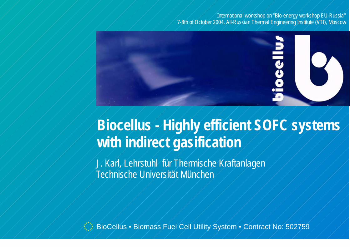
Influence of the system integration on the economics of fuel cell systems
100 %
34 kW
51 %
45 % 900 °C
79 %
Brennkammer
134 %
chemisch gebundene Energie 122 %
fühlbare Wärme 12%
800 °C
EconomicsEconomics
ThermodynamicsThermodynamics
SOFC coolingSOFC cooling
Biocellus Biocellus
ConclusionConclusion
Remarks on thermodynamics of CHP systems
Cooling of SOFC systemsFP6-Project BiocellusConclusion
Contents
EconomicsEconomics
ThermodynamicsThermodynamics
SOFC coolingSOFC cooling
Biocellus Biocellus
ConclusionConclusion
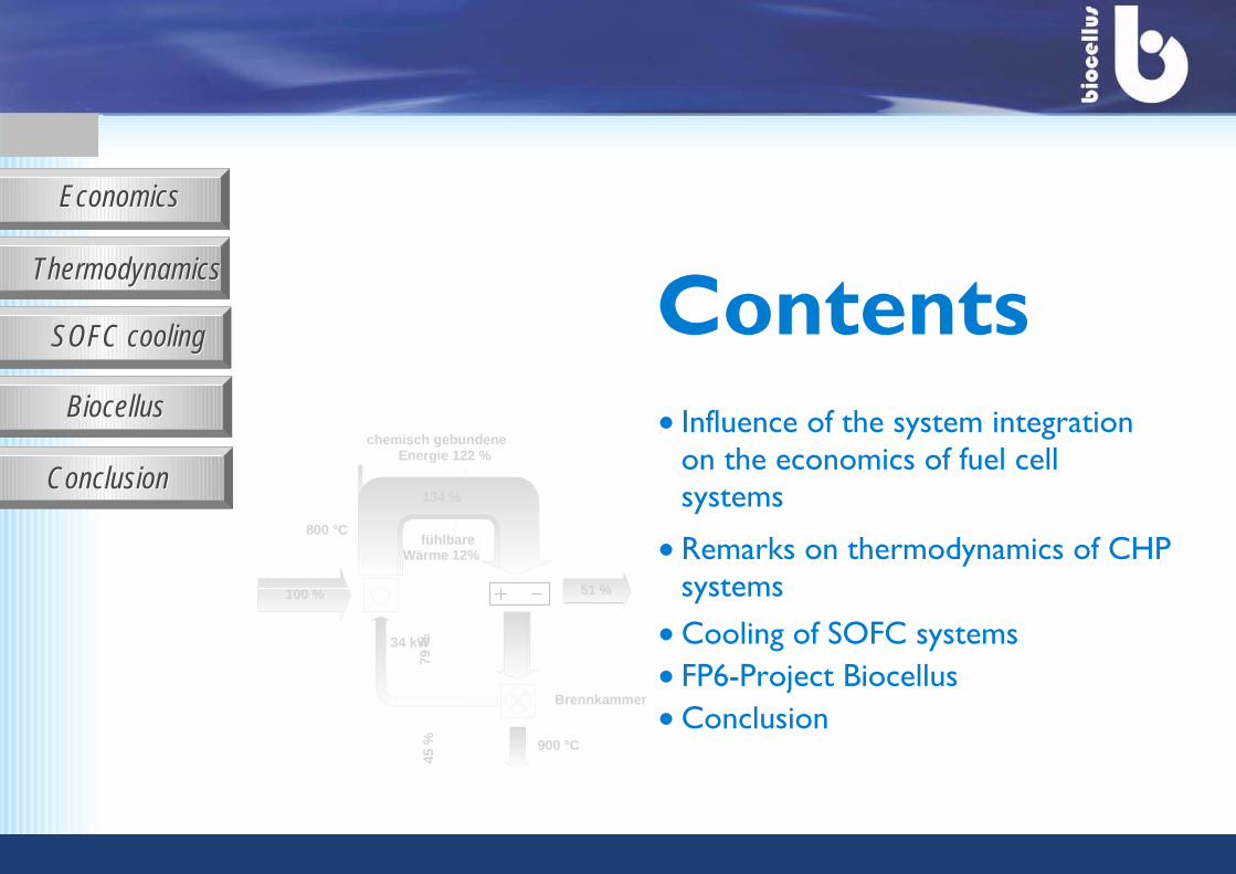
Status quo SOFC development:
Main drawbacks are presently...
... degradation
... system efficiency
... high costs!
SOFC system for domestic heating
(Sulzer-Hexis)
RWE fuel cell pavilionMeteorit-Gelände, Essen
110 kW SOFC system, Siemens-Westinghouse
many highly promissing technical solutions are already available
EconomicsEconomics
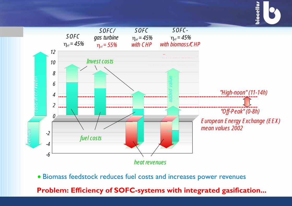
European Energy Exchange (EEX) mean values 2002
German power revenues for biomass
0
2
4
6
8
10
12
SOFC ηel = 45%
"Off-Peak" (0-8h)
"High-noon" (11-14h)
SOFC/gas turbine ηel = 55%
-6
-4
-2
SOFC ηel = 45%with CHP
SOFC- ηel = 45%
with biomass/CHPco
sts
in c
t / k
Wh
cost
s in
ct /
kW
h elel
reve
nues
reve
nues
Invest costs
fuel costs
heat revenuesad
ded
valu
e
Problem: Efficiency of SOFC-systems with integrated gasification...
Biomass feedstock reduces fuel costs and increases power revenues
EconomicsEconomics
ThermodynamicsThermodynamics
SOFC coolingSOFC cooling
Biocellus Biocellus
ConclusionConclusion
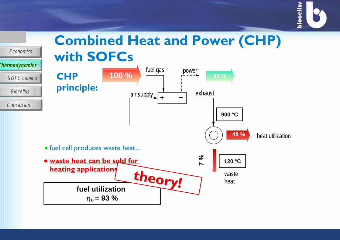
waste heat can be sold for heating applications
fuel utilization ηB = 93 %
100 % 45 %fuel gas
900 °C
exhaustair supply
powerCHP principle:
fuel cell produces waste heat...
48 % heat utilization
7 % 120 °C
waste heattheory!
Combined Heat and Power (CHP) with SOFCs
ThermodynamicsThermodynamics
EconomicsEconomics
ThermodynamicsThermodynamics
SOFC coolingSOFC cooling
Biocellus Biocellus
ConclusionConclusion
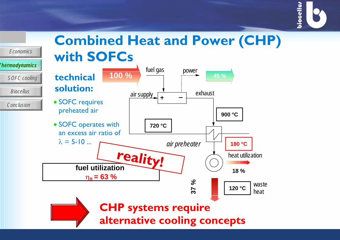
fuel utilization ηB = 63 %
waste heat37
% 120 °C
reality!
CHP systems require alternative cooling concepts
18 %
heat utilization
technical solution:
Combined Heat and Power (CHP) with SOFCs
SOFC requires preheated air
SOFC operates with an excess air ratio of λ = 5-10 ... air preheater
100 % 45 %
900 °C
fuel gas
air supply exhaust
power
720 °C
180 °C
ThermodynamicsThermodynamics
EconomicsEconomics
ThermodynamicsThermodynamics
SOFC coolingSOFC cooling
Biocellus Biocellus
ConclusionConclusion
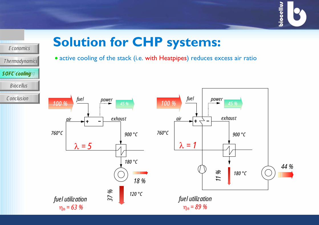
active cooling of the stack (i.e. with Heatpipes) reduces excess air ratio
λ = 1
fuel utilization ηB = 63 %
fuel utilizationηB = 89 %
44 %
100 % 45 %
900 °C
11 % 180 °C
760°C
fuel
air exhaust
power100 % 45 %
37 %
900 °C
fuel
air exhaust
power
18 %
180 °C
120 °C
760°C
Solution for CHP systems:
λ = 5
SOFC coolingSOFC cooling
EconomicsEconomics
ThermodynamicsThermodynamics
SOFC coolingSOFC cooling
Biocellus Biocellus
ConclusionConclusion
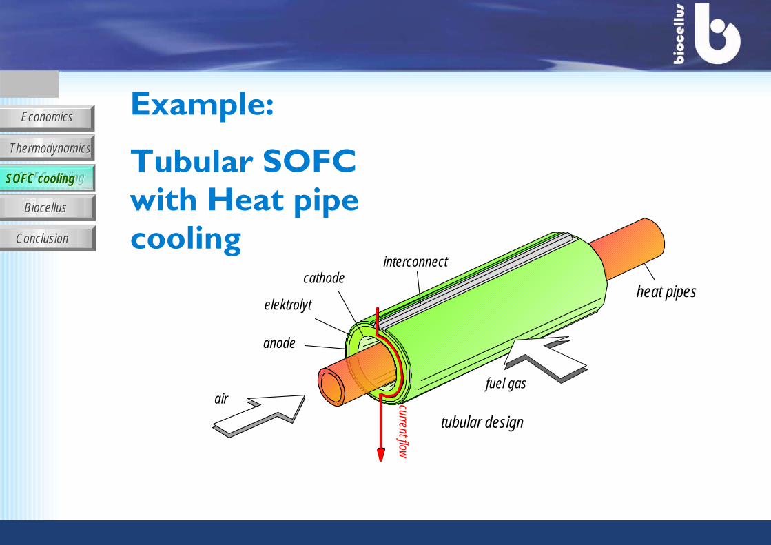
anode
elektrolyt
cathode
airfuel gas
tubular design
current flow
interconnect
heat pipes
Example:
Tubular SOFC with Heat pipe cooling
SOFC coolingSOFC cooling
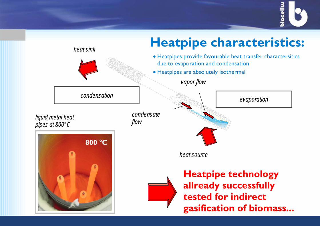
evaporationcondensation
heat sink
heat source
condensateflow
vapor flow
Heatpipe characteristics:
Heatpipe technology allready successfully tested for indirect gasification of biomass...
liquid metal heat pipes at 800°C
Heatpipes provide favourable heat transfer charactersitics due to evaporation and condensationHeatpipes are absolutely isothermal
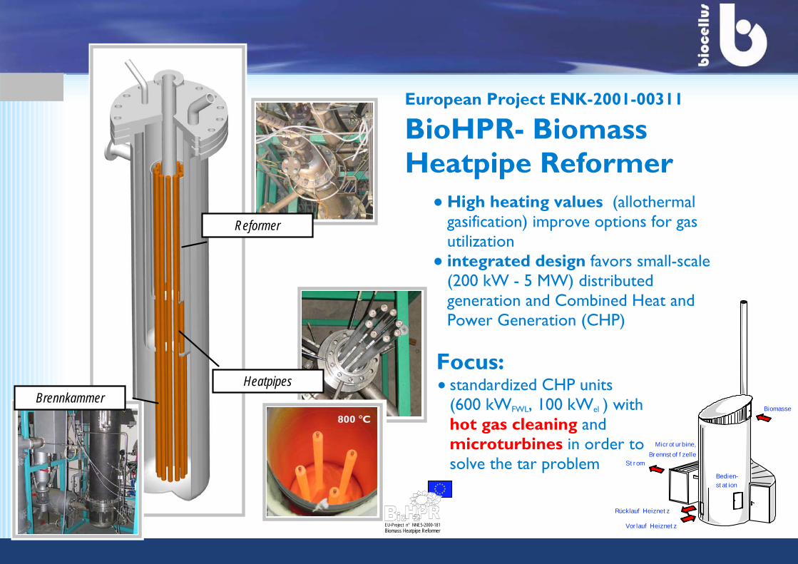
Brennkammer
Reformer
Heatpipes
High heating values (allothermal gasification) improve options for gas utilization integrated design favors small-scale (200 kW - 5 MW) distributed generation and Combined Heat and Power Generation (CHP)
European Project ENK-2001-00311
BioHPR- Biomass Heatpipe Reformer
Focus:standardized CHP units (600 kWFWL, 100 kWel ) with hot gas cleaning and microturbines in order to solve the tar problem
Vorlauf Heiznetz
Rücklauf Heiznetz
Strom
Biomasse
Bedien-station
Microturbine,Brennstoffzelle
EU-Project n° NNE5-2000-181Biomass Heatpipe Reformer
EconomicsEconomics
ThermodynamicsThermodynamics
SOFC coolingSOFC cooling
Biocellus Biocellus
ConclusionConclusion
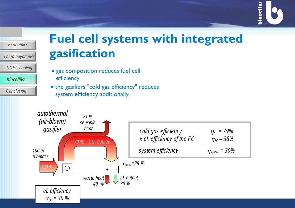
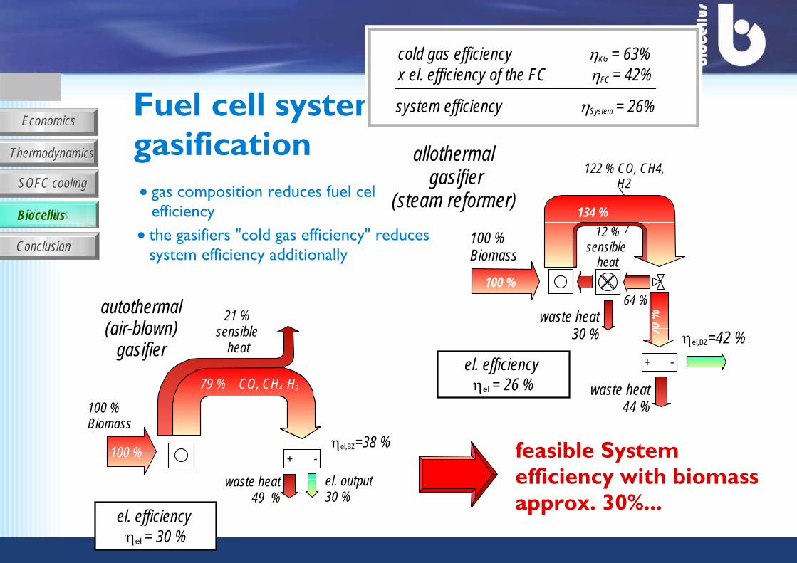
x el. efficiency of the FC ηFC = 38%
system efficiency ηSystem = 30%
the gasifiers "cold gas efficiency" reduces system efficiency additionally
cold gas efficiency ηKG = 79%
79 % CO, CH4 H2
waste heat49 %
100 %
100 % Biomass
autothermal(air-blown)
gasifier
21 % sensible
heat
79 % CO, CH4 H2
el. output30 %
+ -ηel,BZ=38 %
el. efficiency ηel = 30 %
Fuel cell systems with integrated gasification
gas composition reduces fuel cell efficiencyBiocellusBiocellus
EconomicsEconomics
ThermodynamicsThermodynamics
SOFC coolingSOFC cooling
Biocellus Biocellus
ConclusionConclusionthe gasifiers "cold gas efficiency" reduces system efficiency additionally
Fuel cell systems with integrated gasification
gas composition reduces fuel cell efficiency
79 % CO, CH4 H2
waste heat49 %
100 %
100 % Biomass
autothermal(air-blown)
gasifier
21 % sensible
heat
79 % CO, CH4 H2
el. output30 %
el. efficiency ηel = 30 %
+ -ηel,BZ=38 %
allothermal gasifier
(steam reformer)134 %
12 % sensible
heat
122 % CO, CH4, H2
100 %
100 % Biomass
waste heat 30 %
64 %
70 %
el. efficiency ηel = 26 % waste heat
44 %
+ -
ηel,BZ=42 %
x el. efficiency of the FC ηFC = 42%
system efficiency ηSystem = 26%
cold gas efficiency ηKG = 63%
feasible System efficiency with biomassapprox. 30%...
BiocellusBiocellus
EconomicsEconomics
ThermodynamicsThermodynamics
SOFC coolingSOFC cooling
Biocellus Biocellus
ConclusionConclusion
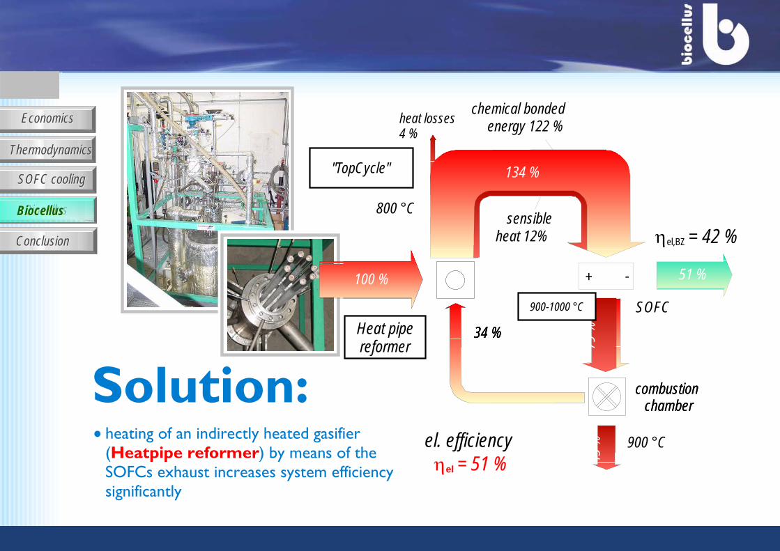
45 % 900 °C
79 %
900-1000 °C SOFC
el. efficiency ηel = 51 %
heating of an indirectly heated gasifier (Heatpipe reformer) by means of the SOFCs exhaust increases system efficiency significantly
Heat pipereformer
"TopCycle"
Solution:
51 %+ -
ηel,BZ = 42 %
134 %
chemical bondedenergy 122 %
sensible heat 12%
800 °C
heat losses 4 %
100 %
34 %
100 %
34 %
combustion chamber
100 %
34 %
combustion chamber
BiocellusBiocellus
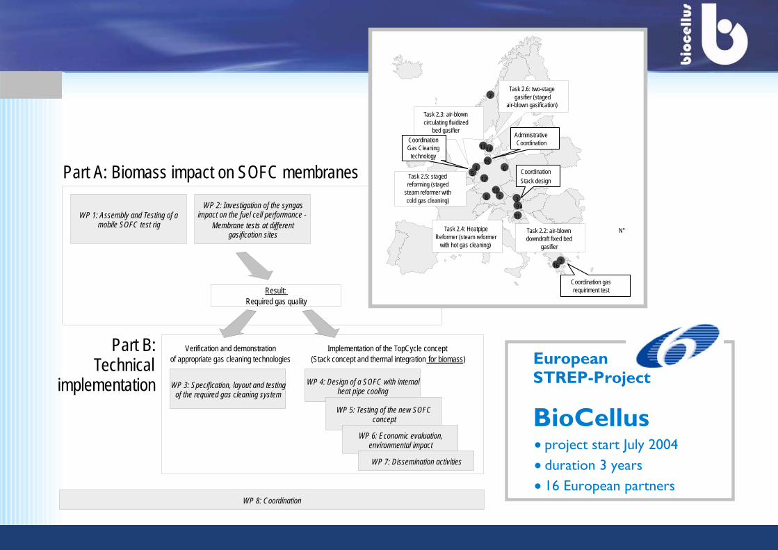
Part A: Biomass impact on SOFC membranes
WP 1: Assembly and Testing of a mobile SOFC test rig
WP 2: Investigation of the syngas impact on the fuel cell performance -
Membrane tests at different gasification sites
Result: Required gas quality
WP 3: Specification, layout and testing of the required gas cleaning system
WP 4: Design of a SOFC with internal heat pipe cooling
WP 5: Testing of the new SOFC concept
WP 6: Economic evaluation, environmental impact
WP 7: Dissemination activities
WP 8: Coordination
Verification and demonstration of appropriate gas cleaning technologies
Implementation of the TopCycle concept (Stack concept and thermal integration for biomass)
Part B:Technical
implementationEuropean STREP-Project
BioCellusproject start July 2004duration 3 years16 European partners
19
2
4
Task 2.3: air-blown circulating fluidized
bed gasifier
Task 2.2: air-blown downdraft fixed bed
gasifier
Task 2.6: two-stage gasifier (staged
air-blown gasification)
Task 2.4: Heatpipe Reformer (steam reformer
with hot gas cleaning)
Task 2.5: staged reforming (staged
steam reformer with cold gas cleaning)
Coordination gas requiriment test
CoordinationStack design
CoordinationGas Cleaning
technology
7
3
56
810
11
12
1314
15
16
Administrative Coordination
N°
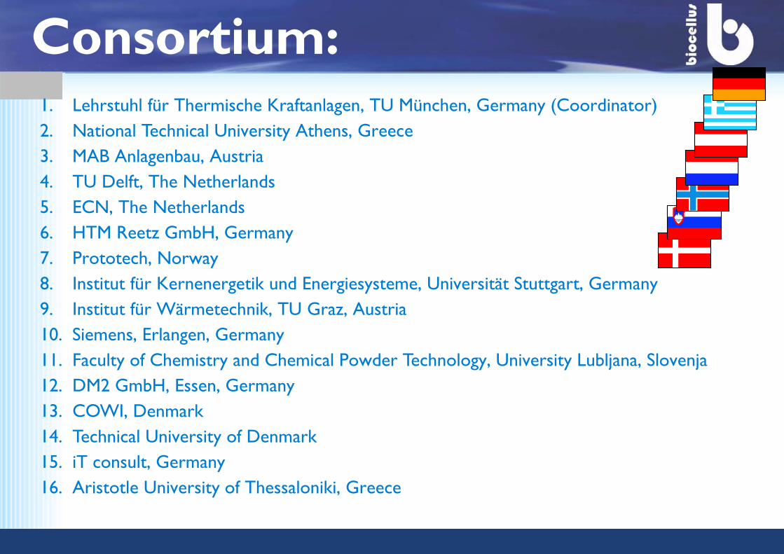
1. Lehrstuhl für Thermische Kraftanlagen, TU München, Germany (Coordinator)2. National Technical University Athens, Greece3. MAB Anlagenbau, Austria4. TU Delft, The Netherlands5. ECN, The Netherlands6. HTM Reetz GmbH, Germany7. Prototech, Norway8. Institut für Kernenergetik und Energiesysteme, Universität Stuttgart, Germany9. Institut für Wärmetechnik, TU Graz, Austria10. Siemens, Erlangen, Germany11. Faculty of Chemistry and Chemical Powder Technology, University Lubljana, Slovenja12. DM2 GmbH, Essen, Germany13. COWI, Denmark14. Technical University of Denmark15. iT consult, Germany16. Aristotle University of Thessaloniki, Greece
Consortium:
EconomicsEconomics
ThermodynamicsThermodynamics
SOFC coolingSOFC cooling
Biocellus Biocellus
ConclusionConclusion
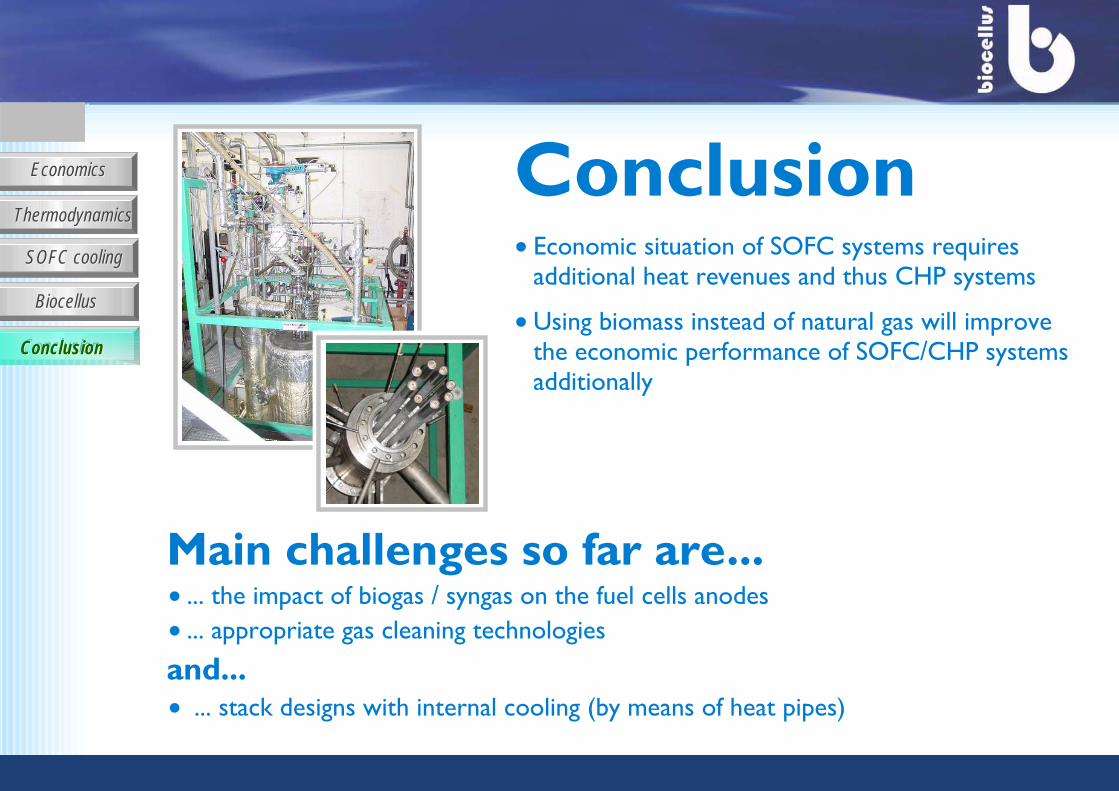
Economic situation of SOFC systems requires additional heat revenues and thus CHP systems
Using biomass instead of natural gas will improve the economic performance of SOFC/CHP systems additionally
Main challenges so far are... ... the impact of biogas / syngas on the fuel cells anodes ... appropriate gas cleaning technologies
and... ... stack designs with internal cooling (by means of heat pipes)
Conclusion
ConclusionConclusion
EconomicsEconomics
ThermodynamicsThermodynamics
SOFC coolingSOFC cooling
Biocellus Biocellus
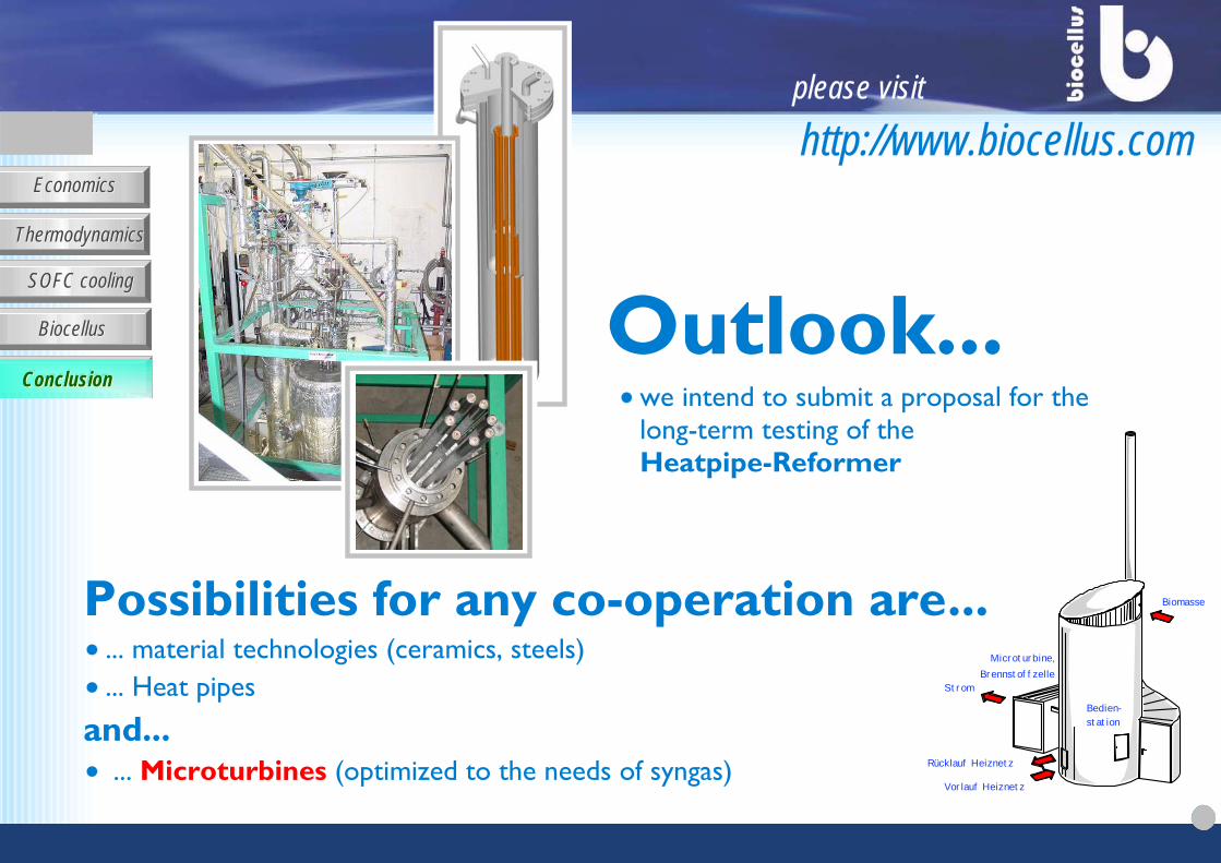
ConclusionConclusionwe intend to submit a proposal for the long-term testing of the Heatpipe-Reformer
Possibilities for any co-operation are... ... material technologies (ceramics, steels)... Heat pipes
and... ... Microturbines (optimized to the needs of syngas)
Outlook...ConclusionConclusionConclusionConclusion
Vorlauf Heiznetz
Rücklauf Heiznetz
Strom
Biomasse
Bedien-station
Microturbine,Brennstoffzelle
please visit
http://www.biocellus.com