Embed Size (px)
Citation preview

Acta Biomaterialia 9 (2013) 5273–5279
Contents lists available at SciVerse ScienceDirect
Acta Biomaterialia
journal homepage: www.elsevier .com/locate /actabiomat
Bio-inspired dental multilayers: Effects of layer architectureon the contact-induced deformation q
J. Du a,b, X. Niu c, N. Rahbar d, W. Soboyejo a,b,e,⇑a Department of Mechanical and Aerospace Engineering, Engineering Quadrangle Room D404B, Princeton University, Princeton, NJ 08544, USAb The Princeton Institute for the Science and Technology of Materials (PRISM), Princeton University, Princeton, NJ 08544, USAc Department of Mechanical and Biomedical Engineering, City University of Hong Kong, Kowloon, Hong Kongd Department of Civil and Environmental Engineering, University of Massachusetts Dartmouth, North Dartmouth, MA 02747, USAe Department of Materials Science and Engineering, African University of Science and Technology, Abuja, Federal Capital Territory, Nigeria
a r t i c l e i n f o a b s t r a c t
Article history:Available online 28 August 2012
Keywords:Bio-inspired designFunctionally graded multilayersFinite element methodSlow crack growth
1742-7061/$ - see front matter � 2012 Acta Materialhttp://dx.doi.org/10.1016/j.actbio.2012.08.034
q Part of the Special Issue ‘‘TMS 2012 BiologicalProfessor Nima Rahbar.⇑ Corresponding author at: Department of Mechan
ing, Engineering Quadrangle Room D404B, Princet08544, USA. Tel.: +1 609 258 5609; fax: +1 609 258 5
E-mail address: [email protected] (W. Sobo
The ceramic crown structures under occlusal contact are idealized as flat multilayered structures that aredeformed under Hertzian contact loading. Those multilayers consist of a crown-like ceramic top layer, anadhesive layer and the dentin-like substrate. Bio-inspired design of the adhesive layer proposed function-ally graded multilayers (FGM) that mimic the dentin–enamel junction in natural teeth. This paper exam-ines the effects of FGM layer architecture on the contact-induced deformation of bio-inspired dentalmultilayers. Finite element modeling was used to explore the effects of thickness and architecture onthe contact-induced stresses that are induced in bio-inspired dental multilayers. A layered nanocompos-ite structure was then fabricated by the sequential rolling of micro-scale nanocomposite materials withlocal moduli that increase from the side near the soft dentin-like polymer composite foundation to theside near the top ceramic layer. The loading rate dependence of the critical failure loads is shown tobe well predicted by a slow crack growth model, which integrates the actual mechanical properties thatare obtained from nanoindentation experiments.
� 2012 Acta Materialia Inc. Published by Elsevier Ltd. All rights reserved.
1. Introduction
Dental crowns generate over $2 billion in revenue each year,with 20% of crowns being all-ceramic units [1]. However, they con-tinue to fail at a rate of �3% per year [2]. For some restorations inwhich ceramics are used as the top layer, more than 20% of themfailed within the first 5 years of use [3]. This has stimulatedresearch efforts to develop ceramic crowns that are more resistantto cracking under occlusal contact. In most cases, the ceramiccrown structures are idealized as flat multilayered structures thatare deformed under Hertzian contact loading [4]. This often leadsto the pop-in of a subsurface radial crack due to the stressconcentration in the subsurface regime in the top ceramic layer[5], which is consistent with the major clinical mode, as reportedby Kelly [6].
ia Inc. Published by Elsevier Ltd. A
Materials’’, guest-edited by
ical and Aerospace Engineer-on University, Princeton, NJ877.
yejo).
The opportunity to reduce the stress concentrations (at thebottom of the top ceramic layer in crown structures) was inspiredby the nanoindentation measurements of Marshall et al. [7], whoshowed that the Young’s modulus varies from �70 GPa for enamelto �20 GPa for dentin. The variation in Young’s modulus across thedentin–enamel junction (DEJ) was also shown to be approximatelylinear. Inspired by the DEJ structure and the linear gradation in theYoung’s modulus of the DEJ, Huang et al. [5] modeled the Hertziancontact-induced stress concentrations. Their results showed thatthe bio-inspired functionally graded structure resulted in lowerstresses in the subsurface region of the top ceramic layer.Subsequent work by Niu et al. [8] and Rahbar et al. [9] also showedsimilar reductions in stress concentrations, which were laterconfirmed by the experimental work of Niu et al. [8].
In this paper, the design of the functionally graded multilayer(FGM) structure is optimized by simulating the effects of layerarchitecture by the finite element method (FEM). A processingmethod for the fabrication of bio-inspired, layered, nanocompositeFGM, is then presented. The variations in Young’s modulus acrossthe FGM are measured using nanoindentation techniques. Themeasured Young’s moduli are then incorporated into a slow crackgrowth (SCG) model for the prediction of pop-in loads. The predic-tions of pop-in loads, at different loading rates, are validated onbio-inspired FGM.
ll rights reserved.

Table 1Material properties of dental materials.
Layer Material Young’s modulus (GPa)
Top ceramic layer Zirconia 205Dental adhesive layer Rely X ARC 5Substrate Z100 18
Fig. 2. Maximum principal stresses in the subsurface region of the ceramic toplayer with or without FGM for different adhesive layer thicknesses.
5274 J. Du et al. / Acta Biomaterialia 9 (2013) 5273–5279
2. Design of FGM structure
2.1. Design of FGM thickness
The finite element simulations were carried out using the Aba-qus FEA software package (Dassault Systemes Simulia Corporation,Providence, RI) to model the stress distributions in the dental mul-tilayers. The simulations considered idealizations of bio-inspireddental multilayers, as well as a single join layer of dental adhesivematerial. Axisymmetric geometries were used to simplify the prob-lem, as shown in Fig. 1.
A 4-node linear axisymmetric quadrilateral element was usedin the mesh. In an effort to capture the high stress concentration,the mesh was dense in the regions near the axisymmetric axis ofthe model. The bottom of the substrate was fixed, while the axi-symmetric boundary condition was added on the axisymmetricaxis. A load of 100 N was applied to the Hertzian indenter, whichwas modeled as a rigid surface. The materials and the propertiesused in the simulation are listed in Table 1.
The FGM was modeled as 10 sublayers, with equal layer thick-nesses. The Young’s modulus was increased linearly from 18 GPa inthe foundation to 205 GPa in the top ceramic layer. Poisson’s ratiowas assumed to be 0.3 for all the materials. The geometry of thedental multilayered structure and the Hertzian indenter are pre-sented in Fig. 1. The thickness of the bonding layer was modeledto be 100, 250, 500 and 1000 lm, respectively.
The maximum principal stress at the subsurface center of thetop ceramic layer, which is associated with the major clinical fail-ure mode, the subsurface radial crack [6], in the dental multilayer,is presented in Fig. 2. Fig. 3 shows the effects of layer thickness onthe stress distribution in the dental multilayered structure, withand without FGM.
At each thickness, the maximum principal stress at thesubsurface center of the top ceramic layer was always lower inthe structures with FGM than in those without FGM. The stressconcentrations in the structures with FGM were also less severethan those in the structures without FGM. Since the FGM had a lar-ger overall Young’s modulus, hence greater stiffness, than the sin-gle dental adhesive layer, under Hertzian contact loading, the topceramic layer received better support from the stiffer FGM layerthan from the single dental adhesive layer. Also, the stress insidethe FGM was greater than that inside the single adhesive layer.This serves as a stress buffer to the top ceramic layer, when stressdissipates from the top ceramic layer into the FGM.
Fig. 1. FEM model of dental multilayer structure subjected to Hertzian contactloading.
As the thickness of the FGM increases, the stress concentrationin the structure is reduced, and the maximum principal stress inthe subsurface center of the top ceramic layer decreases. ThickerFGM provide better support to the top ceramic layer, because ithas higher stiffness. However, when the thickness of the singledental adhesive layer increases, the opposite is true.
2.2. Design of FGM architecture
This section presents the results of efforts to optimize the de-sign of the FGM structure by conducting finite element simulationsof the stress distribution in possible FGM structures. Finite elementsimulations were carried out using the same geometry and bound-ary conditions as shown in Fig. 1. The thickness of the FGM struc-tures was fixed at 100 lm, while the Young’s modulus distributionin the FGM was given by
EðxÞ ¼ Esubstrate þxt
� �nðEtop � EsubstrateÞ ð1aÞ
where x is the distance from the substrate, t is the thickness of theFGM, which in this case is 100 lm, and Etop and Esubstrate are theYoung’s moduli of the top ceramic layer and the substrate, respec-tively. Hence, the Young’s modulus of the FGM varies from that ofthe substrate to that of the top layer. When the exponent n is small,the change is more dramatic near the substrate; when it is big, theopposite is true. When n equals 1, the distribution is linear. As acomparison, the sinusoidal distribution was also simulated, where
EðxÞ ¼ Esubstrate þ1� cosðxp=tÞ
2ðEtop � EsubstrateÞ ð1bÞ
The variations in the Young’s moduli are presented in Fig. 4 forthe different types of modulus gradations.
The maximum principal stress at the subsurface center of thetop ceramic layer and the maximum value of the maximum princi-pal stress in the FGM are compared in Fig. 5. The sinusoidal distri-bution does not have particular advantages. Compared with thelinear distribution, it generates similar stresses in the top ceramiclayer, but much higher stresses in the FGM. For the power law dis-tributions, when the exponent increases, the stiffness of the FGM

Fig. 3. Maximum principal stress distributions in the dental multilayer structures with or without FGM for different adhesive layer thicknesses.
Fig. 4. Distributions of Young’s modulus in the FGM layer.
Fig. 5. Comparison of maximum principal stress inside the top ceramic layer andFGM layer with different distributions of Young’s modulus.
J. Du et al. / Acta Biomaterialia 9 (2013) 5273–5279 5275
decreases. Thus, the support it offers to the top ceramic layerdecreases.
The stresses in the top ceramic layer increase with increasingexponent n. Furthermore, the overall stress levels in the FGM alsodecrease with increasing exponent, although the distribution of thestress was more uniform for smaller exponents n. The combinedeffect of the decreasing stress dissipated into the FGM and less uni-form stress distribution with increasing exponent n gives the trendof the maximum value of the maximum principal stress in theFGM, as shown in Fig. 5.
If the fracture toughness of the FGM is greater than or compa-rable with that of the top ceramic layer, the power law distribution
with an exponent equal to or smaller than 1/5 could be the mostfavorable design, since it lowers the stresses in the top ceramiclayer. In contrast, if the FGM has lower fracture toughness thanthe ceramic layer, the power law distribution with an exponentP5 might be favored. This is because, although the stresses inthe ceramic layer increase, the FGM bears less stress. If the FGMhas fracture toughness comparable with that of the ceramic, a lin-ear distribution will be favored, since it results in comparable max-imum stresses in the FGM and the top ceramic layer.
3. Fabrication and characterization of dental multilayers
3.1. Fabrication of dental multilayer using nanocomposite materials
A 4-mm-thick 10 � 10 cm (4 � 4 inch) steel plate mold (Fig. 6a)was used for the fabrication of the bio-inspired FGM structure. Theplate contained four drilled holes that were sealed with Teflonrings, so that four samples could be fabricated at the same time.The holes had diameters of 9 mm. The substrate was a dentin-likesoft material, Z100 restorative (3M ESPE Dental Products, St. Paul,MN), which is a clinically used dental material. They were moldedin the holes and then cured with UV light for 40 s on both sides.The thickness of the fabricated Z100 substrate was �4 mm, thesame as that of the steel plate mold.
The FGM were produced using nanocomposite materials, a mix-ture of zirconia or alumina nanoparticles (Nanotek Instrument Inc.,Dayton, OH) and an epoxy matrix, EPO-TEK 301 (Epoxy TechnologyInc., Billerica, MA). The nanoparticles had an average diameter of�20 nm. After mixing, the nanocomposite material was depositedonto the steel plate mold with the substrate staying in it. A wire-wound wet-film applicator rod (Gardco, Pompano Beach, FL) wasthen used to spread the nanocomposite material across the steelplate, as shown in Fig. 6b.
When pulled across the steel plate, with a fluid film in front ofthe rod, the applicators could control the volume per unit area andthus the thickness of the fluid film. Since the size scale of the rodthread was much greater than the diameter of the nanoparticles,the applicator rod did not strain them out of the composite.
After each layer had been deposited and spread, the plate wascured in a vacuum oven at 65 �C for 1 h. The deposition and curingprocess was then repeated to build up the multilayered structures.From bottom to top, the functionally graded nanocomposite layerscontained 10 wt% zirconia, 20 wt% zirconia, . . ., 70 wt% zirconia,40 wt% alumina and 45 wt% alumina, respectively. The variationsin filler loading/type are intended to change the stiffness of thelayers.
The crown-like dental ceramic layer on top was fabricated froma medical grade 3 mol.% yttria-stabilized zirconia rod (YTZP; Saint-
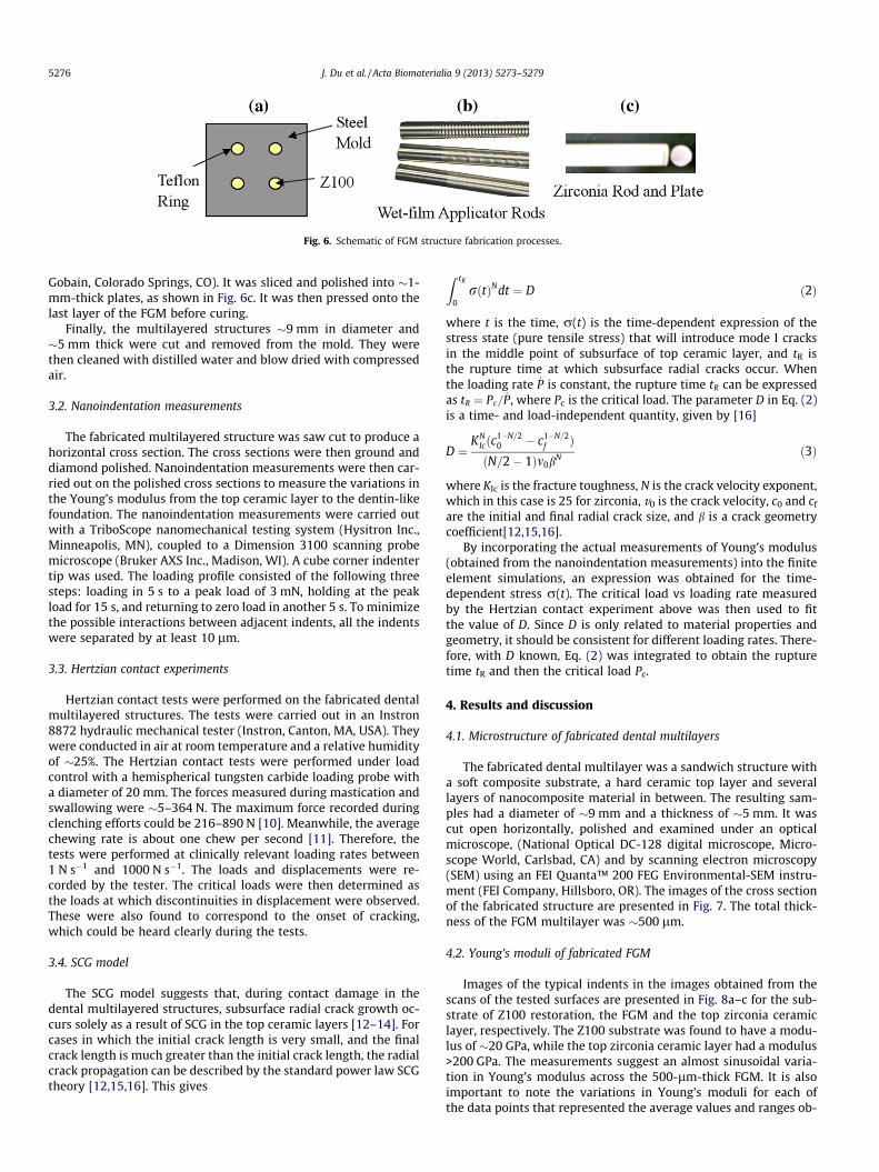
Fig. 6. Schematic of FGM structure fabrication processes.
5276 J. Du et al. / Acta Biomaterialia 9 (2013) 5273–5279
Gobain, Colorado Springs, CO). It was sliced and polished into �1-mm-thick plates, as shown in Fig. 6c. It was then pressed onto thelast layer of the FGM before curing.
Finally, the multilayered structures �9 mm in diameter and�5 mm thick were cut and removed from the mold. They werethen cleaned with distilled water and blow dried with compressedair.
3.2. Nanoindentation measurements
The fabricated multilayered structure was saw cut to produce ahorizontal cross section. The cross sections were then ground anddiamond polished. Nanoindentation measurements were then car-ried out on the polished cross sections to measure the variations inthe Young’s modulus from the top ceramic layer to the dentin-likefoundation. The nanoindentation measurements were carried outwith a TriboScope nanomechanical testing system (Hysitron Inc.,Minneapolis, MN), coupled to a Dimension 3100 scanning probemicroscope (Bruker AXS Inc., Madison, WI). A cube corner indentertip was used. The loading profile consisted of the following threesteps: loading in 5 s to a peak load of 3 mN, holding at the peakload for 15 s, and returning to zero load in another 5 s. To minimizethe possible interactions between adjacent indents, all the indentswere separated by at least 10 lm.
3.3. Hertzian contact experiments
Hertzian contact tests were performed on the fabricated dentalmultilayered structures. The tests were carried out in an Instron8872 hydraulic mechanical tester (Instron, Canton, MA, USA). Theywere conducted in air at room temperature and a relative humidityof �25%. The Hertzian contact tests were performed under loadcontrol with a hemispherical tungsten carbide loading probe witha diameter of 20 mm. The forces measured during mastication andswallowing were �5–364 N. The maximum force recorded duringclenching efforts could be 216–890 N [10]. Meanwhile, the averagechewing rate is about one chew per second [11]. Therefore, thetests were performed at clinically relevant loading rates between1 N s�1 and 1000 N s�1. The loads and displacements were re-corded by the tester. The critical loads were then determined asthe loads at which discontinuities in displacement were observed.These were also found to correspond to the onset of cracking,which could be heard clearly during the tests.
3.4. SCG model
The SCG model suggests that, during contact damage in thedental multilayered structures, subsurface radial crack growth oc-curs solely as a result of SCG in the top ceramic layers [12–14]. Forcases in which the initial crack length is very small, and the finalcrack length is much greater than the initial crack length, the radialcrack propagation can be described by the standard power law SCGtheory [12,15,16]. This gives
Z tR
0rðtÞNdt ¼ D ð2Þ
where t is the time, r(t) is the time-dependent expression of thestress state (pure tensile stress) that will introduce mode I cracksin the middle point of subsurface of top ceramic layer, and tR isthe rupture time at which subsurface radial cracks occur. Whenthe loading rate _P is constant, the rupture time tR can be expressedas tR ¼ Pc= _P, where Pc is the critical load. The parameter D in Eq. (2)is a time- and load-independent quantity, given by [16]
D ¼KN
Icðc1�N=20 � c1�N=2
f ÞðN=2� 1Þm0b
N ð3Þ
where KIc is the fracture toughness, N is the crack velocity exponent,which in this case is 25 for zirconia, v0 is the crack velocity, c0 and cf
are the initial and final radial crack size, and b is a crack geometrycoefficient[12,15,16].
By incorporating the actual measurements of Young’s modulus(obtained from the nanoindentation measurements) into the finiteelement simulations, an expression was obtained for the time-dependent stress r(t). The critical load vs loading rate measuredby the Hertzian contact experiment above was then used to fitthe value of D. Since D is only related to material properties andgeometry, it should be consistent for different loading rates. There-fore, with D known, Eq. (2) was integrated to obtain the rupturetime tR and then the critical load Pc.
4. Results and discussion
4.1. Microstructure of fabricated dental multilayers
The fabricated dental multilayer was a sandwich structure witha soft composite substrate, a hard ceramic top layer and severallayers of nanocomposite material in between. The resulting sam-ples had a diameter of �9 mm and a thickness of �5 mm. It wascut open horizontally, polished and examined under an opticalmicroscope, (National Optical DC-128 digital microscope, Micro-scope World, Carlsbad, CA) and by scanning electron microscopy(SEM) using an FEI Quanta™ 200 FEG Environmental-SEM instru-ment (FEI Company, Hillsboro, OR). The images of the cross sectionof the fabricated structure are presented in Fig. 7. The total thick-ness of the FGM multilayer was �500 lm.
4.2. Young’s moduli of fabricated FGM
Images of the typical indents in the images obtained from thescans of the tested surfaces are presented in Fig. 8a–c for the sub-strate of Z100 restoration, the FGM and the top zirconia ceramiclayer, respectively. The Z100 substrate was found to have a modu-lus of �20 GPa, while the top zirconia ceramic layer had a modulus>200 GPa. The measurements suggest an almost sinusoidal varia-tion in Young’s modulus across the 500-lm-thick FGM. It is alsoimportant to note the variations in Young’s moduli for each ofthe data points that represented the average values and ranges ob-

Fig. 7. Images of fabricated FGM structure cross section: (a) optical image; (b) SEM image.
Fig. 8. Nanoindentation measurement results of the fabricated FGM Structure. (a) A typical image after the test on the substrate. (b) A typical image after the test on the FGMlayer. (c) A typical image after the test on the top ceramic layer. (d) Distribution of Young’s moduli across the FGM layer.
J. Du et al. / Acta Biomaterialia 9 (2013) 5273–5279 5277
tained from three to six measurements. The variabilities in theYoung’s moduli are attributed partly to the clustering and non-uni-form particle distributions that were observed in the opticalmicroscopy images presented in Fig. 7. The images in Fig. 7 showthe graded composite layers across the FGM region.
The Young’s modulus of the Z100 substrate mimics the Young’smodulus of the remaining dentin in natural teeth. Similarly, thedimension of the foundation has been chosen to mimic the dimen-sion of remaining dentin in natural teeth. Hence, the compliance ofthe foundation should be similar to that of the remaining dentin innatural teeth. Also, when the thickness of the foundation is beyondits current thickness of 4 mm, the thickness of the foundation does
not have significant effects on the stress distribution at the bottomof the top ceramic layer.
4.3. Cracking modes and critical loads
Following the onset of pop-in, radial cracks were observed inthe optical microscope. These were sometimes even visible withthe naked eye. The tested samples were also cut open horizontallyand examined under an optical microscope, (National Optical DC-128 digital microscope, Microscope World, Carlsbad, CA). Fig. 9shows a typical subsurface radial crack observed in the ceramictop layer. Evidence of the interfacial cracking (between the top zir-

Fig. 9. Optical image of structure cross section after Hertzian contact test.
5278 J. Du et al. / Acta Biomaterialia 9 (2013) 5273–5279
conia ceramic layer and the FGM layer) is also apparent in this im-age (Fig. 9). The current results, therefore, suggest that pop-in wasassociated with radial crack propagation into the top zirconia cera-mic layer, along with partial interfacial cracking between the topzirconia ceramic layer and the FGM.
The critical loads obtained for the FGM structures are presentedunder Hertzian contact loading at different loading rates in Fig. 10.For each loading rate, between three and five samples were tested.The critical loads increased with increasing loading rates. For anygiven loading rate, the critical loads obtained for the FGM struc-tures were greater than those obtained for the conventional non-FGM flat layered structures [17]. The differences were greater forslower loading rates than they were for faster loading rates. Thesesuggest a loading rate dependence of the layer properties beyondthose considered in this paper.
The predictions of the critical load were made by inputting thestresses obtained from FEM simulation into the SCG model. The pre-dicted critical loads are plotted as hollow dots in Fig. 10. The time-and load-independent quantity D was fitted by the experimental re-sults at the minimum loading rate. The estimated value D was thensubstituted into Eq. (2) to obtain the critical time tR, which was usedto estimate the critical load Pc from tR
_P. The results show clearly thatthe predictions from the SCG model were comparable with thoseobtained from the experiments on the FGM structure.
4.4. Implications
The current results suggest that the model bio-inspired FGMstructures explored in this study could be used to engineer signif-
Fig. 10. Critical loads under different loading rates tested by Hertzian contactexperiments and predicted by the SCG model. The experimental results for non-FGM structures are from Ref. [17].
icant improvements (�20–40%) in the critical loads of dental mul-tilayers. Such FGM structures could be fabricated using layeringmethods that spread nanocomposite layers across the regions be-tween the top ceramic layer and the ‘‘dentin-like’’ Z100 compositelayer. However, there is a need to develop more controlled nano-composite layers across the FGM interlayers.
In any case, it is possible to envisage the development of func-tionally graded tapes, which could be integrated into the develop-ment of adhesive layers that can be used to attach ceramic crownsto ‘‘dentin-like’’ foundation layers. Such layered structures couldbe produced using nanocomposite layers that are similar to thoseexamined in this study. They can also be produced using infiltra-tion techniques [18] and a range of other methods [19] that areavailable for the processing of bio-inspired FGM. Further work isclearly needed to explore these possibilities. Basic studies of con-tact-induced failure are also needed to explore the effects of cyclicloading and environments that are relevant to occlusal contact.These are clearly some the challenges for future work.
5. Conclusions
This paper presented the results of a combined experimentaland theoretical/computational study of the effects of layer archi-tecture on the contact-induced fracture of bio-inspired, function-ally graded, dental multilayers. The salient conclusions arisingfrom this study are summarized below.
1. Finite element simulation of possible FGM architectures andconventional flat layered dental multilayers suggest that theFGM structures reduce the stresses in the top zirconia ceramiccrowns. Greater reductions in the stresses in the ceramiccrowns were observed when the gradients in the moduli ofthe FGM were higher near the ceramic layer.
2. The actual FGM structures fabricated using nanocomposite lay-ers of epoxy/ceramic mixtures had�20–40% higher critical pop-in loads than flat conventional dental multilayers without FGM.The measured pop-in loads obtained at different loading rates(that are relevant to occlusal activity in the oral cavity) were alsofound to be comparable with predictions from a SCG model.
3. The current results suggest that bio-inspired, functionallygraded, dental multilayers can be fabricated and incorporatedinto ‘‘tape’’ structures that can be used to reduce the top layerstresses in dental ceramic restorations. Further work is clearlyneeded to assess the clinical performance of such structuresunder cyclic loading conditions and environmental exposurerelevant to occlusal conditions.
Acknowledgements
This research is supported by the National Institute of Health(Grant No. P01DE10956) and the National Science Foundation(Grant No. 0231418). The authors are grateful to the programmanagers, Dr. Eleni Kouslevari (NIH) and Dr. Carmen Huber(NSF), for their encouragement and support. Appreciation is ex-tended to Professor Dianne Rekow and Professor Van Thompsonfor useful technical discussions. The authors are also grateful toDr. Gerald R. Poirier of PRISM for technical assistance with materialcharacterization.
Appendix A. Figures with essential colour discrimination
Certain figures in this article, particularly Figs. 1, 2, 5–9, aredifficult to interpret in black and white. The full colour imagescan be found in the on-line version, at http://dx.doi.org/10.1016/j.actbio.2012.08.034.

J. Du et al. / Acta Biomaterialia 9 (2013) 5273–5279 5279
References
[1] Rekow D, Thompson VP. Engineering long term clinical success of advancedceramic prostheses. J Mater Sci: Mater Med 2007;18:47–56.
[2] Burke FJT, Fleming GJP, Nathanson D, Marquis PM. Are adhesive technologiesneeded to support ceramics? An assessment of the current evidence. J AdhesDent 2002;4:7–22.
[3] Malament KA, Socransky SS. Survival of Dicor glass–ceramic dentalrestorations over 14 years: Part I. Survival of Dicor complete coveragerestorations and effect of internal surface acid etching, tooth position,gender, and age. J Prosthet Dent 1999;81:23–32.
[4] Shrotriya P, Wang R, Katsube N, Seghi R, Soboyejo WO. Contact damage inmodel dental multilayers: an investigation of the influence of indenter size. JMater Sci: Mater Med 2003;14:17–26.
[5] Huang M, Wang R, Thompson V, Rekow D, Soboyejo WO. Bioinspired design ofdental multilayers. J Mater Sci: Mater Med 2007;18:57–64.
[6] Kelly JR. Ceramics in restorative and prosthetic dentistry. Annu Rev Mater Sci1997;27:443–68.
[7] Marshall GW, Balooch M, Gallagher RR, Gansky SA, Marshall SJ. Mechanicalproperties of the dentinoenamel junction: AFM studies of nanohardness,elastic modulus, and fracture. J Biomed Mater Res 2001;54:87–95.
[8] Niu X, Rahbar N, Farias S, Soboyejo W. Bio-inspired design of dentalmultilayers: experiments and model. J Mech Behav Biomed Mater 2009;2:596–602.
[9] Rahbar N, Soboyejo WO. Design of functionally graded dental multilayers.Fatigue Fract Eng M 2011;34:887–97.
[10] Kelly JR. Clinically relevant approach to failure testing of all-ceramicrestorations. J Prosthet Dent 1999;81:652–61.
[11] Bourne MC. Compression rates in the mouth. J Texture Stud 1977;8:373–6.[12] Lee C-S, Kim DK, Sanchez J, Pedro M, Antonia P, Lawn BR. Rate effects in critical
loads for radial cracking in ceramic coatings. J Am Ceram Soc 2002;24:2019–24.
[13] Niu X, Soboyejo W. Effects of loading rate on the deformation and cracking ofdental multilayers: experiments and models. J Mater Res 2011;21:970–5.
[14] Zhang Y, Lawn BR, Rekow ED, Thompson VP. Effect of sandblasting on the long-term performance of dental ceramics. J Biomed Mater Res B: Appl Biomater2004;71:381–6.
[15] Dabbs TP, Lawn BR, Kelly PL. A dynamic fatigue study of soda-lime silicate andborosilicate glasses using small scale indentation flaws. Phys Chem Glasses1982;23:58–66.
[16] Huang M, Niu X, Soboyejo WO. Creep induced rate effects on radial cracks inmultilayered structures. J Mater Sci: Mater Med. 2007;18:65–9.
[17] Niu X, Yang Y, Soboyejo W. Contact deformation and cracking of zirconia/cement/foundation dental multilayers. Mater Sci Eng A: Struct Mater2008;485:517–23.
[18] Zhang Y, Ma L. Optimization of ceramic strength using elastic gradients. ActaMater 2009;57:2721–9.
[19] Ilschner B. Processing–microstructure–property relationships in gradedmaterials. J Mech Phys Solids 1996;44:647–56.