Embed Size (px)
Citation preview

Ford FEInstallation Manual
For Systems without A/C#14705 / #14725
Billet Specialties, Inc.500 Shawmut Avenue.La Grange, Illinois 60526Tech Line (708) 588-0505Fax (708) 588-7181
Required Tools & Materials
Anti-seize Compound
RTV Silicone
Permatex Hylomar® gasket dressing
Gasket Scraper
Scotch-Brite® Pad
3/8-16 Thread Chaser* & Holder*Thread chasers are available at your local parts store and are different froma thread cutting tap.
PLEASE READ ALL INSTRUCTIONS BEFORE INSTALLING ANY COMPONENTS OF THE TRU TRAC SERPENTINE SYSTEM
3/16” Allen
5/16” Allen
1/4” Allen
7/32” Allen
5/8” Box End Wrench
9/16” Box End Wrench
Socket Wrench & Extension
10mm 12pt. socket
12mm 12pt. socket
3/8” 12pt. Socket
Tech Line: 708.588.0505Fax: 708.588.7181
www.billetspecialties.com
TECH TIP:Billet Specialties recommends the use of Anti-Seize on allfasteners to prevent thread lock-up.
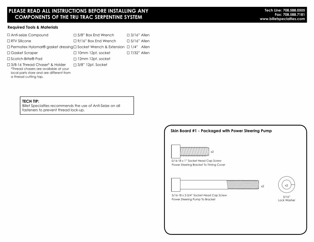
Skin Board #1 - Packaged with Power Steering Pump
5/16-18 x 2-3/4” Socket Head Cap ScrewPower Steering Pump To Bracket
Power Steering Bracket To Timing Cover
x2
5/16”Lock Washer
x2
5/16-18 x 1” Socket Head Cap Screw
x2

Other Hardware / GasketsGoodyear Poly-V Serpentine Belt - 63.50” #4060635 (with power steering)Goodyear Poly-V Serpentine Belt - 50.50” #4060505 (without power steering)
Skin Board #3 - Packaged In Main Box
8mm-1.25 x 25mm 12pt. Cap ScrewBridge Bracket To Alternator
Tensioner Pulley
x1
3/8-16 x 3/4” 12pt. Cap Screw
x1
3/8-16 x 1-3/4” 12pt. Cap ScrewIdler Pulleys
x3
3/8-16 x 1-3/4” Flat Head Cap ScrewBridge Bracket To Water Pump
x3
5/16-18 x 3/4” Socket Head Cap ScrewInto Backside Of Tensioner Thru Tensioner Bracket
x1
5/16-24 x 3/4” Socket Head Cap ScrewWater Pump Pulley
Crankshaft Pulley
x4
3/8-16 x 1” Socket Head Cap Screw
x3
3/8” Belleville Washer
x3
10mm x .5mmShim Washer
x2
10mm x 1mmShim Washer
x2
10mm-1.5 x 70mm 12pt. Cap ScrewBridge Bracket To Alternator
3/8-16 x 2” Hex Head Cap ScrewBackside Of Alternator Bracket
x1
x1
5/16-18 x 1” Flat Head Cap ScrewThru Bridge Bracket Into Tensioner
x2
3/8-16 x 2-1/2” Flat Head Cap ScrewThru Bridge Bracket To Tensioner Bracket
x1
3/8-16 x 1" Socket Head Cap ScrewAlternator Bracket
x1
3/8" Flat Washer
x1
13/16" Spacer
x1
www.billetspecialties.com7
www.billetspecialties.com
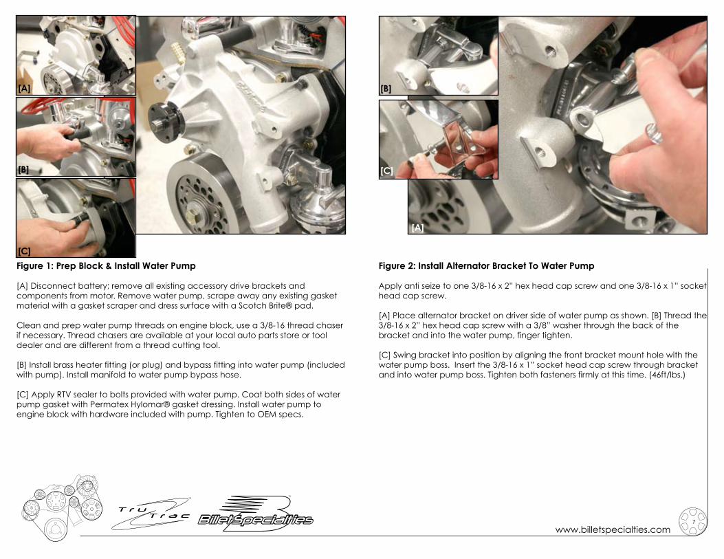
Figure 1: Prep Block & Install Water Pump
[A] Disconnect battery; remove all existing accessory drive brackets and components from motor. Remove water pump, scrape away any existing gasket material with a gasket scraper and dress surface with a Scotch Brite® pad.
Clean and prep water pump threads on engine block, use a 3/8-16 thread chaser if necessary. Thread chasers are available at your local auto parts store or tool dealer and are different from a thread cutting tool.
[B] Install brass heater fitting (or plug) and bypass fitting into water pump (included with pump). Install manifold to water pump bypass hose.
[C] Apply RTV sealer to bolts provided with water pump. Coat both sides of water pump gasket with Permatex Hylomar® gasket dressing. Install water pump to engine block with hardware included with pump. Tighten to OEM specs.
Figure 2: Install Alternator Bracket To Water Pump
Apply anti seize to one 3/8-16 x 2” hex head cap screw and one 3/8-16 x 1” socket head cap screw.
[A] Place alternator bracket on driver side of water pump as shown. [B] Thread the 3/8-16 x 2” hex head cap screw with a 3/8” washer through the back of the bracket and into the water pump, finger tighten.
[C] Swing bracket into position by aligning the front bracket mount hole with the water pump boss. Insert the 3/8-16 x 1” socket head cap screw through bracket and into water pump boss. Tighten both fasteners firmly at this time. (46ft/lbs.)
[A]
[B]
[C]
[B]
[C]
[A]
www.billetspecialties.com9
www.billetspecialties.com
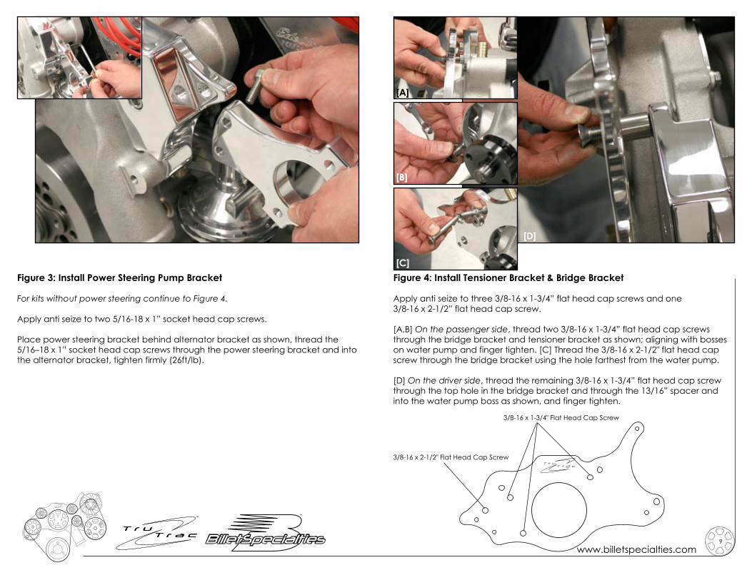
Figure 3: Install Power Steering Pump Bracket
For kits without power steering continue to Figure 4.
Apply anti seize to two 5/16-18 x 1” socket head cap screws.
Place power steering bracket behind alternator bracket as shown, thread the 5/16–18 x 1” socket head cap screws through the power steering bracket and into the alternator bracket, tighten firmly (26ft/lb).
Figure 4: Install Tensioner Bracket & Bridge Bracket
Apply anti seize to three 3/8-16 x 1-3/4” flat head cap screws and one 3/8-16 x 2-1/2” flat head cap screw.
[A,B] On the passenger side, thread two 3/8-16 x 1-3/4” flat head cap screws through the bridge bracket and tensioner bracket as shown; aligning with bosses on water pump and finger tighten. [C] Thread the 3/8-16 x 2-1/2" flat head cap screw through the bridge bracket using the hole farthest from the water pump.
[D] On the driver side, thread the remaining 3/8-16 x 1-3/4” flat head cap screw through the top hole in the bridge bracket and through the 13/16” spacer and into the water pump boss as shown, and finger tighten.
[A]
[B]
[C]
[D]
3/8-16 x 1-3/4" Flat Head Cap Screw
3/8-16 x 2-1/2" Flat Head Cap Screw

www.billetspecialties.com11
www.billetspecialties.com
Figure 5: Install Tensioner
Apply anti seize to two 5/16-18 x 1” flat head cap screws and one 5/16-18 x 3/4” socket head cap screw.
[A,B] Place tensioner between bridge bracket and tensioner bracket; thread the two 1” long flat head cap screws through the bridge bracket and into the tensioner and finger tighten.
[C] Finish installation by threading the 5/16-18 x 3/4” socket head cap screw through the tensioner bracket and into the tensioner as shown and tighten firmly.
[A]
[B]
[C]
Figure 6: Install Alternator
Apply anti seize to one 10mm-1.5 x 70mm 12pt. ARP cap screw and one 8mm-1.25 x 25mm 12pt. ARP cap screw.
[A] Place alternator between the alternator bracket and bridge bracket aligning the bottom bridge bracket hole with the lower alternator boss.
Thread the 10mm-1.5 x 70mm 12pt ARP cap screw through the bridge bracket, alternator and into the alternator bracket.
[B] Finish alternator installation by threading the 8mm-1.25 x 25mm 12pt ARP cap screw through the bridge bracket and into the top alternator boss.
TIGHTEN ALL FASTENERS AT THIS TIME including rear tensioner bolt. Leave lower alternator bolt loose and check to see if a shim needs to be added at this time.
The alternator mounting boss may vary in thickness
due to the polishing process. 10mm shim washers are
provided to shim alternator to bridge bracket (washers
may or may not be needed).
[B]
[A]

www.billetspecialties.com13
www.billetspecialties.com
Figure 7: Install Power Steering Pump With Pulley
For kits without power steering continue to Figure 8.
Apply anti seize to the two 5/16-18 x 2-3/4 socket head cap screws.
Place power steering pump to bracket and thread the two 5/16-18 x 2-3/4” socket head screws with 5/16" lock washers through the power steering pump bosses and into the power steering bracket and tighten firmly (26 ft/lbs). Figure 8: Install Crankshaft & Water Pump Pulleys
Apply anti seize to three 3/8-16 x 1” socket head cap screws and the four 5/16-24 x 3/4” socket head cap screws.
[A] Place the crank pulley on the damper, thread the three 3/8-16 x 1” socket head screws with belleville washers (cup facing pulley) through pulley and into damper, tighten firmly (46ft/lbs).
[B] Finish by placing the water pump pulley on water pump shaft, thread the four 5/16-24 x 3/4” socket head cap screws through the pulley and into the water pump flange, tighten firmly (28 ft/lbs).
[A]
[B]
www.billetspecialties.com15
www.billetspecialties.com
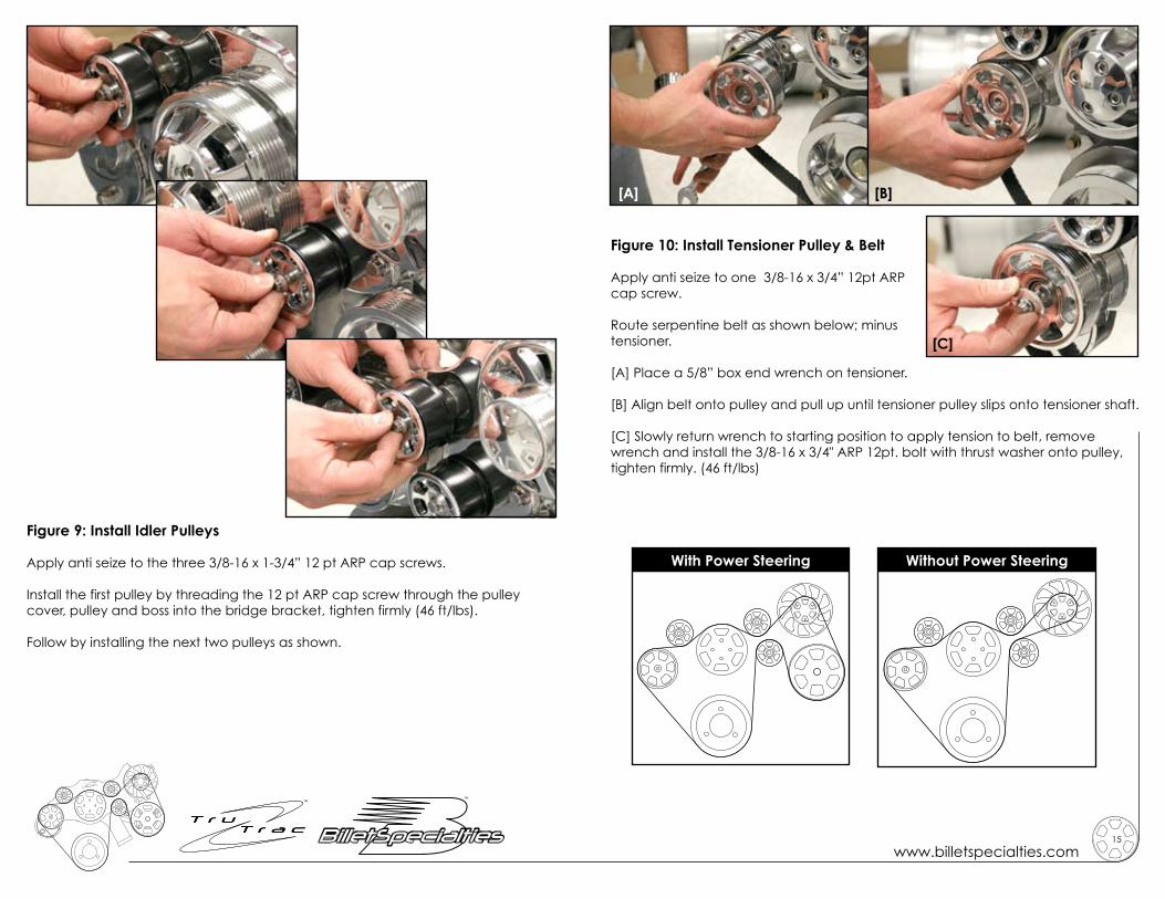
Figure 9: Install Idler Pulleys
Apply anti seize to the three 3/8-16 x 1-3/4” 12 pt ARP cap screws.
Install the first pulley by threading the 12 pt ARP cap screw through the pulley cover, pulley and boss into the bridge bracket, tighten firmly (46 ft/lbs).
Follow by installing the next two pulleys as shown.
Figure 10: Install Tensioner Pulley & Belt
Apply anti seize to one 3/8-16 x 3/4” 12pt ARP cap screw.
Route serpentine belt as shown below; minus tensioner.
[A] Place a 5/8” box end wrench on tensioner.
[B] Align belt onto pulley and pull up until tensioner pulley slips onto tensioner shaft.
[C] Slowly return wrench to starting position to apply tension to belt, remove wrench and install the 3/8-16 x 3/4" ARP 12pt. bolt with thrust washer onto pulley, tighten firmly. (46 ft/lbs)
With Power Steering Without Power Steering
[A] [B]
[C]

Billet Specialties, Inc.500 Shawmut Avenue
La Grange, Illinois 60526Tech Line 708.588.0505
Fax 708.588.7181www.billetspecialties.com
#14705 / #14725