Embed Size (px)
Citation preview

BilgMon488 Instruction Manual vU 1(30)
BRANNSTROM SWEDEN AB www.branntrom.se
INSTRUCTION MANUAL
BilgMon488
15 ppm Bilge Alarm

BilgMon488 Instruction Manual vU 2(30)
BRANNSTROM SWEDEN AB www.branntrom.se
1 TABLE OF CONTENTS 1 Table of Contents ........................................................................................................................2
2 Table of validity ...........................................................................................................................4
3 Introduction ................................................................................................................................5
4 Construction ...............................................................................................................................5
5 Operation....................................................................................................................................5
6 Caution .......................................................................................................................................5
7 Specification ...............................................................................................................................6
7.1 General ...............................................................................................................................6
7.2 Specific 115/230 V AC model ...............................................................................................7
7.3 Specific 24 V AC/DC model ..................................................................................................7
8 Installation ..................................................................................................................................8
8.1 Mechanical ..........................................................................................................................8
8.2 Tube arrangement ...............................................................................................................9
8.2.1 Alternative 1 ................................................................................................................9
8.2.2 Alternative 2 .............................................................................................................. 10
8.3 Electrical ............................................................................................................................ 11
8.3.1 115/230 VAC .............................................................................................................. 11
8.3.2 24V AC/DC ................................................................................................................. 11
9 Calibration ................................................................................................................................ 12
9.1 Schedule ............................................................................................................................ 12
9.2 Calibration certificate expiration........................................................................................ 12
9.3 Calibration check requirements ......................................................................................... 12
9.4 Sensor unit replacement .................................................................................................... 12
10 Operating Instructions ........................................................................................................... 13
10.1 Startup sequence............................................................................................................... 13
10.2 Main menu and indication LEDs ......................................................................................... 13
10.2.1 Main menu ................................................................................................................ 13
10.2.2 LEDs and indications .................................................................................................. 14
10.3 Menu system ..................................................................................................................... 15
10.4 Contrast adjustment .......................................................................................................... 16
10.5 Simulation ......................................................................................................................... 16
10.6 Force automatic stopping device activation ....................................................................... 18
10.7 Acknowledge alarm ........................................................................................................... 18
10.8 Information menu ............................................................................................................. 19

BilgMon488 Instruction Manual vU 3(30)
BRANNSTROM SWEDEN AB www.branntrom.se
10.8.1 Master info ................................................................................................................ 19
10.8.2 Sensor info ................................................................................................................. 19
10.9 Log .................................................................................................................................... 20
10.9.1 Log menu ................................................................................................................... 20
10.9.2 Step log...................................................................................................................... 20
10.10 Cleaning & test .............................................................................................................. 21
10.10.1 Clean cell (zero calibration) .................................................................................... 21
10.10.2 Check 40NTU cal (calibration check) ....................................................................... 21
10.10.3 Test outputs ........................................................................................................... 22
10.11 Settings ......................................................................................................................... 22
10.11.1 Valve settings (automatic stopping device)............................................................. 22
10.11.2 Alarm settings (bridge alarm) ................................................................................. 22
10.11.3 Autoflush feature (automatic freshwater cleaning) ................................................ 23
10.11.4 Set clock................................................................................................................. 23
10.11.5 Curro mode (Current output mode) ....................................................................... 24
10.11.6 Curro 20mA cal. (Calibration of current output) ..................................................... 24
11 Automatic stopping device test ............................................................................................. 25
11.1 While separator is active. .................................................................................................. 25
11.2 While separator is not active. ............................................................................................ 25
12 Response test ........................................................................................................................ 25
12.1 Step 1 ................................................................................................................................ 25
12.2 Step 2 ................................................................................................................................ 25
12.3 Alternative ........................................................................................................................ 25
13 Calibration check ................................................................................................................... 25
14 Log entries ............................................................................................................................ 26
15 Maintenance ......................................................................................................................... 27
16 Spare parts list ...................................................................................................................... 28
17 Troubleshooting .................................................................................................................... 30

BilgMon488 Instruction Manual vU 4(30)
BRANNSTROM SWEDEN AB www.branntrom.se
2 TABLE OF VALIDITY The following table describes the software and hardware versions on which this document was based.
Doc version Master SW ver. Master PCB ver. Sensor SW ver. Sensor PCB ver. vN A3 Bilgbas_H.1/
Bilgbaslv_C.1 Bilgemaster L.1
F Bilgemon H.1
vO, vP A4 Bilgbas_H.1/ Bilgbaslv_D.1 Bilgemaster L.1
B2 Bilgemon J.1
vQ, vR A4 Bilgbase_H.1/ Bilgbaslv_D.1/ Bilgbasco_A Bilgemaster L.1
B2 Bilgemon J.1
vS, vT, vQ A9 Bilgbase_I.1/ Bilgbaslv_D.1/ Bilgbasco_A Bilgemaster N.1
B5 Bilgemon J.1

BilgMon488 Instruction Manual vU 5(30)
BRANNSTROM SWEDEN AB www.branntrom.se
3 INTRODUCTION The BilgMon488 bilge alarm has been designed specifically for use in conjunction with 15 ppm oil-water separator units. BilgMon488 performance meets the requirements of the International Maritime Organisation specifications for 15 ppm bilge alarms contained in resolution MEPC. 107(49).
BilgMon488 is equipped with 2 adjustable alarms that are triggered when the oil-content of the processed sample exceeds the set limit (1 – 15 ppm, works-adjusted to 15ppm). Alarm outputs consist of relays and indicator LEDs. Additionally a 0(4) – 20 mA current output signal (corresponding to 0 – 30 ppm) is available to enable remote surveillance and recording of oil contents.
Downloading the operating log of BilgMon488 can be done through a USB-interface. This requires driver software and cables that can be supplied on demand.
4 CONSTRUCTION BilgMon488 consists of two main parts, the MASTER unit (housing with LCD, buttons and LEDs) and the SENSOR unit (housing with pipe fittings).
The MASTER unit contains all the electronics used for control and data storage of the bilge alarm. Mounted in the lid of the MASTER housing is the main memory containing the bilgealarm log.
The SENSOR unit contains electronics for measuring the sample stream. The SENSOR unit also holds the measurement calibration data. Communication with the MASTER unit is done wireless hence the SENSOR unit is hermetically sealed and shall not be opened.
5 OPERATION Optical sensors monitors the amount of light scattered and absorbed by the oil droplets in the sample stream. Sensor signals are processed by a microprocessor to produce a corresponding oil content (ppm) output. The output is communicated to the MASTER unit where it is processed. The MASTER unit takes action, such as alarm activation, logging etc., depending on the oil content and the separator signal.
Settings that affect the behaviour of the bilge alarm are described in detail in section 10 Operating Instructions.
Zero point calibration can be re-adjusted on site whereas full sensor calibration according to IMO-requirements is performed by manufacturer.
6 CAUTION The lid of the MASTER unit contains a small battery (watch battery). This battery enables the BilgMon488 to keep track of time and date (real time clock, RTC). Do NOT under any circumstance remove this battery as it will cause a unrecoverable error (“RTC check FAILED!!”).
Do NOT open the SENSOR unit as this will invalidate the calibration.
Do NOT open the MASTER unit when it is energized. Hazardous voltages are present inside.
BilgMon488 Instruction Manual vU 6(30)
BRANNSTROM SWEDEN AB www.branntrom.se
7 SPECIFICATION
7.1 GENERAL Measurement: Oil range: 0 – 30 ppm Resolution: 0.1 ppm Accuracy: According to IMO MEPC.107(49) Response time: < 3 sec
Alarms: Alarm 1 (valve control) delay: 0-10 sec user adjustable Alarm 2 (annunciation) delay: 0-600 sec user adjustable Alarm points 1 and 2: 1-15 ppm user adjustable Alarm hysteresis: 0.5 ppm (below alarm point)
Data storage and retrieval: Calibration storage: Stored in sensor housing. IMO required data: Stored in BilgMon488 main housing (sensor
housing may be replaced with data remaining on board).
IMO required data retrieval: Via LCD display, USB.
User interface: LCD display: 2x16 alphanumeric display Control: 4 button keypad
Environment: Ambient temperature range: According to IMO MEPC.107(49), (0-55°C) Enclosure ingress protection rating: IP65
Installation: Sample line inlet operating range: Recommended: 1-2 bar (200 – 300 l/h)
Maximum: 3 bar

BilgMon488 Instruction Manual vU 7(30)
BRANNSTROM SWEDEN AB www.branntrom.se
7.2 SPECIFIC 115/230 V AC MODEL Input/Output: Current output: 0 – 20 mA or 4 – 20 mA for 0 – 30 ppm Communications: USB serial communication (separate cable
and software) Alarm outputs: 2 x relays (0.25A) Clean water solenoid valve output: 1 x relay (0.5A, supply voltage) Switch input: 1 x switch input for separator status
System and supply: Supply: 1 A, 115 or 230 V AC, 50 – 60 Hz Power consumption electronics: 10 VA Power consumption solenoid: 18 VA
7.3 SPECIFIC 24 V AC/DC MODEL Input/Output: Current output: 0 – 20 mA or 4 – 20 mA for 0 – 30 ppm Communications: USB serial communication (separate cable
and software) Alarm outputs: 2 x relays (1A) Clean water solenoid valve output: 1 x relay (1A, supply voltage) Switch input: 1 x switch input for separator status
System and supply: Supply: 1.5 A, 24 V AC (50 – 60 Hz) or 24 V DC Power consumption electronics: 10 VA Power consumption solenoid: 18 VA
BilgMon488 Instruction Manual vU 8(30)
BRANNSTROM SWEDEN AB www.branntrom.se
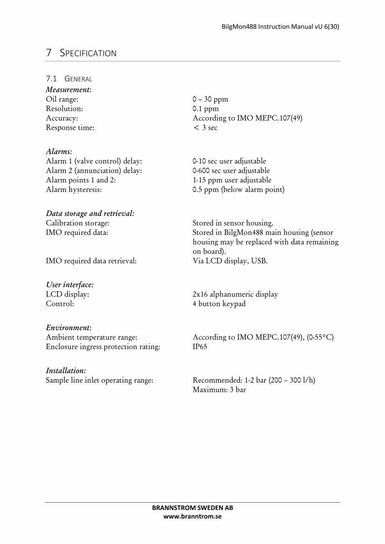
8 INSTALLATION NOTE: If drain valve is fitted. It should always be closed while separator is running.
8.1 MECHANICAL
Illustration 1: Mechanical installation

BilgMon488 Instruction Manual vU 9(30)
BRANNSTROM SWEDEN AB www.branntrom.se
8.2 TUBE ARRANGEMENT
8.2.1 Alternative 1
Illustration 2: Tube arrangement alt. 1
Fresh water flushing valve (cleaning solenoid in arrangement alt 1):
115/230 VAC model: There are two coils delivered with the BilgMon 488 one to be used with 115 VAC (marked 96 V) and one to be used with 230 VAC (marked 205 V). Be sure to install the proper one for the chosen voltage.
24 V AC/DC model: Only one coil delivered with this model (marked 24 V).
NOTE: Both models are equipped with a cable and rectifier (in connection plug for solenoid). The rectifier is necessary for all AC installations.
BilgMon488 Instruction Manual vU 10(30)
BRANNSTROM SWEDEN AB www.branntrom.se
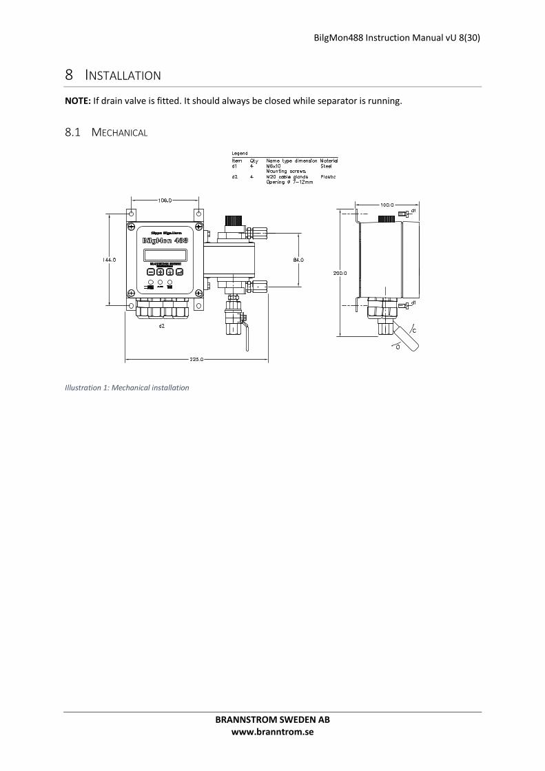
8.2.2 Alternative 2
Illustration 3: Tube arrangement alt. 2.

BilgMon488 Instruction Manual vU 11(30)
BRANNSTROM SWEDEN AB www.branntrom.se
8.3 ELECTRICAL
8.3.1 115/230 VAC
Illustration 4: 115/230 VAC electrical connections
8.3.2 24V AC/DC
Illustration 5: 24V AC/DC electrical connections

BilgMon488 Instruction Manual vU 12(30)
BRANNSTROM SWEDEN AB www.branntrom.se
9 CALIBRATION
9.1 SCHEDULE Two items needs to be addressed when setting up the maintenance schedule for the BilgMon488:
• The calibration certificate expiration of the SENSOR unit. • On occasions “calibration check” is required on a more regular basis.
The following two subchapters explain how to resolve these two items.
9.2 CALIBRATION CERTIFICATE EXPIRATION If the calibration certificate expires the SENSOR unit must be replaced.
The SENSOR of BilgMon488 is designed to be easily replaced by the crew, see 9.4 Sensor unit replacement. Replacement does not require any adjustments of the MASTER unit setup.
Each new SENSOR is accompanied with a new calibration certificate.
9.3 CALIBRATION CHECK REQUIREMENTS On occasion ships may be required to perform a “calibration check” on their units. This might be required to take place at shorter intervals than the calibration certificate validity period.
Calibration check can be achieved in the following ways:
• Checking calibration with a “Calibration Check Kit”. (Requires ordering a kit or consult a service agent)
• If the calibration check fails (calibration check values are not within limits), a new SENSOR must be installed.
9.4 SENSOR UNIT REPLACEMENT
Illustration 6: Sensor unit replacement procedure.
M a ste r U n it 2 x Fa ste n in g b o lts
Se n so r u n it
C o n ta c t su rfa c e s
R e m o vin g Se n so r U n it:
Lo o se n fa ste n in g b o lts .1 .G e n tly p u ll Se n so r U n it 2 .a w a y fro m M a ste r U n it.
M o u n tin g Se n so r U n it:
C le a n c o n ta c t su rfa c e s1 .u sin g w a te r a n d m ildd e te rg e n t.H o ld to g e th e r Se n so r 2 .U n it a n d M a ste r U n it.T ig h te n fa ste n in g b o lts.3 .
M a ste r U n it p re p a ra tio n s :
N o p re p a ra tio n s n e c e ssa ry .Se n so r U n it c o n ta in s a ll c a lib ra tio n d a ta .Sy ste m u p d a te s a u to m a tic a lly .

BilgMon488 Instruction Manual vU 13(30)
BRANNSTROM SWEDEN AB www.branntrom.se
10 OPERATING INSTRUCTIONS
10.1 STARTUP SEQUENCE When BilgMon488 is powered up the LCD display will show an initialization sequence.
Sequence: 1. Internal time reference (Real Time Clock, RTC) is
checked. 2. Information about unit setup is shown.
Explanation of example shown in 2.: BilgMon 488 - Product name. 00A9 - Software version of master unit. 1dec - PPM value display precision. CO - Current Output facility enabled. 15max - Maximum PPM level for alarm and automatic stopping device settings.
1.
2.
10.2 MAIN MENU AND INDICATION LEDS
10.2.1 Main menu After the initialization sequence is done the unit is ready for operation and the main menu will be shown:
The main menu shows date and time followed by PPM measurement and fresh water flushing valve selection.
Date and time is set at factory to UTC time (Coordinated Universal Time) and is displayed on the format:
YYMMDD hh:mm:ss (YY – year, MM – month, DD – day, hh – hour, mm – minutes, ss – seconds)
PPM measurement shows the latest measurement of oil content in parts per million as reported by the sensor unit.
Fresh water flushing valve selection shows the current selection (control output) to the optional fresh water flushing valve:
SPL – sample from separator selected
WTR – fresh water flushing input selected
BilgMon 488 00A9
1dec CO 15max
RTC check:
In progress!
140612 09:10:48
PPM=12.3 SPL
BilgMon488 Instruction Manual vU 14(30)
BRANNSTROM SWEDEN AB www.branntrom.se
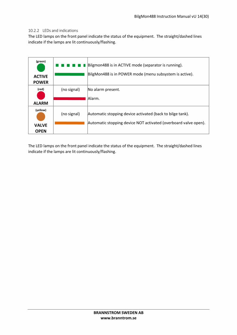
10.2.2 LEDs and indications The LED lamps on the front panel indicate the status of the equipment. The straight/dashed lines indicate if the lamps are lit continuously/flashing.
The LED lamps on the front panel indicate the status of the equipment. The straight/dashed lines indicate if the lamps are lit continuously/flashing.
(green)
ACTIVE POWER
Bilgmon488 is in ACTIVE mode (separator is running).
BilgMon488 is in POWER mode (menu subsystem is active).
(red)
ALARM
(no signal)
No alarm present.
Alarm.
(yellow)
VALVE OPEN
(no signal)
Automatic stopping device activated (back to bilge tank).
Automatic stopping device NOT activated (overboard valve open).

BilgMon488 Instruction Manual vU 15(30)
BRANNSTROM SWEDEN AB www.branntrom.se
10.3 MENU SYSTEM
Main
Info
Navigation using or
Navigation using or
Contrast
Simulation
Force automatic stopping device activation
1) Transition only possible when BilgMon488 is in POWER mode (see 10.2).
Master info
Sensor info
Log Step log
Cleaning & test Clean cell
Check 40NTU cal
Test outputs
Settings Valve
Alarm
Autoflush
Clock
Curro mode
Curro 20mA cal.
1)
1)
Adjust LCD contrast. See 10.4 Contrast adjustment
Simulate PPM measurement and separator status. See 10.5 Simulation
Temporarily activate automatic stopping device. See 10.6 Force automatic stopping device activation
Show information about MASTER unit. See 10.8.1 Master info
Show information about SENSOR unit. See 10.8.2 Sensor info
Step, search and download the log. See 0
Zero calibration of SENSOR unit. See 10.10.1 Clean cell (zero calibration)
Calibration check of SENSOR unit. See 10.10.2 Check 40NTU cal (calibration check)
Relays and input test menu. See 10.10.3 Test outputs
Set PPM limit and delay of automatic stopping device. See 10.11.1 Valve settings (automatic stopping device)
Set PPM limit and delay of alarm. See 10.11.2 Alarm settings (bridge alarm)
Set interval and duration of fresh water autoflush feature. See 10.11.3 Autoflush feature (automatic freshwater cleaning)
Adjust displayed time and date. See 10.11.4 Set clock
Select current output logic. See 10.11.5 Curro mode (Current output mode)
Calibrate 20mA output. See 10.11.6Curro 20mA cal. (Calibration of current output)
Navigation, see 10.4 - 10.7
Acknowledge alarm Acknowledge alarm. See 10.7 Acknowledge alarm

BilgMon488 Instruction Manual vU 16(30)
BRANNSTROM SWEDEN AB www.branntrom.se
10.4 CONTRAST ADJUSTMENT While in main menu press and hold .
With held press / to increment/decrement contrast setting by 10%.
10.5 SIMULATION The simulation menu lets user simulate the PPM input from the sensor unit as well as the separator status input state to verify that the installation of the unit is correct and that it responds as expected to different oil content measurements.
Simulated events will be stored in the log starting with a SIM_ON event and ended with a SIM_OFF event.
Enter simulation menu1: From main menu press and hold . The LCD will now show something similar to the picture on the right. Keep holding to stay in the simulation menu. Leave simulation menu: Release . Toggle the simulated separator status input: While still holding , press to toggle between separator on/off (SEP_ON/SEP_OFF shown in LCD). Increment/decrement simulated PPM value: While holding , press / to increment/decrement the simulated PPM value in steps of 1.0.
1 To enter the simulation menu the BilgMon488 needs to be in POWER mode. POWER mode is when the unit is powered but separator is not running (separator status input is open, see 8.3 Electrical).
Contrast: 010%
Simulation SPL
PPM>30.0 SEP_OFF

BilgMon488 Instruction Manual vU 17(30)
BRANNSTROM SWEDEN AB www.branntrom.se
Example of simulation with explanations:
1) Start in main menu with separator off (separator status input open).
ALARM LED – OFF VALVE LED – OFF (no discharge)
2) Hold (do not release until step #7 in this example). Automatic stopping device (ASD) is now active2 and the alarm is not active since the separator is not running.
ALARM LED – OFF VALVE LED – OFF (no discharge)
3) Press to simulate that the separator starts running (toggle to SEP_ON). ASD and alarm is now active since the PPM value is above 15 PPM and the separator is running.
ALARM LED – ON VALVE LED – OFF (no discharge)
4) Press repeatedly until PPM value is below 15.0 ppm (14.0 or lower value shown). ASD and alarm is now NOT active since the PPM value is below 15.0 ppm and the separator is running.
ALARM LED – OFF VALVE LED – ON (discharge)
5) Press repeatedly until PPM value is above 15.0 PPM (16.0 or higher value shown). ASD and alarm is now active since the separator is running and the PPM value is above 15.0 ppm.
ALARM LED – ON VALVE LED – OFF (no discharge)
6) Press to simulate that the separator stops running (toggle to SEP_OFF). ASD is now active and the alarm is not active since the separator is not running.
ALARM LED – ON VALVE LED – OFF (no discharge)
7) Release to return to main menu and end simulation.
ALARM LED – OFF VALVE LED – OFF (no discharge)
2 The VALVE LED and the automatic stopping device output has reversed logic. Hence when VALVE LED is lit the automatic stopping device is NOT active (overboard valve in discharge position) and vice versa.
140613 09:50:24
PPM>30.0 SPL
Simulation SPL
PPM>30.0 SEP_OFF
Simulation SPL
PPM>30.0 SEP_ON
Simulation SPL
PPM=14.0 SEP_ON
Simulation SPL
PPM=16.0 SEP_ON
Simulation SPL
PPM=16.0 SEP_OFF
140613 09:50:24
PPM>30.0 SPL

BilgMon488 Instruction Manual vU 18(30)
BRANNSTROM SWEDEN AB www.branntrom.se
10.6 FORCE AUTOMATIC STOPPING DEVICE ACTIVATION When the separator is running and the PPM value is below 15.0 ppm the automatic stopping device
can be temporarily activated by pressing and holding for approx. 2 sec.
After 10 seconds or on a press of BilgMon488 returns to normal operation.
10.7 ACKNOWLEDGE ALARM If separator is running (separator status input is closed, BilgMon488 in ACTIVE mode) and the PPM value goes above 15.0 ppm the unit will generate an alarm (alarm output terminal and LED). The
alarm can be acknowledged3 by pressing , or . This means that the alarm output terminal will be put in no alarm position but the alarm LED on the front will still be lit.
3 Automatic stopping device output cannot be acknowledged (only alarm output).
Force valve
close: 10s EXIT

BilgMon488 Instruction Manual vU 19(30)
BRANNSTROM SWEDEN AB www.branntrom.se
10.8 INFORMATION MENU The information submenus will display4 information about the MASTER and the SENSOR unit of BilgMon488 according to examples below:
10.8.1 Master info Cycle 0: Menu name.
Cycle 1: Serial number.
Cycle 2: Software version.
10.8.2 Sensor info Cycle 0: Menu name.
Cycle 1: Serial number.
Cycle 2: Software version.
Cycle 3: Factory calibration date.
Cycle 4: Calibration check date.
Cycle 5: SENSOR internal measurements (temperature, moisture, voltage etc.).
4 Information is continuously cycling (cycle 0, cycle 1, … , cycle n, cycle 0, …).
Master info
Master ID:
000A-4567
Master SW ver:
00A9
Sensor info
Sensor ID:
000B-4325
Sensor SW ver:
00B6
Sensor date:
140112 13:23:10
Cal. checked:
140427 10:43:12
T:25.3 Dry:60
V3:3.20 V03:.312

BilgMon488 Instruction Manual vU 20(30)
BRANNSTROM SWEDEN AB www.branntrom.se
10.9 LOG The log menu enables the user to search and step the IMO-regulated log of the BilgMon488 as well as download parts of or the entire log to file using the “BilgMon488 log download kit” (purchased separately).
10.9.1 Log menu The log menu shows the serial number stored in the log memory (normally same as the serial number of the master unit) and the number of log items currently stored in log. Press to enter the step log submenu.
10.9.2 Step log First row of step log menu shows type of event and second row shows date and time of occurance. Stepping: Navigate the log by pressing resp. to step forwards resp. backwards in the log.
Searching: Press and a small cursor will appear in under the
first entry in the date field. Press again to move the
cursor cyclically through the date/time fields. Use
and to increase/decrease the digit marked by the
cursor. Finish by holding for approx. 3 seconds. The display will now show the event that is closest in time to the date/time you entered.
Sending log via USB (download kit required): When leaving the step log menu ( ) user is asked to send log. If user answers no ( ) the unit returns to log menu. If user answers yes ( ) a follow up question is asked of how many items from the current and forward (in time) is to be sent 100, 500 or all. Select with /
and finalize by holding for approx. 3 seconds. LCD will show “sending log” while sending the log followed by “sent xxxx” when download is complete.
Log (000A:4567)
12343 entries
Log: PPM > 15
140601 23:12:33
Log: PPM > 15
140601 23:12:33
Sending log!
Sent 100!
Sending log!
Number of logs?
100 from current
Send log?
NO YES

BilgMon488 Instruction Manual vU 21(30)
BRANNSTROM SWEDEN AB www.branntrom.se
10.10 CLEANING & TEST
10.10.1 Clean cell (zero calibration) The clean cell menu provides the facility to zero calibrate the BilgMon488. It is also a useful tool for checking on dirt, layering and scratches on the sample tube inside the SENSOR unit.
Values shown range from 0% (clean, same values as factory calibration) to 100% (dirty) where 50% or below is required to perform zero calibration.
Press to start zero calibration process.
Toggle fresh water flushing valve to position WTR by pressing . Make shure the fresh water supply line is closed to prevent the liquid poured in to the SENSOR is not flushed out “backwards”. Unscrew the top cap of the SENSOR, clean thoroughly with mild detergent and soft , rinse and then pour in some clean airfree water. When/if zero value goes below 50%, ZERO is shown. Press enter to send zero calibration command to SENSOR unit.
If zero value does not go below 50% see 17 Troubleshooting.
10.10.2 Check 40NTU cal (calibration check) The check 40NTU cal lets the user perform a calibration check5 of the equipment. The calibration check makes shure that the units sensors are still in good condition and that the measurements of the oily water is still accurate.
Values range from 0% to 100% where 80% or above is considered acceptable (using calibration check kit mixture).
Press to start calibration check process.
Toggle fresh water flushing valve to position WTR by pressing . Make shure the fresh water supply line is closed to prevent the liquid poured in to the SENSOR is not flushed out “backwards”. Unscrew the top cap of the SENSOR and fill with the calibration check kit mixture. When/if cal. value goes above 80%, OK is shown. Press enter to set the calibration check date of the SENSOR unit.
If cal. value does not go above 80% see 17 Troubleshooting.
5 Doing a calibration check requires the “Bilgmon488 calibartion check kit” (bought separately).
Clean cell:
START
Zero value: 045%
WTR ZERO
Check 40NTU cal:
START
Cal value: 093%
WTR OK

BilgMon488 Instruction Manual vU 22(30)
BRANNSTROM SWEDEN AB www.branntrom.se
10.10.3 Test outputs The test outputs menu is used for testing the function of the separator status input as well as the alarm, automatic stopping device and fresh water flushing valve outputs (see 8.3 Electrical).
Press to enter test outputs menu.
ALM: Press to toggle the alarm output.6
VLV: Press to toggle the valve (automatic stopping device) output.6 WTR: Press to toggle the fresh water flushing valve output. O/C: In the upper right corner the status of the separator status input is displayed (O = Open, C = Closed).
10.11 SETTINGS
10.11.1 Valve settings (automatic stopping device) This menu allows the user to lower the detection level for valve output (automatic stopping device output). This might be useful in cases where lower limits than 15 ppm oil content is requested. There is also an adjustable delay (max 10 seconds) of the valve output. Factory defaults are 15 ppm limit, 0 sec delay.
Press to display the cursor (under leftmost digit). Press / to increase/decrease digit. Press to move cursor right one digit (cursor moves
cyclically from left to right, one step per ). Save setting by holding until cursor disappears. Abort input at any time by pressing (cursor disappears, previous values are filled in).
10.11.2 Alarm settings (bridge alarm) This menu lets the user set the parameters for the alarm output.
Press to display the cursor (under leftmost digit). Press / to increase/decrease digit.
6 Alarm and Valve output can only be activated 10 seconds at a time and will always generate an active alarm output. Seconds countdown is shown on LCD.
Test outputs:
START
ALM VLV WTR C
OFF 08 OFF EXIT
Valve settings
ppm:15.0 t:000s
Alarm settings
ppm:15.0 t:000s
BilgMon488 Instruction Manual vU 23(30)
BRANNSTROM SWEDEN AB www.branntrom.se
Press to move cursor right one digit (cursor moves
cyclically from left to right, one step per ). Save setting by holding until cursor disappears. Abort input at any time by pressing (cursor disappears, previous values are filled in).
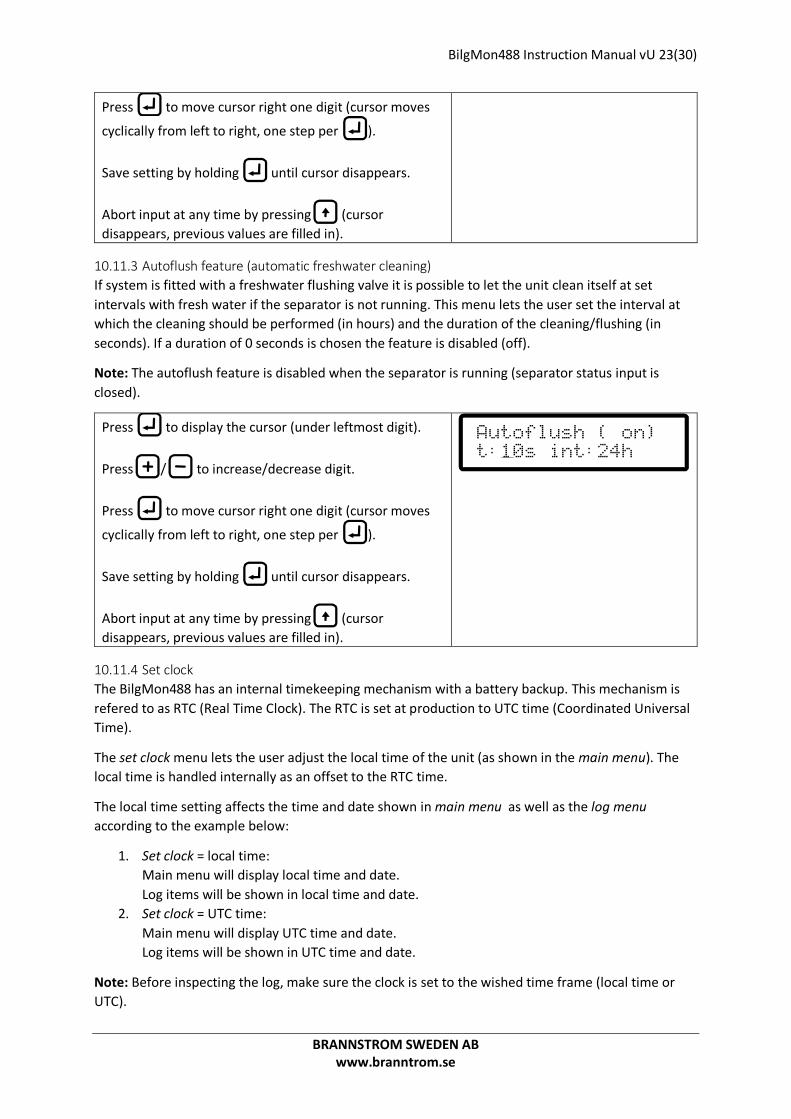
10.11.3 Autoflush feature (automatic freshwater cleaning) If system is fitted with a freshwater flushing valve it is possible to let the unit clean itself at set intervals with fresh water if the separator is not running. This menu lets the user set the interval at which the cleaning should be performed (in hours) and the duration of the cleaning/flushing (in seconds). If a duration of 0 seconds is chosen the feature is disabled (off).
Note: The autoflush feature is disabled when the separator is running (separator status input is closed).
Press to display the cursor (under leftmost digit). Press / to increase/decrease digit. Press to move cursor right one digit (cursor moves
cyclically from left to right, one step per ). Save setting by holding until cursor disappears. Abort input at any time by pressing (cursor disappears, previous values are filled in).
10.11.4 Set clock The BilgMon488 has an internal timekeeping mechanism with a battery backup. This mechanism is refered to as RTC (Real Time Clock). The RTC is set at production to UTC time (Coordinated Universal Time).
The set clock menu lets the user adjust the local time of the unit (as shown in the main menu). The local time is handled internally as an offset to the RTC time.
The local time setting affects the time and date shown in main menu as well as the log menu according to the example below:
1. Set clock = local time: Main menu will display local time and date. Log items will be shown in local time and date.
2. Set clock = UTC time: Main menu will display UTC time and date. Log items will be shown in UTC time and date.
Note: Before inspecting the log, make sure the clock is set to the wished time frame (local time or UTC).
Autoflush ( on)
t:10s int:24h

BilgMon488 Instruction Manual vU 24(30)
BRANNSTROM SWEDEN AB www.branntrom.se
Press to display the cursor (under leftmost digit). Press / to increase/decrease digit. Press to move cursor right one digit (cursor moves
cyclically from left to right, one step per ). Save setting by holding until cursor disappears. Abort input at any time by pressing (cursor disappears, previous values are filled in).
10.11.5 Curro mode (Current output mode) The current output of BilgMon488 can be altered between two modes, 0-20 mA and 4-20 mA. These intervals correspond to 0-30 ppm oil content as displayed in the main menu.
The current output terminal can be used for external printing/logging of the momentary oil content measurement.
Press to display the cursor. Press / to alter mode. Save setting by holding until cursor disappears. Abort input at any time by pressing (cursor disappears, previous values are filled in).
10.11.6 Curro 20mA cal. (Calibration of current output) If current output corresponds badly to the displayed oil content the current output can be calibrated in this manu (one point calibration).
When entering this menu the BilgMon488 will try to output 20 mA (corresponding to 30 ppm). Measure the output with ampere meter. If reading is not correct adjust the output according to below instruction.
Press to display the cursor. Press / to increase/decrease the current output signal (adjust to 20 mA output). Save setting by holding until cursor disappears. Abort input at any time by pressing (cursor disappears, previous values are filled in).
Set clock:
140327 11:34:05
Curro mode
0 to 20 mA
Curro 20mA cal.
59100

BilgMon488 Instruction Manual vU 25(30)
BRANNSTROM SWEDEN AB www.branntrom.se
11 AUTOMATIC STOPPING DEVICE TEST
11.1 WHILE SEPARATOR IS ACTIVE. If the separator is active and the automatic stopping device is not activated (overboard valve open) it is possible to force the activation of the stopping device for a short period of time (10 s) by holding
in the main menu. This allows testing that the automatic is correctly connected.
11.2 WHILE SEPARATOR IS NOT ACTIVE. To check that the automatic stopping device is correctly connected see 12.2 Step 2.
12 RESPONSE TEST
12.1 STEP 1 To check that the sensor responds to objects in the measuring path unscrew the cleaning cap (top of SENSOR housing) and insert a long plastic rod or something similar into the measuring path. Do not use anything that might scratch or in other ways damage the glass tube inside the SENSOR housing (as for example screwdrivers). If the sensor is working properly the display should read “PPM>30.0” (main menu). Note that the air-detection feature of the SENSOR requires the glass tube to be filled with water during this test for it to work.
12.2 STEP 2 Testing alarms and valves are done in simulation mode (see 10.5 Simulation) or in the test outputs submenu of the cleaning & test menu (see 10.10.3 Test outputs) since this doesn't require opening the MASTER housing.
12.3 ALTERNATIVE To make step 1 of the response test affect alarms and valves the apparatus needs to be active. Bilgmon 488 is activated (flashing green led) when in main menu and the separator input signal is active. Activation can be done by strapping connections 10 and 11 (see 8.3 Electrical). This method is not recommended since there is an obvious risk of forgetting the strap and that it requires opening the MASTER unit.
13 CALIBRATION CHECK Doing a calibration check requires the “Bilgmon488 calibartion check kit” (bought separately). This kit also contain detailed information on procedures and mixtures used in the calibration check procedure.
See sections 10.10.1 Clean cell (zero calibration) and 10.10.2 Check 40NTU cal (calibration check).
Note: Complete calibration can only be performed by factory. Calibration check will perform a zero calibration and a check of the units calibration values compared to those set at production.

BilgMon488 Instruction Manual vU 26(30)
BRANNSTROM SWEDEN AB www.branntrom.se
14 LOG ENTRIES Type Example Explanation
POWER ON
Power was turned on at given date and time (yymmdd hh:mm:ss).
POWER OFF
Power was turned off.
SEP ON
Separator signal input turned from not activated to activated.
SEP OFF
Separator signal input turned from activated to not activated.
PPM ABOVE
Measured oil content went from below set valve ppm level to above (in example valve setting is 15 ppm). Automatic stopping device activated.
PPM BELOW
Measured oil content went from above set valve ppm level to below (in example valve setting is 15 ppm). Automatic stopping device deactivated.
PPM AVG
PPM average when below set valve ppm limit since latest SEP ON signal or latest PPM BELOW event.
PPM SET
Valve ppm level setting was changed to indicated value (in example to 5 ppm).
SIM ON
Simulation was turned on.
SIM OFF
Simulation was turned off.
TIME SET
Time offset was adjusted (in settings menu). Offset to BilgMon builtin realtime clock in hours, minutes and seconds is shown.
RTC SET
BilgMon builtin realtime clock was set (logged once at factory).
Log: POWER ON
060102 11:36:32
Log: POWER OFF
060102 14:06:10
Log: SEP ON
060102 12:10:12
Log: SEP OFF
060102 12:23:34
Log: PPM > 15
060102 12:15:13
Log: PPM < 15
060102 12:17:42
Log: PPM AVG 04
051021 09:47:29
Log: PPM SET 05
060102 13:10:07
Log: SIM_ON
060102 12:09:50
Log: SIM_OFF
060102 12:24:19
Log: TIME SET
+0:59:46
Log: RTC SET
051021 09:47:29

BilgMon488 Instruction Manual vU 27(30)
BRANNSTROM SWEDEN AB www.branntrom.se
15 MAINTENANCE The BilgMon488 can be set to autoflush (see 10.11.3 Autoflush feature (automatic freshwater cleaning)). This means that the sensor tube is flushed with clean water at durations and intervals as set in the settings menu. Autoflush is only active when in main menu and BilgeMon488 is not active.
Cleaning the measurement unit should be done using a soft bottle-brush and mild detergent. Note that there is a glass tube inside the SENSOR unit so don't use anything that might scratch or damage the glass (i.e. metal objects). If the glass tube is layered with rust or similar try using low concentrated acid (for example hydrochloric acid). Rinse well and make sure you protect your eyes, skin and airways if using acidic substances.

BilgMon488 Instruction Manual vU 28(30)
BRANNSTROM SWEDEN AB www.branntrom.se
16 SPARE PARTS LIST
1 See Illustration 7: General assembly/Spare parts.
Pos1 Description Order nr. 1 Sensor unit BM201001A-1 2 Master unit BM201001A-2 3 Fresh water flushing valve assembly BM201001A-3 4 Calibration check kit, comprising:
• Cleaning brush • Syringe • Bottle 500 ml with lid • Bottle 50 ml, calibration check liquid. • Instructions • Cleaning cap
BM201001A-4

BilgMon488 Instruction Manual vU 29(30)
BRANNSTROM SWEDEN AB www.branntrom.se
Illustration 7: General assembly/Spare parts

BilgMon488 Instruction Manual vU 30(30)
BRANNSTROM SWEDEN AB www.branntrom.se
17 TROUBLESHOOTING Symptom Possible reason(s) Servicing
BilgMon488 is switched on but LCD remains blank.
Power supply is erroneous. Check connections internally, externally and power supply voltages.
LCD monitor is broken. Order replacement part. Automatic fuses blown. Disconnect externals that
might have caused the short-circuit (f.ex. fresh water flushing valve). Wait until fuses have cooled down power up the unit again.
Oil content measurement (ppm value) remains high.
Dirty senor tube. Clean the sensor tube and performe zero calibration (see 10.10.1 Clean cell (zero calibration))
Air is present in sample. Correct cause of air presence. Clean the sensor tube and performe zero calibration calibration (see 10.10.1 Clean cell (zero calibration))
Excessive contaminates present in sample (rust, bacteria etc …)
Correct cause of contamination. Clean the sensor tube and performe zero calibration calibration (see 10.10.1 Clean cell (zero calibration))
LCD display indication: MEMORY ERROR, MEMORY WRITE ERROR, ERASE ERROR
Memory malfunction. Order replacement part. Memorychip not present. Order replacement part.
LCD display indication: Lost sensor com!
Dirty or damaged MASTER-SENSOR contact area.
Part MASTER and SENSOR units. Clean contact surface with mild detergent.
LCD display indication: RTC check: FAILED!
Internal time reference stopped/malfunctioning.
Order replacement part.