Embed Size (px)
Citation preview

BIG-IP® Solutions Guide
version 4.2
MAN-0043-01

Product VersionThis manual applies to version 4.2 of the BIG-IP® product family.
Legal Notices
CopyrightInformation in this document is subject to change without notice.© 2002 Dell Computer Corporation. All rights reserved.
Reproduction in any manner whatsoever without the written permission of Dell Computer Corporation is strictly forbidden.
Trademarks used in this text: Dell and PowerEdge are trademarks of Dell Computer Corporation.
Other trademarks and trade names may be used in this document to refer to either the entities claiming the marks and names or their products. Dell Computer Corporation disclaims any proprietary interest in trademarks and trade names other than its own.
Copyright 1997-2002, F5 Networks, Inc. All rights reserved.
F5 Networks, Inc. (F5) believes the information it furnishes to be accurate and reliable. However, F5 assumes no responsibility for the use of this information, nor any infringement of patents or other rights of third parties which may result from its use. No license is granted by implication or otherwise under any patent, copyright, or other intellectual property right of F5 except as specifically described herein. F5 reserves the right to change specifications at any time without notice.
TrademarksF5 and the F5 logo, F5 Networks, BIG-IP, 3-DNS, GLOBAL-SITE, SEE-IT, and EDGE-FX are registered trademarks of F5 Networks, Inc. FireGuard, iControl, Internet Control Architecture, and IP Application Switch are trademarks of F5 Networks, Inc. In Japan, the F5 logo is trademark number 4386949, BIG-IP is trademark number 4435184, 3-DNS is trademark number 4435185, and SEE-IT is trademark number 4394516. All other product and company names are registered trademarks or trademarks of their respective holders.
Export Regulation NoticeThis product may include cryptographic software. Under the Export Administration Act, the United States government may consider it a criminal offense to export this product from the United States.
Export WarningThis is a Class A product. In a domestic environment this product may cause radio interference in which case the user may be required to take adequate measures.
FCC ComplianceThis equipment generates, uses, and may emit radio frequency energy. The equipment has been type tested and found to comply with the limits for a Class A digital device pursuant to Part 15 of FCC rules, which are designed to provide reasonable protection against such radio frequency interference.
Operation of this equipment in a residential area may cause interference, in which case the user at his own expense will be required to take whatever measures may be required to correct the interference.
Any modifications to this device, unless expressly approved by the manufacturer, can void the user's authority to operate this equipment under part 15 of the FCC rules.
Canadian Regulatory ComplianceThis class A digital apparatus complies with Canadian I CES-003.
ii

Standards ComplianceThe product conforms to ANSI/UL Std 1950 and Certified to CAN/CSA Std. C22.2 No. 950.
AcknowledgmentsThis product includes software developed by the University of California, Berkeley and its contributors.
This product includes software developed by the Computer Systems Engineering Group at the Lawrence Berkeley Laboratory.
This product includes software developed by the NetBSD Foundation, Inc. and its contributors.
This product includes software developed by Christopher G. Demetriou for the NetBSD Project.
This product includes software developed by Adam Glass.
This product includes software developed by Christian E. Hopps.
This product includes software developed by Dean Huxley.
This product includes software developed by John Kohl.
This product includes software developed by Paul Kranenburg.
This product includes software developed by Terrence R. Lambert.
This product includes software developed by Philip A. Nelson.
This product includes software developed by Herb Peyerl.
This product includes software developed by Jochen Pohl for the NetBSD Project.
This product includes software developed by Chris Provenzano.
This product includes software developed by Theo de Raadt.
This product includes software developed by David Muir Sharnoff.
This product includes software developed by SigmaSoft, Th. Lockert.
This product includes software developed for the NetBSD Project by Jason R. Thorpe.
This product includes software developed by Jason R. Thorpe for And Communications, http://www.and.com.
This product includes software developed for the NetBSD Project by Frank Van der Linden.
This product includes software developed for the NetBSD Project by John M. Vinopal.
This product includes software developed by Christos Zoulas.
This product includes software developed by Charles Hannum.
This product includes software developed by Charles Hannum, by the University of Vermont and State Agricultural College and Garrett A. Wollman, by William F. Jolitz, and by the University of California, Berkeley, Lawrence Berkeley Laboratory, and its contributors.
This product includes software developed by the University of Vermont and State Agricultural College and Garrett A. Wollman.
In the following statement, "This software" refers to the Mitsumi CD-ROM driver: This software was developed by Holger Veit and Brian Moore for use with "386BSD" and similar operating systems. "Similar operating systems" includes mainly non-profit oriented systems for research and education, including but not restricted to "NetBSD," "FreeBSD," "Mach" (by CMU).
In the following statement, "This software" refers to the parallel port driver: This software is a component of "386BSD" developed by William F. Jolitz, TeleMuse.
This product includes software developed by the Apache Group for use in the Apache HTTP server project (http://www.apache.org/).
This product includes software developed by Darren Reed. (© 1993-1998 by Darren Reed).
This product includes software licensed from Richard H. Porter under the GNU Library General Public License (© 1998, Red Hat Software), www.gnu.org/copyleft/lgpl.html.
This product includes the standard version of Perl software licensed under the Perl Artistic License (© 1997, 1998 Tom Christiansen and Nathan Torkington). All rights reserved. You may find the most current standard version of Perl at http://www.perl.com.
BIG-IP® Solutions Guide iii

iv

Table of Contents

Table of Contents
IntroductionIMPORTANT HARDWARE INFORMATION .................................................................Intro-1Getting started .........................................................................................................................Intro-1
Choosing a configuration tool .....................................................................................Intro-1Using the Administrator Kit ..................................................................................................Intro-2
Stylistic conventions .......................................................................................................Intro-3Finding additional help and technical support resources .......................................Intro-4
What’s new in version 4.2 .....................................................................................................Intro-5Support for the Controller and IP Application Switch platforms ........................Intro-5The Setup utility ..............................................................................................................Intro-5Enhanced pools support ................................................................................................Intro-5New filter for rewriting HTTP redirections .............................................................Intro-6New global variables ......................................................................................................Intro-6Enhanced rules support .................................................................................................Intro-6Enhanced support for virtual servers .........................................................................Intro-6SSL Accelerator proxy enhancements .......................................................................Intro-7Support for the nCipher FIPS 140-1 level 3 certifiedSSL cryptographic module ............................................................................................Intro-7Enhanced support for Secure Network AddressTranslations (SNATs) ....................................................................................................Intro-7Enhanced interface statistics ........................................................................................Intro-7Health monitor enhancements ....................................................................................Intro-8Support for LDAP and RADIUS logins ......................................................................Intro-8Enhanced system logging ...............................................................................................Intro-8Web-based Configuration utility enhancements .....................................................Intro-8
Learning more about the BIG-IP product family ..............................................................Intro-8
1BIG-IP Overview
Introduction .....................................................................................................................................1-1User interface .........................................................................................................................1-1
A basic configuration ......................................................................................................................1-2Configuring objects and object properties ...............................................................................1-4
Load balancing modes ...........................................................................................................1-5BIG-IP and intranets .......................................................................................................................1-5
Bidirectional load balancing .................................................................................................1-6Cache control ..................................................................................................................................1-8SSL acceleration ...............................................................................................................................1-8Content conversion .......................................................................................................................1-8VLANs ...............................................................................................................................................1-9
Link aggregation and link failover .......................................................................................1-9Configuring BIG-IP redundant pairs ............................................................................................1-9Making hidden nodes accessible ............................................................................................... 1-10
Address translation ............................................................................................................ 1-10Forwarding ........................................................................................................................... 1-10
2Basic Web Site and E-Commerce Configuration
Working with a basic web site and e-commerce configuration ..........................................2-1Configuring a basic e-commerce site .........................................................................................2-2
Defining the pools ..................................................................................................................2-2Defining the virtual servers .................................................................................................2-3
Additional configuration options .................................................................................................2-4
BIG-IP® Solutions Guide vii

Table of Contents
3Installing a BIG-IP without Changing the IP Network
Installing a BIG-IP without changing IP networks ....................................................................3-1Configuring the BIG-IP for the same IP network ...........................................................3-2
Additional configuration options .................................................................................................3-6
4Hosting for Multiple Customers
Introducing multiple customer hosting ......................................................................................4-1Configuring multiple customer hosting ......................................................................................4-1
Creating VLANs with tagged interfaces ...........................................................................4-1Creating the server pools to load balance .......................................................................4-2Creating the virtual server to load balance the web servers ......................................4-3
Multiple customer hosting using built-in switching .................................................................4-4Creating VLANs with untagged interfaces .......................................................................4-5
Additional configuration options .................................................................................................4-6
5A Simple Intranet Configuration
Working with a simple intranet configuration .........................................................................5-1Creating the simple intranet configuration ......................................................................5-2
Additional configuration options .................................................................................................5-4
6Load Balancing ISPs
Using ISP load balancing .................................................................................................................6-1Configuring ISP load balancing ............................................................................................6-1
Configuring network address translation on routers .............................................................6-3Enabling service 80 and service 443 ...........................................................................................6-4Additional configuration options .................................................................................................6-4
7Load Balancing VPNs
Working with VPN load balancing ..............................................................................................7-1Configuring VPN load balancing .........................................................................................7-1
Using VPN and router load balancing ........................................................................................7-3Configuring virtual servers for VPN and router load balancing ..................................7-4Configuring VPN and router load balancing ....................................................................7-4
Additional configuration options .................................................................................................7-9
8Load Balancing IPSEC Traffic
Configuring load balancing IPSEC traffic across VPN gateways ...........................................8-1Configuring IPSEC load balancing .......................................................................................8-2
IPSEC VPN sandwich configuration ............................................................................................8-5Additional configuration options .................................................................................................8-7
viii

Table of Contents
9Configuring an SSL Accelerator
Introducing the SSL Accelerator .................................................................................................9-1Configuring the SSL Accelerator .................................................................................................9-2
Generating a key and obtaining a certificate ...................................................................9-2Installing certificates from the certificate authority (CA) .............................................9-7Creating a pool for the HTTP servers ..............................................................................9-9Creating an HTTP virtual server ........................................................................................9-9Creating an SSL gateway ................................................................................................... 9-10
Introducing the SSL Accelerator scalable configuration ..................................................... 9-11Creating the scalable SSL Accelerator configuration ................................................. 9-12Configuring the BIG-IP that load balances the SSL Accelerators ............................ 9-13Configuring the SSL Accelerators ................................................................................... 9-16Enabling port 443 ................................................................................................................ 9-17
Using SSL-to-server ..................................................................................................................... 9-18Configuring an SSL Accelerator with SSL-to-server ................................................... 9-18
Additional configuration options .............................................................................................. 9-20
10Balancing Two-Way Traffic Across Firewalls
Introducing two-way firewall load balancing .......................................................................... 10-1Configuring two-way firewall load balancing ......................................................................... 10-2
Configuring routing to the internal network ............................................................... 10-3Creating pools for firewalls and servers ....................................................................... 10-3Enabling port 0 ..................................................................................................................... 10-4Creating virtual servers ..................................................................................................... 10-4Configuring administrative routing ................................................................................. 10-6
Additional configuration options .............................................................................................. 10-7
11Load Balancing a Cache Array for Local Server Acceleration
Introducing local server acceleration ...................................................................................... 11-1Maximizing memory or processing power ................................................................... 11-2Using the configuration diagram ...................................................................................... 11-2
Configuring local acceleration ................................................................................................... 11-3Creating pools .............................................................................................................................. 11-3Creating a cache rule .................................................................................................................. 11-5
Using a cacheable content expression ........................................................................... 11-5Setting content demand status ........................................................................................ 11-7
Creating a virtual server ............................................................................................................. 11-8Configuring for intelligent cache population .......................................................................... 11-8
Configuring a SNAT ........................................................................................................... 11-9Additional configuration options ............................................................................................ 11-10
12Load Balancing a Cache Array for Remote Server Acceleration
Introducing remote server acceleration ................................................................................. 12-1Maximizing memory or processing power ................................................................... 12-2
Configuring remote server acceleration ................................................................................ 12-3Creating pools .............................................................................................................................. 12-3Creating a cache rule .................................................................................................................. 12-5
Working with a cacheable content expression ........................................................... 12-5Understanding content demand status .......................................................................... 12-7
BIG-IP® Solutions Guide ix

Table of Contents
Creating a virtual server ............................................................................................................. 12-8Configuring for intelligent cache population .......................................................................... 12-8
Configuring a SNAT ........................................................................................................... 12-9Configuring a SNAT automap for bounceback .......................................................... 12-10
Additional configuration options ............................................................................................ 12-10
13Load Balancing a Forward Proxy Caching Array
Introducing forward proxy caching .......................................................................................... 13-1Maximizing memory or processing power ................................................................... 13-1Using the configuration diagram ...................................................................................... 13-2
Configuring forward proxy caching ......................................................................................... 13-3Creating pools .............................................................................................................................. 13-3Creating a cache rule .................................................................................................................. 13-5
Working with a cacheable content expression ........................................................... 13-5Understanding content demand status .......................................................................... 13-7
Creating a virtual server ............................................................................................................. 13-8Additional configuration options .............................................................................................. 13-8
14Configuring a Content Converter
Introducing the content converter .......................................................................................... 14-1Configuring the content converter .......................................................................................... 14-2
Configuring the on-the-fly conversion software .......................................................... 14-2Creating the load balancing pool ..................................................................................... 14-3Creating the virtual server ............................................................................................... 14-4Creating a content converter gateway using theConfiguration utility ........................................................................................................... 14-4
Additional configuration options .............................................................................................. 14-5
15Using Link Aggregation with Tagged VLANs
Introducing link aggregation with tagged VLAN interfaces ................................................ 15-1Using the two-network aggregated tagged interface topology ......................................... 15-1
Configuring the two-network topology ........................................................................ 15-2Aggregating the links .......................................................................................................... 15-2Adding tagged interfaces to VLANs ............................................................................... 15-3Creating the pool of web servers to load balance ...................................................... 15-4Creating the virtual server to load balance the web servers ................................... 15-5
Using the one-network aggregated tagged interface topology ......................................... 15-5Configuring the one-network topology ......................................................................... 15-6Creating a VLAN group .................................................................................................... 15-6Creating a self IP for the VLAN group .......................................................................... 15-7
Additional configuration options .............................................................................................. 15-8
16One IP Network Topologies
Introducing the one-IP network topology ............................................................................. 16-1Setting up a one-IP network topology with one interface ................................................. 16-1
Defining the pools for an additional Internet connection ......................................... 16-1Defining the virtual server ................................................................................................ 16-2Configuring the client SNAT ............................................................................................ 16-3
Additional configuration options .............................................................................................. 16-3
x

Table of Contents
17nPath routing
Introducing nPath routing .......................................................................................................... 17-1Configuring nPath routing .......................................................................................................... 17-2
Defining a server pool for nPath routing ...................................................................... 17-2Defining a virtual server with address translation disabled ...................................... 17-3Configuring the virtual server on the content serverloopback interface .............................................................................................................. 17-4Setting the route for inbound traffic .............................................................................. 17-4Setting the return route .................................................................................................... 17-4Setting the idle connection time-out .............................................................................. 17-4
Additional configuration options ............................................................................................. 17-5
Glossary
Index
BIG-IP® Solutions Guide xi

Table of Contents
xii

Introduction
• IMPORTANT HARDWARE INFORMATION
• Getting started
• Using the Administrator Kit
• What’s new in version 4.2
• Learning more about the BIG-IP product family


Introduction
IMPORTANT HARDWARE INFORMATIONReferences to hardware and upgrades contained in this document are specific to F5 Networks hardware products. For information concerning the initial deployment of your system, see the Deployment Guide that was shipped with your system. For in-depth Dell-specific hardware information, see the server documentation that is provided on the Resource CD and that shipped with your system if you ordered printed documentation.
References to hardware-specific features of the F5 Networks IP Application Switch, such as the spanning tree protocol and port mirroring, are not supported on Dell™ PowerEdge™ hardware.
Getting startedBefore you start installing the BIG-IP, we recommend that you browse the BIG-IP Solutions Guide and find the load balancing solution that most closely addresses your needs. If the BIG-IP® unit is running the 3-DNS software module, you may also want to browse the 3-DNS Administrator Guide to find a wide area load balancing solution. Briefly review the basic configuration tasks and the few pieces of information, such as IP addresses and host names, that you should gather in preparation for completing the tasks.
Once you find your solution and gather the necessary network information, turn back to the Configuration Worksheet and Hardware Orientation poster for hardware installation instructions, and then return to the BIG-IP Solutions Guide to follow the steps for setting up your chosen solution.
Choosing a configuration tool
The BIG-IP offers both web-based and command line configuration tools, so that users can work in the environment that they are most comfortable with.
The Setup utility
All users need to use the Setup utility (formerly known as First-Time Boot utility). This utility walks you through the initial system set up. You can run the Setup utility from the command line, or from a web browser. The Setup utility prompts you to enter basic system information including a root password and the IP addresses that will be assigned to the network interfaces. For more information, see Chapter 2 of the BIG-IP Reference Guide.
BIG-IP® Solutions Guide Intro - 1

Chapter Intro
The Configuration utility
The Configuration utility is a web-based application that you use to configure and monitor the load balancing setup on the BIG-IP. Once you complete the installation instructions described in this guide, you can use the Configuration utility to perform the configuration steps necessary for your chosen load balancing solution. In the Configuration utility, you can also monitor current system performance, and download administrative tools such as the SNMP MIB or the SSH client. The Configuration utility requires Netscape Navigator version 4.7, or Microsoft Internet Explorer version 5.0 or later.
The bigpipe and bigtop command line utilities
The bigpipe™ utility is the command line counter-part to the Configuration utility. Using bigpipe commands, you can configure virtual servers, open ports to network traffic, and configure a wide variety of features. To monitor the BIG-IP, you can use certain bigpipe commands, or you can use the bigtop™ utility, which provides real-time system monitoring. You can use the command line utilities directly on the BIG-IP console, or you can run commands using a remote shell, such as the SSH client (encrypted communications only), or a Telnet client (for countries restricted by cryptography export laws). For detailed information about the command line syntax, see the Chapter 7 of the BIG-IP Reference Guide.
Using the Administrator KitThe BIG-IP Administrator Kit provides all of the documentation you need in order to work with the BIG-IP. The information is organized into the guides described below. The following printed documentation is included with the BIG-IP unit.
◆ Hardware Orientation PosterThis poster includes information about the BIG-IP unit. It also contains important environmental warnings.
◆ Configuration WorksheetThis worksheet provides you with a place to plan the basic configuration for the BIG-IP.
The following guides are available in PDF format from the CD-ROM provided with the BIG-IP. These guides are also available from the first Web page you see when you log in to the administrative web server on the BIG-IP.
◆ BIG-IP Solutions GuideThis guide provides examples of common load balancing solutions. Before you begin installing the hardware, we recommend that you browse this guide to find the load balancing solution that works best for you.
Intro - 2

Introduction
◆ BIG-IP Reference GuideThis guide provides detailed configuration information for the BIG-IP. It also provides syntax information for bigpipe commands, other command line utilities, configuration files, system utilities, and monitoring and administration information.
◆ 3-DNS Administrator and Reference GuidesIf your BIG-IP includes the optional 3-DNS software module, your administrator kit also includes manuals for using 3-DNS software. The 3-DNS Administrator Guide provides wide area load balancing solutions and general administrative information. The 3-DNS Reference Guide provides information about configuration file syntax and system utilities specific to the 3-DNS software.
Stylistic conventions
To help you easily identify and understand important information, our documentation uses the stylistic conventions described below.
Using the solution examples
All examples in this documentation use only non-routable IP addresses. When you set up the solutions we describe, you must use IP addresses suitable to your own network in place of our sample addresses.
Identifying new terms
To help you identify sections where a term is defined, the term itself is shown in bold italic text. For example, a virtual server is a specific combination of a virtual address and virtual port, associated with a content site that is managed by a BIG-IP or other type of host server.
Identifying references to objects, names, and commands
We apply bold text to a variety of items to help you easily pick them out of a block of text. These items include web addresses, IP addresses, utility names, and portions of commands, such as variables and keywords. For example, with the bigpipe pool <pool_name> show command, you can specify a specific pool to show by specifying a pool name for the <pool_name> variable.
Identifying references to other documents
We use italic text to denote a reference to another document. In references where we provide the name of a book as well as a specific chapter or section in the book, we show the book name in bold, italic text, and the chapter/section name in italic text to help quickly differentiate the two. For example, you can find information about bigpipe commands in the BIG-IP Reference Guide, Chapter 7, bigpipe Command Reference.
BIG-IP® Solutions Guide Intro - 3

Chapter Intro
Identifying command syntax
We show complete commands in bold Courier text. Note that we do not include the corresponding screen prompt, unless the command is shown in a figure that depicts an entire command line screen. For example, the following command shows the configuration of the specified pool name:
bigpipe pool <pool_name> show
or
b pool <pool_name> show
Table Intro.1 explains additional special conventions used in command line syntax.
Finding additional help and technical support resources
You can find additional technical information about this product in the following locations:
◆ Release notesRelease notes for the current version of this product are available from the product web server home page, and are also available on the technical support site. The release notes contain the latest information for the current version, including a list of new features and enhancements, a list of fixes, and, in some cases, a list of known issues.
◆ Online helpYou can find help online in three different locations:
• The web server on the product has PDF versions of the guides included in the Administrator Kit.
• The web-based Configuration utility has online help for each screen. Simply click the Help button.
• Individual bigpipe commands have online help, including command syntax and examples, in standard UNIX man page format. Simply type the command followed by the word help, and the BIG-IP displays the syntax and usage associated with the command.
Item in text Description
\ Indicates that the command continues on the following line, and that users should type the entire command without typing a line break.
< > Identifies a user-defined parameter. For example, if the command has <your name>, type in your name, but do not include the brackets.
| Separates parts of a command.
[ ] Indicates that syntax inside the brackets is optional.
... Indicates that you can type a series of items.
Table Intro.1 Command line syntax conventions
Intro - 4

Introduction
◆ Third-party documentation for software add-onsThe web server on the product contains online documentation for all third-party software, such as GateD.
◆ Technical support through the World Wide WebThe Dell | Support website at support.dell.com provides the latest technical documentation.
What’s new in version 4.2The BIG-IP offers the following major new features in version 4.2, in addition to many smaller enhancements.
Support for the Controller and IP Application Switch platforms
This release includes support for both the BIG-IP Controller and the IP Application SwitchTM hardware platforms.
The Setup utility
This release includes a new Setup utility for initially configuring your BIG-IP system. The Setup utility replaces the web-based and console-based First-Time Boot utility. For more information, see the BIG-IP Reference Guide, Chapter 2, Using the Setup Utility.
Enhanced pools support
This release contains several new attributes that you can assign to load-balancing pools. These new attributes include support for Session Initiation Protocol (SIP) Call-ID persistence and Windows Terminal Server (WTS) persistence, enhanced ability to redirect HTTP requests, the ability to insert client IP addresses into HTTP requests, and the ability to set specific Quality of Service (QoS) and Type of Service (ToS) levels within a packet. Furthermore, this release allows you to configure a pool to automatically disable a SNAT or NAT connection, or to bypass the load balancing of a connection by automatically forwarding the connection, using IP routing. In addition to using these new pool attributes, you can also specify a pool of multiple default gateways, used for handling administrative traffic such as SSH, telnet, FTP, and HTTPS connections. For more information, see the BIG-IP Reference Guide Pools section in Chapter 4, Configuring the High-Level Network.
BIG-IP® Solutions Guide Intro - 5

Chapter Intro
New filter for rewriting HTTP redirections
This release provides an ISAPI filter, called redirectfilter.dll, which allows IIS servers running Netscape to rewrite HTTP redirections. Rewriting HTTP redirections helps to ensure that SSL connections remain on a secure channel. By installing this filter on your IIS server, you offload the task of rewriting HTTP redirections from your SSL Accelerator proxy to your IIS server. For more information, see the Rewriting HTTP redirection section (which is a subsection of the HTTP Redirection section) in Chapter 4 of the BIG-IP Reference Guide.
New global variables
Two new global variables, open_failover_ports and self_conn_timeout, are included in this release. The open_failover_ports variable allows you to restrict network failover traffic on specific VLANs. The self_conn_timeout variable acts as a tracking mechanism for UDP connections. For more information, see the BIG-IP Reference Guide, Chapter 7, bigpipe Command Reference.
Enhanced rules support
With this release comes a number of new variables and operators, to enhance the ways that you can select pools for load balancing. Using rule statements, you can now select pools based on such criteria as the IP protocol of a packet, TCP/UDP port numbers, and QoS and ToS levels. A rule can also now balance traffic based on whether the client IP address is a member of a specific class. For SSL Accelerator proxies, you can use rules to rewrite HTTP redirection to ensure that traffic remains on an SSL-secured channel. For more information, see the BIG-IP Reference Guide, the Rules section in Chapter 4, Configuring the High-Level Network.
Enhanced support for virtual servers
This release contains a number of enhancements to the BIG-IP virtual server. First, you can now define multiple wildcard virtual servers instead of a single wildcard virtual server only. For information on configuring multiple wildcard virtual servers, see the Creating multiple wildcard servers section (which is a subsection of the Virtual server types section) in the BIG-IP Reference Guide. Secondly, you can configure an option known as dynamic connection rebinding, designed for those virtual servers that are load balancing transparent devices such as firewalls or routers. Dynamic connection rebinding causes any connections to a node address or service to be redirected to another node, if the original node transitions to a DOWN state. Finally, you can prevent a virtual server from sending a TCP reset when a connection is timed out. For more information, see the BIG-IP Reference Guide, the Virtual Servers section in Chapter 4, Configuring the High-Level Network.
Intro - 6

Introduction
SSL Accelerator proxy enhancements
This release includes several important enhancements to the SSL Accelerator proxy. For example, you can now configure options such as specifying ways for an SSL proxy to manage client certificates, inserting headers into HTTP requests, specifying ciphers and protocol versions, and configuring SSL session cache size and timeout values. This release also supports the SSL-to-Server option, which allows you to re-encrypt traffic after it has been decrypted by the BIG-IP. Previously available on the IP Application Switch only, this feature is now available on the BIG-IP Controller platform also. Moreover, this feature has been enhanced in this release to further ensure the security of SSL connections between the proxy and the server. For a complete description of all new SSL Accelerator proxy options, see the BIG-IP Reference Guide, the Proxies section in Chapter 4, Configuring the High-Level Network.
Support for the nCipher FIPS 140-1 level 3 certified SSL cryptographicmodule
For BIG-IP Controller platforms, customers can now install a FIPS 140-1-certified cryptographic network module. The BIG-IP FIPS hardware option is specifically designed for processing SSL traffic within environments that require FIPS 140-1 Level 3 compliant solutions. It comes with the FIPS 140-1 level 3 certified PCI based encryption processing module, attached smart card reader, and 5 smart cards. This product can be installed in any BIG-IP Controller platform (D35) that has BIG-IP software version 4.2 and is authorized by F5 Networks. For more information, see Configuring FIPS 140 Security World on the BIG-IP in the Documentation section of the Software and Documentation CD.
Enhanced support for Secure Network Address Translations (SNATs)
In previous releases, BIG-IP allowed you to automatically map VLANs to translation IP addresses during SNAT creation. In this release, you can now use this automapping feature not only for VLANs, but for one or more individual IP addresses. For more information, see the BIG-IP Reference Guide, Address Translation: NATs, SNATs, and IP Forwarding section in Chapter 4, Configuring the High-Level Network.
Enhanced interface statistics
This release features enhanced statistics for BIG-IP interfaces. The following state information and statistics are now available: MTU, Speed, MAC address, packets in, errors in, packets out, errors out, collisions, dropped packets, bits in, bits out. Previously available on the IP Application Switch, this feature is new for the BIG-IP Controller platform. For more information, see the BIG-IP Reference Guide, Chapter 11, Monitoring and Administration.
BIG-IP® Solutions Guide Intro - 7

Chapter Intro
Health monitor enhancements
In addition to the standard SNMP health monitor template included in BIG-IP, this release now includes a second SNMP template, which allows users to collect data on elements other than CPU, disk, and memory usage. For more information, see the BIG-IP Reference Guide, the Health Monitors section in Chapter 4, Configuring the High-Level Network.
Support for LDAP and RADIUS logins
With this release, BIG-IP can now authenticate SSH users by way of an LDAP or a RADIUS server. For information on configuring this feature, see the To configure RADIUS login support section and the Configuring LDAP login support section (which are a subsections of the Configuring RADIUS or LDAP authentication section) in Chapter 12 of the BIG-IP Reference Guide.
Enhanced system logging
System logging in this release provides more detailed information, such as up or down status for nodes. For more information, see the BIG-IP Reference Guide, Chapter 11, Monitoring and Administration.
Web-based Configuration utility enhancements
This release includes a number of improvements to the web-based Configuration utility. All new features for this release are supported by the Configuration utility.
Learning more about the BIG-IP product familyThe BIG-IP platform offers many different software systems. These systems can be stand-alone, or can run in redundant pairs, with the exception of the BIG-IP e-Commerce Controller, which is only available as a stand-alone system. You can easily upgrade from any special-purpose BIG-IP to the BIG-IP HA software, which supports all BIG-IP features.
◆ The BIG-IPThe BIG-IP HA, HA+, and 5000 software provides the full suite of local area load balancing functionality. The BIG-IP unit also has an optional 3-DNS software module which supports wide-area load balancing.
◆ The BIG-IP e-Commerce ControllerThe BIG-IP e-Commerce Controller uses SSL acceleration technology to increase the speed and reliability of the secure connections that drive e-commerce sites.
Intro - 8

Introduction
◆ The BIG-IP special purpose productsThe special purpose BIG-IP provides the ability to choose from three different BIG-IP feature sets. When you run the Setup utility, you specify one of three types:
• The BIG-IP Load Balancer The BIG-IP Load Balancer provides basic load balancing features.
• The BIG-IP FireGuardThe BIG-IP FireGuard provides load balancing features that maximize the efficiency and performance of a group of firewalls.
• The BIG-IP Cache ControllerThe BIG-IP Cache Controller uses content-aware traffic direction to maximize the efficiency and performance of a group of cache servers.
BIG-IP® Solutions Guide Intro - 9

Chapter Intro
Intro - 10

1
BIG-IP Overview
• Introduction
• A basic configuration
• Configuring objects and object properties
• BIG-IP and intranets
• Cache control
• SSL acceleration
• Content conversion
• VLANs
• Configuring BIG-IP redundant pairs
• Making hidden nodes accessible


BIG-IP Overview
IntroductionThe BIG-IP is an Internet appliance used to implement a wide variety of load balancing and other network traffic solutions, including intelligent cache content determination and SSL acceleration. The subsequent chapters in this guide each outline a solution or solutions and provide configuration instructions for those solutions. This overview introduces you to the BIG-IP, its user interfaces, and the range of solutions possible. This chapter includes these sections:
• User interface
• A basic configuration
• Configuring objects and properties
• Load balancing modes
• Making hidden nodes accessible
• The external VLAN and outbound load balancing
• BIG-IP and intranets
• Cache control
• SSL acceleration
• Content conversion
• VLANs
• Link aggregation and failover
• Configuring BIG-IP redundant pairs
• Making hidden nodes accessible
User interface
The BIG-IP user interface consists primarily of the web-based Configuration utility and the command interface bigpipe. The Configuration utility is contained in the BIG-IP unit’s internal Web server. You can access it through the administrative interface on the BIG-IP using Netscape Navigator version 4.7, or Microsoft Internet Explorer version 5.0, or later. (Netscape Navigator version 6.0 is not supported.)
Figure 1.1 shows the Configuration utility as it first appears, displaying the top-level (System) screen with your existing load-balancing configuration. The Configuration utility provides an instant overview of your network as it is currently configured.
BIG-IP® Solutions Guide 1 - 1

Chapter 1
Figure 1.1 The Configuration utility System screen
The left pane of the screen, referred to as the navigation pane, contains links to screens for the main configuration objects that you create and tailor for your network: Virtual Servers, Nodes, Pools, Rules, NATs, Proxies, Network, Filters, and Monitors. These screens appear in the right pane. The left pane of the screen also contains links to screens for monitoring and system administration (Statistics, Log Files, and System Admin).
A basic configurationAs suggested in the previous section, the System screen shows the objects that are currently configured for the system. These consist of virtual servers, nodes, and a load-balancing pool. What these objects represent is shown in Figure 1.2, a very basic configuration.
1 - 2

BIG-IP Overview
Figure 1.2 A basic configuration
In this configuration, the BIG-IP sits between a router and an array of content servers, and load balances inbound Internet traffic across those servers.
Insertion of the BIG-IP, with its standard two interfaces, divides the network into an external VLAN and an internal VLAN. (However, both VLANs can be on a single IP network, so that inserting the BIG-IP does not require you to change the IP addressing of the network.) The nodes on the external VLAN are routable. The nodes on the internal VLAN, however, are hidden behind the BIG-IP. What will appear in their place is a user-defined virtual server. It is this virtual server that receives requests and distributes them among the physical servers, which are now members of a load-balancing pool.
The key to load balancing through a virtual server is address translation, and the setting of the BIG-IP address as the default route. By default, the virtual server translates the destination address of the incoming packet to that of the server it load balances to, making it the source address of the reply packet. The reply packet returns to the BIG-IP as the default route, and the BIG-IP translates its source address back to that of the virtual server.
BIG-IP® Solutions Guide 1 - 3

Chapter 1
Configuring objects and object propertiesAbstract entities like virtual servers and load balancing pools are called configuration objects, and the options associated with them, like load balancing mode, are called object properties. The basic configuration shown in Figure 1.2 contains three types of objects: node, pool, and virtual server. You can create these objects by clicking the object type in the left pane of the Configuration utility. For example, the pool was created by clicking Pools to open the Pools screen, then clicking the Add (+) button to open the Add Pool screen, shown in Figure 1.3.
Figure 1.3 Add Pool screen
You could configure the same pool from the BIG-IP command line using bigpipe as follows:
b pool my_pool { member 11.12.11.20:80 member 11.12.11.21:80 member 11.12.11.22:80 }
1 - 4

BIG-IP Overview
Either configuration method results in the entry shown in Figure 1.4 being placed in the file /config/bigip.conf on the BIG-IP. You can also edit this file directly using a text editor like vi or pico.
For a complete description of the configuration objects and properties, refer to the BIG-IP Reference Guide.
Load balancing modes
Load balancing is the distribution of network traffic across servers that are elements in the load balancing pool. The user may select from a range of load balancing methods, or modes. The simplest mode is round robin, in which servers are addressed in a set order, and the next request always goes to the next server in the order. Other load balancing modes include ratio, dynamic ratio, fastest, least connections, observed, and predictive.
• In ratio mode, connections are distributed based on weight attribute values that represent load capacity.
• In dynamic ratio mode, the system is configured to read ratio weights determined by the lowest measured response time from external software.
• In fastest mode, the server with the lowest measured average response time is picked.
• In least connections mode, the server with the lowest number of existing connections is picked.
• Observed and predictive modes are combinations of the simpler modes.
For a complete description of the load balancing modes, refer to Pools in the BIG-IP Reference Guide, Chapter 4, Configuring the High-Level Network.
BIG-IP and intranetsDiscussion of previous configurations has been limited to load balancing incoming traffic to the internal VLAN. The BIG-IP can also load balance outbound traffic across routers or firewalls on the external VLAN. This creates the intranet configuration shown in Figure 1.5, which load balances traffic from intranet clients to local servers, to a local cache, or to the Internet.
pool my_pool {member 11.12.11.20:80 member 11.12.11.21:80 member 11.12.11.22:80 }
Figure 1.4 Pool definition in bigip.conf
BIG-IP® Solutions Guide 1 - 5
Chapter 1
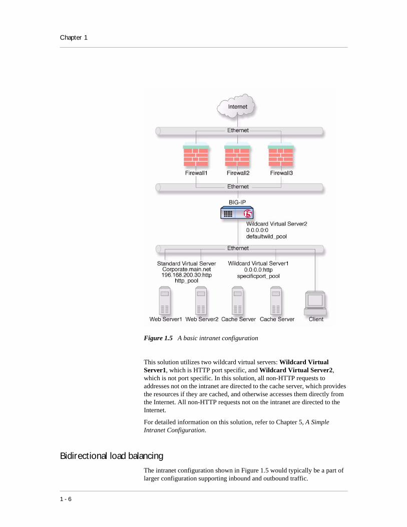
Figure 1.5 A basic intranet configuration
This solution utilizes two wildcard virtual servers: Wildcard Virtual Server1, which is HTTP port specific, and Wildcard Virtual Server2, which is not port specific. In this solution, all non-HTTP requests to addresses not on the intranet are directed to the cache server, which provides the resources if they are cached, and otherwise accesses them directly from the Internet. All non-HTTP requests not on the intranet are directed to the Internet.
For detailed information on this solution, refer to Chapter 5, A Simple Intranet Configuration.
Bidirectional load balancing
The intranet configuration shown in Figure 1.5 would typically be a part of larger configuration supporting inbound and outbound traffic.
1 - 6

BIG-IP Overview
Figure 1.6 shows traffic being load balanced bidirectionally across three firewalls.
Figure 1.6 Load balancing firewalls
This configuration requires two BIG-IP units (or BIG-IP redundant pairs), and the creation of three load balancing pools with corresponding virtual servers. A virtual server on the inside BIG-IP (BIG-IP1 in Figure 1.6) load balances incoming requests across the enterprise servers. Another virtual server on the outside BIG-IP (BIG-IP2 in Figure 1.6) load balances incoming requests across the external interfaces of the firewalls. A third virtual server on the inside BIG-IP redundant system load balances outbound requests across the internal interfaces of the firewalls.
BIG-IP® Solutions Guide 1 - 7

Chapter 1
For detailed information on this solution, refer to Chapter 10, Balancing Two-Way Traffic Across Firewalls.
Cache controlUsing cache control features, you can create rules to distribute content among three server pools, an origin server pool, a cache pool for cachable content, and a hot pool for popular cachable content. The origin pool members contain all content. The cache pool members contain content that is considered cachable (for example all HTTP and all GIF content). The hot pool members contain cachable content that is considered hot, that is, frequently accessed, as determined by a threshold you set. Once identified, hot content is distributed and load balanced across the pool to maximize processing power when it is hot, and localized to the individual caches when it is cool (less frequently accessed).
A special cache feature is destination address affinity (also called sticky persistence). This feature directs requests for a certain destination to the same proxy server, regardless of which client the request comes from. This saves the other proxies from having to duplicate the web page in their caches, which wastes memory.
For detailed information about cache rules, refer to Rules in the BIG-IP Reference Guide, Chapter 4, Configuring the High-level Network, and Chapters 11, 12, and 13 of this guide.
SSL accelerationSSL acceleration uses special software with an accelerator card to speed the encryption and decryption of encoded content. This greatly speeds the flow of HTTPS traffic without affecting the flow of non-HTTPS traffic. In addition, using add-on BIG-IP e-Commerce Controllers, it is possible to create a scalable configuration that can grow with your network.
For detailed information about SSL acceleration, refer to Chapter 9, Configuring an SSL Accelerator.
Content conversionContent conversion is the on-the-fly switching of URLs to ARLs (Akamai Resource Locators) for web resources that are stored geographically nearby on the Akamai Freeflow NetworkTM. This greatly speeds download of large, slow-to-load graphics and other types of objects.
For detailed information about content conversion, refer to Chapter 14, Configuring a Content Converter.
1 - 8
BIG-IP Overview
VLANsThe internal and external VLANs created on the BIG-IP are by default the separate port-specified VLANs external and internal, with the BIG-IP functioning as an L2 switch. In conformance with IEEE 802.lq, the BIG-IP supports both port-specified VLANs and tagged VLANs. This adds the efficiency and flexibility of VLAN segmentation to traffic handling between the networks. For example, with VLANs it is no longer necessary to change any IP addresses after inserting a BIG-IP into a single network.
VLAN capability also supports multi-site hosting, and allows the BIG-IP to fit into and extend a pre-existing VLAN segmentation, or to serve as a VLAN switch in creating a VLAN segmentation for the wider network.
For detailed information on VLANs, refer to VLANs in the BIG-IP Reference Guide, Chapter 2, Using the Setup Utility.
Link aggregation and link failover
You can aggregate links (individual physical interfaces) on the BIG-IP by software means to form a trunk (an aggregation of links). This link aggregation increases the bandwidth of the individual links in an additive manner. Thus four fast Ethernet links, if aggregated, create a single 400 Mb/s link. Link aggregation is highly useful with asymmetric loads. Another advantage of link aggregation is link failover. If one link in a trunk goes down, traffic is simply redistributed over the remaining links. Link aggregation conforms to the IEEE 802.3ad standard.
Configuring BIG-IP redundant pairsYou can configure the BIG-IP units as redundant pairs, with one unit active and the other in standby mode. This is made convenient by the fact that once one unit has been configured, this configuration can be copied automatically to the other unit, a process called configuration synchronization. Once you synchronize the systems, a failure detection system determines whether the active unit has failed, and automatically re-directs traffic to standby unit. This process is called failover.
A special feature of redundant pairs is optional state mirroring. When you use the state mirroring feature, the standby BIG-IP maintains the same state information as the active BIG-IP. Transactions such as FTP file transfers continue uninterrupted if the standby BIG-IP becomes active.
For detailed information about configuring redundant pairs, refer to the BIG-IP Reference Guide, Chapter 6, Configuring a Redundant System.
BIG-IP® Solutions Guide 1 - 9
Chapter 1
Making hidden nodes accessibleTo perform load balancing, the BIG-IP hides physical servers behind a virtual server. This prevents them from receiving direct administrative connections or from initiating requests as clients (for example, to download software upgrades.) There are two basic methods for making nodes on the internal VLAN routable to the outside world: address translation and forwarding.
Address translation
Address translation consists of providing a routable alias that a node can use as its source address when acting as a client. There are two types of address translation: NAT (Network Address Translation) and SNAT (Secure Network Address Translation). NATs are assigned one per node and can be used for both outbound and inbound connections. SNATs may be assigned to multiple nodes, and permit only outbound connections, hence the greater security.
For detailed information about address translation, refer to the SNATs, NATs and IP Forwarding sections in the BIG-IP Reference Guide, Chapter 4, Configuring the High-Level Network.
Forwarding
Forwarding is the simple exposure of a node’s IP address to the BIG-IP unit’s external VLAN so that clients can use it as a standard routable address. There are two types of forwarding: IP forwarding, and the forwarding virtual server. IP forwarding exposes all nodes and all ports on the internal VLAN. You can use the IP filter feature to implement a layer of security.
A forwarding virtual server is like IP forwarding, but exposes only selected servers and/or ports.
1 - 10

2
Basic Web Site and E-CommerceConfiguration• Working with a basic web site and e-commerceconfiguration
• Configuring a basic e-commerce site
• Additional configuration options

Basic Web Site and E-Commerce Configuration
Working with a basic web site and e-commerceconfiguration
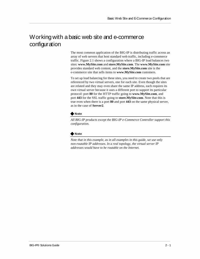
The most common application of the BIG-IP is distributing traffic across an array of web servers that host standard web traffic, including e-commerce traffic. Figure 2.1 shows a configuration where a BIG-IP load balances two sites: www.MySite.com and store.MySite.com. The www.MySite.com site provides standard web content, and the store.MySite.com site is the e-commerce site that sells items to www.MySite.com customers.
To set up load balancing for these sites, you need to create two pools that are referenced by two virtual servers, one for each site. Even though the sites are related and they may even share the same IP address, each requires its own virtual server because it uses a different port to support its particular protocol: port 80 for the HTTP traffic going to www.MySite.com, and port 443 for the SSL traffic going to store.MySite.com. Note that this is true even when there is a port 80 and port 443 on the same physical server, as in the case of Server2.
Note
All BIG-IP products except the BIG-IP e-Commerce Controller support this configuration.
Note
Note that in this example, as in all examples in this guide, we use only non-routable IP addresses. In a real topology, the virtual server IP addresses would have to be routable on the Internet.
BIG-IP® Solutions Guide 2 - 1

Chapter 2
Figure 2.1 A basic configuration
Configuring a basic e-commerce siteTo configure the e-commerce site, you need to complete the following tasks in order:
• Define the load balancing pools
• Define virtual servers for the inbound traffic
Defining the pools
The first step in a basic configuration is to define the two load balancing pools, a pool to load balance HTTP connections for Server1 and Server2, and a pool to load balance SSL connections for Server2 and Server3.
To create the pools using the Configuration utility
1. In the navigation pane, click Pools.The Pools screen opens.
2. Click the Add button.The Add Pool screen opens.
3. For each pool, enter the pool name and member addresses in the Add Pool screen. (For additional information about configuring a pool, click the Help button.)
2 - 2

Basic Web Site and E-Commerce Configuration
Configuration Notes
Create pool http_pool containing members 192.168.100.1:80 and 192.168.100.2:80.
Create pool ssl_pool containing members 192.168.100.2:443 and 192.168.100.3:443.
To define the pools from the command line
To define a pool from the command line, use the following syntax:
b pool <pool_name> {member <member_definition> ... member <member_definition>}
To create the pools http_pool and ssl_pool from the command line, you would type the following commands:
b pool http_pool { \
member 192.168.100.1:80 \
member 192.168.100.2:80 }
b pool ssl_pool { \member 192.168.100.2:443 \member 192.168.100.3:443 }
Defining the virtual servers
The next step in a basic configuration is to define the virtual servers that reference http_pool and ssl_pool, respectively.
To define the virtual servers using the Configuration utility
1. In the navigation pane, click Virtual Servers.The Virtual Servers screen opens.
2. Click the Add button.The Add Virtual Server screen opens.
3. For each virtual server, enter the virtual server address and pool name. (For additional information about configuring a virtual server, click the Help button.)
Configuration notes
Create virtual server 192.168.200.10:80 using pool http_pool
Create virtual server 192.168.200.10:443 using pool ssl_pool
To define the virtual servers from the command line
Use the bigpipe virtual command as shown below. You can use standard service names in place of port numbers. If you have DNS configured, you can also use host names in place of IP addresses.
b virtual <virt IP>:<port> use pool <pool_name>
BIG-IP® Solutions Guide 2 - 3

Chapter 2
The following command defines a virtual server that maps to pools http_pool and ssl_pool, respectively:
b virtual 192.168.200.10:80 use pool http_pool
b virtual 192.168.200.10:443 use pool ssl_pool
Additional configuration optionsWhenever a BIG-IP is configured, you have a number of options:
◆ You have the option in all configurations to configure a BIG-IP redundant system for fail-over. Refer to Chapter 6, Configuring a Redundant System, in the BIG-IP Reference Guide.
◆ All configurations have health monitoring options. Refer to Health Monitors in Chapter 4, Configuring the High-Level Network, in the BIG-IP Reference Guide.
◆ When you create a pool, there is an option to set up persistence and a choice of load balancing methods. Refer to Pools in the Chapter 4, Configuring the High-Level Network, in the BIG-IP Reference Guide.
2 - 4

3
Installing a BIG-IP without Changing the IPNetwork• Installing a BIG-IP without changing IP networks
• Additional configuration options


Installing a BIG-IP without Changing the IP Network
Installing a BIG-IP without changing IP networksA combination of several features of the BIG-IP allows you to place a BIG-IP in a network without changing the existing IP network.
The following figure shows the data center topology before you add the BIG-IP. The data center has one LAN, with one IP network, 10.0.0.0. The data center has one router to the Internet, two web servers, and a back-end mail server.
Figure 3.1 Existing data center network structure
The existing data center structure does not support load balancing or high availability. Figure 3.2 is an example of the data center topology after you add the BIG-IP.
BIG-IP® Solutions Guide 3 - 1

Chapter 3
Figure 3.2 New structure after adding the BIG-IP
Both the internal and external interfaces of the BIG-IP are on the same IP network, 10.0.0.0, but they are effectively on different LANs.
Note that a second switch has been introduced in Figure 3.2. This switch would be eliminated in a configuration using an IP Application Switch.
Configuring the BIG-IP for the same IP network
To configure the BIG-IP for this solution, you must complete the following tasks:
◆ Remove the self IP addresses from the individual VLANsRemove the self IP addresses from the individual VLANs. Routing is handled by the self IP address you create for the VLAN group.
◆ Create a VLAN groupCreate a VLAN group that includes the internal and external VLANs. This enables L2 forwarding. (L2 forwarding causes the two VLANs to behave as a single network.)
◆ Create a self IP for the VLAN groupThe self IP for the VLAN group provides a route for packets destined for the network.
3 - 2

Installing a BIG-IP without Changing the IP Network
◆ Create a pool of web serversCreate a pool that contains the web servers that you want to load balance.
◆ Create a virtual serverCreate a virtual server that load balances the web servers.
Note
This example assumes that you are using the default internal and external VLAN configuration with self IP addresses on each VLAN that are on the same IP network on which you are installing the BIG-IP.
Note
The default route on each content server should be set to the IP address of the router. In this example, you set the default route to 10.0.0.2.
Removing the self IP addresses from the individual VLANs
Remove the self IP addresses from the individual VLANs. After you create the VLAN group, you will create another self IP address for the VLAN group for routing purposes. The individual VLANs no longer need their own self IP addresses.
We recommend that you perform this step from the console or from a self IP address you are not going to delete. If you are connected from a remote workstation though a self IP address you are going to delete, you will be disconnected when you delete it.
To remove the self IP addresses from the default VLANsusing the Configuration utility
1. In the navigation pane, click Network.The VLANs screen opens.
2. In the VLANs screen, click the Self IP Addresses tab.The Self IP Addresses screen opens.
3. Delete the self IP addresses for the external and internal VLANs. (For additional information about adding and removing self IP addresses, click the Help button.)
To delete self IP addresses from the individual VLANs fromthe command line
To delete the self IP addresses from the individual VLANs, use the following syntax.
b self <ip addr> delete
Repeat the command to delete each self IP address on the internal and external VLANs.
BIG-IP® Solutions Guide 3 - 3

Chapter 3
Creating a VLAN group
Create a VLAN group that includes the internal and external VLANs. Packets received by a VLAN in the VLAN group are copied onto the other VLAN in the group. This allows traffic to pass through the BIG-IP on the same IP network. For more information about VLAN groups, refer to the BIG-IP Reference Guide, Chapter 3, Additional Base Network Configuration.
Tip
A VLAN group name can be used anywhere a VLAN name can be used.
To create a VLAN group from the Configuration utility
1. In the navigation pane, click Network.The VLANs screen opens.
2. In the VLANs screen, click the VLAN Groups tab.The VLAN Groups screen opens.
3. In the VLAN Groups screen, click the Add button to add the VLAN group.
Configuration notes
For this example:
The VLAN group name is myvlangroup.
Make sure the Proxy Forward box is checked.
Add the internal and external VLANs to the VLAN group.
To create a VLAN group from the command line
To create the VLAN group myvlangroup from the command line, type the following command:
b vlangroup myvlangroup { vlans add internal external }
Creating a self IP for the VLAN group
The self IP for the VLAN group provides a route for packets destined for the network. With the BIG-IP, the path to an IP network is a VLAN. However, with the VLAN group feature used in this example, the path to the IP network 10.0.0.0 is actually through more than one VLAN. Since IP routers are designed to have only one physical route to a network, a routing conflict can occur. The self IP address feature on the BIG-IP allows you to resolve the routing conflict by putting a self IP address on the VLAN group.
To create a self IP address for a VLAN group using theConfiguration utility
1. In the navigation pane, click Network.The VLANs screen opens.
3 - 4

Installing a BIG-IP without Changing the IP Network
2. In the VLANs screen, click the Self IP Addresses tab.The Self IP Addresses screen opens.
3. In the Self IP Addresses screen, click the Add button to start the Add Self IP Address wizard
Configuration notes
For the example in Figure 3.2, on page 3-2, the self IP address you add for the VLAN group is 10.0.0.6.
When you choose the VLAN you want to apply the self IP address to, select the VLAN group you created that contains the internal and external VLANs.
To create a self IP address for a VLAN group from thecommand line
To create a self IP address on the VLAN group, type the following command:
b self 10.0.0.6 vlan myvlangroup
Creating the pool of web servers to load balance
After you create the network environment for the BIG-IP, you can create the pool of web servers you want to load balance.
To create a pool using the Configuration utility
1. In the navigation pane, click Pools.The Pools screen opens.
2. In the Pools screen, click the Add button to start the Add Pool wizard.
Configuration note
For this example, the pool contains the web servers 10.0.0.3:80 and 10.0.0.4:80.
To create a pool from the command line
To create a pool from the command line, type the following command:
b pool mywebpool { member 10.0.0.3:80 member 10.0.0.4:80 }
In this example, you create the pool name mywebpool with the members 10.0.0.3 and 10.0.0.4.
Creating the virtual server to load balance the web servers
After you create the pool of web servers you want to load balance, you can create the virtual server.
BIG-IP® Solutions Guide 3 - 5

Chapter 3
To create a virtual server using the Configuration utility
1. In the navigation pane, click Virtual Servers.The Virtual Servers screen opens.
2. Click Add (+)The Add Virtual Servers screen opens.
3. Enter the virtual server address and pool name. (For additional information about adding and removing self IP addresses, click the Help button.)
Configuration note
Create virtual server 10.0.0.5 using pool mywebpool.
To create a virtual server from the command line
To create the virtual server for this example from the command line, type the following command:
b virtual 10.0.0.5:80 use pool mywebpool
In this example, mywebpool contains the web servers.
Additional configuration optionsWhenever a BIG-IP is configured, you have a number of options:
◆ You have the option in all configurations to configure a BIG-IP redundant system for fail-over. Refer to Chapter 6, Configuring a Redundant System, in the BIG-IP Reference Guide.
◆ All configurations have health monitoring options. Refer to Health Monitors in Chapter 4, Configuring the High-Level Network, in the BIG-IP Reference Guide.
◆ When you create a pool, there is an option to set up persistence and a choice of load balancing methods. Refer to Pools in the Chapter 4, Configuring the High-Level Network, in the BIG-IP Reference Guide.
3 - 6

4
Hosting for Multiple Customers
• Introducing multiple customer hosting
• Configuring multiple customer hosting
• Multiple customer hosting using built-in switching
• Additional configuration options


Hosting for Multiple Customers
Introducing multiple customer hostingYou can use the BIG-IP to load balance and provide hosting services for multiple customers. In this example, the BIG-IP has a gigabit Ethernet interface tagged to handle traffic for vlanA, vlanB, and vlanC. The servers, in groups of two, host separate customers.
Figure 4.1 An example of multiple site hosting
Configuring multiple customer hostingTo configure the BIG-IP for this solution, you must complete the following tasks:
• Create VLANs with tagged interfaces.
• Create a pool of web servers that contains the web servers that you want to load balance.
• Create a virtual server that load balances the web servers.
Creating VLANs with tagged interfaces
The first step in configuring the BIG-IP for multiple customer hosting is creating VLANs with tagged interfaces. You can do this using the Configuration utility or from the command line.
BIG-IP® Solutions Guide 4 - 1

Chapter 4
To create VLANs with tagged interfaces using theConfiguration utility
1. In the navigation pane, click Network.The VLAN screen opens.
2. For each VLAN:
a) Click the Add button. The Add VLAN screen opens.
b) Enter the VLAN name and tag number. If you do not provide a tag number, the BIG-IP automatically generates a number.
c) In the Resources box, select the internal interface (in the example, 5.1) and click tagged >>. The interface appears in the Current Interfaces box.
Configuration note
For this example, create three VLANs, vlanA, vlanB, and vlanC, adding the internal interface to each VLAN as a tagged interface.
To create VLANs with tagged interfaces from thecommand line
To create a VLAN with tagged interface, you must first create the VLAN and then add tagged interfaces to it. You can create a VLAN using the vlan tag command:
b vlan <vlan_name> tag <tag_number>
You can then add an interface or interfaces to the VLAN using the tagged flag:
b vlan <vlan_name> interfaces add tagged <if_list>
To create VLANs vlanA, vlanB, and vlanC, type:
b vlan vlanA tag 0001
b vlan vlanB tag 0002
b vlan vlanC tag 0003
To add tagged interface 5.1 to VLANs vlanA, vlanB, and vlanC, type:
b vlan vlanA interfaces add tagged 5.1
b vlan vlanB interfaces add tagged 5.1
b vlan vlanC interfaces add tagged 5.1
Creating the server pools to load balance
After you create the network environment for the BIG-IP, create three load balancing pools, one for each network.
4 - 2
Hosting for Multiple Customers
To create a pool in the Configuration utility
1. In the navigation pane, click Pools.The Pools screen opens.
2. In the Pools screen, click the Add button to start the Add Pool wizard.
3. For each pool, enter the pool name and member addresses in the Add Pool screen. (For additional information about configuring a pool, click the Help button.)
Configuration notes
For this example, create the following pools:
server_pool1 containing the web servers 10.1.1.1:80, 10.1.1.2:80
server_pool2 containing the web servers 10.1.2.1:80, 10.1.2.2:80
server_pool3 containing the web servers 10.1.3.1:80, 10.1.3.2:80
To create the pools from the command line
To create a pool from the command line, type the following syntax.
b pool <pool_name> { member <server1> member <server2> ... }
In this example, you create the pool name mywebpool with the members 10.1.1.1:80, 10.1.1.2:80, 10.1.2.1:80, 10.1.2.2:80, 10.1.3.1:80, and 10.1.3.2:80:
b pool server_pool1 { \
member 10.1.1.1:80 \
member 10.1.1.2:80 }
b pool server_pool2 { \
member 10.1.2.1:80 \
member 10.1.2.2:80 }
b pool server_pool3 { \
member 10.1.3.1:80 \
member 10.1.3.2:80 }
Creating the virtual server to load balance the web servers
After you create the web server pools that you want to load balance, create a virtual server for each pool.
To create a virtual server in the Configuration utility
1. In the navigation pane, click Virtual Servers.The Virtual Servers screen opens.
2. In the Virtual Servers screen, click the Add button to start the Add Virtual Server wizard.
BIG-IP® Solutions Guide 4 - 3

Chapter 4
3. Type the address and pool name. (For additional information about configuring a virtual server, click the Help button.)
Configuration notes
For this example, create the following virtual servers:
virtual server 10.1.10.10:80 using server_pool1
virtual server 10.1.10.11:80 using server_pool2
virtual server 10.1.10.12:80 using server_pool3
To create a virtual server from the command line
To create the virtual server for this example from the command line, use the following syntax.
b virtual <addr:service> use pool <pool>
In this example:
b virtual 10.1.10.10:80 use pool server_pool1
b virtual 10.1.10.11:80 use pool server_pool2
b virtual 10.1.10.12:80 use pool server_pool3
Multiple customer hosting using built-in switchingThe configuration shown in Figure 4.1, on page 4-1, uses a two-interface BIG-IP and an external switch. The BIG-IP and external switch may be replaced by a single IP Application Switch. Because the BIG-IP is now the switch, tagging is no longer necessary, but it is necessary to configure the VLANs, with untagged interfaces, on the BIG-IP. Figure 4.2 is an example of this example with the IP Application Switch.
4 - 4

Hosting for Multiple Customers
Figure 4.2 Multiple customer hosting using VLAN switching
Creating VLANs with untagged interfaces
The first step in configuring the BIG-IP for multiple customer hosting on the IP Application Switch is to create VLANs and add untagged interfaces to them. You can do this using the Configuration utility or from the command line.
To create VLANs with untagged interfaces using theConfiguration utility
1. In the navigation pane, click Network.The VLAN screen opens.
2. For each VLAN:
a) Click the Add button. The Add VLAN screen opens.
b) Enter the VLAN name.
c) In the Resources box, select the internal interfaces to be assigned to the VLAN and click untagged >>. The interface appears in the Current Interfaces box.
BIG-IP® Solutions Guide 4 - 5
Chapter 4
Configuration notes
For this example, create three vlans, vlanA, vlanB, and vlanC, adding the untagged internal interfaces they connect to as follows:
vlanA takes interfaces 1.1 and 1.2.
vlanB takes interfaces 1.3 and 1.4.
vlanC takes interfaces 1.5 and 1.6.
To create VLANs with untagged interfaces from thecommand line
You can create a VLAN with untagged interfaces using the vlan command:
b vlan <vlan_name> interfaces add <if_list>
Thus, to create vlanA, vlanB, and vlanC, type:
b vlan vlanA interfaces add 1.1 1.2
b vlan vlanB interfaces add 1.3 1.4
b vlan vlanC interfaces add 1.5 1.6
Additional configuration optionsWhenever a BIG-IP is configured, you have a number of options:
◆ You have the option in all configurations to configure a BIG-IP redundant system for fail-over. Refer to Chapter 6, Configuring a Redundant System, in the BIG-IP Reference Guide.
◆ All configurations have health monitoring options. Refer to Health Monitors in Chapter 4, Configuring the High-Level Network, in the BIG-IP Reference Guide.
◆ When you create a pool, there is an option to set up persistence and a choice of load balancing methods. Refer to Pools in the Chapter 4, Configuring the High-Level Network, in the BIG-IP Reference Guide.
4 - 6

5
A Simple Intranet Configuration
• Working with a simple intranet configuration
• Additional configuration options


A Simple Intranet Configuration
Working with a simple intranet configurationThe simple intranet solution described in this chapter is commonly found in a corporate intranet (see Figure 5.1). In this scenario, the BIG-IP performs load balancing for several different types of connection requests:
◆ HTTP connections to the company’s intranet web site. The BIG-IP load balances the two web servers that host the corporate intranet web site, Corporate.main.net.
◆ HTTP connections to Internet content. These are handled through a pair of cache servers that are also load balanced by the BIG-IP.
◆ Non-HTTP connections to the Internet.
Figure 5.1 A simple intranet configuration
As Figure 5.1 shows, the non-intranet connections are handled by wildcard virtual servers, that is, servers with the IP address 0.0.0.0 (or * or "any"). The wildcard virtual server handling traffic to the cache servers is port specific, specifying port 80 for HTTP requests. This way all HTTP requests
BIG-IP® Solutions Guide 5 - 1
Chapter 5
not matching an IP address on the intranet are directed to the cache server. The wildcard virtual server handling non-HTTP requests is a default wildcard server. A default wildcard virtual server is one that uses only port 0 (or any or * or "" [blank string]). This makes it a catch-all match for outgoing traffic that does not match any standard virtual server or any port-specific wildcard virtual server.
Creating the simple intranet configuration
To create this configuration, you need to complete the following tasks in order:
• Create load balancing poolsCreate pools for the intranet servers you want to load balance and one for the cache server.
• Create virtual serversCreate the virtual servers for each pool and for the non-HTTP requests.
Defining the pools
The first step in a basic configuration is to define the two load balancing pools, a pool for the intranet content servers and a pool for the Internet cache servers.
To create pools using the Configuration utility
1. In the navigation pane, click Pools.The Pools screen opens.
2. Click the Add button.The Add Pool screen opens.
3. For each pool, enter the pool name and member addresses in the Add Pool screen. (For additional information about configuring a pool, click the Help button.)
Configuration notes
For the example in Figure 5.1, on page 5-1, create the pool http_pool containing members 192.168.100.10:80 and 192.168.100.11:80.
Create the pool specificport_pool containing members 192.168.100.20:80 and 192.168.100.21:80.
To create the pools from the command line
To define a pool from the command line, use the following syntax:
b pool <pool_name> { member <member_definition> ... member <member_definition>}
5 - 2

A Simple Intranet Configuration
To create the pools http_pool and specificport_pool from the command line, you type the following commands:
b pool http_pool { \
member 192.168.100.10:80 \
member 192.168.100.11:80 }
b pool specificport_pool { \
member 192.168.100.20:80 \
member 192.168.100.21:80 }
Defining the virtual servers
The next step in a basic configuration is to define the virtual servers that reference http_pool and specificport_pool, respectively, as well as the forwarding server (no pool) for remaining Internet traffic.
To define the virtual servers using the Configuration utility
1. In the navigation pane, click Virtual Servers.The Virtual Servers screen opens.
2. Click the Add button.The Add Virtual Server screen opens.
3. For each virtual server, enter the virtual server address and pool name. (For additional information about configuring a virtual server, click the Help button.)
Configuration notes
For the example in Figure 5.1:
Create virtual server 192.168.200.30:80 using http_pool
Create virtual server 0.0.0.0:80 using specificport_pool
Create virtual server 0.0.0.0:0 as forwarding server (no pool)
To define the virtual servers from the command line
To define a virtual server from the command line, use the following syntax:
b virtual <virt IP>:<port> use pool <pool_name>
You can use standard service names in place of port numbers. If you have DNS configured, you can also use host names in place of IP addresses.
The following commands define virtual servers that map to the pools http_pool and specificport_pool, respectively, and a forwarding virtual server:
b virtual 192.168.200.30:80 use pool http_pool
b virtual 0.0.0.0:80 use pool specificport_pool
b virtual 0.0.0.0:0 forward
BIG-IP® Solutions Guide 5 - 3

Chapter 5
Additional configuration optionsWhenever a BIG-IP is configured, you have a number of options:
◆ You have the option in all configurations to configure a BIG-IP redundant system for fail-over. Refer to Chapter 6, Configuring a Redundant System, in the BIG-IP Reference Guide.
◆ All configurations have health monitoring options. Refer to Health Monitors in Chapter 4, Configuring the High-Level Network, in the BIG-IP Reference Guide.
◆ When you create a pool, there is an option to set up persistence and a choice of load balancing methods. Refer to Pools in the Chapter 4, Configuring the High-Level Network, in the BIG-IP Reference Guide.
5 - 4

6
Load Balancing ISPs
• Using ISP load balancing
• Configuring network address translation on routers
• Enabling service 80 and service 443
• Additional configuration options


Load Balancing ISPs
Using ISP load balancingYou may find that as your network grows, or network traffic increases, you need to add an additional connection to the internet. You can use this configuration to add an additional Internet connection to your existing network. Figure 6.1 shows a network configured with two Internet connections.
Figure 6.1 An example of an additional internet connection
This type of configuration requires you to configure network address translation (NAT) on your routers. If your routers cannot perform NAT, you can use the VLAN SNAT automap feature on the BIG-IP.
Configuring ISP load balancing
When you set up ISP load balancing, you have several tasks to complete on the BIG-IP:
◆ Create two load balancing poolsDefine one pool that load balances the content servers. The other pool balances the inside addresses of the routers.
◆ Configure virtual serversConfigure virtual servers to load balance inbound connections across the servers, and one to load balance outbound connections across the routers.
BIG-IP® Solutions Guide 6 - 1

Chapter 6
◆ Configure NATs or a SNAT automapConfigure NATs or SNAT automap for outbound traffic so that replies will arrive though the same ISP the request went out on.
◆ Enable service 80 and service 443Enable service 80 and service 443 on the BIG-IP. This step is only required if you configure this solution from the command line. The web-based Configuration utility automatically opens the ports.
Defining the pools for an additional Internet connection
First, define one pool that load balances the content servers, and one pool to load balance the routers.
To create the pools using the Configuration utility
1. In the navigation pane, click Pools.The Pools screen opens.
2. Click the Add button.The Add Pool screen opens.
3. For each pool, enter the pool name and member addresses in the Add Pool screen. (For additional information about configuring a pool, click the Help button.)
Configuration notes
For the example in Figure 6.1:
Create the pool server_pool containing the members 10.1.1.1:80 10.1.1.2:80, and 10.1.1.3:80.
Create the pool router_insides containing the router inside addresses 192.168.100.1:0 and 192.168.200.1:0.
To create pools from the command line
Use the following command to define the pool server_pool for the nodes that handle the requests to virtual server 172.100.12.20:80:
b pool server_pool { \
member 10.1.1.1:80 \
member 10.1.1.2:80 \
member 10.1.1.3:80 }
Use the following command to create the pool router_insides:
b pool router_insides { \
member 192.168.100.1:0 \
member 192.168.200.1:0 }
Defining the virtual servers for an additional Internet connection
After you create the pools, you can configure the two virtual servers, one to load balance inbound connections across the servers and one to load balance outbound connections across the routers.
6 - 2

Load Balancing ISPs
To define the virtual servers using the Configuration utility
1. In the navigation pane, click Virtual Servers.The Virtual Servers Screen opens.
2. Click the Add button.The Add Virtual Server screen opens.
3. For each virtual server, enter the virtual server address and pool name. (For additional information about configuring a virtual server, click the Help button.)
Configuration notes
For the example in Figure 6.1:
For the inbound connections, create the virtual server 172.100.12.20:80 and use pool server_pool.
For the outbound connections, create a wildcard virtual server 0.0.0.0:0 and use pool router_insides.
To define the virtual servers from the command line
To handle inbound traffic, create the virtual server for the pool server_pool with the following command:
b virtual 172.100.12.20:80 use pool server_pool
To handle outbound traffic, create a wildcard virtual server for the pool router_insides with the following command:
b virtual 0.0.0.0:0 use pool router_insides
Configuring network address translation on routersYou must now set up address translation for outbound traffic so that replies will arrive though the same ISP that the request went out on. Specifically, you must either configure your routers so that they perform network address translation (NAT), or you must configure SNAT automap.
For instructions on NAT configuration, refer to your router documentation.
To set up a SNAT automap, perform the following tasks:
• Assign IP-specific self IP addresses to the BIG-IP external VLAN, corresponding to the IP networks of the two routers.
• Enable SNAT automap for each of the self addresses.
• Enable SNAT automap for the internal VLAN.
To create self IP addresses and enable SNAT automapusing the Configuration utility
1. In the navigation pane, click NetworkThe Network screen open.
BIG-IP® Solutions Guide 6 - 3

Chapter 6
2. On the Network screen, click Add.The Add Self IP Address screen opens.
3. In the Add Self IP Address screen, for each router, add a new self IP address that matches the network of the router, with the inside IP network address of the router and SNAT Automap enabled.
4. On the Network screen, click the VLANs tab.The VLANs screen opens.
5. Click the internal VLAN.The VLAN Internal screen opens.
6. In the VLAN Internal screen, check the SNAT Automap box. For additional information about configuring a VLAN, click the Help button.
To create self IP addresses and enable SNAT automapfrom the command line
Create IP-specific self IP addresses on the external VLAN using these commands:
b self 192.168.100.10 vlan external snat automap enable
b self 192.168.200.10 vlan external snat automap enable
Use this command to enable snat automap on the internal VLAN:
b vlan internal snat automap enable
Enabling service 80 and service 443This step is required only if you configure this solution from the command line. If you use the web-based Configuration utility for this solution, the services are automatically enabled. Use the following command to enable service 80 and service 443.
b service 80 443 tcp enable
Additional configuration optionsWhenever a BIG-IP is configured, you have a number of options:
◆ You have the option in all configurations to configure a BIG-IP redundant system for fail-over. Refer to Chapter 6, Configuring a Redundant System, in the BIG-IP Reference Guide.
◆ All configurations have health monitoring options. Refer to Health Monitors in Chapter 4, Configuring the High-Level Network, in the BIG-IP Reference Guide.
6 - 4

Load Balancing ISPs
◆ When you create a pool, there is an option to set up persistence and a choice of load balancing methods. Refer to Pools in the Chapter 4, Configuring the High-Level Network, in the BIG-IP Reference Guide.
BIG-IP® Solutions Guide 6 - 5

Chapter 6
6 - 6

7
Load Balancing VPNs
• Working with VPN load balancing
• Using VPN and router load balancing
• Additional configuration options


Load Balancing VPNs
Working with VPN load balancingYou can use the BIG-IP to load balance virtual private network (VPN) gateways used to connect two private networks. Figure 7.1 shows a configuration of this type.
Figure 7.1 An example of a VPN load balancing configuration
Configuring VPN load balancing
There are three tasks required to configure VPN load balancing on the BIG-IP: create a load balancing pool, create two virtual servers, and enable ports 80 and 443.
BIG-IP® Solutions Guide 7 - 1

Chapter 7
The following tasks only show how to configure the BIG-IP on network 192.168.13.0 (BIG-IP 2). The configuration for BIG-IP 1 on 192.168.11.0 is the same, only with different network numbers.
◆ Create a load balancing poolCreate a pool that load balances the inside addresses of the three VPNs.
◆ Create two virtual serversCreate virtual servers to handle inbound and outbound traffic for the VPNs.
◆ Enable service 80 and service 443Enable service 80 and 443 for traffic. This step is only required if you configure this solution from the command line. The web-based Configuration utility automatically allows access to the services.
Defining the pools
First, create two pools, a pool that load balances the content servers and a pool that load balances the VPNs.
To create a pool using the Configuration utility
1. In the navigation pane, click Pools.The Pools screen opens.
2. Click the Add button.The Add Pool screen opens.
3. For each pool, enter the pool name and member addresses in the Add Pool screen. (For additional information about configuring a pool, click the Help button.)
Configuration notes
For the example in Figure 7.1:
Create pool named vpn_insides. This pool contains the following members: <vpn1>, <vpn2>, <vpn3>.
To define a pool from the command line
Define the pool vpn_insides for the VPNs:
b pool vpn_insides { \
member <vpn1>:* \
member <vpn2>:* \
member <vpn3>:* }
Replace <vpn1>, <vpn2>, and <vpn3> with the internal IP address of the respective router. In this example the routers are service checked on port *.
Defining the virtual servers
After you define the pools for the content servers and inside IP addresses of the VPNs, define the virtual servers.
7 - 2
Load Balancing VPNs
To define the virtual servers using the Configuration utility
1. In the navigation pane, click Virtual Servers.
2. Click the Add button.The Add Virtual Server screen opens.
3. For each virtual server, enter the virtual server address and pool name. (For additional information about configuring a virtual server, click the Help button.)
Configuration notes
For the example in Figure 7.1:
For the inbound connections, create the network virtual server 192.168.13.0:0. Specify the netmask 255.255.255.0 and turn forwarding on.
For the outbound connections, create the network virtual server 192.168.11.0:0. specify the netmask 255.255.255.0, use pool vpn_insides, and disable address translation.
To define the virtual servers from the command line
First, create a forwarding network virtual server for inbound VPN traffic:
b virtual 192.168.13.0:0 netmask 255.255.255.0 forward
Then, create a virtual server to load balance traffic outbound to the remote machines through VPNs:
b virtual 192.168.11.0:0 netmask 255.255.255.0 use pool vpn_insides
b virtual 192.168.11.0:0 translate addr disable
(This addresses nodes 192.168.11.1, 192.168.11.2, and 192.168.11.3 that represent the IBM Compatible, Tower box, and MacIntosh on the remote network in Figure 7.1.)
Enabling service 80 and service 443
This step is only required if you configure this solution from the command line. If you use the web-based Configuration utility for this solution, the services are automatically enabled. Use the following command to enable service 80 and service 443.
b service 80 443 tcp enable
Using VPN and router load balancingYou can use the transparent device load balancing feature in the BIG-IP to connect to private networks, as well as to load balance Internet connections through multiple routers. Figure 7.2 is an example of this network configuration.
BIG-IP® Solutions Guide 7 - 3

Chapter 7
Configuring virtual servers for VPN and router load balancing
The following topics deal with only the VPN configuration for the BIG-IP on network 192.168.13.100 (BIG-IP 2). The configuration for 192.168.11.100 is done the same way, but you use different network numbers.
Figure 7.2 An example of a VPN and multiple router load balancing configuration
Configuring VPN and router load balancing
First, complete the following tasks on the BIG-IP:
◆ Create load balancing poolsCreate load balancing pools for the content servers, the routers, and the three VPNs.
7 - 4

Load Balancing VPNs
◆ Create four virtual serversCreate four virtual servers. The first virtual server load balances inbound Internet traffic. The second virtual server load balances outbound Internet traffic. The third virtual server forwards inbound VPN connections. The fourth virtual server load balances outbound VPN connections.
◆ Configure network address translationConfigure NATs or SNAT automap for outbound traffic so that replies will arrive though the same VPN the request went out on.
◆ Enable service 80 and service 443Enable service 80 and 443 for traffic. This step is only required if you configure this solution from the command line. The web-based Configuration utility automatically opens the ports.
Defining the pools for VPN load balancing
Next, create three pools. Create one pool that load balances the content servers, one that load balances the routers, and one that load balances the VPNs. For example:
◆ Create a server pool named server_pool. This pool contains the following members: <server1> and <server2>
◆ Create a pool named router_insides with the following members: <router1> and <router2>
◆ Create a pool named vpn_insides. This pool contains the following members: <vpn1>, <vpn2>, and <vpn3>
To create the pools using the Configuration utility
1. In the navigation pane, click Pools.The Pools screen opens.
2. Click the Add button.The Add Pool screen opens.
3. For each pool, enter the pool name and member addresses in the Add Pool screen. (For additional information about configuring a pool, click the Help button.)
Configuration notes
Create a server pool named server_pool. This pool contains the following members: <server1> and <server2>.
Create a pool named router_insides with the following members: <router1> and <router2>.
Create a pool named vpn_insides. This pool contains the following members: <vpn1>, <vpn2>, and <vpn3>.
BIG-IP® Solutions Guide 7 - 5

Chapter 7
To define a pool from the command line
First, define the pool server_pool for the content servers:
b pool server_pool { \
member <server1>:80 \
member <server2>:80 \
member <server3>:80 }
You will replace <server1>, <server2>, and <server3> with the IP address of each respective server.
Next, define the pool router_insides for the internal addresses of the routers:
b pool router_insides { \
member <router1>:0 \
member <router2>:0 }
Replace <router1> and <router2> with the internal IP address of each respective router.
Finally, define the pool vpn_insides for the internal addresses of the VPN routers:
b pool vpn_insides { \
member <vpn1>:0 \
member <vpn2>:0 \
member <vpn3>:0 }
Replace <vpn1>, <vpn2>, and <vpn3> with the external IP address of each respective router.
Defining the virtual servers for VPN and router load balancing
After you define the pools for the inside IP addresses of the routers, you need to define the following virtual servers for the BIG-IP 2. For example:
◆ For the inbound Internet connection, configure the virtual server 172.100.12.20:80 using server_pool.
◆ For the outbound Internet connection, configure the wildcard virtual server 0.0.0.0:0 using router_insides.
◆ For the inbound VPN connections, create the forwarding network virtual server 192.168.13.0:0. Turn forwarding on.
◆ For the outbound VPN connections, create the network virtual server 192.168.11.0:0. Use pool vpn_insides and disable port and address translation.
To define the virtual server using the Configuration utility
1. In the navigation pane, click Virtual Servers.The Virtual Servers screen opens.
2. Click the Add button.The Add Virtual Server screen opens.
7 - 6

Load Balancing VPNs
3. For each virtual server, enter the virtual server address and pool name. (For additional information about configuring a virtual server, click the Help button.)
Configuration notes
For the inbound Internet connection, configure the virtual server 172.100.12.20:80 using server_pool.
For the outbound Internet connection, configure the wildcard virtual server 0.0.0.0:0 using router_insides.
For the inbound VPN connections, create the forwarding network virtual server 192.168.13.0:0. Turn forwarding on.
For the outbound VPN connections, create the network virtual server 192.168.11.0:0. Use pool vpn_insides and disable port and address translation.
To define virtual servers from the command line
First, configure the BIG-IP to handle inbound traffic from the remote network.
Create the virtual server for BIG-IP 2 with the following commands:
b virtual 192.168.13.0:0 forward
Then, configure BIG-IP 2 to handle outbound traffic. Create a virtual server that sends traffic to the pool you created for the internal interfaces of the VPN routers (vpn_insides). Use the following commands to create virtual servers for connecting to the machines on the remote network:
b virtual 192.168.11.0:0 use pool vpn_insides
b virtual 192.168.11.0:0 translate addr disable
This addresses the nodes 192.168.11.1, 192.168.11.2, and 192.168.11.3 that correspond to the IBM Compatible, Tower box, and MacIntosh on the remote network in Figure 7.2, on page 7-4.
Then, create a virtual server to handle inbound traffic:
b virtual 172.100.12.20:80 use pool server_pool
Finally, configure BIG-IP 2 to handle outbound traffic. Create a virtual server that sends traffic to the pool you created for the internal interfaces of the routers (router_insides). Use the following command to create the virtual server:
b virtual 0.0.0.0:0 use pool router_insides
Configuring network address translation on routers
For outbound traffic you must now set up address translation so that replies will arrive through the same router the request went out on. Specifically, you must either configure your routers so that they perform network address translation (NAT), or you must configure SNAT automap.
For instructions on NAT configuration, refer to your router documentation.
BIG-IP® Solutions Guide 7 - 7

Chapter 7
To perform the SNAT automap you must perform three steps:
• Assign IP-specific self addresses to the external VLAN corresponding the IP networks of the two routers
• Enable SNAT automap for each of the self addresses.
• Enable SNAT automap for the internal VLAN.
To create self addresses and enable SNAT automap to therouter inside interfaces using the Configuration utility
1. In the navigation pane, click Network.The VLANs screen opens.
2. Click the Self IP Addresses tab.The Self IP Addresses screen opens.
3. Click the Add button.The Add Self IP Address screen opens.
4. For each router, add a new self IP address with the inside IP network address of the router and SNAT Automap enabled.
5. On the Network screen, click the VLANs tab.The VLANs screen opens.
6. Click the internal VLAN.The VLAN Internal screen opens.
7. In the VLAN Internal screen, click a check in the SNAT Automap box.For additional information about adding a VLAN, click the Help button.
To create VLAN mappings with SNAT auto mapping to therouter inside interfaces from the command line
Create IP-specific self addresses on the third VLAN with these commands:
b self <ip_addr1> vlan <vlan_name> snat automap enable
b self <ip_addr2> vlan vlan_name> snat automap enable
Enable snat automap on the internal VLAN using this command:
b vlan <int_vlan> snat automap enable
For example:
b self 11.11.11.5 vlan external snat automap enable
b self 11.11.12.5 vlan external snat automap enabl
b vlan internal snat automap enable
7 - 8

Load Balancing VPNs
Enabling service 80 and service 443
This step is required only if you configure this solution from the command line. If you use the web-based Configuration utility for this solution, the services are automatically enabled. Use the following command to enable service 80 and service 443.
b service 80 443 tcp enable
Additional configuration optionsWhenever a BIG-IP is configured, you have a number of options:
◆ You have the option in all configurations to configure a BIG-IP redundant system for fail-over. Refer to Chapter 6, Configuring a Redundant System, in the BIG-IP Reference Guide.
◆ All configurations have health monitoring options. Refer to Health Monitors in Chapter 4, Configuring the High-Level Network, in the BIG-IP Reference Guide.
◆ When you create a pool, there is an option to set up persistence and a choice of load balancing methods. Refer to Pools in the Chapter 4, Configuring the High-Level Network, in the BIG-IP Reference Guide.
BIG-IP® Solutions Guide 7 - 9

Chapter 7
7 - 10
8
Load Balancing IPSEC Traffic
• Configuring load balancing IPSEC traffic across VPNgateways
• IPSEC VPN sandwich configuration
• Additional configuration options


Load Balancing IPSEC Traffic
Configuring load balancing IPSEC traffic across VPNgateways
The previous chapter shows how to load balance across three VPN gateways. The IPSEC protocol (Internet Protocol Security) enables you to load balance between gateways as well. Figure 8.1 shows inbound IPSEC traffic being load balanced to one of three destination VPN gateways.
Figure 8.1 VPN load balancing between VPN gateways
BIG-IP® Solutions Guide 8 - 1

Chapter 8
In this configuration, address translation is on, and IPSEC is in tunnel mode with ESP (Encapsulation Security Payload) specified. The hop shown by the blue arrow represents the IPSEC part of the transmission. A packet originating from Client4 with Client6 as its destination is encapsulated by the VPN gateway (VPN4) serving the client and traverses the Internet in this secure form. The BIG-IP then load balances the packet to one of three destination gateways: VPN1, VPN2, or VPN3. The VPN to which it is load balanced then becomes the established gateway, or tunnel, for packets from VPN4. Traffic from Client1, a separate VPN connection, would be load balanced to a different destination VPN.
For this configuration to work, IPSEC requires certain special settings on the clients and servers, and on the BIG-IP:
• On clients and servers, IPSEC must be configured in tunnel mode with ESP.
• You must enable Any IP mode for the virtual servers on the BIG-IP.
• Enable address translation on the BIG-IP.
• Enable UDP on the BIG-IP to support internet key exchange (IKE) traffic.
• Enable persistence across services on the BIG-IP.
Configuring IPSEC load balancing
First, configure your servers and clients for IPSEC tunnel mode with ESP. Refer to the documentation provided with the server or client. Be sure to use the same security association for all clients.
Next, complete the following tasks on the BIG-IP:
◆ Create two load balancing poolsCreate two load balancing pools for the VPN destination gateways, one specifying port 500 for internet key exchange, one specifying a wildcard service (0) for Any IP mode.
◆ Create two virtual serversCreate two virtual servers for referencing the two pools, one specifying port 500 for internet key exchange, one specifying a wildcard service (0) for Any IP (IPSEC) traffic.
◆ Enable UDPEnable UDP for internet key exchange (IKE) traffic.
◆ Enable persistenceEnable persistence across services.
Defining the pools
To configure IPSEC load balancing, you first define one pool that load balances the VPN destination gateways with a wildcard port, and one pool that load balances the VPN destination gateways handling service 500 traffic.
8 - 2

Load Balancing IPSEC Traffic
To create the pools using the Configuration utility
1. In the navigation pane, click Pools.The Pools screen opens.
2. Click the Add button.The Add Pool screen opens.
3. For each pool, enter the pool name and member addresses in the Add Pool screen. (For additional information about configuring a pool, click the Help button.)
Configuration notes
Create a VPN pool named vpn_anyip. This pool contains the outside addresses of the three VPN destination gateways with service 0.
Create a VPN pool named vpn_ike. This pool contains the outside addresses of the three VPN destination gateways with service 500.
To define pools from the command line
Use the following syntax to define the pools at the command line:
b pool <pool_name> { member <member1> member <member2> ...> }
To create the configuration described in this solution, type the following commands:
b pool vpn_anyip { \
member 10.1.10.1:0 \
member 10.1.10.2:0 \
member 10.1.10.3:0 }
b pool vpn_ike { \
member 10.1.10.1:500 \
member 10.1.10.2:500 \
member 10.1.10.3:500 }
Defining the virtual servers
After you define the pools for the VPNs, you can define the following virtual servers, one to load balance Any IP (IPSEC) traffic, and one to load balance internet key exchange traffic.
To define the virtual server using the Configuration utility
Use this procedure for each BIG-IP that you need to configure.
1. In the navigation pane, click Virtual Servers.
2. Click the Add button.The Add Virtual Server screen opens.
BIG-IP® Solutions Guide 8 - 3

Chapter 8
3. For each virtual server, enter the virtual server address and pool name. (For additional information about configuring a virtual server, click the Help button.)
4. Fill in the attributes for the virtual server. For additional information about this screen, click the Help button.
5. For each of the two VPN load-balancing virtual servers:
a) Click the Virtual Address Properties tab.The Virtual Address Properties screen opens.
b) In the Any IP Traffic area, check the Enable box. Then click Apply.
Configuration notes
Create the virtual server 192.168.13.100:0 and use the pool vpn_anyip.
Create the virtual server 192.168.13.100:500 and use the pool vpn_ike.
To define the virtual servers from the command line
Define the virtual servers from the command line as follows:
b virtual 192.168.13.100:0 use pool vpn_anyip
b virtual 192.168.13.100:500 use pool vpn_ike
Then, enable Any IP for both virtual servers:
b virtual 192.168.13.100 any_ip enable.
Enabling UDP
After you enable the Any IP feature for the virtual servers, enable UDP 500 so that the BIG-IP can handle internet key exchange (IKE) traffic:
b service 500 udp enable
Enabling persistence across services
Finally, complete the configuration by setting up persistence across services on the BIG-IP:
b global persist_across_services enable
8 - 4

Load Balancing IPSEC Traffic
IPSEC VPN sandwich configurationYou can load balance content servers to incoming IPSEC traffic by adding a second BIG-IP in a VPN sandwich configuration. Figure 8.2 shows the VPN sandwich configuration.
Figure 8.2 VPN load balancing between VPN gateways
BIG-IP® Solutions Guide 8 - 5
Chapter 8
When you set up the sandwich configuration, the configuration tasks you use are identical to those you use for the basic VPN IPSEC configuration. The exceptions are that you configure a load balancing pool and virtual server on the second BIG-IP. For example:
◆ Create a VPN pool named server_pool. This pool contains as members the addresses of the four content servers: server1, server2, server3, and server4.
◆ Create the virtual server 10.1.20.10:80 and use the pool server_pool.
Defining the additional pool
To create the pool using the Configuration utility
For the BIG-IP in Figure 8.2 labeled BIG-IP 2:
1. In the navigation pane, click Pools.The Pools screen opens.
2. Click the Add button.The Add Pool screen opens.
3. For each pool, enter the pool name and member addresses in the Add Pool screen. (For additional information about configuring a pool, click the Help button.)
Configuration note
Create a VPN pool named server_pool. This pool contains as members the addresses of the four content servers: server1, server2, server3, and server4.
To define the pool from the command line
Use the following syntax to define the pools from the command line:
b pool <pool_name> { member <member1> member < member2> ... > }
To create the configuration described in this solution, type the following command.
b pool server_pool { \
member 10.1.20.1:80 \
member 10.1.20.2:80 \
member 10.1.20.3:80 \
member 10.1.20.4:80 }
8 - 6

Load Balancing IPSEC Traffic
Defining the additional virtual server
To define the additional virtual server using theConfiguration utility
For each BIG-IP to be configured:
1. In the navigation pane, click Virtual Servers.The Virtual Servers screen opens.
2. Click the Add button.The Add Virtual Server screen opens.
3. For each virtual server, enter the virtual server address and pool name. (For additional information about configuring a virtual server, click the Help button.)
To define the virtual server from the command line
To define the virtual server from the command line, type the following command.
b virtual 10.1.20.10:80 use pool server_pool
Additional configuration optionsWhenever a BIG-IP is configured, you have a number of options:
◆ You have the option in all configurations to configure a BIG-IP redundant system for fail-over. Refer to Chapter 6, Configuring a Redundant System, in the BIG-IP Reference Guide.
◆ All configurations have health monitoring options. Refer to Health Monitors in Chapter 4, Configuring the High-Level Network, in the BIG-IP Reference Guide.
◆ When you create a pool, there is an option to set up persistence and a choice of load balancing methods. Refer to Pools in the Chapter 4, Configuring the High-Level Network, in the BIG-IP Reference Guide.
BIG-IP® Solutions Guide 8 - 7

Chapter 8
8 - 8

9
Configuring an SSL Accelerator
• Introducing the SSL Accelerator
• Configuring the SSL Accelerator
• Introducing the SSL Accelerator scalableconfiguration
• Using SSL-to-server
• Additional configuration options


Configuring an SSL Accelerator
Introducing the SSL AcceleratorThe SSL Accelerator feature allows the BIG-IP to accept HTTPS connections (HTTP over SSL), connect to a web server, retrieve the page, and then send the page to the client.
A key component of the SSL Accelerator feature is that the BIG-IP can retrieve the web page using an unencrypted HTTP request to the content server. With the SSL Accelerator feature, you can configure an SSL gateway on the BIG-IP that decrypts HTTP requests that are encrypted with SSL. Decrypting the request offloads SSL processing from the servers to the BIG-IP and also allows the BIG-IP to use the header of the HTTP request to intelligently control how the request is handled. (Requests to the servers can optionally be re-encrypted to maintain security on the server side of the BIG-IP as well, using a feature called SSL-to-server.)
When the SSL proxy on the BIG-IP connects to the content server, and address translation is not enabled, the proxy uses the original client's IP address and port as its source address and port. In doing so, the proxy appears to be the client, for logging purposes.
This chapter describes the following features of the BIG-IP SSL Accelerator:
• Configuring an SSL Accelerator
• Using an SSL Accelerator scalable configuration
• Using SSL-to-server
Note
If you have FIPS-140 security modules installed in the BIG-IP, you must initialize the security world before you configure the SSL Accelerator for encrypted traffic. For more information, see Configuring the FIPS-140 Security World, available on the Software and Documentation CD.
Note
All products except the BIG-IP LoadBalancer, BIG-IP FireGuard Controller, and the BIG-IP Cache Controller support this configuration.
BIG-IP® Solutions Guide 9 - 1

Chapter 9
Figure 9.1 An incoming SSL connection received by an SSL Accelerator configured on the BIG-IP
Configuring the SSL AcceleratorThere are several tasks required to set up the SSL Accelerator on the BIG-IP. These tasks include:
• Generating a key and obtaining a certificate
• Configuring the BIG-IP with the certificate and key
• Creating a pool for the HTTP servers
• Creating an HTTP virtual server
• Creating the gateway for the SSL Accelerator
Generating a key and obtaining a certificate
In order to use the SSL Accelerator feature, you must obtain a valid x509 certificate from an authorized certificate authority (CA).
Note
If you have FIPS-140 hardware installed in the BIG-IP, see Configuring the Security World on BIG-IP on the product and documentation CD for instructions on how to generate a key and obtain a certificate.
9 - 2
Configuring an SSL Accelerator
The following list contains some companies that are certificate authorities:
• Verisign (http://www.verisign.com)
• Digital Signature Trust Company (http://secure.digsigtrust.com)
• GlobalSign (http://www.globalsign.com)
• GTE Cybertrust (http://www.cybertrust.gte.com)
• Entrust (http://www.entrust.net)
You can generate a key, a temporary certificate, and a certificate request form using the Configuration utility or from the command line.
Note that we recommend using the Configuration utility for this process. The certification process is generally handled through a web page. Parts of the process require you to cut and paste information from a browser window in the Configuration utility to another browser window on the web site of the CA.
Additional information about keys and certificates
You must have a separate certificate for each domain name on each BIG-IP or redundant pair of BIG-IP units, regardless of how many non-SSL web servers are load balanced by the BIG-IP.
If you are already running an SSL server, you can use your existing keys to generate temporary certificates and request files. However, you must obtain new certificates if the ones you have are not for the following web server types:
• Apache + OpenSSL
• Stronghold
Generating a key and obtaining a certificate using the Configuration utility
To obtain a valid certificate, you must have a private key. If you do not have a key, you can use the Configuration utility on the BIG-IP to generate a key and a temporary certificate. You can also use the Configuration utility to create a request file you can submit to a certificate authority (CA). You must complete three tasks in the Configuration utility to create a key and generate a certificate request.
• Generate a certificate request
• Submit the certificate request to a CA and generate a temporary certificate
• Install the SSL certificate from the CA
Each of these tasks is described in detail in the following paragraphs.
To create a new certificate request using the Configurationutility
1. In the navigation pane, click Proxies.The Proxies screen opens.
BIG-IP® Solutions Guide 9 - 3

Chapter 9
2. Click the Create SSL Certificate Request tab.The New SSL Certificate Request screen opens.
3. In the Key Information section, select a key length and key file name.
• Key LengthSelect the key length you want to use for the key. You can choose 512, 1024, 2048 or 4096 bits.
• Keyfile NameType in the name of the key file. This should be the fully qualified domain name of the server for which you want to request a certificate. You must add the .key file extension to the name.
4. In the Certificate Information section, type the information specific to your company. This information includes:
• CountryType the two letter ISO code for your country, or select it from the list. For example, the two-letter code for the United States is US.
• State or ProvinceType the full name of your state or province, or select it from the list. You must enter a state or province.
• LocalityType the city or town name.
• OrganizationType the name of your organization.
• Organizational UnitType the division name or organizational unit.
• Domain NameType the name of the domain upon which the server is installed.
• Email AddressType the email address of a person who can be contacted about this certificate.
• Challenge PasswordType the password you want to use as the challenge password for this certificate. The CA uses the challenge password to verify any changes you make to the certificate at a later date.
• Retype PasswordRetype the password you entered for the challenge password.
5. Click the Generate Certificate Request button.After a short pause, the SSL Certificate Request screen opens.
9 - 4

Configuring an SSL Accelerator
6. Use the SSL Certificate Request screen to start the process of obtaining a certificate from a CA, and then to generate and install a temporary certificate.
• Begin the process for obtaining a certificate from CAClick the URL of a CA to begin the process of obtaining a certificate for the server. After you select a CA, follow the directions on their web site to submit the certificate request. After your certificate request is approved, and you receive a certificate back from the CA, see To install certificates from the CA using the Configuration utility, on page 9-7, for information about installing it on the BIG-IP.
• Generate and install a temporary certificateClick the Generate Self-Signed Certificate button to create a self-signed certificate for the server. We recommend that you use the temporary certificate for testing only. You should take your site live only after you receive a properly-signed certificate from a certificate authority. When you click this button, a temporary certificate is created and installed on the BIG-IP. This certificate is valid for 10 years. This temporary certificate allows you to set up an SSL gateway for the SSL Accelerator while you wait for a CA to return a permanent certificate.
Generating a key and obtaining a certificate from the command line
To obtain a valid certificate, you must have a private key. If you do not have a key, you can use the genconf and genkey utilities on the BIG-IP to generate a key and a temporary certificate. The genkey and gencert utilities automatically generate a request file that you can submit to a certificate authority (CA). If you have a key, you can use the gencert utility to generate a temporary certificate and request file.
These utilities are described in the following list:
◆ genconf This utility creates a key configuration file that contains specific information about your organization. The genkey utility uses this information to generate a certificate.
◆ genkeyAfter you run the genconf utility, run this utility to generate a temporary 10-year certificate for testing the SSL Accelerator on the BIG-IP. This utility also creates a request file that you can submit to a certificate authority (CA) to obtain a certificate.
◆ gencertIf you already have a key, run this utility to generate a temporary certificate and request file for the SSL Accelerator.
BIG-IP® Solutions Guide 9 - 5

Chapter 9
To generate a key configuration file using the genconfutility
If you do not have a key, you can generate a key and certificate with the genconf and genkey utilities. First, run the genconf utility with the following commands:
/usr/local/bin/genconf
The utility prompts you for information about the organization for which you are requesting certification. This information includes:
• The fully qualified domain name (FQDN) of the server. Note that this FQDN must be RFC1034/1035-compliant, and cannot be more than 63 characters long (this is an x509 limitation).
• The two-letter ISO code for your country
• The full name of your state or province
• The city or town name
• The name of your organization
• The division name or organizational unit
For example, Figure 9.2 contains entries for the server my.server.net.
To generate a key using the genkey utility
After you run the genconf utility, you can generate a key with the genkey utility. Type the following command to run the genkey utility:
/usr/local/bin/genkey <server_name>
For the <server_name>, type the FQDN of the server to which the certificate applies. After the utility starts, it prompts you to verify the information created by the genconf utility. After you run this utility, a certificate request form is created in the following directory:
/config/bigconfig/ssl.csr/<fqdn>.csr
The <fqdn> is the fully qualified domain name of the server. Please contact your certificate authority (CA) and follow their instructions for submitting this request form.
In addition to creating a request form that you can submit to a certificate authority, this utility also generates a temporary certificate. The temporary certificate is located in:
/config/bigconfig/ssl.crt/<fqdn>.crt
Common Name (full qualified domain name): my.server.netCountry Name (ISO 2 letter code): USState or Province Name (full name): WASHINGTONLocality Name (city, town, etc.): SEATTLEOrganization Name (company): MY COMPANYOrganizational Unit Name (division): WEB UNIT
Figure 9.2 Example entries for the genconf utility
9 - 6

Configuring an SSL Accelerator
The <fqdn> is the fully qualified domain name of the server.
Note that the keys and certificates are copied to the other BIG-IP in a redundant system when you synchronize the configurations. For more information about synchronizing configurations, see the BIG-IP Reference Guide, Chapter 6, Configuring a Redundant System.
This temporary certificate is good for ten years, but for an SSL proxy you should have a valid certificate from your CA.
Be sure to keep your previous key if you are still undergoing certification. The certificate you receive is valid only with the key that originally generated the request.
To generate a certificate with an existing key using thegencert utility
To generate a temporary certificate and request file to submit to the certificate authority with the gencert utility, you must first copy an existing key for a server into the following directory on the BIG-IP:
/config/bigconfig/ssl.key/
After you copy the key into this directory, type the following command at the command line:
/usr/local/bin/gencert <server_name>
For the <server_name>, type the FQDN of the server to which the certificate applies. After the utility starts, it prompts you for various information. After you run this utility, a certificate request form is created in the following directory:
/config/bigconfig/ssl.crt/<fqdn>.csr
The <fqdn> is the fully qualified domain name of the server. Please contact your certificate authority (CA) and follow their instructions for submitting this request form.
Installing certificates from the certificate authority (CA)
After you obtain a valid x509 certificate from a certificate authority (CA) for the SSL Accelerator, you must copy it onto each BIG-IP in the redundant configuration. You can configure the accelerator with certificates using the Configuration utility or from the command line.
To install certificates from the CA using the Configurationutility
1. In the navigation pane, click Proxies.The Proxies screen opens.
2. On Proxies screen, click the Install SSL Certificate Request tab.The Install SSL Certificate screen opens.
BIG-IP® Solutions Guide 9 - 7

Chapter 9
3. In the Certfile Name box, type the fully qualified domain name of the server with the file extension .crt. If you generated a temporary certificate when you submitted a request to the CA, you can select the name of the certificate from the list. This allows you to overwrite the temporary certificate with the certificate from the CA.
4. Paste the text of the certificate into the Install SSL Certificate window. Make sure you include the BEGIN CERTIFICATE line and the END CERTIFICATE line. For an example of a certificate, see Figure 9.3.
5. Click the Write Certificate File button to install the certificate.
After the certificate is installed, you can continue with the next step in creating an SSL gateway for the server.
To install certificates from the CA from the command line
Copy the certificate into the following directory on each BIG-IP in a redundant system:
/config/bigconfig/ssl.crt/
Note
The certificate you receive from the certificate authority (CA) should overwrite the temporary certificate generated by genkey or gencert.
If you used the genkey or gencert utilities to generate the request file, a copy of the corresponding key should already be in the following directory on the BIG-IP:
/config/bigconfig/ssl.key/
In a redundant system, the keys and certificates must be in place on both BIG-IP units before you configure the SSL Accelerator. To do this you must synchronize the configurations in the redundant system, see the BIG-IP Reference Guide, Chapter 6, Configuring a Redundant System.
-----BEGIN CERTIFICATE-----MIIB1DCCAX4CAQAwDQYJKoZIhvcNAQEEBQAwdTELMAkGA1UEBhMCVVMxCzAJBgNVBAgTAldBMRAwDgYDVQQHEwdTZWF0dGxlMRQwEgYDVQQKEwtGNSBOZXR3b3JrczEcMBoGA1UECxMTUHJvZHVjdCBEZXZlbG9wbWVudDETMBEGA1UEAxMKc2VydmVyLm5ldDAeFw0wMDA0MTkxNjMxNTlaFw0wMDA1MTkxNjMxNTlaMHUxCzAJBgNVBAYTAlVTMQswCQYDVQQIEwJXQTEQMA4GA1UEBxMHU2VhdHRsZTEUMBIGA1UEChMLRjUgTmV0d29ya3MxHDAaBgNVBAsTE1Byb2R1Y3QgRGV2ZWxvcG1lbnQxEzARBgNVBAMTCnNlcnZlci5uZXQwXDANBgkqhkiG9w0BAQEFAANLADBIAkEAsfCFXq3Jt+FevxUqBZ9TZ7nHx9uaF5x9V5xMZYgekjc+LrF/yazhmq4PCxrws3gvJmgpTsh50YJrhJgfs2bEgwIDAQABMA0GCSqGSIb3DQEBBAUAA0EAd1q6+u/aMaM2qdo7EjWx14TYQQGomYoqeydlzb/3FOiJAynDXnGnSt+CVvyRXtvmG7V8xJamzkyEpZd4iLacLQ==-----END CERTIFICATE-----
Figure 9.3 An example of a certificate
9 - 8

Configuring an SSL Accelerator
Creating a pool for the HTTP servers
After you configure the BIG-IP with the certificates and keys, the next step is to create a pool containing the HTTP servers for which the SSL Accelerator handles connections.
To create the pools using the Configuration utility
1. In the navigation pane, click Pools.The Pools screen opens.
2. Click the ADD button.The Add Pool screen opens.
3. For each pool, enter the pool name and member addresses in the Add Pool screen. (For additional information about configuring a pool, click the Help button.)
Configuration note
For this example, you create an HTTP pool named http_pool that would contain the following members:
10.1.1.20:80
10.1.1.21:80
10.1.1.22:80
To define the pool from the command line
To define a pool from the command line, use the following syntax:
b pool <pool_name> { \
member <member_definition> \
member <member_definition> }
To create the pools http_pool and ssl_pool, from the command line, you would type the following commands:
b pool http_pool { \
member 10.1.1.20:80 \
member 10.1.1.21:80 \
member 10.1.1.22:80 }
Creating an HTTP virtual server
The next task in configuring the SSL Accelerator is to create a virtual server that references the HTTP pool. For example, create a virtual server 20.1.1.10:80, that references a pool of HTTP servers named http_pool.
To create an HTTP virtual server using the Configurationutility
1. In the navigation pane, click Virtual Severs.The Virtual Servers screen opens.
BIG-IP® Solutions Guide 9 - 9

Chapter 9
2. Click the ADD button.The Add Virtual Server screen opens.
3. For each virtual server, enter the virtual server address and pool name. (For additional information about configuring a virtual server, click the Help button.)
Configuration note
For this example, you would create a virtual server using the pool http_pool.
To create an HTTP virtual server from the command line
After you have defined a pool that contains the HTTP servers, use the following syntax to create a virtual server that references the pool:
b virtual <virt ip>:<service> use pool <pool_name>
For example, if you want to create a virtual server 20.1.1.10:80, that references a pool of HTTP servers named http_pool, you would type the following command:
b virtual 20.1.1.10:80 use pool http_pool
After you create the virtual server that references the pool of HTTP servers, you can create an SSL gateway. The following section describes how to create an SSL gateway.
Creating an SSL gateway
After you create the HTTP virtual server for which the SSL Accelerator handles connections, the next step is to create an SSL gateway. This section also contains information about managing an SSL gateway.
To create an SSL gateway using the Configuration utility
1. In the navigation pane, click Proxies.The Proxies screen opens.
2. Click the ADD button.The Add Proxy screen opens.
3. In the Add Proxy screen, configure the attributes you want to use with the proxy. For additional information about configuring a proxy, click the Help button.
To create an SSL gateway from the command line
Use the following command syntax to create an SSL gateway:
b proxy <ip>:<service> \
target <server | virtual> <ip>:<service> \
clientssl enable \
9 - 10

Configuring an SSL Accelerator
clientssl key <clientssl_key> \
clientssl cert <clientssl_cert>
For example, you can create an SSL gateway from the command line that looks like this:
b proxy 10.1.1.1:443 \
target virtual 20.1.1.10:80 \
clientssl enable \
clientssl key my.server.net.key \
clientssl cert my.server.net.crt
Introducing the SSL Accelerator scalable configurationThis section explains how to set up a scalable one-armed SSL Accelerator configuration. This configuration is useful for any enterprise that handles a large amount of encrypted traffic.
With this configuration, you can easily add BIG-IP e-Commerce Controllers to keep up with expanding SSL content, or a growing array of SSL content servers without adding more BIG-IP units.
Figure 9.4 shows a scalable configuration. The configuration includes a BIG-IP; the BIG-IP e-Commerce Controllers Accelerator1, Accelerator2, Accelerator3, and Accelerator4; and the server array Server1, Server2, Server3, and Server4.
The following sections refer to Figure 9.4 as an example of how you can set up such a configuration.
Note
The IP addresses shown in these configurations are examples only. When implementing your configuration, choose IP addresses that are consistent with your network or networks.
BIG-IP® Solutions Guide 9 - 11

Chapter 9
Figure 9.4 An SSL Accelerator scalable configuration
Creating the scalable SSL Accelerator configuration
To implement the scalable configuration, you must configure the BIG-IP that load balances the servers and SSL Accelerators, each SSL Accelerator, and each node that handles connections from the SSL Accelerator.
First, complete the following tasks on the BIG-IP that you want to use to load balance connections to the SSL Accelerators:
◆ Create two load balancing poolsOne pool load balances HTTP connections using the IP addresses of the web servers, the other pool load balances SSL connections to the SSL Accelerators.
◆ Create virtual serversCreate virtual servers that reference the load balancing pools. Create one virtual server for the pool load balancing the SSL connections to the accelerators, and another virtual server for the pool that load balances the HTTP connections to the servers. Disable external VLAN for the HTTP virtual server to prevent clients from making a direct connection, bypassing the SSL accelerators.
◆ Enable service 80 and service 443Enable service 80 and service 443 on the BIG-IP.
9 - 12

Configuring an SSL Accelerator
◆ Set the idle connection timerSet the idle connection timer for service 443.
Next, complete the following tasks for the SSL Accelerators:
◆ Set up SSL gatewaysSet up an SSL gateway for each accelerator
◆ Enable service 443Enable service 443 for encrypted traffic.
Configuring the BIG-IP that load balances the SSL Accelerators
To configure the BIG-IP that load balances the SSL Accelerators, complete the following tasks on the BIG-IP. This section describes how to complete each task.
◆ Create two load balancing pools. One pool load balances HTTP connections using the IP addresses of the web servers, the other pool load balances SSL connections from the SSL Accelerators.
◆ Create virtual servers that reference the load balancing pools.
◆ Enable port 80 and port 443 on the BIG-IP.
Creating load balancing pools
You need to create two pools, a pool to load balance connections using the IP addresses of the content server nodes and a pool to load balance the SSL gateways.
To create the pools using the Configuration utility
1. In the navigation pane, click Pools.The Pools screen opens.
2. Click the Add button.The Add Pool screen opens.
3. For each pool, enter the pool name and member addresses in the Add Pool screen. (For additional information about configuring a pool, click the Help button.)
Configuration notes
For this example, create an HTTP pool named http_virtual. This pool contains the following members:Server1 (10.3.0.11)Server2 (10.3.0.12)Server3 (10.3.0.13)Server4 (10.3.0.14)
For this example, you could create an SSL accelerator pool named ssl_gateways. This pool contains the following members:accelerator1 (10.1.0.111)
BIG-IP® Solutions Guide 9 - 13

Chapter 9
accelerator2 (10.1.0.112)accelerator3 (10.1.0.113)accelerator4 (10.1.0.114)
To define a pool from the command line
To define a pool from the command line, use the following syntax:
b pool <pool_name> { member <member_definition> ... member <member_definition>}
For example, if you want to create the pool http_virtual and the pool ssl_gateways, you would type the following commands:
b pool http_virtual { \
member 10.3.0.11:80 \
member 10.3.0.12:80 \
member 10.3.0.13:80 \
member 10.3.0.14:80 }
b pool ssl_gateways { \
member 10.1.0.111:443 \
member 10.1.0.112:443 \
member 10.1.0.113:443 \
member 10.1.0.114:443 }
Creating the virtual servers
Create a virtual server that references the pool that is load balancing the SSL connections, and another virtual server that references the pool that load balances the HTTP connections through the SSL Accelerators.
To define a standard virtual server that references a poolusing the Configuration utility
1. In the navigation pane, click Virtual Servers.
2. Click the Add button.The Add Virtual Server screen opens.
3. For each virtual server, enter the virtual server address and pool name. (For additional information about configuring a virtual server, click the Help button.)
Configuration notes
To create the configuration described in Figure 9.4, create a virtual server 192.168.200.30 on port 443 that references the pool of SSL accelerators.
To create the configuration described in Figure 9.4, create a virtual server 192.168.200.30 on port 80 that references the pool of content servers.
9 - 14

Configuring an SSL Accelerator
To define the virtual servers from the command line
To define a standard virtual server from the command line, use the following syntax:
b virtual <virt_IP>:<service> use pool <pool_name>
Note that you can use host names in place of IP addresses, and that you can use standard service names in place of port numbers.
To create the virtual servers for the configuration in Figure 9.4, you would type the following commands:
b virtual 192.168.200.30:443 use pool ssl_gateways
b virtual 192.168.200.30:80 use pool http_virtual \
vlans external disable
Enabling ports 80 and 443 on the BIG-IP
For security reasons, the BIG-IP ports do not accept traffic until you enable them. In this configuration, the BIG-IP accepts traffic on port 443 for SSL, and on port 80 for HTTP. For this configuration to work, you must enable port 80 and port 443.
Use the following command to enable these ports:
b service 80 443 tcp enable
Setting the idle connection timer for port 443
In this configuration, you should set the idle connection timer to clean up closed connections on port 443. You need to set an appropriate idle connection time-out value so that valid connections are not disconnected, and closed connections are cleaned up in a reasonable time.
To set the idle connection time-out using the Configurationutility
1. In the navigation pane, click Virtual Servers.
2. In the Virtual Servers list, click the virtual server you configured for SSL connections.The Virtual Server Properties screen opens.
3. Click the Virtual Service Properties tab.The Virtual Service Properties screen opens.
4. In the Idle connection timeout TCP (seconds) box, type a time-out value for TCP connections. The default setting is 1005. However, if you are planning to configure an SSL Accelerator that handles client-side connections, the recommended time-out setting is 10 seconds.
5. Click Apply.
BIG-IP® Solutions Guide 9 - 15

Chapter 9
To set the idle connection time-out from the command line
To set the idle connection time-out, type the following command:
b service <service> timeout tcp <timeout>
The <timeout> value is the number of seconds a connection is allowed to remain idle before it is terminated. The <service> value is the port on the wildcard virtual server for which you are configuring out-of-path routing. The recommended value for TCP connection timeouts is 10 seconds.
Configuring the SSL Accelerators
The next step in the process is to configure the SSL Accelerators. Complete the following tasks on each SSL Accelerator:
• Set up an SSL gateway for each e-Commerce Controller
• Enable port 443
• Set the idle connection timer for port 443
Setting up an SSL gateway for each e-Commerce Controller
The first task you must complete on the SSL Accelerator it to set up an SSL gateway for each e-Commerce Controller with the HTTP virtual server as target server.
To create an SSL gateway using the Configuration utility
1. In the navigation pane, click Proxies.The Proxies screen opens.
2. Click the Add button.The Add Proxy screen opens.
3. In the Add Proxy screen, configure the attributes you want to use with the proxy. For additional information about configuring a Proxy, click the Help button.
Configuration note
For this example, create the following proxies on Accelerator1, Accelerator2, Accelerator3, and Accelerator4, respectively: 10.1.0.111:443, 10.1.0.112:443, 10.1.0.113:443, and 10.1.0.114:443.
To create an SSL gateway from the command line
Use the following command syntax to create an SSL gateway: b proxy <ip>:<service> target server <ip>:<service> clientssl enable clientssl key
<clientssl_key> clientssl cert <clientssl_cert>
9 - 16

Configuring an SSL Accelerator
For example, to create the SSL gateways accelerator1, accelerator2, accelerator3 and accelerator4, you would use the following commands on these four e-Commerce Controllers, respectively. Note that the target for each gateway is the HTTP virtual server 192.168.200.30:80. For accelerator1, type the following command:
b proxy 10.1.0.111:443 \
target server 192.168.200.30:80 \
clientssl enable \
clientssl key my.server.net.key \
clientssl cert my.server.net.crt
In this example, to complete the configuration for accelerator2, type the following command:
b proxy 10.1.0.112:443 \
target server 192.168.200.30:80 \
clientssl enable \
clientssl key my.server.net.key \
clientssl cert my.server.net.crt
In this example, to complete the configuration for accelerator3, type the following command:
b proxy 10.1.0.113:443 \
target server 192.168.200.30:80 \
clientssl enable \
clientssl key my.server.net.key \
clientssl cert my.server.net.crt
In this example, to complete the configuration for accelerator4, type the following command:
b proxy 10.1.0.114:443 \
target server 192.168.200.30:80 \
clientssl enable \
clientssl key my.server.net.key \
clientssl cert my.server.net.crt
Enabling port 443
For security reasons, the ports on the SSL Accelerators do not accept traffic until you enable them. In this configuration, the SSL Accelerator accepts traffic on port 443 for SSL. For this configuration to work, you must enable port 443. Use the following command to enable this port:
b service 443 tcp enable
BIG-IP® Solutions Guide 9 - 17
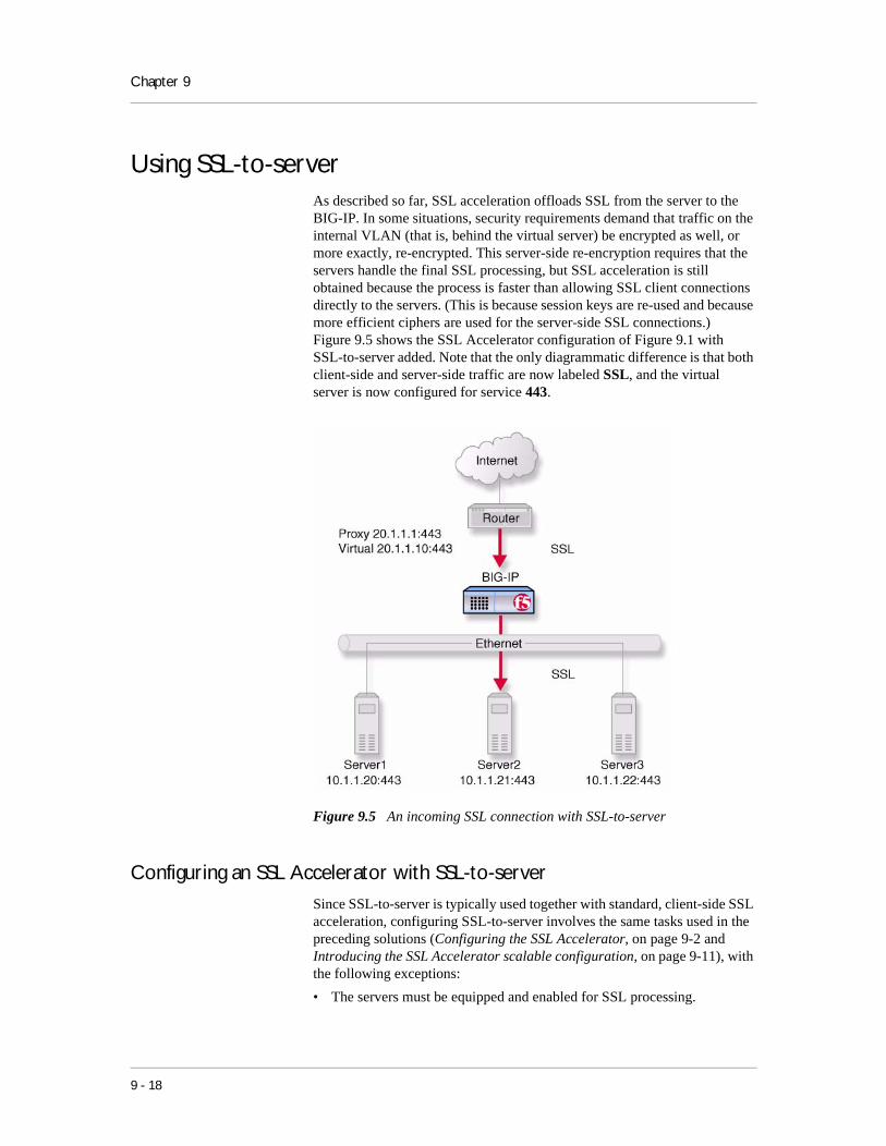
Chapter 9
Using SSL-to-serverAs described so far, SSL acceleration offloads SSL from the server to the BIG-IP. In some situations, security requirements demand that traffic on the internal VLAN (that is, behind the virtual server) be encrypted as well, or more exactly, re-encrypted. This server-side re-encryption requires that the servers handle the final SSL processing, but SSL acceleration is still obtained because the process is faster than allowing SSL client connections directly to the servers. (This is because session keys are re-used and because more efficient ciphers are used for the server-side SSL connections.) Figure 9.5 shows the SSL Accelerator configuration of Figure 9.1 with SSL-to-server added. Note that the only diagrammatic difference is that both client-side and server-side traffic are now labeled SSL, and the virtual server is now configured for service 443.
Figure 9.5 An incoming SSL connection with SSL-to-server
Configuring an SSL Accelerator with SSL-to-server
Since SSL-to-server is typically used together with standard, client-side SSL acceleration, configuring SSL-to-server involves the same tasks used in the preceding solutions (Configuring the SSL Accelerator, on page 9-2 and Introducing the SSL Accelerator scalable configuration, on page 9-11), with the following exceptions:
• The servers must be equipped and enabled for SSL processing.
9 - 18

Configuring an SSL Accelerator
• In most cases, you will want to configure the server pool and virtual server as HTTPS rather than HTTP and change the proxy targets accordingly.
• For the proxy or proxies, you must enable server-side SSL.
Optionally, you may configure a second certificate on the proxy to authenticate it to the servers as a trusted client.
Configuring a server pool and virtual server for HTTPS
To configure the server pool and virtual server for HTTPS for the non-scalable configuration, simply perform the steps in Creating a pool for the HTTP servers, on page 9-9 and Creating an HTTP virtual server, on page 9-9, only rename the pool https_pool and substitute service 443 for service 80 for both the nodes and for the virtual server. (Also, give the virtual server a different IP address.) If you use the command line, you accomplish these tasks as follows:
b pool https_pool { \
member 10.1.1.20:443 \
member 10.1.1.21:443 \
member 10.1.1.22:443 }
b virtual 20.1.1.1:443 use pool https_pool
To configure the server pool members and virtual server for HTTPS for the scalable configuration, perform the steps in Creating load balancing pools, on page 9-13, only rename the pool https_virtual and substitute service 443 for service 80 for all nodes and for the virtual server. If you use the command line, you accomplish these tasks as follows:
b pool https_virtual { \
member 10.3.0.11:443 \
member 10.3.0.12:443 \
member 10.3.0.13:443 \
member 10.3.0.14:443 }
b pool ssl_gateways { \
member 10.1.0.111:443 \
member 10.1.0.112:443 \
member 10.1.0.113:443 \
member 10.1.0.114:443 }
b virtual 192.168.200.30:443 use pool ssl_gateways
b virtual 192.168.200.40:443 use pool https_virtual
Configuring the proxy for server-side SSL
To configure the proxy for server-side SSL for the non-scalable configuration, perform the steps in Creating an SSL gateway, on page 9-10, specifying the serverssl enable attribute in addition to the clientssl enable
BIG-IP® Solutions Guide 9 - 19

Chapter 9
attribute. Also, when specifying the target virtual server, it is recommended that you specify it as HTTPS instead of HTTP. If you use the command line, you accomplish these tasks as follows:
b proxy 20.1.1.1:443 \
target virtual 20.1.1.10:443 \
clientssl enable \
clientssl key my.server.net.key \
clientssl cert my.server.net.crt \
serverssl enable
Optionally, you may specify a key file and a certificate file for the proxy as a client. This is done as follows:
b proxy 20.1.1.1:443 \
target virtual 20.1.1.10:443 \
clientssl enable \
clientssl key my.server.net.key \
clientssl cert my.server.net.crt \
serverssl enable \
serverssl key my.client.net.key \
serverssl cert my.client.net.key
Additional configuration optionsWhenever a BIG-IP is configured, you have a number of options:
◆ When you create an SSL proxy, you have a number of options that you can configure. Refer to Chapter 4, Configuring the High-Level Network, in the BIG-IP Reference Guide.
◆ You have the option in all configurations to configure a BIG-IP redundant system for fail-over. Refer to Chapter 6, Configuring a Redundant System, in the BIG-IP Reference Guide.
◆ All configurations have health monitoring options. Refer to Health Monitors in Chapter 4, Configuring the High-Level Network, in the BIG-IP Reference Guide.
◆ When you create a pool, there is an option to set up persistence and a choice of load balancing methods. Refer to Pools in the Chapter 4, Configuring the High-Level Network, in the BIG-IP Reference Guide.
9 - 20

10
Balancing Two-Way Traffic Across Firewalls
• Introducing two-way firewall load balancing
• Configuring two-way firewall load balancing
• Additional configuration options


Balancing Two-Way Traffic Across Firewalls
Introducing two-way firewall load balancingThis chapter describes how to set up a configuration that load balances two types of traffic:
• Users on the Internet requesting information from a pair of enterprise servers behind the enterprise’s set of firewalls, generating inbound traffic.
• Users behind a set of firewalls requesting information from Internet servers, generating outbound traffic.
This type of configuration is appropriate for any enterprise that wants to provide information by way of the Internet, while limiting traffic to a specific service; and also wants to maintain a large intranet with fast access to the Internet for internal users.
This configuration calls for two BIG-IP units:
• A BIG-IP on the outside (that is, the side nearest the Internet) of the firewalls, to balance traffic inbound across the firewalls.
• A BIG-IP on the inside (that is, the side nearest the enterprise servers) of the firewalls to balance traffic outbound across the firewalls, and also to balance traffic inbound across the server array.
Collectively, this is known as a firewall sandwich configuration, because the BIG-IP units are on either side of the firewalls sandwiching them. Figure 10.1, following, illustrates this type of configuration, and provides an example configuration for this entire chapter. When creating your own configuration, remember to use IP addresses, host names, and so on, that are applicable to your own network.
Note
All products except the BIG-IP e-Commerce Controller support this configuration.
BIG-IP® Solutions Guide 10 - 1
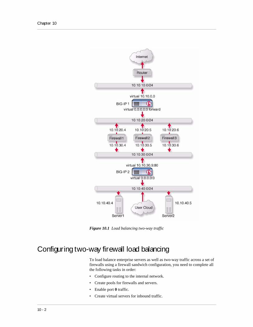
Chapter 10
Figure 10.1 Load balancing two-way traffic
Configuring two-way firewall load balancingTo load balance enterprise servers as well as two-way traffic across a set of firewalls using a firewall sandwich configuration, you need to complete all the following tasks in order:
• Configure routing to the internal network.
• Create pools for firewalls and servers.
• Enable port 0 traffic.
• Create virtual servers for inbound traffic.
10 - 2

Balancing Two-Way Traffic Across Firewalls
• Create virtual servers for outbound traffic.
• Configure administrative routing.
The following sections provide details on how to set up this configuration, using the sample IP addresses and device names in Figure 10.1 as an example.
Configuring routing to the internal network
The external router should route traffic bound for the network that includes your intranet by way of the external shared alias of the external BIG-IP redundant system.
In Figure 10.1, the internal BIG-IP, the network is 10.10.30.0/24, and the external address (or floating alias for redundant system) is 10.10.10.1. Thus, a command to configure this routing might be:
Route add -net 10.10.30.0 -gateway 10.10.10.1
The exact syntax of this command depends on the type of router.
Creating pools for firewalls and servers
To use this configuration, you must create three load balancing pools.
◆ To load balance incoming requests across the external interfaces of your firewalls, you create a pool that includes these external interfaces.
◆ Because requests that pass through the firewalls must be load balanced to the enterprise servers, you create a pool that includes these enterprise servers.
◆ Outgoing requests must be balanced across the internal interfaces of your firewalls, so you create a pool that includes these internal interfaces.
To create a pool using the Configuration utility
1. In the navigation pane, click Pools.The Pools screen opens.
2. Click the Add button.The Add Pool screen opens.
3. Enter the pool name and member addresses in the Add Pool screen. (For additional information about configuring a pool, click the Help button.)
Configuration notes
When you create the configuration shown in Figure 10.1:
On the outside BIG-IP in Figure 10.1 labeled BIG-IP 1, create the pool firewalls_outside containing members 10.10.20.4, 10.10.20.5, and 10.10.20.6.
BIG-IP® Solutions Guide 10 - 3

Chapter 10
On the inside BIG-IP in Figure 10.1 labeled BIG-IP 2, define pool firewalls_inside containing the members 10.10.30.4, 10.10.320.5, and 10.10.30.6.
On the inside BIG-IP 2, define the pool servers containing members 10.10.40.4 and 10.10.20.5.
To define the pools from the command line
Use the bigpipe pool command to create the pool:
b pool <pool name> { member <Firewall1>:0 member <Firewall2>:0 member <Firewall3>:0 }
To achieve the configuration in Figure 10.1, the commands would be:
b pool firewalls_outside { \
member 10.10.20.4:0 \
member 10.10.20.5:0 \
member 10.10.20.6:0 }
b pool firewalls_inside { \
member 10.10.30.4:0 \
member 10.10.30.5:0 \
member 10.10.30.6:0 }
b pool servers { \
member 10.10.40.4:0 \
member 10.10.40.5:0 }
Enabling port 0
For security reasons, the ports on the BIG-IP do not accept traffic until you enable them. In this configuration, the system accepts traffic on port 0. For this configuration to work, you must enable port 0. Use the following command to enable this port:
b service 0 tcp enable
Note
This step is only required if you create this configuration from the command line. If you create the configuration from the web-based Configuration utility, the port is opened automatically.
Creating virtual servers
After you define the pools, you can define virtual servers on the BIG-IP units to load balance inbound and outbound connections.
• For inbound connections, create a network virtual server on the outside BIG-IP in Figure 10.1 labeled BIG-IP 1 to load balance the firewalls. A network virtual server is a virtual server that handles a whole network range, instead of just one IP address.
10 - 4

Balancing Two-Way Traffic Across Firewalls
• For inbound connections, create a standard virtual server on the inside BIG-IP in Figure 10.1 labeled BIG-IP 2 to load balance the enterprise servers.
• For outbound connections, create a wildcard virtual server on the inside BIG-IP to balance traffic outbound to the firewalls.
• For outbound connections, create a forwarding wildcard virtual server on the outside BIG-IP to forward traffic to the Internet. A forwarding virtual server is a virtual server that merely forwards traffic, rather than balancing it across nodes.
To define a virtual server using the Configuration utility
1. In the navigation pane, click Virtual Servers.The Virtual Servers screen opens.
2. Click the Add button.The Add Virtual Server screen opens.
3. Enter the virtual server address and pool name. (For additional information about configuring a virtual server, click the Help button.)
Configuration notes
When you create the configuration shown in Figure 10.1:
Add a network virtual server with address 10.10.0.0 and port 80 using pool firewalls_outside.
Add a standard virtual server with address 10.10.30.9 and port 80 using the pool severs.
Create a wildcard virtual server on the inside BIG-IP with the address 0.0.0.0:0 using pool firewalls_inside.
Create a forwarding wildcard virtual server on the outside BIG-IP with address 0.0.0.0:0. A forwarding virtual server is a virtual server that merely forwards traffic, rather than using a load-balancing pool.
To define the virtual server from the command line
Use the bigpipe virtual command to configure the virtual servers:
b virtual <virt_ip>:<service> use pool <pool name>
For this example, use the following commands:
b virtual 10.10.0.0 use pool firewall_outsides
b virtual 10.10.30.9:80 use pool servers
b virtual 0.0.0.0:0 use pool firewall_insides vlans disable external
b virtual 0.0.0.0:0 forward vlans external disable
BIG-IP® Solutions Guide 10 - 5

Chapter 10
Enhancing security for this configuration
In some situations, you may want to limit the types of traffic that can pass outbound to the Internet. You can use port-specific wildcard virtual servers to restrict traffic in this manner. While a standard wildcard virtual server forwards all traffic, a port-specific wildcard virtual server forwards traffic specific to only the specified port. For more information, see Virtual server in the BIG-IP Reference Guide, Chapter 4, Configuring the High-Level Network.
To create a port-specific wildcard server using theConfiguration utility
Follow the instructions detailed in To define a virtual server using the Configuration utility, on page 10-5.
◆ When you configure the Port attribute, choose the port to which you want outgoing traffic to be limited for that virtual server.
◆ Complete the rest of the steps as detailed on page 10-5, then repeat the process for any other ports you want to be accessible to outgoing traffic.
For example, to implement the configuration shown in Figure 10.1 on page 10-2, to limit the traffic forwarded to HTTP and FTP, you would follow the instructions in To define a virtual server using the Configuration utility three times. That is, once for each of three port-specific virtual servers, entering respectively 80, 20, and 21 for the Port attribute.
To create a port-specific wildcard server from thecommand line
To create a port-specific wildcard server, use the bigpipe virtual command as you did in To define the virtual server from the command line, on page 10-5. For the sample port number, substitute the number of the port to which you want to limit access.
For example, in the configuration shown in Figure 10.1 on page 10-2, to limit the traffic forwarded to HTTP and FTP, you replace the command in the preceding section with the following commands:
b virtual 0.0.0.0:80 use pool firewall
b virtual 0.0.0.0:20 use pool firewall
b virtual 0.0.0.0:21 use pool firewall
Configuring administrative routing
In order to administer the outside BIG-IP from the inside BIG-IP redundant system and the reverse, you need to create routes between the systems, using the firewalls as gateways.
To implement the configuration shown in Figure 10.1 on page 10-2, you use the following commands on the BIG-IP labeled BIG-IP 1:
route add -host 10.10.30.1 -gateway 10.10.20.4
10 - 6

Balancing Two-Way Traffic Across Firewalls
If BIG-IP 2 is a redundant pair with 10.10.30.2 and 10.10.30.3 as its external addresses and 10.10.30.1 as their floating alias use these commands:
route add -host 10.10.30.1 -gateway 10.10.20.4
route add -host 10.10.30.2 -gateway 10.10.20.5
route add -host 10.10.30.3 -gateway 10.10.20.6
To complete the configuration, you use the following commands on the BIG-IP in Figure 10.1 labeled BIG-IP 2:
route add -host 10.10.20.1 -gateway 10.10.30.4
If BIG-IP 1 is a redundant pair with 10.10.20.2 and 10.10.20.3 as its internal addresses and 10.10.20.1 as their floating alias:
route add -host 10.10.20.1 -gateway 10.10.30.4
route add -host 10.10.20.2 -gateway 10.10.30.5
route add -host 10.10.20.3 -gateway 10.10.30.6
Additional configuration optionsWhenever a BIG-IP is configured, you have a number of options:
◆ You have the option in all configurations to configure a BIG-IP redundant system for fail-over. Refer to Chapter 6, Configuring a Redundant System, in the BIG-IP Reference Guide.
◆ All configurations have health monitoring options. Refer to Health Monitors in Chapter 4, Configuring the High-Level Network, in the BIG-IP Reference Guide.
◆ When you create a pool, there is an option to set up persistence and a choice of load balancing methods. Refer to Pools in the Chapter 4, Configuring the High-Level Network, in the BIG-IP Reference Guide.
BIG-IP® Solutions Guide 10 - 7

Chapter 10
10 - 8

11
Load Balancing a Cache Array for LocalServer Acceleration• Introducing local server acceleration
• Configuring local acceleration
• Creating pools
• Creating a cache rule
• Creating a virtual server
• Configuring for intelligent cache population
• Additional configuration options


Load Balancing a Cache Array for Local Server Acceleration
Introducing local server accelerationThis chapter explains how to set up a local server acceleration configuration, in which a BIG-IP uses content-aware traffic direction to enhance the efficiency of an array of cache servers that cache content for a local web server. This type of configuration is useful for any enterprise that wants to improve the speed with which it responds to content requests from users on the Internet.
Note
All BIG-IP products except the BIG-IP LB Controller and BIG-IP e-Commerce Controller support this configuration.
The configuration detailed in this chapter uses the following BIG-IP features:
◆ Cacheable content determinationWith cacheable content determination you can determine the type of content you cache on the basis of any combination of elements in the header of an HTTP request.
◆ Content affinityContent affinity ensures that a given subset of content remains associated with a given cache to the maximum extent possible, even when cache servers become unavailable, or are added or removed. This feature also maximizes efficient use of cache memory.
◆ Hot content load balancingHot content load balancing identifies hot, or frequently requested, content on the basis of the number of requests in a given time period for a given hot content subset. A hot content subset is different from, and typically smaller than, the content subsets used for content striping. Requests for hot content are redirected to a cache server in the hot pool, a designated group of cache servers. This feature maximizes the use of cache server processing power without significantly affecting the memory efficiency gained by content affinity.
◆ Intelligent cache population Intelligent cache population allows caches to retrieve content from other caches in addition to from the origin web server. This feature is useful only when working with non-transparent cache servers, which can receive requests that are destined for the cache servers themselves, as opposed to transparent cache servers, which can intercept requests destined for a web server. Intelligent cache population minimizes the load on the origin web server and speeds cache population.
BIG-IP® Solutions Guide 11 - 1

Chapter 11
Maximizing memory or processing power
From the time you implement a cache rule until such time as a hot content subset becomes hot, the content is divided across your cache servers, so that no two cache servers contain the same content. In this way, efficient use of the cache servers’ memory is maximized.
After a hot content subset becomes hot, requests for any content contained in that subset are load balanced, so that, ultimately, each cache server contains a copy of the hot content. The BIG-IP distributes requests for the hot content among the cache servers. This way, efficient use of the cache servers’ processing power is maximized.
Thus, for a particular content item, the BIG-IP maximizes either cache server memory (when the content is cool) or cache server processing power (when the content is hot), but not both at the same time. The fact that content is requested with greatly varying frequency enables the cache statement rule to evaluate and select the appropriate attribute to maximize for a given content subset.
Using the configuration diagram
Figure 11.1 illustrates a local server acceleration configuration, and provides an example configuration for this entire chapter. When creating your own configuration, remember to use IP addresses, and host names, that are applicable to your own network.
Figure 11.1 Local server acceleration
11 - 2

Load Balancing a Cache Array for Local Server Acceleration
Configuring local accelerationIf you want to configure local server acceleration, you need to complete the following tasks in order:
• Create pools
• Create a cache rule
• Create a virtual server
• Configure for intelligent cache population
Each of the following sections explains one of these tasks, and shows how you would perform the tasks in order to implement the configuration shown in Figure 11.1. Note that in this example, as in all examples in this guide, we use only non-routable IP addresses. In a real topology, the appropriate IP addresses would have to be routable on the Internet.
Creating poolsTo use the local server acceleration configuration, you need to create three sets of load balancing pools. A pool is a group of devices to which you want the BIG-IP to direct traffic. You create pools for your origin server (the web server on which all your content resides), for your cache servers, and for your hot, or frequently requested, content servers, which may or may not be cache servers. For more information about pools, refer to Pools in the BIG-IP Reference Guide, Chapter 4, Configuring the High-Level Network.
You will create these pools:
◆ Cache server poolThe BIG-IP directs all cacheable requests bound for your web server to this pool, unless a request is for hot content.
◆ Origin server poolThis pool includes your origin web server. Requests are directed to this pool when:
• The request is for non-cacheable content; that is, content that is not identified in the cacheable content expression part of a cache statement. For more information, see Using a cacheable content expression, on page 11-5.
• The request is from a cache server that does not yet contain the requested content, and no other cache server yet contains the requested content.
• No cache server in the cache pool is available.
BIG-IP® Solutions Guide 11 - 3

Chapter 11
◆ Hot cache servers poolIf a request is for frequently requested content, the BIG-IP directs the request to this pool.
Note
While the configuration shown in Figure 11.1 implements a hot cache servers pool, this pool is not required if you want to use the content determination and content affinity features. However, you must implement this pool if you want to use the hot content load balancing or intelligent cache population features.
To create a pool using the Configuration utility
1. In the navigation pane, click Pools.The Pools screen opens.
2. Click the Add button.The Add Pool screen opens.
3. For each pool, enter the pool name and member addresses in the Add Pool screen. (For additional information about configuring a pool, click the Help button.)
Configuration Note
For this example create the following pools:
Create a pool named cache_servers with members 10.10.20.4, 10.10.20.5, and 10.10.20.61. For each cache server you add to the pool, specify port 80, which means this cache server accepts traffic for the HTTP service only.
Create a pool named origin_server with member 10.10.20.7 and specify port 80, which means the server accepts traffic for the HTTP service only.
Create a pool named hot_cache_servers with members 10.10.20.4, 10.10.20.5, and 10.10.20.6, in the pool. For each cache server you add to the pool, specify port 80, which means this cache server accepts traffic for the HTTP service only.
To create a pool from the command line
To define a pool from the command line, use the following syntax:
b pool <pool_name> { \
member <member_definition> ... member <member_definition> }
To create the cache server pool, type:
b pool cache_servers { \
member 10.10.20.4:80 \
member 10.10.20.5:80 \
member 10.10.20.6:80 }
11 - 4

Load Balancing a Cache Array for Local Server Acceleration
To create the origin server pool, type:
b pool origin_server { member 10.10.20.7:80 }
To create the hot pool, type:
b pool hot_cache_servers { \
member 10.10.20.4:80 \
member 10.10.20.5:80 \
member 10.10.20.6:80 }
Note
If you have the hot content pool and the cache servers pool reference the same nodes, it enables use of the intelligent cache population feature.
Creating a cache ruleA cache rule is a specific type of rule. A rule establishes criteria by which a BIG-IP directs traffic. A cache rule determines where and how the BIG-IP directs content requests in order to maximize the efficiency of your cache server array and of your origin web server.
A cache rule includes a cache statement, which is composed of a cacheable content expression and two attributes. An attribute is a variable that the cache statement uses to direct requests. It can also include several optional attributes.
A cache statement may be either the only statement in a rule, or it may be nested in a rule within an if statement.
Using a cacheable content expression
The cacheable content expression determines whether the BIG-IP directs a given request to the cache server or to the origin server, based on evaluating variables in the HTTP header of the request.
Any content that does not meet the criteria in the cacheable content expression is deemed non-cacheable.
For example, in the configuration illustrated in this chapter, the cacheable content expression includes content having the file extension .html or .gif. The BIG-IP considers any request for content having a file extension other than .html or .gif to be non-cacheable, and sends such requests directly to the origin server.
For your configuration, you may want to cache any content that is not dynamically generated.
BIG-IP® Solutions Guide 11 - 5

Chapter 11
Working with required attributes
The cache rule must include the following attributes:
◆ origin_poolSpecifies a pool of servers that contain original copies of all content. Requests are load balanced to this pool when any of the following are true:
• The requested content does not meet the criteria in the cacheable content condition.
• No cache server is available.
• The BIG-IP is redirecting a request from a cache server that did not have the requested content.
◆ cache_poolSpecifies a pool of cache servers to which requests are directed in a manner that optimizes cache performance.
Using optional attributes
The attributes in this section apply only if you are using the hot content load balancing feature.
Note
In order to use the intelligent cache population feature, the cache_pool and the hot_pool must either be the same pool, or different pools referencing the same nodes.
◆ hot_poolSpecifies a pool of cache servers to which requests are load balanced when the requested content is hot. The hot_pool attribute is required if any of the following attributes is specified.
◆ hot_thresholdSpecifies the minimum number of requests for content in a given hot content set that causes the content set to change from cool to hot at the end of the period.If you specify a value for hot_pool, but do not specify a value for this variable, the cache statement uses a default hot threshold of 100 requests.
◆ cool_thresholdSpecifies the maximum number of requests for content in a given hot content set that causes the content set to change from hot to cool at the end of the hit period. If you specify a variable for hot_pool, but do not specify a value for this variable, the cache statement uses a default cool threshold of 10 requests.
◆ hit_periodSpecifies the period in seconds over which to count requests for particular content before determining whether to change the content demand status (hot or cool) of the content. If you specify a value for hot_pool, but do not specify a value for this variable, the cache statement uses a default hit period of 60 seconds.
11 - 6

Load Balancing a Cache Array for Local Server Acceleration
◆ content_hash_sizeSpecifies the number of units, or hot content subsets, into which the content is divided when determining whether content demand status is hot or cool. The requests for all content in a given subset are summed, and a content demand status (hot or cool) is assigned to each subset. The content_hash_size should be within the same order of magnitude as the actual number of requests possible. For example, if the entire site is composed of 500,000 pieces of content, a content_hash_size of 100,000 would be typical. If you specify a value for hot_pool, but do not specify a value for this variable, the cache statement uses a default hash size of 1028 subsets.
Setting content demand status
Content demand status is a measure of the frequency with which a given hot content subset is requested. Content demand status, which is either hot or cool, is applicable only when using the hot content load balancing feature. For a given hot content subset, content demand status is cool from the time the cache rule is implemented until the number of requests for the subset exceeds the hot_threshold during a hit_period. At this point, content demand status for the subset becomes hot, and requests for any item in the subset are load balanced to the hot_pool. Content demand status remains hot until the number of requests for the subset falls below the cool_threshold during a hit_period, at which point the content demand status becomes cool. The BIG-IP then directs requests for any item in the subset to the appropriate server in the cache_pool until such time as the subset becomes hot again. The following steps show how, for the configuration shown in Figure 11.1 on page 11-2, you would cache all content having the file extension .html or .gif.
To create a cache rule using the Configuration utility
1. In the navigation pane, click Rules.The Rules screen opens.
2. Click the Add button.The Add Rule screen opens.
3. In the Add Rule screen, type the cache statement. For example, for the configuration shown in Figure 11.1, to cache all content having either the file extension .html or .gif, you would type:
rule cache_rule { cache ( http_uri ends_with "html" or http_uri ends_with "gif" ) {origin_pool origin_server cache_pool cache_servers hot_pool hot_cache_servers } }
4. Click the Add button.
BIG-IP® Solutions Guide 11 - 7

Chapter 11
To create a cache statement rule from the command line
To create a cache statement rule for this configuration, use the following command:
b ’rule cache_rule { \
cache ( http_uri ends_with "html" or http_uri ends_with "gif" )\
{ origin_pool origin_server \
cache_pool cache_servers \
hot_pool hot_cache_servers } }’
This caches all content having the file extension .html or .gif.
Creating a virtual serverNow that you have created pools and a cache rule to determine how the BIG-IP will distribute traffic in the configuration, you need to create a virtual server to use this rule and these pools. For example:
◆ Add a virtual server with address 10.10.10.4 and port 80 (this means the virtual server accepts traffic for the HTTP service only).
◆ Add the rule cache_rule.
To create a virtual server using the Configuration utility
1. In the navigation pane, click Virtual Servers.
2. Click the Add button.The Add Virtual Server screen opens.
3. For each virtual server, enter the virtual server address and pool name. (For additional information about configuring a virtual server, click the Help button.)
To create a virtual server from the command line
To create a virtual server from the command line, type the following command:
b virtual 10.10.10.4:80 use rule cache_rule
Configuring for intelligent cache populationYour cache rule routes a request to the appropriate cache server. However, the cache server will not have the requested content if the content has expired, or if the cache server is receiving a request for this content for the first time. If the cache does not have the requested content, the cache initiates a miss request (that is, a request resulting from a request for content a cache does not have) for this content. The miss request goes to the origin server specified in the configuration of the cache or to another cache server.
11 - 8

Load Balancing a Cache Array for Local Server Acceleration
If you want to allow intelligent cache population, you should configure the cache with its origin server set to be the virtual server on the BIG-IP, so that the cache sends miss requests to the internal interface of the BIG-IP. The BIG-IP translates the destination of the request, and sends the request to either the origin server or another cache server that already has the requested content.
To ensure that the origin server or cache server responds to the BIG-IP rather than to the original cache server that generated the miss request, the BIG-IP also translates the source of the miss request to the translated address and port of the associated Secure Network Address Translation (SNAT) connection.
In order to use this solution, you must create a SNAT on the BIG-IP.
Configuring a SNAT
A Secure Network Address Translation (SNAT) translates the address of a packet from the cache server to the address you specify. For more information about SNATs, see SNATs in the BIG-IP Reference Guide, Chapter 4, Configuring the High-Level Network. When you create the configuration shown in Figure 11.1, use the translation address 10.10.10.5.
To configure a SNAT mapping using the Configurationutility
1. In the navigation pane, click SNATs.The SNATs screen opens.
2. Click the Add button.The Add SNAT screen opens.
3. In the Add SNAT screen, configure the attributes required for the SNAT you want to add. For additional information about configuring a pool, click the Help button.
To configure a SNAT mapping from the command line
Use the bigpipe virtual command to configure the virtual server to use the pool that contains the outside addresses of the firewalls:
b virtual <virt_ip>:<service> use rule <rule name>
To implement the configuration shown in Figure 11.1, you use the command:
b snat map 10.10.20.4 10.10.20.5 10.10.20.6 to 10.10.10.5
BIG-IP® Solutions Guide 11 - 9

Chapter 11
Additional configuration optionsWhenever a BIG-IP is configured, you have a number of options:
◆ You have the option in all configurations to configure a BIG-IP redundant system for fail-over. Refer to Chapter 6, Configuring a Redundant System, in the BIG-IP Reference Guide.
◆ All configurations have health monitoring options. Refer to Health Monitors in Chapter 4, Configuring the High-Level Network, in the BIG-IP Reference Guide.
◆ When you create a pool, there is an option to set up persistence and a choice of load balancing methods. Refer to Pools in the Chapter 4, Configuring the High-Level Network, in the BIG-IP Reference Guide.
11 - 10

12
Load Balancing a Cache Array for RemoteServer Acceleration• Introducing remote server acceleration
• Configuring remote server acceleration
• Creating pools
• Creating a cache rule
• Creating a virtual server
• Configuring for intelligent cache population
• Additional configuration options


Load Balancing a Cache Array for Remote Server Acceleration
Introducing remote server accelerationThis chapter explains how to set up a remote server acceleration configuration, in which a BIG-IP uses content-aware traffic direction to enhance the efficiency of an array of cache servers that cache content for a remote web server.
Note
All BIG-IP products except the BIG-IP LoadBalancer Controller support this configuration.
Figure 12.1 illustrates the remote server acceleration configuration, and provides an example configuration for this entire chapter. Remember that this is just a sample: when creating your own configuration, you must use IP addresses, host names, and so on, that are applicable to your own network.
Figure 12.1 Remote server acceleration
This configuration is similar to the configuration discussed in Chapter 11, Load Balancing a Cache Array for Local Server Acceleration. The difference is that, in this configuration, the cache servers reside on an intranet network, while the origin web server resides on the Internet; in the local server acceleration configuration, the origin web server and the cache servers all reside on the intranet. The remote server acceleration configuration is appropriate for any enterprise in which the cache server network and web server network are separated, and you want maximum speed and efficiency from both the cache servers and web server.
BIG-IP® Solutions Guide 12 - 1
Chapter 12
The configuration detailed in this chapter uses the following BIG-IP features:
◆ Cacheable content determinationWith cacheable content determination, you can determine the type of content you cache on the basis of any combination of elements in the header of an HTTP request.
◆ Content affinityContent affinity ensures that a given subset of content remains associated with a given cache to the maximum extent possible, even when cache servers become unavailable, or are added or removed. This feature also maximizes efficient use of cache memory.
◆ Hot content load balancingHot content load balancing identifies hot, or frequently requested, content on the basis of number of requests in a given time period for a given hot content subset. A hot content subset is different from, and typically smaller than, the content subsets used for content striping. Requests for hot content are redirected to a cache server in the hot pool, a designated group of cache servers. This feature maximizes the use of cache server processing power without significantly affecting the memory efficiency gained by content affinity.
◆ Intelligent cache population Intelligent cache population allows caches to retrieve content from other caches in addition to the origin web server. This feature is useful only when working with non-transparent cache servers, which can receive requests that are destined for the cache servers themselves, as opposed to transparent cache servers, which can intercept requests destined for a web server. Intelligent cache population minimizes the load on the origin web server and speeds cache population.
Maximizing memory or processing power
From the time you implement a cache rule until such time as a hot content subset becomes hot, the content is divided across your cache servers, so that no two cache servers contain the same content. In this way, efficient use of the cache servers’ memory is maximized.
After a hot content subset becomes hot, requests for any content contained in that subset are load balanced, so that, ultimately, each cache server contains a copy of the hot content. The BIG-IP distributes requests for the hot content among the cache servers. In this way, efficient use of the cache servers’ processing power is maximized.
Thus, for a particular content item, the BIG-IP maximizes either cache server memory (when the content is cool) or cache server processing power (when the content is hot), but not both at the same time. The fact that content is requested with greatly varying frequency enables the cache statement rule to evaluate and select the appropriate attribute to maximize for a given content subset.
12 - 2

Load Balancing a Cache Array for Remote Server Acceleration
Configuring remote server accelerationTo configure remote server acceleration, complete the following tasks in order:
• Create pools
• Create a cache rule
• Create a virtual server
• Configure for intelligent cache population
Each of the following sections explains one of these tasks, and shows how you would perform the tasks in order to implement the configuration shown in Figure 12.1. Note that in this example, as in all examples in this guide, we use only non-routable IP addresses. In a real topology, the appropriate IP addresses would have to be routable on the Internet.
Creating poolsTo use the remote server acceleration configuration, you create three sets of load balancing pools. You create pools for your origin server (the web server on which all your content resides), for your cache servers, and for your hot, or frequently requested, content servers, which may or may not be cache servers. A pool is a group of devices to which you want the BIG-IP to direct traffic. For more information about pools, refer to Pools in the BIG-IP Reference Guide, Chapter 4, Configuring the High-Level Network.
You will create these pools:
◆ Cache server poolThe BIG-IP directs all cacheable requests bound for your web server to this pool, unless a request is for hot content.
◆ Origin server poolThis pool includes your origin web server. Requests are directed to this pool when:
• The request is for non-cacheable content; that is, content that is not identified in the cacheable content expression part of a cache statement. For more information, see Working with a cacheable content expression, on page 12-5.
• The request is from a cache server that does not yet contain the requested content, and no other cache server yet contains the requested content.
• No cache server in the cache pool is available.
BIG-IP® Solutions Guide 12 - 3
Chapter 12
◆ Hot cache servers poolIf a request is for frequently requested content, the BIG-IP directs the request to this pool.
Note
While the configuration shown in Figure 12.1 implements a hot cache servers pool, this pool is not required if you want to use the content determination and content affinity features. However, you must implement this pool if you want to use the hot content load balancing or intelligent cache population features.
To create a pool using the Configuration utility
1. In the navigation pane, click Pools.The Pools screen opens.
2. Click the Add button.The Add Pool screen opens.
3. For each pool, enter the pool name and member addresses in the Add Pool screen. (For additional information about configuring a pool, click the Help button.)
Configuration Notes
First, create a pool for the cache servers. For example:
Create a pool named cache_servers with members 10.10.20.4, 10.10.20.5, and 10.10.20.6. For each cache server you add to the pool, specify port 80, which means this cache server accepts traffic for the HTTP service only.
Create a pool named origin_server with member 192.168.10.1 and specify port 80, which means the server accepts traffic for the HTTP service only
Create a pool named hot_cache_servers with members 10.10.20.4, 10.10.20.5, and 10.10.20.6 and specify port 80, which means this cache server accepts traffic for the HTTP service only.
To create a cache server pool from the command line
To define a pool from the command line, use the following syntax:b pool <pool_name> { lb_method <lb_method> member <member_definition> ... member
<member_definition> }
To create the cache server pool, type:
b pool cache_servers { \
member 10.10.20.4:80 \
member 10.10.20.5:80 \
member 10.10.20.6:80 }
To create the origin server pool, type:
b pool origin_server { member 192.168.10.1:80 }
12 - 4

Load Balancing a Cache Array for Remote Server Acceleration
To create the hot pool, type:
b pool hot_cache_servers { \
member 10.10.20.4:80 \
member 10.10.20.5:80 \
member 10.10.20.6:80 }
Note
If you have the hot content pool and the cache servers pool reference the same nodes, it enables use of the intelligent cache population feature.
Creating a cache ruleA cache rule is a specific type of rule. A rule establishes criteria by which a BIG-IP directs traffic. A cache rule determines where and how the BIG-IP directs content requests in order to maximize the efficiency of your cache server array and of your origin web server.
A cache rule includes a cache statement, which is composed of a cacheable content expression and two attributes. An attribute is a variable that the cache statement uses to direct requests. It can also include several optional attributes.
A cache statement may be either the only statement in a rule, or it may be nested in a rule within an if statement.
Working with a cacheable content expression
The cacheable content expression determines whether the BIG-IP directs a given request to the cache server or to the origin server, based on evaluating variables in the HTTP header of the request.
Any content that does not meet the criteria in the cacheable content expression is deemed non-cacheable.
For example, in the configuration illustrated in this chapter, the cacheable content expression includes content having the file extension .html or .gif. The BIG-IP considers any request for content having a file extension other than .html or .gif to be non-cacheable, and sends such requests directly to the origin server.
For your configuration, you may want to cache any content that is not dynamically generated.
BIG-IP® Solutions Guide 12 - 5

Chapter 12
Using required attributes
The cache rule must include the following attributes:
◆ origin_poolSpecifies a pool of servers that contain original copies of all content. Requests are load balanced to this pool when any of the following are true:
• The requested content does not meet the criteria in the cacheable content condition.
• No cache server is available.
• The BIG-IP is redirecting a request from a cache server that did not have the requested content.
◆ cache_poolSpecifies a pool of cache servers to which requests are directed in a manner that optimizes cache performance.
Reviewing optional attributes
The attributes in this section apply only if you are using the hot content load balancing feature.
Note
In order to use the intelligent cache population feature, the cache_pool and the hot_pool must either be the same pool, or different pools referencing the same nodes.
◆ hot_poolSpecifies a pool of cache servers to which requests are load balanced when the requested content is hot.
The hot_pool attribute is required if any of the following attributes is specified:
◆ hot_thresholdSpecifies the minimum number of requests for content in a given hot content set that causes the content set to change from cool to hot at the end of the period.If you specify a value for hot_pool, but do not specify a value for this variable, the cache statement uses a default hot threshold of 100 requests.
◆ cool_thresholdSpecifies the maximum number of requests for content in a given hot content set that causes the content set to change from hot to cool at the end of the hit period. If you specify a variable for hot_pool, but do not specify a value for this variable, the cache statement uses a default cool threshold of 10 requests.
◆ hit_periodSpecifies the period in seconds over which to count requests for particular content before determining whether to change the content
12 - 6

Load Balancing a Cache Array for Remote Server Acceleration
demand status (hot or cool) of the content. If you specify a value for hot_pool, but do not specify a value for this variable, the cache statement uses a default hit period of 60 seconds.
◆ content_hash_sizeSpecifies the number of units, or hot content subsets, into which the content is divided when determining whether content demand status is hot or cool. The requests for all content in a given subset are summed, and a content demand status (hot or cool) is assigned to each subset. The content_hash_size should be within the same order of magnitude as the actual number of requests possible. For example, if the entire site is composed of 500,000 pieces of content, a content_hash_size of 100,000 would be typical. If you specify a value for hot_pool, but do not specify a value for this variable, the cache statement uses a default hash size of 1028 subsets.
Understanding content demand status
Content demand status is a measure of the frequency with which a given hot content subset is requested. Content demand status, which is either hot or cool, is applicable only when using the hot content load balancing feature. For a given hot content subset, content demand status is cool from the time the cache rule is implemented until the number of requests for the subset exceeds the hot_threshold during a hit_period. At this point, content demand status for the subset becomes hot, and requests for any item in the subset are load balanced to the hot_pool. Content demand status remains hot until the number of requests for the subset falls below the cool_threshold during a hit_period, at which point the content demand status becomes cool. The BIG-IP then directs requests for any item in the subset to the appropriate server in the cache_pool until such time as the subset becomes hot again. For the configuration shown in Figure 12.1, on page 12-1, you would create a rule to cache all content having the file extension .html or .gif.
To create a cache statement rule using the Configurationutility
1. In the navigation pane, click Rules.The Rules screen opens.
2. Click the Add button.The Add Rule screen opens.
3. In the Add Rule screen, type the cache statement. To cache all content having either the file extension .html or .gif, you would type:
rule cache_rule { cache ( http_uri ends_with "html" or http_uri ends_with "gif" ) {origin_pool origin_server cache_pool cache_servers hot_pool hot_cache_servers } }
4. Click the Add button.
BIG-IP® Solutions Guide 12 - 7

Chapter 12
To create a cache statement rule from the command line
Given the configuration shown in Figure 12.1, on page 12-1, to cache all content having the file extension .html or .gif, you would use the bigpipe command:
b ’rule cache_rule { \
cache ( http_uri ends_with "html" or http_uri ends_with "gif" ) \
{ origin_pool origin_server \
cache_pool cache_servers \
hot_pool hot_cache_servers } }’
Creating a virtual serverNow that you have created pools and a cache statement rule to determine how the BIG-IP will distribute traffic in the configuration, you need to create a virtual server to use this rule and these pools. For this virtual server, use the host name or IP address that Internet clients use to request content from your site. To create the configuration shown in Figure 12.1:
• Add a virtual server with address 10.10.10.4 and port 80 (this means the virtual server will accept traffic for the HTTP service only).
• Add the rule cache_rule.
To create a virtual server using the Configuration utility
1. In the navigation pane, click Virtual Servers.
2. Click the Add button.The Add Virtual Server screen opens.
3. For each virtual server, enter the virtual server address and pool name. For additional information about configuring a virtual server, click the Help button.
To create a virtual server from the command line
Use the bigpipe virtual command to configure the virtual server to use the pool that contains the outside addresses of the firewalls:
b virtual 10.10.10.4:80 use rule cache_rule
Configuring for intelligent cache populationYour cache rule routes requests to either the origin server or to the appropriate cache server.
When the cache rule directs a request from a user to the origin server, the BIG-IP translates the destination of the request to the origin server and translates the source of the request to the translated address and port of the
12 - 8

Load Balancing a Cache Array for Remote Server Acceleration
associated Secure Network Address Translation (SNAT) connection. This ensures that the request reaches the origin server and that the origin server responds to the BIG-IP and not directly to the user.
When the cache rule directs a request from a user to the cache server, the cache will not contain the requested content if either it is the first time a cache has received a request for the content or the content has expired. In this case, the cache initiates a miss request (that is, a request resulting from a request for content a cache does not have) for this content to the origin server specified in the configuration of the cache or to another cache server. If you want to allow intelligent cache population, you should configure the cache with its origin server set to be the virtual server on the BIG-IP, so that the cache sends miss requests to the internal shared interface of the BIG-IP. The BIG-IP translates the destination of the request, and sends the request to either the origin server or another cache server that already has the requested content.
To ensure that the origin server or cache server responds to the BIG-IP rather than to the original cache server that generated the miss request, the BIG-IP also translates the source of the miss request to the translated address and port of the associated SNAT connection.
In order to enable these scenarios, you must:
• Create a SNAT for each cache server.
• Identify the origin server node as remote.
Configuring a SNAT
The SNAT translates the address of a packet from the cache server to the address you specify. For more information about SNATs, see SNATs in the BIG-IP Reference Guide, Chapter 4, Configuring the High-Level Network. To create the configuration shown in Figure 12.1, on page 12-1, use the translation address 10.10.10.5.
To configure a SNAT mapping using the Configurationutility
1. In the navigation pane, click SNATs.The SNATs screen opens.
2. Click the Add button.The Add SNAT screen opens.
3. In the Add SNAT screen, configure the attributes required for the SNAT you want to add. For additional information about configuring a pool, click the Help button.
To configure a SNAT mapping from the command line
To configure a SNAT mapping from the command line, type:
b snat map 10.10.20.4 10.10.20.5 10.10.20.6 to 10.10.10.5
BIG-IP® Solutions Guide 12 - 9

Chapter 12
Configuring a SNAT automap for bounceback
You must now configure a second SNAT mapping, in this case using SNAT automap, so that when requests are directed to the origin server, the server will reply through the BIG-IP and not directly to the client. (If this were to happen, the next request would then go directly to the origin server, removing the BIG-IP from the loop.)
To configure a SNAT automap from the command line
Configure the existing SNAT address 10.10.10.5 on the external interface as a self address.
b self 10.10.10.5 vlan external snat automap enable
Enable SNAT auto-mapping on the external VLAN:
b vlan external snat automap enable
Additional configuration optionsWhenever a BIG-IP is configured, you have a number of options:
◆ You have the option in all configurations to configure a BIG-IP redundant system for fail-over. Refer to Chapter 6, Configuring a Redundant System, in the BIG-IP Reference Guide.
◆ All configurations have health monitoring options. Refer to Health Monitors in Chapter 4, Configuring the High-Level Network, in the BIG-IP Reference Guide.
◆ When you create a pool, there is an option to set up persistence and a choice of load balancing methods. Refer to Pools in the Chapter 4, Configuring the High-Level Network, in the BIG-IP Reference Guide.
12 - 10

13
Load Balancing a Forward Proxy CachingArray• Introducing forward proxy caching
• Configuring forward proxy caching
• Creating pools
• Creating a cache rule
• Creating a virtual server
• Additional configuration options


Load Balancing a Forward Proxy Caching Array
Introducing forward proxy cachingThis chapter explains how to set up a forward proxy caching configuration, in which a BIG-IP uses content-aware traffic direction to enhance the efficiency of an array of cache servers storing Internet content for internal users. This type of configuration is useful for any enterprise that wants to increase the speed with which its users receive content requests from the Internet.
Note
All BIG-IP products except the BIG-IP LoadBalancer Controller and the BIG-IP e-Commerce Controller support this solution.
The configuration detailed in this chapter uses the following BIG-IP features:
◆ Cacheable content determinationCacheable content determination enables you to determine the type of content you cache on the basis of any combination of elements in the header of an HTTP request.
◆ Content affinityContent affinity ensures that a given subset of content remains associated with a given cache to the maximum extent possible, even when cache servers become unavailable, or are added or removed. This feature also maximizes efficient use of cache memory.
◆ Hot content load balancingHot content load balancing identifies hot, or frequently requested, content on the basis of number of requests in a given time period for a given hot content subset. A hot content subset is different from, and typically smaller than, the content subsets used for content striping. Requests for hot content are redirected to a cache server in the hot pool, a designated group of cache servers. This feature maximizes the use of cache server processing power without significantly affecting the memory efficiency gained by content affinity.
Maximizing memory or processing power
From the time you implement a cache rule until such time as a hot content subset becomes hot, the content is divided across your cache servers, so that no two cache servers contain the same content. In this way, efficient use of the cache servers’ memory is maximized.
After a hot content subset becomes hot, requests for any content contained in that subset are load balanced, so that, ultimately, each cache server contains a copy of the hot content. The BIG-IP distributes requests for the hot content among the cache servers. In this way, efficient use of the cache servers’ processing power is maximized.
BIG-IP® Solutions Guide 13 - 1

Chapter 13
Thus, for a particular content item, the BIG-IP maximizes either cache server memory (when the content is cool) or cache server processing power (when the content is hot), but not both at the same time. The fact that content is requested with greatly varying frequency enables the cache statement rule to evaluate and select the appropriate attribute to maximize for a given content subset.
Using the configuration diagram
Figure 13.1 illustrates a forward proxy caching configuration, and provides an example configuration for this entire chapter. Remember that this is just a sample; when creating your own configuration, you must use IP addresses, host names, and so on, that are applicable to your own network.
Figure 13.1 Caching Internet content
13 - 2

Load Balancing a Forward Proxy Caching Array
Configuring forward proxy cachingTo configure forward proxy caching, complete the following tasks in order:
• Create pools
• Create a cache rule
• Create a virtual server
Each of the following sections explains one of these tasks, and shows how you perform the tasks in order to implement the configuration shown in Figure 13.1. Note that in this example, as in all examples in this guide, we use only non-routable IP addresses. In a real topology, the appropriate IP addresses have to be routable on the Internet.
Creating poolsFor this configuration, you create load balancing pools for your origin server (in this configuration, the origin server is the router that provides access to the Internet), for your cache servers, and for your hot, or frequently requested, content servers, which may or may not be cache servers. A pool is a group of devices to which you want the BIG-IP to direct traffic. For more information about pools, refer to Pools in the BIG-IP Reference Guide, Chapter 4, Configuring the High-Level Network.
You create three pools:
◆ Cache server poolThe BIG-IP directs all cacheable requests bound for your web server to this pool, unless a request is for hot content.
◆ Origin server poolThis pool includes your origin web server. Requests are directed to this pool when:
• The request is for non-cacheable content; that is, content that is not identified in the cacheable content expression part of a cache statement. For more information, see Working with a cacheable content expression, on page 13-5.
• The request is from a cache server that does not yet contain the requested content, and no other cache server yet contains the requested content.
• No cache server in the cache pool is available.
BIG-IP® Solutions Guide 13 - 3

Chapter 13
◆ Hot cache servers poolIf a request is for frequently requested content, the BIG-IP directs the request to this pool.
Note
While the configuration shown in Figure 13.1 implements a hot cache servers pool, this pool is not required if you want to use the content determination and content affinity features. However, you must implement this pool if you want to use the hot content load balancing feature.
To create a pool using the Configuration utility
1. In the navigation pane, click Pools.The Pools screen opens.
2. Click the Add button.The Add Pool screen opens.
3. For each pool, enter the pool name and member addresses in the Add Pool screen. (For additional information about configuring a pool, click the Help button.)
Configuration Notes
Create a pool named cache_servers.
Add each cache server from the example, 10.10.20.4, 10.10.20.5, and 10.10.20.6, to the pool. For each cache server you add to the pool, specify port 80, which means this cache server accepts traffic for the HTTP service only.
Create a pool named origin_server.
Add the origin server from the example, the router 10.10.20.254, to the pool. Specify port 80, which means the origin server accepts traffic for the HTTP service only. In this configuration, the origin server is the router between the cache servers and the Internet.
Create a pool named hot_cache_servers.
Add each cache server from the example, 10.10.20.4, 10.10.20.5, and 10.10.20.6, to the pool. For each cache server you add to the pool, specify port 80, which means this cache server accepts traffic for the HTTP service only.
To create a pool from the command line
To define a pool from the command line, use the following syntax:b pool <pool_name> { lb_method <lb_method> member <member_definition> ... member
<member_definition> }
To create the cache server pools, type:
b pool cache_servers { \
member 10.10.20.4:80 \
member 10.10.20.5:80 \
member 10.10.20.6:80 }
13 - 4

Load Balancing a Forward Proxy Caching Array
To create the origin server pool, type:
b pool origin_server { member 10.10.20.254:80 }
To create the hot pool, type:
b pool hot_cache_servers { \
member 10.10.20.4:80 \
member 10.10.20.5:80 \
member 10.10.20.6:80 }
Creating a cache ruleA cache rule is a specific type of rule. A rule establishes criteria by which a BIG-IP directs traffic. A cache rule determines where and how the BIG-IP directs content requests in order to maximize the efficiency of your cache server array and of your origin web server.
A cache rule includes a cache statement, which is composed of a cacheable content expression and two attributes. An attribute is a variable that the cache statement uses to direct requests. It can also include several optional attributes.
A cache statement may be either the only statement in a rule, or it may be nested in a rule within an if statement.
Working with a cacheable content expression
The cacheable content expression determines whether the BIG-IP directs a given request to the cache server or to the origin server, based on evaluating variables in the HTTP header of the request.
Any content that does not meet the criteria in the cacheable content expression is deemed non-cacheable.
For example, in the configuration illustrated in this chapter, the cacheable content expression includes content having the file extension .html or .gif. The BIG-IP considers any request for content having a file extension other than .html or .gif to be non-cacheable, and sends such requests directly to the origin server.
For your configuration, you may want to cache any content that is not dynamically generated.
BIG-IP® Solutions Guide 13 - 5
Chapter 13
Using required attributes
The cache rule must include the following attributes:
◆ origin_poolSpecifies a pool of servers that contain original copies of all content. Requests are load balanced to this pool when any of the following are true:
• The requested content does not meet the criteria in the cacheable content condition.
• No cache server is available.
• The BIG-IP is redirecting a request from a cache server that did not have the requested content.
◆ cache_poolSpecifies a pool of cache servers to which requests are directed in a manner that optimizes cache performance.
Reviewing optional attributes
The attributes in this section apply only if you are using the hot content load balancing feature.
◆ hot_poolSpecifies a pool of cache servers to which requests are load balanced when the requested content is hot.
The hot_pool attribute is required if any of the following attributes is specified:
◆ hot_thresholdSpecifies the minimum number of requests for content in a given hot content set that causes the content set to change from cool to hot at the end of the period.If you specify a value for hot_pool, but do not specify a value for this variable, the cache statement uses a default hot threshold of 100 requests.
◆ cool_thresholdSpecifies the maximum number of requests for content in a given hot content set that causes the content set to change from hot to cool at the end of the hit period. If you specify a variable for hot_pool, but do not specify a value for this variable, the cache statement uses a default cool threshold of 10 requests.
◆ hit_periodSpecifies the period in seconds over which to count requests for particular content before determining whether to change the content demand status (hot or cool) of the content. If you specify a value for hot_pool, but do not specify a value for this variable, the cache statement uses a default hit period of 60 seconds.
◆ content_hash_sizeSpecifies the number of units, or hot content subsets, into which the content is divided when determining whether content demand status is hot or cool. The requests for all content in a given subset are summed,
13 - 6

Load Balancing a Forward Proxy Caching Array
and a content demand status (hot or cool) is assigned to each subset. The content_hash_size should be within the same order of magnitude as the actual number of requests possible. For example, if the entire site is composed of 500,000 pieces of content, a content_hash_size of 100,000 would be typical. If you specify a value for hot_pool, but do not specify a value for this variable, the cache statement uses a default hash size of 1028 subsets.
Understanding content demand status
Content demand status is a measure of the frequency with which a given hot content subset is requested. Content demand status, which is either hot or cool, is applicable only when using the hot content load balancing feature. For a given hot content subset, content demand status is cool from the time the cache rule is implemented until the number of requests for the subset exceeds the hot_threshold during a hit_period. At this point content demand status for the subset becomes hot and requests for any item in the subset are load balanced to the hot_pool. Content demand status remains hot until the number of requests for the subset falls below the cool_threshold during a hit_period, at which point the content demand status becomes cool. The BIG-IP the directs requests for any item in the subset to the appropriate server in the cache_pool until such time as the subset becomes hot again. The following steps show how, given the configuration shown in Figure 13.1, you would cache all content having either the file extension .html or .gif.
To create a cache statement rule using the Configurationutility
1. In the navigation pane, click Rules.The Rules screen opens.
2. Click the Add button.The Add Rule screen opens.
3. In the Add Rule screen, type the cache statement. For example, given the configuration shown in Figure 13.1, to cache all content having either the file extension .html or .gif, you would type:
rule cache_rule { cache ( http_uri ends_with "html" or http_uri ends_with "gif" ) {origin_pool origin_server cache_pool cache_servers hot_pool hot_cache_servers } }
4. Click the Add button.
To create a cache rule from the command line
To create a cache statement rule from the command line, use the following command:
b ’rule cache_rule { cache \
( http_uri ends_with "html" or http_uri ends_with "gif" ) \
{ origin_pool origin_server \
BIG-IP® Solutions Guide 13 - 7

Chapter 13
cache_pool cache_servers \
hot_pool hot_cache_servers } }’
Creating a virtual serverNow that you have created pools and a cache rule to determine how the BIG-IP will distribute outbound traffic, you need to create a wildcard virtual server to process traffic using this rule and these pools. For example:
◆ Add a virtual server with address 0.0.0.0 and port 0 (this designates a wildcard virtual server).
◆ Add the rule cache_rule.
To create a wildcard virtual server using the Configurationutility
1. In the navigation pane, click Virtual Servers.
2. Click the Add button.The Add Virtual Server screen opens.
3. For each virtual server, enter the virtual server address and pool name. (For additional information about configuring a virtual server, click the Help button.)
To create a wildcard virtual server from the command line
Use the bigpipe virtual command to configure the virtual server to use the pool that contains the outside addresses of the firewalls:
b virtual 0.0.0.0:0 use rule cache_rule
Additional configuration optionsWhenever a BIG-IP is configured, you have a number of options:
◆ You have the option in all configurations to configure a BIG-IP redundant system for fail-over. Refer to Chapter 6, Configuring a Redundant System, in the BIG-IP Reference Guide.
◆ All configurations have health monitoring options. Refer to Health Monitors in Chapter 4, Configuring the High-Level Network, in the BIG-IP Reference Guide.
◆ When you create a pool, there is an option to set up persistence and a choice of load balancing methods. Refer to Pools in the Chapter 4, Configuring the High-Level Network, in the BIG-IP Reference Guide.
13 - 8

14
Configuring a Content Converter
• Introducing the content converter
• Configuring the content converter
• Additional configuration options


Configuring a Content Converter
Introducing the content converterThe content converter feature performs conversion of URLs to ARLs (Akamai Resource Locators). ARLs point to copies of URL targets that are stored on geographically nearby servers on the Akamai Freeflow NetworkTM for greater speed of access. The conversion from URL to ARL is performed whenever a client accesses a web page on a customer site containing a URL with an ARL counterpart, giving it the name on-the-fly content conversion. On-the-fly content conversion has the advantage that the HTML source does not need to be updated each time a new ARL is added.
Note
The content converter feature is usable only by customers of the Akamai Freeflow Network. In addition, the features required to configure this option are available only on the BIG-IP HA and Enterprise versions.
Figure 14.1 Content converter configured on a BIG-IP system
BIG-IP® Solutions Guide 14 - 1

Chapter 14
The content converter is set up as a proxy for the customer web site server. Figure 14.1 shows a basic content converter configuration. The proxy passes resource requests from a client to the server without modifying the content. The HTML resource sent in reply, however, is intercepted by the proxy and URLs converted to ARLs where applicable according to rules defined in a configuration file. The client then receives an HTML page with the ARL substituted for the URL and retrieves the resource from the Akamai Freeflow Network server.
Configuring the content converterSetting up content conversion on the BIG-IP includes the following steps:
• Configure the on-the-fly conversion software.
• Create a pool of web servers handling HTTP connections.
• Create a virtual server that handles connections for the web servers.
• Create the content converter gateway.
You must perform the tasks in this order. If the software is not configured first, the attempt to create a proxy will fail. The following section explains the essential tasks, and shows how you would perform each task in order to implement the example configuration.
Configuring the on-the-fly conversion software
The first task is to configure the Akamai configuration file for the on-the-fly conversion software.
1. On the BIG-IP, bring up the Akamai configuration file /etc/akamai/config1.conf in an editor like vi or pico.
2. Under the heading [CpCode] you will find the text default=XXXXX. Replace the Xs with the CP code provided by your Akamai Integration Consultant. (When contacting your consultant, specify that you are using the BIG-IP on-the-fly Akamaizer based on Akamai's 1.0 source code.) Example:
default=773
3. Under the heading [Serial Number] you will find the text staticSerialNumber=XXXXX. Replace the Xs with the static serial number provided by your Akamai Integration Consultant. Example:
staticSerialNumber=1025
Note: You need to set this value only if algorithm under [Serial Number] is set to static, as it is in the default file. If you choose to set algorithm to deterministicHash or deterministicHashBounded, the static serial number is not applicable. If you are unsure which method to select, contact your Akamai Integration Consultant.
14 - 2

Configuring a Content Converter
4. Under the heading [URLMetaData] you will find the text httpGetDomains=XXXXX. Replace the Xs with an FQDN for a node containing content to be served. Create additional httpGetDomains entries for additional FQDN. Example:
httpGetDomains=image.f5.comhttpGetDomains=support.f5.com
5. Save and exit the file.
6. For each FQDN specified in an httpGetDomains entry, create an entry in the /etc/hosts file mapping the FQDN to the IP address of a server containing the actual content. If the content is referenced by a virtual server on the same BIG-IP as the content converter proxy, do not use the virtual server address. Instead, use the address of an individual member node. Note that these mappings in etc/host do not have to correspond to the mappings of the FQDNs as seen by the outside world. Example:
10.3.0.11 image.f5.com192.168.200.30 support.f5.com
Creating the load balancing pool
Next, you need to create a load balancing pool.
To create a pool using the Configuration utility
1. In the navigation pane, click Pools.The Pools screen opens.
2. Click the Add button.The Add Pool screen opens.
3. For each pool, type the pool name and member addresses in the Add Pool screen. (For additional information about configuring a pool, click the Help button.)
Configuration notes
For this example, create an HTTP pool named http_pool. This pool contains the following members:10.3.0.1110.3.0.12
To define a pool from the command line
To define a pool from the command line, use the following syntax:b pool <pool_name> { member <member_definition> ... member <member_definition> }
BIG-IP® Solutions Guide 14 - 3

Chapter 14
For example, if you want to create the pool http_pool, you would type the following command:
b pool http_pool { \
member 10.3.0.11:80 \
member 10.3.0.12:80 }
Creating the virtual server
After you create the load balancing pool, you can create a virtual server that references the pool load balancing the web servers. You can create the virtual server using the Configuration utility or from the command line.
To define a standard virtual server that references a poolusing the Configuration utility
1. In the navigation pane, click Virtual Servers.
2. Click the Add button.The Add Virtual Server screen opens.
3. Type the virtual server address and pool name. For additional information about configuring a virtual server, click the Help button.
Configuration note
To create the virtual server described in Figure 14.1, create a virtual server 192.168.200.20 on port 80 that references the pool content server pool http_pool.
To define a standard virtual server mapping from thecommand line
Use the bigpipe virtual command as shown below. Also, note that you can use host names in place of IP addresses, and that you can use standard service names in place of port numbers.
b virtual <virt_ip:port> use pool <pool_name>
To create the virtual server for the configuration in Figure 14.1, on page 14-1, you would type:
b virtual 192.168.200.20:80 use pool http_pool
Creating a content converter gateway using the Configuration utility
After you create the virtual server, you can create a content converter gateway.
14 - 4

Configuring a Content Converter
To create a content converter gateway using theConfiguration utility
1. In the navigation pane, click Proxies.The Proxies screen opens.
2. Click the Add button.The Add Proxy screen opens.
3. In the Add Proxy screen, configure the attributes you want to use with the proxy. For additional information about configuring a Proxy, click the Help button.
Configuration notes
To create the configuration shown in Figure 14.1, on page 14-1:
Use 192.168.200.10 for the proxy address and 192.168.200.20 for the destination address.
Select port 80 or http for both the proxy and destination ports.
Select Local Virtual Server as the destination target.
Enable the proxy for akamaization.
Creating a content converter gateway from the commandline
Use the following command syntax to create a proxy:
b proxy <ip>:<port> { target server <ip>:<port> akamaize enable }
For the example in Figure 14.1, you would type:
b proxy 192.168.200.10:80 { \
target virtual 192.168.200.20:80 \
akamaize enable }
Additional configuration optionsWhenever you configure a BIG-IP, a number of options are available to you:
◆ You have the option in all configurations to configure a BIG-IP redundant system for fail-over. Refer to Chapter 6, Configuring a Redundant System, in the BIG-IP Reference Guide.
◆ All configurations have health monitoring options. Refer to Health Monitors in Chapter 4, Configuring the High-Level Network, in the BIG-IP Reference Guide.
◆ When you create a pool, there is an option to set up persistence and a choice of load balancing methods. Refer to Pools in the Chapter 4, Configuring the High-Level Network, in the BIG-IP Reference Guide.
BIG-IP® Solutions Guide 14 - 5

Chapter 14
14 - 6

15
Using Link Aggregation with Tagged VLANs
• Introducing link aggregation with tagged VLANinterfaces
• Using the two-network aggregated tagged interfacetopology
• Using the one-network aggregated tagged interfacetopology
• Additional configuration options


Using Link Aggregation with Tagged VLANs
Introducing link aggregation with tagged VLAN interfacesYou can use the BIG-IP in an aggregated two-interface load balancing topology. This topology contains two tagged interfaces (links), 4.1 and 5.1, aggregated together. There are two VLANs, VLAN1 and VLAN2, passing traffic to and from the switch. A virtual server on VLAN2 load balances connections to the servers on VLAN2.
Thus, both links are on both VLANs, and inbound and outbound traffic can use either interface.
Aggregating the two links has two advantages:
• It increases the bandwidth of the individual NICs in an additive manner.
• If one link goes down, the other link can handle the traffic by itself.
This chapter describes two configurations, the two-network configuration and the single-network configuration.
Note
This configuration requires a switch with interface tagging and link aggregation capabilities.
Using the two-network aggregated tagged interfacetopology
Figure 15.1 shows a two-IP network topology, with one network connected to the external VLAN, and a separate network connected to the internal VLAN.
BIG-IP® Solutions Guide 15 - 1

Chapter 15
Figure 15.1 An example of an aggregated two-interface load balancing configuration
Configuring the two-network topology
To configure the BIG-IP for the two-network solution, you must complete the following tasks:
• Aggregate the links.
• Add tagged interfaces to VLANs.
• Create a pool of web servers that you want to load balance.
• Create a virtual server that load balances the web servers.
Note
This example assumes that are using the default internal and external VLAN configuration with self IP addresses on each VLAN that are on the same IP network on which you are installing the controller.
Aggregating the links
The first task for this solution is to aggregate the links.
To aggregate links using the Configuration utility
1. In the navigation pane, click Network.The VLANs screen opens.
2. Click the Trunks tab.The Trunks screen opens.
15 - 2

Using Link Aggregation with Tagged VLANs
3. On the Trunks screen, click the Add button. The Add Trunk screen opens.
4. Select the link that is to be the controlling link from the Available Interfaces list and click controlling >>. The interface will appear at the top of the Aggregated Interfaces list.
5. Select the remaining link from the Available Interfaces list and click aggregate >>. The interface appears in the Aggregated Interfaces list below the controlling link.
Configuration note
For this example, aggregate interfaces 4.1 and 5.1, using 4.1 as the controlling link.
To aggregate links from the command line
You can aggregate links using the trunk flag:
b trunk <controlling_if> define <if_list>
For this example, to aggregate 4.1 and 5.1, using 4.1 as the controlling link, type:
b trunk 4.1 define 4.1 5.1
Adding tagged interfaces to VLANs
After you aggregate the links, you can create the VLAN tags. Creating VLAN tags means specifying the interfaces assigned to a VLAN as tagged interfaces.
You should perform this task from the console. If you attempt to change the tags from a remote workstation, you will be disconnected.
To add tagged interfaces to VLANs using the Configurationutility
1. In the navigation pane, click Network.The VLAN screen opens.
2. Click the VLAN name in the list. The properties screen for the VLAN opens.
3. Specify the tagged interfaces by selecting them from the Resources list and clicking tagged >>. (It is not necessary to fill in a VLAN tag number. This is done automatically.)
Configuration note
For this example, add the controlling interface 4.1 to the tagged list for both VLANs, external and internal.
BIG-IP® Solutions Guide 15 - 3

Chapter 15
To add tagged interfaces to VLANs from the command line
Using the tagged flag, you can add tagged interfaces to a VLAN:
b vlan <vlan_name> interfaces add tagged <if_list>
To add interfaces 4.1 and 5.1 as tagged interfaces to VLANs external and internal, type:
b vlan external interfaces add tagged 4.1
b vlan internal interfaces add tagged 4.1
Tip
You only need to specify the controlling interface in this command, in this case 4.1.
Creating the pool of web servers to load balance
After you create the network environment for the BIG-IP, you can create the pool of web servers you want to load balance.
To create a pool using the Configuration utility
1. In the navigation pane, click Pools.The Pools screen opens.
2. In the Pools screen, click the Add button to start the Add Pool wizard.
3. For each pool, type the pool name and member addresses in the Add Pool screen. For additional information about configuring a pool, click the Help button.
Configuration note
For this example, the pool contains the web servers 10.0.10.1, 10.0.10.2, 10.0.10.3, and 10.0.10.4.
To create a pool from the command line
To create a pool from the command line, use the following syntax:
b pool mywebpool { member <server1> member <server2> ... }
In this example, you create the pool name mywebpool with the members 10.0.10.1, 10.0.10.2, 10.0.10.3, and 10.0.10.4:
b pool mywebpool { \
member 10.0.10.1 \
member 10.0.10.2 \
member 10.0.10.3 \
member 10.0.10.4 }
15 - 4
Using Link Aggregation with Tagged VLANs
Creating the virtual server to load balance the web servers
After you create the pool of web server you want to load balance, you can create the virtual server.
To create a virtual server in the Configuration utility
1. In the navigation pane, click Virtual Servers.The Virtual Servers screen opens.
2. In the Virtual Servers screen, click the Add button to start the Add Virtual Server wizard.
3. For each virtual server, type the virtual address and port in the Add Virtual Server screen. For additional information about configuring a virtual server, click the Help button.
Configuration note
For this example, the virtual server address is 10.0.10.30 and the pool is mywebpool.
To create a virtual server from the command line
To create the virtual server for this example from the command line, use the following syntax:
b virtual <addr:service> use pool <pool>
To create the virtual server for this solution, you would type:
b virtual 10.0.10.30:80 use pool mywebpool
Using the one-network aggregated tagged interfacetopology
Figure 15.2 shows a single IP network topology. The one-network topology is identical to the two-network topology in all respects except that in the one-network solution, the internal and external VLANs connect to members of the same IP network. This requires that the two VLANs be grouped in order to be able to exchange packets directly.
BIG-IP® Solutions Guide 15 - 5

Chapter 15
Figure 15.2 An example of an aggregated two interface load balancing configuration with one IP network
Configuring the one-network topology
You configure the one-network topology in exactly the same way as the two-network topology (allowing for the fact that the virtual server address will now belong to the same network as the servers), with one additional step: the internal and external VLANs need to be grouped. Therefore, to configure the BIG-IP Controller for this solution, you must complete the following tasks:
• Configure the tagged interfaces, load balancing pool, virtual server, and trunk exactly as in the two-network configuration.
• Group the internal and external VLANs.
Creating a VLAN group
Create a VLAN group that includes the internal and external VLANs. Packets received by a VLAN in the VLAN group are copied onto the other VLAN. This allows traffic to pass through the BIG-IP on the same IP network.
Tip
A VLAN group name can be used anywhere that a VLAN name can be used.
To create a VLAN group using the Configuration utility
1. In the navigation pane, click Network.The VLANs screen opens.
15 - 6

Using Link Aggregation with Tagged VLANs
2. In the VLANs screen, click the VLAN Groups tab.The VLAN Groups screen opens.
3. In the VLAN Groups screen, click the Add button to add the VLAN group. For additional information about creating VLAN groups, click the Help button.
Configuration notes
For this example, the VLAN group name is myvlangroup.
Make sure the Proxy Forwarding box is checked.
Add the internal and external VLANs to the VLAN group.
To create a VLAN group from the command line
To create a VLAN group from the command line, type the following command:
b vlangroup myvlangroup { vlans add internal external }
For this example, the VLAN group name is myvlangroup.
Creating a self IP for the VLAN group
Next, create a self IP address for the VLAN group.
To create a self IP address for a VLAN group using theConfiguration utility
1. In the navigation pane, click Network.The VLANs screen opens.
2. In the Network screen, click the Self IP Addresses tab.The Self IP Addresses screen opens.
3. In the Self IP Addresses screen, click the Add button to start the Add Self IP Address wizard. For additional information about creating self IP addresses, click the Help button.
Configuration notes
For this example, the self IP address you add for the VLAN group is 10.0.10.20.
When you choose the VLAN to which you want to apply the self IP address, select the VLAN group you created that contains the internal and external VLANs.
BIG-IP® Solutions Guide 15 - 7

Chapter 15
To create a self IP address for a VLAN group from thecommand line
To create a self IP address on the VLAN group, use the following command syntax:
b self <addr_name> vlan <vlan_name>
To create the self IP address in this example, type the following command:
b self 10.0.10.20 vlan myvlangroup
Additional configuration optionsWhenever you configure a BIG-IP, a number of options are available to you:
◆ You have the option in all configurations to configure a BIG-IP redundant system for fail-over. Refer to Chapter 6, Configuring a Redundant System, in the BIG-IP Reference Guide.
◆ All configurations have health monitoring options. Refer to Health Monitors in Chapter 4, Configuring the High-Level Network, in the BIG-IP Reference Guide.
◆ When you create a pool, there is an option to set up persistence and a choice of load balancing methods. Refer to Pools in the Chapter 4, Configuring the High-Level Network, in the BIG-IP Reference Guide.
15 - 8

16
One IP Network Topologies
• Introducing the one-IP network topology
• Setting up a one-IP network topology with oneinterface
• Additional configuration options


One IP Network Topologies
Introducing the one-IP network topologyAnother configuration option you can use with the BIG-IP is a the one-IP network topology. This differs from the typical two-network configuration it two ways:
• Because there is only one physical network, this configuration does not require more than one interface on the BIG-IP.
• Clients need to be assigned SNATs to allow them to make connections to servers on the network in a load balancing pool.
The single interface configuration is shown in Figure 16.1.
Figure 16.1 An example of a single interface topology
Setting up a one-IP network topology with one interfaceTo set up this configuration, you need to complete the following tasks on the BIG-IP:
• Create a load balancing pool for the content servers.
• Create a virtual server for the content server pool.
• Configure a SNAT for the client.
Defining the pools for an additional Internet connection
The first task required to set up this solution is to create a pool that contains all the content servers you want to load balance.
BIG-IP® Solutions Guide 16 - 1

Chapter 16
To create pools using the Configuration utility
1. In the navigation pane, click Pools.The Pools screen opens.
2. Click the Add button.
3. For each pool, enter the pool name and member addresses in the Add Pool screen. (For additional information about configuring a pool, click the Help button.)
Configuration note
For this example, you create a pool server_pool that contains the following members: <server1>:80<server2>:80
To define pools from the command line
To define the pool server_pool for the nodes, type the following command:
b pool server_pool { member <server1>:80 member <server2>:80 }
Replace <server1> and <server2> with IP address of the respective server.
Defining the virtual server
The second task required to set up this solution is to create a virtual server that references the pool of servers that you want to load balance. Use the pool you created in the previous step.
To define the virtual server using the Configuration utility
1. In the navigation pane, click Virtual Servers.The Virtual Servers screen opens.
2. Click the Add button.
3. For each virtual server, enter the virtual server address and pool name. (For additional information about configuring a virtual server, click the Help button.)
Configuration note
Create virtual server 192.168.13.1:80 and use pool server_pool.
To define the virtual server from the command line
Use the following command to create a virtual server for connecting to the servers:
bipipe virtual 192.168.13.1:80 use pool server_pool
16 - 2

One IP Network Topologies
Configuring the client SNAT
Finally, configure the BIG-IP to handle connections originating from the client. You must define a SNAT in order to change the source address on the packet to the SNAT external address, which is located on the BIG-IP. If a SNAT were not defined, the server would return the packets directly to the client without giving the BIG-IP the opportunity to translate the source address from the server address back to the virtual server. The client would not recognize the packet if the source address of the returning packet is the IP address of the real server because the client sent its packets to the IP address of the virtual server.
Configure the SNAT using the bigpipe snat command:
b snat map client1 to 192.168.13.99
Replace client1 with the actual name of the client in your configuration.
Additional configuration optionsWhenever you configure a BIG-IP, a number of options are available to you:
◆ You have the option in all configurations to configure a BIG-IP redundant system for fail-over. Refer to Chapter 6, Configuring a Redundant System, in the BIG-IP Reference Guide.
◆ All configurations have health monitoring options. Refer to Health Monitors in Chapter 4, Configuring the High-Level Network, in the BIG-IP Reference Guide.
◆ When you create a pool, there is an option to set up persistence and a choice of load balancing methods. Refer to Pools in the Chapter 4, Configuring the High-Level Network, in the BIG-IP Reference Guide.
BIG-IP® Solutions Guide 16 - 3

Chapter 16
16 - 4

17
nPath routing
• Introducing nPath routing
• Configuring nPath routing
• Additional configuration options


nPath routing
Introducing nPath routingThe nPath routing configuration allows you to route outgoing server traffic around the BIG-IP directly to an outbound router in a single interface configuration. (For more information about the single interface configuration, refer to Chapter 16, One IP Network Topologies.) This method of traffic management increases outbound throughput because packets do not need to be transmitted to the BIG-IP for translation and forwarding to the next hop. Figure 17.1 shows an nPath configuration.
Figure 17.1 An example nPath configuration
Note
This configuration does not support late binding features such as SSL persistence, cookie persistence, and content switching.
In bypassing the BIG-IP on the return path, nPath departs significantly from a typical load-balancing configuration. In a typical load-balancing configuration, the destination address of the incoming packet is translated from that of the virtual server to that of the node being load balanced to, which then becomes the source address of the returning packet. A default route set to the BIG-IP then sees to it that packets returning to the originating client return through the BIG-IP, which translates the source address back to that of the virtual server.
BIG-IP® Solutions Guide 17 - 1

Chapter 17
Configuring nPath routingThe nPath routing configuration differs from this configuration in the following ways:
◆ The default route must be set to the router inside address, not the BIG-IP self-address (10.1.1.1 in Figure 17.1). This causes the return packet to bypass the BIG-IP.
◆ Because the BIG-IP is no longer in the return loop, a translated destination address will not be translated back to the virtual server address. Consequently, it is necessary to turn off address translation on the virtual server. This way the source address on the return packet will match the destination address of the outbound packet and be recognized by the originating client.
◆ Because address translation has been turned off, it is turned off in both directions, meaning that the incoming packet will arrive at the server it is load balanced to with the untranslated virtual server address (11.1.1.1 in Figure 17.1), not the address of the server. For the server to respond to that address, that address must be placed on the loopback interface of the server.
◆ Because the address placed on the loopback interface must be on a different IP network, the virtual server address must also be on a different network than that of the BIG-IP self address. (Thus the virtual server address 11.1.1.1.) This means that the incoming packet with the virtual server address as its destination must have a route to that address.
With nPath routing, you will also need to set an appropriate idle connection time-out value so that valid connections are not disconnected, and closed connections are cleaned up in a reasonable time.
You need to complete the following tasks to configure the BIG-IP to use nPath routing:
• Define a server pool.
• Define a virtual server with address and port translation off.
• Configure the virtual server address on the server loopback interface.
• Set a route on your routers to the virtual server with the BIG-IP as the gateway.
• Set the default route on your servers to the router.
• Set idle connection timeouts.
Defining a server pool for nPath routing
The first task you need to complete for nPath routing is to create a server pool.
17 - 2

nPath routing
To create pools using the Configuration utility
1. In the navigation pane, click Pools.The Pools screen opens.
2. Click the Add button.The Add Pool screen opens.
3. For each pool, enter the pool name and member addresses in the Add Pool screen. (For additional information about configuring a pool, click the Help button.)
Configuration note
For this example, you would create an HTTP pool named http_pool containing the following members:10.1.1.1110.1.1.12
To create a pool from the command line
To define a pool from the command line, use the following syntax:
b pool <pool_name> { member <member_definition> ... member <member_definition>}
To create the pool http_pool, type the following command:
b pool http_pool { \
member 10.1.1.11 \
member 10.1.1.12 }
Defining a virtual server with address translation disabled
After you create a pool server pool, you need to create a virtual server with address translation off.
To define a standard virtual server using the Configurationutility
1. In the navigation pane, click Virtual Servers.
2. Click the Add button.The Add Virtual Server screen opens.
3. For each virtual server, enter the virtual server address and pool name. (For additional information about configuring a virtual server, click the Help button.)
Configuration notes
For this example, you would create a virtual server 11.11.11.1 that references the HTTP pool named http_pool.
For this virtual server, clear the Address Translation Enabled check box to disable address translation.
BIG-IP® Solutions Guide 17 - 3
Chapter 17
To define a virtual server mapping from the command line
To define a virtual server at the command line, use the following syntax.
b virtual <virtual_ip>:<port> use pool <pool>
For this example:
b virtual 11.1.1.1:80 use pool http_pool
Then turn off address and port translation as follows:.
b virtual 11.1.1.1:80 translate addr disable
b virtual 11.1.1.1:80 translate port disable
Configuring the virtual server on the content server loopback interface
The IP address of the virtual server (11.1.1.1 in Figure 17.1 on page 17-1) must be placed on the loopback interface of each server. Most UNIX variants have a loopback interface named lo0. Microsoft Windows® has an MS Loopback interface in its list of network adaptors. Consult your server operating system documentation for information about configuring an IP address on the loopback interface. The ideal loopback interface for the nPath configuration does not participate in the ARP protocol, because that would cause packets to be routed incorrectly.
Setting the route for inbound traffic
For inbound traffic, you must define a route through the BIG-IP self IP address to the virtual server. In the example, this route is 11.1.1.1, with the self address 10.1.1.1 as the gateway.
For information about how to define this route, please refer to the documentation provided with your router.
Setting the return route
For the return traffic, you must define a route from the servers directly to the router inside address. In this example, this route is 10.1.1.1.
For information about how to define this route, please refer to the documentation provided with your servers.
Setting the idle connection time-out
With nPath routing, the BIG-IP cannot track the normal FIN/ACK sequences made by connections. Normally, the BIG-IP shuts down closed connections based on this sequence. With nPath routing, the idle connection time-out must be configured to clean up closed connections. You need to set
17 - 4

nPath routing
an appropriate idle connection time-out value so that valid connections are not disconnected, and closed connections are cleaned up in a reasonable time.
To set the idle connection time-out using the Configurationutility
1. In the navigation pane, click Virtual Servers.The Virtual Servers screen opens.
2. Click the Virtual Ports tab.The Virtual Ports screen opens.
3. In the Virtual Port box, click the port.The Virtual Port Properties screen opens.
4. In the Idle connection timeout TCP (seconds) box, type a time-out value for TCP connections. The recommended time-out setting is 10 seconds.
5. In the Idle connection timeout UDP (seconds) box, type a time-out value for TCP connections. The recommended time-out setting is 10 seconds.
6. Click Apply.
To set the idle connection time-out from the command line
To set the idle connection time-out at the command line, use the following syntax:
b service <port> timeout tcp <seconds>
b service <port> timeout udp <seconds>
The <seconds> value is the number of seconds a connection is allowed to remain idle before it is terminated. The <port> value is the port on the wildcard virtual server for which you are configuring out of path routing. The recommended value for the TCP and UDP connection timeouts is 10 seconds.
Additional configuration optionsWhenever you configure a BIG-IP, a number of options are available to you:
◆ You have the option in all configurations to configure a BIG-IP redundant system for fail-over. Refer to Chapter 6, Configuring a Redundant System, in the BIG-IP Reference Guide.
◆ All configurations have health monitoring options. Refer to Health Monitors in Chapter 4, Configuring the High-Level Network, in the BIG-IP Reference Guide.
BIG-IP® Solutions Guide 17 - 5

Chapter 17
◆ When you create a pool, there is an option to set up persistence and a choice of load balancing methods. Refer to Pools in the Chapter 4, Configuring the High-Level Network, in the BIG-IP Reference Guide.
17 - 6

Glossary


Glossary
Any IP Traffic
Any IP Traffic is a feature that allows the BIG-IP to load balance protocols other than TCP and UDP.
ARL (Akamai Resource Locator)
An ARL is a URL that is modified to point to content on the Akamai Freeflow NetworkTM. In content conversion (akamaization), the URL is converted to an ARL, which retrieves the resource from a geographically nearby server on the Akamai Freeflow Network for faster content delivery.
big3d
The big3d utility is a monitoring utility that collects metrics information about paths between a BIG-IP and a specific local DNS server. The big3d utility runs on BIG-IP units and it forwards metrics information to 3-DNS Controllers.
BIG-IP active unit
In a redundant system, the BIG-IP active unit is the controller that currently load balances connections. If the active unit in the redundant system fails, the standby unit assumes control and begins to load balance connections.
BIG-IP web server
The BIG-IP web server runs on a BIG-IP and hosts the Configuration utility.
bigpipe
The bigpipe utility provides command line access to the BIG-IP.
BIG/stat
BIG/stat is a statistical monitoring utility that ships on the BIG-IP. This utility provides a snap-shot of statistical information.
BIG/top
BIG/top is a statistical monitoring utility that ships on the BIG-IP. This utility provides real-time statistical information.
BIND (Berkeley Internet Name Domain)
BIND is the most common implementation of DNS, which provides a system for matching domain names to IP addresses.
cacheable content determination
Cacheable content determination is a process that determines the type of content you cache on the basis of any combination of elements in the HTTP header.
BIG-IP® Solutions Guide Glossary - 1

Glossary
cacheable content expression
The cacheable content expression determines, based on evaluating variables in the HTTP header of the request, whether a BIG-IP Cache Controller directs a given request to a cache server or to an origin server. Any content that does not meet the criteria in the cacheable content expression is deemed non-cacheable.
cache pool
The cache pool specifies a pool of cache servers to which requests are directed in a manner that optimizes cache performance. The BIG-IP Cache Controller directs all requests bound for your origin server to this pool, unless you have configured the hot content load balancing feature, and the request is for hot (frequently requested) content. See also hot and origin server.
chain
A chain is a series of filtering criteria used to restrict access to an IP address. The order of the criteria in the chain determines how the filter is applied, from the general criteria first, to the more detailed criteria at the end of the chain.
content affinity
Content affinity ensures that a given subset of content remains associated with a given cache server to the maximum extent possible, even when cache servers become unavailable, or are added or removed. This feature also maximizes efficient use of cache memory.
content converter gateway
A content converter gateway is a gateway for converting URLs to ARLs. See also ARL.
content demand status
The content demand status is a measure of the frequency with which content in a given hot content subset is requested over a given hit period. Content demand status is either hot, in which case the number of requests for content in the hot content subset during the most recent hit period has exceeded the hot threshold, or cool, in which case the number of requests during the most recent hit period is less than the cool threshold. See also cool, cool threshold, hit period, hot, hot content subset, and hot threshold.
content hash size
The content hash size pecifies the number of units, or hot content subsets, into which the content is divided when determining whether content is hot or cool. The requests for all content in a given subset are summed, and a state (hot or cool) is assigned to each subset. The content hash size should be within the same order of magnitude as the actual number of requests possible. For example, if the entire site is composed of 500,000 pieces of content, a content hash size of 100,000 is typical.
Glossary - 2
Glossary
If you specify a value for hot pool, but do not specify a value for this variable, the cache statement uses a default hash size of 10 subsets. See also cool, hot, and hot content subset.
content stripes
In products that support caching, content stripes are cacheable content subsets distributed among your cache servers.
cookie persistence
Cookie persistence is a mode of persistence you can configure on the BIG-IP where the controller stores persistent connection information in a cookie.
cool
Cool describes content demand status when you are using hot content load balancing. See also content demand status, hot, and hot content load balancing.
cool threshold
The cool threshold specifies the maximum number of requests for given content that will cause that content to change from hot to cool at the end of the hit period.
If you specify a variable for hot pool, but do not specify a value for this variable, the cache statement uses a default cool threshold of 10 requests. See also cool, hit period, and hot.
default VLANs
The BIG-IP is configured with two default VLANs, one for each interface. One default VLAN is named internal and one is named external. See also VLAN.
default wildcard virtual server
A default wildcard virtual server has an IP address and port number of 0.0.0.0:0. or *:* or "any":"any". This virtual server accepts all traffic that does not match any other virtual server defined in the configuration.
dynamic load balancing
Dynamic load balancing modes use current performance information from each node to determine which node should receive each new connection. The different dynamic load balancing modes incorporate different performance factors such as current server performance and current connection load.
Dynamic Ratio load balancing mode
Dynamic Ratio mode is like Ratio mode (see Ratio mode), except that ratio weights are based on continuous monitoring of the servers and are therefore continually changing. Dynamic Ratio load balancing may currently be
BIG-IP® Solutions Guide Glossary - 3

Glossary
implemented on RealNetworks RealServer platforms, on Windows platforms equipped with Windows Management Instrumentation (WMI), or on a server equipped with either the UC Davis SNMP agent or Windows 2000 Server SNMP agent.
dynamic site content
Dynamic site content is site content that is automatically generated each time a user accesses the site. Examples are current stock quotes or weather satellite images.
EAV (Extended Application Verification)
EAV is a health check that verifies an application on a node by running that application remotely. EAV health check is only one of the three types of health checks available on a BIG-IP. See also health check, health monitor and external monitor.
ECV (Extended Content Verification)
ECV is a health check that allows you to determine if a node is up or down based on whether the node returns specific content. ECV health check is only one of the three types of health checks available on a BIG-IP. See also health check.
external monitor
An external monitor is a user-supplied health monitor. See also, health check, health monitor.
external VLAN
The external VLAN is a default VLAN on the BIG-IP. In a basic configuration, this VLAN has the administration ports locked down. In a normal configuration, this is typically a VLAN on which external clients request connections to internal servers.
F-Secure SSH
F-Secure SSH is an encryption utility that allows secure shell connections to a remote system.
fail-over
Fail-over is the process whereby a standby unit in a redundant system takes over when a software failure or a hardware failure is detected on the active unit.
fail-over cable
The fail-over cable directly connects the two controller units together in a redundant system.
Glossary - 4

Glossary
Fastest mode
Fastest mode is a dynamic load balancing mode that bases connection distribution on which server currently exhibits the fastest response time to node pings.
FDDI (Fiber Distributed Data Interface)
FDDI is a multi-mode protocol used for transmitting data on optical-fiber cables at speeds up to 100 Mbps.
floating self IP address
A floating self IP address is an additional self IP address for a VLAN that serves as a shared address by both units of a BIG-IP redundant system.
forward proxy caching
Forward proxy caching is a configuration in which a BIG-IP Cache Controller redundant system uses content-aware traffic direction to enhance the efficiency of an array of cache servers storing Internet content for internal users.
health check
A health check is a BIG-IP feature that determines whether a node is up or down. Health checks are implemented through health monitors. See also health monitor, ECV, EAV, and external monitor.
health monitor
A health monitor checks a node to see if it is up and functioning for a given service. If the node fails the check, it is marked down. Different monitors exist for checking different services. See also health check, EAV, ECV, and external monitor.
hit period
The hit period specifies the period, in seconds, over which to count requests for particular content before determining whether to change the state (hot or cool) of the content.
If you specify a value for hot pool, but do not specify a value for this variable, the cache statement uses a default hit period of 10 seconds. See also cool, hot, and hot pool.
host
A host is a network server that manages one or more virtual servers that the 3-DNS Controller uses for load balancing.
hot
Hot is a term used to define frequently requested content based on the number of requests in a given time period for a given hot content subset. See also hot content subset.
BIG-IP® Solutions Guide Glossary - 5

Glossary
hot content load balancing
Hot content load balancing identifies hot or frequently requested content on the basis of number of requests in a given time period for a given hot content subset. A hot content subset is different from, and typically smaller than, the content subsets used for content striping. Requests for hot content are redirected to a cache server in the hot pool, a designated group of cache servers. This feature maximizes the use of cache server processing power without significantly affecting the memory efficiency gained by cacheable content determination. See also hot, hot content subset, and hot pool.
hot content subset
A hot content subset is different from, and typically smaller than, the content subsets used for cacheable content determination. This is created once content has been determined to be hot, and is taken or created from the content subset. See also cacheable content determination.
hot pool
A hot pool is a designated group of cache servers to which requests are load balanced when the requested content is hot. If a request is for hot content, the BIG-IP Cache Controller redundant system directs the request to this pool.
hot threshold
The hot threshold specifies the minimum number of requests for content in a given hot content subset that will cause that content to change from cool to hot at the end of the period.
If you specify a value for hot pool, but do not specify a value for this variable, the cache statement uses a default hot threshold of 100 requests. See also cool, hot, hot content subset, and hot pool.
HTTP redirect
An HTTP redirect sends an HTTP 302 Object Found message to clients. You can configure a pool with an HTTP redirect to send clients to another node or virtual server if the members of the pool are marked down.
ICMP (Internet Control Message Protocol)
ICMP is an Internet communications protocol used to determine information about routes to destination addresses, such as virtual servers managed by BIG-IP systems and 3-DNS Controllers.
intelligent cache population
Intelligent cache population allows caches to retrieve content from other caches in addition to the origin web server. Use this feature when working with non-transparent cache servers that can receive requests destined for the cache servers themselves. Intelligent cache population minimizes the load on the origin web server and speeds cache population. See also non-transparent cache server and transparent cache server.
Glossary - 6

Glossary
interface
The physical port on a BIG-IP is called an interface. See also link.
IPSEC
IPSEC (Internet Security Protocol) is a communications protocol that provides security for the network layer of the Internet without imposing requirements on applications running above it.
iQuery
iQuery is a UDP-based protocol used to exchange information between BIG-IP units and 3-DNS Controllers. The iQuery protocol is officially registered for port 4353.
internal VLAN
The internal VLAN is a default VLAN on the BIG-IP. In a basic configuration, this VLAN has the administration ports open. In a normal configuration, this is a network interface that handles connections from internal servers.
last hop
A last hop is the final hop a connection took to get to the BIG-IP. You can allow the BIG-IP to determine the last hop automatically to send packets back to the device from which they originated. You can also specify the last hop manually by making it a member of a last hop pool.
Least Connections mode
Least Connections mode is a dynamic load balancing mode that bases connection distribution on which server currently manages the fewest open connections.
link
A link is a physical interface on the BIG-IP connected to another physical interface in a network.
link aggregation
The link aggregation feature allows you to combine a number of links together to act as one interface.
load balancing mode
A load balancing mode is a particular method of determining how to distribute connections across an array.
loopback adapter
A loopback adapter is a software interface that is not associated with an actual network card. The nPath routing configuration requires you to configure loopback adapters on servers.
BIG-IP® Solutions Guide Glossary - 7

Glossary
MAC (Media Access Control)
MAC is a protocol that defines the way workstations gain access to transmission media, and is most widely used in reference to LANs. For IEEE LANs, the MAC layer is the lower sublayer of the data link layer protocol.
MAC address
A MAC address is used to represent hardware devices on an Ethernet network.
member
Member is a reference to a node when it is included in a particular pool. Pools typically include multiple member nodes.
minimum active members
The minimum active members is the number of members that must be active in a priority group in order for the BIG-IP to send its requests to that group. If the number of active members falls below this number, requests are sent to the next highest priority group (the priority group with the next lowest priority number).
miss request
When a cache does not have requested content and cannot respond to the request, it is called a miss request.
monitor
The BIG-IP uses monitors to determine whether nodes are up or down. There are several different types of monitors and they use various methods to determine the status of a server or service.
monitor destination IP address or IP address:port
The monitor destination IP address or address:port for a user defined monitor is used mainly for setting up a node alias for the monitor to check. All nodes associated with that monitor will be marked down if the alias node (destination IP address:port) is marked down. See also node alias.
monitor instance
You create a monitor instance when a health monitor is associated with a node, node address, or port. It is the monitor instance that actually performs the health check, not the monitor.
monitor template
A monitor template is a system-supplied health monitor that is used primarily as a template to create user-defined monitors, but in some cases can be used as is. The BIG-IP includes a number of monitor templates, each
Glossary - 8

Glossary
specific to a service type, for example, HTTP and FTP. The template has a template type that corresponds to the service type and is usually the name of the template.
named
Named is the name server utility, which manages domain name server software.
NAT (Network Address Translation)
A NAT is an alias IP address that identifies a specific node managed by the BIG-IP to the external network.
node
A node is a specific combination of an IP address and port (service) number associated with a server in the array that is managed by the BIG-IP.
node address
A node address is the IP address associated with one or more nodes. This IP address can be the real IP address of a network server, or it can be an alias IP address on a network server.
node alias
A node alias is a node address that the BIG-IP uses to verify the status of multiple nodes. When the BIG-IP uses a node alias to check node status, it pings the node alias. If the BIG-IP receives a response to the ping, it marks all nodes associated with the node alias as up. If the controller does not receive a response to the ping, the it marks all nodes associated with the node alias as down.
node port
A node port is the port number or service name that is hosted by a specific node.
node status
Node status indicates whether a node is up and available to receive connections, or down and unavailable. The BIG-IP uses the node ping and health check features to determine node status.
non-cacheable content
Non-cacheable content is content that is not identified in the cacheable content condition part of a cache rule statement.
non-transparent cache server
Cache servers that can receive requests that are destined for the cache servers themselves are called non-transparent cache servers.
BIG-IP® Solutions Guide Glossary - 9

Glossary
origin server
An origin server is the web server on which all original copies of your content reside.
origin pool
The origin pool specifies a pool of servers that contain original copies of all content. Requests are load balanced to this pool when any of the following is true: the requested content is not cacheable, no cache server is available, or the BIG-IP Cache Controller redundant system is redirecting a request from a cache server that did not have the requested content.
Observed mode
Observed mode is a dynamic load balancing mode that bases connection distribution on a combination of two factors: the server that currently hosts the fewest connections and also has the fastest response time.
performance monitor
A performance monitor gathers statistics and checks the state of a target device.
persistence
Persistence is a series of related connections received from the same client, having the same session ID. When persistence is turned on, a controller sends all connections having the same session ID to the same node, instead of load balancing the connections.
pool
A pool is composed of a group of network devices (called members). The BIG-IP load balances requests to the nodes within a pool based on the load balancing method and persistence method you choose when you create the pool or edit its properties.
port
A port is represented by a number that is associated with a specific service supported by a host. Refer to the Services and Port Index for a list of port numbers and corresponding services.
port-specific wildcard virtual server
A port-specific wildcard virtual server is a wildcard virtual server that uses a port number other than 0. See wildcard virtual server.
port mirroring
Port mirroring is a feature that allows you to copy traffic from any port or set of ports to a single, separate port where a sniffing device is attached.
Glossary - 10

Glossary
Predictive mode
Predictive mode is a dynamic load balancing mode that bases connection distribution on a combination of two factors: the server that currently hosts the fewest connections, and also has the fastest response time. Predictive mode also ranks server performance over time, and passes connections to servers which exhibit an improvement in performance rather than a decline.
rate class
You create a rate filter from the Configuration utility or command line utility. When you assign a rate class to a rate filter, a rate class determines the volume of traffic allowed through a rate filter. See also rate filter.
rate filterRate filters consist of a basic filter with a rate class. Rate filters are a type of extended IP filter. They use the same IP filter method, but they apply a rate class, which determines the volume of network traffic allowed through the filter. See also rate class.
ratio
A ratio is a parameter that assigns a weight to a virtual server for load balancing purposes.
Ratio mode
The Ratio load balancing mode distributes connections across an array of virtual servers in proportion to the ratio weights assigned to each individual virtual server.
receive expression
A receive expression is the text string that the BIG-IP looks for in the web page returned by a web server during an extended content verification (ECV) health check.
redundant system
Redundant system refers to a pair of controllers that are configured for fail-over. In a redundant system, there are two controller units, one running as the active unit and one running as the standby unit. If the active unit fails, the standby unit takes over and manages connection requests.
remote administrative IP address
A remote administrative IP address is an IP address from which a controller allows shell connections, such as Telnet or SSH.
remote server acceleration
A remote server acceleration configuration is a configuration in which a BIG-IP Cache Controller redundant system uses content-aware traffic direction to enhance the efficiency of an array of cache servers that cache content for a remote web server.
BIG-IP® Solutions Guide Glossary - 11

Glossary
RFC 1918 addresses
An RFC 1918 address is an address that is within the range of non-routable addresses described in the IETF RFC 1918.
Round Robin mode
Round Robin mode is a static load balancing mode that bases connection distribution on a set server order. Round Robin mode sends a connection request to the next available server in the order.
self IP address
Self IP addresses are the IP addresses owned by the BIG-IP that you use to access the internal and external VLANs.
send string
A send string is the request that the BIG-IP sends to the web server during an extended content verification (ECV) health check.
service
Service refers to services such as TCP, UDP, HTTP, and FTP.
Setup utility
The Setup utility walks you through the initial system configuration process. You can run the Setup utility from either the command line or the Configuration utility start page.
SNAT (Secure Network Address Translation)
A SNAT is a feature you can configure on the BIG-IP. A SNAT defines a routable alias IP address that one or more nodes can use as a source IP address when making connections to hosts on the external network.
SNAT automap
This feature allows the BIG-IP to perform a SNAT automatically on any connection that is coming from the system’s internal VLAN. It is easier to use than traditional SNATs and solves certain problems associated with traditional SNATs.
SNMP (Simple Network Management Protocol)
SNMP is the Internet standard protocol, defined in STD 15, RFC 1157, developed to manage nodes on an IP network.
source processing
Source processing means that the interface rewrites the source of an incoming packet.
Glossary - 12
Glossary
spanning tree protocol (STP)
Spanning tree protocol is a protocol that provides loop resolution in configurations where one or more external switches is connected in parallel with the BIG-IP.
SSL gateway
An SSL gateway is a gateway for decrypting HTTPS requests to an HTTP server and encrypting the reply.
standby unit
A standby unit in a redundant system is a unit that is always prepared to become the active unit if the active unit fails.
stateful site content
Content that maintains dynamic information for clients on an individual basis and is commonly found on e-commerce sites is called stateful site content. For example, a site that allows a user to fill a shopping cart, leave the site, and then return and purchase the items in the shopping cart at a later time has stateful site content which retains the information for that client's particular shopping cart.
state mirroring
State mirroring is a feature on the BIG-IP that preserves connection and persistence information in a BIG-IP redundant system.
static load balancing modes
Static load balancing modes base connection distribution on a pre-defined list of criteria; it does not take current server performance or current connection load into account.
static site content
Static site content is a type of site content that is stored in HTML pages, and changes only when an administrator edits the HTML document itself.
sticky mask
A sticky mask is a special IP mask that you can configure on the BIG-IP. This mask optimizes sticky persistence entries by grouping more of them together.
tagged VLAN
You can define any interface as a member of a tagged VLAN. You can create a list of VLAN tags or names for each tagged interface.
transparent cache server
A transparent cache server can intercept requests destined for a web server, but cannot receive requests.
BIG-IP® Solutions Guide Glossary - 13

Glossary
transparent node
A transparent node appears as a router to other network devices, including the BIG-IP.
trunk
A trunk is a combination of two or more interfaces and cables configured as one link. See also link aggregation.
user-defined monitor
A user-defined monitor is a custom monitor configured by a user, based on a system-supplied monitor template. For some monitor types, you must create a user-defined monitor in order to use them. For all monitor types, you must create a user-defined monitor to change system supplied monitor default values.
virtual address
A virtual address is an IP address associated with one or more virtual servers managed by the BIG-IP.
virtual port
A virtual port is the port number or service name associated with one or more virtual servers managed by the BIG-IP. A virtual port number should be the same TCP or UDP port number to which client programs expect to connect.
virtual server
Virtual servers are a specific combination of virtual address and virtual port, associated with a content site that is managed by a BIG-IP or other type of host server.
VLAN
VLAN stands for virtual local area network. A VLAN is a logical grouping of network devices. You can use a VLAN to logically group devices that are on different network segments.
VLAN name
A VLAN name is the symbolic name used to identify a VLAN. For example, you might configure a VLAN named marketing, or a VLAN named development. See also VLAN.
watchdog timer card
A watchdog timer card is a hardware device that monitors the BIG-IP for hardware failure.
Glossary - 14

Glossary
wildcard virtual server
A wildcard virtual server is a virtual server that uses an IP address of 0.0.0.0, * or "any". A wildcard virtual server accepts connection requests for destinations outside of the local network. Wildcard virtual servers are included only in Transparent Node Mode configurations.
BIG-IP® Solutions Guide Glossary - 15

Glossary
Glossary - 16

Index


Index
/etc/bigip.conf file, setting time-out in 9-16, 17-53-DNS software module Intro-3
AAdministrator Kit, description Intro-2Akamai Resource Locators (ARLs) 14-1ARP protocol 17-4attributes
optional 11-6, 12-6, 13-6selecting 11-2, 12-2, 13-2
automapping SNAT 6-1, 6-3, 7-7, 12-10
BBIG-IP product family Intro-8bigpipe commands
pool 11-4, 12-4, 13-4, 13-5rule, for cache rules 13-7snat 12-10virtual 6-3
bigpipe utility Intro-2bigtop utility Intro-2broadcast addresses 17-3browser, supported versions Intro-2built-in switching
for multiple customer hosting 4-4
Ccache configuration 11-8, 12-9cache control rules and intelligent cache population 11-8, 12-8cache memory, using efficiently 11-1, 12-2cache population, speeding 11-1, 12-2cache rule, creating 11-7cache server efficiency, enhancing 11-1cache server memory, maximizing 11-2, 12-2, 13-1cache server pools, defined 11-3cache servers
and hot content 11-2, 12-2, 13-1availability 11-3content 11-2, 12-2, 13-1creating pools for 12-4, 13-4groups. See hot pools, definedresponse 11-9types 11-1, 11-5, 12-2, 12-5, 13-5
cache statementscontents of 11-5, 12-5, 13-5examples 11-7, 12-7nesting 11-5, 12-5, 13-5
cache_pool attribute 11-6, 12-6, 13-6cache_server pools, defined 13-3
cacheable content determination 11-1, 13-1accessing 12-4defined 12-2
cacheable content expressions 11-5, 12-5, 13-5in cache rule statements 11-3, 12-3, 13-3
cache-to-content association. See content affinityconfiguration examples
Internet 2-1Configuration utility
configuring a pool 16-2web-based Intro-2
connectionsadding more 6-1making FIN/ACK sequences 17-4See also Internet connectionsSee also nPath routing
content affinity 11-1, 12-2accessing 12-4
content demand status 11-7content request frequency 11-2, 12-2, 13-2content requests
and hit_period attribute 11-6, 12-6, 13-6directing 12-8from cache servers 13-3receiving 13-1routing 11-8specifying minimum and maximum 11-6, 12-6, 13-6using origin servers 12-8
content retrieval 11-1, 11-5, 12-2, 12-5, 13-5content subsets. See hot content subsetscontent types for caching 11-1, 12-2, 13-1content, expired 12-9content_hash_size attribute 11-7, 12-7, 13-7cool content 11-2, 12-2, 13-2corporate intranet, configuring 5-1
Ddestination translation 12-8
Eefficiency, enhancing 11-1
FFIN/ACK sequences 17-4forward proxy caching tasks 13-3
Ggateways, and nPath routing 17-4
BIG-IP® Solutions Guide Index - 1

Index
Hhot cache server pools, defined 11-3hot content
and attributes 11-6, 12-6, 13-6and cache servers 11-2, 12-2, 13-1load balancing 11-1, 13-1
hot content requestsdistributing 11-2, 12-2, 13-1redirecting 11-1, 13-1
hot content subsets 11-1, 13-1requesting 11-7, 12-7, 13-7specifying 12-7
hot pools, defined 11-1, 13-1hot_pool attribute 12-6, 13-6
defined 11-6hot_pool value, specifying 11-7, 12-7, 13-7HTTP header variables 11-5, 12-5, 13-5HTTP request headers and content caching 11-1, 12-2, 13-1
Iidle connection time-out values 9-15, 17-4, 17-5intelligent cache population 11-1, 11-5, 12-2, 12-5, 13-5interfaces
using link aggregation 15-1internal IP addresses, replacing 7-6internal shared interfaces 11-8Internet connections
adding more 1-6, 1-7, 6-1balancing load through routers 7-3example 1-6, 1-7, 6-1
Internet content caching, illustrated 13-2Internet content, storing 13-1Internet key exchange traffic 8-4intranet, simple configuration 5-1IP addresses
and nPath routing 17-4defining Intro-1
IP aliases and nPath routing 17-4IP Application Switch
for multiple customer hosting 4-4IP network topology
with single interface 3-1, 16-1IP packets
recognition by clients 16-3routing incorrectly 17-4
IPSECconfiguring for tunnel mode 8-2load balancing 8-1, 8-2
ISP load balancing 6-3
LL2 forwarding 3-1link aggregation
about 15-1and network configurations 15-5and VLAN groups 15-6configuring 15-2
load balancingacross VPN gateways 8-1and transparent devices 7-3between VPN gateways 8-1configuring Intro-2for Internet connections 6-1for IPSEC traffic 8-1monitoring Intro-2
load balancing pool typesdescribed 11-3, 13-3listed 12-3
load balancing requests 11-2, 12-2, 13-1local server acceleration
illustrated 11-2setting up 11-1
Mmemory efficiency, affecting 11-1, 12-2, 13-1MIB. See SNMP MIBmiss requests, initiating 11-8, 12-9monitoring, command-line utilities Intro-2MS Loopback interface 17-4multiple customer hosting
about 4-1configuring 4-1creating pools 4-2creating VLAN tags 4-1using built-in switching 4-4using IP Application Switch 4-4
Nnetmask 17-3network adaptor list 17-4network configurations
and link aggregation 15-1, 15-5IP network topology 16-1
network trafficand additional connections 6-1managing 17-1
node addresses 1-10non-cacheable content requests 11-3, 12-3non-cacheable content, defined 13-3
Index - 2

Index
non-transparent cache serversdescribed 11-1, 11-5, 12-2, 12-5, 13-5
nPath routing 17-1defining virtual servers 17-4setting idle connection timeout values 17-4setting up 17-4
Oorigin server pools, defined 11-3origin server response 11-9origin servers
balancing load 11-3defined 11-3
origin web server load, minimizing 11-1, 12-2
Ppool 11-4
and VPN gateways 8-2for a basic configuration 5-2
pool commandfor cache servers 11-4, 12-4for hot content 13-4for origin servers 13-5
pool types. See load balancing pool typesprivate networks, connecting 7-3processing power, maximizing 11-2, 12-2, 13-1
Rredundant controllers 10-4remote server acceleration
illustrated 12-1tasks 12-3
remote vs. local acceleration, compared 12-1response time, improving 11-1response, ensuring 12-9root password
defining Intro-1routers, increasing outbound throughput 17-1routes, defining for nPath routing 17-4rule command, for cache rules 13-7
Sshared internal interfaces 12-9SNAT address mappings, configuring 12-9SNAT automap 6-1, 6-3, 7-7, 12-10snat command 12-10SNAT source translations, configuring 16-1SNMP MIB Intro-2source translation 12-8
SSH clientremote administration Intro-2
SSH client. Intro-2SSL Accelerator
configuring 9-2configuring with certificates and keys 9-7creating an HTTP virtual server 9-9creating an SSL Gateway 9-10hardware acceleration 9-2, 14-2obtaining certificates and keys 9-2scalable configuration 9-11SSL-to-server 9-18
TTCP connections 9-15technical support Intro-5throughput, optimizing with single IP network 16-3transparent cache servers 11-1, 12-2transparent devices 7-3tunnel mode
in IPSEC 8-2
Uutilities Intro-2
Vvirtual server mappings
defining standard 5-3virtual servers
and firewall sandwiches 10-4and SNATs 16-1creating for multiple customer hosting 4-2, 4-3defining for VPNs 7-2, 7-6, 8-3, 8-7defining standard 5-3for a basic configuration 5-3for traffic distribution 11-8, 12-8mapping to IP addresses 17-3
VLAN tagscreating for multiple customer hosting 4-1
VLANscreating a group 15-6creating tags 15-3using link aggregation 15-1
VPN and router load balancing, configuring 7-3VPN gateways
and load balancing 8-1configuring pools 8-2defining virtual servers 8-3, 8-7load balancing between
VPN sandwich, See VPN gateways
BIG-IP® Solutions Guide Index - 3

Index
Wwildcard virtual servers
creating 9-15, 17-5for traffic forwarding 13-8
Xx509 certificate 9-2
Index - 4


![CARB Document: ......CERT STD SFTP @ 4000 miles SFTP @ * miles CO [g/mi] com osite CERT STD CO sc03 CERT 0.09 STD 0.14 CERT 1.7 STD 8.0 CERT 0.04 STD 0.20 CERT 2.4 STD 2.7 CERT STD](https://img.pdfslide.us/doc/110x75/601fc6dcad09a45b411bb1e3/carb-document-cert-std-sftp-4000-miles-sftp-miles-co-gmi-com-osite.jpg)


![D STD ]STD W T STD WXŒP ST DDDDD ...d ˙˛~q˚std˙˛ tw•p˛]std˙˛w_t˜ std˙˛wxŒp st ddddd (¤ dfid˙˛ƒtw]std˙!ƒstdddddddddddd dddddddddddddddddddddhµµµµµµµ! xstd⁄n"]std#wt˜x](https://img.pdfslide.us/doc/110x75/5f0a52c07e708231d42b1742/d-std-std-w-t-std-wxp-st-ddddd-d-qstd-twapstdwtoe-stdwxp.jpg)