Embed Size (px)
Citation preview

www.fansandspares.co.uk
The big book of

2
Roof Twin Fan33
Product contents
Domestic & Commercial Fans
Industrial Fans
Heat Recovery & Air Handling Units
Special Applications Fans
Fume Fans60
Flue Dilution Fans62
Centrif Scrolls70
Flameproof Axials59
Special Applications69
Smoke Axial Fans64
Plastic Fume Fans69
Atex Fans67
Supply AHU 72
Heat Recovery Units73
Residential Units, Central Units & Compact Units,74
Bifurcated Fan49
Roof Fan50
Roof Kitchen Fan57
Contra Axial Fan48
Vertical Discharge56
Roof Axial Fan51
Roof Centrif Fan55
Vertical Axial Fan54
Rectangular In-Line36
Square Mixed Flow37
Long Cased Axial46
Rectangular Fan35
Short Cased Axial44
Multibox Fan38
Plate Axial42
Kitchen Extract Fan41
Central Ducting15
Central Extract16
Wall Fan17
Window Fan18
Kitchen Canopies20
Panel Fan19
Lo Profile Axial7
Axial Fan8
Showerlite9
Shower Fan10
Low Voltage Fan14
Centrifugal Fan11
Metal Tube Fan24
Plastic Tube Fan25
Twin Fan31
In-line Mixed Flow Fan23
Acoustic Fan30
Small Duct Fan26
Compact Fan29
Mixed Flow Fan27

3
Grilles, Diffusers & Louvres
Filters
Heating & Cooling Products
Volume Control & Fire Dampers
Ducting & Fittings
Controls & Sensors
Fans & Spares Accessories
Motors, Belts, Bases 123
Anti Vib Mounts124
Silencers125
Flashings126
Heater Batteries127
Square Duct129
Rectangular Duct129
Circular Duct128
Speed Controls115
Trickle & Boost116
Variable Controls117
Sensors118
Kitchen Fan Alarm120
Demand Ventilation119
Ducting & Fittings113
Flexible Ducting106
Domus Plastic Ducting108
Iris Dampers102
Smoke Dampers103
Fire Blocks104
Volume Control Dampers102
Fusible Link104
Electric Motors103
Tripro Damper104
Fire Dampers103
Air Cleaners94
Ceiling Fans95
Air Curtains100
Hand Driers93
Portable AC Unit98
Portable Fans96
Pedestal Fan97
Destratification Fans96
Panel Filters89
Mesh Grease Filter90
Baffle Grease Filter90
Panel Filter Boxes91
Carbon Can-Filters91
Non Vision80
External Louvre81
Air Valves86
Pressed Steel79
Egg Crate Grilles85
Deflection82
Cone Diffuser84
4 Way Diffuser83

4
Fans & Spares are proud to have supplied ventilation equipment to:

5
Fans & Spares Birmingham72 Cheston RoadBirminghamB7 5EJTel : 0121 322 0310Fax : 0121 322 0311 Fans & Spares London Unit1 Midas Business CentreWantz RoadDagenhamRM10 8PSTel : 0208 595 5226Fax : 0208 593 4257 Fans & Spares Scotland Unit 9 & 10 Port Dundas Trading EstateNorth Canal Bank StreetGlasgowG4 9XPTel : 0141 333 0202Fax : 0141 331 1672 Fans & Spares South East Collins HouseKnight RoadStroodKentME2 2DZTel : 0208 683 1241 / 01634 295 724Fax : 0208 689 0043 / 01634 294 691
Fans & Spares are pleased to present the BIG BOOK, which is a modest attempt to list some of the wide choice of ventilation equipment available from our nationwide network of branches. We hope you fi nd this a most comprehensive catalogue, packed full of information, with great choice, as you would expect from a leading ventilation distributor. At Fans & Spares we have a very simple mission statement.
“We make it Easy”● Express-air, our own brand of job winning products
● Availability of stocks, from our network of branches
● Service & technical advice you can rely on
● Your choice of products & manufacturers
If you can’t fi nd what you are looking for or you need some technical advice, then
just ask. When it comes to Fans there is only one company you need to call.
From your job winning partner.
Neil Rapley
Managing Director
Branch Locations
Fans & Spares Leeds 10 Low Mills RoadLeedsLS12 4UYTel : 0113 279 0501Fax : 0113 231 0969 Fans & Spares Leicester Unit 10The Beaver CentreFreemens CommonLeicesterLE2 7TDTel : 0116 254 9898Fax : 0116 247 0590
Fans & Spares ManchesterUnit 1 Dakota SouthDakota AvenueSalfordManchesterM50 2PUTel : 0161 873 7212Fax : 0161 848 7293
Fans & Spares NottinghamUnit 25 Whitemoor CourtOff Nuthall RoadNottinghamNG8 5BYTel : 0115 929 4104Fax : 0115 929 2710
Fans & Spares SouthernRomsey Industrial EstateGreatbridge RoadRomseySO51 0HRTel : 01794 830399Fax : 01794 830336
Fans & Spares StokeUnit 2 Rosevale RoadParkhouse Ind Est WestNewcastle-under-LymeStaffordshireST5 7EFTel : 01782 579076Fax : 01782 563592
5

6
Domestic & Commercial fans
Wall, Ceiling, Window & Panel
Lo-profile
Low-voltage
Axial & Centrifugal

7
Lo profi le domestic fansby Express-air
The new Express-air Lo Profi le fan has a unique design which enables it to fi t unobtrusively into any wall or ceil-ing and are ideal for Toilets, Bathrooms, Utility Rooms & Kitchens to comply with building regulations on Ventilation. Its fl ush fi tting allows the fan to blend into the décor of the room. Available in three spigot sizes 100mm (4”), 120mm (5”) & 150mm (6”) with a Square or Circular front cover and options of either White, Brass or Chrome effect fi nish. The units are all manufactured using high ABS thermoplastics for strength and durability, aesthetics and easy cleaning. All products are BEAB approved and carry the CE marking and come complete with a 2 year guarantee.
1 Range Code:
EAFL = Axial Fan Lo Profi le (Wall / Ceiling)
2 Fan Size:
100 = 4 inch (100mm)
120 = 5 inch (120mm)
150 = 6 inch (150mm)
3 Options
SSW = Standard Model, Square Cover, White
SSB = Standard Model, Square Cover, Brass
SSC = Standard Model, Square Cover, Chrome
STW = Timer Model (1-20mins), Square Cover, White
STB = Timer Model (1-20mins), Square Cover, Brass
STC = Timer Model (1-20mins), Square Cover, Chrome
CSW = Standard Model, Circular Cover, White
CSB = Standard Model, Circular Cover, Brass
CSC = Standard Model, Circular Cover, Chrome
CTW = Timer Model (1-20mins), Circular Cover, White
CTB = Timer Model (1-20mins), Circular Cover, Brass
CTC = Timer Model (1-20mins), Circular Cover, Chrome
Technical Data
EAFL100 EAFL120 EAFL150
Maximum Airfl ow l/s 23 l/s 36 l/s 64 l/s
m3/hr 85m3/hr 130m3/hr 230m3/hr
Spigot Size 100mm (4”) 120mm (5”) 150mm (6”)
dBA @ 3m 41 41 40
Voltage 230-1-50 230-1-50 230-1-50
Amps 0,12 0,15 0,15
Power W 20 25 25
How to order Lo Profi le domestic fan range
Fan
Ref A B C D
EAFL100S 140 100 10 98 dia
EAFL100C 140 dia 100 10 98 dia
EAFL120S 161 122 10 118 dia
EAFL120C 165 dia 122 10 118 dia
EAFL150S 191 122 10 150 dia
EAFL150C 198 dia 122 10 150 dia
EAFL 100 SSW
1 2 3

8
Domestic axial fansby Express-air
The Express-air range of domestic fans are designed for either wall, ceiling or window* mounting (*kit required) and are ideal for Toilets, Bathrooms, Utility Rooms & Kitchens to comply with building regulations on Ventilation. The range includes 100mm, 120mm & 150mm sizes with options for built in sensors / shutters to suit all your needs. The units are all manufactured using high ABS thermoplastics for strength and durability, aesthetics and easy cleaning. All products are BEAB approved and carry the CE marking and come complete with a 2 year guarantee.
Technical Data
EAF100 EAF120 EAF150
Maximum Airfl ow l/s 23 l/s 36 l/s 64 l/s
m3/hr 85m3/hr 130m3/hr 230m3/hr
Spigot Size 100mm (4”) 120mm (5”) 150mm (6”)
dBA @ 3m 36 36 35
Voltage 230-1-50 230-1-50 230-1-50
Amps 0,12 0,15 0,15
Ref Code Product Type
EAF *** S Axial Fan, Standard model for remote switching (Light switch etc)
EAF *** P Axial Fan, as above but supplied with pullcord switch
EAF *** T Axial Fan, Timer model incorporating adjustable timer (1-20 mins)
EAF *** TH Axial Fan, Adjustable Humidity control between 40% & 95% RH + Run on timer (1 - 20 mins)
EAF *** SS Axial Fan, Standard model for remote switching (Light switch etc) + Automatic shutters
EAF *** PS Axial Fan, as above but supplied with pullcord switch + Automatic shutters
EAF *** TS Axial Fan, Timer model incorporating adjustable timer (1-20 mins) + Automatic shutters
EAF *** THS Axial Fan, Adjustable Humidity control between 40% & 95% RH + Run on timer (1 - 20 mins) + Automatic shutters
EWK*** Wall Fitting Kit - (External grille, white + wall sleeve)
EGK*** Window Fitting Kit
EFS-PIR Passive Infra Red Sensor with run on timer
*** Fan Size 100, 120 or 150
Dimensions mm
A B C
100 mm 163 98 67
120 mm 182 118 112
150 mm 203 150 72

9
Showerliteby Express-air
The new Express-air “Showerlite” is a distinctive light which is incorporated into a circular diffuser and is suitable for both showers & bathroom. The Showerlite is designed to be used with any 100mm Dia in-line fan, such as the EAS100 Shower Fan or the RVK 100 in-line centrif fan for extra power. The Showerlite can be used within the splash area of the shower or bath and is powered by a S.E.L.V remote safety isolating transformer. Available in three colours, White, Brass and Chrome, the Express-air Showerlite will enhance any shower or bathroom providing a rich warm glow of soft light.
Electrical Data12 volt 35W dichroic 5.3 sealed lampPowered by a Transformer T1250W. Input A.C. Output, 12 Volt A.C. 50VA Dimmable
Suitable Extract Fans
EAS100 = Express-air In-line Axial Fan 100mm Dia
Lineo100T = Vortice In-line Mixed Flow Fan 100mm + Run on timer
RVK100 =
EFS-ROT =
Systemair in-line plastic Centrif Fan
Express-air Run on Timer
Dimensions
A B C
140 Dia 74 98
Order Ref:SL-W = White
SL-B = Brass
SL-C = Chrome
T1250W = Transformer

10
In-line axial shower fanby Express-air
The Express-air range of domestic in-line fans are designed for duct mounting and are ideal for toilets, bathrooms, shower rooms, utility rooms & kitchens to comply with build-ing regulations on ventilation. The range includes 100mm, 120mm & 150mm sizes. The units are all manufactured using high ABS thermoplastics for strength and durability. All products are BEAB approved and carry the CE marking and come complete with a 2 year guarantee. Can be used with Express-air “Showerlite”
Technical Data
EAS 100 EAS 120 EAS150
Maximum Airfl ow l/s 23 l/s 36 l/s 64 l/s
m3/hr 85m3/hr 130m3/hr 230m3/hr
Spigot Size 100mm (4”) 120mm (5”) 150mm (6”)
dBA @ 3m 32 32 31
Voltage 230-1-50 230-1-50 230-1-50
Amps 0,12 0,15 0,15
Power W 20 25 25
Dimension
EAS 100 EAS 120 EAS 150
øA 100 118 150
B 90 99 110

11
Domestic centrifugal fanby Express-air
The Express-air range of domestic centrifugal fans are de-signed for either wall or ceiling mounting and are ideal for toilets & bathrooms to comply with building regulations on Ventilation. The fan has a 100mm 4” spigot with an integral back draught shutter with options of built in sensors to suit all your needs. The units are all manufactured using high ABS thermoplastics for strength and durability, aesthetics and easy cleaning. All products are BEAB approved and carry the CE marking and come complete with a 2 year guaran-tee.
Technical Data
EBF
Maximum Airfl ow l/s 25l/s
m3/hr 90m3/hr
Spigot Size 100mm (4”)
dBA @ 3m 37
Voltage 230-1-50
Amps 0,2
Power W 25
Ref Code Product Type
EBF 100 S Centrifugal Fan, Standard model for remote switching (Light switch etc)
EBF 100 P Centrifugal Fan, as above but supplied with pullcord switch
EBF 100 T Centrifugal Fan, Timer model incorporating adjustable timer (1-20 mins)
EBF 100 TH Centrifugal Fan, Adjustable Humidity control between 40% & 95% RH + Run on timer (1 - 20 mins)
EWK100 Wall Fitting Kit - (External grille, white + wall sleeve)
EFS-PIR Passive Infra Red Sensor with run on timer
Dimensions
A B C D E Weight/kg
163 98 Dia 65 90 163 11 kg
Dimensions EBF100 Series

12
Domestic centrifugal fan by Express-air
The Express-air range of domestic centrifugal fans are designed for either wall or ceiling mounting and are ideal for Toilets & Bathrooms to comply with building regulations on Ventilation. The fan has a 100mm 4” spigot with an integral back draught shutter with options of built in sensors to suit all your needs. The units are all manufactured using high ABS thermoplastics for strength and durability, aesthetics and easy cleaning. All products are BEAB approved and carry the CE marking and come complete with a 2 year guarantee.
Technical Data
ECF100
Maximum Airfl ow l/s 31 l/s
m3/hr 110 m3/hr
Spigot Size 100 mm (4”)
dBA @3m 39
Voltage 230-1-50
Amps 0,27
Power W 45
Ref Code Product Type
ECF 100 S Centrifugal Fan, Standard model for remote switching (Light switch etc)
ECF 100 P Centrifugal Fan, as above but supplied with pullcord switch
ECF 100 T Centrifugal Fan, Timer model incorporating adjustable timer (1-20 mins)
ECF 100 TH Centrifugal Fan, Adjustable Humidity control between 40% & 95% RH + Run on timer (1 - 20 mins)
EWK100 Wall Fitting Kit - (External grille, white + wall sleeve)
EFS-PIR Passive Infra Red Sensor with run on timer

13
Multi-vent centrifugal fanby Express-air
The Express-air range of Multi-vent centrifugal fans are designed for either wall or ceiling mounting and are ideal for Bathrooms, Utility rooms & Kitchens to comply with building regulations on Ventilation. The Multi-vent fan has three different speed set-tings, making it easy to select for the room environment, an inte-gral performance selector switch inside the fan allows the install-er to select the fan speed for the appropriate room. This means only one type of fan is required for the total home ventilation requirements. The range is available in either surface mount or fl ush fi tting, a 100mm 4” spigot with an integral back draught shutter with options of built in sensors to suit all your needs. The units are all manufactured using high ABS thermoplastics for strength and durability, aesthetics and easy cleaning.
Technical Data
ECFF100 / ECFS100
Maximum Airfl ow l/s (m3/hr) Setting 1 28l/s (100m3/hr) 37 dBA
Setting 2 45l/s (162m3/hr) 51 dBA
Setting 3 65l/s (234m3/hr) 56 dBA
Spigot Size 100mm (4”)
Voltage 230-1-50
Amps 0,4
Power W 20/40/60
Ref Code Product Type
ECF* 100 S Centrifugal Fan, Standard model for remote switching (Light switch etc)
ECF* 100 P Centrifugal Fan, as above but supplied with pullcord switch
ECF* 100 T Centrifugal Fan, Timer model incorporating adjustable timer (1-20 mins)
ECF* 100 TP Centrifugal Fan, Timer model incorporating adjustable timer (1-20 mins) with pullcord switch
ECF* 100 TH Centrifugal Fan, Adjustable Humidity control between 40% & 95% RH + Run on timer (1 - 20 mins)
ECF* 100 PIR Centrifugal Fan, Passive Infra Red Sensor + Run on timer (1 - 20 mins)
* Add “F” for Flush Fitting or “S” for Surface Mounted
ECFF = Flush Fitting VersionECFS = Surface Mounted Version
Dimensions
ECFF ECFS
A 91 312
B 96 dia 250
C 141 15
D 250 119,5
E 15 22,5
F 155 63
G 210 249

14
Low-voltage domestic fansby Express-air
The Express-air range of Low-voltage domestic fans are designed for either wall or ceiling mounting and are ideal for shower rooms & bathrooms to comply with building regulations on Ventilation. The range includes 100mm (4”) axial & centrifugal fans with a remote Safety Extra Low Voltage transformer offering integral control options to suit all your needs. The units are all manufactured using high ABS thermoplastics for strength and durability, aesthetics and easy cleaning. All products are BEAB approved and carry the CE marking and come complete with a 2 year guarantee.
Technical Data
EAF 100LV ECF 100LV
Maximum Airfl ow l/s 23l/s 31l/s
m3/hr 85m3/hr 110m3/hr
Spigot Size 100 mm (4”) 100 mm (4”)
dBA @ 3m 36 39
Voltage 230-1-50 Input
Amps 12 Volt A.C - SELV
Power W 20 20
Ref Code Product Type
EAF 100 LV Low Voltage Axial Fan 100mm to be used with ET Transformer
ECF 100 LV Low Voltage Centrifugal Fan 100mm to be used with ET Transformer
Transformer Part Ref
ET12S Low Voltage Transformer, Standard model for remote switching (Light switch etc)ET
ET12H Low Voltage Transformer, Adjustable Humidity control between 40% & 95% RH + Run on timer (1 - 20 mins)
ET12T Low Voltage Transformer, Run on timer (1 - 20 mins)
ET12P Low Voltage Transformer, Pullcord
163 67
A 82 mmB 145 mmC 65 mm

15
Centralised ducting systemby Express-air
The Express-air Centralised Ducting System (EACE-5) pro-vides continuous mechanical ventilation throughout the entire house from a single extraction unit and can be used in up to fi ve individual rooms. Made from strong reinforced plastic it is very lightweight, making it easy to install in a loft or ceiling void. A two speed motor is fi tted as standard to enable trickle & boost operation via a switch (Available separately). The range offers a standard model & a Humid-ity model, which switches the fan on at high speed when the humidity reaches a set point. The fan unit is supplied with three extraction inlets, two 80mm inlets, one with a fl ow regulator at 15m3/hr for toilets and the other at 30m3/hr for bathrooms. There is a 125mm spigot also for Kitchens with tabs to regulate the air fl ow from 45 - 135m3/hr, plus two further plugged 80mm inlets for larger applications, all discharging from one 125mm extract duct through either a wall or roof terminal.
Air valves, Flexible ducting, Two speed switches & Flow regulators are all available as separate items.
Model Ref EACE-5S Standard Model EACE-5H Humidity Model
Fan Speed: 1575 r.p.m at Minimum speed, 2060 r.p.m at Maximum speed
Sound Volume: 31dBA at Minimum speed, 40dBA at Maximum speed
Technical Data
The EACE-5 centralised fan unit measures 375mm High x 305mm Depth x 290mm Wide (Weight 3.5kgs)
Electrical data: 220-240V -A.C. 50 Hz, consuming 32 watts on minimum speed & 70 watts on maximum-speed. A double pole isolating switch, having a contact separation of at least 3mm in all poles, must be used with a 3 amp fuse fi tted, to comply with current IEE regulations. The fan unit must not be accessible to a person using either the shower or bath.
Performance data
Flowrate measurements m3/hr
Measurements made using “CETIAT” fl ow meter with 6 metres of duct at each outlet
House size Min. total fl owrate Min. fl owrate in kitchen Norm. fl owrate in kitchen Flowrate in bathroom Flowrate in toilet
3 rooms 94 46 106 32 16
4 rooms 126 46 122 32 16
5+ rooms 134 52 133 33 17

16
EACE-3 Central Extract Systemby Express-air
The Express-air Centralised Ducting System (EACE-3) provides continuous mechanical ventilation throughout the entire house from a single extraction unit and can be used in up to three individual rooms. Made from strong ABS plastic it is very lightweight, making it easy to install in a loft or ceiling void. A three speed fan offers trickle, medium & boost operation via a switch (available separately). The fan unit is supplied with three extraction inlets, all 125mm which discharge from one 125mm extract duct through either a wall or roof terminal. A slimline version is also available to suit applications where space is at a premium, the unit is only 185mm high and is manufactured with three extract points suitable for use with 110mm x 54mm or 204mm x 60mm fl at duct or a mixture of both.
Technical Data
Model EACE-3S EACE-3T EACE-3DC
Static Pa @ 225m3/hr 151 Pa 400 Pa 400 Pa
Output High 41 W 73 W 24.4 W
Medium 22 W 40 W 9.9 W
Low 12 W 13 W 5.1 W
Max amperage 0.18 amps 0.23 amps 0.18 amps
Voltage 230-1-51 230-1-50 230-1-50
Weight 3.4kg 3.5kg 3.5kg
Dimensions
EACE-3 S EACE-3 T EACE-3 DC
17
Technical Data
Fan Ref ES6W ES9W ES12W
Maximum Airfl ow l/s (m3/hr) 77 (278) 185 (668) 281 (1021)
Sound Power Level dBA@3m 40 53 60
Voltage 230-1-50 230-1-50 230-1-50
Amps 0,24 0,4 0,6
Power W 45 80 120
Controller EAC6 EAC9/12 EAC9/12
Commercial wall fansby Express-air
The Express-air range of commercial wall fans are ideal for Offi ces, Restaurants & Public Houses to comply with building regulations on Ventilation. The range includes 6”, 9” & 12” models all fully speed controllable, with the 9 & 12” models being reversible for supply & extract air. The fans are complete with thermo-activated shutters to prevent draughts and save on costs. Different coloured grilles are available in white, terracotta & brown, standard model is pale grey. The units are all manufactured using high ABS thermoplastics for strength and durability, aesthetics and easy cleaning. All products are BEAB approved and carry the CE marking and come complete with a 2 year guarantee.
Controls, Sensors & Ancillaries
EAC6 Variable speed control (6” only)
EAC9/12 Variable speed control & reversible
EFS-PIR Passive infra red sensor with run on timer
EFS-HS Humidistat
EFS-7DAY 7 day analogue timer
EFS-ROT Run on timer 1-20 mins
Please enquire for coloured grille replacements
Performance Graph
Dimensions mm
A B C D E
ES6W 310 310 160-290 278 288
ES9W 390 390 160-290 361 366
ES12W 470 470 160-290 440 447
E
AD
CB

18
Commercial window fansby Express-air
The Express-air range of commercial window fans are ideal for Offi ces, Restaurants & Public Houses to comply with building regulations on Ventilation. The range includes 6”, 9” & 12” models all fully speed controllable, with the 9 & 12” models being reversible for supply & extract air. The fans are complete with thermo-activated shutters to prevent draughts and save on costs. Different coloured grilles are available in white, terracotta & brown, standard model is pale grey. The units are all manufactured using high ABS thermoplastics for strength and durability, aesthetics and easy cleaning. All products are BEAB approved and carry the CE marking and come complete with a 2 year guarantee.
Technical Data
Fan Ref ES6G ES9G ES12G
Maximum Airfl ow l/s (m3/hr) 77 (278) 185 (668) 281 (1021)
Sound Power Level dBA@3m 40 53 60
Voltage 230-1-50 230-1-50 230-1-50
Amps 0,24 0,4 0,6
Power W 45 80 120
Controller EAC6 EAC9/12 EAC9/12
Controls, Sensors & Ancillaries
EAC6 Variable speed control (6” only)
EAC9/12 Variable speed control & Reversible
EFS-PIR Passive infra red sensor with run on timer
EFS-HS Humidistat
EFS-7DAY 7 day analogue timer
EFS-ROT Run on timer 1-20 mins
Please enquire for coloured grille replacements
Dimensions
A B C Hole Dia
ES6G 205 105 25 184
ES9G 286 125 25 260
ES12G 362 145 25 320
Performance Graph
Dimensions (mm)

19
Commercial panel fansby Express-air
The Express-air range of commercial panel fans are ideal for Offi ces, Restaurants & Public Houses to comply with building regulations on Ventilation. The range includes 6”, 9” & 12” models all fully speed controllable, with the 9 & 12” models being reversible for supply & extract air. The fans are complete with thermo-activated shutters to prevent draughts and save on costs. This model is designed for refurbishment projects as they will fi t most leading commercial wall liners. Different coloured grilles are available in white, terracotta & brown, standard model is pale grey. The units are all manufactured using high ABS thermoplastics for strength and durability, aesthetics and easy cleaning. All products are BEAB approved and carry the CE marking and come complete with a 2 year guarantee.
Technical Data
Fan Ref ES6P ES9P ES12P
Maximum Airfl ow l/s (m3/hr) 77 (278) 185 (668) 281 (1021)
Sound Power Level dBA@3m 40 53 60
Voltage 230-1-50 230-1-50 230-1-50
Amps 0,24 0,4 0,6
Power W 45 80 120
Controller EAC6 EAC9/12 EAC9/12
Controls, Sensors & Ancillaries
EAC6 Variable Speed control (6” only)
EAC9/12 Variable Speed control & Reversible
EFS-PIR Passive infra red sensor with run on timer
EFS-HS Humidistat
EFS-7DAY 7 Day Analogue Timer
EFS-ROT Run on timer 1 - 20 mins
Please enquire for Coloured Grille replacements
Dimensions mmDimensions
A B C
ES6P 310 310 110
ES9P 390 390 138
ES12P 470 470 154
Performance Graph

20
Kitchen Canopies by Xpelair
Standard 60cm Cooker Hood
Order Ref: 91189A
• • Available in White or Brown
• • Duct Size 125mm Dia
• • 3 Speed Levels
• • Recirculation or extraction
• • Max extract rate 200m3/hr
• • Built in twin spot light
• • Acrylic grease fi lter in metal grid casing
60 / 90 Chimney Order Ref: 91194AW / 91195AW
• • Stainless Steel fi nish
• • Duct Size 125mm Dia
• • 3 Speed Levels
• • Recirculation or extraction
• • Max extract rate 480m3/hr
• • Built in twin spot light
• • Two Aluminium grease fi lters
• • 600mm or 900mm lengths
Standard Insert Cooker Hood
Order Ref: 91192AW
• • Stainless Steel
• • Duct Size 125mm Dia
• • 3 Speed Levels
• • Recirculation or extraction
• • Max extract rate 229m3/hr
• • Built in twin spot light
• • Acrylic grease fi lter in metal grid casing
• • 600mm length
Integrated Cooker Hood
Order Ref: 91193AW
• • Silver fi nish
• • Duct Size 125mm Dia
• • 3 Speed Levels
• • Recirculation or extraction
• • Max extract rate 350m3/hr
• • Built in twin spot light
• • Metallic grease fi lter in aluminium grille
• • 600mm length

21
Industrial fans

22
Industrial Fans & Fittings

23
Lineo in-line mixed fl ow fanby Vortice
Vortice Lineo extract fan can be mounted in a wide range of options - at the beginning, middle or end of the air duct and horizontally, vertically, against walls, ceilings, false ceilings or any fl at surface. One of the main features of the new Vortice Lineo range, in addition to ease of installation, is the fact that the fan unit can be removed from situ, for inspection and maintenance, in just a few seconds without the use of tools.
• Silent running and certifi ed, guaranteed performance
• Compact overall dimensions
• Protection rating IPX4
• Two speeds
• Adjustable timer
• Double insulation
• Self-extinguishing V0 plastic
• Eco-friendly
• Speed Adjustable
Fan Voltage Speed Power Current Airfl ow m3/sec@Static Pressure Pa. dBA
Ref Watts Amps 0Pa 50Pa 100Pa 150Pa 200Pa 300Pa 3m
LINEO 100 Q 230-1-50 Min 12 0,05 0,043 0,007 29,4
Max 15 0,07 0,055 0,014 37,9
LINEO 100 230-1-50 Min 20 0,09 0,05 0,02 0,008 30,7
Max 23 0,11 0,07 0,05 0,016 0,03 39,4
LINEO 125 230-1-50 Min 25 0,11 0,069 0,041 0,014 33,9
Max 33 0,15 0,101 0,07 0,028 0,007 43
LINEO 150 230-1-50 Min 40 0,18 0,106 0,08 0,06 0,025 41,4
Max 58 0,26 0,152 0,13 0,115 0,1 0,004 50,5
LINEO 160 230-1-50 Min 40 0,18 0,106 0,08 0,06 0,025 41,7
Max 58 0,26 0,152 0,13 0,115 0,1 0,004 50,8
LINEO 200 230-1-50 Min 98 0,43 0,219 0,19 0,17 0,14 0,07 48,8
Max 145 0,64 0,294 0,27 0,25 0,22 0,17 55,1
LINEO 250 230-1-50 Min 110 0,48 0,275 0,21 0,18 0,15 0,1 0,03 51,4
Max 180 0,78 0,375 0,34 0,31 0,29 0,26 0,17 59,1
LINEO 315 230-1-50 Min 200 0,9 0,483 0,4 0,35 0,24 0,2 0,1 50,6
Max 300 1,32 0,638 0,58 0,55 0,48 0,42 0,3 63,4
Models
A B C D E F L Kg
Lineo 100 QVO-QTVO 231 96 82 174 156 95 152 1,25
Lineo 100 V0-TVO 303 96 101,5 211 188,5 90 189 1,8
Lineo 125 VO-TVO 258 122 101,5 211 188,5 90 189 1,8
Lineo 150 VO-TVO 294 146 112,5 234 214,5 110 212 2,4
Lineo 160 VO-TVO 272,5 156 112,5 234 214,5 110 212 2,4
Lineo200 VO-TVO 300 196 125,5 260,5 234,5 140 235 3,7
Lineo250 VO 385 247 152,5 317 300 176,5 292 7
Lineo315 VO 448 312 188,5 392,5 361,5 220,5 359 11,3
24
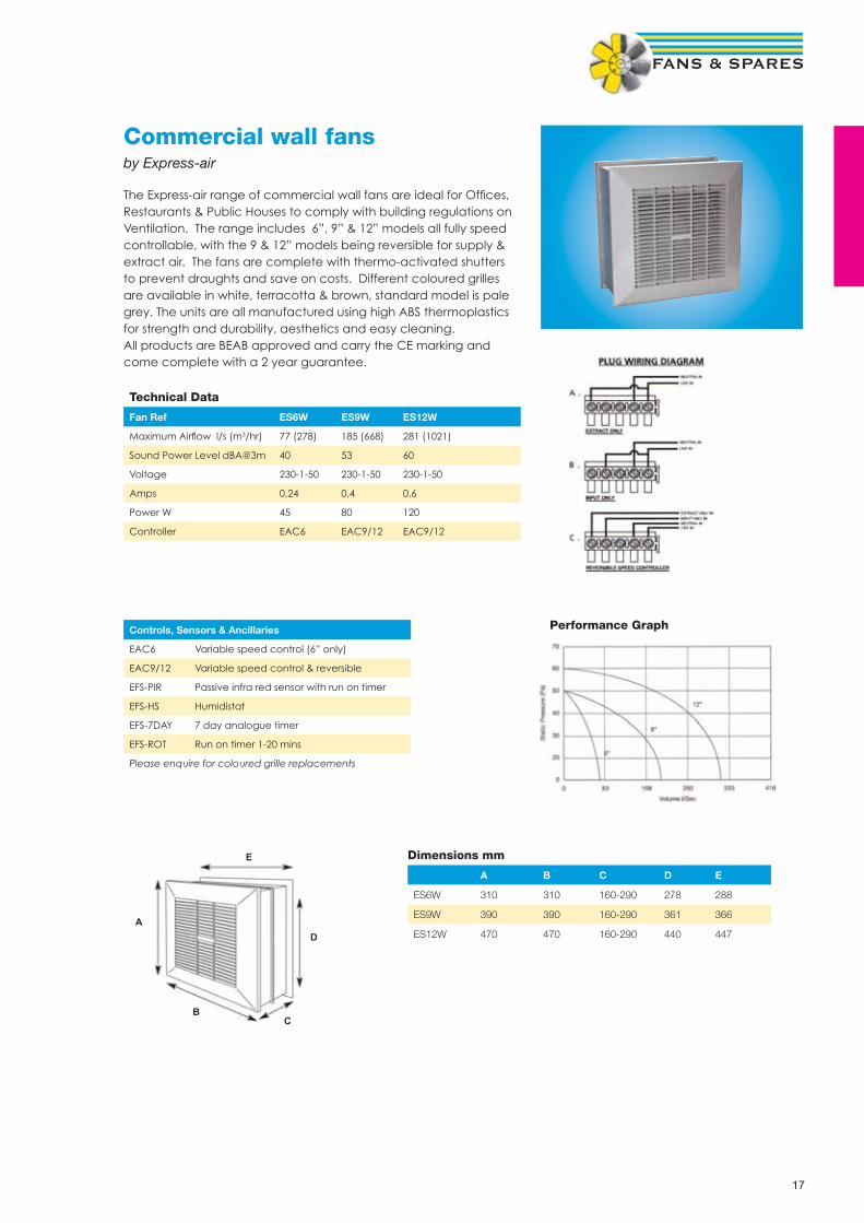
K-fanIn-line metal tube fanby Systemair
• Sizes 100 mm to 315 mm•• Fan - single phase 230V - 1Ph - 50Hz•• Speed-controllable•• Air tightness C-class•• Integral thermal contacts•• Easy to install in any position•• Maintenance-free and reliable•• Available on wall plate KV type•• Mounting bracket fi tted as standard
K A B C D E F Weight / kg
100 M 218 100 26 166 218 26 2
100 XL 246 100 26 161 213 26 4,5
125 M 218 125 27 142 196 27 2
125 XL 246 125 26 151 203 26 4,5
150 M 286 150 25 152 202 25 3
150 XL 336 150 29 171 226 26 4,5
160 M 286 160 25 147 198 26 3
160 XL 336 160 29 166 221 26 4
200 M 336 200 30 148 205 27 3,8
200 L 336 200 30 174 231 27 4,5
250 M 336 250 30 120 177 27 3,6
250 L 336 250 30 145 202 27 5
315 M 408 315 32 160 220 27 7
315 L 408 315 37 160 225 27 9
A B
C DE
F
45Dimensions
FK SG JKL RSK LDC FFR FGR IGK/IGC CB/CBM
Accessories
ProductCode
Speedrpm
Airfl ow m3/sec@Static Pressure Pa. Motor Data dBA3m
Speed Control
50 Pa 100 Pa 150 Pa 200 Pa 300 Pa FLC SC kW Elec Trans
K100M 2730 0.049 0.019 0.11 0.25 0.024 34 SC1.5 RE1.5
K100XL 2385 0.069 0.048 0.037 0.026 0.32 0.70 0.073 48 SC1.5 RE1.5
K125M 2725 0.055 0.026 0.001 0.11 0.25 0.024 38 SC1.5 RE1.5
K125XL 2320 0.090 0.062 0.048 0.032 0.34 0.70 0.076 44 SC1.5 RE1.5
K150M 2395 0.126 0.096 0.076 0.054 0.33 0.70 0.073 43 SC1.5 RE1.5
K150XL 2610 0.195 0.155 0.133 0.110 0.060 0.47 1.00 0.108 52 SC1.5 RE1.5
K160M 2395 0.126 0.095 0.076 0.054 0.33 0.70 0.073 43 SC1.5 RE1.5
K160XL 2610 0.195 0.155 0.133 0.110 0.060 0.47 1.00 0.108 52 SC1.5 RE1.5
K200M 2575 0.215 0.171 0.150 0.126 0.072 0.47 1.00 0.109 50 SC1.5 RE1.5
K200L 2645 0.265 0.227 0.206 0.184 0.139 0.83 2.00 0.18 51 SC1.5 RE1.5
K250M 2585 0.220 0.180 0.157 0.133 0.071 0.46 1.00 0.105 43 SC1.5 RE1.5
K250L 2645 0.280 0.241 0.220 0.200 0.152 0.84 2.00 0.18 46 SC1.5 RE1.5
K315M 2535 0.370 0.320 0.290 0.263 0.203 0.94 2.00 0.215 47 SC1.5 RE1.5
K315L 2360 0.460 0.420 0.370 0.339 0.270 1.39 3.00 0.32 49 SC3.0 RE1.5
For Accessoriessee page 128

25
RVKPlastic in-line centrifugal tube fanby Systemair
• Plastic tube fan, 100 mm to 315 mm• Fan - single phase, 230 V,1 Ph, 50 Hz• 100% speed controllable• Integral thermal contacts• Can be installed in any position• Maintenance free and reliable• Backward curved impeller & external rotor motor• Radon version available, please enquire• Ideal for hydroponics
Dimensions
Product Code
Speedrpm
Airfl ow m3/sec @ Static Pressure Pa. Motor Data dBA @3m
Speed Control
50 Pa 100 Pa 150 Pa 200 Pa 300 Pa FLC SC kW Elec Trans
RVK 100E2-A1 2500 0.040 0.025 0.001 - - 0.19 0.35 0.032 46 SC 1,5 RE 1,5
RVK 125E2-A1 2490 0.047 0.030 - - - 0.19 0.35 0.031 46 SC 1,5 RE 1,5
RVK 125E2-L1 2350 0.081 0.070 0.058 0.044 - 0.35 0.90 0.08 50 SC 1,5 RE 1,5
RVK 150E2-A1 2350 0.107 0.095 0.079 0.060 0.004 0.35 0.90 0.08 50 SC 1,5 RE 1,5
RVK 160E2-A1 2350 0.107 0.095 0.079 0.060 0.004 0.35 0.90 0.08 50 SC 1,5 RE 1,5
RVK 150E2-L1 2520 0.170 0.151 0.127 0.114 0.071 0.5 1.50 0.11 55 SC 1,5 RE 1,5
RVK 160E2-L1 2520 0.170 0.151 0.127 0.114 0.071 0.5 1.50 0.11 55 SC 1,5 RE 1,5
RVK 200E2-A1 2520 0.191 0.171 0.155 0.134 0.089 0.51 1.50 0.11 52 SC 1,5 RE 1,5
RVK 200E2-L1 2580 0.249 0.222 0.200 0.193 0.148 0.76 2.00 0.17 54 SC 1,5 RE 1,5
RVK 250E2-A1 2520 0.202 0.185 0.163 0.138 0.077 0.51 1.50 0.11 52 SC 1,5 RE 1,5
RVK 250E2-L1 2580 0.258 0.238 0.214 0.195 0.143 0.76 2.00 0.17 55 SC 1,5 RE 1,5
RVK 315E2-A1 2410 0.340 0.310 0.290 0.270 0.200 0.88 2.00 0.2 55 SC 1,5 RE 1,5
RVK 315E2-L1 2320 0.450 0.430 0.410 0.380 0.290 1.4 3.20 0.32 58 SC 3,0 RE 1,5
BFB FK SG JKL RSK LDC FFR FGR IGK/IGC CB/CBM
Accessories
drawing
D
E
A B
A
E
RVK A B C D E Weight Kg
RVK100 99 251 170 230 30 2
RVK125 124 251 170 230 30 2
RVK150 149 340,5 170 230 30 5
RVK160 159 340,5 170 230 30 5
RVK200E2-A1 199 340,5 170 230 30 4
RVK200E2-L1 199 340,5 190 250 30 4,5
RVK250E2-A1 249 340,5 170 230 30 5
RVK250E2-L1 249 340,5 190 230 30 5,5
RVK315 315 405 215 275 30 8
For Accessoriessee page 128
C

26
SAMFSmall duct mounted axial fanby Elta
• Duct mounted axial fan 150 mm to 315m • All metal casing with integral mounting brackets• Speed controllable• External rotor motor, IP44, Class B• All units suitable up to 80% RH, 40º air temp
Product Speed Airfl ow m3/s @ Static Pressure Pa Motor Data dBA @ Speed
Ref RPM 0 25 50 75 100 125 150 175 FLC kW 3m Control
SAMF150/2-2 2760 0,110 0,084 0,063 0,044 0,022 - - - 0,25 0,046 43 EL13
SAMF200/4-2 1440 0,144 0,093 0,053 0,017 - - - - 0,13 0,03 52 EL13
SAMF200/2-2 2580 0,238 0,208 0,170 0,135 0,107 0,085 - - 0,3 0,06 39 EL13
SAMF250/4-2 1380 0,279 0,230 0,151 0,079 - - - - 0,21 0,05 49 EL13
SAMF250/2-2 2520 0,420 0,382 0,347 0,309 0,264 0,210 0,151 - 0,54 0,12 40 EL13
SAMF315/4-2 1320 0,555 0,441 0,280 0,161 0,081 - - - 0,32 0,07 47 EL13
SAMF315/2-2 2460 0,639 0,621 0,592 0,530 0,440 0,364 0,267 0,209 0,71 0,16 58 EL13
A B C D Weight Kg
SAMF150/2 147 165 n/a n/a 1,5
SAMF200/4 206 250 236 164 3,5
SAMF200/2 206 250 236 164 3,5
SAMF250/4 260 250 296 190 4,0
SAMF250/2 260 250 296 190 4,0
SAMF315/4 311 250 346 219 4,8
SAMF315/2 311 250 346 219 4,8
Dimensions
FK SG JKL RSK LDC FFR FGR IGK/IGC CB/CBM
Accessories
For Accessoriessee page 128

27
ProductCode
Voltage
Speedrpm
Airfl ow m3/sec@Static Pressure Pa. Motor Data dBA3m
Speed Control
50 Pa 100 Pa 150 Pa 200 Pa 300 Pa FLC SC kW Elec Trans
KD200L 230 2565 0.340 0.315 0.275 0.245 0.150 1.14 4.7 0.256 53 SC1,5 RE1,5
KD250M 230 2565 0.370 0.330 0.315 0.275 0.175 1.13 4.7 0.255 54 SC1,5 RE1,5
KD250L 230 2595 0.525 0.495 0.455 0.420 0.330 1.61 7.0 0.37 55 SC3,0 RE3,0
KD315M 230 2575 0.365 0.345 0.315 0.275 0.190 1.12 4.5 0.252 58 SC1,5 RE1,5
KD315L 230 2590 0.565 0.542 0.505 0.465 0.370 1.62 7.2 0.372 53 SC3,0 RE3,0
KD355S 230 2590 0.570 0.535 0.500 0.460 0.362 1.62 7.2 0.373 53 SC3,0 RE3,0
KD315XL1 230 1375 0.685 0.585 0.450 0.225 - 1.29 5.0 0.275 52 SC3,0 RTRE3
KD355M1 230 1375 0.760 0.640 0.490 0.265 - 1.3 5.0 0.275 50 SC3,0 RTRE3
KD355XL1 230 1310 1.020 0.900 0.770 0.600 0.120 2.0 7.5 0.45 52 SC3,0 RTRE3
KD400M1 230 1310 1.030 0.915 0.780 0.600 0.120 2.03 7.5 0.457 53 SC3,0 RTRE3
KD400XL1 230 1270 1.590 1.465 1.310 1.155 0.785 4.3 11.0 0.893 58 SC5,0 RTRE5
KD450M1 230 1305 1.700 1.570 1.410 1.225 1.020 4.67 11.0 0.922 60 RTRE7
KD450XL1 230 1290 2.235 2.095 1.940 1.790 1.435 6.16 15.0 1.398 61 RTRE7
KD500M1 230 1290 2.250 2.110 1.975 1.815 1.470 6.1 15.0 1.385 64 RTRE7
KD355XL3 400 1395 1.110 1.010 0.890 0.735 0.265 0.91 4.5 0.474 54 RTRD2
KD400M3 400 1390 1.135 1.020 0.905 0.735 0.230 0.93 4.5 0.475 54 RTRD2
KD400XL3 400 1325 1.650 1.535 1.400 1.235 0.800 1.6 4.5 0.861 57 RTRD2
KD450M3 400 1320 1.735 1.600 1.450 1.285 0.830 1.6 4.5 0.864 57 RTRD2
KD450XL3 400 1325 2.135 2.035 1.910 1.770 1.435 2.21 11.0 1.263 60 RTRD4
KD500M3 400 1330 2.210 2.100 1.970 1.830 1.485 2.23 11.0 1.267 60 RTRD4
KD-fanCircular mixed fl ow fanby Systemair
• Duct mounted mixed fl ow fan, 200 mm to 500 mm• High effi ciency - low noise• Speed-controllable• Integral thermal contacts• Can be installed in any position• Maintenance-free and reliable• Mounting brackets fi tted as standard
6030
25
A355
c/c 21ø10
205
B
A = KD 250L: 250 KD 315L: 315
B = KD 250L: 385 KD 315L: 305
ød øD c/cH
L
KD ød L øD c/cH
315XL1 312 484 455 518
400M1/M3 400 480 503 568
400XL1/XL3 400 602 560 625
500MI/M# 500 643 663 721
KD 200 - KD 355S

28
Bac
k d
raft
dam
per
, RS
K
Filt
er c
asse
tte,
FFR
Mix
ed fl
ow
fan
, KD
Sile
ncer
, LD
C
Duc
t he
ater
, CB
Inta
ke g
rid
Fast
cla
mp
s, F
K
Iris
dam
per
, SP
I
Sup
ply
diff
user
s,B
alan
ce-S
Sup
ply
diff
user
s,B
alan
ce-S
Iris
dam
per
, SP
I

29
KVKFCompact acoustic in-line fanby Systemair
• Compact acoustic duct fan, 125mm to 400mm• Fan - single phase, 230V - 1Ph - 50Hz• 100% speed controllable• 40mm acoustic lining (low noise)• Integral thermal contacts• Can be installed in any position• Access panel with removable fan assembly• Single inlet forward curved impeller with external rotor motor (KVKF200 & 250 - backward curved impeller)• Compact fan casing for restricted ceiling voids
Product Code Speed rpm Airfl ow m3/sec @ Static Pressure Pa. Motor Data dBA @3m
Speed Control
50 100 200 300 400 FLC SC kW Elec Trans
KVKF125 1850 0.09 0.080 0.058 0.033 - 0.43 1.2 0.098 37 SC 1,5 RE 1,5
KVKF150M 2005 0.16 0.102 0.081 0.039 - 0.51 1.5 0.117 40 SC 1,5 RE 1,5
KVKF150L 2540 0.127 0.116 0.092 0.050 - 0.58 1.7 0.133 43 SC 1,5 RE 1,5
KVKF160M 2005 0.16 0.102 0.081 0.039 - 0.51 1.5 0.117 40 SC 1,5 RE 1,5
KVKF160L 2540 0.127 0.116 0.092 0.050 - 0.58 1.7 0.133 43 SC 1,5 RE 1,5
KVKF200 2630 0.213 0.204 0.171 0.140 0.107 0.83 2.5 0.178 44 SC 1,5 RE 1,5
KVKF250M 2615 0.268 0.238 0.205 0.164 0.121 0.9 2.7 0.203 42 SC 1,5 RE 1,5
KVKF250L 2415 0.41 0.380 0.335 0.290 0.241 1.34 4.0 0.307 41 SC 1,5 RE 1,5
KVKF315M 1265 0.445 0.410 0.325 0.160 - 2.2 7.0 0.457 46 SC 3,0 RTRE 3,0
KVKF315L 1265 0.57 0.525 0.390 0.192 - 3.01 9.0 0.634 49 SC 5,0 RTRE 5,0
KVKF355 1355 0.77 0.739 0.641 0.495 - 5.47 18.0 1.237 51 RTRE 7,0
KVKF400 1320 0.82 0.783 0.683 0.549 - 5.7 18.0 1.288 50 RTRE 7,0
Dimensions
A L W H S DIA Weight Kg
KVKF125 230 399 349 230 125 12
KVKF150 230 399 349 230 150 12
KVKF160 230 399 349 230 160 12
KVKF200 270 500 481 270 200 20
KVKF250 320 604 597 320 250 26
KVKF315 600 588 630 404 315 42
KVKF355 650 633 684 486 355 53
KVKF400 650 633 684 486 400 53
FK SG JKL RSK LDC FFR FGR IGK/IGC CB/CBM
Accessories
For Accessoriessee page 128

30
KVK FanAcoustic in-line centrifugal fanby Systemair
• Acoustic duct fan, 125 mm to 500 mm• Fan - single phase, 230 V,1 Ph, 50 Hz• 100% speed controllable• 50 mm acoustic lining (low noise)• Integral thermal contacts• Can be installed in any position• Access panel with removable fan assembly• Double inlet forward curved impeller with external rotor motor
ProductCode
Speedrpm
Airfl ow m3/sec @ Static Pressure Pa. Motor Data dBA @ Speed Control
50 100 150 200 300 FLC SC kW 3m Elec Auto Trans
KVK125 1720 0.042 0.031 0.007 0.17 0.5 0.041 28 SC 1,5 RTRE 1,5
KVK160 2010 0.094 0.080 0.061 0.030 0.35 0.85 0.081 35 SC 1,5 RTRE 1,5
KVK200 1810 0.180 0.163 0.145 0.124 0.070 0.75 2.0 0.172 39 SC 1,5 RTRE 1,5
KVK250 1965 0.293 0.270 0.250 0.234 0.171 1.3 3.0 0.304 42 SC 3,0 RTRE 1,5
KVK315M 1325 0.485 0.428 0.353 0.200 1.49 4.0 0.334 35 SC 3,0 RTRE 3
KVK315L 1200 0.751 0.707 0.657 0.599 0.415 2.83 8.0 0.643 37 SC 5,0 RTRE 3
KVK355 1165 0.737 0.690 0.641 0.584 0.415 2.93 8.0 0.665 41 SC 5,0 RTRE 3
KVK400 1105 0.750 0.707 0.657 0.599 0.393 2.83 8.0 0.654 39 SC 5,0 RTRE 3
KVK500 1235 1.42 1.35 1.28 1.22 1.05 6.28 33.0 1.452 56 - RTRE 7
FK SG JKL RSK LDC FFR CB/CBM
Accessories
FGR IGK/IGC
KVK A B C D E F G øH I Weight kg
125 300 292 173 182 364 317 391 125 37 9.1
160 300 292 173 182 364 317 391 160 37 12
200 350 345 207 309 419 372 454 200 41 17,5
250 400 381 201 244.5 489 372 458 250 43 21
315M/L 550 544.5 326.5 273 546 540 626 315 43 40
400 550 544.5 326,5 273 546 540 664 400 62 41
500 700 680.5 403 370 740 690 814 500 62 81
A
B
C
E
DGF
øH(2x)
I
I
Dimensions
For Accessoriessee page 128

31
KVK DUOAcoustic in-line twin fan by Systemair
• Run and stand by motors• Acoustic duct fan, 125mm to 400mm• Fan - single phase, 230V - 1Ph - 50Hz • 100% speed controllable• 50mm acoustic lining (low noise)• Integral thermal contacts• Can be mounted upside down• Access panel with removable fan assembly• Double inlet forward curved impeller with external rotor motor• Auto-change over panel with duty-share and volt free contacts
ProductCode
Speedrpm
Airfl ow m3/sec @ Static Pressure Pa. Motor Data dBA @ 3m
Speed control
50 100 150 200 300 FLC SC kW Elec Trans ACO Panel
KVK DUO125 1720 0.041 0.030 0.010 0.17 0.5 0.041 28 SC 1,5 RTRE 1,5 ACO 8
KVK DUO160 2010 0.094 0.080 0.060 0.030 0.35 0.85 0.081 35 SC 1,5 RTRE 1,5 ACO 8
KVK DUO200 1750 0.180 0.168 0.151 0.130 0.058 0.77 2.0 0.177 39 SC 1,5 RTRE 1,5 ACO 8
KVK DUO250 1965 0.294 0.272 0.250 0.228 0.173 1.3 3.0 0.304 42 SC 3,0 RTRE 3,0 ACO 8
KVK DUO315M 1325 0.493 0.435 0.350 0.201 1.49 4.0 0.334 35 SC 3,0 RTRE 3,0 ACO 8
KVK DUO315L 1220 0.734 0.698 0.645 0.570 0.212 2.61 8.0 0.593 37 SC 5,0 RTRE 3,0 ACO 8
KVK DUO355 1170 0.734 0.698 0.645 0.570 0.212 2.78 8.0 0.632 37 SC 5,0 RTRE 3,0 ACO 8
KVK DUO400 1190 0.734 0.698 0.645 0.570 0.212 2.78 8.0 0.638 39 SC 5,0 RTRE 3,0 ACO 8
FK SG VK IGK RSK LDC FFR CB CBM
Accessories
Dimensions KVK Duo
REF A B C D E F kg
125 514 351 337 125 300 35 19
160 514 351 337 160 300 35 22
200 604 401 390 200 350 39 32
250 724 501 461 250 400 41 36
315-400 952 567 510 315/355/400 550 41/64/65 72
For Accessoriessee page 128

32
Duct & roof mounted twin fans
This range of Direct Drive Twin fans are designed for guaranteed standby ventilation for toilets, plant rooms or other areas where the failsafe extract of contaminated air is required. Available as an Internal unit EFT for duct mounting with spigot connection on inlet and outlet or as an external unit EFTR for roof mounting with plastisol casing, spigot connection on inlet and weatherproof discharge cowl with intergral bird mesh. Bottom inlet available on request.
Size Range:. Duct/Spigot size connection 125mm to 500mm diameter
Impellers: Two DIDW (double inlet double width) forward curved centrifugal type
Motors: Comply with ISO standards. They are fi tted with sealed for life ball bearings
Casing/Finish: Single Skinned in galvanised sheet steel (internal units) or Plastisol (Plastic coated steel for external units). All fans have removable lids sealed with a neoprene gasket. Powder coated paint fi nish (to any BS or RAL number) available on all models.
Operating Temperature: From -15 to + 40 deg C as standard.
Insulation (Optional): 25 mm acoustic foam lining, please add suffi x “L” after fan code
Auto Changeover Panel: ACOP1 with volt free contacts and duty share as standard
Performance Details
Fan Speed Airfl ow m3/s @ Static Pressure Pa Motor Data dBA @
Ref RPM 50 100 125 150 200 250 300 350 550 FLC SC kW 3m
EFT125 1340 0,460 0,037 0,032 0,025 0,005 0,75 4,13 0,015 39
EFT150 1340 0,046 0,037 0,032 0,025 0,005 0,75 4,13 0,015 41
EFT200 1375 0,113 0,070 0,036 0,64 3,52 0,022 37
EFT250 1360 0,228 0,190 0,170 0,145 0,050 1,82 10,01 0,073 43
EFT315 1370 0,398 0,367 0,350 0,320 0,268 0,153 2,00 11,00 0,150 50
EFT355A 1100 0,425 0,412 0,400 0,388 0,353 0,313 0,125 2,00 11,00 0,373 55
EFT355B 1250 0,575 0,560 0,551 0,540 0,491 0,450 0,376 0,175 2,85 15,68 0,373 55
EFT355C 1350 0,750 0,725 0,712 0,690 0,655 0,605 0,540 0,400 3,85 21,18 0,373 58
EFT400 1350 0,810 0,790 0,780 0,770 0,730 0,660 3,80 20,90 0,550 57
EFT450 1350 0,990 0,975 0,965 0,945 0,900 0,820 0,675 4,90 26,40 0,550 59
EFT500 1300 - 1,110 1,100 1,090 1,070 1,040 0,996 0,890 6,85 37,68 0,550 60
EFT500/3 1410 1,790 1,710 1,690 1,680 1,600 1,550 1,500 1,440 1,000 5,00 25,00 1,500 60
dBA values are average spherical free fi eld for comparison only, shown for acoustically lined units, at 3.0m distance. The Full range of performance and sound data is available upon request. All units 240-1-50 supply except 500/3 = 415-3-50
How to order:
EFTR400L = Roof Mounted Twin Fan 400dia - Acoustically LinedEFT250 = Duct Mounted Twin Fan 250dia
Model A B C D F weight
125 575 238 400 125 200 25kg
150 575 238 400 150 200 25kg
200 800 275 450 200 200 32kg
250 800 425 550 250 200 38kg
315 1000 450 650 315 200 44kg
355 1000 475 650 350 250 64kg
400 1050 475 650 400 250 70kg
450 1150 475 650 450 250 70kg
500 1250 525 700 500 250 98kg
Dimension “F” is for roof version only.

33
Belt driven twin fans This range of Belt Driven Twin fans are designed for guaranteed standby ventilation for toilets, plant rooms or other areas where the failsafe extract of contaminated air is required. Available as an Internal unit EFTB for duct mounting with 20mm “mez” fl ange connection on inlet and outlet or as an external unit EFTRB for roof mounting with plastisol casing, 20mm “mez” fl ange connection on inlet and weatherproof discharge cowl with intergral bird mesh. Bottom inlet available on request.
Size Range: Four standard case sizes with different combinations of motors and pulleys giving an extensive range of fan duties.
Impellers: Two DIDW (double inlet double width) forward curved centrifugal type
Motors: Comply with BS5000 & IEC34-1. Foot mounted type TEFV IP55 Class F insulation. They are fi tted with sealed for life ball bearings
Casing/Finish: Double Skinned in galvanised sheet steel (internal units) or Plastisol single skinned (Plastic coated steel for external units). All fans have sealed removable access panels. Powder coated paint fi nish (to any BS or RAL number) available on all models.
Operating Temperature: . From -15 to + 40 deg C as standard
Insulation : (Optional) 25mm acoustic foam lining, please add suffi x “L” after fan code
Auto Changeover Panel: ACOP3/DS with volt free contacts and duty share as standard
Fan Airfl ow m3/s @ Static Pressure Pa Motor Data
Ref 50 100 150 200 250 300 350 400 450 500 FLC SC kW
EFTB 7/1 Airfl ow m3/s 0,790 0,750 0,700 0,650 0,600 2,00 11,00 0,75
dB(A) 79 78 76 75 74
EFTB 7/2 Airfl ow m3/s 0,95 0,9 0,85 0,8 0,75 0,7 2,90 16,00 1,10
dB(A) 79 78 77 76 76 75
EFTB 7/3 Airfl ow m3/s 1.0 0,95 0,9 0,85 0,8 2,90 16,00 1,10
dB(A) 80 79 78 77 77
EFTB 7/4 Airfl ow m3/s 1,0 0,9 0,8 0,7 3,90 21,50 1,50
dB(A) 80 79 77 76
EFTB 8/1 Airfl ow m3/s 1,07 1,02 0,95 0,9 2,00 11,00 0,75
dB(A) 77 76 75 74
EFTB 8/2 Airfl ow m3/s 1,21 1,15 1,1 1,05 1,0 2,90 16,00 1,10
dB(A) 80 79 78 77 77
EFTB 8/3 Airfl ow m3/s 1,25 1,2 1,15 1,1 1,05 3,90 21,50 1,50
dB(A) 81 80 79 79 78
EFTB 8/4 Airfl ow m3/s 1,3 1,25 1,2 1,15 1,1 5,30 29,20 2,20
dB(A) 82 81 80 80 80
EFTB 9/1 Airfl ow m3/s 1,42 1,33 1,28 1,21 2,90 16,00 1,10
dB(A) 80 78 78 77
EFTB 9/2 Airfl ow m3/s 1,7 1,65 1,6 1,55 1,5 3,90 21,50 1,50
dB(A) 79 79 78 78 78
EFTB 9/3 Airfl ow m3/s 1,85 1,8 1,75 1,7 1,65 5,30 29,20 2,20
dB(A) 81 81 81 80 80
EFTB 9/4 Airfl ow m3/s 2,0 1,95 1,9 1,85 1,8 7,10 39,10 3,00
dB(A) 83 82 82 82 82
EFTB 10/1 Airfl ow m3/s 2,14 2,09 2,0 1,9 1,8 3,90 21,50 1,50
dB(A) 80 79 79 78 78
EFTB 10/2 Airfl ow m3/s 2,4 2,35 2,3 2,25 2,16 2,05 5,30 29,20 2,20
dB(A) 82 82 82 81 81 80
EFTB 10/3 Airfl ow m3/s 2,52 2,47 2,42 2,37 2,32 2,28 7,10 39,10 3,00
dB(A) 83 83 83 83 83 83
EFTB 10/4 Airfl ow m3/s 2,53 2,4 2,35 2,3 2,2 7,10 39,10 3,00
dB(A) 84 83 83 83 82
Performance Details

34
Belt driven twin fans
Model A B C D E F Weight kg
7 1000 500 950 600 450 250 190
8 1150 550 1000 750 450 275 240
9 1200 650 1150 900 500 300 275
10 1450 700 1200 900 600 300 300
35
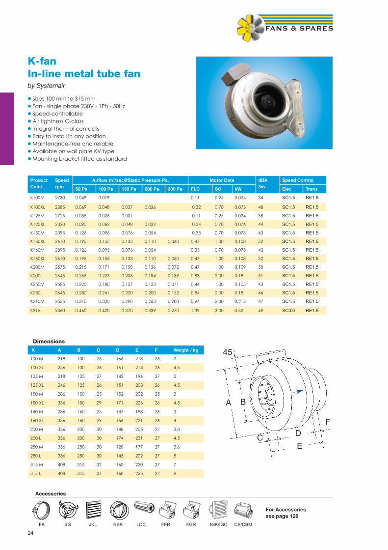
KE/KTRectangular centrifugal fanby Systemair
• Forward curved centrifugal fan• Compact design for ceiling void applications• Can be installed in any position • Maintenance free and reliable• Speed controllable• Integral thermal contacts
Product Voltage Airfl ow m3/s @ static pressure Pa Motor Data dBA @ Speed Control
Code 50 100 150 200 300 FLC KW 3m Trans
KE40-20-4 230-1-50 - 0,245 0,220 0,176 - 1,00 0,230 55 RTRE1.5
KE50-25-4 230-1-50 0,450 0,419 0,386 0,338 - 2,51 0,530 56 RTRE3
KE50-30-4 230-1-50 - 0,595 0,561 0,516 0,411 3,67 0,819 59 RTRE5
KE60-30-4 230-1-50 - - 0,706 0,669 0,573 5,40 1,231 62 RTRE7
KT50-25-4 400-3-50 0,511 0,479 0,443 0,393 0,198 0,95 0,550 55 RTRD2
KT50-30-4 400-3-50 - - 0,615 0,565 0,414 1,41 0,800 57 RTRD2
KT60-30-4 400-3-50 0,922 0,890 0,855 0,808 0,712 2,36 1,360 58 RTRD4
KT60-35-4 400-3-50 - - - 1,286 1,176 4,12 2,460 61 RTRD7
KT70-40-4 400-3-50 - - - - 1,630 6,04 3,616 66 RTRD7
KT70-40-6 400-3-50 1,386 1,308 1,230 1,143 0,918 3,00 1,628 56 RTRD4
KT80-50-6 400-3-50 - 2,048 1,963 1,879 1,611 4,91 2,670 60 RTRD7
KT80-50-8 400-3-50 1,416 1,313 1,176 0,992 - 2,40 1,140 59 RTRD4
KT100-50-6 400-3-50 - - - - 2,350 6,79 3,810 62 RTRD7
KT100-50-8 400-3-50 2,173 2,052 1,930 1,783 1,336 4,67 2,290 58 RTRD7
A B C
D
E
FG
H
ø10(8x)
KE A c/c B C D E c/c F G H
40-20-4 240 220 198 502 398 420 440 28 12
50-25-4 290 270 248 532 498 520 540 30 18
50-30-4 340 320 298 562 498 520 540 32 21
60-30-4 340 320 298 642 598 620 640 47 28
KT A c/c B C D E c/c F G H
50-25-4 290 270 248 532 498 520 540 64 17
50-30-4 340 320 298 562 498 520 540 66 21
60-30-4 340 320 298 642 598 620 640 88 29
60-35-4 390 370 348 717 598 620 640 83 38
70-40-4 440 420 398 787 698 720 740 94 60
70-40-6 440 420 398 787 698 720 740 74 43
80-50-6 540 520 497 880 798 820 840 96 71
80-50-8 540 520 497 880 798 820 840 96 63
100-50-6 540 520 497 980 998 1020 1040 100 95
100-50-8 540 520 497 980 998 1020 1040 100 95
Weight kg
Weight kg
DS VK SRK LDR FFK RB RBM VBR PGK
Accessories
For Accessoriessee page 129

36
RS/RSIRectangular in-line centrifugal fanby Systemair
• Backward curved rectangular fan, RS (acoustic version - RSI)• Fan - single phase, 230V - 1Ph - 50Hz • Fan - three phase, 400V - 1Ph - 50Hz • 100% speed controllable• Integral thermal contacts• Can be installed in any position• Maintenance free and reliable• Backward curved impeller & external rotor motor• Hinged access door• RSI - 50mm acoustic lining
RSI A B C D E c/cF G H c/cJ K
60-35M/L 708 492 717 650 648 370 390 598 620 640 62
70-40L1/L3 808 542 787 650 397 420 440 697 720 740 80
80-50M3/L3 908 662 882 750 497 520 540 797 820 840 107
100-50L3 1108 662 982 760 497 520 540 997 1020 1040 137
C
A
B
D
E
c/cFG
H c/cJK
ø10(8x)
DS VK SRK LDR FFK RB RBM VBR PGK
Accessories
Weight kg
For Accessoriessee page 129
Weight kg
ProductCode
Voltage Speedrpm
Airfl ow m3/sec @ Static Pressure Pa. Motor Data dBA @ 3m Speed Control
50 100 150 200 300 FLC SC kW RS RSI Elec Trans
RS 30-15 240 2270 0.125 0.106 0.088 0.072 0.033 0.35 1.40 0.08 49 - SC 1,5 RE 1,5
RS 40-20M1 240 2605 0.215 0.180 0.165 0.142 0.094 0.46 1.84 0.105 52 - SC 1,5 RE 1,5
RS 40-20L1 240 2315 0.334 0.300 0.271 0.235 0.170 0.89 3.56 0.204 46 - SC 1,5 RE 1,5
RS 50-25M1 240 1365 0.357 0.312 0.264 0.210 0.025 0.6 2.40 0.137 47 - SC 1,5 RE 1,5
RS 60-35M1 240 1335 0.850 0.785 0.710 0.640 0.460 1.75 7.00 0.382 56 50 SC 3,0 RE 3.0
RS 60-35M3 400 1370 0.910 0.850 0.790 0.700 0.520 0.79 3.16 0.399 58 48 - RTRD 2
RS 60-35L1 240 1310 1.050 1.000 0.900 0.820 0.650 2.79 11.16 0.624 57 48 SC 5,0 RTRE 3
RS 60-35L3 400 1410 1.130 1.050 1.000 0.920 0.770 1.59 6.36 0.665 61 51 - RTRD 2
RS 70-40L1 240 1305 1.500 1.400 1.300 1.200 0.980 2.81 11.24 0.624 60 51 SC 5,0 RTRE 3
RS 70-40L3 400 1410 1.320 1.260 1.190 1.100 0.930 1.7 6.80 0.705 61 51 - RTRD 2
RS 80-50M3 400 1330 1.840 1.790 1.680 1.600 1.400 1.96 7.84 1.086 60 53 - RTRD 4
RS 80-50L3 400 1390 2.500 2.375 2.290 2.220 2.000 3.6 14.40 1.894 64 57 - RTRD 7
RS 100-50L3 400 1360 3.240 3.180 3.050 2.960 2.750 5.09 20.36 2.975 66 63 - RTRD 7
RS A B C D E c/c F G H c/c J K
30-15 340 190 402 275 148 170 190 298 320 340 7
40-20 440 240 502 375 198 220 240 398 420 440 12
50-25 540 290 532 450 248 270 290 498 520 540 17
60-35 640 390 717 550 348 370 390 598 620 640 35
70-40 740 440 787 550 398 420 440 698 720 740 43
80-50 840 541 882 670 498 520 541 798 820 840 68
100-50 1040 541 982 670 498 520 541 998 1020 1040 97

37
KDRE/KDRDSquare mixed fl ow fan by Systemair
• Square cased mixed fl ow fan,• KDRE Fan - single phase, 230V - 1Ph - 50Hz• KDRD Fan - three phase, 400V - 3Ph - 50Hz• 100% speed controllable• Integral thermal contacts• Can be installed in any position• Maintenance free and reliable• Mixed fl ow impeller with external rotor motor
ProductCode
Speedrpm
Airfl ow m3/sec @ Static Pressure Pa. Motor Data dBA @3m
Speed Control
50 100 200 300 400 FLC SC kW Elec Trans
KDRE45 1385 0.882 0.740 0.185 1.55 5.0 0.326 46 SC3,0 RTRE3
KDRE50 1310 1.310 1.149 0.680 0.120 2.27 7.5 0.511 54 SC5,0 RTRE5
KDRE55 1282 1.810 1.657 1.240 0.666 0.130 4.1 11.0 0.861 53 SC5,0 RTRE5
KDRE65 1315 2.900 2.710 2.230 1.580 0.885 6.6 16.0 1.497 61 N/A RTRE7
KDRD50 1400 1.380 1.260 0.890 0.260 0.98 6.0 0.504 49 RTRD2
KDRD55 1315 1.746 1.610 1.280 0.760 0.140 1.51 7.5 0.787 54 RTRD2
KDRD65 1305 2.743 2.577 2.140 1.480 0.740 2.24 10.0 1.281 55 RTRD4
KDRD70 1382 3.960 3.800 3.400 2.930 2.320 4.6 25.0 2.493 62 RTRD7
KDRD A B C D
KDRD 45 400 492 470 447 26
KDRD 50 450 547 520 502 41
KDRD 55 485 595 573 550 42
KDRD 65 510 707 680 661 54
KDRD 70 530 742 720 696 62
FFS DSK LDK RBK VBK
Accessories
For Accessoriessee page 129
Weight kg
38
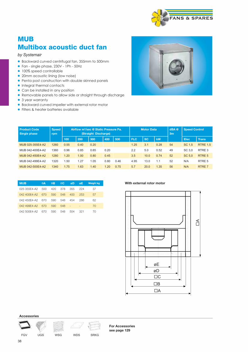
MUBMultibox acoustic duct fanby Systemair
• Backward curved centrifugal fan, 355mm to 500mm• Fan - single phase, 230V - 1Ph - 50Hz• 100% speed controllable• 20mm acoustic lining (low noise)• Penta post construction with double skinned panels• Integral thermal contacts• Can be installed in any position• Removable panels to allow side or straight through discharge• 3 year warranty• Backward curved impeller with external rotor motor• Filters & heater batteries available
Product CodeSingle phase
Speedrpm
Airfl ow m3/sec @ Static Pressure Pa. (Straight Discharge)
Motor Data dBA @ 3m
Speed Control
100 200 300 400 500 FLC SC kW Elec Trans
MUB 025-355E4-A2 1260 0.55 0.40 0.20 1.25 3.1 0.28 54 SC 1,5 RTRE 1,5
MUB 042-400E4-A2 1360 0.96 0.85 0.65 0.20 2.2 5.0 0.52 49 SC 3,0 RTRE 3
MUB 042-450E4-A2 1280 1.20 1.00 0.80 0.45 3.5 10.0 0.74 52 SC 5,0 RTRE 5
MUB 042-499E4-A2 1320 1.50 1.27 1.05 0.80 0.46 4.95 13.0 1.1 52 N/A RTRE 5
MUB 042-500E4-A2 1340 1.75 1.63 1.40 1.20 0.75 5.7 20.0 1.35 56 N/A RTRE 7
øEøD�C
�B�A
�A
MUB pA pB pC øD øE
025 355E4-A2 500 420 378 355 224 37
042 400E4-A2 670 590 548 400 253 57
042 450E4-A2 670 590 548 454 286 62
042 499E4-A2 670 590 548 - - 70
042 500E4-A2 670 590 548 504 321 70
With external rotor motor
FGV
Accessories
UGS WSG WDS SRKG
Weight kg
For Accessoriessee page 129

39
�B
�CøD
øE
�A
MUB pA pB pC øD øE F
025 355 500 420 378 355 224 - 37
042 400 670 590 548 400 253 300 57
042 450 670 590 548 454 286 300 62
042 499 670 590 548 500 320 300 70
042 500 670 590 548 504 321 300 70
062 560 800 720 676 570 361 321 130
062 630 800 720 678 635 407 321 145
Dimension F is for kitchen K2 version only.
With IEC standard motor
MUBMultibox acoustic duct fanBy Systemair
• Backward curved centrifugal fan, 355mm to 630mm• Fan - three phase, 400V - 3Ph - 50Hz • 20mm acoustic lining (low noise)• Penta post construction with double skinned panels• Integral thermal contacts• Can be installed in any position• Removable panels to allow side or straight through discharge• Backward curved impeller• Filters & heater batteries available• Kitchen version K2 with motor out of airstream (temp 100ºc) Side discharge only• All fans ref DV have dual wound motors for two speed operation (switch required)
ProductCode
Speedrpm
Airfl ow m3/sec @ Static Pressure Pa. (Side Discharge) Motor Data dBA @3m
Speed ControlTrans100 200 300 400 500 FLC SC kW
MUB 025-355DV-A2 1300 0.660 0.500 0.285 0.58 1.7 0.28 55 RTRD 2
MUB 042-400DV-A2 1340 1.010 0.840 0.605 0.125 0.85 3.1 0.46 49 RTRD 2
MUB 042-450DV-A2 1230 1.310 1.125 0.925 0.650 1.3 3.4 0.69 52 RTRD 2
MUB 042-499DV-A2 1200 1.700 1.470 1.200 0.900 0.440 1.8 4.9 0.9 55 RTRD 2
MUB 042-500DV-A2 1330 2.230 2.055 1.880 1.660 1.400 4.3 21.0 1.5 56 RTRD 7
MUB 062-560DV-A2 1420 3.200 3.010 2.825 2.610 2.380 5.8 27.0 2.2 57 RTRD 7
MUB 062-630DV-B2 1340 4.160 3.960 3.760 3.560 3.350 6.8 27.0 3.9 69 RTRD 14
MUB 062-630D4-A2 1400 4.285 4.080 3.840 3.590 3.315 9.5 46.0 4.0 69 N/A
Kitchen Version (Motor outside of airstream) 90° discharge only.
MUB 042-400DV-K2 1340 1.000 0.820 0.650 0.200 0.85 3.1 0.46 49 RTRD 2
MUB 042-450DV-K2 1230 1.300 1.150 0.800 0.500 0.150 1.3 3.4 0.69 52 RTRD 2
MUB 042-500DV-K2 1330 1.850 1.700 1.500 1.260 1.040 4.3 23.0 1.5 56 RTRD 7
MUB 062-560DV-K2 1400 2.750 2.600 2.350 2.230 2.000 5.8 32.0 2.2 57 RTRD 7
MUB 062-630D4-K2 1400 4.250 4.050 3.800 3.500 3.270 9.5 46.0 4.0 69 N/A
FGV
Accessories
UGS WSG WDS SRKG
For Accessoriessee page 129
Weight kg
100ºc Temperature
40
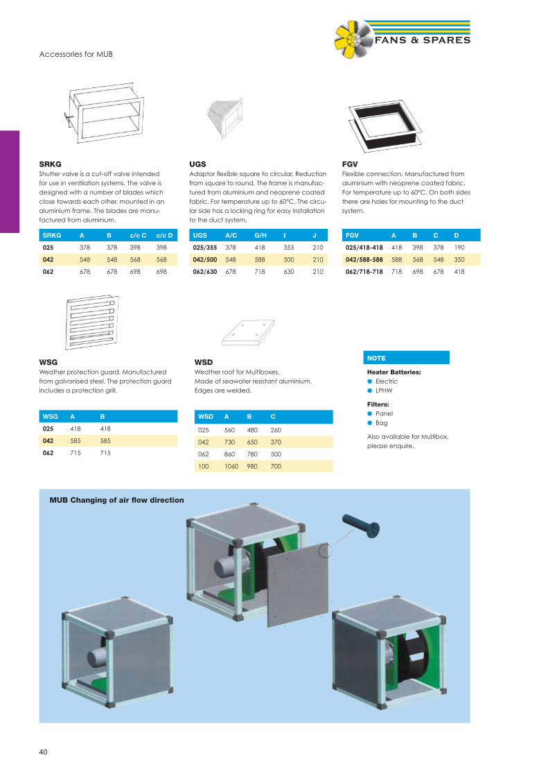
Accessories for MUB
UGSAdaptor fl exible square to circular. Reduction from square to round. The frame is manufac-tured from aluminium and neoprene coated fabric. For temperature up to 60°C. The circu-lar side has a locking ring for easy installation to the duct system.
FGVFlexible connection. Manufactured from aluminium with neoprene coated fabric. For temperature up to 60°C. On both sides there are holes for mounting to the duct system.
WSGWeather protection guard. Manufactured from galvanised steel. The protection guard includes a protection grill.
WSDWeather roof for Multiboxes. Made of seawater resistant aluminium. Edges are welded.
SRKGShutter valve is a cut-off valve intended for use in ventilation systems. The valve is designed with a number of blades which close towards each other, mounted in an aluminium frame. The blades are manu-factured from aluminium.
SRKG A B c/c C c/c D
025 378 378 398 398
042 548 548 568 568
062 678 678 698 698
UGS A/C G/H I J
025/355 378 418 355 210
042/500 548 588 500 210
062/630 678 718 630 210
FGV A B C D
025/418-418 418 398 378 190
042/588-588 588 568 548 350
062/718-718 718 698 678 418
WSG A B
025 418 418
042 585 585
062 715 715
WSD A B C
025 560 480 260
042 730 650 370
062 860 780 500
100 1060 980 700
MUB Changing of air fl ow direction
NOTE
Heater Batteries:● Electric● LPHW
Filters:● Panel● Bag
Also available for Multibox,please enquire.

41
KBT/KBRKitchen extract centrifugal fansBy Systemair
• Duct mounted fan, KBT 160mm to 355mm, KBR 200mm to 355mm • Fan - single phase, 230V - 1Ph - 50Hz• Fan - three phase, 400V - 3Ph - 50Hz • Speed controllable• Integral thermal contacts• Double skin casing with 50mm acoustic lining• Suitable for temperatures up to 120ºc• Hinged access door• KBT - forward curved impeller• KBR - backward curved impeller
ProductCode
Voltage Speedrpm
Airfl ow m3/sec @ Static Pressure Pa. Motor Data dBA @ 3m
Speed controlTrans50 100 200 300 400 FLC SC kW
KBT 160E4 230 1330 0.193 0.151 - - - 1.11 5.0 0.14 49 RTRE 1,5
KBT 160DV 400 1120 0.215 0.174 - - - 0.57 3.5 0.16 49 RTRD 2
KBT 180E4 230 1330 0.370 0.330 0.210 - - 1.11 5.0 0.14 52 RTRE 1,5
KBT 200E4 230 1370 0.500 0.470 0.400 0.130 - 5.10 21.0 0.75 55 RTRE 7
KBT 200DV 400 1360 0.530 0.490 0.390 0.260 - 1.88 11.0 0.55 55 RTRD 2
KBT 225E4 230 1370 0.720 0.690 0.590 0.470 - 5.10 21.0 0.75 59 RTRE 7
KBT 225DV 400 1350 0.730 0.710 0.620 0.530 0.310 2.50 13.0 0.75 59 RTRD 4
KBT 250E4 230 1400 1.090 1.070 1.000 0.900 0.770 10.70 45.0 1.85 63 N/A
KBT 250DV 400 1330 1.080 1.030 0.930 0.810 0.650 4.30 26.0 1.5 63 RTRD 7
KBT 280DV 400 1400 1.380 1.350 1.300 1.230 1.150 5.80 35.0 2.2 66 RTRD 7
KBR 315DV 400 1360 0.570 0.530 0.440 0.300 0.100 1.39 8.5 0.37 54 RTRD 2
KBR 315DZ 400 2710 1.050 1.030 0.970 0.920 0.810 3.40 20.5 1.5 69 RTRD 4
KBR 355E4 230 1330 0.920 0.890 0.780 0.660 0.470 2.10 12.5 0.37 59 RTRE 3
KBR 355DV 400 1360 0.990 0.930 0.830 0.710 0.590 1.39 8.5 0.37 59 RTRD 2
KBR 355E4/K 230 1330 0.76 0.69 0.58 0.44 0.28 2.10 12.5 0.37 59 RTRE 3
KBR 355DV/K 400 1360 0.78 0.72 0.64 0.5 0.32 1.39 8.5 0.37 59 RTRD 2
KBR 355DZ 400 2600 1.94 1.92 1.86 1.75 1.73 6.50 37.0 3.0 72 RTRD 7
KBR 355DZ/K 400 2660 1.56 1.52 1.47 1.38 1.34 5.0 30.0 2.2 72 RTRD 7
KBT A B C D E F øG H J
160 127.4 382 213 248 435 207 160 450 149 25
180 134.4 412 230 269 470 219 200 450 161 29
200 142.7 445 249 292 510 232 200 450 174 38
225 146.5 455 256 301 522 251 225 600 193 40
250 162 500 282 333 576 272 250 600 213 52
280 172 537 295 360 625 291 280 600 234 68
KBR A B C D E F øG H J
315 187.5 600 339 398 690 307 315 800 249 82
355 206.7 655 372 451 770 331 355 800 273 100
Weight kg
Weight kg

42
ZAP/ZSP/AWPlate mounted axial fansby Ziehl Abegg
• Sickle & aerofoil bladed fans, 200 mm to 710 mm• Fan - single phase, 230 V, 1 Ph, 50 Hz• Diecast aluminium impellers• (AW type pressed steel blades)• Insulation class ‘F’ IP54 (AW type IP44)• Operating range -40ºC to 70ºC• Thermal protection ‘TK’• Galv steel wall plate with bellmouth• Corrosion resistant paint pebble grey (AW type black)• Inlet guard• IP54 terminal box• Maintenance free, sealed for life bearings
Single PhaseProduct Code
Speedrpm
Airfl ow m3/sec @ Static Pressure Pa Motor Data dBA @3m
Speed Control
0 Pa 50 Pa 100 Pa FLC SC kW Elec Trans
AW200-E2-K 2600 0.253 0.214 0.097 0.32 1.28 0.071 55 SC 1,5 RE 1,5
AW200-E4-K 1400 0.117 0.013 - 0.062 0.248 0.016 38 SC 1,5 RE 1,5
AW250-E2-K 2500 0.504 0.43 0.241 0.6 2.4 0.14 60 SC 1,5 RE 1,5
AW250-E4-K 1400 0.268 0.1 - 0.21 0.84 0.047 44 SC 1,5 RE 1,5
AW300-E2-K 2700 0.97 0.85 0.75 1.1 2.7 0.23 61 SC 1,5 RE 1,5
AW300-E4-K 1390 0.51 0.36 - 0.32 1.1 0.07 45 SC 1,5 RE 1,5
ZAP315-21 2650 1.056 0.985 0.92 2.1 6.0 0.47 61 N/A RTRE 3
ZSP315-41 1400 0.611 0.5 - 0.59 1.5 0.13 46 SC 1,5 RTRE 1,5
ZAP315-61 880 0.375 - - 0.37 0.7 0.07 40 SC 1,5 RTRE 1,5
ZSP350-41 1400 0.872 0.739 0.52 0.9 2.5 0.2 49 SC 1,5 RTRE 1,5
ZAP350-61 910 0.722 - - 0.5 1.0 0.1 44 SC 1,5 RTRE 1,5
ZSP400-41 1320 1.306 1.143 0.888 1.35 2.9 0.31 51 SC 3,0 RTRE 3
ZAP400-61 940 0.986 - - 0.6 1.4 0.13 48 SC 1,5 RTRE 1,5
ZSP450-41 1310 2.01 1.805 1.509 2.8 7.0 0.61 55 SC 3,0 RTRE 3
ZSP450-61 910 1.368 0.98 - 0.91 2.1 0.21 48 SC 1,5 RTRE 1,5
ZSP500-41 1210 2.517 2.248 1.876 3.4 7.4 0.77 53 N/A RTRE 5
ZSP500-61 890 1.787 1.354 - 1.25 2.4 0.29 47 SC3,0 RTRE 1,5
ZAP560-41 1300 3.61 3.338 3.027 7.5 15.0 1.6 68 RTRE 7
ZAP560-61 880 2.474 1.923 - 1.95 4.6 0.43 55 SC3,0 RTRE 3
ZAP630-61 880 3.345 2.77 - 2.7 5.3 0.6 59 SC3,0 RTRE 3
ZAP630-81 650 2.472 - - 1.45 3.1 0.32 55 SC3,0 RTRE 3
ZAP710-61 850 4.573 3.91 - 4.1 8.0 0.89 61 SC5,0 RTRE 5

43
Three PhaseProduct Code
Speed rpm
Airfl ow m3/sec @ Static Pressure Pa Motor Data dBA @ 3m
Speed ControlTrans
0 Pa 50 Pa 100 Pa FLC SC kW
ZSP315-43 1410 0.611 0.504 - 0.29 1.0 0.12 46 RTRD2
ZAP315-63 900 0.368 - - 0.14 0.45 0.05 40 RTRD2
ZSP350-43 1360 0.861 0.71 0.472 0.35 1.0 0.18 48 RTRD2
ZAP350-63 910 0.736 - - 0.25 0.75 0.09 44 RTRD2
ZSP400-43* 1300 1.292 1.11 0.842 0.48 1.35 0.27 50 RTRD2
ZSP400-63* 970 1.057 0.716 - 0.29 0.78 0.18 46 RTRD2
ZSP450-43* 1340 2.042 1.867 1.577 1.15 3.7 0.61 56 RTRD2
ZSP450-63* 1000 1.663 1.318 - 0.72 1.25 0.41 50 RTRD2
ZSP500-43* 1340 2.694 2.46 2.164 1.35 4.7 0.78 56 RTRD2
ZSP500-63* 1000 2.173 1.75 - 0.94 1.6 0.55 49 RTRD2
ZAP560-43 1300 3.426 3.1 2.66 1.8 7.0 1.0 63 RTRD4
ZAP560-63 860 2.4 1.838 - 0.81 1.75 0.39 55 RTRD2
ZAP630-43 1360 5.22 4.85 4.49 3.2 14.0 1.9 70 RTRD4
ZAP630-63 880 3.39 2.826 - 1.5 3.6 0.7 60 RTRD2
ZAP630-83 630 2.472 - - 0.65 2.0 0.31 55 RTRD2
ZAP710-43 1350 6.81 6.53 6.18 4.9 23.0 2.9 70 RTRD7
ZAP710-63 890 4.71 4.11 3.29 1.8 6.4 0.89 62 RTRD2
ZAP710-83 640 3.39 2.33 - 1.1 3.3 0.42 55 RTRD2
ZAP800-63 900 6.4 5.75 4.85 2.7 9.8 1.4 62 RTRD4
ZAP800-83 680 4.87 3.82 - 1.8 5.5 0.72 55 RTRD2
ZAP1000-63 935 13.89 13.33 12.71 10.5 67.0 5.5 78 Inverter
ZAP1000-83 670 9.6 8.72 7.62 4.2 13.0 2.2 66 RTRD7
ZAP1000-103 530 8.06 6.79 - 2.7 9.5 1.25 60 RTRD4
* 4 Pole fan with two speed motor. Pre-wired Delta for high speed (4 pole). Change to Star confi guration for 6 pole speed.
Plate axial dimensions
Size A B ØC ØD ØE F G H J kg
200 312 260 7 203 215 46 73 6 46 2,7
250 370 320 7 257 265 49 73 6 49 3,9
300 430 380 9 324 330 62 78 11 62 5
315 430 380 9 320 328 84 81 11 70 6,1
350 485 435 9 367 372 97 87 12 75 7,2
400 540 490 9 412 420 104 87 12 88 10,2
450 575 535 11 463 480 143 75 14 96 15,1
500 655 615 11 517 528 141 77 16 104 19,2
560 725 675 11 568 589 160 62 16 119 25
630 805 750 11 643 670 175 66 20 130 32,5
710 850 810 14,5 720 763 242 66 20 150 43
800 970 910 14,5 807 870 202 51 20 150 38
1000 1170 1135 14,5 1009 1067 286 80 20 200 92
ZAP/ZSP/AWPlate mounted axial fansby Ziehl Abegg
• Air operated louvre shutters available for all sizes, please quote VK size, e.g. VK400• Motor side guards

44
ZAC/ZSC/ARShort cased axial fansby Ziehl Abegg
•• Sickle & aerofoil bladed fans, 200mm to 630mm•• Fan - single phase, 230V - 1Ph - 50Hz •• Diecast aluminium impellers (AR type Steel)•• Insulation class ‘F’ IP54 (AR type IP44)•• Operating range -40ºC to 70ºC•• Thermal protection ‘TK’•• Galv steel casing with fl anges•• Corrosion resistant paint ZAC/ZSC pebble Grey, (AR type Black)•• Inlet guard•• IP54 terminal box•• Maintenance free, sealed for life bearings
Single PhaseProduct Code
Speedrpm
Airfl ow m3/sec @ Static Pressure Pa Motor Data Weight dBA @ Speed Control
50 Pa 100 Pa 125 Pa FLC SC kW Kg 3m Elec Trans
AR200-E2-K 2600 0.216 0.109 0.06 0.3 0.9 0.06 2.7 45 SC 1,5 RE 1,5
AR200-E4-K 1370 0.018 - - 0.21 0.6 0.03 2.5 41 SC 1,5 RE 1,5
AR250-E2-K 2500 0.42 0.28 0.07 0.53 1.5 0.15 3.9 60 SC 1,5 RE 1,5
AR250-E4-K 1400 0.073 - - 0.21 0.6 0.04 3.5 44 SC 1,5 RE 1,5
AR300-E2-K 2700 0.83 0.75 0.7 1.1 3.5 0.23 5.0 63 SC 1,5 RE 1,5
AR300-E4-K 1390 0.36 - - 0.32 1.0 0.07 4.9 49 SC 1,5 RE 1,5
ZAC315-21 2650 0.985 0.92 0.881 2.1 6.0 0.47 10.2 61 N/A RE 3,0
ZSC315-41 1400 0.5 - - 0.59 1.5 0.13 6.5 46 SC 1,5 RE 1,5
ZSC350-41 1400 0.739 0.52 - 0.9 2.5 0.2 7.5 49 SC 1,5 RE 1,5
ZSC400-41 1320 1.143 0.888 0.626 1.35 2.9 0.31 10.3 51 SC 3,0 RE 3,0
ZSC450-41 1310 1.805 1.509 1.31 2.8 7.0 0.61 15.8 55 SC 3,0 RE 3,0
ZSC450-61 910 0.98 - - 0.91 2.1 0.21 14.0 48 SC 1,5 RTRE 1,5
ZSC500-41 1210 2.248 1.876 1.61 3.4 7.4 0.77 16.6 53 SC 3,0 RTRE 3,0
ZSC500-61 890 1.354 - - 1.25 2.4 0.29 14.4 47 SC 1,5 RTRE 1,5
ZAC560-41 1300 3.338 3.027 2.875 7.5 15.0 1.6 25.0 68 N/A RTRE 7
ZAC560-61 880 1.923 - - 1.95 4.6 0.43 16.5 55 SC 3,0 RTRE 3,0
ZAC630-61 880 2.77 - - 2.7 5.3 0.6 19.8 59 SC 3,0 RTRE 3,0
Take AR drawing from Systemari Big book
with A, B, C

45
ZAC/ZSCShort cased axial fansby Ziehl Abegg
• Sickle & aerofoil bladed fans 315mm to 1000mm• Fan - three phase, 400V - 3Ph - 50Hz• Diecast aluminium impellers • Insulation class ‘F’ IP54 • Operating range -40ºC to 70ºC• Thermal protection ‘TK’• Galv steel casing with fl anges• Corrosion resistant paint ZSC/ZAC pebble grey • Inlet guard• IP54 terminal box• Maintenance free, sealed for life bearings
Three PhaseProduct Code
Speed Airfl ow m3/sec @ Static Pressure Pa Motor Data dBA @3m
Speed ControlTransrpm 50 Pa 100 Pa 125 Pa FLC SC kW
ZSC315-43 1410 0.504 - - 0.29 1.0 0.12 46 RTRD 2
ZSC350-43 1360 0.71 0.472 - 0.35 1.0 0.18 48 RTRD 2
ZSC400-43* 1300 1.11 0.842 0.515 0.48 1.35 0.27 50 RTRD 2
ZSC400-63* 970 0.716 - - 0.29 0.78 0.18 46 RTRD 2
ZSC450-43* 1340 1.867 1.577 1.4 1.15 3.7 0.61 56 RTRD 2
ZSC450-63* 1000 1.318 - - 0.72 1.25 0.41 50 RTRD 2
ZSC500-43* 1340 2.46 2.164 1.976 1.35 4.7 0.78 56 RTRD 2
ZSC500-63* 1000 1.75 - - 0.94 1.6 0.55 49 RTRD 2
ZAC560-43 1300 3.1 2.66 2.405 1.8 7.0 1.0 63 RTRD 4
ZAC560-63 860 1.838 - - 0.81 1.75 0.39 55 RTRD 2
ZAC630-43 1360 4.85 4.49 4.27 3.2 14.0 1.9 70 RTRD 4
ZAC630-63 880 2.826 - - 1.5 3.6 0.7 60 RTRD 2
ZAC710-43 1350 6.53 6.18 5.99 4.9 23.0 2.9 70 RTRD 7
ZAC710-63 890 4.11 3.29 - 1.8 6.4 0.89 62 RTRD 2
ZAC800-63 900 5.75 4.85 4.1 2.7 9.8 1.4 62 RTRD 4
ZAC800-83 680 3.82 - - 1.8 5.5 0.72 55 RTRD 2
ZAC1000-63 935 13.33 12.71 12.35 10.5 67.0 5.5 78 Inverter
ZAC1000-83 670 8.72 7.62 6.72 4.2 13.0 2.2 66 RTRD 7
* 4 Pole fan with two speed motor. Pre-wired Delta for high speed (4 pole). Change to Star confi guration for 6 pole speed.
Cased axial dimensions
Size ØA ØB ØC ØD E ØF G kg
200 255 204 7 235 85 8 6 2,7
250 306 252 7 286 95 8 6 3,9
300 382 317 7 356 130 8 6 5
315 382 317 9,5 356 135 8 6 6,5
350 421 356 9,5 395 135 8 6 7,5
400 466 400 9,5 438 155 12 6 10,3
450 515 451 9,5 487 160 12 6 15,8
500 567 503 9,5 541 165 12 6 16,6
560 635 559 11,5 605 210 16 8 25
630 707 634 11,5 674 220 16 8 29
710 785 711 11,5 751 260 16 10 45
800 875 797 11,5 837 280 24 10 39
1000 1080 1001 11,5 1043 330 24 5 92
NOTE
Ancillary Packs available including:● Mounting feet● Flex conns● Flanges● Anti Vib Mounts● Clips
Order Code:AR (“Size”) PKe.g. AR 250 PK

46
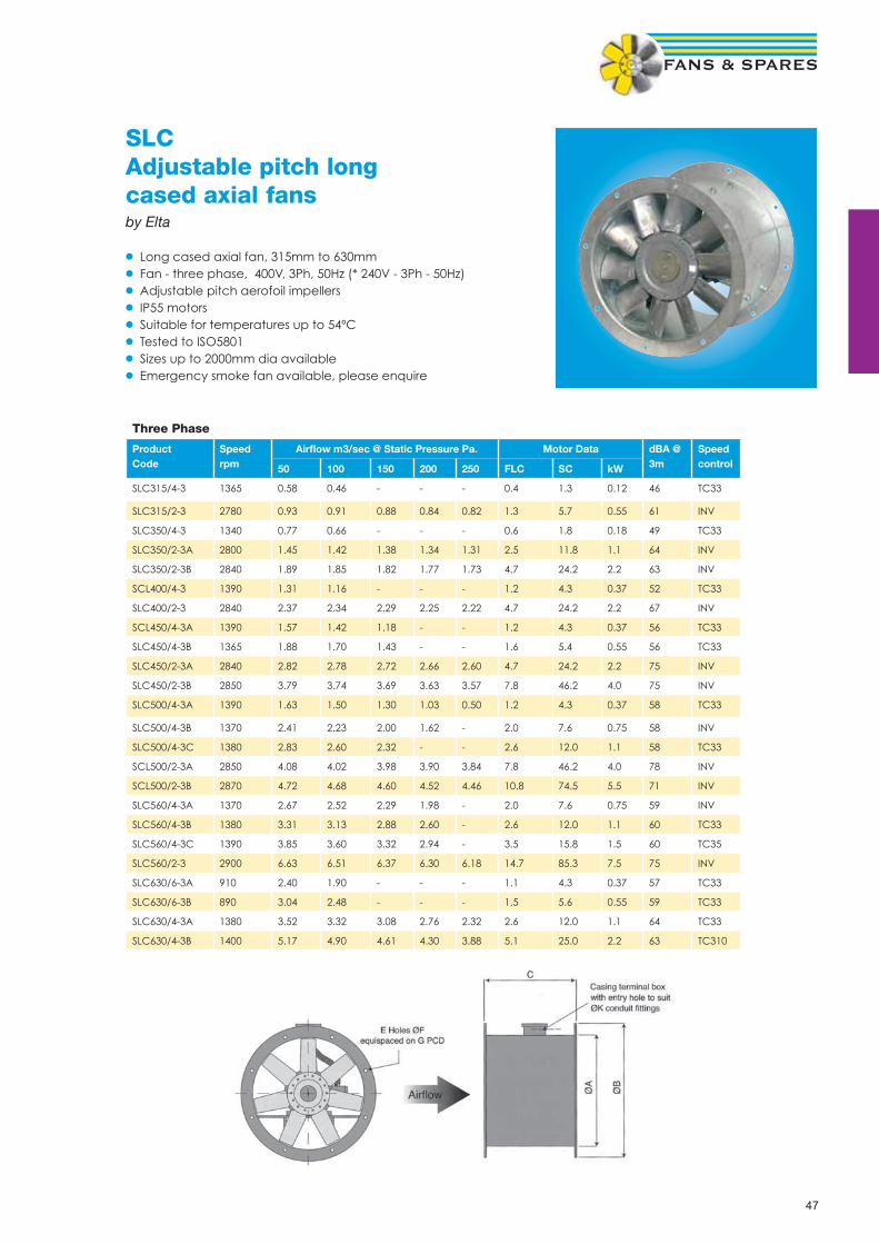
SLCAdjustable pitch longcased axial fansby Elta
• Long cased axial fan, 315mm to 630mm• Fan - single Phase, 240V - 1Ph - 50Hz (1-fi xed 2-variable) • Adjustable pitch aerofoil impellers• IP55 motors• Suitable for temperatures up to 54ºC• Tested to ISO5801• Emergency smoke fan available, please enquire
Single Phase
ProductCode
Speedrpm
Airfl ow m3/sec @ Static Pressure Pa. Motor Data dBA @ 3m
Speed control
0 50 100 150 200 FLC SC kW Elec Auto trans
SLC315/4-2 1300 0.63 0.55 0.38 - - 1.0 2.3 0.12 45 EL13 TC12
SLC315/2-1 2750 1.26 1.20 1.13 1.06 0.98 3.4 12.2 0.55 54
SLC350/4-2 1300 0.85 0.76 0.63 - - 1.3 4.6 0.18 48 EL13 TC12
SLC350/2-1 2820 1.42 1.39 1.36 1.32 1.30 6.9 24.2 1.1 64
SLC400/4-2 1350 1.44 1.32 1.15 - - 2.2 7.0 0.37 52 EL13 TC14
SLC400/2/1 2780 2.07 2.03 1.98 1.92 1.88 10.0 55.0 1.5 66
SLC450/4-2A 1350 1.68 1.56 1.40 1.12 - 2.2 7.0 0.37 55 EL13 TC14
SLC450/4-2B 1350 2.07 1.89 1.67 1.38 - 3.7 11.1 0.55 55 EL16 TC18
SLC450/2-1 2780 3.03 2.93 2.84 2.73 2.62 10.0 55.0 1.5 68
SLC500/4-2A 1350 1.81 1.70 1.57 1.36 1.00 2.2 7.0 0.37 58 EL13 TC14
SLC500/4-2B 1380 2.58 2.42 2.22 2.00 1.64 4.8 16.8 0.75 58 EL16 TC18
SLC560/4-2A 1380 2.90 2.78 2.62 2.42 2.10 4.8 16.8 0.75 59 EL16 TC18
SLC560/4-2B 1350 3.35 3.15 2.96 2.71 2.35 6.0 21.0 1.0 59 TC18
SLC630/6-1A 950 2.54 2.28 1.86 - - 3.0 10.5 0.37 58
SLC630/6-1B 950 3.31 2.95 2.48 - - 4.3 13.6 0.55 58
SLC630/4-2 1350 3.72 3.56 3.36 3.12 2.78 6.0 21.0 1.0 64 TC18
Dimensions
SLC A B C E F G K Weight/kg
315 315 375 300 8 10 355 20 17
350 350 425 375 8 10 395 20 26
400 400 475 400 8 12 450 20 31
450 450 530 375 8 12 500 20 30
450/2-3B 450 530 450 8 12 500 25 45
500 500 585 400 12 12 560 20 33
500/2-3 500 585 450 12 12 560 25 52
560 560 645 400 12 12 620 20 40
560/2-3 560 645 570 12 12 620 20 96
630 630 715 400 12 12 690 20 50
630/4-3B 630 715 450 12 12 690 20 58
47
SLCAdjustable pitch long cased axial fansby Elta
• Long cased axial fan, 315mm to 630mm• Fan - three phase, 400V, 3Ph, 50Hz (* 240V - 3Ph - 50Hz)• Adjustable pitch aerofoil impellers• IP55 motors• Suitable for temperatures up to 54ºC• Tested to ISO5801• Sizes up to 2000mm dia available• Emergency smoke fan available, please enquire
Three Phase
Product Code
Speedrpm
Airfl ow m3/sec @ Static Pressure Pa. Motor Data dBA @3m
Speed control50 100 150 200 250 FLC SC kW
SLC315/4-3 1365 0.58 0.46 - - - 0.4 1.3 0.12 46 TC33
SLC315/2-3 2780 0.93 0.91 0.88 0.84 0.82 1.3 5.7 0.55 61 INV
SLC350/4-3 1340 0.77 0.66 - - - 0.6 1.8 0.18 49 TC33
SLC350/2-3A 2800 1.45 1.42 1.38 1.34 1.31 2.5 11.8 1.1 64 INV
SLC350/2-3B 2840 1.89 1.85 1.82 1.77 1.73 4.7 24.2 2.2 63 INV
SCL400/4-3 1390 1.31 1.16 - - - 1.2 4.3 0.37 52 TC33
SLC400/2-3 2840 2.37 2.34 2.29 2.25 2.22 4.7 24.2 2.2 67 INV
SCL450/4-3A 1390 1.57 1.42 1.18 - - 1.2 4.3 0.37 56 TC33
SLC450/4-3B 1365 1.88 1.70 1.43 - - 1.6 5.4 0.55 56 TC33
SLC450/2-3A 2840 2.82 2.78 2.72 2.66 2.60 4.7 24.2 2.2 75 INV
SLC450/2-3B 2850 3.79 3.74 3.69 3.63 3.57 7.8 46.2 4.0 75 INV
SLC500/4-3A 1390 1.63 1.50 1.30 1.03 0.50 1.2 4.3 0.37 58 TC33
SLC500/4-3B 1370 2.41 2.23 2.00 1.62 - 2.0 7.6 0.75 58 INV
SLC500/4-3C 1380 2.83 2.60 2.32 - - 2.6 12.0 1.1 58 TC33
SCL500/2-3A 2850 4.08 4.02 3.98 3.90 3.84 7.8 46.2 4.0 78 INV
SCL500/2-3B 2870 4.72 4.68 4.60 4.52 4.46 10.8 74.5 5.5 71 INV
SLC560/4-3A 1370 2.67 2.52 2.29 1.98 - 2.0 7.6 0.75 59 INV
SLC560/4-3B 1380 3.31 3.13 2.88 2.60 - 2.6 12.0 1.1 60 TC33
SLC560/4-3C 1390 3.85 3.60 3.32 2.94 - 3.5 15.8 1.5 60 TC35
SLC560/2-3 2900 6.63 6.51 6.37 6.30 6.18 14.7 85.3 7.5 75 INV
SLC630/6-3A 910 2.40 1.90 - - - 1.1 4.3 0.37 57 TC33
SLC630/6-3B 890 3.04 2.48 - - - 1.5 5.6 0.55 59 TC33
SLC630/4-3A 1380 3.52 3.32 3.08 2.76 2.32 2.6 12.0 1.1 64 TC33
SLC630/4-3B 1400 5.17 4.90 4.61 4.30 3.88 5.1 25.0 2.2 63 TC310

48
SCPPContra rotating axial fanby Elta
The compact power plus contra-rotating axial has been design for kitchen canopy installations due to its high pres-sure characteristics. Available in 4 sizes from 450 dia to 630 dia and fully speed controllable. Operating temperatures of 70deg C at fi xed speed and 50deg C when used with speed controllers. Motors have class F insulation and IP55 rating making the fan suitable for external applications.This fan is ideal to cope with high pressure drops through baffl e and carbon fi lters.
ProductCode
Voltage Airfl ow m3/s @ static pressure Pa Motor Data dBA @3m
Speed Control
100 200 300 350 400 500 600 FLC SC KW Elec Trans
SCPP450/4-1 230-1-50 1,67 1,51 1,27 1,13 - 6,0 18 0,74 58 EL61-TK TC18
SCPP500/4-1 230-1-50 2,24 2,09 1,91 1,77 1,61 - 7,2 21,6 1,1 63 EL101 TC18
SCPP560/4-1 230-1-50 3,01 2,80 2,51 2,32 2,05 1,30 - 9,8 30 1,5 68 EL101 TC110
SCPP630/4-1 230-1-50 4,06 3,81 3,49 3,28 3,01 2,30 1,45 15,8 39,6 2,2 71 - TC116
Dimensions
REF A B C E F G K Weight/kg
SCPP450/4-1 450 530 430 8 12 500 20 35
SCPP500/4-1 500 585 500 12 12 560 20 55
SCPP560/4-1 560 645 500 12 12 620 20 60
SCPP630/4-1 630 715 500 12 12 690 20 70
CASING TERMINAL BOX WITH ENTRY HOLE TO SUIT K CONDUIT FITTINGS
10 BLADE IMPELLER
1ST STAGE RH BLADEMOUNTED ON 150 HUB
1ST STAGE 2ND STAGE
AIR-FLOWFORM `B'
MOUNTED ON 150 HUB2ND STAGE LH BLADE
10 BLADE IMPELLER
FORM ‘A’AIR-FLOW
15°
E HOLES FSPACED ON G PCD (BOTH FLANGES)
O
O
O
O
O A
O B
C

49
SBBifurcated axial fansby Elta
• Bifl ow axial fan, 250mm to 630mm dia• Fan - single phase, 240V - 1Ph - 50Hz • Fan - three phase, 380-415V - 3Ph - 50Hz • Adjustable pitch aerofoil impellers to BS1490• IP54 motor• Suitable for temperatures up to 150ºC• Tested to ISO5801• Available in sizes up to 2 metres• Extra high temp/emergency duty please enquire
ProductCode
Speedrpm
Airfl ow m3/sec @ Static Pressure Pa. Motor Data dBA @3m50 75 100 150 200 250 FLC SC kW
SB250-CON4-1 1450 0.15 0.03 - - - - 1.05 2.9 0.12 48
SB315-CON4-1 1370 0.43 0.38 0.23 - - - 1.05 2.9 0.12 51
SB250-CON4-3 1470 0.14 0.04 - - - - 0.47 1.28 0.12 48
SB250-CON2-3 2880 0.5 0.47 0.44 0.36 0.28 0.2 0.8 3.0 0.25 61
SB315-CON4-3 1410 0.43 0.37 0.25 - - - 0.47 1.28 0.12 51
SB315-CON2-3 2780 0.91 0.9 0.88 0.84 0.8 0.76 1.55 6.6 0.55 64
SB400-CYL4-3 1450 0.89 0.82 0.7 - - - 0.8 3.0 0.25 55
SB400-CON2-3 2910 2.05 2.02 2.00 1.96 1.92 1.86 4.8 26.4 2.2 70
SB500-CYL4-3 1450 2.14 2.04 1.92 1.52 - - 2.0 8.5 0.75 62
SB500-CON2-3 2875 3.76 3.73 3.71 3.66 3.6 3.54 8.4 59.0 4.0 80
SB630-CYL4-3 1435 4.27 4.16 4.04 3.76 3.44 - 4.8 26.4 2.2 70
SB A B C E F G H I kg
250 250 325 460 8 10 299 400 220 23
315 315 380 500 8 10 355 460 250 31
400-CYL 400 475 450 8 12 450 N/A 250 29
400-CON 400 485 650 8 12 450 570 305 49
500-CYL 500 585 450 12 12 560 N/A 315 47
500-CON 500 585 710 12 12 560 700 370 86
630 630 715 570 12 12 690 N/A 400 78
Dimensions
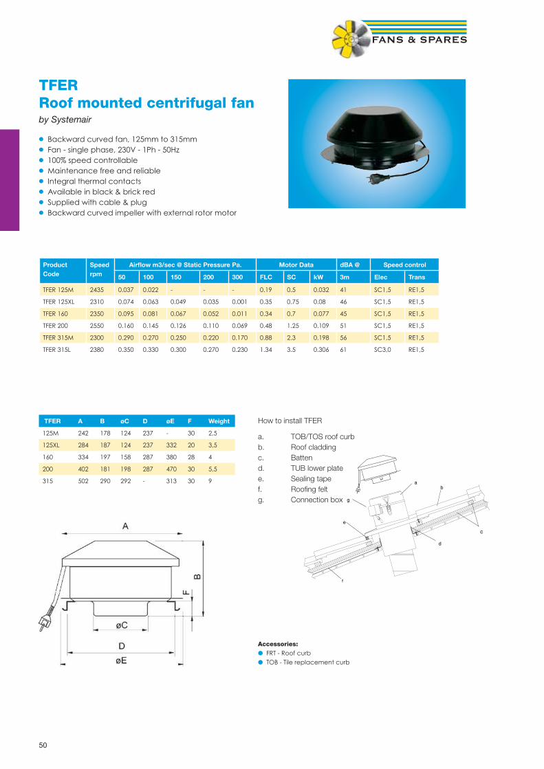
50
TFERRoof mounted centrifugal fanby Systemair
• Backward curved fan, 125mm to 315mm• Fan - single phase, 230V - 1Ph - 50Hz• 100% speed controllable• Maintenance free and reliable• Integral thermal contacts• Available in black & brick red• Supplied with cable & plug• Backward curved impeller with external rotor motor
ProductCode
Speedrpm
Airfl ow m3/sec @ Static Pressure Pa. Motor Data dBA @ Speed control
50 100 150 200 300 FLC SC kW 3m Elec Trans
TFER 125M 2435 0.037 0.022 - - - 0.19 0.5 0.032 41 SC1,5 RE1,5
TFER 125XL 2310 0.074 0.063 0.049 0.035 0.001 0.35 0.75 0.08 46 SC1,5 RE1,5
TFER 160 2350 0.095 0.081 0.067 0.052 0.011 0.34 0.7 0.077 45 SC1,5 RE1,5
TFER 200 2550 0.160 0.145 0.126 0.110 0.069 0.48 1.25 0.109 51 SC1,5 RE1,5
TFER 315M 2300 0.290 0.270 0.250 0.220 0.170 0.88 2.3 0.198 56 SC1,5 RE1,5
TFER 315L 2380 0.350 0.330 0.300 0.270 0.230 1.34 3.5 0.306 61 SC3,0 RE1,5
TFER A B øC D øE F Weight
125M 242 178 124 237 - 30 2,5
125XL 284 187 124 237 332 20 3,5
160 334 197 158 287 380 28 4
200 402 181 198 287 470 30 5,5
315 502 290 292 - 313 30 9 ab
c
d
e
f
g
How to install TFER
a. TOB/TOS roof curbb. Roof claddingc. Battend. TUB lower platee. Sealing tapef. Roofi ng feltg. Connection box
NOTE
Accessories:● FRT - Roof curb● TOB - Tile replacement curb

51
RA / RAWRoof mounted axial fansby Systemair
• Cowl & base complete with axial fan, 200mm to 1000mm• Fan - single phase, 230V - 1Ph - 50Hz• Fan - three phase, 400V - 3Ph - 50Hz• Glass fi bre cowl & base (choice of designs)• Colour RAL7035 (others available)• Complete with plate mounted axial fan (supplied loose)• Can be wired in reverse for input air, performance reduced by up to 30%• Vertical discharge cowls available
Product Code
Speedrpm
Airfl ow m3/sec @ Static Pressure Pa Motor Data dBA @ 3m
Curb SizeExt/Int Sq
Speed control
0Pa 50Pa 100Pa FLC SC kW Elec Trans
RA200-21 2600 0.22 0.18 0.08 0.32 1.28 0.071 56 425/325 SC1.5 RE1.5
RA200-41 1400 0.11 0.03 - 0.062 0.248 0.016 39 425/325 SC1.5 RE1.5
RA250-21 2500 0.44 0.38 0.21 0.6 2.4 0.14 61 425/325 SC1.5 RE1.5
RA250-41 1400 0.22 0.14 - 0.21 0.6 0.04 47 425/325 SC1.5 RE1.5
RA300-21 2700 0.87 0.75 0.65 1.1 2.7 0.23 62 485/385 SC1.5 RE1.5
RA300-41 1390 0.5 0.38 - 0.32 1.1 0.07 48 485/385 SC1.5 RE1.5
RA315-41 1400 0.55 0.43 - 0.59 1.5 0.13 49 485/385 SC1.5 RTRE1.5
RA350-41 1400 0.74 0.62 0.50 0.9 2.5 0.2 52 625/425 SC1.5 RTRE1.5
RA400-41 1320 1.06 0.88 0.71 1.35 2.9 0.31 54 725/525 SC3.0 RTRE3.0
RA450-41 1310 1.42 1.25 1.04 2.8 7.0 0.61 58 725/525 SC3.0 RTRE3.0
RA500-41 1210 1.97 1.71 1.48 3.4 7.4 0.77 56 885/685 - RTRE5
RA560-41 1300 2.31 2.10 1.53 7.5 15.0 1.6 71 885/685 - RTRE7
RA630-61 880 2.57 1.94 - 1.95 4.6 0.43 62 985/785 SC3.0 RTRE3
RA710-61 880 2.95 2.30 - 2.7 5.3 0.6 64 985/785 SC3.0 RTRE5
Single Phase
Product Code
Speed rpm
Airfl ow m3/sec @ Static Pressure Pa. Motor Data dBA @ 3m
Curb sizeExt/Int Sq
Speed control
0Pa 50Pa 100Pa FLC SC kW Trans
RA315-43 1410 0.55 0.44 0.34 0.29 1.0 0.12 52 485/385 RTRD2
RA350-43 1360 0.70 0.59 0.48 0.35 1.0 0.18 54 625/425 RTRD2
RA400-43* 1300 1.03 0.83 0.67 0.48 1.4 0.27 57 725/525 RTRD2
RA450-43* 1340 1.41 1.25 1.10 1.15 3.7 0.61 62 725/525 RTRD2
RA500-43* 1340 2.05 1.82 1.60 1.35 4.7 0.78 62 885/685 RTRD2
RA560-43 1300 2.30 2.02 1.50 1.8 7.0 1.0 66 885/685 RTRD4
RA630-43 1360 3.71 3.47 3.10 3.2 14.0 1.9 73 985/785 RTRD4
RA630-63 880 2.57 1.92 - 1.5 3.6 0.7 63 985/785 RTRD2
RA710-43 1350 5.88 5.55 5.18 4.9 23.0 2.9 75 985/785 RTRD7
RA710-63 890 3.03 2.35 1.58 1.8 6.4 0.89 65 985/785 RTRD2
RA800-63 900 4.69 4.20 3.50 2.7 9.8 1.4 65 1100/900 RTRD4
RA800-83 680 3.59 2.91 - 1.8 5.5 0.72 58 1100/900 RTRD2
RA1000-63 935 11.10 10.51 9.70 10.5 67.0 5.5 81 1300/1100 INV
RA1000-83 670 7.25 6.30 4.31 4.2 13.0 2.2 69 1300/1100 RTRD7
RA1000-103 530 5.20 3.80 - 2.7 9.5 1.25 65 1300/1100 RTRD4
*4 Pole fan with two speed motor. Pre-wired Delta for high speed (4 pole). Change to Star confi guration for 6 pole speed.
Three Phase

52
RARoof Cowl DimensionsRA horizontal discharge roof cowls from Systemair are manufactured from glass reinforced plastic, with an ultra violet stabiliser and are precision moulded to provide a durable unit for the severest weather conditions without deterioration of fi nish. The standard colour fi nish is RAL 7035, but any B.S. or RAL colour can be provided if required.
A full range of ancillary items are available, including: bird guards, back draught shutters, purlin boxes and soaker sheets. RA roof fans are suitable for extract and supply air.
* Weight of RA shown in the chart includes an AW1 plate fan.
Model ref. A sq. B sq. C D sq. E Weight kg*
RA200 325 450 90 490 310 18
RA250 325 450 90 490 310 18
RA300 400 510 90 555 340 20
RA315 400 510 90 555 340 20
RA350 400 650 90 675 380 22
RA400 500 750 90 765 460 26
RA450 500 750 90 765 460 29
RA500 650 910 120 995 550 44
RA560 650 910 120 995 550 47
RA630 790 1010 120 1115 650 70
RA710 790 1010 120 1115 650 73
RA800 900 1165 100 1410 750 65
RA1000 1100 1360 80 1650 750 100 - 140
D
E
C
A
B
NOTE
● Bird guard fi tted as standard● Air operated shutter available - Ref BDS(“size of cowl”)
See page 130 for RAL colour chart options

53
RAResistance / Pressure drop through cowlAir volume m3/s against resistance Pa
Resistance through Cowl Only
Air Volume (m3/s) 0.1 0.2 0.3 0.4 0.5 0.6 0.7 0.8 1.0 1.2 1.4 1.5 1.6 1.8 2.0 2.5 3.0 3.5 4.0 4.5 5.0 5.5 6.0 6.5 7.0 7.5 8.0
RA200/250 Intake 4 16 36 64
RA200/250 Discharge 3 12 27 48
RA300/315 Intake 2 6 13 23 36 52
RA300/315 Discharge 1 4 10 17 27 39
RA350 Intake 1 5 10 18 28 39 52 65 106
RA350 Discharge 1 4 7 14 20 28 38 60 90
RA400/450 Intake 2 5 8 11 16 21 28 43 63 86 98
RA400/450 Discharge 1 3 6 8 12 16 21 33 47 64 73
RA500/560 Intake 5 7 9 11 18 27 37 42 46 60 74
RA500/560 Discharge 3 5 6 8 13 20 27 31 36 45 65
RA630/710 Intake 8 10 14 17 18 23 29 45 64 88 114
RA630/710 Discharge 6 8 10 12 14 17 21 32 48 64 87
RA800 Intake 4 6 8 10 11 13 18 27 36 50 66 84 104
RA800 Discharge 2 4 6 7 8 10 12 20 28 38 50 63 78
RA1000 Intake 3 4 6 8 11 16 21 27 34 41 50 60 70 82 94 106
RA1000 Discharge 2 3 4 6 8 11 16 20 26 31 38 45 53 62 70 79
Soaker sheet detail (profi le required)
Unit ref A square B Upstand C length
SKR200/250 450 150 1800
SKR300/315 515 150 1800
SKR350 650 150 1800
SKR400/450 750 150 1800
SKR500/560 890 150 1800
SKR630/710 1000 150 1800
SKR800 1130 150 1800
SKR1000 1365 150 1800
Upstand detail
Unit ref A’ Exernal B’ Internal
200/250 425 325
300/315 500 400
350 600 400
400/450 700 500
500/560 850 650
630/710 990 790
800 1100 900
1000 1300 1100

54
RVVertical discharge roof axial fanby Systemair
RV vertical discharge roof cowls from Systemair are manufactured from glass reinforced plastic, with an ultra violet-stabiliser and are precision moulded to provide a durable unit for the severest weather conditions without deterioration of fi nish. The standard colour fi nish is RAL 7035, but any B.S. or RAL colour can be provided if required. The fan comes complete with back draught shutters as standard.
RAV dimensions
Model A sq. B sq. C sq. D E sq. F Weight kg
RAV315 690 400 485 475 510 100 20
RAV350 690 400 600 475 650 100 22
RAV400 790 510 725 585 750 100 26
RAV450 790 510 725 585 750 100 29
RAV500 950 620 885 700 910 110 44
RAV560 950 620 885 700 910 110 47
RAV630 1030 780 950 800 1010 110 73
RAV710 1030 780 950 800 1010 110 80
Product Speed Airfl ow m3/s @ Static Pressure Pa Motor Data dBA @ Speed Control
Code rpm 0pa 50pa 100pa FLC SC kW 3m Elec Trans
RV315-4 1400 0,55 0,42 - 0,59 1,5 0,13 49 SC1.5 RTRE1.5
RV350-4 1400 0,75 0,62 - 0,9 2,5 0,2 52 SC1.5 RTRE1.5
RV400-4 1320 1,22 1.0 - 1,35 2,9 0,31 54 SC3 RTRE3
RV450-4 1310 1,65 1,47 1,21 2,8 7.0 0,61 58 SC5 RTRE3
RV500-4 1210 2,4 2,13 1,76 3,4 7,4 0,77 56 SC5 RTRE5
RV560-4 1300 2,97 2,58 2,17 6,5 15 1,6 71 - RTRE7
RV630-6 880 3.0 2,35 - 2,7 5,3 0,6 62 SC5 RTRE3
RV710-6 850 3,6 3.0 1,6 4,1 8.0 0,89 64 SC5 RTRE5
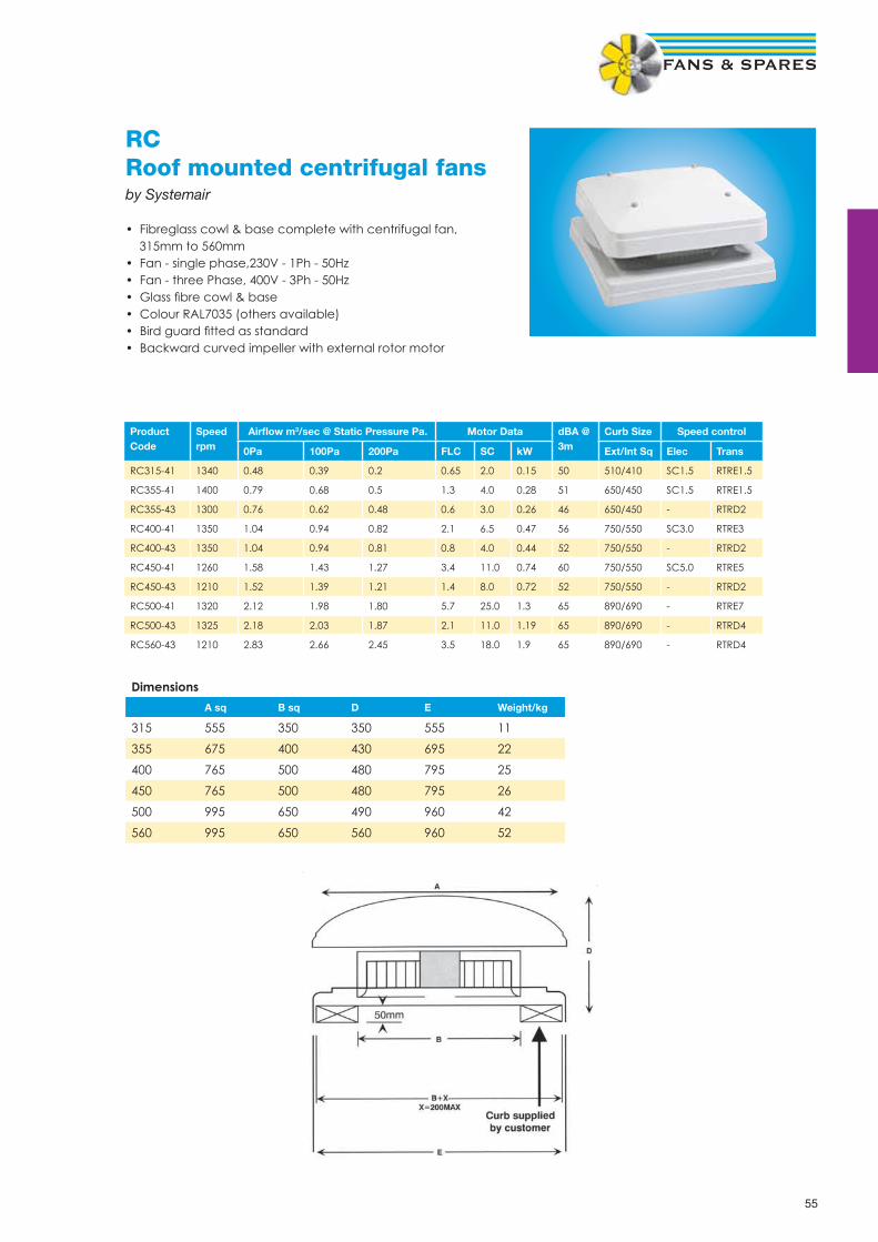
55
RCRoof mounted centrifugal fansby Systemair
• Fibreglass cowl & base complete with centrifugal fan, 315mm to 560mm• Fan - single phase,230V - 1Ph - 50Hz• Fan - three Phase, 400V - 3Ph - 50Hz• Glass fi bre cowl & base• Colour RAL7035 (others available)• Bird guard fi tted as standard• Backward curved impeller with external rotor motor
ProductCode
Speedrpm
Airfl ow m3/sec @ Static Pressure Pa. Motor Data dBA @3m
Curb Size Speed control
0Pa 100Pa 200Pa FLC SC kW Ext/Int Sq Elec Trans
RC315-41 1340 0.48 0.39 0.2 0.65 2.0 0.15 50 510/410 SC1.5 RTRE1.5
RC355-41 1400 0.79 0.68 0.5 1.3 4.0 0.28 51 650/450 SC1.5 RTRE1.5
RC355-43 1300 0.76 0.62 0.48 0.6 3.0 0.26 46 650/450 - RTRD2
RC400-41 1350 1.04 0.94 0.82 2.1 6.5 0.47 56 750/550 SC3.0 RTRE3
RC400-43 1350 1.04 0.94 0.81 0.8 4.0 0.44 52 750/550 - RTRD2
RC450-41 1260 1.58 1.43 1.27 3.4 11.0 0.74 60 750/550 SC5.0 RTRE5
RC450-43 1210 1.52 1.39 1.21 1.4 8.0 0.72 52 750/550 - RTRD2
RC500-41 1320 2.12 1.98 1.80 5.7 25.0 1.3 65 890/690 - RTRE7
RC500-43 1325 2.18 2.03 1.87 2.1 11.0 1.19 65 890/690 - RTRD4
RC560-43 1210 2.83 2.66 2.45 3.5 18.0 1.9 65 890/690 - RTRD4
Dimensions
A sq B sq D E Weight/kg
315 555 350 350 555 11
355 675 400 430 695 22
400 765 500 480 795 25
450 765 500 480 795 26
500 995 650 490 960 42
560 995 650 560 960 52

56
DVSVertical discharge centrifugal fanBy Systemair
• Metal cowl construction• Roof mounted extract fan• Backward curved centrifugal impeller• Speed controllable• Maintenance free and reliable• Acoustic DVSI version available
ProductCode
Voltage Airfl ow m3/s @ static pressure Pa Motor Data dBA @10m
Speed ControlTrans0 50 100 200 300 FLC kW
DVS190EZ 230-1-50 0,133 0,113 0,100 0,064 0,020 0,36 0,080 40 RE1.5
DVS225EZ 230-1-50 0,272 0,250 0,225 0,169 0,094 0,55 0,130 40 RE1.5
DVS311EV 230-1-50 0,488 0,438 0,380 0,211 - 0,65 0,135 37 RE1.5
DVS355E4 230-1-50 0,791 0,730 0,680 0,519 0,238 1,30 0,280 39 RTRE1.5
DVS400DV 400-3-50 1,055 1,019 0,950 0,811 0,650 0,80 0,440 43 RTRD2
DVS400E4 230-1-50 1,055 0,988 0,938 0,788 0,600 2,10 0,470 43 RTRE3
DVS450E4 230-1-50 1,583 1,519 1,419 1,258 1,000 3,40 0,740 45 RTRE5
DVS450DV 400-3-50 1,527 1,469 1,388 1,230 1,000 1,40 0,720 45 RTRD2
DVS499DV 400-3-50 1,833 1,769 1,700 1,500 1,250 1,80 0,900 46 RTRD2
DVS500DV 400-3-50 2,194 2,100 2,038 1,880 1,700 2,10 1,190 48 RTRD4
DVS500DS 400-3-50 1,500 1,350 1,250 0,838 - 1,00 0,440 38 RTRD2
DVS560DV 400-3-50 2,916 2,800 2,700 2,419 2,230 3,50 1,900 50 RTRD4
DVS560DS 400-3-50 2,097 1,900 1,750 1,300 0,500 1,50 0,720 41 RTRD4
DVS630DS 400-3-50 2,777 2,650 2,480 2,169 1,700 2,10 1,100 45 RTRD4
DVS710DS 400-3-50 4,583 4,400 4,200 3,800 3,300 4,00 2,000 50 RTRD7
�A
�B
C
øD
�E
�F
G M20x1,5
G
øH(4x)
J
øD
DVS oA oB C øD oE oF G øH J Weight Kg
190EZ, 225EZ 370 295 170 213 335 245 105 10 6xM6 7
311EV 560 470 330 282 435 330 146 10 6xM6 11
355E4, 400E4/DV 720 618 400 438 595 450 200 12 6xM8 25
450E4-500DS 900 748 440 438 665 535 237 12 6xM8 40
560DV/DS, 630DS 1050 1010 560 605 939 750 293 14 8xM8 58
710DS 1350 1176 660 674 1035 840 320 14 8xM8 88
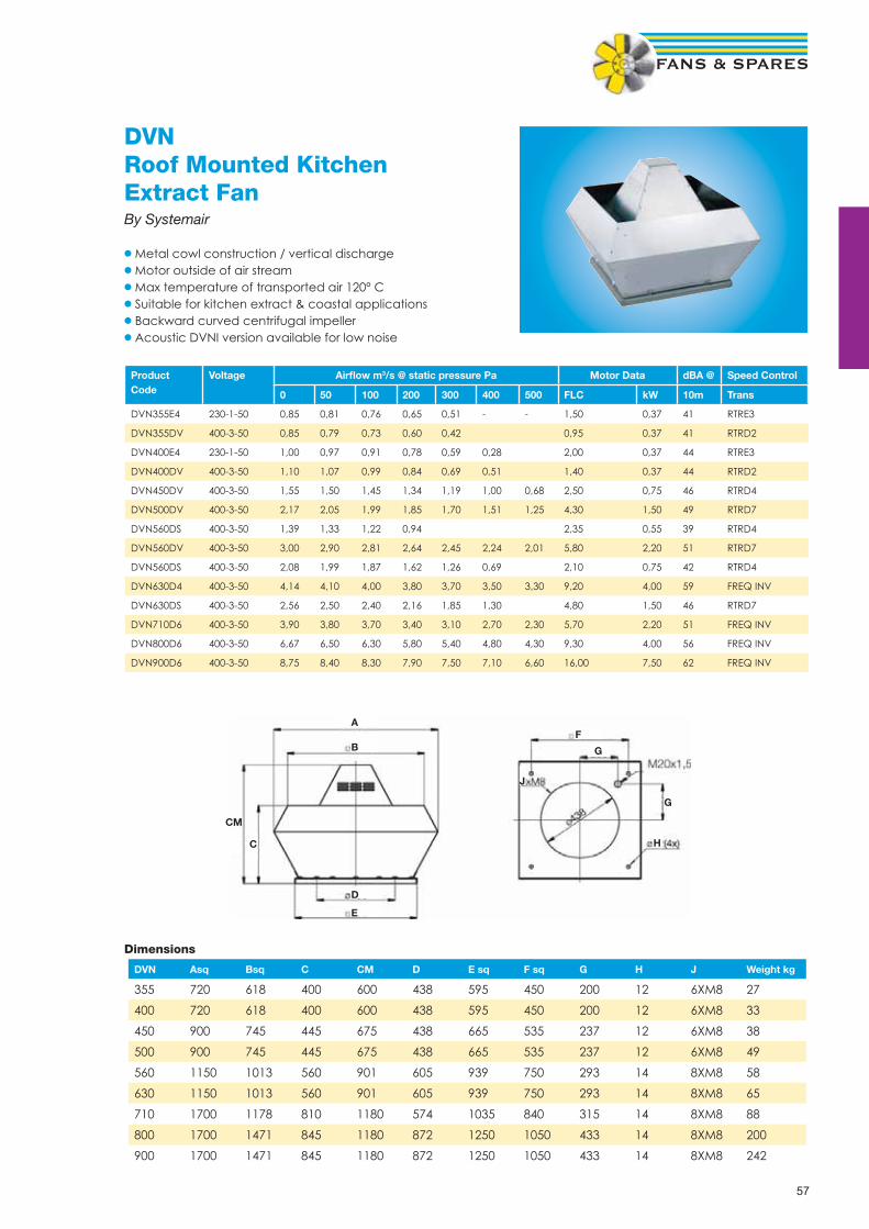
57
DVNRoof Mounted Kitchen Extract FanBy Systemair
• Metal cowl construction / vertical discharge• Motor outside of air stream• Max temperature of transported air 120° C• Suitable for kitchen extract & coastal applications• Backward curved centrifugal impeller• Acoustic DVNI version available for low noise
ProductCode
Voltage Airfl ow m3/s @ static pressure Pa Motor Data dBA @ Speed Control
0 50 100 200 300 400 500 FLC kW 10m Trans
DVN355E4 230-1-50 0,85 0,81 0,76 0,65 0,51 - - 1,50 0,37 41 RTRE3
DVN355DV 400-3-50 0,85 0,79 0,73 0,60 0,42 0,95 0,37 41 RTRD2
DVN400E4 230-1-50 1,00 0,97 0,91 0,78 0,59 0,28 2,00 0,37 44 RTRE3
DVN400DV 400-3-50 1,10 1,07 0,99 0,84 0,69 0,51 1,40 0,37 44 RTRD2
DVN450DV 400-3-50 1,55 1,50 1,45 1,34 1,19 1,00 0,68 2,50 0,75 46 RTRD4
DVN500DV 400-3-50 2,17 2,05 1,99 1,85 1,70 1,51 1,25 4,30 1,50 49 RTRD7
DVN560DS 400-3-50 1,39 1,33 1,22 0,94 2,35 0,55 39 RTRD4
DVN560DV 400-3-50 3,00 2,90 2,81 2,64 2,45 2,24 2,01 5,80 2,20 51 RTRD7
DVN560DS 400-3-50 2,08 1,99 1,87 1,62 1,26 0,69 2,10 0,75 42 RTRD4
DVN630D4 400-3-50 4,14 4,10 4,00 3,80 3,70 3,50 3,30 9,20 4,00 59 FREQ INV
DVN630DS 400-3-50 2,56 2,50 2,40 2,16 1,85 1,30 4,80 1,50 46 RTRD7
DVN710D6 400-3-50 3,90 3,80 3,70 3,40 3,10 2,70 2,30 5,70 2,20 51 FREQ INV
DVN800D6 400-3-50 6,67 6,50 6,30 5,80 5,40 4,80 4,30 9,30 4,00 56 FREQ INV
DVN900D6 400-3-50 8,75 8,40 8,30 7,90 7,50 7,10 6,60 16,00 7,50 62 FREQ INV
DVN Asq Bsq C CM D E sq F sq G H J Weight kg
355 720 618 400 600 438 595 450 200 12 6XM8 27
400 720 618 400 600 438 595 450 200 12 6XM8 33
450 900 745 445 675 438 665 535 237 12 6XM8 38
500 900 745 445 675 438 665 535 237 12 6XM8 49
560 1150 1013 560 901 605 939 750 293 14 8XM8 58
630 1150 1013 560 901 605 939 750 293 14 8XM8 65
710 1700 1178 810 1180 574 1035 840 315 14 8XM8 88
800 1700 1471 845 1180 872 1250 1050 433 14 8XM8 200
900 1700 1471 845 1180 872 1250 1050 433 14 8XM8 242
Dimensions
H
G
G
F
J
A
B
D
E
C
CM

58
Special Applications Fans

59
FLPFlameproof axial fansby The London Fan Company
For use in hazardous areas where fl ammable gas or dust is present ATEX II 2G D [EExd Zone 1]
• Sizes from 190mm to 760mm impeller diameter• All units are fi tted with Breezax anti static blades.• Stainless steel or mild steel plates are available with non-sparking track.• Available in 110V 1Phase version, please enquire• All fans are suitable for internal or external operations at any installed angle.• Airfl ow direction is A form (B form can be supplied if required)• Operating temperatures from -20 C to 50 C
Ancillaries include : Wire safety guards & louvre shutters
Performance Data
Fan Ref Speed Airfl ow m3/s @ Static Pressure Pa dBA @ Motor Data 240-1-50 Motor Data 415-3-50
RPM 0 Pa 12,5 25 37,5 50 62,5 75 3m kW FLC SC kW FLC SC
7.5FLP 4Pole 1400 0,12 0,01 - - - - - 40 0,04 0,5 1,21 0,1 0,6 1,29
7.5FLP 2Pole 2800 0,2 0,19 0,18 0,17 0,15 0,11 0,01 54 0,15 1,1 3,29 0,15 0,8 2,84
9FLP 6Pole 900 0,14 0,12 35 0,035 0,6 0,78 0,035 0,45 0,71
9FLP 4Pole 1400 0,24 0,21 0,18 44 0,04 0,5 1,21 0,1 0,6 1,29
9FLP 2Pole 2800 0,46 0,42 0,39 0,35 0,32 0,31 0,28 58 0,15 1,1 3,29 0,15 0,8 2,84
10.5FLP 6Pole 900 0,17 0,13 38 0,035 0,6 0,78 0,035 0,45 0,71
10.5FLP 4Pole 1400 0,36 0,34 0,24 48 0,04 0,5 1,21 0,1 0,6 1,29
10.5FLP 2Pole 2700 0,61 0,59 0,57 0,54 0,48 0,45 0,41 62 0,3 2,1 8,14 0,3 0,7 2,53
12FLP 6Pole 900 0,36 0,3 0,25 42 0,035 0,6 0,78 0,035 0,45 0,71
12FLP 4Pole 1400 0,54 0,5 0,47 0,39 0,34 52 0,04 0,5 1,21 0,1 0,6 1,29
15FLP 6Pole 900 0,68 0,64 0,53 0,45 48 0,035 0,6 0,78 0,035 0,45 0,71
15FLP 4Pole 1400 1,01 0,99 0,94 0,88 0,78 0,71 0,61 57 0,1 1,2 1,31 0,1 0,6 1,29
18FLP 6Pole 900 1,15 1,12 1,09 0,92 0,73 51 0,37 2,3 7,08 0,37 1,1 3,46
18FLP 4Pole 1400 1,74 1,72 1,67 1,61 1,53 1,44 1,2 61 0,37 2,3 7,07 0,37 1,1 4,19
24FLP 8Pole 700 2,12 1,95 1,76 1,49 1,1 54 Please enquire
24FLP 6Pole 900 2,77 2,72 2,66 2,59 2,54 2,47 2,3 60 0,37 2,3 7,08 0,37 1,1 3,46
Dimensions in mm
Fan size
ins mm A B C F h i k Weight/kg
7,5 190 203 260 26 235 8 323 239 6
9 229 241 330 26 235 10 414 280 7
10,5 267 279 355 26 235 10 450 315 7
12 315 323 394 26 235 12 503 372 8
15 381 392 470 35 235 12 611 447 9
18 457 473 560 35 335 16 728 530 26
24 610 630 718 35 335 19 938 702 37
30 762 800 914 35 335 20 1207 864 -
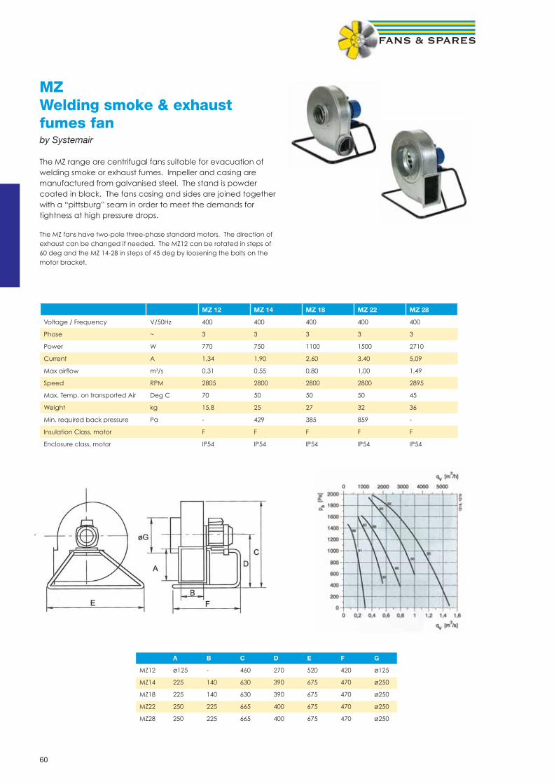
60
MZWelding smoke & exhaust fumes fanby Systemair
The MZ range are centrifugal fans suitable for evacuation of welding smoke or exhaust fumes. Impeller and casing are manufactured from galvanised steel. The stand is powder coated in black. The fans casing and sides are joined together with a “pittsburg” seam in order to meet the demands for tightness at high pressure drops.
The MZ fans have two-pole three-phase standard motors. The direction of exhaust can be changed if needed. The MZ12 can be rotated in steps of 60 deg and the MZ 14-28 in steps of 45 deg by loosening the bolts on the motor bracket.
MZ 12 MZ 14 MZ 18 MZ 22 MZ 28
Voltage / Frequency V/50Hz 400 400 400 400 400
Phase ~ 3 3 3 3 3
Power W 770 750 1100 1500 2710
Current A 1,34 1,90 2,60 3,40 5,09
Max airfl ow m3/s 0,31 0,55 0,80 1,00 1,49
Speed RPM 2805 2800 2800 2800 2895
Max. Temp. on transported Air Deg C 70 50 50 50 45
Weight kg 15,8 25 27 32 36
Min. required back pressure Pa - 429 385 859 -
Insulation Class, motor F F F F F
Enclosure class, motor IP54 IP54 IP54 IP54 IP54
A B C D E F G
MZ12 ø125 - 460 270 520 420 ø125
MZ14 225 140 630 390 675 470 ø250
MZ18 225 140 630 390 675 470 ø250
MZ22 250 225 665 400 675 470 ø250
MZ28 250 225 665 400 675 470 ø250

61
Chimney exhaust fansby Exhausto
A range of complete chimney fan systems consisting of chimney fans with automatic controls which guarantee the optimum chim-ney draught irrespective of the position, dimensions or height of the chimney. This product range can solve any type of chimney draught problem, and among others we supply systems for the following:• Fireplaces and stoves• Single boilers and water heaters burning gas, oil or solid fuel• Multiple appliances where several boilers are connected to the same chimney
The chimney fans offer capacities which will cover any heating appliance from small domestic fi replaces in private homes to larger commercial/ industrial boiler installa-tions. System solutions for gas appliances have a built-in failsafe operation devel-oped to meet international standards.
qv (m3/h)
Centrifugal Fansby Airfl ow
B - Single Inlet BlowersSingle Inlet Blowers-Centrifugal-Quiet,powerful air delivery for localised air movement. Airfl ow rates from 2.8 to 130l/sec, 275 ft3/min
D - Stool Mounted Blowers Stool Mounted Blowers - Centrifugal - A range of robust fans with the availability of different speed motors to effi ciently match your required performance needs. Airfl ow rates up to 1792 l/sec, 6451 m3/hr
C - Double Inlet BlowersDouble Inlet Blowers - Centrifugal - Quiet yet powerful fans with the motor mounted in one inlet. These fans are large air movers and are used where noise criteria are strict. Airfl ow rates from 112-1880 l/sec, 243-6768 m3/hr
Flue Boost FansThe fl ue boost is a boxed shaped unit with in-line spigots for the fl ue connection, a pressure switch to ensure safe operation and plug-in electrical fi ttings for easy connection, all within a com-pact package. There are 3 models in the range to suit different boiler ratings, please enquire for technical help.
Model Boiler Size heat outputs up to Flue gas temps up to Max Airfl ow Elec Data dBA @
Ref m3/s Voltage FLC SC 3m
100 35kW 200 deg C 0,04 240-1-50 0,75 1,2 54
350 102kW 300 deg C 0,15 240-1-50 0,51 0,9 64
800 235kW 300 deg C 0,37 240-1-50 0,72 1,5 68

62
GBDF / SSDFFlue dilution fansby Airfl ow
A new range of dilution fans including stainless steel versions for enhanced corrosion resistance, which allow fl exible siting of gas boilers rated between 30 kW and 650 kW input upgraded to include a pressure switch fail safe system and an easy to connect mains fl ying lead with snap-in plug and socket, the airfl ow range of fl ue dilution fans is available in 5 sizes to satisfy the dilution needs of industrial and commercial boilers. Each size is available in standard form (GBDF series) for atmospheric boilers and water heaters of circa 75% effi ciency. Enhanced corrosion resistance versions (SSDF series) with stainless steel fan cases are also available for installation where regulations or the specifi cation calls for stainless steel duting, and, when higher effi ciency boilers such as modular designs are likely to produce condensation. Condensation should not be allowed to collect in the fan casing.
Performance table at 20°C
Fan Size Airfl ow Litres / Sec @ Pascals Pa Volt FLC Mptor RPM
0 30 60 100 120 160 200 250 275 300 350 375 amps W
GBDF2 / SSDF 2 300 260 230 80 0 230 0,64 75 900
GBDF3 / SSDF3 600 550 510 440 380 120 0 230 1,45 120 880
GBDF4 / SSDF4 1000 950 900 815 760 640 340 80 0 230 2,8 335 930
GBDF5 / SSDF5 Not suitable below 90Pa 1370 1324 1200 1075 850 450 200 0 415 2,6 900 940
GBDF6 / SSDF6 Not suitable below 180Pa 1675 1420 1280 1085 625 460 415 2,9 900 900
Typical performance table at 20°C
Fan Size Units GBDF2 GBDF3 GBDF4 GBDF5 GBDF6
SSDF2 SSDF3 SSDF4 SSDF5 SSDF6
Maximum boiler input rating kW 80 160 270 425 650
Minimum inlet duct diameter mm 254 305 305 457 457
Minimum inlet louvre size mm 300x300 400x400 400x400 600x600 600x600
Minimum discharge duct diameter mm 225 275 345 370 457
Minimum discharge grille size mm 300x300 400x400 450x450 500x500 600x600
Diluted fl ue gas volume l/s 215 430 730 1145 1750
Total static pressure loss in system pa 70 93 130 160 180
Maximum fl ue velocity m/s 5,5 7,3 7,9 10,7 10,7
Fan Size A B C D E F G H I J K L M N P R S
2 218 238 179 200 9,5 402 251 265 78 106 304 335 140 191 260 222 101
3 250 270 236 257 9,5 440 302 302 78 109 359 394 175 222 294 281 109
4 352 384 263 295 9,5 578 302 340 78 141 408 445 194 256 409 321 121

63
Fan Size A B C D E F G H I J K L M N P R S
5 360 386 298 321 7 761 454 454 200 200 500 585 233 314 411 350 129
6 490 517 332 355 7 892 454 454 200 200 500 585 232 336 542 384 145

64
HABV-G(inlet with guide vanes)
HA...(B)-G F300HA...(F)-G F400HABV-G F600
• Two high temperature smoke extract fans in series, same rotation direction• F600 version with capsulated motors with cooling ducts• In case one fan is switched off or stops running for any reason, approx. 65% of the total air volume will be supplied.
HABV (with inlet guide vanes)
HABV...F600 (with inlet guide vanes)• Fan wheel diameter from 450 to 1800 mm• F600 version with capsulated motors with cooling ducts
450
500
560
630
710
800
900
1.000
1.120
1.250
1.400
1.600
1.800
600 °C
0 50 100 150 200 250
max. 250 Pa static
max. 450 Pa static
max. 600 Pa static
max. 800 Pa static
max. 350 Pa static
max. 430 Pa static
max. 570 Pa static
max. 720 Pa static
max. 850 Pa static
max. 1.070 Pa static
max. 700 Pa static
max. 800 Pa static
max. 800 Pa static
Volume flow x 103
[m 3 / h]
Siz
e
315
355
400
450
500
560
630
710
800
900
1.000
1.120
1.250
1.400
1.600
1.800
315
355
400
450
500
560
630
710
800
900
1.000
1.120
1.250
1.400
1.600
450
500
560
630
710
800
900
1.000
1.120
1.250
1.400
1.600
1.800
300 °C 400 °C 600 °C
max. 750 Pa static
max. 920 Pa static
max. 1.160 Pa static
max. 1.460 Pa static
max. 1.840 Pa static
max. 2.200 Pa static
max. 3.000 Pa static
max. 950 Pa static
max. 1.140 Pa static
max. 1.500 Pa static
max. 1.940 Pa static
max. 2.400 Pa static
max. 3.000 Pa static
max. 1.600 Pa static
max. 2.000 Pa static
max. 2.700 Pa static
Volume flow x 103
[m 3 / h]
Siz
e
0 50 100 150 200 250
AccessoriesSilencers
RSA
Protection guards
SG-AW/AR
Back draughtdampers
LRK
CounterFlanges
GFL-AR
Mounting feet, alternativelymounting brackets
MFA-AR
Flexibleconnections
EVH
Inlet cones
ESD

65
Axial fans HA
Axial fanHA...(B) F300HA...(F) F400• Sizes 315 to 1800 mm• P-HA with square wall plate with inlet cone, manufactured from steel, hot dip galvanized, up to size 1000
Axial roof fanHA...(B)-D F300HA...(F)-D F400 HABV...-D F600• Sizes 315 to 1800 mm• With roof cowl and base frame
AXC...(B) F300AXC...(B)-G F300• Fan wheel diameter from 315 to 1250 mm• Adjustable aluminium impellers
• Sizes from 315 to 1250 mm• Casing manufactured from steel, hot dip galvanised
HA...(B)-D
HA
0 50 100 150 200 250
Volume flow x 103
[m 3 / h]
315
355
400
450
500
560
630
710
800
900
1.000
1.120
1.250
1.400
1.600
1.800
400
355
315
450
500
560
630
710
800
900
1.000
1.120
1.250
1.400
1.600
max. 510 Pa static
max. 415 Pa static
max. 310 Pa static
max. 850 Pa static
max. 800 Pa static
max. 610 Pa static
max. 550 Pa static
max. 420 Pa static
max. 375 Pa static
max. 300 Pa static
max. 640 Pa static
max. 1.000 Pa static
max. 1.050 Pa static
max. 700 Pa static
max. 900 Pa static
max. 1.200 Pa static
300 °C 400 °C
Siz
e
AXC
315
355
400
450
500
560
630
710
800
900
1000
1250
0 15.000 30.000 45.000 60.000 75.000 90.000 105.000 120.000 135.000 150.000
max. 950 Pa static
max. 750 Pa static
max. 600 Pa static
max. 450 Pa static
max. 350 Pa static
max. 300 Pa static
max. 1.400 Pa static
max. 400 Pa static
max. 500 Pa static
max. 600 Pa static
max. 750 Pa static
max. 1.300 Pa static
V air in m³/h
AXCG
315
355
400
450
500
560
630
710
800
900
1000
1250
V air in m³/h
0 15.000 30.000 45.000 60.000 75.000 90.000 105.000 120.000 135.000 150.000 165.000
max. 2.150 Pa static
max. 1.600 Pa static
max. 1.300 Pa static
max. 1.000 Pa static
max. 780 Pa static
max. 660 Pa static
max. 840 Pa static
max. 1.100 Pa static
max. 1.200 Pa static
max. 1.600 Pa static
max. 2.600 Pa static
max. 2.600 Pa static

66
DVV F400/F600 Roof fanThe motor is separated from the air stream and insulated. ISO class F, protec-tion class IP 54. Backward curved centrifu-gal impellers, in 400°C version made from galvanized steel, in stainless steel in 600°C
version. Motor cooling via cooling duct in a negative pressure system. The terminal box is fi tted outside the cooling duct. DVV fans are also available in versions for 40°C and 100°C continuous operation.
Back draught damper
VKF/F
Back draught damper with
inlet cone
VKE/F
Bellmouthinlet
ESDV
Inlet fl angefl exible inletconnection
Flat roofsocket
Flat roofsocket
Inlet silencer Inlet silencer Outletsilencer
Adapterfor SSV
Centrifugal fan for wall mounting. Casing from galvanized steel, powder coated. Backward curved centrifugal impellers, in 400°C version made from galvanized steel, in stainless steel in 600°C version. WVA to be installed outside the fi re zone, WVI with insulated motor to be installed inside the fi re zone, with cooling duct ZHZ to be connected to the motor compart-ment. Fans are certifi ed for horizontal installa-tion on a wall, motor pointing downwards. Possibility to connect to a duct system, using accessory SN (inlet duct connection). IN outlet connection with protection guard is used for WVI as duct connection through the wall, for WVA as rain protection.
400
450
560
630
800
1.000
400
450
560
630
800
1.000
400 °C 600 °C
0 9.000 18.000 27.000 36.000 45.000
max. 2.000 Pa static
max. 650 Pa static
max. 550 Pa static
max. 350 Pa static
max. 1.550 Pa static
max. 1.200 Pa static
Air volume [m 3 / h]
Siz
e
55.000Volume fl ow x 103[m3/h]
WVI
WVA
400
450
560
630
800
1.000
400
450
560
630
800
1.000
400 °C 600 °C
0 9.000 18.000 27.000 36.000 40.000
max. 1.200 Pa static
max. 810 Pa static
max. 610 Pa static
max. 450 Pa static
max. 850 Pa static
max. 1.250 Pa static
Air volume [m 3 / h]
Siz
e
AccessoriesFlexible
connection
EPIN/EPSN
Inlet cowl
SN
Outlet cowl
IN
Cooling duct
ZHZ
Console
WBK-W
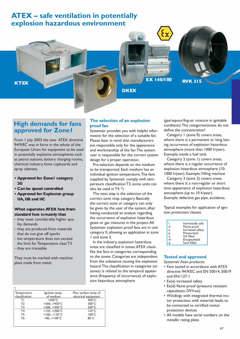
67
KTEX
DKEX
EX 140/180 RVK 315
From 1 July 2003 the new ATEX directive 94/9/EC was in force in the whole of the European Union for equipment to be used in potentially explosive atmospheres such as petrol stations, battery charging rooms, chemical industry, fume cupboards and spray cabinets.
• Approved for Zone1 category 2G• Can be speed controlled• Approved for Explosion group IIA, IIB and IIC
What separates ATEX fans from standard fans is mainly that– they meet considerably higher qua- lity demands– they are produced from materials that do not give off sparks– the temperature does not exceed the limit for Temperature class T3– they are traceable.
They must be marked with machine plate made from metal.
Systemair provides you with helpful infor-mation for the selection of a suitable fan. Please bear in mind that manufacturers are responsible only for the appearance and workmanship of the fan. The system user is responsible for the correct system design for a proper operation. Pre-selection depends on the medium to be transported. Each medium has an individual ignition temperature. The fans supplied by Systemair comply with tem-perature classifi cation T3, some units can also be used in T4. *) The next step is the selection of the correct zone resp. category. Basically the correct zone or category can only be given by the user of the system, after having conducted an analyse regarding the occurrence of explosion hazardous gases or gas mixtures in the project. All Systemair explosion proof fans are in unit category II, allowing an application in zone 1 and zone 2. In the industry, explosion hazardous areas are classifi ed in zones. ATEX classi-fi es the fans in categories, corresponding to the zones. Categories are independent from the substance causing the explosion hazard. The classifi cation in categories (or zones) is related to the temporal appear-ance (frequency of occurrence) of explo-sion hazardous atmosphere
(gas/vapour/fog-air mixture in ignitable condition). The categories/zones do not defi ne the concentration! Category 1 (zone 0) covers areas, where there is a permanent or long last-ing occurrence of explosion hazardous atmosphere (more than 1000 h/year). Example: inside a fuel tank. Category 2 (zone 1) covers areas, where there is a regular occurrence of explosion hazardous atmosphere (10-1000 h/year). Example: Filling machine Category 3 (zone 2) covers areas, where there is a non-regular or short time appearance of explosion hazardous atmosphere (up to 10 h/year).Example: defective gas pipe, accidents.
Typical examples for application of igni-tion protection classes:
Systemair Atex products:• Fans tested in accordance with ATEX directive 94/9/EC and EN 50014, 50019 and EN1127-1• Ex(e) increased safety• Ex(d) fl ame proof (pressure resistant capsulation, DVV-ex)• Windings with integrated thermal mo- tor protection, with external leads, to be connected to certifi ed motor protection devices• All models have serial numbers on the metallic rating plate.
i Intrinsically safe d Flame proof e Increased safety p Pressurized o Oil fi lled m Encapsulated q Sand fi lled
Temperature Ignition temp. Max. surface temp. ofclassifi cation of medium electrical equipment T1 >450°C 450°C T2 >300...>450°C 300°C T3 >200...>300°C 200°C T4 >135...>200°C 135°C T5 >100...>135°C 100°C T6 >85...>100°C 85°C
*)

68
EX 140/180Air fl ow up to 1180 m3/h (0.33 m3/s). Ex(e) increased safety. Motor protection device MSEX available for EX140 and EX180. 230V and 400V models available.
RVKAir fl ow up to 1020 m3/h (0.28 m3/s). Ex(e) increased safety. Casing consists of conducting plastic. Ex-classifi ed terminal box available as accessory. Motor speed controllable by transformer.
DKEXAir fl ow up to 5.000 m3/h (1.4 m3/s). Ex(e) increased safety. Motors speed controllable by transformer.
KTEXAir fl ow up to 5.000 m3/h (1.4 m3/s). Ex(e) increased safety. Ex-classifi ed termi-nal box available as accessory. Motors speed controllable by transformer.
AWEXAir fl ow up to 11.500 m3/h (3.19 m3/s). Ex(e) increased safety. Sizes 355 and 420 are approved for temperature class T4. Ex-classifi ed terminal box available as accessory. Motors speed controllable by transformer.
DVEXAir fl ow up to 8.600 m3/h (2.4 m3/s). Ex(e) increased safety. Motors speed
controllable by transformer. Ex-classifi ed terminal box available as accessory.
DVV-EXAir fl ow up to 44.000 m3/h (12.2 m3/s). Ex(d) fl ame proof. Motors speed control-lable by frequency inverters. Supplied with Ex-classifi ed terminal box pre-installed at the fan casing.
Art no. Model ATEX certifi cate no.1560 EX 140-4 Centrifugal Fan (ATEX) SP03ATEX3101X1562 EX 140-2 Centrifugal Fan (ATEX) SP03ATEX3101X1561 EX 180-4 Centrifugal Fan (ATEX) SP03ATEX3101X1557 EX 140-4C Centrifugal Fan (ATEX) SP03ATEX3101X1559 EX 140-2C Centrifugal Fan (ATEX) SP03ATEX3101X1558 EX 180-4C Centrifugal Fan (ATEX) SP03ATEX3101X1564 KTEX 50-25-4 Rect.fan (ATEX) SP04ATEX3105X3958 KTEX 50-25-4 (230V/3~) (ATEX) SP04ATEX3105X1566 KTEX 50-30-4 Rect.fan (ATEX) SP03ATEX3103X3957 KTEX 50-30-4 (230V/3~) (ATEX) SP03ATEX3103X1568 KTEX 60-30-4 Rect.fan (ATEX) SP04ATEX3107X1570 KTEX 60-35-4 Rect.fan (ATEX) SP04ATEX3109X1572 KTEX 70-40-6 Rect.fan (ATEX) SP04ATEX3111X3965 DKEX 225-4 Centrifugal (ATEX) SP04ATEX3106X3959 DKEX 225-4(230V/3~) (ATEX) SP04ATEX3106X3966 DKEX 250-4 Centrifugal (ATEX) SP03ATEX3104X3986 DKEX 250-4(230V/3~) (ATEX) SP03ATEX3104X3967 DKEX 280-4 Centrifugal (ATEX) SP04ATEX3108X3968 DKEX 315-4 Centrifugal (ATEX) SP04ATEX3110X3969 DKEX 355-6 Centrifugal (ATEX) SP04ATEX3112X1680 DVEX 315D4 Roof fan ATEX SP04ATEX3113X2040 DVEX 315D4 230V 3~Roof fan ATEX SP04ATEX3113X1681 DVEX 355D4 Roof fan ATEX SP04ATEX3114X1682 DVEX 400D4 Roof fan ATEX SP05ATEX3115X1683 DVEX 450D4 Roof fan ATEX SP04ATEX3116X1684 DVEX 500D6 Roof fan ATEX SP04ATEX3117X1685 DVEX 560D6 Roof fan ATEX SP05ATEX3118X1686 DVEX 630D6 Roof fan ATEX SP04ATEX3119X
Art no. Model ATEX certifi cate no.5969 AW 355 D4-2-EX Axial fan ATEX ZELM05ATEX0279X5970 AW 420 D4-2-EX Axial fan ATEX ZELM05ATEX0279X5971 AW 550 D6-2-EX Axial fan ATEX ZELM05ATEX0279X5972 AW 650 D6-2-EX-Axial fan ATEX ZELM05ATEX0279X30271 RVK 315Y4 (ATEX) ZELM03ATEX0198X30841 DVV-EX 560D4 Roof fan 40° SIQ06ATEX062X30842 DVV-EX 560D4-6 Roof fan 40° SIQ06ATEX062X30843 DVV-EX 560D4-8 Roof fan 40° SIQ06ATEX062X30844 DVV-EX 560D6 Roof fan 40° SIQ06ATEX062X30845 DVV-EX 560D6-8 Roof fan 40° SIQ06ATEX062X30846 DVV-EX 560D8 Roof fan 40° SIQ06ATEX062X30852 DVV-EX 630D4 Roof fan 40° SIQ06ATEX062X30848 DVV-EX 630D4-6-K Roof fan 40° SIQ06ATEX062X30853 DVV-EX 630D4-8 Roof fan 40° SIQ06ATEX062X30849 DVV-EX 630D4-8-K Roof fan 40° SIQ06ATEX062X30847 DVV-EX 630D4-K Roof fan 40° SIQ06ATEX062X30854 DVV-EX 630D6 Roof fan 40° SIQ06ATEX062X30855 DVV-EX 630D6-8 Roof fan 40° SIQ06ATEX062X30851 DVV-EX 630D6-8-K Roof fan 40° SIQ06ATEX062X30850 DVV-EX 630D6-8-K Roof fan 40° SIQ06ATEX062X30856 DVV-EX 800D6 Roof fan 40° SIQ06ATEX062X30857 DVV-EX 800D6-8 Roof fan 40° SIQ06ATEX062X30860 DVV-EX 800D6-8-K Roof fan 40° SIQ06ATEX062X30859 DVV-EX 800D6-K Roof fan 40° SIQ06ATEX062X30858 DVV-EX 800D8 Roof fan 40° SIQ06ATEX062X30861 DVV-EX 800D8-K Roof fan 40° SIQ06ATEX062X30862 DVV-EX 1000D6 Roof fan 40° SIQ06ATEX062X30863 DVV-EX 1000D8 Roof fan 40° SIQ06ATEX062X

69
Plastic centrifugal fans - Corrosion resistantSuitable for : Laboratory fume cupboard ventilation, fume removal from chemical storage cabinets and rooms, local fume extraction arms, odour fi ltration, and explosive gas ventilation.
Motor Type Standard, out of airstream Supply Single and three phase models
Protection IP54/IP55 standard + specials Impellers Forward-curved in moulded poly-propylene
Features Moulded polypropylene scroll housing, ‘O’ ring sealed. Models to suit fume cupboard and fi ltration systems
Mounting Standard and weather protecting pedestals
Pressure Medium Speed Control Frequency inverter drive only
Size Ø150 to 350 impellers Flow rate 10000 m³/h maximum
Pressure 1500 Pascals maximum
Special applicationsFor over fi fty years Fans & Spares have built a reputation for being able to supply products for every application within the Air Movement industry.
Epoxy Coated
Stainless Steel
P.V.C
Petrol / Diesel Driven
Belt Driven Axials
Belt Driven Centrifs
60 Hz
Vacuum Pumps
Marine applications
Dust Extraction
Fume Cupboards
High Pressure Blowers
Multi Vane Centrifs
Bifurcated Fans
Jet Fans

70
Centrifugal fan scrollsWhether it’s a replacement or spare part for a direct or belt drive - single or double inlet fan with forward or backward curved impellers - Fans and Spares will have the solution. Why not take along your old fan to one of our trade counters and let us do the hard work in identifying and quoting what you need!
Direct driven centrifugal fans, double inlet, with forward curved blades Wheel sizes from 146 x 146 mm (5” ¾) up to 18-18
Also from sizes from 9/7 tight up to 12-12*
Volume fl ow up to 16000 m3/h
Pressure up to 1000 Pa (static pressure)
Installed power up to 4 kW
Conventional motors, single phase and three phase 50 and 60Hz
*external rotor motors, single phase and three phase 50 and 60Hz
Double inlet centrifugal fans with true airfoil section Wheel size from 315 up to 1000 mm
Volume fl ow up to 120.000 m3/h
Pressure up to 2500 Pa (total pressure)
Installed power up to 75 kW
Belt Driven, Forward Curved Centrifugal, Double Inlet FansWheel size from 160 up to 1000 mm
Volume fl ow up to 240.000 m³/h
Pressure up to 2500 Pa (total pressure)
Installed power up to 75 kW
Direct driven centrifugal fans, single inlet, with forward curved bladesWheel sizes from 97 up to 450 mm (18”)
Volume fl ow up to 7000 m3/h
Pressure up to 1000 Pa (static pressure)
Motor power up to 2200 W
Conventional, high slip motors, single phase and three phase 50 and 60Hz
Direct driven fans for fan-coil units, fan-decksWheel sizes from 4” up to 9”
Volume fl ow up to 10000 m3/h
Pressure up to 750 Pa (static pressure)
Motor power up to 2200 W
Conventional, high slip motors, single phase, 230 V - 50 Hz
71
Heat Recovery &Air Handling Units

72
TASupply air handling unitby Systemair
The TA units are designed for complete plug & play use and are ideal for offi ces, schools and retail shops. The units have low overall height for ceiling void applications, with hinged access doors for ease of maintenance. All TA units are delivered complete with the SCP controller, heating battery and fi lters. The TA EL has an electric heater, whilst the TA HW uses a hot water battery. Manufactured with double skin casings insulated with 50mm mineral wool for ultra low noise breakouts. Remote extract fans can be linked into the SCP control to provide total ventilation.
TA VoltageV/50Hz
MotorW
HeaterkW
Airfl ow m3/s @ Pa Filters
50Pa 100Pa 200Pa 300Pa 400Pa 500Pa
450EL 230/400 130 3/3/6 0.155 0.143 0.11 0.077 0.025 - EU5
650EL 400 220 8,3 0,22 0,21 0,17 0,15 0,1 0,06 EU5
1100EL 400 325 13,3 0,34 0,32 0,27 0,23 0,19 0,14 EU5
1500EL 400 548 20,3 0,49 0,47 0,42 0,37 0,31 0,25 EU5
1500HW 230 573 enq 0,41 0,4 0,35 0,3 0,25 0,2 EU5
2000EL 400 705 33,3 0,6 0,57 0,54 0,49 0,44 0,39 EU5
2000HW 400 673 enq 0,56 0,54 0,5 0,46 0,42 0,36 EU5
3000HW 400 1084 enq 0,95 0,9 0,8 0,64 0,4 0,1 EU5
4500HW 400 1880 enq 1,44 1,39 1,27 1,12 0,9 0,6 EU5
External extract FanAn extract fan can be connected to the unit and be operated in parallel with the TA supply unit. The extract fan must be 1-phase for TA units 650 - 1500 and 3-phase for TA units 2000 & above. The extract fan must also have integrated thermal contacts for protection against over heating.
Available current for external extract fan (Amps) Options
TA 450 650 1100 1500 2000 3000 4500 KVKF - Slim Acoustic Fan 1Ph
230 V 1 ph 0,7 1,0 3,5 2,6 RSI - Acoustic Rect Duct Fan 3 ph
400 V 3 ph 2,8 2,0 4,3
TA Unit A B C D E F G H I J K L Dia dy N Weight kg
450EL 1125 500 354 200dia - 51 - 1042 89 - - - - 176 50
650EL 1203 556 307 200 dia 69 - 1116 82 - - - - 702 55
1100EL 1233 620 374 250 dia 75 - 1146 140 - - - - 731 67
1500EL 1190 750 374 200 400 105 175 1146 69 - - - - 731 82
1500HW 1190 750 374 200 400 105 175 1146 175 102 125 162 21mm 731 71
2000EL 1190 850 374 250 500 73 175 1146 73 - - - - 731 99
2000HW 1190 850 374 250 500 73 175 1146 175 101 92 212 21mm 731 87
3000HW 1296 904 545 300 600 141 152 1252 152 92 160 262 27mm 325 125
4500HW 1346 1006 545 400 700 91 153 1302 153 92 110 362 34mm 320 145
Control panel SCP
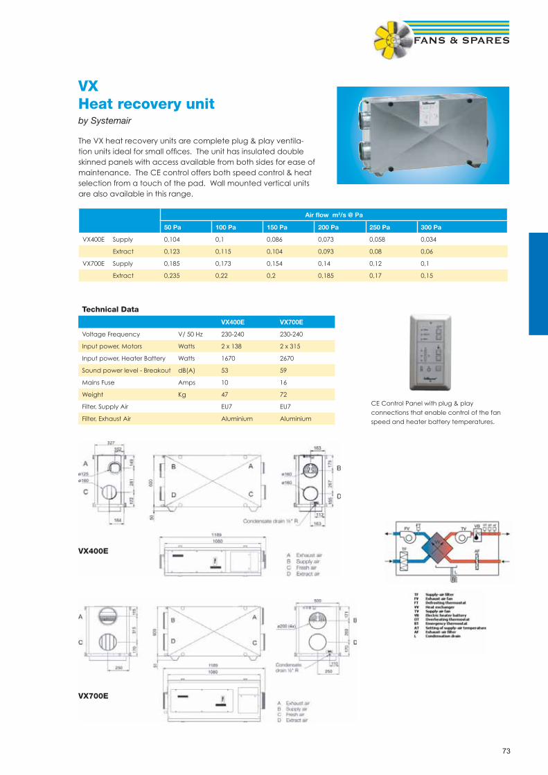
73
VXHeat recovery unitby Systemair
The VX heat recovery units are complete plug & play ventila-tion units ideal for small offi ces. The unit has insulated double skinned panels with access available from both sides for ease of maintenance. The CE control offers both speed control & heat selection from a touch of the pad. Wall mounted vertical units are also available in this range.
Air fl ow m3/s @ Pa
50 Pa 100 Pa 150 Pa 200 Pa 250 Pa 300 Pa
VX400E Supply 0,104 0,1 0,086 0,073 0,058 0,034
Extract 0,123 0,115 0,104 0,093 0,08 0,06
VX700E Supply 0,185 0,173 0,154 0,14 0,12 0,1
Extract 0,235 0,22 0,2 0,185 0,17 0,15
Technical Data
VX400E VX700E
Voltage Frequency V/ 50 Hz 230-240 230-240
Input power, Motors Watts 2 x 138 2 x 315
Input power, Heater Battery Watts 1670 2670
Sound power level - Breakout dB(A) 53 59
Mains Fuse Amps 10 16
Weight Kg 47 72
Filter, Supply Air EU7 EU7
Filter, Exhaust Air Aluminium Aluminium
VX400E
VX700E
CE Control Panel with plug & play connections that enable control of the fan speed and heater battery temperatures.

74
Residential units Residential unitsResidential unitsResidential units
VX 400 EVVX 700 EV
VX 400 EVX 700 E
VR 400 E/700 E VR 250 EH/B
VR 400 E/700 E• External control panel• Possible to connect several external
control panels• Large inspections doors on both sides• Cool recovery function• Adjustable filter change interval• 50 mm insulation
For horizontal installation in a warm orcold space e.g a utility room or attic.
VR 250 EH/B• External control panel• Possible to connect several external
control panels• Large inspections doors on both sides• Cooling recovery function• Adjustable filter change interval• Possible to connect to a cooker hood
Designed for installation on the wall in awarm space, utility room or similar.
VR 400 EV/BVR 700 EV
VX 400 EV/VX 700 EV• Integrated control panel• Possible to connect an external control
panel• Adjustable filter change interval
Designed for installation on the wall in awarm space, utility room or similar.
VX 400 E/VX 700 E• External control panel• Possible to connect several external
control panels• Large inspection doors on both sides• Adjustable filter change interval• 50 mm insulation
For installation horizontally. Can be placedin cold areas.
VX 250 TV/P• Compact design, easy to install• Integrated control panel
Easy to install in new and old dwellings,on the wall in a laundry room or similar.
VR 400 EV/B & 700 EV• Integrated control panel• Possible to connect an external control
panel• Cool recovery function• Adjustable filter change interval• Possible to connect to a cooker hood
Designed for installation on the wall in awarm space, utility room or similar.
VX 250 TV/P
Systemair residential units are suit-able for ventilation of homes andoffices:
• Delivered complete with controlsystem
• User friendly control panel• Easy to service and maintain• High quality external rotor motors• Made from double-skinned gal-
vanised sheet steel (central unitsmade from Aluzinc 185).
VX units have centrifugal fans forsupply and extract air, cross flow ex-changer, reheater battery and filters.
VR units have rotating heat ex-changer, centrifugal fans for supplyand extract air, reheater batteryand filter, automatic change betweennormal and summer operation, flex-ible installation without condensatedrain.
Control panelCE for all units(not VX 250 TV/P)Air flow, supply airtemperature and fil-ter change intervalare easy to setwith the controlpanel.
Lamp indica-tors show chosen settings andif filter change is necessary.

75
Compact unitsCompact unitsCompact units
TA 650-4500 m3/hTA is a series of supply air units, availablein six sizes and with electrical or hotwater re-heater battery.TA is a compactunit with low overall height.
The unit is delivered complete withcontrol system and is designed for simul-taneous operation with a stand aloneextract air fan.
Maxi 1100-2000 m3/hMaxi is a series of heat recovery units inthree sizes, with a low overall height andcrossflow heat exchangers.The uniquedesign with double duct connections foroutdoor air and extract air makes theunits very compact and easy to install.Using the suspension device UDM, theMaxi with electric heater can be installedin a false ceiling.
Topvex 1000-2000 m3/hTop connected heat recovery unit in threesizes with rotating heat exchanger.Theunit is powered by two plug fans mount-ed on external rotor motors.
The top connection saves floor spaceand facilitates installations in alreadyexisting premises.
Rotovex 2400-4800 m3/hHeat recovery unit in three sizes, with arotating heat exchanger and two plugfans with EC-motors to ensure lowpower consumption. Rotovex keeps aconstant airflow (CAV) and automaticallycontrols the supply air temperature.
Rotovex can easily be divided intotwo parts and is designed for easy trans-port through standard doorways with anopening of 800 mm.
Time 1000-14000 m3/hTime is available with a rotating heatexchanger or with a crossflow heatexchanger. The crossflow heat exchangeris mainly used when supply and extractair need to remain separate.
Time has built-in efficient plug fanswith low sound level.
Time is very easy to maintain andcomponents that need servicing can easi-ly be withdrawn.
Compact units
Systemair compact units are ventila-tion units especially suited for small-er industries, warehouses, petrol sta-tions, schools, shops and offices. Theyhave high efficiency, easy maintenanceand are delivered pre-programmedwith controls ready to run.
Control systemThe Systemair control systemis standard in the compactunits and available as anoption with the central units.
All Compact units aredelivered with a very user-friendly and fully integratedSystemair controller. In thispre-configured controller it is easy tochoose different functions by using theexternal SCP (Systemair Control Panel) tonavigate in the menus.The SCP panel canfreely be placed either on the unit or sep-arated from it.
The Systemair control system coversmost of the demands associated with amodern air handling unit.There are differ-ent forms of alarms, time control, temper-ature control and operating status, wherethe most important parameters areshown in the SCP display.
To simplify the start up procedure theSystemair control panel has preprogram-med temperature set points, time settingsand sensors. All these settings can ofcourse easily be changed to other values.
Features like free cooling, heat/coolrecovery and cascade control are standardin most units.The Systemair control sys-tem is suitable for communication withBMS (Building Management Systems).

76
Residential units Residential unitsResidential units
DV 1500-54000 m3/h• Very strong and rigid frame system • Panels and frames corrosion protected
with Aluzinc 185 • Dampers with rigid damper blades in
extruded aluminium • Different types of
- filter classes - heat recovery systems- fans
• Electrical heaters • Hot water heating coils • Cold water cooling coils • DX cooling coils • Disc-Lock system for easy assembling
of sections.
Many alternatives and possibilitiesThe DV unit is a combination Air Hand-ling Unit which features a number ofwell-dimensioned functions, presenting achoice between different heat exchangersystems, a range of fans, filters, heatingand cooling coils and much more.
The DV unit can be delivered in 12different sizes, so it is always possible tofind a solution and a size covering yourneeds.
The large removable inspectiondoors and a lot of parts which demandservice are side withdrawable, it makesthe service access very easy.
The Disc-Lock is a very quick and effi-cient way to assemble the DV sections.The system is standard for outsideassembly but is also available for insideassembly i.e. if a large unit is placed alongthe wall.
To ensure correct dimensioning, wedeveloped a highly advanced design pro-gram, called SystemairCAD.This is a veryuser-friendly program which makes itpossible to quickly and easily combinedifferent AHU functions, perform techni-cal calculations and document entireprocesses in the form of an AutoCADdrawing.
Fully dimensioned drawings, plus con-struction and presentation of technicaldata provide easy interpretation, with theadded benefit of direct transfer of thedrawings to AutoCAD.
Central units
The DV series replaces our formerindustrial units and are also produ-ced in Denmark.
We have further developed thestrong points and added quite a lotof news.The result has become ahighly flexible ventilation unit thatanswers up to our goal of develop-ing products that are innovative inconstruction as well as in function.
The DV together with all theother ventilation units availablefrom Systemair offer a completeventilation solution.With all theother ventilation products in ourrange Systemair can today offer themost complete ventilation packageon the market.
SummarySystemair has developed one of thewidest ranges of heat and coolingrecovery units on the market. Ourunits are well suited for all conditions.They are functional and easy to installand understand.

77
Systemairair handling unitsSystemair’s air handling units are builtin Sweden, Norway and Denmarkand cover an extensive range from200-54 000 m3/h.The units are avail-able in many different variations fromthe easier with simple functions, tothe most advanced.
A simple and a stable systemThe units have a stable constructionwith frame profiles and chamferedcast aluminium corners or doublesheet metal casings. All of the unitshave 50 mm mineral wool insulation.
The combination of heavy insula-tion and high efficient fans ensure alow sound level. Due to the insulationthe unit can also be placed in coldareas without risk of condensation.
Service mindedThe large inspection doors easily giveaccess to all functions, and all compo-nents that require maintenance canbe easily removed.That is why it isfast and simple to service a Systemairair handling unit.
Temperature Extract aircontrol Supply air
Supply air withoutdoor compensationRoom controlOutdoor changing Supply orExtract/Room air
Fan control 2-stepSteplessAirflow control, CAVPressure control,VAVOutdoor compensated airflow
Heat exchanger Cross flowBy-pass damperRotating
Heater Hot waterElectrical
Cold water Externalcooler(0...10VDC) Built-inFree cooling
Cool recoveringDemandventilation, CO2 2-step
Stepless
Pump control HeatingCooling
Exchanger efficiencyExtended runningWeek scheduleDamper control Fresh/Exhaust air
Alarm Alarm messageHigh and low prioritySum alarm output
Communication Exoline, ModbusLON,TCP/IP via RS-485
* Maxi 1100 has the by-pass built-in as standard** By-pass damper is necessary
-S
--
-
S----
---
SS
S-
-
-
--
--
-SSS
S
S
AA
SS
S-
-
S----
--S
SS
S-
-
P
P-
--
-SSS
S--
AA
SS
S-
-
S----
--S
SS
S-
-
P
P-
--
-SSS
S--
AA
SS
SS
S
S---S
SA *-
SS
S-
P **
P **
P-
SS
PSSS
SSS
SA
SS
SS
S
-SSSS
--S
SS
S-
P
P
-P
SS
PSSS
SSS
SA
SS
SS
S
--SS-
SSS
S-
S
SP
P
-P
SS
PSSS
SSS
SA
TA Max
i
Rotov
exTim
e
Topv
ex20
00
Topv
ex10
00-1
500
S = Standard choice P = Possible settingsA = Accessories
Regulation, compact units
VX,VR
Topvex
Maxi
Rotovex
Time
DV
TA
Air flow for Residential, Compact and Central units m3/h
m3/s

78
Grilles, Diffusers& Louvres
Also available, please enquire for the following:
Swirl Diffusers
Linear Bar Grilles
Curved Blade Grilles
Floor Grilles
Linear Slot Diffusers
Jet Nozzle Diffusers
Perforated Diffusers
Security Grilles
Fire Rated Air Valves
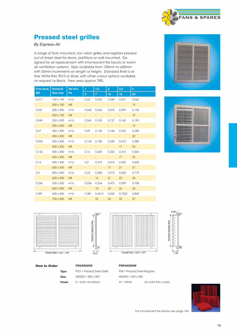
79
Pressed steel grillesBy Express-Air
A range of fl ush mounted, non vision grilles and registers pressed out of sheet steel for doors, partitions or wall mounted. De-signed for air replacement with intumescent fi re blocks or warm air ventilation systems. Sizes available from 100mm to 600mm with 50mm increments on length or height. Standard fi nish is ei-ther White RAL 9010 or Silver, with other colour options available on request i.e Black. Free area approx 78%.
Free AreaM2
NominalSize mm
Vel m/sPa
1 1,5 2 2,5 3
3 7 10 15 20
0,017 150 x 150 m3/s 0,02 0,032 0,040 0,051 0,062
200 x 100 NR - - - - 19
0,031 200 x 200 m3/s 0,042 0,060 0,076 0,099 0,150
250 x 150 NR - - - - 19
0,049 250 x 250 m3/s 0,065 0,100 0,127 0,160 0,190
300 x 200 NR - - - - 19
0,07 300 x 300 m3/s 0,09 0,140 0,184 0,225 0,280
450 x 200 NR - - - - 22
0,096 350 x 350 m3/s 0,125 0,180 0,250 0,310 0,380
500 x 250 NR - - - 17 23
0,125 400 x 400 m3/s 0,16 0,250 0,325 0,410 0,500
450 x 300 NR - - - 17 25
0,16 450 x 450 m3/s 0,2 0,310 0,410 0,520 0,620
600 x 350 NR - - 17 21 27
0,2 500 x 500 m3/s 0,25 0,385 0,510 0,650 0,775
600 x 400 NR - 16 21 25 30
0,236 550 x 550 m3/s 0,236 0,354 0,472 0,590 0,708
600 x 500 NR - 18 23 26 35
0,281 600 x 600 m3/s 0,281 0,4215 0,562 0,7025 0,843
700 x 550 NR - 22 26 32 37
How to Order PSG300300S PSR450300W
Type PSG = Pressed Steel Grille PSR = Pressed Steel Register
Size 300300 = 300 x 300 450300 = 450 x 300
Finish S = Satin Anodised W = White (or state RAL code)
For intumescent fi re blocks see page 104

80
Non vision transfer grillesNVF - Flanged NVS - Surface mountedGrilles with horizontal angled blades permitting the passage of air whilst limiting the passage of light and vision. Ideal for transferring air from adjoining areas and air make up. Avail-able in nominal sizes of 100mm to 1000mm with 50mm incre-ments on length or height. Made from extruded aluminium with mechanical joints to lock the mitred corners of the fl ange. Standard fi nish Silver satin anodised to BS 1615 AA5, Other colours available i.e White. Fixings are via countersunk screw holes in the border. Free area approx 45%. Surface mounted grilles are used when an intumescent fi re block is required.
Free Area Nominal Vel m/s 1 1,5 2 2,5 3
M2 Size mm Pa 8 20 35 46 60
0,025 150 x 150 m3/s 0,025 0,038 0,050 0,063 0,075
200 x 100 NR - - 18 25 30
0,042 200 x 200 m3/s 0,042 0,063 0,084 0,105 0,126
250 x 150 NR - - 20 26 32
0,065 250 x 250 m3/s 0,055 0,085 0,130 0,163 0,195
300 x 200 NR - 15 22 28 33
0,08 300 x 300 m3/s 0,08 0,120 0,160 0,200 0,240
450 x 200 NR - 15 23 30 34
0,106 350 x 350 m3/s 0,1 0,165 0,220 0,270 0,330
500 x 250 NR - 17 24 33 36
0,144 400 x 400 m3/s 0,13 0,200 0,280 0,337 0,400
450 x 300 NR - 18 27 34 36
0,182 450 x 450 m3/s 0,186 0,280 0,375 0,468 0,560
600 x 350 NR - 19 29 35 38
0,231 500 x 500 m3/s 0,23 0,344 0,468 0,595 0,700
600 x 400 NR - 19 30 35 40
0,299 550 x 550 m3/s 0,28 0,410 0,555 0,700 0,850
600 x 500 NR - 20 30 35 42
0,333 600 x 600 m3/s 0,34 0,5 0,68 0,855 1,01
700 x 550 NR - 22 30 38 43
How to Order NVF300300S NVS450300W
Type NVF = Non Vision Flanged NVS = Non Vision Surface
Size 300300 = 300 x 300 450300 = 450 x 300
Finish S = Satin Anodised W = White (or state RAL code)

81
External weather louvresIdeal for use on the external walls of a building for intake or extract air, the 45 deg blades are fi xed at 50mm centres and have excellent integral rain defence features. Constructed from extruded aluminium sections, frames are fully welded and fi tted with a bird guard as standard. Standard fi nish is satin anodised, with other colours available on request. Free area approx 50%.
Free Area Nominal Vel m/s 1 1,5 2 2,5 3
m2 Size mm Pa Intake 11 18 34 48 67
Pa Exhaust 6 13 24 37 50
0,011 150 x 150 m3/s 0,011 0,017 0,022 0,028 0,033
NR - - 18 25 30
0,02 200 x 200 m3/s 0,02 0,030 0,040 0,050 0,060
NR - - 20 26 32
0,032 250 x 250 m3/s 0,032 0,048 0,064 0,080 0,096
NR - 25 31 36 38
0,045 300 x 300 m3/s 0,045 0,068 0,090 0,113 0,135
NR 20 27 33 37 41
0,0613 350 x 350 m3/s 0,0613 0,092 0,123 0,153 0,184
NR 21 29 35 39 43
0,08 400 x 400 m3/s 0,08 0,120 0,160 0,200 0,240
NR 22 30 36 40 44
0,102 450 x 450 m3/s 0,102 0,153 0,204 0,255 0,306
NR 22 30 37 41 45
0,125 500 x 500 m3/s 0,125 0,188 0,250 0,313 0,375
NR 24 32 37 42 46
0,152 550 x 550 m3/s 0,152 0,228 0,304 0,380 0,456
NR 25 33 38 43 47
0,18 600 x 600 m3/s 0,18 0,27 0,36 0,45 0,54
NR 26 34 39 44 48
0,245 700 x 700 m3/s 0,245 0,368 0,490 0,613 0,735
NR 27 35 41 45 48
0,32 800 x 800 m3/s 0,32 0,48 0,64 0,8 0,96
NR 28 36 42 46 50
0,405 900 x 900 m3/s 0,405 0,608 0,810 1,013 1,215
NR 30 37 43 47 51
0,502 1000 x 1000 m3/s 0,502 0,753 1,004 1,255 1,506
NR 31 37 44 48 52

82
Single & Double defl ection grillesPart Codes: SDG or DDGGrilles with either single row or double row of individually adjust-able teardrop section blades and fl anged borders. Supplied with or without an opposed blade damper. Available in nominal sizes of 100mm to 1200mm with 50mm increments on length or height. Made from extruded aluminium with mechanical joints to lock the mitred corners of the fl ange. Standard fi nish Silver satin anodised to BS 1615 AA5, Other colours available i.e White. Fixings are via countersunk screw holes in the border. Free area approx 80%. Heavy duty version and Fixed Blade grilles are available on request.
Free Area Nominal Vel m/s 1,5 2 2,5 3 3,5 4 5
M2 Size mm Pa 5 8 10 15 21 26 38
0,015 150 x 150 m3/s 0,023 0,030 0,038 0,045 0,053 0,060 0,075
Throw M 3,0 4,4 5,4 6,7 7,8 8,8 10,4
NR - - - - 22 25 31
0,034 200 x 200 m3/s 0,051 0,068 0,085 0,102 0,119 0,136 0,170
Throw M 3,6 5,2 6,4 7,7 8,8 9,3 11,0
NR - - 14 21 25 28 35
0,052 250 x 250 m3/s 0,078 0,104 0,130 0,156 0,182 0,208 0,260
Throw M 4,0 5,5 7,0 8,4 9,0 9,9 11,0
NR - - 18 22 27 31 37
0,077 300 x 300 m3/s 0,116 0,154 0,193 0,231 0,270 0,308 0,385
Throw M 4,3 5,6 7,0 8,7 9,7 10,8 12,5
NR - - 18 25 28 32 37
0,105 350 x 350 m3/s 0,158 0,210 0,263 0,315 0,368 0,420 0,525
Throw M 4,5 6,0 7,8 9,5 10,2 11,8 14,0
NR - - 21 26 30 34 41
0,146 400 x 400 m3/s 0,219 0,292 0,365 0,438 0,511 0,584 0,730
Throw M 5,0 6,8 8,6 9,8 11,4 12,7 15,0
NR - 16 23 29 32 36 42
0,18 450 x 450 m3/s 0,270 0,360 0,450 0,540 0,630 0,720 0,900
Throw M 5,5 7,5 9,0 10,6 12,0 14,2 16,7
NR - 18 24 31 35 39 44
0,23 500 x 500 m3/s 0,345 0,460 0,575 0,690 0,805 0,920 1,150
Throw M 6,0 7,9 9,8 11,4 13,2 15,0 18,2
NR - 20 27 31 35 40 46
0,32 600 x 600 m3/s 0,480 0,640 0,800 0,960 1,120 1,280 1,600
Throw M 6,5 9,0 10,3 12,6 14,7 16,7 20,0
NR - 22 29 33 38 42 49
How to Order SDG300300S DDG450350W Type SDG = Single Defl ection DDG = Double Defl ection Size 300300 = 300 x 300 450350 = 450 x 350 Finish S = Satin Anodised W = White (or state RAL code)
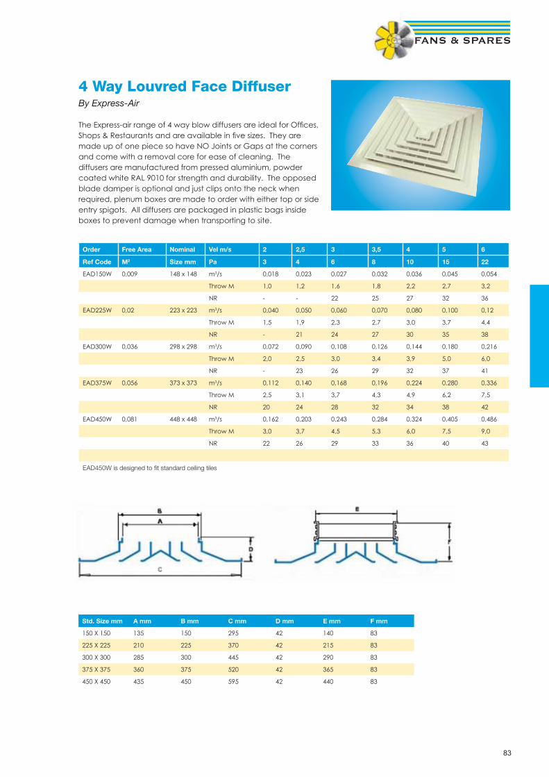
83
4 Way Louvred Face DiffuserBy Express-Air
The Express-air range of 4 way blow diffusers are ideal for Offi ces, Shops & Restaurants and are available in fi ve sizes. They are made up of one piece so have NO Joints or Gaps at the corners and come with a removal core for ease of cleaning. The diffusers are manufactured from pressed aluminium, powder coated white RAL 9010 for strength and durability. The opposed blade damper is optional and just clips onto the neck when required, plenum boxes are made to order with either top or side entry spigots. All diffusers are packaged in plastic bags inside boxes to prevent damage when transporting to site.
Order Free Area Nominal Vel m/s 2 2,5 3 3,5 4 5 6
Ref Code M2 Size mm Pa 3 4 6 8 10 15 22
EAD150W 0,009 148 x 148 m3/s 0,018 0,023 0,027 0,032 0,036 0,045 0,054
Throw M 1,0 1,2 1,6 1,8 2,2 2,7 3,2
NR - - 22 25 27 32 36
EAD225W 0,02 223 x 223 m3/s 0,040 0,050 0,060 0,070 0,080 0,100 0,12
Throw M 1,5 1,9 2,3 2,7 3,0 3,7 4,4
NR - 21 24 27 30 35 38
EAD300W 0,036 298 x 298 m3/s 0,072 0,090 0,108 0,126 0,144 0,180 0,216
Throw M 2,0 2,5 3,0 3,4 3,9 5,0 6,0
NR - 23 26 29 32 37 41
EAD375W 0,056 373 x 373 m3/s 0,112 0,140 0,168 0,196 0,224 0,280 0,336
Throw M 2,5 3,1 3,7 4,3 4,9 6,2 7,5
NR 20 24 28 32 34 38 42
EAD450W 0,081 448 x 448 m3/s 0,162 0,203 0,243 0,284 0,324 0,405 0,486
Throw M 3,0 3,7 4,5 5,3 6,0 7,5 9,0
NR 22 26 29 33 36 40 43
EAD450W is designed to fi t standard ceiling tiles
Std. Size mm A mm B mm C mm D mm E mm F mm
150 X 150 135 150 295 42 140 83
225 X 225 210 225 370 42 215 83
300 X 300 285 300 445 42 290 83
375 X 375 360 375 520 42 365 83
450 X 450 435 450 595 42 440 83

84
Circular multi cone diffuserA Multi cone diffuser for supply or extract air, suitable for ceiling or duct mounting. The diffuser consists of an external cone and an adjustable double center cone. The double cone can be adjusted for changing the air distribution pattern from horizontal to vertical. Manufactured from Steel and powder coated - standard fi nish white RAL 9010, other colour options available on request. Sizes from 160 dia neck to 500 dia neck.
Horizontal Air Pattern Vertical Air Pattern
Konika-A-160 m3/s 0,075 0,094 0,112 Konika-A-160 m3/s 0,060 0,075 0,090
dB(A) 25 33 40 dB(A) 25 33 40
Throw m 4,5 5,5 6 Throw m 7 9 10,5
Pa 17,0 27,0 37 Pa 20 34 45,0
Konika-A-200 m3/s 0,128 0,165 0,190 Konika-A-200 m3/s 0,100 0,120 0,145
dB(A) 25 33 40 dB(A) 25 33 40
Throw m 6 7 8 Throw m 8 11 13,5
Pa 14 23 30 Pa 19 30 41
Konika-A-250 m3/s 0,190 0,240 0,275 Konika-A-250 m3/s 0,150 0,190 0,230
dB(A) 25 33 40 dB(A) 25 33 40
Throw m 7 9 10 Throw m 10 12,5 14,5
Pa 12 19 25 Pa 14 23 32
Konika-A-315 m3/s 0,255 0,320 0,375 Konika-A-315 m3/s 0,210 0,275 0,325
dB(A) 25 33 40 dB(A) 25 33 40
Throw m 8 9,5 11 Throw m 11 14 16
Pa 12 18 25 Pa 13 23 30
Konika-A-400 m3/s 0,440 0,560 0,650 Konika-A-400 m3/s 0,370 0,475 0,550
dB(A) 25 33 40 dB(A) 25 33 40
Throw m 11 14 16 Throw m 15 18 21
Pa 11 18 24 Pa 12 21 27
Konika-A-500 m3/s 0,680 0,840 0,980 Konika-A-500 m3/s 0,530 0,660 0,780
dB(A) 25 33 40 dB(A) 25 33 40
Throw m 12,5 16 19 Throw m 17 20 23
Pa 10 15 21 Pa 10 16 22
A Dia B Dia C D Dia E F G H
Konika-A-160 279 323 12 160 22 85 46 35
Konika-A-200 375 428 10 200 26 101 55 51
Konika-A-250 467 538 14 250 33 117 68 67
Konika-A-315 557 635 10 315 42 135 80 85
Konika-A-400 740 856 14 400 49 166 92 116
Konika-A-500 924 1081 17 500 72 199 116 149
Vertical distribution patternHorizontal distribution pattern

85
Egg Crate Grillesby Express-air
Egg Crate Grilles are the latest addition to the Express-air Product Range. Egg Crate Grilles are designed for use in exhaust or return air situations and may be mounted in walls or ceilings. Made fully out of Aluminium, the Grille has outer frame manufactured from heavy extrusion which can accommodate the egg crate core. Grilles upto 600 mm x 600 mm are available, which can be mounted effi ciently in the ceilings. The Grille core has a standard ½” x ½” x ½” Egg Crate Size. The free area of the grille is >90% of the nominal area, providing maximum air fl ow and very low noise levels. Egg Crate Grilles can also be supplied as plain cores according to customers’ needs. Standard fi nish is Egg Shell White colour – RAL 9010. Can be supplied in other colours as per the requirement of the customers.
OrderRef Code
Free AreaM2
NeckSize mm
Vel m/s 1,5 2 2,5 3 3,5 4 5
Pa 4 6 9 13 18 23 34
ECG100W 0,009 100 x 100 m3/s 0,014 0,018 0,023 0,027 0,032 0,036 0,045
NR - - - - 22 25 31
ECG150W 0,019 150 x 150 m3/s 0,029 0,038 0,048 0,057 0,067 0,076 0,095
NR - - - - 22 25 31
ECG200W 0,034 200 x 200 m3/s 0,051 0,068 0,085 0,102 0,119 0,136 0,170
NR - - - 18 25 28 35
ECG250W 0,054 250 x 250 m3/s 0,081 0,108 0,135 0,162 0,189 0,216 0,270
NR - - - 19 26 28 37
ECG300W 0,078 300 x 300 m3/s 0,117 0,156 0,195 0,234 0,273 0,312 0,390
NR - - 16 20 28 32 40
ECG350W 0,106 350 x 350 m3/s 0,159 0,212 0,265 0,318 0,371 0,424 0,530
NR - - 17 23 30 32 42
ECG400W 0,144 400 x 400 m3/s 0,216 0,288 0,360 0,432 0,504 0,576 0,720
NR - - 19 24 29 33 43
ECG450W 0,182 450 x 450 m3/s 0,273 0,364 0,455 0,546 0,637 0,728 0,910
NR - - 20 25 33 35 45
ECG500W 0,231 500 x 500 m3/s 0,347 0,462 0,578 0,693 0,809 0,924 1,155
NR - - 21 26 33 36 46
ECG595W 0,299 550 x 550 m3/s 0,449 0,598 0,748 0,897 1,047 1,196 1,495
NR - - 22 28 34 38 50 Opposed blade dampers are available for all sizes of Egg crate grilles, please quote ref EAOBD*** (*** neck size)Plenum boxes with either side or top entry made to order - please specify duct diameter

86
Air Valves(Plastic, Metal & Fire Rated)Designed for supply or extract, air valves can be installed in either ceilings, walls or straight onto ductwork and are ideal for toilet ventilation systems. Air fl ow is varied by turning the central cone of the diffuser which also allows easy commissioning. The air valves are supplied with mounting rings for ease of installation. Available in metal or plastic with standard white fi nish from sizes 63mm to 200mm duct dia. Fire rated air valves and stainless steel fi nishes are available on request.
Size A Dia B Dia C Mounting Ring
63 63 90 15 A Dia D Dia Hole Req
80 80 106 15 100 120 97 103
100 100 135 15 125 146 122 128
125 125 160 15 150 180 147 154
150/160 149 191 15 160 180 157 163
200 200 238 18 200 220 197 203
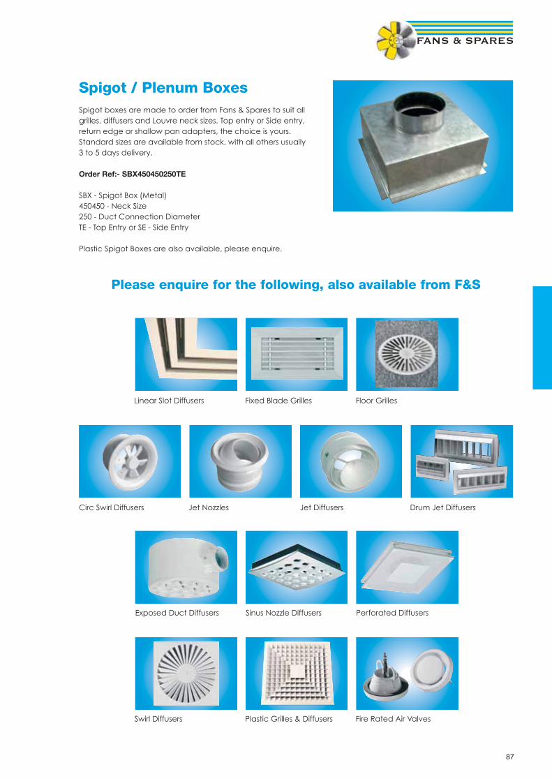
87
Spigot / Plenum BoxesSpigot boxes are made to order from Fans & Spares to suit all grilles, diffusers and Louvre neck sizes. Top entry or Side entry, return edge or shallow pan adapters, the choice is yours. Standard sizes are available from stock, with all others usually 3 to 5 days delivery.
Order Ref:- SBX450450250TE
SBX - Spigot Box (Metal)450450 - Neck Size250 - Duct Connection DiameterTE - Top Entry or SE - Side Entry
Plastic Spigot Boxes are also available, please enquire.
Please enquire for the following, also available from F&S
Linear Slot Diffusers Fixed Blade Grilles Floor Grilles
Circ Swirl Diffusers Jet Nozzles Jet Diffusers Drum Jet Diffusers
Exposed Duct Diffusers Sinus Nozzle Diffusers Perforated Diffusers
Swirl Diffusers Plastic Grilles & Diffusers Fire Rated Air Valves

88
FiltersAlso Available, please enquire for the following:
Bag Filters
Carbon Filters
Media Rolls

89
Panel Filtersby Express-air
Glass Fibre Disposable Filter (Cardboard Frame)
Order Ref Size Inches Size mm FilterGrade
Capacitym3/s *W x H x D W H D
EAAF10101 10 x 10 x 1 241 241 22 G3 0,12
EAAF10102 10 x 10 x 2 241 241 45 G3 0,13
EAAF12121 12 x 12 x 1 292 292 22 G3 0,16
EAAF12122 12 x 12 x 2 292 292 45 G3 0,18
EAAF15152 15 x 15 x 2 368 368 45 G3 0,28
EAAF16161 16 x 16 x 1 394 394 22 G3 0,31
EAAF16162 16 x 16 x 2 394 394 45 G3 0,35
EAAF18182 18 x 18 x 2 445 445 45 G3 0,41
EAAF20101 20 x 10 x 1 495 241 22 G3 0,22
EAAF20102 20 x 10 x 2 495 241 45 G3 0,25
EAAF20152 20 x 15 x 2 495 368 45 G3 0,38
EAAF20162 20 x 16 x 2 495 394 45 G3 0,41
EAAF20201 20 x 20 x 1 495 495 22 G3 0,47
EAAF20202 20 x 20 x 2 495 495 45 G3 0,52
EAAF24122 24 x 12 x 2 594 292 45 G3 0,37
EAAF24242 24 x 24 x 2 594 594 45 G3 0,73
EAAF25162 25 x 16 x 2 622 394 45 G3 0,52
EAAF25202 25 x 20 x 2 622 495 45 G3 0,64
* Capacity based on a face velocity of 2m/s giving initial resistance of 32Pa
Maximum velocity for Glass Fibre Filters 2.5m/s
Synthetic Pleated Disposable Filters (Cardboard Frame)
Order Ref Size Inches Size mm FilterGrade
Capacitym3/s *W x H x D W H D
EAPF10102 10 x 10 x 2 241 241 45 G4 0,12
EAPF12122 12 x 12 x 2 292 292 45 G4 0,18
EAPF15152 15 x 15 x 2 368 368 45 G4 0,27
EAPF16162 16 x 16 x 2 394 394 45 G4 0,35
EAPF18182 18 x 18 x 2 445 445 45 G4 0,41
EAPF20152 20 x 15 x 2 495 368 45 G4 0,37
EAPF20162 20 x 16 x 2 495 394 45 G4 0,40
EAPF20202 20 x 20 x 2 495 495 45 G4 0,48
EAPF24242 24 x 24 x 2 594 594 45 G4 0,72
EAPF25202 25 x 20 x 2 622 495 45 G4 0,63
* Capacity based on initial resistance of 40Pa, max capacity 25% above shown data.
Available as 20mm (1 “) & also 95mm (4”) depths.
Made to order sizes available, please enquire.

90
Grease Filtersby Express-air
Aluminium Frame Galvanised Mesh Grease Filters
Order Ref Size Inches Size mm Capacity
W x H x D W H D m3/s *
EAGF12121 12 x 12 x 1 292 292 20 0,19
EAGF12122 12 x 12 x 2 292 292 45 0,19
EAGF16161 16 x 16 x 1 394 394 20 0,33
EAGF16162 16 x 16 x 2 394 394 45 0,33
EAGF18181 18 x 18 x 1 445 445 20 0,42
EAGF18182 18 x 18 x 2 445 445 45 0,42
EAGF20101 20 x 10 x 1 495 241 20 0,26
EAGF20102 20 x 10 x 2 495 241 45 0,26
EAGF20161 20 x 16 x 1 495 394 20 0,41
EAGF20162 20 x 16 x 2 495 394 45 0,41
EAGF20201 20 x 20 x 1 495 495 20 0,52
EAGF20202 20 x 20 x 2 495 495 45 0,52
EAGF24241 24 x 24 x 1 597 597 20 0,75
EAGF24242 24 x 24 x 2 597 597 45 0,75
EAGF25202 25 x 20 x 2 662 495 45 0,65
*capacity based on Initial clean resistance of 30Pa @ 2.5m/s velocity
Aluminium Baffl e Filters
Order Ref Size InchesW x H x D
Size mm Capacity m3/s against Resistance Pa *
W H D 50pa 100pa 150pa 200pa
EABFA16162 16 x 16 x 2 394 394 45 0,12 0,16 0,20 0,24
EABFA18182 18 x 18 x 2 445 445 45 0,20 0,28 0,35 0,39
EABFA20102 20 x 10 x 2 495 241 45 0,12 0,16 0,20 0,24
EABFA20162 20 x 16 x 2 495 394 45 0,20 0,28 0,35 0,39
EABFA20202 20 x 20 x 2 495 495 45 0,26 0,38 0,46 0,51
EABFA24242 24 x 24 x 2 597 597 45 0,35 0,50 0,66 0,71
Stainless Steel Baffl e Filters
Order Ref Size Inches Size mm Capacity m3/s against Resistance Pa *
W x H x D W H D 50pa 100pa 150pa 200pa
EABFS16162 16 x 16 x 2 394 394 45 0,12 0,16 0,20 0,24
EABFS18182 18 x 18 x 2 445 445 45 0,20 0,28 0,35 0,39
EABFS20102 20 x 10 x 2 495 241 45 0,12 0,16 0,20 0,24
EABFS20162 20 x 16 x 2 495 394 45 0,20 0,28 0,35 0,39
EABFS20202 20 x 20 x 2 495 495 45 0,26 0,38 0,46 0,51
EABFS24242 24 x 24 x 2 597 597 45 0,35 0,50 0,66 0,71
* The resistance quoted above is both the initial and operating resistance due to the self draining capacity of the fi lter.

91
Panel Filter Boxesby Systemair
The FGR fi lter cassette is fi tted with a standard type EU3 panel fi lter. The cassette housing is manufactured from galvanised sheet steel with rubber- sealed circular duct connections, toggle locks and disposable fi lters. This fi lter cassette is suit-able for use as a supply-air fi lter in heavy industry and industrial workshops.
D dia A B C D E F G
FGR100 100 154 196 204 200 199 200 100
FGR125 125 154 196 204 200 199 200 100
FGR150 150 154 196 204 200 199 200 100
FGR160 160 154 196 204 200 199 200 100
FGR200 200 153 202 247 244 243 250 122
FGR250 250 153 206 297 294 293 300 147
FGR315 315 153 206 346 343 342 350 171,5
FGR355 355 153 206 451 448 447 450 224
FGR400 400 153 254 451 448 447 450 224
Carbon Can-Filtersby Express-air
The Express-air range of circular carbon fi lters have been designed for use with extract fans to remove most un-wanted smells. The activated carbon fi lters are a packed bed design to give constant performance, long life and are maintenance free, with a life of up 1.5 years. Packed bed design prevents the forming of preferential channels, which can allow untreated air through the system. The design of Filters gives you a large surface area for lower pressure drops, typically 180pa at max airfl ow with pre-fi lter. A bed depth, that allows for full 0.1 second contact time at max airfl ow for complete odour removal. Ideal for the Hydroponics industry. Available in duct sizes of 100mm up to 315mm
Max Aiflow Weight kg
ECCF100/250 160m3/hr 2.9
ECCF125/400 300m3/hr 5.6
ECCF150/500 480m3/hr 7.9
ECCF150/800 760m3/hr 12.1
ECCF200/500 760m3/hr 9.9
ECCF200/800 1030m3/hr 15.3
ECCF250/750 1080m3/hr 17.8
ECCF315/750 1300m3/hr 27.5
ECCF315/1000 1800m3/hr 35.3
Carbon Can Filters are to be used with the HVK range of plastic
extract duct fans
Order CodeECCF = Circ Carbon Filter150 = Duct Spigot Size mm800 = Length mm
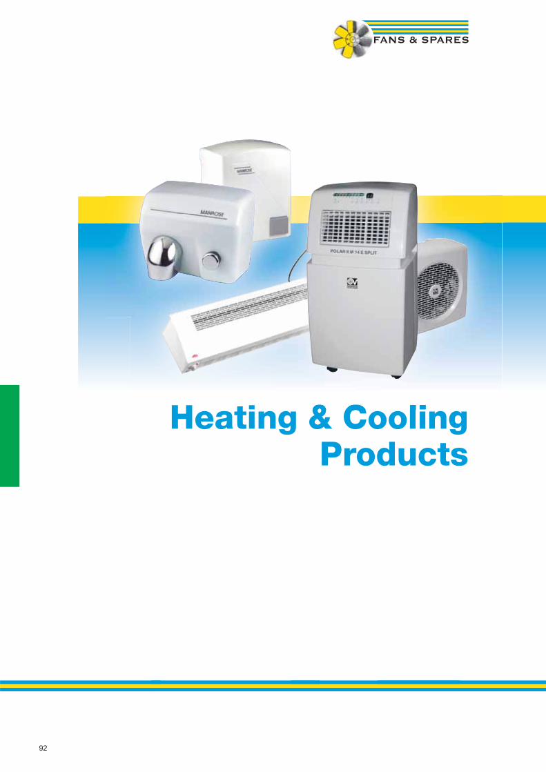
92
Heating & Cooling Products

93
Hand Driersby Manrose
Light Usage ModelsThese models are suitable for use within offi ce & commercial organisations, such as clinics & catering establishments. They are not recommended for use in public areas prone to vandalism, for example public lavatories
Order Ref: MAN/M04A MAN/M-88 MAN/M-88A MAN/A-89
Cover ABS thermoplastics one-piece cover
ABS, 3mm White ABS, 3mm White Aluminium 3mm White
Operation No Touch I.R Detection Push Button Timer 45Sec No Touch I.R Detection No Touch I.R Detection
Electrical 220-240V 9A 50/60Hz 220-240V 9A 50Hz 220-240V 9A 50Hz 220-240V 9A 50Hz
Motor 150W 140W 140W 140W
Wattage 1100W 1940W 1940W 1940W
Dimensions
HxWxD 258x145x138mm 300x250x130mm 300x250x130mm 300x250x130mm
Sound Volume
Levels 60dB(A) 60dB(A) 60dB(A) 60dB(A)
Output at
Diffuser 39 l/sec 56 l/sec 56 l/sec 56 l/sec
Weight 1.2kg 3.25kg 3.25kg 4.25kg
Heavy Duty ModelsThese models are suitable for use in public areas such as lavatories, factories, schools, railway & motorway service stations and are designed for heavy usage and unsupervised areas
Order Ref: MAN/E-88 MAN/E-88A MAN/E-88AD MAN/E-88ACS MAN/E-88C
Cover Steel 2mm White Porcelain Enamelled
Steel 2mm White Porcelain Enamelled
Steel 2mm Gold Plated Steel 2mm Satin Chromed
Steel 2mm Bright Chromed
Operation Push Button Timer 34Sec
No Touch I.R Detection No Touch I.R Detection No Touch I.R Detection Push Button Timer 34Sec
Electrical 220-240V 11A 50Hz 220-240V 11A 50Hz 220-240V 11A 50Hz 220-240V 11A 50Hz 220-240V 11A 50Hz
Motor 250W 5500r.p.m 250W 5500 rpm 250W 5500 rpm 250W 5500 rpm 250W 5500 rpm
Wattage 2450W 2450W 2450W 2450W 2450W
Dimensions
HxWxD 250x275x160mm 250x275x160mm 250x275x160mm 250x275x160mm 250x275x160mm
Sound Volume
Levels 70dB(A) 70dB(A) 70dB(A) 70dB(A) 70dB(A)
Output at
Diffuser 130 l/sec 130 l/sec 130 l/sec 130 l/sec 130 l/sec
Weight 7kg 7kg 7kg 7kg 7kg
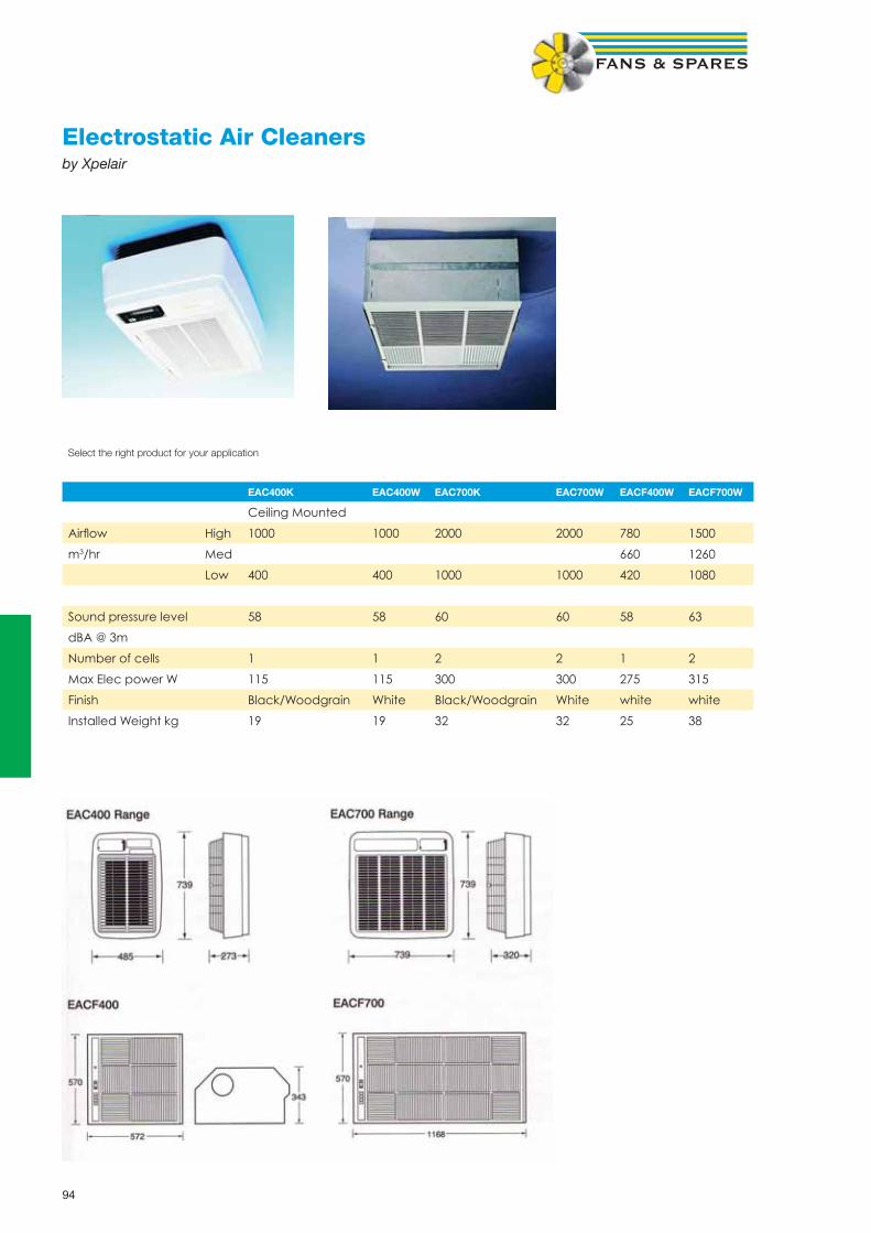
94
Electrostatic Air Cleanersby Xpelair
Select the right product for your application
EAC400K EAC400W EAC700K EAC700W EACF400W EACF700W
Ceiling Mounted
Airfl ow High 1000 1000 2000 2000 780 1500
m3/hr Med 660 1260
Low 400 400 1000 1000 420 1080
Sound pressure level 58 58 60 60 58 63
dBA @ 3m
Number of cells 1 1 2 2 1 2
Max Elec power W 115 115 300 300 275 315
Finish Black/Woodgrain White Black/Woodgrain White white white
Installed Weight kg 19 19 32 32 25 38

95
Ceiling Sweep Fansby Express-air
The Express-air Ceiling fans are available in three blade diameters, 900mm (36”), 1200mm (48”) & 1400mm (56”). The Blades & Downrods are manufactured from high grade steel, with an epoxy polyester powder coated fi nish. The down-rods come complete with a suspension kit and suspension loop. Standard length being 835mm (33”), with an overall length including the motor of 915mm (36”). The EACF 48 & 56 ceiling fans are reversible, for applications where minimal air disturbance is required. In this operation the air is forced up to the ceiling and drops down the walls to the working environment. The EACF 36 is for downward use only.
Performance Data
Fan Code Blade Dia No Poles RPM Voltage Motor kW Amps Duty m3/s
EACF 36 900mm 14 375 230-1-50 0,056 0,3 3,07
EACF 48 1200mm 18 320 230-1-50 0,065 0,35 4,96
EACF 56 1400mm 18 300 230-1-50 0,08 0,4 5,43
Accessories
EACFM** Motor only (Replacement)
EACFB** Blades only (Replacement)
ControllersEACF1.5 Electronic speed controller with forward / reverse switch, can control up to 5 ceiling fans
EAAEC12 + EAAEC12SENSOR Automatic Environment Controller & Sensor.
Designed to control up to 10 Express-air ceiling fans (same size blades). The controller offers two formsof control; Manual or Automatic. Manual offers minimum & maximum speeds via the control knob, whilethe automatic systems works with the EAAEC12SENSOR, to offer temperature control between 0 - 15 deg C.A switch selects either “up”, “down” or “off”, with the other switch controlling “manual” or “automatic”The casing is IP44, complete with indicator lights.
Selection GuideThe mounting height of the ceiling fan shows what fl oor area it will cover in square metres.

96
Portable Axial Fansby Elta
The Portacooler SPC Fan is designed to provide fast, cool relief in many locations including marquees, club rooms, shops, restaurants, gymnasiums, schools, halls, workshops and warehouses.
ConstructionMetal powder coated casing to RAL 7032 (pastel beige) All parts treated to ensure full corrosion protection. Inlet & Outlet protected by Zinc plated steel wire guard. High Quality aerodynamic GRP impellerStrong durable frame with rubber feet
MotorHigh Effi cient, Lightweight induction motor. Class F IP55. Electrical supply - 220-240V, single phase, 50 Hz.Fully Speed ControllableIntegral thermal overload protection
Special FeaturesPowerful 350mm, 450mm & 560mm Dia FanVariable speed-and-off regulator fi tted as standard.Flying lead fi tted with 13A plugFan angle adjuster
Product Dimensions Max Duty Max Speed dBA @ Weight Voltage
Code Height mm Wide mm Depth mm m3/s RPM 3m kg
SPC350/4-1 610 582 460 0,8 1320 56 18 230-1-50
SPC450/4-1 678 671 460 1,5 1300 63 24 230-1-50
SPC560/4-1 733 791 460 3 1350 69 33 230-1-50
De-Stratifi cation Fansby Express-air
The Express-air range of de-stratifi cation fans can be used in stores, warehouses, factories, workshops, as well as many other industrial applications. The unit is made up of a standard plate mounted axial fan, housed in a neat and sturdy casing complete with goal post supports for ease of mounting and angled airfl ow. Ideal for applications where the proposed mounting height requires higher velocity fans or where open bladed ceiling fans are considered unsuitable. The unit provides effective and positive ventilation to improve the working environment, particularly during summer months. In addition these fans can be used during the winter to re-circulate hot air from under ceilings and roofs down to living and working areas, thus helping to conserve energy.
Performance Data
Ref Speed dBA @ 230-1-50 Airfl ow Max Mtg Ht
RPM 3m FLC SC kW m3/s metres
DES 315 1400 46 0,59 1,5 0,13 0,6 13
DES 400 1320 51 1,35 2,9 0,31 1,3 20
DES 450 1310 55 2,8 7 0,61 2 25
Available in larger sizes & three phase options - Please enquire
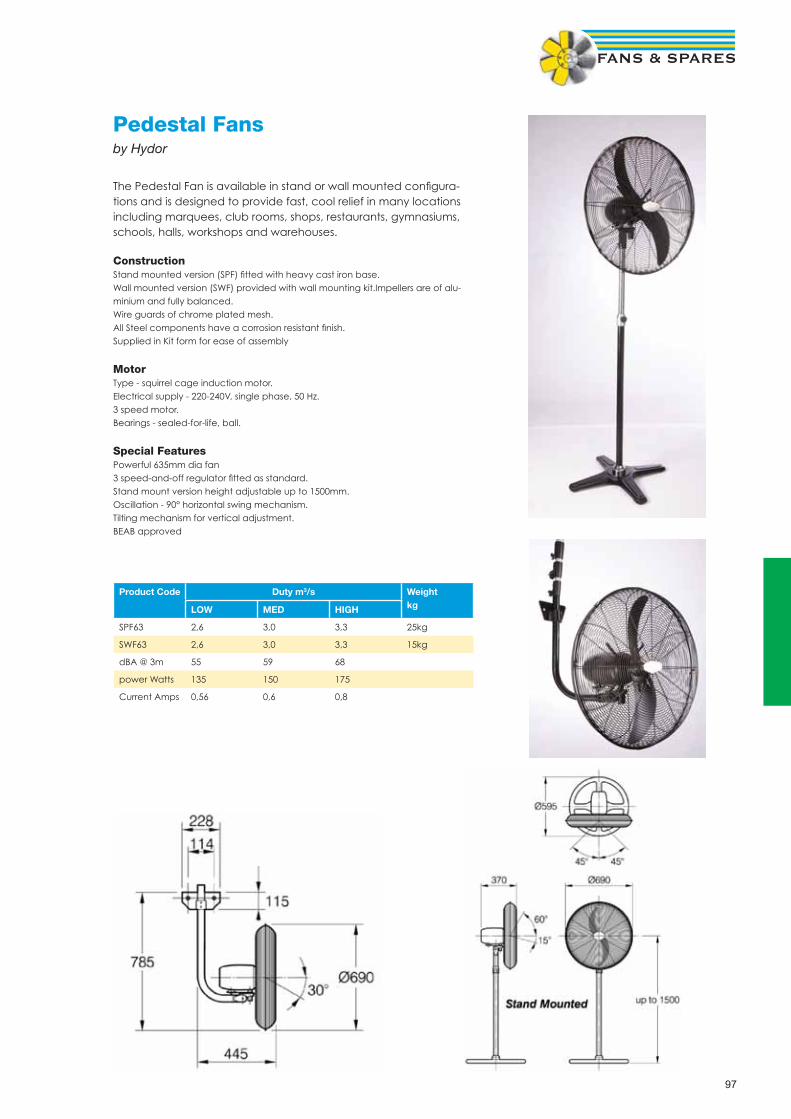
97
Pedestal Fansby Hydor
The Pedestal Fan is available in stand or wall mounted confi gura-tions and is designed to provide fast, cool relief in many locations including marquees, club rooms, shops, restaurants, gymnasiums, schools, halls, workshops and warehouses.
ConstructionStand mounted version (SPF) fi tted with heavy cast iron base.Wall mounted version (SWF) provided with wall mounting kit.Impellers are of alu-minium and fully balanced.Wire guards of chrome plated mesh.All Steel components have a corrosion resistant fi nish.Supplied in Kit form for ease of assembly
MotorType - squirrel cage induction motor.Electrical supply - 220-240V, single phase, 50 Hz.3 speed motor.Bearings - sealed-for-life, ball.
Special FeaturesPowerful 635mm dia fan3 speed-and-off regulator fi tted as standard.Stand mount version height adjustable up to 1500mm.Oscillation - 90° horizontal swing mechanism.Tilting mechanism for vertical adjustment.BEAB approved
Product Code Duty m3/s Weight kgLOW MED HIGH
SPF63 2,6 3,0 3,3 25kg
SWF63 2,6 3,0 3,3 15kg
dBA @ 3m 55 59 68
power Watts 135 150 175
Current Amps 0,56 0,6 0,8

98
Portable Air Conditioning Unitsby Vortice
Dimensions
A B C D E F
410 753 392 480 479 327
Specifi cationsProduct code
M14 E Split
65089/65090
Cooling capacity W 3114
Operating temperature (indoor unit) C 18-32
Operating temperature (outdoor unit) C 21-43
Consumption W 1240
Voltage V 230
Frequency -Hz 50
Energy effi ciency rating 2,51
Energy effi ciency class E
Air fl ow (max) m3/h 410
Rated current A 6,0
Type of refrigerant R 407 C
Type of compressor Rotary
Fan speeds No 2
Noise level at low speed (I.U.) 35.3
Noise level at high speed (I.U.) 37.4
Noise level (O.U.) dB(A) 32.4
Weight (I.U.) kg 30
Weight (O.U.) kg 11
Recommended room size m3 90
Length of air and coolant hose sheath mm 3000
The polar II M14 E Split is a split unit air conditioner with an outdoor unit connected to an indoor unit by a fl exible hose. The indoor unit blows condi-tioned air into the room while the outdoor unit dis-sipates heat and humidity. Robust design ensures an etended working life, and soft-touch electronic controls let you select your preferred room tem-perature at the touch of a button. The Polar II M14 E Split features an infrared remote control, and boasts a particularly elegant, com-pact design that makes it look great in any room.
• Easy to move• Separable unts• Simple controls• Washable dust fi lter• Active carbon fi lter• Remote control• Continuous exhaust• Automatic condensate evaporation system• 2 speeds• Sleep function

99
Wall Mounted Air Conditioning Unitsby Airwell
Performance, aesthetics and comfort are all advantages that characterise the FLORIDA N wall-mounted unit range. With its refi ned design, tried and tested technology and reliable components, the Florida wall-mounted range can also offer unrivalled heat comfort and air quality, which means that it can be incorporated into all residential and commercial buildings. With extremely low noise levels, a broad operating range, the eco-friendly fl uid R410A and energy label A (depending on model), the FLORIDA A wall-mounted unit range has been designed to provide a very high comfort level and to be very easy to fi t for installers.
• Cooling Only Models 2.23kW – 8.8kW• Heat Pump Models 2.28kW – 9.09kW• Infrared remote control
• Night-Time slow running• Three levels of fi ltration• Energy Effi cient
FLO N Cooling Only FLO 7 N FLO 9 N FLO 12 N FLO 14 N FLO 18 N FLO 24 N FLO 30 N
FLO N Heat Pump FLO 7 N RC FLO 9 N RC FLO 12 N RC FLO 14 N RC FLO 18 N RC FLO 24 N RC FLO 30 N RC
Heating Capacity (1) kW 2,28 3 4 4,48 5,56 7,37 9,09
Power input kW 0,66 0,85 1,14 1,39 1,6 2,4 3,06
COP / Energy Label 3.45 / B 3.52 / B 3.51 / B 3.22 / C 3.46 / B 3.07 / D 2.97 / D
Cooling Capacity (2) kW 2,23 2,72 3,63 4 5,5 6,81 8,8
Power input kW 0,68 0,82 1,1 1,33 1,69 2,26 3,01
EER / Energy Label 3.23 / A 3.31 / A 3.3 / A 3.03 / B 3.22 / A 3.01 / B 2.92 / C
INDOOR UNITS
Dehumidifi cation l/h 0,7 0,9 1,3 1,5 1,8 2,66 3,2
Airfl ow (LS/NS/HS) m3/hr 280/320/380 330/380/450 450/550/635 475/550/660 750/840/930 840/930/990 830/1040/1250
Acoustic pressure to 1m (LS/NS/HS) (3)
dB(A) 25/27/30 28/31/35 35/39/43 36/41/46 37/40/43 40/42/45 47/51/55
Net Weight kg 11 11 11,5 11,5 14 15 17
Dimensions (WxDxH) mm 810x190x285 810x190x285 810x190x285 810x190x285 1060x210x295 1060x210x295 1200x236x340
GC 7 N GC 9 N GC 12 N GC 14 N GC 18 N GC 24 N GC 30 N
OUTDOOR UNITS GC 7 NRC GC 9 NRC GC 12 NRC GC 14 NRC GC 18 NRC GC 24 NRC GC 30 NRC
Compressor Type Rotary Rotary Rotary Rotary Rotary Rotary Scroll
Operating Limits Winter/Summer (4)
-10 ºC / + 43 C76
Airfl ow m3/hr 1660 1780 1850 2160 2480 2480 3110
Acoustic pressure to 1m
dB(A) 47 49 53 54 57 58 60
Weight kg 32 35 35 38 56 56 82
Dimensions (WxDxH) 795x290x610 795x290x610 795x290x610 795x290x610 846x302x690 846x302x690 900x340x970
LINKING SPECIFICATION BETWEEN INDOOR AND OUTDOOR UNITS
1-230V Power Supply
Power Supply Side Indoor Indoor Indoor Indoor Ind. or Out. Ind. or Out. Outdoor
Power cable section mm² 3x1.5 3x1.5 3x1.5 3x1.5 3x1.5 3x2.5 3x2.5
Fuse amp A 10 10 15 15 15 20 32
Electrical connection Ind./Out.
mm² 5x1.5 5x1.5 5x1.5 5x1.5 6x1.5 6x1.5 6x1.5
3N-400V Power Supply
Power Supply Side - - - - Outdoor Outdoor Outdoor
Power cable section mm² - - - - 5x1.5 5x1.5 5x1.5
Fuse amp A - - - - - 6 6
Electrical connection Ind./Out.
mm² - - - - 6x1.5 6x1.5 6x1.5
LINKING PIPES
Max. Length m 15 15 15 15 25 25 25
Max. Height m 7 7 7 7 15 15 15
Suction pipe Diameter inches 3/8” 3/8” 3/8” 1/2” 1/2” 3/8” 3/8”
Liquid pipe Diameter inches 1/4” 1/4” 1/4” 1/4” 1/4” 5/8” 5/8”

100
AD 100, for small openings• Designed primarily for smaller openings such as kiosk and service windows, where a norrow hot air stream is required.
~With electric heating 2-3 kW, with cord and cable~With electric heating 4,5 kW, for per-manent installation
length: 0,8 m.
AD 102/103
3,8 m/s 5,4 m/s
AD 105
2,9 m/s 3,0 m/s
1,8 m/s1,6 m/s
2,4 m/s1,9 m/s
1,5 m
1,0 m
0,0 m
0,5 m
AD 200, for door heights up to 2,5 m• Excellent for use in customer entrances where doors are frequently opened; shops, restaurants, supermarkets etc.• An adjustable air outlet grille makes it possible to direct the air for an optimal air curtain effect.• Adjustable distance between mount-ing brackets.
© ambient~ with electric heating 3-4,5 kW, with cord and cable (AD210C03) and cable (AD210C05)~ with electric heating 6-18 kW, for permanent installationS with water heating
length: 1, 1,5 and 2 m.
AD 200 WAD 200 A/E
9.0 m/s
6.5 m/s
4.9 m/s
4.0 m/s
3.5 m/s
3.0 m/s
10.5 m/s
7.4 m/s7.4 m/s
5.5 m/s
4.6 m/s
4.0 m/s
3.5 m/s
0.0 m
0.5 m
1.0 m
1.5 m
2.0 m
2.5 m
AD Corinte,for door heights up to 3 m• A fl exible series that can be mounted ei-ther horizontally or vertically in entrances.• Standard design in brushed or in pol-ished stainless steel.
~ with electric heating 12-20 kW,S with water heating
length: 1, 7, 2,2 and 2,7 m.
0,0 m
0,5 m
1,5 m
2,5 m
3,0 m
14 m/s
AD Corinte E/W
9 m/s
5 m/s
4 m/s
3,6 m/s
AD 400,for door heights 3-4,5 m• Excellent for use in industrial doorways, such as loading bays.• Combines high performance with a compact size and an elegant design.• An adjustable air outlet grille makes it possible to direct the air for an optimal air curtain effect.• Adjustable distance between mounting brackets.
©ambient~with electric heating 13,5 - 27 kWS with water heating
length:1 1,5 and 2 mm.
AD 400 A/E/W
15,0 m/s
9,8 m/s
6,5 m/s
4,6 m/s
3,3 m/s
0,0 m
1.0 m
2.0 m
3.0 m
4.0 m
AD 500, for door heights 3-6 m• Designed for heavy duty applications with high demands on air fl ow perfor-mance.• Effectively prevents energy losses through open doorways. the leakage of heated and refrigerated air is minimized, giving energy savings and a comfort-able indoor climate.• The air stream can be directed to suit a specifi c doorway.
©ambient
length: 1 and 1,5 m.
0,0 m
5,0 m
4,0 m
3,0 m
2,0 m
1,0 m
6,0 m
AC 500
16,5 m/s
4,7 m/s
5,7 m/s
7,1 m/s
8,5 m/s
11,9 m/s
4,0 m/s
Air Curtainsby Frico
Controls
Frico offer a complete range ofcontrol equipment to suit your requirements:
• 5-step speed control• Thermostats• Door contacts• BMS systems

101
Volume Control & Fire Dampers

102
Volume Control DampersFeatures • Standard case construction is galvanised mild steel• Two airfoil blade designs• Four casing options• Out of airfl ow linkage• Easy conversion from manual to motorised or vice versa• Infi nite sizing capability from 100 to 1000mm, 100 to 800mm dia.• Variable fl ange dimensions• Comprehensive control options• Can be supplied with blades and case in 316/430 stainless steel
Specifi cations & Tests• Unless stated otherwise, fl ange models suitable for class A & B of DW144, spigot models suitable for class A B & C• Conforms to HVCA specifi cation DW144• Conforms to Eurovent 2/2 classes A - C• Independent performance tests for pressure drop, leakage and airtightness. Test reports 143, 145 and 146 refer
Flangefi t - 100 to 1000mm sq.Spigotfi t - 100 to 1000mm sq.Circular Spigotfi t - 100 to 800mm dia.Flat Oval Spigotfi t - 100 to 1000mm spigotsControl Options -Extended spindle, Hand Control, Electric Motor, Pneumatic Motor
Iris Dampers The SPI is an iris damper for measuring and adjusting the airfl ow. Specifi cation: Low Noise level, centrically-formed airfl ow and fi xed test points for precise measurements. The damper also has an adjustment aperture which can be opened completely, which means there is no need for an access door for cleaning. Available in sizes 100mm - 630mm Dia.
Max temp:- 70°C The damper is manufactured from galvanised sheet steel and is fi tted with a rubber seal tested for air-tightness.
Dimensions
Ø d C Ø D
SPI 100 99 54 163
SPI 125 124 63 210
SPI 150 149 54 230
SPI 160 159 60 230
SPI 200 199 62 285
SPI 250 249 62 333
SPI 300 299 65 405
SPI 315 314 63 406
SPI 400 399 70 560
SPI 500 499 60 644
SPI 630 629 60 811

103
Smoke dampersFeatures• Standard blade and case construction is galvanised mild steel, with grade 302S stainless steel side seals
• Unique one piece double-skin interlocking airfoil blades
• Four casing options
• Linkage out of airfl ow
• Optional blades and case in grades 316 or 430 stainless steel
• Grade 316 stainless steel side seals available to order
• Infi nite sizing capability from 100sq.mm. to 1200sq.mm
• Variable fl ange dimensions and casing widths
Specifi cations & Tests• Unless stated otherwise, fl ange models suitable for class A & B of DW144, spigot models suitable for class A B & C
• Conforms to HVCA specifi cation DW144
• Conforms to Eurovent 2/2 classes A - C
• Blade construction fi re tested to BS476 part20; 1987 for integrity and leakage
• Elevated temperature tests, reports 231297, 234486 and 127438 refer
• Resistance tested by BSRIA, report 15633/1 refers
• Leakage tested by BSRIA, report 15633/1 refers
• 28 day salt corrosion tested Chatfi eld report RLR3 refers
Electric Motors Air Control Dampers
Model Torque Operations
Nm
NM 24 A 10 Open/Close
NM 230 A 10 Open/Close
NM 24A - SR 10 Open/Close
SM 24 A 20 Open/Close
SM 230A-S 20 Open/Close
SM 24A-S 20 Open/Close
SM 240 A 20 Open/Close
SM 24A - SR 20 Modulating
SM 230A -SR 15 Modulating
GM 24 30 Open/Close
GM 240 30 Open/Close
GM 24 - SR 30 Modulating
Fire / Smoke Dampers
Model Torque Operations
Nm
AF 24 11 Spring Return
AF 24 - S 11 Spring Return
AF 230 11 Spring Return
AF 230 - S 11 Spring Return
AF 24 - SR 11 Modulating
BF 24 12 Spring Return
BF 24 - T 12 Spring Return
BF 230 12 Spring Return
BF 230 - T 12 Spring Return
BAE 72 Replacement Thermal Fuse
BAE 72 - S Replacement Thermal Fuse with Test Switch
ZTPC600-B Thermal Enclosure
NOTE Other models available. Please enquire for price & availability
Control Options Extended spindleHand ControlElectric MotorPneumatic Motor
Flangefi t100mm to 1200mmSpigotfi t100mm to 1200mmCircular100mm to 1200mmFlat Oval 100mm to 1200mm
Fire dampersFeatures• Low/medium and high velocity models• Galvanised or stainless steel blades and casings• Factory fi tted HEVAC approved installation frame, or other approved method• Fully welded construction• Infi nte sizing capability• Comprehensive status and Control options• Tested for four hour duration
Specifi cations & Tests Fire tested to: • European standard EN1366 -2:1999• ISO 10294 -1:1996(E) • Horizontal test report for 4hr duration TE 201814• Verticall test report for 4hr duration TE 201633• BS 476 part 20:1987 for 4hr duration: Warrington report WFRC C43264 stainless steel blades Warrington report WFRC C43265 galvanised blades• 28 day Salt corrosion test Chatfi eld reports C7217/8
• Conforms to DW144 and Eurovent 2/2 as relevant
Type ASquare/rectangular spigotBlades partially in airstreamType B Square/rectangular spigotBlades out of airstreamType I “Induct”Square/rectangular caseBlades partially in airstream
Type C Circular spigotBlades out of airstreamType OFlat Oval spigotBlades out of airstream Control Options SolenoidElectro-magnet
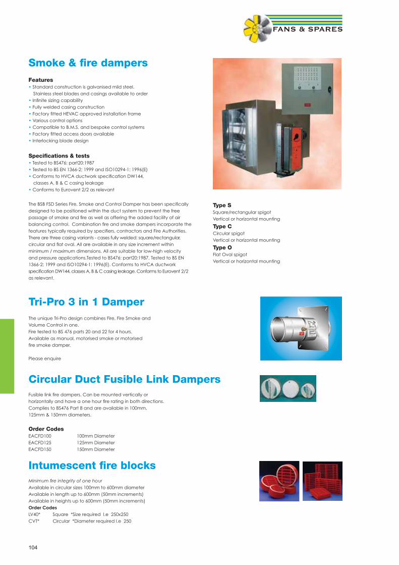
104
Smoke & fi re dampersFeatures• Standard construction is galvanised mild steel. Stainless steel blades and casings available to order• Infi nite sizing capability• Fully welded casing construction• Factory fi tted HEVAC approved installation frame• Various control options• Compatible to B.M.S. and bespoke control systems• Factory fi tted access doors available• Interlocking blade design
Specifi cations & tests• Tested to BS476: part20:1987• Tested to BS EN 1366-2; 1999 and ISO10294-1: 1996(E)• Conforms to HVCA ductwork specifi cation DW144, classes A, B & C casing leakage• Conforms to Eurovent 2/2 as relevant
The BSB FSD Series Fire, Smoke and Control Damper has been specifi cally designed to be positioned within the duct system to prevent the free passage of smoke and fi re as well as offering the added facility of air balancing control. Combination fi re and smoke dampers incorporate the features typically required by specifi ers, contractors and Fire Authorities. There are three casing variants - cases fully welded: square/rectangular, circular and fl at oval. All are available in any size increment within minimum / maximum dimensions. All are suitable for low-high velocity and pressure applications.Tested to BS476: part20:1987. Tested to BS EN 1366-2; 1999 and ISO10294-1: 1996(E). Conforms to HVCA ductwork specifi cation DW144, classes A, B & C casing leakage. Conforms to Eurovent 2/2 as relevant.
Type S Square/rectangular spigot Vertical or horizontal mounting
Type C Circular spigot Vertical or horizontal mounting
Type O Flat Oval spigot Vertical or horizontal mounting
Tri-Pro 3 in 1 Damper The unique Tri-Pro design combines Fire, Fire Smoke and Volume Control in one. Fire tested to BS 476 parts 20 and 22 for 4 hours. Available as manual, motorised smoke or motorised fi re smoke damper. Please enquire
Circular Duct Fusible Link Dampers Fusible link fi re dampers. Can be mounted vertically or horizontally and have a one hour fi re rating in both directions. Complies to BS476 Part 8 and are available in 100mm, 125mm & 150mm diameters.
Order Codes EACFD100 100mm Diameter EACFD125 125mm Diameter EACFD150 150mm Diameter
Intumescent fi re blocks Minimum fi re integrity of one hour Available in circular sizes 100mm to 600mm diameter Available in length up to 600mm (50mm increments) Available in heights up to 600mm (50mm increments) Order Codes LV40* Square *Size required I.e 250x250 CVT* Circular *Diameter required I.e 250

105
Ducting & Fittings

106
Flexible Ductingby Express-air
Aluminium - Type EAALIFDDescription: Fully fl exible, high quality, un-insulated aluminium laminat-ed duct for use in commercial HVAC systems. Easy & Fast installation over round or oval connections. Tough and airtight with a smooth core for low friction loss and lower operation costs.Construction: 5 x layers of tough “aluminium / polyester laminates” plus fl ame retardant adhesive, encapsulating a copper plated high tensile steel wire helix.
Order Standard Airfl ow m3/s @ Velocity m/s Order Standard Airfl ow m3/s @ Velocity m/s
Ref Length 5m/s 10m/s 20m/s Ref Length 5m/s 10m/s 20m/s
EAPVCFD100 10m 0,039 0,079 0,157 EAPVCFD250 10m 0,245 0,491 0,982
EAPVCFD125 10m 0,061 0,123 0,245 EAPVCFD300 10m 0,353 0,707 1,414
EAPVCFD150 10m 0,088 0,177 0,353 EAPVCFD315 10m 0,390 0,779 1,559
EAPVCFD160 10m 0,101 0,201 0,402 EAPVCFD350 10m 0,481 0,962 1,924
EAPVCFD180 10m 0,127 0,255 0,509 EAPVCFD400 10m 0,628 1,257 2,513
EAPVCFD200 10m 0,157 0,314 0,628 EAPVCFD450 10m 0,795 1,590 3,180
EAPVCFD225 10m 0,199 0,398 0,795 EAPVCFD500 10m 0,982 1,964 3,928
Semi-Rigid - Type EASEMFDDescription: Semi fl exible, high quality, aluminium duct for use in all low / medium pressure systems and suitable for AC. Easy & Fast installation, tough and airtight.Construction: 1 x wound layer of tough corrugated aluminium. “Triple Locked” seams for air tightness & strength.
Order Standard Airfl ow m3/s @ Velocity m/s
Ref Length 5m/s 10m/s 20m/s
EASEMFD100 3m 0,039 0,079 0,157
EASEMFD125 3m 0,061 0,123 0,245
EASEMFD150 3m 0,088 0,177 0,353
EASEMFD160 3m 0,101 0,201 0,402
EASEMFD200 3m 0,157 0,314 0,628
EASEMFD250 3m 0,245 0,491 0,982
PVC - Type EAPVCFDDescription: Fully fl exible, high quality, un-insulated aluminium lami-nated duct for use in commercial HVAC systems. Easy & Fast installa-tion over round or oval connections. Tough and reinforced by a “grey outer skin” for resistance to tear and puncture, airtight with a smooth core for low friction loss and lower operation costsConstruction: 6 x layers of tough “aluminium / polyester / co-polymer laminates” plus fl ame retardant adhesive, encapsulating a copper plated high tensile steel wire helix.
Order Standard Airfl ow m3/s @ Velocity m/s Order Standard Airfl ow m3/s @ Velocity m/s
Ref Length 5m/s 10m/s 20m/s Ref Length 5m/s 10m/s 20m/s
EAALIFD100 10m 0,039 0,079 0,157 EAALIFD250 10m 0,245 0,491 0,982
EAALIFD125 10m 0,061 0,123 0,245 EAALIFD300 10m 0,353 0,707 1,414
EAALIFD150 10m 0,088 0,177 0,353 EAALIFD315 10m 0,390 0,779 1,559
EAALIFD160 10m 0,101 0,201 0,402 EAALIFD350 10m 0,481 0,962 1,924
EAALIFD180 10m 0,127 0,255 0,509 EAALIFD400 10m 0,628 1,257 2,513
EAALIFD200 10m 0,157 0,314 0,628 EAALIFD450 10m 0,795 1,590 3,180
EAALIFD225 10m 0,199 0,398 0,795 EAALIFD500 10m 0,982 1,964 3,928
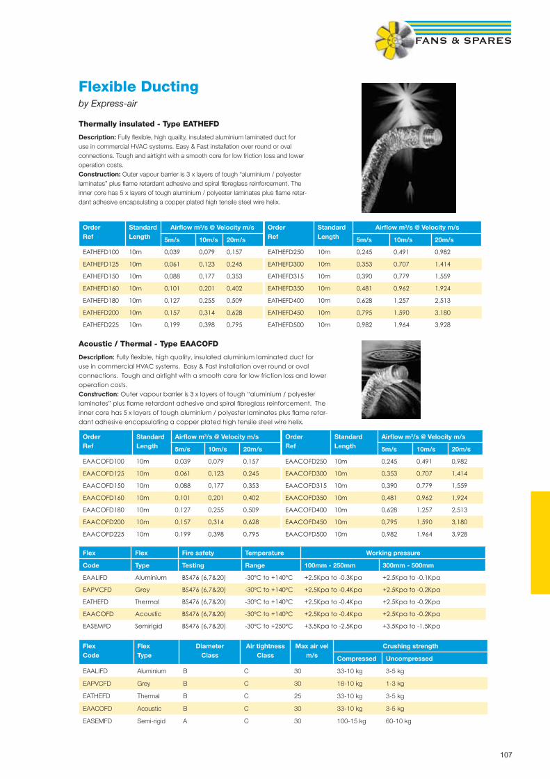
107
Order Ref
StandardLength
Airfl ow m3/s @ Velocity m/s Order Ref
StandardLength
Airfl ow m3/s @ Velocity m/s
5m/s 10m/s 20m/s 5m/s 10m/s 20m/s
EATHEFD100 10m 0,039 0,079 0,157 EATHEFD250 10m 0,245 0,491 0,982
EATHEFD125 10m 0,061 0,123 0,245 EATHEFD300 10m 0,353 0,707 1,414
EATHEFD150 10m 0,088 0,177 0,353 EATHEFD315 10m 0,390 0,779 1,559
EATHEFD160 10m 0,101 0,201 0,402 EATHEFD350 10m 0,481 0,962 1,924
EATHEFD180 10m 0,127 0,255 0,509 EATHEFD400 10m 0,628 1,257 2,513
EATHEFD200 10m 0,157 0,314 0,628 EATHEFD450 10m 0,795 1,590 3,180
EATHEFD225 10m 0,199 0,398 0,795 EATHEFD500 10m 0,982 1,964 3,928
Order Ref
StandardLength
Airfl ow m3/s @ Velocity m/s Order Ref
StandardLength
Airfl ow m3/s @ Velocity m/s
5m/s 10m/s 20m/s 5m/s 10m/s 20m/s
EAACOFD100 10m 0,039 0,079 0,157 EAACOFD250 10m 0,245 0,491 0,982
EAACOFD125 10m 0,061 0,123 0,245 EAACOFD300 10m 0,353 0,707 1,414
EAACOFD150 10m 0,088 0,177 0,353 EAACOFD315 10m 0,390 0,779 1,559
EAACOFD160 10m 0,101 0,201 0,402 EAACOFD350 10m 0,481 0,962 1,924
EAACOFD180 10m 0,127 0,255 0,509 EAACOFD400 10m 0,628 1,257 2,513
EAACOFD200 10m 0,157 0,314 0,628 EAACOFD450 10m 0,795 1,590 3,180
EAACOFD225 10m 0,199 0,398 0,795 EAACOFD500 10m 0,982 1,964 3,928
Flex Flex Fire safety Temperature Working pressure
Code Type Testing Range 100mm - 250mm 300mm - 500mm
EAALIFD Aluminium BS476 (6,7&20) -30ºC to +140ºC +2.5Kpa to -0.3Kpa +2.5Kpa to -0.1Kpa
EAPVCFD Grey BS476 (6,7&20) -30ºC to +140ºC +2.5Kpa to -0.4Kpa +2.5Kpa to -0.2Kpa
EATHEFD Thermal BS476 (6,7&20) -30ºC to +140ºC +2.5Kpa to -0.4Kpa +2.5Kpa to -0.2Kpa
EAACOFD Acoustic BS476 (6,7&20) -30ºC to +140ºC +2.5Kpa to -0.4Kpa +2.5Kpa to -0.2Kpa
EASEMFD Semirigid BS476 (6,7&20) -30ºC to +250ºC +3.5Kpa to -2.5Kpa +3.5Kpa to -1.5Kpa
FlexCode
FlexType
DiameterClass
Air tightnessClass
Max air velm/s
Crushing strength
Compressed Uncompressed
EAALIFD Aluminium B C 30 33-10 kg 3-5 kg
EAPVCFD Grey B C 30 18-10 kg 1-3 kg
EATHEFD Thermal B C 25 33-10 kg 3-5 kg
EAACOFD Acoustic B C 30 33-10 kg 3-5 kg
EASEMFD Semi-rigid A C 30 100-15 kg 60-10 kg
Acoustic / Thermal - Type EAACOFD
Description: Fully fl exible, high quality, insulated aluminium laminated duct for use in commercial HVAC systems. Easy & Fast installation over round or oval connections. Tough and airtight with a smooth core for low friction loss and lower operation costs.Construction: Outer vapour barrier is 3 x layers of tough “aluminium / polyester laminates” plus fl ame retardant adhesive and spiral fi breglass reinforcement. The inner core has 5 x layers of tough aluminium / polyester laminates plus fl ame retar-dant adhesive encapsulating a copper plated high tensile steel wire helix.
Flexible Ductingby Express-air
Thermally insulated - Type EATHEFD
Description: Fully fl exible, high quality, insulated aluminium laminated duct for use in commercial HVAC systems. Easy & Fast installation over round or oval connections. Tough and airtight with a smooth core for low friction loss and lower operation costs.Construction: Outer vapour barrier is 3 x layers of tough “aluminium / polyester laminates” plus fl ame retardant adhesive and spiral fi breglass reinforcement. The inner core has 5 x layers of tough aluminium / polyester laminates plus fl ame retar-dant adhesive encapsulating a copper plated high tensile steel wire helix.

108
Round Louvred 4804 44804 100Grille
with Flyscreen F4804 F44804 100
Multidirectional 4906 44906 100Internal Louvred 5906 n/a 125Grille 6906 n/a 150
Internal Door 145 40145 456 xVentilator 92mm
(overallsize)
DOMUS DUCTING
Size/Description Trade Retail System
Wall Outlet with 4900 44910* • 100Gravity Flaps 4901 44910* S100
5900 n/a • 1256900 n/a • 150/
M220
Cowled Wall 4902 44932* • 100Outlet with Damper 4903 44932* S100
5902 n/a • 1256902 n/a • 150/
M220
Louvred Grille 4904 n/a • 1004905 n/a S1005904 n/a • 1256904 n/a • 150/
M220
Louvred Grille 4994 n/a • 100with Internal 500 n/a • 125Damper
*Packed with round and rectangular spigots
S100 = System 100 S125 = Supertube 125 PV225 = PolyVent 225 PV300 = PolyVent 300M220 = MegaDuct 220 Round Spigot • Rectangular Socket
Size/Description Trade Retail System
Louvred Grillewith Flyscreen F4904 44954* • 100
F4905 44954* S100F5904 n/a • 125F6904 n/a • 150/
M220
Round Cowled Outlet 4802 n/a • 100
Round Cowl ‘High Rise’ Kit 2447 n/a • 100
2647 n/a • 150Domus manufacture modular ventilation ducting fordomestic kitchens and bathrooms, and light industrial and commercial premises.
• Manufactured with flame retardant plastics
• Lightweight, with simple push-fit connections
• Duct easily cut to length
• Non-corrosive
• Recycled materials used wherever possible
• A wide range of wall and ceiling terminals
OUTLETCOLOURS
WHITE
BROWN
BEIGE
TERRACOTTA
Horizontal Airbrick 501 n/a S125with Damper
Louvred AirbrickHorizontal 505 40505 S125Vertical 507 n/a S125
Airbrick Adapter 077 40077 S100Double Airbrick Adapter 977 n/a M220Supertube to MegaductAdapter 957 n/a S125/M220
Extended Horizontal 2009 n/a PV225Airbrick 3009 n/a PV300(For PolyVent)Fits direct to PolyVent channel
Airbrick Adapter 2016 n/a PV225(for PolyVent) 3016 n/a PV300
Airbrick Fascia 2316 n/a PV225/300(for PolyVent Airbrick Adapters)
Double Airbrick 905 n/a M220
Double Airbrick Adapter 954 n/a 100/125/to Round Pipe 150
Trade Packaging Retail Packaging
NEW
NEW

109
Description Trade Retail Size/System
Plinth Ventilator 146 n/a 456 x75mm(overallsize)
Worktop Metal 148 40148 478 xVentilator 79mm
(overallsize)
Louvre 793 40793 271 x95mm
Louvre 796 40796 271 x171mm
Open n Shut Grille 893 40893 271 x95mm
Open n Shut Grille 896 40896 271 x171mm
Air Extract or 136-04 n/a 100supply Valve 136-05 n/a 125(to fit pipe) 136-06 n/a 150
Air Extract or 136-24 40136 100supply Valve 136-25 n/a 125(ceiling) 136-26 n/a 150
Roof Vent Cowl 4110 n/a 110for 110mm pipe
Roof Weathering 4457 n/a 110Slate (457 x(angled) 457mm)
Flat Channel 1m 010 40010 S100510 n/a S125910 n/a M220
1.5m 015 n/a S100515 n/a S125915 n/a M220
2m D1-2000 n/a S100D3-2000 n/a S125
Flat Channel 1m D2-1000 n/a S100Outer Sleeve
Flat Channel Clip 122-4 40122* S100122-5 n/a S125922 n/a M220
*Two items per pack
Description Trade Retail Size/System
Flat Channel 020 40020 S100Connector 520 n/a S125
920 n/a M220
Flat Channel 027 n/a S100Connector with 527 n/a S125Damper
Elbow Bendwith Socket 030 40030 S100with Spigot 040 40040 S100
Elbow Bend 440 n/a 100540 n/a 125640 n/a 150
(Connects Supertube 125 to 100, 125 & 150mm dia.)
Elbow Bend with 441 n/a 100Rotating Offset 541 n/a 125Spigot 641 n/a 150
(Connects Supertube 125 to 100, 125 & 150mm dia.)
Elbow Bend with 941 n/a 100Rotating Offset 951 n/a 125Spigot 961 n/a 150
(Connects MegaDuct 220 to 100, 125 & 150mm dia.)
Adapter - from 125mm 544 n/a S125to 100mmAdapter to fit code 540/541to 100mm spigot
Horizontal 90º 050 40050 S100Bend 550 n/a S125
950 n/a M220
Horizontal 545 n/a S125Adjustable Bend
Vertical 90º 060 40060 S100Bend 560 n/a S125
960 n/a M220
Horizontal T Piece 080 40080 S100582 n/a S125
Round to 070 40070 S100Rectangular 570 n/a S125Adapter 970 n/a M220
Round connection 100mm I.D./125mm I.D./154mm I.D.
Short Round to 071 40071 S100RectangularAdapter
Round connection 100mm O.D.
Rectangular Wall 115-4 40115 S100Plate 115-5 n/a S125
Flat channel outer dimensions are: S100, 110mm x 54mm S125, 204mm x 60mmM220, 220mm x 90mm
NEW
NEW922 Clip

110
Description Trade Retail Size/System
Flat Channel 1m 2001 n/a PV2253001 n/a PV300
1.5m 20150 n/a PV22530150 n/a PV30020200 n/a PV225
2m 30200 n/a PV300
Flat Channel 2006 n/a PV225Connector 3006 n/a PV300
Horizontal 90º 2007 n/a PV225Bend 3007 n/a PV300
Horizontal 45º 2008 n/a PV225Bend 3008 n/a PV300
Vertical 90º 2010 n/a PV225Bend 3010 n/a PV300
Vertical 45º 2011 n/a PV225Bend 3011 n/a PV300
Elbow Bend/Plenum 2013 n/a PV2253013 n/a PV300
Round to Rectangular 2005 n/a PV225Adapter 3005 n/a PV300
Universal Support 2014 n/a PV225/Clip PV300
Round Pipe 350mm 135-4 40135 100135-5 n/a 125135-6 n/a 150
1m 1100-4 41100 1001100-5 n/a 1251100-6 n/a 150
2m 1200-4 n/a 1001200-5 n/a 1251200-6 n/a 150
Round Pipe 2100-4 n/a 100Sleeve 1m 2100-5 n/a 125
2100-6 n/a 150
Telescopic Assembly 130-4 n/a 100250 to 450mm 130-5 n/a 125
130-6 n/a 150
Description Trade Retail Size
Adapter to Round 380 n/a 100Sockets 580 n/a 125
680 n/a 150
90º Bend 490 40490 100590 n/a 125690 n/a 150
45º Bend 491 40491 100591 n/a 125
Equal T Piece Plastic 492 40492 100Metal 592M n/a 125Metal 692M n/a 150
Straight Pipe 493 40493 100Connector 593 n/a 125
693 n/a 150
Straight Pipe 494 40494 100Connector with 594 n/a 125Damper Valve 694 n/a 150
Straight Pipe 495 n/a 100Connector with 595 n/a 125Damper Valve 695 n/a 150& Wall Plate
Pipe Fastener 496 40496* 100596 n/a 125696 n/a 150
*Two items per pack
Condensation Trap with Overflow 497 n/a 100/110without Overflow 498 n/a 100/110
Fits Domus 100mm I.D. + 110mm O.D. pipe
Condensation Trap 2022 n/a 110for Soil Pipe
Fits 110mm O.D. pipe only
Round Wall plate 114-4 40114 100114-5 n/a 125114-6 n/a 150
Aluminium Circular 120 n/a 110/100Adapter110mm I.D. to100mm O.D.
Circular Adapter 125mm I.D. to 100mm O.D. 119 40119 100/125150mm I.D. to 125mm O.D. 118 n/a 125/150150mm I.D. to 100mm O.D. 619 n/a 150/100200mm I.D. to 150mm O.D. 819 n/a 200/150
Rubber Spigot Adapter 120mm - 125mm 519 n/a 120/125
Flat channel outer dimensions are: PV225, 234mm x 29mm PV300, 308mm x 29mm
Pipe available in three diameters 100mm, 125mm and 150mm I.D.
Round connection2013/3013 100mm I.D.
Round connection 100mm I.D.NEW
NEW
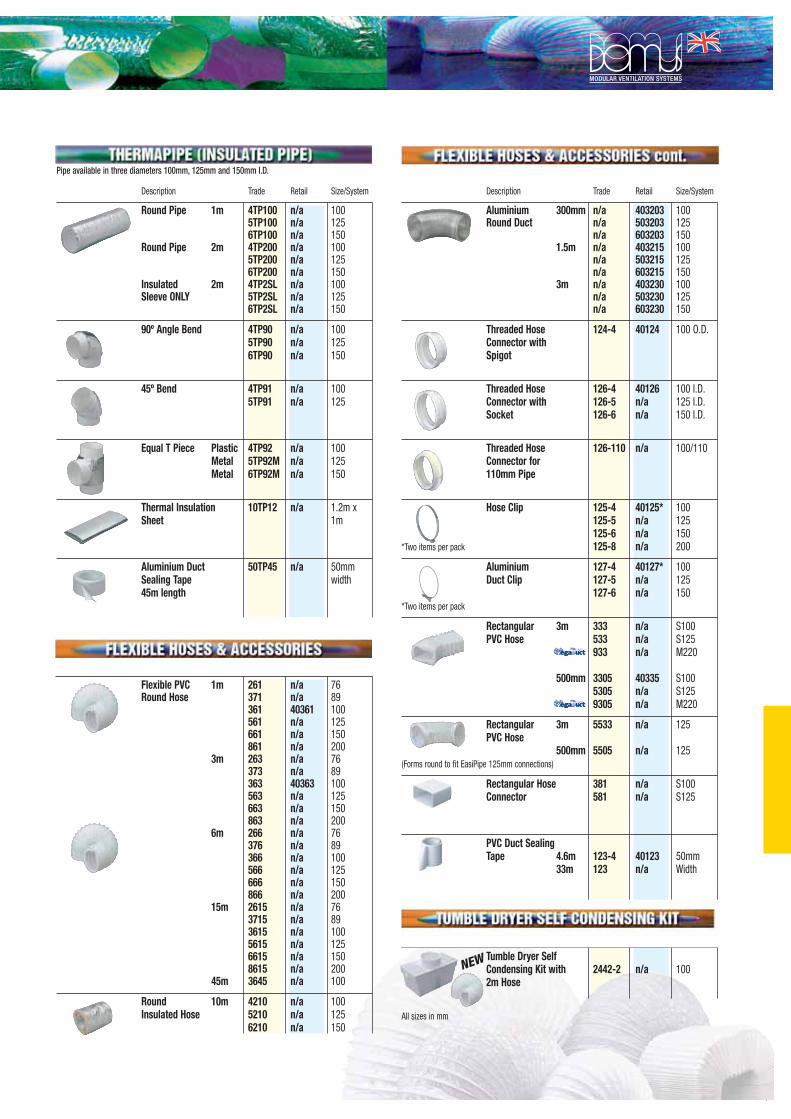
111
Description Trade Retail Size/System
Round Pipe 1m 4TP100 n/a 1005TP100 n/a 1256TP100 n/a 150
Round Pipe 2m 4TP200 n/a 1005TP200 n/a 1256TP200 n/a 150
Insulated 2m 4TP2SL n/a 100Sleeve ONLY 5TP2SL n/a 125
6TP2SL n/a 150
90º Angle Bend 4TP90 n/a 1005TP90 n/a 1256TP90 n/a 150
45º Bend 4TP91 n/a 1005TP91 n/a 125
Equal T Piece Plastic 4TP92 n/a 100Metal 5TP92M n/a 125Metal 6TP92M n/a 150
Thermal Insulation 10TP12 n/a 1.2m xSheet 1m
Aluminium Duct 50TP45 n/a 50mmSealing Tape width45m length
Flexible PVC 1m 261 n/a 76Round Hose 371 n/a 89
361 40361 100561 n/a 125661 n/a 150861 n/a 200
3m 263 n/a 76373 n/a 89363 40363 100563 n/a 125663 n/a 150863 n/a 200
6m 266 n/a 76376 n/a 89366 n/a 100566 n/a 125666 n/a 150866 n/a 200
15m 2615 n/a 763715 n/a 893615 n/a 1005615 n/a 1256615 n/a 1508615 n/a 200
45m 3645 n/a 100
Round 10m 4210 n/a 100Insulated Hose 5210 n/a 125
6210 n/a 150
Description Trade Retail Size/System
Aluminium 300mm n/a 403203 100Round Duct n/a 503203 125
n/a 603203 1501.5m n/a 403215 100
n/a 503215 125n/a 603215 150
3m n/a 403230 100n/a 503230 125n/a 603230 150
Threaded Hose 124-4 40124 100 O.D.Connector withSpigot
Threaded Hose 126-4 40126 100 I.D.Connector with 126-5 n/a 125 I.D.Socket 126-6 n/a 150 I.D.
Threaded Hose 126-110 n/a 100/110Connector for110mm Pipe
Hose Clip 125-4 40125* 100125-5 n/a 125125-6 n/a 150
*Two items per pack 125-8 n/a 200
Aluminium 127-4 40127* 100Duct Clip 127-5 n/a 125
127-6 n/a 150*Two items per pack
Rectangular 3m 333 n/a S100PVC Hose 533 n/a S125
933 n/a M220
500mm 3305 40335 S1005305 n/a S1259305 n/a M220
Rectangular 3m 5533 n/a 125PVC Hose
500mm 5505 n/a 125(Forms round to fit EasiPipe 125mm connections)
Rectangular Hose 381 n/a S100Connector 581 n/a S125
PVC Duct Sealing Tape 4.6m 123-4 40123 50mm
33m 123 n/a Width
Tumble Dryer Self Condensing Kit with 2442-2 n/a 1002m Hose
All sizes in mm
Pipe available in three diameters 100mm, 125mm and 150mm I.D.
NEW

112
Spiral Duct & Fittings
KE
Y
Spira
l Tub
e
Du
ctw
ork
Re
cta
ng
ula
r & Sp
ec
ial Fa
bric
atio
ns
Ac
ce
ssorie
s

113
Ducting & Fittings
Spiral Duct - 3m LengthsPart Code: VSPAvailable 80mm to 630mm
90 Deg BendPart Code: VSP90
45 Deg BendPart Code: VSP45
90 Deg Twin BendPart Code: VSPTB90
ReducerPart Code: VSPR
Metal CowlPart Code: VSPMC
Flat ShoePart Code: VSPFS
Flanged SpigotPart Code: VSPTO
Equal Tee PiecePart Code: VSPET
End CapPart Code: VSPE
Split RingsPart Code: VSPSR
Suspensions RingsPart Code: VSPVSR
Access DoorsPart Code: AJAD
Single Blade Balancing DampersPart Code: VSPBD
Blast Gate DampersPart Code: VSPBG
Pressed SaddlePart Code: VSPPS
Male CouplerPart Code: VSPCM
Female CouplerPart Code: VSPCF

114
Controls & Sensors

115
Auto transformer 5 step speed controls
RE - Single Phase Auto Transformer
Amps Fuse H x W x D mm kg
RE 1.5 1.5A 1.8A 200x105x105 1,5
RE 3 3A 3.5A 200x105x105 2,5
RE 5 5A 6A 200x105x105 4,1
RE 7 7A 8A 275x105x145 7,5
RTRE - Single Phase Auto Transformer with TK’s
Amps Fuse H x W x D mm kg
RTRE 1.5 1.5A 1.8A 200x105x105 1,6
RTRE 3 3A 3.5A 200x105x105 2,6
RTRE 5 5A 6A 200x105x105 4,2
RTRE 7 7A 8A 275x105x145 7,6
RTRD - Three Phase Auto Transformer with TK’s
Amps Fuse H x W x D mm kg
RTRD 2 2A - 255x190x135 7,5
RTRD 4 4A - 309x262x160 12,5
RTRD 7 7A - 309x262x160 18
RTRD 14 14A - 290x400x166 30
Output voltages for each of the 5 steps
Steps 1 2 3 4 5
Voltage V 95 145 190 240 400
Output voltages for each of the 5 steps
Steps 1 2 3 4 5
Voltage V 80 105 130 160 230
Multi-Unit Speed ControlIf multiple fans are to be run off one Auto transformer speed control, then the total combined full load currents (FLC) of the fans, plus a 20% margin must not exceed the Amperage of the controller. All TK’s must be wired in series or Fans without TK’s will each require a motor protection device, STET 10B.
Example 4 no KDRD50 Fan off 1 no RTRD
Full load current of fan 0.98amps multiplied by 4 = 3.92amps Plus 20% = 4.7ampsTherefore speed controller required is RTRD 7 (7amps)
M1 x 230V
M3 x 400V
M1 x 230V
Output voltages for each of the 5 steps
Steps 1 2 3 4 5
Voltage V 80 105 130 160 230

116
Two speed - trickle & boost controlby Systemair
REU - Single Phase 230V 50/60HzREU, a single phase transformer which controls the fan speed by altering the supply voltage in fi ve fi xed steps. The steps are adjusted manually, using the control knobs on the front of the unit. There are two control knobs: one for the higher fan speeds (Boost) and one for lower fan speeds (Trickle), any combi-nation of speed settings can be achieved, i.e low speed set to position 2 and high speed set to position 4. This feature allows for easy set-up and commis-sioning. Switching between the high and low settings is done by an external change-over contact, which could be a thermostat or CO2 Sensor etc. The indicator lamp on the front shows when the transformer is in operation.
Note! Fans with external thermal contact leads (TK) must always be con-nected to a motor protection device (STET 10B)
Output voltages for each of the 5 steps:
Step 1 2 3 4 5
Voltage V 80 105 130 160 230
amps Fuse H x W x D mm kg
REU 1.5 1.5A 1.8A 200x105x105 1,7
REU 3 3A 3.5A 275x105x145 3,2
REU 5 5A 6A 275x105x145 4,8
REU 7 7A 8A 275x105x145 7,7
RTRDU - Three Phase 400V 50/60HzRTRDU, three phase version, as REU but with integral motor protection which cuts the supply voltage to the fan if the thermal contact in the fan motor is ac-tivated. The unit is reset by turning the switch to “0” for 10 seconds. The trans-former has 230V terminals for operating dampers or other exteranl equipment. These terminals have no current when the transformer switch is in position “0”, or when the TK input is open.
Output voltages for each of the 5 steps:
Step 1 2 3 4 5
Voltage V 95 145 190 240 400
amps H x W x D mm kg
RTRDU 2 2A 323x270x172 10
RTRDU 4 4A 323x270x172 13
RTRDU 7 7A 450x290x174 18
M1 x 230V

117
Electronic variable speed control
SC - Single phase electronic variable control
Amps H x W x D mm kg
SC1.5 1,5 255x190x135 7,5
SC3.0 3A 309x262x160 12,5
SC5.0 5A 309x262x160 18
SC8.0 8A 290x400x166 30
NOTE ! Electronic controls may cause motor noise, therefore Fans & Spares recommend auto transformers to be used in noise sensitive areas.
Motor protection devicesThese direct on-line starters, switch off the supply voltage to the motor when the thermal contact (TK) in the motor windings is tripped
STET 10B STDT 16
Voltage V 60-230 60-400
Current min./max. A 0.4/10 16
Max. Fuse A 16 80
Weight kg 0,5 0,5
B x H x T mm 79x141x80 80x150x98
Enclosure IP54 IP55
Auto changeover panelsFor use with Run & Standby fans to provide changeover on fan failure, with the addition of warning lights. The ACO8 also has a built in 24 hour duty share switching between both fans for long life. Volt free contacts are provided for connection to BMS.
ACO8: Single phase 230V, 8.0 ampsThree phase ACO panels are also available
Control PanelsA wide range of customised control panels are available from Fans & Spares, with Standard Features including:
• Supply Fan Connections• Fan interlock• Integral Fan run-on-timer• High temp cut out• Connections for sensors • Timeclocks• Electric heater battery control 3Kw - 54Kw
Please enquire..

118
Sensors & Controlsby Express-air
EAC6:Variable speed control suitable for all “size 6”Express-air commercial fans
EAC9/12:Variable speed control with reversible switchsuitable for all “size 9 & 12” Express-aircommercial fans
EFS-PIR:Remote Passive Infra Red motion detector360 deg vision, with built in Run on Timer
EFS-ROT:Remote Run on Timer 1-20 mins
EFS-7DAY:Remote Analogue 7 Day Timeswitch
EFS-HS:Remote Humidistat 40% - 95% RH
Other Sensors & Controls availablePlease enquire
Air Quality SensorsCO2 SensorsDigital Time Clocks
RT 0-30:Remote Room Thermostat 0 - 30 degC

119
Demand Ventilation Controlsby Systemair
REP - Pressure regulatorRET - Temperature regulatorREPT - Pressure & Temperature regulator
These systems work on demand ventilation and can be used in a wide variety of applications, such as high rise tower block, offi ces & student accomodation. Instead of having a fan for each room, One central fan is used with the speed / extract rate being varied by the control gear. The REP regulates the fan speed on pressure drop changes (using a differential pressure switch), this can work for cooker hoods as well as a PIR activated air valve in the toilets, so only the required extraction rate is used, saving money as well as energy. The RET work on temperature changes, where as the REPT works from both pressure & temperature changes.
/
Centralised extract fan
REP - Pressure regulator
RET - Temperature Regulator
Motorised Damper
Where is picture???
Differential Pressure Switch
Cooker hood (no fan)
PIR activated Air Valve
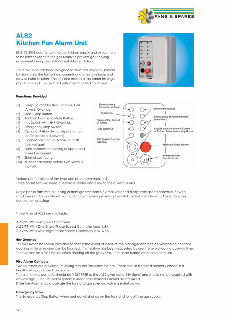
120
ALS2Kitchen Fan Alarm UnitBS 6173 2001 calls for commercial kitchen supply and extract fans to be interlocked with the gas supply to prevent gas cooking equipment being used without suitable ventilation.
The ALS2 Panel has been designed to meet this new requirement by monitoring the fan running currents and offers a reliable and easy to install solution. The unit also acts as a fan starter for single phase fans and can be fi tted with integral speed controllers.
Functions Provided
(1) Lamps to monitor status of Fans, Gas Valve & Override.(2) Start / Stop Button.(3) Audible Alarm and Mute Button.(4) Key Switch with 6HR Override.(5) Emergency Stop Switch.(6) Optional Airfl ow Switch input (to moni tor for blocked ductwork).(7) Connections for Fire Alarm Shut Off (low voltage).(8) Dual channel monitoring of upper and lower fan current.(9) Short circuit fusing.(10) 40 seconds delay before Gas Valve is shut off.
Three Type of ALS2 are available:-
ALS2/P Without Speed ControllersALS2/P1 With One Single Phase Speed Controller Max. 6.5AALS2/P2 With Two Single Phase Speed Controllers Max. 6.5A
6hr OverrideThis key switch has been provided so that in the event of a failure the Manager can decide whether to continue cooking while a repairer can be located. This feature has been requested by users to avoid loosing cooking time. The override lasts for 6 hours before shutting off the gas valve. It must be turned off and on to re-use.
Fire Alarm ContactsTwo terminals are provided for linking into the Fire Alarm system. These should be wired normally closed in a healthy state and break on alarm.The alarm relay contacts should be VOLT FREE as the ALS2 gives out a 24V signal and should not be supplied with any voltage. If no Fire Alarm system is used these terminals should be left linked.If the Fire Alarm should operate the fans and gas solenoid valve are shut down.
Emergency StopThe Emergency Stop Button when pushed will shut down the fans and turn off the gas supply.
Various permutations of fan type can be accommodated.Three phase fans will need a separate starter and a link to the current sensor.
Single phase fans with a running current greater than 6.5 Amps will need a separate speed controller. Several small fans can be paralleled from one current sensor providing the total current is less than 10 Amps. See fan connection drawings.

121
Fans & Spares Accessories

122
Test equipmentby TSI Airfl ow Instruments
Indoor Air Quality
The IAQ50 Indoor Air Quality Meter quickly and accurately measures temperature, humidity and carbon dioxide levels in real time, and includes a data logging function.
Low Flow Hood Kits
Light weight air balancing kit with a range of optional accessories including six fabric hoods and three plastic hoods.
Thermal Anemometer
Digital velocity meter with temperature display and telescopic probe with fl exible neck
Pitot Static Tubes
For permanent and portable use with manometers, transducers etc
Manometers
Industrial Vertical Tube ManometerInclined ManometerInclined Filter Loss Manometer
TH12 Thermohygrometer
Rotating Vane Anemometer
Digital velocity and volume fl ow meter with averaging, imperial and metric display
Rotating Vane Anemometer
Digital velocity and volume fl ow meter with telescopic probe, turbulence indication and auto logging. Wide choice of display units. Analogue and digital outputs
IAQ 10 CO2 Meter
A new generation in compact, portable airfl ow measurement incorporating temperature, volume fl ow, velocity, turbulence, draught intensity IAQ indicator. Wide choice of displays. Analogue and Digital outputs.

123
Motor Slide Bases
Fans & Spares supply the worlds fi nest selection of motor slide bases. These robustly constructed and expertly designed motor slide bases are supplied with a full, money back guarantee.
What are slide bases used for?Motor slide bases are used on fans, conveyors and any other processes that involve belt tightening. Due to varying tempera-tures and belt strength, the tightness of the belt must be adjusted to keep machinery running at its maximum effi ciency. Even the most experienced engineers can take up to an hour adjusting motor slide rails. The “quick-fi t” and “mono-plate” range supplied by Fans & Spares means that belts can be easily adjusted in a matter of minutes, irrespective of engineering experience.
Please enquire for details & selections
Motors, Belts & Pulley’sFans & Spares can offer a complete range of replacement belts & pulley’s to suit most fan motor applications, please enquire
Whatever your motor requirement, Fans & Spares are happy to offer a solution
• 2 pole, 4 pole & 6 pole option• 2 speed motors• Foot or Pad mounted• 0.25kw - 30kw

124
Anti Vibration Mount Weight Range Nominal
Ref kg Defl ection
VT/1 - BLUE 9.0 to 18 Kg 4.0mm
VT/1 - YELLOW 15 to 28 Kg 4.0mm
VT/1 - GREEN 21 to 40 Kg 4.0mm
VT/1 - WHITE 27 to 54 Kg 4.0mm
VT/1 - RED 36 to 72 Kg 4.0mm
VT/2 - BLUE 18 to 60 Kg 5.0mm
VT/2 - GREEN 54 to 108 Kg 5.0mm
VT/2 - WHITE 90 to 180 Kg 5.0mm
VT/2 - RED 135 to 270 Kg 5.0mm
VT/2 - BLACK 180 to 360 Kg 5.0mm
Anti-Vibration MountsRubber & Spring type available, Please enquire
Sealants, Tape, Clips & Gasket
Worm Drive Wire Clips - Specially designed to use with fl exible duct and tube
Multiband on a 30m roll Box of 50no Clamps
Order Ref:
FSMQC110 = up to 110mm Dia
FSMQC165 = up to 165mm Dia
FSMQC215 = up to 215mm Dia
FSMQC325 = up to 325mm Dia
FSMQC525 = up to 525mm Dia
Order Ref:
FSQIPBAND
Order Ref:
FSQIPCLAMP
Nylon ClampingAn economical alternative to metal clamps. Order Ref:-
FSNQC100 = 100mm Dia,
FSNQC127 = 127mm Dia,
FSNQC229 = 229mm Dia
Full range of sealants available from stockOrder Ref:
DUCTGREY
DUCTCLEAR
Duct tape
TAPEPVC = PVC
TAPECLOTH = CLOTH
TAPEALI = ALUMINIUM FOIL
Gasket
FLANGE GASKET = 20mm x 6mm x 15m

125
Attenuators / SilencersCircular Attenuators Ref : LDC Attenuator construction for this range comprises a pre-galva-nised sheet steel spiral wound outer casing, manufactured in accordance with HVCA DW144 specifi cation, with circular spig-otted end caps. Sizes 100mm Dia to 500mm Dia
Circular Attenuators Construction for this range comprises external pre-galvanised sheet steel tube over casing, manufactured in accordance with HVCA DW144 specifi cation, end rings fi tted with tapped inserts to suit the relevant fan drilling detail. Available with or without pod.Sizes 315mm Dia to 1250mm Dia
Rectangular Attenuators This range of rectangular duct attenuators for HVCA applications offers an innovative acoustic splitter construction, which provides signifi cantly improved mechanical integrity of the acoustic me-dia containment envelope.
Acoustic Splitters Acoustic Splitters for ‘build in’ applications Please enquire
Acoustic LouvresThis range of acoustic louvres is designed to ensure optimum acoustic performance with effi cient weather resistance capabil-ity and aesthetic properties.
Acoustic JacketsAvailable for additional attenuation for Fans, to suit Circular, Square & Rectangular type

126
Perfect for Flashing Pipes / Ducts on Metal Roofs
The Original watertight Flashing for Metal Roofs
Ref Pipe mm Ref Pipe mm
MINI DFE 0-35 0 - 35 MINI DF100 0 - 35
DFE 5-55 5 - 55 DF101 5 - 65
DFE 50-70 50 - 70 DF102 45 - 80
DFE 5-120 5 - 120 DF103 5 - 127
DFE 110-170 110 - 170 DF104 73 - 160
DFE 160-220 160 - 220 DF105 108 - 190
DFE 160-300 160 - 300 DF106 125 - 230
DFE 290-440 290 -440 DF107 150 - 280
DF108 175 - 330
EZi-Seal, Forget the Silicone - Just screw it down
Retrofi t, For Repairs & Diffi cult-to-access Pipes
Ref Pipe mm Ref Pipe mm
MINI DFE0-35EZ 0 - 35 RF801 20 - 70
DFE5-55EZ 5 - 55 RF802 50 - 185
DFE50-70EZ 50 - 70 RF803 85 - 255
DFE5-120EZ 5 - 120
DFE110-170EZ 110 - 170
DFE160-300EZ 160 - 300
DFE290-440EZ 290 - 440
5-in-1 Roof Vent Kitby Express-air
The Express-air 5-in-1 roof vent kit, 500 x 500mm lead through roof 5 way ventilation terminal available in dark grey. Duct sizes on cut off spigots• 100mm • 110mm • 125mm • 150mm• 160mm
Order Ref Code: EFS-RCK
Roof Flashingsby Deks
Roof Flashing Fixing Kit REF: DFK1
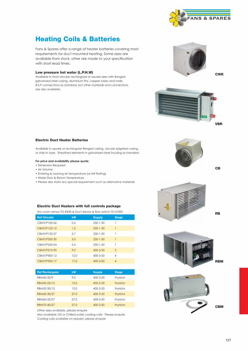
127
Heating Coils & BatteriesFans & Spares offer a range of heater batteries covering most requirements for duct mounted heating. Some sizes are available from stock, other are made to your specifi cation with short lead times.
Low pressure hot water (L.P.H.W)Available in most circular, rectangular or square sizes with fl anged,galvanised steel casing, aluminium fi ns, copper tubes and male B.S.P connections as standard, but other materials and connections are also available.
Electric Duct Heater Batteries
Available in square or rectangular fl anged casing, circular spigoted casing, or stab-in type. Sheathed elements in galvanised steel housing as standard.
For price and availability please quote; • Dimension Required• Air Volume • Entering & Leaving air temperature (or kW Rating)• Water Flow & Return Temperature• Please also state any special requirement such as alternative materials
Electric Duct Heaters with full controls package
(inc room sensor TG-R430 & Duct Sensor & fl ow switch TG-K330)
Ref Circular kW Supply Stage
CBMT/P100-06 0,6 230-1-50 1
CBMT/P125-12 1,2 230-1-50 1
CBMT/P150-27 2,7 230-1-50 1
CBMT/P200-30 3,0 230-1-50 1
CBMT/P250-54 5,4 230-1-50 1
CBMT/P315-90 9,0 400-3-50 3
CBMT/P400-12 12,0 400-3-50 4
CBMT/P500-17 17,0 400-3-50 4
Ref Rectangular kW Supply Stage
RBM40-20/9 9,0 400-3-50 thyristor
RBM50-25/15 15,0 400-3-50 thyristor
RBM50-30/15 15,0 400-3-50 thyristor
RBM60-30/27 27,0 400-3-50 thyristor
RBM60-35/27 27,0 400-3-50 thyristor
RBM70-40/27 27,0 400-3-50 thyristor
Other sizes available, please enquireAlso available: DX or Chilled water cooling coils - Please enquireCooling coils available on request, please enquire
CB
RB
VBR
CWK
RBM
CBM
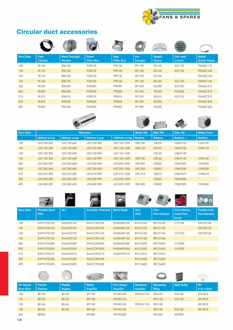
128
Circular duct accessories
Duct Size Fast Clamps
Back DraughtShutter
PanelFilter Box
BagFilter Box
IrisDamper
SpigotGuard
Circ wallLouvre
MetalQuick Clamp
100 FK100 RSK100 FGR100 FFR100 SPI 100 SG100 IGC100 FSMQC110
125 FK125 RSK125 FGR125 FFR125 SPI 125 SG125 IGC125 FSMQC165
150 FK150 RSK150 FGR150 FFR150 SPI 150 SG150 - FSMQC165
160 FK160 RSK160 FGR160 FFR160 SPI 160 SG160 IGC160 FSMQC165
200 FK200 RSK200 FGR200 FFR200 SPI 200 SG200 IGC200 FSMQC215
250 FK250 RSK250 FGR250 FFR250 SPI 250 SG250 IGC250 FSMQC315
315 FK315 RSK315 FGR315 FFR315 SPI 315 SG315 IGC315 FSMQC315
355 FK355 RSK355 FGR355 FFR355 SPI 355 SG355 - FSMQC525
400 FK400 RSK400 FGR400 FFR400 SPI 400 SG400 - FSMQC525
Duct Size Silencers Water Htr Elec Htr Elec Htr Water Cool
300mm Long 600mm Long 900mm Long 1200mm Long Battery Battery Battery + Battery
100 LDC100-300 LDC100-600 LDC100-900 LDC100-1200 VBC100 CB100 CBMT100 CWK100
125 LDC125-300 LDC125-600 LDC125-900 LDC125-1200 VBC125 CB125 CBMT125 CWK125
150 LDC150-300 LDC150-600 LDC150-900 LDC150-1200 - CB150 CBMT150 -
160 LDC160-300 LDC160-600 LDC160-900 LDC160-1200 VBC160 CB160 CBMT160 CWK160
200 LDC200-300 LDC200-600 LDC200-900 LDC200-1200 VBC200 CB200 CBMT200 CWK200
250 LDC250-300 LDC250-600 LDC250-900 LDC250-1200 VBC250 CB250 CBMT250 CWK250
315 LDC315-300 LDC315-600 LDC315-900 LDC315-1200 VBC315 CB315 CBMT315 CWK315
355 LDC355-300 LDC355-600 LDC355-900 LDC355-1200 - CB355 CBMT355 -
400 LDC400-300 LDC400-600 LDC400-900 LDC400-1200 VBC400 CB400 CBMT400 CWK400
Duct Size Flexible Duct PVC
ALI Acoustic /thermal Semi Rigid CircVCD
CircFire Damper
Circ Intume-scent Fire block
Fusible LinkFire Damper
100 EAPVCFD100 EAALIFD100 EAACOFD100 EASEMFD100 BVCA100 BFCG100 CVT100 EACFD100
125 EAPVCFD125 EAALIFD125 EAACOFD125 EASEMFD125 BVCA125 BFCG125 - EACFD125
150 EAPVCFD150 EAALIFD150 EAACOFD150 EASEMFD150 BVCA150 BFCG150 CVT150 EACFD150
160 EAPVCFD160 EAALIFD160 EAACOFD160 EASEMFD160 BVCA160 BFCG160 -
200 EAPVCFD200 EAALIFD200 EAACOFD200 EASEMFD200 BVCA200 BFCG200 CVT200
250 EAPVCFD250 EAALIFD250 EAACOFD250 EASEMFD250 BVCA250 BFCG250 CVT250
315 EAPVCFD315 EAALIFD315 EAACOFD315 EASEMFD315 BVCA315 BFCG315
355 EAPVCFD355 EAALIFD355 EAACOFD355 BVCA355 BFCG355
400 EAPVCFD400 EAALIFD400 EAACOFD400 BVCA400 BFCG400
External Roof Cowl
Air ValvesDuct Size
Plastic Extract
PlasticSupply
MetalSup/Ext
Fire RatedSup/Ext
StainlessSup/Ext
MountingRing
Wall Grille Kit5-in-1 Size
100 BE100 BS100 EFF100 FSVHD100 FSSSVLF100 RFU100 IGK100 EFS-RCK
125 BE125 BS125 EFF125 FSVHD125 RFU125 IGK125 EFS-RCK
150 BE160 BS160 EFF160 FSVHD150 FSSSVLF150 RFU150 - EFS-RCK
160 BE160 BS160 EFF160 FSVHD160 RFU160 IGK160 EFS-RCK
200 BE200 EFF200 FSVHD200 RFU200 IGK200

129
Multibox duct fan accessories
MUB Size
InletAttenuator1200mm
OutletAttenuator900mm
Flex Connection
WeatherLouvre
Squareto CircFlexible
VolumeControlDamper
Bird BeakCowl
WeatherProofRoof
BaseUpstand
Ref No. Ref No. Ref No. Ref No. Ref No. Ref No. Ref No. Ref No. Ref No.
MUB 025 MBI 025 MBO 025 FGV 025 WSG 025 UGS 025 SRKG 025 MBC 025 MBR 025 MBB 025
MUB 042 MBI 042 MBO 042 FGV 042 WSG 042 UGS 042 SRKG 042 MBC 042 MBR 042 MBB 042
MUB 062 MBI 062 MBO 062 FGV 062 WSG 062 UGS 062 SRKG 062 MBC 062 MBR 062 MBB 062
Heater Batteries / Filters / Cooling Coils / Mixing Boxes are available for Multibox, Please enquire
Square duct fan accessories
KDR size
Attenuator 1200 mm Bag Filter Flex Connection Elect Heater Battery 3 Phase
LPHW Heater Battery 2 Row
Ref No. Ref No. Ref No. Ref No. Ref No.
45 LDK45 FFS45 DSK45 RBK45/18 VBK45
50 LDK50 FFS50 DSK50 RBK50/21 VBK50
55 LDK55 FFS55 DSK55 RBK55/33 VBK55
65 LDK65 FFS65 DSK65 RBK65/39 VBK65
70 LDK70 - DSK70 - -
Attenuator Bag Volume Flex Louvre Elect Heater Battery LPHW Heater Battery
950mm Filter Box Control Connection Shutter Rect 3 Phase Rect 2 Row
Damper 4 Row
Duct Size Ref No. Ref No. Ref No. Ref No. Ref No. Ref No. Ref No. Ref No. Ref No.
30-15 LDR30-15 FFK30-15 SRK30-15 DS30-15 - - -
40-20 LDR40-20 FFK40-20 SRK40-20 DS40-20 VK40-20 RB40-20/9 RB40-20/15 VBR40-20-2 VBR40-20-4
50-25 LDR50-25 FFK50-25 SRK50-25 DS50-25 VK50-25 RB50-25/15 RB50-25/27 VBR50-25-2 VBR50-25-4
50-30 LDR50-30 FFK50-30 SRK50-30 DS50-30 VK50-30 RB50-30/15 RB50-30/27 VBR50-30-2 VBR50-30-4
60-30 LDR60-30 FFK60-30 SRK60-30 DS60-30 VK60-30 RB60-30/27 RB60-30/45 VBR60-30-2 VBR60-30-4
60-35 LDR60-35 FFK60-35 SRK60-35 DS60-35 VK60-35 RB60-35/27 RB60-35/45 VBR60-35-2 VBR60-35-4
70-40 LDR70-40 FFK70-40 SRK70-40 DS70-40 VK70-40 RB70-40/27 RB70-40/45 VBR70-40-2 VBR70-40-3
80-50 LDR80-50 - - DS80-50 VK80-50 RB80-50/45 RB80-50/67.5
VBR80-50-2 VBR80-50-3
100-50 LDR100-50 - - DS100-50 VK100-50 RB100-50/45
RB100-50/67.5
VBR100-50-2
VBR100-50-3
Rectangular duct fan accessories

130
RAL Colour ChartColours can be applied to Grilles / Diffusers / Louvres and also Roof Cowls.
DISCLAIMER: Please note that the colours shown on this page offer only an approximation of their actual real-life counterparts. We can’t be held responsible for any mis-match, this chart offers a guide only.
RAL 1001 RAL 1002 RAL 1003 RAL 1012
RAL 1013 RAL 1014 RAL 1015 RAL 1016
RAL 1018 RAL 1024 RAL 1028 RAL 2002
RAL 2003 RAL 2004 RAL 2008 RAL 2012
RAL 3001 RAL 3003 RAL 3005 RAL 3009
RAL 3020 RAL 5002 RAL 5005 RAL 5010
RAL 5012 RAL 5013 RAL 5014 RAL 5021
RAL 6001 RAL 6002 RAL 6005 RAL 6010
RAL 6011 RAL 6017 RAL 6018 RAL 6019
RAL 6020 RAL 6021 RAL 6032 RAL 6034
RAL 7000 RAL 7001 RAL 7004 RAL 7005
RAL 7015 RAL 7016 RAL 7023 RAL 7030
RAL 7032 RAL 7033 RAL 7035 RAL 7036
RAL 7037 RAL 7038 RAL 7040 RAL 7042
RAL 7044 RAL 7045 RAL 7046 RAL 7047
RAL 8017 RAL 9001 RAL 9010 RAL 9004
RAL 9006 RAL 9011 RAL 9016 RAL 9005
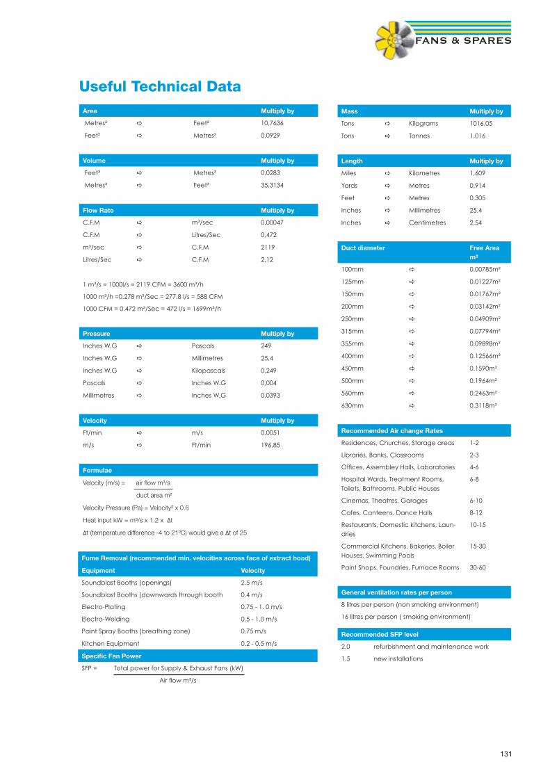
131
Recommended SFP level
2,0 refurbishment and maintenance work
1,5 new installations
Useful Technical DataArea Multiply by
Metres² a Feet² 10,7636
Feet² a Metres² 0,0929
Volume Multiply by
Feet³ a Metres³ 0,0283
Metres³ a Feet³ 35,3134
Flow Rate Multiply by
C.F.M a m³/sec 0,00047
C.F.M a Litres/Sec 0,472
m³/sec a C.F.M 2119
Litres/Sec a C.F.M 2,12
1 m³/s = 1000l/s = 2119 CFM = 3600 m³/h
1000 m³/h =0.278 m³/Sec = 277.8 l/s = 588 CFM
1000 CFM = 0.472 m³/Sec = 472 l/s = 1699m³/h
Pressure Multiply by
Inches W.G a Pascals 249
Inches W.G a Millimetres 25,4
Inches W.G a Kilopascals 0,249
Pascals a Inches W.G 0,004
Millimetres a Inches W.G 0,0393
Velocity Multiply by
Ft/min a m/s 0,0051
m/s a Ft/min 196,85
Formulae
Velocity (m/s) = air fl ow m³/s
duct area m²
Velocity Pressure (Pa) = Velocity² x 0.6
Heat input kW = m³/s x 1.2 x ∆t
∆t (temperature difference -4 to 21ºC) would give a ∆t of 25
Fume Removal (recommended min. velocities across face of extract hood)
Equipment Velocity
Soundblast Booths (openings) 2.5 m/s
Soundblast Booths (downwards through booth 0.4 m/s
Electro-Plating 0.75 - 1. 0 m/s
Electro-Welding 0.5 - 1.0 m/s
Paint Spray Booths (breathing zone) 0.75 m/s
Kitchen Equipment 0.2 - 0.5 m/s
Specifi c Fan Power
SFP = Total power for Supply & Exhaust Fans (kW)
Air fl ow m³/s
Mass Multiply by
Tons a Kilograms 1016,05
Tons a Tonnes 1,016
Length Multiply by
Miles a Kilometres 1,609
Yards a Metres 0,914
Feet a Metres 0,305
Inches a Millimetres 25,4
Inches a Centimetres 2,54
Duct diameter Free Area m²
100mm a 0.00785m²
125mm a 0.01227m²
150mm a 0.01767m²
200mm a 0.03142m²
250mm a 0.04909m²
315mm a 0.07794m²
355mm a 0.09898m²
400mm a 0.12566m²
450mm a 0.1590m²
500mm a 0.1964m²
560mm a 0.2463m²
630mm a 0.3118m²
Recommended Air change Rates
Residences, Churches, Storage areas 1-2
Libraries, Banks, Classrooms 2-3
Offi ces, Assembley Halls, Laboratories 4-6
Hospital Wards, Treatment Rooms, Toilets, Bathrooms, Public Houses
6-8
Cinemas, Theatres, Garages 6-10
Cafes, Canteens, Dance Halls 8-12
Restaurants, Domestic kitchens, Laun-dries
10-15
Commercial Kitchens, Bakeries, Boiler Houses, Swimming Pools
15-30
Paint Shops, Foundries, Furnace Rooms 30-60
General ventilation rates per person
8 litres per person (non smoking environment)
16 litres per person ( smoking environment)

132
1. InterpretationIn these conditions:1.1 the following expressions shall have the meanings set op-posite them unless the context otherwise requires: “Acknowledge-ment of Order” the written acknowledgement given by the Seller to the Buyer in response to an Order; “the Buyer” the person, fi rm or company with whom the Contract is made; “the Contract” the contract between the Seller and the Buyer for the sale of the Goods into which these conditions are incorporated; “Goods” the goods (including any instalment of the goods or any parts of them) which the Seller is to supply in accordance with these conditions; “Order” the written or oral order placed by the Buyer; “Quotation” the written or oral quotation given by the Seller to the Buyer or to others on the Buyer’s behalf; “the Seller” the company referred to overleaf as the Seller; “writing” and “written” shall include telex and facsimile transmission;1.2 any reference in these conditions to any provision of a statute shall be construed as a reference to that provision as amended, re-enacted or extended at the relevant time;1.3 any reference to the singular includes the plural and reference to a gender includes every gender;1.4 the headings are inserted for convenience only and shall not affect the interpretation of these conditions.2. Formation of Contract2.1 All Quotations and Acknowledgements of Order given by the Seller shall be deemed to include these conditions except (subject to the provisions of clause 2.6) insofar as they are inconsistent with any special terms or conditions contained in the Quotation or the Acknowledgement of Order (as the case may be).2.2 The Quotation does not form an offer capable of acceptance by the Buyer but merely an invitation to the Buyer to make an offer in accordance with its terms.2.3 No Order shall be deemed to be accepted by the Seller unless and until acknowledged and confi rmed in writing by the Seller’s authorised representative.2.4 Any terms or conditions contained in the Order or any other document delivered or sent by the Buyer which are inconsistent with these conditions shall not form part of the Contract unless (subject to the provisions of clause 2.6) accepted by the Seller in writing in the Acknowledgement of Order2.5 If subsequent to any contract between the Seller and the Buyer into which these conditions are incorporated any contract for the supply of goods similar to the Goods is made between the Seller and the Buyer whether the same is in writing, orally or oth-erwise, without express reference to any conditions, such contract shall be deemed to be subject to these conditions.2.6 No variation to these conditions shall be effective unless agreed in writing between the authorised representatives of the Buyer and the Seller.3. Basis of the Sale3.1 The Seller’s employees or agents are not authorised to make any representations concerning the Goods unless confi rmed by the Seller in writing. In entering into the Contract the Buyer acknowledges that it does not rely on any such representations which are not so confi rmed and that it shall not have any right of action against the Seller arising out of or in connection with any such representation except in the case of fraud.3.2 Any advice or recommendation given by the Seller or its employees or agents to the Buyer or its employees or agents as to the storage. Application or use of the Goods which is not confi rmed in writing by the Seller is followed or acted upon entirely at the Buyer’s own risk and accordingly the Seller shall not be liable for any such advice or recommendation which is not so confi rmed.3.3 In entering into this Contract the Buyer assumes responsibility for the Goods being suffi cient for its purpose. As the Seller is not responsible for system design and as the Buyer has greater knowledge of his own requirements the Seller shall not accept any responsibility for the performance or suitability of the Goods in their fi nal operating environment whether or not details of the fi nal operating environment have been made available to the Seller.3.4 Any typographical, clerical or other error or omission in any sales literature, Quotation, price list, Acknowledgement of Order, invoice or other document or information issued by the Seller shall be subject to correction without any liability on the part of
the Seller.3.5 The Buyer shall be responsible to the Seller for ensuring the accuracy of the terms of any Order (including any applicable specifi cation) and for giving the Seller any necessary information relating to the Goods within a suffi cient time to enable the Seller to perform the Contract in accordance with its terms.3.6 If the Goods are to be manufactured or any process is to be applied to the Goods by the Seller in accordance with a specifi ca-tion submitted by the Buyer, the Buyer shall indemnify the Seller against all loss, damages, costs and expenses awarded against or incurred by the Seller in settlement of any claim for infringement of any patent, copyright, design, trade mark or other industrial or intellectual property rights of any other person which results from the Seller’s use of the Buyer’s specifi cation.3.7 The Seller reserves the right at any time to change the design, construction and/or specifi cation of the Goods if such change is required to conform with any applicable statutory or EC require-ments or if such change will not in the opinion of the Seller at the time that such change is made adversely affect the quality or performance of such Goods.3.8 No order which has been accepted by the Seller may be cancelled by the Buyer except with the agreement in writing of the Seller and on terms that the Buyer shall indemnify the Seller in full against all loss (including loss of profi t), costs (including the cost of all labour and materials used), damages, charges and expenses incurred by the Seller as a result of cancellation.4. Delivery4.1 Delivery of the Goods shall be made by the Buyer collecting the Goods at the Seller’s premises at any time after the Seller has notifi ed the Buyer that the Goods are ready for collection or, if some other place for delivery is agreed by the Seller, by the Seller delivering the Goods to that place.4.2 Any dates quoted for the delivery of the Goods are ap-proximate only and the Seller shall not be liable for any delay in delivery of the Goods howsoever caused. Time for delivery shall not be of the essence of the Contract unless previously agreed by the Seller in writing.4.3 The Seller may make delivery by instalments. Where Goods are to be delivered in instalments each delivery shall constitute a separate contract and failure by the Seller to deliver any one or more of the instalments in accordance with these conditions or any claim by the Buyer in respect of any one or more instalments shall not entitle the Buyer to treat the Contract as a whole as repudiated.4.4 If the Buyer fails to take delivery of the Goods or fails to give the Seller adequate delivery instructions at the time stated for delivery, then without prejudice to any other right or remedy avail-able to the Seller, the Seller may:4.4.1 store the Goods until actual delivery and charge the Buyer for the reasonable costs (including insurance) of storage; or4.4.2 sell the Goods at the best price readily obtainable and (after deducting all reasonable storage and selling expenses) charge the Buyer for any shortfall below the price under the Contract.4.5 No claim for damage to any Goods or for any shortages in the Goods delivered will be considered by the Seller unless it is ad-vised of such claim in writing within 7 days of the date of delivery of the Goods or such part thereof as are actually delivered. In the absence of such advice, the Buyer will be deemed to have ac-cepted the Goods. No claim for non delivery will be considered by the Seller unless it is advised in writing within 14 days of the date of the Seller’s invoice. Any claim for damage, shortages or non delivery shall also be notifi ed by the Buyer to the carrier (if any) in the manner and within the appropriate time limit prescribed by the carrier’s terms and conditions, as advised by the Seller to the Buyer. In the event of a failure by the Buyer to give the appropriate notices then any claim which the Buyer may otherwise have pursuant to this condition will be deemed to have been waived and will be absolutely barred.5. Guarantee5.1 The Seller will endeavour to transfer to the Buyer the benefi t of any warranty or guarantee given by the manufacturer of the Goods to the Seller.5.2 The Seller will free of charge within a period of 3 months from the date of delivery or such longer period as may be referred to in the Seller’s sales literature repair or at its option replace any
Goods which are proved to the reasonable satisfaction of the Seller to be defective in design, materials or workmanship unless, in the Seller’s reasonable opinion:5.2.1 the Goods have been altered in any way whatsoever or repaired without the Seller’s approval or have been subjected to wilful damage negligence abnormal working conditions or misuse; or5.2.2 the Goods have been improperly installed or connected; or5.2.3 the Buyer has failed to observe any operational or mainte-nance requirements relating to the Goods; or5.2.4 the Buyer has failed to notify the Seller in writing of any defect or suspected defect within 14 days of the same coming to the knowledge of the Buyer; or.5.2.5 the Buyer is in breach of this or any other contract made with the Seller; or5.2.6 the defect in the Goods arises from any drawing, design or specifi cation supplied or approved by or on behalf of the Buyer. Notwithstanding the provisions of this condition, the Seller shall not be obliged to repair or replace any defective Goods unless and until the Buyer returns such Goods to the Seller (without any charge or cost to the Seller) if reasonably requested by the Seller so to do. In the case of any defective Goods which it would be unreasonable for the Seller to require the Buyer to return to the Seller (e.g. because of their size or because following installation or connection they form an integral part of a larger system or structure which it would be unreasonable to require the Buyer to dismantle) notwithstanding the provisions of this condition, the Seller shall not be obliged to repair or replace such Goods unless the Seller is easily able to obtain access to the same for repair or replacement. Any Goods replaced by the Seller will belong to the Seller. Any repaired or replacement Goods will be guaranteed on these terms for the unexpired portion of the 3 month or longer guarantee period.6. Seller’s Liability6.1 Save as provided in conditions 5.1 and 5.2 and subject to condition 6.2 the Seller will be under no liability under the Contract, in tort or otherwise for any personal injury, death, loss or damage of any kind whatsoever whether direct or indirect and whether consequential or otherwise (including but not limited to loss of profi ts, loss of business or contracts, loss of operating time or loss of use whether foreseeable or not) resulting from any defect in the Goods or from any work done in connection therewith or as a result thereof and the Seller hereby excludes all conditions, warranties and stipulations express or implied, statutory, customary or otherwise to the fullest extent permitted by law which but for such exclusion would or might subsist in favour of the Buyer.6.2 The Seller, does not exclude liability for:6.2.1 any breach of the implied condition that the Seller has or will have the right to sell the Goods when property therein is to pass;6.2.2 when the Buyer deals as a consumer (as defi ned in section 12 of the Unfair Contract Terms Act 1977), any breach of the implied terms relating to the conformity of the goods with their description or sample, as to their quality or fi tness for a particular purpose;6.2.3 death or personal injury resulting from its negligence or that of its employees;6.2.4 direct physical damage to or physical loss of the property of the Buyer resulting from the Seller’s, its employee’s or agents’ negligent acts or omissions and which arise out of the perfor-mance of its obligations under the Contract provided that:6.2.4.1 the Seller shall only accept liability for any such damage or loss if and to the extent that such liability is covered by the public/product liability policy taken out by the Seller and operative at the time of the damage or loss. Details of such insurance policy will be made available to the Buyer upon request. If the Buyer requests in writing additional insurance the Seller will take all rea-sonable steps to obtain it on the Buyers behalf and any premium or additional premium and any other expenses incurred in obtain-ing such insurance shall be payable by the Buyer to the Seller.6.2.4.2 the Seller’s liability under this condition 6.2.4 shall not exceed £1 million in aggregate in respect of any one event or series of events.7. Risk
Terms & Conditions of Sale
133
7.1 Risk of damage to or loss of the Goods shall pass to the Buyer:7.1.1 in the case of Goods to be delivered at the Sellers premises, at the time when the Seller notifi es the Buyer that the Goods are available for collection; or7.1.2 in the case of Goods to be delivered otherwise than at the Seller’s premises, at the time of delivery or, if the Buyer wrongfully fails to take delivery of the Goods, the time when the Seller has tendered delivery of the Goods.8. Property in the Goods8.1 Notwithstanding delivery and the passing of risk in the Goods the property in the Goods shall not pass to the Buyer until:8.1.1 the price of the Goods has been paid in full; and8.1.2 payment has been made to the Seller of all sums due or owing from the Buyer to the Seller on any account whatsoever.8.2 Until such time as property in the Goods passes to the Buyer in accordance with condition 8.1:8.2.1 the Buyer shall hold the Goods as the Seller’s fi duciary agent and bailee, shall not obliterate any identifying mark on the Goods or their packaging and shall keep the Goods separate from any other goods of the Buyer or third parties properly stored, protected and insured and identifi ed as the Seller’s property; and8.2.2 the Buyer shall be entitled to use or (subject to condition 8.3) sell the Goods in the ordinary course of to its business.8.3 The Buyer shall not be entitled to pledge or in any way charge by way of security for any indebtedness any of the Goods which remain the property of the Seller but if the Buyer does so all monies owing by the Buyer to the Seller shall (without prejudice to any other right or remedy of the Seller) forthwith become due and payable.8.4 Where the Seller is unable to determine whether any goods are the Goods the Buyer shall be deemed to have sold all goods of the kind sold by the Seller to the Buyer in the order in which they were invoiced to the Buyer.8.5 The Seller may at any time after payment for the Goods has become due take possession of the Goods (which for the avoid-ance of doubt shall include the right to stop the Goods in transit) and remove them and the Buyer shall be deemed to have granted irrevocable authority to the Seller to enter upon the Buyer’s premises or other premises where the Goods may be and, by the Seller’s employees or agents, take possession of the Goods and (if necessary) dismantle the Goods from anything to which they are attached.8.6 The Seller shall have the right to maintain an action against the Buyer for the price of the Goods notwithstanding that property in the Goods has not passed.8.7 Nothing in the Contract shall constitute the Buyer the agent of the Seller in respect of any re-sale of the Goods by the Buyer so as to confer upon a third party any rights against the Seller9. Price9.1 Except as otherwise stated in any Quotation and unless otherwise agreed in writing between the Buyer and the Seller all prices quoted are the price of the Goods (excluding VAT) ex-works and where the Seller agrees to deliver the Goods otherwise than at the Seller’s premises the Buyer shall be liable to pay the Seller’s charges for transport, packaging and insurance.9.2 The Seller reserves the right, by giving notice to the Buyer at any time before delivery, to increase the price of the Goods to refl ect any increase in the cost to the Seller which is due to any factor beyond the control of the Seller (such as, without limitation, any foreign exchange fl uctuation, currency regulation, alteration of duties, signifi cant increase in the costs of labour, materials or other costs of manufacture), any change in delivery dates. quantities or specifi cations for the Goods which is requested by the Buyer or any delay caused by any instructions of the Buyer or failure of the Buyer to give the Seller adequate information or instructions.9.3 The cost of pallets and returnable containers will be charged to the Buyer in addition to the price of the Goods but full credit will be given to the Buyer provided they are returned undamaged to the Seller before the due payment date.10. Payment10.1 Where no account has been opened in advance by the Seller in respect of the Buyer, the Seller will not be obliged to deliver the Goods until the Buyer has paid the amount shown on the
pro-forma invoice relating to the Goods.10.2 Where an account has been opened for the Buyer, the Seller may in its absolute discretion set and on 3 days prior written notice to the Buyer alter the Buyer’s credit limit and the Seller reserves the right not to deliver the Goods if the price thereof increases the amount owed by the Buyer to the Seller beyond the Buyer’s credit limit from time to time.10.3 Where an account has been opened for the Buyer and the price of the Goods together with all other indebtedness of the Buyer to the Seller does not exceed the Buyer’s credit limit from time to time, the price of the Goods will be paid by the Buyer within 30 days from the end of the month in which the Seller’s invoice is issued or within such other period as the Buyer and the Seller may agree in writing. The time of payment shall be of the essence of the Contract.10.4 If the Buyer fails to make any payment on the due date then, without prejudice to any other right or remedy available to the Seller, the Seller may without liability;10.4.1 suspend any further deliveries to the Buyer or cancel the Contract or any other contract between the Seller and the Buyer;10.4.2 charge the Buyer interest (both before and after any judge-ment) on the amount unpaid at the rate of 5% per annum above the base rate from time to time of Barclays Bank Plc until payment in full is made; and10.4.3 appropriate any payment made by the Buyer to such of the Goods (or the goods supplied under any other contract between the Buyer, and the Seller) as the Seller may in its absolute discretion think fi t (notwithstanding any purported appropriation by the Buyer).10.5 The Seller shall be entitled to payment for all instalments of Goods delivered to the Buyer notwithstanding that the remainder of the Goods shall not have been delivered.10.6 The Buyer shall not be entitled to withhold payment of any amount payable under the Contract because of any disputed claim of the Buyer, in respect of faulty goods or any other alleged breach of contract whether in respect of the Contract or any other contract between the Buyer and the Seller not shall the Buyer be entitled to set off against any amount payable under the Contract to the Seller any monies owed by the Seller to the Buyer on any account whatsoever, whether such a right is conferred on the Buyer by statute or otherwise.11. Force MajeureThe Seller shall not be liable to the Buyer or be deemed to be in breach of the Contract by reason of any delay in performing or any failure to perform any of the Seller’s obligations in relation to the Goods if the delay or failure is due to any cause beyond the Seller’s reasonable control. Without prejudice to the generality of the foregoing, the following shall be regarded as causes beyond the Seller’s reasonable control: act of God, explosion, lighting, fl ood, tempest, fi re or accident; war or threat of war, sabotage, insurrection, civil disturbance or requisition; acts, restrictions, regulations, by-laws, prohibitions, or measures of any kind on the part of any governmental, parliamentary or local authority; import or export regulations or embargoes; strikes, lockouts or other industrial actions or trade disputes (whether involving employees of the Seller or any third party); diffi culties in obtaining raw materi-als, labour, fuel, parts or machinery; power failure or breakdown in machinery.12. Cancellation and Suspension of the Contract12.1 This condition applies if:12.1.1 the Buyer is in breach of any of its obligations under the Contract or any other contract between the Buyer and the Seller; or12.1.2 unforeseen events including (without prejudice to the gen-erality of the foregoing) those referred to in condition 11 materially affect the commercial effect of the Contract; or12.1.3 the Buyer makes any voluntary arrangement with its credi-tors or (being an individual or fi rm) becomes bankrupt or (being a company) becomes subject to an administration order or goes into liquidation (otherwise than for the purposes of amalgamation or reconstruction); or12.1.4 an encumbrancer takes possession, or a receiver is ap-pointed, of any of the property or assets of the Buyer; or12.1.5 the Buyer ceases or threatens to cease to carry on business; or
12.1.6 the Seller reasonably apprehends that any of the events mentioned in conditions 12.1.3, 12.1.4 or 12.1.5 is about to oc-cur in relation to the Buyer and notifi es the Buyer accordingly; or12.1.7 the Seller receives notice of any claim alleging that the Goods or any part thereof or any process applied to the Goods infringe any patent, copyright, design right, trademark or other industrial or intellectual property rights of any other person.12.2 If this condition 12 applies then, without prejudice to any other right or remedy available to the Seller, the Seller shall be entitled to cancel the Contract or suspend any further deliveries under the Contract by notice to the Buyer without any liability to the Buyer and if the Goods have been delivered but not paid for then the price shall become immediately due and payable notwithstanding any previous agreement or arrangement to the contrary.13. Export Terms13.1 In these conditions “Incoterms” means the international rules for the interpretation of trade terms of the International Chamber of Commerce as in force at the date when the Contract is made. Unless the context otherwise requires, any term or expression which is defi ned in or given a particular meaning by the provisions of Incoterms shall have the same meaning in these conditions, but if there is any confl ict between the provisions of Incoterms and these conditions, the latter shall prevail.13.2 Where the Goods are supplied for export from the United Kingdom, the provisions of this condition 13 shall (subject to any special terms agreed in writing between the Buyer and the Seller) apply notwithstanding any other provision of these conditions13.3 The Buyer shall be responsible for complying with any legislation or regulations governing the importation of the Goods into the country of destination and for the payment of any duties on them.13.4 Unless otherwise agreed in writing between the Buyer and the Seller, the Goods shall be delivered fob the air or sea port of shipment and the Seller shall be under no obligation to give notice under section 32(3) of the Sale of Goods Act 1979.13.5 The Buyer shall be responsible for arranging for testing and inspection of the Goods at the Seller’s premises before shipment. The Seller shall have no liability for any claim in respect of any defect in the Goods which would be apparent on inspection and which is made after shipment, or in respect of any damage during transit.13.6 Unless otherwise agreed in writing by the Seller payment of all amounts due to the Seller shall be made in sterling by irrevo-cable letter of credit opened by the Buyer in favour of the Seller and confi rmed by a leading London bank acceptable to the Seller within 10 days of the Seller’s acceptance of the Order and upon presentation of the required documents to a London bank.14. General14.1 The Seller shall be entitled to sub-contract the fulfi lment of the Contract or any part thereof in which event the Seller contracts on behalf of itself and its sub-contractors.14.2 The termination of the Contract howsoever arising shall be without prejudice to any rights and duties of either party which may have accrued prior to termination.14.3 The Seller’s rights contained in condition 8 (but not the Buyer’s rights) shall continue beyond the discharge of the parties’ primary obligations under the Contract following its termination by the seller or breach by the Buyer.14.4 Any notice required or permitted to be given by either party to the other under these conditions shall be in writing addressed to that other party at its registered offi ce or principal place of busi-ness or such other address as may at the relevant time have been notifi ed pursuant to this provision to the party giving the notice.14.5 No waiver by the Seller of any breach of the Contract by the Buyer shall be considered as a waiver of any subsequent breach of the same or any other provision.14.6 If any provision of these conditions is held by any competent authority to be invalid or unenforceable in whole or in part the va-lidity of the other provisions of these conditions and the remainder of the provision in question shall not be affected.15. Proper Law and JurisdictionThe Contract shall be governed by the laws of England and the Buyer agrees to submit to the non-exclusive jurisdiction of the English courts.

Fans & Spares Scotland Unit 9 & 10 Port Dundas Trading EstateNorth Canal Bank StreetGlasgowG4 9XPTel: 0141 333 0202Fax: 0141 331 1672
Fans & Spares Leeds10 Low Mills RoadLeedsLS12 4UYTel: 0113 279 0501Fax: 0113 231 0969
Fans & Spares ManchesterUnit 1 Dakota SouthDakota AvenueSalfordManchesterM50 2PUTel: 0161 873 7212Fax: 0161 848 7293
Fans & Spares StokeUnit 2 Rosevale RoadParkhouse Ind Est WestNewcastle-under-LymeStaffordshireST5 7EFTel: 01782 579076Fax: 01782 563592
Fans & Spares NottinghamUnit 25 Whitemoor CourtOff Nuthall RoadNottinghamNG8 5BYTel: 0115 929 4104Fax: 0115 929 2710
Fans & Spares LeicesterUnit 10The Beaver CentreFreemens CommonLeicesterLE2 7TDTel: 0116 254 9898Fax: 0116 247 0590
Fans & Spares Birmingham72 Cheston RoadBirminghamB7 5EJTel: 0121 322 0310Fax: 0121 322 0311
Fans & Spares LondonUnit1 Midas Business CentreWantz RoadDagenhamRM10 8PSTel: 0208 595 5226Fax: 0208 593 4257
Fans & Spares South EastCollins HouseKnight RoadStroodKentME2 2DZTel : 0208 683 1241 / 01634 295 724Fax : 0208 689 0043 / 01634 294 691
Fans & Spares SouthernRomsey Industrial EstateGreatbridge RoadRomseySO51 0HRTel: 01794 830399Fax: 01794 830336
www.fansandspares.co.uk
“Your Job Winning Partner”
Head Offi ce72 Cheston Road, Birmingham B7 5EJTel: 0121 322 0200 Fax: 0121 322 0201part of the world-wide Systemair Group
Forthcoming Projects