Embed Size (px)
Citation preview

General rights Copyright and moral rights for the publications made accessible in the public portal are retained by the authors and/or other copyright owners and it is a condition of accessing publications that users recognise and abide by the legal requirements associated with these rights.
Users may download and print one copy of any publication from the public portal for the purpose of private study or research.
You may not further distribute the material or use it for any profit-making activity or commercial gain
You may freely distribute the URL identifying the publication in the public portal If you believe that this document breaches copyright please contact us providing details, and we will remove access to the work immediately and investigate your claim.
Downloaded from orbit.dtu.dk on: Apr 17, 2020
Bifurcations of a creeping air–water flow in a conical container
Balci, Adnan; Brøns, Morten; Herrada, Miguel A.; Shtern, Vladimir N.
Published in:Theoretical and Computational Fluid Dynamics
Link to article, DOI:10.1007/s00162-016-0391-z
Publication date:2016
Document VersionPeer reviewed version
Link back to DTU Orbit
Citation (APA):Balci, A., Brøns, M., Herrada, M. A., & Shtern, V. N. (2016). Bifurcations of a creeping air–water flow in a conicalcontainer. Theoretical and Computational Fluid Dynamics, 30(5), 485-496. https://doi.org/10.1007/s00162-016-0391-z
1
Bifurcations of a creeping air-water flow in a conical container
Adnan Balci1, Morten Brøns1
, Miguel A. Herrada2 and Vladimir N. Shtern
3
1DTU Compute, Technical University of Denmark 2800 Kgs. Lyngby, Denmark
2E.S.I, Universidad de Sevilla, Camino de los Descubrimientos s/n 41092, Spain
3Shtern Research and Consulting, Houston, Texas 77096, USA
This numerical study describes the eddy emergence and transformations in a slow steady
axisymmetric air-water flow, driven by a rotating top disk in a vertical conical container. As
water height Hw and cone half-angle vary, numerous flow metamorphoses occur. They are
investigated for = 30, 45 and 60. For small Hw, the air flow is multi-cellular with clockwise
meridional circulation near the disk. The air flow becomes one-cellular as Hw exceeds a
threshold depending on . For all , the water flow has an unbounded number of eddies whose
size and strength diminish as the cone apex is approached. As the water level becomes close to
the disk, the outmost water eddy with clockwise meridional circulation expands, reaches the
interface, and induces a thin layer with anticlockwise circulation in the air. Then this layer
expands and occupies the entire air domain. The physical reasons for the flow transformations
are provided. The results are of fundamental interest and can be relevant for aerial bioreactors.
PACS numbers: 47.32.C, 47.15x, 47.55. t
1 Introduction
The emergence of a local circulation region in a swirling flow, often referred to as vortex
breakdown (VB), plays an important role in nature (tornadoes) and technology (delta-wing
aircraft, combustion and vortex reactors) [1]. It was recently revealed that VB occurs even in a
creeping flow [2, 3] that can be important for bioreactors.
Bioreactors are a rapidly developing technology. They employ an air-water flow for the
efficient growth of tissue culture. A rotating disk [4] or a propeller [5], located in the air region,
induces a swirling motion. The swirling air converges toward the reactor axis near the interface
and drives the meridional circulation and rotation of water. The air meridional circulation
delivers oxygen to the interface required for the tissue culture growth. The water circulation
enhances mixing of the dissolved oxygen with other ingredients. The tissue growth is a time-

2
consuming process requiring a slow motion of ingredients and small shear stresses. The air
driving satisfies these requirements.
Commercial bioreactors are cylindrical. The pattern of an air-water flow depends there on
the water height Hw [2]. For small Hw in a cylindrical container with a rotating top disk, the air
meridional circulation is clockwise and the water meridional circulation is anticlockwise. As Hw
increases, clockwise circulation emerges near the bottom center. This transformation occurs via
the swirl decay mechanism similar to that which causes the VB development in a high-speed
swirling flow [6].
In a swirling flow, the centrifugal force typically induces a radial gradient of pressure p:
p/r = v2/r, where v is the swirl velocity, r is the distance from the axis, and is the fluid
density. As a swirling flow meets a normal wall where v = 0, the centrifugal force has a second-
order zero, and p/r, being unbalanced by the centrifugal force, induces a secondary flow which
converges to the rotation axis near the wall and goes away from the wall near the axis [7]. This
mechanism, explaining the emergence of the water clockwise circulation near the bottom of
cylindrical and truncated conical containers [2, 3], does not work near the apex of a conical
container. One goal of this paper is to investigate what mechanism works in a cone.
Studies of a flow in a cone have long history. Ackerberg [8] analyzed a sink flow in a cone.
Conical sidewalls are beneficial for vortex devices. Examples are hydrocyclones [9, 10] and
vortex tubes [11] which have large length-to-radius ratios. Swirl decays downstream due to the
wall friction. The conical geometry partially compensates the decay and thus helps sustain the
centrifugal force to be sufficiently strong as required for particle and thermal separations. The
effect is achieved due to decreasing radial extent in a conical part of device and the angular
momentum, rv, which is nearly conserved in a fast flow.
The conical geometry also can be beneficial for aerial bioreactors where the flow is typically
slow. The swirl rapidly decays from the top toward the bottom of an aerial bioreactor due to
friction at its walls and viscous dissipation dominates in a slow motion. The conical geometry
can reduce the swirl decay. This potentially beneficial effect is a practical motivation for our
study.
The important difference is that the bottom is planar in a cylindrical container, while a non-
truncated conical container has a sharp tip. Even a slow (“creeping”) motion has an unbounded
set of eddies near the tip. Such sets were first discovered in a creeping flow between two

3
inclined walls [12] and then in a cone, where axisymmetric [13-15] and three-dimensional [16-
17] eddies were found.
Wakiya [13] revealed that the eddies exists in a cone whose half-angle (i.e., the angle
between the axis and the sidewall) is less than 80.9. This feature of conical flows is important
for our study, where = 30, 45 and 60. It makes the bifurcation scenario very different from
that in the cylindrical container [2] and in a truncated cone [3]. In particular, the difference is in
the VB occurrence and particularly in the development of a local counter-circulation in water.
As Hw increases in the cylindrical device, VB first emerges in the water flow near the axis-
bottom intersection and then in the air flow. In contrast, no VB in the water flow occurs in the
conical container. There is no necessity for the counter-circulation to emerge because many such
eddies exist in the water at any Hw. Instead of the VB emergence, the closest-to-interface eddy,
having clockwise circulation, expands upward as Hw increases.
The VB emergence in the air flow is similar for both cylindrical and conical containers: as
the water VB cell reaches the interface, it reverses the adjacent air flow and develops a thin layer
of the anticlockwise circulation of the air.
The bifurcation variety is enriched due to interactions of the VB cells with the air and water
eddies located near the interface-sidewall intersection [18]. The bifurcation scenario, found for
the creeping flow, remains unchanged as the Reynolds number Re increases up to a few
thousands. The cell multiplicity is beneficial for bioreactors because eddies enhance the
ingredient mixing thus making the process of culture growth more uniform. It is important that
the shear stresses do not harm the tissue because the flow is slow.
The exploration of topological transformations and VB development in two-fluid flows was
initiated by the pioneer paper of Brady et al. [19]. This paper contributes to a new field which
can be referred to as “Bifurcating multi-fluid flows” which in turn can be viewed as a part of the
topological fluid mechanics whose origin can be traced back to the paper by Arnold [20]. The
foundations of topological fluid dynamics are discussed in the book written by Arnold & Khesin
[21] and in the proceedings of two IUTAM Symposia [22, 23]. Our paper is a contribution to the
part “Bifurcating creeping multi-fluid flows” of this research field.
In the rest of this paper, we formulate the problem in Sect. 2, describe our numerical
technique in Sect. 3, investigate the bifurcation scenario in the cone with = 30 (Sect. 4), 45

4
(Sect. 5) and 60 (Sect. 6), explore the effect of finite Re (Sect. 7) and summarize the results in
Sect. 8.
2 Problem formulation
2.1 Flow geometry
Figure 1 is a schematic of the problem. The lower part, 0 < z < hw, of the conical container is
filled with water, the upper part, hw < z < h, is filled with air; h is the cone height, which serves
as a length scale; is the angle between the axis and the sidewall; g is the gravitational
acceleration. The interface is depicted by the thin horizontal line, z = hw. The top disk of radius
R = htan is located at z = h and rotates with angular velocity . The dimensionless control
parameters are , the relative water height Hw = hw/h, and the Reynolds number, Re = h2/w,
which characterizes the rotation strength; w is the kinematic viscosity of water. The motion is
creeping if Re << 1.
FIG. 1. Schematic of the problem.
Our goal is to study the flow transformations as Hw varies and to find Hw = Hwa, at which
vortex breakdown (VB) in the air flow develops, depending on .
r
z
water
air h
hw
R
g

5
2.2 Governing equations
Using h, h, and w2h
2 as scales for length, velocity, and pressure, respectively, renders all
variables dimensionless. We consider steady axisymmetric flows of air and water both governed
by the Navier-Stokes equations for a viscous incompressible fluid,
r1(ru)/r + w/z = 0, (1)
uu/r + wu/z = v2/r np/r +nRe
1(
2u u/r
2), (2)
uv/r + wv/z + uv/r = nRe1
(2v v/r
2), (3)
uw/r + ww/z = np/z+nRe1
(2w), (4)
where 2 r
1(r/r)/r+
2/z
2, (u, v, w) are the velocity components in cylindrical coordinates
(r, , z), and p is pressure reduced by the hydrostatic contribution. The coefficients, n and n,
both equal to1 for n = 1 (in water) while n = w/a and n = a/w for n = 2 (in air); w = 106
m2/s and a = 1510
6 m
2/s are the kinematic viscosities; w = 1000 kg/m
3 and a = 1.22 kg/m
3
are the densities; subscripts “a” and “w” are abbreviations for “air” and “water”. This air density
value corresponds to atmospheric pressure and room temperature.
2.3 Boundary conditions
Equations (1)-(4) are solved under the following boundary conditions:
(i) Regularity at the axis, 0 < z < 1, r = 0: u = v = 0, w/r = 0,
(ii) No-slip at the sidewall: u = v = w = 0 at 0 < z < 1, r = ztan,
(iii) No-slip, u = w = 0, v = r at the rotating disk, 0 < r < tan, z = 1.
(iii) Continuity of all the velocity and stress components at the air-water interface, z = F(r).
In particular, the balance for the normal stresses yields that
pwpa = We1nRe
1n(wra)nFr
1(1a/w)z+C (5)
where We = w2h
3/ is the Weber number, characterizing the effect of surface tension at the
interface; Fr = 2h/g is the Froude number, g = 9.81 m
2/s being the gravitational acceleration
magnitude (Fig. 1); n is the unit vector normal to the interface; w and a are tensors of the
viscous stresses in water and air, respectively; r is the air-to-water ratio of the dynamic

6
viscosities; C is a constant which is determined by imposing the mass conservation of the liquid
inside the container as the interface is deformed,
60a
[F(r)F(a)]rdr+F(a)a2 = Hwrw
2, (6)
where rw = Hwtan and a is the radial coordinate where the interface meets the sidewall, and a
root of the equation a = F(a)tan.
2.4 Reduced problem
As Re 0, the motion becomes very slow and the interface deformation becomes negligible,
F(r) Hw. The nonlinear terms become negligibly small compared with the linear terms in
equation (3), which reduces to
2v v/r
2 = 0. (7)
This equation has a nonzero solution due to the boundary condition at the disk: v = r at z = 1. At
all other walls, the swirl velocity is zero, v = 0. At the interface, v and the swirl shear stresses
are continuous: vw = va and vw/z = rva/z at z = Hw. Thus the problem for the swirl velocity
becomes separated from the problem for the meridional motion in the limiting case as Re 0,
similar to that in the one-fluid problem studied by Hills [24]. We first solve this linear problem
for swirl.
Next, we address the problem for the meridional motion. Since the boundary conditions are
uniform, the meridional motion is only driven by the centrifugal force corresponding to term v2/r
in equation (2). This term must be preserved, while the other nonlinear terms can be omitted in
the limiting case as Re 0. Then introducing u* = u/Re and w* = w/Re reduces equations (1),
(2), and (4) to
r1(ru*)/r + w*/z = 0, (8)
np/r v2/r = n(
2u* u*/r
2), (9)
np/z = n2w*. (10)
The velocity and shear-stress components are continuous across the undisturbed interface, z =
Hw, where the normal-to-interface velocity, w*, is zero. It is interesting that the entire problem
formally is nonlinear despite the motion is creeping, but can be divided into the two linear

7
problems: one for the swirl velocity (7) and the other for the meridional motion (8)-(10). After
solving problem (7), the “source” term, v2/r in equation (9), is prescribed, so the problem for the
meridional motion also is linear. This feature is also similar to that in the one-fluid flow studied
by Hills [14].
3 Numerical procedures
3.1 Transformation of equations
The numerical technique is similar to that used in Refs. [2], [3] and [25]. We reiterate here
the main features for convenience of the reader. For the Re ranges addressed in this work, the
interface deformation is negligibly small and z = zi = Hw is a good approximation for the
interface. The number of variables involved in the problem is reduced by introducing a stream-
function-vorticity-angular-momentum form. System (1)-(4) is transformed into three equations
for the Stokes stream function , u = r1/z, w = r
1/r, the azimuthal vorticity
component, = u/zw/r, and circulation, rv:
22r
1/r = r, (11)
u/r + w/zu/r = 2r3/z+nRe
1(
2 /r
2), (12)
u/r + w/z = nRe1
(2 2r
1/r), (13)
These equations are solved applying the boundary conditions for , and which follows
from those listed in §2.3 by substitution u = r1/z and w = r
1/r. Contours =
constant, are used to depict patterns of the meridional motion.
3.2 Linear problem
In the limiting case as Re 0, introducing * = /Re and * = /Re reduces equations (11)-
(13) to
2*2r
1*/r = r*, (11a)
2r3/z+n(
2* */r
2) = 0, (12a)
2 2r
1 /r = 0. (13a)

8
3.3 Discretization
A boundary-fitted coordinate system is used to calculate the problem. We use =
atanr/z),in order to have the unit interval 0 < < 1 for any . Both the water and air regions are
mapped onto the fixed rectangular domains (a) 0 ≤ ≤ 1, 0 ≤ ξw ≤ Hw, and (b) 0 ≤ ≤ 1, Hw ≤ ξa
≤ 1Hw. To this end, we perform the coordinate transformations: (a) = r/(1ztan)ξw = z
and (b) = r/(1ztan)ξa = z. These domains are discretized by using a set of nw and na
Chebychev spectral collocation points in the direction. The interval is discretized using a set
of n Chebychev spectral collocation points.
3.4 Nonlinear problem
The Newton iterative procedure is used to solve the discretized non-linear problem derived
from (11)-(13) and their corresponding boundary conditions. Given an initial solution guess, a
new approximate solution is found by solving the system of 3(nw+na)×n linear algebraic
equations for , and at the collocation points resulting from the Newton linearization. For a
prescribed geometrical configuration, the simulation is started with a small value of the Reynolds
number and the flow at rest. Once the approximate solution has converged, the converged
solution is used as a new guess for a new run with a higher Reynolds number.
3.5 Advantages of Chebyshev grid
In the reduced problem, the discretized problem consists of (i) system of (nw+na)×n linear
algebraic equations for and (ii) system of 2(nw+na)×n linear algebraic equations for * and
* which are solved sequentially. All linear systems, in the full and reduced problems, are
solved directly applying the standard procedure of matrix inversion.
For the presented results, the simulations are done mostly with nw = 40, na = 30, and n = 50
(standard grid). In order to verify the grid independence, some runs have been carried out at nw
= 50, na = 40, and n = 60 (fine grid).
Since the Chebyshev grid points concentrate near the interface from both sides, the approach
is adequate to resolve thin circulation layers, located near the interface, even using moderate
values of nw and na. The Chebyshev grid points concentrate near the walls as wellwhich helps

9
to better resolve the Moffatt and other corner eddies, even using a moderate value of n. The
Chebyshev grid points also concentrate near the axis which helps resolve small vortex
breakdown bubbles emerging near the axis-bottom and axis-interface intersections as Hw
increases.
4 Bifurcations at = 30
First, we explore the bifurcation scenario as the water height, Hw, increases in a conical
container with = 30. Fig. 2(a) depicts the pattern of the meridional motion at Hw = 0.1. The
rotating lid, located at z = 1, induces the centrifugal force which pushes air to the periphery near
the top and thus induces the clockwise circulation, indicated by the arrow in Fig. 2(a).
А
(a) Hw = 0.1 (b) Hw = 0.201 (c) Hw = 0.205
(d) Hw = 0.207 (e) Hw = 0.208 (f) Hw = 0.22
FIG. 2. (color online) Patterns of the meridional motion for small Hw at = 30.

10
It is known that a single-fluid flow (e.g., with no water) has a cascade of eddies with
alternating circulation directions [13]. The dimensions and strengths of eddies tend to zero as the
cone tip is approached. Our numerical technique resolves only some of the cascade eddies.
(a) Hw = 0.33 (b) Hw = 0.84 (c) Hw = 0.86
(d) Hw = 0.87 (e) Hw = 0.93 (f) Hw = 0.98
FIG. 3. (color online) Patterns of the meridional motion for large Hw at = 30. The effect of
swirl results in expansion on of cell Cw3and emergence of Ca3, as Hw increases.
Figure 2(a) shows two eddies in the air, Ca1 and Ca2, and two eddies in the water, Cw1 and
Cw2, at Hw = 0.1; since Cw1 and Cw2 are very small in Fig. 2(a) they are indicated in Figure
2(b). ‘C’, ‘a’ and ‘w’ are abbreviations for ‘cell’, ‘air’ and ‘water’, respectively. Contours,
corresponding to the clockwise (anticlockwise) circulation are depicted hereafter by the light
(dark) curves which are blue online.
As Hw increases, region Ca2 shrinks and its upper boundary touches the interface at the axis
as Fig. 2(b) illustrates at Hw = 0.201. Next, Ca2 separates from the axis thus transforming from
a bubble-like into a ring-like shape. At the same value of Hw, the clockwise air circulation in

11
Ca1 induces a new cell, Cw3, in the water as Fig. 2(c) illustrates at Hw = 0.205. We denote this
change in the flow topology as the first bifurcation, b1.
As Hw further increases, region Cw3 expands downward, as Fig. 2(d) shows at Hw = 0.207
and merges with region Cw2 as Fig. 2(e) reveals at Hw = 0.208. Region Cw1 becomes separated
from the axis thus transforming from a bubble-like (Fig. 2(d)) into a ring-like (Fig. 2(e)) shape.
We mark this change in the flow topology as b2 and denote the merged region again as Cw2
in Fig. 2(e). For larger Hw, regions Ca2 and Cw1 shrink to the interface-sidewall intersection, as
Fig. 2(f) illustrates at Hw = 0.22.
Note that in addition to the cascade of eddies near the cone tip, a cascade of eddies also exists
near the interface-sidewall intersection [18]. Ca2 and Cw1 can be considered as the outmost
eddies of this additional cascade. However as Hw increase, Ca2 and Cw1 become so small that
our grid cannot resolve them in Fig. 3 in contrast to Fig. 2(f).
Figure 3(a) depicts the flow pattern at Hw = 0.33, where three eddies are observed in the
water: Cw2, Cw3, and Cw4; Cw4 is well seen in Fig. 3(b). They are driven by the meridional
circulation of air in Ca1 while the direct effect of the centrifugal force is comparatively small.
The solid curve in Fig. 4 depicts the dependence on Hw of the maximal swirl velocity at the
interface, vim, and reveals the strong decay of vim as Hw decreases at = 30. This explains why
the direct effect of swirl on the water motion is negligible at Hw = 0.33.
FIG. 4. The maximal swirl velocity at the interface versus the water height at = 30
(solid curve), 45 (dashed curve) and 60 (dots).
0,00001
0,0001
0,001
0,01
0,1
1
0,4 0,6 0,8 1Hw
vim

12
The effect of swirl becomes significant as Hw increases. The centrifugal force pushes the
fluid to the periphery near the top of a cell and thus enhances (suppresses) the clockwise
(anticlockwise) circulation. Figures 3(a) and 3(b) illustrate this: region Cw3 (Cw2) expands
(shrinks) as Hw increases.
Cw3 mostly expands near the axis (because water moves up there) and reaches the interface
at Hw = 0.86 as Fig. 3(c) illustrates. For large Hw, Cw2 separates from the axis. The water flow
in Cw3 drives the adjacent air away from axis and thus generates cell Ca3. We mark this change
in the flow topology as b3. Regions Ca1, Ca3, Cw2 and Cw3 meet at a saddle point S located at
the interface as shown in Fig. 3(d).
Ca3 is a very thin layer hardly visible in Fig. 3(d) at Hw = 0.87 and well observed in Fig. 3(e)
at Hw = 0.93. Its z-extent is maximal at the axis and diminishes to zero at S. As Hw increases,
Ca3 touches the lid and Ca1 becomes separated from the axis as Fig. 3(f) illustrates at Hw = 0.98.
We mark this change in the flow topology as b4.
Next, the saddle S reaches the sidewall at Hw around 0.98 and cell Ca1 becomes separated
from the interface. We mark this change in the flow topology as b5. Finally, Ca1 shrinks to the
lid-sidewall intersection as Hw 1.
5 Bifurcations at = 45
The bifurcation sequence at = 45 is similar to that at = 30, but the topological changes
occur for = 45 at smaller Hw than for = 30. For example, the flow pattern shown in Fig.
5(a) is similar to that in Fig. 2(b) and the pattern shown in Fig. 5(b) is similar to that in Fig. 2(f).
The bifurcations b1 and b2, occurring in the Hw range around 0.2 at = 30, also occur at = 45,
but in the Hw range around 0.075.
Figure 5(c) depicts the clockwise circulation in the water (region Cw3). As Hw increases,
Cw3 expands and touches the interface at Hw = 0.793 (compare with Hw = 0.86 at which
bifurcation b3 occurs for = 30). Figures 5(d) and 5(e) depict the flow patterns before and after
bifurcation b3. Similarly, bifurcations b4 and b5 occur at smaller Hw at = 45 than those at =
30. Figure 5(f) depicts the flow pattern after b4.
The dashed curve in Fig. 4 illustrates that the swirl decays weaker for = 45 than that for
= 30 as the distance of the interface from the rotating disk increases. The dotted curve in in Fig.

13
4 corresponds to = 60. This case, where the swirl decays weaker than that for = 45, is
discussed in more details below.
(a) Hw = 0.07 (b) Hw = 0.08 (c) Hw = 0.6
(d) Hw = 0.79 (b) Hw = 0.8 (c) Hw = 0.93
FIG. 5. (color online) Flow patterns at = 45.
6 Bifurcations at = 60
In contrast to the cases where = 30 and 45, the air flow is one-cellular for = 60 even at
Hw = 0.02 as Fig. 6(a) illustrates. Another difference is that no eddy is observed near the
interface-sidewall intersection. This agrees with the theory [18] stating that if a flow is driven
from the air side and > 56.55, no Moffatt eddy occurs near the interface-sidewall intersection.
On the other hand according to the theory [18], there is a cascade of eddies in the water flow near
the cone tip at = 60. The numerical grid, we apply, can resolve none of these eddies at Hw =
14
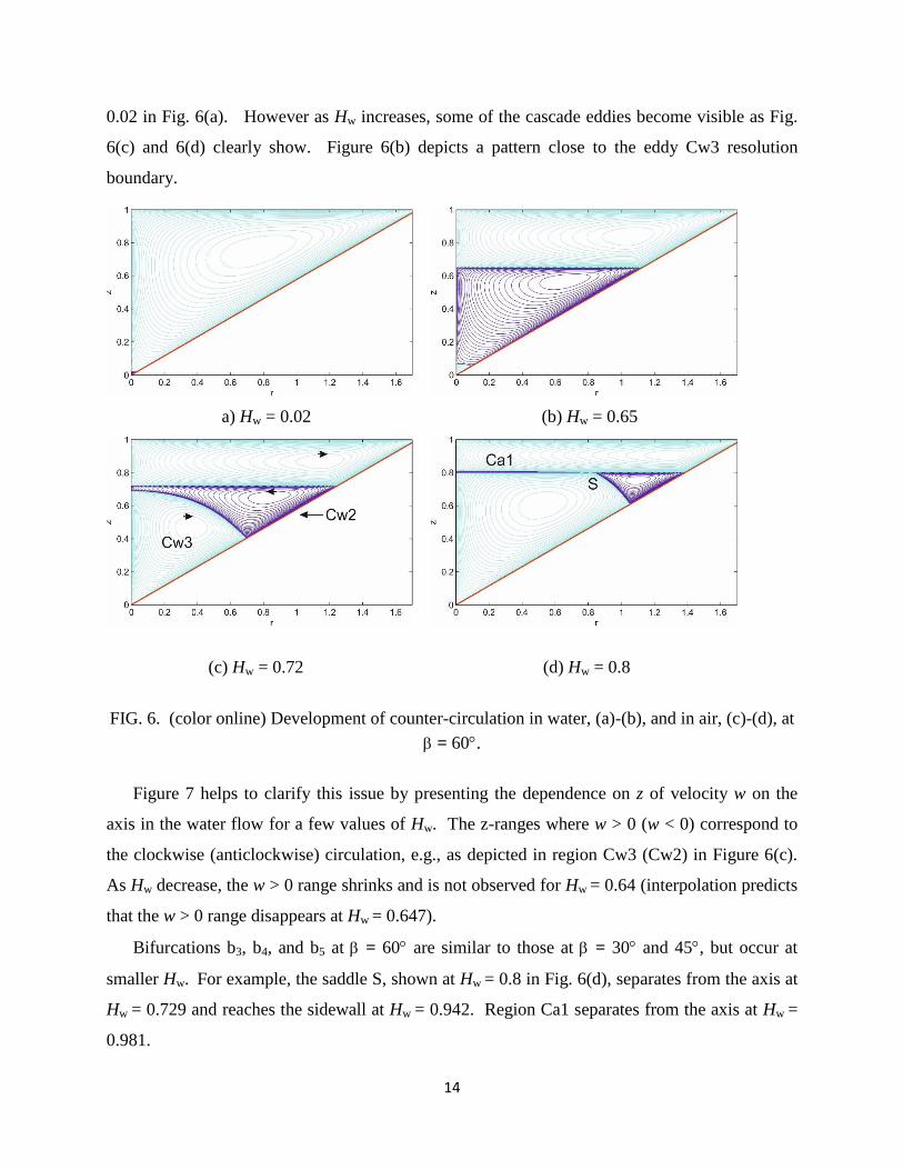
0.02 in Fig. 6(a). However as Hw increases, some of the cascade eddies become visible as Fig.
6(c) and 6(d) clearly show. Figure 6(b) depicts a pattern close to the eddy Cw3 resolution
boundary.
a) Hw = 0.02 (b) Hw = 0.65
(c) Hw = 0.72 (d) Hw = 0.8
FIG. 6. (color online) Development of counter-circulation in water, (a)-(b), and in air, (c)-(d), at
= 60.
Figure 7 helps to clarify this issue by presenting the dependence on z of velocity w on the
axis in the water flow for a few values of Hw. The z-ranges where w > 0 (w < 0) correspond to
the clockwise (anticlockwise) circulation, e.g., as depicted in region Cw3 (Cw2) in Figure 6(c).
As Hw decrease, the w > 0 range shrinks and is not observed for Hw = 0.64 (interpolation predicts
that the w > 0 range disappears at Hw = 0.647).
Bifurcations b3, b4, and b5 at = 60 are similar to those at = 30 and 45, but occur at
smaller Hw. For example, the saddle S, shown at Hw = 0.8 in Fig. 6(d), separates from the axis at
Hw = 0.729 and reaches the sidewall at Hw = 0.942. Region Ca1 separates from the axis at Hw =
0.981.

15
To explore in what range of the Reynolds number, Re, the flow topology remains the same as
that for the creeping flows, we below explore how the flow pattern changes as Re increases.
FIG. 7. (color online) Profiles of velocity at the axis in water show the counter-circulation (w >
0) emergence as Hw increases at = 60.
7 The effect of intensifying disk rotation
Now we come back from the reduced equations (§2.4) to the full equations (§2.2 and §2.3)
and use the numerical techniques for the nonlinear problem (§3). For Re > 0, the interface
becomes deformed. The deformation depends on the Froude number, Fr = 2R/g = aRe
2, and the
Weber number, We =w2R
3/ = bRe
2; a = w
2/(gR
3) and b = ww
2/(R). We fix a and b while
increase Re. The bioreactor radius, R, is around 0.02 m [4]; this yields a = 1.25108
, and b =
7107
at R = 0.02 m. For the range Re considered here, Fr, We, and interface deformation are
small.
To characterize the strength of air flow, we introduce the Reynolds number based on the air
viscosity, Rea = h2/a = Re/n, because the rotating top disk directly (indirectly) drives the air
(water) flow; we take the air-to water kinematic viscosity ratio being n = 15. From the top disk
down to the interface, the swirl velocity significantly drops. Therefore, to characterize the
-2E-07
-1,5E-07
-1E-07
-5E-08
0
5E-08
0 0,2 0,4 0,6 0,8
Hw=0.64
Hw=0.67
Hw=0.68
z
w

16
strength of water flow, we introduce the Reynolds number, Rew, based on the maximal swirl
velocity at the interface, vim; Rew = vimRe.
We increase Re at the fixed values of = 60 and Hw = 0.8. Our goal is to find at what Re
the flow topology becomes different from that presented in Fig. 6(d). As Re increases, the saddle
S, shown in Fig. 6(d), shifts toward the axis, as Fig. 8(a) depicts. The radial coordinate, rs, of S
decreases as Table 1 indicates. The saddle S reaches the axis at Re around 10000 and the flow
pattern becomes as Fig. 8(b) depicts.
Comparison of Figures 8(a) and 8(b) shows that the clockwise circulations in air (Ca1) and in
water (Cw3) become separated by the anticlockwise circulation in water (Cw2). The z-extension
of Cw2 shrinks as Re increases. This feature is the same as that observed in the water-spout
cylindrical flow [25].
Re Rea Rew rs
0.1 0.0067 0.00177 0.607
2000 133 34.4 0.59
4000 267 64.7 0.553
6000 400 90.6 0.499
8000 533 112 0.346
10000 667 135 0
20000 1333 320 0
Table 1 Dependence on Re of the Reynolds number for air (Rea) and water (Rew) flows and of the
radial coordinate of saddle point S (se Fig. 6(d)) at Hw = 0.8 and = 60.

17
(a) Re = 4000 (b) Re = 20000
FIG. 8. (color online) Transformation of the flow pattern as Re increases at Hw = 0.8 and =
60.
8 Conclusions
This paper reveals and explains topological transformations in a slow steady axisymmetric air-
water flow, driven by the rotating top disk, in a vertical conical container. There are five major
flow bifurcations as the water height Hw varies at the cone half-angle = 30 (Sect. 4). Most of
the bifurcations occur at the interface. For small Hw, the direct effect of swirl is negligible for the
water flow where a cascade of eddies exists near the cone tip. As Hw increases, the swirl effect
becomes significant and causes the expansion of the outmost cascade eddy with the clockwise
circulation (Fig. 2). As this eddy reaches the interface, it reverses the adjacent air flow
developing a thin layer with the anticlockwise circulation (Fig. 3). These expansions and
reversals occur for smaller Hw at = 45 (Sect. 5, Fig. 5) and = 60 (Sect. 6, Fig. 6) than those
at = 30. As the disk rotation intensifies, the flow topology remains invariant until the
Reynolds number Re exceeds a value around 104 (Sect. 7, Table 1). For larger Re, the bulk
circulations of both air and water flows are clockwise, separated by a thin layer of anticlockwise
circulation adjacent to the interface from the water side (Fig. 8). The physical reasons for the
flow transformations are provided. The results are of fundamental interest and can be relevant
for aerial bioreactors.
z

18
[1] Shtern, V.: Counterflows. Cambridge University Press (2012).
[2] Herrada, M. A., Shtern, V. N.: Patterns of a creeping water-spout flow. J. Fluid Mech.
744, 65 (2014).
[3] Balci, A., Brøns, M., Herrada, M. A., Shtern, V.N.: Vortex breakdown in a truncated
conical bioreactor. Fluid Dyn. Res. 47, 065503 (2015).
[4] Liow, K. Y. S., Tan, B. T., Thouas, G., Thompson, M. C.: CFD modeling of the
steady-state momentum and oxygen transport in a bioreactor that is driven by a rotating
disk. Modern Physics Letters B 23, 121 (2009).
[5] Ramazanov, Yu. A., Kislykh, V.I., Kosyuk, I.P., Bakuleva, N.V., Shchurikhina, V.V.:
Industrial production of vaccines using embryonic cells in gas-vortex gradient-less
bioreactors. In book “New Aspects of Biotechnology and Medicine”, edited by A. M.
Egorov, ISBN: 1-60021-465-7, pp. 87-91 (2007).
[6] Shtern, V. N., Torregrosa, M. M., Herrada, M. A.: Effect of swirl decay on vortex
breakdown in a confined steady axisymmetric flow. Phys. Fluids 24, 043601 (2012).
[7] Bödewadt, U. T.: Die Drehströmung über festem Grund. Z. Angew. Math. Mech. 20,
241 (1940).
[8] Ackerberg, R. C.: The viscous incompressible flow inside a cone. J. Fluid Mech. 21,47
(1965).
[9] Schultz, V., Gorbach, G., Piesche, M.: Modeling fluid behavior and droplet
interactions during liquid–liquid separation in hydrocyclones. Chem. Eng. Sci.,
64, 3935 (2009).
[10] Ghodraty, M., Kuang, S. B., Yui, A. B., Vince, A., Barnett, G. D., Barnet, P. J.: CFD study
of multiphase flowin classifying cyclone: Effect of cone geometry. Ninth Int. Conf. on CFD

19
in the Mineral and Process Industries CSIRO, Melbourne, Australia 10-12 December 2012.
[11] Secchiaroli, A., Ricci, R., Montelpare, S. D’Alessandro, V.: Numerical simulation of
turbulent flow in a Ranque-Hilsch vortex-tube. Int. J. of Heat and Mass Transfer 52, 5496
(2009).
[12] Moffatt, H. K.: Viscous and resistive eddies near a sharp corner. J. Fluid Mech. 18, 1
(1964).
[13] Wakiya, S.: Axisymmetric flow of a viscous fluid near the vertex of a body.
J. Fluid Mech. 78, 737 (1976).
[14] Liu, C. H., Joseph, D. D.: Stokes flow in conical trenches, SIAM J. Appl. Math. 34, 286
(1978).
[15] Weidman, P. D., Calmidi, V.: Instantaneous Stokes flow in a conical apex aligned with
gravity and bounded by a stress-free surface. SIAM J. Appl. Maths. 59, 1520 (1999).
[16] Malyuga, V. S.: Viscous eddies in a circular cone. J. Fluid Mech. 522, 101 (2005).
[17] Shankar, P. N.: Moffatt eddies in the cone. J. Fluid Mech. 539, 113 (2005).
[18] Shtern, V.: Moffatt eddies at an interface. Theor. Comput. Fluid Dyn. 28, 651 (2014 ).
[19] Brady, P. T., Herrmann, M., Lopez, J. M.: Two-fluid confined flow in a cylinder driven by
a rotating end wall”, Phys. Rev. E 85, 016308 (2012).
[20] Arnold, V.I.: Sur la gćometrie diffćrentielle des groupe de Lie de dimension infinie et ses
applications a l’hydrodynamique des fluides parfaits. Ann. Inst Fourier 16, 319 (1966).
[21] Arnold, V.I., Khesin, B. A.: Topological methods in hydrodynamics. Applied Math. Sci.
125, Springer-Verlag, N.Y (1998).
[22] Moffatt, H. K., Tsinober, A. (editors): Topological Fluid Mechanics. Proc.
of IUTAM Symp. Cambridge, UK (1989).

20
[23] Moffatt, H. K., Bajer, K., Kimura, Y. (editors): IUTAM Symposium on Topological Fluid
Dynamics: Theory and Applications. Procedia IUTAM 7, 1-260. Elsevier (2013).
[24] Hills, C. P. Eddies induced in cylindrical containers by a rotating end wall. Phys. Fluids
13, 2279 (2001).
[25] Herrada, M. A., Shtern, V. N., Lopez-Herrera, J. M.: Vortex breakdown in a water-spout
flow. Phys. Fluids 25, 093604 (2013).