Embed Size (px)
Citation preview
ICON 2000Installation & Maintenance Instructions
Tyco reserves the right to change the contents without notice BIFRM-0003-EN-0807
General instructions for installation
Operation and configuration
Maintenance and trouble-shooting
Spare parts and drawings
www.tycoflowcontrol-eu.com
Index
1 General safety instructions 21.1 Range of application 21.2 Safety instructions for installation in hazardous area 21.3 Applicable standards and regulations 31.4 Terms and conditions 3
2 Storage and pre-installation 42.1 Tests to be carried out when the actuator is received 42.2 Storage procedure 42.3 Checks to be performed before installation 5
3 Installation 63.1 Working condition 63.2 Coupling block: disassembly from the actuator 63.3 Manual operation 93.4 Mounting the actuator onto the valve 103.5 Electrical connections 113.6 Removing the terminal board enclosure 113.7 Cable entries 113.8 Terminal board 123.9 Instructions for the explosion-proof enclosures 133.10 Installation in environment with explosive dusts 13
4 Lubrication 144.1 Lubrication inspection 14
5 Operating the ICON2000 155.1 Operation by handwheel 155.2 Electrical operation 155.3 Local control 155.4 Local indication 165.5 Lock of the 3-position selector 165.6 Remote control 165.7 Operating the ICON2000 for the first time 185.8 Optional modules 185.9 Base card of the ICON2000v4 20
6 Local controls 226.1 Description of the local operator interface 236.2 Configuration options 256.3 Entering the view mode 266.4 Entering the set-up mode 266.5 Exit from view and set-up modes 26
7 Set-up menu 28
8 View menu 30
9 Set-up routines 329.1 Actuator set-up 329.2 Valve data 429.3 Maintenance 429.4 Example of set-up routine 45
10 View routines 4610.1 Actuator set-up 4610.2 Name plate 4610.3 Valve data 4710.4 Maintenance 4710.5 Example of view routine 52
11 Maintenance 5311.1 Standard maintenance 5311.2 Special maintenance 5311.3 Lithium battery change 54
ICON 2000General instructions for installation
Tyco reserves the right to change the contents without notice page 2
12 Trouble-shooting 5612.1 The electronics do not switch on when powered 5612.2 DC output voltage not available at the terminals 5612.3 The actuator does not work from remote controls 5712.4 The motor is very hot and does not start 5712.5 The motor runs but the actuator does not move the valve 5712.6 The manual override can’t be engaged 5812.7 The valve does not seat correctly 5812.8 Excessive torque for valve operation 5812.9 The actuator does not stop in fully open or fully closed position 5812.10 The numeric position display indicates “E01” 5812.11 Diagnostic messages 59
13 Parts list and drawings 6113.1 Introduction 61
1. General safety instructions
1.1 Range of applicationICON2000 electric actuators covered in this I&O Manual are designed for the operation of anykind of industrial valves used in heavy industrial, chemical, petrochemical plants. Biffi will not beliable for any possible damage resulting from use in other than the designated applications. Suchrisk lies entirely with the user.
The noise emitted by the electric actuator in normal working conditions is less than 66 dB (A) withpeak value 115 dB (C). Standard reference ISO 11202 (1st ed., 1995-12-15).
The electric actuators are designed in accordance with the applicable International Rules andSpecifications but the following Regulations must be observed in any case:• the general installation and safety regulations• the plant specific regulations and requirements• the proper use of personal protective devices (glasses, clothing, gloves)• the proper use of tools, lifting and transport equipment.
1.2 Safety instructions for installation in hazardous areaICONs are designed according to EN50014/EN50018/EN50019/EN50281-1-1 standars. Differenttypes of protection are available, depending on the marking printed on the actuator label: EEx dIIB Txx, EEx d IIC Txx with “Explosion proof” terminal board enclosure, or EEx de IIB Txx, EEx deIIB+H2 Txx, EEx de IIC Txx with “Increased safety” terminal board enclosure. They are suitable inhazardous area classified against the risk of explosion for the presence of gas and dust.
Actuators have IP 68 degree of protection according to EN 60529.
Warning
It is assumed that the installation, setting,commissioning, maintenance and repairworks are carried out by qualifiedpersonnel and checked by responsibleSpecialists.
Warning
In case the electric actuator must beinstalled in an HAZARDOUS AREA, asdefined by the local Rules, it ismandatory to check if the nameplate ofthe electric actuator specifies theappropriate degree of protection.Maintenance and repair works must becarried out by qualified personnel andchecked by responsible Specialists.
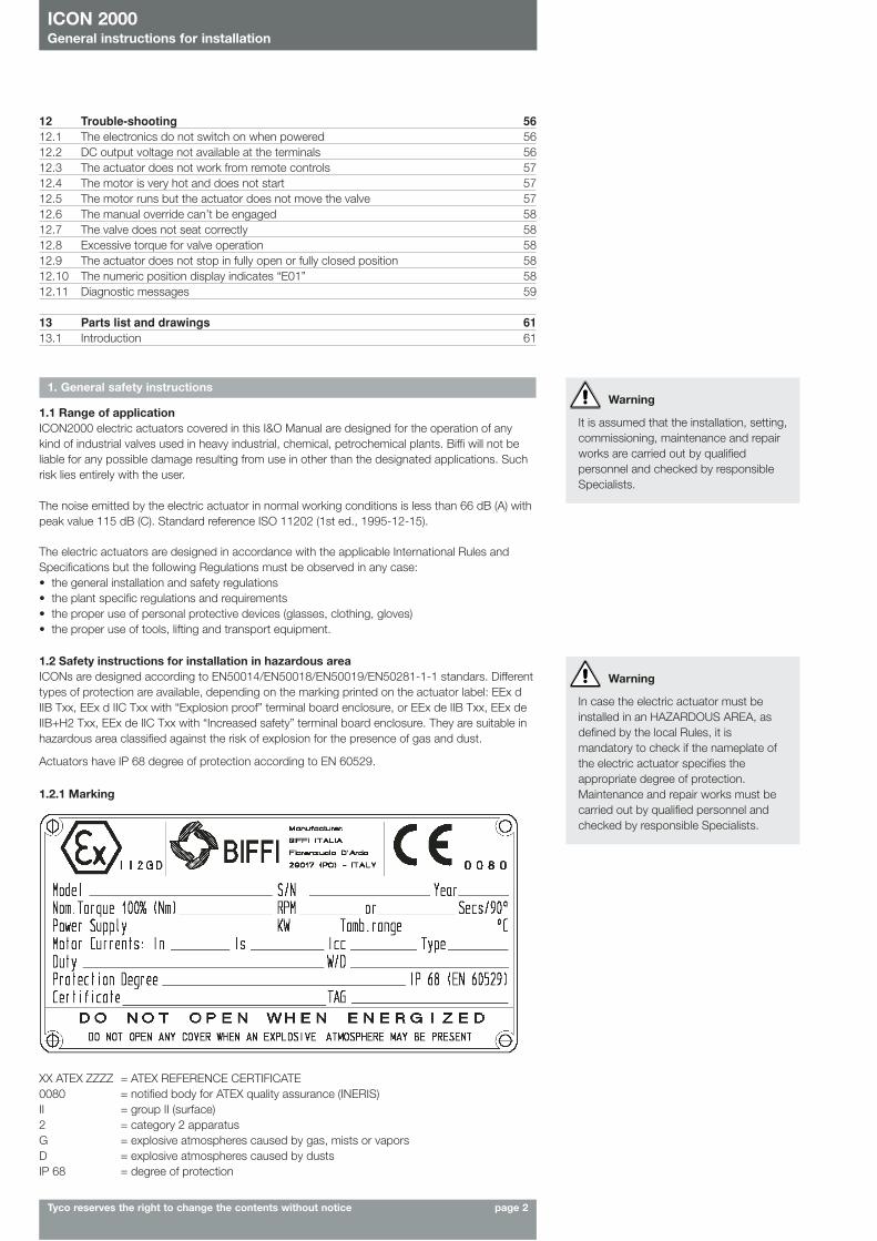
1.2.1 Marking
XX ATEX ZZZZ = ATEX REFERENCE CERTIFICATE 0080 = notified body for ATEX quality assurance (INERIS) II = group II (surface)2 = category 2 apparatus G = explosive atmospheres caused by gas, mists or vaporsD = explosive atmospheres caused by dusts IP 68 = degree of protection
ICON 2000General instructions for installation
Tyco reserves the right to change the contents without notice page 3
Hazardous zone Categories according to 94/9/CE
Directive
Gas, mists or vapours Zone 0 1GGas, mists or vapours Zone 1 2GGas, mists or vapours Zone 2 3GDust Zone 20 1DDust Zone 21 2DDust Zone 22 3D
1.3 Applicable standards and regulations EN 292/1: Safety of machinery - Basic concepts, general principles for design. Part 1-Basicterminology, methodology.EN 292/2: Safety of machinery - Basic concepts, general principles for design. Part 2-Technicalprinciples and specification.En 60204/1: Electrical equipment of industrial machines. Part 1- General requirements.EEC 98/37: Machinery directive.EEC 73/23: Low voltage directive.EEC 89/336: EMC DirectiveATEX 94/9 EEC Directive
1.4 Terms and conditionsBiffi guarantees each single product to be free from defects and to conform to current goodsspecifications. The warranty period is one year from the date of installation by the first user, oreighteen months from the date of shipment to the first user, whichever occurs first. No warranty isgiven for products or components manufactured by third-party companies, or for goods whichhave been subject to misuse, improper installation, corrosion, or which have been modified orrepaired by unauthorised personnel. Repair work due to improper use will be charged at standardrates.
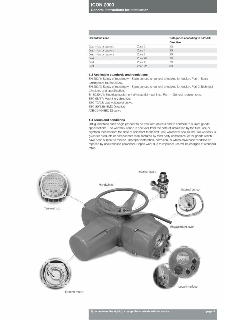
Terminal box
Electric motor
Local interface
Engagement lever
Internal sensor
Internal gears
Handwheel
ICON 2000General instructions for installation
Tyco reserves the right to change the contents without notice page 4
2. Storage and pre-installation
2.1 Tests to be carried out when the actuator is received If the actuator is received already mounted on the valve, all operations should have already beenperformed during valve/actuator assembly.- Check that the display is active.- Turn the handwheel until the valve is in a completely open position;- check that the display reads 100% indicating that the valve is completely open;- rotate the handwheel clockwise and bring the valve to a completely closed position;- check that the display reads 0% indicating that the valve is completely closed.If the test result is satisfactory, the actuator has already been adjusted and you can proceed withthe electrical connection.If the actuator is delivered separately from the valve, or the above procedure shows that theposition is incorrect, all operations described in this manual must be carried out.- Check that no damage has occurred during transport, especially to the push-buttons, the
display area glass and the selector.- Check the information on the nameplate: serial number and performance data (nominal torque,
operation speed, protection class, motor supply voltage, etc.), and verify the correspondingdata on the display (see chapter 10, View routines).
Make sure all accessories have been received with the shipment, as described in the deliverydocumentation.
2.2 Storage procedure2.2.1 GeneralThe actuator leaves the factory in perfect condition, as guaranteed by an individual test certificate.In order to maintain these characteristics until the actuator is installed on site, proper proceduresmust be taken for preservation during the storage period.BIFFI actuators are weatherproof to IP 68. This condition can only be maintained if the units arecorrectly installed/connected on site and if they have been correctly stored.The standard plastic plugs used to close the cable entries are not weatherproof, they just preventthe entry of undesired objects during transport.
2.2.2 Storage for a brief period (less than one year):2.2.2.1 Indoor storage- make sure that the actuators are kept in a dry place, laid on a wooden pallet and protected
from dust.
2.2.2.2 Outdoor storage- make sure that the actuators are protected from the direct action of weather agents (protection
by a canvas tarp or similar cover);- place the actuators on a wooden pallet, or some other raised platform, so that they are not in
direct contact with the ground;- if the actuators are supplied with standard plastic plugs, remove them from the cable entries
and replace them with weatherproof plugs.
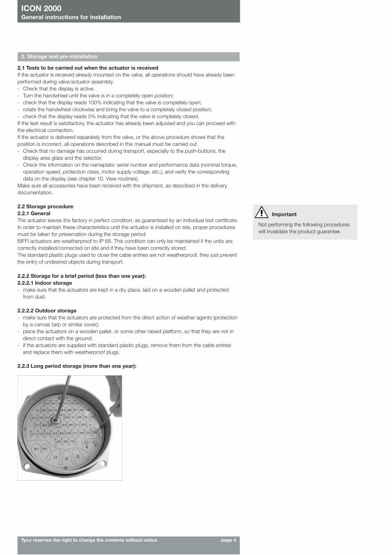
2.2.3 Long period storage (more than one year):
Important
Not performing the following procedureswill invalidate the product guarantee.
ICON 2000General instructions for installation
Tyco reserves the right to change the contents without notice page 5
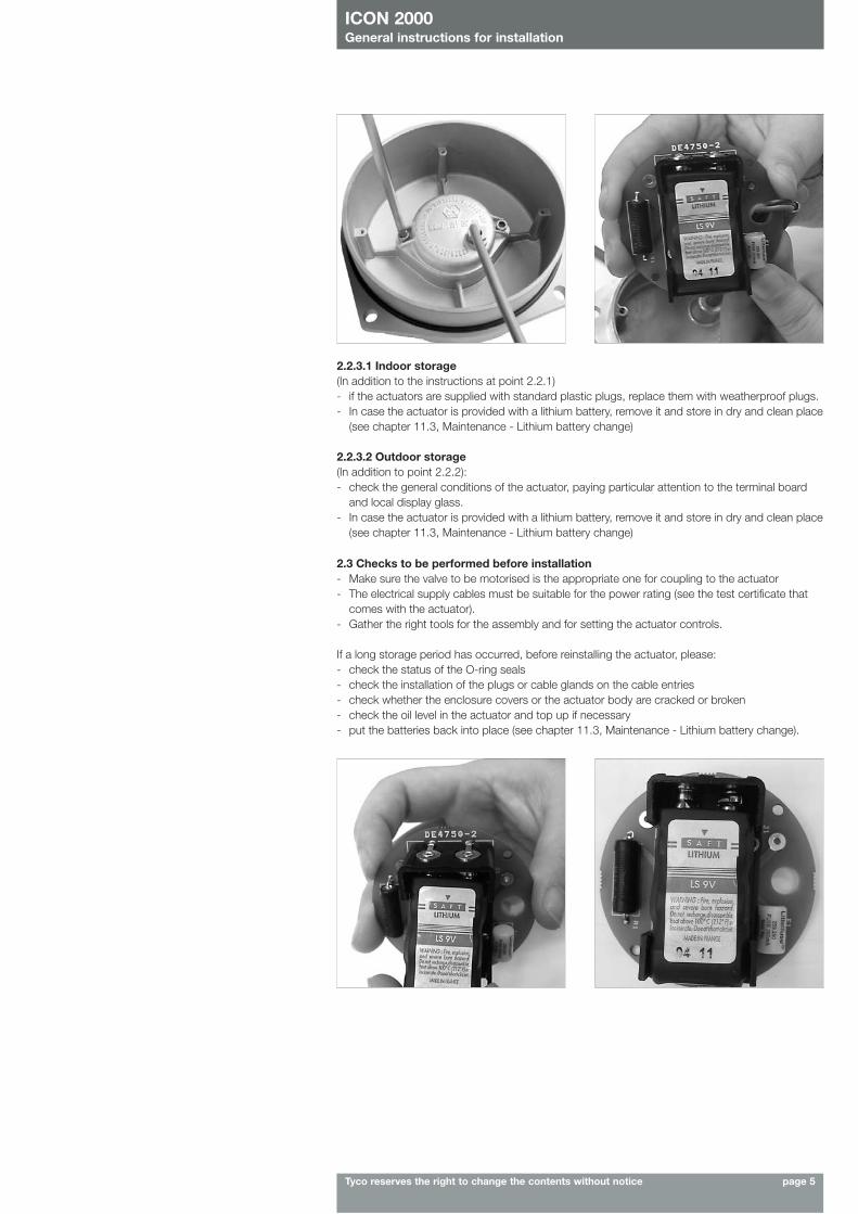
2.2.3.1 Indoor storage(In addition to the instructions at point 2.2.1)- if the actuators are supplied with standard plastic plugs, replace them with weatherproof plugs.- In case the actuator is provided with a lithium battery, remove it and store in dry and clean place
(see chapter 11.3, Maintenance - Lithium battery change)
2.2.3.2 Outdoor storage(In addition to point 2.2.2):- check the general conditions of the actuator, paying particular attention to the terminal board
and local display glass.- In case the actuator is provided with a lithium battery, remove it and store in dry and clean place
(see chapter 11.3, Maintenance - Lithium battery change)
2.3 Checks to be performed before installation- Make sure the valve to be motorised is the appropriate one for coupling to the actuator- The electrical supply cables must be suitable for the power rating (see the test certificate that
comes with the actuator).- Gather the right tools for the assembly and for setting the actuator controls.
If a long storage period has occurred, before reinstalling the actuator, please:- check the status of the O-ring seals- check the installation of the plugs or cable glands on the cable entries- check whether the enclosure covers or the actuator body are cracked or broken- check the oil level in the actuator and top up if necessary- put the batteries back into place (see chapter 11.3, Maintenance - Lithium battery change).
ICON 2000General instructions for installation
Tyco reserves the right to change the contents without notice page 6
3. Installation
3.1 Working conditionThe standard actuators are suitable for the following environment temperatures:
-30°C +85°C (-22°F to +185°F)Special versions are available for extreme environment temperatures:
-40°C +70°C (-40°F to +158°F)-55°C +70°C (-67°F to +158°F)
Note: only for EEx-de version, ambient temperature range: -25°C +65°C (-13°F to +149°F)
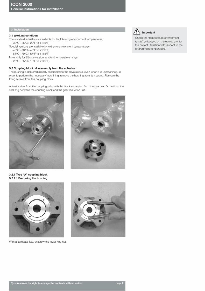
3.2 Coupling block: disassembly from the actuatorThe bushing is delivered already assembled to the drive sleeve, even when it is unmachined. Inorder to perform the necessary machining, remove the bushing from its housing. Remove thefixing screws from the coupling block.
Actuator view from the coupling side, with the block separated from the gearbox. Do not lose theseal ring between the coupling block and the gear reduction unit.
Important
Check the “temperature environmentrange” embossed on the nameplate, forthe correct utilisation with respect to theenvironment temperature.
3.2.1 Type “A” coupling block3.2.1.1 Preparing the bushing
With a compass key, unscrew the lower ring nut.
ICON 2000General instructions for installation
Tyco reserves the right to change the contents without notice page 7
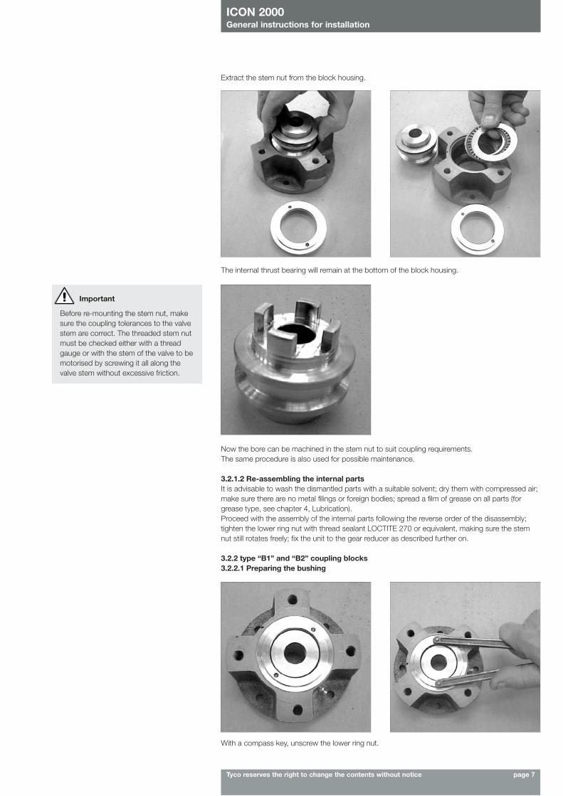
Extract the stem nut from the block housing.
The internal thrust bearing will remain at the bottom of the block housing.
Now the bore can be machined in the stem nut to suit coupling requirements.The same procedure is also used for possible maintenance.
3.2.1.2 Re-assembling the internal partsIt is advisable to wash the dismantled parts with a suitable solvent; dry them with compressed air;make sure there are no metal filings or foreign bodies; spread a film of grease on all parts (forgrease type, see chapter 4, Lubrication).Proceed with the assembly of the internal parts following the reverse order of the disassembly;tighten the lower ring nut with thread sealant LOCTITE 270 or equivalent, making sure the stemnut still rotates freely; fix the unit to the gear reducer as described further on.
3.2.2 type “B1” and “B2” coupling blocks3.2.2.1 Preparing the bushing
Important
Before re-mounting the stem nut, makesure the coupling tolerances to the valvestem are correct. The threaded stem nutmust be checked either with a threadgauge or with the stem of the valve to bemotorised by screwing it all along thevalve stem without excessive friction.
With a compass key, unscrew the lower ring nut.
ICON 2000General instructions for installation
Tyco reserves the right to change the contents without notice page 8
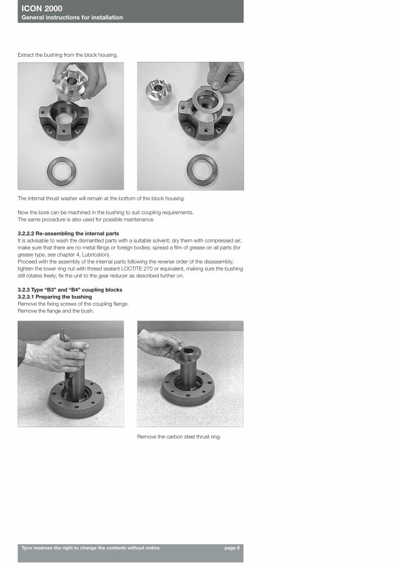
Extract the bushing from the block housing.
The internal thrust washer will remain at the bottom of the block housing.
Now the bore can be machined in the bushing to suit coupling requirements.The same procedure is also used for possible maintenance.
3.2.2.2 Re-assembling the internal partsIt is advisable to wash the dismantled parts with a suitable solvent; dry them with compressed air;make sure that there are no metal filings or foreign bodies; spread a film of grease on all parts (forgrease type, see chapter 4, Lubrication).Proceed with the assembly of the internal parts following the reverse order of the disassembly;tighten the lower ring nut with thread sealant LOCTITE 270 or equivalent, making sure the bushingstill rotates freely; fix the unit to the gear reducer as described further on.
3.2.3 Type “B3” and “B4” coupling blocks3.2.3.1 Preparing the bushingRemove the fixing screws of the coupling flange.Remove the flange and the bush.
Remove the carbon steel thrust ring.
ICON 2000General instructions for installation
Tyco reserves the right to change the contents without notice page 9
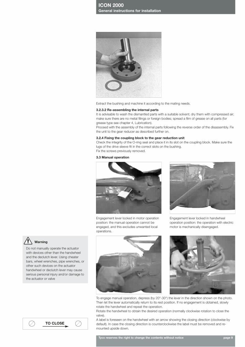
Extract the bushing and machine it according to the mating needs.
3.2.3.2 Re-assembling the internal partsIt is advisable to wash the dismantled parts with a suitable solvent; dry them with compressed air;make sure there are no metal filings or foreign bodies; spread a film of grease on all parts (forgrease type see chapter 4, Lubrication).Proceed with the assembly of the internal parts following the reverse order of the disassembly. Fixthe unit to the gear reducer as described further on.
3.2.4 Fixing the coupling block to the gear reduction unitCheck the integrity of the O-ring seal and place it in its slot on the coupling block. Make sure thelugs of the drive sleeve fit in the correct slots on the bushing. Fix the screws previously removed.
3.3 Manual operation
Engagement lever locked in motor operationposition: the manual operation cannot beengaged, and this excludes unwanted localoperations.
Engagement lever locked in handwheeloperation position: the operation with electricmotor is mechanically disengaged.
To engage manual operation, depress (by 20°-30°) the lever in the direction shown on the photo.Then let the lever automatically return to its rest position. If no engagement is obtained, slowlyrotate the handwheel and repeat the operation.Rotate the handwheel to obtain the desired operation (normally clockwise rotation to close thevalve).A label is foreseen on the handwheel with an arrow showing the closing direction (clockwise bydefault). In case the closing direction is counterclockwise the label must be removed and re-mounted upside down.
Warning
Do not manually operate the actuatorwith devices other than the handwheeland the declutch lever. Using cheaterbars, wheel wrenches, pipe wrenches, orother such devices on the actuatorhandwheel or declutch lever may causeserious personal injury and/or damage tothe actuator or valve
TO CLOSE
ICON 2000General instructions for installation
Tyco reserves the right to change the contents without notice page 10
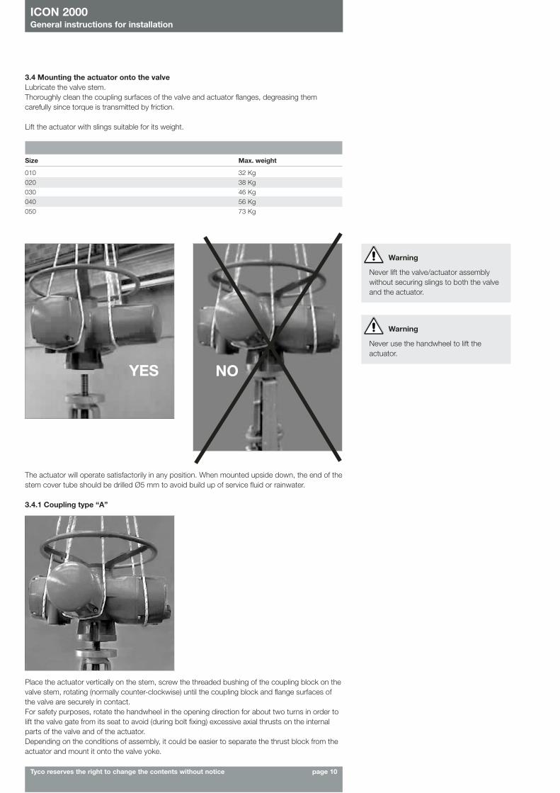
3.4 Mounting the actuator onto the valveLubricate the valve stem.Thoroughly clean the coupling surfaces of the valve and actuator flanges, degreasing themcarefully since torque is transmitted by friction.
Lift the actuator with slings suitable for its weight.
Size Max. weight
010 32 Kg020 38 Kg030 46 Kg040 56 Kg050 73 Kg
Warning
Never lift the valve/actuator assemblywithout securing slings to both the valveand the actuator.
YES NO
Warning
Never use the handwheel to lift theactuator.
The actuator will operate satisfactorily in any position. When mounted upside down, the end of thestem cover tube should be drilled Ø5 mm to avoid build up of service fluid or rainwater.
3.4.1 Coupling type “A”
Place the actuator vertically on the stem, screw the threaded bushing of the coupling block on thevalve stem, rotating (normally counter-clockwise) until the coupling block and flange surfaces ofthe valve are securely in contact.For safety purposes, rotate the handwheel in the opening direction for about two turns in order tolift the valve gate from its seat to avoid (during bolt fixing) excessive axial thrusts on the internalparts of the valve and of the actuator.Depending on the conditions of assembly, it could be easier to separate the thrust block from theactuator and mount it onto the valve yoke.
ICON 2000General instructions for installation
Tyco reserves the right to change the contents without notice page 11
3.4.2 Couplings type “B1”, “B2”,”B3” and “B4”Check the dimensions of the valve mounting details, paying particular attention to the protrusionsof the valve stem in order to avoid any axial thrusts to the internal parts of the actuator or the valvewhen the screws are tightened.Engage the manual operation. Place the actuator vertically on the valve stem. Carry out thecoupling operations (if necessary with the help of manual operation); make sure no mating partsare forced.
3.4.3 Actuator fixing
Model Tightening torque
010 40 Nm020 150 Nm030 150 Nm040 300 Nm050 150 Nm
Important
In case the actuator is supplied withoutstud bolts and nuts the followingmaterials must be used as a minimum:- ISO class 8.8 for studs bolts and nuts or• ASTM A 320 Grade L7 (or L7M) for
studs bolts• ASTM A 194 Grade 4 for nuts
3.5. Electrical connectionsBefore powering the actuator check that the supply voltage details on the nameplate are correctfor the plant. Access to terminals for electrical connections and commissioning is through theterminal cover, since all settings are non-intrusive. The removal of any other covers without Biffi’sapproval will invalidate the warranty. Biffi will not accept any responsibility for any damage or deterioration that may be caused.
3.5.1 Plants requirementsProtection devices (overcurrent breakers, magneto-thermal switches or fuses) should be providedon the plant at Customer care, to protect the mains line in case of motor overcurrent or loss ofinsulation between phases and earth.
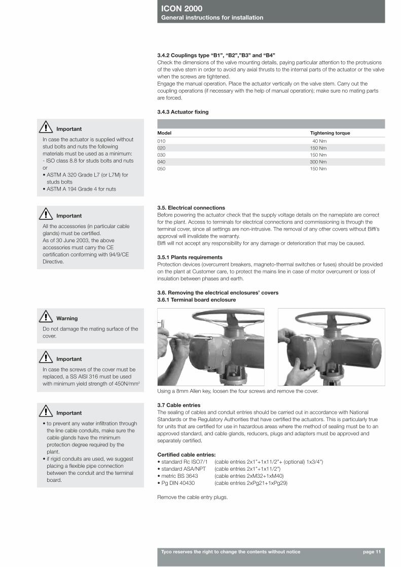
3.6. Removing the electrical enclosures’ covers3.6.1 Terminal board enclosure
Important
All the accessories (in particular cableglands) must be certified.As of 30 June 2003, the aboveaccessories must carry the CEcertification conforming with 94/9/CEDirective.
Using a 8mm Allen key, loosen the four screws and remove the cover.
3.7 Cable entriesThe sealing of cables and conduit entries should be carried out in accordance with NationalStandards or the Regulatory Authorities that have certified the actuators. This is particularly truefor units that are certified for use in hazardous areas where the method of sealing must be to anapproved standard, and cable glands, reducers, plugs and adapters must be approved andseparately certified.
Certified cable entries:• standard Rc ISO7/1 (cable entries 2x1”+1x11/2”+ (optional) 1x3/4”)• standard ASA/NPT (cable entries 2x1”+1x11/2”)• metric BS 3643 (cable entries 2xM32+1xM40)• Pg DIN 40430 (cable entries 2xPg21+1xPg29)
Remove the cable entry plugs.
Warning
Do not damage the mating surface of thecover.
Important
In case the screws of the cover must bereplaced, a SS AISI 316 must be usedwith minimum yield strength of 450N/mm2
Important
• to prevent any water infiltration throughthe line cable conduits, make sure thecable glands have the minimumprotection degree required by theplant.
• if rigid conduits are used, we suggestplacing a flexible pipe connectionbetween the conduit and the terminalboard.
ICON 2000General instructions for installation
Tyco reserves the right to change the contents without notice page 12
To guarantee weatherproof and explosionproof fit, screw the cable glands tightly (at least 5 turns)and block them with a thread sealant. The use of a thread sealant is necessary in case ofexplosionproof and weatherproof application.
If some parts of the cable glands have been removed while working on the cable entries put themback into place now to avoid losing the dismantled parts.Unused entries:• for explosionproof construction: unused entries must be plugged with metal explosionproof
plugs and blocked with a thread sealant• for weatherproof construction: replace the plastic standard protection plugs supplied with the
actuator with metal plugs.
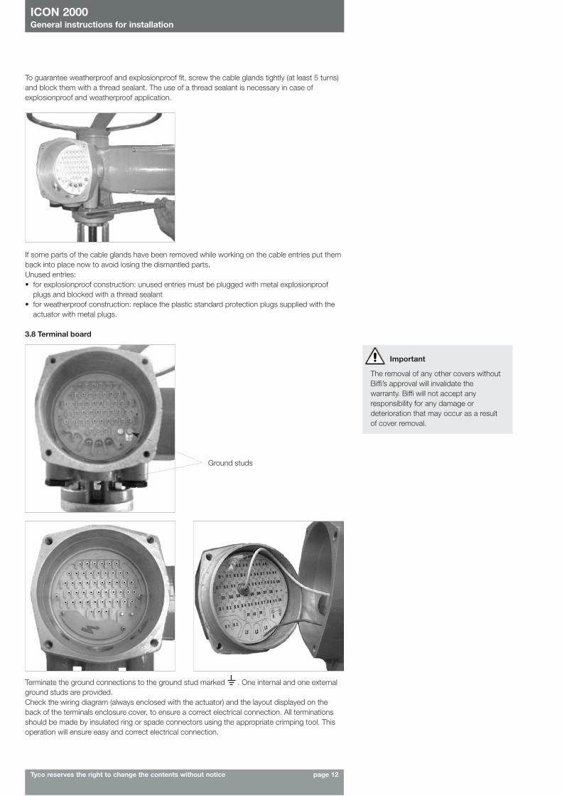
3.8 Terminal board
Important
The removal of any other covers withoutBiffi’s approval will invalidate thewarranty. Biffi will not accept anyresponsibility for any damage ordeterioration that may occur as a resultof cover removal.
Ground studs
Terminate the ground connections to the ground stud marked . One internal and one externalground studs are provided.Check the wiring diagram (always enclosed with the actuator) and the layout displayed on theback of the terminals enclosure cover, to ensure a correct electrical connection. All terminationsshould be made by insulated ring or spade connectors using the appropriate crimping tool. Thisoperation will ensure easy and correct electrical connection.
ICON 2000General instructions for installation
Tyco reserves the right to change the contents without notice page 13
Connect the motor supply cable previously sized in accordance with: - the absorbed current correspondent to the actuator nominal torque with the torque limiting
device set at 100 percent (see the test certificate attached to the actuator)- the applicable plant and safety norms.Assemble the power terminals protective barrier, located in the terminal board compartment, usingthe enclosed screws.The control circuit (controls and signals) must be connected by means of a multicore cable to thecorresponding numbered terminals according to the wiring diagram.The internal cables of the actuator are also numbered according to the wiring diagram.Actuators are always delivered with the motors wound and connected in accordance to customerrequests. Voltage and frequency values are stated on the motor name-plate.
3.9 Instructions for the explosionproof enclosures
During the dismantling and subsequent reassembling of the explosionproof enclosures (covers,cable glands, joints) be careful to bring these enclosures back to their original condition tomaintain their integrity. In particular, be sure the joint surfaces of all enclosures are spread with afilm of recommended grease (see chapter 4, Lubrication).So please:
• Do not damage the explosionproof mating surfaces on the housing and on the electricalenclosures covers.
• Reinstall all the screws that go with the dismantled parts, and block them with a thread sealantafter spreading them with a film of copper- or molybdenum-based grease. This will keep screwsfrom sticking and make maintenance operations easier.
• Check that the bolts and screws are the same dimension and quality as the original ones (asstated on the nameplate), or of a better quality.
• Replace the weatherproof seals that may have been removed (O-ring for the covers, O-ring forthe explosionproof joint of the motor).
When the EEX-de version is supplied, according to the protection degree shown on thenameplate, waterproof cableglands with a minimum IP54 protection degree can be used.
Please make sure that: • the joint surfaces are greased with silicone oil or equivalent before assembly• the cable glands have minimum protection degree IP6X (EN 60529)• periodically verify the quantity of dust deposited on the enclosure and clean it if more than
5mm.
3.10 Installation in environment with explosive dusts
Important
Electric actuator ICON2000 shall be installed and maintained according to the applicablerules regarding the electrical installations in hazardous area (other than mines) classified aszone 1 (gas); example: EN 60079-10 (hazardous area classification), EN 60079-14 (electricalinstallation), EN 60079-17 (maintenance), and/or other national standards).
Warning
Do not operate the actuator electrically when the electrical enclosures are removed.Operating the unit with the electrical enclosures removed could cause personal injury.
Important
Electric actuator ICON2000 shall be installed and maintained; according to the applicablerules regarding the electrical installations in hazardous area (other than mines) classified aszone 21 (dust); example: EN 50281-1-2 (dust) and/or other national standards).
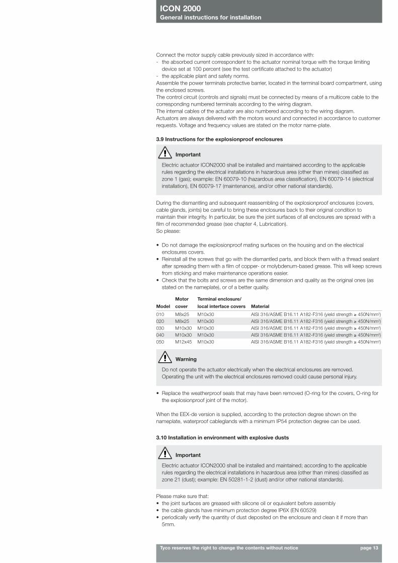
Motor Terminal enclosure/
Model cover local interface covers Material
010 M8x25 M10x30 AISI 316/ASME B16.11 A182-F316 (yield strength ≥ 450N/mm2)020 M8x25 M10x30 AISI 316/ASME B16.11 A182-F316 (yield strength ≥ 450N/mm2)030 M10x30 M10x30 AISI 316/ASME B16.11 A182-F316 (yield strength ≥ 450N/mm2)040 M10x30 M10x30 AISI 316/ASME B16.11 A182-F316 (yield strength ≥ 450N/mm2)050 M12x45 M10x30 AISI 316/ASME B16.11 A182-F316 (yield strength ≥ 450N/mm2)
ICON 2000General instructions for installation
Tyco reserves the right to change the contents without notice page 14
1
3
2
4. Lubrication
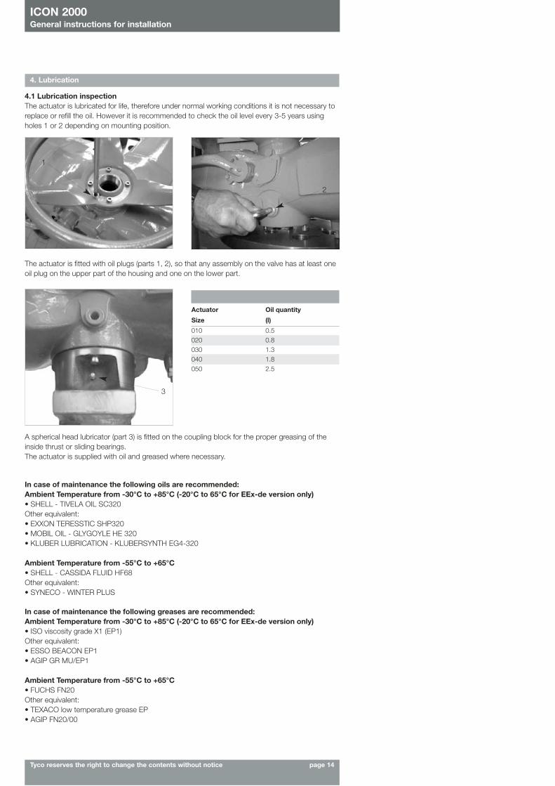
4.1 Lubrication inspectionThe actuator is lubricated for life, therefore under normal working conditions it is not necessary toreplace or refill the oil. However it is recommended to check the oil level every 3-5 years usingholes 1 or 2 depending on mounting position.
The actuator is fitted with oil plugs (parts 1, 2), so that any assembly on the valve has at least oneoil plug on the upper part of the housing and one on the lower part.
A spherical head lubricator (part 3) is fitted on the coupling block for the proper greasing of theinside thrust or sliding bearings.The actuator is supplied with oil and greased where necessary.
Actuator Oil quantity
Size (l)
010 0.5020 0.8030 1.3040 1.8050 2.5
In case of maintenance the following oils are recommended:Ambient Temperature from -30°C to +85°C (-20°C to 65°C for EEx-de version only)• SHELL - TIVELA OIL SC320Other equivalent:• EXXON TERESSTIC SHP320• MOBIL OIL - GLYGOYLE HE 320• KLUBER LUBRICATION - KLUBERSYNTH EG4-320
Ambient Temperature from -55°C to +65°C • SHELL - CASSIDA FLUID HF68Other equivalent:• SYNECO - WINTER PLUS
In case of maintenance the following greases are recommended:Ambient Temperature from -30°C to +85°C (-20°C to 65°C for EEx-de version only)• ISO viscosity grade X1 (EP1)Other equivalent:• ESSO BEACON EP1• AGIP GR MU/EP1
Ambient Temperature from -55°C to +65°C• FUCHS FN20Other equivalent:• TEXACO low temperature grease EP• AGIP FN20/00
ICON 2000Operation and configuration
Tyco reserves the right to change the contents without notice page 15
5. Operating the ICON2000
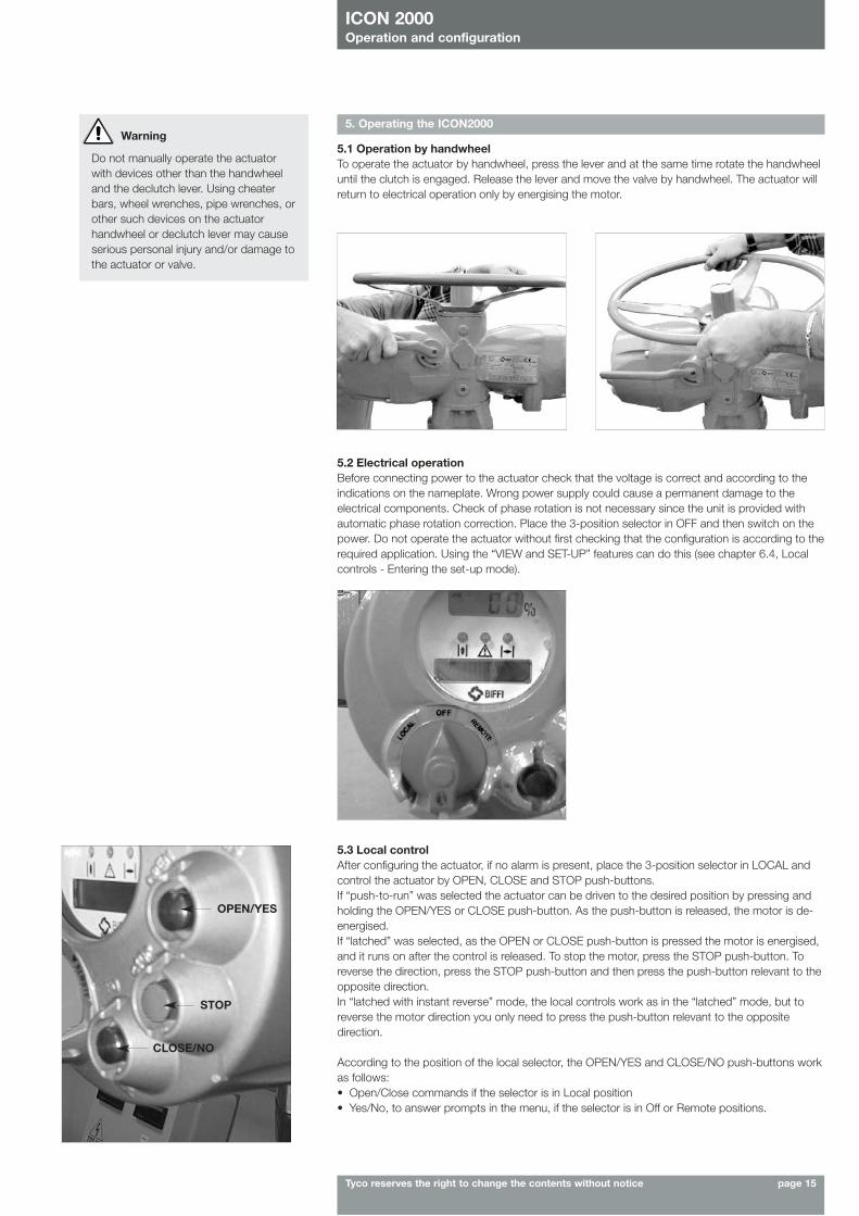
5.1 Operation by handwheelTo operate the actuator by handwheel, press the lever and at the same time rotate the handwheeluntil the clutch is engaged. Release the lever and move the valve by handwheel. The actuator willreturn to electrical operation only by energising the motor.
Warning
Do not manually operate the actuatorwith devices other than the handwheeland the declutch lever. Using cheaterbars, wheel wrenches, pipe wrenches, orother such devices on the actuatorhandwheel or declutch lever may causeserious personal injury and/or damage tothe actuator or valve.
5.2 Electrical operationBefore connecting power to the actuator check that the voltage is correct and according to theindications on the nameplate. Wrong power supply could cause a permanent damage to theelectrical components. Check of phase rotation is not necessary since the unit is provided withautomatic phase rotation correction. Place the 3-position selector in OFF and then switch on thepower. Do not operate the actuator without first checking that the configuration is according to therequired application. Using the “VIEW and SET-UP” features can do this (see chapter 6.4, Localcontrols - Entering the set-up mode).
5.3 Local controlAfter configuring the actuator, if no alarm is present, place the 3-position selector in LOCAL andcontrol the actuator by OPEN, CLOSE and STOP push-buttons.If “push-to-run” was selected the actuator can be driven to the desired position by pressing andholding the OPEN/YES or CLOSE push-button. As the push-button is released, the motor is de-energised.If “latched” was selected, as the OPEN or CLOSE push-button is pressed the motor is energised,and it runs on after the control is released. To stop the motor, press the STOP push-button. Toreverse the direction, press the STOP push-button and then press the push-button relevant to theopposite direction. In “latched with instant reverse” mode, the local controls work as in the “latched” mode, but toreverse the motor direction you only need to press the push-button relevant to the oppositedirection.
According to the position of the local selector, the OPEN/YES and CLOSE/NO push-buttons workas follows:• Open/Close commands if the selector is in Local position• Yes/No, to answer prompts in the menu, if the selector is in Off or Remote positions.
OPEN/YES
STOP
CLOSE/NO
ICON 2000Operation and configuration
Tyco reserves the right to change the contents without notice page 16
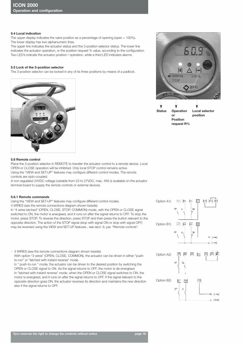
5.4 Local indicationThe upper display indicates the valve position as a percentage of opening (open = 100%). The lower display has two alphanumeric lines. The upper line indicates the actuator status and the 3-position selector status. The lower lineindicates the actuator operation, or the position request % value, according to the configuration.Two LED’s indicate the actuator position / operation, while a third LED indicates alarms.
5.5 Lock of the 3-position selectorThe 3-position selector can be locked in any of its three positions by means of a padlock.
5.6 Remote controlPlace the 3-position selector in REMOTE to transfer the actuator control to a remote device. LocalOPEN or CLOSE operation will be inhibited. Only local STOP control remains active.Using the “VIEW and SET-UP” features may configure different control modes. The remotecontrols are opto-coupled. A non-regulated 24VDC voltage (variable from 23 to 27VDC, max. 4W) is available on the actuatorterminal board to supply the remote controls or external devices.
5.6.1 Remote commandsUsing the “VIEW and SET-UP” features may configure different control modes. 4 WIRES (see the remote connections diagram shown beside)In “4 wires latched” (OPEN, CLOSE, STOP, COMMON) mode, with the OPEN or CLOSE signalswitched to ON, the motor is energised, and it runs on after the signal returns to OFF. To stop themotor, press STOP. To reverse the direction, press STOP and then press the button relevant to theopposite direction. The action of the STOP signal (stop with signal ON or stop with signal OFF)may be reversed using the VIEW and SET-UP features , see sect. 9, par. “Remote controls”.
Option A1)
Option B1)
- 3 WIRES (see the remote connections diagram shown beside)With option “3 wires” (OPEN, CLOSE, COMMON), the actuator can be driven in either “push-to-run” or “latched with instant reverse” mode.In “ push-to-run ” mode, the actuator can be driven to the desired position by switching theOPEN or CLOSE signal to ON. As the signal returns to OFF, the motor is de-energised.In “latched with instant reverse” mode, when the OPEN or CLOSE signal switches to ON, themotor is energised, and it runs on after the signal returns to OFF. If the signal relevant to theopposite direction goes ON, the actuator reverses its direction and maintains the new directionalso if the signal returns to OFF.
Option A2)
Option B2)
Status Operation orPositionrequest R%
Local selector position
ICON 2000Operation and configuration
Tyco reserves the right to change the contents without notice page 17
The circuits associated to the inputs can be supplied by the internally-generated 24VDC or by an external 20-125VDC or 20-120VAC (50/60Hz). The signal levels are the following:• Minimum ON signal > 20 VDC or 20 VAC (50/60Hz)• Maximum ON signal < 125 VDC or 120 VAC (50/60Hz)• Maximum OFF signal < 3 V• Minimum signal duration > 500 ms.• Total current drawn from remote controls < 25mA5.6.2 Output contacts• Monitor relay: on the terminal board, the voltage-free, change-over contacts of the monitor relay are
available. The monitor relay indicates that the actuator can be remotely controlled or that there is aproblem or condition which prevents remote control of the valve. The conditions that cause therelay to switch over are listed in paragraph “Output relays”.
• AS1,2,3,4,5,6,7 relays: on the terminal board, the voltage-free contacts of 7 latching relays areavailable. The status (make or break) and the conditions that cause the switching of the relay canbe viewed and configured by using the “VIEW and SET-UP” features. The status of the latchingrelays is immediately updated as the associated conditions for change occur. Moreover, the statusof the above contacts is cyclically updated (every second).
• AS8 relay: a further voltage-free, change-over contact is available on the terminal board. The conditions that cause the switching of the relay can be viewed and configured by using the“VIEW and SET-UP” features.
• Contact rating: Max. voltage 250VAC/30VDC max. current 5AMin. voltage 5VDC min. current 5mA
Special Version with highly sensitive gold-plated contact relays supplied on request:• Monitor relay: voltage-free, change-over, gold-cap silver palladium contacts.• AS1, 2, 3 relays: voltage-free, change-over, latching, gold-cap silver palladium contacts.• AS4 relay: voltage-free, latching, gold-cap silver palladium contacts, configurable N.O. or N.C. in the
"Output relays" menu.• AS5, 6 relays: voltage-free, change-over, gold-cap silver palladium contacts.• The conditions that cause the switching over of the monitor relay and auxiliary relays AS1...AS6 are
the same of the standard version and are configurable in the "Outout relays" menu.• AS7, 8 relays: not available.• Contact rating: max voltage 250VAC; max current 2A; min switching capability 10 microA,
10mVDC.
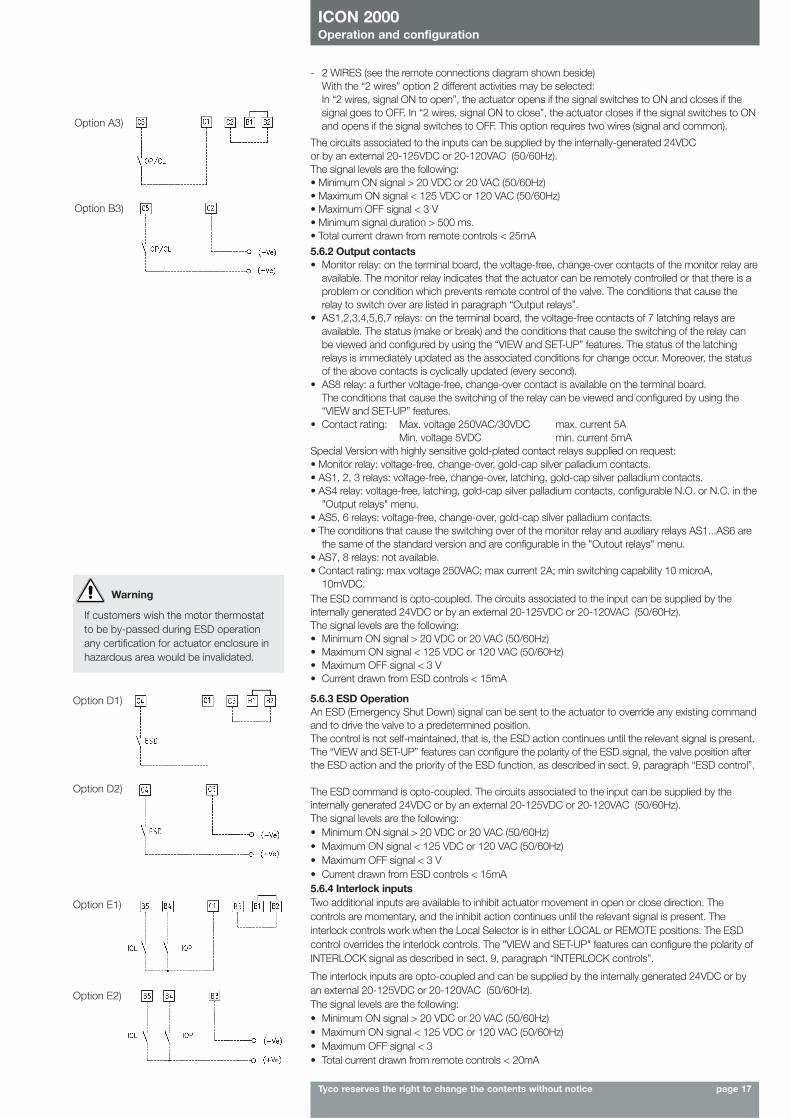
- 2 WIRES (see the remote connections diagram shown beside)With the “2 wires” option 2 different activities may be selected:In “2 wires, signal ON to open”, the actuator opens if the signal switches to ON and closes if thesignal goes to OFF. In “2 wires, signal ON to close”, the actuator closes if the signal switches to ONand opens if the signal switches to OFF. This option requires two wires (signal and common).Option A3)
Option B3)
5.6.3 ESD OperationAn ESD (Emergency Shut Down) signal can be sent to the actuator to override any existing commandand to drive the valve to a predetermined position.The control is not self-maintained, that is, the ESD action continues until the relevant signal is present.The “VIEW and SET-UP” features can configure the polarity of the ESD signal, the valve position afterthe ESD action and the priority of the ESD function, as described in sect. 9, paragraph “ESD control”.
The ESD command is opto-coupled. The circuits associated to the input can be supplied by theinternally generated 24VDC or by an external 20-125VDC or 20-120VAC (50/60Hz). The signal levels are the following:• Minimum ON signal > 20 VDC or 20 VAC (50/60Hz)• Maximum ON signal < 125 VDC or 120 VAC (50/60Hz)• Maximum OFF signal < 3 V• Current drawn from ESD controls < 15mA
The ESD command is opto-coupled. The circuits associated to the input can be supplied by theinternally generated 24VDC or by an external 20-125VDC or 20-120VAC (50/60Hz). The signal levels are the following:• Minimum ON signal > 20 VDC or 20 VAC (50/60Hz)• Maximum ON signal < 125 VDC or 120 VAC (50/60Hz)• Maximum OFF signal < 3 V• Current drawn from ESD controls < 15mA
Warning
If customers wish the motor thermostatto be by-passed during ESD operationany certification for actuator enclosure inhazardous area would be invalidated.
5.6.4 Interlock inputsTwo additional inputs are available to inhibit actuator movement in open or close direction. Thecontrols are momentary, and the inhibit action continues until the relevant signal is present. Theinterlock controls work when the Local Selector is in either LOCAL or REMOTE positions. The ESDcontrol overrides the interlock controls. The "VIEW and SET-UP" features can configure the polarity ofINTERLOCK signal as described in sect. 9, paragraph “INTERLOCK controls”.
The interlock inputs are opto-coupled and can be supplied by the internally generated 24VDC or byan external 20-125VDC or 20-120VAC (50/60Hz). The signal levels are the following:• Minimum ON signal > 20 VDC or 20 VAC (50/60Hz)• Maximum ON signal < 125 VDC or 120 VAC (50/60Hz)• Maximum OFF signal < 3• Total current drawn from remote controls < 20mA
Option D1)
Option D2)
Option E1)
Option E2)
ICON 2000Operation and configuration
Tyco reserves the right to change the contents without notice page 18
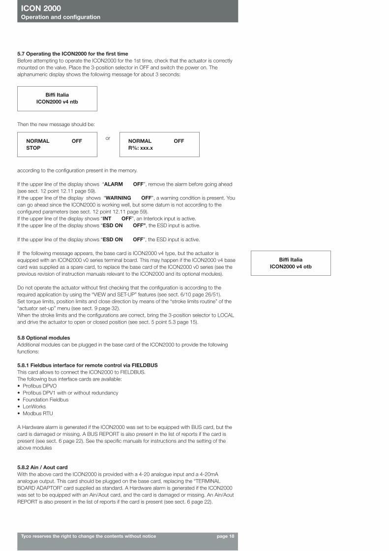
5.7 Operating the ICON2000 for the first timeBefore attempting to operate the ICON2000 for the 1st time, check that the actuator is correctlymounted on the valve. Place the 3-position selector in OFF and switch the power on. Thealphanumeric display shows the following message for about 3 seconds:
5.8 Optional modulesAdditional modules can be plugged in the base card of the ICON2000 to provide the followingfunctions:
5.8.1 Fieldbus interface for remote control via FIELDBUSThis card allows to connect the ICON2000 to FIELDBUS.The following bus interface cards are available:• Profibus DPVO• Profibus DPV1 with or without redundancy• Foundation Fieldbus• LonWorks• Modbus RTU
A Hardware alarm is generated if the ICON2000 was set to be equipped with BUS card, but thecard is damaged or missing. A BUS REPORT is also present in the list of reports if the card ispresent (see sect. 6 page 22). See the specific manuals for instructions and the setting of theabove modules
Biffi ItaliaICON2000 v4 ntb
NORMAL OFFSTOP
NORMAL OFFR%: xxx.x
Then the new message should be:
or
according to the configuration present in the memory.
If the upper line of the display shows “ALARM OFF”, remove the alarm before going ahead(see sect. 12 point 12.11 page 59).If the upper line of the display shows “WARNING OFF”, a warning condition is present. Youcan go ahead since the ICON2000 is working well, but some datum is not according to theconfigured parameters (see sect. 12 point 12.11 page 59).If the upper line of the display shows “INT OFF”, an Interlock input is active. If the upper line of the display shows “ESD ON OFF”, the ESD input is active.
If the upper line of the display shows “ESD ON OFF”, the ESD input is active.
If the following message appears, the base card is ICON2000 v4 type, but the actuator isequipped with an ICON2000 v0 series terminal board. This may happen if the ICON2000 v4 basecard was supplied as a spare card, to replace the base card of the ICON2000 v0 series (see theprevious revision of instruction manuals relevant to the ICON2000 and its optional modules).
Do not operate the actuator without first checking that the configuration is according to therequired application by using the “VIEW and SET-UP” features (see sect. 6/10 page 26/51).Set torque limits, position limits and close direction by means of the “stroke limits routine” of the“actuator set-up” menu (see sect. 9 page 32).When the stroke limits and the configurations are correct, bring the 3-position selector to LOCALand drive the actuator to open or closed position (see sect. 5 point 5.3 page 15).
Biffi ItaliaICON2000 v4 otb
5.8.2 Ain / Aout cardWith the above card the ICON2000 is provided with a 4-20 analogue input and a 4-20mAanalogue output. This card should be plugged on the base card, replacing the “TERMINALBOARD ADAPTOR” card supplied as standard. A Hardware alarm is generated if the ICON2000was set to be equipped with an Ain/Aout card, and the card is damaged or missing. An Ain/AoutREPORT is also present in the list of reports if the card is present (see sect. 6 page 22).
ICON 2000Operation and configuration
Tyco reserves the right to change the contents without notice page 19
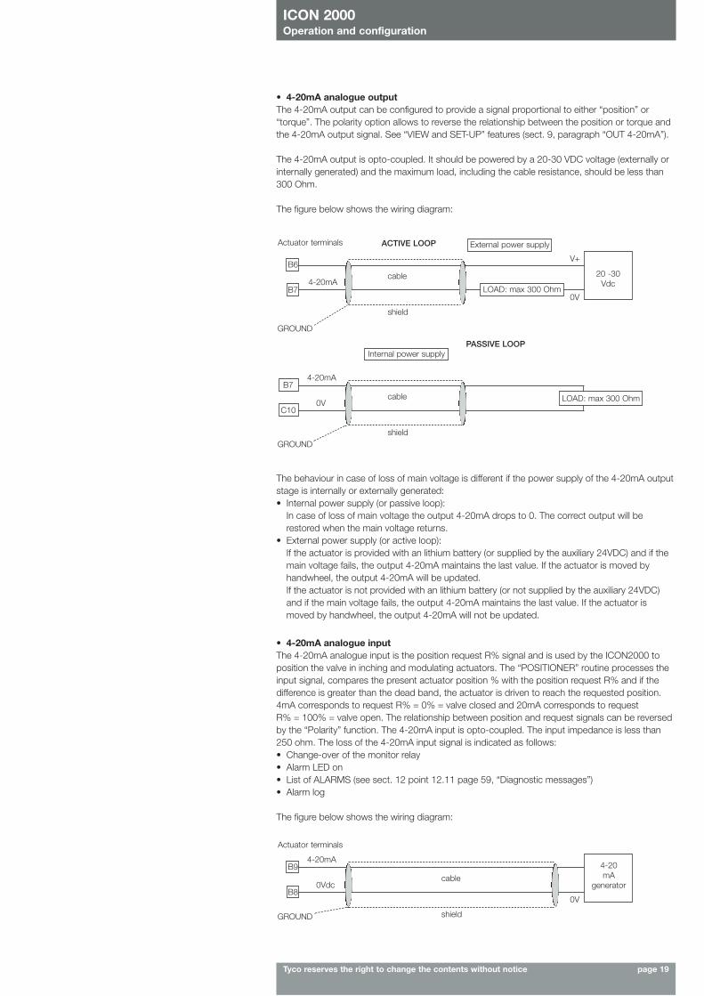
• 4-20mA analogue outputThe 4-20mA output can be configured to provide a signal proportional to either “position” or“torque”. The polarity option allows to reverse the relationship between the position or torque andthe 4-20mA output signal. See “VIEW and SET-UP” features (sect. 9, paragraph “OUT 4-20mA”).
The 4-20mA output is opto-coupled. It should be powered by a 20-30 VDC voltage (externally orinternally generated) and the maximum load, including the cable resistance, should be less than300 Ohm.
The figure below shows the wiring diagram:
Actuator terminals ACTIVE LOOP
PASSIVE LOOP
cable
0V
4-20mA
B6
B7
GROUND
shield
20 -30Vdc
External power supply
LOAD: max 300 Ohm
Internal power supply
cable0V
V+
4-20mAB7
C10
GROUNDshield
LOAD: max 300 Ohm
The behaviour in case of loss of main voltage is different if the power supply of the 4-20mA outputstage is internally or externally generated:• Internal power supply (or passive loop):
In case of loss of main voltage the output 4-20mA drops to 0. The correct output will berestored when the main voltage returns.
• External power supply (or active loop):If the actuator is provided with an lithium battery (or supplied by the auxiliary 24VDC) and if themain voltage fails, the output 4-20mA maintains the last value. If the actuator is moved byhandwheel, the output 4-20mA will be updated.If the actuator is not provided with an lithium battery (or not supplied by the auxiliary 24VDC)and if the main voltage fails, the output 4-20mA maintains the last value. If the actuator ismoved by handwheel, the output 4-20mA will not be updated.
• 4-20mA analogue inputThe 4-20mA analogue input is the position request R% signal and is used by the ICON2000 toposition the valve in inching and modulating actuators. The “POSITIONER” routine processes theinput signal, compares the present actuator position % with the position request R% and if thedifference is greater than the dead band, the actuator is driven to reach the requested position.4mA corresponds to request R% = 0% = valve closed and 20mA corresponds to request R% = 100% = valve open. The relationship between position and request signals can be reversedby the “Polarity” function. The 4-20mA input is opto-coupled. The input impedance is less than250 ohm. The loss of the 4-20mA input signal is indicated as follows:• Change-over of the monitor relay• Alarm LED on• List of ALARMS (see sect. 12 point 12.11 page 59, “Diagnostic messages”)• Alarm log
The figure below shows the wiring diagram:
Actuator terminals
cable0Vdc
0V
4-20mAB9
B8
GROUND shield
4-20mA
generator

ICON 2000Operation and configuration
Tyco reserves the right to change the contents without notice page 20
The "VIEW and SET-UP" features can configure different options which are described in sect. 9,paragraph “POSITIONER”.
If the POSITIONER function is active the alpha-numeric display indicates the value of the positionrequest in % (R%: xxx.x).
Ain / Aout card This optional card is used in place of the Terminal Board Adaptor (TBA) card when an analogue 4-20mA input and output signal is requested. This card cannot be used in the actuators withterminal board series ICON2000 v0 (see sect. 5, point 5.7 page 18, “Operating the ICON2000 forthe first time”).
37,5
5.8.3 BLUETOOTH™ cardThe ICON2000 can be provided with a radiofrequency wireless connection based on a qualifiedBLUETOOTH™ class 1 module. This allows to establish a connection and exchange data with aPDA or PC with built-in BLUETOOTH™ technology. Special PDA’s are available for application inhazardous areas.The following tasks can be wirelessly performed:• View and change configuration• Set maintenance function• Read maintenance data• Download new firmware to the ICON2000
A WIRELESS REPORT is present in the list of reports when the card is present (see sect. 6 page22).
5.9 Base card of the ICON2000 v4
Bottom view of base card
Terminal Board Adaptor card
(TBA)
NORMAL REMOTE R:47% next?
ICON 2000Operation and configuration
Tyco reserves the right to change the contents without notice page 21
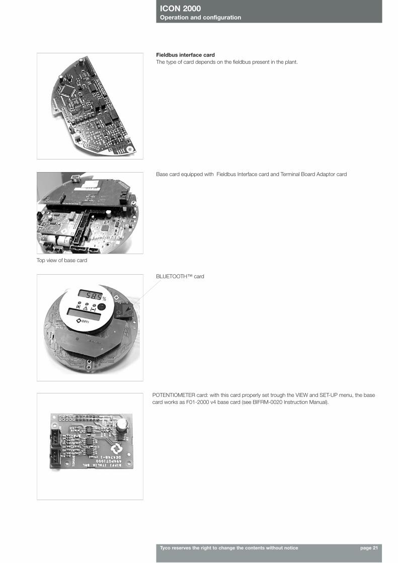
Fieldbus interface cardThe type of card depends on the fieldbus present in the plant.
Base card equipped with Fieldbus Interface card and Terminal Board Adaptor card
Top view of base card
BLUETOOTH™ card
POTENTIOMETER card: with this card properly set trough the VIEW and SET-UP menu, the basecard works as F01-2000 v4 base card (see BIFRM-0020 Instruction Manual).
ICON 2000Operation and configuration
Tyco reserves the right to change the contents without notice page 22
6. Local controls
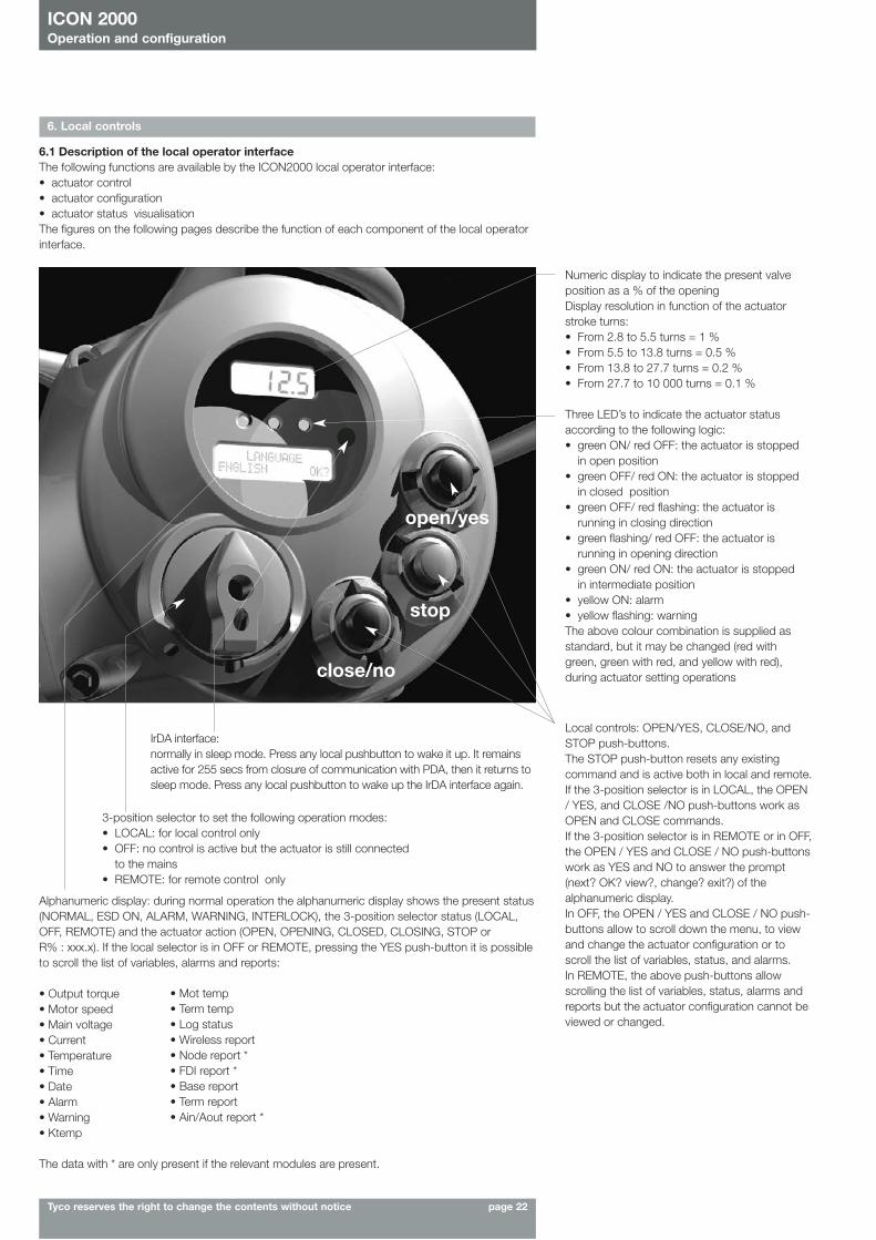
6.1 Description of the local operator interfaceThe following functions are available by the ICON2000 local operator interface:• actuator control• actuator configuration• actuator status visualisationThe figures on the following pages describe the function of each component of the local operatorinterface.
Numeric display to indicate the present valveposition as a % of the openingDisplay resolution in function of the actuatorstroke turns:• From 2.8 to 5.5 turns = 1 % • From 5.5 to 13.8 turns = 0.5 %• From 13.8 to 27.7 turns = 0.2 % • From 27.7 to 10 000 turns = 0.1 %
Three LED’s to indicate the actuator statusaccording to the following logic:• green ON/ red OFF: the actuator is stopped
in open position• green OFF/ red ON: the actuator is stopped
in closed position• green OFF/ red flashing: the actuator is
running in closing direction• green flashing/ red OFF: the actuator is
running in opening direction• green ON/ red ON: the actuator is stopped
in intermediate position• yellow ON: alarm • yellow flashing: warning The above colour combination is supplied asstandard, but it may be changed (red withgreen, green with red, and yellow with red),during actuator setting operations
3-position selector to set the following operation modes:• LOCAL: for local control only• OFF: no control is active but the actuator is still connected
to the mains• REMOTE: for remote control only
Alphanumeric display: during normal operation the alphanumeric display shows the present status(NORMAL, ESD ON, ALARM, WARNING, INTERLOCK), the 3-position selector status (LOCAL,OFF, REMOTE) and the actuator action (OPEN, OPENING, CLOSED, CLOSING, STOP or R% : xxx.x). If the local selector is in OFF or REMOTE, pressing the YES push-button it is possibleto scroll the list of variables, alarms and reports:
• Output torque• Motor speed• Main voltage• Current• Temperature• Time• Date• Alarm• Warning• Ktemp
The data with * are only present if the relevant modules are present.
close/no
stop
open/yes
IrDA interface:normally in sleep mode. Press any local pushbutton to wake it up. It remainsactive for 255 secs from closure of communication with PDA, then it returns tosleep mode. Press any local pushbutton to wake up the IrDA interface again.
• Mot temp• Term temp• Log status• Wireless report• Node report *• FDI report *• Base report• Term report• Ain/Aout report *
Local controls: OPEN/YES, CLOSE/NO, andSTOP push-buttons. The STOP push-button resets any existingcommand and is active both in local and remote.If the 3-position selector is in LOCAL, the OPEN/ YES, and CLOSE /NO push-buttons work asOPEN and CLOSE commands.If the 3-position selector is in REMOTE or in OFF,the OPEN / YES and CLOSE / NO push-buttonswork as YES and NO to answer the prompt(next? OK? view?, change? exit?) of thealphanumeric display.In OFF, the OPEN / YES and CLOSE / NO push-buttons allow to scroll down the menu, to viewand change the actuator configuration or toscroll the list of variables, status, and alarms.In REMOTE, the above push-buttons allowscrolling the list of variables, status, alarms andreports but the actuator configuration cannot beviewed or changed.
ICON 2000Operation and configuration
Tyco reserves the right to change the contents without notice page 23
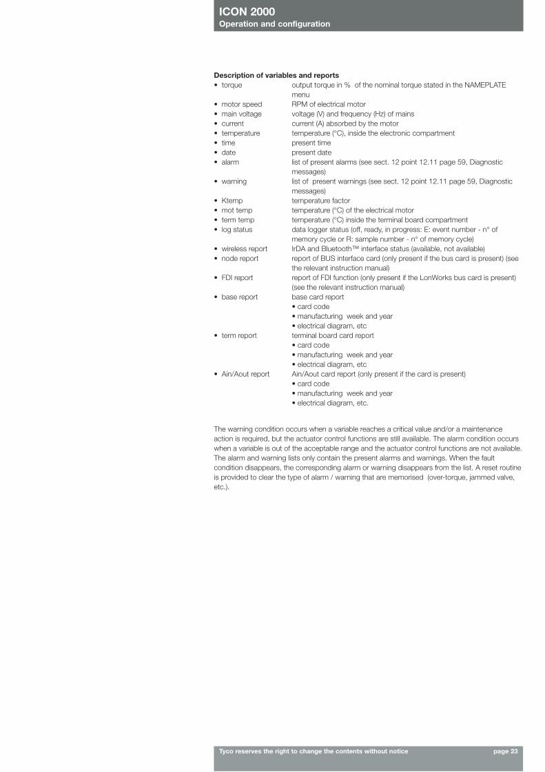
Description of variables and reports• torque output torque in % of the nominal torque stated in the NAMEPLATE
menu• motor speed RPM of electrical motor• main voltage voltage (V) and frequency (Hz) of mains • current current (A) absorbed by the motor• temperature temperature (°C), inside the electronic compartment• time present time • date present date• alarm list of present alarms (see sect. 12 point 12.11 page 59, Diagnostic
messages)• warning list of present warnings (see sect. 12 point 12.11 page 59, Diagnostic
messages)• Ktemp temperature factor• mot temp temperature (°C) of the electrical motor• term temp temperature (°C) inside the terminal board compartment• log status data logger status (off, ready, in progress: E: event number - n° of
memory cycle or R: sample number - n° of memory cycle)• wireless report IrDA and Bluetooth™ interface status (available, not available)• node report report of BUS interface card (only present if the bus card is present) (see
the relevant instruction manual)• FDI report report of FDI function (only present if the LonWorks bus card is present)
(see the relevant instruction manual)• base report base card report
• card code• manufacturing week and year• electrical diagram, etc
• term report terminal board card report• card code• manufacturing week and year• electrical diagram, etc
• Ain/Aout report Ain/Aout card report (only present if the card is present)• card code• manufacturing week and year• electrical diagram, etc.
The warning condition occurs when a variable reaches a critical value and/or a maintenanceaction is required, but the actuator control functions are still available. The alarm condition occurswhen a variable is out of the acceptable range and the actuator control functions are not available.The alarm and warning lists only contain the present alarms and warnings. When the faultcondition disappears, the corresponding alarm or warning disappears from the list. A reset routineis provided to clear the type of alarm / warning that are memorised (over-torque, jammed valve,etc.).
ICON 2000Operation and configuration
Tyco reserves the right to change the contents without notice page 24
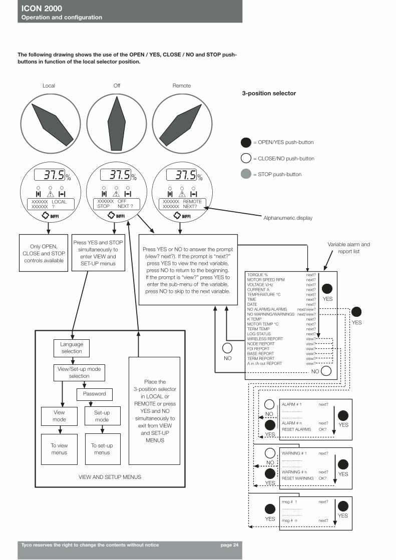
The following drawing shows the use of the OPEN / YES, CLOSE / NO and STOP push-buttons in function of the local selector position.
Local Off Remote3-position selector
= OPEN/YES push-button
= CLOSE/NO push-button
= STOP push-button
Alphanumeric display
Only OPEN,CLOSE and STOPcontrols available
Language selection
Viewmode
Set-upmode
To viewmenus
To set-upmenus
View/Set-up modeselection
Place the 3-position selector
in LOCAL orREMOTE or press
YES and NOsimultaneously to
exit from VIEWand SET-UP
MENUS
VIEW AND SETUP MENUS
Press YES and STOPsimultaneously toenter VIEW andSET-UP menus
Press YES or NO to answer the prompt(view? next?). If the prompt is “next?”press YES to view the next variable,press NO to return to the beginning. If the prompt is “view?” press YES toenter the sub-menu of the variable,
press NO to skip to the next variable.
YES
YES
YES
YES
YES
YES
YES
NO
NO
YES
NO
NO
Variable alarm andreport list
TORQUE % next?MOTOR SPEED RPM next?VOLTAGE V,Hz next?CURRENT A next?TEMPERATURE °C next?TIME next?DATE next?NO ALARMS/ALARMS next/view?NO WARNING/WARNINGS next/view?K TEMP next?MOTOR TEMP °C next?TERM TEMP next?LOG STATUS next?WIRELESS REPORT view?NODE REPORT view?FDI REPORT view?BASE REPORT view?TERM REPORT view?A in /A out REPORT view?
ALARM # 1 next?
..................
..................
ALARM # n next?
RESET ALARMS OK?
WARNING # 1 next?
..................
..................
WARNING # n next?
RESET WARNING OK?
msg # 1 next?
..................
..................
msg # n next?
XXXXXX REMOTEXXXXXX NEXT?
XXXXXX OFFSTOP NEXT ?
XXXXXX LOCALXXXXXX ?
Password
ICON 2000Operation and configuration
Tyco reserves the right to change the contents without notice page 25
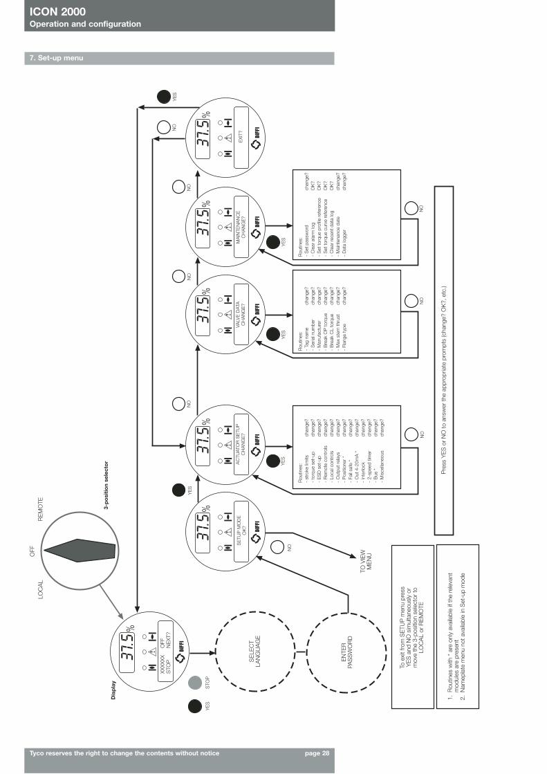
6.2 Configuration optionsThe ICON2000 actuator can be totally configured from the local interface by means of a series ofmenus that can be selected from the alphanumeric display. The operator is guided through thedifferent displays by answering YES or NO to the appropriate prompt (change? OK?, view?, next?,etc.) in the right corner of the lower row of the alphanumeric display.To access the menus: set the local selector in OFF and then simultaneously press OPEN/YES andSTOP. The alphanumeric display will now show the present language. Press YES if the language iscorrect, press NO to scroll the list of available languages and then YES to select.After choosing the language, the next step is the selection among view and set-up mode. Use“View” mode to see the actuator configuration, and use “Set-up” mode to change the presentconfiguration. Unauthorised access to the set-up mode is prevented by a 4-characteralphanumeric password. The actuator is supplied by BIFFI with the default password “ 0 0 0 0 “.Once the correct password has been entered, the actuator parameters can be configured.The present password can also be modified by the “set password” routine in the Maintenancemenu. After entering the new password, the old one ceases to be valid, so it is important torecord the password in a secure location for future retrieval.
The configuration functions (view and set-up mode) are grouped in 4 main menus: Actuator set-up, Nameplate, Valve data, Maintenance.
NameplateThis menu includes a series of data identifying the actuator characteristics, service, and utilisationmode. The data are entered by the manufacturer and can only be viewed (i.e., this menu is onlyavailable in View mode).List of routines:- serial number - power supply - enclosure - torque sensor- actuator type - motor data - certificate - torque/thrust - test date - lubricant- actuator speed - wiring diagram - revision
Valve dataThis menu includes a series of data relevant to the valve. The valve manufacturer and end usershould enter the data.List of routines:- tag name (max 28 characters) - serial number (max 28 characters)- manufacturer (max 28 characters) - break CL torque(max 28 characters)- break OP torque (max 28 characters) - max stem thrust (max 28 characters)
- flange type (max 28 characters)
MaintenanceThis menu includes all diagnostic and historic data which can help the operator in case of failureor during maintenance operations. The Maintenance menu also includes the “Set password”routine.List of routines:Set-up mode View mode- set new password- clear alarm log - alarm log- set torque profile reference - torque profile- set torque curve reference - torque curve- clear recent data log - operation log- set maintenance date - maintenance date- set data logger - data logger
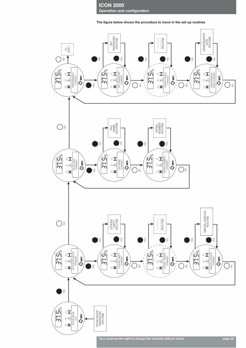
The parameters appear on the alphanumeric display in the same order both in view and set-upmode. At the end of each routine the program will automatically return to the beginning of theroutine, and the operator can choose to either re-enter (by pressing YES) or to move on to a nextroutine (by pressing NO).
Actuator set-upThis menu includes the routines that allow the actuator to be configured according to therequested control mode and to the valve it is mounted on.- stroke limits - local controls - out 4-20mA * - miscellaneous- torque set-up - output relays - interlock- ESD set-up - positioner * - 2-speed timer- remote controls - fail safe * - bus *
The routines with * are only available if the relevant modules are present. If bus interface isLonWorks, the “bus” routine changes to “FDI control”.
ICON 2000Operation and configuration
Tyco reserves the right to change the contents without notice page 26
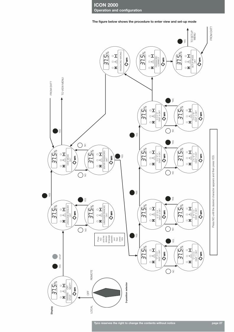
6.3 Entering the view modeThe existing actuator configuration should be checked before commissioning. The parameters areconfigured in factory according to a standard setting, or to customer requirements. In view mode,no password is requested, but no change of parameters can be made.• Ensure the electrical main power is applied.• Move the 3-position selector to OFF and then simultaneously press OPEN/YES and STOP.• The display shows the present language. Press YES to confirm or NO to scroll the list of
available languages. Press YES to select a new language. Press YES to confirm.• Press NO to scroll the list of available menus (actuator set-up, nameplate, valve data,
maintenance) and then press YES to select the desired menu.• Press NO to scroll the list of available routines and press YES to select the routine where the
parameter to be changed is located.• Press NO to scroll the list of parameters and press YES to view the value.
6.4 Entering the set-up modeTo change the existing settings or to set the stroke limits it is necessary to enter the correctpassword.• Ensure the electrical main power (or the external auxiliary supply) is applied.• Move the 3-position selector to OFF and then simultaneously press OPEN/YES and STOP.• The display shows the present language. Press YES to confirm or NO to scroll the list of
available languages. Press YES to select. Press YES to confirm the chosen language.• Press NO when the message is “VIEW MODE OK? ”. Press YES to answer prompt “ENTER
PASSWORD OK?”• Enter password. Enter one digit at a time. Press YES if digit is correct, press NO to scroll the list
of available characters and then press YES when the character is correct. Enter 4 digits. Afterentering the last digit, the microprocessor checks the password. If it is correct the messages“PASSWORD CORRECT” and then “SET-UP MODE OK?” appear. Press YES.
• Press NO to scroll the list of available menus (actuator set-up, valve data, maintenance) andpress YES to select the desired menu
• Press NO to scroll the list of available routines and press YES to select the routine where theparameter to be changed is located.
• Press YES and NO to answer the prompt on the display and change the parameter. • If the password is wrong the message “PASSWORD WRONG” appears and set-up mode will
not available.All settings are automatically saved to a non-volatile memory and retained also if the electricalpower is removed from the actuator.All ICON2000 actuators are configured before shipping with a standard default setting unlessalternatives were requested on order. In case of difficulty during commissioning, the default settingcan be re-instated by the appropriate function in the routine ”miscellaneous” of the actuator set-up menu. The actuator returns to its original configuration and commissioning can be resumed.
6.5 Exit from view and set-up modeThe following conditions cause the exit from view and set-up mode:• move the 3-position selector to LOCAL or REMOTE• answer YES when the display asks “EXIT OK? ”• press YES and NO simultaneously• automatic exit after 90 minutes without any parameter change or view• remove the electrical power from the unit
ICON 2000Operation and configuration
Tyco reserves the right to change the contents without notice page 27
XXXX
XXO
FFS
TOP
NE
XT?
LAN
GU
AG
E E
NG
LIS
HO
K?
VIE
W M
OD
EO
K?
LAN
GU
AGE
FRAN
CAI
SO
K?
EN
TER
PA
SS
WO
RD
OK
?
0 “0
” 0
0D
IGIT
2 O
K?
0 0
“0”
0D
IGIT
3 O
K?
0 0
0 “0
”D
IGIT
4 O
K?
“0”
0 0
0D
IGIT
1 O
K?
“Z”
0 0
0D
IGIT
1 O
K?
Z “K
” 0
0D
IGIT
2 O
K?
Z K
“9”
0D
IGIT
3 O
K?
Z K
9 “
R”
DIG
IT 4
OK
?
SE
TUP
MO
DE
OK
?
PAS
SW
OR
D
CO
RR
EC
T
PAS
SW
OR
D W
RO
NG
Dis
pla
y
LOC
AL
RE
MO
TE
Pre
ssN
Oun
til th
ede
sire
dla
ngua
geap
pear
san
dth
enpr
ess
YE
S
FRO
M E
XIT?
TO V
IEW
ME
NU
TO S
ETU
PM
EN
U
FRO
M E
XIT?
Pre
ss N
O u
ntil
the
desi
red
char
acte
r ap
pear
s an
d th
en p
ress
YE
S
YE
S
YE
S
YE
S
NO
YE
S
YE
S
YE
SN
OY
ES
NO
NO
YE
SY
ES
YE
S
NO
YE
SY
ES
YE
S
NO
NO
STO
P
OFF
3-p
osi
tio
n se
lect
or
The figure below shows the procedure to enter view and set-up mode
ICON 2000Operation and configuration
Tyco reserves the right to change the contents without notice page 28
7. Set-up menu
XXXX
XXO
FFS
TOP
NE
XT?
Dis
pla
y
LOC
AL
RE
MO
TE
Rou
tines
:-
Tag
nam
ech
ange
?-
Ser
ial n
umbe
rch
ange
?-
Man
ufac
ture
rch
ange
?-
Bre
ak O
P to
rque
chan
ge?
- B
reak
CL
torq
uech
ange
?-
Max
ste
m th
rust
chan
ge?
- Fl
ange
type
chan
ge?
Rou
tines
:-
stro
ke li
mits
chan
ge?
- to
rque
set
-up
chan
ge?
- E
SD
set
-up
chan
ge?
- R
emot
e co
ntro
lsch
ange
?-
Loca
l con
trol
sch
ange
?-
Out
put r
elay
sch
ange
?-
Pos
ition
er *
chan
ge?
- Fa
il sa
fe *
chan
ge?
- O
ut 4
-20m
A *
chan
ge?
- In
terlo
ckch
ange
?-
2-sp
eed
timer
chan
ge?
- B
us *
chan
ge?
- M
isce
llane
ous
chan
ge?
To e
xit f
rom
SE
TUP
men
u pr
ess
YE
S a
nd N
O s
imul
tane
ousl
y or
mov
e th
e 3-
posi
tion
sele
ctor
toLO
CA
L or
RE
MO
TE
1.R
outin
es w
ith *
are
onl
y av
aila
ble
if th
e re
leva
ntm
odul
es a
re p
rese
nt2.
Nam
epla
te m
enu
not a
vaila
ble
in S
et-u
p m
ode
EN
TER
PAS
SW
OR
D
TO V
IEW
ME
NU
Pre
ss Y
ES
or
NO
to a
nsw
er th
e ap
prop
riate
pro
mpt
s (c
hang
e? O
K?,
etc
.)
SE
LEC
TLA
NG
UA
GE
Rou
tines
:-
Set
pas
swor
dch
ange
?-
Cle
ar a
larm
log
OK
?-
Set
torq
ue p
rofil
e re
fere
nce
OK
?-
Set
torq
ue c
urve
refe
renc
eO
K?
- C
lear
rece
nt d
ata
log
OK
?-
Mai
nten
ance
dat
ech
ange
?-
Dat
a lo
gger
chan
ge?
YE
S
YE
SY
ES
YE
S
NO
NO
NO
NO
YE
SS
TOP
NO
NO
NO
NO
YE
S
OFF
3-p
osi
tio
n se
lect
or
VALV
E D
ATA
CH
AN
GE
?A
CTU
ATO
R S
ETU
PC
HA
NG
E?
SE
TUP
MO
DE
OK
?M
AIN
TEN
AN
CE
CH
AN
GE
?E
XIT?
ICON 2000Operation and configuration
Tyco reserves the right to change the contents without notice page 29
The figure below shows the procedure to move in the set-up routines
STR
OK
E L
IMIT
SC
HA
NG
E?
XXXX
XX
XXXX
XXC
HA
NG
E?
SE
RIA
L N
UM
BE
RC
HA
NG
E?
TAG
NA
ME
CH
AN
GE
?
VALV
E D
ATA
CH
AN
GE
?
XXXX
XX X
XXXX
XC
HA
NG
E?
MA
INTE
NA
NC
ED
ATE
CH
AN
GE
?
SE
T PA
SS
WO
RD
CH
AN
GE
?
MA
INTE
NA
NC
EC
HA
NG
E?
MIS
CE
LLA
NE
OU
SC
HA
NG
E?
AC
TUAT
OR
SE
TUP
CH
AN
GE
?S
ETU
P M
OD
EO
K?
YE
S
YE
S
NO
NO
NO
YE
S
YE
S
YE
S
YE
SY
ES
YE
S
YE
S
YE
S
YE
S
YE
S
YE
S
YE
S
YE
S
YE
S
YE
S
NO
NO
NO
NO
NO
YE
S
NO
YE
S
YE
S
NO
NO
MIS
CE
LLA
NE
OU
SR
OU
TIN
E
......
......
....
......
......
....
RO
UTI
NE
SE
RIA
LN
UM
BE
RR
OU
TIN
E
......
......
....
......
......
....
RO
UTI
NE
SE
TPA
SS
WO
RD
RO
UTI
NE
TOE
XIT?
MA
INTE
NA
NC
ED
ATE
RO
UTI
NE
TAG
NA
ME
RO
UTI
NE
STR
OK
ELI
MIT
SR
OU
TIN
E
FRO
M E
NTE
RPA
SS
WO
RD
RO
UTI
NE
ICON 2000Operation and configuration
Tyco reserves the right to change the contents without notice page 30
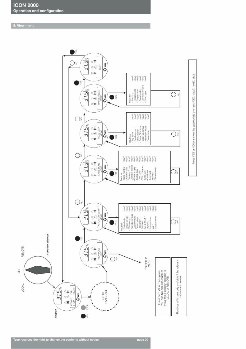
8. View menu
To e
xit f
rom
VIE
W m
enu
pres
sY
ES
and
NO
sim
ulta
neou
sly
orm
ove
the
3-po
sitio
n se
lect
or to
LOC
AL
or R
EM
OTE
Rou
tines
with
* a
re o
nly
avai
labl
e if
the
rele
vant
mod
ules
are
pre
sent
.
TO S
ETU
PM
EN
U
Pre
ss Y
ES
or
NO
to a
nsw
er th
e ap
prop
riate
pro
mpt
s (O
K?,
vie
w?,
nex
t?, e
tc.)
SE
LEC
TLA
NG
UA
GE
Dis
pla
y
LOC
AL
RE
MO
TE
YE
S
YE
SN
ON
ON
OY
ES
YE
SY
ES
YE
SY
ES
NO
NO
NO
NO
NO
YE
SN
O
STO
P
OFF
3-p
osi
tio
n se
lect
or
XXXX
XXO
FFS
TOP
NE
XT?
VIE
W M
OD
EO
K?
AC
TUAT
OR
SE
TUP
VIE
W?
NA
ME
PLA
TEV
IEW
?VA
LVE
DAT
AV
IEW
?M
AIN
TEN
AN
CE
VIE
W?
EXI
T?
Rou
tines
:-
Str
oke
limits
view
?-
Torq
ue s
et-u
pvi
ew?
- E
SD
set
-up
view
?-
Rem
ote
cont
rols
view
?-
Loca
l con
trol
svi
ew?
- O
utpu
t rel
ays
view
?-
Pos
ition
er *
view
?-
Fail
Saf
e *
view
?-
Out
4-2
0mA
*vi
ew?
- In
terlo
ckvi
ew?
- 2-
spee
d tim
ervi
ew?
- B
us *
view
?-
Mis
cella
neou
svi
ew?
Rou
tines
:-
Ser
ial n
umbe
rvi
ew?
- A
ctua
tor
type
view
?-
Torq
ue /
Thr
ust
view
?-
Act
uato
r sp
eed
view
?-
Pow
er s
uppl
yvi
ew?
- M
otor
dat
avi
ew?
- Te
st d
ate
view
?-
Wiri
ng d
iagr
amvi
ew?
- E
nclo
sure
view
?-
Cer
tific
ate
view
?-
Lubr
ican
tvi
ew?
- R
evis
ion
view
?-
Torq
ue s
enso
rvi
ew?
Rou
tines
:-
Tag
nam
evi
ew?
- S
eria
l num
ber
view
?-
Man
ufac
ture
rvi
ew?
- B
reak
OP
torq
uevi
ew?
- B
reak
CL
torq
uevi
ew?
- M
ax s
tem
thru
stvi
ew?
- Fl
ange
type
view
?
Rou
tines
:-
Ala
rm lo
gvi
ew?
- To
rque
pro
file
view
?-
Torq
ue c
urve
view
?-
Ope
ratio
n lo
gvi
ew?
- M
aint
enan
ce d
ate
view
?-
Dat
a lo
gger
view
?
ICON 2000Operation and configuration
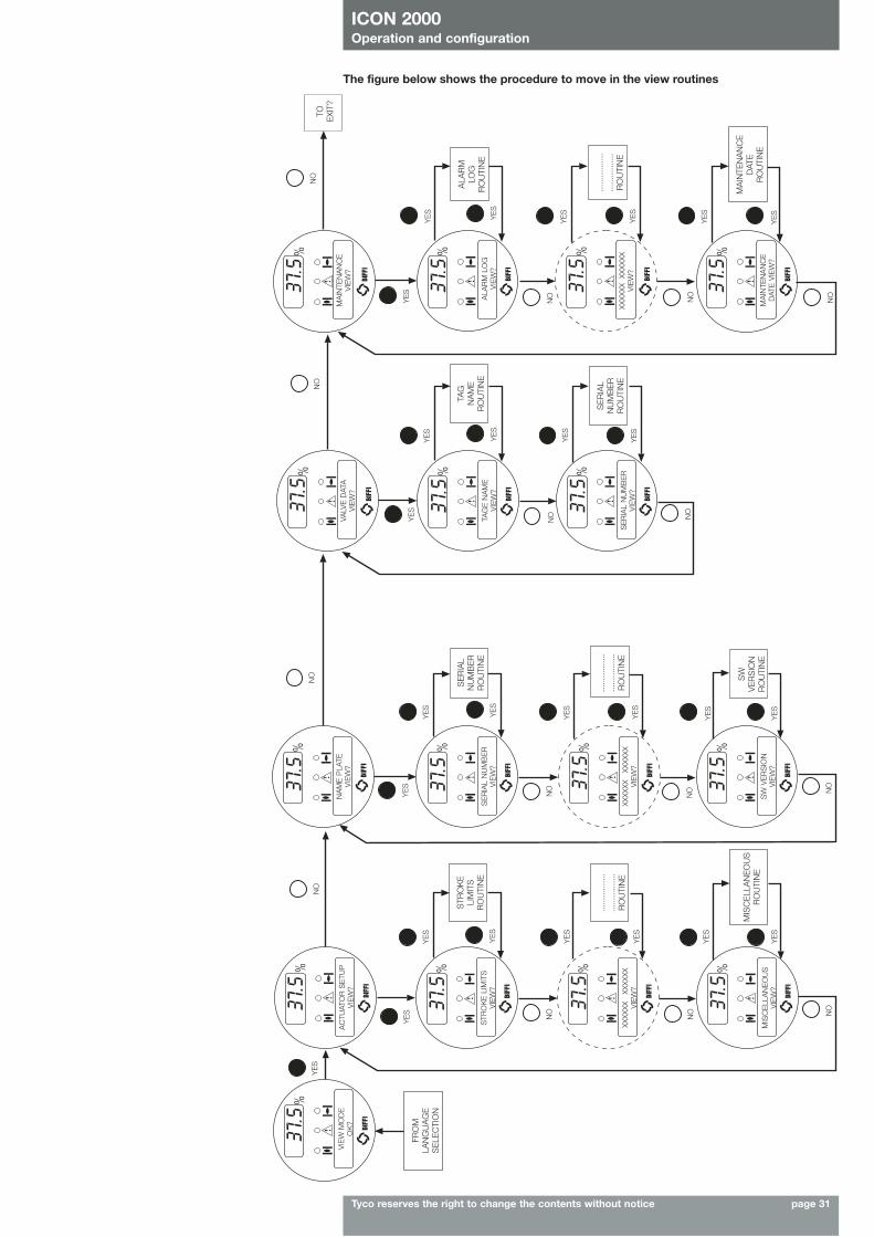
Tyco reserves the right to change the contents without notice page 31
The figure below shows the procedure to move in the view routines
VIE
W M
OD
EO
K?
AC
TUAT
OR
SE
TUP
VIE
W?
NA
ME
PLA
TEV
IEW
?
STR
OK
E L
IMIT
SV
IEW
?
XXXX
XX
XXX
XXX
VIE
W?
MIS
CE
LLA
NE
OU
SV
IEW
?
YE
S
YE
S
NO
NO NO
YE
S
YE
S
YE
S
YE
S
NO NO
YE
S
YE
S
YE
S
YE
S
YE
S
YE
S
YE
S
YE
S
YE
S
SE
RIA
L N
UM
BE
RV
IEW
?
VALV
E D
ATA
VIE
W?
MA
INTE
NA
NC
EV
IEW
?
ALA
RM
LO
GV
IEW
?
XXXX
XX
XXXX
XXV
IEW
?
MA
INTE
NA
NC
ED
ATE
VIE
W?
TAG
E N
AM
EV
IEW
?
SE
RIA
L N
UM
BE
RV
IEW
?XX
XXXX
X
XXXX
XV
IEW
?
SW
VE
RS
ION
VIE
W?
NO
NO N
O
YE
S
YE
S
YE
S
YE
S
YE
S
NO
NO
NO
YE
S
NO NO
NO
YE
S
YE
S
YE
S
YE
S
YE
S
YE
S
NO
......
......
....
......
......
....
RO
UTI
NE
......
......
....
......
......
....
RO
UTI
NE
......
......
....
......
......
....
RO
UTI
NE
MA
INTE
NA
NC
ED
ATE
RO
UTI
NE
SE
RIA
LN
UM
BE
RR
OU
TIN
E
TAG
NA
ME
RO
UTI
NE
ALA
RM
LOG
RO
UTI
NE
TOE
XIT?
SE
RIA
LN
UM
BE
RR
OU
TIN
E
MIS
CE
LLA
NE
OU
SR
OU
TIN
E
SW
VE
RS
ION
RO
UTI
NE
STR
OK
ELI
MIT
SR
OU
TIN
E
FRO
MLA
NG
UA
GE
SE
LEC
TIO
N
ICON 2000Operation and configuration
Tyco reserves the right to change the contents without notice page 32
Set-up procedure:• Engage the manual override and move the valve to the mid-travel position• Move the local selector to OFF and then simultaneously press OPEN and STOP. Select the
language and then enter the password according to the instructions (see “Entering the set-upmode”). When the message displayed is “SET-UP MODE OK?” press YES. Press YES to selectthe actuator set-up menu, and then press YES again to start with the stroke limits routine.
• Press YES if the closing torque limit is correct or NO to scroll the list of available values. Whenthe value is correct, press YES.
• Press YES if the opening torque limit is correct or NO to scroll the list of available values. Whenthe value is correct press YES.
• Press YES if the rotation to close is correct (CW or CCW), or NO to change.When the value is correct press YES.
• Press YES to set the close limit, or NO and then YES to set the open limit.
Close limit type Press YES if the close limit type is correct (torque or position), press NO to change it. Press YES when the type is correct.
Close limit by position• Move the local selector to LOCAL. The local controls can be used.• Move the valve to closed position (by CLOSE control or by handwheel)• Move the local selector to OFF• Press YES to confirm• Press YES to continue with the open limit setting, or press NO and again NO to repeat the
close limit setting procedure. Press NO and then YES to exit from the stroke limits routine.
Close limit by torque• Move the local selector to LOCAL. The local controls can be used.• Press the CLOSE control. The actuator moves in closing direction and when the configured
torque value is reached the motor is stopped and the new position limit is memorised.• Move the local selector to OFF• Press YES to confirm• Press YES to continue with the close limit setting, or press NO and again NO to repeat the
close limit setting procedure. Press NO and then YES to exit from the stroke limits routine.
Open limit type • Press YES if the open limit type is correct (torque or position), press NO to change it. Press YES
to confirm.
Open limit by position• Move the local selector to LOCAL. The local controls become active.• Move the valve to open position (by OPEN control or by handwheel)• Move the local selector to OFF• Press YES to confirm• Press YES to exit, or press NO and then YES to repeat the close limit setting procedure.
9. Set-up routines
9.1 Actuator set-up9.1.1 Set stroke limitsThis routine allows the actuator to be configured according to the type of valve it is mounted on.The following parameters will be set:• opening and closing torque limits: from 40 % to 100 % of the nominal torque. The nominal
torque corresponding to 100% is set in-house and is stated in the name plate menu forreference.
• close direction: clockwise (CW) or counter-clockwise (CCW). Most valves require clockwiserotation of the stem when viewed from the handwheel. Engage the manual override and checkif the valve closes with clockwise or counter-clockwise rotation of the handwheel
• close and open limits type: by position or by torque. Use the following table to choose:
Valve type Close limit Open limit
• Gate (solid, flexible and • Torque • Positionsplit wedge), globe, metal seatedbutterfly valves
• Ball, gate (parallel slide), plug valves, • Position • Positionrubber seated butterfly valves
• Linear valves with • Torque or position • Torqueback-seating on stem
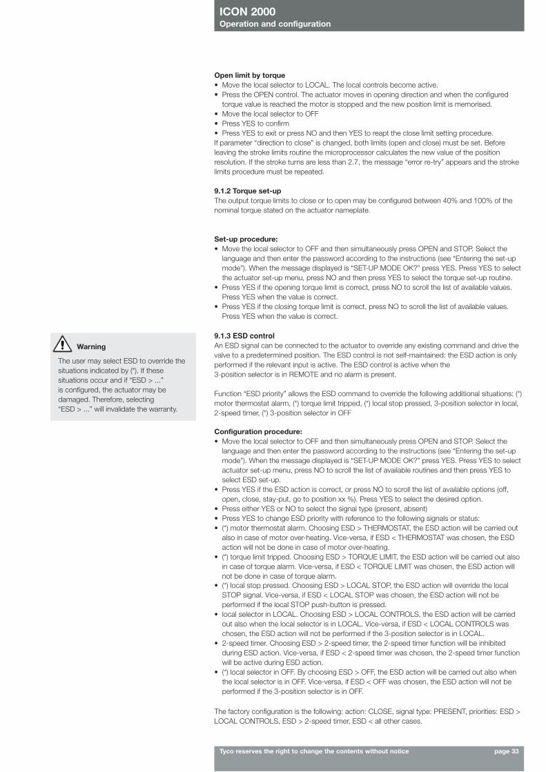
ICON 2000Operation and configuration
Tyco reserves the right to change the contents without notice page 33
Open limit by torque• Move the local selector to LOCAL. The local controls become active.• Press the OPEN control. The actuator moves in opening direction and when the configured
torque value is reached the motor is stopped and the new position limit is memorised.• Move the local selector to OFF• Press YES to confirm• Press YES to exit or press NO and then YES to reapt the close limit setting procedure.If parameter “direction to close” is changed, both limits (open and close) must be set. Beforeleaving the stroke limits routine the microprocessor calculates the new value of the positionresolution. If the stroke turns are less than 2.7, the message “error re-try” appears and the strokelimits procedure must be repeated.
9.1.2 Torque set-upThe output torque limits to close or to open may be configured between 40% and 100% of thenominal torque stated on the actuator nameplate.
Set-up procedure:• Move the local selector to OFF and then simultaneously press OPEN and STOP. Select the
language and then enter the password according to the instructions (see “Entering the set-upmode”). When the message displayed is “SET-UP MODE OK?” press YES. Press YES to selectthe actuator set-up menu, press NO and then press YES to select the torque set-up routine.
• Press YES if the opening torque limit is correct, press NO to scroll the list of available values.Press YES when the value is correct.
• Press YES if the closing torque limit is correct, press NO to scroll the list of available values.Press YES when the value is correct.
9.1.3 ESD controlAn ESD signal can be connected to the actuator to override any existing command and drive thevalve to a predetermined position. The ESD control is not self-maintained: the ESD action is onlyperformed if the relevant input is active. The ESD control is active when the 3-position selector is in REMOTE and no alarm is present.
Function “ESD priority” allows the ESD command to override the following additional situations: (*)motor thermostat alarm, (*) torque limit tripped, (*) local stop pressed, 3-position selector in local,2-speed timer, (*) 3-position selector in OFF
Configuration procedure:• Move the local selector to OFF and then simultaneously press OPEN and STOP. Select the
language and then enter the password according to the instructions (see “Entering the set-upmode”). When the message displayed is “SET-UP MODE OK?” press YES. Press YES to selectactuator set-up menu, press NO to scroll the list of available routines and then press YES toselect ESD set-up.
• Press YES if the ESD action is correct, or press NO to scroll the list of available options (off,open, close, stay-put, go to position xx %). Press YES to select the desired option.
• Press either YES or NO to select the signal type (present, absent)• Press YES to change ESD priority with reference to the following signals or status:• (*) motor thermostat alarm. Choosing ESD > THERMOSTAT, the ESD action will be carried out
also in case of motor over-heating. Vice-versa, if ESD < THERMOSTAT was chosen, the ESDaction will not be done in case of motor over-heating.
• (*) torque limit tripped. Choosing ESD > TORQUE LIMIT, the ESD action will be carried out alsoin case of torque alarm. Vice-versa, if ESD < TORQUE LIMIT was chosen, the ESD action willnot be done in case of torque alarm.
• (*) local stop pressed. Choosing ESD > LOCAL STOP, the ESD action will override the localSTOP signal. Vice-versa, if ESD < LOCAL STOP was chosen, the ESD action will not beperformed if the local STOP push-button is pressed.
• local selector in LOCAL. Choosing ESD > LOCAL CONTROLS, the ESD action will be carriedout also when the local selector is in LOCAL. Vice-versa, if ESD < LOCAL CONTROLS waschosen, the ESD action will not be performed if the 3-position selector is in LOCAL.
• 2-speed timer. Choosing ESD > 2-speed timer, the 2-speed timer function will be inhibitedduring ESD action. Vice-versa, if ESD < 2-speed timer was chosen, the 2-speed timer functionwill be active during ESD action.
• (*) local selector in OFF. By choosing ESD > OFF, the ESD action will be carried out also whenthe local selector is in OFF. Vice-versa, if ESD < OFF was chosen, the ESD action will not beperformed if the 3-position selector is in OFF.
Warning
The user may select ESD to override thesituations indicated by (*). If thesesituations occur and if “ESD > ...”is configured, the actuator may bedamaged. Therefore, selecting“ESD > ...” will invalidate the warranty.
The factory configuration is the following: action: CLOSE, signal type: PRESENT, priorities: ESD >LOCAL CONTROLS, ESD > 2-speed timer, ESD < all other cases.
ICON 2000Operation and configuration
Tyco reserves the right to change the contents without notice page 34
9.1.4 Remote controlsThe actuator may be remotely controlled by 4, or 3, or 2 wires depending on the connection madeon the terminal board of the actuator. The following options are available:• 4 wires latched: requires 2 momentary signals (since the control is self-maintained) to open or
close and one signal to stop in mid-travel• 3 wires latched instant reverse: requires 2 momentary signals (since the control is
self-maintained) to open or close. Reverse momentary signal reverses the direction.• 3 wires momentary: requires 2 push-to-run type signals (since the control is not
self-maintained) to open or close• 2 wires open if signal On: requires signal On to open and no signal to close• 2 wires open if signal Off: requires signal Off to open and signal On to close Configuration should be done during actuator set-up.
Configuration procedure:• Move the local selector to OFF and then simultaneously press OPEN and STOP. Select the
language and then enter the password according to the instructions (see “Entering the set-upmode”). When the message displayed is “SET-UP MODE OK?” press YES. Press YES to selectactuator set-up menu, press NO to scroll the list of available routines and then press YES toselect Remote controls.
• Press YES if the control mode is correct or NO to scroll the list of available options: 4 wires, 3 wires, 2 wires, off. Press YES to select the desired option. If 4 wires was chosen useYES and NO to select the STOP signal: set MAKE to stop when signal is on and set BREAK tostop when signal is off. If “3 wires” was chosen, use YES or NO to answer the prompt on thedisplay and choose among “push-to-run” or “latched instant reverse” control modes. If “2wires” was chosen, use YES and NO to choose among “open if signal ON” or “open if signalOFF” control modes.
9.1.5 Local controlsThis routine allows: • to configure the control mode by means of the local controls when the 3-position selector is in
LOCAL. The available options are “push-to-run”, “latched”, “latched with instant reverse”.• to set the LED’s colour. The following options are available: open LED: green or red; close LED:
green or red; alarm LED: yellow or red.
Configuration procedure:• Move the local selector to OFF and then simultaneously press OPEN and STOP. Select the
language and then enter the password according to the instructions (see “Entering the set-upmode”). When the message displayed is “SET-UP MODE OK?” press YES. Press YES to selectthe actuator set-up menu, press NO to scroll the list of available routines and then press YES toselect Local controls.
• Press YES to change control mode, or press NO to proceed to LED’s colour settingControl mode• Press YES if the display shows the correct control mode or press NO to scroll the list of
available options (push to run, latched). Press YES to confirm. LED’s colour• Press YES if the colour of the open LED is correct. Press NO to change it, then YES to confirm• Press YES if the colour of the close LED is correct. Press NO to change it, then YES to confirm• Press YES if the colour of the alarm LED is correct. Press NO to change it, then YES to confirm
9.1.6 Output relaysMonitor relayThe voltage-free, change-over, contacts of the monitor relay indicate that the actuator is eitheravailable for remote control or that a problem or a condition preventing remote control of the valveexists.
The monitor relay is normally energised and will be de-energised on:- main voltage failure - position sensor failure- lost phase - speed sensor failure- internal temperature alarm - configuration error- K1 contactor failure - HW error- K2 contactor failure - mid-travel alarm
The following situation can be configured individually to switch-over the monitor relay: Motor over-temperature Manual operationOver-torque ESD signal onJammed valve Low lithium battery (if present)LOCAL/OFF selected LOCAL/STOP pressed
ICON 2000Operation and configuration
Tyco reserves the right to change the contents without notice page 35
The contacts may be configured to make or break on condition. The options "EFS in manual","EFS mid-travel" and "PST failed" also appear in the menu, but are not available for ICON2000v4.
Configuration procedure:• Move the local selector to OFF and then simultaneously press OPEN and STOP. Select the
language and enter the password according to the instructions (see “Entering the set-upmode”). When the message displayed is “SET-UP MODE OK?” press YES. Press YES to selectactuator set-up menu, press NO to scroll the list of available routines and then press YES toselect Output relays.
• Press YES to select DEFAULT #1, or press NO to change• Press YES to select DEFAULT #2, or press NO to configure the output relays
Default # 1Monitor relay
• main voltage failure • speed sensor failure• lost phase • configuration error• local/off selected • HW error• local stop pressed • motor over-temperature• manual operation • over-torque• internal temperature alarm • jammed valve• K1 contactor failure • low lithium battery (if present)• K2 contactor failure • mid-travel alarm• position sensor failure
Auxiliary relaysAS1: open limit; makeAS2: close limit; makeAS3: position >90%; makeAS4: position <5%; makeAS5: motor running; makeAS6: overtorque; makeAS7: ESD active; makeAS8: motor overtemperature
Status Alarm• open limit • mid-travel position • motor • valve jammed in OP• closed limit • local selected over-temperature • valve jammed in CL• position >= xx % • remote selected • over-torque • low lithium battery• position <= xx % • local stop active • over-torque in OP (if present)• closing • ESD signal on • over-torque in CL • mid travel alarm • opening • manual operation • valve jammed in CL/OP• motor running • warnings • mains-only AS8• blinker
Auxiliary output relaysFor status indication or diagnostic purposes, 8 voltage-free contacts of 8 relays are available tobe configured individually to switch for the following conditions:
Default # 2Monitor relay
• main voltage failure • speed sensor failure• lost phase • configuration error• local/off selected • HW error• local stop pressed • motor over-temperature• manual operation • over-torque• internal temperature alarm • jammed valve• K1 contactor failure • low lithium battery (if present)• K2 contactor failure • mid-travel alarm• position sensor failure
Auxiliary relaysAS1: open limit; breakAS2: close limit; breakAS3: position >90%; breakAS4: position <5%; breakAS5: motor running; makeAS6: remote selected; makeAS7: warning; makeAS8: local selected
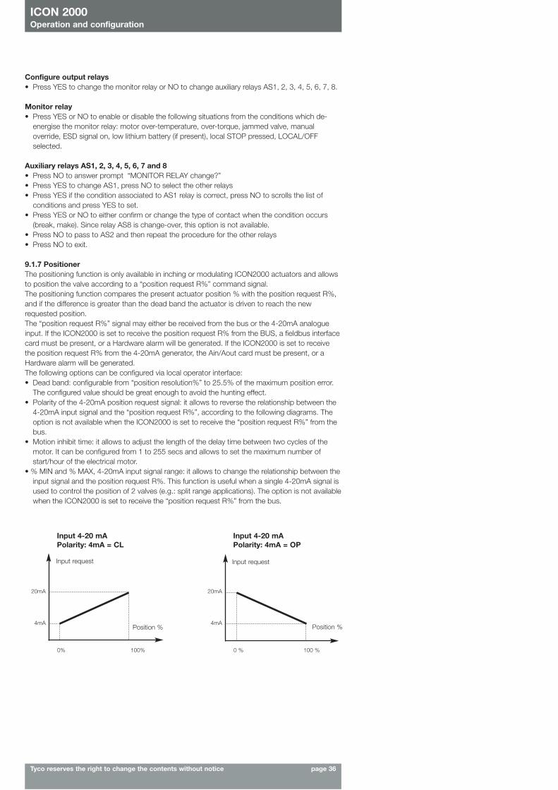
ICON 2000Operation and configuration
Tyco reserves the right to change the contents without notice page 36
Configure output relays• Press YES to change the monitor relay or NO to change auxiliary relays AS1, 2, 3, 4, 5, 6, 7, 8.
Monitor relay• Press YES or NO to enable or disable the following situations from the conditions which de-
energise the monitor relay: motor over-temperature, over-torque, jammed valve, manualoverride, ESD signal on, low lithium battery (if present), local STOP pressed, LOCAL/OFFselected.
Auxiliary relays AS1, 2, 3, 4, 5, 6, 7 and 8• Press NO to answer prompt “MONITOR RELAY change?” • Press YES to change AS1, press NO to select the other relays• Press YES if the condition associated to AS1 relay is correct, press NO to scrolls the list of
conditions and press YES to set.• Press YES or NO to either confirm or change the type of contact when the condition occurs
(break, make). Since relay AS8 is change-over, this option is not available.• Press NO to pass to AS2 and then repeat the procedure for the other relays• Press NO to exit.
9.1.7 PositionerThe positioning function is only available in inching or modulating ICON2000 actuators and allowsto position the valve according to a “position request R%” command signal.The positioning function compares the present actuator position % with the position request R%,and if the difference is greater than the dead band the actuator is driven to reach the newrequested position. The “position request R%” signal may either be received from the bus or the 4-20mA analogueinput. If the ICON2000 is set to receive the position request R% from the BUS, a fieldbus interfacecard must be present, or a Hardware alarm will be generated. If the ICON2000 is set to receivethe position request R% from the 4-20mA generator, the Ain/Aout card must be present, or aHardware alarm will be generated.The following options can be configured via local operator interface:• Dead band: configurable from “position resolution%” to 25.5% of the maximum position error.
The configured value should be great enough to avoid the hunting effect.• Polarity of the 4-20mA position request signal: it allows to reverse the relationship between the
4-20mA input signal and the “position request R%”, according to the following diagrams. Theoption is not available when the ICON2000 is set to receive the “position request R%” from thebus.
• Motion inhibit time: it allows to adjust the length of the delay time between two cycles of themotor. It can be configured from 1 to 255 secs and allows to set the maximum number ofstart/hour of the electrical motor.
• % MIN and % MAX, 4-20mA input signal range: it allows to change the relationship between theinput signal and the position request R%. This function is useful when a single 4-20mA signal isused to control the position of 2 valves (e.g.: split range applications). The option is not availablewhen the ICON2000 is set to receive the “position request R%” from the bus.
Input 4-20 mAPolarity: 4mA = CL
Input 4-20 mAPolarity: 4mA = OP
Input requestInput request
20mA
4mA
20mA
4mAPosition % Position %
0% 100% 0 % 100 %
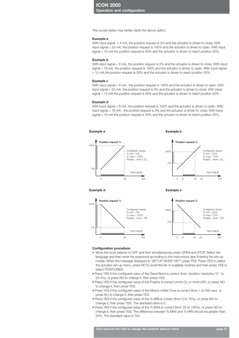
ICON 2000Operation and configuration
Tyco reserves the right to change the contents without notice page 37
The curves below may better clarify the above option:
Example aWith input signal = 4 mA, the position request is 0% and the actuator is driven to close. Withinput signal = 20 mA, the position request is 100% and the actuator is driven to open. With inputsignal = 12 mA the position request is 50% and the actuator is driven to reach position 50%.
Example bWith input signal < 8 mA, the position request is 0% and the actuator is driven to close. With inputsignal = 16 mA, the position request is 100% and the actuator is driven to open. With input signal= 12 mA the position request is 50% and the actuator is driven to reach position 50%.
Example cWith input signal = 4 mA , the position request is 100% and the actuator is driven to open. Withinput signal = 20 mA, the position request is 0% and the actuator is driven to close. With inputsignal = 12 mA the position request is 50% and the actuator is driven to reach position 50%.
Example dWith input signal < 8 mA, the position request is 100% and the actuator is driven to open. Withinput signal = 16 mA , the position request is 0% and the actuator is driven to close. With inputsignal = 12 mA the position request is 50% and the actuator is driven to reach position 50%.
Example a
Position request %100%
0%Input signal
4 20 mA
Configured values:% min = 0%% max = 100%Polarity : 4mA = CL
Example b
Position request %
100%
0%
Input signal
4 8 16 20 mA
Configured values:% min = 25%% max = 75%Polarity : 4mA = CL
Example d
Position request %100%
0%Input signal
4 20 mA
Configured values:% min = 0%% max = 100%Polarity : 4mA = OP
Example e
Position request %
100%
0%
Input signal
4 8 16 20 mA
Configured values:% min = 25%% max = 75%Polarity : 4mA = OP
Configuration procedure:• Move the local selector to OFF and then simultaneously press OPEN and STOP. Select the
language and then enter the password according to the instructions (see Entering the set-upmode). When the message displayed is “SET-UP MODE OK?” press YES. Press YES to selectthe actuator set-up menu, press NO to scroll the list of available routines and then press YES toselect POSITIONER.
• Press YES if the configured value of the Dead Band is correct (from “position resolution %” to25.5%), or press NO to change it, then press YES.
• Press YES if the configured value of the Polarity is correct (4mA=CL or 4mA=OP), or press NOto change it, then press YES.
• Press YES if the configured value of the Motion Inhibit Time is correct (from 1 to 255 sec), orpress NO to change it, then press YES.
• Press YES if the configured value of the % MIN is correct (from 0 to 75%), or press NO tochange it, then press YES. The standard value is 0.
• Press YES if the configured value of the % MAX is correct (from 25 to 100%), or press NO tochange it, then press YES. The difference between % MAX and % MIN should be greater than25%. The standard value is 100.
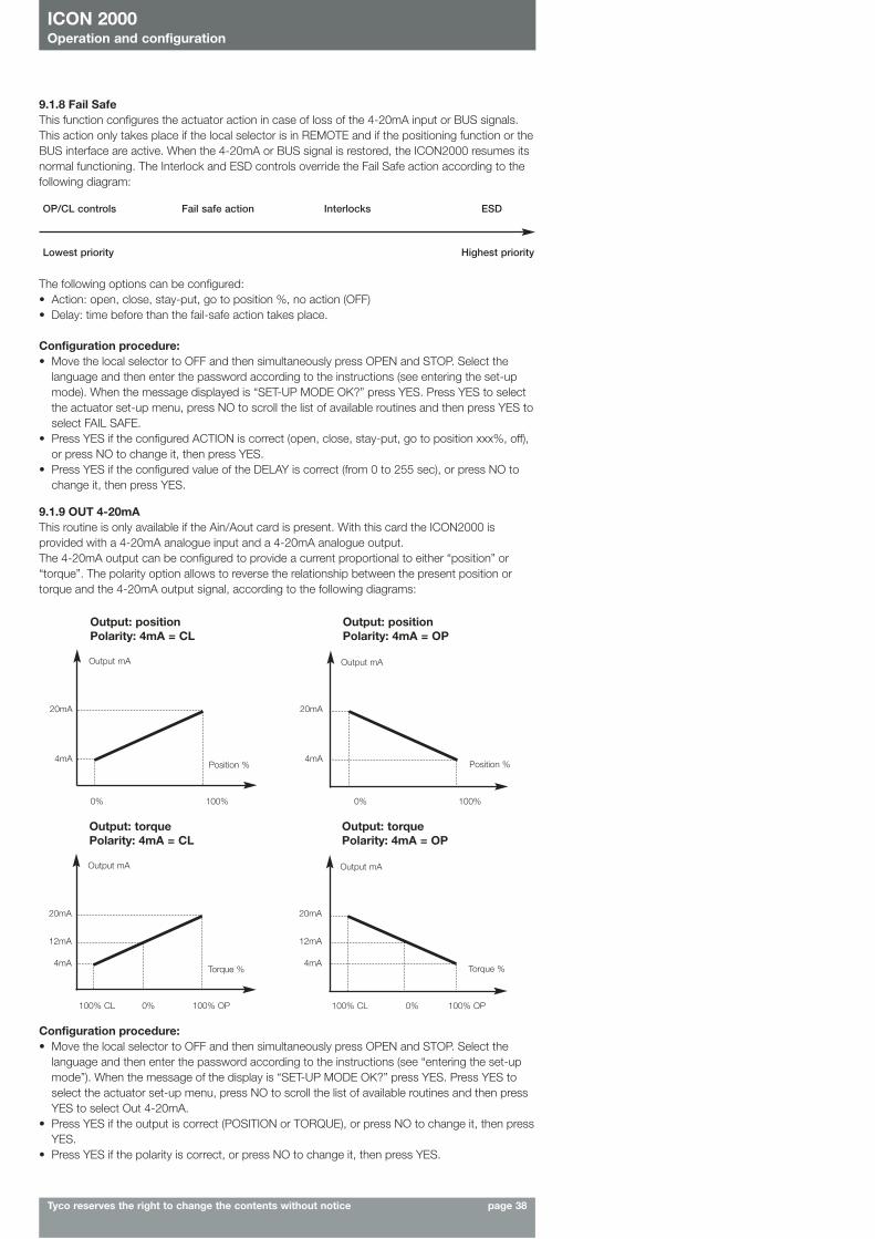
ICON 2000Operation and configuration
Tyco reserves the right to change the contents without notice page 38
9.1.8 Fail SafeThis function configures the actuator action in case of loss of the 4-20mA input or BUS signals.This action only takes place if the local selector is in REMOTE and if the positioning function or theBUS interface are active. When the 4-20mA or BUS signal is restored, the ICON2000 resumes itsnormal functioning. The Interlock and ESD controls override the Fail Safe action according to thefollowing diagram:
OP/CL controls
Lowest priority Highest priority
Fail safe action Interlocks ESD
The following options can be configured:• Action: open, close, stay-put, go to position %, no action (OFF)• Delay: time before than the fail-safe action takes place.
Configuration procedure:• Move the local selector to OFF and then simultaneously press OPEN and STOP. Select the
language and then enter the password according to the instructions (see entering the set-upmode). When the message displayed is “SET-UP MODE OK?” press YES. Press YES to selectthe actuator set-up menu, press NO to scroll the list of available routines and then press YES toselect FAIL SAFE.
• Press YES if the configured ACTION is correct (open, close, stay-put, go to position xxx%, off),or press NO to change it, then press YES.
• Press YES if the configured value of the DELAY is correct (from 0 to 255 sec), or press NO tochange it, then press YES.
9.1.9 OUT 4-20mAThis routine is only available if the Ain/Aout card is present. With this card the ICON2000 isprovided with a 4-20mA analogue input and a 4-20mA analogue output.The 4-20mA output can be configured to provide a current proportional to either “position” or“torque”. The polarity option allows to reverse the relationship between the present position ortorque and the 4-20mA output signal, according to the following diagrams:
Output: positionPolarity: 4mA = CL
Output: positionPolarity: 4mA = OP
Output mAOutput mA
20mA
4mA
20mA
4mAPosition % Position %
0% 100% 0% 100%
Output: torquePolarity: 4mA = CL
Output: torquePolarity: 4mA = OP
Output mAOutput mA
20mA
12mA 12mA
4mA
20mA
4mATorque % Torque %
100% CL 0% 100% OP 100% CL 0% 100% OP
Configuration procedure:• Move the local selector to OFF and then simultaneously press OPEN and STOP. Select the
language and then enter the password according to the instructions (see “entering the set-upmode”). When the message of the display is “SET-UP MODE OK?” press YES. Press YES toselect the actuator set-up menu, press NO to scroll the list of available routines and then pressYES to select Out 4-20mA.
• Press YES if the output is correct (POSITION or TORQUE), or press NO to change it, then pressYES.
• Press YES if the polarity is correct, or press NO to change it, then press YES.
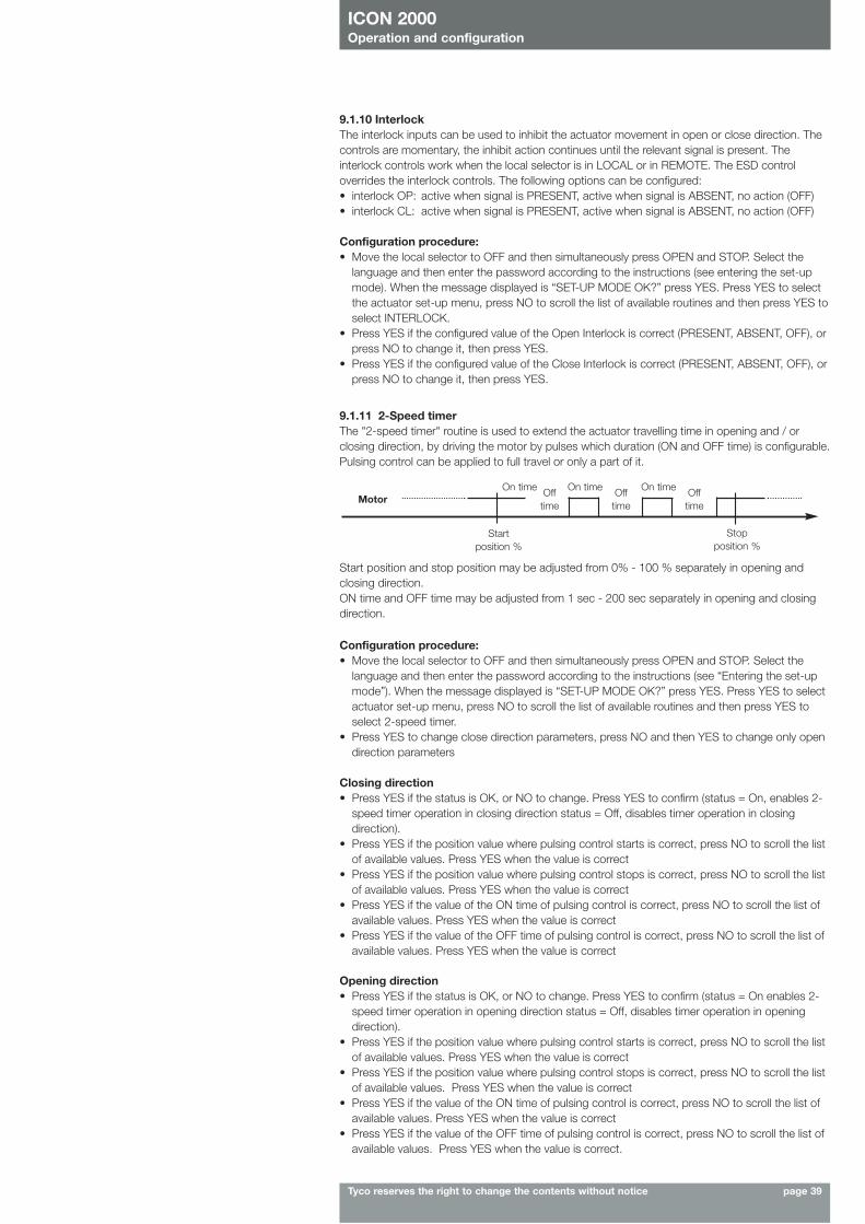
ICON 2000Operation and configuration
Tyco reserves the right to change the contents without notice page 39
Motor
Startposition %
Stopposition %
On time On time On timeOff time
Off time
Off time
Start position and stop position may be adjusted from 0% - 100 % separately in opening andclosing direction.ON time and OFF time may be adjusted from 1 sec - 200 sec separately in opening and closingdirection.
Configuration procedure:• Move the local selector to OFF and then simultaneously press OPEN and STOP. Select the
language and then enter the password according to the instructions (see “Entering the set-upmode”). When the message displayed is “SET-UP MODE OK?” press YES. Press YES to selectactuator set-up menu, press NO to scroll the list of available routines and then press YES toselect 2-speed timer.
• Press YES to change close direction parameters, press NO and then YES to change only opendirection parameters
Closing direction• Press YES if the status is OK, or NO to change. Press YES to confirm (status = On, enables 2-
speed timer operation in closing direction status = Off, disables timer operation in closingdirection).
• Press YES if the position value where pulsing control starts is correct, press NO to scroll the listof available values. Press YES when the value is correct
• Press YES if the position value where pulsing control stops is correct, press NO to scroll the listof available values. Press YES when the value is correct
• Press YES if the value of the ON time of pulsing control is correct, press NO to scroll the list ofavailable values. Press YES when the value is correct
• Press YES if the value of the OFF time of pulsing control is correct, press NO to scroll the list ofavailable values. Press YES when the value is correct
Opening direction• Press YES if the status is OK, or NO to change. Press YES to confirm (status = On enables 2-
speed timer operation in opening direction status = Off, disables timer operation in openingdirection).
• Press YES if the position value where pulsing control starts is correct, press NO to scroll the listof available values. Press YES when the value is correct
• Press YES if the position value where pulsing control stops is correct, press NO to scroll the listof available values. Press YES when the value is correct
• Press YES if the value of the ON time of pulsing control is correct, press NO to scroll the list ofavailable values. Press YES when the value is correct
• Press YES if the value of the OFF time of pulsing control is correct, press NO to scroll the list ofavailable values. Press YES when the value is correct.
9.1.11 2-Speed timerThe "2-speed timer" routine is used to extend the actuator travelling time in opening and / orclosing direction, by driving the motor by pulses which duration (ON and OFF time) is configurable.Pulsing control can be applied to full travel or only a part of it.
9.1.10 InterlockThe interlock inputs can be used to inhibit the actuator movement in open or close direction. Thecontrols are momentary, the inhibit action continues until the relevant signal is present. Theinterlock controls work when the local selector is in LOCAL or in REMOTE. The ESD controloverrides the interlock controls. The following options can be configured:• interlock OP: active when signal is PRESENT, active when signal is ABSENT, no action (OFF)• interlock CL: active when signal is PRESENT, active when signal is ABSENT, no action (OFF)
Configuration procedure:• Move the local selector to OFF and then simultaneously press OPEN and STOP. Select the
language and then enter the password according to the instructions (see entering the set-upmode). When the message displayed is “SET-UP MODE OK?” press YES. Press YES to selectthe actuator set-up menu, press NO to scroll the list of available routines and then press YES toselect INTERLOCK.
• Press YES if the configured value of the Open Interlock is correct (PRESENT, ABSENT, OFF), orpress NO to change it, then press YES.
• Press YES if the configured value of the Close Interlock is correct (PRESENT, ABSENT, OFF), orpress NO to change it, then press YES.
ICON 2000Operation and configuration
Tyco reserves the right to change the contents without notice page 40
9.1.12 Bus (or FDI control)This routine is only available if a fieldbus interface card is present. The routine allows setting themost important parameters (node address, termination, etc.) necessary to connect the actuator toa fieldbus. If the ICON2000 was set to work with fieldbus, but the fieldbus card is not present, aHardware alarm will be generated. Different interfaces are available to connect the ICON2000 todifferent types of fieldbus. If the bus interface is LonWorks, the routine “BUS” changes in “FDIcontrol”. See the specific manuals for instruction and setting of the above modules.
9.1.13 MiscellaneousIt includes different types of routines as “time and date”, “factory settings”, “lithium battery”, “torqueprofile”, etc. used only for special application or in particular conditions.
9.1.13.1 Time and dateTime and date are used in maintenance functions to associate the time information to the memorisedevent (torque profile, alarm log, maintenance request, etc.). Time and date are entered at the time ofmanufacture, but they can be adjusted during commissioning or maintenance operations.
Configuration procedure:• Move the local selector to OFF and then simultaneously press OPEN and STOP. Select the language
and enter the password according to the instructions (see “Entering the set-up mode”). When themessage displayed is “SET-UP MODE OK?” press YES. Press YES to select actuator set-up menu,press NO to scroll the list of available routines and then press YES to select Miscellaneous.
• Press YES to enter the time and date routine.• Press YES if the time is correct, press NO to change it• Enter hours, minutes and seconds. Press NO to scroll the list of available values, press YES to select.• Press YES when the time is correct• Press YES if the date is correct, press NO to change• Enter day, month, and year. Press NO to scroll the list of available values, press YES to select.• Press YES if the date is correct
9.1.13.2 Factory settingsThe above routine resets the present configuration and restores the default configuration as below:
Configuration procedure:• Move the local selector to OFF and then simultaneously press OPEN and STOP. Select the
language and then enter the password according to the instructions (see “Entering the set-upmode”). When the message displayed is “SET-UP MODE OK?” press YES. Press YES to selectthe actuator set-up menu, press NO to scroll the list of available routines and then press YES toselect Miscellaneous.
• Press No to scroll the list of routines and press YES to select factory configuration. Press YESto download the standard configuration, press NO to exit.
- Stroke limits close direction: CWclose limit: by positionopen limit: by position
- Torque set-up Closing torque: 40%Opening torque: 40%
- ESD set-up ESD action: closeESD signal: presentESD priority: ESD < motor thermostat
ESD < torque limitESD < local stopESD > local controlsESD > 2-speed timerESD < OFF
- Remote controls Control type: 4 wires latched - Locals controls Control type: latched with instant reverse
LED’s colour: green = open / openingred = close / closingyellow = alarm / warning
- Output relay Default #1- 2-speed timer Opening direction: off
Closing direction: off- Miscellaneous Lithium battery : absent
Torque profile: standardtorque by-pass: 4%valve jammed: 4 sec.
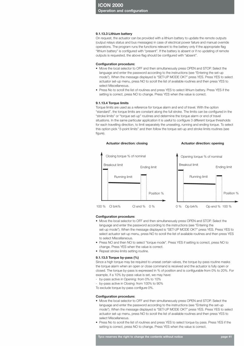
ICON 2000Operation and configuration
Tyco reserves the right to change the contents without notice page 41
9.1.13.3 Lithium batteryOn request, the actuator can be provided with a lithium battery to update the remote outputs(output relays status and bus messages) in case of electrical power failure and manual overrideoperations. The program runs the functions relevant to the battery only if the appropriate flag“lithium battery” is configured with “present”. If the battery is absent or if no updating of remoteoutputs is requested, the above flag should be configured with “absent”.
Configuration procedure:• Move the local selector to OFF and then simultaneously press OPEN and STOP. Select the
language and enter the password according to the instructions (see “Entering the set-up mode”). When the message displayed is “SET-UP MODE OK?” press YES. Press YES toselect actuator set-up menu, press NO to scroll the list of available routines and then press YESto select Miscellaneous.
• Press NO and then NO to select “torque mode”. Press YES if setting is correct, press NO tochange. Press YES when the value is correct.
• Repeat stroke limits setting routine.
9.1.13.4 Torque limitsTorque limits are used as a reference for torque alarm and end of travel. With the option“standard”, the torque limits are constant along the full stroke. The limits can be configured in the“stroke limits” or “torque set-up” routines and determine the torque alarm or end of travelsituations. In the same particular application it is useful to configure 3 different torque thresholdsfor each travelling direction, to limit separately the unseating, running and ending torque. To selectthis option pick “3-point limits” and then follow the torque set-up and stroke limits routines (seefigure).
Configuration procedure:• Move the local selector to OFF and then simultaneously press OPEN and STOP. Select the
language and enter the password according to the instructions (see “Entering the set-upmode”). When the message displayed is “SET-UP MODE OK?” press YES. Press YES to selectactuator set-up menu, press NO to scroll the list of available routines and then press YES toselect Miscellaneous.
• Press No to scroll the list of routines and press YES to select lithium battery. Press YES if thesetting is correct, press NO to change. Press YES when the value is correct.
Actuator direction: closing Actuator direction: opening
Opening torque % of nominalClosing torque % of nominal
Breakout limitEnding limit
Position %
Running limit
Breakout limitEnding limit
Position %
Running limit
100 % Cl brk% Cl end % 0 % 0 % Op brk% Op end % 100 %
9.1.13.5 Torque by-pass (%)Since a high torque may be required to unseat certain valves, the torque by-pass routine masksthe torque alarm when an open or close command is received and the actuator is fully open orclosed. The torque by-pass is expressed in % of position and is configurable from 0% to 20%. Forexample, if a 10% by-pass value is set, we may have:- by-pass active in Opening: from 0% to 10%- by-pass active in Closing: from 100% to 90%To exclude torque by-pass configure 0%.
Configuration procedure:• Move the local selector to OFF and then simultaneously press OPEN and STOP. Select the
language and enter the password according to the instructions (see “Entering the set-upmode”). When the message displayed is “SET-UP MODE OK?” press YES. Press YES to selectactuator set-up menu, press NO to scroll the list of available routines and then press YES toselect Miscellaneous.
• Press No to scroll the list of routines and press YES to select torque by pass. Press YES if thesetting is correct, press NO to change. Press YES when the value is correct.

ICON 2000Operation and configuration
Tyco reserves the right to change the contents without notice page 42
Configuration procedure:• Move the local selector to OFF and then simultaneously press OPEN and STOP. Select the
language and enter the password according to the instructions (see “Entering the set-upmode”.) When the message displayed is “SET-UP MODE OK?” press YES. Press YES to selectactuator set-up menu, press NO to scroll the list of available routines and then press YES toselect Miscellaneous.
• Press No to scroll the list of routines and press YES to select valve jammed. Press YES if thesetting is correct, press NO to change. Press YES when the value is correct.
9.2. Valve dataThe valve data allow identifying the valve and its function in the process. The valve manufacturerand the end user can enter the data. The following data can be entered:• tag name (max. 28 char.) • break OP torque (max 28 char.)• serial number (max. 28 char.) • break CL torque (max 28 char.)• manufacturer (max 28 char.) • max stem thrust (max 28 char.)• flange type (max 28 char.)
9.2.1 Sample Configuration procedure: Tag name• Move the local selector to OFF and then simultaneously press OPEN and STOP. Select the
language and enter the password according to the instructions (see “Entering the set-upmode”). When the message displayed is “SET-UP MODE OK?” press YES. Press NO to scrollthe list of available menus and then press YES to select valve data menu.
• Press NO to scroll the list of available routines and then press YES to select Tag name. • Press YES if the 1st character of the string is correct. Press NO to scroll the list of available
characters. Press YES to select the desired character.• Enter up to 28 characters. Enter a blank character, and “ ” as end of string.
The configuration of all other valve data items is made in the same way, bu selecting the relevantitem from the list of available routines.
9.1.13.6 Valve jammed (time)The valve jammed time is used to monitor the following situations:1. The time passed after receiving an open or close control is greater than the “valve jammed
time”, but the valve position variation is smaller than 0,5%. The motor is blocked, the commandis cleared and the “valve jammed” alarm indication is generated.
2. The valve is moving, but during the travel the position valve variation is smaller than 0,5% in atime equal to “valve jammed time”. The motor is blocked, the command is cleared and the“mid-travel alarm” indication is generated.
The valve jammed time is expressed in seconds and can be configured from 0 to 100 sec.Configure “0” to exclude the routine.
➔
9.2.2 Serial numberConfiguration procedure:• Move the local selector to OFF and then simultaneously press OPEN and STOP. Select the
language and enter the password according to the instructions (see “Entering the set-upmode”). When the message displayed is “SET-UP MODE OK?” press YES. Press NO to scrollthe list of available menus and then press YES to select valve data menu.
• Press NO to scroll the list of available routines and then press YES to select Serial number. • Press YES if the 1st character of the string is correct. Press NO to scroll the list of characters.
Press YES to select.• In the above way enter up to 28 characters. Enter a blank character, and “ ” as end of string.
9.3 MaintenanceA large amount of data is stored in the actuator memory and is available for future analysis or toassist the operator in the maintenance program. The maintenance menu also includes the setpassword routine and the possibility to modify or start the maintenance functions.The following data are available:• set password• clear alarm log• set torque reference• set curve reference• clear recent data log• set maintenance date• set data logger
9.3.1 Set passwordThe actuator is supplied by BIFFI with a default password (“0 0 0 0”). By the above routine the enduser can enter a different password consisting of 4 alphanumeric characters. After entering thenew password, the old one ceases to be valid. Therefore it is mandatory “NOT TO FORGET THEPASSWORD” after the default one has been modified. Forgetting the new password makes itimpossible to enter the set-up menu and to configure the actuator.
➔
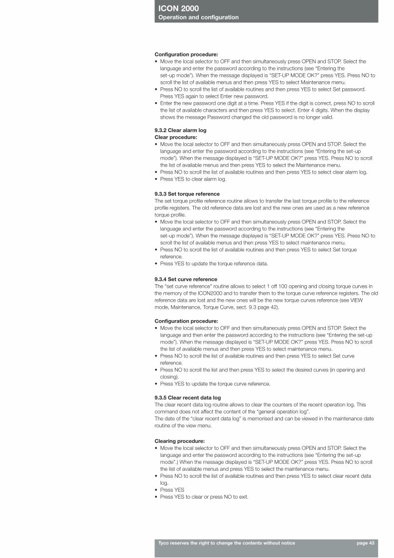
ICON 2000Operation and configuration
Tyco reserves the right to change the contents without notice page 43
Configuration procedure:• Move the local selector to OFF and then simultaneously press OPEN and STOP. Select the
language and enter the password according to the instructions (see “Entering the set-up mode”). When the message displayed is “SET-UP MODE OK?” press YES. Press NO toscroll the list of available menus and then press YES to select Maintenance menu.
• Press NO to scroll the list of available routines and then press YES to select Set password.Press YES again to select Enter new password.
• Enter the new password one digit at a time. Press YES if the digit is correct, press NO to scrollthe list of available characters and then press YES to select. Enter 4 digits. When the displayshows the message Password changed the old password is no longer valid.
9.3.2 Clear alarm logClear procedure:• Move the local selector to OFF and then simultaneously press OPEN and STOP. Select the
language and enter the password according to the instructions (see “Entering the set-upmode”). When the message displayed is “SET-UP MODE OK?” press YES. Press NO to scrollthe list of available menus and then press YES to select the Maintenance menu.
• Press NO to scroll the list of available routines and then press YES to select clear alarm log.• Press YES to clear alarm log.
9.3.3 Set torque referenceThe set torque profile reference routine allows to transfer the last torque profile to the referenceprofile registers. The old reference data are lost and the new ones are used as a new referencetorque profile.• Move the local selector to OFF and then simultaneously press OPEN and STOP. Select the
language and enter the password according to the instructions (see “Entering the set-up mode”). When the message displayed is “SET-UP MODE OK?” press YES. Press NO toscroll the list of available menus and then press YES to select maintenance menu.
• Press NO to scroll the list of available routines and then press YES to select Set torquereference.
• Press YES to update the torque reference data.
Clearing procedure:• Move the local selector to OFF and then simultaneously press OPEN and STOP. Select the
language and enter the password according to the instructions (see “Entering the set-upmode”.) When the message displayed is “SET-UP MODE OK?” press YES. Press NO to scrollthe list of available menus and press YES to select the maintenance menu.
• Press NO to scroll the list of available routines and then press YES to select clear recent datalog.
• Press YES• Press YES to clear or press NO to exit.
9.3.4 Set curve referenceThe “set curve reference” routine allows to select 1 off 100 opening and closing torque curves inthe memory of the ICON2000 and to transfer them to the torque curve reference registers. The oldreference data are lost and the new ones will be the new torque curves reference (see VIEWmode, Maintenance, Torque Curve, sect. 9.3 page 42).
Configuration procedure:• Move the local selector to OFF and then simultaneously press OPEN and STOP. Select the
language and then enter the password according to the instructions (see “Entering the set-upmode”). When the message displayed is “SET-UP MODE OK?” press YES. Press NO to scrollthe list of available menus and then press YES to select maintenance menu.
• Press NO to scroll the list of available routines and then press YES to select Set curvereference.
• Press NO to scroll the list and then press YES to select the desired curves (in opening andclosing).
• Press YES to update the torque curve reference.
9.3.5 Clear recent data logThe clear recent data log routine allows to clear the counters of the recent operation log. Thiscommand does not affect the content of the “general operation log”.The date of the “clear recent data log” is memorised and can be viewed in the maintenance dateroutine of the view menu.
ICON 2000Operation and configuration
Tyco reserves the right to change the contents without notice page 44
Last maintenance date:• Press YES if the date is correct, press NO to change it• Enter day, month, and year. Press NO to scroll the list of available values, press YES to select• Press YES if the date is correct
Next maintenance date:• Press YES if the date is correct, press NO to change it• Enter day, month, and year. Press NO to scroll the list of available values, press YES to select• Press YES if the date is correct
Start-up date:• Press YES if the date is correct, press NO to change it• Enter day, month, and year. Press NO to scroll the list of available values, press YES to select• Press YES if the date is correct
9.3.7 Set data loggerThe “data logger” routine allows to set the data logger parameters (see VIEW mode, Maintenance,Data Logger, sect 10.4.6).To start the data logger the following data should be set:• Logger mode recorder, event, off• Sampling time from 1 to 3600 secs (the sampling time is only used in recorder mode)• Memory mode stop when memory is full, continuous (stop after overwriting the memory
5000 times (event) and 10000 times (recorder/T-recorder) )• Start date date when the logger starts• Start time time when the logger starts
Configuration procedure:• Move the local selector to OFF and then simultaneously press OPEN and STOP. Select the
language and then enter the password according to the instructions (see “Entering the set-upmode”). When the message displayed is “SET-UP MODE OK?” press YES. Press NO to scrollthe list of available menus and then press YES to select maintenance menu.
• Press NO to scroll the list of available routines and then press YES to select “data logger”. • Press YES if the mode is correct. Press NO to scroll the list of modes and press YES to select
the desired value .• Press YES if the sampling time is correct. Press NO to scroll the list of times and press YES to
select the desired value.• Press YES if the memory mode is correct (stop when full or continuous). Press NO to change
and press YES to select. • Press YES if the start time is correct. Press NO to scroll the list and press YES to select the
desired sampling times (hour, min, sec). • Press YES if the start date is correct. Press NO to scroll the list and press YES to select the
desired sampling times (day, month, year) • Press YES to confirm the above settings.
Configuration procedure:• Move the local selector to OFF and then simultaneously press OPEN and STOP. Select the
language and enter the password according to the instructions (see “Entering the set-upmode”). When the message displayed is “SET-UP MODE OK?” press YES. Press NO to scrollthe list of available menus and then YES to select the maintenance menu.
• Press NO to scroll the list of available routines and press YES to select maintenance date.• Press YES to set the last maintenance date. Press NO to skip to “next maintenance date”.
9.3.6 Set maintenance dateThe maintenance date routine allows the following operations:• to set the last maintenance date• to set the next maintenance date• to set the start-up date
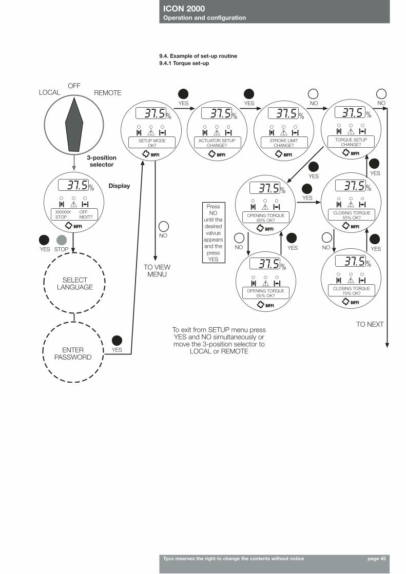
ICON 2000Operation and configuration
Tyco reserves the right to change the contents without notice page 45
9.4. Example of set-up routine9.4.1 Torque set-up
SETUP MODEOK?
ACTUATOR SETUPCHANGE?
STROKE LIMITCHANGE?
TORQUE SETUPCHANGE?
CLOSING TORQUE55% OK?
CLOSING TORQUE70% OK?
OPENING TORQUE60% OK?
OPENING TORQUE65% OK?
YES
YES
YES
YES
YES
YES
YESYES
NO
NO
NO NO
NO
TO NEXT
TO VIEWMENU
To exit from SETUP menu pressYES and NO simultaneously ormove the 3-position selector to
LOCAL or REMOTE
SELECTLANGUAGE
ENTERPASSWORD
PressNO
until thedesiredvalvue
appearsand thepressYES
XXXXXX OFFSTOP NEXT?
Display
LOCAL REMOTE
STOPYES
OFF
3-positionselector
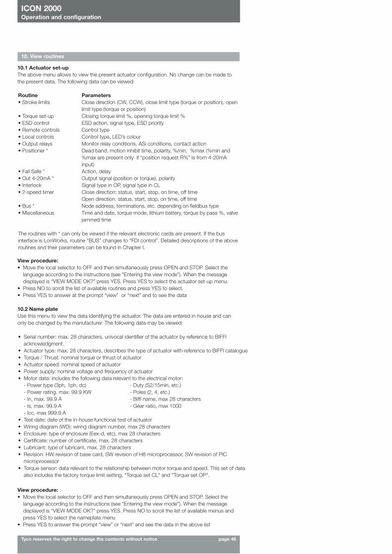
ICON 2000Operation and configuration
Tyco reserves the right to change the contents without notice page 46
10. View routines
10.1 Actuator set-upThe above menu allows to view the present actuator configuration. No change can be made tothe present data. The following data can be viewed:
View procedure:• Move the local selector to OFF and then simultaneously press OPEN and STOP. Select the
language according to the instructions (see “Entering the view mode”). When the messagedisplayed is “VIEW MODE OK?” press YES. Press YES to select the actuator set-up menu.
• Press NO to scroll the list of available routines and press YES to select. • Press YES to answer at the prompt “view” or “next” and to see the data
10.2 Name plate Use this menu to view the data identifying the actuator. The data are entered in-house and canonly be changed by the manufacturer. The following data may be viewed:
Routine Parameters • Stroke limits Close direction (CW, CCW), close limit type (torque or position), open
limit type (torque or position)• Torque set-up Closing torque limit %, opening torque limit %• ESD control ESD action, signal type, ESD priority• Remote controls Control type• Local controls Control type, LED’s colour• Output relays Monitor relay conditions, ASi conditions, contact action• Positioner * Dead band, motion inhibit time, polarity, %min, %max (%min and
%max are present only if “position request R%” is from 4-20mAinput)
• Fail Safe * Action, delay• Out 4-20mA * Output signal (position or torque), polarity• Interlock Signal type in OP, signal type in CL• 2-speed timer Close direction: status, start, stop, on time, off time
Open direction: status, start, stop, on time, off time• Bus * Node address, terminations, etc. depending on fieldbus type• Miscellaneous Time and date, torque mode, lithium battery, torque by pass %, valve
jammed time
The routines with * can only be viewed if the relevant electronic cards are present. If the businterface is LonWorks, routine “BUS” changes to “FDI control”. Detailed descriptions of the aboveroutines and their parameters can be found in Chapter I.
• Serial number: max. 28 characters, univocal identifier of the actuator by reference to BIFFIacknowledgment.
• Actuator type: max. 28 characters, describes the type of actuator with reference to BIFFI catalogue• Torque / Thrust: nominal torque or thrust of actuator• Actuator speed: nominal speed of actuator• Power supply: nominal voltage and frequency of actuator• Motor data: includes the following data relevant to the electrical motor:
- Power type (3ph, 1ph, dc) - Duty (S2/15min, etc.)- Power rating, max. 99.9 KW - Poles (2, 4, etc.)- In, max. 99.9 A - Biffi name, max 28 characters- Is, max. 99.9 A - Gear ratio, max 1000- Icc, max 999.9 A
• Test date: date of the in-house functional test of actuator• Wiring diagram (WD): wiring diagram number, max 28 characters• Enclosure: type of enclosure (Eex-d, etc), max 28 characters• Certificate: number of certificate, max. 28 characters• Lubricant: type of lubricant, max. 28 characters• Revision: HW revision of base card, SW revision of H8 microprocessor, SW revision of PIC
microprocessor • Torque sensor: data relevant to the relationship between motor torque and speed. This set of data
also includes the factory torque limit setting, "Torque set CL" and "Torque set OP".
View procedure:• Move the local selector to OFF and then simultaneously press OPEN and STOP. Select the
language according to the instructions (see “Entering the view mode”). When the messagedisplayed is “VIEW MODE OK?” press YES. Press NO to scroll the list of available menus andpress YES to select the nameplate menu
• Press YES to answer the prompt “view” or “next” and see the data in the above list
ICON 2000Operation and configuration
Tyco reserves the right to change the contents without notice page 47
The following data may be viewed:Closing torque Opening torque• breakout % • breakout %• breakout reference % • breakout reference %• peak run % • peak run %• peak run reference % • peak run reference %• ending % • ending %• ending reference % • ending reference %• date of the last stroke • date of the last stroke • date of reference (same of opening) • date of reference (same of closing)
View procedure:• Move the local selector to OFF and then simultaneously press OPEN and STOP. Select the
language according to the instructions (see “Entering the view mode”). When the messagedisplayed is “VIEW MODE OK?” press YES. Press NO to scroll the list of available menus andpress YES to select the Maintenance menu.
• Press NO to scroll the list of routines and press YES to select torque profile.• Press YES to scroll the list of values
10.4. Maintenance10.4.1 Alarm logThe alarm log routine is used to view the list of the latest 5 alarms and 5 warnings and the data whenthey occurred. The “clear alarm log” routine of the set-up menu should be used to clear the list.
View procedure:• Move the local selector to OFF and then simultaneously press OPEN and STOP. Select the
language according to the instructions (see “Entering the view mode”). When the messagedisplayed is “VIEW MODE OK?” press YES. Press NO to scroll the list of available menus and pressYES to select the Maintenance menu.
• Press YES to answer the prompt “Alarm log view?”.• Press YES to scroll the list of alarms (“Alarms view?”).• Press NO to move on to “Warnings view?” and then YES to scroll the list of warnings.
10.4.2 Torque profileThe torque profile routine gives important information on the actuator working conditions incomparison with a previously memorised reference profile. It can give an indication of a change in theprocess conditions. Details are given of the reference and latest torque expressed in % of the nominal torque.
At the end of a full stroke in opening or closing the ICON2000 stores the 3 maximum torque values inposition intervals 0%-10%, 10%-90%, 90%-100% in opening, and the 3 maximum torque values inposition intervals 100%-90%, 90%-10%, 10%-0% in closing. Time and date of strokes are alsosaved. The above data are updated at the end of every full valve stroke and the previous ones are lost.Function “set torque reference”, in the SET-UP MENU, Maintenance, (Sect. 7), allows to save the“torque profile” data in the “torque profile reference” with date and time. The “torque profile reference”will not be updated until a new “set torque reference” command is entered. The user can compare thelast torque profile relevant to the last valve stroke with the torque profile reference saved before.The following definitions will be used: • Breakout: maximum torque % in position interval 0-10% in opening or 100%-90% in closing =
max. % of torque to unseat the valve.• Peak Running: maximum torque % in position interval 10-90% in opening or 90%-10% in closing =
max. % of torque when the valve runs from Breakout to Ending (maximum mid-travel).• Ending: maximum torque % in position interval 90-100% in opening or 10%-0% in closing = max.
% of torque to seat the valve.
10.3 Valve dataTo identify the valve and its function in the process the following data can be viewed.• tag name (max. 28 char.) • break CL torque (max 28 char.)• serial number (max. 28 char.) • max stem thrust (max 28 char.)• manufacturer (max 28 char.) • flange type (max 28 char.)• break OP torque (max 28 char.)The data should be entered by the valve manufacturer or by the end user during set-upoperations.View procedure:• Move the local selector to OFF and then simultaneously press OPEN and STOP. Select the
language according to the instructions (see “Entering the view mode”). When the messagedisplayed is “VIEW MODE OK?” press YES. Press NO to scroll the list of available menus andpress YES to select the valve data menu.
• Press YES to answer prompts “view” or “next” and see the data in the above list.
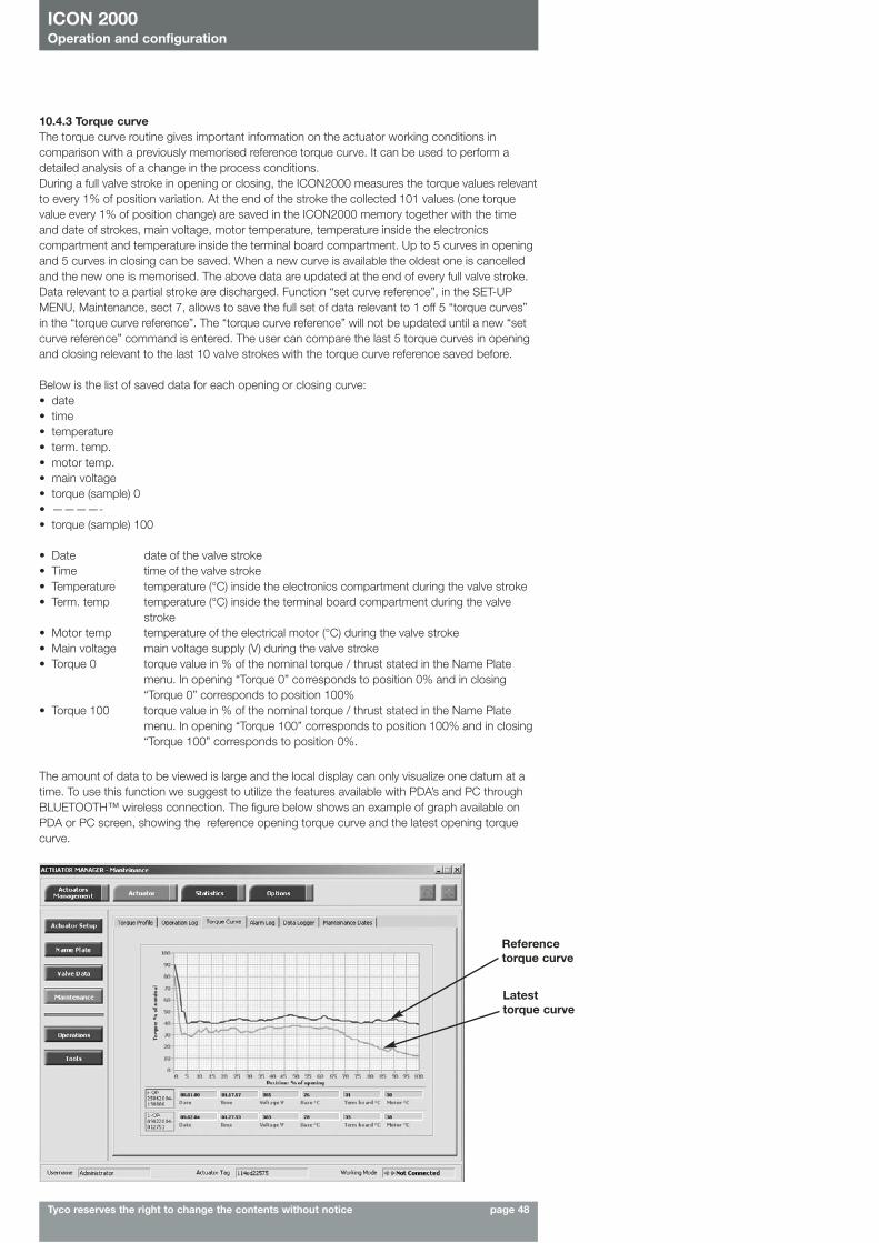
ICON 2000Operation and configuration
Tyco reserves the right to change the contents without notice page 48
10.4.3 Torque curveThe torque curve routine gives important information on the actuator working conditions incomparison with a previously memorised reference torque curve. It can be used to perform adetailed analysis of a change in the process conditions.During a full valve stroke in opening or closing, the ICON2000 measures the torque values relevantto every 1% of position variation. At the end of the stroke the collected 101 values (one torquevalue every 1% of position change) are saved in the ICON2000 memory together with the timeand date of strokes, main voltage, motor temperature, temperature inside the electronicscompartment and temperature inside the terminal board compartment. Up to 5 curves in openingand 5 curves in closing can be saved. When a new curve is available the oldest one is cancelledand the new one is memorised. The above data are updated at the end of every full valve stroke.Data relevant to a partial stroke are discharged. Function “set curve reference”, in the SET-UPMENU, Maintenance, sect 7, allows to save the full set of data relevant to 1 off 5 “torque curves”in the “torque curve reference”. The “torque curve reference” will not be updated until a new “setcurve reference” command is entered. The user can compare the last 5 torque curves in openingand closing relevant to the last 10 valve strokes with the torque curve reference saved before.
Below is the list of saved data for each opening or closing curve:• date • time • temperature• term. temp. • motor temp.• main voltage• torque (sample) 0• ————-• torque (sample) 100
The amount of data to be viewed is large and the local display can only visualize one datum at atime. To use this function we suggest to utilize the features available with PDA’s and PC throughBLUETOOTH™ wireless connection. The figure below shows an example of graph available onPDA or PC screen, showing the reference opening torque curve and the latest opening torquecurve.
Reference torque curve
Latest torque curve
• Date date of the valve stroke• Time time of the valve stroke• Temperature temperature (°C) inside the electronics compartment during the valve stroke• Term. temp temperature (°C) inside the terminal board compartment during the valve
stroke• Motor temp temperature of the electrical motor (°C) during the valve stroke • Main voltage main voltage supply (V) during the valve stroke• Torque 0 torque value in % of the nominal torque / thrust stated in the Name Plate
menu. In opening “Torque 0” corresponds to position 0% and in closing“Torque 0” corresponds to position 100%
• Torque 100 torque value in % of the nominal torque / thrust stated in the Name Platemenu. In opening “Torque 100” corresponds to position 100% and in closing“Torque 100” corresponds to position 0%.
ICON 2000Operation and configuration
Tyco reserves the right to change the contents without notice page 49
View procedure:• Move the local selector to OFF and then simultaneously press OPEN and STOP. Select the
language according to the instructions (see “Entering the view mode”). When the messagedisplayed is “VIEW MODE OK?” press YES. Press NO to scroll the list of available menus andpress YES to select the Maintenance menu.
• Press NO to scroll the list of available routines and press YES to select operation log.• Press YES to select general data or press NO to skip to recent data• Press YES to scroll the list of values. • Press YES to view the recent data log or press NO to exit• Press YES to scroll the list of values.
10.4.4 Operation logThe operation log consists of different counters and routines that provide information to assist in themaintenance program. The data are grouped into 2 families: general and recent data. The generaldata log collects data from "test date" to "present date". The test date is set in house, can be viewedin the “name plate” menu but cannot be changed. The recent data log collects data from the last"clear recent data log" date to "present date".Command “clear recent data log” is available in the SET-UP MENU, maintenance, sect, 7. Thiscommand clears the content of the recent data log and resets the counters to 0. The old data are lost.The main differences between “general” and “recent” data log are the following:• The general data log gives information relevant to the full life of the actuator, starting from the
manufacturing date.• In the recent data log the same data are collected starting from a date set by the user. The date
may be viewed in the MAINTENANCE DATE paragraph.
Below is the list of data collected by the general and recent data log.
General data log Recent data log• opening time • closing time • contactor cycles • contactor cycles• motor run time • motor run time • no power time • no power time• utilisation rate • utilisation rate• temperature min. • temperature min• temperature max. • temperature max• term temp min. • term temp min• term temp max. • term temp max• motor temp max. • motor temp max• thermostat alarms • thermostat alarms• torque alarms • torque alarms
• Opening time this datum is only available in the general data log. It is updated at the end ofevery full valve stroke of the valve in opening direction. The data of theprevious stroke are lost. It gives the time necessary to the valve to move fromthe close position to the open position, expressed in hours, minutes andseconds.
• Closing time: this datum is only available in the general data log. It is updated at the end ofevery full valve stroke of the valve in closing direction. The data of theprevious stroke are lost. It gives the time necessary to the valve to move fromthe open position to the close position, expressed in hours, minutes andseconds.
• Contactor cycles this number counts the cycles of contactors K1 and K2. The value indicatedin the general data log is also used to generate the “max. contactor cycles”warning when the maximum allowable number of cycles of the contactor isreached (see sect. 12 point 12.11 page 59, Diagnostic messages). If themain power is DC or single phase and in modulating actuators, the counters(general and recent) are hold to 0.
• Motor run time this number counts the hours with motor energized.• No power time this number counts the hours without electrical power.• Utilization rate this number % is incremented every 200 full strokes of the actuator. It
reaches 100% after 20 000 full strokes.• Temperature min. this is the lowest temperature value (in °C) measured inside the electronics
compartment. • Temperature max. this is the highest temperature value (in °C) measured inside the electronics
compartment.• Term. temp. min. this is the lowest temperature value (in °C) measured inside the terminal
board enclosure. • Term. temp. max. this is the highest temperature value (in °C) measured inside the terminal
board enclosure. • Motor temp. max. this is the highest temperature value (in °C) measured in the electrical motor. • Thermostat alarms this counts the number of alarms due to the high temperature of the
electrical motor and to the tripping of the motor thermostat.• Torque alarms this counts the number of alarms due to high torque in opening and closing.
ICON 2000Operation and configuration
Tyco reserves the right to change the contents without notice page 50
View procedure:• Move the local selector to OFF and then simultaneously press OPEN and STOP. Select the
language according to the instructions (see “Entering the view mode”). When the messagedisplayed is “VIEW MODE OK?” press YES. Press NO to scroll the list of available menus andpress YES to select the Maintenance menu.
• Press NO to scroll the list of available routines and press YES to select operation log.• Press YES to select general data or press NO to skip to recent data.• Press YES to scroll the list of values. • Press YES to view the recent data log or press NO to exit.• Press YES to scroll the list of values.
10.4.5 Maintenance dateThe routine allows viewing the following dates:• last date• next date• start-up date• recent log date• Last date this is the date of the last maintenance operation. The date should be
updated by the user after all maintenance operations (see sect. 9 point9.3 page 42).
• Next date this is the date of the next scheduled actuator maintenance. When thedate is reached, the ICON2000 generates a maintenance requestwarning. The date should be updated by the user after all maintenanceoperations (see sect. 9 point 9.3 page 42).
• Start-up date this is the date of actuator start-up. During commissioning, the usershould enter the start-up date (see sect. 9 point 9.3 page 42).
• Recent log date this is updated after entering command “Clear recent data log” (see sect.9 point 9.3 page 42). This command clears the “recent data log”counters. The content of “recent log” is updated starting from “recent logdate”.
View procedure:• Move the local selector to OFF and then simultaneously press OPEN and STOP. Select the
language according to the instructions (see “Entering the view mode”). When the messagedisplayed is “VIEW MODE OK?” press YES. Press NO to scroll the list of available menus andpress YES to select the Maintenance menu.
• Press NO to scroll the list of available routines and press YES to select the maintenance dateroutine
• Press YES to scroll the list of dates
In RECORDER and T-RECORDER mode the SAMPLING TIME fixes the time interval among two setsof measures. Up to 256 sets of measures (equivalent to 256x4 samples) can be memorised. Thesampling time can be configured from 1 to 3600 secs. As the memory is full, the recorder stopsrecording or overwrites the previous data according to the selected MEMORY MODE (“stop when full”or “continuous”). If “continuous” was selected, as a new set of measures is achieved the oldest one iscancelled and the new one becomes the latest. Up to 10000 cycles of full memory overwriting aredone, then the recorder stops. In T-RECORDER mode, the recording operation is also stopped incase of OVER-TORQUE ALARM, in opening or in closing. This additional feature allows to maintain inthe memory the last 256 samples and see the trend of torque, motor temperature and main voltagebefore the alarm. A new start of T-RECORDER clears the data stored in the memory. By a PDA or PCthe recorded data can be viewed by a graph where time is on the X axis and the measured data onthe Y axis.
• T-RECORDER mode: the ICON2000 measures and memorises the following 3 data:• Torque in OP/CL • Motor temperature (°C)• Voltage
10.4.6 Data loggerThe “data logger” routine allows to collect different types of data useful in maintenance or indiagnostic programs. Since the amount of collected data is very large, the data logger can only beviewed by means of a PDA or PC. The data can be up-loaded from ICON2000 to PDA or PC bythe BLUETOOTHTM wireless connection. The local display only allows to view the value of theconfigured parameters (see also SET-UP menu, Maintenance, Set data logger, chap I). Thefollowing data can be viewed on the local display:• Logger mode • Sampling time• Memory mode • Date• Time
Data logger functions:• OFF: the data logger is not active.• RECORDER mode: the ICON2000 measures and memorises the following 3 data:
• main voltage supply (V) • motor temperature (°C)• temperature inside the compartment of electronics (°C)
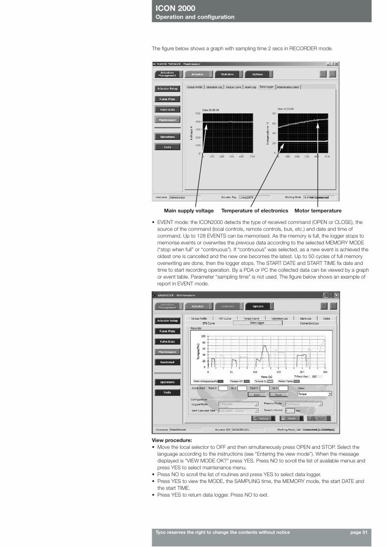
ICON 2000Operation and configuration
Tyco reserves the right to change the contents without notice page 51
View procedure:• Move the local selector to OFF and then simultaneously press OPEN and STOP. Select the
language according to the instructions (see “Entering the view mode”). When the messagedisplayed is “VIEW MODE OK?” press YES. Press NO to scroll the list of available menus andpress YES to select maintenance menu.
• Press NO to scroll the list of routines and press YES to select data logger.• Press YES to view the MODE, the SAMPLING time, the MEMORY mode, the start DATE and
the start TIME.• Press YES to return data logger. Press NO to exit.
• EVENT mode: the ICON2000 detects the type of received command (OPEN or CLOSE), thesource of the command (local controls, remote controls, bus, etc.) and date and time ofcommand. Up to 128 EVENTS can be memorised. As the memory is full, the logger stops tomemorise events or overwrites the previous data according to the selected MEMORY MODE(“stop when full” or “continuous”). If “continuous” was selected, as a new event is achieved theoldest one is cancelled and the new one becomes the latest. Up to 50 cycles of full memoryoverwriting are done, then the logger stops. The START DATE and START TIME fix date andtime to start recording operation. By a PDA or PC the collected data can be viewed by a graphor event table. Parameter “sampling time” is not used. The figure below shows an example ofreport in EVENT mode.
Main supply voltage Temperature of electronics Motor temperature
The figure below shows a graph with sampling time 2 secs in RECORDER mode.
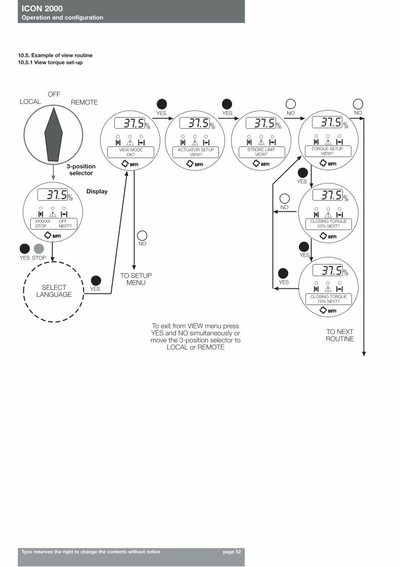
ICON 2000Operation and configuration
Tyco reserves the right to change the contents without notice page 52
CLOSING TORQUE55% NEXT?
CLOSING TORQUE70% NEXT?
TORQUE SETUPVIEW?
STROKE LIMITVIEW?
ACTUATOR SETUPVIEW?
VIEW MODEOK?
YES YES
YES
YES
YES
NO
NO
NO
NO
YES
TO NEXTROUTINE
TO SETUPMENU
SELECTLANGUAGE
To exit from VIEW menu pressYES and NO simultaneously ormove the 3-position selector to
LOCAL or REMOTE
XXXXXX OFFSTOP NEXT?
Display
LOCAL REMOTE
STOPYES
OFF
3-positionselector
10.5. Example of view routine10.5.1 View torque set-up
ICON 2000Maintenance and trouble-shooting
Tyco reserves the right to change the contents without notice page 53
11. Maintenance
11.1 Standard maintenanceApprox. every 2 years:Under normal operating conditions, the ICON2000 is maintenance-free: no actuator maintenanceis formally required, even though visual inspection for oil leakage or external visible damages isrecommended every two years. When conditions are severe (frequent operation or hightemperatures), inspect the oil level and oil quality more often. Replace all seals that permit oilleakage or water ingress.
The following checks will assure optimum performance:- If the stem is external, check that the valve stem is clean and lubricated. If not, clean it and
lubricate it in order to prevent damages to the threaded bush.- Lubricate the internal components of the coupling block by means of the spherical head
lubricator using suggested greases (see chapter 4, Lubrication).- Make sure there are no oil leaks from the actuator housing. The oil level should be approx.
20 mm. from the fill plug (see chapter 4, Lubrication).- Check the external parts for possible damage and replace them immediately, if necessary.
In case the window glass is broken, the complete cover must be replaced (see chapter 13,Parts list and drawings for individual item numbers).
- Repaint all areas where paint is missing. In chemically aggressive or saline environments,remove rust from surfaces and protect with a rust preventative.
- Check that all nuts and bolts securing the actuator to the valve are tight. If necessary, re-tightenwith a dynamometric key (for tightening torque values see chapter 3.4.3, Installation - Mountingthe actuator onto the valve - Actuator fixing).
- For severe applications or if actuator operation is infrequent, perform maintenance checks moreoften.
- For actuators provided with lithium batteries, make sure that the display is still visible whenpower is off and that there is no “Battery low” warning message. If “Battery low” warningappears, replace the battery (see chapter 11.3 Maintenance - Lithium battery change).Always replace batteries if the actuator has been subjected to long periods without power (seechapter 12, Troubleshooting).
11.2 Special maintenanceIn case actuator failure, please refer to chapter 12, Troubleshooting for possible causes.Spare parts can be required to BIFFI: please refer to the individual item number shown in chapter 13,Parts list and drawings.
Important
Before starting any maintenance operation, make sure that the mains and all other servicevoltage connected to terminal board are switched-off.
Warning
The actuator is non-intrusive. The control compartment was sealed in dry and cleanconditions and contains no site serviceable components. Do not open it unless absolutelynecessary. Unauthorised access will invalidate the warranty.
Warning
Since the control compartment contains a 3.6V lithium battery, only open it in safe area. If theactuator is located in a hazardous area a “hot work” permit must be obtained unless theactuator can be moved to a non-hazardous area.
Note
Special maintenance is also recommendedwhen, during operations, the actuatorgenerates an excessive noise.
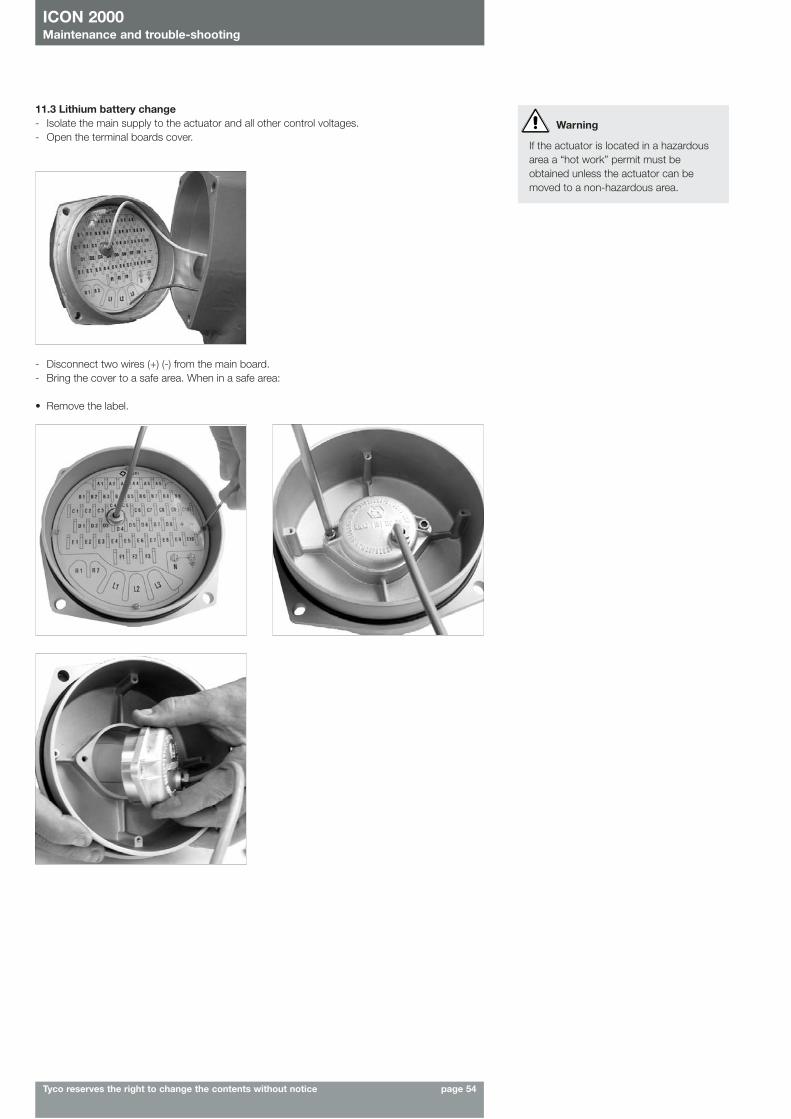
11.3 Lithium battery change- Isolate the main supply to the actuator and all other control voltages.- Open the terminal boards cover.
- Disconnect two wires (+) (-) from the main board.- Bring the cover to a safe area. When in a safe area:
• Remove the label.
ICON 2000Maintenance and trouble-shooting
Tyco reserves the right to change the contents without notice page 54
Warning
If the actuator is located in a hazardousarea a “hot work” permit must beobtained unless the actuator can bemoved to a non-hazardous area.
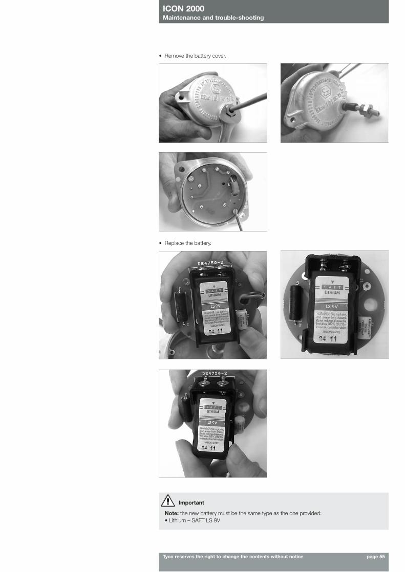
ICON 2000Maintenance and trouble-shooting
Tyco reserves the right to change the contents without notice page 55
Important
Note: the new battery must be the same type as the one provided:• Lithium – SAFT LS 9V
• Remove the battery cover.
• Replace the battery.
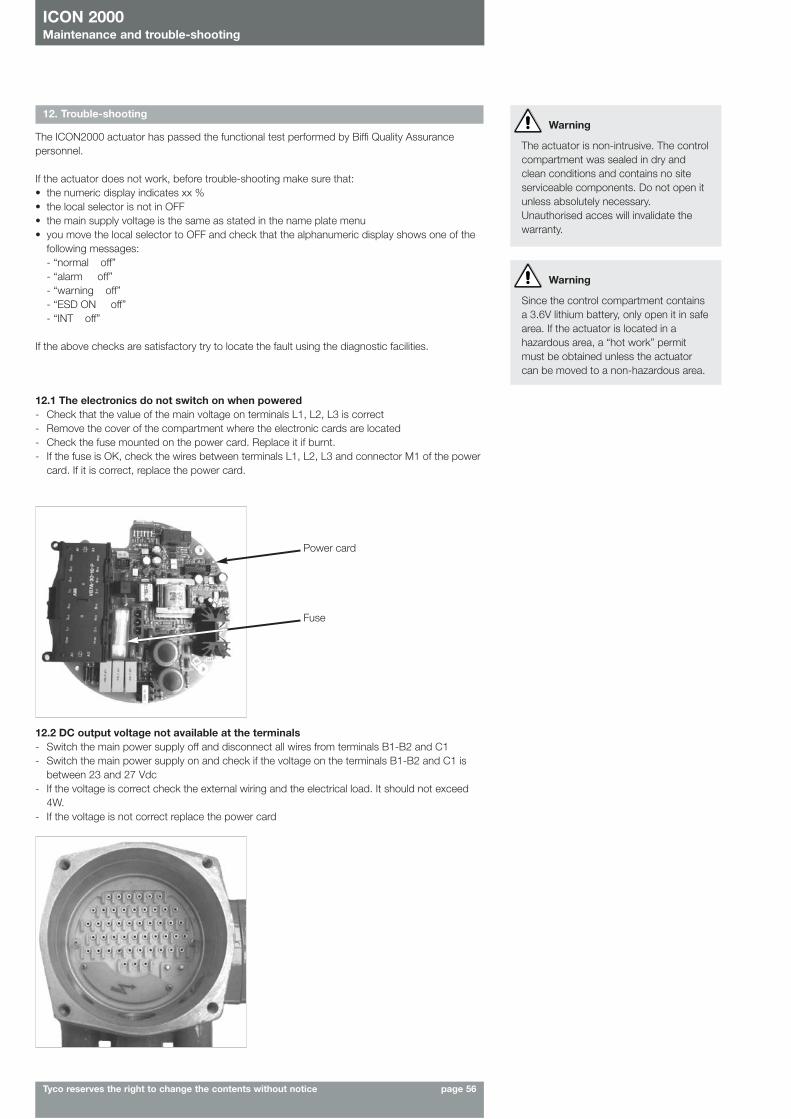
ICON 2000Maintenance and trouble-shooting
Tyco reserves the right to change the contents without notice page 56
Warning
The actuator is non-intrusive. The controlcompartment was sealed in dry andclean conditions and contains no siteserviceable components. Do not open itunless absolutely necessary.Unauthorised acces will invalidate thewarranty.
Warning
Since the control compartment containsa 3.6V lithium battery, only open it in safearea. If the actuator is located in ahazardous area, a “hot work” permitmust be obtained unless the actuatorcan be moved to a non-hazardous area.
12. Trouble-shooting
The ICON2000 actuator has passed the functional test performed by Biffi Quality Assurancepersonnel.
If the actuator does not work, before trouble-shooting make sure that:• the numeric display indicates xx %• the local selector is not in OFF• the main supply voltage is the same as stated in the name plate menu• you move the local selector to OFF and check that the alphanumeric display shows one of the
following messages:- “normal off”- “alarm off”- “warning off”- “ESD ON off”- “INT off”
If the above checks are satisfactory try to locate the fault using the diagnostic facilities.
12.1 The electronics do not switch on when powered- Check that the value of the main voltage on terminals L1, L2, L3 is correct- Remove the cover of the compartment where the electronic cards are located- Check the fuse mounted on the power card. Replace it if burnt.- If the fuse is OK, check the wires between terminals L1, L2, L3 and connector M1 of the power
card. If it is correct, replace the power card.
12.2 DC output voltage not available at the terminals- Switch the main power supply off and disconnect all wires from terminals B1-B2 and C1- Switch the main power supply on and check if the voltage on the terminals B1-B2 and C1 is
between 23 and 27 Vdc- If the voltage is correct check the external wiring and the electrical load. It should not exceed
4W.- If the voltage is not correct replace the power card
Power card
Fuse
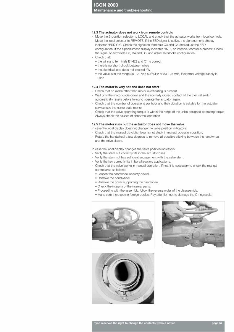
ICON 2000Maintenance and trouble-shooting
Tyco reserves the right to change the contents without notice page 57
12.3 The actuator does not work from remote controls- Move the 3-position selector to LOCAL and check that the actuator works from local controls.- Move the local selector to REMOTE. If the ESD signal is active, the alphanumeric display
indicates “ESD On”. Check the signal on terminals C3 and C4 and adjust the ESDconfiguration. If the alphanumeric display indicates “INT”, an interlock control is present. Checkthe signal on terminals B3, B4 and B5, and adjust Interlocks configuration.
- Check that:• the wiring to terminals B1-B2 and C1 is correct• there is no short-circuit between wires• the electrical load does not exceed 4W• the value is in the range 20-120 Vac 50/60Hz or 20-125 Vdc, if external voltage supply is
used
12.4 The motor is very hot and does not start- Check that no alarm other than motor overheating is present.- Wait until the motor cools down and the normally closed contact of the thermal switch
automatically resets before trying to operate the actuator again.- Check that the number of operations per hour and their duration is suitable for the actuator
service (see the name-plate menu)- Check that the valve operating torque is within the range of the unit’s designed operating torque- Always check the causes of abnormal operation
12.5 The motor runs but the actuator does not move the valveIn case the local display does not change the valve position indicators:- Check that the manual de-clutch lever is not stuck in manual operation position.- Rotate the handwheel a few degrees to remove all possible sticking between the handwheel
and the drive sleeve.
In case the local display changes the valve position indicators:- Verify the stem nut correctly fits in the actuator base.- Verify the stem nut has sufficient engagement with the valve stem.- Verify the key correctly fits in bore/keyways applications.- Check that the valve works in manual operation. If not, it is necessary to check the manual
control area as follows: • Loosen the handwheel security dowel.• Remove the handwheel.• Remove the cover supporting the handwheel.• Check the integrity of the internal parts.• Proceeding with the assembly, follow the reverse order of the disassembly.• Make sure there are no foreign bodies. Pay attention not to damage the O-ring seals.
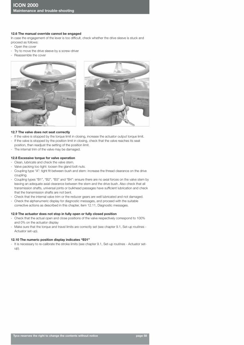
12.7 The valve does not seat correctly- If the valve is stopped by the torque limit in closing, increase the actuator output torque limit.- If the valve is stopped by the position limit in closing, check that the valve reaches its seat
position, then readjust the setting of the position limit.- The internal trim of the valve may be damaged.
12.8 Excessive torque for valve operation- Clean, lubricate and check the valve stem.- Valve packing too tight: loosen the gland bolt nuts.- Coupling type “A”: tight fit between bush and stem: increase the thread clearance on the drive
coupling.- Coupling types “B1”, “B2”, “B3” and “B4”: ensure there are no axial forces on the valve stem by
leaving an adequate axial clearance between the stem and the drive bush. Also check that alltransmission shafts, universal joints or bulkhead passages have sufficient lubrication and checkthat the transmission shafts are not bent.
- Check that the internal valve trim or the reducer gears are well lubricated and not damaged.- Check the alphanumeric display for diagnostic messages, and proceed with the suitable
corrective actions as described in this chapter, item 12.11, Diagnostic messages.
12.9 The actuator does not stop in fully open or fully closed position- Check that the actual open and close positions of the valve respectively correspond to 100%
and 0% on the actuator display- Make sure that the torque and travel limits are correctly set (see chapter 9.1, Set-up routines -
Actuator set-up).
12.10 The numeric position display indicates “E01”- It is necessary to re-calibrate the stroke limits (see chapter 9.1, Set-up routines - Actuator set-
up).
12.6 The manual override cannot be engagedIn case the engagement of the lever is too difficult, check whether the drive sleeve is stuck andproceed as follows:- Open the cover- Try to move the drive sleeve by a screw-driver- Reassemble the cover
ICON 2000Maintenance and trouble-shooting
Tyco reserves the right to change the contents without notice page 58
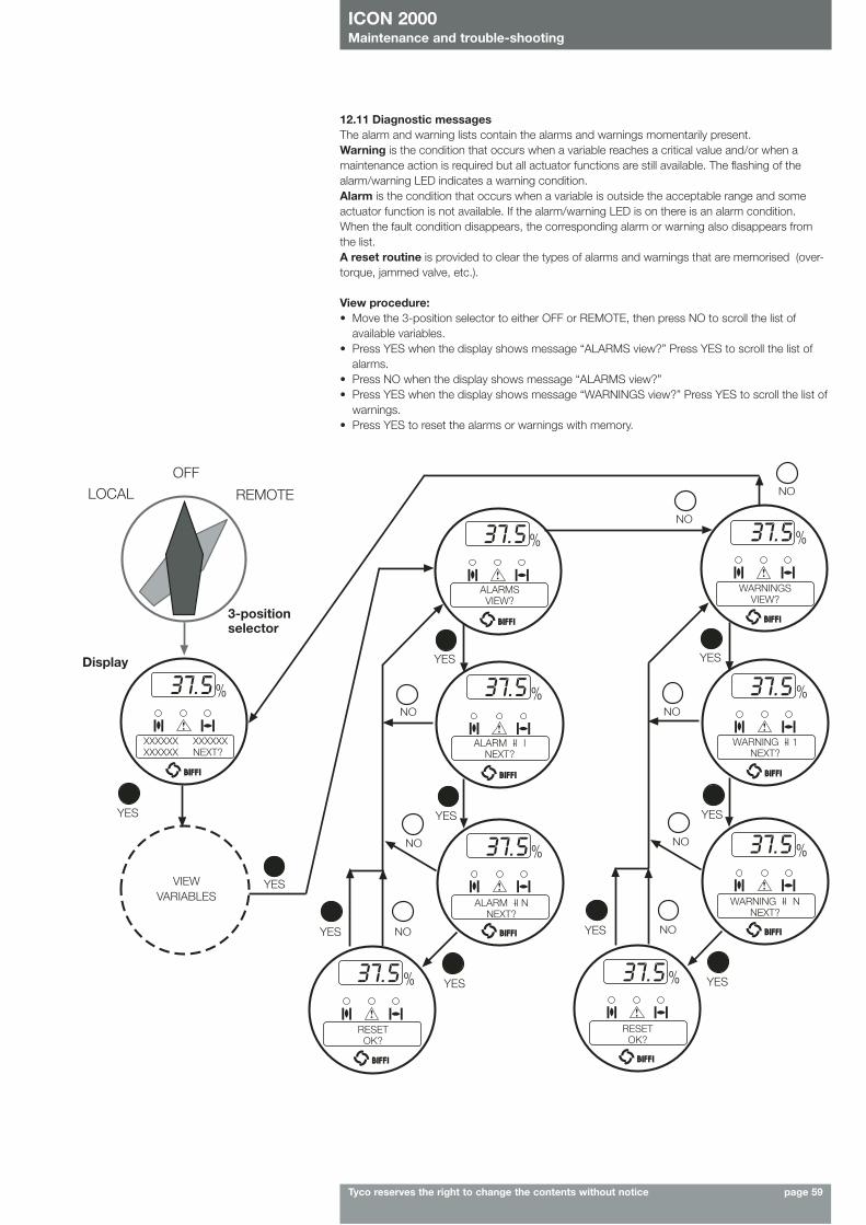
ICON 2000Maintenance and trouble-shooting
Tyco reserves the right to change the contents without notice page 59
12.11 Diagnostic messagesThe alarm and warning lists contain the alarms and warnings momentarily present.Warning is the condition that occurs when a variable reaches a critical value and/or when amaintenance action is required but all actuator functions are still available. The flashing of thealarm/warning LED indicates a warning condition.Alarm is the condition that occurs when a variable is outside the acceptable range and someactuator function is not available. If the alarm/warning LED is on there is an alarm condition.When the fault condition disappears, the corresponding alarm or warning also disappears fromthe list.A reset routine is provided to clear the types of alarms and warnings that are memorised (over-torque, jammed valve, etc.).
View procedure:• Move the 3-position selector to either OFF or REMOTE, then press NO to scroll the list of
available variables.• Press YES when the display shows message “ALARMS view?” Press YES to scroll the list of
alarms.• Press NO when the display shows message “ALARMS view?”• Press YES when the display shows message “WARNINGS view?” Press YES to scroll the list of
warnings.• Press YES to reset the alarms or warnings with memory.
XXXXXX XXXXXXXXXXXX NEXT?
ALARMSVIEW?
ALARM II- I NEXT?
ALARM II- N NEXT?
RESETOK?
RESETOK?
WARNING II- NNEXT?
WARNING II- 1 NEXT?
WARNINGSVIEW?
Display
3-positionselector
LOCAL REMOTE
YES
YES YES
YES
YES
YESYES
YES
YES
YES
NO
NO
NO
NO
NO
NO
NO
NO
OFF
VIEWVARIABLES
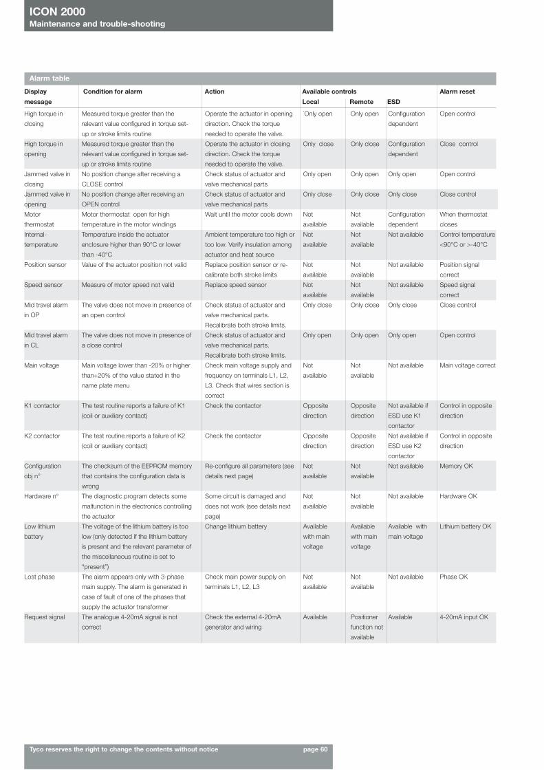
ICON 2000Maintenance and trouble-shooting
Tyco reserves the right to change the contents without notice page 60
Alarm table
Display Condition for alarm Action Available controls Alarm reset
message Local Remote ESD
Measured torque greater than the
relevant value configured in torque set-
up or stroke limits routine
Measured torque greater than the
relevant value configured in torque set-
up or stroke limits routine
No position change after receiving a
CLOSE control
No position change after receiving an
OPEN control
Motor thermostat open for high
temperature in the motor windings
Temperature inside the actuator
enclosure higher than 90°C or lower
than -40°C
Value of the actuator position not valid
Measure of motor speed not valid
The valve does not move in presence of
an open control
The valve does not move in presence of
a close control
Main voltage lower than -20% or higher
than+20% of the value stated in the
name plate menu
The test routine reports a failure of K1
(coil or auxiliary contact)
The test routine reports a failure of K2
(coil or auxiliary contact)
The checksum of the EEPROM memory
that contains the configuration data is
wrong
The diagnostic program detects some
malfunction in the electronics controlling
the actuator
The voltage of the lithium battery is too
low (only detected if the lithium battery
is present and the relevant parameter of
the miscellaneous routine is set to
“present”)
The alarm appears only with 3-phase
main supply. The alarm is generated in
case of fault of one of the phases that
supply the actuator transformer
The analogue 4-20mA signal is not
correct
Operate the actuator in opening
direction. Check the torque
needed to operate the valve.
Operate the actuator in closing
direction. Check the torque
needed to operate the valve.
Check status of actuator and
valve mechanical parts
Check status of actuator and
valve mechanical parts
Wait until the motor cools down
Ambient temperature too high or
too low. Verify insulation among
actuator and heat source
Replace position sensor or re-
calibrate both stroke limits
Replace speed sensor
Check status of actuator and
valve mechanical parts.
Recalibrate both stroke limits.
Check status of actuator and
valve mechanical parts.
Recalibrate both stroke limits.
Check main voltage supply and
frequency on terminals L1, L2,
L3. Check that wires section is
correct
Check the contactor
Check the contactor
Re-configure all parameters (see
details next page)
Some circuit is damaged and
does not work (see details next
page)
Change lithium battery
Check main power supply on
terminals L1, L2, L3
Check the external 4-20mA
generator and wiring
`Only open
Only close
Only open
Only close
Not
available
Not
available
Not
available
Not
available
Only close
Only open
Not
available
Opposite
direction
Opposite
direction
Not
available
Not
available
Available
with main
voltage
Not
available
Available
Only open
Only close
Only open
Only close
Not
available
Not
available
Not
available
Not
available
Only close
Only open
Not
available
Opposite
direction
Opposite
direction
Not
available
Not
available
Available
with main
voltage
Not
available
Positioner
function not
available
Configuration
dependent
Configuration
dependent
Only open
Only close
Configuration
dependent
Not available
Not available
Not available
Only close
Only open
Not available
Not available if
ESD use K1
contactor
Not available if
ESD use K2
contactor
Not available
Not available
Available with
main voltage
Not available
Available
Open control
Close control
Open control
Close control
When thermostat
closes
Control temperature
<90°C or >-40°C
Position signal
correct
Speed signal
correct
Close control
Open control
Main voltage correct
Control in opposite
direction
Control in opposite
direction
Memory OK
Hardware OK
Lithium battery OK
Phase OK
4-20mA input OK
High torque in
closing
High torque in
opening
Jammed valve in
closing
Jammed valve in
opening
Motor
thermostat
Internal-
temperature
Position sensor
Speed sensor
Mid travel alarm
in OP
Mid travel alarm
in CL
Main voltage
K1 contactor
K2 contactor
Configuration
obj n°
Hardware n°
Low lithium
battery
Lost phase
Request signal
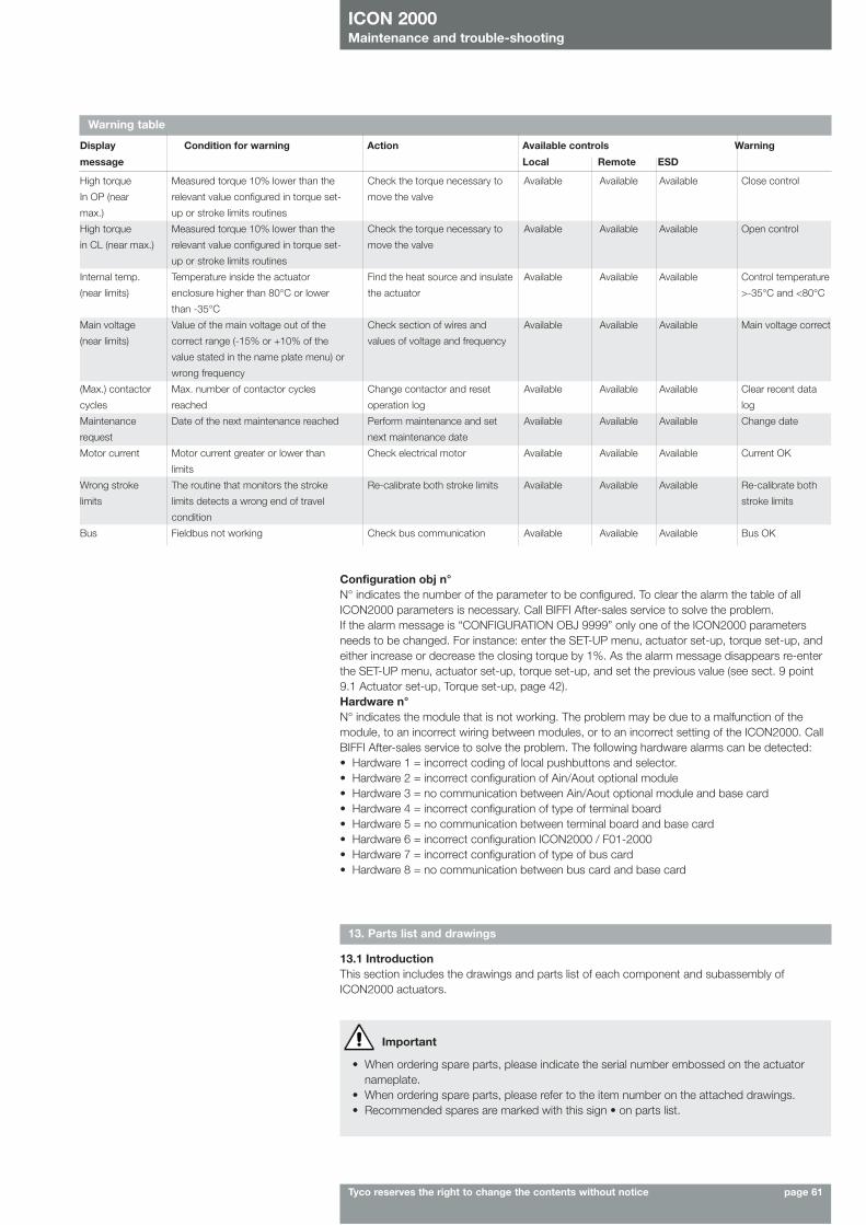
ICON 2000Maintenance and trouble-shooting
Tyco reserves the right to change the contents without notice page 61
13. Parts list and drawings
13.1 IntroductionThis section includes the drawings and parts list of each component and subassembly ofICON2000 actuators.
Important
• When ordering spare parts, please indicate the serial number embossed on the actuatornameplate.
• When ordering spare parts, please refer to the item number on the attached drawings.• Recommended spares are marked with this sign • on parts list.
Warning table
Display Condition for warning Action Available controls Warning
message Local Remote ESD
Measured torque 10% lower than the
relevant value configured in torque set-
up or stroke limits routines
Measured torque 10% lower than the
relevant value configured in torque set-
up or stroke limits routines
Temperature inside the actuator
enclosure higher than 80°C or lower
than -35°C
Value of the main voltage out of the
correct range (-15% or +10% of the
value stated in the name plate menu) or
wrong frequency
Max. number of contactor cycles
reached
Date of the next maintenance reached
Motor current greater or lower than
limits
The routine that monitors the stroke
limits detects a wrong end of travel
condition
Fieldbus not working
Check the torque necessary to
move the valve
Check the torque necessary to
move the valve
Find the heat source and insulate
the actuator
Check section of wires and
values of voltage and frequency
Change contactor and reset
operation log
Perform maintenance and set
next maintenance date
Check electrical motor
Re-calibrate both stroke limits
Check bus communication
Available
Available
Available
Available
Available
Available
Available
Available
Available
Available
Available
Available
Available
Available
Available
Available
Available
Available
Available
Available
Available
Available
Available
Available
Available
Available
Available
Close control
Open control
Control temperature
>-35°C and <80°C
Main voltage correct
Clear recent data
log
Change date
Current OK
Re-calibrate both
stroke limits
Bus OK
High torque
In OP (near
max.)
High torque
in CL (near max.)
Internal temp.
(near limits)
Main voltage
(near limits)
(Max.) contactor
cycles
Maintenance
request
Motor current
Wrong stroke
limits
Bus
Configuration obj n°N° indicates the number of the parameter to be configured. To clear the alarm the table of allICON2000 parameters is necessary. Call BIFFI After-sales service to solve the problem.If the alarm message is “CONFIGURATION OBJ 9999” only one of the ICON2000 parametersneeds to be changed. For instance: enter the SET-UP menu, actuator set-up, torque set-up, andeither increase or decrease the closing torque by 1%. As the alarm message disappears re-enterthe SET-UP menu, actuator set-up, torque set-up, and set the previous value (see sect. 9 point9.1 Actuator set-up, Torque set-up, page 42).Hardware n°N° indicates the module that is not working. The problem may be due to a malfunction of themodule, to an incorrect wiring between modules, or to an incorrect setting of the ICON2000. CallBIFFI After-sales service to solve the problem. The following hardware alarms can be detected: • Hardware 1 = incorrect coding of local pushbuttons and selector. • Hardware 2 = incorrect configuration of Ain/Aout optional module • Hardware 3 = no communication between Ain/Aout optional module and base card• Hardware 4 = incorrect configuration of type of terminal board• Hardware 5 = no communication between terminal board and base card• Hardware 6 = incorrect configuration ICON2000 / F01-2000• Hardware 7 = incorrect configuration of type of bus card• Hardware 8 = no communication between bus card and base card
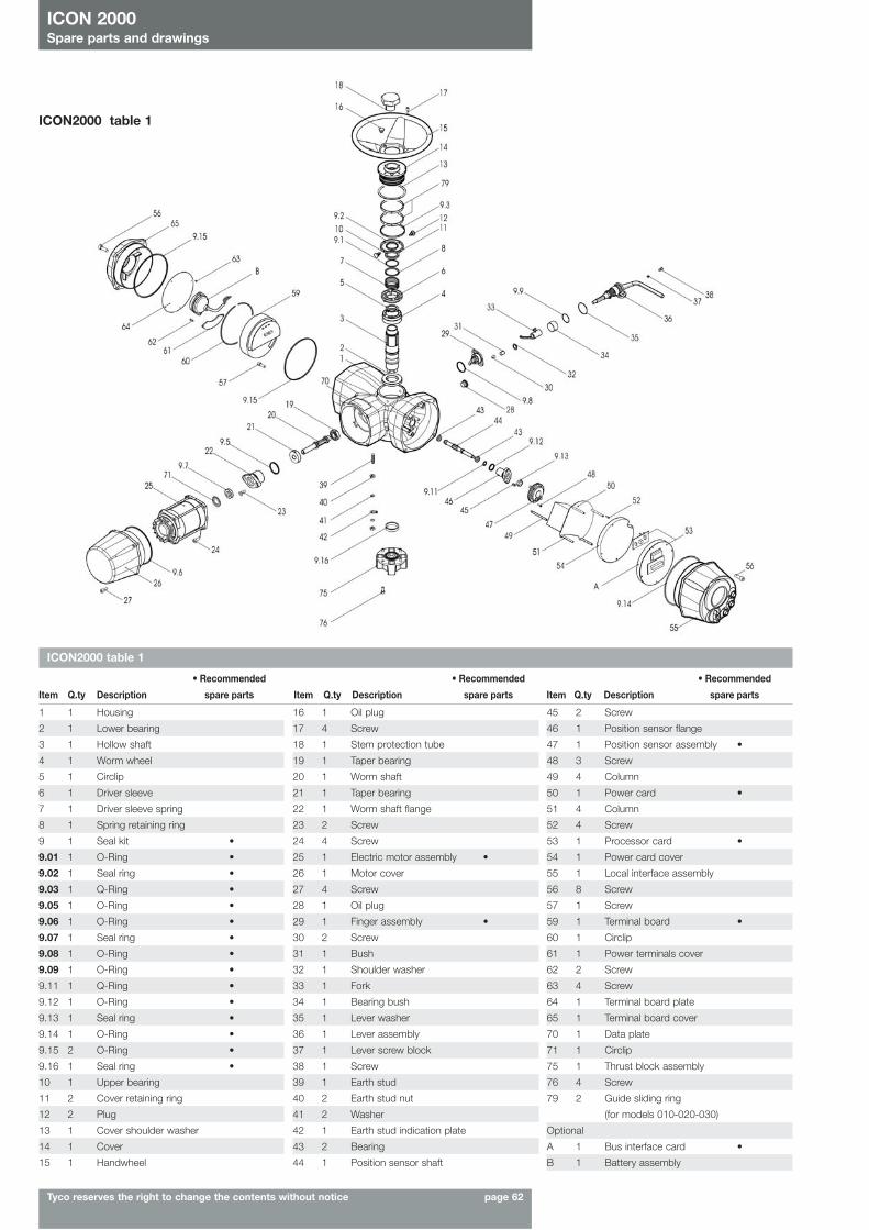
ICON 2000Spare parts and drawings
Tyco reserves the right to change the contents without notice page 62
ICON2000 table 1
• Recommended • Recommended • Recommended
Item Q.ty Description spare parts Item Q.ty Description spare parts Item Q.ty Description spare parts
1 1 Housing
2 1 Lower bearing
3 1 Hollow shaft
4 1 Worm wheel
5 1 Circlip
6 1 Driver sleeve
7 1 Driver sleeve spring
8 1 Spring retaining ring
9 1 Seal kit •
9.01 1 O-Ring •
9.02 1 Seal ring •
9.03 1 Q-Ring •
9.05 1 O-Ring •
9.06 1 O-Ring •
9.07 1 Seal ring •
9.08 1 O-Ring •
9.09 1 O-Ring •
9.11 1 Q-Ring •
9.12 1 O-Ring •
9.13 1 Seal ring •
9.14 1 O-Ring •
9.15 2 O-Ring •
9.16 1 Seal ring •
10 1 Upper bearing
11 2 Cover retaining ring
12 2 Plug
13 1 Cover shoulder washer
14 1 Cover
15 1 Handwheel
16 1 Oil plug
17 4 Screw
18 1 Stem protection tube
19 1 Taper bearing
20 1 Worm shaft
21 1 Taper bearing
22 1 Worm shaft flange
23 2 Screw
24 4 Screw
25 1 Electric motor assembly •
26 1 Motor cover
27 4 Screw
28 1 Oil plug
29 1 Finger assembly •
30 2 Screw
31 1 Bush
32 1 Shoulder washer
33 1 Fork
34 1 Bearing bush
35 1 Lever washer
36 1 Lever assembly
37 1 Lever screw block
38 1 Screw
39 1 Earth stud
40 2 Earth stud nut
41 2 Washer
42 1 Earth stud indication plate
43 2 Bearing
44 1 Position sensor shaft
45 2 Screw
46 1 Position sensor flange
47 1 Position sensor assembly •
48 3 Screw
49 4 Column
50 1 Power card •
51 4 Column
52 4 Screw
53 1 Processor card •
54 1 Power card cover
55 1 Local interface assembly
56 8 Screw
57 1 Screw
59 1 Terminal board •
60 1 Circlip
61 1 Power terminals cover
62 2 Screw
63 4 Screw
64 1 Terminal board plate
65 1 Terminal board cover
70 1 Data plate
71 1 Circlip
75 1 Thrust block assembly
76 4 Screw
79 2 Guide sliding ring
(for models 010-020-030)
Optional
A 1 Bus interface card •
B 1 Battery assembly
ICON2000 table 1
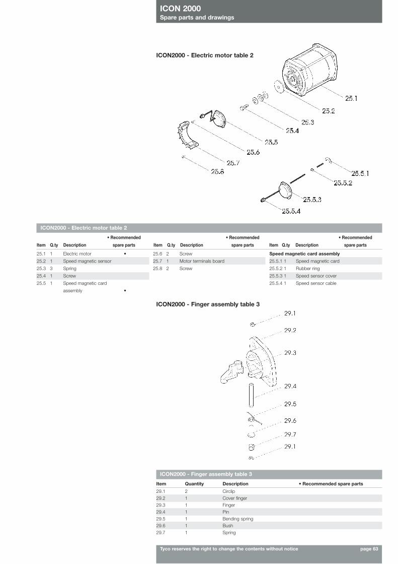
ICON 2000Spare parts and drawings
Tyco reserves the right to change the contents without notice page 63
ICON2000 - Electric motor table 2
ICON2000 - Finger assembly table 3
Item Quantity Description • Recommended spare parts
29.1 2 Circlip29.2 1 Cover finger29.3 1 Finger29.4 1 Pin29.5 1 Bending spring29.6 1 Bush29.7 1 Spring
ICON2000 - Finger assembly table 3
ICON2000 - Electric motor table 2
• Recommended • Recommended • Recommended
Item Q.ty Description spare parts Item Q.ty Description spare parts Item Q.ty Description spare parts
25.1 1 Electric motor •
25.2 1 Speed magnetic sensor
25.3 3 Spring
25.4 1 Screw
25.5 1 Speed magnetic card
assembly •
25.6 2 Screw
25.7 1 Motor terminals board
25.8 2 Screw
Speed magnetic card assembly
25.5.1 1 Speed magnetic card
25.5.2 1 Rubber ring
25.5.3 1 Speed sensor cover
25.5.4 1 Speed sensor cable
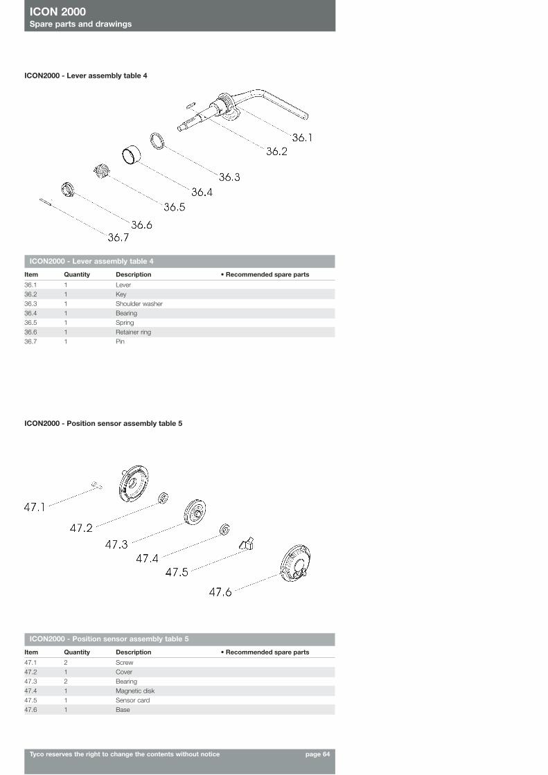
ICON2000 - Position sensor assembly table 5
Item Quantity Description • Recommended spare parts
47.1 2 Screw47.2 1 Cover47.3 2 Bearing47.4 1 Magnetic disk47.5 1 Sensor card47.6 1 Base
ICON 2000Spare parts and drawings
Tyco reserves the right to change the contents without notice page 64
ICON2000 - Lever assembly table 4
Item Quantity Description • Recommended spare parts
36.1 1 Lever36.2 1 Key36.3 1 Shoulder washer36.4 1 Bearing36.5 1 Spring36.6 1 Retainer ring36.7 1 Pin
ICON2000 - Lever assembly table 4
ICON2000 - Position sensor assembly table 5
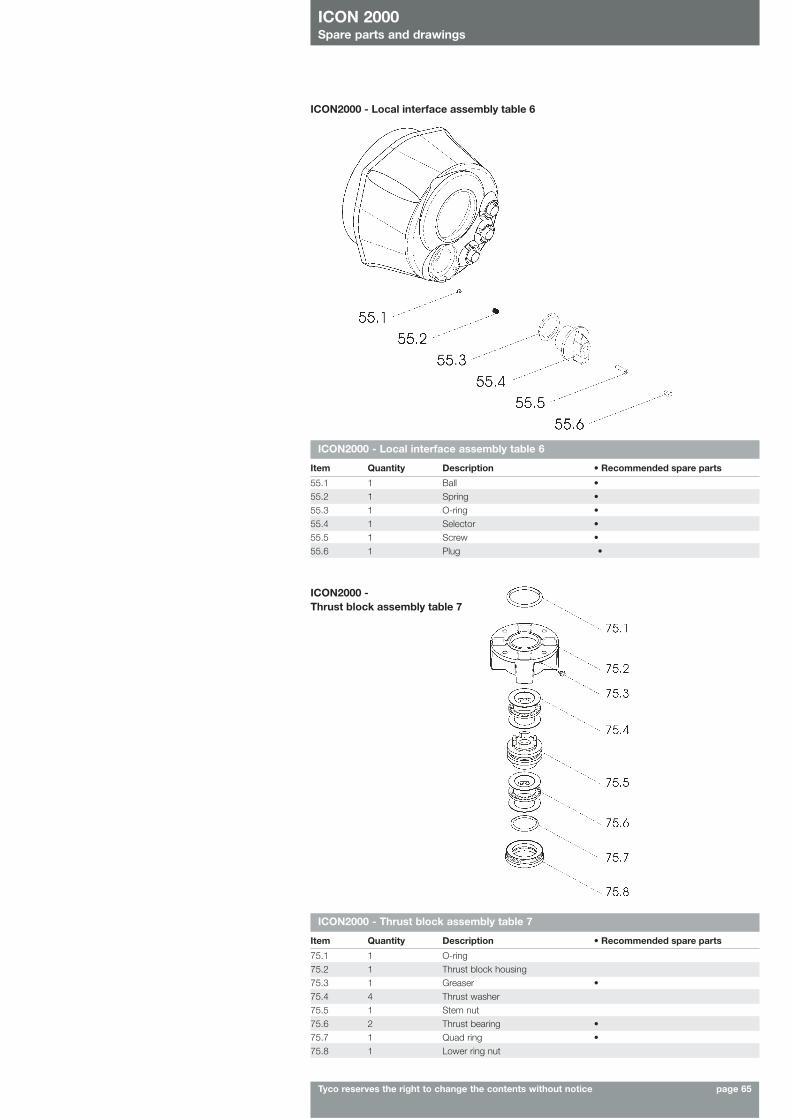
ICON 2000Spare parts and drawings
Tyco reserves the right to change the contents without notice page 65
ICON2000 - Local interface assembly table 6
Item Quantity Description • Recommended spare parts
55.1 1 Ball •55.2 1 Spring •55.3 1 O-ring •55.4 1 Selector •55.5 1 Screw •55.6 1 Plug •
ICON2000 - Local interface assembly table 6
ICON2000 - Thrust block assembly table 7
ICON2000 - Thrust block assembly table 7
Item Quantity Description • Recommended spare parts
75.1 1 O-ring75.2 1 Thrust block housing75.3 1 Greaser •75.4 4 Thrust washer75.5 1 Stem nut75.6 2 Thrust bearing •75.7 1 Quad ring •75.8 1 Lower ring nut
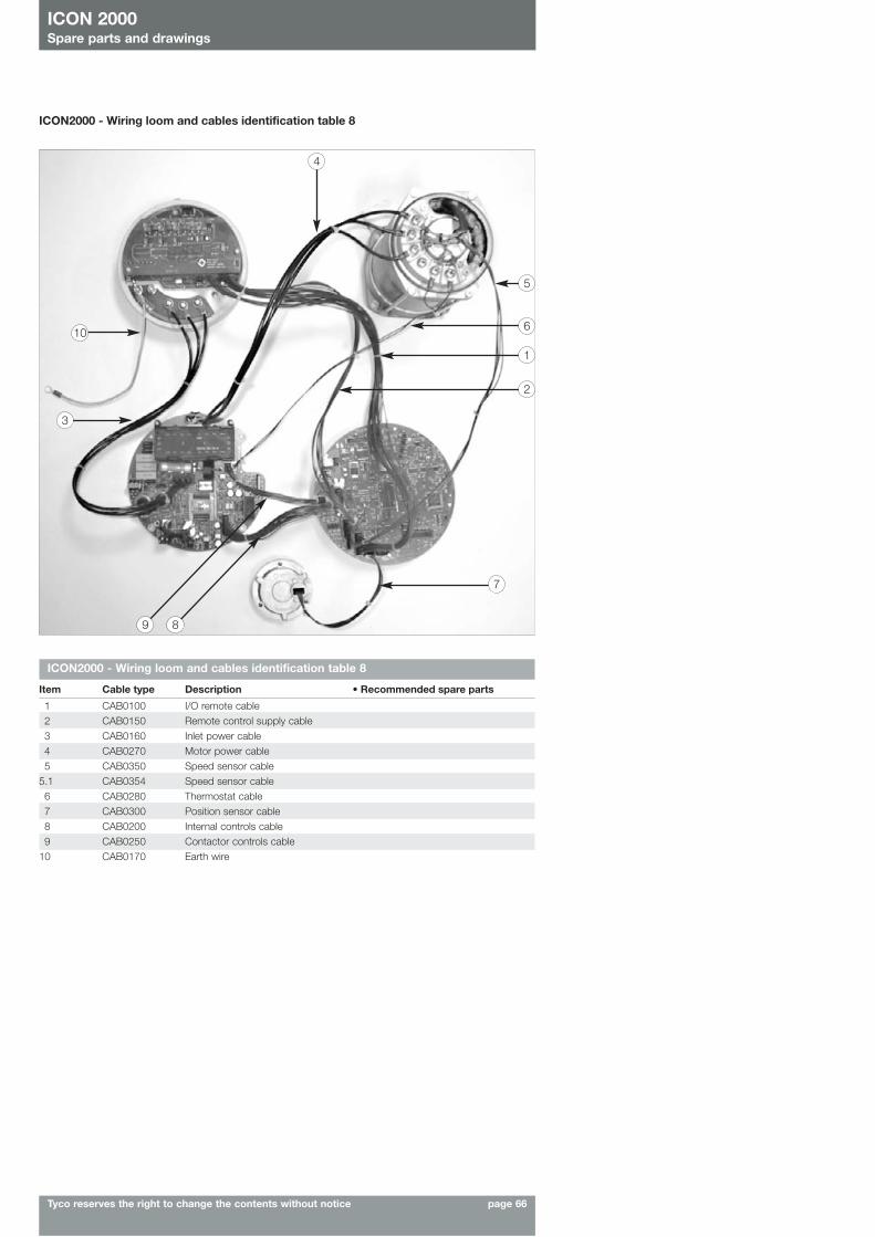
ICON 2000Spare parts and drawings
Tyco reserves the right to change the contents without notice page 66
ICON2000 - Wiring loom and cables identification table 8
ICON2000 - Wiring loom and cables identification table 8
Item Cable type Description • Recommended spare parts
1 CAB0100 I/O remote cable2 CAB0150 Remote control supply cable3 CAB0160 Inlet power cable4 CAB0270 Motor power cable5 CAB0350 Speed sensor cable
5.1 CAB0354 Speed sensor cable6 CAB0280 Thermostat cable7 CAB0300 Position sensor cable8 CAB0200 Internal controls cable9 CAB0250 Contactor controls cable
10 CAB0170 Earth wire
10
3
2
7
89
1
6
5
4