Embed Size (px)
Citation preview

Bifacial PV Performance Models: Comparison and Field Results
Chris Deline, B. Marion, S. MacAlpine (NREL)
J. Stein (SNL), F. Toor (U. Iowa), S. Ayala (U. Ariz.)
BiFiPV 2017 Workshop – Konstanz Germany
October 26, 2017
NATIONAL RENEWABLE ENERGY LABORATORY 2
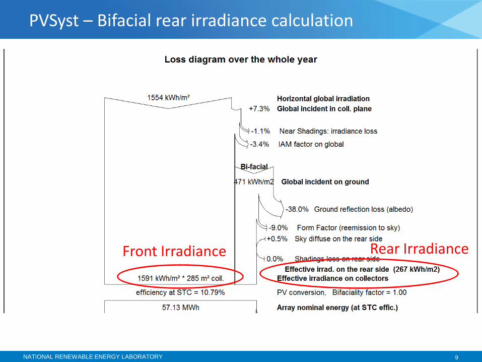
• Project overview
• Rear irradiance models
• Field validation
• Edge effects
• Irradiance nonuniformity
Outline

NATIONAL RENEWABLE ENERGY LABORATORY 3
3-Yr Bifacial Research Project (2016-2018)
• Module scale o Adjustable rack IV curves (height, tilt,
albedo, and backside shading effects)
o Spatial variability in backside irradiance
o Effects of backside obstructions
• String scale o Fixed tilt rack (tilt, mismatch effects)
o Single axis tracker (investigate potential)
o Two-axis tracker
• System scale o String level monitoring on commercial
systems (validation data)
Collaborative project between Sandia, NREL and University of Iowa (pvpmc.sandia.gov/pv-research/bifacial-pv-project/)
Task 1: Measure Outdoor Bifacial Performance
Stein, J. S., D. Riley, M. Lave, C. Deline, F. Toor and C. Hansen (2017). Outdoor Field Performance of Bifacial PV Modules and Systems. 33rd European PV Solar Energy Conference and Exhibition. Amsterdam, Netherlands. SAND2017-10254

NATIONAL RENEWABLE ENERGY LABORATORY 4
• Bifacial_Radiance software release github.com/cdeline/bifacial_radiance
• Configuration analysis publication1 o Effect of row spacing, tilt optimization
o Validation of model using Sandia field data
Ray Tracing simulation
1 A. Asgharzadeh et al, “Analysis of the impact of installation parameters and system size on bifacial gain and energy yield of PV systems”, IEEE PVSC 2017 2B. Marion et al., “A Practical Irradiance Model for Bifacial PV Modules”, IEEE PVSC 2017 . https://www.nrel.gov/docs/fy17osti/67847.pdf
Screenshot – Bifacial_Radiance software
View Factor model • BifacialVF software release
github.com/cdeline/bifacialVF
• Method publication2 o Model detail and configuration
o Validation of model using NREL field data
• Integration with SAM software scheduled 2018
View Factor ground reflection geometry
Task 2: Develop Performance Models
3-Yr Bifacial Research Project (2016-2018)

NATIONAL RENEWABLE ENERGY LABORATORY 5
Radiance CumulativeSky pre-processor
Robinson, Stone “Irradiation modelling made simple: the cumulative sky approach” 2004
Typical ray-tracing approach: use Perez model to generate hourly sky description
o Runtime = hours for annual simulations
CumulativeSky approach: sum annual hourly irradiance into 145 sky patches
o Runtime = seconds for annual simulation.
Single hourly Perez sky (W/m2) Annual cumulative sky conditions (kWh/m2)

NATIONAL RENEWABLE ENERGY LABORATORY 6
Clearance
Modeling Rear Irradiance – parameters to consider
Tilt
Albedo
Others: Spacing between cells Shade obstructions
Size of array / simulation Location Weather Sky Diffuse Model
Image: http://opsun.com/mounting-solutions/flat-roof/bifacial-pv-racking/

NATIONAL RENEWABLE ENERGY LABORATORY 7
Bifacial Gain Calculation
* V. Fakhfouri IEC TS 60904-1-2 ED1 (2017)
Our focus today

NATIONAL RENEWABLE ENERGY LABORATORY 8
PVSyst – 2D “unlimited sheds” bifacial model
o 6.6.4 update increased bifacial response
Solar World “Boost Calculator” – web interface
o Empirical model, not climate sensitive
http://www.solarworld.de/fileadmin/calculator
Industry Bifacial Models for comparison
PVSyst 6.6.4 bifacial interface SolarWorld online calculator
NATIONAL RENEWABLE ENERGY LABORATORY 9
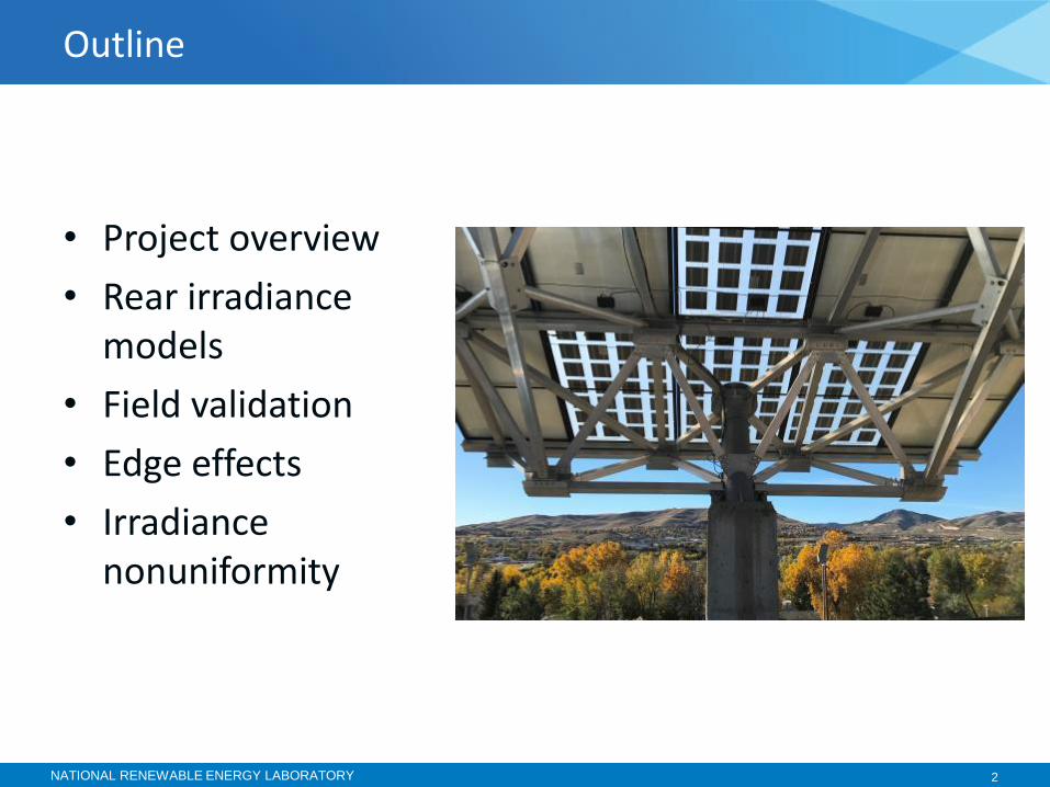
PVSyst – Bifacial rear irradiance calculation
Front Irradiance Rear Irradiance
NATIONAL RENEWABLE ENERGY LABORATORY 10
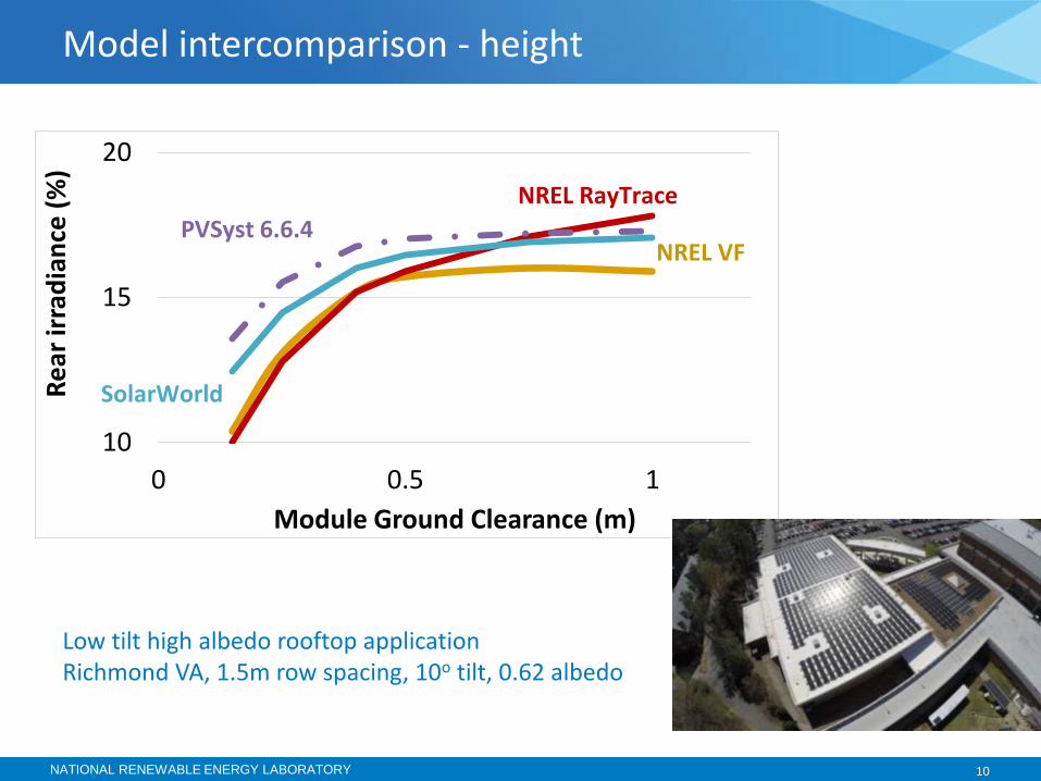
Model intercomparison - height
Low tilt high albedo rooftop application Richmond VA, 1.5m row spacing, 10o tilt, 0.62 albedo
10
15
20
0 0.5 1
Re
ar ir
rad
ian
ce (
%)
Module Ground Clearance (m)
NREL RayTrace
NREL VF PVSyst 6.6.4
SolarWorld

NATIONAL RENEWABLE ENERGY LABORATORY 11
Model intercomparison – row spacing
Not as good agreement
10
15
20
1 2 3 4
Re
ar ir
rad
ian
ce (
%)
Row to Row pitch (m)
NREL RayTrace
NREL VF
PVSyst 6.6.4
SolarWorld
Low tilt high albedo rooftop application Richmond VA, 0.15 m height, 10o tilt, 0.62 albedo

Field Validation: 3-row mock array Adjustable spacing, tilt, height

Field Validation: 3-row mock array Low ground clearance configuration
Front & rear irradiance sensors

NATIONAL RENEWABLE ENERGY LABORATORY 14
Mock array configuration - 4 rear, 2 forward facing irradiance
• Tilt= 10deg.
• Slant length = 610mm 1
• Height = 100 - 500mm 0.16 - 0.9
• Row spacing = 900 - 1800mm 1.5 - 3
• Albedo = 0.62
• Compare measured with site modeled conditions
(normalized)

NATIONAL RENEWABLE ENERGY LABORATORY 15
• 2 months field data
• RayTrace model reflects finite experiment size at high ground clearance.
Mock Array – comparison with NREL models - Height
5%
10%
15%
20%
25%
0 0.2 0.4 0.6 0.8 1
Re
ar ir
rad
ian
ce
Module Ground Clearance (m)
RayTrace model (3 rows)
View Factor model
Measured

NATIONAL RENEWABLE ENERGY LABORATORY 16
• OK agreement. Additional conditions under test
Mock Array – comparison with models – Row spacing
5%
10%
15%
20%
1 1.5 2 2.5 3
Re
ar ir
rad
ian
ce
Row to Row spacing (m)
RayTrace model
View Factor model Measured

NATIONAL RENEWABLE ENERGY LABORATORY 17
0%
10%
20%
30%
40%
50%
1 3 5 7 9 11 13 15
Re
ar ir
rad
ian
ce (
%)
Landscape Modules Per Row
Height = 3 m
Height = 0.25 m
Height = 1 m
0%
10%
20%
30%
40%
50%
1 3 5 7 9 11 13 15
Re
ar ir
rad
ian
ce (
%)
Number of Rows
Height = 3 m
Height = 0.25 m
H = 1 m
System Modeling – Edge Effects
Richmond VA, 1.5 m row spacing, 10o tilt, 0.62 alb. 1m landscape module width 20 modules, 3 rows default
# Modules / row
Total # Rows

NATIONAL RENEWABLE ENERGY LABORATORY 18
0%
10%
20%
30%
40%
50%
1 3 5 7 9 11 13 15
Re
ar ir
rad
ian
ce (
%)
Landscape Modules Per Row
Height = 3 m
Height = 0.25 m
Height = 1 m
0%
10%
20%
30%
40%
50%
1 3 5 7 9 11 13 15
Re
ar ir
rad
ian
ce (
%)
Number of Rows
Height = 3 m
Height = 0.25 m
H = 1 m
System Modeling – Edge Effects
Richmond VA, 1.5 m row spacing, 10o tilt, 0.62 alb. 1m landscape module width 20 modules, 3 rows default
# Modules / row
Total # Rows
* = 1% edge effect
*
*
* = 1% edge effect
* *
*
*


www.nrel.gov
NREL is a national laboratory of the U.S. Department of Energy, Office of Energy Efficiency and Renewable Energy, operated by the Alliance for Sustainable Energy, LLC.
Thank you!
Chris Deline National Renewable Energy Laboratory
[email protected] github.com/cdeline
This work was supported by the U.S. Department of Energy under Contract No. DE-AC36-08-GO28308 with the National Renewable Energy Laboratory

NATIONAL RENEWABLE ENERGY LABORATORY 21
BACKUP SLIDES

NATIONAL RENEWABLE ENERGY LABORATORY 22
• Ground divided into n segments in row-to-row direction and shading determined for each
• Irradiance on each ground segment found using view of the sky (configuration factors)
• Rear side irradiance is sum of sky, ground reflected, object reflected components
• Runtime 4 seconds for annual simulation
NREL View Factor Model1
1B. Marion, “A Practical Irradiance Model for Bifacial PV Modules”, IEEE PVSC, 2017.

NATIONAL RENEWABLE ENERGY LABORATORY 23
Ongoing work: Single-axis tracking
Improvement: the view factor model has been extended to apply to bifacial tracking PV systems. Field validation is underway.