Embed Size (px)
Citation preview
Bidirectional Goniophotometry and Building Materials Patrick Rombauts; Lisa Wastiels 1. Introduction Commonly, materials’ characterisation is done in a general, overall way, expressed by means of for instance only one figure as reflectance or transmittance; at its best it is given for a limited number of geometries of incidence and viewing. In order to be able to determine these properties in a more detailed and accurate manner, goniophotometry is needed, as well as spectral measurements. In this way, energy efficient and intelligent lighting can be achieved, by inserting real material properties into simulation (software) programmes and by realising project oriented photometric control of luminaires and illumination systems. So, classical photometry has been expanded to spectro-gonioreflectometry in a way to cover as far as appropriate the complete geometrical and spectral span. Thus, visual characteristics of a range of building materials are determined, in particular novel type materials as IPC-Inorganic Phosphate Cement, commercially available as Vubonite® [2]. As an example, appearance of these materials with a not so singular but complex typology and rich patterning has been determined and compared with the visual impression. Recent CIECAM-Colour Appearance Models have been tested too on these materials. Furthermore, tactile properties too have been specified and quantified in view of composing a comprehensive descriptive atlas of building materials. 2. “biRdi” : Bidirectional Reflectometer for the measurement of reflection and transmission
properties Our starting point here was to formulate design criteria for road and residential area lighting. The main themes are recovered as conditions on absolute minimum level and distribution of semi-cylindrical illuminance in lighting applications for slow moving observers. The realisation of a definite illuminance/luminance distribution does involve a number of items :
a) the luminous intensity distribution of the light source (e.g. lamp); b) the optical properties of the reflector materials, baffle, louvres and cover (in particular
reflection); c) the basic formalism of luminous flux exchange between lamp, reflector and observer, leading to luminaire design (generally applicable); evenso raytracing techniques, eventually in combination with the radiosity method. Prof. Dr. Ir. Patrick Rombauts VUB-Vrije Universiteit Brussel, Faculteit Ingenieurswetenschappen Vakgroep ETEC-Elektrotechniek-Energietechniek Pleinlaan 2, B-1050 Brussels, Belgium ; e-mail address : [email protected] Ir.-Arch. Lisa Wastiels VUB-Vakgroep ARCH-Architectuur
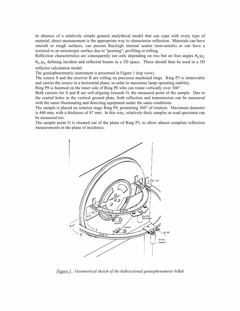
In absence of a relatively simple general analythical model that can cope with every type of material, direct measurement is the appropriate way to characterise reflection. Materials can have smooth or rough surfaces, can present Rayleigh internal scatter (non-metals) or can have a textured or an anisotropic surface due to "peening", profiling or rolling. Reflection characteristics are consequently not only depending on two but on four angles θi,ψi; θv,ψv defining incident and reflected beams in a 3D space. These should then be used in a 3D reflector calculation model. The goniophotometric instrument is presented in Figure 1 (top view). The source S and the receiver R are rolling on precision machined rings. Ring P3 is immovable and carries the source in a horizontal plane, in order to maximise lamp operating stability. Ring P8 is fastened on the inner side of Ring P6 who can rotate vertically over 360°. Both carriers for S and R are self-aligning towards O, the measured point of the sample. Due to the central holes in the vertical ground plate, both reflection and transmission can be measured with the same illuminating and detecting equipment under the same conditions. The sample is placed on rotation stage Ring P4, permitting 360° of rotation. Maximum diameter is 440 mm, with a thickness of 47 mm. In this way, relatively thick samples as road specimen can be measured too. The sample point O is situated out of the plane of Ring P3, to allow almost complete reflection measurements in the plane of incidence.
Figure 1 : Geometrical sketch of the bidirectional goniophotometer biRdi
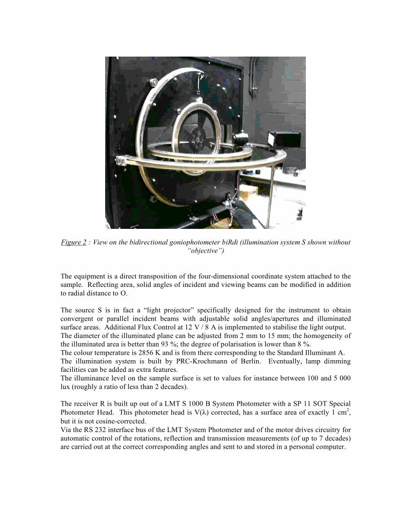
Figure 2 : View on the bidirectional goniophotometer biRdi (illumination system S shown without “objective”)
The equipment is a direct transposition of the four-dimensional coordinate system attached to the sample. Reflecting area, solid angles of incident and viewing beams can be modified in addition to radial distance to O. The source S is in fact a “light projector” specifically designed for the instrument to obtain convergent or parallel incident beams with adjustable solid angles/apertures and illuminated surface areas. Additional Flux Control at 12 V / 8 A is implemented to stabilise the light output. The diameter of the illuminated plane can be adjusted from 2 mm to 15 mm; the homogeneity of the illuminated area is better than 93 %; the degree of polarisation is lower than 8 %. The colour temperature is 2856 K and is from there corresponding to the Standard Illuminant A. The illumination system is built by PRC-Krochmann of Berlin. Eventually, lamp dimming facilities can be added as extra features. The illuminance level on the sample surface is set to values for instance between 100 and 5 000 lux (roughly a ratio of less than 2 decades). The receiver R is built up out of a LMT S 1000 B System Photometer with a SP 11 SOT Special Photometer Head. This photometer head is V(λ) corrected, has a surface area of exactly 1 cm2, but it is not cosine-corrected. Via the RS 232 interface bus of the LMT System Photometer and of the motor drives circuitry for automatic control of the rotations, reflection and transmission measurements (of up to 7 decades) are carried out at the correct corresponding angles and sent to and stored in a personal computer.
The measured characteristic can be reflectance ρ(ωv), luminance factor β, BRDF-Bidirectional Reflectance Distribution Function; or DDR-Directional Density of Reflection [7] (i.e. the ratio of the reflected luminous flux to the incident luminous flux within their respective solid angles ωv and ωi). The key lies in definitions consistent with the lamp model (primary source element) and reflector (reflecting element). The calculation of reflecting surfaces is mostly based on simplified and theoretical models as pure specular and Lambertian reflection. Only simple cases e.g. with axi-symmetrical or linear reflector shape together with point or linear sources can be treated in a 2D calculation model and yield good approximation. However, real 3D design is needful with complex luminaires (f.i. with cross-laths or louvres), arbitrary shape and general lamp model (non-tubular, clear envelope). Typical applications are interior symmetrical low luminance, low peak luminance lighting and residential area lighting. The particular benefit of introducing the measured distribution of reflected light into a calculation model is to eliminate any discrepancies existing between predicted and real luminaire performance (measured with a goniophotometer). Classically, serious problems definitely occur when the lamp or the source is at short distance to the reflecting surface because primary and secondary sources can no longer be considered as point sources. This issue is corresponding to the so-called near-field photometry and should be treated in a different way than far-field photometry. A technique of discretisation of all surfaces, reflecting as measured in our bidirectional photometer, should settle the problem. But nevertheless even when introducing complete reflection distributions consistent with the source and reflector model, care should be taken with complex luminaires : available software packages on the market give considerable errors (more than 30 %) when cross-laths are very close to the lamp. This model and associated computer programme can also be applied generally as in interior lighting. There, refinements can be put into existing models by attributing real non-Lambertian reflection characteristics to the walls of the room. 3. Spectral Goniophotometry & Discussion An important drawback of classical photometrical measurements is the fact that the quantities are (at best) V(λ)-corrected, notwithstanding common lighting practice to transform quantities into “visual” terms. Anyway, the photopic correction filter has limits as regarding to the amount of light captured (sensitivity), diffusing power of the adapter, uniformity of the illuminated surface; aperture angles. This has also serious adverse implications on the “resolution angle” of the instrument. The solution for this problem can be found into modern instrumentation with marked enhanced sensitivities and performances of the composing elements (like lock-in amplifiers and diffraction grating based spectrographs with CCD detector) and novel media as optical fibres.
In this way, goniophotometrical measurements can be combined with measurements of spectral quantities. These spectral quantities can then be weighted according any desired distribution or sensitivity curve. In colorimetry, (X, Y, Z) remain the basis for definition and calculation of colour properties. So, any colour notation or coordinate system can be used, even advanced colour appearance models. The Lighting Laboratory [4] is equipped with a CIE type I goniophotometer that has precisely implemented these elements. Here, the measured characteristic can f.i. be reflectance ρ(ωv, λ), luminance factor β(λ); BRDF(λ)-Bidirectional Reflectance Distribution Function or BSDF(λ)–Bidirectional Scatter Distribution Function; or any other characteristic. Another point of concern is the fact that the illuminance level on the sample surface in the bidirectional photometer is set to values for instance between 100 and 5 000 lux (roughly only a ratio of less than 2 decades). However, measuring quantities of over about 4 to 5 decades are needed to cover the full range of reflected or transmitted power (except for smoothly varying “diffuse” luminous intensity distribution curves as with Lambertian surfaces). This issue is solved too in [4]. For what concerns “biRdi”, the LMT S 1000 B System Photometer can also easily cope with this large dynamic span.
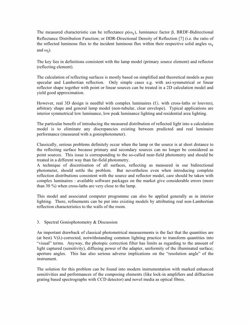
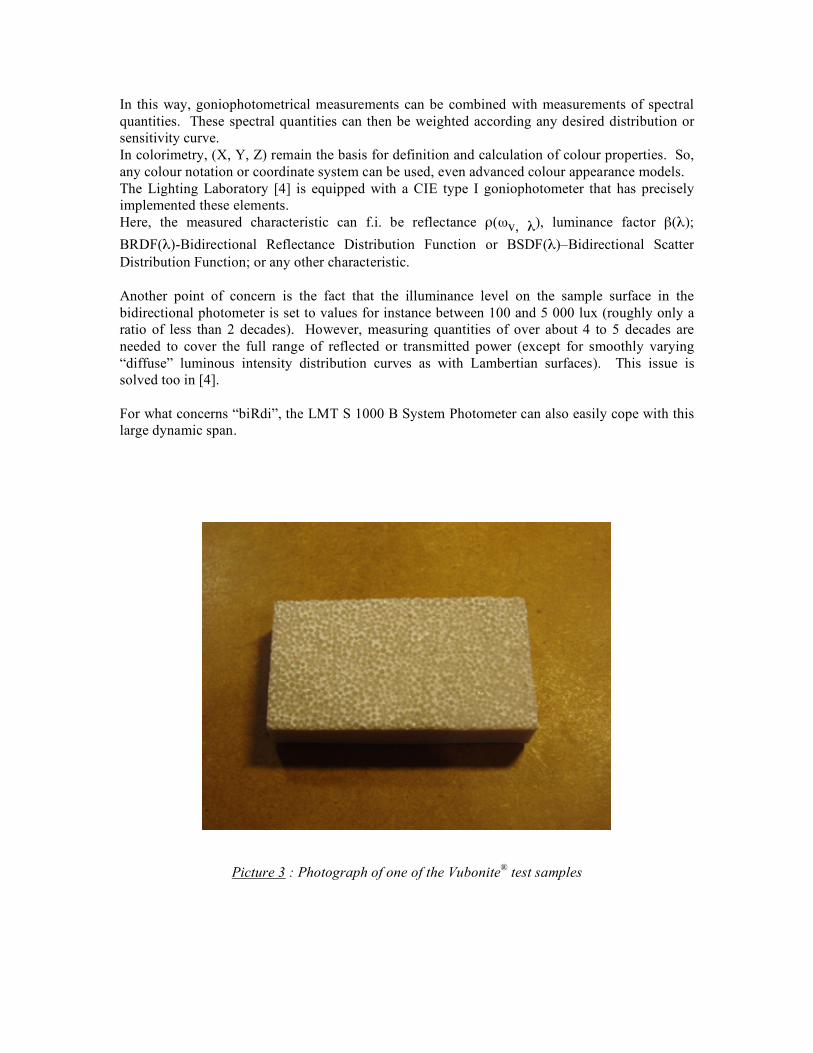
Picture 3 : Photograph of one of the Vubonite® test samples
4. Conclusion The apparatus “biRdi” is an automated goniophotometric instrument for reflection and transmission measurement under identical but adjustable illumination conditions over almost any angle of incidence and viewing within the 3D space. These measurements are all V(λ)-corrected. In the “Laboratory for Optical Measurements and Light Technology” [4], spectral measurement techniques, originating from the pure optical domain, are combined with goniophotometric techniques. In this way, classical photometry has been expanded to spectro-gonioreflectometry in a way to cover as far as appropriate the complete geometrical and spectral span. The measured quantities are then translated into “lighttechnical” parameters as reflectance, BRDF or CIELAB-values; ... Visual characteristics of a range of building materials can then be determined, in particular novel type materials as IPC-Inorganic Phosphate Cement, commercially available as Vubonite® [2]. As an example, appearance of these materials with a not so singular but complex typology and rich patterning has been determined and compared with the visual impression. Recent CIECAM-Colour Appearance Models [6] are going to be tested too on these materials. Furthermore, tactile properties too have been specified and quantified in view of composing a comprehensive descriptive atlas of building materials [1]. 5. References [1] Wastiels Lisa, Plaatsbepaling van Nieuwe Materialen in het Materialenspectrum – Onderzoek
naar de visuele en tactiele eigenschappen van IPC-Inorganic Phosphate Cement, Degree thesis Academical Architectural Engineer, VUB, Brussels, 2004
[2] Vubonite® : http://www.vubonite.com [3] biRdi-Bidirectional Reflectometer, Department ETEC-VUB, Brussels (financed by FWO-
Flanders Scientific Research Fund; Research Council VUB; and R-TECH Liège-Belgium) [4] IWT-LED Projects, Dr. Peter Hanselaer, Laboratory for Optical Measurements and Light
Technology, KaHo Sint-Lieven, Ghent-Belgium - http://ingenieur.kahosl.be/projecten/licht/indexB.htm
[5] META-VUB, Laboratory for Metallurgy and Material Characterisation, Brussels [6] CIE Publ. No. 159:2004 “A Colour Appearance Model for Colour Management Systems : CIECAM02” [7] Rombauts, Patrick "Phenomenology and characterisation of spatial distribution and reflection of light. Application to residential area lighting and reflector design", PhD-thesis VUB- Brussels, 1992 [8] LMT-LichtMessTechnik : http://www.lmt-berlin.de [9] PRC-Krochmann : http://www.prc-krochmann.de Keywords : material characterisation, visual attributes, tactile properties of materials, reflection measurements, composite materials.