Embed Size (px)
Citation preview
BiDi Screen: A Thin, Depth-Sensing LCD for 3D Interaction using Light FieldsMatthew Hirsch1 Douglas Lanman2 Henry Holtzman1 Ramesh Raskar1
1MIT Media Lab 2Brown University
http://www.bidiscreen.com
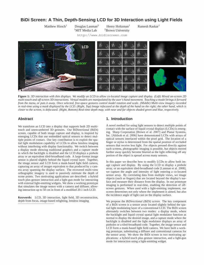
Figure 1: 3D interaction with thin displays. We modify an LCD to allow co-located image capture and display. (Left) Mixed on-screen 2Dmulti-touch and off-screen 3D interactions. Virtual models are manipulatedby the user’s hand movement. Touching a model brings it forwardfrom the menu, or puts it away. Once selected, free-space gestures control model rotation and scale. (Middle) Multi-view imagery recordedin real-time using a mask displayed by the LCD. (Right, Top) Image refocused at the depth of the hand on the right; the other hand, which iscloser to the screen, is defocused. (Right, Bottom) Real-time depth map, withnear and far objects shaded green and blue, respectively.
Abstract
We transform an LCD into a display that supports both 2D multi-touch and unencumbered 3D gestures. Our BiDirectional (BiDi)screen, capable of both image capture and display, is inspired byemerging LCDs that use embedded optical sensors to detect mul-tiple points of contact. Our key contribution is to exploit the spa-tial light modulation capability of LCDs to allow lensless imagingwithout interfering with display functionality. We switch betweena display mode showing traditional graphics and a capture modein which the backlight is disabled and the LCD displays a pinholearray or an equivalent tiled-broadband code. A large-format imagesensor is placed slightly behind the liquid crystal layer. Together,the image sensor and LCD form a mask-based light field camera,capturing an array of images equivalent to that produced by a cam-era array spanning the display surface. The recovered multi-vieworthographic imagery is used to passively estimate the depth ofscene points. Two motivating applications are described: a hybridtouch plus gesture interaction and a light-gun mode for interactingwith external light-emitting widgets. We show a working prototypethat simulates the image sensor with a camera and diffuser, allow-ing interaction up to 50 cm in front of a modified 20.1 inch LCD.
Keywords: LCD, 3D interaction, light field, 3D reconstruction,depth from focus, image-based relighting, lensless imaging
1. Introduction
A novel method for using light sensors to detect multiple points ofcontact with the surface of liquid crystal displays (LCDs) is emerg-ing. Sharp Corporation [Brown et al. 2007] and Planar Systems,Inc. [Abileah et al. 2006] have demonstrated LCDs with arrays ofoptical sensors interlaced within the pixel grid. The location of afinger or stylus is determined from the spatial position of occludedsensors that receive less light. For objects pressed directly againstsuch screens, photographic imaging is possible, but objects movedfurther away quickly become blurred as the light reflecting off anyportion of the object is spread across many sensors.
In this paper we describe how to modify LCDs to allow both im-age capture and display. By using the LCD to display a pinholearray, or an equivalent tiled-broadband code [Lanman et al. 2008],we capture the angle and intensity of light entering a co-locatedsensor array. By correlating data from multiple views, we imageobjects (such as fingers) that are located beyond the display’s sur-face and measure their distance from the display. In our prototypeimaging is performed in real-time, enabling the detection of off-screen gestures. When used with a light-emitting implement, ourscreen determines not only where the implement is aimed, but alsothe incidence angle of light cast on the display surface.
We propose theBiDirectional (BiDi) screen. The key componentof a BiDi screen is a sensor array located slightly behind the spa-tial light modulating layer of a conventional LCD. The BiDi screenalternately switches between two modes: a display mode, wherethe backlight and liquid crystal spatial light modulator function asnormal to display the desired image, and a capture mode where thebacklight is disabled and the light modulator displays an array ofpinholes or a tiled-broadband code. Together, the image sensor andLCD form a mask-based light field camera. We have built a work-ing prototype, substituting a diffuser and conventional cameras forthe sensor array. We show the BiDi screen in two motivating ap-plications: a hybrid touch plus gesture interaction, and a light-gunmode for interaction using a light-emitting widget.
1.1. Contributions
Thin, Depth-Sensing LCDs: Earlier light-sensing displays fo-cused on achieving touch interfaces. Our design advances the fieldby supporting both on-screen 2D multi-touch and off-screen, unen-cumbered 3D gestures. Our key contribution is that the LCD is putto double duty; it alternates between its traditional role in formingthe displayed image and a new role in acting as an optical mask. Weshow that achieving depth- and lighting-aware interactions requiresa small displacement between the sensing plane and the displayplane. Furthermore, we maximize the display and capture framerates using optimally light-efficient mask patterns.
Lensless Light Field Capture: We describe a thin, lensless lightfield camera composed of an optical sensor array and a spatiallight modulator. We evaluate the performance of pinhole arraysand tiled-broadband masks for light field capture from primarily re-flective, rather than transmissive, scenes. We describe key designissues, including: mask selection, spatio-angular resolution trade-offs, and the critical importance of angle-limiting materials.
Unencumbered 3D Interaction: We show novel interaction sce-narios using a BiDi screen to recognize on- and off-screen gestures.We also demonstrate detection of light-emitting widgets, showingnovel interactions between displayed images and external lighting.
1.2. Benefits and Limitations
The BiDi screen has several benefits over related techniques forimaging the space in front of a display. Chief among them is theability to capture multiple orthographic images, with a potentiallythin device, without blocking the backlight or portions of the dis-play. Besides enabling lighting direction and depth measurements,these multi-view images support the creation of a true mirror, wherethe subject gazes into her own eyes, or a videoconferencing appli-cation in which the participants have direct eye contact [Rosenthal1947]. At present, however, the limited resolution of the prototypedoes not produce imagery competitive with consumer webcams.
The BiDi screen requires separating the light-modulating and light-sensing layers, complicating the display design. In our prototype anadditional 2.5 cm was added to the display thickness to allow theplacement of the diffuser. In the future a large-format sensor couldbe accommodated within this distance, however the current proto-type uses a pair of cameras placed about 1 m behind the diffuser—significantly increasing the device dimensions. Also, as the LCD isswitched between display and capture modes, the proposed designwill reduce the native frame rate. Image flicker will result unless thedisplay frame rate remains above the flicker fusion threshold [Izadiet al. 2008]. Lastly, the BiDi screen requires external illumination,either from the room or a light-emitting widget, in order for its cap-ture mode to function. Such external illumination reduces the dis-played image contrast. This effect may be mitigated by applying ananti-reflective coating to the surface of the screen.
2. Related Work2.1. Multi-Touch and 3D Interaction
Sharp and Planar have demonstrated LCDs with integrated opticalsensors co-located at each pixel for inexpensive multi-touch inter-action. The Frustrated Total Internal Reflection (FTIR) multi-touchwall [Han 2005], TouchLight [Wilson 2004], Microsoft Surface,Oblong Industries g-speak, Visual Touchpad [Malik and Laszlo2004], and the HoloWall [Matsushita and Rekimoto 1997] use var-ious specialized cameras to detect touch and gestures. In a closely-related work, ThinSight [Izadi et al. 2007] places a compact IRemitter and detector array behind a traditional LCD. In Tactex’sMTC Express [Lokhorst and Alexander 2004] an array of pres-sure sensors localize where a membrane is depressed. Hillis [1982]
forms a 2D pressure-sensing grid using force-sensitive resistors.Apopular approach to multi-touch sensing is through the use of ca-pacitive arrays, described by Lee et al. [1985] and made popularwith the iPhone from Apple, Inc., following Fingerworks iGes-turePad, both based on the work of Westerman and Elias [Wester-man and Elias 2001]. The SmartSkin [Rekimoto 2002], Diamond-Touch [Dietz and Leigh 2001], and DTLens [Forlines and Shen2005] also use capacitive arrays. Benko and Ishak [Benko andIshak 2005] use a DiamondTouch system and 3D tracked glovesto achieve mixed multi-touch and gesture interaction.
Recent systems image directly through a display surface. Izadiet al. [2008] introduce SecondLight as a rear-projection displaywith an electronically-switchable diffuser. In their design, off-screen gestures are imaged by one or more cameras when the dif-fuser is in the clear state. While supporting high-resolution im-age capture, SecondLight significantly increases the thickness ofthe display—placing several projectors and cameras far behind thediffuser. Similarly, DepthTouch [Benko and Wilson 2009] places adepth-sensing camera behind a rear-projection screen. While pro-ducing inferior image quality, the BiDi screen has several uniquebenefits and limitations with respect to such direct-imaging designs.Foremost, with a suitable large-format sensor, the proposed designmight eliminate the added thickness in currentprojection-visionsystems, at the cost of decreased image quality.
2.2. Sensing Depth
A wide variety of passive and active techniques are available toestimate scene depth in real-time. Our prototype records an inci-dent light field [Levoy and Hanrahan 1996] using attenuating pat-terns equivalent to a pinhole array. A key benefit is that the im-age is formed without refractive optics. Similar lensless systemswith coded apertures are used in astronomical and medical imagingto capture X-rays and gamma rays. Zomet and Nayar [2006] de-scribe a system composed of a bare sensor and several attenuatinglayers, including a single LCD. Liang et al. [2008] use temporally-multiplexed attenuation patterns, also displayed with an LCD, tocapture light fields. Zhang and Chen [2005] recover a light fieldby translating a bare sensor. Levin et al. [2007] and Farid [1997]use coded apertures to estimate intensity and depth from defocusedimages. Vaish et al. [2006] discuss related methods for depth es-timation from light fields. In a closely-related work, Lanman etal. [2008] demonstrate a large-format lensless light field camerausing a family of attenuation patterns, including pinhole arrays,conceptually similar to the heterodyne camera of Veeraraghavan etal. [2007]. We use the tiled-broadband codes from those works toreduce the exposure time in our system. Unlike these systems, ourdesign exploits a mask implemented with a modified LCD panel.In addition, we use reflected light with uncontrolled illumination.
2.3. Lighting-Sensitive Displays
Lighting-sensitive displays have emerged in the market in recentyears; most portable electronics, including laptops and mobilephones, use ambient light sensors to adjust the brightness of thedisplay depending on the lighting environment. Nayar et al. [2004]propose creating lighting-sensitive displays (LSD) by placing opti-cal sensors within the display bezel and altering the rendered im-agery to accurately reflect ambient lighting conditions. Cossairt etal. [2008] implement a light field transfer system, capable of co-located capture and display, to facilitate real-time relighting of syn-thetic and real-world scenes. Fuchs et al. [2008] achieve a passivelighting-sensitive display capable of relighting pre-rendered scenesprinted on static masks. Unlike their design, our system works withdirectional light sources located in front of the display surface andcan support relighting of dynamic computer-generated scenes.
3. Bidirectional Screen Design3.1. Design Goals
It is increasingly common for devices that have the ability to displayimages to also be able to capture them. In creating the BiDi screenwe have four basic design goals:
1. Capture 3D to enable depth- and lighting-aware interaction.2. Prevent image capture from interfering with image display.3. Support walk-up interaction (i.e., no implements or markers).4. Achieve these goals with a portable, thin form factor device.
3.2. Comparison of Design Alternatives
After considering related work and possible image capture options,we believe that the BiDi screen is uniquely positioned to satisfy ourdesign goals. In this section we compare our approach to others.
Capacitive, Resistive, or Acoustic Modalities: A core designdecision was to use optical sensing rather than capacitive, resis-tive, or acoustic modalities. While such technologies are effectivefor multi-touch, they cannot capture 3D gestures. Some capaci-tive solutions detect approaching fingers or hands, but cannot ac-curately determine their distance. Nor do these technologies sup-port lighting-aware interaction. Optical sensing can be achieved invarious ways. In many prior works, cameras image the space infront of the display. The result is typically a specially-crafted envi-ronment, similar to g-speak, where multiple cameras track specialgloves with high contrast markers; or, the display housing is en-larged to accommodate the cameras, as with Microsoft’s Surface.
Cameras Behind, To the Side, or In Front of the Display:An-other issue is the trade-off between placing a small number of cam-eras at various points around the display. A camera behind thedisplay interferes with backlighting, casting shadows and causingvariations in the display brightness. Han’s FTIR sensor, Second-Light, and DepthTouch all avoid this problem by using rear projec-tion onto a diffuser, at the cost of increased display thickness. Ifthe camera is located in front of the display or to the side, then itrisks being occluded by users. Cameras placed in the bezel, look-ing sideways across the display, increase the display thickness andsuffer from user self-occlusion. Furthermore, any design incor-porating a small number of cameras cannot capture the incidentlight field, prohibiting certain relighting applications and requir-ing computationally-intensive multi-view stereo depth estimation,rather than relatively simple depth from focus analysis.
Photodetector Arrays: In contrast, our approach uses an array ofphotodetectors located behind the LCD (see Figure 2). This con-figuration will not obscure the backlight and any attenuation willbe evenly-distributed. Being behind the display, it does not sufferfrom user self-occlusion. The detector layer can be extremely thinand optically transparent (using thin film manufacturing), support-ing our goal of portability. These are all design attributes we sharewith multi-touch displays being contemplated by Sharp and Pla-nar. However, we emphasize that our display additionally requiresa small gap between the spatial light modulating and light detect-ing planes. This critical gap allows measuring the angle of incidentlight, as well as its intensity, and thereby the capture of 3D data.
Camera Arrays: Briefly, we note that a dense camera array placedbehind an LCD is equivalent to our approach. However, such tiledcameras must be synchronized and assembled, increasing the engi-neering complexity compared to the bare sensor in a BiDi screen. Inaddition, the sensors and lenses required by each camera introducebacklight non-uniformity. Designs incorporating dense camera ar-rays must confront similar challenges as the BiDi screen, includinglight absorption (by various LCD layers) and image flicker (due toswitching between display and capture frames).
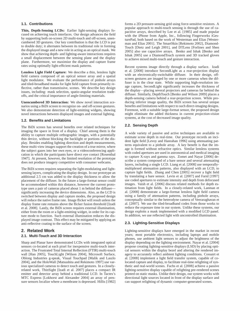
Figure 2: Image capture and display can be achieved by rearrang-ing the optical components within an LCD. A liquid crystal spatiallight modulator is used to display a mask (either a pinhole arrayor equivalent tiled-broadband code). A large-format sensor, placedbehind the spatial light modulator, measures the angle of incidentlight, as well as its intensity. (Left) The modulated light is capturedon a sensor array for decoding. (Right) With no large-area sensoravailable, a camera images a diffuser to simulate the sensor array.In both cases, LEDs restore the backlight function.
4. Designing a Thin, Depth-Sensing LCD
The preferred formulation of the BiDi screen would contain anoptically-transparent thin film sensor array embedded within thebacklight. In this section we discuss an alternate implementationthat substitutes a diffuser and camera array for the sensor array,which is commercially unavailable today. While sub-optimal, manyof the practical benefits and limits of a BiDi screen can be exploredwith our low-cost prototype.
4.1. Overview of LCD Components
We briefly review the functionality of key components included inmodern LCDs to provide context for the modifications we describe.
An LCD is composed of two primary components: a backlight anda spatial light modulator. A typical backlight consists of a cold cath-ode fluorescent lamp (CCFL), a light guide, a rear reflecting surfacecovering the light guide, a diffuser, and several brightness enhanc-ing films. The overall function of these layers is to condition thelight produced by the CCFL such that it is spatially uniform, col-limated, and polarized along a single axis before reaching the spa-tial light modulator. A key role is played by the backlight diffuser.By randomizing both the polarization state and angular variationof transmitted and reflected rays, the diffuser greatly increases theefficiency of the backlight, allowing light rays to be “recycled” byreflecting between the various layers until they satisfy the necessarycollimation and polarization conditions.
The spatial light modulator of an LCD is composed of three pri-mary components: a pair of crossed linear polarizers and a layer ofliquid crystal molecules sandwiched between glass substrates withembedded electrode arrays. The polarizer closest to the backlightfunctions to select a single polarization state. When a variable elec-tric field is applied to an individual electrode (i.e., a single displaypixel), the liquid crystal molecules are reconfigured so that the inci-dent polarization state is rotated. The polarizer closest to the viewerattenuates all but a single polarization state, allowing the pixel toappear various shades of gray depending on the degree of rotationinduced within the liquid crystal layer. Color display is achieved byembedding a spatially-varying set of color filters within the glasssubstrate. To achieve wide-angle viewing in ambient lighting, a fi-nal diffuser, augmented with possible anti-reflection and anti-glarefilms, is placed between the last polarizer and the viewer.
4.2. Hardware Design
As shown in Figure 2, our BiDi screen is formed by repurposingtypical LCD components such that image capture is achieved with-out hindering display functionality. We begin by excluding cer-tain non-essential layers, including the CCFL/light guide/reflectorcomponents, the various brightness enhancing films, and the finaldiffuser between the LCD and the user. In a manner similar to [Lan-man et al. 2008], we then create a large-aperture, multi-view imagecapture device by using the spatial light modulator to display a pin-hole array or tiled-broadband mask. Our key insight is that, forsimultaneous image capture and display, the remaining backlightdiffuser must be movedawayfrom the liquid crystal. In doing so, acoded image equivalent to an array of pinhole images is formed onthe diffuser, which can be photographed by one or more camerasplaced behind the diffuser. The backlight is restored by includingan additional array of LEDs behind the diffuser.
We note that an angle-limiting material or other source of vignettingis critical to achieve image capture using the BiDi screen. In prac-tice, the reflected light from objects in front of the screen will varycontinuously over the full hemisphere of incidence angles. How-ever, the proposed image capture scheme assumes light varies onlyover a limited range of angles—although this range can be arbi-trarily large. An angle-limiting film could be placed in front of theBiDi screen, however such a film would also limit the field of viewof the display. In our design we place the cameras about one meterbehind the diffuser. Since the diffuser disperses light into a narrowcone, the diffuser and cameras act together to create a vignettingeffect equivalent to an angle-limiting film.
4.3. Optical Design with Pinhole Arrays
Our design goals require sufficient image resolution to estimate the3D position of points located in front of the screen, as well as thevariation in position and angle of incident illumination. As de-scribed by [Veeraraghavan et al. 2007], the trade-off between spatialand angular resolution is governed by the pinhole spacing (or theequivalent size of a broadband tile) and by the separation betweenthe spatial light modulator and the image plane (i.e., the diffuser).As with any imaging system, the spatial and angular resolution willbe determined by the point spread function (PSF). In this section weoptimize the BiDi screen for both on-screen and off-screen interac-tion under these constraints for the case of a pinhole array mask. InSection 4.4 we extend this analysis to tiled-broadband masks.
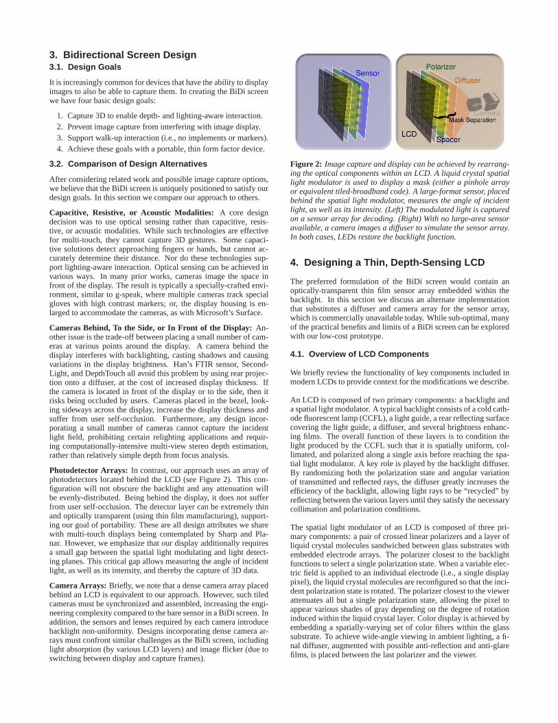
Multi-View Orthographic Imagery: As shown in Figure 3, a uni-form array of pinhole images can be decoded to produce a set ofmulti-view orthographic images. Consider the orthographic imageformed by the set of optical rays perpendicular to the display sur-face. This image can be generated by concatenating the samplesdirectly below each pinhole on the diffuser plane. Similar ortho-graphic views, sampling along different angular directions from thesurface normal of the display, can be obtained by sampling a trans-lated array of points offset from the center pixel under each pinhole.
On-screen Interaction: For multi-touch applications, only the spa-tial resolution of the imaging device in the plane of the display isof interest. For a pinhole mask this is simply the total number ofdisplayed pinholes. Thus, to optimize on-screen interactions thepinhole spacing should be reduced as much as possible (in the limitdisplaying a fully-transparent pattern) and the diffuser brought asclose as possible to the spatial light modulator. This is precisely theconfiguration utilized by the existing optical touch-sensing displaysby Brown et al. [2007] and Abileah et al. [2006].
Off-screen Interaction: To allow hands-free 3D interaction, ad-ditional angular views are necessary. First, to estimate the depthof scene points, angular diversity is needed to provide a sufficient
dp
t
di
do
s
α α α α
θθ θ θ
dp
t
di
do
ss
α α α α α α α
θθθθ θθ θθ
Figure 3: Multi-view orthographic imagery from pinhole arrays. Auniform array of pinhole images (each field of view shaded gray)is resampled to produce a set of orthographic images, each with adifferent viewing angleθ with respect to the surface normal of thedisplay. The set of optical rays perpendicular to the display surface(shown in blue) is sampled underneath the center of each pinhole.A second set of parallel rays (shown in red) is imaged at a uniformgrid of points offset from the center pixels under each pinhole.
baseline for reconstruction. Second, to facilitate interactions withoff-screen light-emitting widgets, the imagery must sample a widerange of incident lighting directions. We conclude that spatial andangular resolution must be traded to optimize the performance fora given application. Off-screen rather than on-screen interaction isthe driving factor behind our decision to separate the diffuser fromthe spatial light modulator, allowing increased angular resolution atthe cost of decreased spatial resolution with a pinhole array mask.
Spatio-Angular Resolution Trade-off: Consider a single pinholecamera shown in Figure 4, optimized for imaging at wavelengthλ,with circular aperture diametera, and sensor-pinhole separationdi.The total widthb of the optical point spread function, for a pointlocated a distancedo from the pinhole, is modeled as
b(di, do, a, λ) =2.44λdi
a+
a(do + di)
do
. (1)
Note that the first and second terms correspond to the approximateblur due to diffraction and the geometric projection of the pinholeaperture onto the sensor plane, respectively [Hecht 2001]. If wenow assume that each pinhole camera has a limited field of view,given byα, then the minimum pinhole spacingdp is
dp(di, do, a, λ, α) = 2di tan(
α
2
)
+ b(di, do, a, λ). (2)
Note that a smaller spacing would cause neighboring pinhole im-ages to overlap. As previously described, a limited field of viewcould be due to vignetting or achieved by the inclusion of an angle-limiting film. Since, in our design, the number of orthographicviewsNangular is determined by the resolution of each pinhole im-age, we conclude that the angular resolution of our system is limitedto the width of an individual pinhole image (equal to the minimumpinhole spacingdp) divided by the PSF widthb as follows.
Nangular(di, do, a, λ, α) =dp(di, do, a, λ, α)
b(di, do, a, λ). (3)
Now consider an array of pinhole cameras uniformly distributedacross a screen of widths and separated by a distancedp (see Fig-ure 3). Note that a limited field of view is necessary to preventoverlapping of neighboring images. As described in Section 4.5,we use a depth from focus method to estimate the separation of ob-jects from the display surface. As a result, the system components
dp
α
di
do
a
b
b/M
Pinhole
MUR Adp
α
di
do
a
b
b/M
dp
α
di
do
a
b
b/M
Pinhole
MUR A
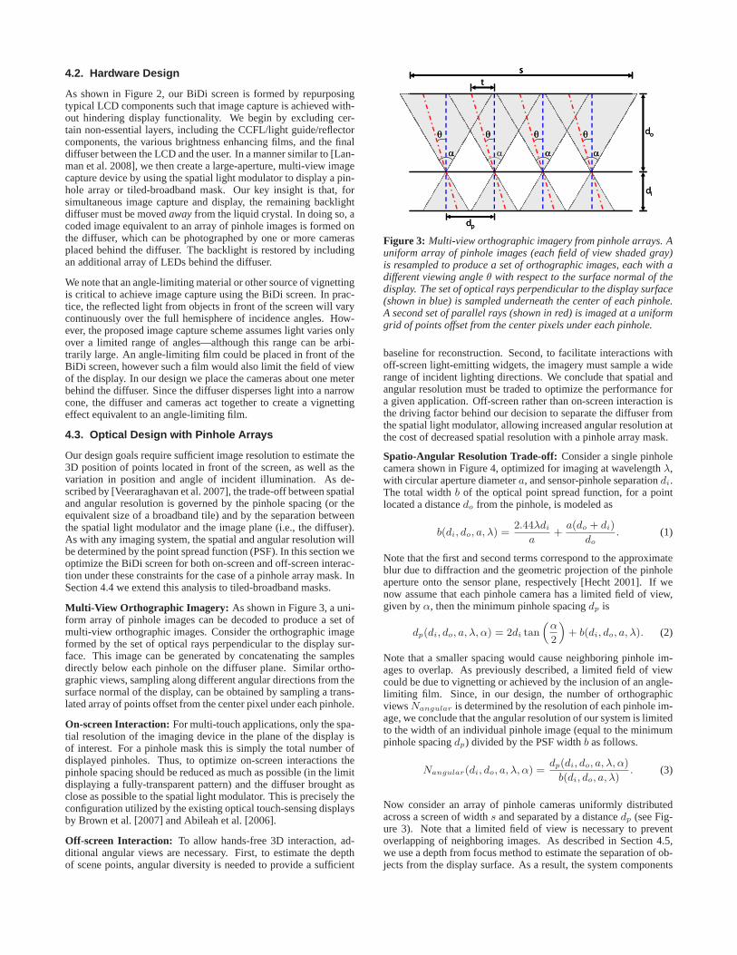
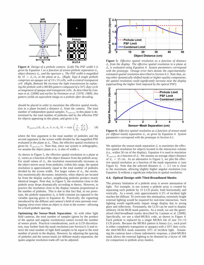
Figure 4: Design of a pinhole camera. (Left) The PSF widthb isgiven by Equation 1 as a function of sensor-pinhole separationdi,object distancedo, and the aperturea. The PSF width is magnifiedby M = di/do in the plane atdo. (Right, Top) A single pinholecomprises an opaque set of19×19 cells, with a central transparentcell. (Right, Bottom) We increase the light transmission by replac-ing the pinhole with a MURA pattern composed of a50% duty cyclearrangement of opaque and transparent cells. As described by Lan-man et al. [2008] and earlier by Fenimore et al. [1978; 1989], thispattern yields an equivalent image as a pinhole after decoding.
should be placed in order to maximize the effective spatial resolu-tion in a plane located a distancedo from the camera. The totalnumber of independent spatial samplesNspatial in this plane is de-termined by the total number of pinholes and by the effective PSFfor objects appearing in this plane, and given is by
Nspatial(di, do, a, λ, α; dp, b) = min
(
s
dp
,dis
dob
)
, (4)
where the first argument is the total number of pinholes and thesecond argument is the screen width divided by the magnified PSFevaluated in the plane atdo. Thus, the effective spatial resolution isgiven byNspatial/s. Note that, since our system is orthographic,we assume the object plane atdo is also of widths.
As shown in Figure 5, the effective spatial resolution in a plane atdo varies as a function of the object distance from the pinhole array.For small values ofdo, the resolution monotonically increases asthe object moves away from pinholes; within this range, the spatialresolution is approximately equal to the total number of pinholesdivided by the screen width. For larger values ofdo, the resolu-tion monotonically decreases; intuitively, when objects are locatedfar from the display surface, neighboring pinholes produce nearlyidentical images. Note that, in Figure 5, the resolution close to thepinhole array drops dramatically according to theory. However, inpractice the resolution close to the display remains proportional tothe number of pinholes. This is due to that fact that, in our proto-type, the pinhole separationdp is held constant (as opposed to thevariable spacing given in Equation 4). Practically, the vignettingintroduced by the diffuser and camera’s field of view prevents over-lapping views even when an object is close to the screen—allowingfor a fixed pinhole spacing.
Optimizing the Sensor-Mask Separation: As with other lightfield cameras, the total number of samples (given by the productof the spatial and angular resolutions) cannot exceed the numberof sensor pixels. Practical considerations, such as LCD discretiza-tion, may further limit the mask resolution (see Section 6.1) and re-strict the total number of light field samples to be equal to the totalnumber of pixels in the display. However, by adjusting the spacingof pinholes and the sensor-mask (or diffuser-mask) separation, thespatio-angular resolution trade-off can be adjusted.
Object Distance (cm)
Sp
ati
al R
eso
luti
on
(d
pcm
)
0 10 20 30 40 500
0.5
1
1.5
2
2.5
Pinhole Limit
PSF Limit
Combined Limit
Figure 5: Effective spatial resolution as a function of distancedo from the display. The effective spatial resolution in a plane atdo is evaluated using Equation 4. System parameters correspondwith the prototype. Orange error bars denote the experimentally-estimated spatial resolution described in Section 6.3. Note that, us-ing either dynamically-shifted masks or higher-quality components,the spatial resolution could significantly increase near the display(approaching the higher limit imposed by the optical PSF).
Sensor−Mask Separation (cm)
Sp
ati
al
Re
so
luti
on
(d
pc
m)
0 1 2 3 4 50
1
2
3
Pinhole Limit
PSF Limit
Combined Limit
Figure 6: Effective spatial resolution as a function of sensor-mask(or diffuser-mask) separationdi, as given by Equation 4. Systemparameters correspond with the prototype in Section 6.1.
We optimize the sensor-mask separationdi to maximize the effec-tive spatial resolution for objects located in the interaction volume(i.e., within 50 cm of the display). Equation 4 is used to maximizeNspatial as a function ofdi. We assume an average object distanceof do = 25 cm. As an alternative to Figure 5, we plot the effec-tive spatial resolution as a function of the mask separationdi (seeFigure 6). Note that the selected distancedi = 2.5 cm is closeto the maximum, allowing slightly higher angular resolution (viaEquation 3) without a significant reduction in spatial resolution.
4.4. Optical Design with Tiled-Broadband Masks
The primary limitation of a pinhole array is severe attenuation oflight. For example, in our system a pinhole array is created byseparating each pinhole by18 LCD pixels, both horizontally andvertically. As a result, only approximately0.2% of incident lightreaches the diffuser. To overcome this attenuation, extremely brightexternal lighting would be required for real-time interaction. Suchlighting would significantly impair image display due to strongglare and reflections. Fortunately, the LCD can be used to displayarbitrary 24-bit RGB mask patterns. As a result, we use the gener-alized tiled-broadband masks described by Lanman et al. [2008].Specifically, we use a tiled-MURA code, as shown in Figure 4.Each pinhole is replaced by a single MURA tile of size19×19LCD pixels. Because the MURA pattern is binary (i.e., each pixelis either completely transparent or opaque) with a50% duty cycle,the tiled-MURA mask transmits50% of incident light. Assum-ing the cameras have a linear radiometric response, a tiled-MURAmask allows the external lighting to be dimmed by a factor of 180(in comparison to pinhole array masks).
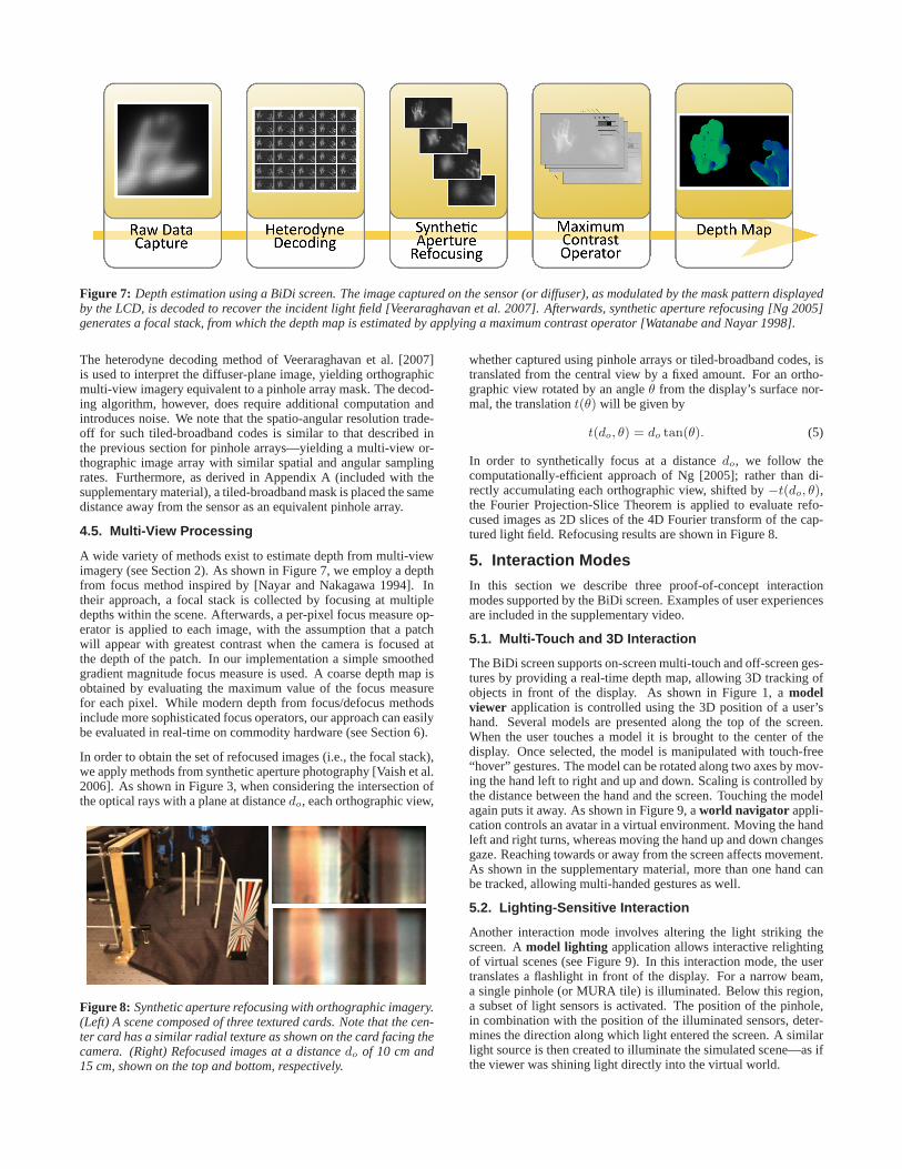
Figure 7: Depth estimation using a BiDi screen. The image captured on the sensor (or diffuser), as modulated by the mask pattern displayedby the LCD, is decoded to recover the incident light field [Veeraraghavan et al. 2007]. Afterwards, synthetic aperture refocusing [Ng 2005]generates a focal stack, from which the depth map is estimated by applying a maximum contrast operator [Watanabe and Nayar 1998].
The heterodyne decoding method of Veeraraghavan et al. [2007]is used to interpret the diffuser-plane image, yielding orthographicmulti-view imagery equivalent to a pinhole array mask. The decod-ing algorithm, however, does require additional computation andintroduces noise. We note that the spatio-angular resolution trade-off for such tiled-broadband codes is similar to that described inthe previous section for pinhole arrays—yielding a multi-view or-thographic image array with similar spatial and angular samplingrates. Furthermore, as derived in Appendix A (included with thesupplementary material), a tiled-broadband mask is placed the samedistance away from the sensor as an equivalent pinhole array.
4.5. Multi-View Processing
A wide variety of methods exist to estimate depth from multi-viewimagery (see Section 2). As shown in Figure 7, we employ a depthfrom focus method inspired by [Nayar and Nakagawa 1994]. Intheir approach, a focal stack is collected by focusing at multipledepths within the scene. Afterwards, a per-pixel focus measure op-erator is applied to each image, with the assumption that a patchwill appear with greatest contrast when the camera is focused atthe depth of the patch. In our implementation a simple smoothedgradient magnitude focus measure is used. A coarse depth map isobtained by evaluating the maximum value of the focus measurefor each pixel. While modern depth from focus/defocus methodsinclude more sophisticated focus operators, our approach can easilybe evaluated in real-time on commodity hardware (see Section 6).
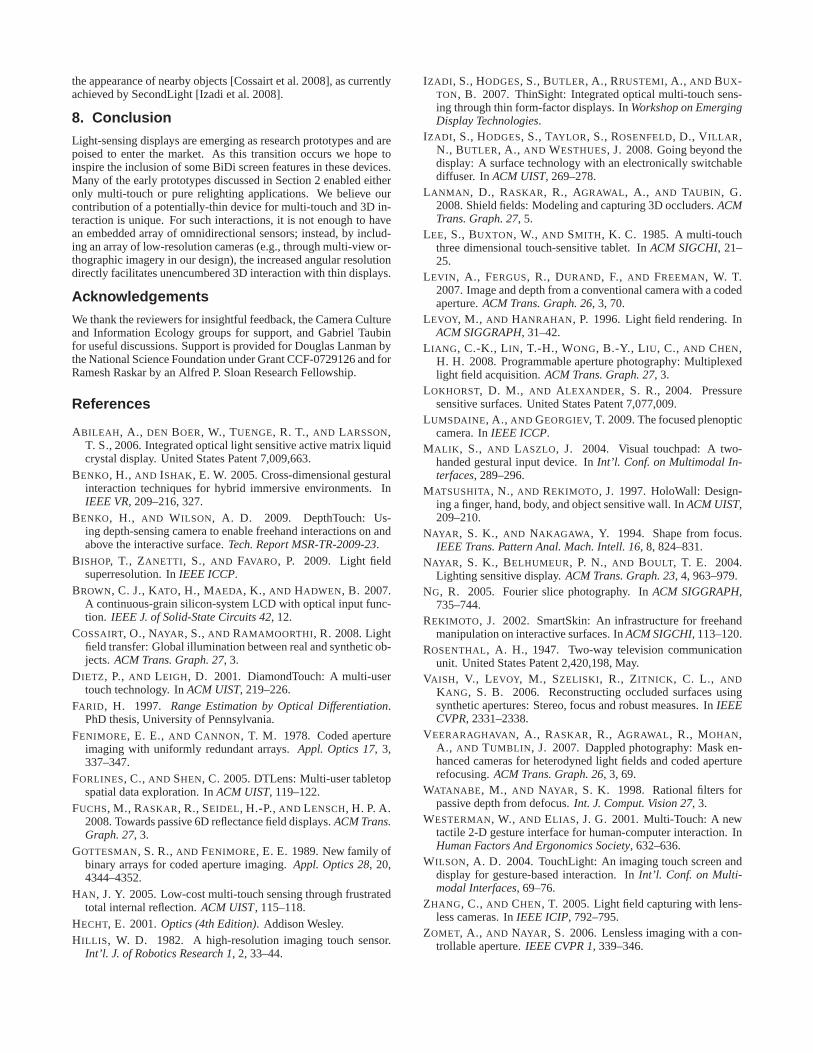
In order to obtain the set of refocused images (i.e., the focal stack),we apply methods from synthetic aperture photography [Vaish et al.2006]. As shown in Figure 3, when considering the intersection ofthe optical rays with a plane at distancedo, each orthographic view,
Figure 8: Synthetic aperture refocusing with orthographic imagery.(Left) A scene composed of three textured cards. Note that the cen-ter card has a similar radial texture as shown on the card facing thecamera. (Right) Refocused images at a distancedo of 10 cm and15 cm, shown on the top and bottom, respectively.
whether captured using pinhole arrays or tiled-broadband codes, istranslated from the central view by a fixed amount. For an ortho-graphic view rotated by an angleθ from the display’s surface nor-mal, the translationt(θ) will be given by
t(do, θ) = do tan(θ). (5)
In order to synthetically focus at a distancedo, we follow thecomputationally-efficient approach of Ng [2005]; rather than di-rectly accumulating each orthographic view, shifted by−t(do, θ),the Fourier Projection-Slice Theorem is applied to evaluate refo-cused images as 2D slices of the 4D Fourier transform of the cap-tured light field. Refocusing results are shown in Figure 8.
5. Interaction ModesIn this section we describe three proof-of-concept interactionmodes supported by the BiDi screen. Examples of user experiencesare included in the supplementary video.
5.1. Multi-Touch and 3D Interaction
The BiDi screen supports on-screen multi-touch and off-screen ges-tures by providing a real-time depth map, allowing 3D tracking ofobjects in front of the display. As shown in Figure 1, amodelviewer application is controlled using the 3D position of a user’shand. Several models are presented along the top of the screen.When the user touches a model it is brought to the center of thedisplay. Once selected, the model is manipulated with touch-free“hover” gestures. The model can be rotated along two axes by mov-ing the hand left to right and up and down. Scaling is controlled bythe distance between the hand and the screen. Touching the modelagain puts it away. As shown in Figure 9, aworld navigator appli-cation controls an avatar in a virtual environment. Moving the handleft and right turns, whereas moving the hand up and down changesgaze. Reaching towards or away from the screen affects movement.As shown in the supplementary material, more than one hand canbe tracked, allowing multi-handed gestures as well.
5.2. Lighting-Sensitive Interaction
Another interaction mode involves altering the light striking thescreen. Amodel lighting application allows interactive relightingof virtual scenes (see Figure 9). In this interaction mode, the usertranslates a flashlight in front of the display. For a narrow beam,a single pinhole (or MURA tile) is illuminated. Below this region,a subset of light sensors is activated. The position of the pinhole,in combination with the position of the illuminated sensors, deter-mines the direction along which light entered the screen. A similarlight source is then created to illuminate the simulated scene—as ifthe viewer was shining light directly into the virtual world.
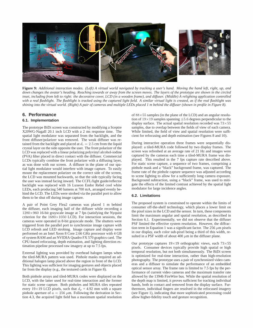
Figure 9: Additional interaction modes. (Left) A virtual world navigated by tracking a user’s hand. Moving the hand left, right, up, anddown changes the avatar’s heading. Reaching towards or away from thescreen moves. The layers of the prototype are shown in the circledinset, including from left to right: the decorative cover, LCD (in a wooden frame), and diffuser. (Middle) A relighting application controlledwith a real flashlight. The flashlight is tracked using the captured light field.A similar virtual light is created, as if the real flashlight wasshining into the virtual world. (Right) A pair of cameras and multiple LEDs placed 1 m behind the diffuser (shown in profile in Figure 8).
6. Performance6.1. Implementation
The prototype BiDi screen was constructed by modifying a SceptreX20WG-NagaII 20.1 inch LCD with a 2 ms response time. Thespatial light modulator was separated from the backlight, and thefront diffuser/polarizer was removed. The weak diffuser was re-tained from the backlight and placed atdi = 2.5 cm from the liquidcrystal layer on the side opposite the user. The front polarizer of theLCD was replaced with a linear polarizing polyvinyl alcohol-iodine(PVA) filter placed in direct contact with the diffuser. CommercialLCDs typically combine the front polarizer with a diffusing layer,as was done with our screen. A diffuser in the plane of our spa-tial light modulator would interfere with image capture. To easilymount the replacement polarizer on the correct side of the screen,the LCD was mounted backwards, so that the side typically facingthe user was instead facing inward. The CCFL/light guide/reflectorbacklight was replaced with 16 Luxeon Endor Rebel cool whiteLEDs, each producing 540 lumens at 700 mA, arranged evenly be-hind the LCD. The LEDs were strobed via the parallel port to allowthem to be shut off during image capture.
A pair of Point Grey Flea2 cameras was placed 1 m behindthe diffuser, each imaging half of the diffuser while recording a1280×960 16-bit grayscale image at 7 fps (satisfying the Nyquistcriterion for the1680×1050 LCD). For interaction sessions, thecameras were operated in 8-bit grayscale mode. The shutters weretriggered from the parallel port to synchronize image capture withLCD refresh and LED strobing. Image capture and display wereperformed on an Intel Xeon 8 Core 2.66 GHz processor with 4 GBof system RAM and an NVIDIA Quadro FX 570 graphics card. TheCPU-based refocusing, depth estimation, and lighting direction es-timation pipeline processed raw imagery at up to 7.5 fps.
External lighting was provided by overhead halogen lamps whenthe tiled-MURA pattern was used. Pinhole masks required an ad-ditional halogen lamp placed above the region in front of the LCD.This lighting was sufficient for imaging gestures and objects placedfar from the display (e.g., the textured cards in Figure 8).
Both pinhole arrays and tiled-MURA codes were displayed on theLCD, with the latter used for real-time interaction and the formerfor static scene capture. Both pinholes and MURA tiles repeatedevery 19×19 LCD pixels, such thatdp = 4.92 mm with a squarepinhole aperture ofa = 256 µm. Following the derivation in Sec-tion 4.3, the acquired light field has a maximum spatial resolution
of 88×55 samples (in the plane of the LCD) and an angular resolu-tion of 19×19 samples spanning±5.6 degrees perpendicular to thedisplay surface. The actual spatial resolution recorded was73×55samples, due to overlap between the fields of view of each camera.While limited, the field of view and spatial resolution were suffi-cient for refocusing and depth estimation (see Figures 8 and 10).
During interactive operation three frames were sequentially dis-played: a tiled-MURA code followed by two display frames. Thescreen was refreshed at an average rate of 21 Hz and images werecaptured by the cameras each time a tiled-MURA frame was dis-played. This resulted in the 7 fps capture rate described above.For static scene capture, a sequence of two frames, comprising apinhole mask and a “black” background frame, was captured. Theframe rate of the pinhole capture sequence was adjusted accordingto scene lighting to allow for a sufficiently long camera exposure.Background subtraction, using a “black” frame, was used to miti-gate the effects of the limited contrast achieved by the spatial lightmodulator for large incidence angles.
6.2. Limitations
The proposed system is constrained to operate within the limits ofconsumer off-the-shelf technology, which places a lower limit onthe pixel sizes in the LCD and the sensor. In turn, these componentslimit the maximum angular and spatial resolution, as described inSection 6.1. Experimentally, we did not observe that the diffuserPSF limited the effective system resolution. However, the diffrac-tion term in Equation 1 was a significant factor. The 256µm pixelsin our display, each color sub-pixel being a third of this width, re-sulted in a PSF width of about 400µm in the diffuser plane.
Our prototype captures 19×19 orthographic views, each 73×55pixels. Consumer devices typically provide high spatial or hightemporal resolution, but not both simultaneously. The BiDi screenis optimized for real-time interaction, rather than high-resolutionphotography. The prototype uses a pair of synchronized video cam-eras and a diffuser to simulate the performance of an embeddedoptical sensor array. The frame rate is limited to 7.5 fps by the per-formance of current video cameras and the maximum transfer rateallowed by the 1394b FireWire bus. While the spatial resolution ofthe depth map is limited, it proves sufficient for tracking individualhands, both in contact and removed from the display surface. Fur-thermore, individual fingers are resolved in the refocused imagery(see Figure 1), indicating that more sophisticated processing couldallow higher-fidelity touch and gesture recognition.
External lighting is required to provide sufficient illumination dur-ing image capture. Efficient mask patterns, such as tiled-MURA,allow lighting to be dimmed. However, any external lighting willreduce display contrast due to glare and reflections. Inclusion ofan anti-reflection coating may mitigate this effect. Objects close tothe display can be occluded from ambient lighting sources, reduc-ing tracking accuracy. In contrast to transmission-mode light fieldcapture, such as in [Lanman et al. 2008], our design requires theinclusion of an angle-limiting element, further reducing the lightreaching the optical sensors. The LCD spatial light modulator haslimited contrast, which is further reduced at large incidence angles.When displaying a tiled-MURA mask, this contrast reduction canbe compensated for algorithmically. However, to compensate forlow contrast when using a pinhole array, a background image alsomust be recorded. Capturing the background image further reducesthe frame rate when using a pinhole array. An additional lightingpitfall is caused by the layered components of our design, whichmay introduce artifacts from reflections and scattering.
6.3. Validation
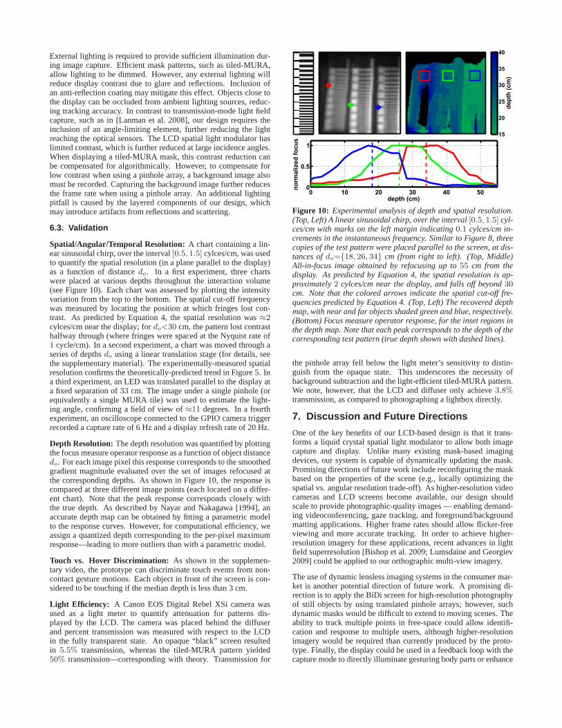
Spatial/Angular/Temporal Resolution: A chart containing a lin-ear sinusoidal chirp, over the interval[0.5, 1.5] cylces/cm, was usedto quantify the spatial resolution (in a plane parallel to the display)as a function of distancedo. In a first experiment, three chartswere placed at various depths throughout the interaction volume(see Figure 10). Each chart was assessed by plotting the intensityvariation from the top to the bottom. The spatial cut-off frequencywas measured by locating the position at which fringes lost con-trast. As predicted by Equation 4, the spatial resolution was≈2cylces/cm near the display; fordo<30 cm, the pattern lost contrasthalfway through (where fringes were spaced at the Nyquist rate of1 cycle/cm). In a second experiment, a chart was moved through aseries of depthsdo using a linear translation stage (for details, seethe supplementary material). The experimentally-measured spatialresolution confirms the theoretically-predicted trend in Figure 5. Ina third experiment, an LED was translated parallel to the display ata fixed separation of33 cm. The image under a single pinhole (orequivalently a single MURA tile) was used to estimate the light-ing angle, confirming a field of view of≈11 degrees. In a fourthexperiment, an oscilloscope connected to the GPIO camera triggerrecorded a capture rate of 6 Hz and a display refresh rate of 20 Hz.
Depth Resolution:The depth resolution was quantified by plottingthe focus measure operator response as a function of object distancedo. For each image pixel this response corresponds to the smoothedgradient magnitude evaluated over the set of images refocused atthe corresponding depths. As shown in Figure 10, the response iscompared at three different image points (each located on a differ-ent chart). Note that the peak response corresponds closely withthe true depth. As described by Nayar and Nakagawa [1994], anaccurate depth map can be obtained by fitting a parametric modelto the response curves. However, for computational efficiency, weassign a quantized depth corresponding to the per-pixel maximumresponse—leading to more outliers than with a parametric model.
Touch vs. Hover Discrimination: As shown in the supplemen-tary video, the prototype can discriminate touch events from non-contact gesture motions. Each object in front of the screen is con-sidered to be touching if the median depth is less than 3 cm.
Light Efficiency: A Canon EOS Digital Rebel XSi camera wasused as a light meter to quantify attenuation for patterns dis-played by the LCD. The camera was placed behind the diffuserand percent transmission was measured with respect to the LCDin the fully transparent state. An opaque “black” screen resultedin 5.5% transmission, whereas the tiled-MURA pattern yielded50% transmission—corresponding with theory. Transmission for
0 10 20 30 40 500
0.5
1
depth (cm)
no
rmalized
fo
cu
s
dep
th (
cm
)
15
20
25
30
35
40
Figure 10: Experimental analysis of depth and spatial resolution.(Top, Left) A linear sinusoidal chirp, over the interval[0.5, 1.5] cyl-ces/cm with marks on the left margin indicating0.1 cylces/cm in-crements in the instantaneous frequency. Similar to Figure 8, threecopies of the test pattern were placed parallel to the screen, at dis-tances ofdo={18, 26, 34} cm (from right to left). (Top, Middle)All-in-focus image obtained by refocusing up to55 cm from thedisplay. As predicted by Equation 4, the spatial resolution is ap-proximately2 cylces/cm near the display, and falls off beyond30cm. Note that the colored arrows indicate the spatial cut-off fre-quencies predicted by Equation 4. (Top, Left) The recovered depthmap, with near and far objects shaded green and blue, respectively.(Bottom) Focus measure operator response, for the inset regions inthe depth map. Note that each peak corresponds to the depth of thecorresponding test pattern (true depth shown with dashed lines).
the pinhole array fell below the light meter’s sensitivity to distin-guish from the opaque state. This underscores the necessity ofbackground subtraction and the light-efficient tiled-MURA pattern.We note, however, that the LCD and diffuser only achieve3.8%transmission, as compared to photographing a lightbox directly.
7. Discussion and Future Directions
One of the key benefits of our LCD-based design is that it trans-forms a liquid crystal spatial light modulator to allow both imagecapture and display. Unlike many existing mask-based imagingdevices, our system is capable of dynamically updating the mask.Promising directions of future work include reconfiguring the maskbased on the properties of the scene (e.g., locally optimizing thespatial vs. angular resolution trade-off). As higher-resolution videocameras and LCD screens become available, our design shouldscale to provide photographic-quality images — enabling demand-ing videoconferencing, gaze tracking, and foreground/backgroundmatting applications. Higher frame rates should allow flicker-freeviewing and more accurate tracking. In order to achieve higher-resolution imagery for these applications, recent advances in lightfield superresolution [Bishop et al. 2009; Lumsdaine and Georgiev2009] could be applied to our orthographic multi-view imagery.
The use of dynamic lensless imaging systems in the consumer mar-ket is another potential direction of future work. A promising di-rection is to apply the BiDi screen for high-resolution photographyof still objects by using translated pinhole arrays; however, suchdynamic masks would be difficult to extend to moving scenes. Theability to track multiple points in free-space could allow identifi-cation and response to multiple users, although higher-resolutionimagery would be required than currently produced by the proto-type. Finally, the display could be used in a feedback loop with thecapture mode to directly illuminate gesturing body parts or enhance
the appearance of nearby objects [Cossairt et al. 2008], as currentlyachieved by SecondLight [Izadi et al. 2008].
8. Conclusion
Light-sensing displays are emerging as research prototypes and arepoised to enter the market. As this transition occurs we hope toinspire the inclusion of some BiDi screen features in these devices.Many of the early prototypes discussed in Section 2 enabled eitheronly multi-touch or pure relighting applications. We believe ourcontribution of a potentially-thin device for multi-touch and 3D in-teraction is unique. For such interactions, it is not enough to havean embedded array of omnidirectional sensors; instead, by includ-ing an array of low-resolution cameras (e.g., through multi-view or-thographic imagery in our design), the increased angular resolutiondirectly facilitates unencumbered 3D interaction with thin displays.
Acknowledgements
We thank the reviewers for insightful feedback, the Camera Cultureand Information Ecology groups for support, and Gabriel Taubinfor useful discussions. Support is provided for Douglas Lanman bythe National Science Foundation under Grant CCF-0729126 and forRamesh Raskar by an Alfred P. Sloan Research Fellowship.
References
ABILEAH , A., DEN BOER, W., TUENGE, R. T., AND LARSSON,T. S., 2006. Integrated optical light sensitive active matrix liquidcrystal display. United States Patent 7,009,663.
BENKO, H., AND ISHAK, E. W. 2005. Cross-dimensional gesturalinteraction techniques for hybrid immersive environments. InIEEE VR, 209–216, 327.
BENKO, H., AND WILSON, A. D. 2009. DepthTouch: Us-ing depth-sensing camera to enable freehand interactions on andabove the interactive surface.Tech. Report MSR-TR-2009-23.
BISHOP, T., ZANETTI , S., AND FAVARO , P. 2009. Light fieldsuperresolution. InIEEE ICCP.
BROWN, C. J., KATO, H., MAEDA , K., AND HADWEN, B. 2007.A continuous-grain silicon-system LCD with optical input func-tion. IEEE J. of Solid-State Circuits 42, 12.
COSSAIRT, O., NAYAR , S.,AND RAMAMOORTHI , R. 2008. Lightfield transfer: Global illumination between real and synthetic ob-jects.ACM Trans. Graph. 27, 3.
DIETZ, P., AND LEIGH, D. 2001. DiamondTouch: A multi-usertouch technology. InACM UIST, 219–226.
FARID , H. 1997. Range Estimation by Optical Differentiation.PhD thesis, University of Pennsylvania.
FENIMORE, E. E., AND CANNON, T. M. 1978. Coded apertureimaging with uniformly redundant arrays.Appl. Optics 17, 3,337–347.
FORLINES, C., AND SHEN, C. 2005. DTLens: Multi-user tabletopspatial data exploration. InACM UIST, 119–122.
FUCHS, M., RASKAR, R., SEIDEL, H.-P.,AND LENSCH, H. P. A.2008. Towards passive 6D reflectance field displays.ACM Trans.Graph. 27, 3.
GOTTESMAN, S. R.,AND FENIMORE, E. E. 1989. New family ofbinary arrays for coded aperture imaging.Appl. Optics 28, 20,4344–4352.
HAN , J. Y. 2005. Low-cost multi-touch sensing through frustratedtotal internal reflection.ACM UIST, 115–118.
HECHT, E. 2001.Optics (4th Edition). Addison Wesley.HILLIS , W. D. 1982. A high-resolution imaging touch sensor.
Int’l. J. of Robotics Research 1, 2, 33–44.
IZADI , S., HODGES, S., BUTLER, A., RRUSTEMI, A., AND BUX-TON, B. 2007. ThinSight: Integrated optical multi-touch sens-ing through thin form-factor displays. InWorkshop on EmergingDisplay Technologies.
IZADI , S., HODGES, S., TAYLOR , S., ROSENFELD, D., VILLAR ,N., BUTLER, A., AND WESTHUES, J. 2008. Going beyond thedisplay: A surface technology with an electronically switchablediffuser. InACM UIST, 269–278.
LANMAN , D., RASKAR, R., AGRAWAL , A., AND TAUBIN , G.2008. Shield fields: Modeling and capturing 3D occluders.ACMTrans. Graph. 27, 5.
LEE, S., BUXTON, W., AND SMITH , K. C. 1985. A multi-touchthree dimensional touch-sensitive tablet. InACM SIGCHI, 21–25.
LEVIN , A., FERGUS, R., DURAND, F., AND FREEMAN, W. T.2007. Image and depth from a conventional camera with a codedaperture.ACM Trans. Graph. 26, 3, 70.
LEVOY, M., AND HANRAHAN , P. 1996. Light field rendering. InACM SIGGRAPH, 31–42.
L IANG , C.-K., LIN , T.-H., WONG, B.-Y., LIU , C., AND CHEN,H. H. 2008. Programmable aperture photography: Multiplexedlight field acquisition.ACM Trans. Graph. 27, 3.
LOKHORST, D. M., AND ALEXANDER, S. R., 2004. Pressuresensitive surfaces. United States Patent 7,077,009.
LUMSDAINE, A., AND GEORGIEV, T. 2009. The focused plenopticcamera. InIEEE ICCP.
MALIK , S., AND LASZLO, J. 2004. Visual touchpad: A two-handed gestural input device. InInt’l. Conf. on Multimodal In-terfaces, 289–296.
MATSUSHITA, N., AND REKIMOTO, J. 1997. HoloWall: Design-ing a finger, hand, body, and object sensitive wall. InACM UIST,209–210.
NAYAR , S. K., AND NAKAGAWA , Y. 1994. Shape from focus.IEEE Trans. Pattern Anal. Mach. Intell. 16, 8, 824–831.
NAYAR , S. K., BELHUMEUR, P. N., AND BOULT, T. E. 2004.Lighting sensitive display.ACM Trans. Graph. 23, 4, 963–979.
NG, R. 2005. Fourier slice photography. InACM SIGGRAPH,735–744.
REKIMOTO, J. 2002. SmartSkin: An infrastructure for freehandmanipulation on interactive surfaces. InACM SIGCHI, 113–120.
ROSENTHAL, A. H., 1947. Two-way television communicationunit. United States Patent 2,420,198, May.
VAISH, V., LEVOY, M., SZELISKI , R., ZITNICK , C. L., ANDKANG, S. B. 2006. Reconstructing occluded surfaces usingsynthetic apertures: Stereo, focus and robust measures. InIEEECVPR, 2331–2338.
VEERARAGHAVAN, A., RASKAR, R., AGRAWAL , R., MOHAN,A., AND TUMBLIN , J. 2007. Dappled photography: Mask en-hanced cameras for heterodyned light fields and coded aperturerefocusing.ACM Trans. Graph. 26, 3, 69.
WATANABE , M., AND NAYAR , S. K. 1998. Rational filters forpassive depth from defocus.Int. J. Comput. Vision 27, 3.
WESTERMAN, W., AND ELIAS , J. G. 2001. Multi-Touch: A newtactile 2-D gesture interface for human-computer interaction. InHuman Factors And Ergonomics Society, 632–636.
WILSON, A. D. 2004. TouchLight: An imaging touch screen anddisplay for gesture-based interaction. InInt’l. Conf. on Multi-modal Interfaces, 69–76.
ZHANG, C., AND CHEN, T. 2005. Light field capturing with lens-less cameras. InIEEE ICIP, 792–795.
ZOMET, A., AND NAYAR , S. 2006. Lensless imaging with a con-trollable aperture.IEEE CVPR 1, 339–346.