Embed Size (px)
Citation preview

BID DOCUMENTS
FOR
2020 Retaining Wall Project
CITY OF OWOSSO 301 W. MAIN STREET
OWOSSO, MICHIGAN 48867
February 11, 2020
1

NOTICE TO BIDDERS 2020 RETAINING WALL PROJECT
FOR THE CITY OF OWOSSO, MICHIGAN
Sealed proposals will be received by the city of Owosso for the
2020 RETAINING WALL PROJECT
and should be addressed to: Bid Coordinator City of Owosso 301 W. Main Street Owosso, Michigan 48867
Major items include: Geotechnical Investigation and Design, retaining wall removal and replacement, and sidewalk removal and replacement at Owosso City Hall in the city of Owosso.
Bids will be accepted until 3:00 p.m. Tuesday, March 17, 2020 for the 2020 Retaining Wall Project at which time bids will be publicly opened and read aloud.
All bids must be in writing and must contain an original signature by an authorized officer of the firm. Electronic bids (i.e., telephonic, fax, email, etc.) are NOT acceptable.
All bids must be accompanied by a certified Cashier’s Check or Bid Bond for a sum of not less than 5% of the total bid and shall be made payable to the city of Owosso. This amount shall be forfeited in the case of failure on the part of the successful bidder to sign a contract and furnish satisfactory bonds as required within ten (10) consecutive calendar days after the acceptance of the bid by the city of Owosso.
The bidder agrees that if the city accepts their proposal, the bidder will, within 10 consecutive calendar days after receiving notice of this acceptance, enter into a contract to furnish all labor, equipment and tools necessary to execute the work at the unit prices named in the bid proposal and will furnish the surety for performance, for one hundred percent (100%) of this bid, which shall be accepted and approved by the city.
All bids shall clearly contain on the outside of the sealed envelope in which they are submitted:
2020 RETAINING WALL PROJECT
Hard copies of the proposal, contract forms and specifications are on file and may be obtained for a fee in accordance with the city’s FOIA Policy at the office of the Bid Coordinator, City Hall, 301 West Main Street, Owosso, Michigan 48867. Bid documents are available at no charge on our website at www.ci.owosso.mi.us or on the MITN website at www.mitn.info.
The city reserves the right to accept any proposal; or to reject any proposal; to waive irregularities in a proposal; or to negotiate if it appears to be in the best interest of the city of Owosso.
Geotechnical investigation and design work shall start by June 8, 2020. No work on the retaining wall can begin before July 6, 2020 and all work is to be completed by September 4, 2020.
INQUIRIES/ADDENDUMS
Addendums will be available on the city’s website at www.ci.owosso.mi.us and on the MITN website at www.mitn.info.
All inquiries regarding this bid request must be submitted to Clayton Wehner and received at least five (5) calendar days prior to the submission and shall be received in, and responded to, in writing, or via FAX at 989-723-8854 or by e-mail to: [email protected] , Call 989-725-0551 to arrange a field inspection.
2

INSTRUCTIONS TO BIDDERS
1. Each proposal must be signed by the bidder with his usual signature. Bids by partnerships should be signed with the partnership name by one of the members of the partnership or by an authorized representative, followed by the signature and title of the person signing. Proposals by corporations must be signed with the name of the corporation, followed by the signature and designation of the president, vice-president or person authorized to bind it in the matter. Any paperwork not filled out properly or signed will cause the bid to be considered non-responsive and shall be rejected by the city.
2. Proposals, to receive consideration, must be received prior to the specified time of opening and reading as designated in the invitation.
3. Bidders are requested to use the proposal form furnished by the city when submitting their proposals. Envelopes must be sealed when submitted and clearly marked on the outside indicating the name of the bid.
4. Proposals having and erasures or corrections thereon may be rejected unless explained or noted over the signature of the bidder.
5. References in the specifications or description of materials, supplies, equipment, or services to a particular trade name, manufacturer’s catalog, or model number are made for descriptive purposes to guide the bidder in interpreting the type of materials or supplies, equipment, or nature of the work desired. They should not be construed as excluding proposals on equivalent types of materials, supplies, and equipment or for performing the work in a manner other than specified. However, the bidders’ attention is called to General Condition seven (7).
6. Proposals should be mailed or delivered to: Bid Coordinator’s Office, City Hall, 301 W. Main Street, Owosso, MI 48867.
7. Special conditions included in this inquiry shall take precedence over any conditions listed under General Conditions or Instructions to Bidders.
8. Insurance coverage – The winning bidder, prior to execution of the contract, shall file with the city copies of completed certificates of insurance naming the city of Owosso as an additional insured party, as evidence that the contractor carries adequate insurance satisfactory to the city.
9. The city of Owosso has a local preference policy for the purchase of goods and services. The policy in part states: A business located within the city limits and paying real or personal property taxes to the city of Owosso will be granted a six percent (6%) bid advantage or $2,500, whichever is less, over a business located outside Shiawassee County. A business located outside the city limits but within Shiawassee County and paying property taxes to the county will be granted a three percent (3%) bid advantage or $2,500, whichever is less, over a business located outside Shiawassee County. The preference also applies to subcontractors performing twenty-five percent (25%) or more of the work of a general contract.
10. The following items must be included with the bid response: a. Vendor Proposal b. W-9 Request for Taxpayer ID No. and Certification c. Signature Page & Legal Status/ Acknowledgement of Addendum(s)insurance
Endorsement
3

BID Proposal
2020 RETAINING WALL PROJECT
TO: THE CITY OF OWOSSO (HEREINAFTER CALLED THE “CITY”)
Bidder must provide pricing for each item listed. If additional pricing elements are being offered by the bidder, they are to be listed under “other services/items offered.”
The undersigned, having examined the bid proposal forms and specifications, does hereby offer to 2020 RETAINING WALL PROJECT from June 8, 2020 through September 4, 2020 listed below at the following prices to wit:
BASE BID ITEMS 1-9:
Item Description Approx. Quantity
Unit Unit Price Total Price
1 Geotechnical Investigation and Design
1 LSUM
2 Mobilization, Max $8,200
1 LSUM
3 Erosion Control, Inlet Protection, Fabric Drop
2 Ea
4 Erosion Control, Silt Fence
275 Ft
5 Structures, Rem 1 LSUM
6 Sidewalk, Rem 225 Syd
7 Anchor Wall Retaining Wall System, Complete
1 LSUM
8 Sidewalk, Conc, 6 inch
1560 Sft
9 Turf Establishment, Performance
175 Syd
Bidder’s Initial _________
4

BASE BID TOTAL
Total of Bid Items 1-9:
(use words)
$ (use figures)
Bidder’s Initial _________
ALTERNATE BID ITEMS 101-103:
Alternate bid option for additional sidewalk and turf restoration work.
Item Description Approx. Quantity
Unit Unit Price Total Price
101 Sidewalk, Rem 160 Syd
102 Sidewalk, Conc, 6 inch
2215 Sft
103 Turf Establishment, Performance
350 Syd
ALTERNATE BID TOTAL:
Total of Bid Items 101-103 above:
(use words)
$ (use figures)
Bidder’s Initial _________
5

BASE BID + ALTERNATE BID TOTAL:
(use words)
$ (use figures)
Bidder’s Initial _________
VARIANCE FROM SPECIFICATIONS: If the bidder is unable to comply with the specifications as outlined, the bidder shall clearly note these variations from the specifications. The bidder may also propose additions to these specifications for the city to consider, but the costs associated with these additions shall be stated separately.
If the work in not complete on or before the date set for completion or any extension, the Contractor shall pay the city liquidated damages of $1,300.00 a calendar day until the work is satisfactorily completed. Liquidated damages for delay may be deducted from payments due the contractor or may be collected from the Contractor or the Contractor’s surety.
The undersigned agrees that if the city accepts this proposal, Contractor will, within 10 consecutive calendar days after receiving notice of this acceptance, enter into a contract to furnish all labor, equipment and tools necessary to execute the work at the unit prices named in the bid proposal. Contractor will furnish the surety for performance, for 100% of this bid, which shall be accepted and approved by the city.
The undersigned agrees that if the city accepts this proposal, Contractor will start this project no sooner than June 8, 2020 and will substantially complete the entire work under this contract by September 4, 2020. This schedule may be extended for rain days or cold weather for calendar days after September 4, 2020, only as approved by the city of Owosso.
6

BIDDER QUALIFICATION SUBMITTAL:
Bidder must be experienced in installation of large segmented block retaining wall systems. Bidder is required to complete and submit this questionnaire demonstrating qualified experience. Qualified experience must be minimum 100,000 square feet of successful installation of large segmented block retaining wall systems. Please include a spreadsheet of in-place installation of segmented block retaining wall systems, along with area amounting to 100,000 square feet (minimum), location, owner name and contact information. Failure to satisfactorily complete the questionnaire to satisfaction of City of Owosso may be grounds for rejection of bid proposal.
The signatory of this proposal guarantees the truth and accuracy of all statements and answers hereinafter made:
1. How many years have you been in business as a contractor under your present name?
2. What similar projects of segmented block retaining wall type projects has your organization contracted forthat amount to minimum 100,000 square feet of in-place installation? Please list below and/or submit acompleted spreadsheet that identify:
a. Name of Owner and Location.b. Name/Address/ Contact Information of Person in Charge as Reference.c. Area and Value of Work Completed.d. Date Completed.
Name of Owner Name/Address/Contact Info Area of Work Value of Work Date Completed And Location of Person In Charge
As Reference
1. ______________________________________________________________________________________
2. ______________________________________________________________________________________
3. ______________________________________________________________________________________
4. ______________________________________________________________________________________
5. ______________________________________________________________________________________
6. ______________________________________________________________________________________
7. ______________________________________________________________________________________
8. ______________________________________________________________________________________
9. ______________________________________________________________________________________
TOTALS ______________ _______________
7
On behalf of _________________________, I hereby submit this proposal for 2020 RETAINING WALL PROJECT for your consideration. The undersigned acknowledges that this proposal is subject to the General Conditions and the General Specifications included in the contract documents. In submitting this proposal, it is understood that the right is reserved by the CITY to reject any and all proposals, and waive any irregularities in the bidding process. The CITY may award this contract based on any combination of the total bid and/or alternates.
Dated and signed at ___________________________ State of _________________________
This _________________ day of _______________________________, 20____.
___________________________________ Bidder
Witness: ______________________________ By/s/
___________________________________ Business Address
___________________________________ Signature
___________________________________ Printed Name
___________________________________ Title
___________________________________ Telephone Number
___________________________________ E-Mail Address
8

GENERAL CONDITIONS
1. LOCAL PREFERENCE POLICYThe city of Owosso has a local preference policy for the purchase of goods and services. The policy inpart states: A business located within the city limits and paying real or personal property taxes to the cityof Owosso will be granted a 6% bid advantage or $2,500, whichever is less, over a business locatedoutside Shiawassee County. A business located outside the city limits but within Shiawassee County andpaying property taxes to the county will be granted a 3% bid advantage or $2,500, whichever is less, overa business located outside Shiawassee County. The preference also applies to subcontractorsperforming 25% or more of the work of a general contract.
2. BID ACCEPTANCEThe city reserves the right to reject any or all proposals. Unless otherwise specified, the city reserves theright to accept any item in the proposal. In case of error in extending the total amount of the bid, the unitprices shall govern. The city objects to any additional terms stated in any documents submitted by thecontractor. Performance pursuant to our Purchase Order/Equipment Agreement constitutes a course ofconduct consisting of Contractor’s Agreement to the terms of our Purchase Order/Equipment Agreement.
3. PAYMENTUnless otherwise stated by the bidder, time, concerning discount offered, will be computed from date ofdelivery and acceptance at destination or from date correct bill or claim voucher properly certified by thecontractor is received. When so stated herein, partial payments, based on a certified approved estimate bythe city of materials, supplies or equipment delivered or work done, may be made upon presentation of aproperly-executed claim voucher. The final payment will be made by the city when materials, supplies,equipment or the work done have been fully delivered or completed to the full satisfaction of the city.
4. BID DEFAULTIn case of default by the bidder or contractor, the city of Owosso may procure the articles or services fromother sources and hold the bidder or contractor responsible for any excess cost occasioned thereby.
5. UNIT PRICESPrices should be stated in units of quantity specified.
6. QUOTED PRICESUnless otherwise stated by the bidder, prices quoted will be considered as being based on delivery to adesignated destination and to include all charges for packing, crating, containers, shipping, etc., and beingin strict accordance with specifications and standards as shown.
7. SUBSTITUTIONSWherever a reference is made in the specifications or description of the materials, supplies, equipment, orservices required, to a particular trade name, manufacturer's catalog, or model number, the bidder, ifawarded a contract or order, will be required to furnish the particular item referred to in strict accordancewith the specifications or description unless a departure or substitution is clearly noted and described inthe proposal.
8. HOLD CITY HARMLESSThe bidder, if awarded an order or contract, agrees to protect, defend, and save the city harmless againstany demand for payment for the use of any patented material, process, article, or device that may enterinto the manufacture, construction, or form a part of the work covered by either order or contract. Bidderfurther agrees to indemnify and save the city harmless from suits or action of every nature and description
9

brought against it, for or on account of any injuries or damages received or sustained by any party or parties, by or from any of the acts of the contractor, his employees, subcontractors, or agents.
9. COMPETITIVE BIDDING STATUTESThe laws of the state of Michigan, the charter and ordinances of the city of Owosso, as far as they applyto the laws of competitive bidding, contracts and purchases, are made a part hereof.
10. SAMPLESSamples, when requested, must be furnished free of expense to the city and, if not destroyed, will uponrequest be returned at the bidder' expense.
11. BONDSA certified check or bid bond may be required, payable to the City of Owosso. If so required in the biddocuments, a performance bond and labor and material bond in the amounts stated in the bid documents,shall be on file with the city before work commences. The city will determine the amount and sufficiencyof the sureties.
12. PROPOSAL GUARANTEEAll checks or bid bonds, except those of the three lowest bidders, will be returned when the bids havebeen opened and tabulated. The certified checks or bid bonds of the three lowest bidders will be held untilthe contract documents have been signed, after which remaining certified checks or bid bonds will bereturned to the respective bidders.
13. BIDDERSThe city may demand that the contractor file a sworn experience and financial statement setting forth thefinancial resources, adequacy of plant and equipment, organization, experience and other pertinent andmaterial facts as may be desirable.
14. INSURANCE AND HOLD HARMLESS
To the fullest extent permitted by law the Contractor agrees to defend, pay on behalf of, indemnify, and hold harmless the City of Owosso, its elected and appointed officials, employees, agents and volunteers, and others working on behalf of the City of Owosso against any and all claims, demands, suits, or loss, including all costs connected therewith, and for any damages which may be asserted, claimed, or recovered against or from the City of Owosso, by reason of personal injury, including bodily injury or death and/or property damage, including loss of use thereof, for all actions of the Contractor.
Contractor shall not commence work under this contract until they have obtained the insurance required under this paragraph, and shall keep such insurance in force during the entire life of this contract. All coverage shall be with insurance companies licensed and admitted to do business in the State of Michigan and acceptable to the City of Owosso. The requirements below should not be interpreted to limit the liability of Contractor. All deductibles and SIR’s are the responsibility of Contractor. Contractor shall procure and maintain the following insurance coverage:
a. Worker’s Compensation Insurance including Employers’ Liability Coverage, in accordance withall applicable statutes of the State of Michigan.
b. Commercial General Liability Insurance on an “Occurrence Basis” with limits of liability not lessthan $1,000,000 per occurrence and aggregate. Coverage shall include the following extensions:
10

(A) Contractual Liability; (B) Products and Completed Operations; (C) Independent ContractorsCoverage; (D) Broad Form General Liability Extensions or equivalent, if not already included.(E) Explosion, Collapse, and Underground (XCU) coverage, if applicable. Limits may beobtained by the use of primary and excess/umbrella liability policies.
c. Automobile Liability including Michigan No-Fault Coverages, with limits of liability not lessthan $1,000,000 per occurrence, combined single limit for Bodily Injury, and Property Damage.Coverage shall include all owned vehicles, all non-owned vehicles, and all hired vehicles.
d. Owners’ and Contractor Protective Liability: The Contractor shall procure and maintain duringthe life of this contract, a separate Owners’ and Contractor’s Protective Liability Policy withlimits of liability not less than $1,000,000 per occurrence and aggregate for Personal Injury,Bodily Injury, and Property Damage. The City of Owosso shall be the “Named Insured” on saidcoverage.
e. Additional Insured: Commercial General Liability and Automobile Liability as described aboveshall include an endorsement stating the City of Owosso shall be listed as additional insured. It isunderstood and agreed by naming the City of Owosso as additional insured, coverage afforded isconsidered to be primary and any other insurance the City of Owosso may have in effect shall beconsidered secondary and/or excess.
f. Cancellation Notice: All policies, as described above, shall include an endorsement stating that isit understood and agreed Thirty (30) days, Ten (10) days for non-payment of premium, AdvanceWritten Notice of Cancellation, shall be sent to: (The City of Owosso, Debbie Hebert,Insurance Coordinator, 301 W. Main Street, Owosso, MI 48867).
g. Proof of Insurance Coverage: Contractor shall provide the City of Owosso at the time that thecontracts are returned by him/her for execution, a Certificate of Insurance as well as the requiredendorsements. In lieu of required endorsements, if applicable, a copy of the policy sectionswhere coverage is provided for additional insured and cancellation notice would be acceptable.
If any of the above coverages expire during the term of this contract, the Contractor shall deliver renewal certificates and endorsements to the City of Owosso at least ten (10) days prior to the expiration date.
15. PROTECTION OF LAND MONUMENTS AND PROPERTY STAKESLand monuments or stakes marking property corners shall not be moved or otherwise disturbed except asdirected by the city. If any land monuments or lot stakes are moved or disturbed by the contractor, thecost of replacing each land monument or lot stake so moved or disturbed shall be deducted from anymoney due the contractor, as payment to the city for the cost of replacing said land monument or lotstakes.
16. CONTRACTOR'S RESPONSIBILITY FOR WORKThe contractor shall be responsible for any damages that the work may sustain before its acceptance, andshall rebuild, repair, restore and make good, at its own expense, all injuries and damages to any portion ofthe work by the action of the elements or from any cause whatsoever before its acceptance. Neither thefinal payment nor any provision in the contract documents shall relieve the contractor of the responsibilityfor negligence or faulty materials or workmanship within the extent and period provided by law, and,upon written notice, the contractor shall remove any defects due therefrom and pay for any damaged dueto other work resulting therefrom, which shall appear within one year after the date of completion andacceptance.
11

17. PAYMENTAt monthly intervals commencing after construction has been started, the city will make partial paymentto the contractor based on a duly-certified estimate prepared by the city of the work done by thecontractor during the preceding four-week period. Each estimate will be submitted to the city council forapproval on either the first or third Monday of each month. The city will retain ten percent (10%) of theamount of each such estimate until final completion and acceptance of all work covered by this contract.Before the contractor shall demand final estimates or payment, contractor will furnish to the city,supported by sworn statements, satisfactory evidence that all persons that have supplied labor, materials,or equipment for the work embraced under this contract have been fully paid for the same; and that, incase such evidence be not furnished as aforesaid, such sums as the city may deem necessary to meet thelawful claims of such persons may be retained by the city from any monies that may be due or becomedue to the contractor under this contract until such liabilities shall be fully discharged and the evidencethereof be furnished to the city.
18. CITY'S RIGHT TO WITHHOLD CERTAIN AMOUNTS AND MAKE APPLICATION THEREOFBesides the payment to be retained by the city under the preceding provisions of these general conditions,the city may withhold a sufficient amount of any payment otherwise due to the contractor to cover a)payments earned or due for just claims for furnish labor or materials on the project under this contract, b)for defective work not remedied and c) for failure of the contractor to make proper payments tosubcontractors. The city shall disburse and shall have the right to act as agent for the contractor indisbursing such funds as have been previously withheld pursuant to this paragraph to the party or partieswho are entitled to payment from it. The city will pay to the contractor a proper accounting of all suchfunds disbursed for the contractor.
19. OWNER'S RIGHT TO DO WORKIf the contractor should neglect to prosecute the work properly or fail to perform any provisions of thiscontract, the city, after three (3) days’ written notice to the contractor and contractor's surety, may withoutprejudice to any other remedy he may have, make good such deficiencies and may deduct the cost of itfrom the payment due the contractor.
20. DEFINITION OF NOTICEWhere in any of the contract documents there is any provision in respect to the giving of notice, suchnotice shall be deemed given to the owner, when written notice is delivered to the city manager, or placedin the United States mail addressed to the city clerk; as to the contractor, when a written notice shall bedelivered to contractor’s representative at the project site or by mailing such written notice in the UnitedStates mail addressed to the contractor at the place stated in the bid proposal as the business address; as tothe surety on the performance bond, when a written notice is placed in the United States mail addressed tothe surety at the surety’s home office or to its agent or agents who executed such performance bond onbehalf of the surety.
21. SUBCONTRACTSThe contractor shall not subcontract any work in the execution of this contract without the written consentof the city. The contractor shall be responsible for the acts or omissions of any subcontractor and ofanyone employed directly or indirectly by such subcontractor.
22. ASSIGNMENT OF CONTRACTThe contractor shall not assign this contract or any part hereof without the written consent of the city. Noassignment shall be valid unless it shall contain a provision that any funds to be paid to the assignee underthis agreement are subject to a prior lien for services rendered or materials or supplies for the performanceof the work specified in the contract in favor of all persons, firms, or corporations rendering such servicesor supplying such materials.
12

23. MAINTAINING TRAFFICThe contractor shall provide flares, signs, barricades, traffic regulators, etc., to conform to the currentMichigan Manual of Uniform Traffic Control Devices or as directed by the city. The contractor shall notclose any road or street without the permission of the city. If any street or road is to be closed by thecontractor, it shall be the responsibility of the contractor to notify the Owosso fire department when thestreet will be closed and again when the street is open to traffic. Traffic control devices for any detoursdeemed necessary by the city shall be provided by the contractor. Cost of maintaining shall be incidentalto the cost of the project unless otherwise provided.
24. ORDER OF COMPLETIONThe contractor shall submit, whenever requested by the city, a schedule of the work showing completiondates. The city may request that certain portions of the work be done before other portions. If sorequested, the contractor shall arrange to schedule to meet the request by the owner.
25. USE OF COMPLETED PORTIONSThe city shall have the right to take possession and use any completed or partially completed portions ofthe work; but such taking possession and use shall not be deemed acceptance. Pending final completionand acceptance of the work, all necessary repairs and adjustments on any section of the work due todefective material, workmanship, natural causes, or other operations of the contractor, other than normalwear and tear, shall be done by and at the expense of the contractor.
26. WATER SUPPLYThe contractor shall secure an adequate water supply for use in construction and for drinking water for hisemployees. If the city's water is used on the work, the contractor shall make the necessary application andshall pay all costs involved. Connections, piping and fittings for conveying water shall be furnished andmaintained by the contractor. Contractor shall pay for water according to the city’s established rates.
27. CLEANUPThe contractor shall keep the project free from waste materials or rubbish caused by its employees orwork. This includes as a minimum excess excavation or backfill material, broken or rejected materials,empty containers or general debris. The owner may require complete cleanup of certain areas asconstruction is completed.
28. SUPERVISIONThe contractor shall have a superintendent on the job site to coordinate and expedite the variousconstruction activities for the duration of this contract.
29. EQUAL EMPLOYMENT OPPORTUNITY AND OTHER CLAUSESThe contractor shall agree not to discriminate against any employee or applicant for employment becauseof age, race, religion, color, handicap, sex, physical condition, developmental disability as defined byMichigan Complied Statutes, or national origin. This provision shall include but not be limited to thefollowing: employment, upgrading, demotion or transfer, recruitment or recruitment advertising, layoffor termination, rate of pay or other forms of compensation, and selection for training includingapprenticeship. The contractor further agrees to take affirmative action to ensure equal employmentopportunities for persons with disabilities. The contractor agrees to post in conspicuous places, availableto employees and applicants for employment, notices setting forth the provision of the non-discriminationclause.
13

LOCAL PREFERENCE POLICY
The following affidavit should be completed if a bidder is located within Shiawassee County or intends to sub-contract more than twenty-five percent (25%) to a Shiawassee County based business: The city of Owosso has a local preference policy for the purchase of goods and services as recorded in the city ordinance in section 2-348. "Lowest qualified bidder" defined.
1. The term "lowest qualified bidder," as used in this division, shall mean the lowest bidder havingqualifications to perform the work which are satisfactory to the council. The lowest bidder shall bedetermined based on an adjusted bid tabulation which shall be prepared in the following manner:To the bid of any bidder which is neither a city-based business nor a county-based business shallbe added an amount equal to six (6) percent of the bid or two thousand five hundred dollars($2,500.00), whichever is less.
2. To the bid of any bidder which is a county-based business shall be added an amount equal tothree (3) percent of the bid or two thousand five hundred dollars ($2,500.00), whichever is less;provided, however, that if no bid is received from a city-based business, no additional amountshall be added to the bid of a county-based business.
3. "Owosso-based business" shall be interpreted to mean a business registered with the countyclerk or a corporation registered with the state having a business address within the city limitswhich pays real and/or personal property taxes levied by the city.
The term "county-based business" shall be interpreted to mean a business other than a city-based business registered with the county clerk or a corporation registered with the state havinga business address within the county which pays real and/or personal property taxes levied bythe county.
4. If twenty-five (25) percent or more of a contract for construction or other services is to besubcontracted by a city-based business bidder to a non-city-based business or businesses, or bya county-based business bidder to a non-county-based business or businesses, the adjusted bidshall be calculated by applying the provisions of this section separately to each portion of thecontract based on the status of the contractor or subcontractor performing that portion of thecontract as a city-based or county-based business.
14

AFFIDAVIT
In accordance with Section 2-348 of the Owosso city code, the bid from a business located in Shiawassee County shall be adjusted to reflect a preference. In order for the city to calculate the adjustment, the bidder hereby deposes and states that their business address is registered, and is currently paying real and/or personal property taxes in Shiawassee County at the following address:
______________________________________________________ Registered business address
The affiant further deposes and states that a sub-contract with a business registered, and paying real and/or personal property taxes in Shiawassee County will be executed for a percentage equal to or greater than twenty-five percent (25%) as stated below: ______________________________________________________ Business name and address of sub-contractor __________________________________ Percentage of contract ____________________________________ Authorized signature __________________________________ ____________________________________ Date Title ____________________________________ Company name
15

SIGNATURE PAGE AND LEGAL STATUS
The undersigned certifies that he is an official legally authorized to bind his firm and to enter into a contract should the city accept this proposal.
Bid proposal by ________________________________________________________________ (Name of Firm)
Legal status of bidder. Please check the appropriate box and USE CORRECT LEGAL NAME.
A. Corporation ____ ; State of Incorporation _____________________________________
B. Partnership ____ ; List of names _________________________________________
_________________________________________
C. DBA ____ ; State full name ____________________________________ DBA
________________________________________
________________________________________
D. Other ____ ; Explain ________________________________________
________________________________________
Signature of Bidder _________________________________ Title _____________________ (Authorized Signature)
Printed name ___________________________________
Signature of Bidder _________________________________ Title _____________________ (Authorized Signature)
Printed name ___________________________________
Address ___________________________ City ___________________ Zip ______________
Telephone ( ) ________________________
Signed this _______________________ day of _______________ 20____.
Bidder acknowledges receipt of the following Addenda:
ADDENDUM NO. BIDDER’S INITIALS
_________________ __________________
_________________ __________________
_________________ __________________
16

W-9 INFORMATION FOR LEGAL STATUS
Sole proprietor. Enter your individual name as shown on your income tax return on the “Name” line. You may enter your business, trade, or “doing business as (DBA)” name on the “Business name/disregarded entity name” line.
Partnership, C Corporation, or S Corporation. Enter the entity's name on the “Name” line and any business, trade, or “doing business as (DBA) name” on the “Business name/disregarded entity name” line.
Disregarded entity. Enter the owner's name on the “Name” line. The name of the entity entered on the “Name” line should never be a disregarded entity. The name on the “Name” line must be the name shown on the income tax return on which the income will be reported. For example, if a foreign LLC that is treated as a disregarded entity for U.S. federal tax purposes has a domestic owner, the domestic owner's name is required to be provided on the “Name” line. If the direct owner of the entity is also a disregarded entity, enter the first owner that is not disregarded for federal tax purposes. Enter the disregarded entity's name on the “Business name/disregarded entity name” line. If the owner of the disregarded entity is a foreign person, you must complete an appropriate Form W-8.
Note. Check the appropriate box for the federal tax classification of the person whose name is entered on the “Name” line (Individual/sole proprietor, Partnership, C Corporation, S Corporation, Trust/estate).
Limited Liability Company (LLC). If the person identified on the “Name” line is an LLC, check the “Limited liability company” box only and enter the appropriate code for the tax classification in the space provided. If you are an LLC that is treated as a partnership for federal tax purposes, enter “P” for partnership. If you are an LLC that has filed a Form 8832 or a Form 2553 to be taxed as a corporation, enter “C” for C corporation or “S” for S corporation. If you are an LLC that is disregarded as an entity separate from its owner under Regulation section 301.7701-3 (except for employment and excise tax), do not check the LLC box unless the owner of the LLC (required to be identified on the “Name” line) is another LLC that is not disregarded for federal tax purposes. If the LLC is disregarded as an entity separate from its owner, enter the appropriate tax classification of the owner identified on the “Name” line.
Other entities. Enter your business name as shown on required federal tax documents on the “Name” line. This name should match the name shown on the charter or other legal document creating the entity. You may enter any business, trade, or DBA name on the “Business name/disregarded entity name” line.
Please see attached W-9 Request for Taxpayer Identification Number and Certification form for a detailed explanation on filling out the W-9 form.
17

PROOF OF INSURANCE
This is to certify that the following endorsement is part of the policy(ies) described below:
NAMED INSURED (CONTRACTOR) COMPANIES AFFORDING COVERAGE A. B.
ADDRESS C.
It is hereby understood and agreed that the city of Owosso, its city council and each member thereof and every officer and employee of the city shall be named as joint and several assureds with respect to claims arising out of the following project:
2020 Retaining Wall Project
It is further agreed that the following indemnity agreement between the city of Owosso and the named insured is covered under this policy: Contractor agrees to indemnify, hold harmless and defend city, its city council and each member thereof and every officer and employee of city from any and all liability or financial loss resulting from any suits, claims, losses or actions brought against and from all costs and expenses of litigation brought against city, its city council and each member thereof and any officer or employee of city which results directly or indirectly from the wrongful or negligent actions of contractor’s officers, employees, agents or others employed by Contractor while engaged by contractor in the (performance of this agreement) construction of this project.
It is further agreed that the inclusion of more than one assured shall not operate to increase the limit of the company’s liability and that insurer waives any right on contribution with insurance which may be available to the city of Owosso.
The contractor, or any of their subcontractors, shall not commence work under this contract until they have attained the insurance required below, and shall keep such insurance in force during the entire life of this contract. All coverage shall be with insurance companies licensed and admitted to do business in the State of Michigan and acceptable to the city of Owosso. The requirements below should not be interpreted to limit the liability of the Contractor. All deductibles and SIR’s are the responsibility of the Contractor.
The Contractor shall procure and maintain the following insurance coverage:
1. Worker’s Compensation Insurance including Employers’ Liability Coverage, in accordance with all applicablestatutes of the State of Michigan.
2. Commercial General Liability Insurance on an “Occurrence Basis” with limits of liability not less than$1,000,000 per occurrence and aggregate. Coverage shall include the following extensions: (A) Contractual Liability; (B)Products and Completed Operations; (C) Independent Contractors Coverage; (D) Broad Form General LiabilityExtensions or equivalent, if not already included.
3. Automobile Liability including Michigan No-Fault Coverages, with limits of liability not less than $1,000,000 peroccurrence, combined single limit for Bodily Injury, and Property Damage. Coverage shall include all owned vehicles, allnon-owned vehicles, and all hired vehicles.
4. Additional Insured: Commercial General Liability and Automobile Liability, as described above, shall include anendorsement stating the following shall be Additional Insureds: City of Owosso, all elected and appointed officials, allemployees and volunteers, all boards, commissions, and/or authorities and board members, including employees andvolunteers thereof. It is understood and agreed by naming City of Owosso as additional insured, coverage afforded isconsidered to be primary and any other insurance the city of Owosso may have in effect shall be considered secondaryand/or excess
5. Cancellation Notice: All policies, as described above, shall include an endorsement stating that it is understoodand agreed that a Ten (10) days notice for non-payment of premium is required and a Thirty (30) days notice is requiredfor Non-Renewal, Reduction, and/or Material Change, shall be sent to: City of Owosso, Bid Coordinator, 301 W. MainStreet, Owosso, Michigan 48867.
18

6. Proof of Insurance Coverage: The Contractor shall provide the city of Owosso, at the time that the contractsare returned by him/her for execution, a Certificate of Insurance as well as the required endorsements. In lieu of requiredendorsements, if applicable, a copy of the policy sections where coverage is provided for additional insured andcancellation notice would be acceptable. Copies or certified copies of all policies mentioned above shall be furnished, ifso requested.
If any of the above coverages expire during the term of this contract, the Contractor shall deliver renewal certificates and endorsements to the city of Owosso at least ten (10) days prior to the expiration date.
Please include a copy of insurance declaration verifying amounts of coverage. The verification of insurance is not an insurance policy and does not amend, extend or alter the coverage afforded by the policies listed herein. Notwithstanding any requirement, term, or condition of any contract or other document with respect to which this certificate or verification of insurance may be issued or may pertain, the insurance afforded by the policies described herein is subject to all the terms, exclusions and conditions of such policies.
DATE _______________________________________ BY ____________________________ Authorized Insurance Agent
AGENCY ____________________________________ TITLE __________________________
ADDRESS ___________________________________
____________________________________
19

Form W-9(Rev. October 2018)Department of the Treasury Internal Revenue Service
Request for Taxpayer Identification Number and Certification
Go to www.irs.gov/FormW9 for instructions and the latest information.
Give Form to the
requester. Do not
send to the IRS.
Pri
nt
or
typ
e.
See
Sp
ec
ific
In
str
uc
tio
ns o
n p
age
3.
1 Name (as shown on your income tax return). Name is required on this line; do not leave this line blank.
2 Business name/disregarded entity name, if different from above
3 Check appropriate box for federal tax classification of the person whose name is entered on line 1. Check only one of the following seven boxes.
Individual/sole proprietor or single-member LLC
C Corporation S Corporation Partnership Trust/estate
Limited liability company. Enter the tax classification (C=C corporation, S=S corporation, P=Partnership)
Note: Check the appropriate box in the line above for the tax classification of the single-member owner. Do not check LLC if the LLC is classified as a single-member LLC that is disregarded from the owner unless the owner of the LLC is another LLC that is not disregarded from the owner for U.S. federal tax purposes. Otherwise, a single-member LLC that is disregarded from the owner should check the appropriate box for the tax classification of its owner.
Other (see instructions)
4 Exemptions (codes apply only to certain entities, not individuals; see instructions on page 3):
Exempt payee code (if any)
Exemption from FATCA reporting
code (if any)
(Applies to accounts maintained outside the U.S.)
5 Address (number, street, and apt. or suite no.) See instructions.
6 City, state, and ZIP code
Requester’s name and address (optional)
7 List account number(s) here (optional)
Part I Taxpayer Identification Number (TIN)
Enter your TIN in the appropriate box. The TIN provided must match the name given on line 1 to avoid backup withholding. For individuals, this is generally your social security number (SSN). However, for a resident alien, sole proprietor, or disregarded entity, see the instructions for Part I, later. For other entities, it is your employer identification number (EIN). If you do not have a number, see How to get a TIN, later.
Note: If the account is in more than one name, see the instructions for line 1. Also see What Name and Number To Give the Requester for guidelines on whose number to enter.
Social security number
– –
orEmployer identification number
–
Part II Certification
Under penalties of perjury, I certify that:
1. The number shown on this form is my correct taxpayer identification number (or I am waiting for a number to be issued to me); and2. I am not subject to backup withholding because: (a) I am exempt from backup withholding, or (b) I have not been notified by the Internal Revenue
Service (IRS) that I am subject to backup withholding as a result of a failure to report all interest or dividends, or (c) the IRS has notified me that I amno longer subject to backup withholding; and
3. I am a U.S. citizen or other U.S. person (defined below); and
4. The FATCA code(s) entered on this form (if any) indicating that I am exempt from FATCA reporting is correct.
Certification instructions. You must cross out item 2 above if you have been notified by the IRS that you are currently subject to backup withholding because you have failed to report all interest and dividends on your tax return. For real estate transactions, item 2 does not apply. For mortgage interest paid, acquisition or abandonment of secured property, cancellation of debt, contributions to an individual retirement arrangement (IRA), and generally, payments other than interest and dividends, you are not required to sign the certification, but you must provide your correct TIN. See the instructions for Part II, later.
Sign Here
Signature of
U.S. person Date
General InstructionsSection references are to the Internal Revenue Code unless otherwise noted.
Future developments. For the latest information about developments related to Form W-9 and its instructions, such as legislation enacted after they were published, go to www.irs.gov/FormW9.
Purpose of FormAn individual or entity (Form W-9 requester) who is required to file an information return with the IRS must obtain your correct taxpayer identification number (TIN) which may be your social security number (SSN), individual taxpayer identification number (ITIN), adoption taxpayer identification number (ATIN), or employer identification number (EIN), to report on an information return the amount paid to you, or other amount reportable on an information return. Examples of information returns include, but are not limited to, the following.
• Form 1099-INT (interest earned or paid)
• Form 1099-DIV (dividends, including those from stocks or mutualfunds)
• Form 1099-MISC (various types of income, prizes, awards, or grossproceeds)
• Form 1099-B (stock or mutual fund sales and certain othertransactions by brokers)
• Form 1099-S (proceeds from real estate transactions)
• Form 1099-K (merchant card and third party network transactions)
• Form 1098 (home mortgage interest), 1098-E (student loan interest),1098-T (tuition)
• Form 1099-C (canceled debt)
• Form 1099-A (acquisition or abandonment of secured property)
Use Form W-9 only if you are a U.S. person (including a residentalien), to provide your correct TIN.
If you do not return Form W-9 to the requester with a TIN, you might be subject to backup withholding. See What is backup withholding, later.
Cat. No. 10231X Form W-9 (Rev. 10-2018)20

Form W-9 (Rev. 10-2018) Page 2
By signing the filled-out form, you:
1. Certify that the TIN you are giving is correct (or you are waiting for anumber to be issued),
2. Certify that you are not subject to backup withholding, or
3. Claim exemption from backup withholding if you are a U.S. exemptpayee. If applicable, you are also certifying that as a U.S. person, your allocable share of any partnership income from a U.S. trade or business is not subject to the withholding tax on foreign partners' share of effectively connected income, and
4. Certify that FATCA code(s) entered on this form (if any) indicatingthat you are exempt from the FATCA reporting, is correct. See What is FATCA reporting, later, for further information.
Note: If you are a U.S. person and a requester gives you a form other than Form W-9 to request your TIN, you must use the requester’s form if it is substantially similar to this Form W-9.
Definition of a U.S. person. For federal tax purposes, you are
considered a U.S. person if you are:
• An individual who is a U.S. citizen or U.S. resident alien;
• A partnership, corporation, company, or association created ororganized in the United States or under the laws of the United States;
• An estate (other than a foreign estate); or
• A domestic trust (as defined in Regulations section 301.7701-7).
Special rules for partnerships. Partnerships that conduct a trade or business in the United States are generally required to pay a withholding tax under section 1446 on any foreign partners’ share of effectively connected taxable income from such business. Further, in certain cases where a Form W-9 has not been received, the rules under section 1446 require a partnership to presume that a partner is a foreign person, and pay the section 1446 withholding tax. Therefore, if you are a U.S. person that is a partner in a partnership conducting a trade or business in the United States, provide Form W-9 to the partnership to establish your U.S. status and avoid section 1446 withholding on your share of partnership income.
In the cases below, the following person must give Form W-9 to the partnership for purposes of establishing its U.S. status and avoiding withholding on its allocable share of net income from the partnership conducting a trade or business in the United States.
• In the case of a disregarded entity with a U.S. owner, the U.S. ownerof the disregarded entity and not the entity;
• In the case of a grantor trust with a U.S. grantor or other U.S. owner,generally, the U.S. grantor or other U.S. owner of the grantor trust andnot the trust; and
• In the case of a U.S. trust (other than a grantor trust), the U.S. trust(other than a grantor trust) and not the beneficiaries of the trust.
Foreign person. If you are a foreign person or the U.S. branch of a foreign bank that has elected to be treated as a U.S. person, do not use Form W-9. Instead, use the appropriate Form W-8 or Form 8233 (see Pub. 515, Withholding of Tax on Nonresident Aliens and Foreign
Entities).
Nonresident alien who becomes a resident alien. Generally, only a nonresident alien individual may use the terms of a tax treaty to reduce or eliminate U.S. tax on certain types of income. However, most tax treaties contain a provision known as a “saving clause.” Exceptions specified in the saving clause may permit an exemption from tax to continue for certain types of income even after the payee has otherwise become a U.S. resident alien for tax purposes.
If you are a U.S. resident alien who is relying on an exception contained in the saving clause of a tax treaty to claim an exemption from U.S. tax on certain types of income, you must attach a statement to Form W-9 that specifies the following five items.
1. The treaty country. Generally, this must be the same treaty underwhich you claimed exemption from tax as a nonresident alien.
2. The treaty article addressing the income.3. The article number (or location) in the tax treaty that contains the
saving clause and its exceptions.4. The type and amount of income that qualifies for the exemption
from tax.5. Sufficient facts to justify the exemption from tax under the terms of
the treaty article.
Example. Article 20 of the U.S.-China income tax treaty allows an exemption from tax for scholarship income received by a Chinese student temporarily present in the United States. Under U.S. law, this student will become a resident alien for tax purposes if his or her stay in the United States exceeds 5 calendar years. However, paragraph 2 of the first Protocol to the U.S.-China treaty (dated April 30, 1984) allows the provisions of Article 20 to continue to apply even after the Chinese student becomes a resident alien of the United States. A Chinese student who qualifies for this exception (under paragraph 2 of the first protocol) and is relying on this exception to claim an exemption from tax on his or her scholarship or fellowship income would attach to Form W-9 a statement that includes the information described above tosupport that exemption.
If you are a nonresident alien or a foreign entity, give the requester the appropriate completed Form W-8 or Form 8233.
Backup WithholdingWhat is backup withholding? Persons making certain payments to you must under certain conditions withhold and pay to the IRS 24% of such payments. This is called “backup withholding.” Payments that may be subject to backup withholding include interest, tax-exempt interest, dividends, broker and barter exchange transactions, rents, royalties, nonemployee pay, payments made in settlement of payment card and third party network transactions, and certain payments from fishing boat operators. Real estate transactions are not subject to backup withholding.
You will not be subject to backup withholding on payments you receive if you give the requester your correct TIN, make the proper certifications, and report all your taxable interest and dividends on your tax return.
Payments you receive will be subject to backup withholding if:
1. You do not furnish your TIN to the requester,
2. You do not certify your TIN when required (see the instructions forPart II for details),
3. The IRS tells the requester that you furnished an incorrect TIN,
4. The IRS tells you that you are subject to backup withholdingbecause you did not report all your interest and dividends on your tax return (for reportable interest and dividends only), or
5. You do not certify to the requester that you are not subject tobackup withholding under 4 above (for reportable interest and dividend accounts opened after 1983 only).
Certain payees and payments are exempt from backup withholding. See Exempt payee code, later, and the separate Instructions for the Requester of Form W-9 for more information.
Also see Special rules for partnerships, earlier.
What is FATCA Reporting?The Foreign Account Tax Compliance Act (FATCA) requires a participating foreign financial institution to report all United States account holders that are specified United States persons. Certain payees are exempt from FATCA reporting. See Exemption from FATCA reporting code, later, and the Instructions for the Requester of Form W-9 for more information.
Updating Your InformationYou must provide updated information to any person to whom you claimed to be an exempt payee if you are no longer an exempt payee and anticipate receiving reportable payments in the future from this person. For example, you may need to provide updated information if you are a C corporation that elects to be an S corporation, or if you no longer are tax exempt. In addition, you must furnish a new Form W-9 if the name or TIN changes for the account; for example, if the grantor of a grantor trust dies.
PenaltiesFailure to furnish TIN. If you fail to furnish your correct TIN to a
requester, you are subject to a penalty of $50 for each such failure unless your failure is due to reasonable cause and not to willful neglect.
Civil penalty for false information with respect to withholding. If you make a false statement with no reasonable basis that results in no backup withholding, you are subject to a $500 penalty.
21

Form W-9 (Rev. 10-2018) Page 3
Criminal penalty for falsifying information. Willfully falsifying
certifications or affirmations may subject you to criminal penalties including fines and/or imprisonment.
Misuse of TINs. If the requester discloses or uses TINs in violation of federal law, the requester may be subject to civil and criminal penalties.
Specific Instructions
Line 1
You must enter one of the following on this line; do not leave this line blank. The name should match the name on your tax return.
If this Form W-9 is for a joint account (other than an account maintained by a foreign financial institution (FFI)), list first, and then circle, the name of the person or entity whose number you entered in Part I of Form W-9. If you are providing Form W-9 to an FFI to document a joint account, each holder of the account that is a U.S. person must provide a Form W-9.
a. Individual. Generally, enter the name shown on your tax return. Ifyou have changed your last name without informing the Social Security Administration (SSA) of the name change, enter your first name, the last name as shown on your social security card, and your new last name.
Note: ITIN applicant: Enter your individual name as it was entered on your Form W-7 application, line 1a. This should also be the same as the name you entered on the Form 1040/1040A/1040EZ you filed with your application.
b. Sole proprietor or single-member LLC. Enter your individualname as shown on your 1040/1040A/1040EZ on line 1. You may enter your business, trade, or “doing business as” (DBA) name on line 2.
c. Partnership, LLC that is not a single-member LLC, C
corporation, or S corporation. Enter the entity's name as shown on the entity's tax return on line 1 and any business, trade, or DBA name on line 2.
d. Other entities. Enter your name as shown on required U.S. federaltax documents on line 1. This name should match the name shown on the charter or other legal document creating the entity. You may enter any business, trade, or DBA name on line 2.
e. Disregarded entity. For U.S. federal tax purposes, an entity that isdisregarded as an entity separate from its owner is treated as a “disregarded entity.” See Regulations section 301.7701-2(c)(2)(iii). Enter the owner's name on line 1. The name of the entity entered on line 1 should never be a disregarded entity. The name on line 1 should be the name shown on the income tax return on which the income should be reported. For example, if a foreign LLC that is treated as a disregarded entity for U.S. federal tax purposes has a single owner that is a U.S. person, the U.S. owner's name is required to be provided on line 1. If the direct owner of the entity is also a disregarded entity, enter the first owner that is not disregarded for federal tax purposes. Enter the disregarded entity's name on line 2, “Business name/disregarded entity name.” If the owner of the disregarded entity is a foreign person, the owner must complete an appropriate Form W-8 instead of a Form W-9. This is the case even if the foreign person has a U.S. TIN.
Line 2
If you have a business name, trade name, DBA name, or disregarded entity name, you may enter it on line 2.
Line 3
Check the appropriate box on line 3 for the U.S. federal tax classification of the person whose name is entered on line 1. Check only one box on line 3.
IF the entity/person on line 1 is
a(n) . . .
THEN check the box for . . .
• Corporation Corporation
• Individual• Sole proprietorship, or• Single-member limited liabilitycompany (LLC) owned by anindividual and disregarded for U.S.federal tax purposes.
Individual/sole proprietor or single-member LLC
• LLC treated as a partnership forU.S. federal tax purposes,• LLC that has filed Form 8832 or2553 to be taxed as a corporation,or• LLC that is disregarded as anentity separate from its owner butthe owner is another LLC that isnot disregarded for U.S. federal taxpurposes.
Limited liability company and enter the appropriate tax classification. (P= Partnership; C= C corporation; or S= S corporation)
• Partnership Partnership
• Trust/estate Trust/estate
Line 4, Exemptions
If you are exempt from backup withholding and/or FATCA reporting, enter in the appropriate space on line 4 any code(s) that may apply to you.
Exempt payee code.
• Generally, individuals (including sole proprietors) are not exempt frombackup withholding.
• Except as provided below, corporations are exempt from backupwithholding for certain payments, including interest and dividends.
• Corporations are not exempt from backup withholding for paymentsmade in settlement of payment card or third party network transactions.
• Corporations are not exempt from backup withholding with respect toattorneys’ fees or gross proceeds paid to attorneys, and corporationsthat provide medical or health care services are not exempt with respectto payments reportable on Form 1099-MISC.
The following codes identify payees that are exempt from backup withholding. Enter the appropriate code in the space in line 4.
1—An organization exempt from tax under section 501(a), any IRA, or a custodial account under section 403(b)(7) if the account satisfies the requirements of section 401(f)(2)
2—The United States or any of its agencies or instrumentalities
3—A state, the District of Columbia, a U.S. commonwealth or possession, or any of their political subdivisions or instrumentalities
4—A foreign government or any of its political subdivisions, agencies, or instrumentalities
5—A corporation
6—A dealer in securities or commodities required to register in the United States, the District of Columbia, or a U.S. commonwealth or possession
7—A futures commission merchant registered with the Commodity Futures Trading Commission
8—A real estate investment trust
9—An entity registered at all times during the tax year under the Investment Company Act of 1940
10—A common trust fund operated by a bank under section 584(a)
11—A financial institution
12—A middleman known in the investment community as a nominee or custodian
13—A trust exempt from tax under section 664 or described in section 4947
22

Form W-9 (Rev. 10-2018) Page 4
The following chart shows types of payments that may be exempt from backup withholding. The chart applies to the exempt payees listed above, 1 through 13.
IF the payment is for . . . THEN the payment is exempt
for . . .
Interest and dividend payments All exempt payees except for 7
Broker transactions Exempt payees 1 through 4 and 6 through 11 and all C corporations. S corporations must not enter an exempt payee code because they are exempt only for sales of noncovered securities acquired prior to 2012.
Barter exchange transactions and patronage dividends
Exempt payees 1 through 4
Payments over $600 required to be reported and direct sales over $5,0001
Generally, exempt payees 1 through 52
Payments made in settlement of payment card or third party network transactions
Exempt payees 1 through 4
1 See Form 1099-MISC, Miscellaneous Income, and its instructions.2 However, the following payments made to a corporation and reportable on Form 1099-MISC are not exempt from backup
withholding: medical and health care payments, attorneys’ fees, gross proceeds paid to an attorney reportable under section 6045(f), and payments for services paid by a federal executive agency.
Exemption from FATCA reporting code. The following codes identify payees that are exempt from reporting under FATCA. These codes apply to persons submitting this form for accounts maintained outside of the United States by certain foreign financial institutions. Therefore, if you are only submitting this form for an account you hold in the United States, you may leave this field blank. Consult with the person requesting this form if you are uncertain if the financial institution is subject to these requirements. A requester may indicate that a code is not required by providing you with a Form W-9 with “Not Applicable” (or any similar indication) written or printed on the line for a FATCA exemption code.
A—An organization exempt from tax under section 501(a) or any individual retirement plan as defined in section 7701(a)(37)
B—The United States or any of its agencies or instrumentalities
C—A state, the District of Columbia, a U.S. commonwealth or possession, or any of their political subdivisions or instrumentalities
D—A corporation the stock of which is regularly traded on one or more established securities markets, as described in Regulations section 1.1472-1(c)(1)(i)
E—A corporation that is a member of the same expanded affiliated group as a corporation described in Regulations section 1.1472-1(c)(1)(i)
F—A dealer in securities, commodities, or derivative financial instruments (including notional principal contracts, futures, forwards, and options) that is registered as such under the laws of the United States or any state
G—A real estate investment trust
H—A regulated investment company as defined in section 851 or an entity registered at all times during the tax year under the Investment Company Act of 1940
I—A common trust fund as defined in section 584(a)
J—A bank as defined in section 581
K—A broker
L—A trust exempt from tax under section 664 or described in section 4947(a)(1)
M—A tax exempt trust under a section 403(b) plan or section 457(g) plan
Note: You may wish to consult with the financial institution requesting this form to determine whether the FATCA code and/or exempt payee code should be completed.
Line 5
Enter your address (number, street, and apartment or suite number). This is where the requester of this Form W-9 will mail your information returns. If this address differs from the one the requester already has on file, write NEW at the top. If a new address is provided, there is still a chance the old address will be used until the payor changes your address in their records.
Line 6
Enter your city, state, and ZIP code.
Part I. Taxpayer Identification Number (TIN)Enter your TIN in the appropriate box. If you are a resident alien and you do not have and are not eligible to get an SSN, your TIN is your IRS individual taxpayer identification number (ITIN). Enter it in the social security number box. If you do not have an ITIN, see How to get a TIN below.
If you are a sole proprietor and you have an EIN, you may enter either your SSN or EIN.
If you are a single-member LLC that is disregarded as an entity separate from its owner, enter the owner’s SSN (or EIN, if the owner has one). Do not enter the disregarded entity’s EIN. If the LLC is classified as a corporation or partnership, enter the entity’s EIN.
Note: See What Name and Number To Give the Requester, later, for further clarification of name and TIN combinations.
How to get a TIN. If you do not have a TIN, apply for one immediately. To apply for an SSN, get Form SS-5, Application for a Social Security Card, from your local SSA office or get this form online at www.SSA.gov. You may also get this form by calling 1-800-772-1213. Use Form W-7, Application for IRS Individual Taxpayer Identification
Number, to apply for an ITIN, or Form SS-4, Application for Employer Identification Number, to apply for an EIN. You can apply for an EIN online by accessing the IRS website at www.irs.gov/Businesses and clicking on Employer Identification Number (EIN) under Starting a Business. Go to www.irs.gov/Forms to view, download, or print Form W-7 and/or Form SS-4. Or, you can go to www.irs.gov/OrderForms toplace an order and have Form W-7 and/or SS-4 mailed to you within 10business days.
If you are asked to complete Form W-9 but do not have a TIN, apply for a TIN and write “Applied For” in the space for the TIN, sign and date the form, and give it to the requester. For interest and dividend payments, and certain payments made with respect to readily tradable instruments, generally you will have 60 days to get a TIN and give it to the requester before you are subject to backup withholding on payments. The 60-day rule does not apply to other types of payments. You will be subject to backup withholding on all such payments until you provide your TIN to the requester.
Note: Entering “Applied For” means that you have already applied for a TIN or that you intend to apply for one soon.
Caution: A disregarded U.S. entity that has a foreign owner must use the appropriate Form W-8.
Part II. CertificationTo establish to the withholding agent that you are a U.S. person, or resident alien, sign Form W-9. You may be requested to sign by the withholding agent even if item 1, 4, or 5 below indicates otherwise.
For a joint account, only the person whose TIN is shown in Part I should sign (when required). In the case of a disregarded entity, the person identified on line 1 must sign. Exempt payees, see Exempt payee code, earlier.
Signature requirements. Complete the certification as indicated in items 1 through 5 below.
23

Form W-9 (Rev. 10-2018) Page 5
1. Interest, dividend, and barter exchange accounts opened
before 1984 and broker accounts considered active during 1983.
You must give your correct TIN, but you do not have to sign the certification.
2. Interest, dividend, broker, and barter exchange accounts
opened after 1983 and broker accounts considered inactive during
1983. You must sign the certification or backup withholding will apply. If you are subject to backup withholding and you are merely providing your correct TIN to the requester, you must cross out item 2 in the certification before signing the form.
3. Real estate transactions. You must sign the certification. You maycross out item 2 of the certification.
4. Other payments. You must give your correct TIN, but you do nothave to sign the certification unless you have been notified that you have previously given an incorrect TIN. “Other payments” include payments made in the course of the requester’s trade or business for rents, royalties, goods (other than bills for merchandise), medical and health care services (including payments to corporations), payments to a nonemployee for services, payments made in settlement of payment card and third party network transactions, payments to certain fishing boat crew members and fishermen, and gross proceeds paid to attorneys (including payments to corporations).
5. Mortgage interest paid by you, acquisition or abandonment of
secured property, cancellation of debt, qualified tuition program
payments (under section 529), ABLE accounts (under section 529A),
IRA, Coverdell ESA, Archer MSA or HSA contributions or
distributions, and pension distributions. You must give your correct TIN, but you do not have to sign the certification.
What Name and Number To Give the RequesterFor this type of account: Give name and SSN of:
1. Individual The individual
2. Two or more individuals (jointaccount) other than an account maintained by an FFI
The actual owner of the account or, if combined funds, the first individual on
the account1
3. Two or more U.S. persons (joint account maintained by an FFI)
Each holder of the account
4. Custodial account of a minor (Uniform Gift to Minors Act)
The minor2
5. a. The usual revocable savings trust (grantor is also trustee) b. So-called trust account that is not a legal or valid trust under state law
The grantor-trustee1
The actual owner1
6. Sole proprietorship or disregarded entity owned by an individual
The owner3
7. Grantor trust filing under Optional Form 1099 Filing Method 1 (see Regulations section 1.671-4(b)(2)(i)(A))
The grantor*
For this type of account: Give name and EIN of:
8. Disregarded entity not owned by an individual
The owner
9. A valid trust, estate, or pension trust Legal entity4
10. Corporation or LLC electing corporate status on Form 8832 or Form 2553
The corporation
11. Association, club, religious, charitable, educational, or other tax-exempt organization
The organization
12. Partnership or multi-member LLC The partnership
13. A broker or registered nominee The broker or nominee
For this type of account: Give name and EIN of:
14. Account with the Department of Agriculture in the name of a public entity (such as a state or local government, school district, or prison) that receives agricultural program payments
The public entity
15. Grantor trust filing under the Form 1041 Filing Method or the Optional Form 1099 Filing Method 2 (see Regulations section 1.671-4(b)(2)(i)(B))
The trust
1 List first and circle the name of the person whose number you furnish. If only one person on a joint account has an SSN, that person’s number must be furnished.2 Circle the minor’s name and furnish the minor’s SSN.3 You must show your individual name and you may also enter your business or DBA name on the “Business name/disregarded entity” name line. You may use either your SSN or EIN (if you have one), but the IRS encourages you to use your SSN.4 List first and circle the name of the trust, estate, or pension trust. (Do not furnish the TIN of the personal representative or trustee unless the legal entity itself is not designated in the account title.) Also see Special rules for partnerships, earlier.
*Note: The grantor also must provide a Form W-9 to trustee of trust.
Note: If no name is circled when more than one name is listed, the number will be considered to be that of the first name listed.
Secure Your Tax Records From Identity TheftIdentity theft occurs when someone uses your personal information such as your name, SSN, or other identifying information, without your permission, to commit fraud or other crimes. An identity thief may use your SSN to get a job or may file a tax return using your SSN to receive a refund.
To reduce your risk:
• Protect your SSN,
• Ensure your employer is protecting your SSN, and
• Be careful when choosing a tax preparer.
If your tax records are affected by identity theft and you receive anotice from the IRS, respond right away to the name and phone number printed on the IRS notice or letter.
If your tax records are not currently affected by identity theft but you think you are at risk due to a lost or stolen purse or wallet, questionable credit card activity or credit report, contact the IRS Identity Theft Hotline at 1-800-908-4490 or submit Form 14039.
For more information, see Pub. 5027, Identity Theft Information for Taxpayers.
Victims of identity theft who are experiencing economic harm or a systemic problem, or are seeking help in resolving tax problems that have not been resolved through normal channels, may be eligible for Taxpayer Advocate Service (TAS) assistance. You can reach TAS by calling the TAS toll-free case intake line at 1-877-777-4778 or TTY/TDD 1-800-829-4059.
Protect yourself from suspicious emails or phishing schemes.
Phishing is the creation and use of email and websites designed to mimic legitimate business emails and websites. The most common act is sending an email to a user falsely claiming to be an established legitimate enterprise in an attempt to scam the user into surrendering private information that will be used for identity theft.
24
Form W-9 (Rev. 10-2018) Page 6
The IRS does not initiate contacts with taxpayers via emails. Also, the IRS does not request personal detailed information through email or ask taxpayers for the PIN numbers, passwords, or similar secret access information for their credit card, bank, or other financial accounts.
If you receive an unsolicited email claiming to be from the IRS, forward this message to [email protected]. You may also report misuse of the IRS name, logo, or other IRS property to the Treasury Inspector General for Tax Administration (TIGTA) at 1-800-366-4484. You can forward suspicious emails to the Federal Trade Commission at [email protected] or report them at www.ftc.gov/complaint. You can contact the FTC at www.ftc.gov/idtheft or 877-IDTHEFT (877-438-4338). If you have been the victim of identity theft, see www.IdentityTheft.gov and Pub. 5027.
Visit www.irs.gov/IdentityTheft to learn more about identity theft and how to reduce your risk.
Privacy Act NoticeSection 6109 of the Internal Revenue Code requires you to provide your correct TIN to persons (including federal agencies) who are required to file information returns with the IRS to report interest, dividends, or certain other income paid to you; mortgage interest you paid; the acquisition or abandonment of secured property; the cancellation of debt; or contributions you made to an IRA, Archer MSA, or HSA. The person collecting this form uses the information on the form to file information returns with the IRS, reporting the above information. Routine uses of this information include giving it to the Department of Justice for civil and criminal litigation and to cities, states, the District of Columbia, and U.S. commonwealths and possessions for use in administering their laws. The information also may be disclosed to other countries under a treaty, to federal and state agencies to enforce civil and criminal laws, or to federal law enforcement and intelligence agencies to combat terrorism. You must provide your TIN whether or not you are required to file a tax return. Under section 3406, payers must generally withhold a percentage of taxable interest, dividend, and certain other payments to a payee who does not give a TIN to the payer. Certain penalties may also apply for providing false or fraudulent information.
25

PROGRESS CLAUSE City of Owosso/CW 1 OF 2 Feb, 2020 The Contractor shall submit at the pre-construction meeting a complete Progress Schedule to the City Engineer. The Progress Schedule shall include, as a minimum, the controlling work items for the completion of the project and the planned dates that these work items will be the controlling operations: all for each of the two project work sites. All Contract dates including open to traffic, project completion, holidays, and other controlling dates of the Contract must be included in the progress schedule. All specific work requirements of the ‘Maintaining Traffic’ Special Provision that affect the Progress Schedule shall be incorporated within the Progress Schedule. Geotechnical investigation and design work shall start by June 8, 2020. Work on the retaining wall shall not commence until the geotechnical design in approved by the City of Owosso. Do not start work on the retaining wall until the date approved by the Engineer, which date must be no earlier than July 6, 2020, but must start within 10 days after July 6, 2020. The project must be completely open to pedestrian traffic on or before September 4, 2020. Failure to complete all work within these dates will result in the Contractor being assessed liquidated damages in accordance with subsection 108.10.C.1 of the MDOT 2012 Standard Specifications for Construction. Unless specific pay items are provided in the Contract, any extra costs incurred by the Contractor due to cold-weather protection, winter grading, sufficient manpower and equipment necessary to maintain the schedule, and/or meet final completion date, and any overtime; will not be paid for separately, but will be included in payment of other contract items. After award and prior to the start work date, the Contractor must attend a preconstruction meeting with the Engineer. The Engineer will determine the day, time and place for the preconstruction meeting. The Contractor is encouraged to contact any of its sub-contractors to attend the preconstruction meeting. The Contractor and its sub-contractors shall submit a Progress Schedule at the preconstruction meeting and be ready to discuss same at the meeting. Contractor must limit work method so as to preserve existing trees within the work influence area. Any alterations (trimming, etc.) to existing trees will be at sole discretion of the City of Owosso. Heavy work items such as structure removal and wall construction will be limited to small enough equipment so as to minimize alterations to trees. The existing fencing around the existing wall shall be preserved during geotechnical work. The Contractor can remove sections of the fencing as needed to get their equipment into the work zone, but must restore the fencing after work is completed. Once construction on the wall begins and the contractor has constructed their temporary fencing, the existing fencing shall be removed and salvaged. City of Owosso DPW will remove the salvaged fencing from the work zone. All costs are included as part of other items.
26

2 OF 2
The Contractor shall coordinate their work with the City of Owosso DPW crews to relocate or reroute electrical lines and lighting fixtures. Before the existing wall is removed, DPW crews will remove and relocate or reroute the existing electrical lines. Necessary lighting fixtures and bases will also be removed by DPW crews. During the backfill process, DPW crews will move the electrical lines back into place and run new conduit as needed for relocating the lighting fixtures. DPW crews will pour new bases and erect the lighting fixtures. The Contractor shall give as much notice to the City of Owosso DPW as possible, preferably one week. If handicap parking at City Hall needs to be relocated, the Contractor shall give the City one week notice to make accommodations. Tree removal and trimming will occur prior to construction by Owosso DPW crews. Failure on the Contractor’s part to carry out the provisions of this Project Clause may be considered sufficient cause to prevent Contractor from bidding future projects.
27

NOTICE TO BIDDERS
UTILITY COORDINATION
City of Owosso/RC 1 of 2 Nov, 2019 The Contractor shall cooperate and coordinate construction activities with the owners of utilities as stated in Section 104.08 of the Michigan Department of Transportation 2012 Standard Specifications for Construction. In addition, for the protection of underground utilities, the contractor shall follow the requirements in Section 107.12 of the Michigan Department of Transportation 2012 Standard Specifications for Construction. Contractor delay claims, resulting from a utility, will be determined based upon Section 108.09 of the Michigan Department of Transportation 2012 Standard Specifications for Construction. For protection of underground utilities and in conformance with Public Act 53, the Contractor shall dial 1-800-482-7171 (or 811) a minimum of three full working days, excluding Saturdays, Sundays, and holidays prior to beginning each excavation in areas where public utilities have not been previously located. Members will thus be routinely notified. This does not relieve the Contractor of the responsibility of notifying utility owners who may not be a part of the "Miss Dig” alert system. The following Public Utilities have facilities located in the road right-of-way or project area: NAME AND ADDRESS OF OWNER KIND OF UTILITY PHONE NUMBER Charter Communication Cable Television (989) 233-9404 1480 S. Valley Center Dr Mark Kelly Bay City, Michigan 48706 [email protected] Frontier Fiber (989) 723-0373 1943 W. M-21 Mark Stevens Owosso, Michigan 48867 [email protected] Consumers Energy Gas (517) 614-8570 530 West Willow Street Adam Bertram PO Box 30162 [email protected] Lansing, Michigan 48909 Consumers Energy Electric (989) 729-3250 530 West Willow Street Tracy Mahar PO Box 30162 [email protected] Lansing, Michigan 48906 City of Owosso Water (989) 725-0555 301 W. Main Street Glenn Chinavare Owosso, Michigan 48867 [email protected]
28

City of Owosso Sanitary Sewer (989) 725-0555 301 W. Main Street Glenn Chinavare Owosso, Michigan 48867 [email protected] Daystarr Communications Fiber (989) 720-6023 307 N. Ball Street Brent Klein Owosso, MI 48867 [email protected] City Engineer Road and Storm Drainage (989) 725-0550 301 W. Main Street Randy Chesney, P.E. Owosso, Michigan 48867 [email protected] Soil Erosion and Sedimentation Control Soil Erosion and (989) 743-2289 Shiawassee County Health Department Sedimentation Control Casey Elliot, REHS Environmental Health Division [email protected] 201 N. Shiwassee Street Corunna, MI 48817 The owners of existing service facilities that are within grading or structure limits and in conflict will move them to locations designated by the Construction Engineer or will remove them entirely from the highway Right-of-Way. Owners of Public Utilities will not be required by the City of Owosso to move additional poles or structures in order to facilitate the operation of construction equipment unless it is determined by the Construction Engineer that such poles or structures constitute a hazard to the public or are extraordinarily dangerous to the contractor’s operations. The existing utilities shown on the plans represent the best information available as obtained from survey and existing records. This information does not relieve the Contractor of the responsibility of protecting all existing utilities, in case utilities have been constructed or removed since the survey date or if utilities are encountered in different locations or if any utilities are not shown on the plans. All existing utilities shall be located as to both horizontal and vertical position prior to starting any utility construction or other excavation. Cost shall be included in the new utility or excavation pay item. The Contractor’s attention is directed to the requirements for cooperation with others, as covered in Section 104.08 of the MDOT 2012 Standard Specification for Construction. UTILITY DAMAGE The Contractor shall be responsible for the protection of all existing utilities during construction of this project. Any utilities damaged by the Contractor shall be repaired in accordance with the related utilities specifications at the Contractor’s expense. UTILITY REPLACEMENTS There are no utility replacements for the project.
29
SPECIAL PROVISION FOR
TECHNICAL SPECIFICATIONS City of Owosso/RC 1 OF 1 Nov, 2019 General Requirement The MDOT 2012 STANDARD SPECIFICATIONS FOR CONSTRUCTION shall govern all technical specifications for this project. The following parts of the Contract will prevail over all other parts in the following order:
1. Special Provisions. 2. Supplemental Specifications. 3. Project Plans and Drawings. 4. MDOT Standard Plans. 5. 2012 Standard Specifications 6. City of Owosso Standard Specifications.
The Contractor shall not take advantage of any apparent error or omission in the contract documents. If any uncertainty, inconsistency, omission, or conflict is discovered within the contract documents, the Engineer will solely decide as to the true intent of the language.
30

SPECIAL PROVISION FOR
MAINTAINING TRAFFIC City of Owosso/RC 1 OF 1 Nov, 2019 GENERAL REQUIREMENTS The work of Maintaining Traffic shall include furnish, erect, maintain, move and adjust, and-upon completion of work-remove all traffic control devices, barricades, and fencing within the project limits and around the perimeter of the project. Walks, driveways, and entrances to City Hall shall not be unnecessarily blocked. Work space inside City Hall parking lot shall be minimized so as not disrupt internal traffic flow. Construction shall be completed in such a manner as to maintain the handicapped entrance to City Hall at all times. The Contractor shall identify and coordinate any removal of permanent signs within the project influence area, with the Engineer. Protection for and protection of pedestrian traffic shall be maintained at all times. Contractor shall place pedestrian barricades at both ends of the project as indicated on the plans. CONSTRUCTION INFLUENCE AREA (CIA) The CIA of the project shall include the designated work area as shown within the project plans and any other areas deemed necessary for wall construction. Should the Contractor desire to utilize a traffic lane on M-21 (Main Street) for work use and or delivery, then the Contractor must apply and coordinate road use under MDOT permit. The Contractor is responsible for coordinating construction activities with all local businesses and residences; keeping them advised before and during construction activities as to their access and potential disruption of access. The Contractor shall schedule work between the hours of 7:00 am and 7:00 pm, Monday through Saturday. No work is allowed outside these time periods. The Contractor shall coordinate work so that any necessary preliminary or closing operations are also done within these time periods. No work will be allowed on national holidays Memorial Day, July 4, Labor Day holiday periods commencing 3:00 pm Friday before and 7:00 am workday after the national holiday. Contractor will be limited to haul routes in accordance with City of Owosso Truck Route system. Any deviation from this requirement must receive advance approval by the City Engineer. MEASUREMENT AND PAYMENT: The work of Maintaining Traffic will not be paid for separately, but is considered as part of other major work items.
31

SPECIAL PROVISION FOR
ANCHOR WALL RETAINING WALL SYSTEM, COMPLETE CITY OF OWOSSO/RC 1 OF 2 FEB, 2020 GENERAL: Anchor Wall Retaining Wall System, Complete (hereinafter referred to as Wall System) shall consist of all material, labor, and equipment necessary to construct a segmental block wall, excavate, backfill, and pedestrian grade fence; altogether with related work items; as shown on the project plans. Installation must be performed by experienced installer possessing 100,000 square feet of similar type installation experience. MATERIALS: Wall System shall include the following materials:
1. Segmental block wall shall consist of Vertica Pro as manufactured by Anchor Wall Systems, Inc. Block shall be straight face type. Wall System shall be gravity application using geo-synthetic reinforcement from bottom of grade to finish grade. Horizontal geo-synthetic reinforcement shall be Miragrid 5XT geogrid. Spacing of geogrid shall be in accordance with Anchor Wall’s design recommendations to meet or exceed Goetechnical design bearing recommendations, and as approved by the City of Owosso. End returns shall be constructed for each block layer with corner stones and minimum one block into earth grade. Top of wall shall be finished with cap stone for full length of block wall.
2. Structural backfill shall be MDOT grade 6A crushed stone, placed under and behind Wall System, completely filling void area and encapsulated by Mirafi 180N nonwoven geotextile, per construction plans and details. Structural backfill shall include drainage system that shall be in accordance with Anchor Wall’s design recommendations and the construction plans and details. Structural backfill shall be constructed up to within one foot of finish grade.
3. Last one foot of fill shall be combination of geotextile separator, 8 inches MDOT grade Granular Material, Class II compacted per MDOT specifications, and four inches compacted topsoil to finish grade or 6 inch of concrete sidewalk to finish grade. Top soil shall be evenly sloped and free of clumps, made ready for City to complete finish work.
4. Pedestrian fence shall consist of MRC-20 Commercial Fence as manufactured by Royal Aluminum & Steel, Inc. Fence height shall be 5’-0” from bottom rail to top rail, fitted onto 2½” corner posts and 2” intermediate posts, with foundations, per manufacturer recommendations. Picket spacing shall be 3¾”. Wall post detail shall be ‘befree’ type per project plans and details. Fence finish color shall be black. Fence foundation shall be constructed with Strata Sleeve-It 1224R System filled with concrete, MDOT grade P1, at diameter and depth per manufacturer recommendations.
CONSTRUCTION METHOD: Installation must be performed in accordance with manufacturer procedures. Prepare existing soil in advance of first layer of Geogrid, geotextile separator, and stone base. Depth of bury shall be in accordance with project plans or per manufacturer recommendations, whichever is greater. Begin constructing wall system on top of prepared stone base. Every block layer shall be set and leveled as to grade with no visible gap in seams. Structural backfill shall be completed before beginning the next block layer. Build block wall to finish grade. Finish backfilling and fence system in a timely manner. MEASUREMENT AND PAYMENT The completed work as measured for Anchor Wall Retaining Wall System, Complete will be paid for by the lump sum at the Contract Unit Price for the following Contract Item (Pay Item): Contract Item (Pay Item) Pay Unit Anchor Wall Retaining Wall System, Complete LSUM
32

2 OF 2 Anchor Wall Retaining Wall System, Complete will be measured in whole by the lump sum; and will be paid for at the contract unit price per lump sum, which price shall be payment in full for all labor, material, and equipment needed to accomplish this work.
33

SPECIAL PROVISION FOR
CONCRETE PAY ITEMS City of Owosso/RC 1 OF 1 Nov, 2019 Description This work shall be done in accordance with sections 601 and 701 of the MDOT 2012 Standard Specifications for Construction, except as modified herein. This special provision indicates the type of concrete mixture to be used for pay items related to curb and gutter, drive approaches, and sidewalks. Materials Cement content for Concrete, Grades S2 and P1, shall be 564 pounds per cubic yard (6 Sack) for all concrete items, in accordance with Sections 601 and 701 of the MDOT 2012 Standard Specifications for Construction. Concrete mix shall not include fly ash or water reducing agents. Construction Construction of concrete related items including but not limited to curb and gutter, driveways, sidewalks, ADA ramps shall be done in accordance with the MDOT 2012 Standard Specifications for Construction, or as directed by the Engineer. Measurement and Payment Payment for the completed work for the various concrete pay items in this contract using a six full sack mix shall be included as part of their individual unit prices.
34

SPECIAL PROVISION FOR
GEOTECHNICAL INVESTIGATION AND DESIGN CITY OF OWOSSO/CW 1 OF 1 NOV, 2019 GENERAL: Contractor shall perform Geotechnical Investigation and Design. Contractor shall perform soil borings and extract soil samples from the site. The soil shall then be analyzed to determine the unit weight, angle of internal friction, and any other characteristics needed. Using this information, a geosynthetic reinforcement design shall be created. A report of the soil characteristics and design shall be shared with the City of Owosso. The Contractor shall not proceed until the design is accepted by the City of Owosso. The analysis and report shall be done under the supervision of a qualified professional engineer licensed in the State of Michigan. MEASUREMENT AND PAYMENT The completed work as measured for Geotechnical Investigation and Design will be paid for at the Contract Unit Price for the following Contract Item (Pay Item): Contract Item (Pay Item) Pay Unit Geotechnical Investigation and Design LSUM Geotechnical Investigation and Design will be measured in whole by Lump Sum; and will be paid for at the contract unit price per Lump Sum, which price shall be payment in full for all labor, material, and equipment needed to accomplish this work.
35

June 12, 2014 Geotechnical Evaluation
FOR INFORMATION ONLY
36

June 12, 2014 Mr. Tony Heriford, PE Civil Engineer Fishbeck, Thompson, Carr & Huber, Inc. 5913 Executive Drive, Suite 100 Lansing, Michigan 48911 Via electronic mail: [email protected] (PDF file) RE: Geotechnical Evaluation 2014 Downtown Infrastructure Improvements – Part 2 City of Owosso, Michigan SME Project No. 069852.00 Dear Mr. Heriford: Soil and Materials Engineers, Inc. (SME) has completed the geotechnical evaluation for the proposed 2014 Downtown Infrastructure Improvements – Part 2 project. We performed our services in general accordance with the scope of services outlined in our Confirmation of Geotechnical Evaluation Services letter (SME Proposal No. P01290.14) dated May 22, 2013. Fishbeck, Thompson, Carr & Huber, Inc. (FTC&H) authorized our services.
SITE AND PROJECT DESCRIPTIONS
The project site (an existing retaining wall) is located on the east bank of the Shiawassee River just south of M-21. The attached Boring Location Diagram shows the approximate site location. The existing wall extends about 110 feet north-south and retains as much as 9 feet of earth. The north end of the wall begins at the south end of the existing M-21 bridge abutment (Abutment B). FTC&H provided existing plan drawings of the M-21 bridge (State of Michigan Department of State Highways Plans of Proposed Bridge State Project BOI of 76062C and the “Wall and Sidewalk West Side of City Hall plan,” dated August 8, 1982, prepared by the City of Owosso. These plans indicated the existing M-21 bridge abutment foundation is 6.5 feet wide and bears at elevation 714 feet. Rubble fill is shown as backfill behind the existing abutment wall and as backfill beneath the sidewalk in front of the existing abutment wall. These plans also include six test holes (TH1 through TH6).
Soil and Materials Engineers, Inc.
tel (517) 887-9181fax (517) 887-2666www.sme-usa.com
2663 Eaton Rapids RoadLansing, MI 48911-6310
Kenneth W. Kramer, PEFounder
Mark K. Kramer, PETimothy H. Bedenis, PEAndrew J. Emmert, CPA
Chuck A. Gemayel, PEJames M. Harless, PhD, CHMM
Dave J. Hurlburt, PELarry P. Jedele, PE, D.GE
Cheryl A. Kehres-Dietrich, CGWPGerard P. Madej, PE
Michael S. Meddock, PETimothy J. Mitchell, PERobert C. Rabeler, PEDaniel O. Roeser, PG
Larry W. Shook, PE
Melinda L. Bacon, PEChristopher R. Byrum, PhD, PE
Daniel R. Cassidy, CPGJohn E. Dingeldein, PE
Sheryl K. Fountain, SPHRMark A. Halloway, OHST
Anthony L. Jarem, PELaurel M. Johnson, PE
Jeffery M. Krusinga, PE, GEJeffrey R. Lanier, PE
Louis J. Northouse, PERohan W. Perera, PhD, PE
Joel W. Rinkel, PEJason A. Schwartzenberger, PE
Thomas H. SkotzkeMichael J. Thelen, PE, D.GE
Anthony B. Thomas, PEJohn C. Zarzecki, CET, CDT, NDE
MichiganOhio
IndianaOFFICES
OFFICESMichigan
IndianaOhio
Passionate People Building and Revitalizing our World© 2014 Soil and Materials Engineers, Inc.
37

The ground surface at the toe of the wall consists of a concrete sidewalk. Mostly lawn extends behind the wall, except for a concrete sidewalk that runs parallel and just east of the wall. The Schematic Design Plan, dated May 7, 2014, prepared by FTC&H provides 1-foot topographic contours of the project site. At the top of the wall, existing grades range from about elevations 733 to 727 feet and descend to the south. At the wall toe, existing grades range from about elevations 727 to 721 feet and descend to the north. The project consists of the design and construction of a new cast-in-place concrete cantilever retaining wall to replace the deteriorating existing wall. The new wall will include stairs near the existing M-21 abutment to access the existing river trail. Existing grade elevations at the top and toe of the wall will remain about the same. The river walk sidewalk at the wall toe will be replaced. The sidewalk behind the wall toe will not be replaced. FTC&H indicated the retaining wall foundation will bear about 3.5 to 4 feet below exterior grades at the river walk sidewalk. Therefore, we anticipate the wall foundations will bear between about elevations 717 to 723 feet. FTC&H plans to lower the wall foundation adjacent to the existing M-21 bridge abutment foundation so the new and existing foundation bearing levels match (elevation 714 feet).
EVALUATION PROCEDURES We drilled two borings, B1 and B2, at the site on May 21, 2014. The attached Boring Location Diagram shows the approximate locations of the borings. The attached boring logs and the Boring Log Terminology sheet provides additional details about the boring procedures, including drill rig type, boring depths, and drilling and backfilling methods. SME and FTC&H determined the number and locations of the borings and SME determined the boring depths. We staked the borings in the field using a measuring wheel and referencing existing site features. SME estimated the existing ground surface elevations to the nearest 1-foot at the boring locations, based on the topographic contours provided on the referenced Schematic Design Plan. The drillers reported groundwater levels during and immediately after completion of each boring. Therefore, we did not obtain long-term groundwater levels from the borings. We returned the recovered soil samples from the field exploration to the SME laboratory for further observation and testing. Laboratory testing consisted of visual soil classification on the recovered samples based on the procedures outlined in ASTM D2488, along with moisture content and hand penetrometer tests on portions of cohesive samples obtained. The attached Laboratory Testing Procedures describes these tests. We based the laboratory testing of rock samples on procedures adapted from the NAVFAC Design Manual DM-7.1 and ASCE’s Subsurface Investigation for Design and Construction of Foundations of Buildings.
© 2014 Soil and Materials Engineers, Inc.
38

Boring logs were then prepared and include materials encountered, penetration resistances, pertinent field observations made during the drilling operations, results of certain laboratory tests, and existing ground surface elevations. The Boring Log Terminology sheet provides explanations of the symbols and terms used on the boring logs. The samples after laboratory testing are subject to moisture loss and are no longer representative of the field conditions. Therefore, we retain soil and rock samples in our laboratory for 60 days and then dispose of them, unless instructed otherwise.
SUBSURFACE CONDITIONS Soil and Rock Conditions The conditions encountered at the boring locations generally consisted of topsoil overlying existing sand fill, then natural sands and clays over weathered sandstone to the explored boring depth. A generalized summary of the conditions encountered in the borings is given below, beginning at the existing ground surface and proceeding downward:
Stratum 1: Topsoil. The ground surface consisted of about 4 or 8 inches of topsoil at borings B1 and B2, respectively.
Stratum 2: Existing Sand Fill. Existing sand fill extended below the topsoil to about 13 and 14 feet below grade or to about elevations 714 and 718 feet at borings B1 and B2, respectively. The fill was silty or clayey and classified as “SC” or “SM”. Portions of the fill contained concrete and/or brick pieces. Standard Penetration Test (SPT) resistances (N-values) ranged from 5 to 21 blows per foot (bpf) indicating a loose to medium dense condition. However, we recorded 50 blows in 5 inches of sampler penetration at sample SB1 at boring B2, which likely does not represent the in-situ strength since we believe the sampler encountered concrete and brick in the fill.
Stratum 3: Natural Sands and Clays. Natural sands extended below the fill at boring B2 and extended to about 22.5 feet below grade or to about elevation 709.5 feet. The sands contained relatively low amounts of silt and classified as “SP” in accordance with the USCS. N-values ranged from 6 to 12 bpf indicating a loose to medium dense condition.
Natural clay extended below the fill at boring B1 to about 14 feet below grade or to about elevations 713 feet. The natural clay exhibited a hard consistency with an undrained shear strength of greater than 4.5 kips per square-foot (ksf). The moisture content was about 12 percent.
Stratum 3: Weathered Sandstone. Weathered sandstone extended below the natural sands or clays, or below about elevations 713 to 710 feet, and to the explored boring depths. Sandstone was reported in TH1 and TH2 for the existing M-21 bridge below about elevations 711 to 710 feet.
© 2014 Soil and Materials Engineers, Inc.
39

The profile described above and included on the boring logs is a generalized description of the conditions encountered. The stratification depths shown on the boring logs and described above are intended to indicate a zone of transition from one soil or rock type to another. They are not intended to show exact depths of change from one soil or rock type to another. Conditions may be different in areas other than at the boring locations. Please refer to the boring logs for the conditions at the specific boring locations. The descriptions are based on visual classification of the encountered. Groundwater Conditions The drillers reported groundwater at borings B1 and B2 during drilling about 8 and 14 feet below the ground surface or at about elevations 719 and 718 feet and after drilling about 21 and 16 feet below grade or at about elevations 706 and 716 feet, respectively. Based on the mostly sandy profile overlying the sandstone at this site, and proximity to the Shiawassee River, we believe the site groundwater levels will be near the levels of the river. As such, expect the hydrostatic groundwater levels and the potential rate of infiltration into excavations to fluctuate throughout the year, based on variations in precipitation, evaporation, run-off, the level of the Shiawassee River, flood events, and other factors. The groundwater levels indicated by the borings represent conditions at the time the readings were taken. The actual groundwater levels at the time of construction could vary.
ANALYSIS AND RECOMMENDATIONS
The bearing level(s) of the existing retaining wall to be replaced was not available. If available, construction drawings for the existing wall to be replaced should be reviewed to identify potential impacts on construction. If construction drawings are not available, test pits could be performed prior to construction to verify existing wall conditions. At the planned wall foundation bearing level between about elevations 714 and 723 feet, we anticipate natural sands or as much as about 9 feet of existing sand fill over natural soils. However, sandstone could be encountered at isolated locations along the proposed foundation alignment. The natural sands, and if encountered sandstone, are suitable to support the proposed retaining wall foundations. The existing fill can be considered to support the proposed retaining wall foundations provided the Owner is willing to accept increasing risks of poor performance resulting from leaving the fill in-place. If the Owner is unwilling to accept the increased risks, then the existing fill must be completely removed and replaced with engineered fill. FTC&H indicated the project does not have sufficient funding to completely remove the existing fill from below planned wall foundation locations. Therefore, FTC&H indicated leaving some fill in-place and accepting performance risk is acceptable. We believe constructing the wall foundations over the existing fill is reasonable, but there will be some risks of poor performance. The risks can be mitigated, but not removed, if the recommendations in this report are followed. We anticipate the remaining risks include settlements that may cause cosmetic cracking of the wall, but not structural damage.
© 2014 Soil and Materials Engineers, Inc.
40

Based on the borings, we anticipate some foundation subgrade improvement and needing imported MDOT Class II or IIA sand for the retaining wall backfill. Therefore, we recommend obtaining unit prices from prospective contractors for removal and replacement of unsuitable fill materials, removal of excess site materials, removal of existing foundations, and importing, placing and compacting engineered fill materials for foundation subgrade undercuts and for wall backfill. We recommend a contingency for this work be included in the project construction budget. Dewatering Considerations As indicated above, based on the mostly sandy profile overlying the sandstone at this site, and proximity to the Shiawassee River, we believe the site groundwater levels will be near the level of the river at the time of construction. The specific amount and type of dewatering required to temporarily lower the groundwater level below needed excavation depths could be significant and relatively costly and will be dependent on the level of the river at the time of construction and needed excavation depth. We recommend performing the wall excavation and construction during seasonally low river levels to potentially reduce the amount of dewatering. The deepest foundation excavation will extend to about elevation 714 feet to match the new wall foundation with the M-21 bridge abutment foundation. Otherwise, we anticipate the foundation excavation will remain at or above about elevation 717 feet, except for foundation subgrade undercuts. The new wall foundation could be supported at shallow depths if load transfer of the new wall to the existing foundations is acceptable. Alternatively, the new wall foundation could be supported on a deep foundation system, such as helical piers. Our specific foundation recommendations are presented in the “Foundation” section. Situating the foundation wall at shallower depths could reduce the amount of needed dewatering. We recommend groundwater levels be lowered at least 1-foot below the bottom of excavations to mitigate the potential for disturbance of the subgrade and to properly backfill excavations. Excavations should not extend below the site groundwater levels until the soils have been sufficiently dewatered. Dewatering should be maintained until backfilling has been completed a sufficient distance above the level where groundwater will rise in the absence of dewatering. A working surface of crushed aggregate will likely be required to stabilize the base of foundation excavations. This aggregate layer could also assist with groundwater control. The dewatering design must require dewatering of soils that overlie the sandstone while considering the relatively shallow sandstone depths. Steel sheet piling cofferdams are considered impractical at this site due to the relatively shallow sandstone depths. The relatively shallow sandstone depths at this site will also limit well point drive depths. As a result, submersible pumps in slotted casings or sump pits in combination with well points will likely be required to control groundwater during construction. Multiple sumps along the proposed foundation alignment connected to a layer of crushed aggregate will be required to control groundwater. Pre-drilling of the sandstone will be required to extend well points or slotted casings into the sandstone. Debris within the existing fill might also limit well point drive depths. Pre-excavation of debris could be required prior to installing well points and slotted casings.
© 2014 Soil and Materials Engineers, Inc.
41
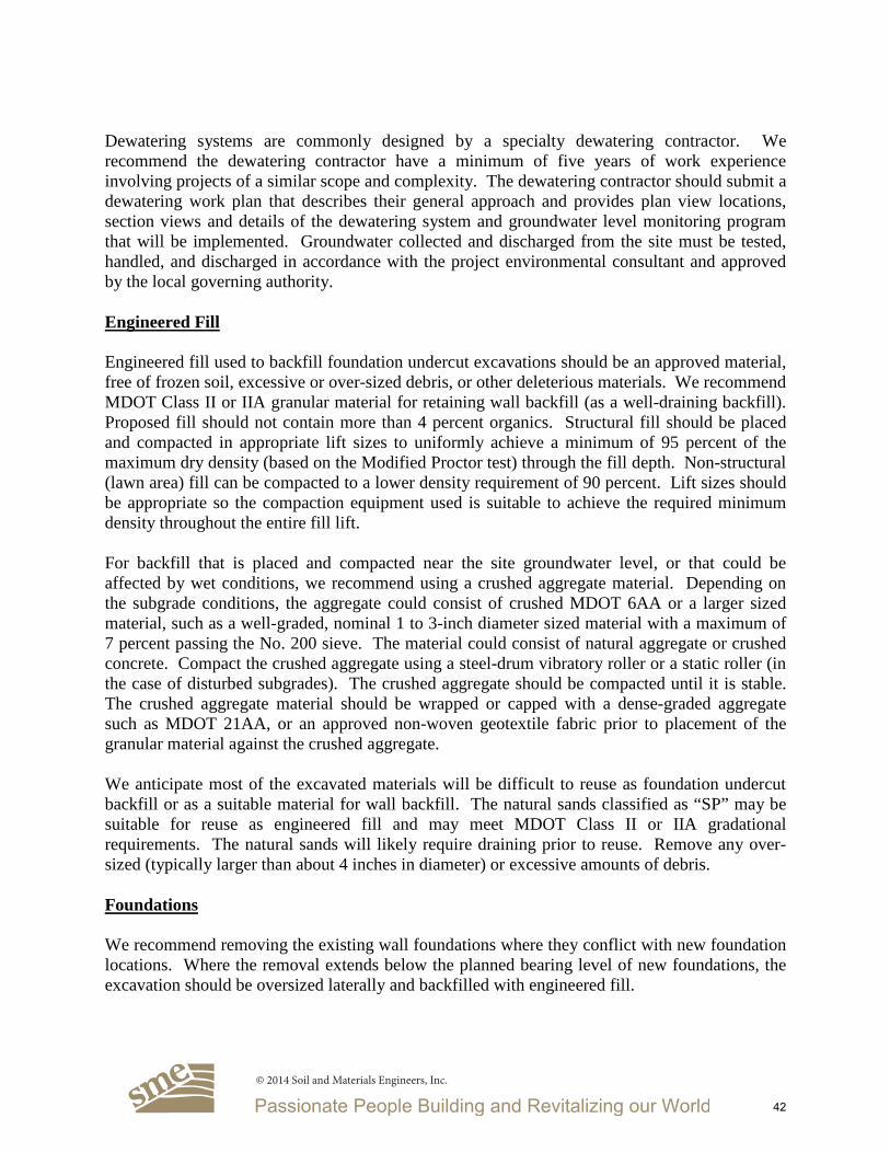
Dewatering systems are commonly designed by a specialty dewatering contractor. We recommend the dewatering contractor have a minimum of five years of work experience involving projects of a similar scope and complexity. The dewatering contractor should submit a dewatering work plan that describes their general approach and provides plan view locations, section views and details of the dewatering system and groundwater level monitoring program that will be implemented. Groundwater collected and discharged from the site must be tested, handled, and discharged in accordance with the project environmental consultant and approved by the local governing authority. Engineered Fill Engineered fill used to backfill foundation undercut excavations should be an approved material, free of frozen soil, excessive or over-sized debris, or other deleterious materials. We recommend MDOT Class II or IIA granular material for retaining wall backfill (as a well-draining backfill). Proposed fill should not contain more than 4 percent organics. Structural fill should be placed and compacted in appropriate lift sizes to uniformly achieve a minimum of 95 percent of the maximum dry density (based on the Modified Proctor test) through the fill depth. Non-structural (lawn area) fill can be compacted to a lower density requirement of 90 percent. Lift sizes should be appropriate so the compaction equipment used is suitable to achieve the required minimum density throughout the entire fill lift. For backfill that is placed and compacted near the site groundwater level, or that could be affected by wet conditions, we recommend using a crushed aggregate material. Depending on the subgrade conditions, the aggregate could consist of crushed MDOT 6AA or a larger sized material, such as a well-graded, nominal 1 to 3-inch diameter sized material with a maximum of 7 percent passing the No. 200 sieve. The material could consist of natural aggregate or crushed concrete. Compact the crushed aggregate using a steel-drum vibratory roller or a static roller (in the case of disturbed subgrades). The crushed aggregate should be compacted until it is stable. The crushed aggregate material should be wrapped or capped with a dense-graded aggregate such as MDOT 21AA, or an approved non-woven geotextile fabric prior to placement of the granular material against the crushed aggregate. We anticipate most of the excavated materials will be difficult to reuse as foundation undercut backfill or as a suitable material for wall backfill. The natural sands classified as “SP” may be suitable for reuse as engineered fill and may meet MDOT Class II or IIA gradational requirements. The natural sands will likely require draining prior to reuse. Remove any over-sized (typically larger than about 4 inches in diameter) or excessive amounts of debris. Foundations We recommend removing the existing wall foundations where they conflict with new foundation locations. Where the removal extends below the planned bearing level of new foundations, the excavation should be oversized laterally and backfilled with engineered fill.
© 2014 Soil and Materials Engineers, Inc.
42

As indicated above, shallow spread foundations are feasible for support of the planned retaining wall, assuming the Owner accepts increased performance risks associated with supporting foundations and wall on or above the site existing fills. For this option, we recommend the bearing soils consist of at least 6-inches of crushed aggregate compacted over suitable existing fills, natural sands and clays, or sandstone. Suitability of the existing fill must be verified during construction. Undercut unsuitable fill that contains excessive debris, such as nested rubble, or debris larger than 4 inches in diameter. Compact loose soils prior to placing the recommended crushed aggregate layer. Use a maximum net allowable soil bearing pressure of 2,000 psf to design shallow foundations. Please contact us if you need a higher soil bearing pressure at the wall toe. Foundation undercut excavations to remove unsuitable soils, and to backfill excavations to remove existing foundations or other obstructions, must extend laterally on a two vertical to one horizontal slope from the edge of the foundation as shown on the following Typical Foundation Undercutting Diagram:
Once each foundation area is exposed, foundation subgrade conditions must be observed and tested by SME to verify suitable soils are encountered. Furthermore, the test method must be capable of testing the soils several feet below the bearing level. Engineered fill or crushed aggregates used to backfill foundation undercut excavations must be placed and compacted per the recommendations provided previously in this report. New foundations adjacent to the existing M-21 abutment wall should be constructed at the same bearing level as existing foundations unless a review of the impact on the existing foundation wall has been studied and determined to not adversely impact the existing abutment wall performance. Prohibit new foundation excavations from extending below the existing M-21 abutment wall foundation bearing level. Limit new foundation vertical “steps” to 1 foot for every 5 horizontal feet.
© 2014 Soil and Materials Engineers, Inc.
43

As indicated above, deep foundations, such as helical piers could be used to support the new retaining wall foundation at levels higher than the existing M-21 abutment foundation. This option would transfer new foundation loads below the existing M-21 abutment foundation, allow the new foundation to be constructed at typical frost depths above the existing M-21 abutment foundation, reduce groundwater control considerations, and reduce potential disturbance to the M-21 abutment wall backfill. Please contact us if you desire helical pier recommendations. The foundations must be situated a minimum of 42 inches below final site grades for protection against frost action during normal winters. The granular soils encountered at the site are subject to sloughing/caving, and forming of the foundation sidewalls will be necessary to maintain vertical faces. In addition, any caved soils must be removed to re-expose suitable bearing soils at the foundation bearing level before placing concrete. We estimate total settlement for the wall foundation using the recommended maximum net allowable bearing pressure and bearing on suitable soils, as described above, should be less than 1-inch. Differential settlements are estimated to be about one-half to three-quarters of the total settlement. The settlement estimates provided are based on the available boring information, design soil bearing pressure, relatively shallow sandstone depth, our experience with similar structures and soil conditions, and field verification of suitable bearing soils by SME. Retaining Wall Backfill Backfill the retaining walls with engineered fill composed of a granular material meeting the requirements of MDOT Class II or IIA sand. As a minimum, compact non-structural (landscape) backfill to the degree where it is stable under construction equipment. Otherwise, place and compact backfill for structural support as engineered fill and meet the minimum dry density requirement of 95 percent. Contractors must exercise care during compaction of wall backfill to avoid overstressing the wall. If required, design the wall to accommodate the additional stresses associated with operating compaction equipment adjacent to the wall. As indicated previously, groundwater levels should be expected to vary seasonally, during flood events, and the water level in the river. Therefore, we recommend the wall design consider the 100 or 500-year flood elevation. For a drained MDOT Class II granular backfill above the design high groundwater level, use an equivalent fluid active earth pressure of 40 pcf. We based this earth pressure on the walls being flexible enough to permit the active earth pressure condition (typically an inward movement equal to approximately 0.001 times the height of the wall). Please contact us if the wall is restrained or rigid enough to not rotate sufficiently to reach the active earth pressure condition. We recommend a properly installed and maintained drain at the base of the wall. The drain should consist of a minimum 6-inch-diameter drain tile, surrounded with a minimum thickness of 6 inches of filter material, such as pea gravel that is completely wrapped in filter fabric. Provide clean-outs to access the drains to maintain them in proper working condition.
© 2014 Soil and Materials Engineers, Inc.
44

Add any additional lateral wall loads resulting from surcharge loading, such as adjacent traffic load or sloping ground, to the above earth pressures. To calculate loads on the wall due to surcharges, we recommend a horizontal coefficient of 0.3. To evaluate the sliding of the wall, compute the sliding resistance at the base and the passive (resisting) and active (driving) earth forces. Determine the sliding resistance using an ultimate sliding coefficient of 0.45 for the recommended aggregate base layer beneath the proposed foundation. To evaluate overturning resistance, use the unit weight of backfill equal to 115 pcf and unit weight of concrete equal to 150 pcf. Passive resistance in front of the wall can also be used to resist sliding and overturning. We understand FTC&H will likely not use the full passive pressure to resist sliding. Contact SME if passive resistance design parameters are desired. During flood conditions, design the wall to resist both soil and water pressure and consider hydrostatic uplift forces. The weight of the foundation concrete and the weight of the soil directly above the foundation can be used to resist uplift loading. Modify the equivalent fluid pressure to 95 pcf, buoyant unit weight of backfill equal to 65 pcf, and buoyant unit weight of concrete equal to 88 pcf below the design high groundwater level. Overall mass stability of the replacement wall has not been studied. If desired, SME can assist the project team with review of overall stability. Construction Considerations Temporary dewatering will be required for wall construction as discussed previously. The contractor must take precautions to protect adjacent existing structures and utilities during construction. Care must be exercised during the demolition, excavating, and compacting operations so that excessive vibrations or loss of ground do not cause settlement of the adjacent existing structure and utilities, and to avoid undermining existing foundations or utilities during excavations. Where sufficient space or setback from existing utilities, property lines, or structures exists, we anticipate the sides of the excavation can be temporarily sloped back in accordance with applicable regulations. However, in areas where sufficient setbacks cannot be maintained, temporary earth retention systems will be required during construction unless grading easements are obtained and existing structures are protected. Earth retention systems should be properly designed by a qualified professional engineer, and installed by a contractor experienced with that type of work. The contractor must provide a safely sloped excavation or an adequately constructed and braced shoring system in accordance with federal, state and local safety regulations for individuals working in an excavation that may expose them to the danger of moving ground. If material is stored or heavy equipment is operated near an excavation, stronger shoring must be used to resist the extra pressure due to the superimposed loads.
© 2014 Soil and Materials Engineers, Inc.
45

Geotechnical Evaluation Report SME Project No. 069852.002014 Downtown Infrastructure Improvements – Part 2 June 12, 2014 - Page 10
We appreciate the opportunity to serve you during this phase of the project. If there arequestions concerning this report, or if we can be of further service, please contact us.
Very truly yours,
SOIL AND MATERIALS ENGINEERS, INC.
Brian D. Moynihan, PE Michael J. Thelen, PE, D. GEProject Engineer Senior Consultant
Attachments: Important Information about your Geotechnical Engineering ReportBoring Location DiagramBoring Log TerminologyBoring Logs (B1 and B2)General CommentsLaboratory Testing Procedures
Distribution: Mrs. Elizabeth Stek, PE – FTC&H (PDF file via e-mail ([email protected])
069000\069852.00\FINAL\069852.00 061214 BDM-LTR.DOC
© 2014 Soil and Materials Engineers, Inc.
46
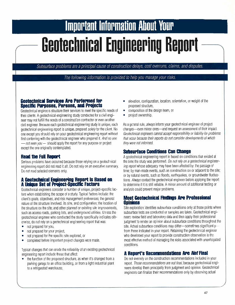
47

48
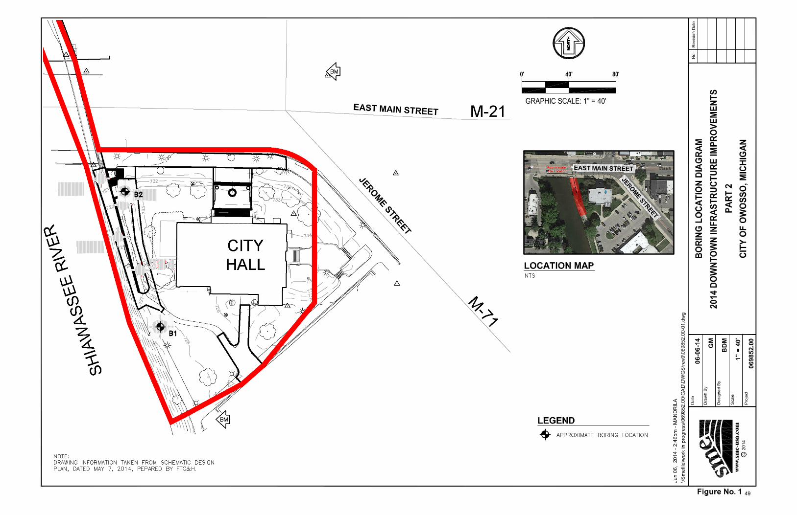
49

Determine percentages of sand and gravel from grain-size curve. Depending on percentage of fines (fraction smaller than No. 200 sieve size), coarse-grained soils are classified as follows: Less than 5 percent……………………..……...GW, GP, SW, SP More than 12 percent……………………..…….GM, GC, SM, SC 5 to 12 percent……………...……..Cases requiring dual symbols SP-SM or SW-SM (SAND with Silt or SAND with Silt and Grav-
el) SP-SC or SW-SC (SAND with Clay or SAND with Clay and
Gravel) GP-GM or GW-GM (GRAVEL with Silt or GRAVEL with Silt and
Sand) GP-GC or GW-GC (GRAVEL with Clay or GRAVEL with Clay
and Sand) If the fines are CL-ML: SC-SM (SILTY CLAYEY SAND or SILTY CLAYEY SAND with
Gravel) SM-SC (CLAYEY SILTY SAND or CLAYEY SILTY SAND with
Gravel) GC-GM (SILTY CLAYEY GRAVEL or SILTY CLAYEY GRAVEL
with Sand) GM-GC (CLAYEY SILTY GRAVEL or CLAYEY SILTY GRAVEL
with Sand)
UNIFIED SOIL CLASSIFICATION AND SYMBOL CHART
COARSE-GRAINED SOIL (more than 50% of material is larger than No. 200 sieve size.)
GRAVEL More than 50% of
coarse fraction larger than
No. 4 sieve size
Clean Gravel (Less than 5% fines)
GW Well-graded gravel; gravel-sand mixtures, little or no fines
GP Poorly-graded gravel; gravel-sand mixtures, little or no fines
GM Silty gravel; gravel-sand-silt mixtures
GC Clayey gravel; gravel-sand-clay mixtures
SAND 50% or more of
coarse fraction smaller than
No. 4 sieve size
Clean Sand (Less than 5% fines)
SW Well-graded sand; sand-gravel mixtures, little or no fines
SP Poorly graded sand; sand-gravel mixtures, little or no fines
Sand with fines (More than 12% fines)
SM Silty sand; sand-silt-gravel mixtures
SC Clayey sand; sand–clay-gravel mixtures
FINE-GRAINED SOIL (50% or more of material is smaller than No. 200 sieve size)
SILT AND
CLAY Liquid limit less than
50%
ML Inorganic silt; sandy silt or gravelly silt with slight plasticity
CL Inorganic clay of low plasticity; lean clay, sandy clay, gravelly clay
OL Organic silt and organic clay of low plasticity
SILT AND
CLAY Liquid limit
50% or greater
MH Inorganic silt of high plasticity, elastic silt
CH Inorganic clay of high plasticity, fat clay
OH Organic silt and organic clay of high plasticity
HIGHLY ORGANIC
SOIL PT Peat and other highly
organic soil
Gravel with fines (More than 12% fines)
LABORATORY CLASSIFICATION CRITERIA
GW D60 D30 CU = greater than 4; CC = between 1 and 3 D10 D10 x D60
GP Not meeting all gradation requirements for GW
GM Atterberg limits below “A” line or PI less than 4 Above “A” line with PI
between 4 and 7 are borderline cases requiring use of dual symbols GC Atterberg limits above “A”
line with PI greater than 7
SW D60 D30 CU = greater than 6; CC = between 1 and 3 D10 D10 x D60
SP Not meeting all gradation requirements for SW
SM Atterberg limits below “A” line or PI less than 4 Above “A” line with PI
between 4 and 7 are borderline cases requiring use of dual symbols SC Atterberg limits above “A”
line with PI greater than 7
BORING LOG TERMINOLOGY
LIQUID LIMIT (LL) (%)
PLASTICITY CHART
DRILLING AND SAMPLING ABBREVIATIONS 2ST – Shelby Tube – 2” O.D. 3ST – Shelby Tube – 3” O.D. AS – Auger Sample GS – Grab Sample LS – Liner Sample NR – No Recovery PM – Pressure Meter RC – Rock Core diamond bit. NX size, except
where noted SB – Split Barrel Sample 1-3/8” I.D., 2” O.D.,
except where noted VS – Vane Shear WS – Wash Sample
OTHER ABBREVIATIONS WOH – Weight of Hammer WOR – Weight of Rods SP – Soil Probe PID – Photo Ionization Device FID – Flame Ionization Device
PARTICLE SIZES Boulders - Greater than 12 inches Cobbles - 3 inches to 12 inches Gravel- Coarse - 3/4 inches to 3 inches Fine - No. 4 to 3/4 inches Sand- Coarse - No. 10 to No. 4 Medium - No. 40 to No. 10 Fine - No. 200 to No. 40 Silt and Clay - Less than (0.0074 mm)
DEPOSITIONAL FEATURES Parting – as much as 1/16 inch thick Seam – 1/16 inch to 1/2 inch thick Layer – 1/2 inch to 12 inches thick Stratum – greater than 12 inches thick Pocket – deposit of limited lateral extent Lens – lenticular deposit Hardpan/Till – an unstratified, consolidated or cemented
mixture of clay, silt, sand and/or gravel, the size/shape of the constituents vary widely
Lacustrine – soil deposited by lake water Mottled – soil irregularly marked with spots of different colors that vary in number and size Varved – alternating partings or seams of silt and/or clay Occasional – one or less per foot of thickness Frequent – more than one per foot of thickness Interbedded – strata of soil or beds of rock lying between or
alternating with other strata of a different nature
VISUAL MANUAL PROCEDURE When laboratory tests are not performed to confirm the classifica-tion of soils exhibiting borderline classifications, the two possible classifications would be separated with a slash, as follows: For soils where it is difficult to distinguish if it is a coarse or fine-grained soil: SC/CL (CLAYEY SAND to Sandy LEAN CLAY) SM/ML (SILTY SAND to Sandy SILT) GC/CL (CLAYEY GRAVEL to Gravelly LEAN CLAY) GM/ML (SILTY GRAVEL to Gravelly SILT) For soils where it is difficult to distinguish if it is sand or gravel, poorly or well-graded sand or gravel; silt or clay; or plastic or non-plastic silt or clay:
SP/GP or SW/GW (SAND with Gravel to GRAVEL with Sand) SC/GC (CLAYEY SAND with Gravel to CLAYEY GRAVEL with
Sand) SM/GM (SILTY SAND with Gravel to SILTY GRAVEL with
Sand) SW/SP (SAND or SAND with Gravel) GP/GW (GRAVEL or GRAVEL with Sand) SC/SM (CLAYEY to SILTY SAND) GM/GC (SILTY to CLAYEY GRAVEL) CL/ML (SILTY CLAY) ML/CL (CLAYEY SILT) CH/MH (FAT CLAY to ELASTIC SILT) CL/CH (LEAN to FAT CLAY) MH/ML (ELASTIC SILT to SILT) OL/OH (ORGANIC SILT or ORGANIC CLAY)
OTHER MATERIAL SYMBOLS
Topsoil
Void
Sandstone
Asphalt
Glacial Till
Siltstone
Base
Coal
Limestone
Concrete
Shale
CLASSIFICATION TERMINOLOGY AND CORRELATIONS
Cohesionless Soils Relative Density N-Value
(Blows per foot)
Very Loose Loose Medium Dense Dense Very Dense Extremely Dense
0 to 4 4 to 10 10 to 30 30 to 50 50 to 80 Over 80
Standard Penetration ‘N-Value’ = Blows per foot of a 140-pound hammer falling 30 inches on a 2-inch O.D. split barrel sampler, except where noted.
Cohesive Soils
Consistency N-Value (Blows per foot)
Undrained Shear Strength (kips/ft2)
Very Soft Soft Medium Stiff Very Stiff Hard
0 - 2 2 - 4 4 - 8
8 - 15 15 - 30 > 30
0.25 or less 0.25 to 0.50
0.50 to 1.0
1.0 to 2.0
2.0 to 4.0
4.0 or greater
CL
PLAS
TIC
ITY
IND
EX (P
I) (%
)
0 10 20 30 40 50 60 70 80 90 100 0
10
60
50
40
30
20
CH
A LINE PI=0.73 (LL-20)
MH & OH
ML & OL CL+ML
50
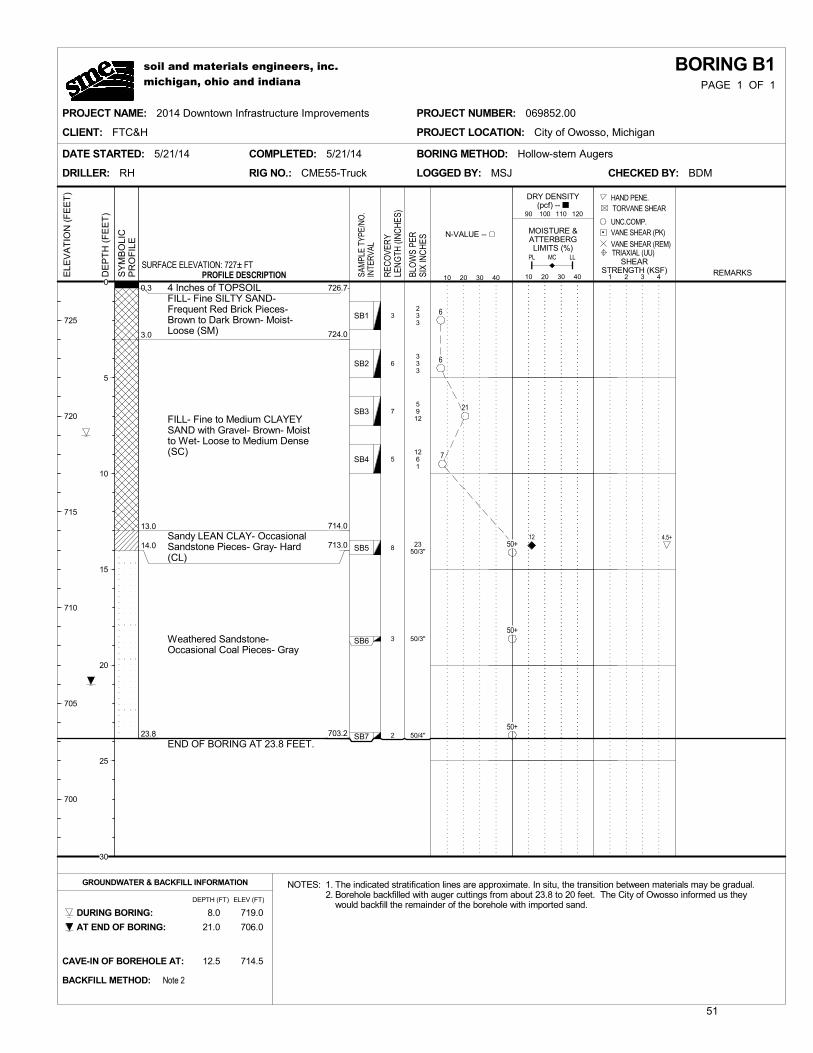
3
6
7
5
8
3
2
233
333
5912
1261
2350/3"
50/3"
50/4"
0.3
3.0
13.0
14.0
23.8
4 Inches of TOPSOILFILL- Fine SILTY SAND-Frequent Red Brick Pieces-Brown to Dark Brown- Moist-Loose (SM)
FILL- Fine to Medium CLAYEYSAND with Gravel- Brown- Moistto Wet- Loose to Medium Dense(SC)
Sandy LEAN CLAY- OccasionalSandstone Pieces- Gray- Hard(CL)
Weathered Sandstone-Occasional Coal Pieces- Gray
END OF BORING AT 23.8 FEET.
SB1
SB2
SB3
SB4
SB5
SB6
SB7
DATE STARTED: 5/21/14 COMPLETED: 5/21/14
LOGGED BY: MSJ CHECKED BY: BDM
BORING METHOD: Hollow-stem Augers
RIG NO.: CME55-TruckDRILLER: RH
GROUNDWATER & BACKFILL INFORMATION NOTES: 1. The indicated stratification lines are approximate. In situ, the transition between materials may be gradual.2. Borehole backfilled with auger cuttings from about 23.8 to 20 feet. The City of Owosso informed us they
would backfill the remainder of the borehole with imported sand.719.0
21.0
DURING BORING:
AT END OF BORING: 706.0
8.0
MCPL LL
12.5
BACKFILL METHOD:
CAVE-IN OF BOREHOLE AT:
Note 2
714.5
DEPTH (FT) ELEV (FT)
REC
OVE
RY
LEN
GTH
(IN
CH
ES)
BLO
WS
PER
SIX
INC
HES
BORING B1E
LEV
AT
ION
(F
EE
T)
N-VALUE --
10 20 30 40
PROJECT LOCATION: City of Owosso, Michigan
PROJECT NAME: 2014 Downtown Infrastructure Improvements PROJECT NUMBER: 069852.00
CLIENT: FTC&H
PAGE 1 OF 1
SY
MB
OLI
CP
RO
FIL
E
SURFACE ELEVATION: 727± FTPROFILE DESCRIPTION
DRY DENSITY(pcf) --
90 100 110 120
MOISTURE &ATTERBERGLIMITS (%)
10 20 30 40 REMARKS
TRIAXIAL (UU)
HAND PENE.
SHEARSTRENGTH (KSF)
1 2 3 4
VANE SHEAR (REM)
VANE SHEAR (PK) UNC.COMP.
TORVANE SHEAR
SAM
PLE
TYPE
/NO
.IN
TER
VAL
soil and materials engineers, inc.michigan, ohio and indiana
725
720
715
710
705
700
DE
PT
H (
FE
ET
)
6
6
21
7
50+
50+
50+
12 4.5+
0
5
10
15
20
25
30
726.7
724.0
714.0
713.0
703.2
51

5
4
10
10
10
3
50/5"
638
8516
323
324
484
50/3"
0.7
5.5
14.0
22.5
23.8
8 Inches of TOPSOIL
FILL- Fine SILTY SAND-Frequent Concrete and BrickPieces- Occasional Clay Layers-Dark Brown and Gray- Moist-Extremely Dense to MediumDense (SM)
FILL- Fine to Medium CLAYEYSAND- Frequent Brick Pieces-Brown to Dark Brown- Moist-Medium Dense to Loose (SC)
Fine to Coarse SAND withGravel- Gray- Wet- Loose toMedium Dense (SP)
Weathered Sandstone- Gray andBlack
END OF BORING AT 23.8 FEET.
Driller reported apossible concreteslab from 7.5 feet to8.5 feet.
SB1
SB2
SB3
SB4
SB5
SB6
SB7
DATE STARTED: 5/20/14 COMPLETED: 5/20/14
LOGGED BY: MSJ CHECKED BY: BDM
BORING METHOD: Hollow-stem Augers
RIG NO.: CME55-TruckDRILLER: RH
GROUNDWATER & BACKFILL INFORMATION NOTES: 1. The indicated stratification lines are approximate. In situ, the transition between materials may be gradual.
718.0
16.0
DURING BORING:
AT END OF BORING: 716.0
14.0
MCPL LL
6.0
BACKFILL METHOD:
CAVE-IN OF BOREHOLE AT:
Auger Cuttings
726.0
DEPTH (FT) ELEV (FT)
REC
OVE
RY
LEN
GTH
(IN
CH
ES)
BLO
WS
PER
SIX
INC
HES
BORING B2E
LEV
AT
ION
(F
EE
T)
N-VALUE --
10 20 30 40
PROJECT LOCATION: City of Owosso, Michigan
PROJECT NAME: 2014 Downtown Infrastructure Improvements PROJECT NUMBER: 069852.00
CLIENT: FTC&H
PAGE 1 OF 1
SY
MB
OLI
CP
RO
FIL
E
SURFACE ELEVATION: 732± FTPROFILE DESCRIPTION
DRY DENSITY(pcf) --
90 100 110 120
MOISTURE &ATTERBERGLIMITS (%)
10 20 30 40 REMARKS
TRIAXIAL (UU)
HAND PENE.
SHEARSTRENGTH (KSF)
1 2 3 4
VANE SHEAR (REM)
VANE SHEAR (PK) UNC.COMP.
TORVANE SHEAR
SAM
PLE
TYPE
/NO
.IN
TER
VAL
soil and materials engineers, inc.michigan, ohio and indiana
730
725
720
715
710
705
DE
PT
H (
FE
ET
)
11
21
5
6
12
50+
0
5
10
15
20
25
30
731.3
726.5
718.0
709.5
708.2
52

GENERAL COMMENTS Basis of Geotechnical Report This report has been prepared in accordance with generally accepted geotechnical engineering practices to assist in the design and/or evaluation of this project. If the project plans, design criteria, and other project information referenced in this report and utilized by SME to prepare our recommendations are changed, the conclusions and recommendations contained in this report are not considered valid unless the changes are reviewed, and the conclusions and recommendations of this report are modified or approved in writing by our office. The discussions and recommendations submitted in this report are based on the available project information, described in this report, and the geotechnical data obtained from the field exploration at the locations indicated in the report. Variations in the soil and groundwater conditions commonly occur between or away from sampling locations. The nature and extent of the variations may not become evident until the time of construction. If significant variations are observed during construction, SME should be contacted to reevaluate the recommendations of this report. SME should be retained to continue our services through construction to observe and evaluate the actual subsurface conditions relative to the recommendations made in this report. In the process of obtaining and testing samples and preparing this report, procedures are followed that represent reasonable and accepted practice in the field of soil and foundation engineering. Specifically, field logs are prepared during the field exploration that describe field occurrences, sampling locations, and other information. Samples obtained in the field are frequently subjected to additional testing and reclassification in the laboratory and differences may exist between the field logs and the report logs. The engineer preparing the report reviews the field logs, laboratory classifications, and test data and then prepares the report logs. Our recommendations are based on the contents of the report logs and the information contained therein.
Review of Design Details, Plans, and Specifications SME should be retained to review the design details, project plans, and specifications to verify those documents are consistent with the recommendations contained in this report.
Review of Report Information With Project Team Implementation of our recommendations may affect the design, construction, and performance of the proposed improvements, along with the potential inherent risks involved with the proposed construction. The client and key members of the design team, including SME, should discuss the issues covered in this report so that the issues are understood and applied in a manner consistent with the owner’s budget, tolerance of risk, and expectations for performance and maintenance.
Field Verification of Geotechnical Conditions SME should be retained to verify the recommendations of this report are properly implemented during construction. This may avoid misinterpretation of our recommendations by other parties and will allow us to review and modify our recommendations if variations in the site subsurface conditions are encountered.
Project Information for Contractor This report and any future addenda or other reports regarding this site should be made available to prospective contractors prior to submitting their proposals for their information only and to supply them with facts relative to the subsurface evaluation and laboratory test results. If the selected contractor encounters subsurface conditions during construction, which differ from those presented in this report, the contractor should promptly describe the nature and extent of the differing conditions in writing and SME should be notified so that we can verify those conditions. The construction contract should include provisions for dealing with differing conditions and contingency funds should be reserved for potential problems during earthwork and foundation construction. We would be pleased to assist you in developing the contract provisions based on our experience. The contractor should be prepared to handle environmental conditions encountered at this site, which may affect the excavation, removal, or disposal of soil; dewatering of excavations; and health and safety of workers. Any Environmental Assessment reports prepared for this site should be made available for review by bidders and the successful contractor.
Third Party Reliance/Reuse of This Report This report has been prepared solely for the use of our Client for the project specifically described in this report. This report cannot be relied upon by other parties not involved in the project, unless specifically allowed by SME in writing. SME also is not responsible for the interpretation by other parties of the geotechnical data and the recommendations provided herein.
© 2014 Soil and Materials Engineers, Inc.© 2014 Soil and Materials Engineers, Inc.
53

LABORATORY TESTING PROCEDURES Visual Engineering Classification
Visual classification was performed on recovered samples. The appended General Notes and Unified Soil Classification System (USCS) sheets include a brief summary of the general method used visually classify the soil and assign an appropriate USCS group symbol. The estimated group symbol, according to the USCS, is shown in parentheses following the textural description of the various strata on the boring logs appended to this report. The soil descriptions developed from visual classifications are sometimes modified to reflect the results of laboratory testing.
Moisture Content
Moisture content tests were performed by weighing samples from the field at their in-situ moisture condition. These samples were then dried at a constant temperature (approximately 110º C) overnight in an oven. After drying, the samples were weighed to determine the dry weight of the sample and the weight of the water that was expelled during drying. The moisture content of the specimen is expressed as a percent and is the weight of the water compared to the dry weight of the specimen.
Hand Penetrometer Tests
In the hand penetrometer test, the unconfined compressive strength of a cohesive soil sample is estimated by measuring the resistance of the sample to the penetration of a small calibrated, spring-loaded cylinder. The maximum capacity of the penetrometer is 4.5 tons per square-foot (tsf). Theoretically, the undrained shear strength of the cohesive sample is one-half the unconfined compressive strength. The undrained shear strength (based on the hand penetrometer test) presented on the boring logs is reported in units of kips per square-foot (ksf).
Torvane Shear Tests
In the Torvane test, the shear strength of a low strength, cohesive soil sample is estimated by measuring the resistance of the sample to a torque applied through vanes inserted into the sample. The undrained shear strength of the samples is measured from the maximum torque required to shear the sample and is reported in units of kips per square-foot (ksf).
Loss-on-Ignition (Organic Content) Tests
Loss-on-ignition (LOI) tests are conducted by first weighing the sample and then heating the sample to dry the moisture from the sample (in the same manner as determining the moisture content of the soil). The sample is then re-weighed to determine the dry weight and then heated for 4 hours in a muffle furnace at a high temperature (approximately 440º C). After cooling, the sample is re-weighed to calculate the amount of ash remaining, which in turn is used to determine the amount of organic matter burned from the original dry sample. The organic matter content of the specimen is expressed as a percent compared to the dry weight of the sample.
Atterberg Limits Tests
Atterberg limits tests consist of two components. The plastic limit of a cohesive sample is determined by rolling the sample into a thread and the plastic limit is the moisture content where a 1/8-inch thread begins to crumble. The liquid limit is determined by placing a ½-inch thick soil pat into the liquid limits cup and using a grooving tool to divide the soil pat in half. The cup is then tapped on the base of the liquid limits device using a crank handle. The number of drops of the cup to close the gap formed by the grooving tool ½ inch is recorded along with the corresponding moisture content of the sample. This procedure is repeated several times at different moisture contents and a graph of moisture content and the corresponding number of blows is plotted. The liquid limit is the moisture content at a nominal 25 drops of the cup. From this test, the plasticity index can be determined by subtracting the plastic limit from the liquid limit.
© 2014 Soil and Materials Engineers, Inc.© 2014 Soil and Materials Engineers, Inc.
54

SPECIAL PROVISION
FOR TURF ESTABLISHMENT, PERFORMANCE
City of Owosso/CW 1 of 5 Nov, 2019
a. Description. For the work identified in this special provision paid for by the pay item Turf
Establishment, Performance only, delete section 816 of the Standard Specifications for Construction and replace it with this special provision. The Contractor is responsible for the performance and quality of turf growth in the areas indicated on the plans and as identified by the Engineer. Comply with all local, state and federal laws when completing this work. Areas damaged by the Contractor outside the work area needing turf restoration will not be eligible for payment.
Establish a durable, permanent, weed-free, mature, perennial turf. The work consists of fundamental turf work, including but not limited to topsoiling, seeding, mulching, erosion control, maintenance, watering and repair of turf as described herein during the life of the contract and during the life of any supplemental performance bond which may ensue.
Choose and implement proven turf establishment industry practices; provide all necessary labor and equipment; select and provide all turf establishment materials; and control erosion and any subsequent sedimentation at all times.
Perform a site analysis, interpret the results and implement a turf establishment program to ensure compliance with this specification. The site analysis must take into consideration topsoil needs, fertilizer and pH requirements, seed mix, existing and future soil moisture levels, slopes and grades, required erosion control items and devices, maintenance requirements, local highway snow removal and deicing practices, and any other characteristics that influence and affect turf establishment.
Subsection 107.11 of the Standard Specifications for Construction is revised relative to the Contractor’s responsibility for the repair of turf establishment work as follows. The Contractor is responsible, at no additional cost to the contract, for the repair of turf establishment work occasioned by storm events up to 3 inches of rain in a 24 hour period as documented by local meteorological data submitted to the Engineer for review and approval. All other portions of subsection 107.11 remain unchanged.
1. Contractor Turf Establishment Experience Requirements. Ensure weed control is
done by a commercial herbicide applicator, licensed by the State of Michigan and certified by the Michigan Department of Agriculture (MDA) in the appropriate category to apply herbicides. Use application procedures and materials according to federal, state and local regulations. Use of restricted use chemicals is prohibited. Provide appropriate documentation and secure approval from the Engineer before application of herbicides.
At least 10 work days prior to start of turf establishment, provide documentation to the Engineer, from the Contractor performing the turf establishment work, that they meet one or both of the following requirements.
A. At least one person employed by the Contractor performing the turf
establishment work and assigned to the job site has a degree or certificate in Turf
55
Management, Horticulture or related field.
B. At least one person employed by the Contractor performing the turf establishment work and assigned to the job site has at least 5 years of experience in roadside turf establishment.
b. Materials. Provide topsoil, seed, mulch, pesticide, herbicide, mulch blankets and any
other unique erosion control materials as necessary to fulfill this specification, as detailed on the plans. Use additional materials, as necessary, to meet the standards set forth for turf establishment in this special provision. The use of sod on the project requires the prior approval of the Engineer and if approved, may be used at limited site locations only.
Selection of all materials is the responsibility of the Contractor with the following minimum conditions.
1. Soil. Provide furnished or salvaged topsoil, which may be blended compost, that will
support vigorous growth. Ensure topsoil is humus bearing and placed at least 4 inches deep. Ensure it is free of stones larger than 1/2 inch (2 inches on freeway projects) in diameter and other debris. Trim and grade the finished slope in accordance with subsection 205.03.N of the Standard Specifications for Construction.
2. Seed. Use Barenburg Turf Saver® RTF® applied at the manufacturers
recommended seeding rate.
3. Mulch. Mulch seeded areas with excelsior mulch blanket to promote germination and growth of seed and to mitigate soil erosion and sedimentation.
4. Herbicides. Comply with all federal, state and local laws. As part of the MDA weed
control application, the Contractor is required to make proper notifications and/or postings as per label and MDA requirements for all locations that will be sprayed. Notify the Engineer at least 48 hours prior to any applications being made. Furnish and apply herbicide(s) as needed. It is the Contractor’s responsibility to select the herbicide(s) and the rate at which it is used. Obtain the Engineer’s approval of work methods and herbicide(s) selected prior to the application of the herbicide(s). Complete a spray log and submit to the Engineer each day an application is made.
Do not draw water from any waterway (i.e. river, ditch, creek, lake etc.) located on state, county or municipal right-of-way, for mixing with herbicides.
5. Fertilizers. Furnish and apply fertilizer(s) as needed. It is the Contractor’s
responsibility to select the fertilizer(s) and the rate at which it is used. Phosphorus is allowed for use only at the time of planting and when required by soil conditions. Obtain the Engineer’s approval of work methods and fertilizer(s) prior to the application of the fertilizer(s).
6. Water. Furnish and apply water from an approved source at a rate to promote
healthy growth.
c. Construction. The Contractor is responsible for all work and all construction methods used in completing this work. Implementation of any part of the standard specifications or standard plans by the Contractor does not relieve the Contractor of responsibility for acceptability of the construction methods or for the quality of the work.
56

1. Inspection of the Work. The Contractor is responsible for all inspection of turf establishment work.
Use a Contractor’s Daily Report, approved by the Engineer, to report inspections made and to document turf establishment work performed on this project. Complete and submit a Contractor’s Daily Report to the Engineer when any work performed under this special provision is in progress.
Include all necessary materials documentation including tests slips, certifications, etc. with the associated Contractor’s Daily Report.
The Engineer will determine the acceptability of the Contractor’s Daily Report in terms of their completeness and accuracy. The Engineer reserves the right to verify all submitted measurements and computations. Failure by the Contractor to submit acceptable and timely reports to the Engineer may result in withholding of progress pay estimates on turf- related items until such time as reports are submitted and deemed acceptable.
The Engineer reserves the right to inspect the project for any reason in accordance with subsection 104.01 of the Standard Specifications for Construction, including the fulfillment of other inspection requirements such as Soil Erosion and Sedimentation Control, NPDES, etc. Inspections made by the Engineer do not relieve the Contractor of the responsibility for inspections required by this special provision or the Contractor’s responsibilities for erosion control and turf establishment.
2. Erosion Control. Control erosion at all times according to section 208 of the
Standard Specifications for Construction. Control of soil erosion is the responsibility of the Contractor. However, sedimentation controls must be placed as indicated on the plans or as directed by the Engineer. Continuously monitor the site for needed erosion repair from any cause as addressed in the contract. Return all eroded areas to original grade as detailed in the contract. Take immediate corrective action if sedimentation occurs in drainage structures or any watercourse or water containment area and stabilize all disturbed areas contributing to this sedimentation within 24 hours after the erosion occurrence. Remove sediment deposited as a result of the Contractor’s inability to control the soil erosion at the Contractor’s expense.
Reimburse the Department for any costs levied against the Department, such as fines, environmental costs, costs for remedies required, or any other costs as a result of the Contractor’s failure to comply with this special provision and with federal, state and local laws.
3. Erosion Repair. The Contractor is responsible for all repairs and liable for all
consequences (legal, monetary or other) associated with erosion or sedimentation damage to finished or unfinished work.
Report all erosion occurrences and the repairs made by the Contractor to the Engineer in the format and at the frequency required by the Engineer. Repair any erosion, displacement or disturbance to ongoing or completed work by any cause at no additional cost to the contract unless otherwise noted herein.
The Contractor is responsible and liable for all traffic control and safety measures required to repair and protect damaged turf areas. Repair any eroded area that may affect the support of the roadbed or safety of the public within 24 hours of the erosion occurrence.
57

Place protective devices such as barriers, directional signs/signals, temporary fence, or any other safety measures immediately after any erosion damage occurs that has the potential of endangering the public. In these instances, provide the Engineer with a written summary of the immediate action taken describing the repairs made and the safety measures taken, within 24 hours of the occurrence of the damage.
4. Mowing and Weeding. Maintain turf to a visually appealing level, and not more than
8 inches in height at any time, prior to acceptance. Weeds must be controlled to less than 10 percent of the turf establishment area at all times during construction.
5. Final Acceptance and Supplemental Performance Bond.
A. Final Acceptance Parameters. Ensure before final acceptance of the turf
establishment work, all of the following minimum parameters are met throughout all exposed areas of the project designated on the plans or identified by the Engineer as turf establishment areas: there must be no exposed bare soil and the turf must be fully germinated, erosion free, weed free, disease free, dark green in color and in a vigorous growing condition.
The Engineer will notify the Contractor of the dates and times of all acceptance inspections. The Contractor may accompany the Engineer during these inspections. If the Contractor does not agree with the decision made by the Engineer, the Contractor may request an inspection by a mutually agreed upon third party (Michigan State University Extension service or other). A joint inspection, to include the Engineer, the Contractor, and the third party, will be scheduled by the Engineer. Pay all expert fees and expenses charged by the third party.
B. Supplemental Performance Bond. In the event that all contract items of work are
completed, including the placement of all turf establishment items of work, and the final acceptance of the project is delayed because the final acceptance parameters for the turf establishment work have not been fully met; the Contractor may propose to the Engineer the use of a supplemental performance bond.
The bond serves to secure the successful completion of turf establishment work and fulfillment of all final acceptance parameters for the turf establishment work. Ensure the supplemental performance bond, in all respects, is satisfactory and acceptable to the Department and executed by a surety company authorized to do business with the State of Michigan.
Ensure the bond is in an amount equal to 50 percent of the turf establishment work items covered by this special provision. Ensure the bond remains in place for two growing seasons. At the discretion of the Engineer, the bond may be reduced on a prorated basis as portions of the areas designated for turf establishment on the project meet the final acceptance parameters.
Prior to commencement of any work necessary to meet the acceptance parameters during the bonded period, the Contractor must apply for a permit to work within MDOT right-of-way using Form 2205. The permit fee and an individual permit performance bond will not be required. The permit insurance requirements, however, will be required.
58

d. Measurement and Payment. The completed work, as described, will be measured and paid for at the contract unit price using the following pay item:
Pay Item Pay Unit
Turf Establishment, Performance .................................................................... Square Yard
Turf Establishment, Performance will include all labor, equipment and materials required or selected by the Contractor to install, maintain, inspect, repair and meet the acceptance parameters for turf establishment specified in this special provision, including preparation, updating and submittal of the Contractor’s Daily Reports.
Repairs made to damaged turf establishment areas as a result of a documented storm by local meteorological data resulting in rainfall amounts of more than 3 inches in a 24 hour period will be paid for as an increase to original quantities in accordance with subsection 109.05 of the Standard Specifications for Construction.
The following schedule of payment applies to work performed according to this special provision. Upon completion of topsoil surfacing stage, 50 percent of the authorized amount for Turf Establishment, Performance will be paid to the Contractor. The remaining 50 percent of the authorized amount will be paid upon completion of all other work necessary to comply with this special provision and to meet all final acceptance parameters for Turf Establishment, Performance or at such time as the supplemental performance bond is accepted by the Department.
The supplemental performance bond and all costs associated with turf establishment work performed during the duration of the performance bond will not be paid for separately. These costs which may include, but are not limited to, mobilization, traffic control devices, and the required permit insurance are included in the unit price bid for Turf Establishment, Performance.
59

PRODUCT INFORMATION
ANCHORWALL.COM
Designed for steep, sloping hillsides and other structural challenges, the Vertica Pro® retaining wall system can be built to virtually any height in incredibly tight spaces – thanks to an impressive 4-degree batter, built-in alignment locators, and a near-vertical rise for less excavation and land loss. Typically used with geosynthetic reinforcement, Vertica Pro blocks meet or exceed industry standards for strength and durability.
• Pinless, patented locator lug gives quick, uniform setback forreduced labor costs
• Used in commercial-site development or anywhere space isat a premium
• Warm earth-tone colors and rugged, rock-like texture
• For gravity wall applications, the Vertica Pro system, with itsdeeper design, can accommodate walls up to approximately6 feet high, including buried course, but excluding the cap*
• Taller walls can be built using geosynthetic reinforcement orthe Anchorplex™ retaining wall system when designed by aqualified engineer
Straight Face• Minimum outside radius, measured on the top course to the
front of the units: 8 feet, 6 inches
• Minimum inside radius, measured on the base course to thefront of the units: 5 feet, 6 inches
Beveled Face• Minimum outside radius, measured on the top course to the
front of the units: 5 feet, 6 inches
• Minimum inside radius, measured on the base course to thefront of the units: 8 feet
*This height assumes cores and insets are filled with drainage aggregate, level backfill and clean,compacted sand or gravel and no surcharge.
Vertica Pro®RETAINING WALL SYSTEM
60

PRODUCT INFORMATION
ANCHORWALL.COM
Visit anchorwall.com for installation instructions.
A&B0808 73.3073.2 11/15 4015
Accessory Units Cap Corner
Approximate Dimensions* Front, 4" x 171⁄4" x 103⁄8" 8" x 18" x 9"Back, 4" x 12" x 103⁄8" 8" x 18" x 9"
Approximate Weight* 41 lbs. 101 lbs.
Coverage 1.22 lin. ft. 1.50 sq. ft.
Stretcher Units Straight Face Beveled Face
Approximate Dimensions* 8" x 18" x 20" 8" x 18" x 20"
Approximate Weight* 115 lbs. 112 lbs.
Coverage 1.00 sq. ft. 1.00 sq. ft.
Setback/System Batter 9⁄16"/4° 9⁄16"/4°*Product dimensions are height by face length by depth. Actual dimensions and weights may vary from these approximate values due to variations in manufacturing processes. Specifications may change without notice. See your Anchor representative for details, color options, block dimensions and additional information.
© 2015 Anchor Wall Systems, Inc. The Vertica Pro® wall system is manufactured under license from Anchor Wall Systems, Inc. (AWS). The “Anchor A” and “Anchor Build Something Beautiful” logos, “Anchorplex” and “Vertica Pro” are trademarks of AWS. The wall system blocks are covered by the AWS Limited Warranty. For a complete copy, visit your local dealer or see anchorwall.com.
Anchor Wall Systems, Inc., 5959 Baker Road, Suite 390, Minnetonka, MN 55345.
Vertica Pro®RETAINING WALL SYSTEM
61

FGS000531ETQR13
Miragrid® 5XT Miragrid® 5XT geogrid is composed of high molecular weight, high tenacity polyester multifilament yarns which are woven in tension and finished with a PVC coating.Miragrid® 5XT geogrid is inert to biological degradation and resistant to naturally encountered chemicals, alkalis, and acids.
Mechanical Properties Test Method Unit
Minimum Average Roll Value
Machine Direction
Tensile Strength (at ultimate) ASTM D 6637 kN/m (lbs/ft) 68.6 (4700)Tensile Strength (at 5% strain) ASTM D 6637 kN/m (lbs/ft) 25.4 (1740)
Creep Reduced Strength ASTM D 5262 kN/m (lbs/ft) 43.4 (2975)Long Term Allowable Design Load1 GRI GG-4(b) kN/m (lbs/ft) 37.6 (2575)
1 NOTE: Long Term Allowable Design values are for sand, silt and clay
Physical Properties Test Method Unit Typical Value
Grid Aperture Size(machine direction) -- mm (in) 30.5 (1.2)
Grid Aperture Size(cross machine direction) -- mm (in) 25.4 (1.0)
Mass/Unit Area ASTM D 5261 g/m2 (oz/yd2) 305.1 (9.0)Roll Dimensions (width x length) -- m (ft) 3.6 (12) x 45.7 (150)
Roll Area -- m2 (yd2) 164.5 (200)Estimated Roll Weight --- kg (lbs) 63 (140)
Disclaimer: TenCate assumes no liability for the accuracy or completeness of this information or for the ultimate useby the purchaser. TenCate disclaims any and all express, implied, or statutory standards, warranties or guarantees,including without limitation any implied warranty as to merchantability or fitness for a particular purpose or arising froma course of dealing or usage of trade as to any equipment, materials, or information furnished herewith. Thisdocument should not be construed as engineering advice.
© 2010 TenCate Geosynthetics North AmericaMiragrid® is a registered trademark of Nicolon Corporation
62

365 South Holland Drive Tel 706 693 2226 Fax 706 693 4400Pendergrass, GA 30567 Tel 888 795 0808 www.tencate.com
FGS000351ETQR70
TENCATE GEOSYNTHETICSAmericas
Testing Lab 1291.01 & 1291.02GAI-LAP-25-97
Mirafi® 180N is a needlepunched nonwoven geotextile composed of polypropylene fibers, which are formed into a stable network such that the fibers retain their relativeposition. Mirafi® 180N is inert to biological degradation and resists naturally encountered chemicals, alkalis, and acids. Mirafi® 180N meets AASHTO M288-06 Class 1 for Elongation > 50%.
TenCate Geosynthetics Americas Laboratories are accredited by a2La (The AmericanAssociation for Laboratory Accreditation) and Geosynthetic Accreditation Institute –Laboratory Accreditation Program (GAI-LAP). NTPEP Number: GTX-2012-01-047
Mechanical Properties Test Method Unit
Minimum Average Roll Value
MD CD
Grab Tensile Strength ASTM D4632 lbs (N) 205 (912) 205 (912)Grab Tensile Elongation ASTM D4632 % 50 50Trapezoid Tear Strength ASTM D4533 lbs (N) 80 (356) 80 (356)CBR Puncture Strength ASTM D6241 lbs (N) 500 (2224)
Apparent Opening Size (AOS)1 ASTM D4751 U.S. Sieve (mm) 80 (0.18)Permittivity ASTM D4491 sec-1 1.4Flow Rate ASTM D4491 gal/min/ft2 (l/min/m2) 95 (3870)
UV Resistance (at 500 hours) ASTM D4355 % strength retained 70
1 ASTM D4751: AOS is a Maximum Opening Diameter Value
Physical Properties Unit Typical Value2
Roll Dimensions (width x length) ft (m) 12.5 x 360 (3.8 x 110) 15 x 300 (4.57 x 91.4)Roll Area yd2 (m2) 500 (418)
Estimated Roll Weight lb (kg) 242 (110)
2 ASTM D4439 Standard Terminology for Geosynthetics: typical value, n—for geosynthetics, the mean value calculated from documentedmanufacturing quality control test results for a defined population obtained from one test method associated with on specific property.
Disclaimer: TenCate assumes no liability for the accuracy or completeness of this information or for the ultimate use by the purchaser. TenCatedisclaims any and all express, implied, or statutory standards, warranties or guarantees, including without limitation any implied warranty as tomerchantability or fitness for a particular purpose or arising from a course of dealing or usage of trade as to any equipment, materials, or informationfurnished herewith. This document should not be construed as engineering advice.
Mirafi® is a registered trademark of Nicolon Corporation. Copyright © 2014 Nicolon Corporation. All Rights Reserved.
Mirafi® 180N
63

Pre-Engineered Fencing Solutions
When Your Wall Needs a Fence
StrataSleeve-It™
System
64

Isometric View of Sleeve-It
1224R System Components
FRONT
SLEEVE
HALF
UPRIGHT
LEG
12’ 0 PVC COATED
CANTILEVER
BASE
PVC COATED
STRUTS
REAR
SLEEVE
HALF
LID
Project DHL Distribution FacilityAllentown, PA
Product Over 350 Sleeve-It 1224Runits used
Savings 10,000 square feet ofreal estate
Step 1
Install the cantilevered Sleeve-It units near the elevation of the top of wall
Step 2
Fill and compact soil up to the top of the sleeve
Step 3
Leave the disposable lid on the sleeve until the fence installer places the fence post in the sleeve and fills with concrete
Step 4
The fencing contractor finishes the fence, supported by the buried Sleeve-It System.
Simple Construction
65

Don’t wait until the retaining wall is built to consider fence requirements. As a pre-engineered/pre-designed system,
Sleeve-It is a proven fence post integration device designed to reduce
specifier liability and associated costs with building-code compliance.
Using the system as part of the SRW eliminates a 3 foot offset require-
ment for rails/fences that are added after wall construction. Sleeve-It
offers a below grade engineered design that provides superior safety in
a cost effective solution.
RETAINING
WALL BLOCK
50PLF LOAD
PER IBC/IRC
FENCE
POST
SONOTUBE OR
PIPE SLEEVE
RETAINING
WALL BLOCK
50PLF LOAD
PER IBC/IRC
FENCE
POST
12”ØX24” DEEP
SLEEVE-IT
RESISTING
SOIL MASS
Maximizing Land Use
Retaining wall solutions that start with
Stratagrid high tenacity geosynthetic
reinforcement receive their finishing touches
from the Sleeve-It™ System. The patented
Sleeve-It System (rail integration device) is
a code compliant, fence-post anchoring
system that integrates stable fence footings
into the support structure of retaining walls,
while the retaining wall is being constructed.
With Sleeve-it
Without Sleeve-it
66

Building Codes Building codes generally require guards (protection)
atop retaining wall structures and are applicable to fencing and
pedestrian rail systems placed atop segmental retaining wall systems.
Residential Codes
The International Residential Code (IRC) states, Section R312 - Guards,
states “guards are required when raised surfaces are located more than 30
inches above the floor or grade below. The guard shall not be less than 36
inches (3 feet) in height. The requirement for guards applies to porches,
balconies, decks, ramps and raised surfaces (i.e. retaining walls).”
Commercial Codes
The International Building Code (IBC), Section 1013 – Guards, states
“guards shall be located along open-sided walking surfaces, mezzanines,
industrial equipment platforms, stairways, ramps and landings that are
located more than 30 inches above the floor or grade below. The guard shall
provide adequate strength to meet the load requirements of Section 1607.7.
Section 1607.7.1 requires guards and handrails to resist a load of 50
pounds per linear foot applied along the top, and Section 1607.7.1.1 states
the assemblies and guards shall be able to resist a single concentrated load
of 200 pounds applied along the top.”
Both residential and commercial building
codes specifically state safety rails shall
be provided when the vertical grade
between different surfaces exceed a fixed
vertical height. Commercial codes further
define minimum load requirements that
the guards are to provide.
SLEEVE-IT 1224RFENCE FOUNDATION SYSTEM
(INSTALL PER SLEEVE-ITINSTALLATION GUIDE)
SRW UNIT (TYP.)
IMPERMEABLE SOIL LAYER(6-INCH (150mm) MIN.)
PERMANENT VEGETATION (TYP.)
NON-WOVEN GEOTEXTILE (TYP.)
TOP SOIL (TYP.)
EROSION CONTROL BLANKET
DRAINAGE FILL3/4-INCH (19mm)
CRUSHED ROCKOR STONE
(MAXIMUM 5% FINES)DRAINAGE FILL
2-INCH (305mm) MIN.BEHIND WALL UNIT
RETAINED FILL
REINFORCED FILL
RETAINED SOIL
EXISTING GRADE
CAP UNIT (TYP.)
STRATAGRID (TYP.), SEE PROFILE FOR TYPE,ELEVATION AND LENGTH
0.5' (150mm) (MIN.)
0.5' (150mm) (MIN.)
*FENCE POST (BY OTHERS)Sleeve-It Testing
Rutgers University in coorperation of
67

Microgrid™A small aperture geosynthetic specially developed for face wrap applications
StrataTex
WOVEN and NON-WOVEN Geotextiles for separation and reinforcement
StrataBase
A rigid biaxial geogrid that provides structural reinforcement for paved and unpaved roads
StrataDrain™High-flow, fusion-bonded, geonet-geotextile composites for improved soil drainage
Stratagrid
The industry’s first geogrid material knitted
from high molecular weight and high
tenacity polyester yarn. Engineered strength
to comply with your geogrid application no
matter how big the job.
Additional Solutions from Strata
StrataWall and StrataSlope systems provide designers and engineers with an array of options for building retaining
walls, vegetated steep slopes, temporary walls, and embankments. Not
only are Strata products easy to handle and simple to install, they’re
built to last.
But Strata doesn’t just manufacture the industry’s highest quality geogrid
products. Our dedicated engineering staff adds value to each soil reinforced
system with a comprehensive program of world-class technical support.
Strata’s superior customer service begins with the design and bidding
process, continues through ongoing consultations, and extends to expert
installation training and other on-site assistance.
68

1.800.680.7750380 Dahlonega Road,
Suite 200,Cumming, GA 30040 USA
The Undeniable Benefits of the Sleeve-It System
Consider Sleeve-It™ Fencing Integration System
CERTIFICATION
ISO 9001
WARRANTIES ON GOODS. Strata Systems represents that all goods
manufactured by Strata Systems will be free from defects in material or
workmanship for a period of one (1) year from date of shipment.
STRATA SYSTEMS MAKES NO OTHER WARRANTY, EXPRESS OR IMPLIED,
AND ALL IMPLIED WARRANTIES OF MERCHANTABILITY AND FITNESS FOR
A PARTICULAR PURPOSE ARE HEREBY DISCLAMIED. All projects which
incorporate the use of Strata products should be desinged by a
competent professional engineer.
69

Barenbrug USA • 33477 Highway 99E • PO Box 239 • Tangent OR 97389 • www.barusa.com Scan code for more information
Turf Saver® RTF®
Rhizomatous Tall Fescue blend
•Self repairing tall fescue turf
•Ideal for many golf course turf applications, includingclub house grounds
•Once established, developing an extensive, deeproot system
•Saves 30% water over comparable cool season turfgrasses
•Great for full sun and partially shaded areas•Excellent disease resistance and insect tolerance•Produces a thick, durable lawn with improved turf
density•Also available as sod through the RTF Producers
Association•Click here to buy now
Turf Saver® RTF® is the most advanced and unique tall fescue blend available, providing the benefits ofrhizomes not found in any other varieties. While other spreading varieties describe “potential” rhizomedevelopment or “aggressive tillering,” the deep-rooted and heat-tolerant Turf Saver RTF has beenproven to mend damaged turf and maintain both uniformity and density.
•A blend featuring 40% RTF varieties combined with two high quality turf-type tall fescues•Including BarRobusto: a dark green tall fescue with high brown patch resistance and is certified for
above average drought tolerance, compared to fellow turf-type tall fescues, by the TurfgrassWater Conservation Alliance
•Soon to include Thor: a high NTEP ranking tall fescue from Columbia Seeds' quality portfolio
•Quick to establish with very good uniformity and density•Strong traffic tolerance — the only self-repairing tall fescue seed mixture available•Extensive, deep root system•Saves 30% water over other cool season grasses•Strong disease resistance and insect tolerance
Alternate forms of RTF include:
•TS RTF w/ Yellow Jacket•TS RTF w/ HGT Kentucky bluegrass•TS RTF w/ HGT Kentucky bluegrass w/ Yellow Jacket•RTF Sod•RTF Sod w/ Kentucky bluegrass•RTF Sod w/ Kentucky bluegrass w/ Yellow Jacket
70

Barenbrug USA • 33477 Highway 99E • PO Box 239 • Tangent OR 97389 • www.barusa.com Scan code for more information
To locate an RTF sod producer near you, click here
SpecificationsSeeding Rate 8 lbs.Mowing Height: Range 0.5" to 3"Mowing Height: Recommendation 2" to 3"Packaging Size 50/25/10/5 lbs.
Composition50
71