Embed Size (px)
Citation preview

BID DOCUMENT
FOR
Renovation and Modernization of 4nos.
Small Hydro Power Projects installed on Abohar Branch Canal,
Distt. Ludhiana, Punjab on Turnkey basis
ISSUED BY
PUNJAB GENCO LTD Plot No. 1 & 2, Sector 33 - D,
Chandigarh Tel/Fax: 0172-2646384, 2663328
(E-mail: [email protected], [email protected])
February – 2016

2
DISCLAIMER
1. This Bid Document No.- 25 is not an agreement or offer by the PGL to the
prospective Bidders or any other party. The purpose of this Bid is to provide the
information to the interested parties and to assist them in formulation of Bid. This Bid
is based on Present status of the Power Plant material and information available in
public domain.
2. While this Bid, has been prepared in good faith, neither the PGL, nor their employees
or advisors make any representation or warranty, express or implied, or accept any
responsibility or liability, whatsoever, in respect of any statements or omissions
herein, or the accuracy, completeness or reliability of information, and shall incur no
liability under any law, statue, rules or regulations as to the accuracy, reliability or
completeness of this Bid, even if any loss or damage is caused by any act or
omissions on their part.
3. PGL reserves the right to, cancel and / or change the e - bidding process at any
stage without assigning any reasons. PGL reserves the right to reject any or all of the
bids received at its discretion, without assigning any reasons whatsoever.

TABLE OF CONTENTS
1.0 Introduction ............................................................................................................... 1
1.1 R&M of Small Hydro Power Stations ......................................................................... 1
SECTION 1 - INSTRUCTIONS TO BIDDERS (ITB) .............................................................. 2
A. General ..................................................................................................................... 2
B. Contents of Bidding Document .................................................................................. 3
C. Preparation of Bids .................................................................................................... 4
D. Submission and Opening of Bids ............................................................................... 8
E. Evaluation and Comparison of Bids ......................................................................... 10
F. Award of Contract .................................................................................................... 11
SECTION 2 – QUALIFICATION CRITERIA ........................................................................ 12
1.0 General ................................................................................................................... 12
2.0 Qualification Criteria ................................................................................................ 12
3.0 Criteria ..................................................................................................................... 12
3.1 Financial Capacity ................................................................................................... 12
3.2 General Experience ................................................................................................. 13
3.3 Specific Technical Criteria ....................................................................................... 13
3.4 Joint Venture Bidder ................................................................................................ 14
3.6 Technical Capabilities .............................................................................................. 14
Form 1: General Information ............................................................................................... 15
Form 2: General Experience Record ................................................................................... 16
Form 3: Joint Venture Summary ......................................................................................... 17
Form 4: Particular Experience Record ................................................................................ 18
FORM 4A: Details of Completed and Current Contracts of Similar Nature and Complexity . 19
Form 4B: Experience Record: Kaplan/Semi-Kaplan Turbine ............................................... 20
Form 4C: Experience Record: Generator ............................................................................ 21
Form 5: Current Contracts Commitments / Work in Progress .............................................. 22
Form 6: Financial Data ........................................................................................................ 23
Form 7: Quality Assurance .................................................................................................. 24
Form 8: Undertaking for Joint Venture (JV) ......................................................................... 25
SECTION 3 - BIDDING FORMS ......................................................................................... 26
Form 10- Prescribed Performa for Performance Bank Guarantee ....................................... 27
Form 11- List of Drawings and Literature Enclosed with the Tender .................................... 28
Form 12- Deviation from “Technical Specification” .............................................................. 29
Form 13- Deviation from “Special Conditions Of Contract” .................................................. 30
Form 14- List of Recommended Spare Parts ...................................................................... 31
Form 15- List Of Recommended Special Tools And Tackles ............................................... 32
Form 16- List of Recommended Test Sets and Testing Instruments ................................... 33
Form 17- Schedule of Quoted Guaranteed Delivery/Project Completion Schedule ............. 34
TECHNICAL PROPOSAL ................................................................................................... 35
TECHNICAL SCHEDULES ................................................................................................. 51
PRICE SCHEDULES .......................................................................................................... 52
SCHEDULES OF RATES AND PRICES ............................................................................. 53
SECTION 4 – GENERAL CONDITIONS OF CONTRACT .................................................. 64
Form 18- Form of Agreement .............................................................................................. 78
SECTION 5- SPECIAL CONDITIONS OF CONTRACT ...................................................... 79
Annexure –1: Performance Bank Guarantee ..................................................................... 109
Annexure -2: Contract Agreement ..................................................................................... 111
Annexure – 3: Bar Chart ................................................................................................... 113
SECTION 6 – GENERAL TECHNICAL SPECIFICATIONS ............................................... 114
1. General Requirements .......................................................................................... 114
2. Technical Documents ............................................................................................ 118
3. SPARE PARTS AND TOOLS ................................................................................ 131
4. Design and Manufacture ....................................................................................... 134
5. Mechanical Works and Steel Structures ................................................................ 154
6. Electrical Works ..................................................................................................... 164
7. Instrumentation and Control Equipment ................................................................. 177
8. Transport and Installation ...................................................................................... 182
9. Inspections and Tests ............................................................................................ 186
Annexure – I ..................................................................................................................... 194
Annexure 2: Symbols and Abbreviations ........................................................................... 196
Annex 1: Required Documents for E&M Equipment .......................................................... 198
SECTION 7: CHUPKI (2x750 KW) SHP PLANT ............................................................... 202
Technical Specifications .................................................................................................... 202
7.1 Plant Details .......................................................................................................... 202
7.2 Technical Particulars ............................................................................................. 202
7.3 Present Status of the Power Station ...................................................................... 207
7.4 Technical Specifications of R&M Works ................................................................ 213
7.5 Civil works ............................................................................................................. 220
SECTION 8: NARANGWAL (2X750 KW) SHP PLANT ..................................................... 221
Technical specifications .................................................................................................... 221
8.1 Plant Details .......................................................................................................... 221
8.2 Technical Particulars ............................................................................................. 221
8.3 Present Status of the Power Station ...................................................................... 224
8.4 Technical Specification of R&M Works .................................................................. 231
8.5 Civil works ............................................................................................................. 237
SECTION 9: TUGAL (2X750 KW) SHP PLANT ................................................................ 238
Technical Specifications .................................................................................................... 238
9.1 Plant Details .......................................................................................................... 238
9.2 Technical Particulars ............................................................................................. 238
9.3 Present Status of the Power Station ...................................................................... 241
9.4 Technical Specification of R&M Works .................................................................. 248
9.5 Civil works ............................................................................................................. 254
SECTION 10 –DALLA (2X500 KW) SHP PLANT .............................................................. 255
10.1 Plant Details .......................................................................................................... 255
10.2 Technical Particulars ............................................................................................. 255
10.3 Present Status of the Power Station ...................................................................... 259
10.4 Technical Specification of R&M Works .................................................................. 265
10.5 Civil Works ............................................................................................................ 272

2
Submission of Proposal and Selection of Bidders
Proposals through e - bidding system for selection of bidders and to be
submitted online in electronic formats in www.etender.punjabgovt.gov.in.
Sr. No. Description Details
1. Tender No. PGL/2016-17/25
2. Bid Document Fee
through IPG / RTGS
(Non - Refundable)
Rs. 10,000.00 (Rupees Ten Thousand
Only)
3. E- Processing Fee
through IPG / RTGS
(Non - Refundable)
Rs. 2300/- (Rs Two Thousand Three
Hundred only)
4. Earnest Money Deposit
(EMD)
Rs. 20,00,000 (Rupees Twenty Lac only)
Through RTGS/IPG mode only to be
submitted at the time submission of bid.
5. Performance Bank
Guarantee (PBG)
Rs. 50,00,000/- (Rupees Fifty Lac Only) in
the form of Bank Guarantee (BG) to be
submitted at the time of signing of contract
Agreement valid for a period of 12 months
from the date of commissioning of last unit
after R & M work.
6. Validity of Proposal 120 days after the date of opening of techno
commercial bid. (240 days for phase –II
work for which refer note – A of section -I i.e.
instructions to bidders )
A

3
Time Schedule:
Sr. No. Events Date & Time Location
1. Date of uploading /
publishing of e-DNIT
20.12.2016
www.etender.pu
njabgovt.gov.in 2 Date of Pre-bid meeting 12.1.2017 at 12.00 Noon
2. Last date & time for
submission of Bid
Document and Processing
Fee (Non Refundable),
EMD through IPG/RTGS
mode only,
03.03.2017 upto 5.00PM
3. Date and Time of Opening
of techno commercial e-bid
06.03.2017 at 11.30 AM
Guidelines for Bid Submission:
1. The bidders are requested to submit their bids prior to last date of submission
in order to avoid any technical problems in accessing the website at last
moments for any reason whatsoever.
2. Bidder shall submit both techno - commercial and financial bids online in
electronic formats.
3. (i) The bidder will have to deposit non-refundable Bid document fee, E-
Processing fee through IPG / RTGS mode along with bid.
(ii) The bidder will also have to deposit prescribed EMD through IPG / RTGS
mode only.
4. In case of any discrepancy between numerical digits and words, the words
shall be considered for evaluation of the bid.
5. The bidders shall provide complete information at the time of submission of
bid. However, if the bidders are asked to furnish any clarification /
confirmation, they shall furnish the same within specified time failing which
the bid shall be finalized / decided on the basis of available information. If
disqualification as a result of non-submission / delay in furnishing the desired
B

4
6. Information / documents happen then PGL in no way shall be held
responsible.
7. The tender document can be downloaded from web site
www.etender.punjabgovt.gov.in Details of this notification can also be seen
in tender document exhibited on PEDA/PGL website www.peda.gov.in but
bids are to be submitted online in electronic format only on website
www.etender.punjabgovt.gov.in.
8. The complete bid documents and formats shall be uploaded on
www.etender.punjabgovt.gov.in in time as the perfomas provided with the
tender document.
9. The bidders who are interested in bidding can download tender documents
from www.etender.punjabgovt.gov.in up to the stipulated date & time free of
cost.
10. Bidders who wish to participate in this tender document will have to register
on www.etender.punjabgovt.gov.in (bidders already registered on
www.etender.punjabgovt.gov.in, need not to register again for this tender). To
participate in online bids, Bidders will have to procure Class 3 Digital
Signature Certificate as per requirement under Information Technology Act -
2000 using which they can sign their electronic bids and also get USER ID
and PASSWORD.
For any clarifications / difficulty regarding bid document or its clauses, bidders
can contact PGL at 0172-2646384, 9815602615, 8699007080, 9815711786,
9023047962 for any technical help regarding e-tendering process flow, please
contact E-tendering helpdesk at 8558870510 or 0172-3934667, 9257209340
and 8054628821.
C

1
RENOVATION AND MODERNIZATION OF 4NOS SMALL HYDRO PROJECTS INSTALLED ON ABOHAR BRANCH CANAL
1.0 INTRODUCTION
Punjab Energy Development Agency (PEDA), the state nodal agency is responsible
for promotion and development of renewable energy sources including small hydropower plants in the state of Punjab. By virtue of its topography, the Punjab state is having extensive network of irrigation canals encountered by many falls in their alignment. These canal falls are ultra-low heads and are being exploited for power generation. Out of these potential canal falls, eight falls have already been developed by PEDA, four each on Abohar and Bathinda branch canals. These eight numbers small hydropower plants are being owned and operated by Punjab Genco Ltd. (PGL), a company owned by PEDA, since their commissioning about 10 to 12 years ago.
M/s PGL intends to undertake these existing eight small hydropower plants for
Renovation and Modernization as power generation from these SHPs has reduced due to their reduced efficiency on account of wear and tear of various equipments. 1.1 R&M OF SMALL HYDRO POWER STATIONS
PEDA has developed number of small hydro power stations which are under operation since past 14-16 years and need frequent maintenance. Their plant availability factor is reduced considerably due to forced shutdowns occurring on account of several reasons. The power generation from these SHPs has also reduced due to their reduced efficiency. In order to restore their plant availability and generating capacity, it is essential to renovate and modernize these plants. Following four plants on Abohar branch Canal have been identified for renovation & modernization in the first instance.
Abohar Branch Canal SHP Plants
SHP Plants
Net Head (m)
Maximum Discharge (cumecs)
Installed Capacity
(KW)
Estimated Annual Generation
(MU)
Date of Commissioning
Chupki 2.72 79.99 2 x 750 9.82 12.11.1999 Narangwal 2.57 77.10 2 x 750 7.08 07.06.1999
Tugal 2.42 64.78 2 x 750 5.7 08.09.1999 Dalla 2.66 54.99 2 x 500 5.0 24.05.1999
The bid document contains following sections
Section 1 – Instructions to Bidders Section 2 – Qualification Criteria Section 3 – Bidding Forms Section 4 – General Conditions of Contract Section 5 – Special Conditions of Contract Section 6 – General Technical Specifications Section 7 – Chupki (2x750 kW) SHP plant Section 8 – Narangwal (2x750 kW) SHP plant Section 9 – Tugal (2x750 kW) SHP plant Section 10 – Dalla (2x500 kW) SHP plant

2
SECTION 1 - INSTRUCTIONS TO BIDDERS (ITB) This section specifies the procedures to be followed by Bidders in the preparation and submission of their Bids. Information is also provided on the submission, opening, and evaluation of bids and on the award of contract. A. Important Note- Allotment of Work The bids have been invited for Renovation & Modernization of four projects namely Chupki, Narangwal, Tugal & Dalla on Abohar Branch Canal. However in the first phase, projects namely Chupki and Tugal will be awarded for the Renovation & Modernization work. The Renovation & Modernization work of the projects namely Narangwal & Dalla will be allocated in the second phase. PGL reserves the right to allocate the work of first and/or second phase of projects fully or partly or decide to re-invite bids. If required, bidders will have to extend the validity of the bid accordingly. Bidder has no right to get the second phase allocated.
A. General 1. Scope of Bid 1.1 In connection with the Notice Inviting Tender Punjab Genco Ltd,
Chandigarh India( the PGL), issues this Bidding Document for Renovation and Modernization of 4nos Small Hydro Projects installed on Abohar canal as specified in ‘Technical Specifications’ The name of the Tender Doc is: Renovation and Modernization of 4nos Small Hydro Projects installed on Abohar canal on Turnkey basis. The identification number of the Tender is PGL/2016-17/25
1.2 Unless otherwise stated, throughout this Bidding Document definitions and interpretations shall be as prescribed in Section 4 (General Conditions of Contract).
2. Issue Of Tender Documents
2.1 For participating in the above e-tendering process, the Bidder shall have to get themselves registered with etender.punjabgovt.gov.in and get user ID, Password. Class-3 Digital Signature mandatory to participate in the e-tendering process. For any clarification/difficulty regarding e-tendering process
flow, the prospective bidder may contact on 8054628821/ 0172
3934667/ 9257209340 Tender Documents can be downloaded from above Web site
3. Corrupt Practices
3.1 "fraudulent practice" means a misrepresentation of facts in order to influence a procurement processor the execution of a contract to the detriment of the PGL (Punjab Genco Ltd), includes collusive practice among bidders (prior to or after bid submission) designed to establish bid prices at artificial non-competitive level;
3.2 Punjab Genco Ltd will not award the contract if it determines that the successful bidder has engaged in corrupt or fraudulent practices in competing for the contract in question
3.3 If in the judgment of the PGL the Contractor has engaged in corrupt or fraudulent practices, in competing for or in executing the Contract, then the PGL may, after having given 14 days notice to the Contractor, terminate the Contractor’s employment under the Contract and expel the Contractor from the Site.
4. Eligible Bidders Eligibility of Bidders is defined in Section 2 – Qualification Criteria. 4.1 A firm that is under a declaration of ineligibility by Punjab Genco Ltd
in accordance with ITB 3 at the date of the deadline for bid submission or thereafter, shall be disqualified.

3
4.2 Government-owned entities shall be eligible only if they can establish that they (i) are legally and financially autonomous, (ii) operate under the principles of commercial law.
4.3 Bidders shall provide such evidence of their continued eligibility satisfactory to the PGL, as the PGL shall reasonably request.
B. Contents of Bidding Document 5. Sections of
Bidding Document
5.1 The Bidding Document consists the Sections indicated below, and should be read in conjunction with any Addenda issued in accordance with ITB 8.
Section 1 - Instructions to Bidders (ITB) Section 2 - Qualification Criteria (QC) Section 3 - Bidding Forms (BDF) Section 4 - General Conditions of Contract (GCC) Section 5 - Special Conditions of Contract (SCC) Section 6 - General Technical Specifications Section 7 - Technical specifications of (2x750)KW Chupki SHP Section 8- Technical Specifications of (2x750) KW Narangwal SHP Section 9 - Technical Specifications of (2x750) KW Tugal SHP Section10 -Technical Specifications(2x500) KW Dalla SHP
5.2 The Notice Inviting Tender issued by the PGL shall be part of the Bidding Document.
5.3 The PGL is not responsible for the completeness of the Bidding Document and its addenda, if they were not obtained directly from the source stated by the PGL in the Notice Inviting Tender.
5.4 The Bidder is expected to examine all instructions, forms, terms and specifications in the Bidding Document. Failure to furnish all information or documentation required by the Bidding Document may result in the rejection of the bid.
6. Clarification of Bidding Document, Site Visit, Pre-Bid Meeting
6.1 For any clarification/difficulty may contact PGL on 0172-2646384, 2663328 or contact following PGL’s office Director Punjab GENCO Ltd Plot no:1 & 2,Sector 33 - D Chandigarh E-mail: [email protected]; [email protected] or raise his enquiries during the pre-bid meeting if provided for in accordance with ITB 6.4. The PGL will respond to any request for clarification, provided that such request is received no later than fifteen (15) days prior to the deadline for submission of bids. The PGL’s response shall be uploaded on Punjab Govt. e-tender web site. Should the PGL deem it necessary to amend the Bidding Document as a result of a request for clarification, it shall do so following the procedure under ITB 7 and ITB 22.2.
6.2 The Bidder is advised to visit and examine the site where the plant is to be renovated and its surroundings and obtain for itself on its own responsibility all information that may be necessary for preparing the bid and entering into a contract for the provision of plant and services. The costs of visiting the site shall be at the Bidder’s own expense.
6.3 The Bidder and any of its personnel or agents will be granted permission by the PGL to enter upon its premises and lands for the purpose of such visit, but only upon the express condition that the Bidder, its personnel, and agents will release and indemnify the PGL and its personnel and agents from and against all liability in
4
respect thereof, and will be responsible for death or personal injury, loss of or damage to property, and any other loss, damage, costs, and expenses incurred as a result of the inspection.
6.4 The Bidder’s designated representative is invited to attend a pre-bid meeting. The purpose of the meeting will be to clarify issues and to answer questions on any matter that may be raised at that stage. date, time and place of Pre-Bid meeting are as follows
Date: 12/01/2017 Time: 12.00 Noon
Place: Director, Punjab Genco Ltd, Plot no :1 & 2,Sector 33 - D, Chandigarh.
6.5 The Bidder is requested to submit any questions in writing, to reach the PGL not later than one week before the pre-bid meeting.
6.6 Any modification to the Bidding Document that may become necessary as a result of the pre-bid meeting shall be made by the PGL exclusively through the issue of a corrigendum on Punjab Genco Ltd. Web site- Punjab Govt. e-tendering website.
6.7 Nonattendance at the pre-bid meeting will not be a cause for disqualification of a Bidder.
7. Amendment of Bidding Document
7.1 At any time prior to the deadline for submission of bids, the may amend the Bidding Document by issuing addenda.
7.2 Any addendum issued shall be part of the Bidding Document and shall be communicated through issue of a corrigendum on Punjab Genco Web site.
7.3 To give prospective Bidders reasonable time in which to take an addendum into account in preparing their bids, the PGL may, at its discretion, extend the deadline for the submission of bids, pursuant to ITB 22.2.
C. Preparation of Bids 8. Cost of
Bidding 8.1 The Bidder shall bear all costs associated with the preparation and
submission of its Bid, and the PGL shall not be responsible or liable for those costs, regardless of the conduct or outcome of the bidding process.
9. Cost Of Tender Document
9.1 The cost of Tender Document is Rs. 10,000/-. The above fee is nonrefundable.
9.2 The Bidder will have to download the tender document from Punjab Govt. e-tendering website free of cost, and will have to deposit the tender document fee while submitting the bid through RTGS/IPG mode.
10. Language of Bid
10.1 The Bid, as well as all correspondence and documents relating to the bid exchanged by the Bidder and the PGL, shall be written in the English language. Supporting documents and printed literature that are part of the Bid may be in another language provided they are accompanied by an accurate translation of the relevant passages into the English language, in which case, for purposes of interpretation of the Bid, such translation shall govern.
11. Documents Comprising the Bid
11.1The tender documents in prescribed form, duly complete and signed by authorized signatory shall be uploaded on website in following two parts:
Techno-commercial Bid : Contains details of “TECHNO-COMMERCIAL BID” for the work of “R&M of 4 nos. SHPs installed at Abohar canal. This Section will contain the information and copies of related documents for prequalification requirement, techno-commercial offer but excluding the price schedules.
5
The bid will be rejected if financial bid is submitted along with techno-commercial bid. Financial Bid: Contains details of “FINANCIAL BID” for the work of ““R&M of 4 nos. SHPs installed at Abohar canal. This section will contain only the price schedules duly filled in by the bidder. Technical bid will be opened first. The Section containing financial bid of only those bidders who are technically qualified will be opened on the date and time which will be uploaded on the website and will also be intimated to technically qualified and eligible bidders by suitable means. The bidders shall furnish documentary proof in support of their eligibility criteria as & where required in in the bid document. The PGL is not bound to award the contract to the lowest bidder and reserves the right to reject any or all the bids or withdraw tender notice without assigning any reason. The stamp fee to be incurred in signing/registering of Contract Agreement shall be borne by the Contractor. Following documents will form part of the techno commercial bid a. In case of Joint Venture, the tender document shall be signed by
one of them, holding Power of Attorney (Copy to be furnished along with the offer). In case of the Corporation/ Companies, tender shall be signed either by the President or the Secretary or any other person Authorized to tender in the legal name of Corporation/ Company (Copy of such Authority to be furnished along with the offer);
b. Letter of Bid (Declaration); c. Documentary evidence in accordance with ITB 13 establishing the
Bidder’s eligibility and qualifications to perform the contract if its Bid is accepted;
d. Technical Proposal in accordance with ITB 15; e. Technical /guaranteed schedules; f. Documentary evidence establishing in accordance with ITB 14 that
the plant and services offered by the Bidder conform to the Bidding Document;
g. In the case of a bid submitted by a Joint Venture, Joint Venture agreement.
h. List of subcontractors, in accordance with ITB 15.2; and i. Experience list along with the performance certificates for
Qualification
j. Duly filled-in Schedules (Un-priced), using forms furnished in section-Bidding Forms
12. Letter of Bid (Declaration) and Schedules
12.1 The Bidder shall complete the ‘Letter of Bid’ (Declaration) and Price Bid, including the appropriate Price Schedules, using the relevant forms furnished in Section 3 (Bidding Forms). The forms must be completed as instructed in each form.
13. Documents Establishing the Eligibility and Qualifications of the Bidder
13.1 To establish its eligibility and qualifications to perform the Contract in accordance with Section 2 (Qualification Criteria), the Bidder shall provide the information requested in the corresponding information sheets.

6
14. Documents
Establishing Conformity of the Plant and Services
14.1 The documentary evidence of the conformity of the plant and services to the Bidding Document may be in the form of literature, drawings and data, and shall furnish:-
(a) a detailed description of the essential technical and performance characteristics of the plant and services, including the functional guarantees of the proposed plant and services, in response to the Specification
(b) a list giving full particulars, including available sources, of all spare parts, special tools, etc., necessary for the proper and continuing functioning of the plant for the period of at least 10 years, following completion of plant and services in accordance with provisions of contract and
(c) a commentary on the PGL’s Specification and adequate evidence demonstrating the substantial responsiveness of the plant and services to those specifications. Bidders shall note that standards for workmanship, materials and equipment designated by the PGL in the Bidding Document are intended to be descriptive (establishing standards of quality and performance) only and not restrictive. The Bidder may substitute alternative standards, brand names and/or catalog numbers in its bid, provided that it demonstrates to the PGL’s satisfaction that the substitutions are substantially equivalent or superior to the standards designated in the Specification.
14.2 In order to facilitate evaluation of Technical Bids, deviations, if any, from the terms and conditions or Specification shall be listed as indicated in relevant form in Section –3 (Bidding Forms).
15. Technical Proposal, Subcontractors
15.1 The Bidder shall furnish a Technical Proposal including a statement of work methods, equipment, personnel, schedule and any other information as stipulated in Section-3 (Bidding Forms), in sufficient detail to demonstrate the adequacy of the Bidders’ proposal to meet the work requirements and the completion time.
15.2 For major items of plant and services as listed by the PGL in Section 2 (Qualification Criteria), which the Bidder intends to purchase or subcontract, the Bidder shall give details of the name and nationality of the proposed Subcontractors, including manufacturers, for each of those items. In addition, the Bidder shall include in its bid information establishing compliance with the requirements specified by the PGL for these items. Bidders are free to list more than one Subcontractor against each item of the plant and services.
15.3 The Bidder shall be responsible for ensuring that any Subcontractor proposed, complies with the requirements of ITB 4, and that any plant or services to be provided by the Subcontractor comply with the requirements of ITB 5 and ITB 13.1.
16. Bid Prices 16.1 Bidders shall quote for the entire plant and services on a “single responsibility”, turnkey basis such that the total bid price covers all the Contractor’s obligations mentioned in or to be reasonably inferred from the bidding document in respect of the design, manufacture, including dismantling of existing equipment, procurement and subcontracting (if any), delivery, construction, installation and completion of the plant. This includes all requirements under the Contractor’s responsibilities for testing, pre-commissioning and commissioning of the plant and, where so required by the bidding document, the acquisition of all permits, approvals and licenses, etc.; the operation, maintenance and
7
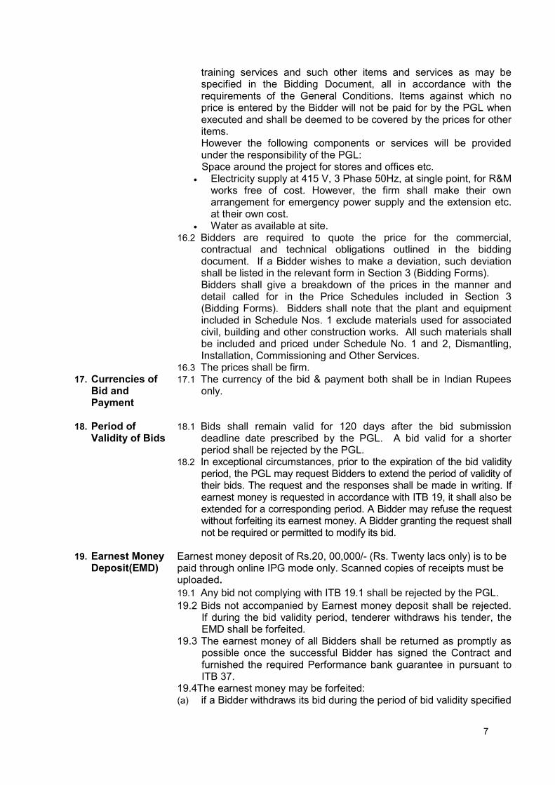
training services and such other items and services as may be specified in the Bidding Document, all in accordance with the requirements of the General Conditions. Items against which no price is entered by the Bidder will not be paid for by the PGL when executed and shall be deemed to be covered by the prices for other items. However the following components or services will be provided under the responsibility of the PGL: Space around the project for stores and offices etc.
Electricity supply at 415 V, 3 Phase 50Hz, at single point, for R&M works free of cost. However, the firm shall make their own arrangement for emergency power supply and the extension etc. at their own cost.
Water as available at site. 16.2 Bidders are required to quote the price for the commercial,
contractual and technical obligations outlined in the bidding document. If a Bidder wishes to make a deviation, such deviation shall be listed in the relevant form in Section 3 (Bidding Forms).
Bidders shall give a breakdown of the prices in the manner and detail called for in the Price Schedules included in Section 3 (Bidding Forms). Bidders shall note that the plant and equipment included in Schedule Nos. 1 exclude materials used for associated civil, building and other construction works. All such materials shall be included and priced under Schedule No. 1 and 2, Dismantling, Installation, Commissioning and Other Services.
16.3 The prices shall be firm. 17. Currencies of
Bid and Payment
17.1 The currency of the bid & payment both shall be in Indian Rupees only.
18. Period of Validity of Bids
18.1 Bids shall remain valid for 120 days after the bid submission deadline date prescribed by the PGL. A bid valid for a shorter period shall be rejected by the PGL.
18.2 In exceptional circumstances, prior to the expiration of the bid validity period, the PGL may request Bidders to extend the period of validity of their bids. The request and the responses shall be made in writing. If earnest money is requested in accordance with ITB 19, it shall also be extended for a corresponding period. A Bidder may refuse the request without forfeiting its earnest money. A Bidder granting the request shall not be required or permitted to modify its bid.
19. Earnest Money Deposit(EMD)
Earnest money deposit of Rs.20, 00,000/- (Rs. Twenty lacs only) is to be paid through online IPG mode only. Scanned copies of receipts must be uploaded.
19.1 Any bid not complying with ITB 19.1 shall be rejected by the PGL.
19.2 Bids not accompanied by Earnest money deposit shall be rejected. If during the bid validity period, tenderer withdraws his tender, the EMD shall be forfeited.
19.3 The earnest money of all Bidders shall be returned as promptly as possible once the successful Bidder has signed the Contract and furnished the required Performance bank guarantee in pursuant to ITB 37.
19.4The earnest money may be forfeited: (a) if a Bidder withdraws its bid during the period of bid validity specified

8
by the Bidder on the Letter of Bid (Declaration), except as provided in ITB 18.2 or
(b) if the successful Bidder fails to: (i) Sign the Contract in accordance with ITB 36; or (ii) Furnish a Performance bank guarantee in accordance with ITB 37.
20. Format and Signing of Bid
The bidders who are interested in bidding can download bid documents from www.etender.punjabgovt.gov.in up to the stipulated date & time free of cost. 20.1 Bidders who wish to submit their bid will have to register on
www.etender.punjabgovt.gov.in. To participate in online bids, Bidders will have to procure Class 3 Digital Signature Certificate as per requirement under Information Technology Act - 2000 using which they can sign their electronic bids and also get USER ID and PASSWORD
20.2 The Bid shall be typed or written in indelible ink and shall be signed by a person duly authorized to sign on behalf of the Bidder. This authorization shall consist written confirmation of authorization to sign on behalf of the Bidder shall consist of power of attorney and shall be attached to the bid. The name and position held by each person signing the authorization must be typed or printed below the signature. All pages of the bid where entries or amendments have been made shall be signed or initialed by the person signing the bid.
20.3 A bid submitted by a Joint Venture should be signed by person having power of attorney, on behalf of all partners, which will be legal binding on all partners.
20.4 Any interlineations, erasures, or overwriting shall be valid only if they are signed or initialed by the person signing the bid.
D. Submission and Opening of Bids 21. Submission,
Sealing and Marking of Bids
11. The bidders are requested to submit their bids prior to last date of submission in order to avoid any technical problems in accessing the website at last moments for any reason whatsoever.
12. Bidder shall submit both techno - commercial and financial bids online in electronic formats bearing electronic signature.
13. (i) The bidder will have to deposit non-refundable Bid document fee (Rs 10,000/-) and E- Processing fee (Rs 2,300/-) through IPG / RTGS mode.
22. Deadline for Submission of Bids
22.1 Bids must be received on line on Punjab Govt. e-tendering website by Date: 03/03/2017 upto 5:00 PM
22.2 The PGL may, at its discretion, extend the deadline for the submission
of bids by amending the Bidding Document in accordance with ITB 7, in which case all rights and obligations of the PGL and Bidders previously subject to the deadline shall thereafter be subject to the deadline as extended.
23. Late Bids 23.1 The PGL shall not consider any bid that arrives after the deadline for submission of bids, in accordance with ITB 22. Any bid received by the PGL after the deadline for submission of bids shall be declared late, rejected, and returned unopened to the Bidder.
24. Substitution, and Modification of Bids
24.1 No substitution and modification of bids shall be allowed.

9
25. Bid Opening 25.1 The PGL shall conduct the opening of Technical Bids in the presence of Bidders designated representatives who choose to attend, and at the address, date and time specified below: Address: Director, Punjab Genco Ltd, Plot no :1 & 2,Sector : 33-D Chandigarh
Date : 06/06/2017 Time : 11:30 AM The Price Bids will remain unopened and will be held in custody of the PGL until the specified time of their opening.
25.2 Technical Bids shall be opened one at a time, and the following read out and recorded:
(a) the name of the Bidder; (b) the presence of tender cost; (c) the presence of Earnest money; and (d) Any other details as the PGL may consider appropriate. Only Technical Bids read out and recorded at bid opening shall be
considered for evaluation. No Bid shall be rejected at the opening of Technical Bids except for late bids, in accordance with ITB Sub-Clause 23.1.
25.3 PGL shall prepare a record of the opening of Technical Bids that shall include, as a minimum: the name of the Bidder and the presence or absence of bid cost & bid security, if one was required. The Bidders’ representatives who are present shall be requested to sign the record. The omission of a Bidder’s signature on the record shall not invalidate the contents and effect of the record.
25.4 At the end of the evaluation of the Technical Bids, the PGL will invite bidders who have been determined as being qualified for award to attend the opening of the Price Bids. The date, time, and location of the opening of Price Bids will be uploaded on PGL’s web site. Bidders shall be given reasonable notice of the opening of Price Bids.
25.5 The PGL shall conduct the opening of Price Bids of all Bidders who have been considered qualified in pursuant to ITB 25.4, in the presence of Bidders` representatives who choose to attend at the address, date and time specified by the PGL. The Bidder’s representatives who are present shall be requested to sign a register evidencing their attendance.
25.6 Price Bids shall be opened one at a time and the following read out and recorded:
(a) the name of the Bidder; (b) the Bid Prices, and (c) Any other details as the PGL may consider appropriate.
Only Price Bids read out and recorded during the opening of Price Bids shall be considered for evaluation. No Bid shall be rejected at the opening of Price Bids.
25.7 The PGL shall prepare a record of the opening of Price Bids that shall include, as a minimum: the name of the Bidder, the Bid Price. The Bidders’ representatives who are present shall be requested to sign the record. The omission of a Bidder’s signature on the record shall not invalidate the contents and effect of the record.
10
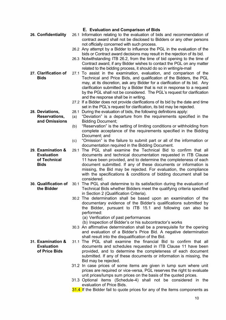
E. Evaluation and Comparison of Bids 26. Confidentiality 26.1 Information relating to the evaluation of bids and recommendation of
contract award shall not be disclosed to Bidders or any other persons not officially concerned with such process.
26.2 Any attempt by a Bidder to influence the PGL in the evaluation of the bids or Contract award decisions may result in the rejection of its bid.
26.3 Notwithstanding ITB 26.2, from the time of bid opening to the time of Contract award, if any Bidder wishes to contact the PGL on any matter related to the bidding process, it should do so in writing/e-mail
27. Clarification of Bids
27.1 To assist in the examination, evaluation, and comparison of the Technical and Price Bids, and qualification of the Bidders, the PGL may, at its discretion, ask any Bidder for a clarification of its bid. Any clarification submitted by a Bidder that is not in response to a request by the PGL shall not be considered. The PGL’s request for clarification and the response shall be in writing.
27.2 If a Bidder does not provide clarifications of its bid by the date and time set in the PGL’s request for clarification, its bid may be rejected.
28. Deviations, Reservations, and Omissions
28.1 During the evaluation of bids, the following definitions apply: (a) “Deviation” is a departure from the requirements specified in the
Bidding Document; (b) “Reservation” is the setting of limiting conditions or withholding from
complete acceptance of the requirements specified in the Bidding Document; and
(c) “Omission” is the failure to submit part or all of the information or documentation required in the Bidding Document.
29. Examination & Evaluation of Technical Bids
29.1 The PGL shall examine the Technical Bid to confirm that all documents and technical documentation requested in ITB Clause 11 have been provided, and to determine the completeness of each document submitted. If any of these documents or information is missing, the Bid may be rejected. For evaluation, the compliance with the specifications & conditions of bidding document shall be considered.
30. Qualification of the Bidder
30.1 The PGL shall determine to its satisfaction during the evaluation of Technical Bids whether Bidders meet the qualifying criteria specified in Section 2 (Qualification Criteria).
30.2 The determination shall be based upon an examination of the documentary evidence of the Bidder’s qualifications submitted by the Bidder, pursuant to ITB 15.1 and following can also be performed: (a) Verification of past performances (b) Inspection of Bidder’s or his subcontractor’s works
30.3 An affirmative determination shall be a prerequisite for the opening and evaluation of a Bidder’s Price Bid. A negative determination shall result into the disqualification of the Bid.
31. Examination & Evaluation of Price Bids
31.1 The PGL shall examine the financial Bid to confirm that all documents and schedules requested in ITB Clause 11 have been provided, and to determine the completeness of each document submitted. If any of these documents or information is missing, the Bid may be rejected.
31.2 In case prices of some items are given in lump sum where unit prices are required or vice-versa, PGL reserves the right to evaluate unit prices/lumps sum prices on the basis of the quoted prices.
31.3 Optional items (Schedule-4) shall not be considered in the evaluation of Price Bids.
31.4 If the Bidder fail to quote prices for any of the items components as

11
asked for, the highest prices as quoted by other Bids for the same shall be added to arrive at F.O.R. destination computed prices of such Bidder for comparison purpose only. The prices shall be compared inclusive of all duties & taxes etc at F.O.R. destination as on date of opening of bids. The FOR site price in the bid may be quoted with breakup of price, taxes and duties. The purchaser will provide requisite “C Forms”. Any variation in the taxes and duties after submission of bid shall be to the account of purchaser (PGL).
31.5 Loading on any other account as may be deemed necessary in the
opinion of PGL to bring the various offers at par to each other for comparison purposes, may be done at the discretion of the PGL.
32. Comparison of Bids
32.1 The PGL shall compare Bids to determine the lowest evaluated bid, in accordance with ITB 29, 30 & 31
33. PGL’s Right to Accept Any Bid, and to Reject Any or All Bids
33.1 The PGL reserves the right to accept or reject any bid, and to annul the bidding process and reject all bids at any time prior to contract award, without thereby incurring any liability to Bidders. In case of annulment, all bids submitted and specifically, bid securities, shall be promptly returned to the Bidders except bid document fee.
F. Award of Contract 34. Award Criteria 34.1 Subject to clause 33, the PGL shall award the Contract to the Bidder
whose offer (as per scope excluding the optional items) has been determined to be the lowest evaluated bid.
34.2 The PGL reserves the right to accept any of the deviations submitted in accordance with ITB 16.2 by the lowest evaluated bidder, at the price shown for the deviation in the bid.
35. Notification of Award
35.1 Prior to the expiration of the period of bid validity, the PGL shall notify the successful Bidder, in writing, that its bid has been accepted.
35.2 Until a formal contract is prepared and executed, the notification of award shall constitute a binding Contract.
36. Signing of Contract
36.1 Promptly after notification, the successful Bidder shall have to enter into a contract agreement with the PGL as per General conditions and other conditions attached with the bid specifications.
36.2 For signing the contract, a duly authorized representative of the successful Bidder shall be required to sign and accept the contract at Chandigarh within Ten (10) days failing which it shall be considered that he is not interested in accepting the offer and action as deemed fit shall be taken by PGL without making any further correspondence with successful Bidder.
37. Performance bank guarantee
37.1 After the receipt of notification of award from the PGL, the successful Bidder shall furnish the performance bank guarantee for Rs 50.00 lacs (Rupees Fifty lacs only) valid up to 12 months after commissioning of all the units before signing the Contract.
37.2 Failure of the successful Bidder to submit the above-mentioned Performance bank guarantee or sign the Contract shall constitute sufficient grounds for the annulment of the award and forfeiture of the earnest money. In that event the PGL may award the Contract to the next lowest evaluated Bidder whose offer is substantially responsive and is determined by the PGL to be qualified to perform the Contract satisfactorily.
37.3 The performance bank guarantee may be forfeited if the contractor withdraws or does not perform.

12
SECTION 2 – QUALIFICATION CRITERIA 1.0 General 1.1 Punjab Genco Limited, a wholly owned subsidiary of PEDA, Punjab, herein referred
to as “PGL”, responsible for operation & maintenance of Small Hydro Power Plant in the State of Punjab intends to implement Renovation & Modernization (herein referred to as R&M) of Chupki (2x750) KW, Narangwal (2x750) KW, Tugal (2x750) KW and Dalla (2x500) KW Small Hydro Power Projects located in district Ludhiana, Punjab.
1.2 A Bidder may be private entity or a government-owned entity - or any combination of
such entities under an existing agreement in the form of a joint venture. 1.3 Qualification for this tender is open to manufacturing and Turnkey Executor
Companies and voluntarily formed Joint Ventures (herein referred to as JV) of such companies from any country provided one of the Companies in Joint Ventures shall be from India. In case of JV, the Bidder must enclose the copy of JV agreement along with the Bid. Loose knit Joint Venture or Consortium is not allowed.
1.4 All information should be submitted in English. 1.5 Failure to provide information which is essential to evaluate the Bidder’s qualifications
may result in disqualification of the Bidder. 2.0 Qualification Criteria 2.1 The qualification of the Bidder will be subjected to their fulfillment of the Qualification
Criteria set hereunder substantiated by authentic relevant information and details in the prescribed formats with this section. Additional information in support of their claim of achievement may be furnished in any form of their device and design.
2.2 Bidder (lead partner as well as other partner in case of JV Bidder) should have
proven experience as contractors, as specified in succeeding paras, in execution of contracts of similar type, magnitude and nature with regard to engineering and integration of components, including erection, testing and commissioning at site.
2.3 The qualification will be based on the Bidder meeting criteria set forth hereunder as
the minimum:
3.0 Criteria
3.1 Financial Capacity
3.1.1 Turnover
Average annual turnover during last Five (5) years ending 31st March of the previous financial year from the date of opening of the Bid should be at least INR 5.0 Crore (Indian Rupees Five Crore) either individually by a sole Bidder or collectively by JV partners. In case
13
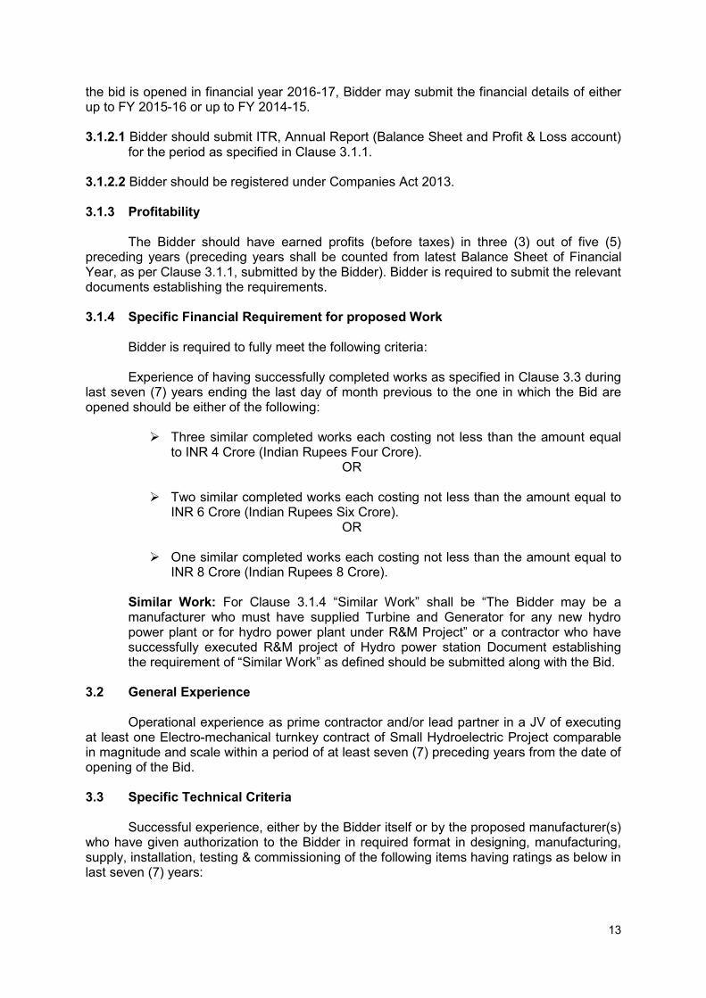
the bid is opened in financial year 2016-17, Bidder may submit the financial details of either up to FY 2015-16 or up to FY 2014-15. 3.1.2.1 Bidder should submit ITR, Annual Report (Balance Sheet and Profit & Loss account)
for the period as specified in Clause 3.1.1. 3.1.2.2 Bidder should be registered under Companies Act 2013. 3.1.3 Profitability
The Bidder should have earned profits (before taxes) in three (3) out of five (5) preceding years (preceding years shall be counted from latest Balance Sheet of Financial Year, as per Clause 3.1.1, submitted by the Bidder). Bidder is required to submit the relevant documents establishing the requirements.
3.1.4 Specific Financial Requirement for proposed Work
Bidder is required to fully meet the following criteria: Experience of having successfully completed works as specified in Clause 3.3 during
last seven (7) years ending the last day of month previous to the one in which the Bid are opened should be either of the following:
Three similar completed works each costing not less than the amount equal
to INR 4 Crore (Indian Rupees Four Crore). OR
Two similar completed works each costing not less than the amount equal to
INR 6 Crore (Indian Rupees Six Crore). OR
One similar completed works each costing not less than the amount equal to
INR 8 Crore (Indian Rupees 8 Crore).
Similar Work: For Clause 3.1.4 “Similar Work” shall be “The Bidder may be a manufacturer who must have supplied Turbine and Generator for any new hydro power plant or for hydro power plant under R&M Project” or a contractor who have successfully executed R&M project of Hydro power station Document establishing the requirement of “Similar Work” as defined should be submitted along with the Bid.
3.2 General Experience
Operational experience as prime contractor and/or lead partner in a JV of executing at least one Electro-mechanical turnkey contract of Small Hydroelectric Project comparable in magnitude and scale within a period of at least seven (7) preceding years from the date of opening of the Bid.
3.3 Specific Technical Criteria
Successful experience, either by the Bidder itself or by the proposed manufacturer(s)
who have given authorization to the Bidder in required format in designing, manufacturing, supply, installation, testing & commissioning of the following items having ratings as below in last seven (7) years:
14
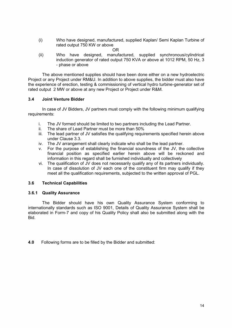
(i) Who have designed, manufactured, supplied Kaplan/ Semi Kaplan Turbine of
rated output 750 KW or above OR (ii) Who have designed, manufactured, supplied synchronous/cylindrical
induction generator of rated output 750 KVA or above at 1012 RPM, 50 Hz, 3 - phase or above
The above mentioned supplies should have been done either on a new hydroelectric
Project or any Project under RM&U. In addition to above supplies, the bidder must also have the experience of erection, testing & commissioning of vertical hydro turbine-generator set of rated output 2 MW or above at any new Project or Project under R&M.
3.4 Joint Venture Bidder
In case of JV Bidders, JV partners must comply with the following minimum qualifying
requirements:
i. The JV formed should be limited to two partners including the Lead Partner. ii. The share of Lead Partner must be more than 50% iii. The lead partner of JV satisfies the qualifying requirements specified herein above
under Clause 3.3. iv. The JV arrangement shall clearly indicate who shall be the lead partner. v. For the purpose of establishing the financial soundness of the JV, the collective
financial position as specified earlier herein above will be reckoned and information in this regard shall be furnished individually and collectively
vi. The qualification of JV does not necessarily qualify any of its partners individually. In case of dissolution of JV each one of the constituent firm may qualify if they meet all the qualification requirements, subjected to the written approval of PGL.
3.6 Technical Capabilities 3.6.1 Quality Assurance
The Bidder should have his own Quality Assurance System conforming to internationally standards such as ISO 9001, Details of Quality Assurance System shall be elaborated in Form-7 and copy of his Quality Policy shall also be submitted along with the Bid.
4.0 Following forms are to be filled by the Bidder and submitted:

15
Form 1: General Information
All sole Bidders and each partner of JV submitted Bid is requested to complete the information in this form.
Where the Bidder proposes to associate manufacturer(s) for any item(s) of equipment costing in excess of 10% of whole works, the following information should also be supplied for such manufacturer(s).
1 Name of bidder:
In case of JV: ( ) Lead Partner ( ) Partner
2 Head Office Address: Country:
3 Telephone Fax Telex
Contact Person Name Title / Position
4 Place of incorporation /registration Date
5 Legal Status of firm Field of specialty in business
6 Nationality of majority of owners or share holders
Number of management executives --------------- Persons
7 Number of permanent employees:
8 Name of place of major factories:
9 Quality assurance system in major factories
Certified by:
Date …………………….. Signature…………………….
16
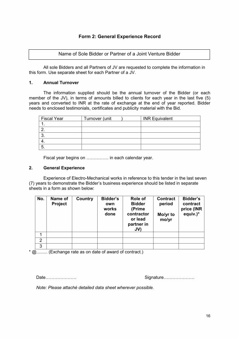
Form 2: General Experience Record
All sole Bidders and all Partners of JV are requested to complete the information in this form. Use separate sheet for each Partner of a JV. 1. Annual Turnover
The information supplied should be the annual turnover of the Bidder (or each
member of the JV), in terms of amounts billed to clients for each year in the last five (5) years and converted to INR at the rate of exchange at the end of year reported. Bidder needs to enclosed testimonials, certificates and publicity material with the Bid.
Fiscal Year Turnover (unit ) INR Equivalent 1. 2. 3. 4. 5. Fiscal year begins on …………… in each calendar year.
2. General Experience
Experience of Electro-Mechanical works in reference to this tender in the last seven
(7) years to demonstrate the Bidder’s business experience should be listed in separate sheets in a form as shown below:
No. Name of Project
Country Bidder’s own
works done
Role of Bidder (Prime
contractor or lead
partner in JV)
Contract period
Mo/yr to
mo/yr
Bidder’s contract
price (INR equiv.)*
1 2 3
* @......... (Exchange rate as on date of award of contract.)
Date………………… Signature…………………
Note: Please attaché detailed data sheet wherever possible.
Name of Sole Bidder or Partner of a Joint Venture Bidder
17
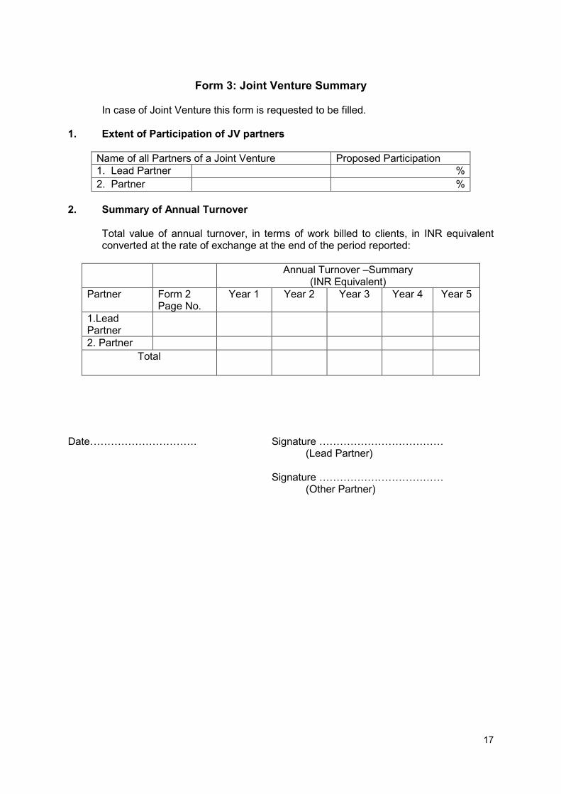
Form 3: Joint Venture Summary
In case of Joint Venture this form is requested to be filled. 1. Extent of Participation of JV partners
Name of all Partners of a Joint Venture Proposed Participation 1. Lead Partner %
2. Partner %
2. Summary of Annual Turnover
Total value of annual turnover, in terms of work billed to clients, in INR equivalent converted at the rate of exchange at the end of the period reported:
Annual Turnover –Summary (INR Equivalent)
Partner Form 2 Page No.
Year 1 Year 2 Year 3 Year 4 Year 5
1.Lead Partner
2. Partner Total
Date…………………………. Signature ……………………………… (Lead Partner) Signature ……………………………… (Other Partner)
18
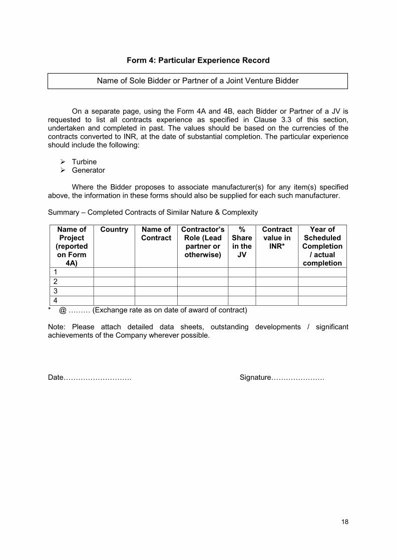
Form 4: Particular Experience Record
On a separate page, using the Form 4A and 4B, each Bidder or Partner of a JV is requested to list all contracts experience as specified in Clause 3.3 of this section, undertaken and completed in past. The values should be based on the currencies of the contracts converted to INR, at the date of substantial completion. The particular experience should include the following:
Turbine Generator
Where the Bidder proposes to associate manufacturer(s) for any item(s) specified
above, the information in these forms should also be supplied for each such manufacturer. Summary – Completed Contracts of Similar Nature & Complexity
Name of Project
(reported on Form
4A)
Country Name of Contract
Contractor’s Role (Lead partner or otherwise)
% Share in the
JV
Contract value in
INR*
Year of Scheduled Completion
/ actual completion
1 2 3 4
* @ ……… (Exchange rate as on date of award of contract) Note: Please attach detailed data sheets, outstanding developments / significant achievements of the Company wherever possible. Date………………………. Signature………………….
Name of Sole Bidder or Partner of a Joint Venture Bidder

19
FORM 4A: Details of Completed and Current Contracts of Similar Nature and Complexity
Use separate sheet for each contract. Copy of Taking over Certificate in respect of each completed contract should be attached.
Dimensions and design heads of the works should be summarized in 4B and 4C.
1 No….. (in Form 4B or 4C) Name of Project
Installed Capacity:………(MW) No. of Units………
Country
State / Province
Name of River 2 Name of PGL
Address
3 Name of Contract:
4 Nature of works (Turbine, Generator) and special features (site conditions, design, etc.) relevant to the contract for which the Bidder is submitting the Bid.
5 6 Contract Value:
Currency:
Equivalent INR: Share of Bidder:
7 Time period as per the Contract document (years & months)
Date of award: Date of completion:
Note: Please attach detailed data sheet wherever applicable. Date………………………… Signature……………………….
Name of Sole Bidder or Partner of a Joint Venture Bidder
20
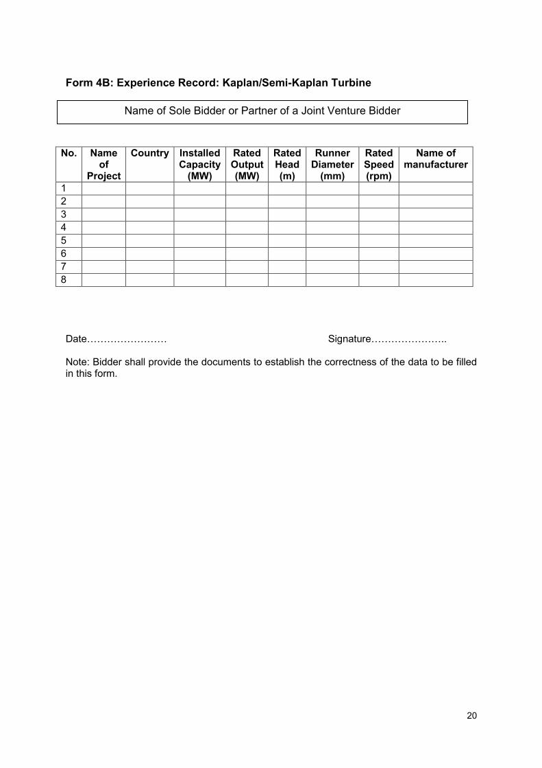
Form 4B: Experience Record: Kaplan/Semi-Kaplan Turbine
No. Name of
Project
Country Installed Capacity
(MW)
Rated Output (MW)
Rated Head (m)
Runner Diameter
(mm)
Rated Speed (rpm)
Name of manufacturer
1 2 3 4 5 6 7 8 Date…………………… Signature………………….. Note: Bidder shall provide the documents to establish the correctness of the data to be filled in this form.
Name of Sole Bidder or Partner of a Joint Venture Bidder
21
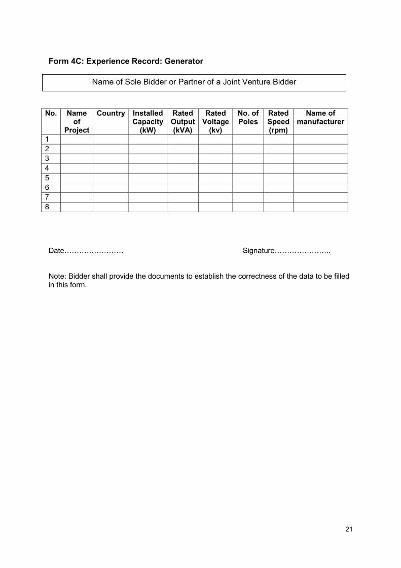
Form 4C: Experience Record: Generator
No. Name of
Project
Country Installed Capacity
(kW)
Rated Output (kVA)
Rated Voltage
(kv)
No. of Poles
Rated Speed (rpm)
Name of manufacturer
1 2 3 4 5 6 7 8 Date…………………… Signature………………….. Note: Bidder shall provide the documents to establish the correctness of the data to be filled in this form.
Name of Sole Bidder or Partner of a Joint Venture Bidder
22
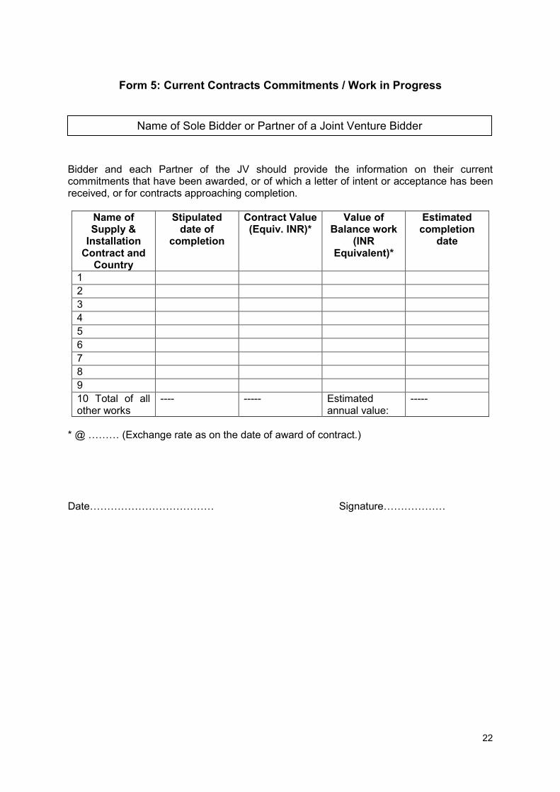
Form 5: Current Contracts Commitments / Work in Progress
Bidder and each Partner of the JV should provide the information on their current commitments that have been awarded, or of which a letter of intent or acceptance has been received, or for contracts approaching completion.
Name of Supply &
Installation Contract and
Country
Stipulated date of
completion
Contract Value (Equiv. INR)*
Value of Balance work
(INR Equivalent)*
Estimated completion
date
1 2 3 4 5 6 7 8 9 10 Total of all other works
---- ----- Estimated annual value:
-----
* @ ……… (Exchange rate as on the date of award of contract.) Date……………………………… Signature………………
Name of Sole Bidder or Partner of a Joint Venture Bidder
23
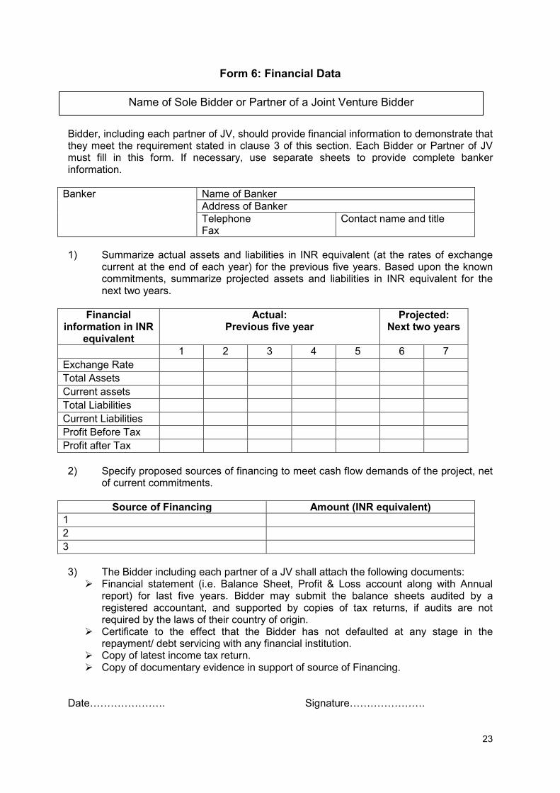
Form 6: Financial Data Bidder, including each partner of JV, should provide financial information to demonstrate that they meet the requirement stated in clause 3 of this section. Each Bidder or Partner of JV must fill in this form. If necessary, use separate sheets to provide complete banker information.
Banker Name of Banker Address of Banker Telephone Fax
Contact name and title
1) Summarize actual assets and liabilities in INR equivalent (at the rates of exchange
current at the end of each year) for the previous five years. Based upon the known commitments, summarize projected assets and liabilities in INR equivalent for the next two years.
Financial information in INR
equivalent
Actual: Previous five year
Projected: Next two years
1 2 3 4 5 6 7
Exchange Rate Total Assets Current assets Total Liabilities Current Liabilities Profit Before Tax Profit after Tax 2) Specify proposed sources of financing to meet cash flow demands of the project, net
of current commitments.
Source of Financing Amount (INR equivalent) 1 2 3 3) The Bidder including each partner of a JV shall attach the following documents:
Financial statement (i.e. Balance Sheet, Profit & Loss account along with Annual report) for last five years. Bidder may submit the balance sheets audited by a registered accountant, and supported by copies of tax returns, if audits are not required by the laws of their country of origin.
Certificate to the effect that the Bidder has not defaulted at any stage in the repayment/ debt servicing with any financial institution.
Copy of latest income tax return. Copy of documentary evidence in support of source of Financing.
Date…………………. Signature………………….
Name of Sole Bidder or Partner of a Joint Venture Bidder

24
Form 7: Quality Assurance
Bidder should provide the information on his Quality Assurance System. Bidder’s Quality Assurance System Date……………. Signature…………………..
Name of Sole Bidder or Partner of a Joint Venture Bidder

25
Form 8: Undertaking for Joint Venture (JV)
To,
Dear Sir,
We have examined and have no reservations to the Bidding Documents, including Addenda issued in accordance with Instructions to Bidders; We offer to execute in conformity with the Invitation for Bid No ……………. & Bidding Documents for Renovation &Modernization of R&M of 4 nos. Small Hydro Power Station installed on Abohar Canal on Turnkey basis;
We ----------------------------------------------- having our registered office at (herein after
referred to as First JV Partner) which in turn shall include our successor, administrator and assign and we -------------------------------------------- having our registered office at --------------------------------------------- ( herein after called as Second JV Partner and Contractor ) are held jointly and severally liable and bound up to Punjab Genco Ltd. (herein after referred to as purchaser) which expression shall include its successor, administrator and assigns, for the successful performance of the contract, including the overall responsibility for Renovation & Modernization of 4 nos. Small Hydro Power Station installed on Abohar canal on Turnkey basis in accordance with the contract. The contractor/ JV Partner hereby agree to depute their technical experts from time to time to contractor’s works/ Project site as mutually agreed upon between the purchaser and the contractor in order to discharge the contractor’s obligations as stipulated in the contract. The Contractor and the JV Partner hereby agree that this undertaking shall be irrevocable and it shall form an integral part of the contract. In witness there of the JV Partner and the Contractor have through their authorized representative set their hands and seal on this day of …………………
For and On Behalf of First JV Partner For and On Behalf of Second JV Partner and Contractor
Signature
Name & Designation (Official Address)
Seal
Signature Name & Designation (Official Address) Seal
Witness ……………………… Signature, Name & Designation ……………………… Signature, Name & Designation

26
SECTION 3 - BIDDING FORMS This Section contains the forms which are to be completed by the Bidder and submitted as part of his Bid.
Form 9 - Letter of Bid (Declaration Form)
Date:……….. Invitation for Bid No.: ………..
To: Punjab Genco Ltd Chandigarh Punjab We, the undersigned, declare that: (a) We have examined and have no reservations to the Bidding Documents,
including Addenda issued in accordance with Instructions to Bidders (ITB) 7; (b) We have visited the site and made ourselves conversant with the present status
of all the plants and site conditions; (c) We offer to execute in conformity with the Bidding Documents for Renovation &
Modernization of 4 nos. Abohar Canal Small Hydro Projects on Turnkey basis; (d) Our Bid, consisting of the ’Techno- Commercial Bid and the Financial Bid’, shall
be valid for a period of . . . . . days from the date fixed for the Opening of the Technical Bid in accordance with the Bidding Documents, and it shall remain binding upon us and may be accepted at any time before the expiration of that period;
(e) If our Bid is accepted, we commit to obtain a ‘Performance bank guarantee' in accordance with the Bidding Documents;
(f) We are not participating, as a Bidder or as a subcontractor, in more than one bid in this bidding process;
(g) Our firm, its affiliates or subsidiaries, including any Subcontractors or Suppliers for any part of the contract, has not been declared ineligible/blacklisted by Government of India or any State Government or any Court or any of their agencies in past,
(h) We are not a government owned entity / we are a government owned entity but meet the requirements of ITB 4.3
Name ............................................................................................................................... In the capacity of .............................................................................................................. Signed .............................................................................................................................. .......................................................................................................................................... Duly authorized to sign the Bid for and on behalf of .......................................................... Date ..................................................................................................................................

27
Form 10- Prescribed Performa for Performance Bank Guarantee To Punjab Genco Ltd., CHANDIGARH Whereas....................................................................... hereinafter called the ‘Contractor’ has undertaken, in pursuance of contract agreement no. .......................................................... dated................... to carry out R&M works of the four Small Hydro Electric Plants at Chupki, Narangwal, Tugal and Dalla in accordance with provisions stipulated in the Contract Agreement as signed with you. AND, Whereas, it has been stipulated in the condition of the said contract that the Contractor shall furnish to the Punjab Genco Ltd., hereinafter, called ‘PGL’, with a Performance Guarantee from a scheduled bank, to cover the compliances of the Contractor’s performance-obligations stipulated in the Contractor Agreement , for an amount of Rs.50 lacs (Rupees fifty lacs only) for the full period of said Contract agreement plus 12 months of guarantee period after commissioning of all the units to be renovated and modernized. AND, Whereas, Contractor has agreed to give the PGL the said guarantee. Therefore ____________ _______________ bank hereby affirms that the Bank, as a Guarantor will be responsible to ‘PGL’ M/s Punjab Genco Ltd on behalf of Contractor M/s. ______________________________________ and undertakes to pay the full amount of Rs.50 lacs (Rupees Fifty lacs only) upon first written demand without arguments declaring the Contractor to be at default under the Contract agreement. This amount, within limits of aforesaid guarantee without needing any proof or showing any grounds of reasons for demand, of the said amount specified here above. This performance guarantee is valid until................................ Day ............... of.........................
Signature and Seal of Guarantor Date: Place:

28
Form 11- List of Drawings and Literature Enclosed with the Tender
Invitation for Bid No.: ……………………
Sl No. Drawing/ Literature No. Titles 1 2 3
Seal of the Company Signature
Name Designation Date
29
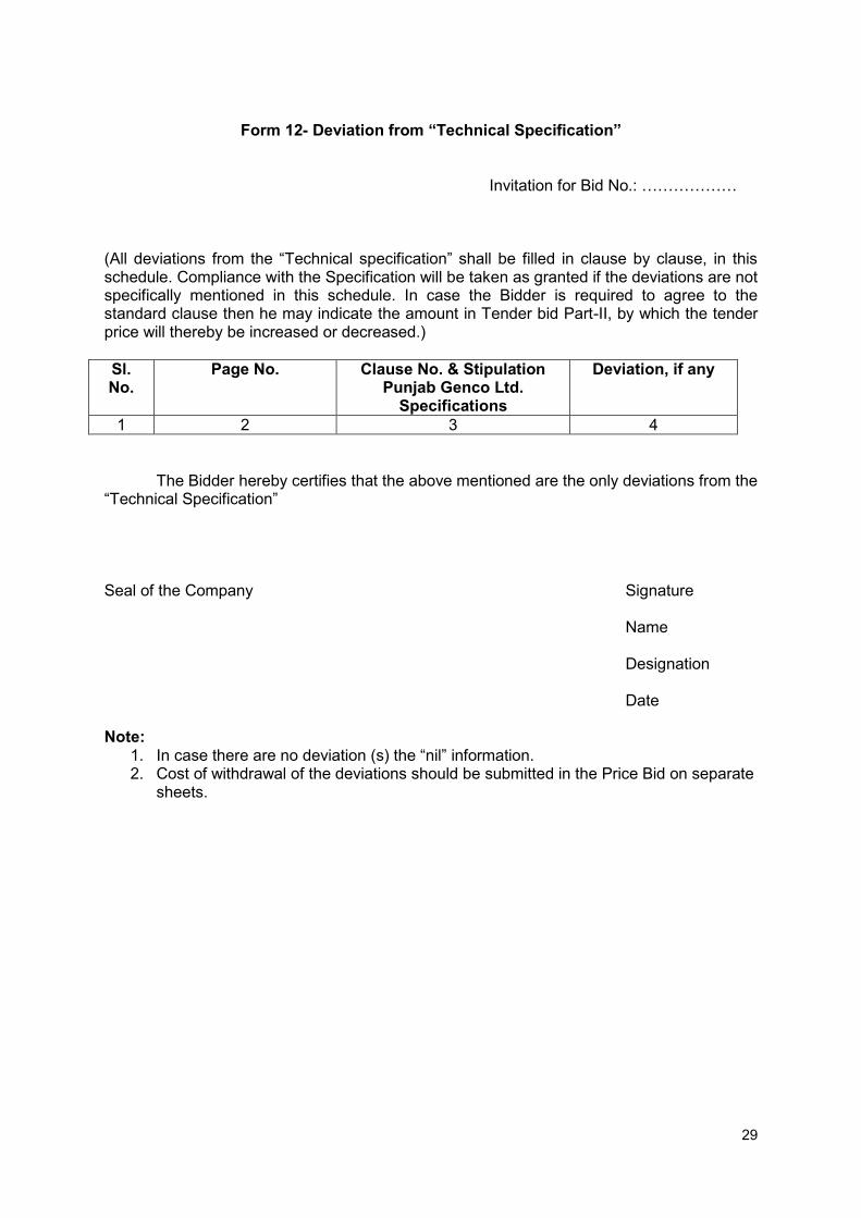
Form 12- Deviation from “Technical Specification”
Invitation for Bid No.: ………………
(All deviations from the “Technical specification” shall be filled in clause by clause, in this schedule. Compliance with the Specification will be taken as granted if the deviations are not specifically mentioned in this schedule. In case the Bidder is required to agree to the standard clause then he may indicate the amount in Tender bid Part-II, by which the tender price will thereby be increased or decreased.)
Sl. No.
Page No. Clause No. & Stipulation Punjab Genco Ltd.
Specifications
Deviation, if any
1 2 3 4 The Bidder hereby certifies that the above mentioned are the only deviations from the “Technical Specification” Seal of the Company Signature
Name Designation Date
Note:
1. In case there are no deviation (s) the “nil” information. 2. Cost of withdrawal of the deviations should be submitted in the Price Bid on separate
sheets.

30
Form 13- Deviation from “Special Conditions Of Contract”
Invitation for Bid No…………………….
(All deviations from the “Special Conditions of Contract” shall be filled in clause by clause, in this schedule. Compliance with the Specification will be taken as granted if the deviations are not specifically mentioned in this schedule. In case the Bidder is required to agree to the standard clause then he may indicate the amount in Tender bid Part-II, by which the tender price will thereby be increased or decreased.)
Sl. No.
Page No. Clause No. & Stipulation in Punjab Genco Ltd.
Specification
Deviation, if any
1 2 3 4
The Bidder hereby certifies that the above mentioned are the only deviations from the “Particular Conditions of Contract”. Seal of the Company Signature
Name Designation Date
Note:
1. In case there are no deviation (s) the “nil” information. 2. Cost of withdrawal of the deviations should be submitted in the Price Bid on separate
sheets.
31
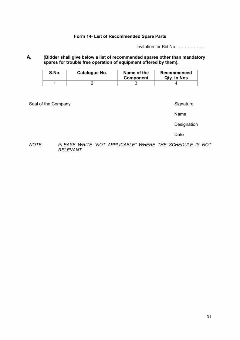
Form 14- List of Recommended Spare Parts
Invitation for Bid No.: ………………
A. (Bidder shall give below a list of recommended spares other than mandatory spares for trouble free operation of equipment offered by them).
S.No. Catalogue No. Name of the Component
Recommenced Qty. in Nos
1 2 3 4 Seal of the Company Signature
Name Designation Date
NOTE: PLEASE WRITE “NOT APPLICABLE” WHERE THE SCHEDULE IS NOT
RELEVANT.
32
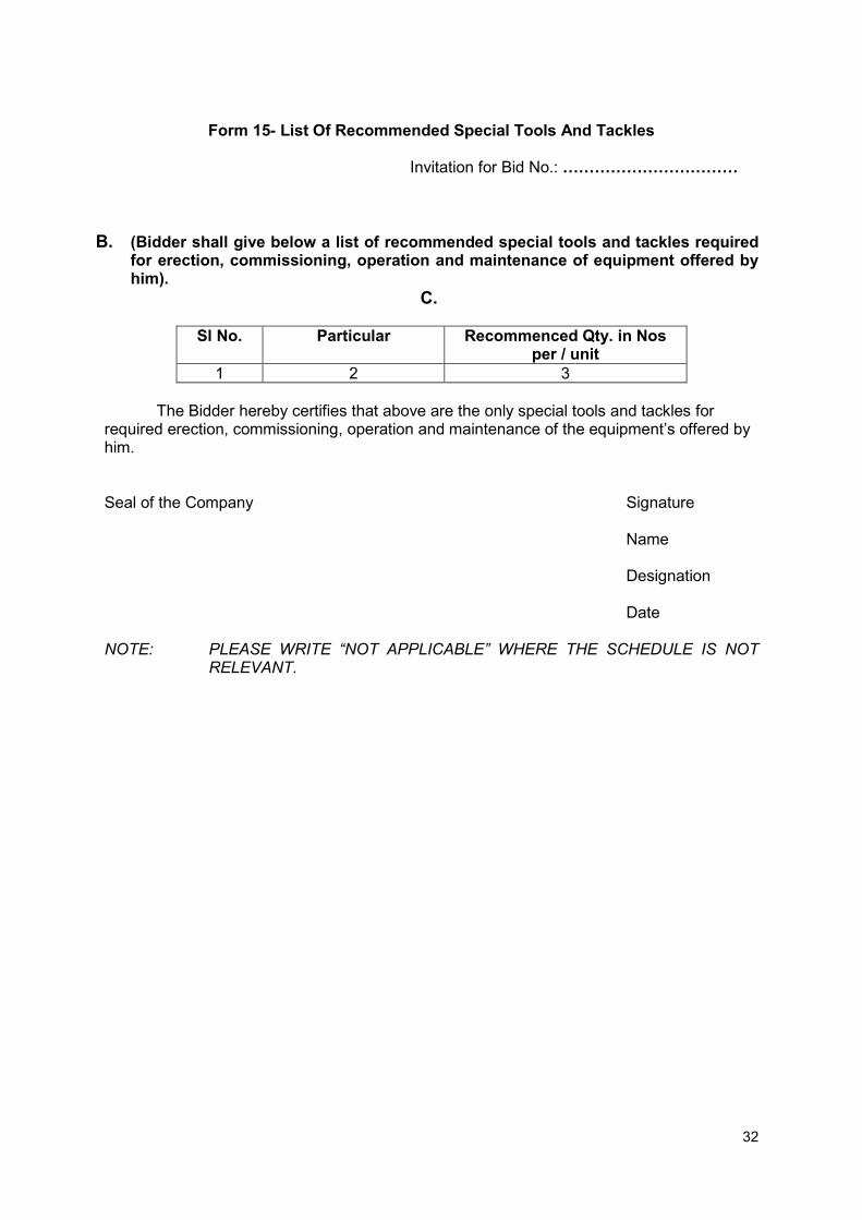
Form 15- List Of Recommended Special Tools And Tackles
Invitation for Bid No.: ……………………………
B. (Bidder shall give below a list of recommended special tools and tackles required for erection, commissioning, operation and maintenance of equipment offered by him).
C.
Sl No. Particular Recommenced Qty. in Nos per / unit
1 2 3
The Bidder hereby certifies that above are the only special tools and tackles for required erection, commissioning, operation and maintenance of the equipment’s offered by him. Seal of the Company Signature
Name Designation Date
NOTE: PLEASE WRITE “NOT APPLICABLE” WHERE THE SCHEDULE IS NOT
RELEVANT.

33
Form 16- List of Recommended Test Sets and Testing Instruments
Invitation for Bid No.: ……………………………….
D. (Bidder shall give below a list of recommended test sets and testing instruments required for erection, commissioning, operation and maintenance).
S. No. Particular Quantity Purpose 1 2 3 4
The Bidder hereby certifies that above are the only test sets and testing instruments required for required erection, commissioning, operation and maintenance of the equipment offered by him. The instruments required for erection & commissioning shall be brought by the Contractor on returnable basis (after commissioning) without extra cost whereas instruments required for operation & maintenance shall remain with the purchaser. Seal of the Company Signature
Name Designation Date
NOTE: PLEASE WRITE “NOT APPLICABLE” WHERE THE SCHEDULE IS NOT
RELEVANT

34
Form 17- Schedule of Quoted Guaranteed Delivery/Project Completion Schedule
Invitation for Bid No.: ………… (Guaranteed DELIVERY/PROJECT COMPLETION SCHEDULE will be reckoned from the date of issue of letter of award to the bidder) (“Please indicate activity wise bar chart with date of start & finish of each activity of the project with submission/approval of drawings/ data, delivery, erection & commissioning, preliminary acceptance tests and final acceptance test/ handing over of the complete project in operating conditions” etc.). Seal of the Company Signature
Name Designation Date

35
TECHNICAL PROPOSAL
GUARANTEED TECHNICAL PARTICULAR 1. GTP of VCB (Outdoor Type
1 Make
2 Installation
3 Design Ambient Temp.
4 Nominal Voltage
5 Maximum Voltage
6 Rated frequency
7 Number of phases and poles
8 Normal current
9 Short circuit breaking capacity
10 Withstand duration of short circuit current
11 Rated S.C. Making current
12 Rated Power Freq. 1 min withstand voltage
13 Rated impulse withstand voltage
14 Duty cycle
15 Operating mechanism
16 Material of contacts
a Fixed contacts
b Moving contacts
c Selection switch
17 Creepage of bushings
18 supports
19 Interrupter Housing
20 Auxiliary switch
21 Close/trip coil voltage
22 Space heater voltage
23 First – pole to –clear factor
24 Transient recovery voltage
25 Peak value
26 Time
27 Application standard
2. Isolator
1. Manufacturer's name 2. Manufacturer's type designation 3. Standards applicable 4. Type Single/double break Horizontal/vertical 5. Rated voltage kV 6. Rated frequency 7. Current rating
a.) Continuous A (at design temp.) b) Current rating at site condition A c) Dynamic through fault kA d) 3 second rating kA e) Making current A

36
8. Design ambient temperature (° C) 9. Maximum temperature of current carrying parts when carrying rated current at
specified ambient temperature, ° C 10. Maximum temperature of current carrying parts when carrying short circuit
current for 3 seconds, °C 11. One minute power frequency dry & wet withstand voltage 12. 1.2 / 50 micro sec. Impulse withstand voltage. 13. Switch contact particulars
a) Type of main isolating contacts b) Area & material of contacts. c) Thickness of silver facing d) Blade material
14. Number of auxiliary contacts on disconnecting switch 15. Rating of auxiliary contacts
a) Continuous A b) Breaking current at --- V DC.
16. Type of interlock between earthing blade and isolator 17. Particulars of isolator operating mechanism 18. Duty Outdoor / Indoor
19. No. of operations, the disconnecting switch can withstand without deterioration of contacts.
20. Clearance a) Between phases, mm b) Between live parts & earth, mm c) Between fixed contacts and blade in open position, mm
21. a) Capacitive current that can safely be interrupted by the switch, A b) Magnetizing current that can safely be interrupted by the switch, A
22. Type and make of insulator 23. No. of insulators per stack 24. One minute dry & wet withstand voltage per stack, kV (rms) 25. Impulse withstands voltage of insulator stack at 1 .2/50 micro seconds
positive full wave, kV (peak). 26. Creepage distance
a) Total mm b) Protected mm
27. Total weight, Kg. 28. Dimensions of switch LxBxH (mm x mm x mm) 29. Shipping dimension of largest package 30. Provision of earthing switch one side/both side 31. G.A. drg. Of disconnect switch along-with support structure Submitted/not
submitted 32. Supporting structures
a) Material b) Total weight/Isolator, kg. c) Thickness of galvanizing, micron d) Total height of structure in mm
33. Power and control power supply voltage. Yes/No 34. Confirm that all particulars given in technical particulars are acceptable to
tenderer 35. If answer is 'NO' in above then indicate point wise deviation
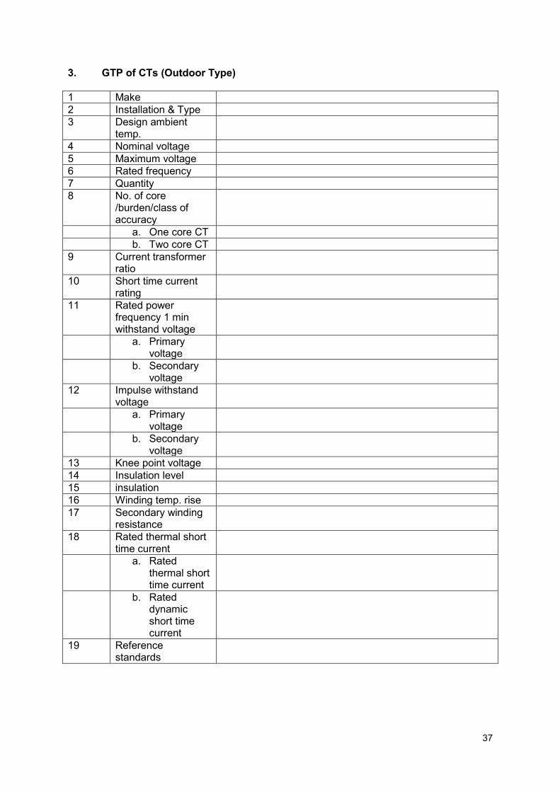
37
3. GTP of CTs (Outdoor Type)
1 Make
2 Installation & Type
3 Design ambient temp.
4 Nominal voltage
5 Maximum voltage
6 Rated frequency
7 Quantity
8 No. of core /burden/class of accuracy
a. One core CT
b. Two core CT
9 Current transformer ratio
10 Short time current rating
11 Rated power frequency 1 min withstand voltage
a. Primary voltage
b. Secondary voltage
12 Impulse withstand voltage
a. Primary voltage
b. Secondary voltage
13 Knee point voltage
14 Insulation level
15 insulation
16 Winding temp. rise
17 Secondary winding resistance
18 Rated thermal short time current
a. Rated thermal short time current
b. Rated dynamic short time current
19 Reference standards
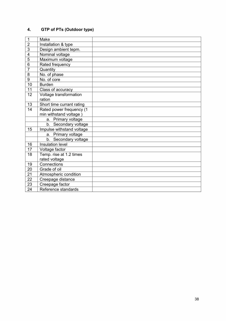
38
4. GTP of PTs (Outdoor type)
1 Make
2 Installation & type
3 Design ambient tepm.
4 Nominal voltage
5 Maximum voltage
6 Rated frequency
7 Quantity
8 No. of phase
9 No. of core
10 Burden
11 Class of accuracy
12 Voltage transformation ration
13 Short time currant rating
14 Rated power frequency (1 min withstand voltage )
a. Primary voltage
b. Secondary voltage
15 Impulse withstand voltage
a. Primary voltage
b. Secondary voltage
16 Insulation level
17 Voltage factor
18 Temp. rise at 1.2 times rated voltage
19 Connections
20 Grade of oil
21 Atmospheric condition
22 Creepage distance
23 Creepage factor
24 Reference standards
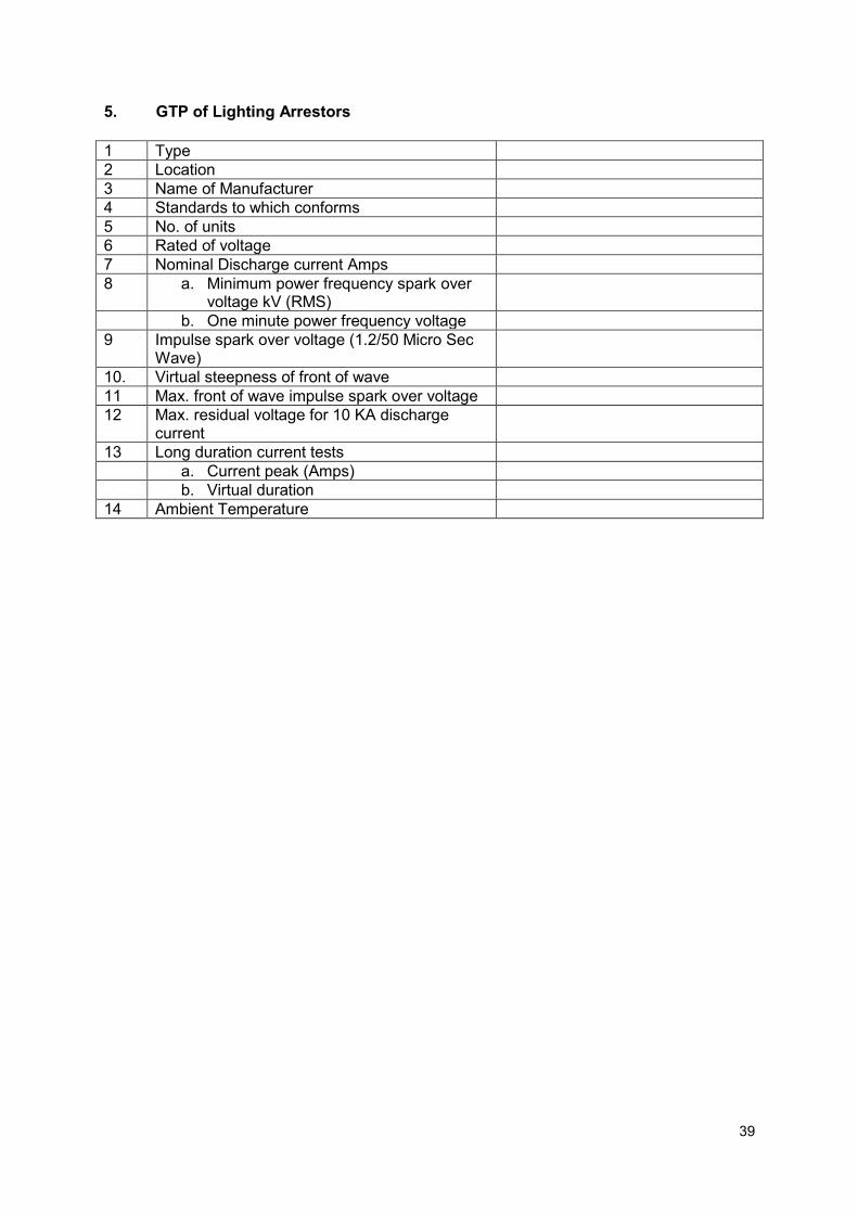
39
5. GTP of Lighting Arrestors
1 Type
2 Location
3 Name of Manufacturer
4 Standards to which conforms
5 No. of units
6 Rated of voltage
7 Nominal Discharge current Amps
8 a. Minimum power frequency spark over voltage kV (RMS)
b. One minute power frequency voltage
9 Impulse spark over voltage (1.2/50 Micro Sec Wave)
10. Virtual steepness of front of wave
11 Max. front of wave impulse spark over voltage
12 Max. residual voltage for 10 KA discharge current
13 Long duration current tests
a. Current peak (Amps)
b. Virtual duration
14 Ambient Temperature

40
6. GTP of Gear box
1 Make of the Gear Box
2 Rated Turbine Output (KW)
3 Stages of Gear Box
4 Efficiency of Gear Box
5 Orientation
6 Speed Ratio
7 Run away speed and duration
8 Generator short circuit torque value and its nature
9 Material of Gear and Pinion
10 Hardness of Gear &Pinion
11 Back Lash (mm)
a First stage
b Second stage
12 Life of Gear box bearings
13 Tooth Contact Pattern in Percentage
a No load
b Full load
14 Noise Level (db) form one meter distance
15 Vibrations
I a. Normal Displacement
b. Max. Displacement (Micron)
ii Velocity (mm/sec)
16 Distance of high speed shaft & low speed shaft in mm
17 Temperature rise in Lubricating oil above ambient temperature in Degree C.
7. GTP of Battery & Battery Charger I. Battery
1 Manufacture name
2 Applicable Standard
3 Type of designation as per IS
4 Capacity in Ampere hours of the battery
5 Rated Voltage of battery
a Nominal
b Maximum
c Minimum
6 Nominal Cell voltage (Volts)
a Float
b Boost
7 No. of cell in each bank
8 No. of spare cells in each bank
9 Material of containers
10 Thickness and type of material separators
11 Construction details and dimensions
a Positive Plate
b Negative plate
c Method of supporting elements
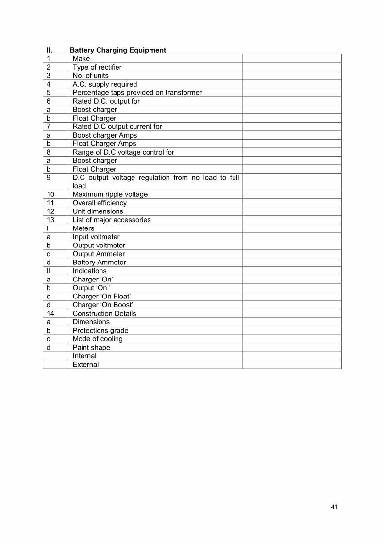
41
II. Battery Charging Equipment
1 Make
2 Type of rectifier
3 No. of units
4 A.C. supply required
5 Percentage taps provided on transformer
6 Rated D.C. output for
a Boost charger
b Float Charger
7 Rated D.C output current for
a Boost charger Amps
b Float Charger Amps
8 Range of D.C voltage control for
a Boost charger
b Float Charger
9 D.C output voltage regulation from no load to full load
10 Maximum ripple voltage
11 Overall efficiency
12 Unit dimensions
13 List of major accessories
I Meters
a Input voltmeter
b Output voltmeter
c Output Ammeter
d Battery Ammeter
II Indications
a Charger ‘On’
b Output ‘On ’
c Charger ‘On Float’
d Charger ‘On Boost’
14 Construction Details
a Dimensions
b Protections grade
c Mode of cooling
d Paint shape
Internal
External

46
8. GTP of XLPE cable
Location of the cable
Cable size no. of cores
Type Armour thickness
(mm)
Approx O.D. (mm)
Current rating Max Dc resistance
at 20 0c/KM
Approx reactance
at 50 HZ/KM
Capacitance Per
PH.MF/Km
Approx Net Wt of
cable Kg/Km
Approx Gross Wt. of Cable Kg/Km
In ground
In duct
In Air
LT panel
Capacitance 1 & II to capacitor bank I,II,III,IV
Gen.I (Line side) to Gen. Panel I
Gen.I (Neutral side) to Gen. Panel I
Gen.II (Line side) to Gen. Panel II
Gen.II (Neutral side) to Gen. Panel II
Aux. transform

47
Location of the cable
Cable size no. of cores
Type Armour thickness
(mm)
Approx O.D. (mm)
Current rating Max Dc resistance
at 20 0c/KM
Approx reactance
at 50 HZ/KM
Capacitance Per
PH.MF/Km
Approx Net Wt of
cable Kg/Km
Approx Gross Wt. of Cable Kg/Km
In ground
In duct
In Air
er to Aux. Panel
Aux, Panel to welding machine
Aux. Panel to Lighting Distribution Board
Aux. Panel to Battery
Aux. Panel to Vacuum Pump Motor I,II
Aux. Panel to Grease Pump Motor I,II (ST)
Aux. Panel to Grease Pump Motor I,II

48
Location of the cable
Cable size no. of cores
Type Armour thickness
(mm)
Approx O.D. (mm)
Current rating Max Dc resistance
at 20 0c/KM
Approx reactance
at 50 HZ/KM
Capacitance Per
PH.MF/Km
Approx Net Wt of
cable Kg/Km
Approx Gross Wt. of Cable Kg/Km
In ground
In duct
In Air
Aux. Panel to Lubricant Pump Motor I,II (ST)
Aux. Panel to Dewatering Pump Motor I,II (ST)
Aux. Panel to Turbine Hydraulic Pump Motor I,II (ST)
HT Cable
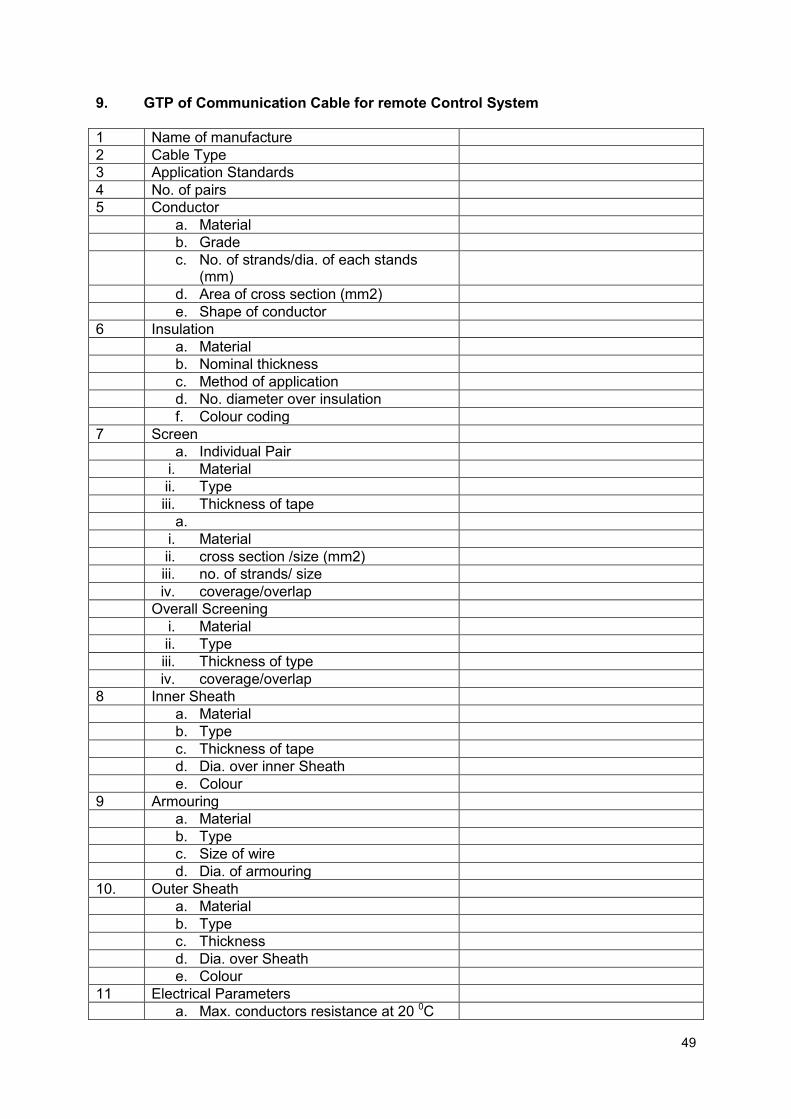
49
9. GTP of Communication Cable for remote Control System
1 Name of manufacture
2 Cable Type
3 Application Standards
4 No. of pairs
5 Conductor
a. Material
b. Grade
c. No. of strands/dia. of each stands (mm)
d. Area of cross section (mm2)
e. Shape of conductor
6 Insulation
a. Material
b. Nominal thickness
c. Method of application
d. No. diameter over insulation
f. Colour coding
7 Screen
a. Individual Pair
i. Material
ii. Type
iii. Thickness of tape
a.
i. Material
ii. cross section /size (mm2)
iii. no. of strands/ size
iv. coverage/overlap
Overall Screening
i. Material
ii. Type
iii. Thickness of type
iv. coverage/overlap
8 Inner Sheath
a. Material
b. Type
c. Thickness of tape
d. Dia. over inner Sheath
e. Colour
9 Armouring
a. Material
b. Type
c. Size of wire
d. Dia. of armouring
10. Outer Sheath
a. Material
b. Type
c. Thickness
d. Dia. over Sheath
e. Colour
11 Electrical Parameters
a. Max. conductors resistance at 20 0C
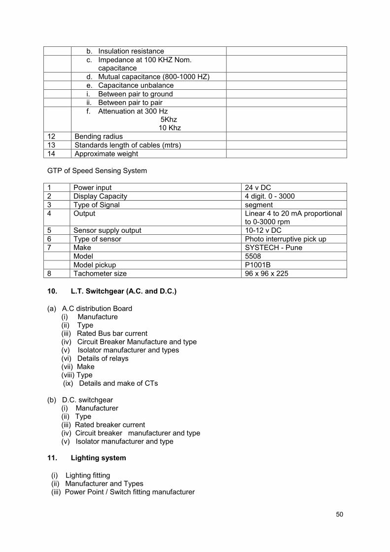
50
b. Insulation resistance
c. Impedance at 100 KHZ Nom. capacitance
d. Mutual capacitance (800-1000 HZ)
e. Capacitance unbalance
i. Between pair to ground
ii. Between pair to pair
f. Attenuation at 300 Hz 5Khz 10 Khz
12 Bending radius
13 Standards length of cables (mtrs)
14 Approximate weight
GTP of Speed Sensing System
1 Power input 24 v DC
2 Display Capacity 4 digit. 0 - 3000
3 Type of Signal segment
4 Output Linear 4 to 20 mA proportional to 0-3000 rpm
5 Sensor supply output 10-12 v DC
6 Type of sensor Photo interruptive pick up
7 Make SYSTECH - Pune
Model 5508
Model pickup P1001B
8 Tachometer size 96 x 96 x 225
10. L.T. Switchgear (A.C. and D.C.)
(a) A.C distribution Board (i) Manufacture (ii) Type (iii) Rated Bus bar current (iv) Circuit Breaker Manufacture and type (v) Isolator manufacturer and types (vi) Details of relays (vii) Make (viii) Type
(ix) Details and make of CTs
(b) D.C. switchgear (i) Manufacturer (ii) Type (iii) Rated breaker current (iv) Circuit breaker manufacturer and type (v) Isolator manufacturer and type 11. Lighting system
(i) Lighting fitting (ii) Manufacturer and Types (iii) Power Point / Switch fitting manufacturer

51
TECHNICAL SCHEDULES
PERFORMANCE GUARANTEES
The Bidder shall get the performance evaluation carried out by an agency approved by Ministry of New and Renewable Energy(MNRE) on each unit of all the four power stations at his own cost and submit the report for release of final payment.
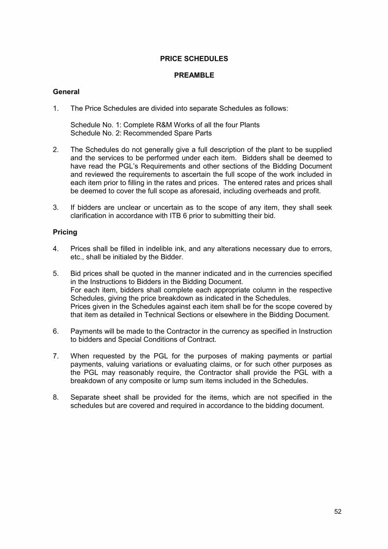
52
PRICE SCHEDULES
PREAMBLE
General 1. The Price Schedules are divided into separate Schedules as follows:
Schedule No. 1: Complete R&M Works of all the four Plants Schedule No. 2: Recommended Spare Parts
2. The Schedules do not generally give a full description of the plant to be supplied and the services to be performed under each item. Bidders shall be deemed to have read the PGL’s Requirements and other sections of the Bidding Document and reviewed the requirements to ascertain the full scope of the work included in each item prior to filling in the rates and prices. The entered rates and prices shall be deemed to cover the full scope as aforesaid, including overheads and profit.
3. If bidders are unclear or uncertain as to the scope of any item, they shall seek
clarification in accordance with ITB 6 prior to submitting their bid. Pricing 4. Prices shall be filled in indelible ink, and any alterations necessary due to errors,
etc., shall be initialed by the Bidder. 5. Bid prices shall be quoted in the manner indicated and in the currencies specified
in the Instructions to Bidders in the Bidding Document. For each item, bidders shall complete each appropriate column in the respective
Schedules, giving the price breakdown as indicated in the Schedules. Prices given in the Schedules against each item shall be for the scope covered by
that item as detailed in Technical Sections or elsewhere in the Bidding Document. 6. Payments will be made to the Contractor in the currency as specified in Instruction
to bidders and Special Conditions of Contract. 7. When requested by the PGL for the purposes of making payments or partial
payments, valuing variations or evaluating claims, or for such other purposes as the PGL may reasonably require, the Contractor shall provide the PGL with a breakdown of any composite or lump sum items included in the Schedules.
8. Separate sheet shall be provided for the items, which are not specified in the
schedules but are covered and required in accordance to the bidding document.

49
SCHEDULES OF RATES AND PRICES
All schedules are to be quoted. Schedule No. 1 – Complete R & M Work of All the Four the Plants. Note: The FOR site price in the bid may be quoted with breakup of price, taxes and duties. The purchaser will provide
requisite “C Forms”. Any variation in the taxes and duties after submission of bid shall be to the account of purchaser (PGL).
1a. Rates are to be quoted for complete refurbishment, repair, replacement and assembly of MHP - Chupki (2 X 750 KW)
S. No.
Description Qty (No)
FOR site Rate/ Unit (Rs)
Amount (Rs)
Taxes and Duties Total FOR site price including
taxes, duties and levies (Rs)
Total Excise/ Custom
duty (Rs)
Total VAT/ CST (Rs)
Service tax @
15% (Rs)
Any other tax/duties/ levies (Rs)
1 2 3 4 5 6 7 8 9 10
COMPLETE REFURBISHMENT, REPAIR AND REPLACEMENT OF BOTH UNITS OF EACH PLANT
1. Turbine and Auxiliaries
1.1 Refurbishment of Servomotors & Hydraulic units
2
1.2 Refurbishment of runner, runner chamber and DT
2
1.3 Refurbishment & Replacement of gear pumps, and other defective and worn out components, sensor, transducer etc
2

50
1.4 Replacement of hydraulic union 2
1.5 Replacement of Blade seals and all fasteners including bronze bushes
2
1.6 Refurbishment of existing Turbine Guide Bearings including replacement of thordon lining
2
1.7 Refurbishment of Vacuum pumps 2
1.8 Replacement of turbine top cover drainage system including pump motor set etc.
2
1.9 Any other work necessary for completion of job
2
2.
Gear Box
Replacement of both Gear boxes (speed increaser) complete including instruments and devices
Replacement of Heat exchanger(Air cooled) of gear box including instruments, sensors etc
Any other work necessary for completion of job
2

51
3.
Generator and auxiliaries
General overhauling of generators including replacement of all speed and temperature sensing devices, power cable terminal box and control cable junction boxes.
Replacement of DE and NDE side bearings.
Any other work necessary for completion of job excluding Generator Winding
2
4 Mechanical auxiliaries
4.1
Crane: Modification of crane for electrical operation through pendant switch or hand held remote switch Providing new 3 T auxiliary hook General overhauling of crane , its gear box and flexible rope
1
4.2
Ventilation and Air Conditioning
Providing exhaust fans with wire mesh on all ventilators of machine hall
Providing five star rated window air conditioners in the control room of 1.5 ton each.
6 2
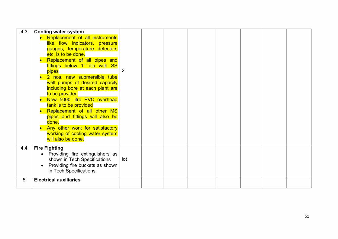
52
4.3 Cooling water system
Replacement of all instruments like flow indicators, pressure gauges, temperature detectors etc. is to be done.
Replacement of all pipes and fittings below 1” dia with SS pipes
2 nos. new submersible tube well pumps of desired capacity including bore at each plant are to be provided
New 5000 litre PVC overhead tank is to be provided
Replacement of all other MS pipes and fittings will also be done.
Any other work for satisfactory working of cooling water system will also be done.
2
4.4 Fire Fighting
Providing fire extinguishers as shown in Tech Specifications
Providing fire buckets as shown in Tech Specifications
lot
5 Electrical auxiliaries

53
5.1 DC System
Replacement of existing battery bank with new 24 V 200 AH, T-Gel type battery bank with mounting stand and provision of emergency lighting system.
Providing new UPS with suitable battery set including replacement of mounting stand as per scope of work
Replacement of battery chargers for above batteries including distribution boards as detailed in Tech Specs
1 1 1
5.2 Control, protection and metering system-SCADA Replacement of entire control system based on PLC- SCADA, protection and metering systems as detailed in Tech. Specs. The existing canal water level monitoring system installed at power house is also to be linked with the new SCADA system along with power control center panels as per scope of work.
1
5.3 Lighting System Replacement of entire lighting system as per details given in Tech Specs
1 Lot

54
5.4 Capacitor Banks Replacement of entire capacitor banks of both units along with panels as per details given in Tech Specs
1 Lot
5.5 Power and control cables Replacement of all power and control cables as per details given in Tech Specs
1 Lot
5.6 DG Set Overhauling of DG Set including replacement of defective switches, push buttons, measuring instrument indicating lamps etc.
1
5.7 Station Service Board Replacement of entire service board including MCCBs, MCBs, digital/analogue meters, indicating lamps along with panels as per details given in Tech Specs
1
5.8 Generator Transformers
General overhauling of transformer
Providing 4 nos. 450mm exhaust fans with mounting arrangement for cooling
Complete transformer oil of suitable grade will be replaced and dehydration of the same will also be done.
1

55
6 Switchyard equipment
6.1 Vacuum Circuit Breakers Supply and replacement of outdoor type 11 KV VCB along with line control panel as per details given in Tech Specs/ scope of work.
1
6.2 Instrument Transformers Supply and Replacement of Outdoor instrument transformers as per details given in Tech Specs including changing of oil, insulators, seals etc. of auxiliary Transformer.
1 lot
6.3 Lightening Arrestors
Supply and replacement of lightening arrestors for protection of Gen. Transformer as per details given in Tech Specs.
Supply and replacement of feeder side Lightening arrestors as per details given in Tech Specs.
3
3
6.5 Isolators General overhauling of isolators including replacement of defective/ worn out component
2
6.6 Metering Replacement of existing 11 KV CT/PT Unit along with main energy meter along with 11 KV cable. Make and
1 lot
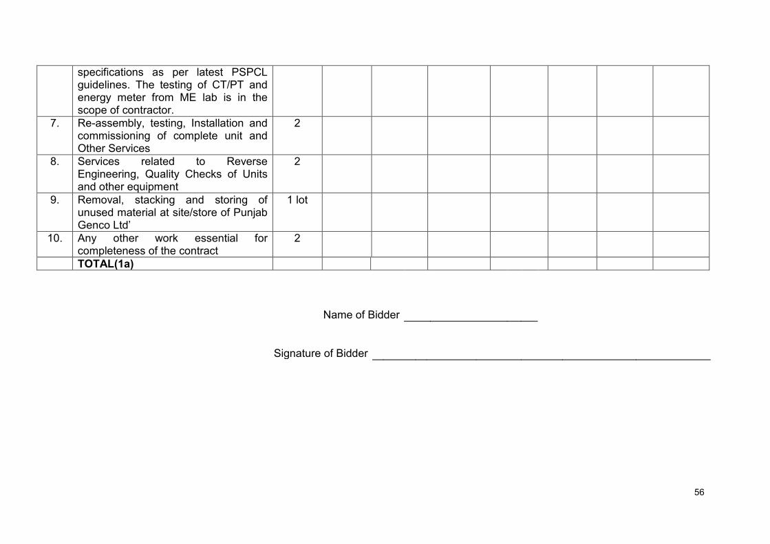
56
specifications as per latest PSPCL guidelines. The testing of CT/PT and energy meter from ME lab is in the scope of contractor.
7. Re-assembly, testing, Installation and commissioning of complete unit and Other Services
2
8. Services related to Reverse Engineering, Quality Checks of Units and other equipment
2
9. Removal, stacking and storing of unused material at site/store of Punjab Genco Ltd’
1 lot
10. Any other work essential for completeness of the contract
2
TOTAL(1a)
Name of Bidder
Signature of Bidder
57
Schedule No. 2a - Recommended Spare Parts and T&P The rates for the recommended spares may be quoted and shall not be considered for bid evaluation. For the purpose of placement of order for recommended spares, if required, average rates of all bidders or the rate quoted by selected bidder, whichever is lower shall be applicable.
Item
Description
Qty (No)
FOR Rate/ Unit (Rs)
Amount (Rs)
Taxes and Duties Total FOR price
including taxes,
duties and levies (Rs)
Total Excise/ Custom
duty (Rs)
Total VAT/ CST (Rs)
Service tax @ 15% (Rs)
Any other tax/duties/ levies (Rs)
1 2 3 4
5
6 7 8 9 10
TOTAL
Name of Bidder
Signature of Bidder
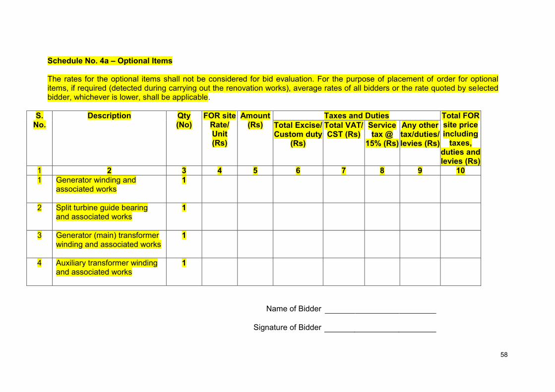
58
Schedule No. 4a – Optional Items The rates for the optional items shall not be considered for bid evaluation. For the purpose of placement of order for optional items, if required (detected during carrying out the renovation works), average rates of all bidders or the rate quoted by selected bidder, whichever is lower, shall be applicable.
S. No.
Description Qty (No)
FOR site Rate/ Unit (Rs)
Amount (Rs)
Taxes and Duties Total FOR site price including
taxes, duties and levies (Rs)
Total Excise/ Custom duty
(Rs)
Total VAT/ CST (Rs)
Service tax @
15% (Rs)
Any other tax/duties/ levies (Rs)
1 2 3 4 5 6 7 8 9 10
1 Generator winding and associated works
1
2 Split turbine guide bearing and associated works
1
3 Generator (main) transformer winding and associated works
1
4 Auxiliary transformer winding and associated works
1
Name of Bidder
Signature of Bidder
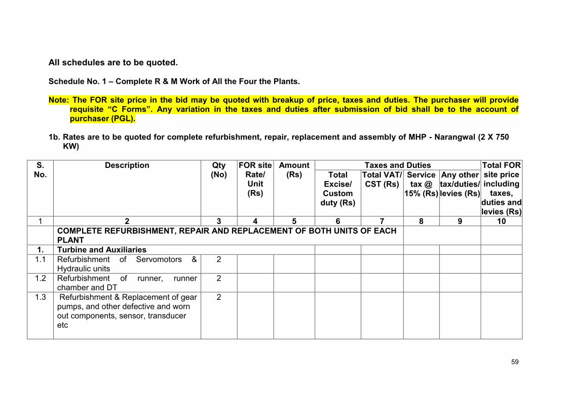
59
All schedules are to be quoted. Schedule No. 1 – Complete R & M Work of All the Four the Plants. Note: The FOR site price in the bid may be quoted with breakup of price, taxes and duties. The purchaser will provide
requisite “C Forms”. Any variation in the taxes and duties after submission of bid shall be to the account of purchaser (PGL).
1b. Rates are to be quoted for complete refurbishment, repair, replacement and assembly of MHP - Narangwal (2 X 750
KW)
S. No.
Description Qty (No)
FOR site Rate/ Unit (Rs)
Amount (Rs)
Taxes and Duties Total FOR site price including
taxes, duties and levies (Rs)
Total Excise/ Custom
duty (Rs)
Total VAT/ CST (Rs)
Service tax @
15% (Rs)
Any other tax/duties/ levies (Rs)
1 2 3 4 5 6 7 8 9 10
COMPLETE REFURBISHMENT, REPAIR AND REPLACEMENT OF BOTH UNITS OF EACH PLANT
1. Turbine and Auxiliaries
1.1 Refurbishment of Servomotors & Hydraulic units
2
1.2 Refurbishment of runner, runner chamber and DT
2
1.3 Refurbishment & Replacement of gear pumps, and other defective and worn out components, sensor, transducer etc
2
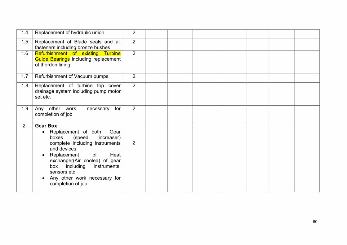
60
1.4 Replacement of hydraulic union 2
1.5 Replacement of Blade seals and all fasteners including bronze bushes
2
1.6 Refurbishment of existing Turbine Guide Bearings including replacement of thordon lining
2
1.7 Refurbishment of Vacuum pumps 2
1.8 Replacement of turbine top cover drainage system including pump motor set etc.
2
1.9 Any other work necessary for completion of job
2
2.
Gear Box
Replacement of both Gear boxes (speed increaser) complete including instruments and devices
Replacement of Heat exchanger(Air cooled) of gear box including instruments, sensors etc
Any other work necessary for completion of job
2

61
3.
Generator and auxiliaries
General overhauling of generators including replacement of all speed and temperature sensing devices, power cable terminal box and control cable junction boxes.
Replacement of DE and NDE side bearings.
Any other work necessary for completion of job excluding Generator Winding
2
4 Mechanical auxiliaries
4.1
Crane: Modification of crane for electrical operation through pendant switch or hand held remote switch Providing new 3 T auxiliary hook General overhauling of crane , its gear box and flexible rope
1
4.2
Ventilation and Air Conditioning
Providing exhaust fans with wire mesh on all ventilators of machine hall
Providing five star rated window air conditioners in the control room of 1.5 ton each.
6 2

62
4.3 Cooling water system
Replacement of all instruments like flow indicators, pressure gauges, temperature detectors etc. is to be done.
Replacement of all pipes and fittings below 1” dia with SS pipes
2 nos. new submersible tube well pumps of desired capacity including bore at each plant are to be provided
New 5000 litre PVC overhead tank is to be provided
Replacement of all other MS pipes and fittings will also be done.
Any other work for satisfactory working of cooling water system will also be done.
2
4.4 Fire Fighting
Providing fire extinguishers as shown in Tech Specifications
Providing fire buckets as shown in Tech Specifications
lot
5 Electrical auxiliaries
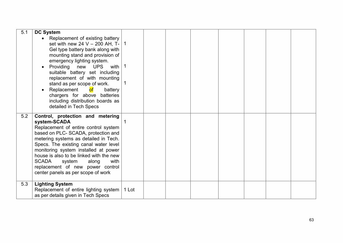
63
5.1 DC System
Replacement of existing battery set with new 24 V – 200 AH, T-Gel type battery bank along with mounting stand and provision of emergency lighting system.
Providing new UPS with suitable battery set including replacement of with mounting stand as per scope of work.
Replacement of battery chargers for above batteries including distribution boards as detailed in Tech Specs
1 1 1
5.2 Control, protection and metering system-SCADA Replacement of entire control system based on PLC- SCADA, protection and metering systems as detailed in Tech. Specs. The existing canal water level monitoring system installed at power house is also to be linked with the new SCADA system along with replacement of new power control center panels as per scope of work
1
5.3 Lighting System Replacement of entire lighting system as per details given in Tech Specs
1 Lot

64
5.4 Capacitor Banks Replacement of entire capacitor banks of both units along with panels as per details given in Tech Specs
1 Lot
5.5 Power and control cables Replacement of all power and control cables as per details given in Tech Specs
1 Lot
5.6 DG Set Overhauling of DG Set including replacement of defective switches, push buttons, measuring instrument indicating lamps etc.
1
5.7 Station Service Board Replacement of entire service board including MCCBs, MCBs, digital/analogue meters, indicating lamps along with panels as per details given in Tech Specs
1
5.8 Generator Transformers
General overhauling of transformer
Providing 4 nos. 450mm exhaust fans with mounting arrangement for cooling
Complete transformer oil of suitable grade will be replaced and dehydration of the same will also be done.
1
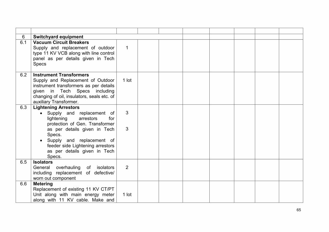
65
6 Switchyard equipment
6.1 Vacuum Circuit Breakers Supply and replacement of outdoor type 11 KV VCB along with line control panel as per details given in Tech Specs
1
6.2 Instrument Transformers Supply and Replacement of Outdoor instrument transformers as per details given in Tech Specs including changing of oil, insulators, seals etc. of auxiliary Transformer.
1 lot
6.3 Lightening Arrestors
Supply and replacement of lightening arrestors for protection of Gen. Transformer as per details given in Tech Specs.
Supply and replacement of feeder side Lightening arrestors as per details given in Tech Specs.
3
3
6.5 Isolators General overhauling of isolators including replacement of defective/ worn out component
2
6.6 Metering Replacement of existing 11 KV CT/PT Unit along with main energy meter along with 11 KV cable. Make and
1 lot

66
specifications as per latest PSPCL guidelines. The testing of CT/PT and energy meter from ME lab is in the scope of contractor.
7. Re-assembly, testing, Installation and commissioning of complete unit and Other Services
2
8. Services related to Reverse Engineering, Quality Checks of Units and other equipment
2
9. Removal, stacking and storing of unused material at site/store of Punjab Genco Ltd’
1 lot
10. Any other work essential for completeness of the contract
2
TOTAL(1b)
Name of Bidder
Signature of Bidder

67
Schedule No. 2b - Recommended Spare Parts and T&P The rates for the recommended spares may be quoted and shall not be considered for bid evaluation. For the purpose of placement of order for recommended spares, if required, average rates of all bidders or the rate quoted by selected bidder, whichever is lower shall be applicable.
Item
Description
Qty (No)
FOR Rate/ Unit (Rs)
Amount (Rs)
Taxes and Duties Total FOR price
including taxes,
duties and levies (Rs)
Total Excise/ Custom
duty (Rs)
Total VAT/ CST (Rs)
Service tax @ 15% (Rs)
Any other tax/duties/ levies (Rs)
1 2 3 4
5
6 7 8 9 10
TOTAL
Name of Bidder
Signature of Bidder

68
Schedule No. 4b – Optional Items The rates for the optional items shall not be considered for bid evaluation. For the purpose of placement of order for optional items, if required (detected during carrying out the renovation works), average rates of all bidders or the rate quoted by selected bidder, whichever is lower, shall be applicable.
S. No.
Description Qty (No)
FOR site Rate/ Unit (Rs)
Amount (Rs)
Taxes and Duties Total FOR site price including
taxes, duties and levies (Rs)
Total Excise/ Custom duty
(Rs)
Total VAT/ CST (Rs)
Service tax @
15% (Rs)
Any other tax/duties/ levies (Rs)
1 2 3 4 5 6 7 8 9 10
1 Generator winding and associated works
1
2 Split turbine guide bearing and associated works
1
3 Generator (main) transformer winding and associated works
1
4 Auxiliary transformer winding and associated works
1
Name of Bidder
Signature of Bidder

69
All schedules are to be quoted. Schedule No. 1 – Complete R & M Work of All the Four the Plants. Note: The FOR site price in the bid may be quoted with breakup of price, taxes and duties. The purchaser will provide
requisite “C Forms”. Any variation in the taxes and duties after submission of bid shall be to the account of purchaser (PGL).
1c. Rates are to be quoted for complete refurbishment, repair, replacement and assembly of MHP - Tugal (2 X 750 KW)
S. No.
Description Qty (No)
FOR site Rate/ Unit (Rs)
Amount (Rs)
Taxes and Duties Total FOR site price including
taxes, duties and levies (Rs)
Total Excise/ Custom
duty (Rs)
Total VAT/ CST (Rs)
Service tax @
15% (Rs)
Any other tax/duties/ levies (Rs)
1 2 3 4 5 6 7 8 9 10
COMPLETE REFURBISHMENT, REPAIR AND REPLACEMENT OF BOTH UNITS OF EACH PLANT
1. Turbine and Auxiliaries
1.1 Refurbishment of Servomotors & Hydraulic units
2
1.2 Refurbishment of runner, runner chamber and DT
2
1.3 Refurbishment & Replacement of gear pumps, and other defective and worn out components, sensor, transducer etc.
2

70
1.4 Replacement of hydraulic union 2
1.5 Replacement of Blade seals and all fasteners including bronze bushes
2
1.6 Refurbishment of existing Turbine Guide Bearings including replacement of thordon lining
2
1.7 Refurbishment of Vacuum pumps 2
1.8 Replacement of turbine top cover drainage system including pump motor set etc.
2
1.9 Any other work necessary for completion of job
2
2.
Gear Box
Replacement of both Gear boxes (speed increaser) complete including instruments and devices
Replacement of Heat exchanger(Air cooled) of gear box including instruments, sensors etc
Any other work necessary for completion of job
2
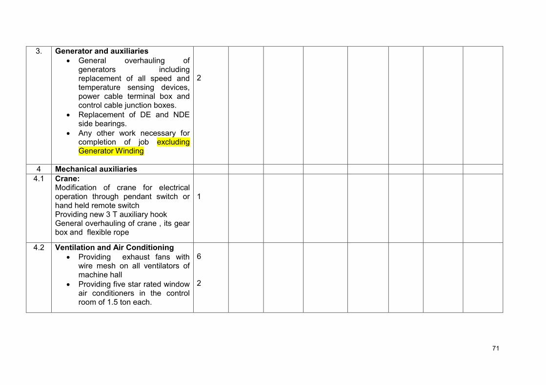
71
3.
Generator and auxiliaries
General overhauling of generators including replacement of all speed and temperature sensing devices, power cable terminal box and control cable junction boxes.
Replacement of DE and NDE side bearings.
Any other work necessary for completion of job excluding Generator Winding
2
4 Mechanical auxiliaries
4.1
Crane: Modification of crane for electrical operation through pendant switch or hand held remote switch Providing new 3 T auxiliary hook General overhauling of crane , its gear box and flexible rope
1
4.2
Ventilation and Air Conditioning
Providing exhaust fans with wire mesh on all ventilators of machine hall
Providing five star rated window air conditioners in the control room of 1.5 ton each.
6 2

72
4.3 Cooling water system
Replacement of all instruments like flow indicators, pressure gauges, temperature detectors etc. is to be done.
Replacement of all pipes and fittings below 1” dia with SS pipes
2 nos. new submersible tube well pumps of desired capacity including bore at each plant are to be provided
New 5000 litre PVC overhead tank is to be provided
Replacement of all other MS pipes and fittings will also be done.
Any other work for satisfactory working of cooling water system will also be done.
2
4.4 Fire Fighting
Providing fire extinguishers as shown in Tech Specifications
Providing fire buckets as shown in Tech Specifications
lot
5 Electrical auxiliaries
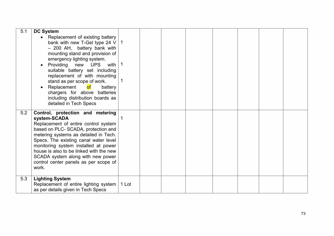
73
5.1 DC System
Replacement of existing battery bank with new T-Gel type 24 V – 200 AH, battery bank with mounting stand and provision of emergency lighting system.
Providing new UPS with suitable battery set including replacement of with mounting stand as per scope of work.
Replacement of battery chargers for above batteries including distribution boards as detailed in Tech Specs
1 1 1
5.2 Control, protection and metering system-SCADA Replacement of entire control system based on PLC- SCADA, protection and metering systems as detailed in Tech. Specs. The existing canal water level monitoring system installed at power house is also to be linked with the new SCADA system along with new power control center panels as per scope of work.
1
5.3 Lighting System Replacement of entire lighting system as per details given in Tech Specs
1 Lot
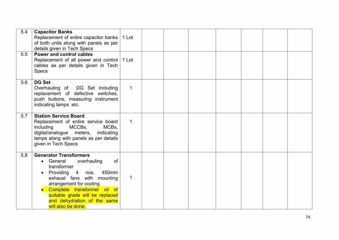
74
5.4 Capacitor Banks Replacement of entire capacitor banks of both units along with panels as per details given in Tech Specs
1 Lot
5.5 Power and control cables Replacement of all power and control cables as per details given in Tech Specs
1 Lot
5.6 DG Set Overhauling of DG Set including replacement of defective switches, push buttons, measuring instrument indicating lamps etc.
1
5.7 Station Service Board Replacement of entire service board including MCCBs, MCBs, digital/analogue meters, indicating lamps along with panels as per details given in Tech Specs
1
5.8 Generator Transformers
General overhauling of transformer
Providing 4 nos. 450mm exhaust fans with mounting arrangement for cooling
Complete transformer oil of suitable grade will be replaced and dehydration of the same will also be done.
1

75
6 Switchyard equipment
6.1 Vacuum Circuit Breakers Supply and replacement of outdoor type 11 KV VCB along with line control panel as per details given in Tech Specs /scope of work.
1
6.2 Instrument Transformers Supply and Replacement of Outdoor instrument transformers as per details given in Tech Specs including changing of oil, insulators, seals etc. of auxiliary Transformer.
1 lot
6.3 Lightening Arrestors
Supply and replacement of lightening arrestors for protection of Gen. Transformer as per details given in Tech Specs.
Supply and replacement of feeder side Lightening arrestors as per details given in Tech Specs.
3
3
6.5 Isolators General overhauling of isolators including replacement of defective/ worn out component
2
6.6 Metering Replacement of existing 11 KV CT/PT Unit along with main energy meter along with 11 KV cable. Make and
1 lot

76
specifications as per latest PSPCL guidelines. The testing of CT/PT and energy meter from ME lab is in the scope of contractor.
7. Re-assembly, testing, Installation and commissioning of complete unit and Other Services
2
8. Services related to Reverse Engineering, Quality Checks of Units and other equipment
2
9. Removal, stacking and storing of unused material at site/store of Punjab Genco Ltd’
1 lot
10. Any other work essential for completeness of the contract
2
TOTAL(1c)
Name of Bidder
Signature of Bidder

77
Schedule No. 2c - Recommended Spare Parts and T&P The rates for the recommended spares may be quoted and shall not be considered for bid evaluation. For the purpose of placement of order for recommended spares, if required, average rates of all bidders or the rate quoted by selected bidder, whichever is lower shall be applicable.
Item
Description
Qty (No)
FOR Rate/ Unit (Rs)
Amount (Rs)
Taxes and Duties Total FOR price
including taxes,
duties and levies (Rs)
Total Excise/ Custom
duty (Rs)
Total VAT/ CST (Rs)
Service tax @ 15% (Rs)
Any other tax/duties/ levies (Rs)
1 2 3 4
5
6 7 8 9 10
TOTAL
Name of Bidder
Signature of Bidder

78
Schedule No. 4c – Optional Items The rates for the optional items shall not be considered for bid evaluation. For the purpose of placement of order for optional items, if required (detected during carrying out the renovation works), average rates of all bidders or the rate quoted by selected bidder, whichever is lower, shall be applicable.
S. No.
Description Qty (No)
FOR site Rate/ Unit (Rs)
Amount (Rs)
Taxes and Duties Total FOR site price including
taxes, duties and levies (Rs)
Total Excise/ Custom duty
(Rs)
Total VAT/ CST (Rs)
Service tax @
15% (Rs)
Any other tax/duties/ levies (Rs)
1 2 3 4 5 6 7 8 9 10
1 Generator winding and associated works
1
2 Split turbine guide bearing and associated works
1
3 Generator (main) transformer winding and associated works
1
4 Auxiliary transformer winding and associated works
1
Name of Bidder
Signature of Bidder

79
SCHEDULES OF RATES AND PRICES
All schedules are to be quoted. Schedule No. 1 – Complete R & M Work of All the Four the Plants. Note: The FOR site price in the bid may be quoted with breakup of price, taxes and duties. The purchaser will provide
requisite “C Forms”. Any variation in the taxes and duties after submission of bid shall be to the account of purchaser (PGL).
1d. Rates are to be quoted for complete refurbishment, repair, replacement and assembly of MHP - Dalla (2 X 500 KW)
S. No.
Description Qty (No)
FOR site Rate/ Unit (Rs)
Amount (Rs)
Taxes and Duties Total FOR site price including
taxes, duties and levies (Rs)
Total Excise/ Custom
duty (Rs)
Total VAT/ CST (Rs)
Service tax @
15% (Rs)
Any other tax/duties/ levies (Rs)
1 2 3 4 5 6 7 8 9 10
COMPLETE REFURBISHMENT, REPAIR AND REPLACEMENT OF BOTH UNITS OF EACH PLANT
1. Turbine and Auxiliaries
1.1 Refurbishment of Servomotors & Hydraulic units
2
1.2 Refurbishment of runner, runner chamber and DT
2
1.3 Refurbishment & Replacement of gear pumps, and other defective and worn out components, sensor, transducer etc.
2

80
1.4 Replacement of hydraulic union 2
1.5 Replacement of Blade seals and all fasteners including bronze bushes
2
1.6 Refurbishment of existing Turbine Guide Bearings including replacement of thordon lining
2
1.7 Refurbishment of Vacuum pumps 2
1.8 Replacement of turbine top cover drainage system including pump motor set etc.
2
1.9 Any other work necessary for completion of job
2
2.
Gear Box
Replacement of both Gear boxes (speed increaser) complete including instruments and devices
Replacement of Heat exchanger(Air cooled) of gear box including instruments, sensors etc
Any other work necessary for completion of job
2

81
3.
Generator and auxiliaries
General overhauling of generators including replacement of all speed and temperature sensing devices, power cable terminal box and control cable junction boxes.
Replacement of DE and NDE side bearings.
Any other work necessary for completion of job excluding Generator Winding
2
4 Mechanical auxiliaries
4.1
Crane: Modification of crane for electrical operation through pendant switch or hand held remote switch Providing new 3 T auxiliary hook General overhauling of crane , its gear box and flexible rope
1
4.2
Ventilation and Air Conditioning
Providing exhaust fans with wire mesh on all ventilators of machine hall
Providing five star rated window air conditioners in the control room of 1.5 ton each.
6 2

82
4.3 Cooling water system
Replacement of all instruments like flow indicators, pressure gauges, temperature detectors etc. is to be done.
Replacement of all pipes and fittings below 1” dia with SS pipes
2 nos. new submersible tube well pumps of desired capacity including bore at each plant are to be provided
New 5000 litre PVC overhead tank is to be provided
Replacement of all other MS pipes and fittings will also be done.
Any other work for satisfactory working of cooling water system will also be done.
2
4.4 Fire Fighting
Providing fire extinguishers as shown in Tech Specifications
Providing fire buckets as shown in Tech Specifications
lot
5 Electrical auxiliaries

83
5.1 DC System
Replacement of existing battery bank with new T-Gel type 24 V 200 AH, battery bank with mounting stand and provision of emergency lighting system.
Providing new UPS with suitable battery set including replacement of with mounting stand as per scope of work.
Replacement of battery chargers for above batteries including distribution boards as detailed in Tech Specs
1 1 1
5.2 Control, protection and metering system-SCADA Replacement of entire control system based on PLC- SCADA, protection and metering systems as detailed in Tech. Specs. The existing canal water level monitoring system installed at power house is also to be linked with the new SCADA system along with new power control center panels as per scope of work.
1
5.3 Lighting System Replacement of entire lighting system as per details given in Tech Specs
1 Lot

84
5.4 Capacitor Banks Replacement of entire capacitor banks of both units along with panels as per details given in Tech Specs
1 Lot
5.5 Power and control cables Replacement of all power and control cables as per details given in Tech Specs
1 Lot
5.6 DG Set Overhauling of 100 KVA DG Set including replacement of defective switches, push buttons, measuring instrument indicating lamps in AMF etc.
1
5.7 Station Service Board Replacement of entire service board including MCCBs, MCBs, digital/analogue meters, indicating lamps along with panels as per details given in Tech Specs
1
5.8 Generator Transformers
General overhauling of transformer
Providing 4 nos. 450mm exhaust fans with mounting arrangement for cooling
Complete transformer oil of suitable grade will be replaced and dehydration of the same
1

85
will also be done.
6 Switchyard equipment
6.1 Vacuum Circuit Breakers Supply and replacement of outdoor type 11 KV VCB along with line control panel as per details given in Tech Specs
1
6.2 Instrument Transformers Supply and Replacement of Outdoor instrument transformers as per details given in Tech Specs including changing of oil, insulators, seals etc. of auxiliary Transformer.
1 lot
6.3 Lightening Arrestors
Supply and replacement of lightening arrestors for protection of Gen. Transformer as per details given in Tech Specs.
Supply and replacement of feeder side Lightening arrestors as per details given in Tech Specs.
3
3
6.5 Isolators General overhauling of isolators including replacement of defective/ worn out component
2
6.6 Metering Replacement of existing 11 KV CT/PT Unit along with main energy meter
1 lot
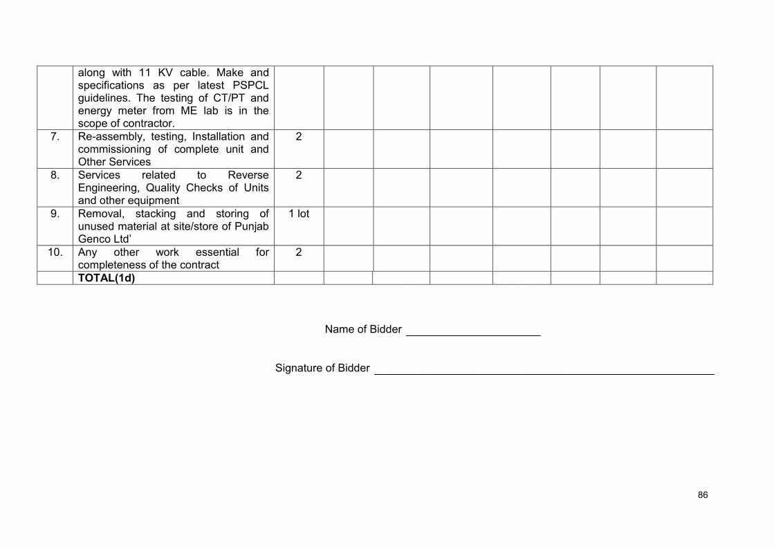
86
along with 11 KV cable. Make and specifications as per latest PSPCL guidelines. The testing of CT/PT and energy meter from ME lab is in the scope of contractor.
7. Re-assembly, testing, Installation and commissioning of complete unit and Other Services
2
8. Services related to Reverse Engineering, Quality Checks of Units and other equipment
2
9. Removal, stacking and storing of unused material at site/store of Punjab Genco Ltd’
1 lot
10. Any other work essential for completeness of the contract
2
TOTAL(1d)
Name of Bidder
Signature of Bidder

87
Schedule No. 2d - Recommended Spare Parts and T&P The rates for the recommended spares may be quoted and shall not be considered for bid evaluation. For the purpose of placement of order for recommended spares, if required, average rates of all bidders or the rate quoted by selected bidder, whichever is lower shall be applicable.
Item
Description
Qty (No)
FOR Rate/ Unit (Rs)
Amount (Rs)
Taxes and Duties Total FOR price
including taxes,
duties and levies (Rs)
Total Excise/ Custom
duty (Rs)
Total VAT/ CST (Rs)
Service tax @ 15% (Rs)
Any other tax/duties/ levies (Rs)
1 2 3 4
5
6 7 8 9 10
TOTAL
Name of Bidder
Signature of Bidder

88
Schedule No. 4d – Optional Items The rates for the optional items shall not be considered for bid evaluation. For the purpose of placement of order for optional items, if required (detected during carrying out the renovation works), average rates of all bidders or the rate quoted by selected bidder, whichever is lower, shall be applicable.
S. No.
Description Qty (No)
FOR site Rate/ Unit (Rs)
Amount (Rs)
Taxes and Duties Total FOR site price including
taxes, duties and levies (Rs)
Total Excise/ Custom duty
(Rs)
Total VAT/ CST (Rs)
Service tax @
15% (Rs)
Any other tax/duties/ levies (Rs)
1 2 3 4 5 6 7 8 9 10
1 Generator winding and associated works
1
2 Split turbine guide bearing and associated works
1
3 Generator (main) transformer winding and associated works
1
4 Auxiliary transformer winding and associated works
1
Name of Bidder
Signature of Bidder

R&M of 4 nos. Abohar Canal Mini Hydro Power Projects
Schedule 3 - Consolidated Cost for all the four MHPs
S. No. Name of MHP Plants Amount
Schedule 1 Schedule 2 Total
1. Chupki
2. Narangwal
3. Tugal
4. Dalla
Grand Total
(Rs…………………..in words)
Name of Bidder
Signature of Bidder
R&M of 4 nos. Abohar Canal Mini Hydro Power Projects
SECTION 4 – GENERAL CONDITIONS OF CONTRACT (Form-A)
A. General 1. Definition of
Terms
In construing these General Conditions and annexed Specification, the following words shall have the meaning herein assigned to them unless there is anything in the subject or context inconsistent with such construction. The “Purchaser” or “PGL” shall mean the PGL and shall include his successors and assigns. The “Contractor” shall mean the tenderer whose tender shall be accepted by the Purchaser and shall include such Tenderer’s heirs, legal representatives, successors and assigns. The “Sub-Contractor” shall mean the person named in the contract for any part of the work for any person to whom any part of the Contract has been sublet with the consent in writing of the Engineer and the heirs, legal representatives, successors and assigns of such person. The “Engineer” shall mean the officer placing the order for the work with the Contractor and such other officer as may be duly authorised and appointed in writing by the Purchaser to act as Engineer for the purposes of the contract and in case where no such officer has been so appointed, the Purchaser or his duly authorised representative. “Plant”, “Equipment”, “Material”, “Work”, or “Works” shall mean respectively the plant and materials to be provided and work or works to be done by the Contractor under the contract. The “Contract” shall mean and include the General Conditions, Specifications, Schedules, Drawings, Form of Tender, Covering letter, Schedule of Prices or the final General Conditions, Specification and Drawings and the Agreement to be entered into under clause 3 of these General Conditions. The “Specification” shall mean the Specification annexed to these General Conditions and the Schedules thereto (if any). The “Site” shall mean the site of the proposed work as detailed in the Specification or any other place where work is to be executed under the Contract. “Tests on Completion” shall mean such tests as are prescribed by the specification to be made by the Contractor before the plant is taken over by the purchaser. “Commercial Use “shall mean that use of the work which the contract contemplates or of which it is commercially capable. “Month” shall mean calendar month.

R&M of 4 nos. Abohar Canal Mini Hydro Power Projects
“Writing” shall include any manuscript, typewritten or printed statement, under or over signature or seal, as the case may be. Words importing persons shall include Firms, Companies, Corporations, and other bodies whether incorporated or not. Words importing the singular only shall also include the plural and vice versa where the context requires
2. Contractor to
inform himself fully
The Contractor shall be deemed to have carefully examined the General Conditions, specifications, Schedules and Drawings. If he shall have any doubt as to the meaning of any portion of these General Conditions, or of the Specification he shall, before signing the Contract, set forth the particulars thereof and submit them to the Engineer in writing, in order that such doubt may be removed.
3. Contract
A formal agreement shall, if required by the Purchaser, be entered into between the Purchaser and the Contractor for the proper fulfillment of the Contract. Further, if required by the Purchaser, the Contractor shall deposit with the purchaser as security for the due and faithful performance of the Contract such sum not being less than one per cent of the total value of the Contract as may be fixed by the Purchaser either in cash or any other form approved by the Purchaser.
The charges in respect of vetting and execution of the contract document shall be borne by the contractor. The contractor shall be furnished with an executed stamped counterpart of the agreement. The import license fee will, in each case, have to be paid by the contractor. Import license may have to be taken in the purchaser’s name.
After the tender has been accepted by the Purchaser all order or instructions to the contractor shall, except as herein otherwise provided, be given by the Engineer on behalf of Purchaser.
4. Contract Drawing
The contractor shall submit in duplicate, to the Engineer for his approval, drawings of the General Arrangement of the works to be carried out and of such detailed drawings, other than shop drawings, as may be reasonably necessary.
Within fourteen days of the receipt of such drawings the Engineer shall signify his approval or otherwise of the same, and in the event of disapproving the drawings, the Contractor shall submit further drawings for approval.
Within a reasonable period of the notification by the Engineer to the Contractor of his approval of such drawings, three sets, in ink or tracing cloth or ferrogallic prints mounted on cloth, of the drawings as approved shall be supplied to him by the Contractor and be signed by him and the Contractor respectively and be thereafter deemed to be the “Contract drawings”.
These drawings when so signed shall become the property of the Purchaser and be deposited with the Engineer, and shall not be departed
R&M of 4 nos. Abohar Canal Mini Hydro Power Projects
from in any way whatsoever except by the written permission of the Engineer, as hereinafter provided. During the execution of the works, one of the sets of drawings shall be available for reference on the site.
In the event of the Contractor desiring to possess a signed set of drawings, he shall supply four sets instead of three sets and in this case the Engineer shall sign the fourth set and return the same to the Contractor.
The contractor, if required by the Engineer, shall supply in addition copies of any drawing other than shop drawings which may reasonably be required for the purpose of the Contract and may make a reasonable charge for such copies. The Engineer or his duly authorized representatives, whose name shall have previously been communicated in writing to the Contractor, shall have the right at all reasonable times to inspect, at the factory of the Contractor, drawings of any portion of the work.
5. Mistakes in Drawings
The contractor shall be responsible for and shall pay for any alterations of the work due to any discrepancies, errors or omissions in the drawings and other particulars supplied by him, whether such drawings or particulars have been approved by the Engineer or not, provided that if such discrepancies, errors or omissions are due to inaccurate information or particulars furnished to the Contractor by the Engineer any alterations in the work necessitated by reasons of such inaccurate information of particulars shall be paid for by the Purchaser. If any dimensions figured upon a drawing or a plan differ from those obtained by scaling the drawing or plan the dimensions as figured upon the drawing or plan shall be taken as correct.
6. Subletting of Contract
The Contractor shall not, without consent in writing of the Engineer or Purchaser, which shall not be unreasonably withheld, assign or sublet his Contract, or any substantial part thereof other than for raw materials, for minor details, or for any part of the work of which the makers are named in the Contract provided that any such consent shall not relieve the Contractor from any obligation, duty or responsibility under the Contract.
7. Patent Rights
In the event of any claim or demand being made or action being brought against the Purchaser for infringement or alleged infringement of Letters patent, in respect of any machine, plant, work or thing used or supplied by the contractor under this Contract or in respect of any method of using or working by the Purchaser of such machine, plant, work or thing, the Contractor will indemnify the Purchaser against such claim or demand and all costs and expenses arising from or incurred by reasons of such claim of demand PROVIDED THAT the purchaser shall notify the Contractor immediately any claim is made and that the Contractor shall be at liberty, if he so desires, with the assistance of the Purchaser, if required but at the Contractor’s own expense, to conduct all negotiations for the settlement of the same or any litigation that may arise there from and PROVIDED THAT no such machine, plant ,work or thing shall be used by the Purchaser for any purpose or in any manner other than that for which they have been supplied by the Contractor and specified under this Contract.
R&M of 4 nos. Abohar Canal Mini Hydro Power Projects
8. Quality of materials
The plant shall be manufactured and constructed in the best and most substantial and most workmanlike manner and with materials of the best or of approved qualities for their respective uses.
9. Packing The contractor shall be responsible for securely, protecting and packing the plant so as to avoid damage under normal Conditions of transport.
10. Delivery The cost of delivering the whole of the material F.O.R at the railway stations specified or on the site as the specification may define and the cost of packing and, unless otherwise agreed, import duties and customs shall be borne by the Contractor. Any variation in the taxes and duties at the time of delivery shall be to the account of Purchaser (PGL).
11. Fencing and lighting for works other than transmission lines
Except as hereinafter provided the purchaser shall ,unless otherwise specified, be responsible for the proper fencing , guarding , lighting and watching of all works other than transmission lines comprised in the Contract and for as the proper provision of temporary roadways ,footways, guards and fences as far as the same may be rendered necessary by reason of the work for the accommodation and protection of foot passengers or other traffic and of the owners and occupiers of adjacent property of the public.
For transmission lines
The Contractor shall at all times provide sufficient fencing, notice boards, lights and watchmen to protect and warn the public and guard the work of transmission lines and in case the Contractor fails to make such provision or the provision made by him is considered by the Purchaser to be inadequate , the Purchaser may make such provisions or further provisions as he may consider necessary and charge the cost thereof to the Contractor.
For all works
If during the period of erection of a plant the Contractor or his workmen or servants shall injure or destroy any part of a building or other structure continuous to the work in progress or if any damage shall be caused from any cause whatsoever to other works whether in progress or completed forming part of the works for which the plant is being installed or if any imperfections become apparent in these works the causes of which imperfections are attributable to the Contractor or his workmen or servants, Contractor shall make good such damages and imperfections and if he fails to do so within a reasonable time , the purchaser may cause the same to be made good and may deduct the cost thereof from any sum that may then or at any time thereafter become due to the Contractor or from his security deposit or the proceeds of sale thereof or of a sufficient portion thereof or may recover it otherwise.
12. Power to vary or omit work
No alterations, amendments, omissions, additions, suspensions or variations of the work (hereinafter referred to as “Variations”) under the Contract as shown by the contract drawings or the Specifications shall be made by the Contractor except as directed in writing by the Engineer, but the Engineer shall have full power, subject to the provision hereinafter contained, from time to time during the execution of the Contract by notice
R&M of 4 nos. Abohar Canal Mini Hydro Power Projects
in writing to instruct the Contractor to make such variations without prejudice to the Contract, and the Contractor shall carry out such instructions , and be bound by the same conditions, as far as applicable, as though the said variations occurred in the specification. If any suggested variations would, in the opinion of the Contractor, if carried out, prevent him from fulfilling any of the obligations or guarantees under the Contract, he shall notify the Engineer thereof in writing, and the Engineer shall decide forthwith whether or not the same shall be carried out, and if the Engineer confirms his instructions, the Contractor’s obligations and guarantees shall be modified to such an extent as may be justified. The difference of cost if any, occasioned by any such variations, shall be added to, or deducted from, the contract price as the case may require. The amount of such difference, if any, shall be ascertained and determined in accordance with the rates specified in the Schedule of Prices, so far as the same may be applicable and where the rates are not contained in the said Schedules, or are not applicable , they shall be settled by the Engineer and Contractor jointly, as far as possible, before such variations are carried out: Provided that the Purchaser shall not become liable for the payment of any charge in respect of any such variations, unless the instruction for the performance of the same shall have been given in writing by the Engineer.
In the event of the Engineer requiring any variations, such reasonable and proper notice shall be given to the Contractor as will enable him to make his arrangements accordingly, and in case where goods or materials have already been prepared or any designs, drawings, or patterns have been made or work done that require to be altered, the Engineer shall allow such Compensation in respect thereof as he shall consider reasonable.
Provided that no such variations shall, except with the consent in writing of the Contractor, be such as will involve an increase or decrease of the total price payable under the contract by more than 10% thereof.
In every case in which the Contractor shall receive instructions form the Engineer for carrying out any work which either then or later will, in the opinion of the Contractor, involve a claim for additional payment, the Contractor shall as soon as reasonably possible after the receipt of such instructions, inform the Engineer of such claim for additional payment.
13. Negligence
If the Contractor shall neglect to execute the work with due diligence and expedition , or shall refuse or neglect to comply with any reasonable orders given to him in writing by the Engineer in connection with the work , or shall contravene any provision of the Contract, the Purchaser may give seven day notice in writing to the Contractor, to make good the failure, neglect, or contravention complained of, and if the Contractor shall fail to comply with the notice within a reasonable time from the date of service thereof , in the case of a failure, neglect, or contravention capable of being made good within that time, then in such case the Purchaser shall be at liberty to employ other workmen , and forthwith perform such work as the Contractor may have neglected to do , or if the Purchaser shall think fit , it shall be lawful for him to take the work wholly , or in part, out of Contractor’s hands and give it to another person on contract at a reasonable price or provide any other materials , tools , tackle or labour for the purpose of completing the work , or any part thereof , and in that
R&M of 4 nos. Abohar Canal Mini Hydro Power Projects
event the Purchaser shall without being responsible to the Contractor for fair wear and tear of the same , have the free use of all the materials, tools, tackle or other things which may be on the site , for use at any time in connection with the work to the exclusion of any right of the Contractor over the same , and the Purchaser shall be entitled to retain and apply any balance which may be otherwise due on the Contract by him to the Contractor or such part thereof as may be necessary to the payment of the cost of executing such work as aforesaid. If the cost of executing the work as aforesaid shall exceed the balance due to the Contractor , and Contractor fails to make good the deficiency, the Purchaser may recover it from the Contractor in any lawful manner or the Purchaser may sell the said materials , tools ,tackle or other things belonging to the Contractor , and the proceeds such sale shall be applied towards the payment of such deficiency and the cost of and incidental to such sale and any balance remaining after crediting the same shall be paid to the Contractor on the certificate of the Engineer , provided that when all expenses , costs and charges incurred in the completion of the work are paid by the Contractor , all such materials , tools , tackle or other things remaining unsold shall be removed by the Contractor.
14. Deaths Bankruptcy etc.
If the Contractor shall die or commit any act of Bankruptcy, or being a corporation commence to be wound up except for reconstruction purposes or carry on its business under a Receiver, the executors, successors, or other representative in law of the estate of the Contractor or any such Receiver, liquidator, or any person in whom the contract may become vested , shall forthwith give notice thereof in writing to the Purchaser and shall for one month, during which he shall take all reasonable steps to prevent a stoppage of the works, have the option of carrying out the contract , subject to his or their providing such guarantee as may be required by the Purchaser, but not exceeding the value of the work , for the time being remaining unexecuted. In the event of stoppage of the works, period of the option under this clause shall be fourteen days only, provided that, should the above option not be exercised, the contract may be determined by the purchaser by notice in writing to the contractor, and the purchaser may exercise the same power which he could exercise and will have the same rights which he would have under the last preceding clause if the work had been taken out of the contractor’s hands under that clause.
15. Inspection and testing
The Engineer, and his duly authorized representatives, shall have at all reasonable times access to the Contractor’s premises, and shall have , the powers at all reasonable times, to inspect and examine the materials and workmanship of the plant during its manufacture there, and if part of the plant is being manufactured on other premises, the Contractor shall obtain for the Engineer and for his duly authorized representative permission to inspect it as if the plant was manufactured on the Contractor’s own premises.
The Engineer shall, on giving seven day’s notices in writing to the Contractor setting out any ground of objections which he may have in respect of the work, be at liberty to reject all or any plant or workmanship connected with such work, which , in his opinion, are not in accordance with the Contract, or are, in his opinion, defective for any reason

R&M of 4 nos. Abohar Canal Mini Hydro Power Projects
whatsoever : Provided that, if such notice be not sent to the Contractor within reasonable time after the grounds upon which such notice is based have come to the knowledge of the Engineer, he shall not be entitled to reject the said plant or workmanship on such grounds. Unless specifically provided otherwise all tests shall be made at Contractor’s works before shipment.
The Contractor shall, if required, give the Engineer notice of any material being ready for testing, and the Engineer, or his said representative, if so desired, shall, on giving twenty four hours previous notice in writing to the Contractor, attend at the Contractor’s premises within seven days of the date on which the material is notified as being ready; failing which visit the contractor may proceed with the tests , which shall be deemed to have been made in the Engineer’s presence, and he shall forthwith forward to the Engineer duly certified copies of the tests in duplicate. Test at Contractor’s premises In all cases where the Contract provides for tests, whether at the premises of the Contractor or of any sub-contractor, the Contractor, except where otherwise specified, shall provide, free of charge such labour, materials, electricity, fuel, water , stores, apparatus and instruments as may reasonably be demanded to carry out efficiently such tests of the plant in accordance with the Contract and shall give facilities to the Engineer or to his authorised representative to accomplish such testing.
If special tests, other than those specified in the Contract are required they shall be paid for by the Purchaser as “Variation” under clause 12.
When the tests have been satisfactorily completed at the Contractor’s works the Engineer shall issue a certificate to that effect. The cost of inspection at the works of manufacturer/supplier will be borne by the contractor including travelling/boarding/lodging of the PGL Engineers. Test on site
In all cases where the Contract provides for tests on the site, the Purchaser, except otherwise specified, shall provide, free of charge, such labour, materials, electricity, fuel, water, stores, apparatus and instruments as may be required from time to time and as may reasonably be demanded, efficiently to carry out such tests of the plant or workmanship in accordance with the Contract. In the case of contractor requiring electricity for tests on site such electricity shall be supplied to the Contractor in the most convenient from available.
16. Delivery of
Plant
The plant or material shall not be forwarded until shipping /dispatch instruction shall have been given to the Contractor. Notification of delivery or dispatch in regard to each and every consignment shall be made to the Purchaser immediately after dispatch or delivery. The supplier shall further supply to the Consignee a priced invoice and packing account of all stores delivered or dispatched by him. All packages, containers, bundles and loose materials forming part of each and every consignment shall be described in full in the packing account and full details of the contents of
R&M of 4 nos. Abohar Canal Mini Hydro Power Projects
packages and quantity of materials shall be given to enable the Consignee to check the stores on arrival at destination.
17. Access to site and work on site
Suitable access to, and possession of the site shall be afforded to the Contractor by the Purchaser in reasonable time, and the Purchaser shall have any foundations to be provided by him ready when required by the Contractor. Where a crane is available, its safe lifting capacity shall be stated in the Specification, and it shall be available for free use of the Contractor until plant is taken over.
Only applicable to complete erection Contracts.
The work, so far as it is carried out on the Purchaser’s premises, shall be carried out at such time as the Purchaser may approve, and so as not to interfere unnecessarily with the conduct of the purchaser’s business, but the Purchaser shall give the Contractor all reasonable facilities for carrying out the work. No person other than the Contractor, subcontractors and workmen and the Contractor’s duly authorized agents shall, except with the special permission in writing, of the Engineer or his representative, be allowed to do any work on the site in connection with the erection of the work, but access to the works shall at all times be accorded to the Engineer and his representatives and other authorized officials of the Purchaser. The Contractor shall permit the execution of work by other contractors or tradesmen whose names shall have been previously communicated in writing to the Contractor by the Engineer, and afford them every facility for the execution of their several works simultaneously with his own.
18. Engineer’s Supervision
All the works shall be carried out under the direction and to the reasonable satisfaction of the Engineer. If supervision of erection or complete erection is included in the contract, the Contractor shall be responsible for the correctness of the positions, levels and dimensions of the works according to the drawings notwithstanding that he may have been assisted by the Engineer in setting out the same.
19. Engineer’s decision
In respect of all matters, which are left to the decision of the Engineer, including the granting or withholding of certificates, the Engineer shall, if required so to do by the Contractor, give in writing a decision thereon, and his reasons for such decision. If the decision is not accepted by the Contractor, the matter shall at the request of the Contractor, be referred to arbitration under the provision for arbitration hereinafter contained but subject to this right of reference to arbitration such decision shall be final and binding on the Contractor.
20. Contractor’s representative and workmen
If the supervision of erection or complete erection is also included in the Contract, the Contractor shall employ at least one competent representative, whose name or names shall have previously been communicated in writing to the Engineer by the Contractor to superintend the erection of the plant and the carrying out of the works. The said representative, or if more than one shall be employed, then one of such representatives shall be present on the site during working hours, and any written orders or instructions which the Engineer or his duly authorised

R&M of 4 nos. Abohar Canal Mini Hydro Power Projects
representative whose name shall have been previously communicated in writing to the Contractor may give to the said representative of the Contractor shall be deemed to have been given to the Contractor. The Engineer shall be at liberty to object to any representative or person employed by the Contractor in the execution of or otherwise about the works who shall in his opinion misconduct himself or be incompetent or negligent, and the Contractor shall remove the person so objected to upon receipt from the Engineer of notice in writing requiring him so to do, and shall provide in his place a competent representative at the Contractor’s expense.
21. Liability for accidents and damage
The Contractor shall be responsible for the loss, damage or depreciation of the plant until the same is taken over under clause 35 or is deemed under that clause to have been taken over, provided ALWAYS that the Contractor shall not be responsible for any such loss, damage and depreciation occurring during such period that plant is operated by the Purchaser’s staff prior to being taken over in accordance with clause 35. Until the plant is taken over or is deemed to have been taken over as aforesaid , the Contractor shall also be liable for and shall indemnify the Purchaser in respect of all injury to person or damage to property resulting from the negligence of the Contractor or his workmen or sub-contractors or from defective design or work , but not from any other cause : Provided that the Contractor shall not be liable for any loss of profit or loss of Contract or any other claim made against the Purchaser not already provided for in the Contract, nor for any injury or damage caused by or arising from the acts of the Purchaser or of any other person, or due to circumstances over which the Contractor has no control, nor shall his total liability for loss, damage or injury under this clause exceed the total value of the Contract.
Only applicable to complete erection contract. The Contractor will indemnify and save harmless the Purchaser against all actions , suits , claims costs , or expenses arising in connection with injuries other than such as may be attributable to the Purchaser or his employees suffered prior to the date when the plant shall have been taken over under clause 35 hereof , by persons employed by the Contractor or his sub-Contractor on the works , whether at Common Law or under the Workmen’s Compensation Act 1923 , or any other Statue in force at the date of Contract relating to the question of the liability of employees for injuries suffered by employees , and will , if called up to do so , take out the necessary policy or policies of insurance to cover such indemnity. In the event of any claim being made, or action brought against the Purchaser involving the Contractor and arising out of the matters referred to and in respect of which the Contractor is liable under this clause, the Contractor shall be immediately notified thereof and he shall, with the assistance, if he so require, of the Purchaser, but at the sole expense of the Contractor, conduct all negotiations for the settlement of the same or

R&M of 4 nos. Abohar Canal Mini Hydro Power Projects
any litigation that may arise there from. In such case, the Purchaser shall, at the request and expense of the contractor, afford all reasonable and available assistance for any such purpose.
22. Insurance The Contractor shall insure the plant and shall keep it insured against loss by theft , destruction or damage by fire , flood, undue exposure to the weather , or through riot , civil commotion , war or rebellion , for the full value of the plant from the time of delivery F.O.R. works until the plant is taken over under clause 35. This insurance shall cover loss by theft on site in the case of Contracts where the Contractor is responsible for complete erection, but not in other cases.
23. Replacement of defective plant or materials
If during the progress of the work the Engineer shall decide and notify in writing to the Contractor that the Contractor has executed any unsound or imperfect work or has supplied any plant inferior in quality to that specified, the contractor, on receiving details of such defects or deficiency shall, at his own expense, within such time as may be reasonably necessary for making it good , proceed to alter, reconstruct or remove such work , or supply fresh materials up to the standard of the specification, and in case the Contractor shall fail so to do, the purchaser may, on giving the Contractor seven days’ notice in writing of his intention so to do, proceed to remove the work complained of , and at the cost of the Contractor , perform all such works or supply all such materials , provided that nothing in this clause shall be deemed to deprive the purchaser of or affect any rights under the Contract which he may otherwise have in respect of such defects or deficiencies.
24. Deduction from contract price
All costs, damages or expenses which the purchaser may have paid, for which under the Contract the Contractor is liable, may be deducted by the Purchaser from any money due or which may become due by him to the Contractor under this contract, or may be recovered by suit or otherwise from the contractor. Any sum of money due and payable to the Contractor (including security deposit returnable to him under this contract) may be appropriated by the Purchaser and set off against any claim of the Purchaser for the payment of a sum of money arising out of or under any other contract made by the contractor with the Purchaser.
25. Provisional sums
In any case where the contract price includes a provisional sum to be provided by the contractor for meeting the expenses of extra work or for work to be done or materials to be supplied by a sub-contractor, such sum shall be expended or used, either wholly or in part, or be not used at the discretion of the Engineer and entirely as he may decide and direct. If no part or only a part thereof be used, then the whole or the part not used, as the case may be, shall be deducted from the contract price. If the sum used is more than such provisional sum the contractor shall pay the excess. In the case of material, supplied or work done by a sub- Contractor, the total of the net sum paid to the sub-contractor on account of such material or works and a sum equal to 10 percent of net sum allowed as contractor’s profit shall be deemed to be the sum used. None of the work or articles to which such sum of money refers shall be done or purchased without the written order of the Engineer. The Contractor shall allow the sub-contractor every facility for the supply of materials or
R&M of 4 nos. Abohar Canal Mini Hydro Power Projects
execution of their several works simultaneously with his own, and shall, within fourteen days after the engineer has requested him in writing so to do, pay the dues of such Sub-Contractors on account of such materials or works : PROVIDED ALWAYS that the contractor shall have no responsibility with regard to such works or articles unless he shall have previously approved the sub-contractor and/or the material or plant to be supplied.
26. Certificates of Engineer
Every application to the Engineer for a certificate must be accompanied by a detailed invoice (in duplicate) setting forth in the order of the Schedule of prices, particulars of the plant supplied and the certificates as to such plant as is in the reasonable opinion of the Engineer, in accordance with the Contract shall be issued within fourteen days of the application for the same. As is reasonably necessary on communication with the site.
The Engineer may, by any certificate, make any correction or modification in any previous certificate which shall have been issued by him and payments shall be regulated and adjusted accordingly.
27. Certified not to effect rights of the Purchaser or contractor
No certificate of the Engineer on account, nor any sum paid on account by the Purchaser, nor any extension of time granted under clause 31 shall affect or prejudice the rights of the Purchaser against the Contractor, either under this Agreement or under the law, or relieve the Contractor of his obligations for the due performance of the contract, or be interpreted as approval of the work or of the material supplied. No certificate of the Engineer shall create liability on the purchaser to pay for any alternation, amendments, variations or additions not ordered in writing by the Engineer, or absolve the Contractor of his liability for the payment of damages whether due, ascertained, or certified or not or of any sum against the payment of which he is bound to indemnify the Purchaser nor shall any such certificate nor the acceptance by him of any sum paid on account or otherwise affect or prejudice the rights of the Contractor against the Purchaser, under this agreement or under the law.
28. Suspension of works
The purchaser shall pay to the Contractor all reasonable expenses, incurred by the contractor by reason of suspension of the work or delay in shipment by order in writing of the Purchaser or the Engineer unless such suspension or delay shall be due to some default on the part of the Contractor or Sub-Contractor.
29. Extension of time for completion
The time given to the Contractor for dispatch, delivery, erection or completion, as the case may be, shall be reckoned from the date of receipt by the Contractor of the order, together with all necessary information and drawings, to enable the work to be put in hand. In all cases in which progress shall be delayed by strikes, lockouts, fire accidents, defective materials, delays in approval of drawings or any cause whatsoever beyond the reasonable control of the Contractor, and whether such delays or impediment shall occur before or after the time or extended time, for dispatch, erection or completion, a reasonable extension of time shall be granted.
30. Test on completion
Whenever possible all tests shall be carried out before shipment. Should , however , it be necessary for the final test as to performance and guarantees to be held over until plant is erected at site , they shall be
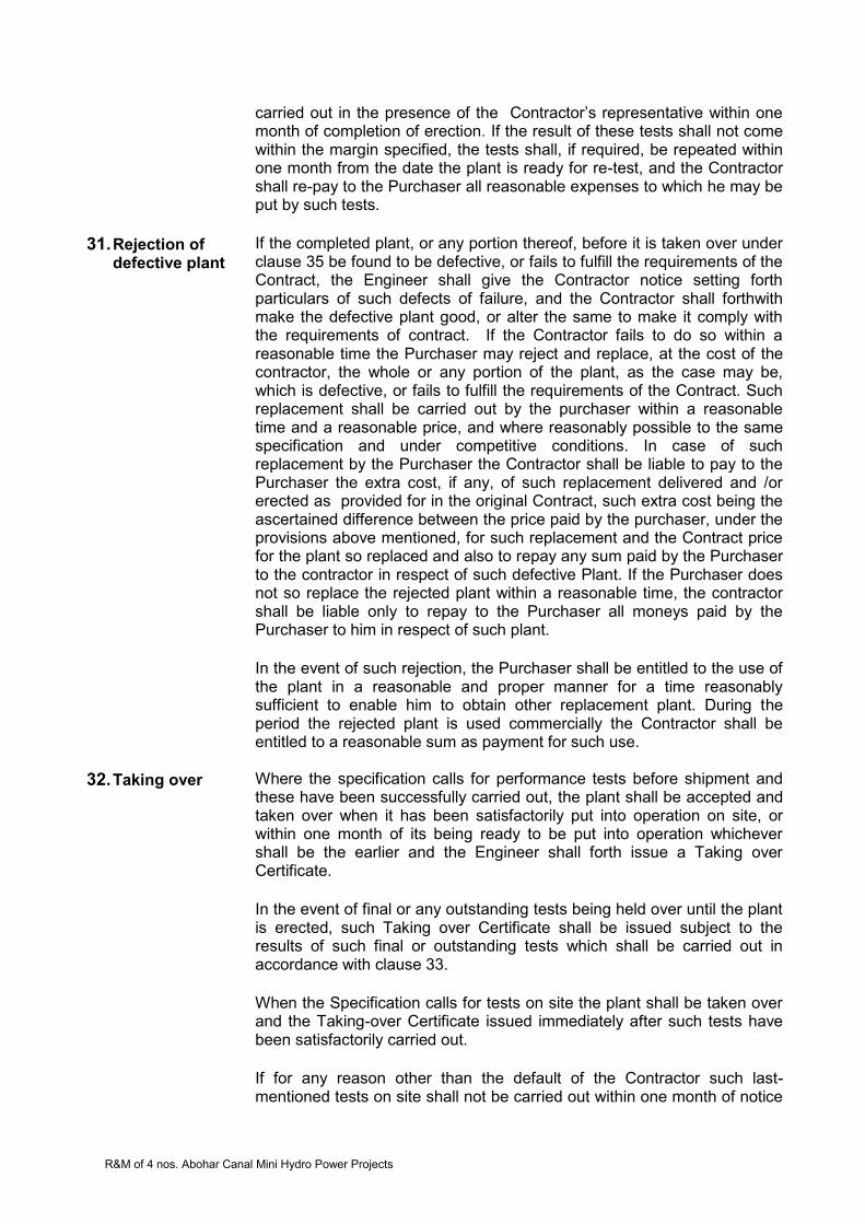
R&M of 4 nos. Abohar Canal Mini Hydro Power Projects
carried out in the presence of the Contractor’s representative within one month of completion of erection. If the result of these tests shall not come within the margin specified, the tests shall, if required, be repeated within one month from the date the plant is ready for re-test, and the Contractor shall re-pay to the Purchaser all reasonable expenses to which he may be put by such tests.
31. Rejection of defective plant
If the completed plant, or any portion thereof, before it is taken over under clause 35 be found to be defective, or fails to fulfill the requirements of the Contract, the Engineer shall give the Contractor notice setting forth particulars of such defects of failure, and the Contractor shall forthwith make the defective plant good, or alter the same to make it comply with the requirements of contract. If the Contractor fails to do so within a reasonable time the Purchaser may reject and replace, at the cost of the contractor, the whole or any portion of the plant, as the case may be, which is defective, or fails to fulfill the requirements of the Contract. Such replacement shall be carried out by the purchaser within a reasonable time and a reasonable price, and where reasonably possible to the same specification and under competitive conditions. In case of such replacement by the Purchaser the Contractor shall be liable to pay to the Purchaser the extra cost, if any, of such replacement delivered and /or erected as provided for in the original Contract, such extra cost being the ascertained difference between the price paid by the purchaser, under the provisions above mentioned, for such replacement and the Contract price for the plant so replaced and also to repay any sum paid by the Purchaser to the contractor in respect of such defective Plant. If the Purchaser does not so replace the rejected plant within a reasonable time, the contractor shall be liable only to repay to the Purchaser all moneys paid by the Purchaser to him in respect of such plant. In the event of such rejection, the Purchaser shall be entitled to the use of the plant in a reasonable and proper manner for a time reasonably sufficient to enable him to obtain other replacement plant. During the period the rejected plant is used commercially the Contractor shall be entitled to a reasonable sum as payment for such use.
32. Taking over
Where the specification calls for performance tests before shipment and these have been successfully carried out, the plant shall be accepted and taken over when it has been satisfactorily put into operation on site, or within one month of its being ready to be put into operation whichever shall be the earlier and the Engineer shall forth issue a Taking over Certificate. In the event of final or any outstanding tests being held over until the plant is erected, such Taking over Certificate shall be issued subject to the results of such final or outstanding tests which shall be carried out in accordance with clause 33. When the Specification calls for tests on site the plant shall be taken over and the Taking-over Certificate issued immediately after such tests have been satisfactorily carried out. If for any reason other than the default of the Contractor such last-mentioned tests on site shall not be carried out within one month of notice
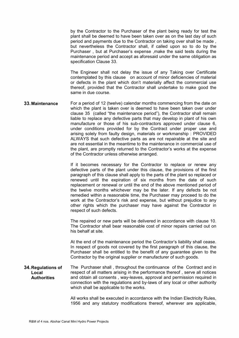
R&M of 4 nos. Abohar Canal Mini Hydro Power Projects
by the Contractor to the Purchaser of the plant being ready for test the plant shall be deemed to have been taken over as on the last day of such period and payments due to the Contractor on taking over shall be made , but nevertheless the Contractor shall, if called upon so to do by the Purchaser , but at Purchaser’s expense ,make the said tests during the maintenance period and accept as aforesaid under the same obligation as specification Clause 33. The Engineer shall not delay the issue of any Taking over Certificate contemplated by this clause on account of minor deficiencies of material or defects in the plant which don’t materially affect the commercial use thereof, provided that the Contractor shall undertake to make good the same in due course.
33. Maintenance
For a period of 12 (twelve) calendar months commencing from the date on which the plant is taken over is deemed to have been taken over under clause 35 (called “the maintenance period”), the Contractor shall remain liable to replace any defective parts that may develop in plant of his own manufacture or those of his sub-contractors approved under clause 6, under conditions provided for by the Contract under proper use and arising solely from faulty design, materials or workmanship : PROVIDED ALWAYS that such defective parts as are not repairable at the site and are not essential in the meantime to the maintenance in commercial use of the plant, are promptly returned to the Contractor’s works at the expense of the Contractor unless otherwise arranged. If it becomes necessary for the Contractor to replace or renew any defective parts of the plant under this clause, the provisions of the first paragraph of this clause shall apply to the parts of the plant so replaced or renewed until the expiration of six months from the date of such replacement or renewal or until the end of the above mentioned period of the twelve months whichever may be the later. If any defects be not remedied within a reasonable time, the Purchaser may proceed to do the work at the Contractor’s risk and expense, but without prejudice to any other rights which the purchaser may have against the Contractor in respect of such defects. The repaired or new parts will be delivered in accordance with clause 10. The Contractor shall bear reasonable cost of minor repairs carried out on his behalf at site. At the end of the maintenance period the Contractor’s liability shall cease. In respect of goods not covered by the first paragraph of this clause, the Purchaser shall be entitled to the benefit of any guarantee given to the Contractor by the original supplier or manufacturer of such goods.
34. Regulations of Local Authorities
The Purchaser shall , throughout the continuance of the Contract and in respect of all matters arising in the performance thereof , serve all notices and obtain all consents , way-leaves, approval and permission required in connection with the regulations and by-laws of any local or other authority which shall be applicable to the works. All works shall be executed in accordance with the Indian Electricity Rules, 1956 and any statutory modifications thereof, wherever are applicable,

R&M of 4 nos. Abohar Canal Mini Hydro Power Projects
unless otherwise agreed to in writing by the Engineer.
35. Arbitration
If any dispute, difference or controversy shall at any time arise between the contractor on the one hand and the Punjab Genco Limited and the Engineer of the contract on the other touching the contract, or as to the true construction, meaning, and intent or any part or condition of, or payment for the same, or as to the true intent, meaning, interpretation, construction or effect of the clauses of the contract, specifications or drawings any of them, or as to anything to be done ,committed or suffered in pursuance of the contract or specifications, or as to the mode of carrying the contract into effect, or as to the breach or alleged breach of the contract, or as to obviating or compensating for the commission of any such breach, or as to any other matter or thing, whatsoever connected with or arising out of the contract, and whether before or during the progress or after the completion of the contract, such question, difference or dispute shall be referred for adjudication to the Chairman and Managing Director, Punjab Genco Ltd. or to any other person nominated by him in this behalf and his decision in writing shall be final, binding and conclusive. This submission shall be deemed to be a submission to arbitration within the meaning of the Indian Arbitration. Act, 1940 or any statutory modification thereof. The arbitrator may from time to time with consent of the parties enlarge the time for making and publishing the award. Upon every or any such reference, the costs of, an incidental to the reference and award respectively shall be in the discretion of the arbitrator, who shall be competent to determine the amount thereof or direct the same to be taxed as between solicitor and client or as between parties and to direct by whom and to whom and in what manner the same shall be borne and paid. Work under the contract shall, if reasonably possible, continue during the arbitration proceedings and no payments due or payable by the Nigam shall be withheld on account of such proceedings.
36. Construction of contract
The Contract shall in all respects be construed and operate as a Contract as defined in the Indian Contract Act, 1872, and all payments there under shall be made in rupees unless otherwise specified.
37. Marginal notes The marginal note to any clause of this Contract shall not effect or control the construction of such clause.
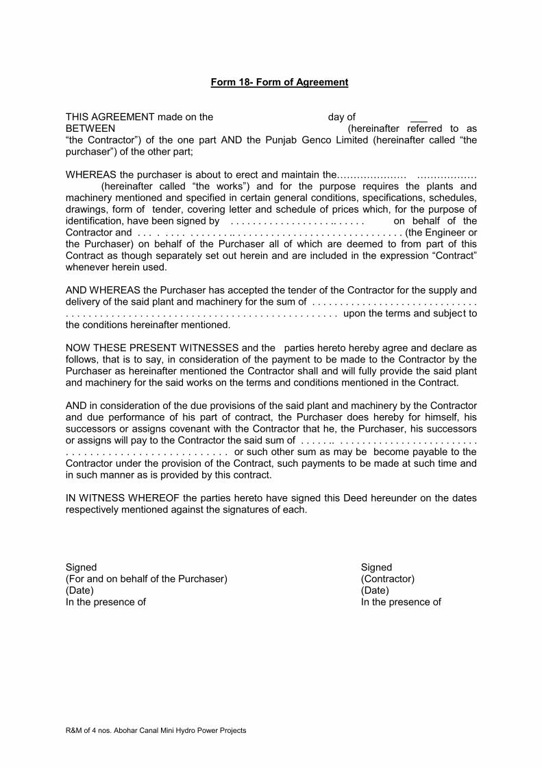
R&M of 4 nos. Abohar Canal Mini Hydro Power Projects
Form 18- Form of Agreement
THIS AGREEMENT made on the day of ___ BETWEEN (hereinafter referred to as “the Contractor”) of the one part AND the Punjab Genco Limited (hereinafter called “the purchaser”) of the other part;
WHEREAS the purchaser is about to erect and maintain the………………… ……………… (hereinafter called “the works”) and for the purpose requires the plants and machinery mentioned and specified in certain general conditions, specifications, schedules, drawings, form of tender, covering letter and schedule of prices which, for the purpose of identification, have been signed by . . . . . . . . . . . . . . . . . . .. . . . . . on behalf of the Contractor and . . . . . . . . . . . . . . . .. . . . . . . . . . . . . . . . . . . . . . . . . . . . . . . (the Engineer or the Purchaser) on behalf of the Purchaser all of which are deemed to from part of this Contract as though separately set out herein and are included in the expression “Contract” whenever herein used.
AND WHEREAS the Purchaser has accepted the tender of the Contractor for the supply and delivery of the said plant and machinery for the sum of . . . . . . . . . . . . . . . . . . . . . . . . . . . . . . . . . . . . . . . . . . . . . . . . . . . . . . . . . . . . . . . . . . . . . . . . . . . . . . upon the terms and subject to the conditions hereinafter mentioned.
NOW THESE PRESENT WITNESSES and the parties hereto hereby agree and declare as follows, that is to say, in consideration of the payment to be made to the Contractor by the Purchaser as hereinafter mentioned the Contractor shall and will fully provide the said plant and machinery for the said works on the terms and conditions mentioned in the Contract.
AND in consideration of the due provisions of the said plant and machinery by the Contractor and due performance of his part of contract, the Purchaser does hereby for himself, his successors or assigns covenant with the Contractor that he, the Purchaser, his successors or assigns will pay to the Contractor the said sum of . . . . . .. . . . . . . . . . . . . . . . . . . . . . . . . . . . . . . . . . . . . . . . . . . . . . . . . . . . . or such other sum as may be become payable to the Contractor under the provision of the Contract, such payments to be made at such time and in such manner as is provided by this contract.
IN WITNESS WHEREOF the parties hereto have signed this Deed hereunder on the dates respectively mentioned against the signatures of each.
Signed Signed (For and on behalf of the Purchaser) (Contractor) (Date) (Date) In the presence of In the presence of

R&M of 4 nos. Abohar Canal Mini Hydro Power Projects
SECTION 5- SPECIAL CONDITIONS OF CONTRACT
1. Scope
1.1 Scope of work includes reverse engineering, if any, manufacturing/procurement of items required to be replaced, testing at works/site before dispatch, packing transportation, loading, unloading and delivery FOR destination, storage at site, dismantling of existing equipment/system, critical inspection of the components which are to be retained critically and damaged & worn out components/ assemblies and repair/modification at site contractor’s works (including transportation of components from site to works and back), ‘removal, stacking and storing of unused material at site/store of Punjab Genco Ltd’, erection, testing, commissioning including preliminary acceptance tests, performance guarantee & post commissioning services for Renovation and Modernization of 4nos. Abohar canal as per enclosed Technical specifications and training of purchasers’ personnel for the operation of power plant, switchyard, and outlets works from local and centralized Control room to ensure a trouble free and safe operation on turnkey basis
1.2 The equipment shall be supplied complete in all respects i.e. with
all fittings/ accessories, apparatus and parts that are necessary for their usual efficient operation. Such parts shall be deemed to be within contractor’s scope whether specifically mentioned or not.
1.3 Insurance during transit, storage, erection and commissioning of all
the equipment and accessories is included in the scope. 1.4 Spares required during testing and commissioning are also
included in the scope. 1.5 Recommended spares and T&P, which are quoted by Bidder may
be purchased, if found prudent by Purchaser. 1.6 These Special Conditions of Contract and detailed Technical
Specifications are supplementary to one another for complete interpretation of PGL’s requirement.
2. Delivery/ completion of works
2.1 The commencement of project completion period shall be counted from the date of handing over of each Unit by the PGL.
2.2 The date of receipt of material in purchaser's store shall be deemed
to be the date of delivery. 2.3 The completion period shall be 12 months counted from the date of handing over of each Unit by the PGL.
A proposed bar chart is enclosed as Annexure-3 If the synchronization of any unit gets delayed behind schedule due to any reason for which the PGL has not already issued a time extension on Contractor’s reasonable request before the expiry of date, the

R&M of 4 nos. Abohar Canal Mini Hydro Power Projects
synchronization delay will result into a penalty on the Contractor as indicated in clause -19 of this Special Conditions.
3. Compliance with Laws Rules, Regulations & Obtaining Statutory Approval
All equipment / materials shall be installed in accordance with the requirement of relevant standards, Indian Electricity Rules and Acts. The contractor shall ensure that the electrical installation supplied and erected by him shall be to the entire satisfaction of Chief Electrical Inspector, Central Electricity Authority or any other statutory body having Jurisdiction in the area and also to the purchaser/his authorized representative.
Chief Electrical Inspector approval for the installation and
commissioning shall be the responsibility of the contractor. Preparation and submission of all necessary drawings, calculations, test certificates and relevant details to the Electrical inspectorate and obtaining prior approval for commencing the work and for the complete installation work done shall be done by the contractor. Any statutory fee for inspection charged by Electrical inspectorate shall be borne by the purchaser.
4. Assignment, Subletting of Contract and Purchased Items
4.1 The Contractor shall not, without consent in writing of the Engineer or PGL, which shall not be unreasonably withheld, assign or sublet his Contract, or any substantial part thereof other than for raw materials, for minor details, or for any part of the work of which the makers are named in the Contract provided that any such consent shall not relieve the Contractor from any obligation, duty or responsibility under the Contract.
4.2 Pursuant to sub-clause 4.1 above, the Contractor shall give a written request to the Purchaser’s Representative for sub-letting or assignment any part of works at least 7 days in advance of the proposed date of sub-letting. Such request for sub-letting or assignment shall contain: Contractor’s certification regarding the financial soundness of the proposed transferee, assignee or sub-contractor for the work, Its scope and estimated value in relation to the Contract Price, Experience of the transferee, assignee or sub-contractor in the related areas of work, The manpower, equipment, material and other resources available with the transferee, assignee or sub-contractor for the work,
4.3 Within 5 days of the date of receipt of request for consent, Purchaser’s Representative shall either give in writing Consent there for communicate refusal. In the event of Purchaser’s Representative failing to communicate the refusal within the above said five days period, the Contractor shall be entitled to proceed as if Purchaser’s Representative had granted consent to such request.
4.4 Not withstanding any transfer, assignment or sub-letting with the approval of Purchaser’s Representative as aforesaid, the Contractor shall be and shall remain solely responsible and liable to the Purchaser for the quality, proper and expeditious execution and performance of the works and for due performance and observance of all the conditions of the contract in all respects, as if such transfer, assignment or sub-letting has
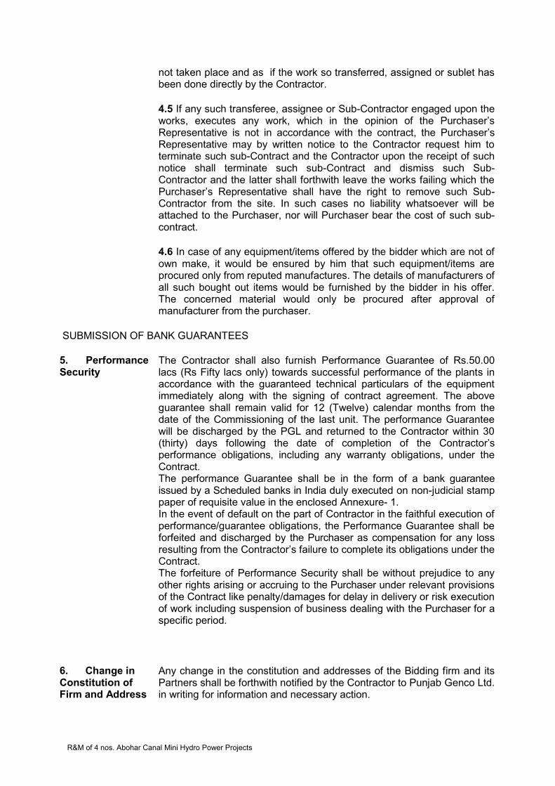
R&M of 4 nos. Abohar Canal Mini Hydro Power Projects
not taken place and as if the work so transferred, assigned or sublet has been done directly by the Contractor.
4.5 If any such transferee, assignee or Sub-Contractor engaged upon the
works, executes any work, which in the opinion of the Purchaser’s Representative is not in accordance with the contract, the Purchaser’s Representative may by written notice to the Contractor request him to terminate such sub-Contract and the Contractor upon the receipt of such notice shall terminate such sub-Contract and dismiss such Sub-Contractor and the latter shall forthwith leave the works failing which the Purchaser’s Representative shall have the right to remove such Sub-Contractor from the site. In such cases no liability whatsoever will be attached to the Purchaser, nor will Purchaser bear the cost of such sub- contract.
4.6 In case of any equipment/items offered by the bidder which are not of
own make, it would be ensured by him that such equipment/items are procured only from reputed manufactures. The details of manufacturers of all such bought out items would be furnished by the bidder in his offer. The concerned material would only be procured after approval of manufacturer from the purchaser.
SUBMISSION OF BANK GUARANTEES 5. Performance Security
The Contractor shall also furnish Performance Guarantee of Rs.50.00 lacs (Rs Fifty lacs only) towards successful performance of the plants in accordance with the guaranteed technical particulars of the equipment immediately along with the signing of contract agreement. The above guarantee shall remain valid for 12 (Twelve) calendar months from the date of the Commissioning of the last unit. The performance Guarantee will be discharged by the PGL and returned to the Contractor within 30 (thirty) days following the date of completion of the Contractor’s performance obligations, including any warranty obligations, under the Contract. The performance Guarantee shall be in the form of a bank guarantee issued by a Scheduled banks in India duly executed on non-judicial stamp paper of requisite value in the enclosed Annexure- 1. In the event of default on the part of Contractor in the faithful execution of performance/guarantee obligations, the Performance Guarantee shall be forfeited and discharged by the Purchaser as compensation for any loss resulting from the Contractor’s failure to complete its obligations under the Contract. The forfeiture of Performance Security shall be without prejudice to any other rights arising or accruing to the Purchaser under relevant provisions of the Contract like penalty/damages for delay in delivery or risk execution of work including suspension of business dealing with the Purchaser for a specific period.
6. Change in Constitution of Firm and Address
Any change in the constitution and addresses of the Bidding firm and its Partners shall be forthwith notified by the Contractor to Punjab Genco Ltd. in writing for information and necessary action.

R&M of 4 nos. Abohar Canal Mini Hydro Power Projects
7. Sufficiency of Project Information
The Contractor shall be deemed to have carefully examined the Conditions, Specifications, Schedules and Drawings. If he shall have any doubt as to the meaning of any portion of these Conditions, or Specifications he shall, before signing the Contract, set forth the particulars thereof and submit them to the Engineer in writing, in order that such doubt may be removed. The data and information given in Tender Document are based on the information available from project site. The Contractor shall satisfy himself about the adequacy of the said data/information and interpretation there-of and if necessary, carry out further investigation at his own cost. Thus, Punjab Genco Ltd. shall not be responsible for in-adequacy of the said data/information and interpretation thereof by the Contractor.
8. Manuals The contractor shall furnish six sets of bound copies of erection, commissioning, operation and maintenance manuals giving detailed instructions, procedures, precautions for all the new equipment before handing over the units to the PGL. The manuals shall be specific to the equipment supplied and work carried out and not of general nature. Three sets of these manuals shall also be supplied with each set of equipment/ work.
9 Safety All units with respect to their location, layout, general arrangement and design and equipment, structural design, etc. shall be safe to the personnel and conform to the relevant safety rules and regulations/statutory requirement issued by Punjab Government and the Central Government as well as to the following: Indian Electricity Rules Indian Electricity Act Indian Explosives Manual Fire Protection Manual issued by Tariff Advisory Committee (India)
10 Work Schedule / Re-Scheduling & Progress Of Work
The Contractor shall submit a detailed PERT network within 10 (TEN) days from the date of receipt of Letter of award of contract. The PERT CHART shall consist of adequate number of activities covering various key phases of the Works such as procurement, manufacturing, shipment, dismantling of the units, overhauling/repair, installation of new equipment, assembly, testing and commissioning of units. This chart shall also clearly indicate the interlinking/interdependencies of interface facilities to be provided by the PGL and the dates by which such facilities are needed. Contractor shall discuss the network so submitted with the Engineer and the agreed network shall form part of the contract to be signed within 10 (ten) days from the date of receipt of Letter of award of contract. The above PERT CHART shall be reviewed jointly by the Purchaser and the Contractor every month, wherein the holdups/delays, if any, in the progress of Works, with reference to the agreed Schedule shall be given special attention. Necessary modifications (updating/revisions) in the schedule within the overall time for completion, shall be carried out by mutual agreement between the Purchaser and the Contractor.

R&M of 4 nos. Abohar Canal Mini Hydro Power Projects
Supply of new parts of equipment at power house shall be planned to ensure their availability about one month in advance of the scheduled dates of installation and matching with the progress. No extra cost, whatsoever, on account of such re-scheduling shall be payable to the Contractor. The R&M activities are required to be carried out in such a manner that the shutdown period is minimum as far as possible. The contractor shall be required to prepare the works schedule accordingly. However, all the efforts are to be made to start site mobilization, taking up and sequencing other activities as early as possible and their execution within a reasonable short period so as to be able to complete the entire work within completion period pursuant to clause 2.4 above.
11. Insurance The contractor shall arrange, secure & maintain insurance as may be necessary to protect his own interest and the interests of the purchaser against all risks. The risks that are to be covered under the insurance shall include, but not be limited to the loss or damage in transit, theft, pilferage/ civil commotion, weather conditions, accidents of all kinds, fire, war risks during ocean transportation, damage during commissioning etc. Insurance is to be taken for the landed at site value of the equipment. All damages and shortages after equipment delivery and storage at site shall be notified by the contractor’s site representative by registered post and fax to purchaser immediately and action shall be taken by contractor within 15 days for making good the damage or shortage by way of replacement/ repair/new supply. The contractor shall take up the matter with insurance company on its own for finalization of claims. All actions in connection with making and settling of claims , if any, will be carried out by the contractor himself for which no extra payment will be made by the purchaser to the contractor in this regard. The contractor shall be responsible to make good the damage or loss by way of repairs and/ or replacement of equipment free of cost and within shortest possible time, without waiting for settlement of claims and irrespective of the fact whether claim is accepted or not by the insurance company, in order to adhere to work schedule The scope of such insurance shall cover the entire value of the contract from time to time
12. Guarantee & Warranty
The Contractor shall guarantee the performance of the equipment as under:- (i) Power output against rated output or maximum historical output
whichever is higher (ii) temperature rise of bearings should not exceed historical
temperature at the rated output or maximum historical output (iii) temperature rise of generator windings should not exceed design
temperature or historical temperature whichever is lower The Contractor shall further warrant that the equipment supplied and overhauled under this Contract shall have no defect arising from design,
R&M of 4 nos. Abohar Canal Mini Hydro Power Projects
material or workmanship or from any act or omission of the Contractor or his approved sub-contractor that may develop under normal use of the equipment. The warranty shall remain valid for 8000 hours of operation or 12 (twelve) months after handing over of the unit, whichever is earlier. The Contractor shall be responsible to fulfill all the warranties and making good as soon as practicable at his expenses, any defect in or damage to any section or part of the work which may appear or occur during the Warranty Period. Repair, modification or replacement of work/part of work as required making good such defect or deficiency or damage shall constitute complete fulfillment of the Contractor’s obligations under the Warranty provided under this Article. The PGL shall promptly notify the Contractor in writing of any claims arising under this warranty. Upon receipt of such notice, the Contractor with all reasonable speed, repair or replace the defective parts thereof free of cost. The Contractor shall take over the replaced parts at the time of their replacement. Such defective parts which are not repairable at site, shall be taken by the Contractor to his works promptly after these can be spared by Purchaser and repaired/replaced at his own cost in the earliest possible time watching PGL’s interest.. The Contractor shall, at any time and from time to time, upon notice from the PGL given before the expiry of said Warranty, promptly make good by correction, repair, amendment, reconstruction or replacement all defects, imperfections or other faults noticed during the Warranty Period (12 months or 8000 working hours of operation whichever is earlier), to the satisfaction of PGL. If effective steps for repair modification or replacement of defects, deficiencies or damages pursuant here to are not taken within seven days of the date of notification thereof by the Purchaser to the Contractor or if such repair, modification or replacement is not completed with reasonable promptitude by the Contractor at his own expense, as required by the PGL in accordance with this Article, the PGL shall be entitled to cause the same to be made good by other agencies or otherwise and deduct expenses (of which the certificate of PGL shall be final) from any sum that may by then or at any time thereafter become due to the Contractor under the Contract or from the amount released by encashing the bank guarantees provided by the Contractor under the Contract or recover otherwise from the Contractor including from any money due to the Contractor on any other accounts whatsoever. The Defects arising due to normal wear and tear or due to misuse by the PGL or other Contractors employed by the PGL or due to defects in areas which are not in scope of Contractor shall not be covered under Warranty/Guaranty by Contractor. However due care is to be ensured during execution of work ensuring safety of equipment.
13. Price Variation, Taxes, Duties & Levies etc.
No Price Variation shall be applicable. The price bid shall be inclusive of all taxes, duties and levies. The F.O.R site price in the bid may be quoted with breakup of price, taxes and duties. The purchaser will provide requisite “C Forms”. Any variation in the taxes and duties after submission of bid shall be to the account of
R&M of 4 nos. Abohar Canal Mini Hydro Power Projects
purchaser (PGL). Taxes (TDS) shall be deductible as per law as applicable at the time of payment.
14. Contract Drawings and Detailed Technical Specifications
Within 15 days from the effective date of the Contract, the Contractor shall send to the Engineer a list of all the drawings with their respective titles and the dates on which they shall be supplied to the PGL. The list shall be amended or extended by the Contractor in consultation with the PGL or as asked by the PGL as and when necessary during the progress of work. The PGL will prepare the list of drawings which shall require the approval of PGL out of the above list supplied by the Contractor. The schedule of submission of drawings shall be coordinated with the work schedule of other work components and shall successively be adjusted in order to meet the actual requirements of other components for completing the works, within the completion period.
All the drawings pertaining to new plants and goods of Electro-Mechanical works shall preferably be worked out on computers using latest version of AutoCAD on maximum A1 size. Electrical drawings including schematic drawings, block diagrams, flow diagrams, terminal details, panel outline drawings, circuit diagrams etc. shall be worked out on A3 size. All drawings shall have a uniform title-block as approved by the Engineer. Beginning with the very first submittal to the Engineer, the Contractor's drawings shall bear a serial number corresponding to a drawing classification plan to be agreed upon by the Contractor and the Engineer. The drawings of bought out items shall also be preferred in AutoCAD version, however, their scanned version will be allowed. Catalogue sheets, illustrations, printed specifications, etc., shall be checked and prepared by the Contractor in such a way that the figures, statements and data valid for the delivered sizes and types of the works concerned are clearly marked. These documents also shall be scanned and stored on CD.
The contractor shall furnish seven prints of each of the following drawing to the Engineer of the contract, within four weeks of the date of order. General arrangement drawings of the equipment offered.
Detailed dimensional drawing and descriptive literature of all the components supplied.
Basic electrical diagrams. In addition, the contractor shall submit seven prints of complete bill of materials with each item identifiable in the detailed drawing to Engineer within 30 days of effective date of contract. This will also form detailed packing list of the equipment.
The PGL Representative shall return to the contractor one print of each
drawing; (a). Stamped APPROVED or (b). Marked Up With Comments. In case of (a) no further resubmission of drawings is required for Engineers approval. In case of (b) the contractor shall correct his
R&M of 4 nos. Abohar Canal Mini Hydro Power Projects
original drawings to conform to the comments made by the Engineer and re-submit in the same manner as stated above, within two weeks after the receipt of the marked up print by him. The contractor on receipt of prints stamped APPROVED shall furnish to PGL’s Representative of the contract one direct reading reproducible of each drawing and bill of materiel within two Weeks of receipt of approved set.
iii. The contractor shall be responsible for and shall pay for any
alterations of the work due to any discrepancies, errors or omissions in the drawings and other particulars supplied by him, whether such drawings or particulars have been approved by the Engineer or not, provided that if such discrepancies, errors or omissions are due to inaccurate information or particulars furnished to the Contractor by the Engineer any alterations in the work necessitated by reasons of such inaccurate information of particulars shall be paid for by the PGL.
If any dimensions figured upon a drawing or a plan differ from those
obtained by scaling the drawing or plan, the dimensions as figured upon the drawing or plan shall be taken as correct.
iv. Other required documents/drawings for which PGL approval is
essentially required:
The contractor is required to submit following documents/drawings at least 30 days ahead of corresponding execution schedule for Purchaser’s approval.
a. Calculation to justify CT/PT Parameters like VA burden, knee
point voltage etc. for all cores. b. Information Category Drawings/Documents
Cable schedule indicating type of cables, from to via, route, total length size of cable and a final summary sheet indicating total requirement of all types of cables (for control and power both). Core wise control cable termination details indicating ferrule no. terminal block no. for each cable/each equipment. Internal wiring diagram for panel(s). Catalogues for each type of equipment, relays, meters etc. Installation and commissioning manuals for each equipment, relay etc. Operation and Maintenance Manuals indicating trouble shooting procedure for all Equipment. Type Test Certificates for all new equipment. Details of Test results, for test conducted at works for all equipment. Details of Test results, for tests conducted at site for all equipment. Spare part list, number and ordering procedure for all recommended spares. Overall GA of all the panels/equipment. Fixing details of all the panels/equipment supporting structures etc. Static and dynamic loadings of each equipment. As executed drawings incorporating site changes along with reproducible.
c. Other required drawings:
R&M of 4 nos. Abohar Canal Mini Hydro Power Projects
a. Single line diagram indicating isolators, CT/PT, all relays, meters, LA, cable sizes, details of CT/PT ratio. VA burden, type and make of all relays, their range nominal and short time ratings of breakers, bus-bars etc. for all equipment included in this specification. b. Front view and GA diagrams for panel(s).
c. Over all layouts of the 11 kV switchyard-indicating sizes of all the premises, cable trenches, clearances etc. d. Control and schematic drawings for control/protection.
e. Lightning protection drawings, showing coverage of all equipment, structures, buildings etc.
f. Interlocking scheme for 11 kV system Grounding/Earthing layout drawing with connections to equipment structures etc.
h. Electrical equipment layout for all electrical premises.
15. Materials and Workmanship
All the equipment, components and materials supplied under the Contract will be new, free from defects and of the respective kinds, grades and specifications described in the Contract as well as conforming to the provisions of relevant codes of Bureau of Indian Standards and shall be subjected from time to time to all necessary tests at the place of manufacture, fabrication or at the Site. The tests shall be carried out as specified by the manufacturer and/or as per relevant IS code and/or as detailed in Technical specifications. The Contractor shall provide, at his cost such assistance, instruments, machines, labour and materials as are normally required for examining, measuring and testing any work and the quality, weight or quantity of any material used and shall supply samples of materials before incorporation in the Works for testing, as may be selected and required by the Engineer. The cost of carrying out all the tests shall be borne by the Contractor.
16. Inspection & Testing
The Engineer, and his duly authorized representatives, shall have at all reasonable times access to the Contractor’s premises, and shall have , the powers at all reasonable times, to inspect and examine the materials and workmanship of the plant during its manufacture there, and if part of the plant is being manufactured on other premises, the Contractor shall obtain permission for the Engineer and for his duly authorised representative, to inspect it as if the plant was manufactured on the Contractor’s own premises. The cost of carrying out such tests will be borne by the contractor including boarding lodging and travelling cost of PGL engineers. The Engineer shall be at liberty to reject any or all plant or workmanship connected with a particular work which in his opinion are defective or not in accordance with contract, after giving seven days in writing notice setting out ground of objections to the Contractor. Such notice is to be sent by Engineer within reasonable time after the grounds on which the notice is based, come to his knowledge, otherwise the Engineer shall not be entitled to reject the plant or workmanship.
Unless specifically provided, all the tests shall be made at Contractor’s works before shipment.

R&M of 4 nos. Abohar Canal Mini Hydro Power Projects
The Contractor shall, if required, give the Engineer notice of any material being ready for testing, and the Engineer, or his said representative, if so desired, shall, on giving twenty four hours notice in writing or through Fax, to the Contractor, attend at the Contractor’s premises within fifteen days of the date on which the material is notified as being ready; failing which visit the contractor may proceed with the tests, which shall be deemed to have been made in the Engineer’s presence, and he shall forthwith forward to the Engineer duly certified copies of the tests in duplicate. The contractor shall give 15 days notice to the Engineer of contract under intimation to purchaser, of every lot of material being ready duly packed for dispatch along with routine test results of the material offered and details of dispatches made against last authorization for dispatch. In addition to the tests specified in the technical specification, the purchaser reserves the right of carrying out at site such tests as he may decide upon. Such additional tests will be carried out at the purchaser’s expenses. The contractor shall also render necessary assistance to the inspecting officers in making random sampling. Wherever considered necessary, material shall be marked embossed or sealed by the inspecting officer after inspection has been carried out and the material approved for dispatch. The PGL reserves the right to draw required number of samples of other major items of raw material. These samples shall however, be drawn and sealed in the presence of contractor or his authorized representative. The purchaser further reserves the right to get these samples tested from any Govt. recognized test house/ laboratory or Govt. test house/ laboratory. The contractor shall record either of the following certificates on the invoice / packing list (Challan) as the case may be. "Certified that the consignment (lot) of material supplied through this invoice/ packing list (challan) has been inspected and tested by representatives of Punjab Genco Ltd. and has been approved for dispatch". Or “Certified that the inspection and testing of consignment (lot) of material supplied through this invoice/ packing list (Challan) has been waived off by the purchaser vide his letter. No. ………….date………….. It is further certified that the material has been tested and results have been found to be within the values specified in the relevant ISS / contract as per copies of Test certificate enclosed". Not with-standing the inspection carried out by the officer of Punjab Genco Ltd., in case of any short/defective supply of material detected by the consignee, the contractor shall be liable to make good such shortage/ rectify the defects. The consignment also being subjected to joint

R&M of 4 nos. Abohar Canal Mini Hydro Power Projects
inspection by representatives of the contractor and the purchaser, in case of any dispute regarding quality and / or quantity of the material supplied. In case, the material offered for inspection is not found ready when the inspecting party reaches the works of contractor, the cost incurred by the Punjab Genco Ltd on this account will become payable by the contractor on demand by the Engineer of Contract within 30 days. All cost for attending test or inspection by PGL representative shall be borne by contractor.
16.1 At Works 16.1.1 All the supplies will be subjected to inspection and testing before clearances are given by the purchaser for dispatch. It is essential that : The Bidder/sub-vendors must have all necessary facilities at their works for carrying out such routine and acceptance tests as prescribed in the relevant standards and any other routine and acceptance tests as specified in the specification. Documentary evidence of existence of such facilities will be provided along with the tender.
16.1.2 Model Quality assurance plan (QAP) for tests and inspection of equipment as submitted by the contractor and approved by PGL, shall be followed .The Engineer shall have the right to ask for more relevant tests if the same could not be included in the quality assurance plan.
16.1.3 The offered equipment must have been fully type tested as per relevant ISS and/ or other specified International Standards, during the last 5 years period, to be reckoned from the date of opening of tender. The type test certificate of prototype manufactured and tested by foreign collaborators of the Bidders at their works shall not be acceptable for indigenously manufactured equipment.
16.1.4 In case the equipment is being, manufactured in India under foreign collaboration, the collaborator’s equipment shall have minimum two years' satisfactory operating experience under tropical climate.
16.1.5 The offered indigenously manufactured equipment should have been type tested and test report submitted with the tender. 16.2 Inspection of Works 16.2.1 The Contractor shall prepare the field quality assurance plan and
get it approved from the PGL before starting works at site. The approved quality assurance plan shall form the basis for inspection and acceptance of the plant and works at site. The Engineer shall have the right to ask for more relevant tests if the same could not be included in the quality assurance plan at the time of their approval due to non-availability of final design drawings.
PGL shall give approval on field QAP within 30 days of submission of same. In case of delay in approval the time schedule shall be
R&M of 4 nos. Abohar Canal Mini Hydro Power Projects
revised accordingly on mutually agreed terms. 16.2.2 During erection, re-assembly, commissioning and trial operation,
the Contractor shall perform at suitable intervals all inspections and tests in the presence of the Engineer in order to prove the orderly execution of the works in accordance with the Contract.
16.2.3 Unless otherwise specified, all costs for testing at site and of the
works and charges associated with it shall be borne by the Contractor. This includes the measuring devices - properly calibrated, and any pertinent accessories which shall be made available by the Contractor for the entire duration of the tests. The Contractor shall delegate his experts to perform the tests at site.
In case of disagreement between the Engineer and Contractor on the test results, an independent expert shall be appointed by Purchaser to whom both parties shall agree. If no amicable settlement can be reached, the Arbitration Clause shall be applied.
17. Packing
The Contractor shall provide such packing of the Goods as is required to prevent their damage or deterioration during transit to their final destination as indicated in the Contract. The packing shall be sufficient to withstand, without limitation, rough handling during transit and exposure to extreme temperatures, salt and precipitation during transit and open storage. Packing case size and weights shall take into consideration, where appropriate, the remoteness of the Good’s final destination and the absence of heavy handling facilities at all points in transit. 17.2 Suitable lifting lugs should be provided in heavy consignments and
clear instructions be marked on the package for handling. 17.3 All electrical parts shall be carefully packed in high-pressure
polyethylene foils where parts may be affected by vibration, they shall be carefully protected and packed to ensure that no damage will occur while they are being transported and handled.
17.4 All bright parts shall be thoroughly protected from rust during transit. Each package shall contain a packing list in polythene cover and six copies shall be sent to the Purchaser. All points shall be marked to facilitate erection.
17.5 Large articles, which are not packed in cases, shall have all screwed holes, plugged suitably and machined surfaces properly protected. Weight and size limitation for transport shall be ensured by the contractor.
17.6 The Contractor will be required to make separate packages for each consignment and shall mark all containers with the implementing document number pertinent to the shipment. Each shipping container shall also be clearly marked on at least two sides as follows:
a. Consignee : b. Contract No. : c. Package number : d. Description : e. Item number (if applicable) : f. Net and gross weight :
R&M of 4 nos. Abohar Canal Mini Hydro Power Projects
g. Volume : h. Country of Origin : i. Port of entry :
18. Delivery of Plant and Dispatch Documents
18.1 The Contractor shall prepare and forward six copies of the master list of packages in bound form within 90 days of award of Contract or at least 60 days before dispatch of any package. This list will be used as checklist for dispatch of all the equipment and materials under the Contract. The list will be updated, if necessary by the Contractor based on changes during subsequent details design.
18.2 The plant or material shall not be forwarded until shipping /dispatch instruction shall have been given to the Contractor. Notification of delivery or dispatch in regard to each and every consignment shall be made to the Purchaser immediately after dispatch or delivery. The supplier shall further supply to the Consignee a priced invoice and packing account of all stores delivered or dispatched by him. All packages, containers, bundles and loose materials forming part of each and every consignment shall be described in full in the packing account and full details of the contents of packages and quantity of materials shall be given to enable the Consignee to check the stores on arrival at destination.
18.3 The Goods shall be dispatched by the Contractor strictly as per the master list of packages and the delivery schedule agreed in the final Contract after getting dispatch instructions from the engineer. Dispatch clearance shall be given by the Engineer based on site requirement keeping in view the limited warranty period.
18.4 Following dispatch documents shall be sent with the packages: a. Three copies of the Contractor invoice showing Goods description,
quantity, unit price, total amount; b. Four copies of packing list identifying contents of each package;
Packages, containers, bundles and loose materials forming part of each and every consignment shall be described in full in the packing account and full details of the contents of packages and quantity of materials shall be given.
c. Delivery note/railway receipt/truck receipt; Manufacturer’s/Contractor’s guarantee certificate; e. Inspection certificate issued by the nominated inspection agency,
and the Contractor’s factory inspection report; and f. Certificate of origin. 18.5 Notification of delivery or dispatch in regard to each and every
consignment shall be made to the PGL immediately after dispatch or delivery.
19. Delays in the Contractor’s Performance & Liquidated Damages (Delay Damages)
19.1 The liquidated damages shall be payable as follows:
On account of delay in commissioning of units from the schedule there will be generation loss as such PGL shall be entitled for liquidated damages. A penalty, therefore, of Rs. 25,000.00(Twenty five Thousand only) per day per unit shall be deducted from the amount payable on commissioning subject to max limit of 5% of
R&M of 4 nos. Abohar Canal Mini Hydro Power Projects
cost of Contract on prorata basis 19.2 Without prejudice to the right of the PGL under the Contract and its
right to entitlement for liquidated damages, the PGL shall be entitled additionally to terminate the Contract without being liable in any manner whatsoever to the Contractor and/or to have the WORKS completed at the risk and cost of the Contractor, by a communication in writing to the Contractor in the following events :
In the event the liquidated damages have become payable in terms of this Article but the maximum limit of the amount of liquidated damages payable hereunder by the Contractor to the Purchaser have been reached and the Contractor has failed to complete the delayed works within 30 (thirty) days of receipt of notice in this behalf from the Purchaser In the event of the Contractor, being in breach of any of the provisions of the Contract and if the Contractor has failed to remedy such breach/default within 30 (thirty) days or such further period as may be mutually agreed between the Purchaser and the Contractor having regard to the nature of the breach or default or shortfall, of the receipt of notice in this behalf from the Purchaser.
19.3 In case the delay in the completion of the work is due to the
reasons not attributable to the Contractor, the Contractor shall not be liable to pay any Liquidated damages due to delay and the delivery period shall be extended accordingly. The payment of LD for Delay attributable to contractor (if any) shall be in full satisfaction of the Purchaser’s respective claims and the Contractor shall have no further liabilities whatsoever to the PGL in respect thereof.
Upon termination of Contract due to Contractor’s default, PGL shall pay to the Contractor the balance amount due to him after adjustments of Contractor liabilities (if any). On termination of contract performance bank guarantee will be forfeited.
19.4 Purchaser shall have the right to terminate the Contract only upon
material breach of the provision of the Contract. Upon such termination due to Contractor’s default, PGL shall pay to the Contractor the balance amount due to him after adjustments of Contractor liabilities (if any).
The aggregate liability of the Contractor in this Contract to the PGL, whether under the contract, in tort or otherwise including the cost of repairing or replacing defective equipment, shall not exceed 100% of the contract price. All liability in the contract shall expire on completion of 12 months period from taking over of last unit by PGL.
19.5 If PGL terminates the Contract for reasons not attributable to the
Contractor, then the PGL shall pay to the Contractor all the amount due to him till the point of termination including that of supplies
R&M of 4 nos. Abohar Canal Mini Hydro Power Projects
made or services rendered by Contractor. Also Contractor shall be compensated by the PGL for all the expenses incurred by the Contractor. Purchaser shall return all the Contractor’s guarantees to the Contractor within 10 days termination of the Contract by the Purchaser subjected to adjustment of payments in accordance with Contract Conditions.
20. Force - Majeure
20.1 If at any time during the continuance of the work the performance in whole or in part by either party of any obligation under this contract, shall be prevented or delayed by reasons of any war, hostility, acts of public enmity, terrorism, Civil Commotion, sabotage, floods, explosion, epidemics, fire, other acts of God or any other event which are beyond the reasonable control of the PGL or of the Contractor , (hereinafter referred to as eventualities) then, provided notice of the happening of any such eventuality is given by either party to the other within 15 days from the date of occurrence thereof, neither party shall by reasons of such eventuality be entitled to terminate this contract nor shall either party have any claim for damages against the other in respect of such non-performance or delay in performance and construction of work under this contract shall be resumed as soon as practicable after such eventuality has ceased. Appropriate extension in time of completion shall be granted.
20.2 The Contractor shall not be liable for delays in performing his
obligations resulting directly or indirectly from any of force Majeure causes. Dates of shipment shall, subject as hereinafter provided, be extended, by a reasonable time. If any such delay lasts for more than 2 (two) months, the parties, hereto, shall immediately consult with one another for purpose of agreeing upon a reasonable basis on which the Contractor shall resume the unfinished work and if the parties do not agree upon a solution of the problem (including adjustment of the price, such price adjustment being both upwards and downwards), then either party may, by written notice cancel that portion of the equipment which is delayed. If the PGL is the canceling party, the Purchaser shall be obliged to pay cancellation charges and if so, amount of such charges, shall be decided by the Arbitrator as herein provided. If the Contractor is canceling party, the PGL shall not be obliged to pay any cancellation charges. All the provisions of this clause shall apply whether the disruption caused is total or partial in its effect upon the ability of the Contractor to perform.
21. Staff and Labour
21.1 The contractor shall comply with all legislations and rules of State and /or Central Government or Other Local Authority formed from time to time governing the protection of health, sanitary arrangements, wages, Provident Fund, welfare and safety for labour directly or indirectly employed on construction works. The rules and other statutory obligations with regard to fair wages, welfare and safety measures including insurance etc, maintenance of register etc. shall be deemed to be part of the contract.
21.2 The age limit for employment of labour shall be strictly in accordance with the existing labour rules and Regulations.
21.3 The Contractor shall comply with the provisions of the Minimum Wages Act 1948 and the rules made there-under by the

R&M of 4 nos. Abohar Canal Mini Hydro Power Projects
Government of Punjab in respect of all employees employed by him or in carrying out this contract. He shall pay the employees wages not less than the minimum rates of wages, if any, fixed by the Government of Punjab, Department of Labour and Employment for that category (including wages payable for weekly holidays contemplated under the minimum wages act of Punjab read with the applicable Rules for minimum wages).
21.4 The contractor shall at all times indemnify the purchaser against all claims arising out of provisions of the Minimum Wages Act 1948 and the Rules framed there under as admissible in respect of any workman employed by the contractor in carrying out the contract and against all costs and expenses and penalties incurred by the purchaser in this connection. Without prejudice to other means of recovery, the purchaser shall be entitled to deduct from any money due or become due to the contractor all moneys paid or payable by the purchaser by way of wages and other dues (including compensation, penalty if any imposed for committing breach of any provision of the Act by the Contractor ) in connection with any claim thereto and the contractor shall abide by the decision of the purchaser as to the sum payable by the contractor under the provisions of this clause. The contractor shall provide at his own cost reasonable amenities for securing proper working and living conditions such as water supply, lavatories, bathing places cleanliness, etc. to the labour directly or indirectly employed on the works. Where the labour is employed, urinals/ lavatories will be provided separately by the contractor for male and female workers as well as crèches for the infant children of labour.
Labour engaged on hazardous jobs and occupations will be provided with necessary safety appliances by contractor, free of charge.
21.7 The contractor’s establishment will be subject to inspection,
investigation etc. by the Engineer or by Engineer’s Representative or such other Representatives of the purchaser as duly authorized on his behalf by him for assuring proper and faithfully compliance of the provisions of this contract by the Contractor with regard to the implementation of labour laws and other matters anticipated herein.
21.8 The contractor shall abide by the decisions and orders of the Engineer with regard to any such matter and furnish, if required, necessary compliance report within the stipulated time.
21.9 Contractor shall be responsible for the observance of the provisions of above para by sub-contractors employed by him in the execution of the contract.
21.10 No adjustment in contract price shall be made for any rise or fall in the cost of labour Goods and other inputs to the plant and the works.
21.11 The Contractor shall not, otherwise than in accordance with the Laws of the Country, import, sell, give, barter or otherwise dispose of any alcoholic liquor or drugs, or permit or allow importation, sale, gift, barter or disposal by Contractor’s Personnel.
21.12 The Contractor shall not give, barter or otherwise dispose of to any person, any arms or ammunition of any kind, or allow Contractor’s
R&M of 4 nos. Abohar Canal Mini Hydro Power Projects
Personnel to do so. 21.13 The Contractor shall respect the Country’s recognized festival, days
of rest and religious or other customs.
22. TERMS OF PAYMENT Subject to any deductions from the contract price as per Contract, the
contractor shall be entitled to receive the contract price in the following manner. 1. An advance of 25% of contract value on pro rata basis against bank
guarantee of 110% amount of advance will be issued after receipt of work order and submission of performance bank guarantee by the contractor.
2. 75% of quoted price for new items on receipt at site after adjustment of 25% mobilization advance on pro rata basis for the corresponding items.
3. 80% of contract value of respective plant on commissioning of first unit of each plant after adjusting the earlier payments.
4. 95% of contract value of respective plant on commissioning of second unit including common facilities for each plant after adjusting the earlier payments.
5. 100% of contract value of respective plant after completion of 100 days of successful operation of each plant after adjusting the earlier payments.
All payments shall be released directly by the PGL to the contractor through direct bank transfer except as otherwise provided in the contract.
23. Patent Rights
In the event of any claim or demand being made or action being brought against the Purchaser for infringement or alleged infringement of patent, in respect of any machine, plant, work or thing used or supplied by the contractor under this Contract or in respect of any method of using or working by the PGL of such machine, plant, work or thing, the Contractor will indemnify the PGL against such claim or demand and all costs and expenses arising from or incurred by reasons of such claim of demand PROVIDED THAT the purchaser shall notify the Contractor immediately any claim is made and that the Contractor shall be at liberty, if he so desires, with the assistance of the Purchaser, if required but at the Contractor’s own expense, to conduct all negotiations for the settlement of the same or any litigation that may arise there from and PROVIDED THAT no such machine, plant ,work or thing shall be used by the PGL for any purpose or in any manner other than that for which they have been supplied by the Contractor and specified under this Contract.
22. Quality of Materials
The plant shall be manufactured and constructed in the best and most substantial and most workmanlike manner and with materials of the best or of approved qualities for their respective uses.
25. Fencing Lighting for Works
Except as hereinafter provided the PGL shall ,unless otherwise specified, be responsible for the proper fencing , guarding , lighting and watching of all works other than transmission lines comprised in the Contract and for as the proper provision of temporary roadways ,footways, guards and fences as far as the same may be rendered necessary by reason of the work for the accommodation and protection of foot passengers or other
R&M of 4 nos. Abohar Canal Mini Hydro Power Projects
traffic and of the owners and occupiers of adjacent property of the public. If during the period of erection of a plant the Contractor or his workmen or servants shall injure or destroy any part of a building or other structure continuous to the work in progress or if any damage shall be caused from any cause whatsoever to other works whether in progress or completed forming part of the works for which the plant is being installed or if any imperfections become apparent in these works the causes of which imperfections are attributable to the Contractor or his workmen or servants, Contractor shall make good such damages and imperfections and if he fails to do so within a reasonable time , the purchaser may cause the same to be made good and may deduct the cost thereof from any sum that may then or at any time thereafter become due to the Contractor or from his security deposit or the proceeds of sale thereof or of a sufficient portion thereof or may recover it otherwise.
26. Power to Vary or Omit Work
No alterations, amendments, omissions, additions, suspensions or variations of the work (hereinafter referred to as “Variations”) under the Contract as shown by the contract drawings or the Specifications shall be made by the Contractor except as directed in writing by the Engineer, but the Engineer shall have full power, subject to the provision hereinafter contained, from time to time during the execution of the Contract by notice in writing to instruct the Contractor to make such variations without prejudice to the Contract, and the Contractor shall carry out such instructions , and be bound by the same conditions, as far as applicable, as though the said variations occurred in the specification. If any suggested variations would, in the opinion of the Contractor, if carried out, prevent him from fulfilling any of the obligations or guarantees under the Contract, he shall notify the Engineer thereof in writing, and the Engineer shall decide forthwith whether or not the same shall be carried out, and if the Engineer confirms his instructions, the Contractor’s obligations and guarantees shall be modified to such an extent as may be justified. The difference of cost if any, occasioned by any such variations, shall be added to, or deducted from, the contract price as the case may require. The amount of such difference, if any, shall be ascertained and determined in accordance with the rates specified in the Schedule of Prices, so far as the same may be applicable and where the rates are not contained in the said Schedules, or are not applicable , they shall be settled by the Engineer and Contractor jointly, as far as possible, before such variations are carried out: Provided that the PGL shall not become liable for the payment of any charge in respect of any such variations, unless the instruction for the performance of the same shall have been given in writing by the Engineer. In the event of the Engineer requiring any variations, such reasonable and proper notice shall be given to the Contractor as will enable him to make his arrangements accordingly, and in case where goods or materials have already been prepared or any designs, drawings, or patterns have been made or work done that require to be altered, the Engineer shall allow such Compensation in respect thereof as he shall consider reasonable. Provided that no such variations shall, except with the consent in writing of the Contractor, be such as will involve an increase or decrease of the total price payable under the contract by more than 10% thereof.
R&M of 4 nos. Abohar Canal Mini Hydro Power Projects
In every case in which the Contractor shall receive instructions from the Engineer for carrying out any work which either then or later will, in the opinion of the Contractor, involve a claim for additional payment, the Contractor shall as soon as reasonably possible after the receipt of such instructions, inform the Engineer of such claim for additional payment.
27. Negligence
If the Contractor shall neglect to execute the work with due diligence and expedition , or shall refuse or neglect to comply with any reasonable orders given to him in writing by the Engineer connection with the work , or shall contravene any provision of the Contract, the Purchaser may give seven days’ notice in writing to the Contractor, to make good the failure, neglect, or contravention complained of, and if the Contractor fail to comply with the notice within a reasonable time from the date of service thereof , in the case of a failure, neglect, or contravention capable of being made good within that time, then in such case the Purchaser shall be at liberty to employ other workmen , and forthwith perform such work as the Contractor may have neglected to do , or if the Purchaser shall think fit , it shall be lawful for him to take the work wholly , or in part, out of Contractor’s hands and give it to another person on contract at a reasonable price or provide any other materials , tools , tackle or labour for the purpose of completing the work , or any part thereof , and in that event the Purchaser shall without being responsible to the Contractor for fair wear and tear of the same, have the free use of all the materials, tools, tackle or other things which may be on the site, for use at any time in connection with the work to the exclusion of any right of the Contractor over the same , and the Purchaser shall be entitled to retain and apply any balance which may be otherwise due on the Contract by him to the Contractor or such part thereof as may be necessary to the payment of the cost of executing such work as aforesaid. If the cost of executing the work as aforesaid shall exceed the balance due to the Contractor, and Contractor fails to make good the deficiency, the PGL may recover it from the Contractor in any lawful manner or the PGL may sell the said materials , tools ,tackle or other things belonging to the Contractor , and the proceeds such sale shall be applied towards the payment of such deficiency and the cost of and incidental to such sale and any balance remaining after crediting the same shall be paid to the Contractor on the certificate of the Engineer , provided that when all expenses , costs and charges incurred in the completion of the work are paid by the Contractor , all such materials , tools , tackle or other things remaining unsold shall be removed by the Contractor.
28. Deaths Bankruptcy Etc.
If the Contractor die or commit any act of Bankruptcy, or being a corporation commence to be wound up except for reconstruction purposes or carry on its business under a Receiver, the executors, successors, or other representative in law of the estate of the Contractor or any such Receiver, liquidator, or any person in whom the contract may become vested , shall forthwith give notice thereof in writing to the Purchaser and shall for one month, during which he shall take all reasonable steps to prevent a stoppage of the works, have the option of carrying out the contract , subject to his or their providing such guarantee as may be required by the Purchaser, but not exceeding the value of the work , for the time being remaining unexecuted. In the event of stoppage of the works , period of the option under this clause shall be fourteen days
R&M of 4 nos. Abohar Canal Mini Hydro Power Projects
only, provided that, should the above option not be exercised, the contract may be determined by the PGL by notice in writing to the contractor, and the purchaser may exercise the same power which he could exercise and will have the same rights which he would have under the last preceding clause if the work had been taken out of the contractor’s hands under that clause
29. Access to Site and Work on Site
Suitable access to, and possession of the site shall be afforded to the Contractor by the PGL in reasonable time, and the Purchaser shall have any foundations to be provided by him ready when required by the Contractor. Where a crane is available, its safe lifting capacity shall be stated in the Specification, and it shall be available for free use of the Contractor until plant is taken over. Only applicable to complete erection Contracts The work, so far as it is carried out on the PGL’s premises, shall be carried out at such time as the Purchaser may approve, and so as not to interfere unnecessarily with the conduct of the purchaser’s business, but the Purchaser shall give the Contractor all reasonable facilities for carrying out the work. No person other than the Contractor, subcontractors and workmen and the Contractor’s duly authorized agents shall, except with the special permission in writing, of the Engineer or his representative, be allowed to do any work on the site in connection with the erection of the work, but access to the works shall at all times be accorded to the Engineer and his representatives and other authorized officials of the Purchaser. The Contractor shall permit the execution of work by other contractors or tradesmen whose names shall have been previously communicated in writing to the Contractor by the Engineer, and afford them every facility for the execution of their several works simultaneously with his own. The Purchaser shall provide all the unskilled labour and facilities necessary for the execution of work included in the Contract unless otherwise specified.
30. Supervision
All the works shall be carried out under the direction and to the reasonable satisfaction of the Engineer of Contract or his representative. The Contractor shall be responsible for the correctness of the positions, levels and dimensions of the works according to the drawings notwithstanding that he may have been assisted by the Engineer in setting out the same.
31. Engineer’s Decision
In respect of all matters, which are left to the decision of the Engineer, including the granting or withholding of certificates, the Engineer shall, if required so to do by the Contractor, give in writing a decision thereon and his reasons for such decision. If the decision is not accepted by the Contractor, the matter shall at the request of the Contractor, be referred to arbitration under the provision for arbitration hereinafter contained but subject to this right of reference to arbitration such decision shall be final and binding on the Contractor.
32. Contractor’s Representative and workmen
The Contractor shall employ at least one competent representative, whose name or names shall have previously been communicated in writing to the Engineer by the Contractor to superintend the erection of the plant and the carrying out of the works. The said representative, or if

R&M of 4 nos. Abohar Canal Mini Hydro Power Projects
more than one shall be employed, then one of such representatives shall be present on the site during working hours, and any written orders or instructions which the Engineer or his duly authorized representative whose name shall have been previously communicated in writing to the Contractor may give to the said representative of the Contractor shall be deemed to have been given to the Contractor. The Engineer shall be at liberty to object to any representative or person employed by the Contractor in the execution of or otherwise about the works who shall in his opinion misconduct himself or be incompetent or negligent, and the Contractor shall remove the person so objected to upon receipt from the Engineer of notice in writing requiring him so to do, and shall provide in his place a competent representative at the Contractor’s expense. The purchaser shall provide suitable living accommodation on the site, if available, for the use of the Contractor’s representatives unless the Contractor exempts him from his liability.
33. Liability for Accidents and Damage
The Contractor shall be responsible for the loss or damage of the plant until the same is taken over under clause 42 or is deemed under that clause to have been taken over, provided ALWAYS that the Contractor shall not be responsible for any such loss, damage and depreciation occurring during such period that plant is operated by the Purchaser’s staff prior to being taken over in accordance with clause 42, without written request from the Contractor to do so, however if Contractor requests to help in operation of plant, same can be extended, at Contractor’s responsibility, without being subject to any claims of loss or damage towards Purchaser. Until the plant is taken over or is deemed to have been taken over as aforesaid , the Contractor shall also be liable for and shall indemnify the Purchaser in respect of all injury to person or damage to property resulting from the negligence of the Contractor or his workmen or sub-contractors or from defective design or work , but not from any other cause : Provided that the Contractor shall not be liable for any loss of profit or loss of Contract or any other claim made against the Purchaser not already provided for in the Contract , nor for any injury or damage caused by or arising from the acts of the Purchaser or of any other person, or due to circumstances over which the Contractor has no control , nor shall his total liability for loss , damage or injury under this clause exceed the total value of the Contract. The Contractor will indemnify and save harmless the Purchaser against all actions, suits, claims costs, or expenses arising in connection with injuries other than such as may be attributable to the Purchaser or his employees suffered prior to the date when the plant shall have been taken over under clause 42 hereof, by persons employed by the Contractor or his sub-Contractor on the works, whether at Common Law or under the Workmen’s Compensation Act 1923, or any other Statue in force at the date of Contract relating to the question of the liability of employees for injuries suffered by employees, and will, if called up to do so, take out the necessary policy or policies of insurance to cover such indemnity. In the event of any claim being made, or action brought against the
R&M of 4 nos. Abohar Canal Mini Hydro Power Projects
Purchaser involving the Contractor and arising out of the matters referred to and in respect of which the Contractor is liable under this clause, the Contractor shall be immediately notified thereof and he shall, with the assistance, if he so require, of the Purchaser, but at the sole expense of the Contractor, conduct all negotiations for the settlement of the same or any litigation that may arise there from. In such case, the Purchaser shall, at the request and expense of the Contractor, afford all reasonable and available assistance for any such purpose.
34. Replacement of Defective Plant or Materials
If during the progress of the work the Engineer decide and notify in writing to the Contractor that the Contractor has executed any unsound or imperfect work or has supplied any plant inferior in quality to that specified, the contractor, on receiving details of such defects or deficiency shall, at his own expense, within such time as may be reasonably necessary for making it good, proceed to alter, reconstruct or remove such work, or supply fresh materials up to the standard of the specification, and in case the Contractor fail so to do, the PGL may, on giving the Contractor seven days’ notice in writing of his intention so to do, proceed to remove the work complained of, and at the cost of the Contractor, perform all such works or supply all such materials, by some other party without being responsible to the Contractor having free use of all the materials, tools, tackle or other things which may be on the site, for use at any time in connection with the work. The PGL shall be entitled to retain and apply any balance which may be otherwise due and as may be necessary for payment of such work. If the cost of executing the work as aforesaid shall exceed the balance due to the Contractor, the Purchaser may recover it from the Contractor in any lawful manner or the Purchaser may sell the said materials , tools ,tackle or other things belonging to the Contractor and the proceeds of such sales shall be applied towards the payment of such deficiency and the cost of and incidental to such sale and any balance remaining after crediting the same shall be paid to the Contractor on the certificate of the Engineer, provided that when all expenses , costs and charges incurred in the completion of the work are paid by the Contractor, all such materials, tools, tackle or other things remaining unsold shall be removed by the Contractor. Nothing in this clause shall be deemed to deprive the PGL of or affect any rights under the Contract which he may otherwise have in respect of such defects or deficiencies.
35. Certificates of Engineer
Every application to the Engineer for a certificate must be accompanied by a detailed invoice (in duplicate) setting forth in the order of the Schedule of prices, particulars of the plant supplied and the certificates as to such plant as is in the reasonable opinion of the Contractor, in accordance with the Contract shall be issued within fourteen days of the application for the same as is reasonably necessary on communication with the site. The Engineer may, by any certificate, make any correction or modification in any previous certificate which shall have been issued by him and payments shall be regulated and adjusted accordingly.
36. Certified not to effect Rights of the PGL or Contractor
No certificate of the Engineer on account, nor any sum paid on account by the PGL, nor any extension of time granted under clause 38 shall affect or prejudice the rights of the Purchaser against the Contractor,
R&M of 4 nos. Abohar Canal Mini Hydro Power Projects
either under this Agreement or under the law, or relieve the Contractor of his obligations for the due performance of the contract, or be interpreted as approval of the work or of the material supplied. No certificate of the Engineer shall create liability on the purchaser to pay for any alternation, amendments, variations or additions not ordered in writing by the Engineer, or absolve the Contractor of his liability for the payment of damages whether due, ascertained, or certified or not or of any sum against the payment of which he is bound to indemnify the Purchaser nor shall any such certificate nor the acceptance by him of any sum paid on account or otherwise affect or prejudice the rights of the Contractor against the Purchaser, under this agreement or under the law.
37 Suspension of Works
The purchaser shall pay to the Contractor all reasonable expenses, incurred by the contractor by reason of suspension of the work or delay in shipment by order in writing of the Purchaser or the Engineer unless such suspension or delay shall be due to some default on the part of the Contractor or Sub-Contractor.
38 Extension of Time for Completion
The time given to the Contractor for dispatch, delivery, erection or completion, as the case may be, shall be reckoned from the date of start of work. In all cases in which progress shall be delayed by strikes, lockouts, fire accidents, defective materials, delays in approval of drawings or any cause whatsoever beyond the reasonable control of the Contractor, and whether such delays or impediment shall occur before or after the time or extended time, for dispatch, erection or completion, a reasonable extension of time shall be granted.
39 As Executed Drawings
Bidder has to submit all ‘as executed’ drawings including ‘cable schedules’, in 7 (seven prints) along with their soft copies before handing over the plant to PGL.
40. Test on Completion
Whenever possible all tests shall be carried out before shipment. Should, however, it be necessary for the final test as to performance and guarantees to be held over until plant is erected at site, they shall be carried out in the presence of the Contractor’s representative within one month of completion of erection. If the result of these tests shall not come within the margin specified, the tests shall, if required, be repeated within one month from the date the plant is ready for re-test, and the Contractor shall re-pay to the Purchaser all reasonable expenses to which he may be put by such tests.
41. Rejection of Defective Plant
If the completed plant, or any portion thereof, before it is taken over under clause 42 found to be defective, or fails to fulfill the requirements of the Contract, the Engineer shall give the Contractor notice setting forth particulars of such defects of failure, and the Contractor shall forthwith make the defective plant good, or alter the same to make it comply with the requirements of contract. If the Contractor fails to do so within a reasonable time the PGL may reject and replace, at the cost of the contractor, the whole or any portion of the plant, as the case may be, which is defective, or fails to fulfill the requirements of the Contract. Such replacement shall be carried out by The purchaser within a reasonable time and a reasonable price, and where reasonably possible to the same specification and under competitive conditions. In case of such replacement by the PGL the Contractor shall be liable to pay to the PGL the extra cost, if any, of such
R&M of 4 nos. Abohar Canal Mini Hydro Power Projects
replacement delivered and /or erected as provided for in the original Contract, such extra cost being the ascertained difference between the price paid by the purchaser, under the provisions above mentioned, for such replacement and the Contract price for the plant so replaced and also to repay any sum paid by the Purchaser to the contractor in respect of such defective Plant. If the PGL does not so replace the rejected plant within a reasonable time, the contractor shall be liable only to repay to the PGL all moneys paid by the PGL to him in respect of such plant.
In the event of such rejection, the PGL shall be entitled to the use of the plant in a reasonable and proper manner for a time reasonably sufficient to enable him to obtain other replacement plant. During the period the rejected plant is used commercially the Contractor shall be entitled to a reasonable sum as payment for such use. Rejection of any equipment will not be held as a valid reason for delay in timely completion of the works.
42. Taking Over
Where the specification calls for performance tests before shipment and these have been successfully carried out, the plant shall be accepted and taken over when it has been satisfactorily put into operation on site, or within one month of its being ready to be put into operation whichever shall be the earlier and the Engineer shall forth issue a Taking over Certificate. In the event of final or any outstanding tests being held over until the plant is erected, such Taking over Certificate shall be issued subject to the results of such final or outstanding tests which shall be carried out in accordance with clause 40.
When the Specification calls for tests on site the plant shall be taken over and the Taking-over Certificate issued immediately after such tests have been satisfactorily carried out. If for any reason other than the default of the Contractor such last-mentioned tests on site shall not be carried out within one month of notice by the Contractor to the PGL of the plant being ready for test the plant shall be deemed to have been taken over as on the last day of such period and payments due to the Contractor on taking over shall be made , but nevertheless the Contractor shall, if called upon so to do by the PGL , but at Purchaser’s expense ,make the said tests during the maintenance period and accept as aforesaid under the same obligation as specification Clause 40.
The Engineer shall not delay the issue of any Taking over Certificate contemplated by this clause on account of minor deficiencies of material or defects in the plant which don’t materially affect the commercial use thereof, provided that the Contractor shall undertake to make good the same in due course.
43. Maintenance
For a period of 12 (twelve) calendar months commencing from the date on which the plant is taken over is deemed to have been taken over under clause 42 (called “the maintenance period”), the Contractor shall remain liable to replace any defective parts that may develop in plant of his own manufacture or those of his sub-contractors approved under clause 6, under conditions provided for by the Contract under proper use and arising solely from faulty design, materials or workmanship : PROVIDED ALWAYS that such defective parts as are not repairable at
R&M of 4 nos. Abohar Canal Mini Hydro Power Projects
the site and are not essential in the meantime to the maintenance in commercial use of the plant, are promptly returned to the Contractor’s works at the expense of the Contractor unless otherwise arranged. If it becomes necessary for the Contractor to replace or renew any defective parts of the plant under this clause, the provisions of the first paragraph of this clause shall apply to the parts of the plant so replaced or renewed until the expiration of six months from the date of such replacement or renewal or until the end of the above mentioned period of the twelve months whichever may be the later. If any defects be not remedied within a reasonable time, the Purchaser may proceed to do the work at the Contractor’s risk and expense, but without prejudice to any other rights which the purchaser may have against the Contractor in respect of such defects. The repaired or new parts will be delivered in accordance with clause 18. The Contractor shall bear reasonable cost of minor repairs carried out on his behalf at site.
At the end of the maintenance period the Contractor’s liability shall cease. In respect of goods not covered by the first paragraph of this clause, the Purchaser shall be entitled to the benefit of any guarantee given to the Contractor by the original supplier or manufacturer.
44. Regulations of Local Authorities
The Purchaser shall , throughout the continuance of the Contract and in respect of all matters arising in the performance thereof, serve all notices and obtain all consents, way-leaves, approval and permission required in connection with the regulations and by-laws of any local or other authority which shall be applicable to the works.
All works shall be executed in accordance with the Indian Electricity Rules, 1956 and any statutory modifications thereof, wherever are applicable, unless otherwise agreed to in writing by the Engineer.
45. Construction of Contract
The Contract shall in all respects be construed and operate as a Contract as defined in the Indian Contract Act, 1872, and all payments there under shall be made in rupees unless otherwise specified.
46. Marginal Notes
The marginal note to any clause of this Contract shall not effect or control the construction of such clause.
47.Certificate of Completion of Works
Before taking over any part of the works into commercial use, the purchaser shall issue a certificate of completion based on the following certifications by the Engineer: i. Acceptable quality and workmanship of the various works including
dimensional accuracy and ii. Acceptance of various field tests by the Engineer after
commissioning the works.
48. Final Acceptance Certificates
A Final Acceptance Certificate shall be issued by the Purchaser to the Contractor on his request within thirty days after the expiry of the Warrantee Period applicable to the works or part thereof, or the date of rectification of outstanding deficiencies/ damages/defects whichever is later. The request for issue of a Final Acceptance Certificate by the Contractor

R&M of 4 nos. Abohar Canal Mini Hydro Power Projects
shall be accompanied by a list of documents already handed over in accordance with the Conditions of the Contract and such other documents/information that may be mutually agreed between the Purchaser and the Contractor.
49. Repair of Components at Contractor’s Works
The contractor will be responsible for conserving, packing and transporting safely the old worn out components from site to his works for repair and return the same after repairs. These components shall remain the property of the Purchaser and shall be issued to Contractor on returnable basis. Any damage to or loss of the component during transportation or repair process will be the sole responsibility of the Contractor and the cost of such damaged or lost components shall be charged from the Contractor. The cost of the component shall be mutually decided with the Engineer of Contract before removing such component from the site and insurance for such component shall be taken by the contractor in favour of Punjab Genco Ltd as prime beneficiary.
If the Contractor feels that some component/equipment identified to be repaired at site, can better be repaired at manufacturing works more quickly and accurately, the same will be considered and decision will be given by the Engineer, however the contractor shall give written guarantee to return the same as per schedule.
50. Contractor to Keep Site Clear
During the progress of the works, contractor shall keep the site reasonably free from all unnecessary obstruction and shall store or subject to approval from the Engineer and subject to the conditions, if any, imposed by the Government of India or the State Government of Punjab or any of its officers, dispose of any construction equipment and surplus materials and from time to time clear away and remove from the site any wreckage, rubbish or temporary works no longer required.
51. Clearance of Site on Completion
On the completion of the works, the contractor shall clear away and remove from the site all the remaining construction equipment surplus materials, rubbish and temporary works of every kind, and leave the whole of the site and works of every kind clean and in a workmanlike condition to the satisfaction of the Engineer. The old plant/goods which are replaced by the new ones, shall be stored in Purchaser’s stores allocated by the Engineer for this purpose and handed over to the Engineer.
52. Co-Operation With PGLs Consulting Engineers
52.1 The PGL/PGL’s representative may appoint consulting engineers to work on their behalf.
52.2 The Contractor shall agree to co-operate with the PGL’s consulting
engineers and freely exchange with them such technical information as is necessary to obtain the most efficient and economical design. However, the Contractor shall do all correspondence with the Consultants in respect of such exchange of technical information through PGL Representative only.
53. Training of Purchaser’s Personnel
The Contractor shall undertake to train adequate number of engineers selected and sent by the PGL at the latter’s expense to the Works of the Contractor. The period of training shall be approximately 4 man-months. These engineers shall be given special training in the shops where the
R&M of 4 nos. Abohar Canal Mini Hydro Power Projects
equipment will be manufactured and where possible in any other power plant where similar manufactured equipment is under installation or test to enable them to become familiar with the equipment being supplied by the Contractor. All the traveling expenses for the engineers to be trained during the total period of training will be borne by the Purchaser. The Engineer while undergoing training shall be responsible to the Contractor for discipline. In the event of the PGL, for any reasons, failing to avail of the training facilities, he shall not be entitled for any rebate whatsoever on this account. The Contractor will arrange necessary accommodation and other facilities such as conveyance etc. at the site of training for trainees or Resident representative of the PGL free of cost. The staff may also be imparted in plant training for approximately 2 man-months. The training plan shall include the information on individual courses: Outline Duration and scheduling Location Qualification of instructor Objectives Prerequisites Contents Training material Audio visual aids Special equipment, tools, etc. Ratio of hours of class room/ to hours of hands on laboratory experience
54. Miscellaneous
Necessary stores required at site shall be constructed by the Bidder at his own cost. The contractor shall be fully responsible for arranging the required tools and tackles. Following components or services will be provided under the responsibility of the PGL: Space around the project, free of cost, for stores and offices etc. Electricity supply at 415 V, 3 Phase 50Hz, at single point, for R & M works free of cost. However, the firm shall make their own arrangement for emergency power supply and the extension etc. at their own cost Water as available at site All precautions shall be taken by the contractor for taking proper shutdowns while working in the vicinity of live equipment or interfacing new equipment with line equipment. The Contractor shall ensure that all personnel employed do not stray into other areas. Any injury caused due to this shall be the sole responsibility of the contractor. The contractor shall ensure that all the workmen and supervisors engaged by him or by his sub- contractor are provided with proper safety appliances. Any violation in safety provisions or failure to maintain safe working conditions will lead to serious penalty on the contractor and finally may lead to termination of the contract. The contractor shall ensure that skilled labours required for specific works have necessary trade certificates and adequate experience of the job.
R&M of 4 nos. Abohar Canal Mini Hydro Power Projects
When the work is carried out in the obscure daylight or night, adequate arrangements for flood lighting in the working area shall be made by the contractor at his own cost. The safety poster/regulation for prevention of accidents shall be displayed by the contractor at appropriate places. Notices and warning signs shall be displayed for all sources of danger at places and in a manner that the same attract attention of the personnel.
55. Judicial Jurisdiction
All disputes arising out of and touching or relating to subject matter of the agreement/ contract shall be subject to jurisdiction of local courts of Ludhiana and High Court of judicature at Chandigarh only.
56. Arbitration Any dispute (s) or difference (s) arising out of or in connection with the Contract Shall be, to the extent possible, be settled amicably between parties. If any dispute or difference of any kind whatsoever shall arise between PGL. and the Contractor, arising out of the Contract for the performance of the works whether during the progress of the works or after its completion or whether before or after the termination, breach or abandonment of the Contract, it shall, in first place, be referred to and settled by the Engineer, who, within a period of 30 days after being requested by either party to do so, shall give written notice of his decision to Punjab Genco Ltd and the Contractor. In the event of the Engineer failing to notify his decision within 30 days after being requested as aforesaid, or in the event of either PGL or the Contractor being dissatisfied with any such decision, as the case may be, either party may refer the matter to arbitration as per below: All disputes or differences which could not be settled by the Engineer shall be finally settled through arbitration, in the manner hereinafter provided: The Punjab Genco Ltd and the Contractor shall each appoint one arbitrator, and these two arbitrators shall jointly appoint a third arbitrator, who shall chair the arbitration panel. If the two arbitrators do not succeed in appointing a third arbitrator within twenty-eight (28) days after the latter of the two arbitrators has been appointed, the third arbitrator shall, at the request of either party, be appointed by the Appointing Authority. The President, Institution of Engineers (India) in New Delhi shall be the “Appointing Authority”. The Arbitration expense shall be paid as may be determined by the Arbitrators. The arbitrators may, from time to time, with the consent of all the parties enlarge the time of making the award. In the event of any of the aforesaid arbitrators dying, neglecting, resigning or being unable to act for any reason, it will be lawful for the party concerned to nominate another arbitrator in place of the outgoing arbitrator. The arbitration shall be conducted in English, in Chandigarh.
R&M of 4 nos. Abohar Canal Mini Hydro Power Projects
Performance of the Contract shall continue during the Arbitration proceeding unless Punjab Genco Ltd shall order the suspension thereof or any part thereof. Payments due to the Contractor or payable by PGL shall not be withheld on account of pending reference to arbitration. Reference of the Disputes to arbitration shall not relieve the Contractor of his obligation to proceed with the works in accordance with Contract (unless Punjab Genco Ltd directs to do so) nor relieve Punjab Genco Ltd. of any of his obligations under the Contract.
All arbitration shall be done in accordance to the Indian Arbitration Act 1996.
57. Application These Special Contract Conditions shall prevail over the General Conditions Of Contract, in case of contradiction, if any.
58. Offices
Any notices given by one party to the other pursuant to the Contract shall be sent in writing by registered/speed post to the following addresses of the PGL’s Representative and Contractor. The notice shall be effective when delivered or on the notice’s effective date, whichever is later. Address of the PGL’s Representative:
Director Punjab Genco Ltd Plot no :1&2,Sector 33-D Chandigarh
Address of Contractor: (to be filled in at the time of signing of the Contract)
59. Change in Laws and Regulations
If, after the date twenty-eight (28) days prior to the date of Bid submission, in the country where the Site is located, any law, regulation, ordinance, order or by-law having the force of law is enacted, promulgated, abrogated or changed (which shall be deemed to include any change in interpretation or application by the competent authorities) that subsequently affects the costs and expenses of the Contractor and/or the Time for Completion, the Contract Price shall be correspondingly increased or decreased, and/or the Time for Completion shall be reasonably adjusted, after mutually agreed terms between the parties, to the extent that the Contractor has thereby been affected in the performance of any of its obligations under the Contract.
60. Documents forming the Contract
Following document shall constitute the Contract between the PGL and Contractor, and each shall be read and construed as an integral part of the Contract: Contract Agreement Notification of Award Corrigendum / Amendments of the Bidding Document Special Condition of Contract Technical Specifications, Drawings, Technical Data Sheets, QAP, Specifications and its Amendments, Project Schedule etc. General Condition of Contract Information for Bidders

R&M of 4 nos. Abohar Canal Mini Hydro Power Projects
The Contractor Bid and Price Schedule and its amendments
61. Priority of Documents
The documents forming the Contract are to be taken as mutually explanatory of one another. For the purposes of interpretation, the priority of the documents shall be in accordance with the following sequence: Contract Agreement Notification of Award Corrigendum / Amendments of the Bidding Document Special Condition of Contract Technical Specifications, Drawings, Technical Data Sheets, QAP, Specifications and its Amendments, Project Schedule etc. General Condition of Contract Information for Bidders The Contractor Bid and Price Schedule and its amendments
62. Contract Agreement
The Contract Agreement shall be executed between the parties as per the PGL Agreement forms. After execution of the contracts bidder needs to submit 25 hard bound copies of the whole agreement to the PGL.
63. Extension of Completion Period
Completion period of Contract shall be extended by delayed period and additional reasonable period (if applicable), if the Contract is delayed or impeded in the performance of any of its obligations under the Contract due to any of the following reasons: Execution of Variation Order Occurrence of Force Majeure conditions/Unforeseen Conditions that could not have been reasonably foreseen prior to the date of Contract Agreement. Suspension of Contract by PGL. Any changes in laws and regulations and its interpretation. Default or breach of the Contract by the PGL act or omission of any other contractors employed by the PGL. Any other reasons which is out of genuine control of the Contractor. While deciding the extension, re-mobilization time required shall also be added to the completion time, if applicable.
R&M of 4 nos. Abohar Canal Mini Hydro Power Projects
Annexure –1: Performance Bank Guarantee
To, Director Punjab GENCO Ltd Plot no: 1&2, Sector 33-D Chandigarh
THIS DEED OF GUARANTEE MADE ON THE .......................day of .................20.
.............. By the .................................... (hereinafter called ‘the Guarantor’) of the one PART IN FAVOUR OF the Punjab Genco Ltd. (hereinafter called the PGL of the other part WHEREAS in accordance with the contract agreement dated the ..............day of .....................2016.................(hereinafter called ‘the said Contract) entered in to between the purchaser and M/s ........................................ a company within the meaning of the companies act and having its registered office at ............................................... (hereinafter called ‘the Contractor’) the Contractor agrees to supply, erect, test & commission (strike off which is not applicable) to the PGL the .......................... as provided in the said Contract. AND WHEREAS the Contract provide that in order to faithful execution of contract the contractor shall furnish to the PGL a Bank Guarantee in the sum of Rs. 50.00 lakh(Rs Fifty lakh only) valid for .......................... and reckoned from the date..............................
Now This Deed Witnesses As Follows
1. In consideration of the promises the Guarantor hereby undertakes that the Contractor
shall duly renovate, modernize and commission 4 nos Small Hydro Power Stations installed on Abohar Canal strictly in accordance with the said contract failing which the guarantor shall pay to the Purchaser on demand such amount or amounts as the Guarantor may be called upon to pay to the maximum aggregate of Rs. 50 lacs (Rs. Fifty Lacs only)
2. The Guarantor shall pay to the Purchaser on demand the sum under clause 1 above without demur and without requiring the PGL to invoke any legal remedy that may be available to it to compel the guarantor to pay the same or to compel such performance by the Contractor. Provided that where the Guarantor considers the demand of the PGL unjustified, it shall nevertheless pay the same though under protest to the PGL and shall not with-hold payment on that account.
3. This guarantee shall come into force the date hereof and shall remain valid for 12
(Twelve) calendar months from the date of the Commissioning of the last unit according to the Contract is the .......................................... day of ............. if however, the period of the Contract is for any reason extended thereby extending the said date and upon such extension, if the Contractor fails to furnish a fresh or renewed bank guarantee for the extended period, the Guarantor shall pay to the PGL the said sum of Rs................................................ or such lesser sum as the PGL may demand.
4. The guarantee herein contained shall not be affected by any change in constitution of
the Guarantor or of the Contractor.

R&M of 4 nos. Abohar Canal Mini Hydro Power Projects
5. Any account settled between the Contractor and the PGL shall be conclusive evidence against the Guarantor of the amount due and shall not be questioned by the Guarantor.
6. The neglect or forbearance of the PGL in enforcement of payment of any moneys the
payment whereof is intended to be hereby secured or the giving of time by the PGL for the payment thereof shall in no way relieve the Guarantor of its liability under this deed.
7. The PGL and the Contractor will be at liberty to carry out any modifications in the said
Contract during the time of the said contract and any extension thereof, notice of which modifications to the guarantor is hereby waived.
8. The expressions ‘The PGL’ and ‘The Guarantor’ and ‘The Contractor’ shall unless
there be any thing repugnant to the subject or context include their respective successors and assigns.
9. Notwithstanding anything contained above, the liability of the Guarantor hereunder is
restricted to the said sum of Rs.50 lacs and this guarantee shall expire on the ............................ day of ............................... 201 .............unless a claim under the guarantee is filled with the Guarantor within six months of such date, all claims shall lapse and the Guarantor shall be discharged from the guarantee.
IN WITNESS WHEREOF
For and on behalf of the Guarantor has signed this deed on the day and year
first above written.
Witness: 1. Signed by 2. (For and on behalf of Guarantor)

R&M of 4 nos. Abohar Canal Mini Hydro Power Projects
Annexure -2: Contract Agreement
AGREEMENT No.
The agreement entered into this date between Punjab Genco Ltd, Chandigarh (hereinafter referred to as the PGL which terms shall include its successors and assigns) and name of bidder (hereinafter referred to as the Contractor which term shall include their successors and legal representatives). WHEREAS
1. The bid No. ……………….. of the Contractor submitted against the tender No. ……………. of …….. Engineer, Punjab Genco Ltd, Chandigarh for the work of R&M of 4 nos. Small Hydro Power Stations installed on Abohar Canal on Turnkey Basis which includes dismantling, refurbishment of damaged components, replacement of items identified in technical specification, assembly, pre-commissioning tests, commissioning of E&M equipment and post commissioning, completion of performance guarantee and test at site as well as civil works defined in the tender was accepted by the said …………… Engineer, Punjab Genco Ltd., Chandigarh on behalf of Punjab Genco Ltd., by LOI No. …………………… dated ……………….
2. The Contractor having accepted the LOI is required to execute agreement and to
furnish a Performance Bank Guarantee at the time of signing of contract agreement for the due fulfilment of the agreement and to cover the full guarantee period under the agreement .
3. The Contractor has furnished Performance Bank Guarantee detailed below in favour
of the PGL for sum of Rs 50 lac (Indian Rupees fifty lacs only), for the due fulfilment of the agreement from the name & address of Bank and to cover the full guarantee period under the agreement. Performance Bank Guarantee Details Bank Guarantee No.: ………….. dated ……….of value Rs 50 lacs (Indian Rupees fifty lacs ………………..) issued by name of bank & address valid till date of completion of guarantee period.
Now this indenture witnessed and it is hereby agreed and declared as follows, that is to say, in consideration of the payments to be made to the Contractor by the PGL as herein after mentioned, the Contractor hereby covenants with the PGL, that the Contractor shall and will erect the goods at site and ensure quality and description as specified and shall do and perform all other works and things in the agreement. The following documents shall constitute the Contract Agreement between PGL and Contractor, and each shall be read and construed as an integral part of the Contract:
a. Contract Agreement b. Letter of Intent c. Special Conditions of Contract d. Technical Specifications, Drawings, Technical Data/Details, QAP,
Specifications and its Amendments, Project Schedule e. General Conditions of Contract f. The Contractor’s Bid and Price Schedule and its amendments
In the event of any ambiguity or conflict between the Contract documents listed above, the order of precedence shall be the order in which the contract documents are listed above.

R&M of 4 nos. Abohar Canal Mini Hydro Power Projects
1. Effective Date: Effective Date shall be reckoned as per Clause No. 2.1 of ‘Special Conditions of Contract’.
2. Liquidated Damages: Liquidated Damages shall be in accordance with Clause No. 19 and its sub-clauses, of ‘Special Conditions of Contract’.
3. Payment Terms: Payment Terms shall be in accordance with Clause No. 22 and its sub-clauses, of ‘Special Conditions of Contract’.
4. Prices:
Prices shall be in accordance with Clause No. 13 of ‘Special Conditions of Contract’.
5. Correspondence All correspondence regarding payments shall be addressed to the consignee. Director Punjab Genco Ltd, Plot No. 1 & 2, Sector – 33 D, Chandigarh
In witness whereof the parties of name of the bidder and M/s PGL, Dehradun to this agreement (hereinafter referred to as the SECOND CONTRACT) have signed this indenture in the presence of the following witnesses. FOR Punjab Genco Ltd. Ltd.
FOR Name & Address of Bidder
(with seal) (with seal) Place: Place: Date:
Date:
Witness: 1. 2.
Witness: 1. 2.
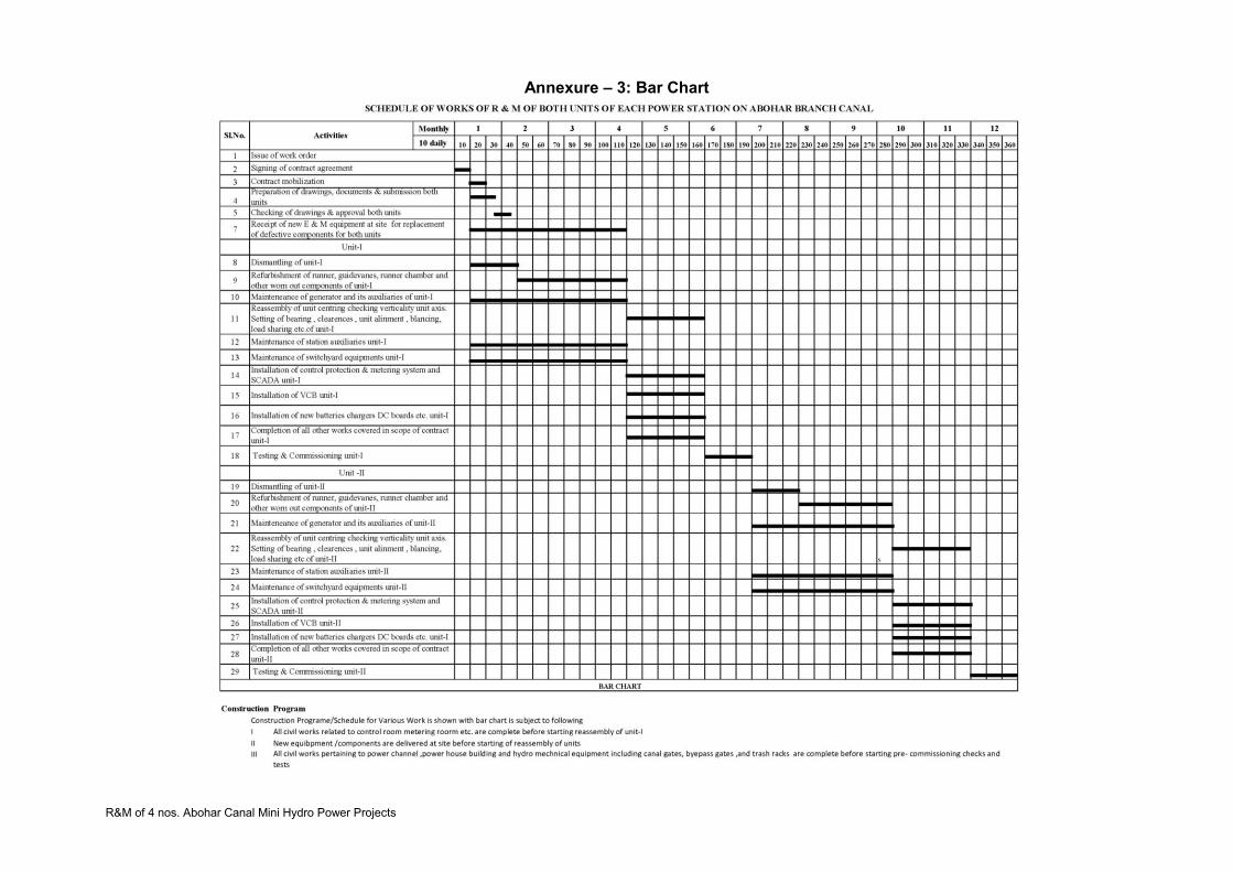
R&M of 4 nos. Abohar Canal Mini Hydro Power Projects
Annexure – 3: Bar Chart

R&M of 4 nos. Abohar Canal Mini Hydro Power Projects
SECTION 6 – GENERAL TECHNICAL SPECIFICATIONS 1. General Requirements 1.1 General
The Contractor shall strictly observe this General Technical Specification in conjunc-tion with the other sections of these specifications. He shall carry out all works in a skilled and workman like manner in conformity with modern methods of engineering. All design; calculations, materials, works, manufacturing and testing shall conform to the latest applicable standards.
In addition, the Contractor shall conform to all applicable regulations regarding the execution of construction and installation work, and shall follow all instructions issued by the competent Authorities, and the Engineer.
The other technical specifications shall take precedence over the general technical
specifications in case of any contradiction or conflict. Clause number cross-references refer to the Section in which they occur unless
stated otherwise. 1.2 Scope of Work
The Scope of work include dismantling of Units (One by one so as to allow operation of remaining units), critically inspect the components which are to be retained, take dimensions of the components necessary for reverse engineering, design, manufacturing & supply new components / equipment, repair the old components at project site / manufacturer’s works, re-assemble the units with new/repaired components, carry out pre-commissioning tests, commission and handover the units to the PGL.
The Contractor shall refurbish, design, manufacture, supply, erect, test & commission
and hand-over to Owner and guarantee for twelve months after commissioning all works complete in every respect with all necessary accessories for reliable, efficient and trouble free continuous operation as per the detailed technical specifications.
These Specifications include the performance of all works and the provision of all
labours, materials, permanent and temporary equipment, tools, accessories for transport to the site, including loading, unloading, if necessary reloading in the port of arrival, intermediate storage, protection of the Works from the effects of the weather, cleaning, drying, storage at site and preservation related works, complete installation, painting, testing and commissioning of all works and accessories of the works.
The Contractor shall make competent and experienced staff available for the training
and assistance of the operating staff during commissioning and trial operation and, if required by the PGL, for a period after completion of the trial operation which shall be agreed separately.
The Contractor shall supply the Operation and Maintenance Instruction Manuals in a
number and at a time as stated in the General and Special Conditions of Contract.

R&M of 4 nos. Abohar Canal Mini Hydro Power Projects
1.3 Standards
Although European or IEC standards for design, stipulated testing, workmanship material and Works have been mostly stipulated in these specifications as a basis of reference, other standards and recommendations of standard international organizations will be acceptable provided they ensure equal or higher quality than those specified, and provided, furthermore, that the Contractor submits for approval detailed standards which he proposes to use.
When IEC or ISO Recommendations or other Standards are referred to, the Edition
shall be that current at the time of issue of Tender Documents, and any Amendments issued till then.
If requested by the Engineer, the Contractor shall supply at his own expense three
copies in English and one in the original language of any national standards, if these are not English, which are applicable to the Contract.
Standard publications issued by the following organizations of standardization are
considered as acceptable standards for the works subject to acceptance of the PGL: 1.3.1 Standards for General Application
AGMA American Gear Manufacturers Association AISI American Iron and Steel Institute ANSI American National Standards Institute ASME American Society of Mechanical Engineers ASTM American Society for Testing of Materials AWS American Welding Society BS British Standards CCITT International Telephone & Telegraph Consulting Committee CECT European committee for Manufacturing of Boilers& Kindred Steel Structures CMAA Crane Manufacturers Association of America DIN Deutsche Institute for Normung IEC International Electro-technical Commission IEEE Institute of Electrical and Electronic Engineers IIW International Institute of Welding IPCEA Insulated Power Cable Engineer's Association IS Indian Standards ISO International Standards Organisation JEC Standards of the Japanese Electro-technical Committee JIS Japan Industrial Standards KS Korean Industrial Standards NEMA National Electrical Manufacturers Association VDE VereinDeutscherElektroingenieure VDI VereinDeutscherIngenieure SIS Swedish Standards Institute USAS United States of America Standards Institute "Not withstanding reference made to various standards all equipment and works as
per provisions and requirements of relevant and latest Indian Standards shall be acceptable“
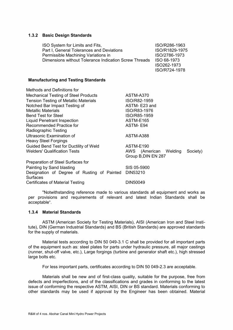
R&M of 4 nos. Abohar Canal Mini Hydro Power Projects
1.3.2 Basic Design Standards
ISO System for Limits and Fits, ISO/R286-1963 Part I, General Tolerances and Deviations ISO/R1829-1975 Permissible Machining Variations in ISO/2786-1973 Dimensions without Tolerance Indication Screw Threads ISO 68-1973
ISO262-1973 ISO/R724-1978 Manufacturing and Testing Standards
Methods and Definitions for Mechanical Testing of Steel Products ASTM-A370 Tension Testing of Metallic Materials ISO/R82-1959 Notched Bar Impact Testing of ASTM- E23 and Metallic Materials ISO/R83-1976 Bend Test for Steel ISO/R85-1959 Liquid Penetrant Inspection ASTM-E165 Recommended Practice for ASTM- E94 Radiographic Testing Ultrasonic Examination of ASTM-A388 Heavy Steel Forgings Guided Bend Test for Ductility of Weld ASTM-E190 Welders' Qualification Tests AWS (American Welding Society)
Group B,DIN EN 287
Preparation of Steel Surfaces for Painting by Sand blasting SIS 05-5900 Designation of Degree of Rusting of Painted Surfaces
DIN53210
Certificates of Material Testing DIN50049
"Notwithstanding reference made to various standards all equipment and works as per provisions and requirements of relevant and latest Indian Standards shall be acceptable“.
1.3.4 Material Standards
ASTM (American Society for Testing Materials), AISI (American Iron and Steel Insti-
tute), DIN (German Industrial Standards) and BS (British Standards) are approved standards for the supply of materials.
Material tests according to DIN 50 049-3.1 C shall be provided for all important parts
of the equipment such as: steel plates for parts under hydraulic pressure, all major castings (runner, shut-off valve, etc.), Large forgings (turbine and generator shaft etc.), high stressed large bolts etc.
For less important parts, certificates according to DIN 50 049-2.3 are acceptable. Materials shall be new and of first-class quality, suitable for the purpose, free from
defects and imperfections, and of the classifications and grades in conforming to the latest issue of conforming the respective ASTM, AISI, DIN or BS standard. Materials conforming to other standards may be used if approval by the Engineer has been obtained. Material

R&M of 4 nos. Abohar Canal Mini Hydro Power Projects
specifications, including grade or class data, shall be shown on the appropriate detailed drawings submitted for review.
For using stock material not specifically prepared for the works under this Contract,
the Contractor shall submit evidence that the material complies with approved standards and that the material is suitable for the intended use.
The materials shall be carefully selected for the intended purpose and with due
consideration of the site conditions and the tropical environment. Higher-grade material shall be used where ordinary material is insufficient.
"Notwithstanding reference made to various standards all equipment and worksshall
be as per provisions and requirements of relevant and latest Indian Standards and shall be acceptable“. 1.3.5 Electrical Standards
The following basic standards for electrical works or any other equivalent approved standards shall be applied:
IS (Indian Standards) Standards issued by IEC (International Electro technical Commission) Standards issued by CCITT (International Telephone and Telegraph Consultative Committee) For specific standards see the Particular Technical Specifications. 1.4 Units of Measurements The international SI-system of units shall be used in documents, calculations, corre-spondence, drawings, etc., relevant to the Tender and the subsequent Contract. 1.5 Works Identification System An approved, uniform Works identification system shall be applied for all Mechanical, Electrical and Instrumentation and Control (I&C) Works to be agreed upon during detailed design. 1.6 Time Schedule
According to the relevant articles in the General and Special Conditions of Contract,
the progress of the work shall conform to the basic Schedule of Work on which the Contract is based. The Schedule to be submitted shall include the following information New Supplies
Design work
Shop work
Testing and inspection of works
Transport to the Site
Storage at site

R&M of 4 nos. Abohar Canal Mini Hydro Power Projects
Works at site
Preparations at the Site
Interdependence with works of other Contractors
Dismantling of unit
Refurbishment/ Repair of identified worn out parts
Replacement of identified items
Erection, testing and commissioning
Acceptance testing
Handing over
Trial operation for thirty (30) days
Removal of erection equipment and clearing of the Site
The Contractor shall pay particular attention to the dates established for the submis-sion of drawings, documents, manuals etc. 2. Technical Documents 2.1 General
This clause specifies the general scope and gives a definition of the documents which, together with those listed in the Technical Specifications, shall be delivered by the Contractor to the Engineer within the periods, and in a number and quality as specified in the General and Special Conditions.
The Engineer reserves the right to request the Contractor for additional documents
as may be required for proper understanding and definition of constructional, operational, co-ordination or other matters.
All documents to be supplied shall be submitted in accordance with the agreed
programme so that any comment made and change requested by the Engineer can be taken into account before starting the manufacture in the workshop and/or erection or installation at the Site.
If the Contractor fails to submit such documents, then the later execution of changes
requested by the Engineer and the resulting additional cost and/or delays shall be the Contractor's responsibility and liability. The Contractor shall not be relieved of his responsibility and guarantee after drawings and computations have been approved by the Engineer.
The preparation of drawings, computations or other technical documents shall not be
sublet by the Contractor without the written authorization of the Engineer. In such a case the Contractor shall be fully responsible for such drawings, computations and other technical documents as if they were done by him.
On drawings, catalogue sheets or pamphlets of standard Works submitted to the
Engineer in charge, the applicable types, paragraphs, data, etc. shall either be marked distinctively or the non-applicable parts shall be crossed out. Documents not marked in such a manner will not be accepted and approved by the Engineer-in-Charge.
For proper understanding of the documents, additional descriptions/explanations
shall be given on these documents or on separate sheets if so requested by the PGL. All symbols, marks, abbreviations, etc., appearing on any document shall clearly be explained by a legend on the same document or on an attached sheet.
R&M of 4 nos. Abohar Canal Mini Hydro Power Projects
Each device appearing on any document (drawing, diagram, list, etc.) shall clearly be designated. The abbreviation mark used for an individual device shall be identical throughout the complete documentation so as to avoid confusion. All documents shall have a uniform title-block and agreed by the Engineer in charge. Beginning with the very first submittal to the Engineer in charge, the Contractor's drawings shall bear a serial number corresponding to a drawing classification plan to be agreed upon by the Contractor and the Engineer in charge. 2.2 Drawings 2.2.1 Loading Drawings
For all larger pieces of Works which, due to their dimensions and/or weight and transport limitations, will require special means for their transportation, the Contractor shall submit binding loading drawings indicating dimensions, weights, etc., of the respective pieces of Works and the necessary trailer for its transportation to the site. 2.2.2 Foundation Drawings
If a piece of Works requires its own foundation or needs a special area for installation, the Contractor shall submit drawings indicating all pertinent dimensions, static and dynamic loads, etc. They shall include all essential details required for proper design and construction of the foundations and/or buildings. In addition, they shall include openings, sleeves, slopes and the arrangement of any supporting structure, i.e. base-frames or other steel constructions for permanent fixing or erection purposes. If conduits are to be installed in the foundations, the relevant information such as diameter, length, and purpose shall be indicated on the drawings. 2.2.3 Arrangement Drawings
All arrangement drawings shall be drawn to scale. The General Arrangement Drawings shall show the physical arrangement of Works (constructions, machines, complete switchgears, control panels, instrument cubicles, etc.), civil constructions (buildings, rooms, foundations, ducts, etc.) and reserved areas (for pipes, cables, lines, etc.) in relation to each other and to agreed co-ordinates and boundaries. Such drawings shall be prepared for the whole plot, for separate plots and for each building (building, hall, room, ducts and trenches, etc.). The Arrangement or Layout Drawings of electrical and instrumentation and control equipment shall indicate the location of all apparatus wherever used, i.e. in or on machines, control boards, switchboards, cubicles, control desks and panels, etc. The apparatus shall be denominated with the same standardised abbreviations as used in all other documents. 2.2.4 Outline Drawings
The Outline Drawing shall show all elements and the main dimensions of individual components where necessary in plan view, cross-section, side and top views. If reasonably possible such dimensions can be shown on Arrangement Drawings.

R&M of 4 nos. Abohar Canal Mini Hydro Power Projects
2.2.5 Design Drawings
The Design Drawings shall include the shop drawings, assembly drawings, erection drawings, piping diagrams and piping arrangement drawings, etc., showing the dimensions, design and data of all constructions, apparatus and Works to be furnished under this Contract.
The drawings shall, where applicable, substantially conform to the Tender Drawings
and shall show:
- Details of manufacturing and treatment of major single work pieces specially manufactured for this Contract
- Assembly of the Works in plan and elevation with main dimensions - Sub-assembly of the principal components of the Works with overall dimensions,
adjustment and clearance tolerances, numbers of corresponding detail drawings - Sub-assemblies in which the Contractor proposes to ship the Works - All necessary details of the parts connecting to the Works supplied by others - Location and sizes of auxiliary connections for oil, grease, water, air, electrical power
etc. - Location and size of the instruments and accessories provided Methods of lubrication
and sealing - Instructions for heat treatment, pressure tests, surface preparation and anti-corrosive
protection - Full details of parts for which adjustment is provided or which are subject to wear - Method and sequence of installation, field joints, erection and lifting devices, jacks,
grout plugs, anchoring details, etc., if not shown on foundation drawings. 2.2.6 Installation Drawings
The construction, mechanical, electrical and I & C Installation Drawings shall provide detailed information on the disposition of the various items of a system (e.g. lighting fixtures, socket outlets, connection boxes, transmitters, actuators, loudspeakers, telephones, pipes, valves, pumps, compressors, etc.) and of the piping and wiring respectively included in the installation or assembly. They shall be based on dimension drawings of cubicles, rooms, buildings or areas containing the Works. 2.3 Diagrams
For electrical diagrams general reference is made to IEC 113-1. "Notwithstanding reference made to various standards all equipment and works as
per provisions and requirements of relevant and latest Indian Standards shall be acceptable“. 2.3.1 Single-Line Diagrams
This is a simplified diagram of the essential electrical Works and their interconnec-
tions. Each circuit shall be represented by a single line only. It shall contain all required technical information of the Works represented, e.g. voltage, current, capacity, short-circuit level, ratios, voltage variations, positive and zero sequence impedances, measuring transformer and protection relay indices, interlocking, kind of switch drive, code designation, etc. as applicable.

R&M of 4 nos. Abohar Canal Mini Hydro Power Projects
Single-line diagrams of individual main components and switchboards shall addition-ally show the control, indicating, measuring, metering, protection, automatic, and other auxiliary electric devices separated for each individual installation site and location as applicable:
Local: Switchboard control compartment, switch compartment, cable termination compartment, etc.
Remote: Control room (from workstation). Unit control Board (from MMI)
Relay (in auxiliary relay cubicle, UCB, LCB, protection cubicle)
Separate energy meter cubicle.
Furthermore, the applied recommended setting of adjustable devices (protection and control elements, time relays, etc.) shall be indicated. 2.3.2 Circuit Diagrams
The Circuit Diagrams shall show the power circuits in all the phases with the main apparatus as well as the pilot circuits (measuring and control circuits). It shall show in full the functioning of part or all installations, Works or circuits with all required technical information.
The control part shall be subdivided into separately drawn "current paths", each
showing all its components regardless of their actual physical location. The individual circuits are to be drawn in a straight-line sequence, avoiding line crossings. The current paths (to be designated by numbers) shall be drawn starting from two horizontal lines, which represent the control voltage source. All devices belonging to the Works or forming part of the Works or control devices shall appear between these two lines.
Contact developments of the installed switches, contactors, relays and other appara-
tus which appear in the diagram shall be shown below the respective contactor coil, indicating by means of numbers and, if not on the same, also the page No., the current path in which the corresponding contact has been used.
Interconnections to other circuit diagrams shall be clearly marked by means of dotted
line separations and the corresponding functional designation. The power circuit portion of the installation shall be drawn at the left side of the
drawing. Circuit diagrams shall also contain all terminals and their correct designations. Termi-
nals grouped together to terminal blocks of switchboards, distributors, etc. shall be shown on the circuit diagrams in one fictitious horizontal line surrounded by demarcation lines. If, for any reason, the current paths of circuit diagrams must be separated, the corresponding counter terminal has to be indicated by all means.
The representation of electrical Works and control circuits shall not be terminated at
the limits of the scope of supply, but has to be extended beyond this limit by all switchgear, protective, measuring and monitoring equipment required for full comprehension of the whole circuit. All terminals and functions of Works to be supplied by others shall be taken over as well.
Standard Circuit Diagrams are patterns of circuit diagrams which have been
standardised with regard to scope, arrangement, representation and allocation of Works with the aim of simplification and easy surveillance of electrical circuitry.
R&M of 4 nos. Abohar Canal Mini Hydro Power Projects
2.3.3 Block Diagrams
The Block Diagrams shall be used to show in a simplified manner the main inter-rela-tionships between the elements of a system by means of symbols, block symbols and pictures without necessarily showing all the connections. The symbols used for the individual kinds of components, e.g. servomotors, computing modules, etc., shall clearly be explained on the diagram or on an attached legend.
Wherever possible, a Block Text Diagram may be prepared, consisting essentially of
explanatory texts enclosed in outlines which are linked by lines showing the functional relationships that exist between the various parts of an installation, Works or circuit. 2.3.4 Logic Diagrams
The Logic or Functional Diagrams shall be used for representation of logic and
sequence controls and interlocking by showing only binary logic elements and their effect on the various process equipment disregarding their electrical realisation. Logic function elements (AND, OR, NOR, NAND, STORAGE, etc.) shall be used for processing and combining binary signals. 2.3.5 Terminal Diagrams
Such diagrams shall be prepared for any type of terminal box, marshalling rack, con-
trol cubicle, switchboard, etc., and shall show the terminals (properly numbered) and the internal and/or external conductors (wires or cables) connected to them.
The terminal diagram of each individual switchboard, terminal box, panel, etc., shall contain, but not be limited to the following information: Terminal number of terminal board with targets (terminal number and current path) of incoming and outgoing cables and wires. Cable designation Type of cable Number and cross-section of conductors Assignment of conductors Number of spare conductors Approx. length of cable and its destination. 2.3.6 Protection Co-ordination Diagrams
These diagrams shall show in a graphical manner separately for each power supply
circuit: A simplified single-line diagram of the circuit with technical data of all instrument
transformers and relays. Co-coordinated tripping curves of related protection devices. Setting of the protection devices.

R&M of 4 nos. Abohar Canal Mini Hydro Power Projects
2.4 Specifications 2.4.1 Material Specifications
Such specifications shall be prepared for all principal Works and installations. They shall describe the performance (design, material, dimensions, corrosion protection, etc.) of the Works and include a list of components providing information on the manufacturer, type and technical data to obtain the following: Full information on the Works, completing the general requirements fixed in the Tender Specification by the data/information of the specific manufacture. Proof of compliance with Contract Specification. For standard Facilities (for example valves, switchgear, control gear, relays, transmitters, indicators, lighting fittings, etc.) catalogues or pamphlets shall be submitted. The technical data of electrical Works shall include as a minimum:
Max. Permissible ambient conditions (temperatures, humidity) Rated current and rated output/capacity Same data as above under specified severest site conditions Rated voltage and ratio or regulation/setting range Max. Service voltage (acc. to IEC) Power frequency and impulse withstand voltages Type and code No. of protection relays and of instantaneous or thermal releases directly attached to circuit breakers and contactors Power requirements for each voltage level (A.C./D.C.). Specific requirements are described in the following paragraphs.
2.4.1.1 Motor Specifications
The motor specifications shall include the thermal motor characteristic both for cold
and hot condition, the start-up characteristic when running with the driven machine and all data required for selection of the appropriate motor protection relay (both for cold and hot condition) and for locked rotor protection. Construction type, class of protection and insulation shall also be given. 2.4.1.2 Cable Specifications
The General Cable Specification shall include the calculation of the de-rating factors
for the individual modes of installation at applicable ambient temperatures and grouping of cables, and furthermore, for each cross section:
The rated current carrying capacity The maximum Short-circuit capacity The voltage drop Type, insulation serving, armouring and sheathing of cable Type, description and catalogue/pamphlet of cable termination. Separate specification(s) shall be prepared for cable trays, conduits, supporting structures and other accessories.

R&M of 4 nos. Abohar Canal Mini Hydro Power Projects
2.4.1.3 Measurement and Control Apparatus Specifications The accuracy of performance with respect to variable ambient conditions and the power supply requirements shall be included. 2.5 Lists and Schedules 2.5.1 Motor Lists The motor lists shall be prepared according to the power distribution boards. The motors are connected to, and shall contain at least the following information/data:
Works identification number Description Manufacturer, type, rated data of driven machine Manufacturer and type of electric motor/consumer Rated capacity Service factor (ratio between motor output and power requirement of the driven machine) Rated speed Rated voltage Rated current Ratio of starting current to rated current Ratio of pull-out torque to rated torque Power factor at rated capacity Efficiency at rated capacity Power consumption at machine design loading Total weight Design/enclosure/cooling (acc. to IEC) Duty (continuous/intermittent/start-up) Starting method/permissible starting frequency Denomination of feeder Motor protection Applicable Standard Circuit Diagram (Category) Maximum number and overall diameter of power cable(s) Manufacturer and type of bearing(s) Manufacturer, type and quantity of lubricant, service interval Manufacturer, type, number, size, spring pressure and service interval of brushes (if applicable).
2.5.2 Motor Starter Lists
The motor starter lists shall include all starters and contactors used for motors and
contain the following technical information as a minimum: Works identification number Electrical design data as nominal and actual current rating, voltage rating, coil rating, making and breaking capacity, mode of operation Maximum power cable size Maximum control cable size Current transformer ratio, class and capacity Type of protection relaying and catalogue number Setting of protection relays and maximum continuous rating of the protected circuit Type and current rating of the back-up fuses/MCBs for the main and control circuits.
R&M of 4 nos. Abohar Canal Mini Hydro Power Projects
Note: Motor Starter Lists can be substituted by part lists, already forming part of switchgear manuals 2.5.3 Cable Lists/Interconnection Lists
The Cable Lists shall include for each individual cable the following as a minimum:
Cable number, in accordance with Identification System.
Cable type Rated voltage Number and size of conductors Overall diameter Cable termination at each end Connection point at each end with cubicle/Works identification and terminal numbers Cable routing
In case interconnecting cubicles are used, the lists shall be prepared to show:
Cable termination for incoming and out coming cables Interconnection wiring
2.5.4 List of Measurements
This list shall indicate all measurements, local as well as remote, and shall contain at
least:
Item/code number, function code Description and denomination of measuring loop Data of tapping point Data of local devices (as detectors, instrument transformers, transmitters) Data of remote devices.
2.5.5 Alarm Lists
These lists shall indicate all alarms and shall contain at least:
Item/code number and function code Description and denomination of alarm Data of alarm detector (contact) referring to applicable circuit diagram Data of alarm annunciator (location and clear text labeling)
2.5.6 List of Final Control Elements
This list shall indicate all control actuators and control valves and shall contain at least:
Item/code number Data of pipe and valve connections Data of valve layout Rated power
R&M of 4 nos. Abohar Canal Mini Hydro Power Projects
2.5.7 Workshop Test Schedules Individual Workshop Test Schedules shall be prepared for Works/installations (such
as pipes, cranes, machines, switchgears, control gear, cables) and shall contain at least: Works identification number Manufacturer Place of manufacture Place of test Date of test Objective of test (all individual tests) Standards applied Certification Inspection (by Engineer / Independent Test Authority / Contractor/ Subcontractor) Release for shipment Remarks On the above schedule or on separate sheets the Test Procedure shall be specified
giving for each test item (kind of test) a description, test method / Standards, used instruments, sample/routine test, test judgment. 2.5.8 Site Test Schedules
Testing at site shall include tests specified in the Technical Specifications and any
tests recommended by the manufacturers as per their standard practices. 2.5.9 List of Tools and Appliances
Lists of Tools and Appliances shall detail for all tools and appliances included in the
scope of supply: Item and code number Description Quantity Weight
Gross storage requirements (separate for open-air, indoor, air-conditioned) for indi-vidual component sets. 2.5.10 Spare Part Lists
Spare part lists shall detail for all spare parts included in the scope of supply:
Detailed drawing (where possible) Item and code number Description Quantity Weight
Gross storage requirements (separate for open-air, indoor, air-conditioned) for indi-vidual component sets.
R&M of 4 nos. Abohar Canal Mini Hydro Power Projects
2.5.11 List of Works Identification Numbers This list shall contain the identification numbers of Works in alphanumeric order and
for each of them a description (the defined Works denomination, for example as written on the Works label) and the location (short definition of outdoor area and level elevation or building/room with elevation and room number). 2.7 Installation and Commissioning Procedures 2.7.1 Installation Procedures
The installations procedures shall describe in sequential steps the erection of major
equipment and shall contain sufficient details such as equipment preparation on erection bay, handling of large and heavy pieces, leveling, anchoring, site welding, site painting, erection checks, site pressure tests, site flushing and cleaning of hydraulic systems, alignment and run out checks to allow the engineer/PGL to plan and supervise the Works at site, if required. 2.7.2 Pre-Commissioning Tests and Procedures
Pre-commissioning tests and procedures shall be described in sequential steps for
the pre-commissioning of all electrical and mechanical equipments and shall also contain sufficient details viz. checking of installations, ratings, cable terminal checking and operation test of all auxiliary equipments etc. 2.7.3 Commissioning Procedures
The commissioning procedures shall sequentially and in sufficient detail describe
activities and tests for all systems covered by the Contract Document. 2.7.4 Commissioning Test
Commissioning acceptance tests shall be carried out, on all generating units to verify
the rating characteristics of generating units and other equipment’s in accordance to relevant standards. The complete field acceptance test reports shall be prepared by the Contractor and submitted to the PGL for approval. 2.7.5 Test Run
The test run on generating units shall be carried out as per relevant provisions of IEC
standards. 2.8 Operation and Maintenance Manuals 2.8.1 Contents
The Operation and Maintenance Manuals shall be provided in Ten (10) copies along
with CD-ROM (three sets), and shall contain the following information in sufficient detail to enable the PGL to maintain, dismantle, reassemble, adjust and operate the Works with all its items of Works and installations:
Table of Contents List of Illustrations Introduction
R&M of 4 nos. Abohar Canal Mini Hydro Power Projects
The Introduction shall contain:
A brief general description of the Works items A brief description of the use of the Works items Definitions of technical terms used in subsequent graphs of the instruction
book A complete list of all items used in accordance with the Works Components
Identification System. Detailed Description
Detailed description shall contain a complete and accurate description of the Works, all components and ancillaries, their assembling and dismantling. An accurate list stating clearances, tolerances, temperatures, fits, etc. shall be included.
Operating Principles and Characteristics
A brief summary of the technical operating principles of the Works, including dia-grams, circuit diagrams, sequence diagrams, piping, etc.
Operating Instructions
The instructions shall be accurate and easy to understand, and shall contain the sequence of individual manipulations required for operation. The information shall be presented in such a manner that the contents of this paragraph can be used for instructing personnel in the operation of the Works. Tables, lists and graphic pres-entations should be used whenever possible for making the description readily understandable. An appropriate trouble-shooting list shall be included in this chapter.
Testing and Adjustment
The entire testing and adjustment procedure required for the Works after overhauls and during operation shall be described.
Maintenance Instructions
This section is divided into six parts:
1) Preventive maintenance, indicating the inspections required at regular intervals, the inspection procedure, and the routine cleaning and lubricating operations, the regular safety checks and similar steps.
The maintenance instructions shall include a tabular (or in other approved form)
summary of the required activities sorted according to
Daily Weekly Monthly Quarterly Yearly (Or other) cycles as applicable.
This document shall provide the maintenance engineer with brief and yet fully
comprehensive information including all references to the applicable, detailed service and maintenance instructions.
R&M of 4 nos. Abohar Canal Mini Hydro Power Projects
2) Repair and adjustment, describing the inspections, fitting and dismantling of parts,
fault tracing as well as repair and adjustment procedures. 3) Spare part lists, containing all the necessary data for ordering spare parts. These
lists shall include all spare parts, those to be supplied and those not to be supplied under the present Contract. Detailed drawing for each item of spare parts shall be supplied. The above list should include minimum and maximum quantities of spares to be maintained by the project.
4) Tool lists, containing all necessary data for identification of tools to be delivered under the present Contract. 5) List of suppliers and alternative suppliers and addresses. 6) As-built drawings 2.8.2 Performance
Each drawing aforementioned shall have a uniform size. The final size of drawings
for the Operation and Maintenance Manual shall be decided by the Engineer-in-charge. Catalogue sheets, illustrations, printed specifications, etc., shall be checked and prepared by the Contractor in such a way that the figures, statements and data valid for the delivered sizes and types of the Works concerned are clearly marked. All figures, statements and data valid for sizes and types not delivered must be crossed out. 2.8.3 Revisions and Supplements
The completeness of the manuals shall be checked during installation, testing, com-
missioning and trial operation jointly by the Contractor and Engineer- in- charge. If it becomes evident during the installation, commissioning trial operation and
defects liability period of the Works that the Operation and Maintenance Manuals are inade-quate or incorrect, the Contractor shall supply immediately the necessary supplements and corrections. This shall be handled in the following manner: Deletions:
One sheet of errata, printed on pink paper, shall be issued indicating the pages and date of issue of those pages, which are to be deleted, and are no longer valid.
Corrections, Revisions, Replacements:
New sheet or sheets shall be issued to replace the wrong pages. Whenever a new sheet is added to the instruction manuals, this sheet shall be given the new date of issue and a revision symbol, and an indication "Substituted for ... " and a marking of the corrected/revised items.
Insertions, Supplements:
Insertions or supplements shall be accompanied by a new respective "Table of Con-tents" page, where the latter shall be handled as described above under replace-ments. The revisions and supplements requested by the Engineer-in-charge shall be made by the Contractor at the Site as far as possible and shall be submitted in each case to the Engineer for checking and approval as stated above.
R&M of 4 nos. Abohar Canal Mini Hydro Power Projects
Before issuing the "Taking-Over Certificate", the ten sets of revised copies of the Operation and Maintenance Manuals shall be submitted together with the specified number of complete sets of drawings of the Works as completed. The Works shall not be considered complete for purposes of taking over under the terms of the General Conditions of the Contract until the above documents have been supplied by the Contractor.
2.9 Progress Reports during Design and Manufacturing
During every quarter design and manufacturing the Contractor shall quarterly submit
four (4) copies of the progress reports in a format acceptable to the Engineer, detailing the progress of the work during the preceding period. The report shall contain (but not be limited to) the following information:
A general description of the Works performed during the reporting period on each main activity, and include any notable problems, which were encountered.
The total overall percentages of design and manufacturing works completed, with reference to the CPM programme. Appropriate comments shall explain any differences.
The percentages of each main work activity completed during the reported quarter
vis-à-vis the scheduled programme. Appropriate comments shall explain any differences. A list of all activities of scheduled and actual progress during the reporting period
including actual starting dates versus scheduled starting dates and actual completion dates versus scheduled completion dates for each activity. Appropriate remarks shall explain any differences, and also methods/actions prepared to be taken for making up the deficiencies in actual design and manufacturing process.
A list of activities scheduled to be started within the next two (2) months, with
expected starting and completion dates. If the expected starting and/or completion dates are different from those shown on the CPM programme, an explanation shall be given. 2.10 Progress Reports during Installation at Site
During erection the Contractor shall, before the tenth (10th) day of each calendar
month, submit four (4) copies of the monthly progress reports in a format acceptable to the Engineer, detailing the progress of the work during the preceding month. The report shall contain (but not be limited to) the following information:
A general description of the Works performed during the reporting period on each
main activity, and includes any notable problems, which were encountered. The total overall percentages of erection works completed, with reference to the CPM
program. Appropriate comments shall explain any differences. The percentages of each main work activity completed during the reported month
with reference to the scheduled program. Appropriate comments shall explain any differences.
A list of all activities of scheduled and actual progress during the reporting period
including actual starting dates and scheduled starting dates and actual completion dates, scheduled completion dates for each activity. Appropriate remarks shall explain any differences.
R&M of 4 nos. Abohar Canal Mini Hydro Power Projects
A list of activities scheduled to be started within the next period of two (2) months, with expected starting and completion dates. If the expected starting and/or completion dates are different from those shown on the CPM program, an explanation shall be given. A list of local manpower (by trade classification) employed during the reporting period. A list of expatriate personnel (by position) employed during the reporting period.
A list of the Contractor's Equipment and materials available at the Site at the beginning of the report period. Also a list of equipment and materials, which arrived at Port of entry and status of custom clearance.
Photographs of progress of significant events. The Engineer-in-charge may demand
specific photographs if deemed necessary.
Main items of temporary facilities constructed during the reporting period.
A statement detailing the status of progress on the overall program and how to regain any lost time or setbacks, which may have occurred. A list of inoperable temporary equipment, and the estimated date when the repair will be completed. A statement about labour relations & an explanation of actual and potential problems. A listing of each accident at the site involving the hospitalization and/or death of any person. A listing of the amount & date of any payments received during the reporting period & the amount of any monthly invoice, which has been submitted but not yet paid. A list of claims (if any) submitted during the reporting period including the claimed cost & extension of time. A statement concerning potential problems and recommendations on how they could be resolved. 3. SPARE PARTS AND TOOLS
3.1 Spare Parts All spare parts to be supplied shall be interchangeable with the corresponding parts
of all the Works supplied under these Specifications and shall be of the same material and workmanship. They shall be replaceable without cutting or destruction of adjacent components. Before issue of the Taking-Over Certificate the spare parts shall be checked at the Site by the Contractor in presence of the Engineer in charge.
Acceptance of any spare part will not take place before the Contractor has submitted
the complete final detailed list of all spare parts and tools. All spare parts shall be protected against corrosion and shall be marked with identifi-
cation labels in English. The identification shall be in accordance with the agreed Works Identification System.

R&M of 4 nos. Abohar Canal Mini Hydro Power Projects
All spare parts, tools and materials shall be delivered in marked boxes of sufficient sturdy construction to withstand long term storage. 3.1.1 General Spare Parts
At least the quantity of general spare parts specified below shall be included in the
Total Tender Price and consequently in the scope of Works of the Contract. If the same spare parts are listed twice under "General Spare Parts" as well as under
“Spare Parts", the quantity listed under "Spare Parts" shall take priority over the quantity stipulated under "General Spare Parts".
Spare Parts subjected to Wear and Tear.
For each installed assembly such as Servomotors, Pumps, Motors, Main Inlet Valves, Pressure Oil Units, Gates, Valves, Compressors, Cranes, Machine Tools etc. the following general Spare Parts shall be delivered.
One (1) complete sets of:
Facing rings of mechanical seals Protection sleeves Carbon brushes for motors (if applicable) Inserts of filters Bearing bushings Brake liners Pickings Roller bearing for rotating shafts and seals for rotating shafts Driving belts Wearing parts of couplings Frequently actuated springs Outdoor installed pressure hoses
Wear and tear items shall be defined as such, which require replacement several
times during the service life of the assembly.
Customary Spare Parts:
For a number of like and identical assemblies the following spare parts shall be deliv-ered, whereas one set shall be defined as the total quantity for one assembly:
"X” Complete Sets related to "Identical Assemblies":
Seals, gaskets and packing Thermometer, manometer, flow meter, level indicator (with and without
contacts) Transducer 4/20 mA for position, pressure, temperature, flow Indoor installed pressure hoses Lamps, signal lamps, push button and switches Fuses, clamps Limit switches, auxiliary relays, pressure switches Roller bearings, sleeves and bushings for movable parts including for
spherical joints Ball bearings.
Resistance thermometer without indicator
R&M of 4 nos. Abohar Canal Mini Hydro Power Projects
Motor-starters, contacts for feeder switches Springs
"X" Complete Valves and Gates:
Related to "Identical Installed Standard Valves and Gates" (manually, hydraulically or electrically driven) including Drive like
Shut-off valves and cocks Globe valves, needle valves or butterfly valves Non-return valves Pressure relieve valves Pressure reducing valves All solenoid valves Safety valves Aeration and venting valves Float controlled valves
The Contractor shall provide 5%, but at least two pieces of all bolts, screws, nuts,
washers, spanner rings and cotters. The quantity may be taken from the surplus handed over to the PGL after completion of the installation "Bolts, Screws, Nuts, etc." of this Section.
For all items under this Contract the Contractor shall deliver 5 % of the quantity of
painting material, but at least one litre, in new sealed containers, for later repair work other than the Contractor's.
Parts with a special size or properties, as listed below are excluded as General
Spare Parts:
Bolts, screws, nuts, washer, spanner rings and cotters with a nominal diameter of more than 80 mm.
Roller bearings, bearing shells, sleeves and bushings for movable parts including for spherical joints with an inner diameter of more than 200 mm.
All valves and gates with a nominal diameter of more than 600 mm.
Main seals for gates, valves, access doors and openings with a total length of more than 2.40 m in straight length or circumference.
3.1.3 Recommended Spare Parts
If any additional spare parts are recommended by the Contractor, these shall be
stated in quantity and description in the Technical Data Sheets for each item. Orders for recommended spare parts shall be optional to purchase by the PGL for a
period of five (5) years after the date of the completion of the project. However optional spare parts will not be considered in tender evaluation.

R&M of 4 nos. Abohar Canal Mini Hydro Power Projects
3.2 Tools and Appliances The scope of work shall include all customary and special tools, as well as auxiliary
devices including lifting devices, ropes, etc. necessary for total assembly and disassembly of all parts of the supplied Works. Furthermore, all accessories for maintenance shall be supplied and included in the Tender. The total price for tools and devices as required by this article shall be included in the Total Tender Price.
The tools, wrenches, etc. shall be unused. Customary tools for erection shall be of
the forged and polished chrome-vanadium type. Use of special tools and devices for erection shall be allowed, but shall be approved by the Engineer in each case. Special tools and devices shall be provided with means for ready identification.
All lifting devices and wire ropes slings to be used at site shall be tested at works and
test certificate shall be supplied to the Engineer. Suitable hardwood or steel boards arranged for wall mounting as well as tool carts
and/or toolboxes shall be included in the delivery. An itemised list and description of all provided tools, auxiliary devices, storage equipment, etc. shall be included in the Tender. Acceptance of any tool or device shall not take place before the Contractor has submitted the complete final detailed List of Tools and Appliances.
Ropes, slings etc. shall be handed over in new condition. The PGL shall be entitled
to take over from the Contractor the entire erection tools, appliances, instruments at mutually agreed conditions.
4. Design and Manufacture 4.1 General
Design, manufacture and construction requirements shall generally be as described
below besides complying with the specific requirements elaborated in particular technical specification 4.2 Design and Construction Requirements
The following directions, information and technical requirements for layout, design
and erection shall be observed as far as they are applicable to the Works to be offered. The technical requirements of the General Technical Specifications are valid for all parts of the Works except where they are modified by additional and/or special requirements, specified in the other Technical Specifications.
Whenever a Contractor deviates from these Specifications, he shall furnish the data
called for in Section 3 and give a summary of and the reasons for all deviations in the "Deviations from Technical Specification’’. Failure to accomplish this may cause the rejection of his Tender, especially when a major deviation is involved.
All changes in the design of any part of the Works, which may become necessary
after signing the contract, have to be submitted in writing to the Engineer for approval, with substantiation and justification.
Additional cost can only be accepted, in case of a basic design change, required by
the Engineer-in-charge after award of Contract.

R&M of 4 nos. Abohar Canal Mini Hydro Power Projects
The Works shall be designed, manufactured, arranged and installed to meet func-tional needs and to provide neat appearance. All parts of the Works shall be arranged to facilitate supervision, maintenance and operation. All control sequences shall be simple and rational.
The parts of the Works shall be designed and arranged so that they can be easily
inspected, cleaned, erected and dismantled without involving large scale and time consuming complex dismantling of other parts of the Works. They shall be designed, and manufactured in accordance with the latest recognised rules of workmanship and modern engineering practice.
The regulations, standards and guidelines listed in these Specifications shall be
observed in the design, calculation and manufacture of the Works. All parts of the Works shall be suitable in every respect for continuous operation at
maximum output under the climatic conditions and operating conditions prevailing at the Site.
Special attention shall be given to Works, parts of which are delivered by different manufacturers. Problems arising in this conjunction shall be solved by the Contractor and be defined in writing.
For individual items of the Works, materials and design are to be selected which are
best suited for the most severe operating conditions to which the parts in question will be subjected. Only such design and types of Works shall be offered which have proven reliability in long-term continuous operation.
All live, moving and rotating parts shall be adequately secured in order to avoid
danger to the operating staff. All electrical components shall be electrically earthed. Contractor shall take appropriate measures to prevent the ingress of dust into any
Works (such as bearings, relays, control and measuring equipment, winding, oil tanks, etc.), which may be endangered thereby.
Suitable lifting eyes and backing-out bolts shall be provided where required or where
they will be useful for erection and dismantling. Pockets and depressions likely to hold water shall be avoided, and if not avoidable
they shall be proper self-draining arrangement. Parts of the Works principally intended for standby purposes shall be protected from
corrosion by careful choice of material and if necessary, by additional means; these should not reduce their continuous standby readiness.
All design details and layout matters shall be discussed in periodic meetings with the
Engineer- in- charge. The first design meeting between the contractor and the Engineer – in - charge shall take place within 60 days after the date of signing of the contract or placement of the order. Further design meetings shall take place as agreed between the participants until the design work is completed. 4.3 Allowable Stress
The design of the parts of items of Works shall fundamentally consider the most
severe conditions to which they will be subjected during testing and operation.

R&M of 4 nos. Abohar Canal Mini Hydro Power Projects
If different stress values are given in the General/Particular Technical Specifications or in the relevant standards and regulations, then the most stringent values shall be applicable.
The dimensions of the parts which are exposed to repetitive and alternating stresses
as well as to impacts and vibrations shall take into account the safety measures approved in practice. 4.4 Design Criteria
The plant equipment shall be designed for the worst possible combination of the
following loading conditions as applicable: All static and dynamic hydraulic loads, All loads due to dead weight and frictional forces, Seismic or wind loads, and Other loads
4.4.2 Seismic Loads
The forces being caused by earthquake including hydraulic loads, which may occur
additionally, shall be taken into account for the computations. Stresses resulting after including these loads shall not exceed permissible stresses.
4.4.3 Wind Loads
The basic wind load as per IS 875 (Part - 3) shall be applied on the vertical projected
area, multiplied with the applicable factor for the different type of structures. 4.5 Tolerances
Gates Water leakage under any head and without the use of any additional sealing
materials per m length of seal:
For Penstock butterfly Valve 1.0 l/m/m 4.6 Standardization of Works
Every effort shall be made to standardise parts and minimise costs of the Works
throughout the Works in order to facilitate keeping stocks, maintenance, replacement, interchangeability, etc.
The Engineer-in-charge, therefore, reserves the right to demand the different
contractors to use uniform types or makes of works & materials. The contractor shall not be entitled to claim extra payment on this account. This shall especially be applicable to small mechanical and electrical works such as:
Valves Thermometers Pressure gauges Flow meters Water level gauges
R&M of 4 nos. Abohar Canal Mini Hydro Power Projects
Terminals & terminal racks Indicating instruments & meters Auxiliary relays Contactors, fuses Motor protection switches Control devices Lights, bulbs, plugs, sockets Limit switches Level switches
The types or makes to be used shall be decided later by the Engineer-in-charge. All
instrument scales shall be written in the ruling language of the contract and in the international SI- System of units. 4.7 Quality of Materials and Works
For general requirements concerning the quality of materials and Works, the
applicable sections of the Technical Specifications, Section-14 may also be referred. 4.8 Noise
The noise level caused by the installed Works shall not exceed the following values if not otherwise stated in the Technical Specifications:
Machine hall, workshops, etc. - max. 85 dB (A) at any place 1 m distant from operat-ing equipment. Offices, control rooms, first aid rooms, canteens, etc.- max 55 dB (A) Emergency diesel generators max. 85 dB (A) at 1 m distance, open field The noise level definition and measurement shall be in accordance with relevant ISO and IEC. The values stated shall be adhered to taking a normal civil construction into account. "Not withstanding reference made to various standards all equipment and works as
per provisions and requirements of relevant and latest Indian Standards shall be acceptable“. 4.9 Identification Plates 4.9.1 General
Each important part to be delivered under this Contract shall be equipped with
permanent identification plates in readily visible locations. Whether a part shall be consid-ered as important in this respect shall be decided by the Engineer.
The identification plates shall be protected during erection and especially during
painting. Damaged or illegible identification plates shall be replaced by new ones. The identification plates of non-corroding, non-disintegrating material (except manufacturer's nameplates of small standardised components) shall be inscribed in the Contractual language.
The inscription shall be printed, stencilled, or hand-written, but in any case,
waterproof, oil-proof and wear-resistant. Works (machines, transformers, etc.) nameplates shall be either of the enamelled type or be of stainless steel covered after stamping with a transparent paint. Wording, size and material of all labels and plates shall be subject to the Engineer's approval.
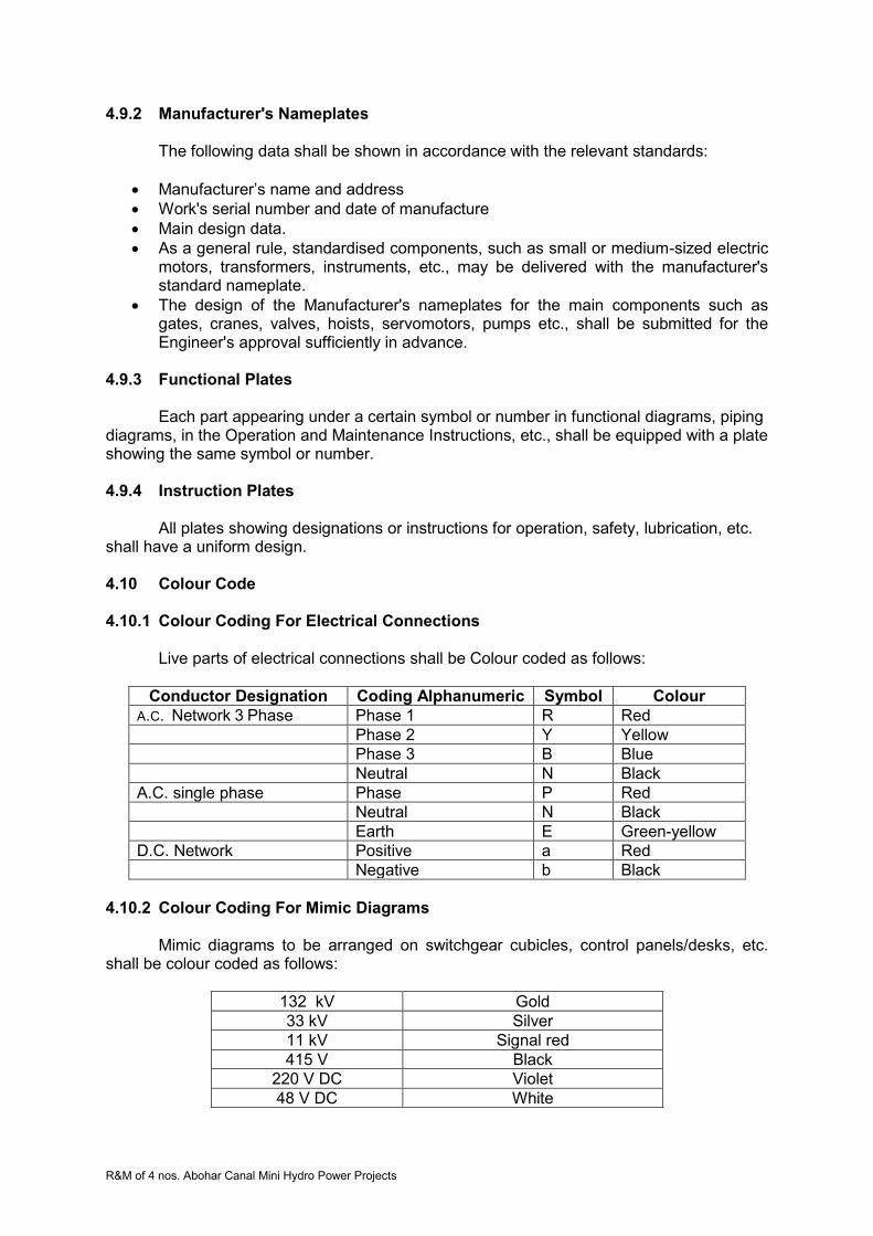
R&M of 4 nos. Abohar Canal Mini Hydro Power Projects
4.9.2 Manufacturer's Nameplates The following data shall be shown in accordance with the relevant standards:
Manufacturer’s name and address
Work's serial number and date of manufacture
Main design data.
As a general rule, standardised components, such as small or medium-sized electric motors, transformers, instruments, etc., may be delivered with the manufacturer's standard nameplate.
The design of the Manufacturer's nameplates for the main components such as gates, cranes, valves, hoists, servomotors, pumps etc., shall be submitted for the Engineer's approval sufficiently in advance.
4.9.3 Functional Plates
Each part appearing under a certain symbol or number in functional diagrams, piping
diagrams, in the Operation and Maintenance Instructions, etc., shall be equipped with a plate showing the same symbol or number. 4.9.4 Instruction Plates
All plates showing designations or instructions for operation, safety, lubrication, etc.
shall have a uniform design. 4.10 Colour Code 4.10.1 Colour Coding For Electrical Connections
Live parts of electrical connections shall be Colour coded as follows:
Conductor Designation Coding Alphanumeric Symbol Colour
A.C. Network 3 Phase Phase 1 R Red
Phase 2 Y Yellow
Phase 3 B Blue
Neutral N Black
A.C. single phase Phase P Red
Neutral N Black
Earth E Green-yellow
D.C. Network Positive a Red
Negative b Black
4.10.2 Colour Coding For Mimic Diagrams
Mimic diagrams to be arranged on switchgear cubicles, control panels/desks, etc.
shall be colour coded as follows:
132 kV Gold
33 kV Silver
11 kV Signal red
415 V Black
220 V DC Violet
48 V DC White

R&M of 4 nos. Abohar Canal Mini Hydro Power Projects
Note: Colours mentioned above shall be finally agreed upon during detailed design. The colour code for equipment not listed in the above mentioned Specifications shall be agreed upon after award of the Contract. The colouring of pipelines, moving parts, etc., shall be according to internationally recognised standards. 4.11 Workmanship
The Contractor shall level and adjust all parts of the equipment on the foundations
and after each item is set up and the Engineer-in-charge approval obtained, grouting or con-creting will be carried out by other contractors and verified by the Contractor. The Contractor shall be responsible for ensuring that such work is carried out to his satisfaction and that level and adjustments made by him are not disturbed by the grouting operation. The Contractor shall be responsible for ensuring that the positions, levels and dimensions of the Works are correct according to the drawings notwithstanding that he may have been assisted by the Engineer in setting out the said position, levels and dimensions. 4.11.1 Finished Surfaces
Where the finish is not indicated or specified, the type of finish shall be most suitable
for the surface to which it applies and shall be consistent with the class of fit required. Surfaces to be machine-finished shall be indicated on the shop drawings by symbols.
Compliance with the specified surface shall be determined by the sense of feel and by visual inspection of the work compared to applicable "Standard Roughness Specimens", or with roughness feeler gauge instruments. Both "Standard Roughness Specimens" and feeler gauge instrument shall be procured by the Contractor at the request of the Engineer. 4.11.2 Unfinished Surfaces
As far as practicable, all works shall be laid out to secure proper matching of
adjoining unfinished surfaces. Where there is a large discrepancy between adjoining unfinished surfaces, they shall be chipped and ground smooth, or machined to secure proper alignment.
Unfinished surfaces shall be true to the lines and dimensions shown on the drawings
and shall be chipped or ground free of all projections and rough spots. Depressions or holes not affecting the strength or usefulness of the parts shall be filled in a manner approved by the Engineer. 4.11.3 Protection of Machined Surfaces
Machine-finished surfaces shall be thoroughly cleaned of foreign matter. Finished
surfaces of large parts and other surfaces shall be protected with wooden pads or other suitable means. Unassembled pins or bolts shall be oiled or greased and wrapped with moisture-resistant paper or protected by other approved means.
4.11.4 Rounding, Chamfers, Edges
The edges of surfaces to be painted shall be rounded (minimum radius 2 mm) or
chamfered accordingly. This requirement must be stated in all shop drawings for the relevant parts.

R&M of 4 nos. Abohar Canal Mini Hydro Power Projects
4.12 Welding and Heat Treatment 4.12.1 General
All welds shall be as shown in detailed drawings and shall be made in such a manner that residual shrinkage stresses will be reduced to a minimum.
The Contractor shall submit with his Tender adequate information concerning the
proposed:
Extent to which automatic welding techniques will be applied;
Extent to which manual welding techniques will be applied;
Extent to which he intends to use pre-weld heat treatment, post-weld stress relieving, full anneal stress relieving or normalising consistent with the thickness and types of material proposed;
Weld electrodes, welding wire and flux, which will be used with the selected plate material or materials;
Standard tolerances for the deviations of mating weld profiles. 4.12.2 Welding Pieces to be joined by welding shall be cut accurately to size including the required allowances. According to the proposed welding method, the welding edges shall be sheared, flame-cut or machined to allow thorough penetration and fusion of the weld with the base material. The cut surfaces shall be free of all visible defects, such as laminations, surface defects caused by shearing or flame-cutting operations. The edges and surfaces to be welded shall be free of rust, mill scale, grease, oil, paint or any other foreign matter. Welding over zinc primers shall be permitted subject to submission of a certificate of a recognised institution stating the pertinent limiting parameters for this welding procedure. In all other cases, welding over paint shall be prohibited; all painting materials next to the joint to be welded shall be removed well beyond the heat-affected zone. Unless otherwise allowed by the Engineer in charge, all steel parts to be welded shall be manufactured of steel produced by the open hearth or electric furnace with Carbon content not higher than 0.20 % and a phosphorous content of not more than 0.05 %. Wherever welding is specified or permitted, a welding process approved by the Engineer-in-charge and conforming generally to DIN or other approved standards shall be used. Approval of the welding process shall not relieve the Contractor of his responsibility for correct welding, the use of correct electrodes and for minimizing distortion in the finished structure. When the welding process has been approved by the Engineer in charge, the Contractor shall produce a record drawing to show the approved process. The drawing shall include details such as the form of edges to be welded, electrodes and other welding mate-rials, welding sequence, etc. Changes in the welding process after the welding method has been approved shall require the consent of the Engineer in charge. Where possible, welding shall be carried out in the workshop. Welding which has to be performed in the field shall be clearly so indicated on drawings.
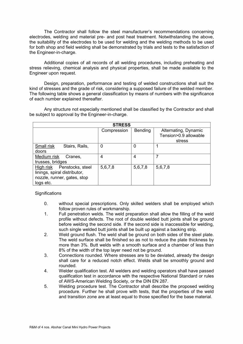
R&M of 4 nos. Abohar Canal Mini Hydro Power Projects
The Contractor shall follow the steel manufacturer’s recommendations concerning electrodes, welding and material pre- and post heat treatment. Notwithstanding the above, the suitability of the electrodes to be used for welding and the welding methods to be used for both shop and field welding shall be demonstrated by trials and tests to the satisfaction of the Engineer-in-charge.
Additional copies of all records of all welding procedures, including preheating and
stress relieving, chemical analysis and physical properties, shall be made available to the Engineer upon request.
Design, preparation, performance and testing of welded constructions shall suit the
kind of stresses and the grade of risk, considering a supposed failure of the welded member. The following table shows a general classification by means of numbers with the significance of each number explained thereafter.
Any structure not especially mentioned shall be classified by the Contractor and shall be subject to approval by the Engineer-in-charge.
STRESS
Compression Bending Alternating, Dynamic Tension>0.9 allowable
stress
Small risk Stairs, Rails, doors
0 0 1
Medium risk Cranes, trusses, bridges
4 4 7
High risk Penstocks, steel linings, spiral distributor, nozzle, runner, gates, stop logs etc.
5,6,7,8 5,6,7,8 5,6,7,8
Significations
0. without special prescriptions. Only skilled welders shall be employed which
follow proven rules of workmanship. 1. Full penetration welds. The weld preparation shall allow the filling of the weld
profile without defects. The root of double welded butt joints shall be ground before welding the second side. If the second side is inaccessible for welding, such single welded butt joints shall be built up against a backing strip.
2. Weld ground flush. The weld shall be ground on both sides of the steel plate. The weld surface shall be finished so as not to reduce the plate thickness by more than 3%. Butt welds with a smooth surface and a chamber of less than 8% of the width of the top layer need not be ground.
3. Connections rounded. Where stresses are to be deviated, already the design shall care for a reduced notch effect. Welds shall be smoothly ground and rounded.
4. Welder qualification test. All welders and welding operators shall have passed qualification test in accordance with the respective National Standard or rules of AWS-American Welding Society, or the DIN EN 287.
5. Welding procedure test. The Contractor shall describe the proposed welding procedure. Further he shall prove with tests, that the properties of the weld and transition zone are at least equal to those specified for the base material.
R&M of 4 nos. Abohar Canal Mini Hydro Power Projects
The welding procedure test may be combined with the welder's qualification test. 6. Welding performance test, executed during fabrication and site welding. Run-
off plates shall be tack-welded to one end of the plate under work. The weld shall continue on that run-off plate (test plate), welded in the same manner and under normal working conditions. One test plate is required every 20 m of weld seam, but at least one of each weld type. The laboratory tests shall cover the same range as the welding procedure tests. On request by the Engineer test plates shall be welded in his presence.
7. Ultrasonic and/or radiographic test. Depending on the location of the weld seams and the plate thickness, ultrasonic and/or radiographic tests shall be performed. The Contractor shall submit a proposal subject to approval by the Engineer. If not stated differently in the Technical Specifications, 20% of the weld length shall be radio graphed, but at least one film per weld type. The Contractor shall record the results of the ultrasonic and/or radiographic testing in these reports and drawings.
8. Marked with welder's stamp. The welder shall mark every seam welded by him with his number, so it can be recognised until the end of the fabrication period.
4.12.3 Welding Qualifications
For welding of principal stress carrying parts, the standard of welding procedures,
welders and welding operators shall conform to standards equivalent to the requirements of the ASME Boiler and Pressure Vessel Code, Sections VIII and IX, or DIN 8560, DIN 8563, EN 287.
For welding of less important parts, the standards and qualifications shall conform
either to the AWS Standard Qualification Procedure or equivalent standards. All welders and welding operators assigned to the work shall have passed a perform-
ance qualification test. If more than one year has elapsed since the welder or welding operator passed his last test, then he shall again be tested.
Welders' and welding operators' test certificates shall be submitted to the Engineer.
4.12.4 Welding Work
All welding (except welding of thin plates or piping of small sizes) shall be performed
by the electric-arc method and where practical, with process controlled automatic machines. The strength of welding of all equipment subject to high and /or alternating stresses,
vibrations etc. shall be at least equal to the strength of the parts being weld-jointed. Between plates and other sections where such stresses are to be transmitted only
butt welds shall be permitted. All main butt welds shall have 100% penetration and where possible, shall be welded from both sides. The backside of the first run shall be suitably gauged out to clear metal before the sealing runs are deposited.
Butt welds on site, which can be welded from one side, only shall be provided with
back strips on the whole length of the seam to be welded. The back strips shall be fixed to the downstream side of the upper element, to prevent accumulation of water and dirt.

R&M of 4 nos. Abohar Canal Mini Hydro Power Projects
For any welding work, only the appropriate welding rod, either arc or gas, shall be used. The properties shall conform to the material to be welded as specified in the respective standards.
The electrodes for arc welding shall be classified on the basis of mechanical proper-
ties of the as welded deposited weld-metal, type of covering, hydrogen absorption, welding position of the electrodes and type of current.
Electrodes shall be used only in the positions and under the conditions of intended
use in accordance with instructions with each container. Electrodes for manual welding shall preferably be of the heavily coated-type and shall be suitable for welding in any position.
After being deposited, welds shall be cleaned of slag and shall show uniform
sections, smoothness of weld metal, feather-edges without overlap, and no porosity and clinker. Visual inspection of the ends of welds shall indicate good fusion with the base metal.
Where weld metal is deposited in successive layers, each layer shall be thoroughly preened before the next layer is applied.
The difference in thickness of adjacent butt-welded plates shall not exceed 3 mm.
where plates of greater thickness are to be welded; a transition with a gradient of 1:5 shall be formed.
Welds shall be balanced as far as possible to minimise distortion and residual stress.
Box type girders shall be welded in such a way as to be completely airtight. All welds transverse to the direction of flow and the longitudinal welds of distributors,
shut-off valves and manifolds shall be ground flush with the plates on the inside. Welds shall be ground flush on both the inside and the outside wherever dynamic stress occurs.
Particular care shall be taken in aligning and separating the edges of the members to
be joined by butt-welding so that complete penetration and fusion at the bottom of the joint will be ensured.
All pinholes, cracks and other defects shall be repaired by chipping or grinding the
defects to sound metal and re-welding. Where fillet welds are used, the members shall fit closely and shall be held together during welding.
The ignition of weld electrodes shall not be started at the plate beside the weld, but at
the seam flanks to prevent detrimental increments of local hardness. Where ignition points of electrodes are discovered, they shall be ground appropriately.
Where auxiliary structural members are welded to components for the purpose of
assembly or installation, these connecting welds shall be given particular care. These auxiliary structural members shall be removed not by knocking them off, but
by burning, followed by grinding the affected areas flush with the plate, without producing additional thermal stresses. 4.12.5 Heat Treatment
The cost of any heat treatment prescribed by the manufacturer of the materials and
the Contractor respectively for the welded parts to be supplied shall be included in the Contract Price.

R&M of 4 nos. Abohar Canal Mini Hydro Power Projects
Heat treatment of field erection welding seams shall be performed according to the specifications for the welding procedure for the corresponding parts, which shall be submitted to the Engineer for approval. 4.12.6 Quality and Procedure Control
Quality control methods, e.g., radiography, ultrasonic crack detection, etc., shall be
done in accordance with the appropriate codes. However, the Contractor shall indicate clearly in the Technical Data Sheets the extent to which these methods shall be used.
All welded joints, which have to be tight, shall be inspected or tested by dye
penetration tests. All major welds carried out on parts under hydraulic pressure shall be subjected to a
minimum of 20 % radio-graphic testing and 100% ultrasonic testing. All welds on the skin-plates shall be tested additionally by dye penetration method as decided by the Engineer- in-charge.
The Contractor shall indicate in the corresponding drawings the type of non-destruc-
tive testing to be carried out during manufacture and at Site. The following or other equivalent Standards shall apply: For radiographic examination:
DIN 54109 Non-destructive Testing; Image Quality of Radiographs of Metallic Materials DIN 54111 Non-destructive Testing; Testing of Welds of Metallic Materials by X- or Gamma Rays; Radiographic Techniques DIN EN 287 Quality Assurance of Welded Structures; Fusion-welded Joints Steel; Requirements Classification AD-leaflet HP 5/3 Manufacture and Testing of Pressure Vessels
For ultrasonic examination: According to the approved "Test and Examination Instructions" of the Contractor
based on AD-leaflet HP 5/3. All radiographic films and data shall become the property of the PGL.
Additional non-destructive controls can be required when it is desired to examine the
acceptability of any welds when, in the opinion of the Engineer, serious doubt exists as to their quality; in this case, the expense of this examination shall be borne by the Contractor.
When required in the Particular Technical Specifications, the detailed description of
welding procedure (including type of welding electrodes, sequence of welding seams, etc.) for certain parts of the delivery shall be submitted to the Engineer before commencement of manufacture.
R&M of 4 nos. Abohar Canal Mini Hydro Power Projects
4.12.7 Defects and Repairs
Plates with laminations discovered after cutting shall be rejected unless the
laminated portion is only local and can easily be repaired; such repairs shall require the consent of the Engineer.
Defects in welds will be reported to the Engineer. The Contractor shall use his discre-
tion in determining whether or not it is advantageous to remove and repair the weld. His decision will require approval by the Engineer.
Defects in welds, which are to be repaired, shall be chipped out to sound metal and
the areas magnifluxed or ultrasonically tested to ensure that the defective material has been completely removed before repair of welding is carried out. The Engineer shall be informed and given the opportunity of making an examination after the defect has been removed and before repair welding commences. Repairs shall be carried out in accordance with the relevant Standards and to the approval of the Engineer. The Contractor shall be fully responsible for the in-service performance of all welding work.
The Work shall be 100% inspected again by the method used first to determine such
faulty work. 4.13 Corrosion Protection 4.13.1 Scope of Work
The Contractor's services shall cover the procurement of all materials, and the prepa-
ration and application of the painting and other protective coats as specified; all costs shall be included in the Tender Price. 4.13.2 Painting Materials
The Contractor shall provide a complete, reliable coating system. Coating materials
shall be standard products of a paint manufacturer with proven experience in the field of corrosion protection of the type of works to be supplied.
The Contractor shall submit for the Engineer's approval full details of the preparation,
type of materials, methods and sequences he proposes to use to comply with the requirements for the protection of the Works.
Paint material shall be delivered in unopened original containers bearing the manu-
facturer's brand name and colour designation, storage directions and handling instructions. The entire paint material for a particular specified paint system shall be supplied by one manufacturer only; who shall guarantee the compatibility and quality of the paint material. A complete list of the proposed paint material shall be submitted to the Engineer. For multicoated painting systems each coat shall have a different colour.
With regard to materials, the Contractor shall submit full details including the source
of the basic raw materials, volatile matter content, nature of solvent, number of components, type of coat, coverage, time interval between coats and number of coats, compatibility of each coat with the previous coat, toxic properties, physical properties, shelf life, resistance against chemical attack, resistance against ozone and UV-radiation, compatibility with drinking water standards, etc.
R&M of 4 nos. Abohar Canal Mini Hydro Power Projects
It shall describe in detail the treatment he proposes to apply in order to give adequate protection during transport, site storage, building and concreting and subsequent erection.
The different coats of primer and subsequent coats shall be each of different shades
of colour where practicable. The Contractor shall submit to the Engineer-in-charge for approval an overall colour
scheme in accordance with the Technical Specifications, for the finished surfaces of all Works. All final coats shall be in the colours approved by the Engineer. On request of the Engineer, painting samples for the different coats and colours shall be provided.
All pigment, paints and primers shall be delivered to Site in sealed containers packed
by the manufacturer. The manufacturer's instructions for preparation and application of all painting and protective coats shall be strictly observed.
Paint materials shall be stored and mixed by the Contractor in strict accordance with
the manufacturer's instructions. Paint material shall be used before the expiration of the shelf life. All safety regulations shall be observed, especially with regard to fire. 4.13.3 Painting Systems
Annex 1 "Painting system", indicates painting materials considered suitable for the
various parts of the Works. 4.13.4 Workmanship 4.13.4.1 Contractor's Equipment
The Contractor shall observe all safety and health precautions to protect his workers
and others. The necessary equipment, such as fans, air-conditioning units, safety masks, nets, safety belts etc. shall be provided by the Contractor. All equipment shall be in strict accordance with the respective safety codes and regulations assuring efficient work of high quality.
The Contractor shall be responsible for the collection and disposal of empty contain-
ers, dirty rags and other wastes. It shall also be the Contractor's entire responsibility to protect equipment and structures not being painted such as nameplates, instruments, panels, floors, walls, etc. and he shall provide and install all necessary drop cloths and screens. 4.13.4.2 Preparation of Paint Material
Paint shall be delivered ready mixed wherever possible. Adding of diluting agents
and mixing of two or multi-component systems shall be done in the field in accordance with the directions of the manufacturer. Mixing and homogenising of the paint material shall be done by a mechanically driven paddle or agitator in the original container. After mixing, the paint shall be poured into a clean container to ensure that no settled pigments are at the bottom.
The Contractor's equipment shall be of perfect quality and servicing and maintenance
must be guaranteed. Cleaning of equipment shall be consistently carried out at each working interval.
R&M of 4 nos. Abohar Canal Mini Hydro Power Projects
4.13.4.3 Application The most commonly used methods of application are painting by brush, roller, pres-
sure and airless spraying equipment. Selection of the application method depends on the surface to be painted. The quality of the paint shall in no way be negatively influenced. The manufacturer's directions shall govern the choice of application method. Inaccessible surfaces shall be painted prior to erection with prime and finish coats according the specification. Areas inaccessible to spraying equipment shall be painted by brush. Corners and edges shall be pre-coated. Bolts, screws, studs, rivets etc. shall be painted as a whole with the complete paint system after erection.
The primer shall be applied to an absolutely clean and dry surface only. Temperature
and dry-out time shall be in accordance with the manufacturer's directions. Whenever possible the prime coat as well as one intermediate coat shall be applied in-doors at the Contractor's shop.
During painting the air temperature shall be at least +5C and the temperature of the
items being painted must be at least 3C above the dew point. During drying of the paint, the
temperature shall not be below 0C. For all paints the surface temperature of the metal
shall not be higher than +50C during the painting. Concerning special paints, the requirements set by the paint manufacturer shall be followed.
Cleaning and painting work outdoors and in non-conditioned rooms shall be stopped
under the following conditions: rain, fog, dew, polluting winds, sand and other dusts. The object to be painted shall be removed to safe places or indoor suitably protected with cover etc. Surface preparation and application of the first paint layer are parallel operations to be carried out within a maximum delay of 4 hours.
All painting shall be free of cracks and blisters and all runs shall be brushed out
immediately. After application of the last coat the paint system shall be free of pores. After erection of the equipment all damages to painted surfaces shall be repaired. Welds, rusty spots, slag, beads, flux deposits etc. shall be repaired and repainted. For touching up, the same materials shall be used as for the main painting work. Repaired finish coats shall be of the same appearance as the original coating.
Electrical plates, surface hardware, fittings and fastenings shall be removed before
starting painting operations and shall be stored, cleaned, and reinstalled after completion of work.
Equipment requiring special knowledge, skills and tools shall be prepared to receive
field coating and painting to meet requirements of the painting schedule. Parts, which are embedded in concrete, need not be protected against corrosion.
However, transition zones of large steel pipes and of steel linings shall be painted over a length of 1 m within the concrete, all other concreted in steel surfaces over a length of 200 mm within the concrete.
In linings surrounded by concrete, surface preparation and painting works shall be
carried out after all Works such as concreting, welding, grouting and cleaning have been completed. The Contractor shall take into account the local climatic conditions and use adequate installations for sandblasting, dust control and sand extraction.

R&M of 4 nos. Abohar Canal Mini Hydro Power Projects
A properly equipped paint shop shall be set up at the Site with a crew of specialists experienced and skilled in the preparation and application of protective coatings, to deal with all site-protective treatment. 4.13.5 Surface Preparation
The term "preparation” as used below includes any cleaning, smoothing or similar
operations that shall be required to ensure that the material to be painted attains a suitable condition.
To be ready for painting, a surface should be clean, dry and sound. The surface to be
coated shall be free from any deleterious material liable to impair good paint adhesion or attack the coat.
For removing rust and mill scale on structural steel, piping and other steel surfaces,
those parts suitable for sandblasting shall be sandblasted to a grade specified or required in accordance with SIS 05.59.00 (Sveriges Standardise rings Kommission) or the American Standard SSPC-SP. This applies particularly to parts, which will be in contact with water, exposed to heavy condensation and humidity or subjected to high temperature.
For health reasons, sandblasting with quartz sand shall be avoided. Sand blasting shall be such as to obtain a smooth surface free of foreign matters with
a roughness of min. 0.04 mm. Corundum or an equivalent mineral shall be used and the grain size of the blasting medium shall not exceed 1.2 mm.
All parts of the Works shall be sandblasted at the shop unless otherwise specified or
approved by the Engineer. The sandblasted surfaces shall receive a shop coat with a quick-drying highly pigmented 2-pack zinc-rich primer, unless otherwise specified.
Parts, which cannot be sandblasted, shall be cleaned of rust by power tool cleaning
to the highest degree possible. Hand or power tool cleaned parts of minor importance and not exposed to water or
humidity may be coated with a quick-drying rustproof primer formulated on a combination of synthetic resins (ready-mixed paint).
4.13.6 Quality Control
The minimum dry-film thickness prescribed in these Specifications shall be observed.
Of each 100 m2, one area of 10 m2 will be measured for dry-film thickness. No measured thickness shall be less than the specified thickness. Where the minimum thickness is not achieved, the coat shall be repaired to reach the specified minimum dry-film thickness.
The dry-film thickness shall be measured by approved gauges; the cost of two new
electronic gauges shall be included in the Tender for use of the Engineer in charge. For checks on porosity, the Contractor shall furnish a D.C. variable high-tension test
instrument with built-in pore counter. The test voltage shall not exceed 2000 V. The tests shall not be performed within 0.5 m distance from uncovered, corrosion resistance surfaces.
The instruments purchased for quality control shall be handed over to the PGL after
commissioning of the Project without any payment to the Contractor.
R&M of 4 nos. Abohar Canal Mini Hydro Power Projects
Upon completion of each coat, the painter shall make a detailed inspection of the painting finish and shall remove from adjoining work all spattering of paint material. He shall make good all damage that can be caused by such cleaning operations.
A detailed inspection of all painting work shall likewise be made, and all abraded,
stained, or otherwise disfigured portions shall be touched up satisfactorily or refinished as required to produce a first-class job throughout and to leave the entire work in a clean and acceptable condition. 4.13.7 Guarantee
The guarantee period for all painting shall be 18 months, starting from the issue of
the "Taking-Over Certificate". This painting guarantee period shall be effective regardless of any other guarantee periods for the project or parts of the project issued prior to the elapse of the painting guarantee period.
At the end of the painting guarantee period the anti-corrosive protection of the
painted or galvanised surfaces shall not have a degree of rusting higher than RE 1 (one) on the European scale of degree of rusting for anti-corrosive paints, (the corrosion committee of the Royal Swedish Academy of Engineering Sciences, Stockholm). 4.13.8 Priming 4.13.8.1 Surface Preparation
Blast cleaning can be undertaken with only when the following time and relative
humidity schedule for application of the first coat can be achieved and maintained:
Relative Humidity Time
85% or above Do Not Blast
80-84 2 Hours
70-79 4 Hours
60-69 10 Hours
50-59 12 Hours
30-49 24 Hours
Under 30% 1 Week
4.13.8.2 Primer
The primer serves, in the first place, as protection against corrosion. In addition,
adherence between base, primer and finish paint is achieved. Primers have only a limited weather resistance. The specified dry film thickness shall be applied to all surfaces of the equipment as required. After the aforesaid has been done, the equipment or parts thereof may be stored in the open air for a limited time only until the finish coat is applied. Only 2-component epoxy resin zinc rich primer shall be used for priming on sandblasted surfaces. 4.13.8.3 Galvanizing
Unless otherwise specified, all structural steel including ladders, platforms, hand rails
and the like and all exterior and interior steel surfaces of outdoor Works, as well as bolts and nuts associated with galvanised parts shall be hot-dip galvanised, electrolytic galvanised or serialised, as may be appropriate to the particular case.

R&M of 4 nos. Abohar Canal Mini Hydro Power Projects
Galvanising shall be performed in accordance with VDE Standard 0210 (Verband Deutscher Elektrotechniker) or IS 4795:1996.
Material:
For galvanising, only original blast furnace raw zinc shall be applied, which shall have
a purity of 98.5%.
The thickness of the zinc coat shall be: For bolts and nuts, approx. 60 micrometer. For all other parts, except for hydraulic steel structures or parts intermittently or
permanently submerged in water, approx. 70 micrometer. For hydraulic steel structures or parts intermittently or permanently submerged in
water, approx. 140 micrometer, in accordance with "VDEW, Druckrohrleitungen - Association of German Electricity Utility Companies, Steel Penstocks".
Cleaning:
All material to be galvanised shall be cleaned carefully of rust, loose scale, dirt, oil,
grease, and other foreign matters. Particular care shall be taken to clean slag from welded areas.
Galvanising of plates and shapes:
Where pieces are of such lengths that they cannot be dipped in one operation, great
care shall be exercised to prevent warping. Finished compression members of steel structures shall not have lateral variations greater than one-thousandth of the axial length between the points, which are to be supported laterally. Finished tension members shall not have lateral variations exceeding 3 mm for each 1.50 m of length. Materials with sharp kinks or bends shall be rejected. All holes in material shall be free of excess spelter after galvanising.
Galvanising of hardware: Bolts, nuts, washers, locknuts and similar hardware shall be galvanised in accordance with the relevant standards. Excess spelter shall be removed by centrifugal spinning.
Straightening after galvanising: All plates and shapes, which have been warped by the galvanising process, shall be straightened by being re-rolled or pressed. The material shall not be hammered or otherwise straightened in a manner that will injure the protective coating. Materials that have been harmfully bent or warped in the process of fabrication or galvanising shall be rejected.

R&M of 4 nos. Abohar Canal Mini Hydro Power Projects
Repair of galvanising:
Material on which galvanising has been damaged shall be re-dipped unless the damage is local and can be repaired by soldering or by applying a galvanising repair compound; in this case, the compound shall be applied in accordance with the manufacturer's instructions. Soldering shall be done with a soldering iron using 50/50% solder (tin and lead). Surplus flux or acid shall be washed off promptly and the work shall be performed so as not to damage the adjacent coating or the metal itself. Any member on which the galvanised coating becomes damaged after having been dipped twice shall be rejected.
4.13.8.4 Items which are not to be painted
These items shall be given a protective coating of e.g. Tectyl 506 or another
adequate material before leaving the Contractor's workshop. This protective coating shall be removed and the surface cleaned before erection. 4.13.9 Painting 4.13.9.1 Surface Preparation (Primed, Galvanised or Stainless Steel Surfaces)
All surfaces to be painted shall be thoroughly cleaned by suitable means before
application of paint. After cleaning the surfaces shall be rinsed in a manner that no residues will remain.
Primed surfaces contaminated with oil or grease shall be de-greased in a manner not
affecting the quality of the primer. 2-component coatings older than six (6) months shall be roughened prior to the application of the next coat.
Hot-dip galvanised surfaces, which are to be painted, shall be lightly sandblasted
prior to through cleaning. 4.13.9.2 Finishing Coats
Whenever specific colouring is required or where priming is not sufficient for
protection against corrosion a finishing coat shall be applied. If not otherwise specified, finishing coats shall be applied to primed surfaces. The primed surface shall be prepared as specified above. Selection of finishing coats with regard to quality and quantity shall be governed by the ambient conditions and its effect on the painted surface.
The Engineer-in-charge will select the type and shade of colouring in accordance
with a standard colour code (e.g. VSLF, RAL, Munsell etc.). For this purpose the Contractor shall submit colour cards or colour samples. On request of the Engineer colour samples shall be applied to selected surfaces to be painted.
4.13.9.3 Painting Systems
The specified painting systems including surface preparation and the permissible
application methods are listed on the enclosed charts (Painting Systems) Annex 1.
R&M of 4 nos. Abohar Canal Mini Hydro Power Projects
4.13.9.4 Cutting and Welding of Painted Structures All painted structures to be cut by torch or blade for fitting and welding purposes and
all field-welds shall be prepared. Reason for this preparation work is the development of aggressive residue when the
paint is burned. This residue cannot be removed and thus a proper surface preparation is not warranted.
Repair of the damaged surface protection shall be executed according to "Repair of
Primer and Finish Coats" described below. 4.13.9.5 Repair of Primer and Finish Coats General
For touching up, the same paint shall be used as for the original painting work. Repaired finish coats shall be of identical appearance with the original and no differ-ence in the colour shall occur. Galvanised and Painted Structures.
Repairs on galvanised and painted structures shall be carried out as follows:
Damages to painting and galvanisation:
Surface Preparation: Scraping, wire brushing or grinding to Grade ST 3 according to SIS 055 900-1967.
Repair of Coatings: One coat of 2-component epoxy resin zinc-chromate primer. Dry
film thickness minimum 0.050 mm. Two coats of 2-component epoxy-resin micaceous iron oxide (mio) paint. Total film
thickness min. 0.160 mm. The colour of the paint shall be the same as originally applied.
Damage to Painting only:
Surface Preparation: Thorough cleaning of the damaged surface i.e. removal of oil, grease, dust, etc.
Repair of Coatings: Two coats of 2-component epoxy-resin micaceous iron oxide (mio) paint. Total film thickness min. 0.160 mm. The colour of the paint shall be the same as originally applied. Painted Structures
Repairs on painted structures shall be carried out as follows: Surface Preparation: Scraping, wire brushing or grinding to Grade ST 3 according to SIS 055 900-1967. Prime Coat: One coat of 2-component epoxy resin zinc-chromate primer. Dry film thickness minimum 0.050 mm.

R&M of 4 nos. Abohar Canal Mini Hydro Power Projects
Intermediate and finish Coats: Type, number of coats and dry film thickness, shall correspond to the specified "Painting System" in Annexure 1.
4.14 Metal Work 4.14.1 Embedded Metal Work
Unless otherwise specified, any foundations, wall & roof openings & coverings,
concrete floor filling, sleeves in foundations & walls & trenches with floor plates for cables, will be provided by the contractor.
The contractor shall supply & install all anchors, fasteners, embedded metal work,
piping, & sleeves associated with & required for the equipment to be installed under this contract, except if otherwise mentioned in the specifications.
As far as practicable, the supports shall be of good design throughout and preferably
of an approved type. Attachments to concrete shall wherever practicable be by means of embedded
inserts of an approved proprietary type. The Contractor will be responsible for the determination and details of all loads and
forces exerted by his equipment and transferred to the foundation. The Contractor shall show the location and full details of all embedded components
on his drawings and shall be responsible for the completeness and accuracy of his drawings and the information supplied to others.
Any steel work which is to be built into the concrete foundations shall not be painted
or coated unless otherwise approved or specified. 4.14.2 Miscellaneous Metalwork
Except where otherwise indicated elsewhere in the Particular Technical Specifica-
tions, the Contractor shall supply the following: All platforms, ladders, guards and handrails necessary for easy and safe access to
Works, shall be supplied under the Contract. Handrails shall be of tubular steel construction except that the top rail shall be of flat bar, fitted with a formed plastic covering.
The use of ladders shall be kept to a practicable minimum. Where ladders are
approved for use they shall be of steel, have an inclination of 70 to the horizontal and a minimum width of 450 mm.
Safety guards at each point where normal access provision would permit personnel
to come within reach of any moving equipment to be provided under the Contract. All covers for pipe and cable trenches, required for completing the floors around and
over Works supplied under the Contract will be supplied and installed. Unless otherwise approved, floor plates shall be of an angular pattern.
Covers and curbing for dismantling hatches in main floors will be provided by the
contractor of civil works.
R&M of 4 nos. Abohar Canal Mini Hydro Power Projects
5. Mechanical Works and Steel Structures 5.1 General
All mechanical Works and steel structures of any mechanical or electrical installation
shall comply with this General Technical Specification and the requirements of the Technical Specification.
The Works shall be of an approved, reliable design providing the highest possible
degree of uniformity and interchangeability. The design and arrangement of Works and installations shall facilitate erection,
testing, operation and maintenance with utmost ease. All Works shall be pre-assembled in the manufacturer’s premises to maximum
extent. Revolving parts shall be balanced statically/dynamically so that when running at
normal speed and at any load up to the maximum, there will be no vibration due to unbalance.
Unless otherwise stipulated in other sections, all materials subjects to hydraulic
pressure shall have an impact strength (Charpy V-notch) of not less than 35 J/cm2 (at 0°C) whereby this figure shall be the minimum of each of 3 specimens. For steel plates this figure shall be understood for the transverse direction.
Where ever IEC specifications are mentioned in the tender specifications, equivalent
Indian standards (IS) shall also be applicable/ may also be acceptable. 5.2 Bolts, Screws, Nuts, etc.
All bolts, studs, screws, nuts, and washers shall be to the ISO metric system except
other standards will be considered for specific applications. The extent to which other standards are proposed shall be indicated by the Contractor. Bolts and nuts shall be hexagonal or socket headed. Sizes smaller than 4 mm shall be used only for instrument and relay internal connections.
Where mild steel bolts and nuts are used, they shall be of the precision cold forged
washer faced type if commercially available in the size required. Alternatively, approved hot forged bolts and nuts, machined so that the undersides of bolt head and nut are faced and parallel to one another when assembled, may be used. In the latter case, a suitable fillet shall be machined between the bolt head and shank. All parts, other than structural steel work, bolted together, shall be spot faced on the back to ensure that nuts and bolt heads bed down satisfactorily. Bolts machined from bar stock shall not be used without approval of the Engineer in charge. All bolting material shall be adequately treated against corrosion before dispatch from the workshop. Mild steel nuts and bolts shall be zinc or cadmium plated. Stainless steel bolts, nuts washers and screws shall be used in water or when exposed to high humidity, for holding renewable parts and parts made of stainless steel.
All bolts or studs which will be subject to high stress and/or temperature shall be of
approved high tensile material with nuts of approved material. All bolts and studs larger than 60 mm in diameter, which are not accessible for tightening, and un-tightening by commercially available pneumatic impact wrenches shall be drilled for heaters or shall have an extension for pre-tensioning by hydraulic tools.

R&M of 4 nos. Abohar Canal Mini Hydro Power Projects
Washers shall be provided under bolt heads and nuts unless otherwise approved by the Engineer. All ferrous nuts and bolts on Works items where dismantling may be required during the life of the Works shall have their threads coated with an approved anti-seize compound. When in position, all bolts or studs shall project through the corresponding nuts by at least one thread, but this projection shall not exceed three threads, unless more length is required for adjustment. All nuts and set screws shall be securely fastened, to prevent loosening due to vibrations, using spring washers, lock nuts, split pins, self-locking inserts or 'Loctite' as appropriate for the purpose and material used.
The Contractor shall supply the net quantities plus 5 percent of all permanent bolts,
screws and other similar items and materials required for installation at the Site. Any such rivets, bolts, screws, etc., which are surplus after the installation of the Works has been completed shall become spare parts and shall be wrapped, marked and handed over to the PGL. 5.3 Seals
The material for large gate seals shall be of first quality non-ageing rubber material,
which shall be unaffected by wetting and drying or temperature changes. The degree of hardness according to Shore shall be 50-55 for sill sealing and 60-80 for lateral sealing. In case the Contractor intends to supply synthetic rubber material, with or without fluro-carbon cladding, he shall furnish the name of the manufacturer and technical data of the material for the Engineer-in-charge approval. Rubber Seals
Seals shall be designed and mounted in such a manner that they are adjustable, water tight and shall be readily removed and replaced.
Seals shall be moulded. Extruded seals will not be permitted. Where seals are
installed curved, they shall be clamped in a jig, which shall form them to the proper radius before the holes are laid out and drilled, and the ends trimmed. Holes in related parts of the seal assemblies shall be carefully drilled, using a template, and assure proper matching when the seal units are assembled. Arrangements shall be made to provide effective continuity of sealing at the corners.
All adjusting screws and bolts for securing the seals and seal assembly in place shall
be of stainless steel. Seals shall be made of synthetic rubber suitable for the temperature ranges of equip-
ment and conditions at the Site and shall be of a material that has proven successful in similar applications. Joints shall be watertight and seal materials shall have following physical properties as determined by tests made in accordance with the relevant Standards.
Property Limits
Tensile strength 21.0 MPa minimum
Ultimate elongation 450% minimum
Durometer hardness (Shore, Type A) 60 - 70
Specific gravity 1.1 to 1.3
Water absorption (70C for 48 hours) 5% by weight (max.)
Compression set 30% maximum
Tensile strength after oxygen bomb ageing
(48 hours at 70C)
80% (min.) of tensile strength before ageing

R&M of 4 nos. Abohar Canal Mini Hydro Power Projects
5.4 Drives and Gears All moving parts of machinery including shafts, couplings, collars, projecting key
heads, gear wheels, rope/ belt-drives shall be completely guarded to provide full protection. All setscrews on revolving shafts shall be countersunk or suitably protected. The guards shall be of approved design and shall be fitted, where necessary, with inspection doors/openings. All guards shall be arranged so that they can be removed without disturbing the parts of the gears and works, which they protect.
Gears shall be designed so that all stresses are within allowable limits when the
maximum loads are being handled. All gears shall be designed and calculated in accordance with DIN, or equivalent international standards, or widely approved methods and to the individual experience of the manufacturer. On request of the Engineer in charge, the manufacturer shall submit the calculation of the gears.
Where worm gears are used as a direct drive, they shall have the same load and
time rating as the motors driving them. The gears shall work in oil and the temperature rise of the oil bath shall not exceed 40-50 degrees C under normal working conditions at Site. The materials of the mating faces of worm wheel and worm shall be of a bronze/steel alloy.
Where practicable gear wheels shall be forced fit on the shaft and in addition, shall
be keyed adequately to prevent any relative motion between the wheel and shaft. Where gears and couplings are secured in position by means of keys, they shall be easily accessible for tightening or removal. All keyways shall be machine cut. Couplings and collars shall be the shrouded or protected-type, free from projections of any kind.
All bearings shall be mounted in dust-proof housings. Base of bearing supports shall
be machined, and shall rest on machined-surfaces. 5.5 Lubrication, Lubricants, Fuel
Efficient means of lubrication, suitable for use under Site conditions, shall be
provided for all moving parts. The contamination of the air, water and soil by lubricants and fuel shall by all means
be avoided by applying of an appropriate design and layout of the Works in conformity with the latest recognised standards for modern engineering practice.
The number of different lubricants, transformer oils, oils for pressure systems, etc.,
used in the items of Works throughout the Works shall be limited to a minimum in order to facilitate keeping stocks and maintenance.
The PGL reserves the right to request the use of certain types of lubricants, oils, etc.
The Contractor shall not be entitled to claim extra payment for this request. All different types of oils, lubricants, etc., shall be subject to the written approval of the Engineer.
Unless otherwise stated in the Particular Technical Specifications, the first filling of oil
or grease for bearings, pressure oil systems, transformers, etc., including the necessary quantity for flushing and for the first oil change shall be included in the Tender Price.
R&M of 4 nos. Abohar Canal Mini Hydro Power Projects
5.6 Piping, Fittings, Valves, Gates and Heat Exchangers 5.6.1 General
Unless otherwise stated, all piping shall be designed for a "nominal pressure". All
piping shall be tested at 1.5 times the design/nominal pressure. All required piping shall be furnished complete with flanges, joints, expansion joints, gaskets, packing, valves, drains, vents, pipe suspensions, supports, etc.
Steel structures, walkways, platforms, stairs and ladders shall be provided to cross
pipes with diameters of 600 mm and larger. Welding as well as application of corrosion protection coats shall be done in the
manufacturer's shop as far as possible. Flanged connections or joints shall be provided only as required for transport,
installation or for reasons of dismantling for repair. Metric (DIN)-flanges shall be used throughout. Welded flanges shall be weld-neck or
slip-on flanges. The raised face shall be machined. Joints between stainless and normal steel flanges shall be of the insulated type. If the piping crosses over joints of civil structures of different settlement, the piping
shall be provided with flexible joints to allow for vertical, horizontal, and angular deviations. Piping installation shall be sloped to prevent trapping of air bubbles. Where required
suitable venting system shall be provided. Adequate clearance shall be given to parallel pipes to allow for easy maintenance
without disturbing other lines. All overhead piping shall have a minimum clearance of 2.00 m from operating floors and platforms.
Where required water piping shall be provided with anti-condensation insulation.
5.6.2 Piping, Fittings
Steel pipes of a diameter <100 mm shall be of carbon Steel. Steel pipes larger than
100 mm in diameter shall be made of galvanised carbon steel. Pipe connections embedded in concrete shall be welded. Other pipe connections shall be flanged. The flange material shall be in conformance with the pipe material. The Contractor shall select the location of the weldments as to ensure sufficient access for adequate touch-up treatment for corrosion protection.
Ductile iron pipes shall conform to ISO R 2531; class K9, fittings to class K12. Unless
waived by the Engineer-in-charge, D.I. pipes and fittings shall be mortar lined to AWWA C 104, double thickness.
Stress calculations of steel pipes shall be in accordance with DIN 2413, "Steel Pipes
under Internal Pressure" or with "AD-Merkblätter; German Association of Manufacturers of Pressure Vessels, Memos.”In no case, the superimposed stress of bending, tension, compression, etc., calculated to the shape variation hypothesis, shall exceed 0.7 of the yield point at maximum applied load at any point of the piping.

R&M of 4 nos. Abohar Canal Mini Hydro Power Projects
The maximum applied load shall take into account test pressure, water hammer pres-sure waves, thermal forces, dead weight, etc. On request of the Engineer-in-charge, a calculation on pipe stresses has to be submitted by the Contractor at no extra cost. The requested calculation will be subject to approval of the Engineer-in-charge.
The minimum steel pipe wall thickness shall be the "normal" or "standard" wall thick-
ness as stated in the applicable standards. Bends shall preferably be of the forged type. Mitered bends shall be allowed for
larger sizes subject to the Engineer's approval. For smaller fittings ductile iron will be per-mitted, too. 5.6.3 Valves, Gates
Small valves and gates shall conform to DIN 3230, "Conditions and Terms for
Delivery of Valves." Generally, valves shall be leak-proof in either flow direction (except for non-return
valves) when the nominal pressure is applied. All valves with design pressures higher than PN 10 and diameters larger than DN
100 shall be workshop-tested to DIN 3230 for tightness and soundness of materials. The change of the disc seals of butterfly valves shall be possible without dismantling
of disc and body. Valves shall close clockwise and be provided with position indicators. The drive units
of motor-driven valves shall also be provided with hand wheels for manual operation. The hand wheel shall be operable under all conditions and shall be independent of the motor drive. Further, it shall not be rigidly coupled to the motor drive and shall not compulsorily turn when the motor is energised.
To facilitate operation, large valves and gates shall be provided with by-pass lines for
pressure balancing, if required. All valves shall be readily accessible for both operation and maintenance, and where
necessary for ease of operation the spindles shall be extended and an approved form of pedestal hand-wheel provided at convenient operating floor level.
Shut-off valves shall be suitable for opening and closing against full unbalanced pres-
sure, including closure against free discharge. If necessary, bypasses are to be provided to meet these requirements.
Valves spindles and pins shall be of stainless steel, nuts and bushes of bronze, and
the body of Cast Steel. All pressure reduction valves; safety valves and similar components shall be work-
shop-tested and provided with a work certificate 2.3 to DIN 50049. 5.6.4 Oil Piping
Piping of a diameter < 50 mm shall be of non-corrosive material. Pipes larger than 50 mm in diameter shall be seamless .Oil pipes shall be as far as possible be prefabricated in the manufacturer’s works. They shall be welded except at terminal points and as necessary for erection and future dismantling. The Contractor shall select the location of the weldments

R&M of 4 nos. Abohar Canal Mini Hydro Power Projects
so as to ensure sufficient access for adequate touch-up treatment for corrosion protection. Pipe connections larger than 50 mm in diameter shall be provided with steel-flanged connections.
All piping shall be hydrostatically tested at a pressure 100 % greater than the maxi-
mum working pressure. The entire pipe arrangement shall be subjected to the pressure test after complete assembly at the site.
Oil pipes shall not be embedded in concrete. Oil pipes crossing civil structures shall
be routed through sleeves embedded in the concrete. All oil piping shall be acid-treated to guarantee clean surfaces, completely free from
welding residues. This treatment shall be applied to workshop and site manufactured piping respec-
tively. The piping can either be treated in an acid-bath or be completely filled with acid. The
duration of the treatment shall be approx. 6 hours. After that the piping shall be neutralised, flushed and corrosion protected for final installation. 5.6.5 Pipe Supports and Hangers
All pipe work and accessories shall be mounted and supported in a safe and neat
manner. All brackets, stays, frames, hangers and supports for carrying and staying the pipes,
including their fasteners shall be included in the supply and completed by the Contractor at the Site. Pipes and fittings shall be supported at or near flanges wherever feasible from the view point of handling.
Supports and hangers shall be designed and arranged so that any pipe can be with-
drawn without disturbing the others. All heavy valves and other mountings shall be supported independently of the pipes
to which they connect, to the satisfaction of the Engineer-in-charge. The Contractor shall supply drawings showing the location of each major anchor and
support and the weight to be carried by that support. 5.6.6 Heat Exchangers
Unless otherwise stated, all the heat exchangers shall be designed for a nominal
pressure PN 10. All piping shall be tested with 1.5 times the design/ nominal pressure. Specification of the material of the heat exchanger shall be:
Cooling tube Cupro-nickel having chemical
Composition of 90:10
Thickness of cooling tube 1mm or more Frame/body Mild/cast steel

R&M of 4 nos. Abohar Canal Mini Hydro Power Projects
5.7 Mechanical Instruments All mechanical parts of instruments shall be suitably protected against shocks and
vibrations, heat, humidity and splash water, etc. Pressures gauges shall be provided with a damping liquid, e.g., glycerin, to compen-
sate vibrations. Pressure gauges without damping means are not permitted, unless approved by the Engineer-in-charge. 5.8 Pressure Oil Systems
Pressure tanks shall be designed, fabricated and tested in accordance with approved
standards. The appropriate inspection certificates shall be furnished. If the pressure is held by compressed air, then the requirements outlined in "Compressed Air Systems" of these General Technical Specifications shall also be applicable.
Oil sump tanks shall be provided with:
Suitable access openings Fine mesh strainer combined with a magnetic filter through which all oil returning from the servomotors shall pass. The strainer shall be readily removable for cleaning. Dehumidifying air filter Flush-mounted oil-level indicator Filling connection with a suitable strainer Drain connection with hand operated shut-off valve. Sump tanks shall be installed so that the bottom of the tank and the drain connection are at least 40 cm above the floor. The bottom of the tank shall be inclined in the direction of the drainage. The pumps shall be removable without the necessity of emptying the tank. Servomotors shall be provided with suitable connections for pressure gauges on the pressure and suction sides of the piston. Servomotor piston rods shall be of stainless steel provided with a hard chromium layer of approximately 0.04 mm thickness. A suitable protection for the piston rod seal shall be provided.
5.10 Pumps Non- submersible pumps & motors
Non-submersible pumps and motors shall be mounted on common frames.
Materials of the pumps shall be: Casing Cast steel Impeller stainless steel
Shaft stainless steel Sleeves stainless steel Wear rings bronze
Keys stainless steel
The pumps shall withstand corrosion and wear by abrasive matters within reasonable limits.
Shafts sealed by packing glands shall be fitted with sleeves. Seals shall be
exchangeable without extensive disassembly of the pump. Leakage water shall be directed to suitable drainage facilities.

R&M of 4 nos. Abohar Canal Mini Hydro Power Projects
Each pump shall be fitted with: Check valve at the discharge side Air and drain valve Pressure gauge. The size of the pump motor shall be 15 % higher than the maximum power required
by the pump at any operation point Submersible pumps & motors For submersible pumps, pump and motor shall be contained in the same casing and
designed as a package unit with incorporated suction strainer and check-valve. The impeller shall be of stainless steel and the material for the other parts as
specified for the non-submersible pumps above. For dirty water pumps, the water passages of corrosive material shall be rubber-lined.
The motors of submersible pumps operating in potable water shall not be filled with oil or other media detrimental to potable water. Motors of submersible pumps operating in dirty water may be filled with oil.
Dirty water submersible sump pumps with the motors mounted on top of the pump
shall be suitable for running dry continuously, without damage to seals, bearings, or motors. For all other items, the requirements described for non-submersible pumps shall
apply. For any pump, the overall pump-motor efficiency for the specified rated head and
discharge shall not be less than 60%. If requested by the Engineer-in-charge for pumps of a capacity higher than 30 kW,
one in three pumps shall pass a performance test to DIN 1944, class II, with measurements taken at 0%, 50%, 80%, 100%, and 120% of specified discharge at rated speed. The results have to be certified in a workshop certificate 2.3 to DIN 50049. For pumps of a capacity higher than 100 kW, the shop tests shall be compulsory; test certificate 3.1 B in accordance with DIN 50049.
Prior to the test, the manufacturer shall provide certified motor performance curves.
5.11 Lifting Equipment 5.11.1 Design and Calculation Standards
Generally, for design, stress calculation, manufacture and installation, the following standards and codes, besides other relevant standards and regulations, shall be applicable:
DIN 4'100 Welded Steel Structures DIN 4'114 Steel Structures: Stability (pp. 1 and 2) DIN 15'018 Cranes, Steel Structures, Calculation and Design DIN 15'020 Rope Drives Safety devices for the operating personnel CMAA Crane Manufacturer's Association of America Safety devices for the operating personnel shall be provided wherever it is deemed
necessary.

R&M of 4 nos. Abohar Canal Mini Hydro Power Projects
The safety rules outlined in VBG 8 of the German "Verband der Berufsgenossen-
schaft" or similar internationally recognised codes shall be observed. Unless otherwise specified, the lifting equipment shall be classified to DIN 15020 as
follows: For lifting capacity up to 100 kN (10 tonnes) "class 2 m", representing an average
daily working time of 2 to 4 hours and an equal share of small, medium, and heavy loads (normal duty);
For lifting capacity above 100 kN (10 tonnes) "class 1 Am", representing an average
daily working time of 2 to 4 hours and a small share of heavy load lifts (light duty). The Contractor shall state the various load combinations and factors of safety taken
as a basis for calculation of the different components of the crane. In addition, the various factors of safety for the different load combinations shall be stated.
Each lifting equipment such as cranes or elevators shall be subject to a test
operation with an overload = 1.25 x nominal load.
The crane girders and rails shall be calculated for a deflection not exceeding 1/1000 of the span at maximum nominal load.
Steel structures of lifting equipment shall be of welded construction, which can be assembled at Site. All field connections and joints shall be bolted.
For maintenance and inspection, appropriate ladders, platforms and steps shall be
provided, fitted with anti-slip chequered plates, tabular handrails and skirting. Walkways, stairs and platforms for lifting equipment shall generally be designed for a service load of
3000 N/m2. For hand operation a handle shall be provided to allow operation under the discon-
necting condition from electrical system and the operation force on the handle shall be less than 100 N per man, at the handle diameter of 600 mm which shall be located within 600 to 800 mm in height from the base. 5.11.2 Material Standards
The material to be used for manufacturing lifting equipment (steel structures) shall
conform to DIN EN 10'025 or to the equivalent ASTM standards. However, the Contractor shall restrict the structural steel to FE 360 B and FE 510 C or ASTM A 36; the latter may be regarded as equivalent to FE 430 C. For these structural steels, connecting bolts and welds, the allowable stresses given in DIN 15'018 shall apply.
If the Contractor intends to supply material other than that mentioned above, he can
do so, provided their equivalence to the specified material standards is verified by the Contractor and approved by the Engineer in charge.
The stresses between the track rails, their fixing elements and the concrete shall not
exceed the following values: Mean allowable compressive stresses 6 MPa Allowable compressive stresses on edge 10 MPa

R&M of 4 nos. Abohar Canal Mini Hydro Power Projects
Allowable bond stresses 0.6 MPa The stresses induced by maximum torque shall not exceed 80% of the material yield
point.
5.11.3 General Design Particulars Nameplates stating the nominal capacity in tonnes shall be attached to both sides of
the lifting equipment structure and to both sides of the tackle. The printing shall be clearly legible from the floor.
Hoists, ropes, drums, sheaves and related Works shall be calculated to DIN 15'020
or equivalent standards. Flexible couplings shall be installed to relieve the bearings and shafts from any
stresses due to misalignment and to facilitate the removal of motors, wheels and gears. The motor couplings also shall be of the flexible type.
All couplings drive wheels and gears shall be press fit and keyed to the shaft. All wheels shall have a hardened tread with a minimum Brinnel hardness number of
400, and shall be made of carbon steel or low-alloy steel forgings. They shall have double flanges, shall be machined to a uniform diameter concentric with the hub bore.
All bearings shall preferably be anti-friction bearings designed to permit easy shaft
disassembly and easy replacement. The minimum average lifetime under design load conditions shall be 5000 hours.
All sleeve bearings except those for the hooks and rope sheaves shall be lubricated
by central lubrication systems. An independent system for the trolley and one or two independent systems for the bridge will be acceptable. These central lubrication systems shall satisfy the following requirements:
The lubricant quantity for each bearing shall be variable Lubricant filters shall be installed in every lubricating pipe The lubrication piping shall be arranged to be easily accessible for maintenance Gears shall preferably be designed as bevel gears. For all high-speed gears and
pinions, oil bath lubrication shall be provided. Low-speed gears may be lubricated with soft grease. Suitable oil and grease drip pans shall be installed and be readily accessible for draining and cleaning.
Bridge and trolley drives shall be equipped with a spring-set, electrically (solenoid or
electro-hydraulic) released shoe or disc brake, with capacities of at least 1.5 times the full operating torque of the drive.
The brake shall be applied when the motor control switch or the main switch is in the
"off" position and/or in case of power failure in any phase. The braking action shall be gradual and the brake shall become fully effective after a certain time lag.

R&M of 4 nos. Abohar Canal Mini Hydro Power Projects
5.12 Steel Structures Generally, design and stress calculation shall conform to: DIN 1'050 Steel Structures, Construction DIN 4'100 Welded Steel Structures, Calculation and Design DIN 4'114 Stress Calculation of Steel Structures DIN 18'800 Steel Structures, Calculation and Construction For standards applicable to steel structures of lifting equipment, refer to "Lifting
Equipment". The permissible design stresses for materials, bolts, rivets, etc. are given in DIN
18'800. Adequate clearance of at least 2 m shall be provided at overhead steel structures to
allow unobstructed passage. Stairs and ladders shall have an inclination of approximately 30 degrees and 75
degrees respectively. Stairs shall be complete with handrails, min. 90 cm high, and kickboards of 8 cm height.
Vertical ladders shall be installed alternating left hand/right hand side to horizontal
platforms placed approx. every 10 m of vertical height. Vertical ladders of more than 2.5 m height shall be guarded.
Load assumptions for ordinary platforms shall be: For platforms used by personnel and for support of light equipment with single
weights of less than 1000 N and 5000 N/m2. For all other platforms 5000 N/m2. Unless otherwise specified or stipulated in the applicable standards. Platforms and stairs shall be provided with anti-slip chequered plates. The materials used for general steel structures shall conform to mild steel FE 360 B and FE 510 C or ASTM A 36.
6. Electrical Works 6.1 General
The electrical items of Works of any electrical or mechanical installation to be pro-
vided under this Contract according to the Particular Technical Specifications shall - if not stated otherwise therein-fulfil the requirements of this Section.
All components shall be of an approved and reliable design. The highest extent of
uniformity and interchangeability shall be reached. The design shall facilitate maintenance and repair of the components with ease and speed.
The Works shall be pre-assembled to the highest possible extent in the Contractor or
Sub-Contractor's works, complete with all devices and wired up to common terminal blocks.
R&M of 4 nos. Abohar Canal Mini Hydro Power Projects
The power supply and control cables shall be laid up to these common terminal blocks. The required control and protection devices, instruments, etc., within the different scopes of work shall be supplied and connected by the relevant Contractor.
Unless otherwise agreed, ratings of main electrical Works (in feeds, bus-ties) as
selected or proposed by the Contractor, whether originally specified or not, shall generally include a safety margin of 10% under consideration of the worst case to be met in service. Prior to approval of such basic characteristics, the Contractor shall submit all relevant information such as consumer lists, short circuit calculations, de-rating factors, etc.
Short-circuit calculations shall be evaluated giving full evidence that every electrical
component can withstand the maximum stresses under fault conditions, for fault levels and durations obtained under the worst conditions, e.g., upon failure of the corresponding main protection device and time delayed fault clearing by the back-up protection device.
All Works shall be suitable for the prevailing climatic conditions. Outdoor installations needing protections shall be protected against solar radiation by
means of adequate covers, where required. The Contractor shall ensure that all the equipments and devices are insensitive to
any signals emitted by wireless communication equipment.
6.2 Standards
The design, manufacture and testing of all Works and installations shall strictly comply with the latest edition of the relevant IEC standards or any other international standards.
6.3 Colour Code
In general, the colour code for electrical Works shall be as described in the Particular
Technical Specifications. The manufacturer's painting systems shall be used to the maximum possible extent,
but shall by all means be subject to the approval of the Engineer. Final coats of paint shall be matching adjacent installations, where required. 6.4 Electric Motors 6.4.1 General
All motors shall be of approved manufacture and shall comply with the requirements
of this Chapter. Motors of the same type and size shall be fully interchangeable and shall comply - as far as applicable - to IEC standard motor dimensions.
The general construction shall be stiff and rigid; no light metal alloy casings will be
accepted. All precautions shall be taken to avoid any type of corrosion.
All motors shall be fitted with approved types of lifting hooks or eyebolts as suitable.
AC motors shall have squirrel cage type rotors.
Motor Voltages and Power Ratings

R&M of 4 nos. Abohar Canal Mini Hydro Power Projects
The service voltages and corresponding power ratings for electric motors to be used in the Project shall be as follows:
Motors up to 100 kW
Service voltage : 3-phase a.c. 415/240 V,50 HZ Mode of starting : direct-on-line up to 50 kW
Above 50 kW with suitable starters
Motors up to 0.75 kW
Service voltage : single-phase a.c. 240 V, 50 HZ Mode of starting : condenser
Motors intended to work on the d.c. System
Service voltage : 220 V D.C. Mode of starting : resistor
6.4.2 Rating
The rating of the motors shall be adequate to meet the requirements of its associated
equipment. The service factor, being the ratio of the installed motor output to the required power at the shaft of the driven machine at its expected maximum power demand, shall be applied as follows:
Power Demand of Driven Machine Service Factor Up to 5 kW 1.2 More than 5 kW 1.1
A.C. motors shall be capable of operating continuously under rated output conditions
at any frequency between 95% and 105% of the rated frequency and/or with any voltage variation between 90% and 110% of the nominal voltage. A transient over voltage of 130% of the nominal voltage shall as well be sustained.
Further, the motors shall be capable of maintaining stable operation when running at
70% nominal voltage for a period of 10 seconds. The pullout torque for continuously loaded motors shall be at least 160% of the rated torque and for intermittently loaded motors 200% of the rated torque.
D.C. motors shall be capable of operating continuously under rated output conditions
at any voltage between 90% and 110% of the nominal voltage with a fixed brush setting for all loads. Unless otherwise approved, the speed drop between no-load and full-load shall not exceed 10% of no-load speed. 6.4.3 Starting
A.C. motors shall be designed for direct on-line starting. They shall be capable of
being switched on without damage to an infinite bus bar at 110% of the nominal voltage with an inherent residual voltage of 100% even in phase opposition. For starting the motors from the individual main and auxiliary bus bars, a momentary voltage drop of 20% referred to nominal voltage should be taken into consideration. With 85% of the nominal voltage applied to the motor terminals, each motor shall be capable of accelerating its associated load to full speed with a minimum accelerating torque of 5% of full load torque.
The maximum starting currents (without any tolerance) shall not exceed the following
values: -

R&M of 4 nos. Abohar Canal Mini Hydro Power Projects
5 times of rated current for low voltage motors rated 100 kW or above 2 times of rated current for D.C. motors (by means of starting resistors) Generally, all motors shall be able to withstand three cold starts per hour, equally
spaced. In addition, each medium voltage motor shall be capable of enduring two successive starts with the motor initially at operating temperature. Each low voltage motor shall be capable of withstanding three successive starts under the same conditions or once every twenty minutes without detrimental heating.
Motors for frequent automatic starting shall have an adequate rating. In the motor list
the Contractor shall state the frequency of starts permitted in compliance with the motor design. 6.4.4 Windings and Insulation Class
The insulation of all motors shall be of class F but will not exceed the temperature
limits of class B materials in operation. It shall be suitable for operation in damp locations, for occasional contact with corrosive gases and vapours and for considerable fluctuations in temperature.
The stator winding shall be suitably braced to withstand the forces due to direct-on-
line starting and transfer conditions as mentioned before. The winding envelopment and tails shall be non-hygroscopic. The stator winding shall withstand the maximum fault current for the period determined by the associated protective devices.
The rotor winding (if applicable) shall be designed to give trouble-free continuous
service including repeated direct-on-line starting. The rotor shall be subjected to a 120% over speed test for 2 minutes without showing any winding dislocation. 6.4.5 Ventilation and Type of Enclosure
All motors shall be of the totally enclosed fan-cooled type, protection class IP 54 according to IEC Recommendation 144. Cable termination points shall be of class IP55.
They shall have a closed internal cooling air circuit re-cooled by an external cooling air circuit drawn from the opposite side of the driving end.
Where motors are installed outdoors, a weatherproof design shall be chosen. L.V. motors of IEC size 132 and above shall be equipped with automatically controlled heating elements for protection against internal condensation of moisture during standstill periods. Such A.C. heater shall be suitably fixed inside the motor casing; the leads shall be led to a separate L.V. terminal box.
Motors installed outdoors and directly subjected to solar radiation shall be rated such as not to exceed a maximum metal temperature of 85°C. Where necessary, such motors shall be provided with sun shields.
Vertical motors shall be provided with a top cover to prevent the ingress of dirt, etc.

R&M of 4 nos. Abohar Canal Mini Hydro Power Projects
6.4.6 Bearings As far as possible, the motors shall have sealed ball or roller bearings. All motors
with ratings of about 1 kW and above shall be equipped with lubricators permitting greasing while the motor is running and for preventing over-lubrication. Additionally, the bearings shall be fitted with grease nipples permitting the use of a universal grease gun.
Vertical motors shall have approved thrust bearings. Where sleeve bearings are being used, they shall be of the self or forced lubricating
type. If forced lubrication is required, it shall be arranged common to both the motor and the driven machine and provisions shall be made to ensure lubrication during start-up and shutdown operations without the necessity to start an auxiliary lube oil pump. Self-lubricated bearings shall be equipped with an easily accessible oil reservoir with overflow pipe and oil collecting vessel.
All bearings shall be easily controllable during operation or standstill without disman-
tling the bearings. The bearings shall further be protected and sealed against dust penetration and oil leakage.
In case of independent bearings, motor and bearing pedestals shall be fitted on a common base plate.
For the transport of motors equipped with ball or roller bearings, special bearing
inserts shall be provided to prevent transport damage. 6.4.7 Shafts and Couplings
The motors shall be provided with a free shaft extension of cylindrical shape with key
and keyway according to IEC Recommendation 72-1 and with the motor side coupling, which shall be pressed on the motor shaft and be balanced together with it. A coupling guard shall be provided. 6.4.8 Brush gear and Commutators
Brush gear for D.C. motors shall be designed to ensure constant brush pressure.
Carbon brushes shall be provided which stand at least 6 months of operation without replacement. Each brush shall be independently adjustable but should not require adjustment throughout its life. A design of brush gear which permits the brush holder to touch the commutator as the brushes wear or which passes current through the pressure fingers will not be accepted.
A sufficient number of brushes, not less than two per pole, shall be fitted to ensure that vibrations do not affect the commutation.
The minimum safe wearing margin of commutators shall not be less than 20 (twenty) per cent of the total thickness of the commutator bars and the minimum safe diameter shall be clearly marked on it. 6.4.9 Terminal Boxes and Earthing
The terminal leads, terminals, terminal boxes and associated equipment shall be suit-
able for terminating the respective type of cables as specified in these General Technical Specifications and in the Particular Technical Specifications.

R&M of 4 nos. Abohar Canal Mini Hydro Power Projects
The terminal boxes shall be of ample size to enable connections to be made in a satisfactory manner. Supports shall be provided at terminal boxes as required for proper guidance and fixing of the incoming cable.
The terminal boxes with the cables installed shall be suitable for connection to supply
systems with the short-circuit current and the fault clearance time determined by the motor protective devices.
A permanently attached connection diagram shall be mounted inside the terminal box
cover. If motors are provided for only one direction of rotation, this shall be clearly indicated. Terminal boxes shall be totally enclosed and designed to prevent the ingress of
moisture and dust. All joints shall be flanged with gaskets of neoprene or similar material. For motors above 1 kW, the terminal box shall be sealed from the internal air circuit of the motor.
Depending on the size, the terminal box of L.V. motors shall be fitted either with an
approved cable sealing-end or with a gland plate drilled as required and provided with suitable fittings for cable fixing and sealing. Such openings shall be temporarily plugged or sealed during transportation.
For earthing purposes, each motor shall have adequately sized bolts with washers at
the lower part of the frame. In addition, each terminal box shall contain one earthing screw. Each equipment/panel shall be earthed by at least two separate earthing strips.
The cable termination philosophy to be adopted shall be such that extensive
grouping of signals by a large scale use of field-mounted group. Junction boxes at strategic locations (where large concentration of signals are available, e.g. switchgear) is done. Termination / Junction boxes shall have either maxi- terminal or cage clamp type terminals 6.4.10 Noise-Level and Vibrations
Under all operating conditions, the noise level of motors shall not exceed 85 dB (A). In order to prevent undue and harmful vibrations, all motors shall be statically and
dynamically balanced. Vibration displacements or velocity shall be measured in accordance with DIN 45 665
for IEC motor sizes 80 to 315. The results for all motors shall be within the "R" (reduced) limits. 6.4.11 Tests
Each motor shall be factory tested and shall undergo a test at site. The following
tests shall be performed under full responsibility of the Contractor. Workshop Tests:
Measurement of winding resistances No-load and short-circuit measurements Measurement of starting current and torque Efficiency measurement (type test) Heat test run Dielectric test Measurement of insulating resistance

R&M of 4 nos. Abohar Canal Mini Hydro Power Projects
Over speed test Site Tests:
Measurement of insulation resistance Measurement of motor vibrations Measurement of starting time.
6.5 M.V. and L.V. Switchgear, Cubicles and Panels 6.5.1 Starters and contactors
Motor starters and contactors shall be equipped with short circuit protection and local
disconnecting devices. Preferably, all starters shall be from one manufacturer. The control circuit voltage shall be obtained from a 415/240 V isolating transformer with primary circuit breaker and secondary fuse. The secondary winding of this transformer shall be grounded. The operating coils of the contactor shall be connected between the grounded side of the transformer and the control contacts.
Starters and contactors shall comply with IEC 292.1 or NEMA IC 1 and be suitable
for direct on-line starting, uninterrupted electrical duty, and capable of 30 operations per hour. They shall be installed in ventilated enclosures for indoor installation and weatherproof enclosures for outdoor installation, unless otherwise approved by the Engineer. The enclosures shall be complete with locks, cable sealing boxes, conduit entries, cable gland plates, bus bars, internal wiring, terminal boards, etc. as required by the duty of the starter or contactor.
Starters and contactors shall be of minimum size compatible with motor size and
capable of satisfactory operation, without damage, for a period of 5 minutes at a voltage 25 percent below nominal, at nominal frequency.
Thermal type overload and phase failure relays shall be supplied with starters for
motors of 7.5 kW or greater. For motors of less than 7.5 kW, suitable rated 3-phase thermal overloads will be acceptable. Ammeters to read current in one phase shall be provided for motors above 7.5 kW.
Each starter shall have sufficient number of auxiliary contacts required for
interlocking and indication purposes plus two spare convertible contacts for Owner's use. 6.5.2 Moulded case circuit breakers
All moulded case circuit breakers shall be of 2 or 3-pole type as required, having
thermal time delay and instantaneous trips with "On-Trip-Off", indicating/operating mechanism. Circuit breakers used in combination type motor starters or contactors shall have the operating mechanisms interlocked with the starter or contactor cover so that the cover cannot be opened unless the circuit breaker is open. The breakers shall comply with applicable section of IEC 157/1 or equivalent standards.
R&M of 4 nos. Abohar Canal Mini Hydro Power Projects
6.5.3 Control relays Relays used as auxiliary control devices in conjunction with motor starters and
magnetic contactors shall be of the type designed for machine tool application featuring contact convertibility. All contacts shall have a minimum thermal current rating of 10A over a range of 6 to 600 V AC. 6.5.4 Pilot devices
Pilot devices such as selector switches, push-button starters and thermostats shall
be of heavy duty type and, where mounted outdoors, shall be housed in weather proof enclosures specially designed for the environment.
All electrical contacts for control, alarm and shutdown shall have a thermal current
rating of not less than 10 A at 220 V DC. 6.5.5 Terminal blocks
All terminal blocks shall be mounted in an accessible position with the spacing
between adjacent blocks not less than 100 mm and space between the bottom blocks and the cable gland plate being a minimum of 200 mm. Sufficient terminals shall be provided to allow for the connection of all incoming and outgoing cables, including spare conductors and drain wires. In addition, 20 percent spare terminals shall be provided. In enclosed cubicles, the terminal blocks shall be inclined toward the door for facilitating terminations.
Terminals shall be of the channel mounting type and shall comprise a system of
individual terminals so that terminal blocks can be formed for easy and convenient cabling consistent with the high reliability required of the circuits.
Terminal blocks shall be provided with shorting links and paralleling links where
applicable and mounting identification numbers and/or letters. Terminal blocks shall conform to the applicable standards. The smallest size to be
used shall be designated for 2.5-sq. mm wire and not more than two conductors shall be connected under one terminal clamp.
Terminal identification shall be provided corresponding to wire number of connected
leads. Circuit terminals for 415 V AC shall be segregated from other terminals and shall be
equipped with noninflammable, transparent covers to prevent contact with live parts. Warning labels with red lettering shall be mounted thereon in a conspicuous position. 6.5.6 Equipment wiring
All wiring connections shall be readily accessible and removable for test or other
purposes. Wiring between terminals of the various devices shall be point to point. Splices or tee connections between terminal points are not acceptable. Wire runs
shall be neatly dressed inside the panels or in wiring troughs. Whenever possible, unused areas of the panels shall be kept free of wiring to facilitate the installation of future equipments.

R&M of 4 nos. Abohar Canal Mini Hydro Power Projects
Multi conductor cables shall be connected to the terminal blocks in such a manner as to minimise crossovers. Approved claw washers of crimp type connector shall be used to terminate all small wiring. Each conductor shall be individually identified at both ends through a system providing ready and permanent identification, utilising slip-on ferrules approved by the Engineer.
Markers may be typed individually or made up from sets of numbers and letters firmly
held in place. Open markers will not be accepted. Markers must withstand a tropical environment and high humidity and only fungus
proof materials will be accepted. Ferrules of adhesive type are not acceptable. All trip circuits shall employ markers having a red background. Sensitive control circuits shall be effectively shielded against extraneous signals and
interference. A separate terminal shall be provided for termination of individual cable shields, which will be grounded at source end only. 6.5.7 Cubicles and control panels
Cubicles and control panel enclosures shall be of sheet steel with minimum thickness
of 2.5mm, of rigid, self-supporting construction and supplied with channel bases. Cubicles shall be fitted with close fitting, gaskets, hinges, lift-off doors capable of
being opened through 180 deg. The doors shall be provided with integral lock and master key.
Cubicles and panels shall be vermin proof. Removable gland plates shall be
supplied and located to provide adequate working clearance for the termination of cables. Under no circumstances shall the floor/roof plate be used as a gland plate. The cables and wiring shall enter from bottom or top as approved or directed by the Engineer.
The cubicles and panels shall be adequately ventilated, if required, by vents or
louvers, and shall be so placed as not to detract from the appearance. All ventilating openings shall be provided with corrosion-resistant metal screens or a suitable filter to prevent entrance of insects or vermin. Space heating elements with thermostatic control shall be included in each panel.
Where cubicles are split between panels for shipping, terminal blocks shall be
provided on each side of the split with all necessary cable extensions across the splits. These cable extensions shall be confined within the panels with suitable internal cable ducts.
Unless stated otherwise, all cubicles and panels shall be provided with a ground bus
with 40mm copper bar extending throughout the length. Each end of this bus shall be drilled and provided with lugs for connecting ground cables ranging from 70 to 120mm2.
The standard phase arrangement when facing the front of the motor control centres
and switchboard shall be RYB from left to right, from top to bottom and front to back. All instruments, devices, buses and other equipments involving 3 phase circuits shall be arranged and connected in accordance with the standard phase arrangement, where possible. Electrical clearances shall conform to applicable standards and shall not require cutting away of adjacent framework.

R&M of 4 nos. Abohar Canal Mini Hydro Power Projects
All instruments, control knobs and indicating lamps shall be flush mounted on the panels. Relays and other devices sensitive to vibration shall not be installed on doors or hinged panels, and no equipment shall be installed on rear access doors.
The instrument and control wiring, including all electrical interlocks and all
interconnecting wiring between sections, shall be completely installed and connected to terminal blocks by the manufacturer.
The arrangement of control and protection devices on the panels and the exterior
finish of the panels shall be subject to the approval of the Engineer. The interior of all cubicles and panels shall have a mat white finish unless specified otherwise.
Switched interior light and socket outlets shall be provided for all cubicles and control
panels. All cubicles and control panels shall be provided with lamacoid nameplates,
identifying the purpose of the panel and all of its components. 6.5.8 Alarm contacts
Where applicable, all alarm contacts shall be of galvanically isolated type and provide
inputs to the following devices.
- Local annunciator - Station annunciator - Supervisory control and sequence of events / fault recorder system.
All alarm contacts shall be changeover type. Where required, relays shall be
provided as contact multiplier. 6.6 Cables
Refer to particular technical specifications Section-IX.
6.7 Earthing System
The contractor of Electro-Mechanical Equipment will make the design calculation and
supply the necessary material and install the earthing system during powerhouse construction in co-coordination with civil contractor 6.8 Explosion Proof Works 6.8.1 General
According to the kind of oils and fuels used, explosion in hazardous locations may be
caused by standard type electrical works. Therefore, the installation in such locations shall generally be kept to a minimum with said works designed or installed in compliance with the latest issue of IEC recommendation 79 and the appropriate articles of the American National Electric Code (NEC) or the German VDE Standards 0165, 0170 and 0171. 6.8.2 Definition of Hazardous Locations
Hazardous locations shall be defined as follows: Class 1, Div. 1 locations are those:
R&M of 4 nos. Abohar Canal Mini Hydro Power Projects
Where hazardous concentrations of inflammable vapours or gases exist
continuously, intermittently, periodically under normal conditions of operation and maintenance and with normal leakage, and
Where the breakdown or faulty operation of process equipment could release explosive concentrations of fuel and cause simultaneous failure of electrical works.
Class 1, Div.2 are those:
Adjacent to Div.1 locations which may occasionally be reached by hazardous concentrations, and
Where inflammable volatile liquids or gases are handled, processed, or used, but where concentrations are not normally hazardous because liquids or gases are handled in closed systems, and
Where hazardous concentration is normally prevented by positive ventilation. These locations become hazardous only when the ventilation system fails.
6.8.3 Design features
The design features of electrical works and /or circuits to reach explosion proof
condition shall be selected with due regards to the place of installation and the kind of works. The main features shall be as follows:
Pressure & flame –proof Enclosure:
All parts, which may ignite a hazardous atmosphere, shall have an enclosure of sufficient strength to withstand the maximum pressure caused by ignition of the most inflammable mixture of the gas involved. All necessary joints of such enclosures shall be provided with long fits (minimum 25 mm) and close clearances (equal or smaller than 0.6 mm) to cool the escaping flame and to prevent flame propagation to the outside atmosphere.
Oil Immersion:
The parts capable of igniting inflammable or explosive mixture shall be immersed in oil to such an extent as to prevent ignition of explosive mixtures above the surface of oil by means of sparks or hot gases produced under oil.
Increased Safety:
To obtain an increased degree of safety on electrical works, special measures shall be taken to prevent non-permissible high temperatures, sparks or arcs inside or outside of the works on which they don’t occur under normal working operations.
Intrinsic safety
All electrical circuits or part of such a circuit shall be considered as intrinsically safe if neither during normal working operation nor under fault conditions explosive mixture is ignited by means of arcs, sparks or any heat generation. Any other approved feature not mentioned above but may be felt necessary during the course of execution.
R&M of 4 nos. Abohar Canal Mini Hydro Power Projects
All explosion proof works shall be of approved design and must have undergone type tests according to appropriate standards. The selection of such works with reference to design features and allocation to hazardous groups shall be subject to approval by the engineer.
6.9 Labels and Plates 6.9.1 General
Labels and data plates shall be provided in accordance with applicable standards
and as detailed hereunder. The proposed material of the labels, size, exact label lettering and proposals for the
arrangement of the labels shall be submitted to the Engineer-in-charge for approval. Where applicable, designations in the selected local language shall appear above or
to the right of the designation in the Contract language. The translations into and writings in the local language shall be submitted for approval. 6.9.2 Equipment Labels and Instruction Plates
Labels written in the Contract language shall be provided for all instruments, relays,
control switches, push buttons, indication lights, breakers, etc. In case of instruments, instrument switches and control switches, where the function is indicated on the device, no label is required. The label shall be fixed close to the devices in such a way that easy identification is possible. Fixing on the dial glass of instruments will not be accepted. The wording shall conform to the wording used in engineering documents.
Each separate construction unit (cubicle, panel, desk, box, etc.) shall be identified by its Works identification number. Cubicles and similar units shall also bear this identification number on the rear side if rear access is possible. The overall designation of each unit shall be given in the Contract language and - if required - also in a selected local language. These labels shall be made of anodised aluminium with black engraved inscriptions, arranged at the top section of the units. Manufacturer's trade labels shall - if desired - appear in the bottom section of the units.
All Works inside cubicles, panels, boxes, etc., shall be properly labelled with their
item number. This number shall be the same as indicated in the pertaining documents (wiring diagrams, Works list, etc.).
Instruction plates in the Contract and selected local language, the sequence
diagrams or instructions for maintenance shall be fitted on the inside of the front door of the electrical switchboards. 6.9.3 Warning Labels
Warning labels shall be made of synthetic resin with letters engraved in the Contract and selected local language, where required in particular cases.
For indoor circuit breakers, starters, etc., transparent plastic material with suitably
contrasting colours and engraved lettering would be acceptable.

R&M of 4 nos. Abohar Canal Mini Hydro Power Projects
Details are stated in the Particular Technical Specifications or will be fixed at a later date. 6.9.4 Labels for Conduits
The material shall be non-corrosive and the inscription be done with 4 mm high
letters/figures. 6.9.5 Labels for Cables
Each cable when completely installed shall have permanently attached to each end
and at intermediate positions as may be considered necessary by the Engineer-in-charge, non-corrosive labels detailing identification number of the cable, voltage, and conductor size.
The cable identification numbers shall comply with those of the cable list. All cables in cable pits and at the entry to buildings shall be labelledutilising the
aforementioned type of label. 6.9.6 Rating Plates
Works (hoists, machines, transformers, etc.) rating plates and other technical
data/informative plates shall either be of the enamelled type or be of stainless steel suitably protected after engraving with a transparent paint resistant to aggressive atmosphere and solar radiation. 6.9.7 Single-Line Diagrams
Each switchgear room shall be furnished with a copy of the final as-built single-line
diagram detailing all electrical data and denominations, separate for each individual switchgear / distribution board / MCC, placed under glass and frame/wall mounted at an approved location.
The same applies to the Station Single-Line Diagram one copy of which shall be
arranged in the control room(s).
6.8 Key System for Electric Boards Key interlocked switches shall be provided with Yale or other approved locks for lock-
ing in the neutral position. Similar locks shall be provided for selector switches for locking the switches in any of the positions.
The locks or padlocks shall be co-ordinated for the different applications and shall be
supplied with three keys. A key cabinet at the end of each board (distribution board, MCC, control cubicles, etc.) shall be provided for storing the keys of that board. All keys shall have six master keys to open any lock or padlock supplied. Each key shall have one identification label fixed above the key-hanging hook inside the cabinet.
The cabinet door keys shall be similar and shall be six (6) in number.
R&M of 4 nos. Abohar Canal Mini Hydro Power Projects
7. Instrumentation and Control Equipment 7.1 General
All instrumentation and control equipment shall be of internationally reputed make
having proven performance and acceptability in the field. 7.2 Design Criteria 7.2.1 General
Chapter 6, "Electrical Works", shall be considered for I& C equipment as far as appli-
cable. Special reference is made to cabling, wiring and labeling. All components shall be of an approved and reliable design. The highest extent of
uniformity and interchangeability shall be reached. The design shall facilitate maintenance and repair of the components.
The Works shall be pre-assembled to the highest extent in the Contractor's or Sub-
Contractor's workshop, e.g., shop welding of thermometer wells and other connections, wiring of boards, desks, etc., including internal wiring and installation of devices shall be carried out. Fragile instruments shall be removed for transportation to site.
All components shall be suitable for continuous operation under site conditions. Materials for instrumentation and control equipment, including piping material, which
is exposed to the measured media, shall be selected accordingly. All components shall be compatible with other electrical, electronic and mechanical
Works. All instrumentation and control functions shall be shown on the piping and
instrumentation diagrams. The symbols to be used shall be in accordance with ISO standard. The identification system (tag numbers) shall be in accordance with the Works identification system and is subject to approval by the Engineer. All measurements and alarms shall be listed in a measuring list of a standard form subject to Approval by the Engineer. For remote controls, a schedule of interlocks shall be provided. The features of automatic controls shall be shown in block diagrams.
Shielded cables shall be provided for the control and supervisory equipment where
required.
7.2.2 Standards If the Contractor intends to apply Standards and Regulations other than those speci-
fied, he shall provide the Engineer-in-charge with two (2) sets of such documents, which shall be complete, unabridged and written in the Contract Language. 7.2.3 Sizes of Indicating Instruments and Recorders
The meters, instruments and recorders shall be of standard size, to be selected to
guarantee aesthetic appearance of switchgears, control panels, control desks, etc. The front glasses shall be of the anti-glare type. The scales shall be 90 degrees type for local control panels but must be 240 degrees type for control room instrumentation.
R&M of 4 nos. Abohar Canal Mini Hydro Power Projects
The control switches, adjusters, etc., on the panels and desks shall harmonise with the utilised indicator sizes. 7.3 Tests
The single components and pre-erected assemblies shall undergo functional and
routine tests in the Contractor's or Sub-Contractor's workshop. The ready mounted control and supervisory system shall undergo functional tests on Site prior to commissioning of the power Works.
Calibration tests shall be made on all-important pressure gauges and other instru-
ments as required by the Engineer in charge. 7.4 Measuring Systems
Electric measuring signals of 4-20 mA shall be transmitted to the control room for
emergency or regulating circuits. In this case the absence of live zero signal shall lead to a warning signal. Measuring signals for indicating purposes will be 4-20 mA.
The components shall quickly respond to any changes of the measured magnitudes.
Measuring ranges of indicators, transducers, etc. shall be selected in such a way that the rated value of the measured magnitude covers approx. 75% of the range.
All local instruments shall, as far as practicable, be mounted vibration free to allow
good reading. Wherever required, damping elements shall be used. Corresponding systems shall be grouped together in local panels. All local indicating instruments and test connections shall be included in the
respective Works as integrated parts. The scope of local indicating instruments and test con-nections shall enable the operator to properly survey the Works, and shall also allow to adequately carrying out all acceptance and other tests.
The binary sensors shall be fused separately and supplied with 24 V D.C.
7.4.1 Flow Measurements
The primary elements of flow meters shall be standard Venturi tubes, pitot tubes,
standard orifices, anubar inductive or ultrasonic type. Their design and performance shall be in accordance with applicable standards.
The design and arrangement of tapping points, piping and valves shall be in accor-
dance with VDI/ VDE rules 3512. Beginning at a rate of flow of at least 5% of the measuring range all flow transmitters
shall measure correctly. The error limit shall be ±1% for a rate of flow higher than 10%. The error of the primary elements is not included in this accuracy. The root extraction of flow measurement shall be effected electrically within the transmitter.
Arrangement:
The arrangement of the throttling devices, the straight lengths upstream and down-
stream from the throttling device shall be in accordance with the said standards. Bends shall be at a sufficient distance upstream from the throttling device, particularly when large orifice ratios are used.

R&M of 4 nos. Abohar Canal Mini Hydro Power Projects
7.4.2 Temperature Measurements All wells for capillary type thermometers, resistance temperature sensors and
thermocouples shall be of the weld-in type. Wells for thermometers and temperature sensors of the screw-in type shall be restricted to measuring points for lubrication oil, and to such measuring points where welding is not suitable, e.g., at cast-iron parts. Shop-welded thermometer wells shall be covered by screw caps for protection during transportation and erection.
Resistance thermometers and thermocouples shall be equipped with waterproof
connection heads. Thermometer arrangements shall be such that the connection heads do
not become warmer than 80 C, and the measuring inserts are easily exchangeable. The temperature sensors shall be selected in such a way to minimise the number of
different spare inserts. Resistance thermometers shall be used as far as possible and shall generally be of type Pt 100. Double resistance thermometers (with two resistors in one insert) should be avoided.
The use of dial-type contact thermometers shall be restricted to bearing metal and oil
temperature measuring. In all other cases, thermocouples or resistance thermometers and electric contact modules (monitors) shall be used. Glass thermometers and similar thermometers will not be accepted as contact thermometers.
7.4.3 Pressure Measurements
Pressure gauges shall be shock and vibration-proof (preferably by filling with
glycerine) and shall be equipped with toothed wheels and toothed segments of the machined type. They shall completely be made of stainless steel.
Higher than rated pressure shall not deteriorate the pressure gauge or affect its cali-
bration. The pressure gauges shall be equipped with a radial-connecting stud, to allow the mounting on a gauge holder.
Pressure gauges with potentiometers will not be accepted for use as a pressure
transmitter.
The error for pressure transmitters shall be limited to 0.5%. Pressure gauges and transmitters for inflammable liquids shall have filled systems
and the filling liquid shall be separated from the inflammable liquid by means of adequate isolating membranes.
Each gauge, pressure switch and transmitter for absolute or differential pressure
shall be equipped with a pressure gauge isolating valve including a test connection of the screwed type M20 x 1.5 mm so that such device can be removed without any disturbance of the plant operation.
Pressure gauges and transmitters for pressures of 10 bar and above shall not be
directly mounted on the pressure tapping point. They shall be mounted apart from the tapping point on gauge holders or gauge boards. Whenever possible, pressure gauges and transmitters shall be group wise combined on racks or consoles.
Pressure gauges for high pressures shall be equipped with a relief valve for safety
reasons in case of leaks (with a rubber reverse flow check).
R&M of 4 nos. Abohar Canal Mini Hydro Power Projects
In case of flowing substances, the measuring point shall be selected in locations of undisturbed flow.
If the pressure is pulsating, the devices concerned shall be connected via flexible
tubes or other pulse-absorbing means. In general, all pressure gauges, transmitters and pressure contacts shall easily be
accessible for maintenance and supervision. The design and arrangement of tapping points, piping and valves shall be in accor-
dance with VDI/VDE rules 3512. The scales shall have a diameter of 150 mm with black letters and figures on a white
background. The calibration shall be in "bar". The adjustment of the pointer shall be possible by means of an adjustment device
without removing the pointer from its axle. The high and low-pressure connections of differential pressure gauges shall be
marked accordingly. All casings shall be dust and watertight and be made of stainless steel.
7.4.4 Level Measurements
The liquid level measurements in reservoirs and tanks with atmospheric pressure
shall be made by means of pressure transmitter of mercury less-type, by displacement-type transmitters or float-disc-transmitters. The errors shall not exceed ± 1.0% of the total measuring range. Level switches shall be of the externally mounted float or displacement operated type. The switch shall be of packing less construction; there shall be a minimum of moving parts. 7.4.5 Electrical Measurements
All Electrical instruments shall be of flush mounted design, dust and moisture-proof.
A.C. ammeters and voltmeters shall have digital type system of not less than 1.5 accuracy class for connection to the secondary side of instrument transformers. D.C. measuring instruments shall have digital type systems of the same accuracy. Watt meters/energy meters shall have electro-dynamic measuring mechanisms if fed by transmitters. Watt meters shall be suitable for unbalanced systems and accuracy of energy meters should be of 0.2 % accuracy class.
All indicating instruments shall generally withstand without damage a continuous
overload of 20% referred to the rated output value of the corresponding instrument transformers. Ammeters shall not be damaged by fault-currents within the rating and fault duration time of the associated switchgear via the primaries of their corresponding instrument transformers.
All instruments and apparatus shall be capable of carrying their full load currents
without undue heating. All instruments and apparatus shall be rear connected, and the enclosures shall be earthed. Means shall be provided for zero adjustment of instruments without dismantling.
R&M of 4 nos. Abohar Canal Mini Hydro Power Projects
All voltage circuits to instruments shall be protected by MCB's in the unearthed phases of the circuit, installed as close as practicable to the instrument transformer terminals, or, where instruments are direct-connected, as close as practicable to the main connection. All power factor indicators shall have the star point of their current coils brought out to a separate terminal which shall be connected to the star point of the current transformer secondary windings.
When more than one measured value is indicated on the same instrument, a meas-
uring point selector switch shall be provided next to the instrument and shall be engraved with a legend specifying each selected measuring point.
All instruments shall be of the flush mounting type and shall be fitted with non-reflect-
ing glass and shall comply in every respect with the requirements of IEC Publication 51. Except for instruments employed for Works performance tests all instruments shall have an accuracy class of 1.5.
Scales shall be arranged in such a way that the normal working indication is between
50-75% of full-scale reading permitting an accurate reading. CT connected Ammeters provided for indication of motor currents shall be provided with suppressed overload scales of twice full scale. The dials of such ammeters shall include a red mark to indicate the full load current of the motor.
Instrument scales shall need the approval by the Engineer-in-charge. All instruments
mounted on the same panel shall be of same style and appearance. Transmitter connected ammeters (for example those in mosaic-type control desks)
shall have 90 degrees or 240 degrees circular scales calibrated 0-120 %. The rated motor current shall correspond to 100% scale indication.
All metering circuits shall be terminated in marked terminal blocks for remote
metering purposes. 7.4.6 Position Measurements
Position transmitters of the potentiometer type will not be accepted. Inductive or
capacitive type shall be provided. Position transmitters for continuous position indication and measuring transducers
shall have an output current of 4-20 mA and aux. supply voltage (if required) 220 or 48 VD.C. The "potentiometer-type" position measuring principle is not permitted. 7.4.7 Limit Switches
Limit switches shall be provided for each electrically operated gate, valve or gantry to automatically stop the motor at both ends of travel. Additional switches shall be provided where necessary for control, interlocks and indication.
Limit switches shall be mounted suitable for easy adjustment and for rigidly locking in position after being adjusted. They shall be of heavy-duty rating and have two changeover contacts suitable for 220 VD.C. Operations.
Switch fixings shall be positive and shall be unaffected by vibration. At the same time they should be capable of easy adjustment to suit changing parameters of the associated plant.

R&M of 4 nos. Abohar Canal Mini Hydro Power Projects
Particular attention shall be paid to potentially harmful environmental conditions, including water, oil, dust, dirt, temperature variations and differential expansions. Where switches operate through linkages, precautions shall be taken to eliminate variations of settings and incorrect operations resulting from wear or tolerances. 7.4.8 Contact Devices
Contacts of level switches, pressure switches, temperature switches, limit switches,
and of all other devices shall be of the snap action type (SPDT). Contact devices for interlocking systems shall be separate, i.e., contact devices serving commonly for interlocking and other purposes will not be accepted. 7.5 Protection Systems
Electrical/Mechanical Protection and Interlocking Systems shall be provided for all
works components and individual systems to ensure a safe and reliable operation and to limit harm and damage to personnel and works to an utmost extent.
The primary functions of these facilities shall be to disconnect selectively faulty sec-
tions of the systems prior to influence or damage to other works and to maintain operative systems as far as possible.
Moreover these devices shall facilitate the duty of the operation staff and prevent
mal-operation. 7.6 Transmitter Racks and Piping
Wherever practicable, transmitters for flow, pressure, etc., shall be installed in readily
accessible positions in the proximity of the measuring point, free from vibration and protected against damage, moisture, dust, corrosive air, and great temperature changes.
The transmitters shall be grouped and assembled as far as practicable on local
transmitter racks or in cubicles with glass or plexi-front. The connecting lines between the primary elements and the transmitters shall be
installed to falls in order to ensure that no air pockets or water locks are created.
8. Transport and Installation 8.1 General
Shipping, loading, transportation, unloading, storage, erection and test running shall
be performed by the Contractor. From the time of manufacturing until commissioning all parts of the plant shall be
protected and insured at the Contractor's expense against damage of any kind. Parts, which are damaged during transport, storage, erection or trial operation, shall be replaced at the Contractor's expense.
The Contractor shall provide the Engineer-in-charge with complete packing lists of
each performed shipment.

R&M of 4 nos. Abohar Canal Mini Hydro Power Projects
8.2 Packing The contractor shall prepare all plant, devices & materials for shipment to protect
them from damage in transit, & shall be responsible for make good all damages due to improper preparations, loading or shipment.
After the workshop assembly & prior to dismantling for shipment to the site, all items
shall be carefully marked to facilitate site erection. Wherever applicable, these markings shall be punched or painted so they are clearly visible.
Dismantling shall be done into convenient sections, so that the weights & sizes are
suitable for transport to site & for handling on the site under the special conditions of the project.
All individual pieces shall be marked with the correct designation shown on the Con-
tractor's detailed drawings and other documents (packing lists, spare part lists, in Operating and Maintenance Instructions, etc.).
Marking shall be done preferably by punching the marks into the metal before paint-
ing, galvanising, etc., and shall be clearly legible after painting, galvanising etc. In labeling, the Contractor shall endeavour to use as few designations as possible and each part of identical size and detail shall have the same designation, regardless of its final position in the plant.
All parts shall be suitably protected against corrosion, water, sand, heat, atmospheric
conditions, shocks, impact, vibrations, etc. All electrical parts shall be carefully protected from damage by sand, moisture, heat
or humid atmospheric conditions by packing them in high-pressure polyethylene foil. Where parts may be affected by vibration, they shall be carefully protected and packed to ensure that no damage will occur while they are being transported and handled.
The Engineer-in-charge reserves the right to inspect & approve the packing before
the items are dispatched but the contractor shall be entirely responsible for ensuring that the packing is suitable for transit & such inspection will not exonerate the contractor from any loss or damage due to faulty packing.
All packing costs shall be included in the scope of Work.
8.3 Marking
The Contractor shall mark all containers with the implementing document number
pertinent to the shipment. Each shipping container shall also be clearly marked on at least two sides as follows:
Consignee :
Contract No. : Country of Origin : Port of entry : Item number (if applicable) : Package number, in sequence : Quantity per package : Description of Works : Net and gross weight, volume :
R&M of 4 nos. Abohar Canal Mini Hydro Power Projects
8.4 Transport and Storage The Contractor shall inform himself fully as to all relevant transport facilities and
requirements, loading gauges and other limitations and shall ensure that the equipment as prepared for transport shall conform to such limitations. The Contractor shall also be responsible for obtaining from the Indian railway or highway authorities any permit that may be required for the transport of loads exceeding the normal gauges.
The Contractor shall provide means for all unloading and reloading for all consign-
ments of plant; both during transport to Site and on the Site. Consignments shall be unloaded immediately on arrival at Site. The Contractor is required to take the necessary steps in order to provide the carriage, special supporting structures for heavy loads, etc.
All parts of the plant shall be brought, as far as possible, to their final place of erec-
tion. The Contractor shall construct his own storage facilities at site. The warehouses shall be weatherproof, with good ventilation and solid floors. The
floors of the warehouses and storage areas shall be designed to carry the loads imposed on them by the stored parts. The following parts shall be stored inside enclosed warehouses:
Bolts, pins, packing, tools, insulation materials, electrical parts with electrical devices
attached, electric motors and excitation equipment, instruments, welding material and equipment, all small parts and all parts of the plant which already have been finally painted.
If large parts are stored in the open air, they shall be provided with weather resistant
and fire-resistant covers. Electrical parts, which are not packed in heavy-duty polyethylene foil and those so packed, but whose packing has been damaged shall be kept in suitable places from the moment of storage to the moment of installation.
All insulation materials which will be taken from the warehouse for installation and
which are stored temporarily in the station shall be protected from weather or humidity. All the equipment shall be stored as per standard storage and preservation
instructions etc. of the suppliers. 8.5 Preparation and Installation
Prior to commencement of installation, the Contractor shall closely inspect the site
and all the foundations and other structures on which parts of the plant supplied under this Contract will be installed; he shall check that the foundations conform to the installation drawings.
The result of this check shall be reported to the Engineer in due time to allow any
errors to be corrected before the commencement of erection. All parts of the plant shall be cleaned carefully of all contamination such as dust, sand, rust, mill scale and other dirt prior to installation. 8.6 Reference Points
The Contractor shall employ a competent surveyor for setting-out of all datum lines
including the constant checking and maintenance of the setting-out until the completion of his works.
R&M of 4 nos. Abohar Canal Mini Hydro Power Projects
The Contractor shall provide all necessary pegs, profiled templates and centre lines and shall establish all such permanent markings and recovery marks as may be required by the Engineer for checking the Contractor's setting-out. The Contractor shall be responsible for rectifying, at his own cost, all work rejected by the Engineer-in-charge due to errors in setting-out.
All bench marks, notch marks, pegs and signals on the surface, alignment pins and
the like put in by the Engineer for the purpose of checking the Contractor's work or as permanent survey marks will be under the care of the Contractor during the period of the Contract. He shall, at his own expense, take all proper and reasonable care and precautions to preserve and maintain them in their true position where such marks are within or adjacent to his work area. In the event of their being disturbed or obliterated by any cause whatsoever, they may, if so determined by the PGL, be replaced by the Engineer-in-charge at the Contractor's expense.
The Contractor shall be responsible for the true and proper staking-out of the works
and levels of reference given by the Engineer in writing, for the correctness of the positions, levels, dimensions and alignment of all parts of the works and for the provision of all necessary instruments, appliances and labour in connection with this.
The checking of any staking-out or of any line or level by the Engineer-in-charge or
the Engineer's Representative shall not in any way relieve the Contractor of his responsibility for its correctness. 8.7 General Notes on Installation Work
All transportation and handling of the plant from the place of storage to the place of
installation shall be carried out by the Contractor. He shall provide all hoisting equipment, staging and scaffolding, winches and wire ropes, slings, tackles and all other appliances and temporary materials. The erection staging and scaffolding shall be provided with coverings and barriers and shall guarantee safe working conditions.
The Contractor shall comply with all applicable and approved safety regulations while
carrying out the works on Site and with all reasonable requirements of the Engineer. This stipulation shall in no way release the Contractor from any obligation concerning his liability for accidents and damages. He shall be responsible for adequate protection of persons, plant and materials against injuries and damages resulting from his operations.
The plant or parts to be installed shall not be overstressed during the process of
installation. The Contractor shall be responsible that the installation of all plant is properly exe-
cuted to the correct lines and levels and in accordance with the manufacturer's instructions and the Contract requirements.
The alignment of the plant shall be done exactly; the tolerances indicated by the
Manufacturers or in the drawings shall be kept. Setting of parts to be aligned shall be performed by means of fine measuring instru-
ments. All erection clearances and settings shall be recorded. Copies of these records shall be given to the Engineer-in-charge. After alignment, the parts shall be held firmly in position by means of set pins, fitted bolts, etc.
R&M of 4 nos. Abohar Canal Mini Hydro Power Projects
All parts to be embedded in concrete shall be set accurately in position and shall be supported rigidly to prevent displacement during the placing of concrete. Adjusting screws and bolts shall be drawn tight and secured adequately. Steel wedges shall be secured by welding. Wooden wedges shall not be used.
The Contractor shall verify carefully the position of all parts to be embedded before
concrete is poured. All important measurements and dimensions shall be recorded. Copies of these records shall be given to the Engineer-in-charge for checking and approval before items are built-in to the Works.
After concreting, the control measurements shall be verified again, indicated in the
above-mentioned records and submitted to the Engineer-in-charge. The Contractor shall provide all necessary anchors and braces to ensure the align-
ment and stability of the parts to be installed. All temporary anchors and bracings shall take care of all dead load, wind load, seismic and erection stresses, e.g., during concreting, and shall remain in place until they can be removed without endangering the stability of the plant.
Welding, torch-cutting and drilling work on the plant to be erected shall only be
carried out with the approval of the Engineer-in-charge only for modification if any. If for installation purposes auxiliary structures have been attached to the plant, they
shall be removed after completion of work and the surface restored to proper condition by grinding and repainting.
Special care shall be taken not to damage surfaces of galvanised or specially treated
plant during erection. Care shall be taken to prevent or remove any rust streaks or foreign matters deposited on galvanised or otherwise finished surfaces during storage or transport or after installation.
Glass parts or other parts, which can easily be damaged, shall be provided with suit-
able protective sheaths or coverings during installation. Machined or bare metal surfaces, which are to receive no coat of paint, shall be pro-
tected during transportation, storage and erection by a suitable anti-corrosion film. All power tools preferably be operated pneumatically. They are to be handed over at
the end of the installation work in good condition in accordance with the instructions of Engineer-in-charge.
After erection, the works shall be finally painted, in accordance with the painting
specification, and any damaged paintwork shall be restored. The Contractor shall keep the site in clean condition during erection and commission-
ing time. On instruction of the Engineer-in-charge, he shall remove waste from the place of installation to the defined deposit site at his own cost. 9. Inspections and Tests 9.1 General In addition to the provisions established in the Conditions of Contract regarding general procedure of inspections and tests, terms and definitions, and time schedules for inspections and tests the following stipulations shall apply.

R&M of 4 nos. Abohar Canal Mini Hydro Power Projects
Approval of assemblies, tests, inspections, related procedures etc. and acceptance of pertinent test and inspection certificates, or waiving of inspections or tests, shall in no way relieve the Contractor of his contractual obligations for finishing the Works in accordance with the provisions of the Specifications.
Three (3) sets of all test records, test certificates, performance curves, tables etc. of
all inspections and tests, whether or not attended by the Engineer-in-charge shall be supplied soonest after performance of each inspection or test. After completion of all tests, two (2) sets of the above-mentioned documents shall be supplied, properly bound in books.
All test certificates shall be endorsed with sufficient information for identification of
the equipment and material to which the certificates refer. In addition, the following references shall be entered in the top right-hand corner: PGL's name Project title Plant's (stage's) name Number of Contractor's drawing Date
9.2 Shop Inspections and Tests
As far as practicable, quality of materials, workmanship and performance of all items
of the Works to be furnished under this Contract shall be inspected at the places of manufacture.
Where the Contractor desires to use stock material, not manufactured specifically for
the Works, satisfactory evidence that such material conforms to the requirements of the Contract shall be submitted.
Arrangements shall be made for expediting the shop inspection by having all shop
assemblies or pieces covering a single shipment ready at one time. Any painting work as well as transport to the site of the Works shall not be started before the approval of the Engineer-in-charge has been obtained.
Free and unrestricted access to the Contractor's factory and shops (including those
of his Subcontractors) shall be granted to the Engineer-in-charge also and upon reasonable notice by the Engineer-in-charge if deemed necessary by the same for additional witnessing of assembly work or inspections and tests.
If an agreed inspection could not be carried out as proposed because of lack of
preparation, obvious negligence or material and/or equipment being presented in a state, not corresponding to the proposed procedure or is clearly not acceptable such an inspection shall be repeated. The cost incurred by the PGL for repeated inspections shall be fully borne by the Contractor. 9.2.1 Material Tests
Unless otherwise specified, the quality of materials (new as well as the equipment
parts to be retained) shall be verified generally by: Chemical analysis. Mechanical tests (yield point, tensile strength, elongation, and notch impact.)
R&M of 4 nos. Abohar Canal Mini Hydro Power Projects
Welding tests (welding procedure, welding material, welding tensile strength, welding bend test, welding reversed bend test, etc.) Non-destructive x-rays, ultrasonic, magnaflux, liquid tests, penetration inspection, etc.). Electrical tests (voltage, losses, tan delta, insulation, magnetic properties etc.) Certified mill test reports of plates will be acceptable when these comply with the
requirement of specifications. Test specimen and samples for analysis shall be plainly marked to indicate the materials they represent.
Castings and forgings shall be tested in the rough state in order to detect flaws in
good time thus avoiding delays. Magnetic particle inspection of important castings shall cover the whole surface of the casting. After partial machining, further tests can be conducted.
Load tests on crane hooks, steel wire ropes, chains and other lifting devices, etc.
shall be considered as material tests. 9.2.2 Checking of Dimensions
The dimensions, especially clearances and fits, (ISO 286) which are essential for
operation and efficiency shall be carefully checked in an approved manner, as for example: Run out and roundness tolerances of shafts, pistons, etc., to be measured on single
parts as well as (wherever possible) on the assembled components, Fits and clearances of bearings, servomotor pistons, valves, guiding, distributing and
actual actuating elements, etc. Accuracy, surface roughness and shape of sliding and guiding surfaces of seals,
bearings, water passages in hydraulic machinery, valves, etc. Dimensions of couplings or connections for assembly with other deliveries from the
Contractor, Sub-contractors or other contractors. 9.2.3 Workshop Assembly
In addition to the quality and production control tests, the following shop assembly
work and tests shall be made to check measurements, fitting and functioning. Works to be furnished shall be shop assembled to a status sufficient to prove that the
design and workmanship have been executed in accordance with the Specifications, that the delivery is complete, and that no work remains to be done at Site, which reasonably can or should be done in the shop.
Where applicable, each item of the Works shall be assembled completely prior to
painting. Field joints shall be temporarily connected. All parts shall be properly match marked, identified and dowelled where practicable,
to facilitate correct and quick field assembly and alignment. Where necessary, suitable dowels shall be inserted, after field assembly and drilling. The holes for any fitted bolt shall be accurately reamed.
R&M of 4 nos. Abohar Canal Mini Hydro Power Projects
During workshop assembly all instruments, control devices and piping shall be fitted. If the assembly shows defects in the design or manufacture or unforeseen difficulties
in assembling and dismantling, these shall be eliminated. If required, design alterations or corrective measures can be executed provided that reliability of operation or interchangeability are not reduced and provided that the agreement of the Engineer-in-charge has been obtained.
If the corrections cannot be carried out in accordance with the terms mentioned
above, the components concerned will be rejected. The decision on possible subsequent corrections is reserved exclusively to the Engineer-in-charge. Faulty parts or Works shall by no means be delivered.
The assembled parts shall subsequently be subject to tests as per applicable
standards or required by the Engineer. 9.2.4 Pressure and Leakage Tests
All parts subject to internal or external pressure or containing any liquids or gases temporarily or permanently during operation shall be tested prior to painting. As far as practicable, these tests shall be done in the shop but can be repeated at site.
Parts exposed during operation to hydraulic pressure, to gas pressure or to any liquid without pressure, shall be treated distinctively.
In addition to the Specifications, the applicable and approved standards and official regulations shall be observed. If any liquid is used for the test that may cause corrosion, all Works and piping shall be thoroughly cleaned immediately after the test.
As far as practicable and required, the influences of temperatures and temperature
differences to which the part will be exposed during operation shall be considered in the execution of the tests.
Leaks and defects can be repaired if permitted by the applicable standards and approved by the Engineer-in-charge. If defects are found, the Engineer-in-charge may reject the defective parts, or permit welding repairs with stress relieving, radiographic examination and additional pressure tests. Parts Exposed to Hydraulic Pressure
Unless otherwise specified or required, the following shall apply: the hydraulic pres-
sure tests shall be carried out using the liquid to be used during operation or a liquid with less viscosity.
The hydraulic test pressure shall be l.5 times the maximum operating pressure
(except for spiral distributor) and shall be maintained for a period of eight hours or longer if required by the applicable standards. Afterwards the test pressure shall be reduced to the operating pressure.
The welded seams of large parts, which are not subjected to any heat treatment
during or after welding, shall be rapped with a 500 g hammer during the pressure decrease or treated otherwise to obtain the required effect of stress relief.

R&M of 4 nos. Abohar Canal Mini Hydro Power Projects
Finally, the test pressure mentioned above shall be maintained for ten (10)minutes. Leakages appearing at seals, joints, etc. shall be measured and stated in the test report, together with the relevant pressures.
Parts Exposed to Gas Pressure
Parts which will be subjected to gas pressure during operation for example pressure tanks, pressure air tanks and others, shall be inspected and tested according to the official regulations with respect to design, construction, fittings, etc.
The pressure test shall be executed by applying the test pressure in accordance with
the relevant standards and specifications.
Parts Exposed to Liquids without Overpressure Parts which shall not be closed and which are exposed to only small pressures of
any liquid during operation e.g., bearing housings, oil containers, etc. shall be subjected to a tightness test at with a suitable liquid of low viscosity. The testing-period shall not be less than 8 hours, unless otherwise agreed. 9.2.5 Functional Tests
Functional tests shall be defined as tests of the function of assemblies, sub-assem-
blies or parts of the Works under no load conditions. Functional tests shall be performed on all Works prior to the execution of operational tests. 9.2.6 Operational Tests
As far as practicable operational test shall be carried out on all Works, simulating
operating conditions. Parts to be delivered by sub suppliers shall be tested either at the premises of the
sub supplier or of the Contractor, as agreed by the Engineer-in-charge. Before testing the Contractor shall submit a notice containing full information on the
tests with detailed tables or graphs on the latest edition of the characteristic values of the Works to be tested and on the test facilities and equipment.
Testing of the electrical Works shall be performed in accordance with applicable
Standards; they shall include but not be limited to tests of heating, loading, overloading, losses.
Operational tests of lifting equipment and other machinery shall include tests under
nominal load and 125 % of nominal load unless otherwise specified. 9.2.7 Electric Tests
Electrical appliances / devices / equipment shall be tested in accordance with
applicable Standards and agreed test programs and procedures. 9.2.8 Model Tests
Model tests for certain parts of the Work or Works shall be carried out as specified or
agreed between the Contractor and the Engineer-in-charge.
R&M of 4 nos. Abohar Canal Mini Hydro Power Projects
9.3 Site Inspection and Tests During erection, commissioning and trial operation, the Contractor shall perform at
suitable intervals all inspections and tests in the presence of the Engineer-in-charge in order to prove the orderly execution of the works in accordance with the Contract.
Unless otherwise specified, all costs for testing at site and of the works and charges
associated with it shall be borne by the Contractor. This includes the measuring devices, properly calibrated, and any pertinent accessories, which shall be made available by the Contractor for the entire duration of the tests. The Contractor shall delegate his experts to perform the tests at site.
The Engineer reserves the right to have checked at his own expenses the Contrac-
tor’s instruments to be used or having been used for any tests by an independent, officially acknowledged institution.
Special tests to be performed at Site are listed in the corresponding chapter of the
Particular Technical Specifications. The Contractor's testing at Site shall be complete in every respect to prove the suc-
cessful performance and operation of all the works and Works supplied and erected under the Contract.
In case of disagreement between the Engineer-in-charge and Contractor(s) on the
test results, an independent expert shall be appointed by the PGL to whom both parties shall agree. If no amicable settlement can be reached, the Adjudication Clause shall be applied.
The procedure of inspections and tests at site, notice to the Engineer-in-charge,
reports, commissioning, trial runs and trial operation, and acceptance tests shall be as per General Conditions of the Contract.
9.3.1 Commissioning and Trial Run
Immediately upon termination of commissioning of a part or section of the Permanent
Works, which can operate as an independent unit a “Certificate of Suitability for Operation”, shall be issued by the Engineer.
This document shall be signed by an authorised representative of the PGL, the
Engineer and the Contractor. This Certificate shall state: The supplier of the Works concerned The quantity and type of Works concerned The conditions of commissioning The names of the participants The date of commencement of trial run The list of minor defects, if any, which has to be corrected by the Contractor During the trial run the Contractor shall make familiar the PGL's personnel with the
equipment, the operation and maintenance of the Works and its auxiliaries to such an extent that, thereafter, the duties can be assigned to the PGL's trained personnel. For achieving this, 20 to 24 authorised operation & maintenance persons of the PGL shall be trained in operation and maintenance for at least 30 days of trial run, prior to handing-over.

R&M of 4 nos. Abohar Canal Mini Hydro Power Projects
If any defects or irregularities affecting the safety or reliability of the Works should arise during the trial run, the trial run shall be interrupted and started again after such defects or irregularities have been corrected by the Contractor. 9.3.2 Acceptance
The taking-over testing of any part or section of the Permanent Works which can
operate as an independent unit, shall be performed in accordance with the standards and regulations laid down in the " General Conditions of contract, and as per the test procedure agreed upon between Engineer-in-charge and Contractor.
Immediately upon termination of any such testing of a part or section of the perma-
nent Works a "Protocol of Acceptance" which shall be deemed to be the Test Certificate required by General Conditions of Contract shall be issued by the Engineer-in-charge.
This document shall be signed by an authorised representative of the PGL, the
Engineer-in-charge and the Contractor and shall form an integral part of the later "Taking-Over Certificate".
This "Protocol of Acceptance" shall state: The date of testing The quantity and type of Works concerned Statement of all minor defects and/or irregularities, which have to be corrected by the Contractor Confirmation that the guaranteed data have been proven Confirmation that all contractual documents have been submitted Confirmation that the PGL's personnel have been familiarised with the Works and that they will be able to operate and maintain the Works. If any test for the verification of the guaranteed data could not be performed for
operational reasons beyond the Contractor's responsibility, this part of the acceptance shall be stated in the "Protocol of Acceptance" and be postponed for a mutually agreed period.
However, the tested part or section of permanent work shall continue to be operated
by the Contractor, with the help of PGL’s personnel, all the generating units have been tested and commissioned and trial run period of 30 days or that to be agreed with the Owner and the Contractor, has been completed in respect of last unit to be commissioned.
NOTE: A part or section of the permanent works shall, for the purpose of this contract, mean one generating unit with all its units and station auxiliaries required to operate the unit at its rated load.

R&M of 4 nos. Abohar Canal Mini Hydro Power Projects
9.4 Quality Assurance Plan & Inspection Schedules 9.4.1 Quality Assurance Plan The Contractor shall submit the detailed Quality Assurance Plan for the complete equipment/materials along with the bid for approval and acceptance by the PGL. This shall form integral part of the contract. The QAP shall include inspection and tests proposed to be conducted on raw material/bought out items at the time of induction in the process of manufacturing and at final stage of assembly. 9.4.2 ISO Certification
The Contractor should have ISO–9000 Series certification. In case the Contractor does not posses ISO-9000 series certification, he shall submit following details along with the bid, for assessment of his capacity to supply quality equipment/materials/services under the contract.
Contractor’s quality system details: Details of system for dealing with items not conforming to prescribed specification. Details of sub vendor analysis procedure Details of stage and final inspection and auditing Contractor’s system for calibration of testing and measuring equipment. Details of testing and measuring equipment available with contractor Details of important facilities/equipment available with the Contractor to produce reliable products having requisite standard. Qualification and experience of contractor’s key QA personnel.
9.4.3 Inspection Schedules
To facilitate the PGL in planning its inspection activities, the Contractor shall submit
along with the bid, the details of the lots along with the time schedule in which the ordered materials shall be offered for inspection as also the places of inspection. These details shall be finalized and approved and form an integral part of the Contract.
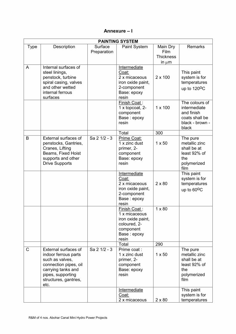
R&M of 4 nos. Abohar Canal Mini Hydro Power Projects
Annexure – I
PAINTING SYSTEM
Type Description Surface Preparation
Paint System Main Dry Film
Thickness
in m
Remarks
A Internal surfaces of steel linings, penstock, turbine spiral casing, valves and other wetted internal ferrous surfaces
Intermediate Coat: 2 x micaceous iron oxide paint, 2-component Base: epoxy resin
2 x 100
This paint system is for temperatures
up to 120oC
Finish Coat : 1 x topcoat, 2-component Base : epoxy resin
1 x 100
The colours of intermediate and finish coats shall be black - brown - black
Total 300
B External surfaces of penstocks, Gantries, Cranes, Lifting Beams, Fixed Hoist supports and other Drive Supports
Sa 2 1/2 - 3 Prime Coat: 1 x zinc dust primer, 2-component Base: epoxy resin
1 x 50
The pure metallic zinc shall be at least 92% of the polymerized film
Intermediate Coat: 2 x micaceous iron oxide paint, 2-component Base : epoxy resin
2 x 80
This paint system is for temperatures
up to 60oC
Finish Coat : 1 x micaceous iron oxide paint, coloured, 2-component Base : epoxy resin
1 x 80
Total 290
C External surfaces of indoor ferrous parts such as valves, connection pipes, oil carrying tanks and pipes, supporting structures, gantries, etc.
Sa 2 1/2 - 3 Prime coat : 1 x zinc dust primer, 2-component Base: epoxy resin
1 x 50
The pure metallic zinc shall be at least 92% of the polymerized film
Intermediate Coat: 2 x micaceous
2 x 80
This paint system is for temperatures
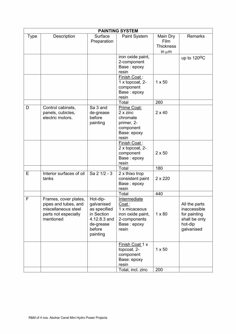
R&M of 4 nos. Abohar Canal Mini Hydro Power Projects
PAINTING SYSTEM
Type Description Surface Preparation
Paint System Main Dry Film
Thickness
in m
Remarks
iron oxide paint, 2-component Base : epoxy resin
up to 120oC
Finish Coat : 1 x topcoat, 2-component Base : epoxy resin
1 x 50
Total 260
D Control cabinets, panels, cubicles, electric motors.
Sa 3 and de-grease before painting
Prime Coat: 2 x zinc chromate primer, 2-component Base: epoxy resin
2 x 40
Finish Coat : 2 x topcoat, 2-component Base : epoxy resin
2 x 50
Total 180
E Interior surfaces of oil tanks
Sa 2 1/2 - 3 2 x thixo trop consistent paint Base : epoxy resin
2 x 220
Total 440
F Frames, cover plates, pipes and tubes, and miscellaneous steel parts not especially mentioned
Hot-dip-galvanised as specified in Section 4.12.8.3 and de-grease before painting
Intermediate Coat : 1 x micaceous iron oxide paint, 2-components Base : epoxy resin
1 x 80
All the parts inaccessible for painting shall be only hot-dip galvanised
Finish Coat 1 x topcoat, 2-component Base: epoxy resin
1 x 50
Total, incl. zinc 200

R&M of 4 nos. Abohar Canal Mini Hydro Power Projects
Annexure 2: Symbols and Abbreviations
1. Length, area and volume
µm micron = m. 10-6
mm millimeter
cm centimeter
m meter
km kilometer
mm2 square millimeter
cm2 square centimeter
m2 square meter
km2 square kilometer
ha hectare
m3 cubic meter
l litre
rad radian
2. Time and time derived units
s second
min minute
h hour
d day
hr hour
yr year
mm/s millimeters per second
m/s meters per second
km/h kilometers per hour
m/s2 meters per second squared (acceleration)
m3/s cubic meters per second
Hz hertz (periods per second)
3. Mass, force and derived units
kg kilogram
g gram = kg . 10-3
mg milligram = kg . 10-6
mg/l milligrams per liter
t tonne = kg . 103
kg/m3 kilograms per cubic meter
t/m3 ton per cubic meter
N Newton
N/m2 Newton per square meter
N/mm2 Newton per square millimeter
bar bar = N/m2. 105
Pa Pascal = 1N/m2

R&M of 4 nos. Abohar Canal Mini Hydro Power Projects
MPa mega Pascal = Pa . 106
atm standard atmosphere = 101325 Pa
J Joule = 1 Nm (Newton-meter)
KJ kilo joule = J . 103
4. Electrical units
A ampere
V volt
kVA kilovolt ampere
kWh kilowatt hour
W watt = 1 J/s
kW kilowatt = W . 103
MW megawatt = W . 106
A.C. Alternating current
D.C. Direct current
HV high voltage (cables)
LV low voltage
MV medium voltage
5. Other symbols and abbreviations
approx. Approximately
bhp brake horsepower
CIF cost, insurance and freight
dia. or diam. Diameter
fig. Figure
hp horsepower
horiz. Horizontal
HT high tensile (steel)
Max. Maximum
Min. Minimum
No. Number (units) e.g. 6 no.
No. Number (order)as in No. 6
temp. Temperature
°C degrees Celsius
vert. Vertical
vol. Volume
wt weight
% per cent
M.F.L maximum flood level
H.W.L high water level
M.O.L. Minimum operation level
IEC International Electro-technical Commission
ISO International Standards Organisation

R&M of 4 nos. Abohar Canal Mini Hydro Power Projects
Annex 1: Required Documents for E&M Equipment
1. Documents for E&M equipment and Installations 1.1 Documents for all E&M equipment as Applicable
Shop test programs A
Material test certificates I
Shop test reports A
Welding procedures A
Welder’s qualification certificates A
Paint schedules A
Instrument lists A
Wiring diagrams I
Installation drawings A
Erection procedures A
Site test procedures A
Commissioning program A
Commissioning procedures (dry and wet) A
Operating & maintenance manuals A
Program for training of PGL’s Personnel A
Site test reports A
Trial operation programme A
Emergency shut-down procedures A
1.2 Turbine & Accessories
Assembly/disassembly drawing of runner removal, maintenance and inspection
A
Drawings for erection/handling facilities I
1.3 Governors
Drawings for erection/handling facilities I
1.4 Fire fighting system
Specification A
Component list(s) A
Layout drawing/details A
Arrangement drawing A
Control panel arrangement A
Logic diagram I
Design calculation I

R&M of 4 nos. Abohar Canal Mini Hydro Power Projects
2. Electrical Equipment 2.1 Generators, Generator Terminal Equipment and Excitation System
Drawings for dismantling, reassembly / lifting and handling facilities
A
2.2 Protection system
Specification A
Component list(s) A
Single-line diagram (protection diagram) I
circuit diagrams (schematic) I
Block diagrams A
Logic diagrams including tripping scheme for protection I
Alarm lists A
Tripping list A
Terminal diagrams I
Specifications for protection relays including tripping curves, setting ranges etc.
A
Arrangement drawings of all panels including front and inside view
A
2.3 Medium Voltage Installations 11 kV Switchgear
Specifications A
Dimension drawings for complete distribution boards and for each type of feeder
A
Single-line diagrams A
Standard circuit diagrams I
Individual circuit diagrams I
Arrangement drawings of cubicles including front view, inside view and sections where necessary
A
Specification for protection relays A
List of Measurements A
2.4 Low Voltage Installations 415 V
Specifications A
Dimension drawings for complete distribution boards and for each type of feeder
A
Single-line diagrams A
Standard circuit diagrams I
Individual circuit diagrams I
Arrangement drawings of cubicles including front view and inside view
A
Specification for protection relays A
List of Measurements
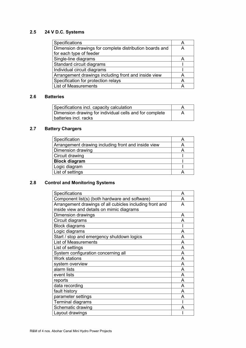
R&M of 4 nos. Abohar Canal Mini Hydro Power Projects
2.5 24 V D.C. Systems
Specifications A
Dimension drawings for complete distribution boards and for each type of feeder
A
Single-line diagrams A
Standard circuit diagrams I
Individual circuit diagrams I
Arrangement drawings including front and inside view A
Specification for protection relays A
List of Measurements A
2.6 Batteries
Specifications incl. capacity calculation A
Dimension drawing for individual cells and for complete batteries incl. racks
A
2.7 Battery Chargers
Specification A
Arrangement drawing including front and inside view A
Dimension drawing A
Circuit drawing I
Block diagram I
Logic diagram I
List of settings A
2.8 Control and Monitoring Systems
Specifications A
Component list(s) (both hardware and software) A
Arrangement drawings of all cubicles including front and inside view and details on mimic diagrams
A
Dimension drawings A
Circuit diagrams A
Block diagrams I
Logic diagrams A
Start / stop and emergency shutdown logics A
List of Measurements A
List of settings A
System configuration concerning all A
Work stations A
system overview A
alarm lists A
event lists A
reports A
data recording A
fault history A
parameter settings A
Terminal diagrams I
Schematic drawing A
Layout drawings I
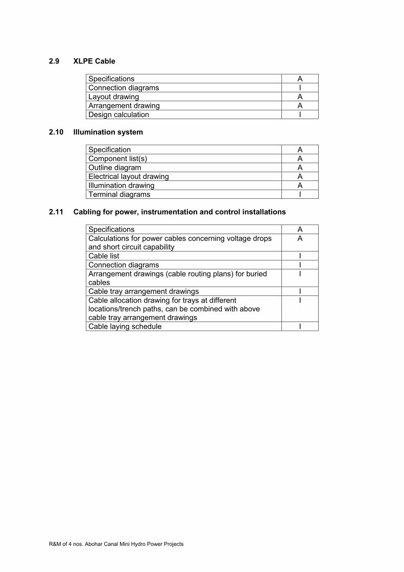
R&M of 4 nos. Abohar Canal Mini Hydro Power Projects
2.9 XLPE Cable
Specifications A
Connection diagrams I
Layout drawing A
Arrangement drawing A
Design calculation I
2.10 Illumination system
Specification A
Component list(s) A
Outline diagram A
Electrical layout drawing A
Illumination drawing A
Terminal diagrams I
2.11 Cabling for power, instrumentation and control installations
Specifications A
Calculations for power cables concerning voltage drops and short circuit capability
A
Cable list I
Connection diagrams I
Arrangement drawings (cable routing plans) for buried cables
I
Cable tray arrangement drawings I
Cable allocation drawing for trays at different locations/trench paths, can be combined with above cable tray arrangement drawings
I
Cable laying schedule I

R&M of 4 nos. Abohar Canal Mini Hydro Power Projects
SECTION 7: CHUPKI (2x750 kW0 SHP PLANT) Technical Specifications 7.1 Plant Details Chupki power station is located on right bank of the canal on bye pass channel having an installed capacity of 2x 750 kW. An ultra low head of 2.72 m has been exploited at this hydropower station. Employing syphon intake technology, this plant uses vertical-axis semi-Kaplan Turbines coupled with induction generators. This plant is fully automated and utilized programmable logic control (PLC) based supervisory control and data acquisition (SCADA) system.
Three numbers electrically operated gates have been provided on the main canal to
divert the water into bye pass channel for power generation. The power station is also having two numbers hydraulically operated gates for controlling discharge available for power generation. Provision of draft tubes gates were made but not installed.
The power station was commissioned on 12.11.1999 where two units of vertical
syphon type Semi Kaplan Turbines are installed with vacuum pump motor sets. The turbines are connected with vertical alternators through gear boxes .The alternators are induction type. The units are controlled and operated through fully automatic PLC based supervisory control and data acquisition system. The generated power is connected with LT bus bar through air circuit breakers and stepped up to 11 kV through one number generator transformer. 11kV outdoor equipment has been installed with all requisite switch gears and instrument transformers etc in the switchyard.
The generated power is transmitted to 66/11 kV Distribution Substation at Alamgir.
Technical particulars of various equipments are as follows:
7.2 Technical Particulars 1. General Details
1. Name of Power House Chupki Small Hydropower Plant
2. Location Located in Punjab near Ludhiana
3. Date of commissioning 12.11.1999
4. Type of Project Canal based
5. Type of diversion: Cross regulator
6. Design discharge (Total) m3/s
71.45
7. Head Gross(m) Net(m)
2.92 2.72
8. Installed capacity 2 x 750 KW
9. Type of turbine Semi Kaplan
10. Type of generator Generating Voltage
Vertical shaft Induction Generator 415V
11. Coupling Through Speed Increaser (Gear Box)
12. Power Evacuation
Connecting Sub Station Details:
Voltage
Location
66/11 KV Alamgir

R&M of 4 nos. Abohar Canal Mini Hydro Power Projects
Distance from the Power House in km
7 km
13 Operating Status Both units working
14. Cost of The Project(at the time of commission)
8 crore approx
2. Technical Details
Name of Equipment Technical Specifications
1. Turbine and ancillaries
A. Turbine
Type Vertical, Semi Kaplan, Siphon intake
Make Triveni Engineering & Industry Ltd. New Delhi
Rated net Head m. 2.72
Rated output at rated net head 798 kW
Rated Speed 90 rpm
Run-away Speed 252 rpm
Direction of rotation Clockwise (viewed from top)
Efficiency at 100% rated load 88.18 %
Discharge at rated head for 100% rated load
33.35m3 /sec
B. Inlet Casing & Speed Ring Inlet section No. of stay vanes
9.4 x 4.3 20
C. Runner Diameter of Runner No. of blades Weight kg Material RB Servomotor Operating Pressure Servomotor Dia. Servomotor Stroke
3110 mm Four 6500 13 Cr 4 Ni S.S. Above Gear box 35 - 40 bar 350 mm 170 mm
D. Shaft Material and composition Diameter Length Weight Material
Forged carbon steel 260 mm 3065 mm 1300 Kg Forged Carbon Steel
E. Turbine Guide Bearing Location Type Lubrication
F. Thrust bearing Location Type
Head Cover Thordon Water Gear Box Oil lubricated taper roller bearing
G. Shaft Seal Stuffing Box Water Lubricated
H. Runner Chamber Diameter mm Length mm Material
3110 1035 SS

R&M of 4 nos. Abohar Canal Mini Hydro Power Projects
I. Draft Tube Length of steel liner mm
Elbow Conical type 5822
J. Oil Pressure Unit Make Eff. Volume of sump tank No of pumps Type of pumps Capacity of each pump Total Vol of oil in system K. Oil Pressure Vessel Type Normal working pressure Governor Type
Rexroth India 250 litre 1 Gear Pump 23 lpm 200 litre N2 Bladder type 150 bar Digital PLC based
L. Vacuum Breaking valve Make Model Motor rating Flow Max De-pressure Motor RPM
ABB Fougal HD-4 15 kW 558 m3/hr 1.43 m of water column 2900
2. GEAR BOX (Speed increaser) Make Model Power to be transmitted Types of gears Overall efficiency Gear ratio Material of gears Hardness of gears Noise level Distance between low speed & high speed shafts
Kirloskar Pneumatic Company Ltd. H2V 500 712 kW Halical 98.5% 90/1012 En 354 HRC 58-62 90 dB 960 mm
Hydraulic Union (for oil pipe lines to runner servomotor) Make Model No. of passage Max speed Max Hyd. Pressure Seal
DEUBLIN 1574-074 ELS Twin 1500 rpm 70 bar Tungsten Carbide - to- Ceramic seal
Cooling Water System Make & Type of Pumps No of pumps Discharge Head Power Duplex strainer make
KSB, Submersible bore well pumps 2 150 lpm 45 m 3 HP CHEMPHARM,
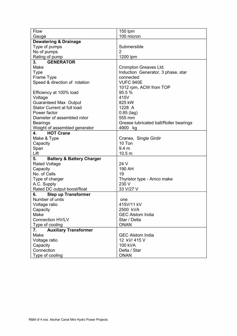
R&M of 4 nos. Abohar Canal Mini Hydro Power Projects
Flow Gauge
150 lpm 100 micron
Dewatering & Drainage Type of pumps No of pumps Rating of pump
Submersible 2 1200 lpm
3. GENERATOR Make Type Frame Type Speed & direction of rotation Efficiency at 100% load Voltage Guaranteed Max Output Stator Current at full load Power factor Diameter of assembled rotor Bearings Weight of assembled generator
Crompton Greaves Ltd. Induction Generator, 3 phase, star connected VUFC 940E 1012 rpm, ACW from TOP 95.5 % 415V 825 kW 1228 A 0.85 (lag) 555 mm Grease lubricated ball/Roller bearings 4900 kg
4. HOT Crane Make & Type Capacity Span Lift
Cranex, Single Girdir 10 Ton 9.4 m 10.5 m
5. Battery & Battery Charger Rated Voltage Capacity No. of Cells Type of charger A.C. Supply Rated DC output boost/float
24 V 190 AH 19 Thyristor type - Amco make 230 V 33 V/27 V
6. Step up Transformer Number of units Voltage ratio Capacity Make Connection HV/LV Type of cooling
one 415V/11 kV 2500 kVA GEC Alstom India Star / Delta ONAN
7. Auxiliary Transformer Make Voltage ratio Capacity Connection Type of cooling
GEC Alstom India 12 kV/ 415 V 100 kVA Delta / Star ONAN

R&M of 4 nos. Abohar Canal Mini Hydro Power Projects
8. Switchyard Equipment 1. Vacuum Circuit Breaker
1. Type of breaker 2. Installation 3. Nominal system voltage 4. Voltage ( Maxm) 5. Rated Current 6. Rated Short Circuit Breaking
current 7. Rated shot Circuit Making Current 8. Power frequency with stand
voltage 9. Lightning impulse with stand
voltage 10. Standard
2. Isolator
1. Rated voltage 2. Highest system voltage 3. Type of isolator 4. Rated current 5. Rated frequency 6. Rated fault current 7. Power frequency with stand
voltage Impulse with stand voltage 8. Creepage distance 9. Temperature rise above 40 0C
ambient 10. Temperature
Copper contacts
Terminal connectors 11. Standard applicable
3. 11 kV Current Transformers
1. Type of CTs 2. Nominal system voltage 3. Maxm system voltage 4. Ratio of CTs 5. Accuracy class /Accuracy limit
factor for protection (general) 6. Accuracy class /Accuracy limit
factor for Differential protection 7. V A burden 8. CT for TVM 9. Standard
4. 11 kV Potential Transformer
1. Type of PTs 2. Nominal system voltage 3. Maximum system voltage 4. Ration of PTs 5. Accuracy class for protection and
Metering
Vacuum Circuit Breaker Out door 11 kV 12 kV 1250 A 25kA / 3 Sec 62.5 kA
28 kV rms
75 kVp IS 13118 : 11 kV : 12 kV : Centre rotating manually operable : 630 A : 50 Hz : 25kA/1 sec : 28 kVrms : 75 kVpeak : 25 mm/kVmax : 65 0C : 50 0C : IS-1921 : Cast resin dry : 11 kV : 12 kV : 150/1-1-1-1A : 5 P 20/Cl. 0.5/Cl. 1.0 : Class PS : 20 VA : 150/1A ,20VA,Cl. 0.2 : IS 2705 : Cast resin type : 11 kV : 12 kV :11/√3 kV/110V/√3/110V/√3 : Class 3P/0.5 : 50 VA
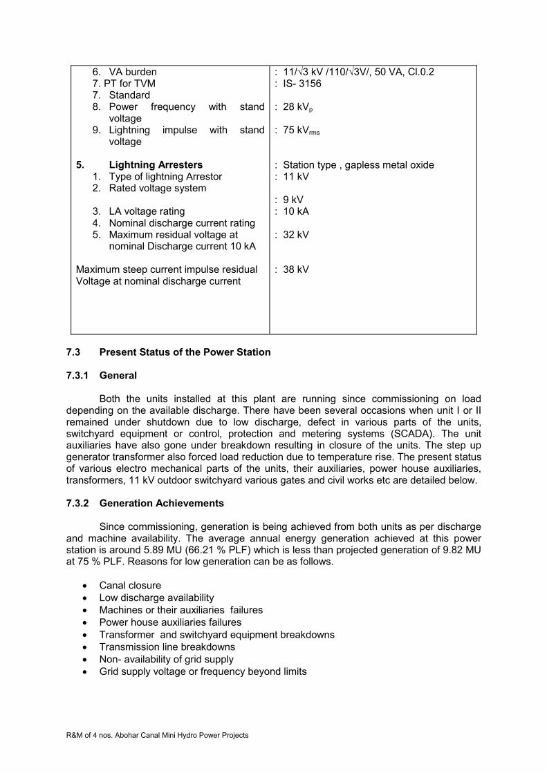
R&M of 4 nos. Abohar Canal Mini Hydro Power Projects
6. VA burden 7. PT for TVM 7. Standard 8. Power frequency with stand
voltage 9. Lightning impulse with stand
voltage
5. Lightning Arresters 1. Type of lightning Arrestor 2. Rated voltage system
3. LA voltage rating 4. Nominal discharge current rating 5. Maximum residual voltage at
nominal Discharge current 10 kA
6. Maximum steep current impulse residual Voltage at nominal discharge current
: 11/√3 kV /110/√3V/, 50 VA, Cl.0.2 : IS- 3156 : 28 kVp
: 75 kVrms : Station type , gapless metal oxide : 11 kV : 9 kV : 10 kA : 32 kV : 38 kV
7.3 Present Status of the Power Station 7.3.1 General
Both the units installed at this plant are running since commissioning on load depending on the available discharge. There have been several occasions when unit I or II remained under shutdown due to low discharge, defect in various parts of the units, switchyard equipment or control, protection and metering systems (SCADA). The unit auxiliaries have also gone under breakdown resulting in closure of the units. The step up generator transformer also forced load reduction due to temperature rise. The present status of various electro mechanical parts of the units, their auxiliaries, power house auxiliaries, transformers, 11 kV outdoor switchyard various gates and civil works etc are detailed below. 7.3.2 Generation Achievements
Since commissioning, generation is being achieved from both units as per discharge and machine availability. The average annual energy generation achieved at this power station is around 5.89 MU (66.21 % PLF) which is less than projected generation of 9.82 MU at 75 % PLF. Reasons for low generation can be as follows.
Canal closure
Low discharge availability
Machines or their auxiliaries failures
Power house auxiliaries failures
Transformer and switchyard equipment breakdowns
Transmission line breakdowns
Non- availability of grid supply
Grid supply voltage or frequency beyond limits

R&M of 4 nos. Abohar Canal Mini Hydro Power Projects
Canal closures are for some definite periods for maintenance works. The canal closures are affected during the period when no water is required for irrigation purposes. Low discharge may be due to low water releases in the canal, leakages in diversion and bye-pass gates etc. The low discharge and grid non availability are the major contributors of low generation. There have been problems in power plant and equipment like gear box, runner assembly and bearing etc due to which machines remained under breakdown for long periods, thereby resulting in low annual generation.
7.3.3 Electromechanical Works
7.3.3.1 Turbines and Their Auxiliaries
The turbines are vertical semi Kaplan type with syphon intake. There are no penstock, no metallic spiral casing and no intake gates. Water is directed to turbine intake through an open concrete channel, passes through stay vanes of speed ring, runner, runner chamber, draft tube and discharges in tail race channel. The performance of these turbines generally remained satisfactory throughout their operation since commissioning.
7.3.3.1.1 Turbine Runner
Runner is semi Kaplan type with four blades. Runner consists of one hub body, four
blades each with trunion bearing, lever, connecting rod, blade seals, seal covers, one cross head, lower cone and main regulating rod. Hub body is spherical in shape on external side and contains four windows for mounting runner blades. The runner blades surface matching the hubs external surface is machined spherical and minimum clearance is kept between the two. Blades external surface too is machined spherically. The runner blades are turned about their axis through lever, connecting rod, cross head and regulating rod. The hub assembly is bolted to turbine shaft assembly.
7.3.3.1.2 Runner Servomotor Assembly
Runner servomotor is located on the top of gearbox driving shaft and rotates with it.
The up and down movement of piston inside the runner servomotor is transmitted to cross head in runner hub through a regulating rod passing through the gearbox shaft and the turbine shaft. Pressure oil from hydraulic control unit is supplied to opening or closing side of the servomotor piston through a concentric pipe assembly fixed on the piston. This pipe assembly is connected to a hydraulic union located over the servomotor in such a way that pipe assembly rotates in hydraulic union. The position of this hydraulic union indicates the angle of runner blades. One linear LVDT is installed with the hydraulic union to sense the runner blade position.
7.3.3.1.3 Turbine Shaft
Turbine shaft is Carbon steel forging with coupling flanges for runner and gear box
shaft. Fitted bolts are used for coupling the turbine shaft and gear box shaft while runner side flange is coupled with runner hub with bolts and cylindrical pins.
7.3.3.1.4 Turbine Guide Bearing
The turbine guide bearing assembly is mounted on inner flange of top cover. It
consists of guide bearing housing and guide bearing bush. The guide bearing housing is a mild steel fabricated structure with reinforcement ribs which houses a guide bearing. The guide bearing is Thordon make which is a proprietary design. Clean water is supplied to bearing for lubrication and cooling.
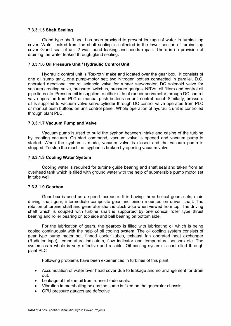
R&M of 4 nos. Abohar Canal Mini Hydro Power Projects
7.3.3.1.5 Shaft Sealing
Gland type shaft seal has been provided to prevent leakage of water in turbine top cover. Water leaked from the shaft sealing is collected in the lower section of turbine top cover Gland seal of unit 2 was found leaking and needs repair. There is no provision of draining the water leaked through gland sealing. 7.3.3.1.6 Oil Pressure Unit / Hydraulic Control Unit
Hydraulic control unit is 'Rexroth' make and located over the gear box. It consists of
one oil sump tank, one pump-motor set; two Nitrogen bottles connected in parallel, D.C. operated directional control solenoid valve for runner servomotor, DC solenoid valve for vacuum creating valve, pressure switches, pressure gauges, NRVs, oil filters and control oil pipe lines etc. Pressure oil is supplied to either side of runner servomotor through DC control valve operated from PLC or manual push buttons on unit control panel. Similarly, pressure oil is supplied to vacuum valve servo-cylinder through DC control valve operated from PLC or manual push buttons on unit control panel. Whole operation of hydraulic unit is controlled through plant PLC.
7.3.3.1.7 Vacuum Pump and Valve
Vacuum pump is used to build the syphon between intake and casing of the turbine by creating vacuum. On start command, vacuum valve is opened and vacuum pump is started. When the syphon is made, vacuum valve is closed and the vacuum pump is stopped. To stop the machine, syphon is broken by opening vacuum valve.
7.3.3.1.8 Cooling Water System
Cooling water is required for turbine guide bearing and shaft seal and taken from an overhead tank which is filled with ground water with the help of submersible pump motor set in tube well.
7.3.3.1.9 Gearbox
Gear box is used as a speed increaser. It is having three helical gears sets, main driving shaft gear, intermediate composite gear and pinion mounted on driven shaft. The rotation of turbine shaft and generator shaft is clock wise when viewed from top. The driving shaft which is coupled with turbine shaft is supported by one conical roller type thrust bearing and roller bearing on top side and ball bearing on bottom side.
For the lubrication of gears, the gearbox is filled with lubricating oil which is being
cooled continuously with the help of oil cooling system. The oil cooling system consists of gear type pump motor set, finned cooler tubes, exhaust fan operated heat exchanger (Radiator type), temperature indicators, flow indicator and temperature sensors etc. The system as a whole is very effective and reliable. Oil cooling system is controlled through plant PLC
Following problems have been experienced in turbines of this plant.
Accumulation of water over head cover due to leakage and no arrangement for drain out.
Leakage of turbine oil from runner blade seals.
Vibration in marshalling box as the same is fixed on the generator chassis.
OPU pressure gauges are defective

R&M of 4 nos. Abohar Canal Mini Hydro Power Projects
Guide bearing damaged
Tensile bolts may be over stressed
Sensors, RTD and switches are defective
Thrust collars and link bushes of runner have abnormal clearances.
Gear box of units failed
7.3.3.2 Generators and Auxiliaries
Vertical axis, cylindrical induction generators of capacity 750 kW, 1012 rpm , 50 HZ , 3-phase ,0.85 PF ,415V are installed at this plant. Each generator is air cooled and suitable for 10% continuous overload rating. The windings of these generators are of class ‘F’ insulation with class B temperature rise conditions. Generator shaft is coupled with gearbox through flexible coupling.
These type of generators generally do not have much auxiliary systems, except the cooling arrangement for bearings, terminal box for line side and neutral side cable terminations speedometer and temperature sensing RTDs . The bearings are grease lubricated roller type and have been changed during break down periods .The terminal boxes are getting heated due to inadequate space and proper ventilation. These boxes are to be redesigned and replaced.
The Crompton Greaves make induction generators are generally in order and may require only small maintenance works. No major breakdowns have been observed in generators at this station. The temperature sensing indicating and speed measuring devices are not in working condition and therefore, require replacement. The dust accumulated inside the generator has to be removed and thorough cleaning and painting with Epoxy insulation paints shall be required.
7.3.3.3 Station Auxiliaries 7.3.3.3.1 Mechanical Auxiliaries
i. HOT Crane
The 10 Tonne crane provided at this station is hand operated with one main hook only. The turbine runner may require to turn during maintenance. Due to non-availability of auxiliary hook, the turning of runner is not possible. Therefore, crane with auxiliary hook and electrically operated system should be provided.
ii. Ventilation and Air conditioning systems
The ventilators have been provided in the machine hall but no exhaust fans are installed. The hot air around generators should be exhausted for containing the temperature rise and to achieve adequate air changes.
The control /relay and PLC/SCADA panels are located in control room. The area is not air conditioned due to which performance of electronic relays and other equipment may not remain satisfactory. iii. Firefighting arrangement
Portable fire extinguishers and fire buckets are essentially required to meet out any eventuality in machine hall, control room, control room for gates and switchyard. Fire extinguishers of required capacity and suitability for the area may be provided.
R&M of 4 nos. Abohar Canal Mini Hydro Power Projects
7.3.3.3.2 Electrical Auxiliaries
i. DC System
This system includes battery set, charger and DC distribution board. One set of 24V 190 AH Amco make NiCd battery set for control, protection and metering have been provided with battery charger cum distribution board. One set of 72 V DC battery set and charger is also provided for PLC system exclusively. Both the chargers and battery sets are defective. UPS are installed for meeting the requirements. Battery cells of both sets are also defective.
ii. Control, protection and metering systems/SCADA
The control through PLC system is generally being used. The computer monitor is not functioning satisfactory. Most of the transducers are defective, due to which required parameters are not available on monitor. Efforts have been made to get these transducers repaired, but the performance of repaired transducers have also not been found satisfactory.
The protection relays are electromagnetic type which are less accurate and of higher burden. Their setting ranges are also limited with no multi-functionality. These type of relays are of larger size but have no system flexibility and self diagnostics.
The metering display meters are all defective. These meters are digital type but not in working order. Analogue meters for indicating voltage and current are also not in working condition on any panel. The indicating lamps and some of the control switches/push buttons etc are also not in working condition.
The circuit breakers in generator panels are although in working conditions, but their operation life has almost been completed. Fast operating switchgears may be required.
iii. Lighting System
The general illumination in machine hall and control room is low. Several fittings are not in working condition. There is no provision of emergency lighting system except a torch in control room. The lighting system of the forebay, diversion and byepass gates areas, tail race and switchyard also found to be inadequate.
iv. Capacitor Banks
The capacitor bank units are found defective. The banks are to be completed through replacement of the unit full banks.
v. Power and Control Cables
The cables from generator to panels are required to be replaced with new XLPE cable of adequate rating. The control cables may also have to be replaced.
vi. D.G Set
The diesel generator set installed at the power house is in satisfactory running condition. This may require minor repair works with replacement of defective switches/PBs, indicating meters and lamps etc on control panel.
R&M of 4 nos. Abohar Canal Mini Hydro Power Projects
7.3.3.4 Transformers
7.3.3.4.1 General
There is one generator transformer and one station auxiliary transformer installed at this power station for stepping up the generated power for transmission to grid substation and power requirements of the plant respectively.
Generator Transformer - 2500 kVA 0.415/11kV , 50 HZ, ONAN , Off load tap changer ±5% insteps of 2.5%
3-phase,YNd1
Station Auxiliary Transformer -100 kVA 11/0.415 kV , 50 HZ, ONAN , 3-phase, Dyn11
7.3.3.4.2 Generator Transformer
M/s GEC-ALSTHOM India Distribution Transformer make oil filled generator transformer is installed near main entrance out side the power house. The performance of the transformer is by and large satisfactory. The officer incharge/staff of the power station has however informed that during summer season, when ambient temperature reaches peak values nearing 500C, the transformer temperature increases. Some time alarm has been observed and generation has to be reduced to contain the temperature. The increase in temperature may be due to inadequate ventilation, as the transformer is located near the two walls corner of the power house.
7.3.3.4.3 Station Auxiliary Transformer
The auxiliary transformer installed at the power house is adequate enough to meet out the power requirements of the power plant. The transformer is in satisfactory condition, as no problems have so far been reported. This transformer is connected with the11 kV line from distribution substation at Roomi.
7.3.3.5 Switchyard Equipment
7.3.3.5.1 General
The 11 kV switchyard is located between power house bye pass channel and main canal. The overhead bare conductor has been used for connecting generator transformer with switchyard bus through isolator and outdoor vacuum circuit breaker, instrument transformers and lightning arrestors etc. The station auxiliary transformer is also located in the switchyard connected with the 11 kV line through isolator and fuse set. The details of various equipments are as follows. 7.3.3.5.2 Vacuum Circuit Breaker
The vacuum circuit breaker of 12 kV, 630 A, 25 kA/3 sec rating, outdoor type is installed in the switchyard. It has been reported that the breaker is giving problems in fault clearing and normal operation. The deterioration may be due to excessive operation on line faults and weather conditions.
7.3.3.5.3 Instrument Transformers
The 11 kV current and voltage transformers of required rating, oil filled and outdoor type are installed in the switchyard. These transformers of 18.4 kA Fault level are giving problems in metering and protection, due to their frequent break downs.
R&M of 4 nos. Abohar Canal Mini Hydro Power Projects
7.3.3.5.4 Lightning Arresters
Lightning Arrestors of rating 9 kV, 10 kA station class self supporting with insulation base and surge counters should be installed on both transformers as near as possible to their HV bushing. This primary protection against lightning surges must be installed on feeder also to protect the equipments. Lightning Arrestors on generator transformer and 11 kV line are installed but surge counters are not provided. These devices have also not been provided near station auxiliary transformer. 7.3.3.5.5 11 kV Isolators
Isolators with and without earth switches have been provided for 11kV line and transformer circuits respectively. These are centre rotating type and appear to be in satisfactory condition. No defect or damages have been observed. 11 kV HG fuse set has been provided for station auxiliary transformer protection. 7.3.3.5.6 Main and Auxiliary Structures
The four pole and double poles main structures with gantries and auxiliary structures for various equipment are found generally in satisfactory condition.
7.3.3.6 Power Evacuation
7.3.3.6.1 11 kV Line to 66/11 kV Substation at Roomi
The line to transmit generated power from Chupki SHP to distribution substation at Alamgir is about 7.0 km long and constructed on PCC poles with ACSR ‘TIGER’ conductor. The line is generally in satisfactory condition except few poles bent. The actual status may however be checked through inspection of the line jointly with PSPCL and required rectification should be undertaken.
7.3.3.6.2 Equipment at 66/11 kV Alamgir Substation
The 11 kV line from Chupki SHP is connected at this substation. The feeder
equipments are in satisfactory working condition. No break down or damage has been found.
7.4 Technical Specifications of R&M Works 7.4.1 Detailed Scope of Work
Scope of work include dismantling of Units (One by one so as to allow operation of
remaining units), critically inspect the components which are to be retained, take dimensions of the components necessary for reverse engineering, design, manufacturing & supply new components/ equipments, repair the old components at project site/manufacturer’s works, re-assemble the units with new/repaired components, carry out pre-commissioning tests, commission and handover the units to the PGL.
R&M of 4 nos. Abohar Canal Mini Hydro Power Projects
7.4.1.1 Turbine, Governing System & Auxiliaries
Runner:
Both the runners are to be dismantled and refurbished in manufacturing shop/site. During refurbishment, all components should be dismantled and inspected carefully and decision be taken for replacement or repair based on their condition. Any component which was repaired earlier should be replaced by new one. Blade seals should be replaced by improved design seals, preferably reinforced rubber seals. Screws for fixing the seal cover plates are to be changed with new stainless steel screws. These screws should preferably be tightened with good quality sealant and their heads be covered with sealant putty. Worn-out bronze bushes of blades trunions be replaced. Blades surfaces are to be checked by DP/UT for any cracks. Defects on blade surfaces are to be weld repaired. Free movement of runner blades to be checked before assembly of runner with shaft.
Runner Servomotor: Oil seals of servomotor got worn out and started leaking. Therefore dismantle the servomotor completely, inspect all components including piston rings/seals, bushes and oil pipe fixed on piston, bronze bushes etc. The defective items are to be changed. All rubber seals are to be compulsorily changed. The piston rod, all connecting rods and concentric oil pipe assembly are to be checked by non-destructive Test. New hydraulic unions are to be provided.
Turbine Guide Bearing:
Complete refurbishment of turbine guide bearing of each unit is to be done. This work includes replacement of Thordon lining.
Turbine Seal: The existing design of seal is in order. Worn out components be changed and fasteners be replaced by SS fasteners.
Hydraulic Control Unit: Refurbishment and replacement of gear pumps. Pump-motor set are to be replaced. Runner blade regulating mechanism be changed to regulate the opening by
proportional control valves to set value by one command rather than pulse commands. Accordingly, governor function in PLC needs modifications.
Oil filters and any other defective component to be replaced. All Instruments like differential pressure switches, pressure gauges, oil
temperature detectors and other transducers etc to be replaced. Nitrogen bladders are to be replaced.
Vacuum Pump System: Routine maintenance may be done and worn out components be changed.
Instruments, Transducers and Devices: Oil flow switch (sensor), pressure switch (sensor), digital tachometer, digital oil temp indicator, runner position LVDT and other instruments, transducers and devices are to be replaced.

R&M of 4 nos. Abohar Canal Mini Hydro Power Projects
Turbine Top Cover Drainage System: New system involving pump-motor set, water level controller and pipe lines be provided for draining leakage water / used cooling water of turbine seal from turbine top cover.
7.4.1.2 Gear Box (Speed Increaser) Replace both gearboxes with improved parameters like service factor 2 and 10% additional capacity. New gearbox should match the existing turbine shaft details, generator shaft, fixing details of base frame and hydraulic thrust of runner. Instruments and devices are also be replaced. Local indication for gear box parameters should also be provided to have better control and operations.
Heat Exchanger of gearbox oil is also to be replaced. Operation of fans is to be
linked with temperature sensors 7.4.1.3 Generators & Their Auxiliaries
Following works are to be carried out under R&M of the generators
Cleaning of stator winding, slots etc
Cleaning of rotor
Insulation Resistance measurement
Painting of windings with insulation paints
General painting with enamel paint
Replacement of Temperature Sensing Devices
Replacement of Speed sensing devices
Replacement of Power Cable Terminal Box with improved design.
Replacement of control cable Junction box.
Replacement of DE and NDE side bearings.
Problem if winding temperature rise is to be studied and remedial measures are to be taken.
Minor maintenance work as required after dismantling of the generator 7.4. 1.4 Station Auxiliaries 7.4.1.4.1 Mechanical Auxiliaries i. Crane
Following works are to be done for R & M of crane
Crane to be modified to be suitable for electrical operation through pendant switch from machine hall floor. Operation through hand held remote control unit may also be considered.
Additional 3 Ton Auxiliary Hook is also to be provided for turning of runner and handling the lower loads.
General overhauling of gear box etc. is to be done
General painting with enamel paints on complete crane
Recommended compound may be applied on flexible crane steel rope

R&M of 4 nos. Abohar Canal Mini Hydro Power Projects
ii. Ventilation and Air Conditioning System
Following R & M works are recommended for these systems
6 nos exhaust fans with wire mesh are to be installed on the ventilators in machine hall
The control room is to be provided with two nos. five star rated window air conditioner of 1.5 ton capacity each.
iii. Cooling Water System The existing cooling water system is to be refurbished completely so that satisfactory working of cooling water system is ascertained. Following works will be required to be done:
Replacement of all instruments like flow indicators, pressure gauges, temperature detectors etc. is to be done.
Replacement of all pipes and fittings below 1” dia with SS pipes
2 nos. new submersible tube well pumps of desired capacity including bore at each plant are to be provided
New 5000 litre PVC overhead tank is to be provided
Replacement of all other MS pipes and fittings will also be done.
Any other work for satisfactory working of cooling water system will also be done. iv. Fire Fighting Arrangement
Portable fire extinguishers are required to be placed at appropriate location. The most vulnerable and fire prone areas may be identified and fire extinguisher of following type and capacity may be located
Control room/ office/ switchgear room 3 x 9 kg CO2 type
Machine hall near OPU 4 x 9 kg foam type
Switchyard & Transformer 2 x 9 kg CO2 type
Gates control room/ D.G room 1 x 9 kg foam type 1 x 9 kg CO2 type In addition to above, two sets of fire buckets filled with dry sand and mounted on covered stand may be located in service bay area of the machine hall and 11 kV switchyard. 7.4.1.4.2 Electrical Auxiliaries i. DC System
Replacement of existing battery set with 24 V – 200 AH new T-Gel type battery bank
with mounting stand and provision of emergency lighting system. Providing new UPS having 5 KVA rated capacity with suitable battery set capable of
providing 3 Hours of back up including replacement of mounting stand. The chargers cum distribution boards are to be replaced with static rectifier systems, protective relays, metering provisions and required MCCB/MCSs. ii. Control, Protection and Metering System –SCADA
The entire control system based on PLC-SCADA provisions is to be replaced with new arrangements. The protection / metering system are also to be replaced with new
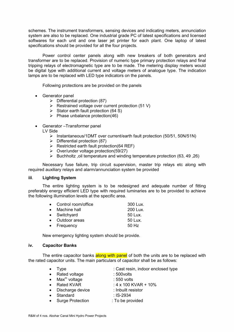
R&M of 4 nos. Abohar Canal Mini Hydro Power Projects
schemes. The instrument transformers, sensing devices and indicating meters, annunciation system are also to be replaced. One industrial grade PC of latest specifications and licensed softwares for each unit and one laser jet printer for each plant. One laptop of latest specifications should be provided for all the four projects.
Power control center panels along with new breakers of both generators and transformer are to be replaced. Provision of numeric type primary protection relays and final tripping relays of electromagnetic type are to be made. The metering display meters would be digital type with additional current and voltage meters of analogue type. The indication lamps are to be replaced with LED type indicators on the panels.
Following protections are be provided on the panels
Generator panel Differential protection (87) Restrained voltage over current protection (51 V) Stator earth fault protection (64 S) Phase unbalance protection(46)
Generator –Transformer panel LV Side
Instantaneous/1DMT over current/earth fault protection (50/51, 50N/51N) Differential protection (87) Restricted earth fault protection(64 REF) Over/under voltage protection(59/27) Buchholtz ,oil temperature and winding temperature protection (63, 49 ,26)
Necessary fuse failure, trip circuit supervision, master trip relays etc along with required auxiliary relays and alarm/annunciation system be provided
iii. Lighting System
The entire lighting system is to be redesigned and adequate number of fitting preferably energy efficient LED type with required luminaries are to be provided to achieve the following illumination levels at the specific area.
Control room/office 300 Lux.
Machine hall 200 Lux.
Switchyard 50 Lux.
Outdoor areas 50 Lux.
Frequency 50 Hz New emergency lighting system should be provide.
iv. Capacitor Banks
The entire capacitor banks along with panel of both the units are to be replaced with the rated capacitor units. The main particulars of capacitor shall be as follows:
Type : Cast resin, indoor enclosed type
Rated voltage : 500volts
Maxm voltage : 550 volts
Rated KVAR : 4 x 100 KVAR + 10%
Discharge device : Inbuilt resistor
Standard : IS-2934
Surge Protection : To be provided

R&M of 4 nos. Abohar Canal Mini Hydro Power Projects
v. Power and Control Cables
1.1 kV grade power cables (PVC) from generator to panels are to be replaced with new XLPE armoured aluminum cables of adequate size. The cable racks in trenches may be cleaned and painted with enamel paints of approved shade, before laying of cable. The cables must be neatly laid, dressed and clamped in required groups.
Control cables are also to be replaced with new PVC multi-strand copper cables and clamped on racks neatly.
11 kV power cables for facilitating connections of 11 kV outdoor type vacuum circuit
breaker with generator –transformer HV side and 11 kV line isolator for feeder are also to be replaced. vi. D.G. Set
General over hauling and other maintenance works of DG set are to be done. Proper Maintenance of the starter panels is to be done and all defective switches, push buttons, measuring instruments and indicating lamps etc. are to be replaced. vii. Station Service Board
The complete AC station service board is to be provided with standard MCCB and
MCBs of required ratings, digital /analogue meters and indicating lamps etc for metering the AC power requirement of the plant.
Provision of one incomer from station auxiliary transformer and other incomer from
D.G. set is to be made, with required number of feeder circuits.
7.4.1.5 Transformer
The normal overhauling and maintenance works including replacement of oil of suitable grade including dehydration of oil, cleaning, replacement of leaking gaskets and painting works etc. is to done on generator and auxiliary transformers. The winding temperature indicator, oil temperature indicator, silica gel breather, tap changer and Buchloz relays etc will also be changed.
The problem of increase in temperature during hot summer season is to be solved by
providing new 4 nos. of 450 mm cooling fans installed on stands. Control of operation of these fans is to be established by providing temperature sensing devices with auxiliary relays and starters etc. Any other work required for proper functioning will also be done excluding transformer re-winding.
7.4.1.6 Switchyard Equipment
7.4.1.6.1 Vacuum Circuit Breakers The existing outdoor type Vacuum Circuit Breakers are old and giving frequent trouble, these are to be replaced with new one along with Line control Panel.
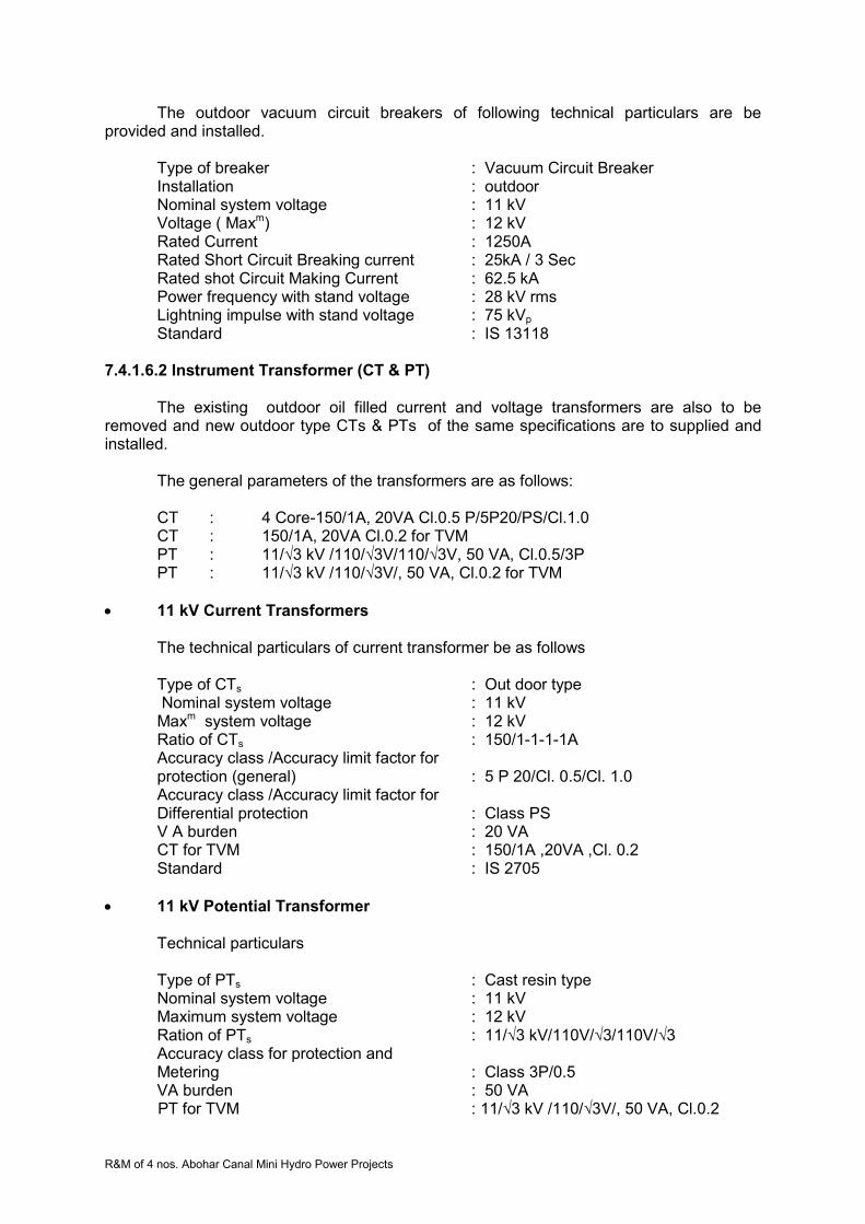
R&M of 4 nos. Abohar Canal Mini Hydro Power Projects
The outdoor vacuum circuit breakers of following technical particulars are be provided and installed.
Type of breaker : Vacuum Circuit Breaker Installation : outdoor Nominal system voltage : 11 kV Voltage ( Maxm) : 12 kV Rated Current : 1250A Rated Short Circuit Breaking current : 25kA / 3 Sec Rated shot Circuit Making Current : 62.5 kA Power frequency with stand voltage : 28 kV rms Lightning impulse with stand voltage : 75 kVp Standard : IS 13118
7.4.1.6.2 Instrument Transformer (CT & PT)
The existing outdoor oil filled current and voltage transformers are also to be
removed and new outdoor type CTs & PTs of the same specifications are to supplied and installed.
The general parameters of the transformers are as follows: CT : 4 Core-150/1A, 20VA Cl.0.5 P/5P20/PS/Cl.1.0 CT : 150/1A, 20VA Cl.0.2 for TVM PT : 11/√3 kV /110/√3V/110/√3V, 50 VA, Cl.0.5/3P PT : 11/√3 kV /110/√3V/, 50 VA, Cl.0.2 for TVM
11 kV Current Transformers The technical particulars of current transformer be as follows Type of CTs : Out door type Nominal system voltage : 11 kV Maxm system voltage : 12 kV Ratio of CTs : 150/1-1-1-1A Accuracy class /Accuracy limit factor for protection (general) : 5 P 20/Cl. 0.5/Cl. 1.0 Accuracy class /Accuracy limit factor for Differential protection : Class PS V A burden : 20 VA CT for TVM : 150/1A ,20VA ,Cl. 0.2 Standard : IS 2705
11 kV Potential Transformer Technical particulars
Type of PTs : Cast resin type Nominal system voltage : 11 kV Maximum system voltage : 12 kV Ration of PTs : 11/√3 kV/110V/√3/110V/√3 Accuracy class for protection and Metering : Class 3P/0.5 VA burden : 50 VA
PT for TVM : 11/√3 kV /110/√3V/, 50 VA, Cl.0.2
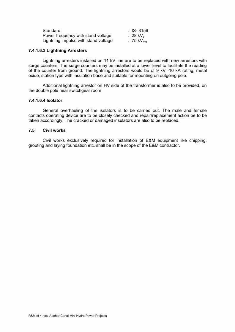
R&M of 4 nos. Abohar Canal Mini Hydro Power Projects
Standard : IS- 3156 Power frequency with stand voltage : 28 kVp Lightning impulse with stand voltage : 75 kVrms
7.4.1.6.3 Lightning Arresters
Lightning arresters installed on 11 kV line are to be replaced with new arrestors with
surge counters. The surge counters may be installed at a lower level to facilitate the reading of the counter from ground. The lightning arrestors would be of 9 kV -10 kA rating, metal oxide, station type with insulation base and suitable for mounting on outgoing pole.
Additional lightning arrestor on HV side of the transformer is also to be provided, on
the double pole near switchgear room
7.4.1.6.4 Isolator
General overhauling of the isolators is to be carried out. The male and female contacts operating device are to be closely checked and repair/replacement action be to be taken accordingly. The cracked or damaged insulators are also to be replaced.
7.5 Civil works Civil works exclusively required for installation of E&M equipment like chipping, grouting and laying foundation etc. shall be in the scope of the E&M contractor.

R&M of 4 nos. Abohar Canal Mini Hydro Power Projects
SECTION 8: NARANGWAL (2X750 kW) MHP PLANT Technical specifications
8.1 Plant Details Narangwal power station is located on right bank of the canal on bye pass channel having an installed capacity of 2x750 kW. An ultra low head of 2.62m has been exploited at this hydropower station. Employing syphon intake technology, this plant uses vertical-axis semi-Kaplan Turbines coupled with induction generators. This plant is fully automated and utilized programmable logic control (PLC) based supervisory control and data acquisition (SCADA) system.
Three numbers electrically operated gates have been provided on the main canal to
divert the water into bye pass channel for power generation. The power station is also having two numbers hydraulically operated gates for controlling discharge available for power generation. Provision of draft tubes gates were made but not installed.
The power station was commissioned on dated 7.6.1999 where two units of vertical
syphon type Semi Kaplan Turbines are installed with vacuum pump motor sets. The turbines are connected with vertical alternators through gear boxes .The alternators are induction type. The units are controlled and operated through fully automatic PLC based supervisory control and data acquisition system. The generated power is connected with LT bus bar through air circuit breakers and stepped up to 11 kV through 1No.generator transformer. 11 kV outdoor equipment has been installed with all requisite switch gears and instrument transformers etc in the switchyard.
The generated power is transmitted to 66/11 kV Distribution Sub Station at
Narangwal through 2.0 km 11 kV single circuit line. The technical particulars of the plant are as follows:
8.2 Technical Particulars 8.2.1 General
1. Station Name Narangwal Small Hydropower Plant
2. Location 22 km from Ludhiana in Punjab
3. Date of commissioned 07.6.1999
4. Type of Plant Irrigation Canal fall based
5. Design discharge (Total) 67.168 m3/s
6. Head Gross(m) Net(m)
2.77 2.62
7. Installed capacity 2 x 750 kW
8. Type of turbine Semi Kaplan
9. Type of generator Generating Voltage
Vertical shaft Induction Generator 415V
10. Turbine-Generator Coupling Through Speed Increaser (Gear Box)
11. Power Evacuation

R&M of 4 nos. Abohar Canal Mini Hydro Power Projects
Connecting Sub Station Details:
Capacity
Location
Distance from the Power House in km
66 KV Narangwal 2
8.2.2 Technical Details Narangwal MHP
Name of Equipment Specifications
TURBINE
Type Vertical, Semi Kaplan, Siphon intake
Make Triveni Engineering & Industry Ltd. New Delhi
Rated net Head m. 2.76
Rated output at rated net head 712 kW
Rated Speed 90 rpm
Run-away Speed 252 rpm
Direction of rotation Clockwise (viewed from top)
Efficiency at 100% rated load 89.00 %
Discharge at rated head for 100% rated load
31.15m3 /sec
Runner Diameter of Runner No. of blades Weight Material R.B. Servomotor Operating Pressure Servomotor Dia. Servomotor Stroke
3110 mm Four 6500 kg. 13 Cr 4 Ni stainless steel Above Gear box 35 - 40 bar 350 mm 170 mm
Shaft Material and composition Diameter Length Weight Material
Forged carbon steel 260 mm 3065 mm 1300 kg Forged Carbon Steel
Turbine Guide Bearing Location Type Lubrication Thrust bearing Location Type
Head Cover Thordon - Water cooled Water Gear Box Oil lubricated taper roller bearing
Shaft Seal Water Lubricated Stuffing Box
Runner Chamber Diameter mm Length mm material
3110 1035 Stainless steel
Draft Tube Length of steel liner mm
Elbow Conical type 5822

R&M of 4 nos. Abohar Canal Mini Hydro Power Projects
Oil Pressure Unit Make Eff. Volume of sump tank No of pumps Type of pumps Capacity of each pump Total Vol of oil in system Oil Pressure Vessel Type Normal working pressure Governor Type
Rexroth India 250 litre 2 Gear Pump 23 lpm 200 litre N2 Bladder type
150 bar Digital PLC based
Vacuum Breaking valve Make Model Output Flow Max De-pressure RPM
ABB Fougal HD-4 15 kW 558 m3/hr 1.43 m of water column 2900
GEAR BOX Make Model Power to be transmitted Types of gears Overall efficiency Gear ratio Material of gears Hardness of gears Noise level Distance between low speed & high speed shaft
Speed increaser Kirloskar Pneumatic Company Ltd. H2V 500 712 kW + 10% Halical 98.5% 90/1012 En 354 HRC 58-62 90 dB 960 mm
Hydraulic Union (for oil pipe lines to runner servomotor) Make Model No. of passage Max speed Max Hyd. Pressure Seal
DEUBLIN 1574-074 ELS Twin 1500 rpm 70 bar Tungsten Carbide - to- Ceramic seal
Cooling Water System Make & Type of Pumps No of pumps Discharge Head Power Duplex strainer make Flow Gauge
KSB, Submersible bore well pumps 2 150 lpm 45 m 3 HP CHEMPHARM, 150 lpm 100 micron
Dewatering & Drainage Type of pumps No of pumps Rating of pump
Submersible 2 1200 lpm

R&M of 4 nos. Abohar Canal Mini Hydro Power Projects
GENERATOR Make Type Frame Type Speed & direction of rotation Efficiency at 100% load Voltage Guaranteed Max Output Stator Current at full load Power factor Diameter of assembled rotor Bearings Weight of assembled generator
Crompton Greaves Ltd. Induction Generator, 3 phase, star connected VUFC 940E 1012 rpm, ACW from TOP 95.5 % 415V 825 kW 1228 A 0.85 (lag) 555 mm Grease lubricated ball/Roller bearings 4900 kg
HOT Crane Make & Type Capacity Span Lift
Cranex, Single Girder 10 Ton 9.4 m 10.5 m
Battery & Battery Charger Rated Voltage Capacity No. of Cells Type of charger A.C. Supply Rated DC output boost/float
24 V 190 AH 19 Thyristor type 230 V 33 V/27 V
Step up Transformer Number of units Voltage ratio Capacity Make Connection HV/LV Type of cooling
one 415V/11 kV 2500 kVA GEC Alstom India Star / Delta ONAN
Auxiliary Transformer Make Voltage ratio Capacity Connection Type of cooling
GEC Alstom India 12 kV/ 415 V 100 kVA Delta / Star ONAN
11 kV Circuit Breaker Type Rated short circuit capacity
VCB 25 kA
Transmission lines 11 kV, 2 km
8.3 Present Status of the Power Station 8.3.1 General
Both the units installed at this plant are running since commissioning on load depending on the available discharge. There have been several occasions when unit I or II remained under shutdown due to low discharge, defect in various parts of the units, switchyard equipment or control, protection and metering systems (SCADA). The unit auxiliaries have also gone under breakdown resulting in closure of the units. The step up generator transformer also forced load reduction due to temperature rise. The present status

R&M of 4 nos. Abohar Canal Mini Hydro Power Projects
of various electro mechanical parts of the units, their auxiliaries, power house auxiliaries, transformers, 11 kV outdoor switchyard and civil works etc. are detailed below. 8.3.2 Generation achievements
Since commissioning, generation is being achieved from both units as per discharge and machine availability. The average annual energy generation achieved at this power station is around 6.47 MU (49.24% PLF) which is less than projected generation of 7.08 MU at 54% PLF. Reasons for low generation can be as follows.
Canal closure
Low discharge availability
Machines or their auxiliaries failures
Power house auxiliaries failures
Transformer and switchyard equipment breakdowns
Transmission line breakdowns
Non- availability of grid supply
Grid supply voltage or frequency beyond limits
Canal closures are for some definite periods for maintenance works. The canal closures are affected during the period when no water is required for irrigation purposes. Low discharge may be due to low water releases in the canal, leakages in diversion and bye-pass gates etc. The low discharge and grid non availability are the major contributors of low generation. There have been problems in power plant and equipment like gear box, runner assembly and bearing etc due to which machines remained under breakdown for long periods, thereby resulting in low annual generation.
8.3.3 Electro-mechanical Works
8.3.3.1 Turbines and their auxiliaries
The turbines are vertical semi Kaplan type with siphon intake. There are no penstock, no metallic spiral casing and no intake gates. Water is directed to turbine intake through an open concrete channel, passes through stay vanes of speed ring, runner, runner chamber, draft tube and discharges in tail race channel. The performance of these turbines generally remained satisfactory throughout their operation since commissioning.
8.3.3.1.1 Turbine Runner
Runner is semi Kaplan type with four blades. Runner consists of one hub body, four
blades each with trunnion bearing, lever, connecting rod, blade seals, seal covers, one cross head, lower cone and main regulating rod. Hub body is spherical in shape on external side and contains four windows for mounting runner blades. The runner blades surface matching the hubs external surface is machined spherical and minimum clearance is kept between the two. Blades external surface too is machined spherically. The runner blades are turned about their axis through lever, connecting rod, cross head and regulating rod. The hub assembly is bolted to turbine shaft assembly.
8.3.3.1.2 Runner Servomotor Assembly
Runner servomotor is located on the top of gearbox driving shaft and rotates with it.
The up and down movement of piston inside the runner servomotor is transmitted to cross head in runner hub through a regulating rod passing through the gearbox shaft and the turbine shaft. Pressure oil from hydraulic control unit is supplied to opening or closing side
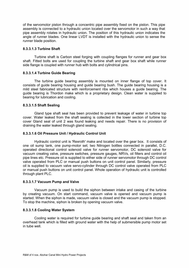
R&M of 4 nos. Abohar Canal Mini Hydro Power Projects
of the servomotor piston through a concentric pipe assembly fixed on the piston. This pipe assembly is connected to a hydraulic union located over the servomotor in such a way that pipe assembly rotates in hydraulic union. The position of this hydraulic union indicates the angle of runner blades. One linear LVDT is installed with the hydraulic union to sense the runner blade position.
8.3.3.1.3 Turbine Shaft
Turbine shaft is Carbon steel forging with coupling flanges for runner and gear box
shaft. Fitted bolts are used for coupling the turbine shaft and gear box shaft while runner side flange is coupled with runner hub with bolts and cylindrical pins.
8.3.3.1.4 Turbine Guide Bearing
The turbine guide bearing assembly is mounted on inner flange of top cover. It
consists of guide bearing housing and guide bearing bush. The guide bearing housing is a mild steel fabricated structure with reinforcement ribs which houses a guide bearing. The guide bearing is Thordon make which is a proprietary design. Clean water is supplied to bearing for lubrication and cooling. 8.3.3.1.5 Shaft Sealing
Gland type shaft seal has been provided to prevent leakage of water in turbine top cover. Water leaked from the shaft sealing is collected in the lower section of turbine top cover Gland seal of unit 2 was found leaking and needs repair. There is no provision of draining the water leaked through gland sealing.
8.3.3.1.6 Oil Pressure Unit / Hydraulic Control Unit
Hydraulic control unit is 'Rexroth' make and located over the gear box. It consists of
one oil sump tank, one pump-motor set; two Nitrogen bottles connected in parallel, D.C. operated directional control solenoid valve for runner servomotor, DC solenoid valve for vacuum creating valve, pressure switches, pressure gauges, NRVs, oil filters and control oil pipe lines etc. Pressure oil is supplied to either side of runner servomotor through DC control valve operated from PLC or manual push buttons on unit control panel. Similarly, pressure oil is supplied to vacuum valve servo-cylinder through DC control valve operated from PLC or manual push buttons on unit control panel. Whole operation of hydraulic unit is controlled through plant PLC.
8.3.3.1.7 Vacuum Pump and Valve
Vacuum pump is used to build the siphon between intake and casing of the turbine by creating vacuum. On start command, vacuum valve is opened and vacuum pump is started. When the siphon is made, vacuum valve is closed and the vacuum pump is stopped. To stop the machine, siphon is broken by opening vacuum valve.
8.3.3.1.8 Cooling Water System
Cooling water is required for turbine guide bearing and shaft seal and taken from an overhead tank which is filled with ground water with the help of submersible pump motor set in tube well.
R&M of 4 nos. Abohar Canal Mini Hydro Power Projects
8.3.3.1.9 Gearbox
Gear box is used as a speed increaser. It is having three helical gears sets, main driving shaft gear, intermediate composite gear and pinion mounted on driven shaft. The rotation of turbine shaft and generator shaft is clock wise when viewed from top. The driving shaft which is coupled with turbine shaft is supported by one conical roller type thrust bearing and roller bearing on top side and ball bearing on bottom side.
For the lubrication of gears, the gearbox is filled with lubricating oil which is being
cooled continuously with the help of oil cooling system. The oil cooling system consists of gear type pump motor set, finned cooler tubes, exhaust fan operated heat exchanger (Radiator type), temperature indicators, flow indicator and temperature sensors etc. The system as a whole is very effective and reliable. Oil cooling system is controlled through plant PLC
Following problems have been experienced in turbines of this plant.
Accumulation of water over head cover due to leakage and no arrangement for drain out.
Leakage of turbine oil from runner blade seals.
Vibration in marshalling box as the same is fixed on the generator chassis.
OPU pressure gauges are defective
Guide bearing damaged
Tensile bolts may be over stressed
Sensors, RTD and switches are defective
Thrust collars and link bushes of runner have abnormal clearances.
Gear box of units failed 8.3.3.2 Generators and Their Auxiliaries
Vertical axis, cylindrical induction generators of capacity 750 kW, 1012 rpm , 50 HZ , 3-phase ,0.85 PF ,415V are installed at this plant. Each generator is air cooled and suitable for 10% continuous overload rating. The windings of these generators are of class ‘F’ insulation with class B temperature rise conditions. Generator shaft is coupled with gearbox through flexible coupling.
These type of generators generally do not have much auxiliary systems, except the cooling arrangement for bearings, terminal box for line side and neutral side cable terminations speedometer and temperature sensing RTDs . The bearings are grease lubricated roller type and have been changed during break down periods .The terminal boxes are getting heated due to inadequate space and proper ventilation. These boxes are to be redesigned and replaced.
The Crompton Greaves make induction generators are generally in order and may require only small maintenance works. No major breakdowns have been observed in generators at this station. The temperature sensing indicating and speed measuring devices are not in working condition and therefore, require replacement. The dust accumulated inside the generator has to be removed and thorough cleaning and painting with Epoxy insulation paints shall be required.

R&M of 4 nos. Abohar Canal Mini Hydro Power Projects
8.3.3.3 Station Auxiliaries 8.3.3.3.1 Mechanical Auxiliaries
i. HOT Crane
The 10 Ton crane provided at this station is hand operated with one main hook only. The turbine runner may require to turn during maintenance. Due to non-availability of auxiliary hook, the turning of runner is not possible. Therefore, crane with auxiliary hook and electrically operated system should be provided.
ii. Ventilation and Air conditioning systems
The ventilators have been provided in the machine hall but no exhaust fans are installed. The hot air around generators should be exhausted for containing the temperature rise and to achieve adequate air changes.
The control /relay and PLC/SCADA panels are located in control room. The area is not air conditioned due to which performance of electronic relays and other equipment may not remain satisfactory. iii. Firefighting Arrangement
Portable fire extinguishers and fire buckets are essentially required to meet out any eventuality in machine hall, control room, control room for gates and switchyard. Fire extinguishers of required capacity and suitability for the area may be provided.
8.3.3.3.2 Electrical Auxiliaries
i. DC System
This system includes battery set, charger and DC distribution board. One set of 24V 210 AH Amco make NiCd battery set for control, protection and metering have been provided with battery charger cum distribution board. One set of 72 V DC battery set and charger is also provided for PLC system exclusively. Both the chargers and battery sets are defective. UPS are installed for meeting the requirements. Battery cells of both sets are also defective.
ii. Control, protection and metering systems/SCADA
The control through PLC system is generally being used. The computer monitor is not functioning satisfactory. Most of the transducers are defective, due to which required parameters are not available on monitor. Efforts have been made to get these transducers repaired, but the performance of repaired transducers have also not been found satisfactory.
The protection relays are electromagnetic type which are less accurate and of higher burden. Their setting ranges are also limited with no multi-functionality. These type of relays are of larger size but have no system flexibility and self-diagnostics.
The metering display meters are all defective. These meters are digital type but not in working order. Analogue meters for indicating voltage and current are also not in working condition on any panel. The indicating lamps and some of the control switches/push buttons etc. are also not in working condition.

R&M of 4 nos. Abohar Canal Mini Hydro Power Projects
The circuit breakers in generator panels are although in working conditions, but their operation life has almost been completed. Fast operating switchgears may be required.
iii. Lighting System
The general illumination in machine hall and control room is low. Several fittings are not in working condition. There is no provision of emergency lighting system except a torch in control room. The lighting system of the fore bay, diversion and bye-pass gates areas, tail race and switchyard also found to be inadequate.
iv. Capacitor Banks
The capacitor bank units are found defective. The banks are to be completed through replacement of the unit full banks.
v. Power and Control Cables
The cables from generator to panels are required to be replaced with new XLPE cable of adequate rating. The control cables may also have to be replaced.
vi. D.G Set
The diesel generator set installed at the power house is in satisfactory running condition. This may require minor repair works with replacement of defective switches/PBs, indicating meters and lamps etc. on control panel.
8.3.3.4 Transformers
8.3.3.4.1 General
There is one generator transformer and one station auxiliary transformer installed at this power station for stepping up the generated power for transmission to grid substation and power requirements of the plant respectively.
Generator Transformer - 2500 kVA 0.415/11kV , 50 HZ, ONAN, Off load tap changer ±5% insteps of 2.5%
3-phase,YNd1
Station Auxiliary Transformer -100 kVA 11/0.415 kV , 50 HZ, ONAN, 3-phase, Dyn11
8.3.3.4.2 Generator Transformer
M/s GEC-ALSTHOM India Distribution Transformer make oil filled generator transformer is installed near main entrance outside the power house. The performance of the transformer is by and large satisfactory. The officer in charge/staff of the power station has however informed that during summer season, when ambient temperature reaches peak values nearing 50 0C, the transformer temperature increases. Sometime alarm has been observed and generation has to be reduced to contain the temperature. The increase in temperature may be due to inadequate ventilation, as the transformer is located near the two walls corner of the power house.
8.3.3.4.3 Station Auxiliary Transformer
The auxiliary transformer installed at the power house is adequate enough to meet out the power requirements of the power plant. The transformer is in satisfactory condition,
R&M of 4 nos. Abohar Canal Mini Hydro Power Projects
as no problems have so far been reported. This transformer is connected with the11 kV line from distribution substation at Narangwal.
8.3.3.5 Switchyard Equipment
8.3.3.5.1 General
The 11 kV switchyard is located between power house bye pass channel and main canal. The overhead bare conductor has been used for connecting generator transformer with switchyard bus through isolator and outdoor vacuum circuit breaker, instrument transformers and lightning arrestors etc. The station auxiliary transformer is also located in the switchyard connected with the 11 kV line through isolator and fuse set. The details of various equipments are as follows.
8.3.3.5.2 Vacuum Circuit Breaker
The vacuum circuit breaker of 12 kV, 630 A, 25 kA/3 sec rating, outdoor type is installed in the switchyard. It has been reported that the breaker is giving problems in fault clearing and normal operation. The deterioration may be due to excessive operation on line faults and weather conditions.
8.3.3.5.3 Instrument Transformers
The 11 kV current and voltage transformers of required rating, oil filled, outdoor type are installed in the switchyard. These transformers of 18.4 kA Fault level are giving problems in metering and protection, due to their frequent break downs.
8.3.3.5.4 Lightning Arresters
Lightning Arrestors of rating 9 kV, 10 kA station class self-supporting with insulation base and surge counters should be installed on both transformers as near as possible to their HV bushing. This primary protection against lightning surges must be installed on feeder also to protect the equipments. Lightning Arrestors on generator transformer and 11 kV line are installed but surge counters are not provided. These devices have also not been provided near station auxiliary transformer. 8.3.3.5.5 11 kV Isolators
Isolators with and without earth switches have been provided for 11kV line and transformer circuits respectively. These are centre rotating type and appear to be in satisfactory condition. No defect or damages have been observed. 11 kV HG fuse set has been provided for station auxiliary transformer protection. 8.3.3.5.6 Main and Auxiliary Structures
The four pole and double poles main structures with gantries and auxiliary structures for various equipment are found generally in satisfactory condition.

R&M of 4 nos. Abohar Canal Mini Hydro Power Projects
8.3.3.6 Power Evacuation
8.3.3.6.111 kV Line To 66/11 kV Substation at Narangwal
The line to transmit generated power from Narangwal SHP to distribution substation at Narangwal is about 2.0 km long and constructed on PCC poles with ACSR ‘TIGER’ conductor. The line is generally in satisfactory condition except few poles bent. The actual status may however be checked through inspection of the line jointly with PSPCL and required rectification should be undertaken.
8.3.3.6.2 Equipment at 66/11 kV Narangwal Substation
The 11 kV line from Narangwal SHP is connected at this substation. The feeder
equipment are in satisfactory working condition. No break down or damage has been found.
8.4 Technical Specification of R&M Works 8.4.1 Detailed Scope of Work
Scope of work include dismantling of Units (One by one so as to allow operation of
remaining units), critically inspect the components which are to be retained, take dimensions of the components necessary for reverse engineering, design, manufacturing & supply new components/equipments, repair the old components at project site/manufacturer’s works, re-assemble the units with new/repaired components, carry out pre-commissioning tests, commission and handover the units to the PGL. 8.4.1.1 Turbine, Governing System & Auxiliaries
Runner
Both the runners are to be dismantled and refurbished in manufacturing shop/site. During refurbishment, all components should be dismantled and inspected carefully and decision be taken for replacement or repair based on their condition. Any component which was repaired earlier should be replaced by new one. Blade seals should be replaced by improved design seals, preferably reinforced rubber seals. Screws for fixing the seal cover plates are to be changed with new stainless steel screws. These screws should preferably be tightened with good quality sealant and their heads be covered with sealant putty. Worn-out bronze bushes of blades trunnions be replaced. Blades surfaces are to be checked by DP/UT for any cracks. Defects on blade surfaces are to be weld repaired. Free movement of runner blades to be checked before assembly of runner with shaft.
Runner Servomotor Oil seals of servomotor got worn out and started leaking. Therefore dismantle the servomotor completely, inspect all components including piston rings/seals, bushes and oil pipe fixed on piston, bronze bushes etc. The defective items are to be changed. All rubber seals are to be compulsorily changed. The piston rod, all connecting rods and concentric oil pipe assembly are to be checked by non-destructive Test. New hydraulic unions are to be provided.

R&M of 4 nos. Abohar Canal Mini Hydro Power Projects
Turbine Guide Bearing Complete refurbishment of turbine guide bearing of each unit is to be done. This work includes replacement of Thordon lining.
Turbine Seal: The existing design of seal is in order. Worn out components be changed and fasteners be replaced by SS fasteners.
Hydraulic Control Unit: Refurbishment and replacement of gear pumps. Pump-motor set are to be replaced. Runner blade regulating mechanism be changed to regulate the opening by
proportional control valves to set value by one command rather than pulse commands. Accordingly, governor function in PLC needs modifications.
Oil filters and any other defective component to be replaced. All Instruments like differential pressure switches, pressure gauges, oil
temperature detectors and other transducers etc. to be replaced. Nitrogen bladders are to be replaced.
Vacuum Pump System Routine maintenance may be done and worn out components be changed.
Instruments, Transducers and Devices Oil flow switch (sensor), pressure switch (sensor), digital tachometer, digital oil temp indicator, runner position LVDT and other instruments, transducers and devices are to be replaced.
Turbine Top Cover Drainage System New system involving pump-motor set, water level controller and pipe lines be provided for draining leakage water / used cooling water of turbine seal from turbine top cover.
8.4.1.2 Gear Box (Speed Increaser) Replace both gearboxes with improved parameters like service factor 2 and 10% additional capacity. New gearbox should match the existing turbine shaft details, generator shaft, fixing details of base frame and hydraulic thrust of runner. Instruments and devices are also be replaced. Local indication for gear box parameters should also be provided to have better control and operations.
Heat Exchanger of gearbox oil is also to be replaced. Operation of fans is to be
linked with temperature sensors 8.4.1.3 Generators & Their Auxiliaries
Following works are to be carried out under R&M of the generators
Cleaning of stator winding, slots etc
Cleaning of rotor
Insulation Resistance measurement
Painting of windings with insulation paints

R&M of 4 nos. Abohar Canal Mini Hydro Power Projects
General painting with enamel paint
Replacement of Temperature Sensing Devices
Replacement of Speed sensing devices
Replacement of Power Cable Terminal Box with improved design.
Replacement of control cable Junction box.
Replacement of DE and NDE side bearings
Problem if winding temperature rise is to be studied and remedial measures are to be taken.
Minor maintenance work as required after dismantling of the generator 8.4. 1.4 Station Auxiliaries
8.4.1.4.1 Mechanical Auxiliaries
i. Crane
Following works are to be done for R & M of crane
Crane to be modified to be suitable for electrical operation through pendant switch from machine hall floor. Operation through hand held remote control unit may also be considered.
Additional 3 Ton Auxiliary Hook is also to be provided for turning of runner and handling the lower loads.
General overhauling of gear box etc. is to be done
General painting with enamel paints on complete crane
Recommended compound may be applied on flexible crane steel rope
ii. Ventilation and Air Conditioning System
Following R & M works are recommended for these systems
6 nos exhaust fans with wire mesh are to be installed on the ventilators in machine hall
The control room is to be provided with two nos. five star rated window air conditioner of 1.5 ton capacity each.
iii. Cooling Water System The existing cooling water system is to be refurbished completely so that satisfactory working of cooling water system is ascertained. Following works will be required to be done:
Replacement of all instruments like flow indicators, pressure gauges, temperature detectors etc. is to be done.
Replacement of all pipes and fittings below 1” dia with SS pipes
2 nos. new submersible tube well pumps of desired capacity including bore at each plant are to be provided
New 5000 litre PVC overhead tank is to be provided
Replacement of all other MS pipes and fittings will also be done.
Any other work for satisfactory working of cooling water system will also be done. iv. Fire Fighting Arrangement
Portable fire extinguishers are required to be placed at appropriate location. The most vulnerable and fire prone areas may be identified and fire extinguisher of following type and capacity may be located

R&M of 4 nos. Abohar Canal Mini Hydro Power Projects
Control room/ office/ switchgear room 3 x 9 kg CO2 type
Machine hall near OPU 4 x 9 kg foam type
Switchyard & Transformer 2 x 9 kg CO2 type
Gates control room/ D.G room 1 x 9 kg foam type 1 x 9 kg CO2 type In addition to above, two sets of fire buckets filled with dry sand and mounted on covered stand may be located in service bay area of the machine hall and 11 kV switchyard. 8.4.1.4.2 Electrical Auxiliaries i. DC System
Replacement of existing battery set with new 24 V – 200 AH T-Gel type battery bank
with mounting stand and provision of emergency lighting system. Providing new UPS having 5 KVA rated capacity with suitable battery set capable of
providing 3 Hours of back up including replacement of mounting stand.
The chargers cum distribution boards are to be replaced with static rectifier systems, protective relays, metering provisions and required MCCB/MCSs.
ii. Control, Protection and Metering System –SCADA
The entire control system based on PLC-SCADA provisions is to be replaced with new arrangements. The protection / metering system are also to be replaced with new schemes. The instrument transformers, sensing devices and indicating meters, annunciation system are also to be replaced. One industrial grade PC of latest specifications for each unit and one laser jet printer for each plant. One laptop of latest specifications should be provided for all the four projects.
The power control panels along with new breakers of both generators and transformer are to be replaced. Provision of numeric type primary protection relays and final tripping relays of electromagnetic type are to be made. The metering display meters would be digital type with additional current and voltage meters of analogue type. The indication lamps are to be replaced with LED type indicators on the panels.
Following protections are be provided on the panels
Generator panel Differential protection (87) Restrained voltage over current protection (51 V) Stator earth fault protection (64 S) Phase unbalance protection(46)
Generator –Transformer panel LV Side
Instantaneous/1DMT over current/earth fault protection (50/51, 50N/51N) Differential protection (87) Restricted earth fault protection(64 REF) Over/under voltage protection(59/27) Buchholz ,oil temperature and winding temperature protection (63, 49 ,26)
Necessary fuse failure, trip circuit supervision, master trip relays etc. along with
required auxiliary relays and alarm/annunciation system be provided
R&M of 4 nos. Abohar Canal Mini Hydro Power Projects
iii. Lighting System
The entire lighting system is to be redesigned and adequate number of fitting preferably energy efficient LED type with required luminaries are to be provided to achieve the following illumination levels at the specific area.
Control room/office 300 Lux.
Machine hall 200 Lux.
Switchyard 50 Lux.
Outdoor areas 50 Lux.
Frequency 50 Hz New emergency lighting system should be provided. v. Capacitor Banks
The entire capacitor banks along with panel of both the units are to be replaced with the rated capacitor units. The main particulars of capacitor shall be as follows:
Type : Cast resin, indoor enclosed type
Rated voltage : 500volts
Maxm voltage : 550 volts
Rated KVAR : 4 x 100 KVAR + 10%
Discharge device : Inbuilt resistor
Standard : IS-2934
Surge Protection : To be provided v. Power and Control Cables
1.1 kV grade power cables (PVC) from generator to panels are to be replaced with new XLPE armoured aluminum cables of adequate size. The cable racks in trenches may be cleaned and painted with enamel paints of approved shade, before laying of cable. The cables must be neatly laid, dressed and clamped in required groups.
Control cables are also to be replaced with new PVC multi-strand copper cables and clamped on racks neatly.
11 kV power cables for facilitating connections of 11 kV outdoor type vacuum circuit
breaker with generator –transformer HV side and 11 kV line isolator for feeder are also to be replaced. vi. D.G. Set
General over hauling and other maintenance works of DG set are to be done. Proper Maintenance of the starter panels is to be done and all defective switches, push buttons, measuring instruments and indicating lamps etc. are to be replaced. vii. Station Service Board
The complete AC station service board is to be provided with standard MCCB and
MCBs of required ratings, digital /analogue meters and indicating lamps etc for metering the AC power requirement of the plant.
R&M of 4 nos. Abohar Canal Mini Hydro Power Projects
Provision of one incomer from station auxiliary transformer and other incomer from D.G. set is to be made, with required number of feeder circuits.
8.4.1.5 Transformer
The normal overhauling and maintenance works including replacement of oil of suitable grade including dehydration of oil, cleaning, replacement of leaking gaskets and painting works etc. is to done on generator and auxiliary transformers. The winding temperature indicator, oil temperature indicator, silica gel breather, tap changer and Buchloz relays etc will also be changed.
The problem of increase in temperature during hot summer season is to be solved by
providing new 4 nos. of 450 mm cooling fans installed on stands. Control of operation of these fans is to be established by providing temperature sensing devices with auxiliary relays and starters etc. Any other work required for proper functioning will also be done excluding transformer re-winding.
8.4.1.6 Switchyard Equipment
8.4.1.6.1Vacuum Circuit Breakers The existing outdoor type Vacuum Circuit Breakers are old and giving frequent trouble, these are to be replaced with new one
The outdoor vacuum circuit breakers along with line control panel of following
technical particulars are be provided and installed.
Type of breaker : Vacuum Circuit Breaker Installation : Indoor Nominal system voltage : 11 kV Voltage ( Maxm) : 12 kV Rated Current : 1250 A Rated Short Circuit Breaking current : 25kA / 3 Sec Rated shot Circuit Making Current : 62.5 kA Power frequency with stand voltage : 28 kV rms Lightning impulse with stand voltage : 75 kVp Standard : IS 13118
8.4.1.6.2Instrument Transformer (CT & PT)
The outdoor oil filled current and voltage transformers are also to be removed and
new instrument transformers are to be supplied and installed
The general parameters of the transformers are as follows: CT : 4 Core-150/1A, 20VA Cl.0.5 P/5P20/PS/Cl.1.0 CT : 150/1A, 20VA Cl.0.2 for TVM PT : 11/√3 kV /110/√3V/110/√3V, 50 VA, Cl.0.5/3P PT : 11/√3 kV /110/√3V/, 50 VA, Cl.0.2 for TVM
11 kV Current Transformers
The technical particulars of current transformer be as follows
Type of CTs : outdoor type Nominal system voltage : 11 kV

R&M of 4 nos. Abohar Canal Mini Hydro Power Projects
Maxm system voltage : 12 kV Ratio of CTs : 150/1-1-1-1A Accuracy class /Accuracy limit factor for protection (general) : 5 P 20/Cl. 0.5/Cl. 1.0 Accuracy class /Accuracy limit factor for Differential protection : Class PS V A burden : 20 VA CT for TVM : 150/1A, 20VA, Cl. 0.2 Standard : IS 2705
11 kV Potential Transformer
Technical particulars
Type of PTs : Out door type Nominal system voltage : 11 kV Maximum system voltage : 12 kV Ration of PTs : 11/√3 kV/110V/√3/110V/√3 Accuracy class for protection and Metering : Class 3P/0.5 VA burden : 50 VA
PT for TVM : 11/√3 kV /110/√3V/, 50 VA, Cl.0.2 Standard : IS- 3156 Power frequency with stand voltage : 28 kVp Lightning impulse with stand voltage : 75 kVrms
8.4.1.6.3 Lightning Arresters
Lightning arresters installed on 11 kV line are to be replaced with new arrestors with
surge counters. The surge counters may be installed at a lower level to facilitate the reading of the counter from ground. The lightning arrestors would be of 9 kV -10 kA rating, metal oxide, station type with insulation base and suitable for mounting on outgoing pole.
Additional lightning arrestor on HV side of the transformer is also to be provided, on
the double pole near switchgear room 8.4.1.6.4 Isolator
General overhauling of the isolators is to be carried out. The male and female contacts operating device are to be closely checked and repair/replacement action be to be taken accordingly. The cracked or damaged insulators are also to be replaced.
8.5 Civil works Civil works exclusively required for installation of E&M equipment like chipping, grouting and laying foundation etc. shall be in the scope of the E&M contractor.

R&M of 4 nos. Abohar Canal Mini Hydro Power Projects
SECTION 9: TUGAL (2X750 KW) SHP PLANT
Technical Specifications
Plant Details and Salient Features
9.1 Plant Details Tugal power station is located on right bank of the canal on bye pass channel havingan installed capacity of 2x 750 kW. An ultra low head of 2.42 m has been exploited at this hydropower station. Employing syphon intake technology, this plant uses vertical-axis semi-Kaplan Turbines coupled with induction generators. This plant is fully automated and utilized programmable logic control (PLC) based supervisory control and data acquisition (SCADA) system.
Three numbers electrically operated gates have been provided on the main canal to
divert the water into bye pass channel for power generation. The power station is also having two numbers hydraulically operated gates for controlling discharge available for power generation. Provision of draft tubes gates were made but not installed.
The power station was commissioned on 08.09.1999 where two units of vertical
syphon type Semi Kaplan Turbines are installed with vacuum pump motor sets. The turbines are connected with vertical alternators through gear boxes .The alternators are induction type. The units are controlled and operated through fully automatic PLC based supervisory control and data acquisition system. The generated power is connected with LT bus bar through air circuit breakers and stepped up to 11 kV through one number generator transformer. 11 kV outdoor equipment has been installed with all requisite switch gears and instrument transformers etc in the switchyard.
The generated power is transmitted to 66/11 kV Distribution Substation at Sudhar
through 9 km 11 kV single circuit line. 9.2 Technical Particulars 9.2.1 General
1. Station Name Tugal Small Hydel Plant
2. Location Located in Punjab 23 km from Ludhiana
3. Date of commissioned 8.9.1999
4. Type of Project Canal based
5. Type of diversion: Cross regulator
6. Design discharge (Total) m3/s 60.94
7. Head Gross(m) Net(m)
2.62 2.42
8. Installed capacity 2 x 750 KW
9. Type of turbine Semi Kaplan
10. Type of generator Generating Voltage
Vertical shaft Induction Generator 415V
11. Coupling Through Speed Increaser (Gear Box)
12. Power Evacuation
Connecting Sub Station Details:

R&M of 4 nos. Abohar Canal Mini Hydro Power Projects
Voltage
Location
Distance from the Power House in km
66 /11KV Sudhar 9 km
13 Operating Status Both units working
14. Cost of The Project(at the time of commission)
8 crore approx
9.2.2 Technical Details of Tugal SHP
Name of Equipment Specifications
TURBINE
Type Vertical, Semi Kaplan, Syphon intake
Make M/s Triveni Engineering & Industry Ltd. New Delhi
Rated net Head 2.85 m
Rated output at rated net head 700 kW
Rated Speed 101 rpm
Run-away Speed 282 rpm
Direction of rotation Clockwise (viewed from top)
Efficiency at 100% rated load 88.20 %
Discharge at rated head for 100% rated load
28.43 m3 /sec
Inlet Casing & Speed Ring Inlet section No. of stay vanes
9.4 x 4.3 20
Runner Diameter of Runner No. of blades Weight Material RB Servomotor Operating Pressure Servomotor Dia. Servomotor Stroke
2850 mm Four 4000 kg 13 Cr 4 Ni S.S. Above Gear box 35 - 40 bar 350 mm 170 mm
Shaft Material and composition Diameter Length Weight Material
Forged carbon steel 250 mm 2887 mm 1200 Kg Forged Carbon Steel
Turbine Guide Bearing Location Type Lubrication Thrust bearing Location Type
Head Cover Thordon Water Gear Box Oil lubricated taper roller bearing
Shaft Seal Stuffing Box, Water Lubricated
Runner Chamber Diameter Length Material
2850 mm 948 mm SS
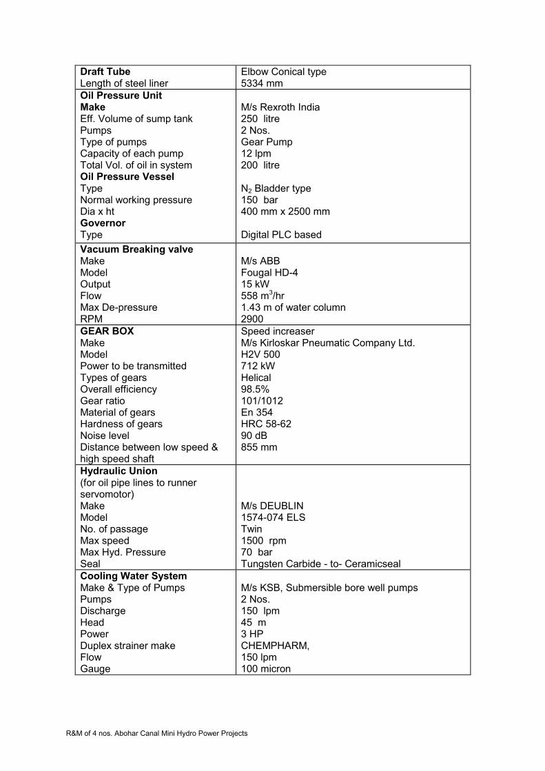
R&M of 4 nos. Abohar Canal Mini Hydro Power Projects
Draft Tube Length of steel liner
Elbow Conical type 5334 mm
Oil Pressure Unit Make Eff. Volume of sump tank Pumps Type of pumps Capacity of each pump Total Vol. of oil in system Oil Pressure Vessel Type Normal working pressure Dia x ht Governor Type
M/s Rexroth India 250 litre 2 Nos. Gear Pump 12 lpm 200 litre N2 Bladder type
150 bar 400 mm x 2500 mm Digital PLC based
Vacuum Breaking valve Make Model Output Flow Max De-pressure RPM
M/s ABB Fougal HD-4 15 kW 558 m3/hr 1.43 m of water column 2900
GEAR BOX Make Model Power to be transmitted Types of gears Overall efficiency Gear ratio Material of gears Hardness of gears Noise level Distance between low speed & high speed shaft
Speed increaser M/s Kirloskar Pneumatic Company Ltd. H2V 500 712 kW Helical 98.5% 101/1012 En 354 HRC 58-62 90 dB 855 mm
Hydraulic Union (for oil pipe lines to runner servomotor) Make Model No. of passage Max speed Max Hyd. Pressure Seal
M/s DEUBLIN 1574-074 ELS Twin 1500 rpm 70 bar Tungsten Carbide - to- Ceramicseal
Cooling Water System Make & Type of Pumps Pumps Discharge Head Power Duplex strainer make Flow Gauge
M/s KSB, Submersible bore well pumps 2 Nos. 150 lpm 45 m 3 HP CHEMPHARM, 150 lpm 100 micron
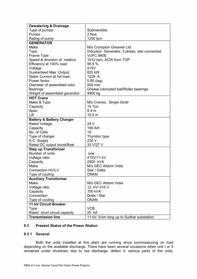
R&M of 4 nos. Abohar Canal Mini Hydro Power Projects
Dewatering & Drainage Type of pumps Pumps Rating of pump
Submersible 2 Nos. 1200 lpm
GENERATOR Make Type Frame Type Speed & direction of rotation Efficiency at 100% load Voltage Guaranteed Max Output Stator Current at full load Power factor Diameter of assembled rotor Bearings Weight of assembled generator
M/s Crompton Greaves Ltd. Induction Generator, 3 phase, star connected VUFC 940E 1012 rpm, ACW from TOP 95.5 % 415V 825 kW 1228 A 0.85 (lag) 555 mm Grease lubricated ball/Roller bearings 4900 kg
HOT Crane Make & Type Capacity Span Lift
M/s Cranex, Single Girdir 10 Ton 9.4 m 10.5 m
Battery & Battery Charger Rated Voltage Capacity No. of Cells Type of charger A.C. Supply Rated DC output boost/float
24 V 190 AH 19 Thyristor type 230 V 33 V/27 V
Step up Transformer Number of units Voltage ratio Capacity Make Connection HV/LV Type of cooling
one 415V/11 kV 2500 kVA M/s GEC Alstom India Star / Delta ONAN
Auxiliary Transformer Make Voltage ratio Capacity Connection Type of cooling
M/s GEC Alstom India 12 kV/ 415 V 100 kVA Delta / Star ONAN
11 kV Circuit Breaker Type Rated short circuit capacity
VCB 25 kA
Transmission line 11 kV, 9 km long up to Sudhar substation
9.3 Present Status of the Power Station
9.3.1 General
Both the units installed at this plant are running since commissioning on load depending on the available discharge. There have been several occasions when unit I or II remained under shutdown due to low discharge, defect in various parts of the units,

R&M of 4 nos. Abohar Canal Mini Hydro Power Projects
switchyard equipment or control, protection and metering systems (SCADA). The unit auxiliaries have also gone under breakdown resulting in closure of the units. The step up generator transformer also forced load reduction due to temperature rise. The present status of various electro mechanical parts of the units, their auxiliaries, power house auxiliaries, transformers, 11 kV outdoor switchyard various gates and civil work section are detailed below. 9.3.2 Generation Achievements
Since commissioning, generation is being achieved from both units as per discharge and machine availability. The average annual energy generation achieved at this power station is around 5.91 MU (44.98% PLF) which is less than projected generation of 8.51 MU at 65% PLF. Reasons for low generation can be as follows.
Canal closure
Low discharge availability
Machines or their auxiliaries failures
Power house auxiliaries failures
Transformer and switchyard equipment breakdowns
Transmission line breakdowns
Non- availability of grid supply
Grid supply voltage or frequency beyond limits
Canal closures are for some definite periods for maintenance works. The canal closures are affected during the period when no water is required for irrigation purposes. Low discharge may be due to low water releases in the canal, leakages in diversion and bye-pass gates etc. The low discharge and grid non availability are the major contributors of low generation. There have been problems in power plant and equipment like gear box, runner assembly and bearing etc. due to which machines remained under breakdown for long periods, thereby resulting in low annual generation.
9.3.3 Electro-mechanical Works
9.3.3.1 Turbines and their Auxiliaries
The turbines are vertical semi Kaplan type with syphon intake. There are no penstock, no metallic spiral casing and no intake gates. Water is directed to turbine intake through an open concrete channel, passes through stay vanes of speed ring, runner, runner chamber, draft tube and discharges in tail race channel. The performance of these turbines generally remained satisfactory throughout their operation since commissioning.
9.3.3.1.1 Turbine Runner
Runner is semi Kaplan type with four blades. Runner consists of one hub body, four
blades each with trunion bearing, lever, connecting rod, blade seals, seal covers, one cross head, lower cone and main regulating rod. Hub body is spherical in shape on external side and contains four windows for mounting runner blades. The runner blades surface matching the hubs external surface is machined spherical and minimum clearance is kept between the two. Blades external surface too is machined spherically. The runner blades are turned about their axis through lever, connecting rod, cross head and regulating rod. The hub assembly is bolted to turbine shaft assembly.
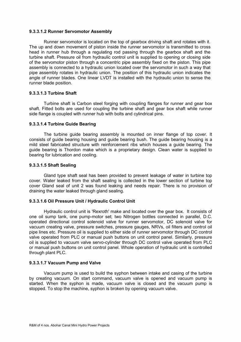
R&M of 4 nos. Abohar Canal Mini Hydro Power Projects
9.3.3.1.2 Runner Servomotor Assembly Runner servomotor is located on the top of gearbox driving shaft and rotates with it.
The up and down movement of piston inside the runner servomotor is transmitted to cross head in runner hub through a regulating rod passing through the gearbox shaft and the turbine shaft. Pressure oil from hydraulic control unit is supplied to opening or closing side of the servomotor piston through a concentric pipe assembly fixed on the piston. This pipe assembly is connected to a hydraulic union located over the servomotor in such a way that pipe assembly rotates in hydraulic union. The position of this hydraulic union indicates the angle of runner blades. One linear LVDT is installed with the hydraulic union to sense the runner blade position.
9.3.3.1.3 Turbine Shaft
Turbine shaft is Carbon steel forging with coupling flanges for runner and gear box
shaft. Fitted bolts are used for coupling the turbine shaft and gear box shaft while runner side flange is coupled with runner hub with bolts and cylindrical pins.
9.3.3.1.4 Turbine Guide Bearing
The turbine guide bearing assembly is mounted on inner flange of top cover. It
consists of guide bearing housing and guide bearing bush. The guide bearing housing is a mild steel fabricated structure with reinforcement ribs which houses a guide bearing. The guide bearing is Thordon make which is a proprietary design. Clean water is supplied to bearing for lubrication and cooling. 9.3.3.1.5 Shaft Sealing
Gland type shaft seal has been provided to prevent leakage of water in turbine top cover. Water leaked from the shaft sealing is collected in the lower section of turbine top cover Gland seal of unit 2 was found leaking and needs repair. There is no provision of draining the water leaked through gland sealing. 9.3.3.1.6 Oil Pressure Unit / Hydraulic Control Unit
Hydraulic control unit is 'Rexroth' make and located over the gear box. It consists of
one oil sump tank, one pump-motor set; two Nitrogen bottles connected in parallel, D.C. operated directional control solenoid valve for runner servomotor, DC solenoid valve for vacuum creating valve, pressure switches, pressure gauges, NRVs, oil filters and control oil pipe lines etc. Pressure oil is supplied to either side of runner servomotor through DC control valve operated from PLC or manual push buttons on unit control panel. Similarly, pressure oil is supplied to vacuum valve servo-cylinder through DC control valve operated from PLC or manual push buttons on unit control panel. Whole operation of hydraulic unit is controlled through plant PLC.
9.3.3.1.7 Vacuum Pump and Valve
Vacuum pump is used to build the syphon between intake and casing of the turbine by creating vacuum. On start command, vacuum valve is opened and vacuum pump is started. When the syphon is made, vacuum valve is closed and the vacuum pump is stopped. To stop the machine, syphon is broken by opening vacuum valve.

R&M of 4 nos. Abohar Canal Mini Hydro Power Projects
9.3.3.1.8 Cooling Water System
Cooling water is required for turbine guide bearing and shaft seal and taken from an overhead tank which is filled with ground water with the help of submersible pump motor set in tube well.
9.3.3.1.9 Gearbox
Gear box is used as a speed increaser. It is having three helical gears sets, main driving shaft gear, intermediate composite gear and pinion mounted on driven shaft. The rotation of turbine shaft and generator shaft is clock wise when viewed from top. The driving shaft which is coupled with turbine shaft is supported by one conical roller type thrust bearing and roller bearing on top side and ball bearing on bottom side.
For the lubrication of gears, the gearbox is filled with lubricating oil which is being
cooled continuously with the help of oil cooling system. The oil cooling system consists of gear type pump motor set, finned cooler tubes, exhaust fan operated heat exchanger (Radiator type), temperature indicators, flow indicator and temperature sensors etc. The system as a whole is very effective and reliable. Oil cooling system is controlled through plant PLC
Following problems have been experienced in turbines of this plant.
Accumulation of water over head cover due to leakage and no arrangement for drain out.
Leakage of turbine oil from runner blade seals.
Vibration in marshalling box as the same is fixed on the generator chassis.
OPU pressure gauges are defective
Guide bearing damaged
Tensile bolts may be over stressed
Sensors, RTD and switches are defective
Thrust collars and link bushes of runner have abnormal clearances.
Gear box of units failed
9.3.3.2 Generators and Auxiliaries
Vertical axis, cylindrical induction generators of capacity 750 kW, 1012 rpm , 50 HZ , 3-phase ,0.85 PF ,415V are installed at this plant. Each generator is air cooled and suitable for 10% continuous overload rating. The windings of these generators are of class ‘F’ insulation with class B temperature rise conditions. Generator shaft is coupled with gearbox through flexible coupling.
These type of generators generally do not have much auxiliary systems, except the cooling arrangement for bearings, terminal box for line side and neutral side cable terminations speedometer and temperature sensing RTDs . The bearings are grease lubricated roller type and have been changed during break down periods .The terminal boxes are getting heated due to inadequate space and proper ventilation. These boxes are to be redesigned and replaced.
The Crompton Greaves make induction generators are generally in order and may require only small maintenance works. No major breakdowns have been observed in generators at this station. The temperature sensing indicating and speed measuring devices are not in working condition and therefore, require replacement. The dust accumulated

R&M of 4 nos. Abohar Canal Mini Hydro Power Projects
inside the generator has to be removed and thorough cleaning and painting with Epoxy insulation paints shall be required.
9.3.3.3 Station Auxiliaries 9.3.3.3.1 Mechanical Auxiliaries
i. HOT Crane
The 10 Ton crane provided at this station is hand operated with one main hook only. The turbine runner may require to turn during maintenance. Due to non-availability of auxiliary hook, the turning of runner is not possible. Therefore, crane with auxiliary hook and electrically operated system should be provided.
ii. Ventilation and Air conditioning systems
The ventilators have been provided in the machine hall but no exhaust fans are installed. The hot air around generators should be exhausted for containing the temperature rise and to achieve adequate air changes.
The control /relay and PLC/SCADA panels are located in control room. The area is not air conditioned due to which performance of electronic relays and other equipment may not remain satisfactory. iii. Firefighting arrangement
Portable fire extinguishers and fire buckets are essentially required to meet out any eventuality in machine hall, control room, control room for gates and switchyard. Fire extinguishers of required capacity and suitability for the area may be provided.
9.3.3.3.2 Electrical Auxiliaries
i. DC System
This system includes battery set, charger and DC distribution board. One set of 24V 190 AH Amco make NiCd battery set for control, protection and metering have been provided with battery charger cum distribution board. One set of 72 V DC battery set and charger is also provided for PLC system exclusively. Both the chargers and battery sets are defective. UPS are installed for meeting the requirements. Battery cells of both sets are also defective.
ii. Control, protection and metering systems/SCADA
The control through PLC system is generally being used. The computer monitor is not functioning satisfactory. Most of the transducers are defective, due to which required parameters are not available on monitor. Efforts have been made to get these transducers repaired, but the performance of repaired transducers have also not been found satisfactory.
The protection relays are electromagnetic type which are less accurate and of higher burden. Their setting ranges are also limited with no multi-functionality. These type of relays are of larger size but have no system flexibility and self diagnostics.
The metering display meters are all defective. These meters are digital type but not in working order. Analogue meters for indicating voltage and current are also not in working
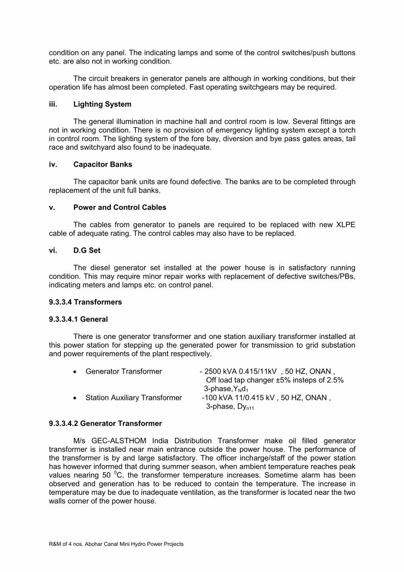
R&M of 4 nos. Abohar Canal Mini Hydro Power Projects
condition on any panel. The indicating lamps and some of the control switches/push buttons etc. are also not in working condition.
The circuit breakers in generator panels are although in working conditions, but their operation life has almost been completed. Fast operating switchgears may be required.
iii. Lighting System
The general illumination in machine hall and control room is low. Several fittings are not in working condition. There is no provision of emergency lighting system except a torch in control room. The lighting system of the fore bay, diversion and bye pass gates areas, tail race and switchyard also found to be inadequate.
iv. Capacitor Banks
The capacitor bank units are found defective. The banks are to be completed through replacement of the unit full banks.
v. Power and Control Cables
The cables from generator to panels are required to be replaced with new XLPE cable of adequate rating. The control cables may also have to be replaced.
vi. D.G Set
The diesel generator set installed at the power house is in satisfactory running condition. This may require minor repair works with replacement of defective switches/PBs, indicating meters and lamps etc. on control panel.
9.3.3.4 Transformers
9.3.3.4.1 General
There is one generator transformer and one station auxiliary transformer installed at this power station for stepping up the generated power for transmission to grid substation and power requirements of the plant respectively.
Generator Transformer - 2500 kVA 0.415/11kV , 50 HZ, ONAN , Off load tap changer ±5% insteps of 2.5%
3-phase,YNd1
Station Auxiliary Transformer -100 kVA 11/0.415 kV , 50 HZ, ONAN , 3-phase, Dyn11
9.3.3.4.2 Generator Transformer
M/s GEC-ALSTHOM India Distribution Transformer make oil filled generator transformer is installed near main entrance outside the power house. The performance of the transformer is by and large satisfactory. The officer incharge/staff of the power station has however informed that during summer season, when ambient temperature reaches peak values nearing 50 0C, the transformer temperature increases. Sometime alarm has been observed and generation has to be reduced to contain the temperature. The increase in temperature may be due to inadequate ventilation, as the transformer is located near the two walls corner of the power house.

R&M of 4 nos. Abohar Canal Mini Hydro Power Projects
9.3.3.4.3 Station Auxiliary Transformer
The auxiliary transformer installed at the power house is adequate enough to meet out the power requirements of the power plant. The transformer is in satisfactory condition, as no problems have so far been reported. This transformer is connected with the11 kV line from distribution substation at Roomi.
9.3.3.5 Switchyard Equipment
9.3.3.5.1 General
The 11 kV switchyard is located between power house bye pass channel and main canal. The overhead bare conductor has been used for connecting generator transformer with switchyard bus through isolator and outdoor vacuum circuit breaker, instrument transformers and lightning arrestors etc. The station auxiliary transformer is also located in the switchyard connected with the 11 kV line through isolator and fuse set. The details of various equipments are as follows.
9.3.3.5.2 Vacuum Circuit Breaker
The vacuum circuit breaker of 12 kV, 630 A, 25 kA/3 sec rating, outdoor type is installed in the switchyard. It has been reported that the breaker is giving problems in fault clearing and normal operation. The deterioration may be due to excessive operation on line faults and weather conditions.
9.3.3.5.3 Instrument Transformers
The 11 kV current and voltage transformers of required rating, oil filled and outdoor type are installed in the switchyard. These transformers of 18.4 kA Fault level are giving problems in metering and protection, due to their frequent break downs.
9.3.3.5.4 Lightning Arresters
Lightning Arrestors of rating 9 kV, 10 kA station class self supporting with insulation base and surge counters should be installed on both transformers as near as possible to their HV bushing. This primary protection against lightning surges must be installed on feeder also to protect the equipments. Lightning Arrestors on generator transformer and 11 kV line are installed but surge counters are not provided. These devices have also not been provided near station auxiliary transformer. 9.3.3.5.5 11 kV Isolators
Isolators with and without earth switches have been provided for 11kV line and transformer circuits respectively. These are centre rotating type and appear to be in satisfactory condition. No defect or damages have been observed. 11 kV HG fuse set has been provided for station auxiliary transformer protection. 9.3.3.5.6 Main and Auxiliary Structures
The four pole and double poles main structures with gantries and auxiliary structures for various equipment are found generally in satisfactory condition.

R&M of 4 nos. Abohar Canal Mini Hydro Power Projects
9.3.3.6 Power Evacuation
9.3.3.6.1 11 kV Line to 66/11 kV Substation at Sudhar The line to transmit generated power from Tugal SHP to distribution substation at
Sudhar is about 9.0 km long and constructed on PCC poles with ACSR ‘TIGER’ conductor. The line is generally in satisfactory condition except few poles bent. The actual status may however be checked through inspection of the line jointly with PSPCL and required rectification should be undertaken.
9.3.3.6.2 Equipment at 66/11 kV Sudhar Substation
The 11 kV line from Tugal SHP is connected at this substation. The feeder
equipments are in satisfactory working condition. No break down or damage has been found.
9.4 Technical Specification of R&M Works 9.4.1 Detailed Scope of Work
Scope of work include dismantling of Units (One by one so as to allow operation of
remaining units), critically inspect the components which are to be retained, take dimensions of the components necessary for reverse engineering, design, manufacturing & supply new components / equipments, repair the old components at project site/manufacturer’s works, re-assemble the units with new/repaired components, carry out pre-commissioning tests, commission and handover the units to the PGL.
9.4.1.1Turbine, Governing System & Auxiliaries
Runner
Both the runners are to be dismantled and refurbished in manufacturing shop/site. During refurbishment, all components should be dismantled and inspected carefully and decision be taken for replacement or repair based on their condition. Any component which was repaired earlier should be replaced by new one. Blade seals should be replaced by improved design seals, preferably reinforced rubber seals. Screws for fixing the seal cover plates are to be changed with new stainless steel screws. These screws should preferably be tightened with good quality sealant and their heads be covered with sealant putty.
Worn-out bronze bushes of blades trunions be replaced. Blades surfaces are to be
checked by DP/UT for any cracks. Defects on blade surfaces are to be weld repaired. Free movement of runner blades to be checked before assembly of runner with shaft.
Runner Servomotor Oil seals of servomotor got worn out and started leaking. Therefore dismantle the servomotor completely, inspect all components including
piston rings/seals, bushes and oil pipe fixed on piston, bronze bushes etc. The defective items are to be changed. All rubber seals are to be compulsorily changed. The piston rod, all connecting rods and concentric oil pipe assembly are to be checked by non-destructive Test. New hydraulic unions are to be provided.

R&M of 4 nos. Abohar Canal Mini Hydro Power Projects
Turbine Guide Bearing Complete refurbishment of turbine guide bearing of each unit is to be done. This work includes replacement of Thordon lining.
Turbine Seal: The existing design of seal is in order. Worn out components be changed and fasteners be replaced by SS fasteners.
Hydraulic Control Unit: Refurbishment and replacement of gear pumps. Pump-motor set are to be replaced. Runner blade regulating mechanism be changed to regulate the opening by
proportional control valves to set value by one command rather than pulse commands. Accordingly, governor function in PLC needs modifications.
Oil filters and any other defective component to be replaced. All Instruments like differential pressure switches, pressure gauges, oil
temperature detectors and other transducers etc to be replaced. Nitrogen bladders are to be replaced.
Vacuum Pump System Routine maintenance may be done and worn out components be changed.
Instruments, Transducers and Devices Oil flow switch (sensor), pressure switch (sensor), digital tachometer, digital oil temp indicator, runner position LVDT and other instruments, transducers and devices are to be replaced.
Turbine Top Cover Drainage System New system involving pump-motor set, water level controller and pipe lines be provided for draining leakage water / used cooling water of turbine seal from turbine top cover.
9.4.1.2 Gear Box (Speed Increaser)
Replace both gearboxes with improved parameters like service factor 2 and 10% additional capacity. New gearbox should match the existing turbine shaft details, generator shaft, fixing details of base frame and hydraulic thrust of runner. Instruments and devices are also be replaced. Local indication for gear box parameters should also be provided to have better control and operations.
Heat Exchanger of gearbox oil is also to be replaced. Operation of fans is to be
linked with temperature sensors 9.4.1.3 Generators & Their Auxiliaries
Following works are to be carried out under R&M of the generators
Cleaning of stator winding, slots etc.
Cleaning of rotor
Insulation Resistance measurement
Painting of windings with insulation paints
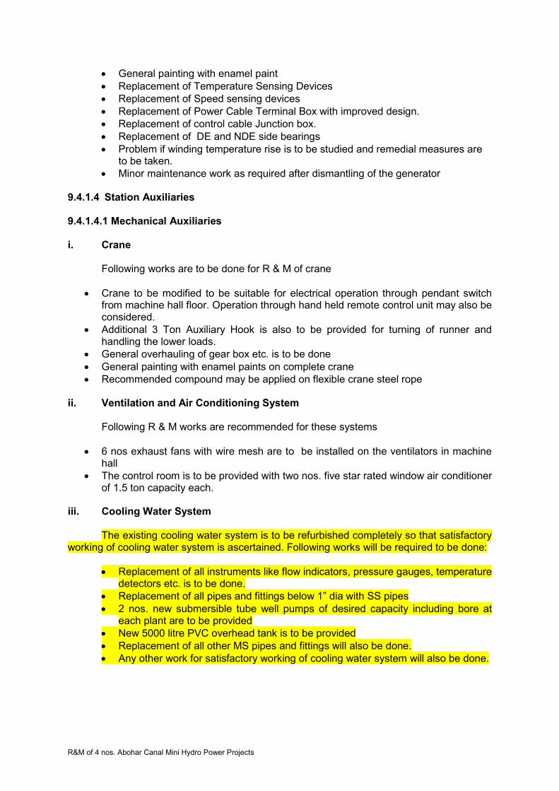
R&M of 4 nos. Abohar Canal Mini Hydro Power Projects
General painting with enamel paint
Replacement of Temperature Sensing Devices
Replacement of Speed sensing devices
Replacement of Power Cable Terminal Box with improved design.
Replacement of control cable Junction box.
Replacement of DE and NDE side bearings
Problem if winding temperature rise is to be studied and remedial measures are to be taken.
Minor maintenance work as required after dismantling of the generator 9.4.1.4 Station Auxiliaries 9.4.1.4.1 Mechanical Auxiliaries i. Crane
Following works are to be done for R & M of crane
Crane to be modified to be suitable for electrical operation through pendant switch from machine hall floor. Operation through hand held remote control unit may also be considered.
Additional 3 Ton Auxiliary Hook is also to be provided for turning of runner and handling the lower loads.
General overhauling of gear box etc. is to be done
General painting with enamel paints on complete crane
Recommended compound may be applied on flexible crane steel rope
ii. Ventilation and Air Conditioning System
Following R & M works are recommended for these systems
6 nos exhaust fans with wire mesh are to be installed on the ventilators in machine hall
The control room is to be provided with two nos. five star rated window air conditioner of 1.5 ton capacity each.
iii. Cooling Water System The existing cooling water system is to be refurbished completely so that satisfactory working of cooling water system is ascertained. Following works will be required to be done:
Replacement of all instruments like flow indicators, pressure gauges, temperature detectors etc. is to be done.
Replacement of all pipes and fittings below 1” dia with SS pipes
2 nos. new submersible tube well pumps of desired capacity including bore at each plant are to be provided
New 5000 litre PVC overhead tank is to be provided
Replacement of all other MS pipes and fittings will also be done.
Any other work for satisfactory working of cooling water system will also be done.

R&M of 4 nos. Abohar Canal Mini Hydro Power Projects
iv. Fire Fighting Arrangement
Portable fire extinguishers are required to be placed at appropriate location. The most vulnerable and fire prone areas may be identified and fire extinguisher of following type and capacity may be located
Control room/ office/ switchgear room 3 x 9 kg CO2 type
Machine hall near OPU 4 x 9 kg foam type
Switchyard & Transformer 2 x 9 kg CO2 type
Gates control room/ D.G room 1 x 9 kg foam type 1 x 9 kg CO2 type In addition to above, two sets of fire buckets filled with dry sand and mounted on covered stand may be located in service bay area of the machine hall and 11 kV switchyard. 9.4.1.4.2 Electrical Auxiliaries i. DC System
Replacement of existing battery set with new 24 V – 200 AH T-Gel type battery bank with mounting stand and provision of emergency lighting system.
Providing new UPS of 5 KVA rated capacity with suitable battery set capable of
providing 3 Hrs of back up including replacement of mounting stand. The chargers cum distribution boards are to be replaced with static rectifier systems, protective relays, metering provisions and required MCCB/MCSs. ii. Control, Protection and Metering System –SCADA
The entire control system based on PLC-SCADA provisions is to be replaced with new arrangements. The protection / metering system are also to be replaced with new schemes. The instrument transformers, sensing devices and indicating meters, annunciation system are also to be replaced. One industrial grade PC of latest specifications for each unit and one laser jet printer for each plant. One laptop of latest specifications should be provided for all the four projects.
The power control center panels alongwith new breakers of both generators and transformer are to be replaced. Provision of numeric type primary protection relays and final tripping relays of electromagnetic type are to be made. The metering display meters would be digital type with additional current and voltage meters of analogue type. The indication lamps are to be replaced with LED type indicators on the panels.
Following protections are be provided on the panels
Generator panel Differential protection (87) Restrained voltage over current protection (51 V) Stator earth fault protection (64 S) Phase unbalance protection(46)
Generator –Transformer panel LV Side
Instantaneous/1DMT over current/earth fault protection (50/51, 50N/51N) Differential protection (87) Restricted earth fault protection(64 REF) Over/under voltage protection(59/27)
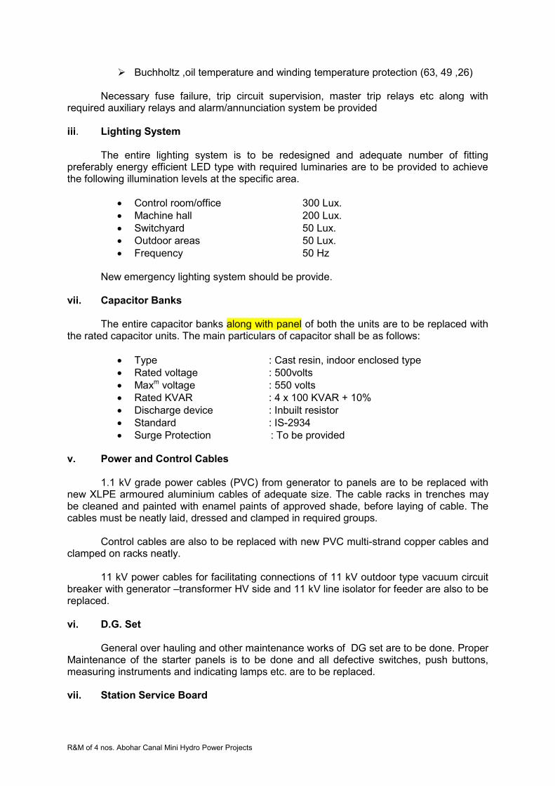
R&M of 4 nos. Abohar Canal Mini Hydro Power Projects
Buchholtz ,oil temperature and winding temperature protection (63, 49 ,26)
Necessary fuse failure, trip circuit supervision, master trip relays etc along with required auxiliary relays and alarm/annunciation system be provided iii. Lighting System
The entire lighting system is to be redesigned and adequate number of fitting preferably energy efficient LED type with required luminaries are to be provided to achieve the following illumination levels at the specific area.
Control room/office 300 Lux.
Machine hall 200 Lux.
Switchyard 50 Lux.
Outdoor areas 50 Lux.
Frequency 50 Hz New emergency lighting system should be provide.
vii. Capacitor Banks
The entire capacitor banks along with panel of both the units are to be replaced with the rated capacitor units. The main particulars of capacitor shall be as follows:
Type : Cast resin, indoor enclosed type
Rated voltage : 500volts
Maxm voltage : 550 volts
Rated KVAR : 4 x 100 KVAR + 10%
Discharge device : Inbuilt resistor
Standard : IS-2934
Surge Protection : To be provided v. Power and Control Cables
1.1 kV grade power cables (PVC) from generator to panels are to be replaced with new XLPE armoured aluminium cables of adequate size. The cable racks in trenches may be cleaned and painted with enamel paints of approved shade, before laying of cable. The cables must be neatly laid, dressed and clamped in required groups.
Control cables are also to be replaced with new PVC multi-strand copper cables and clamped on racks neatly.
11 kV power cables for facilitating connections of 11 kV outdoor type vacuum circuit
breaker with generator –transformer HV side and 11 kV line isolator for feeder are also to be replaced. vi. D.G. Set
General over hauling and other maintenance works of DG set are to be done. Proper Maintenance of the starter panels is to be done and all defective switches, push buttons, measuring instruments and indicating lamps etc. are to be replaced. vii. Station Service Board
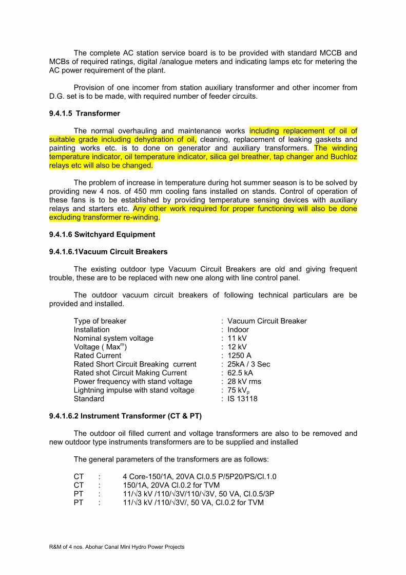
R&M of 4 nos. Abohar Canal Mini Hydro Power Projects
The complete AC station service board is to be provided with standard MCCB and MCBs of required ratings, digital /analogue meters and indicating lamps etc for metering the AC power requirement of the plant.
Provision of one incomer from station auxiliary transformer and other incomer from
D.G. set is to be made, with required number of feeder circuits.
9.4.1.5 Transformer
The normal overhauling and maintenance works including replacement of oil of suitable grade including dehydration of oil, cleaning, replacement of leaking gaskets and painting works etc. is to done on generator and auxiliary transformers. The winding temperature indicator, oil temperature indicator, silica gel breather, tap changer and Buchloz relays etc will also be changed.
The problem of increase in temperature during hot summer season is to be solved by
providing new 4 nos. of 450 mm cooling fans installed on stands. Control of operation of these fans is to be established by providing temperature sensing devices with auxiliary relays and starters etc. Any other work required for proper functioning will also be done excluding transformer re-winding.
9.4.1.6 Switchyard Equipment
9.4.1.6.1Vacuum Circuit Breakers
The existing outdoor type Vacuum Circuit Breakers are old and giving frequent
trouble, these are to be replaced with new one along with line control panel. The outdoor vacuum circuit breakers of following technical particulars are be
provided and installed.
Type of breaker : Vacuum Circuit Breaker Installation : Indoor Nominal system voltage : 11 kV
Voltage ( Maxm) : 12 kV Rated Current : 1250 A
Rated Short Circuit Breaking current : 25kA / 3 Sec Rated shot Circuit Making Current : 62.5 kA Power frequency with stand voltage : 28 kV rms Lightning impulse with stand voltage : 75 kVp Standard : IS 13118
9.4.1.6.2 Instrument Transformer (CT & PT)
The outdoor oil filled current and voltage transformers are also to be removed and
new outdoor type instruments transformers are to be supplied and installed
The general parameters of the transformers are as follows: CT : 4 Core-150/1A, 20VA Cl.0.5 P/5P20/PS/Cl.1.0 CT : 150/1A, 20VA Cl.0.2 for TVM PT : 11/√3 kV /110/√3V/110/√3V, 50 VA, Cl.0.5/3P PT : 11/√3 kV /110/√3V/, 50 VA, Cl.0.2 for TVM

R&M of 4 nos. Abohar Canal Mini Hydro Power Projects
11 kV Current Transformers The technical particulars of current transformer be as follows Type of CTs : out door type Nominal system voltage : 11 kV Maxm system voltage : 12 kV Ratio of CTs : 150/1-1-1-1A Accuracy class /Accuracy limit factor for protection (general) : 5 P 20/Cl. 0.5/Cl. 1.0 Accuracy class /Accuracy limit factor for Differential protection : Class PS V A burden : 20 VA CT for TVM : 150/1A ,20VA ,Cl. 0.2 Standard : IS 2705
11 kV Potential Transformer Technical particulars
1. Type of PTs : out door type 2. Nominal system voltage : 11 kV 3. Maximum system voltage : 12 kV 4. Ration of PTs : 11/√3 kV/110V/√3/110V/√3 5. Accuracy class for protection and
Metering : Class 3P/0.5 6. VA burden : 50 VA 7. PT for TVM : 11/√3 kV /110/√3V/, 50 VA, Cl.0.2 8. Standard : IS- 3156 9. Power frequency with stand voltage : 28 kVp 10. Lightning impulse with stand voltage : 75 kVrms
9.4.1.6.3 Lightning Arresters
Lightning arresters installed on 11 kV line are to be checked and tested. The
defective arrestors are to be replaced with new arrestors with surge counters. The surge counters may be installed at a lower level to facilitate the reading of the counter from ground. The lightning arrestors would be of 9 kV -10 kA rating, metal oxide, station type with insulation base and suitable for mounting on outgoing pole.
Additional lightning arrestor on HV side of the transformer is also to be provided, on
the double pole near switchgear room 9.4.1.6.4 Isolator
General overhauling of the isolators is to be carried out. The male and female contacts operating device are to be closely checked and repair/replacement action be to be taken accordingly. The cracked or damaged insulators are also to be replaced.
9.5 Civil works Civil works exclusively required for installation of E&M equipment like chipping, grouting and laying foundation etc. shall be in the scope of the E&M contractor.
.

R&M of 4 nos. Abohar Canal Mini Hydro Power Projects
.
.
. .
SECTION 10 –DALLA (2X500 KW) SHP PLANT Technical Specifications
10.1 Plant Details Dalla power station is located on right bank of the canal on bye pass channel having an installed capacity of 2 x 500 kW. An ultra-low head of 2.66 m has been exploited at this hydropower station. Employing syphon intake technology, this plant uses vertical-axis semi-Kaplan Turbines coupled with induction generators. This plant is fully automated and utilized programmable logic control (PLC) based supervisory control and data acquisition (SCADA) system.
Three numbers electrically operated gates have been provided on the main canal to
divert the water into bye pass channel for power generation. The power station is also having two numbers hydraulically operated gates for controlling discharge available for power generation. Provision of draft tubes gates were made but not installed.
The power station was commissioned on 24.5.1999 where two units of vertical
syphon type Semi Kaplan Turbines are installed with vacuum pump motor sets. The turbines are connected with vertical alternators through gear boxes .The alternators are induction type. The units are controlled and operated through fully automatic PLC based supervisory control and data acquisition system. The generated power is connected with LT bus bar through air circuit breakers and stepped up to 11 kV through one number generator transformer. 11 kV outdoor equipment has been installed with all requisite switch gears and instrument transformers etc in the switchyard.
The generated power is transmitted to 66/11 kV Distribution Sub Station at Roomi
through 8.0 km 11 kV single circuit line.
10.2 Technical Particulars 10.2.1 General
1. Station Name Dalla
2. Location Village Dalla on Abohar Branch Canal
3. Date of Commissioning 24.5.1999

R&M of 4 nos. Abohar Canal Mini Hydro Power Projects
4. Type of Project Canal based
5. Type of diversion: Cross regulator
6. Net Head(m) 2.66
7. Installed capacity no. of unit x capacity (kW)
2 x 500 KW
8. Type of turbine Semi Kaplan
9. Type of generator Generating Voltage
Induction 415V
10. Coupling Speed Increaser (Gear Box)
11. Power Evacuation
Connecting Sub Station Details:
Voltages
Location
Distance from the Power House in km
66/11 KV Roomi 8km
12 Operating Status All units working
10.2.2 Technical Details at MHP - Dalla
Name of Equipment Specifications
TURBINE
Type Vertical, Semi Kaplan, Syphon intake
Make Triveni Engineering & Industry Ltd. New Delhi
Rated net Head m. 2.48
Rated output at rated net head 504 kW
Rated Speed 94 rpm
Run-away Speed 263 rpm
Direction of rotation Clockwise (viewed from top)
Efficiency at 100% rated load 89.20 %
Discharge at rated head for 100% rated load
23.25 m3 /sec
Runner Diameter of Runner No. of blades Weight kg Material RB Servomotor Operating Pressure Servomotor Dia. Servomotor Stroke
2850 mm Four 4000 13 Cr 4 Ni S.S. Above Gear box 35 - 40 bar 350 mm 170 mm
Shaft Material and composition Diameter Length Weight Material
Forged carbon steel 250 mm 2887 mm 1200 kg Forged Carbon Steel
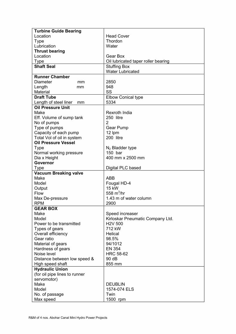
R&M of 4 nos. Abohar Canal Mini Hydro Power Projects
Turbine Guide Bearing Location Type Lubrication Thrust bearing Location Type
Head Cover Thordon Water Gear Box Oil lubricated taper roller bearing
Shaft Seal
Stuffing Box Water Lubricated
Runner Chamber Diameter mm Length mm Material
2850 948 SS
Draft Tube Length of steel liner mm
Elbow Conical type 5334
Oil Pressure Unit Make Eff. Volume of sump tank No of pumps Type of pumps Capacity of each pump Total Vol of oil in system Oil Pressure Vessel Type Normal working pressure Dia x Height Governor Type
Rexroth India 250 litre 2 Gear Pump 12 lpm 200 litre N2 Bladder type
150 bar 400 mm x 2500 mm Digital PLC based
Vacuum Breaking valve Make Model Output Flow Max De-pressure RPM
ABB Fougal HD-4 15 kW 558 m3/hr 1.43 m of water column 2900
GEAR BOX Make Model Power to be transmitted Types of gears Overall efficiency Gear ratio Material of gears Hardness of gears Noise level Distance between low speed & High speed shaft
Speed increaser Kirloskar Pneumatic Company Ltd. H2V 500 712 kW Helical 98.5% 94/1012 EN 354 HRC 58-62 90 dB 855 mm
Hydraulic Union (for oil pipe lines to runner servomotor) Make Model No. of passage Max speed
DEUBLIN 1574-074 ELS Twin 1500 rpm
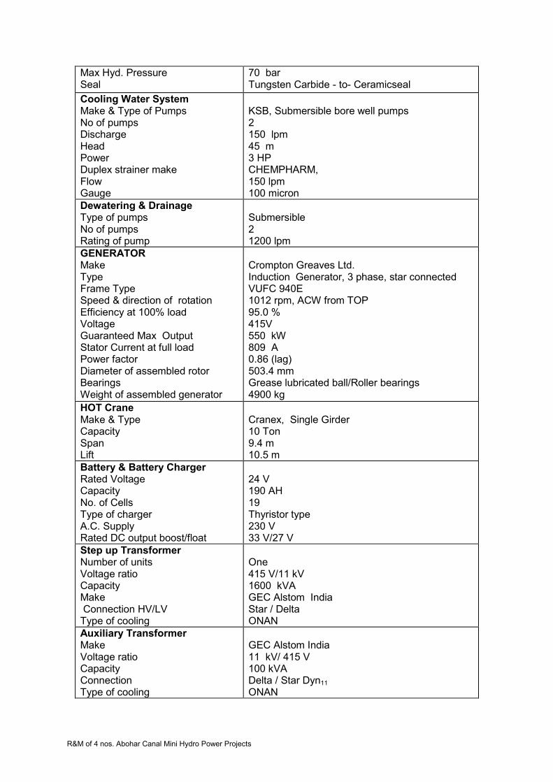
R&M of 4 nos. Abohar Canal Mini Hydro Power Projects
Max Hyd. Pressure Seal
70 bar Tungsten Carbide - to- Ceramicseal
Cooling Water System Make & Type of Pumps No of pumps Discharge Head Power Duplex strainer make Flow Gauge
KSB, Submersible bore well pumps 2 150 lpm 45 m 3 HP CHEMPHARM, 150 lpm 100 micron
Dewatering & Drainage Type of pumps No of pumps Rating of pump
Submersible 2 1200 lpm
GENERATOR Make Type Frame Type Speed & direction of rotation Efficiency at 100% load Voltage Guaranteed Max Output Stator Current at full load Power factor Diameter of assembled rotor Bearings Weight of assembled generator
Crompton Greaves Ltd. Induction Generator, 3 phase, star connected VUFC 940E 1012 rpm, ACW from TOP 95.0 % 415V 550 kW 809 A 0.86 (lag) 503.4 mm Grease lubricated ball/Roller bearings 4900 kg
HOT Crane Make & Type Capacity Span Lift
Cranex, Single Girder 10 Ton 9.4 m 10.5 m
Battery & Battery Charger Rated Voltage Capacity No. of Cells Type of charger A.C. Supply Rated DC output boost/float
24 V 190 AH 19 Thyristor type 230 V 33 V/27 V
Step up Transformer Number of units Voltage ratio Capacity Make Connection HV/LV Type of cooling
One 415 V/11 kV 1600 kVA GEC Alstom India Star / Delta ONAN
Auxiliary Transformer Make Voltage ratio Capacity Connection Type of cooling
GEC Alstom India 11 kV/ 415 V 100 kVA Delta / Star Dyn11 ONAN

R&M of 4 nos. Abohar Canal Mini Hydro Power Projects
11 kV Circuit Braker Type Rated short circuit capacity
VCB (outdoor) 25 kA
Transmission line 11KV
Bypass gates No. of gates Size of gates Operating Hydraulic Pressure Hydraulic Unit No of N2 cylinders No of oil pumps Operating Pressure No of DC valves
2 3300x3000 80 - 125 bar Rexroth make (common for both gates) 2 2 80 - 125 bar 2 (one for each gate)
Trash Cleaning Machine Type
Fully automatic
Main Canal Gates No. of gates
3
10.3 Present Status of the Power Station
10.3.1 General
Both the units installed at this plant are running since commissioning on load depending on the available discharge. There have been several occasions when unit I or II remained under shutdown due to low discharge, defect in various parts of the units, switchyard equipment or control, protection and metering systems (SCADA). The unit auxiliaries have also gone under breakdown resulting in closure of the units. The step up generator transformer also forced load reduction due to temperature rise. The present status of various electro mechanical parts of the units, their auxiliaries, power house auxiliaries, transformers, 11 kV outdoor switchyard various gates and civil works etc. are detailed below. 10.3.2 Generation Achievements
Since commissioning, generation is being achieved from both units as per discharge and machine availability. The average annual energy generation achieved at this power station is around 4.2 MU (48.4% PLF) which is less than projected generation of 5.0 MU at 59% PLF. Reasons for low generation can be as follows.
Canal closure
Low discharge availability
Machines or their auxiliaries failures
Power house auxiliaries failures
Transformer and switchyard equipment breakdowns
Transmission line breakdowns
Non- availability of grid supply
Grid supply voltage or frequency beyond limits
Canal closures are for some definite periods for maintenance works. The canal closures are affected during the period when no water is required for irrigation purposes. Low discharge may be due to low water releases in the canal, leakages in diversion and bye-pass gates etc. The low discharge and grid non availability are the major contributors of low generation. There have been problems in power plant and equipment like gear box,

R&M of 4 nos. Abohar Canal Mini Hydro Power Projects
runner assembly and bearing etc. due to which machines remained under breakdown for long periods, thereby resulting in low annual generation.
10.3.3 Electro-mechanical Works
10.3.3.1 Turbines and Their Auxiliaries
The turbines are vertical semi Kaplan type with syphon intake. There are no penstock, no metallic spiral casing and no intake gates. Water is directed to turbine intake through an open concrete channel, passes through stay vanes of speed ring, runner, runner chamber, draft tube and discharges in tail race channel. The performance of these turbines generally remained satisfactory throughout their operation since commissioning.
10.3.3.1.1 Turbine Runner
Runner is semi Kaplan type with four blades. Runner consists of one hub body, four
blades each with trunion bearing, lever, connecting rod, blade seals, seal covers, one cross head, lower cone and main regulating rod. Hub body is spherical in shape on external side and contains four windows for mounting runner blades. The runner blades surface matching the hubs external surface is machined spherical and minimum clearance is kept between the two. Blades external surface too is machined spherically. The runner blades are turned about their axis through lever, connecting rod, cross head and regulating rod. The hub assembly is bolted to turbine shaft assembly.
10.3.3.1.2 Runner Servomotor Assembly
Runner servomotor is located on the top of gearbox driving shaft and rotates with it.
The up and down movement of piston inside the runner servomotor is transmitted to cross head in runner hub through a regulating rod passing through the gearbox shaft and the turbine shaft. Pressure oil from hydraulic control unit is supplied to opening or closing side of the servomotor piston through a concentric pipe assembly fixed on the piston. This pipe assembly is connected to a hydraulic union located over the servomotor in such a way that pipe assembly rotates in hydraulic union. The position of this hydraulic union indicates the angle of runner blades. One linear LVDT is installed with the hydraulic union to sense the runner blade position.
10.3.3.1.3 Turbine Shaft
Turbine shaft is Carbon steel forging with coupling flanges for runner and gear box
shaft. Fitted bolts are used for coupling the turbine shaft and gear box shaft while runner side flange is coupled with runner hub with bolts and cylindrical pins.
10.3.3.1.4 Turbine Guide Bearing
The turbine guide bearing assembly is mounted on inner flange of top cover. It
consists of guide bearing housing and guide bearing bush. The guide bearing housing is a mild steel fabricated structure with reinforcement ribs which houses a guide bearing. The guide bearing is Thordon make which is a proprietary design. Clean water is supplied to bearing for lubrication and cooling. 10.3.3.1.5 Shaft Sealing
Gland type shaft seal has been provided to prevent leakage of water in turbine top cover. Water leaked from the shaft sealing is collected in the lower section of turbine top
R&M of 4 nos. Abohar Canal Mini Hydro Power Projects
cover Gland seal of unit 2 was found leaking and needs repair. There is no provision of draining the water leaked through gland sealing. 10.3.3.1.6 Oil Pressure Unit / Hydraulic Control Unit
Hydraulic control unit is 'Rexroth' make and located over the gear box. It consists of
one oil sump tank, one pump-motor set; two Nitrogen bottles connected in parallel, D.C. operated directional control solenoid valve for runner servomotor, DC solenoid valve for vacuum creating valve, pressure switches, pressure gauges, NRVs, oil filters and control oil pipe lines etc. Pressure oil is supplied to either side of runner servomotor through DC control valve operated from PLC or manual push buttons on unit control panel. Similarly, pressure oil is supplied to vacuum valve servo-cylinder through DC control valve operated from PLC or manual push buttons on unit control panel. Whole operation of hydraulic unit is controlled through plant PLC.
10.3.3.1.7 Vacuum Pump and Valve
Vacuum pump is used to build the syphon between intake and casing of the turbine by creating vacuum. On start command, vacuum valve is opened and vacuum pump is started. When the syphon is made, vacuum valve is closed and the vacuum pump is stopped. To stop the machine, syphon is broken by opening vacuum valve.
10.3.3.1.8 Cooling Water System
Cooling water is required for turbine guide bearing and shaft seal and taken from an overhead tank which is filled with ground water with the help of submersible pump motor set in tube well.
10.3.3.1.9 Gearbox
Gear box is used as a speed increaser. It is having three helical gears sets, main driving shaft gear, intermediate composite gear and pinion mounted on driven shaft. The rotation of turbine shaft and generator shaft is clock wise when viewed from top. The driving shaft which is coupled with turbine shaft is supported by one conical roller type thrust bearing and roller bearing on top side and ball bearing on bottom side.
For the lubrication of gears, the gearbox is filled with lubricating oil which is being
cooled continuously with the help of oil cooling system. The oil cooling system consists of gear type pump motor set, finned cooler tubes, exhaust fan operated heat exchanger (Radiator type), temperature indicators, flow indicator and temperature sensors etc. Oil cooling system is controlled through plant PLC
Following problems have been experienced in turbines of this plant.
Accumulation of water over head cover due to leakage and no arrangement for drain out.
Leakage of turbine oil from runner blade seals.
Vibration in marshalling box as the same is fixed on the generator chassis.
OPU pressure gauges are defective and valves also damaged
Guide bearing damaged
Tensile bolts may be over stressed
Sensors, RTD and switches are defective
Thrust collars and link bushes of runner have abnormal clearances.
Gear box of both units failed repeated by due to shearing of gear teeth

R&M of 4 nos. Abohar Canal Mini Hydro Power Projects
10.3.3.2 Generators and Auxiliaries
Vertical axis, cylindrical induction generators of capacity 500 kW, 1012 rpm , 50 HZ , 3-phase ,0.86 PF ,415V are installed at this plant. Each generator is air cooled and suitable for 10% continuous overload rating. The windings of these generators are of class ‘F’ insulation with class B temperature rise conditions. Generator shaft is coupled with gearbox through flexible coupling.
These type of generators generally do not have much auxiliary systems, except the cooling arrangement for bearings, terminal box for line side and neutral side cable terminations speedometer and temperature sensing RTDs . The bearings are grease lubricated roller type and have been changed during break down periods .The terminal boxes are getting heated due to inadequate space and proper ventilation. These boxes are to be redesigned and replaced.
The Crompton Greaves make induction generators are generally in order and may require only small maintenance works. No major breakdowns have been observed in generators at this station. The temperature sensing indicating and speed measuring devices are not in working condition and therefore, require replacement. The dust accumulated inside the generator has to be removed and thorough cleaning and painting with Epoxy insulation paints shall be required.
10.3.3.3 Station Auxiliaries 10.3.3.3.1 Mechanical Auxiliaries
i. HOT Crane
The 10 Ton crane provided at this station is hand operated with one main hook only. The turbine runner may require to turn during maintenance. Due to non-availability of auxiliary hook, the turning of runner is not possible. Therefore, crane with auxiliary hook and electrically operated system should be provided.
ii. Ventilation and Air conditioning systems
The ventilators have been provided in the machine hall but no exhaust fans are installed. The hot air around generators should be exhausted for containing the temperature rise and to achieve adequate air changes.
The control /relay and PLC/SCADA panels are located in control room. The area is not air conditioned due to which performance of electronic relays and other equipment may not remain satisfactory. iii. Firefighting arrangement
Portable fire extinguishers and fire buckets are essentially required to meet out any eventuality in machine hall, control room, control room for gates and switchyard. Fire extinguishers of required capacity and suitability for the area may be provided.
10.3.3.3.2 Electrical Auxiliaries
i. DC System
R&M of 4 nos. Abohar Canal Mini Hydro Power Projects
This system includes battery set, charger and DC distribution board. One set of 24V
190 AH Amco make NiCd battery set for control, protection and metering have been provided with battery charger cum distribution board. One set of 72 V DC battery set and charger is also provided for PLC system exclusively. Both the chargers and battery sets are defective. UPS are installed for meeting the requirements. Battery cells of both sets are also defective.
ii. Control, protection and metering systems/SCADA
The control through PLC system is generally being used. The computer monitor is not functioning satisfactory. Most of the transducers are defective, due to which required parameters are not available on monitor. Efforts have been made to get these transducers repaired, but the performance of repaired transducers have also not been found satisfactory.
The protection relays are electromagnetic type which are less accurate and of higher burden. Their setting ranges are also limited with no multi-functionality. These type of relays are of larger size but have no system flexibility and self-diagnostics.
The metering display meters are all defective. These meters are digital type but not in working order. Analogue meters for indicating voltage and current are also not in working condition on any panel. The indicating lamps and some of the control switches/push buttons etc. are also not in working condition.
The circuit breakers in generator panels are although in working conditions, but their operation life has almost been completed. The ACBs have provided problems repeatedly. Therefore, Fast operating switchgears may be required.
iii. Lighting System
The general illumination in machine hall and control room is low. Several fittings are not in working condition. There is no provision of emergency lighting system except a torch in control room. The lighting system of the fore bay, diversion and by-pass gates areas, tail race and switchyard also found to be inadequate.
iv. Capacitor Banks
The capacitor bank units are found defective. The banks are to be completed through replacement of the unit full banks.
v. Power and Control Cables
The cables from generator to panels are required to be replaced with new XLPE cable of adequate rating. The control cables may also have to be replaced.
vi. D.G Set
The diesel generator set installed at the power house is in satisfactory running condition. This may require minor repair works with replacement of defective switches/PBs, indicating meters and lamps etc on control panel.
10.3.3.4 Transformers
10.3.3.4.1 General
R&M of 4 nos. Abohar Canal Mini Hydro Power Projects
There is one generator transformer and one station auxiliary transformer installed at this power station for stepping up the generated power for transmission to grid substation and power requirements of the plant respectively.
Generator Transformer - 1600 kVA 0.415/11kV , 50 HZ, ONAN , Off load tap changer ±5% insteps of 2.5%
3-phase, YNd11
Station Auxiliary Transformer - 100 kVA 11/0.415 kV , 50 HZ, ONAN , 3- phase, Dyn11
10.3.3.4.2 Generator Transformer
M/s GEC-ALSTHOM India Distribution Transformer make oil filled generator transformer is installed near main entrance outside the power house. The performance of the transformer is by and large satisfactory. The officer incharge/staff of the power station has however informed that during summer season, when ambient temperature reaches peak values nearing 50 0C, the transformer temperature increases. Sometime alarm has been observed and generation has to be reduced to contain the temperature. The increase in temperature may be due to inadequate ventilation, as the transformer is located near the two walls corner of the power house.
10.3.3.4.3 Station Auxiliary Transformer
The auxiliary transformer installed at the power house is adequate enough to meet out the power requirements of the power plant. The transformer is in satisfactory condition, as no problems have so far been reported. This transformer is connected with the11 kV line from distribution substation at Roomi.
10.3.3.5 Switchyard Equipment
10.3.3.5.1 General
The 11 kV switchyard is located between power house bye pass channel and main canal. The overhead bare conductor has been used for connecting generator transformer with switchyard bus through isolator and outdoor vacuum circuit breaker, instrument transformers and lightning arrestors etc. The station auxiliary transformer is also located in the switchyard connected with the 11 kV line through isolator and fuse set. The details of various equipments are as follows. 10.3.3.5.2 Vacuum Circuit Breaker
The vacuum circuit breaker of 12 kV, 630 A, 25 kA/3 sec rating, outdoor type is installed in the switchyard. It has been reported that the breaker is giving problems in fault clearing and normal operation. The deterioration may be due to excessive operation on line faults and weather conditions.
10.3.3.5.3 Instrument Transformers
The 11 kV current and voltage transformers of required rating, oil filled and outdoor type are installed in the switchyard. These transformers of 18.4 kA Fault level are giving problems in metering and protection, due to their frequent break downs.
10.3.3.5.4 Lightning Arresters

R&M of 4 nos. Abohar Canal Mini Hydro Power Projects
Lightning Arrestors of rating 9 kV, 10 kA station class self-supporting with insulation base and surge counters should be installed on both transformers as near as possible to their HV bushing. This primary protection against lightning surges must be installed on feeder also to protect the equipments. Lightning Arrestors on generator transformer and 11 kV line are installed but surge counters are not provided. These devices have also not been provided near station auxiliary transformer. 10.3.3.5.5 11 Kv Isolators
Isolators with and without earth switches have been provided for 11kV line and transformer circuits respectively. These are Centre rotating type and appear to be in satisfactory condition. No defect or damages have been observed. 11 kV HG fuse set has been provided for station auxiliary transformer protection. 10.3.3.5.6 Main and Auxiliary Structures
The four pole and double poles main structures with gantries and auxiliary structures for various equipment are found generally in satisfactory condition.
10.3.3.6 Power Evacuation
10.3.3.6.1 11 kV Line to 66/11 kV Substation at Roomi
The line to transmit generated power from Dalla SHP to distribution substation at Roomi is about 8.0 km long and constructed on PCC poles with ACSR ‘TIGER’ conductor. The line is generally in satisfactory condition except few poles bent. The actual status may however be checked through inspection of the line jointly with PSPCL and required rectification should be undertaken.
10.3.3.6.2 Equipment at 66/11 kV Roomi Substation
The 11 kV line from Dalla SHP is connected at this substation. The feeder
equipments are in satisfactory working condition. No break down or damage has been found. 10.4 Technical Specification of R&M Works 10.4.1 Detailed Scope of Work
Scope of work include dismantling of Units (One by one so as to allow operation of
remaining units), critically inspect the components which are to be retained, take dimensions of the components necessary for reverse engineering, design, manufacturing & supply new components/equipment, repair the old components at project site/manufacturer’s works, re-assemble the units with new/repaired components, carry out pre-commissioning tests, commission and handover the units to the PGL.
10.4.1.1 Turbine, Governing System & Auxiliaries
Runner:
Both the runners are to be dismantled and refurbished in manufacturing shop/site. During refurbishment, all components should be dismantled and inspected carefully and decision be taken for replacement or repair based on their condition. Any component which was repaired earlier should be replaced by new one. Blade seals should be replaced by improved design seals, preferably reinforced rubber seals.

R&M of 4 nos. Abohar Canal Mini Hydro Power Projects
Screws for fixing the seal cover plates are to be changed with new stainless steel screws. These screws should preferably be tightened with good quality sealant and their heads be covered with sealant putty. Worn-out bronze bushes of blades trunions be replaced. Blades surfaces are to be checked by DP/UT for any cracks. Defects on blade surfaces are to be weld repaired. Free movement of runner blades to be checked before assembly of runner with shaft.
Runner Servomotor: Oil seals of servomotor got worn out and started leaking. Therefore dismantle the servomotor completely, inspect all components including piston rings/seals, bushes and oil pipe fixed on piston, bronze bushes etc. The defective items are to be changed. All rubber seals are to be compulsorily changed. The piston rod, all connecting rods and concentric oil pipe assembly are to be checked by non-destructive Test. New hydraulic unions are to be provided.
Turbine Guide Bearing: Complete refurbishment of turbine guide bearing of each unit is to be done. This work includes replacement of Thordon lining.
Turbine Seal: The existing design of seal is in order. Worn out components be changed and fasteners be replaced by SS fasteners.
Hydraulic Control Unit: Refurbishment and replacement of gear pumps. Pump-motor set are to be replaced. Runner blade regulating mechanism be changed to regulate the opening by
proportional control valves to set value by one command rather than pulse commands. Accordingly, governor function in PLC needs modifications.
Oil filters and any other defective component to be replaced. All Instruments like differential pressure switches, pressure gauges, oil
temperature detectors and other transducers etc to be replaced. Nitrogen bladders are to be replaced.
Vacuum Pump System: Routine maintenance may be done and worn out components be changed.
Instruments, Transducers and Devices: Oil flow switch (sensor), pressure switch (sensor), digital tachometer, digital oil temp indicator, runner position LVDT and other instruments, transducers and devices are to be replaced.
Turbine Top Cover Drainage System : New system involving pump-motor set, water level controller and pipe lines be provided for draining leakage water / used cooling water of turbine seal from turbine top cover.
10.4.1.2 Gear Box (Speed Increaser)

R&M of 4 nos. Abohar Canal Mini Hydro Power Projects
Replace both gearboxes with improved parameters like service factor 2 and 10% additional capacity. New gearbox should match the existing turbine shaft details, generator shaft, fixing details of base frame and hydraulic thrust of runner. Instruments and devices are also be replaced. Local indication for gear box parameters should also be provided to have better control and operations.
Heat Exchanger of gearbox oil is also to be replaced. Operation of fans is to be
linked with temperature sensors 10.4.1.3 Generators & their Auxiliaries
Following works are to be carried out under R&M of the generators
Cleaning of stator winding, slots etc.
Cleaning of rotor
Insulation Resistance measurement
Painting of windings with insulation paints
General painting with enamel paint
Replacement of Temperature Sensing Devices
Replacement of Speed sensing devices
Replacement of Power Cable Terminal Box with improved design.
Replacement of control cable Junction box.
Replacement of DE and NDE side bearings
Problem if winding temperature rise is to be studied and remedial measures are to be taken.
Minor maintenance work as required after dismantling of the generator 10.4.1.4 Station Auxiliaries 10.4.1.4.1 Mechanical Auxiliaries i. Crane
Following works are to be done for R & M of crane
Crane to be modified to be suitable for electrical operation through pendant switch from machine hall floor. Operation through hand held remote control unit may also be considered.
Additional 3 Ton Auxiliary Hook is also to be provided for turning of runner and handling the lower loads.
General overhauling of gear box etc. is to be done
General painting with enamel paints on complete crane
Recommended compound may be applied on flexible crane steel rope
ii. Ventilation and Air Conditioning System
Following R & M works are recommended for these systems
6 no exhaust fans with wire mesh are to be installed on the ventilators in machine hall
The control room is to be provided with two nos. five star rated window air conditioner of 1.5 ton capacity each.

R&M of 4 nos. Abohar Canal Mini Hydro Power Projects
iii. Cooling Water System The existing cooling water system is to be refurbished completely so that satisfactory working of cooling water system is ascertained. Following works will be required to be done:
Replacement of all instruments like flow indicators, pressure gauges, temperature detectors etc. is to be done.
Replacement of all pipes and fittings below 1” dia with SS pipes
2 nos. new submersible tube well pumps of desired capacity including bore at each plant are to be provided
New 5000 litre PVC overhead tank is to be provided
Replacement of all other MS pipes and fittings will also be done.
Any other work for satisfactory working of cooling water system will also be done. iv. Fire Fighting Arrangement
Portable fire extinguishers are required to be placed at appropriate location. The most vulnerable and fire prone areas may be identified and fire extinguisher of following type and capacity may be located
Control room/ office/ switchgear room 3 x 9 kg CO2 type
Machine hall near OPU 4 x 9 kg foam type
Switchyard & Transformer 2 x 9 kg CO2 type
Gates control room/ D.G room 1 x 9 kg foam type 1 x 9 kg CO2 type In addition to above, two sets of fire buckets filled with dry sand and mounted on covered stand may be located in service bay area of the machine hall and 11 kV switchyard. 10.4.1.4.2 Electrical Auxiliaries i. DC System
Replacement of existing battery set with new 24 V – 200 AH T-Gel type battery bank
with mounting stand. Providing new UPS of 5 KVA rated capacity with suitable battery set capable of
providing 3 hours of back up including replacement of mounting stand and provision of emergency lighting system.
The chargers cum distribution boards should be with static rectifier systems, protective relays, metering provisions. All MCCB/MCSs for distribution are also to be replaced. ii. Control, Protection and Metering System –SCADA
The entire control system based on PLC-SCADA provisions is to be replaced with new one. The protection / metering system are also to be replaced with new schemes. All
R&M of 4 nos. Abohar Canal Mini Hydro Power Projects
defective transformers, sensing devices and indicating meters are to be replaced. One industrial grade PC of latest specifications for each unit and one laser jet printer for each plant. One laptop of latest specifications should be provided for all the four projects.
The power control center panels along with new breakers of both generators and transformer are to be replaced. For primary protection numeric relays and final tripping electromagnetic type relays are to be supplied, installed and commissioned. For metering digital type display meters with additional analogue type current and voltage meters are to be provided on all panels. All indication lamps are to be replaced with LED type on all the panels.
Following protections may be provided on the panels
Generator panel Differential protection (87) Restrained voltage over current protection (51 V) Stator earth fault protection (64 S) Phase unbalance protection(46)
Generator –Transformer panel LV Side
Instantaneous/1DMT over current/earth fault protection (50/51, 50N/51N) Differential protection (87) Restricted earth fault protection(64 REF) Over/under voltage protection(59/27) Buchholz ,oil temperature and winding temperature protection (63, 49 ,26)
Necessary fuse failure, trip circuit supervision, master trip relays etc. along with
required auxiliary relays and alarm/annunciation system be provided. The existing canal water level monitoring system installed at power house is also to be linked with the new SCADA system. iii. Lighting System
The entire lighting system is to be redesigned and adequate number of fitting preferably energy efficient LED type with required luminaries may be provided to achieve the following illumination levels at the specific area.
Control room/office 300 Lux.
Machine hall 200 Lux.
Switchyard 50 Lux.
Outdoor areas 50 Lux.
Frequency 50 Hz New emergency lighting system should be provided.
iv. Capacitor Banks
The entire capacitor banks along with panel of both the units are to be replaced with the rated capacitor units. The main particulars of capacitor shall be as follows:
Type : Cast resin, indoor enclosed type
Rated voltage : 500volts
Maxm voltage : 550 volts
R&M of 4 nos. Abohar Canal Mini Hydro Power Projects
Rated KVAR : 3 x 100 KVAR + 10% for each unit
Discharge device : Inbuilt resistor
Surge protection : To be provided
Standard : IS-2934 v. Power and Control Cables
1.1 kV grade power cables (PVC) from generator to panels are be replaced with new XLPE armoured aluminum cables of adequate size. The cable racks in trenches may be cleaned and painted with enamel paints of approved shade, before laying of cables. The cables must be neatly laid, dressed and clamped in required groups.
Control cables are also to be replaced with new PVC multi-strand copper cables and clamped on racks neatly. 11 kV power cables for facilitating connections of 11 kV indoor type vacuum circuit breaker with generator transformer HV side and 11 kV line isolator for feeder are also to be replaced. vi. D.G. Set General over hauling and other maintenance works are to be done. The starter panels is required to be maintained properly and defective switches, push buttons , measuring instruments and indicating lamps etc. are to be replaced. vii. Station Service Board
The AC distribution board is in very bad condition. The switchgear like MCCB and
MCBs are not working properly. The measuring instruments, indicating lamps and other panel mountings are defective. The complete station service board with standard MCCB and MCBs of required ratings, digital /analogue meters and indicating lamps etc is to be supplied and installed for metering the AC power requirement of the plant. The station service board will have one incomer from station auxiliary transformer and other incomer from D.G. set with required number of feeder circuits.
10.4.1.5 Transformer
The normal overhauling and maintenance works including replacement of oil of suitable grade including dehydration of oil, cleaning, replacement of leaking gaskets and painting works etc. is to done on generator and auxiliary transformers. The winding temperature indicator, oil temperature indicator, silica gel breather, tap changer and Buchloz relays etc will also be changed.
The problem of increase in temperature during hot summer season is to be solved by
providing new 4 nos. of 450 mm cooling fans installed on stands. Control of operation of these fans is to be established by providing temperature sensing devices with auxiliary relays and starters etc. Any other work required for proper functioning will also be done excluding transformer re-winding.
10.4.6 Switchyard Equipment
10.4.6.1 Vacuum Circuit Breakers The existing VCB along with line control panel are to be replaced. The breakers of following technical particulars are to be provided and installed:

R&M of 4 nos. Abohar Canal Mini Hydro Power Projects
. 1. Type of breaker : Vacuum Circuit Breaker 2. Installation : Indoor 3. Nominal system voltage : 11 kV 4. Voltage ( Maxm) : 12 kV 5. Rated Current : 1250 A 6. Rated Short Circuit Breaking current : 25kA / 3 Sec 7. Rated shot Circuit Making Current : 62.5 kA 8. Power frequency with stand voltage : 28 kV rms 9. Lightning impulse with stand voltage : 75 kVp 10. Standard : IS 13118
10.4.6.2 Instrument Transformer (CT & PT)
The outdoor oil filled current and voltage transformers are also to be removed and
new out door type instruments transformers are to be supplied and installed
The general parameters of the transformers are as follows: CT : 4 Core-100/1A, 20VA Cl. 5 P 20/PS/0.5/1.0 : 100/1A, 20VA Cl 0.2 for TVM PT : 11/√3 kV /110/√3V/110/√3V, 50 VA, Cl 0.5/3P : 11/√3 kV /110/√3V 50 VA, Cl 0.2 for TVM
11 kV Current Transformers The technical particulars of current transformer be as follows
1. Type of CTs : out door type 2. Nominal system voltage : 11 kV 3. Maxm system voltage : 12 kV 4. Ratio of CTs : 100/1-1-1-1A 5. Accuracy class /Accuracy limit factor for
protection (general) : 5 P 20/0.5/1.0 6. Accuracy class /Accuracy limit factor for
Differential protection : Class PS 7. V A burden : 20 VA 8. CT for TVM : 100/1A, 20VA Cl 0.2 9. Standard : IS 2705
11 kV Potential Transformer Technical particulars
1. Type of PTs : Out door type 2. Nominal system voltage : 11 kV 3. Maximum system voltage : 12 kV 4. Ration of PTs : 11/√3 kV/110V/√3/110V/√3 5. Accuracy class for protection and
Metering : Class 3P/0.5 6. VA burden : 50 VA 7. PT for TVM : 11/√3 kV /110/√3V 50 VA,Cl 0.2 8. Standard : IS- 3156 9. Power frequency with stand voltage : 28 kVp
R&M of 4 nos. Abohar Canal Mini Hydro Power Projects
10. Lightning impulse with stand voltage : 75 kVrms
10.4.6.3 Lightning Arresters Lightning arresters installed on 11 kV line are to be replaced with new arrestors with
surge counters. The surge counters are to be installed at a lower level to facilitate the reading of the counter from ground. The lightning arrestors will be of 9 kV -10 kA rating, metal oxide, station type with insulation base and suitable for mounting on outgoing pole.
Lightning arrestor on HV side of the transformer is to be supplied and installed, on
the double pole near switchgear room
The general technical particulars of LAS can be as follows:
1. Type of lightning Arrestor : Station type , gapless metal oxide 2. Rated voltage system : 11 kV 3. LA voltage rating : 9 kV 4. Nominal discharge current rating : 10 kA 5. Maximum residual voltage at nominal
Discharge current 10 kA : 32 kV 6. Maximum steep current impulse residual
Voltage at nominal discharge current : 38 kV 10.4.1.6.4 Isolator
Apparently, isolators provided in switchyard are in satisfactory working condition. The male and female contacts operating device are to be closely checked and repair / replacement action is to be taken up accordingly. The cracked or damaged insulators are to also be replaced.
The technical particulars can be as follows. Rated voltage : 11 kV Highest system voltage : 12 kV Type of isolator : Centre rotating manually operable Rated current : 630 A Rated frequency : 50 Hz Rated fault current : 25kA/1 sec Power frequency with stand voltage : 28 kVrms Impulse with stand voltage : 75 kVpeak Creep age distance : 25 mm/kVmax
Temperature rise above 40 0C ambient Temperature
Copper contacts : 65 0C Terminal connectors : 50 0C Standard applicable : IS-1921
10.5 Civil Works

R&M of 4 nos. Abohar Canal Mini Hydro Power Projects
Civil works exclusively required for installation of E&M equipment like chipping, grouting and laying foundation etc. shall be in the scope of the E&M contractor.