Embed Size (px)
Citation preview

PROJECT MANUAL &
TECHNICAL SPECIFICATIONS
HVAC AND LOCKER ROOM IMPROVEMENTS
at CHESHIRE POLICE STATION
TOWN OF CHESHIRE
Bid #2021-15
June 1, 2021
15 MASSIRIO DRIVE SUITE 101
BERLIN, CONNECTICUT TEL 860 828 9221 FAX 860 828 9223

POLICE IMPROVEMENTS TOWN OF CHESHIRE BID #2021-15
This page intentionally left blank.
POLICE IMPROVEMENTS TOWN OF CHESHIRE BID #2021-15 TABLE OF CONTENTS 00 01 10-1
______________________________________________________________________________ TABLE OF CONTENTS 00 01 10-1
00 01 10 – TABLE OF CONTENTS
TECHNICAL SPECIFICATIONS DIVISION 0 - PROCUREMENT AND CONTRACTING REQUIREMENTS 00 01 01 PROJECT TITLE PAGE 00 01 10 TABLE OF CONTENTS 00 01 15 LIST OF DRAWING SHEETS TOWN OF CHESHIRE – ANNOTATED INVITATION TO BID LEGAL NOTICE INVITATION TO BID STANDARD INSTRUCTIONS TO BIDDERS INSURANCE REQUIREMENTS BID FORM BIDDER’S LEGAL STATUS DISCLOSURE BIDDER’S CERTIFICATION BIDDER’S NON-COLLUSION AFFIDAVIT BIDDER’S STATEMENT OF REFERENCES INSTRUCTIONS TO BIDDERS, A701-2018 STANDARD FORM OF AGREEMENT BETWEEN OWNER AND CONTRACTOR, A101-
2017 INSURANCE AND BONDS, A101-2017 EXHIBIT A GENERAL CONDITIONS OF THE CONTRACT FOR CONSTRUCTION, A201-2017 STATE OF CONNECTICUT – PREVAILING WAGE RATES, DATED MAY 27, 2021 (9
PAGES) DIVISION 1 - GENERAL REQUIREMENTS 01 11 00 SUMMARY OF WORK 01 21 00 ALLOWANCES 01 22 00 UNIT PRICES 01 29 00 PAYMENT PROCEDURES 01 31 00 PROJECT MANAGEMENT AND COORDINATION 01 33 00 SUBMITTAL PROCEDURES 01 42 00 REFERENCES 01 45 00 QUALITY CONTROL 01 50 00 TEMPORARY FACILITIES AND CONTROLS 01 70 00 EXECUTION AND CLOSEOUT REQUIREMENTS

POLICE IMPROVEMENTS TOWN OF CHESHIRE BID #2021-15 TABLE OF CONTENTS 00 01 10-2
______________________________________________________________________________ TABLE OF CONTENTS 00 01 10-2
DIVISION 2 - EXISTING CONDITIONS 02 41 19 SELECTIVE DEMOLITION DIVISION 3 - CONCRETE 03 10 00 CONCRETE FORMWORK 03 20 00 CONCRETE REINFORCEMENT 03 30 00 CAST-IN-PLACE CONCRETE DIVISION 4 - MASONRY 04 01 00 MAINTENANCE OF MASONRY 04 20 00 UNIT MASONRY DIVISION 5 - METALS 05 12 00 STRUCTURAL STEEL 05 50 00 METAL FABRICATIONS 05 53 00 METAL GRATINGS DIVISION 6 - WOOD AND PLASTICS 06 10 00 ROUGH CARPENTRY 06 46 00 WOOD TRIM DIVISION 7 - THERMAL AND MOISTURE PROTECTION 07 21 00 THERMAL INSULATION 07 84 00 FIRESTOPPING 07 90 00 JOINT PROTECTION DIVISION 8 - OPENINGS 08 06 00 OPENINGS SCHEDULE 08 11 13 HOLLOW METAL DOORS AND FRAMES 08 14 00 WOOD DOORS 08 31 13 ACCESS DOORS AND FRAMES 08 71 00 DOOR HARDWARE 08 80 00 GLAZING DIVISION 9 - FINISHES 09 20 00 PLASTER AND GYPSUM BOARD

POLICE IMPROVEMENTS TOWN OF CHESHIRE BID #2021-15 TABLE OF CONTENTS 00 01 10-3
______________________________________________________________________________ TABLE OF CONTENTS 00 01 10-3
09 30 00 CERAMIC TILE 09 51 13 ACOUSTICAL PANEL CEILINGS 09 65 00 RESILIENT FLOORING AND BASE 09 91 23 INTERIOR PAINTING 09 94 19 SPECIALTY COATINGS DIVISION 10 - SPECIALTIES 10 11 00 VISUAL DISPLAY UNITS 10 14 23 PANEL SIGNAGE 10 21 13 TOILET COMPARTMENTS 10 28 00 TOILET AND BATH ACCESSORIES 10 51 00 LOCKERS 10 51 13 METAL LOCKERS 10 56 00 STORAGE ASSEMBLIES DIVISION 12 - FURNISHINGS 12 30 00 CASEWORK DIVISION 21 - FIRE PROTECTION 210100 FIRE PROTECTION GENERAL REQUIREMENTS 210517 SLEEVES AND SLEEVE SEALS FOR FIRE-SUPPRESSION PIPING 210518 ESCUTCHEONS FOR FIRE-SUPPRESSION PIPING 210523 GENERAL DUTY VALVES PIPES AND FITTINGS FOR FIRE-SUPPRESSION
SYSTEMS 210529 HANGERS AND SUPPORTS FOR FIRE-SUPPRESSION PIPING AND
EQUIPMENT 210548 VIBRATION AND SEISMIC CONTROLS FOR FIRE-SUPPRESSION PIPING
AND EQUIPMENT 210553 IDENTIFICATION FOR FIRE-SUPPRESSION PIPING AND EQUIPMENT 211313 WET-PIPE SPRINKLER SYSTEMS DIVISION 22 - PLUMBING 220100 PLUMBING GENERAL REQUIREMENTS 220516 EXPANSION FITTINGS AND LOOPS FOR PLUMBING PIPING 220517 SLEEVES AND SLEEVE SEALS FOR PLUMBING PIPING 220518 ESCUTCHEONS FOR PLUMBING PIPING 220519 METERS AND GAGES FOR PLUMBING PIPING 220523 GENERAL DUTY VALVES FOR PLUMBING PIPING 220529 HANGERS AND SUPPORTS FOR PLUMBING PIPING AND EQUIPMENT 220548 VIBRATION AND SEISMIC CONTROLS FOR PLUMBING PIPING AND
EQUIPMENT
POLICE IMPROVEMENTS TOWN OF CHESHIRE BID #2021-15 TABLE OF CONTENTS 00 01 10-4
______________________________________________________________________________ TABLE OF CONTENTS 00 01 10-4
220553 IDENTIFICATION FOR PLUMBING PIPING AND EQUIPMENT 220719 PLUMBING PIPING INSULATION 221116 DOMESTIC WATER PIPING 221119 DOMESTIC WATER PIPING SPECIALTIES 221316 SANITARY WASTE AND VENT PIPING 221319 SANITARY WASTE PIPING SPECIALTIES 224300 PLUMBING FIXTURES DIVISION 23 - HEATING, VENTILATING AND AIR CONDITIONING 230400 GENERAL CONDITIONS FOR MECHANICAL TRADES 230513 COMMON MOTOR REQUIREMENTS FOR HVAC EQUIPMENT 230516 EXPANSION FITTINGS AND LOOPS FOR HVAC PIPING 230517 SLEEVES, SLEEVE SEALS AND ESCUTCHEONS FOR HVAC PIPING 230523.12 BALL VALVES FOR HVAC PIPING 230523.14 CHECK VALVES FOR HVAC PIPING 230529 HANGERS AND SUPPORTS FOR HVAC PIPING AND EQUIPMENT 230548 VIBRATIONS AND SEISMIC CONTROLS FOR HVAC 230553 IDENTIFICATION FOR HVAC PIPING AND EQUIPMENT 230593 TESTING, ADJUSTING AND BALANCING FOR HVAC 230713 DUCT INSULATION 230716 HVAC EQUIPMENT INSULATION 230719 HVAC PIPING INSULATION 230923 DIRECT DIGITAL CONTROL (DDC) SYSTEM FOR HVAC 230993 SEQUENCE OF OPERATIONS FOR HVAC 232113 HYDRONIC PIPING 232116 HYDRONIC PIPING SPECIALTIES 233113 METAL DUCTS 233300 AIR DUCT ACCESSORIES 233346 FLEXIBLE DUCTS 233713.13 AIR DIFFUSERS 233713.23 REGISTERS AND GRILLES 236313 AIR-COOLED REFRIGERANT CONDENSERS 237223.13 PACKAGED INDOOR ENERGY RECOVERY UNITS 237313.13 INDOOR, BASIC AIR-HANDLING UNITS 238229 RADIATORS DIVISION 26 - ELECTRICAL 260100 ELECTRICAL GENERAL REQUIREMENTS 260519 LOW-VOLTAGE ELECTRICAL POWER CONDUCTORS AND CABLES 260526 GROUNDING AND BONDING FOR ELECTRICAL SYSTEMS 260529 HANGERS AND SUPPORTS FOR ELECTRICAL SYSTEMS 260533 RACEWAYS AND BOXES FOR ELECTRICAL SYSTEMS

POLICE IMPROVEMENTS TOWN OF CHESHIRE BID #2021-15 TABLE OF CONTENTS 00 01 10-5
______________________________________________________________________________ TABLE OF CONTENTS 00 01 10-5
260544 SLEEVES AND SLEEVE SEALS FOR ELECTRICAL RACEWAYS AND CABLING
260553 IDENTIFICATION FOR ELECTRICAL SYSTEMS 260923 LIGHTING CONTROL DEVICES 262726 WIRING DEVICES 262813 FUSES 262816 ENCLOSED SWITCHES AND CIRCUIT BREAKERS 265119 LED INTERIOR LIGHTING 265219 EMERGENCY AND EXIT LIGHTING DIVISION 27 - COMMUNICATIONS 270528 PATHWAYS FOR COMMUNICATIONS DIVISION 28 - ELECTRONIC SAFETY AND SECURITY 280513 CONDUCTORS AND CABLES FOR ELECTRONIC SAFETY AND SECURITY 284621.11 ADDRESSABLE FIRE-ALARM SYSTEMS DIVISION 31 - EARTHWORK 31 23 10 STRUCTURAL EXCAVATION AND STRUCTURAL FILL 31 50 00 EARTHWORK PROTECTION DIVISION 32 - EXTERIOR IMPROVEMENTS 32 90 00 PLANTING END OF SECTION 00 01 10

POLICE IMPROVEMENTS TOWN OF CHESHIRE BID #2021-15
This page intentionally left blank.

POLICE IMPROVEMENTS TOWN OF CHESHIRE BID #2021-15 LIST OF DRAWING SHEETS 00 01 15-1
LIST OF DRAWING SHEETS 00 01 15-1
00 01 15 – LIST OF DRAWING SHEETS
HVAC and Locker Room Improvements at
The Police Station Town of Cheshire Bid #2021-15
TITLE SHEET CODE DRAWINGS R-1.1 CODE INFORMATION AND FIRE PROTECTIVE COMPONENTS FLOOR PLAN LOGISTICS DRAWINGS SLP-1 OVERALL CONTRACTOR SITE LOGISTICS PLAN T-1.1 TEMPORARY FACILITIES LOWER LEVEL PLAN T-1.2 PHYSICAL TRAINING EQUIPMENT MOVEMENT PLAN STRUCTURAL DRAWINGS S-1.0 PART FOUNDATION PLAN S-1.1 PART MAIN FLOOR FRAMING PLAN S-2.1 STRUCTURAL SECTIONS S-2.2 STRUCTURAL SECTIONS S-3.0 GENERAL NOTES SECTIONS AND COLUMN SCHEDULE ARCHITECTURAL DRAWINGS A-0.0 REFERENCE PROPOSED FLOOR PLANS A-0.1 ARCH. GENERAL INFORMATION AND ABBREVIATIONS A-0.2 MOUNTING HEIGHTS AND ACCESSIBILITY REQUIREMENTS A-0.3 CEILING DETAILS A-0.4 MISC. DETAILS A-0.5 DOOR, LEAF, AND FRAME TYPES AND DETAILS A-0.6 CASEWORK ELEVATIONS, SECTIONS, AND DETAILS A-2.1 DEMOLITION OF EXISTING CONDITIONS PARTIAL SLAB PLAN A-2.2 DEMOLITION OF EXISTING CONDITIONS PARTIAL FLOOR PLANS

POLICE IMPROVEMENTS TOWN OF CHESHIRE BID #2021-15 LIST OF DRAWING SHEETS 00 01 15-2
LIST OF DRAWING SHEETS 00 01 15-2
A-2.3 DEMOLITION OF EXISTING CONDITIONS PARTIAL REFLECTED CEILING PLANS
A-3.1 NEW WORK CONCRETE PARTIAL SLAB PLAN A-4.1 NEW WORK MASONRY PARTIAL FLOOR PLAN A-4.2 UNIT MASONRY RESTORATION EXTERIOR ELEVATIONS A-5.1 NEW WORK METALS PARTIAL FLOOR PLAN A-6.1 NEW WORK WOOD TRIM PARTIAL FLOOR PLAN A-7.1 NEW WORK THERMAL AND MOISTURE PROTECTION PARTIAL FLOOR
PLANS A-7.2 JOINT RESTORATION EXTERIOR ELEVATIONS A-8.1 NEW WORK OPENINGS PARTIAL FLOOR PLAN A-9.1 NEW WORK FRAMING AND GYPSUM PARTIAL FLOOR PLANS A-9.2 NEW WORK CEILINGS PARTIAL REFLECTED CEILING PLANS A-9.3 NEW WORK FINISHES PARTIAL FLOOR PLANS A9.4 FINISH SCHEDULE A-10.1 NEW WORK SPECIALTIES PARTIAL LOWER LEVEL FLOOR PLAN A-10.2 NEW WORK SPECIALTIES PARTIAL LOWER LEVEL FLOOR PLANS A-10.3 NEW WORK SPECIALTIES PARTIAL UPPER LEVEL FLOOR PLAN A-10.4 NEW WORK TOILET COMPARTMENTS PARTIAL FLOOR PLAN A-12.1 NEW WORK CASEWORK PARTIAL FLOOR PLAN A-22.1 NEW WORK ARCHITECTURAL PLUMBING PARTIAL FLOOR PLAN A-32.1 NEW WORK EXTERIOR IMPROVEMENTS SITE PLAN PLUMBING DRAWINGS DP-1.0 LOWER LEVEL PLUMBING DEMOLITION PLAN DP-1.1 UPPER LEVEL PLUMBING DEMOLITION PLAN P-1.0 LOWER LEVEL PLUMBING PLAN P-2.0 PLUMBING DETAILS P-2.1 PLUMBING NOTES, LEGENDS, AND SCHEDULES FIRE PROTECTION DRAWINGS FP-1.0 LOWER LEVEL FIRE PROTECTION PLAN FP-1.1 UPPER LEVEL FIRE PROTECTION PLAN FP-2.0 FIRE PROTECTION NOTES, LEGENDS, DETAILS, AND SCHEDULES MECHANICAL DRAWINGS DM-1.0 LOWER LEVEL MECHANICAL DEMOLITION PLAN DMP-1.0 LOWER LEVEL MECHANICAL PIPING DEMOLITION PLAN M-1.0 LOWER LEVEL MECHANICAL PLAN MP-1.0 LOWER LEVEL MECHANICAL PIPING PLAN

POLICE IMPROVEMENTS TOWN OF CHESHIRE BID #2021-15 LIST OF DRAWING SHEETS 00 01 15-3
LIST OF DRAWING SHEETS 00 01 15-3
M-2.0 MECHANICAL DETAILS M-2.1 MECHANICAL NOTES, LEGENDS, AND SCHEDULES ELECTRICAL DRAWINGS DE-1.0 LOWER LEVEL POWER DEMOLITION PLAN DE-1.1 LOWER LEVEL LIGHTING DEMOLITION PLAN DE-1.2 UPPER LEVEL POWER DEMOLITION PLAN DE-1.3 UPPER LEVEL LIGHTING DEMOLITION PLAN E-1.0 LOWER LEVEL POWER PLAN E-1.1 LOWER LEVEL LIGHITNG PLAN E-1.2 UPPER LEVEL POWER PLAN E-1.3 UPPER LEVEL LIGHTING PLAN E-2.0 ELECTRICAL RISERS AND SCHEDULES E-2.1 ELECTRICAL NOTES, LEGENDS, AND DETAILS END OF SECTION 00 01 15

POLICE IMPROVEMENTS TOWN OF CHESHIRE BID #2021-15
This page intentionally left blank.
TOWN OF CHESHIRE, CONNECTICUT
ANNOTATED INVITATION TO BID

LEGAL NOTICE
TOWN OF CHESHIRE, CONNECTICUT INVITATION TO BID
Bid #2021-15 HVAC and Locker Room Improvements
at CHESHIRE POLICE STATION
500 HIGHLAND AVENUE CHESHIRE, CONNECTICUT
The Town of Cheshire will receive sealed bids for the HVAC and Locker Room Improvements at Cheshire Police Station, 500 Highland Avenue, Cheshire, CT until 2:00 PM on June 25, 2021. At that time bids will be opened and read aloud. The documents comprising of the Invitation to Bid may be obtained on the Town’s website: www.cheshirect.org , under “Business” and “Bids and RFPs.” Prospective bidders are encouraged to attend a Pre-Bid Conference June 10, 2021 at 10:00 AM at the Cheshire Police Station, 500 Highland Avenue. COVID-19 protocols will be enforced and face masks are required. The Town of Cheshire reserves the rights to amend or terminate this Request for Proposal, accept all or any part of a proposal, reject all proposals, waive any informalities or non-material deficiencies in a proposal, and award the proposal to the proposer that, in the Town’s judgment, will be in the Town’s best interests.

- 1 -
TOWN OF CHESHIRE, CONNECTICUT INVITATION TO BID FOR
Bid #2021-15 HVAC and Locker Room Improvements At
CHESHIRE POLICE STATION 500 HIGHLAND AVENUE CHESHIRE, CONNECTICUT
Bid Number: 2021-15 Bid Opening Date: June 25,2021 Bid Opening Time: 2:00 pm Bid Opening Place: Cheshire Town Hall, Room 209 ******************************************************************************* The Town of Cheshire will receive sealed bids for the HVAC and Locker Room Improvements at Cheshire Police Station, 500 Highland Avenue, Cheshire, CT until 2:00 PM on June 25, 2021. At that time bids will be opened and read aloud. One (1) original, three (3) copies and one (1) digital copy on a thumb drive of sealed bids must be received in the Cheshire Town Hall, Room 213 (Public Works Office), 84 South Main Street, Cheshire, CT 06410 by the date and time noted above. The Town of Cheshire (the “Town”) will not accept submissions by e-mail or fax. The Town will reject bids received after the date and time noted above. The documents comprising this Invitation to Bid may be obtained on the Town’s website, www.cheshirect.org, under “Bids & RFPs.” Each bidder is responsible for checking the Town’s website to determine if the Town has issued any addenda and, if so, to complete its bid in accordance with the Invitation to Bid as modified by the addenda. Bids must be held firm and cannot be withdrawn for sixty (60) calendar days after the opening date. The Town reserves the rights to amend or terminate this Invitation to Bid, accept all or any part of a bid, reject all bids, waive any informalities or non-material deficiencies in a bid, and award the bid to the bidder that, in the Town’s judgment, will be in the Town’s best interests. This Invitation to Bid (“ITB”) includes:
- Standard Instructions to Bidders - Specifications - Insurance Requirements - Bid Form - Bidder’s Legal Status Disclosure - Bidder’s Certification Concerning Equal Employment Opportunities and Affirmative
Action Policy - Bidder’s Non Collusion Affidavit - Bidder’s Statement of References - Addenda, if any - The Contract in the form attached
- 1 -
TOWN OF CHESHIRE, CONNECTICUT
STANDARD INSTRUCTIONS TO BIDDERS
1. INTRODUCTION The Town of Cheshire (the “Town”) is soliciting sealed bids for the HVAC and Locker Room Improvements at Cheshire Police Station, 500 Highland Avenue, Cheshire, CT. At that time bids will be opened and read aloud. This ITB is not a contract offer, and no contract will exist unless and until a written contract is signed by the Town and the successful bidder. Interested parties should submit a bid in accordance with the requirements and directions contained in this ITB. Bidders are prohibited from contacting any Town employee, officer or official concerning this ITB, except as set forth in Section 6, below. A bidder’s failure to comply with this requirement may result in disqualification. If there are any conflicts between the provisions of these Standard Instructions to Bidders and any other documents comprising this ITB, these Standard Instructions to Bidders shall prevail. 2. RIGHT TO AMEND OR TERMINATE THE ITB OR CONTRACT The Town may, before or after bid opening and in its sole discretion, clarify, modify, amend or terminate this ITB if the Town determines it is in the Town’s best interest. Any such action shall be effected by a posting on the Town’s website, www.cheshirect.org, under “Bids & RFPs.” Each bidder is responsible for checking the Town’s website to determine if the Town has issued any addenda and, if so, to complete its bid in accordance with the ITB as modified by the addenda. 3. KEY DATES Pre-Bid Conference: June 10, 2021 at 10:00 am Bid Opening: June 25, 2021 at 2:00pm Preliminary Notice of Award: July 16, 2021 Contract Execution: July 26, 2021 The Preliminary Notice of Award and Contract Execution dates are anticipated, not certain, dates. 4. OBTAINING THE ITB All documents that are a part of this ITB may be obtained , Cheshire Town Hall, Room 213 (Public Works Office), 84 South Main Street, Cheshire, CT 06410 during the hours of 8:30 AM – 4:00 PM Monday through Friday or on the Town’s website, www.cheshirect.org, under “Bids & RFPs”.

- 2 -
5. BID SUBMISSION INSTRUCTIONS Bids must be received in the Cheshire Town Hall, Room 213 (Public Works Office), 84 South Main Street, Cheshire, CT 06410 prior to the date and time the bids are scheduled to be opened publicly. Postmarks prior to the opening date and time do NOT satisfy this condition. The Town will not accept submissions by e-mail or fax. Bidders are solely responsible for ensuring timely delivery. The Town will NOT accept late bids. One (1) original, three (3) copies and one (1) digital copy on a thumb drive of all bid documents must be submitted in sealed, opaque envelopes clearly labeled with the bidder’s name, the bidder’s address, the words "BID DOCUMENTS,” and the Bid Title, Bid Number and Bid Opening Date. The Town may decline to accept bids submitted in unmarked envelopes that the Town opens in its normal course of business. The Town may, but shall not be required to, return such bid documents and inform the bidder that the bid documents may be resubmitted in a sealed envelope properly marked as described above. Bid prices must be submitted on the Bid Form included in this ITB. All blank spaces for bid prices must be completed in ink or be typewritten; bid prices must be stated in both words and figures. The person signing the Bid Form must initial any errors, alterations or corrections on that form. Ditto marks or words such as “SAME” shall not be used in the Bid Form. Bids may be withdrawn personally or in writing provided that the Town receives the withdrawal prior to the time and date the bids are scheduled to be opened. Bids are considered valid, and may not be withdrawn, cancelled or modified, for sixty (60) after the opening date, to give the Town sufficient time to review the bids, investigate the bidders’ qualifications, secure any required municipal approvals, and execute a binding contract with the successful bidder. An authorized person representing the legal entity of the bidder must sign the Bid Form and all other forms included in this ITB.

- 3 -
6. QUESTIONS AND AMENDMENTS Questions concerning the process and procedures applicable to this ITB are to be submitted in writing (including by e-mail or fax) and directed only to: Name: Louis Zullo Department: Town Manager’s Office E-mail: [email protected] Fax: 203-271-6639 Questions concerning this ITB’s Specifications are to be submitted in writing (including by e-mail or fax) and directed only to: Name: Daniel Bombero, Capital Projects Manager Department: Public Works E-mail: [email protected] Fax: 203-271-6659 Bidders are prohibited from contacting any other Town employee, officer or official concerning this ITB. A bidder’s failure to comply with this requirement may result in disqualification. The appropriate Town representative listed above must receive any questions from bidders no later than seven (7) business days before the bid opening date. That representative will confirm receipt of a bidder’s questions by e-mail. The Town will answer all written questions by issuing one or more addenda, which shall be a part of this ITB and the resulting Contract, containing all questions received as provided for above and decisions regarding same. At least four (4) calendar days prior to bid opening, the Town will post any addenda on the Town’s website, www.cheshirect.org, under “Bids & RFPs.” Each bidder is responsible for checking the website to determine if the Town has issued any addenda and, if so, to complete its bid in accordance with the ITB as modified by the addenda. No oral statement of the Town, including oral statements by the Town representative(s) listed above, shall be effective to waive, change or otherwise modify any of the provisions of this ITB, and no bidder shall rely on any alleged oral statement. 7. ADDITIONAL INFORMATION The Town reserves the right, either before or after the opening of bids, to ask any bidder to clarify its bid or to submit additional information that the Town in its sole discretion deems desirable. 8. COSTS FOR PREPARING BID Each bidder’s costs incurred in developing its bid are its sole responsibility, and the Town shall have no liability for such costs.

- 4 -
9. OWNERSHIP OF BIDS All bids submitted become the Town’s property and will not be returned to bidders. 10. FREEDOM OF INFORMATION ACT All information submitted in a bid or in response to a request for additional information is subject to disclosure under the Connecticut Freedom of Information Act as amended and judicially interpreted. A bidder’s responses may contain financial, trade secret or other data that it claims should not be public (the “Confidential Information”). A bidder must identify specifically the pages and portions of its bid or additional information that contain the claimed Confidential Information by visibly marking all such pages and portions. Provided that the bidder cooperates with the Town as described in this section, the Town shall, to the extent permitted by law, protect from unauthorized disclosure such Confidential Information. If the Town receives a request for a bidder’s Confidential Information, it will promptly notify the bidder in writing of such request and provide the bidder with a copy of any written disclosure request. The bidder may provide written consent to the disclosure, or may object to the disclosure by notifying the Town in writing to withhold disclosure of the information, identifying in the notice the basis for its objection, including the statutory exemption(s) from disclosure. The bidder shall be responsible for defending any complaint brought in connection with the nondisclosure, including but not only appearing before the Freedom of Information Commission, and providing witnesses and documents as appropriate. 11. REQUIRED DISCLOSURES In its Bid Form each bidder must disclose, if applicable:
• Its inability or unwillingness to meet any requirement of this ITB, including but not only any of the Contract Terms contained in Section 26, below;
• If it is listed on the State of Connecticut’s Debarment List; • If it is ineligible, pursuant to Conn. Gen. Stat. § 31-57b, to be awarded the Contract
because of occupational safety and health law violations; • All resolved and pending arbitrations and litigation matters in which the bidder or any of
its principals (regardless of place of employment) has been involved within the last ten (10) years;
• All criminal proceedings in which the bidder or any of its principals (regardless of place of employment) has ever been the subject; and
• Each instance in which it or any of its principals (regardless of place of employment) has ever been found to have violated any state or local ethics law, regulation, ordinance, code, policy or standard, or to have committed any other offense arising out of the submission of proposals or bids or the performance of work on public works projects or contracts.
A bidder’s acceptability based on these disclosures lies solely in the Town’s discretion.

- 5 -
12. REFERENCES Each bidder must complete and submit the Bidder’s Statement of References form included in this ITB. 13. LEGAL STATUS If a bidder is a corporation, limited liability company, or other business entity that is required to register with the Connecticut Secretary of the State’s Office, it must have a current registration on file with that office. The Town may, in its sole discretion, request acceptable evidence of any bidder’s legal status. 14. BID SECURITY Each bid must be accompanied by a bid bond with a surety acceptable to the Town in an amount equal to at least FIVE PERCENT (5%) of the bid amount. The bid bond shall be written by a company or companies licensed to issue bonds in the State of Connecticut, which company or companies shall have at least an “A-” VIII policyholders rating as reported in the latest edition of Best Publication’s Key Rating Guide. The successful bidder, upon its refusal or failure to execute and deliver the Contract, certificate(s) of insurance, W-9 form, performance security or other documents required by this ITB within ten (10) business days of written notification of preliminary award, unless the Town otherwise agrees in writing, shall forfeit to the Town, as liquidated damages for such failure or refusal, the security submitted with its bid. 15. PRESUMPTION OF BIDDER’S FULL KNOWLEDGE Each bidder is responsible for having read and understood each document in this ITB and any addenda issued by the Town. A bidder’s failure to have reviewed all information that is part of or applicable to this ITB, including but not only any addenda posted on the Town’s website, shall in no way relieve it from any aspect of its bid or the obligations related thereto. Each bidder is deemed to be familiar with and is required to comply with all federal, state and local laws, regulations, ordinances, codes and orders that in any manner relate to this ITB or the performance of the work/provision of the items described herein. By submitting a bid, each bidder represents that it has thoroughly examined and become familiar with the scope of work/requested items outlined in this ITB, and it is capable of performing the work/providing the items to achieve the Town’s objectives. If applicable, each bidder shall visit the site, examine the areas and thoroughly familiarize itself with all conditions of the property before preparing its bid. 16. SUBSTITUTION FOR NAME BRANDS The bidder must attach detailed information concerning deviations from any name brands specified in the ITB and explain in detail how the substitution compares with the name brand’s specifications. The Town in its sole discretion shall decide whether the substitution is acceptable.

- 6 -
17. TAX EXEMPTIONS The Town is exempt from the payment of federal excise taxes and Connecticut sales and use taxes. Federal Tax Exempt #066-001971. Exemption from State sales tax per Conn. Gen. Stat. Chapter 219, § 12-412(1). No exemption certificates are required, and none will be issued. 18. INSURANCE The successful bidder shall, at its own expense and cost, obtain and keep in force at least the insurance listed in the Insurance Requirements that are a part of this ITB. The Town reserves the right to request from the successful bidder a complete, certified copy of any required insurance policy. 19. PERFORMANCE SECURITY The successful bidder shall furnish a performance bond, covering the faithful performance of the Contract (the “Performance Security”). The Performance Security shall be the full amount of the Contract price, and in a form reasonably acceptable to the Town. The performance bond, it shall be issued by a company licensed by the State of Connecticut that has at least an “A-” VIII policyholders rating according to Best Publication’s latest edition Key Rating Guide. The cost of the Performance Security shall be included in the bid price. In addition to the Performance Security, the successful bidder shall furnish a bond covering the successful bidder’s payment to its subcontractors and suppliers of all obligations arising under the Contract (the “Payment Bond”). The Payment Bond shall be (a) in the full amount of the Contract price; (b) in a form reasonably acceptable to the Town; and (c) issued by a company licensed by the State of Connecticut that has at least an “A-” VIII policyholders rating according to Best Publication’s latest edition Key Rating Guide. The cost of the Payment Bond shall be included in the bid price. 20. DELIVERY ARRANGEMENTS The successful bidder shall deliver the item(s) that are the subject of the ITB, at its sole cost and expense, to the location(s) listed in the Specifications. 21. AWARD CRITERIA; SELECTION; CONTRACT EXECUTION All bids will be publicly opened and read aloud as received on the date, at the time, and at the place identified in this ITB. Bidders may be present at the opening. The Town reserves the right to correct, after bidder verification, any mistake in a bid that is a clerical error, such as a price extension, decimal point error or FOB terms. If an error exists in an extension of prices, the unit price shall prevail. In the event of a discrepancy between the price quoted in words and in figures, the words shall control.

- 7 -
The Town reserves the rights to accept all or any part of a bid, reject all bids, and waive any informalities or non-material deficiencies in a bid. The Town also reserves the right, if applicable, to award the purchase of individual items under this ITB to any combination of separate bids or bidders. The Town will accept the bid that, all things considered, the Town determines is in its best interests. Although price will be an important factor in most invitations to bid, it will not be the only basis for award. Due consideration may also be given to a bidder’s experience, references, service, ability to respond promptly to requests, past performance, and other criteria relevant to the Town’s interests, including compliance with the procedural requirements stated in this ITB. [There may be ITBs for which the Town may want to provide additional and/or more specific criteria upon which an award will be based. If so, those criteria should be inserted here. However, care should be taken to leave the Town as much flexibility as possible.] The Town will not award the bid to any business that or person who is in arrears or in default to the Town with regard to any tax, debt, contract, security, or any other obligation. If the lowest bidder meets all specifications, is responsive, and, if applicable, qualified, but the bid is not acceptable to the Town Manager or, if applicable, the Public Building Commission or the Board of Education, the matter must be referred to the Town Council for its decision on whether to reject all bids, to accept a higher bid, or to take such other action as may be in the Town’s best interests. The Town will select the bid that it deems to be in the Town’s best interest and issue a Preliminary Notice of Award to the successful bidder. The award may be subject to further discussions with the bidder. The making of a preliminary award to a bidder does not provide the bidder with any rights and does not impose upon the Town any obligations. The Town is free to withdraw a preliminary award at any time and for any reason. A bidder has rights, and the Town has obligations, only if and when a Contract is executed by the Town and the bidder. If the bidder does not execute the Contract within ten (10) business days of the date of the Preliminary Notice of Award, unless extended by the Town, the Town may call any bid security provided by the bidder and may enter into discussions with another bidder. The Preliminary Notice of Award and Contract Execution dates in Section 3’s Key Dates are anticipated, not certain, dates. 22. AFFIRMATIVE ACTION, AND EQUAL OPPORTUNITY Each bidder must submit a completed Bidder’s Certification Concerning Equal Employment Opportunities and Affirmative Action Policy form included with this ITB. Bidders with fewer than ten (10) employees should indicate that fact on the form and return the form with their bids.

- 8 -
23. NONRESIDENT REAL PROPERTY CONTRACTORS If the successful bidder is a “nonresident contractor” as defined in Conn. Gen. Stat. § 12-430(7)(A) as amended, it shall comply fully with the provisions of § 12-430(7) and, prior to execution of the Contract, shall furnish the Town with a copy of the requisite certificate of compliance set forth in § 12-430(7)(E). The successful bidder agrees to defend, indemnify, and hold harmless the Town, its employees, officers, officials, agents, volunteers and independent contractors, including any of the foregoing sued as individuals (collectively, the “Town Indemnified Parties”), from any and all taxes, interest and penalties that the State of Connecticut asserts are due with respect to the successful bidder’s activities under the Contract. The successful bidder shall also be required to pay any and all attorney’s fees incurred by the Town Indemnified Parties in enforcing any of the successful bidder’s obligations under this section, whether or not a lawsuit or other proceeding is commenced, which obligations shall survive the termination or expiration of the Contract. 24. COMPLIANCE WITH IMMIGRATION LAWS By submitting a bid, each bidder confirms that it has complied, and during the term of the Contract will comply, with the Immigration Reform and Control Act (“IRCA”) and that each person it provides under the Contract will at all times be authorized for employment in the United States of America. Each bidder also confirms that it has a properly completed Employment Eligibility Verification, Form I-9, for each person who will be assigned under the Contract and that it will require each subcontractor, if any, to confirm that it has a properly completed Form I-9 for each person who will be assigned under the Contract. The successful bidder shall defend, indemnify, and hold harmless the Town, its employees, officers, officials, agents, volunteers and independent contractors, including any of the foregoing sued as individuals (collectively, the “Town Indemnified Parties”), against any and all proceedings, suits, actions, claims, damages, injuries, awards, judgments, losses or expenses, including fines, penalties, punitive damages, attorney’s fees and costs, brought or assessed against, or incurred by, the Town Indemnified Parties related to or arising from the obligations under IRCA imposed upon the successful bidder or its subcontractor. The successful bidder shall also be required to pay any and all attorney’s fees and costs incurred by the Town Indemnified Parties in enforcing any of the successful bidder’s obligations under this provision, whether or not a lawsuit or other proceeding is commenced, which obligations shall survive the termination or expiration of the Contract. 25. NON COLLUSION AFFIDAVIT Each bidder shall submit a completed Bidder’s Non Collusion Affidavit that is part of this ITB. 26. MUNICIPAL PUBLIC WORKS CONTRACT REQUIREMENTS
THIS ITEM IS NOT APPLICABLE TO THIS ITB

- 9 -
27. CONTRACT TERMS A contract template has been provided with this Invitation to Bid. By submitting a bid, the Bidder acknowledges and agrees that it will execute the contract submitted to it for execution by the Town, without alteration or modification by the Bidder, within five (5) days of receipt of notice of award. The following provisions will be mandatory terms of the Town’s Contract with the successful bidder. If a bidder is unwilling or unable to meet any of these Contract Terms, it must disclose that inability or unwillingness in its Bid Form (see Section 11 of these Standard Instructions to Bidders):
a. DEFENSE, HOLD HARMLESS AND INDEMNIFICATION The successful bidder agrees, to the fullest extent permitted by law, to defend, indemnify, and hold harmless the Town, its employees, officers, officials, agents, volunteers and independent contractors, including any of the foregoing sued as individuals (collectively, the “Town Indemnified Parties”), from and against all proceedings, suits, actions, claims, damages, injuries, awards, judgments, losses or expenses, including attorney’s fees, arising out of or relating, directly or indirectly, to the successful bidder’s malfeasance, misconduct, negligence or failure to meet its obligations under the ITB or the Contract. The successful bidder’s obligations under this section shall not be limited in any way by any limitation on the amount or type of the successful bidder’s insurance. Nothing in this section shall obligate the successful bidder to indemnify the Town Indemnified Parties against liability for damage arising out of bodily injury to persons or damage to property caused by or resulting from the negligence of the Town Indemnified Parties. In any and all claims against the Town Indemnified Parties made or brought by any employee of the successful bidder, or anyone directly or indirectly employed or contracted with by the successful bidder, or anyone for whose acts or omissions the successful bidder is or may be liable, the successful bidder’s obligations under this section shall not be limited by any limitation on the amount or type of damages, compensation or benefits payable by the successful bidder under workers’ compensation acts, disability benefit acts, or other employee benefits acts. The successful bidder shall also be required to pay any and all attorney’s fees incurred by the Town Indemnified Parties in enforcing any of the successful bidder’s obligations under this section, which obligations shall survive the termination or expiration of this ITB and the Contract. As a municipal agency of the State of Connecticut, the Town will NOT defend, indemnify, or hold harmless the successful bidder.
b. ADVERTISING The successful bidder shall not name the Town in its advertising, news releases, or promotional efforts without the Town’s prior written approval. If it chooses, the successful bidder may list the Town in a Statement of References or similar document required as part of its response to a public procurement. The Town’s permission to

- 10 -
the successful bidder to do so is not a statement about the quality of the successful bidder’s work or product or the Town’s endorsement of the successful bidder.
c. W-9 FORM The successful bidder must provide the Town with a completed W-9 form before Contract execution.
d. PAYMENTS Bidders are encouraged to offer discounts for early payment. All other payments are to be made 30 days after the appropriate Town employee receives and approves the invoice, unless otherwise specified in the Specifications. “In each of its contracts with subcontractors or materials suppliers, the successful bidder shall agree to pay any amounts due for labor performed or materials furnished not later than thirty (30) days after the date the successful bidder receives payment from the Town that encompasses the labor performed or materials furnished by such subcontractor or material supplier. The successful bidder shall also require in each of its contracts with subcontractors that such subcontractor shall, within thirty (30) days of receipt of payment from the successful bidder, pay any amounts due any sub-subcontractor or material supplier, whether for labor performed or materials furnished. Each payment application or invoice shall be accompanied by a statement showing the status of all pending change orders, pending change directives and approved changes to the Contract. Such statement shall identify the pending change orders and pending change directives, and shall include the date such change orders and change directives were initiated, additional cost and/or time associated with their performance and a description of any work completed. The successful bidder shall require each of its subcontractors and suppliers to include a similar statement with each of their payment applications or invoices.”]
e. TOWN INSPECTION OF WORK/PRODUCTS The Town may inspect the successful bidder’s work or products at all reasonable times. This right of inspection is solely for the Town’s benefit and does not transfer to the Town the responsibility for discovering patent or latent defects. The successful bidder has the sole and exclusive responsibility for performing in accordance with the Contract.
f. REJECTED WORK OR MATERIALS The successful bidder, at its sole cost and expense, shall remove from the Town’s property rejected items, commodities and/or work within 48 hours of the Town’s notice of rejection. Immediate removal may be required when safety or health issues are present.
g. MAINTENANCE AND AVAILABILITY OF RECORDS The successful bidder shall maintain all records related to the Contract for a period of five (5) years after final payment under the Contract or until all pending Town, state and federal audits

- 11 -
are completed, whichever is later. Such records shall be available for examination and audit by Town, state and federal representatives during that time.
h. SUBCONTRACTING Prior to entering into any subcontract agreement(s) for the subject matter of the Contract, the successful bidder shall provide the Town with written notice of the identity (full legal name, street address, mailing address (if different from street address), and telephone number) of each proposed subcontractor. The Town shall have the right to object to any proposed subcontractor by providing the successful bidder with written notice thereof within seven (7) business days of receipt of all required information about the proposed subcontractor. If the Town objects to a proposed subcontractor, the successful bidder shall not use that subcontractor for performance of any portion of the Contract. All permitted subcontracting shall be subject to the same terms and conditions as are applicable to the successful bidder. The successful bidder shall remain fully and solely liable and responsible to the Town for performance of the Contract. The successful bidder also agrees to promptly pay each of its subcontractors within thirty (30) days of receipt of payment from the Town or otherwise in accordance with law. The successful bidder shall assure compliance with all requirements of the Contract. The successful bidder shall also be fully and solely responsible to the Town for the acts and omissions of its subcontractors and of persons employed, whether directly or indirectly, by its subcontractor(s).
i. PREVAILING WAGES State law may require that wages paid on an hourly basis to any person performing the work of any mechanic, laborer or worker under the Contract and the amount of payment or contribution paid or payable on behalf of each such person to any employee welfare fund, as defined in Conn. Gen. Stat. § 31-53, as amended, shall be at a rate equal to the rate customary or prevailing for the same work in the same trade or occupation in the Town. A successful bidder who is not obligated by agreement to make payment or contribution on behalf of such persons to any such employee welfare fund shall pay to each mechanic, laborer or worker as part of such person’s wages the amount of payment or contribution for such person’s classification on each pay day. Upon Contract award, the successful bidder must certify under oath to the State Labor Commissioner the pay scale to be used by the successful bidder and its subcontractors.
j. PREFERENCES The successful bidder shall comply with the requirements of Conn. Gen. Stat. § 31-52(b), as amended. Specifically, the successful bidder agrees that in the employment of labor to perform the Contract, preference shall be given to citizens of the United States who are, and have been continuously for at least three (3) months prior to the date of the Contract, residents of the labor market area (as established by the State of Connecticut Labor Commissioner) in which such work is to be done, and if no such qualified person is available, then to citizens who have continuously resided in New Haven County for at least three (3) months prior to the date hereof, and then to

- 12 -
citizens of the State who have continuously resided in the State at least three (3) months prior to the date of the Contract.
k. WORKERS COMPENSATION Prior to Contract execution, the Town will require the tentative successful bidder to provide a current statement from the State Treasurer that, to the best of the State Treasurer’s knowledge and belief, as of the date of the statement, the tentative successful bidder was not liable to the State for any workers’ compensation payments made pursuant to Conn. Gen. Stat. § 31-355.
l. SAFETY The successful bidder and each of its permitted subcontractors shall furnish proof that each employee performing the work of a mechanic, laborer or worker under the Contract has completed a course of at least ten (10) hours in construction safety and health approved by the federal Occupational Safety and Health Administration or has completed a new miner training program approved by the Federal Mine Safety and Health Administration. Such proof shall be provided with the certified payroll submitted for the first week each such employee, mechanic, laborer, or worker begins work under the Contract.
m. COMPLIANCE WITH LAWS The successful bidder shall comply with all applicable laws, regulations, ordinances, codes and orders of the United States, the State of Connecticut and the Town related to its bid and the performance of the Contract.
n. LICENSES AND PERMITS The successful bidder certifies that, throughout the Contract term, it shall have and provide proof of all approvals, permits and licenses required by the Town and/or any state or federal authority. The successful bidder shall immediately and in writing notify the Town of the loss or suspension of any such approval, permit or license.
o. AMENDMENTS The Contract may not be altered or amended except by the written agreement of both parties.
p. ENTIRE AGREEMENT It is expressly understood and agreed that the Contract contains the entire agreement between the parties, and that the parties are not, and shall not be, bound by any stipulations, representations, agreements or promises, oral or otherwise, not printed or inserted in the Contract or its attached exhibits.
q. VALIDITY

- 13 -
The invalidity of one or more of the phrases, sentences or clauses contained in the Contract shall not affect the remaining portions so long as the material purposes of the Contract can be determined and effectuated.
r. CONNECTICUT LAW AND COURTS The Contract shall be governed by and construed in accordance with the internal laws (as opposed to the conflicts of law provisions) of the State of Connecticut, and the parties irrevocably submit in any suit, action or proceeding arising out of the Contract to the jurisdiction of the United States District Court for the District of Connecticut or of any court of the State of Connecticut, as applicable.
s. NON-EMPLOYMENT RELATIONSHIP The Town and the successful bidder are independent parties. Nothing contained in the Contract shall create, or be construed or deemed as creating, the relationships of principal and agent, partnership, joint venture, employer and employee, and/or any relationship other than that of independent parties contracting with each other solely for the purpose of carrying out the terms and conditions of the Contract. The successful bidder understands and agrees that it is not entitled to employee benefits, including but not limited to workers compensation and employment insurance coverage, and disability. The successful bidder shall be solely responsible for any applicable taxes.
END OF STANDARD INSTRUCTIONS TO BIDDERS
- 14 -
TOWN OF CHESHIRE, CONNECTICUT
INSURANCE REQUIREMENTS FOR Bid #2021-15
HVAC and Locker Room Improvements At CHESHIRE POLICE STATION
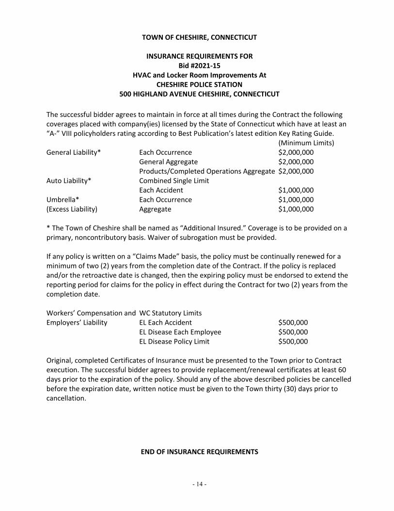
500 HIGHLAND AVENUE CHESHIRE, CONNECTICUT The successful bidder agrees to maintain in force at all times during the Contract the following coverages placed with company(ies) licensed by the State of Connecticut which have at least an “A-” VIII policyholders rating according to Best Publication’s latest edition Key Rating Guide.
(Minimum Limits) General Liability* Each Occurrence $2,000,000
General Aggregate $2,000,000 Products/Completed Operations Aggregate $2,000,000
Auto Liability* Combined Single Limit Each Accident $1,000,000
Umbrella* Each Occurrence $1,000,000 (Excess Liability) Aggregate $1,000,000 * The Town of Cheshire shall be named as “Additional Insured.” Coverage is to be provided on a primary, noncontributory basis. Waiver of subrogation must be provided. If any policy is written on a “Claims Made” basis, the policy must be continually renewed for a minimum of two (2) years from the completion date of the Contract. If the policy is replaced and/or the retroactive date is changed, then the expiring policy must be endorsed to extend the reporting period for claims for the policy in effect during the Contract for two (2) years from the completion date. Workers’ Compensation and WC Statutory Limits Employers’ Liability EL Each Accident $500,000
EL Disease Each Employee $500,000 EL Disease Policy Limit $500,000
Original, completed Certificates of Insurance must be presented to the Town prior to Contract execution. The successful bidder agrees to provide replacement/renewal certificates at least 60 days prior to the expiration of the policy. Should any of the above described policies be cancelled before the expiration date, written notice must be given to the Town thirty (30) days prior to cancellation.
END OF INSURANCE REQUIREMENTS

- 1 -
BID FORM
Bid #2021-15 HVAC and Locker Room Improvements At
CHESHIRE POLICE STATION 500 HIGHLAND AVENUE CHESHIRE, CONNECTICUT
BIDDER’S FULL LEGAL NAME: _______________________________________________ Pursuant to and in full compliance with the ITB, the undersigned bidder, having visited the site or property if applicable, and having thoroughly examined each and every document comprising the ITB, including any addenda, hereby offers and agrees as follows: To provide the products and/or services specified in, and upon the terms and conditions of, the ITB for the total sum of ________________________________________________/100 Dollars (write out in words) ($_______________________________) (in numbers) UNIT PRICES: Should certain changes in the Work be required, by authorization of the Owner in accordance with the Contract Documents, the undersigned agrees that the Unit Prices stated below shall, at the option of the Owner, be the basis of payment to the Contractor or credit to the Owner for such additional work or deleted work. The Unit Prices stated below shall represent the exact net amount per unit to be paid to the Contractor (in the case of additions or increases) or to be credited or refunded to the Owner (in the case of decreases). The Unit Prices shall include all materials, labor, equipment, overhead and profit, transportation, overhead, profit, insurance and bond premiums, fees and all other direct and indirect expenses of the Contractor and all affected Subcontractors. If the Owner elects to use the Unit Prices as the basis for adjustment in the Contract Sum, the Unit Prices specified below shall apply and shall not be adjusted based on the actual quantity of Unit Price work performed. All work is to be accomplished in accordance with applicable sections of the Specifications. C.Y. = cubic yard S.F. = square feet L.F. = linear foot UNIT PRICE: DESCRIPTION:
1. Masonry Repointing, as specified in $_____________ / s.f. Section 04 01 00, Maintenance of Masonry and indicated on the drawings.
2. Brick Replacement, as specified $___________ / brick in Section 04 01 00, Maintenance of Masonry and indicated on the drawings.

- 2 -
3. Exterior Cement Plastering, as specified $____________ / s.f. In Section 09 20 00 Plaster and Gypsum Board and indicated on the drawings. ALLOWANCES: 1. Additional Masonry Repointing: 600 s.f. Included in this proposal is a total allowance of 600 s.f. for masonry repointing that
exceeds that as further defined within Section 04 01 00 “Maintenance of Masonry” and further defined within Section 01 21 00 – “Allowances”.
2. Brick Replacement: 12 masonry units Included in this proposal is a total allowance of 12 masonry units for additional brick
masonry replacement scope as further defined within Section 04 01 00 “Maintenance of Masonry” and further defined within Section 01 21 00 – “Allowances”.
CONTRACT TIME If awarded the Project, the undersigned agrees that the work will commence upon execution of the Contract with the Owner, and shall be Substantially Complete within ten (10) months from the Owner’s Notice to Proceed, as defined in the Contract. ADDENDUM The undersigned Bidder hereby certifies that it is able to furnish labor that can work in harmony with all other elements of labor employed or to be employed on this project. The Bid includes Addenda listed below and they are hereby acknowledged: Addendum # ______ Dated _________________________ Addendum # ______ Dated _________________________ Addendum # ______ Dated _________________________ ACKNOWLEDGEMENT In submitting this Bid Form, the undersigned bidder acknowledges that the price include all labor, materials, transportation, hauling, overhead, fees and insurance(s), bonds or letters of credit, profit, security, permits and licenses, and all other costs to cover the completed work or to provide the items called for in the ITB. Except as otherwise expressly stated in the ITB, no additional payment of any kind will be made for work accomplished or the items provided under the price as proposed.

- 3 -
REQUIRED DISCLOSURES 1. Exceptions to the ITB
______ This bid does not take exception to any requirement of the ITB, including but not only any of the Contract Terms set forth in Section 26 of the Standard Instructions to Bidders.
OR
______ This bid takes exception(s) to certain of the ITB requirements, including but not only the following Contract Terms set forth in Section 26 of the Standard Instructions to Bidders. Attached is a sheet fully describing each such exception.
2. State Debarment List Is the bidder on the State of Connecticut’s Debarment List?
______ Yes ______ No
3. Occupational Safety and Health Law Violations
Has the bidder or any firm, corporation, partnership or association in which it has an interest (1) been cited for three (3) or more willful or serious violations of any occupational safety and health act or of any standard, order or regulation promulgated pursuant to such act, during the three-year period preceding the bid (provided such violations were cited in accordance with the provisions of any state occupational safety and health act or the Occupational Safety and Health Act of 1970, and not abated within the time fixed by the citation and such citation has not been set aside following appeal to the appropriate agency or court having jurisdiction) or (2) received one or more criminal convictions related to the injury or death of any employee in the three-year period preceding the bid? ______ Yes ______ No If “yes,” attach a sheet fully describing each such matter.
4. Arbitration/Litigation
Has either the bidder or any of its principals (regardless of place of employment) been involved for the most recent ten (10) years in any resolved or pending arbitration or litigation?

- 4 -
______ Yes ______ No If “yes,” attach a sheet fully describing each such matter.
5. Criminal Proceedings
Has the bidder or any of its principals (regardless of place of employment) ever been the subject of any criminal proceedings? ______ Yes ______ No If “yes,” attach a sheet fully describing each such matter.
6. Ethics and Offenses in Public Projects or Contracts
Has either the bidder or any of its principals (regardless of place of employment) ever been found to have violated any state or local ethics law, regulation, ordinance, code, policy or standard, or to have committed any other offense arising out of the submission of proposals or bids or the performance of work on public works projects or contracts? ______ Yes ______ No If “yes,” attach a sheet fully describing each such matter.
BID SECURITY The bidder has included herein the required certified check or bid bond in the amount of FIVE PERCENT (5%) of the bid amount. NOTE: THIS DOCUMENT, IN ORDER TO BE CONSIDERED A VALID BID, MUST BE SIGNED BY A PRINCIPAL OFFICER OR OWNER OF THE BUSINESS ENTITY THAT IS SUBMITTING THE BID. SUCH SIGNATURE CONSTITUTES THE BIDDER’S REPRESENTATIONS THAT IT HAS READ, UNDERSTOOD AND FULLY ACCEPTED EACH AND EVERY PROVISION OF EACH DOCUMENT COMPROMISING THE ITB, UNLESS AN EXCEPTION IS DESCRIBED ABOVE. BY ___________________________ TITLE:_____________________________ (PRINT NAME) ______________________________ DATE:_____________________________ (SIGNATURE)
END OF BID FORM

- 1 -
TOWN OF CHESHIRE, CONNECTICUT
BIDDER’S LEGAL STATUS DISCLOSURE
Please fully complete the applicable section below, attaching a separate sheet if you need additional space. For purposes of this disclosure, “permanent place of business” means an office continuously maintained, occupied and used by the bidder’s regular employees regularly in attendance to carry on the bidder’s business in the bidder’s own name. An office maintained, occupied and used by a bidder only for the duration of a contract will not be considered a permanent place of business. An office maintained, occupied and used by a person affiliated with a bidder will not be considered a permanent place of business of the bidder. IF A SOLELY OWNED BUSINESS:
Bidder’s Full Legal Name
Street Address
Mailing Address (if different from Street Address)
Owner’s Full Legal Name
Number of years engaged in business under sole proprietor or trade name
Does the bidder have a “permanent place of business” in Connecticut, as defined above? ________ Yes ________ No If yes, please state the full street address (not a post office box) of that
“permanent place of business.”
IF A CORPORATION:
Bidder’s Full Legal Name
Street Address
Mailing Address (if different from Street Address)
Owner’s Full Legal Name
Number of years engaged in business
Names of Current Officers
_____________________ ______________________ _____________________ President Secretary Chief Financial Officer

- 2 -
Does the bidder have a “permanent place of business” in Connecticut, as defined above? ________ Yes ________ No If yes, please state the full street address (not a post office box) of that
“permanent place of business.” ________________________________________________________
IF A LIMITED LIABILITY COMPANY:
Bidder’s Full Legal Name
Street Address
Mailing Address (if different from Street Address)
Owner’s Full Legal Name
Number of years engaged in business
Names of Current Manager(s) and Member(s)
_______________________________ _______________________________ Name & Title (if any) Residential Address (street only) _______________________________ _______________________________ Name & Title (if any) Residential Address (street only) _______________________________ _______________________________ Name & Title (if any) Residential Address (street only) _______________________________ _______________________________ Name & Title (if any) Residential Address (street only) _______________________________ _______________________________ Name & Title (if any) Residential Address (street only)
Does the bidder have a “permanent place of business” in Connecticut, as defined above? ________ Yes ________ No If yes, please state the full street address (not a post office box) of that
“permanent place of business.” ________________________________________________________
- 3 -
IF A PARTNERSHIP:
Bidder’s Full Legal Name
Street Address
Mailing Address (if different from Street Address)
Owner’s Full Legal Name
Number of years engaged in business
Names of Current Partners _______________________________ _______________________________ Name & Title (if any) Residential Address (street only) _______________________________ _______________________________ Name & Title (if any) Residential Address (street only) _______________________________ _______________________________ Name & Title (if any) Residential Address (street only) _______________________________ _______________________________ Name & Title (if any) Residential Address (street only)
Does the bidder have a “permanent place of business” in Connecticut, as defined above? ________ Yes ________ No If yes, please state the full street address (not a post office box) of that
“permanent place of business.” ________________________________________________________ ************************************************************************* Sign on the next page

- 4 -
_____________________________________________ Bidder’s Full Legal Name _____________________________________________ (print) Name and Title of Bidder’s Authorized Representative _____________________________________________ (signature) Bidder’s Representative, Duly Authorized _____________________________________________ Date
END OF LEGAL STATUS DISCLOSURE FORM

- 1 -
TOWN OF CHESHIRE, CONNECTICUT
INVITATION TO BID FOR Bid #2021-15
HVAC and Locker Room Improvements At CHESHIRE POLICE STATION
500 HIGHLAND AVENUE CHESHIRE, CONNECTICUT
BIDDER’S CERTIFICATION Concerning Equal Employment Opportunities
And Affirmative Action Policy I/we, the bidder, certify that:
1) I/we are in compliance with the equal opportunity clause as set forth in Connecticut state law (Executive Order No. Three, http://www.cslib.org/exeorder3.htm).
2) I/we do not maintain segregated facilities. 3) I/we have filed all required employer's information reports. 4) I/we have developed and maintain written affirmative action programs. 5) I/we list job openings with federal and state employment services. 6) I/we attempt to employ and advance in employment qualified handicapped individuals. 7) I/we are in compliance with the Americans with Disabilities Act. 8) I/we (check one):
______ have an Affirmative Action Program, or ______ employ 10 people or fewer.
_________________________________ ____________________________________ Legal Name of Bidder (signature)
Bidder’s Representative, Duly Authorized ____________________________________ Name of Bidder’s Authorized Representative ____________________________________ Title of Bidder’s Authorized Representative ____________________________________ Date

- 1 -
TOWN OF CHESHIRE, CONNECTICUT
BIDDER’S NON COLLUSION AFFIDAVIT INVITATION TO BID FOR
Bid #2021-15 HVAC and Locker Room Improvements At
CHESHIRE POLICE STATION 500 HIGHLAND AVENUE CHESHIRE, CONNECTICUT
The undersigned bidder, having fully informed himself/herself/itself regarding the accuracy of the statements made herein, certifies that: (1) the bid is genuine; it is not a collusive or sham bid; (2) the bidder developed the bid independently and submitted it without collusion with, and
without any agreement, understanding, communication or planned common course of action with, any other person or entity designed to limit independent competition;
(3) the bidder, its employees and agents have not communicated the contents of the bid to any person not an employee or agent of the bidder and will not communicate the bid to any such person prior to the official opening of the bid; and
(4) no elected or appointed official or other officer or employee of the Town of Cheshire is directly or indirectly interested in the bidder’s bid, or in the supplies, materials, equipment, work or labor to which it relates, or in any of the profits thereof.
The undersigned bidder further certifies that this affidavit is executed for the purpose of inducing the Town of Cheshire to consider its bid and make an award in accordance therewith. _________________________________ _____________________________________ Legal Name of Bidder (signature)
Bidder’s Representative, Duly Authorized _____________________________________ Name of Bidder’s Authorized Representative _____________________________________ Title of Bidder’s Authorized Representative _____________________________________ Date
Subscribed and sworn to before me this _______ day of _____________________, 2021.
_____________________________________ Notary Public My Commission Expires:
- 1 -
TOWN OF CHESHIRE, CONNECTICUT
INVITATION TO BID FOR Bid #2021-15
HVAC and Locker Room Improvements At CHESHIRE POLICE STATION
500 HIGHLAND AVENUE CHESHIRE, CONNECTICUT
BIDDER’S STATEMENT OF REFERENCES Provide at least three (3) references: 1. BUSINESS NAME________________________________________________________
ADDRESS_______________________________________________________________
CITY, STATE____________________________________________________________
TELEPHONE:____________________________________________________________
INDIVIDUAL CONTACT NAME AND POSITION _____________________________
________________________________________________________________________
2. BUSINESS NAME________________________________________________________
ADDRESS_______________________________________________________________
CITY, STATE____________________________________________________________
TELEPHONE:____________________________________________________________
INDIVIDUAL CONTACT NAME AND POSITION _____________________________
________________________________________________________________________
3. BUSINESS NAME________________________________________________________
ADDRESS_______________________________________________________________
CITY, STATE____________________________________________________________
TELEPHONE:____________________________________________________________
INDIVIDUAL CONTACT NAME AND POSITION _____________________________
________________________________________________________________________
END OF STATEMENT OF REFERENCES


Document A101® – 2017Standard Form of Agreement Between Owner and Contractor where the basis of payment is a Stipulated Sum
Init.
/
AIA Document A101® – 2017. Copyright © 1915, 1918, 1925, 1937, 1951, 1958, 1961, 1963, 1967, 1974, 1977, 1987, 1991, 1997, 2007 and 2017 by The American Institute of Architects. All rights reserved. The “American Institute of Architects,” “AIA,” the AIA Logo, "A101," and “AIA Contract Documents” are registered trademarks and may not be used without permission. This document was produced by AIA software at 15:16:27 ET on 06/02/2021 under Order No.2525352985 which expires on 08/31/2021, is not for resale, is licensed for one-time use only, and may only be used in accordance with the AIA Contract Documents® Terms of Service. To report copyright violations, e-mail [email protected] Notes: (3B9ADA46)
1
ADDITIONS AND DELETIONS: The author of this document has added information needed for its completion. The author may also have revised the text of the original AIA standard form. An Additions and Deletions Report that notes added information as well as revisions to the standard form text is available from the author and should be reviewed. A vertical line in the left margin of this document indicates where the author has added necessary information and where the author has added to or deleted from the original AIA text.
This document has important legal consequences. Consultation with an attorney is encouraged with respect to its completion or modification.
The parties should complete A101®–2017, Exhibit A, Insurance and Bonds, contemporaneously with this Agreement. AIA Document A201®–2017, General Conditions of the Contract for Construction, is adopted in this document by reference. Do not use with other general conditions unless this document is modified.
AGREEMENT made as of the day of in the year (In words, indicate day, month and year.)
BETWEEN the Owner:(Name, legal status, address and other information)
Town of Cheshire 84 South Main StreetCheshire, CT 06410
and the Contractor:(Name, legal status, address and other information)
TBD
for the following Project:(Name, location and detailed description)
HVAC and Locker Room Improvements at the Police StationTown of Cheshire Bid #2021-15Cheshire Police Department500 Highland AvenueCheshire, CT 06410
The Architect:(Name, legal status, address and other information)
Jacunski Humes Architects, LLC15 Massirio DriveSuite 101Berlin, CT 06037
The Owner and Contractor agree as follows.

Init.
/
AIA Document A101® – 2017. Copyright © 1915, 1918, 1925, 1937, 1951, 1958, 1961, 1963, 1967, 1974, 1977, 1987, 1991, 1997, 2007 and 2017 by The American Institute of Architects. All rights reserved. The “American Institute of Architects,” “AIA,” the AIA Logo, "A101," and “AIA Contract Documents” are registered trademarks and may not be used without permission. This document was produced by AIA software at 15:16:27 ET on 06/02/2021 under Order No.2525352985 which expires on 08/31/2021, is not for resale, is licensed for one-time use only, and may only be used in accordance with the AIA Contract Documents® Terms of Service. To report copyright violations, e-mail [email protected] Notes: (3B9ADA46)
2
TABLE OF ARTICLES
1 THE CONTRACT DOCUMENTS
2 THE WORK OF THIS CONTRACT
3 DATE OF COMMENCEMENT AND SUBSTANTIAL COMPLETION
4 CONTRACT SUM
5 PAYMENTS
6 DISPUTE RESOLUTION
7 TERMINATION OR SUSPENSION
8 MISCELLANEOUS PROVISIONS
9 ENUMERATION OF CONTRACT DOCUMENTS
EXHIBIT A INSURANCE AND BONDS
ARTICLE 1 THE CONTRACT DOCUMENTSThe Contract Documents consist of this Agreement, Conditions of the Contract (General, Supplementary, and other Conditions), Drawings, Specifications, Addenda issued prior to execution of this Agreement, the Bidding Documents (including Owner’s Instructions to Bidders, Owner’s Invitation to Bid #__________ and all Bidding Documents issued in conjunction therewith), other documents listed in this Agreement, and Modifications issued after execution of this Agreement, all of which form the Contract, and are as fully a part of the Contract as if attached to this Agreement or repeated herein. The Contract represents the entire and integrated agreement between the parties hereto and supersedes prior negotiations, representations, or agreements, either written or oral. An enumeration of the Contract Documents, other than a Modification, appears in Article 9.
ARTICLE 2 THE WORK OF THIS CONTRACTThe Contractor shall fully execute the Work described in the Contract Documents, except as specifically indicated in the Contract Documents to be the responsibility of others.
ARTICLE 3 DATE OF COMMENCEMENT AND SUBSTANTIAL COMPLETION§ 3.1 The date of commencement of the Work shall be:(Check one of the following boxes.)
[ ] The date of this Agreement.
[ X ] A date set forth in a notice to proceed issued by the Owner or Architect. Contractor shall coordinate the scheduling and performance of the Work with the Owner.
[ ] Established as follows:(Insert a date or a means to determine the date of commencement of the Work.)
If a date of commencement of the Work is not selected, then the date of commencement shall be the date of this Agreement.
§ 3.2 The Contract Time shall be measured from the date of commencement of the Work.
§ 3.3 Substantial Completion

Init.
/
AIA Document A101® – 2017. Copyright © 1915, 1918, 1925, 1937, 1951, 1958, 1961, 1963, 1967, 1974, 1977, 1987, 1991, 1997, 2007 and 2017 by The American Institute of Architects. All rights reserved. The “American Institute of Architects,” “AIA,” the AIA Logo, "A101," and “AIA Contract Documents” are registered trademarks and may not be used without permission. This document was produced by AIA software at 15:16:27 ET on 06/02/2021 under Order No.2525352985 which expires on 08/31/2021, is not for resale, is licensed for one-time use only, and may only be used in accordance with the AIA Contract Documents® Terms of Service. To report copyright violations, e-mail [email protected] Notes: (3B9ADA46)
3
§ 3.3.1 Subject to adjustments of the Contract Time as provided in the Contract Documents, the Contractor shall achieve Substantial Completion of the entire Work:(Check one of the following boxes and complete the necessary information.)
[ ] Not later than ten ( 10 ) months from the date of commencement of the Work.
[ X ] By the following date:
TIME IS OF THE ESSENCE WITH REGARD TO THE TIMELY PERFORMANCE OF THE AGREEMENT, ACHIEVEMENT OF ALL MILESTONES, SUBSTANTIAL COMPLETION AND FINAL COMPLETION OF THE PROJECT BY THE CONTRACTOR. If, in the sole opinion of the Owner, the Contractor is not adhering to the Project schedule and/or is not supplying sufficient labor and/or equipment to complete the Work by the Substantial Completion date contained herein, upon forty-eight (48) hours written notice, the Town shall have the right to direct the Contractor to increase its labor and/or equipment to meet established project schedules without additional compensation provided the Town is not responsible or in any way liable for the Contractor not adhering to the Project schedule. Any and all such additional labor or supervision shall be at Contractor’s sole cost and expense and may include, but shall not be limited to, Town directing the Contractor to increase the workers on its crews, supply additional equipment, work overtime, work a second shift during a single day, work weekends, or any combination thereof, without any additional compensation being due to Contractor for such additional personnel. Any costs incurred or arising due to the Contractor’s failure to achieve timely Substantial Completion shall be borne solely by the Contractor. § 3.3.1.1 Contractor expressly agrees, notwithstanding any provision in this Agreement to the contrary, that: (i) a COVID-19 pandemic exists worldwide as of the execution date of this Agreement; (ii) the existence of such pandemic, and its effects, now, and for the duration of Contractor's performance under the Agreement, shall not in and of itself be cause for Contractor to rely upon, invoke, or avail itself to, any rights or remedies under this Agreement, at law, or in equity, for a claim, or an adjustment to the price, schedule, quantities, specifications, or other material terms of this Agreement; (iii) the material terms of this Agreement, particularly terms relating to price, schedule, quantities, availability and specifications, take into consideration, and fully account for, the existence of such pandemic and its effects, as of the date of this Agreement; and (iv) such pandemic shall not render Contractor unable to fulfill any of its obligations under the Agreement, and Contractor shall not have any claim, action, or cause of action against the Owner in connection with such pandemic, including any claim for frustration of purpose change in circumstances, economic balance, or impossibility. This provision shall survive the completion or earlier termination of this Agreement. § 3.3.2 Subject to adjustments of the Contract Time as provided in the Contract Documents, if portions of the Work are to be completed prior to Substantial Completion of the entire Work, the Contractor shall achieve Substantial Completion of such portions by the following dates:
Portion of Work Substantial Completion Date
§ 3.3.3 If the Contractor fails to achieve Substantial Completion as provided in this Section 3.3, liquidated damages, if any, shall be assessed as set forth in Section 4.5.
ARTICLE 4 CONTRACT SUM§ 4.1 The Owner shall pay the Contractor the Contract Sum in current funds for the Contractor’s performance of the Contract. The Contract Sum shall be ($ ), subject to additions and deductions as provided in the Contract Documents.
§ 4.2 Alternates§ 4.2.1 Alternates, if any, included in the Contract Sum:
Item PriceNone

Init.
/
AIA Document A101® – 2017. Copyright © 1915, 1918, 1925, 1937, 1951, 1958, 1961, 1963, 1967, 1974, 1977, 1987, 1991, 1997, 2007 and 2017 by The American Institute of Architects. All rights reserved. The “American Institute of Architects,” “AIA,” the AIA Logo, "A101," and “AIA Contract Documents” are registered trademarks and may not be used without permission. This document was produced by AIA software at 15:16:27 ET on 06/02/2021 under Order No.2525352985 which expires on 08/31/2021, is not for resale, is licensed for one-time use only, and may only be used in accordance with the AIA Contract Documents® Terms of Service. To report copyright violations, e-mail [email protected] Notes: (3B9ADA46)
4
§ 4.2.2 Subject to the conditions noted below, the following alternates may be accepted by the Owner following execution of this Agreement. Upon acceptance, the Owner shall issue a Modification to this Agreement.(Insert below each alternate and the conditions that must be met for the Owner to accept the alternate.)
Item Price Conditions for AcceptanceN/A
§ 4.3 Allowances, if any, included in the Contract Sum:(Identify each allowance.)
Item PriceAs indicated in the Bid Proposal
§ 4.4 Unit prices, if any:(Identify the item and state the unit price and quantity limitations, if any, to which the unit price will be applicable.)
Item Units and Limitations Price per Unit ($0.00)As indicated in the Bid Proposal
§ 4.5 Liquidated damages, if any:(Insert terms and conditions for liquidated damages, if any.)
See A201 as modified.
§ 4.6 Other:(Insert provisions for bonus or other incentives, if any, that might result in a change to the Contract Sum.)
ARTICLE 5 PAYMENTS§ 5.1 Progress Payments§ 5.1.1 Based upon Applications for Payment submitted to the Architect by the Contractor and Certificates for Payment issued by the Architect, the Owner shall make progress payments on account of the Contract Sum to the Contractor as provided below and elsewhere in the Contract Documents.
§ 5.1.2 The period covered by each Application for Payment shall be one calendar month ending on the last day of the month, or as follows:
§ 5.1.3 Provided that an Application for Payment is received by the Architect not later than the 25th day of a month, the Owner shall make payment of the amount certified to the Contractor not later than thirty (30) days after the Owner approves the Application for Payment. If an Application for Payment is received by the Architect after the application date fixed above, payment of the amount certified shall be made by the Owner not later than thirty ( 30 ) days after the approves the Application for Payment certified by the Architect.(Federal, state or local laws may require payment within a certain period of time.)
§ 5.1.4 Each Application for Payment shall be based on the most recent schedule of values submitted by the Contractor in accordance with the Contract Documents. The schedule of values shall allocate the entire Contract Sum among the various portions of the Work. The schedule of values shall be prepared in such form, and supported by such data to substantiate its accuracy, as the Architect may require. This schedule of values shall be used as a basis for reviewing the Contractor’s Applications for Payment.
§ 5.1.5 Applications for Payment shall show the percentage of completion of each portion of the Work as of the end of the period covered by the Application for Payment.

Init.
/
AIA Document A101® – 2017. Copyright © 1915, 1918, 1925, 1937, 1951, 1958, 1961, 1963, 1967, 1974, 1977, 1987, 1991, 1997, 2007 and 2017 by The American Institute of Architects. All rights reserved. The “American Institute of Architects,” “AIA,” the AIA Logo, "A101," and “AIA Contract Documents” are registered trademarks and may not be used without permission. This document was produced by AIA software at 15:16:27 ET on 06/02/2021 under Order No.2525352985 which expires on 08/31/2021, is not for resale, is licensed for one-time use only, and may only be used in accordance with the AIA Contract Documents® Terms of Service. To report copyright violations, e-mail [email protected] Notes: (3B9ADA46)
5
§ 5.1.6 In accordance with AIA Document A201™–2017, General Conditions of the Contract for Construction, and subject to other provisions of the Contract Documents, the amount of each progress payment shall be computed as follows:
§ 5.1.6.1 The amount of each progress payment shall first include:.1 That portion of the Contract Sum properly allocable to completed Work;.2 That portion of the Contract Sum properly allocable to materials and equipment delivered and suitably
stored at the site for subsequent incorporation in the completed construction, or, if approved in advance by the Owner, suitably stored off the site at a location agreed upon in writing; and
.3 That portion of Construction Change Directives that the Architect determines, in the Architect’s professional judgment, to be reasonably justified.
§ 5.1.6.2 The amount of each progress payment shall then be reduced by:.1 The aggregate of any amounts previously paid by the Owner;.2 The amount, if any, for Work that remains uncorrected and for which the Architect has previously
withheld a Certificate for Payment as provided in Article 9 of AIA Document A201–2017;.3 Any amount for which the Contractor does not intend to pay a Subcontractor or material supplier,
unless the Work has been performed by others the Contractor intends to pay;.4 For Work performed or defects discovered since the last payment application, any amount for which
the Architect may withhold payment, or nullify a Certificate of Payment in whole or in part, as provided in Article 9 of AIA Document A201–2017; and
.5 Retainage withheld pursuant to Section 5.1.7.
§ 5.1.7 Retainage§ 5.1.7.1 For each progress payment made prior to Substantial Completion of the Work, the Owner may withhold the following amount, as retainage, from the payment otherwise due:(Insert a percentage or amount to be withheld as retainage from each Application for Payment. The amount of retainage may be limited by governing law.)
Five percent (5%)
§ 5.1.7.1.1 The following items are not subject to retainage:(Insert any items not subject to the withholding of retainage, such as general conditions, insurance, etc.)
N/A
§ 5.1.7.2 Reduction or limitation of retainage, if any, shall be as follows:(If the retainage established in Section 5.1.7.1 is to be modified prior to Substantial Completion of the entire Work, including modifications for Substantial Completion of portions of the Work as provided in Section 3.3.2, insert provisions for such modifications.)
At the Owner’s sole discretion.
§ 5.1.7.3 Except as set forth in this Section 5.1.7.3, upon Substantial Completion of the Work, the Contractor may submit an Application for Payment that includes the retainage withheld from prior Applications for Payment pursuant to this Section 5.1.7. The Application for Payment submitted at Substantial Completion shall not include retainage as follows:(Insert any other conditions for release of retainage upon Substantial Completion.)
Owner shall be entitled to retain two hundred percent (200%) of the estimated cost to complete punchlist items to reach Final Completion.
§ 5.1.8 If final completion of the Work is materially delayed through no fault of the Contractor, the Owner shall pay the Contractor any additional amounts in accordance with Article 9 of AIA Document A201–2017.

Init.
/
AIA Document A101® – 2017. Copyright © 1915, 1918, 1925, 1937, 1951, 1958, 1961, 1963, 1967, 1974, 1977, 1987, 1991, 1997, 2007 and 2017 by The American Institute of Architects. All rights reserved. The “American Institute of Architects,” “AIA,” the AIA Logo, "A101," and “AIA Contract Documents” are registered trademarks and may not be used without permission. This document was produced by AIA software at 15:16:27 ET on 06/02/2021 under Order No.2525352985 which expires on 08/31/2021, is not for resale, is licensed for one-time use only, and may only be used in accordance with the AIA Contract Documents® Terms of Service. To report copyright violations, e-mail [email protected] Notes: (3B9ADA46)
6
§ 5.1.9 Except with the Owner’s prior approval, the Contractor shall not make advance payments to suppliers for materials or equipment which have not been delivered and stored at the site.
§ 5.2 Final Payment§ 5.2.1 Final payment, constituting the entire unpaid balance of the Contract Sum, shall be made by the Owner to the Contractor when
.1 the Contractor has fully performed the Contract except for the Contractor’s responsibility to correct Work as provided in Article 12 of AIA Document A201–2017, and to satisfy other requirements, if any, which extend beyond final payment; and
.2 a final Certificate for Payment has been issued by the Architect and all conditions precedent to final payment have been satisfied.
§ 5.2.2 The Owner’s final payment to the Contractor shall be made no later than 30 days after the issuance of the Architect’s final Certificate for Payment, or as follows:
§ 5.3 Intentionally Deleted.
(Paragraphs Deleted)
ARTICLE 6 DISPUTE RESOLUTION§ 6.1 Initial Decision MakerThe Architect will serve as the Initial Decision Maker pursuant to Article 15 of AIA Document A201–2017, unless the parties appoint below another individual, not a party to this Agreement, to serve as the Initial Decision Maker.(If the parties mutually agree, insert the name, address and other contact information of the Initial Decision Maker, if other than the Architect.)
§ 6.2 Binding Dispute ResolutionFor any Claim subject to, but not resolved by, mediation pursuant to Article 15 of AIA Document A201–2017, the method of binding dispute resolution shall be as follows:(Check the appropriate box.)
[ ] Arbitration pursuant to Section 15.4 of AIA Document A201–2017
[ ] Litigation in a court of competent jurisdiction
[ X ] Other (Specify)
Litigation in Connecticut Superior Court in and for the Judicial District of New Haven unless the Owner, in its sole discretion, elects to arbitrate a dispute..
If the Owner and Contractor do not select a method of binding dispute resolution, or do not subsequently agree in writing to a binding dispute resolution method other than litigation, Claims will be resolved by litigation in a court of competent jurisdiction.
ARTICLE 7 TERMINATION OR SUSPENSION§ 7.1 The Contract may be terminated by the Owner or the Contractor as provided in Article 14 of AIA Document A201–2017.
Init.
/
AIA Document A101® – 2017. Copyright © 1915, 1918, 1925, 1937, 1951, 1958, 1961, 1963, 1967, 1974, 1977, 1987, 1991, 1997, 2007 and 2017 by The American Institute of Architects. All rights reserved. The “American Institute of Architects,” “AIA,” the AIA Logo, "A101," and “AIA Contract Documents” are registered trademarks and may not be used without permission. This document was produced by AIA software at 15:16:27 ET on 06/02/2021 under Order No.2525352985 which expires on 08/31/2021, is not for resale, is licensed for one-time use only, and may only be used in accordance with the AIA Contract Documents® Terms of Service. To report copyright violations, e-mail [email protected] Notes: (3B9ADA46)
7
§ 7.1.1
(Paragraph Deleted)
Intentionally Deleted.
§ 7.2 The Work may be suspended by the Owner as provided in Article 14 of AIA Document A201–2017.
ARTICLE 8 MISCELLANEOUS PROVISIONS§ 8.1 Where reference is made in this Agreement to a provision of AIA Document A201–2017 or another Contract Document, the reference refers to that provision as amended or supplemented by other provisions of the Contract Documents.
§ 8.2 The Owner’s representative:(Name, address, email address, and other information)
To be named by the Owner in writing within ten (10) days of the execution of this Agreement.
§ 8.3 The Contractor’s representative:(Name, address, email address, and other information)
To be named by the Contractor in writing within ten (10) days of the execution of this Agreement
§ 8.4 Neither the Owner’s nor the Contractor’s representative shall be changed without ten days’ prior notice to the other party.
§ 8.5 Insurance and Bonds§ 8.5.1 The Owner and the Contractor shall purchase and maintain insurance as set forth in AIA Document A101™–2017, Standard Form of Agreement Between Owner and Contractor where the basis of payment is a Stipulated Sum, Exhibit A, Insurance and Bonds, and elsewhere in the Contract Documents.
§ 8.5.2 The Contractor shall provide bonds as set forth in AIA Document A101™–2017 Exhibit A, and elsewhere in the Contract Documents.
§ 8.6 Notice in electronic format, pursuant to Article 1 of AIA Document A201–2017, may be given in accordance with AIA Document E203™–2013, Building Information Modeling and Digital Data Exhibit, if completed, or as otherwise set forth below:(If other than in accordance with AIA Document E203–2013, insert requirements for delivering notice in electronic format such as name, title, and email address of the recipient and whether and how the system will be required to generate a read receipt for the transmission.)
§ 8.7 Other provisions:
Init.
/
AIA Document A101® – 2017. Copyright © 1915, 1918, 1925, 1937, 1951, 1958, 1961, 1963, 1967, 1974, 1977, 1987, 1991, 1997, 2007 and 2017 by The American Institute of Architects. All rights reserved. The “American Institute of Architects,” “AIA,” the AIA Logo, "A101," and “AIA Contract Documents” are registered trademarks and may not be used without permission. This document was produced by AIA software at 15:16:27 ET on 06/02/2021 under Order No.2525352985 which expires on 08/31/2021, is not for resale, is licensed for one-time use only, and may only be used in accordance with the AIA Contract Documents® Terms of Service. To report copyright violations, e-mail [email protected] Notes: (3B9ADA46)
8
ARTICLE 9 ENUMERATION OF CONTRACT DOCUMENTS§ 9.1 This Agreement is comprised of the following documents:
.1 AIA Document A101™–2017, Standard Form of Agreement Between Owner and Contractor
.2 AIA Document A101™–2017, Exhibit A, Insurance and Bonds
.3 AIA Document A201™–2017, General Conditions of the Contract for Construction, as modified
.4 AIA Document E203™–2013, Building Information Modeling and Digital Data Exhibit, dated as indicated below:(Insert the date of the E203-2013 incorporated into this Agreement.)
.5 Drawings
Number Title DateSee List of Drawings
.6 Specifications
Section Title Date PagesSee Table of Contents
.7 Addenda, if any:
Number Date PagesTBD
Portions of Addenda relating to bidding or proposal requirements are not part of the Contract Documents unless the bidding or proposal requirements are also enumerated in this Article 9.
.8 Other Exhibits:(Check all boxes that apply and include appropriate information identifying the exhibit where required.)
[ ] AIA Document E204™–2017, Sustainable Projects Exhibit, dated as indicated below:(Insert the date of the E204-2017 incorporated into this Agreement.)
[ ] The Sustainability Plan:
Title Date Pages
[ ] Supplementary and other Conditions of the Contract:
Document Title Date Pages
.9 Other documents, if any, listed below:(List here any additional documents that are intended to form part of the Contract Documents. AIA Document A201™–2017 provides that the advertisement or invitation to bid, Instructions to Bidders, sample forms, the Contractor’s bid or proposal, portions of Addenda relating to bidding or proposal requirements, and other information furnished by the Owner in anticipation of receiving bids or proposals, are not part of the Contract Documents unless enumerated in this Agreement. Any such documents should be listed here only if intended to be part of the Contract Documents.)

Init.
/
AIA Document A101® – 2017. Copyright © 1915, 1918, 1925, 1937, 1951, 1958, 1961, 1963, 1967, 1974, 1977, 1987, 1991, 1997, 2007 and 2017 by The American Institute of Architects. All rights reserved. The “American Institute of Architects,” “AIA,” the AIA Logo, "A101," and “AIA Contract Documents” are registered trademarks and may not be used without permission. This document was produced by AIA software at 15:16:27 ET on 06/02/2021 under Order No.2525352985 which expires on 08/31/2021, is not for resale, is licensed for one-time use only, and may only be used in accordance with the AIA Contract Documents® Terms of Service. To report copyright violations, e-mail [email protected] Notes: (3B9ADA46)
9
Town of Cheshire, Invitation to BidInstructions to Bidders, AIA A701, and supplemental Instructions to BiddersState of CT, Prevailing Wage RatesContractor’s Bid ProposalAddendum No. TBD
This Agreement entered into as of the day and year first written above.
OWNER (Signature) CONTRACTOR (Signature)
(Printed name and title) (Printed name and title)

Additions and Deletions Report forAIA® Document A101® – 2017
This Additions and Deletions Report, as defined on page 1 of the associated document, reproduces below all text the author has added to the standard form AIA document in order to complete it, as well as any text the author may have added to or deleted from the original AIA text. Added text is shown underlined. Deleted text is indicated with a horizontal line through the original AIA text.
Note: This Additions and Deletions Report is provided for information purposes only and is not incorporated into or constitute any part of the associated AIA document. This Additions and Deletions Report and its associated document were generated simultaneously by AIA software at 15:16:27 ET on 06/02/2021.
Additions and Deletions Report for AIA Document A101® – 2017. Copyright © 1915, 1918, 1925, 1937, 1951, 1958, 1961, 1963, 1967, 1974, 1977, 1987, 1991, 1997, 2007 and 2017 by The American Institute of Architects. All rights reserved. The “American Institute of Architects,” “AIA,” the AIA Logo, "A101," and “AIA Contract Documents” are registered trademarks and may not be used without permission. This document was produced by AIA software at 15:16:27 ET on 06/02/2021 under Order No.2525352985 which expires on 08/31/2021, is not for resale, is licensed for one-time use only, and may only be used in accordance with the AIA Contract Documents® Terms of Service. To report copyright violations, e-mail [email protected] Notes: (3B9ADA46)
1
PAGE 1 Town of Cheshire 84 South Main StreetCheshire, CT 06410 ... TBD ... HVAC and Locker Room Improvements at the Police Station ... Town of Cheshire Bid #2021-15 ... Cheshire Police Department500 Highland AvenueCheshire, CT 06410 ... Jacunski Humes Architects, LLC15 Massirio DriveSuite 101 Berlin, CT 06037

Additions and Deletions Report for AIA Document A101® – 2017. Copyright © 1915, 1918, 1925, 1937, 1951, 1958, 1961, 1963, 1967, 1974, 1977, 1987, 1991, 1997, 2007 and 2017 by The American Institute of Architects. All rights reserved. The “American Institute of Architects,” “AIA,” the AIA Logo, "A101," and “AIA Contract Documents” are registered trademarks and may not be used without permission. This document was produced by AIA software at 15:16:27 ET on 06/02/2021 under Order No.2525352985 which expires on 08/31/2021, is not for resale, is licensed for one-time use only, and may only be used in accordance with the AIA Contract Documents® Terms of Service. To report copyright violations, e-mail [email protected] Notes: (3B9ADA46)
2
PAGE 2 The Contract Documents consist of this Agreement, Conditions of the Contract (General, Supplementary, and other Conditions), Drawings, Specifications, Addenda issued prior to execution of this Agreement, the Bidding Documents (including Owner’s Instructions to Bidders, Owner’s Invitation to Bid #__________ and all Bidding Documents issued in conjunction therewith), other documents listed in this Agreement, and Modifications issued after execution of this Agreement, all of which form the Contract, and are as fully a part of the Contract as if attached to this Agreement or repeated herein. The Contract represents the entire and integrated agreement between the parties hereto and supersedes prior negotiations, representations, or agreements, either written or oral. An enumeration of the Contract Documents, other than a Modification, appears in Article 9. ... [ X ] A date set forth in a notice to proceed issued by the Owner or Architect. Contractor shall coordinate the scheduling and performance of the Work with the Owner. PAGE 3 [ ] Not later than ( ) calendar days ten ( 10 ) months from the date of commencement of the Work. ... [ X ] By the following date: ... TIME IS OF THE ESSENCE WITH REGARD TO THE TIMELY PERFORMANCE OF THE AGREEMENT, ACHIEVEMENT OF ALL MILESTONES, SUBSTANTIAL COMPLETION AND FINAL COMPLETION OF THE PROJECT BY THE CONTRACTOR. If, in the sole opinion of the Owner, the Contractor is not adhering to the Project schedule and/or is not supplying sufficient labor and/or equipment to complete the Work by the Substantial Completion date contained herein, upon forty-eight (48) hours written notice, the Town shall have the right to direct the Contractor to increase its labor and/or equipment to meet established project schedules without additional compensation provided the Town is not responsible or in any way liable for the Contractor not adhering to the Project schedule. Any and all such additional labor or supervision shall be at Contractor’s sole cost and expense and may include, but shall not be limited to, Town directing the Contractor to increase the workers on its crews, supply additional equipment, work overtime, work a second shift during a single day, work weekends, or any combination thereof, without any additional compensation being due to Contractor for such additional personnel. Any costs incurred or arising due to the Contractor’s failure to achieve timely Substantial Completion shall be borne solely by the Contractor. ... § 3.3.1.1 Contractor expressly agrees, notwithstanding any provision in this Agreement to the contrary, that: (i) a COVID-19 pandemic exists worldwide as of the execution date of this Agreement; (ii) the existence of such pandemic, and its effects, now, and for the duration of Contractor's performance under the Agreement, shall not in and of itself be cause for Contractor to rely upon, invoke, or avail itself to, any rights or remedies under this Agreement, at law, or in equity, for a claim, or an adjustment to the price, schedule, quantities, specifications, or other material terms of this Agreement; (iii) the material terms of this Agreement, particularly terms relating to price, schedule, quantities, availability and specifications, take into consideration, and fully account for, the existence of such pandemic and its ... effects, as of the date of this Agreement; and (iv) such pandemic shall not render Contractor unable to fulfill any of its obligations under the Agreement, and Contractor shall not have any claim, action, or cause of action against the Owner in connection with such pandemic, including any claim for frustration of purpose change in circumstances,

Additions and Deletions Report for AIA Document A101® – 2017. Copyright © 1915, 1918, 1925, 1937, 1951, 1958, 1961, 1963, 1967, 1974, 1977, 1987, 1991, 1997, 2007 and 2017 by The American Institute of Architects. All rights reserved. The “American Institute of Architects,” “AIA,” the AIA Logo, "A101," and “AIA Contract Documents” are registered trademarks and may not be used without permission. This document was produced by AIA software at 15:16:27 ET on 06/02/2021 under Order No.2525352985 which expires on 08/31/2021, is not for resale, is licensed for one-time use only, and may only be used in accordance with the AIA Contract Documents® Terms of Service. To report copyright violations, e-mail [email protected] Notes: (3B9ADA46)
3
economic balance, or impossibility. This provision shall survive the completion or earlier termination of this Agreement. ...
Portion of Work Substantial Completion Date ...
None PAGE 4
N/A ...
As indicated in the Bid Proposal ...
As indicated in the Bid Proposal ... See A201 as modified. ... § 5.1.3 Provided that an Application for Payment is received by the Architect not later than the 25th day of a month, the Owner shall make payment of the amount certified to the Contractor not later than the day of the month. thirty (30) days after the Owner approves the Application for Payment. If an Application for Payment is received by the Architect after the application date fixed above, payment of the amount certified shall be made by the Owner not later than thirty ( 30 ) days after the Architect receives the Application for Payment.approves the Application for Payment certified by the Architect. PAGE 5 Five percent (5%) ... N/A ... At the Owner’s sole discretion. ... Owner shall be entitled to retain two hundred percent (200%) of the estimated cost to complete punchlist items to reach Final Completion.

Additions and Deletions Report for AIA Document A101® – 2017. Copyright © 1915, 1918, 1925, 1937, 1951, 1958, 1961, 1963, 1967, 1974, 1977, 1987, 1991, 1997, 2007 and 2017 by The American Institute of Architects. All rights reserved. The “American Institute of Architects,” “AIA,” the AIA Logo, "A101," and “AIA Contract Documents” are registered trademarks and may not be used without permission. This document was produced by AIA software at 15:16:27 ET on 06/02/2021 under Order No.2525352985 which expires on 08/31/2021, is not for resale, is licensed for one-time use only, and may only be used in accordance with the AIA Contract Documents® Terms of Service. To report copyright violations, e-mail [email protected] Notes: (3B9ADA46)
4
PAGE 6
.2 a final Certificate for Payment has been issued by the Architect.Architect and all conditions precedent to final payment have been satisfied.
... § 5.3 InterestIntentionally Deleted. ... Payments due and unpaid under the Contract shall bear interest from the date payment is due at the rate stated below, or in the absence thereof, at the legal rate prevailing from time to time at the place where the Project is located. ... (Insert rate of interest agreed upon, if any.) ... % ... [ X ] Other (Specify) ... Litigation in Connecticut Superior Court in and for the Judicial District of New Haven unless the Owner, in its sole discretion, elects to arbitrate a dispute.. PAGE 7 § 7.1.1If the Contract is terminated for the Owner’s convenience in accordance with Article 14 of AIA Document A201–2017, then the Owner shall pay the Contractor a termination fee as follows: ... (Insert the amount of, or method for determining, the fee, if any, payable to the Contractor following a termination for the Owner’s convenience.) ... Intentionally Deleted. ... To be named by the Owner in writing within ten (10) days of the execution of this Agreement. ...

Additions and Deletions Report for AIA Document A101® – 2017. Copyright © 1915, 1918, 1925, 1937, 1951, 1958, 1961, 1963, 1967, 1974, 1977, 1987, 1991, 1997, 2007 and 2017 by The American Institute of Architects. All rights reserved. The “American Institute of Architects,” “AIA,” the AIA Logo, "A101," and “AIA Contract Documents” are registered trademarks and may not be used without permission. This document was produced by AIA software at 15:16:27 ET on 06/02/2021 under Order No.2525352985 which expires on 08/31/2021, is not for resale, is licensed for one-time use only, and may only be used in accordance with the AIA Contract Documents® Terms of Service. To report copyright violations, e-mail [email protected] Notes: (3B9ADA46)
5
To be named by the Contractor in writing within ten (10) days of the execution of this Agreement PAGE 8
.3 AIA Document A201™–2017, General Conditions of the Contract for ConstructionConstruction, as modified
...
See List of Drawings ...
See Table of Contents ...
TBD PAGE 9
Town of Cheshire, Invitation to Bid ...
Instructions to Bidders, AIA A701, and supplemental Instructions to Bidders ...
State of CT, Prevailing Wage Rates ...
Contractor’s Bid Proposal ...
Addendum No. TBD

Document A101® – 2017 Exhibit AInsurance and Bonds
Init.
/
AIA Document A101® – 2017 Exhibit A. Copyright © 2017 by The American Institute of Architects. All rights reserved. The “American Institute of Architects,” “AIA,” the AIA Logo, "A101," and “AIA Contract Documents” are registered trademarks and may not be used without permission. This document was produced by AIA software at 15:18:09 ET on 06/02/2021 under Order No.2525352985 which expires on 08/31/2021, is not for resale, is licensed for one-time use only, and may only be used in accordance with the AIA Contract Documents® Terms of Service. To report copyright violations, e-mail [email protected] Notes: (3B9ADA48)
1
ADDITIONS AND DELETIONS: The author of this document has added information needed for its completion. The author may also have revised the text of the original AIA standard form. An Additions and Deletions Report that notes added information as well as revisions to the standard form text is available from the author and should be reviewed. A vertical line in the left margin of this document indicates where the author has added necessary information and where the author has added to or deleted from the original AIA text.
This document has important legal consequences. Consultation with an attorney is encouraged with respect to its completion or modification.
This document is intended to be used in conjunction with AIA Document A201®–2017, General Conditions of the Contract for Construction. Article 11 of A201®–2017 contains additional insurance provisions.
This Insurance and Bonds Exhibit is part of the Agreement, between the Owner and the Contractor, dated the day of in the year 2021(In words, indicate day, month and year.)
for the following PROJECT:(Name and location or address)
HVAC and Locker Room Improvements at the Police StationTown of Cheshire Bid #2021-15Cheshire Police Department500 Highland Avenue Cheshire, CT 06410
THE OWNER:(Name, legal status and address)
Town of Cheshire 84 South Main StreetCheshire, CT 06410
THE CONTRACTOR:(Name, legal status and address)
TBD
TABLE OF ARTICLES
A.1 GENERAL
A.2 OWNER’S INSURANCE
A.3 CONTRACTOR’S INSURANCE AND BONDS
A.4 SPECIAL TERMS AND CONDITIONS
ARTICLE A.1 GENERALThe Owner and Contractor shall purchase and maintain insurance, and provide bonds, from companies that are acceptable to the Owner, as set forth in this Exhibit. Acceptable sureties shall be those listed in the U. S. Treasury Department’s Circular 570 and lawfully authorized to conduct surety business in Connecticut. As used in this Exhibit, the term General Conditions refers to AIA Document A201™–2017, General Conditions of the Contract for Construction, as modified.

Init.
/
AIA Document A101® – 2017 Exhibit A. Copyright © 2017 by The American Institute of Architects. All rights reserved. The “American Institute of Architects,” “AIA,” the AIA Logo, "A101," and “AIA Contract Documents” are registered trademarks and may not be used without permission. This document was produced by AIA software at 15:18:09 ET on 06/02/2021 under Order No.2525352985 which expires on 08/31/2021, is not for resale, is licensed for one-time use only, and may only be used in accordance with the AIA Contract Documents® Terms of Service. To report copyright violations, e-mail [email protected] Notes: (3B9ADA48)
2
ARTICLE A.2 OWNER’S INSURANCE§ A.2.1 GeneralPrior to commencement of the Work, the Owner shall secure the insurance, and provide evidence of the coverage, required under this Article A.2 and, upon the Contractor’s request, provide a copy of the property insurance policy or policies required by Section A.2.3. The copy of the policy or policies provided shall contain all applicable conditions, definitions, exclusions, and endorsements.
§ A.2.2 Liability InsuranceThe Owner shall be responsible for purchasing and maintaining the Owner’s usual general liability insurance.
§ A.2.3 Required Property Insurance§ A.2.3.1 Unless this obligation is placed on the Contractor pursuant to Section A.3.3.2.1, the Owner shall purchase and maintain, from an insurance company or insurance companies lawfully authorized to issue insurance in the jurisdiction where the Project is located, property insurance written on a builder's risk “all-risks” completed value or equivalent policy form and sufficient to cover the total value of the entire Project on a replacement cost basis. The Owner’s property insurance coverage shall be no less than the amount of the initial Contract Sum, plus the value of subsequent Modifications and labor performed and materials or equipment supplied by others. The property insurance shall be maintained until Substantial Completion and thereafter as provided in Section A.2.3.1.3, unless otherwise provided in the Contract Documents or otherwise agreed in writing by the parties to this Agreement. This insurance shall include the interests of the Owner, Contractor, Subcontractors, and Sub-subcontractors in the Project as insureds. This insurance shall include the interests of mortgagees as loss payees.
§ A.2.3.1.1 Causes of Loss. The insurance required by this Section A.2.3.1 shall provide coverage for direct physical loss or damage, and shall not exclude the risks of fire, explosion, theft, vandalism, malicious mischief, collapse, earthquake, flood, or windstorm. The insurance shall also provide coverage for ensuing loss or resulting damage from error, omission, or deficiency in construction methods, design, specifications, workmanship, or materials. Sub-limits, if any, are as follows:(Indicate below the cause of loss and any applicable sub-limit.)
Causes of Loss Sub-Limit
§ A.2.3.1.2 Specific Required Coverages. The insurance required by this Section A.2.3.1 shall provide coverage for loss or damage to falsework and other temporary structures, and to building systems from testing and startup. The insurance shall also cover debris removal, including demolition occasioned by enforcement of any applicable legal requirements, and reasonable compensation for the Architect’s and Contractor’s services and expenses required as a result of such insured loss, including claim preparation expenses. Sub-limits, if any, are as follows:(Indicate below type of coverage and any applicable sub-limit for specific required coverages.)
Coverage Sub-Limit
§ A.2.3.1.3 Unless the parties agree otherwise, upon Substantial Completion, the Owner shall continue the insurance required by Section A.2.3.1 or, if necessary, replace the insurance policy required under Section A.2.3.1 with property insurance written for the total value of the Project that shall remain in effect until expiration of the period for correction of the Work set forth in Section 12.2.2 of the General Conditions.
§ A.2.3.1.4 Deductibles and Self-Insured Retentions. If the insurance required by this Section A.2.3 is subject to deductibles or self-insured retentions, the Owner shall be responsible for all loss not covered because of such deductibles or retentions.
§ A.2.3.2 Occupancy or Use Prior to Substantial Completion. The Owner’s occupancy or use of any completed or partially completed portion of the Work prior to Substantial Completion shall not commence until the insurance company or companies providing the insurance under Section A.2.3.1 have consented in writing to the continuance of coverage. The Owner and the Contractor shall take no action with respect to partial occupancy or use that would cause cancellation, lapse, or reduction of insurance, unless they agree otherwise in writing.

Init.
/
AIA Document A101® – 2017 Exhibit A. Copyright © 2017 by The American Institute of Architects. All rights reserved. The “American Institute of Architects,” “AIA,” the AIA Logo, "A101," and “AIA Contract Documents” are registered trademarks and may not be used without permission. This document was produced by AIA software at 15:18:09 ET on 06/02/2021 under Order No.2525352985 which expires on 08/31/2021, is not for resale, is licensed for one-time use only, and may only be used in accordance with the AIA Contract Documents® Terms of Service. To report copyright violations, e-mail [email protected] Notes: (3B9ADA48)
3
§ A.2.3.3 Insurance for Existing StructuresIf the Work involves remodeling an existing structure or constructing an addition to an existing structure, the Owner shall purchase and maintain, until the expiration of the period for correction of Work as set forth in Section 12.2.2 of the General Conditions, “all-risks” property insurance, on a replacement cost basis, protecting the existing structure against direct physical loss or damage from the causes of loss identified in Section A.2.3.1, notwithstanding the undertaking of the Work. The Owner shall be responsible for all co-insurance penalties.
§ A.2.4 Optional Extended Property Insurance.The Owner shall purchase and maintain the insurance selected and described below.(Select the types of insurance the Owner is required to purchase and maintain by placing an X in the box(es) next to the description(s) of selected insurance. For each type of insurance selected, indicate applicable limits of coverage or other conditions in the fill point below the selected item.)
[ ] § A.2.4.1 Loss of Use, Business Interruption, and Delay in Completion Insurance, to reimburse the Owner for loss of use of the Owner’s property, or the inability to conduct normal operations due to a covered cause of loss.
[ ] § A.2.4.2 Ordinance or Law Insurance, for the reasonable and necessary costs to satisfy the minimum requirements of the enforcement of any law or ordinance regulating the demolition, construction, repair, replacement or use of the Project.
[ ] § A.2.4.3 Expediting Cost Insurance, for the reasonable and necessary costs for the temporary repair of damage to insured property, and to expedite the permanent repair or replacement of the damaged property.
[ ] § A.2.4.4 Extra Expense Insurance, to provide reimbursement of the reasonable and necessary excess costs incurred during the period of restoration or repair of the damaged property that are over and above the total costs that would normally have been incurred during the same period of time had no loss or damage occurred.
[ ] § A.2.4.5 Civil Authority Insurance, for losses or costs arising from an order of a civil authority prohibiting access to the Project, provided such order is the direct result of physical damage covered under the required property insurance.
[ ] § A.2.4.6 Ingress/Egress Insurance, for loss due to the necessary interruption of the insured’s business due to physical prevention of ingress to, or egress from, the Project as a direct result of physical damage.
[ ] § A.2.4.7 Soft Costs Insurance, to reimburse the Owner for costs due to the delay of completion of the Work, arising out of physical loss or damage covered by the required property insurance: including construction loan fees; leasing and marketing expenses; additional fees, including those of architects, engineers, consultants, attorneys and accountants, needed for the completion of the construction, repairs, or reconstruction; and carrying costs such as property taxes, building permits, additional interest on loans, realty taxes, and insurance premiums over and above normal expenses.
Init.
/
AIA Document A101® – 2017 Exhibit A. Copyright © 2017 by The American Institute of Architects. All rights reserved. The “American Institute of Architects,” “AIA,” the AIA Logo, "A101," and “AIA Contract Documents” are registered trademarks and may not be used without permission. This document was produced by AIA software at 15:18:09 ET on 06/02/2021 under Order No.2525352985 which expires on 08/31/2021, is not for resale, is licensed for one-time use only, and may only be used in accordance with the AIA Contract Documents® Terms of Service. To report copyright violations, e-mail [email protected] Notes: (3B9ADA48)
4
§ A.2.5 Other Optional Insurance.The Owner shall purchase and maintain the insurance selected below.(Select the types of insurance the Owner is required to purchase and maintain by placing an X in the box(es) next to the description(s) of selected insurance.)
[ ] § A.2.5.1 Cyber Security Insurance for loss to the Owner due to data security and privacy breach, including costs of investigating a potential or actual breach of confidential or private information.(Indicate applicable limits of coverage or other conditions in the fill point below.)
[ ] § A.2.5.2 Other Insurance(List below any other insurance coverage to be provided by the Owner and any applicable limits.)
Coverage Limits
ARTICLE A.3 CONTRACTOR’S INSURANCE AND BONDS§ A.3.1 General§ A.3.1.1 Certificates of Insurance. The Contractor shall provide certificates of insurance acceptable to the Owner evidencing compliance with the requirements in this Article A.3 at the following times: (1) prior to commencement of the Work; (2) upon renewal or replacement of each required policy of insurance; and (3) upon the Owner’s written request. An additional certificate evidencing continuation of commercial liability coverage, including coverage for completed operations, shall be submitted with the final Application for Payment and thereafter upon renewal or replacement of such coverage until the expiration of the periods required by Section A.3.2.1 and Section A.3.3.1. The certificates will show the Owner as an additional insured on the Contractor’s Commercial General Liability and excess or umbrella liability policy or policies. Certificates of Insurance shall include the Project description from page 1 of the Agreement, identify the Owner as an Additional Insured on a primary and non-contributing basis, and state that the workers compensation and general liability policies contain waivers of subrogation. Additional Insured endorsement(s) must be attached to the COIs. Policies cannot be modified or canceled with less than thirty (30) days’ notice of such action by certified mail to the Owner. The words "ENDEAVOR TO" and "BUT FAILURE TO MAIL SUCH NOTICE SHALL IMPOSE NO OBLIGATION OR LIABILITY OF 'ANY KIND UPON THE COMPANY, ITS AGENTS OR REPRESENTATIVES" shall be deleted from the certificate form's cancellation provision.
§ A.3.1.2 Deductibles and Self-Insured Retentions. The Contractor shall disclose to the Owner any deductible or self- insured retentions applicable to any insurance required to be provided by the Contractor.
§ A.3.1.3 Additional Insured Obligations. To the fullest extent permitted by law, the Contractor shall cause the commercial general liability, automobile liability and umbrella coverages to include (1) the Owner, the Architect, and the Architect’s consultants as additional insureds for claims caused in whole or in part by the Contractor’s negligent acts or omissions during the Contractor’s operations; and (2) the Owner as an additional insured for claims caused in whole or in part by the Contractor’s negligent acts or omissions for which loss occurs during completed operations. The additional insured coverage shall be primary and non-contributory to any of the Owner’s general liability insurance policies and shall apply to both ongoing and completed operations. To the extent commercially available, the additional insured coverage shall be no less than that provided by Insurance Services Office, Inc. (ISO) forms CG 20 10 07 04, CG 20 37 07 04, and, with respect to the Architect and the Architect’s consultants, CG 20 32 07 04. To the fullest extent permitted by law, the Contractor hereby waives its rights and its insurer(s)’ rights of recovery against Owner for any loss arising from or relating to this Agreement. The Contractor shall require its insurers to execute any waiver of subrogation endorsements which may be necessary to effect such waiver.
Init.
/
AIA Document A101® – 2017 Exhibit A. Copyright © 2017 by The American Institute of Architects. All rights reserved. The “American Institute of Architects,” “AIA,” the AIA Logo, "A101," and “AIA Contract Documents” are registered trademarks and may not be used without permission. This document was produced by AIA software at 15:18:09 ET on 06/02/2021 under Order No.2525352985 which expires on 08/31/2021, is not for resale, is licensed for one-time use only, and may only be used in accordance with the AIA Contract Documents® Terms of Service. To report copyright violations, e-mail [email protected] Notes: (3B9ADA48)
5
§ A.3.2 Contractor’s Required Insurance Coverage§ A.3.2.1 The Contractor shall purchase and maintain the following types and limits of insurance from an insurance company or insurance companies which are lawfully authorized to issue insurance in Connecticut and are acceptable to the Owner. The Contractor shall maintain the required insurance without interruption from the date of commencement of the Work until the date of final payment and termination of any coverage required to be maintained after final payment, and with respect to Contractor's completed operations coverages, as specified in the Contract Documents. If the Contractor fails to purchase and maintain any insurance required by the Contract Documents, the Owner may, but shall not be obligated to, upon two (2) days’ written notice to the Contractor, purchase such insurance on behalf of the Contractor and shall be entitled to be reimbursed by the Contractor promptly upon demand or deduct the amount of such premiums from the Contract Sum. Alternatively, the Owner may order cessation of all construction activities until such time all insurance requirements have been complied with. Under such circumstances, the Contractor shall have no recourse against the Owner. (If the Contractor is required to maintain insurance for a duration other than the expiration of the period for correction of Work, state the duration.)
§ A.3.2.2 Commercial General Liability§ A.3.2.2.1 Commercial General Liability insurance for the Project written on an occurrence form with policy limits of not less than two million dollars ($ 2,000,000 ) each occurrence, two million dollars ($ 2,000,000 ) general aggregate, and two million dollars ($ 2,000,000 ) aggregate for products-completed operations hazard, providing coverage for claims including
.1 damages because of bodily injury, sickness or disease, including occupational sickness or disease, and death of any person;
.2 personal injury and advertising injury;
.3 Premises-Operations and Independent Contractors Protective Products;
.4 damages because of physical damage to or destruction of tangible property, including the loss of use of such property;
.5 bodily injury or property damage arising out of completed operations (which shall be maintained for five (5) years after final payment); and
.6 the Contractor’s indemnity obligations under Section 3.18 of the General Conditions.
It is the responsibility of the Contractor to maintain the CGL coverage on an occurrence form including completed operations for a period of five years beyond final payment. In addition to the preceding, the commercial general liability policy must include an endorsement or endorsements naming the Owner and others as required by contract as Additional Insureds on a primary and noncontributory basis. Copies of additional insured endorsements and evidence of primary and noncontributing language must be attached to the certificate of insurance. Only the following ISO endorsements or their equivalents are acceptable: (i) CG2010 (11/85), or (ii) CG2010 (10/01) when used with CG2037 (10/01), or (iii) CG2010 (07/04) when used with CG2037 (07/04), or (iv) CG2010 (04/13) when used with CG 2037 (04/13).
§ A.3.2.2.2 The Contractor’s Commercial General Liability policy under this Section A.3.2.2 shall not contain an exclusion or restriction of coverage for the following:
.1 Claims by one insured against another insured, if the exclusion or restriction is based solely on the fact that the claimant is an insured, and there would otherwise be coverage for the claim.
.2 Claims for property damage to the Contractor’s Work arising out of the products-completed operations hazard where the damaged Work or the Work out of which the damage arises was performed by a Subcontractor.
Init.
/
AIA Document A101® – 2017 Exhibit A. Copyright © 2017 by The American Institute of Architects. All rights reserved. The “American Institute of Architects,” “AIA,” the AIA Logo, "A101," and “AIA Contract Documents” are registered trademarks and may not be used without permission. This document was produced by AIA software at 15:18:09 ET on 06/02/2021 under Order No.2525352985 which expires on 08/31/2021, is not for resale, is licensed for one-time use only, and may only be used in accordance with the AIA Contract Documents® Terms of Service. To report copyright violations, e-mail [email protected] Notes: (3B9ADA48)
6
.3 Claims for bodily injury other than to employees of the insured.
.4 Claims for indemnity under Section 3.18 of the General Conditions arising out of injury to employees of the insured.
.5 Claims or loss excluded under a prior work endorsement or other similar exclusionary language.
.6 Claims or loss due to physical damage under a prior injury endorsement or similar exclusionary language.
.7 Claims related to residential, multi-family, or other habitational projects, if the Work is to be performed on such a project.
.8 Claims related to roofing, if the Work involves roofing.
.9 Claims related to exterior insulation finish systems (EIFS), synthetic stucco or similar exterior coatings or surfaces, if the Work involves such coatings or surfaces.
.10 Claims related to earth subsidence or movement, where the Work involves such hazards.
.11 Claims related to explosion, collapse and underground hazards, where the Work involves such hazards.
§ A.3.2.3 Automobile Liability covering vehicles owned, non-owned and hired vehicles used, by the Contractor, with policy limits of not less than one million dollars ($ 1,000,000 ) per accident, for bodily injury, death of any person, and property damage arising out of the ownership, maintenance and use of those motor vehicles along with any other statutorily required automobile coverage.
§ A.3.2.4 The Contractor may achieve the required limits and coverage for Commercial General Liability and Automobile Liability through a combination of primary and excess or umbrella liability insurance, provided such primary and excess or umbrella insurance policies result in the same or greater coverage as the coverages required under Section A.3.2.2 and A.3.2.3, and in no event shall any excess or umbrella liability insurance provide narrower coverage than the primary policy. The excess policy shall not require the exhaustion of the underlying limits only through the actual payment by the underlying insurers.
§ A.3.2.5 Workers’ Compensation at statutory limits.
§ A.3.2.6 Employers’ Liability with policy limits not less than five hundred thousand dollars ($ 500,000 ) each accident, five hundred thousand ($ 500,000 ) Disease, five hundred thousand ($500,000) each employee, and five hundred thousand ($ 500,000 ) policy limit.
§ A.3.2.7 Jones Act, and the Longshore & Harbor Workers’ Compensation Act, as required, if the Work involves hazards arising from work on or near navigable waterways, including vessels and docks
§ A.3.2.8 If the Contractor furnishes professional services as part of the Work, the Contractor shall procure Professional Liability insurance covering performance of the professional services, with policy limits of not less than one million dollars ($ 1,000,000 ) per claim and one million dollars ($ 1,000,000 ) in the aggregate.
§ A.3.2.9 If the Work involves the transport, dissemination, use, or release of pollutants, the Contractor shall procure Pollution Liability insurance, with policy limits of not less than one million dollars ($ 1,000,000 ) per claim and one million dollars ($ 1,000,000 ) in the aggregate. The Owner shall be named as an additional insured on all such policies. Contractor shall deliver to the Owner certificate(s) evidencing such insurance prior to starting any remediation or transportation of hazardous materials.
The Contractor or any Subcontractor of any tier which remediates or transports hazardous materials must have the appropriate license(s) from the State and/or U.S. Government and must carry full pollution liability coverage. The Owner will be named as an additional insured on all such policies. Contractor will deliver to the Owner certificate(s) evidencing such insurance prior to starting any remediation or transportation of hazardous materials. § A.3.2.10 Coverage under Sections A.3.2.8 and A.3.2.9 may be procured through a Combined Professional Liability and Pollution Liability insurance policy, with combined policy limits of not less than ($ ) per claim and ($ ) in the aggregate.

Init.
/
AIA Document A101® – 2017 Exhibit A. Copyright © 2017 by The American Institute of Architects. All rights reserved. The “American Institute of Architects,” “AIA,” the AIA Logo, "A101," and “AIA Contract Documents” are registered trademarks and may not be used without permission. This document was produced by AIA software at 15:18:09 ET on 06/02/2021 under Order No.2525352985 which expires on 08/31/2021, is not for resale, is licensed for one-time use only, and may only be used in accordance with the AIA Contract Documents® Terms of Service. To report copyright violations, e-mail [email protected] Notes: (3B9ADA48)
7
§ A.3.2.11 Insurance for maritime liability risks associated with the operation of a vessel, if the Work requires such activities, with policy limits of not less than ($ ) per claim and ($ ) in the aggregate.
§ A.3.2.12 Insurance for the use or operation of manned or unmanned aircraft, if the Work requires such activities, with policy limits of not less than ($ ) per claim and ($ ) in the aggregate.
§ A.3.3 Contractor’s Other Insurance Coverage§ A.3.3.1 Insurance selected and described in this Section A.3.3 shall be purchased from an insurance company or insurance companies lawfully authorized to issue insurance in the jurisdiction where the Project is located. The Contractor shall maintain the required insurance until the expiration of the period for correction of Work as set forth in Section 12.2.2 of the General Conditions, unless a different duration is stated below:(If the Contractor is required to maintain any of the types of insurance selected below for a duration other than the expiration of the period for correction of Work, state the duration.)
§ A.3.3.2 The Contractor shall purchase and maintain the following types and limits of insurance in accordance with Section A.3.3.1.(Select the types of insurance the Contractor is required to purchase and maintain by placing an X in the box(es) next to the description(s) of selected insurance. Where policy limits are provided, include the policy limit in the appropriate fill point.)
[ ] § A.3.3.2.1 Property insurance of the same type and scope satisfying the requirements identified in Section A.2.3, which, if selected in this section A.3.3.2.1, relieves the Owner of the responsibility to purchase and maintain such insurance except insurance required by Section A.2.3.1.3 and Section A.2.3.3. The Contractor shall comply with all obligations of the Owner under Section A.2.3 except to the extent provided below. The Contractor shall disclose to the Owner the amount of any deductible, and the Owner shall be responsible for losses within the deductible. Upon request, the Contractor shall provide the Owner with a copy of the property insurance policy or policies required. The Owner shall adjust and settle the loss with the insurer and be the trustee of the proceeds of the property insurance in accordance with Article 11 of the General Conditions unless otherwise set forth below:(Where the Contractor’s obligation to provide property insurance differs from the Owner’s obligations as described under Section A.2.3, indicate such differences in the space below. Additionally, if a party other than the Owner will be responsible for adjusting and settling a loss with the insurer and acting as the trustee of the proceeds of property insurance in accordance with Article 11 of the General Conditions, indicate the responsible party below.)
[ ] § A.3.3.2.2 Railroad Protective Liability Insurance, with policy limits of not less than ($ ) per claim and ($ ) in the aggregate, for Work within fifty (50) feet of railroad property.
[ ] § A.3.3.2.3 Asbestos Abatement Liability Insurance, with policy limits of not less than ($ ) per claim and ($ ) in the aggregate, for liability arising from the encapsulation, removal, handling, storage, transportation, and disposal of asbestos-containing materials.
[ ] § A.3.3.2.4 Insurance for physical damage to property while it is in storage and in transit to the construction site on an “all-risks” completed value form.
[ ] § A.3.3.2.5 Property insurance on an “all-risks” completed value form, covering property owned by the Contractor and used on the Project, including scaffolding and other equipment.
[ ] § A.3.3.2.6 Other Insurance(List below any other insurance coverage to be provided by the Contractor and any applicable limits.)
Coverage Limits

Init.
/
AIA Document A101® – 2017 Exhibit A. Copyright © 2017 by The American Institute of Architects. All rights reserved. The “American Institute of Architects,” “AIA,” the AIA Logo, "A101," and “AIA Contract Documents” are registered trademarks and may not be used without permission. This document was produced by AIA software at 15:18:09 ET on 06/02/2021 under Order No.2525352985 which expires on 08/31/2021, is not for resale, is licensed for one-time use only, and may only be used in accordance with the AIA Contract Documents® Terms of Service. To report copyright violations, e-mail [email protected] Notes: (3B9ADA48)
8
Umbrella Excess Liability $10,000,000 Over primary insurance $10,000 Retention
§ A.3.4 Performance Bond and Payment BondThe Contractor shall provide surety bonds, from a company or companies lawfully authorized to issue surety bonds in the jurisdiction where the Project is located and which are T listed, in an amount equal to the Contract Sum and all subsequent increases.
(Table Deleted)
Payment and Performance Bonds shall be AIA Document A312™, Payment Bond and Performance Bond, or contain provisions identical to AIA Document A312™, current as of the date of this Agreement, or as acceptable to the Owner.
ARTICLE A.4 SPECIAL TERMS AND CONDITIONSSpecial terms and conditions that modify this Insurance and Bonds Exhibit, if any, are as follows:

Additions and Deletions Report forAIA® Document A101® – 2017 Exhibit A
This Additions and Deletions Report, as defined on page 1 of the associated document, reproduces below all text the author has added to the standard form AIA document in order to complete it, as well as any text the author may have added to or deleted from the original AIA text. Added text is shown underlined. Deleted text is indicated with a horizontal line through the original AIA text.
Note: This Additions and Deletions Report is provided for information purposes only and is not incorporated into or constitute any part of the associated AIA document. This Additions and Deletions Report and its associated document were generated simultaneously by AIA software at 15:18:09 ET on 06/02/2021.
Additions and Deletions Report for AIA Document A101® – 2017 Exhibit A. Copyright © 2017 by The American Institute of Architects. All rights reserved. The “American Institute of Architects,” “AIA,” the AIA Logo, "A101," and “AIA Contract Documents” are registered trademarks and may not be used without permission. This document was produced by AIA software at 15:18:09 ET on 06/02/2021 under Order No.2525352985 which expires on 08/31/2021, is not for resale, is licensed for one-time use only, and may only be used in accordance with the AIA Contract Documents® Terms of Service. To report copyright violations, e-mail [email protected] Notes: (3B9ADA48)
1
PAGE 1 This Insurance and Bonds Exhibit is part of the Agreement, between the Owner and the Contractor, dated the day of in the year 2021 ... HVAC and Locker Room Improvements at the Police Station ... Town of Cheshire Bid #2021-15 ... Cheshire Police Department500 Highland Avenue Cheshire, CT 06410 ... Town of Cheshire 84 South Main StreetCheshire, CT 06410 ... TBD ... The Owner and Contractor shall purchase and maintain insurance, and provide bonds, from companies that are acceptable to the Owner, as set forth in this Exhibit. Acceptable sureties shall be those listed in the U. S. Treasury Department’s Circular 570 and lawfully authorized to conduct surety business in Connecticut. As used in this Exhibit, the term General Conditions refers to AIA Document A201™–2017, General Conditions of the Contract for Construction.Construction, as modified.
Additions and Deletions Report for AIA Document A101® – 2017 Exhibit A. Copyright © 2017 by The American Institute of Architects. All rights reserved. The “American Institute of Architects,” “AIA,” the AIA Logo, "A101," and “AIA Contract Documents” are registered trademarks and may not be used without permission. This document was produced by AIA software at 15:18:09 ET on 06/02/2021 under Order No.2525352985 which expires on 08/31/2021, is not for resale, is licensed for one-time use only, and may only be used in accordance with the AIA Contract Documents® Terms of Service. To report copyright violations, e-mail [email protected] Notes: (3B9ADA48)
2
PAGE 4 § A.3.1.1 Certificates of Insurance. The Contractor shall provide certificates of insurance acceptable to the Owner evidencing compliance with the requirements in this Article A.3 at the following times: (1) prior to commencement of the Work; (2) upon renewal or replacement of each required policy of insurance; and (3) upon the Owner’s written request. An additional certificate evidencing continuation of commercial liability coverage, including coverage for completed operations, shall be submitted with the final Application for Payment and thereafter upon renewal or replacement of such coverage until the expiration of the periods required by Section A.3.2.1 and Section A.3.3.1. The certificates will show the Owner as an additional insured on the Contractor’s Commercial General Liability and excess or umbrella liability policy or policies. Certificates of Insurance shall include the Project description from page 1 of the Agreement, identify the Owner as an Additional Insured on a primary and non-contributing basis, and state that the workers compensation and general liability policies contain waivers of subrogation. Additional Insured endorsement(s) must be attached to the COIs. Policies cannot be modified or canceled with less than thirty (30) days’ notice of such action by certified mail to the Owner. The words "ENDEAVOR TO" and "BUT FAILURE TO MAIL SUCH NOTICE SHALL IMPOSE NO OBLIGATION OR LIABILITY OF 'ANY KIND UPON THE COMPANY, ITS AGENTS OR REPRESENTATIVES" shall be deleted from the certificate form's cancellation provision. ... § A.3.1.3 Additional Insured Obligations. To the fullest extent permitted by law, the Contractor shall cause the commercial general liability coverage liability, automobile liability and umbrella coverages to include (1) the Owner, the Architect, and the Architect’s consultants as additional insureds for claims caused in whole or in part by the Contractor’s negligent acts or omissions during the Contractor’s operations; and (2) the Owner as an additional insured for claims caused in whole or in part by the Contractor’s negligent acts or omissions for which loss occurs during completed operations. The additional insured coverage shall be primary and non-contributory to any of the Owner’s general liability insurance policies and shall apply to both ongoing and completed operations. To the extent commercially available, the additional insured coverage shall be no less than that provided by Insurance Services Office, Inc. (ISO) forms CG 20 10 07 04, CG 20 37 07 04, and, with respect to the Architect and the Architect’s consultants, CG 20 32 07 04. To the fullest extent permitted by law, the Contractor hereby waives its rights and its insurer(s)’ rights of recovery against Owner for any loss arising from or relating to this Agreement. The Contractor shall require its insurers to execute any waiver of subrogation endorsements which may be necessary to effect such waiver. PAGE 5 § A.3.2.1 The Contractor shall purchase and maintain the following types and limits of insurance from an insurance company or insurance companies which are lawfully authorized to issue insurance in the jurisdiction where the Project is located. Connecticut and are acceptable to the Owner. The Contractor shall maintain the required insurance until the expiration of the period for correction of Work as set forth in Section 12.2.2 without interruption from the date of commencement of the Work until the date of final payment and termination of any coverage required to be maintained after final payment, and with respect to Contractor's completed operations coverages, as specified in the Contract Documents. ... If the Contractor fails to purchase and maintain any insurance required by the Contract Documents, the Owner may, but shall not be obligated to, upon two (2) days’ written notice to the Contractor, purchase such insurance on behalf of the Contractor and shall be entitled to be reimbursed by the Contractor promptly upon demand or deduct the amount of such premiums from the Contract Sum. Alternatively, the Owner may order cessation of the General Conditions, unless a different duration is stated below:all construction activities until such time all insurance requirements have been complied with. Under such circumstances, the Contractor shall have no recourse against the Owner.
Additions and Deletions Report for AIA Document A101® – 2017 Exhibit A. Copyright © 2017 by The American Institute of Architects. All rights reserved. The “American Institute of Architects,” “AIA,” the AIA Logo, "A101," and “AIA Contract Documents” are registered trademarks and may not be used without permission. This document was produced by AIA software at 15:18:09 ET on 06/02/2021 under Order No.2525352985 which expires on 08/31/2021, is not for resale, is licensed for one-time use only, and may only be used in accordance with the AIA Contract Documents® Terms of Service. To report copyright violations, e-mail [email protected] Notes: (3B9ADA48)
3
... § A.3.2.2.1 Commercial General Liability insurance for the Project written on an occurrence form with policy limits of not less than two million dollars ($ 2,000,000 ) each occurrence, two million dollars ($ 2,000,000 ) general aggregate, and two million dollars ($ 2,000,000 ) aggregate for products-completed operations hazard, providing coverage for claims including ...
.3 Premises-Operations and Independent Contractors Protective Products; ...
.4 damages because of physical damage to or destruction of tangible property, including the loss of use of such property;
...
.4 .5 bodily injury or property damage arising out of completed operations; operations (which shall be maintained for five (5) years after final payment); and
...
.5 .6 the Contractor’s indemnity obligations under Section 3.18 of the General Conditions. ... It is the responsibility of the Contractor to maintain the CGL coverage on an occurrence form including completed operations for a period of five years beyond final payment. In addition to the preceding, the commercial general liability policy must include an endorsement or endorsements naming the Owner and others as required by contract as Additional Insureds on a primary and noncontributory basis. Copies of additional insured endorsements and evidence of primary and noncontributing language must be attached to the certificate of insurance. Only the following ISO endorsements or their equivalents are acceptable: ... (i) CG2010 (11/85), or ... (ii) CG2010 (10/01) when used with CG2037 (10/01), or ... (iii) CG2010 (07/04) when used with CG2037 (07/04), or (iv) CG2010 (04/13) when used with CG 2037 (04/13).
PAGE 6 § A.3.2.3 Automobile Liability covering vehicles owned, and non-owned non-owned and hired vehicles used, by the Contractor, with policy limits of not less than one million dollars ($ 1,000,000 ) per accident, for bodily injury,

Additions and Deletions Report for AIA Document A101® – 2017 Exhibit A. Copyright © 2017 by The American Institute of Architects. All rights reserved. The “American Institute of Architects,” “AIA,” the AIA Logo, "A101," and “AIA Contract Documents” are registered trademarks and may not be used without permission. This document was produced by AIA software at 15:18:09 ET on 06/02/2021 under Order No.2525352985 which expires on 08/31/2021, is not for resale, is licensed for one-time use only, and may only be used in accordance with the AIA Contract Documents® Terms of Service. To report copyright violations, e-mail [email protected] Notes: (3B9ADA48)
4
death of any person, and property damage arising out of the ownership, maintenance and use of those motor vehicles along with any other statutorily required automobile coverage. ... § A.3.2.6 Employers’ Liability with policy limits not less than five hundred thousand dollars ($ 500,000 ) each accident, five hundred thousand ($ 500,000 ) Disease, five hundred thousand ($500,000) each employee, and five hundred thousand ($ 500,000 ) policy limit. ... § A.3.2.8 If the Contractor is required to furnish furnishes professional services as part of the Work, the Contractor shall procure Professional Liability insurance covering performance of the professional services, with policy limits of not less than one million dollars ($ 1,000,000 ) per claim and one million dollars ($ 1,000,000 ) in the aggregate. ... § A.3.2.9 If the Work involves the transport, dissemination, use, or release of pollutants, the Contractor shall procure Pollution Liability insurance, with policy limits of not less than one million dollars ($ 1,000,000 ) per claim and one million dollars ($ 1,000,000 ) in the aggregate. The Owner shall be named as an additional insured on all such policies. Contractor shall deliver to the Owner certificate(s) evidencing such insurance prior to starting any remediation or transportation of hazardous materials. ... The Contractor or any Subcontractor of any tier which remediates or transports hazardous materials must have the appropriate license(s) from the State and/or U.S. Government and must carry full pollution liability coverage. The Owner will be named as an additional insured on all such policies. Contractor will deliver to the Owner certificate(s) evidencing such insurance prior to starting any remediation or transportation of hazardous materials. PAGE 8
Umbrella Excess Liability $10,000,000 Over primary insurance $10,000 Retention
... The Contractor shall provide surety bonds, from a company or companies lawfully authorized to issue surety bonds in the jurisdiction where the Project is located, as follows: ... (Specify type and penal sum of bonds.)located and which are T listed, in an amount equal to the Contract Sum and all subsequent increases. ...
Type Penal Sum ($0.00)Payment Bond Performance Bond
...

Additions and Deletions Report for AIA Document A101® – 2017 Exhibit A. Copyright © 2017 by The American Institute of Architects. All rights reserved. The “American Institute of Architects,” “AIA,” the AIA Logo, "A101," and “AIA Contract Documents” are registered trademarks and may not be used without permission. This document was produced by AIA software at 15:18:09 ET on 06/02/2021 under Order No.2525352985 which expires on 08/31/2021, is not for resale, is licensed for one-time use only, and may only be used in accordance with the AIA Contract Documents® Terms of Service. To report copyright violations, e-mail [email protected] Notes: (3B9ADA48)
5
Payment and Performance Bonds shall be AIA Document A312™, Payment Bond and Performance Bond, or contain provisions identical to AIA Document A312™, current as of the date of this Agreement.Agreement, or as acceptable to the Owner.

POLICE IMPROVEMENTS TOWN OF CHESHIRE BID #2021-15
This page intentionally left blank.

Document A201® – 2017General Conditions of the Contract for Construction
Init.
/
AIA Document A201® – 2017. Copyright © 1911, 1915, 1918, 1925, 1937, 1951, 1958, 1961, 1963, 1966, 1970, 1976, 1987, 1997, 2007 and 2017 by The American Institute of Architects. All rights reserved. The “American Institute of Architects,” “AIA,” the AIA Logo, "A201," and “AIA Contract Documents” are registered trademarks and may not be used without permission. This document was produced by AIA software at 15:19:16 ET on 06/02/2021 under Order No.2525352985 which expires on 08/31/2021, is not for resale, is licensed for one-time use only, and may only be used in accordance with the AIA Contract Documents® Terms of Service. To report copyright violations, e-mail [email protected] Notes: (3B9ADA48)
1
ADDITIONS AND DELETIONS: The author of this document has added information needed for its completion. The author may also have revised the text of the original AIA standard form. An Additions and Deletions Report that notes added information as well as revisions to the standard form text is available from the author and should be reviewed. A vertical line in the left margin of this document indicates where the author has added necessary information and where the author has added to or deleted from the original AIA text.
This document has important legal consequences. Consultation with an attorney is encouraged with respect to its completion or modification.
For guidance in modifying this document to include supplementary conditions, see AIA Document A503™, Guide for Supplementary Conditions.
for the following PROJECT:(Name and location or address)
HVAC and Locker Room Improvements at the Police Station”. Town of Cheshire Bid #2021-15Cheshire, Connecticut
THE OWNER:(Name, legal status and address)
Town of Cheshire 84 South Main StreetCheshire, CT 06410
THE ARCHITECT:(Name, legal status and address)
Jacunski Humes Architects, LLC15 Massirio DriveSuite 101Berlin, CT 06037
TABLE OF ARTICLES
1 GENERAL PROVISIONS
2 OWNER
3 CONTRACTOR
4 ARCHITECT
5 SUBCONTRACTORS
6 CONSTRUCTION BY OWNER OR BY SEPARATE CONTRACTORS
7 CHANGES IN THE WORK
8 TIME
9 PAYMENTS AND COMPLETION
10 PROTECTION OF PERSONS AND PROPERTY
11 INSURANCE AND BONDS
12 UNCOVERING AND CORRECTION OF WORK

Init.
/
AIA Document A201® – 2017. Copyright © 1911, 1915, 1918, 1925, 1937, 1951, 1958, 1961, 1963, 1966, 1970, 1976, 1987, 1997, 2007 and 2017 by The American Institute of Architects. All rights reserved. The “American Institute of Architects,” “AIA,” the AIA Logo, "A201," and “AIA Contract Documents” are registered trademarks and may not be used without permission. This document was produced by AIA software at 15:19:16 ET on 06/02/2021 under Order No.2525352985 which expires on 08/31/2021, is not for resale, is licensed for one-time use only, and may only be used in accordance with the AIA Contract Documents® Terms of Service. To report copyright violations, e-mail [email protected] Notes: (3B9ADA48)
2
13 MISCELLANEOUS PROVISIONS
14 TERMINATION OR SUSPENSION OF THE CONTRACT
15 CLAIMS AND DISPUTES

Init.
/
AIA Document A201® – 2017. Copyright © 1911, 1915, 1918, 1925, 1937, 1951, 1958, 1961, 1963, 1966, 1970, 1976, 1987, 1997, 2007 and 2017 by The American Institute of Architects. All rights reserved. The “American Institute of Architects,” “AIA,” the AIA Logo, "A201," and “AIA Contract Documents” are registered trademarks and may not be used without permission. This document was produced by AIA software at 15:19:16 ET on 06/02/2021 under Order No.2525352985 which expires on 08/31/2021, is not for resale, is licensed for one-time use only, and may only be used in accordance with the AIA Contract Documents® Terms of Service. To report copyright violations, e-mail [email protected] Notes: (3B9ADA48)
3
INDEX(Topics and numbers in bold are Section headings.)
Acceptance of Nonconforming Work9.6.6, 9.9.3, 12.3Acceptance of Work9.6.6, 9.8.2, 9.9.3, 9.10.1, 9.10.3, 12.3Access to Work3.16, 6.2.1, 12.1Accident Prevention10Acts and Omissions3.2, 3.3.2, 3.12.8, 3.18, 4.2.3, 8.3.1, 9.5.1, 10.2.5, 10.2.8, 13.3.2, 14.1, 15.1.2, 15.2Addenda1.1.1Additional Costs, Claims for3.7.4, 3.7.5, 10.3.2, 15.1.5Additional Inspections and Testing9.4.2, 9.8.3, 12.2.1, 13.4Additional Time, Claims for3.2.4, 3.7.4, 3.7.5, 3.10.2, 8.3.2, 15.1.6Administration of the Contract3.1.3, 4.2, 9.4, 9.5Advertisement or Invitation to Bid1.1.1Aesthetic Effect4.2.13Allowances3.8Applications for Payment4.2.5, 7.3.9, 9.2, 9.3, 9.4, 9.5.1, 9.5.4, 9.6.3, 9.7, 9.10Approvals2.1.1, 2.3.1, 2.5, 3.1.3, 3.10.2, 3.12.8, 3.12.9, 3.12.10.1, 4.2.7, 9.3.2, 13.4.1Arbitration8.3.1, 15.3.2, 15.4 ARCHITECT4Architect, Definition of4.1.1Architect, Extent of Authority2.5, 3.12.7, 4.1.2, 4.2, 5.2, 6.3, 7.1.2, 7.3.4, 7.4, 9.2, 9.3.1, 9.4, 9.5, 9.6.3, 9.8, 9.10.1, 9.10.3, 12.1, 12.2.1, 13.4.1, 13.4.2, 14.2.2, 14.2.4, 15.1.4, 15.2.1Architect, Limitations of Authority and Responsibility2.1.1, 3.12.4, 3.12.8, 3.12.10, 4.1.2, 4.2.1, 4.2.2, 4.2.3, 4.2.6, 4.2.7, 4.2.10, 4.2.12, 4.2.13, 5.2.1, 7.4, 9.4.2, 9.5.4, 9.6.4, 15.1.4, 15.2Architect’s Additional Services and Expenses2.5, 12.2.1, 13.4.2, 13.4.3, 14.2.4Architect’s Administration of the Contract3.1.3, 3.7.4, 15.2, 9.4.1, 9.5Architect’s Approvals
2.5, 3.1.3, 3.5, 3.10.2, 4.2.7Architect’s Authority to Reject Work3.5, 4.2.6, 12.1.2, 12.2.1Architect’s Copyright1.1.7, 1.5Architect’s Decisions3.7.4, 4.2.6, 4.2.7, 4.2.11, 4.2.12, 4.2.13, 4.2.14, 6.3, 7.3.4, 7.3.9, 8.1.3, 8.3.1, 9.2, 9.4.1, 9.5, 9.8.4, 9.9.1, 13.4.2, 15.2Architect’s Inspections3.7.4, 4.2.2, 4.2.9, 9.4.2, 9.8.3, 9.9.2, 9.10.1, 13.4Architect’s Instructions3.2.4, 3.3.1, 4.2.6, 4.2.7, 13.4.2Architect’s Interpretations4.2.11, 4.2.12Architect’s Project Representative4.2.10Architect’s Relationship with Contractor1.1.2, 1.5, 2.3.3, 3.1.3, 3.2.2, 3.2.3, 3.2.4, 3.3.1, 3.4.2, 3.5, 3.7.4, 3.7.5, 3.9.2, 3.9.3, 3.10, 3.11, 3.12, 3.16, 3.18, 4.1.2, 4.2, 5.2, 6.2.2, 7, 8.3.1, 9.2, 9.3, 9.4, 9.5, 9.7, 9.8, 9.9, 10.2.6, 10.3, 11.3, 12, 13.3.2, 13.4, 15.2Architect’s Relationship with Subcontractors1.1.2, 4.2.3, 4.2.4, 4.2.6, 9.6.3, 9.6.4, 11.3Architect’s Representations9.4.2, 9.5.1, 9.10.1Architect’s Site Visits3.7.4, 4.2.2, 4.2.9, 9.4.2, 9.5.1, 9.9.2, 9.10.1, 13.4Asbestos10.3.1Attorneys’ Fees3.18.1, 9.6.8, 9.10.2, 10.3.3Award of Separate Contracts6.1.1, 6.1.2Award of Subcontracts and Other Contracts for Portions of the Work5.2Basic Definitions1.1Bidding Requirements1.1.1Binding Dispute Resolution8.3.1, 9.7, 11.5, 13.1, 15.1.2, 15.1.3, 15.2.1, 15.2.5, 15.2.6.1, 15.3.1, 15.3.2, 15.3.3, 15.4.1Bonds, Lien7.3.4.4, 9.6.8, 9.10.2, 9.10.3Bonds, Performance, and Payment7.3.4.4, 9.6.7, 9.10.3, 11.1.2, 11.1.3, 11.5Building Information Models Use and Reliance1.8Building Permit3.7.1Capitalization1.3Certificate of Substantial Completion9.8.3, 9.8.4, 9.8.5

Init.
/
AIA Document A201® – 2017. Copyright © 1911, 1915, 1918, 1925, 1937, 1951, 1958, 1961, 1963, 1966, 1970, 1976, 1987, 1997, 2007 and 2017 by The American Institute of Architects. All rights reserved. The “American Institute of Architects,” “AIA,” the AIA Logo, "A201," and “AIA Contract Documents” are registered trademarks and may not be used without permission. This document was produced by AIA software at 15:19:16 ET on 06/02/2021 under Order No.2525352985 which expires on 08/31/2021, is not for resale, is licensed for one-time use only, and may only be used in accordance with the AIA Contract Documents® Terms of Service. To report copyright violations, e-mail [email protected] Notes: (3B9ADA48)
4
Certificates for Payment4.2.1, 4.2.5, 4.2.9, 9.3.3, 9.4, 9.5, 9.6.1, 9.6.6, 9.7, 9.10.1, 9.10.3, 14.1.1.3, 14.2.4, 15.1.4Certificates of Inspection, Testing or Approval13.4.4Certificates of Insurance9.10.2Change Orders1.1.1, 3.4.2, 3.7.4, 3.8.2.3, 3.11, 3.12.8, 4.2.8, 5.2.3, 7.1.2, 7.1.3, 7.2, 7.3.2, 7.3.7, 7.3.9, 7.3.10, 8.3.1, 9.3.1.1, 9.10.3, 10.3.2, 11.2, 11.5, 12.1.2Change Orders, Definition of7.2.1CHANGES IN THE WORK2.2.2, 3.11, 4.2.8, 7, 7.2.1, 7.3.1, 7.4, 8.3.1, 9.3.1.1, 11.5Claims, Definition of15.1.1Claims, Notice of1.6.2, 15.1.3CLAIMS AND DISPUTES3.2.4, 6.1.1, 6.3, 7.3.9, 9.3.3, 9.10.4, 10.3.3, 15, 15.4Claims and Timely Assertion of Claims15.4.1Claims for Additional Cost3.2.4, 3.3.1, 3.7.4, 7.3.9, 9.5.2, 10.2.5, 10.3.2, 15.1.5Claims for Additional Time3.2.4, 3.3.1, 3.7.4, 6.1.1, 8.3.2, 9.5.2, 10.3.2, 15.1.6Concealed or Unknown Conditions, Claims for3.7.4Claims for Damages3.2.4, 3.18, 8.3.3, 9.5.1, 9.6.7, 10.2.5, 10.3.3, 11.3, 11.3.2, 14.2.4, 15.1.7Claims Subject to Arbitration15.4.1Cleaning Up3.15, 6.3Commencement of the Work, Conditions Relating to2.2.1, 3.2.2, 3.4.1, 3.7.1, 3.10.1, 3.12.6, 5.2.1, 5.2.3, 6.2.2, 8.1.2, 8.2.2, 8.3.1, 11.1, 11.2, 15.1.5Commencement of the Work, Definition of8.1.2Communications3.9.1, 4.2.4Completion, Conditions Relating to3.4.1, 3.11, 3.15, 4.2.2, 4.2.9, 8.2, 9.4.2, 9.8, 9.9.1, 9.10, 12.2, 14.1.2, 15.1.2COMPLETION, PAYMENTS AND9Completion, Substantial3.10.1, 4.2.9, 8.1.1, 8.1.3, 8.2.3, 9.4.2, 9.8, 9.9.1, 9.10.3, 12.2, 15.1.2Compliance with Laws2.3.2, 3.2.3, 3.6, 3.7, 3.12.10, 3.13, 9.6.4, 10.2.2, 13.1, 13.3, 13.4.1, 13.4.2, 13.5, 14.1.1, 14.2.1.3, 15.2.8, 15.4.2, 15.4.3Concealed or Unknown Conditions
3.7.4, 4.2.8, 8.3.1, 10.3Conditions of the Contract1.1.1, 6.1.1, 6.1.4Consent, Written3.4.2, 3.14.2, 4.1.2, 9.8.5, 9.9.1, 9.10.2, 9.10.3, 13.2, 15.4.4.2Consolidation or Joinder15.4.4CONSTRUCTION BY OWNER OR BY SEPARATE CONTRACTORS1.1.4, 6Construction Change Directive, Definition of7.3.1Construction Change Directives1.1.1, 3.4.2, 3.11, 3.12.8, 4.2.8, 7.1.1, 7.1.2, 7.1.3, 7.3, 9.3.1.1Construction Schedules, Contractor’s3.10, 3.11, 3.12.1, 3.12.2, 6.1.3, 15.1.6.2Contingent Assignment of Subcontracts5.4, 14.2.2.2Continuing Contract Performance15.1.4Contract, Definition of1.1.2CONTRACT, TERMINATION OR SUSPENSION OF THE5.4.1.1, 5.4.2, 11.5, 14Contract Administration3.1.3, 4, 9.4, 9.5Contract Award and Execution, Conditions Relating to3.7.1, 3.10, 5.2, 6.1Contract Documents, Copies Furnished and Use of1.5.2, 2.3.6, 5.3Contract Documents, Definition of1.1.1Contract Sum2.2.2, 2.2.4, 3.7.4, 3.7.5, 3.8, 3.10.2, 5.2.3, 7.3, 7.4, 9.1, 9.2, 9.4.2, 9.5.1.4, 9.6.7, 9.7, 10.3.2, 11.5, 12.1.2, 12.3, 14.2.4, 14.3.2, 15.1.4.2, 15.1.5, 15.2.5Contract Sum, Definition of9.1Contract Time1.1.4, 2.2.1, 2.2.2, 3.7.4, 3.7.5, 3.10.2, 5.2.3, 6.1.5, 7.2.1.3, 7.3.1, 7.3.5, 7.3.6, 7, 7, 7.3.10, 7.4, 8.1.1, 8.2.1, 8.2.3, 8.3.1, 9.5.1, 9.7, 10.3.2, 12.1.1, 12.1.2, 14.3.2, 15.1.4.2, 15.1.6.1, 15.2.5Contract Time, Definition of8.1.1CONTRACTOR3Contractor, Definition of3.1, 6.1.2Contractor’s Construction and Submittal Schedules3.10, 3.12.1, 3.12.2, 4.2.3, 6.1.3, 15.1.6.2Contractor’s Employees

Init.
/
AIA Document A201® – 2017. Copyright © 1911, 1915, 1918, 1925, 1937, 1951, 1958, 1961, 1963, 1966, 1970, 1976, 1987, 1997, 2007 and 2017 by The American Institute of Architects. All rights reserved. The “American Institute of Architects,” “AIA,” the AIA Logo, "A201," and “AIA Contract Documents” are registered trademarks and may not be used without permission. This document was produced by AIA software at 15:19:16 ET on 06/02/2021 under Order No.2525352985 which expires on 08/31/2021, is not for resale, is licensed for one-time use only, and may only be used in accordance with the AIA Contract Documents® Terms of Service. To report copyright violations, e-mail [email protected] Notes: (3B9ADA48)
5
2.2.4, 3.3.2, 3.4.3, 3.8.1, 3.9, 3.18.2, 4.2.3, 4.2.6, 10.2, 10.3, 11.3, 14.1, 14.2.1.1Contractor’s Liability Insurance11.1Contractor’s Relationship with Separate Contractors and Owner’s Forces3.12.5, 3.14.2, 4.2.4, 6, 11.3, 12.2.4Contractor’s Relationship with Subcontractors1.2.2, 2.2.4, 3.3.2, 3.18.1, 3.18.2, 4.2.4, 5, 9.6.2, 9.6.7, 9.10.2, 11.2, 11.3, 11.4Contractor’s Relationship with the Architect1.1.2, 1.5, 2.3.3, 3.1.3, 3.2.2, 3.2.3, 3.2.4, 3.3.1, 3.4.2, 3.5.1, 3.7.4, 3.10, 3.11, 3.12, 3.16, 3.18, 4.2, 5.2, 6.2.2, 7, 8.3.1, 9.2, 9.3, 9.4, 9.5, 9.7, 9.8, 9.9, 10.2.6, 10.3, 11.3, 12, 13.4, 15.1.3, 15.2.1Contractor’s Representations3.2.1, 3.2.2, 3.5, 3.12.6, 6.2.2, 8.2.1, 9.3.3, 9.8.2Contractor’s Responsibility for Those Performing the Work3.3.2, 3.18, 5.3, 6.1.3, 6.2, 9.5.1, 10.2.8Contractor’s Review of Contract Documents3.2Contractor’s Right to Stop the Work2.2.2, 9.7Contractor’s Right to Terminate the Contract14.1Contractor’s Submittals3.10, 3.11, 3.12, 4.2.7, 5.2.1, 5.2.3, 9.2, 9.3, 9.8.2, 9.8.3, 9.9.1, 9.10.2, 9.10.3Contractor’s Superintendent3.9, 10.2.6Contractor’s Supervision and Construction Procedures1.2.2, 3.3, 3.4, 3.12.10, 4.2.2, 4.2.7, 6.1.3, 6.2.4, 7.1.3, 7.3.4, 7.3.6, 8.2, 10, 12, 14, 15.1.4Coordination and Correlation1.2, 3.2.1, 3.3.1, 3.10, 3.12.6, 6.1.3, 6.2.1Copies Furnished of Drawings and Specifications1.5, 2.3.6, 3.11Copyrights1.5, 3.17Correction of Work2.5, 3.7.3, 9.4.2, 9.8.2, 9.8.3, 9.9.1, 12.1.2, 12.2, 12.3, 15.1.3.1, 15.1.3.2, 15.2.1Correlation and Intent of the Contract Documents1.2Cost, Definition of7.3.4Costs2.5, 3.2.4, 3.7.3, 3.8.2, 3.15.2, 5.4.2, 6.1.1, 6.2.3, 7.3.3.3, 7.3.4, 7.3.8, 7.3.9, 9.10.2, 10.3.2, 10.3.6, 11.2, 12.1.2, 12.2.1, 12.2.4, 13.4, 14Cutting and Patching3.14, 6.2.5 Damage to Construction of Owner or Separate Contractors3.14.2, 6.2.4, 10.2.1.2, 10.2.5, 10.4, 12.2.4
Damage to the Work3.14.2, 9.9.1, 10.2.1.2, 10.2.5, 10.4, 12.2.4Damages, Claims for3.2.4, 3.18, 6.1.1, 8.3.3, 9.5.1, 9.6.7, 10.3.3, 11.3.2, 11.3, 14.2.4, 15.1.7Damages for Delay6.2.3, 8.3.3, 9.5.1.6, 9.7, 10.3.2, 14.3.2Date of Commencement of the Work, Definition of8.1.2Date of Substantial Completion, Definition of8.1.3Day, Definition of8.1.4Decisions of the Architect3.7.4, 4.2.6, 4.2.7, 4.2.11, 4.2.12, 4.2.13, 6.3, 7.3.4, 7.3.9, 8.1.3, 8.3.1, 9.2, 9.4, 9.5.1, 9.8.4, 9.9.1, 13.4.2, 14.2.2, 14.2.4, 15.1, 15.2Decisions to Withhold Certification9.4.1, 9.5, 9.7, 14.1.1.3Defective or Nonconforming Work, Acceptance, Rejection and Correction of2.5, 3.5, 4.2.6, 6.2.3, 9.5.1, 9.5.3, 9.6.6, 9.8.2, 9.9.3, 9.10.4, 12.2.1Definitions1.1, 2.1.1, 3.1.1, 3.5, 3.12.1, 3.12.2, 3.12.3, 4.1.1, 5.1, 6.1.2, 7.2.1, 7.3.1, 8.1, 9.1, 9.8.1, 15.1.1Delays and Extensions of Time3.2, 3.7.4, 5.2.3, 7.2.1, 7.3.1, 7.4, 8.3, 9.5.1, 9.7, 10.3.2, 10.4, 14.3.2, 15.1.6, 15.2.5Digital Data Use and Transmission1.7Disputes6.3, 7.3.9, 15.1, 15.2Documents and Samples at the Site3.11Drawings, Definition of1.1.5Drawings and Specifications, Use and Ownership of3.11Effective Date of Insurance8.2.2Emergencies10.4, 14.1.1.2, 15.1.5Employees, Contractor’s3.3.2, 3.4.3, 3.8.1, 3.9, 3.18.2, 4.2.3, 4.2.6, 10.2, 10.3.3, 11.3, 14.1, 14.2.1.1Equipment, Labor, or Materials1.1.3, 1.1.6, 3.4, 3.5, 3.8.2, 3.8.3, 3.12, 3.13, 3.15.1, 4.2.6, 4.2.7, 5.2.1, 6.2.1, 7.3.4, 9.3.2, 9.3.3, 9.5.1.3, 9.10.2, 10.2.1, 10.2.4, 14.2.1.1, 14.2.1.2Execution and Progress of the Work1.1.3, 1.2.1, 1.2.2, 2.3.4, 2.3.6, 3.1, 3.3.1, 3.4.1, 3.7.1, 3.10.1, 3.12, 3.14, 4.2, 6.2.2, 7.1.3, 7.3.6, 8.2, 9.5.1, 9.9.1, 10.2, 10.3, 12.1, 12.2, 14.2, 14.3.1, 15.1.4Extensions of Time3.2.4, 3.7.4, 5.2.3, 7.2.1, 7.3, 7.4, 9.5.1, 9.7, 10.3.2, 10.4, 14.3, 15.1.6, 15.2.5

Init.
/
AIA Document A201® – 2017. Copyright © 1911, 1915, 1918, 1925, 1937, 1951, 1958, 1961, 1963, 1966, 1970, 1976, 1987, 1997, 2007 and 2017 by The American Institute of Architects. All rights reserved. The “American Institute of Architects,” “AIA,” the AIA Logo, "A201," and “AIA Contract Documents” are registered trademarks and may not be used without permission. This document was produced by AIA software at 15:19:16 ET on 06/02/2021 under Order No.2525352985 which expires on 08/31/2021, is not for resale, is licensed for one-time use only, and may only be used in accordance with the AIA Contract Documents® Terms of Service. To report copyright violations, e-mail [email protected] Notes: (3B9ADA48)
6
Failure of Payment9.5.1.3, 9.7, 9.10.2, 13.5, 14.1.1.3, 14.2.1.2Faulty Work(See Defective or Nonconforming Work)Final Completion and Final Payment4.2.1, 4.2.9, 9.8.2, 9.10, 12.3, 14.2.4, 14.4.3Financial Arrangements, Owner’s2.2.1, 13.2.2, 14.1.1.4GENERAL PROVISIONS1Governing Law13.1Guarantees (See Warranty)Hazardous Materials and Substances10.2.4, 10.3Identification of Subcontractors and Suppliers5.2.1Indemnification3.17, 3.18, 9.6.8, 9.10.2, 10.3.3, 11.3Information and Services Required of the Owner2.1.2, 2.2, 2.3, 3.2.2, 3.12.10.1, 6.1.3, 6.1.4, 6.2.5, 9.6.1, 9.9.2, 9.10.3, 10.3.3, 11.2, 13.4.1, 13.4.2, 14.1.1.4, 14.1.4, 15.1.4Initial Decision15.2Initial Decision Maker, Definition of1.1.8Initial Decision Maker, Decisions14.2.4, 15.1.4.2, 15.2.1, 15.2.2, 15.2.3, 15.2.4, 15.2.5Initial Decision Maker, Extent of Authority14.2.4, 15.1.4.2, 15.2.1, 15.2.2, 15.2.3, 15.2.4, 15.2.5Injury or Damage to Person or Property10.2.8, 10.4Inspections3.1.3, 3.3.3, 3.7.1, 4.2.2, 4.2.6, 4.2.9, 9.4.2, 9.8.3, 9.9.2, 9.10.1, 12.2.1, 13.4Instructions to Bidders1.1.1Instructions to the Contractor3.2.4, 3.3.1, 3.8.1, 5.2.1, 7, 8.2.2, 12, 13.4.2Instruments of Service, Definition of1.1.7Insurance6.1.1, 7.3.4, 8.2.2, 9.3.2, 9.8.4, 9.9.1, 9.10.2, 10.2.5, 11Insurance, Notice of Cancellation or Expiration11.1.4, 11.2.3Insurance, Contractor’s Liability11.1Insurance, Effective Date of8.2.2, 14.4.2Insurance, Owner’s Liability11.2Insurance, Property10.2.5, 11.2, 11.4, 11.5Insurance, Stored Materials9.3.2
INSURANCE AND BONDS11Insurance Companies, Consent to Partial Occupancy9.9.1Insured loss, Adjustment and Settlement of11.5Intent of the Contract Documents1.2.1, 4.2.7, 4.2.12, 4.2.13Interest13.5Interpretation1.1.8, 1.2.3, 1.4, 4.1.1, 5.1, 6.1.2, 15.1.1Interpretations, Written4.2.11, 4.2.12Judgment on Final Award15.4.2Labor and Materials, Equipment1.1.3, 1.1.6, 3.4, 3.5, 3.8.2, 3.8.3, 3.12, 3.13, 3.15.1, 5.2.1, 6.2.1, 7.3.4, 9.3.2, 9.3.3, 9.5.1.3, 9.10.2, 10.2.1, 10.2.4, 14.2.1.1, 14.2.1.2Labor Disputes8.3.1Laws and Regulations1.5, 2.3.2, 3.2.3, 3.2.4, 3.6, 3.7, 3.12.10, 3.13, 9.6.4, 9.9.1, 10.2.2, 13.1, 13.3.1, 13.4.2, 13.5, 14, 15.2.8, 15.4Liens2.1.2, 9.3.1, 9.3.3, 9.6.8, 9.10.2, 9.10.4, 15.2.8Limitations, Statutes of12.2.5, 15.1.2, 15.4.1.1Limitations of Liability3.2.2, 3.5, 3.12.10, 3.12.10.1, 3.17, 3.18.1, 4.2.6, 4.2.7, 6.2.2, 9.4.2, 9.6.4, 9.6.7, 9.6.8, 10.2.5, 10.3.3, 11.3, 12.2.5, 13.3.1Limitations of Time2.1.2, 2.2, 2.5, 3.2.2, 3.10, 3.11, 3.12.5, 3.15.1, 4.2.7, 5.2, 5.3, 5.4.1, 6.2.4, 7.3, 7.4, 8.2, 9.2, 9.3.1, 9.3.3, 9.4.1, 9.5, 9.6, 9.7, 9.8, 9.9, 9.10, 12.2, 13.4, 14, 15, 15.1.2, 15.1.3, 15.1.5Materials, Hazardous10.2.4, 10.3Materials, Labor, Equipment and1.1.3, 1.1.6, 3.4.1, 3.5, 3.8.2, 3.8.3, 3.12, 3.13, 3.15.1, 5.2.1, 6.2.1, 7.3.4, 9.3.2, 9.3.3, 9.5.1.3, 9.10.2, 10.2.1.2, 10.2.4, 14.2.1.1, 14.2.1.2Means, Methods, Techniques, Sequences and Procedures of Construction3.3.1, 3.12.10, 4.2.2, 4.2.7, 9.4.2Mechanic’s Lien2.1.2, 9.3.1, 9.3.3, 9.6.8, 9.10.2, 9.10.4, 15.2.8Mediation8.3.1, 15.1.3.2, 15.2.1, 15.2.5, 15.2.6, 15.3, 15.4.1, 15.4.1.1Minor Changes in the Work1.1.1, 3.4.2, 3.12.8, 4.2.8, 7.1, 7.4MISCELLANEOUS PROVISIONS13

Init.
/
AIA Document A201® – 2017. Copyright © 1911, 1915, 1918, 1925, 1937, 1951, 1958, 1961, 1963, 1966, 1970, 1976, 1987, 1997, 2007 and 2017 by The American Institute of Architects. All rights reserved. The “American Institute of Architects,” “AIA,” the AIA Logo, "A201," and “AIA Contract Documents” are registered trademarks and may not be used without permission. This document was produced by AIA software at 15:19:16 ET on 06/02/2021 under Order No.2525352985 which expires on 08/31/2021, is not for resale, is licensed for one-time use only, and may only be used in accordance with the AIA Contract Documents® Terms of Service. To report copyright violations, e-mail [email protected] Notes: (3B9ADA48)
7
Modifications, Definition of1.1.1Modifications to the Contract1.1.1, 1.1.2, 2.5, 3.11, 4.1.2, 4.2.1, 5.2.3, 7, 8.3.1, 9.7, 10.3.2Mutual Responsibility6.2Nonconforming Work, Acceptance of9.6.6, 9.9.3, 12.3Nonconforming Work, Rejection and Correction of2.4, 2.5, 3.5, 4.2.6, 6.2.4, 9.5.1, 9.8.2, 9.9.3, 9.10.4, 12.2Notice1.6, 1.6.1, 1.6.2, 2.1.2, 2.2.2., 2.2.3, 2.2.4, 2.5, 3.2.4, 3.3.1, 3.7.4, 3.7.5, 3.9.2, 3.12.9, 3.12.10, 5.2.1, 7.4, 8.2.2 9.6.8, 9.7, 9.10.1, 10.2.8, 10.3.2, 11.5, 12.2.2.1, 13.4.1, 13.4.2, 14.1, 14.2.2, 14.4.2, 15.1.3, 15.1.5, 15.1.6, 15.4.1Notice of Cancellation or Expiration of Insurance11.1.4, 11.2.3Notice of Claims1.6.2, 2.1.2, 3.7.4, 9.6.8, 10.2.8, 15.1.3, 15.1.5, 15.1.6, 15.2.8, 15.3.2, 15.4.1Notice of Testing and Inspections13.4.1, 13.4.2Observations, Contractor’s3.2, 3.7.4Occupancy2.3.1, 9.6.6, 9.8Orders, Written1.1.1, 2.4, 3.9.2, 7, 8.2.2, 11.5, 12.1, 12.2.2.1, 13.4.2, 14.3.1OWNER2Owner, Definition of2.1.1Owner, Evidence of Financial Arrangements2.2, 13.2.2, 14.1.1.4Owner, Information and Services Required of the2.1.2, 2.2, 2.3, 3.2.2, 3.12.10, 6.1.3, 6.1.4, 6.2.5, 9.3.2, 9.6.1, 9.6.4, 9.9.2, 9.10.3, 10.3.3, 11.2, 13.4.1, 13.4.2, 14.1.1.4, 14.1.4, 15.1.4Owner’s Authority1.5, 2.1.1, 2.3.32.4, 2.5, 3.4.2, 3.8.1, 3.12.10, 3.14.2, 4.1.2, 4.2.4, 4.2.9, 5.2.1, 5.2.4, 5.4.1, 6.1, 6.3, 7.2.1, 7.3.1, 8.2.2, 8.3.1, 9.3.2, 9.5.1, 9.6.4, 9.9.1, 9.10.2, 10.3.2, 11.4, 11.5, 12.2.2, 12.3, 13.2.2, 14.3, 14.4, 15.2.7Owner’s Insurance11.2Owner’s Relationship with Subcontractors1.1.2, 5.2, 5.3, 5.4, 9.6.4, 9.10.2, 14.2.2Owner’s Right to Carry Out the Work2.5, 14.2.2Owner’s Right to Clean Up6.3Owner’s Right to Perform Construction and to Award
Separate Contracts6.1Owner’s Right to Stop the Work2.4Owner’s Right to Suspend the Work14.3Owner’s Right to Terminate the Contract14.2, 14.4Ownership and Use of Drawings, Specifications and Other Instruments of Service1.1.1, 1.1.6, 1.1.7, 1.5, 2.3.6, 3.2.2, 3.11, 3.17, 4.2.12, 5.3Partial Occupancy or Use9.6.6, 9.9Patching, Cutting and3.14, 6.2.5Patents3.17Payment, Applications for4.2.5, 7.3.9, 9.2, 9.3, 9.4, 9.5, 9.6.3, 9.7, 9.8.5, 9.10.1, 14.2.3, 14.2.4, 14.4.3Payment, Certificates for4.2.5, 4.2.9, 9.3.3, 9.4, 9.5, 9.6.1, 9.6.6, 9.7, 9.10.1, 9.10.3, 14.1.1.3, 14.2.4Payment, Failure of9.5.1.3, 9.7, 9.10.2, 13.5, 14.1.1.3, 14.2.1.2Payment, Final4.2.1, 4.2.9, 9.10, 12.3, 14.2.4, 14.4.3Payment Bond, Performance Bond and7.3.4.4, 9.6.7, 9.10.3, 11.1.2Payments, Progress9.3, 9.6, 9.8.5, 9.10.3, 14.2.3, 15.1.4PAYMENTS AND COMPLETION9Payments to Subcontractors5.4.2, 9.5.1.3, 9.6.2, 9.6.3, 9.6.4, 9.6.7, 14.2.1.2PCB10.3.1Performance Bond and Payment Bond7.3.4.4, 9.6.7, 9.10.3, 11.1.2Permits, Fees, Notices and Compliance with Laws2.3.1, 3.7, 3.13, 7.3.4.4, 10.2.2PERSONS AND PROPERTY, PROTECTION OF10Polychlorinated Biphenyl10.3.1Product Data, Definition of3.12.2Product Data and Samples, Shop Drawings3.11, 3.12, 4.2.7Progress and Completion4.2.2, 8.2, 9.8, 9.9.1, 14.1.4, 15.1.4Progress Payments9.3, 9.6, 9.8.5, 9.10.3, 14.2.3, 15.1.4Project, Definition of1.1.4Project Representatives

Init.
/
AIA Document A201® – 2017. Copyright © 1911, 1915, 1918, 1925, 1937, 1951, 1958, 1961, 1963, 1966, 1970, 1976, 1987, 1997, 2007 and 2017 by The American Institute of Architects. All rights reserved. The “American Institute of Architects,” “AIA,” the AIA Logo, "A201," and “AIA Contract Documents” are registered trademarks and may not be used without permission. This document was produced by AIA software at 15:19:16 ET on 06/02/2021 under Order No.2525352985 which expires on 08/31/2021, is not for resale, is licensed for one-time use only, and may only be used in accordance with the AIA Contract Documents® Terms of Service. To report copyright violations, e-mail [email protected] Notes: (3B9ADA48)
8
4.2.10Property Insurance10.2.5, 11.2Proposal Requirements1.1.1PROTECTION OF PERSONS AND PROPERTY10Regulations and Laws1.5, 2.3.2, 3.2.3, 3.6, 3.7, 3.12.10, 3.13, 9.6.4, 9.9.1, 10.2.2, 13.1, 13.3, 13.4.1, 13.4.2, 13.5, 14, 15.2.8, 15.4Rejection of Work4.2.6, 12.2.1Releases and Waivers of Liens9.3.1, 9.10.2Representations3.2.1, 3.5, 3.12.6, 8.2.1, 9.3.3, 9.4.2, 9.5.1, 9.10.1Representatives2.1.1, 3.1.1, 3.9, 4.1.1, 4.2.10, 13.2.1Responsibility for Those Performing the Work3.3.2, 3.18, 4.2.2, 4.2.3, 5.3, 6.1.3, 6.2, 6.3, 9.5.1, 10Retainage9.3.1, 9.6.2, 9.8.5, 9.9.1, 9.10.2, 9.10.3Review of Contract Documents and Field Conditions by Contractor3.2, 3.12.7, 6.1.3Review of Contractor’s Submittals by Owner and Architect3.10.1, 3.10.2, 3.11, 3.12, 4.2, 5.2, 6.1.3, 9.2, 9.8.2Review of Shop Drawings, Product Data and Samples by Contractor3.12Rights and Remedies1.1.2, 2.4, 2.5, 3.5, 3.7.4, 3.15.2, 4.2.6, 5.3, 5.4, 6.1, 6.3, 7.3.1, 8.3, 9.5.1, 9.7, 10.2.5, 10.3, 12.2.1, 12.2.2, 12.2.4, 13.3, 14, 15.4Royalties, Patents and Copyrights3.17Rules and Notices for Arbitration15.4.1Safety of Persons and Property10.2, 10.4Safety Precautions and Programs3.3.1, 4.2.2, 4.2.7, 5.3, 10.1, 10.2, 10.4Samples, Definition of3.12.3Samples, Shop Drawings, Product Data and3.11, 3.12, 4.2.7Samples at the Site, Documents and3.11Schedule of Values9.2, 9.3.1Schedules, Construction3.10, 3.12.1, 3.12.2, 6.1.3, 15.1.6.2Separate Contracts and Contractors1.1.4, 3.12.5, 3.14.2, 4.2.4, 4.2.7, 6, 8.3.1, 12.1.2Separate Contractors, Definition of
6.1.1Shop Drawings, Definition of3.12.1Shop Drawings, Product Data and Samples3.11, 3.12, 4.2.7Site, Use of3.13, 6.1.1, 6.2.1Site Inspections3.2.2, 3.3.3, 3.7.1, 3.7.4, 4.2, 9.9.2, 9.4.2, 9.10.1, 13.4Site Visits, Architect’s3.7.4, 4.2.2, 4.2.9, 9.4.2, 9.5.1, 9.9.2, 9.10.1, 13.4Special Inspections and Testing4.2.6, 12.2.1, 13.4Specifications, Definition of1.1.6Specifications1.1.1, 1.1.6, 1.2.2, 1.5, 3.12.10, 3.17, 4.2.14Statute of Limitations15.1.2, 15.4.1.1Stopping the Work2.2.2, 2.4, 9.7, 10.3, 14.1Stored Materials6.2.1, 9.3.2, 10.2.1.2, 10.2.4Subcontractor, Definition of5.1.1SUBCONTRACTORS5Subcontractors, Work by1.2.2, 3.3.2, 3.12.1, 3.18, 4.2.3, 5.2.3, 5.3, 5.4, 9.3.1.2, 9.6.7Subcontractual Relations5.3, 5.4, 9.3.1.2, 9.6, 9.10, 10.2.1, 14.1, 14.2.1Submittals3.10, 3.11, 3.12, 4.2.7, 5.2.1, 5.2.3, 7.3.4, 9.2, 9.3, 9.8, 9.9.1, 9.10.2, 9.10.3Submittal Schedule3.10.2, 3.12.5, 4.2.7Subrogation, Waivers of6.1.1, 11.3Substances, Hazardous10.3Substantial Completion4.2.9, 8.1.1, 8.1.3, 8.2.3, 9.4.2, 9.8, 9.9.1, 9.10.3, 12.2, 15.1.2Substantial Completion, Definition of9.8.1Substitution of Subcontractors5.2.3, 5.2.4Substitution of Architect2.3.3Substitutions of Materials3.4.2, 3.5, 7.3.8Sub-subcontractor, Definition of5.1.2Subsurface Conditions3.7.4Successors and Assigns

Init.
/
AIA Document A201® – 2017. Copyright © 1911, 1915, 1918, 1925, 1937, 1951, 1958, 1961, 1963, 1966, 1970, 1976, 1987, 1997, 2007 and 2017 by The American Institute of Architects. All rights reserved. The “American Institute of Architects,” “AIA,” the AIA Logo, "A201," and “AIA Contract Documents” are registered trademarks and may not be used without permission. This document was produced by AIA software at 15:19:16 ET on 06/02/2021 under Order No.2525352985 which expires on 08/31/2021, is not for resale, is licensed for one-time use only, and may only be used in accordance with the AIA Contract Documents® Terms of Service. To report copyright violations, e-mail [email protected] Notes: (3B9ADA48)
9
13.2Superintendent3.9, 10.2.6Supervision and Construction Procedures1.2.2, 3.3, 3.4, 3.12.10, 4.2.2, 4.2.7, 6.1.3, 6.2.4, 7.1.3, 7.3.4, 8.2, 8.3.1, 9.4.2, 10, 12, 14, 15.1.4Suppliers1.5, 3.12.1, 4.2.4, 4.2.6, 5.2.1, 9.3, 9.4.2, 9.5.4, 9.6, 9.10.5, 14.2.1Surety5.4.1.2, 9.6.8, 9.8.5, 9.10.2, 9.10.3, 11.1.2, 14.2.2, 15.2.7Surety, Consent of9.8.5, 9.10.2, 9.10.3Surveys1.1.7, 2.3.4Suspension by the Owner for Convenience14.3Suspension of the Work3.7.5, 5.4.2, 14.3Suspension or Termination of the Contract5.4.1.1, 14Taxes3.6, 3.8.2.1, 7.3.4.4Termination by the Contractor14.1, 15.1.7Termination by the Owner for Cause5.4.1.1, 14.2, 15.1.7Termination by the Owner for Convenience14.4Termination of the Architect2.3.3Termination of the Contractor Employment14.2.2
TERMINATION OR SUSPENSION OF THE CONTRACT14Tests and Inspections3.1.3, 3.3.3, 3.7.1, 4.2.2, 4.2.6, 4.2.9, 9.4.2, 9.8.3, 9.9.2, 9.10.1, 10.3.2, 12.2.1, 13.4TIME8Time, Delays and Extensions of3.2.4, 3.7.4, 5.2.3, 7.2.1, 7.3.1, 7.4, 8.3, 9.5.1, 9.7, 10.3.2, 10.4, 14.3.2, 15.1.6, 15.2.5Time Limits
2.1.2, 2.2, 2.5, 3.2.2, 3.10, 3.11, 3.12.5, 3.15.1, 4.2, 5.2, 5.3, 5.4, 6.2.4, 7.3, 7.4, 8.2, 9.2, 9.3.1, 9.3.3, 9.4.1, 9.5, 9.6, 9.7, 9.8, 9.9, 9.10, 12.2, 13.4, 14, 15.1.2, 15.1.3, 15.4Time Limits on Claims3.7.4, 10.2.8, 15.1.2, 15.1.3Title to Work9.3.2, 9.3.3UNCOVERING AND CORRECTION OF WORK12Uncovering of Work12.1Unforeseen Conditions, Concealed or Unknown3.7.4, 8.3.1, 10.3Unit Prices7.3.3.2, 9.1.2Use of Documents1.1.1, 1.5, 2.3.6, 3.12.6, 5.3Use of Site3.13, 6.1.1, 6.2.1Values, Schedule of9.2, 9.3.1Waiver of Claims by the Architect13.3.2Waiver of Claims by the Contractor9.10.5, 13.3.2, 15.1.7Waiver of Claims by the Owner9.9.3, 9.10.3, 9.10.4, 12.2.2.1, 13.3.2, 14.2.4, 15.1.7Waiver of Consequential Damages14.2.4, 15.1.7Waiver of Liens9.3, 9.10.2, 9.10.4Waivers of Subrogation6.1.1, 11.3Warranty3.5, 4.2.9, 9.3.3, 9.8.4, 9.9.1, 9.10.2, 9.10.4, 12.2.2, 15.1.2Weather Delays8.3, 15.1.6.2Work, Definition of1.1.3Written Consent1.5.2, 3.4.2, 3.7.4, 3.12.8, 3.14.2, 4.1.2, 9.3.2, 9.10.3, 13.2, 13.3.2, 15.4.4.2Written Interpretations4.2.11, 4.2.12Written Orders1.1.1, 2.4, 3.9, 7, 8.2.2, 12.1, 12.2, 13.4.2, 14.3.1

Init.
/
AIA Document A201® – 2017. Copyright © 1911, 1915, 1918, 1925, 1937, 1951, 1958, 1961, 1963, 1966, 1970, 1976, 1987, 1997, 2007 and 2017 by The American Institute of Architects. All rights reserved. The “American Institute of Architects,” “AIA,” the AIA Logo, "A201," and “AIA Contract Documents” are registered trademarks and may not be used without permission. This document was produced by AIA software at 15:19:16 ET on 06/02/2021 under Order No.2525352985 which expires on 08/31/2021, is not for resale, is licensed for one-time use only, and may only be used in accordance with the AIA Contract Documents® Terms of Service. To report copyright violations, e-mail [email protected] Notes: (3B9ADA48)
10
ARTICLE 1 GENERAL PROVISIONS§ 1.1 Basic Definitions§ 1.1.1 The Contract DocumentsThe Contract Documents are enumerated in the Agreement between the Owner and Contractor (hereinafter the Agreement) and consist of the Agreement, Conditions of the Contract (General, Supplementary and other Conditions), Drawings, Specifications, Addenda issued prior to execution of the Contract, the Bidding Documents (including the Owner’s Invitation to Bid #__________ and Instructions to Bidders), Contractor’s Proposal, other documents listed in the Agreement, and Modifications issued after execution of the Contract. A Modification is (1) a written amendment to the Contract signed by both parties, (2) a Change Order, (3) a Construction Change Directive, or (4) a written order for a minor change in the Work issued by the Architect. Unless specifically enumerated in the Agreement, the Contract Documents do not include sample forms, other information furnished by the Owner in anticipation of receiving bids or proposals, or portions of Addenda relating to bidding or proposal requirements.
§ 1.1.2 The ContractThe Contract Documents form the Contract for Construction. The Contract represents the entire and integrated agreement between the parties hereto and supersedes prior negotiations, representations, or agreements, either written or oral. The Contract may be amended or modified only by a Modification. The Contract Documents shall not be construed to create a contractual relationship of any kind (1) between the Contractor and the Architect or the Architect’s consultants, (2) between the Owner and a Subcontractor or a Sub-subcontractor, (3) between the Owner and the Architect or the Architect’s consultants, or (4) between any persons or entities other than the Owner and the Contractor. The Architect shall, however, be entitled to performance and enforcement of obligations under the Contract intended to facilitate performance of the Architect’s duties. Subcontractors are not intended thirty-party beneficiaries to the Contract and shall have no direct cause of action against the Owner.
In the event of conflicts or discrepancies among the Contract Documents, interpretations will be based on the following priorities:
.1 Modifications, with those of later date having precedence over those of earlier date.
.2 The Agreement, including any amendment to the Agreement included in the bid package.
.3 Addenda to the Specifications and Drawings, with those of later date having precedence over those of earlier date.
.4 The General Conditions of the Contract for Construction.
.5 Specifications and Drawings.Further, stated dimensions shall take precedence over scaled dimensions; large-scale detail drawings shall take precedence over small-scale drawings; schedules shall take precedence over other data on the drawings.In the case of an inconsistency between Drawings and Specifications or within either Document in describing the Work, the better quality, greater quantity, or more costly work shall be provided in accordance with the Architect’s interpretation. § 1.1.3 The WorkThe term “Work” means the construction and services required by the Contract Documents, whether performed on or off the site of the Project and whether completed or partially completed, and includes all other labor, materials, equipment, and services provided or to be provided by the Contractor, its Subcontractors, Sub-Subcontractors, material suppliers or any other entity for whom the Contractor is responsible to fulfill the Contractor’s obligations. The Work may constitute the whole or a part of the Project.
§ 1.1.4 The ProjectThe Project is the total construction of which the Work performed under the Contract Documents may be the whole or a part and which may include construction by the Owner and by Separate Contractors.
§ 1.1.5 The DrawingsThe Drawings are the graphic and pictorial portions of the Contract Documents showing the design, location and dimensions of the Work, generally including plans, elevations, sections, details, schedules, and diagrams.

Init.
/
AIA Document A201® – 2017. Copyright © 1911, 1915, 1918, 1925, 1937, 1951, 1958, 1961, 1963, 1966, 1970, 1976, 1987, 1997, 2007 and 2017 by The American Institute of Architects. All rights reserved. The “American Institute of Architects,” “AIA,” the AIA Logo, "A201," and “AIA Contract Documents” are registered trademarks and may not be used without permission. This document was produced by AIA software at 15:19:16 ET on 06/02/2021 under Order No.2525352985 which expires on 08/31/2021, is not for resale, is licensed for one-time use only, and may only be used in accordance with the AIA Contract Documents® Terms of Service. To report copyright violations, e-mail [email protected] Notes: (3B9ADA48)
11
§ 1.1.6 The SpecificationsThe Specifications are that portion of the Contract Documents consisting of the written requirements for materials, equipment, systems, standards and workmanship for the Work, and performance of related services.
§ 1.1.7 Instruments of ServiceInstruments of Service are representations, in any medium of expression now known or later developed, of the tangible and intangible creative work performed by the Architect and the Architect’s consultants under their respective professional services agreements. Instruments of Service may include, without limitation, studies, surveys, models, sketches, drawings, specifications, and other similar materials.
§ 1.1.8 Contractor’s Standard of CareThe Contractor shall be responsible for the performance of the Work as an independent contractor and in a good and workmanlike manner (i) consistent with the Contract Documents; (ii) consistent with the instructions, guidance and direction of the Owner and Architect; (iii) consistent with the highest prevailing applicable professional or industry standards; (iv) consistent with sound practices; (v) as expeditiously as is consistent with such professional skill and care and the orderly progress of the Work and with the Contract Documents and the instructions, guidance and direction of the Owner and Architect; (vi) in a manner that will not exceed the Contract Sum as set forth in the Agreement, and (vii) in strict compliance with applicable laws (the standards of this Section 1.1.8 shall be referred to herein as the "Contractor's Standard of Care"). The Contractor shall exercise the Contractor's Standard of Care in performing all aspects of the Work. All references in the Contract Documents to the knowledge, inference, reliance, awareness, determination, belief, observation, recognition or discovery of the Contractor or reference to any similar term shall include the constructive knowledge, inference, reliance, awareness, determination, belief, observation and recognition attributed to the Contractor ("constructive knowledge"). Such constructive knowledge shall include the knowledge, inference, reliance, awareness, determination, belief, observation and recognition the Contractor would have obtained upon the exercise of the Contractor's Standard of Care. § 1.1.9 Initial Decision MakerThe Initial Decision Maker is the person identified in the Agreement to render initial decisions on Claims in accordance with Section 15.2. The Initial Decision Maker shall not show partiality to the Owner or Contractor and shall not be liable for results of interpretations or decisions rendered in good faith.
§ 1.2 Correlation and Intent of the Contract Documents§ 1.2.1 The intent of the Contract Documents is to include all items necessary for the proper execution and completion of the Work by the Contractor. The Contract Documents are complementary, and what is required by one shall be as binding as if required by all; performance by the Contractor shall be required only to the extent consistent with the Contract Documents and reasonably inferable from them as being necessary to produce the indicated results.
.1 Before ordering materials or doing any Work, the Contractor and each Subcontractor shall verify measurements at the Project site and shall be responsible for the correctness of such measurements. No extra charge or compensation will be allowed on account of minor differences between actual dimensions and the dimensions indicated on the Drawings. Any difference which may be found shall be submitted to the Architect for resolution before proceeding with the Work. .2 If a minor change in the Work is found necessary due to actual field conditions, the Contractor shall submit detailed drawings of such departure for the approval by the Architect before making the change.
§ 1.2.1.2 The Architect may, as he deems desirable, issue additional drawings or instructions indicating in greater detail the construction or design of the various parts of the Work reasonably inferable from the Contract Documents; such drawings or instructions may be effected by notice to the Contractor without modification of the contract Time or contract Sum. If the Contractor claims additional cost or delay on account of such additional drawings or instructions, he shall give notice as provided in Subparagraph15.1.

Init.
/
AIA Document A201® – 2017. Copyright © 1911, 1915, 1918, 1925, 1937, 1951, 1958, 1961, 1963, 1966, 1970, 1976, 1987, 1997, 2007 and 2017 by The American Institute of Architects. All rights reserved. The “American Institute of Architects,” “AIA,” the AIA Logo, "A201," and “AIA Contract Documents” are registered trademarks and may not be used without permission. This document was produced by AIA software at 15:19:16 ET on 06/02/2021 under Order No.2525352985 which expires on 08/31/2021, is not for resale, is licensed for one-time use only, and may only be used in accordance with the AIA Contract Documents® Terms of Service. To report copyright violations, e-mail [email protected] Notes: (3B9ADA48)
12
§ 1.2.1.1 The invalidity of any provision of the Contract Documents shall not invalidate the Contract or its remaining provisions. If it is determined that any provision of the Contract Documents violates any law, or is otherwise invalid or unenforceable, then that provision shall be revised to the extent necessary to make that provision legal and enforceable. In such case the Contract Documents shall be construed, to the fullest extent permitted by law, to give effect to the parties’ intentions and purposes in executing the Contract.
§ 1.2.2 Organization of the Specifications into divisions, sections and articles, and arrangement of Drawings shall not control the Contractor in dividing the Work among Subcontractors or in establishing the extent of Work to be performed by any trade.
§ 1.2.3 Unless otherwise stated in the Contract Documents, words that have well-known technical or construction industry meanings are used in the Contract Documents in accordance with such recognized meanings.
§ 1.2.4 The Contractor and all Subcontractors shall refer to all of the Drawings, including those showing primarily the Work of the mechanical, electrical and other specialized trades, and to all of the sections of the Specifications, and shall perform all Work reasonably inferable there from as being necessary to produce the indicated results. § 1.3 CapitalizationTerms capitalized in these General Conditions include those that are (1) specifically defined, (2) the titles of numbered articles, or (3) the titles of other documents published by the American Institute of Architects.
§ 1.4 InterpretationIn the interest of brevity the Contract Documents frequently omit modifying words such as “all” and “any” and articles such as “the” and “an,” but the fact that a modifier or an article is absent from one statement and appears in another is not intended to affect the interpretation of either statement.
§ 1.5 Ownership and Use of Drawings, Specifications, and Other Instruments of Service§ 1.5.1 The Instruments of Service, including the Drawings and Specifications, are and shall be the property of the Owner . The Contractor, Subcontractors, Sub-subcontractors, and suppliers shall not own or claim a copyright in the Instruments of Service. Submittal or distribution to meet official regulatory requirements or for other purposes in connection with the Project is not to be construed as publication in derogation of the reserved rights of the Owner.
§ 1.5.2 The Contractor, Subcontractors, Sub-subcontractors, and suppliers are authorized to use and reproduce the Instruments of Service provided to them, subject to any protocols established pursuant to Sections 1.7 and 1.8, solely and exclusively for execution of the Work. All copies made under this authorization shall bear the copyright notice, if any, shown on the Instruments of Service. The Contractor, Subcontractors, Sub-subcontractors, and suppliers may not use the Instruments of Service for any purpose outside the scope of the Work without the specific written consent of the Owner .§ 1.5.3 Prior to execution of the Agreement, the Contractor evaluated and satisfied itself as to the condition and limitations under which the Work is to be performed, including, without limitation, (i) the location, condition, layout, and nature of the Project site and surrounding areas, (ii) generally prevailing climatic conditions, (iii) anticipated labor supply and costs, (iv) availability and cost of materials, tools, and equipment, and (v) other similar issues. The Owner assumes no responsibility or liability for the physical condition or safety of the Project site or any improvements located on the Project site. The Contractor shall be solely responsible for providing a safe place for the performance of the Work. The Owner shall not be required to make any adjustment in either the Contract Sum or the Contract Time in connection with any failure by the Contractor or any Subcontractor to have complied with the requirements of this Subparagraph 1.5.3.
§ 1.6 Notice§ 1.6.1 Except as otherwise provided in Section 1.6.2, where the Contract Documents require one party to notify or give notice to the other party, such notice shall be provided in writing to the designated representative of the party to whom the notice is addressed and shall be deemed to have been duly served if delivered in person, by mail, by courier, or by electronic transmission if a method for electronic transmission is set forth in the Agreement.

Init.
/
AIA Document A201® – 2017. Copyright © 1911, 1915, 1918, 1925, 1937, 1951, 1958, 1961, 1963, 1966, 1970, 1976, 1987, 1997, 2007 and 2017 by The American Institute of Architects. All rights reserved. The “American Institute of Architects,” “AIA,” the AIA Logo, "A201," and “AIA Contract Documents” are registered trademarks and may not be used without permission. This document was produced by AIA software at 15:19:16 ET on 06/02/2021 under Order No.2525352985 which expires on 08/31/2021, is not for resale, is licensed for one-time use only, and may only be used in accordance with the AIA Contract Documents® Terms of Service. To report copyright violations, e-mail [email protected] Notes: (3B9ADA48)
13
§ 1.6.2 Notice of Claims as provided in Section 15.1.3 shall be provided in writing and shall be deemed to have been duly served only if delivered to the designated representative of the party to whom the notice is addressed by certified or registered mail, or by courier providing proof of delivery.
§ 1.7 Digital Data Use and TransmissionThe parties shall agree upon protocols governing the transmission and use of Instruments of Service or any other information or documentation in digital form. The parties will use AIA Document E203™–2013, Building Information Modeling and Digital Data Exhibit, to establish the protocols for the development, use, transmission, and exchange of digital data.
§ 1.8 Building Information Models Use and RelianceAny use of, or reliance on, all or a portion of a building information model without agreement to protocols governing the use of, and reliance on, the information contained in the model and without having those protocols set forth in AIA Document E203™–2013, Building Information Modeling and Digital Data Exhibit, and the requisite AIA Document G202™–2013, Project Building Information Modeling Protocol Form, shall be at the using or relying party’s sole risk and without liability to the other party and its contractors or consultants, the authors of, or contributors to, the building information model, and each of their agents and employees.
(Paragraph Deleted)
§ 1.9 Any information obtained by the Contractor from the Owner or Architect may not be used, published, distributed, sold or divulged by the Contractor or its Subcontractor or Sub-subcontractors for such party's own purposes or for the benefit of any person, firm, corporation or other entity other than theOwner, without the prior written consent of the Owner. Any information obtained by the Contractor of its Subcontractors or Sub-Subcontractors that is designated by the Owner in accordance with applicable law as confidential shall not be disclosed to any other parties without the prior written consent of the Owner. ARTICLE 2 OWNER§ 2.1 General§ 2.1.1 INTENTIONALLY OMITTED § 2.1.2 INTENTIONALLY OMITTED
§ 2.2 Evidence of the Owner’s Financial Arrangements§ 2.2.1
(Paragraphs Deleted)
INTENTIONALLY OMITTED
§ 2.3 Information and Services Required of the Owner§ 2.3.1 Except for permits and fees that are the responsibility of the Contractor under the Contract Documents, including those required under Section 3.7.1, the Owner shall secure and pay for necessary approvals, easements, assessments and charges required for construction, use or occupancy of permanent structures or for permanent changes in existing facilities. The Owner has agreed to waive the fees of all required building permits related to the completion of this project
§ 2.3.2 The Owner shall retain an architect lawfully licensed to practice architecture, or an entity lawfully practicing architecture, in the jurisdiction where the Project is located. That person or entity is identified as the Architect in the Agreement and is referred to throughout the Contract Documents as if singular in number.
Init.
/
AIA Document A201® – 2017. Copyright © 1911, 1915, 1918, 1925, 1937, 1951, 1958, 1961, 1963, 1966, 1970, 1976, 1987, 1997, 2007 and 2017 by The American Institute of Architects. All rights reserved. The “American Institute of Architects,” “AIA,” the AIA Logo, "A201," and “AIA Contract Documents” are registered trademarks and may not be used without permission. This document was produced by AIA software at 15:19:16 ET on 06/02/2021 under Order No.2525352985 which expires on 08/31/2021, is not for resale, is licensed for one-time use only, and may only be used in accordance with the AIA Contract Documents® Terms of Service. To report copyright violations, e-mail [email protected] Notes: (3B9ADA48)
14
§ 2.3.3 If the employment of the Architect terminates, the Owner shall employ a successor to whom the Contractor has no reasonable objection and whose status under the Contract Documents shall be that of the Architect.
§ 2.3.4 The Owner shall furnish surveys describing physical characteristics, legal limitations and utility locations for the site of the Project, and a legal description of the site.
§ 2.3.5 The Owner shall furnish information or services required of the Owner by the Contract Documents with reasonable promptness. The Owner shall also furnish any other information or services under the Owner’s control and relevant to the Contractor’s performance of the Work with reasonable promptness after receiving the Contractor’s written request for such information or services.
§ 2.3.6 Unless otherwise provided in the Contract Documents, the Owner shall furnish to the Contractor one copy of the Contract Documents for purposes of making reproductions pursuant to Section 1.5.2.
§ 2.4 Owner’s Right to Stop the WorkIf the Contractor fails to correct Work that is not in accordance with the requirements of the Contract Documents as required by Section 12.2 or fails to carry out Work in accordance with the Contract Documents, the Owner may issue a written order to the Contractor to stop the Work, or any portion thereof, however, the right of the Owner to stop the Work shall not give rise to a duty on the part of the Owner to exercise this right for the benefit of the Contractor or any other person or entity, except to the extent required by Section 6.1.3.
§ 2.5 Owner’s Right to Carry Out the WorkIf the Contractor defaults or neglects to carry out the Work in accordance with the Contract Documents and fails within a seven-day period after receipt of notice from the Owner to commence and continue correction of such default or neglect with diligence and promptness, the Owner may, without prejudice to other remedies the Owner may have, correct such default or neglect. The Architect may, pursuant to Section 9.5.1, withhold or nullify a Certificate for Payment in whole or in part, to the extent reasonably necessary to reimburse the Owner for the reasonable cost of correcting such deficiencies, including Owner’s expenses and compensation for the Architect’s additional services made necessary by such default, neglect, or failure. If current and future payments are not sufficient to cover such amounts, the Contractor shall pay the difference to the Owner. If the Contractor disagrees with the actions of the Owner or the Architect, or the amounts claimed as costs to the Owner, the Contractor may file a Claim pursuant to Article 15. The Owner’s right to stop the Work is in addition to and not in restriction or derogation of any and all remedies available to the Owner. The Owner shall have full access to and the right to inspect all portions of the Work for quality, progress, and conformance ot the Contract Documents. Any testing or inspections (including commissioning) performed by or on behalf of the Owner shall in no way relieve or replace the obligations of the Contractor in its fulfillment of its obligations hereunder. Any commissioning activities are at the sole discretion of the Owner and shall not be a requirement of the Agreement.
§ 2.6 In no event shall the Owner have control over, charge or any responsibility for construction means, methods, techniques, sequences, or procedures or for safety precautions and programs in connection with the Work, notwithstanding any of the rights and authority granted the Owner in the Contract Documents. ARTICLE 3 CONTRACTOR§ 3.1 General§ 3.1.1 The Contractor is the person or entity identified as such in the Agreement and is referred to throughout the Contract Documents as if singular in number. The Contractor shall be lawfully licensed, if required in the jurisdiction where the Project is located. The Contractor shall designate in writing a representative who shall have express authority to bind the Contractor with respect to all matters under this Contract. The term “Contractor” means the Contractor or the Contractor’s authorized representative.
§ 3.1.2 The Contractor shall perform the Work in accordance with the Contract Documents.
§ 3.1.3 The Contractor shall not be relieved of its obligations to perform the Work in accordance with the Contract Documents either by activities or duties of the Architect in the Architect’s administration of the Contract, or by tests, inspections or approvals required or performed by persons or entities other than the Contractor.
§ 3.1.4 The Contractor shall comply with the Conditions and all local, state, and federal laws, rules and regulations

Init.
/
AIA Document A201® – 2017. Copyright © 1911, 1915, 1918, 1925, 1937, 1951, 1958, 1961, 1963, 1966, 1970, 1976, 1987, 1997, 2007 and 2017 by The American Institute of Architects. All rights reserved. The “American Institute of Architects,” “AIA,” the AIA Logo, "A201," and “AIA Contract Documents” are registered trademarks and may not be used without permission. This document was produced by AIA software at 15:19:16 ET on 06/02/2021 under Order No.2525352985 which expires on 08/31/2021, is not for resale, is licensed for one-time use only, and may only be used in accordance with the AIA Contract Documents® Terms of Service. To report copyright violations, e-mail [email protected] Notes: (3B9ADA48)
15
applicable to the Contractor, including without limitation those relating to equal opportunity, labor, wage (including prevailing wage laws) and employment. § 3.2 Review of Contract Documents and Field Conditions by Contractor§ 3.2.1 Execution of the Contract by the Contractor is a representation that the Contractor has visited the site, become generally familiar with local conditions under which the Work is to be performed, conducted its own due diligence, and correlated personal observations with requirements of the Contract Documents.
§ 3.2.2 Because the Contract Documents are complementary and extensive , the Contractor shall, before starting each portion of the Work, carefully study and compare the various Contract Documents relative to that portion of the Work, as well as the information furnished by the Owner pursuant to Section 2.3.4, shall take field measurements of any existing conditions related to that portion of the Work, and shall observe any conditions at the site affecting it. These obligations are for the purpose of facilitating coordination and construction by the Contractor and are not for the purpose of discovering errors, omissions, or inconsistencies in the Contract Documents; however, the Contractor shall promptly report to the Architect any errors, inconsistencies or omissions discovered by or made known to the Contractor as a request for information in such form as the Architect may require. It is recognized that the Contractor’s review is made in the Contractor’s capacity as a contractor and not as a licensed design professional, unless otherwise specifically provided in the Contract Documents.. The exactness of grades, elevations, dimensions, or locations given on any Drawings issued by the Architect, or surveys furnished by the Owner, is not guaranteed by the Architect or the Owner. The Contractor shall, therefore, satisfy itself as to the accuracy of all grades, elevations, dimensions, and locations. Any errors due to the Contractor’s failure to so verify all such grades, elevations, dimensions, or locations shall be promptly rectified by the Contractor without any additional cost to the Owner. § 3.2.3 Owner as sumes no contractual liability or responsibility for the physical condition or safety of the Project site or of any improvement thereon. Except as set forth in Section 10.3, the Contractor shall be solely responsible for providing a safe place for the performance of the Work.
§ 3.2.4 If the Contractor believes that additional cost or time is involved because of clarifications or instructions the Architect issues in response to the Contractor’s notices or requests for information pursuant to Sections 3.2.2 or 3.2.3, the Contractor shall submit Claims as provided in Article 15. If the Contractor fails to perform the obligations of Sections 3.2.2 or 3.2.3, the Contractor shall pay such costs and damages to the Owner, subject to Section 15.1.7, as would have been avoided if the Contractor had performed such obligations. If the Contractor performs those obligations, the Contractor shall not be liable to the Owner or Architect for damages resulting from errors, inconsistencies, or omissions in the Contract Documents, for differences between field measurements or conditions and the Contract Documents, or for nonconformities of the Contract Documents to applicable laws, statutes, ordinances, codes, rules and regulations, and lawful orders of public authorities. . If the Contractor or a Subcontractor fails to submit a Claim in accordance with the requirements of Article 15, the Contractor or Subcontractor knowingly and irrevocably waives any Claim for additional compensation or time.
§ 3.2.5 The Contractor shall give the Architect timely notice of any additional Drawings, Specifications, or instructions required to define the Work in greater detail, or to permit the proper progress of the Work. § 3.2.6 The Contractor shall not proceed with any Work not clearly and consistently defined in detail in the Contract Documents, but shall request additional drawings or instructions from the Architect as provided in subparagraph 3.2.5. If the Contractor proceeds with such Work without obtaining further Drawings, Specifications or instructions, the Contractor shall correct Work incorrectly done at the Contractor’s own expense. § 3.2.7 Except as to any reported errors, inconsistencies or omissions, and as to any concealed or unknown conditions as defined in Paragraph 3.7.4. by executing the Agreement, the Contractor represents the following:
1. The Contract Documents are sufficiently complete and detailed for the Contractor to (1) perform the Work required to produce the results intended by the Contract Documents and (2) comply with all the requirements of the Contract Documents.

Init.
/
AIA Document A201® – 2017. Copyright © 1911, 1915, 1918, 1925, 1937, 1951, 1958, 1961, 1963, 1966, 1970, 1976, 1987, 1997, 2007 and 2017 by The American Institute of Architects. All rights reserved. The “American Institute of Architects,” “AIA,” the AIA Logo, "A201," and “AIA Contract Documents” are registered trademarks and may not be used without permission. This document was produced by AIA software at 15:19:16 ET on 06/02/2021 under Order No.2525352985 which expires on 08/31/2021, is not for resale, is licensed for one-time use only, and may only be used in accordance with the AIA Contract Documents® Terms of Service. To report copyright violations, e-mail [email protected] Notes: (3B9ADA48)
16
2. The Work required by the Contract Documents, including, without limitation, all construction details,
construction means, methods, procedures and techniques necessary to perform the Work, use of materials, selection of equipment and requirements of product manufacturers are consistent with: (1) good and sound practices within the construction industry; (2) generally prevailing and accepted industry standards applicable to the Work; and (3) requirements of any warranties applicable to the Work.
§ 3.3 Supervision and Construction Procedures§ 3.3.1 The Contractor shall supervise and direct the Work, using the Contractor’s best skill and attention. The Contractor shall be solely responsible for, and have control over, construction means, methods, techniques, sequences, and procedures, and for coordinating all portions of the Work under the Contract. If the Contract Documents give specific instructions concerning construction means, methods, techniques, sequences, or procedures, the Contractor shall evaluate the jobsite safety thereof and shall be solely responsible for the jobsite safety of such means, methods, techniques, sequences, or procedures. If the Contractor determines that such means, methods, techniques, sequences or procedures may not be safe, the Contractor shall give timely notice to the Owner and Architect, and shall propose alternative means, methods, techniques, sequences, or procedures. The Architect shall evaluate the proposed alternative solely for conformance with the design intent for the completed construction. Unless the Architect objects to the Contractor’s proposed alternative, the Contractor shall perform the Work using its alternative means, methods, techniques, sequences, or procedures.
§ 3.3.2 The Contractor shall be responsible to the Owner for acts and omissions of the Contractor’s employees, Subcontractors and their agents and employees, and other persons or entities performing portions of the Work for, or on behalf of, the Contractor or any of its Subcontractors.
§ 3.3.3 The Contractor shall be responsible for inspection of portions of Work already performed to determine that such portions are in proper condition to receive subsequent Work.
§ 3.3.4 The Contractor shall schedule and perform the Work so as not to unreasonably interfere with any other related or unrelated work being performed by the Owner in or about the Project premises or with the Owner's continued use and operation of the Project premises as a fully operational police station. The Contractor shall protect and prevent damage to all unfinished phases of theWork. § 3.4 Labor and Materials§ 3.4.1 Unless otherwise provided in the Contract Documents, the Contractor shall provide and pay for labor, materials, equipment, tools, construction equipment and machinery, water, heat, utilities, transportation, and other facilities and services necessary for proper execution and completion of the Work, whether temporary or permanent and whether or not incorporated or to be incorporated in the Work.
§ 3.4.2 Except in the case of minor changes in the Work approved by the Architect in accordance with Section 3.12.8 or ordered by the Architect in accordance with Section 7.4, the Contractor may make substitutions only with the consent of the Owner, after evaluation by the Architect and in accordance with a Change Order or Construction Change Directive.
§ 3.4.2.1 Approval by the Owner or Architect of any such substitution shall not relieve the Contractor requesting the substitution of responsibility for any additional costs incurred by other trades for changes made necessary to accommodate the substituted item. § 3.4.2.2 By making requests for substitutions based on subparagraph 3.4.2 above, the Contractor:
.1 represents that the Contractor has personally investigated the proposed substitute product and determined that it is equal or superior in all respects to that specified;
.2 represents that the Contractor will provide the same warranty for the substitution that the Contractor would for that specified;
.3 certifies that the cost data presented is complete and includes all related costs under this Contract except the Architect’s redesign costs, and waives all claims for additional costs related to

Init.
/
AIA Document A201® – 2017. Copyright © 1911, 1915, 1918, 1925, 1937, 1951, 1958, 1961, 1963, 1966, 1970, 1976, 1987, 1997, 2007 and 2017 by The American Institute of Architects. All rights reserved. The “American Institute of Architects,” “AIA,” the AIA Logo, "A201," and “AIA Contract Documents” are registered trademarks and may not be used without permission. This document was produced by AIA software at 15:19:16 ET on 06/02/2021 under Order No.2525352985 which expires on 08/31/2021, is not for resale, is licensed for one-time use only, and may only be used in accordance with the AIA Contract Documents® Terms of Service. To report copyright violations, e-mail [email protected] Notes: (3B9ADA48)
17
substitution which subsequently become apparent; and .4 shall coordinate the installation of the accepted substitution, making such changes as may be required
for the Work to be complete in all respects. § 3.4.3 The Contractor shall enforce strict discipline and good order among the Contractor’s employees and other persons carrying out the Work. The Contractor shall not permit employment of unfit persons or persons not properly skilled in tasks assigned to them.
§ 3.4.4 The Contractor shall be responsible for determining that all materials furnished for the Work meet all requirements of the Contract Documents. The Architect may require the Contractor to produce reasonable evidence that a material meets such requirements, such as certified reports of past tests by qualified testing laboratories, reports of studies by qualified experts, or other evidence which, in the opinion of the Architect, would lead to a reasonable certainty that any material used, or proposed to be used, in the Work meets the requirements of the Contract Documents. All such data shall be furnished at the Contractor’s expense. § 3.4.5 In all cases in which a manufacturer’s name, trade name or other proprietary designation is used in connection with materials or articles to be furnished under this Contract, the Contractor shall furnish the product of the named manufacturer(s) without substitution. § 3.4.6 The Contractor shall only employ or use labor in connection with the Work capable of working harmoniously with all trades, crafts, and any other individuals associated with the Project. The Contractor shall also use best efforts to minimize the likelihood of any strike, work stoppage, or other labor disturbance. § 3.5 Warranty§ 3.5.1 The Contractor warrants to the Owner and Architect that materials and equipment furnished under the Contract will be of good quality and new unless the Contract Documents require or permit otherwise. The Contractor further warrants that the Work will conform to the requirements of the Contract Documents and will be free from defects, except for those inherent in the quality of the Work the Contract Documents require or permit. Work, materials, or equipment not conforming to these requirements may be considered defective. The Contractor’s warranty excludes remedy for damage or defect caused by abuse, alterations to the Work not executed by the Contractor, improper or insufficient maintenance, improper operation, or normal wear and tear and normal usage. If required by the Architect, the Contractor shall furnish satisfactory evidence as to the kind and quality of materials and equipment.
§ 3.5.2 All material, equipment, or other special warranties required by the Contract Documents shall be issued in the name of the Owner, or shall be transferable to the Owner, and shall commence in accordance with Section 9.8.4.
§ 3.5.2 Contractor agrees to assign to the Owner as a condition precedent to Substantial Completion of the Work any and all manufacturer’s warranties relating to materials and equipment installed in the Work and further agrees to perform the Work in such manner so as to preserve any and all such manufacturer’s warranties. § 3.5.3 The warranty provided in this Paragraph 3.5 shall be in addition to and not in limitation of any other warranty or guaranty required by the Contract Documents or otherwise prescribed by law. § 3.5.4 The Contractor shall procure and deliver to the Architect, no later than thirty (30) calendar days after the Date of Substantial Completion, all warranties required by the Contract Documents. §3.5.5 The Warranty shall include the repair and/or replacement of all damaged materials resulting from the defective materials and/or workmanship. This shall include but not be limited to furniture, fixtures, equipment, finishes or any other affected materials or property. § 3.6 Taxes

Init.
/
AIA Document A201® – 2017. Copyright © 1911, 1915, 1918, 1925, 1937, 1951, 1958, 1961, 1963, 1966, 1970, 1976, 1987, 1997, 2007 and 2017 by The American Institute of Architects. All rights reserved. The “American Institute of Architects,” “AIA,” the AIA Logo, "A201," and “AIA Contract Documents” are registered trademarks and may not be used without permission. This document was produced by AIA software at 15:19:16 ET on 06/02/2021 under Order No.2525352985 which expires on 08/31/2021, is not for resale, is licensed for one-time use only, and may only be used in accordance with the AIA Contract Documents® Terms of Service. To report copyright violations, e-mail [email protected] Notes: (3B9ADA48)
18
The Owner is a tax-exempt entity. The Contractor shall be familiar with the current regulations of the Connecticut Department of Revenue Services and the sales or use tax on materials or supplies exempted by such regulations shall not be included as part of the bid or the Contract Sum. A sales tax certificate is available upon written request.
§ 3.7 Permits, Fees, Notices and Compliance with Laws§ 3.7.1 Unless otherwise provided in the Contract Documents, the Contractor shall secure the building permit as well as for other permits, licenses, and inspections by government agencies necessary for proper execution and completion of the Work, including, without limitation, all building permits, subsidiary trade permits, and occupancy permits. All inspection fees as may be imposed by any municipal agency are waived by the Owner. § 3.7.1.1 The "Agencies" are the Department of Public Works for the Town of Cheshire (the "Department"), and all other governmental authorities having regulatory or administrative jurisdiction over the Work and/or Project and all representatives or designees of the Department or such other governmental authorities. The term "Agencies shall also include an individuals or entities designated by the Owner to monitor or oversee compliance of the Project's design with the requirements of governmental authorities having jurisdiction over the Project. § 3.7.1.2 The term "Agencies" shall also include an individual or entity not described in Section 3.7.1.1 from whom the Owner intends to request certification of the Project's design, to the extent included in the Contract Documents.
§ 3.7.2 The Contractor shall comply with and give notices required by applicable laws, statutes, ordinances, codes, rules and regulations, and lawful orders of public authorities applicable to performance of the Work. The Contractor shall procure and obtain all bonds required of the Owner or the Contractor by the municipality in which the Project is located or any public or private body with jurisdiction over the Project. In connection with such bonds, the Contractor shall prepare all applications, supply all necessary backup material, and furnish the surety with any required personal undertakings. The Owner will pay the price of all such bond premiums.
§ 3.7.3 If the Contractor performs Work which it knows or should know is contrary to applicable laws, statutes, ordinances, codes, rules and regulations, or lawful orders of public authorities, the Contractor shall bear responsibility for such Work and shall bear the costs attributable to correction.
§ 3.7.4 Concealed or Unknown ConditionsIf the Contractor encounters conditions at the site that are (1) subsurface or otherwise concealed physical conditions that differ materially from those indicated in the Contract Documents or (2) unknown physical conditions of an unusual nature that differ materially from those ordinarily found to exist and generally recognized as inherent in construction activities of the character provided for in the Contract Documents, the Contractor shall promptly provide written notice to the Owner and the Architect before conditions are disturbed and in no event later than 14 days after first observance of the conditions. The Architect will promptly investigate such conditions and, if the Architect determines that they differ materially and cause an increase or decrease in the Contractor’s cost of, or time required for, performance of any part of the Work, will recommend that an equitable adjustment be made in the Contract Sum or Contract Time, or both. If the Architect determines that the conditions at the site are not materially different from those indicated in the Contract Documents and that no change in the terms of the Contract is justified, the Architect shall promptly notify the Owner and Contractor, stating the reasons. If either party disputes the Architect’s determination or recommendation, that party may submit a Claim as provided in Article 15.
§ 3.7.5 If, in the course of the Work, the Contractor encounters human remains or recognizes the existence of burial markers, archaeological sites or wetlands not indicated in the Contract Documents, the Contractor shall immediately suspend any operations that would affect them and shall notify the Owner and Architect. Upon receipt of such notice, the Owner shall promptly take any action necessary to obtain governmental authorization required to resume the operations. The Contractor shall continue to suspend such operations until otherwise instructed by the Owner but shall continue with all other operations that do not affect those remains or features. Requests for adjustments in the Contract Sum and Contract Time arising from the existence of such remains or features may be made as provided in Article 15.
§ 3.7.6 If any governmental body having jurisdiction over the Work requires licenses or registrations for the

Init.
/
AIA Document A201® – 2017. Copyright © 1911, 1915, 1918, 1925, 1937, 1951, 1958, 1961, 1963, 1966, 1970, 1976, 1987, 1997, 2007 and 2017 by The American Institute of Architects. All rights reserved. The “American Institute of Architects,” “AIA,” the AIA Logo, "A201," and “AIA Contract Documents” are registered trademarks and may not be used without permission. This document was produced by AIA software at 15:19:16 ET on 06/02/2021 under Order No.2525352985 which expires on 08/31/2021, is not for resale, is licensed for one-time use only, and may only be used in accordance with the AIA Contract Documents® Terms of Service. To report copyright violations, e-mail [email protected] Notes: (3B9ADA48)
19
performance of the Work or any part thereof, the Contractor shall hold such valid licenses or registrations as may be required by law to prosecute the Work to completion. If any part of the Work for which such a license or registration is required is to be performed by Subcontractors of any tier, the Contractor shall ensure that such Subcontractors hold such valid licenses or registrations as may be required by law to prosecute said Work to completion. § 3.8 Allowances§ 3.8.1 The Contractor shall include in the Contract Sum all allowances stated in the Contract Documents. Items covered by allowances shall be supplied for such amounts and by such persons or entities as the Owner may direct, but the Contractor shall not be required to employ persons or entities to whom the Contractor has reasonable objection.
§ 3.8.2 Unless otherwise provided in the Contract Documents,.1 allowances shall cover the cost to the Contractor of materials and equipment delivered at the site and
all required taxes, less applicable trade discounts;.2 Contractor’s costs for unloading and handling at the site, labor, installation costs, overhead, profit, and
other expenses contemplated for stated allowance amounts shall be included in the Contract Sum but not in the allowances; and
.3 whenever costs are more than or less than allowances, the Contract Sum shall be adjusted accordingly by Change Order. The amount of the Change Order shall reflect (1) the difference between actual costs and the allowances under Section 3.8.2.1 and (2) changes in Contractor’s costs under Section 3.8.2.2.
§ 3.8.3 Materials and equipment under an allowance shall be selected by the Owner with reasonable promptness.
§ 3.9 Superintendent§ 3.9.1 The Contractor shall employ a competent superintendent and necessary assistants who shall be in attendance at the Project site during performance of the Work. The superintendent shall represent the Contractor, and communications given to the superintendent shall be as binding as if given to the Contractor.
§ 3.9.2 The Contractor, as soon as practicable after award of the Contract, shall notify the Owner and Architect of the name and qualifications of a proposed superintendent. Within 14 days of receipt of the information, the Architect may notify the Contractor, stating whether the Owner or the Architect (1) has reasonable objection to the proposed superintendent or (2) requires additional time for review. Failure of the Owner or Architect to provide notice within the 14-day period shall constitute notice of no reasonable objection.
§ 3.9.3 The Contractor shall not employ a proposed superintendent to whom the Owner or Architect has made reasonable objection. The Contractor shall not change the superintendent without the Owner’s consent, which shall not unreasonably be withheld or delayed.
§ 3.9.4 The Contractor shall coordinate and supervise the Work performed by Subcontractors to the end that the Work is carried out without conflict between trades and so that no trade, at any time, causes delay to the general progress of the Work. The Contractor and all Subcontractors shall at all times afford each trade, any separate contractor, or the Owner, every reasonable opportunity for the installation of Work and the storage of materials. § 3.9.5 Contractor shall at all times enforce strict discipline and good order among its employees (and those of its Subcontractors) and shall not employ on the Work any unfit person or anyone not skilled in the task assigned to them. All labor shall be performed by workmen skilled in their respective trades and workmanship shall be of good quality in accordance with the standards of construction set forth in the Contract Documents. § 3.10 Contractor’s Construction and Submittal Schedules§ 3.10.1 The Contractor, promptly after being awarded the Contract, shall submit for the Owner’s and Architect’s information and approval a Contractor’s construction schedule for the Work. The schedule shall contain detail appropriate for the Project, including (1) the date of commencement of the Work, interim schedule milestone dates, and the date of Substantial Completion; (2) an apportionment of the Work by construction activity; and (3) the time

Init.
/
AIA Document A201® – 2017. Copyright © 1911, 1915, 1918, 1925, 1937, 1951, 1958, 1961, 1963, 1966, 1970, 1976, 1987, 1997, 2007 and 2017 by The American Institute of Architects. All rights reserved. The “American Institute of Architects,” “AIA,” the AIA Logo, "A201," and “AIA Contract Documents” are registered trademarks and may not be used without permission. This document was produced by AIA software at 15:19:16 ET on 06/02/2021 under Order No.2525352985 which expires on 08/31/2021, is not for resale, is licensed for one-time use only, and may only be used in accordance with the AIA Contract Documents® Terms of Service. To report copyright violations, e-mail [email protected] Notes: (3B9ADA48)
20
required for completion of each portion of the Work. The schedule shall provide for the orderly progression of the Work to completion and shall not exceed time limits current under the Contract Documents. The schedule shall be revised at appropriate intervals as required by the conditions of the Work and Project. The schedule shall set forth milestone dates agreed to by the parties and the failure of the Contractor to achieve a milestone shall constitute a material default hereunder. Failure to meet a milestone date shall entitle but not require the Owner to supplement the Contractor’s forces, at the sole cost and expense of the Contractor, and the Contractor shall be solely responsible for coordinating its efforts with and supervising the work of any supplemental manpower.
§ 3.10.2 The Contractor, promptly after being awarded the Contract and thereafter as necessary to maintain a current submittal schedule, shall submit a submittal schedule for the Architect’s approval. The Architect’s approval shall not be unreasonably delayed or withheld. The submittal schedule shall (1) be coordinated with the Contractor’s construction schedule, and (2) allow the Architect reasonable time to review submittals. If the Contractor fails to submit a submittal schedule, or fails to provide submittals in accordance with the approved submittal schedule, the Contractor shall not be entitled to any increase in Contract Sum or extension of Contract Time based on the time required for review of submittals.
§ 3.10.3 The Contractor shall perform the Work in general accordance with the most recent schedules submitted to the Owner and Architect.
§ 3.10.4 The construction schedule shall be in a detailed precedence-style critical path management (“CPM”) format satisfactory to the Owner and the Architect that shall also (i) provide a graphic representation of all activities and events that will occur during performance of the Work; (ii) identify each phase of construction and occupancy; and (iii) set forth dates that are critical in ensuring the timely and orderly completion of the Work in accordance with the requirements of the Contract Documents (hereinafter referred to as “Milestone Dates”). Upon review and acceptance by the Owner and the Architect of the Milestone Dates, the construction schedule shall be deemed part of the Contract Documents. If not accepted, the construction schedule shall be promptly revised by the Contractor in accordance with the recommendations of the Owner and the Architect and resubmitted for acceptance. The Contractor shall monitor the progress of the Work for conformance with the requirements of the construction schedule and shall promptly advise the Owner of any delays or potential delays. The accepted construction schedule shall be updated to reflect actual conditions, as set forth in Subparagraph 3.10.1 or if requested by either the Owner or the Architect. In the event any progress report indicates any delays, the Contractor shall propose an affirmative plan to correct the delay, including overtime and/or additional labor, if necessary. In no event shall any progress report constitute an adjustment in the Contract Time, any Milestone Date, or the Contract Sum unless any such adjustment is agreed to by the Owner and authorized pursuant to Change Order. § 3.10.5 In the event the Owner determines that the performance of the Work, as of a Milestone Date, has not progressed or reached the level of completion required by the Contract Documents, the Owner shall have the right to order the Contractor to take corrective measures necessary to expedite the progress of construction, including, without limitation, (i) working additional shifts or overtime, (ii) supplying additional manpower, equipment, and facilities, and (iii) other similar measures (hereinafter referred to collectively as “Extraordinary Measures”). Such Extraordinary Measures shall continue until the progress of the Work complies with the stage of completion required by the Contract Documents. The Owner’s right to require Extraordinary Measures is solely for the purpose of ensuring the Contractor’s compliance with the construction schedule.
1. The Contractor shall not be entitled to an adjustment in the Contract Sum in connection with Extraordinary Measures required by the Owner under or pursuant to this Subparagraph 3.10.5.
2. The Owner may exercise the rights furnished the Owner under or pursuant to this Subparagraph 3.10.5 as
frequently as the Owner deems necessary to ensure that the Contractor’s performance of the Work will comply with the completion date set forth in the Contract Documents.
§ 3.10.6 The Owner shall have the right to direct a postponement or rescheduling of any date or time for the performance of any part of the Work that may interfere with the operation of the Owner’s premises or any invitees thereof. The Contractor shall, upon the Owner’s request, reschedule any portion of the Work affecting operation of the premises during hours when the premises are in operation. Any postponement or rescheduling under Subparagraph 3.10.5. may be grounds for an extension of the Contract Time if permitted under Subparagraph 8.3.1.

Init.
/
AIA Document A201® – 2017. Copyright © 1911, 1915, 1918, 1925, 1937, 1951, 1958, 1961, 1963, 1966, 1970, 1976, 1987, 1997, 2007 and 2017 by The American Institute of Architects. All rights reserved. The “American Institute of Architects,” “AIA,” the AIA Logo, "A201," and “AIA Contract Documents” are registered trademarks and may not be used without permission. This document was produced by AIA software at 15:19:16 ET on 06/02/2021 under Order No.2525352985 which expires on 08/31/2021, is not for resale, is licensed for one-time use only, and may only be used in accordance with the AIA Contract Documents® Terms of Service. To report copyright violations, e-mail [email protected] Notes: (3B9ADA48)
21
§ 3.10.7 The Contractor shall schedule and conduct construction and progress meetings, on a frequency required to effect coordination, to discuss such matters as procedures, progress, problems, and scheduling. The Contractor shall prepare and distribute minutes within three working days of such meetings. § 3.10.8 The Contractor shall record the progress of the Project, including information on each Subcontractor and each Subcontractor’s Work, as well as the entire Project, showing percentages of completion and the number and amounts of Change Orders. The Contractor will keep a daily log containing a record of weather, Subcontractors’ Work on the site, number of workers, Work accomplished, problems encountered and other similar relevant data as the Owner may require. Upon request, Contractor shall make the logs available to the Owner and the Architect. § 3.11 Documents and Samples at the SiteThe Contractor shall make available, at the Project site, the Contract Documents, including Change Orders, Construction Change Directives, and other Modifications, in good order and marked currently to indicate field changes and selections made during construction, and the approved Shop Drawings, Product Data, Samples, and similar required submittals. These shall be in electronic form or paper copy, available to the Architect and Owner, and delivered to the Architect for submittal to the Owner upon completion of the Work as a record of the Work as constructed.
§ 3.12 Shop Drawings, Product Data and Samples§ 3.12.1 Shop Drawings are drawings, diagrams, schedules, and other data specially prepared for the Work by the Contractor or a Subcontractor, Sub-subcontractor, manufacturer, supplier, or distributor to illustrate some portion of the Work.
§ 3.12.2 Product Data are illustrations, standard schedules, performance charts, instructions, brochures, diagrams, and other information furnished by the Contractor to illustrate materials or equipment for some portion of the Work.
§ 3.12.3 Samples are physical examples that illustrate materials, equipment, or workmanship, and establish standards by which the Work will be judged.
§ 3.12.4 Shop Drawings, Product Data, Samples, and similar submittals are not Contract Documents. Their purpose is to demonstrate how the Contractor proposes to conform to the information given and the design concept expressed in the Contract Documents for those portions of the Work for which the Contract Documents require submittals. Review by the Architect is subject to the limitations of Section 4.2.7. Informational submittals upon which the Architect is not expected to take responsive action may be so identified in the Contract Documents. Submittals that are not required by the Contract Documents may be returned by the Architect without action. The Contractor’s approval shall be noted on the submitted item or in its transmittal letter, together with written notice of any deviation in the submitted item from the requirements of the Work and of the Contract Documents. In collaboration with the Architect, Contractor shall establish and implement procedures for expediting the processing and approval of Shop Drawings, Product Date, Samples, and other submittals.
§ 3.12.5 The Contractor shall review for compliance with the Contract Documents, approve, and submit to the Architect, Shop Drawings, Product Data, Samples, and similar submittals required by the Contract Documents, in accordance with the submittal schedule approved by the Architect or, in the absence of an approved submittal schedule, with reasonable promptness and in such sequence as to cause no delay in the Work or in the activities of the Owner or of Separate Contractors. Each Shop Drawing, Product Data, Sample, and similar submittals shall have a cover sheet identifying the project name and address, contractor information, drawing and/or specification reference, submission date and contents of the submittal. Ample space shall be provided on this cover sheet to allow for the Contractor’s and Architect’s review stamps. The Contractor’s approval shall be noted on the submitted items or in its transmittal letter, together with written notice of any deviation in the submitted item from the requirements of the Work and of the Contract Documents.
§ 3.12.6 By submitting and approving Shop Drawings, Product Data, Samples, and similar submittals, the Contractor represents to the Owner and Architect that the Contractor has (1) reviewed and approved them, (2) determined and verified materials, field measurements and field construction criteria related thereto, or will do so, and (3) checked

Init.
/
AIA Document A201® – 2017. Copyright © 1911, 1915, 1918, 1925, 1937, 1951, 1958, 1961, 1963, 1966, 1970, 1976, 1987, 1997, 2007 and 2017 by The American Institute of Architects. All rights reserved. The “American Institute of Architects,” “AIA,” the AIA Logo, "A201," and “AIA Contract Documents” are registered trademarks and may not be used without permission. This document was produced by AIA software at 15:19:16 ET on 06/02/2021 under Order No.2525352985 which expires on 08/31/2021, is not for resale, is licensed for one-time use only, and may only be used in accordance with the AIA Contract Documents® Terms of Service. To report copyright violations, e-mail [email protected] Notes: (3B9ADA48)
22
and coordinated the information contained within such submittals with the requirements of the Work and of the Contract Documents. The Contractor shall indicate approval on the submittals as evidence of such review and coordinate submittals made to the Architect without such indications of approval may be returned to the Contractor for resubmission. The accuracy of all such information is the responsibility of the Contractor. In approving Shop Drawings, Product Data, Samples, and similar submittals, the Architect shall be entitled to rely upon the Contractor’s representation that such information is accurate and in compliance with the Contract.
§ 3.12.7 The Contractor shall perform no portion of the Work for which the Contract Documents require submittal and review of Shop Drawings, Product Data, Samples, or similar submittals, until the respective submittal has been approved by the Architect. If the Contractor procures, performs, or installs portions of the Work without required approvals, the Contractor does so at its own risk and such Work may be removed or replaced with approved Work at no cost to the Owner.
§ 3.12.8 The Work shall be in accordance with approved submittals except that the Contractor shall not be relieved of responsibility for deviations from the requirements of the Contract Documents by the Architect’s approval of Shop Drawings, Product Data, Samples, or similar submittals, unless the Contractor has specifically notified the Architect of such deviation at the time of submittal and (1) the Architect has given written approval to the specific deviation as a minor change in the Work, or (2) a Change Order or Construction Change Directive has been issued authorizing the deviation. Any submittals forwarded to the Architect for review that include a deviation from the requirements of the Contract Documents or is not the specific make, model or manufacturer that was listed in the Contract Documents shall have a completed Substitution Request Form attached to the submittal. This Substitution Request Form shall be provided by the Owner. Unless such deviation is identified by utilizing the Substitution Request Form, the Contractor shall not be relieved of the responsibility for the specific requirements of the Contract Documents even though the subject submittal was approved by the Architect. The Contractor shall not be relieved of responsibility for the Contractor’s subcontractor’s or vendor’s errors or omissions in Shop Drawings, Product Data, Samples, or similar submittals, by the Architect’s approval thereof.
§ 3.12.9 The Contractor shall direct specific attention, in writing or on resubmitted Shop Drawings, Product Data, Samples, or similar submittals, to revisions other than those requested by the Architect on previous submittals. In the absence of such notice, the Architect’s approval of a resubmission shall not apply to such revisions.
§ 3.12.10 The Contractor shall not be required to provide professional services that constitute the practice of architecture or engineering unless such services are specifically required by the Contract Documents for a portion of the Work or unless the Contractor needs to provide such services in order to carry out the Contractor’s responsibilities for construction means, methods, techniques, sequences, and procedures. The Contractor shall not be required to provide professional services in violation of applicable law.
§ 3.12.10.1 If professional design services or certifications by a design professional related to systems, materials, or equipment are specifically required of the Contractor by the Contract Documents, the Owner and the Architect will specify all performance and design criteria that such services must satisfy. The Contractor shall cause such services or certifications to be provided by a properly licensed design professional who shall have and maintain reasonable limits of insurance, whose signature and seal shall appear on all drawings, calculations, specifications, certifications, Shop Drawings, and other submittals prepared by such professional. Shop Drawings, and other submittals related to the Work, designed or certified by such professional, if prepared by others, shall bear such professional’s written approval when submitted to the Architect. The Owner shall be entitled to rely upon the adequacy and accuracy of the services, certifications, and approvals performed or provided by such design professionals. Pursuant to this Section 3.12.10, the Architect will review and approve or take other appropriate action on submittals only for the limited purpose of checking for conformance with information given and the design concept expressed in the Contract Documents.
§ 3.12.10.2 If the Contract Documents require the Contractor’s design professional to certify that the Work has been performed in accordance with the design criteria, the Contractor shall furnish such certifications to the Architect at the time and in the form specified by the Architect.
Init.
/
AIA Document A201® – 2017. Copyright © 1911, 1915, 1918, 1925, 1937, 1951, 1958, 1961, 1963, 1966, 1970, 1976, 1987, 1997, 2007 and 2017 by The American Institute of Architects. All rights reserved. The “American Institute of Architects,” “AIA,” the AIA Logo, "A201," and “AIA Contract Documents” are registered trademarks and may not be used without permission. This document was produced by AIA software at 15:19:16 ET on 06/02/2021 under Order No.2525352985 which expires on 08/31/2021, is not for resale, is licensed for one-time use only, and may only be used in accordance with the AIA Contract Documents® Terms of Service. To report copyright violations, e-mail [email protected] Notes: (3B9ADA48)
23
§ 3.12.10.3 Services provided by the Architect to evaluate Contractor product substitution requests or to review shop drawings or other project submittals which are required to be submitted more than three (3) times shall be paid for by the Contractor to the Owner. § 3.13 Use of Site§ 3.13.1 The Contractor shall confine operations at the site to areas permitted by applicable laws, statutes, ordinances, codes, rules and regulations, lawful orders of public authorities, and the Contract Documents and shall not unreasonably encumber the site with materials or equipment.
§ 3.13.2 Only materials and equipment that are to be used directly in the Work shall be brought to and stored on the Project site by the Contractor. After equipment is no longer required for the Work, it shall be promptly removed from the Project site. Protection of construction materials and equipment stored at the Project site from weather, theft, damage, and all other adversity is solely the responsibility of the Contractor. The Contractor shall ensure that the Work, at all times, is performed in a manner that affords reasonable access, both vehicular and pedestrian, to the site of the Work and all adjacent areas. The Work shall be performed, to the fullest extent reasonably possible, in such a manner that occupied areas adjacent to the site of the Work shall at all time remain free from all debris and building materials. § 3.13.3 Other than those reasonably required for safety purposes, the Contractor and any entity for whom the Contractor is responsible shall not erect any sign on the Project site without the prior written consent of the Owner, which may be withheld in the sole discretion of the Owner. § 3.13.4 Without limitation of any other provision of the Contract Documents, the Contractor shall use best efforts to minimize any interference with the occupancy or beneficial use of any areas and buildings adjacent to the site of the Work. Without prior written approval of the Owner, the Contractor shall not permit any workers to use any existing facilities at the Project site, including, without limitation, lavatories, toilets, entrances, and parking areas other than those designated by the Owner. § 3.14 Cutting and Patching§ 3.14.1 The Contractor shall be responsible for cutting, fitting, or patching required to complete the Work or to make its parts fit together properly. All areas requiring cutting, fitting, or patching shall be restored to the condition existing prior to the cutting, fitting, or patching, unless otherwise required by the Contract Documents.
§ 3.14.2 The Contractor shall not damage or endanger a portion of the Work or fully or partially completed construction of the Owner or Separate Contractors by cutting, patching, or otherwise altering such construction, or by excavation. The Contractor shall not cut or otherwise alter construction by the Owner or a Separate Contractor except with written consent of the Owner and of the Separate Contractor. Consent shall not be unreasonably withheld. The Contractor shall not unreasonably withhold, from the Owner or a Separate Contractor, its consent to cutting or otherwise altering the Work.
§ 3.15 Cleaning Up§ 3.15.1 The Contractor shall keep the premises and surrounding area free from accumulation of waste materials and rubbish caused by operations under the Contract. At completion of the Work, the Contractor shall remove waste materials, rubbish, the Contractor’s tools, construction equipment, machinery, and surplus materials from and about the Project and shall clean and/or remove all stains, spots, work, blemishes, foreign matter and dirt from other surfaces not part of the Work but where such conditions resulted from the Contractor’s operations. § 3.15.2 If the Contractor fails to clean up as provided in the Contract Documents, the Owner may do so and the Owner shall be entitled to reimbursement from the Contractor for the full cost of such cleanup.
§ 3.16 Access to WorkThe Contractor shall provide the Owner and Architect with access to the Work in preparation and progress wherever located.

Init.
/
AIA Document A201® – 2017. Copyright © 1911, 1915, 1918, 1925, 1937, 1951, 1958, 1961, 1963, 1966, 1970, 1976, 1987, 1997, 2007 and 2017 by The American Institute of Architects. All rights reserved. The “American Institute of Architects,” “AIA,” the AIA Logo, "A201," and “AIA Contract Documents” are registered trademarks and may not be used without permission. This document was produced by AIA software at 15:19:16 ET on 06/02/2021 under Order No.2525352985 which expires on 08/31/2021, is not for resale, is licensed for one-time use only, and may only be used in accordance with the AIA Contract Documents® Terms of Service. To report copyright violations, e-mail [email protected] Notes: (3B9ADA48)
24
§ 3.17 Royalties, Patents and CopyrightsThe Contractor shall pay all royalties and license fees. The Contractor shall defend suits or claims for infringement of copyrights and patent rights and shall hold the Owner and Architect harmless from loss on account thereof, but shall not be responsible for defense or loss when a particular design, process, or product of a particular manufacturer or manufacturers is required by the Contract Documents, or where the copyright violations are contained in Drawings, Specifications, or other documents prepared by the Owner or Architect. However, if an infringement of a copyright or patent is discovered by, or made known to, the Contractor, the Contractor shall be responsible for the loss unless the information is promptly furnished to the Architect.
§ 3.18 Indemnification§ 3.18.1 To the fullest extent permitted by law, the Contractor shall indemnify, defend and hold harmless the Owner, Architect, Architect’s consultants, and agents and employees of any of them from and against claims, damages, losses, and expenses, including but not limited to attorneys’ fees, arising out of or resulting from performance of the Work, provided that such claim, damage, loss, or expense is attributable to bodily injury, sickness, disease or death, or to injury to or destruction of tangible property (other than the Work itself), but only to the extent caused by the negligent acts or omissions of the Contractor, a Subcontractor, anyone directly or indirectly employed by them, or anyone for whose acts they may be liable, regardless of whether or not such claim, damage, loss, or expense is caused in part by a party indemnified hereunder. Such obligation shall not be construed to negate, abridge, or reduce other rights or obligations of indemnity that would otherwise exist as to a party or person described in this Section 3.18.
§ 3.18.2 The Contractor’s indemnity obligations under this Paragraph 3.18 shall also specifically include, without limitation, all fines, penalties, damages, liability, costs, expenses (including, without limitation, reasonable attorneys’ fees), and punitive damages (if any) arising out of, or in connection with, any (i) violation of or failure to comply with any law, statute, ordinance, rule, regulation, code, or requirement of a public authority that bears upon the performance of the Work by the Contractor, a Subcontractor, or any person or entity for whom either is responsible, (ii) means, methods, procedures, techniques, or sequences of execution or performance of the Work, and (iii) failure to secure and pay for permits, fees, approvals, licenses, and inspections as required under the Contract Documents, or any violation of any permit or other approval of a public authority applicable to the Work, by the Contractor, a Subcontractor, or any person or entity for whom either is responsible. § 3.18.3 The Contractor acknowledges that the subject property upon which the Project is being performed is not lienable because it is municipal government property used for governmental purposes. The Contractor shall indemnify, defend and hold harmless the Owner and the Architect against any and all mechanic’s liens placed on the premises or on Owner’s interest in the premises by any Subcontractor of any tier or material supplier. In the event that a Subcontractor of any tier or material supplier places a mechanic’s lien on the premises, the Contractor shall, with thirty (30) days of the filing of any mechanic’s lien, substitute a bond for such lien or cause the lien to be discharged. If the Contractor shall fail to do so, the Owner may, at its option and at the expense of the Contractor, bond such lien or cause the lien to be discharged, and the Contractor will reimburse the Owner for all costs and expenses incurred, including but not limited to attorneys’ fees and court costs. § 3.18.4 The Contractor shall indemnify, defend, and hold harmless the Owner and the Architect from and against any additional costs or expenses incurred by Owner, including attorneys' fees and court costs, as a result of any claim or cause of action by any Subcontractor or supplier of any tier asserted directly against the Owner to recover payment for labor or materials supplied to the Project, unless such claim or cause of action arises from the failure of the Owner to make payments in accordance with the applicable provisions of the Contract Documents. § 3.18.5 The Contractor shall indemnify and hold harmless the Owner, its agents and employees from and against any costs and expenses, including attorneys’ fees and court costs, incurred in enforcing any of the Contractor’s defense, indemnity, and hold harmless obligations under this Contract. § 3.18.6 The Contractor, for itself, its insurers and all subcontractors and their insurers, shall waive governmental immunity as a defense and shall not use the defense of governmental immunity in the adjustment of claims or in the defense of any suit, action or claim brought against the Owner. Nothing herein shall limit the Owner from utilizing the defense of governmental immunity. § 3.19 MEETINGS

Init.
/
AIA Document A201® – 2017. Copyright © 1911, 1915, 1918, 1925, 1937, 1951, 1958, 1961, 1963, 1966, 1970, 1976, 1987, 1997, 2007 and 2017 by The American Institute of Architects. All rights reserved. The “American Institute of Architects,” “AIA,” the AIA Logo, "A201," and “AIA Contract Documents” are registered trademarks and may not be used without permission. This document was produced by AIA software at 15:19:16 ET on 06/02/2021 under Order No.2525352985 which expires on 08/31/2021, is not for resale, is licensed for one-time use only, and may only be used in accordance with the AIA Contract Documents® Terms of Service. To report copyright violations, e-mail [email protected] Notes: (3B9ADA48)
25
The Contractor shall send a qualified representative to periodic progress meetings held at such time and at such place as the Architect or the Owner shall designate in accordance with the Contract Documents and to such other meetings as are necessary to comply with the Contract Documents.
ARTICLE 4 ARCHITECT§ 4.1 General§ 4.1.1 The Architect is the person or entity retained by the Owner pursuant to Section 2.3.2 and identified as such in the Agreement.
§ 4.1.2 Duties, responsibilities, and limitations of authority of the Architect as set forth in the Contract Documents shall not be restricted, modified, or extended without written consent of the Owner, Contractor, and Architect. Consent shall not be unreasonably withheld.
§ 4.2 Administration of the Contract§ 4.2.1 The Architect will provide administration of the Contract as described in the Contract Documents and will be an Owner’s representative during construction, (i) until the final payment is due, (ii) from time to time during the one year period described in Section 12.2, and (iii) while review or certification of the Project from any of the Agencies is pending.. The Architect will have authority to act on behalf of the Owner only to the extent specified in the Contract Documents.
§ 4.2.2 The Architect will visit the site at intervals appropriate to the stage of construction, or as otherwise agreed with the Owner, to become generally familiar with the progress and quality of the portion of the Work completed, and to determine in general if the Work observed is being performed in a manner indicating that the Work, when fully completed, will be in accordance with the Contract Documents. However, the Architect will not be required to make exhaustive or continuous on-site inspections to check the quality or quantity of the Work. The Architect will not have control over, charge of, or responsibility for the construction means, methods, techniques, sequences or procedures, or for the safety precautions and programs in connection with the Work, since these are solely the Contractor’s rights and responsibilities under the Contract Documents.
§ 4.2.3 On the basis of the site visits, the Architect will keep the Owner reasonably informed about the progress and quality of the portion of the Work completed, and promptly report to the Owner (1) known deviations from the Contract Documents, (2) known deviations from the most recent construction schedule submitted by the Contractor, and (3) defects and deficiencies observed in the Work. The Architect will not be responsible for the Contractor’s failure to perform the Work in accordance with the requirements of the Contract Documents. The Architect will not have control over or charge of, and will not be responsible for acts or omissions of, the Contractor, Subcontractors, or their agents or employees, or any other persons or entities performing portions of the Work.
§ 4.2.4 Communications The Owner and Contractor shall include the Architect in all communications that relate to or affect the Architect’s services or professional responsibilities. The Owner shall promptly notify the Architect of the substance of any direct communications between the Owner and the Contractor otherwise relating to the Project. Communications by and with the Architect’s consultants shall be through the Architect. Communications by and with Subcontractors and suppliers shall be through the Contractor. Communications by and with Separate Contractors shall be through the Owner. The Contract Documents may specify other communication protocols.
§ 4.2.5 Based on the Architect’s evaluations of the Contractor’s Applications for Payment, the Architect will review and certify the amounts due the Contractor and will issue Certificates for Payment in such amounts.
§ 4.2.6 The Architect has authority to reject Work that does not conform to the Contract Documents. Whenever the Architect considers it necessary or advisable, the Architect will have authority to require inspection or testing of the Work in accordance with Sections 13.4.2 through 13.4.4, whether or not the Work is fabricated, installed or completed.
§ 4.2.7 The Architect will review and approve, or take other appropriate action upon, the Contractor’s submittals such as Shop Drawings, Product Data, and Samples, but only for the limited purpose of assuring conformity with

Init.
/
AIA Document A201® – 2017. Copyright © 1911, 1915, 1918, 1925, 1937, 1951, 1958, 1961, 1963, 1966, 1970, 1976, 1987, 1997, 2007 and 2017 by The American Institute of Architects. All rights reserved. The “American Institute of Architects,” “AIA,” the AIA Logo, "A201," and “AIA Contract Documents” are registered trademarks and may not be used without permission. This document was produced by AIA software at 15:19:16 ET on 06/02/2021 under Order No.2525352985 which expires on 08/31/2021, is not for resale, is licensed for one-time use only, and may only be used in accordance with the AIA Contract Documents® Terms of Service. To report copyright violations, e-mail [email protected] Notes: (3B9ADA48)
26
information given and the design concept expressed in the Contract Documents. The Architect’s action will be taken in accordance with the submittal schedule approved by the Architect or, in the absence of an approved submittal schedule, with reasonable promptness while allowing sufficient time in the Architect’s professional judgment to permit adequate review. Review of such submittals is not conducted for the purpose of determining the accuracy and completeness of other details such as dimensions and quantities, or for substantiating instructions for installation or performance of equipment or systems, all of which remain the responsibility of the Contractor as required by the Contract Documents. The Architect’s review of the Contractor’s submittals shall not relieve the Contractor of the obligations under Sections 3.3, 3.5, and 3.12. The Architect’s review shall not constitute approval of safety precautions or of any construction means, methods, techniques, sequences, or procedures. The Architect’s approval of a specific item shall not indicate approval of an assembly of which the item is a component.
§ 4.2.8 The Architect will prepare Change Orders and Construction Change Directives, and may order minor changes in the Work as provided in Section 7.4. The Architect will investigate and make determinations and recommendations regarding concealed and unknown conditions as provided in Section 3.7.4.
§ 4.2.9 The Architect will conduct inspections to determine the date or dates of Substantial Completion and the date of final completion; issue Certificates of Substantial Completion pursuant to Section 9.8; receive and forward to the Owner, for the Owner’s review and records, written warranties and related documents required by the Contract Documents and assembled by the Contractor pursuant to Section 9.10; and issue a final Certificate for Payment pursuant to Section 9.10.
§ 4.2.10 The Architect will provide one or more Project representatives to assist in carrying out the Architect’s responsibilities at the site. The Owner shall notify the Contractor of any change in the duties, responsibilities and limitations of authority of the Project representatives.
§ 4.2.11 The Architect will interpret and decide matters concerning performance under, and requirements of, the Contract Documents on written request of either the Owner or Contractor. The Architect’s response to such requests will be made in writing within any time limits agreed upon or otherwise with reasonable promptness.
§ 4.2.12 Interpretations and decisions of the Architect will be consistent with the intent of, and reasonably inferable from, the Contract Documents and will be in writing or in the form of drawings. When making such interpretations and decisions, the Architect will endeavor to secure faithful performance by both Owner and Contractor, will not show partiality to either, and will not be liable for results of these interpretations or decisions rendered in good faith which were necessitated by a reason other than an act or omission of the Architect.
§ 4.2.13 The Architect’s decisions on matters relating to aesthetic effect will be final if consistent with the intent expressed in the Contract Documents.
§ 4.2.14 The Architect will review and respond to requests for information about the Contract Documents. The Architect’s response to such requests will be made in writing within any time limits agreed upon or otherwise with reasonable promptness. Requests for information shall include, at a minimum, a detailed written statement that indicates the specific element of the Contract Documents in need of clarification and the nature of the clarification requested. If appropriate, the Architect will prepare and issue supplemental Drawings and Specifications in response to the requests for information.
§ 4.2.15 Each Subcontract executed by the Contractor shall include language that instructs the Subcontractor that the Subcontractor is to submit written information requests regarding Contract Document interpretation only to the Contractor and not the Architect. The Contractor shall timely review each such information request and only as necessary, submit to the Architect any information request that in the Contractor's professional judgment is not clearly and unambiguously answered in the Contract Documents. ARTICLE 5 SUBCONTRACTORS§ 5.1 Definitions§ 5.1.1 A Subcontractor is a person or entity who has a direct contract with the Contractor to perform a portion of the Work at the site. The term “Subcontractor” is referred to throughout the Contract Documents as if singular in

Init.
/
AIA Document A201® – 2017. Copyright © 1911, 1915, 1918, 1925, 1937, 1951, 1958, 1961, 1963, 1966, 1970, 1976, 1987, 1997, 2007 and 2017 by The American Institute of Architects. All rights reserved. The “American Institute of Architects,” “AIA,” the AIA Logo, "A201," and “AIA Contract Documents” are registered trademarks and may not be used without permission. This document was produced by AIA software at 15:19:16 ET on 06/02/2021 under Order No.2525352985 which expires on 08/31/2021, is not for resale, is licensed for one-time use only, and may only be used in accordance with the AIA Contract Documents® Terms of Service. To report copyright violations, e-mail [email protected] Notes: (3B9ADA48)
27
number and means a Subcontractor or an authorized representative of the Subcontractor. The term “Subcontractor” does not include a Separate Contractor or the subcontractors of a Separate Contractor.
§ 5.1.2 A Sub-subcontractor is a person or entity who has a direct or indirect contract with a Subcontractor to perform a portion of the Work at the site. The term “Sub-subcontractor” is referred to throughout the Contract Documents as if singular in number and means a Sub-subcontractor or an authorized representative of the Sub-subcontractor.
§ 5.2 Award of Subcontracts and Other Contracts for Portions of the Work§ 5.2.1 Unless otherwise stated in the Contract Documents, the Contractor, as soon as practicable after award of the Contract, shall notify the Owner and Architect of the persons or entities proposed for each principal portion of the Work, including those who are to furnish materials or equipment fabricated to a special design. Within 14 days of receipt of the information, the Owner or Architect may notify the Contractor whether the Owner or the Architect (1) has reasonable objection to any such proposed person or entity or (2) either requires additional time for review. Failure of the Architect to provide notice within the 14-day period shall constitute notice of no reasonable objection.
§ 5.2.1.1 To facilitate and expedite the investigations of such proposed persons or entities, the Contractor shall submit a statement in writing in sufficient detail to establish that each has the capacity to carry out the portion of the Work such person or entity is proposing to provide. All such submittals shall include a list of principal personnel of any such entity, and an analysis of the financial condition, construction plant, equipment and facilities of any such person or entity. The Contractor shall terminate, at no cost to Owner, any contract with a person or entity to whom the Owner has a reasonable objection if such proposed and rejected subcontractor or such terminated. § 5.2.2 The Contractor shall not contract with a proposed person or entity to whom the Owner or Architect has made reasonable and timely objection. The Contractor shall not be required to contract with anyone to whom the Contractor has made reasonable objection.
§ 5.2.3 If the Owner or Architect has reasonable objection to a person or entity proposed by the Contractor, the Contractor shall propose another to whom the Owner or Architect has no reasonable objection. If the proposed but rejected Subcontractor was reasonably capable of performing the Work, the Contract Sum and Contract Time shall be increased or decreased by the difference, if any, occasioned by such change, and an appropriate Change Order shall be issued before commencement of the substitute Subcontractor’s Work. However, no increase in the Contract Sum or Contract Time shall be allowed for such change unless the Contractor has acted promptly and responsively in submitting names as required.
§ 5.2.4 If the Contractor proposes to substitute a Subcontractor, person, or entity for one previously selected,the parties shall follow the procedures outlined in Section 5.2.1.
§ 5.3 Subcontractual Relations§ 5.3.1 Any part of the Work performed for the Contractor by a Subcontractor shall be pursuant to a written Subcontract between the Contractor and Subcontractor, which shall be prepared on a form of Subcontract reasonably satisfactory to the Owner in all respects. The Owner shall be a third party beneficiary of all contracts between the Contractor and Subcontractor and all such contracts shall require that the Owner be a third party beneficiary of all contracts between Subcontractors and Sub-Subcontractors. Copies of all Subcontractor bids or proposals shall, upon request of Owner, be submitted to the Owner and Architect. § 5.3.2 By appropriate agreement, written where legally required for validity, the Contractor shall require each Subcontractor, to the extent of the Work to be performed by the Subcontractor, to be bound to the Contractor by terms of the Contract Documents, and to assume toward the Contractor all the obligations and responsibilities, including the responsibility for safety of the Subcontractor's Work, which the Contractor, by these Documents, assumes toward the Owner and Architect. Each subcontract agreement shall preserve and protect the rights of the Owner and Architect under the Contract Documents with respect to the Work to be performed by the Subcontractor so that subcontracting thereof will not prejudice such rights, and shall allow to the Subcontractor, unless specifically provided otherwise in the subcontract agreement, the benefit of all rights, remedies and remedies against the Contractor that the Contractor, by the Contract Documents, has against the Owner. Where appropriate, the Contractor shall require each Subcontractor to enter into similar agreements with Sub-subcontractors. The

Init.
/
AIA Document A201® – 2017. Copyright © 1911, 1915, 1918, 1925, 1937, 1951, 1958, 1961, 1963, 1966, 1970, 1976, 1987, 1997, 2007 and 2017 by The American Institute of Architects. All rights reserved. The “American Institute of Architects,” “AIA,” the AIA Logo, "A201," and “AIA Contract Documents” are registered trademarks and may not be used without permission. This document was produced by AIA software at 15:19:16 ET on 06/02/2021 under Order No.2525352985 which expires on 08/31/2021, is not for resale, is licensed for one-time use only, and may only be used in accordance with the AIA Contract Documents® Terms of Service. To report copyright violations, e-mail [email protected] Notes: (3B9ADA48)
28
Contractor shall make available to each proposed Subcontractor, prior to the execution of the subcontract agreement, copies of the Contract Documents to which the Subcontractor will be bound, and, upon written request of the Subcontractor, identify to the Subcontractor terms and conditions of the proposed subcontract agreement that may be at variance with the Contract Documents. Subcontractors will similarly make copies of applicable portions of such documents available to their respective proposed Sub-subcontractors.
§ 5.3.3 The Contractor shall be fully responsible for coordinating and expediting the work of all Subcontractors, and shall employ the necessary and qualified personnel to produce the required quality of labor and materials and to prevent delays in the progress of the Project. The Contractor shall afford each trade with all reasonable opportunities for the installation of its work and for the storage and handling of its materials. The Contractors shall include in the Contractor's bid, any work, in connection with the mechanical trades, to be done by other trades under the Contractor's direct control. § 5.3.4 Within thirty (30) calendar days after payment to Contractor by the Owner, the Contractor shall pay any amounts due any Subcontractor, whether for labor performed or materials furnished when such labor or material has been included in requisition submitted by such Contractor and paid by Owner. The Contractor shall promptly give notice to the Owner of any claim or demand by a Subcontractor claiming that any amount is due to such Subcontractor or claiming any default by the Contractor in any of the Contractor's obligations to such Subcontractor. § 5.3.5 The Contractor shall include in each of the subcontracts a provision requiring each Subcontractor to pay amounts due to any Sub-Subcontractors, whether for labor performed or materials furnished, within thirty (30) days after such Subcontractor receives a payment from the Contractor which encompasses labor or materials furnished by such Sub-subcontractor and a provision requiring each Subcontractor to promptly any claim or demand by a Sub-subcontractor claiming that any amount is due to such Sub-Subcontractor or claiming any default by such Subcontractor in any of its obligations to such Sub-subcontractor which notice the Contractor shall promptly relay to the Owner. § 5.4 Contingent Assignment of Subcontracts§ 5.4.1 Each subcontract agreement for a portion of the Work is assigned by the Contractor to the Owner, provided that
.1 assignment is effective only after termination of the Contract by the Owner for cause pursuant to Section 14.2 and only for those subcontract agreements that the Owner accepts by notifying the Subcontractor and Contractor; and
.2 assignment is subject to the prior rights of the surety, if any, obligated under bond relating to the Contract.
When the Owner accepts the assignment of a subcontract agreement, the Owner assumes the Contractor’s rights and obligations under the subcontract but does not accept and shall not be liable for Contractor’s obligations prior to the effective date of the assignment. The Contractor agrees to execute any and all other documents required to affect this assignment.
§ 5.4.2 Upon such assignment, if the Work has been suspended for more than 30 days, the Subcontractor’s compensation shall be equitably adjusted for increases in direct costs resulting from the suspension, provided, however, that no such adjustment will be made to the compensation of a Subcontractor who is compensated as a proportion of the total project cost or a Subcontractor who is in default of its subcontract at the time of assignment..
§ 5.4.3 Upon assignment to the Owner under this Section 5.4, the Owner may further assign the subcontract to a successor contractor or other entity.
ARTICLE 6 CONSTRUCTION BY OWNER OR BY SEPARATE CONTRACTORS§ 6.1 Owner’s Right to Perform Construction and to Award Separate Contracts§ 6.1.1 The term “Separate Contractor(s)” shall mean other contractors retained by the Owner under separate agreements.. The Owner reserves the right to perform construction or operations related to the Project with the

Init.
/
AIA Document A201® – 2017. Copyright © 1911, 1915, 1918, 1925, 1937, 1951, 1958, 1961, 1963, 1966, 1970, 1976, 1987, 1997, 2007 and 2017 by The American Institute of Architects. All rights reserved. The “American Institute of Architects,” “AIA,” the AIA Logo, "A201," and “AIA Contract Documents” are registered trademarks and may not be used without permission. This document was produced by AIA software at 15:19:16 ET on 06/02/2021 under Order No.2525352985 which expires on 08/31/2021, is not for resale, is licensed for one-time use only, and may only be used in accordance with the AIA Contract Documents® Terms of Service. To report copyright violations, e-mail [email protected] Notes: (3B9ADA48)
29
Owner’s own forces, to supplement the Contractor’s forces and to award separate contracts in connection with other portions of the Project or other construction or operations on the site. If the Contractor claims that delay or is involved because of such action by the Owner, the Contractor shall make such Claim as is permitted in Articles 8 and 15.
§ 6.1.2 When separate contracts are awarded for different portions of the Project or other construction or operations on the site, the term “Contractor” in the Contract Documents in each case shall mean the Contractor who executes each separate Owner-Contractor Agreement.
§ 6.1.3 The Owner shall provide for coordination of the activities of the Owner’s own forces and of each Separate Contractor with the Work of the Contractor, who shall cooperate with them. The Contractor shall participate with any Separate Contractors and the Owner in reviewing their construction schedules. The Contractor shall make any revisions to its construction schedule deemed necessary after a joint review and mutual agreement. The construction schedules shall then constitute the schedules to be used by the Contractor, Separate Contractors, and the Owner until subsequently revised.
§ 6.1.4 INTENTIONALLY OMITTED
§ 6.2 Mutual Responsibility§ 6.2.1 The Contractor shall afford the Owner and Separate Contractors reasonable opportunity for introduction and storage of their materials and equipment and performance of their activities, and shall connect and coordinate the Contractor’s construction and operations with theirs as required by the Contract Documents.
§ 6.2.2 If part of the Contractor’s Work depends for proper execution or results upon construction or operations by the Owner or a Separate Contractor, the Contractor shall, prior to proceeding with that portion of the Work, promptly notify the Architect of apparent discrepancies or defects in the construction or operations by the Owner or Separate Contractor that would render it unsuitable for proper execution and results of the Contractor’s Work. Failure of the Contractor to notify the Architect of apparent discrepancies or defects prior to proceeding with the Work shall constitute an acknowledgment that the Owner’s or Separate Contractor’s completed or partially completed construction is fit and proper to receive the Contractor’s Work. The Contractor shall not be responsible for discrepancies or defects in the construction or operations by the Owner or Separate Contractor that are not apparent.
§ 6.2.3 The Contractor shall reimburse the Owner for costs the Owner incurs that are payable to a Separate Contractor because of the Contractor’s delays, improperly timed activities or defective construction. The Owner shall be responsible to the Contractor for costs the Contractor incurs because of a Separate Contractor’s delays, improperly timed activities, damage to the Work or defective construction.
§ 6.2.4 The Contractor shall promptly remedy damage that the Contractor wrongfully causes to completed or partially completed construction or to property of the Owner or Separate Contractor as provided in Section 10.2.5. If such separate contractor sues or initiates an arbitration proceeding against the Owner on account of any damage alleged to have been caused by the Contractor, the Owner shall notify the Contractor, who shall defend such proceedings at the Contractor’s expense, and if any judgment or award against the Owner arises therefrom, the Contractor shall pay or satisfy it and shall reimburse the Owner for all attorneys’ fees and court or arbitration costs which the Owner has incurred.
§ 6.2.5 The Owner and each Separate Contractor shall have the same responsibilities for cutting and patching as are described for the Contractor in Section 3.14.
§ 6.3 Owner’s Right to Clean UpIf a dispute arises among the Contractor, Separate Contractors, and the Owner as to the responsibility under their respective contracts for maintaining the premises and surrounding area free from waste materials and rubbish, the Owner may clean up and the Architect will allocate the cost among those responsible.

Init.
/
AIA Document A201® – 2017. Copyright © 1911, 1915, 1918, 1925, 1937, 1951, 1958, 1961, 1963, 1966, 1970, 1976, 1987, 1997, 2007 and 2017 by The American Institute of Architects. All rights reserved. The “American Institute of Architects,” “AIA,” the AIA Logo, "A201," and “AIA Contract Documents” are registered trademarks and may not be used without permission. This document was produced by AIA software at 15:19:16 ET on 06/02/2021 under Order No.2525352985 which expires on 08/31/2021, is not for resale, is licensed for one-time use only, and may only be used in accordance with the AIA Contract Documents® Terms of Service. To report copyright violations, e-mail [email protected] Notes: (3B9ADA48)
30
ARTICLE 7 CHANGES IN THE WORK§ 7.1 General§ 7.1.1 Changes in the Work may be accomplished after execution of the Contract, and without invalidating the Contract, by Change Order, Construction Change Directive or order for a minor change in the Work, subject to the limitations stated in this Article 7 and elsewhere in the Contract Documents. The decision as to whether the Change Work is executed via a Change Order, Construction Change Directive, or a minor change in the Work is the decision of the Owner.
§ 7.1.2 A Change Order shall be based upon agreement among the Owner, Contractor, and Architect. A Construction Change Directive requires agreement by the Owner and Architect and may or may not be agreed to by the Contractor. An order for a minor change in the Work may be issued by the Architect alone.
§ 7.1.3 Changes in the Work shall be performed under applicable provisions of the Contract Documents. The Contractor shall proceed promptly with changes in the Work, unless otherwise provided in the Change Order, Construction Change Directive, or order for a minor change in the Work.
§ 7.1.4 Except as permitted in Paragraph 7.3, a change in the Contract Sum or the Contract Time shall be accomplished only by a written Change Order executed before the Work is performed. Accordingly, no course of conduct or dealings between the parties, nor express or implied acceptance of alterations or additions to the Work, and no claim that Owner has been unjustly enriched by any alteration of or addition to the Work, whether or not there is, in fact, any unjust enrichment to the Work, shall be the basis of any claim to an increase in any amounts due under the Contract Documents or a change in any time period provided for in the Contract Documents. § 7.2 Change Orders§ 7.2.1 A Change Order is a written instrument prepared by the Architect and signed by the Owner, Contractor, and Architect stating their agreement upon all of the following:
.1 The change in the Work;
.2 The amount of the adjustment, if any, in the Contract Sum; and
.3 The extent of the adjustment, if any, in the Contract Time.
§ 7.2.2 Agreement on any Change Order shall constitute a final settlement of all matters relating to the change in the Work that is the subject of the Change Order, including, but not limited to, all direct and indirect costs associated with such change and any and all adjustments to the Contract Sum and the Contract Time. §7.2.3 Proposed changes in the Work requested during the construction phase shall be priced by the Contractor and submitted to the Architect and Owner for review, in such form as the Architect and Owner may require, within ten (10) calendar days following the Contractor’s receipt of the request. The Contractor shall promptly revise and resubmit such proposal if the Architect and Owner determine that it is not in compliance with the requirements of this Article, or that contains errors of fact or mathematical errors. If required by the Architect or Owner, in order to establish the exact cost of new Work added or previously required Work omitted, the Contractor shall obtain and furnish to the Architect and Owner bona fide proposals from recognized suppliers for furnishing and material included in such Work. Such proposals shall be furnished at the Contractor’s expense. § 7.2.4 The Contractor’s proposal for a change in the Work (Change Order Proposal) shall be itemized completely and shall include: Specific number of calendar days for additional time (if applicable); all material costs and quantities accompanied by the original manufacturer invoices; labor wages; unit prices; subcontractor costs; mark ups; equipment costs, profit, overhead, general conditions, fees, bond costs and approved daily time sheet tickets for work performed under the utilization of labor rates. The Architect’s and Owner’s refusal to approve a Change Order or Change Order Proposal due to the Contractor’s lack of itemized backup information shall not be used to substantiate a claim for additional time. § 7.2.5 If the method utilized to execute the Change in the Work is based on labor rates, unit prices and material costs, then actual daily time sheets / tickets, approved by the Superintendent and the Owner, must accompany the Change Order, Construction Change Directive, or minor change in the Work. Not including the actual daily time

Init.
/
AIA Document A201® – 2017. Copyright © 1911, 1915, 1918, 1925, 1937, 1951, 1958, 1961, 1963, 1966, 1970, 1976, 1987, 1997, 2007 and 2017 by The American Institute of Architects. All rights reserved. The “American Institute of Architects,” “AIA,” the AIA Logo, "A201," and “AIA Contract Documents” are registered trademarks and may not be used without permission. This document was produced by AIA software at 15:19:16 ET on 06/02/2021 under Order No.2525352985 which expires on 08/31/2021, is not for resale, is licensed for one-time use only, and may only be used in accordance with the AIA Contract Documents® Terms of Service. To report copyright violations, e-mail [email protected] Notes: (3B9ADA48)
31
sheets / tickets, approved by the Superintendent and the Owner, with the Change Order, Construction Change Directive, or minor change in the Work may be cause for their rejection. § 7.2.6 The amount of credit to be allowed by the Contractor to the Owner for a deletion or change which results in a net decrease in the Contract Sum shall be actual net cost as confirmed by the Architect. When both addition and credits covering related Work or substitutions are involved in a change, the allowance for overhead and profit shall be figured on the basis of net increase, if any, with respect to that change. § 7.3 Construction Change Directives§ 7.3.1 A Construction Change Directive is a written order prepared by the Architect and signed by the Owner and Architect, directing a change in the Work prior to agreement on adjustment, if any, in the Contract Sum or Contract Time, or both. The Owner may by Construction Change Directive, without invalidating the Contract, order changes in the Work within the general scope of the Contract consisting of additions, deletions, or other revisions, the Contract Sum and Contract Time being adjusted accordingly. The Owner may also by Construction Change Directive order work to be performed that has been interpreted by the Owner and Architect to be part of the Work but is disputed by the Contractor through submission of a Claim.
§ 7.3.2 A Construction Change Directive shall be used in the absence of total agreement on the terms of a Change Order or work interpreted by the Owner or Architect to be part of the Contract.
§ 7.3.3 If the Construction Change Directive provides for an adjustment to the Contract Sum, the adjustment shall be based on one of the following methods:
.1 Mutual acceptance of a lump sum properly itemized and supported by sufficient substantiating data to permit evaluation;
.2 Unit prices and rates stated in the Contract Documents or subsequently agreed upon;
.3 Cost to be determined in a manner agreed upon by the parties and a mutually acceptable fixed or percentage fee; or
.4 As provided in Section 7.3.4.
§ 7.3.4 If the Contractor does not respond promptly or disagrees with the method for adjustment in the Contract Sum, the Architect shall determine the adjustment on the basis of reasonable expenditures and savings of those performing the Work attributable to the change, including, in case of an increase in the Contract Sum, an amount for overhead and profit as set forth in the Agreement, or if no such amount is set forth in the Agreement, a reasonable amount. In such case, and also under Section 7.3.3.3, the Contractor shall keep and present, in such form as the Architect may prescribe, an itemized accounting together with appropriate supporting data. Unless otherwise provided in the Contract Documents, costs for the purposes of this Section 7.3.4 shall be limited to the following:
.1 Costs of labor, including applicable payroll taxes, fringe benefits required by agreement or custom, workers’ compensation insurance, and other employee costs approved by the Architect;
.2 Costs of materials, supplies, and equipment, including cost of transportation, whether incorporated or consumed;
.3 Rental costs of machinery and equipment, exclusive of hand tools, whether rented from the Contractor or others;
.4 Costs of premiums for all bonds and insurance, permit fees, and sales, use, or similar taxes, directly related to the change; and
.5 Costs of supervision and field office personnel directly attributable to the change.
§ 7.3.5 If the Contractor disagrees with the adjustment in the Contract Time, the Contractor may make a Claim in accordance with applicable provisions of Article 15.
§ 7.3.6 Upon receipt of a Construction Change Directive, the Contractor shall promptly proceed with the change in the Work involved and advise the Architect, in writing, of the Contractor’s agreement or disagreement with the method, if any, provided in the Construction Change Directive for determining the proposed adjustment in the Contract Sum or Contract Time.

Init.
/
AIA Document A201® – 2017. Copyright © 1911, 1915, 1918, 1925, 1937, 1951, 1958, 1961, 1963, 1966, 1970, 1976, 1987, 1997, 2007 and 2017 by The American Institute of Architects. All rights reserved. The “American Institute of Architects,” “AIA,” the AIA Logo, "A201," and “AIA Contract Documents” are registered trademarks and may not be used without permission. This document was produced by AIA software at 15:19:16 ET on 06/02/2021 under Order No.2525352985 which expires on 08/31/2021, is not for resale, is licensed for one-time use only, and may only be used in accordance with the AIA Contract Documents® Terms of Service. To report copyright violations, e-mail [email protected] Notes: (3B9ADA48)
32
§ 7.3.7 A Construction Change Directive signed by the Contractor indicates the Contractor’s agreement therewith, including adjustment in Contract Sum and Contract Time or the method for determining them. Such agreement shall be effective immediately and shall be recorded as a Change Order.
§ 7.3.8 The amount of credit to be allowed by the Contractor to the Owner for a deletion or change that results in a net decrease in the Contract Sum shall be actual net cost as confirmed by the Architect. When both additions and credits covering related Work or substitutions are involved in a change, the allowance for overhead and profit shall be figured on the basis of net increase, if any, with respect to that change.
§ 7.3.9 Pending final determination of the total cost of a Construction Change Directive to the Owner, the Contractor may request payment for Work completed under the Construction Change Directive in Applications for Payment. The Architect will make an interim determination for purposes of monthly certification for payment for those costs and certify for payment the amount that the Architect determines, in the Architect’s professional judgment, to be necessary for the Contractor to proceed with the Work. The Architect’s interim determination of cost shall adjust the Contract Sum on the same basis as a Change Order, subject to the right of either party to disagree and assert a Claim in accordance with Article 15.
§ 7.3.10 When the Owner and Contractor agree with a determination made by the Architect concerning the adjustments in the Contract Sum and Contract Time, or otherwise reach agreement upon the adjustments, such agreement shall be effective immediately and the Architect will prepare a Change Order. Change Orders may be issued for all or any part of a Construction Change Directive.
§ 7.4 Minor Changes in the WorkThe Architect may order minor changes in the Work that are consistent with the intent of the Contract Documents and do not involve an adjustment in the Contract Sum or an extension of the Contract Time. The Architect’s order for minor changes shall be in writing. If the Contractor believes that the proposed minor change in the Work will affect the Contract Sum or Contract Time, the Contractor shall notify the Architect and shall not proceed to implement the change in the Work. If the Contractor performs the Work set forth in the Architect’s order for a minor change without prior notice to the Architect that such change will affect the Contract Sum or Contract Time, the Contractor waives any adjustment to the Contract Sum or extension of the Contract Time.
ARTICLE 8 TIME§ 8.1 Definitions§ 8.1.1 Unless otherwise provided, Contract Time is the period of time, including authorized adjustments, allotted in the Contract Documents for Substantial Completion of the Work.
§ 8.1.2 The date of commencement of the Work is the date established in the Agreement. . TIME IS OF THE ESSENCE of all Milestone Dates, the Substantial Completion date and the Final Completion date in the accepted Construction Schedule, as such Schedule may be revised and approved by the Owner.
§ 8.1.3 The date of Substantial Completion is the date certified by the Architect in accordance with Section 9.8.
§ 8.1.4 The term “day” as used in the Contract Documents shall mean calendar day unless otherwise specifically defined.
§ 8.2 Progress and Completion§ 8.2.1 Time limits stated in the Contract Documents are of the essence of the Contract. By executing the Agreement, the Contractor confirms that the Contract Time is a reasonable period for performing the Work.
§ 8.2.2 The Contractor shall not commence the Work prior to receiving written notice to commence from the Owner or prior to the effective date of insurance required to be furnished by the Contractor and Owner.
§ 8.2.3 The Contractor shall proceed expeditiously with adequate forces and shall achieve Substantial Completion within the Contract Time.

Init.
/
AIA Document A201® – 2017. Copyright © 1911, 1915, 1918, 1925, 1937, 1951, 1958, 1961, 1963, 1966, 1970, 1976, 1987, 1997, 2007 and 2017 by The American Institute of Architects. All rights reserved. The “American Institute of Architects,” “AIA,” the AIA Logo, "A201," and “AIA Contract Documents” are registered trademarks and may not be used without permission. This document was produced by AIA software at 15:19:16 ET on 06/02/2021 under Order No.2525352985 which expires on 08/31/2021, is not for resale, is licensed for one-time use only, and may only be used in accordance with the AIA Contract Documents® Terms of Service. To report copyright violations, e-mail [email protected] Notes: (3B9ADA48)
33
§ 8.2.4 The Contractor shall proceed expeditiously in accordance with the construction schedule with adequate forces and shall achieve Substantial Completion within the Contract Time. The Contractor shall at all times ensure that each Subcontractor is providing and maintaining sufficient skilled workmen. materials and equipment to achieve Substantial Completion within the Contract Time. Absent Change Orders signed by the Owner or a delay for which the Contractor is entitled to an extension of time by § 8.3.1, the Contractor shall not make any claims for additional payment of straight time. overtime or premium time in undertaking to achieve Substantial Completion of the Work in accordance with the construction schedule. The burden of lost time and costs related to any Subcontractor’s nonperformance shall not be charged to Owner. § 8.3 Delays and Extensions of Time§ 8.3.1 If the Contractor is delayed at any time in the commencement or progress of the Work by (1) an act or neglect of the Owner or Architect, of an employee of either, or of a Separate Contractor; (2) by changes ordered in the Work; (3) by labor disputes, fire, unusual delay in deliveries, unavoidable casualties, adverse weather conditions documented in accordance with Section 15.1.6.2, or other causes beyond the Contractor’s control; (4) by delay authorized by the Owner pending mediation and binding dispute resolution; or (5) by other causes that the Contractor asserts, and the Architect determines, justify delay, then the Contract Time shall be extended for such reasonable time as the Architect may determine. Nothing in this Section 8.3.1 shall absolve the Architect of liability for delays due to the negligence of the Architect or its employees or consultants, or failure to comply with the agreement between the Owner and the Architect or the Contract Documents by the Architect or by the Architect's employees or consultants. Under no circumstances shall Owner be responsible or liable for any delay damages, including any Eichleay or other type of extended overhead or lost profit claims or damages, idle equipment costs, lost productivity or labor inefficiency costs, acceleration damages, suspension damages, consequential damages, incidental damages, or lost opportunity costs. Contractor acknowledges that it is aware of and considered this provision when submitting and pricing its Proposal and Contractor accepts the risk of delays.
§ 8.3.2 Claims relating to time shall be made in accordance with applicable provisions of Article 15. Extensions of time shall be Contractor’s sole remedy in the event of delays.
§ 8.3.3 Notwithstanding anything to the contrary in the Contract Documents, an extension of the Contract Time, to the extent permitted under Subparagraph 8.3.1, shall be the sole and exclusive remedy of the Contractor for any delay, hindrance, disruption, interference or obstruction to the Work (collectively referred to in this Subparagraph 8.3.3 as “Delays”). Except as provided in Section 6.2.6 of the Contract, in no event shall the Contractor be entitled to any compensation or recovery of any damages in connection with any Delay, including, without limitation, consequential damages, loss of efficiency or productivity costs, acceleration costs, lost opportunity costs, impact damages, extended overhead costs, or other similar remuneration. §8.3.4 TIME IS OF THE ESSENCE in the completion of the Work by the Contractor. § 8.3.5 No extension of time, or increase in the Contract Sum, shall be granted because of seasonal variations in temperature, humidity or precipitation, which conditions, excepting force majeure, shall be wholly at the risk of the Contractor. § 8.3.6 The Contractor shall not be entitled to an adjustment of the Contract Time on account of delays: (i) that it could have avoided or mitigated using its best professional efforts; (ii) that do not impact the critical path; (iii) for which there is available float in the chain of activities affected by the delay; (iv) that were caused by or could have been reasonably anticipated by. the Contractor or those for whom it is responsible; or (v) that could have been mitigated or avoided by the Contractor's timely notice to the Owner as required hereunder.
ARTICLE 9 PAYMENTS AND COMPLETION§ 9.1 Contract Sum§ 9.1.1 The Contract Sum is stated in the Agreement and, including authorized adjustments, is the total amount payable by the Owner to the Contractor for performance of the Work under the Contract Documents.

Init.
/
AIA Document A201® – 2017. Copyright © 1911, 1915, 1918, 1925, 1937, 1951, 1958, 1961, 1963, 1966, 1970, 1976, 1987, 1997, 2007 and 2017 by The American Institute of Architects. All rights reserved. The “American Institute of Architects,” “AIA,” the AIA Logo, "A201," and “AIA Contract Documents” are registered trademarks and may not be used without permission. This document was produced by AIA software at 15:19:16 ET on 06/02/2021 under Order No.2525352985 which expires on 08/31/2021, is not for resale, is licensed for one-time use only, and may only be used in accordance with the AIA Contract Documents® Terms of Service. To report copyright violations, e-mail [email protected] Notes: (3B9ADA48)
34
§ 9.1.2 If unit prices are stated in the Contract Documents or subsequently agreed upon, and if quantities originally contemplated are materially changed so that application of such unit prices to the actual quantities causes substantial inequity to the Owner or Contractor, the applicable unit prices shall be equitably adjusted.
§ 9.2 Schedule of ValuesThe Contractor shall submit a schedule of values to the Architect within thirty (30) days of the first of the Contract Award or Preconstruction Meeting, allocating the entire Contract Sum to the various portions of the Work. The schedule of values shall be prepared in the form, and supported by the data to substantiate its accuracy, required by the Architect. This schedule, unless objected to by the Architect, shall be used as a basis for reviewing the Contractor’s Applications for Payment. The description of the Work shall be sufficiently broken down to indicate labor and material costs associated with each area of Work. Any breakdown that fails to include sufficient detail, is unbalanced, or exhibits “front-loading” of the value of the Work, will be rejected. The Schedule of Values shall be revised if later determined by the Owner or Architect to be inaccurate. Any changes to the schedule of values shall be submitted to the Architect and supported by such data to substantiate its accuracy as the Architect may require, and unless objected to by the Architect, shall be used as a basis for reviewing the Contractor’s subsequent Applications for Payment.
§ 9.3 Applications for Payment§ 9.3.1 At least ten days before the date established for each progress payment, the Contractor shall submit to the Architect an itemized Application for Payment prepared in accordance with the schedule of values, if required under Section 9.2, for completed portions of the Work. The application shall be notarized and supported by all data substantiating the Contractor’s right to payment that the Owner or Architect require, such as copies of requisitions, and releases and waivers of liens from Subcontractors and suppliers, and shall reflect retainage if provided for in the Contract Documents.
§ 9.3.1.1 As provided in Section 7.3.9, such applications may include requests for payment on account of changes in the Work that have been properly authorized by Construction Change Directives, or by interim determinations of the Architect, but not yet included in Change Orders.
§ 9.3.1.2 Applications for Payment shall not include requests for payment for portions of the Work for which the Contractor does not intend to pay a Subcontractor or supplier, unless such Work has been performed by others whom the Contractor intends to pay.
§ 9.3.1.3 Each application for payment shall be accompanied by the following, all in form and substance satisfactory to the Owner: (i) a duly executed Contractor’s partial lien waiver; (ii) duly executed partial lien wavers from all Subcontractors and, when reasonably required, from material suppliers and lower tier Subcontractors establishing payment or satisfaction of payment of all amounts requested by the Contractor on behalf of such entities or persons in any previous Application for Payment; and (iii) all information and materials required to comply with the requirements of the Contract Documents or reasonably requested by the Owner or the Architect. § 9.3.2 Unless otherwise provided in the Contract Documents, payments shall be made on account of materials and equipment delivered and suitably stored at the site for subsequent incorporation in the Work. If approved in advance by the Owner, payment may similarly be made for materials and equipment suitably stored off the site at a location agreed upon in writing. Payment for materials and equipment stored on or off the site shall be conditioned upon compliance by the Contractor with procedures satisfactory to the Owner to establish the Owner’s title to such materials and equipment or otherwise protect the Owner’s interest, and shall include the costs of applicable insurance, storage, and transportation to the site, for such materials and equipment stored off the site.
§ 9.3.3 The Contractor warrants that title to all Work covered by an Application for Payment will pass to the Owner no later than the time of payment. The Contractor further warrants that upon submittal of an Application for Payment all Work for which Certificates for Payment have been previously issued and payments received from the Owner shall be free and clear of liens, claims, security interests, or encumbrances, in favor of the Contractor, Subcontractors, suppliers, or other persons or entities that provided labor, materials, and equipment relating to the Work.

Init.
/
AIA Document A201® – 2017. Copyright © 1911, 1915, 1918, 1925, 1937, 1951, 1958, 1961, 1963, 1966, 1970, 1976, 1987, 1997, 2007 and 2017 by The American Institute of Architects. All rights reserved. The “American Institute of Architects,” “AIA,” the AIA Logo, "A201," and “AIA Contract Documents” are registered trademarks and may not be used without permission. This document was produced by AIA software at 15:19:16 ET on 06/02/2021 under Order No.2525352985 which expires on 08/31/2021, is not for resale, is licensed for one-time use only, and may only be used in accordance with the AIA Contract Documents® Terms of Service. To report copyright violations, e-mail [email protected] Notes: (3B9ADA48)
35
§ 9.4 Certificates for Payment§ 9.4.1 The Architect will, within seven days after receipt of the Contractor’s Application for Payment, either (1) issue to the Owner a Certificate for Payment in the full amount of the Application for Payment, with a copy to the Contractor; or (2) issue to the Owner a Certificate for Payment for such amount as the Architect determines is properly due, and notify the Contractor and Owner of the Architect’s reasons for withholding certification in part as provided in Section 9.5.1; or (3) withhold certification of the entire Application for Payment, and notify the Contractor and Owner of the Architect’s reason for withholding certification in whole as provided in Section 9.5.1.
§ 9.4.2 The issuance of a Certificate for Payment will constitute a representation by the Architect solely to the Owner, based on the Architect’s evaluation of the Work as provided in the Contract Documents and/or the data in the Application for Payment, that, to the best of the Architect’s knowledge, information, and belief, the Work has progressed to the point indicated, the quality of the Work is in accordance with the Contract Documents, and that the Contractor is entitled to payment in the amount certified. The foregoing representations are subject to an evaluation of the Work for conformance with the Contract Documents upon Substantial Completion, to results of subsequent tests and inspections, to correction of minor deviations from the Contract Documents prior to completion, and to specific qualifications expressed by the Architect. However, the issuance of a Certificate for Payment will not be a representation that the Architect has (1) made exhaustive or continuous on-site inspections to check the quality or quantity of the Work; (2) reviewed construction means, methods, techniques, sequences, or procedures; or (3) made examination to ascertain how or for what purpose the Contractor has used money previously paid on account of the Contract Sum. Notwithstanding anything herein to the contrary, issuance of a Certificate for Payment by the Architect is a recommendation only; payment to the Contractor of amounts certified in a Certificate for Payment is subject to the Owner's approval.
§ 9.5 Decisions to Withhold Certification§ 9.5.1 The Architect may withhold a Certificate for Payment in whole or in part, to the extent reasonably necessary to protect the Owner, if in the Architect’s opinion the representations to the Owner required by Section 9.4.2 cannot be made. If the Architect is unable to certify payment in the amount of the Application, the Architect will notify the Contractor and Owner as provided in Section 9.4.1. If the Contractor and Architect cannot agree on a revised amount, the Architect will promptly issue a Certificate for Payment for the amount for which the Architect is able to make such representations to the Owner. The Architect may also withhold a Certificate for Payment or, because of subsequently discovered evidence, may nullify the whole or a part of a Certificate for Payment previously issued, to such extent as may be necessary in the Architect’s opinion to protect the Owner from loss for which the Contractor is responsible, including loss resulting from acts and omissions described in Section 3.3.2, because of
.1 defective Work not remedied;
.2 third party claims filed or reasonable evidence indicating probable filing of such claims, unless security acceptable to the Owner is provided by the Contractor;
.3 failure of the Contractor to make payments properly to Subcontractors or suppliers for labor, materials or equipment;
.4 reasonable evidence that the Work cannot be completed for the unpaid balance of the Contract Sum;
.5 damage to the Owner or a Separate Contractor;
.6 reasonable evidence that the Work will not be completed within the Contract Time, and that the unpaid balance would not be adequate to cover actual or liquidated damages for the anticipated delay;
.7 repeated failure to carry out the Work in accordance with the Contract Documents; or
.8 failure to comply with or adhere to the requirements of the Contract Documents.
§ 9.5.2 When either party disputes the Architect’s decision regarding a Certificate for Payment under Section 9.5.1, in whole or in part, that party may submit a Claim in accordance with Article 15. The Owner shall not be deemed to be in default by reason of withholding payment while any of the above grounds remain uncured, nor shall any interest accrue or be payable with respect to any payments so withheld.
§ 9.5.3 When the reasons for withholding certification are removed, certification will be made for amounts previously withheld.
§ 9.5.4 If the Architect withholds certification for payment under Section 9.5.1.3, the Owner may, at its sole option, issue joint checks to the Contractor and to any Subcontractor or supplier to whom the Contractor failed to make

Init.
/
AIA Document A201® – 2017. Copyright © 1911, 1915, 1918, 1925, 1937, 1951, 1958, 1961, 1963, 1966, 1970, 1976, 1987, 1997, 2007 and 2017 by The American Institute of Architects. All rights reserved. The “American Institute of Architects,” “AIA,” the AIA Logo, "A201," and “AIA Contract Documents” are registered trademarks and may not be used without permission. This document was produced by AIA software at 15:19:16 ET on 06/02/2021 under Order No.2525352985 which expires on 08/31/2021, is not for resale, is licensed for one-time use only, and may only be used in accordance with the AIA Contract Documents® Terms of Service. To report copyright violations, e-mail [email protected] Notes: (3B9ADA48)
36
payment for Work properly performed or material or equipment suitably delivered. If the Owner makes payments by joint check, the Owner shall notify the Architect and the Contractor shall reflect such payment on its next Application for Payment.
§ 9.6 Progress Payments§ 9.6.1 After the Architect has issued a Certificate for Payment, the Owner shall make payment in the manner and within the time provided in the Contract Documents, and shall so notify the Architect.
§ 9.6.2 The Contractor shall pay each Subcontractor, no later than five (5) days after receipt of payment from the Owner, the amount to which the Subcontractor is entitled, reflecting percentages actually retained from payments to the Contractor on account of the Subcontractor’s portion of the Work. The Contractor shall, by appropriate agreement with each Subcontractor, require each Subcontractor to make payments to Sub-subcontractors in a similar manner. Notwithstanding anything in this Subparagraph 9.6.2 to the contrary, the Owner may elect, in the Owner’s reasonable discretion, to make any payment requested by the Contractor on behalf of a Subcontractor or material supplier of any tier jointly payable to the Contractor and such Subcontractor or material supplier, or directly payable to such Subcontractor or material supplier. The Contractor and such Subcontractor or material supplier shall be responsible for the allocation and disbursement of funds included as part of any such joint payment. In no event shall any joint payment be construed to create any (i) contract between the Owner and a subcontractor or material supplier of any tier, (ii) obligations from the Owner to such subcontractor or material supplier, or (iii) rights in such subcontractor or material supplier against the Owner. All such payments by the Owner shall be a pro tanto discharge of sums due the Contractor.
§ 9.6.3 The Architect will, on request, furnish to a Subcontractor, if practicable, information regarding percentages of completion or amounts applied for by the Contractor and action taken thereon by the Architect and Owner on account of portions of the Work done by such Subcontractor.
§ 9.6.4 The Owner has the right to request written evidence from the Contractor that the Contractor has properly paid Subcontractors and suppliers amounts paid by the Owner to the Contractor for subcontracted Work. The Owner may contact Subcontractors and suppliers to ascertain whether they have been properly paid. Neither the Owner nor Architect shall have an obligation to pay, or to see to the payment of money to, a Subcontractor or supplier, except as may otherwise be required by law.
§ 9.6.5 The Contractor’s payments to suppliers shall be treated in a manner similar to that provided in Sections 9.6.2, 9.6.3 and 9.6.4.
§ 9.6.6 A Certificate for Payment, a progress payment, or partial or entire use or occupancy of the Project by the Owner shall not constitute acceptance of Work not in accordance with the Contract Documents.
§ 9.6.7 Unless the Contractor provides the Owner with a payment bond in the full penal sum of the Contract Sum, payments received by the Contractor for Work properly performed by Subcontractors or provided by suppliers shall be held by the Contractor for those Subcontractors or suppliers who performed Work or furnished materials, or both, under contract with the Contractor for which payment was made by the Owner. Nothing contained herein shall require money to be placed in a separate account and not commingled with money of the Contractor, create any fiduciary liability or tort liability on the part of the Contractor for breach of trust, or entitle any person or entity to an award of punitive damages against the Contractor for breach of the requirements of this provision.
§ 9.6.8 Provided the Owner has fulfilled its payment obligations under the Contract Documents, the Contractor shall defend and indemnify the Owner from all loss, liability, damage or expense, including reasonable attorney’s fees and litigation expenses, arising out of any lien claim or other claim for payment by any Subcontractor or supplier of any tier. Upon receipt of notice of a lien claim or other claim for payment, the Owner shall notify the Contractor. If approved by the applicable court, when required, the Contractor may substitute a surety bond for the property against which the lien or other claim for payment has been asserted.
§ 9.7 Failure of PaymentIf the Architect does not issue a Certificate for Payment or provide the Contractor with a written explanation for the reason for withholding such Certificate for Payment, through no fault of the Contractor, within seven days after

Init.
/
AIA Document A201® – 2017. Copyright © 1911, 1915, 1918, 1925, 1937, 1951, 1958, 1961, 1963, 1966, 1970, 1976, 1987, 1997, 2007 and 2017 by The American Institute of Architects. All rights reserved. The “American Institute of Architects,” “AIA,” the AIA Logo, "A201," and “AIA Contract Documents” are registered trademarks and may not be used without permission. This document was produced by AIA software at 15:19:16 ET on 06/02/2021 under Order No.2525352985 which expires on 08/31/2021, is not for resale, is licensed for one-time use only, and may only be used in accordance with the AIA Contract Documents® Terms of Service. To report copyright violations, e-mail [email protected] Notes: (3B9ADA48)
37
receipt of the properly submitted Application for Payment, or if the Owner does not pay the Contractor or provide the Contractor with a written explanation of the reason for withholding payment within seven days after the date established in the Contract Documents, the amount certified by the Architect or if the Owner does not so pay an amount awarded by binding dispute resolution, then the Contractor may, upon seven additional days’ notice to the Owner and Architect, stop the Work until payment of the amount owing or an explanation of the reason for withholding such payments has been received. The Contract Time shall be extended appropriately and the Contract Sum shall be increased by the amount of the Contractor’s reasonable costs of shutdown, delay and start-up, plus interest as provided for in the Contract Documents.
§ 9.8 Substantial Completion§ 9.8.1 Substantial Completion is the stage in the progress of the Work when the Work or designated portion thereof is sufficiently complete in accordance with the Contract Documents so that the Owner can occupy or utilize the Work for its intended use. As a condition precedent to Substantial Completion, the Contractor shall assemble and deliver to the Owner (1) all maintenance and operating manuals; (2) marked sets of field record drawings and specifications reflecting as-built conditions; (3) drawings reflecting the location of any concealed utilities, mechanical or electrical systems and components; (4) any special guaranties or warranties required by the Contract Documents; (5) all guaranties and warranties from Subcontractors, vendors, suppliers or manufacturers; (6) a list of the names, addresses and telephone numbers of all subcontractors and any other persons providing guarantees or warranties; (7) a permanent Certificate of Occupancy; (8) Operating permits for any mechanical equipment; and (9) any other permits, approvals, licenses, and other documents from any governmental authority having jurisdiction thereof necessary for the beneficial use and occupancy of the Project.
§ 9.8.2 When the Contractor considers that the Work, or a portion thereof which the Owner agrees to accept separately, is substantially complete, the Contractor shall notify the Architect and the Owner in writing and shall prepare and submit to the Architect (1) a comprehensive list of items to be completed or corrected prior to final payment and (2) all Certificates of Occupancy and applicable permits required by the Contract Documents, endorsed by the Contractor and in a form reasonably acceptable to the Architect and Owner. Promptly after receiving such notice, the Architect will conduct a preliminary review to determine whether or not the Documents are generally complete and correct. If the Architect finds on the basis of this review that the Contractor’s notice and supporting documents are not generally complete or correct, the Architect will return them to the Contractor for revision and resubmittal, describing in general the additions or corrections required. If the Architect finds on one preliminary review of the Contractor’s resubmittal that the resubmitted notice and supporting documents are still not generally complete and correct, the Contractor shall again correct and resubmit them, and shall, in addition, reimburse the Owner for the cost of any change in the Architect’s services resulting from such a second and any subsequent preliminary reviews. When the Architect finds on the basis of a preliminary review that the Contractor’s notice and supporting documents are substantially complete, the Architect will proceed as stated in Section 9.8.3 below . Failure to include an item on such list does not alter the responsibility of the Contractor to complete all Work in accordance with the Contract Documents.
§ 9.8.3 Upon receipt of the Contractor’s list, the Architect will make an inspection to determine whether the Work or designated portion thereof is substantially complete. If the Architect’s inspection discloses any item, whether or not included on the Contractor’s list, which is not sufficiently complete in accordance with the Contract Documents so that the Owner can occupy or utilize the Work or designated portion thereof for its intended use, the Contractor shall, before issuance of the Certificate of Substantial Completion, complete or correct such item upon notification by the Architect. In such case, the Contractor shall then submit a request for another inspection by the Architect to determine Substantial Completion.
§ 9.8.4 When the Work or designated portion thereof is substantially complete, the Architect will prepare a Certificate of Substantial Completion that shall establish the date of Substantial Completion; establish responsibilities of the Owner and Contractor for security, maintenance, heat, utilities, damage to the Work and insurance; and fix the time within which the Contractor shall finish all items on the list accompanying the Certificate. Warranties required by the Contract Documents shall commence on the date of Substantial Completion of the Work or designated portion thereof unless otherwise provided in the Certificate of Substantial Completion.
§ 9.8.5 The Certificate of Substantial Completion shall be submitted to the Owner and Contractor for their written acceptance of responsibilities assigned to them in the Certificate. Upon such acceptance, and consent of surety if any, the Owner shall make payment of retainage applying to the Work or designated portion thereof. Such payment

Init.
/
AIA Document A201® – 2017. Copyright © 1911, 1915, 1918, 1925, 1937, 1951, 1958, 1961, 1963, 1966, 1970, 1976, 1987, 1997, 2007 and 2017 by The American Institute of Architects. All rights reserved. The “American Institute of Architects,” “AIA,” the AIA Logo, "A201," and “AIA Contract Documents” are registered trademarks and may not be used without permission. This document was produced by AIA software at 15:19:16 ET on 06/02/2021 under Order No.2525352985 which expires on 08/31/2021, is not for resale, is licensed for one-time use only, and may only be used in accordance with the AIA Contract Documents® Terms of Service. To report copyright violations, e-mail [email protected] Notes: (3B9ADA48)
38
shall be adjusted for Work that is incomplete or not in accordance with the requirements of the Contract Documents. Owner shall be entitled to retain two hundred percent (200%) of the estimated cost of incomplete or unsatisfactory Work to reach Final Completion.
§ 9.9 Partial Occupancy or Use§ 9.9.1 The Owner may occupy or use any completed or partially completed portion of the Work at any stage when such portion is designated by separate agreement with the Contractor, provided such occupancy or use is consented to by the insurer and authorized by public authorities having jurisdiction over the Project. Such partial occupancy or use may commence whether or not the portion is substantially complete, provided the Owner and Contractor have accepted in writing the responsibilities assigned to each of them for payments, retainage, if any, security, maintenance, heat, utilities, damage to the Work and insurance, and have agreed in writing concerning the period for correction of the Work and commencement of warranties required by the Contract Documents. When the Contractor considers a portion substantially complete, the Contractor shall prepare and submit a list to the Architect as provided under Section 9.8.2. Consent of the Contractor to partial occupancy or use shall not be unreasonably withheld. The stage of the progress of the Work shall be determined by written agreement between the Owner and Contractor or, if no agreement is reached, by decision of the Architect.
§ 9.9.2 Immediately prior to such partial occupancy or use, the Owner, Contractor, and Architect shall jointly inspect the area to be occupied or portion of the Work to be used in order to determine and record the condition of the Work.
§ 9.9.3 Unless otherwise agreed upon, partial occupancy or use of a portion or portions of the Work shall not constitute acceptance of Work not complying with the requirements of the Contract Documents.
§ 9.10 Final Completion and Final Payment§ 9.10.1 Upon receipt of the Contractor’s notice that the Work is ready for final inspection and acceptance and upon receipt of a final Application for Payment, the Architect will promptly make such inspection. When the Architect finds the Work acceptable under the Contract Documents and the Contract fully performed, the Architect will promptly issue a final Certificate for Payment stating that to the best of the Architect’s knowledge, information and belief, and on the basis of the Architect’s on-site visits and inspections, the Work has been completed in accordance with the Contract Documents and that the entire balance found to be due the Contractor and noted in the final Certificate is due and payable. The Architect’s final Certificate for Payment will constitute a further representation that conditions listed in Section 9.10.2 as precedent to the Contractor’s being entitled to final payment have been fulfilled.
§ 9.10.2 Neither final payment nor any remaining retained percentage shall become due until the Contractor submits to the Architect (1) an affidavit that payrolls, bills for materials and equipment, and other indebtedness connected with the Work for which the Owner or the Owner’s property might be responsible or encumbered (less amounts withheld by Owner) have been paid or otherwise satisfied, (2) a certificate evidencing that insurance required by the Contract Documents to remain in force after final payment is currently in effect and will not be canceled or allowed to expire until at least 30 days’ prior written notice has been given to the Owner, (3) a written statement that the Contractor knows of no substantial reason that the insurance will not be renewable to cover the period required by the Contract Documents, (4) consent of surety, if any, to final payment and (5), statements in a form satisfactory to the Owner that in consideration of all prior payments and of final payment, the Contractor and its Subcontractors release and forever discharge the Owner from all mechanic’s liens, claims, demands, obligations and liabilities of every kind arising out of or relating to the Contract or the Project other than those Claims specifically enumerated in the statement. If a Subcontractor refuses to furnish a release or waiver required by the Owner, the Contractor may furnish a bond satisfactory to the Owner to indemnify the Owner against such lien. If such lien remains unsatisfied after payments are made, the Contractor shall refund to the Owner all money that the Owner may be compelled to pay in discharging such lien, including all costs and attorneys’ fees.
§ 9.10.3 If, after Substantial Completion of the Work, final completion thereof is materially delayed through no fault of the Contractor or by issuance of Change Orders affecting final completion, and the Architect so confirms, the Owner shall, upon application by the Contractor and certification by the Architect, and without terminating the Contract, make payment of the balance due for that portion of the Work fully completed, corrected, and accepted. If the remaining balance for Work not fully completed or corrected is less than retainage stipulated in the Contract

Init.
/
AIA Document A201® – 2017. Copyright © 1911, 1915, 1918, 1925, 1937, 1951, 1958, 1961, 1963, 1966, 1970, 1976, 1987, 1997, 2007 and 2017 by The American Institute of Architects. All rights reserved. The “American Institute of Architects,” “AIA,” the AIA Logo, "A201," and “AIA Contract Documents” are registered trademarks and may not be used without permission. This document was produced by AIA software at 15:19:16 ET on 06/02/2021 under Order No.2525352985 which expires on 08/31/2021, is not for resale, is licensed for one-time use only, and may only be used in accordance with the AIA Contract Documents® Terms of Service. To report copyright violations, e-mail [email protected] Notes: (3B9ADA48)
39
Documents, and if bonds have been furnished, the written consent of the surety to payment of the balance due for that portion of the Work fully completed and accepted shall be submitted by the Contractor to the Architect prior to certification of such payment. Such payment shall be made under terms and conditions governing final payment, except that it shall not constitute a waiver of Claims.
§ 9.10.4(Paragraphs Deleted)
INTENTIONALLY OMITTED
(Paragraph Deleted)
§ 9.10.5 Acceptance of final payment by the Contractor, a Subcontractor, or a supplier, shall constitute a waiver of claims by that payee except those previously made in writing and identified by that payee as unsettled at the time of final Application for Payment.
ARTICLE 10 PROTECTION OF PERSONS AND PROPERTY§ 10.1 Safety Precautions and ProgramsThe Contractor shall be responsible for initiating, maintaining, and supervising all safety precautions and programs in connection with the performance of the Contract.
§ 10.2 Safety of Persons and Property§ 10.2.1 The Contractor shall take reasonable precautions for safety of, and shall provide reasonable protection to prevent damage, injury, or loss to
.1 employees on the Work and other persons who may be affected thereby;
.2 the Work and materials and equipment to be incorporated therein, whether in storage on or off the site, under care, custody, or control of the Contractor, a Subcontractor, or a Sub-subcontractor; and
.3 other property at the site or adjacent thereto, such as trees, shrubs, lawns, walks, pavements, roadways, structures, and utilities not designated for removal, relocation, or replacement in the course of construction.
§ 10.2.2 The Contractor shall comply with, and give notices required by the Conditions and applicable laws, statutes, ordinances, codes, rules and regulations, and lawful orders of public authorities, bearing on safety of persons or property or their protection from damage, injury, or loss. Contractor acknowledges that public health, safety, and security are of the utmost importance in connection with its performance of the Work. Contractor shall, at all times, implement and maintain commercially reasonable safety, health, and security protocol with respect to its personnel on site, including implementing best practices as defined by the United States Centers for Disease Control and state and local public health agencies to avoid exposure to and protection against severe acute respiratory syndrome coronavirus 2 (SARS-CoV-2) aka COVID-19. Contractor shall also take such actions as are necessary to protect the health, safety and security of the occupants and users of the subject property in connection with the Work and the Project, including adherence to guidelines promulgated by the State of Connecticut. § 10.2.3 The Contractor shall implement, erect, and maintain, as required by existing conditions and performance of the Contract, reasonable safeguards for safety and protection, including posting danger signs and other warnings against hazards; promulgating safety regulations; and notifying the owners and users of adjacent sites and utilities of the safeguards. The Contractor shall also be responsible, at the Contractor’s sole cost and expense, for all measures necessary to protect any property adjacent to the Project and improvements thereon. Any damage to such property or improvements shall be promptly repaired by the Contractor at its sole cost and expense.
§ 10.2.4.1 When there are indications that the use of explosives or other hazardous material, equipment or unusual methods is necessary for execution of the Work, the Contractor shall give the Owner and Architect reasonable advance notice of the conditions. § 10.2.4.2 The Contractor shall be solely responsible for the handling, storage and use of explosive or other hazardous materials when their use is permitted.
Init.
/
AIA Document A201® – 2017. Copyright © 1911, 1915, 1918, 1925, 1937, 1951, 1958, 1961, 1963, 1966, 1970, 1976, 1987, 1997, 2007 and 2017 by The American Institute of Architects. All rights reserved. The “American Institute of Architects,” “AIA,” the AIA Logo, "A201," and “AIA Contract Documents” are registered trademarks and may not be used without permission. This document was produced by AIA software at 15:19:16 ET on 06/02/2021 under Order No.2525352985 which expires on 08/31/2021, is not for resale, is licensed for one-time use only, and may only be used in accordance with the AIA Contract Documents® Terms of Service. To report copyright violations, e-mail [email protected] Notes: (3B9ADA48)
40
§ 10.2.4.3 The Contractor shall not bring explosives onto the site or use such in the Work without the prior written permission of the Architect and the Owner. For such use, the Contractor shall obtain necessary permits with copies to the Architect and the Owner. The Contractor shall furnish the Owner and Architect with certificates indicating proper and adequate insurance. § 10.2.4 When use or storage of explosives or other hazardous materials or equipment, or unusual methods are necessary for execution of the Work, the Contractor shall exercise utmost care and carry on such activities under supervision of properly qualified personnel.
§ 10.2.5 The Contractor shall promptly remedy damage and loss to property referred to in subparagraphs 10.2.1.2, 10.2.1.3 and 10.2.1.4. If the damage or loss is due in whole or in part to the Contractor’s failure to take the precautions required by this paragraph 10.2, the Contractor shall bear the cost. The foregoing obligations of the Contractor are in addition to the Contractor’s obligations under Section 3.18.
§ 10.2.6 The Contractor shall designate a responsible member of the Contractor’s organization at the site whose duty shall be the prevention of accidents. This person shall be the Contractor’s superintendent unless otherwise designated by the Contractor in writing to the Owner and Architect.
§ 10.2.7 The Contractor shall not permit any part of the construction or site to be loaded so as to cause damage or create an unsafe condition.
§ 10.2.8 The Contractor shall at all times provide protection against weather (snow, rain, wind, storms or heat) so as to maintain all Work, materials, apparatus and fixtures free from damage. At the end of the day's work, all new Work likely to be damaged shall be reasonably protected against such weather. § 10.2.9 The Contractor shall provide adequate fire protection for all operations associated with the Work, and such protection must meet all applicable federal (including OSHA), State and municipal regulations. § 10.2.10 The Contractor shall remove and replace with new work at the Contractor's own expense, any Work damaged by failure to provide protection. § 10.2.11 The Contractor shall be responsible, to the extent not covered by insurance, for damage, loss, or liability due to theft or vandalism to the Work and stored materials when work is not in progress at night, on weekends or holidays. § 10.2.12 No visitors shall be allowed on the work site without prior written permission from the Owner. § 10.2.13 Cutting and welding to be performed in or immediately adjacent to existing spaces shall not be performed without written approval of the Owner for each instance. § 10.2.14 All employees at the worksite shall have successfully completed a course in construction safety and healthapproved by the United States Occupational Safety and Health Administration that is at least 10 hours in duration atthe time the employee begins work. The Contractor and all Subcontractors shall furnish documentation ofsuccessful completion of said course with the first certified payroll report for each employee. The Contractor shallindemnify and hold harmless the Owner from any and all fines. costs and expenses, including but not limited toreasonable attorney’s fees, incurred by Owner due to the Contractor's violation of such Acts. standards and/orregulations. Such indemnity shall not be construed to limit the indemnity required under Subparagraph 3.18.1. § 10.2.15 The Contractor shall comply with the requirements of the Occupational Safety and Health Act and the Construction Safety Act of 1969, including all standards and regulations which have been promulgated by the governmental authorities which administer such Acts and said requirements, standards and regulations are incorporated herein by reference. The Contractor shall be directly responsible for compliance therewith on the part of its agents, employees, subcontractors, and material suppliers and shall directly receive and be responsible for all citations, assessments, fines, or penalties which may be incurred by reason of its agents, employees, material suppliers or subcontractors, to so comply.

Init.
/
AIA Document A201® – 2017. Copyright © 1911, 1915, 1918, 1925, 1937, 1951, 1958, 1961, 1963, 1966, 1970, 1976, 1987, 1997, 2007 and 2017 by The American Institute of Architects. All rights reserved. The “American Institute of Architects,” “AIA,” the AIA Logo, "A201," and “AIA Contract Documents” are registered trademarks and may not be used without permission. This document was produced by AIA software at 15:19:16 ET on 06/02/2021 under Order No.2525352985 which expires on 08/31/2021, is not for resale, is licensed for one-time use only, and may only be used in accordance with the AIA Contract Documents® Terms of Service. To report copyright violations, e-mail [email protected] Notes: (3B9ADA48)
41
§ 10.2.16 The Contractor shall at all times protect excavations, trenches, buildings, and materials from rainwater, ground water, ice, snow, back-up or leakage of sewers, drains, or other piping, and from water of any other origin and shall remove promptly any accumulation of water. The Contractor shall provide and operate all pumps, piping, and other equipment necessary to this end. § 10.2.17 MOLD GROWTH. The Contractor shall establish and maintain a program and safeguards to prevent growth of mold. §10.2.18 Contractor and its Subcontractors shall not make news releases or publicize or issue advertising pertaining to the Work of this Agreement without first obtaining the written approval of the Owner. § 10.2.19If either party suffers injury or damage to person or property because of an act or omission of the other party, or of others for whose acts such party is legally responsible, notice of the injury or damage, whether or not insured, shall be given to the other party within a reasonable time not exceeding 21 days after discovery. The notice shall provide sufficient detail to enable the other party to investigate the matter.
§ 10.2.20 The Contractor shall promptly report in writing to the Owner and Architect all accidents arising out of or in connection with the Work that cause death, personal injury, or property damage, giving full details and statements of any witnesses. In addition, if death, serious personal injuries, or serious damages are caused, the accident shall be reported immediately by telephone or messenger to the Owner and the Architect. § 10.2.21 The Contractor shall provide and maintain in good operating condition suitable and adequate fire protection equipment and services and shall comply with all reasonable recommendations regarding fire protection made by the representatives of the fire insurance company carrying insurance on the Work or by the local fire chief or fire marshal. The area within the site limits shall be kept orderly and clean, and all combustible rubbish shall be promptly removed from the site. § 10.2.22 When all or a portion of the Work is suspended for any reason, the Contractor shall securely fasten down all coverings and protect the Work, as necessary, from injury by any cause. § 10.2.23 The Contractor shall at all times protect excavations, trenches, buildings and materials, from rainwater, ground water, backup or leakage of sewers, drains and other piping, and shall remove promptly any accumulation of water. The Contractor shall provide and operate all pumps, piping and other equipment necessary to this end. § 10.2.24 The Contractor shall remove snow and ice which might result in damage or delay to the Work. § 10.2.25 During the progress of the Work and at all times prior to the date of Substantial Completion or occupancy of the Work by the Owner, whichever is earlier, the Contractor shall provide temporary heat, ventilation, and enclosure, adequate to permit the Work to proceed in a timely fashion, and to prevent damage to completed Work or Work in progress, or to materials stored on the premises. The permanent heating and ventilation systems may be used for these purposes when available and appropriate, but the fuel cost shall be paid by theOwner. § 10.3 Hazardous Materials and Substances§ 10.3.1 The Contractor is responsible for compliance with any requirements included in the Contract Documents regarding hazardous materials or substances. If the Contractor encounters a hazardous material or substance not addressed in the Contract Documents the Contractor shall immediately report the condition to the Owner and the Architect in writing and take reasonable precautions to prevent foreseeable bodily injury or death to persons resulting from a material or substance, including but not limited to asbestos or polychlorinated biphenyl (PCB). If such reasonable precautions will be inadequate to prevent foreseeable bodily injury and death, the Contractor shall immediately stop Work in the affected area and notify the Owner and Architect of the condition.
Init.
/
AIA Document A201® – 2017. Copyright © 1911, 1915, 1918, 1925, 1937, 1951, 1958, 1961, 1963, 1966, 1970, 1976, 1987, 1997, 2007 and 2017 by The American Institute of Architects. All rights reserved. The “American Institute of Architects,” “AIA,” the AIA Logo, "A201," and “AIA Contract Documents” are registered trademarks and may not be used without permission. This document was produced by AIA software at 15:19:16 ET on 06/02/2021 under Order No.2525352985 which expires on 08/31/2021, is not for resale, is licensed for one-time use only, and may only be used in accordance with the AIA Contract Documents® Terms of Service. To report copyright violations, e-mail [email protected] Notes: (3B9ADA48)
42
§ 10.3.2 Upon receipt of the Contractor’s notice, the Owner shall obtain the services of a licensed laboratory to verify the presence or absence of the material or substance reported by the Contractor and, in the event such material or substance is found to be present, to cause it to be rendered harmless. When the material or substance has been rendered harmless, any Work that has been stopped in the affected area shall resume. By Change Order, the Contract Time shall be extended appropriately. appropriately. Termination of the Contract by the Owner due to the discovery of Hazardous Materials on the Project site shall be Termination for Cause. The term "rendered harmless" shall be interpreted to mean that levels of hazardous materials including, but not limited to asbestos andpolychlorinated biphenyl, are less than any applicable exposure standards set forth in OSHA regulations. In no event, however, shall the Owner have any responsibility for any substance or material that is brought to the Project site by the Contractor, any Subcontractor or any materialman or supplier or any entity for whom any of them is responsible. The Contractor agrees not to use any fill or other materials to be incorporated into the Work which are hazardous, toxic or comprised of any items that are hazardous or toxic except to the extent provided in Section 10.3.7. § 10.3.3 The Contractor shall not be liable for pre-existing, environmental matters on, under or about the premises which constitute the Project, including without limitation, those relating to fines, orders, injunctions, penalties, damages, contribution, cost recovery compensation, losses or injuries resulting from the release or threatened release of hazardous materials, special wastes or other contaminates into the environment, the development or growth of mold within or on any structures, air quality levels, and to the generation, use, storage, transportation or illegal disposal of solid wastes, hazardous materials, special wastes or other contaminates. This disclaimer of liability shall apply to all such claims against the Contractor, whether direct or indirect, including without limitation, third party claims for which the Owner is seeking indemnification from the Contractor, excluding, however, any such claims that are caused by the negligence of the Contractor or subcontractor for which the Contractor is responsible.
§ 10.3.4 The Owner shall not be responsible under this Section 10.3 for hazardous materials or substances the Contractor brings to the site unless such materials or substances are required by the Contract Documents. The Owner shall be responsible for hazardous materials or substances required by the Contract Documents, except to the extent of the Contractor’s fault or negligence in the use and handling of such materials or substances.
§ 10.3.5 The Contractor shall reimburse the Owner for the cost and expense the Owner incurs (1) for remediation of hazardous materials or substances the Contractor brings to the site and negligently handles, or (2) where the Contractor fails to perform its obligations under Section 10.3.1, except to the extent that the cost and expense are due to the Owner’s fault or negligence.
§ 10.3.6 If, without negligence or intentional acts on the part of the Contractor, the Contractor is held liable by a government agency for the cost of remediation of a hazardous material or substance solely by reason of properly performing Work as required by the Contract Documents, the Owner shall reimburse the Contractor for all cost and expense thereby incurred.
§ 10.3.7 The Contractor will be solely responsible for compliance with laws and regulations governing the handling, storage, use or disposal of hazardous materials or wastes used, stored, generated, or disposed of in connection with construction of the Work, and shall obtain all permits and approvals, give all required notices, and observe all applicable procedures prescribed by the U.S. Environmental Protection Agency, the State of Connecticut and other governmental authorities having jurisdiction with respect to such activities. At Owner’s request, Contractor shall furnish the Owner promptly with evidence satisfactory to Owner demonstrating the Contractor’s compliance with such procedures, the giving of such notices, and the issuance of such permits and approvals, and shall indemnify Owner and hold Owner harmless with respect to any loss, damage or liability resulting from Contractor’s failure to observe such procedures, give such notices, or obtain such permits and approvals. Contractor will be responsible for removal and disposal only of such “hazardous material” as is required to be removed by the Contract Documents or any such materials placed on the site by the Contractor or any party for which the Contractor is responsible. § 10.3.8 All material and equipment furnished under the Contract shall be free of asbestos and polychlorinated biphenyl (PCB). Any material or equipment containing these hazardous materials shall be considered defective and shall be removed by the Contractor at the Contractor's sole expense.

Init.
/
AIA Document A201® – 2017. Copyright © 1911, 1915, 1918, 1925, 1937, 1951, 1958, 1961, 1963, 1966, 1970, 1976, 1987, 1997, 2007 and 2017 by The American Institute of Architects. All rights reserved. The “American Institute of Architects,” “AIA,” the AIA Logo, "A201," and “AIA Contract Documents” are registered trademarks and may not be used without permission. This document was produced by AIA software at 15:19:16 ET on 06/02/2021 under Order No.2525352985 which expires on 08/31/2021, is not for resale, is licensed for one-time use only, and may only be used in accordance with the AIA Contract Documents® Terms of Service. To report copyright violations, e-mail [email protected] Notes: (3B9ADA48)
43
§ 10.4 EmergenciesIn an emergency affecting safety of persons or property, the Contractor shall act, at the Contractor’s discretion, to prevent threatened damage, injury, or loss. Additional compensation or extension of time claimed by the Contractor on account of an emergency shall be determined as provided in Article 15 and Article 7. The Contractor shall promptly notify insurers as applicable, the Architect and the Owner of the nature of the emergency. Immediately thereafter, the Contractor shall submit to the Architect and the Owner a written report including a description of circumstances of the emergency and details of action taken.
ARTICLE 11 INSURANCE AND BONDS§ 11.1 Contractor’s Insurance and Bonds§ 11.1.1 The Contractor shall purchase and maintain insurance of the types and limits of liability, containing the endorsements, and subject to the terms and conditions, as described in the Agreement or elsewhere in the Contract Documents. The Contractor shall purchase and maintain the required insurance from an insurance company or insurance companies that are acceptable to the Owner and that are lawfully authorized to issue insurance in Connecticut . The Owner, Architect, and Architect’s consultants shall be named as additional insureds under the Contractor’s commercial general liability policy or as otherwise described in the Contract Documents.
The insurance required shall be maintained without interruption from the date of commencement of the Work until the date of final payment and termination of any coverage rquired to be maintained after final payment, and with respect to Contractor's completed operations coverages, as specified in the Contract Documents. § 11.1.2 The Contractor shall provide surety bonds of the types, for such penal sums, and subject to such terms and conditions as required by the Contract Documents. The Contractor shall purchase and maintain the required bonds from a company or companies that are acceptable to the Owner and that are lawfully authorized to issue surety bonds in Connecticut.
§ 11.1.3 Upon the request of any person or entity appearing to be a potential beneficiary of bonds covering payment of obligations arising under the Contract, the Contractor shall promptly furnish a copy of the bonds or shall authorize a copy to be furnished.
§ 11.1.4 Notice of Cancellation or Expiration of Contractor’s Required Insurance. Within three (3) business days of the date the Contractor becomes aware of an impending or actual cancellation or expiration of any insurance required by the Contract Documents, the Contractor shall provide notice to the Owner of such impending or actual cancellation or expiration. Upon receipt of notice from the Contractor, the Owner shall, unless the lapse in coverage arises from an act or omission of the Owner, have the right to stop the Work until the lapse in coverage has been cured by the procurement of replacement coverage by the Contractor. The furnishing of notice by the Contractor shall not relieve the Contractor of any contractual obligation to provide any required coverage.
§ 11.1.5 The limits specified in the Contract Documents are minimum requirements and shall not be construed in any way as limits of liability or as constituting acceptance by the Owner of responsibility for losses in excess of such limits. The Contractor shall be responsible for all deductibles applicable to any insurance. No acceptance and/or approval of any insurance by Owner shall be construed as relieving or excusing Contractor from any liability or obligation imposed by the provisions of the Contract Documents. §11.1.6 The Contractor shall not commence the Work under the Contract nor permit any Subcontractor to commence work on a subcontract until all the insurance required is obtained. The Contractor may carry, at its own expense, such additional coverage as it may deem necessary. The Contractor shall not be deemed to be relieved of any responsibility by the fact it carries insurance. Should the Contractor at any time neglect or refuse to provide the insurance required herein or should such insurance be cancelled or should the full annual aggregate or any policy not be available to satisfy the requirements of the Contract, the Owner shall have the right to procure such insurance and the cost thereof shall be deducted from monies then due or thereafter to become due theContractor.
Init.
/
AIA Document A201® – 2017. Copyright © 1911, 1915, 1918, 1925, 1937, 1951, 1958, 1961, 1963, 1966, 1970, 1976, 1987, 1997, 2007 and 2017 by The American Institute of Architects. All rights reserved. The “American Institute of Architects,” “AIA,” the AIA Logo, "A201," and “AIA Contract Documents” are registered trademarks and may not be used without permission. This document was produced by AIA software at 15:19:16 ET on 06/02/2021 under Order No.2525352985 which expires on 08/31/2021, is not for resale, is licensed for one-time use only, and may only be used in accordance with the AIA Contract Documents® Terms of Service. To report copyright violations, e-mail [email protected] Notes: (3B9ADA48)
44
§ 11.2 Owner’s Insurance§ 11.2.1 The Owner shall purchase and maintain insurance of the types and limits of liability, containing the endorsements, and subject to the terms and conditions, as described in the Agreement or elsewhere in the Contract Documents. The Owner shall purchase and maintain the required insurance from an insurance company or insurance companies lawfully authorized to issue insurance in Connecticut. § 11.2.2 Failure to Purchase Required Property Insurance. If the Owner does not intend to purchase and maintain the required property insurance, with all of the coverages and in the amounts described in the Agreement or elsewhere in the Contract Documents, the Owner shall inform the Contractor in writing prior to commencement of the Work. Upon receipt of notice from the Owner, the Contractor may delay commencement of the Work and may obtain insurance that will protect the interests of the Contractor, Subcontractors, and Sub-Subcontractors in the Work. When the failure to provide coverage has been cured or resolved, the Contract Sum and Contract Time shall be equitably adjusted. In the event the Owner fails to procure coverage, the Owner waives all rights against the Contractor, Subcontractors, and Sub-subcontractors to the extent the loss to the Owner would have been covered by the insurance to have been procured by the Owner. The cost of the insurance shall be charged to the Owner by a Change Order. If the Owner does not provide written notice, and the Contractor is damaged by the failure or neglect of the Owner to purchase or maintain the required insurance, the Owner shall reimburse the Contractor for all reasonable costs and damages attributable thereto.
§ 11.2.3 Notice of Cancellation or Expiration of Owner’s Required Property Insurance. Within three (3) business days of the date the Owner becomes aware of an impending or actual cancellation or expiration of any property insurance required by the Contract Documents, the Owner shall provide notice to the Contractor of such impending or actual cancellation or expiration. Unless the lapse in coverage arises from an act or omission of the Contractor: (1) the Contractor, upon receipt of notice from the Owner, shall have the right to stop the Work until the lapse in coverage has been cured by the procurement of replacement coverage by either the Owner or the Contractor; (2) the Contract Time and Contract Sum shall be equitably adjusted; and (3) the Owner waives all rights against the Contractor, Subcontractors, and Sub-subcontractors to the extent any loss to the Owner would have been covered by the insurance had it not expired or been cancelled. If the Contractor purchases replacement coverage, the cost of the insurance shall be charged to the Owner by an appropriate Change Order. The furnishing of notice by the Owner shall not relieve the Owner of any contractual obligation to provide required insurance.
§ 11.3 Waivers of Subrogation§ 11.3.1 The Owner and Contractor waive all rights against (1) each other and any of their subcontractors, sub-subcontractors, agents, and employees, each of the other; (2) the Architect and Architect’s consultants; and (3) Separate Contractors, if any, and any of their subcontractors, sub-subcontractors, agents, and employees, for damages caused by fire, or other causes of loss, to the extent those losses are covered by property insurance required by the Agreement or other property insurance applicable to the Project, except such rights as they have to proceeds of such insurance. The Owner or Contractor, as appropriate, shall require similar written waivers in favor of the individuals and entities identified above from the Architect, Architect’s consultants, Separate Contractors, subcontractors, and sub-subcontractors. The policies of insurance purchased and maintained by each person or entity agreeing to waive claims pursuant to this section 11.3.1 shall not prohibit this waiver of subrogation. This waiver of subrogation shall be effective as to a person or entity (1) even though that person or entity would otherwise have a duty of indemnification, contractual or otherwise, (2) even though that person or entity did not pay the insurance premium directly or indirectly, or (3) whether or not the person or entity had an insurable interest in the damaged property.
§ 11.3.2 If during the Project construction period the Owner insures properties, real or personal or both, at or adjacent to the site by property insurance under policies separate from those insuring the Project, or if after final payment property insurance is to be provided on the completed Project through a policy or policies other than those insuring the Project during the construction period, to the extent permissible by such policies, the Owner waives all rights in accordance with the terms of Section 11.3.1 for damages caused by fire or other causes of loss covered by this separate property insurance.
§ 11.4 Loss of Use, Business Interruption, and Delay in Completion Insurance

Init.
/
AIA Document A201® – 2017. Copyright © 1911, 1915, 1918, 1925, 1937, 1951, 1958, 1961, 1963, 1966, 1970, 1976, 1987, 1997, 2007 and 2017 by The American Institute of Architects. All rights reserved. The “American Institute of Architects,” “AIA,” the AIA Logo, "A201," and “AIA Contract Documents” are registered trademarks and may not be used without permission. This document was produced by AIA software at 15:19:16 ET on 06/02/2021 under Order No.2525352985 which expires on 08/31/2021, is not for resale, is licensed for one-time use only, and may only be used in accordance with the AIA Contract Documents® Terms of Service. To report copyright violations, e-mail [email protected] Notes: (3B9ADA48)
45
The Owner, at the Owner’s option, may purchase and maintain insurance that will protect the Owner against loss of use of the Owner’s property, or the inability to conduct normal operations, due to fire or other causes of loss. The Owner waives all rights of action against the Contractor and Architect for loss of use of the Owner’s property, due to fire or other hazards however caused.
§11.5 Adjustment and Settlement of Insured Loss§ 11.5.1 A loss insured under the property insurance required by the Agreement shall be adjusted by the Owner as fiduciary and made payable to the Owner in good faith for the insureds, as their interests may appear, subject to requirements of any applicable mortgagee clause and of Section 11.5.2. The Owner shall pay the Architect and Contractor their just shares of insurance proceeds received by the Owner, and by appropriate agreements the Architect and Contractor shall make payments to their consultants and Subcontractors in similar manner.
§ 11.5.2 Prior to settlement of an insured loss, the Owner shall notify the Contractor of the terms of the proposed settlement as well as the proposed allocation of the insurance proceeds. The Contractor shall have 14 days from receipt of notice to object to the proposed settlement or allocation of the proceeds. If the Contractor does not object, the Owner shall settle the loss and the Contractor shall be bound by the settlement and allocation. Upon receipt, the Owner shall deposit the insurance proceeds in a separate account and make the appropriate distributions. Thereafter, if no other agreement is made or the Owner does not terminate the Contract for convenience, the Owner and Contractor shall execute a Change Order for reconstruction of the damaged or destroyed Work in the amount allocated for that purpose. If the Contractor timely objects to either the terms of the proposed settlement or the allocation of the proceeds, the Owner may proceed to settle the insured loss, and any dispute between the Owner and Contractor arising out of the settlement or allocation of the proceeds shall be resolved pursuant to Article 15. Pending resolution of any dispute, the Owner may issue a Construction Change Directive for the reconstruction of the damaged or destroyed Work.
ARTICLE 12 UNCOVERING AND CORRECTION OF WORK§ 12.1 Uncovering of Work§ 12.1.1 If a portion of the Work is covered contrary to the Architect’s request or to requirements specifically expressed in the Contract Documents, it must, if requested in writing by the Architect, be uncovered for the Architect’s examination and be replaced at the Contractor’s expense without change in the Contract Time.
§ 12.1.2 If a portion of the Work has been covered that the Architect has not specifically requested to examine prior to its being covered, the Architect may request to see such Work and it shall be uncovered by the Contractor. If such Work is in accordance with the Contract Documents, the Contractor shall be entitled to an equitable adjustment to the Contract Sum and Contract Time as may be appropriate. If such Work is not in accordance with the Contract Documents, the costs of uncovering the Work, and the cost of correction, shall be at the Contractor’s expense.
§ 12.2 Correction of Work§ 12.2.1 Before Substantial CompletionThe Contractor shall promptly and at its own expense correct Work rejected by the Architect or failing to conform to the requirements of the Contract Documents, discovered before Substantial Completion and whether or not fabricated, installed or completed. Costs of correcting such rejected Work, including additional testing and inspections, the cost of uncovering and replacement, and compensation for the Architect’s services and expenses made necessary thereby, shall be at the Contractor’s expense. This obligation shall survive termination of the Contract under Paragraph 14 of the General Conditions. Nothing in this Section 12.2.1 shall absolve the Architect of its liability for failure to fulfill its obligations under the agreement between the Owner and the Architect.
§ 12.2.2 After Substantial Completion§ 12.2.2.1 In addition to the Contractor’s obligations under Section 3.5, if, within one year after the date of Substantial Completion of the Work or designated portion thereof or after the date for commencement of warranties established under Section 9.9.1, or by terms of any applicable special warranty required by the Contract Documents, any of the Work is found to be not in accordance with the requirements of the Contract Documents, the Contractor shall correct it promptly after receipt of notice from the Owner to do so, unless the Owner has previously given the Contractor a written acceptance of such condition. The Owner shall give such notice promptly after discovery of the condition. During the one-year period for correction of Work, if the Owner fails to notify the Contractor and give the Contractor an opportunity to make the correction, the Owner waives the rights to require correction by the

Init.
/
AIA Document A201® – 2017. Copyright © 1911, 1915, 1918, 1925, 1937, 1951, 1958, 1961, 1963, 1966, 1970, 1976, 1987, 1997, 2007 and 2017 by The American Institute of Architects. All rights reserved. The “American Institute of Architects,” “AIA,” the AIA Logo, "A201," and “AIA Contract Documents” are registered trademarks and may not be used without permission. This document was produced by AIA software at 15:19:16 ET on 06/02/2021 under Order No.2525352985 which expires on 08/31/2021, is not for resale, is licensed for one-time use only, and may only be used in accordance with the AIA Contract Documents® Terms of Service. To report copyright violations, e-mail [email protected] Notes: (3B9ADA48)
46
Contractor and to make a claim for breach of warranty. If the Contractor fails to correct nonconforming Work within a reasonable time during that period after receipt of notice from the Owner or Architect, the Owner may correct it in accordance with Section 2.5.
§ 12.2.2.2 The one-year period for correction of Work shall be extended with respect to portions of Work first performed after Substantial Completion by the period of time between Substantial Completion and the actual completion of that portion of the Work.
§ 12.2.2.3 The one-year period for correction of Work shall not be extended by corrective Work performed by the Contractor pursuant to this Section 12.2. Upon completion of any work under or pursuant to this Section 12.2, the one-year correction period in connection with the Work requiring correction shall be renewed and recommence.
§ 12.2.3 The Contractor shall remove from the site portions of the Work that are not in accordance with the requirements of the Contract Documents and are neither corrected by the Contractor nor accepted by the Owner.
§ 12.2.4 The Contractor shall bear the cost of correcting destroyed or damaged construction of the Owner or Separate Contractors, whether completed or partially completed, caused by the Contractor’s correction or removal of Work that is not in accordance with the requirements of the Contract Documents.
§ 12.2.5 Nothing contained in this Section 12.2 shall be construed to establish a period of limitation with respect to other obligations the Contractor has under the Contract Documents. Establishment of the one-year period for correction of Work as described in Section 12.2.2 relates only to the specific obligation of the Contractor to correct the Work, and has no relationship to the time within which the obligation to comply with the Contract Documents may be sought to be enforced, nor to the time within which proceedings may be commenced to establish the Contractor’s liability with respect to the Contractor’s obligations other than specifically to correct the Work.
§ 12.2.6 AUDITSUpon request of the Owner or the Architect, the Contractor will cooperate, and secure the cooperation of all Subcontractors and Sub-subcontractors and assist the Owner and Architect during any audit of the Project conducted by the Owner at any time after SubstantialCompletion. § 12.3 Acceptance of Nonconforming WorkIf the Owner prefers to accept Work that is not in accordance with the requirements of the Contract Documents, the Owner may do so instead of requiring its removal and correction, in which case the Contract Sum will be reduced as appropriate and equitable. Such adjustment shall be effected whether or not final payment has been made.
ARTICLE 13 MISCELLANEOUS PROVISIONS§ 13.1 Governing Law The Contract shall be governed by the law of the State of Connecticut.
§ 13.2 Successors and Assigns§ 13.2.1 The Owner and Contractor respectively bind themselves, their partners, successors, assigns, and legal representatives to covenants, agreements, and obligations contained in the Contract Documents. The Contractor may not assign the Contract without the Owner's prior written consent, which consent the Owner may withhold in its absolute discretion. If the Contractor attempts to make an assignment without such consent, the Contractor shall nevertheless remain legally responsible for all of the Contractor’s obligations under the Contract.
§ 13.2.2 Contractor shall execute all consents reasonably required to facilitate an assignment by the Owner.
§ 13.3 Rights and Remedies§ 13.3.1 Duties and obligations imposed by the Contract Documents and rights and remedies available thereunder shall be in addition to and not a limitation of duties, obligations, rights, and remedies otherwise imposed or available by law or in equity.

Init.
/
AIA Document A201® – 2017. Copyright © 1911, 1915, 1918, 1925, 1937, 1951, 1958, 1961, 1963, 1966, 1970, 1976, 1987, 1997, 2007 and 2017 by The American Institute of Architects. All rights reserved. The “American Institute of Architects,” “AIA,” the AIA Logo, "A201," and “AIA Contract Documents” are registered trademarks and may not be used without permission. This document was produced by AIA software at 15:19:16 ET on 06/02/2021 under Order No.2525352985 which expires on 08/31/2021, is not for resale, is licensed for one-time use only, and may only be used in accordance with the AIA Contract Documents® Terms of Service. To report copyright violations, e-mail [email protected] Notes: (3B9ADA48)
47
§ 13.3.2 No action or failure to act by the Owner, Architect, or Contractor shall constitute a waiver of a right or duty afforded them under the Contract, nor shall such action or failure to act constitute approval of or acquiescence in a breach thereunder, except as may be specifically agreed upon in writing.
§ 13.3.3 No provision contained in the Contract Documents shall create or give to third parties any claim or right of action against the Owner or the Contractor except as specifically provided herein. § 13.4 Tests and Inspections§ 13.4.1 Tests, inspections, certifications and approvals of portions of the Work shall be made as required by the Contract Documents and by the Conditions, applicable laws, statutes, ordinances, codes, rules, and regulations or lawful orders of public authorities. Unless otherwise provided, the Contractor shall make arrangements for such tests, inspections, and approvals with an independent testing laboratory or entity acceptable to the Owner, or with the appropriate public authority, and shall bear all related costs of tests, inspections, and approvals. The Contractor shall give the Architect timely notice of when and where tests and inspections are to be made so that the Architect may be present for such procedures. The Owner shall bear costs of tests, inspections, or approvals that do not become requirements until after bids are received or negotiations concluded. The Owner shall directly arrange and pay for tests, inspections, or approvals where building codes or applicable laws or regulations so require.
§ 13.4.2 If the Architect, Owner, or public authorities having jurisdiction determine that portions of the Work require additional testing, inspection, or approval not included under Section 13.4.1, the Architect will, upon written authorization from the Owner, instruct the Contractor to make arrangements for such additional testing, inspection, or approval, by an entity acceptable to the Owner, and the Contractor shall give timely notice to the Architect of when and where tests and inspections are to be made so that the Architect may be present for such procedures. Such costs, except as provided in Section 13.4.3 and 13.4.4, shall be at the Owner’s expense.
§ 13.4.3 If inspections and tests conducted under this Section 13.4 reveal failure in a portion of the Work, the Owner may order the inspection and testing, at the Contractor's expense, of any and all portions of the Work that are identical or similar to the failing portion.
§ 13.4.4 Required certificates of testing, certification, inspection or approval shall, unless otherwise required by the Contract Documents, be secured by the Contractor and promptly delivered to the Architect.
§ 13.4.5 If the Architect is to observe tests, inspections, or approvals required by the Contract Documents, the Architect will do so promptly and, where practicable, at the normal place of testing.
§ 13.4.6 Tests or inspections conducted pursuant to the Contract Documents shall be made promptly to avoid unreasonable delay in the Work.
§ 13.4.7 If any of the Work is required to be inspected or approved by any public authority, the Contractor shall cause such inspection or approval to be performed. No inspection performed or failed to be performed by the Owner hereunder shall be a waiver of any of the Contractor’s obligations hereunder or be construed as an approval or acceptance of the work or any parts thereof. § 13.5 InterestINTENTIONALLY OMITTED § 13.6 Wherever possible, each provision of this Agreement shall be interpreted in a manner as to be effective and valid under applicable law. If, however, any provision of this Agreement, or portion thereof, is prohibited by law or found invalid under any law, only such provision or portion therefore shall be ineffective, without in any manner invalidating or affecting the remaining provisions of this Agreement or valid portion of such provision, which are hereby deemed severable. § 13.7 The parties expressly understand and agree that any provision in this Contract related to job site safety, supervision, inspections or compliance with ordinances, laws, statutes, rules, regulations and/or protocols are solely

Init.
/
AIA Document A201® – 2017. Copyright © 1911, 1915, 1918, 1925, 1937, 1951, 1958, 1961, 1963, 1966, 1970, 1976, 1987, 1997, 2007 and 2017 by The American Institute of Architects. All rights reserved. The “American Institute of Architects,” “AIA,” the AIA Logo, "A201," and “AIA Contract Documents” are registered trademarks and may not be used without permission. This document was produced by AIA software at 15:19:16 ET on 06/02/2021 under Order No.2525352985 which expires on 08/31/2021, is not for resale, is licensed for one-time use only, and may only be used in accordance with the AIA Contract Documents® Terms of Service. To report copyright violations, e-mail [email protected] Notes: (3B9ADA48)
48
for the benefit of the Contractor and Owner and do not create any rights, claims, or causes of action in third parties, separate contractors, Subcontractors or Sub-subcontractors, or any of their employees performing work on or at the Project. Nothing in this Agreement is intended to confer any rights in any other contractor, Subcontractor of any tier material supplier, or their employees, as there are no intended third party beneficiaries of this Agreement. § 13.8 Each and every provision of law and clause required by law to be inserted in this contract shall be deemed to be inserted herein and the contract shall be read and enforced as though it were included herein. § 13.9 If the Contractor is a "nonresident contractor" as defined in Section 12-430(7)(A) of the Connecticut General Statutes, as revised, the Contractor shall comply fully with the provisions of Section 12-430(7) and, prior to commencing the Work, shall furnish the Owner with a copy of the requisite certificate of compliance set forth in subparagraph (E) of Section 12-430(7). Contractor agrees to indemnify Owner as to any and all taxes, interest and penalties that the State of Connecticut asserts are due with respect to the Contractor’s activities. § 13.10 Contractor shall comply with the requirements of Connecticut General Statutes Section 31-52. Specifically, Contractor agrees that in the employment of labor to perform the work specified herein, preference shall be given to citizens of the United States, who are, and continuously for at least three months prior to the date hereof have been, residents of the labor market area, as established by the Labor Commissioner, in which such work is to be done, and if no such qualified person is available, then to citizens who have continuously resided in the county in which the work is to be performed for at least three months prior to the date hereof, and then to citizens of the state who have continuously resided in the state at least three months prior to the date hereof. § 13.11 The wages paid on an hourly basis to any person performing the work of any mechanic, laborer or worker on the work herein contracted to be done and the amount of payment or contribution paid or payable on behalf of each such person to any employee welfare fund, as defined in Section 31-53 of the Connecticut General Statutes, shall be at a rate equal to the rate customary or prevailing for the same work in the same trade or occupation in the town in which such public works project is being constructed. Any contractor who is not obligated by agreement to make payment or contribution on behalf of such persons to any such employee welfare fund shall pay to each mechanic, laborer or worker as part of such person's wages the amount of payment or contribution for such person's classification on each pay day. § 13.12 Contractor and each of its Subcontractors shall furnish proof that each employee performing the work of a mechanic, laborer or worker on the Project has completed a course of at least ten (10) hours in construction safety and health approved by the federal Occupational Safety and Health Administration (OSHA) or has completed a new miner training program approved by the Federal Mine Safety and Health Administration. Such proof shall be provided with the certified payroll submitted for the first week each such employee, mechanic, laborer, or worker, begins work on the Project. § 13.13 Contractor hereby confirms that it has complied with the obligations under the Immigration Reform and Control Act (IRCA) and that the workers provided under this Agreement are authorized for employment in the United States. Contractor further confirms that it has properly completed I-9’s for all of its workers assigned to the Project and that it will require each of its Subcontractors to confirm that they have properly completed I-9’s for all of their workers assigned to the Project. Contractor agrees to indemnify, defend, and hold harmless the Owner in the event that any of the workers assigned to the Project are found not to be authorized to work under the law or in the event that there is a determination that the obligations set forth under IRCA, including the obligation to correctly prepare and maintain I-9s, have not been complied with, including but not limited to all damages, fines and penalties, punitive damages, attorneys’ fees and costs. § 13.14 Since the Contractor was required to be prequalified by the Connecticut Department of Administrative Services in the bidding for this Project, in the event the surety assumes the contract or obtains a bid or bids for completion of the contract, the surety shall ensure that the contractor chosen to complete the contract is prequalified pursuant to section 4a-100 of the Connecticut General Statutes in the requisite classification and has the aggregate work capacity rating and single project limit necessary to complete the contract. § 13.15 Each payment application shall be accompanied by a statement showing the status of all pending Change Orders, pending Change Directives and approved changes to the Contract. Such statement shall identify the pending Change Orders and pending Change Directives, and shall include the date such Change Orders and Change

Init.
/
AIA Document A201® – 2017. Copyright © 1911, 1915, 1918, 1925, 1937, 1951, 1958, 1961, 1963, 1966, 1970, 1976, 1987, 1997, 2007 and 2017 by The American Institute of Architects. All rights reserved. The “American Institute of Architects,” “AIA,” the AIA Logo, "A201," and “AIA Contract Documents” are registered trademarks and may not be used without permission. This document was produced by AIA software at 15:19:16 ET on 06/02/2021 under Order No.2525352985 which expires on 08/31/2021, is not for resale, is licensed for one-time use only, and may only be used in accordance with the AIA Contract Documents® Terms of Service. To report copyright violations, e-mail [email protected] Notes: (3B9ADA48)
49
Directives were initiated, additional cost and/or time associated with their performance and a description of any work completed. The Contractor shall require each of its Subcontractors and suppliers to include a similar statement with each of their payment applications or invoices.
ARTICLE 14 TERMINATION OR SUSPENSION OF THE CONTRACT§ 14.1 Termination by the Contractor§ 14.1.1 The Contractor may terminate the Contract if the Work is stopped for a period of 30 consecutive days through no act or fault of the Contractor, a Subcontractor, a Sub-subcontractor, their agents or employees, or any other persons or entities performing portions of the Work, for any of the following reasons:
.1 Issuance of an order of a court or other public authority having jurisdiction that requires all Work to be stopped;
.2 An act of government, such as a declaration of national emergency, that requires all Work to be stopped; or
.3 Because the Architect has not issued a Certificate for Payment and has not notified the Contractor of the reason for withholding certification as provided in Section 9.4.1, or because the Owner has not made payment on a Certificate for Payment within the time stated in the Contract
Documents and has not notified the Contractor of the reason for withholding payment.
§ 14.1.2 The Contractor may terminate the Contract if, through no act or fault of the Contractor, a Subcontractor, a Sub-subcontractor, their agents or employees, or any other persons or entities performing portions of the Work, repeated suspensions, delays, or interruptions of the entire Work by the Owner as described in Section 14.3, constitute in the aggregate more than 100 percent of the total number of days scheduled for completion, or 120 days in any 365-day period, whichever is less.
§ 14.1.3 If one of the reasons described in Section 14.1.1 or 14.1.2 exists, the Contractor may, upon thirty (30) additional days’ notice to the Owner and Architect, terminate the Contract and recover from the Owner payment for Work executed. The notice of termination must state with specificity the means by which the Owner may cure its nonperformance, and the Contractor shall not terminate this Agreement if, within thirty (30) days of the notice, the Owner substantially undertakes such curative measures.
§ 14.1.4 INTENTIONALLY OMITTED § 14.2 Termination by the Owner for Cause§ 14.2.1 The Owner may, without prejudice to any right or remedy available to the Owner under the Contract Documents or at law or in equity terminate the Contract if the Contractor:
.1 institutes proceedings or consents to proceedings requesting relief or arrangement under the Federal Bankruptcy Act or any similar or applicable Federal or state law, or if a petition under any Federal or state bankruptcy or insolvency law is filed against the Contractor and such petition is not dismissed within sixty (60) days from the date of said filing, or if the Contractor admits in writing its inability to pay its debts generally as they become due, or if it makes a general assignment for the benefit of its creditors, or if a receiver, liquidator, trustee or assignee is appointed on account of bankruptcy or insolvency; or if a receiver of all or any substantial portion of the
Contractor's properties isappointed;
.2 abandons the Work; or if it fails, except in cases forwhich extension of time prosecute promptly and diligently the Work;
.3 fails to supply enough properly skilled workers or proper materials for the Work;
.4 submits an Application for Payment, sworn statement, waiver of lien, affidavit or document of any nature whatsoever which is intentionally falsified;
.5 fails to make payment to Subcontractors for materials or labor in accordance with the Contract Documents and the respective agreements between the Contractor and the Subcontractors;
.6 disregards the Conditions, applicable laws, statutes , ordinances, codes; rules and regulations, or lawful orders of a public and appropriate authority;
.7 otherwise commits a substantial breach of a provision of the Contract Documents or
Init.
/
AIA Document A201® – 2017. Copyright © 1911, 1915, 1918, 1925, 1937, 1951, 1958, 1961, 1963, 1966, 1970, 1976, 1987, 1997, 2007 and 2017 by The American Institute of Architects. All rights reserved. The “American Institute of Architects,” “AIA,” the AIA Logo, "A201," and “AIA Contract Documents” are registered trademarks and may not be used without permission. This document was produced by AIA software at 15:19:16 ET on 06/02/2021 under Order No.2525352985 which expires on 08/31/2021, is not for resale, is licensed for one-time use only, and may only be used in accordance with the AIA Contract Documents® Terms of Service. To report copyright violations, e-mail [email protected] Notes: (3B9ADA48)
50
.8 if a mechanic's or materialmen's lien or notice of lien is filed against any part of the Work or the site of the Project and not promptly bonded or insured over by the Contractor after the receipt of notice thereof in a manner reasonably satisfactory to the Owner.
§ 14.2.2 When any of the reasons described in Section 14.2.1 exist, may, without prejudice to any other rights or remedies of the Owner and after giving the Contractor and the Contractor’s surety, if any, seven days’ notice, terminate employment of the Contractor and may, subject to any prior rights of the surety:
.1 Exclude the Contractor from the site and take possession of all materials, equipment, tools, and construction equipment and machinery thereon owned by the Contractor;
.2 Accept assignment of subcontracts pursuant to Section 5.4; and
.3 Finish the Work by whatever reasonable method the Owner may deem expedient. Upon written request of the Contractor, the Owner shall furnish to the Contractor a detailed accounting of the costs incurred by the Owner in finishing the Work.
§ 14.2.3 When the Owner terminates the Contract for one of the reasons stated in Section 14.2.1, the Contractor shall not be entitled to receive further payment until the Work is finished.
§ 14.2.4 If the unpaid balance of the Contract Sum exceeds costs of finishing the Work, including compensation for the Architect’s services and expenses made necessary thereby, and other damages incurred by the Owner and not expressly waived, such excess shall be paid to the Contractor. If such costs and damages exceed the unpaid balance, the Contractor shall pay the difference to the Owner. The amount to be paid to the Contractor or Owner, as the case may be, shall be certified by the Initial Decision Maker, upon application, and this obligation for payment shall survive termination of the Contract.§ 14.2.5 If the Owner terminates the Contractor for cause and it is thereafter determined that the Owner did not have the right to terminate the Contractor for cause, such termination for cause shall automatically be converted into a termination for convenience under Article 14.4 hereto.
§ 14.3 Suspension by the Owner for Convenience§ 14.3.1 The Owner may, without cause, order the Contractor in writing to suspend, delay or interrupt the Work, in whole or in part for such period of time as the Owner may determine.
§ 14.3.2 The Contract Sum and Contract Time shall be adjusted for increases in the direct costs and time caused by suspension, delay, or interruption under Section 14.3.1. No adjustment shall be made to the extent
.1 that performance is, was, or would have been, so suspended, delayed, or interrupted, by another cause for which the Contractor is responsible; or
.2 that an equitable adjustment is made or denied under another provision of the Contract.
§ 14.4 Termination by the Owner for Convenience§ 14.4.1 The Owner may, at any time, terminate the Contract for the Owner’s convenience and without cause.
§ 14.4.2 Upon receipt of notice from the Owner of such termination for the Owner’s convenience, the Contractor shall
.1 cease operations as directed by the Owner in the notice;
.2 take actions necessary, or that the Owner may direct, for the protection and preservation of the Work; and
.3 except for Work directed to be performed prior to the effective date of termination stated in the notice, terminate all existing subcontracts and purchase orders and enter into no further subcontracts and purchase orders.
§ 14.4.3 Upon such termination, the Contractor shall recover as its sole remedy payment for Work properly performed in connection with the terminated portion of the Work prior to the effective date of termination and for items properly and timely fabricated off the Project site, delivered and stored in accordance with the Owner’s’ instructions. The Contractor hereby waives and forfeits all other claims for payment and damages, including, without limitation, anticipated profits and consequential damages. In no event shall Contractor claim or be entitled to payment of overhead or profit on Work not performed. The Owner shall be credited for (i) payments previously made to the Contractor for the terminated portion of the Work, (ii) claims that the Owner has against the Contractor
Init.
/
AIA Document A201® – 2017. Copyright © 1911, 1915, 1918, 1925, 1937, 1951, 1958, 1961, 1963, 1966, 1970, 1976, 1987, 1997, 2007 and 2017 by The American Institute of Architects. All rights reserved. The “American Institute of Architects,” “AIA,” the AIA Logo, "A201," and “AIA Contract Documents” are registered trademarks and may not be used without permission. This document was produced by AIA software at 15:19:16 ET on 06/02/2021 under Order No.2525352985 which expires on 08/31/2021, is not for resale, is licensed for one-time use only, and may only be used in accordance with the AIA Contract Documents® Terms of Service. To report copyright violations, e-mail [email protected] Notes: (3B9ADA48)
51
under the Contract, and (iii) the value of the materials, supplies, equipment, or other items that are to be disposed of by the Contractor that are part of the Contract Sum
ARTICLE 15 CLAIMS AND DISPUTES§ 15.1 Claims § 15.1.1 DefinitionA Claim is a demand or assertion by one of the parties seeking, as a matter of right, payment of money, a change in the Contract Time, or other relief with respect to the terms of the Contract. The term “Claim” also includes other disputes and matters in question between the Owner and Contractor arising out of or relating to the Contract. The responsibility to substantiate Claims shall rest with the party making the Claim. This Section 15.1.1 does not require the Owner to file a Claim in order to impose liquidated damages in accordance with the Contract Documents. Failure to give such timely written notice will bar any claims by the Contractor. The Owner’s prior written consent to proceed with any Work for which the Contractor will claim it is entitled to additional compensation is a condition precedent to recovery for such work. Any notice of Claim must clearly identify the alleged cause and the nature of the Claim and include date and information then available to the claimant that will facilitate prompt verification and evaluation of the Claim.
§ 15.1.2 Time Limits on ClaimsThe Owner and Contractor shall commence all Claims and causes of action against the other and arising out of or related to the Contract, whether in contract, tort, breach of warranty or otherwise, in accordance with the requirements of the binding dispute resolution method selected in the Agreement and within the period specified by applicable law, but in any case not more than 10 years after the date of Substantial Completion of the Work. The Owner and Contractor waive all Claims and causes of action not commenced in accordance with this Section 15.1.2.
§ 15.1.3 Notice of Claims§ 15.1.3.1 Claims by either the Owner or Contractor, where the condition giving rise to the Claim is first discovered prior to expiration of the period for correction of the Work set forth in Section 12.2.2, shall be initiated by notice to the other party and to the Initial Decision Maker with a copy sent to the Architect, if the Architect is not serving as the Initial Decision Maker. Claims by either party under this Section 15.1.3.1 shall be initiated within 21 days after occurrence of the event giving rise to such Claim or within 21 days after the claimant first recognizes the condition giving rise to the Claim, whichever is later. Failure by the Contractor to give such notice within the time specified shall greatly prejudice the Owner, and the failure to submit proper and timely notice shall constitute a waiver and abandonment of such Claim.
§ 15.1.3.2 Claims by either the Owner or Contractor, where the condition giving rise to the Claim is first discovered after expiration of the period for correction of the Work set forth in Section 12.2.2, shall be initiated by notice to the other party. In such event, no decision by the Initial Decision Maker is required.
§ 15.1.4 Continuing Contract Performance§ 15.1.4.1 Pending final resolution of a Claim, except as otherwise agreed in writing or as provided in Section 9.7 and Article 14, the Contractor shall proceed diligently with performance of the Contract and the Owner shall continue to make payments in accordance with the Contract Documents. The Owner shall have no obligation to make payments to the Contractor on or against such claims, disputes, or other matters in question during the pendency of any mediation, arbitration, or other proceedings to resolve such matters. Owner shall continue to make payments of undisputed amounts.
§ 15.1.4.2 The Contract Sum and Contract Time shall be adjusted in accordance with the Initial Decision Maker’s decision, subject to the right of either party to proceed in accordance with this Article 15. The Architect will issue Certificates for Payment in accordance with the decision of the Initial Decision Maker.
§ 15.1.5 Claims for Additional CostIf the Contractor wishes to make a Claim for an increase in the Contract Sum, notice as provided in Section 15.1.3 shall be given before proceeding to execute the portion of the Work that is the subject of the Claim. Prior notice is not required for Claims relating to an emergency endangering life or property arising under Section 10.4.

Init.
/
AIA Document A201® – 2017. Copyright © 1911, 1915, 1918, 1925, 1937, 1951, 1958, 1961, 1963, 1966, 1970, 1976, 1987, 1997, 2007 and 2017 by The American Institute of Architects. All rights reserved. The “American Institute of Architects,” “AIA,” the AIA Logo, "A201," and “AIA Contract Documents” are registered trademarks and may not be used without permission. This document was produced by AIA software at 15:19:16 ET on 06/02/2021 under Order No.2525352985 which expires on 08/31/2021, is not for resale, is licensed for one-time use only, and may only be used in accordance with the AIA Contract Documents® Terms of Service. To report copyright violations, e-mail [email protected] Notes: (3B9ADA48)
52
§ 15.1.6 Claims for Additional Time§ 15.1.6.1 If the Contractor wishes to make a Claim for an increase in the Contract Time, written notice as provided herein shall be given. The Contractor’s Claim shall include an estimate of cost and of probable effect of delay on progress of the Work. The Contractor shall have the burden of demonstrating the effect of the claimed delay on the Contract Time, and shall furnish the Owner and the Architect with such documentation relating thereto as the Owner and the Architect may reasonably require. In the case of a continuing delay, only one Claim is necessary. Any request seeking an extension of time contain:
.1 a detailed description of the nature of each cause of delay, the date or dates upon which each cause of delay began and ended (as known or as projected), the number of days of delay attributable to each such cause, and the impact of such delay upon the construction schedule;
.2 the construction schedule in effect at the start of the delay, showing that the portion of the Work that was, or will be, delayed is on the critical path and that no float remains or will be available for the delayed activities at the start of the delay;
.3 a schedule analysis of the impact of the delay on the critical path in the construction schedule at the time of the delay, including any proposed adjustment to the Contract Time; and
.4 such other supporting data that the Owner may request. § 15.1.6.2 If adverse weather conditions are the basis for a Claim for additional time, such Claim shall be documented by data substantiating that weather conditions were abnormal for the period of time, could not have been reasonably anticipated, and had an adverse effect on the scheduled construction.
§ 15.1.7 Waiver of Claims for Consequential Damages(Paragraph Deleted)
INTENTIONALLY OMITTED § 15.1.6 LIQUIDATED DAMAGESIt is mutually agreed that if the Contractor fails to reach Substantial Completion of the Work by ten (10) months from the Owner’s Notice to
Proceed, the Owner will be damaged; and because the amount of the Owner's damages is difficult if not impossible to definitely ascertain and prove, it is hereby agreed that the amount of such
damages shall be One Thousand Five Hundred Dollars ($1,500) for each Day, or part thereof, of delay in substantially completing the Work. The Contractor agrees that said sum shall be deducted from monies due the Contractor under the
Contract, or, if no money is due the Contractor, the Contractor hereby agrees to pay the Owner as liquidated damages, and not by way of penalty, such total sum as shall be due for such delay. § 15.2 Initial Decision§ 15.2.1 Claims, excluding those where the condition giving rise to the Claim is first discovered after expiration of the period for correction of the Work set forth in Section 12.2.2 or arising under Sections 10.3, 10.4, and 11.5, shall be referred to the Initial Decision Maker for initial decision. The Architect will serve as the Initial Decision Maker, unless otherwise indicated in the Agreement. Except for those Claims excluded by this Section 15.2.1, an initial decision shall be required as a condition precedent to mediation of any Claim. If an initial decision has not been rendered within 30 days after the Claim has been referred to the Initial Decision Maker, the party asserting the Claim may demand mediation and binding dispute resolution without a decision having been rendered. Unless the Initial Decision Maker and all affected parties agree, the Initial Decision Maker will not decide disputes between the Contractor and persons or entities other than the Owner.
§ 15.2.2 The Initial Decision Maker will review Claims and within ten days of the receipt of a Claim take one or more of the following actions: (1) request additional supporting data from the claimant or a response with supporting data from the other party, (2) reject the Claim in whole or in part, (3) approve the Claim, (4) suggest a compromise, or (5) advise the parties that the Initial Decision Maker is unable to resolve the Claim if the Initial Decision Maker lacks sufficient information to evaluate the merits of the Claim or if the Initial Decision Maker concludes that, in the Initial Decision Maker’s sole discretion, it would be inappropriate for the Initial Decision Maker to resolve the Claim.

Init.
/
AIA Document A201® – 2017. Copyright © 1911, 1915, 1918, 1925, 1937, 1951, 1958, 1961, 1963, 1966, 1970, 1976, 1987, 1997, 2007 and 2017 by The American Institute of Architects. All rights reserved. The “American Institute of Architects,” “AIA,” the AIA Logo, "A201," and “AIA Contract Documents” are registered trademarks and may not be used without permission. This document was produced by AIA software at 15:19:16 ET on 06/02/2021 under Order No.2525352985 which expires on 08/31/2021, is not for resale, is licensed for one-time use only, and may only be used in accordance with the AIA Contract Documents® Terms of Service. To report copyright violations, e-mail [email protected] Notes: (3B9ADA48)
53
§ 15.2.3 In evaluating Claims, the Initial Decision Maker may, but shall not be obligated to, consult with or seek information from either party or from persons with special knowledge or expertise who may assist the Initial Decision Maker in rendering a decision. The Initial Decision Maker may request the Owner to authorize retention of such persons at the Owner’s expense.
§ 15.2.4 If the Initial Decision Maker requests a party to provide a response to a Claim or to furnish additional supporting data, such party shall respond, within ten days after receipt of the request, and shall either (1) provide a response on the requested supporting data, (2) advise the Initial Decision Maker when the response or supporting data will be furnished, or (3) advise the Initial Decision Maker that no supporting data will be furnished. Upon receipt of the response or supporting data, if any, the Initial Decision Maker will either reject or approve the Claim in whole or in part.
§ 15.2.5 The Initial Decision Maker will render an initial decision approving or rejecting the Claim, or indicating that the Initial Decision Maker is unable to resolve the Claim. This initial decision shall (1) be in writing; (2) state the reasons therefor; and (3) notify the parties and the Architect, if the Architect is not serving as the Initial Decision Maker, of any change in the Contract Sum or Contract Time or both. The initial decision shall be final and binding on the parties but subject to mediation and, if the parties fail to resolve their dispute through mediation, to binding dispute resolution.
§ 15.2.6 Either party may file for mediation of an initial decision at any time, subject to the terms of Section 15.2.6.1.
§ 15.2.6.1 Either party may demand or file for mediation of a Claim.
§ 15.2.7 In the event of a Claim against the Contractor, the Owner may, but is not obligated to, notify the surety, if any, of the nature and amount of the Claim. If the Claim relates to a possibility of a Contractor’s default, the Owner may, but is not obligated to, notify the surety and request the surety’s assistance in resolving the controversy.
(Paragraph Deleted)
§ 15.3 Mediation§ 15.3.1 Claims, disputes, or other matters in controversy arising out of or related to the Contract, except those waived as provided for in Sections 9.10.4 shall be subject to mediation as a condition precedent to binding dispute resolution.
§ 15.3.2 The parties shall endeavor to resolve their Claims by mediation which, unless the parties mutually agree otherwise, shall be administered by the American Arbitration Association in accordance with its Construction Industry Mediation Procedures in effect on the date of the Agreement. A request for mediation shall be made in writing, delivered to the other party to the Contract, and filed with the person or entity administering the mediation. The request may be made concurrently with the filing of binding dispute resolution proceedings but, in such event, mediation shall proceed in advance of binding dispute resolution proceedings, which shall be stayed pending mediation for a period of 60 days from the date of filing, unless stayed for a longer period by agreement of the parties or court order. If an arbitration is stayed pursuant to this Section 15.3.2, the parties may nonetheless proceed to the selection of the arbitrator(s) and agree upon a schedule for later proceedings.
§ 15.3.3 Either party may, within 30 days from the date that mediation has been concluded without resolution of the dispute or 60 days after mediation has been demanded without resolution of the dispute, demand in writing that the other party file for binding dispute resolution. If such a demand is made and the party receiving the demand fails to file for binding dispute resolution within 60 days after receipt thereof, then both parties waive their rights to binding dispute resolution proceedings with respect to the initial decision.
§ 15.3.4 The parties shall share the mediator’s fee and any filing fees equally. The mediation shall be held in the place where the Project is located, unless another location is mutually agreed upon. Agreements reached in mediation shall be enforceable as settlement agreements in any court having jurisdiction thereof.

Init.
/
AIA Document A201® – 2017. Copyright © 1911, 1915, 1918, 1925, 1937, 1951, 1958, 1961, 1963, 1966, 1970, 1976, 1987, 1997, 2007 and 2017 by The American Institute of Architects. All rights reserved. The “American Institute of Architects,” “AIA,” the AIA Logo, "A201," and “AIA Contract Documents” are registered trademarks and may not be used without permission. This document was produced by AIA software at 15:19:16 ET on 06/02/2021 under Order No.2525352985 which expires on 08/31/2021, is not for resale, is licensed for one-time use only, and may only be used in accordance with the AIA Contract Documents® Terms of Service. To report copyright violations, e-mail [email protected] Notes: (3B9ADA48)
54
§ 15.4 Arbitration§ 15.4.1. All claims, disputes and other matters in question between the Owner and the Contractor arising out of or related to the Contract or the breach thereof, except for claims which have been waived by the making and acceptance of final payments, shall be decided, at the sole option of the Owner, by one of the following dispute resolution procedures: (1) arbitration in accordance with rules agreed to by the Owner and the Contractor, (2) arbitration in accordance with the Construction Industry Arbitration Rules of the American Arbitration Association then obtaining, or (3) litigation. § 15.4.1.1 INTENTIONALLY OMITTED § 15.4.2 If a demand for arbitration is filed by the Contractor, the Owner will advise the Contractor within thirty days after the receipt of such a demand for arbitration if the Owner elects toarbitrate or rejects arbitration; such election, once made, shall be binding. The filing of a demand for arbitration by the Owner shall be deemed an election to arbitrate and shall constitute the exercise of the option of the Owner to proceed with arbitration. The Owner, but not the Contractor, may join or consolidate with any arbitration with the Contractor any disputes with the Architect, any Subcontractor, or any other party having an interest in the proceeding. This agreement to arbitrate shallbe specifically enforceable under applicable law in any court having jurisdiction thereof. The award rendered by the arbitrator or arbitrators shall be final and judgment may be entered upon it in accordance with the applicable law in any court having jurisdiction thereof
§ 15.4.3 The Contractor agrees to continue performance of the Contract Work and shall proceed in accordance with the directives of the Owner, under protest, in the event of a dispute or controversy. Failure to so proceed shall constitute a material breach of the Contract, regardless of the ultimate decision on the dispute, it being understood and agreed that any controversy between the parties shall not be deemed a basis to delay or suspend theContract Work, unless directed otherwise by the Owner.
§ 15.4.4 Consolidation or Joinder § 15.4.4.1 INTENTIONALLY OMITTED
§ 15.4.4.2 INTENTIONALLY OMITTED
§ 15.4.4.3.INTENTIONALLY OMITTED

Additions and Deletions Report forAIA® Document A201® – 2017
This Additions and Deletions Report, as defined on page 1 of the associated document, reproduces below all text the author has added to the standard form AIA document in order to complete it, as well as any text the author may have added to or deleted from the original AIA text. Added text is shown underlined. Deleted text is indicated with a horizontal line through the original AIA text.
Note: This Additions and Deletions Report is provided for information purposes only and is not incorporated into or constitute any part of the associated AIA document. This Additions and Deletions Report and its associated document were generated simultaneously by AIA software at 15:19:16 ET on 06/02/2021.
Additions and Deletions Report for AIA Document A201® – 2017. Copyright © 1911, 1915, 1918, 1925, 1937, 1951, 1958, 1961, 1963, 1966, 1970, 1976, 1987, 1997, 2007 and 2017 by The American Institute of Architects. All rights reserved. The “American Institute of Architects,” “AIA,” the AIA Logo, "A201," and “AIA Contract Documents” are registered trademarks and may not be used without permission. This document was produced by AIA software at 15:19:16 ET on 06/02/2021 under Order No.2525352985 which expires on 08/31/2021, is not for resale, is licensed for one-time use only, and may only be used in accordance with the AIA Contract Documents® Terms of Service. To report copyright violations, e-mail [email protected] Notes: (3B9ADA48)
1
PAGE 1 HVAC and Locker Room Improvements at the Police Station”. ... Town of Cheshire Bid #2021-15 ... Cheshire, Connecticut Town of Cheshire 84 South Main StreetCheshire, CT 06410
... Jacunski Humes Architects, LLC15 Massirio DriveSuite 101Berlin, CT 06037
PAGE 10 ARTICLE 1 GENERAL PROVISIONS ... The Contract Documents are enumerated in the Agreement between the Owner and Contractor (hereinafter the Agreement) and consist of the Agreement, Conditions of the Contract (General, Supplementary and other Conditions), Drawings, Specifications, Addenda issued prior to execution of the Contract, the Bidding Documents (including the Owner’s Invitation to Bid #__________ and Instructions to Bidders), Contractor’s Proposal, other documents listed in the Agreement, and Modifications issued after execution of the Contract. A Modification is (1) a written amendment to the Contract signed by both parties, (2) a Change Order, (3) a Construction Change Directive, or (4) a written order for a minor change in the Work issued by the Architect. Unless specifically enumerated in the Agreement, the Contract Documents do not include the advertisement or invitation to bid, Instructions to Bidders, sample forms, other information furnished by the Owner in anticipation of receiving bids or proposals, the Contractor’s bid or proposal, or portions of Addenda relating to bidding or proposal requirements. ...
Additions and Deletions Report for AIA Document A201® – 2017. Copyright © 1911, 1915, 1918, 1925, 1937, 1951, 1958, 1961, 1963, 1966, 1970, 1976, 1987, 1997, 2007 and 2017 by The American Institute of Architects. All rights reserved. The “American Institute of Architects,” “AIA,” the AIA Logo, "A201," and “AIA Contract Documents” are registered trademarks and may not be used without permission. This document was produced by AIA software at 15:19:16 ET on 06/02/2021 under Order No.2525352985 which expires on 08/31/2021, is not for resale, is licensed for one-time use only, and may only be used in accordance with the AIA Contract Documents® Terms of Service. To report copyright violations, e-mail [email protected] Notes: (3B9ADA48)
2
The Contract Documents form the Contract for Construction. The Contract represents the entire and integrated agreement between the parties hereto and supersedes prior negotiations, representations, or agreements, either written or oral. The Contract may be amended or modified only by a Modification. The Contract Documents shall not be construed to create a contractual relationship of any kind (1) between the Contractor and the Architect or the Architect’s consultants, (2) between the Owner and a Subcontractor or a Sub-subcontractor, (3) between the Owner and the Architect or the Architect’s consultants, or (4) between any persons or entities other than the Owner and the Contractor. The Architect shall, however, be entitled to performance and enforcement of obligations under the Contract intended to facilitate performance of the Architect’s duties. Subcontractors are not intended thirty-party beneficiaries to the Contract and shall have no direct cause of action against the Owner. ... In the event of conflicts or discrepancies among the Contract Documents, interpretations will be based on the following priorities: ...
.1 Modifications, with those of later date having precedence over those of earlier date. ...
.2 The Agreement, including any amendment to the Agreement included in the bid package. ...
.3 Addenda to the Specifications and Drawings, with those of later date having precedence over those of earlier date.
...
.4 The General Conditions of the Contract for Construction. ...
.5 Specifications and Drawings. ... Further, stated dimensions shall take precedence over scaled dimensions; large-scale detail drawings shall take precedence over small-scale drawings; schedules shall take precedence over other data on the drawings. ... In the case of an inconsistency between Drawings and Specifications or within either Document in describing the Work, the better quality, greater quantity, or more costly work shall be provided in accordance with the Architect’s interpretation. ... The term “Work” means the construction and services required by the Contract Documents, whether performed on or off the site of the Project and whether completed or partially completed, and includes all other labor, materials, equipment, and services provided or to be provided by the Contractor, its Subcontractors, Sub-Subcontractors, material suppliers or any other entity for whom the Contractor is responsible

Additions and Deletions Report for AIA Document A201® – 2017. Copyright © 1911, 1915, 1918, 1925, 1937, 1951, 1958, 1961, 1963, 1966, 1970, 1976, 1987, 1997, 2007 and 2017 by The American Institute of Architects. All rights reserved. The “American Institute of Architects,” “AIA,” the AIA Logo, "A201," and “AIA Contract Documents” are registered trademarks and may not be used without permission. This document was produced by AIA software at 15:19:16 ET on 06/02/2021 under Order No.2525352985 which expires on 08/31/2021, is not for resale, is licensed for one-time use only, and may only be used in accordance with the AIA Contract Documents® Terms of Service. To report copyright violations, e-mail [email protected] Notes: (3B9ADA48)
3
... to fulfill the Contractor’s obligations. The Work may constitute the whole or a part of the Project. PAGE 11 § 1.1.8 Contractor’s Standard of Care ... The Contractor shall be responsible for the performance of the Work as an independent contractor and in a good and workmanlike manner (i) consistent with the Contract Documents; (ii) consistent with the instructions, guidance and direction of the Owner and Architect; (iii) consistent with the highest prevailing applicable professional or industry standards; (iv) consistent with sound practices; (v) as expeditiously as is consistent with such professional skill and care and the orderly progress of the Work and with the Contract Documents and the instructions, guidance and direction of the Owner and Architect; (vi) in a manner that will not exceed the Contract Sum as set forth in the Agreement, and (vii) in strict compliance with applicable laws (the standards of this Section 1.1.8 shall be referred to herein as the "Contractor's Standard of Care"). The Contractor shall exercise the Contractor's Standard of Care in performing all aspects of the Work. All references in the Contract Documents to the knowledge, inference, reliance, awareness, determination, belief, observation, recognition or discovery of the Contractor or reference to any similar term shall include the constructive knowledge, inference, reliance, awareness, determination, belief, observation and recognition attributed to the Contractor ("constructive knowledge"). Such constructive knowledge shall include the knowledge, inference, reliance, awareness, determination, belief, observation and recognition the Contractor would have obtained upon the exercise of the Contractor's Standard of Care. ... § 1.1.9 Initial Decision Maker ...
.1 Before ordering materials or doing any Work, the Contractor and each Subcontractor shall verify measurements at the Project site and shall be responsible for the correctness of such measurements. No extra charge or compensation will be allowed on account of minor differences between actual dimensions and the dimensions indicated on the Drawings. Any difference which may be found shall be submitted to the Architect for resolution before proceeding with the Work.
...
.2 If a minor change in the Work is found necessary due to actual field conditions, the Contractor shall submit detailed drawings of such departure for the approval by the Architect before making the change.
... § 1.2.1.2 The Architect may, as he deems desirable, issue additional drawings or instructions indicating in greater detail the construction or design of the various parts of the Work reasonably inferable from the Contract Documents; such drawings or instructions may be effected by notice to the Contractor without modification of the contract Time or contract Sum. If the Contractor claims additional cost or delay on account of such additional drawings or instructions, he shall give notice as provided in Subparagraph15.1.

Additions and Deletions Report for AIA Document A201® – 2017. Copyright © 1911, 1915, 1918, 1925, 1937, 1951, 1958, 1961, 1963, 1966, 1970, 1976, 1987, 1997, 2007 and 2017 by The American Institute of Architects. All rights reserved. The “American Institute of Architects,” “AIA,” the AIA Logo, "A201," and “AIA Contract Documents” are registered trademarks and may not be used without permission. This document was produced by AIA software at 15:19:16 ET on 06/02/2021 under Order No.2525352985 which expires on 08/31/2021, is not for resale, is licensed for one-time use only, and may only be used in accordance with the AIA Contract Documents® Terms of Service. To report copyright violations, e-mail [email protected] Notes: (3B9ADA48)
4
PAGE 12 § 1.2.4 The Contractor and all Subcontractors shall refer to all of the Drawings, including those showing primarily the Work of the mechanical, electrical and other specialized trades, and to all of the sections of the Specifications, and shall perform all Work reasonably inferable there from as being necessary to produce the indicated results. ... § 1.5.1 The Architect and the Architect’s consultants shall be deemed the authors and owners of their respective Instruments of Service, including the Drawings and Specifications, and retain all common law, statutory, and other reserved rights in their Instruments of Service, including copyrights. are and shall be the property of the Owner . The Contractor, Subcontractors, Sub-subcontractors, and suppliers shall not own or claim a copyright in the Instruments of Service. Submittal or distribution to meet official regulatory requirements or for other purposes in connection with the Project is not to be construed as publication in derogation of the Architect’s or Architect’s consultants’ reserved rights.reserved rights of the Owner. ... § 1.5.2 The Contractor, Subcontractors, Sub-subcontractors, and suppliers are authorized to use and reproduce the Instruments of Service provided to them, subject to any protocols established pursuant to Sections 1.7 and 1.8, solely and exclusively for execution of the Work. All copies made under this authorization shall bear the copyright notice, if any, shown on the Instruments of Service. The Contractor, Subcontractors, Sub-subcontractors, and suppliers may not use the Instruments of Service on other projects or for additions to the Project for any purpose outside the scope of the Work without the specific written consent of the Owner, Architect, Owner ... . ... § 1.5.3 Prior to execution of the Agreement, the Contractor evaluated and satisfied itself as to the condition and limitations under which the Work is to be performed, including, without limitation, (i) the location, condition, layout, and the Architect’s consultants.nature of the Project site and surrounding areas, (ii) generally prevailing climatic conditions, (iii) anticipated labor supply and costs, (iv) availability and cost of materials, tools, and equipment, and (v) other similar issues. The Owner assumes no responsibility or liability for the physical condition or safety of the Project site or any improvements located on the Project site. The Contractor shall be solely responsible for providing a safe place for the performance of the Work. The Owner shall not be required to make any adjustment in either the Contract Sum or the Contract Time in connection with any failure by the Contractor or any Subcontractor to have complied with the requirements of this Subparagraph 1.5.3. PAGE 13 ARTICLE 2 OWNER ... § 2.1 General ... § 2.1.1 The Owner is the person or entity identified as such in the Agreement and is referred to throughout the Contract Documents as if singular in number. The Owner shall designate in writing a representative who shall have

Additions and Deletions Report for AIA Document A201® – 2017. Copyright © 1911, 1915, 1918, 1925, 1937, 1951, 1958, 1961, 1963, 1966, 1970, 1976, 1987, 1997, 2007 and 2017 by The American Institute of Architects. All rights reserved. The “American Institute of Architects,” “AIA,” the AIA Logo, "A201," and “AIA Contract Documents” are registered trademarks and may not be used without permission. This document was produced by AIA software at 15:19:16 ET on 06/02/2021 under Order No.2525352985 which expires on 08/31/2021, is not for resale, is licensed for one-time use only, and may only be used in accordance with the AIA Contract Documents® Terms of Service. To report copyright violations, e-mail [email protected] Notes: (3B9ADA48)
5
express authority to bind the Owner with respect to all matters requiring the Owner’s approval or authorization. Except as otherwise provided in Section 4.2.1, the Architect does not have such authority. The term “Owner” means the Owner or the Owner’s authorized representative.1.9 Any information obtained by the Contractor from the Owner or Architect may not be used, published, distributed, sold or divulged by the Contractor or its Subcontractor or Sub-subcontractors for such party's own purposes or for the benefit of any person, firm, corporation or other entity other than the ... § 2.1.2 The Owner shall furnish to the Contractor, within fifteen days after receipt of a written request, information necessary and relevant for the Contractor to evaluate, give notice of, or enforce mechanic’s lien rights. Such information shall include a correct statement of the record legal title to the property on which the Project is located, usually referred to as the site, and the Owner’s interest therein.Owner, without the prior written consent of the Owner. Any information obtained by the Contractor of its Subcontractors or Sub-Subcontractors that is designated by the Owner in accordance with applicable law as confidential shall not be disclosed to any other parties without the prior written consent of the Owner. ... ARTICLE 2 OWNER ... § 2.1 General ... § 2.1.1 INTENTIONALLY OMITTED ... § 2.1.2 INTENTIONALLY OMITTED ... § 2.2.1Prior to commencement of the Work and upon written request by the Contractor, the Owner shall furnish to the Contractor reasonable evidence that the Owner has made financial arrangements to fulfill the Owner’s obligations under the Contract. The Contractor shall have no obligation to commence the Work until the Owner provides such evidence. If commencement of the Work is delayed under this Section 2.2.1, the Contract Time shall be extended appropriately. ... § 2.2.2 Following commencement of the Work and upon written request by the Contractor, the Owner shall furnish to the Contractor reasonable evidence that the Owner has made financial arrangements to fulfill the Owner’s obligations under the Contract only if (1) the Owner fails to make payments to the Contractor as the Contract Documents require; (2) the Contractor identifies in writing a reasonable concern regarding the Owner’s ability to make payment when due; or (3) a change in the Work materially changes the Contract Sum. If the Owner fails to provide such evidence, as required, within fourteen days of the Contractor’s request, the Contractor may immediately stop the Work and, in that event, shall notify the Owner that the Work has stopped. However, if the request is made because a change in the Work materially changes the Contract Sum under (3) above, the Contractor may immediately stop only that portion of the Work affected by the change until reasonable evidence is provided. If the Work is stopped under this Section 2.2.2, the Contract Time shall be extended appropriately and the Contract

Additions and Deletions Report for AIA Document A201® – 2017. Copyright © 1911, 1915, 1918, 1925, 1937, 1951, 1958, 1961, 1963, 1966, 1970, 1976, 1987, 1997, 2007 and 2017 by The American Institute of Architects. All rights reserved. The “American Institute of Architects,” “AIA,” the AIA Logo, "A201," and “AIA Contract Documents” are registered trademarks and may not be used without permission. This document was produced by AIA software at 15:19:16 ET on 06/02/2021 under Order No.2525352985 which expires on 08/31/2021, is not for resale, is licensed for one-time use only, and may only be used in accordance with the AIA Contract Documents® Terms of Service. To report copyright violations, e-mail [email protected] Notes: (3B9ADA48)
6
Sum shall be increased by the amount of the Contractor’s reasonable costs of shutdown, delay and start-up, plus interest as provided in the Contract Documents. ... § 2.2.3 After the Owner furnishes evidence of financial arrangements under this Section 2.2, the Owner shall not materially vary such financial arrangements without prior notice to the Contractor. ... § 2.2.4 Where the Owner has designated information furnished under this Section 2.2 as “confidential,” the Contractor shall keep the information confidential and shall not disclose it to any other person. However, the Contractor may disclose “confidential” information, after seven (7) days’ notice to the Owner, where disclosure is required by law, including a subpoena or other form of compulsory legal process issued by a court or governmental entity, or by court or arbitrator(s) order. The Contractor may also disclose “confidential” information to its employees, consultants, sureties, Subcontractors and their employees, Sub-subcontractors, and others who need to know the content of such information solely and exclusively for the Project and who agree to maintain the confidentiality of such information. ... INTENTIONALLY OMITTED ... § 2.3.1 Except for permits and fees that are the responsibility of the Contractor under the Contract Documents, including those required under Section 3.7.1, the Owner shall secure and pay for necessary approvals, easements, assessments and charges required for construction, use or occupancy of permanent structures or for permanent changes in existing facilities. The Owner has agreed to waive the fees of all required building permits related to the completion of this project PAGE 14 § 2.3.4 The Owner shall furnish surveys describing physical characteristics, legal limitations and utility locations for the site of the Project, and a legal description of the site.The Contractor shall be entitled to rely on the accuracy of information furnished by the Owner but shall exercise proper precautions relating to the safe performance of the Work. ... If the Contractor fails to correct Work that is not in accordance with the requirements of the Contract Documents as required by Section 12.2 or repeatedly fails to carry out Work in accordance with the Contract Documents, the Owner may issue a written order to the Contractor to stop the Work, or any portion thereof, until the cause for such order has been eliminated; however, the right of the Owner to stop the Work shall not give rise to a duty on the part of the Owner to exercise this right for the benefit of the Contractor or any other person or entity, except to the extent required by Section 6.1.3. ... If the Contractor defaults or neglects to carry out the Work in accordance with the Contract Documents and fails within a ten-day seven-day period after receipt of notice from the Owner to commence and continue correction of such default or neglect with diligence and promptness, the Owner may, without prejudice to other remedies the Owner may have, correct such default or neglect. Such action by the Owner and amounts charged to the Contractor are both subject to prior approval of the Architect and the The Architect may, pursuant to Section 9.5.1, withhold or nullify a Certificate for Payment in whole or in part, to the extent reasonably necessary to reimburse the Owner for the reasonable cost of correcting such deficiencies, including Owner’s expenses and compensation for the

Additions and Deletions Report for AIA Document A201® – 2017. Copyright © 1911, 1915, 1918, 1925, 1937, 1951, 1958, 1961, 1963, 1966, 1970, 1976, 1987, 1997, 2007 and 2017 by The American Institute of Architects. All rights reserved. The “American Institute of Architects,” “AIA,” the AIA Logo, "A201," and “AIA Contract Documents” are registered trademarks and may not be used without permission. This document was produced by AIA software at 15:19:16 ET on 06/02/2021 under Order No.2525352985 which expires on 08/31/2021, is not for resale, is licensed for one-time use only, and may only be used in accordance with the AIA Contract Documents® Terms of Service. To report copyright violations, e-mail [email protected] Notes: (3B9ADA48)
7
Architect’s additional services made necessary by such default, neglect, or failure. If current and future payments are not sufficient to cover such amounts, the Contractor shall pay the difference to the Owner. If the Contractor disagrees with the actions of the Owner or the Architect, or the amounts claimed as costs to the Owner, the Contractor may file a Claim pursuant to Article 15. The Owner’s right to stop the Work is in addition to and not in restriction or derogation of any and all remedies available to the Owner. The Owner shall have full access to and the right to inspect all portions of the Work for quality, progress, and conformance ot the Contract Documents. Any testing or inspections (including commissioning) performed by or on behalf of the Owner shall in no way relieve or replace the obligations of the Contractor in its fulfillment of its obligations hereunder. Any commissioning activities are at the sole discretion of the Owner and shall not be a requirement of the Agreement. ... § 2.6 In no event shall the Owner have control over, charge or any responsibility for construction means, methods, techniques, sequences, or procedures or for safety precautions and programs in connection with the Work, notwithstanding any of the rights and authority granted the Owner in the Contract Documents. PAGE 15 § 3.1.4 The Contractor shall comply with the Conditions and all local, state, and federal laws, rules and regulations applicable to the Contractor, including without limitation those relating to equal opportunity, labor, wage (including prevailing wage laws) and employment. ... § 3.2.1 Execution of the Contract by the Contractor is a representation that the Contractor has visited the site, become generally familiar with local conditions under which the Work is to be performed, conducted its own due diligence, and correlated personal observations with requirements of the Contract Documents. ... § 3.2.2 Because the Contract Documents are complementary, complementary and extensive , the Contractor shall, before starting each portion of the Work, carefully study and compare the various Contract Documents relative to that portion of the Work, as well as the information furnished by the Owner pursuant to Section 2.3.4, shall take field measurements of any existing conditions related to that portion of the Work, and shall observe any conditions at the site affecting it. These obligations are for the purpose of facilitating coordination and construction by the Contractor and are not for the purpose of discovering errors, omissions, or inconsistencies in the Contract Documents; however, the Contractor shall promptly report to the Architect any errors, inconsistencies or omissions discovered by or made known to the Contractor as a request for information in such form as the Architect may require. It is recognized that the Contractor’s review is made in the Contractor’s capacity as a contractor and not as a licensed design professional, unless otherwise specifically provided in the Contract Documents. ... § 3.2.3 The Contractor is not required to ascertain that the Contract Documents are in accordance with applicable laws, statutes, ordinances, codes, rules and regulations, or lawful orders of public authorities, but the Contractor shall promptly report to the Architect . The exactness of grades, elevations, dimensions, or locations given on any Drawings issued by the Architect, or surveys furnished by the Owner, is not guaranteed by the Architect or the Owner. The Contractor shall, therefore, satisfy itself as to the accuracy of all grades, elevations, dimensions, and locations. Any errors due to the Contractor’s failure to so verify all such grades, elevations, dimensions, or locations shall be promptly rectified by the Contractor without any additional cost to the Owner.

Additions and Deletions Report for AIA Document A201® – 2017. Copyright © 1911, 1915, 1918, 1925, 1937, 1951, 1958, 1961, 1963, 1966, 1970, 1976, 1987, 1997, 2007 and 2017 by The American Institute of Architects. All rights reserved. The “American Institute of Architects,” “AIA,” the AIA Logo, "A201," and “AIA Contract Documents” are registered trademarks and may not be used without permission. This document was produced by AIA software at 15:19:16 ET on 06/02/2021 under Order No.2525352985 which expires on 08/31/2021, is not for resale, is licensed for one-time use only, and may only be used in accordance with the AIA Contract Documents® Terms of Service. To report copyright violations, e-mail [email protected] Notes: (3B9ADA48)
8
... any nonconformity discovered by or made known to the Contractor as a request for information in such form as the Architect may require.§ 3.2.3 Owner as sumes no contractual liability or responsibility for the physical condition or safety of the Project site or of any improvement thereon. Except as set forth in Section 10.3, the Contractor shall be solely responsible for providing a safe place for the performance of the Work. ... § 3.2.4 If the Contractor believes that additional cost or time is involved because of clarifications or instructions the Architect issues in response to the Contractor’s notices or requests for information pursuant to Sections 3.2.2 or 3.2.3, the Contractor shall submit Claims as provided in Article 15. If the Contractor fails to perform the obligations of Sections 3.2.2 or 3.2.3, the Contractor shall pay such costs and damages to the Owner, subject to Section 15.1.7, as would have been avoided if the Contractor had performed such obligations. If the Contractor performs those obligations, the Contractor shall not be liable to the Owner or Architect for damages resulting from errors, inconsistencies inconsistencies, or omissions in the Contract Documents, for differences between field measurements or conditions and the Contract Documents, or for nonconformities of the Contract Documents to applicable laws, statutes, ordinances, codes, rules and regulations, and lawful orders of public authorities. . If the Contractor or a Subcontractor fails to submit a Claim in accordance with the requirements of Article 15, the Contractor or Subcontractor knowingly and irrevocably waives any Claim for additional compensation or time. ... § 3.2.5 The Contractor shall give the Architect timely notice of any additional Drawings, Specifications, or instructions required to define the Work in greater detail, or to permit the proper progress of the Work. ... § 3.2.6 The Contractor shall not proceed with any Work not clearly and consistently defined in detail in the Contract Documents, but shall request additional drawings or instructions from the Architect as provided in subparagraph 3.2.5. If the Contractor proceeds with such Work without obtaining further Drawings, Specifications or instructions, the Contractor shall correct Work incorrectly done at the Contractor’s own expense. ... § 3.2.7 Except as to any reported errors, inconsistencies or omissions, and as to any concealed or unknown conditions as defined in Paragraph 3.7.4. by executing the Agreement, the Contractor represents the following: ...
1. The Contract Documents are sufficiently complete and detailed for the Contractor to (1) perform the Work required to produce the results intended by the Contract Documents and (2) comply with all the requirements of the Contract Documents.
PAGE 16
2. The Work required by the Contract Documents, including, without limitation, all construction details, construction means, methods, procedures and techniques necessary to perform the Work, use of materials, selection of equipment and requirements of product manufacturers are consistent with: (1) good and sound practices within the construction industry; (2) generally prevailing and accepted industry standards applicable to the Work; and (3) requirements of any warranties applicable to the Work.

Additions and Deletions Report for AIA Document A201® – 2017. Copyright © 1911, 1915, 1918, 1925, 1937, 1951, 1958, 1961, 1963, 1966, 1970, 1976, 1987, 1997, 2007 and 2017 by The American Institute of Architects. All rights reserved. The “American Institute of Architects,” “AIA,” the AIA Logo, "A201," and “AIA Contract Documents” are registered trademarks and may not be used without permission. This document was produced by AIA software at 15:19:16 ET on 06/02/2021 under Order No.2525352985 which expires on 08/31/2021, is not for resale, is licensed for one-time use only, and may only be used in accordance with the AIA Contract Documents® Terms of Service. To report copyright violations, e-mail [email protected] Notes: (3B9ADA48)
9
... § 3.3.4 The Contractor shall schedule and perform the Work so as not to unreasonably interfere with any other related or unrelated work being performed by the Owner in or about the Project premises or with the Owner's continued use and operation of the Project premises as a fully operational police station. The Contractor shall protect and prevent damage to all unfinished phases of the ... § Work. ... § 3.4 Labor and Materials ... § 3.4.2.1 Approval by the Owner or Architect of any such substitution shall not relieve the Contractor requesting the substitution of responsibility for any additional costs incurred by other trades for changes made necessary to accommodate the substituted item. ... § 3.4.2.2 By making requests for substitutions based on subparagraph 3.4.2 above, the Contractor: ...
.1 represents that the Contractor has personally investigated the proposed substitute product and determined that it is equal or superior in all respects to that specified;
...
.2 represents that the Contractor will provide the same warranty for the substitution that the Contractor would for that specified;
PAGE 17
.3 certifies that the cost data presented is complete and includes all related costs under this Contract except the Architect’s redesign costs, and waives all claims for additional costs related to substitution which subsequently become apparent; and
...
.4 shall coordinate the installation of the accepted substitution, making such changes as may be required for the Work to be complete in all respects.
... § 3.4.4 The Contractor shall be responsible for determining that all materials furnished for the Work meet all requirements of the Contract Documents. The Architect may require the Contractor to produce reasonable evidence

Additions and Deletions Report for AIA Document A201® – 2017. Copyright © 1911, 1915, 1918, 1925, 1937, 1951, 1958, 1961, 1963, 1966, 1970, 1976, 1987, 1997, 2007 and 2017 by The American Institute of Architects. All rights reserved. The “American Institute of Architects,” “AIA,” the AIA Logo, "A201," and “AIA Contract Documents” are registered trademarks and may not be used without permission. This document was produced by AIA software at 15:19:16 ET on 06/02/2021 under Order No.2525352985 which expires on 08/31/2021, is not for resale, is licensed for one-time use only, and may only be used in accordance with the AIA Contract Documents® Terms of Service. To report copyright violations, e-mail [email protected] Notes: (3B9ADA48)
10
that a material meets such requirements, such as certified reports of past tests by qualified testing laboratories, reports of studies by qualified experts, or other evidence which, in the opinion of the Architect, would lead to a reasonable certainty that any material used, or proposed to be used, in the Work meets the requirements of the Contract Documents. All such data shall be furnished at the Contractor’s expense. ... § 3.4.5 In all cases in which a manufacturer’s name, trade name or other proprietary designation is used in connection with materials or articles to be furnished under this Contract, the Contractor shall furnish the product of the named manufacturer(s) without substitution. ... § 3.4.6 The Contractor shall only employ or use labor in connection with the Work capable of working harmoniously with all trades, crafts, and any other individuals associated with the Project. The Contractor shall also use best efforts to minimize the likelihood of any strike, work stoppage, or other labor disturbance. ... § 3.6 Taxes3.5.2 Contractor agrees to assign to the Owner as a condition precedent to Substantial Completion of the Work any and all manufacturer’s warranties relating to materials and equipment installed in the Work and further agrees to perform the Work in such manner so as to preserve any and all such manufacturer’s warranties. ... § 3.5.3 The warranty provided in this Paragraph 3.5 shall be in addition to and not in limitation of any other warranty or guaranty required by the Contract Documents or otherwise prescribed by law. ... The Contractor shall pay sales, consumer, use and similar taxes for the Work provided by the § 3.5.4 The Contractor shall procure and deliver to the Architect, no later than thirty (30) calendar days after the Date of Substantial Completion, all warranties required by the Contract Documents. ... §3.5.5 The Warranty shall include the repair and/or replacement of all damaged materials resulting from the defective materials and/or workmanship. This shall include but not be limited to furniture, fixtures, equipment, finishes or any other affected materials or property. ... § 3.6 Taxes PAGE 18

Additions and Deletions Report for AIA Document A201® – 2017. Copyright © 1911, 1915, 1918, 1925, 1937, 1951, 1958, 1961, 1963, 1966, 1970, 1976, 1987, 1997, 2007 and 2017 by The American Institute of Architects. All rights reserved. The “American Institute of Architects,” “AIA,” the AIA Logo, "A201," and “AIA Contract Documents” are registered trademarks and may not be used without permission. This document was produced by AIA software at 15:19:16 ET on 06/02/2021 under Order No.2525352985 which expires on 08/31/2021, is not for resale, is licensed for one-time use only, and may only be used in accordance with the AIA Contract Documents® Terms of Service. To report copyright violations, e-mail [email protected] Notes: (3B9ADA48)
11
Contractor that are legally enacted when bids are received or negotiations concluded, whether or not yet effective or merely scheduled to go into effect.The Owner is a tax-exempt entity. The Contractor shall be familiar with the current regulations of the Connecticut Department of Revenue Services and the sales or use tax on materials or supplies exempted by such regulations shall not be included as part of the bid or the Contract Sum. A sales tax certificate is available upon written request. ... § 3.7.1 Unless otherwise provided in the Contract Documents, the Contractor shall secure and pay for the building permit as well as for other permits, fees, licenses, and inspections by government agencies necessary for proper execution and completion of the Work that Work, including, without limitation, all building permits, subsidiary trade permits, and occupancy permits. All inspection fees as may be imposed by any municipal agency are waived by the Owner. ... are customarily secured after execution of the Contract and legally required at the time bids are received § 3.7.1.1 The "Agencies" are the Department of Public Works for the Town of Cheshire (the "Department"), and all other governmental authorities having regulatory or administrative jurisdiction over the Work and/or Project and all representatives or designees of the Department or such other governmental authorities. The term "Agencies shall also include an individuals or entities designated by the Owner to monitor or oversee compliance of the Project's design with the requirements of governmental authorities having jurisdiction over the Project. ... or negotiations concluded.§ 3.7.1.2 The term "Agencies" shall also include an individual or entity not described in Section 3.7.1.1 from whom the Owner intends to request certification of the Project's design, to the extent included in the Contract Documents. ... § 3.7.2 The Contractor shall comply with and give notices required by applicable laws, statutes, ordinances, codes, rules and regulations, and lawful orders of public authorities applicable to performance of the Work. The Contractor shall procure and obtain all bonds required of the Owner or the Contractor by the municipality in which the Project is located or any public or private body with jurisdiction over the Project. In connection with such bonds, the Contractor shall prepare all applications, supply all necessary backup material, and furnish the surety with any required personal undertakings. The Owner will pay the price of all such bond premiums. ... § 3.7.3 If the Contractor performs Work knowing it to be which it knows or should know is contrary to applicable laws, statutes, ordinances, codes, rules and regulations, or lawful orders of public authorities, the Contractor shall assume appropriate bear responsibility for such Work and shall bear the costs attributable to correction. ... correction. ... If the Contractor encounters conditions at the site that are (1) subsurface or otherwise concealed physical conditions that differ materially from those indicated in the Contract Documents or (2) unknown physical conditions of an unusual nature that differ materially from those ordinarily found to exist and generally recognized as inherent in

Additions and Deletions Report for AIA Document A201® – 2017. Copyright © 1911, 1915, 1918, 1925, 1937, 1951, 1958, 1961, 1963, 1966, 1970, 1976, 1987, 1997, 2007 and 2017 by The American Institute of Architects. All rights reserved. The “American Institute of Architects,” “AIA,” the AIA Logo, "A201," and “AIA Contract Documents” are registered trademarks and may not be used without permission. This document was produced by AIA software at 15:19:16 ET on 06/02/2021 under Order No.2525352985 which expires on 08/31/2021, is not for resale, is licensed for one-time use only, and may only be used in accordance with the AIA Contract Documents® Terms of Service. To report copyright violations, e-mail [email protected] Notes: (3B9ADA48)
12
construction activities of the character provided for in the Contract Documents, the Contractor shall promptly provide written notice to the Owner and the Architect before conditions are disturbed and in no event later than 14 days after first observance of the conditions. The Architect will promptly investigate such conditions and, if the Architect determines that they differ materially and cause an increase or decrease in the Contractor’s cost of, or time required for, performance of any part of the Work, will recommend that an equitable adjustment be made in the Contract Sum or Contract Time, or both. If the Architect determines that the conditions at the site are not materially different from those indicated in the Contract Documents and that no change in the terms of the Contract is justified, the Architect shall promptly notify the Owner and Contractor, stating the reasons. If either party disputes the Architect’s determination or recommendation, that party may submit a Claim as provided in Article 15. PAGE 19 § 3.7.6 If any governmental body having jurisdiction over the Work requires licenses or registrations for the performance of the Work or any part thereof, the Contractor shall hold such valid licenses or registrations as may be required by law to prosecute the Work to completion. If any part of the Work for which such a license or registration is required is to be performed by Subcontractors of any tier, the Contractor shall ensure that such Subcontractors hold such valid licenses or registrations as may be required by law to prosecute said Work to completion. ... § 3.9.2 The Contractor, as soon as practicable after award of the Contract, shall notify the Owner and Architect of the name and qualifications of a proposed superintendent. Within 14 days of receipt of the information, the Architect may notify the Contractor, stating whether the Owner or the Architect (1) has reasonable objection to the proposed superintendent or (2) requires additional time for review. Failure of the Owner or Architect to provide notice within the 14-day period shall constitute notice of no reasonable objection. ... § 3.9.3 The Contractor shall not employ a proposed superintendent to whom the Owner or Architect has made reasonable and timely objection. The Contractor shall not change the superintendent without the Owner’s consent, which shall not unreasonably be withheld or delayed. ... § 3.9.4 The Contractor shall coordinate and supervise the Work performed by Subcontractors to the end that the Work is carried out without conflict between trades and so that no trade, at any time, causes delay to the general progress of the Work. The Contractor and all Subcontractors shall at all times afford each trade, any separate contractor, or the Owner, every reasonable opportunity for the installation of Work and the storage of materials. ... § 3.9.5 Contractor shall at all times enforce strict discipline and good order among its employees (and those of its Subcontractors) and shall not employ on the Work any unfit person or anyone not skilled in the task assigned to them. All labor shall be performed by workmen skilled in their respective trades and workmanship shall be of good quality in accordance with the standards of construction set forth in the Contract Documents. PAGE 20 § 3.10.1 The Contractor, promptly after being awarded the Contract, shall submit for the Owner’s and Architect’s information and approval a Contractor’s construction schedule for the Work. The schedule shall contain detail appropriate for the Project, including (1) the date of commencement of the Work, interim schedule milestone dates,

Additions and Deletions Report for AIA Document A201® – 2017. Copyright © 1911, 1915, 1918, 1925, 1937, 1951, 1958, 1961, 1963, 1966, 1970, 1976, 1987, 1997, 2007 and 2017 by The American Institute of Architects. All rights reserved. The “American Institute of Architects,” “AIA,” the AIA Logo, "A201," and “AIA Contract Documents” are registered trademarks and may not be used without permission. This document was produced by AIA software at 15:19:16 ET on 06/02/2021 under Order No.2525352985 which expires on 08/31/2021, is not for resale, is licensed for one-time use only, and may only be used in accordance with the AIA Contract Documents® Terms of Service. To report copyright violations, e-mail [email protected] Notes: (3B9ADA48)
13
and the date of Substantial Completion; (2) an apportionment of the Work by construction activity; and (3) the time required for completion of each portion of the Work. The schedule shall provide for the orderly progression of the Work to completion and shall not exceed time limits current under the Contract Documents. The schedule shall be revised at appropriate intervals as required by the conditions of the Work and Project. The schedule shall set forth milestone dates agreed to by the parties and the failure of the Contractor to achieve a milestone shall constitute a material default hereunder. Failure to meet a milestone date shall entitle but not require the Owner to supplement the Contractor’s forces, at the sole cost and expense of the Contractor, and the Contractor shall be solely responsible for coordinating its efforts with and supervising the work of any supplemental manpower. ... § 3.10.4 The construction schedule shall be in a detailed precedence-style critical path management (“CPM”) format satisfactory to the Owner and the Architect that shall also (i) provide a graphic representation of all activities and events that will occur during performance of the Work; (ii) identify each phase of construction and occupancy; and (iii) set forth dates that are critical in ensuring the timely and orderly completion of the Work in accordance with the requirements of the Contract Documents (hereinafter referred to as “Milestone Dates”). Upon review and acceptance by the Owner and the Architect of the Milestone Dates, the construction schedule shall be deemed part of the Contract Documents. If not accepted, the construction schedule shall be promptly revised by the Contractor in accordance with the recommendations of the Owner and the Architect and resubmitted for acceptance. The Contractor shall monitor the progress of the Work for conformance with the requirements of the construction schedule and shall promptly advise the Owner of any delays or potential delays. The accepted construction schedule shall be updated to reflect actual conditions, as set forth in Subparagraph 3.10.1 or if requested by either the Owner or the Architect. In the event any progress report indicates any delays, the Contractor shall propose an affirmative plan to correct the delay, including overtime and/or additional labor, if necessary. In no event shall any progress report constitute an adjustment in the Contract Time, any Milestone Date, or the Contract Sum unless any such adjustment is agreed to by the Owner and authorized pursuant to Change Order. ... § 3.10.5 In the event the Owner determines that the performance of the Work, as of a Milestone Date, has not progressed or reached the level of completion required by the Contract Documents, the Owner shall have the right to order the Contractor to take corrective measures necessary to expedite the progress of construction, including, without limitation, (i) working additional shifts or overtime, (ii) supplying additional manpower, equipment, and facilities, and (iii) other similar measures (hereinafter referred to collectively as “Extraordinary Measures”). Such Extraordinary Measures shall continue until the progress of the Work complies with the stage of completion required by the Contract Documents. The Owner’s right to require Extraordinary Measures is solely for the purpose of ensuring the Contractor’s compliance with the construction schedule. ...
1. The Contractor shall not be entitled to an adjustment in the Contract Sum in connection with Extraordinary Measures required by the Owner under or pursuant to this Subparagraph 3.10.5.
...
2. The Owner may exercise the rights furnished the Owner under or pursuant to this Subparagraph 3.10.5 as frequently as the Owner deems necessary to ensure that the Contractor’s performance of the Work will comply with the completion date set forth in the Contract Documents.
... § 3.10.6 The Owner shall have the right to direct a postponement or rescheduling of any date or time for the performance of any part of the Work that may interfere with the operation of the Owner’s premises or any invitees

Additions and Deletions Report for AIA Document A201® – 2017. Copyright © 1911, 1915, 1918, 1925, 1937, 1951, 1958, 1961, 1963, 1966, 1970, 1976, 1987, 1997, 2007 and 2017 by The American Institute of Architects. All rights reserved. The “American Institute of Architects,” “AIA,” the AIA Logo, "A201," and “AIA Contract Documents” are registered trademarks and may not be used without permission. This document was produced by AIA software at 15:19:16 ET on 06/02/2021 under Order No.2525352985 which expires on 08/31/2021, is not for resale, is licensed for one-time use only, and may only be used in accordance with the AIA Contract Documents® Terms of Service. To report copyright violations, e-mail [email protected] Notes: (3B9ADA48)
14
thereof. The Contractor shall, upon the Owner’s request, reschedule any portion of the Work affecting operation of the premises during hours when the premises are in operation. Any postponement or rescheduling under Subparagraph 3.10.5. may be grounds for an extension of the Contract Time if permitted under Subparagraph 8.3.1. PAGE 21 § 3.10.7 The Contractor shall schedule and conduct construction and progress meetings, on a frequency required to effect coordination, to discuss such matters as procedures, progress, problems, and scheduling. The Contractor shall prepare and distribute minutes within three working days of such meetings. ... § 3.10.8 The Contractor shall record the progress of the Project, including information on each Subcontractor and each Subcontractor’s Work, as well as the entire Project, showing percentages of completion and the number and amounts of Change Orders. The Contractor will keep a daily log containing a record of weather, Subcontractors’ Work on the site, number of workers, Work accomplished, problems encountered and other similar relevant data as the Owner may require. Upon request, Contractor shall make the logs available to the Owner and the Architect. ... § 3.12.4 Shop Drawings, Product Data, Samples, and similar submittals are not Contract Documents. Their purpose is to demonstrate how the Contractor proposes to conform to the information given and the design concept expressed in the Contract Documents for those portions of the Work for which the Contract Documents require submittals. Review by the Architect is subject to the limitations of Section 4.2.7. Informational submittals upon which the Architect is not expected to take responsive action may be so identified in the Contract Documents. Submittals that are not required by the Contract Documents may be returned by the Architect without action. The Contractor’s approval shall be noted on the submitted item or in its transmittal letter, together with written notice of any deviation in the submitted item from the requirements of the Work and of the Contract Documents. In collaboration with the Architect, Contractor shall establish and implement procedures for expediting the processing and approval of Shop Drawings, Product Date, Samples, and other submittals. ... § 3.12.5 The Contractor shall review for compliance with the Contract Documents, approve, and submit to the Architect, Shop Drawings, Product Data, Samples, and similar submittals required by the Contract Documents, in accordance with the submittal schedule approved by the Architect or, in the absence of an approved submittal schedule, with reasonable promptness and in such sequence as to cause no delay in the Work or in the activities of the Owner or of Separate Contractors. Each Shop Drawing, Product Data, Sample, and similar submittals shall have a cover sheet identifying the project name and address, contractor information, drawing and/or specification reference, submission date and contents of the submittal. Ample space shall be provided on this cover sheet to allow for the Contractor’s and Architect’s review stamps. The Contractor’s approval shall be noted on the submitted items or in its transmittal letter, together with written notice of any deviation in the submitted item from the requirements of the Work and of the Contract Documents. PAGE 22 § 3.12.6 By submitting and approving Shop Drawings, Product Data, Samples, and similar submittals, the Contractor represents to the Owner and Architect that the Contractor has (1) reviewed and approved them, (2) determined and verified materials, field measurements and field construction criteria related thereto, or will do so, and (3) checked and coordinated the information contained within such submittals with the requirements of the Work and of the Contract Documents. The Contractor shall indicate approval on the submittals as evidence of such review and

Additions and Deletions Report for AIA Document A201® – 2017. Copyright © 1911, 1915, 1918, 1925, 1937, 1951, 1958, 1961, 1963, 1966, 1970, 1976, 1987, 1997, 2007 and 2017 by The American Institute of Architects. All rights reserved. The “American Institute of Architects,” “AIA,” the AIA Logo, "A201," and “AIA Contract Documents” are registered trademarks and may not be used without permission. This document was produced by AIA software at 15:19:16 ET on 06/02/2021 under Order No.2525352985 which expires on 08/31/2021, is not for resale, is licensed for one-time use only, and may only be used in accordance with the AIA Contract Documents® Terms of Service. To report copyright violations, e-mail [email protected] Notes: (3B9ADA48)
15
coordinate submittals made to the Architect without such indications of approval may be returned to the Contractor for resubmission. The accuracy of all such information is the responsibility of the Contractor. In approving Shop Drawings, Product Data, Samples, and similar submittals, the Architect shall be entitled to rely upon the Contractor’s representation that such information is accurate and in compliance with the Contract. ... § 3.12.7 The Contractor shall perform no portion of the Work for which the Contract Documents require submittal and review of Shop Drawings, Product Data, Samples, or similar submittals, until the respective submittal has been approved by the Architect. If the Contractor procures, performs, or installs portions of the Work without required approvals, the Contractor does so at its own risk and such Work may be removed or replaced with approved Work at no cost to the Owner. ... § 3.12.8 The Work shall be in accordance with approved submittals except that the Contractor shall not be relieved of responsibility for deviations from the requirements of the Contract Documents by the Architect’s approval of Shop Drawings, Product Data, Samples, or similar submittals, unless the Contractor has specifically notified the Architect of such deviation at the time of submittal and (1) the Architect has given written approval to the specific deviation as a minor change in the Work, or (2) a Change Order or Construction Change Directive has been issued authorizing the deviation. Any submittals forwarded to the Architect for review that include a deviation from the requirements of the Contract Documents or is not the specific make, model or manufacturer that was listed in the Contract Documents shall have a completed Substitution Request Form attached to the submittal. This Substitution Request Form shall be provided by the Owner. Unless such deviation is identified by utilizing the Substitution Request Form, the Contractor shall not be relieved of the responsibility for the specific requirements of the Contract Documents even though the subject submittal was approved by the Architect. The Contractor shall not be relieved of responsibility for the Contractor’s subcontractor’s or vendor’s errors or omissions in Shop Drawings, Product Data, Samples, or similar submittals, by the Architect’s approval thereof. ... § 3.12.10.1 If professional design services or certifications by a design professional related to systems, materials, or equipment are specifically required of the Contractor by the Contract Documents, the Owner and the Architect will specify all performance and design criteria that such services must satisfy. The Contractor shall be entitled to rely upon the adequacy and accuracy of the performance and design criteria provided in the Contract Documents. The Contractor shall cause such services or certifications to be provided by an appropriately licensed design professional, a properly licensed design professional who shall have and maintain reasonable limits of insurance, whose signature and seal shall appear on all drawings, calculations, specifications, certifications, Shop Drawings, and other submittals prepared by such professional. Shop Drawings, and other submittals related to the Work, designed or certified by such professional, if prepared by others, shall bear such professional’s written approval when submitted to the Architect. The Owner and the Architect shall be entitled to rely upon the adequacy and accuracy of the services, certifications, and approvals performed or provided by such design professionals, provided the Owner and Architect have specified to the Contractor the performance and design criteria that such services must satisfy. professionals. Pursuant to this Section 3.12.10, the Architect will review and approve or take other appropriate action on submittals only for the limited purpose of checking for conformance with information given and the design concept expressed in the Contract Documents. PAGE 23 § 3.12.10.3 Services provided by the Architect to evaluate Contractor product substitution requests or to review shop drawings or other project submittals which are required to be submitted more than three (3) times shall be paid for by the Contractor to the Owner.

Additions and Deletions Report for AIA Document A201® – 2017. Copyright © 1911, 1915, 1918, 1925, 1937, 1951, 1958, 1961, 1963, 1966, 1970, 1976, 1987, 1997, 2007 and 2017 by The American Institute of Architects. All rights reserved. The “American Institute of Architects,” “AIA,” the AIA Logo, "A201," and “AIA Contract Documents” are registered trademarks and may not be used without permission. This document was produced by AIA software at 15:19:16 ET on 06/02/2021 under Order No.2525352985 which expires on 08/31/2021, is not for resale, is licensed for one-time use only, and may only be used in accordance with the AIA Contract Documents® Terms of Service. To report copyright violations, e-mail [email protected] Notes: (3B9ADA48)
16
... § 3.13.1 The Contractor shall confine operations at the site to areas permitted by applicable laws, statutes, ordinances, codes, rules and regulations, lawful orders of public authorities, and the Contract Documents and shall not unreasonably encumber the site with materials or equipment. ... § 3.13.2 Only materials and equipment that are to be used directly in the Work shall be brought to and stored on the Project site by the Contractor. After equipment is no longer required for the Work, it shall be promptly removed from the Project site. Protection of construction materials and equipment stored at the Project site from weather, theft, damage, and all other adversity is solely the responsibility of the Contractor. The Contractor shall ensure that the Work, at all times, is performed in a manner that affords reasonable access, both vehicular and pedestrian, to the site of the Work and all adjacent areas. The Work shall be performed, to the fullest extent reasonably possible, in such a manner that occupied areas adjacent to the site of the Work shall at all time remain free from all debris and building materials. ... § 3.13.3 Other than those reasonably required for safety purposes, the Contractor and any entity for whom the Contractor is responsible shall not erect any sign on the Project site without the prior written consent of the Owner, which may be withheld in the sole discretion of the Owner. ... § 3.13.4 Without limitation of any other provision of the Contract Documents, the Contractor shall use best efforts to minimize any interference with the occupancy or beneficial use of any areas and buildings adjacent to the site of the Work. Without prior written approval of the Owner, the Contractor shall not permit any workers to use any existing facilities at the Project site, including, without limitation, lavatories, toilets, entrances, and parking areas other than those designated by the Owner. ... § 3.15.1 The Contractor shall keep the premises and surrounding area free from accumulation of waste materials and rubbish caused by operations under the Contract. At completion of the Work, the Contractor shall remove waste materials, rubbish, the Contractor’s tools, construction equipment, machinery, and surplus materials from and about the Project.Project and shall clean and/or remove all stains, spots, work, blemishes, foreign matter and dirt from other surfaces not part of the Work but where such conditions resulted from the Contractor’s operations. ... § 3.15.2 If the Contractor fails to clean up as provided in the Contract Documents, the Owner may do so and the Owner shall be entitled to reimbursement from the Contractor.Contractor for the full cost of such cleanup. PAGE 24 § 3.18.1 To the fullest extent permitted by law, the Contractor shall indemnify indemnify, defend and hold harmless the Owner, Architect, Architect’s consultants, and agents and employees of any of them from and against claims, damages, losses, and expenses, including but not limited to attorneys’ fees, arising out of or resulting from performance of the Work, provided that such claim, damage, loss, or expense is attributable to bodily injury, sickness, disease or death, or to injury to or destruction of tangible property (other than the Work itself), but only to the extent caused by the negligent acts or omissions of the Contractor, a Subcontractor, anyone directly or indirectly

Additions and Deletions Report for AIA Document A201® – 2017. Copyright © 1911, 1915, 1918, 1925, 1937, 1951, 1958, 1961, 1963, 1966, 1970, 1976, 1987, 1997, 2007 and 2017 by The American Institute of Architects. All rights reserved. The “American Institute of Architects,” “AIA,” the AIA Logo, "A201," and “AIA Contract Documents” are registered trademarks and may not be used without permission. This document was produced by AIA software at 15:19:16 ET on 06/02/2021 under Order No.2525352985 which expires on 08/31/2021, is not for resale, is licensed for one-time use only, and may only be used in accordance with the AIA Contract Documents® Terms of Service. To report copyright violations, e-mail [email protected] Notes: (3B9ADA48)
17
employed by them, or anyone for whose acts they may be liable, regardless of whether or not such claim, damage, loss, or expense is caused in part by a party indemnified hereunder. Such obligation shall not be construed to negate, abridge, or reduce other rights or obligations of indemnity that would otherwise exist as to a party or person described in this Section 3.18. ... § 3.18.2 In claims against any person or entity indemnified under this Section 3.18 by an employee of the Contractor, a Subcontractor, anyone directly or indirectly employed The Contractor’s indemnity obligations under this Paragraph 3.18 shall also specifically include, without limitation, all fines, penalties, damages, liability, costs, expenses (including, without limitation, reasonable attorneys’ fees), and punitive damages (if any) arising out of, or in connection with, any (i) violation of or failure to comply with any law, statute, ordinance, rule, regulation, code, or requirement of a public authority that bears upon the performance of the Work by the Contractor, a Subcontractor, or any person or entity for whom either is responsible, (ii) means, methods, procedures, techniques, or sequences of execution or performance of the Work, and (iii) failure to secure and pay for permits, fees, approvals, licenses, and inspections as required under the Contract Documents, or any violation of any permit or other approval of a public authority applicable to the Work, by the Contractor, a Subcontractor, or any person or entity for whom either is responsible. ... by them, or anyone for whose acts they may be liable, the indemnification obligation under Section 3.18.1 shall not be limited § 3.18.3 The Contractor acknowledges that the subject property upon which the Project is being performed is not lienable because it is municipal government property used for governmental purposes. The Contractor shall indemnify, defend and hold harmless the Owner and the Architect against any and all mechanic’s liens placed on the premises or on Owner’s interest in the premises by any Subcontractor of any tier or material supplier. In the event that a Subcontractor of any tier or material supplier places a mechanic’s lien on the premises, the Contractor shall, with thirty (30) days of the filing of any mechanic’s lien, substitute a bond for such lien or cause the lien to be discharged. If the Contractor shall fail to do so, the Owner may, at its option and at the expense of the Contractor, bond such lien or cause the lien to be discharged, and the Contractor will reimburse the Owner for all costs and expenses incurred, including but not limited to attorneys’ fees and court costs. ... by a limitation on amount or type of damages, compensation, or benefits payable by or for the § 3.18.4 The Contractor shall indemnify, defend, and hold harmless the Owner and the Architect from and against any additional costs or expenses incurred by Owner, including attorneys' fees and court costs, as a result of any claim or cause of action by any Subcontractor or supplier of any tier asserted directly against the Owner to recover payment for labor or materials supplied to the Project, unless such claim or cause of action arises from the failure of the Owner to make payments in accordance with the applicable provisions of the Contract Documents. ... § 3.18.5 The Contractor shall indemnify and hold harmless the Owner, its agents and employees from and against any costs and expenses, including attorneys’ fees and court costs, incurred in enforcing any of the Contractor’s defense, indemnity, and hold harmless obligations under this Contract. ... § 3.18.6 The Contractor, for itself, its insurers and all subcontractors and their insurers, shall waive governmental immunity as a defense and shall not use the defense of governmental immunity in the adjustment of claims or in the defense of any suit, action or claim brought against the Owner. Nothing herein shall limit the Owner from utilizing the defense of governmental immunity.

Additions and Deletions Report for AIA Document A201® – 2017. Copyright © 1911, 1915, 1918, 1925, 1937, 1951, 1958, 1961, 1963, 1966, 1970, 1976, 1987, 1997, 2007 and 2017 by The American Institute of Architects. All rights reserved. The “American Institute of Architects,” “AIA,” the AIA Logo, "A201," and “AIA Contract Documents” are registered trademarks and may not be used without permission. This document was produced by AIA software at 15:19:16 ET on 06/02/2021 under Order No.2525352985 which expires on 08/31/2021, is not for resale, is licensed for one-time use only, and may only be used in accordance with the AIA Contract Documents® Terms of Service. To report copyright violations, e-mail [email protected] Notes: (3B9ADA48)
18
... § 3.19 MEETINGS PAGE 25 a Subcontractor under workers’ compensation acts, disability benefit acts, or other employee benefit acts.The Contractor shall send a qualified representative to periodic progress meetings held at such time and at such place as the Architect or the Owner shall designate in accordance with the Contract Documents and to such other meetings as are necessary to comply with the Contract Documents. ... § 4.2.1 The Architect will provide administration of the Contract as described in the Contract Documents and will be an Owner’s representative during construction until the date the Architect issues the final Certificate for Payment. construction, (i) until the final payment is due, (ii) from time to time during the one year period described in Section 12.2, and (iii) while review or certification of the Project from any of the Agencies is pending.. The Architect will have authority to act on behalf of the Owner only to the extent provided specified in the Contract Documents. ... § 4.2.6 The Architect has authority to reject Work that does not conform to the Contract Documents. Whenever the Architect considers it necessary or advisable, the Architect will have authority to require inspection or testing of the Work in accordance with Sections 13.4.2 and 13.4.3, through 13.4.4, whether or not the Work is fabricated, installed or completed.However, neither this authority of the Architect nor a decision made in good faith either to exercise or not to exercise such authority shall give rise to a duty or responsibility of the Architect to the Contractor, Subcontractors, suppliers, their agents or employees, or other persons or entities performing portions of the Work. PAGE 26 § 4.2.7 The Architect will review and approve, or take other appropriate action upon, the Contractor’s submittals such as Shop Drawings, Product Data, and Samples, but only for the limited purpose of checking for conformance assuring conformity with information given and the design concept expressed in the Contract Documents. The Architect’s action will be taken in accordance with the submittal schedule approved by the Architect or, in the absence of an approved submittal schedule, with reasonable promptness while allowing sufficient time in the Architect’s professional judgment to permit adequate review. Review of such submittals is not conducted for the purpose of determining the accuracy and completeness of other details such as dimensions and quantities, or for substantiating instructions for installation or performance of equipment or systems, all of which remain the responsibility of the Contractor as required by the Contract Documents. The Architect’s review of the Contractor’s submittals shall not relieve the Contractor of the obligations under Sections 3.3, 3.5, and 3.12. The Architect’s review shall not constitute approval of safety precautions or of any construction means, methods, techniques, sequences, or procedures. The Architect’s approval of a specific item shall not indicate approval of an assembly of which the item is a component. ... § 4.2.9 The Architect will conduct inspections to determine the date or dates of Substantial Completion and the date of final completion; issue Certificates of Substantial Completion pursuant to Section 9.8; receive and forward to the Owner, for the Owner’s review and records, written warranties and related documents required by the Contract Documents and assembled by the Contractor pursuant to Section 9.10; and issue a final Certificate for Payment pursuant to Section 9.10.

Additions and Deletions Report for AIA Document A201® – 2017. Copyright © 1911, 1915, 1918, 1925, 1937, 1951, 1958, 1961, 1963, 1966, 1970, 1976, 1987, 1997, 2007 and 2017 by The American Institute of Architects. All rights reserved. The “American Institute of Architects,” “AIA,” the AIA Logo, "A201," and “AIA Contract Documents” are registered trademarks and may not be used without permission. This document was produced by AIA software at 15:19:16 ET on 06/02/2021 under Order No.2525352985 which expires on 08/31/2021, is not for resale, is licensed for one-time use only, and may only be used in accordance with the AIA Contract Documents® Terms of Service. To report copyright violations, e-mail [email protected] Notes: (3B9ADA48)
19
... § 4.2.10 If the Owner and Architect agree, the The Architect will provide one or more Project representatives to assist in carrying out the Architect’s responsibilities at the site. The Owner shall notify the Contractor of any change in the duties, responsibilities and limitations of authority of the Project representatives. ... § 4.2.12 Interpretations and decisions of the Architect will be consistent with the intent of, and reasonably inferable from, the Contract Documents and will be in writing or in the form of drawings. When making such interpretations and decisions, the Architect will endeavor to secure faithful performance by both Owner and Contractor, will not show partiality to either, and will not be liable for results of these interpretations or decisions rendered in good faith.faith which were necessitated by a reason other than an act or omission of the Architect. ... § 4.2.14 The Architect will review and respond to requests for information about the Contract Documents. The Architect’s response to such requests will be made in writing within any time limits agreed upon or otherwise with reasonable promptness. Requests for information shall include, at a minimum, a detailed written statement that indicates the specific element of the Contract Documents in need of clarification and the nature of the clarification requested. If appropriate, the Architect will prepare and issue supplemental Drawings and Specifications in response to the requests for information. ... § 4.2.15 Each Subcontract executed by the Contractor shall include language that instructs the Subcontractor that the Subcontractor is to submit written information requests regarding Contract Document interpretation only to the Contractor and not the Architect. The Contractor shall timely review each such information request and only as necessary, submit to the Architect any information request that in the Contractor's professional judgment is not clearly and unambiguously answered in the Contract Documents. PAGE 27 § 5.2.1 Unless otherwise stated in the Contract Documents, the Contractor, as soon as practicable after award of the Contract, shall notify the Owner and Architect of the persons or entities proposed for each principal portion of the Work, including those who are to furnish materials or equipment fabricated to a special design. Within 14 days of receipt of the information, the Owner or Architect may notify the Contractor whether the Owner or the Architect (1) has reasonable objection to any such proposed person or entity or (2) either requires additional time for review. Failure of the Architect to provide notice within the 14-day period shall constitute notice of no reasonable objection. ... § 5.2.1.1 To facilitate and expedite the investigations of such proposed persons or entities, the Contractor shall submit a statement in writing in sufficient detail to establish that each has the capacity to carry out the portion of the Work such person or entity is proposing to provide. All such submittals shall include a list of principal personnel of any such entity, and an analysis of the financial condition, construction plant, equipment and facilities of any such person or entity. The Contractor shall terminate, at no cost to Owner, any contract with a person or entity to whom the Owner has a reasonable objection if such proposed and rejected subcontractor or such terminated. ...

Additions and Deletions Report for AIA Document A201® – 2017. Copyright © 1911, 1915, 1918, 1925, 1937, 1951, 1958, 1961, 1963, 1966, 1970, 1976, 1987, 1997, 2007 and 2017 by The American Institute of Architects. All rights reserved. The “American Institute of Architects,” “AIA,” the AIA Logo, "A201," and “AIA Contract Documents” are registered trademarks and may not be used without permission. This document was produced by AIA software at 15:19:16 ET on 06/02/2021 under Order No.2525352985 which expires on 08/31/2021, is not for resale, is licensed for one-time use only, and may only be used in accordance with the AIA Contract Documents® Terms of Service. To report copyright violations, e-mail [email protected] Notes: (3B9ADA48)
20
§ 5.2.4 The Contractor shall not If the Contractor proposes to substitute a Subcontractor, person, or entity for one previously selected if the Owner or Architect makes reasonable objection to such substitution.selected,the parties shall follow the procedures outlined in Section 5.2.1. ... § 5.3.1 Any part of the Work performed for the Contractor by a Subcontractor shall be pursuant to a written Subcontract between the Contractor and Subcontractor, which shall be prepared on a form of Subcontract reasonably satisfactory to the Owner in all respects. The Owner shall be a third party beneficiary of all contracts between the Contractor and Subcontractor and all such contracts shall require that the Owner be a third party beneficiary of all contracts between Subcontractors and Sub-Subcontractors. Copies of all Subcontractor bids or proposals shall, upon request of Owner, be submitted to the Owner and Architect. PAGE 28 By appropriate written agreement, § 5.3.2 By appropriate agreement, written where legally required for validity, the Contractor shall require each Subcontractor, to the extent of the Work to be performed by the Subcontractor, to be bound to the Contractor Contractor by terms of the Contract Documents, and to assume toward the Contractor all the obligations and responsibilities, including the responsibility for safety of the Subcontractor’s Work that Subcontractor's Work, which the Contractor, by these Contract Documents, assumes toward the Owner and Architect. Each subcontract agreement shall preserve and protect the rights of the Owner and Architect under the Contract Documents with respect to the Work to be performed by the Subcontractor so that subcontracting thereof will not prejudice such rights, and shall allow to the Subcontractor, Subcontractor, unless specifically provided otherwise in the subcontract agreement, the benefit of all rights, remedies, and redress remedies and remedies against the Contractor that the Contractor, by the Contract Documents, has against the Owner. Where appropriate, the Contractor shall require each Subcontractor to enter into similar agreements with Sub-subcontractors. Sub-subcontractors. The Contractor shall make available to each proposed Subcontractor, prior to the execution of the subcontract agreement, agreement, copies of the Contract Documents to which the Subcontractor will be bound, and, upon written request of the Subcontractor, identify to the Subcontractor terms and conditions of the proposed subcontract agreement that may be at variance with the Contract Documents. Subcontractors will similarly make copies of applicable portions of such documents available to their respective proposed Sub-subcontractors. ... § 5.3.3 The Contractor shall be fully responsible for coordinating and expediting the work of all Subcontractors, and shall employ the necessary and qualified personnel to produce the required quality of labor and materials and to prevent delays in the progress of the Project. The Contractor shall afford each trade with all reasonable opportunities for the installation of its work and for the storage and handling of its materials. The Contractors shall include in the Contractor's bid, any work, in connection with the mechanical trades, to be done by other trades under the Contractor's direct control. ... § 5.3.4 Within thirty (30) calendar days after payment to Contractor by the Owner, the Contractor shall pay any amounts due any Subcontractor, whether for labor performed or materials furnished when such labor or material has been included in requisition submitted by such Contractor and paid by Owner. The Contractor shall promptly give notice to the Owner of any claim or demand by a Subcontractor claiming that any amount is due to such Subcontractor or claiming any default by the Contractor in any of the Contractor's obligations to such Subcontractor. ... § 5.3.5 The Contractor shall include in each of the subcontracts a provision requiring each Subcontractor to pay amounts due to any Sub-Subcontractors, whether for labor performed or materials furnished, within thirty (30) days after such Subcontractor receives a payment from the Contractor which encompasses labor or materials

Additions and Deletions Report for AIA Document A201® – 2017. Copyright © 1911, 1915, 1918, 1925, 1937, 1951, 1958, 1961, 1963, 1966, 1970, 1976, 1987, 1997, 2007 and 2017 by The American Institute of Architects. All rights reserved. The “American Institute of Architects,” “AIA,” the AIA Logo, "A201," and “AIA Contract Documents” are registered trademarks and may not be used without permission. This document was produced by AIA software at 15:19:16 ET on 06/02/2021 under Order No.2525352985 which expires on 08/31/2021, is not for resale, is licensed for one-time use only, and may only be used in accordance with the AIA Contract Documents® Terms of Service. To report copyright violations, e-mail [email protected] Notes: (3B9ADA48)
21
furnished by such Sub-subcontractor and a provision requiring each Subcontractor to promptly any claim or demand by a Sub-subcontractor claiming that any amount is due to such Sub-Subcontractor or claiming any default by such Subcontractor in any of its obligations to such Sub-subcontractor which notice the Contractor shall promptly relay to the Owner. ... When the Owner accepts the assignment of a subcontract agreement, the Owner assumes the Contractor’s rights and obligations under the subcontract.subcontract but does not accept and shall not be liable for Contractor’s obligations prior to the effective date of the assignment. The Contractor agrees to execute any and all other documents required to affect this assignment. ... § 5.4.2 Upon such assignment, if the Work has been suspended for more than 30 days, the Subcontractor’s compensation shall be equitably adjusted for increases in cost resulting from the suspension.direct costs resulting from the suspension, provided, however, that no such adjustment will be made to the compensation of a Subcontractor who is compensated as a proportion of the total project cost or a Subcontractor who is in default of its subcontract at the time of assignment. ... . ... § 5.4.3 Upon assignment to the Owner under this Section 5.4, the Owner may further assign the subcontract to a successor contractor or other entity.If the Owner assigns the subcontract to a successor contractor or other entity, the Owner shall nevertheless remain legally responsible for all of the successor contractor’s obligations under the subcontract. PAGE 29 § 6.1.1 The term “Separate Contractor(s)” shall mean other contractors retained by the Owner under separate agreements. agreements.. The Owner reserves the right to perform construction or operations related to the Project with the Owner’s own forces, and with Separate Contractors retained under Conditions of the Contract substantially similar to those of this Contract, including those provisions of the Conditions of the Contract related to insurance and waiver of subrogation.to supplement the Contractor’s forces and to award separate contracts in connection with other portions of the Project or other construction or operations on the site. If the Contractor claims that delay or is involved because of such action by the Owner, the Contractor shall make such Claim as is permitted in Articles 8 and 15. ... § 6.1.4 Unless otherwise provided in the Contract Documents, when the Owner performs construction or operations related to the Project with the Owner’s own forces or with Separate Contractors, the Owner or its Separate Contractors shall have the same obligations and rights that the Contractor has under the Conditions of the Contract, including, without excluding others, those stated in Article 3, this Article 6, and Articles 10, 11, and 12.INTENTIONALLY OMITTED ...

Additions and Deletions Report for AIA Document A201® – 2017. Copyright © 1911, 1915, 1918, 1925, 1937, 1951, 1958, 1961, 1963, 1966, 1970, 1976, 1987, 1997, 2007 and 2017 by The American Institute of Architects. All rights reserved. The “American Institute of Architects,” “AIA,” the AIA Logo, "A201," and “AIA Contract Documents” are registered trademarks and may not be used without permission. This document was produced by AIA software at 15:19:16 ET on 06/02/2021 under Order No.2525352985 which expires on 08/31/2021, is not for resale, is licensed for one-time use only, and may only be used in accordance with the AIA Contract Documents® Terms of Service. To report copyright violations, e-mail [email protected] Notes: (3B9ADA48)
22
§ 6.2.4 The Contractor shall promptly remedy damage that the Contractor wrongfully causes to completed or partially completed construction or to property of the Owner or Separate Contractor as provided in Section 10.2.5. If such separate contractor sues or initiates an arbitration proceeding against the Owner on account of any damage alleged to have been caused by the Contractor, the Owner shall notify the Contractor, who shall defend such proceedings at the Contractor’s expense, and if any judgment or award against the Owner arises therefrom, the Contractor shall pay or satisfy it and shall reimburse the Owner for all attorneys’ fees and court or arbitration costs which the Owner has incurred. PAGE 30 § 7.1.1 Changes in the Work may be accomplished after execution of the Contract, and without invalidating the Contract, by Change Order, Construction Change Directive or order for a minor change in the Work, subject to the limitations stated in this Article 7 and elsewhere in the Contract Documents. The decision as to whether the Change Work is executed via a Change Order, Construction Change Directive, or a minor change in the Work is the decision of the Owner. ... § 7.1.2 A Change Order shall be based upon agreement among the Owner, Contractor, and Architect. A Construction Change Directive requires agreement by the Owner and Architect and may or may not be agreed to by the Contractor. An order for a minor change in the Work may be issued by the Architect alone. ... § 7.1.4 Except as permitted in Paragraph 7.3, a change in the Contract Sum or the Contract Time shall be accomplished only by a written Change Order executed before the Work is performed. Accordingly, no course of conduct or dealings between the parties, nor express or implied acceptance of alterations or additions to the Work, and no claim that Owner has been unjustly enriched by any alteration of or addition to the Work, whether or not there is, in fact, any unjust enrichment to the Work, shall be the basis of any claim to an increase in any amounts due under the Contract Documents or a change in any time period provided for in the Contract Documents. ... § 7.2.2 Agreement on any Change Order shall constitute a final settlement of all matters relating to the change in the Work that is the subject of the Change Order, including, but not limited to, all direct and indirect costs associated with such change and any and all adjustments to the Contract Sum and the Contract Time. ... §7.2.3 Proposed changes in the Work requested during the construction phase shall be priced by the Contractor and submitted to the Architect and Owner for review, in such form as the Architect and Owner may require, within ten (10) calendar days following the Contractor’s receipt of the request. The Contractor shall promptly revise and resubmit such proposal if the Architect and Owner determine that it is not in compliance with the requirements of this Article, or that contains errors of fact or mathematical errors. If required by the Architect or Owner, in order to establish the exact cost of new Work added or previously required Work omitted, the Contractor shall obtain and furnish to the Architect and Owner bona fide proposals from recognized suppliers for furnishing and material included in such Work. Such proposals shall be furnished at the Contractor’s expense. ...
Additions and Deletions Report for AIA Document A201® – 2017. Copyright © 1911, 1915, 1918, 1925, 1937, 1951, 1958, 1961, 1963, 1966, 1970, 1976, 1987, 1997, 2007 and 2017 by The American Institute of Architects. All rights reserved. The “American Institute of Architects,” “AIA,” the AIA Logo, "A201," and “AIA Contract Documents” are registered trademarks and may not be used without permission. This document was produced by AIA software at 15:19:16 ET on 06/02/2021 under Order No.2525352985 which expires on 08/31/2021, is not for resale, is licensed for one-time use only, and may only be used in accordance with the AIA Contract Documents® Terms of Service. To report copyright violations, e-mail [email protected] Notes: (3B9ADA48)
23
§ 7.2.4 The Contractor’s proposal for a change in the Work (Change Order Proposal) shall be itemized completely and shall include: Specific number of calendar days for additional time (if applicable); all material costs and quantities accompanied by the original manufacturer invoices; labor wages; unit prices; subcontractor costs; mark ups; equipment costs, profit, overhead, general conditions, fees, bond costs and approved daily time sheet tickets for work performed under the utilization of labor rates. The Architect’s and Owner’s refusal to approve a Change Order or Change Order Proposal due to the Contractor’s lack of itemized backup information shall not be used to substantiate a claim for additional time. PAGE 31 § 7.2.5 If the method utilized to execute the Change in the Work is based on labor rates, unit prices and material costs, then actual daily time sheets / tickets, approved by the Superintendent and the Owner, must accompany the Change Order, Construction Change Directive, or minor change in the Work. Not including the actual daily time sheets / tickets, approved by the Superintendent and the Owner, with the Change Order, Construction Change Directive, or minor change in the Work may be cause for their rejection. ... § 7.2.6 The amount of credit to be allowed by the Contractor to the Owner for a deletion or change which results in a net decrease in the Contract Sum shall be actual net cost as confirmed by the Architect. When both addition and credits covering related Work or substitutions are involved in a change, the allowance for overhead and profit shall be figured on the basis of net increase, if any, with respect to that change. ... § 7.3.1 A Construction Change Directive is a written order prepared by the Architect and signed by the Owner and Architect, directing a change in the Work prior to agreement on adjustment, if any, in the Contract Sum or Contract Time, or both. The Owner may by Construction Change Directive, without invalidating the Contract, order changes in the Work within the general scope of the Contract consisting of additions, deletions, or other revisions, the Contract Sum and Contract Time being adjusted accordingly. The Owner may also by Construction Change Directive order work to be performed that has been interpreted by the Owner and Architect to be part of the Work but is disputed by the Contractor through submission of a Claim. ... § 7.3.2 A Construction Change Directive shall be used in the absence of total agreement on the terms of a Change Order.Order or work interpreted by the Owner or Architect to be part of the Contract. ...
.2 Unit prices and rates stated in the Contract Documents or subsequently agreed upon; ... § 7.3.6 Upon receipt of a Construction Change Directive, the Contractor shall promptly proceed with the change in the Work involved and advise the Architect Architect, in writing, of the Contractor’s agreement or disagreement with the method, if any, provided in the Construction Change Directive for determining the proposed adjustment in the Contract Sum or Contract Time. PAGE 32

Additions and Deletions Report for AIA Document A201® – 2017. Copyright © 1911, 1915, 1918, 1925, 1937, 1951, 1958, 1961, 1963, 1966, 1970, 1976, 1987, 1997, 2007 and 2017 by The American Institute of Architects. All rights reserved. The “American Institute of Architects,” “AIA,” the AIA Logo, "A201," and “AIA Contract Documents” are registered trademarks and may not be used without permission. This document was produced by AIA software at 15:19:16 ET on 06/02/2021 under Order No.2525352985 which expires on 08/31/2021, is not for resale, is licensed for one-time use only, and may only be used in accordance with the AIA Contract Documents® Terms of Service. To report copyright violations, e-mail [email protected] Notes: (3B9ADA48)
24
§ 7.3.9 Pending final determination of the total cost of a Construction Change Directive to the Owner, the Contractor may request payment for Work completed under the Construction Change Directive in Applications for Payment. The Architect will make an interim determination for purposes of monthly certification for payment for those costs and certify for payment the amount that the Architect determines, in the Architect’s professional judgment, to be reasonably justified. necessary for the Contractor to proceed with the Work. The Architect’s interim determination of cost shall adjust the Contract Sum on the same basis as a Change Order, subject to the right of either party to disagree and assert a Claim in accordance with Article 15. ... § 8.1.2 The date of commencement of the Work is the date established in the Agreement. . TIME IS OF THE ESSENCE of all Milestone Dates, the Substantial Completion date and the Final Completion date in the accepted Construction Schedule, as such Schedule may be revised and approved by the Owner. ... § 8.2.2 The Contractor shall not knowingly, except by agreement or instruction of the Owner in writing, commence the Work commence the Work prior to receiving written notice to commence from the Owner or prior to the effective date of insurance required to be furnished by the Contractor and Owner. PAGE 33 § 8.2.4 The Contractor shall proceed expeditiously in accordance with the construction schedule with adequate forces and shall achieve Substantial Completion within the Contract Time. The Contractor shall at all times ensure that each Subcontractor is providing and maintaining sufficient skilled workmen. materials and equipment to achieve Substantial Completion within the Contract Time. Absent Change Orders signed by the Owner or a delay for which the Contractor is entitled to an extension of time by § 8.3.1, the Contractor shall not make any claims for additional payment of straight time. overtime or premium time in undertaking to achieve Substantial Completion of the Work in accordance with the construction schedule. The burden of lost time and costs related to any Subcontractor’s nonperformance shall not be charged to Owner. ... § 8.3.1 If the Contractor is delayed at any time in the commencement or progress of the Work by (1) an act or neglect of the Owner or Architect, of an employee of either, or of a Separate Contractor; (2) by changes ordered in the Work; (3) by labor disputes, fire, unusual delay in deliveries, unavoidable casualties, adverse weather conditions documented in accordance with Section 15.1.6.2, or other causes beyond the Contractor’s control; (4) by delay authorized by the Owner pending mediation and binding dispute resolution; or (5) by other causes that the Contractor asserts, and the Architect determines, justify delay, then the Contract Time shall be extended for such reasonable time as the Architect may determine. Nothing in this Section 8.3.1 shall absolve the Architect of liability for delays due to the negligence of the Architect or its employees or consultants, or failure to comply with the agreement between the Owner and the Architect or the Contract Documents by the Architect or by the Architect's employees or consultants. Under no circumstances shall Owner be responsible or liable for any delay damages, including any Eichleay or other type of extended overhead or lost profit claims or damages, idle equipment costs, lost productivity or labor inefficiency costs, acceleration damages, suspension damages, consequential damages, incidental damages, or lost opportunity costs. Contractor acknowledges that it is aware of and considered this provision when submitting and pricing its Proposal and Contractor accepts the risk of delays. ... § 8.3.2 Claims relating to time shall be made in accordance with applicable provisions of Article 15. Extensions of time shall be Contractor’s sole remedy in the event of delays.

Additions and Deletions Report for AIA Document A201® – 2017. Copyright © 1911, 1915, 1918, 1925, 1937, 1951, 1958, 1961, 1963, 1966, 1970, 1976, 1987, 1997, 2007 and 2017 by The American Institute of Architects. All rights reserved. The “American Institute of Architects,” “AIA,” the AIA Logo, "A201," and “AIA Contract Documents” are registered trademarks and may not be used without permission. This document was produced by AIA software at 15:19:16 ET on 06/02/2021 under Order No.2525352985 which expires on 08/31/2021, is not for resale, is licensed for one-time use only, and may only be used in accordance with the AIA Contract Documents® Terms of Service. To report copyright violations, e-mail [email protected] Notes: (3B9ADA48)
25
... § 8.3.3 This Section 8.3 does not preclude recovery of damages for delay Notwithstanding anything to the contrary in the Contract Documents, an extension of the Contract Time, to the extent permitted under Subparagraph 8.3.1, shall be the sole and exclusive remedy of the Contractor for any delay, hindrance, disruption, interference or obstruction to the Work (collectively referred to in this Subparagraph 8.3.3 as “Delays”). Except as provided in Section 6.2.6 of the Contract, in no event shall the Contractor be entitled to any compensation or recovery of any damages in connection with any Delay, including, without limitation, consequential damages, loss of efficiency or productivity costs, acceleration costs, lost opportunity costs, impact damages, extended overhead costs, or other similar remuneration. ... by either party under other provisions §8.3.4 TIME IS OF THE ESSENCE in the completion of the Work by the Contractor. ... § 8.3.5 No extension of time, or increase in the Contract Sum, shall be granted because of seasonal variations in temperature, humidity or precipitation, which conditions, excepting force majeure, shall be wholly at the risk of the Contractor. ... of the Contract Documents.§ 8.3.6 The Contractor shall not be entitled to an adjustment of the Contract Time on account of delays: (i) that it could have avoided or mitigated using its best professional efforts; (ii) that do not impact the critical path; (iii) for which there is available float in the chain of activities affected by the delay; (iv) that were caused by or could have been reasonably anticipated by. the Contractor or those for whom it is responsible; or (v) that could have been mitigated or avoided by the Contractor's timely notice to the Owner as required hereunder. PAGE 34 Where the Contract is based on a stipulated sum or Guaranteed Maximum Price, the The Contractor shall submit a schedule of values to the Architect before the first Application for Payment, within thirty (30) days of the first of the Contract Award or Preconstruction Meeting, allocating the entire Contract Sum to the various portions of the Work. The schedule of values shall be prepared in the form, and supported by the data to substantiate its accuracy, required by the Architect. This schedule, unless objected to by the Architect, shall be used as a basis for reviewing the Contractor’s Applications for Payment. The description of the Work shall be sufficiently broken down to indicate labor and material costs associated with each area of Work. Any breakdown that fails to include sufficient detail, is unbalanced, or exhibits “front-loading” of the value of the Work, will be rejected. The Schedule of Values shall be revised if later determined by the Owner or Architect to be inaccurate. Any changes to the schedule of values shall be submitted to the Architect and supported by such data to substantiate its accuracy as the Architect may require, and unless objected to by the Architect, shall be used as a basis for reviewing the Contractor’s subsequent Applications for Payment. ... § 9.3.1 At least ten days before the date established for each progress payment, the Contractor shall submit to the Architect an itemized Application for Payment prepared in accordance with the schedule of values, if required under Section 9.2, for completed portions of the Work. The application shall be notarized, if required, notarized and supported by all data substantiating the Contractor’s right to payment that the Owner or Architect require, such as copies of requisitions, and releases and waivers of liens from Subcontractors and suppliers, and shall reflect retainage if provided for in the Contract Documents.

Additions and Deletions Report for AIA Document A201® – 2017. Copyright © 1911, 1915, 1918, 1925, 1937, 1951, 1958, 1961, 1963, 1966, 1970, 1976, 1987, 1997, 2007 and 2017 by The American Institute of Architects. All rights reserved. The “American Institute of Architects,” “AIA,” the AIA Logo, "A201," and “AIA Contract Documents” are registered trademarks and may not be used without permission. This document was produced by AIA software at 15:19:16 ET on 06/02/2021 under Order No.2525352985 which expires on 08/31/2021, is not for resale, is licensed for one-time use only, and may only be used in accordance with the AIA Contract Documents® Terms of Service. To report copyright violations, e-mail [email protected] Notes: (3B9ADA48)
26
... § 9.3.1.3 Each application for payment shall be accompanied by the following, all in form and substance satisfactory to the Owner: (i) a duly executed Contractor’s partial lien waiver; (ii) duly executed partial lien wavers from all Subcontractors and, when reasonably required, from material suppliers and lower tier Subcontractors establishing payment or satisfaction of payment of all amounts requested by the Contractor on behalf of such entities or persons in any previous Application for Payment; and (iii) all information and materials required to comply with the requirements of the Contract Documents or reasonably requested by the Owner or the Architect. ... § 9.3.3 The Contractor warrants that title to all Work covered by an Application for Payment will pass to the Owner no later than the time of payment. The Contractor further warrants that upon submittal of an Application for Payment all Work for which Certificates for Payment have been previously issued and payments received from the Owner shall, to the best of the Contractor’s knowledge, information, and belief, shall be free and clear of liens, claims, security interests, or encumbrances, in favor of the Contractor, Subcontractors, suppliers, or other persons or entities that provided labor, materials, and equipment relating to the Work. PAGE 35 § 9.4.2 The issuance of a Certificate for Payment will constitute a representation by the Architect solely to the Owner, based on the Architect’s evaluation of the Work and as provided in the Contract Documents and/or the data in the Application for Payment, that, to the best of the Architect’s knowledge, information, and belief, the Work has progressed to the point indicated, the quality of the Work is in accordance with the Contract Documents, and that the Contractor is entitled to payment in the amount certified. The foregoing representations are subject to an evaluation of the Work for conformance with the Contract Documents upon Substantial Completion, to results of subsequent tests and inspections, to correction of minor deviations from the Contract Documents prior to completion, and to specific qualifications expressed by the Architect. However, the issuance of a Certificate for Payment will not be a representation that the Architect has (1) made exhaustive or continuous on-site inspections to check the quality or quantity of the Work; (2) reviewed construction means, methods, techniques, sequences, or procedures; (3) reviewed copies of requisitions received from Subcontractors and suppliers and other data requested by the Owner to substantiate the Contractor’s right to payment; or (4) or (3) made examination to ascertain how or for what purpose the Contractor has used money previously paid on account of the Contract Sum. Notwithstanding anything herein to the contrary, issuance of a Certificate for Payment by the Architect is a recommendation only; payment to the Contractor of amounts certified in a Certificate for Payment is subject to the Owner's approval. ...
.6 reasonable evidence that the Work will not be completed within the Contract Time, and that the unpaid balance would not be adequate to cover actual or liquidated damages for the anticipated delay;or
...
.7 repeated failure to carry out the Work in accordance with the Contract Documents; or ...
.8 failure to comply with or adhere to the requirements of the Contract Documents. ... § 9.5.2 When either party disputes the Architect’s decision regarding a Certificate for Payment under Section 9.5.1, in whole or in part, that party may submit a Claim in accordance with Article 15. The Owner shall not be deemed
Additions and Deletions Report for AIA Document A201® – 2017. Copyright © 1911, 1915, 1918, 1925, 1937, 1951, 1958, 1961, 1963, 1966, 1970, 1976, 1987, 1997, 2007 and 2017 by The American Institute of Architects. All rights reserved. The “American Institute of Architects,” “AIA,” the AIA Logo, "A201," and “AIA Contract Documents” are registered trademarks and may not be used without permission. This document was produced by AIA software at 15:19:16 ET on 06/02/2021 under Order No.2525352985 which expires on 08/31/2021, is not for resale, is licensed for one-time use only, and may only be used in accordance with the AIA Contract Documents® Terms of Service. To report copyright violations, e-mail [email protected] Notes: (3B9ADA48)
27
to be in default by reason of withholding payment while any of the above grounds remain uncured, nor shall any interest accrue or be payable with respect to any payments so withheld. PAGE 36 § 9.6.2 The Contractor shall pay each Subcontractor, no later than seven five (5) days after receipt of payment from the Owner, the amount to which the Subcontractor is entitled, reflecting percentages actually retained from payments to the Contractor on account of the Subcontractor’s portion of the Work. The Contractor shall, by appropriate agreement with each Subcontractor, require each Subcontractor to make payments to Sub-subcontractors in a similar manner. Notwithstanding anything in this Subparagraph 9.6.2 to the contrary, the Owner may elect, in the Owner’s reasonable discretion, to make any payment requested by the Contractor on behalf of a Subcontractor or material supplier of any tier jointly payable to the Contractor and such Subcontractor or material supplier, or directly payable to such Subcontractor or material supplier. The Contractor and such Subcontractor or material supplier shall be responsible for the allocation and disbursement of funds included as part of any such joint payment. In no event shall any joint payment be construed to create any (i) contract between the Owner and a subcontractor or material supplier of any tier, (ii) obligations from the Owner to such subcontractor or material supplier, or (iii) rights in such subcontractor or material supplier against the Owner. All such payments by the Owner shall be a pro tanto discharge of sums due the Contractor. ... § 9.6.4 The Owner has the right to request written evidence from the Contractor that the Contractor has properly paid Subcontractors and suppliers amounts paid by the Owner to the Contractor for subcontracted Work. If the Contractor fails to furnish such evidence within seven days, the Owner shall have the right to The Owner may contact Subcontractors and suppliers to ascertain whether they have been properly paid. Neither the Owner nor Architect shall have an obligation to pay, or to see to the payment of money to, a Subcontractor or supplier, except as may otherwise be required by law. PAGE 37 If the Architect does not issue a Certificate for Payment or provide the Contractor with a written explanation for the reason for withholding such Certificate for Payment, through no fault of the Contractor, within seven days after receipt of the Contractor’s properly submitted Application for Payment, or if the Owner does not pay the Contractor or provide the Contractor with a written explanation of the reason for withholding payment within seven days after the date established in the Contract Documents, the amount certified by the Architect or if the Owner does not so pay an amount awarded by binding dispute resolution, then the Contractor may, upon seven additional days’ notice to the Owner and Architect, stop the Work until payment of the amount owing or an explanation of the reason for withholding such payments has been received. The Contract Time shall be extended appropriately and the Contract Sum shall be increased by the amount of the Contractor’s reasonable costs of shutdown, delay and start-up, plus interest as provided for in the Contract Documents. ... § 9.8.1 Substantial Completion is the stage in the progress of the Work when the Work or designated portion thereof is sufficiently complete in accordance with the Contract Documents so that the Owner can occupy or utilize the Work for its intended use. As a condition precedent to Substantial Completion, the Contractor shall assemble and deliver to the Owner (1) all maintenance and operating manuals; (2) marked sets of field record drawings and specifications reflecting as-built conditions; (3) drawings reflecting the location of any concealed utilities, mechanical or electrical systems and components; (4) any special guaranties or warranties required by the Contract Documents; (5) all guaranties and warranties from Subcontractors, vendors, suppliers or manufacturers; (6) a list of the names, addresses and telephone numbers of all subcontractors and any other persons providing guarantees or warranties; (7) a permanent Certificate of Occupancy; (8) Operating permits for any mechanical equipment; and (9) any other permits, approvals, licenses, and other documents from any governmental authority having jurisdiction thereof necessary for the beneficial use and occupancy of the Project.

Additions and Deletions Report for AIA Document A201® – 2017. Copyright © 1911, 1915, 1918, 1925, 1937, 1951, 1958, 1961, 1963, 1966, 1970, 1976, 1987, 1997, 2007 and 2017 by The American Institute of Architects. All rights reserved. The “American Institute of Architects,” “AIA,” the AIA Logo, "A201," and “AIA Contract Documents” are registered trademarks and may not be used without permission. This document was produced by AIA software at 15:19:16 ET on 06/02/2021 under Order No.2525352985 which expires on 08/31/2021, is not for resale, is licensed for one-time use only, and may only be used in accordance with the AIA Contract Documents® Terms of Service. To report copyright violations, e-mail [email protected] Notes: (3B9ADA48)
28
... § 9.8.2 When the Contractor considers that the Work, or a portion thereof which the Owner agrees to accept separately, is substantially complete, the Contractor shall notify the Architect and the Owner in writing and shall prepare and submit to the Architect (1) a comprehensive list of items to be completed or corrected prior to final payment. payment and (2) all Certificates of Occupancy and applicable permits required by the Contract Documents, endorsed by the Contractor and in a form reasonably acceptable to the Architect and Owner. Promptly after receiving such notice, the Architect will conduct a preliminary review to determine whether or not the Documents are generally complete and correct. If the Architect finds on the basis of this review that the Contractor’s notice and supporting documents are not generally complete or correct, the Architect will return them to the Contractor for revision and resubmittal, describing in general the additions or corrections required. If the Architect finds on one preliminary review of the Contractor’s resubmittal that the resubmitted notice and supporting documents are still not generally complete and correct, the Contractor shall again correct and resubmit them, and shall, in addition, reimburse the Owner for the cost of any change in the Architect’s services resulting from such a second and any subsequent preliminary reviews. When the Architect finds on the basis of a preliminary review that the Contractor’s notice and supporting documents are substantially complete, the Architect will proceed as stated in Section 9.8.3 below . Failure to include an item on such list does not alter the responsibility of the Contractor to complete all Work in accordance with the Contract Documents. PAGE 38 § 9.8.5 The Certificate of Substantial Completion shall be submitted to the Owner and Contractor for their written acceptance of responsibilities assigned to them in the Certificate. Upon such acceptance, and consent of surety if any, the Owner shall make payment of retainage applying to the Work or designated portion thereof. Such payment shall be adjusted for Work that is incomplete or not in accordance with the requirements of the Contract Documents. Owner shall be entitled to retain two hundred percent (200%) of the estimated cost of incomplete or unsatisfactory Work to reach Final Completion. ... § 9.10.2 Neither final payment nor any remaining retained percentage shall become due until the Contractor submits to the Architect (1) an affidavit that payrolls, bills for materials and equipment, and other indebtedness connected with the Work for which the Owner or the Owner’s property might be responsible or encumbered (less amounts withheld by Owner) have been paid or otherwise satisfied, (2) a certificate evidencing that insurance required by the Contract Documents to remain in force after final payment is currently in effect, effect and will not be canceled or allowed to expire until at least 30 days’ prior written notice has been given to the Owner, (3) a written statement that the Contractor knows of no substantial reason that the insurance will not be renewable to cover the period required by the Contract Documents, (4) consent of surety, if any, to final payment, (5) documentation of any special warranties, such as manufacturers’ warranties or specific Subcontractor warranties, and (6) if required by the Owner, other data establishing payment or satisfaction of obligations, such as receipts and releases and waivers of liens, claims, security interests, or encumbrances arising out of the Contract, to the extent and in such form as may be designated by the Owner. payment and (5), statements in a form satisfactory to the Owner that in consideration of all prior payments and of final payment, the Contractor and its Subcontractors release and forever discharge the Owner from all mechanic’s liens, claims, demands, obligations and liabilities of every kind arising out of or relating to the Contract or the Project other than those Claims specifically enumerated in the statement. If a Subcontractor refuses to furnish a release or waiver required by the Owner, the Contractor may furnish a bond satisfactory to the Owner to indemnify the Owner against such lien, claim, security interest, or encumbrance. If a lien, claim, security interest, or encumbrance lien. If such lien remains unsatisfied after payments are made, the Contractor shall refund to the Owner all money that the Owner may be compelled to pay in discharging the lien, claim, security interest, or encumbrance, such lien, including all costs and reasonable attorneys’ fees. PAGE 39 § 9.10.4The making of final payment shall constitute a waiver of Claims by the Owner except those arising from
Additions and Deletions Report for AIA Document A201® – 2017. Copyright © 1911, 1915, 1918, 1925, 1937, 1951, 1958, 1961, 1963, 1966, 1970, 1976, 1987, 1997, 2007 and 2017 by The American Institute of Architects. All rights reserved. The “American Institute of Architects,” “AIA,” the AIA Logo, "A201," and “AIA Contract Documents” are registered trademarks and may not be used without permission. This document was produced by AIA software at 15:19:16 ET on 06/02/2021 under Order No.2525352985 which expires on 08/31/2021, is not for resale, is licensed for one-time use only, and may only be used in accordance with the AIA Contract Documents® Terms of Service. To report copyright violations, e-mail [email protected] Notes: (3B9ADA48)
29
...
.1 liens, Claims, security interests, or encumbrances arising out of the Contract and unsettled; ...
.2 failure of the Work to comply with the requirements of the Contract Documents; ...
.3 terms of special warranties required by the Contract Documents; or ... INTENTIONALLY OMITTED ...
.4 audits performed by the Owner, if permitted by the Contract Documents, after final payment. ... § 10.2.2 The Contractor shall comply with, and give notices required by the Conditions and applicable laws, statutes, ordinances, codes, rules and regulations, and lawful orders of public authorities, bearing on safety of persons or property or their protection from damage, injury, or loss. Contractor acknowledges that public health, safety, and security are of the utmost importance in connection with its performance of the Work. Contractor shall, at all times, implement and maintain commercially reasonable safety, health, and security protocol with respect to its personnel on site, including implementing best practices as defined by the United States Centers for Disease Control and state and local public health agencies to avoid exposure to and protection against severe acute respiratory syndrome coronavirus 2 (SARS-CoV-2) aka COVID-19. Contractor shall also take such actions as are necessary to protect the health, safety and security of the occupants and users of the subject property in connection with the Work and the Project, including adherence to guidelines promulgated by the State of Connecticut. ... § 10.2.3 The Contractor shall implement, erect, and maintain, as required by existing conditions and performance of the Contract, reasonable safeguards for safety and protection, including posting danger signs and other warnings against hazards; promulgating safety regulations; and notifying the owners and users of adjacent sites and utilities of the safeguards. The Contractor shall also be responsible, at the Contractor’s sole cost and expense, for all measures necessary to protect any property adjacent to the Project and improvements thereon. Any damage to such property or improvements shall be promptly repaired by the Contractor at its sole cost and expense. ... § 10.2.4.1 When there are indications that the use of explosives or other hazardous material, equipment or unusual methods is necessary for execution of the Work, the Contractor shall give the Owner and Architect reasonable advance notice of the conditions. ... § 10.2.4.2 The Contractor shall be solely responsible for the handling, storage and use of explosive or other hazardous materials when their use is permitted.

Additions and Deletions Report for AIA Document A201® – 2017. Copyright © 1911, 1915, 1918, 1925, 1937, 1951, 1958, 1961, 1963, 1966, 1970, 1976, 1987, 1997, 2007 and 2017 by The American Institute of Architects. All rights reserved. The “American Institute of Architects,” “AIA,” the AIA Logo, "A201," and “AIA Contract Documents” are registered trademarks and may not be used without permission. This document was produced by AIA software at 15:19:16 ET on 06/02/2021 under Order No.2525352985 which expires on 08/31/2021, is not for resale, is licensed for one-time use only, and may only be used in accordance with the AIA Contract Documents® Terms of Service. To report copyright violations, e-mail [email protected] Notes: (3B9ADA48)
30
PAGE 40 § 10.2.4.3 The Contractor shall not bring explosives onto the site or use such in the Work without the prior written permission of the Architect and the Owner. For such use, the Contractor shall obtain necessary permits with copies to the Architect and the Owner. The Contractor shall furnish the Owner and Architect with certificates indicating proper and adequate insurance. ... § 10.2.5 The Contractor shall promptly remedy damage and loss (other than damage or loss insured under property insurance required by the Contract Documents) to property referred to in Sections 10.2.1.2 and 10.2.1.3 caused in whole or in part by the Contractor, a Subcontractor, a Sub-subcontractor, or anyone directly or indirectly employed by any of them, or by anyone for whose acts they may be liable and for which the Contractor is responsible under Sections 10.2.1.2 and 10.2.1.3. The Contractor may make a Claim for the cost to remedy the damage or loss to the extent such damage or loss is attributable to acts or omissions of the Owner or Architect or anyone directly or indirectly employed by either of them, or by anyone for whose acts either of them may be liable, and not attributable to the fault or negligence of the Contractor. to property referred to in subparagraphs 10.2.1.2, 10.2.1.3 and 10.2.1.4. If the damage or loss is due in whole or in part to the Contractor’s failure to take the precautions required by this paragraph 10.2, the Contractor shall bear the cost. The foregoing obligations of the Contractor are in addition to the Contractor’s obligations under Section 3.18. ... § 10.2.8 Injury The Contractor shall at all times provide protection against weather (snow, rain, wind, storms or heat) so as to maintain all Work, materials, apparatus and fixtures free from damage. At the end of the day's work, all new Work likely to be damaged shall be reasonably protected against such weather. ... § 10.2.9 The Contractor shall provide adequate fire protection for all operations associated with the Work, and such protection must meet all applicable federal (including OSHA), State and municipal regulations. ... § 10.2.10 The Contractor shall remove and replace with new work at the Contractor's own expense, any Work damaged by failure to provide protection. ... § 10.2.11 The Contractor shall be responsible, to the extent not covered by insurance, for damage, loss, or liability due to theft or vandalism to the Work and stored materials when work is not in progress at night, on weekends or holidays. ... § 10.2.12 No visitors shall be allowed on the work site without prior written permission from the Owner. ...
Additions and Deletions Report for AIA Document A201® – 2017. Copyright © 1911, 1915, 1918, 1925, 1937, 1951, 1958, 1961, 1963, 1966, 1970, 1976, 1987, 1997, 2007 and 2017 by The American Institute of Architects. All rights reserved. The “American Institute of Architects,” “AIA,” the AIA Logo, "A201," and “AIA Contract Documents” are registered trademarks and may not be used without permission. This document was produced by AIA software at 15:19:16 ET on 06/02/2021 under Order No.2525352985 which expires on 08/31/2021, is not for resale, is licensed for one-time use only, and may only be used in accordance with the AIA Contract Documents® Terms of Service. To report copyright violations, e-mail [email protected] Notes: (3B9ADA48)
31
§ 10.2.13 Cutting and welding to be performed in or immediately adjacent to existing spaces shall not be performed without written approval of the Owner for each instance. ... § 10.2.14 All employees at the worksite shall have successfully completed a course in construction safety and health ... approved by the United States Occupational Safety and Health Administration that is at least 10 hours in duration at ... the time the employee begins work. The Contractor and all Subcontractors shall furnish documentation of ... successful completion of said course with the first certified payroll report for each employee. The Contractor shall ... indemnify and hold harmless the Owner from any and all fines. costs and expenses, including but not limited to ... reasonable attorney’s fees, incurred by Owner due to the Contractor's violation of such Acts. standards and/or ... regulations. Such indemnity shall not be construed to limit the indemnity required under Subparagraph 3.18.1. ... § 10.2.15 The Contractor shall comply with the requirements of the Occupational Safety and Health Act and the Construction Safety Act of 1969, including all standards and regulations which have been promulgated by the governmental authorities which administer such Acts and said requirements, standards and regulations are incorporated herein by reference. The Contractor shall be directly responsible for compliance therewith on the part of its agents, employees, subcontractors, and material suppliers and shall directly receive and be responsible for all citations, assessments, fines, or penalties which may be incurred by reason of its agents, employees, material suppliers or subcontractors, to so comply. PAGE 41 or Damage § 10.2.16 The Contractor shall at all times protect excavations, trenches, buildings, and materials from rainwater, ground water, ice, snow, back-up or leakage of sewers, drains, or other piping, and from water of any other origin and shall remove promptly any accumulation of water. The Contractor shall provide and operate all pumps, piping, and other equipment necessary to this end. ... to Person § 10.2.17 MOLD GROWTH. The Contractor shall establish and maintain a program and safeguards to prevent growth of mold.

Additions and Deletions Report for AIA Document A201® – 2017. Copyright © 1911, 1915, 1918, 1925, 1937, 1951, 1958, 1961, 1963, 1966, 1970, 1976, 1987, 1997, 2007 and 2017 by The American Institute of Architects. All rights reserved. The “American Institute of Architects,” “AIA,” the AIA Logo, "A201," and “AIA Contract Documents” are registered trademarks and may not be used without permission. This document was produced by AIA software at 15:19:16 ET on 06/02/2021 under Order No.2525352985 which expires on 08/31/2021, is not for resale, is licensed for one-time use only, and may only be used in accordance with the AIA Contract Documents® Terms of Service. To report copyright violations, e-mail [email protected] Notes: (3B9ADA48)
32
... or Property§10.2.18 Contractor and its Subcontractors shall not make news releases or publicize or issue advertising pertaining to the Work of this Agreement without first obtaining the written approval of the Owner. ... § 10.2.19 ... § 10.2.20 The Contractor shall promptly report in writing to the Owner and Architect all accidents arising out of or in connection with the Work that cause death, personal injury, or property damage, giving full details and statements of any witnesses. In addition, if death, serious personal injuries, or serious damages are caused, the accident shall be reported immediately by telephone or messenger to the Owner and the Architect. ... § 10.2.21 The Contractor shall provide and maintain in good operating condition suitable and adequate fire protection equipment and services and shall comply with all reasonable recommendations regarding fire protection made by the representatives of the fire insurance company carrying insurance on the Work or by the local fire chief or fire marshal. The area within the site limits shall be kept orderly and clean, and all combustible rubbish shall be promptly removed from the site. ... § 10.2.22 When all or a portion of the Work is suspended for any reason, the Contractor shall securely fasten down all coverings and protect the Work, as necessary, from injury by any cause. ... § 10.2.23 The Contractor shall at all times protect excavations, trenches, buildings and materials, from rainwater, ground water, backup or leakage of sewers, drains and other piping, and shall remove promptly any accumulation of water. The Contractor shall provide and operate all pumps, piping and other equipment necessary to this end. ... § 10.2.24 The Contractor shall remove snow and ice which might result in damage or delay to the Work. ... § 10.2.25 During the progress of the Work and at all times prior to the date of Substantial Completion or occupancy of the Work by the Owner, whichever is earlier, the Contractor shall provide temporary heat, ventilation, and enclosure, adequate to permit the Work to proceed in a timely fashion, and to prevent damage to completed Work or Work in progress, or to materials stored on the premises. The permanent heating and ventilation systems may be used for these purposes when available and appropriate, but the fuel cost shall be paid by the

Additions and Deletions Report for AIA Document A201® – 2017. Copyright © 1911, 1915, 1918, 1925, 1937, 1951, 1958, 1961, 1963, 1966, 1970, 1976, 1987, 1997, 2007 and 2017 by The American Institute of Architects. All rights reserved. The “American Institute of Architects,” “AIA,” the AIA Logo, "A201," and “AIA Contract Documents” are registered trademarks and may not be used without permission. This document was produced by AIA software at 15:19:16 ET on 06/02/2021 under Order No.2525352985 which expires on 08/31/2021, is not for resale, is licensed for one-time use only, and may only be used in accordance with the AIA Contract Documents® Terms of Service. To report copyright violations, e-mail [email protected] Notes: (3B9ADA48)
33
... § Owner. ... § 10.3 Hazardous Materials and Substances ... § 10.3.1 The Contractor is responsible for compliance with any requirements included in the Contract Documents regarding hazardous materials or substances. If the Contractor encounters a hazardous material or substance not addressed in the Contract Documents and if reasonable precautions will be inadequate the Contractor shall immediately report the condition to the Owner and the Architect in writing and take reasonable precautions to prevent foreseeable bodily injury or death to persons resulting from a material or substance, including but not limited to asbestos or polychlorinated biphenyl (PCB), encountered on the site by the Contractor, the Contractor shall, upon recognizing the condition, (PCB). If such reasonable precautions will be inadequate to prevent foreseeable bodily injury and death, the Contractor shall immediately stop Work in the affected area and notify the Owner and Architect of the condition. PAGE 42 § 10.3.2 Upon receipt of the Contractor’s notice, the Owner shall obtain the services of a licensed laboratory to verify the presence or absence of the material or substance reported by the Contractor and, in the event such material or substance is found to be present, to cause it to be rendered harmless. Unless otherwise required by the Contract Documents, the Owner shall furnish in writing to the Contractor and Architect the names and qualifications of persons or entities who are to perform tests verifying the presence or absence of the material or substance or who are to perform the task of removal or safe containment of the material or substance. The Contractor and the Architect will promptly reply to the Owner in writing stating whether or not either has reasonable objection to the persons or entities proposed by the Owner. If either the Contractor or Architect has an objection to a person or entity proposed by the Owner, the Owner shall propose another to whom the Contractor and the Architect have no reasonable objection. When the material or substance has been rendered harmless, any Work that has been stopped in the affected area shall resume upon written agreement of the Owner and Contractor. resume. By Change Order, the Contract Time shall be extended appropriately and the Contract Sum shall be increased by the amount of the Contractor’s reasonable additional costs of shutdown, delay, and start-up.appropriately. appropriately. Termination of the Contract by the Owner due to the discovery of Hazardous Materials on the Project site shall be Termination for Cause. The term "rendered harmless" shall be interpreted to mean that levels of hazardous materials including, but not limited to asbestos and ... § 10.3.3 To the fullest extent permitted by law, the Owner shall indemnify and hold harmless the Contractor, Subcontractors, Architect, Architect’s consultants, and agents and employees of any of them from and against claims, damages, losses, and expenses, including but not limited to attorneys’ fees, arising out of or resulting from performance of the Work in the affected area if in fact the material or substance presents the risk of bodily injury or death as described in Section 10.3.1 and has polychlorinated biphenyl, are less than any applicable exposure standards set forth in OSHA regulations. In no event, however, shall the Owner have any responsibility for any substance or material that is brought to the Project site by the Contractor, any Subcontractor or any materialman or supplier or any entity for whom any of them is responsible. The Contractor agrees not to use any fill or other materials to be incorporated into the Work which are hazardous, toxic or comprised of any items that are hazardous or toxic except to the extent provided in Section 10.3.7.

Additions and Deletions Report for AIA Document A201® – 2017. Copyright © 1911, 1915, 1918, 1925, 1937, 1951, 1958, 1961, 1963, 1966, 1970, 1976, 1987, 1997, 2007 and 2017 by The American Institute of Architects. All rights reserved. The “American Institute of Architects,” “AIA,” the AIA Logo, "A201," and “AIA Contract Documents” are registered trademarks and may not be used without permission. This document was produced by AIA software at 15:19:16 ET on 06/02/2021 under Order No.2525352985 which expires on 08/31/2021, is not for resale, is licensed for one-time use only, and may only be used in accordance with the AIA Contract Documents® Terms of Service. To report copyright violations, e-mail [email protected] Notes: (3B9ADA48)
34
... not been rendered harmless, provided that such claim, damage, loss, or expense is attributable to bodily injury, sickness, disease or death, or to injury to or destruction of tangible property (other than the Work itself), except to the extent that such damage, loss, or expense is due to the fault or negligence of the party seeking indemnity.§ 10.3.3 The Contractor shall not be liable for pre-existing, environmental matters on, under or about the premises which constitute the Project, including without limitation, those relating to fines, orders, injunctions, penalties, damages, contribution, cost recovery compensation, losses or injuries resulting from the release or threatened release of hazardous materials, special wastes or other contaminates into the environment, the development or growth of mold within or on any structures, air quality levels, and to the generation, use, storage, transportation or illegal disposal of solid wastes, hazardous materials, special wastes or other contaminates. This disclaimer of liability shall apply to all such claims against the Contractor, whether direct or indirect, including without limitation, third party claims for which the Owner is seeking indemnification from the Contractor, excluding, however, any such claims that are caused by the negligence of the Contractor or subcontractor for which the Contractor is responsible. ... § 10.3.6 If, without negligence or intentional acts on the part of the Contractor, the Contractor is held liable by a government agency for the cost of remediation of a hazardous material or substance solely by reason of properly performing Work as required by the Contract Documents, the Owner shall reimburse the Contractor for all cost and expense thereby incurred. ... § 10.3.7 The Contractor will be solely responsible for compliance with laws and regulations governing the handling, storage, use or disposal of hazardous materials or wastes used, stored, generated, or disposed of in connection with construction of the Work, and shall obtain all permits and approvals, give all required notices, and observe all applicable procedures prescribed by the U.S. Environmental Protection Agency, the State of Connecticut and other governmental authorities having jurisdiction with respect to such activities. At Owner’s request, Contractor shall furnish the Owner promptly with evidence satisfactory to Owner demonstrating the Contractor’s compliance with such procedures, the giving of such notices, and the issuance of such permits and approvals, and shall indemnify Owner and hold Owner harmless with respect to any loss, damage or liability resulting from Contractor’s failure to observe such procedures, give such notices, or obtain such permits and approvals. Contractor will be responsible for removal and disposal only of such “hazardous material” as is required to be removed by the Contract Documents or any such materials placed on the site by the Contractor or any party for which the Contractor is responsible. ... § 10.3.8 All material and equipment furnished under the Contract shall be free of asbestos and polychlorinated biphenyl (PCB). Any material or equipment containing these hazardous materials shall be considered defective and shall be removed by the Contractor at the Contractor's sole expense. PAGE 43 In an emergency affecting safety of persons or property, the Contractor shall act, at the Contractor’s discretion, to prevent threatened damage, injury, or loss. Additional compensation or extension of time claimed by the Contractor on account of an emergency shall be determined as provided in Article 15 and Article 7. The Contractor shall promptly notify insurers as applicable, the Architect and the Owner of the nature of the emergency. Immediately thereafter, the Contractor shall submit to the Architect and the Owner a written report including a description of circumstances of the emergency and details of action taken.

Additions and Deletions Report for AIA Document A201® – 2017. Copyright © 1911, 1915, 1918, 1925, 1937, 1951, 1958, 1961, 1963, 1966, 1970, 1976, 1987, 1997, 2007 and 2017 by The American Institute of Architects. All rights reserved. The “American Institute of Architects,” “AIA,” the AIA Logo, "A201," and “AIA Contract Documents” are registered trademarks and may not be used without permission. This document was produced by AIA software at 15:19:16 ET on 06/02/2021 under Order No.2525352985 which expires on 08/31/2021, is not for resale, is licensed for one-time use only, and may only be used in accordance with the AIA Contract Documents® Terms of Service. To report copyright violations, e-mail [email protected] Notes: (3B9ADA48)
35
... § 11.1.1 The Contractor shall purchase and maintain insurance of the types and limits of liability, containing the endorsements, and subject to the terms and conditions, as described in the Agreement or elsewhere in the Contract Documents. The Contractor shall purchase and maintain the required insurance from an insurance company or insurance companies that are acceptable to the Owner and that are lawfully authorized to issue insurance in the jurisdiction where the Project is located. Connecticut . The Owner, Architect, and Architect’s consultants shall be named as additional insureds under the Contractor’s commercial general liability policy or as otherwise described in the Contract Documents. ... The insurance required shall be maintained without interruption from the date of commencement of the Work until the date of final payment and termination of any coverage rquired to be maintained after final payment, and with respect to Contractor's completed operations coverages, as specified in the Contract Documents. ... § 11.1.2 The Contractor shall provide surety bonds of the types, for such penal sums, and subject to such terms and conditions as required by the Contract Documents. The Contractor shall purchase and maintain the required bonds from a company or companies that are acceptable to the Owner and that are lawfully authorized to issue surety bonds in the jurisdiction where the Project is located.Connecticut. ... § 11.1.5 The limits specified in the Contract Documents are minimum requirements and shall not be construed in any way as limits of liability or as constituting acceptance by the Owner of responsibility for losses in excess of such limits. The Contractor shall be responsible for all deductibles applicable to any insurance. No acceptance and/or approval of any insurance by Owner shall be construed as relieving or excusing Contractor from any liability or obligation imposed by the provisions of the Contract Documents. ... §11.1.6 The Contractor shall not commence the Work under the Contract nor permit any Subcontractor to commence work on a subcontract until all the insurance required is obtained. The Contractor may carry, at its own expense, such additional coverage as it may deem necessary. The Contractor shall not be deemed to be relieved of any responsibility by the fact it carries insurance. Should the Contractor at any time neglect or refuse to provide the insurance required herein or should such insurance be cancelled or should the full annual aggregate or any policy not be available to satisfy the requirements of the Contract, the Owner shall have the right to procure such insurance and the cost thereof shall be deducted from monies then due or thereafter to become due the ... § Contractor. PAGE 44 § 11.2 Owner’s Insurance

Additions and Deletions Report for AIA Document A201® – 2017. Copyright © 1911, 1915, 1918, 1925, 1937, 1951, 1958, 1961, 1963, 1966, 1970, 1976, 1987, 1997, 2007 and 2017 by The American Institute of Architects. All rights reserved. The “American Institute of Architects,” “AIA,” the AIA Logo, "A201," and “AIA Contract Documents” are registered trademarks and may not be used without permission. This document was produced by AIA software at 15:19:16 ET on 06/02/2021 under Order No.2525352985 which expires on 08/31/2021, is not for resale, is licensed for one-time use only, and may only be used in accordance with the AIA Contract Documents® Terms of Service. To report copyright violations, e-mail [email protected] Notes: (3B9ADA48)
36
... § 11.2.1 The Owner shall purchase and maintain insurance of the types and limits of liability, containing the endorsements, and subject to the terms and conditions, as described in the Agreement or elsewhere in the Contract Documents. The Owner shall purchase and maintain the required insurance from an insurance company or insurance companies lawfully authorized to issue insurance in the jurisdiction where the Project is located.Connecticut. ... § 11.2.2 Failure to Purchase Required Property Insurance. If the Owner fails does not intend to purchase and maintain the required property insurance, with all of the coverages and in the amounts described in the Agreement or elsewhere in the Contract Documents, the Owner shall inform the Contractor in writing prior to commencement of the Work. Upon receipt of notice from the Owner, the Contractor may delay commencement of the Work and may obtain insurance that will protect the interests of the Contractor, Subcontractors, and Sub-Subcontractors in the Work. When the failure to provide coverage has been cured or resolved, the Contract Sum and Contract Time shall be equitably adjusted. In the event the Owner fails to procure coverage, the Owner waives all rights against the Contractor, Subcontractors, and Sub-subcontractors to the extent the loss to the Owner would have been covered by the insurance to have been procured by the Owner. The cost of the insurance shall be charged to the Owner by a Change Order. If the Owner does not provide written notice, and the Contractor is damaged by the failure or neglect of the Owner to purchase or maintain the required insurance, the Owner shall reimburse the Contractor for all reasonable costs and damages attributable thereto. PAGE 45 § 11.5.1 A loss insured under the property insurance required by the Agreement shall be adjusted by the Owner as fiduciary and made payable to the Owner as fiduciary in good faith for the insureds, as their interests may appear, subject to requirements of any applicable mortgagee clause and of Section 11.5.2. The Owner shall pay the Architect and Contractor their just shares of insurance proceeds received by the Owner, and by appropriate agreements the Architect and Contractor shall make payments to their consultants and Subcontractors in similar manner. ... The Contractor shall promptly and at its own expense correct Work rejected by the Architect or failing to conform to the requirements of the Contract Documents, discovered before Substantial Completion and whether or not fabricated, installed or completed. Costs of correcting such rejected Work, including additional testing and inspections, the cost of uncovering and replacement, and compensation for the Architect’s services and expenses made necessary thereby, shall be at the Contractor’s expense. This obligation shall survive termination of the Contract under Paragraph 14 of the General Conditions. Nothing in this Section 12.2.1 shall absolve the Architect of its liability for failure to fulfill its obligations under the agreement between the Owner and the Architect. PAGE 46 § 12.2.2.3 The one-year period for correction of Work shall not be extended by corrective Work performed by the Contractor pursuant to this Section 12.2. Upon completion of any work under or pursuant to this Section 12.2, the one-year correction period in connection with the Work requiring correction shall be renewed and recommence. ... § 12.2.6 AUDITS ... Upon request of the Owner or the Architect, the Contractor will cooperate, and secure the cooperation of all Subcontractors and Sub-subcontractors and assist the Owner and Architect during any audit of the Project conducted

Additions and Deletions Report for AIA Document A201® – 2017. Copyright © 1911, 1915, 1918, 1925, 1937, 1951, 1958, 1961, 1963, 1966, 1970, 1976, 1987, 1997, 2007 and 2017 by The American Institute of Architects. All rights reserved. The “American Institute of Architects,” “AIA,” the AIA Logo, "A201," and “AIA Contract Documents” are registered trademarks and may not be used without permission. This document was produced by AIA software at 15:19:16 ET on 06/02/2021 under Order No.2525352985 which expires on 08/31/2021, is not for resale, is licensed for one-time use only, and may only be used in accordance with the AIA Contract Documents® Terms of Service. To report copyright violations, e-mail [email protected] Notes: (3B9ADA48)
37
by the Owner at any time after Substantial ... § Completion. ... § 12.3 Acceptance of Nonconforming Work ... The Contract shall be governed by the law of the place where the Project is located, excluding that jurisdiction’s choice of law rules. If the parties have selected arbitration as the method of binding dispute resolution, the Federal Arbitration Act shall govern Section 15.4.State of Connecticut. ... § 13.2.1 The Owner and Contractor respectively bind themselves, their partners, successors, assigns, and legal representatives to covenants, agreements, and obligations contained in the Contract Documents. Except as provided in Section 13.2.2, neither party to the Contract shall assign the Contract as a whole without written consent of the other. If either party The Contractor may not assign the Contract without the Owner's prior written consent, which consent the Owner may withhold in its absolute discretion. If the Contractor attempts to make an assignment without such consent, that party the Contractor shall nevertheless remain legally responsible for all of the Contractor’s obligations under the Contract. ... § 13.2.2 The Owner may, without consent of the Contractor, assign the Contract to a lender providing construction financing for the Project, if the lender assumes the Owner’s rights and obligations under the Contract Documents. The Contractor shall execute all consents reasonably required to facilitate the assignment.an assignment by the Owner. ... § 13.3.1 Duties and obligations imposed by the Contract Documents and rights and remedies available thereunder shall be in addition to and not a limitation of duties, obligations, rights, and remedies otherwise imposed or available by law.law or in equity. PAGE 47 § 13.3.3 No provision contained in the Contract Documents shall create or give to third parties any claim or right of action against the Owner or the Contractor except as specifically provided herein. ... § 13.4.1 Tests, inspections, certifications and approvals of portions of the Work shall be made as required by the Contract Documents and by the Conditions, applicable laws, statutes, ordinances, codes, rules, and regulations or lawful orders of public authorities. Unless otherwise provided, the Contractor shall make arrangements for such tests, inspections, and approvals with an independent testing laboratory or entity acceptable to the Owner, or with the appropriate public authority, and shall bear all related costs of tests, inspections, and approvals. The Contractor shall give the Architect timely notice of when and where tests and inspections are to be made so that the Architect

Additions and Deletions Report for AIA Document A201® – 2017. Copyright © 1911, 1915, 1918, 1925, 1937, 1951, 1958, 1961, 1963, 1966, 1970, 1976, 1987, 1997, 2007 and 2017 by The American Institute of Architects. All rights reserved. The “American Institute of Architects,” “AIA,” the AIA Logo, "A201," and “AIA Contract Documents” are registered trademarks and may not be used without permission. This document was produced by AIA software at 15:19:16 ET on 06/02/2021 under Order No.2525352985 which expires on 08/31/2021, is not for resale, is licensed for one-time use only, and may only be used in accordance with the AIA Contract Documents® Terms of Service. To report copyright violations, e-mail [email protected] Notes: (3B9ADA48)
38
may be present for such procedures. The Owner shall bear costs of tests, inspections, or approvals that do not become requirements until after bids are received or negotiations concluded. The Owner shall directly arrange and pay for tests, inspections, or approvals where building codes or applicable laws or regulations so require. ... § 13.4.2 If the Architect, Owner, or public authorities having jurisdiction determine that portions of the Work require additional testing, inspection, or approval not included under Section 13.4.1, the Architect will, upon written authorization from the Owner, instruct the Contractor to make arrangements for such additional testing, inspection, or approval, by an entity acceptable to the Owner, and the Contractor shall give timely notice to the Architect of when and where tests and inspections are to be made so that the Architect may be present for such procedures. Such costs, except as provided in Section 13.4.3, 13.4.3 and 13.4.4, shall be at the Owner’s expense. ... § 13.4.3 If procedures for testing, inspection, or approval under Sections 13.4.1 and 13.4.2 reveal failure of the portions of the Work to comply with requirements established by the Contract Documents, all costs made necessary by such failure, including those of repeated procedures and compensation for the Architect’s services and expenses, shall be at the Contractor’s expense.inspections and tests conducted under this Section 13.4 reveal failure in a portion of the Work, the Owner may order the inspection and testing, at the Contractor's expense, of any and all portions of the Work that are identical or similar to the failing portion. ... § 13.4.4 Required certificates of testing, inspection, certification, inspection or approval shall, unless otherwise required by the Contract Documents, be secured by the Contractor and promptly delivered to the Architect. ... § 13.4.7 If any of the Work is required to be inspected or approved by any public authority, the Contractor shall cause such inspection or approval to be performed. No inspection performed or failed to be performed by the Owner hereunder shall be a waiver of any of the Contractor’s obligations hereunder or be construed as an approval or acceptance of the work or any parts thereof. ... Payments due INTENTIONALLY OMITTED ... and unpaid under the § 13.6 Wherever possible, each provision of this Agreement shall be interpreted in a manner as to be effective and valid under applicable law. If, however, any provision of this Agreement, or portion thereof, is prohibited by law or found invalid under any law, only such provision or portion therefore shall be ineffective, without in any manner invalidating or affecting the remaining provisions of this Agreement or valid portion of such provision, which are hereby deemed severable. PAGE 48 Contract Documents § 13.7 The parties expressly understand and agree that any provision in this Contract related to job site safety, supervision, inspections or compliance with ordinances, laws, statutes, rules, regulations and/or protocols are solely for the benefit of the Contractor and Owner and do not create any rights, claims, or causes of action in third parties, separate contractors, Subcontractors or Sub-subcontractors, or any of their employees performing work on or at the Project. Nothing in this Agreement is intended to confer any rights in any other

Additions and Deletions Report for AIA Document A201® – 2017. Copyright © 1911, 1915, 1918, 1925, 1937, 1951, 1958, 1961, 1963, 1966, 1970, 1976, 1987, 1997, 2007 and 2017 by The American Institute of Architects. All rights reserved. The “American Institute of Architects,” “AIA,” the AIA Logo, "A201," and “AIA Contract Documents” are registered trademarks and may not be used without permission. This document was produced by AIA software at 15:19:16 ET on 06/02/2021 under Order No.2525352985 which expires on 08/31/2021, is not for resale, is licensed for one-time use only, and may only be used in accordance with the AIA Contract Documents® Terms of Service. To report copyright violations, e-mail [email protected] Notes: (3B9ADA48)
39
contractor, Subcontractor of any tier material supplier, or their employees, as there are no intended third party beneficiaries of this Agreement. ... § 13.8 Each and every provision of law and clause required by law to be inserted in this contract shall be deemed to be inserted herein and the contract shall be read and enforced as though it were included herein. ... shall bear interest from § 13.9 If the Contractor is a "nonresident contractor" as defined in Section 12-430(7)(A) of the Connecticut General Statutes, as revised, the Contractor shall comply fully with the provisions of Section 12-430(7) and, prior to commencing the Work, shall furnish the Owner with a copy of the requisite certificate of compliance set forth in subparagraph (E) of Section 12-430(7). Contractor agrees to indemnify Owner as to any and all taxes, interest and penalties that the State of Connecticut asserts are due with respect to the Contractor’s activities. ... the date payment is due at the rate the parties agree upon in writing or, § 13.10 Contractor shall comply with the requirements of Connecticut General Statutes Section 31-52. Specifically, Contractor agrees that in the employment of labor to perform the work specified herein, preference shall be given to citizens of the United States, who are, and continuously for at least three months prior to the date hereof have been, residents of the labor market area, as established by the Labor Commissioner, in which such work is to be done, and if no such qualified person is available, then to citizens who have continuously resided in the county in which the work is to be performed for at least three months prior to the date hereof, and then to citizens of the state who have continuously resided in the state at least three months prior to the date hereof. ... in the absence thereof, at the legal rate prevailing from time to time § 13.11 The wages paid on an hourly basis to any person performing the work of any mechanic, laborer or worker on the work herein contracted to be done and the amount of payment or contribution paid or payable on behalf of each such person to any employee welfare fund, as defined in Section 31-53 of the Connecticut General Statutes, shall be at a rate equal to the rate customary or prevailing for the same work in the same trade or occupation in the town in which such public works project is being constructed. Any contractor who is not obligated by agreement to make payment or contribution on behalf of such persons to any such employee welfare fund shall pay to each mechanic, laborer or worker as part of such person's wages the amount of payment or contribution for such person's classification on each pay day. ... § 13.12 Contractor and each of its Subcontractors shall furnish proof that each employee performing the work of a mechanic, laborer or worker on the Project has completed a course of at least ten (10) hours in construction safety and health approved by the federal Occupational Safety and Health Administration (OSHA) or has completed a new miner training program approved by the Federal Mine Safety and Health Administration. Such proof shall be provided with the certified payroll submitted for the first week each such employee, mechanic, laborer, or worker, begins work on the Project. ... the place where the Project is located.§ 13.13 Contractor hereby confirms that it has complied with the obligations

Additions and Deletions Report for AIA Document A201® – 2017. Copyright © 1911, 1915, 1918, 1925, 1937, 1951, 1958, 1961, 1963, 1966, 1970, 1976, 1987, 1997, 2007 and 2017 by The American Institute of Architects. All rights reserved. The “American Institute of Architects,” “AIA,” the AIA Logo, "A201," and “AIA Contract Documents” are registered trademarks and may not be used without permission. This document was produced by AIA software at 15:19:16 ET on 06/02/2021 under Order No.2525352985 which expires on 08/31/2021, is not for resale, is licensed for one-time use only, and may only be used in accordance with the AIA Contract Documents® Terms of Service. To report copyright violations, e-mail [email protected] Notes: (3B9ADA48)
40
under the Immigration Reform and Control Act (IRCA) and that the workers provided under this Agreement are authorized for employment in the United States. Contractor further confirms that it has properly completed I-9’s for all of its workers assigned to the Project and that it will require each of its Subcontractors to confirm that they have properly completed I-9’s for all of their workers assigned to the Project. Contractor agrees to indemnify, defend, and hold harmless the Owner in the event that any of the workers assigned to the Project are found not to be authorized to work under the law or in the event that there is a determination that the obligations set forth under IRCA, including the obligation to correctly prepare and maintain I-9s, have not been complied with, including but not limited to all damages, fines and penalties, punitive damages, attorneys’ fees and costs. ... § 13.14 Since the Contractor was required to be prequalified by the Connecticut Department of Administrative Services in the bidding for this Project, in the event the surety assumes the contract or obtains a bid or bids for completion of the contract, the surety shall ensure that the contractor chosen to complete the contract is prequalified pursuant to section 4a-100 of the Connecticut General Statutes in the requisite classification and has the aggregate work capacity rating and single project limit necessary to complete the contract. PAGE 49 § 13.15 Each payment application shall be accompanied by a statement showing the status of all pending Change Orders, pending Change Directives and approved changes to the Contract. Such statement shall identify the pending Change Orders and pending Change Directives, and shall include the date such Change Orders and Change Directives were initiated, additional cost and/or time associated with their performance and a description of any work completed. The Contractor shall require each of its Subcontractors and suppliers to include a similar statement with each of their payment applications or invoices. ...
.2 An act of government, such as a declaration of national emergency, that requires all Work to be stopped; or
...
.3 Because the Architect has not issued a Certificate for Payment and has not notified the Contractor of the reason for withholding certification as provided in Section 9.4.1, or because the Owner has not made payment on a Certificate for Payment within the time stated in the Contract Documents; or
...
.4 The Owner has failed to furnish to the Contractor reasonable evidence as required by Section 2.2.Documents and has not notified the Contractor of the reason for withholding payment.
... § 14.1.3 If one of the reasons described in Section 14.1.1 or 14.1.2 exists, the Contractor may, upon seven thirty (30) additional days’ notice to the Owner and Architect, terminate the Contract and recover from the Owner payment for Work executed, as well as reasonable overhead and profit on Work not executed, and costs incurred by reason of such termination. executed. The notice of termination must state with specificity the means by which the Owner may cure its nonperformance, and the Contractor shall not terminate this Agreement if, within thirty (30) days of the notice, the Owner substantially undertakes such curative measures. ... § 14.1.4 If INTENTIONALLY OMITTED

Additions and Deletions Report for AIA Document A201® – 2017. Copyright © 1911, 1915, 1918, 1925, 1937, 1951, 1958, 1961, 1963, 1966, 1970, 1976, 1987, 1997, 2007 and 2017 by The American Institute of Architects. All rights reserved. The “American Institute of Architects,” “AIA,” the AIA Logo, "A201," and “AIA Contract Documents” are registered trademarks and may not be used without permission. This document was produced by AIA software at 15:19:16 ET on 06/02/2021 under Order No.2525352985 which expires on 08/31/2021, is not for resale, is licensed for one-time use only, and may only be used in accordance with the AIA Contract Documents® Terms of Service. To report copyright violations, e-mail [email protected] Notes: (3B9ADA48)
41
... the Work is stopped for a period of 60 consecutive days through no act § 14.2 Termination by the Owner for Cause ... or fault of the Contractor, a Subcontractor, a Sub-subcontractor, or their agents or employees or any other persons or entities performing portions of the Work because the Owner has repeatedly failed § 14.2.1 The Owner may, without prejudice to any right or remedy available to the Owner under the Contract Documents or at law or in equity terminate the Contract if the Contractor: ...
to fulfill the Owner’s obligations under the Contract Documents with respect to matters important to the progress of the Work, the Contractor may, upon seven additional days’ notice to the Owner and the Architect, terminate the Contract and recover from the Owner as provided in Section 14.1.3..1 institutes proceedings or consents to proceedings requesting relief or arrangement under the Federal Bankruptcy Act or any similar or applicable Federal or state law, or if a petition under any Federal or state bankruptcy or insolvency law is filed against the Contractor and such petition is not dismissed within sixty (60) days from the date of said filing, or if the Contractor admits in writing its inability to pay its debts generally as they become due, or if it makes a general assignment for the benefit of its creditors, or if a receiver, liquidator, trustee or assignee is appointed on account of bankruptcy or insolvency; or if a receiver of all or any substantial portion of the
...
Contractor's properties is ... appointed;
... § 14.2 Termination by the Owner for Cause.2 abandons the Work; or if it fails, except in cases for ... § 14.2.1 The Owner may terminate the Contract if the Contractorwhich extension of time prosecute promptly and diligently the Work; ...
.1 repeatedly refuses or .3 fails to supply enough properly skilled workers or proper materials;materials for the Work;
...
.4 submits an Application for Payment, sworn statement, waiver of lien, affidavit or document of any nature whatsoever which is intentionally falsified;
...

Additions and Deletions Report for AIA Document A201® – 2017. Copyright © 1911, 1915, 1918, 1925, 1937, 1951, 1958, 1961, 1963, 1966, 1970, 1976, 1987, 1997, 2007 and 2017 by The American Institute of Architects. All rights reserved. The “American Institute of Architects,” “AIA,” the AIA Logo, "A201," and “AIA Contract Documents” are registered trademarks and may not be used without permission. This document was produced by AIA software at 15:19:16 ET on 06/02/2021 under Order No.2525352985 which expires on 08/31/2021, is not for resale, is licensed for one-time use only, and may only be used in accordance with the AIA Contract Documents® Terms of Service. To report copyright violations, e-mail [email protected] Notes: (3B9ADA48)
42
.2 .5 fails to make payment to Subcontractors or suppliers in accordance with for materials or labor in accordance with the Contract Documents and the respective agreements between the Contractor and the Subcontractors or suppliers;Subcontractors;
...
.3 repeatedly disregards applicable laws, statutes, ordinances, codes, .6 disregards the Conditions, applicable laws, statutes , ordinances, codes; rules and regulations, or lawful orders of a public authority;orand appropriate authority;
...
.4 otherwise is guilty of .7 otherwise commits a substantial breach of a provision of the Contract Documents.Documents or
PAGE 50
.8 if a mechanic's or materialmen's lien or notice of lien is filed against any part of the Work or the site of the Project and not promptly bonded or insured over by the Contractor after the receipt of notice thereof in a manner reasonably satisfactory to the Owner.
... § 14.2.2 When any of the reasons described in Section 14.2.1 exist, and upon certification by the Architect that sufficient cause exists to justify such action, the Owner may, without prejudice to any other rights or remedies of the Owner and after giving the Contractor and the Contractor’s surety, if any, seven days’ notice, terminate employment of the Contractor and may, subject to any prior rights of the surety: ... § 14.2.5 If the Owner terminates the Contractor for cause and it is thereafter determined that the Owner did not have the right to terminate the Contractor for cause, such termination for cause shall automatically be converted into a termination for convenience under Article 14.4 hereto. ... § 14.3.2 The Contract Sum and Contract Time shall be adjusted for increases in the cost direct costs and time caused by suspension, delay, or interruption under Section 14.3.1. Adjustment of the Contract Sum shall include profit. No adjustment shall be made to the extent PAGE 51 § 14.4.3 In case of such termination for the Owner’s convenience, the Owner shall pay the Contractor for Work properly executed; costs incurred by reason of the termination, including costs attributable to termination of Subcontracts; and the termination fee, if any, set forth in the Agreement.Upon such termination, the Contractor shall recover as its sole remedy payment for Work properly performed in connection with the terminated portion of the Work prior to the effective date of termination and for items properly and timely fabricated off the Project site, delivered and stored in accordance with the Owner’s’ instructions. The Contractor hereby waives and forfeits all other claims for payment and damages, including, without limitation, anticipated profits and consequential damages. In no event shall Contractor claim or be entitled to payment of overhead or profit on Work not performed. The Owner shall be credited for (i) payments previously made to the Contractor for the terminated portion of the Work, (ii) claims that the Owner has against the Contractor under the Contract, and (iii) the value of the materials, supplies, equipment, or other items that are to be disposed of by the Contractor that are part of the Contract Sum

Additions and Deletions Report for AIA Document A201® – 2017. Copyright © 1911, 1915, 1918, 1925, 1937, 1951, 1958, 1961, 1963, 1966, 1970, 1976, 1987, 1997, 2007 and 2017 by The American Institute of Architects. All rights reserved. The “American Institute of Architects,” “AIA,” the AIA Logo, "A201," and “AIA Contract Documents” are registered trademarks and may not be used without permission. This document was produced by AIA software at 15:19:16 ET on 06/02/2021 under Order No.2525352985 which expires on 08/31/2021, is not for resale, is licensed for one-time use only, and may only be used in accordance with the AIA Contract Documents® Terms of Service. To report copyright violations, e-mail [email protected] Notes: (3B9ADA48)
43
... A Claim is a demand or assertion by one of the parties seeking, as a matter of right, payment of money, a change in the Contract Time, or other relief with respect to the terms of the Contract. The term “Claim” also includes other disputes and matters in question between the Owner and Contractor arising out of or relating to the Contract. The responsibility to substantiate Claims shall rest with the party making the Claim. This Section 15.1.1 does not require the Owner to file a Claim in order to impose liquidated damages in accordance with the Contract Documents. Failure to give such timely written notice will bar any claims by the Contractor. The Owner’s prior written consent to proceed with any Work for which the Contractor will claim it is entitled to additional compensation is a condition precedent to recovery for such work. Any notice of Claim must clearly identify the alleged cause and the nature of the Claim and include date and information then available to the claimant that will facilitate prompt verification and evaluation of the Claim. ... § 15.1.3.1 Claims by either the Owner or Contractor, where the condition giving rise to the Claim is first discovered prior to expiration of the period for correction of the Work set forth in Section 12.2.2, shall be initiated by notice to the other party and to the Initial Decision Maker with a copy sent to the Architect, if the Architect is not serving as the Initial Decision Maker. Claims by either party under this Section 15.1.3.1 shall be initiated within 21 days after occurrence of the event giving rise to such Claim or within 21 days after the claimant first recognizes the condition giving rise to the Claim, whichever is later. Failure by the Contractor to give such notice within the time specified shall greatly prejudice the Owner, and the failure to submit proper and timely notice shall constitute a waiver and abandonment of such Claim. ... § 15.1.4.1 Pending final resolution of a Claim, except as otherwise agreed in writing or as provided in Section 9.7 and Article 14, the Contractor shall proceed diligently with performance of the Contract and the Owner shall continue to make payments in accordance with the Contract Documents. The Owner shall have no obligation to make payments to the Contractor on or against such claims, disputes, or other matters in question during the pendency of any mediation, arbitration, or other proceedings to resolve such matters. Owner shall continue to make payments of undisputed amounts. PAGE 52 § 15.1.6.1 If the Contractor wishes to make a Claim for an increase in the Contract Time, notice as provided in Section 15.1.3 written notice as provided herein shall be given. The Contractor’s Claim shall include an estimate of cost and of probable effect of delay on progress of the Work. The Contractor shall have the burden of demonstrating the effect of the claimed delay on the Contract Time, and shall furnish the Owner and the Architect with such documentation relating thereto as the Owner and the Architect may reasonably require. In the case of a continuing delay, only one Claim is necessary. Any request seeking an extension of time contain: ... .1 a detailed description of the nature of each cause of delay, the date or dates upon which each cause of delay
began and ended (as known or as projected), the number of days of delay attributable to each such cause, and the impact of such delay upon the construction schedule;
... .2 the construction schedule in effect at the start of the delay, showing that the portion of the Work that was, or
will be, delayed is on the critical path and that no float remains or will be available for the delayed activities at the start of the delay;
...

Additions and Deletions Report for AIA Document A201® – 2017. Copyright © 1911, 1915, 1918, 1925, 1937, 1951, 1958, 1961, 1963, 1966, 1970, 1976, 1987, 1997, 2007 and 2017 by The American Institute of Architects. All rights reserved. The “American Institute of Architects,” “AIA,” the AIA Logo, "A201," and “AIA Contract Documents” are registered trademarks and may not be used without permission. This document was produced by AIA software at 15:19:16 ET on 06/02/2021 under Order No.2525352985 which expires on 08/31/2021, is not for resale, is licensed for one-time use only, and may only be used in accordance with the AIA Contract Documents® Terms of Service. To report copyright violations, e-mail [email protected] Notes: (3B9ADA48)
44
.3 a schedule analysis of the impact of the delay on the critical path in the construction schedule at the time of the delay, including any proposed adjustment to the Contract Time; and
... .4 such other supporting data that the Owner may request. ... The ... INTENTIONALLY OMITTED ... § 15.1.6 LIQUIDATED DAMAGES ... Contractor and Owner waive Claims against each other for consequential damages arising out of or relating to this Contract. This mutual waiver includesIt is mutually agreed that if the Contractor fails to reach Substantial Completion of the Work by ten (10) months from the Owner’s Notice to ...
.1 damages incurred by the Owner for rental expenses, for losses of use, income, profit, financing, business and reputation, and for loss of management or employee productivity or of the services of such persons; andProceed, the Owner will be damaged; and because the amount of the Owner's damages is difficult if not impossible to definitely ascertain and prove, it is hereby agreed that the amount of such
...
.2 damages incurred by the Contractor for principal office expenses including the compensation of personnel stationed there, for losses of financing, business and reputation, and for loss of profit, except anticipated profit arising directly from the Work.damages shall be One Thousand Five Hundred Dollars ($1,500) for each Day, or part thereof, of delay in substantially completing the Work. The Contractor agrees that said sum shall be deducted from monies due the Contractor under the
... This mutual waiver is applicable, without limitation, to all consequential damages due to either party’s termination in accordance with Article 14. Nothing contained in this Section 15.1.7 shall be deemed to preclude assessment of liquidated damages, when applicable, in accordance with the requirements of the Contract Documents.Contract, or, if no money is due the Contractor, the Contractor hereby agrees to pay the Owner as liquidated damages, and not by way of penalty, such total sum as shall be due for such delay. PAGE 53

Additions and Deletions Report for AIA Document A201® – 2017. Copyright © 1911, 1915, 1918, 1925, 1937, 1951, 1958, 1961, 1963, 1966, 1970, 1976, 1987, 1997, 2007 and 2017 by The American Institute of Architects. All rights reserved. The “American Institute of Architects,” “AIA,” the AIA Logo, "A201," and “AIA Contract Documents” are registered trademarks and may not be used without permission. This document was produced by AIA software at 15:19:16 ET on 06/02/2021 under Order No.2525352985 which expires on 08/31/2021, is not for resale, is licensed for one-time use only, and may only be used in accordance with the AIA Contract Documents® Terms of Service. To report copyright violations, e-mail [email protected] Notes: (3B9ADA48)
45
§ 15.2.6.1 Either party may, within 30 days from the date of receipt of an initial decision, demand in writing that the other party file for mediation. If such a demand is made and the party receiving the demand fails to file for mediation within 30 days after receipt thereof, then both parties waive their rights to mediate or pursue binding dispute resolution proceedings with respect to the initial decision.may demand or file for mediation of a Claim. ... § 15.2.8 If a Claim relates to or is the subject of a mechanic’s lien, the party asserting such Claim may proceed in accordance with applicable law to comply with the lien notice or filing deadlines. ... § 15.3.1 Claims, disputes, or other matters in controversy arising out of or related to the Contract, except those waived as provided for in Sections 9.10.4, 9.10.5, and 15.1.7, 9.10.4 shall be subject to mediation as a condition precedent to binding dispute resolution. PAGE 54 § 15.4.1If the parties have selected arbitration as the method for binding dispute resolution in the Agreement, any Claim subject to, but not resolved by, mediation shall be subject to arbitration which, unless the parties mutually agree otherwise, shall be administered by the American Arbitration Association in accordance with its Construction Industry Arbitration Rules in effect on the date of the Agreement. The Arbitration shall be conducted in the place where the Project is located, unless another location is mutually agreed upon. A . All claims, disputes and other matters in question between the Owner and the Contractor arising out of or related to the Contract or the breach thereof, except for claims which have been waived by the making and acceptance of final payments, shall be decided, at the sole option of the Owner, by one of the following dispute resolution procedures: (1) arbitration in accordance with rules agreed to by the Owner and the Contractor, (2) arbitration in accordance with the Construction Industry Arbitration Rules of the American Arbitration Association then obtaining, or (3) litigation. ... § 15.4.1.1 INTENTIONALLY OMITTED ... demand for arbitration shall be made in writing, delivered to the other party to the Contract, and filed with the person or entity administering the arbitration. The party filing a notice of demand for arbitration must assert in the demand all Claims then known to that party on which arbitration is permitted to be demanded.§ 15.4.2 If a demand for arbitration is filed by the Contractor, the Owner will advise the Contractor within thirty days after the receipt of such a demand for arbitration if the Owner elects to ... § 15.4.1.1 A demand for arbitration shall be made no earlier than concurrently with the filing of a request for mediation, but in no event shall it be made after the date when the institution of legal or equitable proceedings based on the Claim would be barred by the applicable statute of limitations. For statute of limitations purposes, receipt of a written demand for arbitration by the person or entity administering the arbitration shall constitute the institution of legal or equitable proceedings based on the Claim.arbitrate or rejects arbitration; such election, once made, shall be binding. The filing of a demand for arbitration by the Owner shall be deemed an election to arbitrate and shall constitute the exercise of the option of the Owner to proceed with arbitration. The Owner, but not the Contractor, may join or consolidate with any arbitration with the Contractor any disputes with the Architect, any Subcontractor, or any other party having an interest in the proceeding. This agreement to arbitrate shall

Additions and Deletions Report for AIA Document A201® – 2017. Copyright © 1911, 1915, 1918, 1925, 1937, 1951, 1958, 1961, 1963, 1966, 1970, 1976, 1987, 1997, 2007 and 2017 by The American Institute of Architects. All rights reserved. The “American Institute of Architects,” “AIA,” the AIA Logo, "A201," and “AIA Contract Documents” are registered trademarks and may not be used without permission. This document was produced by AIA software at 15:19:16 ET on 06/02/2021 under Order No.2525352985 which expires on 08/31/2021, is not for resale, is licensed for one-time use only, and may only be used in accordance with the AIA Contract Documents® Terms of Service. To report copyright violations, e-mail [email protected] Notes: (3B9ADA48)
46
... § 15.4.2 be specifically enforceable under applicable law in any court having jurisdiction thereof. The award rendered by the arbitrator or arbitrators shall be final, final and judgment may be entered upon it in accordance with the applicable law in any court having jurisdiction thereof.thereof ... § 15.4.3The foregoing agreement to arbitrate and other agreements to arbitrate with an additional person or entity duly consented to by parties to the Agreement, shall be specifically enforceable under applicable law in any court having jurisdiction thereof. The Contractor agrees to continue performance of the Contract Work and shall proceed in accordance with the directives of the Owner, under protest, in the event of a dispute or controversy. Failure to so proceed shall constitute a material breach of the Contract, regardless of the ultimate decision on the dispute, it being understood and agreed that any controversy between the parties shall not be deemed a basis to delay or suspend the ... Contract Work, unless directed otherwise by the Owner. ... § 15.4.4.1 Subject to the rules of the American Arbitration Association or other applicable arbitration rules, either party may consolidate an arbitration conducted under this Agreement with any other arbitration to which it is a party provided that (1) the arbitration agreement governing the other arbitration permits consolidation, (2) the arbitrations to be consolidated substantially involve common questions of law or fact, and (3) the arbitrations employ materially similar procedural rules and methods for selecting arbitrator(s).INTENTIONALLY OMITTED ... § 15.4.4.2 Subject to the rules of the American Arbitration Association or other applicable arbitration rules, either party may include by joinder persons or entities substantially involved in a common question of law or fact whose presence is required if complete relief is to be accorded in arbitration, provided that the party sought to be joined consents in writing to such joinder. Consent to arbitration involving an additional person or entity shall not constitute consent to arbitration of any claim, dispute or other matter in question not described in the written consent.INTENTIONALLY OMITTED ... § 15.4.4.3The Owner and Contractor grant to any person or entity made a party to an arbitration conducted under this Section 15.4, whether by joinder or consolidation, the same rights of joinder and consolidation as those of the Owner and Contractor under this Agreement..INTENTIONALLY OMITTED

CLASSIFICATION Hourly Benefits
HVAC and Locker Room Improvements at Cheshire Police Station (Cheshire)Project:
Minimum Rates and Classifications forBuilding Construction
ID#
#2021-15
By virtue of the authority vested in the Labor Commissioner under provisions of Section 31-53 of the GeneralStatutes of Connecticut, as amended, the following are declared to be the prevailing rates and welfarepayments and will apply only where the contract is advertised for bid within 20 days of the date on which therates are established. Any contractor or subcontractor not obligated by agreement to pay
Project Number: #2021-15State#:
Project:
FAP#:Project Town:
HVAC and Locker Room Improvements at Cheshire Police Station (Cheshire)
CheshireCheshire
Connecticut Department of Labor Wage and Workplace Standards
21-23062
1b) Asbestos/Toxic Waste Removal Laborers: Asbestos removal andencapsulation (except its removal from mechanical systems which arenot to be scrapped), toxic waste removers, blasters.**See LaborersGroup 7**
1c) Asbestos Worker/Heat and Frost Insulator 42.07 30.99
2) Boilermaker 38.34 26.01
3a) Bricklayer, Cement Mason, Concrete Finisher (including caulking),Stone Masons
36.18 34.59 + a
3b) Tile Setter 34.9 25.87
3c) Terrazzo Mechanics and Marble Setters 31.69 22.35
3d) Tile, Marble & Terrazzo Finishers 26.7 21.75
3e) Plasterer 33.48 32.06
------LABORERS------
4) Group 1: Laborers (common or general), acetylene burners,concrete specialists, wrecking laborers, fire watchers.
31.5 23.25
4a) Group 2: Mortar mixers, plaster tender, power buggy operators,powdermen, fireproofer/mixer/nozzleman (Person running mixer andspraying fireproof only).
31.75 23.25
As of: May 27, 2021

HVAC and Locker Room Improvements at Cheshire Police Station (Cheshire)Project:
4b) Group 3: Jackhammer operators/pavement breaker, masontender (brick), mason tender (cement/concrete), forklift operatorsand forklift operators (masonry).
32.0 23.25
4c) **Group 4: Pipelayers (Installation of water, storm drainage orsewage lines outside of the building line with P6, P7 license) (thepipelayer rate shall apply only to one or two employees of the totalcrew who primary task is to actually perform the mating of pipesections) P6 and P7 rate is $26.80.
32.5 23.25
4d) Group 5: Air track operator, sand blaster and hydraulic drills. 32.25 23.25
4e) Group 6: Blasters, nuclear and toxic waste removal. 34.5 23.25
4f) Group 7: Asbestos/lead removal and encapsulation (except it'sremoval from mechanical systems which are not to be scrapped).
32.5 23.25
4g) Group 8: Bottom men on open air caisson, cylindrical work andboring crew.
29.78 23.25
4h) Group 9: Top men on open air caisson, cylindrical work andboring crew.
29.24 23.25
4i) Group 10: Traffic Control Signalman 18.0 23.25
5) Carpenter, Acoustical Ceiling Installation, Soft Floor/CarpetLaying, Metal Stud Installation, Form Work and Scaffold Building,Drywall Hanging, Modular-Furniture Systems Installers, Lathers,Piledrivers, Resilient Floor Layers.
35.57 25.65
5a) Millwrights 35.64 26.49
6) Electrical Worker (including low voltage wiring) (Trade Licenserequired: E1,2 L-5,6 C-5,6 T-1,2 L-1,2 V-1,2,7,8,9)
39.0 29.91+3% ofgross wage
7a) Elevator Mechanic (Trade License required: R-1,2,5,6) 56.96 35.825+a+b
-----LINE CONSTRUCTION----
Groundman 26.5 6.5% + 9.00
Linemen/Cable Splicer 48.19 6.5% + 22.00
8) Glazier (Trade License required: FG-1,2) 39.18 22.55 + a
As of: May 27, 2021

HVAC and Locker Room Improvements at Cheshire Police Station (Cheshire)Project:
9) Ironworker, Ornamental, Reinforcing, Structural, and PrecastConcrete Erection
36.67 37.62 + a
----OPERATORS----
Group 1: Crane handling or erecting structural steel or stone,hoisting engineer 2 drums or over, front end loader (7 cubic yards orover), work boat 26 ft. and over and Tunnel Boring Machines. (TradeLicense Required)
43.88 25.80 + a
Group 2: Cranes (100 ton rate capacity and over); Excavator over 2cubic yards; Piledriver ($3.00 premium when operator controlshammer); Bauer Drill/Caisson. (Trade License Required)
43.53 25.80 + a
Group 3: Excavator; Backhoe/Excavator under 2 cubic yards; Cranes(under 100 ton rated capacity), Grader/Blade; Master Mechanic;Hoisting Engineer (all types of equipment where a drum and cable areused to hoist or drag material regardless of motive power ofoperation), Rubber Tire Excavator (Drott-1085 or similar);GraderOperator; Bulldozer Fine Grade. (slopes, shaping, laser or GPS, etc.).(Trade License Required)
42.72 25.80 + a
Group 4: Trenching Machines; Lighter Derrick; Concrete FinishingMachine; CMI Machine or Similar; Koehring Loader (Skooper).
42.3 25.80 + a
Group 5: Specialty Railroad Equipment; Asphalt Paver; AsphaltReclaiming Machine; Line Grinder; Concrete Pumps; Drills with SelfContained Power Units; Boring Machine; Post Hole Digger; Auger;Pounder; Well Digger; Milling Machine (over 24
41.65 25.80 + a
Group 5 continued: Side Boom; Combination Hoe and Loader;Directional Driller; Pile Testing Machine.
41.65 25.80 + a
Group 6: Front End Loader (3 up to 7 cubic yards); Bulldozer (roughgrade dozer).
41.31 25.80 + a
Group 7: Asphalt roller, concrete saws and cutters (ride on types),vermeer concrete cutter, Stump Grinder; Scraper; Snooper; Skidder;Milling Machine (24
40.94 25.80 + a
Group 8: Mechanic, grease truck operator, hydroblaster; barriermover; power stone spreader; welding; work boat under 26 ft.;transfer machine.
40.51 25.80 + a
Group 9: Front end loader (under 3 cubic yards), skid steer loaderregardless of attachments, (Bobcat or Similar): forklift, powerchipper; landscape equipment (including Hydroseeder).
40.04 25.80 + a
Group 10: Vibratory hammer; ice machine; diesel and air, hammer,etc.
37.81 25.80 + a
Group 11: Conveyor, earth roller, power pavement breaker(whiphammer), robot demolition equipment.
37.81 25.80 + a
As of: May 27, 2021

HVAC and Locker Room Improvements at Cheshire Police Station (Cheshire)Project:
Group 12: Wellpoint operator. 37.74 25.80 + a
Group 13: Compressor battery operator. 37.11 25.80 + a
Group 14: Elevator operator; tow motor operator (solid tire no roughterrain).
35.87 25.80 + a
Group 15: Generator Operator; Compressor Operator; PumpOperator; Welding Machine Operator; Heater Operator.
35.43 25.80 + a
Group 16: Maintenance Engineer/Oiler. 34.72 25.80 + a
Group 17: Portable asphalt plant operator; portable crusher plantoperator; portable concrete plant operator.
39.42 25.80 + a
Group 18: Power safety boat; vacuum truck; zim mixer; sweeper;(Minimum for any job requiring a CDL license).
36.77 25.80 + a
------PAINTERS (Including Drywall Finishing)------
10a) Brush and Roller 35.62 22.55
10b) Taping Only/Drywall Finishing 36.37 22.55
10c) Paperhanger and Red Label 36.12 22.55
10e) Blast and Spray 38.62 22.55
11) Plumber (excluding HVAC pipe installation) (Trade Licenserequired: P-1,2,6,7,8,9 J-1,2,3,4 SP-1,2)
44.63 32.95
12) Well Digger, Pile Testing Machine 37.26 24.05 + a
13) Roofer (composition) 38.5 21.50
14) Roofer (slate & tile) 39.0 21.50
15) Sheetmetal Worker (Trade License required for HVAC andDuctwork: SM-1,SM-2,SM-3,SM-4,SM-5,SM-6)
38.9 39.46
16) Pipefitter (Including HVAC work)(Trade License required: S-1,2,3,4,5,6,7,8 B-1,2,3,4 D-1,2,3,4, G-1,G-2, G-8 & G-9)
44.63 32.95
As of: May 27, 2021

HVAC and Locker Room Improvements at Cheshire Police Station (Cheshire)Project:
------TRUCK DRIVERS------
17a) 2 Axle 30.16 27.16 + a
17b) 3 Axle, 2 Axle Ready Mix 30.27 27.16 + a
17c) 3 Axle Ready Mix 30.33 27.16 + a
17d) 4 Axle, Heavy Duty Trailer up to 40 tons 30.39 27.16 + a
17e) 4 Axle Ready Mix 30.44 27.16 + a
17f) Heavy Duty Trailer (40 Tons and Over) 30.66 27.16 + a
17g) Specialized Earth Moving Equipment (Other Than ConventionalType on-the-Road Trucks and Semi-Trailers, Including Euclids)
30.44 27.16 + a
18) Sprinkler Fitter (Trade License required: F-1,2,3,4) 45.92 26.60 + a
19) Theatrical Stage Journeyman 25.76 7.34
As of: May 27, 2021
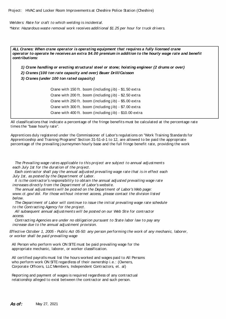
HVAC and Locker Room Improvements at Cheshire Police Station (Cheshire)Project:
ALL Cranes: When crane operator is operating equipment that requires a fully licensed craneoperator to operate he receives an extra $4.00 premium in addition to the hourly wage rate and benefitcontributions:
Welders: Rate for craft to which welding is incidental.*Note: Hazardous waste removal work receives additional $1.25 per hour for truck drivers.
Crane with 150 ft. boom (including jib) - $1.50 extra
Crane with 200 ft. boom (including jib) - $2.50 extra
Crane with 250 ft. boom (including jib) - $5.00 extra
Crane with 300 ft. boom (including jib) - $7.00 extra
Crane with 400 ft. boom (including jib) - $10.00 extra
1) Crane handling or erecting structural steel or stone; hoisting engineer (2 drums or over)2) Cranes (100 ton rate capacity and over) Bauer Drill/Caisson3) Cranes (under 100 ton rated capacity)
All classifications that indicate a percentage of the fringe benefits must be calculated at the percentage ratetimes the "base hourly rate".
Apprentices duly registered under the Commissioner of Labor's regulations on "Work Training Standards forApprenticeship and Training Programs" Section 31-51-d-1 to 12, are allowed to be paid the appropriatepercentage of the prevailing journeymen hourly base and the full fringe benefit rate, providing the work
The Prevailing wage rates applicable to this project are subject to annual adjustmentseach July 1st for the duration of the project. Each contractor shall pay the annual adjusted prevailing wage rate that is in effect eachJuly 1st, as posted by the Department of Labor. It is the contractor's responsibility to obtain the annual adjusted prevailing wage rateincreases directly from the Department of Labor's website. The annual adjustments will be posted on the Department of Labor's Web page:www.ct.gov/dol. For those without internet access, please contact the division listedbelow. The Department of Labor will continue to issue the initial prevailing wage rate scheduleto the Contracting Agency for the project. All subsequent annual adjustments will be posted on our Web Site for contractoraccess. Contracting Agencies are under no obligation pursuant to State labor law to pay anyincrease due to the annual adjustment provision.
Effective October 1, 2005 - Public Act 05-50: any person performing the work of any mechanic, laborer,or worker shall be paid prevailing wage
All Person who perform work ON SITE must be paid prevailing wage for theappropriate mechanic, laborer, or worker classification.
All certified payrolls must list the hours worked and wages paid to All Personswho perform work ON SITE regardless of their ownership i.e.: (Owners,Corporate Officers, LLC Members, Independent Contractors, et. al)
Reporting and payment of wages is required regardless of any contractualrelationship alleged to exist between the contractor and such person.
As of: May 27, 2021

HVAC and Locker Room Improvements at Cheshire Police Station (Cheshire)Project:
~~Unlisted classifications needed for work not included within the scope of theclassifications listed may be added after award only as provided in the laborstandards contract clause (29 CFR 5.5 (a) (1) (ii)).
Please direct any questions which you may have pertaining to classification of work and payment ofprevailing wages to the Wage and Workplace Standards Division, telephone (860)263-6790.
As of: May 27, 2021

Important Information: For use with Building, Heavy/Highway, and Residential
Welders: Rate for craft to which welding is incidental.
*Note: Hazardous waste removal work receives additional $1.25 per hour for truck drivers.
**Note: Hazardous waste premium $3.00 per hour over classified rate.
ALL Cranes: When crane operator is operating equipment that requires a fully licensed crane operator to operate he receives an extra $4.00 premium in addition to the hourly wage rate and benefit contributions:
1) Crane handling or erecting structural steel or stone; hoisting engineer (2 drums or over) 2) Cranes (100 ton rate capacity and over) Bauer Drill/Caisson 3) Cranes (under 100 ton rated capacity)
Crane with boom including jib, 150 feet - $1.50 extra.
Crane with boom including jib, 200 feet - $2.50 extra.
Crane with boom including jib, 250 feet - $5.00 extra.
Crane with boom including jib, 300 feet - $7.00 extra.
Crane with boom including jib, 400 feet - $10.00 extra.
All classifications that indicate a percentage of the fringe benefits must be calculated at the percentage rate
times the "base hourly rate".
Apprentices duly registered under the Commissioner of Labor's regulations on "Work Training Standards for
Apprenticeship and Training Programs" Section 31-51-d-1 to 12, are allowed to be paid the appropriate
percentage of the prevailing journeymen hourly base and the full fringe benefit rate, providing the work site
ratio shall not be less than one full-time journeyperson instructing and supervising the work of one
apprentice in a specific trade.
Connecticut General Statute Section 31-55a: Annual Adjustments to wage rates by contractors
doing state work
The Prevailing wage rates applicable to this project are subject to annual adjustments each July 1st for the
duration of the project.
Each contractor shall pay the annual adjusted prevailing wage rate that is in effect each July 1st, as posted
by the Department of Labor.
It is the contractor's responsibility to obtain the annual adjusted prevailing wage rate increases directly from
the Department of Labor's website.
The annual adjustments will be posted on the Department of Labor's Web page: www.ctdol.state.ct.us.
The Department of Labor will continue to issue the initial prevailing wage rate schedule to the Contracting
Agency for the project.
All subsequent annual adjustments will be posted on our Web Site for contractor access.

Effective October 1, 2005 - Public Act 05-50: any person performing the work of any mechanic,
laborer, or worker shall be paid prevailing wage.
All Persons who perform work ON SITE must be paid prevailing wage for the appropriate mechanic, laborer,
or worker classification.
All certified payrolls must list the hours worked and wages paid to All Persons who perform work ON SITE
regardless of their ownership i.e.: (Owners, Corporate Officers, LLC Members, Independent Contractors, et.
al)
Reporting and payment of wages is required regardless of any contractual relationship alleged to exist
between the contractor and such person.
Unlisted classifications needed for work not included within the scope of the classifications listed may be added
after award only as provided in the labor standards contract clause (29 CFR 5.5 (a) (1) (ii)).
Please direct any questions which you may have pertaining to classification of work and payment
of prevailing wages to the Wage and Workplace Standards Division, telephone (860)263-6790.

POLICE IMPROVEMENTS TOWN OF CHESHIRE BID #2021-15
This page intentionally left blank.

POLICE IMPROVEMENTS TOWN OF CHESHIRE BID #2021-15 SUMMARY OF WORK 01 11 00-1
SUMMARY OF WORK 01 11 00-1
SECTION 01 11 00 - SUMMARY OF WORK PART 1 - GENERAL 1.1 RELATED DOCUMENTS
A. Instructions to Bidders, AIA Document A201 - 2007, “General Conditions of the Contract for Construction”, the Supplementary General Conditions and Division 1, General Requirements, are a part of this Section and shall be binding on the Contractor and or Subcontractor who performs this Work. Note also all Addenda.
1.2 PROJECT DESCRIPTION
A. The Project consists of renovations and restorations to Cheshire, Connecticut Police located at Cheshire, Connecticut, as shown and described on Contract Documents, dated June 1, 2021, as prepared by Jacunski Humes Architects, LLC, 15 Massirio Drive, Suite 101, Berlin, CT.
B. The Work consists of building demolition and legal disposals, complete interior
renovation/restoration to an occupied existing building, and construction phasing to meet the needs of an occupied facility. Interior Renovations includes locker room, physical training room, and records storage spaces including the mechanical, electrical, plumbing, and structural systems supporting them. Erection, maintenance, and removal of temporary locker, toilet, and shower facilities. Exterior restorations of partial building masonry and full building joint protection systems.
1.3 WORK UNDER OTHER CONTRACTS
A. Separate contracts will be issued by the Town of Cheshire for certain additional work as deemed necessary for the completion of the Renovation/Restoration. The installation of new material under these separate contracts may be required prior to the Substantial Completion of the Contract for Construction. The General Contractor shall be required to coordinate his work with and allow access to the work by separate Contractors.
1.4 WORK SEQUENCE / CONSTRUCTION SCHEDULE
A. The Work will be conducted in such a manner to provide the least possible interference to the programmatic operations and needs of the Cheshire Police Department.
B. The General Contractor shall anticipate that portions of work will be required to
be conducted on off-hours as identified within the Contract Documents. 1.5 CONSTRUCTION TIME

POLICE IMPROVEMENTS TOWN OF CHESHIRE BID #2021-15 SUMMARY OF WORK 01 11 00-2
SUMMARY OF WORK 01 11 00-2
A. The Contractor shall furnish all materials, labor, and equipment to complete the
entire project scope within the calendar days noted in the proposal. The General Contractor shall be responsible for preparing a Project Schedule outlining the anticipated duration times each portion of construction and coordinating the required activities to achieve Substantial Completion within the time allocated.
B. All punchlist work for the new construction and sitework shall be completed
within thirty (30) days after the date of Substantial Completion as indicated above.
C. The term “Substantial Completion” or “substantially complete” as used in the
contract documents shall be deemed to refer to Substantial Completion of all contracted scope of work.
D. The term “Contract Time” as used in the contract documents shall mean the time
period from the date of commencement until the Substantial Completion. Such period may be extended in accordance with the provisions of the Contract Documents.
1.6 CONTRACTOR USE OF PREMISES
A. General: Limit use of the premises to construction activities in areas indicated.
1. Confine operations to areas within Contract limit lines indicated on the Contract Documents. Portions of the site beyond areas in which construction operations are indicated are not to be disturbed without prior authorization from the Owner.
2. Confine the parking of workers, and construction vehicles, and the storage of construction materials to a designated staging area to be determined by the General Contractor with approval by the Owner.
3. While the premise is owner occupied, keep entrances serving the premises clear and available to the Owner and Owner’s employees at all times. Do not use these areas for parking or storage of materials. Schedule deliveries to minimize space and time requirements for storage of materials and equipment on site.
1.7 OWNER OCCUPANCY
A. Completion Requirements: Timely completion of the project is critical. Aggressive construction scheduling and careful monitoring of critical path milestones cannot be overemphasized.
B. New Construction: The General Contractor will develop a comprehensive
construction schedule.

POLICE IMPROVEMENTS TOWN OF CHESHIRE BID #2021-15 SUMMARY OF WORK 01 11 00-3
SUMMARY OF WORK 01 11 00-3
1. Subcontractors in accordance with their scope of work shall make all building and energy systems operational before Owner occupancy including, but not necessarily limited to the following:
a. Emergency lighting systems. b. Fire rated enclosures. c. Handicapped accessibility. d. Hardware requirements. e. All other work necessary directed by the local Building Official
and Fire Marshal.
2. All costs associated with performance of the Work at premium rates will be borne by the Subcontractors.
C. Partial Owner Occupancy: The Owner reserves the right to place and install
equipment in completed areas of the building, prior to Substantial Completion, provided that such placing does not interfere with completion of the Work. Such placing of equipment shall not constitute acceptance of the total Work.
1. A Certificate of Substantial Completion will be executed for each specific
portion of the Work to be occupied prior to Owner occupancy. 2. Obtain a Certificate of Occupancy from local building officials prior to
Owner occupancy. 3. Prior to partial Owner occupancy, mechanical and electrical systems shall
be fully operational. Required inspections and tests shall have been successfully completed. Upon occupancy the Owner will provide operation and maintenance of mechanical and electrical systems in occupied portions of the building.
1.8 INTENT
A. These Specifications with the accompanying Drawings are intended to describe and illustrate all material, labor, and equipment necessary to complete the construction of interior renovations for the Town of Cheshire.
B. For convenience of reference, these Specifications are separated into titled
Divisions and Sections. Such separations shall not, however, operate to make the Architect an arbiter to establish limits to Contracts between the Design Builder and Subcontractors. The Divisions of the Specifications do not necessarily define the limits of the Contractor’s subcontracts, the work of any one subcontract may include items specified in several Divisions or Sections. The General Contractor may sublet work as he sees fit, but it is his responsibility to see that all work shown on the Drawings and/or specified is completed in accordance with the Contract.

POLICE IMPROVEMENTS TOWN OF CHESHIRE BID #2021-15 SUMMARY OF WORK 01 11 00-4
SUMMARY OF WORK 01 11 00-4
C. Furnish all materials and accomplish all work in strict accordance with the grades or standards of materials, standards of workmanship, and manufacturer’s specifications listed or mentioned in these documents.
D. The listing or mention of materials shall be sufficient indication that all such
materials shall be furnished by the Subcontractor, in accordance with the grades or standards indicated, free from defects impairing strength, durability or appearance and in sufficient quantity for the proper and complete execution of the work, unless specifically stated otherwise.
E. The listing or mention of any method of installation, erection, fabrication or
workmanship shall not operate to make the Subcontractor an agent, but shall be for the sole purpose of setting a standard of quality for the finished work. The Subcontractor is free to use any alternate method, provided only that, prior to the start of the work, such alternate method is approved in writing by the Architect and Owner, as resulting in quality equal to that intended by these documents. Unless an alternate method is approved, all work shall be in strict accordance with all methods if installation, erection, fabrication and workmanship listed or mentioned herein.
1.9 SOCIAL SECURITY TAXES
A. Each Subcontractor shall pay the taxes measured by the wages of all their employees as required by the Federal Social Security Act and all amendments thereto, and accept the exclusive liability for said taxes. The General Contractor shall also indemnify and hold the Owner, and its respective officers, agents and servants and the Architect harmless on account of any tax measured by the wages aforesaid of employees of the Subcontractors and his lower tier subcontractors, assessed against the Owner under authority of said law.
1.10 UNEMPLOYMENT INSURANCE
A. Each Subcontractor shall pay unemployment insurance measured by the wages of his employees as required by law and accept the exclusive liability for said contributions. The Subcontractor shall also indemnify and hold harmless the Owner on account of any contribution measured by the wages of aforesaid employees of the Trade Contractor and his Subcontractors, assessed against the Owner under authority of law.
1.11 OCCUPATIONAL SAFETY AND HEALTH ACT
A. All Subcontractors shall comply with the requirements of the Occupational Safety and Health Act of 1970 and the Construction Safety Act of 1969, including all standards and regulations which have been promulgated by the Governmental Authorities which administer such Acts and said requirements, standards and regulations are incorporated herein by reference.
POLICE IMPROVEMENTS TOWN OF CHESHIRE BID #2021-15 SUMMARY OF WORK 01 11 00-5
SUMMARY OF WORK 01 11 00-5
B. All Subcontractors shall comply with said regulations, requirements and standards
and require and be directly responsible for compliance therewith on the part of his agents, employees, material men and Subcontractors; and shall directly receive and be responsible for all citations, assessments, fines or penalties which may be incurred by reason of his agents, employees, material men or Subcontractors failing to so comply.
C. The Subcontractor shall indemnify the Owner and Architect and save them
harmless from any and all losses, costs and expenses, including fines and reasonable attorney’s fees incurred by the Owner and Architect by reason of the real or alleged violation of such laws, ordinances, regulations and directives, Federal, State, and Local, which are currently in effect or which become effective in the future, by the Subcontractor, his lower tier Subcontractors or material men.
PART 2 - PRODUCTS (Not applicable). PART 3 - EXECUTION (Not applicable). END OF SECTION 01 11 00

POLICE IMPROVEMENTS TOWN OF CHESHIRE BID #2021-15
This page intentionally left blank.

POLICE IMPROVEMENTS TOWN OF CHESHIRE BID #2021-15 ALLOWANCES 01 21 00-1
ALLOWANCES 01 21 00-1
01 21 00 - ALLOWANCES PART 1 - GENERAL 1.1 RELATED DOCUMENTS
A. Instructions to Bidders, AIA Document A201 - 2007, “General Conditions of the Contract for Construction”, the Supplementary General Conditions and Division 1, General Requirements, are a part of this Section and shall be binding on the Contractor and or Subcontractor who performs this Work. Note also all Addenda.
1.2 SUMMARY
A. This Section specifies administrative and procedural requirements governing handling and processing allowances. Allowances shall be included in Contractor's Bid Proposal and Contract Sum.
B. Quantity allowances are covered by this section.
C. Expenditure of allowances shall be as directed by the Owner and Architect, in
accordance with procedures for submitting and handling Change Orders which are included in Project Specifications.
1.3 SUBMITTALS
A. Submit proposals for expenditures related to in allowances, in the form specified for Change Orders.
B. Submit invoices or delivery slips to indicate actual quantities of materials
delivered to the site, or removed from the site, for use in fulfillment of each allowance.
PART 2 - PRODUCTS (Not Applicable) PART 3 - EXECUTION 3.1 INSPECTION
A. Inspect products covered by an allowance promptly upon delivery for damage or defects.
3.2 PREPARATION
A. Coordinate materials and their installation for each allowance with related materials and installations to ensure that each allowance item is completely integrated and interfaced with related construction activities.

POLICE IMPROVEMENTS TOWN OF CHESHIRE BID #2021-15 ALLOWANCES 01 21 00-2
ALLOWANCES 01 21 00-2
3.3 SCHEDULE OF ALLOWANCES
A. Included in the Bid Proposal are the following Allowances:
1. Masonry Repointing: 600 square feet
a. General Contractor to include all costs for labor and materials to repoint existing masonry surfaces in the quantity listed above within their Lump Sum Base Bid amount.
b. Refer to Section 04 01 00 “Maintenance of Masonry” for additional information pertaining to this Allowance.
c. Refer to Section 01 22 00 “Unit Prices” for additional information pertaining to this Allowance.
d. The actual amount of repointing shall be adjusted in accordance with the UNIT PRICE for this work.
2. Brick Replacement: 12 units
a. General Contractor to include all costs for labor and materials to remove and replace brick units in the quantity listed above within their Lump Sum Base Bid amount.
b. Refer to Section 04 01 00 “Maintenance of Masonry” for additional information pertaining to this Allowance.
c. Refer to Section 01 22 00 “Unit Prices” for additional information pertaining to this Allowance.
d. The actual amount of brick units replaced shall be adjusted in accordance with the UNIT PRICE for this work
END OF SECTION 01 21 00

POLICE IMPROVEMENTS TOWN OF CHESHIRE BID #2021-15 UNIT PRICES 01 22 00-1
UNIT PRICES 01 22 00-1
01 22 00 - UNIT PRICES
PART 1 – GENERAL 1.1 RELATED DOCUMENTS
A. Instructions to Bidders, AIA Document A201 - 2007, “General Conditions of the Contract for Construction”, the Supplementary General Conditions and Division 1, General Requirements, are a part of this Section and shall be binding on the Contractor and or Subcontractor who performs this Work. Note also all Addenda.
1.2 SUMMARY
A. A unit price is an amount proposed by Bidders and stated on the Bid Form as a price per unit of measurement for materials or services that will be added to, or deducted from, the Contract Sum by Change Order in the event the project Scope of Work is altered.
B. Unit prices include material, any direct or indirect expenses of the General Contractor or Sub-Contractor, profit, insurance, bonding and any applicable taxes.
PART 2 – PRODUCTS (not applicable)
PART 3 – EXECUTION 3.1 UNIT PRICES
A. Should the amount of improvements required to be increased or decreased due to special considerations found at the site, or because of a request of the Owner, the undersigned agrees that the following supplemental UNIT PRICES will be the basis price in place for computing the ADD (Extra) or DEDUCT (Credit). Each UNIT PRICE shall include all equipment, tools, labor, permits, fees, etc., incidental to the installation and completion of the work involved including all handling, removal, and legal disposal of any related material.
B. Unit Prices shall be supplemental to the Allowance amounts listed within Section
01 21 00 – “Allowances”. The General Contractor shall make all financial adjustments to the contract amount by use of Unit Pricing. All adjustments shall be “in addition to” or “subtracted from” the Allowance amounts that are carried within the Lump Sum, Base Bid contract amount.

POLICE IMPROVEMENTS TOWN OF CHESHIRE BID #2021-15 UNIT PRICES 01 22 00-2
UNIT PRICES 01 22 00-2
3.1 UNIT PRICE SCHEDULE
A. Unit Prices in accordance with the following schedule shall apply to this Contract.
1. Masonry Repointing – ADD UNIT PRICE
a. $__________________________ per square foot.
2. Brick Replacement – ADD UNIT PRICE
a. $__________________________ per brick.
3. Exterior Cement Plastering – ADD UNIT PRICE
a. $__________________________ per square foot.
B. Refer to Section 04 01 00 “Maintenance of Masonry” for additional information
pertaining to Unit Price 1 and 2. C. Refer to Section 09 20 00 “Plaster and Gypsum Board” for additional information
pertaining to Unit Price 3.
END OF SECTION 01 22 00
POLICE IMPROVEMENTS TOWN OF CHESHIRE BID #2021-15 PAYMENT PROCEDURES 01 29 00-1
____________________________________________________________________ PAYMENT PROCEDURES 01 29 00-1
SECTION 01 29 00 – PAYMENT PROCEDURES PART 1 - GENERAL 1.1 RELATED DOCUMENTS
A. Instructions to Bidders, AIA Document A201 - 2007, “General Conditions of the Contract for Construction”, the Supplementary General Conditions and Division 1, General Requirements, are a part of this Section and shall be binding on the Contractor and or Subcontractor who performs this Work. Note also all Addenda.
1.2 SUMMARY A. This Section specifies administrative and procedural requirements governing the
Contractor's Applications for Payment. B. This Section specifies administrative and procedural requirements governing each
prime Contractor's Applications for Payment. 1. Coordinate the Schedule of Values and Applications for Payment with the
Contractor's Construction Schedule, List of Subcontracts, and Submittal Schedule.
C. The Contractor's Construction Schedule and Submittal Schedule are included in
Section "Submittals". 1.3 SCHEDULE OF VALUES A. Coordinate preparation of the Schedule of Values with preparation of the
Contractor's Construction Schedule. B. Each prime Contractor shall coordinate preparation of its Schedule of Values for its
part of the Work with preparation of the Contractors' Construction Schedule. 1. Correlate line items in the Schedule of Values with other required
administrative schedules and forms, including: a. Contractor's construction schedule. b. Application for Payment form. c. List of subcontractors. d. Schedule of allowances. e. Schedule of alternates. f. List of products. g. List of principal suppliers and fabricators. h. Schedule of submittals.

POLICE IMPROVEMENTS TOWN OF CHESHIRE BID #2021-15 PAYMENT PROCEDURES 01 29 00-2
____________________________________________________________________ PAYMENT PROCEDURES 01 29 00-2
2. Submit the Schedule of Values to the Architect and Owner’s Project Manager at the earliest feasible date, but in no case later than 7 days before the date scheduled for submittal of the initial Application for Payment.
3. Sub-Schedules: Where the Work is separated into phases that require
separately phased payments, provide sub-schedules showing values correlated with each phase of payment.
C. Format and Content: Use the Project Manual Table of Contents as a guide to
establish the format for the Schedule of Values. 1. Identification: Include the following Project identification on the Schedule
of Values: a. Project name and location. b. Name of the Designer. c. Project number. d. Contractor's name and address. e. Date of submittal. 2. Arrange the Schedule of Values in a tabular form with separate columns to
indicate the following for each item listed: a. Generic name. b. Related Specification Section. c. Name of subcontractor. d. Name of manufacturer or fabricator. e. Name of supplier. f. Change Orders (numbers) that have affected value. g. Dollar value. h. Percentage of Contract Sum to the nearest one-hundredth percent,
adjusted to total 100 percent. 3. Provide a breakdown of the Contract Sum in sufficient detail to facilitate
continued evaluation of Applications for Payment and progress reports. Break principal subcontract amounts down into several line items so that individual line items shall not exceed $25,000 in value.
4. Round amounts off to the nearest whole dollar; the total shall equal the
Contract Sum. 5. For each part of the Work where an Application for Payment may include
materials or equipment, purchased or fabricated and stored but not yet installed, provide separate line items on the Schedule of Values for initial cost of the materials for each subsequent stage of completion, and for total installed value of that part of the Work.

POLICE IMPROVEMENTS TOWN OF CHESHIRE BID #2021-15 PAYMENT PROCEDURES 01 29 00-3
____________________________________________________________________ PAYMENT PROCEDURES 01 29 00-3
6. Unit Cost Allowances: Show line item value of unit cost allowances as a
product of unit cost times measured quantity as estimated from the best indication in the Contract Documents.
7. Margins of Cost: Show line items for indirect costs, and margins on actual
costs, only to the extent that such items will be listed individually in Applications for Payment. Each item in the Schedule of Values and Applications for Payment shall be complete including its total cost and proportionate share of general overhead and profit margin.
a. At the Contractor's option, temporary facilities and other major cost
items that are not direct cost of actual work-in- place may be shown as separate line items in the Schedule of Values or distributed as general overhead expense.
8. Schedule Updating: Update and resubmit the Schedule of Values when
Change Orders or Construction Change Directives result in a change in the Contract Sum.
1.4 APPLICATIONS FOR PAYMENT A. Each Application for Payment shall be consistent with previous applications and
payments as certified by the Owner’s Project Manager and paid for by the Owner. 1. The initial Application for Payment, the Application for Payment at time of
Substantial Completion, and the final Application for Payment involve additional requirements.
B. Payment Application Times: Each progress payment date is as indicated in the
Agreement. The period of construction work covered by each Application or Payment is the period indicated in the Agreement.
C. Payment Application Times: The date for each progress payment is the 1st day of
each month. The period of construction Work covered by each Application for Payment is the month prior to the date for each progress payment and starting the day of the preceding period.
1. A Draft Application for Payment shall be submitted to the Owner,
Architect, and Owner’s Project Manager on the date of the last scheduled Job Meeting of the month preceding the payment application time.
2. Final Application for Payment shall be prepared in triplicate (3 copies) and incorporate the revision comments as requested by the Owner, Owner’s Project Manager, or Architect.

POLICE IMPROVEMENTS TOWN OF CHESHIRE BID #2021-15 PAYMENT PROCEDURES 01 29 00-4
____________________________________________________________________ PAYMENT PROCEDURES 01 29 00-4
D. Payment Application Forms: Use AIA Document G 702 and Continuation Sheets G 703 as the form for Application for Payment.
E. Suppliers, Trade and Subcontractors will be required to submit copies of their
Certified Payroll forms to the Construction Manager for the current Application Period. The Construction Manager shall be responsible for transferring all Certified Payroll forms to the Owner’s Project Manager. Owner has the right to withhold payments if required Certified Payroll forms are not being provided in a timely manner.
F. Application Preparation: Complete every entry on the form, including notarization
and execution by person authorized to sign legal documents on behalf of the Owner. Incomplete applications will be returned without action.
2. Entries shall match data on the Schedule of Values and Contractor's
Construction Schedule. Use updated schedules if revisions have been made. 3. Include amounts of Change Orders and Construction Change Directives
issued prior to the last day of the construction period covered by the application.
G. Transmittal: Submit three (3) executed final copies of each Application for Payment
to the Owner’s Project Manager by means ensuring receipt within 24 hours; one copy shall be complete, including waivers of lien and similar attachments, when required.
1. Transmit each copy with a transmittal form listing attachments, and
recording appropriate information related to the application in a manner acceptable to the Owner’s Project Manager.
H. Waivers of Mechanics Lien: With each Application for Payment submit waivers of
mechanics liens from subcontractors or sub- subcontractors and suppliers for the construction period covered by the previous application.
1. Submit partial waivers on each item for the amount requested, prior to
deduction for retainage, on each item. 2. When an application shows completion of an item, submit final or full
waivers. 3. The Owner reserves the right to designate which entities involved in the
Work must submit waivers. 4. Waiver Delays: Submit each Application for Payment with the Contractor's
waiver of mechanics lien for the period of construction covered by the application.

POLICE IMPROVEMENTS TOWN OF CHESHIRE BID #2021-15 PAYMENT PROCEDURES 01 29 00-5
____________________________________________________________________ PAYMENT PROCEDURES 01 29 00-5
a. Submit final Application for Payment with or preceded by final
waivers from every entity involved with performance of Work covered by the application who could lawfully be entitled to a lien.
5. Waiver Forms: Submit waivers of lien on forms, and executed in a manner,
acceptable to Owner. I. Initial Application for Payment: Administrative actions and submittals that must
precede or coincide with submittal of the first Application for Payment include the following:
1. List of subcontractors. 2. List of principal suppliers and fabricators. 3. Schedule of Values. 4. Contractor's Construction Schedule (preliminary, if not final). 5. Schedule of principal products. 6. Schedule of unit prices. 7. Submittal Schedule (preliminary if not final). 8. List of Contractor's staff assignments. 9. List of Contractor's principal consultants. 10. Copies of building permits 11. Copies of authorizations and licenses from governing authorities for
performance of the Work. 12. Initial progress report. 13. Report of pre-construction meeting. 14. Certificates of insurance and insurance policies. 15. Performance and payment bonds (if required). 16. Data needed to acquire Owner's insurance. 17. Initial settlement survey and damage report, if required. J. Application for Payment at Substantial Completion: Following issuance of the
Certificate of Substantial Completion, submit an Application for Payment. This application shall reflect any Certificates of Partial Substantial Completion issued previously for Owner occupancy of designated portions of the Work.
K. Administrative actions and submittals that shall proceed or coincide with this
application include: 1. Occupancy permits and similar approvals. 2. Warranties (guarantees) and maintenance agreements. 3. Test/adjust/balance records. 4. Maintenance instructions. 5. Meter readings. 6. Start-up performance reports.

POLICE IMPROVEMENTS TOWN OF CHESHIRE BID #2021-15 PAYMENT PROCEDURES 01 29 00-6
____________________________________________________________________ PAYMENT PROCEDURES 01 29 00-6
7. Change-over information related to Owner's occupancy, use, operation and maintenance.
8. Final cleaning. 9. Application for reduction of retainage, and consent of surety. 10. Advice on shifting insurance coverages. 11. Final progress photographs. 12. List of incomplete Work, recognized as exceptions to Designer's Certificate
of Substantial Completion. L. Final Payment Application: Administrative actions and submittals, which must
precede or coincide with submittal of the final payment Application for Payment, include the following:
1. Completion of Project closeout requirements. 2. Completion of items specified for completion after Substantial Completion. 3. Assurance that unsettled claims will be settled. 4. Assurance that Work not complete and accepted will be completed without
undue delay. 5. Transmittal of required Project construction records to Owner. 6. Certified property survey. 7. Proof that taxes, fees and similar obligations have been paid. 8. Removal of temporary facilities and services. 9. Removal of surplus materials, rubbish and similar elements. 10. Change of door locks to Owner's access. PART 2 – PRODUCTS (Not Applicable to this Section.) PART 3 – EXECUTION (Not Applicable to this Section.) END OF SECTION 01 29 00

POLICE IMPROVEMENTS TOWN OF CHESHIRE PROJECT MANAGEMENT BID #2021-15 AND COORDINATION 01 31 00-1
PROJECT MANAGEMENT AND COORDINATION 01 31 00-1
SECTION 01 31 00 - PROJECT MANAGEMENT AND COORDINATION PART 1 - GENERAL 1.1 RELATED DOCUMENTS
A. Instructions to Bidders, AIA Document A201 - 2007, “General Conditions of the Contract for Construction”, the Supplementary General Conditions and Division 1, General Requirements, are a part of this Section and shall be binding on the Contractor and or Subcontractor who performs this Work. Note also all Addenda.
1.2 GENERAL
A. This Section specifies administrative and supervisory requirements necessary for Project coordination including, but not necessarily limited to:
1. Coordination. 2. Progress Meetings. 3. Administrative and supervisory personnel. 4. General installation provisions. 5. Cleaning and protection.
B. Requirements for the Contractor’s Construction Schedule are included in Section
01 01 00, “Special Conditions”.
C. Requirements for the Scheduling and Coordination of Tests and Inspections are included in Section 01 45 00, “Quality Control”.
1.3 SUMMARY OF WORK
A. The intent of this bid is to complete the work defined in the Contract Documents. The selected General Contractor must work harmoniously with the Owner to complete the Work within the calendar days noted in the Proposal.
B. The balance of areas of this building, outside of the construction area, will be
occupied by the general public and must remain fully operational throughout the construction period. The Contractor will be required to establish and present to the Architect in writing for approval, his own schedule that will allow the Contractor to complete the most disruptive work within the building during off-hours.
C. The Contractor shall prepare a detailed construction schedule which shall be
presented to the Architect and the Owner for their review, comments and approval. The schedule must clearly demonstrate the proper sequencing of construction and relocation activities and how operational and environmental conditions will be satisfactorily maintained in all occupied spaces.

POLICE IMPROVEMENTS TOWN OF CHESHIRE PROJECT MANAGEMENT BID #2021-15 AND COORDINATION 01 31 00-2
PROJECT MANAGEMENT AND COORDINATION 01 31 00-2
D. Contractor shall provide tight, secure, dust screens to separate all areas of the
work and occupied spaces.
E. All work must be coordinated with the Architect and the Facility Administration to insure satisfactory operational conditions. The Contractor will be required to coordinate and schedule his work to keep a minimum of the facilities shut down at any specific time. Any area that must be shut down may be only with the approval of and during the time designated by the Owner. The Contractor shall phase his work, as required, in the building. The Contractor shall insure safe access to occupied areas by the employees and public. The Contractor shall insure that heat and all other utilities are provided to these areas. Repair of any damage to existing facilities and equipment resulting from interrupted utilities, lack of heat, or Contractor’s work in the areas shall be Contractor’s responsibility. Also, repair of any damage to services and utilities as a result of the work shall be the Contractor’s responsibility. Contractor shall insure safe egress and security of existing areas and equipment during the construction. Existing exitways shall be maintained to provide safe egress from occupied portions of the building at all times.
F. The Contractor shall restrict the parking of workmen and construction vehicles
and the storage of construction materials to a suitable parking area to be determined during a pre-construction conference.
G. Work can proceed after open hours (second and third shifts) at the Contractor’s
option with the stipulation that the building is left dust free, free of barriers and absolutely safe for public occupancy by facility opening time each day. Contractor is to coordinate all work times with Owner.
1.4 COORDINATION
A. Coordination: Coordinate construction activities included under various Sections of these Specifications to assure efficient and orderly installation of each part of the Work. Coordinate construction operations included under different Sections of the Specifications that are dependent upon each other for proper installation, connection, and operation. No claim for extra compensation or extension of Contract time will be allowed for conditions resulting from a lack of said coordination and cooperation.
1. Where installation of one part of the work, is dependent on installation of
other components, either before or after its own installation, schedule construction activities in the sequence required to obtain the best results.
2. Where availability of space is limited, coordinate installation of different components to assure maximum accessibility for required maintenance, service and repair.
POLICE IMPROVEMENTS TOWN OF CHESHIRE PROJECT MANAGEMENT BID #2021-15 AND COORDINATION 01 31 00-3
PROJECT MANAGEMENT AND COORDINATION 01 31 00-3
3. Make adequate provisions to accommodate items scheduled for later installation.
B. Where necessary, prepare memoranda for distribution to each party involved
outlining special procedures required for coordination. Include such items as required notices, reports, and attendance at meetings.
1. Prepare similar memoranda for the Owner and separate Contractors where
coordination of their Work is required.
C. Administrative Procedures: Coordinate scheduling and timing of required administrative procedures with other construction activities to avoid conflicts and ensure orderly progress of the Work. Such administrative activities include, but are not limited to, the following:
1. Preparation of schedules. 2. Installation and removal of temporary facilities. 3. Delivery and processing of submittals. 4. Progress meetings. 5. Project Close-out activities.
D. Conservation: Coordinate construction activities to ensure that operations are
carried out with consideration given to conservation of energy, water, and materials.
1.5 PRE-CONSTRUCTION CONFERENCE
A. The Architect will schedule a pre-construction conference and organizational meeting at the Project site no later than 15 days after execution of the Agreement and prior to commencement of construction activities. Attend the meeting to review responsibilities and personnel assignments.
B. Attendees: The Owner, Architect and their consultants, the Owner’s Clerk-of-the-
Works, the General Contractor and its superintendent, major subcontractors, manufacturers, suppliers and other concerned parties shall each be represented at the conference by persons familiar with and authorized to conclude matters relating to the Work.
1. Notify and arrange for attendance by all parties except the Architect,
Owner, and Owner’s representative.
C. Agenda: Items of significance that could affect progress will be discussed, including such topics as:
1. Tentative construction schedule. 2. Critical Work sequencing.

POLICE IMPROVEMENTS TOWN OF CHESHIRE PROJECT MANAGEMENT BID #2021-15 AND COORDINATION 01 31 00-4
PROJECT MANAGEMENT AND COORDINATION 01 31 00-4
3. Designation of responsible personnel. 4. Procedures for processing field decisions and Change orders. 5. Procedures for processing Applications for Payment. 6. Distribution of Contract Documents. 7. Submittal of Shop Drawings, Product Data and Samples. 8. Preparation of record documents. 9. Use of the premises. 10. Office, Work and storage areas. 11. Equipment deliveries and priorities. 12. Safety procedures. 13. First aid. 14. Security. 15. Housekeeping. 16. Working hours.
1.6 SUBMITTALS
A. Coordination Drawings: Prepare and submit coordination Drawings where close and careful coordination is required for installation of products and materials fabricated off-site by separate entities, and where limited space availability necessitates maximum utilization of space for efficient installation of different components.
1. Show the interrelationship of components shown on separate Shop
Drawings. 2. Indicate required installation sequences. 3. Comply with requirements contained in Section 01 33 00, “Submittal
Procedures”. 4. Refer to Division - 23 and Division - 26, Section for specific coordination
drawing requirements for mechanical and electrical installations.
B. Staff Names: Within fifteen (15) days of Notice to Proceed, submit a list of the Contractor’s principal staff assignments, including the Superintendent and other personnel in attendance at the site; identify individuals, their duties and responsibilities; list their addresses and telephone numbers.
1.7 COORDINATION MEETINGS
A. Conduct Project coordination meetings at regularly scheduled times convenient for all parties involved. Project coordination meetings are in addition to regular progress meetings.
B. Request representation at each meeting by every party currently involved in
coordination or planning for the construction activities involved.

POLICE IMPROVEMENTS TOWN OF CHESHIRE PROJECT MANAGEMENT BID #2021-15 AND COORDINATION 01 31 00-5
PROJECT MANAGEMENT AND COORDINATION 01 31 00-5
C. Record meeting results and distribute copies to everyone in attendance and to others affected by decisions or actions resulting from each meeting.
1.8 PROGRESS MEETINGS
A. The Architect will conduct progress meetings at the Project site at regularly scheduled intervals. Coordinate dates of meetings with preparation of the payment request.
B. Attendees: Notify each subcontractor, supplier or other entity concerned with
current progress or involved in planning, coordination or performance of future activities, to attend these meetings. Persons familiar with the Project and authorized to conclude matters relating to progress shall be represented.
C. Agenda: Review and correction or approval of minutes of the previous progress
meeting. Review of other items of significance that could affect progress. Topics for discussion that is appropriate to the current status of the Project.
1. General Contractor’s Construction Schedule: Prepare a written report
including progress since the last meeting. Determine where each activity is in relation to the General Contractor’s Construction Schedule, whether on time or ahead or behind schedule. Determine how construction behind schedule will be expedited; secure commitments from parties involved to do so. Discuss whether schedule revisions are required to ensure that current and subsequent activities will be completed within the Contract Time.
2. Review of present and future needs of each entity present, including such items as:
a. Interface requirements. b. Time. c. Sequences. d. Deliveries. e. Off-site fabrication problems. f. Access. g. Site utilization. h. Temporary facilities and services. i. Hours of Work. j. Hazards and risks. k. Housekeeping. l. Quality and Work standards. m. Change Order Proposals. n. Documentation of information for payment requests.

POLICE IMPROVEMENTS TOWN OF CHESHIRE PROJECT MANAGEMENT BID #2021-15 AND COORDINATION 01 31 00-6
PROJECT MANAGEMENT AND COORDINATION 01 31 00-6
D. Reporting: The Architect will prepare and distribute copies of minutes of the meeting to Owner and General Contractor. General Contractor shall distribute copies to others that should be informed of decisions.
1. Schedule Updating: Revise the construction schedule after each progress
meeting where revisions to the schedule have been made or recognized. Issue the revised schedule concurrently with the report of each meeting.
PART 2 - PRODUCTS (Not Applicable) PART 3 - EXECUTION 3.1 GENERAL INSTALLATION PROVISIONS
A. Inspection of Conditions: Require the Installer of each major component to inspect both the substrate and conditions under which Work is to be performed. Do not proceed until unsatisfactory conditions have been corrected in an acceptable manner.
B. Manufacturer’s Instructions: Comply with manufacturer’s installation instructions
and recommendations, to the extent that those instructions and recommendations are more explicit or stringent than requirements contained in Contract Documents.
C. Inspect materials or equipment immediately upon delivery and again prior to
installation. Reject damaged and defective items.
D. Provide attachment and connection devices and methods necessary for securing Work. Secure Work true to line and level. Allow for expansion and building movement.
E. Visual Effects: Provide uniform joint widths in exposed Work. Arrange joints in
exposed Work to obtain the best visual effect. Refer questionable choices to the Architect for final decision.
F. Recheck measurements and dimensions, before starting each installation.
G. Install each component during weather conditions and Project status that will
ensure the best possible results. Isolate each part of the completed construction from incompatible material as necessary to prevent deterioration.
H. Coordinate temporary enclosures with required inspections and tests, to minimize
the necessity of uncovering completed construction for that purpose.
I. Mounting Heights: Where mounting heights are not indicated, install individual components at standard mounting heights recognized within the industry for the

POLICE IMPROVEMENTS TOWN OF CHESHIRE PROJECT MANAGEMENT BID #2021-15 AND COORDINATION 01 31 00-7
PROJECT MANAGEMENT AND COORDINATION 01 31 00-7
particular application indicated. Refer questionable mounting height decisions to the Architect for final decision.
3.2 CLEANING AND PROTECTION
A. During handling and installation, clean and protect construction in progress and adjoining materials in place. Apply protective covering where required to ensure protection from damage or deterioration at Substantial Completion.
B. Clean and maintain completed construction as frequently as necessary through the
remainder of the construction period. Adjust and lubricate operable components to ensure operability without damaging effects.
C. Limiting Exposures: Supervise construction activities to ensure that no part of the
construction, completed or in progress, is subject to harmful, dangerous, damaging, or otherwise deleterious exposure during the construction period. Where applicable, such exposures include, but are not limited to, the following:
1. Excessive static or dynamic loading. 2. Excessive internal or external pressures. 3. Excessively high or low temperatures. 4. Thermal shock. 5. Excessively high or low humidity. 6. Air contamination or pollution. 7. Water or ice. 8. Solvents. 9. Chemicals. 10. Light. 11. Radiation. 12. Puncture. 13. Abrasion. 14. Heavy traffic. 15. Soiling, staining and corrosion. 16. Bacteria. 17. Rodent and insect infestation. 18. Combustion. 19. Electrical current. 20. High speed operation, 21. Improper lubrication. 22. Unusual wear or other misuse. 23. Contact between incompatible materials. 24. Destructive testing. 25. Misalignment. 26. Excessive weathering. 27. Unprotected storage. 28. Improper shipping or handling.
POLICE IMPROVEMENTS TOWN OF CHESHIRE PROJECT MANAGEMENT BID #2021-15 AND COORDINATION 01 31 00-8
PROJECT MANAGEMENT AND COORDINATION 01 31 00-8
29. Theft. 30. Vandalism.
END OF SECTION 01 31 00
POLICE IMPROVEMENTS TOWN OF CHESHIRE BID #2021-15 SUBMITTAL PROCEDURES 01 33 00-1
SUBMITTAL PROCEDURES 01 33 00-1
SECTION 01 33 00 – SUBMITTAL PROCEDURES PART 1 - GENERAL 1.1 RELATED DOCUMENTS
A. Instructions to Bidders, AIA Document A201 - 2007, “General Conditions of the Contract for Construction”, the Supplementary General Conditions and Division 1, General Requirements, are a part of this Section and shall be binding on the Contractor and or Subcontractor who performs this Work. Note also all Addenda.
1.2 SUMMARY
A. This Section specifies administrative and procedural requirements for submittals required for performance of the Work, including;
1. Schedule of Values. 2. Shop Drawings. 3. Product Data. 4. Samples.
B. This Section specifies administrative and procedural requirements for handling
requests for substitutions made after award of the Contract.
C. Administrative Submittals: Refer to other Division-1 Sections and other Contract Documents for requirements for administrative submittals. Such submittals include, but are not limited to:
1. Applications for payment. 2. Performance and payment bonds. 3. Insurance certificates. 4. List of Subcontractors.
D. Inspection and test reports are included in Section 01 45 00 “Quality Control”
1.3 SUBMITTAL PROCEDURES
A. Coordination: Within 15 days of the Contract award, submit to the Architect a comprehensive Submittals listing each item to be submitted and the date proposed to be submitted. Coordinate with the Architect in the preparation and processing of submittals with performance of construction activities. Transmit each submittal sufficiently in advance of performance of related construction activities to avoid delay.
POLICE IMPROVEMENTS TOWN OF CHESHIRE BID #2021-15 SUBMITTAL PROCEDURES 01 33 00-2
SUBMITTAL PROCEDURES 01 33 00-2
1. Coordinate each submittal with fabrication, purchasing, testing, delivery, other submittals and related activities that require sequential activity.
2. Coordinate transmittal of different types of submittals for related elements
of the Work so processing will not be delayed by the need to review submittals concurrently for coordination.
a. The Architect reserves the right to withhold action on a submittal
requiring coordination with other submittals until related submittals are received.
b. Coordinate transmittal of all submittals requiring color selection so that comprehensive selection can be processed.
3. Processing: Allow sufficient review time so that installation will not be
delayed as a result of the time required to process submittals, including time for re-submittals.
a. Allow two weeks for initial review. Allow additional time if
processing must be delayed to permit coordination with subsequent submittals. The Architect will promptly advise the General Contractor when a submittal being processed must be delayed for coordination.
b. If an intermediate submittal is necessary, process the same as the initial submittal.
c. Allow two weeks for reprocessing each submittal. d. No extension of Contract Time will be authorized because of
failure to transmit submittals to the Architect sufficiently in advance of the Work to permit processing.
B. Submittal Preparation: Place a permanent label or title block on each submittal
for identification. Indicate the name of the entity that prepared each submittal on the label or title block.
1. Provide a space approximately 4" x 5" on the label or beside the title block
on Shop Drawings to record the Contractor’s review and approval markings and the action taken.
2. Include the following information on all submittals:
a. Name of item being submitted. b. Number and title of appropriate Specification Section. c. Drawing number and detail references, as appropriate. d. Name of manufacturer. e. Name, address and telephone number of supplier. f. Bid Package number and name. g. Project Name.

POLICE IMPROVEMENTS TOWN OF CHESHIRE BID #2021-15 SUBMITTAL PROCEDURES 01 33 00-3
SUBMITTAL PROCEDURES 01 33 00-3
h. Date. i. Name, address and telephone number of Contractor. j. Name, address and telephone number of Subcontractor. k. Name, address and telephone number of Architect.
C. Submittal Transmittal: Package each submittal appropriately for transmittal and
handling. Transmit each submittal from General Contractor to Architect using a transmittal form. Submittals received from sources other than the General Contractor will be returned without action.
D. Number of copies: All submittals shall be made using an Electronic Submittal
Procedure established by the General Contractor. The General Contractor shall be responsible to provide a File Transfer Protocol (FTP), or third party website service, for the transmission of large file sizes (>10MB) not suitable for e-mailing.
1.4 DEFINITIONS
A. Substitutions: Requests for changes in products, materials, equipment, and methods of construction required by Contract Documents proposed by the General Contractor after award of the Contract are considered requests for “substitutions.” The following are not considered substitutions:
1. Substitutions requested by Bidders during the bidding period, and
accepted prior to award of Contract, are considered as included in the Contract Documents and are not subject to requirements specified in this Section for substitutions.
2. Revisions to Contract Documents requested by the Owner or Architect. 3. Specified options of products and construction methods included in
Contract Documents. 4. The General Contractor’s determination of and compliance with governing
regulations and orders issued by governing authorities. 1.5 SCHEDULE OF VALUES
A. Coordinate preparation of the Schedule of Values with preparation of the General Contractor’s Construction Schedule.
1. Correlate line items in the Schedule of Values with other required
administrative schedules and forms, including:
a. General Contractor’s construction schedule. b. Application for Payment form. c. List of subcontractors.

POLICE IMPROVEMENTS TOWN OF CHESHIRE BID #2021-15 SUBMITTAL PROCEDURES 01 33 00-4
SUBMITTAL PROCEDURES 01 33 00-4
2. Submit the Schedule of Values to the Architect at the earliest feasible date, but in no case later than seven (7) days before the date scheduled for submittal of the initial Application for Payment.
B. Format and Content: Use the Project Manual Table of Contents as a guide to
establish the format for the Schedule of Values.
1. Forms: Use AIA Document G702 and Continuation Sheets G703, as the form for the Schedule of Values.
2. Identification: Include the following Project identification on the Schedule of Values:
a. Project name and location. b. Name of the Architect. c. Project number. d. Contractor’s name and address. e. Date of submittal.
3. Arrange the Schedule of Values in a tabular form with separate columns to
indicate the following for each item listed:
a. Generic name. b. Related Specification Section. c. Change Orders (numbers) that have affected value. d. Dollar value. e. Percentage of Contract Sum to the nearest one-hundredth percent,
adjusted to total 100 percent.
4. Provide a breakdown of the Contract Sum in sufficient detail to facilitate continued evaluation of Applications for Payment and progress reports. Break principal subcontract amounts down into several line items.
5. Round amounts off to the nearest whole dollar; the total shall equal the Contract Sum.
6. For each part of the Work where an Application for Payment may include materials or equipment, purchased or fabricated and stored, but not yet installed, provide separate line items on the Schedule of Values for initial cost of the materials, for each subsequent stage of completion, and for total installed value of that part of the Work.
7. Show temporary facilities and other major cost items that are not direct cost of actual work-in-place as separate line items in the Schedule of Values.
1.6 SHOP DRAWINGS

POLICE IMPROVEMENTS TOWN OF CHESHIRE BID #2021-15 SUBMITTAL PROCEDURES 01 33 00-5
SUBMITTAL PROCEDURES 01 33 00-5
A. Submit newly prepared information, drawn to accurate scale. Highlight, encircle, or otherwise indicate deviations from the Contract Documents. Do not reproduce Contract Documents or copy standard information as the basis of Shop Drawings. Standard information prepared without specific reference to the Project is not considered Shop Drawings.
B. Shop Drawings include fabrication and installation drawings, setting diagrams,
schedules, patterns, templates and similar drawings. Include the following information:
1. Dimensions. 2. Identification of products and materials included. 3. Compliance with specified standards. 4. Notation of coordination requirements. 5. Notation of dimensions established by field measurement. 6. Sheet Size: Except for templates, patterns and similar full size Drawings,
submit Shop Drawings on sheets at least 8 ½" x 11", but no larger than 24" x 36".
7. Do not use Shop Drawings without an appropriate final stamp indicating action taken in connection with construction.
C. Shop Drawing Submissions to the Architect in electronic format only will be
acceptable to the Architect given that they are in Adobe, PDF format and contain proper transmittal information.
1.7 PRODUCT DATA
A. Collect Product Data into a single submittal for each element of construction or system. Product Data includes printed information such as manufacturer’s installation instructions, catalog cuts, standard color charts, roughing-in diagrams and templates, standard wiring diagrams and performance curves. Where Product Data must be specially prepared because standard printed data is not suitable for use, submit as “Shop Drawings.”
1. Mark each copy to show applicable choices and options. Where printed
Product Data includes information on several products, some of which are not required, mark copies to indicate the applicable information. Include the following information:
a. Manufacturer’s printed recommendations. b. Compliance with recognized trade association standards. c. Compliance with recognized testing agency standards. d. Application of testing agency labels and seals. e. Notation of dimensions verified by field measurement. f. Notation of coordination requirements.

POLICE IMPROVEMENTS TOWN OF CHESHIRE BID #2021-15 SUBMITTAL PROCEDURES 01 33 00-6
SUBMITTAL PROCEDURES 01 33 00-6
2. Do not submit Product Data until compliance with requirements of the
Contract Documents has been confirmed. 3. Submittals: Submit copies of each required submittal; submit additional
copies where required for maintenance manuals.
a. Unless noncompliance with Contract Document provisions is observed, the submittal may serve as the final submittal.
4. Distribution: Furnish copies of final submittal to Architect for distribution
to installers, subcontractors, suppliers, manufacturers, fabricators, and others required for performance of construction activities.
a. Do not proceed with installation until an approved copy of Product
Data applicable is in the installer’s possession. b. Do not permit use of unmarked copies of Product Data in
connection with construction. 1.8 SAMPLES
A. Submit full-size, fully fabricated Samples cured and finished as specified and physically identical with the material or product proposed. Samples include partial sections of manufactured or fabricated components, cuts or containers of materials, color range sets, and swatches showing color, texture and pattern.
1. Mount, display, or package samples in the manner specified to facilitate
review of qualities indicated. Prepare samples to match the Architect’s sample. Include the following:
a. Generic description of the sample. b. Sample source. c. Product name or name of manufacturer. d. Compliance with recognized standards. e. Availability and delivery time.
2. Submit samples for review of kind, color, pattern, and texture, for a final
check of these characteristics with other elements, and for a comparison of these characteristics between the final submittal and the actual component as delivered and installed.
a. Where variation in color, pattern, texture or other characteristics
are inherent in the material or product represented, submit multiple units that show approximate limits of the variations.
b. Refer to other Specification Sections for requirements for samples that illustrate workmanship, fabrication techniques, details of

POLICE IMPROVEMENTS TOWN OF CHESHIRE BID #2021-15 SUBMITTAL PROCEDURES 01 33 00-7
SUBMITTAL PROCEDURES 01 33 00-7
assembly, connections, operation and similar construction characteristics.
3. Preliminary submittals: Where samples are for selection of color, pattern,
texture or similar characteristics from a range of standard choices, submit a full set of choices for the material or product.
a. Preliminary submittals will be reviewed with the Architect
indicating selection or other action. b. Unless noncompliance with Contract Document provisions is
observed, the submittal may serve as the final submittal.
4. Submittals: Except for samples illustrating assembly details, workmanship, fabrication techniques, connections, operation and similar characteristics, samples will not be returned, unless so requested in advance.
5. Maintain sets of returned samples, at the Project site, for quality
comparisons throughout the course of construction.
a. Comply with submittal requirements to the fullest extent possible. Process transmittal forms to provide a record of activity.
1.9 SUBMITTALS
A. Substitution Request Submittal: Requests for substitution will be considered if received within 60 days after commencement of the Work. Requests received more than 60 days after commencement of the Work may be considered or rejected at the discretion of the Architect.
1. Submit three (3) copies of each request for substitution for consideration.
Submit requests in the form and in accordance with procedures required for Change Order proposals.
2. Identify the product, or the fabrication or installation method to be replaced in each request. Include related Specification Section and Drawing numbers, complete documentation showing compliance with the requirements for substitutions, and the following information, as appropriate:
a. Product Data, including Drawings and descriptions of products,
fabrication and installation procedures. b. Samples, where applicable or requested. c. A detailed comparison of significant qualities of the proposed
substitution with those of the work specified. Significant qualities

POLICE IMPROVEMENTS TOWN OF CHESHIRE BID #2021-15 SUBMITTAL PROCEDURES 01 33 00-8
SUBMITTAL PROCEDURES 01 33 00-8
may include elements such as size, weight, durability, performance and visual effect.
d. Coordination information, including a list of changes or modifications needed to other parts of the Work and to construction performed by the Owner and separate Contractors, that will become necessary to accommodate the proposed substitution.
e. A statement indicating the substitution’s effect on the General Contractor’s Construction Schedule compared to the schedule without approval of the substitution. Indicate the effect of the proposed substitution on overall Contract Time.
f. Cost information, including a proposal of the net change, if any in the Contract Sum.
g. Certification by the Contractor that the substitution proposed is equal-to or better in every significant respect to that required by the Contract Documents, and that it will perform adequately in the application indicated. Include the Contractor’s waiver of rights to additional payment or time, that may subsequently become necessary because of the failure of the substitution to perform adequately.
3. Architect’s Action: Within one week of receipt of the request for
substitution, the Architect will request additional information or documentation necessary for evaluation of the request. Within 2 weeks of receipt of the request, or one week of receipt of the additional information or documentation, which ever is later, the Architect will notify the General Contractor of acceptance or rejection of the proposed substitution. If a decision on use of a proposed substitute cannot be made or obtained within the time allocated, use the product specified by name.
1.10 ARCHITECT’S ACTION
A. Except for submittals for record, information or similar purposes, where action and return is required or requested, the Architect will review each submittal, mark to indicate action taken, and return promptly.
1. Compliance with specified characteristics is the Contractor’s
responsibility.
B. Action Stamp: The Architect will stamp each submittal with a uniform, self-explanatory action stamp. The stamp will be appropriately marked, to indicate the action taken:
1. Final Unrestricted Release: Where submittals are marked “Approved,”
that part of the Work covered by the submittal may proceed provided it

POLICE IMPROVEMENTS TOWN OF CHESHIRE BID #2021-15 SUBMITTAL PROCEDURES 01 33 00-9
SUBMITTAL PROCEDURES 01 33 00-9
complies with requirements of the Contract Documents; final acceptance will depend upon that compliance.
2. Final-But-Restricted Release: When submittals are marked “Approved as Corrected,” that part of the Work covered by the submittal may proceed provided it complies with notations or corrections on the submittal and requirements of the Contract Documents; final acceptance will depend on that compliance.
3. Returned for Resubmittal: When submittal is marked “Not Approved, Revise and Resubmit,” do not proceed with that part of the Work covered by the submittal, including purchasing, fabrication, delivery, or other activity. Revise or prepare a new submittal in accordance with the notations; resubmit without delay. Repeat if necessary to obtain a different action mark.
a. Do not permit submittals marked “Not Approved, Revise and
Resubmit” to be used at the Project site, or elsewhere where Work is in progress.
4. Other Action: Where a submittal is primarily for information or record
purposes, special processing or other activity, the submittal will be returned, marked “Action Not Required”.
PART 2 - PRODUCTS 2.1 SUBSTITUTIONS
A. Conditions: The General Contractor’s substitution request will be received and considered by the Architect when one or more of the following conditions are satisfied, as determined by the Architect; otherwise requests will be returned without action except to record noncompliance with these requirements.
1. Extensive revisions to Contract Documents are not required. 2. Proposed changes are in keeping with the general intent of Contract
Documents. 3. The request is timely, fully documented and properly submitted. 4. The request is directly related to an “or equal” clause or similar language
in the Contract Documents. 5. The specified product or method of construction cannot be provided
within the Contract Time. The request will not be considered if the product or method cannot be provided as a result of failure to pursue the Work promptly or coordinate activities properly.
6. The specified product or method of construction cannot receive necessary approval by a governing authority, and the requested substitution can be approved.

POLICE IMPROVEMENTS TOWN OF CHESHIRE BID #2021-15 SUBMITTAL PROCEDURES 01 33 00-10
SUBMITTAL PROCEDURES 01 33 00-10
7. A substantial advantage is offered the owner, in terms of cost, time, energy conservation or other considerations of merit, after deducting offsetting responsibilities the Owner may be required to bear. Additional responsibilities for the Owner may include additional compensation to the Architect for redesign and evaluation services, increased cost of other construction by the Owner or separate Contractors, and similar considerations.
8. The specified product or method of construction cannot be provided in a manner that is compatible with other materials, and where the General Contractor certifies that the substitution will overcome the incompatibility.
9. The specified product or method of construction cannot be coordinated with other materials, and where the General Contractor certifies that the proposed substitution can be coordinated.
10. The specified product or method of construction cannot provide a warranty required by the Contract Documents and where the General Contractor certifies that the proposed substitution provide the required warranty.
B. The General Contractor’s submittal and Architect’s acceptance of Shop Drawings,
Product Data or Samples that relate to construction activities not complying with the Contract Documents does not constitute an acceptable or valid request for substitution, nor does it constitute approval.
PART 3 - EXECUTION (Not Applicable). END OF SECTION 01 33 00

POLICE IMPROVEMENTS TOWN OF CHESHIRE BID #2021-15 REFERENCES 01 42 00-1
REFERENCES 01 42 00-1
SECTION 01 42 00 – REFERENCES PART 1 - GENERAL 1.1 RELATED DOCUMENTS
A. Instructions to Bidders, AIA Document A201 - 2007, “General Conditions of the Contract for Construction”, the Supplementary General Conditions and Division 1, General Requirements, are a part of this Section and shall be binding on the Contractor and or Subcontractor who performs this Work. Note also all Addenda.
1.2 SUMMARY
A. This Section specifies applicability of industry standards to products specified, administrative and procedural requirements governing the Contractor’s selection of products for use in the Project.
B. Submittals and administrative procedures for handling requests for substitutions
made after award of the Contract are included under Section 01 33 00, “Submittal Procedures”.
1.3 DEFINITIONS
A. General: Basic Contract definitions are included in the Conditions of the Contract.
B. Indicated: The term indicated refers to graphic representations, notes, or
schedules on the Drawings, or other Paragraphs or Schedules in the Specifications, and similar requirements in the Contract Documents. Terms such as shown, noted, scheduled, and specified are used to help the reader locate the reference. There is no limitation on location.
C. Directed: Terms such as directed, requested, authorized, selected, approved,
required, and permitted mean directed by the Architect, requested by the Architect, and similar phrases.
D. Approved: The term approved, when used in conjunction with the Architect’s
action on the Contractor’s submittals, applications, and requests, is limited to the Architect’s duties and responsibilities as stated in the Conditions of the Contract.
E. Regulations: The term regulations includes laws, ordinances, statutes, and lawful
orders issued by authorities having jurisdiction, as well as rules, conventions, and agreements within the construction industry that control performance of the Work.

POLICE IMPROVEMENTS TOWN OF CHESHIRE BID #2021-15 REFERENCES 01 42 00-2
REFERENCES 01 42 00-2
F. Furnish: The term furnish means supply and deliver to the Project site, ready for unloading, unpacking, assembly, installation, and similar operations.
G. Install: The term install describes operations at the Project site including the
actual unloading, unpacking, assembly, erection, placing, anchoring, applying, working to dimension, finishing, curing, protecting, cleaning, and similar operations.
H. Provide: The term provide means to furnish and install, complete and ready for
the intended use.
I. Installer: An Installer is the Contractor or another entity engaged by the Contractor, either as an employee, subcontractor, or contractor of lower tier, to perform a particular construction activity, including installation, erection, application, and similar operations. Installers are required to be experienced in the operations they are engaged to perform.
1. The term experienced, when used with the term Installer, means having a
minimum of five previous projects similar in size and scope to this Project, being familiar with the special requirements indicated, and having complied with requirements of the authority having jurisdiction.
2. Trades: Using terms such as carpentry is not intended to imply that certain construction activities must be performed by accredited or unionized individuals of a corresponding generic name, such as carpenter. It also does not imply that requirements specified apply exclusively to tradespersons of the corresponding generic name.
3. Assigning Specialists: Certain Sections of the Specifications require that specific construction activities shall be performed by specialists who are recognized experts in those operations. The specialists must be engaged for those activities, and their assignments are requirements over which the Contractor has no choice or option. However, the ultimate responsibility for fulfilling Contract requirements remains with the Contractor.
a. This requirement shall not be interpreted to conflict with enforcing
building codes and similar regulations governing the Work. It is also not intended to interfere with local trade union jurisdictional settlements and similar conventions.
J. Project site is the space available to the Contractor for performing construction
activities either exclusively or in conjunction with others performing other work as part of the Project. The extent of the Project site is shown on the Drawings and may or may not be identical with the description of the land on which the Project is to be built.

POLICE IMPROVEMENTS TOWN OF CHESHIRE BID #2021-15 REFERENCES 01 42 00-3
REFERENCES 01 42 00-3
K. Testing Agencies: A testing agency is an independent entity engaged to perform specific inspections or tests, either at the Project site or elsewhere, and to report on and, if required, to interpret results of those inspections or tests.
L. Definitions used in this Article are not intended to change the meaning of other
terms used in the Contract Documents, such as “specialties,” “systems,” “structure,” “finishes,” “accessories,” and similar terms. Such terms such are self-explanatory and have well-recognized meanings in the construction industry.
1. “Products” are items purchased for incorporation in the Work, whether
purchased for the Project or taken from previously purchased stock. The term “product” includes the terms “material,” “equipment,” “system,” and terms of similar intent.
a. “Named Products” are items identified by manufacturer’s product
name, including make or model designation, indicated in the manufacturer’s published product literature, that is current as the date of the Contract Documents.
2. “Materials” are products that are substantially shaped, cut, worked, mixed,
finished, refined or otherwise fabricated, processed, or installed to form a part of the Work.
3. “Equipment” is a product with operational parts, whether motorized or
manually operated, that requires service connections such as wiring or piping.
1.4 SPECIFICATION FORMAT AND CONTENT EXPLANATION
A. These Specifications with the accompanying Drawings are intended to describe and illustrate all material, labor, and equipment necessary to complete the HVAC and Locker Room Improvements at The Police Station, Town of Cheshire, Bid #2021-15.
B. Specification Format: These Specifications are organized into Divisions and
Sections based on the Construction Specifications Institute’s 16 Division format and MASTERFORMAT numbering system.
C. Specification Content: This Specification uses certain conventions regarding the
style of language and the intended meaning of certain terms, words, and phrases when used in particular situations or circumstances. These conventions are explained as follows:
1. Abbreviated Language: Language used in Specifications and other
Contract Documents is abbreviated. Words and meanings shall be interpreted as appropriate. Words that are implied, but not stated, shall be

POLICE IMPROVEMENTS TOWN OF CHESHIRE BID #2021-15 REFERENCES 01 42 00-4
REFERENCES 01 42 00-4
interpolated, as the sense requires. Singular words will be interpreted as plural and plural words interpreted as singular where applicable as the context of the Contract Documents indicates.
2. Imperative and streamlined language is used generally in the Specifications. Requirements expressed in the imperative mood are to be performed by the Contractor. At certain locations in the Text, subjective language is used for clarity to describe responsibilities that must be fulfilled indirectly by the Contractor or by others when so noted.
a. The words “shall be” are implied wherever a colon (:) is used
within a sentence or phrase.
D. In general, the Specifications will describe the “quality” of the work and the Drawings, the “extent” of the work. The Drawings and Specifications are cooperative and supplementary, however, and each item of the work is not necessarily mentioned in both the Drawings and the Specifications. All work necessary to complete the project, so described, is to be included in this Contract.
E. In case of disagreement between Drawings and Specifications, or within either
document itself, the better quality or greater quantity of work for decision and/or adjustment. Any work done by the Contractor without consulting the Architect, when the same requires a decision, shall be done at the Contractor’s risk.
F. Omissions or Errors: If any omissions or errors are noted or instructions at
variance with the obvious intent of the documents, it is the responsibility of the Contractor to call them to the Architect’s attention before signing the Contract.
1.5 SUBMITTALS
A. Comply with requirements contained in Section 01300, “Submittals and Product Substitutions”.
1.6 QUALITY ASSURANCE
A. Source Limitations: To the fullest extent possible, provide products of the same kind, from a single source.
B. Compatibility of Options: When the Contractor is given the option of selecting
between two or more products for use on the Project, the product selected shall be compatible with products previously selected, even if previously selected products were also options.
C. Responsibility to furnish material: Listing or mention of materials is sufficient
indication to make it the Contractor’s responsibility to furnish said materials in accordance with the grades or standards indicated, free from defects impairing

POLICE IMPROVEMENTS TOWN OF CHESHIRE BID #2021-15 REFERENCES 01 42 00-5
REFERENCES 01 42 00-5
strength, durability or appearance, and in sufficient quantity for the proper and complete execution of the work, unless specifically stated otherwise.
D. Responsibility for or methods: The listing or mention of any method of
installation, erection, fabrication or workmanship shall not operate to make the contractor an agent, but shall be for the sole purpose of setting a standard of quality for the finished work. Contractor is free to use any alternate method, provided only that, prior to the start of the work, such alternate method is approved in writing by the Architect, as resulting in quality equal to that intended by these documents. Unless an alternate method is approved, all work shall be in strict accordance with all methods of installation, erection, fabrication and workmanship listed or mentioned herein.
1.7 INDUSTRY STANDARDS
A. Compliance: Furnish all materials and accomplish all work in accordance with the grades or standards of materials, standards of workmanship, and manufacturer’s literature, as referenced in these documents.
B. Applicability of Standards: Except where the Contract Documents include more
stringent requirements, applicable construction industry standards have the same force and effect as if bound or copied directly into the Contract Documents to the extent referenced. Such standards are made a part of the Contract Documents by reference.
C. Publication Dates: Comply with the standards in effect as of the date of the
Contract Documents.
D. Conflicting Requirements: Where compliance with two or more standards is specified and where the standards may establish different or conflicting requirements for minimum quantities or quality levels, refer requirements that are different, but apparently equal, and uncertainties to the Architect for a decision before proceeding.
1. Minimum Quantity or Quality Levels: The quantity or quality level shown
or specified shall be the minimum provided or performed. The actual installation may comply exactly with the minimum quantity or quality specified, or it may exceed the minimum within reasonable limits. To comply with these requirements, indicated numeric values are minimum or maximum, as appropriate, for the context of the requirements. Refer uncertainties to the Architect for a decision before proceeding.
E. Copies of Standards: Each entity engaged in construction on the Project is
required to be familiar with industry standards applicable to its construction activity. Copies of applicable standards are not bound with the Contract Documents.

POLICE IMPROVEMENTS TOWN OF CHESHIRE BID #2021-15 REFERENCES 01 42 00-6
REFERENCES 01 42 00-6
1. Where copies of standards are needed to perform a required construction
activity, the Contractor shall obtain copies directly from the publication source.
F. Abbreviations and Names: Trade association names and titles of general standards
are frequently abbreviated. Where such acronyms or abbreviations are used in the Specifications or other Contract Documents, they mean the recognized name of the trade association, standards-generating organization, authority having jurisdiction, or other entity applicable to the context of the text provision. Refer to the “Encyclopedia of Associations,” published by Gale Research Co., available in most libraries.
1.8 PRODUCT DELIVERY, STORAGE, AND HANDLING
A. Deliver, store and handle products in accordance with the Architect’s and manufacturer’s recommendations, using means and methods that will prevent damage, deterioration and loss, including theft.
1. Schedule delivery to minimize long-term storage at the site and to prevent
overcrowding of construction spaces. 2. Coordinate delivery with installation time to ensure minimum holding
time for items that are flammable, hazardous, easily damaged, or sensitive to deterioration, theft and other losses.
3. Deliver products to the site in the manufacturer’s original sealed container or other packaging system, complete with labels and instructions for handling, storing, unpacking, protecting and installing.
4. Inspect products upon delivery to ensure compliance with the Contract Documents, and to ensure that products are undamaged and properly protected.
5. Store products at the site in a manner that will facilitate inspection and measurement of quantity or counting of units.
6. Store heavy materials away from the Project structure in a manner that will not endanger the supporting construction.
7. Store products subject to damage by the elements above ground, under cover in a weathertight enclosure, with ventilation adequate to prevent condensation. Maintain temperature and humidity within range required by manufacturer’s instructions.
8. Packages, materials and equipment showing evidence of damage may be rejected by the Architect.
9. Store rigid insulation board away from the building. PART 2 - PRODUCTS 2.1 PRODUCT SELECTION
POLICE IMPROVEMENTS TOWN OF CHESHIRE BID #2021-15 REFERENCES 01 42 00-7
REFERENCES 01 42 00-7
A. General Product Requirements: Provide products that comply with the Contract Documents, that are undamaged and, unless otherwise indicated, unused at the time of installation.
1. Provide products complete with all accessories, trim, finish, safety guards
and other devices and details needed for a complete installation and for the intended use and effect.
2. Standard Products: Where available, provide standard products of types that have been produced and used successfully in similar situations on other projects.
B. Product Selection Procedures: Product selection is governed by the Contract
Documents and governing regulations, not by previous Project experience. Procedures governing product selection include the following:
1. Proprietary Specification Requirements: Where only a single product or
manufacturer is named, provide the product indicated, or equal to that described.
2. Semiproprietary Specification Requirements: Where three or more products or manufacturers are named, provide one of the products indicated. No substitutions will be permitted.
a. Where products or manufacturers are specified by name,
accompanied by the term “or equal,” or “or approved equal” comply with the Contract Document provisions concerning “substitutions” to obtain approval for use of an unnamed product.
3. Descriptive Specification Requirements: Where Specifications describe a
product or assembly, listing exact characteristics required, with or without use of a brand or trade name, provide a product or assembly that provides the characteristics and otherwise complies with Contract requirements.
4. Performance Specification Requirements: Where Specifications require
compliance with performance requirements, provide products that comply with these requirements, and are recommended by the manufacturer for the application indicated. General overall performance of a product is implied where the product is specified for a specific application.
a. Manufacturer’s recommendations may be contained in published
product literature, or by the manufacturer’s certification of performance.
5. Compliance with Standards, Codes and Regulations: Where the
Specifications only require compliance with an imposed code, standard or regulation, select a product that complies with the standards, codes or regulations specified.

POLICE IMPROVEMENTS TOWN OF CHESHIRE BID #2021-15 REFERENCES 01 42 00-8
REFERENCES 01 42 00-8
6. Visual Matching: Where Specifications require matching an established
Sample, the Architect’s decision will be final on whether a proposed product matches satisfactorily.
a. Where no product available within the specified category matches
satisfactorily and also complies with other specified requirements, comply with provisions of the Contract Documents concerning “substitutions” for selection of a matching product in another product category, or for noncompliance with specified requirements.
7. Visual Selection: Where specified product requirements include the phrase
“ …. as selected from manufacturer’s standard colors, patterns, textures ….. ” or a similar phrase, select a product and manufacturer that complies with other specified requirements. The Architect will select the color, pattern and texture from the product line selected.
PART 3 - EXECUTION 3.1 INSTALLATION OF PRODUCTS:
A. Comply with manufacturer’s instructions and recommendations for installation of products in the applications indicated. Anchor each product securely in place, accurately located and aligned with other Work.
1. Clean exposed surfaces and protect as necessary to ensure freedom from
damage and deterioration at time of Substantial Completion. END OF SECTION 01 42 00

POLICE IMPROVEMENTS TOWN OF CHESHIRE BID #2021-15 QUALITY CONTROL 01 45 00-1
QUALITY CONTROL 01 45 00-1
SECTION 01 45 00 - QUALITY CONTROL PART 1 - GENERAL 1.1 RELATED DOCUMENTS
A. Instructions to Bidders, AIA Document A201 - 2007, “General Conditions of the Contract for Construction”, the Supplementary General Conditions and Division 1, General Requirements, are a part of this Section and shall be binding on the Contractor and or Subcontractor who performs this Work. Note also all Addenda.
1.2 SUMMARY
A. This Section specifies administrative and procedural requirements for quality control services.
B. Quality control services include inspections and tests and related actions including
reports, performed by independent agencies, governing authorities, and the Contractor. They do not include Contract enforcement activities performed by the Architect.
C. Inspection and testing services are required to verify compliance with
requirements specified or indicated. These services do not relieve the General Contractor of responsibility for compliance with Contract Document requirements.
D. Requirements of this Section relate to customized fabrication and installation
procedures, not production of standard products.
1. Specific quality control requirements for individual construction activities are specified in the Sections that specify those activities. Those requirements, including inspections and tests, cover production of standard products as well as customized fabrication and installation procedures.
2. Inspections, test and related actions specified are not intended to limit the General Contractor’s quality control procedures that facilitate compliance with Contract Document requirements.
3. Requirements for the General Contractor to provide quality control services required by the Architect, Owner, or authorities having jurisdiction are not limited by provisions of this Section.
1.3 RESPONSIBILITIES
A. Retesting: The General Contractor is responsible for retesting where results of required inspections, tests or similar services prove unsatisfactory and do not indicate compliance with Contract Document requirements, regardless of whether the original test was the General Contractor’s responsibility.

POLICE IMPROVEMENTS TOWN OF CHESHIRE BID #2021-15 QUALITY CONTROL 01 45 00-2
QUALITY CONTROL 01 45 00-2
1. Costs of retesting construction revised or replaced by the General
Contractor is the General Contractor’s responsibility, where required tests, performed on original construction, do not indicate compliance with Contract Documents.
B. Associated Services: The General Contractor shall cooperate with agencies
performing required inspections, tests and similar services and provide reasonable auxiliary services as requested. Notify the agency sufficiently in advance of operations to permit assignment of personnel. Auxiliary services required include but are not limited to:
1. Providing access to the Work and furnishing incidental labor and facilities
necessary to facilitate inspections and tests. 2. Taking adequate quantities of representative samples of materials that
require testing or assisting the agency in taking samples. 3. Providing facilities for storage and curing of test samples. 4. Providing the agency with a preliminary design mix proposed for use for
materials mixes that require control by the testing agency. 5. Security and protection of samples and test equipment at the Project site.
C. Owner Responsibilities: The Owner will provide inspections, tests and similar
quality control services specified to be performed by independent agencies and not by the General Contractor, except where they are specifically indicated as the General Contractor’s responsibility or are provided by another identified entity. Costs for these services are not included in the Contract Sum.
1. The Owner will employ and pay for the services of an independent
agency, testing laboratory or other qualified firm to perform services which are the owner’s responsibility.
2. The General Contractor agrees to engage and pay for the quality control services specified as the General Contractor’s responsibility, including retesting, from the independent agency engaged by the Owner.
D. Duties of the Testing Agency and Special Inspector: The independent testing
Agency and the Special Inspector, engaged to perform inspections, sampling and testing of materials and construction specified in individual Specification Sections, shall cooperate with the Architect and Contractor in performance of their duties, and shall provide qualified personnel to perform required inspections and tests.
1. The Agency or the Special Inspector shall notify the Architect and General
Contractor promptly of irregularities or deficiencies observed in the Work during performance of its services.
POLICE IMPROVEMENTS TOWN OF CHESHIRE BID #2021-15 QUALITY CONTROL 01 45 00-3
QUALITY CONTROL 01 45 00-3
2. Neither the Agency nor the Special Inspector is not authorized to release, revoke, alter or enlarge requirements of the Contract Documents, or approve or accept any portion of the Work.
3. Neither the Agency nor the Special Inspector shall not perform any duties of the General Contractor.
E. Coordination: The General Contractor and each Agency engaged to perform
inspections, tests and similar services shall coordinate the sequence of activities to accommodate required services with a minimum of delay. In addition, the General Contractor and each agency shall coordinate activities to avoid the necessity of removing and replacing construction to accommodate inspections and tests.
1. The General Contractor is responsible for scheduling times for
inspections, tests, taking samples and similar activities. PART 2 - PRODUCTS (Not Applicable). PART 3 - EXECUTION 3.1 MOISTURE TESTING IN CONCRETE SLABS PRIOR TO FLOORING
INSTALLATIONS
A. All concrete sub floors must be tested for moisture, PH (alkalinity) to insure proper adhesive bond.
1. Moisture tests shall be conducted in accordance with the following: a. ASTM F 2170, “Standard Test Method for Determining Relative Humidity in Concrete Slabs using in situ Probes”. Three Tests shall be conducted for areas up to 1000 square feet of flooring. Relative humidity of the slab should not exceed 75%.
b. ASTM 1869 “Standard Text Method for Moisture Vapor Emission Rate of Concrete Sub floor”. Three tests shall be conducted for areas up to 100 square feet of flooring. The maximum allowable amount of moisture transmission must not exceed 3.0 lbs per 1000 square feet in 24 hours. 2. If the test results exceed the limitations stated above, the installation of
finish flooring must not proceed until the problem has been corrected to conform to the flooring manufacturer’s specifications.
3. A PH test for alkalinity must be conducted. Results should range between
5 and 9. If the test results are not acceptable, the installation must not proceed until the problem has been corrected.

POLICE IMPROVEMENTS TOWN OF CHESHIRE BID #2021-15 QUALITY CONTROL 01 45 00-4
QUALITY CONTROL 01 45 00-4
3.2 REPAIR AND PROTECTION
A. General: Upon completion of inspection, testing, sample-taking and similar services, repair damaged construction and restore substrates and finishes to eliminate deficiencies, including deficiencies in visual qualities of exposed finishes.
B. Protect construction exposed by or for quality control service activities, and
protect repaired construction.
C. Repair and protection is the General Contractor’s responsibility, regardless of the assignment of responsibility for inspection, testing or similar services.
END OF SECTION 01 45 00

POLICE IMPROVEMENTS TOWN OF CHESHIRE TEMPORARY BID #2021-15 FACILITIES AND CONTROLS 01 50 00-1
TEMPORARY FACILITIES AND CONTROLS 01 50 00-1
SECTION 01 50 00 - TEMPORARY FACILITIES AND CONTROLS PART 1 - GENERAL 1.1 RELATED DOCUMENTS
A. Instructions to Bidders, AIA Document A201 - 2007, “General Conditions of the Contract for Construction”, the Supplementary General Conditions and Division 1, General Requirements, are a part of this Section and shall be binding on the Contractor and or Subcontractor who performs this Work. Note also all Addenda.
1.2 SUMMARY
A. This Section specifies requirements for temporary services and facilities, including utilities, construction and support facilities, security and protection.
B. Temporary utilities required include but are not limited to:
1. Water service and distribution 2. Temporary electric power and light 3. Telephone service
C. Temporary construction and support facilities required include but are not limited
to: 1. Temporary heat (as required for construction) 2. Field offices and storage sheds 3. Relocation of all Owner’s Physical Training Equipment into a
Temporary location, during construction, and then back into the project space upon completion.
4. Temporary toilet facilities for both Owner’s use and Contractor’s use during renovations, including drinking water and temporary electrical connections.
5. Dewatering facilities and drains 6. Temporary enclosures 7. Temporary Project identification signs and bulletin boards 8. Waste disposal services 9. Construction aids and miscellaneous services and facilities
D. Security and protection facilities required include but are not limited to:
1. Temporary fire protection 2. Barricades, warning signs, lights 3. Enclosure fence for the site 4. Environmental protection
1.3 QUALITY ASSURANCE

POLICE IMPROVEMENTS TOWN OF CHESHIRE TEMPORARY BID #2021-15 FACILITIES AND CONTROLS 01 50 00-2
TEMPORARY FACILITIES AND CONTROLS 01 50 00-2
A. Regulations: Comply with industry standards and applicable laws and regulations of authorities having jurisdiction, including but not limited to: 1. Building Code requirements. 2. Health and safety regulations. 3. Utility company regulations. 4. Police and Fire Department rules. 5. Environmental protection regulations.
B. Standards: Comply with NFPA Code 241, “Building Construction and Demolition
Operations”, ANSI-ALO Series standards for “Safety Requirements for Construction and Demolition”, and NECA Electrical Design Library “Temporary Electrical Facilities.” 1. Refer to “Guidelines for Bid Conditions for Temporary Job Utilities and
Services”, prepared jointly by AGC and ASC, for industry recommendations.
2. Electrical Service: Comply with NEMA, NECA and UL standards and regulations for temporary electric service. Install service in compliance with National Electric Code (NFPA 70).
C. Inspections: Arrange for authorities having jurisdiction to inspect and test each
temporary utility before use. Obtain required certifications and permits. 1.4 PROJECT CONDITIONS
A. Temporary Utilities: Prepare a schedule indicating dates for implementation and termination of each temporary utility within fifteen (15) days of the date established for commencement of the Work. At the earliest feasible time, when acceptable to the Owner, change over from use of temporary service to use of the permanent service.
B. Conditions of Use: Keep temporary services and facilities clean and neat in
appearance. Operate in a safe and efficient manner. Take necessary fire prevention measures. Do not overload facilities, or permit them to interfere with progress. Do not allow hazardous dangerous or unsanitary conditions, or public nuisances to develop or persist on the site.
PART 2 - PRODUCTS 2.1 MATERIALS
A. General: Provide new materials; if acceptable to the Architect, undamaged previously used materials in serviceable condition may be used. Provide materials suitable for the use intended.
B. Lumber and Plywood: Comply with requirements in Division - 6 Section “Rough
Carpentry.”

POLICE IMPROVEMENTS TOWN OF CHESHIRE TEMPORARY BID #2021-15 FACILITIES AND CONTROLS 01 50 00-3
TEMPORARY FACILITIES AND CONTROLS 01 50 00-3
1. For signs and directory boards, provide exterior type, Grade B-B High Density Concrete Form Overlay Plywood conforming to PS-1, of sizes and thickness indicated.
C. Gypsum Wallboard: Provide gypsum wallboard complying with requirements of
ASTM C 36 on interior walls of temporary partitions.
D. Paint: Comply with requirements of Division - 9 Section “Finish Painting.” 1. For sign panels and applying graphics, provide exterior grade alkyd gloss
enamel over exterior primer. 2. For interior temporary partitions, provide two coats interior latex flat wall
paint.
E. Tarpaulins: Provide waterproof, fire-resistant, UL labeled tarpaulins with flame-spread rating of 15 or less. For temporary enclosures provide translucent nylon reinforced laminated polyethylene or polyvinyl chloride fire retardant tarpaulins.
F Water: Owner to provide temporary water for the purposes of construction
activity. Water service will be available for Contractor’s use upon approval of the Owner.
G. Temporary Construction Fencing: Provide where indicated on the drawings 11-
gage, galvanized 2-inch chain link fabric fencing, 6-feet high, with galvanized steel pipe posts, 1 ½ inch I.D. for line posts and 2 ½ inch I.D. for corner posts. Temporary construction fencing to include furnishing and installing privacy screening in the form of slats or fabric to conceal all construction activities from adjacent spaces. 1. General Contractor to provide periodic maintenance of fencing and
screening to keep all installations in proper form throughout the duration of the renovations.
2. General Contractor to remove all temporary fencing at the completion of the contract phases and restore all surfaces to original condition.
2.2 EQUIPMENT
A. General: Provide new equipment; if acceptable to the Architect, undamaged, previously used equipment in serviceable condition may be used. Provide equipment suitable for use intended.
B. Water Hoses: Provide ¾ inch heavy-duty, abrasion-resistant, flexible rubber hose
100 ft. long, with pressure rating greater than the maximum pressure of the water distribution system; provide adjustable shut-off nozzles at hose discharge.
C. Electrical Outlets: Provide properly configured NEMA polarized outlets to
prevent insertion of 110-120 volt plugs into higher voltage outlets. Provide
POLICE IMPROVEMENTS TOWN OF CHESHIRE TEMPORARY BID #2021-15 FACILITIES AND CONTROLS 01 50 00-4
TEMPORARY FACILITIES AND CONTROLS 01 50 00-4
receptacle outlets equipped with ground-fault circuit interrupters, reset button and pilot light, for connection of power tools and equipment.
D. Electrical Power Cords: Provide grounded extension cords; use “hard-service”
cords where exposed to abrasion and traffic. Provide waterproof connectors to connect separate lengths of electric cords, if single lengths will not reach areas where construction activities are in progress.
E. Lamps and Light Fixtures: Provide general service incandescent lamps of wattage
required for adequate illumination. Provide guard cages or tempered glass enclosures, where exposed to breakage. Provide exterior fixtures where exposed to moisture.
F. Heating Units: Provide temporary heating units that have been tested and labeled
by UL, FM or another recognized trade association related to the type of fuel being consumed.
G. Temporary Offices: Provide prefabricated or mobile units or similar job-built
construction with lockable entrances, operable windows and serviceable finishes. Provide heated and air- conditioned units on foundations adequate for normal loading.
H. Temporary Toilet Units for Contractor’s Use: Provide self-contained single-
occupant toilet units of the chemical, aerated recirculation, or combustion type, properly vented and fully enclosed with a glass fiber reinforced polyester shell or similar nonabsorbent material.
I. First Aid Supplies: Comply with governing regulations.
J. Fire Extinguishers: Provide hand-carried, portable UL-rated, class “All fire
extinguishers for temporary offices and similar spaces. In other locations provide hand-carried, portable, UL-rated, class “ABC” dry chemical extinguishers, or a combination of extinguishers of NFPA recommended classes for the exposures.
1. Comply with NFPA 10 and 241 for classification, extinguishing agent and
size required by location and class of fire exposure.
K. The General Contractor shall provide all management personnel with cell phone service. All major trades shall also be so equipped. Provide a list of names and numbers for all personnel to the Owner and Architect. Emergency contact information to be provided for use for after-hours emergencies. Emergency contacts to be supplied for access 24/7/365.
PART 3 - EXECUTION 3.1 INSTALLATION

POLICE IMPROVEMENTS TOWN OF CHESHIRE TEMPORARY BID #2021-15 FACILITIES AND CONTROLS 01 50 00-5
TEMPORARY FACILITIES AND CONTROLS 01 50 00-5
A. Use qualified personnel for installation of temporary facilities. Locate facilities
where they will serve the Project adequately and result in minimum interference with performance of the Work. Relocate and modify facilities as required, at no additional cost to the Owner.
B. Provide each facility ready for use when needed to avoid delay. Maintain and
modify as required. Do not remove until facilities are no longer needed, or are replaced by authorized use of completed permanent facilities.
3.2 TEMPORARY UTILITY INSTALLATION
A. General: Where required, engage the appropriate local utility company to install temporary service or connect to existing service. Where the company provides only part of the service, provide the remainder with matching, compatible materials and equipment; comply with the company’s recommendations.
1. Arrange with the company and existing users for a time when service can
be interrupted, where necessary, to make connections for temporary services.
2. Provide adequate capacity at each stage of construction. Prior to temporary utility availability, provide trucked-in services.
B. Water Service: Owner to provide water service for the purposes of construction
activity.
C. Temporary Electric Power Service: Provide weatherproof, grounded electric power connections and distribution system of sufficient size, capacity, and power characteristics during construction period. Include transformers, overload protected disconnects, automatic ground-fault interrupters and main distribution switch gear. The Owner shall be responsible for all costs associated with electric service consumption for construction-related activities. 1. Power Distribution System: Utilize existing power panels / outlets for use
in temporary construction. Where permitted, wiring circuits not exceeding 125 Volts, AC 20 ampere rating, and lighting circuits may be nonmetallic sheathed cable.
2. Furnish light bulbs and extensions cords as may be essential to the execution of the respective trades, and for extensions of lines to power tools and remote areas which cannot be reached with extension cords.
D. Temporary Lighting: Whenever permanent lighting has been removed, provide
temporary lighting with local switching.
1. Install and operate temporary lighting that will fulfill security and protection requirements, without operating the entire system, and will

POLICE IMPROVEMENTS TOWN OF CHESHIRE TEMPORARY BID #2021-15 FACILITIES AND CONTROLS 01 50 00-6
TEMPORARY FACILITIES AND CONTROLS 01 50 00-6
provide adequate illumination for construction operations and traffic conditions.
E. Temporary Telephones: General Contractor to provide all telephones required for
Trade Contractor’s use during the extent of construction and pay all costs for use. Telephones required by separate contractors shall be paid for by that contractor.
3.3 TEMPORARY CONSTRUCTION AND SUPPORT FACILITIES INSTALLATION
A. Locate field offices, storage sheds, sanitary facilities and other temporary construction and support facilities where indicated on the drawings. 1. Confine apparatus, storage materials, equipment, supplies and operations
to the areas bounded by the Contract and on-site limits as shown on the drawings.
2. Maintain temporary construction and support facilities until near Substantial Completion. Remove prior to Substantial Completion. Personnel remaining after Substantial Completion will be permitted to use permanent facilities, under conditions acceptable to the Owner.
B. Provide incombustible construction for offices, shops and sheds located within the
construction area, or within 30 feet of building lines. Comply with requirements of NFPA 241.
C. The General Contractor shall furnish and pay for all necessary temporary
heat to prevent injury to work or to material through dampness or cold. At all times when there is concrete or other masonry not thoroughly set, he shall maintain a temperature of at least 40 degrees F in areas where such work is located. For two (2) days previous to placement or application of any interior work, resilient tile, paint or similar finish, a temperature of at least 60 degrees F shall be maintained in those portions of building in which this work occurs.
D. If temporary heat is required for protection of work or to hasten drying out
process of construction before permanent heating apparatus is available for use, the Trade Contractor shall provide suitable approved heating, apparatus, adequate proper fuel and maintain fires as required at his expense.
E. All temporary heating apparatus shall be installed and operated in such a manner
that finished work will not be damaged thereby. Until the permanent heating system is available, the Trade Contractor is responsible for maintenance of heating equipment.
F. The Electrical Contractor shall provide temporary connections to all
equipment requiring electrical power in order to provide temporary heat. The Electrical Contractor shall remove such temporary connections and equipment when the need for same is concluded.

POLICE IMPROVEMENTS TOWN OF CHESHIRE TEMPORARY BID #2021-15 FACILITIES AND CONTROLS 01 50 00-7
TEMPORARY FACILITIES AND CONTROLS 01 50 00-7
G. With the cooperation of all trades and separate Contractors involved, the General Contractor may utilize the permanent heating and ventilating system when completely installed and operational, providing the following conditions are met by the General Contractor at no additional cost to the Owner:
1. The Contractor shall minimize interruption of heat and hot water to areas
of the building being utilized by the Owner and shall take adequate precaution to prevent any damage from occurring due to lack of heat.
2. The Contractor shall take all necessary precautions to prevent waste of heat due to excessive ventilation of careless operation of openings in the building.
3. The system shall be protected from freezing. Any frost damage shall be repaired at the Trade Contractor’s cost.
4. Arrangements shall be made to monitor the system operation at night and over weekends and holidays by the General Contractor.
5. All safety controls shall be installed and operating. 6. All equipment shall be serviced and brought back to “as new” condition to
the Architect’s satisfaction before acceptance by the Owner. 7. All equipment warranties and guarantees shall be extended so that their
full term is available to the Owner from the date of acceptance. 8. All permanent HVAC systems utilized for heat shall be cleaned
throughout the system, including but not limited to the ductwork, cores, and coils of equipment, etc. Replacement of filters alone does not constitute a thorough cleaning.
9. All costs for power consumption and/or fuel shall be the responsibility of the Owner unless otherwise noted.
10. The General Contractor acknowledges that use of permanent systems is for the sole benefit of the General Contractor and that all other requirements contained within the contract documents shall not be violated or compromised. This includes, but is not limited to, warrantees and service agreements.
11. The use of permanent systems shall be discontinued immediately, if in the sole opinion of the General Contractor, the above requirements are not being properly adhered to.
H. Field Offices: Provide insulated, weathertight temporary offices of sufficient size
to accommodate required office personnel.
I. Storage and Fabrication Sheds: Install storage and fabrication sheds, sized, furnished and equipped to accommodate materials and equipment involved, including temporary utility service. Sheds may be open shelters or fully enclosed spaces on the site.
J. Temporary Physical Training Equipment: Contractor is to provide protections,
disassembly with parts accounting, rigging, movement, and reassembly of all Owner’s Weight Training and Cardio Training equipment, inclusive of

POLICE IMPROVEMENTS TOWN OF CHESHIRE TEMPORARY BID #2021-15 FACILITIES AND CONTROLS 01 50 00-8
TEMPORARY FACILITIES AND CONTROLS 01 50 00-8
existing rubber floor mats to the Garage as identified on the drawings. Contractor is to re-assemble all equipment within the garage and arrange in coordination with the Police Administration. Reference drawings SLP-1, T-1.1, and T-1.2 for additional information. Following substantial completion of rooms Cardio Training #009, Cardio Training #010, Cardio Training #011, and Weight Training #013, Contractor shall provide protections, disassembly with parts accounting, rigging, movement, and reassembly of all Owner’s Weight Training and Cardio Training equipment to the locations identified on drawing T-1.2. Contractor is responsible to ensure that all equipment is in a functional and operational condition within both the Garage and Substantially Complete spaces. Contractor is to remove and dispose of existing rubber floor mats from Garage following the movement of all equipment into the Substantially Complete spaces.
K. Temporary Toilets: Maintain clean, sanitary conditions for both Owner’s use and
Contractor’s use during renovations. SEPARATE facilities shall be provided for each user group. 1. Owner’s Temporary Toilets: Self-contained mobile restroom and
shower trailer unit consisting of the following: a. Power: Electrical Contractor to furnish, install, and remove
upon completion four (4) temporary 20A-110V dedicated circuit connections to trailer location shown on drawings T-1.1 and SLP-1. Core exterior wall as required and provide weather tight penetration. Remove and patch wall system to match following removal of trailer.
b. Water: Plumbing Contractor to furnish, install, and remove upon completion a temporary 3/4-inch potable water hose connection with 30-50 psi supply pressure to trailer location shown on drawings T-1.1 and SLP-1. Provide heat trace of all exposed water piping for freezing weather protections.
c. Fuel: Two (2) 40 lbs propane tanks are to be provided for fueling the water heater. Contractor shall carry all necessary refills for duration of rental.
d. Trailer Size: 20’-0” long, 8’-5” wide, 10’-6” high e. Facilities: 2 private unisex stalls with flushing toilet, running
water sink, and metered hot/cold showers stall within each. Shower curtains to be included.
f. Access: External steps and platform for enhanced access. Provide walkway over grass surfaces to connect building entrance to both trailer steps. Provide weather enclosure from building entrance to both trailer steps inclusive of side panels. Coordinate requirements of weather enclosure installation with both the Building Inspector and Fire Marshal.
g. Interior Environment: All stalls to be climate controlled. Contractor is responsible to keep all hand soap and paper towel dispensers stocked.

POLICE IMPROVEMENTS TOWN OF CHESHIRE TEMPORARY BID #2021-15 FACILITIES AND CONTROLS 01 50 00-9
TEMPORARY FACILITIES AND CONTROLS 01 50 00-9
h. Tanks: 100 gallon waste tank capacity, 230 gallon grey tank capacity. Contractor to carry weekly emptying of both tanks.
i. Protections: Contractor is to provide, and maintain, all necessary freezing weather protections for both the trailer and the connecting utilities for continued operation through all freezing weather conditions.
j. Manufacturer: Subject to compliance with the requirements, provide units by the following:
1) Compact Silver Series (2 stall) restroom shower combo trailer as supplied through United Site Services, 44 Tabor Drive, Branford, CT. Contact: Mary-Jo Madden (P: 203-595-1758)
2) Approved Equal 2. Install Owner’s temporary toilet on the site where indicated on
drawings T-1.1 and SLP-1. Coordinate exact placement and orientation with Owner at time of placement. Contractor shall utilize a trailer dolly should the Owner’s preference of location/access require it.
3. General Contractor to include within their base bid amount a 10-month rental period including all regular maintenance, cleaning, supplies, and delivery charges.
4. Temporary Toilets for Contractor’s Use shall be separate, self-contained units, located on the exterior of the building where indicated on drawing SLP-1.
L. Drinking Water Facilities: The General Contractor’s will be held responsible for
providing clean drinking water for their personnel during the duration of their on-site construction period. Provide sanitary conditions of water storage containers and provide adequate and sanitary drinking cups.
M. Protection:
1. Protect the building at all times from damages from rain water, spring water, ground water, backing up of drains and sewers and all other water. Provide all pumps, equipment and enclosures to insure this protection.
2. Remove all snow and ice as may be required for proper protection and prosecution of the work.
3. Provide all shoring, bracing and sheeting as required for safety and for proper execution of work.
4. Protect all work from damage during cold weather. If low temperatures make it impossible to continue operations safely in spite of cold weather precautions, cease work and so notify Architect. Repair and/or replacement of all work damaged from frost, freezing or any elements of the weather are the responsibility of the Contractor.
5. Protect the building and the site from damage, loss or liability due to theft or vandalism when the work is not in progress at night, weekends, or holidays.

POLICE IMPROVEMENTS TOWN OF CHESHIRE TEMPORARY BID #2021-15 FACILITIES AND CONTROLS 01 50 00-10
TEMPORARY FACILITIES AND CONTROLS 01 50 00-10
6. Exercise precaution for the protection of persons and property at all times. Observe the provisions of applicable laws and construction codes. Take additional safety and health measures, or cause such measures to be taken as reasonably necessary. Maintain guards on machinery, equipment and other hazards as set forth in the safety provisions of the Manual of Accident Prevention in Construction, published by the Associated General Contractors of America, to the extent that such provisions are not in contravention of applicable laws.
7. Protect and preserve in operating conditions all utilities traversing the work area. Repair all damages to any utility due to work performed under this Contract, to the satisfaction of the Architect at no additional cost to the Owner.
N. Temporary Lifts and Hoists: Provide facilities for hoisting materials, rubbish, and
employees. Truck cranes and similar devices used for hoisting materials are considered “tools and equipment” and not temporary facilities.
O. Collection and Disposal of Waste: Collect waste from construction areas and
elsewhere daily. Comply with requirements of NFPA 241 for removal of combustible waste material and debris. Enforce requirements strictly. Do not hold materials more than 7 days during normal weather or 3 days when the temperature is expected to rise above 80 deg F (27 deg C). Handle hazardous, dangerous, or unsanitary waste materials separately from other waste by containerizing properly. Dispose of material in a lawful manner. The General Contractor shall furnish and maintain dumpster service on-site for the removal of all waste material and debris. It is the responsibility of each trade contractor utilized for the completion of this project to remove all associated waste material and debris from the job site on a daily basis and place into appropriate waste receptacle as directed by the General Contractor.
3.4 SECURITY AND PROTECTION FACILITIES INSTALLATION
A. Except for use of permanent fire protection as soon as available, do not change over from use of temporary security and protection facilities to permanent facilities until Substantial Completion, or longer as requested by the Architect.
B. Temporary Fire Protection: Until fire protection needs are supplied by permanent
facilities, install and maintain temporary fire protection facilities of the types needed to protect against reasonably predictable and controllable fire losses. Comply with NFPA 10 “Standard for Portable Fire Extinguishers,” and NFPA 241 “Standard for Safeguarding Construction, Alterations and Demolition Operations. 1. Locate fire extinguishers where convenient and effective for their intended
purpose, but not less than one extinguisher on each floor. 2. Store combustible materials in containers in fire-safe locations.

POLICE IMPROVEMENTS TOWN OF CHESHIRE TEMPORARY BID #2021-15 FACILITIES AND CONTROLS 01 50 00-11
TEMPORARY FACILITIES AND CONTROLS 01 50 00-11
3. Maintain unobstructed access to fire extinguishers, fire hydrants, temporary fire protection facilities, stairways and other access routes for fighting fires. Prohibit smoking in hazardous fire exposure areas.
4. Provide supervision of welding operations, combustion type temporary heating units, and similar sources of fire ignition.
5. No gasoline may be stored in or close to the building at any time.
C. Permanent Fire Protection: At the earliest feasible date in each area of the Project, complete installation of the permanent fire protection facility, including connected services, and place into operation and use. Instruct key personnel on use of facilities.
D. Barricades, Warning Signs and Lights: Comply with standards and code
requirements for erection of structurally adequate barricades. Paint with appropriate colors, graphics and warning signs to inform personnel and the public of the hazard being protected against. Where appropriate and needed provide lighting, including flashing red or amber lights.
E. Security Enclosure and Lockup: Install substantial temporary enclosure of
partially completed areas of construction. Provide locking entrances to prevent unauthorized entrance, vandalism, theft and similar violations of security.
1. Storage: Where materials and equipment must be stored, and are of value
or attractive for theft, provide a secure lockup. Enforce discipline in connection with the installation and release of material to minimize the opportunity for theft and vandalism.
F. Environmental Protection: Provide protection, operate temporary facilities and,
conduct construction in ways and by methods that comply with environmental regulations, and minimize the possibility that air, waterways and subsoil might be contaminated or polluted, or that other undesirable effects might result. Avoid use of tools and equipment which produce harmful noise. Restrict use of noise making tools and equipment to hours that will minimize complaints from persons or firms near the site.
3.5 OPERATION, TERMINATION AND REMOVAL
A. Supervision: Enforce strict discipline in use of temporary facilities. Limit availability of temporary facilities to essential and intended uses to minimize waste and abuse.
B. Maintenance: Maintain facilities in good operating condition until removal.
Protect from damage by freezing temperatures and similar elements. 1. Maintain operation of temporary enclosures, heating, cooling, humidity
control, ventilation and similar facilities on a 24-hour day basis where required to achieve indicated results and to avoid possibility of damage.
POLICE IMPROVEMENTS TOWN OF CHESHIRE TEMPORARY BID #2021-15 FACILITIES AND CONTROLS 01 50 00-12
TEMPORARY FACILITIES AND CONTROLS 01 50 00-12
2. Protection: Prevent water filled piping from freezing. Maintain markers for underground lines. Protect from damage during excavation operations.
C. Termination and Removal: Unless the Architect requests that it be maintained
longer, the contractor responsible for its installation shall remove each temporary facility when the need has ended, or when replaced by authorized use of a permanent facility, or no later than Substantial Completion. Complete or, if necessary, restore permanent construction that may have been delayed because of interference with the temporary facility. Repair damaged Work, clean exposed surfaces and replace construction that cannot be satisfactorily repaired. 1. Materials and facilities that constitute temporary facilities are property of
the Contractor. The Owner reserves the right to take possession of Project identification signs.
2. Remove temporary paving that is not intended for or acceptable for integration into permanent paving. Where the area is intended for landscape development, remove soil and aggregate fill that does not comply with requirements for fill or subsoil in the area. Remove materials contaminated with road oil, asphalt and other petrochemical compounds, and other substances which might impair growth of plant materials or lawns. Repair or replace existing and new street paving, curbs and sidewalks and grassed areas at the temporary entrances, as required by the governing authority.
3. At Substantial Completion, clean and renovate existing and new permanent facilities that have been used during the construction period, including but not limited to:
a. Replace air filters and clean inside of ductwork and housings (new
construction areas only). b. Replace significantly worn parts and parts that have been subject to
unusual operating conditions. c. Replace lamps that are burned out or noticeably dimmed by
substantial hours of use. END OF SECTION 01 50 00

POLICE IMPROVEMENTS TOWN OF CHESHIRE EXECUTION AND BID #2021-15 CLOSEOUT REQUIREMENTS 01 70 00-1
EXECUTION AND CLOSEOUT REQUIREMENTS 01 70 00-1
SECTION 01 70 00 – EXECUTION AND CLOSEOUT REQUIREMENTS PART 1 - GENERAL 1.1 RELATED DOCUMENTS
A. Instructions to Bidders, AIA Document A201 - 2007, “General Conditions of the Contract for Construction”, the Supplementary General Conditions and Division 1, General Requirements, are a part of this Section and shall be binding on the Contractor and or Subcontractor who performs this Work. Note also all Addenda.
1.2 SUMMARY
A. This Section specifies administrative and procedural requirements for project closeout by the General Contractor and each Trade Contractor, including but not limited to:
1. Final inspection procedures. 2. Project record document submittal. 3. Operating and maintenance manual submittal. 4. Submittal of warranties. 5. Final cleaning.
B. Closeout requirements for specific construction activities may also be included in
the appropriate Sections in Divisions - 2 through - 32.
1.3 SUBSTANTIAL COMPLETION
A. Preliminary Procedures: Before requesting inspection by the Architect for certification of Substantial Completion, complete the following. List exceptions in the request.
1. In the Application for Payment that coincides with, or first follows, the
date Substantial Completion is claimed, show 100 percent completion for the portion of the Work claimed as substantially complete. Include supporting documentation for completion as indicated in these Contract Documents and a statement showing an accounting of changes to the Contract Sum.
a. If 100 percent completion cannot be shown, include a list of
incomplete items, the value of incomplete construction, and reasons the Work is not complete.
2. Advise the Owner of pending insurance change-over requirements. 3. Submit specific warranties, workmanship bonds, maintenance agreements,
final certifications and similar documents.
POLICE IMPROVEMENTS TOWN OF CHESHIRE EXECUTION AND BID #2021-15 CLOSEOUT REQUIREMENTS 01 70 00-2
EXECUTION AND CLOSEOUT REQUIREMENTS 01 70 00-2
4. Obtain and submit releases to the Architect enabling the Owner unrestricted use of the Work and access to services and utilities; include occupancy permits, operating certificates and similar releases.
5. Submit record drawings, maintenance manuals and similar final record information to the Architect.
6. Deliver tools, spare parts, extra stock, and similar items. 7. Remove temporary facilities from the site, along with construction tools,
mock-ups, and similar elements. 8. Complete final clean up requirements, including touch-up painting.
Touch-up and otherwise repair and restore marred exposed finishes.
B. Final Inspection Procedures: Submit a request for final inspection, to the Architect. Following the Architect's final inspection, the Architect will either prepare the Certificate of Substantial Completion, or advise the General Contractor of construction that must be completed or corrected before the certificate will be issued.
1. The Architect will repeat final inspection when requested by the General
Contractor and assured that the Work has been substantially completed. 2. Results of the completed final inspection will form the basis of
requirements for final acceptance. 1.4 FINAL ACCEPTANCE
A. Preliminary Procedures: Before requesting final inspection for certification of final acceptance and final payment, complete the following. List exceptions in the request.
1. Submit the final payment request to the Architect with releases and
supporting documentation not previously submitted and accepted. Include certificates of insurance for products and completed operations where required.
2. Submit an updated final statement to the Architect, accounting for final additional changes to the Contract Sum.
3. Submit a certified copy of the Architect’s Final Inspection list of items to be completed or corrected, stating that each item has been completed or otherwise resolved for acceptance, and the list has been endorsed and dated by the General Contractor.
4. Submit consent of surety to final payment. 5. Submit evidence of final, continuing insurance coverage complying with
insurance requirements.
B. Reinspection Procedure: The Architect will re-inspect the work upon receipt of notice from the General Contractor that the Work, including Final Inspection list items from earlier inspections, has been completed, except items whose
POLICE IMPROVEMENTS TOWN OF CHESHIRE EXECUTION AND BID #2021-15 CLOSEOUT REQUIREMENTS 01 70 00-3
EXECUTION AND CLOSEOUT REQUIREMENTS 01 70 00-3
completion has been delayed because of circumstances acceptable to the Owner and Architect.
1. Upon completion of reinspection, the Architect will prepare a certificate of
final acceptance, or advise the General Contractor of Work that is incomplete or of obligations that have not been fulfilled but are required for final acceptance.
2. If necessary, re-inspection will be repeated.
1.5 RECORD DOCUMENT SUBMITTALS
A. General: Do not use record documents for construction purposes; protect from deterioration and loss in a secure, fire-resistive location; provide access to record documents for the Owner's and Architect’s reference during normal working hours.
B. Record Drawings: Maintain a clean, undamaged set of blue or black line white-
prints of Contract Drawings and Shop Drawings. Mark the set to show the actual installation where the installation varies substantially from the Work as originally shown. Mark whichever drawing is most capable of showing conditions fully and accurately; where Shop Drawings are used, record a cross-reference at the corresponding location on the Contract Drawings. Give particular attention to concealed elements that would be difficult to measure and record at a later date.
1. Mark record sets with red erasable pencil; use other colors to distinguish
between variations in separate categories of the Work. 2. Mark new information that is important to the Owner, but was not shown
on Contract Drawings or Shop Drawings. 3. Note related Change Order numbers where applicable. 4. Organize record drawing sheets into manageable sets, bind with durable
paper cover sheets, and print suitable titles, dates and other identification on the cover of each set. Submit to the Architect.
C. Maintenance Manuals: Organize and submit two (2) copies to the Architect of all
operating and maintenance data organized and indexed into suitable sets of manageable size. Bind properly indexed data into individual heavy-duty 2-inch, 3-ring vinyl-covered binders, with pocket folders for folded sheet information. Mark appropriate identification on front and spine of each binder. Include the following types of information:
1. Emergency instructions. 2. Copies of warranties. 3. Recommended “turn around” cycles. 4. Inspection procedures. 5. Shop Drawings and Product Data.

POLICE IMPROVEMENTS TOWN OF CHESHIRE EXECUTION AND BID #2021-15 CLOSEOUT REQUIREMENTS 01 70 00-4
EXECUTION AND CLOSEOUT REQUIREMENTS 01 70 00-4
6. All Maintenance Manuals are to be submitted in duplicate (2 copies). PART 2 - PRODUCTS (Not Applicable) PART 3 - EXECUTION 3.1 FINAL CLEANING
A. General: General cleaning during construction is required by the General Conditions and included in Section 01 50 00, “Temporary Facilities and Controls”.
B. Cleaning: Employ experienced workers or professional cleaners for final
cleaning. Clean each surface or unit to the condition expected in a normal, commercial building cleaning and maintenance program. Comply with manufacturer’s instructions.
1. Complete the following cleaning operations before requesting inspection
for Certification of Substantial Completion.
a. Remove labels that are not permanent labels. b. Clean transparent materials. Remove glazing compound and other
substances that are noticeable vision-obscuring materials. Replace chipped or broken glass and other damaged transparent materials.
c. Clean exposed exterior and interior hard-surfaced finishes to a dust-free condition, free of stains, films and similar foreign substances. Restore reflective surfaces to their original reflective condition. Leave concrete floors broom clean. Vacuum carpeted surfaces.
d. Clean the site, including landscape development areas, of rubbish, litter and other foreign substances. Sweep paved areas broom clean; remove stains, spills and other foreign deposits. Rake grounds that are neither paved nor planted, to a smooth even-textured surface.
C. Removal of Protection: Remove temporary protection and facilities installed for
protection of the work during construction.
D. Compliance: Comply with regulations of authorities having jurisdiction and safety standards for cleaning. Do not burn waste materials. Do not bury debris or excess materials on the Owner’s property. Do not discharge volatile, harmful or dangerous materials into drainage systems. Remove waste materials from the site and dispose of in a lawful manner.

POLICE IMPROVEMENTS TOWN OF CHESHIRE EXECUTION AND BID #2021-15 CLOSEOUT REQUIREMENTS 01 70 00-5
EXECUTION AND CLOSEOUT REQUIREMENTS 01 70 00-5
1. Where extra materials of value remaining after completion of associated Work have become the Owner’s property, arrange for disposition of these materials as directed.
E. If the General Contractor fails to demonstrate a commitment to accomplish the
required cleaning in an orderly, timely fashion, the Owner reserves the right to employ a professional cleaning service, and to deduct any costs thereof from the Contract Amount.
END OF SECTION 01 70 00

POLICE IMPROVEMENTS TOWN OF CHESHIRE BID #2021-15
This page intentionally left blank.

POLICE IMPROVEMENTS TOWN OF CHESHIRE BID #2021-15 SELECTIVE DEMOLITION 02 41 19-1
SELECTIVE DEMOLITION 02 41 19-1
SECTION 02 41 19 - SELECTIVE DEMOLITION PART 1 - GENERAL 1.1 RELATED DOCUMENTS
A. Instructions to Bidders, AIA Document A201 - 2007, “General Conditions of the Contract for Construction”, the Supplementary General Conditions and Division 1, General Requirements, are a part of this Section and shall be binding on the Contractor and or Subcontractor who performs this Work. Note also all Addenda.
1.2 SUMMARY
A. This Section requires the selective removal and subsequent off-site disposal of the following:
1. Portions of existing building indicated on drawings and as required to
accommodate new construction. 2. Associated fire protection, plumbing, mechanical, electrical, and
communications indicated on drawings and as required to accommodate new construction.
3. Removal and legal disposal of all items of selective demolition by this contractor and all sub-contractors that involves demolition of existing equipment, existing installations, or existing construction elements to accommodate new construction and as indicated on the drawings.
B. Related Work Specified Elsewhere, including but not limited to:
1. Division – Structural 2. Division 22 – Plumbing 3. Division 23 – HVAC 4. Division 26 – Electrical
1.3 SUBMITTALS
A. General: Submit the following in accordance with Conditions of Contract and Division 1 Specification Sections:
1. Proposed schedule of operations coordination for shutoff, capping, and
discontinuation of utility services as required. 2. Provide a detailed sequence of demolition and removal work. 3. Permits and notices authorizing demolition from applicable regulatory
agencies. 4. Certificates of severance of utility companies. 5. Permit for transport and disposal of demolition debris.

POLICE IMPROVEMENTS TOWN OF CHESHIRE BID #2021-15 SELECTIVE DEMOLITION 02 41 19-2
SELECTIVE DEMOLITION 02 41 19-2
6. All other items required by any agency or regulation having jurisdiction over the demolition work.
1.4 JOB CONDITIONS
A. Condition of Structures: Owner assumes no responsibility for actual condition of items or structures to be demolished. Conditions existing at time of inspection for bidding purposes will be maintained by Owner insofar as practicable. However, minor variations within structure may occur by Owner’s removal and salvage operations prior to start of selective demolition work.
B. Partial Demolition and Removal: Items indicated to be removed but of
salvageable value to Contractor may be removed from structure as work progresses. Owner has right of first refusal for all salvaged items removed from the existing building and not required for the completed renovation. Owner to designate on-site location for storage of salvaged items for their use. Owner to transport salvaged items for their retention to an off-site location as required. Transport salvaged items from site as they are removed.
1. Storage or sale of removed items on site will not be permitted.
C. Protections: Provide temporary barricades and other forms of protection to
protect Owner’s personnel and general public from injury due to selective demolition work.
1. Provide interior and exterior shoring, bracing, or support to prevent
movement, settlement, or collapse of structure or element to be demolished and adjacent facilities or work to remain.
2. Protect from damage existing finish work that is to remain in place and becomes exposed during demolition operations.
3. Protect floors with suitable coverings when necessary. 4. Provide temporary weather protection during interval between demolition
and removal of existing construction on exterior surfaces and installation of new construction to ensure that no water leakage or damage occurs to structure or interior areas of existing building.
5. Remove protections at completion of work.
D. Damages: Promptly repair damages caused to adjacent surfaces by demolition work.
E. Traffic: Conduct selective demolition operations and debris removal to ensure
minimum interference with roads, streets, walks, and other adjacent occupied or used facilities.
1. Do not close, block, or otherwise obstruct streets, walks, or other occupied
or used facilities without written permission from authorities having

POLICE IMPROVEMENTS TOWN OF CHESHIRE BID #2021-15 SELECTIVE DEMOLITION 02 41 19-3
SELECTIVE DEMOLITION 02 41 19-3
jurisdiction. Provide alternate routes around closed or obstructed traffic ways if required by governing regulations.
F. Utility Services: Maintain existing utilities indicated to remain in service and
protect them against damage during demolition operations.
1. Do not interrupt utilities serving occupied or used facilities, except when authorized in writing by authorities having jurisdiction. Provide temporary services during interruptions to existing utilities, as acceptable to governing authorities.
2. Contractor shall coordinate shut off of all existing utilities serving structure(s) to be demolished. Disconnecting and sealing existing utilities before starting demolition operations is part of this work.
G. Environmental Controls: Use water sprinkling, temporary enclosures, and other
methods to limit dust and dirt migration. Comply with governing regulations pertaining to environmental protection.
1. Do not use water when it may create hazardous or objectionable
conditions such as ice, flooding, and pollution. 1.5 QUALITY ASSURANCE
A. Qualifications of Workers: Use adequate numbers of skilled workers who are thoroughly trained and experienced in the necessary crafts and who are completely familiar with the specified requirements and the methods needed for proper performance of the work of this Section
B. Comply with the requirements of the following
1. Local and State Building Codes and Health Departments 2. U.S. EPA and Massachusetts Department of Environmental Protection 3. Utility companies having jurisdiction and that may have utilities within the
area of the Work. 4. All other applicable local, state, and federal regulations
PART 2 PRODUCTS (Not Applicable) PART 3 EXECUTION 3.1 PREPARATION
A. General: Provide interior and exterior shoring, bracing, or support to prevent movement, settlement, or collapse of areas to be demolished and adjacent facilities to remain.

POLICE IMPROVEMENTS TOWN OF CHESHIRE BID #2021-15 SELECTIVE DEMOLITION 02 41 19-4
SELECTIVE DEMOLITION 02 41 19-4
1. Cease operations and notify Owner’s Representative immediately if safety of structure appears to be endangered. Take precautions to support structure until determination is made for continuing operations.
2. Cover and protect furniture, equipment, and fixtures from soilage or damage when demolition work is performed in areas where such items have not been removed.
3. Locate, identify, stub off, and disconnect utility services that are not indicated to remain.
3.2 DEMOLITION
A. General: Perform selective demolition work in a systematic manner. Use such methods as required to complete work indicated on Drawings in accordance with demolition schedule and governing regulations.
1. Provide services for effective air and water pollution controls as required
by local authorities having jurisdiction. 2. For interior concrete floor slabs, use removal methods that will not crack
or structurally disturb adjacent slabs or partitions. Use power saw where possible.
B. If unanticipated mechanical, electrical, or structural elements that conflict with
intended function or design are encountered, investigate and measure both nature and extent of the conflict. Submit report to Owner’s Construction Manager in written, accurate detail. Pending receipt of directive from Owner’s Construction Manager, rearrange selective demolition schedule as necessary to continue overall job progress without undue delay.
C. Building Demolition: Demolish building elements completely and remove from
site. Use such methods as required to complete work within limitations of governing regulations.
1. Proceed with demolition in systematic manner, from top of structure to
ground. Complete demolition work above each floor or tier before disturbing supporting members on lower levels.
2. Demolish concrete and masonry in small sections. 3. Remove structural framing members and lower to ground by hoists,
derricks, or other suitable methods. 4. Break up all concrete slabs-on-grade. 5. Locate demolition equipment throughout structure and remove materials
so as to not impose excessive loads to supporting walls, floors, or framing.
D. Below-Grade Construction: Demolish foundation walls and other below-grade construction, including concrete slabs, to a depth of not less than 42 inched below finish grade elevation.
POLICE IMPROVEMENTS TOWN OF CHESHIRE BID #2021-15 SELECTIVE DEMOLITION 02 41 19-5
SELECTIVE DEMOLITION 02 41 19-5
3.3 DISPOSAL OF DEMOLISHED MATERIALS
A. Remove from building site debris, rubbish, and other materials resulting from demolition operations.
1. Burning of removed or demolition materials will not be permitted on
project site.
B. Removal: Transport materials removed from demolished structures and legally dispose of at an off site location. Burying demolition debris on site will not be permitted.
3.4 CLEANUP AND REPAIR
A. General: Upon completion of demolition work, remove tools, equipment, and demolished materials from site. Remove protections and leave interior areas broom clean.
1. Repair demolition performed in excess of that required. Return elements
of construction and surfaces to remain to condition existing prior to start operations. Repair adjacent construction or surfaces soiled or damaged by selective demolition work.
END OF SECTION 02 41 19

POLICE IMPROVEMENTS TOWN OF CHESHIRE BID #2021-15
This page intentionally left blank.
POLICE IMPROVEMENTS TOWN OF CHESHIRE BID #2021-15 CONCRETE FORMWORK 03 10 00-1
CONCRETE FORMWORK 03 10 00-1
SECTION 03 10 00 - CONCRETE FORMWORK PART 1 - GENERAL 1.1 RELATED DOCUMENTS
A. The General Provisions of the Contract, including the General and Supplementary Conditions, apply to the work specified in this Section.
1.2 DESCRIPTION OF WORK
A. Furnish all labor, supervision, materials, tools and equipment necessary for, or incidental to the completion of the formwork for cast-in-place concrete as shown on the Contract Drawings and/or as specified.
B. Built-In Inserts
1. Install built-in anchors, anchor bolts, inserts, sleeves, angles, bolts, etc, as required
under other Divisions shall be furnished by such trades. 1.3 RELATED WORK
A. Section 03 20 00 - Concrete Reinforcement B. Section 03 30 00 - Cast-in-Place Concrete
1.4 QUALITY ASSURANCE
A. Design Criteria
1. Design of formwork shall conform to ACI 318 Chapter 6 and ACI 347, Chapter 2. The design and engineering of the formwork, as well as the construction, shall be the responsibility of the Contractor. Formwork shall be designed to support gravity and wind loads as specified by the State Building Code. Allowable stresses shall meet applicable requirements of the State Building Code.
2. Formwork shall be mortar tight, sufficiently rigid and strong to prevent sagging or
springing between supports and to maintain true position and shape during and after placing of concrete, without waves, bulges, or other defects in finished concrete surfaces.
3. Erection and removal of formwork shall conform to the requirements of ACI 301,
Section 2, except as modified herein.
B. Allowable Tolerances
1. Erect and maintain concrete forms so as to insure completed work within the

POLICE IMPROVEMENTS TOWN OF CHESHIRE BID #2021-15 CONCRETE FORMWORK 03 10 00-2
CONCRETE FORMWORK 03 10 00-2
tolerance limits of ACI-117, unless otherwise noted in the Contract Documents. 1.5 SUBMITTALS
A. Contractor shall submit shop drawing to the Engineer for review of temporary shoring locations and locations of any construction, control or expansion joints to be used in all walls and slabs, as outlined in Section 03 20 00 Concrete Reinforcement.
B. The Contractor shall submit fully detailed shop drawings for all permanent metal forms
to the Engineer for review. Shop drawings shall include form thicknesses, physical dimensions, accessories, coatings and method of attachment to supporting structure.
PART 2 - PRODUCTS 2.1 MATERIALS
A. Conform with ACI 347, Chapter 3.
B. Unexposed surfaces may be formed with dressed matched lumber, free from loose knots or major defects.
C. Exposed concrete surfaces shall be formed with three-quarter (3/4") inch thick sound
plywood without patches, A.P.A. Plyform Ext. B-B, using a minimum of pieces and placed symmetrically.
D. Chamfer strips shall be new half-inch (1/2") 45 degree wood strips, nailed six (6") inches
on center, and installed in inside corners of forms.
E. Form releasing agent shall be a clear, non-staining material the approved equal of Nox-Crete.
PART 3 - EXECUTION 3.1 INSPECTION
A. The Contractor shall notify the Engineer twenty-four (24) hours prior to placing foundation forms for examination of soil bearing material.
3.2 PREPARATION OF WOOD FORM SURFACES
A. All forms shall be coated with a non-staining form release agent compound before the reinforcement is placed.
B. Forms shall be thoroughly cleaned and recoated with form release agent before re-use.
3.3 INSTALLATION OF TEMPORARY FORMS
POLICE IMPROVEMENTS TOWN OF CHESHIRE BID #2021-15 CONCRETE FORMWORK 03 10 00-3
CONCRETE FORMWORK 03 10 00-3
A. Construct forms to shape, grade and dimensions shown, sufficiently tight to prevent
leakage. Joints shall be placed on true vertical and horizontal axis.
B. Side forms shall be used for footings and grade beams.
C. Erect formwork and adequately support, brace and maintain so as to safely support construction loads and to remain in correct position during and after placing concrete without displacement.
D. Forms for external corners of exposed members shall be accurately fitted and securely
fastened. Install beveled chamfer strips nailed at six (6") inches on center, in corners of all exposed members to provide a three-quarter (3/4") inch chamfer, measured at the diagonal face.
E. Forms shall be recessed to receive anchor bolts and bearing plates.
F. Formwork shall be pitched as required to meet finished slab elevations as shown on the
Contract Drawings, to maintain the depth of any slab or beam. Camber formwork as shown on Contract Drawings to meet tolerances.
G. Attach to formwork as required items such as preformed reglets, and any other anchors,
inserts, bolts, or sleeves. Coordinate with requirements of all other Divisions' work for proper lines and spacing.
H. Provide cleanout panels at bottom of walls and columns for cleaning and inspection.
I. Keys shown shall be two (2") inches deep by one-third (1/3) the total thickness, and
beveled unless otherwise noted. 3.4 WALL CONSTRUCTION JOINTS
A. Unless otherwise shown on the Drawings, foundation walls shall have vertical construction joints located no more than sixty-five (65') feet apart. No vertical construction joint shall be within four feet zero inches (4'-0") of any column pier, corner or footing joint.
B. See Section 03 30 00 for Slab Construction Joint Requirements.
3.5 TIES
A. Where vertical surfaces are exposed in either exterior or interior areas, use wood cone snap ties with one and one-half (1 1/2") inch break back.
B. Locate form ties for exposed concrete in horizontal rows and vertical tiers. Drill forms
to suit ties used. Do not splinter forms by driving ties through improperly prepared holes.

POLICE IMPROVEMENTS TOWN OF CHESHIRE BID #2021-15 CONCRETE FORMWORK 03 10 00-4
CONCRETE FORMWORK 03 10 00-4
3.6 REMOVAL OF FORMWORK
A. The Contractor shall be solely responsible for construction during and after form removal.
B. Formwork for footings may be removed twenty-four (24) hours after placing of concrete.
C. Formwork not supporting the weight of concrete, such as sides of beams, walls, columns,
and similar parts of the work, may not be removed in less than seventy-two (72) hours after placing the concrete, and provided that curing and protection operations are maintained.
D. Formwork supporting the weight of concrete, such as beam soffits, joists, slabs and other
structural elements of work, may not be removed in less than fourteen (14) days or until the concrete has attained a minimum strength to carry its own weight and any approved superimposed load, which at no time shall exceed the design live load of that floor.
E. No construction loads exceeding the dead load plus live load shall be supported on any
unshored portion of the structure under construction. No construction loads shall be supported on, nor any shoring removed from, any part of the structure under construction except when that portion of the structure in combination with the remaining forming and shoring system has sufficient strength to support safely its weight and the loads placed thereon.
F. Exercise care in form removal to prevent chipping of corners or other damage to concrete.
Any damage to concrete shall be patched as per Section 03 30 00 Cast-in-Place Concrete. END OF SECTION 03 10 00

POLICE IMPROVEMENTS TOWN OF CHESHIRE BID #2021-15 CONCRETE REINFORCEMENT 03 20 00-1
CONCRETE REINFORCEMENT 03 20 00-1
SECTION 03 20 00 - CONCRETE REINFORCEMENT PART 1 - GENERAL 1.1 RELATED DOCUMENTS
A. The General Provisions of the Contract, including the General and Supplementary Conditions, apply to the work specified in this Section.
1.2 DESCRIPTION OF WORK
A. Furnish all labor, supervision, materials, tools and equipment necessary for, or incidental to completion of the concrete reinforcement for cast-in-place concrete as shown on the Contract Drawings and/or specified.
1.3 RELATED WORK
A. Section 03 10 00 - Concrete Formwork B. Section 03 30 00 - Cast-in-Place Concrete
1.4 QUALITY ASSURANCE
A. Allowable tolerances: Fabricating and placing tolerances as outlined in ACI 301, Section 3, except as modified by these specifications.
1.5 SUBMITTALS
A. Shop Drawings
1. The Contractor shall submit detailed drawings which clearly show location, splicing, cover, sizes, and spacing of all reinforcing and wire fabric. Schedules and diagrams shall indicate bends, sizes, and lengths of reinforcing members. All reinforcement in concrete walls and grade beams shall be shown in elevation one eighth inch equals one foot zero inch (1/8" = 1'-0") scale. All construction joints, as required on the Contract Drawings or requested by the Contractor, shall be shown with any additional reinforcement required. Show and locate all concrete openings, including those required for other Divisions. Any drawings submitted without showing construction joints and openings will be rejected and will not be reviewed.
B. No reinforcing shall be cut, fabricated, shipped on the job site or placed before shop
drawings are reviewed. Only shop drawings bearing the Engineer's stamp marked "Furnish as Submitted" or "Furnish as Corrected" shall be used in the field.
C. Certificate
1. The manufacturer shall submit to the Engineer certified test results stating that the

POLICE IMPROVEMENTS TOWN OF CHESHIRE BID #2021-15 CONCRETE REINFORCEMENT 03 20 00-2
CONCRETE REINFORCEMENT 03 20 00-2
reinforcing steel and welded wire fabric conform to the chemical composition and tensile and bending requirements as outlined in ASTM A615 and ASTM A185.
1.6 PRODUCT DELIVERY, STORAGE AND HANDLING
A. Deliver reinforcement to the project site in bundles, marked with metal tags indicating bar size, grade and length.
B. Store reinforcing on skids or other supports above ground and protect from any damage or
surface contamination, which would impair its bonding qualities. PART 2 - PRODUCTS 2.1 MATERIALS
A. All reinforcing bars shall conform to the requirements of ASTM A615, Grade 60.
B. Welded wire fabric shall conform to the requirements of ASTM A185.
C. Metal Accessories
1. Provide all spacers, chairs, ties, clips and other devices required for proper placement.
D. Epoxy adhesive shall be HIT HY 200 as furnished by Hilti, Inc., Tulsa, Oklahoma. 2.2 FABRICATION
A. Bar reinforcing shall be fabricated cold to dimensions given on the Contract Drawings. Conform to ACI standards 318 and 315 for forming hooks and bends and for detailing, fabricating, and erecting reinforcement.
B. Reinforcing shall be accurately formed to dimensions on drawings, details and schedules
within the following tolerances:
Sheared Length ........................ ±1 inch Stirrups, Ties and Spirals ...... ±1/2 inch All Other Bends .................... ±1/2 inch
C. Reinforcing shall be bent cold and shall not be straightened or bent in a manner that will
injure the materials. PART 3 - EXECUTION 3.1 INSPECTION
A. The Contractor shall notify the Engineer twenty-four (24) hours prior to placing concrete to

POLICE IMPROVEMENTS TOWN OF CHESHIRE BID #2021-15 CONCRETE REINFORCEMENT 03 20 00-3
CONCRETE REINFORCEMENT 03 20 00-3
inspect secured reinforcing. No concrete shall be placed until reinforcing has been inspected.
3.2 INSTALLATION
A. Placement
1. Reinforcement shall be free of paint, dirt, oil, or excessive scale or rust that might reduce its bond strength with concrete.
2. Reinforcement shall be accurately placed and secured against displacement before and
during the placing of concrete. Provide metal chairs, supports, and spacers to secure steel in correct horizontal and vertical position. Conform to "Recommended Practice for Placing Reinforcing Bars" (CRSI) in spacing of bolsters for slab and beam bottom reinforcing and in spacing of support bars on continuous high chairs for top slab reinforcement. The use of individual high chairs is prohibited.
3. No welding of bars will be allowed.
4. For exposed concrete in soffits or ceilings, bar supports shall be stainless steel, plastic,
or have plastic ends of an approved type in contact with forms.
5. Reinforcement shall stop at expansion joints and continue through construction joints.
6. All reinforcing bars shall be supported and wired together to prevent displacement by construction loads or the placing of concrete beyond the tolerances specified below. On ground, solid concrete blocks, made of 3000 psi concrete, shall be used to support any reinforcing bars in slabs. Surfaces of blocks shall be sufficiently rough to insure proper bond with cast-in-place concrete. Reinforcement shall be secured against displacement with annealed iron wire ties or suitable clips at all intersections, except reinforcing for footings may be wired at alternate intersections.
B. Cast-in-Place Concrete Reinforcing Cover
1. Footing and grade beams cast against and permanently exposed to earth ................ 3"
2. Walls, #6 bars and larger .......................................................................................... 2"
3. Piers, #5 bars, 5/8 in., wire and smaller .............................................................. 1 1/2"
4. Structural Slabs:
a. Not exposed to weather or in contact with the ground .................................... 3/4" b. Exposed to weather or in contact with the ground .............................................. 1"
5. Beams, girders, columns: Principal reinforcement, ties, stirrups or spirals ....... 1 1/2"

POLICE IMPROVEMENTS TOWN OF CHESHIRE BID #2021-15 CONCRETE REINFORCEMENT 03 20 00-4
CONCRETE REINFORCEMENT 03 20 00-4
C. Reinforcing Placing Tolerances
1. Place reinforcing as shown on drawings and schedules within the following tolerances:
Cast-in-Place Concrete Cover to Formed Surfaces ....+ 1/4 inch Depth to Steel Reinforcing of: 24" or Less .................+ 1/4 inch More than 24" ............+ 1/2 inch Longitudinal Location of Bends and Ends of Bars, Except at Ends of Members .......+ 2 inches
D. Splicing
1. Lap splices - tie securely with wire to prevent displacement during placement of
concrete.
2. Splice bars only at the locations and to the lengths shown on the Contract Drawings or as accepted on the Shop Drawings.
E. Welded Wire Fabric
1. Fabric shall be shipped in flat sheets.
2. Wire fabric end and side laps shall be even multiple of wiring spacing and shall be not
less than six (6") inches.
3. Wire fabric reinforcement for structural slabs shall be supported on continuous high chairs at all slab support member locations.
4. Wire fabric reinforcement for slabs on grade shall be placed in the upper third of slab
depth.
5. Wire fabric for slabs on grade shall be supported on masonry blocks or other suitable supports at a spacing not to exceed four feet zero inch (4'-0") on center.
6. All exterior slabs on grade shall contain welded wire fabric unless otherwise noted.
END OF SECTION 03 20 00

POLICE IMPROVEMENTS TOWN OF CHESHIRE BID #2021-15 CAST-IN-PLACE CONCRETE 03 30 00-1
CAST-IN-PLACE CONCRETE 03 30 00-1
SECTION 03 30 00 - CAST-IN-PLACE CONCRETE PART 1 - GENERAL 1.1 RELATED DOCUMENTS
A. The General Provisions of the Contract, including the General and Supplementary Conditions, apply to the work specified in this Section.
1.2 DESCRIPTION OF WORK
A. Furnish all labor, supervision, materials, tools and equipment necessary for or reasonably incidental to completion of all cast-in-place concrete as shown on the Contract Drawings and/or specified herein.
B. Work shall include all footings, piers, walls, slabs on grade, retaining walls, grade beams,
structural slabs, concrete stairs and platforms and beams shown on the Contract Drawings.
C. Pads and miscellaneous concrete as required for Mechanical and Electrical Divisions.
D. Set anchor bolts and leveling plates specified in Division 5, Structural Steel.
E. Place all anchors, inserts, dovetail slots, hangers, sleeves and etc. which must be encased
in concrete for other Divisions. 1.3 RELATED WORK
A. Section 03 10 00 – Concrete Formwork B. Section 03 20 00 – Concrete Reinforcement
1.4 QUALITY ASSURANCE
A. Standards
1. Concrete work shall conform to all requirements of ACI-301 “Specifications for
Structural Concrete” latest edition.
2. Design of concrete shall conform to all requirements of ACI-318 “Building Code Requirements for Structural Concrete” latest edition.
B. Testing Agency
1. The Owner will engage and pay for an independent commercial testing laboratory to
test concrete used on this project.

POLICE IMPROVEMENTS TOWN OF CHESHIRE BID #2021-15 CAST-IN-PLACE CONCRETE 03 30 00-2
CAST-IN-PLACE CONCRETE 03 30 00-2
2. Testing required under Section 2.2, Proportions, shall be by an independent commercial laboratory as approved by the Engineer, and at the Contractor's expense.
C. Quality Control
1. Compression Tests
a. Tests shall be made in conformance with ASTM C39. Each test shall consist of four (4) cylinders made and tested by the laboratory during the progress of the project, testing as follows:
i. One (1) - after curing seven (7) days in the field. ii. Three (3) - after curing twenty-eight (28) days in the laboratory.
b. At least one (1) test shall be made every one hundred (100 cy) cubic yards of
concrete or fraction thereof, placed in any one concreting operation on any given day.
c. Concrete for each set of cylinders shall be from any one (1) sample, representative
of the entire batch.
d. Specimens shall be made, cured and tested in accordance with ASTM C31.
e. When concrete is pumped, test cylinders shall be made from concrete taken at the discharge end of the pumping train.
2. Additional tests as follows shall be made from the concrete taken to mold the
cylinders.
a. Slump test - in accordance with ASM C143.
b. Air-entrainment test - in accordance with ASTM C173 or ASTM C231.
3. The Contractor shall notify the Engineer and the testing laboratory twenty-four (24) hours before concrete placement and shall cooperate in making of cylinders by the testing laboratory.
1.5 STORAGE AND HANDLING
A. Store materials protected from exposure to harmful weather conditions and at a temperature above 40°Fahrenheit.
1.6 WARRANTY FOR SLAB WATERPROOFING ADMIXTURE
A. Project warranty: Refer to Conditions of the Contract for project warranty provisions.
POLICE IMPROVEMENTS TOWN OF CHESHIRE BID #2021-15 CAST-IN-PLACE CONCRETE 03 30 00-3
CAST-IN-PLACE CONCRETE 03 30 00-3
B. The manufacturer's standard warrantee document executed by an authorized company official. The manufacturer's warrantee is in addition to, and not a limitation of, other rights the owner may have under provisions of the Contract Documents.
1. Warrantee Period: Five years commencing on the date of acceptance of the property
by the Owner or Notice of Completion.
C. Warrantee terms: Terms in include moisture related failures, including all finish floor materials and labor. Testing of slabs containing Barrier-1 Waterproofing Admixture will be coordinated by Barrier-1 to include drilled sample cores on all project slabs. The sample cores will be sent to the project testing laboratory and tested for permeability. The results will be provided as part of the warranty closeout documents.
1.7 SUBMITTALS
A. Test Reports
1. Report of tests shall be submitted to the Engineer and shall include: name of job, date and location of placement, class of concrete, mix data, and slump, air content, compressive strength, age and condition of test cylinders, weight of each cylinder tested for 7 day break, type of fracture, and method of curing.
2. One (1) copy of all test reports shall be promptly forwarded by the testing laboratory
to the Engineer, plus one (1) copy each to the Architect, Contractor and Concrete Supplier.
B. Test Results
1. The average of the tests for any portion of the structure shall equal or exceed the
specified twenty-eight (28) day compressive strength (fc).
2. No single strength test shall have a value less than 90% of the specified compressive strength (fc).
3. Where the concrete does not comply with these requirements, the Engineer may
require other tests, such as cored cylinders (in conformance with ASTM C42) or load tests, all at the Contractor's expense. Should the concrete fail to pass such tests, it shall be removed and replaced at no additional cost to the Owner. In addition, the Contractor may be required to remove and replace sound portions of structure as necessary to insure safety, appearance, and durability of the structure. Additional load tests strengthening or removal and replacement of parts of structure and any costs associated with delay of projects shall be at Contractor's expense.
C. Concrete Proportions
1. See Section 2.2A thru 2.2J for additional requirements.

POLICE IMPROVEMENTS TOWN OF CHESHIRE BID #2021-15 CAST-IN-PLACE CONCRETE 03 30 00-4
CAST-IN-PLACE CONCRETE 03 30 00-4
PART 2 – PRODUCTS 2.1 MATERIALS
A. Cement: domestic portland cement conforming to ASTM C150, Type I or Type II.
B. Fine aggregate: natural sand conforming to ASTM C33.
C. Coarse aggregate: crushed stone or crushed washed gravel conforming to ASTM C33.
D. Water: clean, potable.
E. Admixtures: Each admixture shall be approved by the Engineer. No admixtures containing calcium chloride or other water soluble chlorides will be allowed. Each manufacturer shall submit a written notarized statement to the Engineer of the chloride content of each admixture. Formulate admixtures to avoid an increase in water-cement ratio or loss of strength.
1. Air entraining agent: ASTM C-260.
2. Retarder - Densifier: ASTM C-494, Type D.
3. Accelerator: ASTM C-494 Type C.
4. Water-reducing agent: ASTM C-494, Type A.
5. Slab vapor reducing admixture: Concrete moisture proofing admixture for interior
slab construction shall be one of the following products:
a. Barrier 1 Inc., 1901 Tumblewater Blvd., Ocoee, Florida 34761 b. Moxie 1800 Super-Admix by Moxie International, 3352 Swetzer Road, Loomis,
CA 95650 c. Vapor Lock 20/20 by the Specialty Products Group, Inc., 6254 Skyway Road,
Smithville, Ontario Canada
F. Non-shrink non-metallic grout: CE CRD C-621.
G. Curing and sealing compound: Fed. Spec. TT-C-800A Type I, ASTM C-309.
H. Polyethylene film: white opaque, reinforced six (6) mils thick.
I. Vapor barrier below slabs on grade. Vapor barrier shall meet the requirements of ASTM E1745-97(2004) Class A, with a permeance of 0.01 US perms or less.
1. Install all vapor barriers according to ASTM E 1643-98(2005) guidelines.

POLICE IMPROVEMENTS TOWN OF CHESHIRE BID #2021-15 CAST-IN-PLACE CONCRETE 03 30 00-5
CAST-IN-PLACE CONCRETE 03 30 00-5
J. Curing paper shall be the approved equal of Sisalkraft Paper "Orange Label" that
conforms with ASTM C171, Type I.
K. Premolded joint filler shall be a preformed bituminous expansion type that conforms to ASTM D-994. Joint material thickness shall be one-half (1/2") inch thick, except as otherwise indicated on the drawings.
L. Concrete moisture proofing admixture for interior slab construction shall be Barrier-1
Inc., 1901 Tumblewater Blvd.,Ocoee, Florida 34761. 2.2 PROPORTIONS
A. Concrete mix proportions shall be selected to produce an average compressive strength exceeding the required twenty-eight (28) day compressive strength (fc) in accordance with ACI 318 Chapter 5.3, proportioning on basis of field experience, or trial mixtures, or both. The Contractor shall submit to the Engineer the concrete strength to which the materials were proportioned, and copies of any records that the concrete supplier may have showing standard deviations in previous mixes.
B. Mix proportions shall be made as outlined in ACI 301Section 4 by the testing laboratory.
C. Where a concrete production facility has a record, based on at least thirty (30) consecutive
strength tests that represent similar materials and conditions to those expected, required average compressive strength used as the basis for selecting concrete proportions shall exceed required fc at designated test age by at least:
a. 400 psi if standard deviation is less than 300 psi b. 550 psi if standard deviation is 300 to 400 psi c. 700 psi if standard deviation is 400 to 500 psi d. 900 psi if standard deviation is 500 to 600 psi
1. If standard deviation exceeds 600 psi, concrete proportions shall be selected to produce an average strength at least 1200 psi greater than required fc.
D. Strength test data for determining standard deviation shall be considered to comply with
Section 2.02C, if data represents either a group of at least thirty (30) consecutive tests or a statistical average for two (2) groups totaling thirty (30) or more tests.
E. Strength tests used to establish standard deviation shall represent concrete produced to
meet a specified strength or strengths within 1000 psi of that specified for the proposed work.
F. Changes in materials and proportions within the population of background tests used to
establish standard deviation shall not have been more closely restricted than for the proposed work.

POLICE IMPROVEMENTS TOWN OF CHESHIRE BID #2021-15 CAST-IN-PLACE CONCRETE 03 30 00-6
CAST-IN-PLACE CONCRETE 03 30 00-6
G. After sufficient experience and test data become available from the job, using ACI 211
methods of evaluation, the standard deviation may be reduced when the probable frequency of tests more than 500 psi below required compressive strength will not exceed one in one-hundred (1 in 100), and that probable frequency of an average of three (3) consecutive tests below required compressive strength will not exceed one in one hundred (1 in 100).
H. If it is intended to place any concrete by pumping, a corresponding mix shall be designed
for such placement and so designated.
I. No concrete shall be placed until tests of design mixes show a twenty-eight (28) day average compressive strength at least equal to the specified design compressive strength or until the concrete design mix proportions have been accepted by the Engineer.
J. Contractor shall submit the following data:
1. Fine aggregate - organic content, sieve analysis, fineness modulus and specific
gravity.
2. Coarse aggregate - sieve analysis and average weight loss in accordance with ASTM C-33.
3. Mix design, including cement brand, proportions of aggregate by weight, slump,
water-cement ratio, percentage of air.
4. Thirty (30) twenty-eight (28) day compressive test results on proposed mix that comply with Section 2.2C.
5. Admixture-types, brand and quantity.
2.3 SPECIFIC REQUIREMENTS
A. Concrete for all the parts of the work shall be 3,000 psi at twenty-eight (28) days and meet the values shown in the following Table:
Min. compressive strength @ 28 days (psi) ...............................................................3,000 Slump (inches) ...................................................................................................... 2 1/2 - 4 Max. size coarse aggregate (inches) .......................................................................... 1 1/2 Max. size coarse aggregate for suspended slabs and pumped concrete (inches) .......... 3/4 Max. size coarse aggregate for minimum 5 inch thick slab on grade (inches) .......... 1 1/2 Min. cement factor (sacks per cy) .............................................................................. 5 1/2 1. Water content shall include surface water in aggregates.
B. Concrete for Interior Slabs shall also conform to the following requirements:
POLICE IMPROVEMENTS TOWN OF CHESHIRE BID #2021-15 CAST-IN-PLACE CONCRETE 03 30 00-7
CAST-IN-PLACE CONCRETE 03 30 00-7
Min. compressive strength @ 28 days (psi) ...............................................................3,000 Maximum water cement ratio shall be .........................................................................0.48 Min. cement factor (sacks per C.Y.) .......................................................................... 5 1/2 1. Mix shall include a mid-range water reducer such as Polyheed 997 as manufactured
by Master Builders, Inc. or equivalent. 2. Mix shall be proportioned to provide a maximum 5" slump at point of discharge.
3. Interior concrete slabs-on-grade shall not be air entrained.
4. Add Barrier-1 Admixture in strict accordance with manufacturer's recommendations.
C. Concrete for exterior flatwork shall be 5,000 psi at twenty-eight (28) days and meet the
values shown in the following Table:
Min. compressive strength @ 28 days (psi) ...............................................................5,000 Slump (inches) ...................................................................................................... 2 1/2 - 4 Max. size coarse aggregate (inches) .......................................................................... 1 1/2 Max. size coarse aggregate for suspended slabs and pumped concrete (inches) ..............1 Max. size coarse aggregate for minimum 5 inch thick slab on grade (inches) .......... 1 1/2 Min. cement factor (sacks per cy) .............................................................................. 6 1/2 1. Water content shall include surface water in aggregates.
D. All concrete exposed to the weather, including site work, shall be air-entrained as
follows: Air Content
Maximum Size Aggregate % by Volume 1 1/2 inch....................................... 4 - 7 1 inch .................................... 4.5 - 7.5
3/4 inch................................. 4.5 - 7.5 1/2 inch................................. 5.5 - 8.5 3/8 inch....................................6 – 9
E. Variations of proportions may be permitted to produce more workable materials on
approval by the Engineer. PART 3 - EXECUTION 3.1 PRIOR TO PLACING CONCRETE
A. Soil bottoms for footings and slabs shall be accepted by the Engineer before placing concrete. The subgrade shall be free of frost before concrete placing begins.

POLICE IMPROVEMENTS TOWN OF CHESHIRE BID #2021-15 CAST-IN-PLACE CONCRETE 03 30 00-8
CAST-IN-PLACE CONCRETE 03 30 00-8
B. All debris, sawdust, ice, etc., is to be cleaned from place of deposit before concrete is placed.
C. All water is to be removed from place of deposit before concrete is placed. Provide
drainage or pumping as required to maintain dry excavation until concrete has taken initial set.
D. All conduits and piping are to be dug into subgrade sufficiently so as to provide uniform
slab thickness.
E. Prior to placing any concrete, the Contractor shall notify the Engineer twenty-four (24) hours in advance so that formwork and reinforcing may be inspected. Do not place concrete until inspection has been made or waived.
F. All dowels, anchor bolts, sleeves, inserts and other embedded items shall be set with the
aid of templates and shall be securely positioned in place prior to the placement of concrete.
3.2 MIXING
A. Concrete shall be ready-mixed in conformance with the requirements of ASTM C94 for measurement of materials, batching, mixing and delivery, and shall bedischarged within one and one-half (1 1/2) hours after water is first added to the mix, except that in unusually hot weather, this maximum time may be reduced.
B. Mixing and conveying equipment shall be thoroughly clean and free from hardened
concrete and foreign materials before concrete operation is started.
C. All materials including water shall be added to ready-mixed concrete at the batching plant. Water shall not be added to the mix on the project site. Mixing shall be continued for at least one and one-half (1 1/2) minutes prior to its use.
D. Mixer shall produce thoroughly mixed, uniform mass, and discharge mixture without
segregation. Entire batch shall be discharged before mixer is recharged.
E. Partially hardened concrete shall not be retempered or used.
F. Delivery Tickets
1. One (1) copy of all concrete delivery tickets shall be furnished to the Engineer on request. Contractor shall note on tickets location of placement. Delivery tickets shall provide the following information:
a. Date and truck number b. Name of ready-mix batch plant c. Contractor and job location

POLICE IMPROVEMENTS TOWN OF CHESHIRE BID #2021-15 CAST-IN-PLACE CONCRETE 03 30 00-9
CAST-IN-PLACE CONCRETE 03 30 00-9
d. Cement brand, type mix number and weight in pounds e. Fine aggregate weight in pounds f. Maximum size of aggregate g. Coarse aggregate weight in pounds h. Water in gallons i. Admixture, name and amount in concrete, if any j. Amount of concrete in cubic yards k. Time mix left plant
3.3 DEPOSITING CONCRETE
A. Depositing of all concrete shall be in accordance with ACI 304.
B. Concreting shall conform to the requirements of ACI 305 or ACI 306 in hot or cold weather as required. See Section 3.09.
C. All Contractors whose work is related to the concrete or must be supported by it shall be
given ample notice and opportunity to introduce and/or furnish embedded items before the concrete is placed.
D. Unless adequate protection is provided, and approved by the Engineer, concrete shall not
be placed during rain, sleet, or snow.
E. Concrete shall be conveyed from the mixer to the place of final deposit in a practically continuous flow by methods which will prevent the separation or loss of the ingredients. It shall be placed in the forms or on grade as nearly as practicable to its final position and shall be thoroughly vibrated around all reinforcing bars and mesh to assure complete absence of voids. Under no circumstances shall partially hardened concrete be placed in the work. Concrete shall be prohibited from free-falling in excess of four (4) feet.
F. Concrete may be pumped. Use of aluminum alloys in the pumping train is prohibited.
G. Concrete shall be thoroughly compacted and worked into the forms and around the
reinforcing by means of suitable mechanical vibrators. Sufficient vibrators shall be on hand to allow for breakdowns. Vibrators shall be run deep into the concrete and shall remain in one position until the concrete is thoroughly compacted, but not long enough to cause segregation of the aggregates.
H. Vertical lifts shall not exceed eighteen (18") inches. Vibrate through successive lifts to
avoid pour lines. Vibrate first lift thoroughly until top of lift glistens to avoid stone pockets, honeycomb, and segregation.
I. Concrete shall be deposited continuously, and in layers of such thickness that no concrete
will be deposited on concrete which has hardened sufficiently to cause formation of seams and planes of weakness within section. If section cannot be placed continuously between planned construction joints, as specified, field joint and additional reinforcement shall be introduced so as to preserve structural continuity. Engineer shall be notified in

POLICE IMPROVEMENTS TOWN OF CHESHIRE BID #2021-15 CAST-IN-PLACE CONCRETE 03 30 00-10
CAST-IN-PLACE CONCRETE 03 30 00-10
any such case.
J. Unless otherwise permitted, the work shall be so executed that a section begun on any day shall be completed in daylight on the same day.
K. Cold joints, particularly in exposed concrete, including "honeycomb", are unacceptable.
If they occur in concrete surfaces exposed to view, Engineer may require that entire section in which blemish occurs be removed and replaced with new materials at Contractor's expense.
3.4 INTERIOR SLABS
A. Add Barrier-1 Admixture in strict accordance with manufacturer's recommendations to all ready mix concrete to be placed for interior slab construction at the batch plant or at the job site at a rate of 14 oz per 100 lbs of cementitious materials. The minimum amount shall be 50 oz per cubic yard.
1. A Representative of Barrier-1 Admixture must be present at the jobsite during mixing
and placement of the first batch of treated concrete. The Contractor must not proceed without the Barrier-1 Representative being present for the certification of the mix and placement process. Please provide 10 days notice of the placement of the first batch of treated concrete.
2. Manufacturer's onsite mixing instructions:
a. Add Barrier-1 Admixture to ready mix concrete truck, in the required dosage, and
mix for seven (7) minutes before discharge at the jobsite. Barrier-1 Admixture is to be used in lieu of designed mix water, not in addition to mix water.
b. Do not alter 0.45 water cementitious materials ratio. c. The addition of non-chlorinated admixture is permitted.
3.5 CONSTRUCTION AND CONTROL JOINTS
A. Walls, Columns, Beams, and Slab on Grade, and Structural Slab
1. No additional construction joints, except those shown on the Contract Drawings, accepted on the shop drawings, or accepted by the Engineer will be allowed.
2. The surface of the concrete at all joints shall be hard and thoroughly cleaned prior to
placing adjoining concrete.
3. The cured or partially cured concrete of construction joints, except at locations noted below, shall be dampened (but not saturated) immediately prior to the placing of fresh concrete.

POLICE IMPROVEMENTS TOWN OF CHESHIRE BID #2021-15 CAST-IN-PLACE CONCRETE 03 30 00-11
CAST-IN-PLACE CONCRETE 03 30 00-11
4. The face of hardened concrete joints in exposed work and joints in the middle of beams, girders and slabs shall be dampened (but not saturated) and then thoroughly covered with a coat of neat cement grout of similar proportions to the mortar in the concrete. The grout shall be as thick as possible on vertical surfaces and at least one-quarter (1/4") inch thick on horizontal surfaces. The fresh concrete shall be placed before the grout has attained its initial set.
5. Construction joints shall be constructed with reinforcing continuous through joint
unless otherwise shown. All key bulkhead joints shall be constructed with a key depth of one-third (1/3) the total thickness unless otherwise shown.
6. Sawcut control joints in slabs shall be saw cut within twenty-four (24) hours of
concrete placement. Control joint shall be sawed to depth of one-quarter (1/4) of the slab thickness.
7. Unless otherwise shown on the Drawings, slabs on grade shall be broken down into
sections with control and/or construction joints that do not exceed six hundred fifty (650 sf) square feet area and whose dimensions do not exceed a one and one-half to one (1 1/2 to 1) ratio.
3.6 FINISHED CONCRETE SURFACES
A. Walls
1. It is the intent of this Specification that forming operations be performed in a manner which will produce sound concrete surfaces, free of bulges and offsets, with a minimum of fins, blemishes due to form defects and honeycomb areas.
2. Any exposed concrete which is not formed as shown on the Plans, or for any reason
is out of alignment or level beyond tolerance specified, or shows a defective surface, shall be considered as not conforming with the intent of these Specifications; and shall be removed from the job by the Contractor, at his expense, unless the Engineer grants permission to patch the defective area.
3. Immediately after removing forms, all concrete surfaces shall be inspected and any
pour joints, voids, pockets, or other surface defects shall be repaired at once, before the concrete is thoroughly dry.
4. Cut out surface defects which do not impair structural strength to 1 inch depth and
refill with fresh concrete. Thoroughly wet cuts immediately prior to filling with stiff concrete of approximately the same mix as the adjoining work. After a partial set, compress and rub to produce a finish similar in texture and color to adjoining work.
5. Clean all exposed surfaces, concrete and adjoining work stained by the leakage of
concrete.

POLICE IMPROVEMENTS TOWN OF CHESHIRE BID #2021-15 CAST-IN-PLACE CONCRETE 03 30 00-12
CAST-IN-PLACE CONCRETE 03 30 00-12
6. Remove wood cones remaining after the rods are snapped off, and fill holes with a
concrete mortar finished to the same color and texture of surrounding concrete.
7. All surfaces on both the interior and exterior, which are exposed or are within six (6) inches of being exposed in the completed building, shall have a "rubbed finish" (i.e., smooth rubbed finish, or grout cleaned finish). Parging will not be accepted. Finish all rubbed concrete surfaces in accordance with ACI 301, Section 5.3.3.4.
8. Do not clean, rub or patch in freezing temperatures, or when frost is on concrete
surface.
9. Permission to patch does not imply waiver of Engineer's right to require complete removal and replacement of said work if, in Engineer's opinion, said patching does not satisfactorily restore quality and appearance of work.
B. Slabs Finishing
1. All interior concrete slabs shall be finished by screeding, floating, floated finish, and
steel troweled to a smooth even surface in accordance with ACI 301, Section 5.3.4 unless otherwise noted.
2. All exterior steps and slabs and interior slab scheduled for toppings shall be finished
by screed floating, floated finish and broom finish in accordance with ACI 301, Section 5.3.4.
3. Any slab surface finish not specified shall be finished in accordance with ACI 301,
Section 5.3.4.2.j.
4. No dry cement or other materials shall be applied to surface of any concrete slab to absorb moisture prior to finishing.
5. Provide a positive pitch to all floor drains as shown. Pitch exterior slabs away from
the building as shown on the Drawings.
6. Provide one-eighth (1/8) inch radius tooled edging at all exposed slabs and/or sidewalk edges.
7. Provide proper depression in concrete to accept specified finish floor materials.
C. Stairs
1. Stair treads, landing slabs, and platforms shall be floated and given a troweled finish,
as outlined above.
3.7 TESTING

POLICE IMPROVEMENTS TOWN OF CHESHIRE BID #2021-15 CAST-IN-PLACE CONCRETE 03 30 00-13
CAST-IN-PLACE CONCRETE 03 30 00-13
A. Testing of slabs containing Barrier-1 Waterproofing Admixture will be carried out by
Barrier-1 to include: drilled sample cores and/or 4" cylinders on all project slabs. The sample cores and/or cylinders will be sent to an independent laboratory and tested for permeability, and the result will be provided to the General Contractor/Project Manager prior to the installation of floor covering as part of the warranty closeout documents.
3.8 CURING
A. All concrete shall be kept constantly moist and protected against any drying action for not less than seven (7) days after placing of the concrete, and shall be accomplished in the following manner:
1. Walls, Beams and Columns
a. Formwork shall not be removed for a minimum of three (3) days. b. For the remainder of the curing period, the concrete shall be kept moist by
the application of absorptive mats or other moisture retaining covering as accepted by the Engineer, kept continuously wet or curing compounds. Application of curing compound is to follow immediately behind form removal to prevent surface from drying out.
2. All slabs, either slab on grade or suspended slabs, shall be cured using curing paper.
3. Where concrete is cured by curing paper, cover surface immediately after finishing.
Joints shall be lapped five (5") inches, and squeegee curing paper to remove wrinkles. Repair all rips and tears until end of curing period.
4. The use of curing compounds on exterior slab on grade construction (sidewalks) is
not permitted. 3.9 CONCRETING PRECAUTION FOR WEATHER EXTREME
A. Cold weather: Precautions shall be taken when the temperature is at or below 40 degrees F, or at 45 degrees F and falling, in accordance with "Guide to Cold Weather Concreting", ACI 306.
1. Set up a proper enclosure and heat to 50 degrees F for at least four (4) hours before
starting any pour.
2. Use a water-reducing admixture with an accelerated set, but do not use or rely upon any materials as an "antifreeze".
3. Use vented heaters with blowers so placed that they do not produce localized hot
spots which may dry out the concrete.

POLICE IMPROVEMENTS TOWN OF CHESHIRE BID #2021-15 CAST-IN-PLACE CONCRETE 03 30 00-14
CAST-IN-PLACE CONCRETE 03 30 00-14
4. Maintain the temperature of the concrete at not less than 50 degrees F for seventy-two (72) hours and at above freezing for an additional seven (7) days. The temperature shall then be allowed to drop gradually to the exterior air temperature before the enclosure is removed at the rate of not more than 5 degrees F per hour nor 50 degrees F in any twenty-four (24) hour period before discontinuing.
5. All frozen concrete shall be removed from the job and replaced.
B. Hot weather: Precautions shall be taken when the temperature is at or above 75 degrees
F, or at 70 degrees F and rising, in accordance with "Guide to Hot Weather Concreting", ACI 305. No concrete shall be placed when the air temperature is above 90 degrees F, unless the air is still and relative humidity is above eighty (80%) percent.
1. Set up proper windbreakers for concrete surfaces wherever the relative humidity is
less than 70% for slight air motion or 80% for light breezes.
2. Provide shade for placements otherwise exposed to the sun.
3. Concrete is to be at a temperature of 80 degrees F, or less when placed. If necessary, the batching plant shall cool the aggregate by spraying or by using chilled water or ice. All such water shall be accounted for as part of the mixing water.
4. Use an admixture with a retarded set.
5. All forms shall be thoroughly wetted at least daily, and more often when the relative
humidity is low.
6. For slabs, maintain the required materials for curing at hand so they may be placed immediately upon steel troweling. When the concrete temperature of any slab goes above 100 degrees F, place a layer of sand on it and keep it continuously wet until the temperature is below 90 degrees F.
3.10 CONCRETE MOUNTS FOR MECHANICAL EQUIPMENT
A. Furnish and place all concrete platforms, curbs, piers, etc., required for mechanical equipment as called for in the Mechanical Drawings. Set all anchor bolts, etc., as required.
3.11 GROUTING
A. Install non-shrink grout under all structural steel column base plates, leveling plates and bearing plates.
B. Non-shrink grout shall be mixed in accordance with the manufacturer's printed
instructions. Bedding grout shall be placed solidly between the bearing surface and base
POLICE IMPROVEMENTS TOWN OF CHESHIRE BID #2021-15 CAST-IN-PLACE CONCRETE 03 30 00-15
CAST-IN-PLACE CONCRETE 03 30 00-15
or plate to ensure that no voids remain. Finish edges at 45 degree bevel and properly cure grout.
END OF SECTION 03 30 00

POLICE IMPROVEMENTS TOWN OF CHESHIRE BID #2021-15
This page intentionally left blank.

POLICE IMPROVEMENTS TOWN OF CHESHIRE MAINTENANCE BID #2021-15 OF MASONRY 04 01 00-1
______________________________________________________________________________ MAINTENANCE OF MASONRY 04 01 00-1
SECTION 04 01 00 – MAINTENANCE OF MASONRY PART 1 GENERAL 1.1 GENERAL
A. Instructions to Bidders, AIA Document A201 - 2007, “General Conditions of the Contract for Construction”, the Supplementary General Conditions and Division 1, General Requirements, are a part of this Section and shall be binding on the Contractor and or Subcontractor who performs this Work. Note also all Addenda.
1.2 DESCRIPTION OF WORK
A. This Section includes all labor, materials and equipment required to complete all masonry restoration and related items as shown on the Contract Documents and specified herein, including, but not limited to, the following:
1. Restoration cleaning of existing exterior masonry, concrete, and cement
plaster surfaces by use of chemical restoration cleaners. 2. Repointing all loose, open, and / or deteriorated brick mortar joints at all
locations indicated on the drawings. 3. Water repellent application to cleaned and repointed existing masonry and
concrete systems.
B. Related Sections: The following sections contain requirements that relate to this section:
1. Section 01 21 00 “Allowances” for masonry repointing and brick
replacement allowances. 2. Section 07 90 00 “Joint Protection” for products and scope performed on
the masonry and concrete systems identified herein. 1.3 SUBMITTALS
A. Product Data: Provide manufacturer’s product data sheets on all products to be used for the work.
B. Applicator Qualifications: Submit qualifications of applicator.
1. Certification that applicator is experienced in the application of the
specified products. 2. List of recently completed exterior masonry restoration cleaning projects,
including project name and location, names of owner and architect, and description of cleaning products used, substrates, environmental regulations, and application procedures.
POLICE IMPROVEMENTS TOWN OF CHESHIRE MAINTENANCE BID #2021-15 OF MASONRY 04 01 00-2
______________________________________________________________________________ MAINTENANCE OF MASONRY 04 01 00-2
C. Environmental Regulations: Describe testing, handling, treatment, containment, collection, transport, disposal, and discharge of hazardous wastes and cleaning effluents. Describe any hazardous materials to be cleaned from substrates. Describe types of coatings and substrates. Submit applicable local environmental regulations.
D. Protection: Describe methods for protecting surrounding areas, landscaping,
building occupants, pedestrians, vehicles, and non-masonry surfaces during the work from contact with chemical restoration cleaners, residues, rinse water, fumes, wastes, and cleaning effluents.
E. Surface Preparation: Describe surface preparation to be completed before
application of products.
F. Application: Describe application procedures of restoration cleaners. G. VOC Certification: Submit certification that water repellents furnished comply
with regulations controlling use of volatile organic compounds (VOC). 1.4 QUALITY ASSURANCE
A. Applicator Qualifications:
1. Experienced in the application of the specified products. 2. Employs persons trained for the application of the specified products.
1.5 ENVIRONMENTAL REGULATIONS
A. Comply with applicable federal, state, and local environmental regulations regarding testing, handling, treatment, containment, collection, transport, disposal, and discharge of hazardous wastes and cleaning effluents.
1.6 DELIVERY, STORAGE, AND HANDLING
A. Delivery: Deliver materials to site in manufacturer’s original, unopened containers and packaging, with labels clearly identifying product name and manufacturer.
B. Storage and Handling: Store containers upright in a cool, dry, well ventilated
place, out of the sun. Store away from all other chemicals and potential sources of contamination. Keep lights, fire, sparks, and heat away from containers. Do not drop onto or slide across sharp objects. Keep containers tightly closed when not in use. Store and handle materials in accordance with manufacturer’s instructions.
1.7 PROJECT CONDITIONS

POLICE IMPROVEMENTS TOWN OF CHESHIRE MAINTENANCE BID #2021-15 OF MASONRY 04 01 00-3
______________________________________________________________________________ MAINTENANCE OF MASONRY 04 01 00-3
A. Temperature Limitations:
1. Do not apply products at surface and air temperatures below 40 F or above 95 F, unless otherwise indicated by manufacturer’s written instructions.
2. Do not apply when surface and air temperatures are not expected to remain above 40 F for a minimum of 24 hours after application, unless otherwise indicated by manufacturer’s written instructions.
A. Do not apply under windy conditions such that products may be blown to surfaces
not intended.
B. Do not apply earlier than 24 hours after rain or if rain is predicted for a period of 8 hours after application, unless otherwise indicated by manufacturer’s written instructions.
C. Do not apply to frozen substrate. Allow adequate time for substrate to thaw, if
freezing conditions exist before application.
PART 2 PRODUCTS 2.1 SUBSTITUTIONS
A. Requests for substitution for any of the products listed herein shall be submitted in accordance with the requirements of specification section 01 33 00 – Submittal Procedures.
2.2 PRODUCTS
RC RESTORATION CLEANER
1. Description: Low-odor, non-fuming formulated liquid restoration cleaner containing no mineral acids and safe for unpolished limestone, marble, glass, architectural metals, and painted surfaces.
2. Form: Clear, light yellow liquid with mild odor 3. Specific Gravity: 1.11 4. pH: 2.9 5. Weight per Gallon: 9.15 lbs 6. Active Content: n/a 7. Total Solids: n/a 8. VOC Content: n/a 9. Flash Point: n/a 10. Freeze Point: 28 degrees Fahrenheit (-2 degrees Celsius) 11. Manufacturer / Product Line: Subject to compliance with the requirements,
provide one of the following: a. Prosoco, Inc., 3741 Greenway Circle, Lawrence, KS (800-255-4255) /
Enviro Klean SafRestorer

POLICE IMPROVEMENTS TOWN OF CHESHIRE MAINTENANCE BID #2021-15 OF MASONRY 04 01 00-4
______________________________________________________________________________ MAINTENANCE OF MASONRY 04 01 00-4
b. Approved equal
RM RESTORATION MORTAR
1. Description: Dry preblended mortar mix containing Portland cement, hydrated lime and dried masonry sand.
2. Type: N (PL-04) 3. Compressive Strength: 750 psi at 28 days 4. Water Retention: 75% minimum 5. Air Content: 14% maximum 6. Added Pigments: Mortar Pigment Additive (MP) as identified in this section. 7. Added Water: Potable 8. Portland Cement: Complying with ASTM C150 9. Hydrated Lime: Complying with ASTM C207 10. Sand: Complying with ASTM C144, clean 11. Compliance: ASTM C270, ASTM C1714 12. Manufacturer / Product Line: Subject to compliance with the requirements,
provide one of the following: a. Spec Mix, Inc., 1230 Eagan Industrial Road, Suite 160, Eagan, MN 55121
(888-773-2649) / Portland Lime & Sand Masonry Mortar b. Approved equal
MP MORTAR PIGMENTATION ADDITIVE
1. Description: Synthetic iron oxide pigments for coloring mortar cement. 2. Color: Custom blend to match existing mortar to remain. 3. Compliance: ASTM C979 standard specification for pigments for integrally
colored concrete. 4. Manufacturer / Product Line: Subject to compliance with the requirements,
provide one of the following: a. Lanxess Corporation, 111 RIDC Park West Drive, Pittsburgh, PA 15275-
1112 (800-526-9377) / Bayferrox b. Approved equal
WR WATER REPELLENT
1. Description: Factory mixed (ready-to-use), water-based silane/siloxane water
repellent for concrete, masonry, and stucco surfaces. 2. Form: Cloudy white liquid, odorless 3. Specific Gravity: 0.996 4. pH: 4-5 5. Weight per Gallon: 8.29 lbs 6. Active Content: 7% 7. Total Solids: 4% ASTM D5095 8. VOC Content: <30 g/L Low Solids Coating 9. Flash Point: >212 degrees Fahrenheit (>100 degrees Celsius) 10. Freeze Point: 32 degrees Fahrenheit (0 degrees Celsius)

POLICE IMPROVEMENTS TOWN OF CHESHIRE MAINTENANCE BID #2021-15 OF MASONRY 04 01 00-5
______________________________________________________________________________ MAINTENANCE OF MASONRY 04 01 00-5
11. Manufacturer / Product Line: Subject to compliance with the requirements, provide one of the following: a. Prosoco, Inc., 3741 Greenway Circle, Lawrence, KS (800-255-4255) /
Sure Klean Weather Seal Siloxane PD b. Approved equal
PART 3 EXECUTION 3.1 TEST PANEL
A. General: Expedite the cleaning and repointing of an area approximately 48-inch by 48-inch for Architect and Owner review and approval prior to full-scale applications. The area should be adjacent to a window and/or door for inclusion of joint protection of fenestrations. This area shall be protected in an undisturbed condition during the work to serve as the project standard for bond, mortar tooling, coloring, workmanship, and appearance.
B. Restoration Cleaner (RC): Verify by examination that masonry surfaces are acceptable to receive the specified restoration cleaners. Within designated test area, use manufacturer’s application instructions. Let the test panel dry 3 to 7 days before inspection.
C. Final brick selection shall be made only following architect’s review of sample panel.
3.2 PROTECTION
A. General: Contractor must protect existing construction, while working, from those areas affected. Contractor must repair damaged materials resulting from this work to the satisfaction of the Architect and Owner.
B. RESTORATION CLEANER (RC): Verify by examination that masonry surfaces are acceptable to receive the specified restoration cleaners. Within designated test area, use manufacturer’s application instructions. Let the test panel dry 3 to 7 days before inspection.
1. Protect surrounding areas, landscaping, building occupants, pedestrians, vehicles, and non-masonry surfaces during the work from contact with chemical restoration cleaners, residues, rinse water, fumes, wastes, and cleaning effluents in accordance with manufacturer’s instructions.
2. Test window glass not specified to be replaced for compatibility with chemical cleaning products to determine required protection.
3. Divert and protect pedestrian and auto traffic. 4. Avoid wind drifting of spray of chemical cleaning products, residues, and
rinse water.

POLICE IMPROVEMENTS TOWN OF CHESHIRE MAINTENANCE BID #2021-15 OF MASONRY 04 01 00-6
______________________________________________________________________________ MAINTENANCE OF MASONRY 04 01 00-6
5. Limit contact of cleaner with metal window frames, particularly architectural aluminum. If contact occurs, rinse immediately.
6. Best cleaning results are obtained when air and masonry surface temperatures are 40°F (4°C) or above. To avoid harm to masonry, do not clean when temperatures are below freezing or will be overnight. If freezing conditions exist prior to application, let masonry thaw.
C. Contractor must protect existing construction while working from those areas
requiring masonry restoration. Protection must be placed over areas to be preserved or not requiring masonry restoration. Contractor must repair damaged items due to lack of protection to the satisfaction of the Architect resulting from this work.
3.3 SEQUENCING
A. Sequencing of restoration process shall be as follows with the first listed being the first performed:
1. Restoration clean surfaces 2. Inspect surfaces with Architect to determine scope extents 3. Grinding out of joints and removal of joint protections 4. Washing surfaces 5. Repointing and masonry replacements 6. Sealing 7. Installation of joint protections, see section 07 90 00 “Joint Protection”.
3.4 APPLICATION AND CLEANING
A. General: Remove and dispose of all materials used to protect surrounding areas and non-masonry surfaces, following completion of the work of this section.
B. RESTORATION CLEANER (RC):
1. Application: Apply shall be in accordance with manufacturer’s recommendations and the following:
a. Working from the bottom to the top, thoroughly wet the surface with fresh water.
b. Apply the cleaning solution freely from the bottom of the work area to the top with an acid-resistant brush, heavy nap roller or low-pressure (50 psi max) spray
c. Let the cleaning solution stay on the wall 5-15 minutes. If the cleaner starts to dry, reapply.
d. Reapply the cleaning solution to heavily soiled areas. Scrub gently with a nonabrasive brush or synthetic scrubbing pad.
2. Cleaning: Working from the bottom to the top, thoroughly rinse treated surfaces with clean water. Make sure to flush all spent cleaner and dissolved soiling from the surface, surface pores and adjacent non-masonry surfaces. Rinse spent

POLICE IMPROVEMENTS TOWN OF CHESHIRE MAINTENANCE BID #2021-15 OF MASONRY 04 01 00-7
______________________________________________________________________________ MAINTENANCE OF MASONRY 04 01 00-7
cleaner and dissolved contaminants from the wall with masonry-washing equipment generating 400–1000 psi with a water flow rate of 6–8 gallons per minute. Use a 15–45° fan spray tip. Heated water (150–180°F; 65–82°C), when available, may improve cleaning efficiency. Use adjustable equipment for reducing water flow-rates and rinsing pressure as needed for sensitive surfaces. Clean site of all unused chemical cleaning products, residues, rinse water, wastes, and cleaning effluents in accordance with environmental regulations
C. REPOINTING MORTAR (RM):
1. Mixing is best accomplished by using a mechanical mixer to ensure optimal workability and performance. Maintain the same mixing procedures to maintain consistency throughout the project.
2. Do not retemper colored masonry mortars by adding additional water. 3. All surfaces being repointed must be clean, sound, and free of any material or
coatings which might interfere with adhesion. 4. All loose, open, and / or deteriorated brick / stone mortar joints in all locations
indicated on the drawings shall be cut, brushed clean, washed down and repointed.
5. Cut joints to a depth of approximately 1" or to solid substrate (deeper if necessary). Care must be exercised no to damage the existing brick edge. All dust and debris must be removed from the joint by brushing or blowing with air.
6. Severely deteriorated areas shall be completely removed and rebuilt to match existing brick masonry. Severely deteriorated brick where face has spalled away shall be removed and replaced. New brick shall match existing in color and type. Samples must be presented for approval by Architect.
7. The joints to be pointed should be dampened to ensure good bond. All surface water must be absorbed by the brick.
8. Pack the mortar tightly into the joints in thin layers, ¼" max. Each layer should become “thumbprint” hard before applying the next layer. After the last layer of mortar is “thumbprint” hard, tool the joints to match the existing profile.
D. WATER REPELLENT (WR)
1. Surface Preparation:
a. Clean all dirt, dust, oil, grease, and other contaminants from surfaces that interfere with penetration or performance of water repellents. Use appropriate masonry or concrete cleaners approved by the water repellent manufacturer where necessary. Rinse thoroughly using pressure water spray to remove cleaner residues. Allow surfaces to dry completely before application of water repellents.
b. Repair, patch, and fill all cracks, voids, defects, and damaged areas in surface as approved by the Architect. Allow repair materials to cure completely before application of water repellents.
c. Apply specified sealants and caulking and allow to cure completely before application of water repellents.
d. Seal all open joints.
POLICE IMPROVEMENTS TOWN OF CHESHIRE MAINTENANCE BID #2021-15 OF MASONRY 04 01 00-8
______________________________________________________________________________ MAINTENANCE OF MASONRY 04 01 00-8
e. Allow new masonry and concrete construction and repointed surfaces to cure for minimum of 28 days before application of water repellents.
f. Test for pH level according to water repellent manufacturer’s written instructions to ensure chemical bond to silicate minerals.
2. Application: a. Apply water repellents to substrates in accordance with manufacturer’s
written instructions, environmental regulations, and application procedures determined from test panel results approved by the Architect.
b. Apply to clean, dry, cured, and properly prepared surfaces approved by the Architect.
c. Consult manufacturer’s written instructions for information on application equipment to be used and precautions to be taken with the specified products.
d. Do not dilute or alter water repellents, unless otherwise specified. Do Not Dilute in accordance with manufacturer’s written instructions.
e. Do not apply to below-grade surfaces. f. Do not apply to asphalt or other nonmasonry materials. g. Do not apply to painted surfaces. h. Do not apply to compensate for structural or material defects in substrates. i. Avoid overspray, wind drift, and splash of water repellents.
3. Final Cleaning: a. Clean site of all unused water repellents, residues, rinse water, wastes, and
effluents in accordance with environmental regulations. 3.4 REMOVAL OF RUBBISH
A. The site shall be cleaned of all debris at the end of each work day. No debris shall be permitted to remain exposed after work hours.
B. All generated waster shall be disposed of per local, state, and federal regulations.
END OF SECTION 04 01 00

POLICE IMPROVEMENTS TOWN OF CHESHIRE BID #2021-15 UNIT MASONRY 04 20 00-1
_____________________________________________________________________ UNIT MASONRY 04 20 00-1
04 20 00 – UNIT MASONRY PART 1 - GENERAL 1.1 RELATED DOCUMENTS
A. Instructions to Bidders, AIA Document A201-2007, “The General Conditions of the Contract for Construction,”, the Supplementary General Conditions and Division 1, General Requirements, are a part of this Section and shall be binding on the Contractor and/or Subcontractor who performs this work. Note also all Addenda.
1.2 SUMMARY
A. This Section includes the following: 1. Concrete unit masonry (cmu). 2. Mortar and Grout. 3. Reinforcing steel and joint reinforcement. 4. Ties, anchors, flashing and lintels related to masonry construction.
B. Related Sections: The following sections contain requirements that relate to this
Section: 1. Section 06 10 00 – Rough Carpentry 2. Section 07 84 00 – Firestopping 3. Section 09 91 13 – Interior Painting 4. Installation of recessed mounting hardware, backboxes, conduits, and
related hardware is specified within Division 22, Division 23, Division 26, Division 27 and Division 28.
1.3 SYSTEM PERFORMANCE REQUIREMENTS
A. Provide unit masonry that develops the following installed compressive strengths (f’m): 1. For concrete unit masonry: As follows:
a. f’m = 1500 psi. 1.4 SUBMITTALS
A. General: Submit the following in accordance with Conditions of Contract and Division 1 Specification Sections.
B. Product data for each different masonry unit, accessory, and other manufactured
product indicated.
C. Samples for verification purposes of the following:

POLICE IMPROVEMENTS TOWN OF CHESHIRE BID #2021-15 UNIT MASONRY 04 20 00-2
_____________________________________________________________________ UNIT MASONRY 04 20 00-2
1. Full-size units for each different exposed masonry unit required showing full range of exposed color, texture, and dimensions to be expected in completed construction.
2. Accessories embedded in the masonry.
D. Material certificates for the following signed by manufacturer and Contractor certifying that each material complies with requirements. 1. Each different cement product required for mortar and grout including
name of manufacturer, brand, type, and weight slips at time of delivery. 2. Each material and grade indicated for reinforcing bars. 3. Each type and size of joint reinforcement. 4. Each type and size of anchors, ties, and metal accessories.
E. Material test reports from a qualified independent testing laboratory employed
and paid by Contractor indicating and interpreting test results relative to compliance of the following proposed masonry materials with requirements indicated: 1. Mortar complying with property requirements of ASTM C 270. 2. Grout mixes. Include description of type and proportions of grout
ingredients. 3. Masonry units.
1.5 QUALITY ASSURANCE
A. Unit Masonry Standard: Comply with ACI 530.1/ASCE 6 "Specifications for Masonry Structures," except as otherwise indicated. 1. Revise ACI 530.1/ASCE 6 to exclude Sections 1.4 and 1.7; Parts 2.1.2,
3.1.2, and 4.1.2; and Articles 1.5.1.2. 1.5.1.3, 2.1.1.1, 2.1.1.2, and 2.3.3.9 and to modify Article 2.1.1.4 by deleting requirement for installing vent pipes and conduits built into masonry.
B. Comply with ACI 530/ASCE5 "Building Code Requirements for Masonry
Structures, Section 9.5 Lateral Support for bracing requirements of partitions. C. Fire Performance Characteristics: Where indicated, provide materials and
construction identical to those of assemblies whose fire resistance has been determined per ASTM E 119 by a testing and inspecting organization, by equivalent concrete masonry thickness, or by another means, as acceptable to authorities having jurisdiction.
D. Single-Source Responsibility for Masonry Units: Obtain exposed masonry units
of uniform texture and color, or a uniform blend within the ranges accepted for these characteristics, from one manufacturer for each different product required for each continuous surface or visually related surfaces.
POLICE IMPROVEMENTS TOWN OF CHESHIRE BID #2021-15 UNIT MASONRY 04 20 00-3
_____________________________________________________________________ UNIT MASONRY 04 20 00-3
E. Single-Source Responsibility for Mortar Materials: Obtain mortar ingredients of uniform quality from one manufacturer for each cementitious component and from one source and producer for each aggregate.
1.6 DELIVERY, STORAGE, AND HANDLING
A. Deliver masonry materials to project in undamaged condition. B. Store and handle masonry units off the ground, under cover, and in a dry location
to prevent their deterioration or damage due to moisture, temperature changes, contaminants, corrosion, and other causes. If units become wet, do not place until units are in an air-dried condition.
C. Store cementitious materials off the ground, under cover and in dry location. D. Store aggregates where grading and other required characteristics can be
maintained and contamination avoided. E. Store masonry accessories including metal items to prevent corrosion and
accumulation of dirt and oil. F. Protect insulation materials from physical damage and from deterioration by
moisture, soiling, and other sources. Comply with manufacturer's recommendations for handling, storage and protection during installation.
G. Protect plastic insulation as follows:
1. Do not expose to sunlight, except to extent necessary, for period of installation and concealment.
2. Protect against ignition at all times. Do not deliver plastic insulating materials to project site ahead of installation time.
3. Complete installation and concealment of plastic materials as rapidly as possible in each area of construction.
H. Fire Protection: Do not store rigid insulation or similar combustible materials
within building. 1.7 PROJECT CONDITIONS
A. Protection of Masonry: During erection, cover tops of walls, projections, and sills with waterproof sheeting at end of each day's work. Cover partially completed masonry when construction is not in progress. 1. Extend cover a minimum of 24 inches down both sides and hold cover
securely in place. 2. Where one wythe of multiwythe masonry walls is completed in advance of
other wythes, secure cover a minimum of 24 inches down face next to unconstructed wythe and hold cover in place.

POLICE IMPROVEMENTS TOWN OF CHESHIRE BID #2021-15 UNIT MASONRY 04 20 00-4
_____________________________________________________________________ UNIT MASONRY 04 20 00-4
B. Stain Prevention: Prevent grout, mortar, and soil from staining the face of
masonry to be left exposed or painted. Remove immediately any grout, mortar, and soil that comes in contact with such masonry. 1. Protect base of walls from rain-splashed mud and mortar splatter by means
of coverings spread on ground and over wall surface. 2. Protect sills, ledges, and projections from mortar droppings. 3. Protect surfaces of window and door frames, as well as similar products
with painted and integral finishes from mortar droppings.
C. Cold-weather Construction: Comply with referenced unit masonry standard for cold-weather construction and the following: 1. Do not lay masonry units that are wet or frozen. 2. Remove masonry damaged by freezing conditions. 3. Refer to BIA Technical Note 1 for compliance with cold weather
construction practices.
D. Hot-Weather Construction: Comply with referenced unit masonry standard, BIA Technical Note 1.
PART 2 - PRODUCTS 2.1 MATERIALS, GENERAL
A. Comply with referenced unit masonry standard and other requirements specified in this Section applicable to each material indicated.
2.2 CONCRETE MASONRY UNITS
A. General: Comply with requirements indicated below applicable to each form of concrete masonry unit required. 1. Provide special shapes where indicated and as follows:
a. Furnish and install bullnose units for all corners designated with tag “B” on drawing A-4.1. Bullnose units are not to be provided at tiled walls as depicted on drawing A-4.1.
2. Size: Provide concrete masonry units complying with requirements
indicated below for size that are manufactured to specified face dimensions within tolerances specified in the applicable referenced ASTM specification for concrete masonry units. a. Concrete Masonry Units: Manufactured to specified dimensions of
3/8 inch less than nominal widths by nominal heights by nominal lengths indicated on drawings.
B. Hollow and Solid Load-Bearing Concrete Masonry Units: ASTM C 90-90, C145,
and Grade N and as follows:

POLICE IMPROVEMENTS TOWN OF CHESHIRE BID #2021-15 UNIT MASONRY 04 20 00-5
_____________________________________________________________________ UNIT MASONRY 04 20 00-5
1. Unit Compressive Strength: Provide units with minimum average net area compressive strength indicated below: a. 1900 psi.
2. Weight Classification: Lightweight. 3. Aggregates: Lightweight, expanded shale, clay or slate produced by the
rotary kiln method complying with ASTM C-331, and shall be graded (#4-0 Gradation) to assume constant texture. The blending of screenings or any other deleterious substance which will impair the fire rating or insulation values is prohibited.
4. Units made with pumice or burn-off aggregates will not be accepted. 5. All cmu units exposed to view after completion of construction shall
contain The Dry Block Integral Water Repellent System by W.R. Grace & Co.
D. Fire Rated Concrete Masonry Units: ASTM E 119, UL 618 and the American
Insurance Association Specifications for the equivalent thickness for 2 hours or better, and meeting the requirements for concrete masonry units above.
2.3 MORTAR AND GROUT MATERIALS
A. Portland Cement: ASTM C 150, Type I or II, except Type III may be used for cold-weather construction. Provide natural color or white cement as required to produce required mortar color.
B. Masonry Cement: ASTM C 91.
1. For colored pigmented mortars use premixed colored masonry cements of formulation required to produce color indicated, or if not indicated, as selected from manufacturer's standard formulations.
2. Color of mortar to match existing grout to remain.
C. Products: Subject to compliance with requirements, provide one of the following: 1. Colored Masonry Cement:
a. "Lafarge Masonry Cement," Lafarge North America Inc. b. "Masonry Cement," Lehigh Hanson, Heidelberg Cement Group. c. "Colored Masonry Cement," The Flamingo Brixment Corporation.
2. Varying mortar colors may be selected for each type and color of masonry utilized.
2.4 REINFORCING STEEL
A. General: Provide reinforcing steel complying with requirements of referenced unit masonry standard and this article.
B. Steel Reinforcing Bars: Material and grade as follows:
1. Grade 60.

POLICE IMPROVEMENTS TOWN OF CHESHIRE BID #2021-15 UNIT MASONRY 04 20 00-6
_____________________________________________________________________ UNIT MASONRY 04 20 00-6
C. Deformed Reinforcing Wire: ASTM A 496. 2.5 JOINT REINFORCEMENT
A. General: Provide joint reinforcement complying with requirements of referenced unit masonry standard and this article, formed from the following: 1. Galvanized carbon steel wire, ASTM-Al53, Class B-2, hot-dipped, 1.5 oz.
galvanized coating.
B. Description: Welded-wire units prefabricated with deformed continuous side rods and plain cross rods into straight lengths of not less than 10 feet, with prefabricated corner and tee units, and complying with requirements indicated below: 1. Wire Diameter for Side Rods: 3/16 inch. 2. Wire Diameter for Cross Rods: 9 gage. 3. For single-wythe masonry provide type as follows with single pair of side
rods: a. Truss design with continuous diagonal cross rods spaced not more
than 16 inches o.c. b. Subject to compliance with requirements, provide one of the
following: 1) "120 Truss-Mesh, Extra Heavy Duty", by by Hohman &
Barnard, Inc., or equal. 4. For multiwythe masonry provide type as follows:
a. Truss design with single pair of side rods and adjustable rectangular tie eye sections spaced not more than 16 inches o.c.; with side rods spaced for embedment within each face shell of backup wythe and eyes extended to accommodate pintle ties which will engage the outer wythe by at least 1-1/2 inches.
b. Products: Subject to compliance with requirements, provide one of the following: 1). "170-2X Lox-All Truss Style Adjustable Joint
Reinforcement with Eyes and 2X hook, Extra Heavy Duty", by Hohman & Barnard, Inc., or equal.
2.6 TIES AND ANCHORS, GENERAL
A. General: Provide ties and anchors specified in subsequent articles that comply with requirements for metal and size of referenced unit masonry standard and of this article.
B. Galvanized Carbon Steel Wire: ASTM A 82, ASTM-Al53, Class B-2, hot dipped,
1.5 oz. galvanized coating. C. Galvanized Steel Sheet: As follows:
POLICE IMPROVEMENTS TOWN OF CHESHIRE BID #2021-15 UNIT MASONRY 04 20 00-7
_____________________________________________________________________ UNIT MASONRY 04 20 00-7
1. Galvanized Steel Sheet: ASTM A 366 (commercial quality) cold-rolled carbon steel sheet, hot-dip galvanized after fabrication to comply with ASTM A 525, Class B2 (for unit lengths over 15 inches) and Class B3 (for unit lengths under 15 inches), for all sheet metal ties and anchors.
2.7 ADJUSTABLE ANCHORS FOR CONNECTING MASONRY TO CONCRETE OR
METAL STUD CONSTRUCTION
A. General: A dual-diameter barrel with factory-installed EPDM washers to seal both the face of the insulation and the air/vapor barrier (an extra-large washer helps secure insulation to backup). Projecting Thermal Wings are steel reinforced and coated with highly flame resistant plastic to create a thermal break, decreasing thermal transfer through rigid insulation. The Wings accept a standard or seismic hook, spin to easily orient pintles / hooks to masonry joints, and provide up to 1/2” of adjustability to account for variations in wall thickness. Install with a standard 5/16” hex socket. 1. Performance Characteristics: Capable of withstanding a 200 lb. force in
either tension or compression without deforming over, or developing play in excess of, .05 inch.
B. Masonry Veneer Anchors: Units consisting of wire tie section and metal anchor
section complying with the following requirements: 1. Wire Tie Diameter: 3/16 inch 2. Wire Tie Shape: Double Leg Pintle. 3. Wire Tie Length: 3 inch, 4 inch or 5 inch as required to extend 1-1/2
inches, but no closer than 1-1/4 inch from the outside face of masonry, into masonry wythe of veneer.
C. Products: Subject to compliance with requirements, provide the following:
1. Screw-Attached Masonry Veneer Anchors: a. “Thermal 2-Seal Wing Nut Anchor with 2X-Hook”, Hohman &
Barnard, Inc., or equal. b. Stainless Steel barrel finish. Stainless Steel hook finish. Carbon
Steel Screw finish. 2. Provide powder-actuated fasteners, with a minimum working strength
value of 100 lbs., driven through holes in the masonry veneer anchors into the concrete or metal stud.
2.8 ADJUSTABLE ANCHORS FOR CONNECTING MASONRY TO STRUCTURAL
STEEL
A. General: Two-piece assemblies as described below allowing vertical or horizontal differential movement between wall and structural steel parallel to plane of wall, but resisting tension and compression forces perpendicular to it.

POLICE IMPROVEMENTS TOWN OF CHESHIRE BID #2021-15 UNIT MASONRY 04 20 00-8
_____________________________________________________________________ UNIT MASONRY 04 20 00-8
1. Performance Characteristics: Capable of withstanding a 100 lb. force in either tension or compression without deforming over, or developing play in excess of, .05 inch.
B. For anchorage of masonry inner wythes to the face of steel columns, and to the
underside of structural steel members, furnish to the structural steel fabricator continuous channel slots formed from 16 ga. (mill) galvanized sheet steel. 1. Provide channel slot anchors formed from 3/16 inch diameter wire.
C. Products: Subject to compliance with requirements, provide the following:
1. Channel Slots: a. “362-C Gripstay Channels”, Hohmann & Bernard, or equal.
2. Triangle Tie Slot Anchors: a. “363 Flexible Gripstay Anchors”, Hohmann & Bernard, or equal.
1. Hot dipped galvanized finish
D. For the anchorage of masonry to the webs of steel beams at cavity wall conditions, furnish to the structural steel fabricator channel anchor slots formed from 16 gauge brite sheet steel, 8” long. 1. Provide channel slot anchors formed from 16 gauge corrugated brite sheet
metal, 3-1/2” long.
E. Products: Subject to compliance with requirements, provide the following: 1. Channel Slots:
a. “360 Gripstay Channel”, Hohmann & Bernard, or equal. 2. Corrugated Channel Slot Anchors:
a. PTA 364 Anchors with clear butyrate tubes, Hohmann & Bernard, or equal.
3. Hot dipped galvanized finish. 2.9 ANCHORS FOR CONNECTING MASONRY TO CONCRETE FOUNDATION
WALL
A. General: Two-piece assemblies as described below allowing vertical differential movement. 1. Performance Characteristics: Capable of withstanding a 100 lb. force in
either tension or compression without deforming over, or developing play in excess of, .05 inch.
B. For anchorage of masonry inner wythes to the face of foundation walls, furnish to
the concrete trade contractor continuous dovetail slots formed from 16 ga. (mill) galvanized sheet steel.
C. Products: Subject to compliance with requirements, provide the following:
1. Dovetail Slots: a. 305 Dovetail Slot, Hohmann & Bernard, or equal.

POLICE IMPROVEMENTS TOWN OF CHESHIRE BID #2021-15 UNIT MASONRY 04 20 00-9
_____________________________________________________________________ UNIT MASONRY 04 20 00-9
2. Triangle Tie Slot Anchors: a. “315 Dovetail Triangular Ties, 14 gage, 3/16” wall tie diameter”,
Hohmann & Bernard, or equal. 2.10 ANCHORS FOR CONNECTING INTERIOR MASONRY PARTITIONS TO
UNDERSIDE OF STRUCTURE AND JOINT STABILIZATION
A. For anchorage of interior masonry partitions to the underside of metal decking or other structure above, and for joint stabilization assemblies at expansion, contraction or isolation joints. Spacing at 16 inches maximum centers.
B. Products: Subject to compliance with requirements, provide the following:
1. Joint Stabilization Anchors: a. Slip Set Stabilizer, Hohmann & Bernard, or equal.
2.11 MISCELLANEOUS ANCHORS
A. Provide 4 x 3 x 1/4 x 6 inch long steel clip angle anchors for laterally bracing masonry partitions to floor deck and underside of beams or girders above, arranged in pairs on each face of partition requiring bracing, spaced at 4’ - 0” maximum centers. 1. Provide these anchors in all locations where the length of a partition
between lateral supports (buttresses, crosswalls, columns with ties), exceeds 36 times its thickness.
2. Provide these anchors in all partitions interrupted by control joints (except crosswalls).
2.12 MISCELLANEOUS MASONRY ACCESSORIES
A. Nonmetallic Control Joint Strips: Premolded filler strips complying with ASTM D 1056, Type 2 (closed cell) , Class A (cellular rubber and rubber-like materials with specific resistance to petroleum base oils), Grade 1 (compression-deflection range of 2-5 psi), compressible up to 35 percent, of width and thickness indicated, formulated from the following material: 1. Neoprene.
B. Products: Subject to compliance with requirements, provide one of the following:
1. “NS Closed Cell Neoprene Sponge", Hohmann and Barnard, Inc., or equal.
C. Bond Breaker Strips: Asphalt-saturated organic roofing felt complying with
ASTM D 226, Type I (No. 15 asphalt felt).
E. Wire Mesh Wall Ties: 2" x 2" x 16 gauge hot dipped galvanized wire for intersections of non-structural masonry walls.

POLICE IMPROVEMENTS TOWN OF CHESHIRE BID #2021-15 UNIT MASONRY 04 20 00-10
_____________________________________________________________________ UNIT MASONRY 04 20 00-10
1. Products: Subject to compliance with requirements, provide one of the following: a. “MWT Mesh Wall Ties”, Hohmann and Barnard, Inc., or equal.
2.13 MORTAR AND GROUT MIXES
A. General: Do not add admixtures including coloring pigments, air-entraining agents, accelerators, retarders, water repellent agents, antifreeze compounds, or other admixtures, unless otherwise indicated. 1. Do not use calcium chloride in mortar or grout.
B. Mortar for Unit Masonry: Comply with ASTM C 270, Property Specification for
job-mixed mortar and ASTM C 1142 for ready-mixed mortar, of types indicated below: 1. For exterior, above-grade loadbearing and nonloadbearing walls and
parapet walls, for reinforced masonry and where indicated, use type indicated below: a. Type S.
2. For interior loadbearing walls; for interior nonloadbearing partitions, and for other applications where another type is not indicated, use type indicated below: a. Type S.
C. Grout for Unit Masonry: Comply with ASTM C 476 and referenced unit masonry
standard. PART 3 - EXECUTION 3.1 EXAMINATION
A. Examine conditions, with Installer present, for compliance with requirements for installation tolerances and other specific conditions, and other conditions affecting performance of unit masonry.
B. Examine rough-in and built-in construction to verify actual locations of piping
connections prior to installation.
C. Notify Architect and do not proceed until unsatisfactory conditions have been corrected.
3.2 INSTALLATION, GENERAL
A. Comply with referenced unit masonry standard and other requirements indicated applicable to each type of installation included in Project.

POLICE IMPROVEMENTS TOWN OF CHESHIRE BID #2021-15 UNIT MASONRY 04 20 00-11
_____________________________________________________________________ UNIT MASONRY 04 20 00-11
B. Thickness: Build cavity and composite walls and other masonry construction to the full thickness shown. Build single-wythe walls to the actual thickness of the masonry units, using units of nominal thickness indicated.
C. Build chases and recesses as shown or required to accommodate items specified
in this and other Sections of the Specifications. Provide not less than 8 inches of masonry between chase or recess and jamb of openings and between adjacent chases and recesses.
D. Leave openings for equipment to be installed before completion of masonry.
After installation of equipment, complete masonry to match construction immediately adjacent to the opening.
E. Cut masonry units with motor-driven saws to provide clean, sharp, unchipped
edges. Cut units as required to provide continuous pattern and to fit adjoining construction. Use full-size units without cutting where possible.
3.3 CONSTRUCTION TOLERANCES
A. Comply with construction tolerances of referenced unit masonry standard. 3.4 LAYING MASONRY WALLS
A. Lay out walls in advance for accurate spacing of surface bond patterns with uniform joint widths and for accurate locating of openings, movement-type joints, returns, and offsets. Avoid the use of less-than-half-size units at corners, jambs, and where possible at other locations.
B. Lay up walls to comply with specified construction tolerances, with courses
accurately spaced and coordinated with other construction. C. Bond Pattern for Exposed Masonry: Lay exposed masonry in the following bond
pattern; do not use units with less that nominal 4-inch horizontal face dimensions at corners or jambs. 1. Running bond with vertical joint in each course centered on units in
courses above and below.
D. Lay concealed masonry with all units in a wythe in running bond or bonded by lapping not less than 2 inches. Bond and interlock each course of each wythe at corners. Do not use units with less than nominal 4-inch horizontal face dimensions at corners or jambs.
E. Stopping and Resuming Work: In each course, rake back 1/4-unit length for one-
half running bond; do not tooth. Clean exposed surfaces of set masonry, wet clay masonry units lightly (if required), and remove loose masonry units and mortar prior to laying fresh masonry.

POLICE IMPROVEMENTS TOWN OF CHESHIRE BID #2021-15 UNIT MASONRY 04 20 00-12
_____________________________________________________________________ UNIT MASONRY 04 20 00-12
F. Built-In Work: As construction progresses, build-in items specified under this and
other Sections of the Specifications. Fill in solidly with masonry around all built-in items. 1. Fill space between hollow metal frames and masonry solidly with mortar,
unless otherwise indicated. 2. Where built-in items are to be embedded in cores of hollow masonry units,
place a layer of metal lath in the joint below and rod mortar or grout into core.
3. Fill cores in hollow concrete masonry units with grout 3 courses (24 inches) under bearing plates, beams, lintels, posts, and similar items, unless otherwise indicated.
3.5 MORTAR BEDDING AND JOINTING
A. Lay solid brick masonry units with completely filled bed and head joint; butter ends with sufficient mortar to fill head joints and shove into place. Do not slush head joints.
B. Lay hollow concrete masonry units as follows:
1. With full mortar coverage on horizontal and vertical face shells. 2. Bed webs in mortar in starting course on footings and in all courses of
piers, columns, and pilasters, and where adjacent to cells or cavities to be filled with grout.
3. For starting course on footings where cells are not grouted, spread out full mortar bed including areas under cells.
C. Cut joints flush for masonry walls to be concealed or to be covered by other
materials. D. Tool joints for masonry walls to be exposed in compliance with referenced
masonry standard. E. Tool joints in block and brick veneer as directed by the Architect.
3.6 HORIZONTAL JOINT REINFORCEMENT
A. General: Provide continuous horizontal joint reinforcement as indicated. Install longitudinal side rods in mortar for their entire length with a minimum cover of 5/8 inch on exterior side of walls, ½” inch elsewhere. Lap reinforcing a minimum of 6 inches.
B. Provide continuity at corners and wall intersections by use of prefabricated "L"
and “T” sections. Cut and bend reinforcement units as directed by manufacturer for continuity at returns, offsets, column fireproofing, pipe enclosures, and other special conditions.

POLICE IMPROVEMENTS TOWN OF CHESHIRE BID #2021-15 UNIT MASONRY 04 20 00-13
_____________________________________________________________________ UNIT MASONRY 04 20 00-13
3.7 ANCHORING MASONRY TO STRUCTURAL MEMBERS
A. Anchor masonry to structural members where masonry abuts or faces structural members to comply with the following: 1. Provide an open space not less than 1 inch in width between masonry and
structural member, unless otherwise indicated. Keep open space free of mortar or other rigid materials
2. Anchor masonry to structural members with flexible anchors embedded in masonry joints and attached to structure.
3. Space anchors as indicated, but not more than 16 inches o.c. vertically and 32 inches o.c. horizontally.
3.8 MOVEMENT JOINTS
A. General: Install control joints in unit masonry where indicated. Build in related items as the masonry progresses. Do not form a continuous span through movement joints unless provisions are made to prevent in-plane restraint of wall or partition movement.
B. Form control joints in concrete masonry as follows:
1. Form open joint of not less than 3/8 inch and insert nonmetallic compressible joint filler in width equal to actual width of concrete masonry units, less 3/8 inch for installation of backer rod and sealant by Section 07 92 00 “Joint Sealants”.
2. Where backer rod and sealant will be installed on both sides of masonry units, install joint filler in width equal to actual width of unit masonry, less ¾ inch.
3.9 INSTALLATION OF REINFORCED UNIT MASONRY
A. General: Install reinforced unit masonry to comply with requirements of referenced unit masonry standard.
B. Do not place grout until entire height of masonry to be grouted has attained
sufficient strength to resist grout pressure. C. Install vertical reinforcing and secure with positioning ties before grout is placed.
3.l0 FIELD QUALITY CONTROL
A. Testing Frequency: Tests and evaluations listed in this article will be performed during construction for each 5000 sq. ft. of wall area or portion thereof. 1. Mortar properties will be tested per property specification of ASTM C
270. 2. Mortar composition and properties will be evaluated per ASTM C 780.

POLICE IMPROVEMENTS TOWN OF CHESHIRE BID #2021-15 UNIT MASONRY 04 20 00-14
_____________________________________________________________________ UNIT MASONRY 04 20 00-14
3. Grout compressive strength will be sampled and tested per ASTM C 1019.
B. Evaluation of Quality Control Tests: In absence of other indications of noncompliance with requirements, masonry will be considered satisfactory if results from construction quality control tests comply with minimum requirements indicated.
END OF SECTION 04 20 00

POLICE IMPROVEMENTS TOWN OF CHESHIRE BID #2021-15 STRUCTURAL STEEL 05 12 00-1
STRUCTURAL STEEL 05 12 00-1
SECTION 05 12 00 - STRUCTURAL STEEL PART 1 - GENERAL 1.1 RELATED DOCUMENTS
A. The General Provisions of the Contract, including the General and Supplementary Conditions, apply to the work specified in this Section.
1.2 SCOPE OF WORK
A. The work under this Section consists of furnishing all labor, materials and equipment required to complete the structural steel as shown on the Drawings and/or as herein specified.
B. Work Includes
1. Beams, Girders, Angles and Columns 2. Base Plates, Bearing Plates, and Leveling Plates 3. Anchor Bolts 4. Connections 5. Masonry Anchors
1.3 RELATED WORK – Not Applicable 1.4 QUALITY ASSURANCE
A. Standards
1. Quality control, fabrication and erection shall be in accordance with the 2010 Edition of AISC Specification for the "Specification for Structural Steel Buildings" and the 2016 Edition of AISC "Code of Standard Practice for Steel Buildings and Bridges", except as amended herein.
2. Welding shall be in accordance with the AWS Structural Welding Code as modified
by AISC Section 1.17 "Welds".
3. Surface preparation for structural steel painting shall conform with " SSPC Painting Manual, Vol. 2, Systems and Specifications".
B. Qualified Welders
1. All welding, shop and field, shall be done by certified welders.
C. Testing

POLICE IMPROVEMENTS TOWN OF CHESHIRE BID #2021-15 STRUCTURAL STEEL 05 12 00-2
STRUCTURAL STEEL 05 12 00-2
1. The Owner may retain and pay for an approved testing laboratory to inspect field welds, bolting, decking, and erection.
2. The cost of retesting shall be paid by the Contractor.
1.5 COORDINATION AND MEASUREMENTS
A. Prior to submitting Shop Drawings, the Contractor shall field verify all dimensions and elevations to assure proper fabrication and erection.
B. The work of this Section shall be closely coordinated with work of other trades.
1.6 SUBMITTALS
A. Shop Drawings
1. The Contractor shall submit two (2) prints and one (1) reproducible of Shop and Erection Drawings showing all structural steel members and connections including anchor bolts to the Engineer for review. Any work begun before drawings are reviewed by the Engineer will be at the Contractor's own risk.
2. Erection Drawings shall clearly show the following: sizes, locations and elevations
of all members; grades of steel; standard connections per AISC Manual fully identified for all beam support points; details of non-standard and eccentric connections indicated on Structural Drawings; notes on connectors and fasteners; shop painting instruction, erection notes, and field painting instruction.
3. Detail Shop Drawings showing all members shall be submitted for review. Such
drawings shall show size, length, connections and connection locations.
4. Acceptance will be for size and arrangement for principal and auxiliary members. Any error in dimensions will be the responsibility of the Contractor.
5. The following paragraph in Section 4 "Approved Documents" of the AISC "Code of
Standard Practice for Steel Buildings and Bridges" shall be deleted: "4.4.1 Approval, subject to corrections noted, and similar approvals of the Approved Documents shall constitute the following: a) confirmation that the fabricator has correctly interpreted the Contract Documents in the preparation of those submittals, b) confirmation that the owner’s designated representative for design has reviewed and approved the connection details shown in the Approved Documents and submitted in accordance with Section 3.1.1, if applicable and c) release by the owner’s designated representatives for design and construction for the fabricator to begin fabrication using the approved submittals."
6. Connections shall be designed and detailed per Section 3.1.1 (2) of the AISC “Code

POLICE IMPROVEMENTS TOWN OF CHESHIRE BID #2021-15 STRUCTURAL STEEL 05 12 00-3
STRUCTURAL STEEL 05 12 00-3
of Standard Practice for Steel Buildings and Bridges.”
B. Certificates
1. Mill certificates covering any portion of the steel shall be furnished if requested by the Engineer.
2. AWS welding certificates for shop or field welders shall be furnished if requested by
the Engineer. PART 2 - PRODUCTS 2.1 MATERIALS
A. All structural steel wide flange shapes shall conform to the requirements of ASTM A572, Grade 50 or ASTM A992. Plates, channels, angles, and other miscellaneous steel shall conform to the requirements of ASTM A36.
B. All structural steel tubing shall conform to requirements of ASTM A500, Grade "B",
manufactured by seamless or continuous weld process with rounded corners and outside sizes shown.
C. All structural steel pipe shall conform to requirements of ASTM A53.
D. Welding electrode types for A36, A572, and A992 steel shall conform to AISC
Specifications using E-70XX electrodes.
E. Shop paint shall be Tnemec Co. No. 88HS-559 gray metal modified alkyd primer, or approved equal.
A. Anchor bolts and rods shall conform to ASTM F1554, Grade 36. Use Grade 55 where
specifically noted on Documents. PART 3 - EXECUTION 3.1 FABRICATION AND ERECTION
A. Connections of structural steel members, not otherwise noted or shown, shall be framed using connections which will develop the full strength of the beam. Design of end connections shall be in accordance with the AISC "Manual of Steel Construction". Field connections may be bolted using three-quarter (3/4") inch bolts, except where noted welded. A minimum of two (2) bolts per member connection is required.
B. Connections shall be consistent with "Type 2" construction as described in the AISC
Specifications, unless otherwise indicated on the Structural Drawings.

POLICE IMPROVEMENTS TOWN OF CHESHIRE BID #2021-15 STRUCTURAL STEEL 05 12 00-4
STRUCTURAL STEEL 05 12 00-4
C. All column ends scheduled to receive cap and base plates shall be milled or sawn to ensure full bearing. All surfaces to be welded shall be free from loose scale, rust, grease, paint or other foreign material, except that mill scale which resists vigorous brushing may remain. Joint surfaces shall be free from fins or tears.
D. Fillet weld shall be one-quarter (1/4") inch minimum, unless otherwise noted.
E. Technique of welding employed, the appearance and quality of welds and the methods
of correcting defective work shall conform to American Welding Society's latest edition of "Structural Welding Code". All welding shall be by AWS certified welders.
F. Provide one-half (1/2") inch diameter bolts at two feet six inches (2'-6") on center,
staggered where the attachment of wood blocking and/or nailers are indicated on the Drawings.
G. Provide flexible masonry anchors as required in Division 4.
H. The Contractor shall accept full responsibility for design strength, safety and adequacy
of all temporary bracing and sequencing of structural steel erection to brace the structure. Provide all temporary braces, guys, connections and work platforms required to safely resist all loads to which the structure may be subjected, including storms.
I. The Contractor shall guy, plumb, and align framing in accordance with limits defined in
the "Code of Standard Practice" of AISC.
J. Any corrections required in field to make members fit shall be brought to the attention of the Engineer for approval.
K. Provide angle frames for all openings in steel roof deck larger than twelve (12) inches.
L. Provide angle frame to support all roof drain sump pans.
3.2 PAINTING
A. All structural steel not concrete encased or to which spray fireproofing will not be applied shall receive one (1) coat of shop paint applied only after all fabrication is completed and as specified by the manufacturer's label on the containers. Prior to painting, steel shall be thoroughly cleaned of dirt, mud, loose rust or other foreign matter which may have accumulated. Shop coat dry film thickness shall be two (2.0) mils minimum.
B. Do not shop paint areas adjacent [two (2") inches either side] to field welds.
C. Dried shop paint shall be free of abrasions, runs, sags, cracking, delaminations, skipped,
and missed areas. All deficiencies shall be corrected at no additional cost to the Owner. END OF SECTION 05 12 00

POLICE IMPROVEMENTS TOWN OF CHESHIRE BID #2021-15 METAL FABRICATIONS 05 50 00-1
METAL FABRICATIONS 05 50 00-1
SECTION 05 50 00 – METAL FABRICATIONS PART 1 - GENERAL 1.1 RELATED DOCUMENTS
A. Instructions to Bidders, AIA Document A201-2007, “The General Conditions of the Contract for Construction,”, the Supplementary General Conditions and Division 1, General Requirements, are a part of this Section and shall be binding on the Contractor and/or Subcontractor who performs this work. Note also all Addenda.
1.2 SUMMARY
A. This Section includes the following metal fabrications and described and further described on the drawings: 1. Loose steel lintels for all masonry construction
B. Related Sections: The following Sections contain requirements that relate to this
Section: 1. Section 03 30 00 “Cast in Place Concrete” for installation of concrete slab-
on-grade and reinforcing materials. 2. Section 04 20 00 “Unit Masonry” for installation of loose lintels in
masonry work.
1.3 SUBMITTALS
A. General: Submit each item in this Article according to the Conditions of the Contract and Division 1 Specification Sections.
B. Shop drawings detailing fabrication and erection of each metal fabrication
indicated. Include plans, elevations, sections, and details of metal fabrications and their connections. Show anchorage and accessory items. Provide templates for anchors and bolts specified for installation under other Sections.
C. Welder certificates signed by Contractor certifying that welders comply with
requirements specified under the "Quality Assurance" Article.
D. Qualification data for firms and persons specified in the "Quality Assurance" Article to demonstrate their capabilities and experience. Include a list of completed projects with project name, addresses, names of architects and owners, and other information specified.
1.4 QUALITY ASSURANCE

POLICE IMPROVEMENTS TOWN OF CHESHIRE BID #2021-15 METAL FABRICATIONS 05 50 00-2
METAL FABRICATIONS 05 50 00-2
A. Fabricator Qualifications: Firm experienced in producing metal fabrications similar to those indicated for this Project with a record of successful in-service performance, and with sufficient production capacity to produce required units without delaying the Work.
B. Welding Standards: Comply with applicable provisions of AWS Dl.1 "Structural
Welding Code--Steel," AWS Dl.2 "Structural Welding Code--Aluminum," and AWS Dl.3 "Structural Welding Code--Sheet Steel." 1. Certify that each welder has satisfactorily passed AWS qualification tests
for welding processes involved and, if pertinent, has undergone re-certification.
C. Manufacturer: Provide metal fabrications as complete units produced by a single
manufacturer, including necessary mounting accessories, fittings and fastenings. 1.6 PROJECT CONDITIONS
A. Field Measurements: Check actual locations of walls and other construction to which metal fabrications must fit by accurate field measurements before fabrication. Show recorded measurements on final shop drawings. Coordinate fabrication schedule with construction progress to avoid delaying the Work. 1. Where field measurements cannot be made without delaying the Work,
guarantee dimensions and proceed with fabricating products without field measurements. Coordinate construction to ensure that actual dimensions correspond to guaranteed dimensions. Allow for trimming and fitting at no additional cost to the Owner.
PART 2 - PRODUCTS 2.1 FERROUS METALS
A. Metal Surfaces, General: For surfaces exposed to view in the completed Work, provide materials selected for their surface flatness, smoothness, and freedom from surface blemishes. Do not use materials with exposed pitting, seam marks, roller marks, rolled trade names, roughness, or, for steel sheet, variations in flatness exceeding those permitted by referenced standards for stretcher-leveled sheet.
B. Steel Plates, Shapes, and Bars: ASTM A 36/A 36M. C. Steel Tubing: Product type (manufacturing method) and as follows:
1. Cold-Formed Steel Tubing: ASTM A 500.
D. Rolled Steel Floor Plate: ASTM A 786/A 786M.
POLICE IMPROVEMENTS TOWN OF CHESHIRE BID #2021-15 METAL FABRICATIONS 05 50 00-3
METAL FABRICATIONS 05 50 00-3
E. Uncoated Structural Steel Sheet: Product type (manufacturing method), quality, and grade as follows: 1. Cold-Rolled Structural Steel Sheet: ASTM A 611, grade as follows:
a. Grade A, unless otherwise indicated or required by F. Uncoated Steel Sheet: Commercial quality, product type (method of manufacture)
as follows: 1. Cold-Rolled Steel Sheet: ASTM A 366/A 366M.
G. Gray Iron Castings: ASTM A 48, Class 30.
H. Welding Rods and Bare Electrodes: Select according to AWS specifications for
the metal alloy to be welded. 2.2 PAINT
A. Shop Primer for Ferrous Metal: Fast-curing, lead- and chromate-free, universal modified-alkyd primer complying with performance requirements of FS TT-P-664, selected for good resistance to normal atmospheric corrosion, compatibility with finish paint systems indicated, and capability to provide a sound foundation for field-applied topcoats despite prolonged exposure.
2.3 FASTENERS
A. General: Provide plated fasteners complying with ASTM B 633, Class Fe/Zn 25 for electro-deposited zinc coating, for exterior use or where built into exterior walls. Select fasteners for the type, grade, and class required.
B. Expansion Anchors: Anchor bolt and sleeve assembly of material indicated below
with capability to sustain, without failure, a load equal to 6 times the load imposed when installed in unit masonry and equal to 4 times the load imposed when installed in concrete as determined by testing per ASTM E 488 conducted by a qualified independent testing agency. 1. Material: Group 1 alloy 304 or 316 stainless-steel bolts and nuts
complying with ASTM F 593 (ASTM F 738M) and ASTM F 594 (ASTM F 836M).
2.4 FABRICATION, GENERAL
A. Form metal fabrications from materials of size, thickness, and shapes indicated but not less than that needed to comply with performance requirements indicated. Work to dimensions indicated or accepted on shop drawings, using proven details of fabrication and support. Use type of materials indicated or specified for various components of each metal fabrication.
POLICE IMPROVEMENTS TOWN OF CHESHIRE BID #2021-15 METAL FABRICATIONS 05 50 00-4
METAL FABRICATIONS 05 50 00-4
B. Form exposed work true to line and level with accurate angles and surfaces and straight sharp edges.
C. Shear and punch metals cleanly and accurately. Remove burrs.
D. Ease exposed edges to a radius of approximately 1/32 inch (1 mm), unless
otherwise indicated. Form bent-metal corners to smallest radius possible without causing grain separation or otherwise impairing work.
E. Remove sharp or rough areas on exposed traffic surfaces.
F. Weld corners and seams continuously to comply with the following:
1. Use materials and methods that minimize distortion and develop strength and corrosion resistance of base metals.
2. Obtain fusion without undercut or overlap. 3. Remove welding flux immediately. 4. At exposed connections, finish exposed welds and surfaces smooth and
blended so that no roughness shows after finishing, and contour of welded surface matches those adjacent.
G. Form exposed connections with hairline joints, flush and smooth, using concealed
fasteners wherever possible. Use exposed fasteners of type indicated or, if not indicated, Phillips flat-head (countersunk) screws or bolts. Locate joints where least conspicuous.
H. Provide for anchorage of type indicated; coordinate with supporting structure.
Fabricate and space anchoring devices to secure metal fabrications rigidly in place and to support indicated loads. 1. Include brackets, clips, miscellaneous fittings and anchors for
interconnection and attachment of metal fabrications to other work. 2. Furnish inserts, sleeves and other devices for connecting metal
fabrications to concrete or masonry work.
I. Shop Assembly: Preassemble items in shop to greatest extent possible to minimize field splicing and assembly. Disassemble units only as necessary for shipping and handling limitations. Use connections that maintain structural value of joined pieces. Clearly mark units for re-assembly and coordinated installation.
J. Cut, reinforce, drill, and tap metal fabrications as indicated to receive finish
hardware, screws, and similar items.
K. Fabricate joints that will be exposed to weather in a manner to exclude water, or provide weep holes where water may accumulate.
2.5 LOOSE STEEL LINTELS

POLICE IMPROVEMENTS TOWN OF CHESHIRE BID #2021-15 METAL FABRICATIONS 05 50 00-5
METAL FABRICATIONS 05 50 00-5
A. Fabricate loose structural steel lintels from steel angles and shapes of size indicated for openings and recesses in masonry walls and partitions at locations indicated.
B. Weld adjoining members together to form a single unit where indicated. C. Size loose lintels as indicated on Contract Documents. D. Galvanize all loose lintels located in exterior wall locations.
2.7 FINISHES, GENERAL
A. Comply with NAAMM "Metal Finishes Manual" for recommendations relative to applying and designing finishes.
B. Finish metal fabrications after assembly.
2.8 STEEL AND IRON FINISHES
A. Galvanizing: For those items indicated for galvanizing, apply zinc coating by the hot-dip process complying with the following requirements: 1. ASTM A 123 for galvanizing both fabricated and unfabricated iron and
steel products made of uncoated rolled, pressed, and forged shapes, plates, bars, and strip 0.0299 inch (0.76 mm) thick or thicker.
2. Galvanize miscellaneous metals in the following locations: 1. ALL exterior locations. 2. Other locations as indicated on the Contract Documents.
B. Preparation for Shop Priming: Prepare uncoated ferrous metal surfaces to comply
with minimum requirements indicated below for SSPC surface preparation specifications and environmental exposure conditions of installed metal fabrications: 1. Exteriors (SSPC Zone 1B): SSPC-SP 6 "Commercial Blast Cleaning." 2. Interiors (SSPC Zone 1A): SSPC-SP 3 "Power Tool Cleaning."
C. Apply shop primer to uncoated surfaces of metal fabrications, except those with
galvanized finishes or to be embedded in concrete, sprayed-on fireproofing, or masonry, unless otherwise indicated. Comply with requirements of SSPC-PA 1 "Paint Application Specification No. 111 for shop painting.
PART 3 - EXECUTION 3.1 PREPARATION
A. Coordinate and furnish anchorages, setting drawings, diagrams, templates, instructions, and directions for installing anchorages, including concrete inserts,

POLICE IMPROVEMENTS TOWN OF CHESHIRE BID #2021-15 METAL FABRICATIONS 05 50 00-6
METAL FABRICATIONS 05 50 00-6
sleeves, anchor bolts, and miscellaneous items having integral anchors that are to be embedded in concrete. Coordinate delivery of such items to Project site.
3.2 INSTALLATION, GENERAL
A. Fastening to In-Place Construction: Provide anchorage devices and fasteners where necessary for securing miscellaneous metal fabrications to in-place construction. Include threaded fasteners for concrete inserts, toggle bolts, through-bolts, lag bolts, wood screws, and other connectors as required.
B. Cutting, Fitting, and Placement: Perform cutting, drilling, and fitting required for
installing miscellaneous metal fabrications. Set metal fabrication accurately in location, alignment, and elevation; with edges and surfaces level, plumb, true, and free of rack; and measured from established lines and levels.
C. Provide temporary bracing or anchors in formwork for items that are to be built
into concrete masonry or similar construction.
D. Fit exposed connections accurately together to form hairline joints. Weld connections that are not to be left as exposed joints but cannot be shop-welded because of shipping size limitations. Do not weld, cut, or abrade the surfaces of exterior units that have been hot-dip galvanized after fabrication and are intended for bolted or screwed field connections.
E. Field Welding: Comply with the following requirements:
1. Use materials and methods that minimize distortion and develop strength and corrosion resistance of base metals.
2. Obtain fusion without undercut or overlap. 3. Remove welding flux immediately. 4. At exposed connections, finish exposed welds and surfaces smooth and
blended so that no roughness shows after finishing, and contour of welded surface matches those adjacent.
3.3 ADJUSTING AND CLEANING
A. Touchup Painting: Clean and touchup paint of field welds, bolted connections, and abraded areas of the shop paint on miscellaneous metal.
B. For galvanized surfaces, clean welds, bolted connections, and abraded areas, and
apply galvanizing repair paint to comply with ASTM A 780. END OF SECTION 05 50 00

POLICE IMPROVEMENTS TOWN OF CHESHIRE BID #2021-15 METAL GRATINGS 05 53 00-1
METAL GRATINGS 05 53 00-1
SECTION 05 53 00 – METAL GRATINGS PART 1 - GENERAL 1.1 RELATED DOCUMENTS
A. Instructions to Bidders, AIA Document A201 - 2007, “General Conditions of the Contract for Construction”, the Supplementary General Conditions and Division 1, General Requirements, are a part of this Section and shall be binding on the Contractor and or Subcontractor who performs this Work. Note also all Addenda.
1.2 SUMMARY
A. This Section includes the following metal fabrications and described and further described on the drawings: 1. Pre-fabricated metal bar gratings. Quantity of 2. 2. Prefabricated support frames for gratings. 3. Miscellaneous installation hardware and accessories
1.3 REFERENCES
A. ASTM A-36 Carbon Steel B. ASTM A-510 Carbon Steel Wire Rods C. ANSI/NAMM - MBG-532-09 Heavy Duty Metal Bar Grating Manual
1.4 SUBMITTALS
A. General: Submit each item in this Article according to the Conditions of the Contract and Division 1 Specification Sections.
B. Shop drawings detailing fabrication and erection of each grating indicated.
Include plans, elevations, sections, and details of grating fabrications and their connections. Show anchorage and accessory items. Provide templates for anchors and bolts specified for installation under other Sections.
C. Welder certificates signed by Contractor certifying that welders comply with
requirements specified under the "Quality Assurance" Article.
D. Qualification data for firms and persons specified in the "Quality Assurance" Article to demonstrate their capabilities and experience. Include a list of completed projects with project name, addresses, names of architects and owners, and other information specified.
E. Samples of grating and anchorage system shall be submitted for approval.
POLICE IMPROVEMENTS TOWN OF CHESHIRE BID #2021-15 METAL GRATINGS 05 53 00-2
METAL GRATINGS 05 53 00-2
1.5 QUALITY ASSURANCE
A. Fabricator Qualifications: Firm experienced in producing metal fabrications similar to those indicated for this Project with a record of successful in-service performance, and with sufficient production capacity to produce required units without delaying the Work.
B. Welding Standards: Comply with applicable provisions of AWS Dl.1 "Structural
Welding Code--Steel," AWS Dl.2 "Structural Welding Code--Aluminum," and AWS Dl.3 "Structural Welding Code--Sheet Steel." 1. Certify that each welder has satisfactorily passed AWS qualification tests
for welding processes involved and, if pertinent, has undergone re-certification.
C. Manufacturer: Provide metal fabrications as complete units produced by a single
manufacturer, including necessary mounting accessories, fittings and fastenings. 1.6 PROJECT CONDITIONS
A. Field Measurements: Check actual locations of walls and other construction to which metal fabrications must fit by accurate field measurements before fabrication. Show recorded measurements on final shop drawings. Coordinate fabrication schedule with construction progress to avoid delaying the Work. 1. Where field measurements cannot be made without delaying the Work,
guarantee dimensions and proceed with fabricating products without field measurements. Coordinate construction to ensure that actual dimensions correspond to guaranteed dimensions. Allow for trimming and fitting at no additional cost to the Owner.
PART 2 - PRODUCTS 2.1 GENERAL
A. Requests for substitution for any of the products listed herein shall be submitted in accordance with the requirements of specification section 01 33 00 – Submittal Procedures.
2.2 PRODUCTS
A. BAR GRATINGS
1. Type: Pressure locked metal grating. 2. Size: 36-inch by 101-inch, to be verified in field prior to submittal and
fabrication. 3. Material: Fabricated from extruded aluminum bars, rods, and shapes

POLICE IMPROVEMENTS TOWN OF CHESHIRE BID #2021-15 METAL GRATINGS 05 53 00-3
METAL GRATINGS 05 53 00-3
4. Bearing Bars: 1-inch by 3/16-inch with 1-3/16-inch on-center spacing. Orientate to the +/-36-inch length.
5. Cross Bars: Square aluminum with 4-inch on-center spacing. 6. Surface: Plain 7. Finish: Aluminum mill finish 8. Compliance: ASTM B221 9. Manufacturer / Product Line: Subject to compliance with requirements,
provide one of the following: a. Ametco Manufacturing Corporation / Type 19AG4 b. Approved equal
B. PERIMETER FRAME
1. Type: Metal angle frame with mitered corners. 2. Size: 2-inch minimum width bearing shelf. 3. Material: Extruded aluminum to match grating 4. Location: Continuous along faces of building, align with existing support
ledge at exterior site walls. 5. Fastening Hardware: Provide fasteners and attachment hardware of type, size,
and spacing as recommended by the manufacturer for substrate and project conditions and as required to securely attach gratings.
2.3 FABRICATION, GENERAL
A. Form metal fabrications from materials of size, thickness, and shapes indicated but not less than that needed to comply with performance requirements indicated. Work to dimensions indicated or accepted on shop drawings, using proven details of fabrication and support. Use type of materials indicated or specified for various components of each metal fabrication.
B. Form exposed work true to line and level with accurate angles and surfaces and
straight sharp edges.
C. Shear and punch metals cleanly and accurately. Remove burrs.
D. Ease exposed edges to a radius of approximately 1/32 inch (1 mm), unless otherwise indicated. Form bent-metal corners to smallest radius possible without causing grain separation or otherwise impairing work.
E. Remove sharp or rough areas on exposed traffic surfaces.
F. Weld corners and seams continuously to comply with the following:
1. Use materials and methods that minimize distortion and develop strength and corrosion resistance of base metals.
2. Obtain fusion without undercut or overlap. 3. Remove welding flux immediately.

POLICE IMPROVEMENTS TOWN OF CHESHIRE BID #2021-15 METAL GRATINGS 05 53 00-4
METAL GRATINGS 05 53 00-4
4. At exposed connections, finish exposed welds and surfaces smooth and blended so that no roughness shows after finishing, and contour of welded surface matches those adjacent.
G. Form exposed connections with hairline joints, flush and smooth, using concealed
fasteners wherever possible. Use exposed fasteners of type indicated or, if not indicated, Phillips flat-head (countersunk) screws or bolts. Locate joints where least conspicuous.
H. Provide for anchorage of type indicated; coordinate with supporting structure.
Fabricate and space anchoring devices to secure metal fabrications rigidly in place and to support indicated loads. 1. Include brackets, clips, miscellaneous fittings and anchors for
interconnection and attachment of metal fabrications to other work. 2. Furnish inserts, sleeves and other devices for connecting metal
fabrications to concrete or masonry work.
I. Shop Assembly: Preassemble items in shop to greatest extent possible to minimize field splicing and assembly. Disassemble units only as necessary for shipping and handling limitations. Use connections that maintain structural value of joined pieces. Clearly mark units for re-assembly and coordinated installation.
J. Cut, reinforce, drill, and tap metal fabrications as indicated to receive finish
hardware, screws, and similar items.
K. Fabricate joints that will be exposed to weather in a manner to exclude water, or provide weep holes where water may accumulate.
PART 3 - EXECUTION 3.1 PREPARATION
A. Coordinate and furnish anchorages, setting drawings, diagrams, templates, instructions, and directions for installing anchorages, including concrete inserts, sleeves, anchor bolts, and miscellaneous items having integral anchors that are to be embedded in concrete. Coordinate delivery of such items to Project site.
3.2 INSTALLATION, GENERAL
A. Fastening to In-Place Construction: Provide anchorage devices and fasteners where necessary for securing bar gratings and/or perimeter frames to in-place construction. Include threaded fasteners for concrete inserts, toggle bolts, through-bolts, lag bolts, wood screws, and other connectors as required.
B. Cutting, Fitting, and Placement: Perform cutting, drilling, and fitting required for
installing bar gratings and/or perimeter frames. Set bar gratings and/or perimeter

POLICE IMPROVEMENTS TOWN OF CHESHIRE BID #2021-15 METAL GRATINGS 05 53 00-5
METAL GRATINGS 05 53 00-5
frames accurately in location, alignment, and elevation; with edges and surfaces level, plumb, true, and free of rack; and measured from established lines and levels.
C. Provide temporary bracing or anchors in formwork for items that are to be built
into concrete masonry or similar construction.
D. Fit exposed connections accurately together to form hairline joints. END OF SECTION 05 53 00

POLICE IMPROVEMENTS TOWN OF CHESHIRE BID #2021-15
This page intentionally left blank.

POLICE IMPROVEMENTS TOWN OF CHESHIRE BID #2021-15 ROUGH CARPENTRY 06 10 00-1
_____________________________________________________________________ ROUGH CARPENTRY 06 10 00-1
SECTION 06 10 00 - ROUGH CARPENTRY PART 1 - GENERAL 1.1 RELATED DOCUMENTS
A. Instructions to Bidders, AIA Document A201 - 2007, “General Conditions of the Contract for Construction”, the Supplementary General Conditions and Division 1, General Requirements, are a part of this Section and shall be binding on the Contractor and or Subcontractor who performs this Work. Note also all Addenda.
1.2 SUMMARY
A. This Section includes furnishing and/or installing the following: 1. Wood sills, plates, stud walls, blocking, wall and roof sheathing, ceiling
framing, temporary enclosures and duststops, shoring, bracing and rough hardware.
2. Wood blocking and wood ledgers for support of trim, fastening of built-in components, etc.
3. Installation of steel door frames, door hardware, setting of all door frames and installation of all doors within frames.
4. Installation of toilet and bath accessories as specified. 5. Installation of visual display boards, and required wood blocking to
support installations. 6. Installation of all required access panels as specified in Section 08 31 13
and Divisions 21 thru 28. 7. Installation of equipment and/or accessories not specifically identified
within the specifications. 8. Rough carpentry work not specified elsewhere and generally intended for
support of other work.
B. Related Sections: The following Sections contain requirements that relate to this Section: 1. Section 03 30 00 "Cast-In-Place Concrete" for wood formwork. 2. Section 08 71 00 "Door Hardware" for hardware furnished for installation
under this Section. 3. Section 09 20 00 "Plaster and Gypsum Board" for gypsum sheathing, batt
insulation, and metal stud wall construction. 4. Section 10 11 00 “Visual Display Boards” for tackboards that require
wood blocking and to be installed under this section. 5. Section 10 28 00 "Toilet and Bath Accessories" for toilet and bath
accessories for installation under this Section. 1.3 REFERENCE STANDARDS
A. American Wood Council (AWC): ANSI NDS-2015 "National Design
POLICE IMPROVEMENTS TOWN OF CHESHIRE BID #2021-15 ROUGH CARPENTRY 06 10 00-2
_____________________________________________________________________ ROUGH CARPENTRY 06 10 00-2
Specification for Wood Construction" B. Southern Pine Inspection Bureau (SPIB): SPIB "Grading Rules" (latest edition). C. Western Wood Products Association (WWPA): WWPA "Grading Rules for
Western Lumber" (latest edition) D. National Lumber Grades Authority (NLGA): NLGA - "Standard Grading Rules"
(latest edition) E. American Plywood Association (APA): APA C-20 "Plywood Specification and
Grade Guide" F. American Wood Preserver's Association (AWPA): LP-2 "Above Ground Use,
Pressure Treated with Water-Bourne Preservatives" G. American Wood Council (AWC): AWC SDPWS-2015 “Special Design
Provisions for Wind and Seismic”
1.4 SUBMITTALS
A. General: Submit the following according to Conditions of Contract and Division 1 Specification Sections.
B. Manufacturers information pertaining to dimensional and board lumber including
design strengths, species, and moisture content. C. Wood treatment data from chemical treatment manufacturer. Include chemical
treatment manufacturer's instructions for handling, storing, installing, and finishing treated material. 1. Preservative Treatment: Include certification by treatment plant stating
type of solution and pressure process used, net amount of preservative retained, and compliance with applicable standards.
2. Waterborne Preservative Treatment: Include certification that moisture content of treated wood was reduced to levels specified prior to shipment to Project site.
3. Warranty: Include warranty of chemical treatment manufacturer for each type of treatment.
1.5 DELIVERY, STORAGE, AND HANDLING
A. Delivery and Storage: Keep materials under cover and dry. Protect against exposure to weather and contact with damp or wet surfaces. Stack material above ground level on uniformly spaced supports to prevent deformation. 1. For material pressure treated with waterborne chemicals, place spacers
between each bundle for air circulation.

POLICE IMPROVEMENTS TOWN OF CHESHIRE BID #2021-15 ROUGH CARPENTRY 06 10 00-3
_____________________________________________________________________ ROUGH CARPENTRY 06 10 00-3
B. All wood must be covered and completely weather protected and stored at least twelve (12") inches above grade.
PART 2 - PRODUCTS 2.1 FRAMING LUMBER
A. All horizontal or sloping framing lumber two by six (2x6), two by eight (2x8), two by ten (2x10), and two by twelve (2x12), shall be No. 2 Douglas-Fir, having an allowable extreme fiber stress in bending "Fb" of 875 psi for single use and 1000 psi for repetitive member uses, and an "E" value of 1,600,000 psi, unless otherwise shown.
B. All two by six (2x6) bearing studs, unless otherwise shown, shall be No. 2
Douglas Fir Construction Grade, having an allowable compression parallel to grain "Fc" of 1600 psi, and an "E" value of 1,500,000 psi.
C. All horizontal sills in contact with earth bearing slabs, or concrete shall be
Pressure-Treated. D. Light framing lumber used for studs in non-bearing walls and partitions shall not
be less than Stud or Standard grade and shall have a compressive stress parallel to grain "Fc" of not less than 850 psi, Douglas Fir.
E. Moisture content at delivery shall not exceed 19% for all general framing lumber.
"Grade Mark", "Trade Mark" and Mill Identification Mark of Association having jurisdiction shall appear on each member.
2.2 ROUGH HARDWARE
A. General: Provide fasteners of size and type indicated that comply with requirements and products specified in this Article for material and manufacture. 1. Where carpentry is installed at exterior locations, provide fasteners with
hot-dip zinc coating complying with ASTM A 153/A 153M, or Type 304 stainless steel fasteners, as recommended in writing by wood-preservative-treatment manufacturer.
B. Nails, Wire, Brads, and Staples: FS FF-N-105 C. Power-Driven Fasteners: CABO NER-272. D. Wood Screws: ASME B18.6.1. E. Lag Bolts: ASME B18.2.1. (ASME B18.2.3.8M) F. Bolts: Steel bolts complying with ASTM A 307, Grade A (ASTM F 568M,
Property Class 4.6); with ASTM A 563 (ASTM A 563M) hex nuts and, where
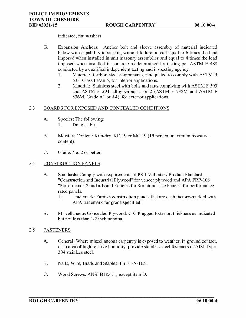
POLICE IMPROVEMENTS TOWN OF CHESHIRE BID #2021-15 ROUGH CARPENTRY 06 10 00-4
_____________________________________________________________________ ROUGH CARPENTRY 06 10 00-4
indicated, flat washers. G. Expansion Anchors: Anchor bolt and sleeve assembly of material indicated
below with capability to sustain, without failure, a load equal to 6 times the load imposed when installed in unit masonry assemblies and equal to 4 times the load imposed when installed in concrete as determined by testing per ASTM E 488 conducted by a qualified independent testing and inspecting agency. 1. Material: Carbon-steel components, zinc plated to comply with ASTM B
633, Class Fe/Zn 5, for interior applications. 2. Material: Stainless steel with bolts and nuts complying with ASTM F 593
and ASTM F 594, alloy Group 1 or 2 (ASTM F 738M and ASTM F 836M, Grade A1 or A4), for exterior applications.
2.3 BOARDS FOR EXPOSED AND CONCEALED CONDITIONS
A. Species: The following: 1. Douglas Fir.
B. Moisture Content: Kiln-dry, KD 19 or MC 19 (19 percent maximum moisture
content). C. Grade: No. 2 or better.
2.4 CONSTRUCTION PANELS
A. Standards: Comply with requirements of PS 1 Voluntary Product Standard "Construction and Industrial Plywood" for veneer plywood and APA PRP-108 "Performance Standards and Policies for Structural-Use Panels" for performance-rated panels. 1. Trademark: Furnish construction panels that are each factory-marked with
APA trademark for grade specified.
B. Miscellaneous Concealed Plywood: C-C Plugged Exterior, thickness as indicated but not less than 1/2 inch nominal.
2.5 FASTENERS
A. General: Where miscellaneous carpentry is exposed to weather, in ground contact, or in area of high relative humidity, provide stainless steel fasteners of AISI Type 304 stainless steel.
B. Nails, Wire, Brads and Staples: FS FF-N-105. C. Wood Screws: ANSI B18.6.1., except item D.

POLICE IMPROVEMENTS TOWN OF CHESHIRE BID #2021-15 ROUGH CARPENTRY 06 10 00-5
_____________________________________________________________________ ROUGH CARPENTRY 06 10 00-5
D. Bolts: ASTM A 307, Grade A or ASTM A36; with ASTM A 563 hex nuts and flat washers.
E. Strapping and metal connectors as required or as indicated on the Drawings, as
manufactured by Simpson Strong-Tie Company, Pleasanton, CA, or equal. F. Miscellaneous metal strapping and metal anchorage hardware, such as truss
anchors, shall be items as indicated on the drawings as manufactured by Simpson Strong Tie Company, Pleasanton, CA, or approved equal.
G. Minimum fastening requirements shall meet or exceed State Building Code
requirements and shall also be in accordance with exceptions that are noted or shown on the Structural Drawings and Specifications.
2.6 PRESERVATIVE WOOD TREATMENT BY PRESSURE PROCESS
A. General: Obtain preservative-treated lumber complying with AWPA Standard C2. Mark each treated item with AWPB or SPIB Quality Mark Requirements. Coat surfaces cut after treatment to comply with AWPA M4.
B. Above-Ground Wood Treatment: Pressure treat with waterborne preservatives to
a minimum retention of 0.25 pcf. 1. Kiln-dry interior dimension lumber after treatment to 15 percent
maximum moisture content. 2. Kiln-dry interior construction panels after treatment to 15 percent
maximum moisture content. 3. Treat wood items indicated and in the following circumstances:
a. In contact with roofing, flashing, or waterproofing. b. In contact with masonry or concrete. c. Within 18 inches of grade.
C. Ground-Contact Wood Treatment: Pressure treat with waterborne preservatives to
a minimum retention of 0.40 pcf. PART 3 - EXECUTION 3.1 INSTALLATION, GENERAL
A. Discard units of material with defects that impair quality of miscellaneous carpentry and in sizes that would require an excessive number or poor arrangement of joints.
B. Cut and fit miscellaneous carpentry accurately. Install members plumb and true
to line and level. C. Coat cut edges of preservative-treated wood to comply with AWPA M4.

POLICE IMPROVEMENTS TOWN OF CHESHIRE BID #2021-15 ROUGH CARPENTRY 06 10 00-6
_____________________________________________________________________ ROUGH CARPENTRY 06 10 00-6
D. Securely fasten miscellaneous carpentry as indicated and according to applicable
codes and recognized standards. E. Countersink nail heads on exposed carpentry work and fill holes. F. Use fasteners of appropriate type and length. Predrill members when necessary to
avoid splitting wood.
G. Install long dimension of plywood roofing panels crossing main framing members (trusses) and wall studs.
H. Implement all framing details, typical and specific, as shown on Structural
Drawings. As example, required details include, but are not limited to, wall top plate splice, wall base anchorage, roof vented blocking, exterior wall header, multi-layer LVL construction (screwing), and stud partition abutting bearing wall details.
I. Care should be taken to properly store all wood materials from damage due to
handling, storage, or environmental conditions. Store all materials off of the ground and properly secured and protected.
J. Carefully inspect the installed work of other trades and verify that all such work is
complete where this installation may properly commence. Verify that rough carpentry may be performed in strict accordance with the design and all pertinent codes and regulations. In the event of discrepancy, notify Architect. Do not proceed with work until directions are received from Architect.
3.2 GENERAL FRAMING
A. General: All rough carpentry shall produce joints true, tight, and well nailed with all members assembled as indicated. Set all horizontal and sloped members with crown up. Double members minimum for headers and trimmers.
B. Selection of Lumber Pieces: Carefully select all members. Select individual
pieces so that knots and obvious defects will not interfere with placing bolts or proper nailing or making proper connections. Cut out and discard all defects which will render a piece unable to serve its intended function. Lumber may be rejected by the Architect, whether or not it has been installed, for excessive warp, twist, bow, crook, mildew, fungus, or mold, as well as for improper cutting and fitting.
C. Bearing: Make all bearings full unless otherwise indicated. Finish all bearing
surfaces on which structural members are to rest so as to give sure and even support. Where framing members slope, cut or notch the ends as required to give uniform bearing surface. Minimum bearing one and one-half (1 1/2") inches on wood, four (4") inches on steel.

POLICE IMPROVEMENTS TOWN OF CHESHIRE BID #2021-15 ROUGH CARPENTRY 06 10 00-7
_____________________________________________________________________ ROUGH CARPENTRY 06 10 00-7
D. Shimming: Do not shim any framing components.
E. Alignment: On all framing members to receive a finished surface, alignment of
the finish subsurface to vary not more than one-eighth (1/8") inch from the plane of surfaces of adjacent framing and furring members. Provide "padding" as required to achieve proper surfaces for finish materials.
F. Holes and Notches: Do not bore holes closer than 2 inches from top or bottom of joists with hole diameter not to exceed one-third (1/3) the depth of member. Do not notch in middle third (1/3) of joist. Depth of notches in top or bottom of joists not to exceed one-sixth (1/6) the member depth. Notched ends not to exceed one-third (1/3) member depth. DO NOT cut holes or notches in truss members. Notches or holes over one (1") inch diameter in two by four (2x4) studs will require metal stud plates equal to Strong Tie SS Stud plates. Include nail stopper at all piping.
G. Sills: Set in bed of Portland Cement mortar. Secure each member with a minimum of two (2) bolts. Secure sills to bolts with recessed washer and nut.
H. Preservatives: Treat all wood in contact with concrete or masonry with wood preservative. Include blocking at perimeter of exterior wall openings.
3.3 BLOCKING
A. Install all blocking required to support all items of finish and to cut off all concealed draft openings, both vertical and horizontal, between ceiling and floor areas. Firestop concealed spaces with wood blocking not less than two (2") inches thick unless blocked by other framing members. Provide blocking to support edges of all soffits, flashing, etc. Provide two (2")-inch solid blocking as required for securing edges of gypsumboard. Provide continuous blocking for gypsumboard ceiling at all edges. Also, provide blocking behind all wall or ceiling mounted accessories such as grab bars, cabinets, fans, light fixtures, plumbing lines, electrical panelboards, bathroom accessories, etc. Note that grab bars must be capable of supporting three hundred (300 LB) pounds after installation.
3.4 FASTENING
A. Rough Hardware: Anchor and nail shall comply with State Building Code. B. Nailing: Use only common wire nails or spikes of the dimensions shown on the
Fastening Schedule, except where otherwise specifically noted on the drawings. For conditions not covered in the Fastening Schedule, provide penetration into the piece receiving the point of not less than one-half (1/2") inch the length of the nail or spike, provided, however, that 16d nails may be used to connect two (2) pieces

POLICE IMPROVEMENTS TOWN OF CHESHIRE BID #2021-15 ROUGH CARPENTRY 06 10 00-8
_____________________________________________________________________ ROUGH CARPENTRY 06 10 00-8
of two (2") inch (nominal) thickness. Do all nailing without splitting wood. Prebore as required. Replace all split members.
C. Bolting: Drill holes one-sixteenth (1/16) inch larger in diameter than the bolts
being used. Drill straight and true from one (1) side only. Bolt threads shall not bear on wood. Use washers under head and nut where both bear on wood. Use washers under all nuts.
D. Screws: For lag screws and wood-screws, prebore holes same diameter as root of
threads; enlarge holes to shank diameter for length of shank. Screw, do not drive, all lag-screws and wood-screws.
3.5 WOOD GROUNDS, NAILERS, BLOCKING, AND SLEEPERS
A. Install where shown and where required for screeding or attachment of other work. Cut and shape to required size. Coordinate location with other work involved.
B. Attach to substrates as required to support applied loading. Countersink bolts and
nuts flush with surfaces, unless otherwise indicated. C. Provide wood blocking for all wall mounted or recessed equipment including, but
not limited to, toilet accessories, fire extinguisher cabinet, visual display boards, metal fabrications, and wall mounted hardware.
3.6 DOOR HARDWARE INSTALLATION
A. Mount hardware units at heights indicated in following applicable publications, except as specifically indicated or required to comply with governing regulations and except as otherwise directed by Architect. 1. "Recommended Locations for Builders Hardware for Standard Steel
Doors and Frames" by the Door and Hardware Institute.
B. Install each hardware item in compliance with the manufacturer's instructions and recommendations. Where cutting and fitting is required to install hardware onto or into surfaces that are later to be painted or finished in another way, coordinate removal, storage, and reinstallation or application of surface protection with finishing work specified in the Division 9 Sections. Do not install surface-mounted items until finishes have been completed on the substrates involved.
C. Set units level, plumb, and true to line and location. Adjust and reinforce the
attachment substrate as necessary for proper installation and operation.
D. Drill and countersink units that are not factory prepared for anchorage fasteners. Space fasteners and anchors in accordance with industry standards.
POLICE IMPROVEMENTS TOWN OF CHESHIRE BID #2021-15 ROUGH CARPENTRY 06 10 00-9
_____________________________________________________________________ ROUGH CARPENTRY 06 10 00-9
E. Set thresholds for exterior doors in full bed of butyl-rubber or polyisobutylene mastic sealant complying with requirements specified in Division 7 Section "Joint Sealers."
F. Weatherstripping and Seals: Comply with manufacturer's instructions and
recommendations to the extent installation requirements are not otherwise indicated.
3.7 TOILET ACCESSORIES INSTALLATION
A. Install each toilet accessories in compliance with the manufacturer's instructions and recommendations
3.8 TEMPORARY ENCLOSURES
A. Provide temporary enclosures, doors and dust barriers as required to protect building from weather and construction damage and to ensure building security. Upon completion, remove all temporary work and repair any damage to permanent finishes and installations. Verify requirements with Architect and Owner.
END OF SECTION 06 10 00

POLICE IMPROVEMENTS TOWN OF CHESHIRE BID #2021-15
This page intentionally left blank.

POLICE IMPROVEMENTS TOWN OF CHESHIRE BID #2021-15 WOOD TRIM 06 46 00-1
WOOD TRIM 06 46 00-1
SECTION 06 46 00 – WOOD TRIM PART 1 - GENERAL 1.1 RELATED DOCUMENTS
A. Instructions to Bidders, AIA Document A201 - 2007, “General Conditions of the Contract for Construction”, the Supplementary General Conditions and Division 1, General Requirements, are a part of this Section and shall be binding on the Contractor and or Subcontractor who performs this Work. Note also all Addenda.
1.2 SUMMARY
A. This Section includes furnishing and installing the following: 1. Wood trim (White Oak, plain sliced) at Men’s Locker Room 001 and
Women’s Locker Room 016 for locker edging as indicated on the drawings.
2. Wood trim (White Oak, plain sliced) at Men’s Locker Room 001 and Wet Gear 015 for shoe shine mirror stop detail as indicated on the drawings.
3. Wood trim (White Oak, plain sliced) at Men’s Locker Room 001 and Wet Gear 015 for closet pole and shelf detail as indicated on the drawings.
B. Related Sections: The following sections contain requirements that relate to this
section: 1. Furring, blocking, and other carpentry work that is not exposed to view is
specified in Section 06 10 00 "Rough Carpentry". 2. Section 09 91 23 "Interior Painting" for final finishing of installed
decorative wood trims as indicated on the drawings. 3. Section 10 51 13 “Metal Lockers” for wood benches furnished and
installed by locker manufacturer. 4. Section 12 30 00 "Casework" for all plastic laminate casework, cabinetry,
and countertops. 1.3 SUBMITTALS
A. General: Submit the following in accordance with Conditions of Contract and Division 1 Specification Sections.
B. Product data for each type of product and process specified in this section and
incorporated into items of architectural woodwork during fabrication, finishing, and installation.
C. Shop drawings for woodwork and fittings showing plan layout, elevations, ends
and cross-sections.

POLICE IMPROVEMENTS TOWN OF CHESHIRE BID #2021-15 WOOD TRIM 06 46 00-2
WOOD TRIM 06 46 00-2
D. Product certificates signed by woodwork manufacturer certifying that products
comply with specified requirements. E. Qualification data for firms and persons specified in "Quality Assurance" article
to demonstrate their capabilities and experience. Include list of completed projects with project names, addresses, names of Architects and Owners, and other information specified.
F. Submit physical samples to Architect prior to approval for release of fabrication
of all products indicated herein.
1.4 QUALITY ASSURANCE
A. Manufacturer Qualifications: Firm experienced in successfully producing architectural woodwork similar to that indicated for this Project, with sufficient production capacity to produce required units without causing delay in the Work.
B. Single-Source manufacturing and Installation Responsibility: Engage a qualified
Manufacturer to assume undivided responsibility for woodwork specified in this section, including fabrication, finishing, and installation.
C. AWI Quality Standard: Comply with applicable requirements of "Architectural
Woodwork Quality Standards" published by the Architectural Woodwork Institute (AWI) except as otherwise indicated.
1.5 DELIVERY, STORAGE, AND HANDLING
A. Protect woodwork during transit, delivery, storage, and handling to prevent damage, soilage, and deterioration. Keep covered with polyethylene film or other protective coating.
B. Do not deliver woodwork until painting, wet work, grinding, and similar
operations that could damage, soil, or deteriorate woodwork have been completed in installation areas. If woodwork must be stored in other than installation areas, store only in areas whose environmental conditions meet requirements specified in "Project Conditions." 1. Follow procedures and schedules as provided by the General Trades
Contractor.
C. Store and dispose of solvent-based materials, and materials used with solvent-based materials, in accordance with requirements of local authorities having jurisdiction.
1.6 PROJECT CONDITIONS

POLICE IMPROVEMENTS TOWN OF CHESHIRE BID #2021-15 WOOD TRIM 06 46 00-3
WOOD TRIM 06 46 00-3
A. Environmental Conditions: Do not install woodwork until optimum temperature and humidity conditions for woodwork have been attained and stabilized so that woodwork is within plus or minus 1.0 percent of optimum moisture content from date of installation through remainder of construction period.
B. Field Measurements: Where woodwork is indicated to be fitted to other
construction, check actual dimensions of other construction by accurate field measurements before manufacturing woodwork; show recorded measurements on final shop drawings. Coordinate manufacturing schedule with construction progress to avoid delay of Work. 1. Where field measurements cannot be made without delaying the Work,
guarantee dimensions and proceed with manufacture of woodwork without field measurements. Coordinate other construction to ensure that actual dimensions correspond to guaranteed dimensions.
C. Field Measurements: Verify sizes and shapes prior to fabrication by field
measurements taken after base materials are installed. PART 2 - PRODUCTS 2.1 MATERIALS, GENERAL
A. References to “stain” and/or “clear top coat” finishes herein are specified under section 09 90 00 “Painting”. Minwax #MW471 “Navy” is the stain color, unless otherwise indicated.
B. All wood products indicated herein shall be Grade A, select (does not exhibit
knots, splits or visible defects) unless otherwise indicated. B. General: Provide materials that comply with requirements of the AWI
woodworking standard for each type of woodwork and quality grade indicated.
C. Lumber Standards: Comply with PS 20 "American Softwood Lumber Standard" for lumber and with applicable grading rules of inspection agencies certified by American Lumber Standards Committee Board of Review.
D. Plywood Standards: Comply with PS 1 "U.S. Product Standard for Construction
and Industrial Plywood" for plywood and, for products not manufactured under PS 1, with APA PRP-108.
E. Hardwood Lumber Standard: Comply with NHLA, National Hardwood Lumber
Association rules. F. Inspection Agencies: Inspection agencies and the abbreviations used to reference
them with lumber grades and species include the following:

POLICE IMPROVEMENTS TOWN OF CHESHIRE BID #2021-15 WOOD TRIM 06 46 00-4
WOOD TRIM 06 46 00-4
1. SPIB - Southern Pine Inspection Bureau. 2. WCLIB - West Coast Lumber Inspection Bureau. 3. WWPA - Western Wood Products Association.
G. Woodworking Standard: Where indicated for a specific product, comply with
specified Divisions of the following: 1. Architectural Woodwork Institute (AWI) Quality Standards.
H. Glued-Up Lumber Standard: Comply with PS 56.
2.2 PRODUCTS
CRS CLOSET ROD AND SHELF SUPPORT
1. Material: White Oak, plain sliced 2. Size: 1 by 3 nominal, 3/4-inch by 2-1/2-inch actual 3. Edge: All outside corners to be eased. 4. Finish: Stain and clear top coat to match wood doors unless otherwise noted. 5. Hanger Pole (Closet Rod) Support: Reference section 12 30 00 “Casework”
for specified Closet Rod diameter. Coordinate with approved submittal for actual diameter. Support on one side to have hole and on the other side a 45-degree removal slot. Round bottom edge of hanger pole support as detailed on drawing.
6. Special Requirements: Route out back and top for intermediate metal shelf and rod brackets.
GS GLAZING STOP
1. Material: White Oak, plain sliced 2. Size: 1/2-inch radius quarter-round 3. Joinery: Scarf all linear joints, miter all corners. 4. Finish: Stain and clear top coat to match wood doors unless otherwise noted.
LTT LOCKER TOP TRIM
1. Material: White Oak, plain sliced 2. Size: 1/2-inch by 2-1/2-inch actual 3. Edge: All outside corners to filleted 1/8-inch. 4. Finish: Stain and clear top coat to match wood doors unless otherwise noted. 5. Joinery: Scarf all linear joints.
2.3 FABRICATION, GENERAL
A. Wood Moisture Content: Comply with requirements of referenced quality standard for moisture content of lumber in relation to relative humidity conditions existing during time of fabrication and in installation areas.

POLICE IMPROVEMENTS TOWN OF CHESHIRE BID #2021-15 WOOD TRIM 06 46 00-5
WOOD TRIM 06 46 00-5
B. Fabricate woodwork to dimensions, profiles, and details indicated. Ease edges to
radius indicated for the following: 1. Corners and edges of solid wood (lumber) members less than 1 inch in
nominal thickness: 1/16 inch. 2. Edges of rails and similar members more than 1 inch in nominal thickness:
1/8 inch.
C. Complete fabrication, including assembly, finishing, and hardware application, before shipment to project site to maximum extent possible. Disassemble components only as necessary for shipment and installation. Where necessary for fitting at site, provide ample allowance for scribing, trimming, and fitting.
D. Factory-cut openings, to maximum extent possible, to receive hardware,
appliances, plumbing fixtures, electrical work, and similar items. Locate openings accurately and use templates or roughing-in diagrams to produce accurately sized and shaped openings. Smooth edges of cutouts and, where located in countertops and similar exposures, seal edges of cutouts with a water-resistant coating.
2.4 FASTENERS AND ANCHORS
A. Screws: Select material, type, size, and finish required for each use. Comply with FS FF-S-111 for applicable requirements. 1. For metal framing supports, provide screws as recommended by metal
framing manufacturer.
B. Nails: Select material, type, size, and finish required for each use. Comply with FS FF-N-105 for applicable requirements. 1. Countersink nails, fill surface flush, and sand where face nailing is
unavoidable.
C. Anchors: Select material, type, size, and finish required by each substrate for secure anchorage. Provide nonferrous metal or hot-dip galvanized anchors and inserts on inside face of exterior walls and elsewhere as required for corrosion resistance. Provide toothed steel or lead expansion bolt devices for drilled-in-place anchors. Furnish inserts and anchors, as required, to be set into concrete or masonry work for subsequent woodwork anchorage.
D. Adhesives: Comply with manufacturer's recommendations for adhesives.
PART 3 - EXECUTION 3.1 EXAMINATION

POLICE IMPROVEMENTS TOWN OF CHESHIRE BID #2021-15 WOOD TRIM 06 46 00-6
WOOD TRIM 06 46 00-6
A. Examine substrates for compliance with requirements for installation tolerances and other conditions affecting installation and performance of finish carpentry. Do not proceed with installation until unsatisfactory conditions have been corrected.
3.2 PREPARATION
A. Condition woodwork to average prevailing humidity conditions in installation areas before installing.
B. Deliver inserts and similar anchoring devices to be built into substrates well in
advance of time substrates are to be built.
C. Before installing architectural woodwork, examine shop-fabricated work for completion and complete work as required, including back priming and removal of packing.
3.3 INSTALLATION
A. Quality Standard: Install woodwork to comply with AWI Section 1700 for same grade specified in Part 2 of this section for type of woodwork involved.
B. Install woodwork plumb, level, true, and straight with no distortions. Shim as
required with concealed shims. Install to a tolerance of 1/8 inch in 8 feet-0 inch for plumb and level (including tops) and with no variations in flushness of adjoining surfaces.
C. Scribe and cut woodwork to fit adjoining work and refinish cut surfaces or repair
damaged finish at cuts. All surfaces of exterior trim to receive primed finish following cutting and scribing.
D. Anchor woodwork to anchors or blocking built in or directly attached to
substrates. Secure to grounds, stripping and blocking with countersunk, concealed fasteners and blind nailing as required for a complete installation. Except where prefinished matching fastener heads are required, use fine finishing nails for exposed nailing, countersunk and filled flush with woodwork and matching final finish where transparent finish is indicated.
E. Caulk all exposed joints of installed woodwork prior to receiving finish paint.
3.4 PROTECTION
A. Provide final protection and maintain conditions in a manner acceptable to manufacturer and installer that ensures woodwork is without damage or deterioration at time of Substantial Completion.

POLICE IMPROVEMENTS TOWN OF CHESHIRE BID #2021-15 WOOD TRIM 06 46 00-7
WOOD TRIM 06 46 00-7
END OF SECTION 06 46 00

POLICE IMPROVEMENTS TOWN OF CHESHIRE BID #2021-15
This page intentionally left blank.

POLICE IMPROVEMENTS TOWN OF CHESHIRE BID #2021-15 THERMAL INSULATION 07 21 00-1
THERMAL INSULATION 07 21 00-1
SECTION 07 21 00 – THERMAL INSULATION PART 1 - GENERAL 1.1 RELATED DOCUMENTS
A. Instructions to Bidders, AIA Document A201 - 2007, “General Conditions of the Contract for Construction”, the Supplementary General Conditions and Division 1, General Requirements, are a part of this Section and shall be binding on the Contractor and or Subcontractor who performs this Work. Note also all Addenda.
1.2 SUMMARY
A. This Section includes furnishing and installing the following: 1. Foundation wall insulation (rigid type) occurring at vertical foundation
wall conditions as indicated on Contract Documents.
B. Related Sections: The following sections contain requirements that relate to this section: 1. Section 07 84 00 "Firestopping" for insulation installed as part of fire and
smoke resistance assemblies. 2. Section 09 20 00 "Plaster and Gypsum Board" for sound attenuation
insulation installed as part of wall and partition assemblies. 1.3 DEFINITIONS
A. Thermal Resistivity: Where the thermal resistivity of insulation products are designated by “r-values," they represent the reciprocal of thermal conductivity (k-values). Thermal conductivity is the rate of heat flow through a homogenous material exactly 1 inch thick. Thermal resistivities are expressed by the temperature difference in degrees F between the two exposed faces required to cause one BTU to flow through one square foot per hour at mean temperatures indicated.
1.4 SUBMITTALS
A. General: Submit the following in accordance with Conditions of Contract and Division 1 Specification Sections.
B. Product test reports from and based on tests performed by qualified independent
testing laboratory evidencing compliance of insulation products with requirements including r-values (aged values for plastic foam insulation), fire performance characteristics, perm ratings, water absorption ratings, and other properties, based on comprehensive testing of current products.

POLICE IMPROVEMENTS TOWN OF CHESHIRE BID #2021-15 THERMAL INSULATION 07 21 00-2
THERMAL INSULATION 07 21 00-2
C. Foundation coating system information including coatings, mesh, and manufacturer’s installation instructions.
1.5 QUALITY ASSURANCE
A. Fire Performance Characteristics: Provide insulation materials identical to those whose indicated fire performance characteristics have been determined per the ASTM test method indicated below, by UL or other testing and inspecting organizations acceptable to authorities having jurisdiction. Identify products with appropriate markings of applicable testing and inspecting organization. 1. Surface Burning Characteristic: ASTM E 84. 2. Fire Resistance Ratings: ASTM E 119. 3. Combustion Characteristics: ASTM E 136.
1.6 DELIVERY, STORAGE, AND HANDLING
A. Protect insulation materials from physical damage and from deterioration by moisture, soiling, and other sources. Store inside and in a dry location. Comply with manufacturer's recommendations for handling, storage, and protection during installation.
B. Protect plastic insulation as follows:
1. Do not expose to sunlight, except to extent necessary for period of installation and concealment.
2. Protect against ignition at all times. Do not deliver plastic insulating materials to project site ahead of installation time.
3. Complete installation and concealment of plastic materials as rapidly as possible in each area of construction.
C. Fire Precaution: Do not store rigid insulation or similar combustible materials
inside the building or within 15 feet of any structure on the site. Observe proper fire precautions during installation of insulation.
PART 2 - PRODUCTS 2.1 MANUFACTURERS
A. Manufacturers: Subject to compliance with requirements, provide insulation products of one of the following: 1. Extruded Polystyrene Board Insulation:
a. Amoco Foam Products Co. b. Dow: The Dow Chemical Company. c. UC Industries, Inc.
2.2 INSULATING MATERIALS
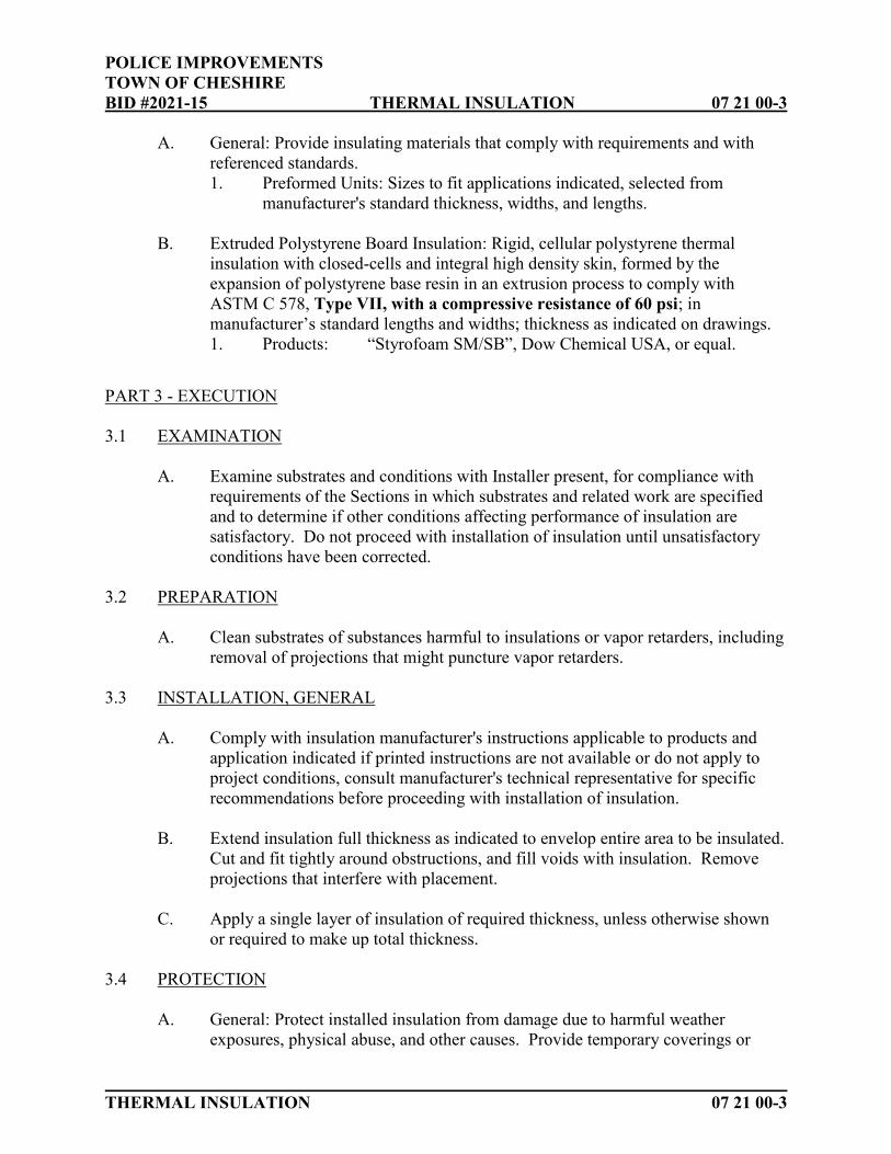
POLICE IMPROVEMENTS TOWN OF CHESHIRE BID #2021-15 THERMAL INSULATION 07 21 00-3
THERMAL INSULATION 07 21 00-3
A. General: Provide insulating materials that comply with requirements and with referenced standards. 1. Preformed Units: Sizes to fit applications indicated, selected from
manufacturer's standard thickness, widths, and lengths.
B. Extruded Polystyrene Board Insulation: Rigid, cellular polystyrene thermal insulation with closed-cells and integral high density skin, formed by the expansion of polystyrene base resin in an extrusion process to comply with ASTM C 578, Type VII, with a compressive resistance of 60 psi; in manufacturer’s standard lengths and widths; thickness as indicated on drawings. 1. Products: “Styrofoam SM/SB”, Dow Chemical USA, or equal.
PART 3 - EXECUTION 3.1 EXAMINATION
A. Examine substrates and conditions with Installer present, for compliance with requirements of the Sections in which substrates and related work are specified and to determine if other conditions affecting performance of insulation are satisfactory. Do not proceed with installation of insulation until unsatisfactory conditions have been corrected.
3.2 PREPARATION
A. Clean substrates of substances harmful to insulations or vapor retarders, including removal of projections that might puncture vapor retarders.
3.3 INSTALLATION, GENERAL
A. Comply with insulation manufacturer's instructions applicable to products and application indicated if printed instructions are not available or do not apply to project conditions, consult manufacturer's technical representative for specific recommendations before proceeding with installation of insulation.
B. Extend insulation full thickness as indicated to envelop entire area to be insulated.
Cut and fit tightly around obstructions, and fill voids with insulation. Remove projections that interfere with placement.
C. Apply a single layer of insulation of required thickness, unless otherwise shown
or required to make up total thickness. 3.4 PROTECTION
A. General: Protect installed insulation from damage due to harmful weather exposures, physical abuse, and other causes. Provide temporary coverings or

POLICE IMPROVEMENTS TOWN OF CHESHIRE BID #2021-15 THERMAL INSULATION 07 21 00-4
THERMAL INSULATION 07 21 00-4
enclosures where insulation will be subject to abuse and cannot be concealed and protected by permanent construction immediately after installation.
END OF SECTION 07 21 00

POLICE IMPROVEMENTS TOWN OF CHESHIRE BID #2021-15 FIRESTOPPING 07 84 00-1
_____________________________________________________________________________________________ FIRESTOPPING 07 84 00-1
07 84 00 - FIRESTOPPING PART 1 - GENERAL 1.1 RELATED DOCUMENTS
A. Instructions to Bidders, AIA Document A201-2007, “The General Conditions of
the Contract for Construction,”, the Supplementary General Conditions and Division 1, General Requirements, are a part of this Section and shall be binding on the Contractor and/or Subcontractor who performs this work. Note also all Addenda.
1.2 SUMMARY
A. This Section includes furnishing and installing firestopping for the following:
1. Joints along the top of fire-resistance-rated wall construction and the underside of structure above.
2. Penetrations through fire-resistance-rated walls and partitions including both empty openings and openings containing cables, pipes, ducts, conduits, and other penetrating items.
3. Sealant joints in fire-resistance-rated construction.
B. Related Sections: The following Sections contain requirements that relate to this Section:
1. Section 07 90 00 "Joint Protection" for non-fire-rated joint sealers. 2. Division 22 Sections specifying ducts and piping penetrations. 3. Division 23 Sections specifying Heating Ventilating and air conditioning 4. Division 26 Sections specifying cable and conduit penetrations. 5. Division 28 Sections specifying Electronic Safety and Security
1.3 SYSTEM PERFORMANCE REQUIREMENTS
A. General: Provide firestopping systems that are produced and installed to resist the spread of fire, according to requirements indicated, and the passage of smoke and other gases.
1. All firestopping systems shall be reviewed and approved for use by the
local fire authority prior to submission to Architect.
B. F-Rated Through-Penetration Firestop Systems: Provide through-penetration firestop systems with F ratings indicated, as determined pet ASTM E 814, but not less than that equaling or exceeding the fire-resistance rating of the constructions penetrated.

POLICE IMPROVEMENTS TOWN OF CHESHIRE BID #2021-15 FIRESTOPPING 07 84 00-2
_____________________________________________________________________________________________ FIRESTOPPING 07 84 00-2
C. T-Rated Through-Penetration Firestop Systems: Provide through-penetration firestop systems with T ratings, in addition to F ratings, as determined per ASTM E 814, where indicated and where systems protect penetrating items exposed to contact with adjacent materials in occupiable floor areas. T-rated assemblies are required where the following conditions exist:
1. Where firestop systems protect penetrations located outside of wall
cavities. 2. Where firestop systems protect penetrations located outside fire-resistive
shaft enclosures. 3. Where firestop systems protect penetrations located in construction
containing doors required to have a temperature-rise rating. 4. Where firestop systems protect penetrating items larger than a 4-inch-
diameter nominal pipe or 16 sq. in. in overall cross-sectional area.
D. Fire-Resistive Joint Sealants: Provide joint sealants with fire-resistance ratings indicated, as determined per ASTM E 119, but not less than that equaling or exceeding the fire-resistance rating of the construction in which the joint occurs.
E. For firestopping exposed to view, traffic, moisture, and physical damage, provide
products that do not deteriorate when exposed to these conditions.
1. For piping penetrations for plumbing and wet-pipe sprinkler systems, provide moisture-resistant through-penetration firestop systems.
2. For penetrations involving insulated piping, provide through-penetration firestop systems not requiring removal of insulation.
F. For firestopping exposed to view, provide products with flame-spread values of
less than 25 and smoke-developed values of less than 450, as determined per ASTM E 84.
G. All firestopping systems shall be FM Global approved and shall meet FM
Approval Class Numbers 4435, 4450, 4451, 4454, 4470, 4471. 1.4 SUBMITTALS
A. General: Submit the following according to Conditions of Contract and Division 1 Specification Sections.
B. Product data for each type of product specified.
1. Certification by firestopping manufacturer that products supplied comply
with local regulations controlling use of volatile organic compounds (VOCS) and are nontoxic to building occupants.

POLICE IMPROVEMENTS TOWN OF CHESHIRE BID #2021-15 FIRESTOPPING 07 84 00-3
_____________________________________________________________________________________________ FIRESTOPPING 07 84 00-3
C. Product test reports from, and based on tests performed by, a qualified testing and inspecting agency evidencing compliance of firestopping with requirements based on comprehensive testing of current products.
1.5 QUALITY ASSURANCE
A. Fire-Test-Response Characteristics: Provide firestopping that complies with the following requirements and those specified under the "System Performance Requirements" article:
1. Firestopping tests are performed by a qualified testing and inspecting
agency. A qualified testing and inspecting agency is UL or Warnock Hersey.
2. Through-penetration firestop systems are identical to those tested per ASTM E 814 under conditions where positive furnace pressure differential of at least 0.01 inch of water is maintained at a distance of 0.78 inch below the fill materials surrounding the penetrating items in the test assembly. Provide rated systems complying with the following requirements: a. Through-penetration firestop system products bear classification
marking of qualified testing and inspecting agency. b. Through-penetration firestop systems correspond to those indicated
by reference to through-penetration firestop system designations listed by UL in their "Fire Resistance Directory," or by Warnock Hersey.
3. Fire-resistive joint sealant systems are identical to those tested for fire-response characteristics per ASTM E 119 under conditions where the positive furnace pressure differential is at least 0.01 inch of water, as measured 0.78 inch from the face exposed to furnace fire. Provide systems complying with the following requirements: a. Fire-Resistance Ratings of Joint Sealants: As indicated by
reference to design designations listed by UL in their "Fire Resistance Directory" or by another qualified testing and inspecting agency.
b. Joint sealants, including backing materials, bear classification marking of qualified testing and inspection agency.
B. Installer Qualifications: Engage an experienced Installer who has completed
firestopping that is similar in material, design, and extent to that indicated for Project and that has performed successfully.
C. Single-Source Responsibility: Obtain through-penetration firestop systems for
each kind of penetration and construction condition indicated from a single manufacturer.

POLICE IMPROVEMENTS TOWN OF CHESHIRE BID #2021-15 FIRESTOPPING 07 84 00-4
_____________________________________________________________________________________________ FIRESTOPPING 07 84 00-4
D. Provide firestopping products containing no detectable asbestos as determined by the method specified in 40 CFR Part 763, Subpart F, Appendix A, Section 1, "Polarized Light Microscopy."
E. Coordinating Work: Coordinate construction of openings and penetrating items to
ensure that designated through-penetration firestop systems are installed per specified requirements.
1.6 DELIVERY, STORAGE, AND HANDLING
A. Deliver firestopping products to Project site in original, unopened containers or packages with intact and legible manufacturers' labels identifying product and manufacturer; date of manufacture; lot number; shelf life, if applicable; qualified testing and inspecting agency's classification marking applicable to Project; curing time; and mixing instructions for multi-component materials.
B. Store and handle firestopping materials to prevent their deterioration or damage
due to moisture, temperature changes, contaminants, or other causes. 1.7 PROJECT CONDITIONS
A. Environmental Conditions: Do not install firestopping when ambient or substrate temperatures are outside limits permitted by firestopping manufacturers or when substrates are wet due to rain, frost, condensation, or other causes.
B. Ventilation: Ventilate firestopping per firestopping manufacturers, instructions by
natural means or, where this is inadequate, forced air circulation. 1.8 SEQUENCING AND SCHEDULING
A. Do not cover up those firestopping installations that will become concealed behind other construction until the owner's Representative and authorities having jurisdiction, if required, have examined each installation.
PART 2 - PRODUCTS 2.1 FIRESTOPPING, GENERAL
A. Compatibility: Provide firestopping composed of components that are compatible with each other, the substrates forming openings, and the items, if any, penetrating the firestopping under conditions of service and application, as demonstrated by firestopping manufacturer based on testing and field experience.
B. Accessories: Provide components for each firestopping system that are needed to
install fill materials and to comply with "System Performance Requirements" article in Part 1. Use only components specified by the firestopping manufacturer

POLICE IMPROVEMENTS TOWN OF CHESHIRE BID #2021-15 FIRESTOPPING 07 84 00-5
_____________________________________________________________________________________________ FIRESTOPPING 07 84 00-5
and approved by the qualified testing and inspecting agency for the designated fire-resistance-rated systems. Accessories include but are not limited to the following items:
1. Permanent forming/damming/backing materials including the following:
a. Ceramic fiber. b. Sealants used in combination with other forming/damming
materials to prevent leakage of fill materials in liquid state. c. Joint fillers for joint sealants.
2. Temporary forming materials. 3. Substrate primers. 4. Collars. 5. Steel sleeves.
C. Applications: Provide firestopping systems composed of materials specified in
this Section that comply with system performance and other requirements. 2.2 FILL MATERIALS FOR THROUGH-PENETRATION FIRESTOP SYSTEMS
A. Ceramic-Fiber Forming/Backing/Damming Material: Formulation of continuous filament ceramic fibers and inorganic binders.
B. Products: Subject to compliance with requirements, provide one of the following:
1. Ceramic-Fiber Forming/Backing/Damming Material:
a. “Ultra Block”, Backer Rod Mfg. & Supply Co. b. “Vedafeu C”, Veda Building Joints c. “Everlastic Dynashield 600”, Williams Products
2. Sealants:
a. “CP 606, Flexible Firestop Sealant”, Hilti b. “SIL 300 Firestop Sealant”, Specified Technologies, Inc. c. “CLK Firestop Sealant”, Hevi-Duty/Nelson.
2.3 FIRE-RESISTIVE ELASTOMERIC JOINT SEALANTS
A. Elastomeric Sealant Standard: Provide manufacturer's standard chemically curing, elastomeric sealants of base polymer indicated that complies with ASTM 920 requirements, including those referenced for Type, Grade, Class, and Uses, and requirements specified in this Section applicable to fire-resistive joint sealants.
B. Sealant Colors: Provide color of exposed joint sealants to comply with the
following:

POLICE IMPROVEMENTS TOWN OF CHESHIRE BID #2021-15 FIRESTOPPING 07 84 00-6
_____________________________________________________________________________________________ FIRESTOPPING 07 84 00-6
1. Provide selections made by Architect from manufacturer's full range of
standard colors for products of type indicated.
C. Products: Subject to compliance with requirements, provide one of the following:
1. Single Component, Neutral Silicone Sealant: a. “CP 601S”, Hilti. b. “864NST”, Pecora Corp. c. “795”, Dow Corning Corp.
2. Multicomponent, Nonsag, Urethane Sealant: a. “Dynatrol II”, Pecora Corp. b. “Sonolastic NP 2”, Sonneborn Building Products Div., BASF c. “Dymeric 240”, Tremco Inc.
2.4 MIXING
A. For those products requiring mixing prior to application, comply with firestopping manufacturer's directions for accurate proportioning of materials, water (if required), type of mixing equipment, selection of mixer speeds, mixing containers, mixing time, and other procedures needed to produce firestopping products of uniform quality with optimum performance characteristics for application indicated.
PART 3 - EXECUTION 3.1 EXAMINATION
A. Examine substrates and conditions, with Installer present, for compliance with requirements for opening configurations, penetrating items, substrates, and other conditions affecting performance of firestopping. Do not proceed with installation until unsatisfactory conditions have been corrected.
3.2 PREPARATION
A. Surface Cleaning: Clean out openings and joints immediately prior to installing firestopping to comply with recommendations of firestopping manufacturer and the following requirements:
1. Remove all foreign materials from surfaces of opening and joint
substrates and from penetrating items that could interfere with adhesion of firestopping.
2. Clean opening and joint substrates and penetrating items to produce clean, sound surfaces capable of developing optimum

POLICE IMPROVEMENTS TOWN OF CHESHIRE BID #2021-15 FIRESTOPPING 07 84 00-7
_____________________________________________________________________________________________ FIRESTOPPING 07 84 00-7
bond with firestopping. Remove loose particles remaining from cleaning operation.
3. Remove laitance and form release agents from concrete.
B. Priming: Prime substrates where recommended by firestopping manufacturer using that manufacturer's recommended products and methods. Confine primers to areas of bond; do not allow spillage and migration on to exposed surfaces.
C. Masking Tape: Use masking tape to prevent firestopping from contacting
adjoining surfaces that will remain exposed upon completion of Work and that would otherwise be permanently stained or damaged by such contact or by cleaning methods used to remove smears from firestopping materials. Remove tape as soon as it is possible to do so without disturbing firestopping's seal with substrates.
3.3 INSTALLING THROUGH-PENETRATION FIRESTOPS
A. Install forming/damming materials and other accessories of types required to support fill materials during their application and in the position needed to produce the cross-sectional shapes and depths required to achieve fire ratings of designated through-penetration firestop systems. After installing fill materials, remove combustible forming materials and other accessories not indicated as permanent components of firestop systems.
B. Install fill materials for through-penetration firestop systems by proven techniques
to produce the following results:
1. Completely fill voids and cavities formed by openings, forming materials, accessories, and penetrating items.
2. Apply materials so they contact and adhere to substrates formed by openings and penetrating items.
3. For fill materials that will remain exposed after completing Work, finish to produce smooth, uniform surfaces that are flush with adjoining finishes.
3.4 INSTALLING FIRE-RESISTIVE JOINT SEALANTS
A. Install joint fillers to provide support of sealants during application and at position required to produce the cross-sectional shapes and depths of installed sealants relative to joint widths that allow optimum sealant movement capability and develop fire-resistance rating required.
B. Install sealants by proven techniques that result in sealants directly contacting and
fully wetting joint substrates, completely filling recesses provided for each joint configuration, and providing uniform, cross-sectional shapes and depths relative to joint width that optimum sealant movement capability. Install sealants at the same time joint fillers are installed.

POLICE IMPROVEMENTS TOWN OF CHESHIRE BID #2021-15 FIRESTOPPING 07 84 00-8
_____________________________________________________________________________________________ FIRESTOPPING 07 84 00-8
C. Tool nonsag sealants immediately after sealant application and prior to the time
skinning or curing begins. Form smooth, uniform beads of configuration indicated or required to produce fire-resistance rating, as well as to eliminate air pockets, and to ensure contact and adhesion of sealants with sides of joint. Remove excess sealant from surfaces adjacent to joint. Do not use tooling agents that discolor sealants or adjacent surfaces or are not approved by sealant manufacturer.
3.5 FIELD QUALITY CONTROL
A. The Owner's Representative will examine completed firestopping to determine, in general, if it is being installed in compliance with requirements.
B. The Owner's Representative will report observations promptly and in writing to
Contractor and Architect. C. Do not proceed to enclose firestopping with other construction until installations
are approved. D. Where deficiencies are found, repair or replace firestopping so that it complies
with requirements. 3.6 CLEANING
A. Clean off excess fill materials and sealants adjacent to openings and joints as work progresses by methods and with cleaning materials approved by manufacturers of firestopping products and of products in which opening and joints occur.
B. Protect firestopping during and after curing period from contact with
contaminating substances or from damage resulting from construction operations or other causes so that they are without deterioration or damage at time of Substantial Completion. If, despite such protection, damage or deterioration occurs, cut out and remove damaged or deteriorated firestopping immediately and install new materials to produce firestopping complying with specified requirements.
END OF SECTION 07 84 00

POLICE IMPROVEMENTS TOWN OF CHESHIRE BID #2021-15 JOINT PROTECTION 07 90 00-1
JOINT PROTECTION 07 90 00-1
07 90 00 - JOINT PROTECTION 1.1 RELATED DOCUMENTS
A. Instructions to Bidders, AIA Document A201 - 2007, “General Conditions of the Contract for Construction”, the Supplementary General Conditions and Division 1, General Requirements, are a part of this Section and shall be binding on the Contractor and or Subcontractor who performs this Work. Note also all Addenda.
1.2 SUMMARY
A. This Section includes furnishing and installing joint sealants: 1. Exterior joints in vertical surfaces and nontraffic horizontal surfaces as
indicated below: a. Expansion joints in unit masonry where exposed to view. b. Joints between unit masonry and dissimilar materials (all
perimeters) c. Other joints as indicated on the contract documents.
2. Interior joints in vertical surfaces and horizontal nontraffic surfaces as indicated below: a. Control joints on all exposed interior surfaces. c. Perimeter joints of all exterior openings. d. Perimeter joints of all Manufactured Wood Casework e. Perimeter joints of all hollow metal frames and wood window
frames, and wall construction against dissimilar materials. f. Vertical control joints on exposed surfaces of interior unit masonry
and concrete walls and partitions. g. All exposed joints between steel columns, drywall, or other
dissimilar materials.
B. Related Sections: The following Sections contain requirements that relate to this Section: 1. Section 07 84 00 "Firestopping" for fire-resistance-rated joint sealants. 2. Section 12 30 00 “Casework” for sealants used in perimeter joints. 3. Division 22 “Plumbing” for types, schedules, and locations for all
plumbing fixtures. 1.3 SYSTEM PERFORMANCE REQUIREMENTS
A. Provide elastomeric joint sealants that have been produced and installed to establish and to maintain watertight and airtight continuous seals without causing staining or deterioration of joint substrates.
B. Provide joint sealants for interior applications that have been produced and
installed to establish and maintain airtight continuous seals that are water resistant and cause no staining or deterioration of joint substrates.

POLICE IMPROVEMENTS TOWN OF CHESHIRE BID #2021-15 JOINT PROTECTION 07 90 00-2
JOINT PROTECTION 07 90 00-2
1.4 SUBMITTALS A. Product data from manufacturers for each joint sealant product required.
1.5 QUALITY ASSURANCE
A. Installer Qualifications: Engage an experienced Installer who has completed joint sealant applications similar in material, design, and extent to that indicated for Project that have resulted in construction with a record of successful in-service performance.
B. Single Source Responsibility for Joint Sealant Materials: Obtain joint sealant
materials from a single manufacturer for each different product required. 1.6 DELIVERY, STORAGE, AND HANDLING
A. Deliver materials to Project site in original unopened containers or bundles with labels indicating manufacturer, product name and designation, color, expiration period for use, pot life, curing time, and mixing instructions for multicomponent materials.
B. Store and handle materials in compliance with manufacturer's recommendations
to prevent their deterioration or damage due to moisture, high or low temperatures, contaminants, or other causes.
1.7 PROJECT CONDITIONS
A. Environmental Conditions: Notify Architect and do not proceed with installation of joint sealants under the following conditions: 1. When ambient and substrate temperature conditions are outside the limits
permitted by joint sealant manufacturer. 2. When ambient and substrate temperature conditions are outside the limits
permitted by joint sealant manufacturer or below 40 deg F (4.4 deg C). 3. When joint substrates are wet.
B. Joint Width Conditions: Notify Architect and do not proceed with installation of
joint sealants where joint widths are less than allowed by joint sealant manufacturer for application indicated.
C. Joint Substrate Conditions: Notify Architect and do not proceed with installation
of joint sealants until contaminants capable of interfering with their adhesion are removed from joint substrates.
1.8 SEQUENCING AND SCHEDULING
A. Sequence installation of joint sealants to occur not less than 21 nor more than 30 days after completion of waterproofing, unless otherwise indicated.

POLICE IMPROVEMENTS TOWN OF CHESHIRE BID #2021-15 JOINT PROTECTION 07 90 00-3
JOINT PROTECTION 07 90 00-3
PART 2 - PRODUCTS 2.1 MATERIALS, GENERAL
A. Compatibility: Provide joint sealants, joint fillers, and other related materials that are compatible with one another and with joint substrates under conditions of service and application, as demonstrated by sealant manufacturer based on testing and field experience.
B. Colors: For exposed joint sealants, provide selections made by Architect from
manufacturer’s full range of standard colors for products of types indicated. Colors will be selected once color selections of adjacent materials have been submitted and approved.
2.2 PRODUCTS
AS ACOUSTICAL SEALANT
1. Material: Acrylic-Emulsion 2. Description: One-part, non-sag, mildew-resistant, paintable latex sealant of
formulation that is recommended for exposed applications on interior and protected exterior locations and that accommodates indicated percentage change in joint width existing at time of installation without failing either adhesively or cohesively.
3. Compliance: ASTM C834, accommodating joint movement of not more than 5-percent in both extension and compression for a total of 10-percent.
4. Manufacturer / Product Line: Subject to compliance with the requirements, provide one of the following:
a. Pecora Corporation / AC-20 +Silicone b. BASF Corporation / MasterSeal NP 520 c. Tremco Inc. / Tremflex 834
5. Locations: Subject to compliance, provide in the following locations: a. Interior control joints on exposed surfaces of exterior walls. b. Interior control joints in ceilings and overhead surfaces. c. Interior perimeter joints of all exterior openings. d. Interior perimeter joints of all ornamental woodwork. e. Interior perimeter joints of all manufactured architectural casework. f. Interior perimeter joints of all hollow metal and wood frames. g. Interior perimeter joints of all plumbing fixtures. h. Interior vertical control joints on exposed surfaces of interior unit
masonry and concrete walls and partitions. i. Interior perimeter joints between steel columns, drywall, or other
dissimilar materials when in contact with epoxy paint.
BB BOND BREAKER

POLICE IMPROVEMENTS TOWN OF CHESHIRE BID #2021-15 JOINT PROTECTION 07 90 00-4
JOINT PROTECTION 07 90 00-4
1. Description: Polyethylene tape or other plastic tape as recommended by sealant manufacturer for preventing sealant from adhering to rigid, inflexible joint filler materials or joint surfaces at back of joint where such adhesion would result in sealant failure. Provide self-adhesive tape where applicable.
BR BACKER ROD
2. General: Provide sealant backings of material and type that are nonstaining;
are compatible with joint substrates, sealants, primers and other joint fillers; and are approved for applications indicated by sealant manufacturer based on field experience and laboratory testing.
3. Description: Plastic foam joint filler, preformed, compressible, resilient, non-staining, non-waxing, non-extruding strips of flexible plastic foam of material indicated below and of size, shape, and density to control sealant depth and otherwise contribute to producing optimum sealant performance.
4. Material: Subject to compliance with requirements, provide one of the following:
a. Open-cell polyurethane foam b. Closed-cell polyethylene foam, nonabsorbent to liquid water and gas,
non-outgassing in un-ruptured state. c. Proprietary, reticulated, closed-cell polymeric foam, non-outgassing,
with a density of 2.5 pcf and tensile strength of 35 psi per ASTM D 1623, and with water absorption less than 0.02 gms/cc per ASTM C 1083.
EX EXTERIOR SEALANT
1. Material: Urethane 2. Description: Multi-Part Non-Sag Urethane Sealant, Chemically curing
elastomeric sealants. 3. Compliance: ASTM 920 classifications for Type, Grade, Class, and Uses. 4. Manufacturer / Product Line: Subject to compliance with requirements,
provide one of the following: a. Pecora Corporation / Dynatrol II b. BASF Corporation / MasterSeal NP2 c. Tremco Inc. / Dymeric 240FC d. Sika Corporation / Sikaflex 2 C NS
5. Locations: Subject to compliance, provide in the following locations: a. Exterior expansion joints in unit masonry where exposed to view. b. Exterior joints between unit masonry and dissimilar materials
encompassing all perimeters. c. Exterior perimeter joints between unit masonry and doors, windows,
and louvers. d. Exterior joints as indicated on the contract documents.
SL SELF-LEVELING SEALANT

POLICE IMPROVEMENTS TOWN OF CHESHIRE BID #2021-15 JOINT PROTECTION 07 90 00-5
JOINT PROTECTION 07 90 00-5
1. Material: Urethane 2. Description: Multi-Part Self-Leveling Urethane Sealant: Chemically curing
elastomeric sealants. 3. Compliance: ASTM 920 classifications for Type, Grade, Class, and Uses. 4. Manufacturer / Product Line: Subject to compliance with requirements,
provide one of the following: a. Sika Corporation / Sikaflex – 2c SL b. BASF Corporation / MasterSeal SL2 c. Pecora Corporation / Dynatrol II-SG
5. Locations: Subject to compliance, provide in the following locations: a. Exterior joints between concrete building foundation and concrete
sidewalk sections.
2.3 MISCELLANEOUS MATERIALS
A. Primer: Material recommended by joint sealant manufacturer where required for adhesion of sealant to joint substrates indicated, as determined from preconstruction joint sealant-substrate tests and field tests.
B. Cleaners for Nonporous Surfaces: Chemical cleaners acceptable to manufacturers
of sealants and sealant backing materials, free of oily residues or other substances capable of staining or harming in any way joint substrates and adjacent nonporous surfaces, and formulated to promote optimum adhesion of sealants with joint substrates.
C. Masking Tape: Nonstaining, nonabsorbent material compatible with joint sealants
and surfaces adjacent to joints. PART 3 - EXECUTION 3.1 EXAMINATION
A. Examine joints indicated to receive joint sealants, with Installer present, for compliance with requirements for joint configuration, installation tolerances, and other conditions affecting joint sealant performance. Notify Architect and do not proceed with installation of joint sealants until unsatisfactory conditions have been corrected.
3.2 PREPARATION
A. Surface Cleaning of Joints: Clean out joints immediately before installing joint sealants to comply with recommendations of joint sealant manufacturer and the following requirements: 1. Remove all foreign material from joint substrates that could interfere with
adhesion of joint sealant, including dust, paints (except for permanent, protective coatings tested and approved for sealant adhesion and

POLICE IMPROVEMENTS TOWN OF CHESHIRE BID #2021-15 JOINT PROTECTION 07 90 00-6
JOINT PROTECTION 07 90 00-6
compatibility by sealant manufacturer), old joint sealants, oil, grease, waterproofing, water repellents, water, surface dirt, and frost.
2. Clean concrete, masonry, unglazed surfaces of ceramic tile, and similar porous joint substrate surfaces by brushing, grinding, blast cleaning, mechanical abrading, or a combination of these methods to produce a clean, sound substrate capable of developing optimum bond with joint sealants. Remove loose particles remaining from above cleaning operations by vacuuming or blowing out joints with oil-free compressed air.
3. Remove laitance and form release agents from concrete. 4. Clean metal, glass, porcelain enamel, glazed surfaces of ceramic tile, and
other nonporous surfaces with chemical cleaners or other means that do not stain, harm substrates, or leave residues capable of interfering with adhesion of joint sealants.
B. Joint Priming: Prime joint substrates where indicated or where recommended by
joint sealant manufacturer based on preconstruction joint sealant-substrate tests or prior experience. Apply primer to comply with joint sealant manufacturer's recommendations. Confine primers to areas of joint sealant bond; do not allow spillage or migration onto adjoining surfaces.
C. Masking Tape: Use masking tape where required to prevent contact of sealant
with adjoining surfaces that otherwise would be permanently stained or damaged by such contact or by cleaning methods required to remove sealant smears. Remove tape immediately after tooling without disturbing joint seal.
3.3 INSTALLATION OF JOINT SEALANTS
A. General: Comply with joint sealant manufacturer's printed installation instructions applicable to products and applications indicated, except where more stringent requirements apply.
B. Installation of Sealant Backings: Install sealant backings to comply with the
following requirements: 1. Install joint fillers of type indicated to provide support of sealants during
application and at position required to produce the cross-sectional shapes and depths of installed sealants relative to joint widths that allow optimum sealant movement capability. a. Do not leave gaps between ends of joint fillers. b. Do not stretch, twist, puncture, or tear joint fillers. c. Remove absorbent joint fillers that have become wet prior to
sealant application and replace with dry material. 2. Install bond breaker tape between sealants where backer rods are not used
between sealants and joint fillers or back of joints.
C. Installation of Sealants: Install sealants by proven techniques that result in sealants directly contacting and fully wetting joint substrates, completely filling

POLICE IMPROVEMENTS TOWN OF CHESHIRE BID #2021-15 JOINT PROTECTION 07 90 00-7
JOINT PROTECTION 07 90 00-7
recesses provided for each joint configuration, and providing uniform, cross-sectional shapes and depths relative to joint widths that allow optimum sealant movement capability. Install sealants at the same time sealant backings are installed.
D. Tooling of Nonsag Sealants: Immediately after sealant application and prior to
time skinning or curing begins, tool sealants to form smooth, uniform beads of configuration indicated, to eliminate air pockets, and to ensure contact and adhesion of sealant with sides of joint. Remove excess sealants from surfaces adjacent to joint. Do not use tooling agents that discolor sealants or adjacent surfaces or are not approved by sealant manufacturer. 1. Provide concave joint configuration per Figure 5A in ASTM C 1193,
unless otherwise indicated. 3.4 CLEANING
A. Clean off excess sealants or sealant smears adjacent to joints as work progresses by methods and with cleaning materials approved by manufacturers of joint sealants and of products in which joints occur.
3.5 PROTECTION
A. Protect joint sealants during and after curing period from contact with contaminating substances or from damage resulting from construction operations or other causes so that they are without deterioration or damage at time of Substantial Completion. If, despite such protection, damage or deterioration occurs, cut out and remove damaged or deteriorated joint sealants immediately so that and installations with repaired areas are indistinguishable from original work.
3.6 GUARANTEE AND CERTIFICATION
A. This Contractor shall and hereby does guarantee that all sealant work will be free from defects of materials and workmanship for a period of five (5) years. The following types of failure will be adjusted: 1. Leakage, cracking, crumbling, melting, shrinking or running of caulking,
or staining of adjacent work by caulking.
B. This Contractor shall repair and replace work which becomes defective during guarantee term without cost to the Owner.
END OF SECTION 07 90 00

POLICE IMPROVEMENTS TOWN OF CHESHIRE BID #2021-15
This page intentionally left blank.

POLI
CE
IMPR
OVE
MEN
TS
TOW
N O
F C
HESH
IRE
BID
#20
21-1
5
OPE
NIN
GS
SCH
EDUL
ED
OO
RFI
RE
CO
DE
ACC
ESSI
BIL
ITY
REQ
UIR
EMEN
TSFR
AME
FIR
E R
ATIN
G
OPENING NUMBER
SHEET NUMBER
SINGLE DOOR LEAF DOUBLE DOOR LEAF
ACTIVE LEAF
HEIGHT
THICKNESS
HANDING
DOOR MATERIAL
FRAME MATERIAL
HEAD DETAIL
JAMB DETAIL
SILL / THRESHOLD DETAIL
U. L. RATING (IN MINUTES) GASKETS AND SMOKE SEALS
PANIC RELEASE HARDWARE POSITIVE LATCHING AUTOMATIC CLOSING ELECT. MAG. DOOR RELEASE PUSH / PULL (Interior Oenpings)
"U" HANDLE / LEVER HANDLE MOP, KICK, & ARMOR PLATES TACTILE WARNING ACCESSIBLE THRESHOLD
ELECTRICAL / SECURITY HARDWARE SET NO.
SOUND DOOR AND GASKETING
ACTIVE LEAF (PRH & PP Hardware)
IN - ACTIVE LEAF
DEGREE OF SWING REQUIRED
l lN
EW W
OR
K
ARAC
OU
STIC
AL R
ATED
SCD
SOU
ND
CO
NTR
OL
DO
OR
- SE
C.0
8347
3
SMO
KE /
POSI
TIVE
P R
ESSU
RE
SP
ADDENDUM NUMBER
SECURITY DWGS DETAIL NUMBER
SEE
"8" S
ERIE
S D
RAW
ING
S"A
8.0#
"
24VD
C A
T AL
L W
ALL
or C
LOSE
R
MAG
HO
LDER
S
"ELM
DR
"
NE
W W
OR
K O
PE
NIN
GS
PA
RT
IAL
FL
OO
R P
LA
NA
-8.1
DR
AWIN
G N
O:
OPE
NIN
G N
OTE
S
AC
, E
U.0
6.4
PU
, E
1, C
L02,
SW
100
1A3' -
0"
7' -
0"
WD
HM
H-2
J-2
FF
S002
A-8
.1l
ll
ll
1-3
/4"
lLH
90
AC
004A
3' -
0"
7' -
0"
WD
HM
H-2
J-2
MT
H004
A-8
.1l
ll
ll
1-3
/4"
LH
CL03, S
W1
006A
3' -
0"
6' -
11"
WD
HM
H-3
J-3
RR
S003
A-8
.1l
ll
ll
1-3
/4"
RH
R90
013B
3' -
0"
7' -
0"
WD
HM
H-2
J-2
MT
H005
A-8
.1l
ll
ll
1-3
/4"
LH
R
AC
, E
U.0
6.4
PU
, E
101
6A3' -
0"
7' -
0"
WD
HM
H-1
J-1
FF
S001
A-8
.1l
ll
ll
1-3
/4"
lLH
AC
018A
3' -
0"
7' -
0"
WD
HM
H-2
J-2
MT
H005
A-8
.1l
ll
ll
1-3
/4"
RH
R
SCH
EDUL
E G
ENER
AL N
OTE
SCO
NSTRU
CTIO
N M
AN
AG
ER /
GEN
ERAL C
ON
TRAC
TO
R:
- ---
----
----
----
----
----
----
----
----
---
CO
NSTRU
CTIO
N M
AN
AG
ER /
GEN
ERAL C
ON
TRAC
TO
R /
HARD
WARE S
UPPLER:
Shall c
oord
inate
an inspection, w
ith a
ll m
anufa
ctu
rer's r
epre
senta
tives t
o c
onfirm
that
all h
ard
ware
has b
een insta
lled a
nd a
dju
ste
d p
roperly;
See "
Specific
ation S
ection -
08 7
1 0
0 -
3.2
-
INSTALLATIO
N
----
----
----
----
----
----
----
----
----
---
HARD
WARE S
UPPLIE
R:
Must
em
plo
y a
n e
xperienced A
rchitectu
ral H
ard
ware
Consultant
(AH
C)
who is a
vailable
to O
wner,
Arc
hitect,
and
Contr
acto
r, a
t re
asonable
tim
es d
uring t
he c
ours
e o
f th
e W
ork
, fo
r consultation.
CO
NFLIC
TS b
etw
een t
he S
PECIF
IED
DO
OR H
ARD
WARE a
nd t
he D
OO
RS /
FRAM
ES m
ust
be b
rought
to t
he a
ttention o
f th
e A
RCH
ITECT p
rior
to s
ubm
itting H
ARD
WARE S
UBM
ITTAL t
o t
he
ARCH
ITECT.
HARD
WARE S
UPPLIE
R m
ust
schedule
a p
re -
insta
llation m
eeting t
o instr
uct
insta
llers
on p
roper
insta
llation a
nd a
dju
stm
ent
of th
e L
ocks, Exit D
evic
es, and C
losers
. A m
anufa
ctu
rers
'
repre
senta
tive o
f each m
ajo
r hard
ware
cate
gory
shall b
e p
resent
to c
om
ple
te t
he instr
uctions, and t
hen c
ert
ify t
o t
he A
rchitect
that
the d
oor
hard
ware
insta
ller
has b
een t
rain
ed in t
he
pro
per
insta
llation p
rocedure
s a
nd is c
ert
ifie
d t
o insta
ll t
he fin
ish h
ard
ware
.
.
5 /30
/202
1 11
:54:
47 A
MR
epor
t Prin
t Dat
eD
OO
R S
CH
EDU
LE08
06
00 -
1
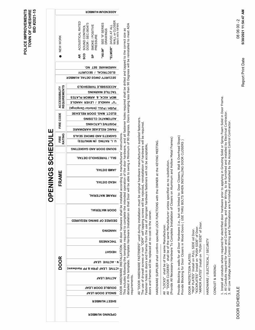
POLI
CE
IMPR
OVE
MEN
TS
TOW
N O
F C
HESH
IRE
BID
#20
21-1
5
OPE
NIN
GS
SCH
EDUL
ED
OO
RFI
RE
CO
DE
ACC
ESSI
BIL
ITY
REQ
UIR
EMEN
TSFR
AME
FIR
E R
ATIN
G
OPENING NUMBER
SHEET NUMBER
SINGLE DOOR LEAF DOUBLE DOOR LEAF
ACTIVE LEAF
HEIGHT
THICKNESS
HANDING
DOOR MATERIAL
FRAME MATERIAL
HEAD DETAIL
JAMB DETAIL
SILL / THRESHOLD DETAIL
U. L. RATING (IN MINUTES) GASKETS AND SMOKE SEALS
PANIC RELEASE HARDWARE POSITIVE LATCHING AUTOMATIC CLOSING ELECT. MAG. DOOR RELEASE PUSH / PULL (Interior Oenpings)
"U" HANDLE / LEVER HANDLE MOP, KICK, & ARMOR PLATES TACTILE WARNING ACCESSIBLE THRESHOLD
ELECTRICAL / SECURITY HARDWARE SET NO.
SOUND DOOR AND GASKETING
ACTIVE LEAF (PRH & PP Hardware)
IN - ACTIVE LEAF
DEGREE OF SWING REQUIRED
l lN
EW W
OR
K
ARAC
OU
STIC
AL R
ATED
SCD
SOU
ND
CO
NTR
OL
DO
OR
- SE
C.0
8347
3
SMO
KE /
POSI
TIVE
P R
ESSU
RE
SP
ADDENDUM NUMBER
SECURITY DWGS DETAIL NUMBER
SEE
"8" S
ERIE
S D
RAW
ING
S"A
8.0#
"
24VD
C A
T AL
L W
ALL
or C
LOSE
R
MAG
HO
LDER
S
"ELM
DR
"
DO
OR H
ARD
WARE I
NSTALLATIO
N:
All d
oor
hard
ware
shall b
e insta
lled a
ccord
ing t
o m
anufa
ctu
res' in
str
uctions.
This
inclu
des follow
ing t
he t
em
pla
te r
equired t
o c
om
ple
te t
he inte
nded o
pera
tion o
f th
e d
oor
hard
ware
, and a
ll faste
ner
hole
s r
equired s
hall b
e d
rilled a
nd t
apped t
o t
he c
orr
ect
siz
e a
s
deta
iled in t
he t
em
pla
te. Tem
pla
te H
ard
ware
Insta
llation s
o t
hat
Door
will be a
ble
to s
win
g a
Min
imum
of 90 d
egre
es. D
oors
sw
ingin
g less t
han 9
0 D
egre
es w
ill be r
ein
sta
lled t
o m
eet
AD
A
requirem
ents
.
All "
DO
OR H
ARD
WARE F
ASTEN
ERS"
used d
uring insta
llation m
ust
be o
rigin
al hard
ware
manufa
ctu
rer's s
upplied faste
ners
.
The u
se o
f dry
wall s
cre
ws o
r non "
OEM
" self t
appin
g s
cre
ws w
ill be r
eje
cte
d, re
insta
llation o
f hard
ware
will be r
equired.
Faste
ner
hole
s in d
oors
and fra
mes fro
m t
he u
se o
f im
pro
per
hard
ware
faste
ners
will not
be a
ccepta
ble
,
doors
and fra
mes w
ill be r
epla
ced a
t no c
ost
to t
he o
wner.
HARD
WARE S
UPPLIE
R s
hall c
onfirm
specifie
d L
OC
K F
UN
CTIO
NS w
ith t
he O
WN
ER a
t th
e K
EYIN
G M
EETIN
G.
----
----
----
----
----
----
----
----
----
---
All "L
OCKS"
shall b
e o
f th
e s
am
e M
anufa
ctu
rer.
All "D
OO
R C
LO
SERS"
shall b
e o
f th
e s
am
e M
anufa
ctu
rer
unle
ss s
pecifie
d a
s n
o s
ubstitu
tion.
(Pro
vid
e A
ll N
ecessary
Hard
ware
To C
om
ple
te I
nsta
llation o
f Clo
sers
on A
lum
inum
and H
ollow
Meta
l Fra
mes)
Pro
vid
e B
lockin
g in w
alls for
all D
oor
Hard
ware
(i.e.,
but
not
lim
ited t
o:
Door
Clo
sers
, W
all &
Overh
ead S
tops)
Pro
vid
e B
lockin
g for
Door
Clo
sers
in W
ood D
oors
( U
SE T
HRU
BO
LTS W
HEN
IN
STALLIN
G D
OO
R C
LO
SERS )
DO
OR P
RO
TECTIO
N P
LATES:
"M
OP P
LATES"
Insta
ll o
n P
ULL S
IDE o
d D
oor.
"KIC
KPLATES"
Insta
ll o
n "
PU
SH
SID
E"
of D
oor.
"ARM
OR P
LATES"
Insta
ll o
n "
PU
SH
SID
E"
of D
oor.
----
----
----
----
----
----
----
----
----
---
HARD
WARE /
ELECTRIC
AL /
SECU
RIT
Y
CO
ND
UIT
& W
IRIN
G:
1. In
sta
ll a
ll c
onduits w
here
required for
ele
ctr
ifie
d d
oor
hard
ware
prior
to a
pply
ing in G
routing S
olid o
r Spra
y F
oam
Solid in D
oor
Fra
me.
2. All C
onduits r
equired for
Pow
er
and C
ontr
ol W
irin
g, and P
ow
er
Wirin
g, to
be furn
ished a
nd insta
lled b
y E
lectr
ical C
ontr
acto
r.
3. All L
ow
Voltage A
ccess C
ontr
ol W
irin
g a
nd T
erm
inations a
re furn
ished a
nd insta
lled b
y t
he A
ccess C
ontr
ol Contr
acto
r.
5/30
/202
1 11
:54:
47 A
MR
epor
t Prin
t Dat
eD
OO
R S
CH
EDU
LE08
06
00 -
2

POLI
CE
IMPR
OVE
MEN
TS
TOW
N O
F C
HESH
IRE
BID
#20
21-1
5
OPE
NIN
GS
SCH
EDUL
ED
OO
RFI
RE
CO
DE
ACC
ESSI
BIL
ITY
REQ
UIR
EMEN
TSFR
AME
FIR
E R
ATIN
G
OPENING NUMBER
SHEET NUMBER
SINGLE DOOR LEAF DOUBLE DOOR LEAF
ACTIVE LEAF
HEIGHT
THICKNESS
HANDING
DOOR MATERIAL
FRAME MATERIAL
HEAD DETAIL
JAMB DETAIL
SILL / THRESHOLD DETAIL
U. L. RATING (IN MINUTES) GASKETS AND SMOKE SEALS
PANIC RELEASE HARDWARE POSITIVE LATCHING AUTOMATIC CLOSING ELECT. MAG. DOOR RELEASE PUSH / PULL (Interior Oenpings)
"U" HANDLE / LEVER HANDLE MOP, KICK, & ARMOR PLATES TACTILE WARNING ACCESSIBLE THRESHOLD
ELECTRICAL / SECURITY HARDWARE SET NO.
SOUND DOOR AND GASKETING
ACTIVE LEAF (PRH & PP Hardware)
IN - ACTIVE LEAF
DEGREE OF SWING REQUIRED
l lN
EW W
OR
K
ARAC
OU
STIC
AL R
ATED
SCD
SOU
ND
CO
NTR
OL
DO
OR
- SE
C.0
8347
3
SMO
KE /
POSI
TIVE
P R
ESSU
RE
SP
ADDENDUM NUMBER
SECURITY DWGS DETAIL NUMBER
SEE
"8" S
ERIE
S D
RAW
ING
S"A
8.0#
"
24VD
C A
T AL
L W
ALL
or C
LOSE
R
MAG
HO
LDER
S
"ELM
DR
"
4. Contr
ols
and C
ontr
ol W
irin
g (
pro
vid
e 1
6 g
a. W
ire u
nle
ss n
ote
d o
therw
ise)
of Ele
ctr
ifie
d D
evic
es, Tra
nsfe
r H
inges, and P
ow
er
Supplies t
o b
e p
rovid
ed b
y S
ecurity
Contr
acto
r.
DO
OR &
FRAM
ES:
1. D
oor
Fra
me S
upplier
must
coord
inate
Door
Conta
ct
Fra
me P
rep w
ith S
ecurity
Contr
acto
r.
2. D
oor
and F
ram
e S
uppliers
must
pre
p d
oors
and fra
mes t
o a
ccom
modate
all e
lectr
ifie
d h
ard
ware
, in
clu
din
g a
ll r
equired c
onduits in
doors
and fra
mes, w
hen p
reppin
g d
oors
and fra
mes for
door
hard
ware
.
HARD
WARE:
1. H
ard
ware
supplier
must
pro
vid
e, W
irin
g D
iagra
ms -
Ele
vation a
nd R
iser
& P
oin
t to
Poin
t, t
o E
lectr
ical Contr
acto
r.
2. Ele
ctr
om
agnetic D
oor
Rele
ase (
Magnetic D
oor
Hold
ers
) to
be furn
ished b
y S
ection 0
8 7
1 0
0 a
nd I
nsta
lled b
y E
lectr
ical C
ontr
acto
r.
ACCESS C
ON
TRO
L R
EAD
ERS:
1. “R
EAD
ERS"
by A
ccess C
ontr
ol /
Security
Contr
acto
r.
OPE
NIN
G N
OTE
S
GEN
ERAL D
OO
R N
OTES:
"A"
All D
oor
Hard
ware
shall b
e A
ccessib
le t
o P
ers
ons w
ith D
isabilitie
s. H
ard
ware
shall c
om
ply
with A
DA S
tandard
s.
__________________________________________________________________________________________
-
Pro
vid
e P
ar
Arm
Clo
ser
with I
nte
gra
l H
eavy D
uty
Sto
p A
rm, (I
nsta
ll "
PU
SH
SID
E"
of D
oor)
.
__________________________________________________________________________________________
CL02
5/30
/202
1 11
:54:
47 A
MR
epor
t Prin
t Dat
eD
OO
R S
CH
EDU
LE08
06
00 -
3

POLI
CE
IMPR
OVE
MEN
TS
TOW
N O
F C
HESH
IRE
BID
#20
21-1
5
OPE
NIN
GS
SCH
EDUL
ED
OO
RFI
RE
CO
DE
ACC
ESSI
BIL
ITY
REQ
UIR
EMEN
TSFR
AME
FIR
E R
ATIN
G
OPENING NUMBER
SHEET NUMBER
SINGLE DOOR LEAF DOUBLE DOOR LEAF
ACTIVE LEAF
HEIGHT
THICKNESS
HANDING
DOOR MATERIAL
FRAME MATERIAL
HEAD DETAIL
JAMB DETAIL
SILL / THRESHOLD DETAIL
U. L. RATING (IN MINUTES) GASKETS AND SMOKE SEALS
PANIC RELEASE HARDWARE POSITIVE LATCHING AUTOMATIC CLOSING ELECT. MAG. DOOR RELEASE PUSH / PULL (Interior Oenpings)
"U" HANDLE / LEVER HANDLE MOP, KICK, & ARMOR PLATES TACTILE WARNING ACCESSIBLE THRESHOLD
ELECTRICAL / SECURITY HARDWARE SET NO.
SOUND DOOR AND GASKETING
ACTIVE LEAF (PRH & PP Hardware)
IN - ACTIVE LEAF
DEGREE OF SWING REQUIRED
l lN
EW W
OR
K
ARAC
OU
STIC
AL R
ATED
SCD
SOU
ND
CO
NTR
OL
DO
OR
- SE
C.0
8347
3
SMO
KE /
POSI
TIVE
P R
ESSU
RE
SP
ADDENDUM NUMBER
SECURITY DWGS DETAIL NUMBER
SEE
"8" S
ERIE
S D
RAW
ING
S"A
8.0#
"
24VD
C A
T AL
L W
ALL
or C
LOSE
R
MAG
HO
LDER
S
"ELM
DR
"
Pro
vid
e P
ar
Arm
Clo
ser
with I
nte
gra
l H
eavy D
uty
Sto
p a
nd H
old
Open A
rm.
__________________________________________________________________________________________
CL03
"E1"
DO
OR C
ON
TACTS -
Door
Positio
n C
onta
cts
to b
e furn
ished a
nd insta
ller
by S
ecurity
Contr
acto
r.
Door(
s)
and F
ram
e(s
) to
have facto
ry p
repara
tions for
Door
Conta
ct(
s),
coord
inate
with D
oor
Positio
n C
onta
cts
Supplied.
____________________________________________________________________________________________________
E1
"EU
06.4
PL”
MO
RTIS
E L
OCK -
"CARD
Reader"
insta
lled o
n t
he P
USH
Sid
e o
f th
e O
penin
g.
Syste
m t
o h
ave "
FAIL
SECU
RE o
pera
tion"
:
Section 0
8 7
1 0
0 t
o p
rovid
e E
lectr
ically L
ocked T
rim
, pro
vid
e I
nte
gra
l Latc
hbolt M
onitor
and R
equest
to E
xit F
unction.
Section 0
8 7
1 0
0 t
o p
rovid
e (
12 R
ETW
) W
ire P
ow
er
Tra
nsfe
r H
inge, and Pow
er
Supply
(See H
ard
ware
Sets
for
PS
Requirem
ents
).
Latc
hbolt b
y G
rip o
ut
sid
e o
nly
when lo
ck is e
nerg
ized.
Outs
ide G
rip locked w
hen lo
ck is n
ot
energ
ized.
Latc
hbolt b
y k
ey o
uts
ide w
hen lo
ck is n
ot
energ
ized.
Auxilia
ry latc
h d
eadlo
cks L
atc
hbolt
Insid
e G
rip a
lways F
REE.
__________________________________________________________________________________________
EU
.06.4
PU
"SW
1"
DEG
REE S
WIN
G (
90)
- Tem
pla
te H
ard
ware
(D
oor
Clo
sers
/ O
verh
ead S
tops)
Insta
llation t
o S
pecifie
d D
egre
e o
f Sw
ing
(90),
See D
oor
Schedule
.
__________________________________________________________________________________________
SW
1
5/30
/202
1 11
:54:
47 A
MR
epor
t Prin
t Dat
eD
OO
R S
CH
EDU
LE08
06
00 -
4

POLICE IMPROVEMENTS TOWN OF CHESHIRE HOLLOW METAL BID #2021-15 DOORS AND FRAMES 08 11 13-1
HOLLOW METAL DOORS AND FRAMES 08 11 13-1
SECTION 08 11 13 – HOLLOW METAL DOORS AND FRAMES PART 1 - GENERAL 1.1 RELATED DOCUMENTS
A. Instructions to Bidders, AIA Document A201 - 2007, “General Conditions of the Contract for Construction”, the Supplementary General Conditions and Division 1, General Requirements, are a part of this Section and shall be binding on the Contractor and or Subcontractor who performs this Work. Note also all Addenda.
1.2 SUMMARY
A. This Section includes furnishing pressed steel frames for doors. 1.3 RELATED SECTIONS
A. Section 06 10 00 “Rough Carpentry” for installation of Standard Steel Doors and Frames.
B. Painting primed doors and frames is specified in Section 09 91 13, "Interior
Painting."
C. Wood doors are specified in Section 08 14 00, "Wood Doors".
D. Door hardware is specified in Section 08 71 00 "Door Hardware". 1.4 REFERENCES
A. NFPA 80: Standard for Fire Doors and Other Opening Protectives B. NFPA 101: Life Safety Code C. NFPA 252: Standard Methods of Fire Tests of Door Assemblies D. NFPA 257: Standard on Fire Tests for Window and Glass Block Assemblies E. UL 10C: Standard for Positive Pressure Fire Tests of Door Assemblies F. ICC/ANSI A117.1: Accessible and Usable Buildings and Facilities G. ANSI A 250.4: Test Procedure and Acceptance Criteria for Physical Endurance for
Steel Doors and Hardware Reinforcings H. ANSI A250.10: Test Procedure and Acceptance Criteria for Prime Painted Steel
Surfaces for Steel Doors and Frames
POLICE IMPROVEMENTS TOWN OF CHESHIRE HOLLOW METAL BID #2021-15 DOORS AND FRAMES 08 11 13-2
HOLLOW METAL DOORS AND FRAMES 08 11 13-2
I. ANSI/DHI A115.1G: Installation Guide for Doors and Hardware J. ASTM A 653: Standard Specification for Steel Sheet, Zinc-Coated (Galvanized) or
Zinc-Iron Alloy-Coated (Galvannealed) by the Hot-Dip Process. K. ASTM A 1008: Standard Specification for Steel Sheet, Cold-Rolled, Carbon,
Structural, High-Strength Low-Alloy and High-Strength Low-Alloy with Improved Formability.
L. NAAMM HMMA 840-99: Guide Specifications for Installation and Storage of
Hollow Metal Doors and Frames M. C518 - 04 Standard Test Method for Steady-State Thermal Transmission Properties
by Means of the Heat Flow Meter Apparatus
1.5 SUBMITTALS
A. General: Submit the following in accordance with Conditions of Contract and Division 1 Specification Sections.
B. Product data for each type of door and frame specified, including details of
construction, materials, dimensions, hardware preparation, core, label compliance, sound ratings, profiles, finishes, detail of molding, conduit and prep for power signal and control systems.
C. Shop drawings showing fabrication and installation of standard steel doors and
frames. Include details of each frame type, elevations of door design types, conditions at openings, details of construction, location and installation requirements of door and frame hardware and reinforcements, and details of joints and connections. Show anchorage and accessory items. 1. Provide schedule of doors and frames using same reference numbers for
details and openings as those on contract drawings. 2. Indicate coordination of glazing frames and stops with glass and glazing
requirements.
D. Label Construction Certification: For door assemblies required to be fire-rated and exceeding limitations of labeled assemblies, submit manufacturer's certification that each door and frame assembly has been constructed to conform to design, materials and construction equivalent to requirements for labeled construction.
1.6 QUALITY ASSURANCE
A. Provide doors and frames from a single source manufacturer.

POLICE IMPROVEMENTS TOWN OF CHESHIRE HOLLOW METAL BID #2021-15 DOORS AND FRAMES 08 11 13-3
HOLLOW METAL DOORS AND FRAMES 08 11 13-3
B. Distributor’s qualifications: Five (5) years’ experience in similar projects. C. Installer’s qualifications: Five (5) years’ experience in similar projects.
1.7 DELIVERY, STORAGE, AND HANDLING
A. Deliver doors and frames cardboard-wrapped or crated to provide protection during transit and job storage. Provide additional protection to prevent damage to finish of factory-finished doors and frames.
B. Inspect doors and frames upon delivery for quantity and damage. Minor damages
may be repaired provided refinished items are equal in all respects to new work and acceptable to Architect; otherwise, remove and replace damaged items as directed.
C. Store and protect materials in accordance with NAAMM HMMA 840. Store
doors and frames at building site under cover. Place units on minimum 4-inches high wood blocking. Avoid use of non-vented plastic or canvas shelters which could create humidity chamber. If cardboard wrapper on door becomes wet, remove carton immediately. Provide 1/4-inches spaces between stacked doors to promote air circulation.
D. Identify products with a label indicating:
1. Manufacturer’s name 2. Architect’s opening number 3. Product description and dimensions
1.8 WARRANTY
A. Provide written manufacturer’s warranty for one (1) year from substantial
completion of the project on both material and workmanship. PART 2 - PRODUCTS 2.1 SUBSTITUTIONS
A. Requests for substitution for any of the products listed herein shall be submitted in accordance with the requirements of specification section 01 33 00 – Submittal Procedures.
2.2 PRODUCTS
RC RESILIENT COATING
1. Description: Water-based asphaltic frame undercoating for corrosion resistance.

POLICE IMPROVEMENTS TOWN OF CHESHIRE HOLLOW METAL BID #2021-15 DOORS AND FRAMES 08 11 13-4
HOLLOW METAL DOORS AND FRAMES 08 11 13-4
2. Location: Apply to all inside faces of frame (throat) where scheduled to be grout-filled.
3. Environtmental: GreenGuard certified and VOC Free 4. Fire Rating: Approved for use with UL (Underwriters Laboratories) and WH
(Warnock Hersey) fire rated frames. 5. Manufacturer / Product Line: Subject to compliance with the requirements,
provide one of the following: a. Ceco Door (Assa Abloy), Milan, TN (888-232-6366) / Asphaltic Frame
Undercoating (Option “AFC” - #6001197, #6001198, and #6001195) b. Approved Equal
2.3 ACCEPTABLE FRAME MANUFACTURERS
A. Manufacturer: Subject to compliance with requirements, provide standard steel
doors and frames by one of the following: 1. Standard Steel Doors and Frames:
a. De la Fontaine Industries b. Amweld Building Products, Inc. c. Ceco Corp. d. Republic Builders Products. e. Steelcraft Manufacturing Co.
2.4 FRAME MATERIALS
A. Steel requirements 1. Interior doors and frames: Comply with ASTM A653, Designation A40. 2. Exterior doors and frames: Comply with ASTM A653, Designation A60.
2.5 FRAME FABRICATION
A. Frames 1. Frame assembly: face welded, dressed smooth with seamless face. 2. Gauges
a. Interior openings up to 48” width: 16-gauge b. Interior openings over 48” width: 14-gauge c. Exterior openings: 14-gauge
d. Side light, transom and borrowed light: 16-gauge
B. Anchors 1. Suitable for wall conditions. 2. Located close to hinge reinforcements and at the same height on strike jamb.
a. Quantity: 2 per jamb up to 60” of door opening height, one additional anchor for each additional 30” of door height (or fraction thereof).
b. An additional floor anchor at the bottom of each jamb.
POLICE IMPROVEMENTS TOWN OF CHESHIRE HOLLOW METAL BID #2021-15 DOORS AND FRAMES 08 11 13-5
HOLLOW METAL DOORS AND FRAMES 08 11 13-5
C. Clearances 1. On non-fire rated openings:
a. Between door and frame: 1/8” b. Between meeting edges of pair of doors: 1/8” c. Between bottom of door and bottom of frame: ¾” without threshold.
D. Manufacturing tolerances:
1. Frames: Width: +1/16”, -1/32” Face, stop, rabbet and jamb depth: +/-1/32
G. Frame hardware preparation
1. Surface-applied hardware: factory reinforced only, 12-gauge 2. Mortise hardware: factory reinforced, drilled and tapped. 3. Hinge and pivot reinforcements: to prevent door sagging.
a. 7-gauge flat hinge reinforcements at all locations or b. 10-gauge high frequency hinge reinforcements, with a flange.
4. Strike reinforcement: 16-gauge. 5. Closer reinforcement: 12-gauge. 6. Other reinforcements: 16-gauge.
I. Finishing
1. Hot dipped galvanized A40/A60 a. Factory applied primer to protect the area where zinc was removed in
the welding process. 2. Primer
a. Factory applied primer. Primer shall comply with ANSI A250.10. 2.6 ACCESSORIES
A. Frame accessories
1. Dust/mortar box at strike location on drywall frames 2. Shipping bars on welded frames
a. 1 for frames with less than 7” jamb depth b. 2 for frames with 7” jamb depth and more
3. Drill holes for silencers: a. Single openings: 3 per strike jamb. b. Pair openings: 2 per header.
PART 3 - EXECUTION 3.1 EXAMINATION
A. Inspect rough openings to detect problems that would prevent the proper installation of doors and frames.
B. Rough openings shall be square, level and plumb with accurate dimensions.

POLICE IMPROVEMENTS TOWN OF CHESHIRE HOLLOW METAL BID #2021-15 DOORS AND FRAMES 08 11 13-6
HOLLOW METAL DOORS AND FRAMES 08 11 13-6
3.2 INSTALLATION
A. Plan and manage a pre-installation meeting to explain the proper methods to install hollow metal doors and frames.
B. Remove shipping bars on welded frames before installation and verify frame
dimensions. C. For grouted frames, apply on site a coat of bituminous coating inside the frame
throat. D. Install doors and frames in accordance with:
1. Approved door and hardware schedule 2. Approved shop drawings 3. Manufacturer’s recommendations 4. Local building codes 5. NFPA 80 6. ANSI/DHI A115.1G 7. NAAMM HMMA 840
3.3 ADJUSTING, CLEANING, AND PROTECTION
A. Repair or replace damaged products. B. Correct defects in installation. C. Clean area in accordance with Section 01700. D. Protect doors and frames until transfer of the building to the Owner.
END OF SECTION 08 11 13

POLICE IMPROVEMENTS TOWN OF CHESHIRE BID #2021-15 WOOD DOORS 08 14 00-1
WOOD DOORS 08 14 00-1
SECTION 08 14 00 – WOOD DOORS PART 1 - GENERAL 1.1 RELATED DOCUMENTS:
A. Instructions to Bidders, AIA Document A201-2007, “The General Conditions of the Contract for Construction,” Supplementary General Conditions and Division 1, General Requirements, are a part of this Section and shall be binding on the Contractor and/or Subcontractor who performs this work. Note also all Addenda.
1.2 SUMMARY:
A. Extent and location of each type of wood door is indicated on drawings and in schedules.
B. Types of doors required include the following:
1. Solid core wood doors with wood veneer faces (Plain Sliced White Oak) and factory finishing
C. Factory-premachining for hardware for wood doors is mandatory. D. Factory finishing of wood doors is mandatory. E. Related Sections: The following sections contain requirements that relate to this
section: 1. Section 06 46 00 – Wood Trim: Additional woodwork other than wood
doors. 2. Section 08 11 13 – Hollow Metal Doors and Frames: Metal door frames
for wood doors. 3. Section 08 71 00 – Door Hardware: Door hardware for wood doors. 4. Section 08 80 00 – Glazing: Glazing for wood doors.
1.3 SUBMITTALS:
A. Product Data: Door manufacturer's technical data for each type of door, including details of core and edge construction, trim for openings and factory-finishing specifications.
B. Shop Drawings: Submit shop drawings indicating location and size of each door,
elevation of each kind of door, details of construction, location and extent of hardware blocking, fire ratings, requirements for factory finishing and other pertinent data. 1. For factory-premachined doors, indicate dimensions and locations of
cutouts for locksets and other cutouts adjacent to light and louver openings.

POLICE IMPROVEMENTS TOWN OF CHESHIRE BID #2021-15 WOOD DOORS 08 14 00-2
WOOD DOORS 08 14 00-2
C. Samples: Submit samples of both finish stains on the wood species identified to the Architect for review and approval prior to fabrication release.
1.4 QUALITY ASSURANCE:
A. Quality Standards: Comply with the following standards: 1. NWWDA Quality Standard: I.S.1 "Industry Standard for Wood Flush
Doors", of National Wood Window and Door Association (NWWDA). 2. AWI Quality Standard: "Architectural Woodwork Quality Standards";
including Section 1300 "Architectural Flush Doors", of Architectural Woodwork Institute (AWI) for grade of door, core construction, finish and other requirements exceeding those of NWWDA quality standard.
B. NWWDA Quality Marking: Mark each wood door with NWWDA Wood Flush
Door Certification Hallmark certifying compliance with applicable requirements of NWWDA I.S. 1 Series.
C. Manufacturer: Obtain doors from a single manufacturer. D. Factory prefinishing shall meet the performance standards of AWI finish system
TR-6 (AWI #5) and OP-6 (AWI #11) with stain coat. 1.5 PRODUCT DELIVERY, STORAGE, AND HANDLING:
A. Protect doors during transit, storage and handling to prevent damage, soiling and deterioration. Comply with requirements of referenced standards and recommendations of NWWDA pamphlet "How to Store, Handle, Finish, Install, and Maintain Wood Doors", as well as with manufacturer's instructions.
B. Identify each door with individual opening numbers which correlate with
designation system used on shop drawings for door, frames, and hardware, using temporary, removable or concealed markings.
1.6 PROJECT CONDITIONS:
A. Conditioning: Do not deliver or install doors until conditions for temperature and relative humidity have been stabilized and will be maintained in storage and installation areas during remainder of construction period to comply with the following requirements applicable to project's geographical location: 1. Referenced AWI quality standard including Section 100-S-3 "Moisture
Content". 1.7 WARRANTY:
A. General: Warranties shall be in addition to, and not a limitation of, other rights the Owner may have under the Contract Documents.

POLICE IMPROVEMENTS TOWN OF CHESHIRE BID #2021-15 WOOD DOORS 08 14 00-3
WOOD DOORS 08 14 00-3
B. Door Manufacturer's Warranty: Submit written agreement in door manufacturer's standard form signed by Manufacturer, Installer and Contractor, agreeing to repair or replace defective doors that have warped (bow, cup or twist) or that show telegraphing of core construction in face veneers, or do not conform to tolerance limitations of referenced quality standards. 1. Warranty shall also include reinstallation which may be required due to
repair or replacement of defective doors where defect was not apparent prior to hanging.
2. Warranty shall be in effect during following period of time after date of Substantial Completion.
3. Solid Core Interior Doors: a. Life of installation.
C. Contractor's Responsibilities: Replace or refinish doors where Contractor's work
contributed to rejection or to voiding of manufacturer's warranty. PART 2 - PRODUCTS 2.1 SUBSTITUTIONS
A. Requests for substitution for any of the products listed herein shall be submitted in accordance with the requirements of specification section 01 33 00 – Submittal Procedures.
2.2 PRODUCTS
WD WOOD DOORS
1. Description: Solid particle board core, wood veneer, non-rated door leaf. 2. Thickness: 1-3/4-inch 3. Surface Material: Grade A, White Oak, plain sliced cut veneer. Match
veneer for all pair doors. 4. AWI Grade: Custom 5. Crossbands: Wood-based composites of a minimum thickness of 1/16".
Crossbands and face veneers are laminated to the core using the Hot Press process. Crossbands must extend the full width of the door. Minimum properties include internal bond of 100 psi and density of 50 lbs. per cubic foot.
6. Stile Type: Matching 7. Vertical Edges: Matching/compatible veneer edge band over structural
composite lumber 8. Horizontal Edges: Rails are solid wood, structural composite lumber meeting
the minimum requirements of WDMA, or medium density fiberboard meeting requirements of ANSI 208.2 (Medium Density Fiberboard for Interior Use).
9. Face & Core Assembly Adhesive: Type 1 10. Core Construction: Particleboard Core (PC-5) to comply with ANSI Stnd.
A208.1- 1989 LD-2, with screw holding power of 125 lbs., modulus of

POLICE IMPROVEMENTS TOWN OF CHESHIRE BID #2021-15 WOOD DOORS 08 14 00-4
WOOD DOORS 08 14 00-4
rupture of 800 psi, modulus of elasticity of 150,000 psi and density of 30-35 lbs. per cubic foot.
11. Lite / Louvers Openings and Frames: Factory glazed. Glazing per section 08 80 00 “Glazing” and door leaf schedule on drawings. Wood beads with species and finish to match door face. Dual finish required for dual finish doors.
12. Distance Between Lock and Lite Cutouts: 3-1/4-inch minimum 13. Machining: Machining preparation per hardware manufacturer’s templates.
Coordinate with door hardware schedule and specification. 14. Blocking Requirements: Minimum 5” top rail and 5” bottom rail required. 15. Factory Finishing: All doors to be finished at the factory, with UV cured
system with performance properties equivalent to TR-6 or OP-6 Catalyzed Polyurethane per AWI Section 1500, Premium grade. Factory pre-finished doors to be individually protected with transparent poly-wrap at the factory. Final color, build, and sheen to be approved by architect based on actual review samples supplied by the manufacturer. Finish to comply with the following: a. Dual Finish Doors: Custom staining. Doors in openings #004A, #013B,
and #018A are to have two different stain finishes. The finish on the existing Corridor side is to match the existing facility doors to remain (similar to Masonite color Honey). The finish on the scope of work area side is to match the Single Finish Doors requirement listed below.
b. Single Finish Doors: Custom staining. All wood doors, unless otherwise indicated above, are to receive stain color Minwax #MW471 “Navy”, below the clear top coat, unless otherwise indicated.
16. Acoustic Rating: STC 30 17. Environmental: CARB PH2 /TSCA Title VI Compliant 18. Quality Standard: WDMA I.S.1A Architectural Wood Flush Doors (Standard
Construction), performance level Heavy Duty. 19. Door Weight: 5.5 lbs per square foot. 20. Manufacturer / Product Line: Subject to compliance with the requirements,
provide heat treated glass units by the following: a. Masonite Architectural / Aspiro Series, Marshfield-Algoma b. Approved Equal
2.3 FABRICATION:
A. Fabricate wood doors to produce doors complying with following requirements: 1. In sizes indicated for job-site fitting. 2. Factory-prefit and premachine doors to fit frame opening sizes indicated
with the following uniform clearances and bevels: a. Comply with tolerance requirements of AWI for prefitting.
Comply with final hardware schedules and door frame shop drawings and with hardware templates.
b. Coordinate measurements of hardware mortises in metal frames to verify dimensions and alignment before proceeding with factory premachining.

POLICE IMPROVEMENTS TOWN OF CHESHIRE BID #2021-15 WOOD DOORS 08 14 00-5
WOOD DOORS 08 14 00-5
B. Openings: Cut and trim openings through doors to comply with applicable
requirements of referenced standards for kind(s) of doors required. 1. Light Openings: Trim openings with moldings of material and profile
indicated. PART 3 - EXECUTION 3.1 EXAMINATION:
A. Examine installed door frames prior to hanging door: 1. Verify that frames comply with indicated requirements for type, size,
location, and swing characteristics and have been installed with plumb jambs and level heads.
2. Reject doors with defects.
B. Do not proceed with installation until unsatisfactory conditions have been corrected.
3.2 INSTALLATION:
A. Hardware: For installation see Section 08 71 00 "Door Hardware" section of these specifications.
B. Manufacturer's Instructions: Install wood doors to comply with manufacturer's
instructions and of referenced AWI standard and as indicated. 1. Install fire-rated doors in corresponding fire-rated frames in accordance
with requirements of NFPA No. 80. C. Job-Fit Doors: Align and fit doors in frames with uniform clearances and bevels
as indicated below; do not trim stiles and rails in excess of limits set by manufacturer or permitted with fire-rated doors. Machine doors for hardware. Seal cut surfaces after fitting and machining. 1. Fitting Clearances for Non-Rated Doors: Provide 1/8 inch, at jambs and
heads; 1/16 inch per leaf at meeting stiles for pairs of doors; and 1/8 inch from bottom of door to top of decorative floor finish or covering. Where threshold is shown or scheduled, provide ¼ inch clearance from bottom of door to top of threshold.
2. Fitting Clearances for Fire-Rated Doors: Complying with NFPA 80. 3. Bevel non-rated doors 1/8 inch in 2 inches at lock and hinge edges. 4. Bevel fire-rated doors 1/8 inch in 2 inches at lock edge; trim stiles and
rails only to extent permitted by labeling agency.
D. Prefit Doors: Fit to frames for uniform clearance at each edge. 3.3 ADJUSTING AND PROTECTION:
POLICE IMPROVEMENTS TOWN OF CHESHIRE BID #2021-15 WOOD DOORS 08 14 00-6
WOOD DOORS 08 14 00-6
A. Operation: Rehang or replace doors which do not swing or operate freely. B. Finished Doors: Refinish or replace doors damaged during installation. C. Protect doors as recommended by door manufacturer to ensure that wood doors
will be without damage or deterioration at time of Substantial Completion. END OF SECTION 08 14 00

POLICE IMPROVEMENTS TOWN OF CHESHIRE ACCESS DOORS BID #2021-15 AND FRAMES 08 31 13-1
_____________________________________________________________________ ACCESS DOORS AND FRAMES 08 31 13-1
08 31 13 - ACCESS DOORS AND FRAMES PART 1 - GENERAL 1.1 RELATED DOCUMENTS
A. Instructions to Bidders, AIA Document A201 - 2007, “General Conditions of the
Contract for Construction”, the Supplementary General Conditions and Division 1, General Requirements, are a part of this Section and shall be binding on the Contractor and or Subcontractor who performs this Work. Note also all Addenda.
1.2 SUMMARY
A. This Section includes furnishing access doors for installation in the following types of construction:
1. Non-rated access panels for masonry wall construction.
1.3 SUBMITTALS
A. General: Submit the following in accordance with Conditions of Contract and Division 1 Specification Sections.
1. Product data in form of manufacturer's technical data and installation
instructions for each type of access door assembly, including setting drawings, templates, instructions, and directions for installation of anchorage, devices.
1.4 QUALITY ASSURANCE
A. Single-Source Responsibility: Obtain access doors for entire project from one source from a single manufacturer.
B. Size Variations: Obtain Architect's acceptance of manufacturer's standard size
units, which may vary slightly from sizes indicated.
C. Coordination: Furnish inserts and anchoring devices that must be built into other work for installation of access doors. Coordinate delivery with other work to avoid delay.
1.5 PROJECT CONDITIONS
A. Verification: Obtain specific locations and sizes for required access doors from trades requiring access to concealed equipment, and indicate on submittal schedule.

POLICE IMPROVEMENTS TOWN OF CHESHIRE ACCESS DOORS BID #2021-15 AND FRAMES 08 31 13-2
_____________________________________________________________________ ACCESS DOORS AND FRAMES 08 31 13-2
PART 2 - PRODUCTS 2.1 MANUFACTURERS
A. Manufacturers: Subject to compliance with requirements, provide access doors by one of the following:
1. Cesco Products 2. J.L. Industries 3. Milcor, Inc. 4. Nystrom, Inc.
2.2 MATERIALS AND FABRICATION
A. General: Furnish each access door assembly manufactured as an integral unit, complete with all parts, and ready for installation.
B. Steel Access Doors and Frames: Fabricate units of continuous welded steel
construction unless otherwise indicated. Grind welds smooth and flush with adjacent surfaces. Furnish attachment devices and fasteners of type required to secure access panels to types of support shown.
C. Frames: Fabricate from 16-gauge steel.
1. Fabricate frame with exposed flange nominal 1-inch wide around
perimeter of frame for units installed in the following construction: a. Exposed masonry.
2. For installation in masonry construction, furnish frames with adjustable metal masonry anchors.
D. Flush Panel Doors: Fabricate from not less than 14 gage sheet steel, with
concealed continuous piano hinge set to open 175 degrees. Finish with manufacturer's factory-applied prime paint.
E. Locking Devices: Furnish flush, screwdriver-operated cam locks of number
required to hold door in flush, smooth plane when closed.
1. Provide one cylinder lock per access door. Furnish 2 keys per lock. Key all locks alike, unless otherwise scheduled.
F. Finish: All steel is to be galvanized. All exposed faces of doors and frames are to
be primed and painted to match adjacent wall finish color. PART 3 - EXECUTION 3.1 INSTALLATION

POLICE IMPROVEMENTS TOWN OF CHESHIRE ACCESS DOORS BID #2021-15 AND FRAMES 08 31 13-3
_____________________________________________________________________ ACCESS DOORS AND FRAMES 08 31 13-3
A. Comply with manufacturer's instructions for installation of access doors. B. Coordinate installation with work of other trades. C. Set frames accurately in position and securely attach to supports with face panels
plumb or level in relation to adjacent finish surfaces. 3.2 ADJUST AND CLEAN
A. Adjust hardware and panels after installation for proper operation.
B. Remove and replace panels or frames that are warped, bowed, or otherwise damaged.
END OF SECTION 08 31 13

POLICE IMPROVEMENTS TOWN OF CHESHIRE BID #2021-15
This page intentionally left blank.

POLICE IMPROVEMENTS TOWN OF CHESHIRE BID #2021-15 DOOR HARDWARE 08 71 00-1
____________ ___ DOOR HARDWARE 08 71 00-1 Last Edit – 05/30/2021
08 71 00 - DOOR HARDWARE
PART 1 - GENERAL
1.1 RELATED DOCUMENTS
A. Instructions to Bidders, AIA Document A201-2007, “The General Conditions of the Contract for Construction,”, the Supplementary General Conditions and Division 1, General Requirements, are a part of this Section and shall be binding on the Contractor and/or Subcontractor who performs this work. Note also all Addenda.
1.2 SUMMARY
A. This Section includes items known commercially as finish or door hardware that are required for swing, sliding, and folding doors, except special types of unique hardware specified in the same Sections as the doors and door frames on which they are installed. Furnish and deliver all door hardware necessary for all doors, also hardware as specified herein and as enumerated in hardware sets and as indicated and required by actual conditions at the building. The hardware shall include the furnishing of all necessary screws, bolts, expansion shields, drop plates, and all other devices necessary for the proper application of the hardware.
B. ALL DOOR HARDWARE MUST BE FURNISHED BY SECTION 08 71 00 DOOR HARDWARE SUPPLIER.
"CONTRACTS, Including Door Hardware, ISSUED TO ALUMINUM DOOR SUPPLIER" must stipulate aluminum door hardware must be purchased from SECTION 087100 HARDWARE SUPPLIER
C. HARDWARE SUPPLIER: Must employ an experienced Architectural Hardware Consultant (AHC) who is available to Owner, Architect, and Contractor, at reasonable times during the course of the Work, for consultation.
D. Related Sections: The following Sections contain requirements that relate to this Section:
1. Division 8 Section 08 06 00 “SCHEDULE FOR OPENINGS”. 2. Division 8 Section 08 11 13 “HOLLOW METAL DOORS AND FRAMES”. 3. Division 8 Section 08 14 16 "FLUSH WOOD DOORS". 4. Division 26 “ELECTRICAL". 5. Division 28 “ELECTRONIC SECURITY SYSTEMS".

POLICE IMPROVEMENTS TOWN OF CHESHIRE BID #2021-15 DOOR HARDWARE 08 71 00-2
____________ ___ DOOR HARDWARE 08 71 00-2 Last Edit – 05/30/2021
1.3 REFERENCES
A. Standards:
1. ANSI/BHMA, A156.1 (2013) - Butts & Hinges 2. ANSI/BHMA, A156.2 (2011) - Bored and Preassembled Locks and Latches 3. ANSI/BHMA, A156.4 (2008) - Door Controls - Closers 4. ANSI/BHMA, A156.5 (2010) - Auxiliary Locks and Associated Products 5. ANSI/BHMA, A156.6 (2010) - Architectural Door Trim 6. ANSI/BHMA, A156.7 (2009) - Template Hinge Dimensions 7. ANSI/BHMA, A156.8 (2010) - Door Controls - Overhead Stops and Holders 8. ANSI/BHMA, A156.13 (2012) - Mortise Locks & Latches, Series 1000 9. ANSI/BHMA, A156.18 (2012) - Materials and Finishes. 10. ANSI/BHMA, A156.21 (2009) - American National Standard for Thresholds 11. ANSI/BHMA, A156.25 (2007) - Electrified Locking Devices 12. ANSI/BHMA, A156.26 (2012) - Continuous Hinges 13. ANSI/BHMA, A156.28 (2007) - Recommended Practices for Keying Systems 14. ANSI/BHMA, A156.30 (2003) - American National Standard for High Security Cylinders 15. ANSI/BHMA, A156.36 (2010) - American National Standard for Auxiliary Locks 16. ANSI/BHMA, A156.115 (2006) - Hardware Preparation in Steel Doors and Steel Frames 17. NFPA 80 - Fire Doors and Windows 18. UL10C - Positive Pressure Fire Tests of Door Assemblies 19. AIA 232 2009 - General Conditions of the Contract for Construction, Construction Manager as Advisor Edition.
B. Codes: 1. Applicable state and local building codes. 2. 2015 International Building Code as Amended for the 2018 Connecticut State Code [CSBC 101.1.1] 3. NFPA 101 - Life Safety code 4. NFPA 105 - Smoke and Draft Control Door Assemblies 5. ICC / ANSI A117.1 - Accessible and Usable Buildings and Facilities 6. ADA - Americans with Disabilities Act
C. UL Underwriters Laboratories 1. UL 10C – Fire Tests of Door Assemblies 2. UL 305 – Panic Hardware
D. DHI – Door and Hardware Institute

POLICE IMPROVEMENTS TOWN OF CHESHIRE BID #2021-15 DOOR HARDWARE 08 71 00-3
____________ ___ DOOR HARDWARE 08 71 00-3 Last Edit – 05/30/2021
1. Sequence and Form and for the Hardware Schedule 2. Recommended Locations for Builders Hardware
1.4 SUBMITTALS
A. General: Submit the following in accordance with Conditions of Contract and Section 1 Specification Sections.
B. Product data including manufacturer’s technical product data for each item of door hardware, installation instructions, maintenance of operating parts and finish of door hardware.
C. Final hardware schedule must be coordinated with doors, frames, and related work to ensure proper size, thickness, hand function, and finish of door hardware. Conflicts between the SPECIFIED DOOR HARDWARE and the DOORS / FRAMES must be brought to the attention of the ARCHITECT prior to submitting HARDWARE SUBMITTAL to the ARCHITECT.
D. HARDWARE SUPPLIER shall confirm specified LOCK FUNCTIONS with the OWNER at the KEYING MEETING.
1. Final Hardware Schedule Content: Based on hardware indicated, organize schedule into “HARDWARE SETS” indicating complete designation of every item required for each door or opening. Include the following information: Type, style, function, size, and finish of each hardware item.
a. Name and manufacturer of each item. b. Fastenings and other pertinent information. c. Location of Hardware Set, cross-referenced to indication of Drawings both on floor plans, in door, and frame schedule. d. Explanation of all abbreviations, symbols, and codes contained in schedule. e. Mounting locations for hardware. Door handles, pulls, latches, locks and other operating devices shall be installed
34 inches (864 mm) minimum and 48 inches (1219 mm) maximum above the finish
floor. Locks used only for security purposes and not used for normal operation are
permitted at any height. Provide “DHI” Standard Mounting Locations in the Hardware Submittal. f. Door and frame sizes and materials. g. Keying information. h. Name and phone number for the local manufacturer’s representative for each product.
2. Submittal Sequence: submit final schedule at earliest possible date particularly where acceptance of hardware schedule must precede fabrication of other work that is

POLICE IMPROVEMENTS TOWN OF CHESHIRE BID #2021-15 DOOR HARDWARE 08 71 00-4
____________ ___ DOOR HARDWARE 08 71 00-4 Last Edit – 05/30/2021
critical in the Project construction schedule. Include with schedule the product data, samples, shop drawings of other work affected by door hardware, and other information essential to the coordinated review to schedule. 3. Keying Schedule: After a keying meeting between representatives of the Owner, Architect, hardware supplier, and, if requested, the representative for the lock manufacturer, provide a keying schedule, listing the levels of keying, as well as an explanation of the key system’s function, the key symbols used, and the door numbers controlled.
E. Samples: If requested by Architect, submit samples of each type of exposed hardware unit in finish indicated and tagged with full description for coordination with schedule. Submit samples prior to submission of final hardware schedule.
1. Samples will be returned to the supplier. Units that are acceptable and remain undamaged through submittal, review, and field comparison process may, after final check of operation, be incorporated in the Work, within limitations of keying coordination requirements.
F. Templates for doors, frames, and other work specified to be factory prepared for the installation of door hardware. Check shop drawings of other work to confirm that adequate provisions are made for locating and installing door hardware to comply with indicated requirements.
G. Wiring Diagrams: Upon final approval of the hardware schedule, submit wiring and riser diagrams as required for the complete and proper installation of all electrical, electromechanical, and electromagnetic products. Submittals must represent that coordination has occurred with the security system submittals and shop drawings. Also, that shop drawings submitted, and schedules developed have been specifically reviewed and coordinated for both physical equipment fitment and power requirements with the security system contractor approved shop drawings.
H. “Hardware Schedule and Templates”, Hardware schedules shall be created which reference specifically to the specified lock voltages and separately indicating whether the door is a “fail safe” or “fail secure” electrified lock arrangement.
I. Electrified Hardware: Electrified Hardware to be used for security purposes must be UL Listed for Burglary Applications.
J. At the completion of hardware installation, and prior to issuance of certificate of occupancy, prepare and submit the hardware inspection report to include the following: 1. Current and predictable problems of substantial nature in the performance of the hardware.

POLICE IMPROVEMENTS TOWN OF CHESHIRE BID #2021-15 DOOR HARDWARE 08 71 00-5
____________ ___ DOOR HARDWARE 08 71 00-5 Last Edit – 05/30/2021
2. Hardware has been installed and adjusted in accordance with manufacturer’s recommendations and instructions.
K. At the completion of the project, provide Owner with two (2) copies of an Operation and Maintenance Manual. This manual shall consist of a hard cover (3) ring binder with the project name listed on the front. Included will be:
1. A final copy of the approved and as built hardware schedule. 2. A final copy of the approved keying schedule. 3. Catalog cuts for each item used in the project. 4. Parts list and numbers for each item used. 5. Maintenance instructions for all items. 6. Name, address and phone number of local representatives for each item used.
1.5 QUALITY ASSURANCE
A. Substitutions: Products are to be those specified to ensure a uniform basis of acceptable materials. Requests for substitutions must be made in accordance with Section 1 requirements. If proposing a substitute to a specified item, indicate basis for substitution and savings to be made. Provide sample if requested. Certain products have been selected for their unique characteristics and particular project suitability. All Hardware is “Basis-of-Design” product specification as defined in Section 08 71 00. Model numbers (and Manufacturer’s) listed in “Hardware Set Schedule” are “Basis-of-Design”.
1. Items specified, as “no substitution” shall be provided exactly as listed. 2. Items listed with no substitute manufacturers listed have been requested by the Owner or Architect to match existing for continuity and/or future performance and maintenance standards or because there is no known equal product. 3. If no other products are listed in a category, then “no substitution” is implied.
B. Supplier Qualifications: A recognized architectural door hardware supplier, with warehousing facilities in the Project’s vicinity, that has a record of successful in-service performance for supplying door hardware similar in quantity, type, and quality to that indicated for this Project and that employs an experienced architectural hardware consultant (AHC) who is available to Owner, architect, and Contractor, at reasonable times during the course of the Work, for consultation. 1. Require supplier to meet with Owner to finalize keying requirements and to obtain final instructions in writing.
C. A pre-installation meeting shall be held to instruct installers on the proper installation and adjustment of door hardware. A representative of each major hardware category, including, but not limited to, Locks, Exit Devices, & Closers, shall instruct the

POLICE IMPROVEMENTS TOWN OF CHESHIRE BID #2021-15 DOOR HARDWARE 08 71 00-6
____________ ___ DOOR HARDWARE 08 71 00-6 Last Edit – 05/30/2021
installers on the correct installation of their products. The manufacturers of the Door Hardware provided on this project shall certify to the Architect that the door hardware installer for this project has been trained in the proper installation procedures and is certified to install the door hardware.
D. Fire-Rated Openings: Provide door hardware for fire-rated openings that complies with NFPA Standard No. 80 and requirements of authorities having jurisdiction. Provide only items of door hardware that are listed and are identical to products tested by UL, Intertek Testing Services, Warnock Hersey, Factory Mutual, or other testing and inspecting organization acceptable to authorities having jurisdiction for use on types and sizes of doors indicated in compliance with requirements of fire-rated door and door frame labels.
E. Accessible Hardware: Door Hardware; Handles, pulls, latches, locks and other
operable parts on accessible doors shall have a shape that is easy to grasp with one
hand and does not require tight grasping, pinching, or twisting of the wrist to operate.
Such hardware shall 34 inches (865 mm) minimum and 48 inches (1220 mm)
maximum above the floor or ground. Where sliding doors are in the fully open
position, operating hardware shall be exposed and usable from both sides.
EXCEPTION: Locks used only for security purposes and not used for normal
operation are permitted in any location.
F. Accessible Hardware: Door-Opening Force; Fire Doors shall have the minimum opening force allowable by the appropriate administrative authority. The maximum force for pushing open or pulling open doors other than fire doors shall be as follows:
1. Interior hinged door: 5.0 pounds 2. Sliding or folding door: 5.0 pounds 3. Fire Doors: Minimum opening force allowable by authorities having jurisdiction, but not greater than 10 lbf
These forces do not apply to the force required to retract latch bolts or disengage
other devices that hold the door in a closed position. The maximum force required to
release the latch shall not exceed 15 lbf. 4. Bevel raised thresholds with a slope of not more than 1:2. Provide thresholds not more than 1/2 inch high. 5. Adjust door closer sweep periods so that, from an open position of 70 degrees, the door will take at least 3 seconds to move to a point 3 inches from the latch, measured to the leading edge of the door.
1.6 PRODUCT HANDLING

POLICE IMPROVEMENTS TOWN OF CHESHIRE BID #2021-15 DOOR HARDWARE 08 71 00-7
____________ ___ DOOR HARDWARE 08 71 00-7 Last Edit – 05/30/2021
A. Tag each item or package separately with identification related to final hardware schedule and include basic installation instructions with each item or package.
B. Each item of hardware shall be individually packaged in manufacturer’s original container.
C. Receiving and storing of door hardware is responsibility of supplier. Prior to delivery of door hardware to the project, Hardware Supplier must sort and clearly mark with appropriate hardware set number to match set numbers of approved hardware schedule. Two or more identical sets may be packed in same container.
D. Inventory door hardware jointly with representatives of hardware supplier and hardware installer until each is satisfied that count is correct.
E. Deliver individually packaged door hardware items promptly to place of installation (shop or Project site).
F. Provide secure lock-up for door hardware delivered to the Project, but not yet installed. Control handling and installation of hardware items that are not immediately replaceable so that completion of the Work will not be delayed by hardware losses both before and after installation.
1.7 WARRANTY
A. Provide manufacturer’s Standard Warrantees.
B. Starting date for all warranty periods to be date of substantial completion of the Project.
C. No liability is to be assumed where damage or faulty operation is due to improper installation, improper use, or abuse.
D. Products judged to be defective during the warranty period shall be replaced or repaired in accordance with the manufacturer’s warranty, at no additional cost to the Owner.
PART 2 - PRODUCTS
2.1 MANUFACTURERS
A. Manufacturers: Subject to compliance with requirements, provide products by one of the following:
1. Butts and Hinges:

POLICE IMPROVEMENTS TOWN OF CHESHIRE BID #2021-15 DOOR HARDWARE 08 71 00-8
____________ ___ DOOR HARDWARE 08 71 00-8 Last Edit – 05/30/2021
a. Hager Companies b. Bommer c. Ives, Allegion d. McKinney Hinge, Div of Assa Abloy. e. PBB World Class Hinges f. Stanley Hardware
2. Continuous Hinges:
a. Hager Companies b. Bommer c. Ives, Allegion d. McKinney Hinge, Div of Assa Abloy. e. PBB World Class Hinges f. Pemko g. Select
3. Key Control System:
a. HPC b. Lund, Inc. c. Telkee Inc.
4. Locks:
a. Sargent, Div of Assa Abloy “8200”, “10-Line x LL” Series. 5. Push/Pull Units:
a. Hager Companies b. Burns Manufacturing, Inc c. Ives, Allegion d. Rockwood, Mfr.
6. Overhead Surface Closers:
a. Sargent, Div of Assa Abloy, Inc., “281(Heavy Duty Arms)” Series
7. Door Control Devices:
a. DORMAKABA USA. b. Burns Manufacturing, Inc c. Glynn Johnson, Allegion. d. MAG Security

POLICE IMPROVEMENTS TOWN OF CHESHIRE BID #2021-15 DOOR HARDWARE 08 71 00-9
____________ ___ DOOR HARDWARE 08 71 00-9 Last Edit – 05/30/2021
e. Rixson, Div of Assa Abloy f. Sargent, Div of Assa Abloy
8. Kick and Mop Plates:
a. Hager Companies b. Burns Manufacturing, Inc. c. Ives, Allegion. d. Rockwood
9. Smoke and Sound Stripping: a. Hager Companies. b. Legacy Manufacturing LLC c. National Guard Products. d. Pemko Manufacturing Co., Inc. e. Reese Enterprises, Inc. 10. Door Stops
a. Hager Companies b. Burns Manufacturing, Inc c. Glynn Johnson, Allegion. d. H.B. Ives, Allegion e. Rockwood Manufacturing
11. Electrified Hinges
a. Hager Companies b. Bommer c. McKinney Hinge, Div of Assa Abloy d. PBB World Class Hinges e. Stanley Hardware
12. Electrified Power Transfers
a. DORMAKABA USA. b. Locknetics, Allegion c. Precision Hardware. d. Security Door Controls e. Securitron, Div of Assa Abloy f. Von-Duprin, Allegion

POLICE IMPROVEMENTS TOWN OF CHESHIRE BID #2021-15 DOOR HARDWARE 08 71 00-10
____________ ___ DOOR HARDWARE 08 71 00-10 Last Edit – 05/30/2021
2.2 SCHEDULED HARDWARE
A. Requirements for each type of door hardware are indicated on the “Door Schedule”, and in the Schedule at the end of this Section. Products are identified by using hardware designation numbers of the following:
1. Manufacturer’s Product Designations: The product designation and name of one manufacturer are listed for each hardware type required for the purpose of establishing minimum requirements. Manufacturer and model numbers indicated in Hardware Sets constitute a “Basis-of-Design” product specification as defined in this Section.
2.3 MATERIALS AND FABRICATION
A. Manufacturer’s Name Plate: Do not use manufacturers’ products that have manufacturer’s name or trade name displayed in a visible location (omit removable nameplates) except in conjunction with required fire-rated labels and as otherwise acceptable to Architect.
1. Manufacturer’s identification will be permitted on rim of lock cylinders only.
B. Base Metals: Product hardware units of basic metal and forming methods indicated, using manufacturer's standard metal alloy, composition, temper, and hardness, but in no case of lesser (commercially recognized), quality than specified for applicable hardware units by applicable ANSI/BHMA A156 series standards for each type of hardware item and with ANSI/BHMA A156.18 for finish designations indicated. Do not furnish “optional” materials or forming methods for those indicated, except as otherwise specified.
C. Fasteners: Provide hardware manufactured to conform to published templates generally prepared for machine screw installation. Do not provide hardware that has been prepared for self-tapping sheet metal screws, except as specifically indicated.
D. Furnish screws for installation with each hardware item. Provide Phillips flat-head screws except as otherwise indicated. Finish exposed (exposed under any condition) screws to match hardware finish or, if exposed in surfaces of other work, to match finish of this other work as closely as possible including “prepared for paint” surfaces to receive paint.
E. Provide concealed fasteners. Provide tamper resistant fasteners when they cannot be concealed. Fasteners shall be of the same finish as the balance of the hardware. Where thru-bolts are used as a means of reinforcing the work, provide sleeves for each thru-bolt or use sex screw fasteners.
2.4 HINGES, BUTTS, AND CONTINUOUS HINGES

POLICE IMPROVEMENTS TOWN OF CHESHIRE BID #2021-15 DOOR HARDWARE 08 71 00-11
____________ ___ DOOR HARDWARE 08 71 00-11 Last Edit – 05/30/2021
A. Templates: Except for hinges and pivots to be installed entirely (both leaves) into wood doors and frames, provide only template-produced units.
B. Screws: Provide Phillips flat-head screws complying with the following requirements:
1. For metal doors and frames install machine screws into drilled and tapped holes. 2. For wood doors and frames install wood screws. 3. For fire-rated wood doors install #12 x ¼ inch, threaded-to-the-head steel wood screws. 4. Finish screw heads to match surface of hinges or pivots.
C. Hinge Pins: Except as otherwise indicated, provide hinge pins as follows:
1. Out-Swing Exterior Doors: Non-removable pins. 2. Interior Doors: Non-rising pins. 3. All “Card Reader Doors”: Non-removable pins.
D. Number of Hinges: Provide number of hinges indicated but not less than 3 hinges per door leaf for doors 90 inches of additional height.
1. Fire-Rated Doors: Not less than 3 hinges per door leaf for doors 86 inches or less in height with same rule for additional hinges.
E. Size and weight of butts:
1. See Hardware Sets for Details.
F. Power Transfer Hinges
1. Power transfer hinges may be EPT or ETW types. Armored cable may be used only where EPT or ETW electrified hinges are not practical. 2. Furnish all power transfer hinges as 12 conductor units.
2.5 LOCK CYLINDERS AND KEYING
A. Review the keying system with the Owner and provide the type required grandmaster or great-grandmaster, integrated with Owner’s existing system.
B. HARDWARE SUPPLIER SHALL CONFIRM SPECIFIED LOCK FUNCTIONS WITH OWNER AT THE KEYING MEETING.
********************************************************************* 1. Key Quantity: Furnish 3 change keys for each lock, 5 master keys for each master system,

POLICE IMPROVEMENTS TOWN OF CHESHIRE BID #2021-15 DOOR HARDWARE 08 71 00-12
____________ ___ DOOR HARDWARE 08 71 00-12 Last Edit – 05/30/2021
2. Deliver keys to Owner.
C. Metals: Construct lock cylinder parts from brass or bronze, stainless steel, or nickel silver.
D. Comply with Owner’s instructions for master keying and, except as otherwise indicated, provide individual change key for each lock that is not designated to be keyed alike with a group of related locks.
E. Key Material: Provide keys of nickel silver only.
F. Final cores to be installed by the hardware supplier, installer must verify that all cylinders are working correctly.
2.6 KEY CONTROL SYSTEM
A. Provide a key control system including envelopes, labels, tags with self-locking key clips, receipt forms, 3-way visible card index, temporary markers, permanent markers, and standard metal cabinet, all as recommended by system manufacturer, with capacity for 150 percent of the number of “Key Sets” required for the Project.
1. Provide complete cross-index system set up by key control manufacturer, and place
keys on markers and hooks in the cabinet as determined by the final key schedule. 2. Provide hinged-panel type cabinet for wall mounting. 3. Acceptable Manufacturers
a. Lund Equipment. b. MMF Industries. c. Telkee.
*********************************************************************
2.7 LOCKS, LATCHES, AND BOLTS
A. Strikes: Provide manufacturer’s standard wrought box strike for each latch or lock bolt, with curved lip extended to protect frame, finished to match hardware set, unless otherwise indicated.
1. Provide flat lip strikes for locks with 3 pieces, anti-friction latchbolt as recommended by manufacturer. 2. Provide recess type top strikes for bolts locking into head frames, unless otherwise indicated. 3. Provide dust-proof strikes for foot bolts, except where special threshold construction provides non-recessed strike for bolt.

POLICE IMPROVEMENTS TOWN OF CHESHIRE BID #2021-15 DOOR HARDWARE 08 71 00-13
____________ ___ DOOR HARDWARE 08 71 00-13 Last Edit – 05/30/2021
4. Provide roller type strikes where recommended by manufacturer of the latch and lock units. 5. Electrified locks, wherever possible, shall be “fail secure”. Specified hardware must always allow exiting in the path of exiting travel from the secured room. Where “fail safe” doors are required to comply with life safety exiting code, insure that the fire alarm specifications call for an appropriate relay to kill power between the lock power supply and the electrified lock so that it must go to an unlocked condition.
B. Accessibility Requirements: Where handles, pulls, latches, locks, and other operating devices are indicated to comply with accessibility requirements, comply with the 2010 ADA Standards, ICC/ANSI A117.1.
1. Comply with the following maximum opening-force requirements:
a. Interior, Non-Fire-Rated Hinged Doors: 5 lbf applied perpendicular to door. b. Folding Doors: 5 lbf applied parallel to door at latch. c. Fire Doors: Minimum opening force allowable by authorities having jurisdiction, but not greater than 10 lbf.
2. Comply with the following maximum closing speed requirements:
a. Adjust closers so that from an open position of 90 degrees, the time required to move the door to an open position of 12 degrees is to be 5 seconds minimum. b. Adjust closers so that from an open position of 70 degrees, the time required to move the door to an open position of 3 inches from the latch is to be 3 seconds minimum.
C. Mortise Locks
1. Mortise locks shall be certified as ANSI A156.13, Series 1000, Operational and Security Grade 1, and meets A117.1 Accessibility Code, and shall be manufactured from heavy gauge steel, containing components of steel with zinc dichromate plating for corrosion resistance. Lock case shall be multi-function and field reversible for handling.
2. Locks are to have a standard 2-3/4” backset with a full ¾” throw 2-piece stainless steel mechanical anti-friction latch-bolt.
3. Lever trim shall be solid brass, bronze, or stainless steel, cast or forged in the design specified, with wrought roses and external Security requirement. Levers shall be thru-bolted to assure proper alignment and shall have a 2-piece spindle. Lever trim on the secure side of doors serving rooms considered by the authority having jurisdiction to be hazardous shall have a tactile warning.
4. Provide flat lip strikes for locks with 3 pieces, anti-friction latch bolt as recommended by manufacturer.
5. Provide electrical options as scheduled.

POLICE IMPROVEMENTS TOWN OF CHESHIRE BID #2021-15 DOOR HARDWARE 08 71 00-14
____________ ___ DOOR HARDWARE 08 71 00-14 Last Edit – 05/30/2021
a. All Openings scheduled to receive Electrified Hardware must include a Quick Connect Wiring Harness and Raceway in all Doors.
b. “Request to Exit”, Electrified Lockset shall be provided with one internal SPDT switch which monitors the Lever Trim, as called for on the security system drawings.
c. “Latch bolt Monitoring”, Electrified Lockset shall be provided with one internal SPDT switch which monitors the Lock Latch, as called for on the security system drawings.
d. Lock Power Supplies: It is imperative that the security contractor and hardware supplier coordinate the lock voltage requirements, fail safe/fail secure requirements, lock in-rush current requirements, whether locks are continuous duty or not and any other related issues. Power supplies to be furnished by Door Hardware Suppliers and installed by the Security or Electrical Contractor. Locate power supplies and battery backup in the access control mechanical space when wire run lengths permit. Where wire runs exceed manufacturer’s written recommendations, coordinate the installation location with Construction Manager / General Contractor and Architect
e. Local Audible Alarms shall be furnished and installed by the Security Contractor. f. Power transfer hinges may be “EPT” or “ETW” types. Armored cable may be used
only where “EPT” or “ETW” electrified hinges are not practical. g. Furnish all power transfer hinges as 12 conductor units.
D. Cylindrical Locks
1. Cylindrical locks shall be certified as ANSI A156.2, Series 4000, Grade 1, and meet A117.1 Accessibility Code, with solid cast levers without plastic inserts, and shall have wrought roses on both sides. Lever trim on the secure side of doors serving rooms considered by the authority having jurisdiction to be hazardous shall have a tactile warning. 2. Locks are to have a standard 2-3/4” backset with a ½” latch throw. At U.L. Rated pairs of doors, provide a ¾” latch throw, no exception. 3. Locksets shall have separate anti-rotation through-bolts and shall have no exposed screws. Levers shall operate independently and shall have 2 external return spring cassettes mounted under roses to prevent lever sag. 4. Provide standard ASA strikes unless extended lip strikes are necessary to protect trim. 5. Locksets shall have “CLUTCH’ / FREE WHEELING” type trim.
2.8 CLOSERS AND DOOR CONTROL DEVICES.
A. Size of Units: Except as otherwise specifically indicated, comply with the manufacturer’s recommendations for size of door control unit depending on size of door, exposure to weather, and anticipated frequency of use.

POLICE IMPROVEMENTS TOWN OF CHESHIRE BID #2021-15 DOOR HARDWARE 08 71 00-15
____________ ___ DOOR HARDWARE 08 71 00-15 Last Edit – 05/30/2021
1. Where parallel arms are indicated for closers, provide closer with Heavy Duty Arm. 2. Provide parallel arms for all overhead closers, except as otherwise indicated. 3. Closers must operate at 180 degree opening where indicated on plans and door schedule. 4. Provide all necessary Drop Plate Brackets, Shims, and Angle Brackets, where required to complete installation of closers on doors and frames. 5. Furnish and Install “THRU BOLTS” on Hollow Metal, and Wood Doors.
B. Access-Free Manual Closers: Where manual closers are indicated for doors required to be accessible to the physically handicapped, provide adjustable units complying with ANSI A117.1 provisions for door opening force and closing speed.
2.9 DOOR STOPS AND HOLDERS
A. It shall be the responsibility of the hardware supplier to provide door stops for all doors in accordance with the following requirements. Where overhead stops and holders are specified, or otherwise required, they shall have 3” pins on larger doors, and be heavy duty, and of solid brass or stainless steel with no plastic type parts. Provide Door Stops as indicated in Hardware Sets.
2.10 DOOR TRIM UNITS
A. Fasteners: Provide manufacturer’s standard exposed fasteners for door trim units consisting of either machine screws or self-tapping screws.
B. Fabricate protection plates not more than 2 inches less than door width on push side of door and by height indicated.
1. Metal Plates: Stainless steel, 0.050 inch (U.S. 18 gage). 2. Provide UL Rated “KICK / ARMOR’ Plates where detailed on UL Rated Openings.
2.11 MISCELLANEOUS HARDWARE
A. Furnish four (4) extra screws or fasteners of each type, used for the hinges, door closers, holders and protective plates of the same finish used in this project.
B. Furnish two (2) additional adjusting wrenches for the door closers.
2.12 HARDWARE FINISHES

POLICE IMPROVEMENTS TOWN OF CHESHIRE BID #2021-15 DOOR HARDWARE 08 71 00-16
____________ ___ DOOR HARDWARE 08 71 00-16 Last Edit – 05/30/2021
A. Match items to the manufacturer’s standard color and texture finish for the latch and lock sets (or push-pull units if not latch or lock sets).
B. Provide quality of finish, including thickness of plating or coating (if any), composition, hardness, and other qualities complying with manufacturer’s standards, but in no case less than specified by referenced standards for the applicable units of hardware.
C. The designations used in schedules and elsewhere to indicate hardware finishes are those listed in ANSI/BHMA A156.18, “Materials and Finishes”, including coordination with the traditional U.S. finishes show by certain manufacturers for their products.
PART 3 - EXECUTION
3.1 EXAMINATION
A. Prior to installation of any hardware, examine all doors, frames, walls and related items for conditions that would prevent proper installation of door hardware. Correct all defects prior to proceeding with installation.
3.2 INSTALLATION
A. All hardware to be installed by qualified tradesmen, skilled in the application of commercial grade hardware. For technical assistance if necessary, installers may contact the manufacturer’s rep for the item in question.
B. Furnish and Install “THRU BOLTS” on Hollow Metal and Wood Doors.
C. Electronic hardware shall be furnished and installed by qualified tradesmen. Hardware shall be wired by the security system contractor. Door Hardware installer shall be present to complete final adjustments to door hardware, when security contractor completes electrical terminations.
D. Mount hardware units at heights indicated in “Recommended Locations for Builders Hardware for Standard Steel Doors and Frames” by the Door and Hardware Institute.
E. Install each hardware item in compliance with the manufacturer’s instructions and recommendations, using only the fasteners provided by the manufacturer.
F. Do not install surface mounted items until finishes have been completed on the substrate. Protect all installed hardware during painting.

POLICE IMPROVEMENTS TOWN OF CHESHIRE BID #2021-15 DOOR HARDWARE 08 71 00-17
____________ ___ DOOR HARDWARE 08 71 00-17 Last Edit – 05/30/2021
G. Set units’ level, plumb and true to line and location. Adjust and reinforce the attachment substrate as necessary for proper installation and operation.
H. All operating parts shall move freely and smoothly without binding, sticking, or excessive clearance.
3.3 ADJUSTING, CLEANING, AND DEMONSTRATING
A. Adjust and check each operating item of hardware and each door, to insure proper operation or function of every unit. Replace units, which cannot be adjusted to operate freely and smoothly.
B. Where door hardware is installed more than one-month prior to acceptance or occupancy of a space or area, return to the installation during the week prior to acceptance or occupancy to perform a final check and adjustment of all hardware items in such space or area. Clean operating doors. Adjust door control devices to compensate for final operation of heating and ventilating equipment.
C. Clean adjacent surfaces soiled by hardware installation.
D. At the completion of “BALANCING” of all “AIR HANDLING SYSTEMS”, prior to owner taking occupancy, ‘Hardware Installer” will re-adjust all closer closing and latching cycles.
E. Approximately six months after the Date of Substantial Completion, the installer shall perform the following:
1. Examine and readjust each item of door hardware as necessary to ensure function of doors, door hardware, and electrified hardware. 2. Consult with and instruct owners’ personnel on recommend maintenance procedures. 3. Replace door hardware items that have deteriorated or failed due to faulty design, materials, or installation of door hardware units.
3.4 FIELD QUALITY CONTROL
A. Prior to Substantial Completion, the installer, accompanied by representatives of the manufacturers of latchsets and locksets, door closers, and exit devices, and of other major hardware suppliers, shall perform the following work.
B. Examine (by representatives of the manufacturers) and re-adjust (by hardware installer) each item of door hardware as necessary to restore function of doors and hardware to comply with specified requirements.

POLICE IMPROVEMENTS TOWN OF CHESHIRE BID #2021-15 DOOR HARDWARE 08 71 00-18
____________ ___ DOOR HARDWARE 08 71 00-18 Last Edit – 05/30/2021
C. Consult with and instruct Owner’s personnel in recommended additions to the maintenance procedures.
D. Replace hardware items that have deteriorated or failed due to faulty design or materials (work to be performed by representatives of the manufacturers including removal and reinstallation).
E. Replace hardware items that have deteriorated or failed due to incorrect installation (work to be performed by hardware installer including removal and reinstallation) of hardware units.
F. Prepare a written report of current and predictable problems of substantial nature in the performance of the hardware.
3.5 PROTECTION
A. Provide for the proper protection of all items of hardware until the Owner accepts the project as complete. Damaged or disfigured hardware shall be replaced or repaired by the responsible party.
3.6 HARDWARE SCHEDULE
A. General: Provide hardware for each door to comply with requirements of this Section, Door and Hardware Schedule Section 08 06 00”, and the following Hardware Sets. The door hardware sets listed herein shall not be considered as a complete hardware schedule and shall only be considered as an indication of the hardware requirements desired by the Owner. It shall be this Contractor’s responsibility to visit the site, examine the drawings and door schedule and provide all necessary hardware as shown. Such items shall be of same quality, quantity, and type as that scheduled for similar doors or parts of the building used for similar purposes.
B. Door and Hardware Schedule Section 08 06 00, “BULLETS”, “SCHEDULE GENERAL NOTES” and “OPENING NOTES” shall be considered part of Section 08 71 00.
C. Conflicts between the SPECIFIED DOOR HARDWARE and the DOORS / FRAMES must be brought to the attention of the ARCHITECT prior to submitting HARDWARE SUBMITTAL to the ARCHITECT.

POLICE IMPROVEMENTS TOWN OF CHESHIRE BID #2021-15 DOOR HARDWARE 08 71 00-19
____________ ___ DOOR HARDWARE 08 71 00-19 Last Edit – 05/30/2021
HARDWARE SETS / NOTES
DOOR HARDWARE DOOR SCHEDULE NOTES OPENING NUMBER SET
001A 002 AC, EU.06.4PU, E1, CL02, SW1 004A 004 006A 003 CL03, SW1 013B 005 016A 001 AC, EU.06.4PU, E1 018A 005
OPENING NOTES "A” All Door Hardware shall be Accessible to Persons with Disabilities. Hardware shall comply with ADA Standards. __________________________________________________________________________________________
CL02 Provide Par Arm Closer with Integral Heavy Duty Stop Arm, (Install "PUSH SIDE" of Door). __________________________________________________________________________________________
CL03 Provide Par Arm Closer with Integral Heavy Duty Stop and Hold Open Arm. __________________________________________________________________________________________
E1 "E1" DOOR CONTACTS - Door Position Contacts to be furnished and installer by Security Contractor. Door(s) and Frame(s) to have factory preparations for Door Contact(s), coordinate with Door Position Contacts Supplied. _________________________________________________________________________________________________
EU.06.4PU ELECTRIC MORTISE LOCK - "CARD Reader" installed on the PUSH Side of the Opening. System to have "FAIL SECURE operation": Section 08 71 00 to provide Electrically Locked Trim, provide Integral Latchbolt Monitor and Request to Exit Function. Section 08 71 00 to provide (12 RETW) Wire Power Transfer Hinge, and Power Supply (See Hardware Sets for PS Requirements). Latchbolt by Grip outside only when lock is energized. Outside Grip locked when lock is not energized. Latchbolt by key outside when lock is not energized. Auxiliary latch deadlocks Latchbolt Inside Grip always FREE. __________________________________________________________________________________________
SW1 "SW1” DEGREE SWING (90) - Template Hardware (Door Closers / Overhead Stops) Installation to Specified Degree of Swing (90), See Door Schedule.
__________________________________________________________________________________________

POLICE IMPROVEMENTS TOWN OF CHESHIRE BID #2021-15 DOOR HARDWARE 08 71 00-20
____________ ___ DOOR HARDWARE 08 71 00-20 Last Edit – 05/30/2021
Hardware Set 001 1 Hinge, Continuous Geared 780 - 112 HD - 83" - CLEAR - Concealed Leaf - RETW- Roton QC ( 12-Wire) 1 Mortar Box 430 Hager 1 Electrically Unlocked RX - LX - 76 - 8271 x LNL - 24 Volt AC/DC - US26D Sargent 1 Closer, Reg Arm 281 - O - EN Sargent 1 Armor Plate K1050 - 34" x 34" - 18 ga. - US32D Rockwood 1 Stop, Wall 409 - US26D Rockwood 3 Silencer, HM Dr. Frame 608 - Gray Rockwood 1 Power Supply BPS-24-1 (24VDC @ 1 Amps), (Provide Necessary Securitron Relays) 1 Card Reader Card Reader by Section 17740 By Others 1 Diagrams Diagrams - Elevation and Riser By MFR 1 Diagrams Diagrams - Point To Point By MFR
Hardware Set 002 1 Hinge, Continuous Geared 780 - 112 HD - 83" - CLEAR - Concealed Leaf - RETW- Roton QC ( 12-Wire) 1 Mortar Box 430 Hager 1 Electrically Unlocked RX - LX - 76 - 8271 x LNL - 24 Volt AC/DC - US26D Sargent 1 Closer, Par Arm 281 - CPS - EN ( Install "PUSH" Side ) Sargent 1 Armor Plate K1050 - 34" x 34" - 18 ga. - US32D Rockwood 3 Silencer, HM Dr. Frame 608 - Gray Rockwood 1 Power Supply BPS-24-1 (24VDC @ 1 Amps), (Provide Necessary Securitron Relays) 1 Card Reader Card Reader by Section 17740 By Others 1 Diagrams Diagrams - Elevation and Riser By MFR 1 Diagrams Diagrams - Point To Point By MFR
Hardware Set 003 3 Hinge, Ball Bearing BB1279 - 4.5 x 4.5 - US26D - NRP Hager 1 Lockset, Classroom 10G04 - OL - US26D Sargent 1 Closer, Par Arm 281 - CPS - TB - EN - ( HD / Stop Arm to 110 Degrees ) Sargent 1 Kick Plate K1050 - 16" x 34" - 18 ga. - US32D Rockwood 3 Silencer, HM Dr. Frame 608 - Gray Rockwood
Hardware Set 004 1 Hinge, Continuous Geared 780 - 112 HD - 83" - CLEAR - Concealed Leaf Roton 1 Push Plate 70C - 4" x 16" - US32D Rockwood 1 Pull Plate BF-107 - 70C - 4" x 16" - US32D Rockwood 1 Closer, Reg Arm 281 - O - EN Sargent 1 Armor Plate K1050 - 34" x 34" - 18 ga. - US32D Rockwood 3 Silencer, HM Dr. Frame 608 - Gray Rockwood

POLICE IMPROVEMENTS TOWN OF CHESHIRE BID #2021-15 DOOR HARDWARE 08 71 00-21
____________ ___ DOOR HARDWARE 08 71 00-21 Last Edit – 05/30/2021
Hardware Set 005 1 Hinge, Continuous Geared 780 - 112 HD - 83" - CLEAR - Concealed Leaf Roton 1 Push Plate 70C - 4" x 16" - US32D Rockwood 1 Pull Plate BF-107 - 70C - 4" x 16" - US32D Rockwood 1 Closer, Par Arm 281 - P10 - EN Sargent 1 Armor Plate K1050 - 34" x 34" - 18 ga. - US32D Rockwood 3 Silencer, HM Dr. Frame 608 - Gray Rockwood
END OF SECTION 08 71 00

POLICE IMPROVEMENTS TOWN OF CHESHIRE BID #2021-15
This page intentionally left blank.

POLICE IMPROVEMENTS TOWN OF CHESHIRE BID #2021-15 GLAZING 08 80 00-1
____________________________________________________________________ GLAZING 08 80 00-1
08 80 00 - GLAZING PART 1 - GENERAL 1.1 RELATED DOCUMENTS
A. Instructions to Bidders, AIA Document A201 - 2007, “General Conditions of the Contract for Construction”, the Supplementary General Conditions and Division 1, General Requirements, are a part of this Section and shall be binding on the Contractor and or Subcontractor who performs this Work. Note also all Addenda.
1.2 SUMMARY
A. This Section includes furnishing and installing glazing for the following products, including those specified in other Sections where glazing requirements are specified by reference to this Section:
1. Mirrored wall surfaces over lavatory counters within Men’s Lavatory
#004 and Women’s Toilet #019. 2. Non-insulated tempered glazing within door leafs.
B. Related Sections: The following sections contain requirements that relate to this
Section. 1. Section 08 14 00 "Wood Doors", for wood door leafs requiring glazing. 2. Section 10 28 00 "Toilet Accessories", for factory glass mirrors in frames.
1.3 QUALITY CONTROL
A. Contractor Licensing Requirements: In accordance with Connecticut General Statute Chapter 393, Sections 20-330 through 20-341, all persons engaged in flat glass work must be licensed. Installation Contractor must submit evidence of current licensure under the following classification:
1. FG-1 (Unlimited Contractor’s License for Flat Glass Work): The holder
of this license may perform the installation, maintenance, or repair of flat glass in commercial structures.
2. FG-2 (Unlimited Journeyperson’s License for Flat Glass Work): The holder of this license may perform the installation, maintenance, or repair of flat glass in commercial structures.
1.4 SYSTEM PERFORMANCE REQUIREMENTS
A. General: Provide glazing systems that are produced, fabricated, and installed to withstand normal thermal movement, wind loading, and impact loading (where applicable), without failure including loss or glass breakage attributable to the

POLICE IMPROVEMENTS TOWN OF CHESHIRE BID #2021-15 GLAZING 08 80 00-2
____________________________________________________________________ GLAZING 08 80 00-2
following: defective manufacture, fabrication, and installation; failure of sealants or gaskets to remain watertight and airtight; deterioration of glazing materials; and other defects in construction.
B. Glass Design: Glass thickness indicated on Drawings are for detailing only.
Confirm glass thickness by analyzing Project loads and in-service conditions. Provide glass lites for the various size openings in the thickness and strengths (annealed or heat-treated) to meet or exceed the following criteria:
1. Minimum glass thickness of lites, whether composed of annealed or heat-
treated glass, are selected so the worst-case probability of failure does not exceed the following:
a. 8 lites per 1000 for lites set vertically or not over 15 degrees off
vertical and under wind action. Determine minimum thickness of monolithic annealed glass according to ASTM E 1300. For other than monolithic annealed glass, determine thickness per glass manufacturer's standard method of analysis including applying adjustment factors to ASTM E 1300 based on type of glass.
C. Normal thermal movement results from the following maximum change (range)
in ambient and surface temperatures acting on glass-framing members and glazing components. Base engineering calculation on materials, actual surface temperatures due to both solar heat gain and nighttime sky heat loss.
1. Temperature Change (Range): 120 deg F (67 deg C) ambient; 180 deg F
(100 deg C), material surfaces. 1.5 SUBMITTALS
A. General: Submit the following according to Conditions of Contract and Division 1 Specification Sections.
B. Product data for each glass product and glazing material
1.6 DELIVERY, STORAGE, AND HANDLING
A. Protect glazing materials to comply with manufacturer's directions and as needed to prevent damage to glass and glazing materials from condensation, temperature changes, direct exposure to sun, or other causes.
1.7 WARRANTY
A. General: Warranties specified in this Article shall not deprive the Owner of other rights the Owner may have under other provisions of the Contract Documents and

POLICE IMPROVEMENTS TOWN OF CHESHIRE BID #2021-15 GLAZING 08 80 00-3
____________________________________________________________________ GLAZING 08 80 00-3
will be in addition to and run concurrent with other warranties made by the Contractor under requirements of the Contract Documents.
B. Manufacturer's Warranty on Insulating Glass: Submit written warranty signed by
manufacturer of insulating glass agreeing to furnish replacements for insulating glass units that deteriorate, f.o.b. point of manufacture, freight allowed Project site, within specified warranty period indicated below. Warranty covers only deterioration due to normal conditions of use and not to handling, installing, protecting, and maintaining practices contrary to glass manufacturer's published instructions.
1. Warranty Period: Manufacturer's standard but not less than ten (10) years
after date of Substantial Completion. PART 2 - PRODUCTS 2.1 SUBSTITUTIONS
A. Requests for substitution for any of the products listed herein shall be submitted in accordance with the requirements of specification section 01 33 00 – Submittal Procedures.
2.2 PRODUCTS
FWM FULL-WIDTH MIRROR WITH FRAME
1. Description: Mirrored, heat-treated float glass with full perimeter stainless steel frame
2. Tempering: fully tempered 3. Glazing thickness: 1/4-inch (6 mm) 4. Frame: 1/2"-face width, type-430 stainless steel with brushed finish and
mitered corners. 5. Overall dimensions: 36-inches high by the full width of vanity below it. 6. Compliance: ASTM 1036-85 7. Manufacturer: Subject to compliance with the requirements, provide heat
treated glass units by the following: a. PPG Industries, Inc., Pittsburgh, PA b. Guardian Industries, Auburn Hills, MI c. NSG/Pilkington
M MIRRORED GLAZING
1. Description: Mirrored, heat-treated float glass 2. Tempering: fully tempered 3. Thickness: 1/4-inch (6 mm) 4. Compliance: ASTM 1036-85

POLICE IMPROVEMENTS TOWN OF CHESHIRE BID #2021-15 GLAZING 08 80 00-4
____________________________________________________________________ GLAZING 08 80 00-4
5. Manufacturer: Subject to compliance with the requirements, provide heat treated glass units by the following: a. PPG Industries, Inc., Pittsburgh, PA b. Guardian Industries, Auburn Hills, MI c. NSG/Pilkington
T TEMPERED GLAZING
1. Description: Uncoated, clear, heat-treated float glass 2. Tempering: fully tempered 3. Thickness: 1/4-inch (6 mm) 4. Type: I, transparent glass, flat 5. Class: 1, clear 6. Quality: q3, glazing select 7. Compliance: ASTM C1048, Condition A (uncoated surfaces) 8. Manufacturer: Subject to compliance with the requirements, provide heat
treated glass units by the following: a. PPG Industries, Inc., Pittsburgh, PA b. Viracon, Inc., Owatonna, MN c. Guardian Industries, Auburn Hills, MI d. Cardinal Glass Industries, Eden Prairie, MN e. Oldcastle Building Envelope, Santa Monica, CA
2.3 ELASTOMERIC GLAZING SEALANTS
A. General: Provide products of type indicated, complying with the following requirements:
1. Compatibility: Select glazing sealants and tapes of proven compatibility
with other materials they will contact, including glass products, seals of insulating glass units, and glazing channel substrates, under conditions of installation and service, as demonstrated by testing and field experience.
2. Suitability: Comply with sealant and glass manufacturer's recommendations for selecting glazing sealants and tapes that are suitable for applications indicated and conditions existing at time of installation.
B. Elastomeric Glazing Sealant Standard: Provide manufacturer's standard
chemically curing, elastomeric sealants of base polymer indicated that comply with ASTM C 920 requirements.
2.4 GLAZING TAPES
A. Back-Bedding Mastic Glazing Tape: Preformed, butyl-based elastomeric tape with a solids content of 100 percent, nonstaining and nonmigrating in contact with nonporous surfaces, with or without spacer rod as recommended by tape and glass

POLICE IMPROVEMENTS TOWN OF CHESHIRE BID #2021-15 GLAZING 08 80 00-5
____________________________________________________________________ GLAZING 08 80 00-5
manufacturers for application indicated, packaged on rolls with a release paper backing, and complying with AAMA 800 for products indicated below:
1. AAMA 804.1. 2. AAMA 806.1. 3. AAMA 807.1.
B. Expanded Cellular Glazing Tape: Closed-cell, polyvinyl chloride foam tape,
factory coated with adhesive on both surfaces, packaged on rolls with release liner protecting adhesive, and complying with AAMA 800 for product 810.5.
2.5 MISCELLANEOUS GLAZING MATERIALS
A. General: Provide products of material, size, and shape complying with referenced glazing standard, requirements of manufacturers of glass and other glazing materials involved for glazing application indicated, and with a proven record of compatibility with surfaces contacted in installation.
B. Cleaners, Primers and Sealers: Type recommended by sealant or gasket
manufacturer.
C. Setting Blocks: Elastomeric material with a Shore A durometer hardness of 85 plus or minus 5.
D. Spacers: Elastomeric blocks or continuous extrusions with a Shore A durometer
hardness required by glass manufacturer to maintain glass lites in place for installation indicated.
E. Edge Blocks: Elastomeric material of hardness needed to limit glass lateral
movement (side-walking).
F. Plastic Foam Joint Fillers: Preformed, compressible, resilient, nonstaining, nonextruding, nonoutgassing, strips of closed-cell plastic foam of density, size, and shape to control sealant depth and otherwise contribute to produce optimum sealant performance.
2.6 FABRICATION OF GLASS AND OTHER GLAZING PRODUCTS
A. Fabricate glass and other glazing products in sizes required to glaze openings indicated for Project, with edge and face clearances, edge and surface conditions, and bite complying with recommendations of product manufacturer and referenced glazing standard as required to comply with system performance requirements.
PART 3 - EXECUTION

POLICE IMPROVEMENTS TOWN OF CHESHIRE BID #2021-15 GLAZING 08 80 00-6
____________________________________________________________________ GLAZING 08 80 00-6
3.1 EXAMINATION
A. Examine glass framing, with glazier present, for compliance with the following:
1. Manufacturing and installation tolerances, including those for size, squareness, offsets at corners.
2. Presence and functioning of weep system. 3. Minimum required face or edge clearances. 4. Effective sealing between joints of glass-framing members.
B. Do not proceed with glazing until unsatisfactory conditions have been corrected.
3.2 PREPARATION
A. Clean glazing channels and other framing members receiving glass immediately before glazing. Remove coatings that are not firmly bonded to substrates.
3.3 GLAZING, GENERAL
A. Comply with combined recommendations of manufacturers of glass, sealants, gaskets, and other glazing materials, except where more stringent requirements are indicated, including those in referenced glazing publications.
B. Protect glass from edge damage during handling and installation as follows:
1. Use a rolling block in rotating glass units to prevent damage to glass
corners. Do not impact glass with metal framing. Use suction cups to shift glass units within openings; do not raise or drift glass with a pry bar. Rotate glass lites with flares or bevels on bottom horizontal edges so edges are located at top of opening, unless otherwise indicated by manufacturer's label.
2. Remove damaged glass from Project site and legally dispose of off site. Damaged glass is glass with edge damage or other imperfections that, when installed, weaken glass and impair performance and appearance.
C. Apply primers to joint surfaces where required for adhesion of sealants, as
determined by pre-construction sealant-substrate testing. D. Install elastomeric setting blocks in sill rabbets, sized and located to comply with
referenced glazing standard, unless otherwise required by glass manufacturer. Set blocks in thin course of compatible sealant suitable for heel bead.
E. Do not exceed edge pressures stipulated by glass manufacturers for installing
glass lites.
POLICE IMPROVEMENTS TOWN OF CHESHIRE BID #2021-15 GLAZING 08 80 00-7
____________________________________________________________________ GLAZING 08 80 00-7
F. Provide spacers for glass sizes larger than 50 united inches (length plus height) as follows:
1. Locate spacers inside, outside, and directly opposite each other. Install
correct size and spacing to preserve required face clearances, except where gaskets and glazing tapes are used that have demonstrated .ability to maintain required face clearances and comply with system performance requirements.
2. Provide 1/8-inch minimum bite of spacers on glass and use thickness equal to sealant width. With glazing tape, use thickness slightly less than final compressed thickness of tape.
G. Provide edge blocking to comply with requirements of referenced glazing
publications, unless otherwise required by glass manufacturer.
H. Set glass lites in each series with uniform pattern, draw, bow, and similar characteristics.
3.4 TAPE GLAZING
A. Position tapes on fixed stops so that when compressed by glass their exposed edges are flush with or protrude slightly above sightline of stops.
B. Install tapes continuously but not in one continuous length. Do not stretch tapes
to make them fit opening. C. Where framing joints are vertical, cover these joints by applying tapes to heads
and sills first and then to jambs. Where framing joints are horizontal, cover these joints by applying tapes to jambs and then to heads and sills.
D. Place joints in tapes at corners of opening with adjoining lengths butted together,
not lapped. Seal joints in tapes with compatible sealant approved by tape manufacturer.
E. Do not remove release paper from tape until just before each lite is installed.
F. Apply heel bead of elastomeric sealant.
G. Center glass lites in openings on setting blocks and press firmly against tape by
inserting dense compression gaskets formed and installed to lock in place against faces of removable stops. Start gasket applications at corners and work toward centers of openings.
H. Apply cap bead of elastomeric sealant over exposed edge of tape.
3.5 PROTECTION AND CLEANING

POLICE IMPROVEMENTS TOWN OF CHESHIRE BID #2021-15 GLAZING 08 80 00-8
____________________________________________________________________ GLAZING 08 80 00-8
A. Protect glass from breakage immediately after installation by attaching crossed
streamers to framing held away from glass. Do not apply markers to glass surface. Remove nonpermanent labels, and clean surfaces.
B. Protect glass from contact with contaminating substances resulting from
construction operations including weld splatter. If, despite such protection, contaminating substances do come into contact with glass, remove them immediately as recommended by glass manufacturer.
C. Examine glass surfaces adjacent to or below exterior concrete and other masonry
surfaces at frequent intervals during construction, but not less than once a month, for build-up of dirt, scum, alkali deposits, or stains, and remove as recommended by glass manufacturer.
D. Remove and replace glass that is broken, chipped, cracked, abraded, or damaged
in any way, including natural causes, accidents and vandalism, during construction period.
E. Wash glass on both faces in each area of Project not more than 4 days prior to
date scheduled for inspections that establish date of Substantial Completion. Wash glass as recommended by glass manufacturer.
END OF SECTION 08 80 00
POLICE IMPROVEMENTS TOWN OF CHESHIRE PLASTER AND BID #2021-15 GYPSUM BOARD 09 20 00-1
PLASTER AND GYPSUM BOARD 09 20 00-1
SECTION 09 20 00 – PLASTER AND GYPSUM BOARD PART 1 - GENERAL 1.1 RELATED DOCUMENTS
A. Instructions to Bidders, AIA Document A201-2007, “The General Conditions of the Contract for Construction,”, the Supplementary General Conditions and Division 1, General Requirements, are a part of this Section and shall be binding on the Contractor and/or Subcontractor who performs this work. Note also all Addenda.
1.2 SUMMARY
A. This Section includes the following: 1. Non-load-bearing interior and exterior steel framing members for gypsum
board and sheathing board assemblies. 2. Gypsum board assemblies attached to steel framing. 3. Moisture, Mold, and Mildew-resistant gypsum backing board installed
with gypsum board assemblies. 4. Cementitious fiber-mat reinforced sheathing located at all tiled wall areas. 5. Sound attenuation blankets in interior partitions as indicated. 6. Cementitious plaster for interior and exterior finishing of existing concrete
and masonry walls.
B. Related Sections: The following Sections contain requirements that relate to this Section: 1. Section 06 10 00 "Rough Carpentry" for the following:
a. Wood blocking and furring. 2. Section 07 84 00 "Firestopping" for firestopping systems and fire-resistive
rated joint sealants. 3. Section 09 30 00 "Tiling" for locations receiving ceramic tile. 4. Section 09 91 13 “Interior Painting” for locations receiving painting.
1.3 DEFINITIONS
A. Gypsum Board Construction Terminology: Refer to ASTM C I 1 and GA-505 for definitions of terms related to gypsum board assemblies not defined in this Section or in other referenced standards.
1.4 ASSEMBLY PERFORMANCE REQUIREMENTS
A. Sound Transmission Characteristics: For gypsum board assemblies indicated to have STC ratings, provide materials and construction identical to those of assemblies whose STC ratings were determined per ASTM E 90 and classified per ASTM E 413 by a qualified independent testing agency.
POLICE IMPROVEMENTS TOWN OF CHESHIRE PLASTER AND BID #2021-15 GYPSUM BOARD 09 20 00-2
PLASTER AND GYPSUM BOARD 09 20 00-2
1.5 SUBMITTALS
A. General: Submit the following according to Conditions of the Contract and Division 1 Specification Sections.
B. Product data for each type of product specified. C. Product certificates signed by manufacturers of gypsum board assembly
components certifying that their products comply with specified requirements. 1.6 QUALITY ASSURANCE
A. Fire-Test-Response Characteristics: Where fire-rated gypsum board assemblies are indicated, provide materials and construction identical to those of assemblies tested for fire resistance per ASTM E 1 19 by an independent testing and inspecting agency acceptable to authorities having jurisdiction. 1. Fire Resistance Ratings: As indicated by reference to GA File Numbers in
GA-600 "Fire Resistance Design Manual" or to design designations in UL "Fire Resistance Directory".
B. Single-Source Responsibility for Steel Framing: obtain steel framing members for
gypsum board assemblies from a single manufacturer. C. Single-Source Responsibility for Panel Products: Obtain each type of gypsum
board and other panel products from a single manufacturer. D. Single-Source Responsibility for Finishing Materials: obtain finishing materials
from either the same manufacturer that supplies gypsum board and other panel products or from a manufacturer acceptable to gypsum board manufacturer.
E. Testing: Materials and construction are subject to testing and inspection by the
Owner’s agent. Work or materials failing to meet the requirements of the Contract Documents and submitted design drawings will be subject to removal and replacement at no expense to the Owner.
1.7 DELIVERY, STORAGE, AND HANDLING
A. Deliver materials in original packages, containers, or bundles bearing brand name and identification of manufacturer or supplier.
B. Store materials inside under cover and keep them dry and protected against
damage from weather, direct sunlight, surface contamination, corrosion, construction traffic, and other causes. Neatly stack gypsum panels flat to prevent sagging.

POLICE IMPROVEMENTS TOWN OF CHESHIRE PLASTER AND BID #2021-15 GYPSUM BOARD 09 20 00-3
PLASTER AND GYPSUM BOARD 09 20 00-3
C. Handle gypsum board to prevent damage to edges, ends, and surfaces. Do not bend or otherwise damage metal corner beads and trim.
1.8 PROJECT CONDITIONS
A. Environmental Conditions, General: Establish and maintain environmental conditions for applying and finishing gypsum board to comply with ASTM C 840 and with gypsum board manufacturer’s recommendations.
B. Room Temperatures: For non-adhesive attachment of gypsum board to framing,
maintain not less than 40 deg F (4 deg C). For adhesive attachment and finishing of gypsum board, maintain not less than 50 deg F (10 deg C) for 48 hours prior to application and continuously after until dry. Do not exceed 95 deg F (35 deg C) when using temporary heat sources.
C. Ventilation: Ventilate building spaces, as required, for drying joint treatment
materials. Avoid drafts during hot dry weather to prevent finishing materials from drying too rapidly.
PART2 - PRODUCTS 2.1 GENERAL
A. General: For gypsum sheathing, joint finishing compounds, and joint tapes, provide materials from a single manufacturing source.
B. Substitutions: Requests for substitution for any of the products listed herein shall
be submitted in accordance with the requirements of specification section 01 33 00 – Submittal Procedures.
2.2 PRODUCTS
AI ACOUSTICAL INSULATION
1. Composition: Mineral-fiber blanket insulation produced by combining mineral fibers, of type described below, with thermosetting resins.
2. Fiber Type: Fibers manufactured from glass. 3. Compliance: ASTM C665 for Type I (blankets without membrane facing) 4. Facing(s): Unfaced 5. Thickness: Full depth and width of stud framing voids, as indicated on drawings,
unless otherwise noted. 6. Manufacturer: Subject to compliance with the requirements, provide acoustical
insulation units by the following: a. Owens Corning b. Johns Manville c. Certainteed

POLICE IMPROVEMENTS TOWN OF CHESHIRE PLASTER AND BID #2021-15 GYPSUM BOARD 09 20 00-4
PLASTER AND GYPSUM BOARD 09 20 00-4
BB BOND BREAKER (product option 1)
1. Composition: Asphalt-saturated organic roofing felt 2. Material: Type I, No. 15 asphalt felt, non-perforated 3. Compliance: ASTM D226/D226M 4. Width: To match track or stud web 5. Location: Provide between metal framing components and concrete or masonry
assemblies.
BB BOND BREAKER (product option 2)
1. Composition: Adhesive-backed foam strips 2. Material: closed-cell vinyl foam that allows fastener penetration without foam
displacement. 3. Thickness: 1/8-inch (3.2 mm) 4. Width: To match track or stud web 5. Location: Provide between metal framing components and concrete or masonry
assemblies.
CB CORNER BEAD
1. Description: A formed metal bead, concealed with joint compound, that protects exterior corners and angles in drywall construction.
2. Material: Sheet steel zinc-coated G30 hot-dipped galvanized steel. 3. Flange: 1-1/4-inch by 1-1/4-inch 4. Thickness: 0.0125-inches minimum 5. Compliance: ASTM C1047 6. Manufacturer / Product Line: Subject to compliance with the requirements,
provide corner bead units by the following: a. United States Gypsum / Sheetrock Dur-A-Bead b. Clark Dietrich / 103 Deluxe Corner Bead (CBU) c. Approved Equal
CPI CEMENT PLASTER, Interior application
1. Description: Portland cement-based stucco designed for use as a two-coat application.
2. Bonding Agent: Type II Ethylene Polyvinyl Acetate Co–Polymer Bonding Agent for Portland Cement Repair Mortars. Bond strength of >1250 psi at 20 days in accordance with ASTM C1059.
3. Bonding Agent Application: Spray, brush or roller application or applied as a blended Portland Cement/Bonding Adhesive slurry coat.
4. Base Coat: Scratch and Brown Base Coat Stucco meeting the requirements of ASTM C926 for Portland cement-based plaster. Compressive strength of 1,200 psi at 28 days in accordance with ASTM C109.

POLICE IMPROVEMENTS TOWN OF CHESHIRE PLASTER AND BID #2021-15 GYPSUM BOARD 09 20 00-5
PLASTER AND GYPSUM BOARD 09 20 00-5
5. Base Coat Application: Trowel applied, uniform finish to match adjacent existing to remain.
6. Finish Coat: Finish Coat Stucco meeting the requirements of ASTM C109/C109M Standard Test Method for Compressive Strength of Hydraulic Cement Mortars and ASTM C926 Standard Specification for Application of Portland Cement-Base Plaster. Compressive strength of 1,200 psi at 28 days in accordance with ASTM C109.
7. Finish Coat Application: Trowel applied, uniform finish to match adjacent existing to remain.
8. Color: White 9. Manufacturer / Product Line: Subject to compliance with the requirements,
provide corner bead units by the following: a. The Quikrete Companies / Concrete Bonding Adhesive #9902 (Bonding
Agent); Scratch and Brown Base Coat Stucco #1139 (Base Coat); Finish Coat Stucco #1201 (Finish Coat)
b. Approved Equal CPX CEMENT PLASTER, Exterior application
1. Description: Portland cement-based stucco designed for use as a two-coat application.
2. Bonding Agent: Type II Ethylene Polyvinyl Acetate Co–Polymer Bonding Agent for Portland Cement Repair Mortars. Bond strength of >1250 psi at 20 days in accordance with ASTM C1059.
3. Bonding Agent Application: Spray, brush or roller application or applied as a blended Portland Cement/Bonding Adhesive slurry coat.
4. Base Coat: Scratch and Brown Base Coat Stucco meeting the requirements of ASTM C926 for Portland cement-based plaster. Compressive strength of 1,200 psi at 28 days in accordance with ASTM C109.
5. Base Coat Application: Trowel applied, uniform finish to match adjacent existing to remain.
6. Finish Coat: Finish Coat Stucco meeting the requirements of ASTM C109/C109M Standard Test Method for Compressive Strength of Hydraulic Cement Mortars and ASTM C926 Standard Specification for Application of Portland Cement-Base Plaster. Compressive strength of 1,200 psi at 28 days in accordance with ASTM C109.
7. Finish Coat Application: Trowel applied, uniform finish to match adjacent existing to remain.
8. Color: Custom mixed color to match existing adjacent to remain. 9. Protections:
a. Cold Weather Conditions: Do not apply when ambient temperature is less than 35 degrees F. Do not apply to frozen surfaces or surfaces containing frost. Protect against freezing for a minimum period of 24 hours. Tenting, heat and ventilation must be provided if installed in a temperature below 35 degrees F.

POLICE IMPROVEMENTS TOWN OF CHESHIRE PLASTER AND BID #2021-15 GYPSUM BOARD 09 20 00-6
PLASTER AND GYPSUM BOARD 09 20 00-6
b. Warm Weather Conditions: Protect from uneven and excessive evaporation in warm, windy weather. Moist curing is required.
10. Manufacturer / Product Line: Subject to compliance with the requirements, provide corner bead units by the following:
a. The Quikrete Companies / Concrete Bonding Adhesive #9902 (Bonding Agent); Scratch and Brown Base Coat Stucco #1139 (Base Coat); Finish Coat Stucco #1201 (Finish Coat); Stucco & Mortar Color #1319 (Colorant).
b. Approved Equal GBS GYPSUM BOARD SHEATHING
1. General: Provide gypsum board sheathing in maximum lengths available to minimize end-to-end butt joints
2. Thickness: 5/8-inch, unless otherwise indicated 3. Core: Type X, noncombustible, moisture-and-mold-resistant gypsum 4. Facers: 100% recycled paper (green or purple exposed face coloring) 5. Weight: 2.2 lb./sq.ft. (9.03 kg/sq.m.) nominal 6. Edges: Tapered 7. Mold and Mildew Resistance: Complies with ASTM D3273 with score of 10 or
greater. 8. Moisture Resistance: ASTM C473 with surface absorption of not more than 5%
of weight. 9. Surface Burning Characteristics: Complies with ASTM E84 with flame spread of
15 and smoke development of 0. 10. Compliance: ASTM C1396, ASTM E136, UL Type ULIX 11. Manufacturer / Product Line: Subject to compliance with the requirements,
provide gypsum board sheathing units by the following: a. United States Gypsum / Sheetrock Mold Tough Firecode X b. GP Gypsum / ToughRock Fireguard X Mold-Guard c. Gold Bond Building Products / XP Fire-Shield
JB J-BEAD (U-TRIM)
1. Description: A metal bead, concealed with joint compound, that protects and provides clean finished edges in drywall construction.
2. Material: Sheet steel zinc-coated G30 hot-dipped galvanized steel. 3. Flange: 1-1/4-inch face leg, 1/2-inch back leg 4. Thickness: 0.012-inches 5. Compliance: ASTM C1047 6. Manufacturer / Product Line: Subject to compliance with the requirements,
provide corner bead units by the following: a. Clark Dietrich / Metal U-Trim #200-A (M20A) b. Approved Equal
JC JOINT COMPOUND

POLICE IMPROVEMENTS TOWN OF CHESHIRE PLASTER AND BID #2021-15 GYPSUM BOARD 09 20 00-7
PLASTER AND GYPSUM BOARD 09 20 00-7
1. Description: Factory-packaged vinyl-based ready-mix drying-type joint
compound formulated for both taping and topping compounds. 2. Compliance: ASTM C475 3. Manufacturer / Product Line: Subject to compliance with the requirements,
provide corner bead units by the following: a. United States Gypsum / Sheetrock All Purpose Joint Compound b. Approved Equal
JT JOINT TAPE
1. Description: A cross-fibered tape to reinforce joints and corners in gypsum drywall interiors.
2. Width: 2-1/16-inch 3. Manufacturer / Product Line: Subject to compliance with the requirements,
provide corner bead units by the following: a. United States Gypsum / Sheetrock Paper Joint Tape b. Approved Equal
MF# METAL FRAMING, # = nominal web size in inches
1. Composition: Light gauge steel stud framing 2. Coating: G40 hot-dip galvanized per ASTM A525 3. Thickness: No less than that required to achieve a maximum deflection of L/240
at 5 lbs per sq.ft. in accordance with ASTM C754. For web sizes less than 6-inches, installations shall be a minimum of 0.0190-inches (20 mil). For web sizes of 6-inches or more, installations shall be a minimum of 0.0346 (33 mil).
4. Flange: 1-1/4-inch minimum flange with 3/16-inch minimum return 5. Web Size(s):
a. 2 = 1-1/2-inches b. 4 = 3-5/8-inches c. 6 = 6-inches
6. Compliance: ASTM A525, ASTM A1003, ASTM C645, ASTM C754, ASTM E90, ASTm E119, ASTM E72, ASTM C1629
7. Manufacturer / Product Line: Subject to compliance with the requirements, provide metal framing units by the following:
a. Marino\Ware / ViperStud MFC METAL FRAMING CHANNEL BRACING
1. Composition: Cold rolled steel channel 2. Coating: G40 hot-dip galvanized per ASTM A525 3. Thickness: No less than that required to achieve a maximum deflection of L/240
at 5 lbs per sq.ft. in accordance with ASTM C754. For web sizes less than 6-inches, installations shall be a minimum of 0.0190-inches (20 mil). For web sizes of 6-inches or more, installations shall be a minimum of 0.0346 (33 mil).
POLICE IMPROVEMENTS TOWN OF CHESHIRE PLASTER AND BID #2021-15 GYPSUM BOARD 09 20 00-8
PLASTER AND GYPSUM BOARD 09 20 00-8
4. Flange: 1/2-inch 5. Web: 1-1/2-inch 6. Compliance: ASTM A525, ASTM A1003, ASTM C645, ASTM C754, ASTM
E90, ASTm E119, ASTM E72, ASTM C1629 7. Manufacturer / Product Line: Subject to compliance with the requirements,
provide metal framing units by the following: a. Marino\Ware / Cold Rolled Channel (CRC)
MFD# METAL FRAMING DEFLECTION TRACK, # = nominal web size in inches
1. Description: Light gauge steel stud deflection track (runner) 2. Coating: G40 hot-dip galvanized per ASTM A525 3. Thickness: No less than that required to achieve a maximum deflection of L/240
at 5 lbs per sq.ft. in accordance with ASTM C754. For web sizes less than 6-inches, installations shall be a minimum of 0.0190-inches (20 mil). For web sizes of 6-inches or more, installations shall be a minimum of 0.0346 (33 mil).
4. Leg: 2-inch minimum at top track. 2-1/2-inch minimum at nested slip track (where applicable).
5. Assembly: provide one of the following assemblies: a. Top track with slip track nested inside with a 1/2-inch gap between webs.
Studs mechanically anchored to slip track only. b. Top track with studs terminating 1/2-inch from web face. Provide
continuous channel bracing (MFC), within 12-inches of top of partition, with anchoring clips at each stud.
6. Web Size(s): a. 2 = 1-1/2-inches b. 4 = 3-5/8-inches c. 6 = 6-inches
7. Location: Provide at top of all metal stud partitions extending to underside of structural above.
8. Compliance: ASTM A525, ASTM A1003, ASTM C645, ASTM C754, ASTM E90, ASTm E119, ASTM E72, ASTM C1629
9. Manufacturer / Product Line: Subject to compliance with the requirements, provide metal framing units by the following:
a. Marino\Ware / ViperTrack MFT# METAL FRAMING TRACK, # = nominal web size in inches
1. Description: Light gauge steel stud track (runner) 2. Coating: G40 hot-dip galvanized per ASTM A525 3. Thickness: No less than that required to achieve a maximum deflection of L/240
at 5 lbs per sq.ft. in accordance with ASTM C754. For web sizes less than 6-inches, installations shall be a minimum of 0.0190-inches (20 mil). For web sizes of 6-inches or more, installations shall be a minimum of 0.0346 (33 mil).
4. Leg: 1-1/4-inch minimum 5. Web Size(s):

POLICE IMPROVEMENTS TOWN OF CHESHIRE PLASTER AND BID #2021-15 GYPSUM BOARD 09 20 00-9
PLASTER AND GYPSUM BOARD 09 20 00-9
a. 2 = 1-1/2-inches b. 4 = 3-5/8-inches c. 6 = 6-inches
6. Location: Provide at the base of all metal stud partitions and at the top of all partial height partitions.
7. Compliance: ASTM A525, ASTM A1003, ASTM C645, ASTM C754, ASTM E90, ASTm E119, ASTM E72, ASTM C1629
8. Manufacturer / Product Line: Subject to compliance with the requirements, provide metal framing units by the following:
a. Marino\Ware / ViperTrack MFZ# METAL FRAMING Z-SHAPED FURRING, # = nominal depth in inches
1. Composition: Light gauge steel z-furring channel 2. Coating: G40 hot-dip galvanized per ASTM A525 3. Thickness: 0.0190-inches (20 mil) minimum. 4. Legs: 3/4-inch front, 1-1/4-inch back 5. Web Size(s):
a. 2 = 1-1/2-inches 6. Compliance: ASTM A525, ASTM A1003, ASTM C645, ASTM C754, ASTM
E90, ASTm E119, ASTM E72, ASTM C1629 7. Manufacturer / Product Line: Subject to compliance with the requirements,
provide metal framing units by the following: a. Marino\Ware / Z-Furring Channel (ZF)
TBB TILE BACKERBOARD
1. Thickness: 5/8-inch, unless otherwise indicated 2. Core: Portland cement and aggregate 3. Facers: Fiberglass mesh 4. Weight: 3.65 lbs./sq.ft. 5. Edges: Round 6. Compliance: ASTM C473, ASTM C1325, ASTM C1780, ASTM D3273, ASTM
E84 7. Installation Location: To be utilized at all installations where ceramic tile is
indicated for final wall finish. 8. Manufacturer / Product Line: Subject to compliance with the requirements,
provide tile backerboard units by the following: a. National Gypsum / PermaBASE Cement Board b. United States Gypsum / Durock Cement Board with Edgeguard
2.3 STEEL FRAMING COMPONENTS FOR SUSPENDED AND FURRED CEILINGS
A. General: Provide components of sizes indicated but not less than that required to comply with ASTM C 754 for conditions indicated.

POLICE IMPROVEMENTS TOWN OF CHESHIRE PLASTER AND BID #2021-15 GYPSUM BOARD 09 20 00-10
PLASTER AND GYPSUM BOARD 09 20 00-10
B. Powder-Actuated Fasteners in Concrete: Fastener system of type suitable for application indicated, fabricated from corrosion-resistant materials, with clips or other accessory devices for attaching hangers of type indicated, and with capability to sustain, without failure, a load equal to 10 times that imposed by ceiling construction, as determined by testing per ASTM E II 90 conducted by a qualified testing agency.
C. Wire for Hangers and Ties: ASTM A 641, Class I zinc coating, soft temper. D. Hanger Rods: Mild steel and zinc-coated or protected with rust-inhibitive paint. E. Angle-Type Hangers: Angles with legs not less than 7/8 inch wide, formed from
0.0635-inch-thick galvanized steel sheet complying with ASTM A 446 Coating Designation G90, with bolted connections and 5/16-inch-diameter bolts.
F. Channels: Cold-rolled steel, 0.05980-inch-minimum thickness of base (uncoated)
metal and 7/16-inch-wide flanges, and as follows: 1. Carrying Channels: 2 inches deep, 590 lb per I 000 feet, unless otherwise
indicated. 2. Carrying Channels: 1-1/2 inch deep, 475 lb per 1000 feet, unless otherwise
indicated. 3. Furring Channels: 3/4 inch deep, 300 lb per 1000 feet, unless otherwise
indicated. 4. Finish: Rust-inhibitive paint, unless otherwise indicated. 5. Finish: G-60 hot-dip galvanized coating per ASTM A 525 for framing for
exterior soffits and where indicated.
G. Steel Studs for Furring Channels: ASTM C 645, with flange edges bent back 90 deg and doubled over to form 3/16-inch minimum lip (return), minimum thickness of base (uncoated) metal and minimum depth as follows: 1. Thickness: 0.0329 inch, unless otherwise indicated. 2. Protective Coating: Manufacturer's standard corrosion-resistant coating. 3. Protective Coating: G40 hot-dip galvanized coating per ASTM A 525 for
framing for exterior soffits and ceiling suspension members in areas within 10 feet of exterior walls.
H. Steel Resilient Furring Channels: Manufacturer's standard product designed to
reduce sound transmission, fabricated from steel sheet complying with ASTM A 525 or ASTM A 568 to form 7/8-inch-deep channel of the following configuration:
I. Double-Leg Configuration: Hat-shaped channel, with 1-1/2-inch-wide face
connected to flanges by double slotted or expanded metal legs (webs).
1. Grid Suspension System for Interior Ceilings: ASTM C 645, manufacturer's standard direct-hung grid suspension system composed of

POLICE IMPROVEMENTS TOWN OF CHESHIRE PLASTER AND BID #2021-15 GYPSUM BOARD 09 20 00-11
PLASTER AND GYPSUM BOARD 09 20 00-11
main beams and cross furring members that interlock to form a modular supporting network.
2.4 MISCELLANEOUS MATERIALS
A. General: Provide auxiliary materials for gypsum board construction that comply with referenced standards and recommendations of gypsum board manufacturer.
B. Spot Grout: ASTM C 475, setting-type joint compound recommended for spot
grouting hollow metal door frames. C. Fastening Adhesive for Metal: Special adhesive recommended for laminating
gypsum panels to steel framing. D. Steel drill screws complying with ASTM C 1002 for the following applications:
1. Fastening gypsum board to steel members less than 0.03 inch thick. 2. Fastening gypsum board to gypsum board.
E. Steel drill screws complying with ASTM C 954 for fastening gypsum board to
steel members from 0.033 to 0. 1 1/2 inch thick. F. Fasteners for Metal Framing: Provide fasteners of type, material, size, corrosion
resistance, holding power, and other properties required to fasten steel framing and furring members securely to substrates involved; complying with the recommendations of gypsum board manufacturers for applications indicated
PART 3 - EXECUTION 3.1 EXAMINATION
A. Examine substrates to which gypsum board assemblies attach or abut, installed hollow metal frames, cast-in-anchors, and structural framing with Installer present for compliance with requirements for installation tolerances and other conditions affecting performance of assemblies specified in this Section. Do not proceed with installation until unsatisfactory conditions have been corrected.
3.2 PREPARATION
A. Ceiling Anchorages: Coordinate installation of ceiling suspension systems with installation of overhead structural assemblies to ensure that inserts and other provisions for anchorages to building structure have been installed to receive ceiling hangers that will develop their full strength and at spacing required to support ceilings.
3.3 INSTALLING STEEL FRAMING, GENERAL

POLICE IMPROVEMENTS TOWN OF CHESHIRE PLASTER AND BID #2021-15 GYPSUM BOARD 09 20 00-12
PLASTER AND GYPSUM BOARD 09 20 00-12
A. Steel Framing Installation Standard: Install steel framing to comply with ASTM C
754 and with ASTM C 840 requirements that apply to framing installation. B. Install supplementary framing, blocking, and bracing at termination's in gypsum
board assemblies to support fixtures, equipment services, heavy trim, grab bars, toilet accessories, furnishings, or similar construction. Comply with details indicated and with recommendations of gypsum board manufacturer or, if none available, with "Gypsum Construction Handbook" published by United States Gypsum Co.
C. Isolate steel framing from building structure at locations indicated to prevent
transfer of loading imposed by structural movement. Comply with details shown on Drawings. 1. Where building structure abuts ceiling perimeter or penetrates ceiling. 2. Where partition framing and wall furring abut structure except at floor.
a. Provide slip- or cushioned-type joints as detailed to attain lateral support and avoid axial loading.
D. Do not bridge building expansion and control joints with steel framing or furring
members. Independently frame both sides of joints with framing or furring members as indicated.
E. All steel frame wall assemblies including gypsum board and sound attenuation
blankets, are to extent to underside of structure above. All voids at mechanical, electrical, fire protection, or plumbing to be filled solid.
3.4 INSTALLING STEEL FRAMING FOR SUSPENDED AND FURRED CEILINGS
A. Suspend ceiling hangers from building structural members and as follows: 1. Install hangers plumb and free from contact with insulation or other
objects within ceiling plenum that are not part of supporting structural or ceiling suspension system. Splay hangers only where required to miss obstructions and offset resulting horizontal forces by bracing, countersplaying, or other equally effective means.
2. Where width of ducts and other construction within ceiling plenum produces hanger spacing that interfere with the location of hangers required to support standard suspension system members, install supplemental suspension members and hangers in form of trapezes or equivalent devices. Size supplemental suspension members and hangers to support ceiling loads within performance limits established by referenced standards.
3. Secure wire hangers by looping and wire-tying, either directly to structures or to inserts, eye screws, or other devices and fasteners that are secure and appropriate for substrate, and in a manner that will not cause

POLICE IMPROVEMENTS TOWN OF CHESHIRE PLASTER AND BID #2021-15 GYPSUM BOARD 09 20 00-13
PLASTER AND GYPSUM BOARD 09 20 00-13
them to deteriorate or otherwise fail due to age, corrosion, or elevated temperatures.
4. Secure flat, angle, channel, and rod hangers to structure, including intermediate framing members, by attaching to inserts, eyescrews, or other devices and fasteners that are secure and appropriate for structure as well as for type of hanger involved, and in a manner that will not cause them to deteriorate or fail due to -age, corrosion, or elevated temperatures.
5. Do not support ceilings directly from permanent metal forms. Furnish cast-in-place hanger inserts that extend through forms.
6. Do not attach hangers to steel deck tabs. 7. Do not attach hangers to steel roof deck. Attach hangers to structural
members. 8. Do not connect or suspend steel framing from ducts, pipes or conduit.
B. Sway-brace suspended steel framing with hangers used for support. C. Install suspended steel framing components in sizes and at spacing indicated but
not less than that required by the referenced steel framing installation standard. 1. Wire Hangers: 0.1620-inch (8-gage) diameter, 4 feet O.C. 2. Carrying Channels (Main Runners): 1-1/2 inch, 4 feet O.C. 3 Rigid Furring Channels (Furring Members): 16 inches O.C.
D. Installation Tolerances: Install steel framing components for suspended ceilings
so that cross-furring members or grid suspension members are level to within 1/8 inch in 12 feet as measured both lengthwise on each member and transversely between parallel members.
E. Wire-tie or clip furring members to main runners and to other structural supports
as indicated. F. Grid Suspension System: Attach perimeter wall track or angle where grid
suspension system meets vertical surfaces. Mechanically join main beam and cross-furring members to each other and butt-cut to fit into wall track.
3.5 INSTALLING STEEL FRAMING FOR WALLS AND PARTITIONS
A. Install runners (tracks) at floors, ceilings, and structural walls and columns where gypsum board stud assemblies abut other construction.
B. Installation Tolerances: Install each steel framing and furring member so that
fastening surfaces do not vary more than 1/8 inch from the plane formed by the faces of adjacent framing.
C. Extend partition framing full height to structural supports or substrates above
suspended ceilings. Cut studs 1/2 inch short of full height. Continue framing

POLICE IMPROVEMENTS TOWN OF CHESHIRE PLASTER AND BID #2021-15 GYPSUM BOARD 09 20 00-14
PLASTER AND GYPSUM BOARD 09 20 00-14
over frames for doors and openings and frame around ducts penetrating partitions above ceiling to provide support for gypsum board. 1. For STC-rated and fire-resistive-rated partitions requiring partitions to
extend to the underside of floor/roof slabs and decks or other continuous solid structural surfaces to obtain ratings, install framing around structural and other members extending below floor/roof slabs and decks, as needed, to support gypsum board closures needed to make partitions continuous from floor to underside of solid structure.
D. Install steel studs and furring in sizes and at spacing indicated but not less than
that required by the referenced steel framing installation standard to comply with maximum deflection and minimum loading requirements specified: 1. Single Layer Construction: Space studs at 16 inches o.c., or as indicated
on drawings.
E. Install steel studs so that flanges point in the same direction and so that leading edges or ends of each gypsum board can be attached to open (unsupported) edges of stud flanges first.
F. Frame door openings to comply with details indicated, with GA-219, and with
applicable published recommendations of gypsum board manufacturer. Attach vertical studs at jambs with screws either directly to frames or to jamb anchor clips on door frames; install runner track section (for cripple studs) at head and secure to jamb studs.
G. Extend vertical jamb studs through suspended ceilings and attach to underside of
floor or roof structure above.
H. Frame openings other than door openings to comply with details indicated or, if none indicated, in same manner as required for door openings. Install framing below sills of openings to match framing required above door heads.
3.6 APPLYING AND FINISHING GYPSUM BOARD, GENERAL
A. Gypsum Board Application and Finishing Standards: Install and finish gypsum panels to comply with ASTM C 840 and GA-216.
B. Install sound attenuation blankets in all required interior partitions prior to
installing gypsum panels unless blankets are readily installed after panels have been installed on one side.
C. Install ceiling board panels across framing to minimize the number of abutting
end joints and avoid abutting end joints in the central area of each ceiling. Stagger abutting end joints of adjacent panels not less than one framing member.

POLICE IMPROVEMENTS TOWN OF CHESHIRE PLASTER AND BID #2021-15 GYPSUM BOARD 09 20 00-15
PLASTER AND GYPSUM BOARD 09 20 00-15
D. Install wall/partition board panels to minimize the number of abutting end joints or avoid them entirely. Stagger abutting end joints not less than one framing member in alternate courses of board. At high walls, install panels horizontally with end abutting joints over studs and staggered.
E. Locate both edge or end joints over supports, except in ceiling applications where
intermediate supports or gypsum board back-blocking is provided behind end joints. Position adjoining panels so that tapered edges abut tapered edges, and field-cut edges abut field-cut edges and ends. Do not place tapered edges against cut edges or ends. Stagger vertical joints over different studs on opposite sides of partitions. Avoid joints at corners of framed openings where possible.
F. Attach gypsum panels to steel studs so that the leading edge or end of each panel
is attached to open (unsupported) edges of stud flanges first. G. Attach gypsum panels to framing provided at openings and cutouts. H. Form control joints and expansion joints at locations indicated and as detailed,
with space between edges of adjoining gypsum panels, as well as supporting framing behind gypsum panels.
I. Cover both faces of steel stud partition framing with gypsum panels in concealed
spaces (above ceilings, etc.), except in chase walls that are braced internally. 1. Except where concealed application is indicated or required for sound,
fire, air, or smoke ratings, coverage may be accomplished with scraps of not less than 8 sq. ft. in area.
2. Fit gypsum panels around ducts, pipes, and conduits.
J. Isolate perimeter of non-load-bearing gypsum board partitions at structural abutments, except floors, as detailed. Provide 1/4-inch-to-1/2-inch-wide spaces at these locations and trim edges with U-bead edge trim where edges of gypsum panels are exposed. Seal joints between edges and abutting structural surfaces with acoustical sealant.
K. Seal construction at perimeters, behind control and expansion joints, openings,
and penetrations with a continuous bead of acoustical sealant including a bead at both faces of the partitions. Comply with ASTM C 919 and manufacturer's recommendations for location of edge trim and closing off sound-flanking paths around or through gypsum board assemblies, including sealing partitions above acoustical ceilings.
L. Space fasteners in gypsum panels according to referenced gypsum board
application and finishing standard and manufacturer's recommendations. 3.7 GYPSUM BOARD APPLICATION METHODS

POLICE IMPROVEMENTS TOWN OF CHESHIRE PLASTER AND BID #2021-15 GYPSUM BOARD 09 20 00-16
PLASTER AND GYPSUM BOARD 09 20 00-16
A. Single-Layer Application: Install gypsum wallboard panels as follows: 1. On ceilings, apply gypsum panels prior to wall/partition board application
to the greatest extent possible and at right angles to framing, unless otherwise indicated.
2. On partitions/walls 10 feet or less in height, apply gypsum panels vertically (parallel to framing), unless otherwise indicated, and provide panel lengths that will minimize end joints.
3. On partitions walls greater than 10 feet in height, apply gypsum panels horizontally (perpendicular to framing), unless parallel application is required for fire-resistive-rated assemblies. Use maximum-length panels to minimize end joints.
B. Wall Tile Substrates: For substrates indicated to receive thin-set ceramic tile and
similar rigid applied wall finishes, comply with the following: 1. Install water resistant gypsum board to comply with ANSI Al 08.1 1.
C. Single-Layer Fastening Methods: Apply gypsum panels to supports as follows:
1. Fasten with screws. 3.8 INSTALLING TRIM ACCESSORIES
A. General: For trim accessories with back flanges, fasten to framing with the same fasteners used to fasten gypsum board. otherwise, fasten trim accessories according to accessory manufacturer's directions for type, length, and spacing of fasteners.
B. Install corner beads at external corners. C. Install edge trim where edge of gypsum panels would otherwise be exposed or
semi-exposed. Provide edge trim type with face flange formed to receive joint compound except where other types are indicated. 1. Install “J-Bead (U-Trim)” where gypsum panels are tightly abutted to
other construction and back flange can be attached to framing or supporting substrate.
D. Install control joints and reveal joints at locations indicated, and where not
indicated according to ASTM C 840, and in locations approved by Architect for visual effect.
3.9 FINISHING GYPSUM BOARD ASSEMBLIES
A. General: Apply joint treatment at gypsum board joints (both directions); flanges of corner bead, edge trim, and control joints; penetrations; fastener heads, surface defects, and elsewhere as required to prepare gypsum board surfaces for decoration and levels of gypsum board finish indicated.
POLICE IMPROVEMENTS TOWN OF CHESHIRE PLASTER AND BID #2021-15 GYPSUM BOARD 09 20 00-17
PLASTER AND GYPSUM BOARD 09 20 00-17
B. Prefill open joints, rounded or beveled edges, and damaged areas using setting-type joint compound.
C. Apply joint tape over gypsum board joints except those with trim accessories
having concealed face flanges not requiring taping to prevent cracks from developing in joint treatment at flange edges.
D. Levels of Gypsum Board Finish: Provide the following levels of gypsum board
finish per GA-214. 1. Level 1 for ceiling plenum areas, concealed areas, and where indicated,
unless a higher level of finish is required for fire-resistive-rated assemblies and sound-rated assemblies.
2. Level 4 for gypsum board surfaces unless otherwise indicated. 3. Level 5 for gypsum board surfaces at all ceilings and false work.
E. For level 4 gypsum board finish, embed tape in joint compound and apply three
separate coats of joint compound over joints, angles, fastener heads, and accessories. Touch up and sand between coats and after last coat as needed to produce a surf ace free of visual defects and ready for decoration. Use the following joint compound combination: 1. Embedding and First Coat: Ready-mixed, drying-type, all-purpose or
taping compound. 2. Fill (Second) Coat: Ready-mixed, drying-type, all-purpose or topping
compound. 3. Finish (Third) Coat: Ready-mixed, drying-type, all-purpose or topping
compound.
F. Where level 5 gypsum board finish is indicated, apply joint compound combination specified for level 4 plus a thin, uniform skim coat of joint compound over entire surface. Use joint compound specified for the finish (third coat) or a product specially formulated for this purpose and acceptable to gypsum board manufacturer. Produce surfaces free of tool marks and ridges ready for decoration of type indicated.
G. Where level 1 gypsum board finish is indicated, apply joint compound specified
for embedding coat. H. Finish water-resistant gypsum backing board forming base for ceramic tile to
comply with ASTM C 840 and board manufacturer's directions for treatment of joints behind tile.
3.10 CLEANING AND PROTECTION
A. Promptly remove any residual joint compound from adjacent surfaces.

POLICE IMPROVEMENTS TOWN OF CHESHIRE PLASTER AND BID #2021-15 GYPSUM BOARD 09 20 00-18
PLASTER AND GYPSUM BOARD 09 20 00-18
B. Provide final protection and maintain conditions, in a manner suitable to Installer that ensures gypsum board assemblies remain without damage or deterioration at time of Substantial Completion.
C. Protect gypsum sheathing that will be left exposed to weather for more than one
month as follows: 1. Protect cutouts, corners, and joints in the sheathing by filling with a
flexible sealant or by applying sheathing tape recommended by sheathing manufacturer at the time sheathing is applied.
END OF SECTION 09 20 00

POLICE IMPROVEMENTS TOWN OF CHESHIRE BID #2021-15 CERAMIC TILE 09 30 00-1
CERAMIC TILE 09 30 00-1
SECTION 09 30 00 - CERAMIC TILE PART 1 - GENERAL 1.1 RELATED DOCUMENTS
A. Instructions to Bidders, Supplementary Instruction to Bidders, AIA Document A201-2007, “The General Conditions of the Contract for Construction,” Supplementary General Conditions and Division 1, General Requirements, are a part of this Section and shall be binding on the Contractor and/or Subcontractor who performs this work. Note also all Addenda.
1.2 SUMMARY/DESCRIPTION OF WORK
A. The extent of tile work is shown on Drawings/ Schedules. The work includes
medium set porcelain floor tile, thin-set ceramic tile walls, ceramic mosaic floor tile and base, marble thresholds at doorways of ceramic tiled spaces, metal edge protection, uncoupling membrane, waterproofing membrane, grouting materials and all accessories as required. 1. Tile dimensions, coursing, colors, and manufacturer's products shall be as
noted in Drawings/ Schedules as shown and specified. 2. Large Format Porcelain Floor tile. 3. Glazed wall tile. 4. Unglazed ceramic mosaic floor tile. 5. Gray marble or beige filled travertine where marble thresholds are
scheduled. 6. Uncoupling Membrane 7. Waterproofing Membrane 8. Ceramic Tile bases.
B. Related Work Specified Elsewhere:
1. Section 03 30 04 – Cast In Place Concrete 2. Section 10 28 00 - Toilet and Bath Accessories 3. Section 07 92 00 - Joint Sealers 4. Section 09 21 00 - Gypsum Board Assemblies 5. Division 22 - Plumbing
1.3 QUALITY ASSURANCE
A. Furnish tile conforming with the Standard Grade Requirements of ANSI/TCA
137.1. B. When using setting and grouting materials manufactured under TCA license,
include identification and formula number on each container.

POLICE IMPROVEMENTS TOWN OF CHESHIRE BID #2021-15 CERAMIC TILE 09 30 00-2
CERAMIC TILE 09 30 00-2
C. Provide materials obtained from only one source for each type of tile and color to minimize variations in appearance and quality.
D. Manufacturer's Products: Provide ceramic tile products, colors, textures, patterns,
as noted on Drawings. Products where noted should be calibrated to insure dimensional accuracy required to create patterns as shown in drawings.
1.4 SUBMITTALS (all products)
A. Manufacturer's Data.
B. Technical Information.
C. Warranty Information.
D. Drawings of floor or wall tile if required.
E. Details regarding patterns and layout information.
F. Certificates.
G. Electronic Submittals in addition to hard copies required. H. Samples:
1. Tile: Submit an electronic copy and 3 tangible samples of each type and color of tile required, not less than 12" square on plywood or hardboard backing, and grouted as required.
2. Marble Threshold: Submit 6" section of unit proposed for use. 3. Colored Grout: Manufacturer's standard range of mineral oxide pigment
grout colors. I. Maintenance Stock:
1. After completion of work deliver replacement materials to the project site, as follows: a. For each type and color of tile, including trim and special shapes of
each color and type, not less than 10% of total tiled area. 2. Furnish replacement materials from same manufactured lot as material
installed. J. Tile Grade Certificate: Provide manufacturer's Master Grade Certificate bearing
TCA certification mark for each shipment of tile.
1.5 PRODUCT DELIVERY, STORAGE AND HANDLING A. Deliver packaged materials and store in original containers with seals unbroken
and labels intact until time of use, in accordance with manufacturer's directions.

POLICE IMPROVEMENTS TOWN OF CHESHIRE BID #2021-15 CERAMIC TILE 09 30 00-3
CERAMIC TILE 09 30 00-3
1.6 PROJECTS CONDITIONS
A. Contractor shall phase ceramic tile work to proceed only after all toilet room
lighting has been installed.
PART 2 - PRODUCTS
2.1 GENERAL
A. ANSI Ceramic Tile Standard: Provide tile that complies with ANSI A137.1 for types, compositions, and other characteristics indicated.
1. Provide tile complying with Standard grade requirements unless otherwise indicated.
B. ANSI Standards for Tile Installation Materials: Provide materials complying with ANSI A108.02, ANSI standards referenced in other Part 2 articles, ANSI standards referenced by TNCA installation methods specified in tile installation schedules, and other requirements specified.
C. ISO 13007 Standards for Ceramic Tiles, Adhesives and Grouts.
D. FloorScore Compliance: Tile for floors shall comply with requirements of FloorScore Standard.
E. Low-Emitting Materials: Tile flooring systems shall comply with the testing and product requirements of the California Department of Health Services' "Standard Practice for the Testing of Volatile Organic Emissions from Various Sources Using Small-Scale Environmental Chambers."
F. Factory Blending: For tile exhibiting color variations within ranges, blend tile in factory and package so tile units taken from one package show same range in colors as those taken from other packages and match approved Samples.
G. Mounting: For factory-mounted tile, provide back- or edge-mounted tile assemblies as standard with manufacturer unless otherwise indicated.
H. Retain subparagraph below if tile is used in swimming pools, on exteriors, or in wet areas. According to ANSI A137.1, manufacturers must specify whether back- or edge-mounted tile assemblies are suitable for these installations because mounting materials will decrease contact area of setting material to tile, and mounting materials may not be as strong or as waterproof as setting materials.
a. Where tile is indicated for installation in wet areas, do not use back- or edge-mounted tile assemblies unless tile manufacturer specifies in writing that this type of mounting is suitable for installation indicated and has a record of successful in-service performance.

POLICE IMPROVEMENTS TOWN OF CHESHIRE BID #2021-15 CERAMIC TILE 09 30 00-4
CERAMIC TILE 09 30 00-4
I. Factory-Applied Temporary Protective Coating: Where indicated under tile type, protect exposed surfaces of tile against adherence of mortar and grout by pre-coating with continuous film of petroleum paraffin wax, applied hot. Do not coat unexposed tile surfaces.
J. Existing Conditions: All tile products should be installed following the manufacturers recommendations and in compliance with the Tile Council of North America (TCNA).Flatness and Lippage tolerances must be followed according to TCNA. In conditions when a flatness and lippage tolerances can not be met due to a field condition then a leveler must used. This is not a patch but a full scope, see 2.4/F. When requiring patching products see 2.4 / G. Lighting also affects ceramic tile final installation. GC must coordinate work for an approvable installation.
2.2 CERAMIC AND PORCELAIN TILE
A. Large Format Rectangular Porcelain Floor Tile – CT-1. LFT setting materials
must be used with LFT tile. 1. Manufacturer: Crossville, Inc.- Color Blox. 2. Type: Porcelain Tile, Rectified Edges. 3. Size: 12” x 24”x 3/8”- finish: Unpolished. 4. Pattern: should not exceed 1/3” staggered brick joint. 5. Recommended grout joint: 3/16”. 6. Contact: Crossville, Garden State Tile, Pam King,
[email protected], cell: 203-434-5547. 7. Or Approved Equal Products from the following manufacturers:
1) American Olean, Belnap White, Contact: Roanne Marquardt, [email protected].
2) Daltile, Lucia Franco, [email protected], cell: 203-671-0930.
B. Mesh Mounted Porcelain Floor Tile: CT-2. (long lead time item).
1. Manufacturer: Crossville Inc. – Color Blox Mosaic. 2. Type: Porcelain Tile, Rectified Edges. 3. Size: 3”x3” Mosaic – dot mounted on 11-7/8”” x 11-7/8” sheet. 4. Finish: Matte. 5. Recommended grout joint: 1/8”. 6. Contact: Crossville, Garden State Tile, Pam King,
[email protected], cell: 203-434-5547. 7. Or Approved Equal Products from the following manufacturers:
1) American Olean, Belnap White, Contact: Roanne Marquardt, [email protected].
2) Daltile, Lucia Franco, [email protected], cell: 203-671-0930.
C. Mesh Mounted Porcelain Floor Tile: CT-3. 1. Manufacturer: Daltile, Keystones.

POLICE IMPROVEMENTS TOWN OF CHESHIRE BID #2021-15 CERAMIC TILE 09 30 00-5
CERAMIC TILE 09 30 00-5
2. Type: Porcelain Tile, Rectified Edges. 3. Size: 2”x2” Mosaic – dot mounted on 12” x 24” sheet. 4. Finish: Matte. 5. Recommended grout joint: 1/8”. 6. Contact: Daltile, Lucia Franco, [email protected],
cell: 203-671-0930. 7. Or Approved Equal Products from the following manufacturers:
1) Crossville, Garden State Tile, Pam King, [email protected], cell: 203-434-5547.
2) American Olean, Belnap White Group. Contact: Roanne Marquardt, [email protected]./ Mobile: 203-868-7811.
D. Porcelain Wall Base: CTB-1. (Coordinates with CT-1). Cove base is for walls
without wall tile. 1. Manufacturer: Crossville, Inc.- Color Blox. 2. Type: Porcelain Tile, Rectified Edges. 3. Size: 6” x 12” finish: Unpolished. 4. Recommended grout joint: 3/16”. 5. Contact: Crossville, Garden State Tile, Pam King,
[email protected], cell: 203-434-5547. 6. Or Approved Equal Products from the following manufacturers:
3) American Olean, Belnap White, Contact: Roanne Marquardt, [email protected].
4) Daltile, Lucia Franco, [email protected], cell: 203-671-0930.
E. Porcelain Wall Base: CTB-2. Cove with bull-nose base is for painted walls at sinks.
1. Manufacturer: Daltile, Classic. 2. Type: Porcelain Tile, bull-nose cove base. 3. Size: 6” x 6”- S-3619T. 4. Finish: matte. 5. Recommended grout joint: 1/8”. 6. Contact: Daltile, Lucia Franco, [email protected],
cell: 203-671-0930. 7. Or Approved Equal Products from the following manufacturers:
1) Crossville, Garden State Tile, Pam King, [email protected], cell: 203-434-5547.
2) American Olean, Belnap White, Contact: Roanne Marquardt, [email protected].
F. Porcelain Wall Base: CTB-3 & CTB-4. Cove base is for walls with wall tile.
1. Manufacturer: Daltile, Classic. 2. Type: Porcelain Tile, straight / flat cove base. 3. Size: 6” x 6” A3601.
POLICE IMPROVEMENTS TOWN OF CHESHIRE BID #2021-15 CERAMIC TILE 09 30 00-6
CERAMIC TILE 09 30 00-6
4. Finish: CTB-3 matte, CTB-4 gloss (w/ CWT-1). 5. Recommended grout joint: 1/8”. 6. Contact: Daltile, Lucia Franco, [email protected],
cell: 203-671-0930. 7. Or Approved Equal Products from the following manufacturers:
3) Crossville, Garden State Tile, Pam King, [email protected], cell: 203-434-5547.
4) American Olean, Belnap White, Contact: Roanne Marquardt, [email protected].
G. Porcelain Wall Tile: Glazed Ceramic Wall Tile: CWT-1 (subway tile- running
horizontal - staggered brick joint – main wall tile includes Wet Gear Areas). 1. Manufacturer: Daltile. 2. Type: Glazed Rectangular Tile-matte finish. 3. Size: 3” x 6”x 5/16”. 4. Style: CLASSIC COLLECTION. 5. Recommended Grout Width: 1/16”. 6. Contact: Daltile, Lucia Franco, [email protected], cell: 203-671-
0930. 7. Or Approved Equal Products from the following manufacturers:
1) Crossville, Garden State Tile, Pam King, [email protected], cell: 203-434-5547.
2) American Olean, Belnap White, Contact: Roanne Marquardt, [email protected].
H. Glazed Ceramic Wall Tile: CWT-2 (subway tile- running horizontal- staggered
brick joint – includes Wet Walls). 1. Manufacturer: Daltile. 2. Type: Glazed Rectangular Tile-gloss finish. 3. Size: 3” x 6”x 5/16”. 4. Style: CLASSIC COLLECTION. 5. Recommended Grout Width: 1/16”. 6. Contact: Daltile, Lucia Franco, [email protected], cell: 203-671-
0930. 7. Or Approved Equal Products from the following manufacturers:
3) Crossville, Garden State Tile, Pam King, [email protected], cell: 203-434-5547.
4) American Olean, Belnap White, Contact: Roanne Marquardt, [email protected].
I. Glazed Ceramic Wall Tile: CWT-3 (Includes Wet Gear Areas – Men and
Woman’s Locker Rooms and any exposed edges and out corners). 1. Manufacturer: Daltile. 2. Type: Glazed Rectangular Tile-matte finish. 3. Size: 3” x 6”x 5/16” w/ bullnose edge- S-4639MOD. 4. Style: CLASSIC COLLECTION.

POLICE IMPROVEMENTS TOWN OF CHESHIRE BID #2021-15 CERAMIC TILE 09 30 00-7
CERAMIC TILE 09 30 00-7
5. Recommended Grout Width: 1/16”. 6. Contact: Daltile, Lucia Franco, [email protected], cell: 203-671-
0930. 7. Or Approved Equal Products from the following manufacturers:
5) Crossville, Garden State Tile, Pam King, [email protected], cell: 203-434-5547.
6) American Olean, Belnap White, Contact: Roanne Marquardt, [email protected].
2.3 MARBLE THRESHOLDS: M.TH. (Grey Marble)
A. Provide sound Group "A" Travertine marble 7/8" thick, shaped as shown, with an
abrasive hardness of not less than 10.0, when tested in accordance with ASTM C241. Top of threshold shall not be more than 3/8" above lowest finish floor.
2.4 SETTING, GROUTING AND PROTECTION MATERIALS
A. Provide thin-set application as indicated on Drawings and per manufacturer's
recommendations. B. Provide Flexible Mortar:
1. Manufacturer: Mapei. 2. Granirapid system : Improved modified dry-set cement mortar, fast
setting for thin-set for large and heavy tile applications complying with ANSI 118.15F , A118.4 ,A118.11 and ISO 13007 C2FS2P2
3. Contact: Rick Lindsey, email: [email protected], Cell: 603-957-2001. 4. Equal Products by the approved manufacturers:
1) Laticrete North America. 2) Hydroment by Bostik Americas, www.bostik-us.com.
C. Provide Flexible Mortar For Large Format Tiles (CT-1 a large format tile).
1. Manufacturer: Mapei. 2. Ultraflex LFT -ANSI A118.4-A118.11 and ISO 13007; C2TES1P1: 3. Contact: Rick Lindsey, email: [email protected], Cell: 603-957-2001. 4. Equal Products by the approved manufacturers:
1) Laticrete North America. 2) Hydroment by Bostik Americas, www.bostik-us.com.
D. Provide Grout- GT-1, 2,3,4.
1. Manufacturer: Mapei. 2. Flexcolor CQ: Ready to use Grout: Professional grade, ready to use color
consistent quartz aggregate, for use with grout joints 1/16” to ½”. 3. Contact: Rick Lindsey, email: [email protected], Cell: 603-957-2001. 4. Equal Products by the approved manufacturers:
1) Laticrete, Contact: Daltile, Lucia Franco, [email protected], cell: 203-671-0930

POLICE IMPROVEMENTS TOWN OF CHESHIRE BID #2021-15 CERAMIC TILE 09 30 00-8
CERAMIC TILE 09 30 00-8
2) Hydroment by Bostik Americas, www.bostik-us.com.
E. Provide protective products for Water proofing and Crack Isolation Membrane under all tile products. 1. Manufacturer: Mapei. 2. Mapelastic Turbo: Two component rapid-drying, cementitious -binder
based membrane exceeding ANSI A118.10 and 118.12 standards and having IAPMO certification as a shower pan liner.
3. Contact: Rick Lindsey, email: [email protected], Cell: 603-957-2001. 4. Equal Products may be submitted for approval.
F. Provide Self Leveler: 1. Manufacturer: Mapei. 2. NonoPlan 2 plus. 3. Contact: Rick Lindsey, email: [email protected], Cell: 603-957-2001. 4. Equal Products by the approved manufacturers:
1) Laticrete North America. 2) Hydroment by Bostik Americas, www.bostik-us.com. 3) Ardex Americas.
G. Provide Patching Compounds: 1. Manufacturer: Mapei. 2. Planipatch Plus. 3. Contact: Rick Lindsey, email: [email protected], Cell: 603-957-2001. 4. Equal Products by the approved manufacturers:
1) Laticrete North America. 2) Hydroment by Bostik Americas, www.bostik-us.com. 3) Ardex Americas- Feather Finish XF.
PART 3 - EXECUTION
3.1 INSPECTION
A. Installer must examine the substrate and conditions under which ceramic tile is to
be installed and notify the Contractor in writing of any conditions detrimental to the proper and timely completion of work. Do not proceed with the work until unsatisfactory conditions have been corrected in a manner acceptable to the Installer.
3.2 INSTALLATION, GENERAL
A. Comply with the ANSI standard installation specifications for applications
indicated. B. Handle, store, mix and apply proprietary setting and grouting materials in
compliance with the manufacturer's instructions.

POLICE IMPROVEMENTS TOWN OF CHESHIRE BID #2021-15 CERAMIC TILE 09 30 00-9
CERAMIC TILE 09 30 00-9
C. For pre-grouted sheets, field grout perimeters of individual sheets and other un-grouted joints using same elastomeric material as used in the factory or as recommended by manufacturer for specific application.
D. Extend tile work into recesses and under equipment and fixtures, to form a complete covering without interruptions, except as otherwise shown. Terminate work neatly at obstructions, edges and corners without disruption of pattern or joint alignment.
E. Accurately form intersections and returns. Perform cutting and drilling of tile
without marring visible surfaces. Carefully grind cut edges of tile abutting trim, finish, or built-in items for straight, aligned joints. Fit tile closely to electrical outlets, piping and fixtures so that plates, collars, or covers overlap tile.
F. Acceptability of Surfaces: Before tiling, be sure variations of surface to be tiled
fall within maximum variations of 1/8" in 8' for walls and 1/16" in 8' for floors. G. Surface preparation: Surface must be free of dust, grease, wax, plaster drippings
or other extraneous material to assure proper adhesion. All movement joints must be located prior to starting to lay tile.
H. Cuts must be planned to be in the least conspicuous locations, and cuts under 2"
(5 cm) should be avoided. K. Install in accordance with the applicable standards.
3.5 CLEAN, SEALING AND PROTECTION
A. Cleaning:
1. Clean grout and setting materials from face of tile and marble where materials are workable. Leave surfaces clean and free of all foreign matter. Stained material will not be accepted.
2. Unglazed tile may be cleaned with acid solutions only when permitted by the tile and grout manufacturer's printed instructions, but not sooner than 14 days after installation. Protect metal surfaces, cast iron and citreous plumbing fixtures from effects of acid. Flush the surface with clean water before and after cleaning.
3. Leave finished installation clean and free of cracked, chipped, broken, un-bonded, or otherwise defective tile work.
4. Sealer is not required with specified grout. If grout is substituted then a sealer may be required.
B. Protection:
1. When recommended by tile manufacturer, apply a protective coat of neutral protective cleaner to complete tile walls and floors.
2. Protect installed tile work with Kraft paper or other heavy covering during the construction period to prevent damage and wear.
POLICE IMPROVEMENTS TOWN OF CHESHIRE BID #2021-15 CERAMIC TILE 09 30 00-10
CERAMIC TILE 09 30 00-10
3. Prohibit all foot and wheel traffic from using tiled floors for at least 5 days.
4. Before final inspection, remove protective coverings and rinse neutral cleaner from all tile surfaces.
END OF SECTION 09 30 00

POLICE IMPROVEMENTS TOWN OF CHESHIRE ACOUSTICAL BID #2021-15 PANEL CEILINGS 09 51 13-1
_____________________________________________________________________ ACOUSTICAL PANEL CEILINGS 09 51 13-1
09 51 13 – ACOUSTICAL PANEL CEILINGS PART 1 - GENERAL 1.1 RELATED DOCUMENTS
A. Instructions to Bidders, AIA Document A201 - 2007, “General Conditions of the
Contract for Construction”, the Supplementary General Conditions and Division 1, General Requirements, are a part of this Section and shall be binding on the Contractor and or Subcontractor who performs this Work. Note also all Addenda.
1.2 SUMMARY
A. This Section includes furnishing and installing acoustical panel ceilings installed with exposed suspension systems and accessories.
B. Related Sections: The following sections contain requirements that relate to this
section:
1. Division 23 for grilles, registers, and diffusers in acoustical ceilings. 2. Division 26 for lighting fixtures in ceilings. 3. Divisions 27 and 28 for fixtures and equipment in ceilings.
1.3 SUBMITTALS
A. General: Submit the following in accordance with Conditions of Contract and Division 1 Specification Sections.
1. Product data for each type of product specified. 2. Samples for verification purposes of each type of exposed finish required,
prepared on samples of size indicated below and of same thickness and material indicated for final unit of Work. Where finishes involve normal color and texture variations, include sample sets showing full range of variations expected.
a. 6-inch-square samples of each acoustical panel type, pattern, and
color. b. Set of 12-inch-long samples of exposed suspension system
members, including moldings, for each color and system type required.
1.4 QUALITY ASSURANCE
A. Installer Qualifications: Engage an experienced Installer who has successfully completed acoustical ceilings similar in material, design, and extent to those indicated for Project. Installer shall thoroughly review Contract Documents and be familiar with structure and all necessary requirements for attachment to same.

POLICE IMPROVEMENTS TOWN OF CHESHIRE ACOUSTICAL BID #2021-15 PANEL CEILINGS 09 51 13-2
_____________________________________________________________________ ACOUSTICAL PANEL CEILINGS 09 51 13-2
B. Fire-Performance Characteristics: Provide acoustical ceilings that are identical to
those tested for the following fire-performance characteristics, per ASTM test method indicated below, by UL or other testing and inspecting organizations acceptable to authorities having jurisdiction. Identify acoustical ceiling components with appropriate markings of applicable testing and inspecting organization.
1. Surface Burning Characteristics: As follows, tested per ASTM E 84 and
complying with ASTM E 1264 for Class A products.
a. Flame Spread: 25 or less. b. Smoke Developed: 50 or less.
C. Single-Source Responsibility for Ceiling Units: Obtain each type of acoustical
ceiling unit from a single source with resources to provide products of consistent quality in appearance and physical properties without delaying progress of the Work.
D. Single-Source Responsibility for Suspension System: Obtain each type of
suspension system from a single source with resources to provide products of consistent quality in appearance and physical properties without delaying progress of the Work.
1. Obtain suspension system from same manufacturer that produces
acoustical ceiling units.
E. Coordination of Work: Coordinate layout and installation of acoustical ceiling units and suspension system components with other construction that penetrates ceilings or is supported by them, including light fixtures, HVAC equipment, fire-suppression system components.
1.5 DELIVERY, STORAGE, AND HANDLING
A. Deliver acoustical ceiling units to project site in original, unopened packages and store them in a fully enclosed space where they will be protected against damage from moisture, direct sunlight, surface contamination, and other causes.
B. Before installing acoustical ceiling units, permit them to reach room temperature
and stabilized moisture content. C. Handle acoustical ceiling units carefully to avoid chipping edges or damaging
units in any way. 1.6 PROJECT CONDITIONS

POLICE IMPROVEMENTS TOWN OF CHESHIRE ACOUSTICAL BID #2021-15 PANEL CEILINGS 09 51 13-3
_____________________________________________________________________ ACOUSTICAL PANEL CEILINGS 09 51 13-3
A. Space Enclosure: Do not install interior acoustical ceilings until space is enclosed and weatherproof, wet-work in space is completed and nominally dry, work above ceilings is complete, and ambient conditions of temperature and humidity will be continuously maintained at values near those indicated for final occupancy.
1.7 EXTRA MATERIALS
A. Deliver extra materials to Owner. Furnish extra materials described below that match products installed, are packaged with protective covering for storage, and are identified with appropriate labels.
1. Acoustical Ceiling Units: Furnish quantity of full-size units equal to 2.0
percent of amount installed. 2. Exposed Suspension System Components: Furnish quantity of each
exposed component equal to 2.0 percent of amount installed. PART 2 - PRODUCTS 2.1 SUBSTITUTIONS
A. Requests for substitution for any of the products listed herein shall be submitted in accordance with the requirements of specification section 01 33 00 – Submittal Procedures.
2.2 PRODUCTS
GES ACOUSTICAL CEILING GRID, edge molding, standard
1. Manufacturer / Product Line: USG Donn Brand DX 2. Model: 7/8”x7/8” Wall Angle Molding, Item #M7 3. Material: G30 hot-dipped galvanized steel body and cap 4. Compliance: Conforms to ASTM C635. 5. Fire Rating: Firecode, Class A 6. Finish: Baked-on polyester paint 7. Color: Flat White 050 8. Recycled Content: 50% 9. Warranty: ClimaPlus 30-year lifetime system warranty against visible sag,
mold and mildew.
GFS ACOUSTICAL CEILING GRID, field, standard
1. Manufacturer / Product Line: USG Donn Brand DX 2. Model: 15/16” Tee System, Item #DX24 & #DX216 3. Material: G30 hot-dipped galvanized steel body and cap 4. Compliance: Conforms to ASTM C635. 5. Fire Rating: Firecode, Class A 6. Finish: Baked-on polyester paint
POLICE IMPROVEMENTS TOWN OF CHESHIRE ACOUSTICAL BID #2021-15 PANEL CEILINGS 09 51 13-4
_____________________________________________________________________ ACOUSTICAL PANEL CEILINGS 09 51 13-4
7. Color: Flat White 050 8. Recycled Content: 50% 9. Warranty: ClimaPlus 30-year lifetime system warranty against visible sag,
mold and mildew. PS2 ACOUSTICAL CEILING PANEL, square, 2-feet x 2-feet
1. Manufacturer / Product Line: USG Mars 2. Model: Square Edge (SQ), 2-feet x 2-feet x 3/4-inch, Item #86185 3. Material: Wet-formed mineral fiber, anti-mold & mildew, sag resistant 4. Fire Rating: Firecode, Class A 5. NRC: 0.75 6. CAC Min.: 35 7. LR: 0.90 8. Finish: Washable and scrubbable, impact and scratch resistant 9. Color: Flat White 050 10. Recycled Content: 69% 11. Support & Attachment: Reference the requirements identified for product
type “SC” within this section. 12. Warranty: ClimaPlus 30-year lifetime system warranty against visible sag,
mold and mildew. PS4 ACOUSTICAL CEILING PANEL, square, 2-feet x 4-feet
1. Manufacturer / Product Line: USG Mars 2. Model: Square Edge (SQ), 2-feet x 4-feet x 3/4-inch, Item #88185 3. Material: Wet-formed mineral fiber, anti-mold & mildew, sag resistant 4. Fire Rating: Firecode, Class A 5. NRC: 0.75 6. CAC Min.: 35 7. LR: 0.90 8. Finish: Washable and scrubbable, impact and scratch resistant 9. Color: Flat White 050 10. Recycled Content: 69% 11. Warranty: ClimaPlus 30-year lifetime system warranty against visible sag,
mold and mildew. PT4s ACOUSTICAL CEILING PANEL, tegular scored, 2-feet x 4-feet
1. Manufacturer / Product Line: USG Radar Illusion 2. Model: Tegular Edge (SLT), 2-feet x 4-feet x 3/4-inch, Item #2842 3. Material: Wet-formed mineral fiber, anti-mold & mildew, sag resistant 4. Fire Rating: Firecode, Class A 5. NRC: 0.55 6. CAC Min.: 35 7. LR: 0.84 8. Finish: Face scored into two/24 panels

POLICE IMPROVEMENTS TOWN OF CHESHIRE ACOUSTICAL BID #2021-15 PANEL CEILINGS 09 51 13-5
_____________________________________________________________________ ACOUSTICAL PANEL CEILINGS 09 51 13-5
9. Color: Flat White 050 10. Recycled Content: 25% 11. Warranty: ClimaPlus 30-year lifetime system warranty against visible sag,
mold and mildew. SC ACOUSTICAL PANEL CEILING SUSPENSION CABLING
1. Material: ASTM A641, class 1 zinc coating (galvanized), carbon steel; soft temper, pre-stretched; yield stress load at least three times the design load (ASTM C635, Table 1, direct hung) but not less than 0.106-inch diameter (12-gauge).
2. Attachment Devices: Size for 5 times design load indicated in ASTM C635, Table 1, Direct Hung unless otherwise indicated.
3. Spacing: 48-inch spacing capable of supporting 16-pounds-per-linear-foot unless otherwise shown. Provide hanger not more than 8-inches from ends of each member.
2.3 ACOUSTICAL CEILING UNITS, GENERAL
A. Standard for Acoustical Ceiling Units: Provide manufacturers' standard units of configuration indicated that comply with ASTM E 1264 classifications as designated by reference to types, patterns, acoustical ratings, and light reflectance’s, unless otherwise indicated.
1. Mounting Method for Measuring NRC: Type E-400 (plenum mounting in
which face of test specimen is 15-3/4 inches [400 mm] away from the test surface) per ASTM E 795.
PART 3 - EXECUTION 3.1 EXAMINATION
A. Examine substrates and structural framing to which ceiling system attaches or abuts, with Installer present, for compliance with requirements specified in this and other sections that affect installation and anchorage of ceiling system. Do not proceed with installation until unsatisfactory conditions have been corrected.
3.2 PREPARATION
A. Measure each ceiling area and establish layout of acoustical units to balance border widths at opposite edges of each ceiling. Avoid use of less-than-half-width units at borders, and comply with reflected ceiling plans.
3.3 INSTALLATION

POLICE IMPROVEMENTS TOWN OF CHESHIRE ACOUSTICAL BID #2021-15 PANEL CEILINGS 09 51 13-6
_____________________________________________________________________ ACOUSTICAL PANEL CEILINGS 09 51 13-6
A. General: Install acoustical ceiling systems to comply with installation standard referenced below, per manufacturer's instructions and CISCA "Ceiling Systems Handbook.”.
1. Standards for Installation of Ceiling Suspension Systems: Comply with
ASTM C 636 and ASTM E 580 for areas requiring seismic restraint. See structural drawings for appropriate Seismic Design Category.
B. Arrange acoustical units and orient directionally patterned units in a manner
shown by reflected ceiling plans.
C. Suspend ceiling hangers from building structural members and as follows:
1. Install hangers plumb and free from contact with insulation or other objects within ceiling space that are not part of supporting structural or ceiling suspension system. Splay hangers only where required to miss obstructions and offset resulting horizontal forces by bracing, countersplaying, or other equally effective means.
2. Where width of ducts and other construction within ceiling space produces hanger spacings that interfere with the location of hangers at spacings required to support standard suspension system members, install supplemental suspension members and hangers in form of trapezes or equivalent devices. Size supplemental suspension members and hangers to support ceiling loads within performance limits established by referenced standards.
3. Secure wire hangers by looping and wire-tying, either directly to structures or to inserts, eyescrews, or other devices that are secure and appropriate for substrate, and in a manner that will not cause them to deteriorate or otherwise fail due to age, corrosion, or elevated temperatures.
4. Do not attach hangers to steel roof deck. Attach hangers to structural members.
D. Install edge moldings of type indicated and size required by seismic provisions of
ASTM E580 at perimeter of acoustical ceiling area and where necessary to conceal edges.
E. Install acoustical panels in coordination with suspension system, with edges
concealed by support of suspension members. Scribe and cut panels to fit accurately at borders and at penetrations.
1. Install hold-down clips in areas where required by governing regulations;
space as recommended by panel manufacturer unless otherwise indicated or required.
F. Remove, store, protect and reinstall acoustic panels in existing areas as necessary
for the installation of work of other trades.

POLICE IMPROVEMENTS TOWN OF CHESHIRE ACOUSTICAL BID #2021-15 PANEL CEILINGS 09 51 13-7
_____________________________________________________________________ ACOUSTICAL PANEL CEILINGS 09 51 13-7
1. Exercise caution in handling of existing panels to avoid damage. All tiles
damaged by this Contract (by any Contractor or Subcontractor) shall be replaced at no cost to the Owner.
3.4 CLEANING
A. Clean exposed surfaces of acoustical ceilings, including trim, edge moldings, and suspension members. Comply with manufacturer's instructions for cleaning and touch-up of minor finish damage. Remove and replace work that cannot be successfully cleaned and repaired to permanently eliminate evidence of damage.
END OF SECTION 09 51 13

POLICE IMPROVEMENTS TOWN OF CHESHIRE BID #2021-15
This page intentionally left blank.

POLICE IMPROVEMENTS TOWN OF CHESHIRE BID #2021-15 RESILIENT FLOORING AND BASE 09 65 00-1
RESILIENT FLOORING AND BASE 09 65 00-1
SECTION 09 65 00 – RESILIENT FLOORING AND BASE PART 1 - GENERAL 1.1 RELATED DOCUMENTS
A. Instructions to Bidders, Supplementary Instruction to Bidders, AIA Document
A201-2007, “The General Conditions of the Contract for Construction,” Supplementary General Conditions and Division 1, General Requirements, are a part of this Section and shall be binding on the Contractor and/or Subcontractor who performs this work. Note also all Addenda.
1.2 SUMMARY
A. Section includes furnishing and installing the following as indicated on the drawings and specified herein: 1.Resilient Tile –Vinyl Composition Tile (VCT). 2.Resilient Plank Flooring (VP). 3.Resilient- Rubber Sport Floor (RSF). 4.Resilient – Rubber Base (B) and accessories (RRS).
Related Sections: 5.Section 09 30 00 - Ceramic Tile.
1.3 SUBMITTALS
A. Product Data: For each type of product indicated.
Samples for Initial Selection: For each type of product indicated.
Samples for Verification: For each type of product indicated, in manufacturer's standard-size samples of each resilient product color, texture, and pattern required.
Product Schedule: For resilient products. Use same designations indicated on Drawings.
1.4 QUALITY ASSURANCE
A. Mockups: Provide resilient products with mockups specified in other Sections.
1.5 DELIVERY, STORAGE AND HANDLING
A. Store resilient products and installation materials in dry spaces protected from the weather, with ambient temperatures maintained within range recommended by the manufacturer, but not less than 55 deg F (13 deg C) or more than 85 deg F (29 deg C).

POLICE IMPROVEMENTS TOWN OF CHESHIRE BID #2021-15 RESILIENT FLOORING AND BASE 09 65 00-2
RESILIENT FLOORING AND BASE 09 65 00-2
1.6 PROJECT CONDTIONS
A. Install resilient products after other finishing operations, including painting, have been completed.
Maintain ambient temperatures within range recommended by Johnsonite, but not less than 65 deg F (18 deg C) or more than 85 deg F (29 deg C) in spaces to receive resilient products during the following time periods: 1. 48 hours before installation 2. During installation 3. 48 hours after installation
Maintain the ambient relative humidity between 40% and 60% during installation.
Until Substantial Completion, maintain ambient temperatures within range recommended by the manufacturer, but not less than 55 deg F (13 deg C) or more than 85 deg F (29 deg C).
1.7 EXTRA MATERIALS
A. Furnish extra materials that match products installed and that are packaged with protective covering for storage and identified with labels describing contents.
B. Floor Tile: Furnish 1 box for every (50) boxes, or fractions therefor, of each type, color and pattern of floor tile.
PART 2 - PRODUCTS
2.1 RESILIENT FLOORING, BASE, AND ACCESSORY PRODUCTS:
A. VINYL COMPOSITION TILE, VCT-1,2: Tile composed of polyvinyl chloride resin, plasticizers, fillers, stabilizers and pigments with colors and texture dispersed uniformly throughout its entire thickness. (patch to match only).
1. VCT-1 Armstrong World Industries -Description: Tile composed of polyvinyl chloride resin, plasticizers, fillers, stabilizers and pigments with colors and texture dispersed uniformly throughout its entire thickness.
a. Type: Standard Excelon. b. Size: 12” x 12” x 1/8”. c. Fire Resistance: Exceeds ASTM E648 d. ASTM E 662, Smoke Density - Less Than 450

POLICE IMPROVEMENTS TOWN OF CHESHIRE BID #2021-15 RESILIENT FLOORING AND BASE 09 65 00-3
RESILIENT FLOORING AND BASE 09 65 00-3
e. Critical Radiant Flux: ASTM E-648- Less than 1.0 watts per Square Centimeter.
f. Static Load Limit: 800 psi. g. Slip Resistance: ADA Compliant.<0.6 COF h. Armstrong Flooring, Inc., Belnap White Group. Contact:
Roanne Marquardt, [email protected]./ Mobile: 203-868-7811.
i. Equal Products: 1) Mannington Commercial Flooring. 2) Mohawk Group.
B. SOILD VINYL PLANK TILE – VP-1 (Patch to Match only.
1. Manufacturer: Milliken. a. Resilient Vinyl Plank Tile –Commercial Grade: b. Style # Change agent Relic- Elixir-rel108) c. Size: 9.84” x 39.4”. d. Thickness:0.197”. e. Installation- Full spread glue down w/ M99.0 adhesive. f. Wear Layer Thickness:22 mil. g. Tile Texture: Embossed, Type B – ASTM F 1700. h. Coating: ProGuard Max Polyurethane Coating. i. Contact: Milliken Flooring, Janis Newell.
[email protected]. j. Slip Resistance: ASTM D 2047, ADA Compliant. k. Static Load Limit, ASTM F 970: 1000 psi (lbs.sq.in) – 0.005 in. l. Residual Indentation, ASTM 1914: Passes < 8% m. Flexibility, ASTM F 137: Passes. n. Dimensional Stability: Federal Standard #501A, Method 6211:
<0.02”/ft., Passes o. Resistance to Heat, ASTM F 1514: Passes. p. Resistance to Light, ASTM F 1515: Passes. q. Resistance to Chemicals, ASTM 925: Passes. r. Resistance to Fungi, ASTM G 21: Passes, Rate zero (Rate zero:
Fungi Free). s. Antibacterial Activity, AATCC 147: Passes, resists the
propagation of bacteria. t. Radiant Flux, ASTM E 648: greater than 0.45 watts/cm, NFPA
Class I. u. Smoke Density, ASTM E 662: less than 450, Passes. v. IIC Sound Rating, ASTM E 492: 56 when tested over 6” concrete
with ceiling plenum. w. Warranty:10 Year Limited Commercial Warranty.
D. RUBBER COVE BASE, B-1 & B-4 – 6”H and B-2 & B-3 4”H.

POLICE IMPROVEMENTS TOWN OF CHESHIRE BID #2021-15 RESILIENT FLOORING AND BASE 09 65 00-4
RESILIENT FLOORING AND BASE 09 65 00-4
1. Rubber Cove Base: a. Manufacturer: Mohawk Group – Elemental Edges. b. Type: Rubber with Toe. c. Height: 4” and 6” d. Contact: Mohawk Commercial Floors - John Talio [email protected]. Cell: 1-914-953-5368. e. Equal Products: Roppe Products: Contact Salesmaster, Kyle Gable, [email protected] and or Johnsonite Flooring: Contact: Carrie Bartucca, (Michael Halebian & CO. Inc) [email protected], cell: 860-305-2599.
E. RESILIENT ACCESSORIES: 1. RRS-1
a. Manufacturer: Johnsonite. b. Type: CTA-XX-K ( 1/8” res. To 3/8” sports floor).
2. RRS-2: a. Manufacturer: Johnsonite.
b. Type: CRS-XX-B (no floor to Sports Floor). 3. Equal Products:
a. Roppe Industries. b. Armstrong World Industries Inc.
F. RESILIENT SPORTS Flooring RSF-1: 1. Manufacturer: Johnsonite, Tarkett Group: REPLAY “roll” or Equal.
A. Resilient Rubber Athletic Sheet Flooring with the following physical characteristics:
1. Manufactured from a composition of recycled truck tire crumb rubber
encapsulated in a urethane binder. 2. Overall thickness:
a. 3/8" (9.5 mm) 3. Roll/Sheet Width: 4' (1.22 m) 4. ASTM D 2240 Standard Test Method for Rubber Property—Durometer
Hardness: 65 Shore A. 5. ASTM D 2047, Standard Test Method for Static Coefficient of Friction of
Polish-Coated Flooring or 0.6 or greater. 6. ASTM F 970, Standard Test Method for Static Load Limit – passes 250
PSI. 7. ASTM D 3389 Standard Test Method for Coated Fabrics Abrasion
Resistance: < 1.00 gram weight loss.

POLICE IMPROVEMENTS TOWN OF CHESHIRE BID #2021-15 RESILIENT FLOORING AND BASE 09 65 00-5
RESILIENT FLOORING AND BASE 09 65 00-5
8. ASTM D 2859 Standard Test Method for Ignition Characteristics of Finished Floor Covering Materials (Pill Test): passes with greater than 1" of un-charred area.
9. Johnsonite offers a RESTART reclamation program for returning jobsite scrap
10. Replay Rubber Athletic Sheet Flooring contains 92% post-consumer recycled content
11. SCS FloorScore Certified and meets California Specifications Section 01350
12. Resilient Rubber athletic Flooring contains 7% rapidly renewable content 13. 100% Recyclable 14. Phthalate, chlorine and halogen-free.
G. Provide Self Leveler:
1. Manufacturer: Mapei. 2. NonoPlan 2 plus. 3. Contact: Rick Lindsey, email: [email protected], Cell: 603-957-2001. 4. Equal Products by the approved manufacturers:
1) Laticrete North America. 2) Hydroment by Bostik Americas, www.bostik-us.com. 3) Ardex Americas.
H. Provide Patching Compounds: 5. Manufacturer: Mapei. 6. Planipatch Plus. 7. Contact: Rick Lindsey, email: [email protected], Cell: 603-957-2001. 8. Equal Products by the approved manufacturers:
1) Laticrete North America. 2) Hydroment by Bostik Americas, www.bostik-us.com. 3) Ardex Americas- Feather Finish XF.
2.2 INSTALLATION MATERIALS FOR RESILIENT PRODUCTS INCLUDE: Note: ALL resilient flooring requires a self-leveling / patching compound per manufacturer’s recommendations for smooth installation see 2.1/G &H. The Weight Training Room floor will require a cleaner for the existing floor’s adhesive and residue. Product must coordinate with the RSF-1.
A. INSTALLATION MATERIALS FOR VINYL COMPOSITION TILE (VCT).
1. Trowel-able Leveling and Patching Compounds: Latex-modified, Portland cement based or blended hydraulic-cement-based formulation.
2. Adhesives: As recommended by Armstrong World Industries to meet site conditions.

POLICE IMPROVEMENTS TOWN OF CHESHIRE BID #2021-15 RESILIENT FLOORING AND BASE 09 65 00-6
RESILIENT FLOORING AND BASE 09 65 00-6
3. Vinyl Composition Tile: a. S-515 floor tile adhesive for Standard Excelon.
1) For patching, smoothing, and leveling monolithic subfloors (concrete).
2) For priming porous substrates to aid in adhesive bond strength and reducing subfloor porosity, provide S-454 Prime Strong™ acrylic primer for porous substrates. For non-porous substrates, provide S-455 Prime Strong™ acrylic primer for non-porous substrates.
3) For sealing joints between the top of wall base or integral cove cap and irregular wall surfaces such as masonry, provide plastic filler applied according to the manufacturer's recommendations.
4) Provide transition/reducing strips tapered to meet abutting materials.
B. INSTALLATION MATERIALS FOR VINYL PLANK (VP).
1. Trowel-able Leveling and Patching Compounds: Latex-modified, portland cement based or blended hydraulic-cement-based formulation provided or approved by floor tile manufacturer for applications indicated.
2. Floor Polish: Floor Finish is optional. If floor finish is desired, provide protective, neutral pH liquid floor-polish products recommended by floor tile manufacturer.
E. INSTALLATION MATERIALS FOR COVE BASE (B-1 –B-4) AND FLOOR
ACCESSORIES, TRANSITION STRIPS, REDUCERS, ADAPTORS ETC.
1. Rubber Base Adhesive a. Base Adhesive M45. b. Follow all the manufacturer’s standards for installation.
G. INSTALLATION MATERIALS FOR RESILIENT SPORTS FLOOR RSF-1:
1. All adhesives, patch products, levelers must comply with manufacturers written instructions.

POLICE IMPROVEMENTS TOWN OF CHESHIRE BID #2021-15 RESILIENT FLOORING AND BASE 09 65 00-7
RESILIENT FLOORING AND BASE 09 65 00-7
PART 3 - EXECUTION
3.1 EXAMINATION
A. Examine substrates, with Installer present, for compliance with requirements for maximum moisture content and other conditions affecting performance of the work.
B. Verify that finishes of substrates comply with tolerances and other requirements specified in other Sections and that substrates are free of cracks, ridges, depressions, scale, and foreign deposits that might interfere with adhesion of resilient products.
C. Proceed with installation only after unsatisfactory conditions have been corrected.
3.2 PREPARATION
A. Prepare substrates according to the Manufacturer’s written instructions to ensure adhesion of Resilient Tile Flooring.
1. Verify that substrates are dry and free of curing compounds, sealers, and hardeners.
2. Remove substrate paint, coatings and other substances that are incompatible with adhesives or contain soap, wax, oil, solvents, or silicone, using mechanical methods recommended by manufacturer. Do not use solvents.
3. Mechanically remove contamination on the substrate that may cause damage to the resilient flooring material. Permanent and non-permanent markers, pens, crayons, paint, etc., must not be used to write on the back of the flooring material or used to mark the substrate as they could bleed through and stain the flooring material.
4. Prepare Substrates according to ASTM F 710 including the following: a. Moisture Testing: Perform tests recommended by manufacturer.
Proceed with installation only after substrates pass testing. 1) For all Products except VP-1 :Perform anhydrous calcium
chloride test, ASTM F 1869. Results must not exceed 5 lbs. Moisture Vapor Emission Rate per 1,000 sq. ft. in 24 hours.
– or – 2) For all Products except VP-1: Perform relative humidity
test using in situ probes, ASTM F 2170. Must not exceed 80%.

POLICE IMPROVEMENTS TOWN OF CHESHIRE BID #2021-15 RESILIENT FLOORING AND BASE 09 65 00-8
RESILIENT FLOORING AND BASE 09 65 00-8
3) Perform relative humidity test using situ probes according to ASTM F 2170. Proceed with installation only after substrate are below 95% relative humidity level.
b. A pH test for alkalinity must be conducted. Results should range between 7 and 9. If the test results are not within the acceptable range of 7 to 9, the installation must not proceed until the problem has been corrected.
c. Alkalinity and Adhesion Testing: Perform tests recommended by manufacturer.
d. Do not install over OSB (Oriented Strand Board), particle board, chipboard, lauan or composite type under-layments.
e. All new flooring requires a bond test.
B. Fill cracks, holes, depressions and irregularities in the substrate with good quality Portland cement based underlayment leveling and patching compound and remove bumps and ridges to produce a uniform and smooth substrate.
C. Floor covering shall not be installed over expansion joints.
D. Do not install resilient products until they are same temperature as the space where they are to be installed. 1. Move resilient products and installation materials into spaces where they
will be installed at least 48 hours in advance of installation.
E. Sweep and vacuum clean substrates to be covered by resilient products immediately before installation.
3.3 INSTALLATION METHODS FOR RESILIENT PRODUCTS A. INSTALLATION- VINYL COMPOSITION TILE (VCT-1,2).
1. Install with Armstrong World Industries (the Manufacturer’s) adhesive specified for the site conditions and follow adhesive label for proper use.
2. Install flooring wall to wall before the installation of floor-set cabinets, casework, furniture, equipment, movable partitions, etc. Extend flooring into toe spaces, door recesses, closets, and similar openings as shown on the drawings.
3. If required, install flooring on pan-type floor access covers. Maintain continuity of color and pattern within pieces of flooring installed on these covers. Adhere flooring to the subfloor around covers and to covers.
4. Scribe, cut, and fit to permanent fixtures, columns, walls, partitions, pipes, outlets, and built-in furniture and cabinets.
5. Install flooring with adhesives, tools, and procedures in strict accordance with the manufacturer's written instructions. Observe the recommended adhesive trowel notching, open times, and working times.
POLICE IMPROVEMENTS TOWN OF CHESHIRE BID #2021-15 RESILIENT FLOORING AND BASE 09 65 00-9
RESILIENT FLOORING AND BASE 09 65 00-9
B. VINYL PLANK INSTALLATION (VP-1).
1. Comply with manufacturer's written instructions for installing floor tile.
2. Lay out floor tiles from center marks established with principal walls, discounting minor offsets, so tiles at opposite edges of room are of equal width. Adjust as necessary to avoid using cut widths that equal less than one-half tile at perimeter.
a. Lay tiles square with room axis.
3. Match floor tiles for color and pattern by selecting tiles from cartons in the same sequence as manufactured and packaged, if so numbered. Discard broken, cracked, chipped, or deformed tiles.
a. Lay tiles with grain running in one direction.
4. Scribe, cut, and fit floor tiles to butt neatly and tightly to vertical surfaces and permanent fixtures including built-in furniture, cabinets, pipes, outlets, and door frames.
5. Extend floor tiles into toe spaces, door reveals, closets, and similar openings. Extend floor tiles to center of door openings.
6.Maintain reference markers, holes, and openings that are in place or marked for future cutting by repeating on floor tiles as marked on substrates. Use chalk or other nonpermanent marking device.
7.Install floor tiles on covers for telephone and electrical ducts, building expansion-joint covers, and similar items in finished floor areas. Maintain overall continuity of color and pattern between pieces of tile installed on covers and adjoining tiles. Tightly adhere tile edges to substrates that abut covers and to cover perimeters.
8.Loose lay and click together floor tiles to produce a completed installation without open cracks, voids, raising and puckering at joints, telegraphing of surface imperfections.
E. INSTALLATION OF RESILIENT COVE BASE (B-1,2,3,4). 1. General: Installation shall be as recommended by manufacturer. 2. Fit joints tight and vertical. Use as long lengths as is practicable. Miter
internal corners. Use pre-formed outside corners. 3. Scribe to fit to doorframes and other obstructions.
F. INSTALLATION OF RESILIENT ACCESSORIES, TRANSITION STRIPS, REDUCERS, ADPATORES, ETC. (RSS-X). 1. General: Installation shall be as recommended by manufacturer. 2. Fit joints tight. 3. Use as long lengths as is practicable.

POLICE IMPROVEMENTS TOWN OF CHESHIRE BID #2021-15 RESILIENT FLOORING AND BASE 09 65 00-10
RESILIENT FLOORING AND BASE 09 65 00-10
4. Scribe to fit to doorframes and other obstructions.
G. RESILIENT ATHLETIC FLOORING INSTALLATION (RSF).
1. Comply with manufacturer's written instructions for installing resilient athletic flooring.
A. Resilient Athletic Rubber Sheet Flooring:
1. Install with Johnsonite adhesive specified for the site conditions and follow
adhesive label for proper use. 2. Install rolls in sequential order following roll numbers on the labels. 3. Reverse sheets unless instructed otherwise in Johnsonite Installation Instructions. 4. Roll the flooring in both directions using a 100 pound three-section roller.
3.4 CLEANING AND PROTECTION FOR RESILIENT PRODUCTS
A. CLEANING AND PROTECTION FOR VINYL COMPOSITION TILE (VCT).
1. Perform initial and on-going maintenance according to the latest edition of the maintenance recommendations for Standard Excelon Imperial Texture.
B. CLEANING AND PROTECTION FOR VINYL PLANK (VP). 1. Comply with manufacturer's written instructions for cleaning and
protection of resilient products. 2.Perform the following operations immediately after completing resilient product
installation: 3.Remove adhesive and other blemishes from exposed surfaces. 4.Sweep and vacuum surfaces thoroughly. 5.Damp-mop surfaces to remove marks and soil. 6.Protect resilient products from mars, marks, indentations, and other damage
from construction operations and placement of equipment and fixtures during remainder of construction period.
7.No traffic for 24 hours after installation. 8.No heavy traffic, rolling loads, or furniture placement for 72 hours after
installation. 9.Wait 72 hours after installation before performing initial cleaning. 10. A regular maintenance program must be started after the initial cleaning.
E. CLEANING AND PROTECTION FOR RUBBER COVE BASE (B-X) AND ACCESSORIES (RSS-X). 1. Comply with manufacturer's written instructions for cleaning and
protection of resilient products.

POLICE IMPROVEMENTS TOWN OF CHESHIRE BID #2021-15 RESILIENT FLOORING AND BASE 09 65 00-11
RESILIENT FLOORING AND BASE 09 65 00-11
2.Perform the following operations immediately after completing resilient product installation: a) Remove adhesive and other blemishes from exposed surfaces. b) Wipe down with clean cloth rubber base surfaces thoroughly. c) Damp-mop floor surfaces to remove marks and soil.
3.Protect resilient products from mars, marks, indentations, and other damage from construction operations and placement of equipment and fixtures during remainder of construction period.
F. CLEANING AND PROTECTION FOR RUBBER SPORT FLOOR (RSF-1).
1. Comply with manufacturer's written instructions for cleaning and protection of resilient products.
2. Perform the following operations immediately after completing resilient product installation: 1. Remove adhesive and other blemishes from exposed surfaces. 2. Sweep and vacuum surfaces thoroughly. 3. Damp-mop surfaces to remove marks and soil.
3. Protect resilient products from mars, marks, indentations, and other damage from construction operations and placement of equipment and fixtures during remainder of construction period. 1. No traffic for 24 hours after installation. 2. No heavy traffic, rolling loads, or furniture placement for 72 hours after installation.
4. Wait 72 hours after installation before performing initial cleaning
5. A regular maintenance program must be started after the initial cleaning.
END OF SECTION 09 65 00

POLICE IMPROVEMENTS TOWN OF CHESHIRE BID #2021-15
This page intentionally left blank.

POLICE IMPROVEMENTS TOWN OF CHESHIRE BID #2021-15 INTERIOR PAINTING 09 91 23-1
INTERIOR PAINTING 09 91 23-1
SECTION 09 91 23 – INTERIOR PAINTING PART 1 - GENERAL 1.1 RELATED DOCUMENTS
A. Instructions to Bidders, Supplementary Instruction to Bidders, AIA Document A201-2007, “The General Conditions of the Contract for Construction,” Supplementary General Conditions and Division 1, General Requirements, are a part of this Section and shall be binding on the Contractor and/or Subcontractor who performs this work. Note also all Addenda.
1.2 SUMMARY / DESCRIPTION OF WORK
A. This Section includes surface preparation, all necessary materials and
painting for the interior environment in this project where so specified. The extent of painting work is shown on Drawings/ Schedules. Work shall include: primers, latex wall paint, ceiling paint, shower ceiling paint, all trims to receive stain and polyeurthane, and sealed concrete.
B. Manufacturer's products and colors shall be as noted in Drawings/
Schedules as shown and specified. C. Related Sections: The following sections contain requirements that relate
to this section: 1. Division 3 for sealing of Concrete. 2. Division 4 for painting of Unit Masonry. 3. Division 5 for painting of Metal Fabrications. 4. Division 8 for painting of Steel Doors and Frames. 5. Division 9 for painting of Gypsum Board Walls Assemblies. 6. Section 06 44 00, “Ornamental Woodwork” for exposed
architectural woodwork and trims. 7. Section 09 91 13, “Exterior Painting” for all Exterior Painting. 8. Section 09 94 19 “Specialty Coatings”. 9. Division 9 for concrete coatings.
1.3 WORK NOT INCLUDED
A. Metal surfaces of anodized aluminum, stainless steel, chromium plate,
copper and similar finished materials will not require painting under this Section, unless so noted.
B. Do not paint the moving parts of operating units, mechanical or electrical
parts such as valve operators, linkages, sensing devices and motor shafts.

POLICE IMPROVEMENTS TOWN OF CHESHIRE BID #2021-15 INTERIOR PAINTING 09 91 23-2
INTERIOR PAINTING 09 91 23-2
C. Do not paint over required labels or equipment identification, performance
rating name or nomenclature plates. D. Painting not required for shop finished millwork items. Note: see casework
elevations for painted elements at the circulation desks. E. Do not paint ceramic tile or similar finished materials.
1.4 SUBMITTALS A. General: Submit the following in accordance with Conditions of Contract
and Division 1 Specification Sections. 1. Materials data sheet for each type of product specified with an
electronic copy. 2. Samples for verification purposes of each type of exposed finish
required, prepared on samples of size indicated below. Where finishes involve normal color and texture variations, include sample sets showing full range of variations expected. Provide 3 sets of “draw down” samples for each color with the proper finish. See color legend.
B. 8”x10” samples (draw downs) of each paint color and schemes. See Finish Schedule for Colors.
C. Coating Maintenance Manual: Upon conclusion of the project, the Contractor or paint manufacturer/supplier shall furnish a coating maintenance manual, such as Sherwin-Williams “Custodian Project Color and Product Information” report or equal. Manual shall include an Area Summary with finish schedule, Area Detail designating where each product/color/finish was used, product data pages, Material Safety Data Sheets, care and cleaning instructions, touch-up procedures, and color samples of each color and finish used.
1.5 QUALITY ASSURANCE
A. Installer Qualifications: Engage an experienced Installer who has
successfully completed painting projects similar in material, design, and extent to those indicated for Project. Installer shall thoroughly review Contract Documents and be familiar with structure and all necessary requirements for attachment to same.
B. Fire-Performance Characteristics: Conform to Building Code for Flame
Rating Requirement for finishes.

POLICE IMPROVEMENTS TOWN OF CHESHIRE BID #2021-15 INTERIOR PAINTING 09 91 23-3
INTERIOR PAINTING 09 91 23-3
C. Coordination of Work: Coordinate work with other construction.
1.6 DELIVERY, STORAGE, AND HANDLING A. Deliver paint materials and floor system materials to project site in original,
labeled, unopened packages and store them in a fully enclosed space where they will be protected against damage. Labeling to include manufacturer’s name, type of paint, brand name, color designation, drying time, clean up and instructions for mixing and use.
B. Store paint materials and floor system materials at a minimum ambient
temperature of 45 degrees F and a maximum ambient temperature of 90 degrees F in a well-ventilated area, unless otherwise directed by manufacturer’s instructions.
C. Take precautionary measures to prevent fire hazards and spontaneous
combustion.
1.7 PROJECT CONDITIONS A. Provide continuous ventilation and heating of space to maintain surface
and ambient temperature above 65 degrees F for 24 hours before, during and 48 hours after application of finishes, unless otherwise indicated by manufacturer or specifications herein.
B. Provide lighting level of 80 foot-candles measured mid-height at substrate
surface.
1.8 EXTRA MATERIALS A. Deliver extra materials to Owner. Furnish extra materials described below
that match products installed, are packaged with protective covering for storage, and are identified with appropriate labels. 1. Minimum of one quart of each finish specified. Labeling shall
include manufacturer, type, color name and number.
PART 2 - PRODUCTS
2.1 MANUFACTURERS A. Acceptable Manufacturers:
1. The Sherwin Williams Company, Contact: Mark Weiner, [email protected], office: 401-245-5176.
2. Benjamin Moore and Company. 3. Pittsburgh Paints, PPG. Contact: [email protected].

POLICE IMPROVEMENTS TOWN OF CHESHIRE BID #2021-15 INTERIOR PAINTING 09 91 23-4
INTERIOR PAINTING 09 91 23-4
2.2 MATERIALS- GENERAL
A. Provide products which will meet all Federal regulations for amount of lead
in paint (Less than 0.06% lead in non-volatile ingredients). B. Coatings: Provide best quality grade of various types of coatings.
Materials not displaying manufacturer’s identification as a standard, best-grade product will not be accepted.
C. Use only thinners approved by paint manufacturers for applications
intended and use only within recommended limits. D. Stain Coatings: When applying a stain coat. Two coats of stain and two
coats of polyurethane clear coatings are required. Follow manufacturer’s recommendations for preparation, for all steps between coats and the final coat.
PART 3 - EXECUTION
3.1 EXAMINATION
A. Examine substrates and verify that conditions are ready to receive work as
instructed by the product manufacturer. B. Beginning of installation means acceptance of substrate.
3.2 PREPARATION A. Remove electrical plates, hardware, light fixture trim and fittings prior to
preparing the finishes for painting. B. Correct minor defects and clean surfaces which may affect the work of this
section. D. Correct Shellac and seal marks that may bleed through surface finishes. E. Gypsum Board Surfaces: Latex fill minor defects. Spot prime defects after
repair. F. Galvanized Surfaces: Remove surface contamination and oils and wash
with solvent. Apply coat of etching primer. G. Concrete and Unit Masonry Surfaces Scheduled to Receive Paint Finish:
Remove loose dirt, loose mortar, scale, salt, or alkali powder or other

POLICE IMPROVEMENTS TOWN OF CHESHIRE BID #2021-15 INTERIOR PAINTING 09 91 23-5
INTERIOR PAINTING 09 91 23-5
foreign matter. Remove oil or grease with a solution of tri-sodium phosphate. Rinse well and allow to dry.
H. Uncoated Steel and Iron Surfaces: Remove grease, scale, dirt and rust.
Where heavy coatings of scale are evident, remove by wire brushing. Clean with solvent. Spot prime paint after repairs.
I. Shop Primed Steel Surfaces: Sand and scrape to remove loose primer
and rust. Feather edges to make touch-up patches inconspicuous. Clean surfaces with solvent. Prime bare steel surfaces.
J. Interior Wood Items (Stained): Wipe off dust and grit prior to priming. Seal
knots, pitch streaks and sappy sections with sealer. Fill nail holes and cracks after primer has dried; sand between coats.
K. Concrete Floor Scheduled for Sealing: Surfaces must be clean, dry and
absorbent. Confirm surface absorbency with a light water spray. If surface does not wet uniformly, use the appropriate manufacturer’s recommended surface preparation cleaner or mechanical process to remove remaining surface contaminants.
3.3 PROTECTION
A. Protect elements surrounding the work of this Section from damage or
disfiguration. B. Repair damage to other surfaces caused by work of this Section. C. Furnish drop cloths, shields and protective methods to prevent spray or
droppings from other surfaces. D. Remove all empty paint containers from site.
3.4 APPLICATION A. Apply all products in accordance with manufacturer’s instructions. B. No work shall be performed in spaces that are not broom clean and free
of dust and waste. C. Apply each coat to a uniform finish, free of brush or roller marks, drops, runs or sags. D. Sand lightly between coats to achieve required finish.

POLICE IMPROVEMENTS TOWN OF CHESHIRE BID #2021-15 INTERIOR PAINTING 09 91 23-6
INTERIOR PAINTING 09 91 23-6
E. Allow applied coat to dry before next coat is applied. Allow a minimum of 48 hours for enamel paints to dry before recoating.
F. Where clear finishes are required, tint fillers to match wood. Work fillers into the grain before set. Wipe excess from surface.
G. Prime back surfaces of interior woodwork scheduled to receive stain or
varnish with gloss varnish reduced to 24 percent with mineral spirits with primer paint.
H. Finish doors on tops, bottoms and side edges same as exterior faces. I. As work proceeds, promptly remove paint where spilled, splashed or
spattered. J. Collect cloths and materials which may constitute a fire hazard, place in a
closed metal container and remove daily from site. 3.5 CLEANING
A. At the completion of work of other trades, touch-up and restore all
damaged or defaced painted surfaces.
3.6 SCHEDULE-INTERIOR SURFACES
A. Concrete Block:
1. One coat block filler 2. One coat primer sealer acrylic latex 3. Two coats acrylic latex, eggshell enamel
Latex Systems: Eg-Shel / Satin Finish: 1. 1st Coat: S-W Pro Industrial Heavy Duty Block Filler B42W00150
16.0 mils wet, 8.0mils dry). 2. 2nd Coat: S-W ProMar 200 Zero VOC Latex Eg-Shel, B20-2600
Series. 3. 3rd Coat: S-W ProMar 200 Zero VOC Latex Eg-Shel, B20-2600
Series (4 mils wet, 1.7 mils dry per coat). B. Steel- Primed (door frames)
1. Touch-up with original primer 2. Two coats Industrial Acrylic Coating- Industrial. B.1 Latex Systems:Semi-Gloss / Satin High Performance:
1. 1st Coat: S-W Pro Industrial Pro-Cryl Universal Primer, B66-

POLICE IMPROVEMENTS TOWN OF CHESHIRE BID #2021-15 INTERIOR PAINTING 09 91 23-7
INTERIOR PAINTING 09 91 23-7
310 Series (5.0 mils wet, 2.0 mils dry) if needed. 2. 2nd Coat: S-W Pro Industrial Acrylic Coating Semi-Gloss
B66-650 Series. 3. 3rd Coat: S-W Pro Industrial Acrylic Coating Semi-Gloss
B66-650 (6.0 mils wet, 2.5 mils dry per coat).
C. Gypsum Board to receive solid color paint: 1. One coat latex primer sealer. 2. Two coats acrylic latex, eggshell finish.
Latex Systems: Eg-Shel / Satin Finish:
1. 1st Coat: S-W Promar 200 Zero VOC Primer,B28W2600Series (4.0 mils wet, 1.5 mils dry).
2. 2nd Coat: S-W ProMar 200 Zero VOC Latex Eg-Shel Acrylic, B20 Series.
3. 3rd Coat: S-W Promar 200 200 Zero VOC Latex Eg-Shel, B20 Series (4.0 mils wet, 1.7 mils dry per coat).
D. Gypsum Board Soffits and Ceilings for Water-based Flat Finish (all soffits and gypsum ceiling):
1. 1st Coat: S-W ProMar 200 Zero VOC Interior Latex Primer,
B28W2600 (4 mils wet, 1.5 mils dry). 2. 2nd Coat: S-W ProMar Ceiling Paint Latex Flat, A27 Series. 3. 3rd Coat: S-W ProMar Ceiling Paint Latex Flat, A27W05050 (4
mils wet, 1.2 mils dry per coat).
D. Gypsum Board Soffits and Ceilings for Water Resistant Shower Areas.
4. 1st Coat: S-W ProMar 200 Zero VOC Interior Latex Primer, B28W2600 (4 mils wet, 1.5 mils dry).
5. 2nd Coat: S-W ProMar Ceiling Paint Latex Flat, A27 Series. 6. 3rd Coat: S-W ProMar Ceiling Paint Latex Flat, A27W05050 (4 mils
wet, 1.2 mils dry per coat). TRUMBULL
E. Stain Misc. Wood Trims- including sanding and prepping for stain- WF-1 (includes trims and benches). 1. 1st Coat: S-W / Minwax- 250 VOC Stain 1. 2nd Coat: S-W MINWAX POLYCRYLICSATIN 2. 3rd Coat: S-W MINWAX POLYCRYLICSATIN
F. Polyurethane Top Coat for Misc. Wood Trims – WF-2 (includes trims and benches).

POLICE IMPROVEMENTS TOWN OF CHESHIRE BID #2021-15 INTERIOR PAINTING 09 91 23-8
INTERIOR PAINTING 09 91 23-8
3. 1st Coat: S-W / Minwax- 250 VOC Stain 4. 2nd Coat: S-WMINWAX POLYCRYLICSATIN ProMar 200
Zero VOC HP Acrylic- Semi-Gloss. 5. 3rd Coat: S-W MINWAX POLYCRYLICSATIN ProMar 200
Zero VOC HP Acrylic- Semi-Gloss.
J. Steel- Unprimed (exposed lintel & lintel assemblies): 1. One coat acrylic metal primer 2. Two coats acrylic enamel, semi-gloss or two coats direct to metal -
Semi-gloss enamel.
K. Concrete Floor to receive Sealer - SC. 1. Sealed Concrete: Sherwin Williams High Performance Floors 3477
Epoxy Water Emulsion Primer Sealer.
L. Masonry Concrete Wall – Existing Weight Training – 013 Exterior Wall. Scraping, Sanding, Cleaning and Patching are part of the procedures for this condition. Follow manufacturers written instructions for the system listed below. Wall must be prepped properly in order to receive coatings listed below. See Division 9 for more information on under-layers.
1. Epoxy Systems; Waterbased: a. Eg-Shel/Low Luster Finish: 1st Coat: S-W Loxon Block Surfacer, LX01W200 – (50-100 sq ft/gal). 2nd Coat: S-W Pro Industrial Pre-Catalyzed Waterbased Epoxy,
K45- Series. 3rd Coat: S-W Pro Industrial Pre-Catalyzed Waterbased Epoxy,
K45- Series (4.0 mils wet, 1.5 mils dry per coat.
END OF SECTION 09 91 23

POLICE IMPROVEMENTS TOWN OF CHESHIRE BID #2021-15 SPECIALTY COATINGS 09 94 19-1
SPECIALTY COATINGS 09 94 09-1
SECTION 09 94 19 – SPECIALTY COATINGS PART 1 GENERAL 1.01 RELATED DOCUMENTS A. Drawings and general provisions of the Contract, including General Conditions,
Division 01 - General Requirements, and other applicable specification sections in the Project Manual apply to the work specified in this Section.
1.02 SUMMARY
A. Scope: Provide labor, material, equipment, related services, and supervision required, including, but not limited to, manufacturing, fabrication, erection, and application for multi-color wall finishes as required for the complete performance of the work, and as shown on the Drawings and as herein specified. 1. Provide a water-based single component multi-color finish in a single can that shall
be spray-applied. Product shall meet or exceed applicable LEED standards, and shall meet or exceed values indicated in the Performance Paragraph. Product shall contain anti-microbial product that shall fight mold and mildew build-up on the dried paint film.
B. Related Sections: Related sections include, but shall not be limited to, the following:
1. Section 03 30 00 - Cast-in-Place Concrete. 2. Section 03 40 00 - Precast Concrete. 3. Section 04 20 00 - Unit Masonry. 4. Section 09 20 00 - Lath and Plaster. 5. Section 09 29 00 - Gypsum Board. 6. Section 09 91 23 - Painting.
1.03 REFERENCES
A. General: The publications listed below form a part of this Specification to the extent referenced. The publications are referred to in the text by the basic designation only. The edition/revision of the referenced publications shall be the latest date as of the date of the Contract Documents, unless otherwise specified.
B. ASTM (ASTM)
1. ASTM D 56, "Standard Test Method for Flash Point by Tag Closed Tester." 2. ASTM D 522, "Standard Test Methods for Mandrel Bend Test of Attached Organic
Coatings." 3. ASTM D 523, "Standard Test Method for Specular Gloss."

POLICE IMPROVEMENTS TOWN OF CHESHIRE BID #2021-15 SPECIALTY COATINGS 09 94 19-2
SPECIALTY COATINGS 09 94 09-2
4. ASTM D 1308, "Standard Test Method for Effect of Household Chemicals on Clear and Pigmented Organic Finishes."
5. ASTM D 1653, "Standard Test Methods for Water Vapor Transmission of Organic Coating Films."
6. ASTM D 2486, "Standard Test Method for Scrub Resistance of Interior Latex Flat Wall Paints."
7. ASTM D 2574, “Standard Test Method for Resistance of Emulsion Paints in the Container to Attack by Microorganisms.”
8. ASTM D 2794, "Standard Test Method for Resistance of Organic Coatings to the Effects of Rapid Deformation (Impact)."
9. ASTM D 3273, “Standard Test Method for Resistance to Growth of Mold on the Surface of Interior Coatings in an Environmental Chamber.”
10. ASTM D 3359, "Standard Test Method for Measuring Adhesion by Tape Test." 11. ASTM D 3363, "Standard Test Method for Film Hardness by Pencil Test." 12. ASTM D 3456, "Standard Practice for Determining by Exterior Exposure Tests the
Susceptibility of Paint Films to Microbiological Attack." 13. ASTM D 3960, "Standard Practice for Determining Volatile Organic Compound
(VOC) Content of Paints and Related Coatings." 14. ASTM D 4060, "Standard Test Method for Abrasion Resistance of Organic
Coatings by the Taber Abraser." 15. ASTM E 84, "Standard Test Method for Surface Burning Characteristics of
Building Materials." 16. ASTM G 53, "Standard Practice for Operating Light- and Water-Exposure
Apparatus (Fluorescent UV - Condensation Type) for Exposure of Non-Metallic Materials."
C. Federal Standards (Fed. Std.):
1. Fed. Std. 141, “Paint, Varnish, Lacquer and related materials: Methods of Inspection, Sampling and Testing.”
D. South Coast Air Quality Management District (SCAQMD):
1. SCAQMD Rule #1168, “Adhesive and Sealant Applications,” including most recent amendments.
E. SSPC: The Society for Protective Coatings (SSPC):
1. SSPC SP-3, "Surface Preparation Specification No. 3, Power Tool Cleaning." 1.04 SYSTEM DESCRIPTION A. Performance:
1. Abrasion Resistance: 101 mg loss/1000 cycles/1000 gram weight, ASTM D 4060.
POLICE IMPROVEMENTS TOWN OF CHESHIRE BID #2021-15 SPECIALTY COATINGS 09 94 19-3
SPECIALTY COATINGS 09 94 09-3
2. Accelerated Weathering: 500 hours, no chalking or change in film integrity, very good color retention, excellent water resistance, ASTM G 53.
3. Adhesion Over Primed Surfaces: Good adhesion, ASTM D 3359. 4. Bacterial Resistance: No growth, ASTM D 3456. 5. Continuous Color: Complete integration of color particles within and throughout
the paint finish. 6. Coverage: Up to 160 square feet per gallon depending upon surface porosity,
surface texture and method of application. 7. Fire Rating: Coating shall be Class A fire-rated, ASTM E 84. 8. Flashpoint: D.O.T., not regulated; OSHA, not regulated; ASTM D 56. 9. Flexibility Test: No cracking of film when bent around a 1/8 inch (3 mm) mandrel,
ASTM D 522. 10. Hardness, Pencil: HB, ASTM D 3363. 11. Impact Resistance: Pass, 60 lbs. in, no visible cracking (over bonderite steel panel),
ASTM D 2794. 12. Lifting: Can be re-coated, painted or covered with sheet goods without stripping,
Fed. Std. 141, Method 6252. 13. Mildew and Fungal Resistance: No growth, ASTM D 3273. 14. Permeability: 7.5 perms to 11.4 perms (with 100 percent acrylic primer), ASTM D
1653. 15. Resistance of Emulsion Paint in the Container to Attack by Micro-Organism: No
growth, ASTM D 2574. 16. Resistance to Common Cleaners and Disinfectants: Including soapy water, liquid
cleansers, mild abrasive cleansers, 70 percent isopropyl alcohol solutions, film not affected, ASTM D 1308.
17. Scrubability: ~4500 cycles (to system failure), ASTM D 2486. 18. Specular Gloss: Maximum of 10 at 60 degrees, ASTM D 523. 19. Stain Resistance: Resistant to mustard, catsup, butter, orange juice, soda, vegetable
oil, acetic acid, gasoline, motor oil, and betadine, ASTM D 1308. 20. VOC: 30 g/L, ASTM D 3960. 21. Washability of Paints: No change in specular gloss, Fed. Std. 141, Method 6141.
1.05 SUBMITTALS
A. General: See Section 01 33 00 - Submittal Procedures.
B. Product Data: Submit product data showing material proposed. Submit sufficient information to determine compliance with the Drawings and Specifications. Product data shall include, but shall not be limited to, manufacturer's product data and application instructions.
C. Samples:

POLICE IMPROVEMENTS TOWN OF CHESHIRE BID #2021-15 SPECIALTY COATINGS 09 94 19-4
SPECIALTY COATINGS 09 94 09-4
1. Color Samples: Submit two samples of each color (5 inches [127 mm] by 8 inches [203 mm]).
2. Control Samples: Submit a spray-out with each batch of finish coat to demonstrate that batches match approved samples.
D. Quality Control Submittals: Submit letter from manufacturer stating that applicator has
completed manufacturer's training program.
1. Low-Emitting Materials: Submit certification by the manufacturer confirming that products (i.e., adhesives, sealants, paints, coatings, etc.) meet or exceed the volatile organic compound (VOC) limits set by specific agencies or other requirements as outlined in LEED Green Building Rating System. VOC limits shall be clearly stated in the submittal.
1.06 QUALITY ASSURANCE
A. Qualifications: 1. Manufacturer Qualifications: Manufacturer shall be a firm engaged in the
manufacture of multi-color wall finish of types and sizes required, and whose products have been in satisfactory use in similar service for a minimum of five years. a. Manufacturer to certify they make all materials in this Section. b. All materials within special coatings section including, but not limited to,
finishes, and primers shall be supplied by or recommended by one manufacturer.
2. Applicator Qualifications: Recommended that Applicator shall be a firm with
experience of successful applications/experience with projects utilizing specialty wall finishes similar in type and scope to that required for this project.
B. Regulatory Requirements: Comply with applicable requirements of the laws, codes,
ordinances, and regulations of Federal, State, and local authorities having jurisdiction. Obtain necessary approvals from such authorities.
C. Fire Ratings: Provide Class A fire hazard classification, test procedure ASTM E 84.
D. Mock-Ups: Prior to application of the work, fabricate and erect mock-ups for each type
of finish and application required to verify selections made under sample submittals and to demonstrate aesthetic effects as well as qualities of materials and execution. Build mock-ups to comply with the following requirements, using materials indicated for final unit of work.
POLICE IMPROVEMENTS TOWN OF CHESHIRE BID #2021-15 SPECIALTY COATINGS 09 94 19-5
SPECIALTY COATINGS 09 94 09-5
1. Minimum 100 square foot (9.3 square meter) mock-up application of specified coating system on each type of surface. Provide separate mock-up for each color blend.
2. Upon acceptance by the Architect, mock-ups shall serve as standard for the work. 3. Mock-up shall remain as part of the completed Project.
E. Pre-Application Conference: Conduct pre-application conference in accordance with
Section 01 31 19 - Project Meetings. Prior to commencing the application, meet at the Project site to review the material selections, application procedures, and coordination with other trades. Mock-ups shall be reviewed during the pre-application conference. Pre-application conference shall include, but shall not be limited to, the Contractor, the Applicator, manufacturer’s representatives, and any trade that requires coordination with the work. Date and time of the pre-application conference shall be acceptable to the Owner and the Architect.
1.07 DELIVERY, STORAGE, AND HANDLING
A. Deliver materials in their original, unopened containers bearing manufacturer's labels.
B. Provide fire extinguisher in storage area. Do not leave containers open. Remove empty cans and rags with oil or solvent from building every day.
C. Store between 50 degrees F (10 degrees C) and 85 degrees F (29 degrees C). Protect
from freezing. 1.08 PROJECT CONDITIONS
A. Apply coating under following conditions: 1. Temperature of air and substrate is between 50 degrees F (10 degrees C) and 85
degrees F (29 degrees C). 2. Temperature of substrate is above dew point. 3. Substrate is dry to touch.
B. Protect surfaces not to be coated.
C. Provide adequate illumination.
D. Provide adequate fresh air and ventilation during application.
E. Protect other finishes and equipment if required in the space when spraying this product.
1.10 MAINTENANCE MATERIALS

POLICE IMPROVEMENTS TOWN OF CHESHIRE BID #2021-15 SPECIALTY COATINGS 09 94 19-6
SPECIALTY COATINGS 09 94 09-6
A. General: Provide two sheets of finishes “FastFix” samples for each color blend used.
B. Extra Stock: Provide 1 gallon of each color blend used. Provide in sealed, labeled
containers. PART 2 PRODUCTS 2.01 MANUFACTURERS
A. Basis of Design: Polymyx / Zolotone- Polymyx Airless MCIC-1 & MCIC-2. B. Products specified are those as manufactured by Master Coating Technologies. Items
specified are to establish a standard of quality for design, function, materials, and appearance.
C. The Architect will be the sole judge of the basis of what is equivalent. D. Contact: Cal Raymond, [email protected] – mobile: 413-313-1346.
2.02 MATERIALS
1. Low-Emitting Materials: Use adhesives, sealants, paints, coatings, etc., that comply with the specified limits for VOC content when calculated according to SCAQMD Rule #1168. See LEED Green Building Rating System for VOC content limits.
A. Primers, Sealers, and Fillers: Provide primers recommended by manufacturer for
substrates. Do not tint primers. Provide white only.
1. Gypsum Board Primer: a. Basis of Design: “SP203 Acrylic Drywall Primer,” Master Coating Technologies.
2. Block Filler: a. Basis of Design: Quality Block Filling Primer that accepts water-base top coat. Coordinate block filler and coats with the paint spec section.
3. Water Base Primer: a. Basis of Design: “SP97 Multi-Purpose Waterbase Primer,” Master Coating
Technologies. 4. Stain Blocker:
a. Basis of Design: “SP97 Multi-Purpose Waterbase Primer,” Master Coating
Technologies. Or Quality Stain Blocking primer that accepts water-base top coat.
B. Intermediate and Finish Coats: Finish shall be ready mixed; no tinting shall be required.

POLICE IMPROVEMENTS TOWN OF CHESHIRE BID #2021-15 SPECIALTY COATINGS 09 94 19-7
SPECIALTY COATINGS 09 94 09-7
1. Basis of Design: “Polomyx Airless,” Master Coating Technologies. 2.03 EQUIPMENT
A. Use airless spray equipment only. Apply with equipment recommended by coating manufacturer. Utilize tips and hoses appropriate to selected units, per manufacturer’s instructions. Remove filters and screens. Set spray pressures to match specified look. See manufacturer’s application guidelines or contact the local manufacturer’s representative for more details.
PART 3 EXECUTION 3.01 EXAMINATION
A. Verification of Conditions: Examine areas and conditions under which the work is to be applied, and notify the Contractor in writing, with a copy to the Owner and the Architect, of any conditions detrimental to the proper and timely completion of the work. Do not proceed with the work until unsatisfactory conditions have been corrected. 1. Verify that substrates are ready to receive work of this Section and are in accordance
with coating manufacturer's requirements. Report any conditions that would adversely affect the appearance or performance of the coating systems.
2. Beginning of the work shall indicate acceptance of the areas and conditions as satisfactory by the Applicator.
3.02 SURFACE PREPARATION
A. General: 1. Protection: Prior to surface preparation and application operations, completely
mask, remove, or otherwise protect hardware, accessories, plates, lighting fixtures, floors, and similar items in contact with or in the vicinity of coating surfaces, but not scheduled to receive special coating. Protect and store removed items. Re-install items after completion of coating application.
2. Cleaning: Before applying special coating, thoroughly clean surfaces involved. Surfaces shall be clean, dry, and adequately protected from dampness. Surfaces shall be smooth, even and true to place, and free of any foreign material which will adversely affect adhesion or appearance of applied coating.
3. Moisture Levels: Gypsum board, plaster, concrete, and masonry surfaces shall be tested with moisture testing device before coating is applied. No coating shall be applied when moisture content exceeds 12 percent, except as may be required by the manufacturer of the coating materials used.

POLICE IMPROVEMENTS TOWN OF CHESHIRE BID #2021-15 SPECIALTY COATINGS 09 94 19-8
SPECIALTY COATINGS 09 94 09-8
4. Mildew: Mildew shall be removed and neutralized. 5. pH: pH of surface to be coated shall be under 10. 6. Priming: Provide recommended primers for surfaces to receive special coating.
The Contractor shall sand and re-prime all abrasions and damage spots in the surface of the primer before proceeding with subsequent finish coat.
B. Concrete: Remove high spots, fill holes, and clean surfaces as specified in
Section 03 30 00 - Cast-In-Place Concrete. Cure 28 days minimum before application of coating.
C. Masonry: Tool joints and clean surfaces as specified in Section 04 20 00 - Unit Masonry.
Rinse off cleaning solutions and allow surface to dry. Cure mortar 28 days minimum before application of coating.
D. Gypsum Board: Apply joint tape and compound to joints, fastener heads, dents, and
surface flaws as specified in Section 09 29 00 - Gypsum Board. Prepare surface to a minimum Level 3 gypsum board finish. Use acrylic joint compound, lightweight muds may cause joint problems. Sand smooth and flush with adjacent surfaces. 1. Prepare surface of moisture-resistant board to a minimum Level 3 gypsum board
finish. Surface shall be completely primed with manufacturer’s recommended stain blocker before general priming.
2. Prepare surface of impact-resistant board to a minimum Level 3 gypsum board finish. Surface shall be completely primed with manufacturer’s recommended stain blocker before general priming.
E. Previously Painted Surfaces: Thoroughly clean and dry surface to be re-coated. Sand
lightly and remove sanding dust. Prime entire wall surface with manufacturer’s recommended stain blocker before general priming.
3.03 APPLICATION
A. Follow manufacturer’s recommendations and instructions carefully regarding special coating product so as to provide the best quality work.
B. Equipment shall be kept clean and in proper working condition to provide best quality
work as intended by this Section.
C. Materials shall be applied under adequate illumination, evenly spread, and smoothly applied, free of runs, sags, holidays, lap marks, air bubbles, and pinholes to assure a smooth finish.

POLICE IMPROVEMENTS TOWN OF CHESHIRE BID #2021-15 SPECIALTY COATINGS 09 94 19-9
SPECIALTY COATINGS 09 94 09-9
D. Suction or hot spots shall be spot-primed prior to general priming.
E. Apply as many primer coats as necessary to produce a white uniform substrate
appearance. Do not exceed manufacturer's recommended coverage rate. Allow individual coats to dry prior to application of subsequent coats. Over gypsum board, back-roll primer if airless applied.
F. Over gypsum board], sand primer with 100 grit or finer sandpaper. Remove dust.
G. Apply special coating using one-step, cross-hatch spray technique. Overlap passes to the
wall by 50 percent. Maintain constant pressure. Slight variations in pattern and texture are normal for multi-color coatings.
H. Apply multicolor finish to “FastFix” sheets as well as the specified substrate. Insert
finished sheets into manufacturer’s maintenance manual or job close out package. Should any coat of coating be deemed unsatisfactory, it shall be sanded and additional coats applied.
3.04 INSPECTION
A. Request acceptance of each coat before applying succeeding coats.
B. Touch-up and repair work that is not acceptable to the Architect and request final acceptance.
3.05 CLEANING
A. Remove paint spatters from adjoining surfaces.
B. Repair any damage to coatings or surfaces caused by cleaning operations.
C. Remove debris from job site and leave storage area clean. 3.06 PROTECTION
A. Provide final protection and maintain conditions in a manner acceptable to the Applicator, that shall ensure that the multi-color wall finishes shall be without damage at time of Substantial Completion.
3.07 REPAIR/MAINTENANCE

POLICE IMPROVEMENTS TOWN OF CHESHIRE BID #2021-15 SPECIALTY COATINGS 09 94 19-10
SPECIALTY COATINGS 09 94 09-10
A. Maintenance:
1. When necessary, the surface can be washed down with a mild solution of detergent and water (this shall be done when film of dust, dirt, or smoke appears on surface).
2. Stubborn stains can be removed with mild (bleach-free) abrasive cleanser or 70 percent isopropyl alcohol solutions with intermittent rinsing.
B. Necessary Equipment:
1. Finished sheets of “FastFix.” 2. An option to the contractor specification shall be to provide single gallons of each
color for future repairs. 3. Appropriate airless equipment as recommended by the manufacturer. 4. For repairs utilize airless equipment used in original application.
C. Surface Preparation:
1. Make sure area to be repaired is spackled. Use acrylic spackle, lightweight muds may cause porosity differences on the wall. Sand smooth and level.
2. Spot prime with recommended white primer.
D. Repair Procedure: 1. Apply self-adhering “FastFix” patch(es) for temporary repair of damaged
surface(s). 2. For spray-applied spot repairs set pressure on compressor to 50 psi (345 kPa). Turn
control knob on the spray gun clockwise for sheer, then counter-clockwise for pattern step. Carefully sheer area and blend it into the surrounding surface. Allow sheer to tack dry. Set pressure on compressor to approximately 30 psi (207 kPa). Lower pressure will make larger flecks, higher pressure will make smaller flecks. Adjust accordingly to match existing surface.
3.08 MCIC -1 & MCIC-2 -PAINTING SCHEDULE A. Interior: As indicated on schedules.
1. Gypsum Board and Plaster: a. Primer: “SP203 Acrylic Drywall Primer,” (until uniformly white in color and
sealed; may require two coats depending on substrate; back-roll if airless applied) Master Coating Technologies.
b. Finish: “Polomyx Airless,” Master Coating Technologies. 2. Moisture-Resistant Gypsum Board:
a. Primer: “SP97 Multi-Purpose Waterbase Primer,” Master Coating Technologies. b. Second Primer: “SP203 Acrylic Drywall Primer,” Master Coating Technologies. c. Finish: “Polomyx Airless,” Master Coating Technologies.
3. Concrete and Masonry (Unfilled):

POLICE IMPROVEMENTS TOWN OF CHESHIRE BID #2021-15 SPECIALTY COATINGS 09 94 19-11
SPECIALTY COATINGS 09 94 09-11
a. Primer: “SP203 Acrylic Drywall Primer,” Master Coating Technologies. b. Finish: “Polomyx Airless,” Master Coating Technologies.
4. Concrete and Masonry (Filled): a. Primer: Quality Block Filling Primer that accepts water-base top coat. b. Optional Second Coat (for a Sealed Surface): “SP97 Multi-Purpose Waterbase
Primer,” Master Coating Technologies. c. Finish: “Polomyx Airless,” Master Coating Technologies.
5. Previously Painted Surfaces: a. Primer: “SP97 Multi-Purpose Waterbase Primer,” Master Coating Technologies. b. Second Primer: “SP203 Acrylic Drywall Prime,” Master Coating Technologies. c. Finish: “Polomyx Airless,” Master Coating Technologies.
END OF SECTION

POLICE IMPROVEMENTS TOWN OF CHESHIRE BID #2021-15
This page intentionally left blank.
POLICE IMPROVEMENTS TOWN OF CHESHIRE BID #2021-15 VISUAL DISPLAY UNITS 10 11 00-1
_____________________________________________________________________ VISUAL DISPLAY UNITS 10 11 00-1
10 11 00 - VISUAL DISPLAY UNITS PART 1 - GENERAL 1.1 RELATED DOCUMENTS
A. Instructions to Bidders, AIA Document A201-2007, “The General Conditions of
the Contract for Construction,”, the Supplementary General Conditions and Division 1, General Requirements, are a part of this Section and shall be binding on the Contractor and/or Subcontractor who performs this work. Note also all Addenda.
1.2 SUMMARY
A. This Section includes furnishing the following types of visual display boards: 1. Vinyl-fabric-faced cork tackboards.
B. Related Sections: The following sections contain requirements that relate to this
section: 1. Section 06 10 00 - "Rough Carpentry" for wood blocking and grounds and
installation of visual display boards. 1.3 SUBMITTALS
A. General: Submit the following in accordance with Conditions of the Contract and Division 1 Specification Sections.
B. Product Data: Include manufacturer's data substantiating that tackboard materials
comply with requirements indicated. C. Shop Drawings: Provide shop drawings for each type of tackboard required.
Include sections of typical trim members and dimensioned elevations. Show anchors, grounds, reinforcement, accessories, layout, and installation details.
D. Samples: Provide the following samples of each product for initial selection of
colors, patterns, and textures, as required, and for verification of compliance with requirements indicated. 1. Samples for initial selection of color, pattern, and texture:
a. Vinyl-fabric-faced Cork Tackboards: Manufacturer's color charts consisting of actual sections of vinyl fabric, showing the full range of colors, textures, and patterns available for each type of vinyl-fabric-faced cork tackboard indicated.
E. Certificates: In lieu of laboratory test reports, when permitted by the Architect,
submit the manufacturer's certification that vinyl-fabric-faced cork tackboard materials furnished comply with requirements specified for flame spread ratings.

POLICE IMPROVEMENTS TOWN OF CHESHIRE BID #2021-15 VISUAL DISPLAY UNITS 10 11 00-2
_____________________________________________________________________ VISUAL DISPLAY UNITS 10 11 00-2
1.4 QUALITY ASSURANCE
A. Installer Qualifications: Engage an experienced Installer who is an authorized representative of the manufacturer for both installation and maintenance of the units required for this Project.
B. Fire Performance Characteristics: Provide vinyl-fabric-faced tackboards with
surface burning characteristics indicated below, as determined by testing assembled materials composed of facings and backings identical to those required in this section, in accordance with ASTM E 84, by a testing organization acceptable to authorities having jurisdiction.
1. Flame Spread: 25 or less. 2. Smoke Developed: 10 or less.
C. Design Criteria: The drawings indicate dimensional width requirements of visual
display boards and are based on the specific type and model indicated. Other visual display boards having equal performance characteristics by other manufacturers may be considered provided that deviations in dimensions and profiles are minor and do not change the design concept or intended performance as judged by the Architect. The burden of proof of equality is on the proposer. All visual display boards to be 4 feet-0 inch, high by width indicated on documents.
1.5 PROJECT CONDITIONS
A. Field Measurements: Take field measurements prior to preparation of shop drawings and fabrication to ensure proper fitting. Show recorded measurements on final shop drawings. Coordinate fabrication schedule with construction progress to avoid delay.
1. Allow for trimming and fitting wherever taking field measurements before fabrication might delay the Work.
PART 2 - PRODUCTS 2.1 MANUFACTURERS
A. Manufacturer: Subject to compliance with requirements, provide products of one of the following: 1. Tackboards:
a. Claridge Products and Equipment, Inc. b. Greensteel, Inc. c. ADP Lemco, Inc.
2.2 MATERIALS

POLICE IMPROVEMENTS TOWN OF CHESHIRE BID #2021-15 VISUAL DISPLAY UNITS 10 11 00-3
_____________________________________________________________________ VISUAL DISPLAY UNITS 10 11 00-3
A. Vinyl-Fabric-Faced Tackboards: Provide mildew-resistant, washable, vinyl fabric complying with FS CCC-W-408, Type II, weighing not less than 13 ounces per square yard, laminated to 1/4-inch-thick cork sheet. Provide fabric that has a flame spread rating of 25 or less when tested in accordance with ASTM E 84. Provide color and texture as scheduled or as selected from the manufacturer's standards. 1. Vinyl Manufacturer: Subject to compliance with requirements, provide
products of one of the following: a. BF Goodrich, Koroseal, Harborweave. b. Claridge, Fabricork. c. K-Pro, Pro-Tak Fabrics.
2. Backing: Make panels rigid by factory laminating cork face sheet under pressure to 5/16-inch-thick particleboard backing.
2.3 ACCESSORIES
A. Metal Trim and Accessories: Fabricate frames and trim of not less than 0.062-inch-thick aluminum alloy, size and shape as indicated, to suit type of installation. Provide straight, single-length units wherever possible; keep joints to a minimum. Miter corners to a neat, hairline closure. 1. Where the size of boards or other conditions exist that require support in
addition to the normal trim, provide structural supports or modify the trim as indicated or as selected by the Architect from the manufacturer's standard structural support accessories to suit the condition indicated.
2. Field-Applied Trim: Provide the manufacturer's standard snap-on trim, with no visible screws or exposed joints.
2.4 FABRICATION
A. Assembly: Provide factory-assembled tackboard units, except where field-assembled units are required.
2.5 FINISHES
A. General: Comply with NAAMM "Metal Finishes Manual,, for recommendations relative to application and designations of finishes. 1. Finish designations prefixed by "AA" conform to the system established
by the Aluminum Association for designating aluminum finishes. PART 3 - EXECUTION 3.1 INSTALLATION
A. Deliver factory-built tackboard units completely assembled in one piece without joints, wherever possible. Where dimensions exceed panel size, provide 2 or more pieces of equal length as acceptable to the Architect. When overall

POLICE IMPROVEMENTS TOWN OF CHESHIRE BID #2021-15 VISUAL DISPLAY UNITS 10 11 00-4
_____________________________________________________________________ VISUAL DISPLAY UNITS 10 11 00-4
dimensions require delivery in separate units, prefit components at the factory, disassemble for delivery, and make final joints at the site. Use splines at joints to maintain surface alignment.
B. Install units in locations and at mounting heights indicated and in accordance with
the manufacturer's instructions. Keep perimeter lines straight, plumb, and level. Provide grounds, clips, backing materials, adhesives, brackets, anchors, trim, and accessories necessary for a complete installation. 1. Finished vertical surfaces shall be flat, free of warp or bends.
C. Coordinate job-site assembled units with grounds, trim, and accessories. Join
parts with a neat, precision fit. 3.2 ADJUST AND CLEAN
A. Verify that accessories required for each unit have been properly installed and that operating units function properly.
B. Clean units in accordance with the manufacturer's instructions.
END OF SECTION 10 11 00

POLICE IMPROVEMENTS TOWN OF CHESHIRE BID #2021-15 PANEL SIGNAGE 10 14 23-1
PANEL SIGNAGE 10 14 23-1
SECTION 10 14 23 - PANEL SIGNAGE PART 1 - GENERAL 1.1 RELATED DOCUMENTS
A. Instructions to Bidders, AIA Document A201 - 2007, “General Conditions of the Contract for Construction”, the Supplementary General Conditions and Division 1, General Requirements, are a part of this Section and shall be binding on the Contractor and or Subcontractor who performs this Work. Note also all Addenda.
1.2 SUMMARY
A. This Section includes furnishing and installing the following types of signs: 1. Interior, panel rooms signs as specified herein and as quantified and
scheduled on the drawings. 2. Interior, vinyl-applied graphic panel signs as specified herein and as
quantified and scheduled on the drawings. 1.3 SUBMITTALS
A. Samples: Provide samples of each sign component for initial selection of color, pattern and surface texture as required and for verification of compliance with requirements indicated.
B. Product Data: Include manufacturer's construction details relative to materials,
dimensions of individual signs, profiles, and finishes for each type of sign required.
C. Full size or scaled proof of each type of sign for approval before fabrication.
1.3 QUALITY ASSURANCE
A. Code Compliance: Provide panel room signs in conformance with the Uniform Federal Accessibility Standards; Section 4.30, ANSI A117.1; and Americans with Disabilities Act (ADA), sections 4.28.2, -.3, -.5.
B. Single-Source Responsibility: For each separate type of sign required, obtain
signs from one source from a single manufacturer. 1.4 PROJECT CONDITIONS
A. Field Measurements: Take field measurements prior to preparation of shop drawings and fabrication to ensure proper fitting. Show recorded measurements on final shop drawings. Coordinate fabrication schedule with construction progress to avoid delay.

POLICE IMPROVEMENTS TOWN OF CHESHIRE BID #2021-15 PANEL SIGNAGE 10 14 23-2
PANEL SIGNAGE 10 14 23-2
PART 2 - PRODUCTS 2.1 MATERIALS
A. ADA Panels: Provide 1/2" thick Photopolymer per ANSI A117 and ADA requirements. Letters and graphics shall be raised 1/32” and Braille shall be raised tactical type.
B. Fasteners: Panels or Backers mounted to surface w/ Double sided foam vinyl
VHB. 2.2 PANEL ROOM SIGNS
A. Panel Room Signs: Comply with requirements indicated for materials, thickness, finishes, colors, designs, shapes, sizes, and details of construction. 1. Produce smooth, even, level sign panel surfaces, constructed to remain flat
under installed conditions within a tolerance of plus or minus 1/16 inch measured diagonally.
B. Unframed Panel Room Signs: Fabricate signs with edges mechanically and
smoothly finished to conform to the following requirements: 1. Edge condition: Square cut. 2. Corner condition: Square, unless otherwise depicted/indicated. 3. Typical panel Size: See drawing A-0.4. 4. Typical updatable panel size: See drawing A-0.4, type RS-S 5. Handicapped accessible signs: See drawing A-0.4. 6. Color: Backgrounds to be manufacturer's CUSTOM color as selected by
Architect. C. Graphic Content and Style: Provide signs that comply with format and wording
indicated in type details on drawing A-0.4, and conforming to the following characteristics: 1. Letters and Numerals: Sans Serif font type with a width-to-height ratio of
3:3.5, and a stroke-width to height ratio of 1:5. Heights and case per drawings.
2. Braille: Grade 2 (ONLY WHERE ISHA INDICATED). See drawing A-0.4.
3. Pictograms: See drawing A-0.4.
D. Sign type “RS-PDB” as detailed on drawing A-0.4 and located on drawings A-10.1 and A-10.2 shall utilize the same material, thickness, and fasteners identified in paragraph 2.1 above. The edges shall be colored “black” and the face shall have applied to it a fully-adhered vinyl graphic in accordance with detail 6/A-0.4. The exact shape of the sign shall be derived from the extent of the badge graphic with the overall width being as identified in the detail. A high resolution image vector file will be supplied by the owner upon request from the awarded

POLICE IMPROVEMENTS TOWN OF CHESHIRE BID #2021-15 PANEL SIGNAGE 10 14 23-3
PANEL SIGNAGE 10 14 23-3
fabricator. The intent is for the coloring, sheen, thickness, and edge treatment to match the existing badge shown as item “27” on drawing T-1.2.
PART 3 - EXECUTION 3.1 INSTALLATION
A. General: Locate sign units and accessories where indicated, using mounting methods of the type described and in compliance with the manufacturer's instructions. 1. Install signs level, plumb, and at the height indicated, with sign surfaces
free from distortion or other defects in appearance.
B. Wall Mounted Panel Signs: Attach panel signs to wall surfaces using the methods indicated below: 1. Vinyl-Tape Mounting: Use double-sided VHB foam tape to mount signs.
A blank sign is required to be mounted on the reverse side of any glass-mounted sign.
3. Mounting Location and Height: Install signs on the wall adjacent to the latch side of the door. Where there is no wall space to the latch side of the door, including at double leaf doors, install signs at the nearest adjacent wall. Mounting height shall be 60” to centerline above the finish floor unless otherwise indicated on drawings. Mounting location for such signage shall be so that a person may approach within 3” of signage without encountering protruding objects or standing within the swing of a door.
3.2 CLEANING AND PROTECTION
A. At completion of the installation, clean soiled sign surfaces in accordance with the manufacturer's instructions. Protect units from damage until acceptance by the Owner.
3.3 SCHEDULE
A. Refer to drawings A-10.1 and A-10.2 for quantities and locations. B. Refer to drawing A-0.4 for signage types.
END OF SECTION 10 14 23

POLICE IMPROVEMENTS TOWN OF CHESHIRE BID #2021-15
This page intentionally left blank.

POLICE IMPROVEMENTS TOWN OF CHESHIRE BID #2021-15 TOILET COMPARTMENTS 10 21 13-1
TOILET COMPARTMENTS 10 21 13-1
SECTION 10 21 13 - TOILET COMPARTMENTS PART 1 - GENERAL 1.1 RELATED DOCUMENTS
A. Instructions to Bidders, AIA Document A201 - 2007, “General Conditions of the Contract for Construction”, the Supplementary General Conditions and Division 1, General Requirements, are a part of this Section and shall be binding on the Contractor and or Subcontractor who performs this Work. Note also all Addenda.
1.2 SUMMARY
A. This Section includes furnishing and installing stock, manufactured toilet compartments as specified and where indicated on the drawings.
B. Types of toilet partitions and urinal screens include:
1. Solid phenolic core.
C. Style of Toilet Compartment, include: 1. Floor mounted, overhead braced, toilet partitions. 2. Wall mounted urinal screens
D. Toilet accessories, such as grab bars are specified in Section 10 28 00 "Toilet
Accessories". 1.3 SUBMITTALS
A. General: Submit the following in accordance with Conditions of Contract and Division 1 Specification Sections.
B. Product data for materials, fabrication, and installation including catalog cuts of
anchors, hardware, fastenings, and accessories. C. Shop drawings for fabrication and erection of toilet compartment assemblies not
fully described by product drawings, templates, and instructions for installation of anchorage devices built into other work.
D. Samples of full range of colors for each type of unit required. Submit 6-inch-
square samples of each color and finish on same substrate to be used in work, for color verification after selections have been made.
1.4 QUALITY ASSURANCE
A. Field Measurements: Take field measurements prior to preparation of shop drawings and fabrication, where possible, to ensure proper fitting of work.

POLICE IMPROVEMENTS TOWN OF CHESHIRE BID #2021-15 TOILET COMPARTMENTS 10 21 13-2
TOILET COMPARTMENTS 10 21 13-2
However, allow for adjustments where taking of field measurements before fabrication might delay work.
B. Coordination: Furnish inserts and anchorages which must be built into other work
for installation of toilet compartments and related items. Coordinate delivery with other work to avoid delay.
PART 2 - PRODUCTS 2.1 MANUFACTURERS
A. Manufacturer: Subject to compliance with requirements, provide products by one of the following: 1. Solid Phenolic:
a. American Sanitary Partition Corp. b. Bobrick Washroom Equip, Inc. c. Flush-Metal Partition Corp. d. Global Steel Products, Corp. e. General Partitions Mfg. Corp.
2.2 MATERIALS
A. General: Provide materials which have been selected for surface flatness and smoothness. Exposed surfaces which exhibit pitting, seam marks, roller marks, stains, discolorations, telegraphing of core material, or other imperfections on finished units are not acceptable.
B. Solid Phenolic: Provide ¾ inch thick solid phenolic doors and pilasters and ½
inch thick solid phenolic partitions and panels. Provide solid phenolic core with multiple resin-impregnated kraft, color, and clear Melamine surface sheets fused at high temperature and pressure. Edges shall be polished phenolic warranted for 10 years against delamination, corrosion or breakage.
C. Hardware and Accessories: Heavy duty operating hardware and accessories of
ASTM 162, Type 302/304 Stainless Steel, #4 satin finish. D. Anchorages and Fasteners: Manufacturer's standard exposed fasteners of stainless
steel, chromium-plated steel, or brass, finished to match hardware, with theft-resistant-type heads and nuts. For concealed anchors, use stainless steel.
E. Fire resistance characteristics per ASTM E-84 Tests: flame spread of 0-25 max.
smoke density 100 max. 2.3 FABRICATION

POLICE IMPROVEMENTS TOWN OF CHESHIRE BID #2021-15 TOILET COMPARTMENTS 10 21 13-3
TOILET COMPARTMENTS 10 21 13-3
A. General: Furnish doors, fabricated for compartment system. Furnish units with cutouts, drilled holes, and internal reinforcement to receive hardware and accessories as indicated.
B. Door Dimensions: Unless otherwise indicated, furnish 24-inch-wide in-swinging
doors for ordinary toilet stalls and 32-inch-wide (clear opening) out-swinging doors for stalls equipped for use by handicapped.
C. Hardware: Furnish hardware for each compartment to comply with ANSI A117.1
and U.S. ADA Guidelines for handicapped accessibility and as follows: 1. Hinges: Continuous hinge full height of door. Type 304 satin finish
stainless steel; extra heavy duty 16 gauge. Through bolted to door and stile with 12 theft-resistant, one way screws fastened into threaded metal inserts.
2. Latch and Keeper: Door latch with shock resistant nylon track into 1 inch wide keeper formed from one piece 1/8 inch 11 gauge stainless steel. Keeper shall be through bolted to stile with theft resistant one-way screws fastened into threaded metal inserts. Vinyl coated door stops.
3. Coat Hook: Manufacturer's standard unit, combination hook and rubber-tipped bumper, sized to prevent door hitting mounted accessories.
4. Door Pull: Manufacturer's standard unit for out-swinging doors. Provide pulls on both faces of handicapped compartment doors. The pull on the interior side of handicapped compartment doors (tagged “TPp” on drawings A-10.1 and A-10.2) shall be no more than 6” from the hinge.
5. Pilaster Shoes: ASTM A 167, Type 304 stainless steel not less than 4 inches high, finished to match hardware.
6. Overhead bracing: Continuous stainless steel at all sides and subdivisions. 2.4 FINISH
A. Color: One (1) of manufacturer's standard colors for each room indicated to receive toilet partitions. Color to be as selected by Architect from manufacturer’s standard colors, or as indicated on the Finish Schedules.
PART 3 - EXECUTION 3.1 INSTALLATION
A. General: Comply with manufacturer's recommended procedures and installation sequence. Install compartment units rigid, straight, plumb, and level. Provide clearances of not more than 1/2 inch between pilasters and panels, and not more than 1 inch between panels and walls.
3.2 ADJUST AND CLEAN

POLICE IMPROVEMENTS TOWN OF CHESHIRE BID #2021-15 TOILET COMPARTMENTS 10 21 13-4
TOILET COMPARTMENTS 10 21 13-4
A. Hardware Adjustment: Adjust and lubricate hardware for proper operation. Set hinges on in-swinging doors to hold open approximately 30 degrees from closed position when unlatched. Set hinges on out-swinging doors (and entrance swing doors) to return to fully closed position.
B. Clean exposed surfaces of partition system components using materials and
methods recommended by manufacturer, and provide protection as necessary to prevent damage during remainder of construction period.
END OF SECTION 10 21 13

POLICE IMPROVEMENTS TOWN OF CHESHIRE TOILET AND BATH BID #2021-15 ACCESSORIES 10 28 00-1
TOILET AND BATH ACCESSORIES 10 28 00-1
SECTION 10 28 00 - TOILET AND BATH ACCESSORIES PART 1 - GENERAL 1.1 RELATED DOCUMENTS
A. Instructions to Bidders, AIA Document A201-2007, “The General Conditions of the Contract for Construction,”, the Supplementary General Conditions and Division 1, General Requirements, are a part of this Section and shall be binding on the Contractor and/or Subcontractor who performs this work. Note also all Addenda.
1.2 SUMMARY
A. This Section includes furnishing toilet and bath accessory items as shown on the drawings and as specified herein.
B. Installation of toilet and bath accessories is specified in Section 06 10 00, "Rough
Carpentry".
C. Installation of wood blocking is specified in Section 06 10 00, "Rough Carpentry".
1.3 SUBMITTALS
A. General: Submit the following according to Conditions of Contract and Division 1 Specifications Sections.
B. Product data for each toilet accessory item specified, including construction
details relative to materials, dimensions, gages, profiles, mounting method, specified options, and finishes.
C. Schedule indicating types, quantities, sizes, and installation locations (by room)
for each toilet accessory item to be provided for project. D. Setting drawings where cutouts are required in other work, including templates,
substrate preparation instructions, and directions for preparing cutouts and installing anchorage devices.
E. Maintenance instructions including replaceable parts and service
recommendations. 1.4 QUALITY ASSURANCE

POLICE IMPROVEMENTS TOWN OF CHESHIRE TOILET AND BATH BID #2021-15 ACCESSORIES 10 28 00-2
TOILET AND BATH ACCESSORIES 10 28 00-2
A. Inserts and Anchorages: Furnish accessory manufacturers' standard inserts and anchoring devices that must be set in concrete or built into masonry. Coordinate delivery with other work to avoid delay.
B. Single-Source Responsibility: Provide products of same manufacturer for each
type of accessory unit and for units exposed to view in same areas, unless otherwise acceptable to Architect.
C. Catalog Standards: Manufacturer's catalog numbers may be shown on drawings
for convenience in identifying certain work. Unless modified by notation on drawings or otherwise specified, catalog description for indicated number constitutes requirements for each item.
1. The use of catalog numbers and specific requirements set forth in
drawings and specifications are not intended to preclude the use of any other acceptable manufacturer's product or procedures which may be equivalent, but are given for purpose of establishing standard of design and quality for materials, construction, and workmanship.
2. The approval of other listed manufacturers, products does not relieve the
Contractor from compliance with the detailed requirements of this Section. 1.5 PROJECT CONDITIONS
A. Coordination: Coordinate accessory locations, installation, and sequencing with other work to avoid interference with and ensure proper installation, operation, adjustment, cleaning, and servicing of toilet accessory items.
1.6 WARRANTY
A. Warranty: Submit a written warranty executed by mirror manufacturer, agreeing to replace any mirrors that develop visible silver spoilage defects within warranty period.
B. Warranty Period: 15 years from date of Substantial Completion.
C. The warranty shall not deprive the Owner of other rights the owner may have
under other provisions of the Contract Documents and will be in addition to and run concurrent with other warranties made by the Contractor under requirements of the Contract Documents.
PART 2 - PRODUCTS 2.1 MATERIALS, GENERAL

POLICE IMPROVEMENTS TOWN OF CHESHIRE TOILET AND BATH BID #2021-15 ACCESSORIES 10 28 00-3
TOILET AND BATH ACCESSORIES 10 28 00-3
A. Stainless Steel: AISI Type 302/304, with polished No. 4 finish, 0.034-inch (22-gage) minimum thickness.
B. Brass: Leaded and unleaded, flat products, ASTM B 19; rods, shapes, forgings,
and flat products with finished edges, ASTM B 16; Castings, ASTM B 30.
C. Sheet Steel: Cold-rolled, commercial quality ASTM A 366, 0.04-inch (20-gage) minimum. Surface preparation and metal pretreatment as required for applied finish.
D. Galvanized Steel Sheet: ASTM A 527, G60. E. Chromium Plating: Nickel and chromium electro-deposited on base metal, ASTM
B 456, Type SC 2.
F. Galvanized Steel Mounting Devices: ASTM A 153, hot-dip galvanized after fabrication.
G. Fasteners: Screws, bolts, and other devices of same material as accessory unit, or
of galvanized steel where concealed. 2.2 ACCESSORIES
DBw DOOR BUMPER, wall-mounted
1. Substrate Material: Cast Brass 2. Finish: Satin Nickel, US15 3. Bumper: Grey convex rubber 4. Subject to conformance with requirements, provide “WS404-CVX US15” as
manufactured by Ives Hardware (877-671-7011) FHM FULL-HEIGHT MIRROR
1. Mirror shall have a one-piece type-430 stainless steel channel frame, with 90° mitered corners; all exposed surfaces shall have bright polished finish. Select float glass mirror shall be guaranteed for 15 years against silver spoilage. The back shall be protected by full-size, shock-absorbing, water-resistant, nonabrasive, polyethylene padding. Galvanized steel back shall have integral horizontal hanging brackets located at top and bottom for mounting on concealed wall hanger to prevent the mirror from pulling away from the wall. Locking devices secure mirror to concealed wall hanger. Mirror shall be removable from the wall.
2. Subject to conformance with requirements, provide “B-165” as manufactured by Bobrick Washroom Equipment, Inc., 200 Commerce Drive, Clifton Park, NY 12065-1350, P: 518-877-7444

POLICE IMPROVEMENTS TOWN OF CHESHIRE TOILET AND BATH BID #2021-15 ACCESSORIES 10 28 00-4
TOILET AND BATH ACCESSORIES 10 28 00-4
3. FHM: Provide lock tab design with suffix “2460” and include 2 hanger brackets. The suffix noted above is subject to change based on the locker manufacturer. Coordinate with locker manufacturer and provide unit dimensions of adequate size to fully cover the end panels of the locker banks.
GB# GRAB BAR (# = LENGTH IN INCHES) GBR GRAB BAR, REAR WALL GBS GRAB BAR, SIDE WALL GBV GRAB BAR, VERTICAL
1. Grab bar shall be type-304 stainless steel with satin-finish with peened gripping surface. Grab bar shall have 18-gauge (1.2mm) wall thickness and 1-1/2" (38mm) outside diameter. Clearance between the grab bar and wall shall be 1-1/2" (38mm). Concealed mounting flanges shall be 11-gauge (3.2mm) thick stainless steel plate, 2" x 3-1/8" (50 x 80mm), and equipped with at least two screw holes for attachment to wall. Flange covers shall be 22 gauge (0.8mm), 3-1/4" (85mm) diameter x 1/2" (13mm) deep, and shall snap over mounting flange to conceal mounting fasteners. Ends of grab bar shall pass through concealed mounting flanges and be heliarc welded to form one structural unit. Grab bar shall comply with accessible design (including ADAAG in the U.S.A.) for structural strength.
2. Subject to conformance with requirements, provide “B-6806.99” as manufactured by Bobrick Washroom Equipment, Inc., 200 Commerce Drive, Clifton Park, NY 12065-1350, P: 518-877-7444
3. Unit # (24): Provide unit with suffix “x 24” 4. Unit # (30): Provide unit with suffix “x 30” 5. GBR: Provide unit with suffix “x 36” 6. GBS: Provide unit with suffix “x 42” 7. GBV: Provide unit with suffix “x 18”
LB# LINEN BAR (# = LENGTH IN INCHES)
1. Linen bar shall be type-304 stainless steel with satin finish. Linen bar shall have 18-gauge (1.2mm) wall thickness and 1" (25mm) outside diameter. Clearance between the linen bar and wall shall be 1-1/2" (38mm). Concealed mounting flanges shall be 11-gauge (3.2mm) thick stainless steel plate, 2'' x 3-1/8'' (50 x 80mm), and equipped with at least two screw holes for attachment to wall. Flange covers shall be 22-gauge (0.8mm) stainless steel, 3-1/4'' (85mm) diameter, and shall snap over mounting flanges to conceal mounting screws. Ends of linen bar shall pass through flanges and be welded to form one structural unit.
2. Subject to conformance with requirements, provide “B-530” as manufactured by Bobrick Washroom Equipment, Inc., 200 Commerce Drive, Clifton Park, NY 12065-1350, P: 518-877-7444
3. Unit # (18): Provide unit with suffix “x 18”

POLICE IMPROVEMENTS TOWN OF CHESHIRE TOILET AND BATH BID #2021-15 ACCESSORIES 10 28 00-5
TOILET AND BATH ACCESSORIES 10 28 00-5
PTDWR PAPER TOWEL DISPENSER AND WASTE RECEPTACLE
1. Surface-mounted paper towel dispenser and waste receptacle with stainless steel all-welded construction.
2. Cabinet: 18-8, type-304, 22-gauge (0.8mm) stainless steel. All-welded construction. Exposed surfaces have satin-finish.
3. Flange: 18-8, type-304, 22-gauge (0.8mm) stainless steel with satin-finish. Drawn, one-piece, seamless construction.
4. Door: 18-8, type-304, 18-gauge (1.2mm) stainless steel with satin-finish. Drawn, one-piece, seamless construction. Secured to cabinet with a full-length stainless steel piano-hinge. Equipped with a stainless steel cable door-swing limiter and flush tumbler lock keyed like other washroom accessories.
5. Paper Towel Dispenser: 18-8, type-304, 22-gauge (0.8mm) stainless steel with satin-finish. Cabinet inside equipped with 90° return towel guide angle to prevent paper towels from falling forward out when door is opened for servicing. Rounded towel tray has hemmed opening to dispense paper towels without tearing. Unit equipped with TowelMate consisting of a 90° return towel guide angle inside cabinet to prevent paper towels from falling forward out when door is opened for servicing and a Nylon Rod across the center of the towel tray to dispense paper towels one at a time. Waste receptacle shall have a formed, 18-gauge (1.2mm), one-piece, seamless, removable front panel with top edge hemmed.
6. Capacity: 600 C-fold or 800 multifold paper towels. 7. Subject to conformance with requirements, provide “B-43949” as
manufactured by Bobrick Washroom Equipment, Inc., 200 Commerce Drive, Clifton Park, NY 12065-1350, P: 518-877-7444.
8. Contractor to fill all installed units with C-fold paper towels and provide owner with an equal quantity for their custodial stock.
RHA ROBE HOOK, ACCESSIBLE HEIGHT RHS ROBE HOOK, STANDARD HEIGHT RHT ROBE HOOK, TOILET PARTITION HEIGHT
1. Surface-mounted robe hook. 2. Hook and Flange: One-piece brass casting with satin nickel-plated finish.
Withstands 300-lb (136-kg) downward pull if properly installed. Secured to concealed wall plate with three stainless steel setscrews.
3. Concealed Wall Plate: 12-gauge (2.7mm) case hardened steel 4. Subject to conformance with requirements, provide “B-2116” as manufactured by
Bobrick Washroom Equipment, Inc., 200 Commerce Drive, Clifton Park, NY 12065-1350, P: 518-877-7444.
5. The “RHT” instances on the compartment side of non-handicapped toilet and shower stalls (total quantity of five (5) locations) shall be furnished by specification section 10 21 13 “Toilet Compartments”. All other instances of “RHT” shall be furnished in accordance with this section.

POLICE IMPROVEMENTS TOWN OF CHESHIRE TOILET AND BATH BID #2021-15 ACCESSORIES 10 28 00-6
TOILET AND BATH ACCESSORIES 10 28 00-6
SC# SHOWER CURTAIN (# = LENGTH IN INCHES)
1. Shower curtains shall be opaque, matte white vinyl 0.008" (0.2mm) thick, containing antibacterial and flame-retardant agents (Formulated to meet CFSM Title 19.13115), and shall have nickel-plated brass grommets along top. Bottom and sides shall be hemmed.
2. Subject to conformance with requirements, provide “B-204” as manufactured by Bobrick Washroom Equipment, Inc., 200 Commerce Drive, Clifton Park, NY 12065-1350, P: 518-877-7444.
3. Unit # (36): Provide unit with suffix “-2” 4. Unit # (60): Provide unit with suffix “-3”
SCH SHOWER CURTAIN HOOKS
1. Shower curtain hooks shall be 0.09" (2mm) diameter, 18-8, type-304 stainless steel. Hooks shall be usable with 1" and 1-1/4" (25 and 32mm) diameter shower curtain rods.
2. Subject to conformance with requirements, provide “B-204-1” as manufactured by Bobrick Washroom Equipment, Inc., 200 Commerce Drive, Clifton Park, NY 12065-1350, P: 518-877-7444.
3. For shower curtains with 42” width (suffix “-2”), provide quantity seven (7) hooks.
4. For shower curtains with 70” width (suffix “-3”), provide quantity twelve (12) hooks.
SCR# SHOWER CURTAIN ROD (# = LENGTH IN INCHES)
1. Shower curtain rod shall be 18-8, type-304, 18-gauge (1.2mm) stainless steel tubing with satin finish and have outside diameter of 1-1/4" (30mm). One-piece, die-formed flanges shall be 18-8, type-304, 20-gauge (1.0mm) stainless steel with satin finish.
2. Subject to conformance with requirements, provide “B-6047” as manufactured by Bobrick Washroom Equipment, Inc., 200 Commerce Drive, Clifton Park, NY 12065-1350, P: 518-877-7444.
3. Unit # (36): Provide unit with suffix “x 36” 4. Unit # (60): Provide unit with suffix “x 60” 5. Contractor to field cut rod to length as required
SDc SOAP DISPENSER, COUNTER-MOUNTED
1. Counter-mounted soap dispenser for liquid and lotion soaps and detergents. 2. Piston, Spout, and Top Cover: Type-304 stainless steel with bright polished
finish. Spout shall rotate 360 degrees without damage to valve mechanism. Piston, spout, and supply-tube assembly shall be removable from top for filling and maintenance.
3. Cover Spacer: Rigid, impact-resistant polyester.

POLICE IMPROVEMENTS TOWN OF CHESHIRE TOILET AND BATH BID #2021-15 ACCESSORIES 10 28 00-7
TOILET AND BATH ACCESSORIES 10 28 00-7
4. Escutcheon: Chrome-plated, high-impact-resistant ABS with bright polished finish. Concealed locking mechanism opened with special key.
5. Body and Shank: High-impact-resistant plastic. 6. Valve: ABS cylinder. Stainless steel spring. U-packing seal and duckbills. 7. Container: Translucent, shatter-resistant polyethylene. 8. Capacity: 34-fl oz (1.0-L). 9. Subject to conformance with requirements, provide “B-8226” as
manufactured by Bobrick Washroom Equipment, Inc., 200 Commerce Drive, Clifton Park, NY 12065-1350, P: 518-877-7444.
SND SANITARY NAPKIN DISPOSAL
1. Surface-mounted sanitary napkin disposal. 2. Container: 18-8, type-304, 22-gauge (0.8mm) stainless steel. All-welded
construction. Exposed surfaces have satin finish. Integral finger depression for opening cover.
3. Cover: 18-8, type-304, 22-gauge (0.8mm) stainless steel with satin finish. Drawn, one-piece, seamless construction. Secured to container with a full-length stainless steel piano-hinge.
4. Subject to conformance with requirements, provide “B-270” as manufactured by Bobrick Washroom Equipment, Inc., 200 Commerce Drive, Clifton Park, NY 12065-1350, P: 518-877-7444.
5. For toilet partition mounting, provide stainless steel tamper-resistant sex bolts. Bolt length shall be sized so as to not protrude from sex bolt nut on back side of partition.
TTD TOILET TISSUE DISPENSER
1. Surface-mounted multi-roll toilet tissue dispenser. 2. Cabinet: 18-8, type-304, 22-gauge (0.8mm) stainless steel. All-welded
construction. Exposed surfaces have satin finish. Radius on top corners of cabinet match corners and edges of door.
3. Door: 18-8, type-304, 22-gauge (0.8mm) stainless steel with 18-gauge (1.2mm) stainless steel door frame. Exposed surfaces have satin finish. Front of door is drawn, one-piece, seamless construction. Radius on corners and edges of door match top corners of cabinet. Secured to cabinet with two rivets. Equipped with a flush tumbler lock keyed like other washroom accessories.
4. Dispensing Mechanism, Inner Housing and Cam: 18-8, type-304, 18-gauge (1.2mm) stainless steel. Extra roll automatically drops in plate when bottom roll is depleted. Depleted rolls can only be removed after unlocking door.
5. Spindles: Two (2), Heavy-duty, one-piece, molded ABS. Theft-resistant. Retained in dispensing mechanism when door is locked.
6. Capacity: Two (2) standard-core toilet tissue rolls up to 5-1/4” (133mm) diameter (1800 sheets).
POLICE IMPROVEMENTS TOWN OF CHESHIRE TOILET AND BATH BID #2021-15 ACCESSORIES 10 28 00-8
TOILET AND BATH ACCESSORIES 10 28 00-8
7. Subject to conformance with requirements, provide “B-4288” as manufactured by Bobrick Washroom Equipment, Inc., 200 Commerce Drive, Clifton Park, NY 12065-1350, P: 518-877-7444.
8. Contractor to fill all installed units with 5-1/4” diameter (1800) sheet toilet tissue rolls and provide owner with an equal quantity for their custodial stock.
9. For toilet partition mounting, provide stainless steel tamper-resistant sex bolts. Bolt length shall be sized so as to not protrude from sex bolt nut on back side of partition.
2.3 FABRICATION
A. General: Only a maximum 1-1/2-inch-diameter, unobtrusive stamped manufacturer logo, as approved by Architect, is permitted on exposed face of toilet or bath accessory units. on either interior surface not exposed to view or back surface, provide additional identification by either a printed, waterproof label or a stamped nameplate, indicating manufacturer's name and product model number.
B. Surface-Mounted Toilet Accessories, General: Except where otherwise indicated,
fabricate units with tight welded seams and joints, exposed edges rolled. Hang doors or access panels with continuous stainless steel piano hinge. Provide concealed anchorage wherever possible.
C. Framed Mirror Units, General: Fabricate frames for glass mirror units to
accommodate wood, felt, plastic, or other glass edge protection material. Provide mirror backing and support system that will permit rigid, tamperproof glass installation and prevent moisture accumulation, as follows:
1. Provide galvanized-steel backing sheet, not less than 0.034 inch (22 gage)
and full mirror size, with non-absorptive filler material. Corrugated cardboard is not an acceptable filler material.
D. Mirror Unit Hangers: Provide system for mounting mirror units that will permit
rigid, tamperproof, and theft proof installation, as follows:
1. Heavy-duty wall brackets of galvanized steel, equipped with concealed locking devices requiring a special tool to remove.
E. Keys: Provide universal keys for access to toilet accessory units requiring internal
access for servicing, resupply, etc. Provide minimum of six (6) keys to Owner's representative.
PART 3 - EXECUTION 3.1 INSTALLATION

POLICE IMPROVEMENTS TOWN OF CHESHIRE TOILET AND BATH BID #2021-15 ACCESSORIES 10 28 00-9
TOILET AND BATH ACCESSORIES 10 28 00-9
A. Install toilet accessory units according to manufacturers, instructions, using fasteners appropriate to substrate as recommended by unit manufacturer. Install units plumb and level, firmly anchored in locations and at heights indicated.
1. Reinforcement of stud walls to support wall-mounted cabinets will be
accomplished during wall erection by trade involved; however, indicating accurate location and sizing of reinforcement is responsibility of toilet and bath accessories installer.
2. Install toilet accessory units furnished by the owner using fasteners
appropriate to substrate as required.
B. Secure mirrors to walls in concealed, tamperproof manner with special hangers, toggle bolts, or screws. Set units plumb, level, and square at locations indicated, according to manufacturer's instructions for type of substrate involved.
C. Install grab bars to withstand a downward load of at least 250 lbs, complying with
ASTM F 446. 3.2 ADJUSTING AND CLEANING
A. Adjust toilet accessories for proper operation and verify that mechanisms function smoothly. Replace damaged or defective items.
B. Clean and polish all exposed surfaces strictly according to manufacturer's
recommendations after removing temporary labels and protective coatings. END OF SECTION 10 28 00

POLICE IMPROVEMENTS TOWN OF CHESHIRE BID #2021-15
This page intentionally left blank.

POLICE IMPROVEMENTS TOWN OF CHESHIRE BID #2021-15 LOCKERS 10 51 00-1
LOCKERS 10 51 00-1
SECTION 10 51 00 – LOCKERS PART 1 - GENERAL 1.1 RELATED DOCUMENTS
A. Instructions to Bidders, AIA Document A201 - 2007, “General Conditions of the Contract for Construction”, the Supplementary General Conditions and Division 1, General Requirements, are a part of this Section and shall be binding on the Contractor and or Subcontractor who performs this Work. Note also all Addenda.
1.2 SUMMARY
A. This Section includes the following: 1. Metal lockers and accessories, including the following:
a. Personnel Property lockers (Civilian Locker Room 022), seventeen (17) units, single tier
B. Related Sections: The following Sections contain requirements that relate to this Section: 1. Section 06 10 00 "Rough Carpentry" for wood base, furring and grounds. 2. Section 10 51 13 “Metal Lockers” for fully welded police duty lockers
within Locker Rooms. 1.3 SUBMITTALS
A. General: Submit each item in this Article according to the Conditions of the Contract and Division 1 Specification Sections.
B. Product Data: Manufacturer's printed data including materials, accessories,
construction, finishes, assembly, and installation instructions for lockers and benches.
C. Shop Drawings: Layout and dimensions of metal lockers and benches. Indicate
relationship to adjoining surfaces. Show locker elevations and details, fillers, trim, base, sloping tops, and accessories. Include numbering sequence for lockers. Indicate installation and anchorage requirements.
D. Samples for Initial Color Selection: Manufacturer's color charts showing a full
range of available colors. E. Maintenance Instructions: Instructions for cleaning lockers and for adjusting,
repairing, and replacing locker doors and latching mechanisms. 1.4 QUALITY ASSURANCE

POLICE IMPROVEMENTS TOWN OF CHESHIRE BID #2021-15 LOCKERS 10 51 00-2
LOCKERS 10 51 00-2
A. Single-Source Responsibility: Obtain locker units and accessories from one manufacturer.
1.5 DELIVERY, STORAGE, AND HANDLING
A. Do not deliver lockers until spaces to receive them are clean, dry, and ready for locker installation.
B. Protect lockers from damage during delivery, handling, storage, and installation.
PART 2 - PRODUCTS 2.1 GENERAL 2.2 PRODUCTS
PP1218 PERSONNEL PROPERTY LOCKER
1. Description: 12-inch width by 18-inch depth by 72-inch height, single-tier, single door, with sloping hoods, closed metal bases, and filler panels as necessary for a finished installation.
2. Material: Prime grade mild cold-rolled sheet steel free from surface imperfection, capable of taking a high-grade enamel finish and in compliance with ASTM A1008. Sheet steel components shall be fabricated using zinc-coated steel free from surface imperfection, capable of taking a high-grade enamel finish and in compliance with ASTM A879.
3. Bolts and Nuts: Zinc plated truss fin head bolts and hex nuts. 4. Locking Mechanism: Provide built-in combination locks. Each locker to be
keyed to one (1) masterkey. Provide a minimum of three (3) masterkeys for Owner’s use.
5. Body and Shelving: Steel specially formed for added strength and rigidity and to ensure tight joints at fastening points a. Tops and bottoms with three sides formed 90 degrees, the front offset
formed to be flush with horizontal frame member. b. Shelves with four sides formed to 90 degrees, front edge having a second
bend. c. Hole spacing in locker body construction: Not exceeding 9 inches. d. Form door frame members to a channel shape, not less than 16 gauge
steel. e. Provide vertical door frame members with additional 3/8 inch flange as a
continuous door strike. f. Mortise and tenon intermembering parts; electrically weld together in a
rigid assembly capable of resisting strains. g. Securely weld cross frame members of channel shapes to vertical framing
members to ensure rigidity, including intermediate cross frame on double and triple tier lockers.

POLICE IMPROVEMENTS TOWN OF CHESHIRE BID #2021-15 LOCKERS 10 51 00-3
LOCKERS 10 51 00-3
h. Optional factory assembly of locker bodies using rivets. i. Center partitions: 24 gauge steel vertical partitions, full depth between
bottom and shelf. j. Tops, Bottoms, Backs, Sides, and Shelves: 24 gauge sheet steel.
6. Doors: One piece sheet steel multi-point latching doors. Full channel formation of adequate depth to fully conceal lock bar on lock side, channel formation on hinge side, right angle formations across top and bottom, with holes for attaching number plates a. Material: 16 gauge sheet steel b. Reinforcing: 3 inch wide 20 gauge full height reinforcing pan welded to
inside face of door at 6 inch (150 mm) centers. c. Ventilation: Louvers in groups of 6 at top and bottom.
7. 16 gauge sheet steel. 8. Door Hinge: Quantity of three (3) per door. Two inch high, 0.074 inch thick
sheet steel, double spun, full loop, tight pin, projection welded to door frame and securely fastened to the door with two steel rivets.
9. Legs: 6 inches (150 mm) high (standard). 10. Base: 18 gauge closed metal front and end bases, finished to match lockers. 11. Manufacturer / Product Line: Subject to compliance with the requirements,
provide one of the following: a. Penco Products, Inc. / Vanguard Standard Duty Knocked Down Lockers b. Republic Storage Systems Company, Inc. / Standard Duty Knocked Down
Lockers c. Approved equal
2.3 LOCKER ACCESSORIES
A. Number Plates: Provide each locker with a polished aluminum number plate, 2-1/4 inches wide by 1 inch high, with black numerals not less than 3/8 inch high; attach to face of door with two aluminum rivets.
B. Continuous Sloped Hoods: 18 gauge steel, slope rise equal to 1/3 of the locker
depth (18.5 degrees), plus a 1 inch vertical rise at front. 1. Supplied in 72 inch (1829 mm) minimum lengths. 2. Slip joints without visible fasteners at splice locations. 3. Provide necessary end closures. 4. Finish to match lockers.
5. Align hood edges with locker faces.
C. Front Fillers: 20 gauge steel formed in an angle shape, with 20 gauge slip joint angles formed in an angle shape with double bend on one leg forming a pocket to provide adjustable mating with angle filler.
1. Attachment by means of concealed fasteners. 2. Finish to match lockers. D. Recess Trim: 18 gauge steel, 3 inch face dimension.

POLICE IMPROVEMENTS TOWN OF CHESHIRE BID #2021-15 LOCKERS 10 51 00-4
LOCKERS 10 51 00-4
1. Vertical and/or horizontal as required. 2. Standard lengths as long as practical. 3. Attach to lockers with concealed clips. 4. Provide necessary finish caps and splices. 5. Finish to match lockers. 2.4 FABRICATION
A. Fabricate lockers square, rigid, and without warp, with metal faces flat and free of dents or distortion. Make exposed metal edges free of sharp edges and burrs, and safe to touch. 1. Form locker body panels, doors, shelves and accessories from 1-piece
steel sheet unless otherwise indicated. 2.5 FINISHES, GENERAL
A. Comply with NAAMM "Metal Finishes Manual" for recommendations relative to applying and designating finishes.
B. Finish all steel surfaces and accessories, except prefinished stainless-steel and
chrome-plated surfaces. C. Protect mechanical finishes on exposed surfaces from damage by applying
strippable, temporary protective covering prior to shipment.
D. Appearance of Finished Work: Variations in appearance of abutting or adjacent pieces are acceptable if they are within ½ of the range of approved samples. Noticeable variations in the same piece are not acceptable. Variations in appearance of other components are acceptable if they are within the range of approved samples and they are assembled or installed to minimize contrast.
2.6 STEEL SHEET FINISHES
A. Surface Preparation: Solvent-clean surfaces complying with SSPC-SP 1 to remove dirt, oil, grease, and other contaminants that could impair paint bond. Remove mill scale and rust, if present, from uncoated steel complying with SSPC-SP 5 (White Metal Blast Cleaning) or SSPC-SP 8 (Pickling), and phosphatize surfaces.
B. Finish: Enamel powder coat paint finish electrostatically applied and properly
cured to manufacturer’s specifications for optimum performance. Finishes containing volatile organic compounds and subject to out-gassing are not acceptable. 1. Powder Coat - Dry Thickness: 1 to 1.2 mils 2. Color and Gloss: As selected by Architect from manufacturer's standard
colors. One (1) color may be selected for each installation location.
POLICE IMPROVEMENTS TOWN OF CHESHIRE BID #2021-15 LOCKERS 10 51 00-5
LOCKERS 10 51 00-5
PART 3 - EXECUTION 3.1 INSTALLATION
A. Install metal lockers complete with accessories according to manufacturer's recommendations. Install plumb, level, rigid, and flush.
B. Connect together locker groups with standard fasteners according to
manufacturer's recommendations, with no exposed fasteners on face frames. C. Anchor lockers to bases and walls at intervals recommended by manufacturer but
no greater than 36 inches. Install anchors through back-up reinforcing plates where necessary to avoid metal distortion, using concealed fasteners.
D. Install recess trim to recessed lockers using concealed fasteners. Provide hairline
joints and concealed splice plates. E. Install sloping hood units to lockers using concealed fasteners. Provide hairline
joints and concealed splice plates. 3.2 ADJUSTING, CLEANING, AND PROTECTION
A. Adjust doors and latches to operate easily without binding. Verify that integral locking devices are operating properly.
B. Clean interior and exposed exterior surfaces and polish nonferrous metal surfaces. C. Protect lockers from damage, abuse, dust, dirt, stain, or paint. Do not permit
locker use during construction.
D. Touch up marred finishes, or replace locker units that cannot be restored to factory-finished appearance. Use only materials and procedures recommended or furnished by locker manufacturer.
END OF SECTION 10 51 00

POLICE IMPROVEMENTS TOWN OF CHESHIRE BID #2021-15
This page intentionally left blank.

POLICE IMPROVEMENTS TOWN OF CHESHIRE BID #2021-15 METAL LOCKERS 10 51 13-1
METAL LOCKERS 10 51 13-1
SECTION 10 51 13 – METAL LOCKERS PART 1 - GENERAL 1.1 RELATED DOCUMENTS
A. Instructions to Bidders, AIA Document A201 - 2007, “General Conditions of the Contract for Construction”, the Supplementary General Conditions and Division 1, General Requirements, are a part of this Section and shall be binding on the Contractor and or Subcontractor who performs this Work. Note also all Addenda.
1.2 SUMMARY
A. This Section includes furnishing and installing the following: 1. Metal wardrobe lockers and accessories as specified herein and indicated
on the drawings at the following locations: a. Men’s Locker Room 001 fifty one (51) 24-inch wide wardrobe
lockers as specified herein. b. Women’s Locker Room 016 twelve (12) 24-inch wide wardrobe
lockers as specified herein. B. Related Sections: The following Sections contain requirements that relate to this
Section: 1. Section 06 10 00 "Rough Carpentry" for wood furring and grounds
required for locker installations. 2. Section 06 46 00 “Wood Trim” for wood trims required at tops of locker
installations. 3. Section 09 91 13 “Interior Painting” for custom finishing of wood
benches. 4. Division 23 – “Mechanical” for air distribution system attached to locker
tops. 5. Division 26 – “Electrical” for power distribution to wardrobe lockers.
1.3 PERFORMANCE REQUIREMENTS
A. Design Requirements: Total height of all units shall not be greater than elevations per attached drawings.
1.4 SUBMITTALS
A. General: Submit each item in this Article according to the Conditions of the Contract and Division 1 Specification Sections.
B. Product Data: Manufacturer's printed data including materials, accessories,
construction, finishes, assembly, and installation instructions for lockers.
POLICE IMPROVEMENTS TOWN OF CHESHIRE BID #2021-15 METAL LOCKERS 10 51 13-2
METAL LOCKERS 10 51 13-2
C. Shop Drawings: Layout and dimensions of metal lockers. Indicate relationship to adjoining surfaces. Show locker elevations and details, fillers, trim, base, and accessories. Include locker numbering sequence. Indicate installation and anchorage requirements.
D. Samples for Initial Color Selection: Manufacturer's color charts showing a full
range of available colors. E. Maintenance Instructions: Instructions for cleaning lockers and for adjusting,
repairing, and replacing locker doors and latching mechanisms.
F. Warranty: Submit a written warranty, by Contractor, Installer, and Manufacturer, agreeing to repair or replace units which fail in materials or workmanship within the specified warranty period. This warranty shall be in addition to and not a limitation of other rights the Owner may have against the Contractor under Contract Documents.
The entire installation will be warranted against defects in material and workmanship of moving parts for 5 years from date of acceptance by the Owner. Provide a 10 year warranty on the frame.
G. Project detailed completion timeline from date of award showing detailed
milestones for manufacturing, delivery and installation. H. Reference List: Provide a list of 10 installed systems of same size, scope and
magnitude to be contacted by owner. Reference list must include system address, contact and phone number, number and type of lockers.
1.5 QUALITY ASSURANCE
A. Installer Qualifications: Engage an experienced installation supervisor who is an authorized and certified representative (employee) of the vendor with 2 years’ experience installing systems similar to those required for this project, and certified by the manufacturer. Certification required by manufacturer on manufacturer’s letterhead at time of bid. Certifications by sales reps, dealers or distributors are unacceptable. Guaranteed maximum response time to service call of 24 hours required, and must be part of submittal. Qualification must include resume of certified installation supervisor.
B. Single-Source Responsibility: Obtain metal wardrobe locker units and accessories
from one manufacturer.
1.6 PROJECT CONDITIONS
A. Field Measurements: Verify locker locations by field measurements before fabrication and indicate measurements on Shop Drawings. Coordinate fabrication schedule with construction progress to avoid delaying the Work.

POLICE IMPROVEMENTS TOWN OF CHESHIRE BID #2021-15 METAL LOCKERS 10 51 13-3
METAL LOCKERS 10 51 13-3
1. Established Dimensions: Where field measurements cannot be made
without delaying the Work, establish dimensions and proceed with fabricating units without field measurements. Coordinate construction to ensure actual dimensions correspond to established dimensions.
B. Pre-installation Conference: Conduct conference at Project site to comply with
requirements of Division 1 Section “Project Meetings”. Review methods and procedures related to units including, but not limited to, the following: 1. Inspect and discuss condition and levelness of flooring and other
preparatory work performed under other contracts. 2. Review structural loading limitations. 3. In addition to the Contractor and the installer, arrange for attendance of
the following: a. Other installers affected by the work of this section. b. The Owner’s representative. c. The Architect. d. Manufacturer’s representative.
1.7 DELIVERY, STORAGE, AND HANDLING
A. Delivery, Storage, & Handling: Comply with instructions and recommendations of manufacturer for special delivery, storage and handling requirements.
B. Do not deliver lockers until spaces to receive them are clean, dry, and ready for
locker installation. C. Protect lockers from damage during delivery, handling, storage, and installation.
D. Sequence & Scheduling: Sequence installation with other work to minimize
possibility of damage and soiling during remainder of construction period. PART 2 – PRODUCTS 2.1 GENERAL
A. Requests for substitution for any of the products listed herein shall be submitted in accordance with the requirements of specification section 01 33 00 – Submittal Procedures.
2.2 PRODUCTS
TL24 WARDROBE TACTICAL LOCKER, 24-inch width
POLICE IMPROVEMENTS TOWN OF CHESHIRE BID #2021-15 METAL LOCKERS 10 51 13-4
METAL LOCKERS 10 51 13-4
1. Wardrobe Unit: 24-inch width by 24-inch depth by 72-inch height (not including bench assembly). Lockers shall be factory assembled to specifications, quantity, and size listed.
2. Locking Mechanism: Combination Lock with Master Key Override. 3. Locker Material: Top, bottom, back and sides are 14-gauge. Shelves, door
and reinforcements are 16-gauge, cold-rolled steel conforming to ASTM A 1008B. All steel to be free from imperfections and capable of taking a high-grade powder coat finish. Surfaces shall be cleaned in a multi-stage process to inhibit corrosion. Door hinges shall be continuous type, 14-gauge.
4. Finish: All parts shall be finished with heavy (5 mil min) baked on powder coat finish.
5. Frame Fabrication: Formed as integrated part of sides and tops with doors installed.
6. Body Part Fabrication: Formed shelves, tops and bottoms (perforated to allow air to flow through the bottom and out the top of the locker), back panels and sides. All body parts to be attached to assembly by using corrosion resistant nuts/bolts and 3/16” plated steel rivets.
7. Door Fabrication: Both doors are formed on all sides and are solid with no louvers. Lift latch operated, right door top and bottom bayonet engaged, allows door to latch when pushed closed without raising lift handle. Equipped with lock as specified herein. Left door is secured in place by right door overlap. Doors can be opened with one-handed operation. No twist handles. a. Doors open at least 130 degrees and have steel 14-gauge continuous full-
length hinges. b. Recessed door latch, painted cup with integral door latch/pull so locking
device does not protrude beyond face of door, pry resistant. c. Number plates included and shipped loose for installation in factory
punched mounting holes. 8. Interior Equipment: Each locker to be supplied with the following:
a. Three (3) small shelves: Two are 7”W x 13-15/16”D x 8”H. Including a lockable compartment for storage of sidearm and/or other valuables. One is 7”W x 10-15/16”D x 8”H. NOTE: All shelves stop 2” from rear of locker to allow a positive flow of fresh air.
b. Two (2) larger shelves (1) 24”W x 13-15/16”D x 4-15/16”H for briefcases and (1) shelf 24”W x 20 -11/16”D x 7-7/8”H for headgear etc.
c. Clothing section, with slotted coat rack bar, 16”W x 22 - 3/4”D x 55-5/16”H
d. Perforated metal boot tray allows dirt/sand to fall thru, easily removable for cleaning, shall sit below the clothing section for the storage and drying of footwear.
e. Separate compartment with hook for body armor 7”W x 22-3/4”D x 29-5/16”H allowing a full flow of air around it.
f. Single hooks on each side of interior. g. Left door equipped with pegboard type panel with two (2) hooks per door
to allow hanging of duty belt. h. Left door furnished with large pocket for police clipboard i. Unbreakable mirror with magnetic attachment (shipped loose)

POLICE IMPROVEMENTS TOWN OF CHESHIRE BID #2021-15 METAL LOCKERS 10 51 13-5
METAL LOCKERS 10 51 13-5
j. Standard knockout placement for running conduit to the locker k. Modular electrical Plug and Play Kit to be provided by locker
manufacturer, each locker to include two receptacles. Plug and Play kit to be 3 circuit system with dedicated neutrals. Electrical Contractor to provide necessary wiring from circuits indicated to junction boxes adjacent to locker outlet connection in ceiling space of locker room.
9. Drawer Unit: A separate compartment under each locker, 24”W x 36”D x 18”H, complete with a nominal 22”W x 36”D x 18”H drawer, heavy-duty 200# capacity -28” drawer slides and integrally formed ventilated handles. Keyless lock (Drawer locks when pushed shut. Drawer can be closed when doors are shut. A mechanical release lever located inside of the upper compartment is pulled to unlock the drawer.
10. Drawer Unit Benches: 9-1/2-inch wide by 1-1/4-inch thick hardwood benches to be furnished by locker manufacturer unfinished. Finishing of benches is to be by section 09 90 00 “Painting” to match the Locker Top Trim specified under section 06 46 00 – 2.2 – LTT. Locker benches are to be installed by this section. Reference drawings for anticipated bench section lengths.
11. Manufacturer / Product Line: Subject to compliance with the requirements, provide one of the following: a. Tiffin Metal Products, Tiffin, Ohio, USA (800-537-0983) / Sentinel
Airflow Wardrobe Lockers b. Lincora Group, Montreal, Quebec, Canada (800-564-9001) / Law
Enforcement Tactical Lockers c. Products by other manufacturers will be considered provided they comply
with technical requirements and match the specified product in layout, configuration, construction, appearance and finish, in accordance with the design concept and intent.
2.3 ACCESSORIES
A. Finish trim and filler panels for a complete installation from finished wall surface to finished wall surface.
B. Finished end panels to be provided at all exposed locker ends to conceal all
fasteners and perforations. PART 3 – EXECUTION 3.1 INSTALLATION
A. INSTALLATION: Install metal wardrobe lockers at location shown in accordance with approved shop drawings and manufacturer’s instructions for plumb, level, and flush installation.
1. Use Factory Trained and Certified installers 2. Follow all manufacturers’ supplied installation specifications without
deviation.
POLICE IMPROVEMENTS TOWN OF CHESHIRE BID #2021-15 METAL LOCKERS 10 51 13-6
METAL LOCKERS 10 51 13-6
3. Perform a post installation walk-thru with the owner for verification of specification adherence and overall performance of the locker system.
B. Anchor lockers / bases to the floor and wall as recommended by the manufacturer to suit adjacent materials and finishes.
C. Install continuous fillers using concealed fasteners and holding devices where possible. Provide flush hairline joints against adjacent surfaces to completely close off unwanted openings.
D. ADJUST & CLEAN: Adjust doors and latches to operate without binding. Verify that the latches are operating properly.
E. Touch up marred finishes with manufacturer supplied, color matched, aerosol or touch-up paint.
END OF SECTION 10 51 13

POLICE IMPROVEMENTS TOWN OF CHESHIRE BID #2021-15 STORAGE ASSEMBLIES 10 56 00-1
____________________________________________________________________ STORAGE ASSEMBLIES 10 56 00-1
10 56 00 – STORAGE ASSEMBLIES
PART 1 – GENERAL
1.1 RELATED DOCUMENTS
A. Instructions to Bidders, AIA Document A201 - 2007, “General Conditions of the Contract for Construction”, the Supplementary General Conditions and Division 1, General Requirements, are a part of this Section and shall be binding on the Contractor and or Subcontractor who performs this Work. Note also all Addenda.
1.2 SUMMARY
A. This section includes furnishing and installing storage assemblies for the following:
1. High-density mobile storage system consisting of four-post metal storage
shelving/housings mounted on wheeled carriage assemblies riding on multiple steel rails with floor and ramp infill.
B. Related Sections: The following sections contain requirements that relate to this
Section.
1. Section 05 10 00 “Structural Steel”, for alignment of storage support rails with structural steel framing members.
2. Section 09 65 00 "Resilient Flooring", for resilient flooring on installed on storage assembly elevated platform.
1.3 REFERENCES
A. American National Standards Institute (ANSI) Standards
B. American Society for Testing and Materials (ASTM) Standards 1.5 DESCRIPTION
A. General: High-density mobile storage system consisting of storage housings mounted on wheeled carriage assemblies riding on multiple steel rails. Purpose is to allow multiple ranges of storage housings to be accessed by means of one roving aisle, thus greatly reducing floor space requirements from that of conventional rows of storage housings. For clarification, the term storage housing shall refer to the shelving, rack, or cabinets which are a component of the high-density mobile system herein specified.

POLICE IMPROVEMENTS TOWN OF CHESHIRE BID #2021-15 STORAGE ASSEMBLIES 10 56 00-2
____________________________________________________________________ STORAGE ASSEMBLIES 10 56 00-2
B. Carriage: The carriage shall be formed of a welded structural steel frame with machined steel wheels mating and/or aligning to corresponding steel rails. All bearings shall be permanently lubricated and shielded.
C. Drive Controls: Triple arm operating control with ergonomic user-friendly knobs
shall be provided on the drive ends. A minimum of one operation knob per carriage shall be within ADA reach guidelines at all times.
1. Front drive control consisting of chain, sprocket, and upper drive bearing
assembly shall be completely self-contained and enclosed within a steel housing independent of the face panel and shall be an integral part of the carriage structure. Carriage end panel drive assemblies which merely attach to the face panel and are not supported by a dedicated structure shall be unacceptable.
2. Carriage drive mechanism shall be a direct line shaft thru-wheel drive to provide an efficient, smooth, non-binding, and non-slipping movement. Drive system shall be designed to provide a movement of up to 4,000 lbs. of load with only 1 lb. of user effort at the drive control handle.
3. All bearings in drive system shall be permanently lubricated and shielded. D. Safety Items: An interconnected dual aisle safety locking mechanism for dual end
control carriages shall be provided to enable securing an open aisle at one end of the carriage/aisle and releasing it from the opposite end of the carriage/aisle.
E. Finishes: Metal Components and Assemblies shall be finished with an
electrostatically applied Gloss-Tek™ powder coat. Finish shall consist of a non-glare raised surface that provides scuff and scratch resistance. Finish shall be a non-VOC emitting hybrid powder coat which meets or exceeds ASTM test criteria for adhesion, flexibility, hardness, and humidity resistance. A minimum of 29 standard manufacturer’s colors shall be offered.
F. Sizes: Per manufacturer’s standard offering.
1.6 PERFORMANCE REQUIREMENTS
A. Design Requirements:
1. Consult drawing for plan view and elevation details. 2. For ceiling height or sprinkler code requirements, rail with required grout for
leveling, carriage structure, and storage housing heights must be considered for an overall system height.
3. Carriages shall be designed to accommodate existing or new storage housings as specified in accompanying documentation.

POLICE IMPROVEMENTS TOWN OF CHESHIRE BID #2021-15 STORAGE ASSEMBLIES 10 56 00-3
____________________________________________________________________ STORAGE ASSEMBLIES 10 56 00-3
B. Seismic Performance: Provide high-density mobile (compact) storage units and four-post metal shelving capable of withstanding the effects of earthquake motion as required by applicable building codes. Site specific third party evaluation shall be provided by a licensed local structural engineer.
1.7 SUBMITTALS
A. Product Data: Submit manufacturer’s product literature and installation
instructions. B. Drawings: Provide dimensional layout of complete system including elevations,
adjacent room details including pertinent notations and descriptions. Provide dimensional drawings including elevations of all storage housings locating on or adjacent to the system specified.
C. Initial Selection Samples: For initial selection of colors and textures, submit
manufacturer’s color chart(s) showing full range of colors and textures available. D. Samples: (optional) Provide minimum 3 inch (76 mm) square sample of each
color and texture selected. E. Warranty: Submit a copy of manufacturer’s warranty. F. Maintenance Data: Provide manufacturer’s operation manual, maintenance and
care instructions, and instructions for care and cleaning of the finish. G. Reference List: Provide list of recently installed similar type high-density mobile
installations. H. A list shall be submitted of all specification deviations with a complete
description and validation.
1.8 QUALITY ASSURANCE A. Manufacturer Qualifications: Engage an experienced manufacturer who has been
continuously manufacturing this type of product without interruption for a minimum of 20 years and can supply a list of references upon request.
B. Manufacturing Qualifications: Engage an experienced manufacturer whose
internal processes meet or exceed ISO 9001 requirements. C. Installer Qualifications: Engage an experienced installer who is authorized by the
manufacturer to install a high-density mobile system and four-post metal shelving of this magnitude and has a minimum of 1 year experience doing so.

POLICE IMPROVEMENTS TOWN OF CHESHIRE BID #2021-15 STORAGE ASSEMBLIES 10 56 00-4
____________________________________________________________________ STORAGE ASSEMBLIES 10 56 00-4
1.9 DELIVERY, STORAGE AND HANDLING
A. Follow manufacturer’s instructions and recommendations for delivery, storage
and handling requirements.
1.10 PROJECT CONDITIONS A. Field Measurements: Verify all dimensions of perimeter area and proposed
system prior to manufacture. Any variations shall be addressed by the general contractor or designated project representative prior to manufacture. Coordinate fabrication and delivery to ensure there is no delay in progress of the work.
B. Established Dimensions: Where field measurements cannot be made without
delaying the work, establish dimensions and proceed with fabricating high-density mobile storage units. Coordinate construction to ensure actual dimensions correspond to established dimensions.
1.11 SEQUENCING AND SCHEDULING
A. Sequence high-density mobile storage system and four-post shelving units with
adjoining work to minimize possibility of damage and soiling during entire construction period.
B. Schedule installation of specified high-density mobile system and four-post
shelving units after finishing operations; including painting have been completed. C. Delivery, Storage, and Handling: Comply with all instructions and
recommendations made by manufacturer or manufacturer’s representative for delivery, storage, and handling requirements.
D. Pre-installation Conference: Schedule and conduct conference on project site to
review methods, procedures, and logistic details for coordination of installation of high-density mobile system.
1. Recommend attendees:
a. Owner’s representative b. Prime contractor or representative c. Architect, engineer, or person responsible for the layout design d. Manufacturer’s representative e. Subcontractors or installers whose work may affect, or be affected by
the installation of this system
1.12 WARRANTY

POLICE IMPROVEMENTS TOWN OF CHESHIRE BID #2021-15 STORAGE ASSEMBLIES 10 56 00-5
____________________________________________________________________ STORAGE ASSEMBLIES 10 56 00-5
A. Provide a written warranty, executed by contractor, installer, and manufacturer,
agreeing to repair or replace equipment which fails in materials or workmanship within the established warranty period. This warranty shall be in addition to, and not a limitation of, other rights the owner may have under general conditions provisions of the contract documents.
B. High-density mobile storage system: Warrantied against defects in material and
workmanship for a minimum of 10 years from date of final acceptance by owner. C. Four-post shelving: Subject to the terms in the written warranty, warrant the
original purchaser exclusively that the shelving manufactured by it will be free from defects in materials and workmanship for the lifetime of the four-post shelving.
PART 2 – PRODUCTS 2.1 SUBSTITUTIONS
A. Requests for substitution for any of the products listed herein shall be submitted
in accordance with the requirements of specification section 01 33 00 – Submittal Procedures.
2.2 BASIS-OF-DESIGN MANUFACTURER
A. Specifications stated herein are based upon high-density compact mobile storage products and Quik-Lok four-post shelving systems as manufactured by Aurora Storage Products, Inc, 600 S Lake Street, Aurora, IL 60506 (800-277-1699). Contact: Tom O’Connor (413-427-3777).
2.3 BASIC MATERIALS
A. General: Provide materials and quality of workmanship, which meet or exceed established industry standards for products specified. Material selection and composition shall be manufacturer’s option unless indicated otherwise. Fabricate units from ASTM Class 1, cold-rolled commercial grade sheet or coil steel with all bends and radiuses consistent and true. There shall be no sharp edges and shelving shall exhibit no irregular seams, oil-canning, dents or distortion in any manner.
B. Grout: Shall be ready-mixed high strength; controlled expansive grout with
superior dynamic load stability, which when mixed with water shall harden rapidly to produce a permanent foundation for the mobile storage system. Grout
POLICE IMPROVEMENTS TOWN OF CHESHIRE BID #2021-15 STORAGE ASSEMBLIES 10 56 00-6
____________________________________________________________________ STORAGE ASSEMBLIES 10 56 00-6
shall be non-corrosive, non-metallic and non-shrink. The grout after curing shall have a minimum strength of 8000 pounds (3629 kg) per square inch.
2.4 MANUFACTURED COMPONENTS
A. Rail:
1. Rail shall be ASTM/AISI Type 1045 steel of manufacturer’s selection designed and manufactured to carry a load of 1000 pounds per lineal foot (1488 kg/m) of carriage length.
2. Rail shall be designed to be anchored to structurally sound base floor capable of supporting fully loaded system and exhibiting a maximum deflection not to exceed L/700.
3. The rails are required to be aligned with the new structural steel beams installed below the floor slab. Rails mis-aligned to the new structural steel are not to be loaded with the storage assembly carriages as the slab alone does not have the structural bearing capacity to support it. The new structural steel systems below this storage system are required to be fully installed, grouted in, and engineer approved for loading prior to the installation of the storage system.
4. Rail shall be positioned, leveled and grouted in accordance with the manufacturer’s instructions, providing a minimum of 7/16 inch (11 mm) of grout under the rail from the high spot on the floor. Void under leveled rail shall be completely filled with a non-shrink grout.
5. Shimming of rail is not acceptable either as a means of support or for leveling. Rail shall be drilled and tapped to accommodate leveling screws adjacent to all anchor holes. Each rail shall have a minimum width of 2-3/8 inch (60 mm) and all rails must extend completely under all stationary ranges.
6. Rail shall be level not to exceed 1/16 inch (1.6 mm) maximum variation from true level within module and 1/16 inch (1.6 mm) maximum variation between adjacent rails perpendicular to rail direction. Each section of rail shall be a minimum of 12 inches (305 mm) and a maximum of 120 inches (3048 mm) with shorter length used only to terminate each individual rail assembly.
7. Each end of the rail shall be connected by means of twin stainless steel dowels pinned between the rail splice. The splice shall be designed for the most severe operating conditions. Connection joints shall demonstrate vertical and horizontal continuity and provide a transfer of load to and from the adjoining rail sections. Butt splice joints and tongue and groove rail splice joints which only prevent movement in one direction are unacceptable.
B. Floor and Ramp:
POLICE IMPROVEMENTS TOWN OF CHESHIRE BID #2021-15 STORAGE ASSEMBLIES 10 56 00-7
____________________________________________________________________ STORAGE ASSEMBLIES 10 56 00-7
1. Floor shall be constructed of a minimum of 3/4 inch (19 mm) underlayment grade exterior glue 5-ply Fire retardant rated plywood. There shall be no open gaps between the floor and the rail.
2. Ramp shall be constructed of stainless steel. 3. Ramp shall not extend beyond the end of the carriage if at all avoidable. The
vertical transition from the ramp edge to the floor shall be a maximum of 1/8 inch (3 mm) with ramp having a maximum slope of nine degrees.
4. Ramp shall extend under all mobile and stationary carriages.
C. Carriages:
1. Carriages are to be welded steel construction. Riveted or bolted carriages shall be unacceptable. Galvanized components are unacceptable. Components of unlike finish or material are unacceptable.
2. Overall height shall be no greater than 4-1/2 inches (114 mm) from top surface of rail to base for storage housing on top of carriage.
3. Carriage shall be designed for a capacity of 750 pounds per linear foot (1116 kg/m).
4. Carriage construction shall provide for shelving to be securely anchored with vibration-proof fasteners.
5. Carriages designed to recess the shelving or storage housing, thus causing the carriage to protrude beyond the plane of the face of the shelving or storage housing shall be unacceptable.
6. Carriages shall be powder coat finished inside and out. Galvanized components are unacceptable.
7. Fixed carriages shall be of the same construction and height as the mobile carriages and securely anchored to the continuous rail located beneath the fixed carriages.
8. Splices shall be designed to maintain proper unit alignment with no visible fasteners on the outside of the carriage. Fasteners connecting any carriage splice joint shall be vibration-proof in design.
9. Carriages shall be straight and square. There shall be no movement in any splice or welded joint when loaded to recommendation and normal operation is applied.
D. Wheels:
1. All wheels whether load or driven shall be a minimum of 3-5/8 inches (92 mm) in diameter, constructed of cast ductile iron, and precision machined for smooth operation and to ensure compatibility to the corresponding rail.
2. Bearings shall be permanently lubricated and shielded. 3. Dynamic load rating on wheel bearings shall be a minimum of 5775 pounds
(2620 kg) per wheel.

POLICE IMPROVEMENTS TOWN OF CHESHIRE BID #2021-15 STORAGE ASSEMBLIES 10 56 00-8
____________________________________________________________________ STORAGE ASSEMBLIES 10 56 00-8
E. Guidance: 1. Guide Design:
a. All rails and wheels shall guide carriage to ensure precise carriage tracking alignment.
b. All rails shall have a convex top surface to provide friction-free self-centering alignment with the carriage wheels.
c. All carriage wheels shall have a concave load surface which aligns with the rail to provide precise carriage tracking.
d. Roller guide and wheel flange methods of guidance which have play between the guide points and the rail sides shall be unacceptable.
2. Drive Design: a. Carriage drive shall consist of a continuous thru-wheel shaft assembly
driving all rails. b. Drive shaft shall be a minimum of 3/4 inch (19 mm) diameter solid steel
and a non-load bearing member of the drive mechanism for ease of movement.
c. Couplers shall be securely keyed into place to prevent looseness in the drive mechanisms.
d. Systems that do not drive all rails shall be unacceptable. F. Operation:
1. Gearing requirements unless specified will be at the discretion of the manufacturer based on anticipated weight load and carriage size. Reduction drive units must be available at the following ratios resulting in the noted carriage travel per revolution of the operator control handle:
a. 1:4000 ratio / 5.88-inches travel per revolution of operation handle 2. Operator handles shall be provided in an ergonomic three-spoke design with
rotating knobs. 3. All operator handles shall be provided with a minimum 1.75” (44MM)
diameter ergonomic push-pull knob (Aisle Safety Lock) located at the center of the operator handle to secure adjacent carriages in place while an aisle is being occupied. Smaller knobs shall be unacceptable.
4. Operator handles shall be available at each end of each possible aisle. 5. Operator handles and aisle access both into and around the system shall
conform to all applicable codes including but not limited to the Americans with Disabilities Act.
G. End/Face Panels:
1. End panels or chain box covers shall be provided to cover the drive chain mechanism and enhance the aesthetics of the system.

POLICE IMPROVEMENTS TOWN OF CHESHIRE BID #2021-15 STORAGE ASSEMBLIES 10 56 00-9
____________________________________________________________________ STORAGE ASSEMBLIES 10 56 00-9
2. End panels must extend the full width of the carriage and extend from the bottom edge of the carriage to the top of the storage housing on the carriage.
3. End panel selection shall be from the following options: a. Steel: Panels less than 48 inches (1219 mm) in width shall be fabricated
from 16 gauge powder coated steel. Panels 48 inches (1219 mm) wide and greater may be fabricated from a lesser gauge sheet steel if additional reinforcing hat channel are provided. Finish and color shall be selected from manufacturer’s full offering.
H. Four-Post Shelving
1. Design: Four-post type consisting of uprights, shelves, shelf supports, and Quik-Bases™, designed to be assembled without fasteners or clips. Shelves (except for divider locating slots where applicable) and upright posts shall have no holes on any exposed surface faces. Cross-bracing of any sort shall be unacceptable. Shelf fronts and backs shall be flush with outside faces of upright posts. Back Panels when required shall be flush with the post face and require no additional tools or hardware to install. Design shall permit individual shelf adjustment or removal anywhere along the entire height of the shelving unit. Shelving shall require no tools to erect or make adjustments to, including relocation or removal of individual shelves.
2. Uprights: Formed from steel sheet to tubular “T” (tee) shape posts for intermediate supports and tubular “L” (angle) shape posts for end supports. Posts shall have keyhole slots on inner wall only and shall have either a full size sheet steel panel or tie strips linking the posts and forming an upright. Upright quantities, sizes, and types are to be determined by plan view and elevations.
a. Open Uprights: i. Single unit (starter) and/or row end uprights on a range of shelving
shall consist of two 1 inch (25 mm) wide 18 gauge cold rolled steel posts roll-formed into a tubular “L” formation. Keyhole slots shall be punched on the inner wall only located on 1-1/2 inch (38 mm) centers. There shall be no holes in the outside face surface of the posts. The front and back posts shall be joined by welding 3-1/8 inch (79 mm) high by nominal shelf depth 18 gauge spacers to provide the required upright depth and structural rigidity. Open “L” (angle) uprights to be manufactured to heights specified.
ii. Intermediate (adder) uprights located between and linking shelf sections within a range of shelving shall consist of two 2 inch (51 mm) wide 18 gauge cold rolled steel posts roll-formed into a tubular “T” formation. "T" uprights shall be used as a common upright between units. Keyhole slots shall be punched on the inner wall only located on 1-1/2 inch (38 mm) centers. There shall be no holes in the outside face surface of the posts. The front and back posts shall

POLICE IMPROVEMENTS TOWN OF CHESHIRE BID #2021-15 STORAGE ASSEMBLIES 10 56 00-10
____________________________________________________________________ STORAGE ASSEMBLIES 10 56 00-10
be joined by welding 3-1/8 inch (79 mm) high by nominal shelf depth 18 gauge spacers to provide the required upright depth and structural rigidity. Open “T” (tee) uprights to be manufactured to heights specified.
3. Closed Uprights:
a. Single unit (starter) and/or row end uprights on a range of shelving shall consist of two 1 inch (25 mm) wide 18 gauge cold rolled steel posts roll-formed into a tubular “L” formation. Keyhole slots shall be punched on the inner wall only located on 1-1/2 inch (38 mm) centers. There shall be no holes in the outside face surface of the posts. The front and back posts shall be joined by welding a full height 24 gauge closure sheet to provide the required upright depth and structural rigidity. Closed “L” (angle) uprights to be manufactured to heights specified.
b. Intermediate (adder) uprights located between and linking shelf sections within a range of shelving shall consist of two 2 inch (51 mm) wide 18 gauge cold rolled steel posts roll-formed into a tubular “T” formation. "T" uprights shall be used as a common upright between units. Keyhole slots shall be punched on the inner wall only located on 1-1/2 inch (38 mm) centers. There shall be no holes in the outside face surface of the posts. The front and back posts shall be joined by welding a full height 24 gauge closure sheet to provide the required upright depth and structural rigidity. Closed “T” (tee) uprights to be manufactured to heights specified.
I. Shelves:
1. Shelf shall be formed from 22 gauge (18 gauge optional) cold rolled sheet
steel with 5/8 inch (16 mm) flanges on all sides and a return hem on the front and back flanges. Shelves shall be independently adjustable on 1-1/2 inch (38 mm) centers. If slotted, single entry shelves shall have two rows, and double entry 4 rows of slots to accept file divider tabs. If plain, no holes shall be permitted on shelf surface for shelf depths less than 18 inches (457 mm).
J. Canopy Tops:
1. Same construction as shelf. Must be plain, exhibiting no holes on surface for
depths less than 18 inches (457 mm).
K. Shelf supports:
1. Formed from heavy gauge sheet steel. 24 inch (610 mm), 30 inch (762 mm) and 36 inch (914 mm) widths shall be formed of 14 gauge and 42 inch (1067 mm) and 48 inch (1219 mm) shall be formed of 11 gauge hot rolled pickled

POLICE IMPROVEMENTS TOWN OF CHESHIRE BID #2021-15 STORAGE ASSEMBLIES 10 56 00-11
____________________________________________________________________ STORAGE ASSEMBLIES 10 56 00-11
steel to the specified width x 3/4 inch (19 mm) or optional 1-1/4 inch (32 mm) high with two additional return flanges to form a structural channel. A 13/16 inch (21 mm) flange at each end shall be left unformed to accept two shoulder rivets. Rivets shall be 7/16 inch (11 mm) diameter at the head, solid steel, and spaced to interlock into keyhole slots on the inner wall of upright post.
L. Nominal Shelf Dimensions:
1. Width: As indicated on the drawing(s). 24 inches (610 mm), 30 inches (762
mm), 36 inches (914 mm), 42 inches (1067 mm), and 48 inches (1219 mm) as required to best meet available room area and media dimensions.
2. Depth: As indicated on the drawing(s). 12 inches (305 mm), 13 inches (330 mm), 15 inches (381 mm), 16 inches (406 mm), 18 inches (457 mm), 24 inches (610 mm), 26 inches (660 mm), 30 inches (762 mm), 32 inches (813 mm), and 36 inches (914 mm).
3. Shelf Edge Vertical Profile: 3/4 inch (19 mm) maximum. 4. Vertical Adjustment increment: 1-1/2 inches (38 mm) 5. Width of Intermediate uprights: 2 inches (51 mm) 6. Clearance Between Uprights: Nominal shelf section width minus 2 inches (51
mm) 7. Levelness of Completed Shelf Units: Maximum of 1/8 inch (3.2 mm) top to
bottom, measured at any upright. 8. Number of Vertical Shelf Spaces: As indicated on the drawings. 9. Vertical Shelf-To-Shelf Spacing: As indicated on the drawings.
M. Load Carrying Capabilities:
1. Provide shelf units capable of supporting a minimum of 40 pounds per lineal
foot (18 kg per 305 mm) with maximum deflection of L/140. Shelves shall exhibit no permanent deflection under fully loaded conditions.
N. Accessories:
1. Provide manufacturer’s standard. Location and quantity as indicated on the
drawings. a. Reference Shelves b. File Dividers c. Back Stops d. Center Stops e. Hinged Doors f. Sliding Doors g. Rolling (Tambour) Doors h. Retractable Doors i. Filing Drawers

POLICE IMPROVEMENTS TOWN OF CHESHIRE BID #2021-15 STORAGE ASSEMBLIES 10 56 00-12
____________________________________________________________________ STORAGE ASSEMBLIES 10 56 00-12
j. Divided Drawers k. Aisle Ties l. Wall Ties m. Leveling Feet n. Touch-Up Paint o. Waist level carriage lock p. Carriage mounted lock q. Mechanical carriage safety sweep and brake r. Chain box cover s. Dual aisle safety lock
O. Environmental Requirements: All carriages, steel shelving, and steel end panels
shall contain a minimum of 40% recycled steel content, comprised of a mixture of post and pre-consumer and industrial. Finishes on carriages, steel shelving, and steel end panels shall be a Gloss-Tek™ powder coat finish with low VOC (volatile organic compounds) and application must incorporate a powder recycle process.
2.5 FABRICATION
A. General: Coordinate all parties to ensure timely execution of this project and to
related work. Ensure that all necessary information relating to this portion of the project has been transmitted to the parties involved.
PART 3 – EXECUTION 3.1 EXAMINATION
A. Verify that building floor structure is adequate to support high-density mobile system within limits of established deflection criteria based on mobile system type and manufacturer’s published criteria.
B. With installer present, examine floor area within area of mobile system to verify
that it is in condition per manufacturer’s requirements for rail installation. C. With installer present, examine mobile carriages for proper sizing, proper
placements of support members for the shelving, and to ensure that mounting surface is square and level
D. For all installations it shall be the installer’s responsibility to know and to execute
all phases of the installation in compliance with local building codes.
3.2 INSTALLATION

POLICE IMPROVEMENTS TOWN OF CHESHIRE BID #2021-15 STORAGE ASSEMBLIES 10 56 00-13
____________________________________________________________________ STORAGE ASSEMBLIES 10 56 00-13
A. General: Follow all manufacturer’s documented instructions and procedures for installation of rail, floor and ramp if applicable, fixed and movable carriages, shelving, panels and related accessories.
3.3 FIELD QUALITY CONTROL
A. Verify all fixed and movable carriages are installed and operating square and
level. Correct if necessary. B. Verify all end or face panels, shelving components and accessories are aligned
properly. Correct if necessary. C. Replace components that are scratched, dented, or damaged in any manner with
new items from the manufacturer. Surface scratches may be touched up but repair must be complete and undistinguishable.
3.4 ADJUSTING
A. Adjust all components and accessories to provide smooth operation and proper
tracking alignment. Perform final visual check that all panels align when aisles are closed, and all gaps are consistent.
3.5 CLEANING A. Upon completion of installation, clean all components and surfaces. Cover to
protect from dust and environmental fallout as a result of other work continuing in the surrounding area. Remove all packaging material and debris that accumulated as a result of the installation immediately upon completion. Leave area of installation neat, in broom clean condition, and ready to present to appropriate persons.
3.6 DEMONSTRATION AND TRAINING
A. Schedule and conduct demonstration of the high-density mobile system. Review
all safety features and proper carriage operation with owner’s personnel. Review any additional features or points of interest as appropriate.
B. Schedule and conduct maintenance training with owner’s maintenance personnel.
Training session should include a full operation demonstration and all preventative maintenance and minor repair procedures for the high-density mobile system that they would normally be expected to perform.
3.7 PROTECTION

POLICE IMPROVEMENTS TOWN OF CHESHIRE BID #2021-15 STORAGE ASSEMBLIES 10 56 00-14
____________________________________________________________________ STORAGE ASSEMBLIES 10 56 00-14
A. Protect system against dirt and damage during remainder of construction period. Recommend to owner of any additional precautions needed to ensure that system will remain unharmed during balance of construction in surrounding area.
END OF SECTION 10 56 00

POLICE IMPROVEMENTS TOWN OF CHESHIRE BID #2021-15 CASEWORK 12 30 00-1
CASEWORK 12 30 00-1
SECTION 12 30 00 – CASEWORK PART 1 - GENERAL 1.1 RELATED DOCUMENTS
A. Instructions to Bidders, AIA Document A201-2007, “The General Conditions of the Contract for Construction,”, the Supplementary General Conditions and Division 1, General Requirements, are a part of this Section and shall be binding on the Contractor and/or Subcontractor who performs this work. Note also all Addenda.
1.2 SUMMARY
A. This Section includes furnishing and installing the following: 1. Laminate clad casework (plastic-covered casework). 2. Solid surface tops (as indicated on the drawings). 3. Backsplashes, filler panels and scribe pieces for complete installation.
B. Related Sections: The following sections contain requirements that relate to this
section: 1. Section 06 46 00 "Wood Trim" for exposed architectural woodwork and
solid surface shelves. 2. Furring, blocking, and other carpentry work that is not exposed to view is
specified in Section 06 10 00 "Rough Carpentry". 3. Section 08 80 00 “Glazing” for associated mirrored glass. 4. Section 09 91 13 “Interior Painting” for finishing of associated wood
components. 1.3 DEFINITIONS
A. Exposed Surfaces: Surfaces visible when drawers and opaque doors are closed; behind clear glass doors; bottoms of casework 43 inches or more above finished floor.
B. Semi-exposed Surfaces: Surfaces which become visible when opaque doors are
open or drawers are extended; bottoms of casework are more than 30 inches and less than 42 inches above finished floor.
C. Concealed Surfaces: Surfaces considered concealed when surfaces not visible
after installation; bottoms of casework less than 30 inches above finished floor; tops of casework over 78 inches above finished floor and not visible from an upper level; stretchers, blocking, and components concealed by drawers.
D. Flush Overlay: Door and drawer faces cover cabinet frame with space between
faces sufficient for operating clearance.
POLICE IMPROVEMENTS TOWN OF CHESHIRE BID #2021-15 CASEWORK 12 30 00-2
CASEWORK 12 30 00-2
1.4 SUBMITTALS
A. General: Submit the following in accordance with Conditions of Contract and Division 1 Specification Sections.
B. Product data for each type of product and process specified in this section and
incorporated into items of architectural casework during fabrication, finishing, and installation.
C. Shop drawings for casework and fittings showing plan layout, elevations, ends,
cross-sections, service run spaces, location and type of service fittings, together with associated service supply connection required. 1. Include details and location of anchorages and fitting to floors, walls, and
base, including required blocking or back-blocking. 2. Include layout of units with relation to surrounding walls, doors, windows,
and other building components. 3. Coordinate shop drawings with other work involved. 4. Include manufacturer's recommendations for blocking and securing of
casework units and fittings.
D. Samples for initial selection purposes of the following in form of manufacturer's color charts consisting of actual units or sections of units showing full range of colors, textures, and patterns available for each type of material indicated. 1. Plastic laminate. 2. Exposed cabinet hardware, one unit of each type and finish.
E. Product certificates signed by casework manufacturer certifying that products
comply with specified requirements.
F. Qualification data for firms and persons specified in "Quality Assurance" article to demonstrate their capabilities and experience. Include list of completed projects with project names, addresses, names of Architects and Owners, and other information specified.
1.5 QUALITY ASSURANCE
A. Manufacturer Qualifications: Firm experienced in successfully producing architectural casework similar to that indicated for this Project, with sufficient production capacity to produce required units without causing delay in the Work.
B. Single-Source Manufacturing and Installation Responsibility: Engage a qualified
Manufacturer to assume undivided responsibility for casework specified in this section, including fabrication, finishing, and installation.

POLICE IMPROVEMENTS TOWN OF CHESHIRE BID #2021-15 CASEWORK 12 30 00-3
CASEWORK 12 30 00-3
C. AWI Quality Standard: Comply with applicable requirements of "Architectural Casework Quality Standards" published by the Architectural Casework Institute (AWI) except as otherwise indicated.
1.6 DELIVERY, STORAGE, AND HANDLING
A. Protect casework during transit, delivery, storage, and handling to prevent damage, soilage, and deterioration. Keep covered with polyethylene film or other protective coating.
B. Do not deliver casework until painting, wet work, grinding, and similar operations
that could damage, soil, or deteriorate casework have been completed in installation areas. If casework must be stored in other than installation areas, store only in areas whose environmental conditions meet requirements specified in "Project Conditions."
1. Follow procedures and schedules as provided by the General Contractor.
1.7 PROJECT CONDITIONS
A. Environmental Conditions: Do not install casework until optimum temperature and humidity conditions for casework have been attained and stabilized so that casework is within plus or minus 1.0 percent of optimum moisture content from date of installation through remainder of construction period.
B. Field Measurements: Where casework is indicated to be fitted to other
construction, check actual dimensions of other construction by accurate field measurements before manufacturing casework; show recorded measurements on final shop drawings. Coordinate manufacturing schedule with if construction progress to avoid delay of Work. 1. Where field measurements cannot be made without delaying the Work,
guarantee dimensions and proceed with manufacture of casework without field measurements. Coordinate other construction to ensure that actual dimensions correspond to guaranteed dimensions.
C. Field Measurements: Verify countertop size and shape prior to fabrication by field
measurements taken after base units are installed. PART 2 - PRODUCTS 2.1 SUBSTITUTIONS
A. Requests for substitution for any of the products listed herein shall be submitted in accordance with the requirements of specification section 01 33 00 – Submittal Procedures.

POLICE IMPROVEMENTS TOWN OF CHESHIRE BID #2021-15 CASEWORK 12 30 00-4
CASEWORK 12 30 00-4
2.2 PRODUCTS
AS ADJUSTABLE SHELVING
1. Manufacturer / Product Line: Subject to compliance with the requirements, provide units by the following: a. Knape & Vogt, Grand Rapids, MI (800-253-1561) / (Identified below) b. Approved Equal
2. Brackets: a. Material: Steel, 16 gauge b. Size: 12-inch depth shelves c. Design: Double-Lug d. Quantity: As shown on drawings e. Finish: Painted f. Color: White (WH) g. Product Line: 182 Series
3. Support Rails: a. Material: Steel, 14 gauge b. Size: 11/16-inch deep, 1-1/16-inch wide, 78-inch length c. Design: Double Slot d. Adjustment Spacing: 1-1/4-inch e. Finish: Painted f. Color: White (WH) g. Product Line: 82 Series
CR CLOSET ROD
1. Material: Steel, commercial grade 2. Diameter: 1-1/16-inch 3. Wall Thickness: 0.106-inch 4. Length: As required for dimensioned assembly shown on the drawings. 5. Finish: Double-plated premium chrome 6. Manufacturer / Product Line: Subject to compliance with the requirements,
provide units by the following: a. Knape & Vogt, Grand Rapids, MI (800-253-1561) / 770 1 Series Extra-
Duty Round b. Approved Equal
LL LINER LAMINATE
1. Material: Decorative papers saturated in melamine resin with phenolic-
impregnated kraft layers at pressures exceeding the NEMA specification of 1,000 psi and temperatures approaching 300-deg. F.
2. Thickness: 0.020-inch 3. Finish: Matte (M) 4. Color: True White
POLICE IMPROVEMENTS TOWN OF CHESHIRE BID #2021-15 CASEWORK 12 30 00-5
CASEWORK 12 30 00-5
5. Manufacturer / Product Line: Subject to compliance with the requirements, provide units by the following: a. Panolam Industries International, Shelton, CT (877-726-6526) / Pionite
Cabinet Liner, type C20 b. Approved Equal
PB PARTICLE BOARD
1. Material: Moisture-resistant, medium density fiberboard (MDF) utilizing a
formaldehyde-free adhesive system and wood fiber. 2. Thickness: 3/4-inch unless otherwise noted on the drawings. 3. Density: 48 lb/ft3 4. Internal Bond: 200 lb/in2 5. Modulus of Rupture: 6,000 lb/in2 6. Modulus of Elasticity: 600,000 lb/in2 7. Modulus of Hardness: 1,200 lbs. Janka ball 8. Screw Holding, Face: 350 lbs. 9. Screw Holding, Edge: 275 lbs. 10. Thickness Tolerance: +/- 0.005-inch 11. Thickness Swell: 3% 12. Linear Expansion: 0.30% 13. Water Absorption: 5% 14. Flame Spread Rating: Class C (3) 15. Moisture Content: 4% to 6% 16. Formaldehyde Emissions: less than 0.01 ppm 17. Manufacturer / Product Line: Subject to compliance with the requirements,
provide units by the following: a. SierraPine Composite Solutions, Roseville, CA (800-676-3339) / Medex
SDF (MDF) b. Approved Equal
PL PLASTIC LAMINATE
1. Material: Decorative surface papers impregnated with melamine resins
pressed over Kraft paper core sheets impregnated with phenolic resin and bonded at pressures greater than 1000 pounds per square inch at temperatures approaching 300°F (149°C). Finished sheets are trimmed and the backs are sanded to facilitate bonding.
2. Grade: Horizontal countertop 3. Thickness: 0.048-inch 4. Weight: 0.322 lbs per square foot. 5. Flame Spread Classification: 25, Class A 6. Substrate: Fully bonded to 3/4-inch thick 45-pound particle board (PB) unless
otherwise indicated 7. Compliance: Meets all NEMA standards.

POLICE IMPROVEMENTS TOWN OF CHESHIRE BID #2021-15 CASEWORK 12 30 00-6
CASEWORK 12 30 00-6
8. Location: Provide on all exposed surfaces (including inside of shoe shine storage) unless otherwise indicated.
9. Edges: Square nosed and self-edges unless otherwise indicated. 10. Finish: Textured finish with moderate reflective quality. If scheduled color is
not available in this finish, provide closest available finish texture with a nominal glossometer reading of 10. Finishes for listed manufacturers: a. Wilsonart: #60 Matte b. Panolam: Crystal (CR) c. Formica: Matte (-58)
11. Color: To be selected from full range of manufacturer’s available colors, or as scheduled on the drawings
12. Manufacturer / Product Line: Subject to compliance with the requirements, provide units by the following: a. Wilsonart Americas, Temple, TX (800-433-3222) / General Purpose
(HGS) Type 107 b. Panolam Industries International, Shelton, CT (877-726-6526) / General
Purpose (HGS) Type NG48 c. Formica Corporation, Cincinnati, OH (800-367-6422) / General Purpose
(HGS) Grade 10 PLY PLYWOOD
1. Material: Decorative domestic veneer-core hardwood plywood utilizing a
formaldehyde-free adhesive system. 2. Thickness: 3/4-inch unless otherwise noted on the drawings. 3. Face: For surfaces to be finished with plastic laminate (PL) or other bonded
sheet material, provide A-grade finish on plywood surface. 4. Manufacturer / Product Line: Subject to compliance with the requirements,
provide units by the following: a. Columbia Forest Products / PureBond Domestic Veneer Core b. Approved Equal
RSS ROD AND SHELF SUPPORT
1. Material: 10-gauge steel construction 2. Hook Depth: 3-inches 3. Shelf Platform: 11-1/4-inch 4. Rod Diameter: 1-1/4-inch to 1-5/16-inch 5. Load Capacity: 1,000 lbs. per pair 6. Finish: Brushed Nickel 7. Manufacturer / Product Line: Subject to compliance with the requirements,
provide units by the following: a. Knape & Vogt, Grand Rapids, MI (800-253-1561) / 1198 Extra-Duty
Series b. Approved Equal

POLICE IMPROVEMENTS TOWN OF CHESHIRE BID #2021-15 CASEWORK 12 30 00-7
CASEWORK 12 30 00-7
SS SOLID SURFACE
1. Material: Solid, non-porous, homogenous surfacing material maintaining the same composition throughout the part with a composition of acrylic polymer, aluminum trihydrate filler, and pigment.
2. Tensile Strength: 6,000 psi minimum in accordance with ASTM D638. 3. Flammability: Class 1 and A in accordance with ASTM E84 and UL 723. 4. Thickness: 1/2-inch unless otherwise noted. 5. Substrate: 45-pound particle board where indicated. Thickness as required to
meet assembly dimensions noted on drawing. 6. Finish: Semi-gloss, with a 60° gloss rating of 25-50. 7. Edges: Rout and finish component edges to a smooth, uniform finish. Rout
cutouts and then sand edges smooth. Leading edges of countertops are to be provided with edge profiles as indicated on the drawings.
8. Graining: Orient and align the grains between every separate piece of a single assembly.
9. Color: To be selected from full range of manufacturer’s available colors, or as scheduled on the drawings
10. Lavatory countertops with integral bowls: Coordinate with plumbing contractor to provide sink cutouts as required. Solid polymer material sink bowls are to be chemically bonded to the top countertop sheet for a watertight condition. Outside corner edge of sink perimeter rim shall be filleted to a minimum radius of 1/4-inch.
11. Backsplashes: Provide to dimensions shown on the drawings. 12. Sidesplashes: Provide at all sidewall conditions at solid surface counters.
Match the dimensions shown on the drawings for the backsplashes. 13. Cutouts: Provide holes or cutouts for plumbing and bath accessories as
indicated within the specifications and/or on the drawings. 14. Manufacturer / Product Line: Subject to compliance with the requirements,
provide units by the following: a. Corian / (Product Per Finish Schedule) b. Approved Equal
STS STAINLESS STEEL
1. Material: Stainless steel sheet and bar shapes for casework systems indicated
and detailed on the drawings. 2. Type: 316 Series 3. Gauge: 14 gauge for sheet conditions. Solid for shape conditions. 4. Finish: Type 4, brushed 5. Seams: Fully welded and ground smooth. Seams with burnouts, burrs, voids,
marring, and discoloration will not be accepted. 6. Graining: Orient and align the grains between every separate piece of a single
assembly. Orient the sheet grain to align with the solid bar cleat.

POLICE IMPROVEMENTS TOWN OF CHESHIRE BID #2021-15 CASEWORK 12 30 00-8
CASEWORK 12 30 00-8
7. Forming: Provide formed stainless steel surfaces where indicated on the drawings. All formed surfaces, on each assembly, shall form one continuous surface.
WS WOOD SHELVING
1. Substrate: Particle Board (PB) as defined in this section. 2. Finish: Liner Laminate (LL) on all sides as defined in this section. 3. Depth: 12-inch nominal depth, coordinate exact depth with bracket
requirements. 4. Width: Full width of closet. Provide 1/4-inch gap each end to permit
installation and adjustments. 2.3 CONSTRUCTION
A. Concealed backs of sheathing with plastic laminate finish to have liner laminate (LL) balancing sheet.
B. Filler strips, as identified on the drawings, shall be constructed of the same materials and finishes as the unit(s) they abut.
C. Liner laminate (LL) is permitted for the concealed side of plumbing closure panels at Lavatory counters. Edges of plumbing closure panels are to match the exposed face finish.
D. For both Plastic Laminate (PL) and Liner Laminate (LL) installations, provide backer sheets as recommended by manufacturer’s requirements to ensure stability and warpage controls in the final product. Backer sheets shall be single-sourced from the same manufacturer as the laminate.
2.4 MISCELLANEOUS HARDWARE
A. Piano Hinge: One continuous type 316 stainless steel piano hinge for full width of shoe shine lid.
B. Lavatory Closure Panel Ball Catch: Solid brass ball bearing catch with polished
chrome finish. PART 3 - EXECUTION 3.1 STORAGE AND PROTECTION
A. Casework shall be protected in transit. Store under cover in a ventilated building not exposed to extreme temperature and humidity changes. Do not install casework in building until concrete, masonry and plaster work is dry.

POLICE IMPROVEMENTS TOWN OF CHESHIRE BID #2021-15 CASEWORK 12 30 00-9
CASEWORK 12 30 00-9
3.2 WORKMANSHIP
A. In areas identified on the drawings to be Handicapped Accessible, countertop installations shall comply with the following: 1. For counters without sinks, the top of the counter surface shall not exceed
34-inches above the finished floor surface. Vertical knee clearance below shall be 27-inches minimum with a profiled depth as identified on the drawings.
2. For counters with sinks, the top rim of the sink shall not exceed 34-inches above the finished floor surface. Vertical knee clearance below shall be 27-inches minimum with a profiled depth as identified on the drawings.
B. Accurately machine and construct with glue and dowel method. C. All cases shall be square, plumb and true. D. Filler panels shall be aligned flush with abutting faces. E. Erect casework straight, level and plumb and securely anchor in place. Scribe and
closely fit to adjacent work. Cut and fit work around pipes, ducts, etc. F. Install all items complete and adjust all moving parts to operate properly.
G. Leave surfaces clean and free from defects at time of final acceptance.
3.3 CLEAN UP
A. Installer to remove all cartons, debris, sawdust, scraps, etc. and leave spaces clean and all casework ready for use.
END OF SECTION 12 30 00

POLICE IMPROVEMENTS TOWN OF CHESHIRE BID #2021-15
This page intentionally left blank.

POLICE IMPROVEMENTS TOWN OF CHESHIRE BID #2021-15 FIRE PROTECTION GENERAL REQUIREMENTS 21 01 00-1
FIRE PROTECTION GENERAL REQUIREMENTS 21 01 00-1
SECTION 21 01 00 – FIRE PROTECTION GENERAL REQUIREMENTS
PART 1 - GENERAL
1.1 RELATED DOCUMENTS
A. All of the Contract Documents as listed on the Table of Contents and including General and Supplementary Conditions and Division 1 - General Requirements shall be included in and made part of this Section.
1.2 DESCRIPTION OF WORK
A. The General Conditions and Supplementary General Conditions are a part of this Division and are to be considered a part of this Contract.
B. Where items of the General Conditions and Supplementary General Conditions are repeated in other Sections of the Specifications, it is merely intended to qualify or to call particular attention to them. It is not intended that any other parts of the General Conditions and Supplementary General Conditions shall be assumed to be omitted if not repeated therein. This Section applies equally and specifically to all Contractors supplying labor and/or equipment and/or materials as required under each Section of this Division. Where conflicts exist between the drawings and the specifications or between this section of the specifications and other sections, the more stringent or higher cost option shall apply.
C. The work under this Contract shall include all labor, materials, tools, equipment, transportation, insurance, temporary protection, supervision and incidental items essential for proper installation and operation, even though not specifically mentioned or indicated on the drawings, but which are usually provided or are essential for proper installation and operation, of all systems as indicated on the drawings and specified herein.
D. The specifications and drawings describe the minimum requirements that must be met by the Fire Protection Subcontractor for the installation of all work as shown on the drawings and as specified herein under.
E. Coordinate work with that of all other Trades affecting or affected by the work of this Section. Cooperate with such Trades to assure the steady progress of all work under the Contract.
1.3 INTENT

POLICE IMPROVEMENTS TOWN OF CHESHIRE BID #2021-15 FIRE PROTECTION GENERAL REQUIREMENTS 21 01 00-2
FIRE PROTECTION GENERAL REQUIREMENTS 21 01 00-2
A. It is the intent of the Contract Documents to require finished work, tested and ready for operation.
B. It is not intended that Contract Documents show every pipe, fitting and appurtenance; however, such parts as may be necessary to complete the systems in accordance with best trade practice and Code requirements and to Architect’s satisfaction shall be deemed to be included.
C. Drawings are diagrammatic and indicate the general arrangement of systems and work included in the Contract. DO NOT SCALE THE DRAWINGS.
1.4 DEFINITIONS
A. Words in the singular shall also mean and include the plural, wherever the context so indicates, and words in the plural shall mean the singular, wherever the context so indicates.
B. “Acceptable”: Acceptable, as determined in the opinion of the Architect.
C. The term “Acceptable equivalent” or “Equal”: Of weight, size, design, capacity and efficiency to meet requirements specified and shown, and of acceptable manufacturer, as determined in the opinion of the Architect.
D. "Accessible": Indicates ease of access with or without the use of ladders and without requiring extensive removal of other equipment, such as ductwork, piping, etc. to gain access. "Accessible ceiling" indicates acoustic tile type hung ceilings. Concealed spline or sheetrock ceilings with access panels shall not be considered accessible ceilings.
E. "Approved", or "Approval": Shall mean the written approval of the Architect.
F. "Architect": Shall refer to the Architect: JACUNSKI HUMES Architects, LLC and/or the Engineer "Innovative Engineering Services, LLC.”
G. “Concealed”: Hidden from site, embedded in masonry or other construction; or installed in furred spaces, trenches, or crawl spaces; or installed within double partitions or hung ceilings; or in enclosures.
H. The term "Contract Documents": Shall mean the entire set of Drawings and Specifications as listed in the Table of Contents of the General Conditions including all bound and unbound material and all items officially issued to date such as addenda, bulletins, job modifications, etc.
I. “Contractor”: General Contractor.
J. The term "Directed", "Required", "Permitted", "Ordered", "Designated", "Prescribed", and similar words: Shall mean the direction, requirement,

POLICE IMPROVEMENTS TOWN OF CHESHIRE BID #2021-15 FIRE PROTECTION GENERAL REQUIREMENTS 21 01 00-3
FIRE PROTECTION GENERAL REQUIREMENTS 21 01 00-3
permission, order, designation or prescription of the Architect; the terms "Approved", "Acceptable", "Satisfactory", and similar words shall mean approved by, acceptable or satisfactory to the Architect; and, the terms "Necessary", "Reasonable", "Proper", "Correct", and similar words shall mean necessary, reasonable, proper or correct in the judgment of the Architect.
K. “Exposed”: Visible to building occupants, excluding mechanical room and utility tunnel locations.
L. The term “Furnish” or “Supply”: Shall mean purchase, deliver to, and off-load at the job site, ready to be installed including where appropriate all necessary interim storage and protection.
M. The term “Finished”: Refers to all rooms and areas to be specified to receive architectural treatment as indicated on the drawings. All rooms and areas not covered, including underground tunnels and areas above ceilings shall be considered not finished, unless otherwise noted.
N. The term “Indicated”: Refers to graphic representations, notes, or schedules on the Drawings, other paragraphs or schedules in the Specifications, and similar requirements in the Contract Documents. Where terms such as "shown," "noted," "scheduled," and "specified" are used, it is to help the reader locate the reference; no limitation on location is intended.
O. “Installed”: Shall mean set in place complete with all mounting facilities and connections as necessary ready for normal use or service.
P. "Material": Is used in the specifications it will mean any "Product", "Equipment", "Device", "Assembly", or "Item" required under the Contract, as indicated by trade or brand name, manufacturer's name, standard specification reference or other description.
Q. “Named” Product: Manufacturer’s name for product, as recorded in published documents of latest issue as of date of Contract Documents. Obtain Architect’s permission before using products of later or earlier model.
R. "Owner": Shall refer to the Owner or designated representative.
S. "Other Work Contractor" (O.W.C.): Refers to the Contractor(s), or Subcontractor(s) performing work under other Sections of the Contract Documents.
T. "Fire Protection Subcontractor": Refers to the Subcontractor responsible for furnishing and installation of all work indicated on the Fire Protection drawings and in the Fire Protection specifications.

POLICE IMPROVEMENTS TOWN OF CHESHIRE BID #2021-15 FIRE PROTECTION GENERAL REQUIREMENTS 21 01 00-4
FIRE PROTECTION GENERAL REQUIREMENTS 21 01 00-4
U. “Product”: Shall mean any item of equipment, material, fixture, apparatus, appliance or accessory installed under this Division.
V. "Provide": Is used in the specifications it will mean "Furnish" and "Install", "Connect", "Apply", Erect", "Construct", or similar terms, unless otherwise indicated in the specifications.
W. The term "Regulations" includes laws, ordinances, statutes, and lawful orders issued by authorities having jurisdiction, as well as rules, conventions, and agreements within the construction industry that control performance of the Work.
X. The term “Remove” means to disconnect from its present position, remove from the premises and to dispose of in a legal manner.
Y. The term "Shown on Drawings": Is used in the specifications, they shall mean "Noted", "Indicated", "Scheduled", "Detailed", or any other diagrammatic or written reference made on the drawings.
Z. The term “Special Warranties” Are written warranties required by or incorporated in the Contract Documents, either to extend time limits provided by standard warranties or to provide greater rights for the Owner.
AA. "Specification": Shall mean all information contained in the bound or unbound volume, including all "Contract Documents" defined therein, except for the drawings.
BB. The term “Standard Product Warranties” Are preprinted written warranties published by individual manufacturers for particular products and are specifically endorsed by the manufacturer to the Owner.
CC. “Substitution”: Requests for changes in products, materials, equipment, and methods of construction proposed by the Contractor are considered requests for "Substitutions”.
DD. “Wiring”: Shall mean cable assembly, raceway, conductors, fittings and any other necessary accessories to make a complete wiring system.
EE. “Work”: Labor, materials, equipment, apparatus, controls and accessories required for proper and complete installation.
1.5 RELATED WORK
A. For work to be included as part of this Section, to be furnished and installed by the Fire Protection Subcontractor, refer to the following Sections:
1. Section 210517 Sleeves and Sleeve Seals for Fire Suppression Piping.

POLICE IMPROVEMENTS TOWN OF CHESHIRE BID #2021-15 FIRE PROTECTION GENERAL REQUIREMENTS 21 01 00-5
FIRE PROTECTION GENERAL REQUIREMENTS 21 01 00-5
2. Section 210518 Escutcheons for Fire-Suppression Piping. 3. Section 210523 General Duty Valves, Pipe and Fittings for
Fire Suppression Systems. 4. Section 210529 Hangers and Supports for Fire Suppression
Piping and Equipment. 5. Section 210548 Vibration and Seismic Controls for Fire
Suppression Piping and Equipment. 6. Section 210553 Identification for Fire Suppression Piping
and Equipment. 7. Section 211313 Wet Pipe Sprinkler Systems.
B. For work related to, and to be coordinated with the Fire Protection work, but not included in this Section and required to be performed under other designated Sections, see the following:
1. Division 1 Section “General Commissioning Requirements” for Fire Protection construction.
2. Division 4 Section “Masonry Work” for Fire Protection construction.
3. Division 7 Section “Firestopping”. 4. Division 7 Section “Caulking, Flashing, Waterproofing, Roofing
and setting of Roof Drains”. 5. Division 8 Section “Access Panels”. 6. Division 9 Section “Painting”.
1.6 DRAWINGS
A. The Contract Drawings are diagrammatic only intending to show general runs and locations of the piping, equipment, systems equipment, etc. and not necessarily showing all required offsets, details and accessories and equipment to be connected. All work shall be accurately laid out with other Trades to avoid conflicts and to obtain a neat and workman like installation which will afford maximum accessibility for operation, maintenance and headroom.
B. Where discrepancies in scope of work as to what Trade provides items, such conflicts shall be reported to the Architect during bidding and prior to signing of the Contract. If such action is not taken, the Fire Protection Subcontractor shall furnish such items as part of his work as necessary, for complete and operable systems and equipment, as determined by the Architect.
C. The Fire Protection Subcontractor shall coordinate the installation of all equipment.
D. Where drawing details, plans, specification requirements and/or scheduled equipment capacities are in conflict or equipment are shown to be different between plans and/or between plans and riser diagrams, details or specifications, the most stringent requirement will be included in the Contract.

POLICE IMPROVEMENTS TOWN OF CHESHIRE BID #2021-15 FIRE PROTECTION GENERAL REQUIREMENTS 21 01 00-6
FIRE PROTECTION GENERAL REQUIREMENTS 21 01 00-6
Fire Protection systems and equipment called for in the specification and/or shown on the drawings shall be provided under this Contract as if it were required by both the drawings and specifications. However, prior to ordering or installation of any portion of work which appears to be in conflict, such work shall be brought to Architect's attention for direction as to what is to be provided.
1.7 CODES AND STANDARDS
A. All materials and workmanship shall comply with all applicable Codes, Specifications, Local and State Ordinances, Industry Standards and Utility Company Regulations, latest editions.
B. In case of difference between Building Codes, State Laws, Local Ordinances, Industry Standards and Utility Company Regulations and the Contract Documents, the Fire Protection Subcontractor shall promptly notify the Architect in writing of any such difference.
C. In case of conflict between the Contract Documents and the requirements of any Code or Authorities having jurisdiction, the most stringent requirements of the aforementioned shall govern.
D. Should the Fire Protection Subcontractor perform any work that does not comply with the requirements of the applicable Building Codes, State Laws, Local Ordinances, Industry Standards and Utility Company Regulations, he shall bear all costs arising in correcting the deficiencies, as approved by the Architect/Owner.
E. Applicable Codes and Standards shall include all State Laws, Local Ordinances, Utility Company Regulations, and the applicable requirements of the latest adopted edition of the following Codes and Standards, without limiting the number, as follows:
1. International Building Code IBC, 2015 Edition, as amended by The State of Connecticut 2018 Amendments.
2. International Fire Code IFC, 2015 Edition, as amended by The State of Connecticut 2018 Amendments.
3. The 2018 State of Connecticut Fire Prevention Code. 4. The 2018 State of Connecticut Fire Safety Code. 5. NFPA 101, Life Safety Code, 2015 Edition, as amended by The
State of Connecticut 2018 Amendments. 6. NFPA 70: National Electrical Code, 2017 Edition, as amended by
The State of Connecticut 2018 Amendments. 7. NFPA 13 2013 Edition. 8. NFPA 72: National Fire Alarm Code, 2013 Edition. 9. Occupational Safety and Health Standards
POLICE IMPROVEMENTS TOWN OF CHESHIRE BID #2021-15 FIRE PROTECTION GENERAL REQUIREMENTS 21 01 00-7
FIRE PROTECTION GENERAL REQUIREMENTS 21 01 00-7
10. Department of Environmental Protection 11. International Energy Conservation Code, 2015, as amended by
The State of Connecticut 2018 Amendments. 12. State Demolition Code. 13. Local Building Code. 14. ICC/ANSI A117.1, 2009, Accessible and Usable Buildings and
Facilities, as amended by The State of Connecticut 2018 Amendments.
F. In these specifications, references made to the following Industry Standards and Code Bodies are intended to indicate the latest volume or publication of the Standard. All equipment, materials and details of installation shall comply with the requirements and latest revisions of the following Bodies, as applicable:
ANSI: American National Standards Institute ASTM: American Society of Testing Materials FM: Factory Mutual NEMA: National Electrical Manufacturers As-
sociation UL: Underwriters' Laboratories IRI: Industrial Risk Insurers ISO: Insurance Services Office NBS: National Bureau of Standards NSC: National Safety Council
1.8 PERMITS AND FEES
A. Fire Protection Subcontractor for the work in his scope of work shall give all necessary notices, obtain all permits, pay all governmental taxes, fees and other costs in connection with his work; file for necessary approvals with the jurisdiction under which the work is to be performed. Fire Protection Subcontractor shall obtain all required Certificates of Inspection for his respective work and deliver same to the Architect before request for acceptance of his portion of work is made and before final payment.
1.9 QUALITY ASSURANCE
A. The manufacturers listed within these specifications have been preselected for use on this project. No submittal will be accepted from a manufacturer other than specified.
POLICE IMPROVEMENTS TOWN OF CHESHIRE BID #2021-15 FIRE PROTECTION GENERAL REQUIREMENTS 21 01 00-8
FIRE PROTECTION GENERAL REQUIREMENTS 21 01 00-8
B. Fire Protection Subcontractor shall furnish and install all equipment, accessories, connections and incidental items necessary to fully complete the work under his Contract for use, occupancy and operation by the Owner.
C. Where equipment of a substitute manufacturer differ from that specified and require different arrangement or connections from those shown, it shall be the responsibility of the Subcontractor responsible for the substitution to modify the installation of the equipment/system to operate properly and in harmony with the original intent of the drawings and specifications. When directed by the Architect, the Fire Protection Subcontractor shall submit drawings showing the proposed, substitute installation. If the proposed installation is accepted, the Fire Protection Subcontractor shall make all necessary changes in all affected related work provided under his and other Sections including location of roughing-in connections by other Trades, supports, etc. All changes shall be made at no increase in the Contract amount or additional cost to the Owner. The General Contractor shall be responsible to assure that the Subcontractor responsible for the substitution bears the cost arising to all other Trades as a result of the substitution.
D. Unless specifically indicated otherwise, all equipment and materials required for installation under these specifications shall be new, unused and without blemish or defect. Equipment and materials shall be products which will meet with the acceptance of the Authorities having jurisdiction over the work and as specified hereinbefore. Where such acceptance is contingent upon having the products listed and/or labeled by FM or UL or another testing laboratory, the products shall be so listed and/or labeled. Where no specific indication as to the type or quality of material or equipment is indicated, a first class standard article shall be provided.
1.10 SUBSTITUTIONS
A. Contractor shall pay Architect/Engineer for time spent reviewing substitution requests. Charges shall be $120/hour. Submittal of substitution request will be construed as evidence of Contractor’s agreement to pay such charges, with no added cost to Owner.
B. Contractor’s request for substitution may be submitted only after award of Contract. Requests shall be in writing on Contractor’s letterhead and shall include:
1. Contractor’s detailed comparison of significant qualities between specified item and proposed substitution.
2. Statement of effect on construction time, coordination with other affected work, and cost information or proposal.
3. Contractor’s statement to the effect that proposed substitution will result in overall work equal to, or better than, work originally intended.

POLICE IMPROVEMENTS TOWN OF CHESHIRE BID #2021-15 FIRE PROTECTION GENERAL REQUIREMENTS 21 01 00-9
FIRE PROTECTION GENERAL REQUIREMENTS 21 01 00-9
C. Substitution requests will be considered: If extensive revisions to Contract Documents are not required; if changes are in keeping with general intent of Contract Documents; if submitted in timely and proper manner, fully documented; and if one or more of following conditions is satisfied; all as judged by Architect:
1. Where request is directly related to “acceptable equivalent” clause, “or equal” clause or words of similar effect in Contract Documents.
2. Where specified product, material or method cannot be provided within Contract Time; but not as a result of Contractor’s failure to pursue the work promptly or to coordinate various activities properly.
3. Where specified product, material or method cannot be provided in manner which is compatible with other materials of the work and where Contractor certifies that proposed substitution is compatible.
4. Where specified product, material or method cannot be properly coordinated with other materials of the work and where Contractor certifies that proposed substitution can be properly coordinated.
5. Where specified product, material or method cannot be warranted as required and where Contractor certifies that proposed substitution can be so warranted.
6. Where specified product, material or method cannot be used without adversely affecting Owner’s insurance coverage on completed work and where Contractor certifies that proposed substitution can be so used.
7. Where specified product, material or method will encounter other substantial non-compliance, which are not possible to otherwise overcome except by using proposed substitution.
8. Where specified product, material or method cannot receive required approval by governing authority and proposed substitution can be so approved.
9. Where substantial advantage is offered to the Owner; in terms of cost, time, energy conservation or other valuable considerations; after deducting offsetting responsibilities that Owner may be required to bear, including additional compensation to Architect for redesign and evaluation services, increased cost of other work by Owner or separate contractors, and similar considerations.
D. The burden is upon the Contractor, supplier and manufacturer to satisfy Architect that:
1. Proposed substitute is equal to, or superior to, the item specified. 2. Intent of the Contract Documents, including required performance,
capacity, efficiency, quality, durability, safety, function,

POLICE IMPROVEMENTS TOWN OF CHESHIRE BID #2021-15 FIRE PROTECTION GENERAL REQUIREMENTS 21 01 00-10
FIRE PROTECTION GENERAL REQUIREMENTS 21 01 00-10
appearance, space clearances and delivery date, will be equaled or bettered.
E. Submission of shop drawings of unspecified manufacturer or shop drawings at variance with the Contract Documents is not a proper request for substitution.
F. Changes in work of other trades, such as structural supports, which are required as a result of substitution and the associated costs for such changes, shall be the complete responsibility of Contractor proposing substitution. Except as noted in subparagraph 1.11.C.9 above, there shall be no additional expense to the Owner.
1.11 SUBMITTALS
A. Prepare and submit shop drawings in accordance with the requirements hereinbefore specified, and with Division 1 Section “Submittal Procedures” in the manner described therein, modified as noted hereinafter.
B. The selection and intention to use a product specified by name shall not excuse the need for timely submission of shop drawings for that product.
C. Prior to submitting shop drawings, submit for review preliminary list of intended or proposed manufacturers for all items for which shop drawings are required.
D. Submission of shop drawings of an unnamed manufacture or shop drawings at variance with the Contract Documents is not a proper request for substitution.
E. Samples that are submitted in lieu of shop drawings shall be clearly identified and shall be submitted in duplicate. Only one sample will be returned and that accepted sample shall be kept available at appropriate job site office. Accepted sample retained by Architect will be kept available at Architect’s home office.
F. Upon completion of shop drawing review, shop drawings will be returned, marked with one of following notations: No Exception Taken, Revise as Noted, Revise and Resubmit, or Rejected. Only products whose shop drawings are marked “No Exception Taken” or “Revise as Noted” shall be used on the project.
G. Submittals shall include the following information: 1. Descriptive and product data necessary to verify compliance with
Contract Documents. 2. Manufacturer’s specifications including materials of construction,
metal gauge, thickness and finish.

POLICE IMPROVEMENTS TOWN OF CHESHIRE BID #2021-15 FIRE PROTECTION GENERAL REQUIREMENTS 21 01 00-11
FIRE PROTECTION GENERAL REQUIREMENTS 21 01 00-11
3. Certified dimensional drawings including clearances required for maintenance or access.
4. Performance data, ratings, operating characteristics, and operating limits.
5. Electrical ratings and characteristics. 6. Wiring and control diagrams, where applicable. 7. Certifications requested, including UL label or listing. 8. List of accessories, which are required but are not being provided
by the product manufacturer or are not being furnished under this Section. Identify the Section(s) under which the accessories are being furnished.
H. In addition, submittals shall be clearly marked for the following: 1. Specification Section and Paragraph, or Drawing
Schedule/Note/Detail/etc., where equipment is specified. 2. Equipment or fixture identification corresponding to that used in
Contract Documents. 3. Accessories and special or non-standard features and materials
which are being furnished.
1.12 PRODUCT SELECTION
A. Contractor’s options for selecting products are limited by Contract Document requirements and governing regulations and are not controlled by industry traditions or procedures experienced by Contractor on previous construction projects. Required procedures include, but are not necessarily limited to, following various methods of specifying:
1. Single Product Manufacturer Named: Provide product indicated. Advise Architect, and obtain instructions before proceeding, when named product is known to be unacceptable or not feasible.
2. Two or More Manufacturers’ Products Named: Provide one of the named products, at Contractor’s option, but excluding products which do not comply with requirements. Do not provide, nor offer to provide, an unnamed product unless named products do not comply with requirements or are not feasible.
3. “Acceptable Equivalent” or “Or Equal”: Where named products are accompanied by this term or words of similar effect, provide named products or propose substitute product according to paragraph 1.11, SUBSTITUTIONS.
4. Standards, Codes and Regulations: Where specification requires only compliance with a standard, code or regulation, Contractor may select any product which complies with requirements of that standard, code or regulation.
5. Performance Requirements: Provide products which comply with specific performances indicated and which are recommended by

POLICE IMPROVEMENTS TOWN OF CHESHIRE BID #2021-15 FIRE PROTECTION GENERAL REQUIREMENTS 21 01 00-12
FIRE PROTECTION GENERAL REQUIREMENTS 21 01 00-12
manufacturer (in published product literature or by individual certification) for application intended. Overall performance of product is implied where product is specified with only certain specific performance requirements.
6. Prescriptive Requirements: Provide products which have been produced in accordance with prescriptive requirements using specified materials and components, and complying with specified requirements for fabricating, finishing, testing and other manufacturing processes.
7. Visual Matching: Where matching with an established material is required, Architect’s judgment of whether proposed product matches established material shall be final. Where product specified does NOT match established material, propose substitute product according to paragraph 1.11, SUBSTITUTIONS. Follow requirements for CHANGE ORDERS, also, if matching product within cost category of specified product is not available.
8. “Color as Selected by Architect”: Unless otherwise noted, where specified product requirements include “Color as Selected by Architect” or words of similar effect, the selection of manufacturer and basic product complying with Contract Documents is Contractor’s option and subsequent selection of color is Architect’s option.
B. Inclusion by name, of more than one manufacturer or fabricator, does not necessarily imply acceptability of standard products of those named. All manufacturers, named or proposed, shall conform, with modification as necessary, to criteria established by contract documents for performance, efficiency, materials and special accessories.
1.13 COORDINATION DRAWINGS
A. Before materials are purchased, fabricated or work is begun, each Subcontractor shall prepare and obtain approval of coordination drawings, and sections for all floors/areas, including buried system/services, resulting in one (1) set of all-Trade-composite at 3/8" scale drawings, showing the size and location of all equipment, in the manner described herein under General Requirements. Architects review and approval of coordination drawings must be obtained prior to any fabrication or installation of any equipment or systems.
B. The coordination drawings shall be generated from a computer CAD program compatible with AutoCAD Release 2013, in DWG or DXF format. The Fire Protection Subcontractor shall take the lead, supervise, and coordinate production of coordinated layout drawings, to show and coordinate all equipment. These drawings shall then be circulated to the Plumbing and HVAC Subcontractor so that he can indicate all his work as directed by the
POLICE IMPROVEMENTS TOWN OF CHESHIRE BID #2021-15 FIRE PROTECTION GENERAL REQUIREMENTS 21 01 00-13
FIRE PROTECTION GENERAL REQUIREMENTS 21 01 00-13
General Contractor and Architect and as required, to result in a fully coordinated installation.
C. All costs associated with all aspects of coordination drawings, regardless as to how long they take to produce and how many times they have to be redrawn, shall be borne by the Fire Protection Subcontractor.
D. The Fire Protection Subcontractor may purchase the Fire Protection AutoCAD computer drawing files from the Fire Protection Contract set on disk or via modem from the Engineer at the nominal cost of $500.00, if he so chooses.
1.14 COORDINATION OF WORK WITH OTHER TRADES
A. The Fire Protection Subcontractor shall compare his drawings and specifications with those of other Trades as well as the Architectural drawings and specifications, and report any discrepancies between them to the Architect and obtain from the Architect written instructions for changes necessary in the Fire Protection work.
B. Coordinate work with that of all other Trades affecting or affected by the work of this Section. Cooperate with such Trades to assure the steady progress of all work under the Contract.
C. All work shall be installed in cooperation with other Trades installing interrelated work. Before installation, Fire Protection Subcontractor shall make proper provisions to avoid interferences in a manner approved by the Architect. All changes required in the work of the Fire Protection Subcontractor or that of any other trade caused by the Fire Protection Subcontractor's neglect, shall be made by him at his own expense, to the Architect's satisfaction.
D. The Fire Protection Subcontractor must include in his bid sufficient dollar amounts to coordinate the work of this Contract. This project is complex and will require additional time to coordinate all Trades and allow implementation of the Owners Standards and maintenance serviceability requirements. This requirement shall include, but not be limited to, producing the coordination drawings, as many times and as many drawings as required, to ensure serviceability of equipment, as approved by the Architect.
E. Locations of ductwork and piping distribution, equipment, systems, etc. shall be adjusted to accommodate the work with interferences anticipated and encountered. The Fire Protection Subcontractor shall determine the exact routing and location of his systems prior to fabrication or installation of any system component. Accurate measurements and coordination drawings shall be completed to verify dimensions and characteristics of the various systems installations.

POLICE IMPROVEMENTS TOWN OF CHESHIRE BID #2021-15 FIRE PROTECTION GENERAL REQUIREMENTS 21 01 00-14
FIRE PROTECTION GENERAL REQUIREMENTS 21 01 00-14
F. Lines which pitch shall have the right-of-way over those which do not pitch. For example, steam piping shall normally have the right-of-way. Lines whose elevations cannot be changed shall have the right-of-way over lines whose elevations can be changed.
G. Offsets, transitions and changes of direction in all systems shall be made as required to maintain proper headroom and pitch of sloping lines whether or not indicated on the drawings. The Fire Protection Subcontractor shall provide elbows, fittings, offsets in piping, etc. as required for his work to affect these offsets, transitions and changes in direction.
H. All work shall be installed in a way to permit removal (without damage to other parts) all other system components provided under this Contract requiring periodic replacement or maintenance. All work shall be done to allow easy access for maintaining equipment. The Owner and Engineer will require proof via the preparation of large scale sections and part plans that pull and junction boxes, etc. are accessible after the work is completed. Any items in the field discovered to be in non-compliance shall be removed and relocated, as required, and as directed by the Architect.
I. Any equipment shown on the Fire Protection and/or Architectural drawings to be provided with services shall be included under this Contract as applicable to make equipment complete and operable. Additional equipment, etc., shall be provided to accomplish the above requirement, as required, all as part of this Contract, at no extra cost to the Owner. This requirement necessitates that the Fire Protection Subcontractor review the Architectural drawings and the drawings of other Trades during bidding to ascertain the extent of all requirements, and interface between the Trades and scope of work.
J. The Fire Protection Subcontractor shall coordinate his work with other Trades' work so that all equipment and systems can be easily, safety and properly serviced and maintained. It is imperative that service personnel can safely access all equipment. Provide safety rails, steps, ladders, valve chains, handle extensions, etc. as required, in addition to the ones shown on the drawings, to ensure safe and easy access to all equipment is provided in a manner approved by the Architect.
1.15 WARRANTY
A. Attention is directed to provisions of the General Requirements and Supplementary General Requirements regarding and warranties for work under this Contract.
B. All warranties shall begin on the Date of Substantial Completion of the entire project or the Owner’s acceptance of the workmanship and/or material covered by the warranty, whichever is later. The warranty coverage shall

POLICE IMPROVEMENTS TOWN OF CHESHIRE BID #2021-15 FIRE PROTECTION GENERAL REQUIREMENTS 21 01 00-15
FIRE PROTECTION GENERAL REQUIREMENTS 21 01 00-15
continue for the specified period. Refer to individual specification sections for warranty period. If no specific warranty period is specified, the warranty shall extend for a minimum of 365 days.
C. Manufacturers shall provide their standard warranties for work under the Fire Protection Trades. However, such warranties shall be in addition to, and not in lieu of, all other liabilities which the manufacturer and Fire Protection Subcontractor may have by law or by other provisions of the Contract Documents.
D. All materials, items of equipment and workmanship furnished under the Fire Protection Section shall carry the standard warranty against all defects in material and workmanship. Any fault due to defective or improper material, equipment, workmanship or design which may develop shall be made good, forthwith, by and at the expense of the Fire Protection Subcontractor for the work under his Contract, including all other damage done to areas, materials and other systems resulting from this failure.
E. The Fire Protection Subcontractor shall warranty that all elements of the systems which are to be provided under his Contract, are of sufficient capacity to meet the specified performance requirements as set forth herein or as indicated.
F. Upon receipt of notice from the Owner or Architect of failure of any part of the systems or equipment during the warranty period, the affected part or parts shall be replaced by the Fire Protection Subcontractor for his work or any other work affected by the failure(s).
G. Fire Protection Subcontractor shall furnish, before the final payment is made, a written warranty covering the above requirements in accordance with the General Requirements.
1.16 THE SUBCONTRACTOR
A. The Fire Protection Subcontractor shall visit the site of the proposed new facility and base his bids from his own site examinations and estimates. The Fire Protection Subcontractor shall not hold the Architect, Engineer, Owner or their agents or employees responsible for, or bound by, any schedule, estimate or of any plan thereof. The Fire Protection Subcontractor shall study the Contract Documents included under this Contract to determine exactly the extent of work provided under this Contract, as well as to ascertain the difficulty to be encountered in performing the work, in installing new equipment and systems and coordinating the work with the other Trades and existing building conditions.

POLICE IMPROVEMENTS TOWN OF CHESHIRE BID #2021-15 FIRE PROTECTION GENERAL REQUIREMENTS 21 01 00-16
FIRE PROTECTION GENERAL REQUIREMENTS 21 01 00-16
B. The Fire Protection Subcontractor shall faithfully execute his work according to the terms and conditions of the Contract and specifications, and shall take all responsibility for and bear all losses resulting to him in the execution of his work.
C. The Fire Protection Subcontractor shall be responsible for the location and performance of work provided under his Contract as indicated on the Contract Documents. All parties employed directly or indirectly by the Fire Protection Subcontractor shall perform their work according to all the conditions as set forth in these specifications.
D. The Fire Protection Subcontractor shall furnish all materials and do all work in accordance with these specifications, and any supplementary documents provided by the Architect. The work shall include everything shown on the drawings and/or required by the specifications as interpreted by the Architect, regardless of where such information is indicated in the Contract Documents (Architectural, Electrical, Plumbing, HVAC, etc.). Unless specifically indicated otherwise, all work and materials furnished and installed shall be new, unused and of the best quality and workmanship. The Fire Protection Subcontractor shall cooperate with the Architect so that no error or discrepancy in the Contract Documents shall cause defective materials to be used or poor workmanship to be performed.
1.17 COORDINATION OF WORK
A. The Fire Protection Subcontractor shall compare his drawings and specifications with those of other Trades as well as the Architectural drawings and specifications, and report any discrepancies between them to the Architect and obtain from the Architect written instructions for changes necessary in the Fire Protection work.
B. Coordinate work with that of all other Trades affecting or affected by the work of this Section. Cooperate with such Trades to assure the steady progress of all work under the Contract.
C. All work shall be installed in cooperation with other Trades installing interrelated work. Before installation, Fire Protection Subcontractor shall make proper provisions to avoid interferences in a manner approved by the Architect. All changes required in the work of the Fire Protection Subcontractor or that of any other trade caused by the Fire Protection Subcontractor's neglect, shall be made by him at his own expense, to the Architect's satisfaction.
D. The Fire Protection Subcontractor must include in his bid sufficient dollar amounts to coordinate the work of this Contract. This project is complex and will require additional time to coordinate all Trades and allow implementation

POLICE IMPROVEMENTS TOWN OF CHESHIRE BID #2021-15 FIRE PROTECTION GENERAL REQUIREMENTS 21 01 00-17
FIRE PROTECTION GENERAL REQUIREMENTS 21 01 00-17
of the Owners Standards and maintenance serviceability requirements. This requirement shall include, but not be limited to, producing the coordination drawings, as many times and as many drawings as required, to ensure serviceability of equipment, as approved by the Architect.
E. Locations of ductwork and piping distribution, equipment, systems, etc. shall be adjusted to accommodate the work with interferences anticipated and encountered. The Fire Protection Subcontractor shall determine the exact routing and location of his systems prior to fabrication or installation of any system component. Accurate measurements and coordination drawings shall be completed to verify dimensions and characteristics of the various systems installations.
F. Lines which pitch shall have the right-of-way over those which do not pitch. For example, steam piping shall normally have the right-of-way. Lines whose elevations cannot be changed shall have the right-of-way over lines whose elevations can be changed.
G. Offsets, transitions and changes of direction in all systems shall be made as required to maintain proper headroom and pitch of sloping lines whether or not indicated on the drawings. The Fire Protection Subcontractor shall provide elbows, fittings, offsets in piping, etc. as required for his work to affect these offsets, transitions and changes in direction.
H. All work shall be installed in a way to permit removal (without damage to other parts) all other system components provided under this Contract requiring periodic replacement or maintenance. All work shall be done to allow easy access for maintaining equipment. The Owner and Engineer will require proof via the preparation of large scale sections and part plans that pull and junction boxes, etc. are accessible after the work is completed. Any items in the field discovered to be in non-compliance shall be removed and relocated, as required, and as directed by the Architect.
I. The Contract Drawings are diagrammatic only intending to show general runs and locations of the ductwork, piping, equipment, systems equipment, etc. and not necessarily showing all required offsets, details and accessories and equipment to be connected. All work shall be accurately laid out with other Trades to avoid conflicts and to obtain a neat and work-man-like installation which will afford maximum accessibility for operation, maintenance and headroom.
J. Where discrepancies in scope of work as to what Trade provides items, such conflicts shall be reported to the Architect during bidding and prior to signing of the Contract. If such action is not taken, the Fire Protection Subcontractor shall furnish such items as part of his work as necessary, for complete and operable systems and equipment, as determined by the Architect.

POLICE IMPROVEMENTS TOWN OF CHESHIRE BID #2021-15 FIRE PROTECTION GENERAL REQUIREMENTS 21 01 00-18
FIRE PROTECTION GENERAL REQUIREMENTS 21 01 00-18
K. The Fire Protection Subcontractor shall coordinate the installation of all equipment.
L. Where drawing details, plans, specification requirements and/or scheduled equipment capacities are in conflict or equipment are shown to be different between plans and/or between plans and riser diagrams, details or specifications, the most stringent requirement will be included in the Contract. Fire Protection systems and equipment called for in the specification and/or shown on the drawings shall be provided under this Contract as if it were required by both the drawings and specifications. However, prior to ordering or installation of any portion of work which appears to be in conflict, such work shall be brought to Architect's attention for direction as to what is to be provided.
M. Any equipment shown on the Fire Protection and/or Architectural drawings to be provided with services shall be included under this Contract as applicable to make equipment complete and operable. Additional equipment, etc., shall be provided to accomplish the above requirement, as required, all as part of this Contract, at no extra cost to the Owner. This requirement necessitates that the Fire Protection Subcontractor review the Architectural drawings and the drawings of other Trades during bidding to ascertain the extent of all requirements, and interface between the Trades and scope of work.
N. The Fire Protection Subcontractor shall coordinate his work with other Trades' work so that all equipment and systems can be easily, safety and properly serviced and maintained. It is imperative that service personnel can safely access all equipment. Provide safety rails, steps, ladders, valve chains, handle extensions, etc. as required, in addition to the ones shown on the drawings, to ensure safe and easy access to all equipment is provided in a manner approved by the Architect.
1.18 GIVING INFORMATION
A. Fire Protection Subcontractor shall keep himself fully informed as to the shape, size and position of all openings required for his apparatus and shall give information to the General Contractor and other Subcontractors sufficiently in advance of the work so that all openings may be built in advance.
1.19 EQUIPMENT AND MATERIALS
A. Equipment and materials shall be delivered to the site and stored in original sealed containers, suitably sheltered from the elements, but readily accessible for inspection by the Architect until installed. All items subject to moisture damage such as controls shall be stored in dry, heated spaces.

POLICE IMPROVEMENTS TOWN OF CHESHIRE BID #2021-15 FIRE PROTECTION GENERAL REQUIREMENTS 21 01 00-19
FIRE PROTECTION GENERAL REQUIREMENTS 21 01 00-19
B. Equipment shall be tightly covered and protected against dirt, water, and chemical or mechanical injury and theft. At the completion of the work, equipment and materials shall be cleaned and polished thoroughly and turned over to the Owner in a condition satisfactory to the Architect. Damage or defects that develop before acceptance of the work shall be made good at the Fire Protection Subcontractor's expense.
C. The Fire Protection Subcontractor shall make necessary field measurements to ascertain space requirements, for equipment and connections to be provided under his respective trade and shall furnish and install such sizes and shapes of equipment to allow for the final installation to conform to the drawings and specifications.
D. Manufacturer's directions shall be followed completely in the delivery, storage, protection and installation. Promptly notify the Architect in writing of any conflict between any requirements of the Contract Documents and the manufacturer's directions. Obtain the Architect's written instructions before proceeding with the work. Should Fire Protection Subcontractor perform any work that does not comply with the manufacturer's directions or written instructions from the Architect, he shall bear all costs arising in correcting any deficiencies that should arise.
E. All equipment of one type shall be the products of one manufacturer.
F. Equipment pre-purchased by the General Contractor on behalf of the Owner or by the Owner himself, if assigned to the Fire Protection Subcontractor, shall be received, installed, tested, etc., as if the equipment was purchased by the Fire Protection Subcontractor. All guarantees, service contracts, etc., shall be the same as for all other equipment provided under this Contract.
1.20 USE OF PREMISES
A. The Fire Protection Subcontractor shall confine all apparatus, storage of materials and construction to the limits as directed by the Architect and he shall not encumber the premises with his materials. The Fire Protection Subcontractor shall be held responsible for repairs, patching, or cleaning arising from any unauthorized use of premises.
B. Notwithstanding any approvals or instructions which must be obtained by the Fire Protection Subcontractor from the Architect in connection with the use of the premises, the responsibility for the safe working conditions at the site shall remain that of the Fire Protection Subcontractor. The Architect, Engineer or Owner shall not be deemed to have any responsibility or liability in connection with safe working conditions at the site.
1.21 PROTECTION
POLICE IMPROVEMENTS TOWN OF CHESHIRE BID #2021-15 FIRE PROTECTION GENERAL REQUIREMENTS 21 01 00-20
FIRE PROTECTION GENERAL REQUIREMENTS 21 01 00-20
A. Materials, equipment, etc., shall be properly protected during construction and all conduit openings shall be temporarily closed so as to prevent obstruction and damage. Post notice prohibiting the use of all systems provided under the Fire Protection Contract, prior to completion of work and acceptance of all systems by the Owner except as otherwise, instructed by Architect. Take precautions to protect all materials furnished from damage and theft.
B. The Fire Protection Subcontractor shall furnish, place and maintain proper safety guards for the prevention of accidents that might be caused by the workmanship, materials, equipment or Fire Protection systems provided under his Contract.
1.22 DAMAGE TO OTHER WORK
A. The Fire Protection Subcontractor shall be held responsible and shall pay for all damages caused by his work to the building structures, equipment, systems, etc., and all work and finishes installed under this Contract. Repair of such damage shall be done by the General Contractor at the expense of the Fire Protection Subcontractor, to the Architect's satisfaction.
1.23 CORRECTION OF WORK
A. The Fire Protection Subcontractor shall promptly correct all work provided under his Contract and rejected by the Architect as defective or as failing to conform to the Contract Documents, whether observed before or after completion of work, and whether or not fabricated, installed or completed.
1.24 EXTRA WORK
A. No claim for extra work will be allowed unless it is authorized by the Architect before commencement of the extra said work.
1.25 TOUCH-UP PAINTING
A. All equipment and systems shall be thoroughly cleaned of rust, splatters and other foreign matter of discoloration leaving every part of all systems in an acceptable prime condition. The Fire Protection Subcontractor for the work under his Contract shall refinish and restore to the original condition all equipment which has sustained damage to the manufacturer's prime and finish coats of paint and/or enamel during the course of construction, regardless of the source of damage.
1.26 PARTS LIST AND INSTRUCTIONS FOR OPERATION AND MAINTENANCE
A. The Fire Protection Subcontractor shall thoroughly instruct the Owner, to the complete satisfaction of the Architect, in the proper operation of all systems

POLICE IMPROVEMENTS TOWN OF CHESHIRE BID #2021-15 FIRE PROTECTION GENERAL REQUIREMENTS 21 01 00-21
FIRE PROTECTION GENERAL REQUIREMENTS 21 01 00-21
and equipment provided by him. The Fire Protection Subcontractor shall make arrangements, via the Architect, as to whom the instructions are to be given in the operation of the basic and auxiliary systems and the period of time in which they are to be given. The Architect shall be completely satisfied that the Owner has been thoroughly and completely instructed in the proper operation of all systems and equipment before final payment is made. If the Architect determines that complete and thorough instructions have not been given by the Fire Protection Subcontractor to the Owner's representative, then the Fire Protection Subcontractor shall be directed by the Architect to provide whatever instructions are necessary until the intent of this specification has been complied with.
B. Fire Protection Subcontractor shall submit to the Architect for approval, the required typed sets (see General Conditions and Division 1) bound neatly in loose-leaf binders, of all instructions for the installation, operation, emergency operation, start-up, care and maintenance of all equipment and systems (including instructions for the ordering and stocking of spare parts for all equipment installed under this Contract). The lists shall include part numbers and suggested supplier. Each set shall also include an itemized list of component parts that should be kept on hand and where such parts can be purchased.
C. Information shall indicate possible problems with equipment and suggested corrective action. The manuals shall be indexed for each type of equipment. Each section shall be clearly divided from the other sections. A sub-index for each section shall also be provided. The methodology of setting-up the manuals shall be submitted to the Architect and Owner for review prior to final submission of manuals.
1.27 MANUFACTURER'S REPRESENTATIVE
A. The Fire Protection Subcontractor shall provide, at the appropriate time or as directed by Architect, the on-site services of a competent factory trained Engineer of the manufacturer of specific equipment, to inspect, test, adjust and place in proper operating condition any and all items of the same manufacturer. No additional compensation will be allowed for such services. A written report shall be issued by the particular manufacturer with his findings for the Architect's record.
1.28 RECORD DRAWINGS/AS-BUILT DRAWINGS
A. The Fire Protection Subcontractor shall maintain current at the site a set of his drawings on which he shall accurately show the actual installation of all work provided under his Contract indicating hereon any variation from the Contract Drawings, in accordance with the General Conditions and Division 1. Changes, whether resulting from formal change orders or other instructions

POLICE IMPROVEMENTS TOWN OF CHESHIRE BID #2021-15 FIRE PROTECTION GENERAL REQUIREMENTS 21 01 00-22
FIRE PROTECTION GENERAL REQUIREMENTS 21 01 00-22
issued by the Architect, shall be recorded. Include changes in sizes, location, and dimensions of equipment, etc.
B. The Fire Protection Subcontractor shall indicate progress by coloring-in equipment and associated appurtenances exactly as they are erected. This process shall incorporate both the changes noted above and all other deviations from the original drawings whether resulting from job conditions encountered or from any other causes.
C. The marked-up and colored-up prints will be used as a guide for determining the progress of the work installed. They shall be inspected periodically by the Architect and Owner and they shall be corrected immediately if found either inaccurate or incomplete. This procedure is mandatory.
D. At the completion of the job, these prints shall be submitted to the General Contractor and then to the Architect for final review and comment. The prints will be returned with appropriate comments and recommendations. These corrected prints, together with corrected prints indicating all the revisions, additions and deletions of work, shall form the basis for preparing a set of As-built Record Drawings.
E. The Fire Protection Subcontractor shall be responsible for generating as-built Record Drawings utilizing CAD based documents in AutoCAD Release 2000 DWG or DXF format. A bound set of plans, as well as the computer files, on disk, shall be turned over to the Architect for review. After acceptance of the as-built documents by the Architect, the Fire Protection Subcontractor shall make any corrections necessary to the as-built documents and prepare one reproducible set of drawings as well as bound blueprint set(s) (quantity as determined by the Architect) for distribution to the Owner via the Architect.
F. The Fire Protection Subcontractor may use the computer drawing files used for coordination drawings or purchase the Engineers most recently updated computer drawing files at a nominal charge of $500.00 per drawing file. The updated drawings may not include all changes made during the course of construction and it shall be the Fire Protection Subcontractors responsibility to update the as-built documents to include all changes brought forth to the project resulting from bulletins, request for information (RFI's), change orders, etc. The Fire Protection Subcontractor may review the Engineers latest computer files for completeness prior to purchase, however the Engineer will not be responsible for updating the computer files.
G. Included with the above shall be a complete drawing list and a standard layering system, which shall be required to be maintained within the as-built Record CAD documents.

POLICE IMPROVEMENTS TOWN OF CHESHIRE BID #2021-15 FIRE PROTECTION GENERAL REQUIREMENTS 21 01 00-23
FIRE PROTECTION GENERAL REQUIREMENTS 21 01 00-23
H. The Fire Protection Subcontractor shall be issued bulletins in the same manner as the original Design Documents described above.
I. The as-built CAD documents required shall be in addition to other requirements stated elsewhere.
1.29 SAMPLES
A. Submit samples as requested by Architect.
1.30 GENERAL PRODUCT REQUIREMENTS
A. Products shall be undamaged and unused at time of installation and shall be complete with accessories, trim, finish, safety guards and other devices and details needed for complete installation and for intended use.
B. Where available, products shall be standard products of types which have been produced and use previously and successfully on other projects and in similar applications.
C. Where products by their nature and their use are likely to need replacement parts on future date, for maintenance and repair or replacement work, products shall be standard domestically produced products likely to have such parts available to Owner in future.
D. Labels and stamps which are required for observation after installation shall be located on accessible surfaces which, in occupied spaces, are not conspicuous. Other labels and stamps shall be located on concealed surfaces.
1.31 COOPERATION AND WORK PROGRESS
A. The Fire Protection work shall be carried on under the usual construction conditions, in conjunction with all other work at the site. The Fire Protection Subcontractor shall cooperate with the Architect, General Contractor, all other Subcontractors and equipment suppliers working at the site. The Fire Protection Subcontractor shall coordinate the work and proceed in a manner so as not to delay the progress of the project.
B. The Fire Protection Subcontractor shall coordinate his work with the progress of the building and other Trades so that he will complete his work as soon as conditions permit and such that interruptions of the building functions will be at a minimum. Any overtime hours worked or additional costs incurred due to lack of or improper coordination with other Trades or the Owner by the Fire Protection Subcontractor, shall be assumed by him without any additional cost to the Owner.
POLICE IMPROVEMENTS TOWN OF CHESHIRE BID #2021-15 FIRE PROTECTION GENERAL REQUIREMENTS 21 01 00-24
FIRE PROTECTION GENERAL REQUIREMENTS 21 01 00-24
C. The Fire Protection Subcontractor shall furnish information on all equipment that is furnished under this Section but installed under another Section to the installing Subcontractor as specified herein.
D. The Fire Protection Subcontractor shall provide all materials, equipment and workmanship to provide for adequate protection of all Fire Protection equipment during the course of construction of the project. This shall also include protection from moisture and all foreign matter. The Fire Protection Subcontractor shall also be responsible for damage which he causes to the work of other Trades, and he shall remedy such injury at his own expense.
E. Waste materials shall be removed promptly from the premises. All material and equipment stored on the premises shall be kept in a neat and orderly fashion. Material or equipment shall not be stored where exposed to the weather. The Fire Protection Subcontractor shall be responsible for the security, safekeeping and damages, including acts of vandalism, of all material and equipment stored at the job site.
F. The Fire Protection Subcontractor shall be responsible for unloading all Fire Protection equipment and materials delivered to the site. This shall also include all large and heavy items or equipment which require hoisting. Consult with the General Contractor for hoisting/crane requirements. During construction of the building, the Fire Protection Subcontractor shall provide additional protection against moisture, dust accumulation and physical damage of the main service and distribution equipment. This shall include furnishing and installing temporary heaters within these units, as approved, to evaporate excessive moisture and ventilate it from the room, as may be required.
G. It shall be the responsibility of the Fire Protection Subcontractor to coordinate the delivery of the Fire Protection equipment to the project prior to the time installation of equipment will be required; but he shall also make sure such equipment is not delivered too far in advance of such required installation, to ensure that possible damage and deterioration of such equipment will not occur. Such equipment stored for an excessively long period of time (as determined in the opinion of the Architect) on the project site prior to installation may be subject to rejection by the Architect.
H. The Fire Protection Subcontractor shall erect and maintain, at all times, necessary safeguards for the protection of life and property of the Owner, Workmen, Staff and the Public.
I. Prior to installation, the Fire Protection Subcontractor has the responsibility to coordinate the exact mounting arrangement and location of Fire Protection equipment to allow proper space requirements as indicated in the NEC. Particular attention shall be given in the field to group installations. If it is questionable that sufficient space, conflict with the work of other

POLICE IMPROVEMENTS TOWN OF CHESHIRE BID #2021-15 FIRE PROTECTION GENERAL REQUIREMENTS 21 01 00-25
FIRE PROTECTION GENERAL REQUIREMENTS 21 01 00-25
Subcontractors, architectural or structural obstructions will result in an arrangement which will prevent proper access, operation or maintenance of the indicated equipment, the Fire Protection Subcontractor shall immediately notify the Contractor and not proceed with this part of the Contract work until definite instructions have been given to him by the Architect.
J. The Fire Protection Subcontractor shall obtain from the Plumbing, HVAC and Electrical Subcontractors copies of all shop drawing prints showing the ductwork and piping installation as they will be put in place on the project. These drawings shall be thoroughly checked by the Fire Protection Subcontractor be coordinated with the work of other trades so as to prevent any installation conflict.
1.32 INSTALLATION
A. General: 1. Unless specifically noted or indicated otherwise, all equipment
and material specified in Division 21 of this specification or indicated on the drawings shall be installed under this Contract whether or not specifically itemized herein. This Section covers particular installation methods and requirements peculiar to certain items and classes or material and equipment.
2. The Fire Protection Subcontractor shall obtain detailed information from manufacturers of equipment as to proper methods of installation.
3. The Fire Protection Subcontractor shall obtain final roughing dimensions and other information as needed for complete installation of items furnished under other Sections or furnished by the Owner.
4. The Fire Protection Subcontractor shall keep fully informed of size, shape and position of openings required for material and equipment provided under this and other Sections. Ensure that openings required for work of this Section are coordinated with work of other Sections. Provide cutting, coring and patching as necessary.
5. All miscellaneous hardware and support accessories, including support rods, nuts, bolts, screws and other such items, shall be of a galvanized or cadmium plated finish or of another approved rust-inhibiting coating.
6. Throughout this Section where reference is made to steel channel supports, it shall be understood to mean that the minimum size shall be 1 5/8" mild strip steel with minimum wall thickness of 0.105", similar to Unistrut P1000 or equal products manufactured by Kindorf or Husky Products Co.
1.33 MATERIALS AND WORKMANSHIP

POLICE IMPROVEMENTS TOWN OF CHESHIRE BID #2021-15 FIRE PROTECTION GENERAL REQUIREMENTS 21 01 00-26
FIRE PROTECTION GENERAL REQUIREMENTS 21 01 00-26
A. All materials and equipment shall be new and unused and shall meet requirements of the latest Standards of NEMA, UL, IPCEA, ANSI and IEEE. Equipment shall have components required or recommended by OSHA, applicable NFPA documents and shall be UL listed and labeled.
B. Despite references in the specifications or on the drawings to materials or pieces of equipment by name, make or catalog number, such references shall be interpreted as establishing standards of quality for materials and performance.
C. Finish of materials, components and equipment shall not be less than Industry good practice. When material or equipment is visible or subject to corrosive or atmospheric conditions, the finish shall be as approved by the Architect.
D. Provide proper access to material or equipment that requires inspection, replacement, repair or service. If proper access cannot be provided, confer with the Architect as to the best method of approach to minimize effects of reduced access.
E. All work shall be installed in a neat and workmanlike manner and shall be done in accordance with all Local and State Codes.
F. The Owner will not be responsible for material, equipment or the installation of same before testing and acceptance.
1.34 CLEANING
A. This Section of the specifications shall include the cleaning of all equipment on a day-to-day basis and final cleaning of all Fire Protection equipment prior to turning building over to the Owner. All necessary cleaning referred to herein shall be cleaned to the satisfaction of the Architect.
1.35 FINAL INSPECTION
A. When all Fire Protection work on the project has been completed and is ready for final inspection, such an inspection shall be made. At this time, and in addition to all other requirements in the Contract Documents, the Fire Protection Subcontractor, for the work under this Contract, shall demonstrate that the requirements of these specifications have been met to the Architect's satisfaction.
END OF SECTION 210100

POLICE IMPROVEMENTSTOWN OF CHESHIREBID #2021-15 SLEEVES AND SLEEVE SEALS FOR FIRE-SUPPRESSION PIPING 21 05 17-1
______________________________________________________________________________SLEEVES AND SLEEVE SEALS FOR FIRE-SUPPRESSION PIPING 21 05 17-1
SECTION 21 05 17 - SLEEVES AND SLEEVE SEALS FOR FIRE-SUPPRESSION PIPING
PART 1 - GENERAL
1.1 RELATED DOCUMENTS
A. Drawings and general provisions of the Contract, including General and Supplementary Conditions and Division 01 Specification Sections, apply to this Section.
1.2 SUMMARY
A. Section Includes:
1. Sleeves.2. Stack-sleeve fittings.3. Sleeve-seal systems.4. Sleeve-seal fittings.5. Grout.6. Silicone sealants.
B. Related Sections:1. Section 09 90 00 - Painting and Coating: Execution requirements for piping painting specified by
this section.2. Section 21 01 00 - Fire Protection General Requirements.3. Section 21 05 18 – Escutcheons for Fire Suppression Piping.4. Section 21 05 23 – General Duty Valves, Pipe and Fittings for Fire Suppression Systems.5. Section 210529 – Hangers and Supports for Fire Suppression Piping and Equipment. 6. Section 21 05 48 – Vibration and Seismic Controls for Fire-Suppression Piping and Equipment.7. Section 21 05 53 - Identification for Fire Suppression Piping and Equipment.8. Section 21 13 13 – Wet-Pipe Sprinkler System.
1.3 SUBMITTALS
A. Section 01 33 00 - Submittal Procedures: Submittal procedures.
B. Product Data: For each type of product indicated.
C. Field quality-control reports.
POLICE IMPROVEMENTSTOWN OF CHESHIREBID #2021-15 SLEEVES AND SLEEVE SEALS FOR FIRE-SUPPRESSION PIPING 21 05 17-2
______________________________________________________________________________SLEEVES AND SLEEVE SEALS FOR FIRE-SUPPRESSION PIPING 21 05 17-2
PART 2 - PRODUCTS
2.1 SLEEVES
A. Cast-Iron Pipe Sleeves: Cast or fabricated of cast or ductile iron and equivalent to ductile-iron pressure pipe, with plain ends and integral waterstop.
B. Steel Pipe Sleeves: ASTM A53/A53M, Type E, Grade B, Schedule 40, anticorrosion coated with plain ends and integral welded waterstop collar.
C. Steel Pipe Sleeves: ASTM A53/A53M, Type E, Grade B, Schedule 40, galvanized, with plain ends and integral welded waterstop collar.
D. Galvanized-Steel-Sheet Sleeves: 0.0239-inch minimum thickness; round tube closed with welded longitudinal joint.
2.2 STACK-SLEEVE FITTINGS
A. Description: Manufactured, Dura-coated or Duco-coated or galvanized cast-iron sleeve with integral clamping flange for use in waterproof floors and roofs. Include clamping ring, bolts, and nuts for membrane flashing.
1. Underdeck Clamp: Clamping ring with setscrews.
2.3 SLEEVE-SEAL SYSTEMS
A. Manufacturers: provide products by one of the following:
1. Advance Products & Systems, Inc.2. CALPICO, Inc.3. Metraflex Company (The).4. Pipeline Seal and Insulator, Inc.5. Proco Products, Inc.
B. Description:
1. Modular sealing-element unit, designed for field assembly, for filling annular space between piping and sleeve.
2. Designed to form a hydrostatic seal of 20 psig minimum.3. Sealing Elements: EPDM-rubber high temperature silicone or Nitrile (Buna N) interlocking links
shaped to fit surface of pipe. Include type and number required for pipe material and size of pipe.4. Pressure Plates: Carbon steel or Stainless steel, Type 316.

POLICE IMPROVEMENTSTOWN OF CHESHIREBID #2021-15 SLEEVES AND SLEEVE SEALS FOR FIRE-SUPPRESSION PIPING 21 05 17-3
______________________________________________________________________________SLEEVES AND SLEEVE SEALS FOR FIRE-SUPPRESSION PIPING 21 05 17-3
5. Connecting Bolts and Nuts: Carbon steel, with corrosion-resistant coating, ASTM B633, Stainless steel, Type 316 of length required to secure pressure plates to sealing elements.
2.4 SLEEVE-SEAL FITTINGS
A. Description: Manufactured plastic, sleeve-type, waterstop assembly made for imbedding in concrete slab or wall.
2.5 GROUT
A. Description: Non-shrink, for interior and exterior sealing openings in non-fire-rated walls or floors.
B. Standard: ASTM C1107/C1107M, Grade B, post-hardening and volume-adjusting, dry, hydraulic-cement grout.
C. Design Mix: 5000-psi, 28-day compressive strength.
D. Packaging: Premixed and factory packaged.
2.6 SILICONE SEALANTS
A. Silicone, S, NS, 25, NT: Single-component, non-sag, plus 25 percent and minus 25 percent movement capability, nontraffic-use, neutral-curing silicone joint sealant, ASTM C920, Type S, Grade NS, Class 25, Use NT.
B. Silicone, S, P, 25, T, NT: Single-component, pourable, plus 25 percent and minus 25 percent movement capability, traffic- and nontraffic-use, neutral-curing silicone joint sealant; ASTM C920, Type S, Grade P, Class 25, Uses T and NT. Grade P Pourable (self-leveling) formulation is for opening in floors and other horizontal surfaces that are not fire rated.
C. Silicone Foam: Multicomponent, silicone-based liquid elastomers that, when mixed, expand and cure in place to produce a flexible, non-shrinking foam.
PART 3 - EXECUTION
3.1 SLEEVE INSTALLATION
A. Install sleeves for piping passing through penetrations in floors, partitions, roofs, and walls.
B. For sleeves that will have sleeve-seal system installed, select sleeves of size large enough to provide 1-inch annular clear space between piping and concrete slabs and walls.

POLICE IMPROVEMENTSTOWN OF CHESHIREBID #2021-15 SLEEVES AND SLEEVE SEALS FOR FIRE-SUPPRESSION PIPING 21 05 17-4
______________________________________________________________________________SLEEVES AND SLEEVE SEALS FOR FIRE-SUPPRESSION PIPING 21 05 17-4
1. Sleeves are not required for core-drilled holes.
C. Install sleeves in concrete floors, concrete roof slabs, and concrete walls as new slabs and walls are constructed.
1. Permanent sleeves are not required for holes in slabs formed by molded-PE or -PP sleeves.2. Cut sleeves to length for mounting flush with both surfaces.
a. Exception: Extend sleeves installed in floors of mechanical equipment areas or other wet areas 2-inches above finished floor level.
3. Using grout, seal the space outside of sleeves in slabs and walls without sleeve-seal system.
D. Install sleeves for pipes passing through interior partitions.
1. Cut sleeves to length for mounting flush with both surfaces.2. Install sleeves that are large enough to provide 1/4-inch annular clear space between sleeve and
pipe or pipe insulation.3. Seal annular space between sleeve and piping or piping insulation; use joint sealants appropriate
for size, depth, and location of joint. Comply with requirements for sealants specified in Section 079200 "Joint Sealants."
E. Fire-Resistance-Rated Penetrations, Horizontal Assembly Penetrations, and Smoke Barrier Penetrations: Maintain indicated fire or smoke rating of walls, partitions, ceilings, and floors at pipe penetrations. Seal pipe penetrations with fire- and smoke-stop materials. Comply with requirements for firestopping and fill materials specified in Section 078413 "Penetration Firestopping."
3.2 STACK-SLEEVE-FITTING INSTALLATION
A. Install stack-sleeve fittings in new slabs as slabs are constructed.
1. Install fittings that are large enough to provide 1/4-inch annular clear space between sleeve and pipe or pipe insulation.
2. Secure flashing between clamping flanges for pipes penetrating floors with membrane waterproofing. Comply with requirements for flashing specified in Section 076200 "Sheet Metal Flashing and Trim."
3. Install section of cast-iron soil pipe to extend sleeve to 2-inches above finished floor level.4. Extend cast-iron sleeve fittings below floor slab as required to secure clamping ring if ring is
specified.5. Using grout, seal the space around outside of stack-sleeve fittings.

POLICE IMPROVEMENTSTOWN OF CHESHIREBID #2021-15 SLEEVES AND SLEEVE SEALS FOR FIRE-SUPPRESSION PIPING 21 05 17-5
______________________________________________________________________________SLEEVES AND SLEEVE SEALS FOR FIRE-SUPPRESSION PIPING 21 05 17-5
B. Fire-Resistance-Rated Penetrations, Horizontal Assembly Penetrations, and Smoke Barrier Penetrations: Maintain indicated fire or smoke rating of floors at pipe penetrations. Seal pipe penetrations with fire- or smoke-stop materials. Comply with requirements for firestopping specified in Section 078413 "Penetration Firestopping."
3.3 SLEEVE-SEAL-SYSTEM INSTALLATION
A. Install sleeve-seal systems in sleeves in exterior concrete walls and slabs-on-grade at service piping entries into building.
B. Select type, size, and number of sealing elements required for piping material and size and for sleeve ID or hole size. Position piping in center of sleeve. Center piping in penetration, assemble sleeve-seal system components, and install in annular space between piping and sleeve. Tighten bolts against pressure plates that cause sealing elements to expand and make a watertight seal.
3.4 SLEEVE-SEAL-FITTING INSTALLATION
A. Install sleeve-seal fittings in new walls and slabs as they are constructed.
B. Assemble fitting components of length to be flush with both surfaces of concrete slabs and walls. Position water stop flange to be centered in concrete slab or wall.
C. Secure nailing flanges to concrete forms.
D. Using grout, or silicone sealant to seal the space around outside of sleeve-seal fittings.
3.5 FIELD QUALITY CONTROL
A. Perform the following tests and inspections:
1. Leak Test: After allowing for a full cure, test sleeves and sleeve seals for leaks. Repair leaks and retest until no leaks exist.
B. Sleeves and sleeve seals will be considered defective if they do not pass tests and inspections.
C. Prepare test and inspection reports.
3.6 SLEEVE AND SLEEVE-SEAL SCHEDULE
A. Use sleeves and sleeve seals for the following piping-penetration applications:
1. Exterior Concrete Walls above Grade:

POLICE IMPROVEMENTSTOWN OF CHESHIREBID #2021-15 SLEEVES AND SLEEVE SEALS FOR FIRE-SUPPRESSION PIPING 21 05 17-6
______________________________________________________________________________SLEEVES AND SLEEVE SEALS FOR FIRE-SUPPRESSION PIPING 21 05 17-6
a. Piping Smaller Than 6-inches: Cast-iron pipe sleeves Steel pipe sleeves and Sleeve-seal fittings.
b. Piping 6-inches and Larger: Cast-iron pipe sleeves Steel pipe sleeves and Sleeve-seal fittings.
2. Exterior Concrete Walls below Grade:
a. Piping Smaller Than 6-inches: Cast-iron pipe sleeves with sleeve-seal system Steel pipe sleeves with sleeve-seal system and Sleeve-seal fittings.
1) Select sleeve size to allow for 1-inch annular clear space between piping and sleeve for installing sleeve-seal system.
b. Piping 6-inches and Larger: Cast-iron pipe sleeves with sleeve-seal system Steel pipe sleeves with sleeve-seal system.
1) Select sleeve size to allow for 1-inch annular clear space between piping and sleeve for installing sleeve-seal system.
3. Concrete Slabs-on-Grade:
a. Piping Smaller Than 6-inches: Cast-iron pipe sleeves with sleeve-seal system Steel pipe sleeves with sleeve-seal system and Sleeve-seal fittings.
1) Select sleeve size to allow for 1-inch annular clear space between piping and sleeve for installing sleeve-seal system.
b. Piping 6-inches and Larger: Cast-iron pipe sleeves with sleeve-seal system Steel pipe sleeves with sleeve-seal system and Sleeve-seal fittings.
1) Select sleeve size to allow for 1-inch annular clear space between piping and sleeve for installing sleeve-seal system.
4. Concrete Slabs above Grade:
a. Piping Smaller Than 6-inches: Galvanized-steel-pipe sleeves.b. Piping 6-inches and Larger: Galvanized-steel-pipe sleeves or Stack-sleeve fittings.
5. Interior Partitions:
a. Piping Smaller Than 6-inch: Galvanized-steel-pipe sleeves PVC-pipe sleeves.b. Piping 6-inches and Larger: Galvanized-steel-sheet sleeves.
END OF SECTION 210517
POLICE IMPROVEMENTSTOWN OF CHESHIREBID #2021-15 ESCUTCHEONS FOR FIRE-SUPPRESSION PIPING 21 05 18-1
_____________________________________________________________________________________ESCUTCHEONS FOR FIRE-SUPPRESSION PIPING 210518 - 1
SECTION 21 05 18 - ESCUTCHEONS FOR FIRE-SUPPRESSION PIPING
PART 1 - GENERAL
1.1 RELATED DOCUMENTS
A. Drawings and general provisions of the Contract, including General and Supplementary Conditions and Division 01 Specification Sections, apply to this Section.
1.2 SUMMARY
A. Section Includes:
1. Escutcheons.2. Floor plates.
B. Related Sections:1. Section 09 90 00 - Painting and Coating: Execution requirements for piping painting
specified by this section.2. Section 21 01 00 - Fire Protection General Requirements.3. Section 21 05 17 – Sleeves and Sleeve Seals for Fire Suppression Piping.4. Section 21 05 23 – General Duty Valves, Pipe and Fittings for Fire Suppression
Systems.5. Section 210529 – Hangers and Supports for Fire Suppression Piping and Equipment.6. Section 21 05 48 – Vibration and Seismic Controls for Fire-Suppression Piping and
Equipment.7. Section 21 05 53 - Identification for Fire Suppression Piping and Equipment.8. Section 21 13 13 – Wet-Pipe Sprinkler System.
1.3 DEFINITIONS
A. Existing Piping to Remain: Existing piping that is not to be removed and that is not otherwise indicated to be removed, removed and salvaged, or removed and reinstalled.
1.4 SUBMITTALS
A. Product Data: For each type of product indicated.
B. Section 01 33 00 - Submittal Procedures: Submittal procedures.

POLICE IMPROVEMENTSTOWN OF CHESHIREBID #2021-15 ESCUTCHEONS FOR FIRE-SUPPRESSION PIPING 21 05 18-2
_____________________________________________________________________________________ESCUTCHEONS FOR FIRE-SUPPRESSION PIPING 210518 - 2
PART 2 - PRODUCTS
2.1 ESCUTCHEONS
A. One-Piece, Steel Type: With polished, chrome-plated finish and setscrew fastener.
B. One-Piece, Stainless-Steel Type: With polished stainless-steel finish.
C. One-Piece, Cast-Brass Type: With polished, chrome-plated finish and setscrew fastener.
D. One-Piece, Deep-Pattern Type: Deep-drawn, box-shaped steel with polished, chrome-plated finish and spring-clip fasteners.
E. One-Piece, Stamped-Steel Type: With polished, chrome-plated finish and spring-clip fasteners.
F. Split-Plate, Stamped-Steel Type: With polished, chrome-plated finish; concealed hinge; and spring-clip fasteners.
2.2 FLOOR PLATES
A. Split Floor Plates: Steel with concealed hinge.
PART 3 - EXECUTION
3.1 INSTALLATION
A. Install escutcheons for piping penetrations of walls, ceilings, and finished floors.
B. Install escutcheons with ID to closely fit around pipe, tube, and insulation of piping and with OD that completely covers opening.
1. Escutcheons for New Piping:
a. Piping with Fitting or Sleeve Protruding from Wall: One-piece, deep-pattern type.b. Chrome-Plated Piping: One-piece, steel type with polished, chrome-plated finish.c. Insulated Piping: One-piece, stamped-steel with polished, chrome-plated finish.d. Bare Piping at Wall and Floor Penetrations in Finished Spaces: One-piece, steel
with polished, chrome-plated finish.e. Bare Piping at Ceiling Penetrations in Finished Spaces: One-piece, steel with
polished chrome plated finish.
POLICE IMPROVEMENTSTOWN OF CHESHIREBID #2021-15 ESCUTCHEONS FOR FIRE-SUPPRESSION PIPING 21 05 18-3
_____________________________________________________________________________________ESCUTCHEONS FOR FIRE-SUPPRESSION PIPING 210518 - 3
f. Bare Piping in Unfinished Service Spaces: One-piece, one piece steel with polished, chrome-plated finish.
g. Bare Piping in Equipment Rooms: One-piece, steel with polished, chrome-plated finish.
2. Escutcheons for Existing Piping:
a. Chrome-Plated Piping: Split-plate, stamped steel with concealed hinge with polished, chrome-plated finish.
b. Insulated Piping: Split-plate, stamped steel with concealed hinge with polished, chrome-plated finish.
c. Bare Piping at Wall and Floor Penetrations in Finished Spaces: Split-plate, stamped steel with concealed hinge with polished, chrome-plated finish.
d. Bare Piping at Ceiling Penetrations in Finished Spaces: Split-plate, stamped steel with concealed hinge with polished, chrome-plated finish.
e. Bare Piping in Unfinished Service Spaces: Split-plate, stamped steel with concealed hinge with polished, chrome-plated finish.
f. Bare Piping in Equipment Rooms: Split-plate, stamped steel with concealed hinge with polished, chrome-plated finish.
C. Install floor plates for piping penetrations of equipment-room floors.
D. Install floor plates with ID to closely fit around pipe, tube, and insulation of piping and with OD that completely covers opening.
1. New Piping: One-piece, floor-plate type.2. Existing Piping: Split-casting, floor-plate type.
3.2 FIELD QUALITY CONTROL
A. Replace broken and damaged escutcheons and floor plates using new materials.
END OF SECTION 210518

POLICE IMPROVEMENTS TOWN OF CHESHIRE BID #2021-15
This page intentionally left blank.
POLICE IMPROVEMENTSTOWN OF CHESHIREBID #2021-15 GENERAL-DUTY VALVES, PIPE, AND FITTINGS FOR FIRE PROTECTION PIPING 21 05 23-1
_____________________________________________________________________________________GENERAL-DUTY VALVES, PIPE, AND FITTINGS FOR FIRE PROTECTION PIPING
21 05 23 - 1
SECTION 21 05 23 - GENERAL-DUTY VALVES PIPES AND FITTINGS FOR FIRE-SUPPRESSION SYSTEMS
PART 1 - GENERAL
1.1 RELATED DOCUMENTS
A. Drawings and general provisions of the Contract, including General and Supplementary Conditions and Division 01 Specification Sections, apply to this Section.
B. Related Sections:1. Section 09 90 00 - Painting and Coating: Execution requirements for piping
painting specified by this section.2. Section 21 01 00 - Fire Protection General Requirements.3. Section 21 05 17 – Sleeves and Sleeve Seals for Fire Suppression Piping.4. Section 21 05 18 – Escutcheons for Fire Suppression Piping.5. Section 21 05 48 – Vibration and Seismic Controls for Fire-Suppression Piping
and Equipment.6. Section 21 05 53 - Identification for Fire Suppression Piping and Equipment.7. Section 21 12 00 - Fire Suppression Standpipes.8. Section 21 13 13 – Wet-Pipe Sprinkler System.
1.2 SUMMARY
A. Section Includes:
1. Ball valves with indicators.2. Butterfly valves with indicators.3. Check valves.4. OS&Y gate valves.5. Non-rising stem gate valves.6. Backflow preventer assemblies7. Indicator posts.8. Trim and drain valves.9. Pipe and fittings.10. Fire department connections.
1.3 REFERENCES
A. American Society of Mechanical Engineers:1. ASME B16.1 - Cast Iron Pipe Flanges and Flanged Fittings, Class 25, 125, 250
and 800.

POLICE IMPROVEMENTSTOWN OF CHESHIREBID #2021-15 GENERAL-DUTY VALVES, PIPE, AND FITTINGS FOR FIRE PROTECTION PIPING 21 05 23-2
_____________________________________________________________________________________GENERAL-DUTY VALVES, PIPE, AND FITTINGS FOR FIRE PROTECTION PIPING
21 05 23 - 2
2. ASME B16.3 – Malleable Iron Threaded Fittings, Class 150 and 300.3. ASME B16.4 - Cast Iron Threaded Fittings, Class 125 and 250.4. ASME B16.5 - Pipe Flanges and Flanged Fittings5. ASME B16.9 – Factory-made Wrought Steel Butt Welding Fittings.6. ASME B16.11 - Forged Steel Fittings - Socket-Welding and Threaded.7. ASME B16.18 - Cast Copper Alloy Solder Joint Pressure Fittings.8. ASME B16.22 - Wrought Copper and Copper Alloy Solder Joint Pressure
Fittings.9. ASME B16.25 – Butt Welding Ends.10. ASME B36.10M - Welded and Seamless Wrought Steel Pipe.11. ASME Sec 9 - Welding and Brazing Qualifications.
B. American Society of Sanitary Engineers:1. ASSE 1013 – Standard for Reduced Pressure Principal Backflow Preventer2. ASSE 1015 – Standard for Double Check Backflow Preventer Assembly3. ASSE 1047 – Standard for Reduced Pressure Detector Backflow Preventer4. ASSE 1048 – Standard for Double Check Detector Assembly Backflow
Preventer.
C. ASTM International:1. ASTM A47 – Malleable Iron Castings.2. ASTM A53/A53M - Standard Specification for Pipe, Steel, Black and Hot-
Dipped, Zinc-Coated, Welded and Seamless.3. ASTM A135 - Standard Specification for Electric-Resistance-Welded Steel Pipe.4. ASTM A126 – Standard for Gray Iron Castings for Valves, Flanges and Pipe
Fittings.5. ASTM A234/A234M - Standard Specification for Piping Fittings of Wrought
Carbon Steel and Alloy Steel for Moderate and High Temperature Service.6. ASTM A536 – Standard for Ductile Iron Casting.7. ASTM A795/A795M - Standard Specification for Black and Hot-Dipped Zinc-
Coated (Galvanized) Welded and Seamless Steel Pipe for Fire Protection Use.8. ASTM B32 - Standard Specification for Solder Metal.9. ASTM B75 - Standard Specification for Seamless Copper Tube.10. ASTM B88 - Standard Specification for Seamless Copper Water Tube.11. ASTM B251 - Standard Specification for General Requirements for Wrought
Seamless Copper and Copper-Alloy Tube.
D. American Welding Society:1. AWS A5.8 - Specification for Filler Metals for Brazing and Braze Welding.2. AWS D1.1 - Structural Welding Code - Steel.3. AWS D10.9 - Specifications for Qualification of Welding Procedures and
Welders for Piping and Tubing.

POLICE IMPROVEMENTSTOWN OF CHESHIREBID #2021-15 GENERAL-DUTY VALVES, PIPE, AND FITTINGS FOR FIRE PROTECTION PIPING 21 05 23-3
_____________________________________________________________________________________GENERAL-DUTY VALVES, PIPE, AND FITTINGS FOR FIRE PROTECTION PIPING
21 05 23 - 3
E. American Water Works Association:1. AWWA C110 - American National Standard for Ductile-Iron and Grey-Iron
Fittings, 3 in. through 48 in. (75 mm through 1200 mm), for Water and Other Liquids.
2. AWWA C111 - American National Standard for Rubber-Gasket Joints for Ductile-Iron Pressure Pipe and Fittings.
3. AWWA C151 - American National Standard for Ductile-Iron Pipe, Centrifugally Cast, for Water.
4. AWWA C510 – Standard for Double Check Valve Backflow Prevention Assembly.
5. AWWA C511 – Standard for Reduced Pressure Principal Backflow Prevention Assembly.
6. AWWA C606 – Standard for Grooved and Shouldered Joints.
F. National Fire Protection Association:1. NFPA 13 - Installation of Sprinkler Systems.2. NFPA 14 - Standard for the Installation of Standpipe and Hose Systems.3. NFPA 24 - Installation of Private Fire Service Mains and Their Appurtenances.
G. Underwriter Laboratories, Inc.:1. UL 1887 - Fire Tests of Plastic Sprinkler Pipe for Visible Flame and Smoke
Characteristics.2. UL - Fire Resistance Directory.
H. Factory Mutual:1. FM - Factory Mutual Approval Guide.
1.4 DEFINITIONS
A. NRS: Non rising stem.
B. OS&Y: Outside screw and yoke.
C. SBR: Styrene-butadiene rubber.
1.5 SUBMITTALS
A. Section 01 33 00 - Submittal Procedures: Submittal procedures.
B. Shop Drawings: Indicate pipe materials used, jointing methods, supports, floor and wall penetration seals. Indicate installation, layout, weights, mounting and support details, and piping connections.

POLICE IMPROVEMENTSTOWN OF CHESHIREBID #2021-15 GENERAL-DUTY VALVES, PIPE, AND FITTINGS FOR FIRE PROTECTION PIPING 21 05 23-4
_____________________________________________________________________________________GENERAL-DUTY VALVES, PIPE, AND FITTINGS FOR FIRE PROTECTION PIPING
21 05 23 - 4
C. Product Data: Submit manufacturer’s catalogue information. Provide data on each valve, and fittings, including manufacturers catalog information. Submit performance ratings, rough-in details, weights, support requirements, and piping connections.
D. Grooved joint couplings and fittings shall be shown on shop drawings and product submittals and shall be specifically identified with the applicable Victaulic style or series designation.
E. Manufacturer's Certificate: Certify that system has been tested and meets or exceeds specified requirements and all code requirements.
1.6 CLOSE OUT SUBMITTALS
A. Section 01 77 00 - Execution and Closeout Requirements: Closeout procedures.
B. Project Record Documents: Record actual locations of components and tag numbering.
C. Operation and Maintenance Data: Submit spare parts lists.
1.7 QUALITY ASSURANCE
A. Workmanship and Qualifications: All materials and equipment shall be installed in accordance with NFPA and all applicable local codes and ordinances. The Sprinkler Contractor shall be state licensed to install sprinkler systems. The Sprinkler Contractor shall make sure that all work and materials conform to the requirements set forth by this Specification. Fire protection equipment shall be installed to conform to NFPA as applicable, and devices used shall be listed and approved by Underwriters laboratories (UL) and/or Factory Mutual (FM).
B. Codes and Standards: All work shall be equal or superior to that required by codes, regulations, ordinances, and laws imposed by the jurisdictional authorities, including those of the State of Connecticut, State Fire Marshall, local ordinances and OSHA. Nothing in the Specifications permit violations of such directives, and where conflict occurs, the directive shall govern, except where superior work is specified or indicated.
C. In addition to complying with the above codes and regulations, comply with the requirements of the following:1. NFPA Standard 13.2. NFPA Standard 24.3. State Building and Fire Codes.4. Local Jurisdictional Authorities.

POLICE IMPROVEMENTSTOWN OF CHESHIREBID #2021-15 GENERAL-DUTY VALVES, PIPE, AND FITTINGS FOR FIRE PROTECTION PIPING 21 05 23-5
_____________________________________________________________________________________GENERAL-DUTY VALVES, PIPE, AND FITTINGS FOR FIRE PROTECTION PIPING
21 05 23 - 5
D. All grooved joint couplings, fittings, valves, and specialties shall be the products of a single manufacturer. Grooving tools shall be of the same manufacturer as the grooved components.
E. Valves: Bear UL and/or FM label or marking. Provide manufacturer’s name and pressure rating marked on valve body.
F. All items of similar class shall be the products of the same manufacturer. All valves, accessory items, etc., shall be from the same source.
G. Provide fire sprinkler piping located in plenums with peak optical density not greater than 0.5, average optical density not greater than 0.15, and flame spread not greater than 5 feet (1.5 m) when tested in accordance with UL 1887.
H. Maintain one copy of each document on site.
1.8 DELIVERY, STORAGE, AND HANDLING
A. Prepare valves for shipping as follows:
1. Furnish cast iron and steel valves with temporary protective coating.2. Protect internal parts against rust and corrosion.3. Protect threads, flange faces, and weld ends.4. Set valves open to minimize exposure of functional surfaces.
B. Use the following precautions during storage:
1. Deliver and store valves in shipping containers, with labeling in place.2. Maintain valve end protection, furnish cast iron and steel valves with temporary
protective coating.3. Store valves indoors and maintain at higher than ambient dew point temperature.
If outdoor storage is necessary, store valves off the ground in watertight enclosures.
4. Furnish temporary end caps and closures on piping and fittings. Maintain in place until installation.
5. All equipment, valves, gages etc., shall be covered and protected during the execution of the work. All equipment and piping shall be protected from freezing. Labeling to remain in place.
C. Protect flanges and specialties from moisture and dirt.
D. All unloading, hauling, and handling of materials shall be the responsibility of the Sprinkler Contractor.

POLICE IMPROVEMENTSTOWN OF CHESHIREBID #2021-15 GENERAL-DUTY VALVES, PIPE, AND FITTINGS FOR FIRE PROTECTION PIPING 21 05 23-6
_____________________________________________________________________________________GENERAL-DUTY VALVES, PIPE, AND FITTINGS FOR FIRE PROTECTION PIPING
21 05 23 - 6
E. Use sling to handle large valves; rig sling to avoid damage to exposed parts. Do not use operating handles or stems as lifting or rigging points.
F. The Sprinkler Contractor can obtain information on available storage space on site from the Owner when making examination of the site.
1.9 WARRANTY
A. Section 01 77 00 - Execution and Closeout Requirements: Product warranties and product bonds.
B. Furnish five-year manufacturer warranty for basic fire suppression materials and methods.
1.10 EXTRA MATERIALS
A. Section 01 77 00 - Execution and Closeout Requirements: Spare parts and maintenance products.
B. Furnish two sets of valve stem packing for each size and type of valve installed.
PART 2 - PRODUCTS
2.1 GENERAL REQUIREMENTS FOR VALVES
A. UL Listed: Valves shall be listed in UL's "Online Certifications Directory" and shall bear UL mark.
B. FM Global Approved: Valves shall be listed in its "Approval Guide," for Automatic Sprinkler Systems.
C. Source Limitations for Valves: Obtain valves for each valve type from single manufacturer.
D. ASME Compliance:
1. ASME B16.1 for flanges on iron valves.2. ASME B1.20.1 for threads for threaded-end valves.3. ASME B31.9 for building services piping valves.
E. AWWA Compliance: Comply with AWWA C606 for grooved-end connections.
F. NFPA Compliance: Comply with NFPA 13 for valves.

POLICE IMPROVEMENTSTOWN OF CHESHIREBID #2021-15 GENERAL-DUTY VALVES, PIPE, AND FITTINGS FOR FIRE PROTECTION PIPING 21 05 23-7
_____________________________________________________________________________________GENERAL-DUTY VALVES, PIPE, AND FITTINGS FOR FIRE PROTECTION PIPING
21 05 23 - 7
G. Valve Pressure Ratings: Not less than the minimum pressure rating indicated or higher as required by system pressures.
H. Valve Sizes: Same as upstream piping unless otherwise indicated.
I. Valve Actuator Types:
1. Worm-gear actuator with handwheel for quarter-turn valves, except for trim and drain valves.
2. Handwheel: For other than quarter-turn trim and drain valves.3. Hand lever: For quarter-turn trim and drain valves 2-inch and smaller.
2.2 VALVE MANUFACTURES
A. Description:
1. Kennedy Valve Mfg. Co.2. Victaulic.3. Stockham.4. Nibco.5. Watts.6. Wilkins7. Hammond.8. Milwaukee.9. Substitutions: Section 01 60 00 - Product Requirements.
2.3 TWO-PIECE BALL VALVES WITH INDICATORS
A. Description:
1. UL 1091, except with ball instead of disc and FM Global standard for indicating valves (butterfly or ball type), Class Number 1112.
2. Minimum Pressure Rating: 175 psig.3. Body Design: Two piece.4. Body Material: Forged brass or bronze.5. Port Size: Full or standard.6. Seats: PTFE.7. Stem: Bronze or stainless steel.8. Ball: Stainless Steel.9. Actuator: Worm gear or traveling nut.10. Supervisory Switch: Internal or external.

POLICE IMPROVEMENTSTOWN OF CHESHIREBID #2021-15 GENERAL-DUTY VALVES, PIPE, AND FITTINGS FOR FIRE PROTECTION PIPING 21 05 23-8
_____________________________________________________________________________________GENERAL-DUTY VALVES, PIPE, AND FITTINGS FOR FIRE PROTECTION PIPING
21 05 23 - 8
11. End Connections for Valves 1-inch through 2-inch: Threaded ends.12. End Connections for Valves 2-1/2-inch: Grooved ends.
2.4 BRONZE BUTTERFLY VALVES WITH INDICATORS
A. Description:
1. Standard: UL 1091 and FM Global standard for indicating valves, (butterfly or ball type), Class Number 1112.
2. Minimum: Pressure rating: 175 psig.3. Body Material: Bronze.4. Seat Material: EPDM.5. Stem Material: Bronze or stainless steel.6. Disc: Ductile iron disc with EPDM coating.7. Actuator: Worm gear or traveling nut.8. Supervisory Switch: Internal or external.9. Ends Connections for Valves 1-inch through 2-inch: Threaded ends.10. Ends Connections for Valves 2-1/2-inch: Grooved ends.
2.5 IRON BUTTERFLY VALVES WITH INDICATORS
A. Description:
1. Standard: UL 1091 and FM Global standard for indicating valves, (butterfly or ball type), Class Number 112.
2. Minimum Pressure Rating: 175 psig.3. Body Material: Cast or ductile iron.4. Seat Material: EPDM.5. Stem: Stainless steel.6. Disc: Ductile iron, with EPDM coating.7. Actuator: Worm gear or traveling nut.8. Supervisory Switch: Internal or external.9. Body Design: Lug or grooved-end connections.
2.6 CHECK VALVES
A. Description, up to 2-inch:
1. Standard: UL 312 and FM Global standard for swing check valves, Class Number 1210.
2. Minimum Pressure Rating: 175 psig.

POLICE IMPROVEMENTSTOWN OF CHESHIREBID #2021-15 GENERAL-DUTY VALVES, PIPE, AND FITTINGS FOR FIRE PROTECTION PIPING 21 05 23-9
_____________________________________________________________________________________GENERAL-DUTY VALVES, PIPE, AND FITTINGS FOR FIRE PROTECTION PIPING
21 05 23 - 9
3. Type: Single swing check.4. Body Material: bronze.5. Clapper: Bronze, with elastomeric seal.6. Clapper Seat: Brass, bronze, or stainless steel.7. Hinge Shaft: Bronze or stainless steel.8. Hinge Spring: Stainless steel.9. End Connections: threaded.
B. Description, over 2-inch:
1. Standard: UL 312 and FM Global standard for swing check valves, Class Number 1210.
2. Minimum Pressure Rating: 175 psig.3. Type: Single swing check.4. Body Material: ductile iron.5. Clapper: stainless steel with elastomeric seal.6. Clapper Seat: stainless steel.7. Hinge Shaft: stainless steel.8. Hinge Spring: Stainless steel.9. End Connections: Flanged or grooved.
2.7 &Y GATE VALVES
A. Description:
1. Standard: UL 262 and FM Global standard for fire-service water control valves (OS&Y- and NRS-type gate valves).
2. Minimum Pressure Rating: 175 psig.3. Body and Bonnet Material: Bronze or brass.4. Wedge: One-piece bronze or brass.5. Wedge Seat: Bronze.6. Stem: Bronze or brass.7. Packing: Non-asbestos PTFE.8. Supervisory Switch: External.9. End Connections: Threaded.
2.8 IRON OS&Y GATE VALVES
A. Description:
1. Standard: UL 262 and FM Global standard for fire-service water control valves (OS&Y- and NRS-type gate valves).

POLICE IMPROVEMENTSTOWN OF CHESHIREBID #2021-15 GENERAL-DUTY VALVES, PIPE, AND FITTINGS FOR FIRE PROTECTION PIPING 21 05 23-10
_____________________________________________________________________________________GENERAL-DUTY VALVES, PIPE, AND FITTINGS FOR FIRE PROTECTION PIPING
21 05 23 - 10
2. Minimum Pressure Rating: 175 psig.3. Body and Bonnet Material: Cast or ductile iron.4. Wedge: Cast or ductile iron, or bronze with elastomeric coating.5. Wedge Seat: Cast or ductile iron, or bronze with elastomeric coating.6. Stem: Brass or bronze.7. Packing: Non-asbestos PTFE.8. Supervisory Switch: External.9. End Connections: Flanged or Grooved.
2.9 NRS GATE VALVES
A. Description:
1. Standard: UL 262 and FM Global standard for fire-service water control valves (OS&Y- and NRS-type gate valves).
2. Minimum Pressure Rating: 175 psig.3. Body and Bonnet Material: Cast or ductile iron.4. Wedge: Cast or ductile iron with elastomeric coating.5. Wedge Seat: Cast or ductile iron, or bronze with elastomeric coating.6. Stem: Brass or bronze.7. Packing: Non-asbestos PTFE.8. Supervisory Switch: External.9. End Connections: Flanged or Grooved.
2.10 BACKFLOW PREVENTERS
A. Reduced-Pressure Detector-Check, Fire-Protection, Backflow-Preventer Assemblies:1. Standard: ASSE 1047 and is FM Global approved or UL listed.2. Operation: Continuous-pressure applications.3. Body: Cast iron with interior lining that complies with AWWA C550 or that is
FDA approved Steel with interior lining that complies with AWWA C550 or that is FDA approved or Stainless steel.
4. End Connections: Flanged Grooved.5. Configuration: Designed for horizontal, straight-through vertical configuration
flow.6. Accessories:
a. Valves: Outside-screw and yoke-gate type with flanged or Grooved ends on inlet and outlet.
b. Air-Gap Fitting: ASME A112.1.2, matching backflow-preventer connection.

POLICE IMPROVEMENTSTOWN OF CHESHIREBID #2021-15 GENERAL-DUTY VALVES, PIPE, AND FITTINGS FOR FIRE PROTECTION PIPING 21 05 23-11
_____________________________________________________________________________________GENERAL-DUTY VALVES, PIPE, AND FITTINGS FOR FIRE PROTECTION PIPING
21 05 23 - 11
c. Bypass: With displacement-type water meter, shutoff valves, and reduced-pressure backflow preventer.
B. Double-Check, Detector-Check Assembly Backflow Preventer Assemblies:1. Standard: ASSE 1048 and is FM Global approved or UL listed.2. Operation: Continuous-pressure applications.3. Body: Cast iron with interior lining that complies with AWWA C550 or that is
FDA approved Steel with interior lining that complies with AWWA C550 or that is FDA approved or Stainless steel.
4. End Connections: Flanged or Grooved.5. Configuration: Designed for horizontal, straight-through vertical configuration
flow.6. Accessories:
a. Valves: Outside-screw and yoke-gate type with flanged or Grooved ends on inlet and outlet.
b. Bypass: With displacement-type water meter, shutoff valves, and double check valve.
2.11 TRIM AND DRAIN VALVES
A. Ball Valves:1. Description:
a. Pressure Rating: 175 psig.b. Body Design: Two piece.c. Body Material: Forged brass or bronze.d. Port size: Full or standard.e. Seats: PTFE.f. Stem: Bronze or stainless steel.g. Ball: stainless steel.h. Actuator: Hand lever.i. End Connections for Valves 1-inch through 2-inch: Threaded ends.j. End Connections for Valves 2-1/2-inch and over: Grooved ends.
B. Angle Valves:1. Description:
a. Pressure Rating: 175 psig.b. Body Material: Brass or bronze.c. Ends: Threaded.d. Stem: Bronze.e. Disc: Bronze.

POLICE IMPROVEMENTSTOWN OF CHESHIREBID #2021-15 GENERAL-DUTY VALVES, PIPE, AND FITTINGS FOR FIRE PROTECTION PIPING 21 05 23-12
_____________________________________________________________________________________GENERAL-DUTY VALVES, PIPE, AND FITTINGS FOR FIRE PROTECTION PIPING
21 05 23 - 12
f. Packing: Asbestos free.g. Handwheel: Malleable iron, bronze, or aluminum.
C. Globe Valves:1. Description:
a. Pressure Rating: 175 psig.b. Body Material: Bronze with integral seat and screw-in bonnet.c. Ends: Threaded.d. Stem: Bronze.e. Disc Holder and Nut: Bronze.f. Disc Seat: Nitrile.g. Packing: Asbestos free.h. Handwheel: Malleable iron, bronze, or aluminum.
2.12 STEEL PIPE AND FITTINGS (WET PIPE)
A. Buried Piping:1. Ductile Iron Pipe: ANSI/AWWA C151, cement lined.
a. Fittings: ANSI/AWWA C110, standard thickness.b. Cast Iron Fittings: ASME B16.1, flanges, and flanged fittings.c. Joints: ANSI/AWWA C111, rubber gasket.
B. Above Ground Piping:1. Black-Steel Pipe: ASTM A 53/A 53M, schedule 40 seamless carbon steel. Pipe
ends may be factory or field formed to match joining method.2. Black-Steel Pipe: ASTM A 135/A 135M, or ASTM A 795/A 795M, Schedule 10
for pipe sizes 2-inch and larger; and NFPA 13-specified wall thickness in 6-inch to 10-inch, plain end.
3. Cast Iron Fittings: ANSI/ASME B16.1, flanges, and flanged fittings; ANSI/ASME B16.4, screwed fittings.
4. Malleable Iron Fittings: ANSI/ASME B16.3, screwed Class 300 type. Threads shall conform to ANSI/ASTM A47.
5. Grooved Mechanical Fittings: ANSI A21.10/AWWA C-110 ductile iron; ASTM A536 Grade 65-45-12 ductile iron; ASTM A234 Grade WPB; or factory fabricated from carbon steel pipe conforming to ASTM A53; with grooves or shoulders designed to accept grooved end couplings. Fittings shall be of the same manufacturer as the adjoining couplings. Grooved Mechanical Couplings: ASTM A536 Grade 65-45-12, ductile iron housing, elastomer gasket with nuts and bolts to secure roll grooved pipe and fittings.a. Rigid Type Couplings: Housings cast with offsetting, angle-pattern bolt
pads to provide rigidity and system support and hanging in accordance with NFPA-13.
POLICE IMPROVEMENTSTOWN OF CHESHIREBID #2021-15 GENERAL-DUTY VALVES, PIPE, AND FITTINGS FOR FIRE PROTECTION PIPING 21 05 23-13
_____________________________________________________________________________________GENERAL-DUTY VALVES, PIPE, AND FITTINGS FOR FIRE PROTECTION PIPING
21 05 23 - 13
1) 2” through 4”: Factory assembled for direct stab installation without field disassembly. Victaulic Style 009 EZ.
2) 5” through 8”: Victaulic Firelock™ Style 005.3) 10” and larger: Victaulic Zero-Flex® Style 07.
b. Flexible Type Couplings: Use in locations where vibration attenuation and stress relief are required, and for seismic considerations in accordance with the manufacturer’s instructions. Victaulic Style 75.
2.13 STEEL PIPE AND FITTINGS
A. Standard-Weight, Steel Pipe: ASTM A 53/A 53M, Type E, Grade B. Pipe ends may be factory or field formed to match joining method.
B. Schedule 40, Steel Pipe: ASTM A 135/A 135M; ASTM A 795/A 795M, Type E; or ASME B36.10M wrought steel, with wall thickness not less than Schedule 40. Pipe ends may be factory or field formed to match joining method.
C. Thinwall Steel Pipe: ASTM A 135/A 135M or ASTM A 795/A 795M, threadable, with wall thickness less than Schedule 30 and equal to or greater than Schedule 10. Pipe ends may be factory or field formed to match joining method.
D. Steel Pipe Nipples: ASTM A 733, made of ASTM A 53/A 53M, standard-weight, seamless steel pipe with threaded ends.
E. Steel Couplings: ASTM A 865/A 865M, threaded.
F. Gray-Iron Threaded Fittings: ASME B16.4, Class 125, standard pattern.
G. Malleable- or Ductile-Iron Unions: UL 860.
H. Cast-Iron Flanges: ASME B16.1, Class 125.
I. Grooved-Joint, Steel-Pipe Appurtenances:1. Pressure Rating: 175-psig minimum.2. Galvanized, Grooved-End Fittings for Steel Piping: ASTM A 47/A 47M,
malleable-iron casting or ASTM A 536, ductile-iron casting, with dimensions matching steel pipe.
3. Grooved-End-Pipe Couplings for Steel Piping: AWWA C606 and UL 213 rigid pattern, unless otherwise indicated, for steel-pipe dimensions. Include ferrous housing sections, EPDM-rubber gasket, and bolts and nuts.

POLICE IMPROVEMENTSTOWN OF CHESHIREBID #2021-15 GENERAL-DUTY VALVES, PIPE, AND FITTINGS FOR FIRE PROTECTION PIPING 21 05 23-14
_____________________________________________________________________________________GENERAL-DUTY VALVES, PIPE, AND FITTINGS FOR FIRE PROTECTION PIPING
21 05 23 - 14
2.14 COPPER TUBE AND FITTINGS
A. Hard Copper Tube: ASTM B 88, Type L water tube, drawn temper.
B. Cast-Copper, Solder-Joint Fittings: ASME B16.18 pressure fittings.
C. Wrought-Copper, Solder-Joint Fittings: ASME B16.22 pressure fittings.
D. Brazing Filler Metals: AWS A5.8/A5.8M, BCuP Series, copper-phosphorus alloys for general-duty brazing unless otherwise indicated.
E. Bronze Flanges: ASME B16.24, Class 150, with solder-joint ends.
F. Copper Unions: MSS SP-123, cast-copper-alloy, hexagonal-stock body, with ball-and-socket, metal-to-metal seating surfaces and solder-joint or threaded ends.
G. Copper Pressure-Seal Fittings:1. Standard: UL 213.2. 2-inch and Smaller: Wrought-copper fitting with EPDM-rubber O-ring seal in
each end.3. 2-1/2-inch and larger: Cast-bronze fitting with EPDM-rubber O-ring seal in each
end.
H. Grooved-Joint, Copper-Tube Appurtenances:1. Grooved-End Copper Fittings: ASTM B 75 copper tube or ASTM B 584 bronze
castings.2. Grooved-End-Tube Couplings: To fit copper-tube dimensions, with design similar
to AWWA C606. Include ferrous housing sections, EPDM-rubber gasket suitable for hot and cold water, and bolts and nuts.
I. Copper-Tube, Extruded-Tee Connections:1. Description: Tee formed in copper tube according to ASTM F 2014.
2.15 UNIONS AND DIELECTRIC CONNECTIONS
A. Unions for Pipe 2 Inches (50 mm) and Under:1. Ferrous Piping: 150 psig (1034 kPa) malleable iron, threaded.2. Copper Pipe: Bronze, soldered joints.
B. Dielectric Connections: Union, waterway fitting, or flange with water impervious isolation barrier; Victaulic Style 47 or Watts 3000 Series or approved equal.

POLICE IMPROVEMENTSTOWN OF CHESHIREBID #2021-15 GENERAL-DUTY VALVES, PIPE, AND FITTINGS FOR FIRE PROTECTION PIPING 21 05 23-15
_____________________________________________________________________________________GENERAL-DUTY VALVES, PIPE, AND FITTINGS FOR FIRE PROTECTION PIPING
21 05 23 - 15
PART 3 - EXECUTION
3.1 PREPARATION
A. Coordinate work of this Section with other affected work.
B. Ream pipe and tube ends. Remove burrs. Bevel plain end ferrous pipe.
C. Remove scale and foreign material, from inside and outside, before assembly.
D. Prepare piping connections to equipment with flanges or unions.
3.2 EXAMINATION
A. Examine valve interior for cleanliness, freedom from foreign matter, and corrosion. Remove special packing materials, such as blocks, used to prevent disc movement during shipping and handling.
B. Operate valves in positions from fully open to fully closed. Examine guides and seats made accessible by such operations.
C. Examine threads on valve and mating pipe for form and cleanliness.
D. Examine mating flange faces for conditions that might cause leakage. Check bolting for proper size, length, and material. Verify that gasket is of proper size, that its material composition is suitable for service, and that it is free from defects and damage.
E. Do not attempt to repair defective valves; replace with new valves.
3.3 INSTALLATION – GENERAL
A. Install in accordance with manufacturer’s instructions.
B. The Contractor shall maintain a clean and orderly site during the installation of the sprinkler system. Materials shall not be stored in the halls or other public areas.
C. Cutting, welding and other hot work shall not be permitted without permission from the building owner. Contractor shall provide a fire watch for one hour after all welding.
D. The required tests shall be witnessed by the Fire Marshall, authority having jurisdiction, Owner's insurance underwriter and Architect/Engineer.
E. Pipe Hangers and Supports:

POLICE IMPROVEMENTSTOWN OF CHESHIREBID #2021-15 GENERAL-DUTY VALVES, PIPE, AND FITTINGS FOR FIRE PROTECTION PIPING 21 05 23-16
_____________________________________________________________________________________GENERAL-DUTY VALVES, PIPE, AND FITTINGS FOR FIRE PROTECTION PIPING
21 05 23 - 16
1. Install in accordance with NFPA 13 and NFPA 14.2. Install hangers to with minimum 1/2-inch space between finished covering and
adjacent work.3. Place hangers within 12 inches of each horizontal elbow.4. Use hangers with 1-1/2-inch minimum vertical adjustment. Design hangers for
pipe movement without disengagement of supported pipe.5. Where installing several pipes in parallel and at same elevation, provide multiple
or trapeze hangers.6. Prime coat exposed steel hangers and supports. Refer to Section 09 90 00.
Hangers and supports located in crawl spaces, pipe shafts, and suspended ceiling spaces are not considered exposed.
3.4 PIPING INSTALLATION
A. Locations and Arrangements: Drawing plans, schematics, and diagrams indicate general location and arrangement of piping. Install piping as indicated on approved working plans.
1. Deviations from approved working plans for piping require written approval from authorities having jurisdiction. File written approval with Architect before deviating from approved working plans.
2. Coordinate layout and installation of sprinklers with other construction that penetrates ceilings, including light fixtures, HVAC equipment, and partition assemblies.
B. Pipe/insulation: All wet sprinkler piping must be plumbed on the heated side of the building insulation to prevent freezing. The fire protection contractor must install the wet sprinkler piping such that space is provided around all wet piping for insulation to be installed. The space required for insulation is dictated by the insulation R-value for the specific area as specified by the Architect.
C. Install piping to allow for expansion and contraction without stressing pipe, joints, or connected equipment. Use Victaulic Style 77 or 75 couplings in accordance with Victaulic instructions for expansion and contraction of pipe.
D. Piping Standard: Comply with NFPA 13 requirements for installation of sprinkler piping.
E. Install seismic restraints on piping. Comply with NFPA 13 requirements for seismic-restraint device materials and installation.
F. Use listed fittings to make changes in direction, branch takeoffs from mains, and reductions in pipe sizes.

POLICE IMPROVEMENTSTOWN OF CHESHIREBID #2021-15 GENERAL-DUTY VALVES, PIPE, AND FITTINGS FOR FIRE PROTECTION PIPING 21 05 23-17
_____________________________________________________________________________________GENERAL-DUTY VALVES, PIPE, AND FITTINGS FOR FIRE PROTECTION PIPING
21 05 23 - 17
G. Install unions adjacent to each valve in pipes 2-inch and smaller.
H. Install flanges, flange adapters, or couplings for grooved-end piping on valves, apparatus, and equipment having 2-1/2-inch and larger end connections.
I. Install "Inspector's Test Connections" in sprinkler system piping, complete with shutoff valve, and sized and located according to NFPA 13.
J. Pitch piping and arrange systems to drain at low points. Use eccentric reducers to maintain top of pipe level.
K. Install sprinkler piping with drains for complete system drainage.
L. Install sprinkler control valves, test assemblies, and drain risers adjacent to standpipes when sprinkler piping is connected to standpipes.
M. Place piping in concealed spaces above finished ceilings unless noted otherwise.
N. Route piping in orderly manner, plumb and parallel to building structure. Maintain gradient.
O. Install piping to conserve building space, to not interfere with use of space and other work.
P. Group piping whenever practical at common elevations.
Q. Prepare pipe, fittings, supports, and accessories for finish painting. Where pipe support members are welded to structural building framing, scrape, brush clean, and apply one coat of zinc rich primer to welding. Refer to Section 09 90 00.
R. Install automatic (ball drip) drain valve at each check valve for fire-department connection, to drain piping between fire-department connection and check valve. Install drain piping to and spill over floor drain or to outside building.
S. Do not penetrate building structural members unless indicated.
T. Install alarm devices in piping systems.
U. Provide surge restrainers on all end of branches and arm overs in excess of 12-inches.
V. Fill sprinkler system piping with water.
W. Install hangers and supports for sprinkler system piping according to NFPA 13. Comply with requirements for hanger materials in NFPA 13. In seismic-rated areas, refer to Section 210548 "Seismic Controls for Fire-Suppression Piping and Equipment.”

POLICE IMPROVEMENTSTOWN OF CHESHIREBID #2021-15 GENERAL-DUTY VALVES, PIPE, AND FITTINGS FOR FIRE PROTECTION PIPING 21 05 23-18
_____________________________________________________________________________________GENERAL-DUTY VALVES, PIPE, AND FITTINGS FOR FIRE PROTECTION PIPING
21 05 23 - 18
X. Install pressure gages on riser or feed main, at each sprinkler test connection. Include pressure gages with connection not less than ¼-inch and with soft-metal seated globe valve, arranged for draining pipe between gage and valve. Install gages to permit removal and install where they are not subject to freezing.
Y. Install sleeves for piping penetrations of walls, ceilings, and floors. Comply with requirements for sleeves specified in Section 210517 "Sleeves and Sleeve Seals for Fire-Suppression Piping."
Z. Install sleeve seals for piping penetrations of concrete walls and slabs. Comply with requirements for sleeve seals specified in Section 210517 "Sleeves and Sleeve Seals for Fire-Suppression Piping."
AA. Install escutcheons for piping penetrations of walls, ceilings, and floors. Comply with requirements for escutcheons specified in Section 210518 "Escutcheons for Fire-Suppression Piping."
3.5 JOINT CONSTRUCTION
A. Install couplings, flanges, flanged fittings, unions, nipples, and transition and special fittings that have finish and pressure ratings same as or higher than system's pressure rating for aboveground applications unless otherwise indicated.
B. Install unions adjacent to each valve in pipes 2-inch and smaller.
C. Install flanges, flange adapters, or couplings for grooved-end piping on valves, apparatus, and equipment having 2-1/2-inch and larger end connections.
D. Ream ends of pipes and tubes and remove burrs. Bevel plain ends of steel pipe.
E. Remove scale, slag, dirt, and debris from inside and outside of pipes, tubes, and fittings before assembly.
F. Flanged Joints: Select appropriate gasket material in size, type, and thickness suitable for water service. Join flanges with gasket and bolts according to ASME B31.9.
G. Threaded Joints: Thread pipe with tapered pipe threads according to ASME B1.20.1. Cut threads full and clean using sharp dies. Ream threaded pipe ends to remove burrs and restore full ID. Join pipe fittings and valves as follows:
1. Apply appropriate tape or thread compound to external pipe threads.2. Damaged Threads: Do not use pipe or pipe fittings with threads that are corroded
or damaged.

POLICE IMPROVEMENTSTOWN OF CHESHIREBID #2021-15 GENERAL-DUTY VALVES, PIPE, AND FITTINGS FOR FIRE PROTECTION PIPING 21 05 23-19
_____________________________________________________________________________________GENERAL-DUTY VALVES, PIPE, AND FITTINGS FOR FIRE PROTECTION PIPING
21 05 23 - 19
H. Steel-Piping, Pressure-Sealed Joints: Join light wall steel pipe and steel pressure-seal fittings with tools recommended by fitting manufacturer.
I. Welded Joints: Construct joints according to AWS D10.12M/D10.12, using qualified processes and welding operators according to "Quality Assurance" Article.
1. Shop weld pipe joints where welded piping is indicated. Do not use welded joints for galvanized-steel pipe.
J. Grooved joint couplings and fittings shall be installed in accordance with the manufacturer’s written installation instructions. Grooved ends shall be clean and free from indentations, projections, and roll marks in the area from pipe end to groove. Gaskets shall be verified as suitable for the intended service prior to installation. Gaskets shall be molded and produced by the coupling manufacturer. The grooved coupling manufacturer’s factory trained representative shall provide on-site training for contractor’s field personnel in the use of grooving tools, application of groove, and installation of grooved joint products. The manufacturer’s representative shall periodically visit the jobsite and review installation. Contractor shall remove and replace any joints deemed improperly installed.
K. Steel-Piping, Cut-Grooved Joints: Cut square-edge groove in end of pipe according to AWWA C606. Assemble coupling with housing, gasket, lubricant, and bolts. Join steel pipe and grooved-end fittings according to AWWA C606 for steel-pipe joints.
L. Steel-Piping, Roll-Grooved Joints: Roll rounded-edge groove in end of pipe according to AWWA C606. Assemble coupling with housing, gasket, lubricant, and bolts. Join steel pipe and grooved-end fittings according to AWWA C606 for steel-pipe grooved joints.
M. Brazed Joints: Join copper tube and fittings according to CDA's "Copper Tube Handbook," "Brazed Joints" Chapter.
N. Copper-Tubing Grooved Joints: Roll rounded-edge groove in end of tube according to AWWA C606. Assemble coupling with housing, gasket, lubricant, and bolts. Join copper tube and grooved-end fittings according to AWWA C606 for steel-pipe grooved joints.
O. Copper-Tubing, Pressure-Sealed Joints: Join copper tube and copper pressure-seal fittings with tools recommended by fitting manufacturer.
P. Extruded-Tee Connections: Form tee in copper tube according to ASTM F 2014. Use tool designed for copper tube; drill pilot hole, form collar for outlet, dimple tube to form seating stop, and braze branch tube into collar.

POLICE IMPROVEMENTSTOWN OF CHESHIREBID #2021-15 GENERAL-DUTY VALVES, PIPE, AND FITTINGS FOR FIRE PROTECTION PIPING 21 05 23-20
_____________________________________________________________________________________GENERAL-DUTY VALVES, PIPE, AND FITTINGS FOR FIRE PROTECTION PIPING
21 05 23 - 20
Q. Dissimilar-Material Piping Joints: Make joints using adapters compatible with materials of both piping systems.
3.6 GENERAL REQUIREMENTS FOR VALVE INSTALLATION
A. Install listed fire-protection shutoff valves supervised-open, located to control sources of water supply except from fire-department connections. Install permanent identification signs indicating portion of system controlled by each valve.
B. Install valves having threaded connections with unions at each piece of equipment arranged to allow easy access, service, maintenance, and equipment removal without system shutdown. Provide separate support where necessary.
C. Install valves in horizontal piping with stem at or above the pipe center.
D. Install valves in position to allow full stem movement.
E. Install valve tags. Comply with requirements in Section 210553 "Identification for Fire-Suppression Piping and Equipment" for valve tags and schedules and signs on surfaces concealing valves; and the NFPA standard applying to the piping system in which valves are installed. Install permanent identification signs indicating the portion of system controlled by each valve.
F. Install drain valves at main shut-off valves, low points of piping and apparatus.
G. All valves shall be accessible for operation and servicing. Provide access panels where required.
H. Install valves with stems upright or horizontal, not inverted. Remove protective coatings after installation.
I. Install gate valves for shut-off or isolating service.
J. Install buried shut-off valves in valve box.
K. Provide double check valve reduced pressure backflow preventer assembly at sprinkler system water source connection. Install a drain line from the air gap fitting and terminate at the nearest floor drain. The double check valve assembly shall not be installed at more than 5’0” above finished floor for maintenance. The reduced pressure backflow preventer assembly shall be installed at a minimum height to allow installation of the air gap fitting but shall not be installed at more than 5’0” above finished floor for maintenance.

POLICE IMPROVEMENTSTOWN OF CHESHIREBID #2021-15 GENERAL-DUTY VALVES, PIPE, AND FITTINGS FOR FIRE PROTECTION PIPING 21 05 23-21
_____________________________________________________________________________________GENERAL-DUTY VALVES, PIPE, AND FITTINGS FOR FIRE PROTECTION PIPING
21 05 23 - 21
3.7 SLEEVE INSTALLATION
A. Install sleeves in accordance with Specification Section 210517 – “Sleeves and Sleeve Seals for Fire Suppression Piping”.
3.8 ESCUTCHEON INSTALLATION
A. Install escutcheons in accordance with Specification Section 210518 – “Escutcheons for Fire Suppression Piping”.
3.9 PIPING SCHEDULE
A. Piping between Fire Department Connections and Check Valves: , standard-weight steel pipe with threaded ends and cast-iron threaded fittings or grooved ends with grooved-end fittings and grooved-end-pipe couplings joints.
B. Sprinkler specialty fittings may be used, downstream of control valves, instead of specified fittings.
C. Copper-tube, extruded-tee connections may be used for tee branches in copper tubing instead of specified copper fittings. Branch-connection joints must be brazed.
D. Wet Pipe Sprinkler System:1. Standard-pressure, wet-pipe sprinkler system, 1 1/2-inch and smaller, shall be one
of the following:a. Schedule 40, black-steel pipe with threaded ends; uncoated, gray-iron
threaded fittings; and threaded joints.b. Type L, hard copper tube with plain ends; wrought-copper, solder-joint
fittings; and brazed joints.2. Standard-pressure, wet-pipe sprinkler system, 2-inch to 4-inch, shall be one of the
following:a. Schedule 40, black-steel pipe with cut-grooved ends; uncoated, grooved-
end fittings for steel piping; grooved-end-pipe couplings for steel piping; and grooved joints.
b. Schedule 40, black-steel pipe with steel welding fittings; and welded joints.c. Schedule 10 black-steel pipe with roll-grooved ends; uncoated, grooved-end
fittings for steel piping; grooved-end-pipe couplings for steel piping; and grooved joints.
d. Schedule 10 black-steel pipe with welding fittings; and welded joints.e. Schedule 40, black-steel pipe with cut-grooved ends; uncoated, grooved-
end fittings for steel piping; grooved-end-pipe couplings for steel piping; and grooved joints.

POLICE IMPROVEMENTSTOWN OF CHESHIREBID #2021-15 GENERAL-DUTY VALVES, PIPE, AND FITTINGS FOR FIRE PROTECTION PIPING 21 05 23-22
_____________________________________________________________________________________GENERAL-DUTY VALVES, PIPE, AND FITTINGS FOR FIRE PROTECTION PIPING
21 05 23 - 22
f. Schedule 40, black-steel pipe with steel welding fittings; and welded joints.g. Schedule 10 black-steel pipe with roll-grooved ends; uncoated, grooved-end
fittings for steel piping; grooved-end-pipe couplings for steel piping; and grooved joints.
h. Schedule 10 black-steel pipe with welding fittings; and welded joints.
3.10 SERVICE CONNECTION
A. Provide new fire service complete with double check valve assembly reduced pressure backflow preventer assembly, and isolation valves with tamper switches.1. Provide sleeve in wall for service main and support at wall with reinforced
concrete bridge. Caulk enlarged sleeve and make watertight with pliable material. Anchor service main inside to concrete wall.
2. Provide Link Seal Modular Seal Assembly Model C for temperature rating of -40°F to 250°F. Install per manufacturers written instructions.
3.11 TESTING
A. Piping: The complete system shall be subject to a pressure test, and to such other tests as the authorities having jurisdiction may require. The pressure test shall be a hydrostatic pressure of 200 pounds per square inch for a period of two hours. The above ground piping and attached appurtenances shall show no pressure loss or leaks, refer to NFPA Standard 13 Hydrostatic tests. For buried piping refer to NFPA Standard 24 Testing Underground Systems. Before applying specified test pressure, all air must be expelled from the system. All defects of whatever type shall be repaired or replaced to the satisfaction of the Owner and authorities having jurisdiction and at no additional cost to the Owner. Packing rings, special joint bolts, gaskets, and other material required for the proper installation of the pipe and fittings shall be provided. Testing shall be completed prior to permanent sealing of walls and partitions.
B. Leaks in mechanical joints shall be repaired by dismantling the joint, reassembling it, and tightening the bolts in the correct order. Leaks in screw or grooved joint shall be repaired by dismantling the joint and reassembling it. Attempting to repair leaks in joints by over tightening the bolts or fittings shall not be permitted.
C. Upon satisfactory completion of all tests, the Contractor shall submit three copies of the Standard Contractors Material and Test Certificate to the Owner.
END OF SECTION 210523

POLICE IMPROVEMENTSTOWN OF CHESHIREBID #2021-15 HANGERS AND SUPPORTS FOR FIRE SUPPRESSION PIPING AND EQUIPMENT 21 05 29-1
_____________________________________________________________________________________HANGERS AND SUPPORTS FOR FIRE-SUPPRESSION PIPING AND EQUIPMENT
21 05 29 - 1
SECTION 21 05 29 - HANGERS AND SUPPORTS FOR FIRE-SUPPRESSION PIPING AND EQUIPMENT
PART 1 - GENERAL
1.1 RELATED DOCUMENTS
A. Drawings and general provisions of the Contract, including General and Supplementary Conditions and Division 01 Specification Sections, apply to this Section.
B. Related Sections:1. Section 09 90 00 - Painting and Coating: Execution requirements for piping painting
specified by this section.2. Section 21 01 00 - Fire Protection General Requirements.3. Section 21 05 17 – Sleeves and Sleeve Seals for Fire Suppression Piping.4. Section 21 05 18 – Escutcheons for Fire Suppression Piping.5. Section 21 05 23 – General Duty Valves, Pipes and Fittings for Fire Suppression
Systems.6. Section 21 05 48 – Vibration and Seismic Controls for Fire-Suppression Piping and
Equipment.7. Section 21 05 53 - Identification for Fire Suppression Piping and Equipment.8. Section 21 13 13 – Wet-Pipe Sprinkler System.
1.2 SUMMARY
A. Section Includes:
1. Metal pipe hangers and supports.2. Trapeze pipe hangers.3. Metal framing systems.4. Thermal hanger-shield inserts.5. Fastener systems.6. Equipment supports.
B. Related Requirements:
1. Section 055000 "Metal Fabrications" for structural-steel shapes and plates for trapeze hangers for pipe and equipment supports.
2. Section 210548 "Vibration and Seismic Controls for Fire-Suppression Piping and Equipment" for seismic restraints.

POLICE IMPROVEMENTSTOWN OF CHESHIREBID #2021-15 HANGERS AND SUPPORTS FOR FIRE SUPPRESSION PIPING AND EQUIPMENT 21 05 29-2
_____________________________________________________________________________________HANGERS AND SUPPORTS FOR FIRE-SUPPRESSION PIPING AND EQUIPMENT
21 05 29 - 2
1.3 ACTION SUBMITTALS
A. Product Data: For each type of product.
B. Shop Drawings: Show fabrication and installation details and include calculations for the following:
1. Trapeze pipe hangers.2. Metal framing systems.3. Equipment supports.
C. Delegated-Design Submittal: For trapeze hangers indicated to comply with performance requirements and design criteria, including analysis data signed and sealed by the qualified professional engineer responsible for their preparation.
1. Detail fabrication and assembly of trapeze hangers.2. Include design calculations for designing trapeze hangers.
1.4 INFORMATIONAL SUBMITTALS
A. Welding certificates.
1.5 QUALITY ASSURANCE
A. Structural-Steel Welding Qualifications: Qualify procedures and personnel according to AWS D1.1/D1.1M.
B. Pipe Welding Qualifications: Qualify procedures and operators according to 2015 ASME Boiler and Pressure Vessel Code, Section IX.
PART 2 - PRODUCTS
2.1 PERFORMANCE REQUIREMENTS
A. Delegated Design: Engage a qualified professional engineer, as defined in Section 014000 "Quality Requirements," to design trapeze pipe hangers and equipment supports.
B. Structural Performance: Hangers and supports for fire-suppression piping and equipment shall withstand the effects of gravity loads and stresses within limits and under conditions indicated according to ASCE/SEI 7.

POLICE IMPROVEMENTSTOWN OF CHESHIREBID #2021-15 HANGERS AND SUPPORTS FOR FIRE SUPPRESSION PIPING AND EQUIPMENT 21 05 29-3
_____________________________________________________________________________________HANGERS AND SUPPORTS FOR FIRE-SUPPRESSION PIPING AND EQUIPMENT
21 05 29 - 3
1. Design supports for multiple pipes, including pipe stands, capable of supporting combined weight of supported systems, system contents, and test water.
2. Design equipment supports capable of supporting combined operating weight of supported equipment and connected systems and components.
3. Design seismic-restraint hangers and supports for piping and equipment.
C. NFPA Compliance: Comply with NFPA 13.
D. UL Compliance: Comply with UL 203.
2.2 METAL PIPE HANGERS AND SUPPORTS
A. Carbon-Steel Pipe Hangers and Supports:
1. Description: Factory-fabricated components, NFPA approved, UL listed, or FM approved for fire-suppression piping support.
2. Galvanized Metallic Coatings: Pregalvanized or hot-dip galvanized.3. Hanger Rods: Continuous-thread rod, nuts, and washer made of carbon steel.
B. Copper Pipe and Tube Hangers:
1. Description: Copper-coated-steel, factory-fabricated components, NFPA approved, UL listed, or FM approved for fire-suppression piping support.
2. Hanger Rods: Continuous-thread rod, nuts, and washer made of copper-coated steel.
2.3 TRAPEZE PIPE HANGERS
A. Description: MSS SP-58, Type 59, shop- or field-fabricated pipe-support assembly, made from structural-carbon-steel shapes, with NFPA-approved, UL-listed, or FM-approved carbon-steel hanger rods, nuts, saddles, and U-bolts.
2.4 METAL FRAMING SYSTEMS
A. MFMA Manufacturer Metal Framing Systems:
1. Description: Shop- or field-fabricated pipe-support assembly, made of steel channels, accessories, fittings, and other components for supporting multiple parallel pipes.
2. Standard: Comply with MFMA-4, factory-fabricated components for field assembly.3. Channels: Continuous slotted carbon-steel channel with inturned lips.4. Channel Width: Selected for applicable load criteria.

POLICE IMPROVEMENTSTOWN OF CHESHIREBID #2021-15 HANGERS AND SUPPORTS FOR FIRE SUPPRESSION PIPING AND EQUIPMENT 21 05 29-4
_____________________________________________________________________________________HANGERS AND SUPPORTS FOR FIRE-SUPPRESSION PIPING AND EQUIPMENT
21 05 29 - 4
5. Channel Nuts: Formed or stamped nuts or other devices designed to fit into channel slot and, when tightened, prevent slipping along channel.
6. Hanger Rods: Continuous-thread rod, nuts, and washer made of carbon steel.7. Metallic Coating: No coating.
B. Non-MFMA Manufacturer Metal Framing Systems:
1. Description: Shop- or field-fabricated pipe-support assembly, made of steel channels, accessories, fittings, and other components for supporting multiple parallel pipes.
2. Standard: Comply with MFMA-4, factory-fabricated components for field assembly.3. Channels: Continuous slotted carbon-steel channel with inturned lips.4. Channel Width: Select for applicable load criteria.5. Channel Nuts: Formed or stamped nuts or other devices designed to fit into channel slot
and, when tightened, prevent slipping along channel.6. Hanger Rods: Continuous-thread rod, nuts, and washer made of carbon steel.7. Metallic Coating: No coating.
2.5 THERMAL HANGER-SHIELD INSERTS
A. Insulation-Insert Material: Water-repellent-treated, ASTM C533, Type I calcium silicate with 100-psi minimum compressive strength.
B. For Trapeze or Clamped Systems: Insert and shield shall cover entire circumference of pipe.
C. For Clevis or Band Hangers: Insert and shield shall cover lower 180 degrees of pipe.
D. Insert Length: Extend 2 inches beyond sheet metal shield for piping operating below ambient air temperature.
2.6 FASTENER SYSTEMS
A. Powder-Actuated Fasteners: NFPA-approved, UL-listed, or FM-approved threaded-steel stud, for use in hardened portland cement concrete, with pull-out, tension, and shear capacities appropriate for supported loads and building materials where used.
B. Mechanical-Expansion Anchors: NFPA-approved, UL-listed, or FM-approved, insert-wedge-type anchors, for use in hardened portland cement concrete; with pull-out, tension, and shear capacities appropriate for supported loads and building materials where used.
1. Indoor Applications: Zinc-coated steel.

POLICE IMPROVEMENTSTOWN OF CHESHIREBID #2021-15 HANGERS AND SUPPORTS FOR FIRE SUPPRESSION PIPING AND EQUIPMENT 21 05 29-5
_____________________________________________________________________________________HANGERS AND SUPPORTS FOR FIRE-SUPPRESSION PIPING AND EQUIPMENT
21 05 29 - 5
2. Outdoor Applications: Stainless steel.
2.7 EQUIPMENT SUPPORTS
A. Description: NFPA-approved, UL-listed, or FM-approved, welded, shop- or field-fabricated equipment support, made from structural-carbon-steel shapes.
2.8 MATERIALS
A. Aluminum: ASTM B221.
B. Carbon Steel: ASTM A1011/A1011M.
C. Structural Steel: ASTM A36/A36M, carbon-steel plates, shapes, and bars; black and galvanized.
D. Grout: ASTM C1107/C1107M, factory-mixed and -packaged, dry, hydraulic-cement, nonshrink and nonmetallic grout, suitable for interior and exterior applications.
1. Properties: Nonstaining, noncorrosive, and nongaseous.2. Design Mix: 5000-psi, 28-day compressive strength.
PART 3 - EXECUTION
3.1 APPLICATION
A. Comply with requirements in Section 078413 "Penetration Firestopping" for firestopping materials and installation, for penetrations through fire-rated walls, ceilings, and assemblies.
B. Strength of Support Assemblies: Where not indicated, select sizes of components, so strength will be adequate to carry present and future static loads within specified loading limits. Minimum static design load used for strength determination shall be weight of supported components plus 200 lb.
3.2 INSTALLATION OF HANGERS AND SUPPORTS
A. Metal Pipe-Hanger Installation: Comply with installation requirements of approvals and listings. Install hangers, supports, clamps, and attachments as required to properly support piping from building structure.

POLICE IMPROVEMENTSTOWN OF CHESHIREBID #2021-15 HANGERS AND SUPPORTS FOR FIRE SUPPRESSION PIPING AND EQUIPMENT 21 05 29-6
_____________________________________________________________________________________HANGERS AND SUPPORTS FOR FIRE-SUPPRESSION PIPING AND EQUIPMENT
21 05 29 - 6
B. Metal Trapeze Pipe-Hanger Installation: Comply with MSS SP-58. Arrange for grouping of parallel runs of horizontal piping and support together on field-fabricated trapeze pipe hangers.
1. Pipes of Various Sizes: Support together and space trapezes for smallest pipe size or install intermediate supports for smaller-diameter pipes as specified for individual pipe hangers.
2. Field fabricate from ASTM A36/A36M carbon-steel shapes selected for loads being supported. Weld steel according to AWS D1.1/D1.1M.
C. Metal Framing System Installation: Arrange for grouping of parallel runs of piping and support together on field-assembled metal strut systems.
D. Thermal Hanger-Shield Installation: Install in pipe hanger or shield for insulated piping.
E. Fastener System Installation:
1. Install powder-actuated fasteners for use in lightweight concrete or concrete slabs less than 4 inches thick in concrete, after concrete is placed and completely cured. Use operators that are licensed by powder-actuated tool manufacturer. Install fasteners according to powder-actuated tool manufacturer's operating manual. Install in accordance with approvals and listings.
2. Install mechanical-expansion anchors in concrete, after concrete is placed and completely cured. Install fasteners according to manufacturer's written instructions. Install in accordance with approvals and listings.
F. Install hangers and supports complete with necessary attachments, inserts, bolts, rods, nuts, washers, and other accessories.
G. Equipment Support Installation: Fabricate from welded-structural-steel shapes.
H. Install hangers and supports to allow controlled thermal and seismic movement of piping systems, to permit freedom of movement between pipe anchors, and to facilitate action of expansion joints, expansion loops, expansion bends, and similar units.
I. Install lateral bracing with pipe hangers and supports to prevent swaying.
J. Install building attachments within concrete slabs or attach to structural steel. Install additional attachments at concentrated loads, including valves, flanges, and strainers, 2-1/2-inch and larger and at changes in direction of piping. Install concrete inserts before concrete is placed; fasten inserts to forms and install reinforcing bars through openings at top of inserts.
K. Load Distribution: Install hangers and supports, so that piping live and dead loads and stresses from movement will not be transmitted to connected equipment.

POLICE IMPROVEMENTSTOWN OF CHESHIREBID #2021-15 HANGERS AND SUPPORTS FOR FIRE SUPPRESSION PIPING AND EQUIPMENT 21 05 29-7
_____________________________________________________________________________________HANGERS AND SUPPORTS FOR FIRE-SUPPRESSION PIPING AND EQUIPMENT
21 05 29 - 7
L. Pipe Slopes: Install hangers and supports to provide indicated pipe slopes and to not exceed maximum pipe deflections allowed by ASME B31.9 for building services piping.
M. Insulated Piping:
1. Attach clamps and spacers to piping.
a. Piping Operating Above Ambient Air Temperature: Clamp may project through insulation.
b. Piping Operating Below Ambient Air Temperature: Use thermal hanger-shield insert with clamp sized to match OD of insert.
c. Do not exceed pipe stress limits allowed by ASME B31.9 for building services piping.
2. Install MSS SP-58, Type 39 protection saddles if insulation without vapor barrier is indicated. Fill interior voids with insulation that matches adjoining insulation.
a. MSS SP-58, Type 39 Option: Thermal hanger-shield inserts may be used. Include steel weight-distribution plate for pipe 4-inch and larger if pipe is installed on rollers.
3. Install MSS SP-58, Type 40 protective shields on cold piping with vapor barrier. Shields shall span an arc of 180 degrees.
a. MSS SP-58, Type 40 Option: Thermal hanger-shield inserts may be used. Include steel weight-distribution plate for pipe 4-inch and larger if pipe is installed on rollers.
4. Shield Dimensions for Pipe: Not less than the following:
a. 1/4 to 3-inch: 12 inches long and 0.048 inch thick.b. 4-inch: 12 inches long and 0.06 inch thick.c. 6-inch: 18 inches long and 0.06 inch thick.d. 8 to 12-inch: 24 inches long and 0.075 inch thick.
5. Pipes 8-inch and Larger: Include wood or reinforced calcium-silicate-insulation inserts of length at least as long as protective shield.
6. Thermal Hanger Shields: Install with insulation of same thickness as piping insulation.
3.3 INSTALLATION OF EQUIPMENT SUPPORTS
A. Fabricate structural-steel stands to suspend equipment from structure overhead or to support equipment above floor.

POLICE IMPROVEMENTSTOWN OF CHESHIREBID #2021-15 HANGERS AND SUPPORTS FOR FIRE SUPPRESSION PIPING AND EQUIPMENT 21 05 29-8
_____________________________________________________________________________________HANGERS AND SUPPORTS FOR FIRE-SUPPRESSION PIPING AND EQUIPMENT
21 05 29 - 8
B. Grouting: Place grout under supports for equipment and make bearing surface smooth.
C. Provide lateral bracing, to prevent swaying, for equipment supports.
3.4 METAL FABRICATIONS
A. Cut, drill, and fit miscellaneous metal fabrications for trapeze pipe hangers and equipment supports.
B. Fit exposed connections together to form hairline joints. Field weld connections that cannot be shop welded because of shipping size limitations.
C. Field Welding: Comply with AWS D1.1/D1.1M procedures for shielded, metal arc welding; appearance and quality of welds; and methods used in correcting welding work; and with the following:
1. Use materials and methods that minimize distortion and develop strength and corrosion resistance of base metals.
2. Obtain fusion without undercut or overlap.3. Remove welding flux immediately.4. Finish welds at exposed connections, so no roughness shows after finishing and so
contours of welded surfaces match adjacent contours.
3.5 ADJUSTING
A. Hanger Adjustments: Adjust hangers to distribute loads equally on attachments and to achieve indicated slope of pipe.
B. Trim excess length of continuous-thread hanger and support rods to 1-1/2 inches.
3.6 PAINTING
A. Touchup:
1. Clean field welds and abraded, shop-painted areas. Paint exposed areas immediately after erecting hangers and supports. Use same materials as those used for shop painting. Comply with SSPC-PA 1 requirements for touching up field-painted surfaces.
a. Apply paint by brush or spray to provide a minimum dry film thickness of 2.0 mils.

POLICE IMPROVEMENTSTOWN OF CHESHIREBID #2021-15 HANGERS AND SUPPORTS FOR FIRE SUPPRESSION PIPING AND EQUIPMENT 21 05 29-9
_____________________________________________________________________________________HANGERS AND SUPPORTS FOR FIRE-SUPPRESSION PIPING AND EQUIPMENT
21 05 29 - 9
2. Cleaning and touchup painting of field welds, bolted connections, and abraded, shop-painted areas on miscellaneous metal are specified in Division 9.
B. Galvanized Surfaces: Clean welds, bolted connections, and abraded areas, and apply galvanizing-repair paint to comply with ASTM A780/A780M.
3.7 HANGER AND SUPPORT SCHEDULE
A. Specific hanger and support requirements are in Sections specifying piping systems and equipment.
B. Comply with NFPA requirements for pipe-hanger selections and applications that are not specified in piping system Sections.
C. Use hangers and supports with galvanized metallic coatings for piping and equipment that will not have field-applied finishes.
D. Use nonmetallic coatings on attachments for electrolytic protection where attachments are in direct contact with copper tubing.
E. Use carbon-steel pipe hangers and supports, metal trapeze pipe hangers and metal framing systems and attachments for general service applications.
F. Use copper-plated pipe hangers and copper attachments for copper piping and tubing.
G. Use thermal hanger-shield inserts for insulated piping and tubing.
H. Horizontal-Piping Hangers and Supports: Comply with NFPA requirements. Unless otherwise indicated and except as specified in piping system Sections, install the following types:
1. Adjustable, Steel Clevis Hangers (MSS Type 1): For suspension of noninsulated or insulated, stationary pipes.
2. Steel Pipe Clamps (MSS Type 4): For suspension of pipe if little or no insulation is required.
3. Adjustable, Swivel-Ring Band Hangers (MSS Type 10): For suspension of noninsulated, stationary pipes.
4. Split Pipe Ring with or without Turnbuckle Hangers (MSS Type 11): For suspension of noninsulated, stationary pipes.
5. Extension Hinged or Two-Bolt Split Pipe Clamps (MSS Type 12): For suspension of noninsulated, stationary pipes.
6. U-Bolts (MSS Type 24): For support of heavy pipes.7. Pipe Saddle Supports (MSS Type 36): For support of pipes with steel-pipe base
stanchion support and cast-iron floor flange or carbon-steel plate.

POLICE IMPROVEMENTSTOWN OF CHESHIREBID #2021-15 HANGERS AND SUPPORTS FOR FIRE SUPPRESSION PIPING AND EQUIPMENT 21 05 29-10
_____________________________________________________________________________________HANGERS AND SUPPORTS FOR FIRE-SUPPRESSION PIPING AND EQUIPMENT
21 05 29 - 10
8. Pipe Stanchion Saddles (MSS Type 37): For support of pipes 4 to 12-inch, with steel-pipe base stanchion support and cast-iron floor flange or carbon-steel plate, and with U-bolt to retain pipe.
9. Adjustable Pipe Saddle Supports (MSS Type 38): For stanchion-type support for pipes 2-1/2 to 12-inch if vertical adjustment is required, with steel-pipe base stanchion support and cast-iron floor flange.
I. Vertical-Piping Clamps: Unless otherwise indicated and except as specified in piping system Sections, install the following types:
1. Extension Pipe or Riser Clamps (MSS Type 8): For support of pipe risers.2. Carbon- or Alloy-Steel Riser Clamps (MSS Type 42): For support of pipe risers if
longer ends are required for riser clamps.
J. Hanger-Rod Attachments: Comply with NFPA requirements.
K. Building Attachments: Comply with NFPA requirements. Unless otherwise indicated and except as specified in piping system Sections, install the following types:
1. Steel or Malleable-Concrete Inserts (MSS Type 18): For upper attachment to suspend pipe hangers from concrete ceiling.
2. C-Clamps (MSS Type 23): For structural shapes.3. Side-Beam Brackets (MSS Type 34): For sides of steel or wooden beams.
L. Saddles and Shields: Comply with NFPA requirements. Unless otherwise indicated and except as specified in piping system Sections, install the following types:
1. Steel-Pipe-Covering Protection Saddles (MSS Type 39): To fill interior voids with insulation that matches adjoining insulation.
2. Protection Shields (MSS Type 40): Of length recommended in writing by manufacturer to prevent crushing insulation.
3. Thermal Hanger-Shield Inserts: For supporting insulated pipe.
M. Comply with NFPA requirements for trapeze pipe-hanger selections and applications that are not specified in piping system Sections.
N. Comply with MFMA-103 for metal framing system selections and applications that are not specified in piping system Sections.
O. Use powder-actuated fasteners or mechanical-expansion anchors instead of building attachments where required in concrete construction.
END OF SECTION 210529

POLICE IMPROVEMENTSTOWN OF CHESHIREBID #2021-15 VIBRATION AND SEISMIC CONTROLS
FOR FIRE-SUPPRESSION PIPING ANDEQUIPMENT 21 05 48-1
VIBRATION AND SEISMIC CONTROLS FORFIRE-SUPPRESSION PIPING AND EQUIPMENT21 05 48-1
SECTION 210548 - VIBRATION AND SEISMIC CONTROLS FOR FIRE-SUPPRESSION PIPING AND EQUIPMENT
PART 1 - GENERAL
1.1 RELATED DOCUMENTS
A. Drawings and general provisions of the Contract, including General and Supplementary Conditions and Division 01 Specification Sections, apply to this Section.
B. Related Sections:1. Section 21 05 00 - Fire Protection General Requirements.2. Section 21 05 23 – General Duty Valves, Pipe and Fittings for Fire Suppression Systems.3. Section 210529 – Hangers and Supports for Fire Suppression Piping and Equipment.4. Section 21 13 13 – Wet-Pipe Sprinkler System.
C. Section Includes:
1. Elastomeric isolation pads.2. Elastomeric isolation mounts.3. Restrained elastomeric isolation mounts.4. Pipe-riser resilient supports.5. Resilient pipe guides.6. Elastomeric hangers.7. Snubbers.8. Restraint channel bracings.9. Seismic-restraint accessories.10. Mechanical anchor bolts.11. Adhesive anchor bolts.
1.2 DEFINITIONS
A. IBC: International Building Code.
B. ICC-ES: ICC-Evaluation Service.
C. OSHPD: Office of Statewide Health Planning & Development (for the State of California).
POLICE IMPROVEMENTSTOWN OF CHESHIREBID #2021-15 VIBRATION AND SEISMIC CONTROLS
FOR FIRE-SUPPRESSION PIPING ANDEQUIPMENT 21 05 48-2
VIBRATION AND SEISMIC CONTROLS FORFIRE-SUPPRESSION PIPING AND EQUIPMENT21 05 48-2
1.3 SUBMITTALS
A. Product Data: For each type of product.
1. Include rated load, rated deflection, and overload capacity for each vibration isolation device.2. Illustrate and indicate style, material, strength, fastening provision, and finish for each type and size of
vibration isolation device and seismic-restraint component required.
a. Tabulate types and sizes of seismic restraints, complete with report numbers and rated strength in tension and shear as evaluated by an agency acceptable to authorities having jurisdiction an evaluation service member of ICC-ES and OSHPD.
b. Annotate to indicate application of each product submitted and compliance with requirements.
3. Interlocking Snubbers: Include ratings for horizontal, vertical, and combined loads.
B. Delegated-Design Submittal: For each vibration isolation and seismic-restraint device.
1. Include design calculations and details for selecting vibration isolators and seismic restraints complying with performance requirements, design criteria, and analysis data signed and sealed by a qualified professional engineer.
2. Design Calculations: Calculate static and dynamic loading due to equipment weight and operation, due to seismic forces required to select vibration isolators, and due to seismic restraints.
3. Riser Supports: Include riser diagrams and calculations showing anticipated expansion and contraction at each support point, initial and final loads on building structure, spring deflection changes, and seismic loads. Include certification that riser system was examined for excessive stress and that none exists.
4. Seismic-Restraint Details:
a. Design Analysis: To support selection and arrangement of seismic restraints. Include calculations of combined tensile and shear loads.
b. Details: Indicate fabrication and arrangement. Detail attachments of restraints to the restrained items and to the structure. Show attachment locations, methods, and spacings. Identify components, list their strengths, and indicate directions and values of forces transmitted to the structure during seismic events. Indicate association with vibration isolation devices.

POLICE IMPROVEMENTSTOWN OF CHESHIREBID #2021-15 VIBRATION AND SEISMIC CONTROLS
FOR FIRE-SUPPRESSION PIPING ANDEQUIPMENT 21 05 48-3
VIBRATION AND SEISMIC CONTROLS FORFIRE-SUPPRESSION PIPING AND EQUIPMENT21 05 48-3
c. Coordinate seismic-restraint and vibration isolation details with wind-restraint details required for equipment mounted outdoors. Comply with requirements in other Sections for equipment mounted outdoors.
d. Preapproval and Evaluation Documentation: By an agency acceptable to authorities having jurisdiction an evaluation service member of ICC-ES and OSHPD, showing maximum ratings of restraint items and the basis for approval (tests or calculations).
C. Information Submittals.
1. Coordination Drawings: Show coordination of vibration isolation device installation and seismic bracing for fire-suppression piping and equipment with other systems and equipment in the vicinity, including other supports and restraints, if any.
2. Qualification Data: For professional engineer.3. Welding certificates.4. Field quality-control reports.
1.4 QUALITY ASSURANCE
A. Testing Agency Qualifications: An independent agency, with the experience and capability to conduct the testing indicated, that is an NRTL as defined by OSHA in 29 CFR 1910.7 and that is acceptable to authorities having jurisdiction.
B. Comply with seismic-restraint requirements in the IBC unless requirements in this Section are more stringent.
C. Welding Qualifications: Qualify procedures and personnel according to AWS D1.1/D1.1M, "Structural Welding Code - Steel."
D. Seismic-restraint devices shall have horizontal and vertical load testing and analysis and shall bear anchorage preapproval OPA number from OSHPD, preapproval by ICC-ES, or preapproval by another agency acceptable to authorities having jurisdiction, showing maximum seismic-restraint ratings. Ratings based on independent testing are preferred to ratings based on calculations. If preapproved ratings are unavailable, submittals based on independent testing are preferred. Calculations (including combining shear and tensile loads) to support seismic-restraint designs must be signed and sealed by a qualified professional engineer.

POLICE IMPROVEMENTSTOWN OF CHESHIREBID #2021-15 VIBRATION AND SEISMIC CONTROLS
FOR FIRE-SUPPRESSION PIPING ANDEQUIPMENT 21 05 48-4
VIBRATION AND SEISMIC CONTROLS FORFIRE-SUPPRESSION PIPING AND EQUIPMENT21 05 48-4
PART 2 - PRODUCTS
2.1 PERFORMANCE REQUIREMENTS
A. Seismic-Restraint Loading:
1. Site Class as Defined in the IBC: A.2. Assigned Seismic Use Group or Building Category as Defined in the IBC: I.
a. Component Importance Factor: 1.5.b. Component Response Modification Factor: 2.5.c. Component Amplification Factor: 1.0.
3. Design Spectral Response Acceleration at Short Periods (0.2 Second): 1.5.4. Design Spectral Response Acceleration at 1.0-Second Period: .6.5. Rated strengths, features, and applications shall be as defined in reports by an agency acceptable to
authorities having jurisdiction an evaluation service member of ICC-ES and OSHPD.
a. Structural Safety Factor: Allowable strength in tension, shear, and pullout force of components shall be at least four times the maximum seismic forces to which they are subjected.
2.2 ELASTOMERIC ISOLATION PADS
A. Elastomeric Isolation Pads:1. Fabrication: Single or multiple layers of sufficient durometer stiffness for uniform loading over pad
area.2. Size: Factory or field cut to match requirements of supported equipment.3. Pad Material: Oil and water resistant with elastomeric properties.4. Surface Pattern: Smooth Ribbed or Waffle pattern.5. Infused nonwoven cotton or synthetic fibers.6. Load-bearing metal plates adhered to pads.7. Sandwich-Core Material: Resilient and elastomeric.
a. Surface Pattern: Smooth Ribbed or Waffle pattern.b. Infused nonwoven cotton or synthetic fibers.
2.3 ELASTOMERIC ISOLATION MOUNTS
A. Double-Deflection, Elastomeric Isolation Mounts:.

POLICE IMPROVEMENTSTOWN OF CHESHIREBID #2021-15 VIBRATION AND SEISMIC CONTROLS
FOR FIRE-SUPPRESSION PIPING ANDEQUIPMENT 21 05 48-5
VIBRATION AND SEISMIC CONTROLS FORFIRE-SUPPRESSION PIPING AND EQUIPMENT21 05 48-5
1. Mounting Plates:
a. Top Plate: Encapsulated steel load transfer top plates, factory drilled and threaded with threaded studs or bolts.
b. Baseplate: Encapsulated steel bottom plates with holes provided for anchoring to support structure.
2. Elastomeric Material: Molded, oil-resistant rubber, neoprene, or other elastomeric material.
2.4 RESTRAINED ELASTOMERIC ISOLATION MOUNTS
A. Restrained Elastomeric Isolation Mounts:1. Description: All-directional isolator with seismic restraints containing two separate and opposing
elastomeric elements that prevent central threaded element and attachment hardware from contacting the housing during normal operation.
a. Housing: Cast-ductile iron or welded steel.b. Elastomeric Material: Molded, oil-resistant rubber, neoprene or other elastomeric material.
2.5 PIPE-RISER RESILIENT SUPPORT
A. Description: All-directional, acoustical pipe anchor consisting of two steel tubes separated by a minimum 1/2-inch-thick neoprene.
1. Vertical-Limit Stops: Steel and neoprene vertical-limit stops arranged to prevent vertical travel in both directions.
2. Maximum Load Per Support: 500 psig on isolation material providing equal isolation in all directions.
2.6 RESILIENT PIPE GUIDES
A. Description: Telescopic arrangement of two steel tubes or post-and-sleeve arrangement separated by a minimum 1/2-inch-thick neoprene.
1. Factory-Set Height Guide with Shear Pin: Shear pin shall be removable and reinsertable to allow for selection of pipe movement. Guides shall be capable of motion to meet location requirements.
POLICE IMPROVEMENTSTOWN OF CHESHIREBID #2021-15 VIBRATION AND SEISMIC CONTROLS
FOR FIRE-SUPPRESSION PIPING ANDEQUIPMENT 21 05 48-6
VIBRATION AND SEISMIC CONTROLS FORFIRE-SUPPRESSION PIPING AND EQUIPMENT21 05 48-6
2.7 ELASTOMERIC HANGERS
A. Elastomeric Mount in a Steel Frame with Upper and Lower Steel Hanger Rods:1. Frame: Steel, fabricated with a connection for an upper threaded hanger rod and an opening on the
underside to allow for a maximum of 30 degrees of angular lower hanger-rod misalignment without binding or reducing isolation efficiency.
2. Dampening Element: Molded, oil-resistant rubber, neoprene, or other elastomeric material with a projecting bushing for the underside opening preventing steel to steel contact.
2.8 SNUBBERS
A. Description: Factory fabricated using welded structural-steel shapes and plates, anchor bolts, and replaceable resilient isolation washers and bushings.
1. Anchor bolts for attaching to concrete shall be seismic-rated, drill-in, and stud-wedge or female-wedge type.
2. Resilient Isolation Washers and Bushings: Oil- and water-resistant neoprene.3. Maximum 1/4-inch air gap, and minimum 1/4-inch-thick resilient cushion.
2.9 RESTRAINT CHANNEL BRACINGS
A. Description: MFMA-4, shop- or field-fabricated bracing assembly made of slotted steel channels with accessories for attachment to braced component at one end and to building structure at the other end and other matching components and with corrosion-resistant coating; rated in tension, compression, and torsion forces.
2.10 SEISMIC-RESTRAINT ACCESSORIES
A. Hanger-Rod Stiffener: Steel tube or steel slotted-support-system sleeve with internally bolted connections or Reinforcing steel angle clamped to hanger rod.
B. Hinged and Swivel Brace Attachments: Multifunctional steel connectors for attaching hangers to rigid channel bracings.
C. Bushings for Floor-Mounted Equipment Anchor Bolts: Neoprene bushings designed for rigid equipment mountings and matched to type and size of anchor bolts and studs.
D. Bushing Assemblies for Wall-Mounted Equipment Anchorage: Assemblies of neoprene elements and steel sleeves designed for rigid equipment mountings and matched to type and size of attachment devices used.

POLICE IMPROVEMENTSTOWN OF CHESHIREBID #2021-15 VIBRATION AND SEISMIC CONTROLS
FOR FIRE-SUPPRESSION PIPING ANDEQUIPMENT 21 05 48-7
VIBRATION AND SEISMIC CONTROLS FORFIRE-SUPPRESSION PIPING AND EQUIPMENT21 05 48-7
E. Resilient Isolation Washers and Bushings: One-piece, molded, oil- and water-resistant neoprene, with a flat washer face.
2.11 MECHANICAL ANCHOR BOLTS
A. Mechanical Anchor Bolts: Drilled-in and stud-wedge or female-wedge type in zinc-coated steel for interior applications and stainless steel for exterior applications. Select anchor bolts with strength required for anchor and as tested according to ASTM E 488.
2.12 ADHESIVE ANCHOR BOLTS
A. Adhesive Anchor Bolts: Drilled-in and capsule anchor system containing PVC or urethane methacrylate-based resin and accelerator, or injected polymer or hybrid mortar adhesive. Provide anchor bolts and hardware with zinc-coated steel for interior applications and stainless steel for exterior applications. Select anchor bolts with strength required for anchor and as tested according to ASTM E 488.
PART 3 - EXECUTION
3.1 EXAMINATION
A. Examine areas and equipment to receive vibration isolation and seismic-control devices for compliance with requirements for installation tolerances and other conditions affecting performance of the Work.
B. Examine roughing-in of reinforcement and cast-in-place anchors to verify actual locations before installation.
C. Proceed with installation only after unsatisfactory conditions have been corrected.
3.2 APPLICATIONS
A. Multiple Pipe Supports: Secure pipes to trapeze member with clamps approved for application by an agency acceptable to authorities having jurisdiction an evaluation service member of ICC-ES or OSHPD.
B. Hanger-Rod Stiffeners: Install hanger-rod stiffeners where indicated or scheduled on Drawings to receive them and where required to prevent buckling of hanger rods due to seismic forces.

POLICE IMPROVEMENTSTOWN OF CHESHIREBID #2021-15 VIBRATION AND SEISMIC CONTROLS
FOR FIRE-SUPPRESSION PIPING ANDEQUIPMENT 21 05 48-8
VIBRATION AND SEISMIC CONTROLS FORFIRE-SUPPRESSION PIPING AND EQUIPMENT21 05 48-8
C. Strength of Support and Seismic-Restraint Assemblies: Where not indicated, select sizes of components so strength is adequate to carry present and future static and seismic loads within specified loading limits.
3.3 VIBRATION CONTROL AND SEISMIC-RESTRAINT DEVICE INSTALLATION
A. Coordinate the location of embedded connection hardware with supported equipment attachment and mounting points and with requirements for concrete reinforcement and formwork specified in Section 033000 "Cast-in-Place Concrete." and Section 033053 "Miscellaneous Cast-in-Place Concrete."
B. Installation of vibration isolators must not cause any change of position of equipment, piping, or ductwork resulting in stresses or misalignment.
C. Equipment Restraints:
1. Install seismic snubbers on fire-suppression equipment mounted on vibration isolators. Locate snubbers as close as possible to vibration isolators and bolt to equipment base and supporting structure.
2. Install resilient bolt isolation washers on equipment anchor bolts where clearance between anchor and adjacent surface exceeds 0.125 inch.
3. Install seismic-restraint devices using methods approved by an agency acceptable to authorities having jurisdiction an evaluation service member of ICC-ES or OSHPD that provides required submittals for component.
D. Piping Restraints:
1. Comply with requirements in MSS SP-127.2. Space lateral supports a maximum of 40 feet o.c., and longitudinal supports a maximum of 80 feet o.c.3. Brace a change of direction longer than 12 feet.
E. Install seismic-restraint devices using methods approved by an agency acceptable to authorities having jurisdiction an evaluation service member of ICC-ES or OSHPD that provides required submittals for component.
F. Install bushing assemblies for anchor bolts for floor-mounted equipment, arranged to provide resilient media between anchor bolt and mounting hole in concrete base.
G. Install bushing assemblies for mounting bolts for wall-mounted equipment, arranged to provide resilient media where equipment or equipment-mounting channels are attached to wall.

POLICE IMPROVEMENTSTOWN OF CHESHIREBID #2021-15 VIBRATION AND SEISMIC CONTROLS
FOR FIRE-SUPPRESSION PIPING ANDEQUIPMENT 21 05 48-9
VIBRATION AND SEISMIC CONTROLS FORFIRE-SUPPRESSION PIPING AND EQUIPMENT21 05 48-9
H. Attachment to Structure: If specific attachment is not indicated, anchor bracing to structure at flanges of beams, at upper truss chords of bar joists, or at concrete members.
I. Drilled-in Anchors:
1. Identify position of reinforcing steel and other embedded items prior to drilling holes for anchors. Do not damage existing reinforcing or embedded items during coring or drilling. Notify the structural engineer if reinforcing steel or other embedded items are encountered during drilling. Locate and avoid prestressed tendons, electrical and telecommunications conduit, and gas lines.
2. Do not drill holes in concrete or masonry until concrete, mortar, or grout has achieved full design strength.
3. Wedge Anchors: Protect threads from damage during anchor installation. Heavy-duty sleeve anchors shall be installed with sleeve fully engaged in the structural element to which anchor is to be fastened.
4. Adhesive Anchors: Clean holes to remove loose material and drilling dust prior to installation of adhesive. Place adhesive in holes proceeding from the bottom of the hole and progressing toward the surface in such a manner as to avoid introduction of air pockets in the adhesive.
5. Set anchors to manufacturer's recommended torque, using a torque wrench.6. Install zinc-coated steel anchors for interior and stainless-steel anchors for exterior applications.
3.4 ACCOMMODATION OF DIFFERENTIAL SEISMIC MOTION
A. Install flexible connections in piping where they cross seismic joints, where adjacent sections or branches are supported by different structural elements, and where the connections terminate with connection to equipment that is anchored to a different structural element from the one supporting the connections as they approach equipment. Comply with requirements in Section 211200 "Fire-Suppression Standpipes," Section 211313 "Wet-Pipe Sprinkler Systems," and Section 211316 "Dry-Pipe Sprinkler Systems" for piping flexible connections.
3.5 FIELD QUALITY CONTROL
A. Testing Agency: Engage a qualified testing agency to perform tests and inspections.
B. Perform tests and inspections.
C. Tests and Inspections:

POLICE IMPROVEMENTSTOWN OF CHESHIREBID #2021-15 VIBRATION AND SEISMIC CONTROLS
FOR FIRE-SUPPRESSION PIPING ANDEQUIPMENT 21 05 48-10
VIBRATION AND SEISMIC CONTROLS FORFIRE-SUPPRESSION PIPING AND EQUIPMENT21 05 48-10
1. Provide evidence of recent calibration of test equipment by a testing agency acceptable to authorities having jurisdiction.
2. Schedule test with Owner, through Architect, before connecting anchorage device to restrained component (unless post connection testing has been approved), and with at least seven days' advance notice.
3. Obtain Architect's approval before transmitting test loads to structure. Provide temporary load-spreading members.
4. Test at least four of each type and size of installed anchors and fasteners selected by Architect.5. Test to 90 percent of rated proof load of device.6. Measure isolator restraint clearance.7. Measure isolator deflection.8. Verify snubber minimum clearances.
D. Remove and replace malfunctioning units and retest as specified above.
E. Prepare test and inspection reports.
END OF SECTION 210548

POLICE IMPROVEMENTSTOWN OF CHESHIREBID #2021-15 IDENTIFICATION FOR FIRE-SUPPRESSION
PIPING AND EQUIPMENT 21 05 53-1
IDENTIFICATION FOR FIRE-SUPPRESSIONPIPING AND EQUIPMENT 21 05 53-1
SECTION 21 05 53 - IDENTIFICATION FOR FIRE-SUPPRESSION PIPING AND EQUIPMENT
PART 1 - GENERAL
1.1 RELATED DOCUMENTS
A. Drawings and general provisions of the Contract, including General and Supplementary Conditions and Division 01 Specification Sections, apply to this Section.
B. Related Sections:1. Section 21 01 00 - Fire Protection General Requirements.2. Section 21 05 23 – General Duty Valves, Pipes and Fittings for Fire Suppression
Systems.3. Section 210529 – Hangers and Supports for Fire Suppression Piping and Equipment.4. Section 21 13 13 – Wet-Pipe Sprinkler System.
1.2 SUMMARY
A. Section Includes:
1. Equipment labels.2. Warning signs and labels.3. Warning Tape.4. Pipe labels.5. Stencils.6. Valve tags.7. Warning tags.
1.3 ACTION SUBMITTALS
A. Product Data: For each type of product.
B. Samples: For color, letter style, and graphic representation required for each identification material and device.
C. Equipment-Label Schedule: Include a listing of all equipment to be labeled and the proposed content for each label.

POLICE IMPROVEMENTSTOWN OF CHESHIREBID #2021-15 IDENTIFICATION FOR FIRE-SUPPRESSION
PIPING AND EQUIPMENT 21 05 53-2
IDENTIFICATION FOR FIRE-SUPPRESSIONPIPING AND EQUIPMENT 21 05 53-2
D. Valve-numbering scheme.
E. Valve Schedules: Valve numbering scheme.
PART 2 - PRODUCTS
2.1 EQUIPMENT LABELS
A. Metal Labels for Equipment:
1. Material and Thickness: Brass, 0.032-inch stainless steel, 0.025 inch or aluminum, 0.032 inch thick, with predrilled holes for attachment hardware.
2. Letter Color: White.3. Background Color: Black.4. Minimum Label Size: Length and width vary for required label content, but not less
than 2-1/2 by 3/4 inch.5. Minimum Letter Size: 1/4 inch for name of units if viewing distance is less than 24
inches, 1/2 inch for viewing distances up to 72 inches, and proportionately larger lettering for greater viewing distances. Include secondary lettering two-thirds to three-fourths the size of principal lettering.
6. Fasteners: Stainless-steel rivets or self-tapping screws.7. Adhesive: Contact-type permanent adhesive, compatible with label and with
substrate.
B. Plastic Labels for Equipment:1. Material and Thickness: Multilayer, multicolor, plastic labels for mechanical
engraving, 1/8 inch thick, with predrilled holes for attachment hardware.2. Letter Color: White.3. Background Color: Black.4. Maximum Temperature: Able to withstand temperatures up to 160 deg F.5. Minimum Label Size: Length and width vary for required label content, but not less
than 2-1/2 by 3/4 inch.6. Minimum Letter Size: 1/4 inch for name of units if viewing distance is less than 24
inches, 1/2 inch for viewing distances up to 72 inches, and proportionately larger lettering for greater viewing distances. Include secondary lettering two-thirds to three-fourths the size of principal lettering.
7. Fasteners: Stainless-steel rivets or self-tapping screws.8. Adhesive: Contact-type permanent adhesive, compatible with label and with
substrate.

POLICE IMPROVEMENTSTOWN OF CHESHIREBID #2021-15 IDENTIFICATION FOR FIRE-SUPPRESSION
PIPING AND EQUIPMENT 21 05 53-3
IDENTIFICATION FOR FIRE-SUPPRESSIONPIPING AND EQUIPMENT 21 05 53-3
C. Label Content: Include equipment's Drawing designation or unique equipment number, drawing numbers where equipment is indicated (plans, details, and schedules), and the Specification Section number and title where equipment is specified.
D. Equipment-Label Schedule: For each item of equipment to be labeled, on 8-1/2-by-11-inch bond paper. Tabulate equipment identification number and identify Drawing numbers where equipment is indicated (plans, details, and schedules) and the Specification Section number and title where equipment is specified. Equipment schedule shall be included in operation and maintenance data.
2.2 WARNING SIGNS AND LABELS
A. Material and Thickness: Multilayer, multicolor, plastic labels for mechanical engraving, 1/8 inch thick, with predrilled holes for attachment hardware.
B. Letter Color: White.
C. Background Color: Black.
D. Maximum Temperature: Able to withstand temperatures up to 160 deg F.
E. Minimum Label Size: Length and width vary for required label content, but not less than 2-1/2 by 3/4 inch.
F. Minimum Letter Size: 1/4 inch for name of units if viewing distance is less than 24 inches, 1/2 inch for viewing distances up to 72 inches, and proportionately larger lettering for greater viewing distances. Include secondary lettering two-thirds to three-fourths the size of principal lettering.
G. Fasteners: Stainless-steel rivets or self-tapping screws.
H. Adhesive: Contact-type permanent adhesive, compatible with label and with substrate.
I. Arc-Flash Warning Signs: Provide arc-flash warning signs in locations and with content in accordance with requirements of OSHA and NFPA 70E.
J. Label Content: Include caution and warning information, plus emergency notification instructions.
2.3 WARNING TAPE
A. Material: Vinyl.
POLICE IMPROVEMENTSTOWN OF CHESHIREBID #2021-15 IDENTIFICATION FOR FIRE-SUPPRESSION
PIPING AND EQUIPMENT 21 05 53-4
IDENTIFICATION FOR FIRE-SUPPRESSIONPIPING AND EQUIPMENT 21 05 53-4
B. Minimum Thickness: 0.005 inch.
C. Letter, Pattern, and Background Color: As indicated for specific application under Part 3.
D. Waterproof Adhesive Backing: Suitable for indoor or outdoor use.
E. Maximum Temperature: 160 deg F.
F. Minimum Width: 2 inches.
2.4 PIPE LABELS
A. General Requirements for Manufactured Pipe Labels: Preprinted, color-coded, with lettering indicating service and showing flow direction according to ASME A13.1.
B. Letter and Background Color: As indicated for specific application under Part 3.
C. Pre-tensioned Pipe Labels: Pre-coiled, semi-rigid plastic formed to cover full circumference of pipe and to attach to pipe without fasteners or adhesive.
D. Self-adhesive Pipe Labels: Printed plastic with contact-type, permanent-adhesive backing.
E. Pipe-Label Contents: Include identification of piping service using same designations or abbreviations as used on Drawings, pipe size, and an arrow indicating flow direction.
1. Pipe size.2. Flow-Direction Arrows: Include flow-direction arrows on main distribution piping.
Arrows may be either integral with label or applied separately.3. Lettering Size: Size letters according to ASME A13.1 for piping. Lettering shall be
minimum of 1/2 inch.
F. Pipe-Label Colors:
1. Background Color: Safety Red.2. Letter Color: White.
2.5 STENCILS
A. Stencils for Piping:

POLICE IMPROVEMENTSTOWN OF CHESHIREBID #2021-15 IDENTIFICATION FOR FIRE-SUPPRESSION
PIPING AND EQUIPMENT 21 05 53-5
IDENTIFICATION FOR FIRE-SUPPRESSIONPIPING AND EQUIPMENT 21 05 53-5
1. Lettering Size: Size letters according to ASME A13.1 for piping. Lettering shall be minimum of 1/2 inch.
2. Stencil Material: Aluminum or Brass.3. Stencil Paint: Safety Red, exterior, gloss, acrylic enamel. Paint may be in pressurized
spray-can form.4. Identification Paint: White, exterior, acrylic enamel. Paint may be in pressurized
spray-can form.5. Letter and Background Color: As indicated for specific application under Part 3.
2.6 VALVE TAGS
A. Description: Stamped or engraved with 1/4-inch letters for piping-system abbreviation and 1/2-inch numbers.
1. Tag Material: Brass, 0.04-inch stainless steel, 0.024 inch thick, with predrilled holes for attachment hardware.
2. Fasteners: Brass beaded chain or S-hook.
B. Letter and Background Color: As indicated for specific application under Part 3.
C. Valve Schedules: For each piping system, on 8-1/2-by-11-inch bond paper. Tabulate valve number, piping system, system abbreviation (as shown on valve tag), location of valve (room or space), normal-operating position (open, closed, or modulating), and variations for identification. Mark valves for emergency shutoff and similar special uses.
1. Valve-tag schedule shall be included in operation and maintenance data.
2.7 WARNING TAGS
A. Description: Preprinted or partially preprinted, accident-prevention tags, of plasticized card stock with matte finish suitable for writing.
1. Size: 3 by 5-1/4 inches minimum.2. Fasteners: Reinforced grommet and wire or string.3. Nomenclature: Large-size primary caption such as "DANGER," "CAUTION," or
"DO NOT OPERATE."4. Letter and Background Color: As indicated for specific application under Part 3.

POLICE IMPROVEMENTSTOWN OF CHESHIREBID #2021-15 IDENTIFICATION FOR FIRE-SUPPRESSION
PIPING AND EQUIPMENT 21 05 53-6
IDENTIFICATION FOR FIRE-SUPPRESSIONPIPING AND EQUIPMENT 21 05 53-6
PART 3 - EXECUTION
3.1 PREPARATION
A. Clean piping and equipment surfaces of incompatible primers, paints, and encapsulants, as well as dirt, oil, grease, release agents, and other substances that could impair bond of identification devices.
3.2 INSTALLATION GENERAL REQUIREMENTS
A. Coordinate installation of identifying devices with completion of covering and painting of surfaces where devices are to be installed.
B. Coordinate installation of identifying devices with locations of access panels and doors.
C. Install identifying devices before installing acoustical ceilings and similar concealment.
D. Locate identifying devices so that they are readily visible from the point of normal approach.
3.3 INSTALLATION OF EQUIPMENT LABELS, WARNING SIGNS, AND LABELS
A. Permanently fasten labels on each item of fire-suppression equipment.
B. Sign and Label Colors:
1. White letters on an ANSI Z535.1 safety-red background.
C. Arc-Flash Warning Signs: Provide arc-flash warning signs on electrical disconnects and other equipment where arc-flash hazard exists, as indicated on Drawings, and in accordance with requirements of OSHA and NFPA 70E, and other applicable codes and standards.
3.4 INSTALLATION OF WARNING TAPE
A. Warning Tape Color and Pattern: Yellow background with black diagonal stripes.
B. Install warning tape on pipes and ducts, with cross-designated walkways providing less than 6 ft. of clearance.
C. Locate tape so as to be readily visible from the point of normal approach.

POLICE IMPROVEMENTSTOWN OF CHESHIREBID #2021-15 IDENTIFICATION FOR FIRE-SUPPRESSION
PIPING AND EQUIPMENT 21 05 53-7
IDENTIFICATION FOR FIRE-SUPPRESSIONPIPING AND EQUIPMENT 21 05 53-7
3.5 INSTALLATION OF PIPE LABELS
A. Piping Color Coding: Painting of piping is specified in Division 9.
B. Install pipe labels showing service and flow direction with permanent adhesive on pipes.
C. Stenciled Pipe-Label Option: Stenciled labels showing service and flow direction may be provided instead of manufactured pipe labels, at Installer's option. Install stenciled pipe labels, complying with ASME A13.1, with painted, color-coded bands or rectangles on each piping system.
1. Identification Paint: Use for contrasting background.2. Stencil Paint: Use for pipe marking.
D. Pipe-Label Locations: Locate pipe labels where piping is exposed or above accessible ceilings in finished spaces; machine rooms; accessible maintenance spaces such as shafts, tunnels, and plenums; and exterior exposed locations as follows:
1. Within 3 ft. of each valve and control device.2. At access doors, manholes, and similar access points that permit a view of concealed
piping.3. Within 3 ft. of equipment items and other points of origination and termination.4. Spaced at maximum intervals of 25 ft. along each run. Reduce intervals to 10 ft. in
areas of congested piping and equipment.
E. Flow- Direction Arrows: Provide arrows to indicate direction of flow in pipes, including pipes where flow is allowed in both directions.
3.6 INSTALLATION OF VALVE TAGS
A. Install tags on valves and control devices in fire-suppression piping systems. List tagged valves in a valve-tag schedule in the operating and maintenance manual. Include the identification "FSV" on all fire-suppression system valve tags.
B. Valve-Tag Application Schedule: Tag valves according to size, shape, and with captions similar to those indicated in "Valve-Tag Size and Shape" Subparagraph below.
1. Valve-Tag Size and Shape:
a. Wet-Pipe Sprinkler System: 1-1/2 inches, round.
2. Valve-Tag Color: White letters on an ANSI Z535.1 safety-red background.

POLICE IMPROVEMENTSTOWN OF CHESHIREBID #2021-15 IDENTIFICATION FOR FIRE-SUPPRESSION
PIPING AND EQUIPMENT 21 05 53-8
IDENTIFICATION FOR FIRE-SUPPRESSIONPIPING AND EQUIPMENT 21 05 53-8
3.7 INSTALLATION OF WARNING TAGS
A. Warning Tag Color: Black letters on an ANSI Z535.1 safety-yellow background.
B. Attach warning tags, with proper message, to equipment and other items.
END OF SECTION 210553

POLICE IMPROVEMENTS
TOWN OF CHESHIRE
BID #2021-15 WET-PIPE SPRINKLER SYSTEMS 21 13 13-1
WET-PIPE SPRINKLER SYSTEMS 21 13 13-1
SECTION 21 13 13 - WET-PIPE SPRINKLER SYSTEMS
PART 1 - GENERAL
1.1 RELATED DOCUMENTS
A. Drawings and general provisions of the Contract, including General and Supplementary
Conditions and Division 01 Specification Sections, apply to this Section.
B. Related Sections:
1. Section 210100 “Fire Protection General Requirements”.
2. Section 210517 “Sleeves and Sleeve Seals for Fire Suppression Piping”.
3. Section 210518 “Escutcheons for Fire Suppression Piping”.
4. Section 210523 "General-Duty Valves, Pipe and Fittings for Fire Suppression
Systems.
5. Section 210529 – Hangers and Supports for Fire Suppression Piping and
Equipment.
6. Section 210548 “Vibration and Seismic Controls for Fire Suppression Piping and
Equipment”.
7. Section 210553 Identification for Fire Suppression Piping and Equipment”.
1.2 SUMMARY
A. Section Includes:
1. Specialty valves.
2. Sprinklers.
3. Alarm devices.
4. Pressure gages.
5. Specialties.
1.3 DEFINITIONS
A. High-Pressure Sprinkler Piping: Wet-pipe sprinkler system piping designed to operate
at working pressure higher than standard 175 psig, but not higher than 250 psig.
B. Standard-Pressure Sprinkler Piping: Wet-pipe sprinkler system piping designed to
operate at working pressure of 175-psig maximum.

POLICE IMPROVEMENTS
TOWN OF CHESHIRE
BID #2021-15 WET-PIPE SPRINKLER SYSTEMS 21 13 13-2
WET-PIPE SPRINKLER SYSTEMS 21 13 13-2
1.4 REFERENCES
A. National Fire Protection Association:
1. NFPA 13 - Installation of Sprinkler Systems.
2. NFPA 24 - Installation of Private Fire Service Mains and Their Appurtenances.
B. Underwriter Laboratories, Inc.:
1. UL - Fire Resistance Directory.
C. Factory Mutual:
1. FM - Factory Mutual Approval Guide.
1.5 SYSTEM DESCRIPTION
A. Provide a wet pipe system hydraulically designed in accordance with NFPA 13 and all
requirements of the local Authority Having Jurisdiction.
B. System to provide coverage for the entire building building areas indicated on the Fire
Protection Drawings.
C. Provide system to NFPA Standard occupancy requirements as noted on the drawings.
D. Hydraulic data and water supply information shall be confirmed by contractor.
E. Interface system with building fire alarm system.
F. The sprinkler locations and piping arrangements indicated on the contract documents
are diagrammatic. It is the responsibility of the contractor to fully coordinate sprinkler
and piping locations with all other trades.
G. Sprinkler locations indicated on the Contract Documents indicate sprinkler coverage
utilizing standard coverage sprinklers maximum 225 square feet per sprinkler for light
hazard and 130 square feet per sprinkler for ordinary hazard. Extended coverage
sprinklers shall not be installed in any locations unless specifically indicated on the
Contract Document drawings.
H. All sprinklers installed in a light hazard classification occupancy shall be a listed quick
response type.
I. Provide fire department connections as indicated on Drawings.
J. Sprinkler Cabinets: Finished, wall-mounted, steel cabinet with hinged cover, and with
space for minimum of six spare sprinklers plus sprinkler wrench. Include number of
sprinklers required by NFPA 13 and sprinkler wrench. Include separate cabinet with
sprinklers and wrench for each type of sprinkler used on Project.
POLICE IMPROVEMENTS
TOWN OF CHESHIRE
BID #2021-15 WET-PIPE SPRINKLER SYSTEMS 21 13 13-3
WET-PIPE SPRINKLER SYSTEMS 21 13 13-3
1.6 PERFORMANCE REQUIREMENTS
A. Standard-Pressure Piping System Component: Listed for 175-psig minimum working
pressure.
B. High-Pressure Piping System Component: Listed for 250-psig minimum working
pressure.
C. Delegated Design: Design sprinkler system(s), including comprehensive engineering
analysis by a qualified professional engineer, using performance requirements and
design criteria indicated.
1. Available fire-hydrant flow test records indicate the following conditions:
a. Refer to fire protection drawings.
D. Sprinkler system design shall be approved by authorities having jurisdiction.
1. Margin of Safety for Available Water Flow and Pressure: 10 percent, including
losses through water-service piping, valves, and backflow preventers.
2. Sprinkler Occupancy Hazard Classifications:
a. Automobile Parking Areas: Ordinary Hazard, Group 1.
b. Building Service Areas: Ordinary Hazard, Group 1.
c. Electrical Equipment Rooms: Ordinary Hazard, Group 1.
d. General Storage Areas: Ordinary Hazard, Group 1.
e. Libraries except Stack Areas: Light Hazard.
f. Library Stack Areas: Ordinary Hazard, Group 2.
g. Mechanical Equipment Rooms: Ordinary Hazard, Group 1.
h. Office and Public Areas: Light Hazard.
3. Minimum Density for Automatic-Sprinkler Piping Design:
a. Residential (Dwelling) Occupancy: 0.05 gpm over 400-sq. ft. area.
b. Light-Hazard Occupancy: 0.10 gpm over 1500-sq. ft. area.
c. Ordinary-Hazard, Group 1 Occupancy: 0.15 gpm over 1500-sq. ft. area.
d. Ordinary-Hazard, Group 2 Occupancy: 0.20 gpm over 1500-sq. ft. area.
e. Extra-Hazard, Group 1 Occupancy: 0.30 gpm over 2500-sq. ft. area.
f. Extra-Hazard, Group 2 Occupancy: 0.40 gpm over 2500-sq. ft. area.
g. Special Occupancy Hazard: As determined by authorities having
jurisdiction.
4. Maximum Protection Area per Sprinkler:
a. Residential Areas: 225 sq. ft.
b. Office Spaces: 225 sq. ft.

POLICE IMPROVEMENTS
TOWN OF CHESHIRE
BID #2021-15 WET-PIPE SPRINKLER SYSTEMS 21 13 13-4
WET-PIPE SPRINKLER SYSTEMS 21 13 13-4
c. Storage Areas: 130 sq. ft.
d. Mechanical Equipment Rooms: 130 sq. ft.
e. Electrical Equipment Rooms: 130 sq. ft.
f. Other Areas: According to NFPA 13 recommendations unless otherwise
indicated.
5. Total Combined Hose-Stream Demand Requirement: According to NFPA 13
unless otherwise indicated:
a. Light-Hazard Occupancies: 100 gpm for 30 minutes.
b. Ordinary-Hazard Occupancies: 250 gpm for 60 to 90 minutes.
c. Extra-Hazard Occupancies: 500 gpm for 90 to 120 minutes.
E. Seismic Performance: Sprinkler piping shall withstand the effects of earthquake
motions determined according to NFPA 13 and ASCE/SEI 7.
1.7 SUBMITTALS
A. Section 01 33 00 - Submittal Procedures: Submittal procedures.
B. Where the terms “authorities having jurisdiction” is used, within this Specification, it is
intended to include the Insurance Underwriter and all regulatory agencies having vested
interest in this project.
C. Shop Drawings:
1. Provide fire protections shop drawings drawn to a minimum scale of ¼”=1’-0”.
Indicate pipe materials used, joining methods, supports, floor and wall penetration
seals. Indicate installation, layout, weights, mounting and support details, and
piping connections.
2. Provide hydraulic calculations, detailed pipe layout, hangers and supports,
components and accessories. Indicate system controls.
3. All sprinkler drawings and calculations shall bear the seal of a Professional
Engineer licensed in the State of Connecticut. Seal and signature shall not be
copied and shall be provided as an original drawing and each calculation.
4. Sprinklers shall be as shown on drawings and submittals and shall be specifically
identified with the applicable style or series designation as published in the
appropriate agency listing or approval. Trade names or other abbreviated
designations are not permitted.
5. Working plans, prepared according to NFPA 13.
6. Sprinkler Contractor shall conduct a hydrant flow test. This flow data shall be
used for the Sprinkler Contractor’s hydraulic calculations. Coordinate flow test
requirements with the water company. All fees associated with the flow test shall
be paid for by the Sprinkler Contractor.

POLICE IMPROVEMENTS
TOWN OF CHESHIRE
BID #2021-15 WET-PIPE SPRINKLER SYSTEMS 21 13 13-5
WET-PIPE SPRINKLER SYSTEMS 21 13 13-5
D. Product Data: Provide data on sprinklers, valves, and specialties, including
manufacturers catalog information. Submit performance ratings, rough-in details,
weights, support requirements, and piping connections.
E. After successful review by the Engineer, submit sprinkler layout shop drawings,
product data, hydraulic calculations to authority having jurisdiction, Fire Marshall, and
Owner's insurance underwriter for approval. Submit proof of approval to
Architect/Engineer.
F. Grooved joint couplings and fittings shall be shown on shop drawings and product
submittals and shall be specifically identified with the applicable Victaulic style or
series designation.
G. Manufacturer’s Certificate: Certify that system has been tested and meets or exceeds
specified requirements and all code requirements.
H. Provide submittals for information purposes:
1. Qualification Data: For qualified Installer and professional engineer.
2. Welding certificates.
3. Fire-hydrant flow test report.
4. Field Test Reports and Certificates: Indicate and interpret test results for
compliance with performance requirements and as described in NFPA 13. Include
"Contractor's Material and Test Certificate for Aboveground Piping.”
5. Field quality-control reports.
1.8 INFORMATIONAL SUBMITTALS
A. Coordination Drawings: Sprinkler systems, drawn to scale, on which the following
items are shown and coordinated with each other, using input from installers of the
items involved:
1. Domestic water piping.
2. HVAC hydronic piping.
3. Items penetrating finished ceiling including the following:
a. Lighting fixtures.
b. Air outlets and inlets.
B. Qualification Data: For qualified Installer and professional engineer.
C. Approved Sprinkler Piping Drawings: Working plans, prepared according to NFPA 13,
that have been approved by authorities having jurisdiction, including hydraulic
calculations if applicable.
D. Fire-hydrant flow test report.

POLICE IMPROVEMENTS
TOWN OF CHESHIRE
BID #2021-15 WET-PIPE SPRINKLER SYSTEMS 21 13 13-6
WET-PIPE SPRINKLER SYSTEMS 21 13 13-6
E. Field Test Reports and Certificates: Indicate and interpret test results for compliance
with performance requirements and as described in NFPA 13. Include "Contractor's
Material and Test Certificate for Aboveground Piping."
F. Field quality-control reports.
1.9 CLOSEOUT SUBMITTALS
A. Section 01 77 00 - Execution and Closeout Requirements: Closeout procedures.
B. Project Record Documents: Record actual locations of sprinklers and deviations of
piping from drawings. Indicate drain and test locations.
C. Operation and Maintenance Data: For wet-pipe sprinkler systems and specialties to
include in emergency, operation, and maintenance manuals. Submit components of
system, servicing requirements, record drawings, inspection data, replacement part
numbers and availability, and location and numbers of service depot.
1.10 MAINTENANCE MATERIAL SUBMITTALS
A. Furnish extra materials that match products installed and that are packaged with
protective covering for storage and identified with labels describing contents.
1. Sprinkler Cabinets: Finished, wall-mounted, steel cabinet with hinged cover, and
with space for minimum of six spare sprinklers plus sprinkler wrench. Include
number of sprinklers required by NFPA 13 and sprinkler wrench. Include separate
cabinet with sprinklers and wrench for each type of sprinkler used on Project.
1.11 QUALITY ASSURANCE
A. Workmanship and Qualifications: All materials and equipment shall be installed in
accordance with NFPA and all applicable local codes and ordinances. The Sprinkler
Contractor shall be state licensed to install sprinkler systems. The Sprinkler Contractor
shall make sure that all work and materials conform to the requirements set forth by this
Specification. Fire protection equipment shall be installed to conform to NFPA as
applicable, and devices used shall be listed and approved by Underwriters laboratories
(UL) and/or Factory Mutual (FM).
B. Codes and Standards: All work shall be equal or superior to that required by codes,
regulations, ordinances, and laws imposed by the jurisdictional authorities, including
those of the State of Connecticut, State Fire Marshall, local ordinances, and OSHA.
Nothing in the Specifications permit violations of such directives, and where conflict
occurs, the directive shall govern, except where superior work is specified or indicated.

POLICE IMPROVEMENTS
TOWN OF CHESHIRE
BID #2021-15 WET-PIPE SPRINKLER SYSTEMS 21 13 13-7
WET-PIPE SPRINKLER SYSTEMS 21 13 13-7
C. In addition to complying with the above codes and regulations, comply with the
requirements of the following:
1. NFPA Standard 13.
2. NFPA Standard 24.
3. State Building and Fire Codes.
4. Local Jurisdictional Authorities.
D. All grooved joint couplings, fittings, valves, and specialties shall be the products of a
single manufacturer. Grooving tools shall be of the same manufacturer as the grooved
components.
E. Valves: Bear UL and/or FM label or marking. Provide manufacturer’s name and
pressure rating marked on valve body.
F. All items of similar class shall be the products of the same manufacturer. All valves,
accessory items, etc., shall be from the same source.
G. Maintain one copy of each applicable NFPA standard on site.
H. Manufacturer Qualifications: Company specializing in manufacturing the Products
specified in this section with minimum three years documented experience.
I. Installer: Company specializing in performing work of this Section with minimum five
years experience.
J. Design sprinkler system under direct supervision of a Professional Engineer
experienced in design of this Work and licensed in the State where the project is
located.
K. Welding Qualifications: Qualify procedures and operators according to 2010 ASME
Boiler and Pressure Vessel Code.
L. Provide sprinklers system hydraulic calculations with a 10% safety factor.
M. Maximum pipe velocity for hydraulic calculations shall be 18 feet per second (FPS).
1.12 FIELD CONDITIONS
A. Interruption of Existing Sprinkler Service: Do not interrupt sprinkler service to facilities
occupied by Owner or others unless permitted under the following conditions and then
only after arranging to provide temporary sprinkler service according to requirements
indicated:
1. Notify Owner no fewer than two days in advance of proposed interruption of
sprinkler service.
POLICE IMPROVEMENTS
TOWN OF CHESHIRE
BID #2021-15 WET-PIPE SPRINKLER SYSTEMS 21 13 13-8
WET-PIPE SPRINKLER SYSTEMS 21 13 13-8
2. Do not proceed with interruption of sprinkler service without Owner's written
permission.
1.13 DELIVERY, STORAGE AND HANDLING
A. Section 01 60 00 - Product Requirements: Product storage and handling requirements.
B. Deliver and store products in shipping containers, with labeling in place.
C. All equipment, valves, gages etc., shall be covered and protected during the execution
of the work. All equipment and piping shall be protected from freezing. Labeling to
remain in place.
D. All unloading, hauling, and handling of materials shall be the responsibility of the
Sprinkler Contractor.
E. The Sprinkler Contractor can obtain information on available storage space on site from
the Owner when making examination of the site.
1.14 WARRANTY
A. Section 01 77 00 - Execution and Closeout Requirements: Product warranties and
product bonds.
1.15 EXTRA MATERIALS
A. Section 01 77 00 - Execution and Closeout Requirements: Spare parts and maintenance
products.
B. Furnish extra sprinklers under provisions of NFPA 13.
C. Furnish suitable wrenches for each sprinkler type.
D. Provide metal storage cabinet adjacent to the existing sprinkler riser.
PART 2 - PRODUCTS
2.1 PERFORMANCE REQUIREMENTS
A. Standard-Pressure Piping System Component: Listed for 175-psig minimum working
pressure.

POLICE IMPROVEMENTS
TOWN OF CHESHIRE
BID #2021-15 WET-PIPE SPRINKLER SYSTEMS 21 13 13-9
WET-PIPE SPRINKLER SYSTEMS 21 13 13-9
B. High-Pressure Piping System Component: Listed for 250-psig minimum working
pressure.
C. Seismic Performance: Sprinkler piping shall withstand the effects of earthquake
motions determined according to NFPA 13 and ASCE/SEI 7.
2.2 SPECIALTY VALVES
A. Listed in UL's "Fire Protection Equipment Directory" or FM Global's "Approval
Guide."
B. Pressure Rating:
1. Standard-Pressure Piping Specialty Valves: 175-psig minimum.
2. High-Pressure Piping Specialty Valves: 250-psig minimum.
C. Body Material: Cast or ductile iron.
D. Size: Same as connected piping.
E. End Connections: Flanged or grooved.
F. Manufactures:
1. Viking.
2. Tyco.
3. Victaulic.
4. Grinnell Corp.
5. Reliable Sprinkler Corp.
G. Alarm Valves:
1. Check type valve with Nitrile seat o-ring aluminum bronze clapper with EPDM
seal to automatically actuate electrically and hydraulically operated alarms, with
pressure retard chamber and variable pressure trim. Valve internal components
shall be replaceable without removing valve from the installed position. Valve
shall be Series 751 as manufactured by Victaulic Co or engineer approved equal.
2. Provide retard chamber as part of wet alarm valve trim to allow for pressure
fluctuations. Retard chamber shall be Victaulic Series 752 or engineer approved
equal by manufacturers listed above. Provide all other trim as recommended by
the manufacturer.
3. Alarm check valve assembly shall allow discharge of one or more sprinklers to
activate electric and hydraulic alarms.
4. Drip Cup Assembly: Pipe drain without valves and separate from main drain
piping.

POLICE IMPROVEMENTS
TOWN OF CHESHIRE
BID #2021-15 WET-PIPE SPRINKLER SYSTEMS 21 13 13-10
WET-PIPE SPRINKLER SYSTEMS 21 13 13-10
5. Electrical Components, Devices, and Accessories: Listed and labeled as defined
in NFPA 70, by a qualified testing agency, and marked for intended location and
application.
H. Automatic (Ball Drip) Drain Valves:
1. Standard: UL 1726.
2. Pressure Rating: 175-psig minimum.
3. Type: Automatic draining, ball check.
4. Size: NPS 3/4.
5. End Connections: Threaded.
2.3 SPRINKLER PIPING SPECIALTIES
A. Manufactures:
1. Potter.
2. Potter-Roemer.
3. System Sensor.
4. Victaulic.
5. Viking.
B. Flow Detection and Test Assemblies:
1. Standard: UL's "Fire Protection Equipment Directory" or FM Global's "Approval
Guide."
2. Pressure Rating: 175-psig minimum.
3. Body Material: Cast- or ductile-iron housing with orifice, sight glass, and integral
test valve.
4. Size: Same as connected piping.
5. Inlet and Outlet: Threaded or grooved.
C. Branch Line Testers:
1. Standard: UL 199.
2. Pressure Rating: 175 psig.
3. Body Material: Brass.
4. Size: Same as connected piping.
5. Inlet: Threaded.
6. Drain Outlet: Threaded and capped.
7. Branch Outlet: Threaded, for sprinkler.
D. Sprinkler Inspector's Test Fittings:
1. Standard: UL's "Fire Protection Equipment Directory" or FM Global's "Approval
Guide."
2. Pressure Rating: 175-psig.
3. Body Material: Cast- or ductile-iron housing with sight glass.
4. Size: Same as connected piping.

POLICE IMPROVEMENTS
TOWN OF CHESHIRE
BID #2021-15 WET-PIPE SPRINKLER SYSTEMS 21 13 13-11
WET-PIPE SPRINKLER SYSTEMS 21 13 13-11
5. Inlet and Outlet: Threaded.
E. Adjustable Drop Nipples:
1. Standard: UL 1474.
2. Pressure Rating: 250-psig minimum.
3. Body Material: Steel pipe with EPDM-rubber O-ring seals.
4. Size: Same as connected piping.
5. Length: Adjustable.
6. Inlet and Outlet: Threaded.
F. Flexible Sprinkler Hose Fittings:
1. Standard: UL 1474.
2. Type: Flexible hose for connection to sprinkler, and with bracket for connection
to ceiling grid.
3. Pressure Rating: 175-psig minimum.
4. Size: Same as connected piping, for sprinkler.
2.4 SPRINKLERS
A. Listed in UL's "Fire Protection Equipment Directory" or FM Global's "Approval
Guide."
B. Pressure Rating for Residential Sprinklers: 175-psig maximum.
C. Pressure Rating for Automatic Sprinklers: 175-psig minimum.
D. Pressure Rating for High-Pressure Automatic Sprinklers: 300-psig minimum.
E. Manufacturers:
1. Viking.
2. Tyco.
3. Victaulic.
4. Grinnell Corp.
5. Reliable Sprinkler Corp.
F. All sprinklers shall be adjustable, glass bulb, automatic sprinklers with ½ inch orifice
and 5.6 K-factor unless noted otherwise. Type of sprinkler head shall be as indicated on
the plans and in accordance with section 211313.
G. Sprinkler bodies shall be die-cast brass, with hex shaped wrench boss integrally cast
into the sprinkler body to reduce the risk of damage during installation.
H. Unless noted otherwise, ordinary temperature rated sprinkler heads shall be used
throughout the building.

POLICE IMPROVEMENTS
TOWN OF CHESHIRE
BID #2021-15 WET-PIPE SPRINKLER SYSTEMS 21 13 13-12
WET-PIPE SPRINKLER SYSTEMS 21 13 13-12
I. Where sprinklers will be installed in close proximity to heat sources and special
locations, as identified in NFPA 13, temperature ratings shall be in accordance with the
requirements of NFPA 13.
J. Where plans call for extended coverage sprinkler heads coordinate coverage
requirements with required pressure and K-factor.
K. Spare Sprinklers: The Sprinkler Contractor shall furnish spare automatic sprinklers in
accordance with the requirements of NFPA for stock of extra sprinklers. The sprinklers
shall be packed in a suitable container and shall be representative of, and in proportion
to, the number of each type and temperature rating of the sprinklers installed. The
Sprinkler Contractor shall furnish no less than two special sprinkler wrenches, or at
least one wrench for each container or sprinkler box, whichever is greater.
L. In areas where sprinkler heads are subject to physical damage, provide sprinkler guard
assembly over head, finish to match sprinkler finish. This shall include but not limited
to the following locations.
1. Heads in elevator shafts.
2. Heads under lower rakes of stairways.
3. Heads in electrical rooms, boiler rooms and other mechanical rooms.
4. Heads installed 7’-0” or less above finished floors.
5. Heads in gymnasium/fitness center areas.
M. Sprinklers shall be in accordance with the following table:
Sprinkler Type Sprinkler Finish Manufacturer/Model Num-
ber
Pendent Type Sprinklers Chrome plated finish with
chrome plated surface es-
cutcheon
Reliable Model F156
add -300 for high pressure
sprinklers
Upright Type Sprinklers Brass finish. Reliable Model F156.
Semi-recessed Pendent
Type Sprinkler
Chrome plated finish with
chrome plated adjustable
semi-recessed escutcheon
Reliable Model F156
Concealed Type Sprin-
klers
Brass finish with factory
painted white cover plate.
Reliable Model G4
Sidewall Type Sprin-klers
Chrome plated finish with
chrome plated, adjustable,
semi-recessed escutcheon.
Reliable Model F156
Quick-response Pendent and Upright Type Sprin-
Chrome plated finish with Reliable Model F1FR

POLICE IMPROVEMENTS
TOWN OF CHESHIRE
BID #2021-15 WET-PIPE SPRINKLER SYSTEMS 21 13 13-13
WET-PIPE SPRINKLER SYSTEMS 21 13 13-13
klers chrome plated adjustable
semi-recessed escutcheon
Quick-response Sidewall Type Sprinklers
Chrome plated finish with
chrome plated adjustable
semi-recessed escutcheon
Reliable Model F1FR
Quick-response Con-
cealed Type Sprinklers
Brass finish with factory
painted white cover plate.
Reliable Model G5-56
Dry Pendent Type
Sprinklers
Chrome plated finish with
chrome plated adjustable
semi-recessed escutcheon
Reliable F3
Dry Horizontal Sidewall
Type Sprinklers
Chrome plated finish with
chrome plated, adjustable,
semi-recessed escutcheon.
Reliable Model F3
Quick-response Dry
Pendent Type Sprinkler
Chrome plated finish with
chrome plated adjustable
semi-recessed escutcheon
Reliable Model F3QR
Quick-response Dry
Horizontal Sidewall
Type Sprinklers
Chrome plated finish with
chrome plated, adjustable,
semi-recessed escutcheon.
Reliable Model DH56
HSW FP
2.5 ALARM DEVICES
A. Manufacturers:
1. Potter.
2. Potter-Roemer.
3. System Sensor.
4. Victaulic.
5. Viking.
B. Alarm-device types shall match piping and equipment connections.
C. Water-Motor-Operated Alarm:
1. Standard: UL 753.
2. Type: Mechanically operated, with Pelton wheel.
3. Alarm Gong: Cast aluminum with red-enamel factory finish.
4. Size: 8-1/2-inches diameter.
5. Components: Shaft length, bearings, and sleeve to suit wall construction.
6. Inlet: NPS 3/4.
7. Outlet: NPS 1 drain connection.
D. Electrically Operated Alarm Bell:

POLICE IMPROVEMENTS
TOWN OF CHESHIRE
BID #2021-15 WET-PIPE SPRINKLER SYSTEMS 21 13 13-14
WET-PIPE SPRINKLER SYSTEMS 21 13 13-14
1. Standard: UL 464.
2. Type: Vibrating, metal alarm bell.
3. Size: 8-inch diameter.
4. Finish: Red-enamel factory finish, suitable for outdoor use.
5. Electrical Components, Devices, and Accessories: Listed and labeled as defined
in NFPA 70, by a qualified testing agency, and marked for intended location and
application.
E. Water-Flow Indicators:
1. Standard: UL 346.
2. Water-Flow Detector: Electrically supervised.
3. Components: Two single-pole, double-throw circuit switches for isolated alarm
and auxiliary contacts, 7 A, 125-V ac and 0.25 A, 24-V dc; complete with factory-
set, field-adjustable retard element to prevent false signals and tamperproof cover
that sends signal if removed.
4. Type: Paddle operated.
5. Pressure Rating: 250 psig.
6. Design Installation: Horizontal or vertical.
F. Pressure Switches:
1. Standard: UL 346.
2. Type: Electrically supervised water-flow switch with retard feature.
3. Components: Single-pole, double-throw switch with normally closed contacts.
4. Design Operation: Rising pressure signals water flow.
G. Valve Supervisory Switches:
1. Standard: UL 346.
2. Type: Electrically supervised.
3. Components: Single-pole, double-throw switch with normally closed contacts.
4. Design: Signals that controlled valve is in other than fully open position.
5. Electrical Components, Devices, and Accessories: Listed and labeled as defined
in NFPA 70, by a qualified testing agency, and marked for intended location and
application.
2.6 PRESSURE GAGES
A. Standard: UL 393.
B. Dial Size: 3-1/2- to 4-1/2-inch diameter.
C. Pressure Gage Range: 0- to 250-psig minimum.
D. Label: Include "WATER" label on dial face.

POLICE IMPROVEMENTS
TOWN OF CHESHIRE
BID #2021-15 WET-PIPE SPRINKLER SYSTEMS 21 13 13-15
WET-PIPE SPRINKLER SYSTEMS 21 13 13-15
PART 3 - EXECUTION
3.1 PREPARATION
A. Perform fire-hydrant flow test according to NFPA 13 and NFPA 291. Use results for
system design calculations required in "Quality Assurance" Article.
B. Report test results promptly and in writing.
C. Coordinate work of this Section with other affected work.
D. Prepare piping connections to equipment with grooved joint couplings, flanges, or
unions.
3.2 WATER-SUPPLY CONNECTIONS
A. Connect sprinkler piping to building's interior water-distribution piping. Comply with
requirements for interior piping in Section 221116 "Domestic Water Piping."
B. Install shutoff valve, backflow preventer, pressure gage, drain, and other accessories
indicated at connection to water-distribution piping. Comply with requirements in
Section 221119 "Domestic Water Piping Specialties" for backflow preventers.
C. Install shutoff valve, check valve, pressure gage, and drain at connection to water
supply.
3.3 VALVE AND SPECIALTIES INSTALLATION
A. Install listed fire-protection valves, trim and drain valves, specialty valves and trim,
controls, and specialties according to NFPA 13 and authorities having jurisdiction.
B. Install listed fire-protection shutoff valves supervised open, located to control sources of
water supply except from fire-department connections. Install permanent identification
signs indicating portion of system controlled by each valve.
C. Installation of Alarm Valves: Install a drain line from the drain connection to the
nearest floor drain. Install a test line from the test connection to the exterior of the
building. Provide a splash block. Provide gate valves at each line. Minimum alarm
valve riser shall be 4-inch.
D. Install check valve in each water-supply connection. Install backflow preventers instead
of check valves in potable-water-supply sources.
POLICE IMPROVEMENTS
TOWN OF CHESHIRE
BID #2021-15 WET-PIPE SPRINKLER SYSTEMS 21 13 13-16
WET-PIPE SPRINKLER SYSTEMS 21 13 13-16
E. Locate outside alarm gong on building wall as indicated.
F. Coordinate flow switches, tamper switches, and all other sprinkler devices with the fire
alarm system.
3.4 SPRINKLER INSTALLATION
A. Install sprinklers in suspended ceilings in center of acoustical ceiling panels, provide
pipe off-sets as required.
B. Install sprinklers into flexible, sprinkler hose fittings, and install hose into bracket on
ceiling grid.
C. Sprinkler Bulb protector must remain in place until the sprinkler is completely installed.
Remove the bulb protector by hand after installation and before the system is placed in
service. (Do not use any tools to remove the bulb protector).
D. Do not install sprinklers that have been dropped, damaged, or show a visible loss of
fluid. Never install sprinklers with cracked bulbs.
3.5 IDENTIFICATION
A. Install labeling and pipe markers on equipment and piping according to requirements in
NFPA 13.
B. Install identification for fire protection systems in accordance with Section 210553
“Identification for Fire Suppression Piping and Equipment”.
C. Provide and apply signs to control, drain, test and alarm valves to identify their purpose
and function. Provide and permanently attach hydraulic calculations data nameplate at
the controlling valve for the sprinkler system. Provide lettering size and style from
NFPA’s suggested styles.
3.6 FIELD QUALITY CONTROL
A. Perform the following tests and inspections:
1. Leak Test: After installation, charge systems and test for leaks. Repair leaks and
retest until no leaks exist.
2. Test and adjust controls and safeties. Replace damaged and malfunctioning
controls and equipment.
3. Flush, test, and inspect sprinkler systems according to NFPA 13, "Systems
Acceptance" Chapter.

POLICE IMPROVEMENTS
TOWN OF CHESHIRE
BID #2021-15 WET-PIPE SPRINKLER SYSTEMS 21 13 13-17
WET-PIPE SPRINKLER SYSTEMS 21 13 13-17
4. Energize circuits to electrical equipment and devices.
5. Coordinate with fire-alarm tests. Operate as required.
6. Coordinate with fire-pump tests. Operate as required.
7. Verify that equipment hose threads are same as local fire department equipment.
B. Sprinkler piping system will be considered defective if it does not pass tests and
inspections.
C. Prepare test and inspection reports.
D. Apply masking tape or paper cover to protect concealed sprinklers, cover plates, and
sprinkler escutcheons not receiving field paint finish. Remove after painting. Replace
painted sprinklers with new.
3.7 CLEANING
A. Flush entire piping system of foreign matter.
B. Clean dirt and debris from sprinklers.
C. Only sprinklers with their original factory finish are acceptable. Remove and replace
any sprinklers that are painted or have any other finish than their original factory finish.
3.8 TESTING
A. The required tests shall be witnessed by the Fire Marshall, authority having jurisdiction,
Owner's insurance underwriter and Architect/Engineer.
B. Section 21 05 23 - General Duty Valves Pipe and Fittings and hangers for Fire
Suppression Systems.
3.9 DEMONSTRATION
A. Engage a factory-authorized service representative to train Owner's maintenance
personnel to adjust, operate, and maintain specialty valves.
3.10 SPRINKLER SCHEDULE
A. Use sprinkler types in subparagraphs below for the following applications:
1. Rooms without Ceilings: Upright sprinklers.

POLICE IMPROVEMENTS
TOWN OF CHESHIRE
BID #2021-15 WET-PIPE SPRINKLER SYSTEMS 21 13 13-18
WET-PIPE SPRINKLER SYSTEMS 21 13 13-18
2. Rooms with Suspended Ceilings: Concealed sprinklers Recessed Pendent
sprinklers.
3. Wall Mounting: Sidewall sprinklers.
4. Spaces Subject to Freezing: Upright sprinklers Pendent, dry sprinklers Sidewall,
dry sprinklers.
5. Deluge-Sprinkler Systems: Upright and pendent, open sprinklers.
6. Special Applications: Extended-coverage, flow-control, and quick-response
sprinklers where indicated, Attic sprinklers, Combustible concealed space
sprinklers and Institutional space sprinklers.
END OF SECTION 211313

POLICE IMPROVEMENTS
TOWN OF CHESHIRE
BID #2021-15 PLUMBING GENERAL REQUIREMENTS 22 01 00-1
______________________________________________________________________________ PLUMBING GENERAL REQUIREMENTS 22 01 00 - 1
SECTION 22 01 00 - PLUMBING GENERAL REQUIREMENTS
PART 1 - GENERAL
1.1 RELATED DOCUMENTS
A. All of the Contract Documents as listed on the Table of Contents and including General and Supplementary Conditions and Division 1 - General Requirements shall be included in and made part of this Section.
1.2 DESCRIPTION OF WORK
A. The General Conditions and Supplementary General Conditions are a part of this Division and are to be considered a part of this Contract.
B. Where items of the General Conditions and Supplementary General Conditions are repeated in other Sections of the Specifications, it is merely intended to qualify or to call particular attention to them. It is not intended that any other parts of the General Conditions and Supplementary General Conditions shall be assumed to be omitted if not repeated therein. This Section applies equally and specifically to all Contractors supplying labor and/or equipment and/or materials as required under each Section of this Division. Where conflicts exist between the drawings and the specifications or between this section of the specifications and other sections, the more stringent or higher cost option shall apply.
C. The work under this Contract shall include all labor, materials, tools, equipment, transportation, insurance, temporary protection, supervision and incidental items essential for proper installation and operation, even though not specifically mentioned or indicated on the drawings, but which are usually provided or are essential for proper installation and operation, of all systems as indicated on the drawings and specified herein.
D. The specifications and drawings describe the minimum requirements that must be met by the Plumbing Subcontractor for the installation of all work as shown on the drawings and as specified herein under.
E. Coordinate work with that of all other Trades affecting or affected by the work of this Section. Cooperate with such Trades to assure the steady progress of all work under the Contract.

POLICE IMPROVEMENTS
TOWN OF CHESHIRE
BID #2021-15 PLUMBING GENERAL REQUIREMENTS 22 01 00-2
______________________________________________________________________________ PLUMBING GENERAL REQUIREMENTS 22 01 00 - 2
1.3 INTENT
A. It is the intent of the Contract Documents to require finished work, tested and ready for operation.
B. It is not intended that Contract Documents show every pipe, fitting and appurtenance; however, such parts as may be necessary to complete the systems in accordance with best trade practice and Code requirements and to Architect’s satisfaction shall be deemed to be included.
C. Drawings are diagrammatic and indicate the general arrangement of systems and work included in the Contract. DO NOT SCALE THE DRAWINGS.
1.4 DEFINITIONS
A. Words in the singular shall also mean and include the plural, wherever the context so indicates, and words in the plural shall mean the singular, wherever the context so indicates.
B. “Acceptable”: Acceptable, as determined in the opinion of the Architect.
C. The term “Acceptable equivalent” or “Equal”: Of weight, size, design, capacity and efficiency to meet requirements specified and shown, and of acceptable manufacturer, as determined in the opinion of the Architect.
D. "Accessible": Indicates ease of access with or without the use of ladders and without requiring extensive removal of other equipment, such as ductwork, piping, etc. to gain access. "Accessible ceiling" indicates acoustic tile type hung ceilings. Concealed spline or sheetrock ceilings with access panels shall not be considered accessible ceilings.
E. "Approved", or "Approval": Shall mean the written approval of the Architect.
F. "Architect": Shall refer to the Architect: “JACUNSKI HUMES” Architects, LLC” and/or the Engineer "Innovative Engineering Services, LLC.”
G. “Concealed”: Hidden from site, embedded in masonry or other construction; or installed in furred spaces, trenches, or crawl spaces; or installed within double partitions or hung ceilings; or in enclosures.

POLICE IMPROVEMENTS
TOWN OF CHESHIRE
BID #2021-15 PLUMBING GENERAL REQUIREMENTS 22 01 00-3
______________________________________________________________________________ PLUMBING GENERAL REQUIREMENTS 22 01 00 - 3
H. The term "Contract Documents": Shall mean the entire set of Drawings and Specifications as listed in the Table of Contents of the General Conditions including all bound and unbound material and all items officially issued to date such as addenda, bulletins, job modifications, etc.
I. “Contractor”: General Contractor.
J. The term "Directed", "Required", "Permitted", "Ordered", "Designated", "Prescribed", and similar words: Shall mean the direction, requirement, permission, order, designation or prescription of the Architect; the terms "Approved", "Acceptable", "Satisfactory", and similar words shall mean approved by, acceptable or satisfactory to the Architect; and, the terms "Necessary", "Reasonable", "Proper", "Correct", and similar words shall mean necessary, reasonable, proper or correct in the judgment of the Architect.
K. “Exposed”: Visible to building occupants, excluding mechanical room and utility tunnel locations.
L. The term “Furnish” or “Supply”: Shall mean purchase, deliver to, and off-load at the job site, ready to be installed including where appropriate all necessary interim storage and protection.
M. The term “Finished”: Refers to all rooms and areas to be specified to receive architectural treatment as indicated on the drawings. All rooms and areas not covered, including underground tunnels and areas above ceilings shall be considered not finished, unless otherwise noted.
N. The term “Indicated”: Refers to graphic representations, notes, or schedules on the Drawings, other paragraphs or schedules in the Specifications, and similar requirements in the Contract Documents. Where terms such as "shown," "noted," "scheduled," and "specified" are used, it is to help the reader locate the reference; no limitation on location is intended.
O. “Installed”: Shall mean set in place complete with all mounting facilities and connections as necessary ready for normal use or service.
P. "Material": Is used in the specifications it will mean any "Product", "Equipment", "Device", "Assembly", or "Item" required under the Contract, as indicated by trade or brand name, manufacturer's name, standard specification reference or other description.

POLICE IMPROVEMENTS
TOWN OF CHESHIRE
BID #2021-15 PLUMBING GENERAL REQUIREMENTS 22 01 00-4
______________________________________________________________________________ PLUMBING GENERAL REQUIREMENTS 22 01 00 - 4
Q. “Named” Product: Manufacturer’s name for product, as recorded in published documents of latest issue as of date of Contract Documents. Obtain Architect’s permission before using products of later or earlier model.
R. "Owner": Shall refer to the Owner or designated representative.
S. "Other Work Contractor" (O.W.C.): Refers to the Contractor(s), or Subcontractor(s) performing work under other Sections of the Contract Documents.
T. "Plumbing Subcontractor": Refers to the Subcontractor responsible for furnishing and installation of all work indicated on the Plumbing drawings and in the Plumbing specifications.
U. “Product”: Shall mean any item of equipment, material, fixture, apparatus, appliance or accessory installed under this Division.
V. "Provide": Is used in the specifications it will mean "Furnish" and "Install", "Connect", "Apply", Erect", "Construct", or similar terms, unless otherwise indicated in the specifications.
W. The term "Regulations" includes laws, ordinances, statutes, and lawful orders issued by authorities having jurisdiction, as well as rules, conventions, and agreements within the construction industry that control performance of the Work
X. The term “Remove” means to disconnect from its present position, remove from the premises and to dispose of in a legal manner.
Y. The term "Shown on Drawings": Is used in the specifications, they shall mean "Noted", "Indicated", "Scheduled", "Detailed", or any other diagrammatic or written reference made on the drawings
Z. The term “Special Warranties” Are written warranties required by or incorporated in the Contract Documents, either to extend time limits provided by standard warranties or to provide greater rights for the Owner.
AA. "Specification": Shall mean all information contained in the bound or unbound volume, including all "Contract Documents" defined therein, except for the drawings.

POLICE IMPROVEMENTS
TOWN OF CHESHIRE
BID #2021-15 PLUMBING GENERAL REQUIREMENTS 22 01 00-5
______________________________________________________________________________ PLUMBING GENERAL REQUIREMENTS 22 01 00 - 5
BB. The term “Standard Product Warranties” Are preprinted written warranties published by individual manufacturers for particular products and are specifically endorsed by the manufacturer to the Owner.
CC. “Substitution”: Requests for changes in products, materials, equipment, and methods of construction proposed by the Contractor are considered requests for "Substitutions”.
DD. “Wiring”: Shall mean cable assembly, raceway, conductors, fittings, and any other necessary accessories to make a complete wiring system.
EE. “Work”: Labor, materials, equipment, apparatus, controls, and accessories required for proper and complete installation.
1.5 RELATED WORK
A. For work to be included as part of this Section, to be furnished and installed by the Plumbing Subcontractor, refer to the following Sections:
1. Section 22 01 00 Plumbing General Requirements 2. Section 22 05 16 Expansion Fittings and Loops for Plumbing Piping 3. Section 22 05 17 Sleeves and Sleeve Seals for Plumbing Piping 4. Section 22 05 18 Escutcheons for Plumbing Piping 5. Section 22 05 19 Meters and Gauges for Plumbing Piping 6. Section 22 05 23 General Duty Valves for Plumbing Piping 7. Section 22 05 48 Vibration and Seismic Controls for Plumbing
Piping and Equipment 8. Section 22 05 53 Identification for Plumbing Piping and Equipment 9. Section 22 07 19 Plumbing Piping Insulation 10. Section 22 11 16 Domestic Water Piping 11. Section 22 11 19 Domestic Water Piping Specialties 12. Section 22 13 16 Sanitary Waste and Vent Piping 13. Section 22 13 19 Sanitary Waste Pipe Specialties 14. Section 22 43 00 Plumbing Fixtures
B. For work related to, and to be coordinated with the Plumbing work, but not included in this Section and required to be performed under other designated Sections, see the following:
1. Division 1 Section “General Commissioning Requirements” to Plumbing construction.
2. Division 4 Section “Masonry Work” for Plumbing construction. 3. Division 7 Section “Fire stopping”.

POLICE IMPROVEMENTS
TOWN OF CHESHIRE
BID #2021-15 PLUMBING GENERAL REQUIREMENTS 22 01 00-6
______________________________________________________________________________ PLUMBING GENERAL REQUIREMENTS 22 01 00 - 6
4. Division 7 Section “Caulking, Flashing, Waterproofing, Roofing and setting of Roof Drains”.
5. Division 8 Section “Access Panels”. 6. Division 9 Section “Painting”.
1.6 DRAWINGS
A. The Contract Drawings are diagrammatic only intending to show general runs and locations of the ductwork, piping, equipment, systems equipment, etc. and not necessarily showing all required offsets, details and accessories and equipment to be connected. All work shall be accurately laid out with other Trades to avoid conflicts and to obtain a neat and workmanlike installation which will afford maximum accessibility for operation, maintenance and headroom.
B. Where discrepancies in scope of work as to what Trade provides items, such conflicts shall be reported to the Architect during bidding and prior to signing of the Contract. If such action is not taken, the Plumbing Subcontractor shall furnish such items as part of his work as necessary, for complete and operable systems and equipment, as determined by the Architect.
C. The Plumbing Subcontractor shall coordinate the installation of all equipment.
D. Where drawing details, plans, specification requirements and/or scheduled equipment capacities are in conflict or equipment are shown to be different between plans and/or between plans and riser diagrams, details or specifications, the most stringent requirement will be included in the Contract. Plumbing systems and equipment called for in the specification and/or shown on the drawings shall be provided under this Contract as if it were required by both the drawings and specifications. However, prior to ordering or installation of any portion of work which appears to be in conflict, such work shall be brought to Architect's attention for direction as to what is to be provided.
1.7 CODES AND STANDARDS
A. All materials and workmanship shall comply with all applicable Codes, Specifications, Local and State Ordinances, Industry Standards and Utility Company Regulations, latest editions.
B. In case of difference between Building Codes, State Laws, Local Ordinances, Industry Standards and Utility Company Regulations and the Contract Documents, the Plumbing Subcontractor shall promptly notify the Architect in writing of any such difference.

POLICE IMPROVEMENTS
TOWN OF CHESHIRE
BID #2021-15 PLUMBING GENERAL REQUIREMENTS 22 01 00-7
______________________________________________________________________________ PLUMBING GENERAL REQUIREMENTS 22 01 00 - 7
C. In case of conflict between the Contract Documents and the requirements of any Code or Authorities having jurisdiction, the most stringent requirements of the aforementioned shall govern.
D. Should the Plumbing Subcontractor perform any work that does not comply with the requirements of the applicable Building Codes, State Laws, Local Ordinances, Industry Standards and Utility Company Regulations, he shall bear all costs arising in correcting the deficiencies, as approved by the Architect/Owner.
E. Applicable Codes and Standards shall include all State Laws, Local Ordinances, Utility Company Regulations, and the applicable requirements of the latest adopted edition of the following Codes and Standards, without limiting the number, as follows:
1. International Building Code International Building Code IBC, 2015 Edition, as amended by The State of Connecticut 2018 Amendments.
2. International Plumbing Code IPC, 2015 Edition, as amended by The State of Connecticut 2018 Amendments.
3. International Mechanical Code IMC, 2015 Edition, as amended by The State of Connecticut 2018 Amendments
4. NFPA 101, Life Safety Code, 2015 Edition, as amended by The State of Connecticut 2018 Amendments.
5. NFPA 54, National Fuel Gas Code, 2015 Edition, as amended by The State of Connecticut 2018 Amendments.
6. NFPA 70: National Electrical Code, 2017 Edition, as amended by The State of Connecticut 2018 Amendments.
7. Connecticut Department of Public Health Code. 8. Occupational Safety and Health Standards 9. Department of Environmental Protection 10. International Energy Conservation Code, 2015, as amended by The State of
Connecticut 2018 Amendments. 11. State Demolition Code. 12. Local Building Code. 13. ICC/ANSI A117.1, 2009, Accessible and Usable Buildings and Facilities,
as amended by The State of Connecticut 2018 Amendments.
F. In these specifications, references made to the following Industry Standards and Code Bodies are intended to indicate the latest volume or publication of the Standard. All equipment, materials and details of installation shall comply with the requirements and latest revisions of the following Bodies, as applicable:
ANSI: American National Standards Institute ASTM/ASME: American Society of Testing Materials ASSE: American Society of Sanitary Engineers
POLICE IMPROVEMENTS
TOWN OF CHESHIRE
BID #2021-15 PLUMBING GENERAL REQUIREMENTS 22 01 00-8
______________________________________________________________________________ PLUMBING GENERAL REQUIREMENTS 22 01 00 - 8
AWS: American Welding Society AWWA: American Water Works Association NEMA: National Electrical Manufacturers As-
sociation NFPA: National Fire Protection Association UL: Underwriters' Laboratories NBS: National Bureau of Standards NSC: National Safety Council
G. Plumbing Subcontractor for the work in his scope of work shall give all necessary notices, obtain all permits, pay all governmental taxes, fees and other costs in connection with his work; file for necessary approvals with the jurisdiction under which the work is to be performed. Plumbing Subcontractor shall obtain all required Certificates of Inspection for his respective work and deliver same to the Architect before request for acceptance of his portion of work is made and before final payment.
1.8 PERMITS AND FEES
A. Plumbing Subcontractor for the work in his scope of work shall give all necessary notices, obtain all permits, pay all governmental taxes, fees and other costs in connection with his work; file for necessary approvals with the jurisdiction under which the work is to be performed. Plumbing Subcontractor shall obtain all required Certificates of Inspection for his respective work and deliver same to the Architect before request for acceptance of his portion of work is made and before final payment.
1.9 QUALITY ASSURANCE
A. The manufacturers listed within these specifications have been preselected for use on this project. No submittal will be accepted from a manufacturer other than specified.
B. Plumbing Subcontractor shall furnish and install all equipment, accessories, connections and incidental items necessary to fully complete the work under his Contract for use, occupancy and operation by the Owner.
C. Where equipment of a substitute manufacturer differs from that specified and require different arrangement or connections from those shown, it shall be the responsibility of the Subcontractor responsible for the substitution to modify the installation of the equipment/system to operate properly and in harmony with the original intent of the drawings and specifications. When directed by the Architect, the Plumbing Subcontractor shall submit drawings showing the proposed, substitute installation. If the proposed installation is accepted, the Plumbing Subcontractor shall make all necessary changes in all affected related work provided under his and other Sections including
POLICE IMPROVEMENTS
TOWN OF CHESHIRE
BID #2021-15 PLUMBING GENERAL REQUIREMENTS 22 01 00-9
______________________________________________________________________________ PLUMBING GENERAL REQUIREMENTS 22 01 00 - 9
location of roughing-in connections by other Trades, supports, etc. All changes shall be made at no increase in the Contract amount or additional cost to the Owner. The General Contractor shall be responsible to assure that the Subcontractor responsible for the substitution bears the cost arising to all other Trades as a result of the substitution.
D. Unless specifically indicated otherwise, all equipment and materials required for installation under these specifications shall be new, unused and without blemish or defect. Equipment and materials shall be products which will meet with the acceptance of the Authorities having jurisdiction over the work and as specified hereinbefore. Where such acceptance is contingent upon having the products listed and/or labeled by FM or UL or another testing laboratory, the products shall be so listed and/or labeled. Where no specific indication as to the type or quality of material or equipment is indicated, a first-class standard article shall be provided.
1.10 SUBSTITUTIONS
A. Contractor shall pay Architect/Engineer for time spent reviewing substitution requests. Charges shall be $120/hour. Submittal of substitution request will be construed as evidence of Contractor’s agreement to pay such charges, with no added cost to Owner.
B. Contractor’s request for substitution may be submitted only after award of Contract. Requests shall be in writing on Contractor’s letterhead and shall include:
1. Contractor’s detailed comparison of significant qualities between specified item and proposed substitution.
2. Statement of effect on construction time, coordination with other affected work, and cost information or proposal.
3. Contractor’s statement to the effect that proposed substitution will result in overall work equal to, or better than, work originally intended.
C. The burden is upon the Contractor, supplier and manufacturer to satisfy Architect that:
1. Proposed substitute is equal to, or superior to, the item specified. 2. Intent of the Contract Documents, including required performance,
capacity, efficiency, quality, durability, safety, function, appearance, space clearances and delivery date, will be equaled or bettered.
D. Submission of shop drawings of unspecified manufacturer or shop drawings at variance with the Contract Documents is not a proper request for substitution.
E. Changes in work of other trades, such as structural supports, which are required as a result of substitution and the associated costs for such changes, shall be the complete

POLICE IMPROVEMENTS
TOWN OF CHESHIRE
BID #2021-15 PLUMBING GENERAL REQUIREMENTS 22 01 00-10
______________________________________________________________________________ PLUMBING GENERAL REQUIREMENTS 22 01 00 - 10
responsibility of Contractor proposing substitution. Except as noted in subparagraph 1.10.C.9 above, there shall be no additional expense to the Owner.
1.11 SUBMITTALS
A. Prepare and submit shop drawings in accordance with the requirements hereinbefore specified, and with Division 1 Section “Submittal Procedures” in the manner described therein, modified as noted hereinafter.
B. The selection and intention to use a product specified by name shall not excuse the need for timely submission of shop drawings for that product.
C. Prior to submitting shop drawings, submit for review preliminary list of intended or proposed manufacturers for all items for which shop drawings are required.
D. Submission of shop drawings of an unnamed manufacture or shop drawings at variance with the Contract Documents is not a proper request for substitution.
E. Samples that are submitted in lieu of shop drawings shall be clearly identified and shall be submitted in duplicate. Only one sample will be returned, and that accepted sample shall be kept available at appropriate job site office. Accepted sample retained by Architect will be kept available at Architect’s home office.
F. Upon completion of shop drawing review, shop drawings will be returned, marked with one of following notations: No Exception Taken, Revise as Noted, Revise and Resubmit, or Rejected. Only products whose shop drawings are marked “No Exception Taken” or “Revise as Noted” shall be used on the project.
G. Submittals shall include the following information:
1. Descriptive and product data necessary to verify compliance with Contract Documents.
2. Manufacturer’s specifications including materials of construction, metal gauge, thickness, and finish.
3. Certified dimensional drawings including clearances required for maintenance or access.
4. Performance data, ratings, operating characteristics, and operating limits. 5. Electrical ratings and characteristics. 6. Wiring and control diagrams, where applicable.
POLICE IMPROVEMENTS
TOWN OF CHESHIRE
BID #2021-15 PLUMBING GENERAL REQUIREMENTS 22 01 00-11
______________________________________________________________________________ PLUMBING GENERAL REQUIREMENTS 22 01 00 - 11
7. Certifications requested, including UL label or listing. 8. List of accessories, which are required but are not being provided by the
product manufacturer or are not being furnished under this Section. Identify the Section(s) under which the accessories are being furnished.
H. In addition, submittals shall be clearly marked for the following:
1. Specification Section and Paragraph, or Drawing Schedule/Note/Detail/etc., where equipment is specified.
2. Equipment or fixture identification corresponding to that used in Contract Documents.
3. Accessories and special or non-standard features and materials which are being furnished.
1.12 PRODUCT SELECTION
A. Contractor’s options for selecting products are limited by Contract Document requirements and governing regulations and are not controlled by industry traditions or procedures experienced by Contractor on previous construction projects. Required procedures include, but are not necessarily limited to, following various methods of specifying:
1. Single Product Manufacturer Named: Provide product indicated. Advise Architect, and obtain instructions before proceeding, when named product is known to be unacceptable or not feasible.
2. Two or More Manufacturers’ Products Named: Provide one of the named products, at Contractor’s option, but excluding products which do not comply with requirements. Do not provide, nor offer to provide, an unnamed product unless named products do not comply with requirements or are not feasible.
3. “Acceptable Equivalent” or “Or Equal”: Where named products are accompanied by this term or words of similar effect, provide named products or propose substitute product according to paragraph 1.11.
4. Standards, Codes and Regulations: Where specification requires only compliance with a standard, code or regulation, Contractor may select any product which complies with requirements of that standard, code or regulation.
5. Performance Requirements: Provide products which comply with specific performances indicated and which are recommended by manufacturer (in published product literature or by individual certification) for application intended. Overall performance of product is implied where product is specified with only certain specific performance requirements.
6. Prescriptive Requirements: Provide products which have been produced in accordance with prescriptive requirements using specified materials and
POLICE IMPROVEMENTS
TOWN OF CHESHIRE
BID #2021-15 PLUMBING GENERAL REQUIREMENTS 22 01 00-12
______________________________________________________________________________ PLUMBING GENERAL REQUIREMENTS 22 01 00 - 12
components, and complying with specified requirements for fabricating, finishing, testing and other manufacturing processes.
7. Visual Matching: Where matching with an established material is required, Architect’s judgment of whether proposed product matches established material shall be final. Follow requirements for CHANGE ORDERS, also, if matching product within cost category of specified product is not available.
8. “Color as Selected by Architect”: Unless otherwise noted, where specified product requirements include “Color as Selected by Architect” or words of similar effect, the selection of manufacturer and basic product complying with Contract Documents is Contractor’s option and subsequent selection of color is Architect’s option.
B. Inclusion by name, of more than one manufacturer or fabricator, does not necessarily imply acceptability of standard products of those named. All manufacturers, named or proposed, shall conform, with modification as necessary to criteria established by contract documents for performance, efficiency, materials and special accessories.
1.13 COORDINATION DRAWINGS
A. Before materials are purchased, fabricated or work is begun, each Subcontractor shall prepare and obtain approval of coordination drawings, and sections for all floors/areas, including buried system/services, resulting in one (1) set of all-Trade-composite at 3/8" scale drawings, showing the size and location of all equipment, in the manner described herein under General Requirements. Architects review and approval of coordination drawings must be obtained prior to any fabrication or installation of any equipment or systems.
B. The coordination drawings shall be generated from a computer CAD program compatible with AutoCAD Release 2013, in DWG or DXF format. The Plumbing Subcontractor shall take the lead, supervise, and coordinate production of coordinated layout drawings, to show and coordinate all equipment. These drawings shall then be circulated to the Plumbing Subcontractor so that he can indicate all his work as directed by the General Contractor and Architect and as required, to result in a fully coordinated installation.
C. All costs associated with all aspects of coordination drawings, regardless as to how long they take to produce and how many times they have to be redrawn, shall be borne by the Plumbing Subcontractor.

POLICE IMPROVEMENTS
TOWN OF CHESHIRE
BID #2021-15 PLUMBING GENERAL REQUIREMENTS 22 01 00-13
______________________________________________________________________________ PLUMBING GENERAL REQUIREMENTS 22 01 00 - 13
D. The Plumbing Subcontractor may purchase the Plumbing AutoCAD computer drawing files from the Plumbing Contract set on disk or via modem from the Engineer at the nominal cost of $500.00 if he so chooses.
1.14 COORDINATION OF WORK WITH OTHER TRADES
A. The Plumbing Subcontractor shall compare his drawings and specifications with those of other Trades as well as the Architectural drawings and specifications and report any discrepancies between them to the Architect and obtain from the Architect written instructions for changes necessary in the Plumbing work.
B. Coordinate work with that of all other Trades affecting or affected by the work of this Section. Cooperate with such Trades to assure the steady progress of all work under the Contract.
C. All work shall be installed in cooperation with other Trades installing interrelated work. Before installation, Plumbing Subcontractor shall make proper provisions to avoid interferences in a manner approved by the Architect. All changes required in the work of the Plumbing Subcontractor or that of any other trade caused by the Plumbing Subcontractor's neglect, shall be made by him at his own expense, to the Architect's satisfaction.
D. The Plumbing Subcontractor must include in his bid sufficient dollar amounts to coordinate the work of this Contract. This project is complex and will require additional time to coordinate all Trades and allow implementation of the Owners Standards and maintenance serviceability requirements. This requirement shall include, but not be limited to, producing the coordination drawings, as many times and as many drawings as required, to ensure serviceability of equipment, as approved by the Architect.
E. Locations of ductwork and piping distribution, equipment, systems, etc. shall be adjusted to accommodate the work with interferences anticipated and encountered. The Plumbing Subcontractor shall determine the exact routing and location of his systems prior to fabrication or installation of any system component. Accurate measurements and coordination drawings shall be completed to verify dimensions and characteristics of the various systems installations.
F. Lines which pitch shall have the right-of-way over those which do not pitch. For example, steam piping shall normally have the right-of-way. Lines whose elevations cannot be changed shall have the right-of-way over lines whose elevations can be changed.

POLICE IMPROVEMENTS
TOWN OF CHESHIRE
BID #2021-15 PLUMBING GENERAL REQUIREMENTS 22 01 00-14
______________________________________________________________________________ PLUMBING GENERAL REQUIREMENTS 22 01 00 - 14
G. Offsets, transitions and changes of direction in all systems shall be made as required to maintain proper headroom and pitch of sloping lines whether or not indicated on the drawings. The Plumbing Subcontractor shall provide elbows, fittings, offsets in ductwork and piping, etc. as required for his work to affect these offsets, transitions and changes in direction.
H. All work shall be installed in a way to permit removal (without damage to other parts) all other system components provided under this Contract requiring periodic replacement or maintenance. All work shall be done to allow easy access for maintaining equipment. The Owner and Engineer will require proof via the preparation of large-scale sections and part plans that pull and junction boxes, etc. are accessible after the work is completed. Any items in the field discovered to be in non-compliance shall be removed and relocated, as required, and as directed by the Architect.
I. Any equipment shown on the Plumbing and/or Architectural drawings to be provided with services shall be included under this Contract as applicable to make equipment complete and operable. Additional equipment, etc., shall be provided to accomplish the above requirement, as required, all as part of this Contract, at no extra cost to the Owner. This requirement necessitates that the Plumbing Subcontractor review the Architectural drawings and the drawings of other Trades during bidding to ascertain the extent of all requirements, and interface between the Trades and scope of work.
J. The Plumbing Subcontractor shall coordinate his work with other Trades' work so that all equipment and systems can be easily, safety and properly serviced and maintained. It is imperative that service personnel can safely access all equipment. Provide safety rails, steps, ladders, valve chains, handle extensions, etc. as required, in addition to the ones shown on the drawings, to ensure safe and easy access to all equipment is provided in a manner approved by the Architect.
1.15 WARRANTEE
A. Attention is directed to provisions of the General Requirements and Supplementary General Requirements regarding and warranties for work under this Contract.
B. All warranties shall begin on the Date of Substantial Completion of the entire project or the Owner’s acceptance of the workmanship and/or material covered by the warranty, whichever is later. The warranty coverage shall continue for the specified period. Refer to individual specification sections for warranty period. If no specific warranty period is specified, the warranty shall extend for a minimum of 365 days.

POLICE IMPROVEMENTS
TOWN OF CHESHIRE
BID #2021-15 PLUMBING GENERAL REQUIREMENTS 22 01 00-15
______________________________________________________________________________ PLUMBING GENERAL REQUIREMENTS 22 01 00 - 15
C. Manufacturers shall provide their standard warranties for work under the Plumbing Trades. However, such warranties shall be in addition to, and not in lieu of, all other liabilities which the manufacturer and Plumbing Subcontractor may have by law or by other provisions of the Contract Documents.
D. All materials, items of equipment and workmanship furnished under the Plumbing Section shall carry the standard warranty against all defects in material and workmanship. Any fault due to defective or improper material, equipment, workmanship, or design which may develop shall be made good, forthwith, by and at the expense of the Plumbing Subcontractor for the work under his Contract, including all other damage done to areas, materials and other systems resulting from this failure.
E. The Plumbing Subcontractor shall warranty that all elements of the systems which are to be provided under his Contract, are of sufficient capacity to meet the specified performance requirements as set forth herein or as indicated.
F. Upon receipt of notice from the Owner or Architect of failure of any part of the systems or equipment during the warranty period, the affected part or parts shall be replaced by the Plumbing Subcontractor for his work or any other work affected by the failure(s).
G. Plumbing Subcontractor shall furnish, before the final payment is made, a written warranty covering the above requirements in accordance with the General Requirements.
1.16 THE SUBCONTRACTOR
A. The Plumbing Subcontractor shall visit the site of the proposed new facility and base his bids from his own site examinations and estimates. The Plumbing Subcontractor shall not hold the Architect, Engineer, Owner or their agents or employees responsible for, or bound by, any schedule, estimate or of any plan thereof. The Plumbing Subcontractor shall study the Contract Documents included under this Contract to determine exactly the extent of work provided under this Contract, as well as to ascertain the difficulty to be encountered in performing the work, in installing new equipment and systems and coordinating the work with the other Trades and existing building conditions.
B. The Plumbing Subcontractor shall faithfully execute his work according to the terms and conditions of the Contract and specifications and shall take all responsibility for and bear all losses resulting to him in the execution of his work.
POLICE IMPROVEMENTS
TOWN OF CHESHIRE
BID #2021-15 PLUMBING GENERAL REQUIREMENTS 22 01 00-16
______________________________________________________________________________ PLUMBING GENERAL REQUIREMENTS 22 01 00 - 16
C. The Plumbing Subcontractor shall be responsible for the location and performance of work provided under his Contract as indicated on the Contract Documents. All parties employed directly or indirectly by the Plumbing Subcontractor shall perform their work according to all the conditions as set forth in these specifications.
D. The Plumbing Subcontractor shall furnish all materials and do all work in accordance with these specifications, and any supplementary documents provided by the Architect. The work shall include everything shown on the drawings and/or required by the specifications as interpreted by the Architect, regardless of where such information is indicated in the Contract Documents (Architectural, Electrical, Fire Protection, HVAC, etc.). Unless specifically indicated otherwise, all work and materials furnished and installed shall be new, unused and of the best quality and workmanship. The Plumbing Subcontractor shall cooperate with the Architect so that no error or discrepancy in the Contract Documents shall cause defective materials to be used or poor workmanship to be performed.
1.17 COORDINATION OF WORK
A. The Plumbing Subcontractor shall compare his drawings and specifications with those of other Trades as well as the Architectural drawings and specifications and report any discrepancies between them to the Architect and obtain from the Architect written instructions for changes necessary in the Plumbing work.
B. Coordinate work with that of all other Trades affecting or affected by the work of this Section. Cooperate with such Trades to assure the steady progress of all work under the Contract.
C. All work shall be installed in cooperation with other Trades installing interrelated work. Before installation, Plumbing Subcontractor shall make proper provisions to avoid interferences in a manner approved by the Architect. All changes required in the work of the Plumbing Subcontractor or that of any other trade caused by the Plumbing Subcontractor's neglect, shall be made by him at his own expense, to the Architect's satisfaction.
D. The Plumbing Subcontractor must include in his bid sufficient dollar amounts to coordinate the work of this Contract. This project is complex and will require additional time to coordinate all Trades and allow implementation of the Owners Standards and maintenance serviceability requirements. This requirement shall include, but not be limited to, producing the coordination drawings, as many times and as many drawings as required, to ensure serviceability of equipment, as approved by the Architect.
POLICE IMPROVEMENTS
TOWN OF CHESHIRE
BID #2021-15 PLUMBING GENERAL REQUIREMENTS 22 01 00-17
______________________________________________________________________________ PLUMBING GENERAL REQUIREMENTS 22 01 00 - 17
E. Locations of ductwork and piping distribution, equipment, systems, etc. shall be adjusted to accommodate the work with interferences anticipated and encountered. The Plumbing Subcontractor shall determine the exact routing and location of his systems prior to fabrication or installation of any system component. Accurate measurements and coordination drawings shall be completed to verify dimensions and characteristics of the various systems installations.
F. Lines which pitch shall have the right-of-way over those which do not pitch. For example, steam piping shall normally have the right-of-way. Lines whose elevations cannot be changed shall have the right-of-way over lines whose elevations can be changed.
G. Offsets, transitions and changes of direction in all systems shall be made as required to maintain proper headroom and pitch of sloping lines whether or not indicated on the drawings. The Plumbing Subcontractor shall provide elbows, fittings, offsets in ductwork and piping, etc. as required for his work to affect these offsets, transitions and changes in direction.
H. All work shall be installed in a way to permit removal (without damage to other parts) all other system components provided under this Contract requiring periodic replacement or maintenance. All work shall be done to allow easy access for maintaining equipment. The Owner and Engineer will require proof via the preparation of large-scale sections and part plans that pull and junction boxes, etc. are accessible after the work is completed. Any items in the field discovered to be in non-compliance shall be removed and relocated, as required, and as directed by the Architect.
I. The Contract Drawings are diagrammatic only intending to show general runs and locations of the ductwork, piping, equipment, systems equipment, etc. and not necessarily showing all required offsets, details and accessories and equipment to be connected. All work shall be accurately laid out with other Trades to avoid conflicts and to obtain a neat and workmanlike installation which will afford maximum accessibility for operation, maintenance, and headroom.
J. Where discrepancies in scope of work as to what Trade provides items, such conflicts shall be reported to the Architect during bidding and prior to signing of the Contract. If such action is not taken, the Plumbing Subcontractor shall furnish such items as part of his work as necessary, for complete and operable systems and equipment, as determined by the Architect.
K. The Plumbing Subcontractor shall coordinate the installation of all equipment.

POLICE IMPROVEMENTS
TOWN OF CHESHIRE
BID #2021-15 PLUMBING GENERAL REQUIREMENTS 22 01 00-18
______________________________________________________________________________ PLUMBING GENERAL REQUIREMENTS 22 01 00 - 18
L. Where drawing details, plans, specification requirements and/or scheduled equipment capacities are in conflict or equipment are shown to be different between plans and/or between plans and riser diagrams, details or specifications, the most stringent requirement will be included in the Contract. Plumbing systems and equipment called for in the specification and/or shown on the drawings shall be provided under this Contract as if it were required by both the drawings and specifications. However, prior to ordering or installation of any portion of work which appears to be in conflict, such work shall be brought to Architect's attention for direction as to what is to be provided.
M. Any equipment shown on the Plumbing and/or Architectural drawings to be provided with services shall be included under this Contract as applicable to make equipment complete and operable. Additional equipment, etc., shall be provided to accomplish the above requirement, as required, all as part of this Contract, at no extra cost to the Owner. This requirement necessitates that the Plumbing Subcontractor review the Architectural drawings and the drawings of other Trades during bidding to ascertain the extent of all requirements, and interface between the Trades and scope of work.
N. The Plumbing Subcontractor shall coordinate his work with other Trades' work so that all equipment and systems can be easily, safety and properly serviced and maintained. It is imperative that service personnel can safely access all equipment. Provide safety rails, steps, ladders, valve chains, handle extensions, etc. as required, in addition to the ones shown on the drawings, to ensure safe and easy access to all equipment is provided in a manner approved by the Architect.
1.18 GIVING INFORMATION
A. Plumbing Subcontractor shall keep himself fully informed as to the shape, size and position of all openings required for his apparatus and shall give information to the General Contractor and other Subcontractors sufficiently in advance of the work so that all openings may be built in advance.
1.19 EQUIPMENT AND MATERIALS
A. Equipment and materials shall be delivered to the site and stored in original sealed containers, suitably sheltered from the elements, but readily accessible for inspection by the Architect until installed. All items subject to moisture damage such as controls shall be stored in dry, heated spaces.
B. Equipment shall be tightly covered and protected against dirt, water, and chemical or mechanical injury and theft. At the completion of the work, equipment and materials shall be cleaned and polished thoroughly and turned over to the Owner in a condition

POLICE IMPROVEMENTS
TOWN OF CHESHIRE
BID #2021-15 PLUMBING GENERAL REQUIREMENTS 22 01 00-19
______________________________________________________________________________ PLUMBING GENERAL REQUIREMENTS 22 01 00 - 19
satisfactory to the Architect. Damage or defects that develop before acceptance of the work shall be made good at the Plumbing Subcontractor's expense.
C. The Plumbing Subcontractor shall make necessary field measurements to ascertain space requirements, for equipment and connections to be provided under his respective Trade and shall furnish and install such sizes and shapes of equipment to allow for the final installation to conform to the drawings and specifications.
D. Manufacturer's directions shall be followed completely in the delivery, storage, protection, and installation. Promptly notify the Architect in writing of any conflict between any requirements of the Contract Documents and the manufacturer's directions. Obtain the Architect's written instructions before proceeding with the work. Should Plumbing Subcontractor perform any work that does not comply with the manufacturer's directions or written instructions from the Architect, he shall bear all costs arising in correcting any deficiencies that should arise.
E. All equipment of one type shall be the products of one manufacturer.
F. Equipment prepurchased by the General Contractor on behalf of the Owner or by the Owner himself, if assigned to the Plumbing Subcontractor, shall be received, installed, tested, etc., as if the equipment was purchased by the Plumbing Subcontractor. All guarantees, service contracts, etc., shall be the same as for all other equipment provided under this Contract.
1.20 USE OF PREMISES
A. The Plumbing Subcontractor shall confine all apparatus, storage of materials and construction to the limits as directed by the Architect and he shall not encumber the premises with his materials. The Plumbing Subcontractor shall be held responsible for repairs, patching, or cleaning arising from any unauthorized use of premises.
B. Notwithstanding any approvals or instructions which must be obtained by the Plumbing Subcontractor from the Architect in connection with the use of the premises, the responsibility for the safe working conditions at the site shall remain that of the Plumbing Subcontractor. The Architect, Engineer or Owner shall not be deemed to have any responsibility or liability in connection with safe working conditions at the site.
1.21 PROTECTION

POLICE IMPROVEMENTS
TOWN OF CHESHIRE
BID #2021-15 PLUMBING GENERAL REQUIREMENTS 22 01 00-20
______________________________________________________________________________ PLUMBING GENERAL REQUIREMENTS 22 01 00 - 20
A. Materials, equipment, etc., shall be properly protected during construction and all conduit openings shall be temporarily closed so as to prevent obstruction and damage. Post notice prohibiting the use of all systems provided under the Plumbing Contract, prior to completion of work and acceptance of all systems by the Owner except as otherwise, instructed by Architect. Take precautions to protect all materials furnished from damage and theft.
B. The Plumbing Subcontractor shall furnish, place and maintain proper safety guards for the prevention of accidents that might be caused by the workmanship, materials, equipment or Plumbing systems provided under his Contract.
1.22 DAMAGE TO OTHER WORK
A. The Plumbing Subcontractor shall be held responsible and shall pay for all damages caused by his work to the building structures, equipment, systems, etc., and all work and finishes installed under this Contract. Repair of such damage shall be done by the General Contractor at the expense of the Plumbing Subcontractor, to the Architect's satisfaction.
1.23 CORRECTION OF WORK
A. The Plumbing Subcontractor shall promptly correct all work provided under his Contract and rejected by the Architect as defective or as failing to conform to the Contract Documents, whether observed before or after completion of work, and whether fabricated, installed or completed.
1.24 EXTRA WORK
A. No claim for extra work will be allowed unless it is authorized by the Architect before commencement of the extra said work.
1.25 TOUCH-UP PAINTING
A. All equipment and systems shall be thoroughly cleaned of rust, splatters and other foreign matter of discoloration leaving every part of all systems in an acceptable prime condition. The Plumbing Subcontractor for the work under his Contract shall refinish and restore to the original condition all equipment which has sustained damage to the manufacturer's prime and finish coats of paint and/or enamel during the course of construction, regardless of the source of damage.
POLICE IMPROVEMENTS
TOWN OF CHESHIRE
BID #2021-15 PLUMBING GENERAL REQUIREMENTS 22 01 00-21
______________________________________________________________________________ PLUMBING GENERAL REQUIREMENTS 22 01 00 - 21
1.26 PARTS LIST AND INSTRUCTIONS FOR OPERATION AND MAINTENANCE
A. The Plumbing Subcontractor shall thoroughly instruct the Owner, to the complete satisfaction of the Architect, in the proper operation of all systems and equipment provided by him. The Plumbing Subcontractor shall make arrangements, via the Architect, as to whom the instructions are to be given in the operation of the basic and auxiliary systems and the period of time in which they are to be given. The Architect shall be completely satisfied that the Owner has been thoroughly and completely instructed in the proper operation of all systems and equipment before final payment is made. If the Architect determines that complete and thorough instructions have not been given by the Plumbing Subcontractor to the Owner's representative, then the Plumbing Subcontractor shall be directed by the Architect to provide whatever instructions are necessary until the intent of this specification has been complied with.
B. Plumbing Subcontractor shall submit to the Architect for approval, the required typed sets (see General Conditions and Division 1) bound neatly in loose-leaf binders, of all instructions for the installation, operation, emergency operation, start-up, care and maintenance of all equipment and systems (including instructions for the ordering and stocking of spare parts for all equipment installed under this Contract). The lists shall include part numbers and suggested supplier. Each set shall also include an itemized list of component parts that should be kept on hand and where such parts can be purchased.
C. Information shall indicate possible problems with equipment and suggested corrective action. The manuals shall be indexed for each type of equipment. Each section shall be clearly divided from the other sections. A sub-index for each section shall also be provided. The methodology of setting-up the manuals shall be submitted to the Architect and Owner for review prior to final submission of manuals.
1.27 MANUFACTURER'S REPRESENTATIVE
A. The Plumbing Subcontractor shall provide, at the appropriate time or as directed by Architect, the on-site services of a competent factory trained Engineer of the manufacturer of specific equipment, to inspect, test, adjust and place in proper operating condition any and all items of the same manufacturer. No additional compensation will be allowed for such services. A written report shall be issued by the particular manufacturer with his findings for the Architect's record.
1.28 RECORD DRAWINGS/AS-BUILT DRAWINGS
A. The Plumbing Subcontractor shall maintain current at the site a set of his drawings on which he shall accurately show the actual installation of all work provided under his Contract indicating hereon any variation from the Contract Drawings, in accordance
POLICE IMPROVEMENTS
TOWN OF CHESHIRE
BID #2021-15 PLUMBING GENERAL REQUIREMENTS 22 01 00-22
______________________________________________________________________________ PLUMBING GENERAL REQUIREMENTS 22 01 00 - 22
with the General Conditions and Division 1. Changes, whether resulting from formal change orders or other instructions issued by the Architect, shall be recorded. Include changes in sizes, location, and dimensions of equipment, etc.
B. The Plumbing Subcontractor shall indicate progress by coloring-in equipment and associated appurtenances exactly as they are erected. This process shall incorporate both the changes noted above and all other deviations from the original drawings whether resulting from job conditions encountered or from any other causes.
C. The marked-up and colored-up prints will be used as a guide for determining the progress of the work installed. They shall be inspected periodically by the Architect and Owner and they shall be corrected immediately if found either inaccurate or incomplete. This procedure is mandatory.
D. At the completion of the job, these prints shall be submitted to the General Contractor and then to the Architect for final review and comment. The prints will be returned with appropriate comments and recommendations. These corrected prints, together with corrected prints indicating all the revisions, additions and deletions of work, shall form the basis for preparing a set of As-built Record Drawings.
E. The Subcontractor shall be responsible for generating as-built Record Drawings utilizing CAD based documents in AutoCAD Release 2000 DWG or DXF format. A bound set of plans, as well as the computer files, on disk, shall be turned over to the Architect for review. After acceptance of the as-built documents by the Architect, the Plumbing Subcontractor shall make any corrections necessary to the as-built documents and prepare one reproducible set of drawings as well as bound blueprint set(s) (quantity as determined by the Architect) for distribution to the Owner via the Architect.
F. The Plumbing Subcontractor may use the computer drawing files used for coordination drawings or purchase the Engineers most recently updated computer drawing files at a nominal charge of $500.00 per drawing file. The updated drawings may not include all changes made during the course of construction and it shall be the Plumbing Subcontractors responsibility to update the as-built documents to include all changes brought forth to the project resulting from bulletins, request for information (RFI's), change orders, etc. The Plumbing Subcontractor may review the Engineers latest computer files for completeness prior to purchase, however the Engineer will not be responsible for updating the computer files.

POLICE IMPROVEMENTS
TOWN OF CHESHIRE
BID #2021-15 PLUMBING GENERAL REQUIREMENTS 22 01 00-23
______________________________________________________________________________ PLUMBING GENERAL REQUIREMENTS 22 01 00 - 23
G. Included with the above shall be a complete drawing list and a standard layering system, which shall be required to be maintained within the as-built Record CAD documents.
H. The Plumbing Subcontractor shall be issued bulletins in the same manner as the original Design Documents described above.
I. The as-built CAD documents required shall be in addition to other requirements stated elsewhere.
1.29 SAMPLES
A. Submit samples as requested by Architect.
1.30 GENERAL PRODUCT REQUIREMENTS
A. Products shall be undamaged and unused at time of installation and shall be complete with accessories, trim, finish, safety guards and other devices and details needed for complete installation and for intended use.
B. Where available, products shall be standard products of types which have been produced and use previously and successfully on other projects and in similar applications.
C. Where products by their nature and their use are likely to need replacement parts on future date, for maintenance and repair or replacement work, products shall be standard domestically produced products likely to have such parts available to Owner in future.
D. Labels and stamps which are required for observation after installation shall be located on accessible surfaces which, in occupied spaces, are not conspicuous. Other labels and stamps shall be located on concealed surfaces.
1.31 COOPERATION AND WORK PROGRESS
A. The Plumbing work shall be carried on under the usual construction conditions, in conjunction with all other work at the site. The Plumbing Subcontractor shall cooperate with the Architect, General Contractor, all other Subcontractors and equipment suppliers working at the site. The Plumbing Subcontractor shall coordinate the work and proceed in a manner so as not to delay the progress of the project.

POLICE IMPROVEMENTS
TOWN OF CHESHIRE
BID #2021-15 PLUMBING GENERAL REQUIREMENTS 22 01 00-24
______________________________________________________________________________ PLUMBING GENERAL REQUIREMENTS 22 01 00 - 24
B. The Plumbing Subcontractor shall coordinate his work with the progress of the building and other Trades so that he will complete his work as soon as conditions permit and such that interruptions of the building functions will be at a minimum. Any overtime hours worked or additional costs incurred due to lack of or improper coordination with other Trades or the Owner by the Plumbing Subcontractor, shall be assumed by him without any additional cost to the Owner.
C. The Plumbing Subcontractor shall furnish information on all equipment that is furnished under this Section but installed under another Section to the installing Subcontractor as specified herein.
D. The Plumbing Subcontractor shall provide all materials, equipment, and workmanship to provide for adequate protection of all Plumbing equipment during the course of construction of the project. This shall also include protection from moisture and all foreign matter. The Plumbing Subcontractor shall also be responsible for damage which he causes to the work of other Trades, and he shall remedy such injury at his own expense.
E. Waste materials shall be removed promptly from the premises. All material and equipment stored on the premises shall be kept in a neat and orderly fashion. Material or equipment shall not be stored where exposed to the weather. The Plumbing Subcontractor shall be responsible for the security, safekeeping and damages, including acts of vandalism, of all material and equipment stored at the job site.
F. The Plumbing Subcontractor shall be responsible for unloading all Plumbing equipment and materials delivered to the site. This shall also include all large and heavy items or equipment which require hoisting. Consult with the General Contractor for hoisting/crane requirements. During construction of the building, the Plumbing Subcontractor shall provide additional protection against moisture, dust accumulation and physical damage of the main service and distribution equipment. This shall include furnishing and installing temporary heaters within these units, as approved, to evaporate excessive moisture and ventilate it from the room, as may be required.
G. It shall be the responsibility of the Plumbing Subcontractor to coordinate the delivery of the Plumbing equipment to the project prior to the time installation of equipment will be required; but he shall also make sure such equipment is not delivered too far in advance of such required installation, to ensure that possible damage and deterioration of such equipment will not occur. Such equipment stored for an excessively long period of time (as determined in the opinion of the Architect) on the project site prior to installation may be subject to rejection by the Architect.

POLICE IMPROVEMENTS
TOWN OF CHESHIRE
BID #2021-15 PLUMBING GENERAL REQUIREMENTS 22 01 00-25
______________________________________________________________________________ PLUMBING GENERAL REQUIREMENTS 22 01 00 - 25
H. The Plumbing Subcontractor shall erect and maintain, at all times, necessary safeguards for the protection of life and property of the Owner, Workmen, Staff and the Public.
I. Prior to installation, the Plumbing Subcontractor has the responsibility to coordinate the exact mounting arrangement and location of Plumbing equipment to allow proper space requirements as indicated in the NEC. Particular attention shall be given in the field to group installations. If it is questionable that sufficient space, conflict with the work of other Subcontractors, architectural or structural obstructions will result in an arrangement which will prevent proper access, operation or maintenance of the indicated equipment, the Plumbing Subcontractor shall immediately notify the Contractor and not proceed with this part of the Contract work until definite instructions have been given to him by the Architect.
J. The Plumbing Subcontractor shall obtain from the Plumbing and Electrical Subcontractors copies of all shop drawing prints showing the ductwork and piping installation as they will be put in place on the project. These drawings shall be thoroughly checked by the Plumbing Subcontractor be coordinated with the work of other trades so as to prevent any installation conflict.
1.32 INSTALLATION
A. General:
1. Unless specifically noted or indicated otherwise, all equipment and material specified in Division 22 of this specification or indicated on the drawings shall be installed under this Contract whether or not specifically itemized herein. This Section covers particular installation methods and requirements peculiar to certain items and classes or material and equipment.
2. The Plumbing Subcontractor shall obtain detailed information from manufacturers of equipment as to proper methods of installation.
3. The Plumbing Subcontractor shall obtain final roughing dimensions and other information as needed for complete installation of items furnished under other Sections or furnished by the Owner.
4. The Plumbing Subcontractor shall keep fully informed of size, shape and position of openings required for material and equipment provided under this and other Sections. Ensure that openings required for work of this Section are coordinated with work of other Sections. Provide cutting coring and patching as necessary.
5. All miscellaneous hardware and support accessories, including support rods, nuts, bolts, screws and other such items, shall be of a galvanized or cadmium plated finish or of another approved rust-inhibiting coating.
POLICE IMPROVEMENTS
TOWN OF CHESHIRE
BID #2021-15 PLUMBING GENERAL REQUIREMENTS 22 01 00-26
______________________________________________________________________________ PLUMBING GENERAL REQUIREMENTS 22 01 00 - 26
6. Throughout this Section where reference is made to steel channel supports, it shall be understood to mean that the minimum size shall be 1 5/8" mild strip steel with minimum wall thickness of 0.105", similar to Unistrut P1000 or equal products manufactured by Kindorf or Husky Products Co.
1.33 MATERIALS AND WORKMANSHIP
A. All materials and equipment shall be new and unused and shall meet requirements of the latest Standards of NEMA, UL, IPCEA, ANSI and IEEE. Equipment shall have components required or recommended by OSHA, applicable NFPA documents and shall be UL listed and labeled.
B. Despite references in the specifications or on the drawings to materials or pieces of equipment by name, make or catalog number, such references shall be interpreted as establishing standards of quality for materials and performance.
C. Finish of materials, components and equipment shall not be less than Industry good practice. When material or equipment is visible or subject to corrosive or atmospheric conditions, the finish shall be as approved by the Architect.
D. Provide proper access to material or equipment that requires inspection, replacement, repair or service. If proper access cannot be provided, confer with the Architect as to the best method of approach to minimize effects of reduced access.
E. All work shall be installed in a neat and workmanlike manner and shall be done in accordance with all Local and State Codes.
F. The Owner will not be responsible for material, equipment or the installation of same before testing and acceptance.
1.34 CLEANING
A. This Section of the specifications shall include the cleaning of all equipment on a day-to-day basis and final cleaning of all Plumbing equipment prior to turning building over to the Owner. All necessary cleaning referred to herein shall be cleaned to the satisfaction of the Architect.
1.35 FINAL INSPECTION

POLICE IMPROVEMENTS
TOWN OF CHESHIRE
BID #2021-15 PLUMBING GENERAL REQUIREMENTS 22 01 00-27
______________________________________________________________________________ PLUMBING GENERAL REQUIREMENTS 22 01 00 - 27
A. When all Plumbing work on the project has been completed and is ready for final inspection, such an inspection shall be made. At this time, and in addition to all other requirements in the Contract Documents, the Plumbing Subcontractor, for the work under this Contract, shall demonstrate that the requirements of these specifications have been met to the Architect's satisfaction.
END OF SECTION 22 01 00

POLICE IMPROVEMENTS TOWN OF CHESHIRE BID #2021-15
This page intentionally left blank.

POLICE IMPROVEMENTSTOWN OF CHESHIREBID #2021-15 EXPANSION FITTINGS AND LOOPS FOR
PLUMBING PIPING 22 05 16-1
______________________________________________________________________________EXPANSION FITTINGS AND LOOPS FOR PLUMBING PIPING 22 05 16 - 1
SECTION 22 05 16 - EXPANSION FITTINGS AND LOOPS FOR PLUMBING PIPING
PART 1 - GENERAL
1.1 RELATED DOCUMENTS
A. Drawings and general provisions of the Contract, including General and Supplementary Conditions and Division 01 Specification Sections, apply to this Section.
B. Related Sections:1. Section 22 01 00 Plumbing General Requirements2. Section 22 05 17 Sleeves and Sleeve Seals for Plumbing Piping3. Section 22 05 18 Escutcheons for Plumbing Piping4. Section 22 05 29 Hangers and Supports for Plumbing Piping and Equipment5. Section 22 05 48 Vibration and Seismic Controls for Plumbing Piping and
Equipment6. Section 22 05 53 Identification for Plumbing Piping and Equipment7. Section 22 07 19 Plumbing Piping Insulation8. Section 22 11 16 Domestic Water Piping9. Section 22 11 19 Domestic Water Piping Specialties
1.2 SUMMARY
A. Section Includes:
1. Rubber union connector packless expansion joints.2. Flexible hose packless expansion joints.3. Metal-bellows packless expansion joints.4. Externally pressurized metal-bellows packless expansion joints.5. Rubber packless expansion joints.6. Grooved-joint expansion joints.7. Alignment guides and anchors.8. Pipe loops and swing connections.
1.3 PERFORMANCE REQUIREMENTS
A. Compatibility: Products shall be suitable for piping service fluids, materials, working pressures, and temperatures.

POLICE IMPROVEMENTSTOWN OF CHESHIREBID #2021-15 EXPANSION FITTINGS AND LOOPS FOR
PLUMBING PIPING 22 05 16-2
______________________________________________________________________________EXPANSION FITTINGS AND LOOPS FOR PLUMBING PIPING 22 05 16 - 2
B. Capability: Products to absorb 200 percent of maximum axial movement between anchors.
1.4 SUBMITTALS
A. Product Data: For each type of product.
B. Delegated-Design Submittal: For each anchor and alignment guide, including analysis data, signed, and sealed by the qualified professional engineer responsible for their preparation.
1. Design Calculations: Calculate requirements for thermal expansion of piping systems and for selecting and designing expansion joints, loops, and swing connections.
2. Anchor Details: Detail fabrication of each anchor indicated. Show dimensions and methods of assembly and attachment to building structure.
3. Alignment Guide Details: Detail field assembly and attachment to building structure.4. Schedule: Indicate type, manufacturer's number, size, material, pressure rating, end
connections, and location for each expansion joint.
C. Welding certificates.
D. Maintenance Data: For expansion joints to include in maintenance manuals.
1.5 QUALITY ASSURANCE
A. Welding Qualifications: Qualify procedures and personnel according to AWS D1.1/D1.1M, "Structural Welding Code - Steel."
B. Pipe and Pressure-Vessel Welding Qualifications: Qualify procedures and operators according to ASME Boiler and Pressure Vessel Code.
PART 2 - PRODUCTS
2.1 MANUFACTURERS
A. Manufacturers: Provide products by one of the following.1. Adsco Manufacturing LLC.2. Advanced Thermal Systems, Inc.3. American BOA, Inc.

POLICE IMPROVEMENTSTOWN OF CHESHIREBID #2021-15 EXPANSION FITTINGS AND LOOPS FOR
PLUMBING PIPING 22 05 16-3
______________________________________________________________________________EXPANSION FITTINGS AND LOOPS FOR PLUMBING PIPING 22 05 16 - 3
4. Anvil International, Inc.5. Badger Industries, Inc.6. Expansion Joint Systems, Inc.7. Flex-Hose Co., Inc.8. Flexicraft Industries.9. Flex-Weld, Inc.10. Hyspan Precision Products, Inc.11. Mason Industries, Inc.; Mercer Rubber Co.12. Metraflex, Inc.13. Senior Flexonics Pathway.14. Shurjoint Piping Products.15. Tozen Corporation.16. Unaflex.17. Unisource Manufacturing, Inc.18. U.S. Bellows, Inc.19. Victaulic Company.
2.2 PACKLESS EXPANSION JOINTS
A. Rubber Union Connector Expansion Joints:
1. Material: Twin reinforced-rubber spheres with external restraining cables.2. Minimum Pressure Rating: 150 psig at 170 deg F, unless otherwise indicated.3. End Connections for 2-inch and Smaller: Threaded.
B. Flexible-Hose Packless Expansion Joints:
1. Description: Manufactured assembly with inlet and outlet elbow fittings and two flexible-metal-hose legs joined by long-radius, 180-degree return bend or center section of flexible hose.
2. Flexible Hose: Corrugated-metal inner hoses and braided outer sheaths.3. Expansion Joints for Copper Tubing 2-inch and Smaller: Copper-alloy fittings with
solder-joint end connections.
a. Bronze hoses and single-braid bronze sheaths with 450 psig at 70 deg F ratings.
b. Bronze hoses and double-braid bronze sheaths with 700 psig at 70 deg F ratings.
4. Expansion Joints for Copper Tubing 2-1/2-inch to 4-inch: Copper-alloy fittings with threaded end connections.

POLICE IMPROVEMENTSTOWN OF CHESHIREBID #2021-15 EXPANSION FITTINGS AND LOOPS FOR
PLUMBING PIPING 22 05 16-4
______________________________________________________________________________EXPANSION FITTINGS AND LOOPS FOR PLUMBING PIPING 22 05 16 - 4
a. Stainless-steel hoses and single-braid, stainless-steel sheaths with 300 psig at 70 deg F ratings.
b. Stainless-steel hoses and double-braid, stainless-steel sheaths with 420 psig at 70 deg F ratings.
5. Expansion Joints for Steel Piping 2-inch and Smaller: Carbon-steel fittings with threaded end connections.
a. Stainless-steel hoses and single-braid, stainless-steel sheaths with 450 psig at 70 deg F ratings.
b. Stainless-steel hoses and double-braid, stainless-steel sheaths with 700 psig at 70 deg F ratings.
6. Expansion Joints for Steel Piping 2-1/2-inch to 6-inch: Carbon-steel fittings with welded end connections.
a. Stainless-steel hoses and single-braid, stainless-steel sheaths with 200 psig at 70 deg F ratings.
b. Stainless-steel hoses and double-braid, stainless-steel sheaths with 275 psig at 70 deg F ratings.
7. Expansion Joints for Steel Piping 8-inch to 12-inch: Carbon-steel fittings with flanged end connections.
a. Stainless-steel hoses and single-braid, stainless-steel sheaths with 125 psig at 70 deg F ratings.
b. Stainless-steel hoses and double-braid, stainless-steel sheaths with 165 psig at 70 deg F ratings.
8. Expansion Joints for Steel Piping 14-inch and Larger: Carbon-steel fittings with flanged end connections.
a. Stainless-steel hoses and double-braid, stainless-steel sheaths with 165 psig at 70 deg F ratings.
C. Metal-Bellows Packless Expansion Joints:
1. Standards: ASTM F 1120 and EJMA's "Standards of the Expansion Joint Manufacturers Association, Inc."
2. Type: Circular, corrugated bellows with external tie rods.3. Minimum Pressure Rating: 175 psig, unless otherwise indicated.4. Configuration: Single joint with base and double joint with base class(es), unless
otherwise indicated.

POLICE IMPROVEMENTSTOWN OF CHESHIREBID #2021-15 EXPANSION FITTINGS AND LOOPS FOR
PLUMBING PIPING 22 05 16-5
______________________________________________________________________________EXPANSION FITTINGS AND LOOPS FOR PLUMBING PIPING 22 05 16 - 5
5. Expansion Joints for Copper Tubing: Single or multi-ply phosphor-bronze bellows, copper pipe ends, and brass shrouds.
a. End Connections for Copper Tubing 2-inch and Smaller: Solder joint.b. End Connections for Copper Tubing 2-1/2-inch to 4-inch or threaded.c. End Connections for Copper Tubing 5-inch and Larger: Flanged.
6. Expansion Joints for Steel Piping: Single or multi-ply stainless-steel bellows, steel pipe ends, and carbon-steel shroud.
a. End Connections for Steel Pipe 2-inch and Smaller: Threaded.b. End Connections for Steel Pipe 2-1/2-inch and Larger: Welded.
D. Externally Pressurized Metal-Bellows Packless Expansion Joints:
1. Minimum Pressure Rating: 200 psig, unless otherwise indicated.2. Description:
a. Totally enclosed, externally pressurized, multi-ply, stainless-steel bellows isolated from fluid flow by an internal pipe sleeve.
b. Carbon-steel housing.c. Drain plugs and lifting lug for 3-inch and larger.d. Bellows shall have operating clearance between the internal pipe sleeves and
the external shrouds.e. Joints shall be supplied with a built-in scale to confirm the starting position
and operating movement.f. Joint Axial Movement: 4 inches of compression and 1 inch of extension.
3. Permanent Locking Bolts: Set locking bolts to maintain joint lengths during installation. Temporary welding tabs that are removed after installation in lieu of locking bolts are not acceptable.
4. End Connection Configuration: Flanged; one raised, fixed and one floating flange.
E. Rubber Packless Expansion Joints:
1. Standards: ASTM F 1123 and FSA's "Technical Handbook: Non-Metallic Expansion Joints and Flexible Pipe Connectors."
2. Material: Fabric-reinforced rubber complying with FSA-PSJ-703.3. Arch Type: Single or multiple arches with external control rods.4. Spherical Type: Single or multiple spheres with external control rods.5. Minimum Pressure Rating for 1-1/2-inch to 4-inch: 150 psig at 220 deg F.6. Minimum Pressure Rating for 5-inch and 6-inch: 140 psig at 200 deg F.7. Material for Fluids Containing Acids, Alkalis, or Chemicals: Chlorosulfonyl-
polyethylene rubber.

POLICE IMPROVEMENTSTOWN OF CHESHIREBID #2021-15 EXPANSION FITTINGS AND LOOPS FOR
PLUMBING PIPING 22 05 16-6
______________________________________________________________________________EXPANSION FITTINGS AND LOOPS FOR PLUMBING PIPING 22 05 16 - 6
8. Material for Fluids Containing Gas, Hydrocarbons, or Oil: Buna-N.9. Material for Water: Ethylene-propylene-diene terpolymer rubber.10. End Connections: Full-faced, integral steel flanges with steel retaining rings.
2.3 GROOVED-JOINT EXPANSION JOINTS
A. Description: Factory-assembled expansion joint made of several grooved-end pipe nipples, couplings, and grooved joints.
B. Standard: AWWA C606, for grooved joints.
C. Nipples: ASTM A 53/A 53M, Schedule 40, Type E or S, steel pipe with grooved ends.
D. Couplings: Seven, flexible type for steel-pipe dimensions. Include ferrous housing sections, Buna-N gasket suitable for diluted acid, alkaline fluids, ethylene-propylene-diene terpolymer rubber gasket suitable for cold and hot water, and bolts and nuts.
2.4 ALIGNMENT GUIDES AND ANCHORS
A. Alignment Guides:
1. Description: Steel, factory-fabricated alignment guide, with bolted two-section outer cylinder and base for attaching to structure; with two-section guiding slider for bolting to pipe.
B. Anchor Materials:
1. Steel Shapes and Plates: ASTM A 36/A 36M.2. Bolts and Nuts: ASME B18.10 or ASTM A 183, steel hex head.3. Washers: ASTM F 844, steel, plain, flat washers.4. Mechanical Fasteners: Insert-wedge-type stud with expansion plug anchor for use in
hardened portland cement concrete, with tension and shear capacities appropriate for application.
a. Stud: Threaded, zinc-coated carbon steel.b. Expansion Plug: Zinc-coated steel.c. Washer and Nut: Zinc-coated steel.
5. Chemical Fasteners: Insert-type stud, bonding-system anchor for use with hardened portland cement concrete, with tension and shear capacities appropriate for application.

POLICE IMPROVEMENTSTOWN OF CHESHIREBID #2021-15 EXPANSION FITTINGS AND LOOPS FOR
PLUMBING PIPING 22 05 16-7
______________________________________________________________________________EXPANSION FITTINGS AND LOOPS FOR PLUMBING PIPING 22 05 16 - 7
a. Bonding Material: ASTM C 881/C 881M, Type IV, Grade 3, two-component epoxy resin suitable for surface temperature of hardened concrete where fastener is to be installed.
b. Stud: ASTM A 307, zinc-coated carbon steel with continuous thread on stud, unless otherwise indicated.
c. Washer and Nut: Zinc-coated steel.
PART 3 - EXECUTION
3.1 EXPANSION JOINT INSTALLATION
A. Install expansion joints of sizes matching sizes of piping in which they are installed.
B. Install metal-bellows expansion joints according to EJMA's "Standards of the Expansion Joint Manufacturers Association, Inc."
C. Install rubber packless expansion joints according to FSA-PSJ-703.
D. Install grooved-joint expansion joints to grooved-end steel piping.
3.2 PIPE LOOP AND SWING CONNECTION INSTALLATION
A. Install pipe loops cold-sprung in tension or compression as required to partly absorb tension or compression produced during anticipated change in temperature.
B. Connect risers and branch connections to mains with at least five pipe fittings, including tee in main.
C. Connect risers and branch connections to terminal units with at least four pipe fittings, including tee in riser.
D. Connect mains and branch connections to terminal units with at least four pipe fittings, including tee in main.
3.3 ALIGNMENT-GUIDE AND ANCHOR INSTALLATION
A. Install alignment guides to guide expansion and to avoid end-loading and torsional stress.
B. Install one guide on each side of pipe expansion fittings and loops. Install guides nearest to expansion joint not more than four pipe diameters from expansion joint.

POLICE IMPROVEMENTSTOWN OF CHESHIREBID #2021-15 EXPANSION FITTINGS AND LOOPS FOR
PLUMBING PIPING 22 05 16-8
______________________________________________________________________________EXPANSION FITTINGS AND LOOPS FOR PLUMBING PIPING 22 05 16 - 8
C. Attach guides to pipe, and secure guides to building structure.
D. Install anchors at locations to prevent stresses from exceeding those permitted by ASME B31.9 and to prevent transfer of loading and stresses to connected equipment.
E. Anchor Attachments:
1. Anchor Attachment to Steel Pipe: Attach by welding. Comply with ASME B31.9 and ASME Boiler and Pressure Vessel Code: Section IX, "Welding and Brazing Qualifications."
2. Anchor Attachment to Galvanized-Steel Pipe: Attach with pipe hangers. Use MSS SP-69, Type 42, riser clamp welded to anchor.
3. Anchor Attachment to Copper Tubing: Attach with pipe hangers. Use MSS SP-69, Type 24; U bolts bolted to anchor.
F. Fabricate and install steel anchors by welding steel shapes, plates, and bars. Comply with ASME B31.9 and AWS D1.1/D1.1M.
1. Anchor Attachment to Steel Structural Members: Attach by welding.2. Anchor Attachment to Concrete Structural Members: Attach by fasteners. Follow
fastener manufacturer's written instructions.
G. Use grout to form flat bearing surfaces for guides and anchors attached to concrete.
END OF SECTION 22016

POLICE IMPROVEMENTSTOWN OF CHESHIREBID #2021-15 SLEEVES AND SLEEVE SEALS FOR
PLUMBING PIPING 22 05 17-1
______________________________________________________________________________SLEEVES AND SLEEVE SEALS FOR PLUMBING PIPING 22 05 17 - 1
SECTION 22 05 17 - SLEEVES AND SLEEVE SEALS FOR PLUMBING PIPING
PART 1 - GENERAL
1.1 RELATED DOCUMENTS
A. Drawings and general provisions of the Contract, including General and Supplementary Conditions and Division 01 Specification Sections, apply to this Section.
B. Related Sections:1. Section 22 01 00 Plumbing General Requirements2. Section 22 05 18 Escutcheons for Plumbing Piping3. Section 22 07 19 Plumbing Piping Insulation4. Section 22 11 16 Domestic Water Piping5. Section 22 13 16 Sanitary Waste and Vent Piping
1.2 SUMMARY
A. Section Includes:
1. Sleeves.2. Stack-sleeve fittings.3. Sleeve-seal systems.4. Sleeve-seal fittings.5. Grout.
1.3 SUBMITTALS
A. Product Data: For each type of product indicated.
PART 2 - PRODUCTS
2.1 SLEEVES
A. Cast-Iron Wall Pipes: Cast or fabricated of cast or ductile iron and equivalent to ductile-iron pressure pipe, with plain ends and integral waterstop unless otherwise indicated.
B. Galvanized-Steel Wall Pipes: ASTM A53/A53M, Schedule 40, with plain ends and welded steel collar; zinc coated.

POLICE IMPROVEMENTSTOWN OF CHESHIREBID #2021-15 SLEEVES AND SLEEVE SEALS FOR
PLUMBING PIPING 22 05 17-2
______________________________________________________________________________SLEEVES AND SLEEVE SEALS FOR PLUMBING PIPING 22 05 17 - 2
C. Galvanized-Steel-Pipe Sleeves: ASTM A53/A53M, Type E, Grade B, Schedule 40, zinc coated, with plain ends.
D. PVC-Pipe Sleeves: ASTM D 1785, Schedule 40.
E. Galvanized-Steel-Sheet Sleeves: 0.0239-inchminimum thickness; round tube closed with welded longitudinal joint.
F. Molded-PE or -PP Sleeves: Removable, tapered-cup shaped, and smooth outer surface with nailing flange for attaching to wooden forms.
G. Molded-PVC Sleeves: With nailing flange for attaching to wooden forms.
2.2 STACK-SLEEVE FITTINGS
A. Description: Manufactured, cast-iron sleeve with integral clamping flange. Include clamping ring, bolts, and nuts for membrane flashing.
1. Underdeck Clamp: Clamping ring with setscrews.
2.3 SLEEVE-SEAL SYSTEMS
A. Description: Modular sealing-element unit, designed for field assembly, for filling annular space between piping and sleeve.
1. Sealing Elements: EPDM-rubber interlocking links shaped to fit surface of pipe. Include type and number required for pipe material and size of pipe.
2. Pressure Plates: Carbon steel.3. Connecting Bolts and Nuts: Stainless steel of length required to secure pressure
plates to sealing elements.
2.4 SLEEVE-SEAL FITTINGS
A. Description: Manufactured plastic, sleeve-type, waterstop assembly made for imbedding in concrete slab or wall. Unit has plastic or rubber waterstop collar with center opening to match piping OD.
2.5 GROUT
A. Standard: ASTM C 1107/C 1107M, Grade B, post-hardening and volume-adjusting, dry, hydraulic-cement grout.

POLICE IMPROVEMENTSTOWN OF CHESHIREBID #2021-15 SLEEVES AND SLEEVE SEALS FOR
PLUMBING PIPING 22 05 17-3
______________________________________________________________________________SLEEVES AND SLEEVE SEALS FOR PLUMBING PIPING 22 05 17 - 3
B. Characteristics: Nonshrink; recommended for interior and exterior applications.
C. Design Mix: 5000-psi, 28-day compressive strength.
D. Packaging: Premixed and factory packaged.
PART 3 - EXECUTION
3.1 SLEEVE INSTALLATION
A. Install sleeves for piping passing through penetrations in floors, partitions, roofs, and walls.
B. For sleeves that will have sleeve-seal system installed, select sleeves of size large enough to provide 1-inchannular clear space between piping and concrete slabs and walls.
1. Sleeves are not required for core-drilled holes.
C. Install sleeves in concrete floors, concrete roof slabs, and concrete walls as new slabs and walls are constructed.
1. Permanent sleeves are not required for holes in slabs formed by molded-PE or -PP sleeves.
2. Cut sleeves to length for mounting flush with both surfaces.
a. Exception: Extend sleeves installed in floors of mechanical equipment areas or other wet areas 2 inches above finished floor level.
3. Using grout, seal the space outside of sleeves in slabs and walls without sleeve-seal system.
D. Install sleeves for pipes passing through interior partitions.
1. Cut sleeves to length for mounting flush with both surfaces.2. Install sleeves that are large enough to provide 1/4-inchannular clear space between
sleeve and pipe or pipe insulation.3. Seal annular space between sleeve and piping or piping insulation; use joint
sealants appropriate for size, depth, and location of joint. Comply with requirements for sealants specified in Section 07 92 00 "Joint Sealants."
E. Fire-Barrier Penetrations: Maintain indicated fire rating of walls, partitions, ceilings, and floors at pipe penetrations. Seal pipe penetrations with firestop materials. Comply

POLICE IMPROVEMENTSTOWN OF CHESHIREBID #2021-15 SLEEVES AND SLEEVE SEALS FOR
PLUMBING PIPING 22 05 17-4
______________________________________________________________________________SLEEVES AND SLEEVE SEALS FOR PLUMBING PIPING 22 05 17 - 4
with requirements for firestopping specified in Section 07 84 13 "Penetration Firestopping."
3.2 STACK-SLEEVE-FITTING INSTALLATION
A. Install stack-sleeve fittings in new slabs as slabs are constructed.
1. Install fittings that are large enough to provide 1/4-inchannular clear space between sleeve and pipe or pipe insulation.
2. Secure flashing between clamping flanges for pipes penetrating floors with membrane waterproofing. Comply with requirements for flashing specified in Section 07 62 00 "Sheet Metal Flashing and Trim."
3. Install section of cast-iron soil pipe to extend sleeve to 2 inches above finished floor level.
4. Extend cast-iron sleeve fittings below floor slab as required to secure clamping ring if ring is specified.
5. Using grout, seal the space around outside of stack-sleeve fittings.
B. Fire-Barrier Penetrations: Maintain indicated fire rating of floors at pipe penetrations. Seal pipe penetrations with firestop materials. Comply with requirements for firestopping specified in Section 07 84 13 "Penetration Firestopping."
3.3 SLEEVE-SEAL-SYSTEM INSTALLATION
A. Install sleeve-seal systems in sleeves in exterior concrete walls and slabs-on-grade at service piping entries into building.
B. Select type, size, and number of sealing elements required for piping material and size and for sleeve ID or hole size. Position piping in center of sleeve. Center piping in penetration, assemble sleeve-seal system components, and install in annular space between piping and sleeve. Tighten bolts against pressure plates that cause sealing elements to expand and make a watertight seal.
3.4 SLEEVE-SEAL-FITTING INSTALLATION
A. Install sleeve-seal fittings in new walls and slabs as they are constructed.
B. Assemble fitting components of length to be flush with both surfaces of concrete slabs and walls. Position waterstop flange to be centered in concrete slab or wall.
C. Secure nailing flanges to concrete forms.

POLICE IMPROVEMENTSTOWN OF CHESHIREBID #2021-15 SLEEVES AND SLEEVE SEALS FOR
PLUMBING PIPING 22 05 17-5
______________________________________________________________________________SLEEVES AND SLEEVE SEALS FOR PLUMBING PIPING 22 05 17 - 5
D. Using grout, seal the space around outside of sleeve-seal fittings.
3.5 SLEEVE AND SLEEVE-SEAL SCHEDULE
A. Use sleeves and sleeve seals for the following piping-penetration applications:
1. Exterior Concrete Walls above Grade:
a. Piping Smaller Than 6-inch: Galvanized-steel wall sleeves.b. Piping 6-inch and Larger: Galvanized-steel wall sleeves.
2. Exterior Concrete Walls below Grade:
a. Piping Smaller Than 6-inch: Cast-iron wall sleeves with sleeve-seal system.
1) Select sleeve size to allow for 1-inchannular clear space between piping and sleeve for installing sleeve-seal system.
b. Piping 6-inch and Larger: Cast-iron wall sleeves with sleeve-seal system.
1) Select sleeve size to allow for 1-inchannular clear space between piping and sleeve for installing sleeve-seal system.
3. Concrete Slabs-on-Grade:
a. Piping Smaller Than 6-inch: Cast-iron wall sleeves with sleeve-seal system.
1) Select sleeve size to allow for 1-inchannular clear space between piping and sleeve for installing sleeve-seal system.
b. Piping 6-inch and Larger: Cast-iron wall sleeves with sleeve-seal system.
1) Select sleeve size to allow for 1-inchannular clear space between piping and sleeve for installing sleeve-seal system.
4. Concrete Slabs above Grade:
a. Piping Smaller Than 6-inch: Galvanized-steel-pipe sleeves.b. Piping 6-inch and Larger: Galvanized-steel-pipe sleeves.
5. Interior Partitions:
a. Piping Smaller Than 6-inch: Galvanized-steel-pipe sleeves.b. Piping 6-inch and Larger: Galvanized-steel-sheet sleeves.

POLICE IMPROVEMENTSTOWN OF CHESHIREBID #2021-15 SLEEVES AND SLEEVE SEALS FOR
PLUMBING PIPING 22 05 17-6
______________________________________________________________________________SLEEVES AND SLEEVE SEALS FOR PLUMBING PIPING 22 05 17 - 6
END OF SECTION 22 05 17
POLICE IMPROVEMENTSTOWN OF CHESHIREBID #2021-15 ESCUTCHEONS FOR PLUMBING PIPING 22 05 18-1
______________________________________________________________________________ESCUTCHEONS FOR PLUMBING PIPING 22 05 18 - 1
SECTION 22 05 18 - ESCUTCHEONS FOR PLUMBING PIPING
PART 1 - GENERAL
1.1 RELATED DOCUMENTS
A. Drawings and general provisions of the Contract, including General and Supplementary Conditions and Division 01 Specification Sections, apply to this Section.
B. Related Sections:1. Section 22 01 00 Plumbing General Requirements2. Section 22 05 17 Sleeves and Sleeve Seals for Plumbing Piping3. Section 22 07 19 Plumbing Piping Insulation4. Section 22 11 16 Domestic Water Piping5. Section 22 13 16 Sanitary Waste and Vent Piping
C. Section Includes:
1. Escutcheons.2. Floor plates.
1.2 SUBMITTALS
A. Product Data: For each type of product indicated.
PART 2 - PRODUCTS
2.1 ESCUTCHEONS
A. One-Piece, Cast-Brass Type: With polished, chrome-plated finish and setscrew fastener.
B. One-Piece, Deep-Pattern Type: Deep-drawn, box-shaped brass with chrome-plated finish and spring-clip fasteners.
C. One-Piece, Stamped-Steel Type: With chrome-plated finish and spring-clip fasteners.
D. Split-Casting Brass Type: With polished, chrome-plated finish and with concealed hinge and setscrew.
E. Split-Plate, Stamped-Steel Type: With chrome-plated finish, concealed hinge, and spring-clip fasteners.

POLICE IMPROVEMENTSTOWN OF CHESHIREBID #2021-15 ESCUTCHEONS FOR PLUMBING PIPING 22 05 18-2
______________________________________________________________________________ESCUTCHEONS FOR PLUMBING PIPING 22 05 18 - 2
2.2 FLOOR PLATES
A. One-Piece Floor Plates: Cast-iron flange with holes for fasteners.
B. Split-Casting Floor Plates: Cast brass with concealed hinge.
PART 3 - EXECUTION
3.1 INSTALLATION
A. Install escutcheons for piping penetrations of walls, ceilings, and finished floors.
B. Install escutcheons with ID to closely fit around pipe, tube, and insulation of insulated piping and with OD that completely covers opening.
1. Escutcheons for New Piping:
a. Piping with Fitting or Sleeve Protruding from Wall: One-piece, deep-pattern type.b. Chrome-Plated Piping: One-piece, cast-brass type with polished, chrome-plated
finish.c. Insulated Piping: One-piece, stamped-steel type.d. Bare Piping at Wall and Floor Penetrations in Finished Spaces: One-piece, cast-
brass type with polished, chrome-plated finish.e. Bare Piping at Wall and Floor Penetrations in Finished Spaces: One-piece,
stamped-steel type.f. Bare Piping at Ceiling Penetrations in Finished Spaces: One-piece, cast-brass type
with polished, chrome-plated finish.g. Bare Piping at Ceiling Penetrations in Finished Spaces: One-piece, stamped-steel
type.h. Bare Piping in Unfinished Service Spaces: One-piece, cast-brass finish.i. Bare Piping in Unfinished Service Spaces: One-piece, stamped-steel type.j. Bare Piping in Equipment Rooms: One-piece, cast-brass finish.k. Bare Piping in Equipment Rooms: One-piece, stamped-steel type.
2. Escutcheons for Existing Piping:
a. Chrome-Plated Piping: Split-casting brass type with polished, chrome-plated finish.b. Insulated Piping: Split-plate, stamped-steel type with concealed hinge.c. Bare Piping at Wall and Floor Penetrations in Finished Spaces: Split-casting brass
type with polished, chrome-plated finish.d. Bare Piping at Wall and Floor Penetrations in Finished Spaces: Split-plate,
stamped-steel type with concealed hinge.

POLICE IMPROVEMENTSTOWN OF CHESHIREBID #2021-15 ESCUTCHEONS FOR PLUMBING PIPING 22 05 18-3
______________________________________________________________________________ESCUTCHEONS FOR PLUMBING PIPING 22 05 18 - 3
e. Bare Piping at Ceiling Penetrations in Finished Spaces: Split-casting brass type with polished, chrome-plated finish.
f. Bare Piping at Ceiling Penetrations in Finished Spaces: Split-plate, stamped-steel type with concealed hinge.
g. Bare Piping in Unfinished Service Spaces: Split-casting brass type with polished, chrome-plated finish.
h. Bare Piping in Unfinished Service Spaces: Split-plate, stamped-steel type with concealed hinge.
i. Bare Piping in Equipment Rooms: Split-casting brass type with polished, chrome-plated finish.
j. Bare Piping in Equipment Rooms: Split-plate, stamped-steel type with concealed hinge.
C. Install floor plates for piping penetrations of equipment-room floors.
D. Install floor plates with ID to closely fit around pipe, tube, and insulation of piping and with OD that completely covers opening.
1. New Piping: One-piece, floor-plate type.2. Existing Piping: Split-casting, floor-plate type.
3.2 FIELD QUALITY CONTROL
A. Replace broken and damaged escutcheons and floor plates using new materials.
END OF SECTION 22 05 18

POLICE IMPROVEMENTS TOWN OF CHESHIRE BID #2021-15
This page intentionally left blank.

POLICE IMPROVEMENTSTOWN OF CHESHIREBID #2021-15 METERS AND GAGES FOR PLUMBING PIPING 22 05 19-1
______________________________________________________________________________METERS AND GAGES FOR PLUMBING PIPING 22 05 19 - 1
SECTION 22 05 19 - METERS AND GAGES FOR PLUMBING PIPING
PART 1 - GENERAL
1.1 RELATED DOCUMENTS
A. Drawings and general provisions of the Contract, including General and Supplementary Conditions and Division 01 Specification Sections, apply to this Section.
B. Related Sections:1. Section 22 01 00 Plumbing General Requirements2. Section 22 05 53 Identification for Plumbing Piping and Equipment3. Section 22 11 13 Facility Water Distribution Piping4. Section 22 11 16 Domestic Water Piping5. Section 22 11 19 Domestic Water Piping Specialties6. Section 22 43 00 Plumbing Fixtures
1.2 SUMMARY
A. Section Includes:
1. Bimetallic-actuated thermometers.2. Filled-system thermometers.3. Liquid-in-glass thermometers.4. Light-activated thermometers.5. Thermowells.6. Dial-type pressure gages.7. Gage attachments.8. Test plugs.9. Test-plug kits.10. Sight flow indicators.
1.3 SUBMITTALS
A. Product Data: For each type of product indicated.
B. Product Certificates: For each type of meter and gage, from manufacturer.
C. Operation and Maintenance Data: For meters and gages to include in operation and maintenance manuals.

POLICE IMPROVEMENTSTOWN OF CHESHIREBID #2021-15 METERS AND GAGES FOR PLUMBING PIPING 22 05 19-2
______________________________________________________________________________METERS AND GAGES FOR PLUMBING PIPING 22 05 19 - 2
PART 2 - PRODUCTS
2.1 MANUFACTURERS
A. Manufacturers: Provide products by one of the following:
1. Ashcroft Inc.2. Blue Ribbon Corp.3. Marsh Bellofram.4. Miljoco Corporation.5. Palmer Wahl Instrumentation Group.6. REOTEMP Instrument Corporation.7. Tel-Tru Manufacturing Company.8. Trerice, H. O. Co.9. Watts Regulator Co.; a div. of Watts Water Technologies, Inc.10. Weiss Instruments, Inc.11. WIKA Instrument Corporation - USA.
2.2 BIMETALLIC-ACTUATED THERMOMETERS
A. Standard: ASME B40.200.
B. Case: Liquid-filled and sealed type(s); stainless steel with 3-inch nominal diameter.
C. Dial: Nonreflective aluminum with permanently etched scale markings and scales in deg F.
D. Connector Type(s): Union joint, rigid, back, and rigid, bottom, with unified-inch screw threads.
E. Connector Size: 1/2 inch with ASME B1.1 screw thread.
F. Stem: 0.25in diameter; stainless steel.
G. Window: Heavy glass.
H. Ring: Stainless steel.
I. Element: Bimetal coil.
J. Pointer: Dark-colored metal.
K. Accuracy: Plus, or minus 1 percent of scale range.

POLICE IMPROVEMENTSTOWN OF CHESHIREBID #2021-15 METERS AND GAGES FOR PLUMBING PIPING 22 05 19-3
______________________________________________________________________________METERS AND GAGES FOR PLUMBING PIPING 22 05 19 - 3
2.3 FILLED-SYSTEM THERMOMETERS
A. Direct-Mounted, Metal-Case, Vapor-Actuated Thermometers:1. Standard: ASME B40.200.2. Case: Sealed type, cast aluminum or drawn steel; 4-1/2-inch nominal diameter.3. Element: Bourdon tube or other type of pressure element.4. Movement: Mechanical, dampening type, with link to pressure element and connection to
pointer.5. Dial: Nonreflective aluminum with permanently etched scale markings graduated in deg F.6. Pointer: Dark-colored metal.7. Window: Heavy glass.8. Ring: Stainless steel.9. Connector Type(s): Union joint, adjustable, 180 degrees in vertical plane, 360 degrees in
horizontal plane, with locking device; with ASME B1.1 screw thread.10. Thermal System: Liquid-filled bulb in copper-plated steel, aluminum, or brass stem and of
length to suit installation.
a. Design for Thermowell Installation: Bare stem.
11. Accuracy: Plus, or minus 1 percent of scale range.
2.4 LIQUID-IN-GLASS THERMOMETERS
A. Metal-Case, Compact-Style, Liquid-in-Glass Thermometers:1. Standard: ASME B40.200.2. Case: Cast aluminum; 6-inchnominal size.3. Case Form: Back angle or Straight unless otherwise indicated.4. Tube: Glass with magnifying lens and blue organic liquid.5. Tube Background: Nonreflective aluminum with permanently etched scale markings
graduated in deg F.6. Window: Glass.7. Stem: Aluminum or brass and of length to suit installation.
a. Design for Thermowell Installation: Bare stem.
8. Connector: 3/4 inch, with ASME B1.1 screw thread.9. Accuracy: Plus, or minus 1 percent of scale range or one scale division, to a maximum of
1.5 percent of scale range.
B. Metal-Case, Industrial-Style, Liquid-in-Glass Thermometers:1. Standard: ASME B40.200.2. Case: Cast aluminum; 9-inch nominal size unless otherwise indicated.3. Case Form: Back angle or Straight unless otherwise indicated.4. Tube: Glass with magnifying lens and blue organic liquid.

POLICE IMPROVEMENTSTOWN OF CHESHIREBID #2021-15 METERS AND GAGES FOR PLUMBING PIPING 22 05 19-4
______________________________________________________________________________METERS AND GAGES FOR PLUMBING PIPING 22 05 19 - 4
5. Tube Background: Nonreflective aluminum with permanently etched scale markings graduated in deg F.
6. Window: Glass.7. Stem: Aluminum and of length to suit installation.
a. Design for Thermowell Installation: Bare stem.
8. Connector: 1-1/4 inches, with ASME B1.1 screw thread.9. Accuracy: Plus, or minus 1 percent of scale range or one scale division, to a maximum of
1.5 percent of scale range.
2.5 THERMOWELLS
A. Thermowells:
1. Standard: ASME B40.200.2. Description: Pressure-tight, socket-type fitting made for insertion into piping tee fitting.3. Material for Use with Copper Tubing: CNR.4. Material for Use with Steel Piping: CRES.5. Type: Stepped shank unless straight or tapered shank is indicated.6. External Threads: NPS 1/2, NPS 3/4, or NPS 1, ASME B1.20.1 pipe threads.7. Internal Threads: 1/2, 3/4, and 1 inch, with ASME B1.1 screw thread.8. Bore: Diameter required to match thermometer bulb or stem.9. Insertion Length: Length required to match thermometer bulb or stem.10. Lagging Extension: Include on thermowells for insulated piping and tubing.11. Bushings: For converting size of thermowell's internal screw thread to size of thermometer
connection.
B. Heat-Transfer Medium: Mixture of graphite and glycerin.
2.6 PRESSURE GAGES
A. Direct-Mounted, Metal-Case, Dial-Type Pressure Gages:
1. Standard: ASME B40.100.2. Case: Liquid-filled; cast aluminum or drawn steel; 4 ½-inch nominal diameter.3. Pressure-Element Assembly: Bourdon tube unless otherwise indicated.4. Pressure Connection: Brass, with ¼-inch or ½-inch, ASME B1.20.1 pipe threads and
bottom-outlet type unless back-outlet type is indicated.5. Movement: Mechanical, with link to pressure element and connection to pointer.6. Dial: Nonreflective aluminum with permanently etched scale markings graduated in psi.7. Pointer: Dark-colored metal.8. Window: Glass.
POLICE IMPROVEMENTSTOWN OF CHESHIREBID #2021-15 METERS AND GAGES FOR PLUMBING PIPING 22 05 19-5
______________________________________________________________________________METERS AND GAGES FOR PLUMBING PIPING 22 05 19 - 5
9. Ring: Metal.10. Accuracy: Grade A, plus or minus 1 percent of middle half of scale range.
2.7 GAGE ATTACHMENTS
A. Snubbers: ASME B40.100, brass; with ¼-inch or ½-inch, ASME B1.20.1 pipe threads and piston-type surge-dampening device. Include extension for use on insulated piping.
B. Valves: Brass ball, with ¼-inch or ½-inch, ASME B1.20.1 pipe threads.
2.8 TEST PLUGS
A. Description: Test-station fitting made for insertion into piping tee fitting.
B. Body: Brass or stainless steel with core inserts and gasketed and threaded cap. Include extended stem on units to be installed in insulated piping.
C. Thread Size: ¼-inchor ½-inch, ASME B1.20.1 pipe thread.
D. Minimum Pressure and Temperature Rating: 500 psig at 200 deg F.
E. Core Inserts: Chlorosulfonated polyethylene synthetic and EPDM self-sealing rubber.
2.9 TEST-PLUG KITS
A. Furnish one test-plug kit(s) containing one thermometer, one pressure gage and adapter, and carrying case. Thermometer sensing elements, pressure gage, and adapter probes shall be of diameter to fit test plugs and of length to project into piping.
B. Low-Range Thermometer: Small, bimetallic insertion type with 1- to 2-inch-diameter dial and tapered-end sensing element. Dial range shall be at least 25 to 125 deg F.
C. High-Range Thermometer: Small, bimetallic insertion type with 1- to 2-inch-diameter dial and tapered-end sensing element. Dial range shall be at least 0 to 220 deg F.
D. Pressure Gage: Small, Bourdon-tube insertion type with 2- to 3-inch-diameter dial and probe. Dial range shall be at least 0 to 200 psig.
E. Carrying Case: Metal or plastic, with formed instrument padding.
2.10 SIGHT FLOW INDICATORS
A. Description: Piping inline-installation device for visual verification of flow.
POLICE IMPROVEMENTSTOWN OF CHESHIREBID #2021-15 METERS AND GAGES FOR PLUMBING PIPING 22 05 19-6
______________________________________________________________________________METERS AND GAGES FOR PLUMBING PIPING 22 05 19 - 6
B. Construction: Bronze or stainless-steel body, with sight glass and ball, flapper, or paddle wheel indicator, and threaded or flanged ends.
C. Minimum Pressure Rating: 150 psig.
D. Minimum Temperature Rating: 200 deg F.
E. End Connections for 2-inch and Smaller: Threaded.
F. End Connections for 2-1/2-inch and Larger: Flanged.
PART 3 - EXECUTION
3.1 INSTALLATION
A. Install thermowells with socket extending to center of pipe and in vertical position in piping tees.
B. Install thermowells of sizes required to match thermometer connectors. Include bushings if required to match sizes.
C. Install thermowells with extension on insulated piping.
D. Fill thermowells with heat-transfer medium.
E. Install direct-mounted thermometers in thermowells and adjust vertical and tilted positions.
F. Install direct-mounted pressure gages in piping tees with pressure gage located on pipe at the most readable position.
G. Install valve and snubber in piping for each pressure gage for fluids.
H. Install test plugs in piping tees.
I. Install thermometers in the following locations:
1. Inlet and outlet of each water heater.2. Inlets and outlets of each domestic water heat exchanger.3. Inlet and outlet of each domestic hot-water storage tank.
J. Install pressure gages in the following locations:
1. Building water service entrance into building.2. Inlet and outlet of each pressure-reducing valve.3. Suction and discharge of each domestic water pump.
POLICE IMPROVEMENTSTOWN OF CHESHIREBID #2021-15 METERS AND GAGES FOR PLUMBING PIPING 22 05 19-7
______________________________________________________________________________METERS AND GAGES FOR PLUMBING PIPING 22 05 19 - 7
3.2 CONNECTIONS
A. Install meters and gages adjacent to machines and equipment to allow service and maintenance of meters, gages, machines, and equipment.
3.3 ADJUSTING
A. Adjust faces of meters and gages to proper angle for best visibility.
3.4 THERMOMETER SCHEDULE
A. Thermometers at inlet and outlet of each domestic water heater and hot water storage tank shall be the following:
1. Liquid-filled, bimetallic-actuated type.
B. Thermometer stems shall be of length to match thermowell insertion length.
3.5 THERMOMETER SCALE-RANGE SCHEDULE
A. Scale Range for Domestic Cold-Water Piping: 0 to 100 deg F.
B. Scale Range for Domestic Hot-Water and hot water return piping: 0 to 250 deg F.
3.6 PRESSURE-GAGE SCHEDULE
A. Pressure gages at discharge of water service into building shall be the following:
1. Liquid-filled, direct-mounted, metal case.
B. Pressure gages at inlet and outlet of each water pressure-reducing valve shall be the following:
1. Liquid-filled, direct-mounted, metal case.
C. Pressure gages at suction and discharge of each domestic water pump shall be the following:
1. Liquid-filled, direct-mounted, metal case.
3.7 PRESSURE-GAGE SCALE-RANGE SCHEDULE
A. Scale Range for Water Service Piping: 0 to 160 psi.

POLICE IMPROVEMENTSTOWN OF CHESHIREBID #2021-15 METERS AND GAGES FOR PLUMBING PIPING 22 05 19-8
______________________________________________________________________________METERS AND GAGES FOR PLUMBING PIPING 22 05 19 - 8
END OF SECTION 22 05 19
POLICE IMPROVEMENTSTOWN OF CHESHIREBID #2021-15 GENERAL DUTY VALVES FOR
PLUMBING PIPING 22 05 23-1
______________________________________________________________________________GENERAL DUTY VALVES FOR PLUMBING PIPING 22 05 23 - 1
SECTION 22 05 23 – GENERAL DUTY VALVES FOR PLUMBING PIPING
PART 1 - GENERAL
1.1 RELATED DOCUMENTS
A. Drawings and general provisions of the Contract, including General and Supplementary Conditions and Division 01 Specification Sections, apply to this Section.
B. Related Sections:1. Section 22 01 00 Plumbing General Requirements2. Section 22 05 19 Meters and Gauges for Plumbing Piping3. Section 22 05 29 Hangers and Supports for Plumbing Piping and Equipment4. Section 22 05 53 Identification for Plumbing Piping and Equipment5. Section 22 11 16 Domestic Water Piping6. Section 22 11 19 Domestic Water Piping Specialties7. Section 22 43 00 Plumbing Fixtures
1.2 SUMMARY
A. Section Includes:
1. Ball valves.2. Gate valves.3. Check valves.4. Globe valves.5. Butterfly valves.6. Angle valves.7. Chain wheels.
1.3 REFERENCES
A. ASTM International:1. ASTM D1785 - Standard Specification for Rigid Poly (Vinyl Chloride) (PVC)
Compounds and Chlorinated Poly (Vinyl Chloride) (CPVC) Compounds.2. ASTM D4101 - Standard Specification for Propylene Injection and Extrusion
Materials.
B. Manufacturers Standardization Society of the Valve and Fittings Industry:1. MSS SP 67 - Butterfly Valves.2. MSS SP 70 - Cast Iron Gate Valves, Flanged and Threaded Ends.

POLICE IMPROVEMENTSTOWN OF CHESHIREBID #2021-15 GENERAL DUTY VALVES FOR
PLUMBING PIPING 22 05 23-2
______________________________________________________________________________GENERAL DUTY VALVES FOR PLUMBING PIPING 22 05 23 - 2
3. MSS SP 71 - Cast Iron Swing Check Valves, Flanged and Threaded Ends.4. MSS SP 78 - Cast Iron Plug Valves, Flanged and Threaded Ends.5. MSS SP 80 - Bronze Gate, Globe, Angle and Check Valves.6. MSS SP 110 - Ball Valves Threaded, Socket-Welding, Solder Joint, Grooved and
Flared Ends.
C. Safe Drinking Water Act:1. SDWA 1417 - Reduction of Lead in Drinking Water.
1.4 DEFINITIONS
A. CWP: Cold working pressure.
B. EPDM: Ethylene propylene copolymer rubber.
C. NBR: Acrylonitrile-butadiene, Buna-N, or nitrile rubber.
D. NRS: Nonrising stem.
E. OS&Y: Outside screw and yoke.
F. RS: Rising stem.
G. SWP: Steam working pressure.
1.5 SUBMITTALS
A. Product Data: For each type of valve.
1. Certification that products comply with NSF 61 Annex G.
2. Product Data: Submit manufacturers catalog information with valve data and ratings for each service.
3. Manufacturer's Installation Instructions: Submit hanging and support methods, joining procedures.
4. Manufacturer's Certificate: Certify products meet or exceed specified requirements.
1.6 CLOSEOUT SUBMITTALS
A. Project Record Documents: Record actual locations of valves.

POLICE IMPROVEMENTSTOWN OF CHESHIREBID #2021-15 GENERAL DUTY VALVES FOR
PLUMBING PIPING 22 05 23-3
______________________________________________________________________________GENERAL DUTY VALVES FOR PLUMBING PIPING 22 05 23 - 3
B. Operation and Maintenance Data: Submit installation instructions, spare parts lists, exploded assembly views.
1.7 QUALITY ASSURANCE
A. Source Limitations for Valves: Obtain each type of valve from single source from single manufacturer.
B. For drinking water service, provide valves complying with NSF 61.
C. All valves installed on the domestic water distribution system shall comply with SDWA 1417. Exception shall be main shut-off valve at domestic water service entrance that is 2-inches or larger.
D. All valve manufacturers shall demonstrate that valve products have been certified per NSF/ANSI Standard 372.
E. All valves installed on the domestic water system shall have labeling of lead content engraved on the valve body.
1.8 DELIVERY, STORAGE, AND HANDLING
A. Prepare valves for shipping as follows:
1. Protect internal parts against rust and corrosion.2. Protect threads, flange faces, and soldered ends.3. Set ball valves open to minimize exposure of functional surfaces.
B. Use the following precautions during storage:
1. Maintain valve end protection.2. Store valves indoors and maintain at higher-than-ambient-dew-point temperature.
If outdoor storage is necessary, store valves off the ground in watertight enclosures.
C. Use sling to handle large valves; rig sling to avoid damage to exposed parts. Do not use operating handles or stems as lifting or rigging points.

POLICE IMPROVEMENTSTOWN OF CHESHIREBID #2021-15 GENERAL DUTY VALVES FOR
PLUMBING PIPING 22 05 23-4
______________________________________________________________________________GENERAL DUTY VALVES FOR PLUMBING PIPING 22 05 23 - 4
PART 2 - PRODUCTS
2.1 GENERAL REQUIREMENTS FOR VALVES
A. Source Limitations for Valves: Obtain each type of valve from single source from single manufacturer.
B. ASME Compliance:
1. ASME B1.20.1 for threads for threaded end valves.2. ASME B16.1 for flanges on iron valves.3. ASME B16.5 for flanges on steel valves.4. ASME B16.10 and ASME B16.34 for ferrous valve dimensions and design
criteria.5. ASME B16.18 for solder-joint connections.6. ASME B31.9 for building services piping valves.
C. NSF Compliance: NSF 61 Annex G and NSF 372 for valve materials for potable-water service.
D. Bronze valves shall be made with dezincification-resistant materials. Bronze valves made with copper alloy (brass) containing more than 15 percent zinc are not permitted.
E. Valve Pressure-Temperature Ratings: Not less than indicated and as required for system pressures and temperatures.
F. Valve Sizes: Same as upstream piping unless otherwise indicated.
G. Valve Actuator Types:
1. Gear Actuator: For quarter-turn valves 4-inch and larger.2. Handwheel: For valves other than quarter-turn types.3. Handlever: For quarter-turn valves smaller than 4-inch.4. Chainwheel: Device for attachment to valve handwheel, stem, or other actuator;
of size and with chain for mounting height, as indicated in the "Valve Installation" Article.
H. Valves in Insulated Piping:
1. Include 2-inchstem extensions.2. Extended operating handles of nonthermal-conductive material and protective
sleeves that allow operation of valves without breaking vapor seals or disturbing insulation.
3. Memory stops that are fully adjustable after insulation is applied.

POLICE IMPROVEMENTSTOWN OF CHESHIREBID #2021-15 GENERAL DUTY VALVES FOR
PLUMBING PIPING 22 05 23-5
______________________________________________________________________________GENERAL DUTY VALVES FOR PLUMBING PIPING 22 05 23 - 5
I. Valve-End Connections:
1. Flanged: With flanges according to ASME B16.1 for iron valves.2. Grooved: With grooves according to AWWA C606.3. Solder Joint: With sockets according to ASME B16.18.4. Threaded: With threads according to ASME B1.20.1.
J. Valve Bypass and Drain Connections: MSS SP-45.
2.2 VALVE MANUFACTURERS
A. Manufacturers: Subject to compliance with requirements, provide products by one of the following:1. Hammond Valve.2. Milwaukee Valve Company3. American Valve, Inc4. NIBCO INC5. Crane Co.; Crane Valve Group; Stockham Division6. Red-White Valve Corporation7. Victaulic8. Tyco9. Kennedy10. Apollo Valve Co.11. Watts12. Kitz.13. Jomar.
2.3 BRONZE BALL VALVES
A. One-Piece, Reduced-Port, Brass Ball Valves with Brass Trim:
a. Standard: MSS SP-110.b. CWP Rating: 400 psig.c. Body Design: One piece.d. Body Material: Forged brass.e. Ends: Threaded.f. Seats: PTFE or TFE.g. Stem: Brass.h. Ball: Stainless steel.i. Port: Reduced.
B. Two-Piece, Bronze Ball Valves with Full Port and Stainless-Steel Trim:1. Description:

POLICE IMPROVEMENTSTOWN OF CHESHIREBID #2021-15 GENERAL DUTY VALVES FOR
PLUMBING PIPING 22 05 23-6
______________________________________________________________________________GENERAL DUTY VALVES FOR PLUMBING PIPING 22 05 23 - 6
a. Standard: MSS SP-110.b. CWP Rating: 600 psig.c. Body Design: Two piece.d. Body Material: Bronze.e. Ends: Threaded or soldered.f. Seats: PTFE.g. Stem: Stainless steel.h. Ball: Stainless steel, vented.i. Port: Full.
C. Three-Piece, Bronze Ball Valves with Full Port and Stainless-Steel Trim:1. Description:
a. Standard: MSS SP-110.b. CWP Rating: 600 psig.c. Body Design: Three piece.d. Body Material: Bronze.e. Ends: Threaded.f. Seats: PTFE.g. Stem: Stainless steel.h. Ball: Stainless steel, vented.i. Port: Full.
2.4 STEEL BALL VALVES
A. Class 150, Steel Ball Valves with Full Port:1. Description:
a. Standard: MSS SP-72.b. CWP Rating: 285 psig.c. Body Design: Split body.d. Body Material: Carbon steel, ASTM A 216, Type WCB.e. Ends: Flanged or threaded.f. Seats: PTFE.g. Stem: Stainless steel.h. Ball: Stainless steel, vented.i. Port: Full.
2.5 IRON BALL VALVES
A. Class 150, Iron Ball Valves:1. Description:

POLICE IMPROVEMENTSTOWN OF CHESHIREBID #2021-15 GENERAL DUTY VALVES FOR
PLUMBING PIPING 22 05 23-7
______________________________________________________________________________GENERAL DUTY VALVES FOR PLUMBING PIPING 22 05 23 - 7
a. Standard: MSS SP-72.b. CWP Rating: 200 psig.c. Body Design: Split body.d. Body Material: ASTM A 126, gray iron.e. Ends: Flanged or threaded.f. Seats: PTFE.g. Stem: Stainless steel.h. Ball: Stainless steel.i. Port: Full.
2.6 BRONZE GATE VALVES
A. Class 150, NRS, Bronze Gate Valves:1. Description:
a. Standard: MSS SP-80, Type 1.b. CWP Rating: 300 psig.c. Body Material: Bronze with integral seat and union-ring bonnet.d. Ends: Threaded.e. Stem: Bronze.f. Disc: Solid wedge; bronze.g. Packing: Asbestos free.h. Handwheel: Malleable iron, bronze, or aluminum.
2.7 IRON GATE VALVES
A. Class 125, NRS, Iron Gate Valves:1. Description:
a. Standard: MSS SP-70, Type I.b. CWP Rating: 200 psig.c. Body Material: Gray iron with bolted bonnet.d. Ends: Flanged.e. Trim: Bronze.f. Disc: Solid wedge.g. Packing and Gasket: Asbestos free.
B. Class 125, OS&Y, Iron Gate Valves:1. Description:
a. Standard: MSS SP-70, Type I.b. CWP Rating: 200 psig.c. Body Material: Gray iron with bolted bonnet.

POLICE IMPROVEMENTSTOWN OF CHESHIREBID #2021-15 GENERAL DUTY VALVES FOR
PLUMBING PIPING 22 05 23-8
______________________________________________________________________________GENERAL DUTY VALVES FOR PLUMBING PIPING 22 05 23 - 8
d. Ends: Flanged.e. Trim: Bronze.f. Disc: Solid wedge.g. Packing and Gasket: Asbestos free.
C. Class 250, NRS, Iron Gate Valves:1. Description:
a. Standard: MSS SP-70, Type I.b. CWP Rating: 500 psig.c. Body Material: Gray iron with bolted bonnet.d. Ends: Flanged.e. Trim: Bronze.f. Disc: Solid wedge.g. Packing and Gasket: Asbestos free.
D. Class 250, OS&Y, Iron Gate Valves:1. Description:
a. Standard: MSS SP-70, Type I.b. CWP Rating: 500 psig.c. Body Material: Gray iron with bolted bonnet.d. Ends: Flanged.e. Trim: Bronze.f. Disc: Solid wedge.g. Packing and Gasket: Asbestos free.
2.8 CHAINWHEELS
A. Description: Valve actuation assembly with sprocket rim, chain guides, chain, and attachment brackets for mounting chain wheels directly to hand wheels.
1. Sprocket Rim with Chain Guides: Ductile or cast iron, of type and size required for valve. Include epoxy coating.
2. Chain: Hot-dip galvanized steel, of size required to fit sprocket rim.
2.9 BRONZE LIFT CHECK VALVES
A. Class 125, Lift Check Valves with Bronze Disc:1. Description:
a. Standard: MSS SP-80, Type 1.b. CWP Rating: 200 psig.c. Body Design: Vertical flow.

POLICE IMPROVEMENTSTOWN OF CHESHIREBID #2021-15 GENERAL DUTY VALVES FOR
PLUMBING PIPING 22 05 23-9
______________________________________________________________________________GENERAL DUTY VALVES FOR PLUMBING PIPING 22 05 23 - 9
d. Body Material: ASTM B 61 or ASTM B 62, bronze.e. Ends: Threaded or soldered. See valve schedule articles.f. Disc: Bronze.
2.10 BRONZE SWING CHECK VALVES
A. Class 125, Bronze, Swing Check Valves with Bronze Disc:1. Description:
a. Standard: MSS SP-80, Type 3.b. CWP Rating: 200 psig.c. Body Design: Horizontal flow.d. Body Material: ASTM B 62, bronze.e. Ends: Threaded or soldered. See valve schedule articles.f. Disc: Bronze.
B. Class 150, Bronze Swing Check Valves with Bronze Disc:1. Description:
a. Standard: MSS SP-80, Type 3.b. CWP Rating: 300 psig.c. Body Design: Horizontal flow.d. Body Material: ASTM B 62, bronze.e. Ends: Threaded or soldered. See valve schedule articles.f. Disc: Bronze.
2.11 IRON SWING CHECK VALVES
A. Class 125, Iron Swing Check Valves with Metal Seats:1. Description:
a. Standard: MSS SP-71, Type I.b. CWP Rating: 200 psig.c. Body Design: Clear or full waterway.d. Body Material: ASTM A 126, gray iron with bolted bonnet.e. Ends: Flanged or threaded. See valve schedule articles.f. Trim: Bronze.g. Gasket: Asbestos free.
B. Class 250, Iron Swing Check Valves with Metal Seats:1. Description:
a. Standard: MSS SP-71, Type I.b. CWP Rating: 500 psig.
POLICE IMPROVEMENTSTOWN OF CHESHIREBID #2021-15 GENERAL DUTY VALVES FOR
PLUMBING PIPING 22 05 23-10
______________________________________________________________________________GENERAL DUTY VALVES FOR PLUMBING PIPING 22 05 23 - 10
c. Body Design: Clear or full waterway.d. Body Material: ASTM A 126, gray iron with bolted bonnet.e. Ends: Flanged or threaded. See valve schedule articles.f. Trim: Bronze.g. Gasket: Asbestos free.
2.12 IRON SWING CHECK VALVES WITH CLOSURE CONTROL
A. Class 125, Iron Swing Check Valves with Lever- and Spring-Closure Control:1. Description:
a. Standard: MSS SP-71, Type I.b. CWP Rating: 200 psig.c. Body Design: Clear or full waterway.d. Body Material: ASTM A 126, gray iron with bolted bonnet.e. Ends: Flanged or threaded. See valve schedule articles.f. Trim: Bronze.g. Gasket: Asbestos free.h. Closure Control: Factory-installed exterior lever and weight.
2.13 IRON, GROOVED-END SWING CHECK VALVES
A. 300 CWP, Iron, Grooved-End Swing Check Valves:1. Description:
a. CWP Rating: 300 psig.b. Body Material: ASTM A 536, ductile iron.c. Seal: EPDM.d. Disc: Spring operated, ductile iron or stainless steel.
2.14 IRON, CENTER-GUIDED, SPRING-LOADED CHECK VALVES
A. Class 125, Iron, Compact-Wafer, Center-Guided Check Valves with Metal Seat:1. Description:
a. Standard: MSS SP-125.b. CWP Rating: 200 psig.c. Body Material: ASTM A 126, gray iron.d. Style: Compact wafer, spring loaded.e. Seat: Bronze.
B. Class 125, Iron, Globe, Center-Guided Check Valves with Metal Seat:1. Description:

POLICE IMPROVEMENTSTOWN OF CHESHIREBID #2021-15 GENERAL DUTY VALVES FOR
PLUMBING PIPING 22 05 23-11
______________________________________________________________________________GENERAL DUTY VALVES FOR PLUMBING PIPING 22 05 23 - 11
a. Standard: MSS SP-125.b. CWP Rating: 200 psig.c. Body Material: ASTM A 126, gray iron.d. Style: Globe, spring loaded.e. Ends: Flanged.f. Seat: Bronze.
C. Class 150, Iron, Compact-Wafer, Center-Guided Check Valves with Metal Seat:1. Description:
a. Standard: MSS SP-125.b. CWP Rating: 300 psig.c. Body Material: ASTM A 395/A 395M or ASTM A 536, ductile iron.d. Style: Compact wafer, spring loaded.e. Seat: Bronze.
D. Class 150, Iron, Globe, Center-Guided Check Valves with Metal Seat:1. Description:
a. Standard: MSS SP-125.b. CWP Rating: 300 psig.c. Body Material: ASTM A 395/A 395M or ASTM A 536, ductile iron.d. Style: Globe, spring loaded.e. Ends: Flanged.f. Seat: Bronze.
E. Class 250, Iron, Compact-Wafer, Center-Guided Check Valves with Metal Seat:1. Description:
a. Standard: MSS SP-125.b. CWP Rating: 400 psig.c. Body Material: ASTM A 126, gray iron.d. Style: Compact wafer, spring loaded.e. Seat: Bronze.
F. Class 250, Iron, Globe, Center-Guided Check Valves with Metal Seat:1. Description:
a. Standard: MSS SP-125.b. CWP Rating: 400 psig.c. Body Material: ASTM A 126, gray iron.d. Style: Globe, spring loaded.e. Ends: Flanged.f. Seat: Bronze.

POLICE IMPROVEMENTSTOWN OF CHESHIREBID #2021-15 GENERAL DUTY VALVES FOR
PLUMBING PIPING 22 05 23-12
______________________________________________________________________________GENERAL DUTY VALVES FOR PLUMBING PIPING 22 05 23 - 12
G. Class 125, Iron, Globe, Center-Guided Check Valves with Resilient Seat:1. Description:
a. Standard: MSS SP-125.b. CWP Rating: 200 psig.c. Body Material: ASTM A 126, gray iron.d. Style: Globe, spring loaded.e. Ends: Flanged.f. Seat: EPDM.
H. Class 150, Iron, Globe, Center-Guided Check Valves with Resilient Seat:1. Description:
a. Standard: MSS SP-125.b. CWP Rating: 300 psig.c. Body Material: ASTM A 395/A 395M or ASTM A 536, ductile iron.d. Style: Globe, spring loaded.e. Ends: Flanged.f. Seat: EPDM or NBR.
I. Class 250, Iron, Globe, Center-Guided Check Valves with Resilient Seat:
a. Standard: MSS SP-125.b. CWP Rating: 400 psig.c. Body Material: ASTM A 126, gray iron.d. Style: Globe, spring loaded.e. Ends: Flanged.f. Seat: EPDM or NBR.
2.15 BRONZE GLOBE VALVES
A. Class 125, Bronze Globe Valves with Bronze Disc:
a. Standard: MSS SP-80, Type 1.b. CWP Rating: 200 psig.c. Body Material: ASTM B 62, bronze with integral seat and screw-in bonnet.d. Ends: Threaded or solder joint.e. Stem and Disc: Bronze.f. Packing: Asbestos free.g. Handwheel: Malleable iron.
2.16 IRON GLOBE VALVES
A. Class 125, Iron Globe Valves:
POLICE IMPROVEMENTSTOWN OF CHESHIREBID #2021-15 GENERAL DUTY VALVES FOR
PLUMBING PIPING 22 05 23-13
______________________________________________________________________________GENERAL DUTY VALVES FOR PLUMBING PIPING 22 05 23 - 13
a. Standard: MSS SP-85, Type I.b. CWP Rating: 200 psig.c. Body Material: ASTM A 126, gray iron with bolted bonnet.d. Ends: Flanged.e. Trim: Bronze.f. Packing and Gasket: Asbestos free.
B. Class 250, Iron Globe Valves:
a. Standard: MSS SP-85, Type I.b. CWP Rating: 500 psig.c. Body Material: ASTM A 126, gray iron with bolted bonnet.d. Ends: Flanged.e. Trim: Bronze.f. Packing and Gasket: Asbestos free.
2.17 IRON, SINGLE-FLANGE BUTTERFLY VALVES
A. 200 CWP, Iron, Single-Flange Butterfly Valves with EPDM Seat and Aluminum-Bronze Disc:
a. Standard: MSS SP-67, Type I.b. CWP Rating: 200 psig.c. Body Design: Lug type; suitable for bidirectional dead-end service at rated
pressure without use of downstream flange.d. Body Material: ASTM A 126, cast iron or ASTM A 536, ductile iron.e. Seat: EPDM.f. Stem: One- or two-piece stainless steel.g. Disc: Aluminum bronze.
B. 200 CWP, Iron, Single-Flange Butterfly Valves with NBR Seat and Aluminum-Bronze Disc:
a. Standard: MSS SP-67, Type I.b. CWP Rating: 200 psig.c. Body Design: Lug type; suitable for bidirectional dead-end service at rated
pressure without use of downstream flange.d. Body Material: ASTM A 126, cast iron or ASTM A 536, ductile iron.e. Seat: NBR.f. Stem: One- or two-piece stainless steel.g. Disc: Aluminum bronze.
C. 200 CWP, Iron, Single-Flange Butterfly Valves with EPDM Seat and Ductile-Iron Disc:

POLICE IMPROVEMENTSTOWN OF CHESHIREBID #2021-15 GENERAL DUTY VALVES FOR
PLUMBING PIPING 22 05 23-14
______________________________________________________________________________GENERAL DUTY VALVES FOR PLUMBING PIPING 22 05 23 - 14
a. Standard: MSS SP-67, Type I.b. CWP Rating: 200 psig.c. Body Design: Lug type; suitable for bidirectional dead-end service at rated
pressure without use of downstream flange.d. Body Material: ASTM A 126, cast iron or ASTM A 536, ductile iron.e. Seat: EPDM.f. Stem: One- or two-piece stainless steel.g. Disc: Nickel-plated or coated ductile iron.
D. 200 CWP, Iron, Single-Flange Butterfly Valves with NBR Seat and Ductile-Iron Disc:
a. Standard: MSS SP-67, Type I.b. CWP Rating: 200 psig.c. Body Design: Lug type; suitable for bidirectional dead-end service at rated
pressure without use of downstream flange.d. Body Material: ASTM A 126, cast iron or ASTM A 536, ductile iron.e. Seat: NBR.f. Stem: One- or two-piece stainless steel.g. Disc: Nickel-plated or -coated ductile iron.
E. 200 CWP, Iron, Single-Flange Butterfly Valves with EPDM Seat and Stainless-Steel Disc:
a. Standard: MSS SP-67, Type I.b. CWP Rating: 200 psig.c. Body Design: Lug type; suitable for bidirectional dead-end service at rated
pressure without use of downstream flange.d. Body Material: ASTM A 126, cast iron or ASTM A 536, ductile iron.e. Seat: EPDM.f. Stem: One- or two-piece stainless steel.g. Disc: Stainless steel.
F. 200 CWP, Iron, Single-Flange Butterfly Valves with NBR Seat and Stainless-Steel Disc:
a. Standard: MSS SP-67, Type I.b. CWP Rating: 200 psig.c. Body Design: Lug type; suitable for bidirectional dead-end service at rated
pressure without use of downstream flange.d. Body Material: ASTM A 126, cast iron or ASTM A 536, ductile iron.e. Seat: NBR.f. Stem: One- or two-piece stainless steel.g. Disc: Stainless steel.]

POLICE IMPROVEMENTSTOWN OF CHESHIREBID #2021-15 GENERAL DUTY VALVES FOR
PLUMBING PIPING 22 05 23-15
______________________________________________________________________________GENERAL DUTY VALVES FOR PLUMBING PIPING 22 05 23 - 15
2.18 IRON, GROOVED-END BUTTERFLY VALVES
A. 175 CWP, Iron, Grooved-End Butterfly Valves:
a. Standard: MSS SP-67, Type I.b. CWP Rating: 175 psig.c. Body Material: Coated, ductile iron.d. Stem: Two-piece stainless steel.e. Disc: Coated, ductile iron.f. Seal: EPDM.
B. 300 CWP, Iron, Grooved-End Butterfly Valves:
1. Description:
a. Standard: MSS SP-67, Type I.b. 8-inch and Smaller CWP Rating: 300 psig.c. 10-inch and Larger CWP Rating: 200 psig.d. Body Material: Coated, ductile iron.e. Stem: Two-piece stainless steel.f. Disc: Coated, ductile iron.g. Seal: EPDM.
2.19 BRONZE ANGLE VALVES
A. Class 125, Bronze Angle Valves with Bronze Disc:
a. Standard: MSS SP-80, Type 1.b. CWP Rating: 200 psig.c. Body Material: ASTM B 62, bronze with integral seat and screw-in bonnet.d. Ends: Threaded.e. Stem and Disc: Bronze.f. Packing: Asbestos free.g. Handwheel: Malleable iron.
B. Class 150, Bronze Angle Valves with Bronze Disc:
a. Standard: MSS SP-80, Type 1.b. CWP Rating: 300 psig.c. Body Material: ASTM B 62, bronze with integral seat and union-ring
bonnet.d. Ends: Threaded.e. Stem and Disc: Bronze.f. Packing: Asbestos free.g. Handwheel: Malleable iron.

POLICE IMPROVEMENTSTOWN OF CHESHIREBID #2021-15 GENERAL DUTY VALVES FOR
PLUMBING PIPING 22 05 23-16
______________________________________________________________________________GENERAL DUTY VALVES FOR PLUMBING PIPING 22 05 23 - 16
PART 3 - EXECUTION
3.1 EXAMINATION
A. Examine valve interior for cleanliness, freedom from foreign matter, and corrosion. Remove special packing materials, such as blocks, used to prevent disc movement during shipping and handling.
B. Operate valves in positions from fully open to fully closed. Examine guides and seats made accessible by such operations.
C. Examine threads on valve and mating pipe for form and cleanliness.
D. Examine mating flange faces for conditions that might cause leakage. Check bolting for proper size, length, and material. Verify that gasket is of proper size, that its material composition is suitable for service, and that it is free from defects and damage.
E. Do not attempt to repair defective valves; replace with new valves.
3.2 VALVE INSTALLATION
A. Install valves with unions or flanges at each piece of equipment arranged to allow service, maintenance, and equipment removal without system shutdown.
B. Locate valves for easy access and provide separate support where necessary.
C. Install valves in horizontal piping with stem at or above center of pipe.
D. Install valves in position to allow full stem movement.
E. Install chainwheels on operators for gate valves 4-inch and larger and more than 96 inches above floor. Extend chains to 60 inches above finished floor.
F. Install check valves for proper direction of flow and as follows:
1. Swing Check Valves: In horizontal position with hinge pin level.2. Center-Guided and Plate-Type Check Valves: In horizontal or vertical position,
between flanges.3. Lift Check Valves: With stem upright and plumb.
G. Install valve tags. Comply with requirements in Section 22 05 53 "Identification for Plumbing Piping and Equipment" for valve tags and schedules.

POLICE IMPROVEMENTSTOWN OF CHESHIREBID #2021-15 GENERAL DUTY VALVES FOR
PLUMBING PIPING 22 05 23-17
______________________________________________________________________________GENERAL DUTY VALVES FOR PLUMBING PIPING 22 05 23 - 17
3.3 ADJUSTING
A. Adjust or replace valve packing after piping systems have been tested and put into service but before final adjusting and balancing. Replace valves if persistent leaking occurs.
3.4 GENERAL REQUIREMENTS FOR VALVE APPLICATIONS
A. If valves with specified CWP ratings are unavailable, the same types of valves with higher CWP ratings may be substituted.
B. If valve applications are not indicated, use the following:
1. Shutoff Service: Gate valves.2. Butterfly Valve Dead-End Service: Single-flange (lug) type.3. Throttling Service: Globe or ball valves.4. Pump-Discharge Check Valves:
a. 2-inch and Smaller: Bronze swing check valves with bronze disc.b. 2-1/2-inch and Larger for Domestic Water: Iron swing check valves with
lever and weight or with spring or iron, center-guided, metal-seat check valves.
c. 2-1/2-inch and Larger for Sanitary Waste and Storm Drainage: Iron swing check valves with lever and weight or spring.
C. If valves with specified SWP classes or CWP ratings are not available, the same types of valves with higher SWP classes or CWP ratings may be substituted.
D. Select valves except wafer types with the following end connections:
1. For Copper Tubing, 2-inch and Smaller: Threaded ends except where solder-joint valve-end option is indicated in valve schedules below.
2. For Copper Tubing, 2-1/2-inch to 4-inch: Flanged ends except where threaded valve-end option is indicated in valve schedules below.
3. For Copper Tubing, 5-inch and Larger: Flanged ends.4. For Steel Piping, 2-inch and Smaller: Threaded ends.5. For Steel Piping, 2-1/2-inch to 4-inch: Flanged ends except where threaded valve-
end option is indicated in valve schedules below.6. For Steel Piping, 5-inch and Larger: Flanged ends.
3.5 DOMESTIC HOT- AND COLD-WATER VALVE SCHEDULE
A. Pipe 2-inch and Smaller:

POLICE IMPROVEMENTSTOWN OF CHESHIREBID #2021-15 GENERAL DUTY VALVES FOR
PLUMBING PIPING 22 05 23-18
______________________________________________________________________________GENERAL DUTY VALVES FOR PLUMBING PIPING 22 05 23 - 18
1. Bronze Valves: May be provided with solder-joint ends instead of threaded ends.2. Two-piece, bronze ball valves with full port and stainless-steel trim.3. Three-piece, bronze ball valves with full port and stainless-steel trim.
B. Pipe 2-1/2-inch and Larger:
1. Steel and Iron Valves, 2-1/2-inch to 4-inch: May be provided with threaded ends instead of flanged ends.
2. Two-piece, bronze ball valves with full port and stainless-steel trim.3. Three-piece, bronze ball valves with full port and stainless-steel trim.4. Class 150, steel ball valves with full port.5. Class 150, iron ball valves.
3.6 SANITARY-WASTE VALVE SCHEDULE
A. Pipe 2-inch and Smaller:1. Bronze Swing Check Valves: Class 150, bronze disc.2. Bronze Gate Valves: Class 150, NRS.3. Bronze Globe Valves: Class 150, bronze disc.
B. Pipe 2-1/2-inch and Larger:
1. Iron Valves, 2-1/2-inch to 4-inch: May be provided with threaded ends instead of flanged ends.
2. Iron Swing Check Valves: Class 125, metal seats.3. Iron Swing Check Valves with Closure Control: Class 125, lever, and spring.4. Iron, Grooved-End Swing Check Valves: 300 CWP.5. Iron Gate Valves: Class 125, OS&Y.6. Iron Globe Valves: Class 125.
END OF SECTION 22 05 23
POLICE IMPROVEMENTSTOWN OF CHESHIREBID #2021-15 HANGERS AND SUPPORTS FOR PLUMBING
PIPING AND EQUIPMENT 22 05 29-1
______________________________________________________________________________HANGERS AND SUPPORTS FOR PLUMBING PIPING AND EQUIPMENT 22 05 29 - 1
SECTION 22 05 29 - HANGERS AND SUPPORTS FOR PLUMBING PIPING AND EQUIPMENT
PART 1 - GENERAL
1.1 RELATED DOCUMENTS
A. Drawings and general provisions of the Contract, including General and Supplementary Conditions and Division 01 Specification Sections, apply to this Section.
B. Related Requirements:
1. Section 05 50 00 "Metal Fabrications" for structural-steel shapes and plates for trapeze hangers for pipe and equipment supports.
C. Related Sections:1. Section 22 01 00 Plumbing General Requirements2. Section 22 05 16 Expansion Fittings and Loops for Plumbing Piping3. Section 22 05 23 General Duty Valves for Plumbing Piping4. Section 22 05 48 Vibration and Seismic Controls for Plumbing Piping and
Equipment5. Section 22 07 19 Plumbing Piping Insulation6. Section 22 11 16 Domestic Water Piping7. Section 22 13 16 Sanitary Waste and Vent Piping8. Section 22 43 00 Plumbing Fixtures
1.2 SUMMARY
A. Section Includes:
1. Metal pipe hangers and supports.2. Trapeze pipe hangers.3. Fiberglass pipe hangers.4. Metal framing systems.5. Fiberglass strut systems.6. Thermal-hanger shield inserts.7. Fastener systems.8. Pipe stands.9. Pipe positioning systems.10. Equipment supports.

POLICE IMPROVEMENTSTOWN OF CHESHIREBID #2021-15 HANGERS AND SUPPORTS FOR PLUMBING
PIPING AND EQUIPMENT 22 05 29-2
______________________________________________________________________________HANGERS AND SUPPORTS FOR PLUMBING PIPING AND EQUIPMENT 22 05 29 - 2
1.3 DEFINITIONS
A. MSS: Manufacturers Standardization Society of the Valve and Fittings Industry Inc.
1.4 PERFORMANCE REQUIREMENTS
A. Delegated Design: Design trapeze pipe hangers and equipment supports, including comprehensive engineering analysis by a qualified professional engineer, using performance requirements and design criteria indicated.
B. Structural Performance: Hangers and supports for plumbing piping and equipment shall withstand the effects of gravity loads and stresses within limits and under conditions indicated according to ASCE/SEI 7.
1. Design supports for multiple pipes, including pipe stands, capable of supporting combined weight of supported systems, system contents, and test water.
2. Design equipment supports capable of supporting combined operating weight of supported equipment and connected systems and components.
3. Design seismic-restraint hangers and supports for piping and equipment and obtain approval from authorities having jurisdiction.
1.5 ACTION SUBMITTALS
A. Product Data: For each type of product indicated.
B. Shop Drawings: Show fabrication and installation details and include calculations for the following: include Product Data for components:
1. Trapeze pipe hangers.2. Metal framing systems.3. Fiberglass strut systems.4. Pipe stands.5. Equipment supports.
C. Delegated-Design Submittal: For trapeze hangers indicated to comply with performance requirements and design criteria, including analysis data signed and sealed by the qualified professional engineer responsible for their preparation.
1. Detail fabrication and assembly of trapeze hangers.2. Design Calculations: Calculate requirements for designing trapeze hangers.
POLICE IMPROVEMENTSTOWN OF CHESHIREBID #2021-15 HANGERS AND SUPPORTS FOR PLUMBING
PIPING AND EQUIPMENT 22 05 29-3
______________________________________________________________________________HANGERS AND SUPPORTS FOR PLUMBING PIPING AND EQUIPMENT 22 05 29 - 3
1.6 INFORMATIONAL SUBMITTALS
A. Welding certificates.
1.7 QUALITY ASSURANCE
A. Structural Steel Welding Qualifications: Qualify procedures and personnel according to AWS D1.1/D1.1M, "Structural Welding Code - Steel."
B. Pipe Welding Qualifications: Qualify procedures and operators according to ASME Boiler and Pressure Vessel Code.
PART 2 - PRODUCTS
2.1 METAL PIPE HANGERS AND SUPPORTS
A. Carbon-Steel Pipe Hangers and Supports (Inside Building):
1. Description: MSS SP-58, Types 1 through 58, factory-fabricated components.2. Galvanized Metallic Coatings: Pregalvanized or hot dipped.3. Nonmetallic Coatings: Plastic coating, jacket, or liner.4. Padded Hangers: Hanger with fiberglass or other pipe insulation pad or cushion to support
bearing surface of piping.5. Hanger Rods: Continuous-thread rod, nuts, and washer made of carbon steel.
B. Stainless-Steel Pipe Hangers and Supports (Outside Building and in moist environments):
1. Description: MSS SP-58, Types 1 through 58, factory-fabricated components.2. Padded Hangers: Hanger with fiberglass or other pipe insulation pad or cushion to support
bearing surface of piping.3. Hanger Rods: Continuous-thread rod, nuts, and washer made of stainless steel.
C. Copper Pipe Hangers:
1. Description: MSS SP-58, Types 1 through 58, copper-coated-steel, factory-fabricated components.
2. Hanger Rods: Continuous-thread rod, nuts, and washer made of stainless steel.

POLICE IMPROVEMENTSTOWN OF CHESHIREBID #2021-15 HANGERS AND SUPPORTS FOR PLUMBING
PIPING AND EQUIPMENT 22 05 29-4
______________________________________________________________________________HANGERS AND SUPPORTS FOR PLUMBING PIPING AND EQUIPMENT 22 05 29 - 4
2.2 TRAPEZE PIPE HANGERS
A. Description: MSS SP-69, Type 59, shop- or field-fabricated pipe-support assembly made from structural carbon-steel shapes with MSS SP-58 carbon-steel hanger rods, nuts, saddles, and U-bolts.
2.3 FIBERGLASS PIPE HANGERS
A. Clevis-Type, Fiberglass Pipe Hangers:
1. Description: Similar to MSS SP-58, Type 1, steel pipe hanger except hanger is made of fiberglass or fiberglass-reinforced resin.
2. Hanger Rods: Continuous-thread rod, washer, and nuts made of stainless steel.
B. Strap-Type, Fiberglass Pipe Hangers:
1. Description: Similar to MSS SP-58, Type 9 or Type 10, steel pipe hanger except hanger is made of fiberglass-reinforced resin.
2. Hanger Rod and Fittings: Continuous-thread rod, washer, and nuts made of stainless steel.
2.4 METAL FRAMING SYSTEMS
A. MFMA Manufacturer Metal Framing Systems:1. Description: Shop- or field-fabricated pipe-support assembly for supporting multiple
parallel pipes.2. Standard: MFMA-4.3. Channels: Continuous slotted steel channel with inturned lips.4. Channel Nuts: Formed or stamped steel nuts or other devices designed to fit into channel
slot and, when tightened, prevent slipping along channel.5. Hanger Rods: Continuous-thread rod, nuts, and washer made of carbon steel.6. Metallic Coating: Hot-dipped galvanized.7. Paint Coating: Epoxy.8. Plastic Coating: Epoxy.
B. Non-MFMA Manufacturer Metal Framing Systems:1. Description: Shop- or field-fabricated pipe-support assembly made of steel channels,
accessories, fittings, and other components for supporting multiple parallel pipes.2. Standard: Comply with MFMA-4.3. Channels: Continuous slotted steel channel with inturned lips.4. Channel Nuts: Formed or stamped steel nuts or other devices designed to fit into channel
slot and, when tightened, prevent slipping along channel.

POLICE IMPROVEMENTSTOWN OF CHESHIREBID #2021-15 HANGERS AND SUPPORTS FOR PLUMBING
PIPING AND EQUIPMENT 22 05 29-5
______________________________________________________________________________HANGERS AND SUPPORTS FOR PLUMBING PIPING AND EQUIPMENT 22 05 29 - 5
5. Hanger Rods: Continuous-thread rod, nuts, and washer made of carbon steel.6. Coating: Zinc.
2.5 FIBERGLASS STRUT SYSTEMS
A. Description: Shop- or field-fabricated pipe-support assembly similar to MFMA-4 for supporting multiple parallel pipes.
1. Channels: Continuous slotted fiberglass channel with inturned lips.2. Channel Nuts: Fiberglass nuts or other devices designed to fit into channel slot and, when
tightened, prevent slipping along channel.3. Hanger Rods: Continuous-thread rod, nuts, and washer made of stainless steel.
2.6 THERMAL-HANGER SHIELD INSERTS
A. Insulation-Insert Material for Hot and Cold Piping: ASTM C 591, Type VI, Grade 1 polyisocyanurate with 125-psigminimum compressive strength and vapor barrier.
B. For Trapeze or Clamped Systems: Insert and shield shall cover entire circumference of pipe.
C. For Clevis or Band Hangers: Insert and shield shall cover lower 180 degrees of pipe.
D. Insert Length: Extend 2 inches beyond sheet metal shield for piping operating below ambient air temperature.
2.7 FASTENER SYSTEMS
A. Powder-Actuated Fasteners: Threaded-steel stud, for use in hardened portland cement concrete with pull-out, tension, and shear capacities appropriate for supported loads and building materials where used.
B. Mechanical-Expansion Anchors: Insert-wedge-type, stainless-steel anchors, for use in hardened portland cement concrete; with pull-out, tension, and shear capacities appropriate for supported loads and building materials where used.
2.8 PIPE STANDS
A. General Requirements for Pipe Stands: Shop- or field-fabricated assemblies made of manufactured corrosion-resistant components to support roof-mounted piping.

POLICE IMPROVEMENTSTOWN OF CHESHIREBID #2021-15 HANGERS AND SUPPORTS FOR PLUMBING
PIPING AND EQUIPMENT 22 05 29-6
______________________________________________________________________________HANGERS AND SUPPORTS FOR PLUMBING PIPING AND EQUIPMENT 22 05 29 - 6
B. Compact Pipe Stand: One-piece plastic unit with integral-rod roller, pipe clamps, or V-shaped cradle to support pipe, for roof installation without membrane penetration.
C. Low-Type, Single-Pipe Stand: One-piece stainless-steel base unit with plastic roller, for roof installation without membrane penetration.
D. High-Type, Single-Pipe Stand:
1. Description: Assembly of base, vertical and horizontal members, and pipe support, for roof installation without membrane penetration.
2. Base: Stainless steel.3. Vertical Members: Two or more cadmium-plated-steel or stainless-steel, continuous-thread
rods.4. Horizontal Member: Cadmium-plated-steel or stainless-steel rod with plastic or stainless-
steel, roller-type pipe support.
E. High-Type, Multiple-Pipe Stand:
1. Description: Assembly of bases, vertical and horizontal members, and pipe supports, for roof installation without membrane penetration.
2. Bases: One or more; plastic.3. Vertical Members: Two or more protective-coated-steel channels.4. Horizontal Member: Protective-coated-steel channel.5. Pipe Supports: Galvanized-steel, clevis-type pipe hangers.
F. Curb-Mounting-Type Pipe Stands: Shop- or field-fabricated pipe supports made from structural-steel shapes, continuous-thread rods, and rollers, for mounting on permanent stationary roof curb.
2.9 PIPE POSITIONING SYSTEMS
A. Description: IAPMO PS 42, positioning system of metal brackets, clips, and straps for positioning piping in pipe spaces; for plumbing fixtures in commercial applications.
2.10 EQUIPMENT SUPPORTS
A. Description: Welded, shop- or field-fabricated equipment support made from structural carbon-steel shapes.
2.11 MISCELLANEOUS MATERIALS
A. Structural Steel: ASTM A 36/A 36M, carbon-steel plates, shapes, and bars; black and galvanized.

POLICE IMPROVEMENTSTOWN OF CHESHIREBID #2021-15 HANGERS AND SUPPORTS FOR PLUMBING
PIPING AND EQUIPMENT 22 05 29-7
______________________________________________________________________________HANGERS AND SUPPORTS FOR PLUMBING PIPING AND EQUIPMENT 22 05 29 - 7
B. Grout: ASTM C 1107, factory-mixed and -packaged, dry, hydraulic-cement, nonshrink and nonmetallic grout; suitable for interior and exterior applications.
1. Properties: Nonstaining, noncorrosive, and nongaseous.2. Design Mix: 5000-psi, 28-day compressive strength.
PART 3 - EXECUTION
3.1 HANGER AND SUPPORT INSTALLATION
A. Metal Pipe-Hanger Installation: Comply with MSS SP-69 and MSS SP-89. Install hangers, supports, clamps, and attachments as required to properly support piping from the building structure.
B. Metal Trapeze Pipe-Hanger Installation: Comply with MSS SP-69 and MSS SP-89. Arrange for grouping of parallel runs of horizontal piping and support together on field-fabricated trapeze pipe hangers.
1. Pipes of Various Sizes: Support together and space trapezes for smallest pipe size or install intermediate supports for smaller diameter pipes as specified for individual pipe hangers.
2. Field fabricate from ASTM A 36/A 36M, carbon-steel shapes selected for loads being supported. Weld steel according to AWS D1.1/D1.1M.
C. Fiberglass Pipe-Hanger Installation: Comply with applicable portions of MSS SP-69 and MSS SP-89. Install hangers and attachments as required to properly support piping from building structure.
D. Metal Framing System Installation: Arrange for grouping of parallel runs of piping and support together on field-assembled metal framing systems.
E. Fiberglass Strut System Installation: Arrange for grouping of parallel runs of piping and support together on field-assembled fiberglass struts.
F. Thermal-Hanger Shield Installation: Install in pipe hanger or shield for insulated piping.
G. Fastener System Installation:
1. Install powder-actuated fasteners for use in lightweight concrete or concrete slabs less than 4 inches thick in concrete after concrete is placed and completely cured. Use operators that are licensed by powder-actuated tool manufacturer. Install fasteners according to powder-actuated tool manufacturer's operating manual.

POLICE IMPROVEMENTSTOWN OF CHESHIREBID #2021-15 HANGERS AND SUPPORTS FOR PLUMBING
PIPING AND EQUIPMENT 22 05 29-8
______________________________________________________________________________HANGERS AND SUPPORTS FOR PLUMBING PIPING AND EQUIPMENT 22 05 29 - 8
2. Install mechanical-expansion anchors in concrete after concrete is placed and completely cured. Install fasteners according to manufacturer's written instructions.
H. Pipe Stand Installation:
1. Pipe Stand Types except Curb-Mounted Type: Assemble components and mount on smooth roof surface. Do not penetrate roof membrane.
2. Curb-Mounted-Type Pipe Stands: Assemble components or fabricate pipe stand and mount on permanent, stationary roof curb. See Section 07 72 00 "Roof Accessories" for curbs.
I. Pipe Positioning-System Installation: Install support devices to make rigid supply and waste piping connections to each plumbing fixture.
J. Install hangers and supports complete with necessary attachments, inserts, bolts, rods, nuts, washers, and other accessories.
K. Equipment Support Installation: Fabricate from welded-structural-steel shapes.
L. Install hangers and supports to allow controlled thermal and seismic movement of piping systems, to permit freedom of movement between pipe anchors, and to facilitate action of expansion joints, expansion loops, expansion bends, and similar units.
M. Install lateral bracing with pipe hangers and supports to prevent swaying.
N. Install building attachments within concrete slabs or attach to structural steel. Install additional attachments at concentrated loads, including valves, flanges, and strainers, 2-1/2-inch and larger and at changes in direction of piping. Install concrete inserts before concrete is placed; fasten inserts to forms and install reinforcing bars through openings at top of inserts.
O. Load Distribution: Install hangers and supports so that piping live and dead loads and stresses from movement will not be transmitted to connected equipment.
P. Pipe Slopes: Install hangers and supports to provide indicated pipe slopes and to not exceed maximum pipe deflections allowed by ASME B31.9 for building services piping.
Q. Insulated Piping:
1. Attach clamps and spacers to piping.
a. Piping Operating above Ambient Air Temperature: Clamp may project through insulation.

POLICE IMPROVEMENTSTOWN OF CHESHIREBID #2021-15 HANGERS AND SUPPORTS FOR PLUMBING
PIPING AND EQUIPMENT 22 05 29-9
______________________________________________________________________________HANGERS AND SUPPORTS FOR PLUMBING PIPING AND EQUIPMENT 22 05 29 - 9
b. Piping Operating below Ambient Air Temperature: Use thermal-hanger shield insert with clamp sized to match OD of insert.
c. Do not exceed pipe stress limits allowed by ASME B31.9 for building services piping.
2. Install MSS SP-58, Type 39, protection saddles if insulation without vapor barrier is indicated. Fill interior voids with insulation that matches adjoining insulation.
a. Option: Thermal-hanger shield inserts may be used. Include steel weight-distribution plate for pipe 4-inch and larger if pipe is installed on rollers.
3. Install MSS SP-58, Type 40, protective shields on cold piping with vapor barrier. Shields shall span an arc of 180 degrees.
a. Option: Thermal-hanger shield inserts may be used. Include steel weight-distribution plate for pipe 4-inch and larger if pipe is installed on rollers.
4. Shield Dimensions for Pipe: Not less than the following:
a. ¼-inch to 3-inch: 12 inches long and 0.048 inch thick.b. 4-inch: 12 inches long and 0.06 inch thick.c. 5-inch and 6-inch: 18 inches long and 0.06 inch thick.d. 8-inch to 14-inch: 24 inches long and 0.075 inch thick.e. 16-inch to 24-inch: 24 inches long and 0.105 inch thick.
5. Pipes 8-inch and Larger: Include wood or reinforced calcium-silicate-insulation inserts of length at least as long as protective shield.
6. Thermal-Hanger Shields: Install with insulation same thickness as piping insulation.
3.2 EQUIPMENT SUPPORTS
A. Fabricate structural-steel stands to suspend equipment from structure overhead or to support equipment above floor.
B. Grouting: Place grout under supports for equipment and make bearing surface smooth.
C. Provide lateral bracing, to prevent swaying, for equipment supports.
3.3 METAL FABRICATIONS
A. Cut, drill, and fit miscellaneous metal fabrications for trapeze pipe hangers and equipment supports.

POLICE IMPROVEMENTSTOWN OF CHESHIREBID #2021-15 HANGERS AND SUPPORTS FOR PLUMBING
PIPING AND EQUIPMENT 22 05 29-10
______________________________________________________________________________HANGERS AND SUPPORTS FOR PLUMBING PIPING AND EQUIPMENT 22 05 29 - 10
B. Fit exposed connections together to form hairline joints. Field weld connections that cannot be shop welded because of shipping size limitations.
C. Field Welding: Comply with AWS D1.1/D1.1M procedures for shielded, metal arc welding; appearance and quality of welds; and methods used in correcting welding work; and with the following:
1. Use materials and methods that minimize distortion and develop strength and corrosion resistance of base metals.
2. Obtain fusion without undercut or overlap.3. Remove welding flux immediately.4. Finish welds at exposed connections so no roughness shows after finishing and so contours
of welded surfaces match adjacent contours.
3.4 ADJUSTING
A. Hanger Adjustments: Adjust hangers to distribute loads equally on attachments and to achieve indicated slope of pipe.
B. Trim excess length of continuous-thread hanger and support rods to 1-1/2 inches.
3.5 PAINTING
A. Touchup: Clean field welds and abraded areas of shop paint. Paint exposed areas immediately after erecting hangers and supports. Use same materials as used for shop painting. Comply with SSPC-PA 1 requirements for touching up field-painted surfaces.
1. Apply paint by brush or spray to provide a minimum dry film thickness of 2.0 mils.
B. Touchup: Cleaning and touchup painting of field welds, bolted connections, and abraded areas of shop paint on miscellaneous metal are specified in Division 9.
C. Galvanized Surfaces: Clean welds, bolted connections, and abraded areas and apply galvanizing-repair paint to comply with ASTM A 780.
3.6 HANGER AND SUPPORT SCHEDULE
A. Specific hanger and support requirements are in Sections specifying piping systems and equipment.
B. Comply with MSS SP-69 for pipe-hanger selections and applications that are not specified in piping system Sections.

POLICE IMPROVEMENTSTOWN OF CHESHIREBID #2021-15 HANGERS AND SUPPORTS FOR PLUMBING
PIPING AND EQUIPMENT 22 05 29-11
______________________________________________________________________________HANGERS AND SUPPORTS FOR PLUMBING PIPING AND EQUIPMENT 22 05 29 - 11
C. Use hangers and supports with galvanized metallic coatings for piping and equipment that will not have field-applied finish.
D. Use nonmetallic coatings on attachments for electrolytic protection where attachments are in direct contact with copper tubing.
E. Use carbon-steel pipe hangers and supports, metal trapeze pipe hangers and metal framing systems and attachments for general service applications.
F. Use stainless-steel pipe hangers, Fiberglass pipe hangers, fiberglass strut systems and stainless-steel or corrosion-resistant attachments for hostile environment applications.
G. Use copper-plated pipe hangers and copper or stainless-steel attachments for copper piping and tubing.
H. Use padded hangers for piping that is subject to scratching.
I. Use thermal-hanger shield inserts for insulated piping and tubing.
J. Horizontal-Piping Hangers and Supports: Unless otherwise indicated and except as specified in piping system Sections, install the following types:
1. Adjustable, Steel Clevis Hangers (MSS Type 1): For suspension of noninsulated or insulated, stationary pipes ½-inch to 12-inch.
2. Yoke-Type Pipe Clamps (MSS Type 2): For suspension of up to 1050 deg F, pipes 4-inch to 24-inch, requiring up to 4-inchesof insulation.
3. Carbon- or Alloy-Steel, Double-Bolt Pipe Clamps (MSS Type 3): For suspension of pipes ¾-inch to 12-inch, requiring clamp flexibility and up to 4-inchesof insulation.
4. Steel Pipe Clamps (MSS Type 4): For suspension of cold and hot pipes ½-inch to 12-inchif little or no insulation is required.
5. Pipe Hangers (MSS Type 5): For suspension of pipes ½-inch to 4-inch, to allow off-center closure for hanger installation before pipe erection.
6. Adjustable, Swivel Split- or Solid-Ring Hangers (MSS Type 6): For suspension of noninsulated, stationary pipes ¾-inch to 8-inch.
7. Adjustable, Steel Band Hangers (MSS Type 7): For suspension of noninsulated, stationary pipes ½-inch to 8-inch.
8. Adjustable Band Hangers (MSS Type 9): For suspension of noninsulated, stationary pipes ½-inch to 8-inch.
9. Adjustable, Swivel-Ring Band Hangers (MSS Type 10): For suspension of noninsulated, stationary pipes ½-inch to 8-inch.
10. Split Pipe Ring with or without Turnbuckle Hangers (MSS Type 11): For suspension of noninsulated, stationary pipes 3/8-inch to 8-inch.
11. Extension Hinged or Two-Bolt Split Pipe Clamps (MSS Type 12): For suspension of noninsulated, stationary pipes 3/8-inch to 3-inch.

POLICE IMPROVEMENTSTOWN OF CHESHIREBID #2021-15 HANGERS AND SUPPORTS FOR PLUMBING
PIPING AND EQUIPMENT 22 05 29-12
______________________________________________________________________________HANGERS AND SUPPORTS FOR PLUMBING PIPING AND EQUIPMENT 22 05 29 - 12
12. U-Bolts (MSS Type 24): For support of heavy pipes ½-inch to 12-inch.13. Clips (MSS Type 26): For support of insulated pipes not subject to expansion or
contraction.14. Pipe Saddle Supports (MSS Type 36): For support of pipes 4-inch to 12-inch, with steel-
pipe base stanchion support and cast-iron floor flange or carbon-steel plate.15. Pipe Stanchion Saddles (MSS Type 37): For support of pipes 4-inch to 12-inch, with steel-
pipe base stanchion support and cast-iron floor flange or carbon-steel plate, and with U-bolt to retain pipe.
16. Adjustable Pipe Saddle Supports (MSS Type 38): For stanchion-type support for pipes 2-1/2-inch to 12-inch if vertical adjustment is required, with steel-pipe base stanchion support and cast-iron floor flange.
17. Single-Pipe Rolls (MSS Type 41): For suspension of pipes 1-inch to 12-inch, from two rods if longitudinal movement caused by expansion and contraction might occur.
18. Adjustable Roller Hangers (MSS Type 43): For suspension of pipes 2-1/2-inch to 12-inch, from single rod if horizontal movement caused by expansion and contraction might occur.
19. Complete Pipe Rolls (MSS Type 44): For support of pipes 2-inch to 12-inch if longitudinal movement caused by expansion and contraction might occur but vertical adjustment is not necessary.
20. Pipe Roll and Plate Units (MSS Type 45): For support of pipes 2-inch to 12-inch if small horizontal movement caused by expansion and contraction might occur and vertical adjustment is not necessary.
21. Adjustable Pipe Roll and Base Units (MSS Type 46): For support of pipes 2-inch to 12-inch if vertical and lateral adjustment during installation might be required in addition to expansion and contraction.
K. Vertical-Piping Clamps: Unless otherwise indicated and except as specified in piping system Sections, install the following types:
1. Extension Pipe or Riser Clamps (MSS Type 8): For support of pipe risers ¾-inch to 12-inch.
2. Carbon- or Alloy-Steel Riser Clamps (MSS Type 42): For support of pipe risers ¾-inch to 12-inch if longer ends are required for riser clamps.
L. Hanger-Rod Attachments: Unless otherwise indicated and except as specified in piping system Sections, install the following types:
1. Steel Turnbuckles (MSS Type 13): For adjustment up to 6-inches for heavy loads.2. Steel Clevises (MSS Type 14): For 120 to 450 deg F piping installations.3. Swivel Turnbuckles (MSS Type 15): For use with MSS Type 11, split pipe rings.4. Malleable-Iron Sockets (MSS Type 16): For attaching hanger rods to various types of
building attachments.

POLICE IMPROVEMENTSTOWN OF CHESHIREBID #2021-15 HANGERS AND SUPPORTS FOR PLUMBING
PIPING AND EQUIPMENT 22 05 29-13
______________________________________________________________________________HANGERS AND SUPPORTS FOR PLUMBING PIPING AND EQUIPMENT 22 05 29 - 13
5. Steel Weldless Eye Nuts (MSS Type 17): For 120 to 450 deg F piping installations.
M. Building Attachments: Unless otherwise indicated and except as specified in piping system Sections, install the following types:
1. Steel or Malleable Concrete Inserts (MSS Type 18): For upper attachment to suspend pipe hangers from concrete ceiling.
2. Top-Beam C-Clamps (MSS Type 19): For use under roof installations with bar-joist construction, to attach to top flange of structural shape.
3. Side-Beam or Channel Clamps (MSS Type 20): For attaching to bottom flange of beams, channels, or angles.
4. Center-Beam Clamps (MSS Type 21): For attaching to center of bottom flange of beams.5. Welded Beam Attachments (MSS Type 22): For attaching to bottom of beams if loads are
considerable and rod sizes are large.6. C-Clamps (MSS Type 23): For structural shapes.7. Top-Beam Clamps (MSS Type 25): For top of beams if hanger rod is required tangent to
flange edge.8. Side-Beam Clamps (MSS Type 27): For bottom of steel I-beams.9. Steel-Beam Clamps with Eye Nuts (MSS Type 28): For attaching to bottom of steel I-
beams for heavy loads.10. Linked-Steel Clamps with Eye Nuts (MSS Type 29): For attaching to bottom of steel I-
beams for heavy loads, with link extensions.11. Malleable-Beam Clamps with Extension Pieces (MSS Type 30): For attaching to structural
steel.12. Welded-Steel Brackets: For support of pipes from below or for suspending from above by
using clip and rod. Use one of the following for indicated loads:
a. Light (MSS Type 31): 750 lb.b. Medium (MSS Type 32): 1500 lb.c. Heavy (MSS Type 33): 3000 lb.
13. Side-Beam Brackets (MSS Type 34): For sides of steel or wooden beams.14. Plate Lugs (MSS Type 57): For attaching to steel beams if flexibility at beam is required.15. Horizontal Travelers (MSS Type 58): For supporting piping systems subject to linear
horizontal movement where headroom is limited.
N. Saddles and Shields: Unless otherwise indicated and except as specified in piping system Sections, install the following types:
1. Steel-Pipe-Covering Protection Saddles (MSS Type 39): To fill interior voids with insulation that matches adjoining insulation.
POLICE IMPROVEMENTSTOWN OF CHESHIREBID #2021-15 HANGERS AND SUPPORTS FOR PLUMBING
PIPING AND EQUIPMENT 22 05 29-14
______________________________________________________________________________HANGERS AND SUPPORTS FOR PLUMBING PIPING AND EQUIPMENT 22 05 29 - 14
2. Protection Shields (MSS Type 40): Of length recommended in writing by manufacturer to prevent crushing insulation.
3. Thermal-Hanger Shield Inserts: For supporting insulated pipe.
O. Spring Hangers and Supports: Unless otherwise indicated and except as specified in piping system Sections, install the following types:
1. Restraint-Control Devices (MSS Type 47): Where indicated to control piping movement.2. Spring Cushions (MSS Type 48): For light loads if vertical movement does not exceed 1-
1/4 inches.3. Spring-Cushion Roll Hangers (MSS Type 49): For equipping Type 41, roll hanger with
springs.4. Spring Sway Braces (MSS Type 50): To retard sway, shock, vibration, or thermal
expansion in piping systems.5. Variable-Spring Hangers (MSS Type 51): Preset to indicated load and limit variability
factor to 25 percent to allow expansion and contraction of piping system from hanger.6. Variable-Spring Base Supports (MSS Type 52): Preset to indicated load and limit
variability factor to 25 percent to allow expansion and contraction of piping system from base support.
7. Variable-Spring Trapeze Hangers (MSS Type 53): Preset to indicated load and limit variability factor to 25 percent to allow expansion and contraction of piping system from trapeze support.
8. Constant Supports: For critical piping stress and if necessary, to avoid transfer of stress from one support to another support, critical terminal, or connected equipment. Include auxiliary stops for erection, hydrostatic test, and load-adjustment capability. These supports include the following types:
a. Horizontal (MSS Type 54): Mounted horizontally.b. Vertical (MSS Type 55): Mounted vertically.c. Trapeze (MSS Type 56): Two vertical type supports and one trapeze member.
P. Comply with MSS SP-69 for trapeze pipe-hanger selections and applications that are not specified in piping system Sections.
Q. Comply with MFMA-103 for metal framing system selections and applications that are not specified in piping system Sections.
R. Use mechanical-expansion anchors instead of building attachments where required in concrete construction.
S. Use pipe positioning systems in pipe spaces behind plumbing fixtures to support supply and waste piping for plumbing fixtures.

POLICE IMPROVEMENTSTOWN OF CHESHIREBID #2021-15 HANGERS AND SUPPORTS FOR PLUMBING
PIPING AND EQUIPMENT 22 05 29-15
______________________________________________________________________________HANGERS AND SUPPORTS FOR PLUMBING PIPING AND EQUIPMENT 22 05 29 - 15
END OF SECTION 22 05 29

POLICE IMPROVEMENTS TOWN OF CHESHIRE BID #2021-15
This page intentionally left blank.

POLICE IMPROVEMENTSTOWN OF CHESHIREBID #2021-15 VIBRATION AND SEISMIC CONTROLS FOR
PLUMBING PIPING AND EQUIPMENT 22 05 48-1
______________________________________________________________________________VIBRATION AND SEISMIC CONTROLS FOR PLUMBING PIPING AND EQUIPMENT
22 05 48 - 1
SECTION 22 05 48 - VIBRATION AND SEISMIC CONTROLS FOR PLUMBING PIPING AND EQUIPMENT
PART 1 - GENERAL
1.1 RELATED DOCUMENTS
A. Drawings and general provisions of the Contract, including General and Supplementary Conditions and Division 01 Specification Sections, apply to this Section.
B. Related Sections:1. Section 22 01 00 Plumbing General Requirements2. Section 22 05 13 Common Motor Requirements for Plumbing Equipment3. Section 22 05 16 Expansion Fittings and Loops for Plumbing Piping4. Section 22 05 17 Sleeves and Sleeve Seals for Plumbing Piping5. Section 22 05 29 Hangers and Supports for Plumbing Piping and Equipment6. Section 22 11 16 Domestic Water Piping7. Section 22 13 16 Sanitary Waste and Vent Piping
1.2 SUMMARY
A. Section Includes:
1. Elastomeric isolation pads.2. Elastomeric isolation mounts.3. Restrained elastomeric isolation mounts.4. Open-spring isolators.5. Housed-spring isolators.6. Restrained-spring isolators.7. Housed-restrained-spring isolators.8. Pipe-riser resilient supports.9. Resilient pipe guides.10. Elastomeric hangers.11. Spring hangers.12. Snubbers.13. Restraint channel bracings.14. Restraint cables.15. Seismic-restraint accessories.16. Mechanical anchor bolts.17. Adhesive anchor bolts.

POLICE IMPROVEMENTSTOWN OF CHESHIREBID #2021-15 VIBRATION AND SEISMIC CONTROLS FOR
PLUMBING PIPING AND EQUIPMENT 22 05 48-2
______________________________________________________________________________VIBRATION AND SEISMIC CONTROLS FOR PLUMBING PIPING AND EQUIPMENT
22 05 48 - 2
1.3 ACTION SUBMITTALS
A. Product Data: For each type of product.
1. Include rated load, rated deflection, and overload capacity for each vibration isolation device.
2. Illustrate and indicate style, material, strength, fastening provision, and finish for each type and size of vibration isolation device and seismic-restraint component required.
a. Tabulate types and sizes of seismic restraints, complete with report numbers and rated strength in tension and shear as evaluated by an agency acceptable to authorities having jurisdiction.
b. Annotate to indicate application of each product submitted and compliance with requirements.
3. Interlocking Snubbers: Include ratings for horizontal, vertical, and combined loads.
B. Shop Drawings:
1. Detail fabrication and assembly of equipment bases. Detail fabrication including anchorages and attachments to structure and to supported equipment.
2. Vibration Isolation Base Details: Detail fabrication including anchorages and attachments to structure and to supported equipment. Include adjustable motor bases, rails, and frames for equipment mounting.
C. Delegated-Design Submittal: For each vibration isolation and seismic-restraint device.
1. Include design calculations and details for selecting vibration isolators and seismic restraints complying with performance requirements, design criteria, and analysis data signed and sealed by the qualified professional engineer responsible for their preparation.
2. Design Calculations: Calculate static and dynamic loading due to equipment weight and operation, due to seismic forces required to select vibration isolators, and due to seismic restraints.
3. Riser Supports: Include riser diagrams and calculations showing anticipated expansion and contraction at each support point, initial and final loads on building structure, spring deflection changes, and seismic loads. Include certification that riser system was examined for excessive stress and that none exists.
4. Seismic-Restraint Details:
a. Design Analysis: To support selection and arrangement of seismic restraints. Include calculations of combined tensile and shear loads.

POLICE IMPROVEMENTSTOWN OF CHESHIREBID #2021-15 VIBRATION AND SEISMIC CONTROLS FOR
PLUMBING PIPING AND EQUIPMENT 22 05 48-3
______________________________________________________________________________VIBRATION AND SEISMIC CONTROLS FOR PLUMBING PIPING AND EQUIPMENT
22 05 48 - 3
b. Details: Indicate fabrication and arrangement. Detail attachments of restraints to the restrained items and to the structure. Show attachment locations, methods, and spacings. Identify components, list their strengths, and indicate directions and values of forces transmitted to the structure during seismic events. Indicate association with vibration isolation devices.
c. Coordinate seismic-restraint and vibration isolation details with wind-restraint details required for equipment mounted outdoors. Comply with requirements in other Sections for equipment mounted outdoors.
d. Preapproval and Evaluation Documentation: By an evaluation service member of ICC-ES, OSHPD or an agency acceptable to authorities having jurisdiction, showing maximum ratings of restraint items and the basis for approval (tests or calculations).
1.4 INFORMATIONAL SUBMITTALS
A. Coordination Drawings: Show coordination of vibration isolation device installation and seismic bracing for plumbing piping and equipment with other systems and equipment in the vicinity, including other supports and restraints, if any.
B. Qualification Data: For professional engineer and testing agency.
C. Welding certificates.
D. Field quality-control reports.
1.5 QUALITY ASSURANCE
A. Testing Agency Qualifications: An independent agency, with the experience and capability to conduct the testing indicated, that is an NRTL as defined by OSHA in 29 CFR 1910.7 and that is acceptable to authorities having jurisdiction.
B. Comply with seismic-restraint requirements in the IBC unless requirements in this Section are more stringent.
C. Welding Qualifications: Qualify procedures and personnel according to AWS D1.1/D1.1M, "Structural Welding Code - Steel."
D. Seismic-restraint devices shall have horizontal and vertical load testing and analysis and shall bear anchorage preapproval OPA number from OSHPD, preapproval by ICC-ES, or preapproval by another agency acceptable to authorities having jurisdiction, showing maximum seismic-restraint ratings. Ratings based on independent testing are preferred to ratings based on calculations. If preapproved ratings are unavailable, submittals based on independent testing are preferred. Calculations (including combining shear

POLICE IMPROVEMENTSTOWN OF CHESHIREBID #2021-15 VIBRATION AND SEISMIC CONTROLS FOR
PLUMBING PIPING AND EQUIPMENT 22 05 48-4
______________________________________________________________________________VIBRATION AND SEISMIC CONTROLS FOR PLUMBING PIPING AND EQUIPMENT
22 05 48 - 4
and tensile loads) to support seismic-restraint designs must be signed and sealed by a qualified professional engineer.
PART 2 - PRODUCTS
2.1 PERFORMANCE REQUIREMENTS
A. Seismic-Restraint Loading:
1. Site Class as Defined in the IBC: A.2. Assigned Seismic Use Group or Building Category as Defined in the IBC: I.
a. Component Importance Factor: 1.0.b. Component Response Modification Factor: 1.5.c. Component Amplification Factor: 1.0.
3. Design Spectral Response Acceleration at Short Periods (0.2 Second).4. Design Spectral Response Acceleration at 1.0-Second Period.5. Rated strengths, features, and applications shall be as defined in reports by an agency
acceptable to authorities having jurisdiction.
a. Structural Safety Factor: Allowable strength in tension, shear, and pullout force of components shall be at least four times the maximum seismic forces to which they are subjected.
2.2 ELASTOMERIC ISOLATION PADS
A. Elastomeric Isolation Pads.1. Fabrication: Single or multiple layers of sufficient durometer stiffness for uniform
loading over pad area.2. Size: Factory or field cut to match requirements of supported equipment.3. Pad Material: Oil and water resistant with elastomeric properties.4. Surface Pattern: Smooth pattern.5. Infused nonwoven cotton or synthetic fibers.6. Load-bearing metal plates adhered to pads.7. Sandwich-Core Material: Resilient and elastomeric.
a. Surface Pattern: Smooth pattern.b. Infused nonwoven cotton or synthetic fibers.

POLICE IMPROVEMENTSTOWN OF CHESHIREBID #2021-15 VIBRATION AND SEISMIC CONTROLS FOR
PLUMBING PIPING AND EQUIPMENT 22 05 48-5
______________________________________________________________________________VIBRATION AND SEISMIC CONTROLS FOR PLUMBING PIPING AND EQUIPMENT
22 05 48 - 5
2.3 ELASTOMERIC ISOLATION MOUNTS
A. Double-Deflection, Elastomeric Isolation Mounts.1. Mounting Plates:
a. Top Plate: Encapsulated steel load transfer top plates, factory drilled and threaded with threaded studs or bolts.
b. Baseplate: Encapsulated steel bottom plates with holes provided for anchoring to support structure.
2. Elastomeric Material: Molded, oil-resistant rubber, neoprene, or other elastomeric material.
2.4 RESTRAINED ELASTOMERIC ISOLATION MOUNTS
A. Restrained Elastomeric Isolation Mounts.1. Description: All-directional isolator with seismic restraints containing two separate
and opposing elastomeric elements that prevent central threaded element and attachment hardware from contacting the housing during normal operation.
a. Housing: Cast-ductile iron or welded steel.b. Elastomeric Material: Molded, oil-resistant rubber, neoprene, or other
elastomeric material.
2.5 OPEN-SPRING ISOLATORS
A. Freestanding, Laterally Stable, Open-Spring Isolators.1. Outside Spring Diameter: Not less than 80 percent of the compressed height of the
spring at rated load.2. Minimum Additional Travel: 50 percent of the required deflection at rated load.3. Lateral Stiffness: More than 80 percent of rated vertical stiffness.4. Overload Capacity: Support 200 percent of rated load, fully compressed, without
deformation or failure.5. Baseplates: Factory-drilled steel plate for bolting to structure with an elastomeric
isolator pad attached to the underside. Baseplates shall limit floor load to 500 psig.6. Top Plate and Adjustment Bolt: Threaded top plate with adjustment bolt and cap
screw to fasten and level equipment.
POLICE IMPROVEMENTSTOWN OF CHESHIREBID #2021-15 VIBRATION AND SEISMIC CONTROLS FOR
PLUMBING PIPING AND EQUIPMENT 22 05 48-6
______________________________________________________________________________VIBRATION AND SEISMIC CONTROLS FOR PLUMBING PIPING AND EQUIPMENT
22 05 48 - 6
2.6 HOUSED-SPRING ISOLATORS
A. Freestanding, Laterally Stable, Open-Spring Isolators in Two-Part Telescoping Housing.1. Outside Spring Diameter: Not less than 80 percent of the compressed height of the
spring at rated load.2. Minimum Additional Travel: 50 percent of the required deflection at rated load.3. Lateral Stiffness: More than 80 percent of rated vertical stiffness.4. Overload Capacity: Support 200 percent of rated load, fully compressed, without
deformation or failure.5. Two-Part Telescoping Housing: A steel top and bottom frame separated by an
elastomeric material and enclosing the spring isolators.
a. Drilled base housing for bolting to structure with an elastomeric isolator pad attached to the underside. Bases shall limit floor load to 500 psig.
b. Top housing with elastomeric pad.
2.7 RESTRAINED-SPRING ISOLATORS
A. Freestanding, Laterally Stable, Open-Spring Isolators with Vertical-Limit Stop Restraint.1. Housing: Steel housing with vertical limit stops to prevent spring extension due to
weight being removed.
a. Base with holes for bolting to structure with an elastomeric isolator pad attached to the underside. Bases shall limit floor load to 500 psig.
b. Top plate with elastomeric pad.c. Internal leveling bolt that acts as blocking during installation.
2. Restraint: Limit stop as required for equipment and authorities having jurisdiction.3. Outside Spring Diameter: Not less than 80 percent of the compressed height of the
spring at rated load.4. Minimum Additional Travel: 50 percent of the required deflection at rated load.5. Lateral Stiffness: More than 80 percent of rated vertical stiffness.6. Overload Capacity: Support 200 percent of rated load, fully compressed, without
deformation or failure.
2.8 HOUSED-RESTRAINED-SPRING ISOLATORS
A. Freestanding, Steel, Open-Spring Isolators with Vertical-Limit Stop Restraint in Two-Part Telescoping Housing.
POLICE IMPROVEMENTSTOWN OF CHESHIREBID #2021-15 VIBRATION AND SEISMIC CONTROLS FOR
PLUMBING PIPING AND EQUIPMENT 22 05 48-7
______________________________________________________________________________VIBRATION AND SEISMIC CONTROLS FOR PLUMBING PIPING AND EQUIPMENT
22 05 48 - 7
1. Two-Part Telescoping Housing: A steel top and bottom frame separated by an elastomeric material and enclosing the spring isolators. Housings are equipped with adjustable snubbers to limit vertical movement.
a. Drilled base housing for bolting to structure with an elastomeric isolator pad attached to the underside. Bases shall limit floor load to 500 psig.
b. Threaded top housing with adjustment bolt and cap screw to fasten and level equipment.
2. Outside Spring Diameter: Not less than 80 percent of the compressed height of the spring at rated load.
3. Minimum Additional Travel: 50 percent of the required deflection at rated load.4. Lateral Stiffness: More than 80 percent of rated vertical stiffness.5. Overload Capacity: Support 200 percent of rated load, fully compressed, without
deformation or failure.
2.9 PIPE-RISER RESILIENT SUPPORT
A. Description: All-directional, acoustical pipe anchor consisting of two steel tubes separated by a minimum 1/2-inchthick neoprene.
1. Vertical-Limit Stops: Steel and neoprene vertical-limit stops arranged to prevent vertical travel in both directions.
2. Maximum Load Per Support: 500 psig on isolation material providing equal isolation in all directions.
2.10 RESILIENT PIPE GUIDES
A. Description: Telescopic arrangement of two steel tubes or post and sleeve arrangement separated by a minimum 1/2-inch-thick neoprene.
1. Factory-Set Height Guide with Shear Pin: Shear pin shall be removable and reinsertable to allow for selection of pipe movement. Guides shall be capable of motion to meet location requirements.
2.11 ELASTOMERIC HANGERS
A. Elastomeric Mount in a Steel Frame with Upper and Lower Steel Hanger Rods.1. Frame: Steel, fabricated with a connection for an upper threaded hanger rod and an
opening on the underside to allow for a maximum of 30 degrees of angular lower hanger-rod misalignment without binding or reducing isolation efficiency.

POLICE IMPROVEMENTSTOWN OF CHESHIREBID #2021-15 VIBRATION AND SEISMIC CONTROLS FOR
PLUMBING PIPING AND EQUIPMENT 22 05 48-8
______________________________________________________________________________VIBRATION AND SEISMIC CONTROLS FOR PLUMBING PIPING AND EQUIPMENT
22 05 48 - 8
2. Dampening Element: Molded, oil-resistant rubber, neoprene, or other elastomeric material with a projecting bushing for the underside opening preventing steel to steel contact.
2.12 SPRING HANGERS
A. Combination Coil-Spring and Elastomeric-Insert Hanger with Spring and Insert in Compression.1. Frame: Steel, fabricated for connection to threaded hanger rods and to allow for a
maximum of 30 degrees of angular hanger-rod misalignment without binding or reducing isolation efficiency.
2. Outside Spring Diameter: Not less than 80 percent of the compressed height of the spring at rated load.
3. Minimum Additional Travel: 50 percent of the required deflection at rated load.4. Lateral Stiffness: More than 80 percent of rated vertical stiffness.5. Overload Capacity: Support 200 percent of rated load, fully compressed, without
deformation or failure.6. Elastomeric Element: Molded, oil-resistant rubber or neoprene. Steel-washer-
reinforced cup to support spring and bushing projecting through bottom of frame.7. Adjustable Vertical Stop: Steel washer with neoprene washer "up-stop" on lower
threaded rod.8. Self-centering hanger-rod cap to ensure concentricity between hanger rod and support
spring coil.
2.13 SNUBBERS
A. Description: Factory fabricated using welded structural-steel shapes and plates, anchor bolts, and replaceable resilient isolation washers and bushings.
1. Anchor bolts for attaching to concrete shall be seismic-rated, drill-in, and stud-wedge or female-wedge type.
2. Resilient Isolation Washers and Bushings: Oil- and water-resistant neoprene.3. Maximum 1/4-inchair gap, and minimum 1/4-inchthick resilient cushion.
2.14 RESTRAINT CHANNEL BRACINGS
A. Description: MFMA-4, shop- or field-fabricated bracing assembly made of slotted steel channels with accessories for attachment to braced component at one end and to building structure at the other end and other matching components and with corrosion-resistant coating; rated in tension, compression, and torsion forces.
POLICE IMPROVEMENTSTOWN OF CHESHIREBID #2021-15 VIBRATION AND SEISMIC CONTROLS FOR
PLUMBING PIPING AND EQUIPMENT 22 05 48-9
______________________________________________________________________________VIBRATION AND SEISMIC CONTROLS FOR PLUMBING PIPING AND EQUIPMENT
22 05 48 - 9
2.15 RESTRAINT CABLES
A. Restraint Cables: ASTM A 603 galvanized-steel cables. End connections made of steel assemblies with thimbles, brackets, swivel, and bolts designed for restraining cable service; with a minimum of two clamping bolts for cable engagement.
2.16 SEISMIC-RESTRAINT ACCESSORIES
A. Hanger-Rod Stiffener: Steel tube or steel slotted-support-system sleeve with internally bolted connections to hanger rod.
B. Hinged and Swivel Brace Attachments: Multifunctional steel connectors for attaching hangers to rigid channel bracings and restraint cables.
C. Bushings for Floor-Mounted Equipment Anchor Bolts: Neoprene bushings designed for rigid equipment mountings and matched to type and size of anchor bolts and studs.
D. Bushing Assemblies for Wall-Mounted Equipment Anchorage: Assemblies of neoprene elements and steel sleeves designed for rigid equipment mountings and matched to type and size of attachment devices used.
E. Resilient Isolation Washers and Bushings: One-piece, molded, oil- and water-resistant neoprene, with a flat washer face.
2.17 MECHANICAL ANCHOR BOLTS
A. Mechanical Anchor Bolts: Drilled-in and stud-wedge or female-wedge type in zinc-coated steel for interior applications and stainless steel for exterior applications. Select anchor bolts with strength required for anchor and as tested according to ASTM E 488.
2.18 ADHESIVE ANCHOR BOLTS
A. Adhesive Anchor Bolts: Drilled-in and capsule anchor system containing PVC or urethane methacrylate-based resin and accelerator, or injected polymer or hybrid mortar adhesive. Provide anchor bolts and hardware with zinc-coated steel for interior applications and stainless steel for exterior applications. Select anchor bolts with strength required for anchor and as tested according to ASTM E 488.

POLICE IMPROVEMENTSTOWN OF CHESHIREBID #2021-15 VIBRATION AND SEISMIC CONTROLS FOR
PLUMBING PIPING AND EQUIPMENT 22 05 48-10
______________________________________________________________________________VIBRATION AND SEISMIC CONTROLS FOR PLUMBING PIPING AND EQUIPMENT
22 05 48 - 10
PART 3 - EXECUTION
3.1 EXAMINATION
A. Examine areas and equipment to receive vibration isolation and seismic-control devices for compliance with requirements for installation tolerances and other conditions affecting performance of the Work.
B. Examine roughing-in of reinforcement and cast-in-place anchors to verify actual locations before installation.
C. Proceed with installation only after unsatisfactory conditions have been corrected.
3.2 APPLICATIONS
A. Multiple Pipe Supports: Secure pipes to trapeze member with clamps approved for application by an evaluation service member of ICC-ES, OSHPD or an agency acceptable to authorities having jurisdiction.
B. Hanger-Rod Stiffeners: Install hanger-rod stiffeners where indicated or scheduled on Drawings to receive them and where required to prevent buckling of hanger rods due to seismic forces.
C. Strength of Support and Seismic-Restraint Assemblies: Where not indicated, select sizes of components so strength is adequate to carry present and future static and seismic loads within specified loading limits.
3.3 VIBRATION CONTROL AND SEISMIC-RESTRAINT DEVICE INSTALLATION
A. Coordinate the location of embedded connection hardware with supported equipment attachment and mounting points and with requirements for concrete reinforcement and formwork specified in Division 3.
B. Installation of vibration isolators must not cause any change of position of equipment or piping resulting in stresses or misalignment.
C. Comply with requirements in Section 07 72 00 "Roof Accessories" for installation of equipment supports and roof penetrations.
D. Equipment Restraints:
POLICE IMPROVEMENTSTOWN OF CHESHIREBID #2021-15 VIBRATION AND SEISMIC CONTROLS FOR
PLUMBING PIPING AND EQUIPMENT 22 05 48-11
______________________________________________________________________________VIBRATION AND SEISMIC CONTROLS FOR PLUMBING PIPING AND EQUIPMENT
22 05 48 - 11
1. Install seismic snubbers on plumbing equipment mounted on vibration isolators. Locate snubbers as close as possible to vibration isolators and bolt to equipment base and supporting structure.
2. Install resilient bolt isolation washers on equipment anchor bolts where clearance between anchor and adjacent surface exceeds 0.125 inch.
3. Install seismic-restraint devices using methods approved by an evaluation service member of ICC-ES, OSHPD or an agency acceptable to authorities having jurisdiction that provides required submittals for component.
E. Piping Restraints:
1. Comply with requirements in MSS SP-127.2. Space lateral supports a maximum of 40 feet o.c., and longitudinal supports a
maximum of 80 feet o.c.3. Brace a change of direction longer than 12 feet.
F. Install cables so they do not bend across edges of adjacent equipment or building structure.
G. Install seismic-restraint devices using methods approved by an evaluation service member of ICC-ES, OSHPD or an agency acceptable to authorities having jurisdiction that provides required submittals for component.
H. Install bushing assemblies for anchor bolts for floor-mounted equipment, arranged to provide resilient media between anchor bolt and mounting hole in concrete base.
I. Install bushing assemblies for mounting bolts for wall-mounted equipment, arranged to provide resilient media where equipment or equipment-mounting channels are attached to wall.
J. Attachment to Structure: If specific attachment is not indicated, anchor bracing to structure at flanges of beams, at upper truss chords of bar joists, or at concrete members.
K. Drilled-in Anchors:
1. Identify position of reinforcing steel and other embedded items prior to drilling holes for anchors. Do not damage existing reinforcing or embedded items during coring or drilling. Notify the structural engineer if reinforcing steel or other embedded items are encountered during drilling. Locate and avoid prestressed tendons, electrical and telecommunications conduit, and gas lines.
2. Do not drill holes in concrete or masonry until concrete, mortar, or grout has achieved full design strength.
3. Wedge Anchors: Protect threads from damage during anchor installation. Heavy-duty sleeve anchors shall be installed with sleeve fully engaged in the structural element to which anchor is to be fastened.

POLICE IMPROVEMENTSTOWN OF CHESHIREBID #2021-15 VIBRATION AND SEISMIC CONTROLS FOR
PLUMBING PIPING AND EQUIPMENT 22 05 48-12
______________________________________________________________________________VIBRATION AND SEISMIC CONTROLS FOR PLUMBING PIPING AND EQUIPMENT
22 05 48 - 12
4. Adhesive Anchors: Clean holes to remove loose material and drilling dust prior to installation of adhesive. Place adhesive in holes proceeding from the bottom of the hole and progressing toward the surface in such a manner as to avoid introduction of air pockets in the adhesive.
5. Set anchors to manufacturer's recommended torque, using a torque wrench.6. Install zinc-coated steel anchors for interior and stainless-steel anchors for exterior
applications.
3.4 ACCOMMODATION OF DIFFERENTIAL SEISMIC MOTION
A. Install flexible connections in piping where they cross seismic joints, where adjacent sections or branches are supported by different structural elements, and where the connections terminate with connection to equipment that is anchored to a different structural element from the one supporting the connections as they approach equipment. Comply with requirements in Section 22 11 16 "Domestic Water Piping" for piping flexible connections.
3.5 FIELD QUALITY CONTROL
A. Testing Agency: Engage a qualified testing agency to perform tests and inspections.
B. Perform tests and inspections.
C. Tests and Inspections:
1. Provide evidence of recent calibration of test equipment by a testing agency acceptable to authorities having jurisdiction.
2. Schedule test with Owner, through Architect, before connecting anchorage device to restrained component (unless postconnection testing has been approved), and with at least seven days' advance notice.
3. Obtain Architect's approval before transmitting test loads to structure. Provide temporary load-spreading members.
4. Test at least four of each type and size of installed anchors and fasteners selected by Architect.
5. Test to 90 percent of rated proof load of device.6. Measure isolator restraint clearance.7. Measure isolator deflection.8. Verify snubber minimum clearances.
D. Remove and replace malfunctioning units and retest as specified above.
E. Prepare test and inspection reports.

POLICE IMPROVEMENTSTOWN OF CHESHIREBID #2021-15 VIBRATION AND SEISMIC CONTROLS FOR
PLUMBING PIPING AND EQUIPMENT 22 05 48-13
______________________________________________________________________________VIBRATION AND SEISMIC CONTROLS FOR PLUMBING PIPING AND EQUIPMENT
22 05 48 - 13
3.6 ADJUSTING
A. Adjust isolators after piping system is at operating weight.
B. Adjust limit stops on restrained-spring isolators to mount equipment at normal operating height. After equipment installation is complete, adjust limit stops so they are out of contact during normal operation.
END OF SECTION 22 05 48

POLICE IMPROVEMENTS TOWN OF CHESHIRE BID #2021-15
This page intentionally left blank.

POLICE IMPROVEMENTSTOWN OF CHESHIREBID #2021-15 IDENTIFICATION FOR PLUMBING AND EQUIPMENT 22 05 53-1
______________________________________________________________________________IDENTIFICATION FOR PLUMBING PIPING AND EQUIPMENT 22 05 53 - 1
SECTION 22 05 53 - IDENTIFICATION FOR PLUMBING PIPING AND EQUIPMENT
PART 1 - GENERAL
1.1 RELATED DOCUMENTS
A. Drawings and general provisions of the Contract, including General and Supplementary Conditions and Division 01 Specification Sections, apply to this Section.
B. Related Sections:1. Section 22 01 00 Plumbing General Requirements2. Section 22 05 23 General Duty Valves for Plumbing Piping3. Section 22 11 16 Domestic Water Piping4. Section 22 13 16 Sanitary Waste and Vent Piping
C. Section Includes:
1. Equipment labels.2. Warning signs and labels.3. Pipe labels.4. Stencils.5. Valve tags.6. Warning tags.
1.2 SUBMITTALS
A. Product Data: For each type of product indicated.
B. Samples: For color, letter style, and graphic representation required for each identification material and device.
C. Equipment Label Schedule: Include a listing of all equipment to be labeled with the proposed content for each label.
D. Valve numbering scheme.
E. Valve Schedules: For each piping system to include in maintenance manuals.
1.3 COORDINATION
A. Coordinate installation of identifying devices with completion of covering and painting of surfaces where devices are to be applied.

POLICE IMPROVEMENTSTOWN OF CHESHIREBID #2021-15 IDENTIFICATION FOR PLUMBING AND EQUIPMENT 22 05 53-2
______________________________________________________________________________IDENTIFICATION FOR PLUMBING PIPING AND EQUIPMENT 22 05 53 - 2
B. Coordinate installation of identifying devices with locations of access panels and doors.
C. Install identifying devices before installing acoustical ceilings and similar concealment.
PART 2 - PRODUCTS
2.1 EQUIPMENT LABELS
A. Metal Labels for Equipment:
1. Material and Thickness: Brass, 0.032-inch minimum thickness, and having predrilled or stamped holes for attachment hardware.
2. Letter Color: Black.3. Background Color: White.4. Minimum Label Size: Length and width vary for required label content, but not less than 2-
1/2 by 3/4 inch.5. Minimum Letter Size: 1/4 inch for name of units if viewing distance is less than 24 inches,
1/2 inch for viewing distances up to 72 inches, and proportionately larger lettering for greater viewing distances. Include secondary lettering two-thirds to three-quarters the size of principal lettering.
6. Fasteners: Stainless-steel self-tapping screws.7. Adhesive: Contact-type permanent adhesive, compatible with label and with substrate.
B. Plastic Labels for Equipment:1. Material and Thickness: Multilayer, multicolor, plastic labels for mechanical engraving, 1/8
inch thick, and having predrilled holes for attachment hardware.2. Letter Color: Black.3. Background Color: White.4. Maximum Temperature: Able to withstand temperatures up to 160 deg F.5. Minimum Label Size: Length and width vary for required label content, but not less than 2-
1/2 by 3/4 inch.6. Minimum Letter Size: 1/4 inch for name of units if viewing distance is less than 24 inches,
1/2 inch for viewing distances up to 72 inches, and proportionately larger lettering for greater viewing distances. Include secondary lettering two-thirds to three-quarters the size of principal lettering.
7. Fasteners: Stainless-steel self-tapping screws.8. Adhesive: Contact-type permanent adhesive, compatible with label and with substrate.
C. Label Content: Include equipment's Drawing designation or unique equipment number, Drawing numbers where equipment is indicated (plans, details, and schedules), and the Specification Section number and title where equipment is specified.
POLICE IMPROVEMENTSTOWN OF CHESHIREBID #2021-15 IDENTIFICATION FOR PLUMBING AND EQUIPMENT 22 05 53-3
______________________________________________________________________________IDENTIFICATION FOR PLUMBING PIPING AND EQUIPMENT 22 05 53 - 3
D. Equipment Label Schedule: For each item of equipment to be labeled, on 8-1/2-by-11-inchbond paper. Tabulate equipment identification number and identify Drawing numbers where equipment is indicated (plans, details, and schedules) and the Specification Section number and title where equipment is specified. Equipment schedule shall be included in operation and maintenance data.
2.2 WARNING SIGNS AND LABELS
A. Material and Thickness: Multilayer, multicolor, plastic labels for mechanical engraving, 1/8 inch thick, and having predrilled holes for attachment hardware.
B. Letter Color: Black.
C. Background Color: White.
D. Maximum Temperature: Able to withstand temperatures up to 160 deg F.
E. Minimum Label Size: Length and width vary for required label content, but not less than 2-1/2 by 3/4 inch.
F. Minimum Letter Size: 1/4 inch for name of units if viewing distance is less than 24 inches, 1/2 inch for viewing distances up to 72 inches, and proportionately larger lettering for greater viewing distances. Include secondary lettering two-thirds to three-quarters the size of principal lettering.
G. Fasteners: Stainless-steel self-tapping screws.
H. Adhesive: Contact-type permanent adhesive, compatible with label and with substrate.
I. Label Content: Include caution and warning information plus emergency notification instructions.
2.3 PIPE LABELS
A. General Requirements for Manufactured Pipe Labels: Preprinted, color-coded, with lettering indicating service, and showing flow direction.
B. Pretensioned Pipe Labels: Precoiled, semirigid plastic formed to cover full circumference of pipe and to attach to pipe without fasteners or adhesive.
C. Self-Adhesive Pipe Labels: Printed plastic with contact-type, permanent-adhesive backing.

POLICE IMPROVEMENTSTOWN OF CHESHIREBID #2021-15 IDENTIFICATION FOR PLUMBING AND EQUIPMENT 22 05 53-4
______________________________________________________________________________IDENTIFICATION FOR PLUMBING PIPING AND EQUIPMENT 22 05 53 - 4
D. Pipe Label Contents: Include identification of piping service using same designations or abbreviations as used on Drawings; also include pipe size and an arrow indicating flow direction.
1. Flow-Direction Arrows: Integral with piping-system service lettering to accommodate both directions or as separate unit on each pipe label to indicate flow direction.
2. Lettering Size: Size letters according to ASME A13.1 for piping (minimum of ½-inch).
2.4 STENCILS
A. Stencils for Piping:
1. Lettering Size: Size letters according to ASME A13.1 for piping (minimum of 3/4-inch).2. Stencil Material: Aluminum.3. Stencil Paint: Exterior, gloss, acrylic enamel in colors complying with recommendations in
ASME A13.1 unless otherwise indicated. Paint may be in pressurized spray-can form.4. Identification Paint: Exterior, acrylic enamel in colors according to ASME A13.1 unless
otherwise indicated. Paint may be in pressurized spray-can form.
2.5 VALVE TAGS
A. Valve Tags: Stamped or engraved with 1/4-inch letters for piping system abbreviation and 1/2-inchnumbers.
1. Tag Material: Brass, 0.032-inch minimum thickness, and having predrilled or stamped holes for attachment hardware.
2. Fasteners: Brass wire-link chain or beaded chain.
B. Valve Schedules: For each piping system, on 8-1/2-by-11-inchbond paper. Tabulate valve number, piping system, system abbreviation (as shown on valve tag), location of valve (room or space), normal-operating position (open, closed, or modulating), and variations for identification. Mark valves for emergency shutoff and similar special uses.
1. Valve-tag schedule shall be included in operation and maintenance data.
POLICE IMPROVEMENTSTOWN OF CHESHIREBID #2021-15 IDENTIFICATION FOR PLUMBING AND EQUIPMENT 22 05 53-5
______________________________________________________________________________IDENTIFICATION FOR PLUMBING PIPING AND EQUIPMENT 22 05 53 - 5
2.6 WARNING TAGS
A. Description: Preprinted or partially preprinted accident-prevention tags of plasticized card stock with matte finish suitable for writing.
1. Size: Approximately 4 by 7 inches.2. Fasteners: Reinforced grommet and wire.3. Nomenclature: Large-size primary caption such as "DANGER," "CAUTION," or "DO NOT
OPERATE."4. Color: Safety yellow background with black lettering.
PART 3 - EXECUTION
3.1 PREPARATION
A. Clean piping and equipment surface of substances that could impair bond of identification devices, including dirt, oil, grease, release agents, and incompatible primers, paints, and encapsulants.
3.2 GENERAL INSTALLATION REQUIREMENTS
A. Coordinate installation of identifying devices with completion of covering and painting of surfaces where devices are to be applied.
B. Coordinate installation of identifying devices with locations of access panels and doors.
C. Install identifying devices before installing acoustical ceilings and similar concealment.
3.3 EQUIPMENT LABEL INSTALLATION
A. Install or permanently fasten labels on each major item of mechanical equipment.
B. Locate equipment labels where accessible and visible.
3.4 PIPE LABEL INSTALLATION
A. Piping Color Coding: Painting of piping is specified in Division 9.
B. Stenciled Pipe Label Option: Stenciled labels may be provided instead of manufactured pipe labels, at Installer's option. Install stenciled pipe labels, complying with ASME A13.1, with painted, color-coded bands or rectangles on each piping system.

POLICE IMPROVEMENTSTOWN OF CHESHIREBID #2021-15 IDENTIFICATION FOR PLUMBING AND EQUIPMENT 22 05 53-6
______________________________________________________________________________IDENTIFICATION FOR PLUMBING PIPING AND EQUIPMENT 22 05 53 - 6
1. Identification Paint: Use for contrasting background.2. Stencil Paint: Use for pipe marking.
C. Pipe Label Locations: Locate pipe labels where piping is exposed or above accessible ceilings in finished spaces; machine rooms; accessible maintenance spaces such as shafts, tunnels, and plenums; and exterior exposed locations as follows:
1. Near each valve and control device.2. Near each branch connection, excluding short takeoffs for fixtures and terminal units.
Where flow pattern is not obvious, mark each pipe at branch.3. Near penetrations through walls, floors, ceilings, and inaccessible enclosures.4. At access doors, manholes, and similar access points that permit view of concealed piping.5. Near major equipment items and other points of origination and termination.6. Spaced at maximum intervals of 25feet along each run. Reduce intervals to 10feetin areas of
congested piping and equipment.7. On piping above removable acoustical ceilings. Omit intermediately spaced labels.
D. Directional Flow Arrows: Arrows shall be used to indicate direction of flow in pipes, including pipes where flow is allowed in both directions.
E. Pipe Label Color Schedule:
1. Domestic Water Piping
a. Background: Safety green.b. Letter Colors: White.
2. Sanitary Waste and Storm Drainage Piping:
a. Background Color: Safety white.b. Letter Color: Black.
3.5 VALVE-TAG INSTALLATION
A. Install tags on valves and control devices in piping systems, except check valves, valves within factory-fabricated equipment units, shutoff valves, faucets, convenience and lawn-watering hose connections, and similar roughing-in connections of end-use fixtures and units. List tagged valves in a valve schedule.
B. Valve-Tag Application Schedule: Tag valves according to size, shape, and color scheme and with captions similar to those indicated in the following subparagraphs:
1. Valve-Tag Size and Shape:
POLICE IMPROVEMENTSTOWN OF CHESHIREBID #2021-15 IDENTIFICATION FOR PLUMBING AND EQUIPMENT 22 05 53-7
______________________________________________________________________________IDENTIFICATION FOR PLUMBING PIPING AND EQUIPMENT 22 05 53 - 7
a. Hot and Cold Water: 1-1/2 inches, round.b. Low-Pressure Compressed Air: 1-1/2 inches, round.c. High-Pressure Compressed Air: 1-1/2 inches, round.
2. Valve-Tag Colors:
a. Cold Water: Natural.b. Hot Water: Natural.c. Low-Pressure Compressed Air: Natural.d. High-Pressure Compressed Air: Natural.
3. Letter Colors:
a. Hot and Cold Water: Black.b. Low-Pressure Compressed Air: Black.c. High-Pressure Compressed Air: Black.
3.6 WARNING-TAG INSTALLATION
A. Write required message on, and attach warning tags to, equipment and other items where required.
END OF SECTION 22 05 53

POLICE IMPROVEMENTS TOWN OF CHESHIRE BID #2021-15
This page intentionally left blank.

POLICE IMPROVEMENTSTOWN OF CHESHIREBID #2021-15 PLUMBING PIPING INSULATION 22 07 19-1
______________________________________________________________________________PLUMBING PIPING INSULATION 22 07 19 - 1
SECTION 22 07 19 - PLUMBING PIPING INSULATION
PART 1 - GENERAL
1.1 RELATED DOCUMENTS
A. Drawings and general provisions of the Contract, including General and Supplementary Conditions and Division 01 Specification Sections, apply to this Section.
B. Related Sections:1. Section 22 01 00 Plumbing General Requirements2. Section 22 05 23 General Duty Valves for Plumbing Piping3. Section 22 05 29 Hangers and Supports for Plumbing Piping and Equipment4. Section 22 05 53 Identification for Plumbing Piping and Equipment5. Section 22 11 16 Domestic Water Piping6. Section 22 13 16 Sanitary Waste and Vent Piping7. Section 22 43 00 Plumbing Fixtures
1.2 SUMMARY
A. Section includes insulating the following plumbing piping services:
1. Domestic cold-water piping.2. Domestic hot-water piping.3. Domestic recirculating hot-water piping.4. Domestic chilled-water piping for drinking fountains.5. Sanitary waste piping exposed to freezing conditions.6. Supplies and drains for handicap-accessible lavatories and sinks.
1.3 REFERENCE STANDARDS
A. ASTM International (ASTM).
B. American Society of Heating, Refrigerating, and Air Conditioning Engineers, Inc. (ASHRAE).
C. North American Insulation Manufacturers Association (NAIMA).
D. NAIMA – "Guide to Insulating Chilled Water Piping Systems with Mineral Fiber Pipe Insulation."
E. "National Commercial & Industrial Insulation Standards" – MICA Manual.

POLICE IMPROVEMENTSTOWN OF CHESHIREBID #2021-15 PLUMBING PIPING INSULATION 22 07 19-2
______________________________________________________________________________PLUMBING PIPING INSULATION 22 07 19 - 2
F. National Fire Protection Association (NFPA).
G. Sheet Metal and Air Conditioning Contractors National Association, Inc. (SMACNA).
H. Underwriter's Laboratories (UL).
I. Underwriter's Laboratories Environmental (UL Environment).
1.4 SUBMITTALS
A. Product Data: For each type of product indicated. Include thermal conductivity, water-vapor permeance thickness, and jackets (both factory- and field-applied, if any).
B. Shop Drawings: Include plans, elevations, sections, details, and attachments to other work.
1. Detail application of protective shields, saddles, and inserts at hangers for each type of insulation and hanger.
2. Detail attachment and covering of heat tracing inside insulation.3. Detail insulation application at pipe expansion joints for each type of insulation.4. Detail insulation application at elbows, fittings, flanges, valves, and specialties for each
type of insulation.5. Detail removable insulation at piping specialties, equipment connections, and access
panels.6. Detail application of field-applied jackets.7. Detail application at linkages of control devices.
C. Samples: For each type of insulation and jacket indicated. Identify each Sample, describing product and intended use. Sample sizes are as follows:
1. Preformed Pipe Insulation Materials: 12 inches long by 2-inches.2. Jacket Materials for Pipe: 12 inches long by 2-inches.3. Sheet Jacket Materials: 12 inches square.4. Manufacturer's Color Charts: For products where color is specified, show the full range
of colors available for each type of finish material.
1.5 INFORMATIONAL SUBMITTALS
A. Qualification Data: For qualified Installer.
B. Material Test Reports: From a qualified testing agency acceptable to authorities having jurisdiction indicating, interpreting, and certifying test results for compliance of insulation materials, sealers, attachments, cements, and jackets, with requirements indicated. Include dates of tests and test methods employed.
POLICE IMPROVEMENTSTOWN OF CHESHIREBID #2021-15 PLUMBING PIPING INSULATION 22 07 19-3
______________________________________________________________________________PLUMBING PIPING INSULATION 22 07 19 - 3
C. Field quality-control reports.
1.6 QUALITY ASSURANCE
A. Installer Qualifications: Skilled mechanics who have successfully completed an apprenticeship program or another craft training program certified by the Department of Labor, Bureau of Apprenticeship and Training.
B. Surface-Burning Characteristics: For insulation and related materials, as determined by testing identical products according to ASTM E 84 by a testing agency acceptable to authorities having jurisdiction. Factory label insulation and jacket materials and adhesive, mastic, tapes, and cement material containers, with appropriate markings of applicable testing agency.
1. Insulation Installed Indoors: Flame-spread index of 25 or less, and smoke-developed index of 50 or less.
2. Insulation Installed Outdoors: Flame-spread index of 75 or less, and smoke-developed index of 150 or less.
C. Comply with the following applicable standards and other requirements specified for miscellaneous components:
1. Supply and Drain Protective Shielding Guards: ANSI A117.1.
1.7 DELIVERY, STORAGE, AND HANDLING
A. Packaging: Insulation material containers shall be marked by manufacturer with appropriate ASTM standard designation, type and grade, and maximum use temperature.
1.8 COORDINATION
A. Coordinate sizes and locations of supports, hangers, and insulation shields specified in Section 22 05 29 "Hangers and Supports for Plumbing Piping and Equipment."
B. Coordinate clearance requirements with piping Installer for piping insulation application. Before preparing piping Shop Drawings, establish and maintain clearance requirements for installation of insulation and field-applied jackets and finishes and for space required for maintenance.

POLICE IMPROVEMENTSTOWN OF CHESHIREBID #2021-15 PLUMBING PIPING INSULATION 22 07 19-4
______________________________________________________________________________PLUMBING PIPING INSULATION 22 07 19 - 4
1.9 SCHEDULING
A. Schedule insulation application after pressure testing systems. Insulation application may begin on segments that have satisfactory test results.
B. Complete installation and concealment of plastic materials as rapidly as possible in each area of construction.
PART 2 - PRODUCTS
2.1 INSULATION MATERIALS
A. Fiberglas: Inorganic, incombustible, molded of heavy density resin bonded inorganic glass fibers.1. Density: ASTM C 302.2. Operating Temp. Range: ASTM C 411.3. Jacket Temp Limitation: ASTM C 1136.4. Jacket Permeance: ASTM E 96.
B. Flexible Elastomeric Insulation: Closed-cell, sponge- or expanded-rubber materials. Comply with ASTM C 534, Type I for tubular materials.
C. Mineral-Fiber, Preformed Pipe Insulation:
1. Type I, 850 Deg F Materials: Mineral or glass fibers bonded with a thermosetting resin. Comply with ASTM C 547, Type I, Grade A, with factory-applied ASJ-SSL.
D. Phenolic:1. Preformed pipe insulation of rigid, expanded, closed-cell structure. Comply with
ASTM C 1126, Type III, Grade 1.2. Block insulation of rigid, expanded, closed-cell structure. Comply with ASTM C 1126,
Type II, Grade 1.3. Factories fabricate shapes according to ASTM C 450 and ASTM C 585.4. Factory-Applied Jacket: Requirements are specified in "Factory-Applied Jackets"
Article.
E. Comply with requirements in "Piping Insulation Schedule, General," "Indoor Piping Insulation Schedule," "Outdoor, Aboveground Piping Insulation Schedule," and "Outdoor, Underground Piping Insulation Schedule" articles for where insulating materials shall be applied.
F. Products shall not contain asbestos, lead, mercury, or mercury compounds.
G. Composite surface burning characteristic shall comply with ASTM E84.

POLICE IMPROVEMENTSTOWN OF CHESHIREBID #2021-15 PLUMBING PIPING INSULATION 22 07 19-5
______________________________________________________________________________PLUMBING PIPING INSULATION 22 07 19 - 5
H. Products that come in contact with stainless steel shall have a leachable chloride content of less than 50 ppm when tested according to ASTM C 871.
I. Insulation materials for use on austenitic stainless steel shall be qualified as acceptable according to ASTM C 795.
J. Foam insulation materials shall not use CFC or HCFC blowing agents in the manufacturing process.
2.2 INSULATING CEMENTS
A. Mineral-Fiber Insulating Cement: Comply with ASTM C 195.
B. Expanded or Exfoliated Vermiculite Insulating Cement: Comply with ASTM C 196.
C. Mineral-Fiber, Hydraulic-Setting Insulating and Finishing Cement: Comply with ASTM C 449.
2.3 ADHESIVES
A. Materials shall be compatible with insulation materials, jackets, and substrates and for bonding insulation to itself and to surfaces to be insulated, unless otherwise indicated.
B. Flexible Elastomeric and Polyolefin Adhesive: Comply with MIL-A-24179A, Type II, Class I.
1. For indoor applications, adhesive shall have a VOC content of 50 g/L or less when calculated according to 40 CFR 59, Subpart D (EPA Method 24).
2. Adhesive shall comply with the testing and product requirements of the California Department of Health Services' "Standard Practice for the Testing of Volatile Organic Emissions from Various Sources Using Small-Scale Environmental Chambers."
C. Mineral-Fiber Adhesive: Comply with MIL-A-3316C, Class 2, Grade A.
1. For indoor applications, adhesive shall have a VOC content of 80 g/L or less when calculated according to 40 CFR 59, Subpart D (EPA Method 24).
2. Adhesive shall comply with the testing and product requirements of the California Department of Health Services' "Standard Practice for the Testing of Volatile Organic Emissions from Various Sources Using Small-Scale Environmental Chambers."
D. ASJ Adhesive, and FSK Jacket Adhesive: Comply with MIL-A-3316C, Class 2, Grade A for bonding insulation jacket lap seams and joints.
POLICE IMPROVEMENTSTOWN OF CHESHIREBID #2021-15 PLUMBING PIPING INSULATION 22 07 19-6
______________________________________________________________________________PLUMBING PIPING INSULATION 22 07 19 - 6
1. For indoor applications, adhesive shall have a VOC content of 50 g/L or less when calculated according to 40 CFR 59, Subpart D (EPA Method 24).
E. PVC Jacket Adhesive: Compatible with PVC jacket.
1. For indoor applications, adhesive shall have a VOC content of 50 g/L or less when calculated according to 40 CFR 59, Subpart D (EPA Method 24).
2. Adhesive shall comply with the testing and product requirements of the California Department of Health Services' "Standard Practice for the Testing of Volatile Organic Emissions from Various Sources Using Small-Scale Environmental Chambers."
2.4 MASTICS
A. Materials shall be compatible with insulation materials, jackets, and substrates; comply with MIL-PRF-19565C, Type II.
1. For indoor applications, use mastics that have a VOC content of 50 g/L or less when calculated according to 40 CFR 59, Subpart D (EPA Method 24).
B. Vapor-Barrier Mastic: Water based; suitable for indoor use on below-ambient services.1. Water-Vapor Permeance: ASTM E 96/E 96M, Procedure B, 0.013 perm at 43-mildry
film thickness.2. Service Temperature Range: Minus 20 to plus 180 deg F.3. Solids Content: ASTM D 1644, 58 percent by volume and 70 percent by weight.4. Color: White.
C. Vapor-Barrier Mastic: Solvent based; suitable for indoor use on below-ambient 1. Water-Vapor Permeance: ASTM F 1249, 0.05 perm at 35-mildry film thickness.2. Service Temperature Range: 0 to 180 deg F.3. Solids Content: ASTM D 1644, 44 percent by volume and 62 percent by weight.4. Color: White.
D. Vapor-Barrier Mastic: Solvent based; suitable for outdoor use on below-ambient services.1. Water-Vapor Permeance: ASTM F 1249, 0.05 perm at 30-mildry film thickness.2. Service Temperature Range: Minus 50 to plus 220 deg F.3. Solids Content: ASTM D 1644, 33 percent by volume and 46 percent by weight.4. Color: White.
E. Breather Mastic: Water based; suitable for indoor and outdoor use on above-ambient services.1. Water-Vapor Permeance: ASTM F 1249, 1.8 perms at 0.0625-inch dry film thickness.2. Service Temperature Range: Minus 20 to plus 180 deg F.

POLICE IMPROVEMENTSTOWN OF CHESHIREBID #2021-15 PLUMBING PIPING INSULATION 22 07 19-7
______________________________________________________________________________PLUMBING PIPING INSULATION 22 07 19 - 7
3. Solids Content: 60 percent by volume and 66 percent by weight.4. Color: White.
2.5 LAGGING ADHESIVES
A. Description: Comply with MIL-A-3316C, Class I, Grade A, and shall be compatible with insulation materials, jackets, and substrates.
1. For indoor applications, use lagging adhesives that have a VOC content of 50 g/L or less when calculated according to 40 CFR 59, Subpart D (EPA Method 24).
2. Fire-resistant, water-based lagging adhesive and coating for use indoors to adhere fire-resistant lagging cloths over pipe insulation.
3. Service Temperature Range: 0 to plus 180 deg F.4. Color: White.
2.6 SEALANTS
A. Joint Sealants:
1. Materials shall be compatible with insulation materials, jackets, and substrates.2. Permanently flexible, elastomeric sealant.3. Service Temperature Range: Minus 100 to plus 300 deg F.4. Color: White or gray.5. For indoor applications, sealants shall have a VOC content of 420 g/L or less when
calculated according to 40 CFR 59, Subpart D (EPA Method 24).6. Sealants shall comply with the testing and product requirements of the California
Department of Health Services' "Standard Practice for the Testing of Volatile Organic Emissions from Various Sources Using Small-Scale Environmental Chambers."
B. FSK and Metal Jacket Flashing Sealants:1. Materials shall be compatible with insulation materials, jackets, and substrates.2. Fire- and water-resistant, flexible, elastomeric sealant.3. Service Temperature Range: Minus 40 to plus 250 deg F.4. Color: Aluminum.5. For indoor applications, sealants shall have a VOC content of 420 g/L or less when
calculated according to 40 CFR 59, Subpart D (EPA Method 24).6. Sealants shall comply with the testing and product requirements of the California
Department of Health Services' "Standard Practice for the Testing of Volatile Organic Emissions from Various Sources Using Small-Scale Environmental Chambers."
C. ASJ Flashing Sealants, and Vinyl, PVDC, and PVC Jacket Flashing Sealants:1. Materials shall be compatible with insulation materials, jackets, and substrates.

POLICE IMPROVEMENTSTOWN OF CHESHIREBID #2021-15 PLUMBING PIPING INSULATION 22 07 19-8
______________________________________________________________________________PLUMBING PIPING INSULATION 22 07 19 - 8
2. Fire- and water-resistant, flexible, elastomeric sealant.3. Service Temperature Range: Minus 40 to plus 250 deg F.4. Color: White.5. For indoor applications, sealants shall have a VOC content of 420 g/L or less when
calculated according to 40 CFR 59, Subpart D (EPA Method 24).6. Sealants shall comply with the testing and product requirements of the California
Department of Health Services' "Standard Practice for the Testing of Volatile Organic Emissions from Various Sources Using Small-Scale Environmental Chambers."
2.7 FACTORY-APPLIED JACKETS
A. Insulation system schedules indicate factory-applied jackets on various applications. When factory-applied jackets are indicated, comply with the following:
1. ASJ: White, kraft-paper, fiberglass-reinforced scrim with aluminum-foil backing; complying with ASTM C 1136, Type I.
2. ASJ-SSL: ASJ with self-sealing, pressure-sensitive, acrylic-based adhesive covered by a removable protective strip; complying with ASTM C 1136, Type I.
3. FSK Jacket: Aluminum-foil, fiberglass-reinforced scrim with kraft-paper backing; complying with ASTM C 1136, Type II.
2.8 FIELD-APPLIED FABRIC-REINFORCING MESH
A. Woven Glass-Fiber Fabric: Approximately 2 oz./sq. yd. with a thread count of 10 strands by 10 strands/sq. in.for covering pipe and pipe fittings.
B. Woven Polyester Fabric: Approximately 1 oz./sq. yd. with a thread count of 10 strands by 10 strands/sq. in. in a Leno weave, for pipe.
2.9 FIELD-APPLIED CLOTHS
A. Woven Glass-Fiber Fabric: Comply with MIL-C-20079H, Type I, plain weave, and presized a minimum of 8 oz./sq. yd.
2.10 FIELD-APPLIED JACKETS
A. Field-applied jackets shall comply with ASTM C 921, Type I, unless otherwise indicated.
B. PVC Jacket: High-impact-resistant, UV-resistant PVC complying with ASTM D 1784, Class 16354-C; thickness as scheduled; roll stock ready for shop or field cutting and forming. Thickness is indicated in field-applied jacket schedules.

POLICE IMPROVEMENTSTOWN OF CHESHIREBID #2021-15 PLUMBING PIPING INSULATION 22 07 19-9
______________________________________________________________________________PLUMBING PIPING INSULATION 22 07 19 - 9
1. Adhesive: As recommended by jacket material manufacturer.2. Color: White.3. Factory-fabricated fitting covers to match jacket if available; otherwise, field fabricate.
a. Shapes: 45- and 90-degree, short- and long-radius elbows, tees, valves, flanges, unions, reducers, end caps, soil-pipe hubs, traps, mechanical joints, and P-trap and supply covers for lavatories.
C. Metal Jacket:1. Aluminum Jacket: Comply with ASTM B 209, Alloy 3003, 3005, 3105, or 5005,
Temper H-14.
a. Factory cut and rolled to size.b. Finish and thickness are indicated in field-applied jacket schedules.c. Moisture Barrier for Indoor Applications: 1-mil-thick, heat-bonded polyethylene
and kraft paper.d. Moisture Barrier for Outdoor Applications: 3-mil-thick, heat-bonded
polyethylene and kraft paper.e. Factory-Fabricated Fitting Covers:
1) Same material, finish, and thickness as jacket.2) Preformed 2-piece or gore, 45- and 90-degree, short- and long-radius
elbows.3) Tee covers.4) Flange and union cover.5) End caps.6) Beveled collars.7) Valve covers.8) Field fabricate fitting covers only if factory-fabricated fitting covers are not
available.
2. Stainless-Steel Jacket: ASTM A 167 or ASTM A 240/A 240M.
a. Factory cut and rolled to size.b. Material, finish, and thickness are indicated in field-applied jacket schedules.c. Moisture Barrier for Indoor Applications: 1-mil-thick, heat-bonded polyethylene
and kraft paper.d. Moisture Barrier for Outdoor Applications: 3-mil-thick, heat-bonded
polyethylene and kraft paper.e. Factory-Fabricated Fitting Covers:
1) Same material, finish, and thickness as jacket.2) Preformed 2-piece or gore, 45- and 90-degree, short- and long-radius
elbows.

POLICE IMPROVEMENTSTOWN OF CHESHIREBID #2021-15 PLUMBING PIPING INSULATION 22 07 19-10
______________________________________________________________________________PLUMBING PIPING INSULATION 22 07 19 - 10
3) Tee covers.4) Flange and union covers.5) End caps.6) Beveled collars.7) Valve covers.8) Field fabricate fitting covers only if factory-fabricated fitting covers are not
available.
D. Underground Direct-Buried Jacket: 125-mil-thick vapor barrier and waterproofing membrane consisting of a rubberized bituminous resin reinforced with a woven-glass fiber or polyester scrim and laminated aluminum foil.
2.11 TAPES
A. ASJ Tape: White vapor-retarder tape matching factory-applied jacket with acrylic adhesive, complying with ASTM C 1136.1. Width: 3 inches.2. Thickness: 11.5 mils.3. Adhesion: 90 ounces force/inch in width.4. Elongation: 2 percent.5. Tensile Strength: 40 lbf/inch in width.6. ASJ Tape Disks and Squares: Precut disks or squares of ASJ tape.
B. FSK Tape: Foil-face, vapor-retarder tape matching factory-applied jacket with acrylic adhesive; complying with ASTM C 1136.1. Width: 3 inches.2. Thickness: 6.5 mils.3. Adhesion: 90 ounces force/inch in width.4. Elongation: 2 percent.5. Tensile Strength: 40 lbf/inch in width.6. FSK Tape Disks and Squares: Precut disks or squares of FSK tape.
C. PVC Tape: White vapor-retarder tape matching field-applied PVC jacket with acrylic adhesive; suitable for indoor and outdoor applications.1. Width: 2 inches.2. Thickness: 6 mils.3. Adhesion: 64 ounces force/inch in width.4. Elongation: 500 percent.5. Tensile Strength: 18 lbf/inch in width.
D. Aluminum-Foil Tape: Vapor-retarder tape with acrylic adhesive.1. Width: 2 inches.2. Thickness: 3.7 mils.3. Adhesion: 100 ounces force/inch in width.4. Elongation: 5 percent.
POLICE IMPROVEMENTSTOWN OF CHESHIREBID #2021-15 PLUMBING PIPING INSULATION 22 07 19-11
______________________________________________________________________________PLUMBING PIPING INSULATION 22 07 19 - 11
5. Tensile Strength: 34 lbf/inch in width.
2.12 SECUREMENTS
A. Bands:
1. Stainless Steel: ASTM A 167 or ASTM A 240/A 240M, Type 304; 0.015 inch thick, 1/2 inchwide with wing seal or closed seal.
2. Aluminum: ASTM B 209, Alloy 3003, 3005, 3105, or 5005; Temper H-14, 0.020 inch thick, 1/2 inchwide with wing seal or closed seal.
B. Staples: Outward-clinching insulation staples, nominal 3/4-inch-wide, stainless steel or Monel.
C. Wire: 0.062-inchsoft-annealed, stainless steel.
2.13 PROTECTIVE SHIELDING GUARDS
A. Protective Shielding Pipe Covers:1. Description: Manufactured plastic wraps for covering plumbing fixture hot- and cold-
water supplies and trap and drain piping. Comply with Americans with Disabilities Act (ADA) requirements.
B. Protective Shielding Piping Enclosures:1. Description: Manufactured plastic enclosure for covering plumbing fixture hot- and
cold-water supplies and trap and drain piping. Comply with ADA requirements.
PART 3 - EXECUTION
3.1 EXAMINATION
A. Examine substrates and conditions for compliance with requirements for installation tolerances and other conditions affecting performance of insulation application.
1. Verify that systems to be insulated have been tested and are free of defects.2. Verify that surfaces to be insulated are clean and dry.
B. Proceed with installation only after unsatisfactory conditions have been corrected.

POLICE IMPROVEMENTSTOWN OF CHESHIREBID #2021-15 PLUMBING PIPING INSULATION 22 07 19-12
______________________________________________________________________________PLUMBING PIPING INSULATION 22 07 19 - 12
3.2 PREPARATION
A. Surface Preparation: Clean and dry surfaces to receive insulation. Remove materials that will adversely affect insulation application.
B. Surface Preparation: Clean and prepare surfaces to be insulated. Before insulating, apply a corrosion coating to insulated surfaces as follows:
1. Stainless Steel: Coat 300 series stainless steel with an epoxy primer 5 mils thick and an epoxy finish 5 mils thick if operating in a temperature range between 140 and 300 deg F. Consult coating manufacturer for appropriate coating materials and application methods for operating temperature range.
2. Carbon Steel: Coat carbon steel operating at a service temperature between 32 and 300 deg F with an epoxy coating. Consult coating manufacturer for appropriate coating materials and application methods for operating temperature range.
C. Coordinate insulation installation with the trade installing heat tracing. Comply with requirements for heat tracing that apply to insulation.
D. Mix insulating cements with clean potable water; if insulating cements are to be in contact with stainless-steel surfaces, use demineralized water.
3.3 GENERAL INSTALLATION REQUIREMENTS
A. Install insulation materials, accessories, and finishes with smooth, straight, and even surfaces; free of voids throughout the length of piping including fittings, valves, and specialties.
B. Install insulation materials, forms, vapor barriers or retarders, jackets, and thicknesses required for each item of pipe system as specified in insulation system schedules.
C. Install accessories compatible with insulation materials and suitable for the service. Install accessories that do not corrode, soften, or otherwise attack insulation or jacket in either wet or dry state.
D. Install insulation with longitudinal seams at top and bottom of horizontal runs.
E. Install multiple layers of insulation with longitudinal and end seams staggered.
F. Do not weld brackets, clips, or other attachment devices to piping, fittings, and specialties.
G. Keep insulation materials dry during application and finishing.
H. Install insulation with tight longitudinal seams and end joints. Bond seams and joints with adhesive recommended by insulation material manufacturer.

POLICE IMPROVEMENTSTOWN OF CHESHIREBID #2021-15 PLUMBING PIPING INSULATION 22 07 19-13
______________________________________________________________________________PLUMBING PIPING INSULATION 22 07 19 - 13
I. Install insulation with least number of joints practical.
J. Where vapor barrier is indicated, seal joints, seams, and penetrations in insulation at hangers, supports, anchors, and other projections with vapor-barrier mastic.
1. Install insulation continuously through hangers and around anchor attachments.2. For insulation application where vapor barriers are indicated, extend insulation on
anchor legs from point of attachment to supported item to point of attachment to structure. Taper and seal ends at attachment to structure with vapor-barrier mastic.
3. Install insert materials and install insulation to tightly join the insert. Seal insulation to insulation inserts with adhesive or sealing compound recommended by insulation material manufacturer.
4. Cover inserts with jacket material matching adjacent pipe insulation. Install shields over jacket, arranged to protect jacket from tear or puncture by hanger, support, and shield.
K. Apply adhesives, mastics, and sealants at manufacturer's recommended coverage rate and wet and dry film thicknesses.
L. All indoor exposed plumbing piping that requires insulation shall be provided with a PVC jacket.
M. All outdoor exposed plumbing piping that requires insulation shall be provided with an aluminum or Stainless-steel jacket.
N. Install insulation with factory-applied jackets as follows:
1. Draw jacket tight and smooth.2. Cover circumferential joints with 3-inch-wide strips of same material as insulation
jacket. Secure strips with adhesive and outward clinching staples along both edges of strip, spaced 4 inches o.c.
3. Overlap jacket longitudinal seams at least 1-1/2 inches. Install insulation with longitudinal seams at bottom of pipe. Clean and dry surface to receive self-sealing lap. Staple laps with outward clinching staples along edge at 2 inches o.c.
a. For below-ambient services, apply vapor-barrier mastic over staples.
4. Cover joints and seams with tape, according to insulation material manufacturer's written instructions, to maintain vapor seal.
5. Where vapor barriers are indicated, apply vapor-barrier mastic on seams and joints and at ends adjacent to pipe flanges and fittings.
O. Cut insulation in a manner to avoid compressing insulation more than 75 percent of its nominal thickness.
P. Finish installation with systems at operating conditions. Repair joint separations and cracking due to thermal movement.
POLICE IMPROVEMENTSTOWN OF CHESHIREBID #2021-15 PLUMBING PIPING INSULATION 22 07 19-14
______________________________________________________________________________PLUMBING PIPING INSULATION 22 07 19 - 14
Q. Repair damaged insulation facings by applying same facing material over damaged areas. Extend patches at least 4 inches beyond damaged areas. Adhere, staple, and seal patches similar to butt joints.
R. For above-ambient services, do not install insulation to the following:
1. Vibration-control devices.2. Testing agency labels and stamps.3. Nameplates and data plates.4. Cleanouts.
3.4 PENETRATIONS
A. Insulation Installation at Roof Penetrations: Install insulation continuously through roof penetrations.
1. Seal penetrations with flashing sealant.2. For applications requiring only indoor insulation, terminate insulation above roof
surface and seal with joint sealant. For applications requiring indoor and outdoor insulation, install insulation for outdoor applications tightly joined to indoor insulation ends. Seal joint with joint sealant.
3. Extend jacket of outdoor insulation outside roof flashing at least 2 inches below top of roof flashing.
4. Seal jacket to roof flashing with flashing sealant.
B. Insulation Installation at Underground Exterior Wall Penetrations: Terminate insulation flush with sleeve seal. Seal terminations with flashing sealant.
C. Insulation Installation at Aboveground Exterior Wall Penetrations: Install insulation continuously through wall penetrations.
1. Seal penetrations with flashing sealant.2. For applications requiring only indoor insulation, terminate insulation inside wall
surface and seal with joint sealant. For applications requiring indoor and outdoor insulation, install insulation for outdoor applications tightly joined to indoor insulation ends. Seal joint with joint sealant.
3. Extend jacket of outdoor insulation outside wall flashing and overlap wall flashing at least 2 inches.
4. Seal jacket to wall flashing with flashing sealant.
D. Insulation Installation at Interior Wall and Partition Penetrations (That Are Not Fire Rated): Install insulation continuously through walls and partitions.
E. Insulation Installation at Fire-Rated Wall and Partition Penetrations: Install insulation continuously through penetrations of fire-rated walls and partitions.

POLICE IMPROVEMENTSTOWN OF CHESHIREBID #2021-15 PLUMBING PIPING INSULATION 22 07 19-15
______________________________________________________________________________PLUMBING PIPING INSULATION 22 07 19 - 15
1. Comply with requirements in Section 07 84 13 "Penetration Firestopping" for firestopping and fire-resistive joint sealers.
F. Insulation Installation at Floor Penetrations:
1. Pipe: Install insulation continuously through floor penetrations.2. Seal penetrations through fire-rated assemblies. Comply with requirements in
Section 07 84 13 "Penetration Firestopping."
3.5 GENERAL PIPE INSULATION INSTALLATION
A. Requirements in this article generally apply to all insulation materials except where more specific requirements are specified in various pipe insulation material installation articles.
B. Insulation Installation on Fittings, Valves, Strainers, Flanges, and Unions:
1. Install insulation over fittings, valves, strainers, flanges, unions, and other specialties with continuous thermal and vapor-retarder integrity unless otherwise indicated.
2. Insulate pipe elbows using preformed fitting insulation or mitered fittings made from same material and density as adjacent pipe insulation. Each piece shall be butted tightly against adjoining piece and bonded with adhesive. Fill joints, seams, voids, and irregular surfaces with insulating cement finished to a smooth, hard, and uniform contour that is uniform with adjoining pipe insulation.
3. Insulate tee fittings with preformed fitting insulation or sectional pipe insulation of same material and thickness as used for adjacent pipe. Cut sectional pipe insulation to fit. Butt each section closely to the next and hold in place with tie wire. Bond pieces with adhesive.
4. Insulate valves using preformed fitting insulation or sectional pipe insulation of same material, density, and thickness as used for adjacent pipe. Overlap adjoining pipe insulation by not less than two times the thickness of pipe insulation, or one pipe diameter, whichever is thicker. For valves, insulate up to and including the bonnets, valve stuffing-box studs, bolts, and nuts. Fill joints, seams, and irregular surfaces with insulating cement.
5. Insulate strainers using preformed fitting insulation or sectional pipe insulation of same material, density, and thickness as used for adjacent pipe. Overlap adjoining pipe insulation by not less than two times the thickness of pipe insulation, or one pipe diameter, whichever is thicker. Fill joints, seams, and irregular surfaces with insulating cement. Insulate strainers so strainer basket flange or plug can be easily removed and replaced without damaging the insulation and jacket. Provide a removable reusable insulation cover. For below-ambient services, provide a design that maintains vapor barrier.

POLICE IMPROVEMENTSTOWN OF CHESHIREBID #2021-15 PLUMBING PIPING INSULATION 22 07 19-16
______________________________________________________________________________PLUMBING PIPING INSULATION 22 07 19 - 16
6. Insulate flanges and unions using a section of oversized preformed pipe insulation. Overlap adjoining pipe insulation by not less than two times the thickness of pipe insulation, or one pipe diameter, whichever is thicker.
7. Cover segmented insulated surfaces with a layer of finishing cement and coat with a mastic. Install vapor-barrier mastic for below-ambient services and a breather mastic for above-ambient services. Reinforce the mastic with fabric-reinforcing mesh. Trowel the mastic to a smooth and well-shaped contour.
8. For services not specified to receive a field-applied jacket except for flexible elastomeric and polyolefin, install fitted PVC cover over elbows, tees, strainers, valves, flanges, and unions. Terminate ends with PVC end caps. Tape PVC covers to adjoining insulation facing using PVC tape.
9. Stencil or label the outside insulation jacket of each union with the word "union." Match size and color of pipe labels.
C. Insulate instrument connections for thermometers, pressure gages, pressure temperature taps, test connections, flow meters, sensors, switches, and transmitters on insulated pipes. Shape insulation at these connections by tapering it to and around the connection with insulating cement and finish with finishing cement, mastic, and flashing sealant.
D. Install removable insulation covers at locations indicated. Installation shall conform to the following:
1. Make removable flange and union insulation from sectional pipe insulation of same thickness as that on adjoining pipe. Install same insulation jacket as adjoining pipe insulation.
2. When flange and union covers are made from sectional pipe insulation, extend insulation from flanges or union long at least two times the insulation thickness over adjacent pipe insulation on each side of flange or union. Secure flange cover in place with stainless-steel or aluminum bands. Select band material compatible with insulation and jacket.
3. Construct removable valve insulation covers in same manner as for flanges, except divide the two-part section on the vertical center line of valve body.
4. When covers are made from block insulation, make two halves, each consisting of mitered blocks wired to stainless-steel fabric. Secure this wire frame, with its attached insulation, to flanges with tie wire. Extend insulation at least 2 inches over adjacent pipe insulation on each side of valve. Fill space between flange or union cover and pipe insulation with insulating cement. Finish cover assembly with insulating cement applied in two coats. After first coat is dry, apply and trowel second coat to a smooth finish.
5. Unless a PVC jacket is indicated in field-applied jacket schedules, finish exposed surfaces with a metal jacket.
3.6 INSTALLATION OF FIBERGLASS INSULATION
A. General Installation Requirements:

POLICE IMPROVEMENTSTOWN OF CHESHIREBID #2021-15 PLUMBING PIPING INSULATION 22 07 19-17
______________________________________________________________________________PLUMBING PIPING INSULATION 22 07 19 - 17
1. Secure single-layer insulation with stainless-steel bands at 12-inchintervals and tighten bands without deforming insulation materials.
2. Install 2-layer insulation with joints tightly butted and staggered at least 3 inches. Secure inner layer with 0.062-inch wire spaced at 12-inchintervals. Secure outer layer with stainless-steel bands at 12-inch intervals.
B. Insulation Installation on Straight Pipes and Tubes:
1. Secure each layer of insulation to pipe with wire or bands and tighten bands without deforming insulation materials.
2. Where vapor barriers are indicated, seal longitudinal seams, end joints, and protrusions with vapor-barrier mastic and joint sealant.
3. For insulation with factory-applied jackets on above-ambient services, secure laps with outward clinched staples at 6 inches o.c.
4. For insulation with factory-applied jackets with vapor retarders on below-ambient services, do not staple longitudinal tabs. Instead, secure tabs with additional adhesive as recommended by insulation material manufacturer and seal with vapor-barrier mastic and flashing sealant.
C. Insulation Installation on Pipe Flanges:
1. Install preformed pipe insulation to outer diameter of pipe flange.2. Make width of insulation section same as overall width of flange and bolts, plus twice
the thickness of pipe insulation.3. Fill voids between inner circumference of flange insulation and outer circumference of
adjacent straight pipe segments with cut sections of block insulation of same material and thickness as pipe insulation.
D. Insulation Installation on Pipe Fittings and Elbows:
1. Install preformed insulation sections of same material as straight segments of pipe insulation. Secure according to manufacturer's written instructions.
E. Insulation Installation on Valves and Pipe Specialties:
1. Install preformed insulation sections of same material as straight segments of pipe insulation. Secure according to manufacturer's written instructions.
2. Arrange insulation to permit access to packing and to allow valve operation without disturbing insulation.
3. Install insulation to flanges as specified for flange insulation application.
3.7 INSTALLATION OF FLEXIBLE ELASTOMERIC INSULATION
A. Seal longitudinal seams and end joints with manufacturer's recommended adhesive to eliminate openings in insulation that allow passage of air to surface being insulated.

POLICE IMPROVEMENTSTOWN OF CHESHIREBID #2021-15 PLUMBING PIPING INSULATION 22 07 19-18
______________________________________________________________________________PLUMBING PIPING INSULATION 22 07 19 - 18
B. Insulation Installation on Pipe Flanges:
1. Install pipe insulation to outer diameter of pipe flange.2. Make width of insulation section same as overall width of flange and bolts, plus twice
the thickness of pipe insulation.3. Fill voids between inner circumference of flange insulation and outer circumference of
adjacent straight pipe segments with cut sections of sheet insulation of same thickness as pipe insulation.
4. Secure insulation to flanges and seal seams with manufacturer's recommended adhesive to eliminate openings in insulation that allow passage of air to surface being insulated.
C. Insulation Installation on Pipe Fittings and Elbows:
1. Install mitered sections of pipe insulation.2. Secure insulation materials and seal seams with manufacturer's recommended adhesive
to eliminate openings in insulation that allow passage of air to surface being insulated.
D. Insulation Installation on Valves and Pipe Specialties:
1. Install preformed valve covers manufactured of same material as pipe insulation when available.
2. When preformed valve covers are not available, install cut sections of pipe and sheet insulation to valve body. Arrange insulation to permit access to packing and to allow valve operation without disturbing insulation.
3. Install insulation to flanges as specified for flange insulation application.4. Secure insulation to valves and specialties and seal seams with manufacturer's
recommended adhesive to eliminate openings in insulation that allow passage of air to surface being insulated.
3.8 INSTALLATION OF MINERAL-FIBER INSULATION
A. Insulation Installation on Straight Pipes and Tubes:
1. Secure each layer of preformed pipe insulation to pipe with wire or bands and tighten bands without deforming insulation materials.
2. Where vapor barriers are indicated, seal longitudinal seams, end joints, and protrusions with vapor-barrier mastic and joint sealant.
3. For insulation with factory-applied jackets on above-ambient surfaces, secure laps with outward clinched staples at 6 inches o.c.
4. For insulation with factory-applied jackets on below-ambient surfaces, do not staple longitudinal tabs. Instead, secure tabs with additional adhesive as recommended by insulation material manufacturer and seal with vapor-barrier mastic and flashing sealant.
POLICE IMPROVEMENTSTOWN OF CHESHIREBID #2021-15 PLUMBING PIPING INSULATION 22 07 19-19
______________________________________________________________________________PLUMBING PIPING INSULATION 22 07 19 - 19
B. Insulation Installation on Pipe Flanges:
1. Install preformed pipe insulation to outer diameter of pipe flange.2. Make width of insulation section same as overall width of flange and bolts, plus twice
the thickness of pipe insulation.3. Fill voids between inner circumference of flange insulation and outer circumference of
adjacent straight pipe segments with mineral-fiber blanket insulation.4. Install jacket material with manufacturer's recommended adhesive, overlap seams at
least 1 inch, and seal joints with flashing sealant.
C. Insulation Installation on Pipe Fittings and Elbows:
1. Install preformed sections of same material as straight segments of pipe insulation when available.
2. When preformed insulation elbows and fittings are not available, install mitered sections of pipe insulation, to a thickness equal to adjoining pipe insulation. Secure insulation materials with wire or bands.
D. Insulation Installation on Valves and Pipe Specialties:
1. Install preformed sections of same material as straight segments of pipe insulation when available.
2. When preformed sections are not available, install mitered sections of pipe insulation to valve body.
3. Arrange insulation to permit access to packing and to allow valve operation without disturbing insulation.
4. Install insulation to flanges as specified for flange insulation application.
3.9 INSTALLATION OF PHENOLIC INSULATION
A. General Installation Requirements:
1. Secure single-layer insulation with stainless-steel bands at 12-inchintervals and tighten bands without deforming insulation materials.
2. Install 2-layer insulation with joints tightly butted and staggered at least 3 inches. Secure inner layer with 0.062-inchwire spaced at 12-inchintervals. Secure outer layer with stainless-steel bands at 12-inch intervals.
B. Insulation Installation on Straight Pipes and Tubes:
1. Secure each layer of insulation to pipe with wire or bands and tighten bands without deforming insulation materials.
2. Where vapor barriers are indicated, seal longitudinal seams, end joints, and protrusions with vapor-barrier mastic and joint sealant.

POLICE IMPROVEMENTSTOWN OF CHESHIREBID #2021-15 PLUMBING PIPING INSULATION 22 07 19-20
______________________________________________________________________________PLUMBING PIPING INSULATION 22 07 19 - 20
3. For insulation with factory-applied jackets on above-ambient services, secure laps with outward clinched staples at 6 inches o.c.
4. For insulation with factory-applied jackets with vapor retarders on below-ambient services, do not staple longitudinal tabs. Instead, secure tabs with additional adhesive as recommended by insulation material manufacturer and seal with vapor-barrier mastic and flashing sealant.
C. Insulation Installation on Pipe Flanges:
1. Install preformed pipe insulation to outer diameter of pipe flange.2. Make width of insulation section same as overall width of flange and bolts, plus twice
the thickness of pipe insulation.3. Fill voids between inner circumference of flange insulation and outer circumference of
adjacent straight pipe segments with cut sections of block insulation of same material and thickness as pipe insulation.
D. Insulation Installation on Pipe Fittings and Elbows:
1. Install preformed insulation sections of same material as straight segments of pipe insulation. Secure according to manufacturer's written instructions.
E. Insulation Installation on Valves and Pipe Specialties:
1. Install preformed insulation sections of same material as straight segments of pipe insulation. Secure according to manufacturer's written instructions.
2. Arrange insulation to permit access to packing and to allow valve operation without disturbing insulation.
3. Install insulation to flanges as specified for flange insulation application.
3.10 FIELD-APPLIED JACKET INSTALLATION
A. Where glass-cloth jackets are indicated, install directly over bare insulation or insulation with factory-applied jackets.
1. Draw jacket smooth and tight to surface with 2-inchoverlap at seams and joints.2. Embed glass cloth between two 0.062-inch-thick coats of lagging adhesive.3. Completely encapsulate insulation with coating, leaving no exposed insulation.
B. Where FSK jackets are indicated, install as follows:
1. Draw jacket material smooth and tight.2. Install lap or joint strips with same material as jacket.3. Secure jacket to insulation with manufacturer's recommended adhesive.4. Install jacket with 1-1/2-inchlaps at longitudinal seams and 3-inch-wide joint strips at
end joints.
POLICE IMPROVEMENTSTOWN OF CHESHIREBID #2021-15 PLUMBING PIPING INSULATION 22 07 19-21
______________________________________________________________________________PLUMBING PIPING INSULATION 22 07 19 - 21
5. Seal openings, punctures, and breaks in vapor-retarder jackets and exposed insulation with vapor-barrier mastic.
C. Where PVC jackets are indicated, install with 1-inchoverlap at longitudinal seams and end joints. Seal with manufacturer's recommended adhesive.
1. Apply two continuous beads of adhesive to seams and joints, one bead under lap and the finish bead along seam and joint edge.
D. Where metal jackets are indicated, install with 2-inchoverlap at longitudinal seams and end joints. Overlap longitudinal seams arranged to shed water. Seal end joints with weatherproof sealant recommended by insulation manufacturer. Secure jacket with stainless-steel bands 12 inches o.c. and at end joints.
3.11 FINISHES
A. Insulation with ASJ, Glass-Cloth, or Other Paintable Jacket Material: Paint jacket with paint system identified below and as specified in Section 09 91 13 "Exterior Painting" and Section 09 91 23 "Interior Painting."
1. Flat Acrylic Finish: Two finish coats over a primer that is compatible with jacket material and finish coat paint. Add fungicidal agent to render fabric mildew proof.
a. Finish Coat Material: Interior, flat, latex-emulsion size.
B. Flexible Elastomeric Thermal Insulation: After adhesive has fully cured, apply two coats of insulation manufacturer's recommended protective coating.
C. Color: Final color as selected by Architect. Vary first and second coats to allow visual inspection of the completed Work.
D. Do not field paint aluminum or stainless-steel jackets.
3.12 FIELD QUALITY CONTROL
A. Testing Agency: Engage a qualified testing agency to perform tests and inspections.
B. Perform tests and inspections.
C. Tests and Inspections:
1. Inspect pipe, fittings, strainers, and valves, randomly selected by Architect, by removing field-applied jacket and insulation in layers in reverse order of their installation. Extent of inspection shall be limited to three locations of straight pipe, three locations of threaded fittings, three locations of welded fittings, two

POLICE IMPROVEMENTSTOWN OF CHESHIREBID #2021-15 PLUMBING PIPING INSULATION 22 07 19-22
______________________________________________________________________________PLUMBING PIPING INSULATION 22 07 19 - 22
locations of threaded strainers, two locations of welded strainers, three locations of threaded valves, and three locations of flanged valves for each pipe service defined in the "Piping Insulation Schedule, General" Article.
D. All insulation applications will be considered defective Work if sample inspection reveals noncompliance with requirements.
3.13 PIPING INSULATION SCHEDULE, GENERAL
A. Acceptable preformed pipe and tubular insulation materials and thicknesses are identified for each piping system and pipe size range. If more than one material is listed for a piping system, selection from materials listed is Contractor's option.
B. Items Not Insulated: Unless otherwise indicated, do not install insulation on the following:
1. Drainage piping located in crawl spaces.2. Underground piping.3. Chrome-plated pipes and fittings unless there is a potential for personnel injury.
3.14 INDOOR PIPING INSULATION SCHEDULE
A. Domestic Cold Water:
1. 1-inch and Smaller: Insulation shall be one of the following:
a. Fiberglass: 1/2-inchthick.b. Flexible Elastomeric: 1/2-inchthick (for buried water piping only).c. Mineral-Fiber, Preformed Pipe Insulation, Type I: 1/2-inchthick.d. Phenolic: 1-inch thick.
2. 1 1/4-inch and Larger: Insulation shall be one of the following:
a. Fiberglass: 1-inchthick.b. Mineral-Fiber, Preformed Pipe Insulation, Type I: 1-inchthick.c. Phenolic: 1 1/2-inchesthick.
B. Domestic Hot and Recirculated Hot Water:
1. 1 1/4-inch and Smaller: Insulation shall be one of the following:
a. Fiberglass: 1 inch thick.b. Flexible Elastomeric: 3/4 inch thick (for buried water piping only).c. Mineral-Fiber, Preformed Pipe Insulation, Type I: 1-inchthick.d. Phenolic: 1-inchthick.

POLICE IMPROVEMENTSTOWN OF CHESHIREBID #2021-15 PLUMBING PIPING INSULATION 22 07 19-23
______________________________________________________________________________PLUMBING PIPING INSULATION 22 07 19 - 23
2. 1-1/2-inch and Larger: Insulation shall be one of the following:
a. Fiberglass: 1-1/2 inches thick.b. Mineral-Fiber, Preformed Pipe Insulation, Type I: 1-1/2 inches thick.c. Phenolic: 1-1/2 inches thick.
3.15 INDOOR, FIELD-APPLIED JACKET SCHEDULE
A. Install jacket over insulation material. For insulation with factory-applied jacket, install the field-applied jacket over the factory-applied jacket.
B. If more than one material is listed, selection from materials listed is Contractor's option.
C. Piping, Concealed:
1. None.2. PVC 20 mils thick
D. Piping, Exposed:
1. PVC 20 mils thick.2. Aluminum, Smooth: 0.020 inch thick.3. Painted Aluminum, Smooth 0.020 inch thick.4. Stainless Steel, Type 304 , Smooth 2B Finish: 0.016 inch thick.
END OF SECTION 22 07 19

POLICE IMPROVEMENTS TOWN OF CHESHIRE BID #2021-15
This page intentionally left blank.

POLICE IMPROVEMENTSTOWN OF CHESHIREBID #2021-15 DOMESTIC WATER PIPING 22 11 16-1
______________________________________________________________________________DOMESTIC WATER PIPING 22 11 16 - 1
SECTION 22 11 16 - DOMESTIC WATER PIPING
PART 1 - GENERAL
1.1 RELATED DOCUMENTS
A. Drawings and general provisions of the Contract, including General and Supplementary Conditions and Division 01 Specification Sections, apply to this Section.
B. Related Sections:
1. Section 22 01 00 Plumbing General Requirements2. Section 22 05 16 Expansion Fittings and Loops for Plumbing Piping3. Section 22 05 17 Sleeves and Sleeve Seals for Plumbing Piping4. Section 22 05 18 Escutcheons for Plumbing Piping5. Section 22 05 19 Meters and Gauges for Plumbing Piping6. Section 22 05 23 General Duty Valves for Plumbing Piping7. Section 22 05 29 Hangers and Supports for Plumbing Piping and Equipment8. Section 22 05 48 Vibration and Seismic Controls for Plumbing Piping and Equipment9. Section 22 05 53 Identification for Plumbing Piping and Equipment10. Section 22 07 19 Plumbing Piping Insulation11. Section 22 11 19 Domestic Water Piping Specialties12. Section 22 43 00 Plumbing Fixtures
1.2 SUMMARY
A. Section Includes:
1. Under-building-slab and aboveground domestic water pipes, tubes, and fittings inside buildings.2. Encasement for piping.
1.3 REFERENCES
A. American Society of Mechanical Engineers:1. ASME B16.1 - Cast Iron Pipe Flanges and Flanged Fittings.2. ASME B16.3 - Malleable Iron Threaded Fittings.3. ASME B16.4 - Gray Iron Threaded Fittings.4. ASME B16.18 - Cast Copper Alloy Solder Joint Pressure Fittings.5. ASME B16.22 - Wrought Copper and Copper Alloy Solder Joint Pressure Fittings.

POLICE IMPROVEMENTSTOWN OF CHESHIREBID #2021-15 DOMESTIC WATER PIPING 22 11 16-2
______________________________________________________________________________DOMESTIC WATER PIPING 22 11 16 - 2
6. ASME B16.26 - Cast Copper Alloy Fittings for Flared Copper Tubes.7. ASME B31.9 - Building Services Piping.8. ASME B36.10M - Welded and Seamless Wrought Steel Pipe.
B. ASTM International:1. ASTM A47/A47M - Standard Specification for Ferritic Malleable Iron Castings.2. ASTM A53/A53M - Standard Specification for Pipe, Steel, Black and Hot-Dipped, Zinc-Coated,
Welded and Seamless.3. ASTM A234/A234M - Standard Specification for Piping Fittings of Wrought Carbon Steel and Alloy
Steel for Moderate and High Temperature Service.4. ASTM A395/A395M - Standard Specification for Ferritic Ductile Iron Pressure-Retaining Castings
for Use at Elevated Temperatures.5. ASTM A536 - Standard Specification for Ductile Iron Castings.6. ASTM B32 - Standard Specification for Solder Metal.7. ASTM B42 - Standard Specification for Seamless Copper Pipe, Standard Sizes.8. ASTM B43 - Standard Specification for Seamless Red Brass Pipe, Standard Sizes.9. ASTM B75 - Standard Specification for Seamless Copper Tube.10. ASTM B88 - Standard Specification for Seamless Copper Water Tube.11. ASTM B251 - Standard Specification for General Requirements for Wrought Seamless Copper and
Copper-Alloy Tube.12. ASTM B302 - Standard Specification for Threadless Copper Pipe, Standard Sizes.
C. American Welding Society:1. AWS A5.8 - Specification for Filler Metals for Brazing and Braze Welding.2. AWS D1.1 - Structural Welding Code - Steel.
D. American Water Works Association:1. AWWA C104 - American National Standard for Cement-Mortar Lining for Ductile-Iron Pipe and
Fittings for Water.2. AWWA C105 - American National Standard for Polyethylene Encasement for Ductile-Iron Pipe
Systems.3. AWWA C110 - American National Standard for Ductile-Iron and Grey-Iron Fittings, 3 in. through
48 in. (75 mm through 1200 mm), for Water and Other Liquids.4. AWWA C111 - American National Standard for Rubber-Gasket Joints for Ductile-Iron Pressure Pipe
and Fittings.5. AWWA C151 - American National Standard for Ductile-Iron Pipe, Centrifugally Cast, for Water.
E. NSF International:1. NSF 61 - Standard for Drinking Water System Components - Health Effects.
F. Safe Drinking Water Act:1. SDWA 1417 - Standard for Lead Free Drinking Water.
POLICE IMPROVEMENTSTOWN OF CHESHIREBID #2021-15 DOMESTIC WATER PIPING 22 11 16-3
______________________________________________________________________________DOMESTIC WATER PIPING 22 11 16 - 3
1.4 SUBMITTALS
A. Product Data: For the following products:
1. Pipe and fittings2. Transition fittings.3. Dielectric fittings.
B. System purging and disinfecting activities report.
C. Field quality-control reports.
1.5 PERFORMANCE REQUIREMENTS
A. Seismic Performance: Domestic water piping and support and installation shall withstand effects of earthquake motions determined according to ASCE/SEI 7.
1.6 QUALITY ASSURANCE
A. Piping materials shall bear label, stamp, or other markings of specified testing agency.
B. Comply with NSF 61 for potable domestic water piping and components.
C. All components of the potable domestic water system shall meet the requirements of SDWA-1417.
1.7 FIELD CONDITIONS
A. Interruption of Existing Water Service: Do not interrupt water service to facilities occupied by Owner or others unless permitted under the following conditions and then only after arranging to provide temporary water service according to requirements indicated:
1. Notify Owner no fewer than two days in advance of proposed interruption of water service.2. Do not interrupt water service without Owner's written permission.
1.8 COORDINATION
A. Coordinate sizes and locations of concrete bases with actual equipment provided.
POLICE IMPROVEMENTSTOWN OF CHESHIREBID #2021-15 DOMESTIC WATER PIPING 22 11 16-4
______________________________________________________________________________DOMESTIC WATER PIPING 22 11 16 - 4
PART 2 - PRODUCTS
2.1 PIPING MATERIALS
A. Comply with requirements in "Piping Schedule" Article for applications of pipe, tube, fitting materials, and joining methods for specific services, service locations, and pipe sizes.
B. Potable-water piping, and components shall comply with NSF 14 and NSF 61 Annex G.
2.2 COPPER TUBE AND FITTINGS
A. Hard Copper Tube: ASTM B 88, Type L water tube, drawn temper.
B. Soft Copper Tube: ASTM B 88, Type K or ASTM B 88, Type L water tube, annealed temper.
C. Cast-Copper, Solder-Joint Fittings: ASME B16.18, pressure fittings.
D. Wrought-Copper, Solder-Joint Fittings: ASME B16.22, wrought-copper pressure fittings.
E. Bronze Flanges: ASME B16.24, Class 150, with solder-joint ends.
F. Joints: ASTM B32, Alloy Grade Sb5 tin-antimony, or Alloy Grade Sn95 tin-silver, lead free solder AWS A5.8 Classification BCuP-3 or BCuP-4 silver braze.
G. Copper Unions:
1. MSS SP-123.2. Cast-copper-alloy, hexagonal-stock body.3. Ball-and-socket, metal-to-metal seating surfaces.4. Solder-joint or threaded ends.
H. Copper-Tube, Extruded-Tee Connections:1. Description: Tee formed in copper tube according to ASTM F 2014.
I. Appurtenances for Grooved-End Copper Tubing:1. Bronze Fittings for Grooved-End, Copper Tubing: ASTM B 75copper tube or ASTM B 584 bronze
castings.2. Mechanical Couplings for Grooved-End Copper Tubing:
a. Copper-tube dimensions and design similar to AWWA C606.b. Ferrous housing sections.c. EPDM-rubber gaskets suitable for hot and cold water.

POLICE IMPROVEMENTSTOWN OF CHESHIREBID #2021-15 DOMESTIC WATER PIPING 22 11 16-5
______________________________________________________________________________DOMESTIC WATER PIPING 22 11 16 - 5
d. Bolts and nuts.e. Minimum Pressure Rating: 300 psig.
J. Press Fit Connections:1. Press Fitting: Copper and copper alloy press fittings conforming to ASME B16.18 or ASME B16.22.
Sealing elements for press fittings shall be EPDM and factory installed. Press ends shall have SC feature design (leakage path) to assure detection and easy identification of leakage of liquids from inside the system past the sealing element of an unpressed connection.
K. Copper, Brass, or Bronze Pressure-Seal-Joint Fittings:1. Fittings: Cast-brass, cast-bronze or wrought-copper with EPDM O-ring seal in each end. Sizes
NPS 2-1/2 and larger with stainless steel grip ring and EPDM O-ring seal.2. Minimum 200-psig working-pressure rating at 250 deg F.
2.3 DUCTILE-IRON PIPE AND FITTINGS
A. Mechanical-Joint, Ductile-Iron Pipe:
1. AWWA C151/A21.51, with mechanical-joint bell and plain spigot end unless grooved or flanged ends are indicated.
2. Glands, Gaskets, and Bolts: AWWA C111/A21.11, ductile- or gray-iron glands, rubber gaskets, and steel bolts.
2.4 PIPING JOINING MATERIALS
A. Pipe-Flange Gasket Materials:
1. AWWA C110/A21.10, rubber, flat face, 1/8 inch thick or ASME B16.21, nonmetallic and asbestos free unless otherwise indicated.
2. Full-face or ring type unless otherwise indicated.
B. Metal, Pipe-Flange Bolts and Nuts: ASME B18.2.1, carbon steel unless otherwise indicated.
C. Solder Filler Metals: ASTM B 32, lead-free alloys.
D. Flux: ASTM B 813, water flushable.
E. Brazing Filler Metals: AWS A5.8/A5.8M, BCuP Series, copper-phosphorus alloys for general-duty brazing unless otherwise indicated.

POLICE IMPROVEMENTSTOWN OF CHESHIREBID #2021-15 DOMESTIC WATER PIPING 22 11 16-6
______________________________________________________________________________DOMESTIC WATER PIPING 22 11 16 - 6
2.5 ENCASEMENT FOR PIPING
A. Standard: ASTM A 674 or AWWA C105/A21.5.
B. Form: Sheet or tube.
C. Color: Black or natural.
2.6 TRANSITION FITTINGS
A. General Requirements:
1. Same size as pipes to be joined.2. Pressure rating at least equal to pipes to be joined.3. End connections compatible with pipes to be joined.
B. Fitting-Type Transition Couplings: Manufactured piping coupling or specified piping system fitting.
C. Sleeve-Type Transition Coupling: AWWA C219.
D. Plastic-to-Metal Transition Fittings:1. Description:
a. CPVC one-piece fitting with manufacturer's Schedule 80 equivalent dimensions.b. One end with threaded brass inserts and one solvent-cement-socket or threaded end.
E. Plastic-to-Metal Transition Unions:1. Description:
a. CPVC four-part union.b. Brass or stainless-steel threaded end.c. Solvent-cement threaded plastic end.d. Rubber O-ring.e. Union nut.
2.7 DIELECTRIC FITTINGS
A. General Requirements: Assembly of copper alloy and ferrous materials with separating nonconductive insulating material. Include end connections compatible with pipes to be joined.
B. Dielectric Unions:

POLICE IMPROVEMENTSTOWN OF CHESHIREBID #2021-15 DOMESTIC WATER PIPING 22 11 16-7
______________________________________________________________________________DOMESTIC WATER PIPING 22 11 16 - 7
1. Standard: ASSE 1079.2. Pressure Rating: 125 psig minimum at 180 deg F.3. End Connections: Solder-joint copper alloy and threaded ferrous.
C. Dielectric Flanges:1. Standard: ASSE 1079.2. Factory-fabricated, bolted, companion-flange assembly.3. Pressure Rating: 125 psig minimum at 180 deg F.4. End Connections: Solder-joint copper alloy and threaded ferrous; threaded solder-joint copper alloy
and threaded ferrous.
D. Dielectric-Flange Insulating Kits:1. Nonconducting materials for field assembly of companion flanges.2. Pressure Rating: 150 psig.3. Gasket: Neoprene or phenolic.4. Bolt Sleeves: Phenolic or polyethylene.5. Washers: Phenolic with steel backing washers.
E. Dielectric Nipples:1. Standard: IAPMO PS 66.2. Electroplated steel nipple complying with ASTM F 1545.3. Pressure Rating and Temperature: 300 psig at 225 deg F.4. End Connections: Male threaded or grooved.5. Lining: Inert and noncorrosive, propylene.
PART 3 - EXECUTION
3.1 EARTHWORK
A. Comply with requirements in Section 31 20 00 "Earth Moving" for excavating, trenching, and backfilling.
3.2 PIPING INSTALLATION
A. Drawing plans, schematics, and diagrams indicate general location and arrangement of domestic water piping. Indicated locations and arrangements are used to size pipe and calculate friction loss, expansion, and other design considerations. Install piping as indicated unless deviations to layout are approved on coordination drawings.
B. Install copper tubing under building slab according to CDA's "Copper Tube Handbook."
C. Install ductile-iron piping under building slab with restrained joints according to AWWA C600 and AWWA M41.

POLICE IMPROVEMENTSTOWN OF CHESHIREBID #2021-15 DOMESTIC WATER PIPING 22 11 16-8
______________________________________________________________________________DOMESTIC WATER PIPING 22 11 16 - 8
D. Install underground copper tube and ductile-iron pipe in PE encasement according to ASTM A 674 or AWWA C105/A21.5.
E. Install shutoff valve, hose-end drain valve, strainer, pressure gage, and test tee with valve inside the building at each domestic water-service entrance. Comply with requirements for pressure gages in Section 22 05 19 "Meters and Gages for Plumbing Piping" and with requirements for drain valves and strainers in Section 22 11 19 "Domestic Water Piping Specialties."
F. Install shutoff valve immediately upstream of each dielectric fitting.
G. Install water-pressure-reducing valves downstream from shutoff valves. Comply with requirements for pressure-reducing valves in Section 22 11 19 "Domestic Water Piping Specialties."
H. Install domestic water piping level with 0.25 percent slope downward toward drain and plumb.
I. Rough-in domestic water piping for water-meter installation according to utility company's requirements.
J. Install seismic restraints on piping. Comply with requirements for seismic-restraint devices in Section 22 05 48 "Vibration and Seismic Controls for Plumbing Piping and Equipment."
K. Install piping concealed from view and protected from physical contact by building occupants unless otherwise indicated and except in equipment rooms and service areas.
L. Install piping indicated to be exposed and piping in equipment rooms and service areas at right angles or parallel to building walls. Diagonal runs are prohibited unless specifically indicated otherwise.
M. Install piping above accessible ceilings to allow sufficient space for ceiling panel removal and coordinate with other services occupying that space.
N. Install piping to permit valve servicing.
O. Install nipples, unions, special fittings, and valves with pressure ratings the same as or higher than the system pressure rating used in applications below unless otherwise indicated.
P. Install piping free of sags and bends.
Q. Install fittings for changes in direction and branch connections.
R. Install unions in copper tubing at final connection to each piece of equipment, machine, and specialty.

POLICE IMPROVEMENTSTOWN OF CHESHIREBID #2021-15 DOMESTIC WATER PIPING 22 11 16-9
______________________________________________________________________________DOMESTIC WATER PIPING 22 11 16 - 9
S. Install thermostats in hot-water circulation piping.
T. Install thermometers on inlet and outlet piping from each water heater. Comply with requirements for thermometers in Section 22 05 19 "Meters and Gages for Plumbing Piping."
U. Install sleeves for piping penetrations of walls, ceilings, and floors. Comply with requirements for sleeves specified in Section 22 05 17 "Sleeves and Sleeve Seals for Plumbing Piping."
V. Install sleeve seals for piping penetrations of concrete walls and slabs. Comply with requirements for sleeve seals specified in Section 22 05 17 "Sleeves and Sleeve Seals for Plumbing Piping."
W. Install escutcheons for piping penetrations of walls, ceilings, and floors. Comply with requirements for escutcheons specified in Section 22 05 18 "Escutcheons for Plumbing Piping."
3.3 JOINT CONSTRUCTION
A. Ream ends of pipes and tubes and remove burrs. Bevel plain ends of steel pipe.
B. Remove scale, slag, dirt, and debris from inside and outside of pipes, tubes, and fittings before assembly.
C. Threaded Joints: Thread pipe with tapered pipe threads according to ASME B1.20.1. Cut threads full and clean using sharp dies. Ream threaded pipe ends to remove burrs and restore full ID. Join pipe fittings and valves as follows:
1. Apply appropriate tape or thread compound to external pipe threads.2. Damaged Threads: Do not use pipe or pipe fittings with threads that are corroded or damaged.
D. Brazed Joints for Copper Tubing: Comply with CDA's "Copper Tube Handbook," "Brazed Joints" chapter.
E. Soldered Joints for Copper Tubing: Apply ASTM B 813, water-flushable flux to end of tube. Join copper tube and fittings according to ASTM B 828 or CDA's "Copper Tube Handbook."
F. Extruded-Tee Connections: Form tee in copper tube according to ASTM F 2014. Use tool designed for copper tube; drill pilot hole, form collar for outlet, dimple tube to form seating stop, and braze branch tube into collar.
G. Joint Construction for Grooved-End Copper Tubing: Make joints according to AWWA C606. Roll groove ends of tubes. Lubricate and install gasket over ends of

POLICE IMPROVEMENTSTOWN OF CHESHIREBID #2021-15 DOMESTIC WATER PIPING 22 11 16-10
______________________________________________________________________________DOMESTIC WATER PIPING 22 11 16 - 10
tubes or tube and fitting. Install coupling housing sections over gasket with keys seated in tubing grooves. Install and tighten housing bolts.
H. Joint Construction for Grooved-End, Ductile-Iron Piping: Make joints according to AWWA C606. Cut round-bottom grooves in ends of pipe at gasket-seat dimension required for specified (flexible or rigid) joint. Lubricate and install gasket over ends of pipes or pipe and fitting. Install coupling housing sections over gasket with keys seated in piping grooves. Install and tighten housing bolts.
I. Joint Construction for Grooved-End Steel Piping: Make joints according to AWWA C606. Square cut Roll groove ends of pipe as specified. Lubricate and install gasket over ends of pipes or pipe and fitting. Install coupling housing sections over gasket with keys seated in piping grooves. Install and tighten housing bolts.
J. Flanged Joints: Select appropriate asbestos-free, nonmetallic gasket material in size, type, and thickness suitable for domestic water service. Join flanges with gasket and bolts according to ASME B31.9.
K. Joints for Dissimilar-Material Piping: Make joints using adapters compatible with materials of both piping systems.
3.4 TRANSITION FITTING INSTALLATION
A. Install transition couplings at joints of dissimilar piping.
B. Transition Fittings in Underground Domestic Water Piping:
1. Fittings for 1-1/2-inch and Smaller: Fitting-type coupling.2. Fittings for 2-inch and Larger: Sleeve-type coupling.
C. Transition Fittings in Aboveground Domestic Water Piping 2-inch and Smaller: Plastic-to-metal transition fittings or unions.
3.5 DIELECTRIC FITTING INSTALLATION
A. Install dielectric fittings in piping at connections of dissimilar metal piping and tubing.
B. Dielectric Fittings for 2-inch and Smaller: Use dielectric couplings.
C. Dielectric Fittings for 2-1/2-inch to 4-inch: Use dielectric flange kits.
D. Dielectric Fittings for 5-inch and Larger: Use dielectric flange kits.

POLICE IMPROVEMENTSTOWN OF CHESHIREBID #2021-15 DOMESTIC WATER PIPING 22 11 16-11
______________________________________________________________________________DOMESTIC WATER PIPING 22 11 16 - 11
3.6 HANGER AND SUPPORT INSTALLATION
A. Comply with requirements for seismic-restraint devices in Section 22 05 48 "Vibration and Seismic Controls for Plumbing Piping and Equipment."
B. Comply with requirements for pipe hanger, support products, and installation in Section 22 05 29 "Hangers and Supports for Plumbing Piping and Equipment."
1. Vertical Piping: MSS Type 8 or 42, clamps.2. Individual, Straight, Horizontal Piping Runs:
a. 100 Feet and Less: MSS Type 1, adjustable, steel clevis hangers.b. Longer than 100 Feet: MSS Type 43, adjustable roller hangers.c. Longer than 100 Feet if Indicated: MSS Type 49, spring cushion rolls.
3. Multiple, Straight, Horizontal Piping Runs 100 Feet or Longer: MSS Type 44, pipe rolls. Support pipe rolls on trapeze.
4. Base of Vertical Piping: MSS Type 52, spring hangers.
C. Support vertical piping and tubing at base and at each floor.
D. Rod diameter may be reduced one size for double-rod hangers, to a minimum of 3/8 inch.
E. Install hangers for copper tubing with the following maximum horizontal spacing and minimum rod diameters:
1. 3/4-inchand Smaller: 60 inches with 3/8-inchrod.2. 1-inch and 1-1/4-inch: 72 inches with 3/8-inchrod.3. 1-1/2-inch and 2-inch: 96 inches with 3/8-inchrod.4. 2-1/2-inch: 108 inches with 1/2-inchrod.5. 3-inch to 5-inch: 10 feet with 1/2-inchrod.6. 6-inch: 10 feet with 5/8-inchrod.7. 8-inch: 10 feet with 3/4-inch rod.
F. Install supports for vertical copper tubing every 10 feet.
G. Install hangers for steel piping with the following maximum horizontal spacing and minimum rod diameters:
1. 1-1/4-inch and Smaller: 84 inches with 3/8-inchrod.2. 1-1/2-inch: 108 inches with 3/8-inchrod.3. 2-inch: 10 feet with 3/8-inchrod.4. 2-1/2-inch: 11 feet with 1/2-inchrod.5. 3-inch: 12 feet with 1/2-inchrod.6. 4-inch and 5-inch: 12 feet with 5/8-inchrod.7. 6-inch: 12 feet with 3/4-inchrod.

POLICE IMPROVEMENTSTOWN OF CHESHIREBID #2021-15 DOMESTIC WATER PIPING 22 11 16-12
______________________________________________________________________________DOMESTIC WATER PIPING 22 11 16 - 12
8. 8-inch to 12-inch: 12 feet with 7/8-inchrod.
H. Install supports for vertical steel piping every 15 feet.
I. Support piping and tubing not listed in this article according to MSS SP-69 and manufacturer's written instructions.
3.7 CONNECTIONS
A. Drawings indicate general arrangement of piping, fittings, and specialties.
B. When installing piping adjacent to equipment and machines, allow space for service and maintenance.
C. Connect domestic water piping to exterior water-service piping. Use transition fitting to join dissimilar piping materials.
D. Connect domestic water piping to water-service piping with shutoff valve; extend and connect to the following:1. Plumbing Fixtures: Cold- and hot-water-supply piping in sizes indicated, but not smaller than that
required by plumbing code.2. Equipment: Cold- and hot-water-supply piping as indicated, but not smaller than equipment
connections. Provide shutoff valve and union for each connection. Use flanges instead of unions for 2-1/2-inch and larger.
3.8 IDENTIFICATION
A. Identify system components. Comply with requirements for identification materials and installation in Section 22 05 53 "Identification for Plumbing Piping and Equipment."
B. Label pressure piping with system operating pressure.
3.9 FIELD QUALITY CONTROL
A. Perform the following tests and inspections:
1. Piping Inspections:
a. Do not enclose, cover, or put piping into operation until it has been inspected and approved by authorities having jurisdiction.
b. During installation, notify authorities having jurisdiction at least one day before inspection must be made. Perform tests specified below in presence of authorities having jurisdiction:
POLICE IMPROVEMENTSTOWN OF CHESHIREBID #2021-15 DOMESTIC WATER PIPING 22 11 16-13
______________________________________________________________________________DOMESTIC WATER PIPING 22 11 16 - 13
1) Roughing-in Inspection: Arrange for inspection of piping before concealing or closing in after roughing in and before setting fixtures.
2) Final Inspection: Arrange for authorities having jurisdiction to observe tests specified in "Piping Tests" Subparagraph below and to ensure compliance with requirements.
c. Reinspection: If authorities having jurisdiction find that piping will not pass tests or inspections, make required corrections and arrange for reinspection.
d. Reports: Prepare inspection reports and have them signed by authorities having jurisdiction.
2. Piping Tests:
a. Fill domestic water piping. Check components to determine that they are not air bound and that piping is full of water.
b. Test for leaks and defects in new piping and parts of existing piping that have been altered, extended, or repaired. If testing is performed in segments, submit a separate report for each test, complete with diagram of portion of piping tested.
c. Leave new, altered, extended, or replaced domestic water piping uncovered and unconcealed until it has been tested and approved. Expose work that was covered or concealed before it was tested.
d. Cap and subject piping to static water pressure of 50 psig above operating pressure, without exceeding pressure rating of piping system materials. Isolate test source and allow it to stand for four hours. Leaks and loss in test pressure constitute defects that must be repaired.
e. Repair leaks and defects with new materials, and retest piping or portion thereof until satisfactory results are obtained.
f. Prepare reports for tests and for corrective action required.
B. Domestic water piping will be considered defective if it does not pass tests and inspections.
C. Prepare test and inspection reports.
3.10 ADJUSTING
A. Perform the following adjustments before operation:
1. Close drain valves, hydrants, and hose bibbs.2. Open shutoff valves to fully open position.3. Open throttling valves to proper setting.4. Adjust balancing valves in hot-water-circulation return piping to provide adequate flow.

POLICE IMPROVEMENTSTOWN OF CHESHIREBID #2021-15 DOMESTIC WATER PIPING 22 11 16-14
______________________________________________________________________________DOMESTIC WATER PIPING 22 11 16 - 14
a. Manually adjust ball-type balancing valves in hot-water-circulation return piping to provide hot-water flow in each branch.
b. Adjust calibrated balancing valves to flows indicated.
5. Remove plugs used during testing of piping and for temporary sealing of piping during installation.6. Remove and clean strainer screens. Close drain valves and replace drain plugs.7. Remove filter cartridges from housings and verify that cartridges are as specified for application were
used and are clean and ready for use.8. Check plumbing specialties and verify proper settings, adjustments, and operation.
3.11 CLEANING
A. Clean and disinfect potable domestic water piping as follows:
1. Purge new piping and parts of existing piping that have been altered, extended, or repaired before using.
2. Use purging and disinfecting procedures prescribed by authorities having jurisdiction; if methods are not prescribed, use procedures described in either AWWA C651 or AWWA C652 or follow procedures described below:
a. Flush piping system with clean, potable water until dirty water does not appear at outlets.b. Fill and isolate system according to either of the following:
1) Fill system or part thereof with water/chlorine solution with at least 50 ppm of chlorine. Isolate with valves and allow to stand for 24 hours.
2) Fill system or part thereof with water/chlorine solution with at least 200 ppm of chlorine. Isolate and allow to stand for three hours.
c. Flush system with clean, potable water until no chlorine is in water coming from system after the standing time.
d. Repeat procedures if biological examination shows contamination.e. Submit water samples in sterile bottles to authorities having jurisdiction.
B. Clean non-potable domestic water piping as follows:
1. Purge new piping and parts of existing piping that have been altered, extended, or repaired before using.
2. Use purging procedures prescribed by authorities having jurisdiction or; if methods are not prescribed, follow procedures described below:
a. Flush piping system with clean, potable water until dirty water does not appear at outlets.

POLICE IMPROVEMENTSTOWN OF CHESHIREBID #2021-15 DOMESTIC WATER PIPING 22 11 16-15
______________________________________________________________________________DOMESTIC WATER PIPING 22 11 16 - 15
b. Submit water samples in sterile bottles to authorities having jurisdiction. Repeat procedures if biological examination shows contamination.
C. Prepare and submit reports of purging and disinfecting activities. Include copies of water-sample approvals from authorities having jurisdiction.
D. Clean interior of domestic water piping system. Remove dirt and debris as work progresses.
3.12 PIPING SCHEDULE
A. Transition and special fittings with pressure ratings at least equal to piping rating may be used in applications below unless otherwise indicated.
B. Flanges and unions may be used for aboveground piping joints unless otherwise indicated.
C. Fitting Option: Extruded-tee connections and brazed joints may be used on aboveground copper tubing.
D. Under-building-slab, domestic water, building-service piping, 3-inch and smaller, shall be the following:
1. Soft copper tube, ASTM B 88, Type K or ASTM B 88, Type L; wrought-copper, solder-joint fittings; and brazed joints.
E. Under-building-slab, domestic water, building-service piping, 4-inch to 8-inch, shall be the following:1. Mechanical-joint, ductile-iron pipe; standard-pattern, mechanical-joint fittings; and mechanical
joints.
F. Under-building-slab, domestic water piping, 2-inch and smaller, shall be the following:
1. Soft copper tube, ASTM B 88, Type L; wrought-copper, solder-joint fittings; and brazed joints.
G. Aboveground domestic water piping, 2-inch and smaller, shall be one of the following:
1. Hard copper tube, ASTM B 88, Type L; wrought-copper, solder-joint fittings; and soldered joints.2. Hard copper tube, ASTM B 88, Type L wrought-copper, press-fit fittings; and press-fit joints.3. Hard copper tube, ASTM B 88, Type L; wrought-copper, grooved end tubing and fittings; and
mechanical couplings.4. Galvanized-steel pipe and nipples; galvanized, gray-iron threaded fittings; and threaded joints.

POLICE IMPROVEMENTSTOWN OF CHESHIREBID #2021-15 DOMESTIC WATER PIPING 22 11 16-16
______________________________________________________________________________DOMESTIC WATER PIPING 22 11 16 - 16
H. Aboveground domestic water piping, 2-1/2-inch to 4-inch, shall be one of the following:
1. Hard copper tube, ASTM B 88, Type L; wrought-copper, solder-joint fittings; and soldered joints.2. Hard copper tube, ASTM B 88, Type L; wrought-copper, press-fit fittings; and press-fit joints.3. Hard copper tube, ASTM B 88, Type L; wrought-copper, grooved end tubing and fittings; and
mechanical couplings.4. Galvanized-steel pipe and nipples; galvanized, gray-iron threaded fittings; and threaded joints]5. Galvanized-steel pipe; grooved-joint, galvanized-steel-pipe appurtenances; and grooved joints.
I. Aboveground domestic water piping, 5-inch to 8-inch, shall be one of the following:
1. Hard copper tube, ASTM B 88, Type L; wrought-copper, solder-joint fittings; and soldered joints.2. Hard copper tube, ASTM B 88, Type L; wrought-copper, press-fit fittings; and press-fit joints.3. Hard copper tube, ASTM B 88, Type L; wrought-copper, grooved end tubing and fittings; and
mechanical couplings.4. Galvanized-steel pipe and nipples; galvanized, gray-iron threaded fittings; and threaded joints.5. Galvanized-steel pipe; grooved-joint, galvanized-steel-pipe appurtenances; and grooved joints.
J. Aboveground, combined domestic water-service and fire-service-main piping, 6-inch 12-inch, shall be one of the following:
1. Plain-end, ductile-iron pipe; grooved-joint, ductile-iron-pipe appurtenances; and grooved joints.2. Galvanized-steel pipe and nipples; galvanized, gray-iron threaded fittings; and threaded joints.3. Galvanized-steel pipe; grooved-joint, galvanized-steel-pipe appurtenances; and grooved joints.
3.13 VALVE SCHEDULE
A. Drawings indicate valve types to be used. Where specific valve types are not indicated, the following requirements apply:
1. Shutoff Duty: Use ball or gate valves for piping 2-inch and smaller. Use ball, or gate valves with flanged ends for piping 2-1/2-inch and larger.

POLICE IMPROVEMENTSTOWN OF CHESHIREBID #2021-15 DOMESTIC WATER PIPING 22 11 16-17
______________________________________________________________________________DOMESTIC WATER PIPING 22 11 16 - 17
2. Throttling Duty: Use ball or globe valves for piping 2-inch and smaller. Use ball valves with flanged ends for piping 2-1/2-inch and larger.
3. Hot-Water Circulation Piping, Balancing Duty: Calibrated balancing valves.4. Drain Duty: Hose-end drain valves.
B. Use check valves to maintain correct direction of domestic water flow to and from equipment.
C. Iron grooved-end valves may be used with grooved-end piping.
END OF SECTION 22 11 16

POLICE IMPROVEMENTS TOWN OF CHESHIRE BID #2021-15
This page intentionally left blank.

POLICE IMPROVEMENTSTOWN OF CHESHIREBID #2021-15 DOMESTIC WATER PIPING SPECIALTIES 22 11 19-1
______________________________________________________________________________DOMESTIC WATER PIPING SPECIALTIES 22 11 19 - 1
SECTION 22 11 19 - DOMESTIC WATER PIPING SPECIALTIES
PART 1 - GENERAL
1.1 RELATED DOCUMENTS
A. Drawings and general provisions of the Contract, including General and Supplementary Conditions and Division 01 Specification Sections, apply to this Section.
B. Related Sections:1. Section 22 01 00 Plumbing General Requirements2. Section 22 05 19 Meters and Gauges for Plumbing Piping3. Section 22 05 23 General Duty Valves for Plumbing Piping4. Section 22 05 29 Hangers and Supports for Plumbing Piping and Equipment5. Section 22 05 53 Identification for Plumbing Piping and Equipment6. Section 22 11 16 Domestic Water Piping7. Section 22 43 00 Plumbing Fixtures
1.2 SUMMARY
A. Section Includes:
1. Vacuum breakers.2. Backflow preventers.3. Water pressure-reducing valves.4. Balancing valves.5. Temperature-actuated, water mixing valves.6. Strainers.7. Hose bibbs.8. Drain valves.9. Water-hammer arresters.10. Air vents.11. Trap-seal primer valves.12. Trap-seal primer systems.13. Trap guards.14. Flexible connectors.
1.3 PERFORMANCE REQUIREMENTS
A. Minimum Working Pressure for Domestic Water Piping Specialties: 125 psig, unless otherwise indicated.

POLICE IMPROVEMENTSTOWN OF CHESHIREBID #2021-15 DOMESTIC WATER PIPING SPECIALTIES 22 11 19-2
______________________________________________________________________________DOMESTIC WATER PIPING SPECIALTIES 22 11 19 - 2
1.4 SUBMITTALS
A. Product Data: For each type of product.
B. Shop Drawings: For domestic water piping specialties.
1. Include diagrams for power, signal, and control wiring.
C. Field quality-control test reports.
D. Operation and Maintenance Data: For domestic water piping specialties to include in emergency, operation, and maintenance manuals.
1.5 QUALITY ASSURANCE
A. Electrical Components, Devices, and Accessories: Listed and labeled as defined in NFPA 70, Article 100, by a testing agency acceptable to authorities having jurisdiction, and marked for intended use.
B. NSF Compliance:
1. Comply with NSF 14, "Plastics Piping Components and Related Materials," for plastic domestic water piping components.
2. Comply with NSF 61, "Drinking Water System Components - Health Effects; Sections 1 through 9."
PART 2 - PRODUCTS
2.1 GENERAL REQUIREMENTS FOR PIPING SPECIALTIES
A. Potable-water piping, and components shall comply with NSF 61 Annex G and NSF 14.
2.2 VACUUM BREAKERS
A. Manufacturers: Subject to compliance with requirements, provide products by one of the following:1. Febco.2. Watts.3. Zurn.4. Conbraco.
B. Pipe-Applied, Atmospheric-Type Vacuum Breakers:1. Standard: ASSE 1001.2. Size: 1/4-inch to 3-inch, as required to match connected piping.

POLICE IMPROVEMENTSTOWN OF CHESHIREBID #2021-15 DOMESTIC WATER PIPING SPECIALTIES 22 11 19-3
______________________________________________________________________________DOMESTIC WATER PIPING SPECIALTIES 22 11 19 - 3
3. Body: Bronze.4. Inlet and Outlet Connections: Threaded.5. Finish: Chrome plated.
C. Hose-Connection Vacuum Breakers:1. Standard: ASSE 1011.2. Body: Bronze, nonremovable, with manual drain.3. Outlet Connection: Garden-hose threaded complying with ASME B1.20.7.4. Finish: Chrome.
D. Pressure Vacuum Breakers:1. Standard: ASSE 1020.2. Operation: Continuous-pressure applications.3. Pressure Loss: 5 psig maximum, through middle third of flow range.4. Size: Refer to drawings.5. Accessories:
a. Valves: Ball type, on inlet and outlet.
E. Laboratory-Faucet Vacuum Breakers:1. Standard: ASSE 1035.2. Size: NPS 1/4 or NPS 3/8matching faucet size.3. Body: Bronze.4. End Connections: Threaded.5. Finish: Chrome plated.
F. Spill-Resistant Vacuum Breakers:1. Standard: ASSE 1056.2. Operation: Continuous-pressure applications.3. Size: 3/8-inch.4. Accessories:
a. Valves: Ball type, on inlet and outlet.
2.3 BACKFLOW PREVENTERS
A. Manufacturers: Subject to compliance with requirements, provide products by one of the following:1. Febco.2. Watts.3. Zurn.4. Conbraco.
B. Intermediate Atmospheric-Vent Backflow Preventers:1. Standard: ASSE 1012.

POLICE IMPROVEMENTSTOWN OF CHESHIREBID #2021-15 DOMESTIC WATER PIPING SPECIALTIES 22 11 19-4
______________________________________________________________________________DOMESTIC WATER PIPING SPECIALTIES 22 11 19 - 4
2. Operation: Continuous-pressure applications.3. Size: Refer to Plumbing Drawings.4. Body: Bronze.5. End Connections: Solder joint.6. Finish: Rough bronze.
C. Reduced-Pressure-Principal Backflow Preventers:1. Standard: ASSE 1013.2. Operation: Continuous-pressure applications.3. Pressure Loss: 12 psig maximum, through middle third of flow range.4. Body: Bronze for 2inch and smaller; cast iron with interior lining that complies with AWWA C550
or that is FDA approved for 2-1/2-inch and larger.5. End Connections: Threaded for 2-inch and smaller; flanged [or grooved] for 2-1/2-inch and larger.6. Configuration: Designed for horizontal, straight-through vertical-inlet, horizontal-center-section,
and vertical-outlet flow.7. Accessories:
a. Valves 2-inch and Smaller: Ball type with threaded ends on inlet and outlet.b. Valves 2-1/2-inch and Larger: Outside-screw and yoke-gate type with flanged ends on inlet
and outlet.c. Air-Gap Fitting: ASME A112.1.2, matching backflow-preventer connection.
D. Dual-Check-Valve Backflow Preventers:1. Standard: ASSE 1024.2. Operation: Continuous-pressure applications.3. Size: Refer to Plumbing Drawings.4. Body: Bronze with union inlet.
E. Double-Check, Detector-Assembly Backflow Preventers:1. Standard: ASSE 1048 and is FM Global approved or UL listed.2. Operation: Continuous-pressure applications.3. Pressure Loss: 5 psig maximum, through middle third of flow range.4. Size: Refer to Plumbing Drawings.5. Body: Cast iron with interior lining that complies with AWWA C550 or that is FDA approved.6. End Connections: Flanged.7. Configuration: Designed for horizontal, straight-through vertical-inlet, horizontal-center-section,
and vertical-outlet flow.8. Accessories:
a. Valves: Outside-screw and yoke-gate type with flanged ends on inlet and outlet.b. Bypass: With displacement-type water meter, shutoff valves, and reduced-pressure
backflow preventer.
POLICE IMPROVEMENTSTOWN OF CHESHIREBID #2021-15 DOMESTIC WATER PIPING SPECIALTIES 22 11 19-5
______________________________________________________________________________DOMESTIC WATER PIPING SPECIALTIES 22 11 19 - 5
F. Hose-Connection Backflow Preventers:1. Operation: Up to 10-foot head of water back pressure.2. Inlet Size: 1/2-inch or 3/4-inch.3. Outlet Size: Garden-hose thread complying with ASME B1.20.7.4. Capacity: At least 3-gpm flow.
G. Backflow-Preventer Test Kits:1. Description: Factory calibrated, with gages, fittings, hoses, and carrying case with test-procedure
instructions.
2.4 WATER PRESSURE-REDUCING VALVES
A. Manufacturers: Subject to compliance with requirements, provide products by one of the following:1. Cash Acme.2. Watts.3. Zurn.4. Conbraco.5. CLA-VAL Automatic Control Valves.
B. Water Regulators:1. Standard: ASSE 1003.2. Pressure Rating: Initial working pressure of 150 psi.3. Size: Refer to Plumbing Drawings. 4. Body: Bronze with chrome-plated finish for 2-inchand smaller; cast iron with interior lining that
complies with AWWA C550 or that is FDA approved for 2-1/2-inch and 3-inch.5. Valves for Booster Heater Water Supply: Include integral bypass.6. End Connections: Threaded for 2-inch and smaller; flanged for 2-1/2-inch and 3-inch.
C. Water-Control Valves:1. Description: Pilot-operated, diaphragm-type, single-seated, main water-control valve.2. Pressure Rating: Initial working pressure of 150 psig minimum with AWWA C550 or FDA-
approved, interior epoxy coating. Include small pilot-control valve, restrictor device, specialty fittings, and sensor piping.
3. Main Valve Body: Cast- or ductile-iron body with AWWA C550 or FDA-approved, interior epoxy coating; or stainless-steel body.
a. Size: Refer to Plumbing Drawings.b. Pattern: Globe or Angle-valve design.c. Trim: Stainless steel.
4. End Connections: Threaded for 2-inch and smaller; flanged for 2-1/2-inch and larger.

POLICE IMPROVEMENTSTOWN OF CHESHIREBID #2021-15 DOMESTIC WATER PIPING SPECIALTIES 22 11 19-6
______________________________________________________________________________DOMESTIC WATER PIPING SPECIALTIES 22 11 19 - 6
2.5 BALANCING VALVES
A. Manufacturers: Subject to compliance with requirements, provide products by one of the following:1. Armstrong International, Inc.2. Watts.3. ITT Industries; Bell & Gossett Div.4. Taco Inc.5. Flo Fab Inc.
B. Copper-Alloy Calibrated Balancing Valves:1. Type: Ball valve with two readout ports and memory-setting indicator.2. Body: Bronze.3. Size: Same as connected piping, but not larger than 2-inch.4. Accessories: Meter hoses, fittings, valves, differential pressure meter, and carrying case.
C. Memory-Stop Balancing Valves:1. Standard: MSS SP-110 for two-piece, copper-alloy ball valves.2. Pressure Rating: 400-psigminimum CWP.3. Size: 2-inch or smaller.4. Body: Copper alloy.5. Port: Standard or full port.6. Ball: Chrome-plated brass.7. Seats and Seals: Replaceable.8. End Connections: Solder joint or threaded.9. Handle: Vinyl-covered steel with memory-setting device.
2.6 TEMPERATURE-ACTUATED, WATER MIXING VALVES
A. Manufacturers: Subject to compliance with requirements, provide products by one of the following:1. Armstrong International, Inc.2. Lawler.3. Leonard.4. Watts.5. Symmons.6. Powers.7. Acorn.
B. Water-Temperature Limiting Devices:1. Standard: ASSE 1017.2. Pressure Rating: 125 psig.3. Type: Thermostatically controlled, water mixing valve.4. Material: Bronze body with corrosion-resistant interior components.

POLICE IMPROVEMENTSTOWN OF CHESHIREBID #2021-15 DOMESTIC WATER PIPING SPECIALTIES 22 11 19-7
______________________________________________________________________________DOMESTIC WATER PIPING SPECIALTIES 22 11 19 - 7
5. Connections: Threaded union inlets and outlet.6. Accessories: Check stops on hot- and cold-water supplies, and adjustable, temperature-control
handle.7. Tempered-Water Setting: 118 deg F.
C. Primary, Thermostatic, Water Mixing Valves:1. Standard: ASSE 1017.2. Pressure Rating: 125 psig minimum unless otherwise indicated.3. Type: Exposed-mounted, thermostatically controlled, water mixing valve.4. Material: Bronze body with corrosion-resistant interior components.5. Connections: Threaded union inlets and outlet.6. Accessories: Manual temperature control, check stops on hot- and cold-water supplies, and
adjustable, temperature-control handle.7. Tempered-Water Setting: 118 deg F.8. Valve Finish: Chrome plated, Polished, chrome plated or Rough bronze.9. Piping Finish: Copper or Chrome plated.10. Cabinet: Factory fabricated, stainless steel, for surface mounting and with hinged, stainless-steel
door.
D. Individual-Fixture, Water Tempering Valves:1. Standard: ASSE 1016, thermostatically controlled, water tempering valve.2. Pressure Rating: 125 psig minimum unless otherwise indicated.3. Body: Bronze body with corrosion-resistant interior components.4. Temperature Control: Adjustable.5. Inlets and Outlet: Threaded.6. Finish: Rough or chrome-plated bronze.7. Tempered-Water Setting: Refer to Plumbing Drawings.
E. Primary Water Tempering Valves:1. Standard: ASSE 1017, thermostatically controlled, water tempering valve, listed as tempering
valve.2. Pressure Rating: 125 psig minimum unless otherwise indicated.3. Body: Bronze.4. Temperature Control: Manual.5. Inlets and Outlet: Threaded.6. Selected Primary Water Tempering Valve Size: Refer to Plumbing Drawings.7. Tempered-Water Setting: 118 deg F.
2.7 STRAINERS FOR DOMESTIC WATER PIPING
A. Manufacturers: Subject to compliance with requirements, provide products by one of the following:1. Cash Acme.2. Watts.3. Zurn.

POLICE IMPROVEMENTSTOWN OF CHESHIREBID #2021-15 DOMESTIC WATER PIPING SPECIALTIES 22 11 19-8
______________________________________________________________________________DOMESTIC WATER PIPING SPECIALTIES 22 11 19 - 8
4. Conbraco.5. CLA-VAL Automatic Control Valves.
B. Y-Pattern Strainers:
1. Pressure Rating: 125 psig minimum unless otherwise indicated.2. Body: Bronze for 2-inch and smaller; cast iron for 2-1/2-inch and larger.3. End Connections: Threaded for 2-inch and smaller; flanged for 2-1/2-inch and larger.4. Screen: Stainless steel with round perforations unless otherwise indicated.5. Perforation Size:
a. Strainers 2-inch and Smaller: 0.020 inch.b. Strainers 2-1/2-inch to 4-inch: 0.045 inch.c. Strainers 5-inch and Larger: 0.10 inch.
6. Drain: Factory-installed, hose-end drain valve or Pipe plug.
2.8 OUTLET BOXES1. Cash Acme.2. Watts.3. Zurn.4. Conbraco.5. CLA-VAL Automatic Control Valves.
B. Clothes Washer Outlet Boxes:1. Mounting: Recessed.2. Material and Finish: Enameled or epoxy-painted 20 gauge steel box and faceplate.3. Faucet: Combination valved fitting or separate hot- and cold-water valved fittings complying with
ASME A112.18.1. Include garden-hose thread complying with ASME B1.20.7 on outlets.4. Supply Shutoff Fittings: 1/2-inch gate, globe, or ball valves and 1/2-inch copper, water tubing.5. Drain: 2-inch standpipe and P-trap for direct waste connection to drainage piping.6. Inlet Hoses: Two 60-inch-long, rubber household clothes washer inlet hoses with female, garden-
hose-thread couplings. Include rubber washers.7. Drain Hose: One 48-inch-long, rubber household clothes washer drain hose with hooked end.
2.9 DRAIN VALVES
A. Ball-Valve-Type, Hose-End Drain Valves:
1. Standard: MSS SP-110 for standard-port, two-piece ball valves.2. Pressure Rating: 400-psig minimum CWP.

POLICE IMPROVEMENTSTOWN OF CHESHIREBID #2021-15 DOMESTIC WATER PIPING SPECIALTIES 22 11 19-9
______________________________________________________________________________DOMESTIC WATER PIPING SPECIALTIES 22 11 19 - 9
3. Size: 3/4-inch.4. Body: Copper alloy.5. Ball: Chrome-plated brass.6. Seats and Seals: Replaceable.7. Handle: Vinyl-covered steel.8. Inlet: Threaded or solder joint.9. Outlet: Threaded, short nipple with garden-hose thread complying with ASME B1.20.7 and cap
with brass chain.
B. Gate-Valve-Type, Hose-End Drain Valves:
1. Standard: MSS SP-80 for gate valves.2. Pressure Rating: Class 125.3. Size: 3/4-inch.4. Body: ASTM B 62 bronze.5. Inlet: 3/4-inch threaded or solder joint.6. Outlet: Garden-hose thread complying with ASME B1.20.7 and cap with brass chain.
C. Stop-and-Waste Drain Valves:
1. Standard: MSS SP-110 for ball valves or MSS SP-80 for gate valves.2. Pressure Rating: 200-psigminimum CWP or Class 125.3. Size: 3/4-inch.4. Body: Copper alloy or ASTM B 62 bronze.5. Drain: 1/8-inch side outlet with cap.
2.10 WATER-HAMMER ARRESTERS
A. Manufacturers: Subject to compliance with requirements, provide products by one of the following:
1. Josam Company.2. PPP Inc.3. Watts.4. JR Smith.5. Sioux Chief.6. Zurn.
B. Water-Hammer Arresters:1. Standard: ASSE 1010 or PDI-WH 201.2. Type: Copper tube with piston or Metal bellows.3. Size: ASSE 1010, Sizes AA and A through F, or PDI-WH 201, Sizes A through F

POLICE IMPROVEMENTSTOWN OF CHESHIREBID #2021-15 DOMESTIC WATER PIPING SPECIALTIES 22 11 19-10
______________________________________________________________________________DOMESTIC WATER PIPING SPECIALTIES 22 11 19 - 10
2.11 AIR VENTS
A. Bolted-Construction Automatic Air Vents:
1. Body: Bronze.2. Pressure Rating and Temperature: 125-psigminimum pressure rating at 140 deg F.3. Float: Replaceable, corrosion-resistant metal.4. Mechanism and Seat: Stainless steel.5. Size: 1/2-inch minimum inlet.6. Inlet and Vent Outlet End Connections: Threaded.
B. Welded-Construction Automatic Air Vents:
1. Body: Stainless steel.2. Pressure Rating: 150-psigminimum pressure rating.3. Float: Replaceable, corrosion-resistant metal.4. Mechanism and Seat: Stainless steel.5. Size: 3/8-inchminimum inlet.6. Inlet and Vent Outlet End Connections: Threaded.
2.12 TRAP-SEAL PRIMER DEVICE
A. Manufacturers: Subject to compliance with requirements, provide products by one of the following:
1. JR Smith.2. PPP Inc.3. Watts.4. Sioux Chief.
B. Supply-Type, Trap-Seal Primer Device:1. Standard: ASSE 1018.2. Pressure Rating: 125 psig minimum.3. Body: Bronze.4. Inlet and Outlet Connections: 1/2-inch threaded, union, or solder joint.5. Gravity Drain Outlet Connection: 1/2-inch threaded or solder joint.6. Finish: Chrome plated, or rough bronze for units used with pipe or tube that is not chrome finished.
C. Drainage-Type, Trap-Seal Primer Device:1. Standard: ASSE 1044, lavatory P-trap with 3/8-inch minimum, trap makeup connection.2. Size: 1-1/4-inch minimum.3. Material: Chrome-plated, cast brass.

POLICE IMPROVEMENTSTOWN OF CHESHIREBID #2021-15 DOMESTIC WATER PIPING SPECIALTIES 22 11 19-11
______________________________________________________________________________DOMESTIC WATER PIPING SPECIALTIES 22 11 19 - 11
2.13 TRAP-SEAL PRIMER SYSTEMS
A. Manufacturers: Subject to compliance with requirements, provide products by one of the following:
1. JR Smith.2. PPP Inc.3. Watts.4. Sioux Chief.
B. Trap-Seal Primer Systems:1. Standard: ASSE 1044.2. Piping: 3/4-inch, ASTM B 88, Type L; copper, water tubing.3. Cabinet: Surface Recessed mounted steel box with stainless-steel cover.4. Electric Controls: 24-hour timer, solenoid valve, and manual switch for 120-V ac power.
a. Electrical Components, Devices, and Accessories: Listed and labeled as defined in NFPA 70, by a qualified testing agency, and marked for intended location and application.
5. Vacuum Breaker: ASSE 1001.6. Number Outlets: Four.7. Size Outlets: 1/2-inch.
2.14 TRAP-GUARDS
A. Manufacturers: Subject to compliance with requirements, provide products by one of the following:
1. Sure Seal.2. ProSet.3. JR Smith.
B. Trap-Guard Device:1. Standard: ASSE 1072.2. Commercial grade UV and Ozone resistant ABS plastic housing with EPDM rubber diaphragm
and soft rubber sealing gasket.3. Size: Refer to Plumbing Drawings.
2.15 FLEXIBLE CONNECTORS
A. Bronze-Hose Flexible Connectors: Corrugated-bronze tubing with bronze wire-braid covering and ends brazed to inner tubing.

POLICE IMPROVEMENTSTOWN OF CHESHIREBID #2021-15 DOMESTIC WATER PIPING SPECIALTIES 22 11 19-12
______________________________________________________________________________DOMESTIC WATER PIPING SPECIALTIES 22 11 19 - 12
1. Working-Pressure Rating: Minimum 250 psig.2. End Connections 2-inch and Smaller: Threaded copper pipe or plain-end copper tube.3. End Connections 2-1/2-inch and Larger: Flanged copper alloy.
B. Stainless-Steel-Hose Flexible Connectors: Corrugated-stainless-steel tubing with stainless-steel wire-braid covering and ends welded to inner tubing.
1. Working-Pressure Rating: Minimum 200 psig.2. End Connections 2-inch and Smaller: Threaded steel-pipe nipple.3. End Connections 2-1/2-inch and Larger: Flanged steel nipple.
PART 3 - EXECUTION
3.1 INSTALLATION
A. Install backflow preventers in each water supply to mechanical equipment and systems and to other equipment and water systems that may be sources of contamination. Comply with authorities having jurisdiction.
1. Locate backflow preventers in same room as connected equipment or system.2. Install drain for backflow preventers with atmospheric-vent drain connection with airgap fitting,
fixed air-gap fitting, or equivalent positive pipe separation of at least two pipe diameters in drain piping and pipe-to-floor drain. Locate air-gap device attached to or under backflow preventer. Simple air breaks are unacceptable for this application.
3. Do not install bypass piping around backflow preventers.
B. Install water regulators with inlet and outlet shutoff valves and bypass with memory-stop balancing valve. Install pressure gages on inlet and outlet.
C. Install balancing valves in locations where they can easily be adjusted.
D. Install temperature-actuated, water mixing valves with check stops or shutoff valves on inlets and with shutoff valve on outlet.
1. Install cabinet-type units recessed in or surface mounted on wall as specified.
E. Install Y-pattern strainers for water on supply side of each control valve and water pressure-reducing valve.
F. Install outlet boxes recessed in wall or surface mounted on wall. Install 2-by-4-inchfire-retardant-treated-wood blocking, wall reinforcement between studs. Comply with requirements for fire-retardant-treated-wood blocking in Section 06 10 00 "Rough Carpentry."

POLICE IMPROVEMENTSTOWN OF CHESHIREBID #2021-15 DOMESTIC WATER PIPING SPECIALTIES 22 11 19-13
______________________________________________________________________________DOMESTIC WATER PIPING SPECIALTIES 22 11 19 - 13
G. Install water-hammer arresters in water piping according to PDI-WH 201.
H. Install air vents at high points of water piping. Install drain piping and discharge onto floor drain.
I. Install supply-type, trap-seal primer valves with outlet piping pitched down toward drain trap a minimum of 1 percent, and connect to floor-drain body, trap, or inlet fitting. Adjust valve for proper flow.
J. Install drainage-type, trap-seal primer valves as lavatory trap with outlet piping pitched down toward drain trap a minimum of 1 percent, and connect to floor-drain body, trap, or inlet fitting.
K. Install trap-seal primer systems with outlet piping pitched down toward drain trap a minimum of 1 percent, and connect to floor-drain body, trap, or inlet fitting. Adjust system for proper flow.
3.2 CONNECTIONS
A. Comply with requirements for ground equipment in Section 26 05 26 "Grounding and Bonding for Electrical Systems."
B. Fire-retardant-treated-wood blocking is specified in Section 26 05 19 "Low-Voltage Electrical Power Conductors and Cables" for electrical connections.
3.3 LABELING AND IDENTIFYING
A. Equipment Nameplates and Signs: Install engraved plastic-laminate equipment nameplate or sign on or near each of the following:
1. Pressure vacuum breakers.2. Intermediate atmospheric-vent backflow preventers.3. Reduced-pressure-principal backflow preventers.4. Double-check, backflow-prevention assemblies.5. Carbonated-beverage-machine backflow preventers.6. Dual-check-valve backflow preventers.7. Reduced-pressure-detector, fire-protection, backflow-preventer assemblies.8. Double-check, detector-assembly backflow preventers.9. Water pressure-reducing valves.10. Calibrated balancing valves.11. Primary, thermostatic, water mixing valves.12. Manifold, thermostatic, water mixing-valve assemblies.13. Photographic-process, thermostatic, water mixing-valve assemblies.14. Primary water tempering valves.15. Outlet boxes.

POLICE IMPROVEMENTSTOWN OF CHESHIREBID #2021-15 DOMESTIC WATER PIPING SPECIALTIES 22 11 19-14
______________________________________________________________________________DOMESTIC WATER PIPING SPECIALTIES 22 11 19 - 14
16. Hose stations.17. Supply-type, trap-seal primer valves.18. Trap-seal primer systems.
B. Distinguish among multiple units, inform operator of operational requirements, indicate safety and emergency precautions, and warn of hazards and improper operations, in addition to identifying unit. Nameplates and signs are specified in Section 22 05 53 "Identification for Plumbing Piping and Equipment."
3.4 FIELD QUALITY CONTROL
A. Perform the following tests and inspections:
1. Test each pressure vacuum breaker, reduced-pressure-principal backflow preventer, double-check, backflow-prevention assembly and double-check, detector-assembly backflow preventer according to authorities having jurisdiction and the device's reference standard.
B. Domestic water piping specialties will be considered defective if they do not pass tests and inspections.
C. Prepare test and inspection reports.
3.5 ADJUSTING
A. Set field-adjustable pressure set points of water pressure-reducing valves.
B. Set field-adjustable flow set points of balancing valves.
C. Set field-adjustable temperature set points of temperature-actuated, water mixing valves.
END OF SECTION 22 11 19

POLICE IMPROVEMENTSTOWN OF CHESHIREBID #2021-15 SANITARY WASTE AND VENT PIPING 22 13 16-1
______________________________________________________________________________SANITARY WASTE AND VENT PIPING 22 13 16 - 1
SECTION 22 13 16 - SANITARY WASTE AND VENT PIPING
PART 1 - GENERAL
1.1 RELATED DOCUMENTS
A. Drawings and general provisions of the Contract, including General and Supplementary Conditions and Division 01 Specification Sections, apply to this Section.
B. Related Sections:
1. Section 22 01 00 Plumbing General Requirements2. Section 22 05 17 Sleeves and Sleeve Seals for Plumbing Piping3. Section 22 05 18 Escutcheons for Plumbing Piping4. Section 22 05 29 Hangers and Supports for Plumbing Piping and Equipment5. Section 22 05 48 Vibration and Seismic Controls for Plumbing Piping and Equipment6. Section 22 05 53 Identification for Plumbing Piping and Equipment7. Section 22 13 19 Sanitary Waste Piping Specialties8. Section 22 43 00 Plumbing Fixtures
1.2 SUMMARY
A. Section Includes:
1. Hub-and-spigot, cast-iron soil pipe and fittings.2. Hubless, cast-iron soil pipe and fittings.3. PVC pipe and fittings.4. Specialty pipe fittings.
1.3 REFERENCES
A. American Society of Mechanical Engineers:1. ASME B16.12 - Cast Iron Threaded Drainage Fittings.
B. ASTM International:1. ASTM A74 - Standard Specification for Cast Iron Pipe.2. ASTM A888 - Standard Specification for Cast Iron Pipe.3. ASTM F1488 - Standard Specification for PVC DWV schedule 40 pipe (solid).
C. Cast Iron Soil Pipe Institute:

POLICE IMPROVEMENTSTOWN OF CHESHIREBID #2021-15 SANITARY WASTE AND VENT PIPING 22 13 16-2
______________________________________________________________________________SANITARY WASTE AND VENT PIPING 22 13 16 - 2
1. CISPI 301 – Specification for Hubless Cast Iron Soil Pipe and Fittings for Sanitary and Storm Drain, Waste and Vent Piping Applications.
1.4 ACTION SUBMITTALS
A. Product Data: For each type of product.
B. Shop Drawings: For hubless, single-stack drainage system. Include plans, elevations, sections, and details.
1.5 INFORMATIONAL SUBMITTALS
A. Seismic Qualification Certificates: For waste and vent piping, accessories, and components, from manufacturer.
1. Basis for Certification: Indicate whether withstand certification is based on actual test of assembled components or on calculation.
2. Detailed description of piping anchorage devices on which the certification is based and their installation requirements.
B. Field quality-control reports.
1.6 QUALITY ASSURANCE
A. Piping materials shall bear label, stamp, or other markings of specified testing agency.
B. Comply with NSF/ANSI 14, "Plastics Piping Systems Components and Related Materials," for plastic piping components. Include marking with "NSF-dwv" for plastic drain, waste, and vent piping and "NSF-sewer" for plastic sewer piping.
C. All pipe and fittings shall be marked with the collective trademark of the Cast Iron Soil Pipe Institute ® and listed by NSF® International.
1.7 FIELD CONDITIONS
A. Interruption of Existing Sanitary Waste Service: Do not interrupt service to facilities occupied by Owner or others unless permitted under the following conditions and then only after arranging to provide temporary service according to requirements indicated:
1. Notify Owner no fewer than three days in advance of proposed interruption of sanitary waste service.2. Do not proceed with interruption of sanitary waste service without Owners written permission.

POLICE IMPROVEMENTSTOWN OF CHESHIREBID #2021-15 SANITARY WASTE AND VENT PIPING 22 13 16-3
______________________________________________________________________________SANITARY WASTE AND VENT PIPING 22 13 16 - 3
PART 2 - PRODUCTS
2.1 PERFORMANCE REQUIREMENTS
A. Components and installation shall be capable of withstanding the following minimum working pressure unless otherwise indicated:
1. Soil, Waste, and Vent Piping: 10-foot head of water.
B. Seismic Performance: Soil, waste, and vent piping and support and installation shall withstand the effects of earthquake motions determined according to ASCE/SEI 7.
2.2 PIPING MATERIALS
A. Piping materials shall bear label, stamp, or other markings of specified testing agency.
B. Comply with requirements in "Piping Schedule" Article for applications of pipe, tube, fitting materials, and joining methods for specific services, service locations, and pipe sizes.
2.3 HUB-AND-SPIGOT, CAST-IRON SOIL PIPE AND FITTINGS
A. Pipe and Fittings: ASTM A 74, Service and Extra Heavy class(es).
B. Gaskets: ASTM C 564, rubber.
C. Calking Materials: ASTM B 29, pure lead and oakum or hemp fiber.
2.4 HUBLESS, CAST-IRON SOIL PIPE AND FITTINGS
A. Pipe and Fittings: ASTM A 888 or CISPI 301.
B. Single-Stack Aerator Fittings: ASME B16.45, hubless, cast-iron aerator and deaerator drainage fittings.
C. CISPI, Hubless-Piping Couplings:1. Standards: ASTM C 1277 and CISPI 310.2. Description: Stainless-steel corrugated shield with stainless-steel bands and tightening devices; and
ASTM C 564, rubber sleeve with integral, center pipe stops.
D. Heavy-Duty, Hubless-Piping Couplings:1. Standards: ASTM C 1277 and ASTM C 1540.
POLICE IMPROVEMENTSTOWN OF CHESHIREBID #2021-15 SANITARY WASTE AND VENT PIPING 22 13 16-4
______________________________________________________________________________SANITARY WASTE AND VENT PIPING 22 13 16 - 4
2. Description: Stainless-steel shield with stainless-steel bands and tightening devices; and ASTM C 564, rubber sleeve with integral, center pipe stops.
2.5 PVC PIPE AND FITTINGS
A. Comply with NSF 14, "Plastics Piping Systems Components and Related Materials," for plastic piping components. Include marking with "NSF-dwv" for plastic drain, waste, and vent piping and "NSF-sewer" for plastic sewer piping.
B. Solid-Wall PVC Pipe: ASTM D 2665, drain, waste, and vent.
C. PVC Socket Fittings: ASTM D 2665, made to ASTM D 3311, drain, waste, and vent patterns and to fit Schedule 40 pipe.
D. Adhesive Primer: ASTM F 656.
1. Adhesive primer shall have a VOC content of 550 g/L or less when calculated according to 40 CFR 59, Subpart D (EPA Method 24).
E. Solvent Cement: ASTM D 2564.
1. PVC solvent cement shall have a VOC content of 510 g/L or less when calculated according to 40 CFR 59, Subpart D (EPA Method 24).
2.6 SPECIALTY PIPE FITTINGS
A. Transition Couplings:1. General Requirements: Fitting or device for joining piping with small differences in OD's or of
different materials. Include end connections same size as and compatible with pipes to be joined.2. Fitting-Type Transition Couplings: Manufactured piping coupling or specified piping system fitting.
3. Shielded, Non pressure Transition Couplings:
a. Standard: ASTM C 1460.b. Description: Elastomeric or rubber sleeve with full-length, corrosion-resistant outer shield and
corrosion-resistant-metal tension band and tightening mechanism on each end.c. End Connections: Same size as and compatible with pipes to be joined.

POLICE IMPROVEMENTSTOWN OF CHESHIREBID #2021-15 SANITARY WASTE AND VENT PIPING 22 13 16-5
______________________________________________________________________________SANITARY WASTE AND VENT PIPING 22 13 16 - 5
PART 3 - EXECUTION
3.1 EARTH MOVING
A. Comply with requirements for excavating, trenching, and backfilling specified in Section 31 20 00 "Earth Moving."
3.2 PIPING INSTALLATION
A. Drawing plans, schematics, and diagrams indicate general location and arrangement of piping systems.
1. Indicated locations and arrangements were used to size pipe and calculate friction loss, expansion, pump sizing, and other design considerations.
2. Install piping as indicated unless deviations to layout are approved on coordination drawings.
B. Install piping in concealed locations unless otherwise indicated and except in equipment rooms and service areas.
C. Install piping indicated to be exposed and piping in equipment rooms and service areas at right angles or parallel to building walls. Diagonal runs are prohibited unless specifically indicated otherwise.
D. Install piping above accessible ceilings to allow sufficient space for ceiling panel removal.
E. Install piping to permit valve servicing.
F. Install piping at indicated slopes.
G. Install piping free of sags and bends.
H. Install fittings for changes in direction and branch connections.
I. Install piping to allow application of insulation.
J. Install seismic restraints on piping. Comply with requirements for seismic-restraint devices specified in Section 22 05 48 "Vibration and Seismic Controls for Plumbing Piping and Equipment."
K. Make changes in direction for soil and waste drainage and vent piping using appropriate branches, bends, and long-sweep bends.

POLICE IMPROVEMENTSTOWN OF CHESHIREBID #2021-15 SANITARY WASTE AND VENT PIPING 22 13 16-6
______________________________________________________________________________SANITARY WASTE AND VENT PIPING 22 13 16 - 6
1. Sanitary tees and short-sweep 1/4 bends may be used on vertical stacks if change in direction of flow is from horizontal to vertical.
2. Use long-turn, double Y-branch, and 1/8-bend fittings if two fixtures are installed back-to-back or side by side with common drainpipe.
a. Straight tees, elbows, and crosses may be used on vent lines.
3. Do not change direction of flow more than 90 degrees.4. Use proper size of standard increasers and reducers if pipes of different sizes are connected.
a. Reducing size of waste piping in direction of flow is prohibited.
L. Lay buried building waste piping beginning at low point of each system.
1. Install true to grades and alignment indicated, with unbroken continuity of invert. Place hub ends of piping upstream.
2. Install required gaskets according to manufacturer's written instructions for use of lubricants, cements, and other installation requirements.
3. Maintain swab in piping and pull past each joint as completed.
M. Install soil and waste and vent piping at the following minimum slopes unless otherwise indicated:
1. Building Sanitary Waste: 2 percent downward in direction of flow for piping 2 ½-inch and smaller; 1 percent downward in direction of flow for piping 3-inch and larger.
2. Horizontal Sanitary Waste Piping: 2 percent downward in direction of flow.3. Vent Piping: 1 percent down toward vertical fixture vent or toward vent stack.
N. Install cast-iron soil piping according to CISPI's "Cast Iron Soil Pipe and Fittings Handbook," Chapter IV, "Installation of Cast Iron Soil Pipe and Fittings."
O. Install aboveground PVC piping according to ASTM D 2665.
P. Install underground PVC piping according to ASTM D 2321.
Q. Plumbing Specialties:
1. Install backwater valves in sanitary waster gravity-flow piping.
a. Comply with requirements for backwater valves specified in Section 22 13 19 "Sanitary Waste Piping Specialties."
2. Install cleanouts at grade and extend to where building sanitary drains connect to building sanitary sewers in sanitary waste gravity-flow piping.

POLICE IMPROVEMENTSTOWN OF CHESHIREBID #2021-15 SANITARY WASTE AND VENT PIPING 22 13 16-7
______________________________________________________________________________SANITARY WASTE AND VENT PIPING 22 13 16 - 7
a. Install cleanout fitting with closure plug inside the building in sanitary drainage force-main piping.
b. Comply with requirements for cleanouts specified in Section 22 13 19 "Sanitary Waste Piping Specialties."
3. Install drains in sanitary waste gravity-flow piping.
a. Comply with requirements for drains specified in Section 22 13 19 "Sanitary Waste Piping Specialties."
R. Do not enclose, cover, or put piping into operation until it is inspected and approved by authorities having jurisdiction.
S. Install sleeves for piping penetrations of walls, ceilings, and floors.
1. Comply with requirements for sleeves specified in Section 22 05 17 "Sleeves and Sleeve Seals for Plumbing Piping."
T. Install sleeve seals for piping penetrations of concrete walls and slabs.
1. Comply with requirements for sleeve seals specified in Section 22 05 17 "Sleeves and Sleeve Seals for Plumbing Piping."
U. Install escutcheons for piping penetrations of walls, ceilings, and floors.
1. Comply with requirements for escutcheons specified in Section 22 05 18 "Escutcheons for Plumbing Piping."
3.3 JOINT CONSTRUCTION
A. Join hub-and-spigot, cast-iron soil piping with gasket joints according to CISPI's "Cast Iron Soil Pipe and Fittings Handbook" for compression joints.
B. Join hubless, cast-iron soil piping according to CISPI 310 and CISPI's "Cast Iron Soil Pipe and Fittings Handbook" for hubless-piping coupling joints.
C. Threaded Joints: Thread pipe with tapered pipe threads according to ASME B1.20.1.
1. Cut threads full and clean using sharp dies.2. Ream threaded pipe ends to remove burrs and restore full ID. Join pipe fittings and valves as follows:
a. Apply appropriate tape or thread compound to external pipe threads unless dry seal threading is specified.
b. Damaged Threads: Do not use pipe or pipe fittings with threads that are corroded or damaged.
POLICE IMPROVEMENTSTOWN OF CHESHIREBID #2021-15 SANITARY WASTE AND VENT PIPING 22 13 16-8
______________________________________________________________________________SANITARY WASTE AND VENT PIPING 22 13 16 - 8
D. Plastic, Nonpressure-Piping, Solvent-Cement Joints: Clean and dry joining surfaces. Join pipe and fittings according to the following:
1. Comply with ASTM F 402 for safe-handling practice of cleaners, primers, and solvent cements.2. PVC Piping: Join according to ASTM D 2855 and ASTM D 2665 appendixes.
3.4 SPECIALTY PIPE FITTING INSTALLATION
A. Transition Couplings:
1. Install transition couplings at joints of piping with small differences in ODs.2. In Waste Drainage Piping: Shielded, nonpressure transition couplings.3. In Aboveground Force Main Piping: Fitting-type transition couplings.4. In Underground Force Main Piping:
a. 1-1/2-inch and Smaller: Fitting-type transition couplings.b. 2-inch and Larger: Pressure transition couplings.
B. Dielectric Fittings:
1. Install dielectric fittings in piping at connections of dissimilar metal piping and tubing.2. Dielectric Fittings for 2-inch and Smaller: Use dielectric nipples or unions.
3.5 VALVE INSTALLATION
A. Comply with requirements in Section 22 05 23.12 "Ball Valves for Plumbing Piping," Section 22 05 23.13 "Butterfly Valves for Plumbing Piping," Section 22 05 23.14 "Check Valves for Plumbing Piping," and Section 22 05 23.15 "Gate Valves for Plumbing Piping" for general-duty valve installation requirements.
B. Shutoff Valves:
1. Install shutoff valve on each sewage pump discharge.2. Install gate or full-port ball valve for piping 2-inch and smaller.3. Install gate valve for piping 2-1/2-inch and larger.
C. Check Valves: Install swing check valve, between pump and shutoff valve, on each sewage pump discharge.
D. Backwater Valves: Install backwater valves in piping subject to backflow.
1. Horizontal Piping: Horizontal backwater valves, use normally closed type unless otherwise indicated.

POLICE IMPROVEMENTSTOWN OF CHESHIREBID #2021-15 SANITARY WASTE AND VENT PIPING 22 13 16-9
______________________________________________________________________________SANITARY WASTE AND VENT PIPING 22 13 16 - 9
2. Floor Drains: Drain outlet backwater valves unless drain has integral backwater valve.3. Install backwater valves in accessible locations.4. Comply with requirements for backwater valve specified in Section 22 13 19 "Sanitary Waste Piping
Specialties."
3.6 HANGER AND SUPPORT INSTALLATION
A. Comply with requirements for seismic-restraint devices specified in Section 22 05 48 "Vibration and Seismic Controls for Plumbing Piping and Equipment."
B. Comply with requirements for pipe hanger and support devices and installation specified in Section 22 05 29 "Hangers and Supports for Plumbing Piping and Equipment." Section 22 05 48.13 "Vibration Controls for Plumbing Piping and Equipment."
1. Install carbon-steel pipe hangers for horizontal piping in noncorrosive environments.2. Install carbon-steel pipe support clamps for vertical piping in noncorrosive environments.3. Vertical Piping: MSS Type 8 or Type 42, clamps.4. Install individual, straight, horizontal piping runs:
a. 100 Feet and Less: MSS Type 1, adjustable, steel clevis hangers.b. Longer Than 100 Feet: MSS Type 43, adjustable roller hangers.c. Longer Than 100 Feet if Indicated: MSS Type 49, spring cushion rolls.
5. Multiple, Straight, Horizontal Piping Runs 100 Feet or Longer: MSS Type 44, pipe rolls. Support pipe rolls on trapeze.
6. Base of Vertical Piping: MSS Type 52, spring hangers.
C. Support horizontal piping and tubing within 12 inches of each fitting, valve, and coupling.
D. Support vertical piping and tubing at base and at each floor.
E. Rod diameter may be reduced one size for double-rod hangers, with 3/8-inchminimum rods.
F. Install hangers for cast-iron soil piping with the following maximum horizontal spacing and minimum rod diameters:
1. 1-1/2 and 2-inch: 60 inches with 3/8-inch rod.2. 3-inch: 60 inches with 1/2-inchrod.3. 4 and 5-inch: 60 inches with 5/8-inch rod.

POLICE IMPROVEMENTSTOWN OF CHESHIREBID #2021-15 SANITARY WASTE AND VENT PIPING 22 13 16-10
______________________________________________________________________________SANITARY WASTE AND VENT PIPING 22 13 16 - 10
G. Install supports for vertical cast-iron soil piping every 15 feet.
H. Install hangers for PVC piping with the following maximum horizontal spacing and minimum rod diameters:
1. 1-1/2 and 2-inch: 48 inches with 3/8-inchrod.2. 3-inch: 48 inches with 1/2-inchrod.3. 4 and 5-inch: 48 inches with 5/8-inchrod.
I. Install supports for vertical PVC piping every 48 inches.
3.7 CONNECTIONS
A. Drawings indicate general arrangement of piping, fittings, and specialties.
B. Connect soil and waste piping to exterior sanitary sewerage piping. Use transition fitting to join dissimilar piping materials.
C. Connect waste and vent piping to the following:
1. Plumbing Fixtures: Connect waste piping in sizes indicated, but not smaller than required by plumbing code.
2. Plumbing Fixtures and Equipment: Connect atmospheric vent piping in sizes indicated, but not smaller than required by authorities having jurisdiction.
3. Plumbing Specialties: Connect waste and vent piping in sizes indicated, but not smaller than required by plumbing code.
4. Install test tees (wall cleanouts) in conductors near floor and floor cleanouts with cover flush with floor.
5. Install horizontal backwater valves with cleanout cover flush with floor.6. Comply with requirements for backwater valves, cleanouts and drains specified in Section 22 13 19
"Sanitary Waste Piping Specialties."
D. Where installing piping adjacent to equipment, allow space for service and maintenance of equipment.
E. Make connections according to the following unless otherwise indicated:
1. Install unions, in piping 2-inch and smaller, adjacent to each valve and at final connection to each piece of equipment.
2. Install flanges, in piping 2-1/2-inch and larger, adjacent to flanged valves and at final connection to each piece of equipment.
3.8 IDENTIFICATION
A. Identify exposed sanitary waste and vent piping.

POLICE IMPROVEMENTSTOWN OF CHESHIREBID #2021-15 SANITARY WASTE AND VENT PIPING 22 13 16-11
______________________________________________________________________________SANITARY WASTE AND VENT PIPING 22 13 16 - 11
B. Comply with requirements for identification specified in Section 22 05 53 "Identification for Plumbing Piping and Equipment."
3.9 FIELD QUALITY CONTROL
A. During installation, notify authorities having jurisdiction at least 24 hours before inspection must be made. Perform tests specified below in presence of authorities having jurisdiction.
1. Roughing-in Inspection: Arrange for inspection of piping before concealing or closing-in after roughing-in and before setting fixtures.
2. Final Inspection: Arrange for final inspection by authorities having jurisdiction to observe tests specified below and to ensure compliance with requirements.
B. Reinspection: If authorities having jurisdiction find that piping will not pass test or inspection, make required corrections, and arrange for reinspection.
C. Reports: Prepare inspection reports and have them signed by authorities having jurisdiction.
D. Test sanitary waste and vent piping according to procedures of authorities having jurisdiction or, in absence of published procedures, as follows:
1. Test for leaks and defects in new piping and parts of existing piping that have been altered, extended, or repaired.
a. If testing is performed in segments, submit separate report for each test, complete with diagram of portion of piping tested.
2. Leave uncovered and unconcealed new, altered, extended, or replaced waste and vent piping until it has been tested and approved.
a. Expose work that was covered or concealed before it was tested.
3. Roughing-in Plumbing Test Procedure: Test waste and vent piping on completion of roughing-in.
a. Close openings in piping system and fill with water to point of overflow, but not less than 10-foot head of water.
b. From 15 minutes before inspection starts to completion of inspection, water level must not drop.
c. Inspect joints for leaks.
4. Finished Plumbing Test Procedure: After plumbing fixtures have been set and traps filled with water, test connections and prove they are gastight and watertight.

POLICE IMPROVEMENTSTOWN OF CHESHIREBID #2021-15 SANITARY WASTE AND VENT PIPING 22 13 16-12
______________________________________________________________________________SANITARY WASTE AND VENT PIPING 22 13 16 - 12
a. Plug vent-stack openings on roof and building drains where they leave building. Introduce air into piping system equal to pressure of 1-inch wg.
b. Use U-tube or manometer inserted in trap of water closet to measure this pressure.c. Air pressure must remain constant without introducing additional air throughout period of
inspection.d. Inspect plumbing fixture connections for gas and water leaks.
5. Repair leaks and defects with new materials and retest piping, or portion thereof, until satisfactory results are obtained.
6. Prepare reports for tests and required corrective action.
3.10 CLEANING AND PROTECTION
A. Clean interior of piping. Remove dirt and debris as work progresses.
B. Protect sanitary waste and vent piping during remainder of construction period to avoid clogging with dirt and debris and to prevent damage from traffic and construction work.
C. Place plugs in ends of uncompleted piping at end of day and when work stops.
D. Exposed PVC Piping: Protect plumbing vents exposed to sunlight with two coats of water-based latex paint.
E. Repair damage to adjacent materials caused by waste and vent piping installation.
3.11 PIPING SCHEDULE
A. Flanges and unions may be used on aboveground pressure piping unless otherwise indicated.
B. Aboveground, soil and waste piping 4-inch and smaller shall be any of the following:
1. Service class, cast-iron soil pipe and fittings; gaskets; and gasketed joints.2. Hubless, cast-iron soil pipe and fittings and hubless, single-stack aerator fittings; CISPI heavy-duty
hubless-piping couplings; and coupled joints.3. Copper Type DWV tube, copper drainage fittings, and soldered joints.4. Solid-wall PVC pipe, PVC socket fittings, and solvent-cemented joints.5. Dissimilar Pipe-Material Couplings: Unshielded or Shielded, nonpressure transition couplings.
C. Aboveground, soil and waste piping 5-inch and larger shall be any of the following:
1. Service class, cast-iron soil pipe and fittings; gaskets; and gasketed joints.
POLICE IMPROVEMENTSTOWN OF CHESHIREBID #2021-15 SANITARY WASTE AND VENT PIPING 22 13 16-13
______________________________________________________________________________SANITARY WASTE AND VENT PIPING 22 13 16 - 13
2. Hubless, cast-iron soil pipe and fittings and hubless, single-stack aerator fittings; CISPI heavy-duty hubless-piping couplings; and coupled joints.
3. Solid-wall PVC pipe, PVC socket fittings, and solvent-cemented joints.4. Dissimilar Pipe-Material Couplings: Shielded, non-pressure transition couplings.
D. Underground, soil, waste and vent piping 2-inch and larger shall be any of the following:
1. Service class, cast-iron soil pipe and fittings; gaskets; and gasketed joints.2. Hubless, cast-iron soil pipe and fittings; CISPI heavy-duty hubless-piping couplings; and coupled
joints.3. Solid-wall PVC pipe, PVC socket fittings, and solvent-cemented joints.4. Dissimilar Pipe-Material Couplings: Unshielded or Shielded, nonpressure transition couplings.
END OF SECTION 22 13 16

POLICE IMPROVEMENTS TOWN OF CHESHIRE BID #2021-15
This page intentionally left blank.

POLICE IMPROVEMENTSTOWN OF CHESHIREBID #2021-15 SANITARY WASTE PIPING SPECIALTIES 22 13 19-1
______________________________________________________________________________SANITARY WASTE PIPING SPECIALTIES 22 13 19 - 1
SECTION 22 13 19 - SANITARY WASTE PIPING SPECIALTIES
PART 1 - GENERAL
1.1 RELATED DOCUMENTS
A. Drawings and general provisions of the Contract, including General and Supplementary Conditions and Division 01 Specification Sections, apply to this Section.
B. Related Sections:
1. Section 22 01 00 Plumbing General Requirements2. Section 22 05 17 Sleeves and Sleeve Seals for Plumbing Piping3. Section 22 05 18 Escutcheons for Plumbing Piping4. Section 22 05 29 Hangers and Supports for Plumbing Piping and Equipment5. Section 22 05 48 Vibration and Seismic Controls for Plumbing Piping and Equipment6. Section 22 05 53 Identification for Plumbing Piping and Equipment7. Section 22 13 16 Sanitary Waste and Vent Piping8. Section 22 43 00 Plumbing Fixtures
1.2 SUMMARY
A. Section Includes:
1. Backwater valves.2. Cleanouts.3. Air-admittance valves.4. Roof flashing assemblies.5. Through-penetration firestop assemblies.6. Miscellaneous sanitary drainage piping specialties.
1.3 REFERENCES
A. American Society of Mechanical Engineers:1. ASME A112.14.1 – Backwater Valves.2. ASME A112.36.2M - Cleanouts.3. ASME B16.12 - Cast Iron Threaded Drainage Fittings.4. ASME B16.23 - Cast Copper Alloy Solder Joint Drainage Fitting DWV.5. ASME B16.26 - Cast Copper Alloy Fittings for Flared Copper Tubes.6. ASME B16.29 - Wrought Copper and Wrought Copper Alloy Solder Joint Drainage Fitting DWV.

POLICE IMPROVEMENTSTOWN OF CHESHIREBID #2021-15 SANITARY WASTE PIPING SPECIALTIES 22 13 19-2
______________________________________________________________________________SANITARY WASTE PIPING SPECIALTIES 22 13 19 - 2
B. ASTM International:1. ASTM A74 - Standard Specification for Cast Iron Pipe.2. ASTM A888 - Standard Specification for Cast Iron Pipe.3. ASTM B32 - Standard Specification for Solder Metal.4. ASTM B42 - Standard Specification for Seamless Copper Pipe, Standard Sizes.5. ASTM B75 - Standard Specification for Seamless Copper Tube.6. ASTM B88 - Standard Specification for Seamless Copper Water Tube.7. ASTM B251 - Standard Specification for General Requirements for Wrought Seamless Copper and
Copper-Alloy Tube.8. ASTM B302 - Standard Specification for Threadless Copper Pipe, Standard Sizes.9. ASTM F1412 – Standard for Polyolefin pipe and Fittings for Corrosive Waste Drainage Systems.10. ASTM F1488 - Standard Specification for PVC DWV schedule 40 pipe (solid).
C. Cast Iron Soil Pipe Institute:1. CISPI 301 – Specification for Hubless Cast Iron Soil Pipe and Fittings for Sanitary and Storm
Drain, Waste and Vent Piping Applications.2. CISPI 10 - Specification for Coupling for Use in Connection with Hubless Cast Iron Soil Pipe and
Fittings for Sanitary and Storm Drain, Waste and Vent Piping Applications.
1.4 DEFINITIONS
A. PVC: Polyvinyl chloride.
1.5 CLOSEOUT SUBMITTALS
A. Operation and Maintenance Data: For sanitary waste piping specialties to include in emergency, operation, and maintenance manuals.
PART 2 - PRODUCTS
2.1 ASSEMBLY DESCRIPTIONS
A. Sanitary waste piping specialties shall bear label, stamp, or other markings of specified testing agency.
B. Comply with NSF 14 for plastic sanitary waste piping specialty components.
C. Electrical Components, Devices, and Accessories: Listed and labeled as defined in NFPA 70, by a qualified testing, and marked for intended location and application.
POLICE IMPROVEMENTSTOWN OF CHESHIREBID #2021-15 SANITARY WASTE PIPING SPECIALTIES 22 13 19-3
______________________________________________________________________________SANITARY WASTE PIPING SPECIALTIES 22 13 19 - 3
2.2 BACKWATER VALVES
A. Horizontal, Cast-Iron Backwater Valves:
1. Manufacturers: Subject to compliance with requirements, provide products by one of the following:
a. Jay R. Smith Mfg. Co.b. Josam Company.c. MIFAB, Inc.d. Tyler Pipe; a subsidiary of McWane Inc.e. WATTS.f. Zurn Industries, LLC.
2. Standard: ASME A112.14.1.
3. Size: Same as connected piping.4. Body: Cast iron.5. Cover: Cast iron with bolted or threaded access check valve.6. End Connections: Hub and spigot or hubless.7. Type Check Valve: Removable, bronze, swing check, factory assembled, or field modified to hang
closed.8. Extension: ASTM A 74, Service class; full-size, cast-iron, soil-pipe extension to field-installed
cleanout at floor; replaces backwater valve cover.
B. Drain-Outlet Backwater Valves:
1. Manufacturers: Subject to compliance with requirements, provide products by one of the following:
a. Jay R. Smith Mfg. Co.b. Josam Company.c. WATTS.d. Zurn Industries, LLC.
2. Size: Same as floor drain outlet.
3. Body: Cast iron or bronze made for vertical installation in bottom outlet of floor drain.4. Check Valve: Removable ball float.5. Inlet: Threaded.6. Outlet: Threaded or spigot.
C. Horizontal, Plastic Backwater Valves:
1. Manufacturers: Subject to compliance with requirements, provide products by one of the following:

POLICE IMPROVEMENTSTOWN OF CHESHIREBID #2021-15 SANITARY WASTE PIPING SPECIALTIES 22 13 19-4
______________________________________________________________________________SANITARY WASTE PIPING SPECIALTIES 22 13 19 - 4
a. Canplas LLC.b. IPS Corporation.c. NDS Inc.d. Oatey.e. Plastic Oddities.f. Sioux Chief Manufacturing Company, Inc.g. Zurn Industries, LLC.
2. Size: Same as connected piping.
3. Body: ABS or PVC.4. Cover: Same material as body with threaded access to check valve.5. Check Valve: Removable swing check.6. End Connections: Socket type.
2.3 CLEANOUTS
A. Cast-Iron Exposed Cleanouts:1. Standard: ASME A112.36.2M.2. Size: Same as connected drainage piping3. Body Material: Hub-and-spigot, cast-iron soil pipe T-branch or Hubless, cast-iron soil pipe test tee
as required to match connected piping.4. Closure: Countersunk or raised-head, brass or cast-iron plug.5. Closure Plug Size: Same as or not more than one size smaller than cleanout size.
B. Cast-Iron Exposed Floor Cleanouts:1. Standard: ASME A112.36.2M for adjustable housing, cast-iron soil pipe with cast-iron ferrule,
heavy-duty, adjustable housing or threaded, adjustable housing cleanout.2. Size: Same as connected branch.3. Type: Adjustable housing or Cast-iron soil pipe with cast-iron ferrule, Heavy-duty, adjustable
housing or Threaded, adjustable housing.4. Body or Ferrule: Cast iron.5. Outlet Connection: Inside calk, Spigot or Threaded.6. Closure: Brass plug with straight threads and gasket, Brass plug with tapered threads or Cast-iron
plug.7. Adjustable Housing Material: Cast iron with threads, setscrews or other device.8. Frame and Cover Material and Finish: Nickel-bronze, copper alloy, Polished bronze, or Rough
bronze.9. Frame and Cover Shape: Round.10. Top Loading Classification: Medium Duty.11. Riser: ASTM A 74, Service class, cast-iron drainage pipe fitting and riser to cleanout.
C. Cast-Iron Wall Cleanouts:

POLICE IMPROVEMENTSTOWN OF CHESHIREBID #2021-15 SANITARY WASTE PIPING SPECIALTIES 22 13 19-5
______________________________________________________________________________SANITARY WASTE PIPING SPECIALTIES 22 13 19 - 5
1. Standard: ASME A112.36.2M. Include wall access.2. Size: Same as connected drainage piping.3. Body: Hub-and-spigot, cast-iron soil pipe T-branch or Hubless, cast-iron soil pipe test tee as
required to match connected piping.4. Closure Plug:
a. Cast iron.b. Countersunk or raised head.c. Drilled and threaded for cover attachment screw.d. Size: Same as or not more than one size smaller than cleanout size.
5. Wall Access: Round, flat, chrome-plated brass or stainless-steel cover plate with screw.6. Wall Access: Round wall-installation frame and cover.
2.4 AIR-ADMITTANCE VALVES
A. Fixture Air-Admittance Valves:1. Standard: ASSE 1051, Type A for single fixture or Type B for branch piping.2. Housing: Plastic.3. Operation: Mechanical sealing diaphragm.4. Size: Same as connected fixture or branch vent piping.
B. Stack Air-Admittance Valves:1. Standard: ASSE 1050 for vent stacks.2. Housing: Plastic.3. Operation: Mechanical sealing diaphragm.4. Size: Same as connected stack vent or vent stack.
C. Wall Box for Air-Admittance Valves:1. Description: White plastic housing with white plastic grille, made for recessed installation. Include
bottom pipe connection and space to contain one air-admittance valve.2. Size: About 9 inches wide by 8 inches high by 4 inches deep.
2.5 THROUGH-PENETRATION FIRESTOP ASSEMBLIES
A. Through-Penetration Firestop Assemblies:1. Standard: UL 1479 assembly of sleeve-and-stack fitting with firestopping plug.2. Size: Same as connected soil, waste, or vent stack.3. Sleeve: Molded-PVC plastic, of length to match slab thickness and with integral nailing flange on
one end for installation in cast-in-place concrete slabs.

POLICE IMPROVEMENTSTOWN OF CHESHIREBID #2021-15 SANITARY WASTE PIPING SPECIALTIES 22 13 19-6
______________________________________________________________________________SANITARY WASTE PIPING SPECIALTIES 22 13 19 - 6
4. Stack Fitting: ASTM A 48/A 48M, gray-iron, hubless-pattern wye branch with neoprene O-ring at base and gray-iron plug in thermal-release harness. Include PVC protective cap for plug.
5. Special Coating: Corrosion resistant on interior of fittings.
2.6 MISCELLANEOUS SANITARY DRAINAGE PIPING SPECIALTIES
A. Open Drains:
1. Description: Shop or field fabricate from ASTM A 74, Service class, hub-and-spigot, cast-iron soil-pipe fittings. Include P-trap, hub-and-spigot riser section; and where required, increaser fitting joined with ASTM C 564 rubber gaskets.
2. Size: Same as connected waste piping with increaser fitting of size indicated.
B. Deep-Seal Traps:
1. Description: Cast-iron or bronze casting, with inlet and outlet matching connected piping and cleanout trap-seal primer valve connection.
2. Size: Same as connected waste piping.
a. NPS 2: 4-inch-minimum water seal.b. NPS 2-1/2 and Larger: 5-inch-minimum water seal.
C. Floor-Drain, Trap-Seal Primer Fittings:
1. Description: Cast iron, with threaded inlet and threaded or spigot outlet, and trap-seal primer valve connection.
2. Size: Same as floor drain outlet with NPS 1/2 side inlet.
D. Air-Gap Fittings:
1. Standard: ASME A112.1.2, for fitting designed to ensure fixed, positive air gap between installed inlet and outlet piping.
2. Body: Bronze or cast iron.3. Inlet: Opening in top of body.4. Outlet: Larger than inlet.5. Size: Same as connected waste piping and with inlet large enough for associated indirect waste
piping.
E. Sleeve Flashing Device:
1. Description: Manufactured, cast-iron fitting, with clamping device that forms sleeve for pipe floor penetrations of floor membrane. Include galvanized-steel pipe extension in top of fitting that will extend 1 inch above finished floor and galvanized-steel pipe extension in bottom of fitting that will extend through floor slab.

POLICE IMPROVEMENTSTOWN OF CHESHIREBID #2021-15 SANITARY WASTE PIPING SPECIALTIES 22 13 19-7
______________________________________________________________________________SANITARY WASTE PIPING SPECIALTIES 22 13 19 - 7
2. Size: As required for close fit to riser or stack piping.
F. Stack Flashing Fittings:
1. Description: Counterflashing-type, cast-iron fitting, with bottom recess for terminating roof membrane, and with threaded or hub top for extending vent pipe.
2. Size: Same as connected stack vent or vent stack.
G. Vent Caps:
1. Description: Cast-iron body with threaded or hub inlet and vandal-proof design. Include vented hood and setscrews to secure to vent pipe.
2. Size: Same as connected stack vent or vent stack.
H. Expansion Joints:
1. Standard: ASME A112.6.4.2. Body: Cast iron with bronze sleeve, packing, and gland.3. End Connections: Matching connected piping.4. Size: Same as connected soil, waste, or vent piping.
PART 3 - EXECUTION
3.1 INSTALLATION
A. Equipment Mounting:
1. Comply with requirements for vibration-isolation and seismic-control devices specified in Section 22 05 48 "Vibration and Seismic Controls for Plumbing Piping and Equipment."
2. Comply with requirements for vibration-isolation devices specified in Section 22 05 48.13 "Vibration Controls for Plumbing Piping and Equipment."
B. Install backwater valves in building drain piping.
1. For interior installation, provide cleanout deck plate flush with floor and centered over backwater valve cover, and of adequate size to remove valve cover for servicing.
C. Install cleanouts in aboveground piping and building drain piping according to the following, unless otherwise indicated:
1. Size same as drainage piping up to NPS 4. Use NPS 4 for larger drainage piping unless larger cleanout is indicated.
2. Locate at each change in direction of piping greater than 45 degrees.

POLICE IMPROVEMENTSTOWN OF CHESHIREBID #2021-15 SANITARY WASTE PIPING SPECIALTIES 22 13 19-8
______________________________________________________________________________SANITARY WASTE PIPING SPECIALTIES 22 13 19 - 8
3. Locate at minimum intervals of 50 feet for piping NPS 4 and smaller and 100 feet for larger piping.4. Locate at base of each vertical soil and waste stack.
D. For floor cleanouts for piping below floors, install cleanout deck plates with top flush with finished floor.
E. For cleanouts located in concealed piping, install cleanout wall access covers, of types indicated, with frame and cover flush with finished wall.
F. Install fixture air-admittance valves on fixture drain piping.
G. Install stack air-admittance valves at top of stack vent and vent stack piping.
H. Install air-admittance-valve wall boxes recessed in wall.
I. Install roof flashing assemblies on sanitary stack vents and vent stacks that extend through roof. Comply with requirements in Section 07 62 00 "Sheet Metal Flashing and Trim."
J. Install flashing fittings on sanitary stack vents and vent stacks that extend through roof. Comply with requirements in Section 07 62 00 "Sheet Metal Flashing and Trim."
K. Install through-penetration firestop assemblies in plastic conductors and stacks at floor penetrations.
1. Comply with requirements in Section 07 84 13 "Penetration Firestopping."
L. Assemble open drain fittings and install with top of hub 1 inch above floor.
M. Install deep-seal traps on floor drains and other waste outlets, if indicated.
N. Install floor-drain, trap-seal primer fittings on inlet to floor drains that require trap-seal primer connection.
1. Exception: Fitting may be omitted if trap has trap-seal primer connection.2. Size: Same as floor drain inlet.
O. Install air-gap fittings on draining-type backflow preventers and on indirect-waste piping discharge into sanitary drainage system.
P. Install sleeve and sleeve seals with each riser and stack passing through floors with waterproof membrane.
Q. Install vent caps on each vent pipe passing through roof.

POLICE IMPROVEMENTSTOWN OF CHESHIREBID #2021-15 SANITARY WASTE PIPING SPECIALTIES 22 13 19-9
______________________________________________________________________________SANITARY WASTE PIPING SPECIALTIES 22 13 19 - 9
R. Install frost-resistant vent terminals on each vent pipe passing through roof. Maintain 1-inch clearance between vent pipe and roof substrate.
S. Install expansion joints on vertical stacks and conductors. Position expansion joints for easy access and maintenance.
T. Install wood-blocking reinforcement for wall-mounting-type specialties.
U. Install traps on plumbing specialty drain outlets. Omit traps on indirect wastes unless trap is indicated.
3.2 CONNECTIONS
A. Comply with requirements in Section 22 13 16 "Sanitary Waste and Vent Piping" for piping installation requirements. Drawings indicate general arrangement of piping, fittings, and specialties.
B. Install piping adjacent to equipment to allow service and maintenance.
C. Ground equipment according to Section 26 05 26 "Grounding and Bonding for Electrical Systems."
D. Connect wiring according to Section 26 05 19 "Low-Voltage Electrical Power Conductors and Cables."
3.3 FLASHING INSTALLATION
A. Comply with requirements in Section 07 62 00 "Sheet Metal Flashing and Trim."
B. Fabricate flashing from single piece unless large pans, sumps, or other drainage shapes are required.
C. Install sheet flashing on pipes, sleeves, and specialties passing through or embedded in floors and roofs with waterproof membrane.
1. Pipe Flashing: Sleeve type, matching pipe size, with minimum length of 10 inches, and skirt or flange extending at least 8 inches around pipe.
2. Sleeve Flashing: Flat sheet, with skirt or flange extending at least 8 inches around sleeve.3. Embedded Specialty Flashing: Flat sheet, with skirt or flange extending at least 8 inches around
specialty.
D. Set flashing on floors and roofs in solid coating of bituminous cement.
E. Secure flashing into sleeve and specialty clamping ring or device.

POLICE IMPROVEMENTSTOWN OF CHESHIREBID #2021-15 SANITARY WASTE PIPING SPECIALTIES 22 13 19-10
______________________________________________________________________________SANITARY WASTE PIPING SPECIALTIES 22 13 19 - 10
F. Install flashing for piping passing through roofs with counterflashing or commercially made flashing fittings, according to Section 07 62 00 "Sheet Metal Flashing and Trim."
G. Extend flashing up vent pipe passing through roofs and turn down into pipe, or secure flashing into cast-iron sleeve having calking recess.
3.4 LABELING AND IDENTIFYING
A. Distinguish among multiple units, inform operator of operational requirements, indicate safety and emergency precautions, and warn of hazards and improper operations, in addition to identifying unit.
1. Nameplates and signs are specified in Section 22 05 53 "Identification for Plumbing Piping and Equipment."
3.5 FIELD QUALITY CONTROL
A. Perform tests and inspections and prepare test reports.
B. Tests and Inspections:
1. Leak Test: After installation, charge system and test for leaks. Repair leaks and retest until no leaks exist.
3.6 PROTECTION
A. Protect drains during remainder of construction period to avoid clogging with dirt or debris and to prevent damage from traffic or construction work.
B. Place plugs in ends of uncompleted piping at end of each day or when work stops.
END OF SECTION 22 13 19

POLICE IMPROVEMENTSTOWN OF CHESHIREBID #2021-15 PLUMBING FIXTURES 22 43 00-1
______________________________________________________________________________PLUMBING FIXTURES 22 43 00 - 1
SECTION 22 43 00 - PLUMBING FIXTURES
PART 1 - GENERAL
1.1 RELATED DOCUMENTS
A. Drawings and general provisions of the Contract, including General and Supplementary Conditions and Division 01 Specification Sections, apply to this Section.
1.2 SUMMARY
A. This Section includes the following conventional plumbing fixtures and related components:
1. Faucets for lavatories and showers.2. Flushometers.3. Toilet seats.4. Protective shielding guards.5. Fixture supports.6. Shower receptors.7. Water closets.8. Urinals.9. Lavatories.10. Individual showers.
B. Related Sections include the following:
1. Division 22 Section "Domestic Water Piping Specialties" for backflow preventers, floor drains, and specialty fixtures not included in this Section.
1.3 DEFINITIONS
A. Accessible Fixture: Plumbing fixture that can be approached, entered, and used by people with disabilities.
B. Cast Polymer: Cast-filled-polymer-plastic material. This material includes cultured-marble and solid-surface materials.
C. Cultured Marble: Cast-filled-polymer-plastic material with surface coating.

POLICE IMPROVEMENTSTOWN OF CHESHIREBID #2021-15 PLUMBING FIXTURES 22 43 00-2
______________________________________________________________________________PLUMBING FIXTURES 22 43 00 - 2
D. Fitting: Device that controls the flow of water into or out of the plumbing fixture. Fittings specified in this Section include supplies and stops, faucets and shower heads, drains and tailpieces, and traps and waste pipes. Piping and general-duty valves are included where indicated.
E. FRP: Fiberglass-reinforced plastic.
F. PMMA: Polymethyl methacrylate (acrylic) plastic.
G. PVC: Polyvinyl chloride plastic.
H. Solid Surface: Nonporous, homogeneous, cast-polymer-plastic material with heat-, impact-, scratch-, and stain-resistance qualities.
1.4 SUBMITTALS
A. Product Data: For each type of plumbing fixture indicated. Include selected fixture and trim, fittings, accessories, appliances, appurtenances, equipment, and supports. Indicate materials and finishes, dimensions, construction details, and flow-control rates.
B. Shop Drawings: Diagram power, signal, and control wiring.
C. Operation and Maintenance Data: For plumbing fixtures to include in emergency, operation, and maintenance manuals.
D. Warranty: Special warranty specified in this Section.
1.5 QUALITY ASSURANCE
A. Source Limitations: Obtain plumbing fixtures, faucets, and other components of each category through one source from a single manufacturer.
1. Exception: If fixtures, faucets, or other components are not available from a single manufacturer, obtain similar products from other manufacturers specified for that category.
B. Regulatory Requirements: Comply with requirements in ICC A117.1, "Accessible and Usable Buildings and Facilities"; Public Law 90-480, "Architectural Barriers Act"; and Public Law 101-336, "Americans with Disabilities Act"; for plumbing fixtures for people with disabilities.
C. Regulatory Requirements: Comply with requirements in Public Law 102-486, "Energy Policy Act," about water flow and consumption rates for plumbing fixtures.

POLICE IMPROVEMENTSTOWN OF CHESHIREBID #2021-15 PLUMBING FIXTURES 22 43 00-3
______________________________________________________________________________PLUMBING FIXTURES 22 43 00 - 3
D. NSF Standard: Comply with NSF 61, "Drinking Water System Components--Health Effects," for fixture materials that will be in contact with potable water.
E. Select combinations of fixtures and trim, faucets, fittings, and other components that are compatible.
F. Comply with the following applicable standards and other requirements specified for plumbing fixtures:
1. Enameled, Cast-Iron Fixtures: ASME A112.19.1M.2. Plastic Shower Enclosures: ANSI Z124.2.3. Slip-Resistant Bathing Surfaces: ASTM F 462.4. Solid-Surface-Material Lavatories and Sinks: ANSI/ICPA SS-1.5. Vitreous-China Fixtures: ASME A112.19.2M.
G. Comply with the following applicable standards and other requirements specified for lavatory and sink faucets:
1. Backflow Protection Devices for Faucets with Side Spray: ASME A112.18.3M.2. Backflow Protection Devices for Faucets with Hose-Thread Outlet: ASME A112.18.3M.3. Diverter Valves for Faucets with Hose Spray: ASSE 1025.4. Faucets: ASME A112.18.1.5. Hose-Connection Vacuum Breakers: ASSE 1011.6. Hose-Coupling Threads: ASME B1.20.7.7. Integral, Atmospheric Vacuum Breakers: ASSE 1001.8. NSF Potable-Water Materials: NSF 61.9. Pipe Threads: ASME B1.20.1.10. Supply Fittings: ASME A112.18.1.11. Brass Waste Fittings: ASME A112.18.2.
H. Comply with the following applicable standards and other requirements specified for bathtub/shower faucets:
1. Backflow Protection Devices for Hand-Held Showers: ASME A112.18.3M.2. Combination, Pressure-Equalizing and Thermostatic-Control Antiscald Faucets: ASSE 1016.3. Faucets: ASME A112.18.1.4. Hand-Held Showers: ASSE 1014.5. High-Temperature-Limit Controls for Thermal-Shock-Preventing Devices: ASTM F 445.6. Pressure-Equalizing-Control Antiscald Faucets: ASTM F 444 and ASSE 1016.7. Sensor-Actuated Faucets and Electrical Devices: UL 1951.8. Thermostatic-Control Antiscald Faucets: ASTM F 444 and ASSE 1016.

POLICE IMPROVEMENTSTOWN OF CHESHIREBID #2021-15 PLUMBING FIXTURES 22 43 00-4
______________________________________________________________________________PLUMBING FIXTURES 22 43 00 - 4
I. Comply with the following applicable standards and other requirements specified for miscellaneous fittings:
1. Atmospheric Vacuum Breakers: ASSE 1001.2. Brass and Copper Supplies: ASME A112.18.1.3. Manual-Operation Flushometers: ASSE 1037.4. Brass Waste Fittings: ASME A112.18.2.
J. Comply with the following applicable standards and other requirements specified for miscellaneous components:1. Flexible Water Connectors: ASME A112.18.6.2. Floor Drains: ASME A112.6.3.3. Grab Bars: ASTM F 446.4. Pipe Threads: ASME B1.20.1.5. Plastic Toilet Seats: ANSI Z124.5.6. Supply and Drain Protective Shielding Guards: ICC A117.1.
1.6 WARRANTY
A. Special Warranties: Manufacturer's standard form in which manufacturer agrees to repair or replace components of whirlpools that fail in materials or workmanship within specified warranty period.
1. Failures include, but are not limited to, the following:
a. Structural failures of unit shell.b. Faulty operation of controls, blowers, pumps, heaters, and timers.c. Deterioration of metals, metal finishes, and other materials beyond normal use.
2. Warranty Period for Commercial Applications: One year(s) from date of Substantial Completion.
3. Warranty Period for Residential Applications of Shells: Five years from date of Substantial Completion.
1.7 EXTRA MATERIALS
A. Furnish extra materials described below that match products installed and that are packaged with protective covering for storage and identified with labels describing contents.
1. Faucet Washers and O-Rings: Equal to 10 percent of amount of each type and size installed.2. Faucet Cartridges and O-Rings: Equal to 5 percent of amount of each type and size installed.

POLICE IMPROVEMENTSTOWN OF CHESHIREBID #2021-15 PLUMBING FIXTURES 22 43 00-5
______________________________________________________________________________PLUMBING FIXTURES 22 43 00 - 5
3. Flushometer Valve, Repair Kits: Equal to 10 percent of amount of each type installed, but no fewer than 12 of each type.
4. Toilet Seats: Equal to 5 percent of amount of each type installed.
PART 2 - PRODUCTS
2.1 LAVATORY FAUCETS
A. Lavatory Faucets:
1. Available Manufacturers: Subject to compliance with requirements, manufacturers offering products that may be incorporated into the Work include, but are not limited to, the following:
a. American Standard Companies, Inc.b. Bradley Corporation.c. Chicago Faucets.d. Grohe America, Inc.e. Just Manufacturing Company.f. Kohler Co.g. Moen, Inc.h. Royal Brass Mfg. Co.i. Speakman Company.
2. Description: Single control mixing valve. Include hot- and cold-water indicators; coordinate faucet inlets with supplies and fixture holes; coordinate outlet with spout and fixture receptor.
a. Body Material: Commercial, solid brass, General-duty, solid brass or copper or brass underbody with brass cover plate.
b. Finish: Polished chrome plate.c. Maximum Flow Rate: 2.2 gpm.d. Centers: 4 inches.e. Mounting: Deck, exposed.f. Valve Handle(s): Lever.g. Inlet(s): NPS 3/8 tubing, plain end.h. Spout: Rigid type.i. Spout Outlet: Aerator.j. Operation: Compression, manual.k. Drain: not required.l. Tempering Device: Mechanical.
POLICE IMPROVEMENTSTOWN OF CHESHIREBID #2021-15 PLUMBING FIXTURES 22 43 00-6
______________________________________________________________________________PLUMBING FIXTURES 22 43 00 - 6
2.2 SHOWER FAUCETS
A. Shower Faucets:
1. Available Manufacturers: Subject to compliance with requirements, manufacturers offering products that may be incorporated into the Work include, but are not limited to, the following:
a. American Standard Companies, Inc.b. Brasstech Inc.; Newport Brass Div.c. Broadway Collection.d. Central Brass Manufacturing Company.e. Kohler Co.f. Leonard Valve Company.g. Moen, Inc.h. Speakman Company.i. Symmons Industries, Inc.
2. Description: Single-handle pressure-balance valve for bathtub and for shower. Include hot- and cold-water indicators; check stops; tub spout; and shower head, arm, and flange. Coordinate faucet inlets with supplies, coordinate outlet with diverter valve.
a. Body Material: Solid brass.b. Finish: Polished chrome plate.c. Diverter Valve: Integral with mixing valve.d. Mounting: Wall.e. Operation: Compression, manual.f. Antiscald Device: Integral with mixing valve.g. Check Stops: Check-valve type, integral with or attached to body; on hot- and cold-
water supply connections.h. Supply Connections: NPS 1/2.i. Backflow Protection Device for Hand-Held Shower: Required.j. Shower Head Type: Ball joint and head integral with mounting flange.k. Shower Head Material: Metallic with chrome-plated finish.l. Spray Pattern: Fixed.m. Integral Volume Control: Required.n. Shower-Arm Flow-Control Fitting: not required.
2.3 FLUSHOMETERS
A. Flushometers:

POLICE IMPROVEMENTSTOWN OF CHESHIREBID #2021-15 PLUMBING FIXTURES 22 43 00-7
______________________________________________________________________________PLUMBING FIXTURES 22 43 00 - 7
1. Available Manufacturers: Subject to compliance with requirements, manufacturers offering products that may be incorporated into the Work include, but are not limited to, the following:
2. Manufacturers: Subject to compliance with requirements, provide products by one of the following:
3. Basis-of-Design Product: Subject to compliance with requirements, provide the product indicated on Drawings or a comparable product by one of the following:
a. Coyne & Delany Co.b. Sloan Valve Company.c. Zurn Plumbing Products Group; Commercial Brass Operation.d. Hydrotek International, Inc.
4. Description: Flushometer for urinal and water-closet-type fixture. Include brass body with corrosion-resistant internal components, non-hold-open feature, control stop with check valve, vacuum breaker, copper or brass tubing, and polished chrome-plated finish on exposed parts.
a. Internal Design: Diaphragm or piston operation.b. Style: Exposed.c. Inlet Size: NPS 1.d. Trip Mechanism: Oscillating, lever-handle actuator, or Battery-operated sensor
actuator.e. Consumption: 1.6 gal./flush.f. Tailpiece Size: NPS 1-1/2 and standard length to top of bowl.
2.4 TOILET SEATS
A. Toilet Seats:
1. Available Manufacturers: Subject to compliance with requirements, manufacturers offering products that may be incorporated into the Work include, but are not limited to, the following:
a. American Standard Companies, Inc.b. Bemis Manufacturing Company.c. Church Seats.d. Kohler Co.e. Olsonite Corp.
2. Description: Toilet seat for water-closet-type fixture.
a. Material: Molded, solid plastic.b. Configuration: Open front with cover.c. Size: Elongated.

POLICE IMPROVEMENTSTOWN OF CHESHIREBID #2021-15 PLUMBING FIXTURES 22 43 00-8
______________________________________________________________________________PLUMBING FIXTURES 22 43 00 - 8
d. Hinge Type: CK, check.e. Class: Standard commercial.f. Color: White.
2.5 PROTECTIVE SHIELDING GUARDS
A. Protective Shielding Piping Enclosures:
1. Manufacturers: Subject to compliance with requirements, provide products by one of the following:
a. TRUEBRO, Inc.
2. Description: Manufactured plastic enclosure for covering plumbing fixture hot- and cold-water supplies and trap and drain piping. Comply with ADA requirements.
2.6 FIXTURE SUPPORTS
A. Available Manufacturers: Subject to compliance with requirements, manufacturers offering products that may be incorporated into the Work include, but are not limited to, the following:
1. Josam Company.2. MIFAB Manufacturing Inc.3. Smith, Jay R. Mfg. Co.4. Tyler Pipe; Wade Div.
B. Water-Closet Supports:
1. Description: Combination carrier designed for accessible and standard mounting height of wall-mounting, water-closet-type fixture. Include single or double, vertical, or horizontal, hub-and-spigot or hubless waste fitting as required for piping arrangement; faceplates; couplings with gaskets; feet; and fixture bolts and hardware matching fixture. Include additional extension coupling, faceplate, and feet for installation in wide pipe space.
C. Urinal Supports:
1. Description: Type I, urinal carrier with fixture support plates and coupling with seal and fixture bolts and hardware matching fixture for wall-mounting, urinal-type fixture. Include steel uprights with feet.
2. Accessible-Fixture Support: Include rectangular steel uprights.

POLICE IMPROVEMENTSTOWN OF CHESHIREBID #2021-15 PLUMBING FIXTURES 22 43 00-9
______________________________________________________________________________PLUMBING FIXTURES 22 43 00 - 9
D. Lavatory Supports:
1. Description: Type I, lavatory carrier with exposed arms and tie rods for wall-mounting, lavatory-type fixture. Include steel uprights with feet.
2. Accessible-Fixture Support: Include rectangular steel uprights.
2.7 SHOWER RECEPTORS
A. Shower Receptors:
1. Available Manufacturers: Subject to compliance with requirements, manufacturers offering products that may be incorporate the following:
a. Kohler Co.b. Comfort Design Manufacture.
2. Description: Cast-polymer, Acrylic base for built-up-type shower fixture.
a. Type: Handicapped/wheelchair.b. Color: White.c. Outlet: Cast-in-floor drain NPS 2 outlet.
2.8 WATER CLOSETS
A. Water Closets:
1. Available Manufacturers: Subject to compliance with requirements, manufacturers offering products that may be incorporated into the Work include, but are not limited to, the following:
a. Crane Plumbing, L.L.C./Fiat Products.b. American Standard Companies, Inc.c. Kohler
2. Description Accessible, wall-mounting, back-outlet, vitreous-china fixture designed for flushometer valve operation.
a. Style: One piece.
1) Bowl Type: Elongated with siphon-jet design.2) Design Consumption: 1.6 gal./flush.3) Tank: Flushometer type with trim. Include cover.4) Trip Mechanism: Lever-handle actuator.5) Color: White.

POLICE IMPROVEMENTSTOWN OF CHESHIREBID #2021-15 PLUMBING FIXTURES 22 43 00-10
______________________________________________________________________________PLUMBING FIXTURES 22 43 00 - 10
b. Supply: NPS 1 chrome-plated brass or copper with wheel-handle stop.c. Style: Flushometer valve.
1) Bowl Type: Elongated with siphon-jet design.2) Design Consumption: 1.6 gal./flush.3) Color: White.
d. Fixture Support: Water-closet support combination carrier.
2.9 URINALS
A. Urinals:
1. Available Manufacturers: Subject to compliance with requirements, manufacturers offering products that may be incorporated into the Work include, but are not limited to, the following:
a. American Standard Companies, Inc.b. Crane Plumbing, L.L.C./Fiat Products.c. Kohler Co.
2. Description: Accessible, wall-mounting, back-outlet, vitreous-china fixture designed for flushometer valve operation.
a. Type: siphon jet.b. Strainer or Trapway: Integral cast strainer with integral trap.c. Design Consumption: .5 gal./flush.d. Color: White.e. Supply Spud Size: NPS 3/4.f. Outlet Size: NPS 2.g. Flushometer: See Flushometers.h. Fixture Support: Urinal chair carrier.
2.10 LAVATORIES
A. Lavatories:
1. Available Manufacturers: Subject to compliance with requirements, manufacturers offering products that may be incorporated into the following:
a. Corian Design Manufacturer.
2. Description: Solid surface under mount counter type sink.a. Faucet Hole Punching: Three holes, 4-inch centers.b. Faucet Hole Location: Top.c. Color: White.

POLICE IMPROVEMENTSTOWN OF CHESHIREBID #2021-15 PLUMBING FIXTURES 22 43 00-11
______________________________________________________________________________PLUMBING FIXTURES 22 43 00 - 11
d. Faucet: Lavatory with grid strainer waste.e. Supplies: NPS 3/8 chrome-plated copper with stops.f. Drain: offset lavatory grid strainer.
1) Location: Near back of bowl.
g. Drain Piping: NPS 1-1/2 chrome-plated, cast-brass P-trap thick tubular brass waste to wall; and wall escutcheon.
1) Exception: Omit P-trap if hair interceptor is required.h. Protective Piping Guard(s):
2.11 INDIVIDUAL SHOWERS
A. Individual Showers:
1. Available Manufacturers: Subject to compliance with requirements, manufacturers offering products that may be incorporated into the following:
a. Kohler Co., Inc.b. Comfort Designs.
2. Description: Accessible, Acrylic molded-in shower base and shower enclosure with slip-resistant bathing surface and shower rod with curtain.a. Shower Base: One piece.b. Surround: Three piece.c. Color: White.d. Drain Location: Center.e. Accessibility Options: Include grab bar and bench.f. Faucet: Shower.g. Drain: Grid, NPS 2.
PART 3 - EXECUTION
3.1 EXAMINATION
A. Examine roughing-in of water supply and sanitary drainage and vent piping systems to verify actual locations of piping connections before plumbing fixture installation.
B. Examine cabinets, counters, floors, and walls for suitable conditions where fixtures will be installed.
C. Proceed with installation only after unsatisfactory conditions have been corrected.

POLICE IMPROVEMENTSTOWN OF CHESHIREBID #2021-15 PLUMBING FIXTURES 22 43 00-12
______________________________________________________________________________PLUMBING FIXTURES 22 43 00 - 12
3.2 INSTALLATION
A. Assemble plumbing fixtures, trim, fittings, and other components according to manufacturers' written instructions.
B. Install off-floor supports, affixed to building substrate, for wall-mounting fixtures.
1. Use carrier supports with waste fitting and seal for back-outlet fixtures.2. Use carrier supports without waste fitting for fixtures with tubular waste piping.3. Use chair-type carrier supports with rectangular Stainless-steel uprights for accessible fixtures.
C. Install back-outlet, wall-mounting fixtures onto waste fitting seals and attach to supports.
D. Install wall-mounting fixtures with tubular waste piping attached to supports.
E. Install counter-mounting fixtures in and attached to casework.
F. Install fixtures level and plumb according to roughing-in drawings.
G. Install water-supply piping with stop on each supply to each fixture to be connected to water distribution piping. Attach supplies to supports or substrate within pipe spaces behind fixtures. Install stops in locations where they can be easily reached for operation.
1. Exception: Use ball, gate, or globe valves if supply stops are not specified with fixture. Valves are specified in Division 22 Section "General-Duty Valves for Plumbing Piping."
H. Install trap and tubular waste piping on drain outlet of each fixture to be directly connected to sanitary drainage system.
I. Install flushometer valves for accessible water closets and urinals with handle mounted on wide side of compartment. Install other actuators in locations that are easy for people with disabilities to reach.
J. Install toilet seats on water closets.
K. Install trap-seal liquid in dry urinals.
L. Install faucet-spout fittings with specified flow rates and patterns in faucet spouts if faucets are not available with required rates and patterns. Include adapters if required.
M. Install water-supply flow-control fittings with specified flow rates in fixture supplies at stop valves.

POLICE IMPROVEMENTSTOWN OF CHESHIREBID #2021-15 PLUMBING FIXTURES 22 43 00-13
______________________________________________________________________________PLUMBING FIXTURES 22 43 00 - 13
N. Install faucet flow-control fittings with specified flow rates and patterns in faucet spouts if faucets are not available with required rates and patterns. Include adapters if required.
O. Install shower flow-control fittings with specified maximum flow rates in shower arms.
P. Install traps on fixture outlets.
1. Exception: Omit trap on fixtures with integral traps.2. Exception: Omit trap on indirect wastes, unless otherwise indicated.
Q. Install escutcheons at piping wall ceiling penetrations in exposed, finished locations and within cabinets and millwork. Use deep-pattern escutcheons if required to conceal protruding fittings. Escutcheons are specified in Division 22 Section "Escutcheons for Plumbing Piping."
R. Set shower receptors in leveling bed of cement grout. Grout is specified in Division 22 Section "Common Work Results for Plumbing."
S. Seal joints between fixtures and walls, floors, and countertops using sanitary-type, one-part, mildew-resistant silicone sealant. Match sealant color to fixture color. Sealants are specified in Division 07 Section "Joint Sealants."
3.3 CONNECTIONS
A. Piping installation requirements are specified in other Division 22 Sections. Drawings indicate general arrangement of piping, fittings, and specialties.
B. Connect fixtures with water supplies, stops, and risers, and with traps, soil, waste, and vent piping. Use size fittings required to match fixtures.
3.4 FIELD QUALITY CONTROL
A. Verify that installed plumbing fixtures are categories and types specified for locations where installed.
B. Check that plumbing fixtures are complete with trim, faucets, fittings, and other specified components.
C. Inspect installed plumbing fixtures for damage. Replace damaged fixtures and components.
D. Test installed fixtures after water systems are pressurized for proper operation. Replace malfunctioning fixtures and components, then retest. Repeat procedure until units operate properly.

POLICE IMPROVEMENTSTOWN OF CHESHIREBID #2021-15 PLUMBING FIXTURES 22 43 00-14
______________________________________________________________________________PLUMBING FIXTURES 22 43 00 - 14
3.5 ADJUSTING
A. Operate and adjust faucets and controls. Replace damaged and malfunctioning fixtures, fittings, and controls.
B. Adjust water pressure at faucets and flushometer valves to produce proper flow and stream.
C. Replace washers and seals of leaking and dripping faucets and stops.
3.6 CLEANING
A. Clean fixtures, faucets, and other fittings with manufacturers' recommended cleaning methods and materials. Do the following:
1. Remove faucet spouts and strainers, remove sediment and debris, and reinstall strainers and spouts.
2. Remove sediment and debris from drains.
B. After completing installation of exposed, factory-finished fixtures, faucets, and fittings, inspect exposed finishes and repair damaged finishes.
3.7 PROTECTION
A. Provide protective covering for installed fixtures and fittings.
B. Do not allow use of plumbing fixtures for temporary facilities unless approved in writing by Owner.
END OF SECTION 22 40 00

POLICE IMPROVEMENTSTOWN OF CHESHIREBID #2021-15 GENERAL CONDITIONS FOR MECHANICAL
TRADES 23 04 00-1
___________________________________________________________________________GENERAL CONDITIONS FOR MECHANICAL TRADES 23 04 00-1
SECTION 23 04 00 - GENERAL CONDITIONS FOR MECHANICAL TRADES
PART 1 GENERAL
1.1 RELATED REQUIREMENTS
A. Drawings and general provisions of Contract, including General and Supplementary Conditions and Division 1 Specification Sections, apply to this Section.
B. Section 01 90 00 -Building Commissioning Requirements.
1.2 DESCRIPTION
A. The General Conditions and Supplementary General Conditions are a part of this Division and are to be considered a part of this Contract.
B. Where items of the General Conditions and Supplementary General Conditions are repeated in other Sections of the Specifications, it is merely intended to qualify or to call particular attention to them. It is not intended that any other parts of the General Conditions and Supplementary General Conditions shall be assumed to be omitted if not repeated therein. This Section applies equally and specifically to all Contractors supplying labor and/or equipment and/or materials as required under each Section of this Division. Where conflicts exist between the drawings and the specifications or between this section of the specifications and other sections, the more stringent or higher cost option shall apply.
C. Demolition and renovation work shall be performed in accordance with SMACNA IAQ Guidelines for Occupied Buildings under Construction.
1.3 INTENT
A. It is the intent of the Specifications and Drawings to call for finished work, tested and ready for operation.
B. Any apparatus, appliance, material or work not shown on drawings but mentioned in the specifications, or vice versa, or any incidental accessories necessary to make the work complete and perfect in all respects and ready for operation as determined by good trade practice even if not particularly specified, shall be furnished, delivered and installed under their respective Divisions without any additional expense to the Owner.
C. Minor details not usually shown or specified but necessary for proper installation and operation shall be included in the work as though they were hereinafter shown or specified.

POLICE IMPROVEMENTSTOWN OF CHESHIREBID #2021-15 GENERAL CONDITIONS FOR MECHANICAL
TRADES 23 04 00-2
___________________________________________________________________________GENERAL CONDITIONS FOR MECHANICAL TRADES 23 04 00-2
D. Work under each Section shall include giving written notice to the Owner and Engineer of any materials or apparatus believed inadequate or unsuitable; in violation of laws, ordinances, rules or regulations of authorities having jurisdiction; and any necessary items of work omitted. In the absence of such written notice, it is mutually agreed that the work under each Section includes the cost of all required items for the accepted, satisfactory functioning of the entire system without extra compensation.
1.4 DEFINITIONS
A. “Approve”: The term “approve”, where used in conjunction with the Engineer's action on the Contractor's submittals, applications, and requests, is limited to the Engineer's duties and responsibilities as stated in General and Supplementary Conditions.
B. “Approved equal” means any product which in the opinion of the Engineer is equal in quality, arrangement, appearance, and performance to the product specified.
C. “Directed”: Terms such as “directed”, “requested”, “authorized”, “selected”, “approved”, “required”, and “permitted” mean “directed by the Engineer”, “requested by the Engineer”, and similar phrases.
D. “Finished” refers to all rooms and areas to be specified to receive architectural treatment as indicated on the drawings. All rooms and areas not covered, including underground tunnels and areas above ceilings shall be considered not finished, unless otherwise noted.
E. “Furnish” or “supply” shall mean purchase, deliver to, and off-load at the job site, ready to be installed including where appropriate all necessary interim storage and protection.
F. “Indicated”: The term “indicated” refers to graphic representations, notes, or schedules on the Drawings, other paragraphs or schedules in the Specifications, and similar requirements in the Contract Documents. Where terms such as “shown”, “noted”, “scheduled” and “specified” are used, it is to help the reader locate the reference; no limitation on location is intended.
G. “Install” shall mean set in place complete with all mounting facilities and connections as necessary ready for normal use or service.
H. “Product” shall mean any item of equipment, material, fixture, apparatus, appliance or accessory installed under this Division.
I. “Provide” shall mean furnish (or supply) and install as necessary.
J. “Regulation”: The term “Regulation” includes laws, ordinances,

POLICE IMPROVEMENTSTOWN OF CHESHIREBID #2021-15 GENERAL CONDITIONS FOR MECHANICAL
TRADES 23 04 00-3
___________________________________________________________________________GENERAL CONDITIONS FOR MECHANICAL TRADES 23 04 00-3
statutes, and lawful orders issued by authorities having jurisdiction, as well as rules, conventions, and agreements within the construction industry that control performance of the Work.
K. “Remove”: The term “remove” means “to disconnect from its present position, remove from the premises and to dispose of in a legal manner”.
L. “Special Warranties”: The term “Special Warranties” are written warranties required by or incorporated in the Contract Documents, either to extend time limits provided by standard warranties or to provide greater rights for the Owner.
M. “Standard Product Warranties”: The term “Standard Product Warranties” are preprinted written warranties published by individual manufacturers for particular products and are specifically endorsed by the manufacturer to the Owner.
N. “Subcontractor” means specifically the subcontractor working under this Division. Other Contractors are specifically designated “Mechanical Subcontractor”, “General Contractor” and so on. Note: Take care to ascertain limits of responsibility for connecting equipment which requires connections by two or more trades.
0. “Substitutions”: Requests for changes in products, materials, equipment, and methods of construction proposed by the Contractor are considered requests for “substitutions”.
P. “Wiring” shall mean cable assembly, raceway, conductors, fittings and any other necessary accessories to make a complete wiring system.
1.5 DRAWINGS
A. Drawings are diagrammatic and indicate the general arrangement of systems and work included in the Contract. Consult the Architectural Drawings and Details for exact location of fixtures and equipment; where same are not definitely located, obtain this information from the Architect. (Do not scale the drawings)
B. Work under each Section shall closely follow Drawings in layout of work; check Drawings of other Divisions to verify spaces in which work will be installed. Maintain maximum headroom; where space conditions appear inadequate, Owner and Engineer shall be notified before proceeding with installations.
C. The Owner may, without extra charge, make reasonable modifications in the layout as needed to prevent conflict with work of other trades and/or for proper execution of the work.
D. Where variances occur between the Drawings and Specifications or within either of the Documents, the item or arrangement of better quality, shall be
POLICE IMPROVEMENTSTOWN OF CHESHIREBID #2021-15 GENERAL CONDITIONS FOR MECHANICAL
TRADES 23 04 00-4
___________________________________________________________________________GENERAL CONDITIONS FOR MECHANICAL TRADES 23 04 00-4
included in the Contract price. The Owner and Engineer shall decide on the item and the manner in which the work shall be installed.
1.6 SURVEYS AND MEASUREMENTS
A. Before submitting his Bid, the Contractors shall visit the site and become thoroughly familiar with all existing conditions under which work will be installed. This Contract includes all modifications of existing systems required for the installation of new equipment. This Contract includes all necessary offsets, transitions and modifications required to install all new equipment in existing spaces. All new and existing equipment and systems shall be fully operational under this Contract before the job is considered complete. The Contractors shall be held responsible for any assumptions he makes, any omissions or errors he makes as a result of his failure to become fully familiar with the existing conditions at the site and the Contract Documents.
B. The Contractor shall base all measurements, both horizontal and vertical, from established bench marks. All work shall agree with these established lines and levels. Verify all measurements at the site and check the correctness of same as related to the work.
C. Should the Contractor discover any discrepancies between actual measurements and those indicated which prevent following good practice or which interfere with the intent of the Drawings and Specifications, the Engineer will be notified and work will not proceed until instructions from the Engineer are received.
1.7 DEMOLITION
A. Demolition work shall be performed in a neat and orderly fashion. After piping, ductwork, equipment, etc., has been removed, neatly cap remaining ductwork and piping, and insulate caps in accordance to Section 23 07 00 - HVAC Insulation. In finished areas, all ductwork and piping shall be cut back to a concealed location, i.e., within walls, above ceilings, etc., before capping.
B. Before submitting his Bid, the Contractor shall visit the site with Architectural and Mechanical Plans in hand and shall inspect all existing systems to determine the extent of demolition work involved. Particular attention is drawn to the removal of existing walls or portions of existing walls. In those areas, all exposed and concealed piping, ductwork, equipment, etc., running across or through affected areas shall be removed as required. Piping and ductwork shall then be either capped, or, if required for the proper continuing operation of an existing system to remain, piping and ductwork shall be rerouted around the affected areas and reconnected as required.

POLICE IMPROVEMENTSTOWN OF CHESHIREBID #2021-15 GENERAL CONDITIONS FOR MECHANICAL
TRADES 23 04 00-5
___________________________________________________________________________GENERAL CONDITIONS FOR MECHANICAL TRADES 23 04 00-5
C. Cut, remove and legally dispose of selected mechanical equipment, components, and materials as indicated, including but not limited to removal of mechanical piping, heating units, and other mechanical items made obsolete by the new Work.
D. Location of existing systems and equipment shown on the drawings is based on the best available information. The Contractor shall verify dimensions and locations of existing systems and equipment in the field and adjust as necessary.
E. Certain items of existing equipment and piping or ductwork may be indicated for removal or relocation. Items noted for removal shall be disconnected and disposed of by the Contractor or turned over to the Owner if requested. If instructed to dispose of items, the Contractor shall remove the items from the premises and dispose of them in a safe, legal and responsible manner and location. Items noted for relocation are intended for reuse in another location as designated on the Drawings. It shall be the responsibility of the Contractor to remove the material from its present location, store the material in a safe place and reinstall the material in its new location. Questions regarding the suitability of the material or equipment shall be brought to the attention of the Owner and Engineer in writing.
F. Demolition work shall be performed in accordance with SMACNA IAQ Guidelines for Occupied Buildings Under Construction.
1.8 REFRIGERANT RECLAMATION
A The Contractor shall provide all required equipment and labor to reclaim all chlorofluorocarbon refrigerant liquids and vapors from all refrigeration equipment being demolished under this Contract, including all existing equipment, freon storage tanks and piping. When work on an existing system would otherwise release refrigerant to the environment, the Contractor shall reclaim all refrigerant before commencing with such work.
1.9 CODES AND STANDARDS
A. A All materials and workmanship shall comply with all applicable Codes, Specifications, Local and State Ordinances, Industry Standards and Utility Company Regulations, latest editions.
B. In case of difference between Building Codes, State Laws, Local Ordinances, Industry Standards and Utility Company Regulations and the Contract Documents, the Plumbing Subcontractor shall promptly notify the Architect in writing of any such difference.

POLICE IMPROVEMENTSTOWN OF CHESHIREBID #2021-15 GENERAL CONDITIONS FOR MECHANICAL
TRADES 23 04 00-6
___________________________________________________________________________GENERAL CONDITIONS FOR MECHANICAL TRADES 23 04 00-6
C. In case of conflict between the Contract Documents and the requirements of any Code or Authorities having jurisdiction, the most stringent requirements of the aforementioned shall govern.
D. Should the Plumbing Subcontractor perform any work that does not comply with the requirements of the applicable Building Codes, State Laws, Local Ordinances, Industry Standards and Utility Company Regulations, he shall bear all costs arising in correcting the deficiencies, as approved by the Architect/Owner.
E. Applicable Codes and Standards shall include all State Laws, Local Ordinances, Utility Company Regulations, and the applicable requirements of the latest adopted edition of the following Codes and Standards, without limiting the number, as follows:
1. International Building Code International Building Code IBC, 2015 Edition, as amended by The State of Connecticut 2018 Amendments.
2. International Plumbing Code IPC, 2015 Edition, as amended by The State of Connecticut 2018 Amendments.
3. International Mechanical Code IMC, 2015 Edition, as amended by The State of Connecticut 2018 Amendments
4. NFPA 101, Life Safety Code, 2015 Edition, as amended by The State of Connecticut 2018 Amendments.
5. NFPA 54, National Fuel Gas Code, 2015 Edition, as amended by The State of Connecticut 2018 Amendments.
6. NFPA 70: National Electrical Code, 2017 Edition, as amended by The State of Connecticut 2018 Amendments.
7. Connecticut Department of Public Health Code.8. Occupational Safety and Health Standards9. Department of Environmental Protection 10. International Energy Conservation Code, 2015, as amended by The
State of Connecticut 2018 Amendments.11. State Demolition Code.12. Local Building Code.13. ICC/ANSI A117.1, 2009, Accessible and Usable Buildings and
Facilities, as amended by The State of Connecticut 2018 Amendments.
F. In these specifications, references made to the following Industry Standards and Code Bodies are intended to indicate the latest volume or publication of the Standard. All equipment, materials and details of installation shall comply with the requirements and latest revisions of the following Bodies, as applicable:
ANSI: American National Standards Institute
ASTM/ASME: American Society of Testing Materials
ASSE: American Society of Sanitary Engineers

POLICE IMPROVEMENTSTOWN OF CHESHIREBID #2021-15 GENERAL CONDITIONS FOR MECHANICAL
TRADES 23 04 00-7
___________________________________________________________________________GENERAL CONDITIONS FOR MECHANICAL TRADES 23 04 00-7
AWS: American Welding Society
AWWA: American Water Works Association
NEMA: National Electrical Manufacturers Association
NFPA: National Fire Protection Association
UL: Underwriters' Laboratories
NBS: National Bureau of Standards
NSC: National Safety Council
G. Plumbing Subcontractor for the work in his scope of work shall give all necessary notices, obtain all permits, pay all governmental taxes, fees and other costs in connection with his work; file for necessary approvals with the jurisdiction under which the work is to be performed. Plumbing Subcontractor shall obtain all required Certificates of Inspection for his respective work and deliver same to the Architect before request for acceptance of his portion of work is made and before final payment.
1.10 PERMITS AND FEES
A. The Contractor shall give all necessary notices, obtain all permits; and pay all Government and State sales taxes and fees where applicable, and other costs, including utility connections or extensions in connection with the work, file all necessary Drawings, prepare all documents and obtain all necessary approvals of all Governmental and State departments having jurisdiction, obtain all required certificates of inspection for his work, and deliver a copy to the Owner and Engineer before request for acceptance and final payment for the work.
1.11 EQUIPMENT SUBSTITUTIONS
A. In these Specifications and on the accompanying Drawings, one or more makes of materials, apparatus or appliances may have been specified for use in this installation. This has been done for convenience in fixing the standard of workmanship, finish and design required for installation. The details of workmanship, finish and design, and the guaranteed performance of any material, apparatus or appliance which the Contractor desires to deviate from those mentioned herein shall also conform to these standards.
B. Where no specific make of material, apparatus or appliance is

POLICE IMPROVEMENTSTOWN OF CHESHIREBID #2021-15 GENERAL CONDITIONS FOR MECHANICAL
TRADES 23 04 00-8
___________________________________________________________________________GENERAL CONDITIONS FOR MECHANICAL TRADES 23 04 00-8
mentioned any first-class product made by a reputable manufacturer may be submitted for the Engineers review.
C. Where two or more names are given as equivalents, the Contractor must use the specified item or one of the named equivalents, or apply for a product substitution in accordance with Division 1, and this section of the specifications.
D. Equipment, material or devices submitted for review as an "equivalent" shall meet the following requirements:1. The equivalent shall have the same construction features such as,
but not limited to:a. Material thickness, gauge, weight,
density, etc. b. Welded, riveted, bolted, etc., construction.c. Finish, undercoating, corrosion protection.
2. The equivalent shall perform with the same or better operating efficiency.
3. The equivalent shall be locally represented by the manufacturer for service, parts and technical information.
4. The equivalent shall bear the same labels of performance certification as is applicable to the specified item, such as AMCA or ARI labels.
E. Where the Contractor proposes to deviate from the equipment or materials as hereinafter specified, he shall do so by making a request in writing. The Contractor shall state in his request the amount of credit or extra cost involved. A copy of said request shall be included in the Mechanical Base Bid with manufacturer's equipment cuts. The Base Bid shall be based on using the materials and equipment as specified with no exceptions.
F. Where the Contractor proposes to use an item of equipment other than specified or detailed on the Drawings which requires any redesign of the structure, partitions, foundations, piping, wiring or any other part of the mechanical, electrical or architectural layout, all such redesign and all new drawings and detailing required therefore shall be prepared by the Designers of Record at the expense of the Contractor and at no additional cost to the Owner.
G. Where such accepted substitution requires a different quantity and arrangement of piping, ductwork, valves, pumps, insulation, wiring, conduit and equipment from that specified or indicated on the Drawings, the Contractor shall, with the acceptance by the Engineer, furnish and install any such additional equipment required by the system at no additional cost to the Owner, including any costs added to other trades due to the substitution.