Embed Size (px)
Citation preview
Collapse Campus Design
Speed over Complexity Reducing the Total Cost of Ownership
Timothy J Kraft RCDD, NTS, OSP, Network ArchitectGt Gith.com
518.330.1188
Agenda• Current Paradigms (Where we are)• The evolution of design and technology• Backbone Fiber selection• Campus Fiber Topology• Network Topology• Phased backbone fiber construction• Extending the backbone into the riser• Highly Available implementations• Operational and technology comparisons
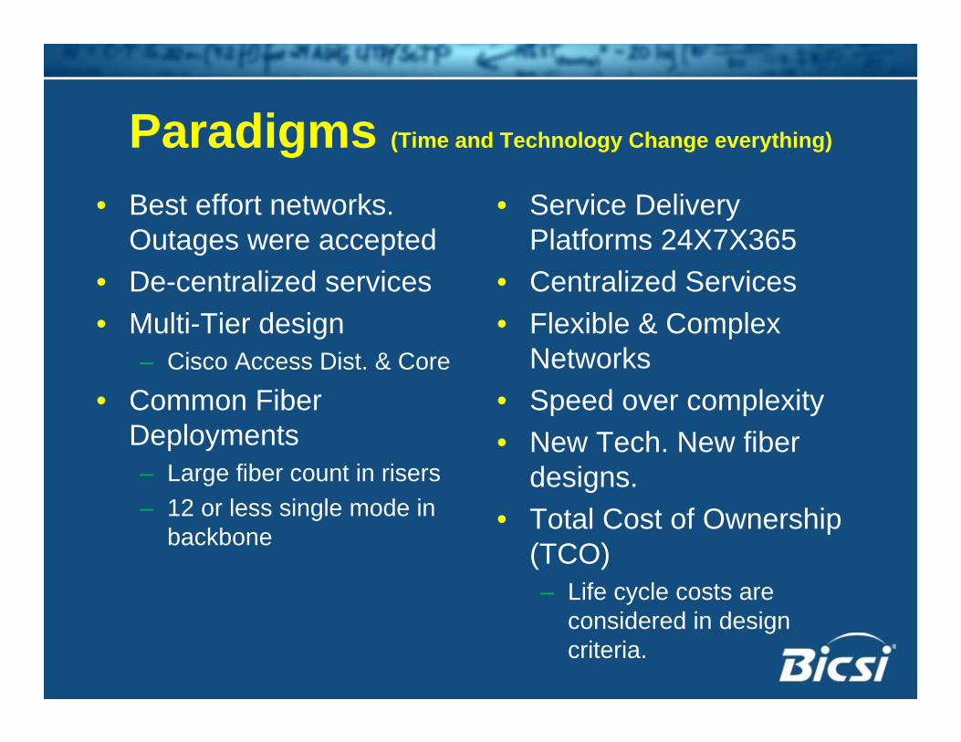
Paradigms (Time and Technology Change everything)
• Best effort networks. Outages were accepted
• De-centralized services• Multi-Tier design
– Cisco Access Dist. & Core
• Common Fiber Deployments– Large fiber count in risers– 12 or less single mode in
backbone
• Service Delivery Platforms 24X7X365
• Centralized Services• Flexible & Complex
Networks• Speed over complexity• New Tech. New fiber
designs. • Total Cost of Ownership
(TCO)– Life cycle costs are
considered in design criteria.
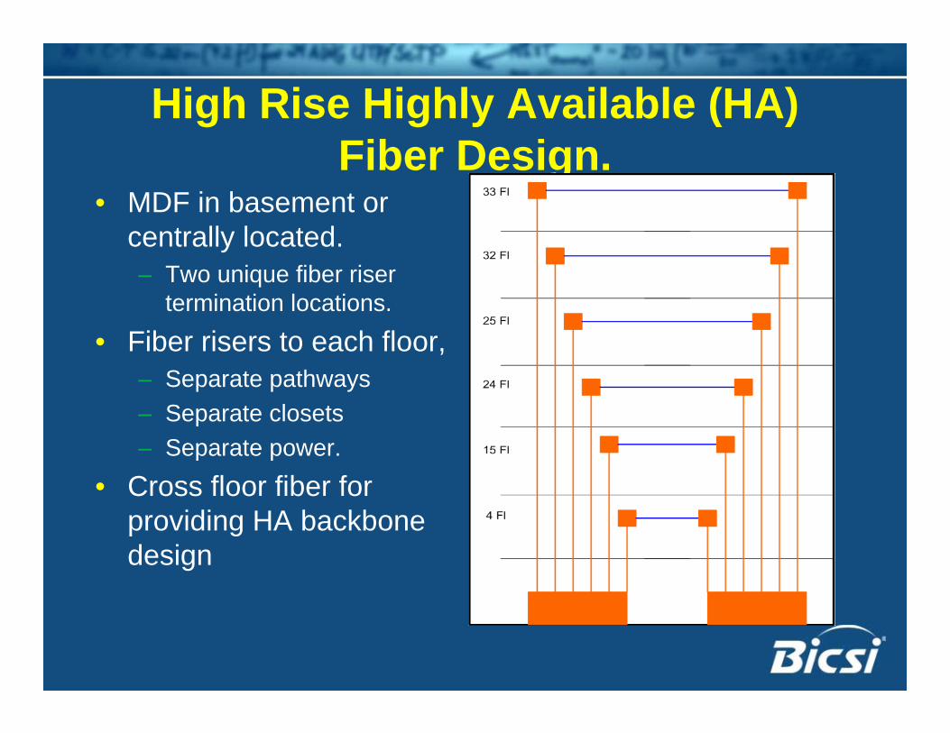
High Rise Highly Available (HA) Fiber Design.
• MDF in basement or centrally located.– Two unique fiber riser
termination locations.
• Fiber risers to each floor, – Separate pathways – Separate closets – Separate power.
• Cross floor fiber for providing HA backbone design
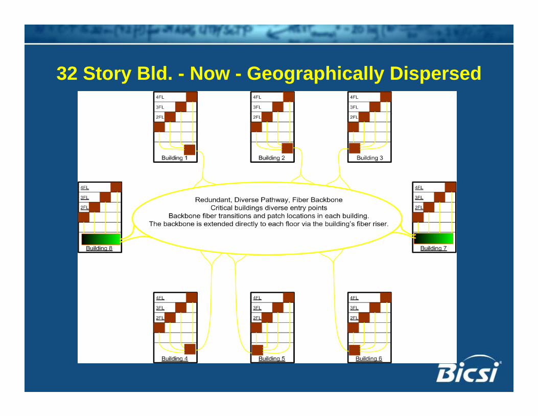
32 Story Bld. - Now - Geographically Dispersed
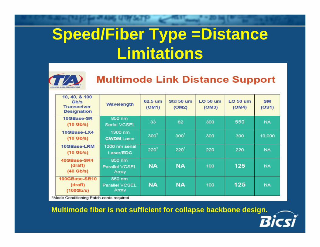
Speed/Fiber Type =Distance Limitations
Multimode fiber is not sufficient for collapse backbone design.
Single Mode Fiber (SMF)• Reduces/eliminates distance limitations.• Single fiber pair (Tx, Rx) per connection.• High SMF fiber count in backbone cabling.• Extend SMF into the building riser.
– MMF is fine for intra building distribution for Zone and Telecommunication Enclosures (TE) designs.
• Breakout backbone cable construction.– East-West fiber paths to redundant switching facilities.
• High Density patch fields.– Main termination fields.– Transition points for building risers.
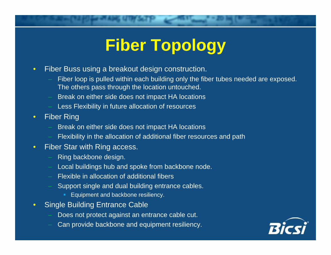
Fiber Topology• Fiber Buss using a breakout design construction.
– Fiber loop is pulled within each building only the fiber tubes needed are exposed. The others pass through the location untouched.
– Break on either side does not impact HA locations– Less Flexibility in future allocation of resources
• Fiber Ring– Break on either side does not impact HA locations– Flexibility in the allocation of additional fiber resources and path
• Fiber Star with Ring access.– Ring backbone design.– Local buildings hub and spoke from backbone node.– Flexible in allocation of additional fibers– Support single and dual building entrance cables.
Equipment and backbone resiliency.
• Single Building Entrance Cable– Does not protect against an entrance cable cut.– Can provide backbone and equipment resiliency.
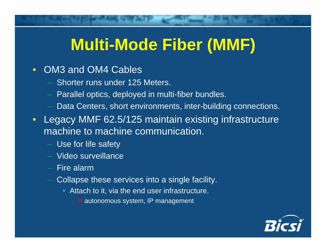
Multi-Mode Fiber (MMF)• OM3 and OM4 Cables
– Shorter runs under 125 Meters.– Parallel optics, deployed in multi-fiber bundles.– Data Centers, short environments, inter-building connections.
• Legacy MMF 62.5/125 maintain existing infrastructure machine to machine communication. – Use for life safety– Video surveillance– Fire alarm– Collapse these services into a single facility.
Attach to it, via the end user infrastructure. autonomous system, IP management
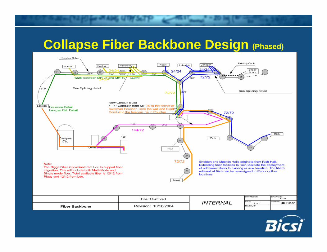
Collapse Fiber Backbone Design (Phased)
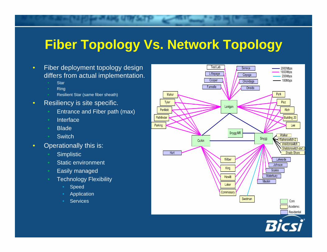
Fiber Topology Vs. Network Topology• Fiber deployment topology design
differs from actual implementation. • Star • Ring• Resilient Star (same fiber sheath)
• Resiliency is site specific.• Entrance and Fiber path (max)• Interface• Blade• Switch
• Operationally this is:• Simplistic • Static environment • Easily managed• Technology Flexibility
• Speed• Application• Services
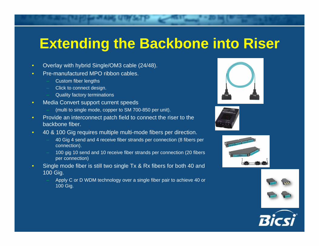
Extending the Backbone into Riser• Overlay with hybrid Single/OM3 cable (24/48). • Pre-manufactured MPO ribbon cables.
– Custom fiber lengths– Click to connect design.– Quality factory terminations
• Media Convert support current speeds – (multi to single mode, copper to SM 700-850 per unit).
• Provide an interconnect patch field to connect the riser to the backbone fiber.
• 40 & 100 Gig requires multiple multi-mode fibers per direction.– 40 Gig 4 send and 4 receive fiber strands per connection (8 fibers per
connection).– 100 gig 10 send and 10 receive fiber strands per connection (20 fibers
per connection) • Single mode fiber is still two single Tx & Rx fibers for both 40 and
100 Gig. – Apply C or D WDM technology over a single fiber pair to achieve 40 or
100 Gig.
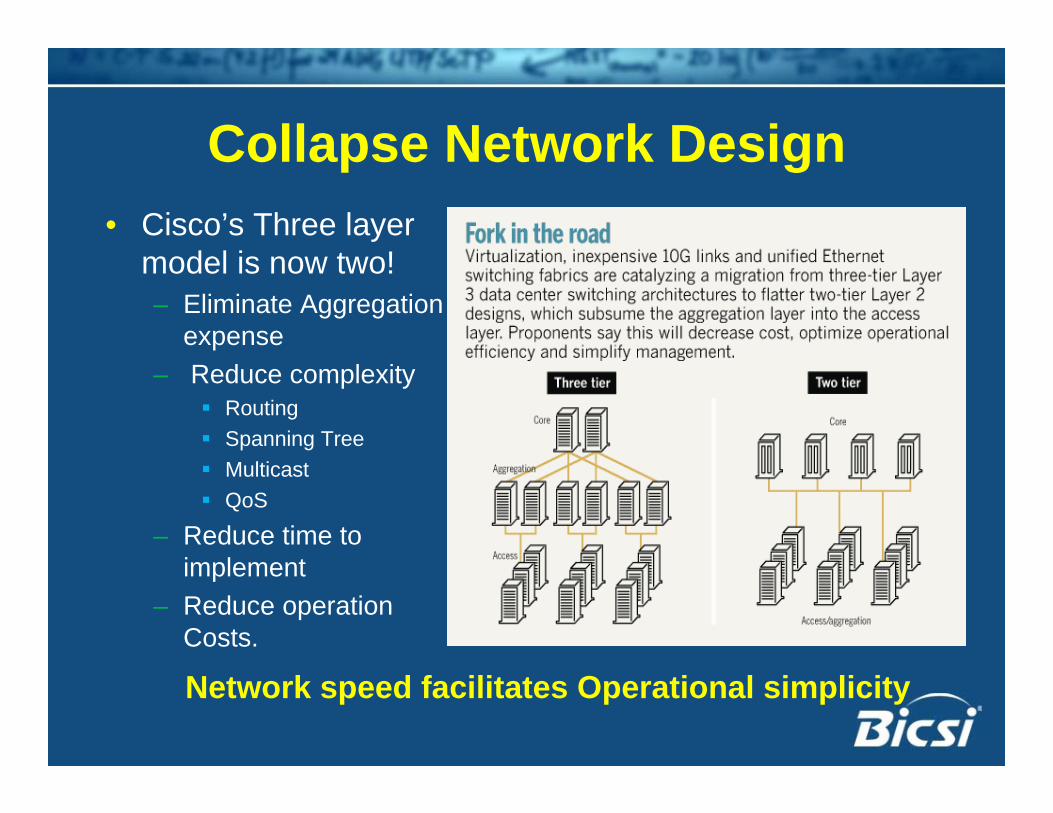
Collapse Network Design • Cisco’s Three layer
model is now two!– Eliminate Aggregation
expense– Reduce complexity
RoutingSpanning TreeMulticastQoS
– Reduce time to implement
– Reduce operation Costs.
Network speed facilitates Operational simplicity
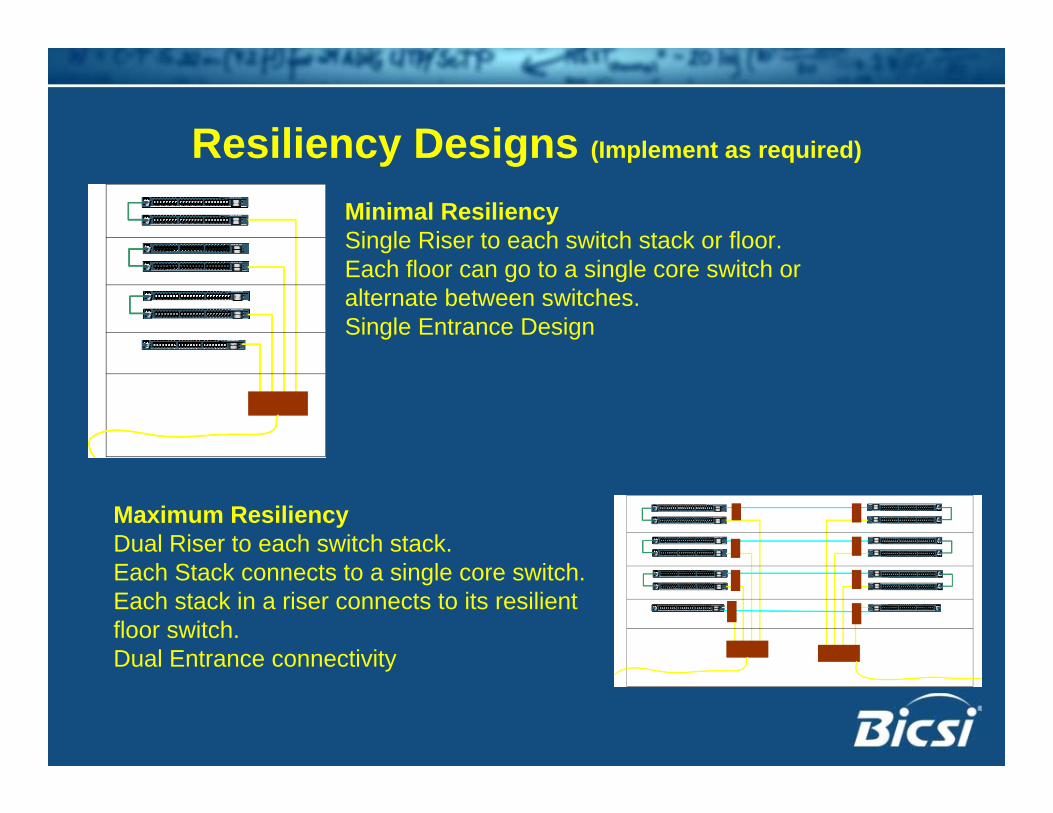
Resiliency Designs (Implement as required)
Maximum ResiliencyDual Riser to each switch stack.Each Stack connects to a single core switch.Each stack in a riser connects to its resilient floor switch. Dual Entrance connectivity
Minimal ResiliencySingle Riser to each switch stack or floor.Each floor can go to a single core switch or alternate between switches.Single Entrance Design
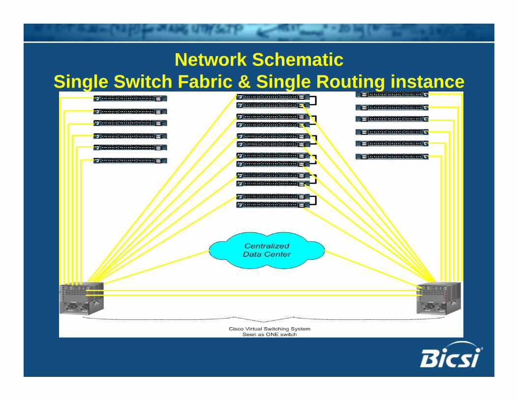
Network Schematic Single Switch Fabric & Single Routing instance
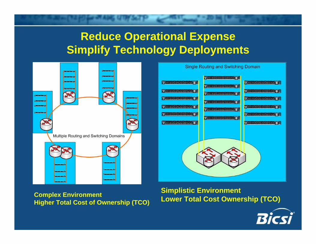
Reduce Operational ExpenseSimplify Technology Deployments
Complex EnvironmentHigher Total Cost of Ownership (TCO)
Simplistic EnvironmentLower Total Cost Ownership (TCO)
Thank you!
Timothy J Kraft RCDD, NTS, OSP Network Architect. President/CEO GT Gith LLC.