Embed Size (px)
Citation preview
1
BIAXIAL CURVATURE AND DUCTILITY CAPACITY OF RC
COLUMN BASE CROSS SECTIONS
Liborio CAVALERI1, Fabio DI TRAPANI
2, Giuseppe MACALUSO
3 and Gaia SCADUTO
4
ABSTRACT
The deformation performance of the base cross sections of reinforced concrete buildings is
fundamental when large seismic events occur allowing the structure to have large excursions in
nonlinear field and guaranteeing an overall ductile behaviour.
It is well known that the axial force acting on columns significantly reduces the curvature capacity of
the sections and for this reason the technical codes give design criteria stating a limitation in order to
preserve the displacement capacity. It is also recognized that when biaxial bending occur the cross
section undergo a loss in strength capacity. Starting the study of from Bresler (1960), which provided
suitable expression to predict 3D limit interaction surfaces, several numerical and analytical models
were developed to take into account the biaxial interaction in strength.
Simultaneously it is noteworthy to point out that the presence of biaxial bending also influences the
deformation capacity of sections causing in most of the cases a relevant loss of the curvature and
ductility available with respect to the one owned along the principal axes. This important issue is not
faced by technical codes and not exhaustively treated in scientific literature as it was done for strength.
Moreover nonlinear structural models based on lumped plasticity do not take into account these
interaction aspects when defining plastic hinge properties in terms of curvature capacity.
The paper presents a numerical study in which the deformation capacity of RC cross sections
subjected to axial load and biaxial bending is investigated by means of a fiber discretization.
A procedure for the numerical definition of biaxial domains of ultimate curvature, yielding curvature
and curvature ductility is provided and the sensitivity of the biaxial deformation performance to some
geometrical and mechanical parameters (aspect ratio, concrete strength and confinement efficacy) is
discussed.
INTRODUCTION
The necessity to assess the seismic capacity of new and existing buildings is today going to
have a large increase. This is mainly due to the opportunities offered by the continuous development
of refined nonlinear investigation techniques based on static or dynamic procedures. Also the
renovation of technical codes is strongly related to the advances reached by structural engineering and
many innovations proposed by the scientific community became fundamental for design and
prediction of buildings structural safety and basic in practical applications. With special regard to
1 Associate Professor of Structural Engineering, University of Palermo, Palermo, [email protected]
2 PhD, University of Palermo, Palermo, [email protected]
3 PhD, University of Palermo, Palermo, [email protected]
4 Masters Graduate Student, University of Palermo, Palermo.
2
reinforced concrete structures it is well known that the accuracy in prediction of the seismic capacity
strongly depends on the accuracy in estimation of the beam and columns deformation performances.
In particular, the base cross section of RC columns are affected by the simultaneous presence of
axial forces and bending moments acting on a plane that is not coincident with one of the two principal
planes of inertia. This occurs first of all because of the ground motions may interest the structures in
any direction with respect to their planar symmetry axes. Moreover in the case of irregular or complex
buildings, the possible activation of torsional modal contributions may significantly affect the overall
response requesting biaxial bending capacity, in terms of strength and ductility.
From a careful overview of technical codes and scientific literature itself it seems that the
question of the deformation performance of the RC cross sections subjected to axial load and biaxial
bending appear however today not completely faced, neither its importance is underlined. With regard
to this topic, the only instructions recognizable in technical codes regard the assessment of biaxial
strength of sections, while no recommendations or criteria are given about the question of the
estimation of biaxial ultimate curvature and ductility capacity. It is the case of ACI 318 and Eurocode
2 codes that make use of Bresler theory as instrument for the evaluation of the strength limit surfaces
of RC sections, but no tools or prescriptive suggestions, regarding the necessary biaxial deformation
capacity, are provided. This lack in technical codes however reflects the fact that even in scientific
literature the question appears not sufficiently investigated in this sense. Most of the authors in fact,
focused their attention to improve the effectiveness of algorithms that are firstly aimed at the
evaluation of biaxial strength capacity of RC sections. Some of these approaches makes use of
numerical techniques (Hulse and Mosley, (1986), Spiegel and Limbrunner (1988), Da Vivo and Rosati
(1998)) for the determination of the interaction surface, or analytical solutions providing useful closed
form expressions (Fafitis (2001), Monti and Alessandri (2006)).
Among the more recent studies, the interest in the evaluation of biaxial curvature capacity of
sections became more evident even if the major efforts have been addressed to computational aspects.
Kim and Lee (2000) provided a fiber decomposition finite element formulation validated by
experimental tests on square and rectangular columns in which also curvature length localization were
measured varying eccentricity angles. In Bonet et al. (2004) a generic algorithm for the analysis of
arbitrary cross sections under axial load and biaxial bending, based on an analytical integration
scheme described by curvilinear polygons is proposed. The algorithm focuses on the generation of
moment–curvature diagrams, interaction curves and failure surfaces.
The above mentioned algorithms constitute efficient computational tools for prediction of
biaxial strength and a curvature capacity of RC cross sections; however a discussion about the
variation in deformation capacity when the section is subjected to axial load and axial bending and
major mechanical parameter involved the problem is not faced in these studies.
Only recently Di Ludovico et al. (2007) and Fossetti and Papia (2012) focused their attention to
this question. In the first work the authors presented a discussion on the influence of some key
parameters on the definition of numerically generated ultimate curvature domains for different classes
of RC sections. In the second a numerical procedure based on the stripe decomposition technique able
to define resistance and curvature domains for symmetric RC cross sections subjected to axial load
and biaxial bending is developed with the support of some experimental tests. In this latest study the
question of biaxial curvature reduction is investigated in dimensionless terms and also here the
influence of some parameters (axial force level, section geometry and steel hardening ratio) is
discussed.
Considering the relevance of the topic, a wider parametric study, regarding all mechanical and
geometrical parameters involved in the problem appears anyway to be necessary, in order to not only
have a deep understanding, but also to individuate the better design criteria for RC column cross-
sections. Moreover the capacity of a cross-section to support inelastic deformation demand and
dissipate energy under biaxial bending cannot be assessed by the observing of ultimate curvature alone
but the determination of the available curvature ductility along each bending direction appear more
significant.
In this paper the deformation capacity of the cross section is investigated firstly defining a
numerical procedure for the identification of ultimate curvature, yielding curvature and curvature
ductility domains. Subsequently the influence of the most representative geometrical and mechanical
parameters (e.g. concrete strength, cross-section shape and concrete confinement level), on the biaxial
L.Cavaleri, F.Di Trapani, G.Macaluso, G.Scaduto 3
deformation capacity is examined through a deep parametric analysis. The discussion allowed
individuating the most sensitive parameters to be taken into account in the during design and
verification phases.
DEFINITION OF BIAXIAL ULTIMATE CURVATURE, ELASTIC CURVATURE
AND CURVATURE DUCTILITY DOMAINS
In order to provide a numerical assessment of biaxial deformation capacity of the cross sections
by means of a numerical modelling, the following assumptions on stress – strain relationships have
been done. Two different constitutive laws were adopted to characterize cover and core concrete. In
both cases a Kent-Scott-Park concrete law with a parabolic branch ending at the fixed compressive
strain εc0=2‰ (corresponding to maximum stress fc) have been used. The following linear softening
branch between εc0 and ultimate strain core
cuε depended each time on the considered core concrete
confinement level. The unconfined cover concrete ultimate strain was assumed er
cu
covε =3.5‰. Steel
rebars were modelled by means of an elastic-plastic law with a linear hardening ratio of ηh=0.001. The
elastic Young modulus was assumed to be Es=210.000 MPa, while yielding stress was fy=450 MPa.
No limit was given to ultimate steel strain assuming the concrete crushing as failure condition when
the most compressed core fiber reached the ultimate strain value core
cuε . Under these hypotheses the
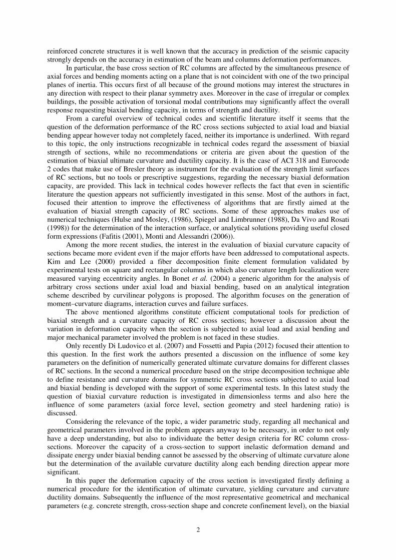
ultimate curvature ϕu, which the cross section is able to reach, is given by the expression
core
cu
core
cuu
x
εϕ = (1)
core
cux being the distance between the neutral axis and the point of the core region of the section
interested by the maximum compression strain (Fig. 1).
Figure 1. Ultimate stress-strain condition of a rectangular cross section under axial load and biaxial bending.
The ultimate curvature of a rectangular cross section is generally conventionally calculated
along the principal (x and y) axes. The values obtained are used for the further definition of the
structural model nonlinearities. However this information does not allow a complete assessment of the
deformation performance of the section under a general axial load and biaxial bending condition.
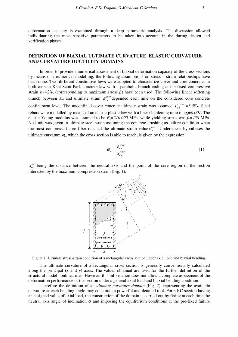
Therefore the definition of an ultimate curvature domain (Fig. 2), representing the available
curvature at each bending angle may constitute a powerful and detailed tool. For a RC section having
an assigned value of axial load, the construction of the domain is carried out by fixing at each time the
neutral axis angle of inclination α and imposing the equilibrium conditions at the pre-fixed failure
4
conditioncore
cu
core
c εε = . Once calculated the neutral axis position, the ultimate curvature at that angle is
evaluated by means of Eq. 1. In this way it is possible to build a numerical diagram having coordinates
are ϕux=ϕu cosα on the x axis and ϕuy=ϕu sinα on the y axis. Each point of the diagram individuates
univocally an angle of inclination of neural axis. The modulus of each vector pointing from the axes
origin a general point represents the ultimate curvature along one direction identified by the bending
angle and is analytically determined as [ ] 502
uy
2
uxu
.
ϕϕϕ += .
a) b)
Figure 2. Numerically built ultimate curvature domains for different axial force levels: a) square section; b)
rectangular section.
The axial force level acting on the section strongly influences the curvature capacity, therefore
the dimensionless axial force ν=N/fcbh is here used as parameter defining the compression level and as
also is shown in Fig. (2). As it can be expected, when increasing the axial force level the domain
extension becomes smaller because of a general reduction of the ultimate curvature capacity. From a
general point of view it can be moreover observed that the ultimate curvature values available for the
cross section along x and y principal axes, undergo a significant reduction under biaxial regime.
Even though the domains reported in Fig. (2) are referred to specific sections; the loss in biaxial
curvature capacity generally affects all rectangular sections and will be deeply discussed afterwards.
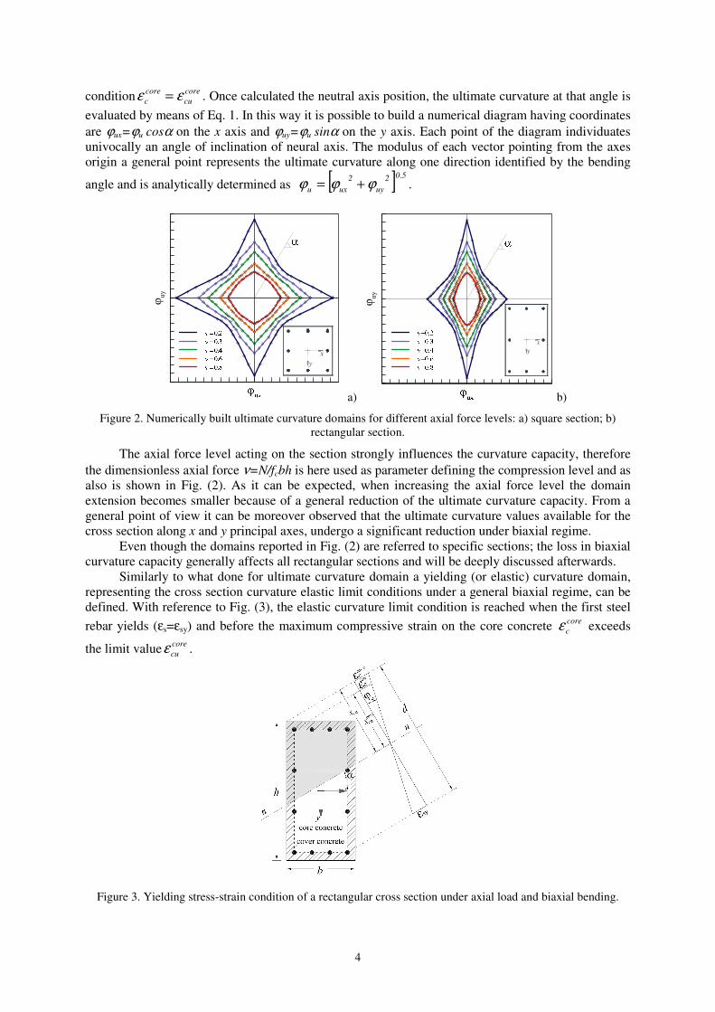
Similarly to what done for ultimate curvature domain a yielding (or elastic) curvature domain,
representing the cross section curvature elastic limit conditions under a general biaxial regime, can be
defined. With reference to Fig. (3), the elastic curvature limit condition is reached when the first steel
rebar yields (εs=εsy) and before the maximum compressive strain on the core concrete core
cε exceeds
the limit valuecore
cuε .
Figure 3. Yielding stress-strain condition of a rectangular cross section under axial load and biaxial bending.
L.Cavaleri, F.Di Trapani, G.Macaluso, G.Scaduto 5
Under this condition the yielding curvature ϕe for a generically defined neutral axis α angle is
expressed as
ce
sy
exd −
=ε
ϕ (2)
in which d is the distance between the yielded rebar and the concrete fiber subjected to the maximum
compressive strain er
cu
covε on the section cover and xce the neutral axis distance to this fiber.
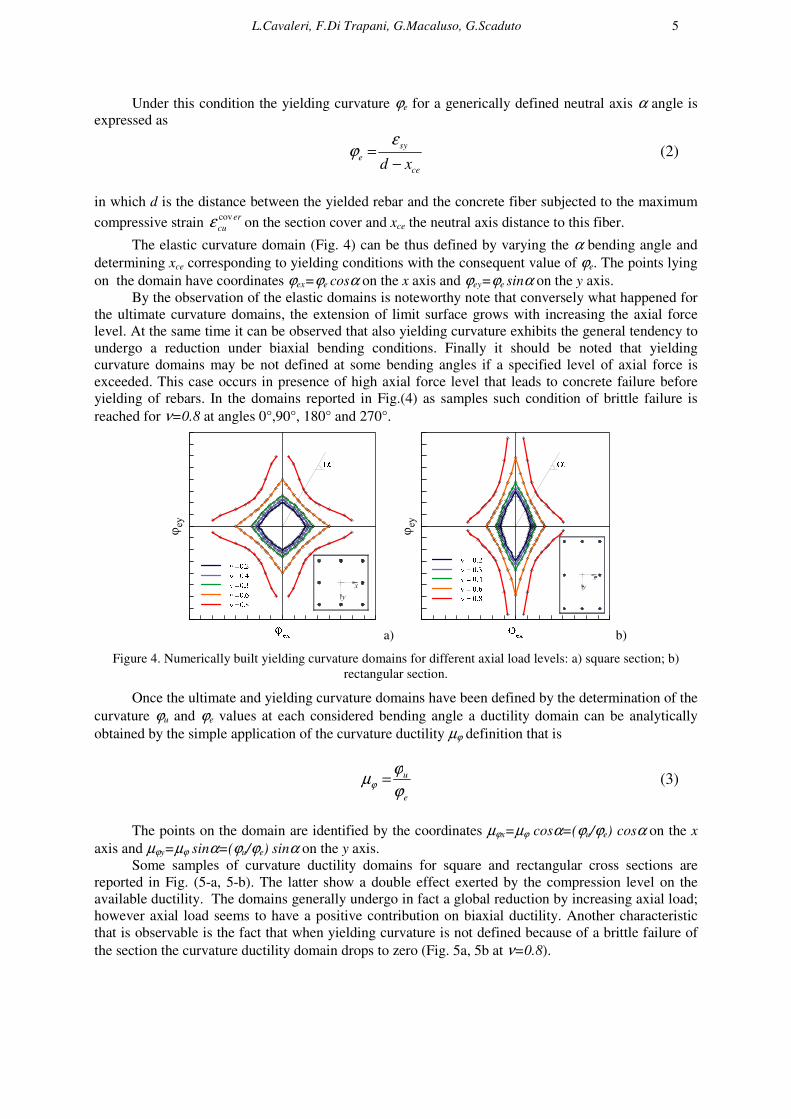
The elastic curvature domain (Fig. 4) can be thus defined by varying the α bending angle and
determining xce corresponding to yielding conditions with the consequent value of ϕe. The points lying
on the domain have coordinates ϕex=ϕe cosα on the x axis and ϕey=ϕe sinα on the y axis.
By the observation of the elastic domains is noteworthy note that conversely what happened for
the ultimate curvature domains, the extension of limit surface grows with increasing the axial force
level. At the same time it can be observed that also yielding curvature exhibits the general tendency to
undergo a reduction under biaxial bending conditions. Finally it should be noted that yielding
curvature domains may be not defined at some bending angles if a specified level of axial force is
exceeded. This case occurs in presence of high axial force level that leads to concrete failure before
yielding of rebars. In the domains reported in Fig.(4) as samples such condition of brittle failure is
reached for ν=0.8 at angles 0°,90°, 180° and 270°.
a) b)
Figure 4. Numerically built yielding curvature domains for different axial load levels: a) square section; b)
rectangular section.
Once the ultimate and yielding curvature domains have been defined by the determination of the
curvature ϕu and ϕe values at each considered bending angle a ductility domain can be analytically
obtained by the simple application of the curvature ductility µϕ definition that is
e
u
ϕ
ϕµϕ = (3)
The points on the domain are identified by the coordinates µϕx=µϕ cosα=(ϕu/ϕe) cosα on the x
axis and µϕy=µϕ sinα=(ϕu/ϕe) sinα on the y axis.
Some samples of curvature ductility domains for square and rectangular cross sections are
reported in Fig. (5-a, 5-b). The latter show a double effect exerted by the compression level on the
available ductility. The domains generally undergo in fact a global reduction by increasing axial load;
however axial load seems to have a positive contribution on biaxial ductility. Another characteristic
that is observable is the fact that when yielding curvature is not defined because of a brittle failure of
the section the curvature ductility domain drops to zero (Fig. 5a, 5b at ν=0.8).
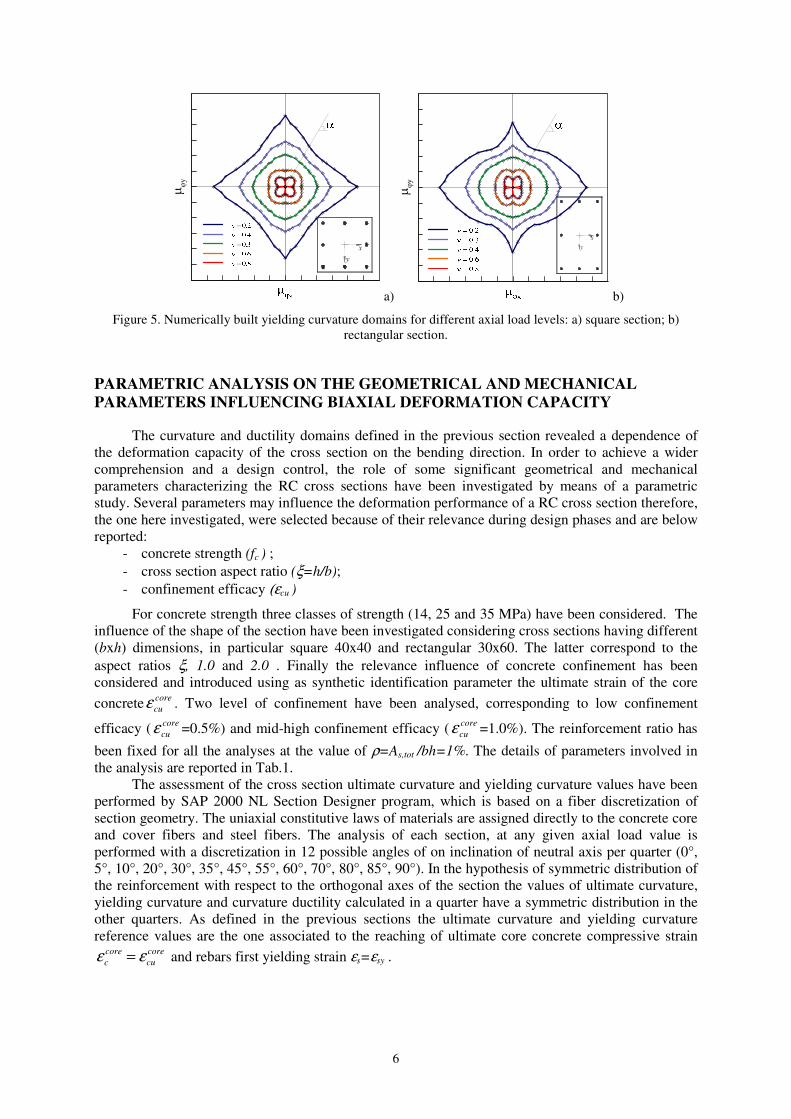
6
a) b)
Figure 5. Numerically built yielding curvature domains for different axial load levels: a) square section; b)
rectangular section.
PARAMETRIC ANALYSIS ON THE GEOMETRICAL AND MECHANICAL
PARAMETERS INFLUENCING BIAXIAL DEFORMATION CAPACITY
The curvature and ductility domains defined in the previous section revealed a dependence of
the deformation capacity of the cross section on the bending direction. In order to achieve a wider
comprehension and a design control, the role of some significant geometrical and mechanical
parameters characterizing the RC cross sections have been investigated by means of a parametric
study. Several parameters may influence the deformation performance of a RC cross section therefore,
the one here investigated, were selected because of their relevance during design phases and are below
reported:
- concrete strength (fc ) ;
- cross section aspect ratio (ξ=h/b);
- confinement efficacy (εcu )
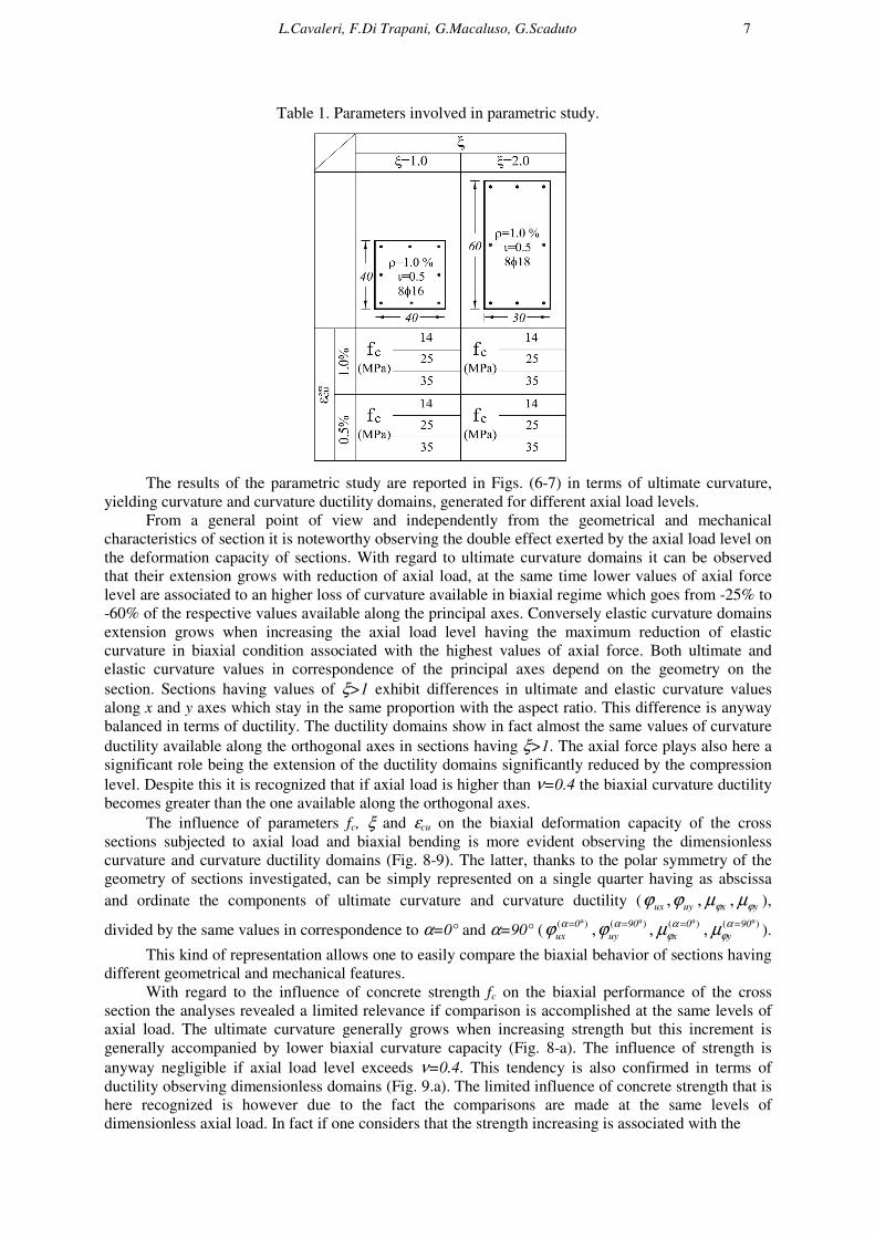
For concrete strength three classes of strength (14, 25 and 35 MPa) have been considered. The
influence of the shape of the section have been investigated considering cross sections having different
(bxh) dimensions, in particular square 40x40 and rectangular 30x60. The latter correspond to the
aspect ratios ξ, 1.0 and 2.0 . Finally the relevance influence of concrete confinement has been
considered and introduced using as synthetic identification parameter the ultimate strain of the core
concretecore
cuε . Two level of confinement have been analysed, corresponding to low confinement
efficacy (core
cuε =0.5%) and mid-high confinement efficacy (core
cuε =1.0%). The reinforcement ratio has
been fixed for all the analyses at the value of ρ=As,tot /bh=1%. The details of parameters involved in
the analysis are reported in Tab.1.
The assessment of the cross section ultimate curvature and yielding curvature values have been
performed by SAP 2000 NL Section Designer program, which is based on a fiber discretization of
section geometry. The uniaxial constitutive laws of materials are assigned directly to the concrete core
and cover fibers and steel fibers. The analysis of each section, at any given axial load value is
performed with a discretization in 12 possible angles of on inclination of neutral axis per quarter (0°,
5°, 10°, 20°, 30°, 35°, 45°, 55°, 60°, 70°, 80°, 85°, 90°). In the hypothesis of symmetric distribution of
the reinforcement with respect to the orthogonal axes of the section the values of ultimate curvature,
yielding curvature and curvature ductility calculated in a quarter have a symmetric distribution in the
other quarters. As defined in the previous sections the ultimate curvature and yielding curvature
reference values are the one associated to the reaching of ultimate core concrete compressive strain core
cu
core
c εε = and rebars first yielding strain εs=εsy .
L.Cavaleri, F.Di Trapani, G.Macaluso, G.Scaduto 7
Table 1. Parameters involved in parametric study.
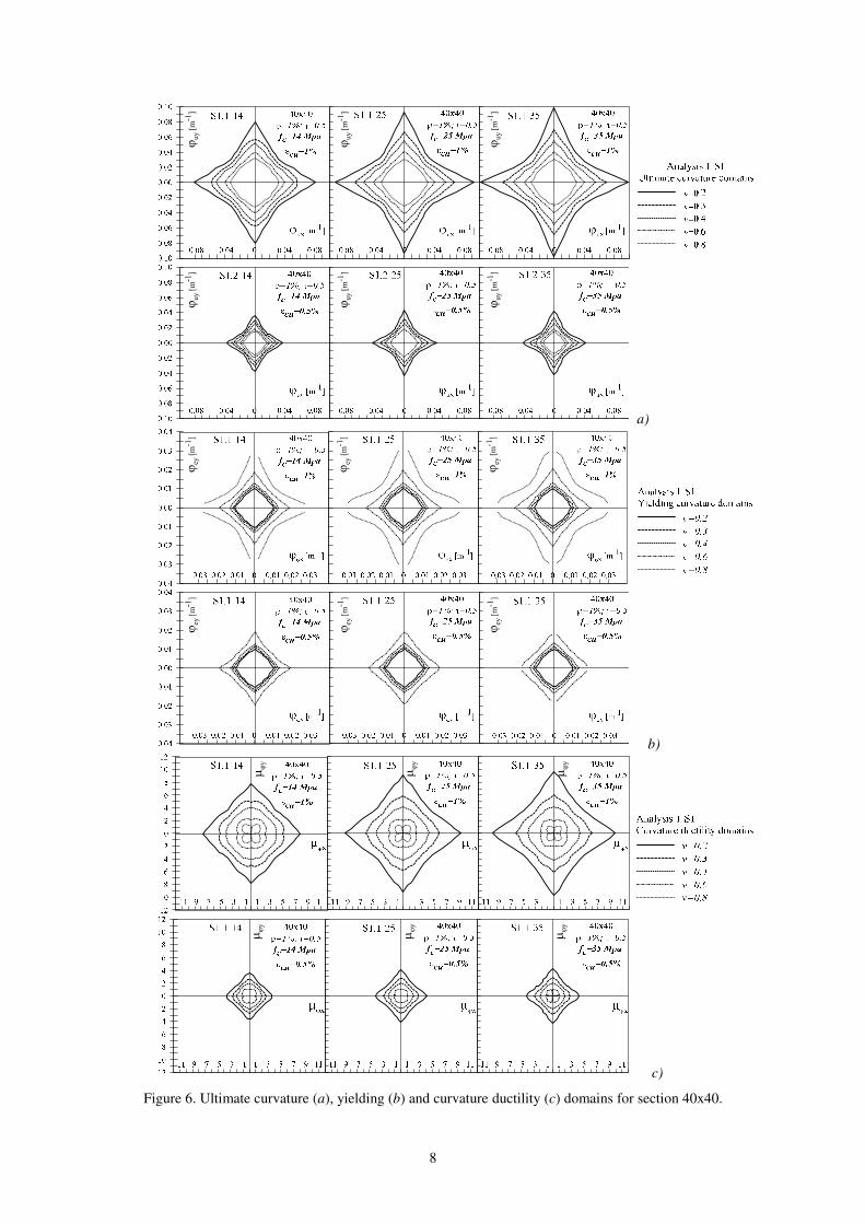
The results of the parametric study are reported in Figs. (6-7) in terms of ultimate curvature,
yielding curvature and curvature ductility domains, generated for different axial load levels.
From a general point of view and independently from the geometrical and mechanical
characteristics of section it is noteworthy observing the double effect exerted by the axial load level on
the deformation capacity of sections. With regard to ultimate curvature domains it can be observed
that their extension grows with reduction of axial load, at the same time lower values of axial force
level are associated to an higher loss of curvature available in biaxial regime which goes from -25% to
-60% of the respective values available along the principal axes. Conversely elastic curvature domains
extension grows when increasing the axial load level having the maximum reduction of elastic
curvature in biaxial condition associated with the highest values of axial force. Both ultimate and
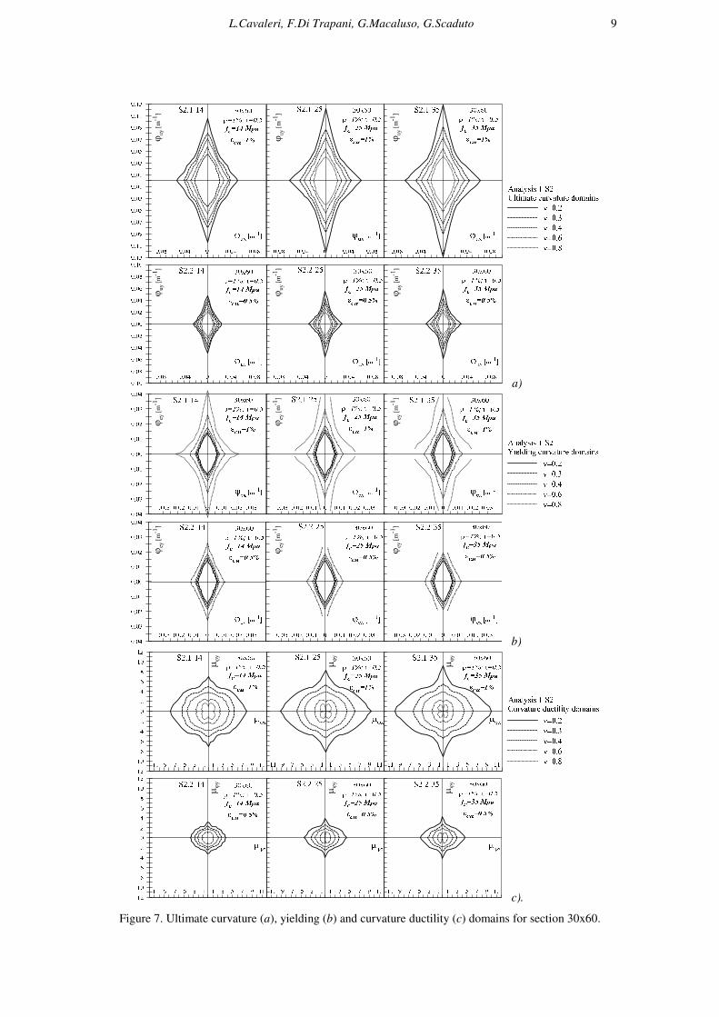
elastic curvature values in correspondence of the principal axes depend on the geometry on the
section. Sections having values of ξ>1 exhibit differences in ultimate and elastic curvature values
along x and y axes which stay in the same proportion with the aspect ratio. This difference is anyway
balanced in terms of ductility. The ductility domains show in fact almost the same values of curvature
ductility available along the orthogonal axes in sections having ξ>1. The axial force plays also here a
significant role being the extension of the ductility domains significantly reduced by the compression
level. Despite this it is recognized that if axial load is higher than ν=0.4 the biaxial curvature ductility
becomes greater than the one available along the orthogonal axes.
The influence of parameters fc, ξ and εcu on the biaxial deformation capacity of the cross
sections subjected to axial load and biaxial bending is more evident observing the dimensionless
curvature and curvature ductility domains (Fig. 8-9). The latter, thanks to the polar symmetry of the
geometry of sections investigated, can be simply represented on a single quarter having as abscissa
and ordinate the components of ultimate curvature and curvature ductility ( uxϕ , uyϕ , xϕµ , yϕµ ),
divided by the same values in correspondence to α=0° and α=90° ()( °=0
ux
αϕ , )( °=90
uy
αϕ , )( °=0
x
αϕµ , )( °=90
y
αϕµ ).
This kind of representation allows one to easily compare the biaxial behavior of sections having
different geometrical and mechanical features.
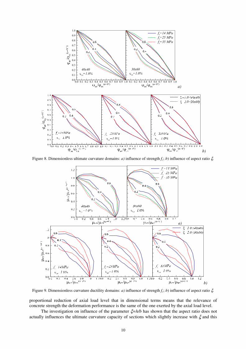
With regard to the influence of concrete strength fc on the biaxial performance of the cross
section the analyses revealed a limited relevance if comparison is accomplished at the same levels of
axial load. The ultimate curvature generally grows when increasing strength but this increment is
generally accompanied by lower biaxial curvature capacity (Fig. 8-a). The influence of strength is
anyway negligible if axial load level exceeds ν=0.4. This tendency is also confirmed in terms of
ductility observing dimensionless domains (Fig. 9.a). The limited influence of concrete strength that is
here recognized is however due to the fact the comparisons are made at the same levels of
dimensionless axial load. In fact if one considers that the strength increasing is associated with the
8
a)
b)
c)
Figure 6. Ultimate curvature (a), yielding (b) and curvature ductility (c) domains for section 40x40.
L.Cavaleri, F.Di Trapani, G.Macaluso, G.Scaduto 9
a)
b)
c).
Figure 7. Ultimate curvature (a), yielding (b) and curvature ductility (c) domains for section 30x60.
10
0.0
0.1
0.2
0.3
0.4
0.5
0.6
0.7
0.8
0.9
1.0
0.0 0.1 0.2 0.3 0.4 0.5 0.6 0.7 0.8 0.9 1.0
ux ux( =0°)
fc=14 MPa
fc=25 MPa
fc=35 MPa
40x40
cu=1.0%
0.1 0.2 0.3 0.4 0.5 0.6 0.7 0.8 0.9 1.0
ux ux( =0°)
30x60
cu=1.0%
a)
b)
Figure 8. Dimensionless ultimate curvature domains: a) influence of strength fc; b) influence of aspect ratio ξ.
a)
b)
Figure 9. Dimensionless curvature ductility domains: a) influence of strength fc; b) influence of aspect ratio ξ.
proportional reduction of axial load level that in dimensional terms means that the relevance of
concrete strength the deformation performance is the same of the one exerted by the axial load level.
The investigation on influence of the parameter ξ=h/b has shown that the aspect ratio does not
actually influences the ultimate curvature capacity of sections which slightly increase with ξ and this
L.Cavaleri, F.Di Trapani, G.Macaluso, G.Scaduto 11
influence is negligible after ν=0.3 (Fig. 6-7). This trend is more evident observing dimensionless
ultimate curvature domains Fig. (8.b).
The influence of confinement efficacy is finally considered. It can be easily observed by Figs.
(6-7) that this parameter does not have any capacity to increase biaxial curvature and ductility capacity
with respect to the one available along principal axes. A good confinement of concrete produces in
fact a general improvement of the deformation capacity along any direction at the same way being the
ultimate curvature domains directly proportional to the ultimate core concrete strain. The ultimate
curvature and curvature ductility domains, determined for the two analyzed confinement levels,
undergo a simple translation that stays in the same ratio of the considered core concrete ultimate
strains.
CONCLUSIONS
Axial load and biaxial bending action influences in a not negligible way the deformation
capacity of RC cross-sections. The biaxial action has a relevant impact on the ultimate curvature and
curvature ductility and in most of the cases produces a relevant loss with respect to the principal
directions. In order to account these aspects a numerical construction of dimensional and
dimensionless biaxial ultimate curvature, yielding curvature and curvature ductility domains is
described in the paper.
The effects of some physical and mechanical parameters on the deformation capacity of RC
cross-sections have been investigated by means of a parametric study. The parameters considered were
1) concrete strength, 2) concrete confinement, 3) aspect ratio of cross-sections. The influence of each
parameter has been evaluated at different levels of the dimensionless axial load.
The analyses have shown that each of the parameters above listed has a role. Nevertheless some
of them have a much more important influence. Further in spite of important variations in the ultimate
curvature capacity in presence of biaxial bending, the curvature ductility capacity may undergo
variations not so important (i.e., a strong reduction of ultimate curvature may not correspond to an
equal strong reduction of curvature ductility).
The parameter that more than any other influences the deformation capacity of cross-sections is
the confinement of core concrete that however impacts on the overall deformation performance and
not on the biaxial in particular. The other parameters can reduce the differences between the
deformation capacities in biaxial bending and along principal axes bending but have a lower influence.
The analyses have highlighted that:
- an increasing in the dimensionless axial load tends to cancel the differences between the axial
bending deformation capacity and biaxial bending deformation capacity;
- the aspect ratio of cross-sections modifies the shape of the ultimate curvature domains and the
curvature ductility domains being the possibility of a major reduction of the deformation capacity for
major values of the aspect ratio;
- an increasing of the strength of concrete does not modify the shape of the ultimate curvature
domains and of the curvature ductility domains but produces a light increasing of the area of these
domains. However if the comparison is made with the same level of dimensional axial load the
strength increasing produces a reduction of dimensionless axial load and a consequent increasing of
defamation performance.
From a general point of view the study revealed the quite relevance of the issue of the biaxial
deformation performance of RC cross section. In particular it appears evident that the loss in ultimate
curvature and ductility capacity exhibited under biaxial condition cannot be neglected during design
phases or assessment of existing buildings. A more accurate nonlinear modeling of these aspects
especially when using lumped plasticity should be therefore encouraged to get a more proper overall
definition of capacity of RC buildings.
12
AKNOWLEDGEMENTS
This study was supported by PO Italy – Malta 2007-2013. SIMIT Research Project: “Costituzione di
un sistema integrato di protezione civile transfontaliero Italo-Maltese ”
REFERENCES
ACI 318 (2008). “Building code requirements for structural concrete and commentary”, American Concrete
Institute (ACI).
Eurocode 2 (2005). “Design of concrete structures, part 1-1: general rules and rules for buildings”, European
Committee for Standardization (CEN).
Bresler B (1960). “Design criteria of reinforced columns under axial load and biaxial bending”, ACI Journal,
57(5):481-490.
Hulse R, Mosley WH (1986). Reinforced concrete design by computer, MAcmillan Education Ltd. New York.
Spiegel L, Limbrunner GF (1988). Reinforced concrete design, Prentice-Hall, Upper Saddle River, N.J..
De Vivo L, Rosati L (1998). “Ultimate strength analysis of reinforced concrete section subject to axial force and
biaxial moment”, Comput. Methods Appl. Mech. Engrg,166:261-287.
Fafitis A (2001). “Interaction surface of reinforced-concrete section in biaxial bending”. Journal of Stuctural
Engineering, 840-846.
Monti G, Alessandri S (2006). “Assessment of columns under combined biaxial bending and axial load”,
proceedings of second FIB congress, Naples, Italy.
Kim JK, Lee S (2000). The behavior of reinforced concrete columns subjected to axial force and biaxial
bending. Engineering Structures 2000, 23:1518-1528.
Bonet JL, Miguel PF, Fernandez MA, Romeo ML (2004). “Analytical approach to failure surfaces in reinforced
concrete sections subjected to axial load and biaxial bending”, J. Struct Eng (ASCE),130(12):2006-2015.
Bonet JL, Romero M, Miguel P, Fernandez ML (2004). “A fast stress integration algorithm for reinforced
concrete section with axial loads and biaxial bending”, Computers and Structures, 82:213-225.
Fossetti M, Papia M (2012). “Dimensionless analysis of RC rectangular sections under axial load and biaxial
bending”, Engineering Structures , 44:34-45.
Di Ludovico M, Lignola G, Prota A, Cosenza E (2007). “Analisi non lineare di sezioni in c.a. soggette a
pressoflessione deviata”. ANIDIS XII Convegno, L’Ingegneria sismica in Italia, Pisa, Italy.