Embed Size (px)
Citation preview

BH60PCW/BH100PCWUPS
RE60FW/RE100FWAC Stabilized Power Supply (CVCF)
Instruction Manual
• This manual contains important information regarding the safe use of the BH60PCW/BH100PCW/RE60FW/RE100FW. Please read these instructions before installation and/or use.
• Keep this manual in a convenient location near the BH60PCW/BH100PCW/RE60FW/RE100FW so that you can refer to it whenever necessary.
Unauthorized reproduction of this manual, in part or in whole, is prohibited. The contents of this manual are subject to change without notice.

Introduction
Notes on using the UPS and AC stabilized power supply (CVCF)
• This product is designed and manufactured for use with OA equipment such as personal computers. Do not use this product when a very high degree of reliability and safety is required, such as in the following types
of applications: • Medical equipment that supports life directly • Applications that may cause injury (applications that directly affect the operation and control of planes, ships,
railroads, elevators, etc.) • Applications that are subject to constant vibration, such as in cars and ships• Applicationsinwhichfailuremaysignificantlydamageorimpactthesocietyandpublic(Importantcomputersys-
tems or communication equipment, public transportation systems, etc.) • Other equipment with the same level of importance
• For equipment that greatly affects the safety of people and maintains public functions, special considerations re-lated to operation, maintenance, and management, such as performing system duplication and emergency power generation facilities, must be taken.
• Observe the contents of this manual, particularly those concerning the operating conditions and environment.
• When you want to use this product for an important system that requires very high reliability, contact the Electronic Systems & Equipments customer support center at: __________.
• Do not modify/alter this product.
• This product is designed for use within Japan. Please contact us when incorporating this product into equipment for export. • Export of this product (including transport by an individual) may require the permission of the Ministry of Econo-my,TradeandIndustryundertheForeignExchangeandForeignTradeLaw.Exportofthisproductwithouttherequired permission is punishable under the law.
• Injuryorfiremayresultifthevoltageorfrequencyisdifferent.
• Windows is the registered trademark of Microsoft Corporation in the United States and/or other countries. • The names of other companies and products mentioned herein are the trademarks or registered trade-
marks of their respective owners. • Note on user registration Fill out the required items on the included user registration card, and send it to the OMRON Electronic Sys-
tems & Equipments customer support center.
©OMRON Corporation. 2006 All Rights Reserved.
Features of this product
Thank you for purchasing an OMRON Uninterruptible Power Supply (UPS).
• The UPS protects computers and other devices from power failures, voltage variations, instantaneous voltage drops, and surge voltage such as that caused by lightning (phenomena in which extraordinarily high voltage occurs instantaneously).
The UPS (BH series) uses a full-time inverter supply method. Under normal conditions, commercial power is con-verted to direct current, and then it is converted back to a stable sinusoidal current before it is output. When a com-mercial power failure, voltage variation, or other problem is detected, the unit switches to battery supply to provide continuous sine wave output.
This is especially suitable for use where power supply conditions are poor (for example, when there are large varia-tions in voltage).
The AC stabilized power supply (RE series) can stabilize the voltage and frequency before output, and can convert 50Hz to 60Hz (or 60Hz to 50Hz) before output.
• The output capacity is 600VA/420W for the BH60PCW/RE60FW, and 1kVA/700W for the BH100PCW/RE100FW.
DisclaimersOMRON is not liable for any damage or secondary damage resulting from the use of this product, including the mal-function or failure of equipment, connected devices, or software.
• Make sure to read the safety precautions before using the unit.
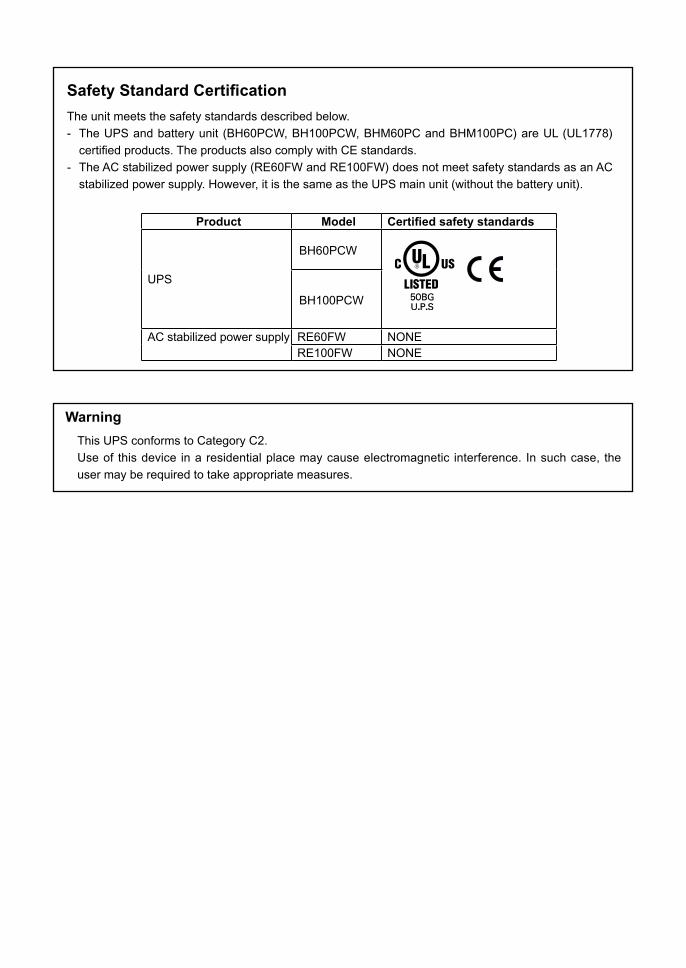
Product Model Certified safety standards
UPS
BH60PCW
BH100PCW
AC stabilized power supply RE60FW NONERE100FW NONE
Safety Standard Certification
The unit meets the safety standards described below.
- TheUPSandbatteryunit(BH60PCW,BH100PCW,BHM60PCandBHM100PC)areUL(UL1778)
certifiedproducts.TheproductsalsocomplywithCEstandards.
- The AC stabilized power supply (RE60FW and RE100FW) does not meet safety standards as an AC
stabilized power supply. However, it is the same as the UPS main unit (without the battery unit).
Warning
This UPS conforms to Category C2.
Useof thisdevice inaresidentialplacemaycauseelectromagnetic interference. Insuchcase, the
user may be required to take appropriate measures.

IMPORTANT SAFETY INSTRUCTION1. SAVE THESE INSTRUCTIONS.
This manual contains important instructions for BH60PCW and BH100PCW that should be fol lowed dur ing instal lat ion and maintenance of the UPS and batteries.
2. SYMBOL This symbol indicates earth ground.
This symbol indicates turning on UPS.
This symbol indicates turning off UPS.
3. INTERNAL BATTERYInternal battery voltage is 24VDC for battery unitBHM60PCandBHM100PC.
4. TEMPERATURE RATINGThe maximum ambient temperature of the UPS is 55°C.
5. ENVIRONMENTThe unit is intended for installation in a temperature controlled, indoor area free of conductive contaminants.

1
Procedure from installation to operation
Start
Yes
No
Yes
No
Read “Safety precautions”.... Page 3
Remove the product from the package and check the contents .... Page 10
Use as UPS
Set up the equipment.... Page 14
Perform installation and connection .... Page 17
Check the operation and displays .... Page 26
Charge the battery .... Page 36
Measure the backup time.... Page 36
Charge the battery again.... Page 36
* Preparation for operation is complete.
Are you using UPS monitoring software
or contact signal?
Using the UPS monitoring software and contact signal
.... Page 55
Operate .... Page 39
Deteriorated battery?
Perform maintenance and inspection .... Page 51
Installation/connection
Preparation for operation
Maintenance/inspection
Use as AC stabilized power supply
Set up the equipment .... Page 14
Perform installation and connection .... Page 17
Check the operation and displays .... Page 26
Operate .... Page 45
Perform maintenance and inspection .... Page 51
Replace the battery .... Page 53
The procedure from installation to operation is displayed below.

2
Table of Contents
Introduction
Procedure from installation to operation ........................................................................1
Safety precautions ............................................................................................................3
1. Preparation .......................................................................................................10
1-1 Unpacking the product ....................................................................................10 1-2 Checking the accessories ...............................................................................10 1-3 Part names ......................................................................................................11 1-4 Explanation of symbols used on unit ...............................................................12 2. Preparing for installation .................................................................................14
2-1 Settings for use as uninterruptible power supply (UPS) ..................................14 2-2 Settings for use with cold start ........................................................................15 2-3 Settings for use as AC stabilized power supply (CVCF, AVR) .........................16 3. Installation and connection .............................................................................17
3-1 Precautions and notes for installation and connection ....................................17 3-2 Installation .......................................................................................................20 3-3 Connection ......................................................................................................23
3-4 Extending the UPS backup time (Adding a battery unit) .................................25 3-5 Checking the operation ...................................................................................26 3-6 Preparing for operation when using uninterruptible power supply (UPS) .......36 4. Operation ..........................................................................................................37
4-1 Precautions and notes for operation ...............................................................37 4-2 Operation of UPS ............................................................................................39 4-3 Operation of AC stabilized power supply (no battery connection) ...................45
4-4 Interpretingbeepsanddisplays ......................................................................48 4-5 Changing function settings ..............................................................................49
5. Maintenance and inspection ...........................................................................51
5-1 Checking the battery .......................................................................................52 5-2 Replacing the battery ......................................................................................53 5-3 Replacing the fan ............................................................................................53 5-4 Cleaning ..........................................................................................................54 6. Using the UPS monitoring software and contact signal ..............................55
6-1 Selecting the UPS monitoring software ...........................................................55 6-2 Connection procedure .....................................................................................55 6-3 When using the included UPS monitoring software ........................................56 6-4 When using the UPS service...........................................................................57 6-5 Using the contact signal ..................................................................................62 7. Measuring the backup time .............................................................................65
7-1 How to measure backup time ..........................................................................65 7-2 Estimated backup time ....................................................................................65 8. Troubleshooting ...............................................................................................67
References .....................................................................................................................69
A.Specifications.........................................................................................................69 B. Dimensions ............................................................................................................71 C. Circuit block diagram .............................................................................................73 D. Related products ...................................................................................................73
Table of Contents

3
Safety precautions
:Indicatesaprohibitedaction(somethingyoumustnotdo).Forexample,indicatesthatdisas sembly is prohibited. :Indicatesanecessaryaction(somethingyoumustdo).Forexample,indicatesthatgroundingis necessary.
This manual contains important information regarding the safe use of this product. Please read these instructions before installing or using the product.
Indicatesanimminentlyhazardoussituationwhich,ifnothandled properly, may result in death or serious injury.
Indicatesapotentially hazardous situationwhich, if not handled properly, may result in injury or property damage.
Warning
Caution
Safety precautions
The safety symbols used in this manual are explained below.
* Property damage means damage to houses/household effects, livestock, and pets.
Note that some items described as cautions may result in more serious damage under certain conditions.The information described here is very important and must be strictly observed.
Do not use this product in applications which require an extremely high degree of reliability and safety, such as those listed below. * This product is designed and manufactured for use with OA equipment such as personal
computers.
• Medical equipment or systems that support life directly• Applications that directly affect the safety of people (for example, the operation and control of cars and el-
evators) • Applicationsinwhichfailuremaysignificantlydamageorimpactthesocietyandpublic(forexample,im-
portant computer systems or communication equipment.) • Applications with the same level of importance as those described above.
Warning (product use)
Caution (installation)
Do not try to disassemble, repair, or modify the product. • Doingsomaycauseanelectricshockorafire.
Be careful of electric shock from output receptacles B and C! (Shock may occur when performing ON/OFF control with UPS monitoring software.) • Output turns ON when the control circuit fails or stops.
• When the receptacle output is stopped• When the receptacle output is stopped due to delay function
Warning
Consider the weight when carrying or unpacking the unit. Place the unit on a level, stable and solid surface.• Injurymayresultiftheunitfallsorisdropped.• The weight of the unit is approximately: BH60PCW (RE60FW): 6.3kg BH100PCW (RE100FW): 6.6kg BHM60PCbatteryunit:8.2kg BHM100PCbatteryunit:10.3kg• Ifyoudroptheunit,stopusingitandhaveitinspectedandrepaired.
Keep plastic bags out of the reach of children. • Children may suffocate if they put their heads into plastic bags.

4
Safety precautions
Provide secure grounding of input and output. • Connect the AC input plug of the unit directory to a 3P wall outlet (NEMA5-15).• The neutral line (W) of a secondary (output) should be grounded, when AC source is supplied through a
transformer.• Connect AC input plugs of devices directory to 3P outlet of this unit (NEMA5-15).
Do not use the product where the ambient temperature exceeds 55ºC. • The battery deteriorates rapidly. • Doing so may cause the unit to fail or malfunction.
Do not exceed the ranges specified for environmental conditions during use/storage.Do not install or store the unit in the types of places listed below. • Do not store the unit in places where the humidity is lower than 10% or higher than 90%. • Do not use the unit in places where the humidity is lower than 10% or higher than 90% (with no condensa-
tion). • Do not install/store the unit in closed places such as cabinets with no clearance, places where there is
flammableorcorrosivegas,placesexposedtovibrationand/orsuddenmovement,oroutdoors.• Installingorstoringtheunitinsuchplacesmaycauseafire.
Do not block the air vents on the front and side of the unit. Do not use the product in a closed place and/or do not cover the product.• Doingsomaycauseabnormalheatingorafire.• Doing so will cause the internal temperature to rise, which may cause the unit to fail and the battery to dete-
riorate. • Leaveatleast5cmofspacebetweentheventandthewall.
Do not install the unit in any position other than those specified. Do not install the unit on an unstable base. Anchor the unit when it is used in a vertical position to prevent it from falling over. • Referto“3-2Installation”....onpage18forproperinstallationpositions.• Injurymayresultiftheunitfallsorisdropped.
Do not place objects on the unit that are 25kg or heavier, and do not drop metal objects onto the unit. Do not place objects on the unit (except other units when stacking). • Doingsomaycausedistortion/damagetothecaseorafailureoftheinternalcircuit,andmaycauseafire.
Do not pinch or tie the cable of the unit. • Doingsomaydamagethecableorcauseittobecomehot,resultinginanelectricshockorafire.• Ifthecableisdamaged,immediatelystopusingtheunitandhaveitrepaired.
All of the included accessories are designed to be used exclusively with the unit. Do not use the accessories with other devices. • Doing so may compromise the safety of devices.
When installing the unit on a rack, use support angles (sold separately) and mounting brackets to support and stabilize the unit. When a battery unit is added, make sure to position the battery unit so that it is below the main unit. • When installing the unit on a rack, use support angles (sold separately) and mounting brackets. The front
mounting brackets are not able to support the weight of the unit without support angles. • Weight of the unit is approximately: BH60PCW (RE60FW): 6.3kg BH100PCW (RE100FW): 6.6kg BHM60PCbatteryunit:8.2kg BHM100PCbatteryunit:10.3kg
When installing the unit on a rack, place it on the lowest shelf. • Injurymayresultiftheunitfalls.
When using separately purchased brackets, make sure to use the mounting screws that were included. • Mounting screws other than those included may not be strong enough to support the unit, causing it to fall.
Caution (installation)

5
Safety precautions
Caution (connection)
Connect the unit to a wall outlet (commercial power) with a capacity higher than that of its maximum input current. • Otherwise, the wiring of the unit may overheat. • The maximum input currents when rated capacity devices are connected are: BH60PCW, RE60FW: 7A BH100PCW, RE100FW: 12A
Make sure to connect the unit’s AC input plug to a wall outlet (commercial power) with rated input voltage (50/60Hz). • Connectingtoawalloutlet(commercialpower)withadifferentvoltagemayresultinafire.• Doing so may cause the unit to fail.
The socket-outlet for pluggable equipment shall be installed near the equipment and shall be easily accessible.
Do not connect equipment that exceeds the output capacity of the unit. You can use a plug strip to connect additional devices, but do not connect devices that exceed the current capacity of the plug strip.• The unit may detect an overload, which may stop the output. • Thepowerstripmayoverheatandcauseafire.
Do not connect devices (such as dryers) which have a half-wave rectifier that allows only half-cycle AC power to flow through. • Doing so may cause the unit to fail.
Do not connect devices that cannot be used with commercial power supply. • When the unit’s power supply output switch is turned ON and an error occurs with a connected device,
bypass operation is performed and commercial power supply is supplied directly to the connected devices.
Caution (use)
If liquid leaks from the battery, do not touch it. • Doing so may cause blindness or burns. • Iftheliquidtouchesyoureyesorskin,washitoutwithlotsofcleanwaterandconsultyourdoctor.
If you notice an abnormal sound or smell, smoke or leaking fluid,
UPS case Immediately turn OFF the UPS power output switch ( ), and disconnect the AC input plug from the wall outlet (commercial power) and disconnect the battery connector (with Red and Black code) from the UPS rear panel.
CVCF/AVR case Immediately turn OFF the unit’s power output switch ( ), and disconnect the AC input plug from the wall outlet (commercial power). • Usingtheunitundersuchconditionsmaycauseagroundfaultorfire.• Ifyounoticesuchconditions,stopusingtheunitandcontactusat__________forinspectionandrepairs.• Use the unit in such a way that you can immediately disconnect the AC input plug from the wall outlet
(commercial power) in the event a problem occurs.
Do not place objects on the unit that are 25kg or heavier, and do not drop metal objects onto the unit.Do not place objects on the unit (except other units when stacking). • Doingsomaycausedistortion/damagetothecaseorafailureoftheinternalcircuit,andmaycauseafire.
Do not use the product in a closed place and/or do not cover the product. • Doingsomaycauseabnormalheatingorafire.

6
Safety precautions
*Thevaluesinthetableontheleftreflecttheexpectedlifeun-der standard conditions, andare not guaranteed values.
Caution (use)
Do not pour water on the unit and do not allow it to become wet. • Doingsomaycauseanelectricshockorafire.• Iftheunitbecomeswet,immediatelystopusingitandhaveitinspectedandrepaired.
Do not insert metal objects into the unit’s output receptacles. • Doing so may cause an electric shock.
Never touch the metal part of the AC input plug if it is disconnected while the unit isoperating.• Doing so may result in electric shock.• The leak current of this product itself is less than the value of the safety standard (leak current: 1 mA).
However, because connected equipment causes the leak current to increase, you must never touch the metal part of the AC input plug.
• When the unit is operating, voltage is generated in the metal parts of the AC input plug viacapacitors in the internal circuit, regardless of the elapsed time.
Periodically wipe the AC input plug clean of dirt with a dry cloth.• Accumulateddustmaycauseafire.
When the battery replacement lamp is blinking or when the backup time becomes shorter than the required time, immediately stop using the unit and replace the battery pack.• Continuingtousetheunitmaycauseafire.Formoreonhowtocheckthebattery,see“5.Maintenanceandinspection”onpage51.
Do not try to disassemble, repair, or modify the product.• Doingsomaycauseanelectricshockorafire.
If liquid leaks from the battery, do not touch it.• Doing so may cause blindness or burns.• Iftheliquidtouchesyoureyesorskin,washitoutwithlotsofcleanwaterandconsultyourdoctor.
When maintaining connected equipment, turn OFF the unit’s power output switch ( ) and disconnect the AC input plug from the wall outlet (commercial power).• Make sure the output voltage is stopped before performing maintenance.
• The backup function continues to supply power from the power output receptacles while the UPS is oper-ating, even when the AC input plug is disconnected.
• Power output is supplied at the next scheduled operation start if a scheduled operation is set and the AC input plug is connected to a wall outlet (commercial power).
Do not insert metal objects into the battery connectors.Do not create a short between the battery connectors.• Doing so may cause an electric shock.• Doingsomaycauseafire,batteryexplosion,orburns.
Caution (maintenance)
Ambient temperature Expected lifespan20℃ 5 to 7years30℃ 3 to 4years40℃ 1 to 2years50℃ 0.7 to 1years

7
Safety precautions
Battery can be replaced while the unit is stopped only.• When replacing the battery, stop the connected devices, turn off the power supply (UPS) output switch ( ),
and disconnect the AC input plug from the wall outlet.
When performing battery replacement, do not insert metal objects into the battery receptacles.• Failure to do so may result in an electric shock or short-circuit.
Do not short the battery with metal objects.• Doingsomayresultinburnsorafire.• Some electrical energy remains inside the spent battery.
Do not put the battery into fire.• The batteries may explode.
Replace batteries only with the same model and brand:• Battery pack models: BHB60PC: For BHM60PC battery unit (BH60PCW). BHB100PC: For BHM100PC battery unit (BH100PCW).• Manufacturer: OMRON Corporation.• Using a battery other than that which is specified may cause a fire.
Risk of explosion if battery is replaced by an incorrect type. Dispose of used batteries according to the instructions
Do not use a new battery and an old battery at the same time.• The battery may weaken quickly or leak dilute sulfuric acid.
Do not drop the battery or expose it to strong impact.• Doing so may cause the battery to leak dilute sulfuric acid.
Do not perform battery replacement in a place where there is flammable gas.• Asparkmayoccurwhenconnectingthebattery,resultinginafire.
Perform replacement on a stable and flat surface.• Carefully hold the battery with both hands so that you do not drop it.• Dropping the battery may result in injury or burns due to leakage (acid).
If liquid leaks from the battery, do not touch it.• Touching the liquid (dilute sulfuric acid) may cause blindness or burns.
Do not open or mutilate batteries. • Releasedelectrolyteisharmfultotheskinandeyes.Itmaybetoxic.
Caution (battery replacement)
When replacing the fan, you must follow the procedure below to stop the unit (UPS/AC stabilized power supply).• Stop all connected devices.• Turn OFF the unit's power output supply switch to stop the power supply output.• Disconnect the AC input plug from the wall outlet (commercial power).
Caution (fan replacement)

8
Safety precautions
NoteWhen moving the unit from a cold place to a warm place, leave it for several hours beforeu sing it.• IftheunitispromptlyturnedONafterbeingmovedtoawarmerplace,condensationmayforminsidetheunitandcause
it to fail.
Check system operation beforehand if the unit is used in combination with a device whose power supply frequency fluctuates widely, such as a personal electric generator.• Theunitautomaticallyrecognizestheinputpowerfrequencywheninputpowerissupplied.Iftheunitisconnectedwhen
the input power frequency is not stable at the rated level, the unit may misidentify the power supply frequency and may fail tooperatenormally. (If theunit is inoperation,changing fromcommercialpowersupply toanotherpowersupplysource, such as generating equipment, will cause no problem.)
If the unit is used with an inductive device such as a coil or motor, check the operation beforehand.• With some types of devices, the effect of inrush current may cause this unit to stop operating properly.
Do not short the output lines of the unit with each other, and to not short the output lines with the ground.• Doing so may cause the unit to fail.
Do not perform a withstand voltage test.• A withstand voltage test may damage the surge absorption element built into the power supply input circuit.• When performing a withstand voltage test, disconnect the surge protection FG’s ground wire from the ground terminal
onthebackoftheunit.Makesuretoconnectthegroundwireofthe“surgeprotectionFG”tothegroundingterminaldur-ing use.
Do not connect a page printer (such as a laser printer) to the unit.• The page printer has a large peak current, so an excess connection capacity or a power failure due to instantaneous
voltage drop may be detected.• The unit repeatedly switches between Commercial Power Mode and Battery Mode, shortening the life of the battery.
Take measures for handling unforeseen accidents, such as data backup and system redundancy.• The output may stop when there is a circuit failure.
Installation/storage location• Do not install or store the unit in a place exposed to direct sunlight. - Doing so may cause the unit to fail or malfunction. A rise in temperature may cause the built-in battery to deteriorate rapidly and become unusable.

9
Safety precautions
Notes (UPS)
Charge the battery soon after purchasing the unit.• Ifyoudonotusetheunitforalongtimeafterpurchase,thebatteryperformancemaydeteriorateanditmaybecome
unusable.• The battery charges automatically once the AC input plug of the UPS is connected to a wall outlet (commercial power).
Charge the battery before storing the UPS.• The battery discharges even when it not being used, and it goes into over discharge state if it is left for a long period of
time. The backup time may become shorter or the battery may become unusable.• The storable period of the built-in battery of the UPS is 6 months after being fully charged. (Storage temperature of 40ºC
or less is recommended.)• When storing the battery for more than 6 months, recharge the battery before 6 months has elapsed by connecting the
AC input plug of the UPS to a commercial power wall outlet.• Turn OFF the power supply output switch ( ) of the UPS while it is in storage.
Do not connect the unit’s AC input plug to a power output receptacle during Battery Mode.• Doing so may cause the unit to fail.
Before stopping commercial power to the unit, turn OFF the unit’s power supply output switch.• TheunitentersBatteryModewhencommercialpower isstopped. Ifyoufrequentlyusetheunit inBatteryMode, the
batterylifemaybesignificantlyshortened.
This unit uses a lead acid battery.• Leadacidbatteriesareavaluablerecyclableresource.Pleaserecycle. For information about recycling, please contact the Electronic Systems & Equipments repair center
at: __________. Pb
Explanation (UPS)
Usual operation• You may either leave the power supply output switch of the unit ON (operation status) or turn it OFF each time when
stopping the connected system. Choose whichever operation method is more convenient.• The battery charges once the unit is connected to commercial power.
Quitting Battery Mode• Ifapower failure lasts foranextendedperiodof time, thebatterydischargesandpowersupply fromtheUPSstops.
Shut down your computer after performing appropriate procedures (for example, saving data) while the UPS is still sup-plying power.
Rebooting• If thebatterydischargescompletelyduringapower failure, theUPSstops.Afterrecovery fromthepower failure, the
UPSautomaticallyrestartsandsuppliespower.IfyoudonotwantthedevicesconnectedtotheUPStostartup,turnOFF their power switches.
• The automatic restart setting can be disabled with the setting switch on the back of the unit.
Scheduled operation using the UPS monitoring software• When scheduled operation is used and commercial power supply input is stopped during a scheduled stop period,
specify a period of no more than 1 month for the start of the next operation. During period that commercial power input is stopped, the timer runs on internal battery power. Ifthetimerstops,theoperationdoesnotstartaccordingtoschedule.
Operation start using the UPS monitoring software during scheduled stop• If theUPSstartsoperationduringascheduledstopperiod, turnOFFthepowersupplyoutputswitchonce,andthen
turn it back on again. You can start the UPS manually. The schedule is reset once the power supply output switch is turned OFF.

10
1. Preparation
• UPS: BH60PCW/BH100PCW
Open the package and take out the unit (UPS) and accessories.
1-1 Unpacking the product
The weight of the unit is:• BH60PCW unit (RE60FW): 6.3kg• BH60PCW unit (RE60FW): 6.6kg•BHM60PC: 8.2kg• BHM100PC: 10.3kg
Carefully consider the weight when unpacking/transporting this product.• Injurymayresultiftheunitfalls.
Do not install the unit on an unstable base.• Injurymayresultiftheunitfallsorisdropped.
1-2 Checking the accessoriesMake sure that all accessories are included and that there is no external damage.Ifyounoticeanydefects,immediatelycontacttheshopofpurchase.
1. Preparation
Caution (installation and connection)
(1)Instructionmanual 1(2)Label(Howtodetermineoperatingstatus 1(3) Omron contact info label 1(4) Auto shutdown software CD-ROM (with RS232C communication cable) 1(5) UPS monitoring software instruction manual 1(6) Warrant 1(7) User registration card 1
• Battery unit (BHM60PC/BHM100PC) is included in a separate box with the UPS.
• AC stabilized power supply: RE60FW/RE100FW(1)Instructionmanual 1(2)Label(Howtodetermineoperatingstatus) 1(3) Omron contact info label 1(4) Warranty 1(5) User registration card 1
Instruction manual
Warranty card
Label (How to determine
operating status)
User registration
card
Instruction manual
Warranty card
Label (How to determine
operating status)
CD-ROMCommunication
(RS232C) cable (approx. 2.2m)
User registration
card
Omron contact info label
UPS monitoring software instruction manual

11
1. Preparation
1-3 Part namesFormoreinformationonthefunctionofeachpart,referto“3.Installationandconnection”onpage17and“4.Operation”onpage37.
• Front view
<Enlarged view of operation panel>
UPS <BH60PCW/BH100PCW>AC stabilized power supply <RE60FW/RE100FW>
<Operation panel><Cooling fan air vent>
A. Battery backup lampB. Constant voltage output lampC. Constant frequency lampD. IndicatorselectionswitchE. Beep stop/test switchF. Power supply output A lamp Power supply output B lamp Power supply output C lampG.Power supply output switchH. Battery replacement lampI. BatteryModelampJ. AC input lampK. Bypass lampL.Statusindicatordigitaldisplay
L
J
I
H
K
F
E
D
C
G
BA
Battery unit <BHM60PC/BHM100PC>
Charging lamp
Air vents
12
1. Preparation
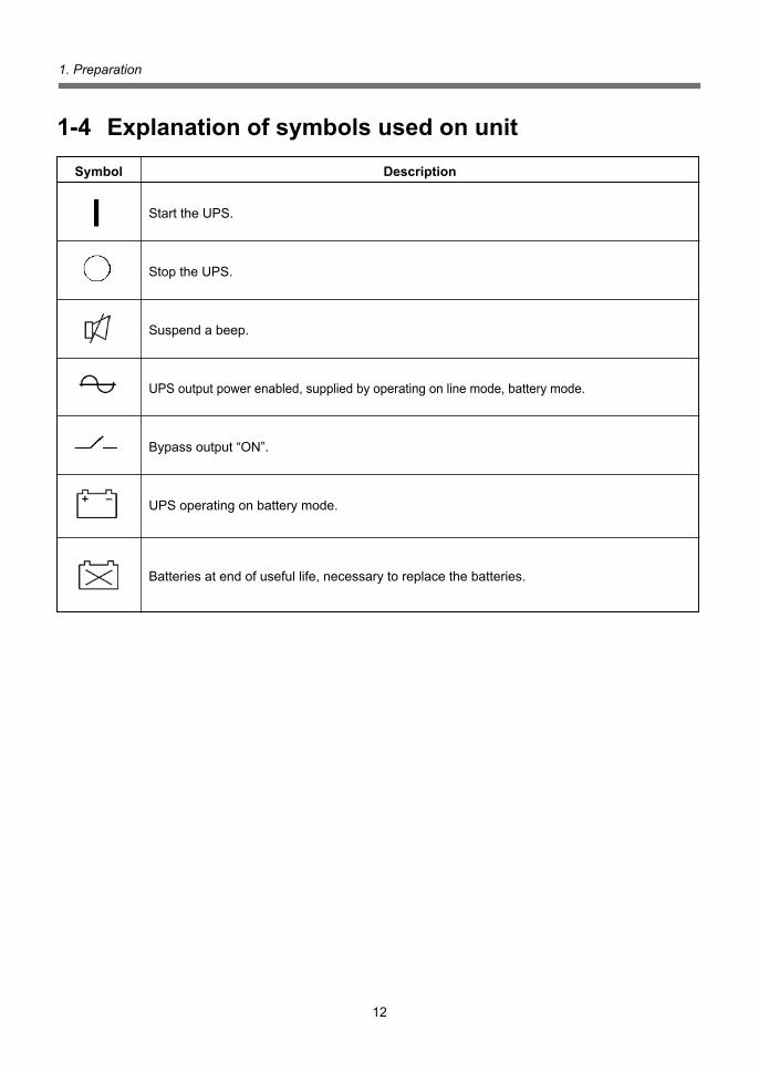
1-4 Explanation of symbols used on unit
Symbol Description
Start the UPS.
Stop the UPS.
Suspend a beep.
UPS output power enabled, supplied by operating on line mode, battery mode.
Bypassoutput“ON”.
UPS operating on battery mode.
Batteries at end of useful life, necessary to replace the batteries.

13
1. Preparation
Rear view
A. Setting switchB. Contact/serial communication
selection switchC. Power supply output receptacle CD. Power supply output receptacle BE. Power supply output receptacle AF. Air ventG. Bypass switch OFF
UPS <BH60PCW/BH100PCW>AC stabilized power supply <RE60FW/RE100FW>
A B C D E G H
JKMNO L
I
F
P
H. Bypass switch ONI. PoweroutputreceptacleforbatteryunitJ. AC input cable/plugK. Grounding terminalL. SurgeprotectionFGM. Battery connectorN. Battery unit signal connectorO. Communication interface (D-sub 9-pin) connectorP. Fixing bracket
Battery unit <BHM60PC/BHM100PC>
A
EFG D
B
C
H
A. Air ventB. Battery unit signal connectorC. Additional battery unit signal connector (BHM100PC only)D. Additional battery connector (BHM100PC only) * The unit ships with a connector cover. E. Battery connectorF. Power output receptacle for battery unit (BHM100PC only)G. AC input cable/plugH. Surge protection FG

14
2. Preparing for installation
2-1 Settings for use as uninterruptible power supply (UPS)
2. Preparing for installation
• Lock the bypass switch with the bracket. After making the settings, use the bracket and screw to lock the switch as shown in the diagram.
• Set the setting switch and bypass switch on the back of the unit according to the type of usage, as shown below.
Caution (Make sure to perform the settings below before installation.)
(1) Constant voltage input/output synchronization operation(Normal usage, where output frequency is synchronized with input frequency before output)
Battery unit connection Available Settingswitchselection SW8Coldstart OFF SW9: Synchronized/ Non-synchronized selection OFF SW10 50/60Hz selection OFF/ON
1 2
Setting switch
53 4 8 9 10
ON
6 7 ON
ScrewFixing bracketOFF
Bypass switch
See also 4-5 Changing function settings → Page 49
1 2
Setting switch
53 4 8 9 10
ON
6 7
ON
Screw
Fixing bracketOFF
MakesurethebypassswitchissettoON.IfitisOFFandoverloadorfailureoccurs,theoutput stops and direct output cannot be performed.
3. Installation and connection → Page 17Next
Setting switch 1→Page 49
Beep ON/OFF setting
Bypass switch ON
UPS

15
2. Preparing for installation
Setting switch 1→Page 49
(2) Constant voltage/constant frequency output (frequency conversion) operation(Usage in which output has a constant frequency that is not synchronized with input frequency)• Use this setting only when you want to stabilize the output frequency, or when you want to
output at a frequency different from the input frequency.
1 2
(50 Hz) Setting switch
53 4 8 9 10
ON
6 7
1 2
(60 Hz)
53 4 8 9 10
ON
6 7
ON
ScrewFixing bracket
OFF
Bypass switch
3. Installation and connection → Page 17Next
Output starts up with no commercial input, and it operates on battery power supply.
1 2
(50 Hz) Setting switch
53 4 8 9 10
ON
6 7
1 2
(60 Hz)
53 4 8 9 10
ON
6 7
ON
ScrewFixing bracket
OFF
Bypass switch
2-2 Settings for use with cold start
Output frequency 50Hz output 60Hz output Battery unit connection Available Available Settingswitch SW8Coldstart OFF OFF selection SW9: Synchronized/Non-synchronized selection
ON ON
SW10 50/60Hz selection OFF ON
The bypass switch cannot be used during operation when this setting is used. Turn OFF the bypass switch. Direct output is not performed when a failure or overload occurs.
Bypass switch OFF
Bypass switch OFF
The bypass switch cannot be used during operation when this setting is used. Turn OFF the bypass switch. Direct output is not performed when a failure or overload occurs.
3. Installation and connection → Page 17Next
Output frequency 50Hz output 60Hz output Commercial power input None None Battery unit connection Available Available Settingswitch SW8:Batterystartup ON ON selection SW9: Synchronized/Non-synchronized selection
ON/OFF ON/OFF
SW10 50/60Hz selection OFF ON
UPS

16
2. Preparing for installation
1 2
Setting switch
53 4 8 9 10
ON
6 7 ON
ScrewFixing bracketOFF
Bypass switch
2-3 Settings for use as AC stabilized power supply (CVCF, AVR)
1 2
(50 Hz) Setting switch
53 4 8 9 10
ON
6 7
1 2
(60 Hz)
53 4 8 9 10
ON
6 7
ON
ScrewFixing bracket
OFF
Bypass switch
(1) Constant voltage/constant frequency (frequency conversion) operation (CVCF)(Usage in which output has a constant frequency that is not synchronized with input frequency)
Output frequency 50Hz output 60Hz output Battery unit connection None None Settingswitch SW8Coldstart OFF OFF selection SW9: Synchronized/ Non-synchronized selection
ON ON
SW10 50/60Hz selection OFF ON
The bypass switch cannot be used during operation when this setting is used. Turn OFF the bypass switch. Direct output is not performed when a failure or overload occurs.
Bypass switch OFF
3. Installation and connection → Page 17Next
3. Installation and connection → Page 17Next
Battery unit connection None Settingswitchselection SW8Coldstart OFF SW9: Synchronized/ Non-synchronized selection OFF SW10 50/60Hz selection ON/OFF
Bypass switch ON
(2) Constant voltage/input synchronization operation (AVR)(Usage in which output voltage is stabilized and output frequency is synchronized with inputfrequency before output)
MakesurethebypassswitchissettoON.IfitisOFFandoverloadorfailureoccurs,theoutput stops and direct output cannot be performed.
CVCF•AVR
17
3. Installation and connection
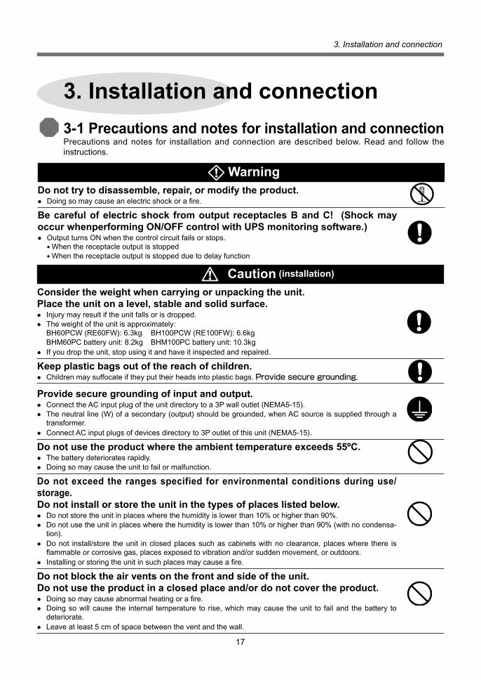
3-1 Precautions and notes for installation and connectionPrecautions and notes for installation and connection are described below. Read and follow the instructions.
3. Installation and connection
Consider the weight when carrying or unpacking the unit. Place the unit on a level, stable and solid surface.• Injurymayresultiftheunitfallsorisdropped.• The weight of the unit is approximately: BH60PCW (RE60FW): 6.3kg BH100PCW (RE100FW): 6.6kg BHM60PCbatteryunit:8.2kg BHM100PCbatteryunit:10.3kg• Ifyoudroptheunit,stopusingitandhaveitinspectedandrepaired.
Keep plastic bags out of the reach of children. • Children may suffocate if they put their heads into plastic bags. Provide secure grounding.
Provide secure grounding of input and output. • Connect the AC input plug of the unit directory to a 3P wall outlet (NEMA5-15).• The neutral line (W) of a secondary (output) should be grounded, when AC source is supplied through a
transformer.• Connect AC input plugs of devices directory to 3P outlet of this unit (NEMA5-15).
Do not use the product where the ambient temperature exceeds 55ºC. • The battery deteriorates rapidly. • Doing so may cause the unit to fail or malfunction.
Do not exceed the ranges specified for environmental conditions during use/storage.Do not install or store the unit in the types of places listed below. • Do not store the unit in places where the humidity is lower than 10% or higher than 90%. • Do not use the unit in places where the humidity is lower than 10% or higher than 90% (with no condensa-
tion). • Do not install/store the unit in closed places such as cabinets with no clearance, places where there is
flammableorcorrosivegas,placesexposedtovibrationand/orsuddenmovement,oroutdoors.• Installingorstoringtheunitinsuchplacesmaycauseafire.
Do not block the air vents on the front and side of the unit. Do not use the product in a closed place and/or do not cover the product.• Doingsomaycauseabnormalheatingorafire.• Doing so will cause the internal temperature to rise, which may cause the unit to fail and the battery to
deteriorate. • Leaveatleast5cmofspacebetweentheventandthewall.
Caution (installation)
Do not try to disassemble, repair, or modify the product.• Doingsomaycauseanelectricshockorafire.
Be careful of electric shock from output receptacles B and C! (Shock may occur whenperforming ON/OFF control with UPS monitoring software.)• Output turns ON when the control circuit fails or stops.
• When the receptacle output is stopped• When the receptacle output is stopped due to delay function
Warning

3. Installation and connection
18
Do not install the unit in any position other than those specified. Do not install the unit on an unstable base. Anchor the unit when it is used in a vertical position to prevent it from falling over. • Referto“3-2Installation”....onpage20forproperinstallationpositions.• Injurymayresultiftheunitfallsorisdropped.
Do not place objects on the unit that are 25kg or heavier, and do not drop metal objects onto the unit. Do not place objects on the unit (except other units when stacking). • Doingsomaycausedistortion/damagetothecaseorafailureoftheinternalcircuit,andmaycauseafire.
Do not pinch or tie the cable of the unit. • Doingsomaydamagethecableorcauseittobecomehot,resultinginanelectricshockorafire.• Ifthecableisdamaged,immediatelystopusingtheunitandhaveitrepaired.
All of the included accessories are designed to be used exclusively with the unit. Do not use the accessories with other devices. • Doing so may compromise the safety of devices.
When installing the unit on a rack, use support angles (sold separately) and mounting brackets to support and stabilize the unit. When a battery unit is added, make sure to position the battery unit so that it is below the main unit. • When installing the unit on a rack, use support angles (sold separately) and mounting brackets. The front
mounting brackets are not able to support the weight of the unit without support angles. • Weight of the unit is approximately: BH60PCW (RE60FW): 6.3kg BH100PCW (RE100FW): 6.6kg BHM60PCbatteryunit:8.2kg BHM100PCbatteryunit:10.3kg
When installing the unit on a rack, place it on the lowest shelf. • Injurymayresultiftheunitfalls.
When using separately purchased brackets, make sure to use the mounting screws that were included. • Mounting screws other than those included may not be strong enough to support the unit, causing it to fall.
Caution (installation)
Caution (connection)
Connect the unit to a wall outlet (commercial power) with a capacity higher than that of its maximum input current. • Otherwise, the wiring of the unit may overheat. • The maximum input currents when rated capacity devices are connected are: BH60PCW, RE60FW: 7A BH100PCW, RE100FW: 12A
Make sure to connect the unit’s AC input plug to a wall outlet (commercial power) with rated input voltage (50/60Hz). • Connectingtoawalloutlet(commercialpower)withadifferentvoltagemayresultinafire.• Doing so may cause the unit to fail.
The socket-outlet for pluggable equipment shall be installed near the equipment and shall be easily accessible.
Do not connect equipment that exceeds the output capacity of the unit. You can use a plug strip to connect additional devices, but do not connect devices that exceed the current capacity of the plug strip.• The unit may detect an overload, which may stop the output. • Thepowerstripmayoverheatandcauseafire.

19
3. Installation and connection
NoteWhen moving the unit from a cold place to a warm place, leave it for several hours beforeu sing it.• IftheunitispromptlyturnedONafterbeingmovedtoawarmerplace,condensationmayforminsidetheunitandcause
it to fail.
Check system operation beforehand if the unit is used in combination with a device whose power supply frequency fluctuates widely, such as a personal electric generator.• Theunitautomaticallyrecognizestheinputpowerfrequencywheninputpowerissupplied.Iftheunitisconnectedwhen
the input power frequency is not stable at the rated level, the unit may misidentify the power supply frequency and may fail tooperatenormally. (If theunit is inoperation,changing fromcommercialpowersupply toanotherpowersupplysource, such as generating equipment, will cause no problem.)
If the unit is used with an inductive device such as a coil or motor, check the operation beforehand.• With some types of devices, the effect of inrush current may cause this unit to stop operating properly.
Do not short the output lines of the unit with each other, and to not short the output lines with the ground.• Doing so may cause the unit to fail.
Do not perform a withstand voltage test.• A withstand voltage test may damage the surge absorption element built into the power supply input circuit.• When performing a withstand voltage test, disconnect the surge protection FG’s ground wire from the ground terminal on the
backoftheunit.Makesuretoconnectthegroundwireofthe“surgeprotectionFG”tothegroundingterminalduringuse.
Do not connect a page printer (such as a laser printer) to the unit.• The page printer has a large peak current, so an excess connection capacity or a power failure due to instantaneous
voltage drop may be detected.• The unit repeatedly switches between Commercial Power Mode and Battery Mode, shortening the life of the battery.
Take measures for handling unforeseen accidents, such as data backup and system redundancy.• The output may stop when there is a circuit failure.
Notes (UPS)
Charge the battery soon after purchasing the unit.• Ifyoudonotusetheunitforalongtimeafterpurchase,thebatteryperformancemaydeteriorateanditmaybecomeunusable.• The battery charges automatically once the AC input plug of the UPS is connected to a wall outlet (commercial power).
Charge the battery before storing the UPS.• The battery discharges even when it not being used, and it goes into over discharge state if it is left for a long period of
time. The backup time may become shorter or the battery may become unusable.• The storable period of the built-in battery of the UPS is 6 months after being fully charged. (Storage temperature of 40ºC
or less is recommended.)• When storing the battery for more than 6 months, recharge the battery before 6 months has elapsed by connecting the
AC input plug of the UPS to a commercial power wall outlet.• Turn OFF the power supply output switch ( ) of the UPS while it is in storage.
Caution (connection)
Do not connect devices (such as dryers) which have a half-wave rectifier that allows only half-cycle AC power to flow through. • Doing so may cause the unit to fail.
Do not connect devices that cannot be used with commercial power supply. • When the unit’s power supply output switch is turned ON and an error occurs with a connected device,
bypass operation is performed and commercial power supply is supplied directly to the connected devices.

3. Installation and connection
20
Correct positions
UPS AC stabilized power supply (CVCF, AVR)
Battery unit
3-2 Installation
The unit can be installed in any of the positions shown below. Choose the installation position most suitable for your environment.
1. Stationary installation• Horizontal Attach the included rubber feet.
Whenusingwithouttherubberfeetattached,becarefulnottopinchyourfingers.
Correct positions
UPS
AC stabilized power supplyBattery unit
AC stabilized power supply (CVCF, AVR)
Battery unit
NoteBefore installing this device, make a record of the serial number.The serial number is required when contacting us about the device.The serial number is printed on the unit’s label.
• VerticalPosition it so that the right side (when facing the front of the unit) is facing upward.
Anchor the unit to prevent it from falling over.

21
3. Installation and connection
Upside-down Upside-down
Incorrect positions
UPS AC stabilized power supply (CVCF, AVR)
Right side is facing downward Right side is facing downward
Front/rear side is facing up/down
The battery is positioned upside-down when the left side is facing downward, which maycause a reduction in performance, battery deterioration, leakage, etc.
Caution (installation and connection)

3. Installation and connection
22
3. Installation and connection
Caution
When using an EIA 19-inch rack • When attaching to the rack, use BHP60P mounting brackets (sold separately) to connect the UPS
body with the battery unit. For details, refer to the instruction manual included with the rack-mount brackets (BHP60P) and support angles (BUP06).
When using a JIS 19-inch rack • When attaching to the rack, use BHP60J mounting brackets (sold separately) to connect the UPS
body with the battery unit. BUP06supportanglesarenotcompatiblewithJISstandards.Usearackshelf. For details, refer to the instruction manual included with the rack-mount brackets (BHP60J). For details, refer to the instruction manual included with the rack-mount brackets (BHP60P) and
support angles (BUP06). Support angles are not compatible. Use a server rack.
When installing the unit on an EIA 19-inch rack, use both BHP60P mounting brackets and BUP06 support angles (both sold separately) to support and stabilize the unit. • When installing the unit on a rack, make sure to use mounting brackets and support angles (both sold separate-
ly). The front mounting brackets are not able to support the weight of the unit without support angles.
When installing the unit on a JIS 19-inch rack, use both BHP60J mounting brackets and a rack shelf (base plate) (both sold separately) to support and stabilize the unit.• When installing the unit on a rack, use mounting brackets and a rack shelf (both sold separately).
The front mounting brackets are not able to support the weight of the unit without the rack shelf (base plate).
• The weight of the unit is approximately: BH60PCW (RE60FW): 6.3kg BH100PCW (RE100FW): 6.6kg BHM60PCbatteryunit:8.2kg BHM100PC:10.3kg
When installing the unit on a rack, place it on the lowest shelf.• Injurymayresultiftheunitfalls.
Make sure to use the mounting screws included with the brackets.• Mounting screws other than those included may not be strong enough to support the unit, caus-
ing it to fall.
When using support angles or the rack shelf, do not stack multiple UPS or additional battery units on top of each other.• Use a separate set of support angles or rack shelf for each connected unit.
Precautions when adding a battery unit: When there is an odd number of UPS and battery units, they cannot be mounted on a rack. Two units need to be connected when mounting on a rack.
Rack-mount bracket (two pieces, right and left)
Linking bracket (two pieces, top and bottom)
• When attaching to a rack, detach the rubber feet from the bottom surface of the unit.

23
3. Installation and connection
3-3 Connection
2. Connection when using as AC stabilized power supply (CVCF, AVR) Battery unit is not required.
Checkthebypassswitchsetting.(Referto“2.Preparingforinstallation”Page14)
Caution (installation and connection)
Checkthebypassswitchsetting.(Referto“2.Preparingforinstallation”Page14)
Caution (installation and connection)
• Whenusing the included “PowerActPRO”UPSmonitoringsoftwareandWindowsstandardUPS service, or when using contact signal input/output, refer to “6. Using the UPS monitoring software andcontactsignal”onpage55.
UPS
CVCF•AVR
1. Connection when using as uninterruptible power supply (UPS) Connect the UPS (BH60PCW/BH100PCW) and battery unit (BHM60PC/BHM100PC) as shown
in the diagram below. A connection cable and connector cover are included with the battery unit. Refer to the battery unit instruction manual for more details.
Power supply output receptacle
AC input cableConnect to the commercial power supply100V to 120V AC input
AC input cableConnect to power output receptacle for battery unit
Battery cableSignal cable
UPSBH60PCWBH100PCWMain unit
Battery unitBHM60PCBHM100PC
Connect with a 3P AC plug (NEMA5-15)
Provide secure grounding
Connect with a 3P AC plug (NEMA5-15)
Provide secure grounding
C B A
AC input cable/plug
Run the battery cable through the connector cover, connect the cable, and screw the connector cover shut.
C BPower supply output receptacle
AC input cableConnect to the commercial power supply100V to 120V AC input
A
AC stabilized power supplyRE60FWRE100FW
Connect with a 3P AC plug (NEMA5-15)
Provide secure grounding
Connect with a 3P AC plug (NEMA5-15)
Provide secure grounding

3. Installation and connection
24
• Group control of power supply output receptaclesThis function can be used with the UPS monitoring software included with the UPS.The output receptacles of the BH60PCW/BH100PCW are separated into 3 groups: A, B, and C.1. Power supply output receptacle A Output begins at the same time as startup.
2. Power supply output receptacles B, C• The output start times for power supply output receptacles B and C are independent of pow-
er supply output receptacle A, so they can be delayed or set to precede the output stop time.• The output start/stop time control function is only available when using the included “PowerAct PRO”UPSmonitoringsoftware.
• Output ON/OFF can be controlled with the included UPS monitoring software while the BH60P-CW/BH100PCW is operating.
• The delay settings and ON/OFF control described here can be performed independently for power supply output receptacle B and power supply output receptacle C.
This function can be used to set the startup order of servers, peripheral devices, etc. ON/OFF control of connected devices can be performed remotely.
3. Device connection procedure• Connecting a device to the output receptacle
Make sure that the total capacity of devices connected to output receptacle does not exceed the output capacity rating of the BH60PCW (RE60FW)/BH100PCW (RE100FW).
Ifanoverloadisindicated,reducethenumberofconnecteddevices.• The output current capacity varies according to the output voltage setting value, as
shown below.
Output capacity (VA) Number of receptaclesOutput
BH60PCW BH100PCW receptacles (RE60FW) (RE100FW)
Power supply output receptacle A 600VA 1kVA 1Power supply output receptacle B 600VA 1kVA 1Power supply output receptacle C 600VA 1kVA 1
Max. rated value of output capacity 600VA/420W 1kVA/700W(Total value of output receptacles A, B, and C)• For 100V output voltage Max. 6A Max. 10A • For 110V output voltage Max. 5.5A Max. 9.1A•For115Voutputvoltage Max.5.2A Max.8.7A•For120Voutputvoltage Max.5A Max.8.3A
Power supply output receptacle A
Output ON Output OFF
Power supply output receptacle B
Power supply output receptacle C
Be careful of electric shock from output receptacles B and C! (Shock may occur whenperforming ON/OFF control with UPS monitoring software.)
• While output receptacle A is outputting, outputs B and C turn ON when the control circuit fails or stops.• While receptacle outputs B and C are stopped• While receptacle outputs B and C are stopped due to delay function
Warning

25
3. Installation and connection
3-4 Extending the UPS backup time (Adding a battery unit)• Up to 5 battery units can be connected to the 1kVA-type BH100PCW. *WhenusingtheunitincompliancewithULstandards,atotalofupto2batteryunitscanbe
connected. Do not connect more than 3 units.• TheadditionalbatteryunitalsousesthesametypemodelofBHM100PC(for1kVA)asthefirstunit.
UPSBH100PCW
Battery unit 1BHM100PC
Battery units 2 to 5BHM100PC
Max. total of 5Run the battery cable through the connector cover, connect the cable, and screw the connector cover shut.
• Each battery unit is equipped with a charging circuit. The charging time does not increase when a battery unit is added.
* When adding a BHM100PC to a BHM100PC, remove the connector cover attached at shipment and connect the cable.

3. Installation and connection
26
3-5 Checking the operation
• Functions that have been set are displayed.
• Just after the input power supply is turned ON, the status indicator turns ON and displays the details of the error that occurred most recently.
When there is no record of error, the following is displayed: • Next, the input voltage value is displayed. When the indicator blinks, the input voltage value is outside the startup range, so it does not
operate when the power supply output switch is turned ON.
(2) Turn ON the unit°«s power supply output switch.• The beep sounds, and the output voltage setting value and output frequency are displayed in
sequence on the status indicator.• Output begins with bypass.• The bypass indication lamp turns OFF and inverter output starts.
• About 5 seconds after output starts, the self-diagnostic test is performed in Battery Mode for about 10 seconds.
(Theself-diagnostictestisnotperformedwhenbatterychargeisinsufficient.)
● ON 〇 OFF
Battery backup : ONConstant voltage output : ONConstant frequency output : OFF
Inputvoltage(V)isdisplayed.
Bypass: ON, Power supply output: ON
Bypass: OFF
1. Operation check when using as uninterruptible power supply (UPS)Whenyou finish connectingdevices to theunit, follow theprocedurebelow to check thatBattery Modeworksproperly.(Inthisoperationcheck,theACinputplugisdisconnectedfromthewalloutlet(commercial power) to reproduce the effects of a power failure.)
1-1. When using input synchronization operation(1) After connecting devices such as a PC to the UPS, connect the AC input plug of the UPS to a
wall outlet (commercial power).• The indicator appears as shown below when the AC input plug is connected.
See also Seealso“2.Preparingforinstallation”page14
The remaining time of the test (seconds) is displayed.
AC input : ON
Battery unit charging display : ON
UPS

27
3. Installation and connection
When the above procedure ends normally, operation continues in the state describedbelow.
Power supply output switch: ON
AC input : ONPower supply output : ON
(3) Put all connected devices into an operational state.(This includes devices connected to power outlets on the backs of computers or otherconnected devices.)
Operate the devices in such a way that they are not damaged by a sudden power stop.
• Make sure that error states with the overload indicator do not occur in this state. Ifnormal,operationproceedswiththeindicatordescribedin(2)above.→ Proceed to (4). Iftheerrordisplayappears,referto“8.Troubleshooting”…onpage66andrespondaccordingly.• The indicator selection switch can be used to display the capacity of connected devices. Capacity can be checked in terms of volt-amperes (VA) or watts (W). Keep turning ON/OFF the indicator selection switch until one of the following indications is
displayed.
Indicatestheloadcapacity(VA).
Indicatestheloadcapacity(W).
• The status indication below blinks when overload occurs.
(4) Disconnect the unit’s AC input plug from the commercial power source to make it enter Battery Mode.• The Battery Mode indicator blinks. (The AC input indicator turns OFF while this is occurring.)
Beep sounds in 0.5-second intervals
OverloadIndicatestheloadrate(%).
Battery Mode : Blinking
Inputvoltage(V)isdisplayed.
● ON 〇 OFF Blinking
Battery backup : ONConstant voltage output : ONConstant frequency output : OFF
UPS

3. Installation and connection
28
• Does the status indicator match one of the states shown in the table below? Status is normal if one of the states below occurs.
Status indicatorBattery voltage (V) is displayed.
Beep
Intermittent 4-second intervals
Output
ON
ON
Charging
OFF
ON
Description
InBatteryModeduetopoweroutage.
InBatteryModeduetopoweroutage, but battery level is low.
• The indicator details vary according to the battery charge and load capacity. The values shown above are for reference only.
Iftheerrordisplayappears,referto“8.Troubleshooting”…onpage67andrespondac-cordingly.
• IftheUPSandconnecteddevicesbecomeunabletoperformanybackup,aninsufficientbattery charge may be the cause.
Connect the AC input plug of the UPS to a wall outlet (commercial power) and wait at least8hoursforthebatterytocharge,andthengobackto(4).
Iftheproblemremainsaftercheckingthe2pointsabove,contacttheElectronicSystems& Equipments customer support center at: __________.
• The operation check of the uninterruptible power supply is complete.
Installationandconnectioniscomplete.
Next 3-6. Preparing for operation when using uninterruptible power supply → Page 36
● ON 〇 OFF
The beep can be turned ON/OFF with setting switch 1 . → Page 49
(5) Reconnect the AC input plug to the commercial power supply.• The display returns to Commercial Power Mode status, and the beeping sound stops.
See also
Intermittent 1-second intervals
UPS

29
3. Installation and connection
1-2. Constant frequency (frequency conversion) operation of uninterruptible power supply
(1) After connecting devices such as a PC to the UPS, connect the AC input plug of the UPS to a wall outlet (commercial power).
Bypass: OFF, Power supply output: ON
(Theself-diagnostictestisnotperformedwhenbatterychargeisinsufficient.)• When the above procedure ends normally, operation continues in the state described below.
Power supply output switch: ON
Output frequency (Hz) is displayed.
The remaining time of the test (seconds) is displayed
• Functions that have been set are displayed.
● ON 〇 OFF
Battery backup : ONConstant voltage output : ONConstant frequency output : ON
Inputvoltage(V)isdisplayed.
AC input : ON
Battery backup : ONConstant voltage output : ONConstant frequency output : ON
Output frequency (Hz) is dis-played.
AC input : ONPower supply output : ON
Battery unit charging display : ON
• Just after the input power supply is turned ON, the status indicator turns ON and displays the details of the error that occurred most recently.
When there is no record of error, the following is displayed: • Next, the input voltage value is displayed. When the indicator blinks, the input voltage value is outside the startup range, so it does not
operate when the power supply output switch is turned ON.
(2) Turn ON the unit’s power supply output switch.• The beep sounds, and the output voltage setting value and output frequency are displayed in
sequence on the status indicator.• Inverteroutputbegins.(Thereisnobypassfunction.)
• About 5 seconds after output starts, the self-diagnostic test is performed in Battery Mode for about 10 seconds.
UPS

3. Installation and connection
30
Indicatestheloadcapacity(VA).
Indicatestheloadcapacity(W).
• The status indication below blinks when overload occurs.
(4) Disconnect the unit’s AC input plug from the commercial power source to make it enter Battery Mode.• The Battery Mode indicator blinks. (The AC input indicator turns OFF while this is occurring.)
Beep sounds in 0.5-second intervals
OverloadIndicatestheloadrate(%).
● ON 〇 OFF Blinking
Battery Mode : Blinking
• Does the status indicator match one of the states shown in the table below? Status is normal if one of the states below occurs.
Status indicatorBattery voltage (V) is displayed.
Beep
Intermittent 4-second intervals
Intermittent 1-second intervals
Output
ON
ON
Charging
OFF
OFF
Description
InBatteryModeduetopoweroutage.
InBatteryModeduetopoweroutage, but battery level is low.
• The indicator details vary according to the battery charge and load capacity. The values shown above are for reference only.
Iftheerrordisplayappears,referto“8.Troubleshooting”onpage67andrespondaccord-ingly.
UPS
(3) Put all connected devices into an operational state.(This includes devices connected to power outlets on the backs of computers or otherconnected devices.)
Operate the devices in such a way that they are not damaged by a sudden power stop.
• Make sure that error states with the overload indicator do not occur in this state. Ifnormal,operationproceedswiththeindicatordescribedin(2)above.→ Proceed to (4). Iftheerrordisplayappears,referto“8.Troubleshooting”onpage67andrespondaccordingly.• The indicator selection switch can be used to display the capacity of connected devices. Capacity can be checked in terms of volt-amperes (VA) or watts (W). Keep turning ON/OFF the indicator selection switch until one of the following indications is displayed.
31
3. Installation and connection
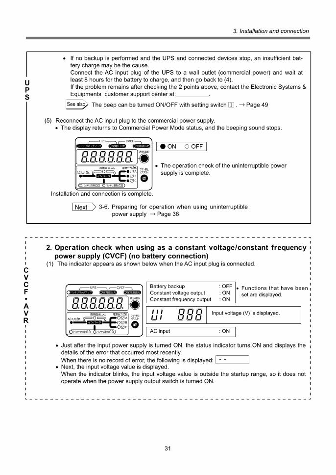
2. Operation check when using as a constant voltage/constant frequency power supply (CVCF) (no battery connection)(1) The indicator appears as shown below when the AC input plug is connected.
• IfnobackupisperformedandtheUPSandconnecteddevicesstop,aninsufficientbat-tery charge may be the cause.
Connect the AC input plug of the UPS to a wall outlet (commercial power) and wait at least8hoursforthebatterytocharge,andthengobackto(4).
Iftheproblemremainsaftercheckingthe2pointsabove,contacttheElectronicSystems&Equipments customer support center at:__________.
The beep can be turned ON/OFF with setting switch 1 . → Page 49
• The operation check of the uninterruptible power supply is complete.
Installationandconnectioniscomplete.
Next 3-6. Preparing for operation when using uninterruptible power supply → Page 36
● ON 〇 OFF
(5) Reconnect the AC input plug to the commercial power supply.• The display returns to Commercial Power Mode status, and the beeping sound stops.
• Functions that have been set are displayed.
Battery backup : OFFConstant voltage output : ONConstant frequency output : ON
Inputvoltage(V)isdisplayed.
• Just after the input power supply is turned ON, the status indicator turns ON and displays the details of the error that occurred most recently.
When there is no record of error, the following is displayed: • Next, the input voltage value is displayed. When the indicator blinks, the input voltage value is outside the startup range, so it does not
operate when the power supply output switch is turned ON.
See also
AC input : ON
UPS
CVCF•AVR

3. Installation and connection
32
Power supply output switch: ON
Bypass: OFF, Power supply output: ON
• When the above procedure ends, operation continues in the state described below.
Output frequency (Hz) is displayed.
(2) Turn ON the unit’s power supply output switch.• The beep sounds, and the output voltage setting value and output frequency are displayed in
sequence on the status indicator.• Inverteroutputbegins.(Thereisnobypassfunction.)
Battery backup : OFFConstant voltage output : ONConstant frequency output : ON
Output frequency (Hz) is displayed.
AC input : ONPower supply output : ON
● ON 〇 OFF
(3) Put all connected devices into an operational state.(This includes devices connected to power outlets on the backs of computers or otherconnected devices.)• Make sure that error states with the overload indicator do not occur in this state. Ifnormal,theoperationcheckiscomplete. Iftheerrordisplayappears,referto“8.Troubleshooting”onpage67andrespondaccordingly.• The indicator selection switch can be used to display the capacity of connected devices. Capacity can be checked in terms of volt-amperes (VA) or watts (W). Keep turning ON/OFF the indicator selection switch until one of the following indications is
displayed.
Indicatestheloadcapacity(VA).
Indicatestheloadcapacity(W).
• The indication below appears when overload occurs. Reduce the number of connected devices.
Beep sounds in 0.5-second intervals
OverloadIndicatestheloadrate(%).
• Installationandconnectioniscomplete.
Next 4. Operation → Page 37
CVCF•AVR

33
3. Installation and connection
3. Operation check when using cold start operation(1)MakesurethattheSW8settingswitchonthebackoftheunitisON.
• IfSW8isOFF,operationcannotoccurwithoutcommercialinput.• Output frequency is determined according to the SW10 setting switch setting. Check that the desired setting has been made.
“2.Preparingforinstallation”and“2-2.Settingsforusewithcoldstart”
(2) Turn ON the unit’s power supply output switch.• The beep sounds, and the status indicator turns ON and displays the details of the error that
occurred most recently. When there is no record of error, the following is displayed: . Next, the output voltage setting value and output frequency are displayed in sequence on the
status indicator.• Inverteroutputbeginsusingpowersuppliedfromthebattery.
• When the above procedure ends normally, operation continues in the state described below.
Battery Mode : BlinkingPower supply output : ON
Power supply output switch: ON
Battery voltage (V) is displayed.
Status indicator Battery voltage (V) is displayed.
Beep
Intermittent4-second intervals
Intermittent1-second intervals
Output
ON
ON
Charging
OFF
OFF
Description
Battery Mode: ON, Power supply output: ON
● ON 〇 OFF Blinking
Battery backup : ONConstant voltage output : ONConstant frequency output : ON
• Functions that have been set are displayed.
(3) Put all connected devices into an operational state.(This includes devices connected to power outlets on the backs of computers or otherconnected devices.)
Operate the devices in such a way that they are not damaged by a sudden power stop.
• Make sure that error states with the overload indicator do not occur in this state.• Does the status indicator match one of the states shown in the table below? Status is normal if one of the states below occurs.
Running in Battery Mode.
InBatteryMode,butbattery level is low.
• The indicator details vary according to the battery charge. The values shown above are for reference only.
Iftheerrordisplayappears,referto“8.Troubleshooting”onpage67andrespondaccord-ingly.
See also
UPS

3. Installation and connection
34
• The indicator selection switch can be used to display the capacity of connected devices. Capacity can be checked in terms of volt-amperes (VA) or watts (W). Keep turning ON/OFF the indicator selection switch until one of the following indications is
displayed.
• The indication below appears when overload occurs. Reduce the number of connected devices.
• Ifnobackup isperformedand theUPSandconnecteddevicesstop,an insufficientbatterycharge may be the cause. Connect the AC input plug of the UPS to a wall outlet (commercial power)andwaitatleast8hoursforthebatterytocharge,andthengobackto(2).
• If theproblemremainsafterchecking the2pointsabove,contact theElectronicSystems&Equipments customer support center at: __________.
• The cold start operation check is complete.• Installationandconnectioniscomplete.
Indicatestheloadcapacity(VA).
Indicatestheloadcapacity(W).
Beep sounds in0.5-second intervals
OverloadIndicatestheloadrate(%).
Next 4. Operation → Page 37
4. Operation check when using as a constant voltage power supply (AVR) (no battery connection)(1) The indicator appears as shown below when the AC input plug is connected.
• Just after the input power supply is turned ON, the status indicator turns ON and displays the details of the error that occurred most recently.
When there is no record of error, the following is displayed: • Next, the input voltage value is displayed. When the indicator blinks, the input voltage value is outside the startup range, so it does not
operate when the power supply output switch is turned ON.
(2) Turn ON the unit’s power supply output switch.The beep sounds, and the output voltage setting value and output frequency are displayed in sequence on the status indicator.
• Functions that have been set are displayed.
Battery backup : OFFConstant voltage output : ONConstant frequency output : OFF
Inputvoltage(V)isdisplayed.
AC input : ON
UPS
CVCF•AVR

35
3. Installation and connection
• Output begins with bypass.
• The bypass indication lamp turns OFF and inverter output starts.
Bypass: ON, Power supply output: ON
Bypass: OFF
• When the above procedure ends normally, operation continues in the state described below.
(3) Put all connected devices into an operational state. (This includes devices connected to power outlets on the backs of computers or other con-
nected devices.)• Make sure that error states with the overload indicator do not occur in this state. Ifnormal,theoperationcheckiscomplete. If theerrordisplayappears, refer to “8.Troubleshooting”onpage67and respondaccord-
ingly.• The indicator selection switch can be used to display the capacity of connected devices. Capacity can be checked in terms of volt-amperes (VA) or watts (W). Keep turning ON/OFF the indicator selection switch until one of the following indications is displayed.
Power supply output switch: ON
• The indication below appears when overload occurs. Reduce the number of connected devices.
Installationandconnectioniscomplete.
Indicatestheloadcapacity(VA).
Indicatestheloadcapacity(W).
Beep sounds in0.5-second intervals
OverloadIndicatestheloadrate(%).
Next 4. Operation → Page 37
Battery backup : OFFConstant voltage output : ONConstant frequency output : OFF
Inputvoltage(V)isdisplayed.
AC input : ONPower supply output : ON
CVCF•AVR

3. Installation and connection
36
3-6 Preparing for operation when using as uninterruptible power supply1. Charging the battery When the AC input plug is connected to a wall outlet (commercial power), the battery automati-
cally starts charging, taking up to 12 hours to complete. (This occurs regardless of whether the power supply output switch is ON or OFF.)
•Theunitwaschargedbeforeshipment,but if it isbeingused for thefirst time, thebackuptime may be reduced due to natural discharge. We recommend charging the unit before use.
• Ifyoudonotperformtheinitialbackuptimemeasurementdescribedbelowin“7.Measuringtheinitialvalueofbackuptime”,proceedto“4.Operation”.→ Page 37
2. Measuring the initial value of backup time
Next 4. Operation → Page 37
• When you measure the backup time initial value of the unit in your environment, this value can be used as a guide when checking the battery and deciding the UPS monitoring software setting values.
Seealso“7.Measuringthebackuptime”→ Page 65
See also
See also
UPS
3. Recharging the battery The battery is discharged completely when the backup time is measured, so you need to re-
charge it before using the unit.• You can use connected devices while recharging the battery, but the backup time when a
power failure occurs is shorter until the battery is fully charged. (Ifapowerfailureoccursimmediatelyafterthestartofcharging,backupstopsimmediately.)
Charge the battery as described above. Preparation for starting operation is now complete.

37
4.Operation
4-1 Cautions and notes for operationCautions and notes for operation are described below.
4. Operation
Caution (use)
If liquid leaks from the battery, do not touch it. • Doing so may cause blindness or burns. • Iftheliquidtouchesyoureyesorskin,washitoutwithlotsofcleanwaterandconsultyourdoctor.If you notice an abnormal sound or smell, smoke or leaking fluid,
UPS case Immediately turn OFF the UPS power output switch ( ), and disconnect the AC input plug from the wall outlet (commercial power) and disconnect the battery connector (with Red and Black code) from the UPS rear panel.
CVCF/AVR case Immediately turn OFF the unit’s power output switch ( ), and disconnect the AC input plug from the wall outlet (commercial power). • Usingtheunitundersuchconditionsmaycauseagroundfaultorfire.• Ifyounoticesuchconditions,stopusingtheunitandcontactusat__________forinspectionandrepairs.• Use the unit in such a way that you can immediately disconnect the AC input plug from the wall outlet
(commercial power) in the event a problem occurs.
Do not place objects on the unit that are 25kg or heavier, and do not drop metal objects onto the unit.Do not place objects on the unit (except other units when stacking). • Doingsomaycausedistortion/damagetothecaseorafailureoftheinternalcircuit,andmaycauseafire.
Do not use the product in a closed place and/or do not cover the product. • Doingsomaycauseabnormalheatingorafire.
Do not pour water on the unit and do not allow it to become wet. • Doingsomaycauseanelectricshockorafire.• Iftheunitbecomeswet,immediatelystopusingitandhaveitinspectedandrepaired.
Do not insert metal objects into the unit’s output receptacles. • Doing so may cause an electric shock.
Never touch the metal part of the AC input plug if it is disconnected while the unit isoperating.• Doing so may result in electric shock.• The leak current of this product itself is less than the value of the safety standard (leak current: 1 mA).
However, because connected equipment causes the leak current to increase, you must never touch the metal part of the AC input plug.
• When the unit is operating, voltage is generated in the metal parts of the AC input plug viacapacitors in the internal circuit, regardless of the elapsed time.
Periodically wipe the AC input plug clean of dirt with a dry cloth.• Accumulateddustmaycauseafire.

38
4.Operation
Next Using as an uninterruptible power supply ... See “4-2. Operation of UPS” → Page 38Using as an AC stabilized power supply ... “4-3. Operation of AC stabilized power supply(CVCF)” → Page 45
Notes (UPS)
Do not connect the unit’s AC input plug to a power output receptacle during Battery Mode.• Doing so may cause the unit to fail.
Before stopping commercial power to the unit, turn OFF the unit’s power supply output switch.• TheunitentersBatteryModewhencommercialpower isstopped. Ifyoufrequentlyusetheunit inBatteryMode, the
batterylifemaybesignificantlyshortened.
This unit uses a lead acid battery.• Leadacidbatteriesareavaluablerecyclableresource.Pleaserecycle. For information about recycling, please contact the OMRONElectronic Systems & Equipments repair
Center at: __________. Pb
Explanation (UPS)
Usual operation• You may either leave the power supply output switch of the unit ON (operation status) or turn it OFF each time when
stopping the connected system. Choose whichever operation method is more convenient.• The battery charges once the unit is connected to commercial power.
Quitting Battery Mode• Ifapower failure lasts foranextendedperiodof time, thebatterydischargesandpowersupply fromtheUPSstops.
Shut down your computer after performing appropriate procedures (for example, saving data) while the UPS is still sup-plying power.
Rebooting• If thebatterydischargescompletelyduringapower failure, theUPSstops.Afterrecovery fromthepower failure, the
UPSautomaticallyrestartsandsuppliespower.IfyoudonotwantthedevicesconnectedtotheUPStostartup,turnOFF their power switches.
• The automatic restart setting can be disabled with the setting switch on the back of the unit.
Scheduled operation using the UPS monitoring software• When scheduled operation is used and commercial power supply input is stopped during a scheduled stop period,
specify a period of no more than 1 month for the start of the next operation. During period that commercial power input is stopped, the timer runs on internal battery power. Ifthetimerstops,theoperationdoesnotstartaccordingtoschedule.
Operation start using the UPS monitoring software during scheduled stop• If theUPSstartsoperationduringascheduledstopperiod, turnOFFthepowersupplyoutputswitchonce,andthen
turn it back on again. You can start the UPS manually. The schedule is reset once the power supply output switch is turned OFF.
Caution (use)
* Thevaluesinthetableontheleftreflecttheexpectedlifeunderstandard conditions, andare not guaranteed values.
Ambient temperature Expected lifespan20℃ 5 to 7years30℃ 3 to 4years40℃ 1 to 2years50℃ 0.7 to 1years
When the battery replacement lamp is blinking or when the backup time becomes shorter than the required time, immediately stop using the unit and replace the battery pack.• Continuingtousetheunitmaycauseafire. Formoreonhowtocheckthebattery,see“5.Maintenanceandinspection”onpage51.

39
4.Operation
• Operation startup procedure(1) For input synchronization operation: When the uninterruptible power supply (UPS) is used with input/output synchronization
operation, the bypass function is available.
• The beep sounds, and the output voltage setting value and output frequency are displayed in sequence on the status indicator.
• Output begins with bypass.
• The bypass indication lamp turns OFF and inverter output starts.
• The output frequency is synchronized with the input frequency.• About 5 seconds after output starts, the self-diagnostic test is performed in Battery Mode for
about 10 seconds. The beep does not sound during the test.
(Theself-diagnostictestisnotperformedwhenbatterychargeisinsufficient.)• Next, it enters the commercial operation state described on the next page.• The battery automatically charges during operation.
Bypass: ON, Power supply output: ON
1. Basic procedures for operation and stopping• When connected to commercial power supply and AC input is ON• When power supply output switch is OFF
• Power supply output is stopped.
● ON 〇 OFF
AC input : ON
Outside the startup range when blinking.• The contents of the status indicator can be changed by
pressing the indicator selection switch.
See also 4-4.Interpretingbeepsanddisplays →Page48
• When the input voltage value indicator blinks, the voltage is outside the startup range, so it does not operate when the power output supply switch is turned ON.
• The battery charges automatically.
Battery unit charging display : ON
4-2 Operation of UPS
Inputvoltage(V)isdisplayed.
Battery backup : ONConstant voltage output : ONConstant frequency output : OFF : ON (For frequency conversion operation)
Operation Press the power supply output switch to turn it ON.
Bypass: OFF
The remaining time of the test (seconds) is displayed.
UPS

40
4.Operation
(Theself-diagnostictestisnotperformedwhenbatterychargeisinsufficient.)• Next, it enters the commercial operation state described below.• The battery automatically charges during operation.
Power supply outputs A, B, C: ON
AC input : ON
Power supply output switch: ON
Battery backup : ONConstant voltage output : ONConstant frequency output : OFF
● ON 〇 OFF
The contents of the status indicator can be changed by pressing the indicator selection switch.
See also 4-4.Interpretingbeepsanddisplays→Page48
Power supply output switch: ON Power supply outputs A, B, C: ON
AC input : ON
(2) For constant frequency (frequency conversion) operation: When the uninterruptible power supply (UPS) is used with frequency conversion output,
the bypass function is not available.
• The beep sounds, and the output voltage setting value and output frequency are displayed in sequence on the status indicator.
• Inverteroutputbegins.
• About 5 seconds after output starts, the self-diagnostic test is performed in Battery Mode for about 10 seconds.
The beep does not sound during the test.
Bypass: OFF, Power supply output: ON
Inputvoltage(V)isdisplayed.
Output frequency (Hz) is displayed.
The remaining time of the test (seconds) is displayed.
Output frequency (Hz) is displayed.
Operation Press the power supply output switch to turn it ON.
Battery backup : ONConstant voltage output : ONConstant frequency output : ON
The contents of the status indicator can be changed by pressing the indicator selection switch.
4-4.Interpretingbeepsanddisplays→Page48See also
UPS

41
4.Operation
• Operation during power outage• When a power outage or input power supply error occurs, the unit automatically switches to
Battery Mode and power supply output continues using power from the battery.• The Battery Mode indicator blinks. (The AC input indicator turns OFF while this is occurring.)• Asanotification,thebeepsoundscontinuously. The status indicator automatically displays the battery voltage.
• Operation when power is restored• When recovery from power outage or input power supply error is made, Commercial Power
Mode is automatically restored.• The Battery Mode indicator lamp turns OFF and the AC input indicator lamp turns ON.• The status indicator shows the input voltage value again and the beeping sound stops.• Recharging of the expended battery begins automatically.
AC input display lamp is ON
Battery Mode: Blinking
Battery unit charging display: OFF
* The indicator voltage value decreases as the battery discharges.
Status indicator Battery voltage (V) is displayed.
Beep
Intermittent4-secondintervals
Output
ON
ON
Charging
OFF
OFF
Description
InBatteryModeduetopoweroutage.
InBatteryModeduetopoweroutage, but battery level is low.
● ON 〇 OFF Blinking
The beep sound can be paused by pressing the beep stop button.
Battery voltage (V) is displayed.
Inputvoltage(V)isdisplayed.
Intermittent1-secondintervals
The contents of the status indicator can be changed by pressing the indicator selection switch.
See also 4-4.Interpretingbeepsanddisplays→Page48
The contents of the status indicator can be changed by pressing the indicator selection switch.
See also 4-4.Interpretingbeepsanddisplays→Page48
UPS

42
4.Operation
• The beep sounds while the status indicator displays the error code of the error that occurred most recently, the output voltage setting value, and the output frequency in order.
• Power supply output begins using power supplied from the battery.
Battery Mode: Blinking, Power supply output: ON
• Operation stop procedure
• Power supply output stops.• IfcommercialpowerissuppliedevenwhenthepowersupplyoutputswitchisturnedOFF,
the battery charges automatically.
2. Basic procedures for operation and stopping for cold start operation• When cold start operation is used, the bypass function is not available.
• All of the indicators are OFF.• Power supply output is stopped.
• Operation startup procedure
AC input : ON
Power supply output switch: OFF
Operation Press the power supply output switch to turn it OFF.
● ON 〇 OFF
Operation Press the power supply output switch to turn it ON.
• The Battery Mode indicator blinks. (The AC input indicator lamp does not turn ON.)• The beep sounds continuously. The voltage value is automatically displayed on the status indicator.
Inputvoltage(V)isdisplayed.
Power supply outputs A, B, C: OFF
UPS
The contents of the status indicator can be changed by pressing the indicator selection switch.
See also 4-4.Interpretingbeepsanddisplays→Page48

43
4.Operation
The contents of the status indicator can be changed by pressing the indicator selection switch.
See also 4-4.Interpretingbeepsanddisplays→Page48Power supply output switch: ON
Battery Mode: Blinking
Power supply outputs A, B, C: ON
The beep sound can be paused by pressing the beep stop button.
* The indicator voltage value decreases as the battery discharges.
• Operation when commercial power supply begins• After starting up in Battery Mode, it automatically switches to Commercial Power Mode when
input power is supplied.• The Battery Mode indicator lamp turns OFF and the AC input indicator lamp turns ON.• The status indicator displays the input voltage value and the beeping sound stops.• Recharging of the expended battery begins automatically.
Status indicator Battery voltage (V) is displayed.
Beep
Intermittent4-secondintervals
Intermittent1-secondintervals
Output
ON
ON
Charging
OFF
OFF
Description
Running in Battery Mode.
InBatteryMode,butbattery level is low.
AC input: ON
The contents of the status indicator can be changed by pressing the indicator selection switch.
See also 4-4.Interpretingbeepsanddisplays→Page48
Battery voltage (V) is displayed.(“BL”blinks.)
Battery backup : ONConstant voltage output : ONConstant frequency output : ON
● ON 〇 OFF Blinking
Output frequency (Hz) is displayed.
UPS

44
4.Operation
3. Self-diagnosis test Use the procedure below to check whether a failure has occurred inside the unit and whether
battery replacement is required.
The self-diagnostic test is not performed if the battery is not fully charged.
(1) Connect your computer and other devices to the unit and turn ON the power supply output switch.
(2) Press and hold the beep stop/test switch for more than 10 seconds. Release the beep stop/test switch after the beep sounds. Battery Mode starts for the
purpose of testing. (The beep does not sound.) When the test is complete after about 10 seconds, normal operation resumes automatically.
(3) Ifthestatusindicator’serrordisplayorbatteryreplacementlampblinksandthebeepersounds:
4. Battery auto test The unit is equipped with functions that automatically check whether battery replacement is
required and whether there is a fault in the internal circuit. (You do not have to perform any special operations.)
The test is performed once every 4 weeks after the AC input plug is connected to a wall outlet (commercial power).
The test is not performed if the power supply output switch is OFF or if the battery is not fully charged.• When the UPS is in continuous operation, the battery test is automatically performed every 4weeks. If you include theperiodof time that the commercial power supply to theUPS isstopped, the test is performed each time the total power failure time reaches 4 weeks.
The 4 weeks includes time when the power supply output switch is OFF, as long as commercial power is supplied to the unit.
• Operation stop procedure
• Power supply output stops.• When there is no AC input, all of the indicators turn OFF and charging stops.• When there is no AC input, and if commercial power is supplied when the power sup-
ply output switch is turned OFF, the indicator appears as shown below and the battery charges automatically.
Operation Press the power supply output switch to turn it OFF.
Power supply output switch: OFF
The contents of the status indicator can be changed by pressing the indicator selection switch.
See also 4-4.Interpretingbeepsanddisplays→Page48
Inputvoltage(V)isdisplayed.
● ON 〇 OFF
Power supply outputs A, B, C: OFF
AC input : ON
Followthedirectionsforthesolutionsdescribedin“4-4.Interpretingbeepsanddisplays”and “5-1.Checkingthebattery(forUPSonly)”.
See also
UPS

45
4.Operation
(1) Battery Mode automatically starts when the auto battery test starts. (The beep does not sound.) When the test is complete, normal operation resumes automatically.
(2) Ifthestatusindicatordisplaysanerrorcode,thebatteryreplacementlampblinks,orthebeepersounds:
• Formoreonhowtoreplacethebattery,see“5.Maintenanceandinspection”onpage51.
4-3 Operation of AC stabilized power supply (CVCF, AVR)
1. Operation/stop procedures and basic operations when using with constant voltage/constant frequency power supply (CVCF)When using as a constant voltage/constant frequency power supply (CVCF), the bypass function cannot be used.• When connected to commercial power supply and AC input is ON• When power supply output switch is OFF
• Power supply output is stopped.
• When the input voltage value blinks, the voltage is outside the startup range, so it does not oper-ate when the power output supply switch is turned ON.
Bypass: Always OFF, Power supply output: ON
The“disabletheautobatterytest”settingcanbeselectedwiththesettingswitchontheback of the unit.
4-5 Changing function settings → Page 49Seealso“AutobatterytestON/OFFsetting”.
Followthedirectionsforthesolutionsdescribedin“4-4.Interpretingbeepsanddisplays/Displayswhenthereisanequipmentfailure”and“5-1.Checkingthebattery(forUPSonly)”.
See also
The contents of the status indicator can be changed by pressing the indicator selection switch.
See also 4-4.Interpretingbeepsanddisplays→Page48
Inputvoltage(V)isdisplayed.
● ON 〇 OFF
AC input : ON
Battery backup : OFFConstant voltage output : ONConstant frequency output : ON
• Operation stop procedure
• The beep sounds, and the output voltage setting value and output frequency are displayed in sequence on the status indicator.
• Inverteroutputbegins.
• The output frequency, which has no relation to the input frequency, matches the frequency selected by the setting switch (SW10).
Operation Press the power supply output switch to turn it ON.
See alsoUPS
CVCF•AVR

46
4.Operation
• Next, it enters the operation state described below.
Power supply outputs A, B, C: OFF
AC input : ON
Power supply output switch: OFF
The contents of the status indicator can be changed by pressing the indicator selection switch.
See also 4-4.Interpretingbeepsanddisplays→Page48
2. Operation/stop procedures and basic operations when using with constant voltage power supply (AVR)
When used as a constant voltage power supply (AVR), the bypass function is available.• When connected to commercial power supply and AC input is ON• When power supply output switch is OFF• Power supply output is stopped.
AC input : ON
• When the input voltage value blinks, the voltage is outside the startup range, so it does not oper-ate when the power output supply switch is turned ON.
Inputvoltage(V)isdisplayed.
Inputvoltage(V)isdisplayed.
The contents of the status indicator can be changed by pressing the indicator selection switch.
See also 4-4.Interpretingbeepsanddisplays→Page48
● ON 〇 OFF Battery backup : OFFConstant voltage output : ONConstant frequency output : ON
Power supply output switch: ON
AC input : ON
Power supply outputs A, B, C: ON
• Operation stop procedure
• Power supply output stops.
Operation Press the power supply output switch to turn it OFF.
Battery backup : OFFConstant voltage output : ONConstant frequency output : OFF
Outside the startup range when blinking.The contents of the status indicator can be changed by pressing the indicator selection switch.
See also 4-4.Interpretingbeepsanddisplays→Page48
Output frequency (Hz) is displayed.
CVCF•AVR

47
4.Operation
Bypass: ON, Power supply output: ON
• The bypass indication lamp turns OFF and inverter output starts.
Bypass: OFF
• The output frequency is synchronized with the input frequency.• Next, it enters the commercial operation state described below.
Inputvoltage(V)isdisplayed.
Inputvoltage(V)isdisplayed.
• Operation startup procedure
• The beep sounds, and the output voltage setting value and output frequency are dis-played in sequence on the status indicator.
• Output begins with bypass.
Operation Press the power supply output switch to turn it ON.
● ON 〇 OFF
Power supply outputs A, B, C: ON
Power supply output switch: ON
AC input : ON
• Operation stop procedure
• Power supply output stops.
Operation Press the power supply output switch to turn it OFF.
Power supply outputs A, B, C: OFF
Power supply output switch: OFF
AC input : ON
CVCF•AVR
The contents of the status indicator can be changed by pressing the indicator selection switch.
See also 4-4.Interpretingbeepsanddisplays→ Page 47
The contents of the status indicator can be changed by pressing the indicator selection switch.
See also 4-4.Interpretingbeepsanddisplays→Page48

48
4.Operation
4-4 Interpreting beeps and displaysInterpretingthestatusindicator• When the beep sound occurs, it can be paused by pressing the beep stop button.
No. Status indicatorDisplay characters (units)Beep Description of display
1 VI_ * * * (V)Input voltageWhen “VI” blinks: Outside the operating range
VO_ * * * (V) Output voltage
FI_ * * . * (Hz)Input frequencyWhen “FI” blinks: Outside the operating range
2
3
FO_ * * . * (Hz) Output frequency4
CG_ * * * (%)Battery charge level (percentage)(when battery is connected and power supply output switch is ON)
5
LD_ * * * (%)Load rate(Power capacity of connected devices)
6
VA * * * * (VA)Load capacity (apparent power)(Volt-amperes)
7
P_ * * * (W)Load capacity (effective power)(Watts)
8
VB_ * * . * (V)
Indicator when in Battery Mode due to power outage (only when battery is connected)
Indicator while test is being performed (only when battery is connected)
Indicator when there is a device error or warning (“OL”, “REP”, “EO”, “ES”, “EB”, or “EE” blink)
Indicator while operation mode setting is being performed
Battery voltage(when battery is connected and power supply output switch is ON)
9
4-secondintervals
1-secondintervals
None
None
None
0.5-secondintervals
Continuous
Continuous
Continuous
Continuous
Continuous
None
None
VB_ * * . * (V) Battery voltage10
BL_ * * . * (V)Low battery voltage/low battery level.Output will soon stop.
11
FU__ * * (seconds)Self-diagnostic test in progress.Displays the amount of time until test is complete.
12
BC_ _ _ _ (seconds)Battery test in progress.Initial stage of test.
13
BC * * * * (seconds)Battery test in progress.Displays the amount of time until test is complete.
14
OL_ * * * (%) Overload15
REPFan or battery unit is being replaced without stopping output (only possible when setting switches 8 and 9 are OFF)
16
EOOutput stopped due to overload or exceeded time (when no bypass)
17
ESOutput stopped due to output short-circuit or overcurrent
18
EB Too many batteries connected19
EE _ _ _ *The * denotes a code number from 1 to 9.
Failure occurred.The number indicates the typeof failure. 8. Troubleshooting “EE_* (code number)” explanation (P.67)
20
SV_ * * * (V)Output voltage setting value100V/110V/115V/120V
21
SD_ * * * (seconds)Power outage signal output delay time setting value
22
(Alphabetic+numeric characters)
See also

49
4.Operation
4-5 Changing function settings1. Using the setting switch to change functions
Selectionsettings8,9,and10becomeeffectivewhenACinputstarts.
Make setting changes while output and AC input are stopped (while the AC input plug is unplugged).Settings are loaded when AC input is ON.
Selection settings 1, 2, 3, 4, 5, 6, and 7 become effective when the power supply output switch is turned ON and output begins.
Make setting changes while the power supply output switch is turned OFF and output is stopped.Settings are read when the power supply output switch is ON.
Listoffunctionsusingthesettingswitch(At factory shipment, all settings are set to OFF.)
*1: Enabled only when contact signal interface is used.• When using the contact signal, set the communication selection switch on the back of the unit to “contact”.
No. Function to set OFF side ON side
The beep does not sound when in Battery 1 Beep setting The beep sounds. Mode or to indicate a battery replacement warning. The beep sounds when there is a failure or error during operation.
2 Start output with auto-restart when Auto-restart is performed. Auto-restart is not performed. AC input is restored
ON/OFF setting for auto battery test Automatically tests battery once 3 (enabled only when battery is every 4 weeks. Test is not performed. connected)
Power supply output stop delay No.4 No.5 4 time Sets the time until output OFF OFF No stop delay stops after BSsignal is input ON OFF 60 seconds until stop 5 (enabled only when battery is OFF ON 120 seconds until stop connected) *1 ON ON Output does not stop
BS signal reception condition Output stop is enabled via signal Output stop is enabled via signal input only 6 setting (enabled only when battery input when in Commercial Power when in Battery Mode is connected) *1 Mode or Battery Mode
Contact signal output BU/NBU 7 (8-pin)selection(enabledonlywhen Outputspoweroutagesignal(BU). OutputsNBU(reverselogicofBU)signal. battery is connected) *1
Cold start Startup/power supply in UPS does not start up without AC UPS can start up without AC input. 8 BatteryMode(enabledonlywhen input. battery is connected) Select ON/OFF for the bypass Turn OFF the bypass switch on the back of switch according to setting No.9. the unit.
Input/outputfrequency Synchronizestheoutputfrequency Input/outputfrequencyisnotsynchronized, synchronization/no and with the input frequency for output frequency is set to 50Hz or 60Hz for 9 n-synchronization switchNot operation. operation. enabledwhenNo.8isON TurnONthebypassswitchonthe TurnOFFthebypassswitchonthe back of the unit. back of the unit.
10 Output frequency selection Outputs at 50Hz. Outputs at 60Hz. (enabledwhenNo.8orNo.9isON)
1 2
Setting switch
53 4 8 9 10
ON
6 7
Serial ContactCommunication
selection
See also → Page 14

50
4.Operation
2. Operation mode settings Output voltage settings
• Setting procedure(1) Select the output voltage.
• Turn ON the power supply output switch while pressing the indicator selection switch on the front panel. (Beep sounds for 0.5 second.)
The status indicator shows “SV*** ”(SetVoltage), the“currentsettingforoutputvoltage”. Example:“SV100”isdisplayedwhenthecurrentsettingis100VAC.
• Output does not start up at this time.• When the indicator selection switch is pressed repeatedly, the display changes as shown below.
(2) Set the output voltage.• When the beep stop/test switch is pressed while the desired voltage is displayed, the setting
value is applied and power supply output starts up.• The setting value is saved in the UPS, and this setting is used
at startup in future operations.
“SV 100” → “SV 110” → “SV 115” → “SV 120”
• Setting procedure(1) Select the power outage signal output delay time.
• Turn ON the power supply output switch while pressing the beep stop/test switch on the front panel. (Beep sounds for 0.5 second.)
The status indicator shows “SD*** ”(SetSignalDelay),the“currentsettingforsignaldelaytime”.
Example:“SD30”isshownwhenthecurrentsettingisfora30-seconddelay.• Output does not start up at this time.• When the indicator selection switch is pressed repeatedly, the display changes as shown below.
“SD 30” → “SD 60” → “SD 180” → “SD 0”
(2) Set the power outage signal output delay time.• When the beep stop/test switch is pressed while the desired delay time is displayed, the setting
value is applied and power supply output starts up. (Beep sounds for 0.5 second.)• The setting value is saved in the UPS, and this setting is used at startup in future operations.
Power outage signal (BU/NBU) output delay time setting
Power supply output switch
Power supply output switch: ON
Beep stop/test switch
Setting Status indicator
Outputdelayselection Nodelay “SD0”
forBU/NBUpower Signaloutputafter0.5minute “SD30”
outagesignaloutput Signaloutputafter1minute “SD60”
Signaloutputafter3minutes “SD180”
Setting Status indicator
100Voutput “SV100”
Outputvoltage 110Voutput “SV110”selection
115Voutput “SV115”
120Voutput “SV120”

51
5. Maintenance and inspection
Battery can be replaced while the unit is stopped only.• When replacing the battery, stop the connected devices, turn off the power supply (UPS) output switch ( ),
and disconnect the AC input plug from the wall outlet.
When performing battery replacement, do not insert metal objects into the battery receptacles.• Failure to do so may result in an electric shock or short-circuit.
Do not short the battery with metal objects.• Doingsomayresultinburnsorafire.• Some electrical energy remains inside the spent battery.
Do not put the battery into fire.• The batteries may explode.
Replace batteries only with the same model and brand:• Battery pack models: BHB60PC: For BHM60PC battery unit (BH60PCW). BHB100PC: For BHM100PC battery unit (BH100PCW).• Manufacturer: OMRON Corporation.• Using a battery other than that which is specified may cause a fire.
Risk of explosion if battery is replaced by an incorrect type. Dispose of used batteries according to the instructions
Do not use a new battery and an old battery at the same time.• The battery may weaken quickly or leak dilute sulfuric acid.
Do not drop the battery or expose it to strong impact.• Doing so may cause the battery to leak dilute sulfuric acid.
Do not perform battery replacement in a place where there is flammable gas.• Asparkmayoccurwhenconnectingthebattery,resultinginafire.
5. Maintenance and inspection
Do not try to disassemble, repair, or modify the product.• Doingsomaycauseanelectricshockorafire.
If liquid leaks from the battery, do not touch it.• Doing so may cause blindness or burns.• Iftheliquidtouchesyoureyesorskin,washitoutwithlotsofcleanwaterandconsultyourdoctor.
When maintaining connected equipment, turn OFF the unit’s power output switch ( ) and disconnect the AC input plug from the wall outlet (commercial power).• Make sure the output voltage is stopped before performing maintenance.• The backup function continues to supply power from the power output receptacles while the UPS is oper-
ating, even when the AC input plug is disconnected.• Power output is supplied at the next scheduled operation start if a scheduled operation is set and the AC
input plug is connected to a wall outlet (commercial power).
Do not insert metal objects into the battery connectors.Do not create a short between the battery connectors.• Doing so may cause an electric shock.• Doingsomaycauseafire,batteryexplosion,orburns.
Caution (maintenance)
Caution (battery replacement)

52
5. Maintenance and inspection
• The battery deteriorates even if it is stored. The higher the temperature is, the shorter the lifespan becomes.
5-1 Checking the battery (for UPS only)
2. Methods for checking the batteryThere are 3 methods for checking the battery.• Perform a self-diagnostic test. (See page 44.)• Use the auto battery test function. (See page 44.)• Measure the backup time. (See page 65.) By measuring the backup time, the battery life can be determined more accurately.
Measure the backup time according to the instructions in “7-1 How to measurebackuptime”.→ Page 65
Ifthemeasuredvalueisequaltothe“initialvalueofthebackuptime”orlessthanhalfthevalueobtainedfromthe“Estimatedbackuptime”graphonpage65,replacethebattery.•Whencomparingthemeasured“initialvalueofthebackuptime”withthecurrentbackuptime,
ensure that the comparison is accurate by making the capacity of devices connected to the UPS the same as when you measured the initial value.
3. Guidelines for how often to check the battery (measure the backup time)
See also
The sealed lead battery used in the unit has a limited lifespan.(The lifespan varies depending on the storage/use conditions and the backup frequency.)Battery deterioration becomes more rapid as it approaches the end of its life.
1. Battery lifespan (estimated timing of replacement)
Average ambient Battery lifespan Estimated replacement
temperature 20ºC 5 to 7 years 5 years after starting use
30ºC 3 to 4 years 3 years after starting use
40ºC 1.5 to 2 years 1.5 years after starting use
50ºC 0.7 to 1 year 0.5 year after starting use
Perform replacement on a stable and flat surface.• Carefully hold the battery with both hands so that you do not drop it.• Dropping the battery may result in injury or burns due to leakage (acid).
If liquid leaks from the battery, do not touch it.• Touching the liquid (dilute sulfuric acid) may cause blindness or burns.
Do not open or mutilate batteries. • Releasedelectrolyteisharmfultotheskinandeyes.Itmaybetoxic.
Caution (battery replacement)
Average ambient 6-month check Monthly check temperature 20ºC Forthefirst4yearsafterstartinguse When4yearsormorehavepassedafterstartinguse
30ºC Forthefirst2yearsafterstartinguse When2yearsormorehavepassedafterstartinguse
40ºC Forthefirst1yearafterstartinguse When1yearormorehaspassedafterstartinguse
50ºC Forthefirst0.5yearafterstartinguse When0.5yearormorehaspassedafterstartinguse

53
5. Maintenance and inspection
5-3 Replacing the fan
Note
Ifthefanfails,youcanreplaceitviathefrontpanelofthedevicewhileoperationisstopped(powersupply output switch is OFF) and AC input is OFF (AC cable is disconnected).• Make sure to use replacement fan model number REF60F (sold separately).
5-2 Replacing the battery
• Make sure to use a replacement battery pack (sold separately).
• For information on how to replace the battery, read the manual included with the battery unit or replacement battery pack.
UPS model Replacement battery pack models
• BH60PCW BHB60PC (one battery unit) (Battery unit: BHM60PC)
• BH100PCW BHB100PC (one battery unit) (Battery unit: BHM100PC)
Caution
WhentheUPSisusedincompliancewithUL,CEstandards,donotreplacethebatterywhileinopera-tion(whilepowerisbeingoutput).ReplacingthebatterywhileinoperationdoesnotcomplywithUL,CE standards.Replace the battery while UPS operation is stopped.
(1) Preparation Obtain a replacement cooling fan (sold separately).
Model: REF60F
Compatible with the following products:• UPS (BH60PCW/BH100PCW)• AC stabilized power supply (RE60FW/RE100FW)
(2) Replacing the fan
1) Before replacing the fan, you must follow the procedure below to stop the unit (UPS/AC stabi-lized power supply).• Stop all connected devices.• Turn OFF the unit’s power output supply switch to stop the power supply output.• Disconnect the AC input plug from the wall outlet (commercial power).
Make sure all the displays are OFF.
2) Open the front panel and remove the fan.• Remove the screws from each of the four corners of the front panel.

54
5. Maintenance and inspection
5-4 Cleaning• Cleaning the unit
Moisten a soft cloth with water or detergent, squeeze it tightly, and wipe the unit lightly.Do not use chemicals such as thinner or benzene to clean the unit. (Doing so may deform or dis-color the unit.)
• Removing dust from the AC input plug• Turn OFF the power supply output switch of the unit and all connected devices.• Disconnect the AC input plug from the wall outlet (commercial power) and use a dry cloth to re-
move the dust from the plug.• Disconnect the AC input plugs of all connected devices from the unit and clean them.• Reconnect the AC input plugs of the connected devices to the unit, and reconnect the unit’s AC
input plug to the wall outlet.
For more information on how to perform connection:
• Remove the 2 screws and the fanguard that hold the fan in place and remove the fan. (Save the 2 screws and the fanguard and use them when installing the new fan.)
• Disconnect the fan’s connector.
3) Connect the new fan’s connector and use the 2 screws to attach the fan to the unit with the fanguard.
4) Attach the front panel.• Use the 4 screws to attach the panel.
<Cooling fan air vent>
Screws
3.Installationandconnection→ Page 17See also
Screws
Pullout the fan’s connetor
Screws

55
6. Using the UPS monitoring software and contact signal
IfyoudonotusetheUPSmonitoringsoftwareorcontactsignal,youcandisregardthissection.
6. Using the UPS monitoring software and contact signal
6-1 Selecting the UPS monitoring softwareUPS monitoring software selection table
Note 1: Files cannot be automatically saved.Note2:ToautomaticallystoptheUPS,itmaybenecessarytochangethePC’sBIOSsettings. ChangethePC’sBIOSsettingssothatthePC’spowersupplydoesnotautomaticallycutoffafterOSshut-
down is performed.Note 3: Even if the UPS does not stop when the OS is shut down, it stops automatically when the battery is depleted.Note4:IftheconnectedPCisanNECPC-9800seriesorPC-9821seriescomputer,useBUC19.Note 5: For the latest information, check our website at
The UPS monitoring software can be used with UPS models BH60PCW and BH100PCW.
• The UPS monitoring software cannot be used with an AC stabilized power supply (RE60FW/RE100FW).
–
–
– BUC26 optional cable
BUC26 optional cable
–
–
6-2 Connecting the UPSCommunication interface connection• Setthecommunicationselectionswitchonthebackoftheunittoeither“serial”or“contact”,accord-
ing to the communication method in the table above. Diagram on page 49
Connect to RS-232C terminal
Connector
Connect to RS-232C port on PC
Connect to RS-232C port on UPS
Included communication (RS-232C) cable or optional cable
Connector
Connect to RS-232C terminal on UPS
Serial (RS-232C)
Serial (RS-232C)
Contact signal (Note 2) (Note4)
Contact signal (Note 1) (Note2)
Serial (RS-232C)
Serial (RS-232C) (Note1)
OS Communication method UPS monitoring software Required options (sold separately)
Windows Vista
Windows Server2003 x64 Edition Windows XP/2000
x64 Edition Windows Server2003 Windows XP/2000
Windows NT4.0
WindowsMe/98
Linux
PowerAct Pro (Note 1)
PowerAct Pro (Note 1)
UPS service (OS standard) + UPS service driver (included software UPS service (OS standard)
UPS service (OS standard)
PowerAct Pro (included)PowerAct Pro (included)
When using this product as a CE marking compliant product, use a connection cable that is 3m or less.
Caution

56
6. Using the UPS monitoring software and contact signal
Explanation
Operation start using the UPS monitoring software during scheduled stop• Iftheunitstartsoperationduringascheduledstopperiod,turnthepowersupplyoutputswitch
OFF once, and then turn it back ON. You can start the unit manually. Inthiscase,thenextscheduledONoperationiscancelled.
Auto restart after OS shutdown by UPS monitoring software• Intheeventofapowerfailure,somePCmodels(see*1below)automaticallyrestartimmedi-
ately after the completion of the OS shutdown processing by the UPS monitoring software. In this case, theunit stopsduring restart or after startup, possiblydamaging filesand/or the
hard disk. ThisproblemcanbeavoidedbydisablingPOWERMANAGEMENTintheBIOSsettings. *1)PCmodels:ThisproblemhasbeenreportedwithMICRONMilleniaMme.• WhenthePCdoesnotstartupautomatically,selectthe“Systemstartupatpowerrestoration”setting(example:RestoreOnAC/PowerLoss)intheBIOSsettingsofyourPC,andchangetoa“Systemstartupafterpowerrestoration”setting(example:PowerOn).
IndividualBIOSsettingmethodsand/or displaysmaydiffer dependingon thePC.Formore information, refer to your PC instruction manual or the technical support center for your PC.
• When considering a system with automatic startup at power restoration, choose a PC that satisfiestheconditionshownbelow.FormoreinformationonPCoperationwheninputpowerissupplied, consult your PC instruction manual or contact the PC technical support center.
[Condition] Without pressing the power supply output switch, the PC starts up when input power is sup-
plied.• After shutdown processing in the event of a power failure, the unit restarts automatically and suppliespoweroncepower isrestored.Ifyoudonotwantthedevicesconnectedtostartup,turn OFF their switches.
• The automatic restart setting can be disabled with the setting switch on the back of the unit.
6-3 When using the included UPS monitoring softwareTousethesoftware,usethe“PowerActPro”(Windows/Linux)ontheincludedCD-ROM,andconnectthe PC to the unit using the following method:• BH60PCW/BH100PCW (RS-232C connection): Connect using the included communication
(RS-232C) cable• Communicationselectionswitch:Setto“serial”
• “PowerActPRO”UPSmonitoringsoftwareincludedwiththeBH60PCW/BH100PCWUPS Using the includedUPSmonitoring softwareallows you to automatically savedata filesand shut
down your computer when a power failure occurs. However, make settings so that the time from the occurrence of the power failure until computer shutdown is less than the maximum backup time. For more details, refer to the instruction manual and online help for the UPS monitoring software.
The included UPS monitoring software also enables you to use additional functions and scheduled operation.

57
6. Using the UPS monitoring software and contact signal
Click
Click
6-4 When using the UPS service1. When using the UPS service in Windows Server2003/XP/2000
Installthe“UPSservicedriver”thatisontheincludedCD-ROM,andconnecttotheunitusingthemethod shown below.
• BH60PCW/BH100PCW (RS-232C connection): Connect using the included communication (RS-232C) cable
Whenthereisaproblemwiththepowersupply,filescanbesaved,applicationscanbequit, Windows can be shut down, and the UPS can be stopped (shut down).• Communicationselectionswitch:Setto“serial”
2. When using the Windows NT 4.0 UPS serviceWhen used in combination with an optional cable, the OS standard UPS service can be used.• DOS/V machine (use a BUC26 optional cable to connect)• Communicationselectionswitch:Setto“contact”
3. Perform UPS service setup.<When using the Windows Server 2003/XP/2000 standard UPS service>Start up the computer after connecting it with the UPS.
Perform“LogontoWindows”astheAdministrator.
After logging on, follow the instructions below to set up the UPS service.
• How to set up UPS service (shut down Windows when low battery level is detected)1) Double-clickthe“Powersupplyoptions”iconinControlPanels.2) Clickthe“UPS”tabinthepowersupplyoptionswindow.Clickthe“Select(S)”button.

58
6. Using the UPS monitoring software and contact signal
Click
Click
Click
Click
Click
Check
Check
3)Clickthebuttonontherightofthe“Selectmanufacturer(S)”window,andselect“General”fromthe list.
Clickon“Custom”inthe“Selectmodel(M)”window. Clickthebuttonontherightofthe“Port(P)”window,andselectfromthelisttheportthatthe UPSisconnectedto.(Intheexamplescreenbelow,theUPSisconnectedtoCOM1.) Clickthe“Next(N)”button.
4) In theUPSsignalpolaritybox,clickon theboxes to the rightof “Powersupply failure/batterydrive(P)”and“Lowbattery(L)”signalstoinsertcheckmarks.
Setthepolarityforeachsignalto“Negative”.Clickthe“End”button.

59
6. Using the UPS monitoring software and contact signal
<How to set up UPS service (set the time to shut down Windows)>
1)Afterperformingthesetupdescribedintheprevioussection,clickthe“Configure(C)”buttoninthepower supply options window.
Click
Stopping the UPS
IntheWindowsServer2003/XP/2000UPSservice,thereisnofunctiontostoptheUPS.After Windows is shut down, manually turn OFF the unit’s power supply output switch.
Click
5)Clickthe“OK”buttoninthepowersupplyoptionswindow. Setup is complete.
When a power failure occurs, Windows shutdown starts once the low battery voltage signal is
detected.
Ifthepowerisrestoredbeforethelowbatteryvoltagesignalisdetected,Windowsshutdowndoes
not start and the normal monitoring state is restored.
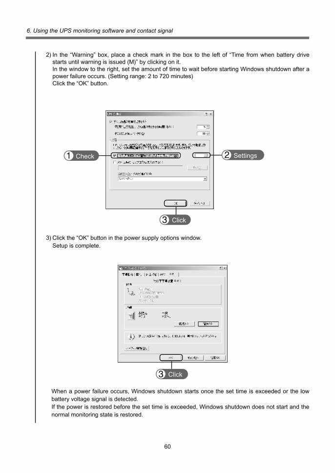
60
6. Using the UPS monitoring software and contact signal
2)In the “Warning”box,placeacheckmark in thebox to the leftof “Time fromwhenbatterydrivestartsuntilwarningisissued(M)”byclickingonit.
Inthewindowtotheright,settheamountoftimetowaitbeforestartingWindowsshutdownafterapower failure occurs. (Setting range: 2 to 720 minutes)
Clickthe“OK”button.
Check Settings
Click
3)Clickthe“OK”buttoninthepowersupplyoptionswindow. Setup is complete.
When a power failure occurs, Windows shutdown starts once the set time is exceeded or the low battery voltage signal is detected.Ifthepowerisrestoredbeforethesettimeisexceeded,Windowsshutdowndoesnotstartandthenormal monitoring state is restored.
Click

61
6. Using the UPS monitoring software and contact signal
4)Afterthesettingsaremade,double-clickthe“Service”iconinControlPanels.5)SelecttheUPSserviceandclickthe“Start”button.
By starting the Alerter service, Messenger service, and Event log service in advance, the UPS service sends warning messages to the user and records a history of events such as power fail-ures when they occur.
When a power failure occurs, Windows shutdown is performed once the low battery voltage signalisdetected.Ifthepowerisrestoredbeforethelowbatteryvoltagesignalisdetected,Win-dows shutdown is not performed and the normal monitoring state is restored.
Click
<When using the Windows NT standard UPS service>1)Double-clickthe“UPS”iconinControlPanels.2) Insertacheckmarkinthecheckboxtotheleftof“PortwhereUPSisinstalled(U)....”byclickingonit. Inthesettingfield,selectthenumberoftheserialport(COM1to4)theunitisconnectedto.3) Insertcheckmarks ineachof thecheckboxes to the leftof “Power failuresignal (P)”, “Lowbat-terylevelsignal(L)”,“Remoteuninterruptiblepowersourceshutdownsignal(R)”byclickingontheboxes.
Check
Check
Settings
Set each signal interface voltage setting as shown below.• Power failure signal (P) .................................................... Negative•Lowbatterysignal(L) ....................................................... Negative• Remote uninterruptible power source shutdown .............. Positive
Note
Please note that in the case of incorrect interface voltage signal settings, Windows NT will not receive the signal from the UPS and the UPS will not stop when there is a power failure.
Failure to put check marks in the boxes will lead to the same result.

62
6. Using the UPS monitoring software and contact signal
6-5 Using the contact signalBasedonthefollowingspecifications,youcandevelopyourownsystemforautomatingtheprocesswhen there is a power failure.You can perform power failure and shutdown processing by allowing the system to detect the backup signalandlowbatterysignal,oryoucanusethetroublesignaltoperformfailurenotification.You can stop the unit by inputting the backup power supply stop signal from the system.The unit can also be stopped remotely by using the remote ON/OFF signal. Except for remote ON/OFF, the contact signal function is enabled only when the communication selection switch is set to “contact”(Seepage47.)
BU-COM ON when there is a power failure
NBU-COM OFF when there is a power failure
1. Signal output The unit has 5 types of signal output. The output circuit is an open collector circuit (a type of elec-
tronic switch) that uses a photo-coupler.• Backup signal output (BU) Continues during a power failure, and turns ON.• Backup signal reverse output (NBU) Continues during a power failure, and turns OFF.
•Batterylowsignaloutput(BL) Turns ON when the battery becomes weak when in Battery Mode.• Trouble signal output (TR) Turns ON when a failure occurs inside the unit.• Battery replacement signal output (WB) Turns ON when the battery needs to be replaced due to deterioration.
2. Input of the backup power supply stop signal (BS) StopstheoutputoftheUPSafterthetimeperiodspecifiedbythe“poweroutputstopdelaytimeset-ting”(settingswitches4and5)haselapsed.
(1) When the backup power supply stop signal setting (setting switch 6) is set to OFF: The unit’s power supply output can be stopped externally by inputting a voltage signal (High)
that continues for 0.01 (10 ms) second or more.(2) When the backup power supply stop signal setting (setting switch 6) is set to ON: The unit’s power supply output can be stopped externally when the stop signal is received only
during backup, by inputting a voltage signal (High) that continues for 0.01 (10 ms) second or more.
See also 4-5 Changing function settings Page 49
3. Remote ON/OFF signal The remote ON/OFF signal can stop and start the unit by means of
an externally connected contact or the ON/OFF status of the open collector circuit. To use this function, the power supply output switch of the UPS must be turned ON.
(Note: It isnotpossible tostartup theUPSwith the remoteON/OFFsignalwhen there isnoACpower supply, even when cold start is set to ON.)
* The remote ON/OFF signal function can be used even when the communication selection switch is set to“serial”.
BL-COM ONwhenbatteryislow
TR-COM ON when a failure occurs
ON when battery deterioration is
detectedWB-COM
BS-COM UPS stops
External contact Operate
Open Start
Close Stop
NBU is output only when the “communication connector 8 th-pin output signal switching setting”(settingswitch7)issettoON.

63
6. Using the UPS monitoring software and contact signal
BL
TR
BU/NBU
WB
BS
COM
2.2k
470
Remote ON/OFF (+)
Remote ON/OFF (-)
+5V
GND
470
2.2K
4. Connecting with the system Make a cable yourself to connect to the system.
See also “8.Signalinput/outputcircuitusageexamples”→ Page 64
5. Signal input/output connector (DSUB9P female)
6. Signal input/output ratings• Signaloutput(BL,TR,BU/NBU,WB) • Backup power supply stop signal input (BS) Photo-couplerratings InputvoltageHigh5to24VDC Applicablevoltage:35VDCmax. Low0.7VDCmax. Maximum current: 10 mA• Remote ON/OFF Voltage between terminals: 5 VDC max. Current when closed: 10 mA max.
7. Signal input/output circuit inside the unit
Pin assignment Pin number Signal name
1 BL
2 TR
3 BS
4 –
5 COM
6 Remote ON/OFF (+)
7 Remote ON/OFF (-)
8 BU/NBU
9 WB
5 4 3 2 1
9 8 7 6
Front viewScrewsize:Inchscrew
#4-40UNC

64
6. Using the UPS monitoring software and contact signal
Note
• When connecting a device such as a relay that generates counter electromo-tive force to the signal output circuit, connect diodes that prevent counter elec-tromotive force to both ends of the relay.
Explanation
• When power is restored after the unit stopped automatically during a power failure,theunitautomaticallyrestartsandsuppliespower.Ifyoudonotwantto start the connected devices, turn OFF their switches or set the auto restart setting (setting switch 2) to ON. (See page 49.)
• BS signal usage example
• Remote ON/OFF signal usage example
9. Precautions and notes for using signal input/output
GND
BS
COMSystem side
C2458
12V 1K
1.2K
TLP521
To port on PC
Connection cable (twisted or shielded)
UPS side
8. Signal input/output circuit usage examples• BU signal usage example
BU
COM
12V 1KSystem side
TLP627
To port on PCConnection cable (twisted or shielded)
UPS side
Remote ON/OFF circuit

65
7. Measuring the backup time
7-1 How to measure backup time(1)Connecttheunit’sACinputplugtoawalloutlet(commercialpower)andchargefor8hours. Iftheunithasbeeninoperationformorethan8hours,itisalreadycharged.Ifapowerfailureoc-
curs while charging, perform the charging process again.(2) Turn ON all devices connected to the power supply output receptacle. (This includes devices con-
nected to power outlets on the backs of computers.) Operate the devices in such a way that they are not damaged by a sudden power stop.
7. Measuring the backup time
•ForWindowsServer2003/Vista/XP/Me/2000/WindosNT/Linux,performmeasurementwhenthe hard drive is stopped.
• ForWindows98/95, choose “ShutDown” inWindowsandperform the following to shutdownyour OS:
Select “Restart inMS-DOSmode” to shut down theOSanddisplay theMS-DOSmodescreen.
(3) Disconnect the unit’s AC input plug and measure the backup time. With the plug disconnected, measure the time until the unit automatically stops and all displays
disappear.
• Thebackup time youmeasure for the first timeafter purchase is the “initial valueof the backuptime”.
7-2 Estimated backup timeThe backup time varies depending on the capacity of connected devices.After calculating the total capacity of connected devices, refer to the backup time graph to obtain an estimation of the initial value of the backup time.(This also applies to checking the battery.)
(1) Convert the total capacity (power consumption) of the connected devices to watts (W). For the indication of connected devices, check you computer and the rear of the display. The indicator can show values in three different ways: volt-amperes (VA), amperes (A), and watts (W).
Example 1: 100 VAC, 50/60 Hz, 145 W Example2:100VAC,50/60Hz,1.8A Example 3: 100 VAC, 50/60 Hz, 145 VA
For devices that use VA or A notation, convert the capacity into W. Convert by multiplying the value indicated on devices by the value in the table shown on the right.
(Whenthepowerfactorisunknown,enter“1”.Thepowerfactorusuallyrangesbetween0.6and1.)
(2) Add the values converted into W to obtain the total capacity of the connected devices.(3) Use the graph on the next page to calculate the initial value of the backup time for the total capac-
ity of the connected devices.
• Backup time graph (initial values for new products)• The backup time becomes longer as the capacity of connected devices decreases.
Notation Value VA x power factor = W A x power factor x 100 = W

66
7. Measuring the backup time
120
110
100
90
80
70
60
50
40
30
20
10
0
Connection capacity (W)
0 100 200 300 400 500 600 700 800 900 1000 1100420W
Bac
kup
time
(min
.)
Backup time(25ºC, initial value)
BH100PCW
BH100PCW + BHM100PC (1 additional unit)
BH100PCW + BHM100PC (2 additional units)
BH100PCW + BHM100PC (3 additional units)
BH100PCW + BHM100PC (4 additional units)
BH60PCW
• The values in the table above are reference values for the initial state and are not guaranteed values. Times may vary according to battery deterioration and external environmental conditions (temperature, etc.).
Model 20W 50W 100W 200W 300W 400W 500W 600W 700W
BH60PCW 65 40 23 13 8 5(420W) - - -
BH100PCW 100 70 45 25 14 10 7 5 4
BH100PCW + BHM100PC (1 additional unit) 210 140 95 50 35 25 19 15 12
BH100PCW+BHM100PC(2additionalunits) 320 220 140 80 55 40 30 25 20
BH100PCW + BHM100PC (3 additional units) 430 300 190 110 75 55 45 35 30
BH100PCW+BHM100PC(4additionalunits) 550 380 260 140 95 70 55 45 40
Time unit: Minutes

67
8. Troubleshooting
Check/solution
(1) Make sure the AC input plug is securely connected to commercial power.(2)Isthevoltageofthewalloutlet(commercialpower)toolow? Disconnect devices with high power consumption, such as air conditioners. Try connecting to a wall outlet (commercial power) in another room or building. (Theunitdoesnotoperateatvoltagesbelow85V.) Checktheinputvoltagevalue(“”V)displayedonthestatusindicator.(3)Whennotperformingcoldstart,makesuresettingswitchNo.8isON. Iftheproblempersistsafterperformingthesechecks,theunitmayhaveablown fuse or other problem. Please contact the Omron Electronic Systems & Equipments customer support center at: _____.
(1)Istheunitsufficientlycharged? Chargethebatteryforatleast8hoursandperformthetest.(Youcanchargethe battery by connecting the AC input plug of the unit to a wall outlet (commercial power).) Make sure the battery unit’s charge indicator lamp is ON. Isthebatteryunit’ACinputcableconnectedtothepoweroutletreceptacleforthe ACstabilizedpowersupply’sbatteryunit?Ifnot,thechargingcircuitdoesnotoperate.(2) Are the connection cables (2) for the battery unit and AC stabilized power connected? Open the battery unit’s front panel and check the connection.(3)Isthebatteryconnectorinsidethebatteryunitconnected?
(1) There may be an abnormality in the input power supply. Connect the unit to a wall outlet (commercial power) in another room, or another building if possible. Also, try stopping large devices such as air conditioners.(2)Isapageprinter(laserprinter,etc.)connected? Page printers cannot be used because they draw a large instantaneous current.
There are too many connected devices. Reduce the number of connected devices untilthe“”displayturnsOFF.Selectthe“”and“”displayswiththeindicatorselectionswitch to check the apparent power (VA: volt-amperes) and power consumption (W: watts) of connected devices.Reduce the number of connected devices so that both values are within the speci-fiedoutputcapacityoftheUPSorACstabilizedpowersupply.
The unit immediately stopped because too many devices were connected for 2 min-utes or more, or because the capacity of the connected devices exceeded 130%. Turn OFF all power to the unit and connected devices, and reduce the number of connected devices. Then, turn the power to the unit and connected devices back ON and check whether operation starts up and proceeds as normal.
The battery auto test or self-diagnostic test determined that the battery is dead.Battery Mode cannot be performed properly, so the battery needs to be replaced.Ifthebatteryisnotreplacedbeforelong,backupwillbecomeunavailable.
Problem
Unit does not operate.The AC input display lamp does not turn ON when the unit’s AC input plug is con-nected to a wall outlet (com-mercial power).
Cannot perform backup.The connected devices stop when a power failure occurs.
Backup is performed too frequently.Switching is frequently per-formed even when no power failure occurs.A switching sound can be heard.
The status indicator shows “”,andthebeepersoundsat 0.5-second intervals.
The status indicatorblinks“”,andthe beeper soundscontinuously.
The battery replacement lampblinks and the beeper sounds at 2-second intervals.
8. Troubleshooting
Perform the checks shown below if the unit is operating abnormally.Iftheunitcontinuestooperateabnormally,pleasecontactourElectronicSystems&Equipmentsecustomer support center at _____.

68
8. Troubleshooting
Check/solution
“”indicatesashort-circuitontheoutputsideorexcessincomingcurrentfromthe connected devices.“”indicatesthatthenumberofconnectedbatteryunitsexceedsthemaximumnumber of 5.“”indicatesthatanoperationalerrororfailureoccurred.Check the error code, and contact our Electronic Systems & Equipments customer support center at _____.
Problem
The following error displays are shown on the statusindicator:“”,“”,or“”.
(code number) explanation
[Solution]When connected devices are operating with bypass output, turn OFF the power switches of all connected devices and follow
the procedure described below.
(1) Perform the troubleshooting provided in the error display section.
(2)Whenthereiscommercialinput,“”isrestoredontheinputvoltagedisplay.
If thestatusdoesnotdisplaywithoutrestarting, there isaproblemwith theUPS.Contact theshopofpurchaseorour
Electronic Systems & Equipments customer support center at: _____.
(3)Afterconfirmingitem2,turnbackONtheunit’spowerswitchwhilealltheconnecteddevicesremainstopped.
If,afterthepowersupplyoutputswitchisturnedON,the“EE_(numbercode)”displaydoesnotappearandthereisnooutput,
there is a problem with the unit. Contact the shop of purchase or our Electronic Systems & Equipments customer support center
at: _____.
Status indicator
Charging Power
Explanation No. (Error code number) Output Beep (Only when battery
switch (Output stops when bypass circuit Solution
is connected) is set to OFF)
20-1 ON Continuous Charging ON Excess output voltage detected, Power supply
bypass output or output stopped output switch: OFF Insufficientoutputvoltage
Power supply 20-2 ON Continuous Charging ON detected, bypass output or output
output switch: OFF stopped ON ON Power supply output 20-3 Continuous Stopped Excess charge voltage switch OFF → OFF OFF AC input OFF ON ON Insufficientchargevoltage Power supply output 20-4 Continuous Stopped Charger malfunction detected switch OFF → OFF OFF AC input OFF Excess output DC voltage
Power supply output 20-5 ON Continuous Charging ON detected, bypass output or output
switch: OFF stopped Abnormal internal temperature Power supply output
20-6 ON Continuous ――― ON detected, bypass output or output switch: OFF
stopped Wait for it to cool down naturally.
20-7 ON Continuous Charging ON DC bus voltage error detected, Power supply output
bypass output or output stopped switch: OFF Cooling fan malfunction
Power supply output 20-8 ON Continuous Charging ON detected,bypassoutputoroutput
switch: OFF stopped Control function error
20-9 OFF Continuous ――― ON (CPU error/reset or other Power supply output
malfunction) switch: OFF Bypass output or output stopped
(Only when battery is connected)
(Only when battery is connected)

69
References
References
A. Specifications BH60PCW BH100PCW RE60FW RE100FW
Operation method Full-time inverter supply method
Method Output synchronization method Select between commercial sync or commercial non-sync
Cooling method Forced air cooling
Bypass circuit Automatic bypass switching. No bypass function for CVCF/UPS (frequency conversion output)
Rated input voltage 100 to 120 VAC
Inputvoltagerange 80±2to141±2VAC(90%orlessconnectedload)
85±2to141±2VAC(90%ormoreconnectedload)
Inputfrequency 50Hz/60Hz±4.5Hz
Inputcurrent 7A 12A/100V
Input Phase Single phase, two wire
Inputpowerfactor >0.95
Inputprotection Fuse(builtintodevice)
Inputprotectioncapacity 10A 15A
Output capacity *1 600VA / 420W 1KVA / 700W
Rated factor 0.7
Switching time Uninterrupted
Outputvoltage 100Vmode:100VAC±1.5%
(InCommercialPowerMode) 110Vmode:110VAC±1.5%
115Vmode:115VAC±1.5%
120Vmode:120VAC±1.5%
Outputvoltage 100Vmode:100VAC±1.5%
(InBatteryMode) 110Vmode:110VAC±1.5%
115Vmode:115VAC±1.5%
120Vmode:120VAC±1.5%
Output frequency Synchronous mode: synchronized with an input frequency, (InCommercialPowerMode) Asynchroousmode:frquency50Hz/60Hzfixed
Output Phase Single phase, two wire
Output voltage waveform Sine wave / Sine wave
Waveformdistortionrate 7%orless(Rectifiedloadatratedoutput)
Output receptacle NEMA5-15R
Number of output receptacles 3 (1 each for A, B, C)
Output control *2 (1) Output ON/OFF control (2) Output start delay control
Functions for power output supply receptacles B and C only
Type Compact sealed lead battery (long-lasting type)
Expected lifespan 5 to 7 years (at ambient temperature of 20°C)
Battery Capacity (number of batteries) 2VDC/5Ah(x12) 2VDC/8Ah(x12)
BH60PCW/BH100PCW Backup time 5 minutes (with rated load connected, 4 minutes (with rated load connected,
only at 20°C, initial value) at 20°C, initial value)
Number of battery units 1
Max. 5
connected
Chargingtime 12hours(80%)

70
References
*1: Make sure that both the VA value and the W value of the load capacity connected to the UPS are within the rangespecifiedhere.
*2:Availableonlywhenusingthe“PowerActPRO”UPSmonitoringsoftwareincludedwiththeUPS.
BH60PCW BH100PCW RE60FW RE100FW
Method (1) RS-232C serial communication (compatible with UPS monitoring soft ware)
Communication (2) Contact signal
interface Remote ON/OFF Output ON/OFF can be controlled by contact signal input
Connector type D-Sub, 9-pin (female)
Operating ambient temperature -10 to +55°C
Environment Operating ambient humidity 10 to 90% RH (no condensation)
Storage temperature -20 to 65°C
Storage humidity 10 to 90% RH (Store with battery fully charged and with no condensation)
Dimensions(W×D×Hmm) 220×84×500/1box Battery unit connection for UPS: 2 boxes
Weight of unit 6.3kg 6.6kg
Weightofthebatteryunit 8.2kg 10.3kg
Max. internal power consumption
(When no battery is connected) Withnoload 80W 80W Other With rated load 100W 120W
(When battery is connected) With no load 100W 100W (When 5 battery units are connected) – 200W With rated load 130W 150W (When 5 battery units are connected) – 250W
Safety standard compliance UL1778 BH60PCW: Complied BH100PCW: Complied RE60FW: None RE100FW: None
CE BH60PCW: Complied BH100PCW: Complied RE60FW: None RE100FW: None
Noise regulation (compliancestandard) VCCIClassA

71
References
B. Dimensions◦
BH
60P
CW
/BH
100P
CW
(U
PS
mai
n u
nit
)◦
RE
100P
CW
/RE
60P
CW
(A
C s
tab
ilize
d p
ow
er s
up
ply
)
220 84 15
500
2000
(unit:mm/Tolerance:±1m
m)
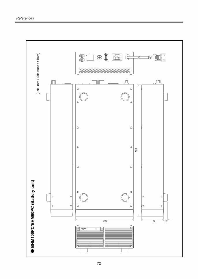
72
References
◦ B
HM
100P
C/B
HM
60P
C (
Bat
tery
un
it)
220 84 15
500
(unit:mm/Tolerance:±1m
m)

73
References
D. Related products
C. Circuit block diagram
NF
Cold through
Battery12cell24V
Input filter
Bypass circuit
AC input
Converter Inverter
Bypass switch
30A2-pararell
15A
Inverter unit
Output filter
Signal connection
RS-232CCommunication Interface
External contactInterface
Battery unit
Charger
IndicatorsBHM60PC/BHM100PC
BH60PCW (RE60FW)/BH100PCW (RE100FW)
Step-up Converter Gate drive
Digital controllerDetection circuit
NF
Output 100 to 120 VAC
A
B
C
LED
operation panel
BH60PCW BH100PCW
Additional battery unit ––––––––– BHM100PC
Replacement battery pack BHB60PC BHB100PC
EIArack-mountbracket BHP60P
EIAsupportangle BUP06
JISrack-mountbracket BHP60J
Replacement fan REF60F
Contact signal cable BUC26

K1L-D-08199D
Unauthorized reproduction of this manual, in part or in whole, is prohibited.The contents of this manual are subject to change without notice.


![[XLS]Sutomo 031-70578299xa.yimg.com/kq/groups/23867749/1648457101/name/Y-PRICE... · Web viewHarga Promo Termurah UPS ICA CE1200 1200VA UPS ICA Compact Smart CS-638 600VA UPS ICA](https://img.pdfslide.us/doc/110x75/5b0e6db77f8b9af9688bf4fc/xlssutomo-031-viewharga-promo-termurah-ups-ica-ce1200-1200va-ups-ica-compact.jpg)


![PSCAD/EMTDC CVCF Micro-grid · 2019-05-20 · 2018년한국산학기술학회추계학술발표논문집-179-[ 1]CVCF그림 인버터기반Micro-grid의보호협조개념도 3.PSCAD/EMTDC](https://img.pdfslide.us/doc/110x75/5e81a459466d0016fd48ee32/pscademtdc-cvcf-micro-2019-05-20-2018eoeeeoeeeoeoeee-179-.jpg)


![DM2G200SH6A-0908.ppt [호환 모드] · Motor Drives, High Power Inverters, Welding Machine, Induction Heating, UPS , CVCF, Robotics , Servo Controls, High Speed SMPS Absolute Maximum](https://img.pdfslide.us/doc/110x75/5fee4892aa3fe86313595969/dm2g200sh6a-0908ppt-eeoe-motor-drives-high-power-inverters-welding.jpg)