Embed Size (px)
Citation preview

C H R I S W O O D F I E L D
@ C W O O D F I E L D
B G P M I G R AT I O N S I N A L I V E DATA C E N T E R
OSPF - THE RIGHT APPROACH AT THE TIMELayer 3, Multi-area topology
SPINE1 SPINE2 SPINE3 SPINE4
CL1-2CL!-1 CL2-2CL2-1 EDGE2EDGE1
A13414BackboneTOR1-1 TOR1-2 TOR1-3 TOR1-4
TOR1-1 TOR1-2 TOR1-3 TOR1-4
Area 0.0.0.0
Area 0.0.0.10
Area 0.0.0.20
OSPF - THE RIGHT APPROACH AT THE TIME
• Incomplete BGP Feature Set in TORs (ca 2010/11)
• Most Traffic was N/S due to monolithic app
• Clusters divided in logical “roles” (FE, Storage, …)
• Inter-cluster traffic augmentation via expansion of LACP trunks
SPINE1 SPINE2 SPINE3 SPINE4
CL1-2CL!-1 CL2-2CL2-1 EDGE2EDGE1
A13414BackboneTOR1-1 TOR1-2 TOR1-3 TOR1-4
TOR1-1 TOR1-2 TOR1-3 TOR1-4
Area 0.0.0.0
Area 0.0.0.10
Area 0.0.0.20
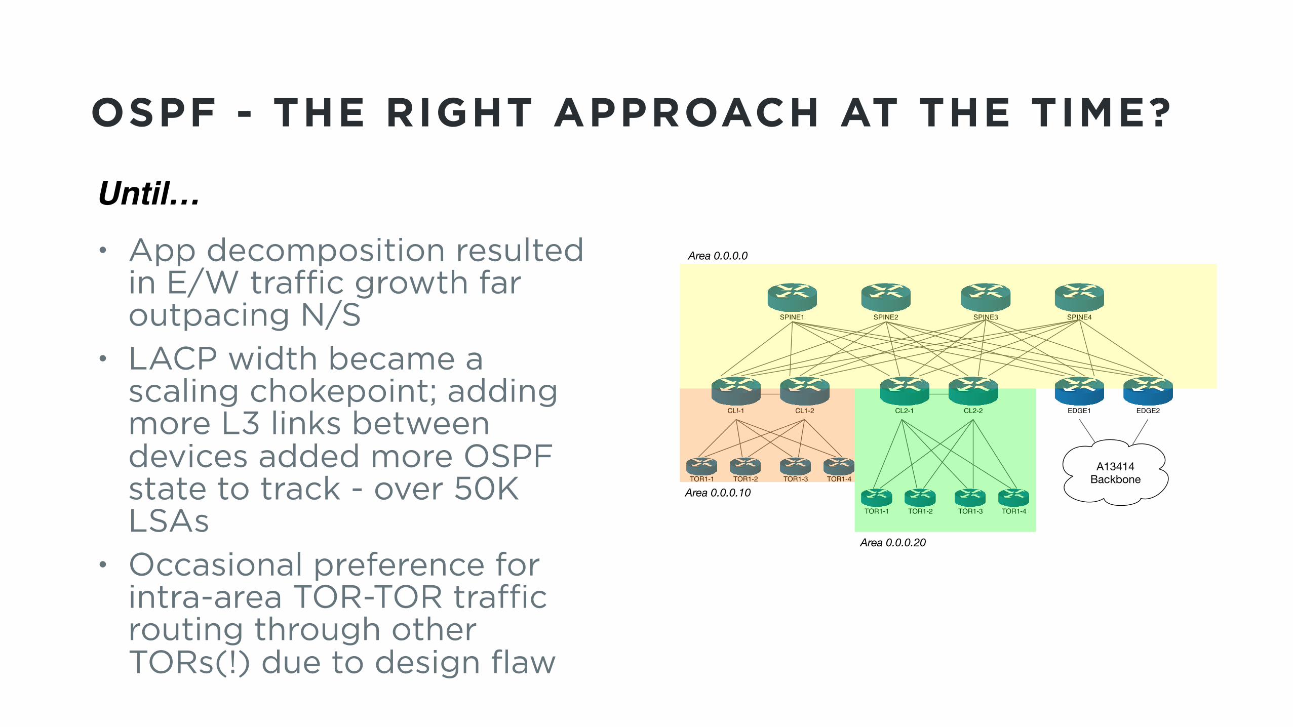
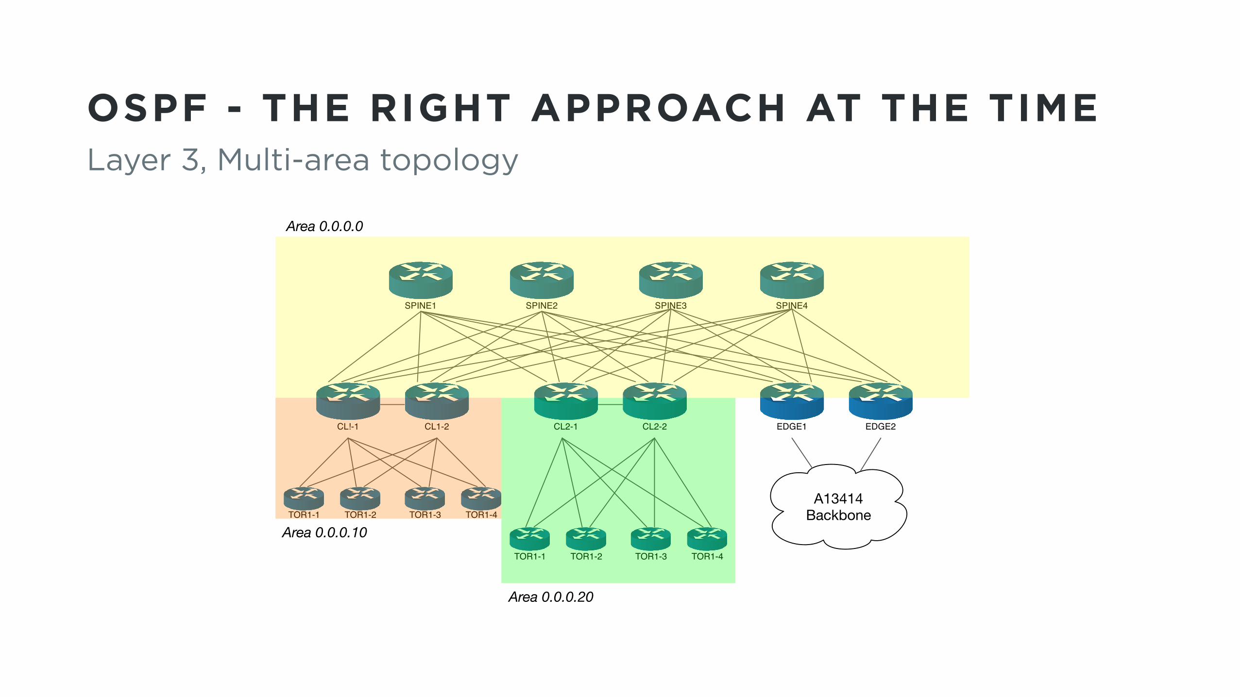
OSPF - THE RIGHT APPROACH AT THE TIME?
• App decomposition resulted in E/W traffic growth far outpacing N/S
• LACP width became a scaling chokepoint; adding more L3 links between devices added more OSPF state to track - over 50K LSAs
• Occasional preference for intra-area TOR-TOR traffic routing through other TORs(!) due to design flaw
Until…
SPINE1 SPINE2 SPINE3 SPINE4
CL1-2CL!-1 CL2-2CL2-1 EDGE2EDGE1
A13414BackboneTOR1-1 TOR1-2 TOR1-3 TOR1-4
TOR1-1 TOR1-2 TOR1-3 TOR1-4
Area 0.0.0.0
Area 0.0.0.10
Area 0.0.0.20
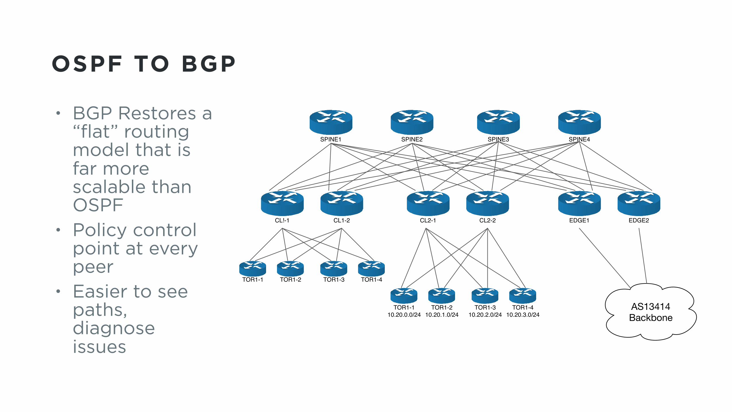
OSPF TO BGP
• BGP Restores a “flat” routing model that is far more scalable than OSPF
• Policy control point at every peer
• Easier to see paths, diagnose issues
SPINE1 SPINE2 SPINE3 SPINE4
CL1-2CL!-1 CL2-2CL2-1 EDGE2EDGE1
AS13414Backbone
TOR1-1 TOR1-2 TOR1-3 TOR1-4
TOR1-110.20.0.0/24
TOR1-210.20.1.0/24
TOR1-310.20.2.0/24
TOR1-410.20.3.0/24
OSPF TO BGP
• Ideally, this becomes a “Next-Gen” design applied to the next major build.
• However, there were no new builds on the horizon, and no foreseeable way to migrate app to new topology incrementally.
• Thus a decision was made. You may make this decision too.

OSPF TO BGP
IN EACH DATACENTER:
• Backbone Edge Routers (Terminates LBs, FWs, and connects to DC Fabric)
• Dozens of Fabric/Cluster switches, hundreds of links in Area 0 • Thousands of TORs • Multiple Tbps of intra-datacenter traffic, supporting… • A very sensitive real-time application.
FIRST STEPS: ASSESS
Audit BGP capabilities of your hardware. TORs will most likely be the weakest link. • FIB limits • ECMP maximums • Support for BGP features (32-bit ASNs, Multi-as multipath, …)
State of existing hardware will often dictate your design!
NEXT STEP: DESIGN
• Single or Multiple Spines? Depends on whether or not your TORs can take a full table - blackhole potential if TOR ECMPs traffic to aggregate or default routes.
• How many spines? Limit is ECMP maximums on cluster switches • Shared or unique ASNs? Check support for 32-bit private ASN
range and multiple-AS multipath.
State of existing hardware will often dictate your final design!
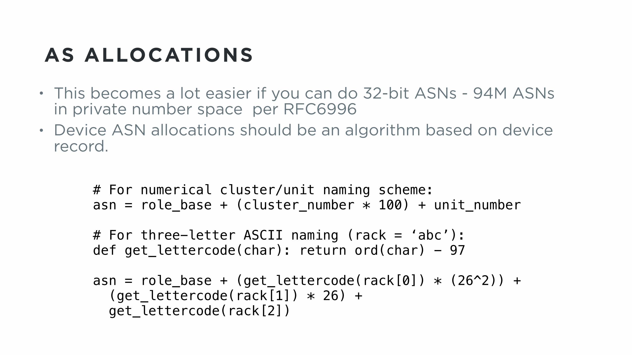
AS ALLOCATIONS
• This becomes a lot easier if you can do 32-bit ASNs - 94M ASNs in private number space per RFC6996
• Device ASN allocations should be an algorithm based on device record.
# For numerical cluster/unit naming scheme: asn = role_base + (cluster_number * 100) + unit_number
# For three-letter ASCII naming (rack = ‘abc’): def get_lettercode(char): return ord(char) - 97
asn = role_base + (get_lettercode(rack[0]) * (26^2)) + (get_lettercode(rack[1]) * 26) + get_lettercode(rack[2])

ROUTING POLICY
• OSPF area aggregation can break in BGP Clos model due to lack of horizontal interconnects; you’ll likely need to leak in rack more-specifics (at least to Cluster and Fabric)
• /31|/127 linknets should be aggregated by device, or left out of BGP table entirely.
SPINE1
CL1-210.10.0.0/20
CL2-210.10.0.0/20
TOR1-110.10.1.0/24
TOR1-110.10.2.0/24
SPINE: 10.10.1.0/24: ECMP to CL1-2, 2-2CL1-2: 10.10.1.0/24 NH to TOR1-1
CL2-2: 10.10.0.0/20 to Null0
ROUTING POLICY TIPS
• Generate default route to Fabric from DC edge (for DC egress only).
• If TORs can’t take full table: float aggregates in addition to more-specific prefixes to protect from loss of default route.
• Across EBGP neighbors, LPREF is not transitive. Policies that manipulate LPREF must match on all devices.
• Enable BGP advertise-inactive until OSPF is completely removed. • Implement GSHUT support (but don’t strip community inside DC).
AUTOMATION
• No reasonable way to manage this transition without robots configuring the devices! • Discover Current State • Generate new
Configurations • Deploy configuration
updates • Audit peerings and
routes
AUTOMATION STEP 1: DISCOVER
• For each device we need: • Platform/code version • Role • Router ID • Neighbor address, ASN, role data
• BGP configs reference neighbors which must be learned from existing state: • Walk device LLDP data • Store linknet addresses, find matching /31s
Discover should run on an ongoing basis, tracking changes
AUTOMATION STEP 2: GENERATE
• Device type/code/role points to templates - keep configurations consistent across roles (common baseline, vary only if needed)
• Easier to separate out baseline BGP policy configuration from neighbor configuration templates
• Only filter routes as needed to avoid scenic routing or using Clusters as transit. Avoid localpref changes if possible.
• IMPORTANT: Build templates for rollback too! • Jinja2 was our choice of template frameworks
AUTOMATION STEP 3: DEPLOY
• Config push scripting, built framework to track progress of devices
• It’s OK to go slow. Deployed configs to 2-3 devices in parallel over a number of days, in 100-device batches
• You don’t want to be watching a script run all day, so build passive notifications (syslog, chatbot status notifications).
• Active notifications on errors only and batch run completion
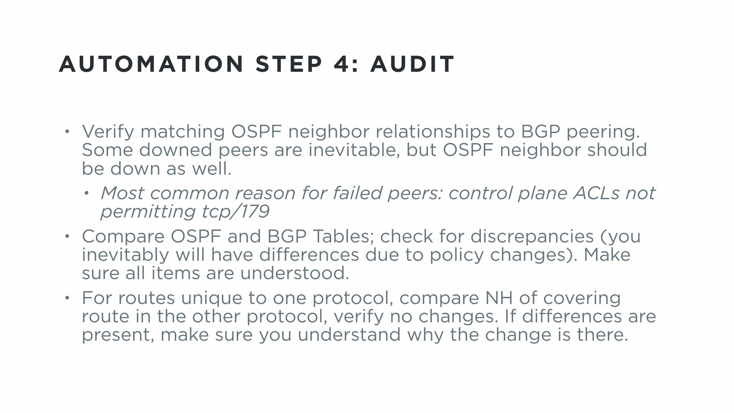
AUTOMATION STEP 4: AUDIT
• Verify matching OSPF neighbor relationships to BGP peering. Some downed peers are inevitable, but OSPF neighbor should be down as well. • Most common reason for failed peers: control plane ACLs not
permitting tcp/179 • Compare OSPF and BGP Tables; check for discrepancies (you
inevitably will have differences due to policy changes). Make sure all items are understood.
• For routes unique to one protocol, compare NH of covering route in the other protocol, verify no changes. If differences are present, make sure you understand why the change is there.
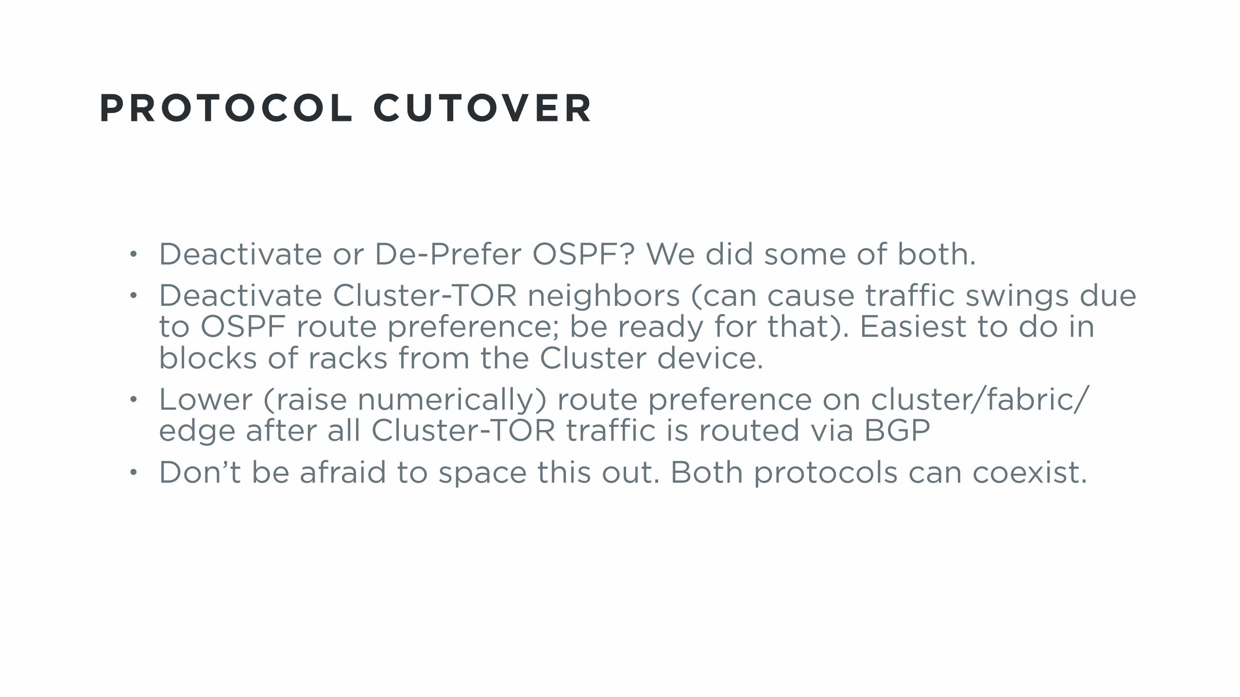
PROTOCOL CUTOVER
• Deactivate or De-Prefer OSPF? We did some of both. • Deactivate Cluster-TOR neighbors (can cause traffic swings due
to OSPF route preference; be ready for that). Easiest to do in blocks of racks from the Cluster device.
• Lower (raise numerically) route preference on cluster/fabric/edge after all Cluster-TOR traffic is routed via BGP
• Don’t be afraid to space this out. Both protocols can coexist.
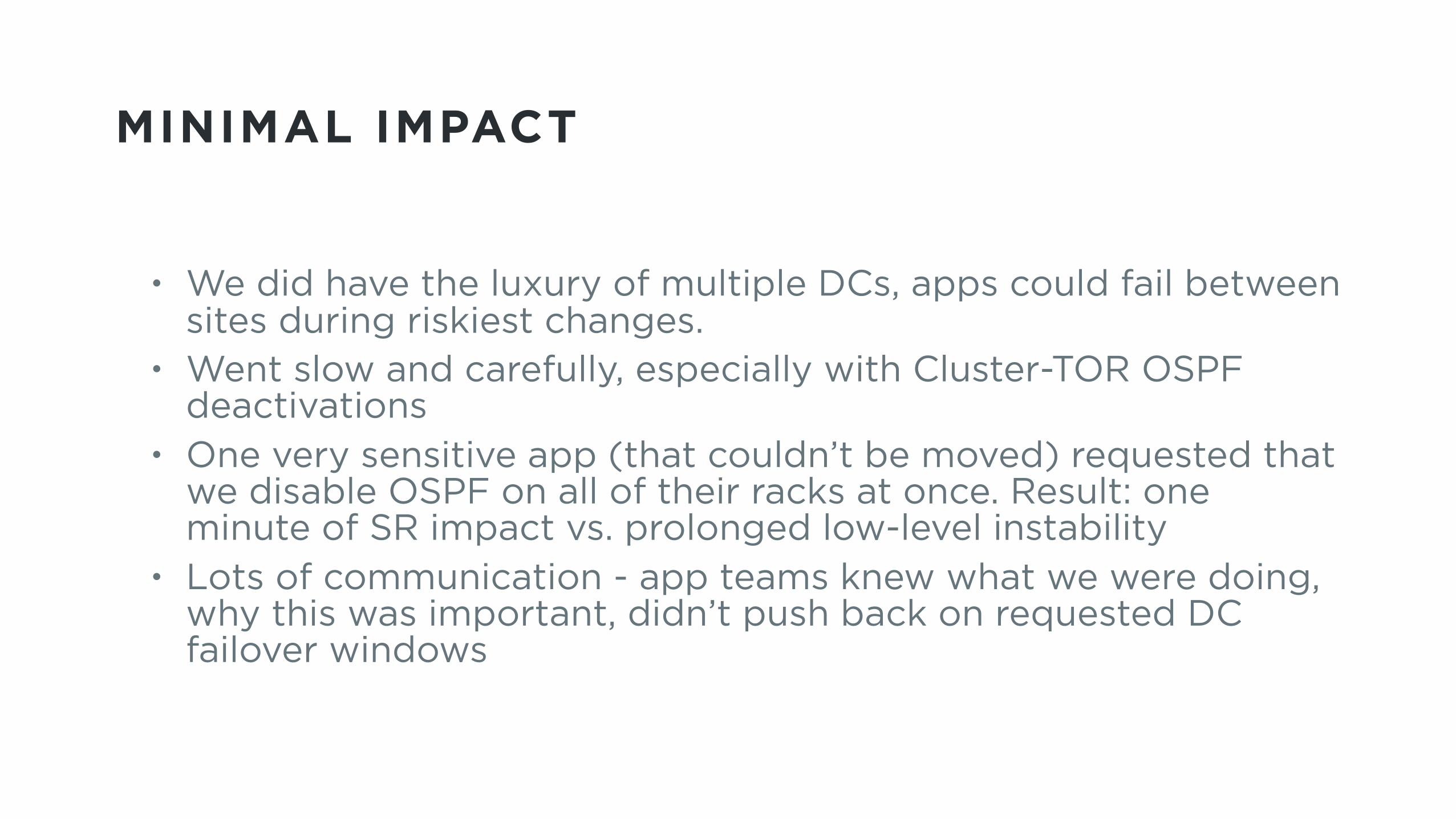
MINIMAL IMPACT
• We did have the luxury of multiple DCs, apps could fail between sites during riskiest changes.
• Went slow and carefully, especially with Cluster-TOR OSPF deactivations
• One very sensitive app (that couldn’t be moved) requested that we disable OSPF on all of their racks at once. Result: one minute of SR impact vs. prolonged low-level instability
• Lots of communication - app teams knew what we were doing, why this was important, didn’t push back on requested DC failover windows
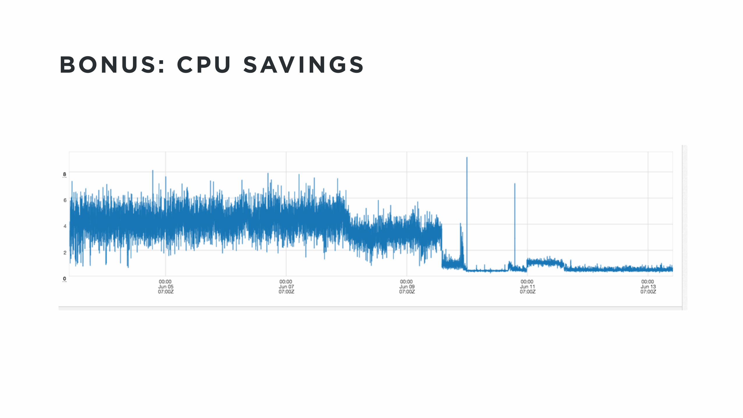
BONUS: CPU SAVINGS

MISTAKES WERE MADE• Lab testing is no guarantee of a seamless prod rollout. Canary
early and often. • Many steps could have been further automated, but would have
delayed deployment timeline. Froze dev work at “good enough”.
• Ops documentation/runbooks fell behind deployment - Document first then deploy!
• One user-impact incident due to migration, due to incorrect information on apps running in cluster being converted
• GSHUT support not fully implemented in first iteration, had to retro policy change to many TORs.
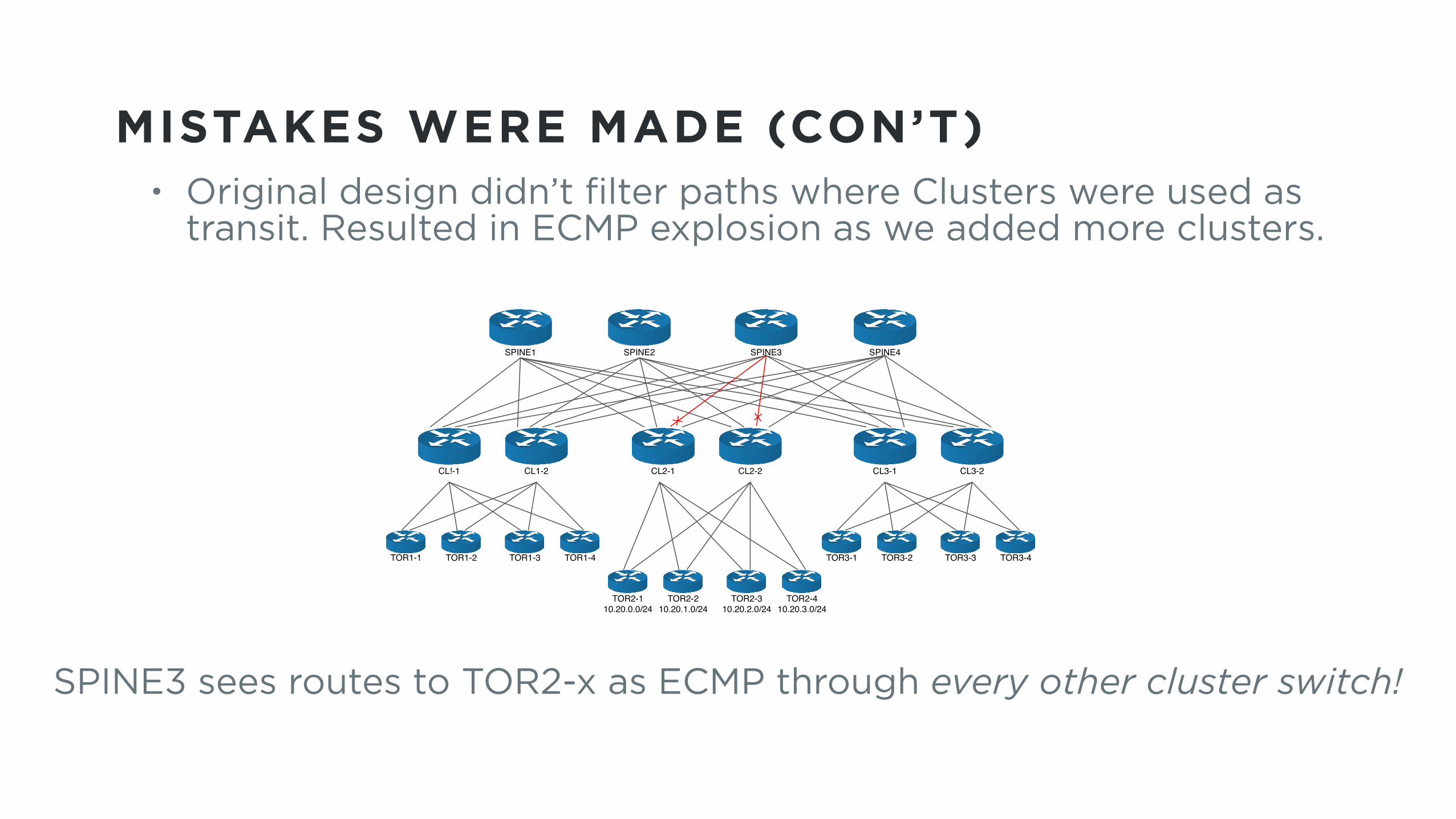
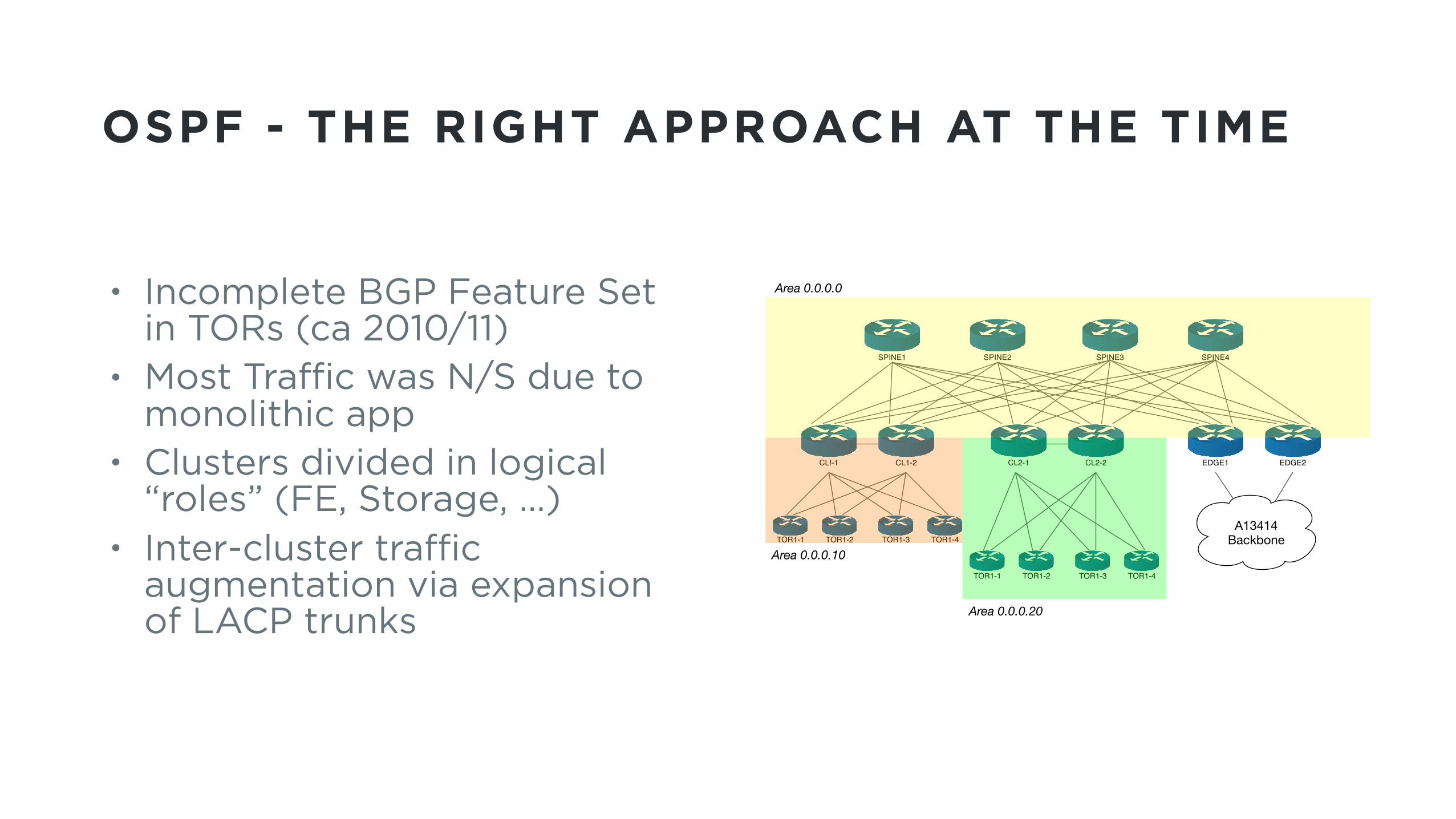
MISTAKES WERE MADE (CON’T)• Original design didn’t filter paths where Clusters were used as
transit. Resulted in ECMP explosion as we added more clusters.
SPINE1 SPINE2 SPINE3 SPINE4
CL1-2CL!-1 CL2-2CL2-1 CL3-2CL3-1
TOR1-1 TOR1-2 TOR1-3 TOR1-4
TOR2-110.20.0.0/24
TOR2-210.20.1.0/24
TOR2-310.20.2.0/24
TOR2-410.20.3.0/24
TOR3-1 TOR3-2 TOR3-3 TOR3-4
Spine 3 Route to TORs in CL2: ECMP Through Every Other Cluster Switch!
SPINE3 sees routes to TOR2-x as ECMP through every other cluster switch!

M A R K E T I N G W I T H T W I T T E R
A U T O S@ T W I T T E R H A N D L E
THANK YOU!