Embed Size (px)
Citation preview

AheAd OF the F lOw ®
B u t t e r f l y Va l v e s
C-BFV-0912 Catalog C-BFV-0912

NIBCO INC. WORLD HEADQUARTERS • 1516 MIDDLEBURY ST. • ELKHART, IN 46516-4740 • USA • PH: 1.800.234.0227 TECH SERVICES PH:1.888.446.4226 • FAX: 1.888.336.4226 • INTERNATIONAL OFFICE PH: +1.574.295.3327 • FAX: +1.574.295.3455
www.nibco.com
the velocity with which e-business evolves demands that new products and serv- ices be continuously developed and introduced to keep our customers at the center of our business efforts. niBCo provides an entire suite of business-to-business solutions that is changing the way we interact with customers.
look to niBCo for technology leadership.
Business-to-Business solutions
niBCopartner.comsm is an exclusive set of secure web applications that allow quick access to customer-specific information and online order processing. this self-service approach gives you 24/7 access to your order status putting you in total control of your business.
real time information includes:• online order entry • Current price checks• Viewable invoices & reports • order status• inventory availability • online library of price sheets, catalogs & submittals
electronic Data interchange (eDi) makes it possible to trade business documents at the speed of light. this technology cuts the cost of each transaction by eliminating the manual labor and paper-work involved in traditional order taking. this amounts to cost-savings, increased accuracy and better use of resources.
With eDi, you can trade:• Purchase orders • Product activity data• Po acknowledgements • advanced ship notices• invoices • remittance advice
Vendor managed inventory (Vmi), a sophisticated service for automated inventory management, reduces your overhead by transferring inventory management, order entry and forecasting to niBCo. this is an on-going, interactive partnership with niBCo.
through automation, Vmi brings results:• improves customer service • Cuts transaction costs• optimum inventory efficiencies • Peace of mind• Better forecasting • relief from day-to-day management

A H E A D O F T H E F L O W®www.nibco.com
NIBCO INC. WORLD HEADQUARTERS • 1516 MIDDLEBURY ST. • ELKHART, IN 46516-4740 • USA • PH: 1.800.234.0227 TECH SERVICES PH: 1.888.446.4226 • FAX: 1.888.234.0557 • INTERNATIONAL OFFICE PH: +1.574.295.3327 • FAX: +1.574.295.3455
www.nibco.com3
General IndexButterfly Valves
Warranty . . . . . . . . . . . . . . . . . . . . . . . . . . . . . . . . . . . . . . . . . . . . 4
Butterfly ValVes . . . . . . . . . . . . . . . . . . . . . . . . . . . . . . . . . . . .5-35 HIGH PerfOrManCe Butterfly ValVe . . . . . . . . . . . . . . . . .36-42
OPtIOns and aCCessOrIes Index . . . . . . . . . . . . . . . . . . . . . . . . . . . . . . . . .43-45
enGIneerInG data Index . . . . . . . . . . . . . . . . . . . . . . . . . . . . . . 46
specifications . . . . . . . . . . . . . . . . . . . . . . . . . . . . . . . . . . . . . . . 47
flow data . . . . . . . . . . . . . . . . . . . . . . . . . . . . . . . . . . . . . . . .48-49
Properties of Materials . . . . . . . . . . . . . . . . . . . . . . . . . . . . .50-53
technical Information . . . . . . . . . . . . . . . . . . . . . . . . . . . . . . .54-60
actuation data sheet . . . . . . . . . . . . . . . . . . . . . . . . . . . . . . . . . 61
fIGure nuMBer COMParIsOns . . . . . . . . . . . . . . . . . . . . . . . . . 62
Key to Butterfly Valve Figure Number System* L D - 2 0 0 0 - 0
Body Body Pressure Seat Disc Stem & Bushing Combinations Operating Type Material Rating Material Material Stem Upper & Lower Collar Mechanism L-Lug D-Ductile Iron L-Actuated 0-EPDM 0-Aluminum Bronze 0-416SS Copper Alloy Brass 0-Bare Stem W-Wafer C-Cast Iron 1-150 psi 1-Buna-N (Nitrile) 1-Ductile Iron1 1-416SS 316SS Brass 1-Infinite Position G-Grooved 2-200 psi 2-Fluoroelastomer 2-CF8M 2-17-4PH3 316SS3 316SS Plate and Lock F-Flanged 3-250 psi 5-UL/FM 6-EPDM Coated 5-416SS PTFE/Bronze _ 3-Lever Lock (std) 4-300 psi 7-Polyamide Ductile Iron2 7-416SS PTFE _ 5-Gear 5-285 psi 7-Buna-N Coated 8-316SS 6-350 psi Brass or Ductile Iron2 9-17-4PH 7-232 psi 8-Nylon Coated Ductile Iron
*This key is a guide only, it is not intended to infer that all combinations can or will be produced. 1 Electro Nickel Plated. 2 Grooved and flanged end only. 3 Lug style 14" and larger are 316SS stem with bronze bushings.
Key to N200 Butterfly Valves Series Body Style Seat Material Disc Material Operator N200 = 2"-12" 1 = Wafer 3 = EPDM 5 = Aluminum Bronze LH = Lever 2 = Lug 4 = Buna 6 = Ductile Iron GO = Gear 8 = Nylon Coated Ductile Iron
Visit our website for the most current information.
Revision 9/7/2012

A H E A D O F T H E F L O W®www.nibco.com
NIBCO INC. WORLD HEADQUARTERS • 1516 MIDDLEBURY ST. • ELKHART, IN 46516-4740 • USA • PH: 1.800.234.0227 TECH SERVICES PH: 1.888.446.4226 • FAX: 1.888.234.0557 • INTERNATIONAL OFFICE PH: +1.574.295.3327 • FAX: +1.574.295.3455
www.nibco.com4
Warranty
NIBCO INC. 125% LIMITED WARRANTYApplicable to NIBCO INC. Pressure Rated Metal Valves
NIBCO INC. warrants each NIBCO pressure rated metal valve to be free from defects in materials and workman-ship under normal use and service for a period of five (5) years from date put into service.
In the event any defect occurs which the owner believes is covered by this warranty, the owner should immediately contact NIBCO Technical Services, either in writing or by telephone at (888) 446-4226 or (574) 295-3000. The owner will be instructed to return said product, at the owner’s expense, to NIBCO INC., or an authorized representa-tive for inspection. In the event said inspection discloses to NIBCO INC.’s satisfaction that said valve is defective, it will be replaced at NIBCO INC.’s expense. Replacements shall be shipped free of charge to the owner. In the event of the replacement of any valve, NIBCO INC. shall further pay the owner the greater of Twenty-Five (25%) Percent of the price of the valve according to NIBCO INC.’s published suggested list price schedule in effect at the time of purchase, or Ten ($10.00) Dollars, to apply on the cost of the installation of said replacement valve.
TO THE EXTENT PERMITTED BY LAW, THIS WARRANTY SPECIFICALLY EXCLUDES INCIDENTAL AND CONSEQUENTIAL DAMAGES OF EVERY TYPE AND DESCRIPTION RESULTING FROM ANY CLAIMED DEFECT IN MATERIAL OR WORKMANSHIP, INCLUDING BUT NOT LIMITED TO, PERSONAL INJURIES AND PROPERTY DAMAGES. Some states or coun-tries do not allow the exclusion or limitation of incidental or consequential damages so these limitations may not apply to you. TO THE EXTENT PERMITTED BY LAW, IMPLIED WARRANTIES OF MERCHANTABILITY AND FITNESS FOR A PARTICULAR PURPOSE ARE LIMITED IN DURATION.
This warranty gives you specific legal rights, and you may also have other rights which vary from state to state and country to country.

A H E A D O F T H E F L O W®www.nibco.com
NIBCO INC. WORLD HEADQUARTERS • 1516 MIDDLEBURY ST. • ELKHART, IN 46516-4740 • USA • PH: 1.800.234.0227 TECH SERVICES PH: 1.888.446.4226 • FAX: 1.888.234.0557 • INTERNATIONAL OFFICE PH: +1.574.295.3327 • FAX: +1.574.295.3455
www.nibco.com5
Butterfly Valves
Butterfly valves can provide many maintenance free cycles and still provide “bubble tight” shut off .
energy costs go up with excessive pressure drop . Point to keep in mind–the valve or valves are but one factor in a piping system that contribute to pressure drop . Of equal concern are these factors: • flow area of piping . • friction loss against pipe walls . • Change of flow direction via fittings . Butterfly valves have flow characteristics three times better than globe valves and approximately 75% of an equivalent size gate valve .
Butterfly valves can be used for on/off service and throttling/balancing . they are superior in “versatility” as compared to a gate or globe valve . Butterfly valves have a wider range of chemical resistance due to the trim options and choice of elastomeric liners .
Installation dollars saved with lightweight butterfly valves as compared to heavyweight cast iron valves; i .e . a 10" butterfly may weigh 55 pounds, whereas a 10" iron gate may weigh 490 pounds . this can be an important savings when it is calculated over an entire system . the heavier the system, the stronger the pipe hangers, and the more expensive they become . so by considering the weight of a valve one can also reduce piping system costs .
Butterfly valves take up approximately 1/6 the space of a gate valve . every cubic foot of a building costs money . I .e .: 10" butterfly is about 21" high 10" iron gate is about 43" high
Gate and globe (metal to metal) seats cannot provide bubble tight shut-off . resilient seated butterfly valves are bubble tight by design .
Butterfly valves offer 1/4 turn (90°) open to close . Gates and globes require multiple turns to open and close . ease of opening or closing means that butterfly valves can employ less expensive operators .
a butterfly valve is generally 40% the cost of an iron gate . not only low initial cost but low installation costs also .
Properly installed butterfly valves are virtually self cleaning and are less susceptible to failure due to trash material in the line .
Factors to Consider When Choosing Butterfly Valves
Operating Life
Pressure Drop
Versatility
Weight
Physical Size
Bubble Tight Shut-OffEase of Operation
Cost
Maintenance

A H E A D O F T H E F L O W®www.nibco.com
NIBCO INC. WORLD HEADQUARTERS • 1516 MIDDLEBURY ST. • ELKHART, IN 46516-4740 • USA • PH: 1.800.234.0227 TECH SERVICES PH: 1.888.446.4226 • FAX: 1.888.234.0557 • INTERNATIONAL OFFICE PH: +1.574.295.3327 • FAX: +1.574.295.3455
www.nibco.com6
2000/3000/5000 Series Butterfly Valves
* Threaded Collar Bushing for positive stem retention (blow-out proof)
Body and Stem O-ring Seals of ePdM, Buna-n or fluorocarbon .
Extended Neck for insulation up to 2" .
Molded-in Liner fully support-ed by valve body at flange seals . eliminates leakage between body and liner as in cartridge or boot type liners . Provides dead-end service without the need for a flange on the downstream side .
* Do not remove collar bushing with valve under pressure.
A High-Pressure Resilient-Seated Butterfly Valve Featuring:
• Pressure rating to 250 psi, 285 psi for 5000 series, Vacuum to 28" Mercury
• Wide choice of materials to suit customer’s application• Bubble-tight shutoff at full pressure rating• 200/232/250 bi-directional dead end service rating without a
downstream flange required
High-Strength Stem materials with one-piece thru-disc design .
Upper and Lower Bushings are
standard for smooth valve operation .
Streamlined Spherical Disc with high flow capacity .
Internal Stem/Disc Drive elimi-nates the need for pins or bolts which create additional leak paths, turbulence in the waterway or flow reduction .
Ductile Iron Body more durable than cast iron (reduces breakage) .
“Blind-Hole” lower bushing prevents leakage .
OperationBare shaft, lever-lock flow control handle, worm gear
operator, electric and pneumatic actuators
Body Stylestapped full lug or wafer
Revision 1/28/2009
A H E A D O F T H E F L O W®www.nibco.com
NIBCO INC. WORLD HEADQUARTERS • 1516 MIDDLEBURY ST. • ELKHART, IN 46516-4740 • USA • PH: 1.800.234.0227 TECH SERVICES PH: 1.888.446.4226 • FAX: 1.888.234.0557 • INTERNATIONAL OFFICE PH: +1.574.295.3327 • FAX: +1.574.295.3455
www.nibco.com7
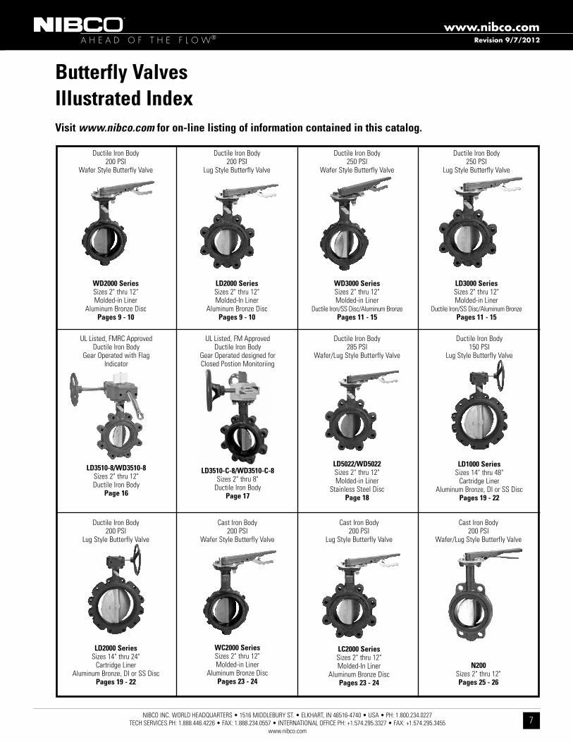
Butterfly ValvesIllustrated IndexVisit www.nibco.com for on-line listing of information contained in this catalog.
ductile Iron Body200 PsI
Wafer style Butterfly Valve
WD2000 Seriessizes 2" thru 12"Molded-in liner
aluminum Bronze discPages 9 - 10
ductile Iron Body250 PsI
Wafer style Butterfly Valve
WD3000 Seriessizes 2" thru 12"Molded-in liner
ductile Iron/ss disc/aluminum BronzePages 11 - 15
ductile Iron Body250 PsI
lug style Butterfly Valve
LD3000 Seriessizes 2" thru 12"Molded-in liner
ductile Iron/ss disc/aluminum BronzePages 11 - 15
ductile Iron Body150 PsI
lug style Butterfly Valve
LD1000 Seriessizes 14" thru 48"
Cartridge lineraluminum Bronze, dI or ss disc
Pages 19 - 22
ul listed, fMrC approvedductile Iron Body
Gear Operated with flagIndicator
LD3510-8/WD3510-8sizes 2" thru 12"ductile Iron Body
Page 16
ductile Iron Body200 PsI
lug style Butterfly Valve
LD2000 Seriessizes 2" thru 12"Molded-In liner
aluminum Bronze discPages 9 - 10
ductile Iron Body200 PsI
lug style Butterfly Valve
LD2000 Seriessizes 14" thru 24"
Cartridge lineraluminum Bronze, dI or ss disc
Pages 19 - 22
Cast Iron Body200 PsI
Wafer style Butterfly Valve
WC2000 Seriessizes 2" thru 12"Molded-in liner
aluminum Bronze discPages 23 - 24
ul listed, fM approvedductile Iron Body
Gear Operated designed forClosed Postion Monitoriing
LD3510-C-8/WD3510-C-8sizes 2" thru 8"
ductile Iron BodyPage 17
Revision 9/7/2012
ductile Iron Body285 PsI
Wafer/lug style Butterfly Valve
LD5022/WD5022sizes 2" thru 12"Molded-in liner
stainless steel discPage 18
Cast Iron Body200 PsI
Wafer/lug style Butterfly Valve
N200sizes 2" thru 12"Pages 25 - 26
Cast Iron Body200 PsI
lug style Butterfly Valve
LC2000 Seriessizes 2" thru 12"Molded-In liner
aluminum Bronze discPages 23 - 24

A H E A D O F T H E F L O W®www.nibco.com
NIBCO INC. WORLD HEADQUARTERS • 1516 MIDDLEBURY ST. • ELKHART, IN 46516-4740 • USA • PH: 1.800.234.0227 TECH SERVICES PH: 1.888.446.4226 • FAX: 1.888.234.0557 • INTERNATIONAL OFFICE PH: +1.574.295.3327 • FAX: +1.574.295.3455
www.nibco.com8
Butterfly ValvesIllustrated IndexVisit www.nibco.com for on-line listing of information contained in this catalog.
ductile Iron BodyPolyamide Coating
300 PsIGrooved end Butterfly Valve
GD4765/4775sizes 2" thru 12"
elastomer Coated discPage 28
ul listed, fM approvedPolyamide Coated ductile Iron Body
Gear Operator with flag300 PsI W .W .P .
GD4765-8NGrooved Mechanical type
sizes 2¹⁄₂" thru 10"Page 30
CI or dI Body200/285 PsI
flanged Butterfly Valve
FC2000/FD5000 Seriessizes 2" thru 12"
elastomer Coasted discPages 33 - 35
Carbon steel150/300 ClassHigh Performance Butterfly Valve
LCS6822/LCS7822 Seriessizes 2 1⁄2" thru 24"
ss discPages 36 - 42
ul listednylon Coated ductile Iron Body
Gear Operator with flag350 lb . WWP
GD6765-8NGrooved Mechanical style
sizes 2¹⁄₂", 3", 4", 6", 8", 10"Page 32
Revision 9/7/2012
ductile Iron BodyPolyamide Coating
300 PsIGrooved end Butterfly Valve
nsf/ansI 61nsf/ansI 372
GD4765Nsizes 2" thru 12"
elastomer Coated discPage 29
ul listed, fM approvedPolyamide Coated ductile Iron Body
Gear Operator designed forClosed Postion Monitoriing
300 PsI W .W .P .
GD4765-C-8NGrooved Mechanical type
sizes 2¹⁄₂" thru 8"Page 31

A H E A D O F T H E F L O W®www.nibco.com
NIBCO INC. WORLD HEADQUARTERS • 1516 MIDDLEBURY ST. • ELKHART, IN 46516-4740 • USA • PH: 1.800.234.0227 TECH SERVICES PH: 1.888.446.4226 • FAX: 1.888.234.0557 • INTERNATIONAL OFFICE PH: +1.574.295.3327 • FAX: +1.574.295.3455
www.nibco.com9
For actuated service where a lower torque is required use NIBCO Fig. No. WDLXXX-0 or LDLXXX-0 series, sizes 2" thru 12" only. Maximum pressure rating of 100 PSI for wet application and 50 PSI for dry application.
Revision 8/6/2013
200 PSI Butterfly Valvesductile Iron Body • extended neck • Geometric driveMolded-in seat liner • lug and Wafer style Sizes 2" through 12"Install between std . asMe Class 125/150 flanges . lug style 200 PsI bi-directional dead end service rating without a downstream flange required .
1. Stem Stainless Steel ASTM A582 Type 416 2. Collar Bushing Brass ASTM B16 3. Stem Seal EPDM Rubber 4. Body Seal EPDM Rubber 5. Nameplate Aluminum 6. Upper Bushing Copper CDA 122 7. Liner EPDM Rubber 8. Disc Alum. Brz. ASTM B148 Alloy 955 9. Lower Bushing Copper CDA 122 10. Body Wafer Ductile Iron ASTM A536 11. Body Lug Ductile Iron ASTM A536
MATERIAL LIST PaRT SPeCiFiCaTiON
DIMENSIONS — WEIGHTS Size G Metal Rubber J N in. mm. a B C D e F Flat H i Square Dia. 2 50 2.53 4.00 1.25 5.38 2.88 .38 .312 1.688 1.812 3.25 .500
2¹⁄₂65 2.90 4.69 1.25 5.88 3.27 .38 .370 1.812 1.938 3.25 .562
3 80 3.15 5.12 1.25 6.12 3.40 .38 .370 1.812 1.938 3.25 .562
4 100 4.09 6.12 1.25 6.88 4.00 .38 .403 2.062 2.188 3.25 .625
5 125 5.13 7.25 1.25 7.38 4.75 .38 .496 2.188 2.312 3.25 .750
6 150 6.13 8.25 1.25 8.00 5.29 .38 .496 2.188 2.312 3.25 .750
8 200 8.13 10.41 1.25 9.25 6.50 .50 .560 2.375 2.500 3.25 .875
10 250 10.13 12.52 1.25 10.50 8.00 .50 .686 2.688 2.812 4.75 1.125
12 300 12.13 15.00 1.25 12.00 9.25 .50 .748 3.000 3.125 4.75 1.250
LD 2000lug style
ePdM liner and aluminum
Bronze disc
WD 2000Wafer styleePdM liner
and aluminum Bronze disc
nOt reCOMMended fOr steaM serVICe
desIGned tO Meet Mss sP-67 standard •u .s . COast Guard "CateGOry a" • CertIfIed lead -free*
By IaPMO r&t tO nsf/ansI 372
Lug Wafer Size O P R K L Wafer Lug M Weight Weight in. mm. B.C. Dia. Dia. No. Dia. Length Length B.C. Lbs. Kg. Lbs. Kg.
2 50 3.25 .437 .437 4 ⁵⁄₈-11unc 4³⁄₄ 7 3.2 5.5 2.5
2¹⁄₂ 65 3.25 .437 .500 4 ⁵⁄₈-11unc 5¹⁄₂ 9 4.1 7.5 3.4
3 80 3.25 .437 .500 4 ⁵⁄₈-11unc 6 9.5 4.3 8 3.6
4 100 3.25 .437 .562 8 ⁵⁄₈-11unc 7¹⁄₂ 15 6.8 11 5.0
5 125 3.25 .437 .656 8 ³⁄₄-10unc 8¹⁄₂ 21 9.5 15 6.8
6 150 3.25 .437 .656 8 ³⁄₄-10unc 9¹⁄₂ 24 10.9 18 8.2
8 200 3.25 .437 .781 8 ³⁄₄-10unc 11³⁄₄ 34 15.4 28 12.7
10 250 5.00 .562 1.000 12 ⁷⁄₈-9unc 14¹⁄₄ 62 28.1 45.5 20.7
12 300 5.00 .562 1.062 12 ⁷⁄₈-9unc 17 90 40.9 70 31.8
Capscrew/Stud Data
Refer to butterfly
valvetechnical
informationfor bolt lengths
*lead free refers to the wetted surface of pipe, fittings and fixtures in potable water systems that have a weighted average lead content ≤ 0 .25% per the safe drinking Water act (sec . 1417) amended 1-4-2011 and other equivalent state regulations .

A H E A D O F T H E F L O W®www.nibco.com
NIBCO INC. WORLD HEADQUARTERS • 1516 MIDDLEBURY ST. • ELKHART, IN 46516-4740 • USA • PH: 1.800.234.0227 TECH SERVICES PH: 1.888.446.4226 • FAX: 1.888.234.0557 • INTERNATIONAL OFFICE PH: +1.574.295.3327 • FAX: +1.574.295.3455
www.nibco.com10
Revision 8/6/2013
200 PSI Butterfly Valvesductile Iron Body • extended neck • Geometric driveMolded-in seat liner • lug and Wafer style Sizes 2" through 12"Install between std . asMe Class 125/150 flangeslug style 200 PsI bi-directional dead end service rating without a downstream flange required .
1. Stem Stainless Steel ASTM A582 Type 416 2. Collar Bushing Brass ASTM B16 3. Stem Seal Buna-N Rubber Nitrile 4. Body Seal Buna-N Rubber Nitrile 5. Nameplate Aluminum 6. Upper Bushing Copper CDA 122 7. Liner Buna-N Rubber Nitrile 8. Disc Alum. Brz. ASTM B148 Alloy 954/955 9. Lower Bushing Copper CDA 122 10. Body Wafer Ductile Iron ASTM A536 11. Body Lug Ductile Iron ASTM A536
MATERIAL LIST PaRT SPeCiFiCaTiON
LD 2100lug style
Buna-n liner and aluminum
Bronze disc
WD 2100Wafer styleBuna-n liner
and aluminum Bronze disc
DIMENSIONS — WEIGHTS Size G Metal Rubber J N in. mm. a B C D e F Flat H i Square Dia.
2 50 2.53 4.00 1.25 5.38 2.88 .38 .312 1.688 1.812 3.25 .500
2¹⁄₂ 65 2.90 4.69 1.25 5.88 3.27 .38 .370 1.812 1.938 3.25 .562
3 80 3.15 5.12 1.25 6.12 3.40 .38 .370 1.812 1.938 3.25 .562
4 100 4.09 6.12 1.25 6.88 4.00 .38 .403 2.062 2.188 3.25 .625
5 125 5.13 7.25 1.25 7.38 4.75 .38 .496 2.188 2.312 3.25 .750
6 150 6.13 8.25 1.25 8.00 5.29 .38 .496 2.188 2.312 3.25 .750
8 200 8.13 10.41 1.25 9.25 6.50 .50 .560 2.375 2.500 3.25 .875
10 250 10.13 12.52 1.25 10.50 8.00 .50 .686 2.688 2.812 4.75 1.125
12 300 12.13 15.00 1.25 12.00 9.25 .50 .748 3.000 3.125 4.75 1.250
Lug Wafer
Size O P R K L Wafer Lug M Weight Weight in. mm. B.C. Dia. Dia. No. Dia. Length Length B.C. Lbs. Kg. Lbs. Kg.
2 50 3.25 .437 .437 4 ⁵⁄₈-11unc 4 1¹⁄₂ 4³⁄₄ 7 3.2 5.5 2.5
2¹⁄₂ 65 3.25 .437 .500 4 ⁵⁄₈-11unc 4¹⁄₄ 1¹⁄₂ 5¹⁄₂ 9 4.1 7.5 3.4
3 80 3.25 .437 .500 4 ⁵⁄₈-11unc 4¹⁄₄ 1⁵⁄₈ 6 9.5 4.3 8 3.6
4 100 3.25 .437 .562 8 ⁵⁄₈-11unc 5 1⁷⁄₈ 7¹⁄₂ 15 6.8 11 5.0
5 125 3.25 .437 .656 8 ³⁄₄-10unc 5¹⁄₄ 2 8¹⁄₂ 21 9.5 15 6.8
6 150 3.25 .437 .656 8 ³⁄₄-10unc 5¹⁄₄ 2 9¹⁄₂ 24 10.9 18 8.2
8 200 3.25 .437 .781 8 ³⁄₄-10unc 5³⁄₄ 2¹⁄₄ 11³⁄₄ 34 15.4 28 12.7
10 250 5.00 .562 1.000 12 ⁷⁄₈-9unc 6¹⁄₄ 2¹⁄₄ 14¹⁄₄ 62 28.1 45.5 20.7
12 300 5.00 .562 1.062 12 ⁷⁄₈-9unc 6³⁄₄ 2¹⁄₂ 17 90 40.9 70 31.8
nOt reCOMMended fOr steaM serVICe
Capscrew/Stud Data
desIGned tO Meet Mss sP-67 standardu .s . COast Guard "CateGOry a"
For actuated service where a lower torque is required use NIBCO Fig. No. WDLXXX-0 or LDLXXX-0 series, sizes 2" thru 12" only. Maximum pressure rating of 100 PSI for wet application and 50 PSI for dry application
Refer to butterfly
valvetechnical
informationfor bolt lengths

A H E A D O F T H E F L O W®www.nibco.com
NIBCO INC. WORLD HEADQUARTERS • 1516 MIDDLEBURY ST. • ELKHART, IN 46516-4740 • USA • PH: 1.800.234.0227 TECH SERVICES PH: 1.888.446.4226 • FAX: 1.888.234.0557 • INTERNATIONAL OFFICE PH: +1.574.295.3327 • FAX: +1.574.295.3455
www.nibco.com11
Lug Wafer Size O P R K L Wafer Lug M Weight Weight in. mm. B.C. Dia. Dia. No. Dia. Length Length B.C. Lbs. Kg. Lbs. Kg.
2 50 3.25 .437 .437 4 ⁵⁄₈-11unc 4³⁄₄ 7 3.2 5.5 2.5
2¹⁄₂ 65 3.25 .437 .500 4 ⁵⁄₈-11unc 5¹⁄₂ 9 4.1 7.5 3.4
3 80 3.25 .437 .500 4 ⁵⁄₈-11unc 6 9.5 4.3 8 3.6
4 100 3.25 .437 .562 8 ⁵⁄₈-11unc 7¹⁄₂ 15 6.8 11 5.0
5 125 3.25 .437 .656 8 ³⁄₄-10unc 8¹⁄₂ 21 9.5 15 6.8
6 150 3.25 .437 .656 8 ³⁄₄-10unc 9¹⁄₂ 24 10.9 18 8.2
8 200 3.25 .437 .781 8 ³⁄₄-10unc 11³⁄₄ 34 15.4 28 12.7
10 250 5.00 .562 1.000 12 ⁷⁄₈-9unc 14¹⁄₄ 62 28.1 45.5 20.7
12 300 5.00 .562 1.062 12 ⁷⁄₈-9unc 17 90 40.9 70 31.8
250 PSI Butterfly Valvesductile Iron Body • extended neck • Geometric drive • Molded-in seat liner • lug and Wafer style Sizes 2" through 12"Install between std . asMe Class 125/150 flangeslug style 232 PsI bi-directional dead end service rating without a downstream flange required .
1. Stem Stainless Steel ASTM A582 Type 416 2. Collar Bushing Brass ASTM B16 3. Stem Seal EPDM Rubber 4. Body Seal EPDM Rubber 5. Nameplate Aluminum 6. Upper Bushing Copper CDA 122 7. Liner EPDM Rubber 8. Disc Alum. Brz. ASTM B148 Alloy 954/955 9. Lower Bushing Copper CDA 122 10. Body Wafer Ductile Iron ASTM A536 11. Body Lug Ductile Iron ASTM A536
MATERIAL LIST PaRT SPeCiFiCaTiON
DIMENSIONS — WEIGHTS Size G Metal Rubber J N in. mm. a B C D e F Flat H i Square Dia. 2 50 2.53 4.00 1.25 5.38 2.88 .38 .312 1.688 1.812 3.25 .500
2¹⁄₂65 2.90 4.69 1.25 5.88 3.27 .38 .370 1.812 1.938 3.25 .562
3 80 3.15 5.12 1.25 6.12 3.40 .38 .370 1.812 1.938 3.25 .562
4 100 4.09 6.12 1.25 6.88 4.00 .38 .403 2.062 2.188 3.25 .625
5 125 5.13 7.25 1.25 7.38 4.75 .38 .496 2.188 2.312 3.25 .750
6 150 6.13 8.25 1.25 8.00 5.29 .38 .496 2.188 2.312 3.25 .750
8 200 8.13 10.41 1.25 9.25 6.50 .50 .560 2.375 2.500 3.25 .875
10 250 10.13 12.52 1.25 10.50 8.00 .50 .686 2.688 2.812 4.75 1.125
12 300 12.13 15.00 1.25 12.00 9.25 .50 .748 3.000 3.125 4.75 1.250
LD 3000lug style
ePdM liner and aluminum
Bronze disc
nOt reCOMMended fOr steaM serVICe
Capscrew/Stud Data
Refer to butterfly
valvetechnical
informationfor bolt lengths
WD 3000Wafer styleePdM liner
and aluminum Bronze disc
desIGned tO Meet Mss sP-67 standard• u .s . COast Guard "CateGOry a"
Revision 8/6/2013
A H E A D O F T H E F L O W®www.nibco.com
NIBCO INC. WORLD HEADQUARTERS • 1516 MIDDLEBURY ST. • ELKHART, IN 46516-4740 • USA • PH: 1.800.234.0227 TECH SERVICES PH: 1.888.446.4226 • FAX: 1.888.234.0557 • INTERNATIONAL OFFICE PH: +1.574.295.3327 • FAX: +1.574.295.3455
www.nibco.com12
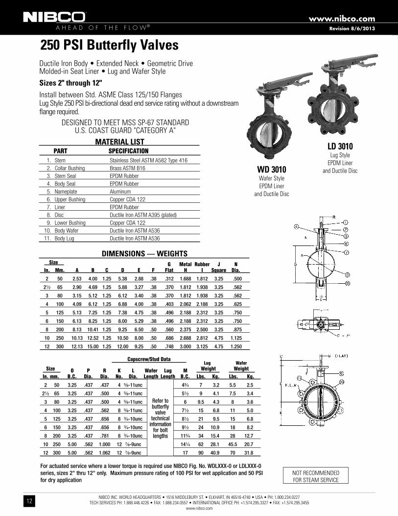
250 PSI Butterfly Valvesductile Iron Body • extended neck • Geometric driveMolded-in seat liner • lug and Wafer style Sizes 2" through 12"Install between std . asMe Class 125/150 flangeslug style 250 PsI bi-directional dead end service rating without a downstream flange required .
LD 3010lug style
ePdM liner and ductile discWD 3010
Wafer styleePdM liner
and ductile disc
1. Stem Stainless Steel ASTM A582 Type 416 2. Collar Bushing Brass ASTM B16 3. Stem Seal EPDM Rubber 4. Body Seal EPDM Rubber 5. Nameplate Aluminum 6. Upper Bushing Copper CDA 122 7. Liner EPDM Rubber 8. Disc Ductile Iron ASTM A395 (plated) 9. Lower Bushing Copper CDA 122 10. Body Wafer Ductile Iron ASTM A536 11. Body Lug Ductile Iron ASTM A536
MATERIAL LIST PaRT SPeCiFiCaTiON
Lug Wafer
Size O P R K L Wafer Lug M Weight Weight in. mm. B.C. Dia. Dia. No. Dia. Length Length B.C. Lbs. Kg. Lbs. Kg.
2 50 3.25 .437 .437 4 ⁵⁄₈-11unc 4 1¹⁄₂ 4³⁄₄ 7 3.2 5.5 2.5
2¹⁄₂ 65 3.25 .437 .500 4 ⁵⁄₈-11unc 4¹⁄₄ 1¹⁄₂ 5¹⁄₂ 9 4.1 7.5 3.4
3 80 3.25 .437 .500 4 ⁵⁄₈-11unc 4¹⁄₄ 1⁵⁄₈ 6 9.5 4.3 8 3.6
4 100 3.25 .437 .562 8 ⁵⁄₈-11unc 5 1⁷⁄₈ 7¹⁄₂ 15 6.8 11 5.0
5 125 3.25 .437 .656 8 ³⁄₄-10unc 5¹⁄₄ 2 8¹⁄₂ 21 9.5 15 6.8
6 150 3.25 .437 .656 8 ³⁄₄-10unc 5¹⁄₄ 2 9¹⁄₂ 24 10.9 18 8.2
8 200 3.25 .437 .781 8 ³⁄₄-10unc 5³⁄₄ 2¹⁄₄ 11³⁄₄ 34 15.4 28 12.7
10 250 5.00 .562 1.000 12 ⁷⁄₈-9unc 6¹⁄₄ 2¹⁄₄ 14¹⁄₄ 62 28.1 45.5 20.7
12 300 5.00 .562 1.062 12 ⁷⁄₈-9unc 6³⁄₄ 2¹⁄₂ 17 90 40.9 70 31.8
nOt reCOMMended fOr steaM serVICe
DIMENSIONS — WEIGHTS Size G Metal Rubber J N in. Mm. a B C D e F Flat H i Square Dia.
2 50 2.53 4.00 1.25 5.38 2.88 .38 .312 1.688 1.812 3.25 .500
2¹⁄₂ 65 2.90 4.69 1.25 5.88 3.27 .38 .370 1.812 1.938 3.25 .562
3 80 3.15 5.12 1.25 6.12 3.40 .38 .370 1.812 1.938 3.25 .562
4 100 4.09 6.12 1.25 6.88 4.00 .38 .403 2.062 2.188 3.25 .625
5 125 5.13 7.25 1.25 7.38 4.75 .38 .496 2.188 2.312 3.25 .750
6 150 6.13 8.25 1.25 8.00 5.29 .38 .496 2.188 2.312 3.25 .750
8 200 8.13 10.41 1.25 9.25 6.50 .50 .560 2.375 2.500 3.25 .875
10 250 10.13 12.52 1.25 10.50 8.00 .50 .686 2.688 2.812 4.75 1.125
12 300 12.13 15.00 1.25 12.00 9.25 .50 .748 3.000 3.125 4.75 1.250
Capscrew/Stud Data
desIGned tO Meet Mss sP-67 standardu .s . COast Guard "CateGOry a"
For actuated service where a lower torque is required use NIBCO Fig. No. WDLXXX-0 or LDLXXX-0 series, sizes 2" thru 12" only. Maximum pressure rating of 100 PSI for wet application and 50 PSI for dry application
Refer to butterfly
valvetechnical
informationfor bolt lengths
Revision 8/6/2013

A H E A D O F T H E F L O W®www.nibco.com
NIBCO INC. WORLD HEADQUARTERS • 1516 MIDDLEBURY ST. • ELKHART, IN 46516-4740 • USA • PH: 1.800.234.0227 TECH SERVICES PH: 1.888.446.4226 • FAX: 1.888.234.0557 • INTERNATIONAL OFFICE PH: +1.574.295.3327 • FAX: +1.574.295.3455
www.nibco.com13
Revision 8/6/2013
250 PSI Butterfly Valvesductile Iron Body • extended neck • Geometric drive • Molded-in seat liner • lug and Wafer style Sizes 2" through 12"Install between std . asMe Class 125/150 flangeslug style 232 PsI bi-directional dead end service rating without a downstream flange required .
1. Stem Stainless Steel ASTM A582 Type 416 2. Collar Bushing Brass ASTM B16 3. Stem Seal Buna-N Rubber Nitrile 4. Body Seal Buna-N Rubber Nitrile 5. Nameplate Aluminum 6. Upper Bushing Copper CDA 122 7. Liner Buna-N Rubber Nitrile 8. Disc Alum. Brz. ASTM B148 Alloy 954/955 9. Lower Bushing Copper CDA 122 10. Body Wafer Ductile Iron ASTM A536 11. Body Lug Ductile Iron ASTM A536
MATERIAL LIST PaRT SPeCiFiCaTiON
LD 3100lug style
Buna-n liner and aluminum
Bronze disc
DIMENSIONS — WEIGHTS Size G Metal Rubber J N in. mm. a B C D e F Flat H i Square Dia.
2 50 2.53 4.00 1.25 5.38 2.88 .38 .312 1.688 1.812 3.25 .500
2¹⁄₂ 65 2.90 4.69 1.25 5.88 3.27 .38 .370 1.812 1.938 3.25 .562
3 80 3.15 5.12 1.25 6.12 3.40 .38 .370 1.812 1.938 3.25 .562
4 100 4.09 6.12 1.25 6.88 4.00 .38 .403 2.062 2.188 3.25 .625
5 125 5.13 7.25 1.25 7.38 4.75 .38 .496 2.188 2.312 3.25 .750
6 150 6.13 8.25 1.25 8.00 5.29 .38 .496 2.188 2.312 3.25 .750
8 200 8.13 10.41 1.25 9.25 6.50 .50 .560 2.375 2.500 3.25 .875
10 250 10.13 12.52 1.25 10.50 8.00 .50 .686 2.688 2.812 4.75 1.125
12 300 12.13 15.00 1.25 12.00 9.25 .50 .748 3.000 3.125 4.75 1.250
Lug Wafer
Size O P R K L Wafer Lug M Weight Weight in. mm. B.C. Dia. Dia. No. Dia. Length Length B.C. Lbs. Kg. Lbs. Kg.
2 50 3.25 .437 .437 4 ⁵⁄₈-11unc 4 1¹⁄₂ 4³⁄₄ 7 3.2 5.5 2.5
2¹⁄₂ 65 3.25 .437 .500 4 ⁵⁄₈-11unc 4¹⁄₄ 1¹⁄₂ 5¹⁄₂ 9 4.1 7.5 3.4
3 80 3.25 .437 .500 4 ⁵⁄₈-11unc 4¹⁄₄ 1⁵⁄₈ 6 9.5 4.3 8 3.6
4 100 3.25 .437 .562 8 ⁵⁄₈-11unc 5 1⁷⁄₈ 7¹⁄₂ 15 6.8 11 5.0
5 125 3.25 .437 .656 8 ³⁄₄-10unc 5¹⁄₄ 2 8¹⁄₂ 21 9.5 15 6.8
6 150 3.25 .437 .656 8 ³⁄₄-10unc 5¹⁄₄ 2 9¹⁄₂ 24 10.9 18 8.2
8 200 3.25 .437 .781 8 ³⁄₄-10unc 5³⁄₄ 2¹⁄₄ 11³⁄₄ 34 15.4 28 12.7
10 250 5.00 .562 1.000 12 ⁷⁄₈-9unc 6¹⁄₄ 2¹⁄₄ 14¹⁄₄ 62 28.1 45.5 20.7
12 300 5.00 .562 1.062 12 ⁷⁄₈-9unc 6³⁄₄ 2¹⁄₂ 17 90 40.9 70 31.8
nOt reCOMMended fOr steaM serVICe
Capscrew/Stud Data
desIGned tO Meet Mss sP-67 standardu .s . COast Guard "CateGOry a"
Refer to butterfly
valvetechnical
informationfor bolt lengths
WD 3100Wafer styleBuna-n liner
and aluminum Bronze disc

A H E A D O F T H E F L O W®www.nibco.com
NIBCO INC. WORLD HEADQUARTERS • 1516 MIDDLEBURY ST. • ELKHART, IN 46516-4740 • USA • PH: 1.800.234.0227 TECH SERVICES PH: 1.888.446.4226 • FAX: 1.888.234.0557 • INTERNATIONAL OFFICE PH: +1.574.295.3327 • FAX: +1.574.295.3455
www.nibco.com14
Revision 8/6/2013
250 PSI Butterfly Valvesductile Iron Body • extended neck • Geometric driveMolded-in seat liner • lug and Wafer styleSizes 2" through 12"Install between std . asMe Class 125/150 flangeslug style 250 PsI bi-directional dead end service rating without a downstream flange required .
1. Stem Stainless Steel ASTM A582 Type 416 2. Collar Bushing Brass ASTM B16 3. Stem Seal Buna-N Rubber 4. Body Seal Buna-N Rubber 5. Nameplate Aluminum 6. Upper Bushing Copper CDA 122 7. Liner Buna-N Rubber 8. Disc Ductile Iron ASTM A395 (Plated) 9. Lower Bushing Copper CDA 122 10. Body Wafer Ductile Iron ASTM A536 11. Body Lug Ductile Iron ASTM A536
MATERIAL LIST PaRT SPeCiFiCaTiON
LD 3110lug style
Buna-n liner and ductile discWD 3110
Wafer styleBuna-n liner
and ductile disc
DIMENSIONS — WEIGHTS Size G Metal Rubber J N in. mm. a B C D e F Flat H i Square Dia.
2 50 2.53 4.00 1.25 5.38 2.88 .38 .312 1.688 1.812 3.25 .500
2¹⁄₂ 65 2.90 4.69 1.25 5.88 3.27 .38 .370 1.812 1.938 3.25 .562
3 80 3.15 5.12 1.25 6.12 3.40 .38 .370 1.812 1.938 3.25 .562
4 100 4.09 6.12 1.25 6.88 4.00 .38 .403 2.062 2.188 3.25 .625
5 125 5.13 7.25 1.25 7.38 4.75 .38 .496 2.188 2.312 3.25 .750
6 150 6.13 8.25 1.25 8.00 5.29 .38 .496 2.188 2.312 3.25 .750
8 200 8.13 10.41 1.25 9.25 6.50 .50 .560 2.375 2.500 3.25 .875
10 250 10.13 12.52 1.25 10.50 8.00 .50 .686 2.688 2.812 4.75 1.125
12 300 12.13 15.00 1.25 12.00 9.25 .50 .748 3.000 3.125 4.75 1.250
Lug Wafer
Size O P R K L Wafer Lug M Weight Weight in. mm. B.C. Dia. Dia. No. Dia. Length Length B.C. Lbs. Kg. Lbs. Kg.
2 50 3.25 .437 .437 4 ⁵⁄₈-11unc 4 1¹⁄₂ 4³⁄₄ 7 3.2 5.5 2.5
2¹⁄₂ 65 3.25 .437 .500 4 ⁵⁄₈-11unc 4¹⁄₄ 1¹⁄₂ 5¹⁄₂ 9 4.1 7.5 3.4
3 80 3.25 .437 .500 4 ⁵⁄₈-11unc 4¹⁄₄ 1⁵⁄₈ 6 9.5 4.3 8 3.6
4 100 3.25 .437 .562 8 ⁵⁄₈-11unc 5 1⁷⁄₈ 7¹⁄₂ 15 6.8 11 5.0
5 125 3.25 .437 .656 8 ³⁄₄-10unc 5¹⁄₄ 2 8¹⁄₂ 21 9.5 15 6.8
6 150 3.25 .437 .656 8 ³⁄₄-10unc 5¹⁄₄ 2 9¹⁄₂ 24 10.9 18 8.2
8 200 3.25 .437 .781 8 ³⁄₄-10unc 5³⁄₄ 2¹⁄₄ 11³⁄₄ 34 15.4 28 12.7
10 250 5.00 .562 1.000 12 ⁷⁄₈-9unc 6¹⁄₄ 2¹⁄₄ 14¹⁄₄ 62 28.1 45.5 20.7
12 300 5.00 .562 1.062 12 ⁷⁄₈-9unc 6³⁄₄ 2¹⁄₂ 17 90 40.9 70 31.8
nOt reCOMMended fOr steaM serVICe
Capscrew/Stud Data
desIGned tO Meet Mss sP-67 standardu .s . COast Guard "CateGOry a"
For actuated service where a lower torque is required use NIBCO Fig. No. WDLXXX-0 or LDLXXX-0 series, sizes 2" thru 12" only. Maximum pressure rating of 100 PSI for wet application and 50 PSI for dry application
Refer to butterfly
valvetechnical
informationfor bolt lengths

A H E A D O F T H E F L O W®www.nibco.com
NIBCO INC. WORLD HEADQUARTERS • 1516 MIDDLEBURY ST. • ELKHART, IN 46516-4740 • USA • PH: 1.800.234.0227 TECH SERVICES PH: 1.888.446.4226 • FAX: 1.888.234.0557 • INTERNATIONAL OFFICE PH: +1.574.295.3327 • FAX: +1.574.295.3455
www.nibco.com15
Revision 8/6/2013
250 PSI Butterfly Valvesductile Iron Body • extended neck • Geometric drive • 316 s .s . trimMolded-in seat liner • lug and Wafer styleSizes 2" through 12"Install between std . asMe Class 125/150 flangeslug style 250 PsI bi-directional dead end service rating without a downstream flange required .
1. Stem Stainless Steel ASTM A564 Type 17-4PH 2. Collar Bushing Stainless Steel ASTM A276 Type 316 3. Stem Seal Options: See Below* 4. Body Seal Options: See Below* 5. Nameplate Aluminum 6. Upper Bushing Stainless Steel ASTM A276 Type 316 7. Liner Options: See Below* 8. Disc Stainless Steel ASTM A743 Grade CF8M 9. Lower Bushing Stainless Steel ASTM A276 Type 316 10. Body Wafer Ductile Iron ASTM A536 11. Body Lug Ductile Iron ASTM A536
MATERIAL LIST PaRT SPeCiFiCaTiON
LD 3*22lug style
Optional liner and Cf8M discWD 3*22
Wafer styleOptional liner and Cf8M disc
nOt reCOMMended fOr steaM serVICe
DIMENSIONS — WEIGHTS Size G Metal Rubber J N in. mm. a B C D e F Flat H i Square Dia.
2 50 2.53 4.00 1.25 5.38 2.88 .38 .312 1.688 1.812 3.25 .500
2¹⁄₂ 65 2.90 4.69 1.25 5.88 3.27 .38 .370 1.812 1.938 3.25 .562
3 80 3.15 5.12 1.25 6.12 3.40 .38 .370 1.812 1.938 3.25 .562
4 100 4.09 6.12 1.25 6.88 4.00 .38 .403 2.062 2.188 3.25 .625
5 125 5.13 7.25 1.25 7.38 4.75 .38 .496 2.188 2.312 3.25 .750
6 150 6.13 8.25 1.25 8.00 5.29 .38 .496 2.188 2.312 3.25 .750
8 200 8.13 10.41 1.25 9.25 6.50 .50 .560 2.375 2.500 3.25 .875
10 250 10.13 12.52 1.25 10.50 8.00 .50 .686 2.688 2.812 4.75 1.125
12 300 12.13 15.00 1.25 12.00 9.25 .50 .748 3.000 3.125 4.75 1.250
Lug Wafer Size O P R K L Wafer Lug M Weight Weight in. mm. B.C. Dia. Dia. No. Dia. Length Length B.C. Lbs. Kg. Lbs. Kg.
2 50 3.25 .437 .437 4 ⁵⁄₈-11unc 4 1¹⁄₂ 4³⁄₄ 7 3.2 5.5 2.5
2¹⁄₂ 65 3.25 .437 .500 4 ⁵⁄₈-11unc 4¹⁄₄ 1¹⁄₂ 5¹⁄₂ 9 4.1 7.5 3.4
3 80 3.25 .437 .500 4 ⁵⁄₈-11unc 4¹⁄₄ 1⁵⁄₈ 6 9.5 4.3 8 3.6
4 100 3.25 .437 .562 8 ⁵⁄₈-11unc 5 1⁷⁄₈ 7¹⁄₂ 15 6.8 11 5.0
5 125 3.25 .437 .656 8 ³⁄₄-10unc 5¹⁄₄ 2 8¹⁄₂ 21 9.5 15 6.8
6 150 3.25 .437 .656 8 ³⁄₄-10unc 5¹⁄₄ 2 9¹⁄₂ 24 10.9 18 8.2
8 200 3.25 .437 .781 8 ³⁄₄-10unc 5³⁄₄ 2¹⁄₄ 11³⁄₄ 34 15.4 28 12.7
10 250 5.00 .562 1.000 12 ⁷⁄₈-9unc 6¹⁄₄ 2¹⁄₄ 14¹⁄₄ 62 28.1 45.5 20.7
12 300 5.00 .562 1.062 12 ⁷⁄₈-9unc 6³⁄₄ 2¹⁄₂ 17 90 40.9 70 31.8
Capscrew/Stud Data
desIGned tO Meet Mss sP-67 standardu .s . COast Guard "CateGOry a"
For actuated service where a lower torque is required use NIBCO Fig. No. WDLXXX-0 or LDLXXX-0 series, sizes 2" thru 12" only. Maximum pressure rating of 100 PSI for wet application and 50 PSI for dry application
Refer to butterfly
valvetechnical
informationfor bolt lengths
*Optional Liners/Seals: 0 - ePDM 1 - Buna-N (Nitrile) 2 - Fluoroelastomer

A H E A D O F T H E F L O W®www.nibco.com
NIBCO INC. WORLD HEADQUARTERS • 1516 MIDDLEBURY ST. • ELKHART, IN 46516-4740 • USA • PH: 1.800.234.0227 TECH SERVICES PH: 1.888.446.4226 • FAX: 1.888.234.0557 • INTERNATIONAL OFFICE PH: +1.574.295.3327 • FAX: +1.574.295.3455
www.nibco.com16
Revision 8/6/2013
MATERIAL LIST PART SPECIFICATION 1 . stem stainless steel astM 582 type 416 2 . Collar Bushing Brass astM B16 3 . upper Bushing Copper alloy Cda 122 4 . stem seal ePdM 5 . Body seal ePdM 6 . disc ductile Iron astM 395 (nickel Plated) 7 . liner ePdM 8 . lower Bushing Copper alloy Cda 122 9 . nameplate aluminum 10 . Body ductile Iron astM a536 11 . Gear Operator Cast Iron and steel 12 . Indicator flag Cast Iron 13 . Handwheel Cast Iron
WD3510-8** Wafer
(4" shown)LD3510-8**
lug(not shown)
250 PSI/17.2 Bar Non-Shock Cold Water
desIGned tO Meet Mss sP-67 standard • ul/ulC lIsted • fMrC aPPrOVed • ul lIsted fOr IndOOr and OutdOOr serVICe
• aPPrOVed By neW yOrk CIty Mea 9-97-e, VOl .2 WHenasseMBled WItH aPPrOPrIate nyC IndICatOr flaG
• CalIfOrnIa state fIre MarsHal lIstInG nO . 7770-1243:104 • u .s . COast Guard "CateGOry a"
(10" shown)
250 lb. WWP UL/FM Butterfly Valvesfire Protection Valve • Wafer or lug style Body • Molded in seat • accepts internal supervisory switches
** -8 version has two factory mounted internal supervisory switches. 2" thru 8" uses switch TS-3. 10" thru 12" uses switch TS-1. -4 version less switches.Note: Wafer body will mate with ANSI or ISO flanges. O.D. of wafer body notched to fit ISO bolt circle. Lug body available with ISO flange dimensions and metric bolt hole threads. For dead-end service use lug style (rated 200 PSI for this service).
Dimensions Size K M N P In. mm. In. mm. In. mm. In. mm. In. mm. 2 50 3 .54 90 5 .82 148 2 .13 54 5 .9 150 4 ⁵⁄₈ 16 4 .00 101 1 .25 32 4 .75 121 23 11 21 10 2¹⁄₂ 65 3 .54 90 5 .82 148 2 .13 54 5 .9 150 4 ⁵⁄₈ 16 4 .25 108 1 .50 38 5 .50 140 25 11 24 11 3 80 3 .54 90 5 .82 148 2 .13 54 5 .9 150 4 ⁵⁄₈ 16 4 .25 108 1 .50 38 6 .00 152 26 12 24 11 4 100 3 .54 90 5 .82 148 2 .13 54 5 .9 150 8 ⁵⁄₈ 16 5 .00 127 2 .00 51 7 .50 191 31 14 27 12 5 125 3 .54 90 7 .64 194 2 .13 54 5 .9 150 8 ³⁄₄ 20 5 .25 133 2 .00 51 8 .50 216 37 17 31 14 6 150 3 .54 90 7 .64 194 2 .13 54 5 .9 150 8 ³⁄₄ 20 5 .25 133 2 .00 51 9 .50 241 40 18 34 15 8 200 3 .54 90 7 .91 201 2 .13 54 9 .8 250 8 ³⁄₄ 20 5 .75 146 2 .25 57 11 .75 298 55 25 49 22 10 250 3 .98 101 9 .49 241 3 .03 77 11 .8 300 12 ⁷⁄₈ 22 6 .25 159 2 .50 64 14 .25 362 95 43 78 35 12 300 3 .98 101 9 .49 241 3 .03 77 11 .8 300 12 ⁷⁄₈ 22 6 .75 171 2 .50 64 17 .00 432 123 56 103 47
Flange/Stud Data Weight Dia. Wafer Lug BC Lug Wafer No. In. mm. In. mm. In. mm. In. mm. Lbs. Kg. Lbs. Kg.
Refer tobutterfly
valvetechnical
informationfor boltlengths
DIMENSIONS—WEIGHTS—QUANTITIES Dimensions Size A B C D E F G H I J In. mm. In. mm. In. mm. In. mm. In. mm. In. mm. In. mm. In. mm. In. mm. In. mm. In. mm. 2 50 2 .53 64 4 .88 124 4 .62 117 5 .38 137 2 .88 73 6 .89 175 12 .75 324 1 .68 43 1 .81 46 2 .91 74 2¹⁄₂ 65 2 .90 74 5 .62 143 5 .12 130 5 .88 149 3 .25 83 7 .36 187 13 .63 346 1 .81 46 1 .94 49 2 .91 74 3 80 3 .17 81 6 .12 155 5 .50 140 6 .12 155 3 .38 86 7 .60 193 14 .00 356 1 .81 46 1 .94 49 2 .91 74 4 100 4 .17 106 7 .00 178 8 .25 210 6 .88 175 4 .00 102 8 .39 213 15 .38 391 2 .06 52 2 .19 56 2 .91 74 5 125 5 .17 131 8 .25 210 9 .38 238 7 .38 187 4 .75 121 8 .86 225 16 .63 422 2 .19 56 2 .31 59 2 .91 74 6 150 6 .17 157 9 .25 235 10 .25 260 8 .00 203 5 .25 133 9 .49 241 17 .75 451 2 .19 56 2 .31 59 2 .91 74 8 200 8 .17 208 11 .62 295 12 .38 314 9 .25 235 6 .50 165 10 .75 273 20 .25 514 2 .38 60 2 .50 64 2 .91 74 10 250 10 .17 258 14 .25 362 15 .50 394 10 .50 267 8 .00 203 12 .28 312 23 .50 597 2 .68 69 2 .81 71 3 .90 99 12 300 12 .17 309 16 .75 425 18 .25 464 12 .00 305 9 .25 235 13 .78 350 26 .25 667 3 .00 76 3 .12 79 3 .90 99

A H E A D O F T H E F L O W®www.nibco.com
NIBCO INC. WORLD HEADQUARTERS • 1516 MIDDLEBURY ST. • ELKHART, IN 46516-4740 • USA • PH: 1.800.234.0227 TECH SERVICES PH: 1.888.446.4226 • FAX: 1.888.234.0557 • INTERNATIONAL OFFICE PH: +1.574.295.3327 • FAX: +1.574.295.3455
www.nibco.com17
MATERIAL LIST PART SPECIFICATION
1 . stem stainless steel astM 582 type 416 2 . Collar Bushing Brass astM B16 3 . upper Bushing Copper alloy Cda 122 4 . stem seal ePdM 5 . Body seal ePdM 6 . disc ductile Iron astM 395 (nickel Plated) 7 . liner ePdM 8 . lower Bushing Copper alloy Cda 122 9 . nameplate aluminum 10 . Body ductile Iron astM a536 11 . Gear Operator Cast Iron and steel 12 . Indicator flag Cast Iron 13 . Handwheel Cast Iron
250 PSI/17.2 Bar Non-Shock Cold Waterul/ulC lIsted** • fM aPPrOVed** •
desIGned tO Meet Mss sP-67 standard
2¹⁄₂" - 8" ul lIsted fOr IndOOr and OutdOOr serVICe
Warning: These valves are not to be used between the water source and sprinkler head.
250 PSI WWP UL/FM Butterfly Valves
fire Protection Valve • lug or Wafer style Body • factory Mounted Monitoring switches • Mates with C .I . Class 125and steel Class 150 flanges
Note: Wafer body will mate with ANSI or ISO flanges. O.D. of wafer body notched to fit ISO bolt circle. For dead-end service use lug style (rated 200 PSI for this service). Comes with two factory mounted internal supervisory switches. Use switch Figure No. TS-4. See page 4 of I & M manual for
installation & wiring instructions
DIMENSIONS—WEIGHTS—QUANTITIES Dimensions Size A B C D E F G H I J In. mm. In. mm. In. mm. In. mm. In. mm. In. mm. In. mm. In. mm. In. mm. In. mm. In. mm. 21/2 65 2 .90 74 5 .62 143 5 .12 130 5 .88 149 3 .25 83 7 .36 187 13 .63 346 1 .81 46 1 .94 49 2 .91 74 3 80 3 .17 81 6 .12 155 5 .50 140 6 .12 155 3 .38 86 7 .60 193 14 .00 356 1 .81 46 1 .94 49 2 .91 74 4 100 4 .17 106 7 .00 178 8 .25 210 6 .88 175 4 .00 102 8 .39 213 15 .38 391 2 .06 52 2 .19 56 2 .91 74 6 150 6 .17 157 9 .25 235 10 .25 260 8 .00 203 5 .25 133 9 .49 241 17 .75 451 2 .19 56 2 .31 59 2 .91 74 8 200 8 .17 208 11 .62 295 12 .38 314 9 .25 235 6 .50 165 10 .75 273 20 .25 514 2 .38 60 2 .50 64 2 .91 74
Dimensions Flange/Stud Data Weight Size K M N P Dia Wafer Lug BC Lug Wafer In. mm. In. mm. In. mm. In. mm. In. mm. No. In. mm. In. mm. In. mm. In. mm. Lbs. Kg. Lbs. Kg. 21/2 65 3 .54 90 5 .82 148 2 .13 54 5 .9 150 4 5/8 16 4 .25 108 1 .50 38 5 .50 140 25 11 24 11 3 80 3 .54 90 5 .82 148 2 .13 54 5 .9 150 4 5/8 16 4 .25 108 1 .50 38 6 .00 152 26 12 24 11 4 100 3 .54 90 5 .82 148 2 .13 54 5 .9 150 8 5/8 16 5 .00 127 2 .00 51 7 .50 191 31 14 27 12 6 150 3 .54 90 7 .64 194 2 .13 54 5 .9 150 8 3/4 20 5 .25 133 2 .00 51 9 .50 241 40 18 34 15 8 200 3 .54 90 7 .91 201 2 .13 54 9 .8 250 8 3/4 20 5 .75 146 2 .25 57 11 .75 298 55 25 49 22**Compliance with standards for butterfly valves for fire protection ul1091 & fM1112
Designed for normally closed position monitoring
LD-3510-C-8
WD-3510-C-8
Revision 8/6/2013
A H E A D O F T H E F L O W®www.nibco.com
NIBCO INC. WORLD HEADQUARTERS • 1516 MIDDLEBURY ST. • ELKHART, IN 46516-4740 • USA • PH: 1.800.234.0227 TECH SERVICES PH: 1.888.446.4226 • FAX: 1.888.234.0557 • INTERNATIONAL OFFICE PH: +1.574.295.3327 • FAX: +1.574.295.3455
www.nibco.com18
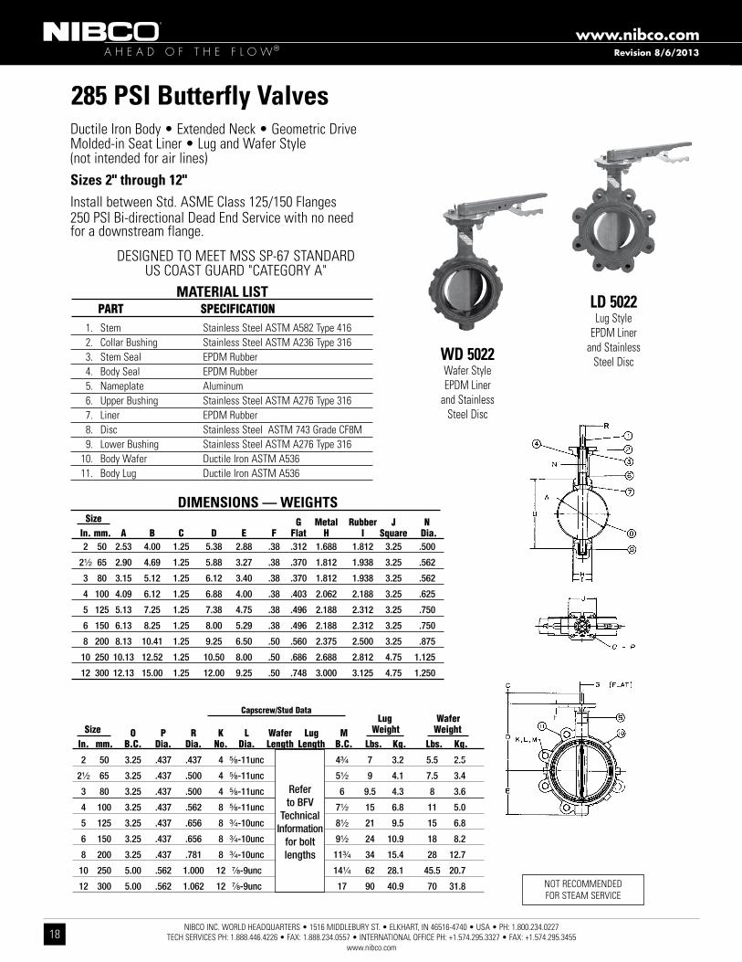
285 PSI Butterfly Valvesductile Iron Body • extended neck • Geometric driveMolded-in seat liner • lug and Wafer style (not intended for air lines)Sizes 2" through 12"Install between std . asMe Class 125/150 flanges250 PsI Bi-directional dead end service with no needfor a downstream flange .
1 . stem stainless steel astM a582 type 416 2 . Collar Bushing stainless steel astM a236 type 316 3 . stem seal ePdM rubber 4 . Body seal ePdM rubber 5 . nameplate aluminum 6 . upper Bushing stainless steel astM a276 type 316 7 . liner ePdM rubber 8 . disc stainless steel astM 743 Grade Cf8M 9 . lower Bushing stainless steel astM a276 type 316 10 . Body Wafer ductile Iron astM a536 11 . Body lug ductile Iron astM a536
MATERIAL LIST PaRT SPeCiFiCaTiON LD 5022
lug styleePdM liner
and stainlesssteel discWD 5022
Wafer styleePdM liner
and stainless steel disc
nOt reCOMMended fOr steaM serVICe
DIMENSIONS — WEIGHTS Size G Metal Rubber J N in. mm. a B C D e F Flat H i Square Dia. 2 50 2.53 4.00 1.25 5.38 2.88 .38 .312 1.688 1.812 3.25 .500
2¹⁄₂65 2.90 4.69 1.25 5.88 3.27 .38 .370 1.812 1.938 3.25 .562
3 80 3.15 5.12 1.25 6.12 3.40 .38 .370 1.812 1.938 3.25 .562
4 100 4.09 6.12 1.25 6.88 4.00 .38 .403 2.062 2.188 3.25 .625
5 125 5.13 7.25 1.25 7.38 4.75 .38 .496 2.188 2.312 3.25 .750
6 150 6.13 8.25 1.25 8.00 5.29 .38 .496 2.188 2.312 3.25 .750
8 200 8.13 10.41 1.25 9.25 6.50 .50 .560 2.375 2.500 3.25 .875
10 250 10.13 12.52 1.25 10.50 8.00 .50 .686 2.688 2.812 4.75 1.125
12 300 12.13 15.00 1.25 12.00 9.25 .50 .748 3.000 3.125 4.75 1.250
desIGned tO Meet Mss sP-67 standardus COast Guard "CateGOry a"
Lug Wafer Size O P R K L Wafer Lug M Weight Weight in. mm. B.C. Dia. Dia. No. Dia. Length Length B.C. Lbs. Kg. Lbs. Kg.
2 50 3.25 .437 .437 4 ⁵⁄₈-11unc 4³⁄₄ 7 3.2 5.5 2.5
2¹⁄₂ 65 3.25 .437 .500 4 ⁵⁄₈-11unc 5¹⁄₂ 9 4.1 7.5 3.4
3 80 3.25 .437 .500 4 ⁵⁄₈-11unc 6 9.5 4.3 8 3.6
4 100 3.25 .437 .562 8 ⁵⁄₈-11unc 7¹⁄₂ 15 6.8 11 5.0
5 125 3.25 .437 .656 8 ³⁄₄-10unc 8¹⁄₂ 21 9.5 15 6.8
6 150 3.25 .437 .656 8 ³⁄₄-10unc 9¹⁄₂ 24 10.9 18 8.2
8 200 3.25 .437 .781 8 ³⁄₄-10unc 11³⁄₄ 34 15.4 28 12.7
10 250 5.00 .562 1.000 12 ⁷⁄₈-9unc 14¹⁄₄ 62 28.1 45.5 20.7
12 300 5.00 .562 1.062 12 ⁷⁄₈-9unc 17 90 40.9 70 31.8
Capscrew/Stud Data
Refer to BFV
Technical Information
for bolt lengths
Revision 8/6/2013

A H E A D O F T H E F L O W®www.nibco.com
NIBCO INC. WORLD HEADQUARTERS • 1516 MIDDLEBURY ST. • ELKHART, IN 46516-4740 • USA • PH: 1.800.234.0227 TECH SERVICES PH: 1.888.446.4226 • FAX: 1.888.234.0557 • INTERNATIONAL OFFICE PH: +1.574.295.3327 • FAX: +1.574.295.3455
www.nibco.com19
Revision 8/6/2013
Large Diameter Butterfly Valves
Ductile Ironlug body
EPDM or Buna-N liner materials
• 14" thru 48" size range
• 150/200 PsI WOG
• Bubble tight shut off at full rated pressure
• Bidirectional dead end service sizes 14"- 24" 150 psi sizes 30" - 48" 100 psi
• extended neck for 2" of insulation
• aluminum bronze, 316ss, nickel plated ductile iron disc
• 416 stainless steel stem
• designed to meet Mss sP-67 standard
LD1000/2000 Series

A H E A D O F T H E F L O W®www.nibco.com
NIBCO INC. WORLD HEADQUARTERS • 1516 MIDDLEBURY ST. • ELKHART, IN 46516-4740 • USA • PH: 1.800.234.0227 TECH SERVICES PH: 1.888.446.4226 • FAX: 1.888.234.0557 • INTERNATIONAL OFFICE PH: +1.574.295.3327 • FAX: +1.574.295.3455
www.nibco.com20
Revision 8/6/2013
150 PSI Butterfly Valvesductile Iron Body • Cartridge liner • lug styleSizes 14", 16", 18", 20", and 24"Install between std . asMe Class 125/150 flanges 150 PsI bi-directional dead end service rating without a downstream flange . do nOt install between aWWa C115/a21 .5 type flanges .
1. Screw Steel, ANSI 1035 (2) 16" & 18" (4) 20" & 24" 2. Bottom Plate Ductile Iron ASTM A536 grade 65-45-12 3. O-ring Nitrile ASTM D2000 4. Body Ductile Iron ASTM a536 grade 65-45-12 5. Long Bushing Bronze ASTM B584 UNS C83600 Stainless Steel ASTM A276 UNS s31600 6. Stem Stainless Steel ASTM A582 UNS S41600 Stainless Steel ASTM A276 UNS S31600 Stainless Steel ASTM A276 UNS S43100 7. Disc Aluminum bronze ASTM B148 UNS C95400 Ductile Iron ASTM A536 grade 65-45-12 Nickel Plated Stainless Steel ASTM A351 CF8M 8. Taper Pin (2) Stainless Steel ASTM A564 UNS S17400 Stainless Steel ASTM A276 UNS S31600 9. Seat Nitrile ASTM D2000 EPDM ASTM D2000 10. Nameplate Aluminum 11. Short Bushing (2) Bronze ASTM B584 UNS C83600 Stainless Steel ASTM A276 UNS S31600 12. O-ring Nitrile ASTM D2000 13. Key Steel, ASTM A108 UNS C10450 14. Screw Steel, ANSI 1035 (6) 14" thru 18" (8) 20" & 24"
MATERIAL LIST PaRT SPeCiFiCaTiON
nOt reCOMMended fOr steaM serVICe
LD 1000/LD 1100lug style
ePdM or Buna-n liner aluminum Bronze disc
LD 1010/LD 1110lug style
ePdM or Buna-n liner .ductile Iron disc
LD 1022/LD 1122lug style
ePdM or Buna-n liner stainless steel disc
14" reference
desIGned tO Meet Mss sP-67 standard• CertIfIed lead -free* By IaPMO r&t tO nsf/ansI 372
*lead free refers to the wetted surface of pipe, fittings and fixtures in potable water systems that have a weighted average lead content ≤ 0 .25% per the safe drinking Water act (sec . 1417) amended 1-4-2011 and other equivalent state regulations .
DIMENSIONS — WEIGHTSSize a Minimum.
Pipe i.D.
B C
D e F
G H i
in. mm Dia. Dia. Dia. Body Seat Dia.
14” 350 13.12 13.02 14.77 17.20 14.49 1.77 26.77 3.00 3.13 1.244
16” 400 15.34 15.20 17.30 19.21 15.75 2.02 29.93 3.37 3.54 1.305
18” 450 17.34 17.09 19.31 21.22 16.61 2.02 31.54 4.12 4.29 1.494
20” 500 19.36 18.90 21.08 23.31 18.90 2.53 35.64 5.13 5.31 1.619
24” 600 23.33 23.05 25.71 32.09 22.13 2.76 42.96 5.96 6.14 1.993
DIMENSIONS — WEIGHTSSize J K L M P Q R T WeiGHT
in. mm Dia. Dia. Dia. Drive Key Dia. Dia. in. Lbs. Kg
14” 350 5.51 4.25 0.55 .250 x 1.125 WOODRUFF #809 12 1”-8 UNC 18.75 17.52 141 64
16” 400 7.76 6.25 0.83 .312 X.312 X 1.811 LONG 16 1”-8 UNC 21.25 20.08 199 90
18” 450 7.76 6.25 0.83 .375 X .375 X 1.881 LONG 16 1-1/8”-7 UNC 22.75 21.26 261 119
20” 500 7.76 6.25 0.83 .375 x .375 x 1.811 LONG 20 1-1/8”-7 UNC 25.00 24.02 395 179
24” 600 10.87 8.50 0.94 .500 x .500 x 2.362 LONG 20 1-1/4”-7 UNC 29.50 27.87 591 268
A H E A D O F T H E F L O W®www.nibco.com
NIBCO INC. WORLD HEADQUARTERS • 1516 MIDDLEBURY ST. • ELKHART, IN 46516-4740 • USA • PH: 1.800.234.0227 TECH SERVICES PH: 1.888.446.4226 • FAX: 1.888.234.0557 • INTERNATIONAL OFFICE PH: +1.574.295.3327 • FAX: +1.574.295.3455
www.nibco.com21
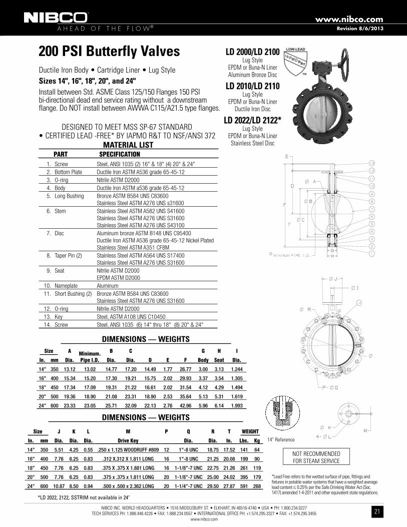
200 PSI Butterfly Valvesductile Iron Body • Cartridge liner • lug styleSizes 14", 16", 18", 20", and 24"Install between std . asMe Class 125/150 flanges 150 PsI bi-directional dead end service rating without a downstream flange . do nOt install between aWWa C115/a21 .5 type flanges .
nOt reCOMMended fOr steaM serVICe
LD 2000/LD 2100lug style
ePdM or Buna-n liner aluminum Bronze disc
LD 2010/LD 2110lug style
ePdM or Buna-n liner ductile Iron disc
LD 2022/LD 2122*lug style
ePdM or Buna-n liner stainless steel disc
14" reference
Revision 8/6/2013
*LD 2022, 2122, SSTRIM not available in 24"
desIGned tO Meet Mss sP-67 standard• CertIfIed lead -free* By IaPMO r&t tO nsf/ansI 372
*lead free refers to the wetted surface of pipe, fittings and fixtures in potable water systems that have a weighted average lead content ≤ 0 .25% per the safe drinking Water act (sec . 1417) amended 1-4-2011 and other equivalent state regulations .
1. Screw Steel, ANSI 1035 (2) 16" & 18" (4) 20" & 24" 2. Bottom Plate Ductile Iron ASTM A536 grade 65-45-12 3. O-ring Nitrile ASTM D2000 4. Body Ductile Iron ASTM a536 grade 65-45-12 5. Long Bushing Bronze ASTM B584 UNS C83600 Stainless Steel ASTM A276 UNS s31600 6. Stem Stainless Steel ASTM A582 UNS S41600 Stainless Steel ASTM A276 UNS S31600 Stainless Steel ASTM A276 UNS S43100 7. Disc Aluminum bronze ASTM B148 UNS C95400 Ductile Iron ASTM A536 grade 65-45-12 Nickel Plated Stainless Steel ASTM A351 CF8M 8. Taper Pin (2) Stainless Steel ASTM A564 UNS S17400 Stainless Steel ASTM A276 UNS S31600 9. Seat Nitrile ASTM D2000 EPDM ASTM D2000 10. Nameplate Aluminum 11. Short Bushing (2) Bronze ASTM B584 UNS C83600 Stainless Steel ASTM A276 UNS S31600 12. O-ring Nitrile ASTM D2000 13. Key Steel, ASTM A108 UNS C10450 14. Screw Steel, ANSI 1035 (6) 14" thru 18" (8) 20" & 24"
MATERIAL LIST PaRT SPeCiFiCaTiON
DIMENSIONS — WEIGHTSSize a Minimum.
Pipe i.D.
B C
D e F
G H i
in. mm Dia. Dia. Dia. Body Seat Dia.
14” 350 13.12 13.02 14.77 17.20 14.49 1.77 26.77 3.00 3.13 1.244
16” 400 15.34 15.20 17.30 19.21 15.75 2.02 29.93 3.37 3.54 1.305
18” 450 17.34 17.09 19.31 21.22 16.61 2.02 31.54 4.12 4.29 1.494
20” 500 19.36 18.90 21.08 23.31 18.90 2.53 35.64 5.13 5.31 1.619
24” 600 23.33 23.05 25.71 32.09 22.13 2.76 42.96 5.96 6.14 1.993
DIMENSIONS — WEIGHTS
Size J K L M P Q R T WeiGHT
in. mm Dia. Dia. Dia. Drive Key Dia. Dia. in. Lbs. Kg
14” 350 5.51 4.25 0.55 .250 x 1.125 WOODRUFF #809 12 1”-8 UNC 18.75 17.52 141 64
16” 400 7.76 6.25 0.83 .312 X.312 X 1.811 LONG 16 1”-8 UNC 21.25 20.08 199 90
18” 450 7.76 6.25 0.83 .375 X .375 X 1.881 LONG 16 1-1/8”-7 UNC 22.75 21.26 261 119
20” 500 7.76 6.25 0.83 .375 x .375 x 1.811 LONG 20 1-1/8”-7 UNC 25.00 24.02 395 179
24” 600 10.87 8.50 0.94 .500 x .500 x 2.362 LONG 20 1-1/4”-7 UNC 29.50 27.87 591 268

A H E A D O F T H E F L O W®www.nibco.com
NIBCO INC. WORLD HEADQUARTERS • 1516 MIDDLEBURY ST. • ELKHART, IN 46516-4740 • USA • PH: 1.800.234.0227 TECH SERVICES PH: 1.888.446.4226 • FAX: 1.888.234.0557 • INTERNATIONAL OFFICE PH: +1.574.295.3327 • FAX: +1.574.295.3455
www.nibco.com22
Revision 8/6/2013
150 PSI Butterfly Valvesductile Iron Body • Cartridge liner • double flangedSizes 30", 36", 42" and 48"Install between std . asMe Class 125/150 flanges 150 PsI bi-directional dead end service rating without a downstream flange . do nOt install between aWWa C115/a21 .5 type flanges .
1. Body Ductile Iron ASTM A536 2. Bushing Bronze ASTM B584 Grade C83600 3. Lower Stem Stainless Steel ASTM A582 Type 416 Stainless Steel ASTM A276 Type 316SS 3a. Upper Stem Stainless Steel ASTM A582 Type 416 Stainless Steel ASTM A276 Type 316SS 4. Seat Back Ring Phenolic Resin, Aluminum B26 30" - 36" eight set screws in backing 42" - 48" ten set screws in backing 5. Seat Rubber - BUNA (NBR) Rubber - EPDM 6. Disc Aluminum Bronze ASTM B148 C95400 Ductile Iron ASTM A536 65-45-12 (Nickel Plated) Stainless Steel ASTM A351 Grade CF8M 7. Taper Pin (3) Stainless Steel ASTM A582 Type 416 or ASTM A564 8. Rivet Steel 9. Nameplate Aluminum 10. Bushing Bronze ASTM B584 C83600 11. Flat Key Steel ASTM A108 1045 12. Bushing Bronze ASTM B584 C83600 13. Socket Bolt Steel ASTM A307 14. O-Ring Rubber BUNA (NBR) 15. Bottom Plate Steel ASTM A108 1035 16. Thrust Bearing Bearing Steel 17. Washer Steel
MATERIAL LIST PaRT SPeCiFiCaTiON
desIGned tO Meet Mss sP-67 standard
LD 1000/LD 1100lug style
ePdM or Buna-n liner aluminum Bronze disc
LD 1010lug style
ePdM liner ductile Iron disc
LD 1022lug style
ePdM liner stainless steel disc
nOt reCOMMended fOr steaM serVICe
Size D8In. mm. D1 D2 D4 D5 D7 Dia. D9 D10 D11 C30 750 29.30 36.00 10.00 0.71 38.74 2.50 11.81 28.56 11/4-7UNC 6.57
36 900 34.04 42.75 10.00 0.71 46.00 2.95 11.81 33.09 11/2-6UNC 8.00
42 1050 40.55 49.50 11.73 0.87 53.00 3.74 13.78 39.33 11/2-6UNC 9.88
48 1200 45.67 56.00 11.73 0.87 59.50 4.13 13.78 44.35 11/2-6UNC 10.88
Size K WeightIn. mm. L A B E F J N1 N2 T Key Size Lbs. Kg.30 750 6.81 50.63 26.00 2.60 0.709 2.809 8 28 2.12 .709 x .433 x 2.50 926 420
36 900 8.31 58.82 28.35 4.65 0.787 3.307 8 32 2.38 .787 x .472 x 4.00 1482 660
42 1050 10.28 70.28 33.78 5.91 0.984 4.134 8 36 2.62 .984 x .551 x 4.50 1971 896
48 1200 11.26 76.96 37.04 5.91 1.102 4.606 8 44 2.75 1.104 x .630 x 4.50 2816 1280
A H E A D O F T H E F L O W®www.nibco.com
NIBCO INC. WORLD HEADQUARTERS • 1516 MIDDLEBURY ST. • ELKHART, IN 46516-4740 • USA • PH: 1.800.234.0227 TECH SERVICES PH: 1.888.446.4226 • FAX: 1.888.234.0557 • INTERNATIONAL OFFICE PH: +1.574.295.3327 • FAX: +1.574.295.3455
www.nibco.com23
N200 Series
Revision 8/22/2012
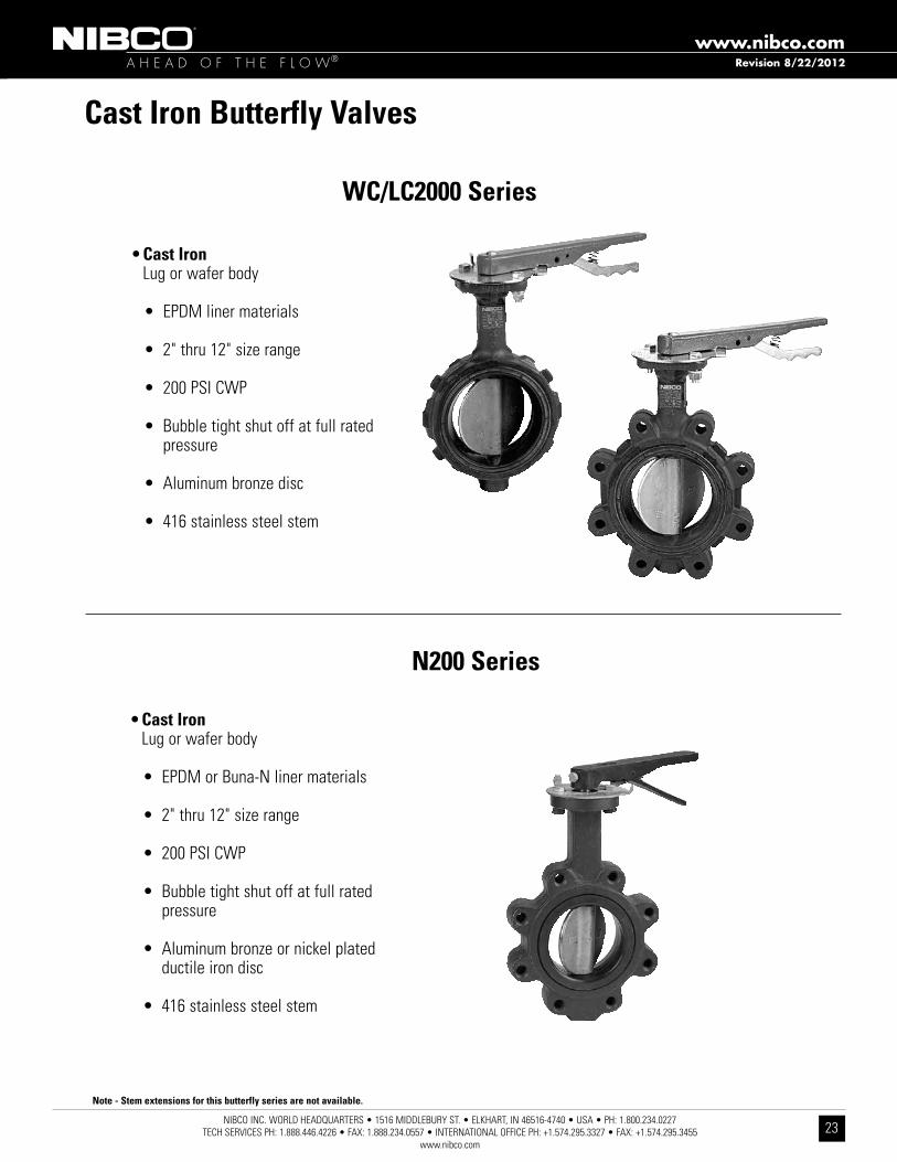
Cast Iron Butterfly Valves
• Cast Iron lug or wafer body
• ePdM or Buna-n liner materials
• 2" thru 12" size range
• 200 PsI CWP
• Bubble tight shut off at full rated pressure
• aluminum bronze or nickel plated ductile iron disc
• 416 stainless steel stem
WC/LC2000 Series
Note - Stem extensions for this butterfly series are not available.
• Cast Iron lug or wafer body
• ePdM liner materials
• 2" thru 12" size range
• 200 PsI CWP
• Bubble tight shut off at full rated pressure
• aluminum bronze disc
• 416 stainless steel stem

A H E A D O F T H E F L O W®www.nibco.com
NIBCO INC. WORLD HEADQUARTERS • 1516 MIDDLEBURY ST. • ELKHART, IN 46516-4740 • USA • PH: 1.800.234.0227 TECH SERVICES PH: 1.888.446.4226 • FAX: 1.888.234.0557 • INTERNATIONAL OFFICE PH: +1.574.295.3327 • FAX: +1.574.295.3455
www.nibco.com24
200 PSI Butterfly ValvesCast Iron Body • extended neck • Geometric driveMolded-in seat liner • lug and Wafer style Sizes 2" through 12"Install between std . asMe Class 125/150 flanges†lug style 200 PsI bi-directional dead end service rating without a downstream flange required .
1. Stem Stainless Steel ASTM A582 Type 416 2. Collar Bushing Brass ASTM B16 3. Stem Seal EPDM Rubber 4. Body Seal EPDM Rubber 5. Nameplate Aluminum 6. Upper Bushing Copper CDA 122 7. Liner EPDM Rubber 8. Disc Alum. Brz. ASTM B148 Alloy 955 9. Lower Bushing Copper CDA 122 10. Body Wafer Cast Iron A126 Class B 11. Body Lug Cast Iron A126 Class B
MATERIAL LIST PaRT SPeCiFiCaTiON
LC 2000lug style
ePdM liner and aluminum
Bronze discWC 2000Wafer styleePdM liner
and aluminum Bronze disc
nOt reCOMMended fOr steaM serVICe
DIMENSIONS — WEIGHTS Size G Metal Rubber J N in. mm. a B C D e F Flat H i Square Dia. 2 50 2.53 4.00 1.25 5.38 2.88 .38 .312 1.688 1.812 3.25 .500
2¹⁄₂65 2.90 4.69 1.25 5.88 3.27 .38 .370 1.812 1.938 3.25 .562
3 80 3.15 5.12 1.25 6.12 3.40 .38 .370 1.812 1.938 3.25 .562
4 100 4.09 6.12 1.25 6.88 4.00 .38 .403 2.062 2.188 3.25 .625
5 125 5.13 7.25 1.25 7.38 4.75 .38 .496 2.188 2.312 3.25 .750
6 150 6.13 8.25 1.25 8.00 5.29 .38 .496 2.188 2.312 3.25 .750
8 200 8.13 10.41 1.25 9.25 6.50 .50 .560 2.375 2.500 3.25 .875
10 250 10.13 12.52 1.25 10.50 8.00 .50 .686 2.688 2.812 4.75 1.125
12 300 12.13 15.00 1.25 12.00 9.25 .50 .748 3.000 3.125 4.75 1.250
desIGned tO Meet Mss sP-67 standardus COast Guard "CateGOry a"
Lug Wafer Size O P R K L Wafer Lug M Weight Weight in. mm. B.C. Dia. Dia. No. Dia. Length Length B.C. Lbs. Kg. Lbs. Kg.
2 50 3.25 .437 .437 4 ⁵⁄₈-11unc 4³⁄₄ 7 3.2 5.5 2.5
2¹⁄₂ 65 3.25 .437 .500 4 ⁵⁄₈-11unc 5¹⁄₂ 9 4.1 7.5 3.4
3 80 3.25 .437 .500 4 ⁵⁄₈-11unc 6 9.5 4.3 8 3.6
4 100 3.25 .437 .562 8 ⁵⁄₈-11unc 7¹⁄₂ 15 6.8 11 5.0
5 125 3.25 .437 .656 8 ³⁄₄-10unc 8¹⁄₂ 21 9.5 15 6.8
6 150 3.25 .437 .656 8 ³⁄₄-10unc 9¹⁄₂ 24 10.9 18 8.2
8 200 3.25 .437 .781 8 ³⁄₄-10unc 11³⁄₄ 34 15.4 28 12.7
10 250 5.00 .562 1.000 12 ⁷⁄₈-9unc 14¹⁄₄ 62 28.1 45.5 20.7
12 300 5.00 .562 1.062 12 ⁷⁄₈-9unc 17 90 40.9 70 31.8
Capscrew/Stud Data
Refer to butterfly
valvetechnical
informationfor bolt lengths
Revision 8/6/2013
†NOTE: LUG STYLE VALVES - Extra care should be used when installing with raised face flanges. Over-tightening can result in broken lugs.

A H E A D O F T H E F L O W®www.nibco.com
NIBCO INC. WORLD HEADQUARTERS • 1516 MIDDLEBURY ST. • ELKHART, IN 46516-4740 • USA • PH: 1.800.234.0227 TECH SERVICES PH: 1.888.446.4226 • FAX: 1.888.234.0557 • INTERNATIONAL OFFICE PH: +1.574.295.3327 • FAX: +1.574.295.3455
www.nibco.com25
Revision 8/6/2013
200 PSI Butterfly Valves Cast Iron Body • extended neck Cartridge seat liner • lug styleSizes 2" through 12"Install between std . asMe Class 125/150 flanges† Bi-directional dead end service rating without a downstream flange required: 2"-6" 200 PsI, 8" 150 PsI, 10"-12" 100 PsI
1. Body Cast Iron, Epoxy coated ASTM A126 CL.B 2. Body Bushing Bronze ASTM B584 Grade C83600 3. Liner EPDM Rubber w/Phenolic Backing Buna-N Rubber Nitrile w/Phenolic Backing 4. Stem Stainless Steel ASTM A582 Type 416 5. Disc Alum. Brz. ASTM B148 Alloy C95400 Ductile Iron ASTM A536 Grade 65-45-12 (plated) 6. Taper Pin Stainless Steel ASTM A582 Type 416 (2 pin 6" - 12") 7. Name Plate Aluminum 8. Shaft Bushing Bronze ASTM B584 Grade C83600 9. Stem Seal Buna-N Rubber Nitrile
MATERIAL LIST PaRT SPeCiFiCaTiON
N200235lug style
ePdM liner aluminum Bronze disc
N200236lug style
ePdM liner ductile Iron disc
N200245lug style
Buna liner aluminum Bronze disc
N200246lug style
Buna liner ductile Iron disc
K Lug Size J B.C. L M R Q T Weight in. mm. Dia. Dia. Dia. Dia. Dia P Dia. Flats Lbs. Kg.
2 50 3.00 1.97 0.28 0.75 4.75 4 ⁵⁄₈-11UNC .350 8.6 3.9
2¹⁄₂ 65 3.03 1.97 0.28 0.75 5.50 4 ⁵⁄₈-11UNC .350 10.8 4.9
3 80 3.03 1.97 0.28 0.75 6.00 4 ⁵⁄₈-11UNC .350 11.4 5.2
4 100 3.62 2.76 0.39 0.75 7.50 8 ⁵⁄₈-11UNC .437 18.9 8.6
5 125 3.62 2.76 0.39 0.88 8.50 8 ³⁄₄-10UNC .500 22.8 10.4
6 150 3.62 2.76 0.39 0.88 9.50 8 ³⁄₄-10UNC .500 27.1 12.3
8 200 4.50 4.02 0.47 0.88 11.75 8 ³⁄₄-10UNC .625 41.2 18.7
10 250 4.50 4.02 0.47 1.00 14.25 12 ⁷⁄₈-9UNC .812 56.3 25.9
12 300 5.50 4.02 0.47 1.00 17.00 12 ⁷⁄₈-9UNC .875 90.3 41.0
DIMENSIONS — WEIGHTS Size a Min. B C G H i in. mm. Dia. Pipe i.D. Dia. Dia. D e F Body Seat Dia.
2 50 2.08 1.38 3.00 3.94 6.34 1.26 10.75 1.655 1.81 0.496
2¹⁄₂65 2.54 1.95 3.50 4.72 6.89 1.26 11.65 1.759 1.93 0.496
3 80 3.10 2.66 4.09 5.00 7.13 1.26 12.12 1.780 1.93 0.496
4 100 4.10 3.67 5.32 6.14 7.87 1.26 13.62 2.050 2.18 0.621
5 125 4.85 4.48 6.26 7.48 8.39 1.26 14.65 2.140 2.31 0.745
6 150 6.12 5.84 7.42 8.35 8.90 1.26 15.62 2.195 2.33 0.745
8 200 7.97 7.85 9.38 10.55 10.24 1.77 18.88 2.385 2.52 0.870
10 250 9.86 9.76 11.51 12.79 11.50 1.77 21.26 2.584 2.83 1.120
12 300 11.87 11.72 13.55 15.87 13.27 1.77 24.57 3.029 3.19 1.244
desIGned tO Meet Mss sP-67 standard
nOt reCOMMended fOr steaM serVICe
†NOTE: LUG STYLE VALVES - Extra care should be used when installing with raised face flanges. Over-tightening can result in broken lugs.

A H E A D O F T H E F L O W®www.nibco.com
NIBCO INC. WORLD HEADQUARTERS • 1516 MIDDLEBURY ST. • ELKHART, IN 46516-4740 • USA • PH: 1.800.234.0227 TECH SERVICES PH: 1.888.446.4226 • FAX: 1.888.234.0557 • INTERNATIONAL OFFICE PH: +1.574.295.3327 • FAX: +1.574.295.3455
www.nibco.com26
Revision 8/6/2013
200 PSI Butterfly Valves Cast Iron Body • extended neck Cartridge seat liner • Wafer styleSizes 2" through 12"Install between std . asMe Class 125/150 flanges
1. Body Cast Iron, Epoxy coated ASTM A126 CL.B 2. Body Bushing Bronze ASTM B584 Grade C83600 3. Liner EPDM Rubber w/Phenolic Backing Buna-N Rubber Nitrile w/Phenolic Backing 4. Stem Stainless Steel ASTM A582 Type 416 5. Disc Alum. Brz. ASTM B148 Alloy C95400 Ductile Iron ASTM A536 Grade 65-45-12 (plated) 6. Taper Pin Stainless Steel ASTM A582 Type 416 (2 pin 6" - 12") 7. Name Plate Aluminum 8. Shaft Bushing Bronze ASTM B584 Grade C83600 9. Stem Seal Buna-N Rubber Nitrile
MATERIAL LIST PaRT SPeCiFiCaTiON
N200135Wafer styleePdM liner
aluminum Bronze disc
N200136Wafer styleePdM liner
ductile Iron disc
N200145Wafer styleBuna liner
aluminum Bronze disc
N200146Wafer styleBuna liner
ductile Iron disc
DIMENSIONS — WEIGHTS Size a Min. B C G H i in. mm. Dia. Pipe i.D. Dia. Dia. D e F Body Seat Dia.
2 50 2.08 1.38 3.00 3.94 6.34 1.26 10.75 1.655 1.81 0.496
2¹⁄₂ 65 2.54 1.95 3.50 4.72 6.89 1.26 11.65 1.759 1.93 0.496
3 80 3.10 2.66 4.09 5.00 7.13 1.26 12.12 1.780 1.93 0.496
4 100 4.10 3.67 5.32 6.14 7.87 1.26 13.62 2.050 2.18 0.621
5 125 4.85 4.48 6.26 7.48 8.39 1.26 14.65 2.140 2.31 0.745
6 150 6.12 5.84 7.42 8.35 8.90 1.26 15.62 2.195 2.33 0.745
8 200 7.97 7.85 9.38 10.55 10.24 1.77 18.90 2.385 2.52 0.870
10 250 9.86 9.76 11.51 12.79 11.50 1.77 21.26 2.584 2.83 1.120
12 300 11.87 11.72 13.55 15.87 13.27 1.77 24.57 3.029 3.19 1.244
desIGned tO Meet Mss sP-67 standard
nOt reCOMMended fOr steaM serVICe
Lug Size J B.C. L M R Q T Weight in. mm. Dia. Dia. Dia. Dia. Dia P Dia. Flats Lbs. Kg.
2 50 3.00 2.25 0.28 0.75 4.75 4 ⁵⁄₈-11UNC .350 5.7 2.6
2¹⁄₂ 65 3.03 2.25 0.28 0.75 5.50 4 ⁵⁄₈-11UNC .350 7.5 3.9
3 80 3.03 2.25 0.28 0.75 6.00 4 ⁵⁄₈-11UNC .350 8.4 3.8
4 100 3.62 2.75 0.39 0.75 7.50 8 ⁵⁄₈-11UNC .437 12.3 5.6
5 125 3.62 2.75 0.39 0.88 8.50 8 ³⁄₄-10UNC .500 17.2 7.8
6 150 3.62 2.75 0.39 0.88 9.50 8 ³⁄₄-10UNC .500 19.6 8.9
8 200 4.50 3.50 0.47 0.88 11.75 8 ³⁄₄-10UNC .625 29.7 13.5
10 250 4.50 3.50 0.47 1.00 14.25 12 ⁷⁄₈-9UNC .812 44.0 20.0
12 300 5.50 4.25 0.47 1.00 17.00 12 ⁷⁄₈-9UNC .875 65.8 29.9
A H E A D O F T H E F L O W®www.nibco.com
NIBCO INC. WORLD HEADQUARTERS • 1516 MIDDLEBURY ST. • ELKHART, IN 46516-4740 • USA • PH: 1.800.234.0227 TECH SERVICES PH: 1.888.446.4226 • FAX: 1.888.234.0557 • INTERNATIONAL OFFICE PH: +1.574.295.3327 • FAX: +1.574.295.3455
www.nibco.com27
Revision 8/6/2013
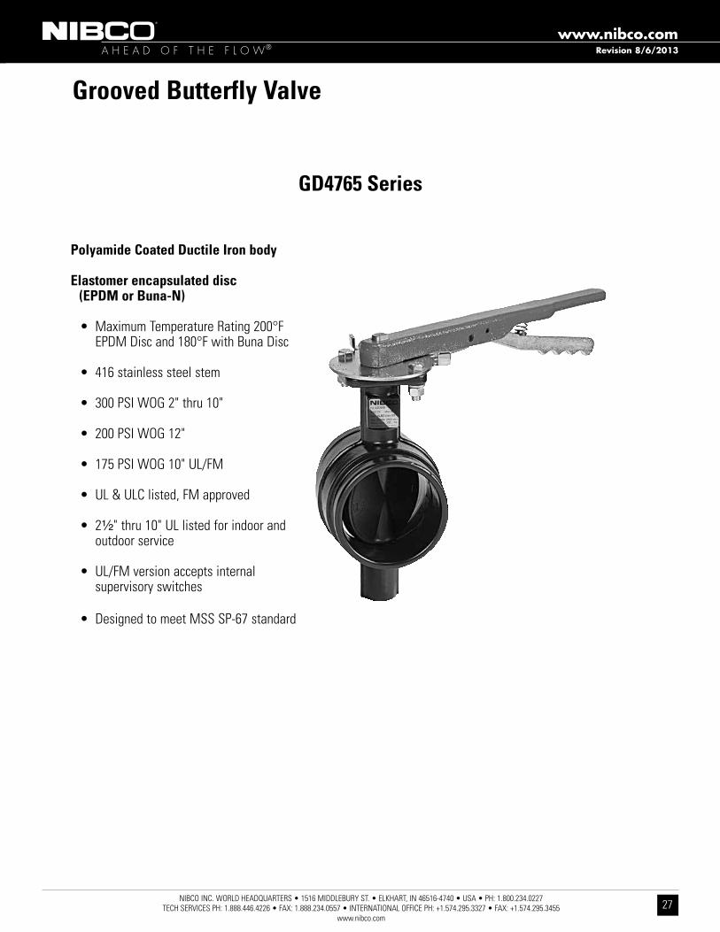
Grooved Butterfly Valve
Polyamide Coated Ductile Iron body
Elastomer encapsulated disc (EPDM or Buna-N)
• Maximum temperature rating 200°f ePdM disc and 180°f with Buna disc
• 416 stainless steel stem
• 300 PsI WOG 2" thru 10"
• 200 PsI WOG 12"
• 175 PsI WOG 10" ul/fM
• ul & ulC listed, fM approved
• 2¹⁄₂" thru 10" ul listed for indoor and outdoor service
• ul/fM version accepts internal supervisory switches
• designed to meet Mss sP-67 standard
GD4765 Series

A H E A D O F T H E F L O W®www.nibco.com
NIBCO INC. WORLD HEADQUARTERS • 1516 MIDDLEBURY ST. • ELKHART, IN 46516-4740 • USA • PH: 1.800.234.0227 TECH SERVICES PH: 1.888.446.4226 • FAX: 1.888.234.0557 • INTERNATIONAL OFFICE PH: +1.574.295.3327 • FAX: +1.574.295.3455
www.nibco.com28
Revision 8/6/2013
GD 4765w/ePdM liner
GD 4775w/Buna-n liner
300 PSI Grooved End Butterfly ValvesPolyamide Coated ductile Iron Body • extended neck • elastomer encapsulated disc • Grooved Mechanical style • 12" Maximum Pressure rating 200 PsI • Maximum temperature rating of 200°f ePdM disc and 180°f Buna disc • Grooved end Compatible with IPs Pipe
Sizes 2" through 12"
DIMENSIONS — WEIGHTS Size in. mm. a B C D e F G J 2 50 2.38 2.32 .33 .63 3.33 2.42 .46 1.31 2¹⁄₂ 65 2.88 2.72 .31 .63 3.85 2.42 .46 1.22 3 80 3.50 3.34 .31 .63 3.85 2.86 .46 1.18 3 O.D. 76.1 3.00 2.84 .31 .63 3.85 2.42 .46 1.22 4 100 4.50 4.33 .38 .63 4.56 3.84 .46 1.24 5 125 5.56 5.39 .38 .63 5.86 4.79 .46 1.24 6 150 6.63 6.45 .38 .63 5.86 5.73 .46 1.29 6¹⁄₂ O.D. 165.1 6.51 6.32 .38 .63 5.86 5.73 .46 1.29 8 200 8.63 8.44 .44 .75 5.26 7.71 .46 1.32 10 250 10.75 10.56 .50 .75 6.29 9.56 .70 1.38 12 300 12.76 12.51 .50 .75 6.52 11.55 .70 1.38
1. Upper Stem Stainless Steel ASTM A582 Type 416 2. Upper Bearing Split Metal 3. O-Ring EPDM or Buna-N 4. Body Ductile Iron ASTM A395 w/Polyamide Coating 5. Disc Ductile Iron ASTM A395 w/EPDM or Buna-N Encapsulation 6. Lower Bearing Split Metal 7. Lower Stem Stainless Steel ASTM A582 Type 416 8. Dust Plug PVC 9. Name Plate Aluminum
Polyamide coating has NSF certification
MATERIAL LIST PaRT SPeCiFiCaTiON
Size Weight in. mm. K L M N P Q R Lbs. Kg. 2 50 3.25 .50 .37 4.00 3.14 .437 2.89 6.7 3.0 2¹⁄₂ 65 3.25 .50 .37 4.19 3.25 .437 3.46 7.5 3.4 3 80 3.25 .50 .37 4.44 3.54 .437 3.97 8.7 3.9 3 O.D. 76.1 3.25 .50 .37 4.19 3.25 .437 3.46 8.7 3.9 4 100 3.25 .66 .50 5.33 4.35 .437 5.03 12.2 5.5 5 125 3.25 .66 .50 5.83 4.84 .437 6.27 17.3 7.8 6 150 3.25 .78 .56 7.11 5.93 .437 7.25 27.4 12.4 6¹⁄₂ O.D. 165.1 3.25 .78 .56 7.11 5.93 .437 7.25 27.4 12.4 8 200 3.25 .78 .56 8.05 6.87 .437 9.25 32.5 14.7 10 250 5.00 1.06 .75 9.86 9.17 .562 11.25 69.6 31.6 12 300 5.00 1.06 .75 10.85 10.17 .562 13.14 88.0 39.9
desIGned tO Meet Mss sP-67 standard
nOt reCOMMended fOr steaM serVICe
Flat

A H E A D O F T H E F L O W®www.nibco.com
NIBCO INC. WORLD HEADQUARTERS • 1516 MIDDLEBURY ST. • ELKHART, IN 46516-4740 • USA • PH: 1.800.234.0227 TECH SERVICES PH: 1.888.446.4226 • FAX: 1.888.234.0557 • INTERNATIONAL OFFICE PH: +1.574.295.3327 • FAX: +1.574.295.3455
www.nibco.com29
GD 4765Nw/ePdM liner
300 PSI Grooved End Butterfly ValvesPolyamide Coated ductile Iron Body • extended neck • elastomer encapsulated disc • Grooved Mechanical style • 12" Maximum Pressure rating 200 PsI • Maximum temperature rating of 200°f ePdM disc and 180°f Buna disc • Grooved end Compatible with IPs Pipe Sizes 2" through 12"
DIMENSIONS — WEIGHTS Size In. mm. A B C D E F G J 2 50 2 .38 2 .32 .33 .63 3 .33 2 .42 .46 1 .31 21/2 65 2 .88 2 .72 .31 .63 3 .85 2 .42 .46 1 .22 3 80 3 .50 3 .34 .31 .63 3 .85 2 .86 .46 1 .18 3 O .d . 76 .1 3 .00 2 .84 .31 .63 3 .85 2 .42 .46 1 .22 4 100 4 .50 4 .33 .38 .63 4 .56 3 .84 .46 1 .24 5 125 5 .56 5 .39 .38 .63 5 .86 4 .79 .46 1 .24 6 150 6 .63 6 .45 .38 .63 5 .86 5 .73 .46 1 .29 61/2 O .d . 165 .1 6 .51 6 .32 .38 .63 5 .86 5 .73 .46 1 .29 8 200 8 .63 8 .44 .44 .75 5 .26 7 .71 .46 1 .32 10 250 10 .75 10 .56 .50 .75 6 .29 9 .56 .70 1 .38 12 300 12 .76 12 .51 .50 .75 6 .52 11 .55 .70 1 .38
1. Upper Stem Stainless Steel ASTM A582 Type 416 2. Upper Bearing Split Metal 3. O-Ring EPDM or Buna-N 4. Body Ductile Iron ASTM A395 w/Polyamide Coating 5. Disc Ductile Iron ASTM A395 w/EPDM 6. Lower Bearing Split Metal 7. Lower Stem Stainless Steel ASTM A582 Type 416 8. Dust Plug PVC 9. Name Plate Aluminum
MATERIAL LIST PaRT SPeCiFiCaTiON
Size Weight In. mm. K L M N P Q R Lbs. Kg. 2 50 3 .25 .50 .37 4 .00 3 .14 .437 2 .89 6 .7 3 .0 21/2 65 3 .25 .50 .37 4 .19 3 .25 .437 3 .46 7 .5 3 .4 3 80 3 .25 .50 .37 4 .44 3 .54 .437 3 .97 8 .7 3 .9 3 O .d . 76 .1 3 .25 .50 .37 4 .19 3 .25 .437 3 .46 8 .7 3 .9 4 100 3 .25 .66 .50 5 .33 4 .35 .437 5 .03 12 .2 5 .5 5 125 3 .25 .66 .50 5 .83 4 .84 .437 6 .27 17 .3 7 .8 6 150 3 .25 .78 .56 7 .11 5 .93 .437 7 .25 27 .4 12 .461/2 O .d . 165 .1 3 .25 .78 .56 7 .11 5 .93 .437 7 .25 27 .4 12 .4 8 200 3 .25 .78 .56 8 .05 6 .87 .437 9 .25 32 .5 14 .7 10 250 5 .00 1 .06 .75 9 .86 9 .17 .562 11 .25 69 .6 31 .6 12 300 5 .00 1 .06 .75 10 .85 10 .17 .562 13 .14 88 .0 39 .9
desIGned tO Meet Mss sP-67 standard• CertIfIed lead -free* By IaPMO r&t tO nsf/ansI 372
nOt reCOMMended fOr steaM serVICe
Flat
Revision 8/7/2013
*lead free refers to the wetted surface of pipe, fittings and fixtures in potable water systems that have a weighted average lead content ≤ 0 .25% per the safe drinking Water act (sec . 1417) amended 1-4-2011 and other equivalent state regulations .

A H E A D O F T H E F L O W®www.nibco.com
NIBCO INC. WORLD HEADQUARTERS • 1516 MIDDLEBURY ST. • ELKHART, IN 46516-4740 • USA • PH: 1.800.234.0227 TECH SERVICES PH: 1.888.446.4226 • FAX: 1.888.234.0557 • INTERNATIONAL OFFICE PH: +1.574.295.3327 • FAX: +1.574.295.3455
www.nibco.com30
A H E A D O F T H E F L O W®www.nibco.com
nIBCO InC . WOrld HeadQuarters • 1516 MIddleBury st . • elkHart, In 46516-4740 • usa • PH: 1 .800 .234 .0227 teCH serVICes PH: 1 .888 .446 .4226 • fax: 1 .888 .234 .0557 • InternatIOnal OffICe PH: +1 .574 .295 .3327 • fax: +1 .574 .295 .3455
www .nibco .com
Revision 9/7/2012
MATERIAL LIST PART SPECIFICATION
1. Upper Stem Stainless Steel ASTM A582 Type 416 2. Upper Bushing PTFE Bronze Sintered on Steel 3. "O" Ring EPDM 4. Body Ductile Iron ASTM A395 with Polyamide Coating 5. Disc Ductile Iron ASTM A395 with EPDM Encapsulation 6. Lower Bushing PTFE Bronze Sintered on Steel 7. Lower Stem Stainless Steel ASTM A582 Type 416 8. Dust Plug PVC 9. Nameplate Aluminum 10. Gear Operator Cast Iron and Steel 11. Indicator Flag Cast Iron 12. Handwheel Cast Iron*-8N version has two factory mounted internal supervisory switches. -4N version is gear operated onlyUses NIBCO model #TS-4 Switch Kit. Polyamide coating has NSF certification.
ul/ulC lIsted • fM aPPrOVed • 2¹⁄₂" - 10" ul lIsted fOr IndOOr and OutdOOr serVICe • CalIfOrnIa state fIre MarsHall lIstInG nO . 7770-1243:101 • aPPrOVed By tHe neW yOrk CIty Mea 9-97-e, VOl .2 WHen asseMBled WItH aPPrOPrIate nyC IndICatOr flaG
fire Protection Valve • Grooved Mechanical style • nylon Coated ductile Iron Body • extended neck • elastomer encapsulated disc • Internal supervisory switches standard on -8 Version • Compatible with IPs Pipe
DIMENSIONS—WEIGHTS—QUANTITIES Dimensions Size A B C D E F G H In . mm . In . mm . In . mm . In . mm . In . mm . In . mm . In . mm . In . mm . In . mm . 2¹⁄₂ 65 2 .88 73 2 .72 69 0 .31 8 0 .63 16 3 .85 98 2 .42 61 11 .94 303 2 .91 74 3 O .d . 76 .1 3 .00 76 2 .84 72 0 .31 8 0 .63 16 3 .85 98 2 .42 61 11 .94 303 2 .91 74 3 80 3 .50 89 3 .34 85 0 .31 8 0 .63 16 3 .85 98 2 .86 73 12 .48 317 2 .91 74 4 100 4 .50 114 4 .33 110 0 .38 10 0 .63 16 4 .56 116 3 .84 98 14 .18 360 2 .91 74 5 125 5 .56 141 5 .39 137 0 .38 10 0 .63 16 5 .86 149 4 .79 122 15 .17 385 2 .91 74 6 150 6 .63 168 6 .45 164 0 .38 10 0 .63 16 5 .86 149 5 .73 146 17 .54 446 2 .91 74 6¹⁄₂ O .d . 165 .1 6 .51 165 6 .32 161 0 .38 10 0 .63 16 5 .86 149 5 .73 146 17 .54 446 2 .91 74 8 200 8 .63 219 8 .44 214 0 .44 11 0 .75 19 5 .26 134 7 .71 196 19 .42 493 2 .91 74 10 250 10 .75 273 10 .56 268 0 .50 13 0 .75 19 6 .29 160 9 .56 243 24 .03 610 3 .90 99 Dimensions Size J K L M N P Q R Weight In. mm. In. mm. In. mm. In. mm. In. mm. In. mm. In. mm. In. mm. In. mm. Lbs. Kg. 2¹⁄₂ 65 3 .54 90 2 .13 54 5 .82 148 5 .67 144 4 .19 106 3 .25 83 5 .9 150 3 .46 88 22 10 .0 3 O .d . 76 .1 3 .54 90 2 .13 54 5 .82 148 5 .67 144 4 .19 106 3 .25 83 5 .9 150 3 .46 88 22 10 .4 3 80 3 .54 90 2 .13 54 5 .82 148 5 .94 151 4 .44 113 3 .54 90 5 .9 150 3 .97 101 23 10 .4 4 100 3 .54 90 2 .13 54 7 .64 194 6 .31 173 5 .33 135 4 .35 110 5 .9 150 5 .03 128 28 12 .7 5 125 3 .54 90 2 .13 54 7 .64 194 7 .32 186 5 .83 148 4 .84 123 5 .9 150 6 .27 159 31 14 .1 6 150 3 .54 90 2 .13 54 7 .64 194 8 .62 219 7 .11 181 5 .93 151 5 .9 150 7 .25 184 41 18 .6 6¹⁄₂ O .d . 165 .1 3 .54 90 2 .13 54 7 .64 194 8 .62 219 7 .11 181 5 .93 151 5 .9 150 7 .25 184 41 18 .6 8 200 3 .54 90 2 .13 54 7 .91 201 9 .80 249 8 .05 204 6 .87 174 9 .8 250 9 .25 235 53 24 .1 10 250 3 .98 101 3 .03 77 9 .49 241 11 .61 295 9 .86 250 9 .17 233 18 .0 457 11 .80 300 88 40 .0
GD-4765-8N*Grooved
2¹⁄₂" thru 8"
GD-1765-8N10"
(not shown)
300 lb. WWP UL/FM Butterfly Valves

A H E A D O F T H E F L O W®www.nibco.com
NIBCO INC. WORLD HEADQUARTERS • 1516 MIDDLEBURY ST. • ELKHART, IN 46516-4740 • USA • PH: 1.800.234.0227 TECH SERVICES PH: 1.888.446.4226 • FAX: 1.888.234.0557 • INTERNATIONAL OFFICE PH: +1.574.295.3327 • FAX: +1.574.295.3455
www.nibco.com31
300 PSI/20.7 Bar Non-Shock Cold Water 21⁄2” - 8”
MATERIAL LIST PART SPECIFICATION
1. Upper Stem Stainless Steel ASTM A582 Type 416 2. Upper Bushing PTFE Bronze Sintered on Steel 3. "O" Ring EPDM 4. Body Ductile Iron ASTM A395 with Polyamide Coating 5. Disc Ductile Iron ASTM A395 with EPDM Encapsulation 6. Lower Bushing PTFE Bronze Sintered on Steel 7. Lower Stem Stainless Steel ASTM A582 Type 416 8. Dust Plug PVC 9. Nameplate Aluminum 10. Gear Operator Cast Iron and Steel 11. Indicator Flag Cast Iron 12. Handwheel Cast Iron
Note: Comes with two factory mounted internal supervisory switches. Uses NIBCO model #TS-4 Switch Kit. See page 4 of I & M manual for installation and wiring instructions.
Polyamide coating has NSF certification.
ul/ulC lIsted** • fM aPPrOVed** • 2¹⁄₂" - 8" ul lIsted fOr IndOOr and OutdOOr serVICe
Warning: These valves are not to be used between the water source and sprinkler head.
fire Protection Valve • Grooved Mechanical style • nylon Coated ductile Iron Body • extended neck • elastomer encapsulated disc • factory Installed Internal Monitoring switches • Compatible with IPs Pipe
DIMENSIONS—WEIGHTS—QUANTITIES Dimensions Size A B C D E F G H In . mm . In . mm . In . mm . In . mm . In . mm . In . mm . In . mm . In . mm . In . mm . 2¹⁄₂ 65 2 .88 73 2 .72 69 0 .31 8 0 .63 16 3 .85 98 2 .42 61 11 .94 303 2 .91 74 3 80 3 .50 89 3 .34 85 0 .31 8 0 .63 16 3 .85 98 2 .86 73 12 .48 317 2 .91 74 4 100 4 .50 114 4 .33 110 0 .38 10 0 .63 16 4 .56 116 3 .84 98 14 .18 360 2 .91 74 6 150 6 .63 168 6 .45 164 0 .38 10 0 .63 16 5 .86 149 5 .73 146 17 .54 446 2 .91 74 8 200 8 .63 219 8 .44 214 0 .44 11 0 .75 19 5 .26 134 7 .71 196 19 .42 493 2 .91 74
Dimensions Size J K L M N P Q R Weight In. mm. In. mm. In. mm. In. mm. In. mm. In. mm. In. mm. In. mm. In. mm. Lbs. Kg. 2¹⁄₂ 65 3 .54 90 2 .13 54 5 .82 148 5 .67 144 4 .19 106 3 .25 83 5 .9 150 3 .46 88 22 10 .0 3 80 3 .54 90 2 .13 54 5 .82 148 5 .94 151 4 .44 113 3 .54 90 5 .9 150 3 .97 101 23 10 .4 4 100 3 .54 90 2 .13 54 7 .64 194 6 .31 173 5 .33 135 4 .35 110 5 .9 150 5 .03 128 28 12 .7 6 150 3 .54 90 2 .13 54 7 .64 194 8 .62 219 7 .11 181 5 .93 151 5 .9 150 7 .25 184 41 18 .6 8 200 3 .54 90 2 .13 54 7 .91 201 9 .80 249 8 .05 204 6 .87 174 9 .8 250 9 .25 235 53 24 .1
300 PSI WWP UL/FM Butterfly Valves
** Compliance with the Standards for Butterfly Valves for Fire Protection Service, UL 1091 & FM 1112.
Designed for normally closed position monitoring
GD-4765-C-8N
Revision 9/7/2012

A H E A D O F T H E F L O W®www.nibco.com
NIBCO INC. WORLD HEADQUARTERS • 1516 MIDDLEBURY ST. • ELKHART, IN 46516-4740 • USA • PH: 1.800.234.0227 TECH SERVICES PH: 1.888.446.4226 • FAX: 1.888.234.0557 • INTERNATIONAL OFFICE PH: +1.574.295.3327 • FAX: +1.574.295.3455
www.nibco.com32
A H E A D O F T H E F L O W®www.nibco.com
nIBCO InC . WOrld HeadQuarters • 1516 MIddleBury st . • elkHart, In 46516-4740 • usa • PH: 1 .800 .234 .0227 teCH serVICes PH: 1 .888 .446 .4226 • fax: 1 .888 .234 .0557 • InternatIOnal OffICe PH: +1 .574 .295 .3327 • fax: +1 .574 .295 .3455
www .nibco .com
MATERIAL LIST PART SPECIFICATION
1. Upper Stem Stainless Steel ASTM A582 Type 416 2. Upper Bushing PTFE Bronze Sintered on Steel 3. "O" Ring EPDM 4. Body Ductile Iron ASTM A395 with Polyamide Coating 5. Disc Ductile Iron ASTM A395 with EPDM Encapsulation 6. Lower Bushing PTFE Bronze Sintered on Steel 7. Lower Stem Stainless Steel ASTM A582 Type 416 8. Dust Plug PVC 9. Nameplate Aluminum 10. Gear Operator Cast Iron and Steel 11. Indicator Flag Cast Iron 12. Handwheel Cast Iron
Factory mounted with two internal supervisory switches.Uses NIBCO model #TS-4 Switch Kit.Polyamide coating has NSF certification.
ul/ulC lIsted • ul lIsted fOr IndOOr and OutdOOr serVICe • aPPrOVed By neW yOrk CIty Mea 9-97-e VOl . 3 at 350 PsI nOn-sHOCk COld Water WHen asseMBled WItH aPPrOPrIate nyC flaG
fire Protection Valve • Grooved Mechanical style • nylon Coated ductile Iron Body • extended neck • elastomer encapsulated disc • Internal supervisory switches standard on -8 Version
GD-6765-8NGrooved
2¹⁄₂" thru 10"
350 lb. WWP UL Butterfly Valves
350 PSI/24 Bar Non-Shock Cold Water
Revision 8/7/2013
DIMENSIONS—WEIGHTS—QUANTITIES Dimensions Size A B C D E F G H In . mm . In . mm . In . mm . In . mm . In . mm . In . mm . In . mm . In . mm . In . mm . 2¹⁄₂ 65 2 .88 73 2 .72 69 0 .31 8 0 .63 16 3 .85 98 2 .42 61 11 .94 303 2 .91 74 3 O .d . 76 .1 3 .00 76 2 .84 72 0 .31 8 0 .63 16 3 .85 98 2 .42 61 11 .94 303 2 .91 74 3 80 3 .50 89 3 .34 85 0 .31 8 0 .63 16 3 .85 98 2 .86 73 12 .48 317 2 .91 74 4 100 4 .50 114 4 .33 110 0 .38 10 0 .63 16 4 .56 116 3 .84 98 14 .18 360 2 .91 74 5 125 5 .56 141 5 .39 137 0 .38 10 0 .63 16 5 .86 149 4 .79 122 15 .17 385 2 .91 74 6 150 6 .63 168 6 .45 164 0 .38 10 0 .63 16 5 .86 149 5 .73 146 17 .54 446 2 .91 74 6¹⁄₂ O .d . 165 .1 6 .51 165 6 .32 161 0 .38 10 0 .63 16 5 .86 149 5 .73 146 17 .54 446 2 .91 74 8 200 8 .63 219 8 .44 214 0 .44 11 0 .75 19 5 .26 134 7 .71 196 19 .42 493 2 .91 74 10 250 10 .75 273 10 .56 268 0 .50 13 0 .75 19 6 .29 160 9 .56 243 24 .03 610 3 .90 99 Dimensions Size J K L M N P Q R Weight In. mm. In. mm. In. mm. In. mm. In. mm. In. mm. In. mm. In. mm. In. mm. Lbs. Kg. 2¹⁄₂ 65 3 .54 90 2 .13 54 5 .82 148 5 .67 144 4 .19 106 3 .25 83 5 .9 150 3 .46 88 22 10 .0 3 O .d . 76 .1 3 .54 90 2 .13 54 5 .82 148 5 .67 144 4 .19 106 3 .25 83 5 .9 150 3 .46 88 22 10 .4 3 80 3 .54 90 2 .13 54 5 .82 148 5 .94 151 4 .44 113 3 .54 90 5 .9 150 3 .97 101 23 10 .4 4 100 3 .54 90 2 .13 54 7 .64 194 6 .31 173 5 .33 135 4 .35 110 5 .9 150 5 .03 128 28 12 .7 5 125 3 .54 90 2 .13 54 7 .64 194 7 .32 186 5 .83 148 4 .84 123 5 .9 150 6 .27 159 31 14 .1 6 150 3 .54 90 2 .13 54 7 .64 194 8 .62 219 7 .11 181 5 .93 151 5 .9 150 7 .25 184 41 18 .6 6¹⁄₂ O .d . 165 .1 3 .54 90 2 .13 54 7 .64 194 8 .62 219 7 .11 181 5 .93 151 5 .9 150 7 .25 184 41 18 .6 8 200 3 .54 90 2 .13 54 7 .91 201 9 .80 249 8 .05 204 6 .87 174 9 .8 250 9 .25 235 53 24 .1 10 250 3 .98 101 3 .03 77 9 .49 241 11 .61 295 9 .86 250 9 .17 233 18 .0 457 11 .80 300 88 40 .0

A H E A D O F T H E F L O W®www.nibco.com
NIBCO INC. WORLD HEADQUARTERS • 1516 MIDDLEBURY ST. • ELKHART, IN 46516-4740 • USA • PH: 1.800.234.0227 TECH SERVICES PH: 1.888.446.4226 • FAX: 1.888.234.0557 • INTERNATIONAL OFFICE PH: +1.574.295.3327 • FAX: +1.574.295.3455
www.nibco.com33
Revision 9/13/2010
totally encapsulated disc (ePdM or Buna-n)
Disc Sealing Edgethe double sealing surface of the disc provides low torque operation for actuation . the pressure assisted seal-ing allows for increased disc contact as pressure rises . this sealing system guar-antees bubble-tight bi-directional shutoff at full rated pressure
Bosses for tapping bypasses, drains, etc .
face to face dimension conforms to asMe standard B16 .10
nIBCO’s flanged Butterfly Valve dimensionally replaces the:
• Gate Valve
• Ball Valve
• Plug Valve
• spooled Butterfly Valve
Polyamide coating provides exterior and interior corrosion resistance
Cold formed stem to disc connection provides positive stem retention with zero backlash
FC2000 SeriesFD5000 Series
Sizes 2"-12"
Your Best Valve Replacement Option
O-ring seal
Note - Polyamide Coating Maximum Temperature 200°F

A H E A D O F T H E F L O W®www.nibco.com
NIBCO INC. WORLD HEADQUARTERS • 1516 MIDDLEBURY ST. • ELKHART, IN 46516-4740 • USA • PH: 1.800.234.0227 TECH SERVICES PH: 1.888.446.4226 • FAX: 1.888.234.0557 • INTERNATIONAL OFFICE PH: +1.574.295.3327 • FAX: +1.574.295.3455
www.nibco.com34
Revision 8/6/2013
1. Upper Stem Stainless Steel, ASTM A582 Type 416 2. Upper Bushing PTFE over Porous Bronze, Steel Backed 3. O-Ring EPDM or BUNA-N 4. Body Cast Iron ASTM A126 Class B with Polyamide Coating 5. Disc Ductile Iron ASTM A395 with EPDM or BUNA-N Encapsulation 6. Lower Bushing PTFE over Porous Bronze, Steel Backed 7. Lower Stem Stainless Steel, ASTM A582 Type 416 8. Dust Plug PVC 9. Nameplate Aluminum
Class 125 flange ends
Polyamide coating has NSF certification
MATERIAL LIST PaRT SPeCiFiCaTiON
FC-27*5-0*Optional disc
ePdM (6)or Buna (7)
200 PSI Flanged End Butterfly ValvesPolyamide Coated Cast Iron Body • extended neck • Cold form stem drive • elastomer encapsulated disc • flanged ends • Max . temp . 200°f with ePdM only • asMe B16 .10 face-to-face dimensions Patent PendingSizes 2" through 12"
DIMENSIONS — WEIGHTS Size in. mm. a B C D e F G J 2 50 2.11 6.0 0.62 5.69 3.16 6.94 7.00 0.437
2¹⁄₂ 6 2.59 7.0 0.69 5.78 3.25 7.03 7.50 0.437
3 80 3.07 7.5 0.75 5.99 3.54 7.24 8.00 0.437
4 100 4.03 9.0 0.94 6.99 4.35 8.24 9.00 0.437
5 125 5.05 10.0 0.94 7.47 4.85 8.72 10.00 0.437
6 150 6.07 11.0 1.00 8.28 5.94 9.53 10.50 0.437
8 200 7.98 13.5 1.12 9.25 6.87 10.50 11.50 0.437
10 250 10.02 16.0 1.19 11.03 9.18 12.28 13.00 0.562
12 300 12.00 19.0 1.25 12.01 10.16 13.26 14.00 0.562
Size Weight in. mm. K L M N P Q R Lbs. Kg. 2 50 3.25 3.25 0.50 0.37 0.75 4.75 4 16.5 7.5
2¹⁄₂ 65 3.25 3.25 0.50 0.37 0.75 5.50 4 24 10.9
3 80 3.25 3.25 0.50 0.37 0.75 6.00 4 28 12.7
4 100 3.25 3.25 0.66 0.50 0.75 7.50 8 44 20.0
5 125 3.25 3.25 0.66 0.50 0.88 8.50 8 53 24.1
6 150 3.25 3.25 0.78 0.56 0.88 9.50 8 65 30.0
8 200 3.25 3.25 0.78 0.56 0.88 11.75 8 94 42.7
10 250 5.00 4.75 1.06 0.75 1.00 14.25 12 155 70.4
12 300 5.00 4.75 1.06 0.75 1.00 17.00 12 214 97.6
nOt reCOMMended fOr steaM serVICe
desIGned tO Meet Mss sP-67 standard

A H E A D O F T H E F L O W®www.nibco.com
NIBCO INC. WORLD HEADQUARTERS • 1516 MIDDLEBURY ST. • ELKHART, IN 46516-4740 • USA • PH: 1.800.234.0227 TECH SERVICES PH: 1.888.446.4226 • FAX: 1.888.234.0557 • INTERNATIONAL OFFICE PH: +1.574.295.3327 • FAX: +1.574.295.3455
www.nibco.com35
Revision 8/6/2013
DIMENSIONS — WEIGHTS Size in. mm. a B C D e F G H 2 50 2.11 6.0 0.62 5.69 3.16 6.94 7.00 3.62
2¹⁄₂ 65 2.59 7.0 0.69 5.78 3.25 7.03 7.50 4.12
3 80 3.07 7.5 0.75 5.99 3.54 7.24 8.00 5.00
4 100 4.03 9.0 0.94 6.99 4.35 8.24 9.00 6.19
5 125 5.05 10.0 0.94 7.47 4.85 8.72 10.00 7.31
6 150 6.07 11.0 1.00 8.28 5.94 9.53 10.50 8.50
8 200 7.98 13.5 1.12 9.25 6.87 10.50 11.50 10.62
10 250 10.02 16.0 1.19 11.03 9.18 12.28 13.00 12.75
12 300 12.00 19.0 1.25 12.01 10.16 13.26 14.00 15.00
Size Weight in. mm. J K L M N P Q R Lbs. Kg. 2 50 0.437 3.25 3.25 0.50 0.37 0.75 4.75 4 16 7.3
2¹⁄₂ 65 0.437 3.25 3.25 0.50 0.37 0.75 5.50 4 23 10.4
3 80 0.437 3.25 3.25 0.50 0.37 0.75 6.00 4 27 12.3
4 100 0.437 3.25 3.25 0.66 0.50 0.75 7.50 8 43 19.5
5 125 0.437 3.25 3.25 0.66 0.50 0.88 8.50 8 52 23.6
6 150 0.437 3.25 3.25 0.78 0.56 0.88 9.50 8 65 29.5
8 200 0.437 3.25 3.25 0.78 0.56 0.88 11.75 8 93 42.2
10 250 0.562 5.00 4.75 1.06 0.75 1.00 14.25 12 154 69.9
12 300 0.562 5.00 4.75 1.06 0.75 1.00 17.00 12 210 95.3
FD-57*5-0*Optional disc
ePdM (6)or Buna (7)
285 PSI Flanged End Butterfly ValvesPolyamide Coated ductile Iron Body • extended neck • Cold form stem drive • elastomer encapsulated disc • flanged ends • Max . temp . 200°f with ePdM only • asMe B16 .50 face-to-face dimensions Patent PendingSizes 2" through 12"
1. Upper Stem Stainless Steel, ASTM A582 Type 416 2. Upper Bushing PTFE over Porous Bronze, Steel Backed 3. "O" Ring EPDM or BUNA-N 4. Body Ductile Iron ASTM A536 with Polyamide Coating 5. Disc Ductile Iron ASTM A395 with EPDM or BUNA-N Encapsulation 6. Lower Bushing PTFE over Porous Bronze, Steel Backed 7. Lower Stem Stainless Steel, ASTM A582 Type 416 8. Dust Plug PVC 9. Nameplate AluminumClass 150 ends are standard. PN10, PN16 available.Sizes 2" through 8", 285 psi - 10" to 12", 200 psi Polyamide coating has NSF certification
MATERIAL LIST PaRT SPeCiFiCaTiON
nOt reCOMMended fOr steaM serVICe
desIGned tO Meet Mss sP-67 standard

A H E A D O F T H E F L O W®www.nibco.com
NIBCO INC. WORLD HEADQUARTERS • 1516 MIDDLEBURY ST. • ELKHART, IN 46516-4740 • USA • PH: 1.800.234.0227 TECH SERVICES PH: 1.888.446.4226 • FAX: 1.888.234.0557 • INTERNATIONAL OFFICE PH: +1.574.295.3327 • FAX: +1.574.295.3455
www.nibco.com36
Revision 8/22/2012
• Body constructed of carbon steel• stainless steel disc and stem• seats of reinforced Ptfe for
exceptional chemical and heat resistance
• Welded disc pins• silicone is not used in the
manufacture of this valve
HIGH PERFORMANCE BUTTERFLY VALVE LCS6822 (Class 150) LCS7822 (Class 300)
APPLICATIONS
MATERIALS & CONSTRUCTION
DESIGN CRITERIA
• Mss sP-68 (design & testing)• Mss sP-25 (Markings)• aPI-609 seat Pressure/
temperature ratings/ Blow-out proof stem
• asMe/ansI B16 .34a, Body Pressure/temperature ratings
• asMe/ansI B16 .5 flange dimensions
• IsO 5211, en 12116 actuator Mounting top Works
• ansI Class 150 and Class 300• dual Offset design
Ideally suited for Commercial, Industrial and Mechanical HVaC services . use in other applica-tions must be approved by the manufacturer
• Heating Hot Water• Condenser Water• Glycol• Chilled Water• Compressed air• steam rated - 2" - 12" 150 psi
for on/off applications and 50 psi modulating
• Chemical Process• Isolation and throttling• domestic Water
Class 150Pictured
• Powder coated epoxy finish
• One-piece stem
• Direct mount actuation
• Live loaded adjustable packing with unique flush-mounted packing gland
• Integrally cast disc-stop
• Dual offset design
• Blow-out proof stem
• Bi-directional dead end service (Arrow on body indicates preferred flow)
• Maximum operating temperature 400°F at 100 psi
• 100% production tested per MSS SP-68
FEATURES

A H E A D O F T H E F L O W®www.nibco.com
NIBCO INC. WORLD HEADQUARTERS • 1516 MIDDLEBURY ST. • ELKHART, IN 46516-4740 • USA • PH: 1.800.234.0227 TECH SERVICES PH: 1.888.446.4226 • FAX: 1.888.234.0557 • INTERNATIONAL OFFICE PH: +1.574.295.3327 • FAX: +1.574.295.3455
www.nibco.com37
1. Stem Stainless Steel UNS ASTM A564 UNS S17400 2. Flange, Gland Stainless Steel ASTM A351 Grade CF8M 3. Retainer, Stem (4) Stainless Steel ASTM A276 UNS S31600 4. Gland, Packing Stainless Steel ASTM A276 UNS S31600 5. Packing (set) PTFE 6. Retainer, Packing Stainless Steel ASTM A276 UNS S31600 7. Lockwasher (2) Stainless Steel Type 304 18-8 8. Nut (2) Stainless Steel Type 304 18-8 9. Stud (2) Stainless Steel Type 304 18-8 10. Screw, SHCS Stainless Steel Type 304 18-8 11. Retainer, Seat Stainless Steel ASTM A276 UNS S31600 12. Bushing, Upper Stainless Steel Type 304 PTFE Coated 13. Seat PTFE 15% Glass Reinforced 14. Disc Stainless Steel ASTM A351 Grade CF8M 15. Pin, Disc (2) Stainless Steel ASTM A276 UNS S31600 16. Bushing, Lower Stainless Steel TYPE 304 PTFE Coated 17. Body Carbon Steel ASTM A216 GRADE WCB 18. Disc, Spacer Stainless Steel ASTM A240 UNS S31600 19. Seal, Lower PTFE 20. Cap, Body Stainless Steel ASTM A351 Grade CF8M 21. Lockwasher (4) Stainless Steel Type 304 18-8 22. Screw, Hex (4) Stainless Steel Type 304 18-8 23. Handle Assembly Mallable Iron (shown separately) 24. Plate, Throttle Steel, Plated (shown separately) 25. Screw, Hex Carbon Steel, Plated (shown separately) 26. Lockwasher Carbon Steel, Plated (shown separately) 27. Key Carbon Steel ASTM A108 Grade 1045 28. ID Plate Stainless Steel
MATERIAL LIST PaRT SPeCiFiCaTiON
High Performance Butterfly Valve Series 6822 & 7822Carbon steel Body • stainless steel disc and stem • IsO 5211 actuation Mounting
CLASS 150 - SIzES 2" THROUGH 30"CLASS 300 - SIzES 2" THROUGH 24"
ansI Class 150 & 300
2" - 8" Class 150 Valves2" - 6" Class 300 Valves
10" - 30" Class 150 Valves8" - 24" Class 300 Valves
NOTE: For severe steam applications, contact NIBCO Technical Services. NOTE: If valve is installed opposite the flow arrow for dead end service
a downstream flange is recommended.
Revision 8/22/2012

A H E A D O F T H E F L O W®www.nibco.com
NIBCO INC. WORLD HEADQUARTERS • 1516 MIDDLEBURY ST. • ELKHART, IN 46516-4740 • USA • PH: 1.800.234.0227 TECH SERVICES PH: 1.888.446.4226 • FAX: 1.888.234.0557 • INTERNATIONAL OFFICE PH: +1.574.295.3327 • FAX: +1.574.295.3455
www.nibco.com38
Revision 9/7/2012
High Performance Butterfly Valve Series 6822
ANSI ClASS 150DIMENSIONS — WEIGHTS
Gear Valve Operator A B C D E F G Size Mounting In. mm In. mm. In. mm. In. mm. In. mm. Threads In. mm. 2" f07 1 .25 31 .75 5 .78 146 .8 3 .94 100 .1 1 .25 31 .8 4 .75 120 .65 4 x 5/8"-11 unC 1 .68 42 .7 2½" f07 1 .25 31 .75 6 .49 164 .8 4 .06 103 .1 1 .25 31 .8 5 .50 139 .70 4 x 5/8"-11 unC 2 .24 56 .9 3" f07 1 .25 31 .75 6 .77 172 .0 4 .37 111 .0 1 .25 31 .8 6 .00 152 .40 4 x 5/8"-11 unC 2 .72 69 .1 4" f07 1 .25 31 .75 6 .98 177 .3 4 .80 121 .9 1 .25 31 .8 7 .50 190 .50 8 x 5/8"-11 unC 3 .38 85 .9 5" f07 1 .25 31 .75 8 .39 213 .1 6 .38 162 .1 1 .25 31 .8 8 .50 215 .90 8 x 3/4"-10 unC 4 .48 113 .8 6" f07 1 .25 31 .75 8 .71 221 .2 5 .97 151 .6 1 .25 31 .8 9 .50 241 .30 8 x 3/4"-10 unC 5 .34 135 .6 8" f10 1 .25 31 .75 10 .43 264 .9 7 .76 197 .1 1 .60 40 .6 11 .75 298 .45 8 x 3/4"-10 unC 7 .28 184 .9 10" f12 2 .00 50 .80 11 .81 300 .0 8 .61 218 .7 1 .00 25 .4 14 .25 361 .95 12 x 7/8"-9 unC 9 .13 231 .9 12" f12 2 .00 50 .80 12 .80 325 .1 10 .63 270 .0 1 .00 25 .4 17 .00 431 .80 12 x 7/8"-9 unC 10 .68 271 .3 14" f12 2 .25 57 .15 16 .03 407 .2 11 .68 296 .7 1 .00 25 .4 18 .75 476 .25 12 x 1"-8 unC 12 .14 308 .4 16" f16 3 .00 76 .20 16 .73 424 .9 13 .78 350 .0 1 .88 47 .8 21 .25 539 .75 16 x 1"-8 unC 13 .98 355 .1 18" f16 3 .00 76 .20 17 .72 450 .1 14 .76 374 .9 1 .88 47 .8 22 .75 577 .85 16 x 1-1/8"-8 un* 16 .18 411 .0 20" f16 3 .00 76 .20 18 .94 481 .1 16 .43 417 .3 2 .00 50 .8 25 .00 635 .00 20 x 1-1/8"-8 un* 18 .13 460 .5 24" f16/f25 4 .00 101 .60 23 .23 590 .0 19 .37 492 .0 2 .50 63 .5 29 .50 749 .30 20 x 1-1/4"-8 un* 21 .17 537 .7 30" f25 5 .33 135 .38 26 .90 683 .3 24 .24 615 .7 3 .00 76 .2 36 .00 914 .4 28 x 1-1/4"88 un* 26 .87 682 .5
Operating Torque Valve H J K L M N P Valve Wt. at 285 psi Size In. mm. In. mm. In. mm. In. mm. In. mm. In. mm. In. mm. Lbs. Kg. In.-Lbs. N-m 2" 4 .15 105 .4 1 .69 42 .93 2 .76 70 .10 0 .500 12 .700 0 .37 9 .40 0 .375 9 .525 13 .75 349 .3 12 .5 6 290 33 2½" 4 .15 105 .4 1 .84 46 .74 2 .76 70 .10 0 .625 15 .875 0 .37 9 .40 0 .438 11 .125 13 .75 349 .3 16 7 320 36 3" 4 .15 105 .4 1 .88 47 .75 2 .76 70 .10 0 .625 15 .875 0 .37 9 .40 0 .438 11 .125 13 .75 349 .3 18 8 350 40 4" 4 .15 105 .4 2 .12 53 .85 2 .76 70 .10 0 .625 15 .875 0 .37 9 .40 0 .438 11 .125 13 .75 349 .3 31 14 510 58 5" 4 .15 105 .4 2 .25 57 .15 2 .76 70 .10 0 .750 19 .050 0 .37 9 .40 0 .500 12 .700 13 .75 349 .3 38 17 725 82 6" 4 .15 105 .4 2 .25 57 .15 2 .76 70 .10 0 .750 19 .050 0 .37 9 .40 0 .500 12 .700 13 .75 349 .3 44 20 845 95 8" 5 .12 130 .0 2 .50 63 .50 4 .02 102 .11 0 .875 22 .225 0 .44 11 .18 0 .625 15 .875 — — 68 31 1430 162 10" 5 .25 133 .4 2 .83 71 .88 4 .92 124 .97 1 .125 28 .575 0 .56 14 .22 1/4" x 1/4" — — 104 47 2400 271 12" 5 .25 133 .4 3 .19 81 .03 4 .92 124 .97 1 .125 28 .575 0 .56 14 .22 1/4" x 1/4" — — 148 67 3650 412 14" 5 .25 133 .4 3 .62 91 .95 4 .92 124 .97 1 .375 34 .925 0 .56 14 .22 5/16" x 5/16" — — 201 91 6000 678 16" 6 .50 165 .1 4 .00 101 .60 6 .50 165 .10 1 .875 47 .625 0 .81 20 .57 3/8" x 1/2" — — 309 140 8800 994 18" 6 .50 165 .1 4 .50 114 .30 6 .50 165 .10 1 .875 47 .625 0 .81 20 .57 3/8" x 1/2" — — 346 157 11500 1299 20" 6 .50 165 .1 5 .00 127 .00 6 .50 165 .10 2 .125 53 .975 0 .81 20 .57 1/2" x 1/2" — — 426 194 16500 1864 24" 11 .02 279 .9 6 .06 153 .92 6 .50 165 .10 2 .555 64 .897 0 .81 20 .57 3/4" x 1/2" — — 675 307 24600 2779 30" 11 .25 285 .8 7 .51 190 .75 10 .00 254 .00 3 .142 79 .807 0 .69 15 .53 .866 x .788 — — 1026 466 37175 4200
SIzES 2" THROUGH 30"
(2" - 8" Valves)
(10" - 30" Valves)
*SPECIAL PITCH CAP SCREW THREAD REqUIRED PER MSS SP-68 SPECIFICATIONS.

A H E A D O F T H E F L O W®www.nibco.com
NIBCO INC. WORLD HEADQUARTERS • 1516 MIDDLEBURY ST. • ELKHART, IN 46516-4740 • USA • PH: 1.800.234.0227 TECH SERVICES PH: 1.888.446.4226 • FAX: 1.888.234.0557 • INTERNATIONAL OFFICE PH: +1.574.295.3327 • FAX: +1.574.295.3455
www.nibco.com39
Revision 9/7/2012
High Performance Butterfly Valve Series 7822
ANSI CLASS 300DIMENSIONS — WEIGHTS
Gear Valve Operator A B C D E F G Size Mounting In. mm In. mm. In. mm. In. mm. In. mm. Threads In. mm. 2" f07 1 .25 31 .75 5 .78 146 .8 3 .94 100 .1 1 .25 31 .8 5 .00 127 .00 8 x 5/8"-11 unC 1 .68 42 .7 2½" f07 1 .25 31 .75 6 .49 164 .8 4 .06 103 .1 1 .25 31 .8 5 .88 149 .35 8 x 3/4"-10 unC 2 .24 56 .9 3" f07 1 .25 31 .75 6 .77 172 .0 4 .37 111 .0 1 .25 31 .8 6 .62 168 .15 8 x 3/4"-10 unC 2 .72 69 .1 4" f07 1 .25 31 .75 6 .98 177 .3 4 .80 121 .9 1 .25 31 .8 7 .88 200 .15 8 x 3/4"-10 unC 3 .38 85 .9 5" f07 1 .25 31 .75 8 .39 213 .1 6 .38 162 .1 1 .25 31 .8 9 .25 234 .95 8 x 3/4"-10 unC 4 .42 112 .3 6" f07 1 .25 31 .75 9 .53 242 .1 7 .75 196 .9 1 .25 31 .8 10 .62 269 .75 12 x 3/4"-10 unC 4 .07 103 .4 8" f10 2 .00 50 .80 11 .42 290 .1 8 .91 226 .3 2 .00 50 .8 13 .00 330 .20 12 x 7/8"-9 unC 7 .03 178 .6 10" f12 2 .25 57 .15 12 .32 312 .9 9 .88 251 .0 1 .00 25 .4 15 .25 387 .35 16 x 1"-8 unC 9 .11 231 .4 12" f12 3 .00 76 .20 13 .90 353 .1 11 .00 279 .4 1 .00 25 .4 17 .75 450 .85 16 x 1-1/8"-8 un* 10 .55 268 .0 14" f16 3 .00 76 .20 15 .95 405 .1 12 .57 319 .3 2 .00 50 .8 20 .25 514 .35 20 x 1-1/8"-8 un* 11 .99 304 .5 16" f16 3 .00 76 .20 18 .31 465 .1 15 .83 402 .1 2 .00 50 .8 22 .50 571 .50 20 x 1-1/4"-8 un* 13 .80 350 .5 18" f25 4 .33 109 .98 19 .29 490 .0 16 .81 427 .0 1 .25 31 .8 24 .75 628 .65 24 x 1-1/4"-8 un* 15 .81 401 .6 20" f25 4 .33 109 .98 22 .44 570 .0 17 .72 450 .1 1 .25 31 .8 27 .00 685 .80 24 x 1-1/4"-8 un* 17 .50 444 .5 24" f25 4 .33 109 .98 24 .92 633 .0 21 .65 549 .9 1 .25 31 .8 32 .00 912 .80 24 x 1-1/2"-8 un* 21 .50 546 .1
Operating Torque Valve H J K L M N P Valve at 700 psi Size In. mm. In. mm. In. mm. In. mm. In. mm. In. mm. In. mm. Lbs. Kg. In.-Lbs. N-m 2" 4 .15 105 .4 1 .69 42 .93 2 .76 70 .10 0 .500 12 .700 0 .37 9 .40 0 .375 9 .525 13 .75 349 .3 14 6 390 44 2½" 4 .15 105 .4 1 .84 46 .74 2 .76 70 .10 0 .625 15 .875 0 .37 9 .40 0 .438 11 .125 13 .75 349 .3 21 10 425 48 3" 4 .15 105 .4 1 .88 47 .75 2 .76 70 .10 0 .625 15 .875 0 .37 9 .40 0 .438 11 .125 13 .75 349 .3 27 12 450 51 4" 4 .15 105 .4 2 .12 53 .85 2 .76 70 .10 0 .625 15 .875 0 .37 9 .40 0 .438 11 .125 13 .75 349 .3 49 22 725 82 5" 4 .15 105 .4 2 .31 58 .67 2 .76 70 .10 0 .750 19 .050 0 .37 9 .40 0 .500 12 .700 13 .75 349 .3 60 27 1000 113 6" 4 .15 105 .4 2 .31 58 .67 2 .76 70 .10 0 .750 19 .050 0 .37 9 .40 0 .500 12 .700 13 .75 349 .3 71 32 1250 141 8" 5 .12 130 .0 2 .88 73 .15 4 .02 102 .11 1 .125 28 .575 0 .44 11 .18 1/4" x 1/4" — — 121 55 2025 229 10" 5 .25 133 .4 3 .25 82 .55 4 .92 124 .97 1 .375 34 .925 0 .56 14 .22 5/16" x 5/16" — — 143 65 3775 426 12" 5 .25 133 .4 3 .62 91 .95 4 .92 124 .97 1 .625 41 .275 0 .56 14 .22 3/8" x 3/8" — — 216 98 5725 647 14" 6 .50 165 .1 4 .62 117 .35 6 .50 165 .10 1 .875 47 .625 0 .81 20 .57 1/2" x 3/8" — — 378 172 11500 1299 16" 6 .50 165 .1 5 .25 133 .35 6 .50 165 .10 1 .875 47 .625 0 .81 20 .57 1/2" x 3/8" — — 488 222 15338 1733 18" 11 .02 279 .9 5 .88 149 .35 10 .0 254 .00 2 .555 64 .897 0 .75 19 .05 3/4" x 1/2" — — 720 327 19516 2205 20" 11 .02 279 .9 6 .30 160 .02 10 .0 254 .00 2 .555 64 .897 0 .75 19 .05 3/4" x 1/2" — — 855 389 26022 2940 24" 11 .02 279 .9 7 .12 180 .85 10 .0 254 .00 2 .555 64 .897 0 .75 19 .05 3/4" x 1/2" — —
SIzES 2" THROUGH 24"
(2" - 6" Valves)
(8" - 24" Valves)
*SPECIAL PITCH CAP SCREW THREAD REqUIRED PER MSS SP-68 SPECIFICATIONS.

A H E A D O F T H E F L O W®www.nibco.com
NIBCO INC. WORLD HEADQUARTERS • 1516 MIDDLEBURY ST. • ELKHART, IN 46516-4740 • USA • PH: 1.800.234.0227 TECH SERVICES PH: 1.888.446.4226 • FAX: 1.888.234.0557 • INTERNATIONAL OFFICE PH: +1.574.295.3327 • FAX: +1.574.295.3455
www.nibco.com40
Revision 8/29/2012
High Performance Butterfly Valve Technical Data
Class 150
Class 300
Tem
pera
ture
°F
-20 285 740
0 285 740
50 285 740
100 285 740
150 273 708
200 260 675
250 254 530
300 230 390
350 215 250
400 100 100
450 0 0
500 0 0
Pressure PSI
Valv Size CvRating
DISC OPEN - Degrees10° 20° 30° 40° 50° 60° 70° 80° 90°
2" 92 2 6 13 20 30 43 72 81 922½" 150 3 11 21 33 50 71 117 132 1503" 260 5 18 36 57 86 122 203 230 2604" 460 9 32 64 101 152 216 360 405 4605" 760 15 53 106 167 251 357 595 670 7606" 1150 23 81 161 253 380 540 897 1015 11508" 2100 42 147 295 462 695 987 1640 1850 2100
10" 3200 64 225 450 705 1056 1505 2496 2816 320012" 4700 94 330 660 1035 1551 2210 3666 4136 470014" 5800 116 406 815 1276 1915 2726 4525 5105 580016" 8000 160 560 1120 1760 2640 3760 6240 7040 800018" 10500 210 735 1470 2310 3465 4935 8190 9240 1050020" 14000 280 980 1960 3080 4620 6580 10920 12320 1400024" 21000 420 1470 2940 4620 6930 9870 16380 18480 2100030" 980 2750 4700 7800 11700 17000 23700 29600 33500
ValveSize
CvRating
DISC OPEN - Degrees10° 20° 30° 40° 50° 60° 70° 80° 90°
2" 92 2 6 13 20 30 43 72 81 922½" 150 3 11 21 33 50 71 117 132 1503" 260 5 18 36 57 86 122 203 230 2604" 460 9 32 65 101 152 216 360 405 4605" 760 15 53 106 167 251 357 595 670 7606" 1150 23 81 161 253 380 540 987 1015 11508" 1900 38 133 266 418 627 895 1485 1675 1900
10" 2800 56 196 392 616 925 1316 2185 2465 280012" 4100 82 287 575 905 1355 1930 3200 3610 410014" 110 385 770 1210 1815 2585 4290 4840 550016" 152 532 1065 1675 2510 3575 5930 6690 760018" 198 695 1390 2180 3270 4566 7725 8715 990020" 260 910 1820 2860 4290 6110 10140 11440 1300024" 390 1365 2730 4290 6435 9165 15210 14160 19500
Cv = Flow in U.S. Gallons per minute of 60°F water with a 1 psi pressure drop across valve
CLASS 150 HPBFV 6800 Series Flow Data
CLASS 300 HPBFV 7800 Series Flow Data

A H E A D O F T H E F L O W®www.nibco.com
NIBCO INC. WORLD HEADQUARTERS • 1516 MIDDLEBURY ST. • ELKHART, IN 46516-4740 • USA • PH: 1.800.234.0227 TECH SERVICES PH: 1.888.446.4226 • FAX: 1.888.234.0557 • INTERNATIONAL OFFICE PH: +1.574.295.3327 • FAX: +1.574.295.3455
www.nibco.com41
Revision 8/22/2012
High Performance Butterfly Valve Technical DataOPERATORS
Valve Size Gear OperatorFigure Number
NIBCO Material Number
RatioGear
Operator Efficiency
Gear Operator Mounting
A B C D
Class 150 Class 300 In. mm. In. mm. In. mm. In. mm.
2" 2" GO24:1-1-8 rG70001 24:1 15% f07 5 .77 146 .6 1 .73 43 .9 2 .65 67 .3 0 .625 15 .882-1/2", 3", 4" 2-1/2", 3", 4" GO24:1-3-8 W/stsa-4 rG70002 24:1 15% f07 5 .77 146 .6 1 .73 43 .9 2 .65 67 .3 0 .625 15 .88
5", 6" 5", 6" GO24:1-3-8 W/stsa-5 rG70003 24:1 15% f07 5 .77 146 .6 1 .73 43 .9 2 .65 67 .3 0 .6250 15 .888" — GO30:1-1-12 W/stsa-6 rG70004 30:1 19% f10 9 .50 241 .3 2 .50 63 .5 3 .00 76 .2 0 .750 19 .05— 8" GO30:1-1-12 rG70005 30:1 19% f10 9 .50 241 .3 2 .50 63 .5 3 .00 76 .2 0 .750 19 .0510" — GO30:1-2-12 rG70006 30:1 19% f12 9 .50 241 .3 2 .50 63 .5 3 .00 76 .2 0 .750 19 .05
12", 14" 10", 12" GO50:1-3-16 rG70007 50:1 20% f12 9 .00 228 .6 3 .00 76 .2 3 .00 76 .2 0 .750 19 .0516" — GO80:1-2-16 rG70008 80:1 20% f12 10 .75 273 .1 4 .75 120 .7 4 .40 111 .8 1 .000 25 .4018" — GO80:1-1-1-20 rG70009 80:1 16% d16 10 .75 273 .1 4 .75 120 .7 440 111 .8 1 .000 25 .4020" — GO320:1-1-20 rG70010 320:1 16% f16 15 .51 394 .0 6 .06 153 .9 6 .46 164 .1 1 .190 30 .2324" — GO320:1-2-20 rG70011 320:1 16% f16 15 .51 394 .0 6 .06 153 .9 6 .46 164 .1 1 .190 30 .2330" — GO320:1-4-20 rG70020 320:1 15% f25 15 .51 394 .0 6 .06 153 .9 6 .46 164 .1 1 .190 30 .23
GEAR OPERATOR DIMENSIONS
Valve Size E G H J Mounting Screws
HandwheelPin Size
Weight
Class 150 Class 300 In. mm. In. mm. In. mm. In. mm. Lbs. Kg.
2" 2" 8 203 4 .00 101 .6 5 .07 128 .8 2 .90 73 .7 5/16"-18 unC Ø .190 x 1 .63 lOnG 12 5 .52-1/2", 3", 4" 2-1/2", 3", 4" 8 203 4 .00 101 .6 5 .07 128 .8 2 .90 73 .7 5/16"-18 unC Ø .190 x 1 .63 lOnG 12 5 .5
5", 6" 5", 6" 8 203 4 .00 101 .6 5 .07 128 .8 2 .90 73 .7 5/16"-18 unC Ø .190 x 1 .63 lOnG 12 5 .58" — 12 305 6 .00 152 .4 6 .90 175 .3 3 .90 99 .1 3/8"-16 unC Ø .190 x 1 .63 lOnG 26 .5 12— 8" 12 305 6 .00 152 .4 6 .90 175 .3 3 .90 99 .1 3/8"-16 unC Ø .190 x 1 .63 lOnG 26 .5 1210" — 12 305 6 .00 152 .4 6 .90 175 .3 3 .90 99 .1 3/8"-16 unC Ø .190 x 1 .63 lOnG 26 .5 12
12", 14" 10", 12" 16 406 6 .70 170 .2 7 .80 198 .1 4 .60 116 .8 1/2"-13 unC Ø .190 x 1 .63 lOnG 37 .5 1716" — 16 406 10 .25 260 .4 11 .50 292 .1 6 .25 158 .8 3/4"-10 unC Ø .380 x 1 .81 lOnG 72 3318" — 20 508 10 .25 260 .4 11 .50 292 .1 6 .25 158 .8 3/4"-10 unC Ø .380 x 1 .81 lOnG 72 3320" — 20 508 11 .81 300 .0 17 .00 431 .8 11 .10 281 .9 3/4"-10 unC Ø .380 x 2 .50 lOnG 200 9124" — 20 508 11 .81 300 .0 17 .00 431 .8 11 .10 281 .9 5/8"-11 unC Ø .380 x 2 .50 lOnG 200 9130" — 20 508 11 .81 300 .0 17 .00 431 .8 11 .10 281 .9 5/8"-11 unC Ø .380 x 2 .50 lOnG 200 91
LEVER HANDLE
Item Description Material
23 Handle assembly Mallable Iron
24 Plate, throttle steel, Plated
25 screw, Hex Carbon steel, Plated
26 lockwasher Carbon steel, Plated
Locking Handle Optional2" - 6" Sizes Only

A H E A D O F T H E F L O W®www.nibco.com
NIBCO INC. WORLD HEADQUARTERS • 1516 MIDDLEBURY ST. • ELKHART, IN 46516-4740 • USA • PH: 1.800.234.0227 TECH SERVICES PH: 1.888.446.4226 • FAX: 1.888.234.0557 • INTERNATIONAL OFFICE PH: +1.574.295.3327 • FAX: +1.574.295.3455
www.nibco.com42
High Performance Butterfly Valve Technical Data
1. Stem Stainless Steel UNS ASTM A564 UNS S17400 2. Flange, Gland Stainless Steel ASTM A351 Grade CF8M 3. Retainer, Stem (2) Stainless Steel ASTM A276 UNS S31600 4. Gland, Packing Stainless Steel ASTM A276 UNS S31600 5. Packing PTFE 6. Retainer, Packing Stainless Steel ASTM A276 UNS S31600 7. Lockwasher (2) Stainless Steel Type 304 18-8 8. Nut (2) Stainless Steel Type 304 18-8 9. Stud (2) Stainless Steel Type 304 18-8 10. Screw, SHCS Stainless Steel Type 304 18-8 11. Retainer, Seat Stainless Steel ASTM A276 UNS S31600 12. Bushing, Upper Stainless Steel Type 304 PTFE Coated 13. Seat PTFE 15% Glass Reinforced 14. Disc Stainless Steel ASTM A351 Grade CF8M 15. Pin, Disc (2) Stainless Steel ASTM A276 UNS S31600 16. Bushing, Lower Stainless Steel Type 304 PTFE Coated 17. Body Carbon Steel ASTM A216 Grade WCB 18. Disc, Spacer Stainless Steel ASTM A240 UNS S31600 19. Seal, Lower PTFE 20. Cap, Body Stainless Steel ASTM A351 Grade CF8M 21. Lockwasher (4) Stainless Steel Type 304 18-8 22. Screw, Hex (4) Stainless Steel Type 304 18-8
MATERIAL LIST PaRT SPeCiFiCaTiON
Revision 9/13/2010

A H E A D O F T H E F L O W®www.nibco.com
NIBCO INC. WORLD HEADQUARTERS • 1516 MIDDLEBURY ST. • ELKHART, IN 46516-4740 • USA • PH: 1.800.234.0227 TECH SERVICES PH: 1.888.446.4226 • FAX: 1.888.234.0557 • INTERNATIONAL OFFICE PH: +1.574.295.3327 • FAX: +1.574.295.3455
www.nibco.com43
Revision 8/22/2012
Lever-Lock Operator (Standard)LD/WD2000/3000/5022
Options and Accessories Index PageOperators lever-lock . . . . . . . . . . . . . . . . . . . . . . . . . . . . . . . . . . . . . . . . . . . . . . . . . . . . . . . . . . . . . . . . . . . . . . . . . . 43 Gear . . . . . . . . . . . . . . . . . . . . . . . . . . . . . . . . . . . . . . . . . . . . . . . . . . . . . . . . . . . . . . . . . . . . . . . . . . . . . . 44 stem extensions, silcone free Issue . . . . . . . . . . . . . . . . . . . . . . . . . . . . . . . . . . . . . . . . . . . . . . . . . . . . . 45
Position-Lock Operator (Optional)LD/WD2000/3000/5022
1. Handle Polymer Coated Iron 2. Lever-Lock Zinc Plated Steel 3. Throttle Plate Zinc Plated Steel
MATERIAL LIST PaRT SPeCiFiCaTiON
DIMENSIONS AND TORQUE OUTPUT LD/WD FC/FD Dimensions Torque Rated Output in inch-Pounds Valve GD Valve Lever Throttle Plate Throttle Plate/ Size Size (STD) (STD) infinite Pos. Kit a B C D at 60 pounds Pull at 100 pounds Pull
2" T115106PP T115138PP T114840FG 10¹⁄₂ 1 4⁵⁄₈ 6³⁄₁₆ 540 In-Lbs. 900 In-Lbs. 2¹⁄₂” - 3” 2", 2¹⁄₂", 3" T115107PP T115138PP T114841FG 10¹⁄₂ 1 4⁵⁄₈ 6³⁄₁₆ 540 In-Lbs. 900 In-Lbs. 4” T115108PP T115138PP T114842FG 10¹⁄₂ 1 4⁵⁄₈ 6³⁄₁₆ 540 In-Lbs. 900 In-Lbs. 4" - 5" T118446PP T115138PP T114843FG 10¹⁄₂ 1 4⁵⁄₈ 6³⁄₁₆ 540 In-Lbs. 900 In-Lbs. 5” - 6” T115109PP T115138PP T114843FG 13³⁄₄ 1 4⁵⁄₈ 6³⁄₁₆ 735 In-Lbs. 1225 In-Lbs. 8" 6" T115110PP T115138PP T114844FG 13³⁄₄ 1 4⁵⁄₈ 6³⁄₁₆ 735 In-Lbs. 1225 In-Lbs.*Not recommended for 8", 10" and 12" valves
the lever-lock handle and throttling plate provide throttling notches every 10o for excellent manual control in balancing up to 90o or shut off service . the valve may be padlocked in any one of the positions including opened or closed by virtue of a locking hole located in the handle and lever .
the position-lock can be used to set the valve in any position or as a memory stop so the valve may be reopened to the previous position . the valve may be padlocked in full open or full closed position .
Ordering: sold as a field retrofitable kit only .
LCS LCS 6822 7822 LeVeR a B C & D @ 60 LBS. @ 100 LBS.
Class 150 Class 300 PULL PULL
2" 2" RG70031 & 13.75" 1.25" N/A 735 In-Lbs. 1225 In-Lbs. RG70034 Bushing 2¹⁄₂" - 4" 2¹⁄₂" - 4" RG70032 13.75" 1.25" N/A 735 In-Lbs. 1225 In-Lbs. 5" - 6" 5" - 6" RG70033 13.75" 1.25" N/A 735 In-Lbs. 1225 In-Lbs.
DIMENSIONS AND TORQUE OUTPUT

A H E A D O F T H E F L O W®www.nibco.com
NIBCO INC. WORLD HEADQUARTERS • 1516 MIDDLEBURY ST. • ELKHART, IN 46516-4740 • USA • PH: 1.800.234.0227 TECH SERVICES PH: 1.888.446.4226 • FAX: 1.888.234.0557 • INTERNATIONAL OFFICE PH: +1.574.295.3327 • FAX: +1.574.295.3455
www.nibco.com44
Revision 9/16/2010
Butterfly ValvesOptions and Accessories
Cast Iron Gear Operatorthe nIBCO butterfly valve can be provided with heavy-duty operator and indi-cator . recommended for valves 8" and larger, for trouble-free operation in all moisture and weather conditions (not submersible) . Operator is a self-locking worm gear type . equipped with adjustable stops at open and shut positions . Ordering: specify by adding (-5) to fig . no ., i .e ., Wd2000-5 . Babbit sprocket may be added to handwheel . see below for sizing information . available options: Memory stop Gear Operator kit, 2" square Operating nut, flag Indicator and Handwheel for GO .
Gear Operator options and accessories (2" through 12" 2000/3000/5022 series only)
2" square Operating nut Memory stop flag Indicator
2"-24"
Notes:1. Gear operator comes with handwheel. Larger sizes come with handwheel unattached. Pin is taped to handwheel.2. Stem adapter bushing must be ordered seperately when needed for smaller size valves.3. All other accessories must be ordered separately. (Sprocket rim, square operator nut, flag indicator & memory stop kit.)
GEAR OPERATOR DETAIL FOR SIzES 2" TO 24" (LCS6822 & LCS7822)* GEAR OPERATOR ACCESSORIES & REPLACEMENT PARTS LCS6822 LCS7822 GEAR GEAR DIMENSIONS (INCHES) STEM SPROCKET REPLACEMENT CL 150 CL 300 OPERATOR RATIO OP ADAPTER RIM
HANDWHEEL HPBFV HPBFV NUMBER WEIGHT A B C D E F BUSHING MODEL 2" 2" rG70001 24:1 12 5 .77 1 .73 5 .07 4 .00 8 .00 2 .65 dIreCt #2 rG70014 2½", 3", 4" 2½", 3", 4" rG70002 24:1 12 5 .77 1 .73 5 .07 4 .00 8 .00 2 .65 rG70022 #2 rG70014 5", 6" 5", 6" rG70003 24:1 12 5 .77 1 .73 5 .07 4 .00 8 .00 2 .65 rG70023 #2 rG70014 8" - rG70004 30:1 26 9 .50 2 .50 6 .90 6 .00 12 .00 3 .00 rG70024 #2½ rG70015 - 8" rG70005 30:1 26 9 .50 2 .50 6 .90 6 .00 12 .00 3 .00 rG70025 #2½ rG70015 10" - rG70006 30:1 26 9 .50 2 .50 6 .90 6 .00 12 .00 3 .00 rG70025 #2½ rG70015 - 10" rG70008 50:1 37 9 .00 3 .00 7 .80 6 .70 16 .00 3 .00 rG70026 #3 rG70016 12" - rG70007 50:1 37 9 .00 3 .00 7 .80 6 .70 16 .00 3 .00 rG70025 #3 rG70016 - 12" rG70009 80:1 72 10 .75 4 .75 11 .50 10 .25 16 .00 4 .40 rG70027 #3 rG70017 14" - rG70008 50:1 37 9 .00 3 .00 7 .80 6 .70 16 .00 3 .00 rG70026 #3 rG70016 16" - rG70010 80:1 72 10 .75 4 .75 11 .50 10 .25 16 .00 4 .40 rG70028 #3 rG70017 18" - rG70011 80:1 74 10 .75 4 .75 11 .50 10 .25 20 .00 4 .40 rG70028 #4 rG70018 20" - rG70012 320:1 200 15 .51 6 .06 17 .00 11 .81 20 .00 6 .46 rG70029 #4 rG70019 24" - rG70013 320:1 200 15 .51 6 .06 17 .00 11 .81 20 .00 6 .46 rG70030 #4 rG70019
GEAR OPERATOR DETAIL FOR SIzES 2" TO 48" (1000/2000/3000/5022) GEAR OPERATOR ACCESSORIES & REPLACEMENT PARTS LD / WD FC / FD / GD GEAR GEAR DIMENSIONS (INCHES) STEM SPROCKET SQUARE FLAG MEMORY REPLACEMENT VALVE VALVE OPERATOR RATIO OP ADAPTER RIM OPERATING
INDICATOR
STOP KIT
HANDWHEEL SIzE SIzE NUMBER WEIGHT A B C D E F BUSHING MODEL NUT 2" - t117118PP 24:1 10 7 .64 1 .77 5 .04 4 .24 5 .91 2 .79 t046652PP #1½ t117792fC t116682PP t026196PP t117122PP 2½"- 3" 2"-2½"-3" t117118PP 24:1 10 7 .64 1 .77 5 .04 4 .24 5 .91 2 .79 t046653PP #1½ t117792fC t116682PP t026196PP t117122PP 4" - t117118PP 24:1 10 7 .64 1 .77 5 .04 4 .24 5 .91 2 .79 t046654PP #1½ t117792fC t116682PP t026196PP t117122PP 5"- 6" 4"- 5" t117118PP 24:1 10 7 .64 1 .77 5 .04 4 .24 5 .91 2 .79 t046655PP #1½ t117792fC t116682PP t026196PP t117122PP 8" 6"- 8" t117119PP 24:1 14 9 .53 1 .77 5 .04 4 .24 9 .84 2 .79 t046656PP #2½ t117792fC t116682PP t026196PP t117123PP 10" - t117120PP 30:1 23 11 .54 2 .48 6 .93 6 .06 9 .84 3 .26 - #2½ t117793fC t116682PP t026197PP t117124PP 12" 10"- 12" t117121PP 30:1 23 11 .54 2 .48 6 .93 6 .06 9 .84 3 .26 - #2½ t117793fC t116682PP t026197PP t117124PP 14" - t116697PP 50:1 26 12 .87 3 .08 7 .48 6 .28 11 .81 3 .26 - #2½ t117793fC t116682PP t026198PP t117169PP 16" - t026150PP 80:1 58 13 .58 4 .72 10 .24 9 .84 11 .81 4 .27 - #2½ t118099fC t116682PP t026199PP t026131PP 18" - t026151PP 80:1 57 15 .04 4 .72 10 .24 9 .84 15 .75 4 .27 - #3½ t118099fC t116682PP t026199PP t026142PP 20" - t026211PP 291:1 90 18 .11 4 .13 11 .42 9 .84 11 .81 5 .24 - #2½ t118099fC t116682PP t026199PP t026131PP 24" - t026212PP 291:1 90 18 .11 4 .13 11 .42 9 .84 11 .81 5 .24 - #2½ t118099fC t116682PP t026199PP t026131PP 30" - - 540:1 174 13 .23 5 .98 15 .16 11 .81 15 .75 6 .54 - #3½ - - - t117836PP 36" - - 648:1 332 15 .71 8 .46 20 .40 17 .17 15 .75 7 .83 - #3½ - - - t117836PP 42" - - 800:1 510 17 .17 14 .21 21 .02 19 .69 17 .72 11 .85 - #3½ - - - t117837PP 48" - - 800:1 510 17 .17 14 .21 21 .02 19 .69 17 .72 11 .85 - #3½ - - - t117837PP
* No square operating nuts, flag indicators, or memory stop kits are available for this series butterfly valves.

A H E A D O F T H E F L O W®www.nibco.com
NIBCO INC. WORLD HEADQUARTERS • 1516 MIDDLEBURY ST. • ELKHART, IN 46516-4740 • USA • PH: 1.800.234.0227 TECH SERVICES PH: 1.888.446.4226 • FAX: 1.888.234.0557 • INTERNATIONAL OFFICE PH: +1.574.295.3327 • FAX: +1.574.295.3455
www.nibco.com45
Butterfly Valves Options and Accessories
Stem Extensionsstem extensions can be furnished to permit remote operation of butterfly valves in any required length . the top flange of an extension stem, plug shaft diameter, and distance across flats on plug shaft are the same size as the valve selected . this allows interchangeability of gear operators, actuators, and adapter bushings from valve mounting flange to extension stem top flange . When order-ing, specify valve size, figure number, and the exact distance from the valve flange to the top of extension flange (customer-specified length shown at right) . stem extensions are available in lengths up to 10 feet . for stem exten-sions in excess of 10 feet consult factory .
1 . Plug steel 2 . top flange Bushing Bronze 3 . top flange steel 4 . Housing (steel Pipe) steel 5 . Plug and rod Coupling steel 6 . rod steel 7 . rod and stem Coupling steel 8 . Bottom flange steel
MATERIAL LIST PART SPECIFICATION
DIMENSIONS Size a B C 2"-12" 2.88 1.125 1.12
14"-24" consult NIBCO Technical Services
Adjustable Sprocket Rimthe Babbitt adjustable sprocket rim will provide for remote
operation of butterfly valves in high, normally out-of-reach
locations . When ordering specify either the sprocket and
chain number or the nIBCO valve figure number and size . the
chain length must also be specified . (Chain length is deter-
mined by Height x 2 + 2 ft .)
No Silicone Used - Silicone Free Issueall butterfly valves may incorporate the use of silicone in either grease or aerosol form during the assembly . ld/Wd/Gd series butterfly valves can
be special ordered as “assemble-dry” without test .” these valves will be assembled not using silicone in the form of grease or aerosol spray .
note: even though provisions are made to assemble valves and not incorporate the use of silicone lubricants, the potential for it to be present as
air-borne particles prevents us from certifying that our valves are 100% silicone free
DIMENSIONS - SPECIFICATIONS Dia. of Dia. of Chain Sprocket HDWL Chain Weight Butterfly Size Wheel Weight Rim Size per 100' Valve No. in inches in Lbs. Will Fit No. in Lbs. Size 1 5⁷⁄₈ 4 4¹⁄₈ to 5⁷⁄₈ 1/0 17¹⁄₂ — 1¹⁄₂ 7¹⁄₂ 5 6 to 7¹⁄₂ 1/0 17¹⁄₂ 2-6” 2 9 8 7³⁄₄ to 9 1/0 17¹⁄₂ — 2¹⁄₂ 12¹⁄₂ 15 9¹⁄₄ to 12¹⁄₂ 4/0 30 8-16", 20", 24" 3 15¹⁄₂ 21 12³⁄₄ to 15¹⁄₂ 4/0 30 — 3¹⁄₂ 19 25 15³⁄₄ to 19 4/0 30 18", 30"- 48" 4 22 34 19¹⁄₄ to 22 5/0 35 —

A H E A D O F T H E F L O W®www.nibco.com
NIBCO INC. WORLD HEADQUARTERS • 1516 MIDDLEBURY ST. • ELKHART, IN 46516-4740 • USA • PH: 1.800.234.0227 TECH SERVICES PH: 1.888.446.4226 • FAX: 1.888.234.0557 • INTERNATIONAL OFFICE PH: +1.574.295.3327 • FAX: +1.574.295.3455
www.nibco.com46
Revision 9/6/2012
Engineering Data Index
Pagespecifications . . . . . . . . . . . . . . . . . . . . . . . . . . . . . . . . . . . . . . . . . . . . . . . . . . . . . . . . . . . . . . 47flow data . . . . . . . . . . . . . . . . . . . . . . . . . . . . . . . . . . . . . . . . . . . . . . . . . . . . . . . . . . . . . . 48-49Property of Materials . . . . . . . . . . . . . . . . . . . . . . . . . . . . . . . . . . . . . . . . . . . . . . . . . . . . . 50-53
Technical Information ----- Butterfly Valves Piping/flange Inside diameter requirements . . . . . . . . . . . . . . . . . . . . . . . . . . . . . . . . . . 54 Installation Guide . . . . . . . . . . . . . . . . . . . . . . . . . . . . . . . . . . . . . . . . . . . . . . . . . . . . . . . . 55 Capscrew & Bolt data . . . . . . . . . . . . . . . . . . . . . . . . . . . . . . . . . . . . . . . . . . . . . . . . . . . . 55 Gear Operator Installation . . . . . . . . . . . . . . . . . . . . . . . . . . . . . . . . . . . . . . . . . . . . . . 56-57 resilient liner Materials . . . . . . . . . . . . . . . . . . . . . . . . . . . . . . . . . . . . . . . . . . . . . . . . . . 58 Metals used in Valves & fittings . . . . . . . . . . . . . . . . . . . . . . . . . . . . . . . . . . . . . . . . . . . . 59 torque data . . . . . . . . . . . . . . . . . . . . . . . . . . . . . . . . . . . . . . . . . . . . . . . . . . . . . . . . . . . . . 60 actuation data sheet . . . . . . . . . . . . . . . . . . . . . . . . . . . . . . . . . . . . . . . . . . . . . . . . . . . . . 61

A H E A D O F T H E F L O W®www.nibco.com
NIBCO INC. WORLD HEADQUARTERS • 1516 MIDDLEBURY ST. • ELKHART, IN 46516-4740 • USA • PH: 1.800.234.0227 TECH SERVICES PH: 1.888.446.4226 • FAX: 1.888.234.0557 • INTERNATIONAL OFFICE PH: +1.574.295.3327 • FAX: +1.574.295.3455
www.nibco.com47
Revision 9/15/2010
nIBCO butterfly valves are designed and manufactured to give maximum performance on recommended service at the lowest possible initial and upkeep cost . they are designed to meet standards, codes, and/or specifications, as noted .
American Petroleum InstituteaPI-609 desIGn
Manufacturers Standardization Society of the Valve and Fitting Industry, Inc.Mss sP-25, Mss sP-67 (shell test performed upon request), Mss sP-68
United States Coast Guard — CG190 now called “CIMdtInst — M16714 .3”“equipment list”“Items approved, certified or accepted under Marine Inspection and navigation laws”nIBCO valves, fittings and flanges are listed in this document . Code of federal regulations title 46 shipping Parts 41 to 69the Code of federal regulations is a codification of the general and permanent rules published in the federal regulations by the executive departments and agencies of the federal Government .this regulation is constantly revised to reference the latest ansI, astM & Mss standards ___________ .NIBCO 2000 and 3000 services have been designated as suitable for Category A service.
NAVY — APL, CID, NSN“department of the navy”“navy ships Parts Control Center”Mechanicsburg, Pathe department of the navy, when using standard commodity type valves, assigns aPl-CId numbers to each individual valve manufactured by a company . Valves of the same figure number, but of different size get different CId numbers .the (aPl) allowance Parts list, (CId) Code Identification numbers and (nsn) national stock numbers are used by the navy in the Parts Control Center to order replacement valves or parts of valves that are installed on board united states navy vessels .When a navy vessel is being built, the shipyard doing the construction must apply to the Parts Control Center for CId numbers for all valves before the navy will accept delivery of the vessel .On many nIBCO valves, the CId and nsn numbers have been assigned . Consult nIBCO for more information .
American Bureau of Shipping — Rules for Buildingthe american Bureau of shipping states in article 36 .15 .1; all valves are to be constructed and tested in accordance with a recognized standard, such as ansI, Mss or other, acceptable to the Bureau . they are to bear the trademark of the manufacturer legibly stamped or cast on the exterior of the valve, as well as the pressure rating class for which the manufacturer guarantees the valve will meet the requirements of the standards .the following nIBCO butterfly valves are manufactured in facilities approved by aBs for marine service: ld or Wd 2000 and 3000 series .aBs Certificate no .: 00n09621-x Manufacturers federal Code: nIBCO — 12168
LLoyd’s Register of ShippingnIBCO is an approved manufacturer of grey and ductile iron butterfly valves .
Det Norske VeritasnIBCO dI Butterfly valves are in compliance with dnV rules for classification of ships and mobile offshore units . dnV standards for Certification 2 .09 no . 101 . approved for fresh water, sea water, sanitary water, water ballast, cargo oil transfer and bilge lines
Sample Butterfly Valve SpecificationLine Control Valves 2" or largerButterfly Valves: Valve shall be full lug or wafer body style . Valves designed to comply with Mss sP-67 standard . the valves shall be rated at least 200 PsI (2" - 12") and 150 PsI (14" - 48") bi-directional differential pressure . Body to have 2" extended neck for insulation and shock resistant ductile iron . Valves to have aluminum bronze disc and molded in or cartridge seat of ePdM rubber . stem shall be 400 series stain-less steel . top and bottom stem bushings of dissimilar material are required with a positive stem retention mechanism . sizes 2" - 6" shall be lever operated with a 10 position throttling plate; sizes 8" and larger shall be gear operated . Lug style valves shall be capable of providing bi-directional “Dead End Service” minimally at 200 PSI (2-12"), 150 PSI (14"-24"), 100 PSI (30"-48") without the need for down stream flange .
acceptable valves:nIBCO ld-2000 (2" - 12"), ld-1000 (14" - 48")
Specifications

A H E A D O F T H E F L O W®www.nibco.com
NIBCO INC. WORLD HEADQUARTERS • 1516 MIDDLEBURY ST. • ELKHART, IN 46516-4740 • USA • PH: 1.800.234.0227 TECH SERVICES PH: 1.888.446.4226 • FAX: 1.888.234.0557 • INTERNATIONAL OFFICE PH: +1.574.295.3327 • FAX: +1.574.295.3455
www.nibco.com48
Size (mm.) 4 8 10 15 20 25 32 40 50 65 80 90 100 125 150Size (in.) ¹⁄₈ ¹⁄₄ ³⁄₈ ¹⁄₂ ³⁄₄ 1 1¹⁄₄ 1¹⁄₂ 2 2¹⁄₂ 3 3¹⁄₂ 4 5 6GATES S/T-29 .5 2 4.9 9.1 22 40 65 95 175 S/T-111, 113, 131, 133 134, 136, 154, 174, 176 – 5.6 10.7 17.6 32 54 97 135 230 337 536 710 960 1,525 2,250 T/F-617, 619, 667, 669, 607, 609 F-637, 639 215 335 510 710 945 1,525 2,250GLOBES S/T-211, 235, 256 275-Y .61 1.16 2.2 3.64 6.65 11.1 20 28 48 70 111 – 198 T-275-B – 1.16 2.21 3.64 6.65 11.1 20 28 48 70 111 F-718, F-738 45 70 105 – 195 315 465CHECKS S/T-413, 433, 473 (Swing) – 1.3 2.5 4.8 14.3 24 43 60 102 150 238 315 435 675 1,000 S/T-480 (Poppet) – – 3.70 6.86 16.3 30 49 72 130 F-908 (Swing) 243 356 – 665 1,073 1,584 T/F-918, 968, 938 (Swing) 137 221 327 – 605 975 1,440 KW-900-W 60 105 184 – 354 577 801 F-910, 960 (Poppet) 110 155 – 278 431 625 W-910, 960 (Poppet) 66 88 130 – 228 350 520 G-920-W 77 129 209 – 358 573 898 W-920-W 71 108 178 – 330 560 840BALL F-510, 530 – – – 11 25 45 – 137 217 – 482 – 790 – 1,144 F-515, 535 – – – 25 50 85 – 259 440 840 1,400 – 2,350 – 5,200 F-565 – – – – – 75 – 235 400 – 1,180 – 2,040 – – T-560-BR/CS/S6 – 4.0 4.0 5 12 22 35 52 95 – – T-570 – – – 7 12 25 38 52 95 – – T/S-580 – – – 5.8 13.9 27 44 64 100 – – T/S-580-70 – – – – – – 38.5 76 101.4 183 390 T/S-585-70 – 4.2 6.2 15.3 30.4 48.8 103 143 245 – – TM-585-70-66 – – – 15.3 30.4 48.8 103 143 245 – – AT-585-70-66 – – – – – – – – – 183 – T-580-70-W3 – – – – – – 21.6 38 48.5 – – T/S-585-70-W3 – – – 6 12 19.5 – – – – – T-580 (CS-S6) – 6 12 15 23 36 44 64 114 – – T/S-590-Y – – – – – – 44 64 100 183 390 T/S-595-Y – 5.9 11.4 18.7 34 57 103 143 245 310 – TM/KM-595 (CS-S6) – 6 12 19 37 64 103 143 245 – – T/K-595 (CS-S6) – 6 12 19 37 64 103 143 245 – –BuTTErFLy LD/WD-1000, 2000, 3000 166 247 340 – 660 1,080 1,613 GD-4765, 4775 FC-2700, FD-5700 145 195 290 – 600 930 1,600 NOTE: Flow data for angle valves use globe Cv times 1.25: Bronze Angles – 311, 335, 375, 376-AP Iron Angles – 818, 869, 831
Flow DataCv Values for Valves
ValVe Size
Revision 8/22/2012

A H E A D O F T H E F L O W®www.nibco.com
NIBCO INC. WORLD HEADQUARTERS • 1516 MIDDLEBURY ST. • ELKHART, IN 46516-4740 • USA • PH: 1.800.234.0227 TECH SERVICES PH: 1.888.446.4226 • FAX: 1.888.234.0557 • INTERNATIONAL OFFICE PH: +1.574.295.3327 • FAX: +1.574.295.3455
www.nibco.com49
200 250 300 350 400 450 500 600 750 900 8 10 12 14 16 18 20 24 30 36 0 10 20 30 40 50 60 70 80 90 100
4,150 6,700 9,925 13,800 18,375 23,600 29,600 43,570
0 .35 .65 .90 .93 .96 .98 .99 1.00 1.00 1.00 0 .03 .035 .06 .1 .16 .24 .32 .47 .68 1.00 860 1,390 0 .35 .65 .90 .93 .96 .98 .99 1.00 1.00 1.00
2,937 4,730 6,985 2,670 4,300 6,350 1,500 2,357 3,742 1,115 1,770 2,500 3,400 4,400 5,600 6,900 10,000 15,400 22,400 900 1,450 1,740 3,180 5,270 1,600 2,700 4,000
2,164 3,507 5,516 10,200 14,400 25,300
3,759 5,300 7,969 11,917 16,383 21,705 27,908 43,116 63,328 86,375 3,450 5,800 8,950
WARNING
the fluid flow factors contained herein are calculated values . they are, therefore, approximations and cannot be used for highly critical flow or pres-sure drop calculations . for very precise flow measurements, tests must be conducted on any valve mentioned within this catalog . throttling of ball valves is not recommended when valves are less than 45° open .
(THROTTLING FACTORS)for throttling use with disc partially open . Multiply Cv by factor .
NOTE: Gate valves are not throttled .
0 10 20 30 40 45 50 60 70 80 900 .01 .05 .16 .30 .37 .45 .58 .71 .87 1.000 .01 .05 .16 .30 .37 .45 .58 .71 .87 1.000 .01 .05 .16 .30 .37 .45 .58 .71 .87 1.000 .01 .05 .16 .30 .37 .45 .58 .71 .87 1.000 .01 .05 .16 .30 .37 .45 .58 .71 .87 1.000 .01 .05 .16 .30 .37 .45 .58 .71 .87 1.000 .01 .05 .16 .30 .37 .45 .58 .71 .87 1.000 .01 .05 .16 .30 .37 .45 .58 .71 .87 1.000 .01 .05 .16 .30 .37 .45 .58 .71 .87 1.000 .01 .05 .16 .30 .37 .45 .58 .71 .87 1.000 .01 .05 .16 .30 .37 .45 .58 .71 .87 1.000 .01 .05 .16 .30 .37 .45 .58 .71 .87 1.000 .01 .05 .16 .30 .37 .45 .58 .71 .87 1.000 .01 .05 .16 .30 .37 .45 .58 .71 .87 1.000 .01 .05 .16 .30 .37 .45 .58 .71 .87 1.000 .01 .05 .16 .30 .37 .45 .58 .71 .87 1.000 .01 .05 .16 .30 .37 .45 .58 .71 .87 1.00
0 .03 .06 .12 .18 .22 .27 .40 .56 .80 1.000 .03 .06 .12 .18 .22 .27 .40 .56 .80 1.00
Revision 9/7/2012

A H E A D O F T H E F L O W®www.nibco.com
NIBCO INC. WORLD HEADQUARTERS • 1516 MIDDLEBURY ST. • ELKHART, IN 46516-4740 • USA • PH: 1.800.234.0227 TECH SERVICES PH: 1.888.446.4226 • FAX: 1.888.234.0557 • INTERNATIONAL OFFICE PH: +1.574.295.3327 • FAX: +1.574.295.3455
www.nibco.com50
Revision 6/4/2008
Properties of Valve Materials
OTHeR MaNGa- MOLYB- aSTM aLLOY CaRBON CHROMe COBaLT COPPeR iRON LeaD NeSe DeNUM aLLOY NO. DeSiGNaTiON aL C Cr Co Cu Fe Pb Mn Mo
Commercial Aluminum 380 SC 84 A UNS A38000 87.0 1.0 1.3 .35 (modified)
Free Cutting Brass B 16 UNS C36000 61.5 3.0
Navy "M" (Steam Bronze) B 61 UNS C92200 .005 88.0 .25 1.5
Composition Bronze (Ounce Metal) B 62 UNS C83600 .005 85.0 .30 5.0
Copper-Silicon Alloy B B 98/B 99 UNS C65100 96.0 .8 .05 .7
Forging Brass B 124 UNS C37700 60.0 .3 2.0
Forging Brass B 283 UNS C37700 58.0 .3 2.5
Brass Wire (Red Brass) B 134 UNS C23000 85.0 .05 .05
Leaded Red Brass B 140 UNS C31400 89.0 .10 1.9
Aluminum Bronze (Cast) B 148 UNS C95400 11.0 85.0 4.0
Aluminum Bronze (Rod) B 150 UNS C64200 7.0 91.0 .30 .05 .10
Silicon Red Brass B 371 UNS C69400 81.5 .20 .30
Leaded Semi-Red Brass B 584 UNS C84400 .005 81.0 .40 7.0
Leaded Red Brass UNS C84500 .005 78.0 .40 7.0
Leaded Nickel Bronze B 584 UNS C97600 64.0 4.0
Copper (Wrot) B 75 UNS C12200 99.9
Gray Iron A 126 Class B
3% Ni Gray Iron A 126 Class B (modified)
Austenitic Gray Iron (Ni-Resist) A 436 Type 2 3.00 2.0 .5 1.0
Ductile Iron (Ferritic) A 395 3.20
Austenitic Ductile Iron (Ductile) A 536 65-45-12 (Ductile) A 536 80-55-06 (Ni-Resist) A 439 D2C 2.9 .5 2.4 1.0
NOMiNaL OR MaxiMUM CHeMiCaL COMPOSiTiON
Iron
Cop
per
Bro
nze
& B
rass

A H E A D O F T H E F L O W®www.nibco.com
NIBCO INC. WORLD HEADQUARTERS • 1516 MIDDLEBURY ST. • ELKHART, IN 46516-4740 • USA • PH: 1.800.234.0227 TECH SERVICES PH: 1.888.446.4226 • FAX: 1.888.234.0557 • INTERNATIONAL OFFICE PH: +1.574.295.3327 • FAX: +1.574.295.3455
www.nibco.com51
TiTaN- TUNG- TeNSiLe YieLD NiCKeL PHOS SiLiCON SULFUR TiN iUM STeN ziNC STReNGTH STReNGTH % Ni P Si S Sn Ti W zn Psi Psi eLONGaTiON HaRDNeSS
.50 12.0 .15 .50 42,000 19,000 3.5
35.5 50,000 20,000 15 75 HRB
65 HB 1.0 .05 .005 .05 6.0 4.5 34,000 16,000 22 *500 kg
60 HB 1.0 .05 .005 .08 5.0 5.0 30,000 14,000 20 500 kg
1.6 1.5 86,000** 20,000 11 65 HRB
38.0 52,000 20,000 45 80 HRB
38.0 52,000 20,000 45 78 HRB
15.0 56,000 60 HRB
.7 9.1 50,000 30,000 7 60 HRB
170 HB 75,000 30,000 12 *3000 kg
.25 2.0 .20 .50 90,000 45,000 9 80 HRB
4.0 14.5 80,000 40,000 15 85 HRB
55 HB .02 .005 .08 3.0 9.0 29,000 13,000 18 *500 kg
55 HB 1.0 .02 .005 .08 3.0 12.0 29,000 13,000 16 *500 kg
20.0 4.0 8.0 40,000 17,000 10 80 HB
.02 36,000 30,000 25 45 T
.75 .15 31,000 195 HB
3.00 .75 .15 31,000 195 HB
20.0 2.0 .12 25,000 118 HB
.08 2.50 60,000 40,000 18 167 HB
.08 2.50 65,000 45,000 12 160 HB .08 2.50 80,000 55,000 6 160 HB 24.0 .08 3.0 58,000 28,000 20 146 HB
*Load Applied During Testing **Allowable Range is 75,000 to 95,000
NOMiNaL OR MaxiMUM CHeMiCaL COMPOSiTiON NOMiNaL PHYSiCaL PROPeRTieS
Revision 6/4/2008
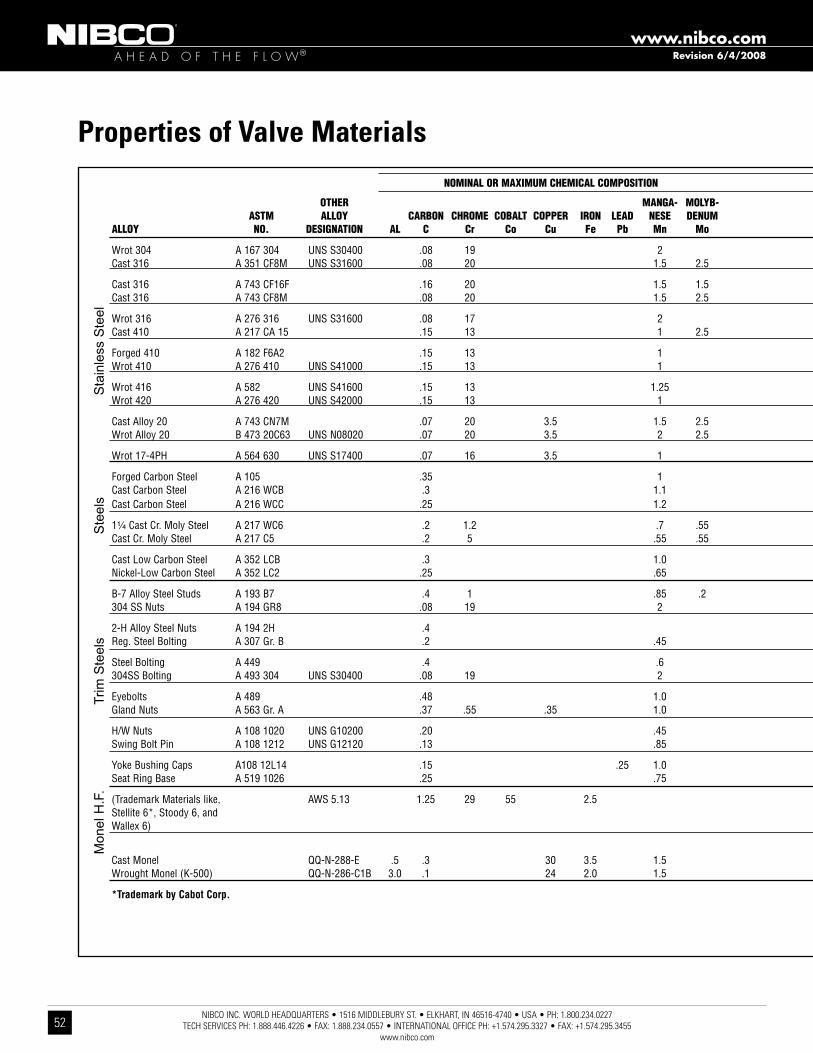
A H E A D O F T H E F L O W®www.nibco.com
NIBCO INC. WORLD HEADQUARTERS • 1516 MIDDLEBURY ST. • ELKHART, IN 46516-4740 • USA • PH: 1.800.234.0227 TECH SERVICES PH: 1.888.446.4226 • FAX: 1.888.234.0557 • INTERNATIONAL OFFICE PH: +1.574.295.3327 • FAX: +1.574.295.3455
www.nibco.com52
OTHeR MaNGa- MOLYB- aSTM aLLOY CaRBON CHROMe COBaLT COPPeR iRON LeaD NeSe DeNUM aLLOY NO. DeSiGNaTiON aL C Cr Co Cu Fe Pb Mn Mo
Wrot 304 A 167 304 UNS S30400 .08 19 2 Cast 316 A 351 CF8M UNS S31600 .08 20 1.5 2.5
Cast 316 A 743 CF16F .16 20 1.5 1.5 Cast 316 A 743 CF8M .08 20 1.5 2.5
Wrot 316 A 276 316 UNS S31600 .08 17 2 Cast 410 A 217 CA 15 .15 13 1 2.5
Forged 410 A 182 F6A2 .15 13 1 Wrot 410 A 276 410 UNS S41000 .15 13 1
Wrot 416 A 582 UNS S41600 .15 13 1.25 Wrot 420 A 276 420 UNS S42000 .15 13 1
Cast Alloy 20 A 743 CN7M .07 20 3.5 1.5 2.5 Wrot Alloy 20 B 473 20C63 UNS N08020 .07 20 3.5 2 2.5
Wrot 17-4PH A 564 630 UNS S17400 .07 16 3.5 1
Forged Carbon Steel A 105 .35 1 Cast Carbon Steel A 216 WCB .3 1.1Cast Carbon Steel A 216 WCC .25 1.2
1¹⁄₄ Cast Cr. Moly Steel A 217 WC6 .2 1.2 .7 .55 Cast Cr. Moly Steel A 217 C5 .2 5 .55 .55
Cast Low Carbon Steel A 352 LCB .3 1.0 Nickel-Low Carbon Steel A 352 LC2 .25 .65
B-7 Alloy Steel Studs A 193 B7 .4 1 .85 .2 304 SS Nuts A 194 GR8 .08 19 2
2-H Alloy Steel Nuts A 194 2H .4 Reg. Steel Bolting A 307 Gr. B .2 .45
Steel Bolting A 449 .4 .6 304SS Bolting A 493 304 UNS S30400 .08 19 2
Eyebolts A 489 .48 1.0 Gland Nuts A 563 Gr. A .37 .55 .35 1.0
H/W Nuts A 108 1020 UNS G10200 .20 .45 Swing Bolt Pin A 108 1212 UNS G12120 .13 .85
Yoke Bushing Caps A108 12L14 .15 .25 1.0 Seat Ring Base A 519 1026 .25 .75
(Trademark Materials like, AWS 5.13 1.25 29 55 2.5 Stellite 6*, Stoody 6, and Wallex 6)
Cast Monel QQ-N-288-E .5 .3 30 3.5 1.5 Wrought Monel (K-500) QQ-N-286-C1B 3.0 .1 24 2.0 1.5
*Trademark by Cabot Corp.
NOMiNaL OR MaxiMUM CHeMiCaL COMPOSiTiON
Trim
Ste
els
Mon
el H
.F.
Ste
els
Sta
inle
ss S
teel
Properties of Valve Materials
Revision 6/4/2008

A H E A D O F T H E F L O W®www.nibco.com
NIBCO INC. WORLD HEADQUARTERS • 1516 MIDDLEBURY ST. • ELKHART, IN 46516-4740 • USA • PH: 1.800.234.0227 TECH SERVICES PH: 1.888.446.4226 • FAX: 1.888.234.0557 • INTERNATIONAL OFFICE PH: +1.574.295.3327 • FAX: +1.574.295.3455
www.nibco.com53
TiTaN- TUNG- TeNSiLe YieLD NiCKeL PHOS SiLiCON SULFUR TiN iUM STeN ziNC STReNGTH STReNGTH % Ni P Si S Sn Ti W zn Psi Psi eLONGaTiON HaRDNeSS
9 .045 1.0 .03 75,000 30,000 40 202 HB 11 .04 2.0 .04 70,000 30,000 25
11 .04 2.0 .04 70,000 30,000 30 12 .045 1.0 .03 75,000 30,000 30
12 .045 1.0 .03 75,000 30,000 30 1 .04 1.5 .04 90,000 65,000 18
.04 1.0 .03 85,000 55,000 18 200/225 HB .5 .04 1.0 .03 100,000 80,000 15
.06 1.0 .15 114,000 95,000 17 235 HB .04 1.0 .03 250/450 HB
28 .04 1.5 .04 62,000 25,000 35 35 .045 1.0 .035 85,000 35,000 30
4 .04 1.0 .03 115,000 75,000 18 255 HB
.04 .035 .05 70,000 36,000 22 187 HB .04 .6 .045 70,000 36,000 22 .04 .6 .04 70,000 40,000 22
.04 .06 .045 .04 .75 .045
.04 .6 .045 65,000 35,000 24 2.5 .04 .6 .045 70,000 40,000 24
.035 .25 .04 125,000 105,000 16 9 .045 1.0 .03 126/300 HB
.04 .05 250/300 HB .04 .05 100,000 18 121/212 HB
.04 .05 120,000 92,000 14 9 .045 1.0 .03 90,000
.04 .25 .05 75,000 30,000 30 .35 .04 .2 .05
.04 .05 120/300 HB .10 .20
.07 .3 .04 .05 55,000 35,000 25
3 5 105,000 10 350 HB
60 1.5 65,000 32,500 25 125/150 HB 67 .5 .01 .5 135,000 95,000 20 255 HB
NOMiNaL OR MaxiMUM CHeMiCaL COMPOSiTiON NOMiNaL PHYSiCaL PROPeRTieS
Revision 6/4/2008

A H E A D O F T H E F L O W®www.nibco.com
NIBCO INC. WORLD HEADQUARTERS • 1516 MIDDLEBURY ST. • ELKHART, IN 46516-4740 • USA • PH: 1.800.234.0227 TECH SERVICES PH: 1.888.446.4226 • FAX: 1.888.234.0557 • INTERNATIONAL OFFICE PH: +1.574.295.3327 • FAX: +1.574.295.3455
www.nibco.com54
Piping/Flange Inside Diameter Requirements
Valve Series LD/WD/LC/WC 1000/2000/3000/5000 N200 Series
Valve Size
Minimum Pipe/Flange ID for Disc Clearance
Maximum Pipe/Flange ID for Disc Clearance
Minimum Pipe/Flange ID for Disc Clearance
Maximum Pipe/Flange ID for Disc Clearance
2 2 .00 2 .49 1 .38 2 .24
21/2 2 .37 2 .86 1 .95 2 .74
3 2 .67 3 .43 2 .66 3 .33
4 3 .69 4 .55 3 .67 4 .55
5 4 .76 5 .62 4 .48 5 .50
6 5 .96 6 .62 5 .96 6 .66
8 8 .01 8 .62 7 .85 8 .61
10 10 .00 10 .80 9 .76 10 .75
12 11 .99 13 .12 11 .72 12 .79
14 13 .16 14 .01 — —
16 15 .34 16 .30 — —
18 17 .23 18 .31 — —
20 19 .04 20 .08 — —
24 23 .05 24 .71 — —
30 29 .06 30 .29 — —
36 33 .59 35 .78 — —
42 39 .83 42 .77 — —
48 44 .85 48 .27 — —
Butterfly Valve Technical Information

A H E A D O F T H E F L O W®www.nibco.com
NIBCO INC. WORLD HEADQUARTERS • 1516 MIDDLEBURY ST. • ELKHART, IN 46516-4740 • USA • PH: 1.800.234.0227 TECH SERVICES PH: 1.888.446.4226 • FAX: 1.888.234.0557 • INTERNATIONAL OFFICE PH: +1.574.295.3327 • FAX: +1.574.295.3455
www.nibco.com55
Revision 8/22/2012
Butterfly Valve Technical InformationValve Installation Procedure - For Lug & Wafer Style Valvesalways position the connecting pipe flanges accurately in the line, allowing sufficient space between the flanges for the valve . Make sure the pipe flangefaces are clean of any foreign material such as scale, metal shavings or welding slag . Valves should be installed with the disc in the closed position to prevent damage to sealing surfaces . 1 . Carefully insert the valves between the pipe flanges . do not apply any lubricants to the seat faces as this may damage them . 2 . line up, center and secure the valve between flanges using desired bolts or studs as listed in table 4 . do not tighten bolts at this time . 3 . Carefully open the valve to assure free unobstructed disc movement . disc interference may result when valves are installed in pipelines having smaller than normal inside diameters, such as heavy wall pipe, plastic-lined pipe, as-cast flanges or reducing flanges . Interference can also occur when connecting directly to a swing check or silent check . suitable corrective measures must be taken to remove these obstructions, such as taper boring the pipe or installing a spacer or spool piece . 4 . after proper operation is verified, tighten the bolts to the minimum recommended bolt torques listed in table 3 below using a cross-over pattern, also shown below in figure 3 . 5 . Pressurize piping to valve and inspect for leakage . If leakage is observed, tighten bolts using cross-over pattern, increasing torque until leak stops . dO nOt exCeed MaxIMuM tOrQues lIsted In taBle 3 . 6 . recommended torques are made without warranty . Installer must verify proper strength bolts for application . Bolts shall be clean and un-lubricated .
4
2
1
3
8
6
5
7
Bolt TighteningCross Over Pattern
Fig. 3
SuggestedBolting Methods
Flange Bolt Minimum Bolt Maximum Bolt Size Size Torque (ft.•lbs.) Torque (ft.•lbs.) 2"- 4" 5/8" 20 70 5"- 8" 3/4" 30 120 10" & 12" 7/8" 50 200 14" & 16" 1" 70 240 18" & 20" 1-1/8" 100 380 24" & 30" 1-1/4" 140 520 36"- 48" 1/1/2" 200 800
Table 3 Recommended Bolt Tightening Torques
Caution1. Class 250 cast iron and Class 300 steel flanges can not be used on these valves.2. Rubber faced or mechanical flanges are not recommended.3. This valve is not recommended for steam service.4. Valves should not be assembled to the flanges and then welded into the piping system.5. Lever-lock handles are not recommended for use on 8" and larger valves.6. Do not install EPDM liner in compressed air lines.
2" 1 .69
0 .63 — — 1 .25 4 .00 8/4 5/8-11 unC — 0 .75 — 1 .50 4 .00 8/4
2 1/2" 1 .81
0 .69 — — 1 .50 5 .00 8/4 5/8-11 unC — 0 .88 — 1 .75 5 .00 8/4
3" 1 .81
0 .75 — — 1 .50 5 .00 8/4 5/8-11 unC — 0 .94 — 1 .75 5 .00 8/4
4" 2 .06 0 .94 0 .94 — 1 .75 5 .00 16/8 5/8-11 unC 5" 2 .19 0 .94 0 .94 — 1 .75 5 .00 16/8 3/4-10 unC 6" 2 .19 1 .00 1 .00 — 2 .00 6 .00 16/8 3/4-10 unC 8" 2 .38 1 .12 1 .12 — 2 .25 6 .00 16/8 3/4-10 unC 10" 2 .69 1 .19 1 .19 — 2 .25 7 .00 24/12 7/8-9 unC 12" 3 .00 1 .25 1 .25 — 2 .50 7 .00 24/12 7/8-9 unC 14" 3 .01 1 .38 1 .38 — 2 .50 7 .00 24/12 1-8 unC 16" 3 .38 1 .44 1 .44 — 3 .00 8 .00 32/16 1-8 unC 18" 4 .12 1 .56 1 .56 — 3 .00 9 .00 32/16 1 1/8-7 unC 20" 5 .14 1 .69 1 .69 — 3 .50 10 .00 40/20 1 1/8-7 unC 24" 5 .98 1 .88 1 .88 — 4 .00 11 .00 40/20 1 1/4-7 unC 2 .12 — — 3 .50 — 56
30" 6 .57 — — — 3 .00 — 56
1 1/4-7 unC — — — 3 .50 — 56 — — 2 .94 4 .25 — 56 2 .38 — — 4 .00 — 64
36" 8 .00 — — — 3 .50 — 64
1 1/2-6 unC — — — 4 .00 — 64 — — 3 .56 5 .00 — 64 2 .62 — — 4 .50 — 72
42" 9 .88 — — — 4 .00 — 72
1 1/2-6 unC — — — 4 .50 — 72 — — 3 .81 5 .50 — 72 2 .75 — — 4 .50 — 88
48" 10 .87 — — — 4 .50 — 88
1 1/2-6 unC — — — 5 .00 — 88 — — 4 .25 6 .00 — 88
VA
LVE
SIZ
E10
00/2
000/
3000
SE
RIE
S O
NLY
TO
TAL
VA
LVE
BO
DY
WID
TH
AN
SI B
16.1
CLA
SS
125
CA
ST
IRO
NFL
AN
GE
TH
ICK
NE
SS
AN
SI B
16.5
CLA
SS
150
ST
EE
LFL
AN
GE
TH
ICK
NE
SS
AN
SI B
16.4
7 (S
ER
IES
A)
CLA
SS
150
ST
EE
LM
SS
SP
-44
FLA
NG
E T
HIC
KN
ES
S)
RE
CO
MM
EN
DE
DC
AP
SC
RE
W L
EN
GT
H(L
UG
GE
D V
ALV
ES
)D
IME
NS
ION
"Y
"
RE
CO
MM
EN
DE
DB
OLT
LE
NG
TH
(WA
FER
VA
LVE
S)
DIM
EN
SIO
N "
X"
TO
TAL
QU
AN
TIT
YC
AP
SC
RE
WS
/BO
LTS
(TO
MO
UN
T 2
FLA
NG
ES
)
CA
P S
CR
EW
SIZ
E
Table 4 Recommended Bolt Lengths
X
Y
NOTE: LUG STYLE VALVES - Extra care should be used when installing with raised face flanges. Over-tightening can result in broken lugs.

A H E A D O F T H E F L O W®www.nibco.com
NIBCO INC. WORLD HEADQUARTERS • 1516 MIDDLEBURY ST. • ELKHART, IN 46516-4740 • USA • PH: 1.800.234.0227 TECH SERVICES PH: 1.888.446.4226 • FAX: 1.888.234.0557 • INTERNATIONAL OFFICE PH: +1.574.295.3327 • FAX: +1.574.295.3455
www.nibco.com56
INSTALLATION1 . Install handwheel (1) onto gear operator shaft and secure with pin (2) .
(If not already attached) see fig . 1 .
2 . turn the handwheel (1) clockwise until in full sHut position .
3 . remove 2 screws holding pointer cover plate to center of gear operator to expose bore . retain pointer cover plate and screws for reinstallation later .
4 . assure valve is in full sHut position, turn valve stem (5) to close disc if necessary .
5 . assure both mounting base of gear operator (3) and valve top flange (6) are clean and dry .
6 . determined desired handwheel position in reference to the piping system and compare with fig . 2 . Basically there are 2 mounting positions for the gear operator
onto the valve and the valve can be mounted in either direction into the piping system . this will allow handwheel to be positioned in any of the 4 Quadrants as
shown in fig . 2 . note that 10" and 12" size commercial valves only allow for handwheel positioning in Quadrants 1 and 2 .
7a . Gear operators with adapter bushing
• Insert adapter bushing (4) into gear operator (3) bore aligning bushing key with
desired keyway . keyway selection will determine handwheel orientation position .
• align adapter bushing (4) bore with valve stem (5) and slide gear operator
assembly onto valve stem (5) until seated with valve top flange .
7b . Gear operators without adapter bushing
• align gear operator (3) bore with valve stem (5) and align with desired keyway .
keyway selection will determine handwheel orientation position .
• slide gear operator assembly onto valve stem (5) until seated with valve top flange .
8 . secure gear operator (3) to valve top flange (6) using supplied* fasteners (7 & 8) .
9 . reinstall pointer cover plate onto gear operator that you removed in step 3 above . arrow should be aligned to indicate sHut position .
10 . rotate handwheel from full sHut to full OPen positions several times to assure proper operation .
11 . Proceed with valve installation into piping system .
*A minimum of two fasteners is required, installed in opposite diagonal corners.
Revision 11/8/2005
Butterfly Valve Technical Information
Tools Required
fire Protection 2" — 8" 9/16" hex wrench & 1/8" hex allen wrench
(ul/fM) 10" — 12" 3/4" hex wrench and 1/8" hex allen wrench 2" — 8" 9/16" hex wrench
Commercial 10" — 14" 3/4" hex wrench
16" — 18" 1 1⁄8" hex wrench
Gear Operator Installation and Handwheel Positioning
Fig. 1
Fig. 2
Note - Connection of gear operator to valve stem varies depending on gear operator model, size and style. The adapter bushing and key may be different from illustration shown.

A H E A D O F T H E F L O W®www.nibco.com
NIBCO INC. WORLD HEADQUARTERS • 1516 MIDDLEBURY ST. • ELKHART, IN 46516-4740 • USA • PH: 1.800.234.0227 TECH SERVICES PH: 1.888.446.4226 • FAX: 1.888.234.0557 • INTERNATIONAL OFFICE PH: +1.574.295.3327 • FAX: +1.574.295.3455
www.nibco.com57
Revision 1/29/2009
2000/3000 Series Technical Information
Valve with Gear Mounted
Typical LD/WD2000-5 and LD1000-5
Valve A B C D E F G H I J K L M N P Size (Lug) (Wafer) (Metal) (Rubber) 2” 2 .5 4 .6 4 .9 5 .4 2 .9 6 .9 11 .1 1 .69 1 .81 2 .9 2 .13 8 .2 7 .64 2 .12 5 .91 2½” 2 .9 5 .6 5 .6 5 .9 3 .3 7 .4 12 .0 1 .81 1 .94 2 .9 2 .13 8 .7 7 .64 2 .12 5 .91 3” 3 .1 6 .1 6 .1 6 .1 3 .4 7 .6 12 .3 1 .81 1 .94 2 .9 2 .13 8 .9 7 .64 2 .12 5 .91 4” 4 .1 8 .3 7 .0 6 .9 4 .0 8 .4 13 .7 2 .06 2 .19 2 .9 2 .13 9 .7 7 .64 2 .12 5 .91 5” 5 .1 9 .4 8 .3 7 .4 4 .8 8 .9 15 .0 2 .19 2 .31 2 .9 2 .13 10 .2 7 .64 2 .12 5 .91 6” 6 .1 10 .3 9 .3 8 .0 5 .3 9 .5 16 .1 2 .19 2 .31 2 .9 2 .13 10 .8 7 .64 2 .12 5 .91 8” 8 .1 13 .4 11 .6 9 .3 6 .5 10 .8 18 .5 2 .38 2 .5 2 .9 2 .13 12 .0 9 .53 2 .12 9 .84 10” 10 .1 15 .5 14 .3 10 .5 8 .0 12 .3 21 .8 2 .69 2 .81 3 .9 3 .03 13 .8 11 .54 3 .03 9 .84 12” 12 .1 18 .3 16 .8 12 .0 9 .3 13 .8 24 .6 3 .00 3 .13 3 .9 3 .03 15 .3 11 .54 3 .03 9 .84 14” 13 .1 - 20 .6 14 .5 10 .5 16 .3 28 .3 3 .01 3 .13 4 .3 3 .15 17 .8 12 .87 3 .14 11 .81 16” 15 .3 - 22 .3 15 .7 11 .7 17 .9 31 .7 3 .38 3 .54 6 .3 3 .94 20 .0 13 .58 4 .92 11 .81 18” 17 .3 - 25 .2 16 .6 12 .4 18 .8 33 .3 4 .12 4 .29 6 .3 3 .94 20 .9 15 .04 4 .92 15 .75 20” 19 .4 - 27 .4 18 .9 13 .7 21 .3 37 .8 5 .14 5 .31 6 .5 4 .92 24 .1 18 .11 4 .92 11 .81 24” 23 .3 - 31 .5 22 .1 17 .5 24 .5 44 .8 5 .98 6 .14 6 .5 4 .92 27 .3 18 .11 4 .92 11 .81
DIMENSIONS

A H E A D O F T H E F L O W®www.nibco.com
NIBCO INC. WORLD HEADQUARTERS • 1516 MIDDLEBURY ST. • ELKHART, IN 46516-4740 • USA • PH: 1.800.234.0227 TECH SERVICES PH: 1.888.446.4226 • FAX: 1.888.234.0557 • INTERNATIONAL OFFICE PH: +1.574.295.3327 • FAX: +1.574.295.3455
www.nibco.com58
Butterfly Valve Technical Information
Resilient Liner Materials
EPDM – ePdM is a terpolymer elastomer made from ethylene-propylene diene monomer . ePdM has good abrasion and tear resistance and offers excellent chemical resistance to a variety of acids and alkalines . It is susceptible to attack by oils and is not recommended for applications involving petroleum oils, strong acids, or strong alkalines . ePdM should not be used on compressed air lines . It has exceptionally good weather aging and ozone resistance . It is fairly good in ketones and alcohols .
BUNA-N (Nitrile) (NBR) – Buna-n is a general purpose oil resistant polymer known as nitrile rubber . nitrile is a copo-lymer of butadiene and acrylonitrile . Buna-n has good solvent, oil, water and hydraulic fluid resistance . It displays good compression set, abrasion resistance and tensile strength . Buna-n should not be used in highly polar solvents such as acetone and methyl ethyl ketone, nor should it be used in chlorinated hydrocarbons, ozone or nitro hydrocarbons . some aviation fuels may not be compatible .
Fluoroelastomer (FKM) – fluoroelastomers are inherently compatible with a broad spectrum of chemicals . Because of this extensive chemical compatibility which spans considerable concentration and temperature ranges, fluoroelastomers have gained wide acceptance as a material of construction for butterfly valve O-rings and seats . fluoroelastomer can be used in most applications involving mineral acids, salt solutions, chlorinated hydrocarbons and petroleum oils . It is par-ticularly good in hydrocarbon service .fkM is not recommended for use in high temperature water .
Proprietary compound formulas are used for each of the elastomers to provide the right combination of seat compression, abrasion resistance, and chemical resistance to match your application . elastomeric seat materials are not suitable for steam service .
Liner Temperature RatingsLiner Material TemperatureEPDM** -20°F to + 250°FNitrile (Buna-N) -20°F to + 180°FFluoroelastomer -20°F to + 300°F** EPDM is rated at 250°F intermittent service and 225°F continuous service.
NOTE – The NIBCO® Chemical Resistance Guide should be referenced for liner material compatibility for each application.
Revision 1/29/2009

A H E A D O F T H E F L O W®www.nibco.com
NIBCO INC. WORLD HEADQUARTERS • 1516 MIDDLEBURY ST. • ELKHART, IN 46516-4740 • USA • PH: 1.800.234.0227 TECH SERVICES PH: 1.888.446.4226 • FAX: 1.888.234.0557 • INTERNATIONAL OFFICE PH: +1.574.295.3327 • FAX: +1.574.295.3455
www.nibco.com59
Butterfly Valve Technical Information
Metals Used in Valves & FittingsAluminum–A non-ferrous metal, very lightweight, approximately one-third as much as steel. Aluminum exhibits excellent atmospheric corrosion resistance, but can be very reactive with other metals. In valves, aluminum is mainly used as an exterior trim component such as a handwheel or identification tag.
Copper–Among the most important properties of wrot copper materials are their thermal and electrical conductivity, corrosion resistance, wear resistance, and ductility. Wrot copper performs well in high temperature applications and is easily joined by soldering or brazing. Wrot copper is exclusively used for fittings.
Bronze–One of the first alloys developed in the bronze age is generally accepted as the industry standard for pressure rated bronze valves and fittings. Bronze has a higher strength than pure copper, is easily cast, has improved machinability, and is very easily joined by soldering or brazing. Bronze is very resistant to pitting corrosion, with general resistance to most chemicals less than that of pure copper.
Silicone Bronze–Has the ductility of copper but much more strength. Silicon bronze has equal or greater corrosion resistance to that of copper. Commonly used as stem material in pressure-rated valves, silicon bronze has greater resistance to stress corrosion cracking than common brasses.
Aluminum Bronze–The most widely accepted disc material used in butterfly valves, aluminum bronze is heat treatable and has the strength of steel. Formation of an aluminum oxide layer on exposed surfaces makes this metal very corrosion resistant. Not recommended for high pH wet systems.
Brass–Generally good corrosion resistance. Susceptible to de-zincification in specific applications; excellent machinability. Primary uses for wrot brass are for ball valve stems and balls, and iron valve stems. A forging grade of brass is used in ball valve bodies and end pieces.
Gray Iron–An alloy of iron, carbon and silicon; easily cast; good pressure tightness in the as-cast condition. Gray iron has excellent dampening properties and is easily machined. It is standard material for bodies and bonnets of Class 125 and 250 iron body valves. Gray iron has corrosion resistance that is improved over steel in certain environments.
Ductile Iron–Has composition similar to gray iron. Special treatment modifies metallurgical structure which yields higher mechanical properties; some grades are heat treated to improve ductility. Ductile iron has the strength properties of steel using similar casting techniques to that of gray iron.
Carbon Steel– Very good mechanical properties; good resistance to stress corrosion and sulfides. Carbon steel has high and low temperature strength, is very tough and has excellent fatigue strength. Mainly used in gate, globe, and check valves for applications up to 850oF, and in one-, two-, and three-piece ball valves.
3% Nickel Iron–Improved corrosion resistance over gray and ductile iron. Higher temperature corrosion resistance and mechanical properties. Very resistant to oxidizing atmospheres.
Nickel-Plated Ductile Iron–Nickel coatings have received wide acceptance for use in chemical processing. These coatings have very high tensile strength, 50 to 225 ksi. To some extent, the hardness of a material is indicative of its resistance to abrasion and wear characteristics. Nickel plating is widely specified as a disc coating for butterfly valves.
400 Series Stainless Steel–An alloy of iron, carbon, and chromium. This stainless is normally magnetic due to its martensitic structure and iron-content. 400 series stainless steel is resistant to high temperature oxidation and has improved physical and mechanical properties over carbon steel. Most 400 series stain-less steels are heat-treatable. The most common applications in valves are, for stem material in butterfly valves, and backseat bushings and wedges in cast steel valves.
316 Stainless Steel–An alloy of iron, carbon, nickel, and chromium. A non-magnetic stainless steel with more ductility than 400SS. Austinetic in structure, 316 stainless steel has very good corrosion resistance to a wide range of environments, is not susceptible to stress corrosion cracking and is not affected by heat treatment. Most common uses in valves are: stem, body and ball materials.
17-4 PH Stainless Steel*–Is a martensitic precipitation/age hardening stainless steel offering high strength and hardness. 17.4 PH withstands corrosive attack better than any of the 400 series stainless steels and in most conditions its corrosion resistance closely approaches that of 300 series stainless steel. 17.4 PH is primarily used as a stem material for butterfly and ball valves.
Alloy 20Cb-3*–This alloy has higher amounts of nickel and chromium than 300 series stainless steel and with the addition of columbium, this alloy retards stress corrosion cracking and has improved resistance to sulfuric acid. Alloy 20 finds wide use in all phases of chemical processing. Commonly used as interior trim on butterfly valves.
Monel*–Is a nickel-copper alloy used primarily as interior trim on butterfly and ball valves. One of the most specified materials for corrosion resistance to sea and salt water. Monel is also very resistant to strong caustic solutions.
Stellite*–Cobalt base alloy, one of the best all-purpose hard facing alloys. Very resistant to heat, abrasion, corrosion, impact, galling, oxidation, thermal shock and erosion. Stellite takes a high polish and is used in steel valve seat rings. Normally applied with transfer plasma-arc; Stellite hardness is not affected by heat treatment.
Hastelloy C*–A high nickel-chromium molybdenum alloy which has outstanding resistance to a wide variety of chemical process environments including strong oxidizers such as wet chlorine, chlorine gas, and ferric chloride. Hastelloy C is also resistant to nitric, hydrochloric, and sulfuric acids at moderate temperatures.
Note: See NIBCO’s "Chemical Resistance Guide Catalog" for specific questions.
*Alloy 20Cb-3 is a registered trademark of Carpenter Technology*Hastelloy C is a registered trademark of Cabot Corporation*Stellite is a registered trademark of Cabot Corporation* Monel is a registered trademark of International Nickel*17-4 PH Stainless Steel is a registered trademark of Armco Steel Company

A H E A D O F T H E F L O W®www.nibco.com
NIBCO INC. WORLD HEADQUARTERS • 1516 MIDDLEBURY ST. • ELKHART, IN 46516-4740 • USA • PH: 1.800.234.0227 TECH SERVICES PH: 1.888.446.4226 • FAX: 1.888.234.0557 • INTERNATIONAL OFFICE PH: +1.574.295.3327 • FAX: +1.574.295.3455
www.nibco.com60
Revision 9/14/2010
Butterfly Valve Technical InformationTorque Data
Butterfly Valve Torque Data
Torque is the rotary effort required to operate a valve . this turning force in a butterfly valve is determined by three fac-tors . (1) friction of the disc to seat for sealing (2) Bearing friction (3) dynamic torque .
Breakaway Torque is the total of the torques resulting from bearing friction and seat/disc interference friction at a given pressure differential . this value is normally the highest required torque to operate a valve, and is used in sizing actu-ators . the values listed at the left are based on performance tests and include a safety factor . the torques listed are valid for water and lubricating fluids at ambient temperature . for dry and non-lubricating fluids, contact your nIBCO customer service representative .
Butterfly valves, sizes 8" and larger, when used on liquids, show a marked increase in dynamic torque which tends to close the valve . for this reason, gear operated or actuated valves are recommended .
torque listed for ePdM . When calculating torques for Buna-n, or fluoroelastomer multiply listed torque by 1 .25 . Consult factory for dry service valves .
LD/WD 2000/3000/5022 Series Torque Data (in. Lbs.) Size 100 PSi 200 PSi 250 PSi 2” 140 180 195 2¹⁄₂” 190 235 255 3” 250 300 325 4” 430 530 580 5” 590 790 845 6” 795 1,035 1,155 8” 1,850 2,350 2,600 10” 2,350 2,900 3,125 12” 3,875 5,390 6,145
LD/WD 1000/2000 Series Torque Data (in. Lbs.) Size 50 PSi 75 PSi 100 PSi 150 PSi 14” — 3,837 — 4,870 16” — 5,003 — 6,685 18” — 6,567 — 8,958 20” — 8,540 — 11,950 24” — 13,220 — 18,680 30" 28,320 29,782 30,864 33,336 36" 40,624 41,875 43,480 46,528 42" 69,744 72,076 74,632 79,864 48" 96,648 100,520 103,840 111,112
N200 Series Torque Data (in. Lbs.) Size 100 PSi 200 PSi 2 120 220 2¹⁄₂ 130 320 3 180 480 4 280 820 5 360 1,162 6 600 1,560 8 1,100 2,890 10 2,040 5,270 12 4,500 8,050
Note: Torque Data shown is for general service (clean water, ambient temperatures). For non-lubricating, high temperatures or aggressive media, consult Nibco Technical Service.
FC/FD27*5/57*5 GD4765/4775 Torque Data (in. Lbs.) Size 100 PSi 200 PSi 300 PSi 2 48 67 83 2¹⁄₂ 48 67 83 3 100 134 168 4 185 251 317 5 294 410 499 6 520 705 890 8 1,070 1,495 1,798 10 1,550 2,214 2,654 12 2,150 3,024 3,662
Note: See Pages 38-39 for High Performance BFV Torque Data.

A H E A D O F T H E F L O W®www.nibco.com
NIBCO INC. WORLD HEADQUARTERS • 1516 MIDDLEBURY ST. • ELKHART, IN 46516-4740 • USA • PH: 1.800.234.0227 TECH SERVICES PH: 1.888.446.4226 • FAX: 1.888.234.0557 • INTERNATIONAL OFFICE PH: +1.574.295.3327 • FAX: +1.574.295.3455
www.nibco.com61
Butterfly Valve Actuation Data Sheet
To actuate all valves it is necessary to provide certain data to assure proper sizing and prevent damage to the system. Please supply as much data as possible.
I. Valve Information:
A. Type: Butterfly Ball
B. Fig. No. _______________ Size _____________ Qty. ______________
C. Type of Fluid in Valve: ______________ Inlet Pressure: ____________ Is Fluid: Dry Wet
Differential Pressure: ______________ System Velocity: ____________
System GPM: ____________________ Temperature:_______________
II. Actuator Information:
A. Electric: Voltage:______________ Time for 90° rotation: ________________
Type Enclosure: NEMA 4 NEMA 7 Other ______________
Special Requirements: Brake Thermostat Heater and Thermostat
Manual Override Extended Duty Motor
Modulating Control Position Transmitter
Extra SPDT Switches Potentiometer
B. Pneumatic: Air supply to actuator: ____________ PSI (Min. 40 psi, Max. 120 psi)
Actuator Type: Air-to-Air
Air-to-Spring Failsafe: Open Closed
Solenoid: NEMA 4 NEMA 7
Switch Box: If so: NEMA 4 NEMA 7
Type: SPDT DPDT (two each is standard)
Pneumatic Positioner: 3-15 4-20 MA
III. Special Notes: _ _ _ _ _ _ _ _ _ _ _ _ _ _ _ _ _ _ _ _ _ _ _ _ _ _ _ _ _ _ _ _ _ _ _ _ _ _ _ _ _ _ _ _ _ _ _ _ _ _
Note: If special features are required for actuators such as modulating positioners either for electric or pneumatic actuators, consult factory.

A H E A D O F T H E F L O W®www.nibco.com
NIBCO INC. WORLD HEADQUARTERS • 1516 MIDDLEBURY ST. • ELKHART, IN 46516-4740 • USA • PH: 1.800.234.0227 TECH SERVICES PH: 1.888.446.4226 • FAX: 1.888.234.0557 • INTERNATIONAL OFFICE PH: +1.574.295.3327 • FAX: +1.574.295.3455
www.nibco.com62
NiBCO WD2000 LD2000 WD2100 LD2100 WD3010 LD3010 WD3110 LD3110 WD3022 LD3022
Bray 30-11010-120 31-11010-120 30-11010-684 31-11010-684 30-11010-119 31-11010-119 30-11010-713 31-11010-713 30-11010-124 31-11010-124
Centerline A2-061-05 B2-061-05 A2-061-01 B2-061-01 A2-021-05 B2-021-05 A2-021-01 B2-021-01 A2-044-05 B2-044-05
Demco NEC1114351 NEC5114351 NEC1114311 NEC5114311 NEC1115351 NEC5115351 NEC1115311 NEC5115311 NEC1122351 NEC5122351
Grinnell WD-8281-3 LD-8281-3 WD-8181-3 LD-8181-3 WD-8201-3 LD-8201-3 WD-8101-3 LD-8101-3 WD-8271-4 LD-8271-4
Keystone HS-1 HS-2 HS-1 HS-2 HS-1 HS-2 HS-1 HS-2 HS-1 HS-2
Milwaukee MW-233-E ML-233-E MW-233-B ML-233-B MW-232-E ML-232-E MW-232-B ML-232-B MW-234-E ML-234-E
Mueller Steam 55-ANK6-1 56-ANK6-1 55-ANK3-1 56-ANK3-1 55-ANI6-1 56-ANI6-1 55-ANI3-1 56-ANI3-1 55-AHH6-1 56-AHH6-1
Watts DBF-04-121-15 DBF-03-121-15 DBF-04-121-25 DBF-03-121-25 DBF-04-111-15 DBF-03-111-15 DBF-04-111-25 DBF-03-111-25 DBF-04-131-25 DBF-03-131-25
Figure Number Comparisons*Butterfly Valves
DUCTiLe iRON
NiBCO N200235 N200135 N200245 N200145 N200236 N200136 N200246 N200146
Grinnell LC128*3 WC128*3 LC118*3 WC118-3 LC120*3 WC120*3 LC110*3 WC110*3
Centerline B106135 A106145 B106161 A106131 B102135 A102135 B102131 A102131
Watts BF03-121-1 BF04-121-1 BF03-121-2 BF04-121-2 BF03-111-1 BF04-111-1 BF03-111-2 BF04-111-2
Milwaukee CL223E CW223E CL223B CW223B CL222E CW222E CL222B CW222B
CaST iRON
*To be used as a guide only. Some variation in detail is possible.Information subject to change.
NOTE: nIBCO lug style butterfly valves are fully rated for dead end service without a downstream flange . all valves listed above as comparable may not have this rating .

NIBCO INC. WORLD HEADQUARTERS • 1516 MIDDLEBURY ST. • ELKHART, IN 46516-4740 • USA • PH: 1.800.234.0227 TECH SERVICES PH:1.888.446.4226 • FAX: 1.888.336.4226 • INTERNATIONAL OFFICE PH: +1.574.295.3327 • FAX: +1.574.295.3455
www.nibco.com
It’s a new age of
business, and a new
way at NIBCO. From
Elkhart, Indiana to
Lodz, Poland, and
points beyond,
our company has
integrated manufacturing,
distribution, and networked
communications to provide
a seamless source of
information and service, 24
hours a day, 7 days a week.
But this integration hasn’t
happened overnight. It’s been
part of a long-term strategic
process that has pushed us
to reconsider every aspect
of our business. The result?
We’re a vertically integrated
manufacturer with the
products and systems in
place to deliver low cost
and high quality. NIBCO®
products are manufactured
under a Quality Management
System conforming to the
current revision of ISO-9001
International Standards. We
know the flow control industry
is only going to get more
demanding, and we are more
than ready. We will continue
to lead. That’s what NIBCO is
all about.
globally connecting you at all levels
World Headquarters
Elkhart, Indiana
Metal Valves and Fittings
Blytheville, Arkansas
McAllen, Texas
Nacogdoches, Texas
Stuarts Draft, Virginia
Plastic Pipe, Valves, and Fittings
Greensboro, Georgia
Goshen, Indiana
Lebanon,Ohio
Industrial Plastics
Charlestown, Indiana
International
Reynosa, Mexico
Lodz, Poland
U.S. Distribution Centers
Elkhart, Indiana
Global Offices
Elkhart, Indiana
Lodz, Poland
M A N U FA C T U R I N G D I S T R I B U T I O N I N T E R N AT I O N A L
* * *
*
*
*
*Denotes u.s. and international Direct shipping locations
*

C-BFV-0912
C-BFV-0912 © 2012 NIBCO INC., Al l R ights Reser ved. Pr in ted in U.S.A.
N i b c o i N c .
w o r l d h e a d q u a r t e r s
w e B : w w w. n i b c o . c o m
1516 M Idd l eBURy S t R e e t
e l khARt, IN 46516 -4740
USA
d O M e S t I C C U S t O M e R S e R V I C e
P h O N e : 8 0 0 . 2 3 4 . 0 2 2 7
FA x : 8 0 0 . 2 3 4 . 0 5 5 7
t e C h N I C A l S e R V I C e
P h O N e : 8 8 8 . 4 4 6 . 4 2 2 6
FA x : 8 8 8 . 3 3 6 . 4 2 2 6
I N t e R N At I O N A l O F F I C e
P h O N e : + 1 / 5 7 4 . 2 9 5 . 3 3 2 7
FA x : + 1 / 5 7 4 . 2 9 5 . 3 4 5 5
F e at u r i n g n i bco® systemsNIBCO® PEX Piping Systems • NIBCO® Press System®
Chemtrol®
thermoplastic pipe, valves and fittings in PVC, Corzan® CPVC, polypropylene and PVdF kynar® • Pneumatic and electric actuation systems
Corzan® is a registered trademark of The Lubrizol Corporation. • Kynar® is a registered trademark of Arkema Inc.
F i t t i n g sWrot and cast copper pressure and drainage fittings • Cast copper alloy flanges • Wrot and cast press fittings • ABS and PVC DWV fittings • Schedule 40 PVC pressure fittings • CPVC CTS fittings • CPVC CTS- to -metal transition fittings • Schedule 80 PVC and CPVC systems • CPVC metric piping systems • CPVC BlazeMaster® fire protection fittings • Lead-Free* fittingsBlazeMaster® is a registered trademark of The Lubrizol Corporation.*weighted average lead content ≤0.25%
eniBCoEDI—Electronic Data Interchange • VMI—Vendor Managed Inventory • NIBCO.com • NIBCOpartner.com
ValVes & aCtuationPressure-rated bronze, iron and alloy-iron gate, globe and check valves • Pressure-rated bronze ball valves • Boiler specialty valves • Commercial and industrial butterfly valves • Circuit balancing valves • Carbon and stainless steel ball valves • ANSI flanged steel ball valves • Pneumatic and electric actuators and controls • Grooved ball and butterfly valves • High performance butterfly valves • UL/FM fire protection valves • MSS specification valves • Bronze specialty valves • Low pressure gate, globe, check and ball valves • Frostproof sillcocks • Quarter--turn supply stops • Quarter-turn low pressure valves • PVC ball valves • CPVC CTS ball valves • Just Right® recirculating valves • Bronze & Iron Y-Strainers • Lead-Free* valves*weighted average lead content ≤0.25%