Embed Size (px)
DESCRIPTION
valves pdf
Citation preview
Home Table of Contents
Product Search
How To Order
Print Next
Home Table of Contents
Product Search
How To Order
PrintBack Next
59
PRESSURE SEALSWING CHECKVALVE COMPONENTS
CAP SCREW
STIRR UP
PIN
CAP SCREW
RETAINER RING
GASKET RETAINER
SPACER RING
BONNET GASKET
BONNETSEATDISC
HINGE
WASHERNUTS FOR DITTO
BODY
HANDWHEEL
NUTS FOR DITTO
GLAND BOLTS
GLAND FLANGENUTS FOR DITTO
GLAND PACKING
PACKINGLANTERN RING
PACKINGFLEXIBLE RINGBOTTON RING
BACK SEATPART ZBODY
PRESSURE SEAL GLOBEVALVE COMPONENTS
HANDWHEEL NUT
THRUST RING
BEARING
DISCRETAINER
SEGMENTALRING
DISC
YOKE NUT
GREASE FITTINGYOKE
YOKE STUD BOLTS
PART X
PART YBONNET
KEY
PRESSURE SEAL GATEVALVE COMPONENTS
HANDWHEELNUT
HANDWHEEL
THRUST RINGGREASEFITTINGNUTS FORDITTO
YOKECAP SCREW
GASKETRETAINER
SPACER RING
RETAINER RING
KEYBONNET GASKET
WEDGE
GUIDE
BODY
STEM
BACK SEATYOKE STUD BOLTSDRAIN PLUG
SEAT
JOKE NUT
BEARINGGLAND
FLANGE
BEARING
GLANDPACKING
GLANDBOLTS
NUTSFOR
DITTOLANTERN
RING
PACKING
BUTTONRING
2
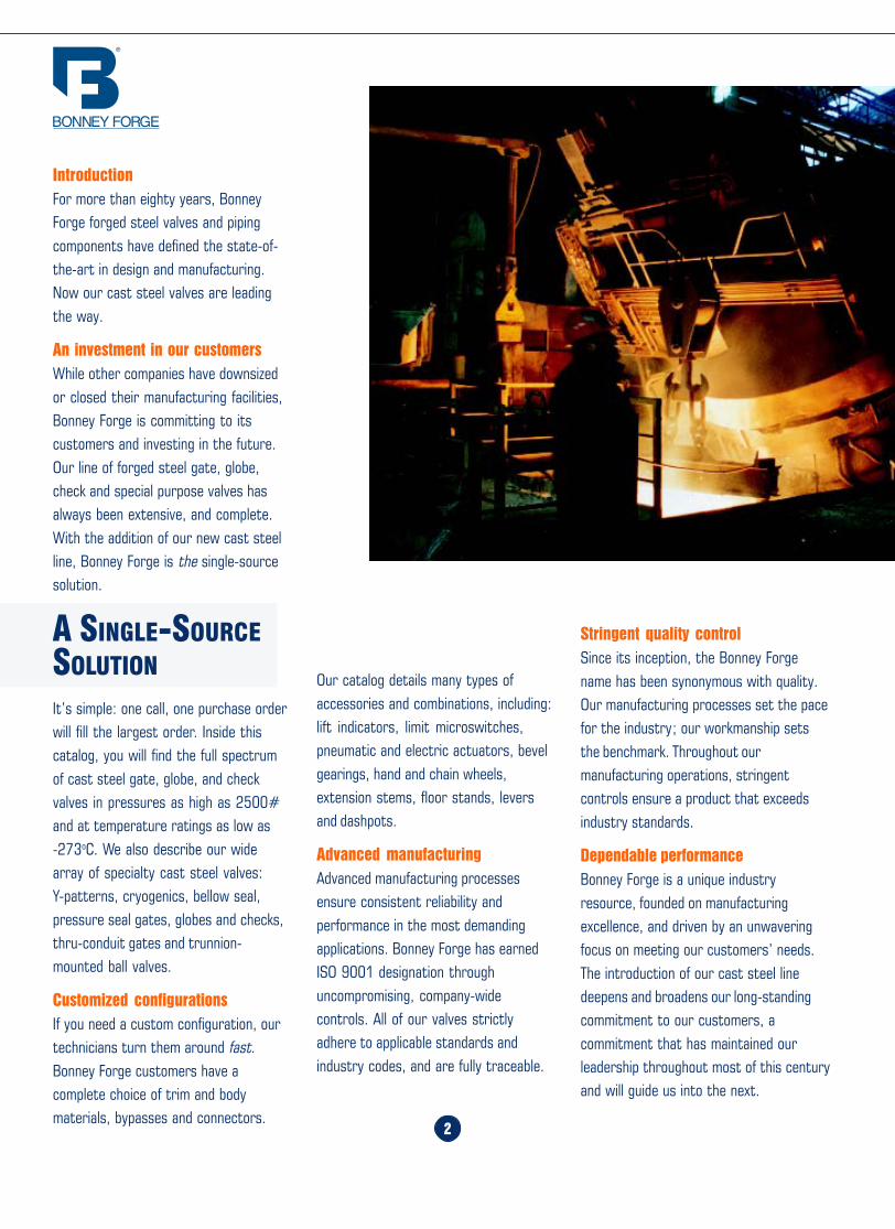
IntroductionFor more than eighty years, BonneyForge forged steel valves and pipingcomponents have defined the state-of-the-art in design and manufacturing.Now our cast steel valves are leadingthe way.
An investment in our customersWhile other companies have downsizedor closed their manufacturing facilities,Bonney Forge is committing to itscustomers and investing in the future.Our line of forged steel gate, globe,check and special purpose valves hasalways been extensive, and complete.With the addition of our new cast steelline, Bonney Forge is the single-sourcesolution.
It’s simple: one call, one purchase orderwill fill the largest order. Inside thiscatalog, you will find the full spectrumof cast steel gate, globe, and checkvalves in pressures as high as 2500#and at temperature ratings as low as-273oC. We also describe our widearray of specialty cast steel valves:Y-patterns, cryogenics, bellow seal,pressure seal gates, globes and checks,thru-conduit gates and trunnion-mounted ball valves.
Customized configurationsIf you need a custom configuration, ourtechnicians turn them around fast.Bonney Forge customers have acomplete choice of trim and bodymaterials, bypasses and connectors.
A SINGLE-SOURCESOLUTION
Stringent quality controlSince its inception, the Bonney Forgename has been synonymous with quality.Our manufacturing processes set the pacefor the industry; our workmanship setsthe benchmark. Throughout ourmanufacturing operations, stringentcontrols ensure a product that exceedsindustry standards.
Dependable performanceBonney Forge is a unique industryresource, founded on manufacturingexcellence, and driven by an unwaveringfocus on meeting our customers’ needs.The introduction of our cast steel linedeepens and broadens our long-standingcommitment to our customers, acommitment that has maintained ourleadership throughout most of this centuryand will guide us into the next.
Our catalog details many types ofaccessories and combinations, including:lift indicators, limit microswitches,pneumatic and electric actuators, bevelgearings, hand and chain wheels,extension stems, floor stands, leversand dashpots.
Advanced manufacturingAdvanced manufacturing processesensure consistent reliability andperformance in the most demandingapplications. Bonney Forge has earnedISO 9001 designation throughuncompromising, company-widecontrols. All of our valves strictlyadhere to applicable standards andindustry codes, and are fully traceable.
Home Table of Contents
Product Search
How To Order
PrintBack Next
Home Table of Contents
Product Search
How To Order
PrintBack
58
STORAGE, INSTALLATION AND MAINTENANCE PROCEDURES (CONT.)
3
SECTION 4 - V-LOK GATE VALVES, GLOBE VALVES AND CHECK VALVES
4.1 Disassembling4.1.1 Fully relieve line pressure from the valve. If the valve is a gate or globe type, unseat the wedge/disc and disassemble the yoke(see sect 3).
4.1.2 Grind down the seal weld by using a small light grinding disc. Care must be taken not to cause permanent damage becausethere is thin clearance between the body and the bonnet around the complete seal weld (see fig. A).Caution: The amount of care taken in removing this seal will determine the number of times the valve can be disassembled.
4.1.3 Hammer the bonnet to push it down about 1 mm.
4.1.4 Turn the bonnet anti clock wise, approx. 45 degrees (see fig. B).
4.1.5 The bonnet is now free to be lifted from the body.
4.1.6 For “V”-Lok and “V” Seal type tilting disc valves there is an additional seal weld around the plug of the hinge pin. Todisassemble the pin, grind out the seal weld by using a small and light grinding disc until a clearance appears all around. Thenunscrew the plug and remove the pin (see fig. C). For reweld see par. 5.6.
Section 5 - Assembling5.1 Reinstall the bonnet back into the body so the bonnet lug in the packing area is at 45 degrees.
5.2 Turn bonnet 45 degrees with the bonnet lug in line with valve run.
5.3 If the valve is a gate or globe, assemble the complete yoke, fit the yoke bolts and fasten nuts. Turn hand wheel so the disc/wedge is in its fully open position with the stem head tight against the back seat. For check valves, lift the bonnet using the relevantlug to provide full contact in that area. This operation is essential to avoid stressing the seal weld.
5.4 Before rewelding the seal weld, apply 4 (four) tack welds to maintain the bonnet in the upper position.
5.5 When seal weld is complete check with PT examination following by a pneumatic test of shell at 6 BAR (80 PSIG).
5.6 Welding instruction (WPS) applicable to each type of Body Bonnet materials are available on request.
Figure BFigure C
Figure A
Flexible Ring Flexible Ring
BodyBody
Bonnet Bonnet
Home Table of Contents
Product Search
How To Order
Print Next
Home Table of Contents
Product Search
How To Order
PrintBack Next
57
SECTION 3 - GATE AND GLOBE PRESSURE SEAL (“V” SEAL)
3.1 Disassembling
3.1.1 Partially open the valve to unseat the wedge from the seat-rings. Remove the hand wheel nut, hand wheel, yoke retaining nut,the yoke nut and companion thrust bearings. The yoke can now be removed totally.
3.1.2 Remove the retainer bolts by alternately loosening them diagonally across the bonnet’s diagonal.
3.1.3 Pull out the bolts from the bonnet retainer and extract the sector retaining ring.
3.1.4 Remove the entire assembly consisting of the bonnet, stem, and wedge. The bonnet will include the spacer ring and the bodybonnet gasket.
3.2 Re-assembling3.2.1 Before proceeding further, check the surfaces of the bonnet body gasket (generally made in stainless steel), housing andbonnet do not have evidence of corrosion or scratches.
3.2.2 Reverse the above procedure to re-assemble the unit.
3.2.3 After positioning the bonnet with its respective gasket and spacer ring, put in place the sector retaining ring and the bonnetretainer. Next, screw-in the retainer bolts taking care to tighten them alternatively by opposite diameters.
3.2.4 Assemble the yoke and the remaining components of the valve.Caution: It is possible that at low pressure the valve leaks between the body and bonnet. This is because the bolt’s function is morefor positioning the bonnet correctly and not tightening. To determine if more tightening is required, the valve needs to be fullypressurized.
3.3 Globe Valve
3.3.1 Follow the same procedure for gate valves. Note that some globe valves for dimensional reasons, require disassembly of theopposite gland flange screwed on the bonnet.
3.4 Check Valve
3.4.1 For either swing type, tilting or piston check valves, the procedure to follow is the same as the gates. The only exception inthe procedure is the bonnet retainer is substituted by a disc.
HOW TO ORDER/SPECIFY CAST STEEL VALVES
1. Specify valve size2. Designate Bonnet Style and Pressure Class from Section A3. Select Valve Type desired from Section B4. Indicate Body/Bonnet and Trim Material from Section C5. Select End Configuration from Section D6. Select other Body/Bonnet/Trim from Section E7. Select Special Requirement(s) from Section F8. Specify as a Suffix String, after Section D or E, any Body/Bonnet
Material, Trim Material or Special Requirements not listed below
SECTION A- BONNET STYLE AND PRESSURE CLASS
1 Bolted Bonnet Class 150#3 Bolted Bonnet Class 300#6 Bolted Bonnet Class 600#9 Bolted Bonnet Class 900#15 Bolted Bonnet Class 1500#25 Bolted Bonnet Class 2500#6PS Pressure Seal Bonnet Class 600#9PS Pressure Seal Bonnet Class 900#15PS Pressure Seal Bonnet Class 1500#25PS Pressure Seal Bonnet Class 2500#
SECTION B- TYPE OF VALVE
1 Gate Valve, Flexible Wedge2 Gate Valve, Plain Solid Wedge3 Globe Valve, T Pattern3Y Globe Valve, Y Pattern3A Globe Valve, Angle Pattern3SC Globe Stop Check Valve6 Check Valve, Swing Type7 Check Valve, Piston Type7Y Check Valve, Y Pattern Piston Type9 Check Valve, Tilting DiscTBV Ball Valve, Trunnion MountedTCG Thru-Conduit Gate
4
Home Table of Contents
Product Search
How To Order
PrintBack Next
Home Table of Contents
Product Search
How To Order
PrintBack Next
56
STORAGE, INSTALLATION AND MAINTENANCE PROCEDURES (CONT.)
INSTRUCTION FOR INSTALLATION AND MAINTENANCE
OF HIGH PRESSURE VALVES TYPE “V” SEAL AND “V” LOK
Section 1 - Installation, Operation and Maintenance1.1 Valve products manufactured by Bonney Forge may be installed and operated in service conditions suitable to their design andconstruction and only in accordance with all applicable codes, standards and generally accepted construction and operating practices.
1.2 No special tools are required for installation, disassembly, maintenance and reassembly of these valve products.
*1.3 Replacement of minor valve components, including stem packing and bonnet gaskets, may be done in the field provided thatproper procedures are followed.
1.4 Replacement of major components, including stem, wedge and seat rings should not be done in the field but should be done onlyin a properly equipped work shop.
1.5 We recommend that the bonnet studs on the valve be checked for tightness prior to pressurization and also after a short periodof service. This is particularly important if the valve has been subjected to severe changes in temperature. Tightening of bolts shouldbe done alternately from one side of the bonnet to the other to prevent distortion.
1.6 We recommend that packing gland nuts and bolts be tightened prior to installation of valves. It is also recommended that alubricant, such as grease, be inserted in the grease fitting of the yoke nut.
Section 2 - Stem Packing2.1 Stem packing is used on all standard gate and globe valves, both bolted bonnet and “V” Lok and “V” Seal types.
2.2 We suggest periodic inspection of the stem packing. In the event that the stem packing is leaking, it may only be necessary totighten the gland flange bolting. To prevent seizure of the stem, care must be taken not to over compress the stem packing.
*2.3 Procedure for Changing Stem Packing.2.3.1 The valve must be in the fully open position with the stem retracted against the back seat bushing.
2.3.2 Only when the stem is fully back seated can the gland flange bolting be loosened slightly to release any compression load inthe packing/stuffing box chamber.
2.3.3 The gland flange bolting may be further loosened to allow gland bushing to move up the stem permitting the removal andreplacement of the stem packing.
*CAUTION: Always be sure that the valve is de-pressurized and isolated prior to performing any maintenance work.
5
SECTION C- BODY/BONNET AND TRIM MATERIAL
1 A216WCB Body/Bonnet, Trim 13% Cr (F6/CA15) Hard FacedSeats (1/2 Stellite) API Trim #8
1N A216WCB Body/Bonnet, Trim 13% Cr (F6/CA15) API Trim #12 A216WCB Body/Bonnet, Trim 13% Cr (F6/CA15) Hard Faced
Seats & Disc (Full Stellite) API Trim #53 A216WCB Body/Bonnet, Trim 18% Cr-8NI (316/CF8M) API Trim # 104 A216WCB Body/Bonnet, Trim Ni-Cu Alloy, (Monel Metal) API Trim #95 A217WC9 Body/Bonnet, 2. 1/4% Cr 1% Mo, Trim 13% Cr
(F6/CA15) Hard Faced Seats (1/2 Stellite) API Trim #86 A217C5 Body/Bonnet, 5% Cr 1/2 % Mo, Trim 13% Cr
(F6/CA15) Hard Faced Seats (1/2 Stellite) API Trim #87 A351CF8 Body/Bonnet, Trim 18% Cr - 8 Ni(304/CF8)
Trim 304 Stainless Steel API Trim #28 A351CF8M Body/Bonnet, Trim 18% Cr - 8 Ni(316/CF8M)
Trim 316 Stainless Steel Api Trim #108S A351CF8M Body/Bonnet, Trim 18% Cr - 8 Ni(316/CF8M) Trim 316
Stainless Steel, Hard Faced Seats (1/2 Stellite) API Trim #129 A217WC6 Body/Bonnet, 1.1/4 Cr 1/2 Mo, Trim 13% Cr
(F6/CA15) Hard Faced Seats (1/2 Stellite) API Trim #80 Other Specify
SECTION D- END CONFIGURATION
RF Raised Face, Flanged End, 125-250 AARHRFSF Raised Face, Flanged End, 125 AARHRTJ Ring Type JointBW Butt Weld Ends (Specify Pipe Schedule)
SECTION E- OTHER BODY/BONNET OR TRIM MATERIALS
WCC A216WCC Carbon SteelWC1 A217WC1 Carbon/Moly SteelC12 A217C12 9% Cr 1% Moly SteelCA15 A217CA15 13% Cr1/2 Moly SteelLCB A352LCB Low Temp Carbon Steel - 50° FLC3 A352LC3 Low Temp Carbon Steel - 150° FCF3 A351CF3 Stainless Steel, Type 304LCF8M A351CF8M Stainless Steel, Type 316CN7M A351CN7M Stainless Steel, Type Alloy 20CF8C A351CF8C Stainless Steel, Type 347
Home Table of Contents
Product Search
How To Order
PrintBack
Home Table of Contents
Product Search
How To Order
PrintBack Next
55
PLATE
PLUG
HANDWHEEL NUT
HANDWHEEL
YOKE SLEEVE RETAINING NUTYOKE SLEEVE
NUTYOKE SLEEVE BEARING
GLAND FLANGEGLAND
LANTERN RINGNUTPACKINGBACK SEAT BUSHINGNUTEYE BOLTPINBONNETSTUD BOLT
STEMWEDGE
SEAT RING
BONNET GASKET
NUT
BODY
GATE VALVECOMPONENTS
GLOBE VALVECOMPONENTS
PLATE
NUT
HANDWHEEL NUTHANDWHEELYOKE SLEEVERETAINING NUT
NUTGLAND FLANGEGLAND
LANTERN RINGPACKING
BACK SEAT BUSHING
PLUG
EYE BOLT
PIN
BONNET GASKET
STEM
DISC NUTHALF RING
BONNET GASKET
BODY
SETSCREW
BONNET
STUDBOLT
NUT
SWING CHECKVALVE COMPONENTS
PIN
NUT
DISC WASHER
HINGE DISCDISC
SEAT RING
PIN
BONNET
STUD BOLT
PLUG
PLUG GASKET
GASKET
NUT
BODY
PLUG GASKET
PLUG
HINGE PIN
HOW TO ORDER/SPECIFY CAST STEEL VALVES (CONT.)
High Alloy Special SteelsM35-1 A494M35-1 Monel Nickel/Nickel Alloy SteelN-12M A494N-12M Hastelloy B, Nickel/Nickel Alloy SteelCW-12M A494-CW-12M Hastelloy C, Nickel/Nickel Alloy SteelCY-40 A494CY-40 Inconel Nickel/Nickel Alloy SteelCZ-100 A494CZ-100 Nickel Alloy SteelF-51 UNS S 31803 Duplex Stainless SteelH Grade Materials also available
Special Trim/Trim Combinations(H) H Grade Trim(L) L Grade TrimHFS 1/2 StelliteFHF Full Hard Face (Full Stellite)MON Monel TrimA20 Alloy 20 Trim321 321 Stainless Steel Trim347 347 Stainless Steel Trim
6
SECTION E- OTHER BODY/BONNET OR TRIM MATERIALS
SL Bellow Seal BonnetBG Bevel Gear OperatorBYP BypassCWO Chainwheel OperatedCRY Cryogenic BonnetEMO Electric Motor OperatorGD Guided Disc (Globe Valves)NACE NACE Requirements to MR-01-75, latest editionPMI Positive Material Identification required
List as a suffix, by abbreviation if possible,any other requirement not shown on this list
Example: 3" 150# RF Flanged Gate Valve, Bolted Bonnet,ASTM A216WCB Body/Bonnet with 1/2 Stellite Trim
1 11 RF_________ ____________ ____________
Sec A Sec. B, Sec. C Sec. D
AS: 3" 1-11-RF
SECTION F- MODIFICATIONS/SPECIAL REQUIREMENTS
Home Table of Contents
Product Search
How To Order
PrintBack Next
Home Table of Contents
Product Search
How To Order
54
STORAGE, INSTALLATION AND MAINTENANCE PROCEDURES (CONT.)
SWING CHECK VALVES
No periodic maintenance is necessary. If gasket leaks are detected, correct using the following procedure.
1 - Disassemble all cover bolts and nuts.
2 - For check valves in sizes 16" and larger, lift up the cover by using a lever inserted into the drilled and tapped cover hole. Forvalves in sizes 14" and smaller, use one or two bolts and nuts inserted into cover holes and, using adequate force, move the coverupwards.
3 - Check that the hinge, nut, and pin are in good condition and firmly connected. Replace damaged parts as necessary.
4 - Lift and remove the disc-hinge assembly. Movement should be free and not hindered by any malfunction of the hinge pin. Wheredisc travel is not sufficiently smooth, remove plugs or blind flanges and then remove hinge pin. Check surface for seizure marks. Ifmarks are deeper than 1.5 mm (1/16"); re-machine hinge pin and re-assemble. If defect depth is greater than 1.5 mm (1/16") anew hinge pin is necessary. When reassembling hinge pin, it is recommended that the disc be removed by loosening nut.
5 - When leakage is due to deterioration of seal surfaces caused by corrosion or foreign substances, it must be determined whetherthe disc or seat seal are the cause.
a) Deterioration of disc surfaces:Disassemble disc by removing nut and washer. Repair surface by grinding and relapping using fine grain abrasive paste.
b) Deterioration of seat seal surfaces:When seal surfaces are damaged and defects are confined to a small area but are not deeper than 0.8 mm (1/32"), the sealsurface can be repaired. The recommended method is to use a cast iron strap with an outside diameter matching the valve’sraceway. Then using a fine grain abrasive paste between the strap and raceway, it is rotated on the seat to restore originaltightness. When defects are deeper than 0.8 mm (1/32") and found on the entire seal surface, a new seat is required. Toreplace the new seat, use preferably a pneumatic tool with a shape to match the dimensions of the valve seat. It is recom-mended that an anti seizing compound be used when installing the replacement seat to make threading it in to the body easier.
*CAUTION: Always be sure that the valve is de-pressurized and isolated prior to performing any maintenance work.
G A T E VA LV E S
Overview .......................................... 8
150 lb. valves ................................... 9
300 lb. valves ................................... 9
600 lb. valves ................................. 10
900 lb. valves ................................. 10
1500 lb. valves ............................... 10
2500 lb. valves ............................... 10
7
Home Table of Contents
Product Search
How To Order
Print Next
Home Table of Contents
Product Search
How To Order
PrintBack Next
Home Table of Contents
Product Search
How To Order
PrintBack Next
53
OVERVIEW
8
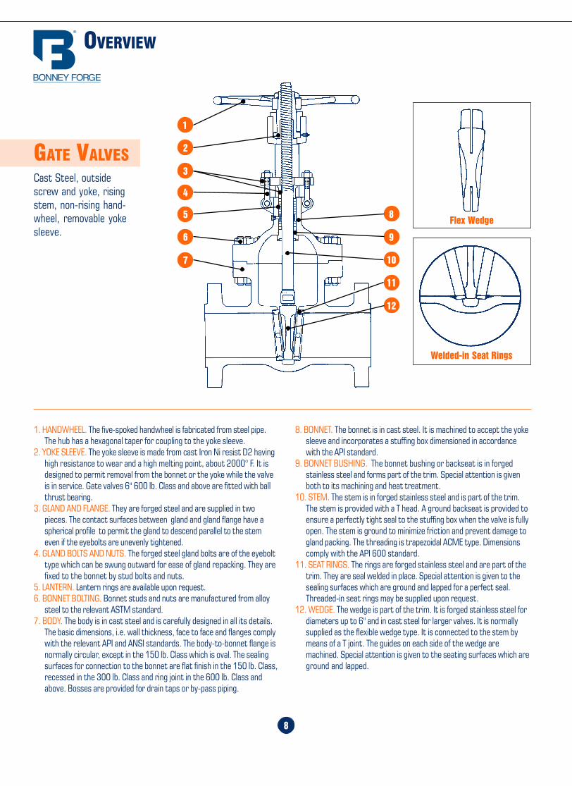
GATE VALVESCast Steel, outsidescrew and yoke, risingstem, non-rising hand-wheel, removable yokesleeve.
8. BONNET. The bonnet is in cast steel. It is machined to accept the yokesleeve and incorporates a stuffing box dimensioned in accordancewith the API standard.
9. BONNET BUSHING. The bonnet bushing or backseat is in forgedstainless steel and forms part of the trim. Special attention is givenboth to its machining and heat treatment.
10. STEM. The stem is in forged stainless steel and is part of the trim.The stem is provided with a T head. A ground backseat is provided toensure a perfectly tight seal to the stuffing box when the valve is fullyopen. The stem is ground to minimize friction and prevent damage togland packing. The threading is trapezoidal ACME type. Dimensionscomply with the API 600 standard.
11. SEAT RINGS. The rings are forged stainless steel and are part of thetrim. They are seal welded in place. Special attention is given to thesealing surfaces which are ground and lapped for a perfect seal.Threaded-in seat rings may be supplied upon request.
12. WEDGE. The wedge is part of the trim. It is forged stainless steel fordiameters up to 6" and in cast steel for larger valves. It is normallysupplied as the flexible wedge type. It is connected to the stem bymeans of a T joint. The guides on each side of the wedge aremachined. Special attention is given to the seating surfaces which areground and lapped.
1. HANDWHEEL. The five-spoked handwheel is fabricated from steel pipe.The hub has a hexagonal taper for coupling to the yoke sleeve.
2. YOKE SLEEVE. The yoke sleeve is made from cast Iron Ni resist D2 havinghigh resistance to wear and a high melting point, about 2000° F. It isdesigned to permit removal from the bonnet or the yoke while the valveis in service. Gate valves 6" 600 lb. Class and above are fitted with ballthrust bearing.
3. GLAND AND FLANGE. They are forged steel and are supplied in twopieces. The contact surfaces between gland and gland flange have aspherical profile to permit the gland to descend parallel to the stemeven if the eyebolts are unevenly tightened.
4. GLAND BOLTS AND NUTS. The forged steel gland bolts are of the eyebolttype which can be swung outward for ease of gland repacking. They arefixed to the bonnet by stud bolts and nuts.
5. LANTERN. Lantern rings are available upon request.6. BONNET BOLTING. Bonnet studs and nuts are manufactured from alloy
steel to the relevant ASTM standard.7. BODY. The body is in cast steel and is carefully designed in all its details.
The basic dimensions, i.e. wall thickness, face to face and flanges complywith the relevant API and ANSI standards. The body-to-bonnet flange isnormally circular, except in the 150 lb. Class which is oval. The sealingsurfaces for connection to the bonnet are flat finish in the 150 lb. Class,recessed in the 300 lb. Class and ring joint in the 600 lb. Class andabove. Bosses are provided for drain taps or by-pass piping.
1
2
4
3
5
6
7
8
9
10
11
12
Flex Wedge
Welded-in Seat Rings
2.3 The procedure to re-assembling the valve is as follows:Re-insert the stem through the stuffing box, taking special care to reassemble parts in sequence. If so equipped, avoid allowing thelantern ring to slide into the stuffing box. If the valve is equipped with a lantern ring, first insert 3 packing rings into the stuffing box.Next, insert the remaining packing rings into the stuffing box and compress using the gland ring and flange. Then, reassemble nuts andtighten. Note, the stem must slide freely through the stuffing box without applying excessive force. Finally, install the bonnet gasketmaking sure it is not damaged. The gasket should be replaced if there is any question as to its performance.
2.4 Raise the bonnet assembly, making sure the stem is in the fully open position. Lower bonnet on to the valve body making surethat the disc fits exactly into body guides and the bonnet gasket is properly seated. Align holes and tighten bonnet nuts taking carethat excessive force is not used, possibly damaging the gasket. Hydrostatically test the valve to assure that there is no leakage.
2.5 Disassembly of yoke nutWhen necessary use the following procedure for disassembling and replacing yoke nut:
a) direct hand-operated valves (handwheel)- remove set screw;- unscrew handwheel nut;- remove handwheel;- unscrew yoke nut retaining nut, removing spot welds if necessary;- Reverse the procedure for re-assembly.
b) bevel gear operated valves- to remove the bevel gear from the valve, unscrew nuts and turn the handwheel in the open direction indicated by the arrow until
the drive nuts are disengaged from the stem.- to check the condition of the drive nut or bearing, unscrew the retainer ring and remove drive the nut and bearing. If damaged, a
new drive nut or bearing is necessary.
2.6 Disk and SeatsLeakage through disk and seats are not always easy to spot when valves are in service. However, when leaks are identified, immediateaction is necessary. Any delay can permanently damage seat or wedge seal surfaces.
To repair or replace the disk or seats, the valve must be removed from line, then use the following procedure:- make sure that the valve is not under pressure before unscrewing bonnet nuts;- remove bonnet, being careful not to damage the gasket;- remove bonnet when disk is in full open position;- lift up bonnet
If seat surfaces show signs of seizing, pitting, grooves or other defects not deeper that 1.5 mm (1/16") it is possible to repairseating surfaces to its original conditions by relapping the surface with line grain abrasive paste, creating a perfect tightness onceagain. Defects having a depth exceeding 1.5 mm (1/16") cannot be repaired by lapping. In this case, parts must be replaced.
It is recommended that the face of the disc be blued to check for contact of seating surface after final lapping. For re-assembly ofvalves use the procedure outlined under para. 2.4.
Home Table of Contents
Product Search
How To Order
PrintBack Next
Home Table of Contents
Product Search
How To Order
PrintBack Next
52
STORAGE, INSTALLATION AND MAINTENANCE PROCEDURES (CONT.)
GLOBE VALVES -“O.S.” & “Y”1.0 Periodic Inspections
1.1 The valve stem packing should be inspected at least monthly. If the stem packing shows signs of leakage, simply tighten theadjusting nuts to compress the packing. Do not over-tighten the adjusting nuts as this will make operation of the valve moredifficult. If, after tightening the adjusting nuts to their fullest extent, the leakage does not stop, it is then necessary to replace thestem packing. It is not recommended that additional packing rings be added to the stuffing box as this may cause damage to thestem sealing system. Please contact Bonney Forge or it’s distributor for new stem packing sets. For packing replacement seeparagraphs 2.2 and 2.3.
1.2 The lubrication of the yokenut should be inspected at least monthly. A high pressure grease gun should be used for valvessupplied with ball type grease fittings. For valves supplied with a Stauffer type grease cup, the cup should be checked to assure thatit is full so that the grease can be injected by turning the screw cap.
1.3 Bonnet bolt tension should be checked periodically when valves are used in high temperature applications where creep mayoccur. Although leaks through ring joints are rare, erosion or corrosion could cause rings to fail. In these cases, a new ring gasket isrequired.
2.0 Extraordinary Maintenance or Replacement of Damaged Parts
2.1 Stem. If the stem locks or freezes, causes can generally be attributed to dry worn packing or a dry yoke nut. In either of thesecases, the following service is required:
*a) Unscrew gland nuts, remove gland flange and bushing to expose stem packing and lantern ring. Replace stem packing if it isdamaged. If the lantern ring is seized, completely disassemble the stem and replace the lantern ring.
b) Check lubrication of yoke nut. If it is dry, remove the yoke nut and determine if there is evidence of seizure marks. If so, replaceit with a new yoke nut.
*2.2 Disassembly of Stem Packing.a) In those cases where the valve cannot be removed from the piping system, it is important that prior to servicing, the valve be
opened to its fullest extent. Partially unscrew nuts to reduce the compression load on the stuffing box. Next, if so equipped,remove the plug to check that there is no leakage. Remove the stem packing and, if so equipped, the lantern and bottom set ofstem packing then replace with new set(s) of packing. Reassemble plug and gland flange. Finally, tighten nuts sufficiently whileallowing the stem to operate smoothly.
b) To replace the stem when the valve is completely disassembled for general maintenance follow this procedure:- Open valve fully then remove bonnet bolts and nuts.- With the bonnet removed, unscrew the gland bolts then lift up gland flange exposing the stem packing.- Remove stem packing above the lantern ring (if so equipped).- Remove handwheel then turn stem to release it from yoke nut and remove from stuffing box.- Check condition of back-seat bushing for seizure marks. If apparent, order replacement parts.- If required, turn the bonnet up-side-down and remove lantern ring.- If so equipped, remove stem packing below the lantern ring.
*CAUTION: Always be sure that the valve is de-pressurized and isolated prior to performing any maintenance work.
9
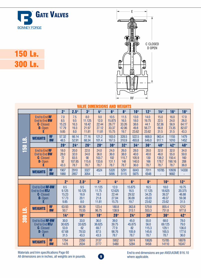
150 LB.300 LB.
14" 16" 18" 20" 24" 30" 36" 42"End to End RF-BW 30.0 33.0 36.0 39.0 45.0 55.0 68.0 78.0
End to End RTJ 30.625 33.625 36.625 39.75 45.875 56.0 69.125 79.0C- Closed 53.9 62 69.7 77.9 82 115.3 129.1 136.0D- Open 67.68 78.53 87.5 98.76 105.9 145.6 165.5 177.6
E 31.5 43.3 43.3 78.7 78.7 78.7 78.7 36.0
RF 1764 2350 3137 5952 5974 10626 15785 18078BW 1478 2034 2777 5480 5284 9458 14110 16347WEIGHTS
300
LB.
2" 2.5" 3" 4" 6" 8" 10" 12"End to End RF-BW 8.5 9.5 11.125 12.0 15.875 16.5 18.0 19.75
End to End RTJ 9.125 10.125 11.75 12.625 16.5 17.125 18.625 20.375C- Closed 15.23 16.9 18.3 22.44 29.52 34.25 39.37 46.88D- Open 17.73 20.1 21.8 27.04 36.09 43.03 49.37 59.38
E 9.85 8.0 11.81 15.75 19.7 23.62 23.62 31.5
RF 63.93 90.39 123.4 180.8 363.8 579.8 855.4 1212BW 50.7 70.55 96.75 138.9 313.1 553.3 751.8 977.8WEIGHTS
Materials and trim specifications Page 60All dimensions are in inches, all weights are in pounds.
20" 24" 26" 28" 30" 32" 34" 36" 40" 42" 48"End to End RF 18.0 20.0 22.0 24.0 24.0 26.0 28.0 28.0 32.0 32.0 34.0End to End BW 28.0 32.0 34.0 36.0 36.0 38.0 40.0 40.0 46.0 55.0 50.0
C- Closed 72 83.5 90 103.7 102 115.7 105.9 130 138.2 150.4 160D- Open 92 107.85 115.6 133.6 131.1 148 140.0 166 178.7 190.16 208
E 43.3 78.7 78.7 78.7 78.7 78.7 36.0 78.7 78.7 78.7 36.0
RF 1907 2910 3327 4524 5320 5291 6043 7011 10785 10939 14330BW 1880 2857 3054 - 5095 5115 5875 6548 - 9682 -WEIGHTS
150
LB.
2" 2.5" 3" 4" 6" 8" 10" 12" 14" 16" 18"End to End RF 7.0 7.5 8.0 9.0 10.5 11.5 13.0 14.0 15.0 16.0 17.0End to End BW 8.5 9.5 11.125 12.0 15.875 16.5 18.0 19.75 22.5 24.0 26.0
C- Closed 15.23 16.3 18.42 22.44 26.77 33.26 38.6 44.1 52.36 56.9 64.17D- Open 17.79 19.3 21.97 27.12 33.37 42.06 49.8 56.77 66.8 73.35 82.07
E 9.85 8.0 11.81 11.81 15.75 19.7 23.62 23.62 31.5 31.5 43.3
RF 57.32 66.14 77.16 121.2 183.0 328.5 522.5 668.0 963.4 1155 1479BW 48.5 52.91 68.34 101.4 167.5 310.9 493.8 646.0 917.1 1010 1452WEIGHTS
VALVE DIMENSIONS AND WEIGHTS
GATE VALVES
RF
E
C CLOSEDD OPEN
End to end dimensions are per ANSI\ASME B16.10where applicable.
Home Table of Contents
Product Search
How To Order
PrintBack
Home Table of Contents
Product Search
How To Order
PrintBack Next
GATE VALVES
10
VALVE DIMENSIONS AND WEIGHTS
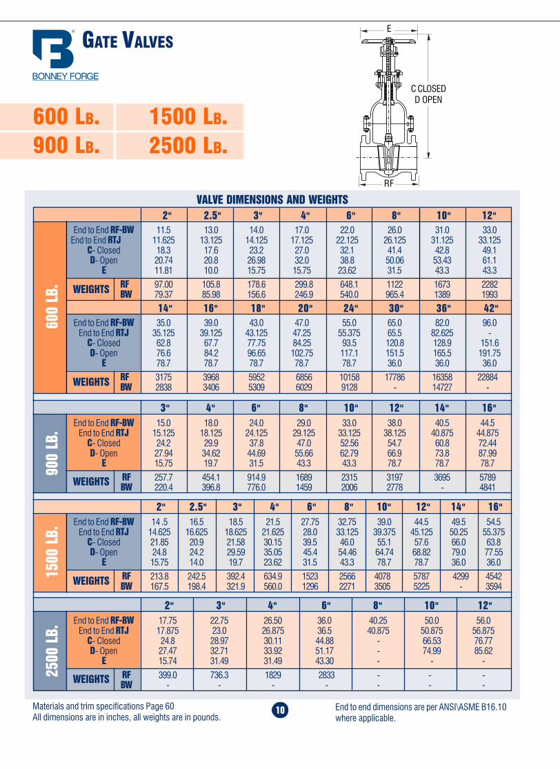
900
LB.
3" 4" 6" 8" 10" 12" 14" 16"
1500
LB.
End to End RF-BW 15.0 18.0 24.0 29.0 33.0 38.0 40.5 44.5End to End RTJ 15.125 18.125 24.125 29.125 33.125 38.125 40.875 44.875
C- Closed 24.2 29.9 37.8 47.0 52.56 54.7 60.8 72.44D- Open 27.94 34.62 44.69 55.66 62.79 66.9 73.8 87.99
E 15.75 19.7 31.5 43.3 43.3 78.7 78.7 78.7
RF 257.7 454.1 914.9 1689 2315 3197 3695 5789BW 220.4 396.8 776.0 1459 2006 2778 - 4841
14" 16" 18" 20" 24" 30" 36" 42"End to End RF-BW 35.0 39.0 43.0 47.0 55.0 65.0 82.0 96.0
End to End RTJ 35.125 39.125 43.125 47.25 55.375 65.5 82.625 -C- Closed 62.8 67.7 77.75 84.25 93.5 120.8 128.9 151.6D- Open 76.6 84.2 96.65 102.75 117.1 151.5 165.5 191.75
E 78.7 78.7 78.7 78.7 78.7 36.0 36.0 36.0
RF 3175 3968 5952 6856 10158 17786 16358 22884BW 2838 3406 5309 6029 9128 - 14727 -WEIGHTS
600
LB.
2" 2.5" 3" 4" 6" 8" 10" 12"End to End RF-BW 11.5 13.0 14.0 17.0 22.0 26.0 31.0 33.0
End to End RTJ 11.625 13.125 14.125 17.125 22.125 26.125 31.125 33.125C- Closed 18.3 17.6 23.2 27.0 32.1 41.4 42.8 49.1D- Open 20.74 20.8 26.98 32.0 38.8 50.06 53.43 61.1
E 11.81 10.0 15.75 15.75 23.62 31.5 43.3 43.3
RF 97.00 105.8 178.6 299.8 648.1 1122 1673 2282BW 79.37 85.98 156.6 246.9 540.0 965.4 1389 1993WEIGHTS
2" 2.5" 3" 4" 6" 8" 10" 12" 14" 16"End to End RF-BW 14 .5 16.5 18.5 21.5 27.75 32.75 39.0 44.5 49.5 54.5
End to End RTJ 14.625 16.625 18.625 21.625 28.0 33.125 39.375 45.125 50.25 55.375C- Closed 21.85 20.9 21.58 30.15 39.5 46.0 55.1 57.6 66.0 63.8D- Open 24.8 24.2 29.59 35.05 45.4 54.46 64.74 68.82 79.0 77.55
E 15.75 14.0 19.7 23.62 31.5 43.3 78.7 78.7 36.0 36.0
RF 213.8 242.5 392.4 634.9 1523 2566 4078 5787 4299 4542BW 167.5 198.4 321.9 560.0 1296 2271 3505 5225 - 3594
2500
LB.
2" 3" 4" 6" 8" 10" 12"End to End RF-BW 17.75 22.75 26.50 36.0 40.25 50.0 56.0
End to End RTJ 17.875 23.0 26.875 36.5 40.875 50.875 56.875C- Closed 24.8 28.97 30.11 44.88 - 66.53 76.77D- Open 27.47 32.71 33.92 51.17 - 74.99 85.62
E 15.74 31.49 31.49 43.30 - - -
RF 399.0 736.3 1829 2833 - - -BW - - - - - - -
E
RF
600 LB.900 LB.
1500 LB.2500 LB.
C CLOSEDD OPEN
Materials and trim specifications Page 60All dimensions are in inches, all weights are in pounds.
End to end dimensions are per ANSI\ASME B16.10where applicable.
51
2.3 The procedure to re-assembly the valve is as follows:Re-insert the stem through the stuffing box taking special care to reassemble parts in sequence. If so equipped, avoid allowing thelantern ring to slide into the stuffing box. If the valve is equipped with a lantern ring, first insert 3 packing rings into the stuffing boxfollowed by a lantern ring. Next, insert the remaining packing rings into the stuffing box and compress using the gland and flange.Then, reassemble nuts and tighten. Note, the stem must slide freely through the stuffing box without applying excessive force.Finally, install the bonnet gasket making sure it is not damaged. The gasket should be replaced if there is any question as to itsperformance.
2.4 Raise the bonnet, making sure the stem is in a half open position, then connect disc to stem. Lower bonnet on to the valve bodymaking sure that the disc fits exactly into body guides and the bonnet gasket is properly seated. Align holes and tighten bonnet nutstaking care that excessive force is not used, possibly damaging the gasket. Hydrostatically test the valve to assure that there is noleakage.
2.5 Disassembly of yoke nutWhen necessary use the following procedure for disassembling and replacing yoke nut:
a) direct hand-operated valves (handwheel)- remove set screw;- unscrew handwheel nut;- remove handwheel;- unscrew yoke nut retaining nut, removing spot welds if necessary;
Reverse the procedure for re-assembly.
b) bevel gear operated valves- to remove the bevel gear from the valve, unscrew nuts and turn the handwheel in the open direction indicated by the arrow until
the drive nuts are disengaged from the stem.- to check the condition of the drive nut or bearing, unscrew the retainer ring and remove drive the nut and bearing. If damaged, a
new drive nut or bearing is necessary.
2.6 Wedge and SeatsLeakage through seats and wedges are not always easy to spot when valves are in service. However, when leaks are identified,immediate action is necessary. Any delay can permanently damage seat or wedge seal surfaces.
To repair or replace wedges or seats, the valve must be removed from line then use the following procedure:
- make sure that the valve is not under pressure before unscrewing bonnet nuts;- remove bonnet, being careful not to damage the gasket;- remove bonnet when wedge is in half open position;- lift up bonnet until wedge is disconnected from guides;- release wedge from stem.
If seat surfaces show signs of seizing, pitting, grooves or other defects not deeper that 0.8 mm (1/32") it is possible to repairseating surfaces to its original conditions by relapping the surface with line grain abrasive paste, creating a perfect tightness onceagain.
Defects having a depth exceeding 0.8 mm (1/32") cannot be repaired by lapping. In this case, parts must be replaced.
It is recommended that the face of the disc be blued to check for contact of seating surface after final lapping. For re-assembly ofvalves use the procedure outlined under para. 2.4.
WEIGHTS
WEIGHTS
WEIGHTS

Home Table of Contents
Product Search
How To Order
PrintBack Next
Home Table of Contents
Product Search
How To Order
50
STORAGE, INSTALLATION AND MAINTENANCE PROCEDURES
GATE VALVE “O.S.” & “Y”1.0 Periodic Inspections1.1 The valve stem packing should be inspected at least monthly. If the stem packing shows signs of leakage, simply tighten theadjusting nuts to compress the packing. Do not over-tighten the adjusting nuts as this will make operation of the valve moredifficult. If, after tightening the adjusting nuts to their fullest extent, the leakage does not stop , it is then necessary to replace thestem packing. It is not recommended that additional packing rings be added to the stuffing box as this may cause damage to thestem sealing system. Please contact Bonney Forge or it’s distributor for new stem packing sets. For packing replacement seeparagraphs 2.2 and 2.3.
1.2 The lubrication of the yokenut should be inspected at least monthly. A high pressure grease gun should be used for valvessupplied with ball type grease fittings. For valves supplied with a Stauffer type grease cup, the cup should be checked to assure thatit is full so that the grease can be injected by turning the screw cap.
1.3 Bonnet bolt tension should be checked periodically when valves are used in high temperature applications where creep mayoccur. Although leaks through ring joints are rare, erosion or corrosion could cause rings to fail. In these cases, a new ring gasket isrequired.
2.0 Extraordinary Maintenance or Replacement of Damaged Parts2.1 Stem. If the stem locks or "freezes", causes can generally be attributed to dry worn packing or a dry yoke nut. In either of thesecases, the following service is required:
*a) Unscrew gland nuts, remove the gland flange and bushing to expose stem packing and lantern ring. Replace stem packing if itis damaged. If the lantern ring is seized, completely disassemble the stem and replace the lantern ring.
b) Check lubrication of yoke nut. If it is dry, remove the yoke nut and determine if there is evidence of seizure marks. If so, replaceit with a new yoke nut.
*2.2 Disassembly of Stem Packing.
a) In those cases where the valve can not be removed from the piping system, it is important that prior to servicing, the valve beopened to its fullest extent. Partially unscrew nuts to reduce the compression load on the stuffing box. Next, if so equipped,remove the plug to check that there is no leakage. Remove the stem packing and, if so equipped, the lantern and bottom set ofstem packing then replace with new set(s) of packing. Finally, tighten nuts sufficiently while allowing the stem to operatesmoothly.
b) To replace the stem when the valve is completely disassembled for general maintenance follow this procedure:- Open valve half way then remove bonnet bolts and nuts.- Lift up the bonnet to remove wedge.- With the bonnet removed, unscrew the gland bolts then lift up gland flange exposing the stem packing.- Remove stem packing above the lantern ring (if so equipped) and then turn the handwheel to force the stem down.- Remove the stem through the stuffing box. Turn the bonnet up-side-down and remove lantern ring.- If so equipped, remove stem packing below the lantern ring.
*CAUTION: Always be sure that the valve is de-pressurized and isolated prior to performing any maintenance work.
G L O B E VA LV E S
11
Overview ........................................ 12
150 lb. valves ................................. 13
300 lb. valves ................................. 13
600 lb. valves ................................. 14
900 lb. valves ................................. 14
1500 lb. valves ............................... 14
Home Table of Contents
Product Search
How To Order
Print Next
Home Table of Contents
Product Search
How To Order
PrintBack Next
Home Table of Contents
Product Search
How To Order
PrintBack Next
OVERVIEW
12
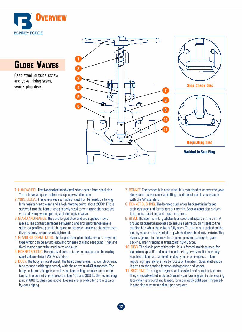
GLOBE VALVESCast steel, outside screwand yoke, rising stem,swivel plug disc.
7. BONNET. The bonnet is in cast steel. It is machined to accept the yokesleeve and incorporates a stuffing box dimensioned in accordancewith the API standard.
8. BONNET BUSHING. The bonnet bushing or backseat is in forgedstainless steel and forms part of the trim. Special attention is givenboth to its machining and heat treatment.
9. STEM. The stem is in forged stainless steel and is part of the trim. Aground backseat is provided to ensure a perfectly tight seal to thestuffing box when the valve is fully open. The stem is attached to thedisc by means of a threaded ring which allows the disc to rotate. Thestem is ground to minimize friction and prevent damage to glandpacking. The threading is trapezoidal ACME type.
10. DISC. The disc is part of the trim. It is in forged stainless steel fordiameters up to 6" and in cast steel for larger valves. It is normallysupplied of the flat, tapered or plug type or, on request, of theregulating type, always free to rotate on the stem. Special attentionis given to the seating face which is ground and lapped.
11. SEAT RING. The ring is forged stainless steel and is part of the trim.They are seal welded in place. Special attention is given to the seatingface which is ground and lapped, for a perfectly tight seal. Threaded-in seat ring may be supplied upon request.
1. HANDWHEEL. The five-spoked handwheel is fabricated from steel pipe.The hub has a square hole for coupling with the stem.
2. YOKE SLEEVE. The yoke sleeve is made of cast Iron Ni resist D2 havinghigh resistance to wear and a high melting point, about 2000° F. It isscrewed into the bonnet and properly sized to withstand the stresseswhich develop when opening and closing the valve.
3. GLAND AND FLANGE. They are forged steel and are supplied in twopieces. The contact surfaces between gland and gland flange have aspherical profile to permit the gland to descend parallel to the stem evenif the eyebolts are unevenly tightened.
4. GLAND BOLTS AND NUTS. The forged steel gland bolts are of the eyebolttype which can be swung outward for ease of gland repacking. They arefixed to the bonnet by stud bolts and nuts.
5. BONNET BOLTING. Bonnet studs and nuts are manufactured from alloysteel to the relevant ASTM standard.
6. BODY. The body is in cast steel. The basic dimensions, i.e. wall thickness,face to face and flanges comply with the relevant ANSI standards. Thebody-to-bonnet flange is circular and the sealing surfaces for connec-tion to the bonnet are recessed in the 150 and 300 lb. Series and ringjoint in 600 lb. class and above. Bosses are provided for drain taps orby-pass piping.
Stop Check Disc
Regulating Disc
Welded-in Seat Ring
1
2
4
3
5
6
7
8
9
10
11
Storage, Installation andMaintenance Procedures ........... 50-59
Material & Trim Specifications ......... 60
Terms & Conditions ........................ 61
49
INSTALL ATION
SPECIF ICATIONS
Home Table of Contents
Product Search
How To Order
PrintBack Next

Home Table of Contents
Product Search
How To Order
PrintBack Next
Home Table of Contents
Product Search
How To Order
PrintBack Next
48
STANDARD CLASS PRESSURE TEMPERATURE RATINGS (CONT.)
Temperature,°F
WorkingPressure
byClasses
-20 to 100 6170 5785 6250 5785 6250 6250 6250 6250 6250 6000 6000 6000 5000200 5625 5470 6250 5660 6250 5930 5965 6250 6250 5000 5160 5300 4640300 5470 5315 6070 5435 6070 5605 5640 6070 6070 4400 4660 4900 4360400 5280 5145 5880 5330 5880 5485 5400 5880 5880 3920 4280 4620 4010500 4990 4850 5540 5180 5540 5350 5330 5540 5540 3640 3980 4320 3900600 4560 4440 5040 5040 5040 5040 5040 5040 5040 3460 3760 4100 3790650 4475 4355 4905 4905 4905 4905 4905 4905 4905 3400 3700 4000 3750700 4440 4320 4730 4730 4730 4730 4730 4730 4730 3360 3600 3900 3710750 4200 3945 4200 4430 4430 4430 4430 4430 4430 3320 3520 3840 3665800 3430 3260 3430 4230 4230 4230 4230 4145 4230 3280 3460 3800 3600850 2230 2230 2230 4060 4060 4060 4060 3660 4060 3240 3380 3700 -900 1430 1430 1430 3745 3745 3745 3745 2945 3745 3200 3280 3600 -950 860 860 860 2345 2860 3145 3145 2170 3085 3120 3220 3220 -
1000 430 430 430 1370 1770 1860 2230 1600 2430 2685 3030 3030 -1050 - - - - 1570 1145 1660 1170 1570 2570 3000 3000 -1100 - - - - - 800 945 860 945 2145 2685 2685 -1150 - - - - - 430 860 570 630 1630 2285 2285 -1200 - - - - - 285 460 370 430 1285 1715 1430 -1250 - - - - - - - - - 915 1515 1030 -1300 - - - - - - - - - 685 1145 770 -1350 - - - - - - - - - 515 860 570 -1400 - - - - - - - - - 400 630 430 -1450 - - - - - - - - - 285 485 345 -1500 - - - - - - - - - 200 345 285 -
A 217WC1(b)
A 352LC1(d)
A 352LCB(d)
A 217WC4(h)
A 217WC5(i)
A 217WC6(j)
A 217C5
A 217C12
A 351CF3(f)
A 351CF8
A 217WC9(j)
A 351CF3M(g)
A 351CF8M
A 351CF8C
A 351CN7M(l)
A 216WCB(a)
Working Pressures in PSI
A 216 WCC(a)A 352 LC2(d)A 352 LC3(d)A 352 LCC(e)
2500
LB.
ANSI/ASME B 16.34
NOTE:(1) For welding end valves only. Flanged end ratings terminate at 1000°F.
NOTES:(a) Permissable, but not recommended for prolonged usage above about 800°F.(b) Permissable, but not recommended for prolonged usage above about 850°F.(d) Not to be used over 650°F.(e) Not to be used over 700°F.(f) Not to be used over 800°F.(g) Not to be used over 850°F.(h) Not to be used over 1000°F.(i) Not to be used over 1050°F.(j) Not to be used over 1100°F.(l) Ratings apply for 300°F and lower.
FLOW
13
150 LB.300 LB.
GLOBE VALVES
VALVE DIMENSIONS AND WEIGHTS
End to End RF-BW 8.0 8.5 9.5 11.5 16.0 19.5 24.5 27.5 31.0 36.0 37.44 38.5C- Closed 15.18 15.3 17.2 20.51 22.5 25.88 28.03 35.62 33.38 48.58 52.7 45.58D- Open 16.16 16.378 18.77 22.16 24.67 29.67 32.79 40.81 38.73 57.32 60.2 57.32
E 11.81 11.81 11.81 11.81 23.62 23.62 31.49 31.49 78.74 36.0 36.0 36.0RF 57.32 72.75 92.59 147.7 251.3 396.8 659.2 923.7 1184 1784 2344 3111BW 46.30 59.29 72.75 112.4 216.0 357.1 593.0 862.0 1065 1583 2183 -WEIGHTS15
0 LB
.
2" 2.5" 3" 4" 6" 8" 10" 12" 14" 16" 18" 20"
300
LB.
2" 2.5" 3" 4" 6" 8" 10" 12" 14" 16"End to End RF-BW 10.5 11.5 12.5 14.0 17.5 22.0 24.5 28.0 34.0 36.0
End to End RTJ 11.125 12.125 13.125 14.625 18.125 22.625 25.125 28.625 34.625 36.625C- Closed 15.15 15.3 18.81 21.77 24.05 27.08 33.42 45.98 43.85 57.87D- Open 16.8 17.0 20.26 23.65 27.0 31.64 36.92 50.38 49.75 66.49
E 11.81 11.81 11.81 15.74 23.62 31.49 31.49 43.3 78.74 36.0
RF 74.96 99.21 132.3 194.0 372.6 562.2 937.0 1510 1911 2465BW 57.32 79.40 108.0 143.3 319.7 469.6 811.4 1343 1659 2150
FLOW
E
RF
Materials and trim specifications Page 60All dimensions are in inches, all weights are in pounds.
End to end dimensions are per ANSI\ASME B16.10where applicable.
C CLOSEDD OPEN
WEIGHTS

Home Table of Contents
Product Search
How To Order
PrintBack
Home Table of Contents
Product Search
How To Order
PrintBack Next
14
600 LB.900 LB.1500 LB.
2" 2.5" 3" 4" 6" 8" 10"End to End RF-BW 14.5 16.5 18.5 21.5 27.75 32.75 39.0
End to End RTJ 14.625 16.625 18.625 21.625 28.0 33.125 39.375C- Closed 22.15 25.8 27.44 32.16 47.44 59.05 65.7D- Open 24.35 27.5 31.06 36.01 50.58 65.03 69.7
E 23.62 18.0 31.49 31.49 78.74 78.74 36.0
RF 211.6 295.4 414.5 676.8 1808 2425 3946BW 180.7 233.7 352.8 590.8 1621 2099 3395
1500
LB.
VALVE DIMENSIONS AND WEIGHTS2" 2.5" 3" 4" 6" 8" 10" 12" 14" 16"
600
LB. End to End RF-BW 11.5 13.0 14.0 17.0 22.0 26.0 31.0 33.0 35.0 39.0
End to End RTJ 11.625 13.125 14.125 17.125 22.125 26.125 31.125 33.125 35.125 39.125C- Closed 18.08 20.5 21.92 26.45 36.96 42.50 48.98 60.55 60.55 68.57D- Open 18.98 21.65 23.92 29.42 40.18 46.90 54.12 66.14 66.14 74.94
E 11.81 15.74 15.74 23.62 31.49 43.3 43.3 43.3 36.0 36.0
RF 101.4 134.5 180.8 317.5 698.9 1212 1940 2645 3307 3645BW 83.77 112.4 152.1 273.4 579.9 1089 1686 2283 2965 -
3" 4" 6" 8" 10" 12"End to End RF-BW 15.0 18.0 24.0 29.0 33.0 38.0
End to End RTJ 15.125 18.125 24.125 29.125 33.125 38.125C- Closed 26.10 29.44 43.85 48.03 56.61 63.70D- Open 28.24 33.21 47.78 53.1 63.3 70.84
E 23.62 23.62 31.5 43.3 78.74 53.15
RF 264.5 476.2 1146 1817 2976 3748BW 229.3 432.1 1023 1696 2747 3439
900
LB.
FLOW
E
C CLOSEDD OPEN
RF
Materials and trim specifications Page 60All dimensions are in inches, all weights are in pounds.
End to end dimensions are per ANSI\ASME B16.10where applicable.
47
-20 to 100 3705 3470 3750 3470 3750 3750 3750 3750 3750 3600 3600 3600 3000200 3375 3280 3750 3395 3750 3560 3580 3750 3750 3000 3095 3180 2785300 3280 3190 3640 3260 3640 3365 3385 3640 3640 2640 2795 2940 2615400 3170 3085 3530 3200 3530 3290 3240 3530 3530 2350 2570 2770 2405500 2995 2910 3325 3105 3325 3210 3200 3325 3325 2185 2390 2590 2340
600 2735 2665 3025 3025 3025 3025 3025 3025 3025 2075 2255 2460 2275650 2685 2615 2940 2940 2940 2940 2940 2940 2940 2040 2220 2400 2250700 2665 2590 2840 2840 2840 2840 2840 2840 2840 2015 2160 2340 2225750 2520 2365 2520 2660 2660 2660 2660 2660 2660 1990 2110 2305 2200800 2060 1955 2060 2540 2540 2540 2540 2485 2540 1970 2075 2280 2160
850 1340 1340 1340 2435 2435 2435 2435 2195 2435 1945 2030 2220 -900 860 860 860 2245 2245 2245 2245 1765 2245 1920 1970 2160 -950 515 515 515 1405 1715 1885 1885 1305 1850 1870 1930 1930 -
1000 260 260 260 825 1065 1115 1340 960 1460 1610 1820 1820 -1050 - - - - 945 684 995 705 945 1545 1800 1800 -
1100 - - - - - 480 565 515 565 1285 1610 1610 -1150 - - - - - 260 515 345 380 980 1370 1370 -1200 - - - - - 170 275 225 260 770 1030 855 -1250 - - - - - - - - - 550 910 615 -1300 - - - - - - - - - 410 685 465 -
1350 - - - - - - - - - 310 515 345 -1400 - - - - - - - - - 240 380 255 -1450 - - - - - - - - - 170 290 205 -1500 - - - - - - - - - 120 205 170 -
1500
LB.
Temperature,°F
WorkingPressure
byClasses
-20 to 100 2220 2085 2250 2085 2250 2250 2250 2250 2250 2160 2160 2160 1800200 2025 1970 2250 2035 2250 2135 2150 2250 2250 1800 1860 1910 1670300 1970 1915 2185 1955 2185 2020 2030 2185 2185 1585 1680 1765 1570400 1900 1850 2115 1920 2115 1975 1945 2115 2115 1410 1540 1665 1445500 1795 1745 1995 1865 1995 1925 1920 1995 1995 1310 1435 1555 1405600 1640 1600 1815 1815 1815 1815 1815 1815 1815 1245 1355 1475 1365650 1610 1570 1765 1765 1765 1765 1765 1765 1765 1225 1330 1440 1350700 1600 1555 1705 1705 1705 1705 1705 1705 1705 1210 1295 1405 1335750 1510 1420 1510 1595 1595 1595 1595 1595 1595 1195 1270 1385 1320800 1235 1175 1235 1525 1525 1525 1525 1490 1525 1180 1245 1370 1295850 805 805 805 1460 1460 1460 1460 1315 1460 1165 1215 1330 -900 515 515 515 1350 1350 1350 1350 1060 1350 1150 1180 1295 -950 310 310 310 845 1030 1130 1130 780 1110 1125 1160 1160 -
1000 155 155 155 495 640 670 805 575 875 965 1090 1090 -1050 - - - - 565 410 595 420 565 925 1080 1080 -1100 - - - - - 290 340 310 340 770 965 965 -1150 - - - - - 155 310 205 225 585 825 825 -1200 - - - - - 105 165 135 155 465 620 515 -1250 - - - - - - - - - 330 545 370 -1300 - - - - - - - - - 245 410 280 -1350 - - - - - - - - - 185 310 205 -1400 - - - - - - - - - 145 225 155 -1450 - - - - - - - - - 105 175 125 -1500 - - - - - - - - - 70 125 105 -
A 217WC1(b)
A 352LC1(d)
A 352LCB(d)
A 217WC4(h)
A 217WC5(i)
A 217WC6(j)
A 217C5
A 217C12
A 351CF3(f)
A 351CF8
A 217WC9(j)
A 351CF3M(g)
A 351CF8M
A 351CF8C
A 351CN7M(l)
A 216WCB(a)
Working Pressures in PSI
A 216 WCC(a)A 352 LC2(d)A 352 LC3(d)A 352 LCC(e)
900
LB.
GLOBE VALVES
WEIGHTS
WEIGHTS
WEIGHTS
Home Table of Contents
Product Search
How To Order
PrintBack Next
Home Table of Contents
Product Search
How To Order
46
STANDARD CLASS PRESSURE TEMPERATURE RATINGS (CONT.)
-20 to 100 1480 1390 1500 1390 1500 1500 1500 1500 1500 1440 1440 1440 1200200 1350 1315 1500 1360 1500 1425 1430 1500 1500 1200 1240 1270 1115300 1315 1275 1455 1305 1455 1345 1355 1455 1455 1055 1120 1175 1045400 1270 1235 1410 1280 1410 1315 1295 1410 1410 940 1030 1110 960500 1200 1165 1330 1245 1330 1285 1280 1330 1330 875 955 1035 935
600 1095 1065 1210 1210 1210 1210 1210 1210 1210 830 905 985 910650 1075 1045 1175 1175 1175 1175 1175 1175 1175 815 890 960 900700 1065 1035 1135 1135 1135 1135 1135 1135 1135 805 865 935 890750 1010 945 1010 1065 1065 1065 1065 1065 1065 795 845 920 880800 825 780 825 1015 1015 1015 1015 995 1015 790 830 910 865
850 535 535 535 975 975 975 975 880 975 780 810 890 -900 345 345 345 900 900 900 900 705 900 770 790 865 -950 205 205 205 560 685 755 755 520 740 750 775 775 -
1000 105 105 105 330 425 445 535 385 585 645 725 725 -1050 - - - - 380 275 400 280 380 620 720 720 -
1100 - - - - - 190 225 205 225 515 645 645 -1150 - - - - - 105 205 140 150 390 550 550 -1200 - - - - - 70 110 90 105 310 410 345 -1250 - - - - - - - - - 220 365 245 -1300 - - - - - - - - - 165 275 185 -
1350 - - - - - - - - - 125 205 135 -1400 - - - - - - - - - 95 150 105 -1450 - - - - - - - - - 70 115 80 -1500 - - - - - - - - - 50 85 70 -
600
LB.
Temperature,°F
WorkingPressure
byClasses
-20 to 100 990 925 1000 925 1000 1000 1000 1000 1000 960 960 960 800200 900 875 1000 905 1000 950 955 1000 1000 800 825 850 740300 875 850 970 870 970 895 905 970 970 705 745 785 700400 845 825 940 855 940 880 865 940 940 630 685 740 640500 800 775 885 830 885 855 855 885 885 585 635 690 625600 730 710 805 805 805 805 805 805 805 555 600 655 605650 715 695 785 785 785 785 785 785 785 545 590 640 600700 710 690 755 755 755 755 755 755 755 540 575 625 595750 670 630 670 710 710 710 710 710 710 530 565 615 585800 550 520 550 675 675 675 675 665 675 525 555 610 575850 355 355 355 650 650 650 650 585 650 520 540 590 -900 230 230 230 600 600 600 600 470 600 510 525 575 -950 140 140 140 375 460 505 505 350 495 500 515 515 -
1000 70 70 70 220 285 300 355 255 390 430 485 485 -1050 - - - - 250 185 265 190 250 410 480 480 -1100 - - - - - 130 150 140 150 345 430 430 -1150 - - - - - 70 140 90 100 260 365 365 -1200 - - - - - 45 75 60 70 205 275 230 -1250 - - - - - - - - - 145 245 165 -1300 - - - - - - - - - 110 185 125 -1350 - - - - - - - - - 85 140 90 -1400 - - - - - - - - - 65 100 70 -1450 - - - - - - - - - 45 80 55 -1500 - - - - - - - - - 30 55 45 -
A 217WC1(b)
A 352LC1(d)
A 352LCB(d)
A 217WC4(h)
A 217WC5(i)
A 217WC6(j)
A 217C5
A 217C12
A 351CF3(f)
A 351CF8
A 217WC9(j)
A 351CF3M(g)
A 351CF8M
A 351CF8C
A 351CN7M(l)
A 216WCB(a)
Working Pressures in PSI
A 216 WCC(a)A 352 LC2(d)A 352 LC3(d)A 352 LCC(e)
400
LB.
ANSI/ASME B 16.5 and B 16.20
CH E C K VA LV E S
Overview ........................................ 16
150 lb. valves ................................. 17
300 lb. valves ................................. 17
600 lb. valves ................................. 18
900 lb. valves ................................. 18
1500 lb. valves ............................... 18
15
Home Table of Contents
Product Search
How To Order
Print Next
Home Table of Contents
Product Search
How To Order
PrintBack Next
Home Table of Contents
Product Search
How To Order
PrintBack Next
OVERVIEW
16
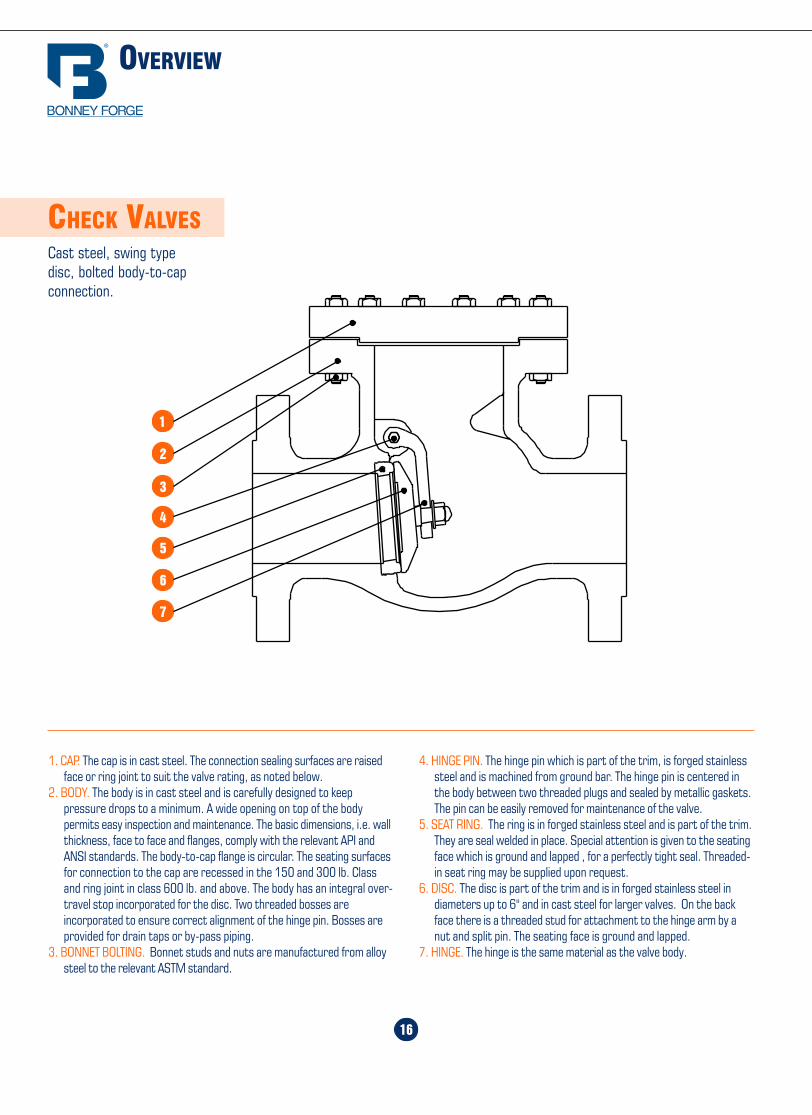
CHECK VALVESCast steel, swing typedisc, bolted body-to-capconnection.
4. HINGE PIN. The hinge pin which is part of the trim, is forged stainlesssteel and is machined from ground bar. The hinge pin is centered inthe body between two threaded plugs and sealed by metallic gaskets.The pin can be easily removed for maintenance of the valve.
5. SEAT RING. The ring is in forged stainless steel and is part of the trim.They are seal welded in place. Special attention is given to the seatingface which is ground and lapped , for a perfectly tight seal. Threaded-in seat ring may be supplied upon request.
6. DISC. The disc is part of the trim and is in forged stainless steel indiameters up to 6" and in cast steel for larger valves. On the backface there is a threaded stud for attachment to the hinge arm by anut and split pin. The seating face is ground and lapped.
7. HINGE. The hinge is the same material as the valve body.
1. CAP. The cap is in cast steel. The connection sealing surfaces are raisedface or ring joint to suit the valve rating, as noted below.
2. BODY. The body is in cast steel and is carefully designed to keeppressure drops to a minimum. A wide opening on top of the bodypermits easy inspection and maintenance. The basic dimensions, i.e. wallthickness, face to face and flanges, comply with the relevant API andANSI standards. The body-to-cap flange is circular. The seating surfacesfor connection to the cap are recessed in the 150 and 300 lb. Classand ring joint in class 600 lb. and above. The body has an integral over-travel stop incorporated for the disc. Two threaded bosses areincorporated to ensure correct alignment of the hinge pin. Bosses areprovided for drain taps or by-pass piping.
3. BONNET BOLTING. Bonnet studs and nuts are manufactured from alloysteel to the relevant ASTM standard.
45
STANDARD CLASS PRESSURE TEMPERATURE RATINGS
-20 to 100 740 695 750 695 750 750 750 750 750 720 720 720 600200 675 655 750 680 750 710 715 750 750 600 620 635 555300 655 640 730 655 730 675 675 730 730 530 560 590 525400 635 620 705 640 705 660 650 705 705 470 515 555 480500 600 585 665 620 665 640 640 665 665 435 480 520 470
600 550 535 605 605 605 605 605 605 605 415 450 490 455650 535 525 590 590 590 590 590 590 590 410 445 480 450700 535 520 570 570 570 570 570 570 570 405 430 470 445750 505 475 505 530 530 530 530 530 530 400 425 460 440800 410 390 410 510 510 510 510 500 510 395 415 455 430
850 270 270 270 485 485 485 485 440 485 390 405 445 -900 170 170 170 450 450 450 450 355 450 385 395 430 -950 105 105 105 280 345 380 380 260 370 375 385 385 -
1000 50 50 50 165 215 225 270 190 290 325 365 365 -1050 - - - - 190 140 200 140 190 310 360 360 -
1100 - - - - - 95 115 105 115 260 325 325 -1150 - - - - - 50 105 70 75 195 275 275 -1200 - - - - - 35 55 45 50 155 205 170 -1250 - - - - - - - - - 110 180 125 -1300 - - - - - - - - - 85 140 95 -
1350 - - - - - - - - - 60 105 70 -1400 - - - - - - - - - 50 75 50 -1450 - - - - - - - - - 35 60 40 -1500 - - - - - - - - - 25 40 35 -
300
LB.
Temperature,°F
WorkingPressure
byClasses
-20 to 100 285 265 290 265 290 290 290 290 290 275 275 275 230200 260 250 260 260 260 260 260 260 260 235 240 245 215300 230 230 230 230 230 230 230 230 230 205 215 225 200400 200 200 200 200 200 200 200 200 200 180 195 200 185500 170 170 170 170 170 170 170 170 170 170 170 170 170600 140 140 140 140 140 140 140 140 140 140 140 140 140650 125 125 125 125 125 125 125 125 125 125 125 125 125700 110 110 110 110 110 110 110 110 110 110 110 110 110750 95 95 95 95 95 95 95 95 95 95 95 95 95800 80 80 80 80 80 80 80 80 80 80 80 80 80850 65 65 65 65 65 65 65 65 65 65 65 65 -900 50 50 50 50 50 50 50 50 50 50 50 50 -950 35 35 35 35 35 35 35 35 35 35 35 35 -
1000 20 20 20 20 20 20 20 20 20 20 20 20 -1050 - - - - 20(1) 20(1) 20(1) 20(1) 20(1) 20(1) 20(1) 20(1) -1100 - - - - - 20(1) 20(1) 20(1) 20(1) 20(1) 20(1) 20(1) -1150 - - - - - 20(1) 20(1) 20(1) 20(1) 20(1) 20(1) 20(1) -1200 - - - - - 15(1) 20(1) 20(1) 20(1) 20(1) 20(1) 20(1) -1250 - - - - - - - - - 20(1) 20(1) 20(1) -1300 - - - - - - - - - 20(1) 20(1) 20(1) -1350 - - - - - - - - - 20(1) 20(1) 20(1) -1400 - - - - - - - - - 20(1) 20(1) 20(1) -1450 - - - - - - - - - 15(1) 20(1) 20(1) -1500 - - - - - - - - - 10(1) 15(1) 15(1) -
A 217WC1(b)
A 352LC1(d)
A 352LCB(d)
A 217WC4(h)
A 217WC5(i)
A 217WC6(j)
A 217C5
A 217C12
A 351CF3(f)
A 351CF8
A 217WC9(j)
A 351CF3M(g)
A 351CF8M
A 351CF8C
A 351CN7M(l)
A 216WCB(a)
Working Pressures in PSI
A 216 WCC(a)A 352 LC2(d)A 352 LC3(d)A 352 LCC(e)
150
LB.
ANSI/ASME B 16.34
1
2
4
3
5
6
7
Home Table of Contents
Product Search
How To Order
PrintBack Next
Home Table of Contents
Product Search
How To Order
PrintBack Next
44
A
B
11/2 t
1/8 R
3/4
371/2°± 21/2°
1/16 ± 1/32
10° ± 1°
30°
45°
11/2 t
1/8 R
A
B
1/16 ± 1/3230°
45° 371/2° ± 21/2°
All dimensions given in inchesDesignations per ANSI B 16.25
STD = Standard Wall ThicknessXS = Extra Strong Wall ThicknessXXS = Double Extra Strong Wall Thickness
IMPORTANT: When ordering buttwelding end valves please state thetype of ends required and give the pipedimensions or schedule number.
BUTT-WELDING ENDS
NominalPipe Size
NominalPipe OD
Wall Thicknessof Pipe
T
Nominal IDB
Valve ODA
ScheduleNumber
2.875 40 2.875 0.203 2.46980 0.276 20323160 0.375 2.125XXS 0.552 1.771
3.500 40 3 19/32 0.216 3.06880 0.300 2.900160 0.438 2.624XXS 0.600 2.300
4.500 40 4 5/8 0.237 4.02680 0.337 3.826120 0.438 3.624160 0.531 3.438XXS 0.674 3.152
5.563 40 5 11/16 0.258 5.04780 0.375 4.813120 0.500 4.563160 0.625 4.313XXS 0.750 4.063
6.625 40 6 25/32 0.280 6.06580 0.432 5.761120 0.562 5.501160 0.719 5.187XXS 0.864 4.897
8.625 40 8 25/32 0.322 7.98160 0.406 7.81380 0.500 7.625100 0.594 7.437120 0.719 7.187140 0.812 7.001XXS 0.875 6.875160 0.906 6.813
10.750 40 10 15/16 0.365 10.02060 0.500 9.75080 0.594 9.562100 0.719 9.312120 0.844 9.062140 1.000 8.750160 1.125 8.500
12.750 STD 12 31/32 0.375 12.00040 0.406 11.938XS 0.500 11.75060 0.562 11.62580 0.688 11.375120 1.000 10.750140 1.125 10.500160 1.312 10.126
14.000 STD 14 1/4 0.375 13.25040 0.438 13.125XS 0.500 13.00060 0.594 12.81280 0.750 12.500100 0.938 12.124120 1.094 11.812140 1.250 11.500160 1.406 11.188
16.000 STD 16 1/4 0.375 15.25040 0.500 15.00060 0.656 14.68880 0.844 14.312100 1.031 13.938120 1.219 13.562140 1.438 13.124160 1.594 12.812
18.000 40 18 9/32 0.562 16.87660 0.750 16.50080 0.938 16.124100 1.156 15.688120 1.375 15.250140 1.562 14.876160 1.781 14.438
20.000 40 20 5/16 0.594 18.81260 0.812 18.37680 1.031 17.938100 1.281 17.438120 1.500 17.000140 1.750 16.500160 1.969 16.062
24.000 30 24 3/8 0.562 22.87640 0.688 22.62460 0.969 22.06280 1.219 21.562100 1.531 20.938120 1.812 20.376140 2.062 19.876160 2.344 19.312
2 1/2
3
4
5
6
8
16
18
10
12
14
20
24
Figures refer to
ANSI B 16-25
ANSI/ASME B 16.25
17
150 LB.300 LB.
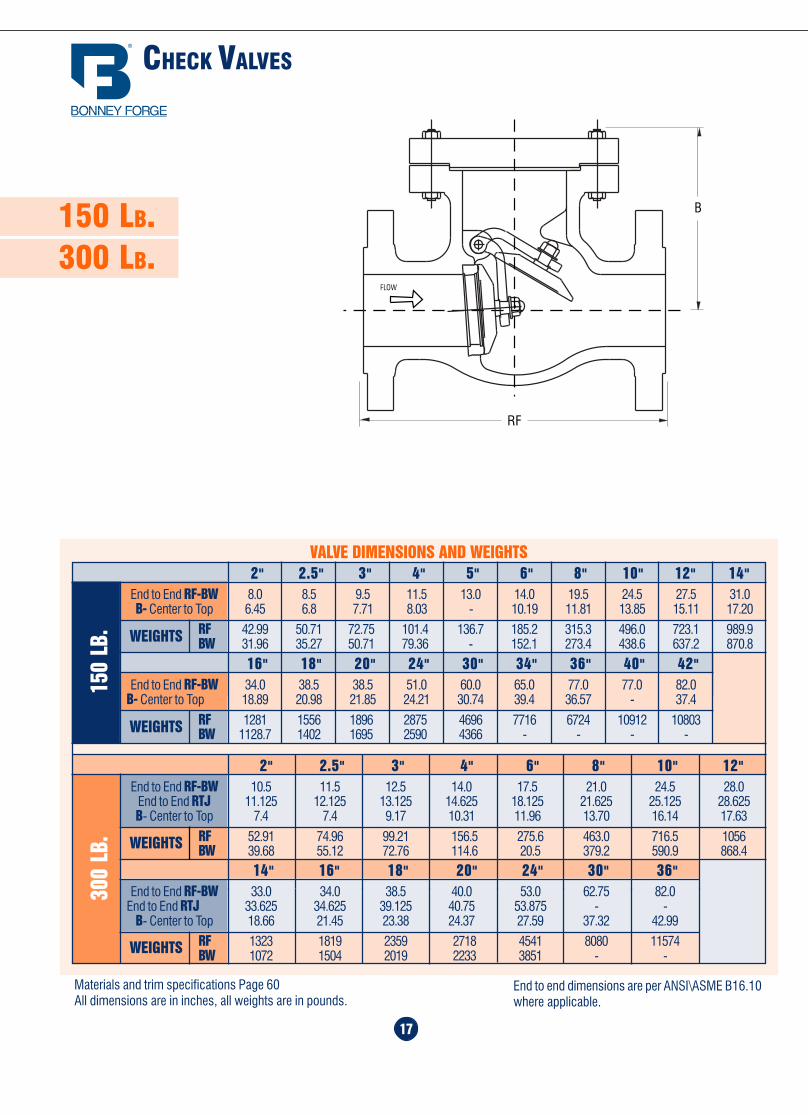
CHECK VALVES
150
LB.
2" 2.5" 3" 4" 5" 6" 8" 10" 12" 14"End to End RF-BW 8.0 8.5 9.5 11.5 13.0 14.0 19.5 24.5 27.5 31.0B- Center to Top 6.45 6.8 7.71 8.03 - 10.19 11.81 13.85 15.11 17.20
RF 42.99 50.71 72.75 101.4 136.7 185.2 315.3 496.0 723.1 989.9BW 31.96 35.27 50.71 79.36 - 152.1 273.4 438.6 637.2 870.8
VALVE DIMENSIONS AND WEIGHTS
WEIGHTS
16" 18" 20" 24" 30" 34" 36" 40" 42"End to End RF-BW 34.0 38.5 38.5 51.0 60.0 65.0 77.0 77.0 82.0
B- Center to Top 18.89 20.98 21.85 24.21 30.74 39.4 36.57 - 37.4
RF 1281 1556 1896 2875 4696 7716 6724 10912 10803BW 1128.7 1402 1695 2590 4366 - - - -WEIGHTS
14" 16" 18" 20" 24" 30" 36"End to End RF-BW 33.0 34.0 38.5 40.0 53.0 62.75 82.0
End to End RTJ 33.625 34.625 39.125 40.75 53.875 - -B- Center to Top 18.66 21.45 23.38 24.37 27.59 37.32 42.99
RF 1323 1819 2359 2718 4541 8080 11574BW 1072 1504 2019 2233 3851 - -WEIGHTS
300
LB.
2" 2.5" 3" 4" 6" 8" 10" 12"End to End RF-BW 10.5 11.5 12.5 14.0 17.5 21.0 24.5 28.0
End to End RTJ 11.125 12.125 13.125 14.625 18.125 21.625 25.125 28.625B- Center to Top 7.4 7.4 9.17 10.31 11.96 13.70 16.14 17.63
RF 52.91 74.96 99.21 156.5 275.6 463.0 716.5 1056BW 39.68 55.12 72.76 114.6 20.5 379.2 590.9 868.4WEIGHTS
FLOW
RF
B
Materials and trim specifications Page 60All dimensions are in inches, all weights are in pounds.
End to end dimensions are per ANSI\ASME B16.10where applicable.

Home Table of Contents
Product Search
How To Order
PrintBack
Home Table of Contents
Product Search
How To Order
PrintBack Next
3" 4" 6" 8" 10" 12" 14" 16"End to End RF-BW 15.0 18.0 24.0 29.0 33.0 38.0 40.5 44.5
End to End RTJ 15.125 18.125 24.125 29.125 33.125 38.125 40.875 44.875B- Center to Top 11.18 13.62 16.3 19.21 22.48 24.05 24.05 32.72
RF 196.2 359.3 701.1 1208 2138 2822 4104 5071BW 152.1 52.9 167.5 229.5 1807 2403 - -90
0 LB
.
18
600 LB.900 LB.1500 LB.
VALVE DIMENSIONS AND WEIGHTS
12" 14" 16" 18" 20" 24" 30" 36"
2" 2.5" 3" 4" 6" 8" 10"
End to End RF-BW 33.0 35.0 39.0 43.0 47.0 55.0 65.0 82.0End to End RTJ 33.125 35.125 39.125 43.125 47.25 53.37 - 82.6B- Center to Top 18.0 22.75 25.98 31.14 31.69 35.39 41.1 51.06
RF 1737 2337 3155 4409 5412 8444 12434 20525BW 1448 1995 2624 3818 4596 7414 10560 -
End to End RF-BW 11.5 13.0 14.0 17.0 22.0 26.0 31.0End to End RTJ 11.625 13.125 14.125 17.125 22.125 26.125 31.125B- Center to Top 7.95 8.5 9.84 11.85 14.29 17.0 19.60
RF 74.96 105.8 143.3 253.5 474.0 881.8 1323BW 52.92 83.78 119.0 200.6 365.9 736.3 1067.7
600
LB.
End to End RF-BW 14.5 16.5 18.5 21.5 27.75 32.75 39.0 44.5 49.5 54.5 60.5End to End RTJ 14.625 16.625 18.625 21.625 28.0 33.125 39.375 45.125 50.25 55.375 61.375B- Center to Top 10.0 11.2 13.0 15.7 19.76 23.27 26.97 32.75 31.1 33.5 40.5
RF 158.7 242.5 372.6 661.4 1318 2187 3574 5842 - 7959 10075BW 121.3 189.6 315.3 579.9 1168.3 1861 3022 5033 - 6449 -15
00 L
B.
2" 2.5" 3" 4" 6" 8" 10" 12" 14" 16" 18"
FLOW
RF
B
Materials and trim specifications Page 60All dimensions are in inches, all weights are in pounds.
End to end dimensions are per ANSI\ASME B16.10where applicable. 43
1500
LB.
1/2 R12 5/16 9/16 11/32 1/2 2 3/8 1/4 1 9/161/4 R14 5/16 9/16 11/32 1/2 2 3/8 1/4 1 3/41 R16 5/16 9/16 11/32 1/2 2 13/16 1/4 2
1 1/4 R18 5/16 9/16 11/32 1/2 3 3/16 1/4 2 3/81 1/2 R20 5/16 9/16 11/32 1/2 3 5/8 1/4 2 11/16
2 R24 7/16 11/16 15/32 5/8 4 7/8 5/16 3 3/42 1/2 R27 7/16 11/16 15/32 5/8 5 3/8 5/16 4 1/4
3 R35 7/16 11/16 15/32 5/8 6 5/8 5/16 5 3/84 R39 7/16 11/16 15/32 5/8 7 5/8 5/16 6 3/85 R44 7/16 11/16 15/32 5/8 9 5/16 7 5/86 R46 1/2 3/4 17/32 11/16 9 3/4 3/8 8 5/168 R50 5/8 7/8 21/32 13/16 12 1/2 7/16 10 5/810 R54 5/8 7/8 21/32 13/16 14 5/8 7/16 12 3/412 R58 7/8 1 1/8 29/32 1 1/16 17 1/4 9/16 1514 R63 1 1 5/16 1 1/16 1 1/4 19 1/4 5/8 16 1/216 R67 1 1/8 1 7/16 1 3/16 1 3/8 21 1/2 11/16 18 1/218 R71 1 1/8 1 7/16 1 3/16 1 3/8 24 1/8 11/16 2120 R75 1 1/4 1 9/16 1 5/16 1 1/2 26 1/2 11/16 2324 R79 1 3/8 1 3/4 1 7/16 1 5/8 31 1/4 13/16 27 1/4
900
LB.
3 R31 7/16 11/16 15/32 5/8 6 1/8 5/16 4 7/84 R37 7/16 11/16 15/32 5/8 7 1/8 5/16 5 7/85 R41 7/16 11/16 15/32 5/8 8 1/2 5/16 7 1/86 R45 7/16 11/16 15/32 5/8 9 1/2 5/16 8 5/168 R49 7/16 11/16 15/32 5/8 12 1/8 5/16 10 5/810 R53 7/16 11/16 15/32 5/8 14 1/4 5/16 12 3/412 R57 7/16 11/16 15/32 5/8 16 1/2 5/16 1514 R62 5/8 7/8 21/32 13/16 18 3/8 7/16 16 1/216 R66 5/8 7/8 21/32 13/16 20 5/8 7/16 18 1/218 R70 3/4 1 25/32 15/16 23 3/8 1/2 2120 R74 3/4 1 25/32 15/16 25 1/2 1/2 2324 R78 1 1 5/16 1 1/16 1 1/4 30 3/8 5/8 27 1/4
NominalPipe Size
RingNumber
RingWidth
A
Oval RingHeight
B
GrooveWidth
D
OctagonalRing Height
H
GrooveDepth
L
Ring JointRaisedFace
DiameterK
Ring &GroovePitch
DiameterP
2500
LB.
1/2 R13 5/16 9/16 11/32 1/2 2 9/16 1/4 1 11/163/4 R16 5/16 9/16 11/32 1/2 2 7/8 1/4 21 R18 5/16 9/16 11/32 1/2 3 1/4 1/4 2 3/8
1 1/4 R21 7/16 11/16 15/32 5/8 4 5/16 2 27/321 1/2 R23 7/16 11/16 15/32 5/8 4 1/2 5/16 3 1/4
2 R26 7/16 11/16 15/32 5/8 5 1/4 5/16 42 1/2 R28 1/2 3/4 17/32 11/16 5 7/8 3/8 4 3/8
3 R32 1/2 3/4 17/32 11/16 6 5/8 3/8 54 R38 5/8 7/8 21/32 13/16 8 7/16 6 3/165 R42 3/4 1 25/32 15/16 9 1/2 1/2 7 1/26 R47 3/4 1 25/32 15/16 11 1/2 98 R51 7/8 1 1/8 29/32 1 1/16 13 3/8 9/16 1110 R55 1 1/8 1 7/16 1 3/16 1 3/8 16 3/4 11/16 13 1/212 R60 1 1/4 1 9/16 1 5/16 1 1/2 19 1/2 11/16 16
All dimensions are in inches
CHECK VALVES
WEIGHTS
WEIGHTS
WEIGHTS
WEIGHTS

Home Table of Contents
Product Search
How To Order
PrintBack Next
Home Table of Contents
Product Search
How To Order
PrintNext
42
RING JOINT FACINGS
300-
400-
600
LB.
150
LB.
1 R15 5/16 9/16 11/32 1/2 2 1/2 1/4 1 7/81 1/4 R17 5/16 9/16 11/32 1/2 2 7/8 1/4 2 1/41 1/2 R19 5/16 9/16 11/32 1/2 3 1/4 1/4 2 9/16
2 R22 5/16 9/16 11/32 1/2 4 1/4 3 1/42 1/2 R25 5/16 9/16 11/32 1/2 4 3/4 1/4 4
3 R29 5/16 9/16 11/32 1/2 5 1/4 1/4 4 1/24 R36 5/16 9/16 11/32 1/2 6 3/4 1/4 5 7/85 R40 5/16 9/16 11/32 1/2 7 5/8 1/4 6 3/46 R43 5/16 9/16 11/32 1/2 8 5/8 1/4 7 5/88 R48 5/16 9/16 11/32 1/2 10 3/4 1/4 9 3/410 R52 5/16 9/16 11/32 1/2 13 1/4 1212 R56 5/16 9/16 11/32 1/2 16 1/4 1514 R59 5/16 9/16 11/32 1/2 16 3/4 1/4 15 5/816 R64 5/16 9/16 11/32 1/2 19 1/4 17 7/818 R68 5/16 9/16 11/32 1/2 21 1/2 1/4 20 3/820 R72 5/16 9/16 11/32 1/2 23 1/2 1/4 2224 R76 5/16 9/16 11/32 1/2 28 1/4 26 1/2
NominalPipe Size
RingNumber
RingWidth
A
Oval RingHeight
B
GrooveWidth
D
OctagonalRing Height
H
GrooveDepth
L
Ring JointRaisedFace
DiameterK
Ring &GroovePitch
DiameterP
1/2 R11 1/4 7/16 9/32 3/8 2 7/32 1 11/323/4 R13 5/16 9/16 11/32 1/2 2 1/2 1/4 1 11/161 R16 5/16 9/16 11/32 1/2 2 3/4 1/4 2
1 1/4 R18 5/16 9/16 11/32 1/2 3 1/8 1/4 2 3/81 1/2 R20 5/16 9/16 11/32 1/2 3 9/16 1/4 2 11/16
2 R23 7/16 11/16 15/32 5/8 4 1/4 5 /16 3 1/42 1/2 R26 7/16 11/16 15/32 5/8 5 5/16 4
3 R31 7/16 11/16 15/32 5/8 5 3/4 5/16 4 7/84 R37 7/16 11/16 15/32 5/8 6 7/8 5/16 5 7/85 R41 7/16 11/16 15/32 5/8 8 1/4 5/16 7 1/86 R45 7/16 11/16 15/32 5/8 9 1/2 5/16 8 5/168 R49 7/16 11/16 15/32 5/8 11 7/8 5/16 10 5/810 R53 7/16 11/16 15/32 5/8 14 5/16 12 3/412 R57 7/16 11/16 15/32 5/8 16 1/4 5/16 1514 R61 7/16 11/16 15/32 5/8 18 5/16 16 1/216 R65 7/16 11/16 15/32 5/8 20 5/16 18 1/218 R69 7/16 11/16 15/32 5/8 22 5/8 5/16 2120 R73 1/2 3/4 17/32 11/16 25 3/8 2324 R77 5/8 7/8 21/32 13/16 29 1/2 7/16 27 1/4
ANSI/ASME B 16.5 and B 16.20
B
C
H
D
A 23°
Groove suitable for either Oval or Octagonal ring
OCTAGONAL RING
OVAL RING
23°
All dimensions are in inches
Overview ........................................ 20
Pressure Seal Gate Valves .............. 21
Pressure Seal GlobeValves “T-Pattern” ........................... 22
Pressure Seal Check Valves ............ 23
Pressure Seal Globe Valves “Y-Pattern” .......................... 24
19
PRESSURE SEAL
VALVES
Home Table of Contents
Product Search
How To Order
Print Next
Home Table of Contents
Product Search
How To Order
PrintBack Next
Home Table of Contents
Product Search
How To Order
PrintBack Next
OVERVIEW
20
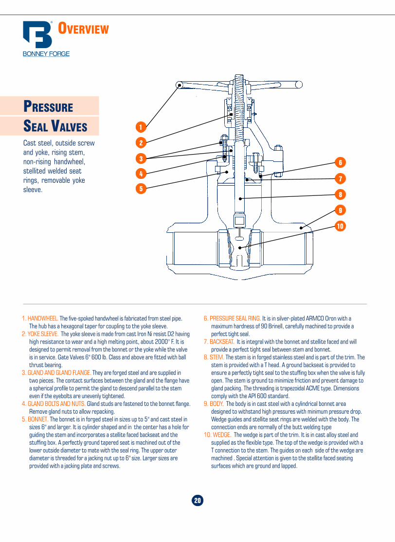
PRESSURE
SEAL VALVESCast steel, outside screwand yoke, rising stem,non-rising handwheel,stellited welded seatrings, removable yokesleeve.
6. PRESSURE SEAL RING. It is in silver-plated ARMCO Oron with amaximum hardness of 90 Brinell, carefully machined to provide aperfect tight seal.
7. BACKSEAT. It is integral with the bonnet and stellite faced and willprovide a perfect tight seal between stem and bonnet.
8. STEM. The stem is in forged stainless steel and is part of the trim. Thestem is provided with a T head. A ground backseat is provided toensure a perfectly tight seal to the stuffing box when the valve is fullyopen. The stem is ground to minimize friction and prevent damage togland packing. The threading is trapezoidal ACME type. Dimensionscomply with the API 600 standard.
9. BODY. The body is in cast steel with a cylindrical bonnet areadesigned to withstand high pressures with minimum pressure drop.Wedge guides and stellite seat rings are welded with the body. Theconnection ends are normally of the butt welding type
10. WEDGE. The wedge is part of the trim. It is in cast alloy steel andsupplied as the flexible type. The top of the wedge is provided with aT connection to the stem. The guides on each side of the wedge aremachined . Special attention is given to the stellite faced seatingsurfaces which are ground and lapped.
1. HANDWHEEL. The five-spoked handwheel is fabricated from steel pipe.The hub has a hexagonal taper for coupling to the yoke sleeve.
2. YOKE SLEEVE. The yoke sleeve is made from cast Iron Ni resist D2 havinghigh resistance to wear and a high melting point, about 2000° F. It isdesigned to permit removal from the bonnet or the yoke while the valveis in service. Gate Valves 6" 600 lb. Class and above are fitted with ballthrust bearing.
3. GLAND AND GLAND FLANGE. They are forged steel and are supplied intwo pieces. The contact surfaces between the gland and the flange havea spherical profile to permit the gland to descend parallel to the stemeven if the eyebolts are unevenly tightened.
4. GLAND BOLTS AND NUTS. Gland studs are fastened to the bonnet flange.Remove gland nuts to allow repacking.
5. BONNET. The bonnet is in forged steel in sizes up to 5" and cast steel insizes 6" and larger. It is cylinder shaped and in the center has a hole forguiding the stem and incorporates a stellite faced backseat and thestuffing box. A perfectly ground tapered seat is machined out of thelower outside diameter to mate with the seal ring. The upper outerdiameter is threaded for a jacking nut up to 6" size. Larger sizes areprovided with a jacking plate and screws.
1
2
4
57
8
9
10
3 6
41
150 &300 lb. Steel
ADC
B
1/16"
E
A
CD
1/16"
B
E
400, 600,900, 1500 &2500 lb. Steel
ANSI
900
ANSI
600
1/2 3 3/4 9/16 1 3/8 2 5/8 5/8 4 1/23/4 4 5/8 5/8 1 11/16 3 1/4 3/4 4 5/81 4 7/8 11/16 2 3 1/2 3/4 4 5/8
1 1/4 5 1/4 13/16 2 1/2 3 7/8 3/4 4 5/81 1/2 6 1/8 7/8 2 7/8 4 1/2 7/8 4 3/4
2 6 1/2 1 3 5/8 5 3/4 8 5/82 1/2 7 1/2 1 1/8 4 1/8 5 7/8 7/8 8 3/4
3 8 1/4 1 1/4 5 6 5/8 7/8 8 3/43 1/2 9 1 3/8 5 1/2 7 1/4 1 8 7/8
4 10 3/4 1 1/2 6 3/16 8 1/2 1 8 7/85 13 1 3/4 7 5/16 10 1/2 1 1/8 8 16 14 1 7/8 8 1/2 11 1/2 1 1/8 12 18 16 1/2 2 3/16 10 5/8 13 3/4 1 1/4 12 1 1/810 20 2 1/2 12 3/4 17 1 3/8 16 1 1/412 22 2 5/8 15 19 1/4 1 3/8 20 1 1/414 23 3/4 2 3/4 16 1/4 20 3/4 1 1/2 20 1 3/816 27 3 18 1/2 23 3/4 1 5/8 20 1 1/218 29 1/4 3 1/4 21 25 3/4 1 3/4 20 1 5/820 32 3 1/2 23 28 1/2 1 3/4 24 1 5/824 37 4 27 1/4 33 2 24 1 7/826 40 4 1/4 29 1/2 36 2 28 1 7/828 42 1/4 4 3/8 31 1/2 38 2 1/8 28 230 44 1/2 4 1/2 33 3/4 40 1/4 2 1/8 28 232 47 4 5/8 36 42 1/2 2 3/8 28 2 1/434 49 4 3/4 38 44 1/2 2 3/8 28 2 1/436 51 3/4 4 7/8 40 1/4 47 2 5/8 28 2 1/2
NominalPipe Size
FlangeDiameter
AFlange
ThicknessDiameter ofRaised Face
C
Diameter of BoltCircle
D
Diameter of BoltHoles
E
Numberof Bolts
Diameter ofBolts
ANSI
150
0
3 9 1/2 1 1/2 5 7 1/2 1 8 7/84 11 1/2 1 3/4 6 3/16 9 1/4 1 1/4 8 1 1/85 13 3/4 2 7 5/16 11 1 3/8 8 1 1/46 15 2 3/16 8 1/2 12 1/2 1 1/4 12 1 1/88 18 1/2 2 1/2 10 5/8 15 1/2 1 1/2 12 1 3/810 21 1/2 2 3/4 12 3/4 18 1/2 1 1/2 16 1 3/812 24 3 1/8 15 21 1 1/2 20 1 3/814 25 1/4 3 3/8 16 1/4 22 1 5/8 20 1 1/216 27 3/4 3 1/2 18 1/2 24 1/4 1 3/4 20 1 5/818 31 4 21 27 2 20 1 7/820 33 3/4 4 1/4 23 29 1/2 2 1/8 20 224 41 5 1/2 27 1/4 35 1/2 2 5/8 20 2 1/2
1/2 4 3/4 7/8 1 3/8 3 1/4 7/8 4 3/43/4 5 1/8 1 1 11/16 3 1/2 7/8 4 3/41 5 7/8 1/18 2 4 1 4 7/8
1 1/4 6 1/4 1 1/8 2 1/2 4 3/8 1 4 7/81 1/2 7 1 1/4 2 7/8 4 7/8 1 1/8 4 1
2 8 1/2 1 1/2 3 5/8 6 1/2 1 8 7/82 1/2 9 5/8 1 5/8 4 1/8 7 1/2 1 1/8 8 1
3 10 1/2 1 7/8 5 8 1 1/4 8 1 1/84 12 1/4 2 1/8 6 3/16 9 1/2 1 3/8 8 1 1/45 14 3/4 2 7/8 7 5/16 11 1/2 1 5/8 8 1 1/26 15 1/2 3 1/4 8 1/2 12 1/2 1 1/2 12 1 3/88 19 3 5/8 10 5/8 15 1/2 1 3/4 12 1 5/810 23 4 1/4 12 3/4 19 2 12 1 7/812 26 1/2 4 7/8 15 22 1/2 2 1/8 16 214 29 1/2 5 1/4 16 1/4 25 2 3/8 16 2 1/416 32 1/2 5 3/4 18 1/2 27 3/4 2 5/8 16 2 1/218 36 6 3/8 21 30 1/2 2 7/8 16 2 3/420 38 3/4 7 23 32 3/4 3 1/8 16 324 46 8 27 1/4 39 3 5/8 16 3 1/2
ANSI
250
0
1/2 5 1/4 1 3/16 1 3/8 3 1/2 7/8 4 3/43/4 5 1/2 1 1/4 1 11/16 3 3/4 7/8 4 3/41 6 1/4 1 3/8 2 4 1/4 1 4 7/8
1 1/4 7 1/4 1 1/2 2 1/2 5 1/8 1 1/8 4 11 1/2 8 1 3/4 2 7/8 5 3/4 1 1/4 4 1 1/8
2 9 1/4 2 3 5/8 6 3/4 1 1/8 8 12 1/2 10 1/2 2 1/4 4 1/8 7 3/4 1 1/4 8 1 1/8
3 12 2 5/8 5 9 1 3/8 8 1 1/44 14 3 6 3/16 10 3/4 1 5/8 8 1 1/25 16 1/2 3 5/8 7 5/16 12 3/4 1 7/8 8 1 3/46 19 4 1/4 8 1/2 14 1/2 2 1/8 8 28 21 3/4 5 10 5/8 17 1/4 2 1/8 12 210 26 1/2 6 1/2 12 3/4 21 1/4 2 5/8 12 2 1/212 30 7 1/4 15 24 3/8 2 7/8 12 2 3/4
The regular 1/4-inch raised face of900 and 1500 lb. flanges is notincluded in the minimum flange
thickness given. The bolt holes,which are in multiples of four, are
drilled to straddle the centerlineunless otherwise ordered.
Use 1500 lb. dimensions in sizessmaller than 3-inch.
The regular 1/4-inch raised face of600 lb. flanges is not included in
the minimum flange thicknessgiven. The bolt holes, which are in
multiples of four, are drilled tostraddle the centerline unless
otherwise ordered.
The regular 1/4-inch raised face of2500 lb. flanges is not included in the
minimum flange thickness given.The bolt holes, which are in multiples
of four, are drilled to straddle thecenterline unless otherwise ordered.
End Flange dimensions comply withANSI/ASME B 16.5 and MSS-SP-44 All dimensions are in inches
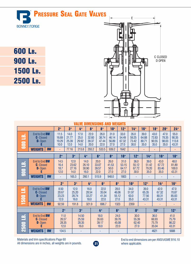
Home Table of Contents
Product Search
How To Order
PrintBack Next
Home Table of Contents
Product Search
How To Order
PrintBack Next
40
FLANGE DIMENSIONS
ANSI/ASME B 16.5 and MSS-SP-44
4 10 1 3/8 6 13/16 7 7/8 1 8 7/85 11 1 1/2 7 5/16 9 1/4 1 8 7/86 12 1/2 1 5/8 8 1/2 10 5/8 1 12 7/88 15 1 7/8 10 5/8 13 1 1/8 12 110 17 1/2 2 1/8 12 3/4 15 1/4 1 1/4 16 1 1/812 20 1/2 2 1/4 15 17 3/4 1 3/8 16 1 1/414 23 2 3/8 16 1/4 20 1/4 1 3/8 20 1 1/416 25 1/2 2 1/2 18 1/2 22 1/2 1 1/2 20 1 3/818 28 2 5/8 21 24 3/4 1 1/2 24 1 3/820 30 1/2 2 3/4 23 27 1 5/8 24 1 1/224 36 3 27 1/4 32 1 7/8 24 1 3/426 38 1/4 3 1/2 29 1/2 34 1/2 1 7/8 28 1 3/428 40 3/4 3 3/4 31 1/2 37 1 7/8 28 1 7/830 43 4 33 3/4 39 1/4 2 28 232 45 1/4 4 1/4 36 41 1/2 2 1/8 28 234 47 1/2 4 3/8 38 43 1/2 2 1/8 28 236 50 4 1/2 40 1/4 46 2 1/8 32 2
ANSI
300
1/2 3 3/4 9/16 1 3/8 2 5/8 5/8 4 1/23/4 4 5/8 5/8 1 11/16 3 1/4 3/4 4 5/81 4 7/8 11/16 2 3 1/2 3/4 4 5/8
1 1/4 5 1/4 3/4 2 1/2 3 7/8 3/4 4 5/81 1/2 6 1/8 13/16 2 7/8 4 1/2 7/8 4 3/4
2 6 1/2 7/8 3 5/8 5 3/4 8 5/82 1/2 7 1/2 1 4 1/8 5 7/8 7/8 8 3/4
3 8 1/4 1 1/8 5 6 5/8 7/8 8 3/43 1/2 9 1 13/16 5 1/2 7 1/4 7/8 8 3/4
4 10 1 1/4 6 3/16 7 7/8 7/8 8 3/45 11 1 3/8 7 5/16 9 1/4 7/8 8 3/46 12 1/2 1 7/16 8 1/2 10 5/8 7/8 12 3/48 15 1 5/8 10 5/8 13 1 12 7/810 17 1/2 1 7/8 12 3/4 15 1/4 1 1/8 16 112 20 1/2 2 15 17 3/4 1 1/4 16 1 1/814 23 2 1/8 16 1/4 20 1/4 1 1/4 20 1 1/816 25 1/2 2 1/4 18 1/2 22 1/2 1 3/8 20 1 1/416 28 2 3/8 21 24 3/4 1 3/8 24 1 1/420 30 1/2 2 1/2 23 27 1 3/8 24 1 1/424 36 2 3/4 27 1/4 32 1 5/8 24 1 1/226 38 1/4 3 1/8 29 1/2 34 1/2 1 3/4 28 1 5/828 40 3/4 3 3/8 31 1/2 37 1 3/4 28 1 5/830 43 3 5/8 33 3/4 39 1/4 1 7/8 28 1 3/432 45 1/4 3 7/8 36 41 1/2 2 28 1 7/834 47 1/2 4 38 43 1/2 2 28 1 7/836 50 4 1/8 40 1/4 46 2 1/8 32 238 46 4 1/4 40 1/2 43 1 5/8 32 1 1/240 48 3/4 4 1/2 42 3/4 45 1/2 1 3/4 32 1 5/8
ANSI
150
1/2 3 1/2 7/16 - 1 3/8 2 3/8 5/8 4 1/23/4 3 1/2 1/2 - 1 11/16 2 3/4 5/8 4 1/21 4 1/2 9/16 7/16 2 3 1/8 5/8 4 1/2
1 1/4 4 1/2 5/8 1/2 2 1/2 3 1/2 5/8 4 1/21 1/2 5 11/16 9/16 2 7/8 3 7/8 5/8 4 1/2
2 6 3/4 5/8 3 5/8 4 3/4 3/4 4 5/82 1/2 7 7/8 11/16 4 1/8 5 1/2 3/4 4 5/8
3 7 1/2 15/16 3/4 5 6 3/4 4 5/83 1/2 8 1/2 15/16 13/16 5 1/2 7 3/4 8 5/8
4 9 15/16 6 3/16 7 1/2 3/4 8 5/85 10 15/16 7 5/16 8 1/2 7/8 8 3/46 11 1 8 1/2 9 1/2 7/8 8 3/48 13 1/2 1 1/8 10 5/8 11 3/4 7/8 8 3/410 16 1 3/16 12 3/4 14 1/4 1 12 7/812 19 1 1/4 15 17 1 12 7/814 21 1 3/8 16 1/4 18 3/4 1 1/8 12 116 23 1/2 1 7/16 18 1/2 21 1/4 1 1/8 16 116 25 1 9/16 21 22 3/4 1 1/4 16 1 1/820 27 1/2 1 11/16 23 25 1 1/4 20 1 1/824 32 1 7/8 27 1/4 291/2 1 3/8 20 1 1/826 34 1/4 2 11/16 29 1/2 31 3/4 1 5/8 24 1 1/428 36 1/2 2 13/16 31 1/2 34 1 5/8 28 1 1/430 38 3/4 2 15/16 33 3/4 36 1 5/8 28 1 1/432 41 3/4 3 3/16 36 38 1/2 1 5/8 28 1 1/234 43 3/4 3 1/4 38 40 1/2 1 5/8 32 1 1/236 46 3 9/16 40 1/4 42 3/4 1 5/8 32 1 1/238 48 3/4 3 7/16 42 1/4 45 1/4 1 5/8 32 1 1/240 50 3/4 3 9/16 44 1/4 47 1/4 1 5/8 36 1 1/242 53 3 13/16 47 49 1/2 1 5/8 36 1 1/2
NominalPipe Size
FlangeDiameter
A
Flange ThicknessCompanion Valve
Flange B Flange B
Diameter ofRaised Face
C
Diameter of BoltCircle
D
Diameter of BoltHoles
E
Numberof Bolts
Diameter ofBolts
ANSI
400
The regular 1/16-inch raised faceof 150 lb. flanges is included inthe minimum flange thickness
given, but other raised faces mustbe added thereto. The bolt holes,which are in multiples of four, are
drilled to straddle the centerlineunless otherwise ordered.
The regular 1/16-inch raised faceof 300 lb. flanges is included inthe minimum flange thickness
given, but other raised faces mustbe added thereto. The bolt holes,which are in multiples of four, are
drilled to straddle the centerlineunless otherwise ordered.
The regular 1/4-inch raised face of400 lb. flanges is not included in
the minimum flange thicknessgiven. The bolt holes, which are in
multiples of four, are drilled tostraddle the centerline unless
otherwise ordered.
End Flange dimensions comply withANSI/ASME B 16.5 and MSS-SP-44 All dimensions are in inches
21
600 LB.900 LB.
PRESSURE SEAL GATE VALVES
1500 LB.
VALVE DIMENSIONS AND WEIGHTS2" 3" 4" 6" 8" 10" 12" 14" 16" 18" 20" 24"
600
LB. End to End BW 11.5 14.0 17.0 22.0 26.0 31.0 33.0 35.0 39.0 43.0 47.0 55.0
C- Closed 16.69 21.77 25.0 32.60 38.74 46.14 54.49 59.25 64.88 72.83 78.35 90.35D- Open 19.29 25.39 29.92 39.37 47.44 56.89 67.32 73.42 80.71 90.55 98.03 113.8
E 10.0 12.0 14.0 20.0 22.0 27.0 27.0 30.0 35.0 35.0 35.0 43.31
BW - 77.16 213.8 293.2 533.5 939.2 1642 - - - - -
E
C CLOSEDD OPEN
BW
2" 3" 4" 6" 8" 10" 12" 14" 16" 18"
900
LB. End to End BW 14.5 12.0 14.0 20.0 26.0 31.0 36.0 39.0 43.0 48.0
C- Closed 16.4 23.62 26.10 33.07 41.53 53.15 55.12 51.42 67.72 81.89D- Open 18.7 27.16 30.90 39.57 50.0 64.17 67.72 79.20 83.46 100.0
E 12.0 14.0 16.0 22.0 27.0 27.0 30.0 35.0 35.0 43.31
BW - 165.3 260.1 515.9 948.0 1803 - - - -
2" 3" 4" 6" 8" 10" 12" 14" 16"
1500
LB. End to End BW 8.50 12.0 16.0 22.0 28.0 34.0 39.0 42.0 47.0
C- Closed 20.67 25.20 28.54 35.04 46.06 51.97 65.35 67.32 70.87D- Open 23.23 28.74 33.27 41.34 55.12 63.0 77.56 80.31 85.83
E 12.0 16.0 18.0 22.0 27.0 35.0 43.31 43.31 43.31
BW 92.59 191.8 321.9 696.7 1323 2359 - - -
2" 3" 4" 6" 8" 10" 12"
2500
LB. End to End BW 11.0 14.50 18.0 24.0 30.0 36.0 41.0
C- Closed 26.57 25.59 35.63 39.76 55.39 66.93 75.79D- Open 28.35 28.35 39.17 45.08 62.40 75.79 86.22
E 12.0 16.0 18.0 22.0 27.0 35.04 43.31
BW 134.5 - - - - 4621 5688
2500 LB.
Materials and trim specifications Page 60All dimensions are in inches, all weights are in pounds.
End to end dimensions are per ANSI\ASME B16.10where applicable.
WEIGHTS
WEIGHTS
WEIGHTS
WEIGHTS
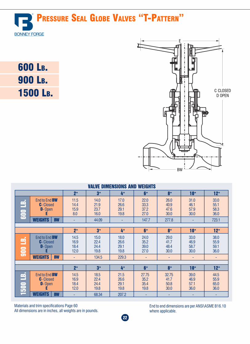
Home Table of Contents
Product Search
How To Order
PrintBack Next
Home Table of Contents
Product Search
How To Order
PrintBack Next
PRESSURE SEAL GLOBE VALVES “T-PATTERN”
22
600 LB.900 LB.1500 LB.
VALVE DIMENSIONS AND WEIGHTS
2" 3" 4" 6" 8" 10" 12"
1500
LB. End to End BW 14.5 18.5 21.5 27.75 32.75 39.0 44.5
C- Closed 16.9 22.4 26.6 35.2 41.7 46.9 55.9D- Open 18.4 24.4 29.1 35.4 50.8 57.1 65.0
E 12.0 19.8 19.8 19.8 30.0 36.0 36.0
BW - 68.34 207.2 - - - -
2" 3" 4" 6" 8" 10" 12"
900
LB. End to End BW 14.5 15.0 18.0 24.0 29.0 33.0 38.0
C- Closed 16.9 22.4 26.6 35.2 41.7 46.9 55.9D- Open 18.4 24.4 29.1 39.0 48.4 58.7 59.1
E 12.0 19.8 19.8 27.0 30.0 30.0 36.0
BW - 134.5 229.3 - - - -
2" 3" 4" 6" 8" 10" 12"
600
LB. End to End BW 11.5 14.0 17.0 22.0 26.0 31.0 33.0
C- Closed 14.4 21.9 26.6 33.3 40.9 46.1 55.1D- Open 15.9 23.7 29.1 37.2 47.6 57.9 58.3
E 8.0 16.0 19.8 27.0 30.0 30.0 36.0
BW - 44.09 - 147.7 277.8 - 723.1
BW
E
C CLOSEDD OPEN
Materials and trim specifications Page 60All dimensions are in inches, all weights are in pounds.
End to end dimensions are per ANSI\ASME B16.10where applicable.
39
BYPASS & DRAIN CONNECTION
Bonney Forge valves can be equipped with by-passes which permit equalization of pressure on both sides ofthe valve. Unless otherwise specified the by-pass arrangement will be furnished on the side of the main valve. By-passes of other types can be made to order. Inquiries should give complete description or drawings.
By-pass valves are “Bonney Forge” forged steel bolted-bonnet, outside screw and yoke, socket-weld endglobe valves, and materials are suitable for the same service as the main valve.
DRAIN & BY PASS DIMENSIONS
Size of Valve 2" to 4" 5" to 8" 10" to 24"
Size of Tapping 1/2 3/4 1
Length of Thread T 9/16 9/16 11/16
Minimum Diameter of Socket A 7/8 1 1/16 1 5/16
Minimum Depth of Socket B 3/16 1/4 1/4
Diameter of Boss J 1 1/2 1 3/4 2 1/8
All dimensions given in inches
BT
JA
THREAD FOR CONNECTION TAPPING SOCKET WELDING FOR CONNECTIONS BOSSES FOR CONNECTIONS
I K
J H
A B
C D
(on the sameside as E & F)
C
A B
D
EG F
GATE VALVE GLOBE VALVE
CD
A & B
E & FE
F
DC
CHECK VALVEANGLE VALVE
These illustrations show the location of tapped holes. When placing anorder please quote the letters in the above illustrations designating the
location of the tapped holes. For more information see MSS-SP-45.
AF
E B
A
B
C
DE
FF
E
C
D
A B
C
GAC
B
E F
DG
G
WEIGHTS
WEIGHTS
WEIGHTS
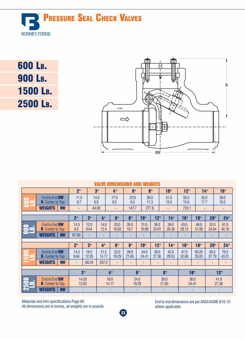
Home Table of Contents
Product Search
How To Order
PrintBack Next
Home Table of Contents
Product Search
How To Order
PrintBack Next
23
600 LB.900 LB.
PRESSURE SEAL CHECK VALVES
1500 LB.
VALVE DIMENSIONS AND WEIGHTS
End to End BW 11.5 14.0 17.0 22.0 26.0 31.0 33.0 35.0 39.0B- Center to Top 6.7 6.9 8.5 9.3 11.3 13.4 15.6 17.7 19.3
BW - 44.09 - 147.7 277.8 - 723.1 - -WEIGHTS600
LB.
2" 3" 4" 6" 8" 10" 12" 14" 16"
End to End BW 14.5 12.0 14.0 20.0 26.0 31.0 36.0 39.0 43.0 48.0 52.0 61.0B- Center to Top 6.9 9.64 12.4 16.93 18.7 19.96 24.01 26.38 29.13 31.89 34.64 40.16
BW 97.00 - - - - - - - - - - -WEIGHTS900
LB.
2" 3" 4" 6" 8" 10" 12" 14" 16" 18" 20" 24"
End to End BW 14.5 18.5 21.5 22.0 28.0 34.0 39.0 42.0 47.0 60.25 65.5 76.5B- Center to Top 9.64 12.05 14.17 19.29 21.65 24.41 27.36 29.53 32.68 35.83 37.79 43.31
BW - 68.34 207.2 - - - - - - - - -WEIGHTS1500 LB.
2" 3" 4" 6" 8" 10" 12" 14" 16" 18" 20" 24"
End to End BW 14.50 18.0 24.0 30.0 36.0 41.0B- Center to Top 12.05 14.17 19.29 21.65 24.41 27.36
BW - - - - - -WEIGHTS2500 LB.
3" 4" 6" 8" 10" 12"
FLOW
BW
B
2500 LB.
Materials and trim specifications Page 60All dimensions are in inches, all weights are in pounds.
End to end dimensions are per ANSI\ASME B16.10where applicable.
38
SPECIAL FEATURES
Cryogenic Valves
Constant new development, in the petrochemical, refrigeration, military, space age, and various interrelated
chemical and processing fields have, in turn, imposed special designs for valves and materials which can serve
safely and adequately at below zero temperatures.
Technically, this frozen frontier can be divided into two areas of application. The one area, somewhat generically
referred to as “Low temperature”, ranges from minus 20° C (-4°F) down to the boiling point of methane, or
Natural gas at minus 160oC (-256°F), while the second term “Cryogenic” sees as an upper limit minus
180°C (-292°F) the temperature at which oxygen liquefies, and descends towards absolute zero - 273°C (-459°F).
Extended Bonnet valves are used in cryogenic service because proper bonnet extensions keeps both packing and
handwheel quite far from the cold zone and pipe insulation so that, at this point the metal temperature is close to
atmospheric temperature.
Avoiding frost, on the packing area valves will remain functional. Valves 2” and larger may have holes and plugs inposition “G” and/or “H”. All gate valves have a bleed hole in the wedge to equalize pressure in the body cavity with
that on the upstream side of the wedge.
Cryogenic valves have an extended bonnet obtained by integral casting for valves up to 8” size in accordance with
BS6364. For dimensions over 8” extended bonnet is obtained by a pipe spool, welded between the bonnet packing
section and back seat section.
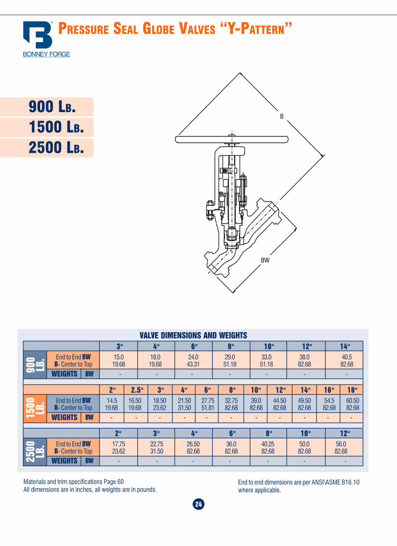
Home Table of Contents
Product Search
How To Order
PrintBack
Home Table of Contents
Product Search
How To Order
PrintBack Next
PRESSURE SEAL GLOBE VALVES “Y-PATTERN”
900 LB.1500 LB.2500 LB.
24
VALVE DIMENSIONS AND WEIGHTS
End to End BW 15.0 18.0 24.0 29.0 33.0 38.0 40.5B- Center to Top 19.68 19.68 43.31 51.18 51.18 82.68 82.68
BW - - - - - - -WEIGHTS900
LB.
3" 4" 6" 8" 10" 12" 14"
End to End BW 14.5 16.50 18.50 21.50 27.75 32.75 39.0 44.50 49.50 54.5 60.50B- Center to Top 19.68 19.68 23.62 31.50 51.81 82.68 82.68 82.68 82.68 82.68 82.68
BW - - - - - - - - - - -WEIGHTS1500 LB.
2" 2.5" 3" 4" 6" 8" 10" 12" 14" 16" 18"
End to End BW 17.75 22.75 26.50 36.0 40.25 50.0 56.0B- Center to Top 23.62 31.50 82.68 82.68 82.68 82.68 82.68
BW - - - - - - -WEIGHTS2500 LB.
2" 3" 4" 6" 8" 10" 12"
Materials and trim specifications Page 60All dimensions are in inches, all weights are in pounds.
End to end dimensions are per ANSI\ASME B16.10where applicable.
EXTENSIONSTEM
CHAINWHEEL
FLOORSTAND
FLOOR STAND WITHUNIVERSAL JOINT
CHECK VALVEWITH DASH POT
CHECK VALVE WITHOUTSIDE LEVER & WEIGHT
37
BW
B
Home Table of Contents
Product Search
How To Order
PrintBack Next
Home Table of Contents
Product Search
How To Order
Overview ........................................ 26
150 lb. valves ................................. 27
300 lb. valves ................................. 28
600 lb. valves ................................. 29
900 lb valves .................................. 30
1500 lb. valves ............................... 30
25
B A L L V A LV E S
36
SPECIAL FEATURES
LIFTINDICATOR
BEVELGEARING
LIMIT MICROSWITCHES
PNEUMATICOPERATOR
BEVEL GEARING WITHHORIZONTAL HANDWHEEL
ELECTRICACTUATOR
Home Table of Contents
Product Search
How To Order
Print Next
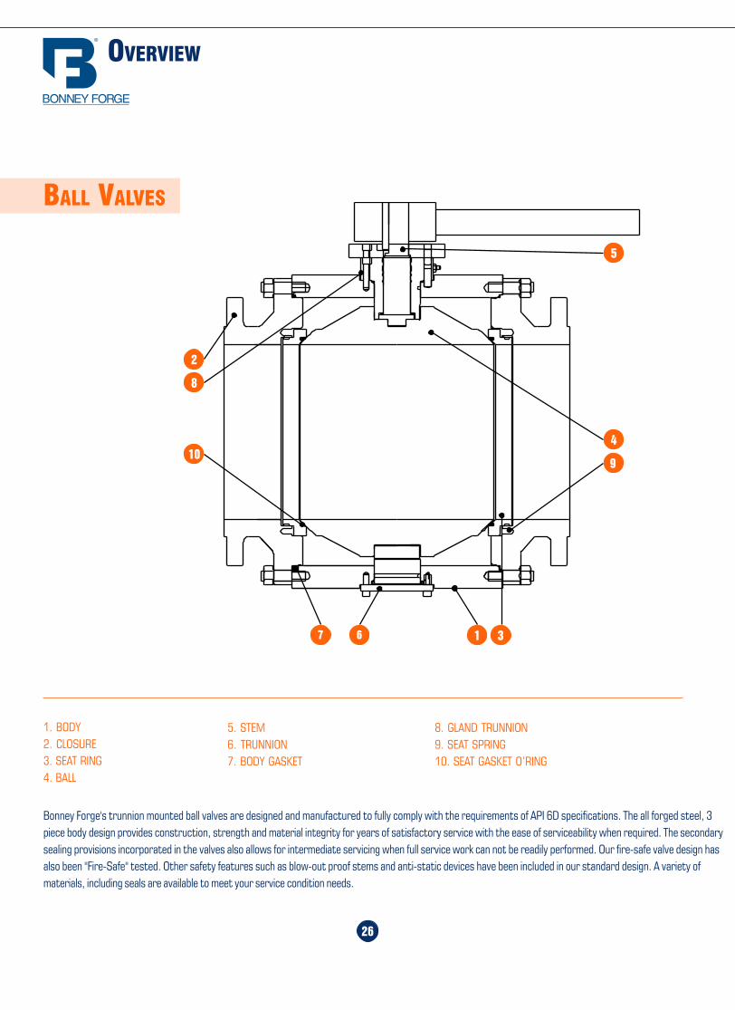
Home Table of Contents
Product Search
How To Order
PrintBack Next
Home Table of Contents
Product Search
How To Order
PrintBack Next
OVERVIEW
26
BALL VALVES
1. BODY2. CLOSURE3. SEAT RING4. BALL
8. GLAND TRUNNION9. SEAT SPRING10. SEAT GASKET O’RING
5. STEM6. TRUNNION7. BODY GASKET
Bonney Forge's trunnion mounted ball valves are designed and manufactured to fully comply with the requirements of API 6D specifications. The all forged steel, 3piece body design provides construction, strength and material integrity for years of satisfactory service with the ease of serviceability when required. The secondarysealing provisions incorporated in the valves also allows for intermediate servicing when full service work can not be readily performed. Our fire-safe valve design hasalso been "Fire-Safe" tested. Other safety features such as blow-out proof stems and anti-static devices have been included in our standard design. A variety ofmaterials, including seals are available to meet your service condition needs.
Special Features ........................ 36-38
Bypass & Drain Connection ............ 39
Flange Dimensions .................... 40,41
Ring Joint Facings ..................... 42,43
Butt-Welding Ends .......................... 44
Standard Class .......................... 45-48
35
ENGINEERING
SPECIFICATIONS
5
2
8
104
9
1 367
Home Table of Contents
Product Search
How To Order
PrintBack Next
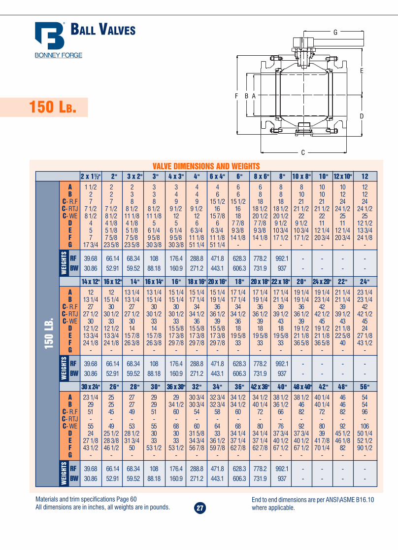
Home Table of Contents
Product Search
How To Order
PrintBack Next
Home Table of Contents
Product Search
How To Order
PrintBack Next
27
150 LB.
BALL VALVES
30 x 24" 26" 28" 30" 36 x 30" 32" 34" 36" 42 x 36" 40" 48 x 40" 42" 48" 56"A 23 1/4 25 27 29 29 30 3/4 32 3/4 34 1/2 34 1/2 38 1/2 38 1/2 40 1/4 46 54B 29 25 27 29 34 1/2 30 3/4 32 3/4 34 1/2 40 1/4 36 1/2 46 40 1/4 46 54
C- R.F 51 45 49 51 60 54 58 60 72 66 82 72 82 96C- RTJ - - - - - - - - - - - - - -C- WE 55 49 53 55 68 60 64 68 80 76 92 80 92 106
D 24 25 1/2 28 1/2 30 30 31 5/8 33 34 1/4 34 1/4 37 3/4 37 3/4 39 45 1/2 50 1/4E 27 1/8 28 3/8 31 3/4 33 33 34 3/4 36 1/2 37 1/4 37 1/4 40 1/2 40 1/2 41 7/8 46 1/8 52 1/2F 43 1/2 46 1/2 50 53 1/2 53 1/2 56 7/8 59 7/8 62 7/8 62 7/8 67 1/2 67 1/2 70 1/4 82 90 1/2G - - - - - - - - - - - - - -
RF 39.68 66.14 68.34 108 176.4 288.8 471.8 628.3 778.2 992.1 - - - -
BW 30.86 52.91 59.52 88.18 160.9 271.2 443.1 606.3 731.9 937 - - - -
WEI
GHTS
14 x 12" 16 x 12" 14" 16 x 14" 16" 18 x 16" 20 x 16" 18" 20 x 18" 22 x 18" 20" 24 x 20" 22" 24"
A 12 12 13 1/4 13 1/4 15 1/4 15 1/4 15 1/4 17 1/4 17 1/4 17 1/4 19 1/4 19 1/4 21 1/4 23 1/4B 13 1/4 15 1/4 13 1/4 15 1/4 15 1/4 17 1/4 19 1/4 17 1/4 19 1/4 21 1/4 19 1/4 23 1/4 21 1/4 23 1/4
C- R.F 27 30 27 30 30 34 36 34 36 39 36 42 39 42C- RTJ 27 1/2 30 1/2 27 1/2 30 1/2 30 1/2 34 1/2 36 1/2 34 1/2 36 1/2 39 1/2 36 1/2 42 1/2 39 1/2 42 1/2C- WE 30 33 30 33 33 36 39 36 39 43 39 45 43 45
D 12 1/2 12 1/2 14 14 15 5/8 15 5/8 15 5/8 18 18 18 19 1/2 19 1/2 21 1/8 24E 13 3/4 13 3/4 15 7/8 15 7/8 17 3/8 17 3/8 17 3/8 19 5/8 19 5/8 19 5/8 21 1/8 21 1/8 22 5/8 27 1/8F 24 1/8 24 1/8 26 3/8 26 3/8 29 7/8 29 7/8 29 7/8 33 33 33 36 5/8 36 5/8 40 43 1/2G - - - - - - - - - - - - - -
RF 39.68 66.14 68.34 108 176.4 288.8 471.8 628.3 778.2 992.1 - - - -
BW 30.86 52.91 59.52 88.18 160.9 271.2 443.1 606.3 731.9 937 - - - -WEI
GHTS
150
LB.
2 x 11/2" 2" 3 x 2" 3" 4 x 3" 4" 6 x 4" 6" 8 x 6" 8" 10 x 8" 10" 12 x 10" 12
A 1 1/2 2 2 3 3 4 4 6 6 8 8 10 10 12B 2 2 3 3 4 4 6 6 8 8 10 10 12 12
C- R.F 7 7 8 8 9 9 15 1/2 15 1/2 18 18 21 21 24 24C- RTJ 7 1/2 7 1/2 8 1/2 8 1/2 9 1/2 9 1/2 16 16 18 1/2 18 1/2 21 1/2 21 1/2 24 1/2 24 1/2C- WE 8 1/2 8 1/2 11 1/8 11 1/8 12 12 15 7/8 18 20 1/2 20 1/2 22 22 25 25
D 4 4 1/8 4 1/8 5 5 6 6 7 7/8 7 7/8 9 1/2 9 1/2 11 11 12 1/2E 5 5 1/8 5 1/8 6 1/4 6 1/4 6 3/4 6 3/4 9 3/8 9 3/8 10 3/4 10 3/4 12 1/4 12 1/4 13 3/4F 7 7 5/8 7 5/8 9 5/8 9 5/8 11 1/8 11 1/8 14 1/8 14 1/8 17 1/2 17 1/2 20 3/4 20 3/4 24 1/8G 17 3/4 23 5/8 23 5/8 30 3/8 30 3/8 51 1/4 51 1/4 - - - - - - -
RF 39.68 66.14 68.34 108 176.4 288.8 471.8 628.3 778.2 992.1 - - - -
BW 30.86 52.91 59.52 88.18 160.9 271.2 443.1 606.3 731.9 937 - - - -
VALVE DIMENSIONS AND WEIGHTS
WEI
GHTS
Materials and trim specifications Page 60All dimensions are in inches, all weights are in pounds.
End to end dimensions are per ANSI\ASME B16.10where applicable.
THRU-CONDUIT PIPELINE GATE VALVES
34
600 LB.
600
LB.
RF 11.5 13.0 14.0 17.0 22.0 26.0 31.0 33.0 35.0 39.0 43.0 47.0RJ 11.625 13.125 14.125 17.125 22.125 26.125 31.125 33.125 35.125 39.125 43.125 47.25BW 11.5 13.0 14.0 17.0 22.0 26.0 31.0 33.0 35.0 39.0 43.0 47.0A 6.2 7.4 8.3 12.1 17.2 20.7 23.6 27.6 29.4 33.1 36.1 37.7B 19.2 21.6 23.1 28.3 37.1 45.5 53.5 61.7 68.7 75.5 83.8 91.1C 11.8 11.8 11.8 11.8 11.8 17.7 23.6 23.6 23.6 31.5 31.5 43.3D — — — 11.8 11.8 11.8 17.7 17.7 23.6 23.6 31.5 31.5
FE 280 340 475 560 735 1050 1815 2415 3625 4800 5920 7830WE 240 310 425 485 575 820 1475 2015 3165 4140 5120 6810WEIGHTS
2" 2.5" 3" 4" 6" 8" 10" 12" 14" 16" 18" 20"
RF 51.0 55.0 57.0 61.0 65.0 70.0 76.0 82.0 86.0 90.0 96.0 110.0RJ 51.375 55.375 57.5 61.5 65.5 70.625 76.625 82.625 — — — —BW 51.0 55.0 57.0 61.0 65.0 70.0 76.0 82.0 86.0 90.0 96.0 110.0A 44.4 45.7 47.3 51.9 57.0 58.0 61.3 65.2 67.8 71.1 73.3 81.2B 103.3 109.1 112.0 123.7 132.8 139.2 149.0 154.1 162.0 171.7 173.2 201.4C — — — — — — — — — — — —D 31.5 31.5 31.5 39.4 39.4 39.4 39.4 39.4 39.4 43.3 43.3 43.3
FE 8610 9220 11340 14160 16635 17385 18765 19840 21425 21995 22360 30440WE 7464 7560 9375 12565 13770 14400 15545 16800 18150 18650 20360 24000WEIGHTS
22" 24" 26" 28" 30" 32" 34" 36" 38" 40" 42" 48"
VALVE DIMENSIONS AND WEIGHTS
Materials and trim specifications Page 60All dimensions are in inches, all weights are in pounds.
End to end dimensions are per ANSI\ASME B16.10where applicable.
C
D
RF-RJBW
A
B (OPEN)
ABF
C
G
E
D
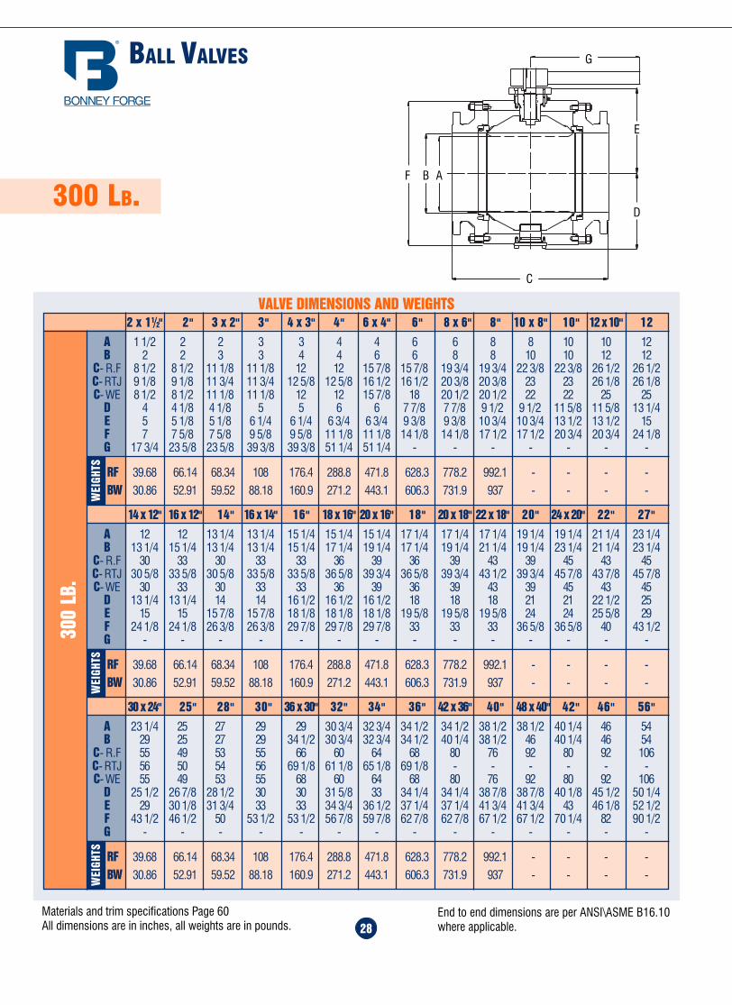
Home Table of Contents
Product Search
How To Order
PrintBack Next
Home Table of Contents
Product Search
How To Order
PrintBack Next
28
300 LB.
BALL VALVES
30 x 24" 25" 28" 30" 36 x 30" 32" 34" 36" 42 x 36" 40" 48 x 40" 42" 46" 56"
A 23 1/4 25 27 29 29 30 3/4 32 3/4 34 1/2 34 1/2 38 1/2 38 1/2 40 1/4 46 54B 29 25 27 29 34 1/2 30 3/4 32 3/4 34 1/2 40 1/4 38 1/2 46 40 1/4 46 54
C- R.F 55 49 53 55 66 60 64 68 80 76 92 80 92 106C- RTJ 56 50 54 56 69 1/8 61 1/8 65 1/8 69 1/8 - - - - - -C- WE 55 49 53 55 68 60 64 68 80 76 92 80 92 106
D 25 1/2 26 7/8 28 1/2 30 30 31 5/8 33 34 1/4 34 1/4 38 7/8 38 7/8 40 1/8 45 1/2 50 1/4E 29 30 1/8 31 3/4 33 33 34 3/4 36 1/2 37 1/4 37 1/4 41 3/4 41 3/4 43 46 1/8 52 1/2F 43 1/2 46 1/2 50 53 1/2 53 1/2 56 7/8 59 7/8 62 7/8 62 7/8 67 1/2 67 1/2 70 1/4 82 90 1/2G - - - - - - - - - - - - - -
RF 39.68 66.14 68.34 108 176.4 288.8 471.8 628.3 778.2 992.1 - - - -
BW 30.86 52.91 59.52 88.18 160.9 271.2 443.1 606.3 731.9 937 - - - -WEI
GHTS
14 x 12" 16 x 12" 14" 16 x 14" 16" 18 x 16" 20 x 16" 18" 20 x 18" 22 x 18" 20" 24 x 20" 22" 27"
A 12 12 13 1/4 13 1/4 15 1/4 15 1/4 15 1/4 17 1/4 17 1/4 17 1/4 19 1/4 19 1/4 21 1/4 23 1/4B 13 1/4 15 1/4 13 1/4 13 1/4 15 1/4 17 1/4 19 1/4 17 1/4 19 1/4 21 1/4 19 1/4 23 1/4 21 1/4 23 1/4
C- R.F 30 33 30 33 33 36 39 36 39 43 39 45 43 45C- RTJ 30 5/8 33 5/8 30 5/8 33 5/8 33 5/8 36 5/8 39 3/4 36 5/8 39 3/4 43 1/2 39 3/4 45 7/8 43 7/8 45 7/8C- WE 30 33 30 33 33 36 39 36 39 43 39 45 43 45
D 13 1/4 13 1/4 14 14 16 1/2 16 1/2 16 1/2 18 18 18 21 21 22 1/2 25E 15 15 15 7/8 15 7/8 18 1/8 18 1/8 18 1/8 19 5/8 19 5/8 19 5/8 24 24 25 5/8 29F 24 1/8 24 1/8 26 3/8 26 3/8 29 7/8 29 7/8 29 7/8 33 33 33 36 5/8 36 5/8 40 43 1/2G - - - - - - - - - - - - - -
RF 39.68 66.14 68.34 108 176.4 288.8 471.8 628.3 778.2 992.1 - - - -
BW 30.86 52.91 59.52 88.18 160.9 271.2 443.1 606.3 731.9 937 - - - -WEI
GHTS
300
LB.
2 x 11/2" 2" 3 x 2" 3" 4 x 3" 4" 6 x 4" 6" 8 x 6" 8" 10 x 8" 10" 12 x 10" 12
A 1 1/2 2 2 3 3 4 4 6 6 8 8 10 10 12B 2 2 3 3 4 4 6 6 8 8 10 10 12 12
C- R.F 8 1/2 8 1/2 11 1/8 11 1/8 12 12 15 7/8 15 7/8 19 3/4 19 3/4 22 3/8 22 3/8 26 1/2 26 1/2C- RTJ 9 1/8 9 1/8 11 3/4 11 3/4 12 5/8 12 5/8 16 1/2 16 1/2 20 3/8 20 3/8 23 23 26 1/8 26 1/8C- WE 8 1/2 8 1/2 11 1/8 11 1/8 12 12 15 7/8 18 20 1/2 20 1/2 22 22 25 25
D 4 4 1/8 4 1/8 5 5 6 6 7 7/8 7 7/8 9 1/2 9 1/2 11 5/8 11 5/8 13 1/4E 5 5 1/8 5 1/8 6 1/4 6 1/4 6 3/4 6 3/4 9 3/8 9 3/8 10 3/4 10 3/4 13 1/2 13 1/2 15F 7 7 5/8 7 5/8 9 5/8 9 5/8 11 1/8 11 1/8 14 1/8 14 1/8 17 1/2 17 1/2 20 3/4 20 3/4 24 1/8G 17 3/4 23 5/8 23 5/8 39 3/8 39 3/8 51 1/4 51 1/4 - - - - - - -
RF 39.68 66.14 68.34 108 176.4 288.8 471.8 628.3 778.2 992.1 - - - -
BW 30.86 52.91 59.52 88.18 160.9 271.2 443.1 606.3 731.9 937 - - - -
VALVE DIMENSIONS AND WEIGHTS
WEI
GHTS
Materials and trim specifications Page 60All dimensions are in inches, all weights are in pounds.
End to end dimensions are per ANSI\ASME B16.10where applicable. 33
150 LB.300 LB.
THRU-CONDUIT PIPELINE GATE VALVES
300
LB.
RF 20.0 20.0 22.0 24.0 26.0 28.0 30.0 32.0 34.0 36.0 38.0 44.0BW 30.0 32.0 34.0 36.0 36.0 38.0 40.0 40.0 42.0 44.0 46.0 52.0A 42.0 47.7 50.1 52.1 55.7 58.5 58.9 67.6 69.0 72.1 73.3 82.4B 97.8 104.0 111.7 119.4 126.4 134.1 142.6 148.9 157.8 164.3 167.7 190.2C 31.5 31.5 31.5 31.5 31.5 — — — — — — —D 23.6 23.6 23.6 23.6 23.6 23.6 23.6 23.6 23.6 23.6 23.6 23.6
FE 4680 5510 6885 8265 8600 9750 11655 13430 14975 16680 18535 23655WE 4275 5125 6405 7450 7875 8925 10670 12330 13750 15315 17035 21655
WEIGHTS
22" 24" 26" 28" 30" 32" 34" 36" 38" 40" 42" 48"
VALVE DIMENSIONS AND WEIGHTS
RF 7.0 7.5 8.0 9.0 10.5 11.5 13.0 14.0 15.0 16.0 17.0 18.0BW 8.5 9.5 11.125 12.0 15.875 16.5 18.0 19.75 22.5 24.0 26.0 28.0A 6.3 7.4 8.1 9.9 13.3 16.6 20.2 23.2 25.1 28.6 36.1 38.9B 19.2 21.4 23.0 25.7 34.9 43.3 52.5 61.4 65.9 73.7 80.8 87.9C 11.8 11.8 11.8 11.8 11.8 17.7 23.6 23.6 23.6 23.6 23.6 23.6D — — — — 11.8 11.8 11.8 17.7 17.7 23.6 23.6 23.6
FE 195 235 295 505 605 865 1435 1955 2055 2495 3095 3805WE 170 190 255 475 565 805 1345 1825 1875 2295 2835 3475
WEIGHTS
150
LB.
2" 2.5" 3" 4" 6" 8" 10" 12" 14" 16" 18" 20"
RF 8.5 9.5 11.125 12.0 15.875 16.5 18.0 19.75 30.0 33.0 36.0 38.5RJ 9.125 10.125 11.75 12.625 16.5 17.125 18.625 20.375 30.625 33.625 36.625 39.750BW 8.5 9.5 11.125 12.0 15.875 16.5 18.0 19.75 30.0 33.0 36.0 39.0A 6.2 7.4 8.3 10.0 14.1 17.2 20.0 20.9 26.0 29.4 32.2 35.3B 19.2 21.6 23.1 26.0 38.6 54.3 55.8 61.1 69.6 77.1 81.4 93.2C 11.8 11.8 11.8 11.8 11.8 11.8 23.6 23.6 23.6 31.5 31.5 43.3D — — — 11.8 11.8 11.8 11.8 23.6 23.6 23.6 23.6 23.6
FE 255 315 435 520 640 920 1595 2125 2245 3325 4165 5075WE 230 290 375 475 565 805 1430 1895 1915 2945 3665 4445WEIGHTS
2" 2.5" 3" 4" 6" 8" 10" 12" 14" 16" 18" 20"
RF 43.0 45.0 49.0 53.0 55.0 60.0 64.0 68.0 72.0 76.6 80.0 92.0RJ 43.875 45.875 50.0 54.0 56.0 61.125 65.125 69.125 73.125 77.125 81.125 93.125BW 43.0 45.0 49.0 53.0 55.0 60.0 64.0 68.0 72.0 76.0 80.0 92.0A 38.7 40.8 45.0 49.3 56.0 58.7 59.5 62.3 63.9 67.8 77.6 84.3B 97.8 103.3 121.7 128.9 136.0 144.7 153.3 162.4 172.2 188.8 206.1 247.8C — — -— — — — — — — — — —D 23.6 23.6 23.6 23.6 23.6 23.6 23.6 23.6 23.6 23.6 23.6 23.6
FE 6100 7790 8460 9755 11625 12860 13550 14855 16635 18235 20290 25505WE 5345 6840 7425 7935 9765 10795 11385 13435 15050 16500 18290 22000WEIGHTS
22" 24" 26" 28" 30" 32" 34" 36" 38" 40" 42" 48"
Materials and trim specifications Page 60All dimensions are in inches, all weights are in pounds.
End to end dimensions are per ANSI\ASME B16.10where applicable.
D
C
B (OPEN)
A
RF-RJ
BW
ABF
C
G
E
D

Home Table of Contents
Product Search
How To Order
PrintBack Next
Home Table of Contents
Product Search
How To Order
PrintBack Next
29
600 LB.
BALL VALVES
WEI
GHTS
WEI
GHTS
600
LB.
VALVE DIMENSIONS AND WEIGHTS
WEI
GHTS
30 x 24" 26" 28" 30" 36 x 30" 32" 34" 36" 42 x 36" 40" 48 x 40" 42" 48" 56"
A 23 1/4 25 27 29 29 30 3/4 32 3/4 34 1/2 34 1/2 38 1/2 38 1/2 40 1/4 46 54B 29 25 27 29 34 1/2 30 3/4 32 3/4 34 1/2 40 1/4 38 1/2 46 40 1/4 46 54
C- R.F 65 57 61 65 82 70 76 82 86 82 96 86 96 112C- RTJ 65 1/2 57 1/2 61 1/2 65 1/2 82 5/8 70 5/8 76 5/8 82 5/8 - - - - - -C- WE 65 57 61 65 82 70 76 82 86 82 96 86 96 112
D 25 1/2 26 3/4 30 1/2 32 1/4 32 1/4 33 1/2 34 3/4 36 1/4 36 1/4 39 39 40 47 3/4 54 1/2E 29 30 1/8 33 34 1/2 34 1/2 36 37 3/4 38 1/2 38 1/2 41 3/4 41 3/4 43 49 1/4 55 7/8F 47 50 53 7/8 57 1/2 57 1/2 61 1/8 64 3/8 67 1/2 67 1/2 73 1/8 73 1/8 74 1/4 88 3/4 100G - - - - - - - - - - - - - -
RF 39.68 66.14 68.34 108 176.4 288.8 471.8 628.3 778.2 992.1 - - - -
BW 30.86 52.91 59.52 88.18 160.9 271.2 443.1 606.3 731.9 937 - - - -
A 12 12 13 1/4 13 1/4 15 1/4 15 1/4 15 1/4 17 1/4 17 1/4 17 1/4 19 1/4 19 1/4 21 1/4 23 1/4B 13 1/4 15 1/4 13 1/4 15 1/4 15 1/4 17 1/4 19 1/4 17 1/4 19 1/4 21 1/4 19 1/4 23 1/4 21 1/4 23 1/4
C- R.F 35 39 35 39 39 43 47 43 47 51 47 55 51 55C- RTJ 35 1/8 39 1/8 35 1/8 39 1/8 39 1/8 43 1/8 47 1/8 43 1/8 47 1/8 51 3/8 47 1/8 55 1/2 51 3/8 55 3/8C- WE 35 39 35 39 39 43 47 43 47 51 47 55 51 55
D 13 1/4 13 1/4 15 1/8 15 1/8 18 3/8 18 3/8 18 3/8 19 3/4 19 3/4 19 3/4 22 7/8 22 7/8 24 1/2 25 1/2E 15 15 16 5/8 16 5/8 21 21 21 22 1/2 22 1/2 22 1/2 25 7/8 25 7/8 27 1/2 29F 26 26 26 28 1/4 28 1/4 32 32 35 5/8 35 5/8 35 5/8 39 1/2 39 1/2 43 1/8 47G - - - - - - - - - - - - - -
RF 39.68 66.14 68.34 108 176.4 288.8 471.8 628.3 778.2 992.1 - - - -
BW 30.86 52.91 59.52 88.18 160.9 271.2 443.1 606.3 731.9 937 - - - -
2 x 11/2" 2" 3 x 2" 3" 4 x 3" 4" 6 x 4" 6" 8 x 6" 8" 10 x 8" 10" 12 x 10" 12
A 1 1/2 2 2 3 3 4 4 6 6 8 8 10 10 12B 2 2 3 3 4 4 6 6 8 8 10 10 12 12
C- R.F 11 1/2 11 1/2 14 14 17 17 22 22 26 26 31 31 33 33C- RTJ 11 5/8 11 5/8 14 1/8 14 1/8 17 1/8 17 1/8 22 1/8 22 1/8 26 1/8 26 1/8 31 1/8 31 1/8 33 1/8 33 1/8C- WE 11 1/2 11 1/2 14 14 17 17 22 22 26 26 31 31 33 33
D 4 4 1/8 4 1/8 5 5 6 6 7 7/8 7 7/8 10 1/4 10 1/4 11 1/2 11 1/2 13 1/4E 5 5 1/8 5 1/8 6 1/4 6 1/4 6 3/4 6 3/4 9 3/8 9 3/8 12 12 13 1/2 13 1/2 15F 7 3/8 8 8 10 10 11 1/2 11 1/2 15 1/8 15 1/8 18 5/8 18 5/8 22 1/8 22 1/8 22 7/8G 17 3/4 23 5/8 23 5/8 39 3/8 39 3/8 51 1/4 51 1/4 - - - - - - -
RF 39.68 66.14 68.34 108 176.4 288.8 471.8 628.3 778.2 992.1 - - - -
BW 30.86 52.91 59.52 88.18 160.9 271.2 443.1 606.3 731.9 937 - - - -
14 x 12" 16 x 12" 14" 16 x 14" 16" 18 x 16" 20 x 16" 18" 20 x 18" 22 x 18" 20" 24 x 20" 22" 27"
Materials and trim specifications Page 60All dimensions are in inches, all weights are in pounds.
End to end dimensions are per ANSI\ASME B16.10where applicable.32
THRU-CONDUIT PIPELINE
GATE VALVES
Bonney Forge's Thru-Conduit pipeline Gate valves are designed and manufactured for transportation of fluids and Gas. They fully comply with API6D specifications. Our Thru-Conduit offers simplicity of design along with positive sealing action to give total control of any fluid to flow freelywith a minimum of turbulence. Our valves are generally cast up to 12" size while for larger diameters the construction is a combination ofcastings - plate - pipe. In the open position our valves allow the running of "Pigs" through the pipeline with no danger of damage to the valvesealing. When the valve is in the closed position the valve seats combine to form a tight seal upstream and downstream.
The valve seats have a nylon of PTFE circular insert on their sealing faces. For underground installation the valves may be supplied with greaseinjectors to remedy quickly any eventual damage that could occur in service to the sealing components.
1. BODY.2. BONNET.3. YOKE.
7. BONNET GASKET.8. YOKE NUT.9. HANDWHEEL.
4. SEAT.5. SLAB GATE.6. STEM.
10. PACKING RETAINER.11. STEM PACKING.12. SPRINGS
OVERVIEW
2
1
4
12
3
9
8
11
10
7
6
5
METAL TO METAL
SOFT-SEATED
ABF
C
G
E
D
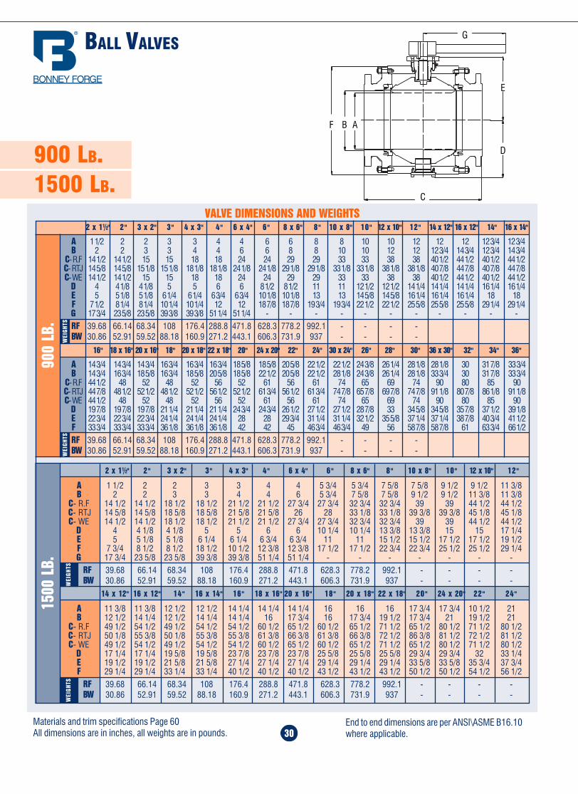
Home Table of Contents
Product Search
How To Order
PrintBack
Home Table of Contents
Product Search
How To Order
PrintBack Next
14 x 12" 16 x 12" 14" 16 x 14" 16" 18 x 16" 20 x 16" 18" 20 x 18" 22 x 18" 20" 24 x 20" 22" 24"
A 11 3/8 11 3/8 12 1/2 12 1/2 14 1/4 14 1/4 14 1/4 16 16 16 17 3/4 17 3/4 10 1/2 21B 12 1/2 14 1/4 12 1/2 14 1/4 14 1/4 16 17 3/4 16 17 3/4 19 1/2 17 3/4 21 19 1/2 21
C- R.F 49 1/2 54 1/2 49 1/2 54 1/2 54 1/2 60 1/2 65 1/2 60 1/2 65 1/2 71 1/2 65 1/2 80 1/2 71 1/2 80 1/2C- RTJ 50 1/8 55 3/8 50 1/8 55 3/8 55 3/8 61 3/8 66 3/8 61 3/8 66 3/8 72 1/2 86 3/8 81 1/2 72 1/2 81 1/2C- WE 49 1/2 54 1/2 49 1/2 54 1/2 54 1/2 60 1/2 65 1/2 60 1/2 65 1/2 71 1/2 65 1/2 80 1/2 71 1/2 80 1/2
D 17 1/4 17 1/4 19 5/8 19 5/8 23 7/8 23 7/8 23 7/8 25 5/8 25 5/8 25 5/8 29 3/4 29 3/4 32 33 1/4E 19 1/2 19 1/2 21 5/8 21 5/8 27 1/4 27 1/4 27 1/4 29 1/4 29 1/4 29 1/4 33 5/8 33 5/8 35 3/4 37 3/4F 29 1/4 29 1/4 33 1/4 33 1/4 40 1/2 40 1/2 40 1/2 43 1/2 43 1/2 43 1/2 50 1/2 50 1/2 54 1/2 56 1/2
RF 39.68 66.14 68.34 108 176.4 288.8 471.8 628.3 778.2 992.1 - - - -BW 30.86 52.91 59.52 88.18 160.9 271.2 443.1 606.3 731.9 937 - - - -
1500
LB.
16" 18 x 16" 20 x 16" 18" 20 x 18" 22 x 18" 20" 24 x 20" 22" 24" 30 x 24" 26" 28" 30" 36 x 30" 32" 34" 36"
A 14 3/4 14 3/4 14 3/4 16 3/4 16 3/4 16 3/4 18 5/8 18 5/8 20 5/8 22 1/2 22 1/2 24 3/8 26 1/4 28 1/8 28 1/8 30 31 7/8 33 3/4B 14 3/4 16 3/4 18 5/8 16 3/4 18 5/8 20 5/8 18 5/8 22 1/2 20 5/8 22 1/2 28 1/8 24 3/8 26 1/4 28 1/8 33 3/4 30 31 7/8 33 3/4
C- R.F 44 1/2 48 52 48 52 56 52 61 56 61 74 65 69 74 90 80 85 90C- RTJ 44 7/8 48 1/2 52 1/2 48 1/2 52 1/2 56 1/2 52 1/2 61 3/4 56 1/2 61 3/4 74 7/8 65 7/8 69 7/8 74 7/8 91 1/8 80 7/8 86 1/8 91 1/8C- WE 44 1/2 48 52 48 52 56 52 61 56 61 74 65 69 74 90 80 85 90
D 19 7/8 19 7/8 19 7/8 21 1/4 21 1/4 21 1/4 24 3/4 24 3/4 26 1/2 27 1/2 27 1/2 28 7/8 33 34 5/8 34 5/8 35 7/8 37 1/2 39 1/8E 22 3/4 22 3/4 22 3/4 24 1/4 24 1/4 24 1/4 28 28 29 3/4 31 1/4 31 1/4 32 1/2 35 5/8 37 1/4 37 1/4 38 7/8 40 3/4 41 1/2F 33 3/4 33 3/4 33 3/4 36 1/8 36 1/8 36 1/8 42 42 45 46 3/4 46 3/4 49 56 58 7/8 58 7/8 61 63 3/4 66 1/2RF 39.68 66.14 68.34 108 176.4 288.8 471.8 628.3 778.2 992.1 - - - -BW 30.86 52.91 59.52 88.18 160.9 271.2 443.1 606.3 731.9 937 - - - -W
EIGH
TS
31
BALL VALVES
30
900 LB.1500 LB.
900
LB.
2 x 11/2" 2" 3 x 2" 3" 4 x 3" 4" 6 x 4" 6" 8 x 6" 8" 10 x 8" 10" 12 x 10" 12" 14 x 12" 16 x 12" 14" 16 x 14"
A 1 1/2 2 2 3 3 4 4 6 6 8 8 10 10 12 12 12 12 3/4 12 3/4B 2 2 3 3 4 4 6 6 8 8 10 10 12 12 12 3/4 14 3/4 12 3/4 14 3/4
C- R.F 14 1/2 14 1/2 15 15 18 18 24 24 29 29 33 33 38 38 40 1/2 44 1/2 40 1/2 44 1/2C- RTJ 14 5/8 14 5/8 15 1/8 15 1/8 18 1/8 18 1/8 24 1/8 24 1/8 29 1/8 29 1/8 33 1/8 33 1/8 38 1/8 38 1/8 40 7/8 44 7/8 40 7/8 44 7/8C- WE 14 1/2 14 1/2 15 15 18 18 24 24 29 29 33 33 38 38 40 1/2 44 1/2 40 1/2 44 1/2
D 4 4 1/8 4 1/8 5 5 6 6 8 1/2 8 1/2 11 11 12 1/2 12 1/2 14 1/4 14 1/4 14 1/4 16 1/4 16 1/4E 5 5 1/8 5 1/8 6 1/4 6 1/4 6 3/4 6 3/4 10 1/8 10 1/8 13 13 14 5/8 14 5/8 16 1/4 16 1/4 16 1/4 18 18F 7 1/2 8 1/4 8 1/4 10 1/4 10 1/4 12 12 18 7/8 18 7/8 19 3/4 19 3/4 22 1/2 22 1/2 25 5/8 25 5/8 25 5/8 29 1/4 29 1/4G 17 3/4 23 5/8 23 5/8 39 3/8 39 3/8 51 1/4 51 1/4 - - - - - - - - - - -RF 39.68 66.14 68.34 108 176.4 288.8 471.8 628.3 778.2 992.1 - - - -BW 30.86 52.91 59.52 88.18 160.9 271.2 443.1 606.3 731.9 937 - - - -
VALVE DIMENSIONS AND WEIGHTS
WEI
GHTS
WEI
GHTS
2 x 11/2" 2" 3 x 2" 3" 4 x 3" 4" 6 x 4" 6" 8 x 6" 8" 10 x 8" 10" 12 x 10" 12"
A 1 1/2 2 2 3 3 4 4 5 3/4 5 3/4 7 5/8 7 5/8 9 1/2 9 1/2 11 3/8B 2 2 3 3 4 4 6 5 3/4 7 5/8 7 5/8 9 1/2 9 1/2 11 3/8 11 3/8
C- R.F 14 1/2 14 1/2 18 1/2 18 1/2 21 1/2 21 1/2 27 3/4 27 3/4 32 3/4 32 3/4 39 39 44 1/2 44 1/2C- RTJ 14 5/8 14 5/8 18 5/8 18 5/8 21 5/8 21 5/8 26 28 33 1/8 33 1/8 39 3/8 39 3/8 45 1/8 45 1/8C- WE 14 1/2 14 1/2 18 1/2 18 1/2 21 1/2 21 1/2 27 3/4 27 3/4 32 3/4 32 3/4 39 39 44 1/2 44 1/2
D 4 4 1/8 4 1/8 5 5 6 6 10 1/4 10 1/4 13 3/8 13 3/8 15 15 17 1/4E 5 5 1/8 5 1/8 6 1/4 6 1/4 6 3/4 6 3/4 11 11 15 1/2 15 1/2 17 1/2 17 1/2 19 1/2F 7 3/4 8 1/2 8 1/2 18 1/2 10 1/2 12 3/8 12 3/8 17 1/2 17 1/2 22 3/4 22 3/4 25 1/2 25 1/2 29 1/4G 17 3/4 23 5/8 23 5/8 39 3/8 39 3/8 51 1/4 51 1/4 - - - - - - -
RF 39.68 66.14 68.34 108 176.4 288.8 471.8 628.3 778.2 992.1 - - - -BW 30.86 52.91 59.52 88.18 160.9 271.2 443.1 606.3 731.9 937 - - - -
WEI
GHTS
Overview ........................................ 32
150 lb. valves ................................. 33
300 lb. valves ................................. 33
600 lb. valves ................................. 34
THRU-CONDUIT
PIPELINE GATE
VALVES
Materials and trim specifications Page 60All dimensions are in inches, all weights are in pounds.
End to end dimensions are per ANSI\ASME B16.10where applicable.
ABF
C
G
E
D
Home Table of Contents
Product Search
How To Order
PrintBack Next

Home Table of Contents
Product Search
How To Order
PrintBack Next
Home Table of Contents
Product Search
How To Order
Printt
14 x 12" 16 x 12" 14" 16 x 14" 16" 18 x 16" 20 x 16" 18" 20 x 18" 22 x 18" 20" 24 x 20" 22" 24"
A 11 3/8 11 3/8 12 1/2 12 1/2 14 1/4 14 1/4 14 1/4 16 16 16 17 3/4 17 3/4 10 1/2 21B 12 1/2 14 1/4 12 1/2 14 1/4 14 1/4 16 17 3/4 16 17 3/4 19 1/2 17 3/4 21 19 1/2 21
C- R.F 49 1/2 54 1/2 49 1/2 54 1/2 54 1/2 60 1/2 65 1/2 60 1/2 65 1/2 71 1/2 65 1/2 80 1/2 71 1/2 80 1/2C- RTJ 50 1/8 55 3/8 50 1/8 55 3/8 55 3/8 61 3/8 66 3/8 61 3/8 66 3/8 72 1/2 86 3/8 81 1/2 72 1/2 81 1/2C- WE 49 1/2 54 1/2 49 1/2 54 1/2 54 1/2 60 1/2 65 1/2 60 1/2 65 1/2 71 1/2 65 1/2 80 1/2 71 1/2 80 1/2
D 17 1/4 17 1/4 19 5/8 19 5/8 23 7/8 23 7/8 23 7/8 25 5/8 25 5/8 25 5/8 29 3/4 29 3/4 32 33 1/4E 19 1/2 19 1/2 21 5/8 21 5/8 27 1/4 27 1/4 27 1/4 29 1/4 29 1/4 29 1/4 33 5/8 33 5/8 35 3/4 37 3/4F 29 1/4 29 1/4 33 1/4 33 1/4 40 1/2 40 1/2 40 1/2 43 1/2 43 1/2 43 1/2 50 1/2 50 1/2 54 1/2 56 1/2
RF 39.68 66.14 68.34 108 176.4 288.8 471.8 628.3 778.2 992.1 - - - -BW 30.86 52.91 59.52 88.18 160.9 271.2 443.1 606.3 731.9 937 - - - -
1500
LB.
16" 18 x 16" 20 x 16" 18" 20 x 18" 22 x 18" 20" 24 x 20" 22" 24" 30 x 24" 26" 28" 30" 36 x 30" 32" 34" 36"
A 14 3/4 14 3/4 14 3/4 16 3/4 16 3/4 16 3/4 18 5/8 18 5/8 20 5/8 22 1/2 22 1/2 24 3/8 26 1/4 28 1/8 28 1/8 30 31 7/8 33 3/4B 14 3/4 16 3/4 18 5/8 16 3/4 18 5/8 20 5/8 18 5/8 22 1/2 20 5/8 22 1/2 28 1/8 24 3/8 26 1/4 28 1/8 33 3/4 30 31 7/8 33 3/4
C- R.F 44 1/2 48 52 48 52 56 52 61 56 61 74 65 69 74 90 80 85 90C- RTJ 44 7/8 48 1/2 52 1/2 48 1/2 52 1/2 56 1/2 52 1/2 61 3/4 56 1/2 61 3/4 74 7/8 65 7/8 69 7/8 74 7/8 91 1/8 80 7/8 86 1/8 91 1/8C- WE 44 1/2 48 52 48 52 56 52 61 56 61 74 65 69 74 90 80 85 90
D 19 7/8 19 7/8 19 7/8 21 1/4 21 1/4 21 1/4 24 3/4 24 3/4 26 1/2 27 1/2 27 1/2 28 7/8 33 34 5/8 34 5/8 35 7/8 37 1/2 39 1/8E 22 3/4 22 3/4 22 3/4 24 1/4 24 1/4 24 1/4 28 28 29 3/4 31 1/4 31 1/4 32 1/2 35 5/8 37 1/4 37 1/4 38 7/8 40 3/4 41 1/2F 33 3/4 33 3/4 33 3/4 36 1/8 36 1/8 36 1/8 42 42 45 46 3/4 46 3/4 49 56 58 7/8 58 7/8 61 63 3/4 66 1/2RF 39.68 66.14 68.34 108 176.4 288.8 471.8 628.3 778.2 992.1 - - - -BW 30.86 52.91 59.52 88.18 160.9 271.2 443.1 606.3 731.9 937 - - - -W
EIGH
TS
31
BALL VALVES
30
900 LB.1500 LB.
900
LB.
2 x 11/2" 2" 3 x 2" 3" 4 x 3" 4" 6 x 4" 6" 8 x 6" 8" 10 x 8" 10" 12 x 10" 12" 14 x 12" 16 x 12" 14" 16 x 14"
A 1 1/2 2 2 3 3 4 4 6 6 8 8 10 10 12 12 12 12 3/4 12 3/4B 2 2 3 3 4 4 6 6 8 8 10 10 12 12 12 3/4 14 3/4 12 3/4 14 3/4
C- R.F 14 1/2 14 1/2 15 15 18 18 24 24 29 29 33 33 38 38 40 1/2 44 1/2 40 1/2 44 1/2C- RTJ 14 5/8 14 5/8 15 1/8 15 1/8 18 1/8 18 1/8 24 1/8 24 1/8 29 1/8 29 1/8 33 1/8 33 1/8 38 1/8 38 1/8 40 7/8 44 7/8 40 7/8 44 7/8C- WE 14 1/2 14 1/2 15 15 18 18 24 24 29 29 33 33 38 38 40 1/2 44 1/2 40 1/2 44 1/2
D 4 4 1/8 4 1/8 5 5 6 6 8 1/2 8 1/2 11 11 12 1/2 12 1/2 14 1/4 14 1/4 14 1/4 16 1/4 16 1/4E 5 5 1/8 5 1/8 6 1/4 6 1/4 6 3/4 6 3/4 10 1/8 10 1/8 13 13 14 5/8 14 5/8 16 1/4 16 1/4 16 1/4 18 18F 7 1/2 8 1/4 8 1/4 10 1/4 10 1/4 12 12 18 7/8 18 7/8 19 3/4 19 3/4 22 1/2 22 1/2 25 5/8 25 5/8 25 5/8 29 1/4 29 1/4G 17 3/4 23 5/8 23 5/8 39 3/8 39 3/8 51 1/4 51 1/4 - - - - - - - - - - -RF 39.68 66.14 68.34 108 176.4 288.8 471.8 628.3 778.2 992.1 - - - -BW 30.86 52.91 59.52 88.18 160.9 271.2 443.1 606.3 731.9 937 - - - -
VALVE DIMENSIONS AND WEIGHTS
WEI
GHTS
WEI
GHTS
2 x 11/2" 2" 3 x 2" 3" 4 x 3" 4" 6 x 4" 6" 8 x 6" 8" 10 x 8" 10" 12 x 10" 12"
A 1 1/2 2 2 3 3 4 4 5 3/4 5 3/4 7 5/8 7 5/8 9 1/2 9 1/2 11 3/8B 2 2 3 3 4 4 6 5 3/4 7 5/8 7 5/8 9 1/2 9 1/2 11 3/8 11 3/8
C- R.F 14 1/2 14 1/2 18 1/2 18 1/2 21 1/2 21 1/2 27 3/4 27 3/4 32 3/4 32 3/4 39 39 44 1/2 44 1/2C- RTJ 14 5/8 14 5/8 18 5/8 18 5/8 21 5/8 21 5/8 26 28 33 1/8 33 1/8 39 3/8 39 3/8 45 1/8 45 1/8C- WE 14 1/2 14 1/2 18 1/2 18 1/2 21 1/2 21 1/2 27 3/4 27 3/4 32 3/4 32 3/4 39 39 44 1/2 44 1/2
D 4 4 1/8 4 1/8 5 5 6 6 10 1/4 10 1/4 13 3/8 13 3/8 15 15 17 1/4E 5 5 1/8 5 1/8 6 1/4 6 1/4 6 3/4 6 3/4 11 11 15 1/2 15 1/2 17 1/2 17 1/2 19 1/2F 7 3/4 8 1/2 8 1/2 18 1/2 10 1/2 12 3/8 12 3/8 17 1/2 17 1/2 22 3/4 22 3/4 25 1/2 25 1/2 29 1/4G 17 3/4 23 5/8 23 5/8 39 3/8 39 3/8 51 1/4 51 1/4 - - - - - - -
RF 39.68 66.14 68.34 108 176.4 288.8 471.8 628.3 778.2 992.1 - - - -BW 30.86 52.91 59.52 88.18 160.9 271.2 443.1 606.3 731.9 937 - - - -
WEI
GHTS
Overview ........................................ 32
150 lb. valves ................................. 33
300 lb. valves ................................. 33
600 lb. valves ................................. 34
THRU-CONDUIT
PIPELINE GATE
VALVES
Materials and trim specifications Page 60All dimensions are in inches, all weights are in pounds.
End to end dimensions are per ANSI\ASME B16.10where applicable.
ABF
C
G
E
D
Home Table of Contents
Product Search
How To Order
Print Next
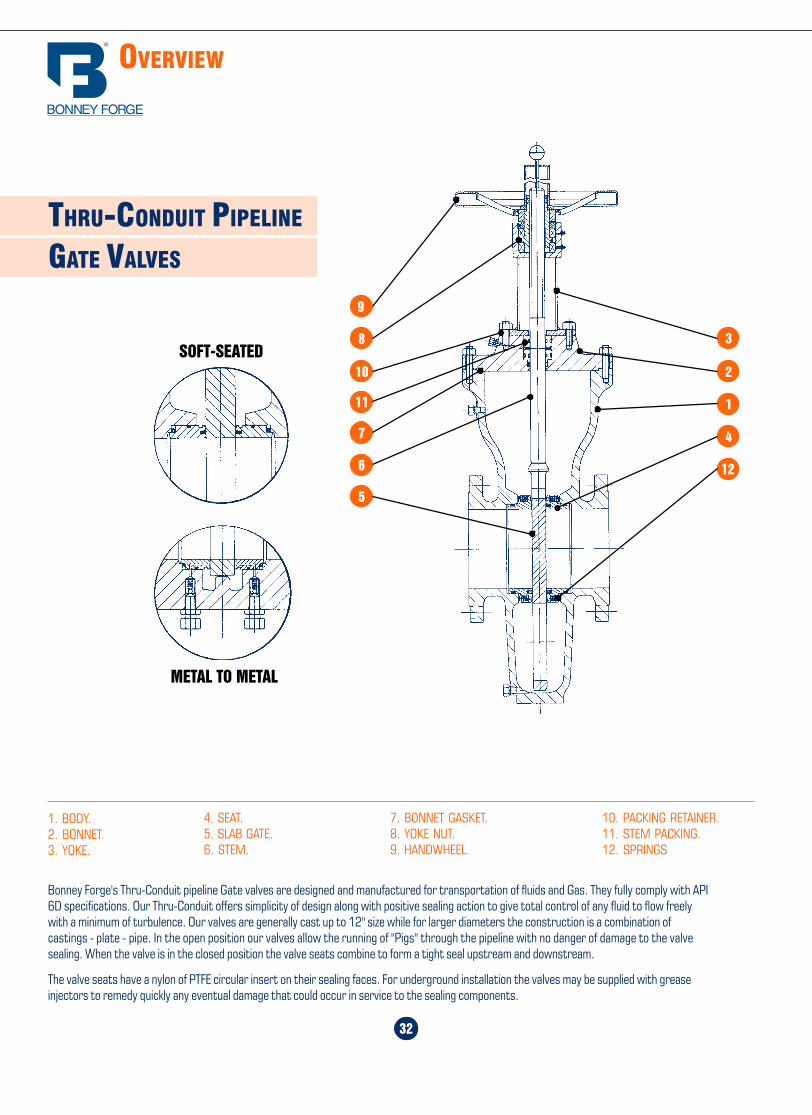
Home Table of Contents
Product Search
How To Order
PrintBack Next
Home Table of Contents
Product Search
How To Order
PrintBack Next
29
600 LB.
BALL VALVES
WEI
GHTS
WEI
GHTS
600
LB.
VALVE DIMENSIONS AND WEIGHTS
WEI
GHTS
30 x 24" 26" 28" 30" 36 x 30" 32" 34" 36" 42 x 36" 40" 48 x 40" 42" 48" 56"
A 23 1/4 25 27 29 29 30 3/4 32 3/4 34 1/2 34 1/2 38 1/2 38 1/2 40 1/4 46 54B 29 25 27 29 34 1/2 30 3/4 32 3/4 34 1/2 40 1/4 38 1/2 46 40 1/4 46 54
C- R.F 65 57 61 65 82 70 76 82 86 82 96 86 96 112C- RTJ 65 1/2 57 1/2 61 1/2 65 1/2 82 5/8 70 5/8 76 5/8 82 5/8 - - - - - -C- WE 65 57 61 65 82 70 76 82 86 82 96 86 96 112
D 25 1/2 26 3/4 30 1/2 32 1/4 32 1/4 33 1/2 34 3/4 36 1/4 36 1/4 39 39 40 47 3/4 54 1/2E 29 30 1/8 33 34 1/2 34 1/2 36 37 3/4 38 1/2 38 1/2 41 3/4 41 3/4 43 49 1/4 55 7/8F 47 50 53 7/8 57 1/2 57 1/2 61 1/8 64 3/8 67 1/2 67 1/2 73 1/8 73 1/8 74 1/4 88 3/4 100G - - - - - - - - - - - - - -
RF 39.68 66.14 68.34 108 176.4 288.8 471.8 628.3 778.2 992.1 - - - -
BW 30.86 52.91 59.52 88.18 160.9 271.2 443.1 606.3 731.9 937 - - - -
A 12 12 13 1/4 13 1/4 15 1/4 15 1/4 15 1/4 17 1/4 17 1/4 17 1/4 19 1/4 19 1/4 21 1/4 23 1/4B 13 1/4 15 1/4 13 1/4 15 1/4 15 1/4 17 1/4 19 1/4 17 1/4 19 1/4 21 1/4 19 1/4 23 1/4 21 1/4 23 1/4
C- R.F 35 39 35 39 39 43 47 43 47 51 47 55 51 55C- RTJ 35 1/8 39 1/8 35 1/8 39 1/8 39 1/8 43 1/8 47 1/8 43 1/8 47 1/8 51 3/8 47 1/8 55 1/2 51 3/8 55 3/8C- WE 35 39 35 39 39 43 47 43 47 51 47 55 51 55
D 13 1/4 13 1/4 15 1/8 15 1/8 18 3/8 18 3/8 18 3/8 19 3/4 19 3/4 19 3/4 22 7/8 22 7/8 24 1/2 25 1/2E 15 15 16 5/8 16 5/8 21 21 21 22 1/2 22 1/2 22 1/2 25 7/8 25 7/8 27 1/2 29F 26 26 26 28 1/4 28 1/4 32 32 35 5/8 35 5/8 35 5/8 39 1/2 39 1/2 43 1/8 47G - - - - - - - - - - - - - -
RF 39.68 66.14 68.34 108 176.4 288.8 471.8 628.3 778.2 992.1 - - - -
BW 30.86 52.91 59.52 88.18 160.9 271.2 443.1 606.3 731.9 937 - - - -
2 x 11/2" 2" 3 x 2" 3" 4 x 3" 4" 6 x 4" 6" 8 x 6" 8" 10 x 8" 10" 12 x 10" 12
A 1 1/2 2 2 3 3 4 4 6 6 8 8 10 10 12B 2 2 3 3 4 4 6 6 8 8 10 10 12 12
C- R.F 11 1/2 11 1/2 14 14 17 17 22 22 26 26 31 31 33 33C- RTJ 11 5/8 11 5/8 14 1/8 14 1/8 17 1/8 17 1/8 22 1/8 22 1/8 26 1/8 26 1/8 31 1/8 31 1/8 33 1/8 33 1/8C- WE 11 1/2 11 1/2 14 14 17 17 22 22 26 26 31 31 33 33
D 4 4 1/8 4 1/8 5 5 6 6 7 7/8 7 7/8 10 1/4 10 1/4 11 1/2 11 1/2 13 1/4E 5 5 1/8 5 1/8 6 1/4 6 1/4 6 3/4 6 3/4 9 3/8 9 3/8 12 12 13 1/2 13 1/2 15F 7 3/8 8 8 10 10 11 1/2 11 1/2 15 1/8 15 1/8 18 5/8 18 5/8 22 1/8 22 1/8 22 7/8G 17 3/4 23 5/8 23 5/8 39 3/8 39 3/8 51 1/4 51 1/4 - - - - - - -
RF 39.68 66.14 68.34 108 176.4 288.8 471.8 628.3 778.2 992.1 - - - -
BW 30.86 52.91 59.52 88.18 160.9 271.2 443.1 606.3 731.9 937 - - - -
14 x 12" 16 x 12" 14" 16 x 14" 16" 18 x 16" 20 x 16" 18" 20 x 18" 22 x 18" 20" 24 x 20" 22" 27"
Materials and trim specifications Page 60All dimensions are in inches, all weights are in pounds.
End to end dimensions are per ANSI\ASME B16.10where applicable.32
THRU-CONDUIT PIPELINE
GATE VALVES
Bonney Forge's Thru-Conduit pipeline Gate valves are designed and manufactured for transportation of fluids and Gas. They fully comply with API6D specifications. Our Thru-Conduit offers simplicity of design along with positive sealing action to give total control of any fluid to flow freelywith a minimum of turbulence. Our valves are generally cast up to 12" size while for larger diameters the construction is a combination ofcastings - plate - pipe. In the open position our valves allow the running of "Pigs" through the pipeline with no danger of damage to the valvesealing. When the valve is in the closed position the valve seats combine to form a tight seal upstream and downstream.
The valve seats have a nylon of PTFE circular insert on their sealing faces. For underground installation the valves may be supplied with greaseinjectors to remedy quickly any eventual damage that could occur in service to the sealing components.
1. BODY.2. BONNET.3. YOKE.
7. BONNET GASKET.8. YOKE NUT.9. HANDWHEEL.
4. SEAT.5. SLAB GATE.6. STEM.
10. PACKING RETAINER.11. STEM PACKING.12. SPRINGS
OVERVIEW
2
1
4
12
3
9
8
11
10
7
6
5
METAL TO METAL
SOFT-SEATED
ABF
C
G
E
D
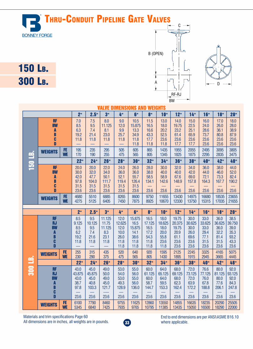
Home Table of Contents
Product Search
How To Order
PrintBack Next
Home Table of Contents
Product Search
How To Order
PrintBack Next
28
300 LB.
BALL VALVES
30 x 24" 25" 28" 30" 36 x 30" 32" 34" 36" 42 x 36" 40" 48 x 40" 42" 46" 56"
A 23 1/4 25 27 29 29 30 3/4 32 3/4 34 1/2 34 1/2 38 1/2 38 1/2 40 1/4 46 54B 29 25 27 29 34 1/2 30 3/4 32 3/4 34 1/2 40 1/4 38 1/2 46 40 1/4 46 54
C- R.F 55 49 53 55 66 60 64 68 80 76 92 80 92 106C- RTJ 56 50 54 56 69 1/8 61 1/8 65 1/8 69 1/8 - - - - - -C- WE 55 49 53 55 68 60 64 68 80 76 92 80 92 106
D 25 1/2 26 7/8 28 1/2 30 30 31 5/8 33 34 1/4 34 1/4 38 7/8 38 7/8 40 1/8 45 1/2 50 1/4E 29 30 1/8 31 3/4 33 33 34 3/4 36 1/2 37 1/4 37 1/4 41 3/4 41 3/4 43 46 1/8 52 1/2F 43 1/2 46 1/2 50 53 1/2 53 1/2 56 7/8 59 7/8 62 7/8 62 7/8 67 1/2 67 1/2 70 1/4 82 90 1/2G - - - - - - - - - - - - - -
RF 39.68 66.14 68.34 108 176.4 288.8 471.8 628.3 778.2 992.1 - - - -
BW 30.86 52.91 59.52 88.18 160.9 271.2 443.1 606.3 731.9 937 - - - -WEI
GHTS
14 x 12" 16 x 12" 14" 16 x 14" 16" 18 x 16" 20 x 16" 18" 20 x 18" 22 x 18" 20" 24 x 20" 22" 27"
A 12 12 13 1/4 13 1/4 15 1/4 15 1/4 15 1/4 17 1/4 17 1/4 17 1/4 19 1/4 19 1/4 21 1/4 23 1/4B 13 1/4 15 1/4 13 1/4 13 1/4 15 1/4 17 1/4 19 1/4 17 1/4 19 1/4 21 1/4 19 1/4 23 1/4 21 1/4 23 1/4
C- R.F 30 33 30 33 33 36 39 36 39 43 39 45 43 45C- RTJ 30 5/8 33 5/8 30 5/8 33 5/8 33 5/8 36 5/8 39 3/4 36 5/8 39 3/4 43 1/2 39 3/4 45 7/8 43 7/8 45 7/8C- WE 30 33 30 33 33 36 39 36 39 43 39 45 43 45
D 13 1/4 13 1/4 14 14 16 1/2 16 1/2 16 1/2 18 18 18 21 21 22 1/2 25E 15 15 15 7/8 15 7/8 18 1/8 18 1/8 18 1/8 19 5/8 19 5/8 19 5/8 24 24 25 5/8 29F 24 1/8 24 1/8 26 3/8 26 3/8 29 7/8 29 7/8 29 7/8 33 33 33 36 5/8 36 5/8 40 43 1/2G - - - - - - - - - - - - - -
RF 39.68 66.14 68.34 108 176.4 288.8 471.8 628.3 778.2 992.1 - - - -
BW 30.86 52.91 59.52 88.18 160.9 271.2 443.1 606.3 731.9 937 - - - -WEI
GHTS
300
LB.
2 x 11/2" 2" 3 x 2" 3" 4 x 3" 4" 6 x 4" 6" 8 x 6" 8" 10 x 8" 10" 12 x 10" 12
A 1 1/2 2 2 3 3 4 4 6 6 8 8 10 10 12B 2 2 3 3 4 4 6 6 8 8 10 10 12 12
C- R.F 8 1/2 8 1/2 11 1/8 11 1/8 12 12 15 7/8 15 7/8 19 3/4 19 3/4 22 3/8 22 3/8 26 1/2 26 1/2C- RTJ 9 1/8 9 1/8 11 3/4 11 3/4 12 5/8 12 5/8 16 1/2 16 1/2 20 3/8 20 3/8 23 23 26 1/8 26 1/8C- WE 8 1/2 8 1/2 11 1/8 11 1/8 12 12 15 7/8 18 20 1/2 20 1/2 22 22 25 25
D 4 4 1/8 4 1/8 5 5 6 6 7 7/8 7 7/8 9 1/2 9 1/2 11 5/8 11 5/8 13 1/4E 5 5 1/8 5 1/8 6 1/4 6 1/4 6 3/4 6 3/4 9 3/8 9 3/8 10 3/4 10 3/4 13 1/2 13 1/2 15F 7 7 5/8 7 5/8 9 5/8 9 5/8 11 1/8 11 1/8 14 1/8 14 1/8 17 1/2 17 1/2 20 3/4 20 3/4 24 1/8G 17 3/4 23 5/8 23 5/8 39 3/8 39 3/8 51 1/4 51 1/4 - - - - - - -
RF 39.68 66.14 68.34 108 176.4 288.8 471.8 628.3 778.2 992.1 - - - -
BW 30.86 52.91 59.52 88.18 160.9 271.2 443.1 606.3 731.9 937 - - - -
VALVE DIMENSIONS AND WEIGHTS
WEI
GHTS
Materials and trim specifications Page 60All dimensions are in inches, all weights are in pounds.
End to end dimensions are per ANSI\ASME B16.10where applicable. 33
150 LB.300 LB.
THRU-CONDUIT PIPELINE GATE VALVES
300
LB.
RF 20.0 20.0 22.0 24.0 26.0 28.0 30.0 32.0 34.0 36.0 38.0 44.0BW 30.0 32.0 34.0 36.0 36.0 38.0 40.0 40.0 42.0 44.0 46.0 52.0A 42.0 47.7 50.1 52.1 55.7 58.5 58.9 67.6 69.0 72.1 73.3 82.4B 97.8 104.0 111.7 119.4 126.4 134.1 142.6 148.9 157.8 164.3 167.7 190.2C 31.5 31.5 31.5 31.5 31.5 — — — — — — —D 23.6 23.6 23.6 23.6 23.6 23.6 23.6 23.6 23.6 23.6 23.6 23.6
FE 4680 5510 6885 8265 8600 9750 11655 13430 14975 16680 18535 23655WE 4275 5125 6405 7450 7875 8925 10670 12330 13750 15315 17035 21655
WEIGHTS
22" 24" 26" 28" 30" 32" 34" 36" 38" 40" 42" 48"
VALVE DIMENSIONS AND WEIGHTS
RF 7.0 7.5 8.0 9.0 10.5 11.5 13.0 14.0 15.0 16.0 17.0 18.0BW 8.5 9.5 11.125 12.0 15.875 16.5 18.0 19.75 22.5 24.0 26.0 28.0A 6.3 7.4 8.1 9.9 13.3 16.6 20.2 23.2 25.1 28.6 36.1 38.9B 19.2 21.4 23.0 25.7 34.9 43.3 52.5 61.4 65.9 73.7 80.8 87.9C 11.8 11.8 11.8 11.8 11.8 17.7 23.6 23.6 23.6 23.6 23.6 23.6D — — — — 11.8 11.8 11.8 17.7 17.7 23.6 23.6 23.6
FE 195 235 295 505 605 865 1435 1955 2055 2495 3095 3805WE 170 190 255 475 565 805 1345 1825 1875 2295 2835 3475
WEIGHTS
150
LB.
2" 2.5" 3" 4" 6" 8" 10" 12" 14" 16" 18" 20"
RF 8.5 9.5 11.125 12.0 15.875 16.5 18.0 19.75 30.0 33.0 36.0 38.5RJ 9.125 10.125 11.75 12.625 16.5 17.125 18.625 20.375 30.625 33.625 36.625 39.750BW 8.5 9.5 11.125 12.0 15.875 16.5 18.0 19.75 30.0 33.0 36.0 39.0A 6.2 7.4 8.3 10.0 14.1 17.2 20.0 20.9 26.0 29.4 32.2 35.3B 19.2 21.6 23.1 26.0 38.6 54.3 55.8 61.1 69.6 77.1 81.4 93.2C 11.8 11.8 11.8 11.8 11.8 11.8 23.6 23.6 23.6 31.5 31.5 43.3D — — — 11.8 11.8 11.8 11.8 23.6 23.6 23.6 23.6 23.6
FE 255 315 435 520 640 920 1595 2125 2245 3325 4165 5075WE 230 290 375 475 565 805 1430 1895 1915 2945 3665 4445WEIGHTS
2" 2.5" 3" 4" 6" 8" 10" 12" 14" 16" 18" 20"
RF 43.0 45.0 49.0 53.0 55.0 60.0 64.0 68.0 72.0 76.6 80.0 92.0RJ 43.875 45.875 50.0 54.0 56.0 61.125 65.125 69.125 73.125 77.125 81.125 93.125BW 43.0 45.0 49.0 53.0 55.0 60.0 64.0 68.0 72.0 76.0 80.0 92.0A 38.7 40.8 45.0 49.3 56.0 58.7 59.5 62.3 63.9 67.8 77.6 84.3B 97.8 103.3 121.7 128.9 136.0 144.7 153.3 162.4 172.2 188.8 206.1 247.8C — — -— — — — — — — — — —D 23.6 23.6 23.6 23.6 23.6 23.6 23.6 23.6 23.6 23.6 23.6 23.6
FE 6100 7790 8460 9755 11625 12860 13550 14855 16635 18235 20290 25505WE 5345 6840 7425 7935 9765 10795 11385 13435 15050 16500 18290 22000WEIGHTS
22" 24" 26" 28" 30" 32" 34" 36" 38" 40" 42" 48"
Materials and trim specifications Page 60All dimensions are in inches, all weights are in pounds.
End to end dimensions are per ANSI\ASME B16.10where applicable.
D
C
B (OPEN)
A
RF-RJ
BW
ABF
C
G
E
D
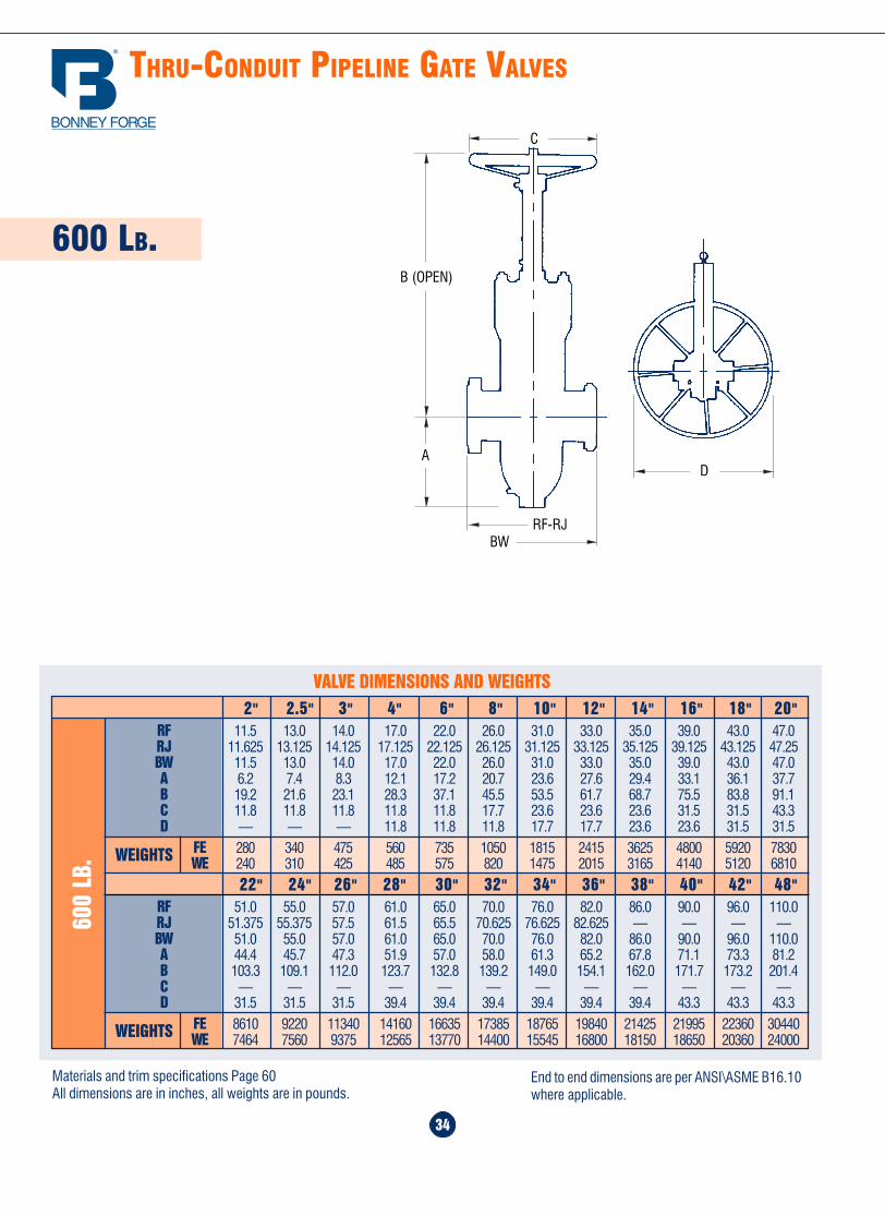
Home Table of Contents
Product Search
How To Order
PrintBack
Home Table of Contents
Product Search
How To Order
PrintBack Next
27
150 LB.
BALL VALVES
30 x 24" 26" 28" 30" 36 x 30" 32" 34" 36" 42 x 36" 40" 48 x 40" 42" 48" 56"A 23 1/4 25 27 29 29 30 3/4 32 3/4 34 1/2 34 1/2 38 1/2 38 1/2 40 1/4 46 54B 29 25 27 29 34 1/2 30 3/4 32 3/4 34 1/2 40 1/4 36 1/2 46 40 1/4 46 54
C- R.F 51 45 49 51 60 54 58 60 72 66 82 72 82 96C- RTJ - - - - - - - - - - - - - -C- WE 55 49 53 55 68 60 64 68 80 76 92 80 92 106
D 24 25 1/2 28 1/2 30 30 31 5/8 33 34 1/4 34 1/4 37 3/4 37 3/4 39 45 1/2 50 1/4E 27 1/8 28 3/8 31 3/4 33 33 34 3/4 36 1/2 37 1/4 37 1/4 40 1/2 40 1/2 41 7/8 46 1/8 52 1/2F 43 1/2 46 1/2 50 53 1/2 53 1/2 56 7/8 59 7/8 62 7/8 62 7/8 67 1/2 67 1/2 70 1/4 82 90 1/2G - - - - - - - - - - - - - -
RF 39.68 66.14 68.34 108 176.4 288.8 471.8 628.3 778.2 992.1 - - - -
BW 30.86 52.91 59.52 88.18 160.9 271.2 443.1 606.3 731.9 937 - - - -
WEI
GHTS
14 x 12" 16 x 12" 14" 16 x 14" 16" 18 x 16" 20 x 16" 18" 20 x 18" 22 x 18" 20" 24 x 20" 22" 24"
A 12 12 13 1/4 13 1/4 15 1/4 15 1/4 15 1/4 17 1/4 17 1/4 17 1/4 19 1/4 19 1/4 21 1/4 23 1/4B 13 1/4 15 1/4 13 1/4 15 1/4 15 1/4 17 1/4 19 1/4 17 1/4 19 1/4 21 1/4 19 1/4 23 1/4 21 1/4 23 1/4
C- R.F 27 30 27 30 30 34 36 34 36 39 36 42 39 42C- RTJ 27 1/2 30 1/2 27 1/2 30 1/2 30 1/2 34 1/2 36 1/2 34 1/2 36 1/2 39 1/2 36 1/2 42 1/2 39 1/2 42 1/2C- WE 30 33 30 33 33 36 39 36 39 43 39 45 43 45
D 12 1/2 12 1/2 14 14 15 5/8 15 5/8 15 5/8 18 18 18 19 1/2 19 1/2 21 1/8 24E 13 3/4 13 3/4 15 7/8 15 7/8 17 3/8 17 3/8 17 3/8 19 5/8 19 5/8 19 5/8 21 1/8 21 1/8 22 5/8 27 1/8F 24 1/8 24 1/8 26 3/8 26 3/8 29 7/8 29 7/8 29 7/8 33 33 33 36 5/8 36 5/8 40 43 1/2G - - - - - - - - - - - - - -
RF 39.68 66.14 68.34 108 176.4 288.8 471.8 628.3 778.2 992.1 - - - -
BW 30.86 52.91 59.52 88.18 160.9 271.2 443.1 606.3 731.9 937 - - - -WEI
GHTS
150
LB.
2 x 11/2" 2" 3 x 2" 3" 4 x 3" 4" 6 x 4" 6" 8 x 6" 8" 10 x 8" 10" 12 x 10" 12
A 1 1/2 2 2 3 3 4 4 6 6 8 8 10 10 12B 2 2 3 3 4 4 6 6 8 8 10 10 12 12
C- R.F 7 7 8 8 9 9 15 1/2 15 1/2 18 18 21 21 24 24C- RTJ 7 1/2 7 1/2 8 1/2 8 1/2 9 1/2 9 1/2 16 16 18 1/2 18 1/2 21 1/2 21 1/2 24 1/2 24 1/2C- WE 8 1/2 8 1/2 11 1/8 11 1/8 12 12 15 7/8 18 20 1/2 20 1/2 22 22 25 25
D 4 4 1/8 4 1/8 5 5 6 6 7 7/8 7 7/8 9 1/2 9 1/2 11 11 12 1/2E 5 5 1/8 5 1/8 6 1/4 6 1/4 6 3/4 6 3/4 9 3/8 9 3/8 10 3/4 10 3/4 12 1/4 12 1/4 13 3/4F 7 7 5/8 7 5/8 9 5/8 9 5/8 11 1/8 11 1/8 14 1/8 14 1/8 17 1/2 17 1/2 20 3/4 20 3/4 24 1/8G 17 3/4 23 5/8 23 5/8 30 3/8 30 3/8 51 1/4 51 1/4 - - - - - - -
RF 39.68 66.14 68.34 108 176.4 288.8 471.8 628.3 778.2 992.1 - - - -
BW 30.86 52.91 59.52 88.18 160.9 271.2 443.1 606.3 731.9 937 - - - -
VALVE DIMENSIONS AND WEIGHTS
WEI
GHTS
Materials and trim specifications Page 60All dimensions are in inches, all weights are in pounds.
End to end dimensions are per ANSI\ASME B16.10where applicable.
THRU-CONDUIT PIPELINE GATE VALVES
34
600 LB.
600
LB.
RF 11.5 13.0 14.0 17.0 22.0 26.0 31.0 33.0 35.0 39.0 43.0 47.0RJ 11.625 13.125 14.125 17.125 22.125 26.125 31.125 33.125 35.125 39.125 43.125 47.25BW 11.5 13.0 14.0 17.0 22.0 26.0 31.0 33.0 35.0 39.0 43.0 47.0A 6.2 7.4 8.3 12.1 17.2 20.7 23.6 27.6 29.4 33.1 36.1 37.7B 19.2 21.6 23.1 28.3 37.1 45.5 53.5 61.7 68.7 75.5 83.8 91.1C 11.8 11.8 11.8 11.8 11.8 17.7 23.6 23.6 23.6 31.5 31.5 43.3D — — — 11.8 11.8 11.8 17.7 17.7 23.6 23.6 31.5 31.5
FE 280 340 475 560 735 1050 1815 2415 3625 4800 5920 7830WE 240 310 425 485 575 820 1475 2015 3165 4140 5120 6810WEIGHTS
2" 2.5" 3" 4" 6" 8" 10" 12" 14" 16" 18" 20"
RF 51.0 55.0 57.0 61.0 65.0 70.0 76.0 82.0 86.0 90.0 96.0 110.0RJ 51.375 55.375 57.5 61.5 65.5 70.625 76.625 82.625 — — — —BW 51.0 55.0 57.0 61.0 65.0 70.0 76.0 82.0 86.0 90.0 96.0 110.0A 44.4 45.7 47.3 51.9 57.0 58.0 61.3 65.2 67.8 71.1 73.3 81.2B 103.3 109.1 112.0 123.7 132.8 139.2 149.0 154.1 162.0 171.7 173.2 201.4C — — — — — — — — — — — —D 31.5 31.5 31.5 39.4 39.4 39.4 39.4 39.4 39.4 43.3 43.3 43.3
FE 8610 9220 11340 14160 16635 17385 18765 19840 21425 21995 22360 30440WE 7464 7560 9375 12565 13770 14400 15545 16800 18150 18650 20360 24000WEIGHTS
22" 24" 26" 28" 30" 32" 34" 36" 38" 40" 42" 48"
VALVE DIMENSIONS AND WEIGHTS
Materials and trim specifications Page 60All dimensions are in inches, all weights are in pounds.
End to end dimensions are per ANSI\ASME B16.10where applicable.
C
D
RF-RJBW
A
B (OPEN)
ABF
C
G
E
D

Home Table of Contents
Product Search
How To Order
Print Next
Home Table of Contents
Product Search
How To Order
PrintBack Next
Overview ........................................ 26
150 lb. valves ................................. 27
300 lb. valves ................................. 28
600 lb. valves ................................. 29
900 lb valves .................................. 30
1500 lb. valves ............................... 30
25
B A L L V A LV E S
36
SPECIAL FEATURES
LIFTINDICATOR
BEVELGEARING
LIMIT MICROSWITCHES
PNEUMATICOPERATOR
BEVEL GEARING WITHHORIZONTAL HANDWHEEL
ELECTRICACTUATOR
Home Table of Contents
Product Search
How To Order
PrintBack Next

Home Table of Contents
Product Search
How To Order
PrintBack Next
Home Table of Contents
Product Search
How To Order
PrintBack Next
PRESSURE SEAL GLOBE VALVES “Y-PATTERN”
900 LB.1500 LB.2500 LB.
24
VALVE DIMENSIONS AND WEIGHTS
End to End BW 15.0 18.0 24.0 29.0 33.0 38.0 40.5B- Center to Top 19.68 19.68 43.31 51.18 51.18 82.68 82.68
BW - - - - - - -WEIGHTS900
LB.
3" 4" 6" 8" 10" 12" 14"
End to End BW 14.5 16.50 18.50 21.50 27.75 32.75 39.0 44.50 49.50 54.5 60.50B- Center to Top 19.68 19.68 23.62 31.50 51.81 82.68 82.68 82.68 82.68 82.68 82.68
BW - - - - - - - - - - -WEIGHTS1500 LB.
2" 2.5" 3" 4" 6" 8" 10" 12" 14" 16" 18"
End to End BW 17.75 22.75 26.50 36.0 40.25 50.0 56.0B- Center to Top 23.62 31.50 82.68 82.68 82.68 82.68 82.68
BW - - - - - - -WEIGHTS2500 LB.
2" 3" 4" 6" 8" 10" 12"
Materials and trim specifications Page 60All dimensions are in inches, all weights are in pounds.
End to end dimensions are per ANSI\ASME B16.10where applicable.
EXTENSIONSTEM
CHAINWHEEL
FLOORSTAND
FLOOR STAND WITHUNIVERSAL JOINT
CHECK VALVEWITH DASH POT
CHECK VALVE WITHOUTSIDE LEVER & WEIGHT
37
BW
B

Home Table of Contents
Product Search
How To Order
PrintBack
Home Table of Contents
Product Search
How To Order
PrintBack Next
23
600 LB.900 LB.
PRESSURE SEAL CHECK VALVES
1500 LB.
VALVE DIMENSIONS AND WEIGHTS
End to End BW 11.5 14.0 17.0 22.0 26.0 31.0 33.0 35.0 39.0B- Center to Top 6.7 6.9 8.5 9.3 11.3 13.4 15.6 17.7 19.3
BW - 44.09 - 147.7 277.8 - 723.1 - -WEIGHTS600
LB.
2" 3" 4" 6" 8" 10" 12" 14" 16"
End to End BW 14.5 12.0 14.0 20.0 26.0 31.0 36.0 39.0 43.0 48.0 52.0 61.0B- Center to Top 6.9 9.64 12.4 16.93 18.7 19.96 24.01 26.38 29.13 31.89 34.64 40.16
BW 97.00 - - - - - - - - - - -WEIGHTS900
LB.
2" 3" 4" 6" 8" 10" 12" 14" 16" 18" 20" 24"
End to End BW 14.5 18.5 21.5 22.0 28.0 34.0 39.0 42.0 47.0 60.25 65.5 76.5B- Center to Top 9.64 12.05 14.17 19.29 21.65 24.41 27.36 29.53 32.68 35.83 37.79 43.31
BW - 68.34 207.2 - - - - - - - - -WEIGHTS1500 LB.
2" 3" 4" 6" 8" 10" 12" 14" 16" 18" 20" 24"
End to End BW 14.50 18.0 24.0 30.0 36.0 41.0B- Center to Top 12.05 14.17 19.29 21.65 24.41 27.36
BW - - - - - -WEIGHTS2500 LB.
3" 4" 6" 8" 10" 12"
FLOW
BW
B
2500 LB.
Materials and trim specifications Page 60All dimensions are in inches, all weights are in pounds.
End to end dimensions are per ANSI\ASME B16.10where applicable.
38
SPECIAL FEATURES
Cryogenic Valves
Constant new development, in the petrochemical, refrigeration, military, space age, and various interrelated
chemical and processing fields have, in turn, imposed special designs for valves and materials which can serve
safely and adequately at below zero temperatures.
Technically, this frozen frontier can be divided into two areas of application. The one area, somewhat generically
referred to as “Low temperature”, ranges from minus 20° C (-4°F) down to the boiling point of methane, or
Natural gas at minus 160oC (-256°F), while the second term “Cryogenic” sees as an upper limit minus
180°C (-292°F) the temperature at which oxygen liquefies, and descends towards absolute zero - 273°C (-459°F).
Extended Bonnet valves are used in cryogenic service because proper bonnet extensions keeps both packing and
handwheel quite far from the cold zone and pipe insulation so that, at this point the metal temperature is close to
atmospheric temperature.
Avoiding frost, on the packing area valves will remain functional. Valves 2” and larger may have holes and plugs inposition “G” and/or “H”. All gate valves have a bleed hole in the wedge to equalize pressure in the body cavity with
that on the upstream side of the wedge.
Cryogenic valves have an extended bonnet obtained by integral casting for valves up to 8” size in accordance with
BS6364. For dimensions over 8” extended bonnet is obtained by a pipe spool, welded between the bonnet packing
section and back seat section.

Home Table of Contents
Product Search
How To Order
PrintBack Next
Home Table of Contents
Product Search
How To Order
PRESSURE SEAL GLOBE VALVES “T-PATTERN”
22
600 LB.900 LB.1500 LB.
VALVE DIMENSIONS AND WEIGHTS
2" 3" 4" 6" 8" 10" 12"
1500
LB. End to End BW 14.5 18.5 21.5 27.75 32.75 39.0 44.5
C- Closed 16.9 22.4 26.6 35.2 41.7 46.9 55.9D- Open 18.4 24.4 29.1 35.4 50.8 57.1 65.0
E 12.0 19.8 19.8 19.8 30.0 36.0 36.0
BW - 68.34 207.2 - - - -
2" 3" 4" 6" 8" 10" 12"
900
LB. End to End BW 14.5 15.0 18.0 24.0 29.0 33.0 38.0
C- Closed 16.9 22.4 26.6 35.2 41.7 46.9 55.9D- Open 18.4 24.4 29.1 39.0 48.4 58.7 59.1
E 12.0 19.8 19.8 27.0 30.0 30.0 36.0
BW - 134.5 229.3 - - - -
2" 3" 4" 6" 8" 10" 12"
600
LB. End to End BW 11.5 14.0 17.0 22.0 26.0 31.0 33.0
C- Closed 14.4 21.9 26.6 33.3 40.9 46.1 55.1D- Open 15.9 23.7 29.1 37.2 47.6 57.9 58.3
E 8.0 16.0 19.8 27.0 30.0 30.0 36.0
BW - 44.09 - 147.7 277.8 - 723.1
BW
E
C CLOSEDD OPEN
Materials and trim specifications Page 60All dimensions are in inches, all weights are in pounds.
End to end dimensions are per ANSI\ASME B16.10where applicable.
39
BYPASS & DRAIN CONNECTION
Bonney Forge valves can be equipped with by-passes which permit equalization of pressure on both sides ofthe valve. Unless otherwise specified the by-pass arrangement will be furnished on the side of the main valve. By-passes of other types can be made to order. Inquiries should give complete description or drawings.
By-pass valves are “Bonney Forge” forged steel bolted-bonnet, outside screw and yoke, socket-weld endglobe valves, and materials are suitable for the same service as the main valve.
DRAIN & BY PASS DIMENSIONS
Size of Valve 2" to 4" 5" to 8" 10" to 24"
Size of Tapping 1/2 3/4 1
Length of Thread T 9/16 9/16 11/16
Minimum Diameter of Socket A 7/8 1 1/16 1 5/16
Minimum Depth of Socket B 3/16 1/4 1/4
Diameter of Boss J 1 1/2 1 3/4 2 1/8
All dimensions given in inches
BT
JA
THREAD FOR CONNECTION TAPPING SOCKET WELDING FOR CONNECTIONS BOSSES FOR CONNECTIONS
I K
J H
A B
C D
(on the sameside as E & F)
C
A B
D
EG F
GATE VALVE GLOBE VALVE
CD
A & B
E & FE
F
DC
CHECK VALVEANGLE VALVE
These illustrations show the location of tapped holes. When placing anorder please quote the letters in the above illustrations designating the
location of the tapped holes. For more information see MSS-SP-45.
AF
E B
A
B
C
DE
FF
E
C
D
A B
C
GAC
B
E F
DG
G
WEIGHTS
WEIGHTS
WEIGHTS

Home Table of Contents
Product Search
How To Order
Print Next
Home Table of Contents
Product Search
How To Order
PrintBack Next
40
FLANGE DIMENSIONS
ANSI/ASME B 16.5 and MSS-SP-44
4 10 1 3/8 6 13/16 7 7/8 1 8 7/85 11 1 1/2 7 5/16 9 1/4 1 8 7/86 12 1/2 1 5/8 8 1/2 10 5/8 1 12 7/88 15 1 7/8 10 5/8 13 1 1/8 12 110 17 1/2 2 1/8 12 3/4 15 1/4 1 1/4 16 1 1/812 20 1/2 2 1/4 15 17 3/4 1 3/8 16 1 1/414 23 2 3/8 16 1/4 20 1/4 1 3/8 20 1 1/416 25 1/2 2 1/2 18 1/2 22 1/2 1 1/2 20 1 3/818 28 2 5/8 21 24 3/4 1 1/2 24 1 3/820 30 1/2 2 3/4 23 27 1 5/8 24 1 1/224 36 3 27 1/4 32 1 7/8 24 1 3/426 38 1/4 3 1/2 29 1/2 34 1/2 1 7/8 28 1 3/428 40 3/4 3 3/4 31 1/2 37 1 7/8 28 1 7/830 43 4 33 3/4 39 1/4 2 28 232 45 1/4 4 1/4 36 41 1/2 2 1/8 28 234 47 1/2 4 3/8 38 43 1/2 2 1/8 28 236 50 4 1/2 40 1/4 46 2 1/8 32 2
ANSI
300
1/2 3 3/4 9/16 1 3/8 2 5/8 5/8 4 1/23/4 4 5/8 5/8 1 11/16 3 1/4 3/4 4 5/81 4 7/8 11/16 2 3 1/2 3/4 4 5/8
1 1/4 5 1/4 3/4 2 1/2 3 7/8 3/4 4 5/81 1/2 6 1/8 13/16 2 7/8 4 1/2 7/8 4 3/4
2 6 1/2 7/8 3 5/8 5 3/4 8 5/82 1/2 7 1/2 1 4 1/8 5 7/8 7/8 8 3/4
3 8 1/4 1 1/8 5 6 5/8 7/8 8 3/43 1/2 9 1 13/16 5 1/2 7 1/4 7/8 8 3/4
4 10 1 1/4 6 3/16 7 7/8 7/8 8 3/45 11 1 3/8 7 5/16 9 1/4 7/8 8 3/46 12 1/2 1 7/16 8 1/2 10 5/8 7/8 12 3/48 15 1 5/8 10 5/8 13 1 12 7/810 17 1/2 1 7/8 12 3/4 15 1/4 1 1/8 16 112 20 1/2 2 15 17 3/4 1 1/4 16 1 1/814 23 2 1/8 16 1/4 20 1/4 1 1/4 20 1 1/816 25 1/2 2 1/4 18 1/2 22 1/2 1 3/8 20 1 1/416 28 2 3/8 21 24 3/4 1 3/8 24 1 1/420 30 1/2 2 1/2 23 27 1 3/8 24 1 1/424 36 2 3/4 27 1/4 32 1 5/8 24 1 1/226 38 1/4 3 1/8 29 1/2 34 1/2 1 3/4 28 1 5/828 40 3/4 3 3/8 31 1/2 37 1 3/4 28 1 5/830 43 3 5/8 33 3/4 39 1/4 1 7/8 28 1 3/432 45 1/4 3 7/8 36 41 1/2 2 28 1 7/834 47 1/2 4 38 43 1/2 2 28 1 7/836 50 4 1/8 40 1/4 46 2 1/8 32 238 46 4 1/4 40 1/2 43 1 5/8 32 1 1/240 48 3/4 4 1/2 42 3/4 45 1/2 1 3/4 32 1 5/8
ANSI
150
1/2 3 1/2 7/16 - 1 3/8 2 3/8 5/8 4 1/23/4 3 1/2 1/2 - 1 11/16 2 3/4 5/8 4 1/21 4 1/2 9/16 7/16 2 3 1/8 5/8 4 1/2
1 1/4 4 1/2 5/8 1/2 2 1/2 3 1/2 5/8 4 1/21 1/2 5 11/16 9/16 2 7/8 3 7/8 5/8 4 1/2
2 6 3/4 5/8 3 5/8 4 3/4 3/4 4 5/82 1/2 7 7/8 11/16 4 1/8 5 1/2 3/4 4 5/8
3 7 1/2 15/16 3/4 5 6 3/4 4 5/83 1/2 8 1/2 15/16 13/16 5 1/2 7 3/4 8 5/8
4 9 15/16 6 3/16 7 1/2 3/4 8 5/85 10 15/16 7 5/16 8 1/2 7/8 8 3/46 11 1 8 1/2 9 1/2 7/8 8 3/48 13 1/2 1 1/8 10 5/8 11 3/4 7/8 8 3/410 16 1 3/16 12 3/4 14 1/4 1 12 7/812 19 1 1/4 15 17 1 12 7/814 21 1 3/8 16 1/4 18 3/4 1 1/8 12 116 23 1/2 1 7/16 18 1/2 21 1/4 1 1/8 16 116 25 1 9/16 21 22 3/4 1 1/4 16 1 1/820 27 1/2 1 11/16 23 25 1 1/4 20 1 1/824 32 1 7/8 27 1/4 291/2 1 3/8 20 1 1/826 34 1/4 2 11/16 29 1/2 31 3/4 1 5/8 24 1 1/428 36 1/2 2 13/16 31 1/2 34 1 5/8 28 1 1/430 38 3/4 2 15/16 33 3/4 36 1 5/8 28 1 1/432 41 3/4 3 3/16 36 38 1/2 1 5/8 28 1 1/234 43 3/4 3 1/4 38 40 1/2 1 5/8 32 1 1/236 46 3 9/16 40 1/4 42 3/4 1 5/8 32 1 1/238 48 3/4 3 7/16 42 1/4 45 1/4 1 5/8 32 1 1/240 50 3/4 3 9/16 44 1/4 47 1/4 1 5/8 36 1 1/242 53 3 13/16 47 49 1/2 1 5/8 36 1 1/2
NominalPipe Size
FlangeDiameter
A
Flange ThicknessCompanion Valve
Flange B Flange B
Diameter ofRaised Face
C
Diameter of BoltCircle
D
Diameter of BoltHoles
E
Numberof Bolts
Diameter ofBolts
ANSI
400
The regular 1/16-inch raised faceof 150 lb. flanges is included inthe minimum flange thickness
given, but other raised faces mustbe added thereto. The bolt holes,which are in multiples of four, are
drilled to straddle the centerlineunless otherwise ordered.
The regular 1/16-inch raised faceof 300 lb. flanges is included inthe minimum flange thickness
given, but other raised faces mustbe added thereto. The bolt holes,which are in multiples of four, are
drilled to straddle the centerlineunless otherwise ordered.
The regular 1/4-inch raised face of400 lb. flanges is not included in
the minimum flange thicknessgiven. The bolt holes, which are in
multiples of four, are drilled tostraddle the centerline unless
otherwise ordered.
End Flange dimensions comply withANSI/ASME B 16.5 and MSS-SP-44 All dimensions are in inches
21
600 LB.900 LB.
PRESSURE SEAL GATE VALVES
1500 LB.
VALVE DIMENSIONS AND WEIGHTS2" 3" 4" 6" 8" 10" 12" 14" 16" 18" 20" 24"
600
LB. End to End BW 11.5 14.0 17.0 22.0 26.0 31.0 33.0 35.0 39.0 43.0 47.0 55.0
C- Closed 16.69 21.77 25.0 32.60 38.74 46.14 54.49 59.25 64.88 72.83 78.35 90.35D- Open 19.29 25.39 29.92 39.37 47.44 56.89 67.32 73.42 80.71 90.55 98.03 113.8
E 10.0 12.0 14.0 20.0 22.0 27.0 27.0 30.0 35.0 35.0 35.0 43.31
BW - 77.16 213.8 293.2 533.5 939.2 1642 - - - - -
E
C CLOSEDD OPEN
BW
2" 3" 4" 6" 8" 10" 12" 14" 16" 18"
900
LB. End to End BW 14.5 12.0 14.0 20.0 26.0 31.0 36.0 39.0 43.0 48.0
C- Closed 16.4 23.62 26.10 33.07 41.53 53.15 55.12 51.42 67.72 81.89D- Open 18.7 27.16 30.90 39.57 50.0 64.17 67.72 79.20 83.46 100.0
E 12.0 14.0 16.0 22.0 27.0 27.0 30.0 35.0 35.0 43.31
BW - 165.3 260.1 515.9 948.0 1803 - - - -
2" 3" 4" 6" 8" 10" 12" 14" 16"
1500
LB. End to End BW 8.50 12.0 16.0 22.0 28.0 34.0 39.0 42.0 47.0
C- Closed 20.67 25.20 28.54 35.04 46.06 51.97 65.35 67.32 70.87D- Open 23.23 28.74 33.27 41.34 55.12 63.0 77.56 80.31 85.83
E 12.0 16.0 18.0 22.0 27.0 35.0 43.31 43.31 43.31
BW 92.59 191.8 321.9 696.7 1323 2359 - - -
2" 3" 4" 6" 8" 10" 12"
2500
LB. End to End BW 11.0 14.50 18.0 24.0 30.0 36.0 41.0
C- Closed 26.57 25.59 35.63 39.76 55.39 66.93 75.79D- Open 28.35 28.35 39.17 45.08 62.40 75.79 86.22
E 12.0 16.0 18.0 22.0 27.0 35.04 43.31
BW 134.5 - - - - 4621 5688
2500 LB.
Materials and trim specifications Page 60All dimensions are in inches, all weights are in pounds.
End to end dimensions are per ANSI\ASME B16.10where applicable.
WEIGHTS
WEIGHTS
WEIGHTS
WEIGHTS
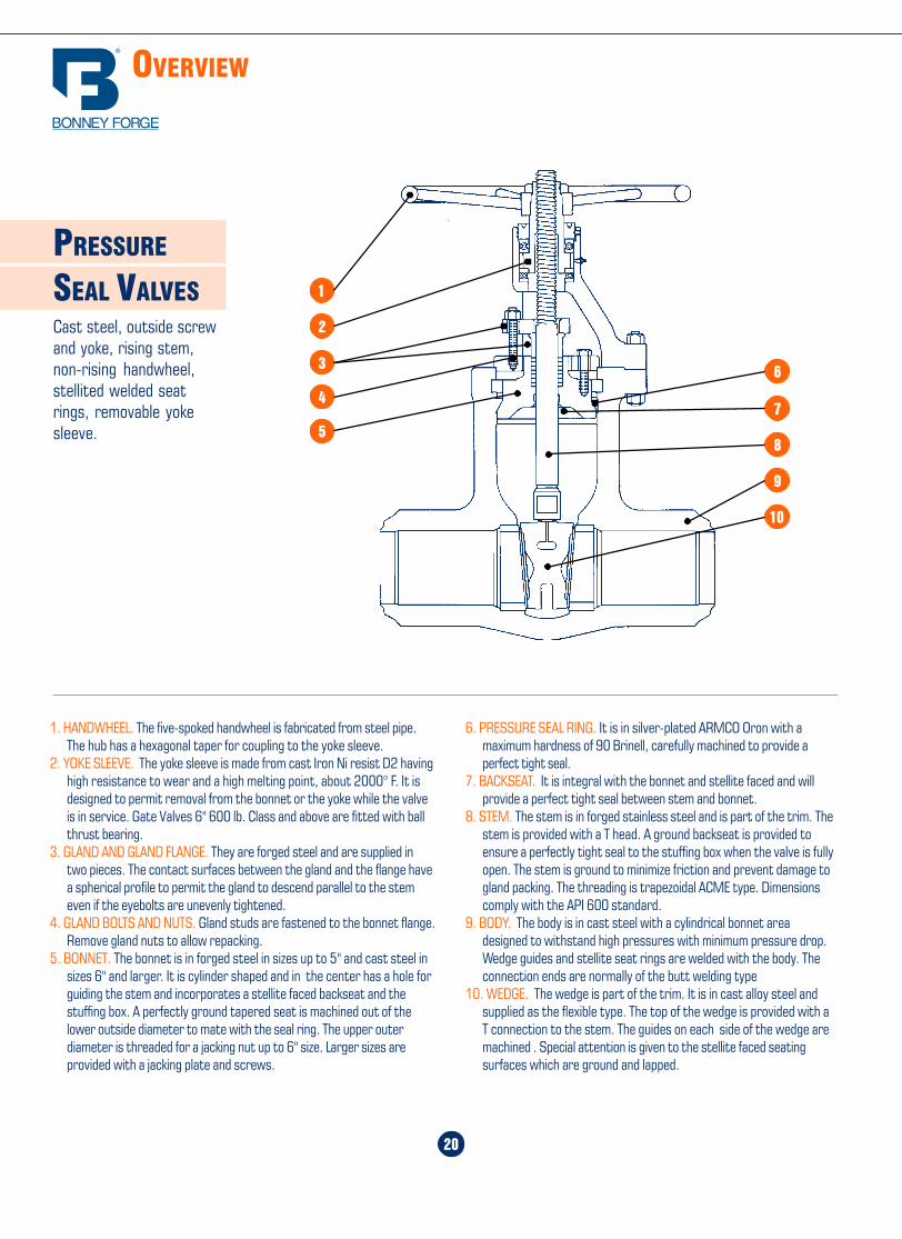
Home Table of Contents
Product Search
How To Order
PrintBack Next
Home Table of Contents
Product Search
How To Order
PrintBack
OVERVIEW
20
PRESSURE
SEAL VALVESCast steel, outside screwand yoke, rising stem,non-rising handwheel,stellited welded seatrings, removable yokesleeve.
6. PRESSURE SEAL RING. It is in silver-plated ARMCO Oron with amaximum hardness of 90 Brinell, carefully machined to provide aperfect tight seal.
7. BACKSEAT. It is integral with the bonnet and stellite faced and willprovide a perfect tight seal between stem and bonnet.
8. STEM. The stem is in forged stainless steel and is part of the trim. Thestem is provided with a T head. A ground backseat is provided toensure a perfectly tight seal to the stuffing box when the valve is fullyopen. The stem is ground to minimize friction and prevent damage togland packing. The threading is trapezoidal ACME type. Dimensionscomply with the API 600 standard.
9. BODY. The body is in cast steel with a cylindrical bonnet areadesigned to withstand high pressures with minimum pressure drop.Wedge guides and stellite seat rings are welded with the body. Theconnection ends are normally of the butt welding type
10. WEDGE. The wedge is part of the trim. It is in cast alloy steel andsupplied as the flexible type. The top of the wedge is provided with aT connection to the stem. The guides on each side of the wedge aremachined . Special attention is given to the stellite faced seatingsurfaces which are ground and lapped.
1. HANDWHEEL. The five-spoked handwheel is fabricated from steel pipe.The hub has a hexagonal taper for coupling to the yoke sleeve.
2. YOKE SLEEVE. The yoke sleeve is made from cast Iron Ni resist D2 havinghigh resistance to wear and a high melting point, about 2000° F. It isdesigned to permit removal from the bonnet or the yoke while the valveis in service. Gate Valves 6" 600 lb. Class and above are fitted with ballthrust bearing.
3. GLAND AND GLAND FLANGE. They are forged steel and are supplied intwo pieces. The contact surfaces between the gland and the flange havea spherical profile to permit the gland to descend parallel to the stemeven if the eyebolts are unevenly tightened.
4. GLAND BOLTS AND NUTS. Gland studs are fastened to the bonnet flange.Remove gland nuts to allow repacking.
5. BONNET. The bonnet is in forged steel in sizes up to 5" and cast steel insizes 6" and larger. It is cylinder shaped and in the center has a hole forguiding the stem and incorporates a stellite faced backseat and thestuffing box. A perfectly ground tapered seat is machined out of thelower outside diameter to mate with the seal ring. The upper outerdiameter is threaded for a jacking nut up to 6" size. Larger sizes areprovided with a jacking plate and screws.
1
2
4
57
8
9
10
3 6
41
150 &300 lb. Steel
ADC
B
1/16"
E
A
CD
1/16"
B
E
400, 600,900, 1500 &2500 lb. Steel
ANSI
900
ANSI
600
1/2 3 3/4 9/16 1 3/8 2 5/8 5/8 4 1/23/4 4 5/8 5/8 1 11/16 3 1/4 3/4 4 5/81 4 7/8 11/16 2 3 1/2 3/4 4 5/8
1 1/4 5 1/4 13/16 2 1/2 3 7/8 3/4 4 5/81 1/2 6 1/8 7/8 2 7/8 4 1/2 7/8 4 3/4
2 6 1/2 1 3 5/8 5 3/4 8 5/82 1/2 7 1/2 1 1/8 4 1/8 5 7/8 7/8 8 3/4
3 8 1/4 1 1/4 5 6 5/8 7/8 8 3/43 1/2 9 1 3/8 5 1/2 7 1/4 1 8 7/8
4 10 3/4 1 1/2 6 3/16 8 1/2 1 8 7/85 13 1 3/4 7 5/16 10 1/2 1 1/8 8 16 14 1 7/8 8 1/2 11 1/2 1 1/8 12 18 16 1/2 2 3/16 10 5/8 13 3/4 1 1/4 12 1 1/810 20 2 1/2 12 3/4 17 1 3/8 16 1 1/412 22 2 5/8 15 19 1/4 1 3/8 20 1 1/414 23 3/4 2 3/4 16 1/4 20 3/4 1 1/2 20 1 3/816 27 3 18 1/2 23 3/4 1 5/8 20 1 1/218 29 1/4 3 1/4 21 25 3/4 1 3/4 20 1 5/820 32 3 1/2 23 28 1/2 1 3/4 24 1 5/824 37 4 27 1/4 33 2 24 1 7/826 40 4 1/4 29 1/2 36 2 28 1 7/828 42 1/4 4 3/8 31 1/2 38 2 1/8 28 230 44 1/2 4 1/2 33 3/4 40 1/4 2 1/8 28 232 47 4 5/8 36 42 1/2 2 3/8 28 2 1/434 49 4 3/4 38 44 1/2 2 3/8 28 2 1/436 51 3/4 4 7/8 40 1/4 47 2 5/8 28 2 1/2
NominalPipe Size
FlangeDiameter
AFlange
ThicknessDiameter ofRaised Face
C
Diameter of BoltCircle
D
Diameter of BoltHoles
E
Numberof Bolts
Diameter ofBolts
ANSI
150
0
3 9 1/2 1 1/2 5 7 1/2 1 8 7/84 11 1/2 1 3/4 6 3/16 9 1/4 1 1/4 8 1 1/85 13 3/4 2 7 5/16 11 1 3/8 8 1 1/46 15 2 3/16 8 1/2 12 1/2 1 1/4 12 1 1/88 18 1/2 2 1/2 10 5/8 15 1/2 1 1/2 12 1 3/810 21 1/2 2 3/4 12 3/4 18 1/2 1 1/2 16 1 3/812 24 3 1/8 15 21 1 1/2 20 1 3/814 25 1/4 3 3/8 16 1/4 22 1 5/8 20 1 1/216 27 3/4 3 1/2 18 1/2 24 1/4 1 3/4 20 1 5/818 31 4 21 27 2 20 1 7/820 33 3/4 4 1/4 23 29 1/2 2 1/8 20 224 41 5 1/2 27 1/4 35 1/2 2 5/8 20 2 1/2
1/2 4 3/4 7/8 1 3/8 3 1/4 7/8 4 3/43/4 5 1/8 1 1 11/16 3 1/2 7/8 4 3/41 5 7/8 1/18 2 4 1 4 7/8
1 1/4 6 1/4 1 1/8 2 1/2 4 3/8 1 4 7/81 1/2 7 1 1/4 2 7/8 4 7/8 1 1/8 4 1
2 8 1/2 1 1/2 3 5/8 6 1/2 1 8 7/82 1/2 9 5/8 1 5/8 4 1/8 7 1/2 1 1/8 8 1
3 10 1/2 1 7/8 5 8 1 1/4 8 1 1/84 12 1/4 2 1/8 6 3/16 9 1/2 1 3/8 8 1 1/45 14 3/4 2 7/8 7 5/16 11 1/2 1 5/8 8 1 1/26 15 1/2 3 1/4 8 1/2 12 1/2 1 1/2 12 1 3/88 19 3 5/8 10 5/8 15 1/2 1 3/4 12 1 5/810 23 4 1/4 12 3/4 19 2 12 1 7/812 26 1/2 4 7/8 15 22 1/2 2 1/8 16 214 29 1/2 5 1/4 16 1/4 25 2 3/8 16 2 1/416 32 1/2 5 3/4 18 1/2 27 3/4 2 5/8 16 2 1/218 36 6 3/8 21 30 1/2 2 7/8 16 2 3/420 38 3/4 7 23 32 3/4 3 1/8 16 324 46 8 27 1/4 39 3 5/8 16 3 1/2
ANSI
250
0
1/2 5 1/4 1 3/16 1 3/8 3 1/2 7/8 4 3/43/4 5 1/2 1 1/4 1 11/16 3 3/4 7/8 4 3/41 6 1/4 1 3/8 2 4 1/4 1 4 7/8
1 1/4 7 1/4 1 1/2 2 1/2 5 1/8 1 1/8 4 11 1/2 8 1 3/4 2 7/8 5 3/4 1 1/4 4 1 1/8
2 9 1/4 2 3 5/8 6 3/4 1 1/8 8 12 1/2 10 1/2 2 1/4 4 1/8 7 3/4 1 1/4 8 1 1/8
3 12 2 5/8 5 9 1 3/8 8 1 1/44 14 3 6 3/16 10 3/4 1 5/8 8 1 1/25 16 1/2 3 5/8 7 5/16 12 3/4 1 7/8 8 1 3/46 19 4 1/4 8 1/2 14 1/2 2 1/8 8 28 21 3/4 5 10 5/8 17 1/4 2 1/8 12 210 26 1/2 6 1/2 12 3/4 21 1/4 2 5/8 12 2 1/212 30 7 1/4 15 24 3/8 2 7/8 12 2 3/4
The regular 1/4-inch raised face of900 and 1500 lb. flanges is notincluded in the minimum flange
thickness given. The bolt holes,which are in multiples of four, are
drilled to straddle the centerlineunless otherwise ordered.
Use 1500 lb. dimensions in sizessmaller than 3-inch.
The regular 1/4-inch raised face of600 lb. flanges is not included in
the minimum flange thicknessgiven. The bolt holes, which are in
multiples of four, are drilled tostraddle the centerline unless
otherwise ordered.
The regular 1/4-inch raised face of2500 lb. flanges is not included in the
minimum flange thickness given.The bolt holes, which are in multiples
of four, are drilled to straddle thecenterline unless otherwise ordered.
End Flange dimensions comply withANSI/ASME B 16.5 and MSS-SP-44 All dimensions are in inches
Home Table of Contents
Product Search
How To Order
Print Next
Home Table of Contents
Product Search
How To Order
PrintBack Next
42
RING JOINT FACINGS
300-
400-
600
LB.
150
LB.
1 R15 5/16 9/16 11/32 1/2 2 1/2 1/4 1 7/81 1/4 R17 5/16 9/16 11/32 1/2 2 7/8 1/4 2 1/41 1/2 R19 5/16 9/16 11/32 1/2 3 1/4 1/4 2 9/16
2 R22 5/16 9/16 11/32 1/2 4 1/4 3 1/42 1/2 R25 5/16 9/16 11/32 1/2 4 3/4 1/4 4
3 R29 5/16 9/16 11/32 1/2 5 1/4 1/4 4 1/24 R36 5/16 9/16 11/32 1/2 6 3/4 1/4 5 7/85 R40 5/16 9/16 11/32 1/2 7 5/8 1/4 6 3/46 R43 5/16 9/16 11/32 1/2 8 5/8 1/4 7 5/88 R48 5/16 9/16 11/32 1/2 10 3/4 1/4 9 3/410 R52 5/16 9/16 11/32 1/2 13 1/4 1212 R56 5/16 9/16 11/32 1/2 16 1/4 1514 R59 5/16 9/16 11/32 1/2 16 3/4 1/4 15 5/816 R64 5/16 9/16 11/32 1/2 19 1/4 17 7/818 R68 5/16 9/16 11/32 1/2 21 1/2 1/4 20 3/820 R72 5/16 9/16 11/32 1/2 23 1/2 1/4 2224 R76 5/16 9/16 11/32 1/2 28 1/4 26 1/2
NominalPipe Size
RingNumber
RingWidth
A
Oval RingHeight
B
GrooveWidth
D
OctagonalRing Height
H
GrooveDepth
L
Ring JointRaisedFace
DiameterK
Ring &GroovePitch
DiameterP
1/2 R11 1/4 7/16 9/32 3/8 2 7/32 1 11/323/4 R13 5/16 9/16 11/32 1/2 2 1/2 1/4 1 11/161 R16 5/16 9/16 11/32 1/2 2 3/4 1/4 2
1 1/4 R18 5/16 9/16 11/32 1/2 3 1/8 1/4 2 3/81 1/2 R20 5/16 9/16 11/32 1/2 3 9/16 1/4 2 11/16
2 R23 7/16 11/16 15/32 5/8 4 1/4 5 /16 3 1/42 1/2 R26 7/16 11/16 15/32 5/8 5 5/16 4
3 R31 7/16 11/16 15/32 5/8 5 3/4 5/16 4 7/84 R37 7/16 11/16 15/32 5/8 6 7/8 5/16 5 7/85 R41 7/16 11/16 15/32 5/8 8 1/4 5/16 7 1/86 R45 7/16 11/16 15/32 5/8 9 1/2 5/16 8 5/168 R49 7/16 11/16 15/32 5/8 11 7/8 5/16 10 5/810 R53 7/16 11/16 15/32 5/8 14 5/16 12 3/412 R57 7/16 11/16 15/32 5/8 16 1/4 5/16 1514 R61 7/16 11/16 15/32 5/8 18 5/16 16 1/216 R65 7/16 11/16 15/32 5/8 20 5/16 18 1/218 R69 7/16 11/16 15/32 5/8 22 5/8 5/16 2120 R73 1/2 3/4 17/32 11/16 25 3/8 2324 R77 5/8 7/8 21/32 13/16 29 1/2 7/16 27 1/4
ANSI/ASME B 16.5 and B 16.20
B
C
H
D
A 23°
Groove suitable for either Oval or Octagonal ring
OCTAGONAL RING
OVAL RING
23°
All dimensions are in inches
Overview ........................................ 20
Pressure Seal Gate Valves .............. 21
Pressure Seal GlobeValves “T-Pattern” ........................... 22
Pressure Seal Check Valves ............ 23
Pressure Seal Globe Valves “Y-Pattern” .......................... 24
19
PRESSURE SEAL
VALVES
Home Table of Contents
Product Search
How To Order
PrintBack Next
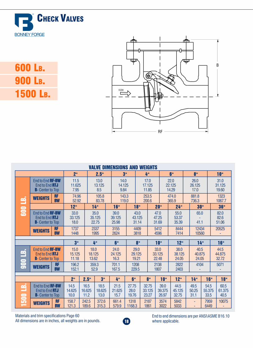
Home Table of Contents
Product Search
How To Order
PrintBack Next
Home Table of Contents
Product Search
How To Order
PrintBack
3" 4" 6" 8" 10" 12" 14" 16"End to End RF-BW 15.0 18.0 24.0 29.0 33.0 38.0 40.5 44.5
End to End RTJ 15.125 18.125 24.125 29.125 33.125 38.125 40.875 44.875B- Center to Top 11.18 13.62 16.3 19.21 22.48 24.05 24.05 32.72
RF 196.2 359.3 701.1 1208 2138 2822 4104 5071BW 152.1 52.9 167.5 229.5 1807 2403 - -90
0 LB
.
18
600 LB.900 LB.1500 LB.
VALVE DIMENSIONS AND WEIGHTS
12" 14" 16" 18" 20" 24" 30" 36"
2" 2.5" 3" 4" 6" 8" 10"
End to End RF-BW 33.0 35.0 39.0 43.0 47.0 55.0 65.0 82.0End to End RTJ 33.125 35.125 39.125 43.125 47.25 53.37 - 82.6B- Center to Top 18.0 22.75 25.98 31.14 31.69 35.39 41.1 51.06
RF 1737 2337 3155 4409 5412 8444 12434 20525BW 1448 1995 2624 3818 4596 7414 10560 -
End to End RF-BW 11.5 13.0 14.0 17.0 22.0 26.0 31.0End to End RTJ 11.625 13.125 14.125 17.125 22.125 26.125 31.125B- Center to Top 7.95 8.5 9.84 11.85 14.29 17.0 19.60
RF 74.96 105.8 143.3 253.5 474.0 881.8 1323BW 52.92 83.78 119.0 200.6 365.9 736.3 1067.7
600
LB.
End to End RF-BW 14.5 16.5 18.5 21.5 27.75 32.75 39.0 44.5 49.5 54.5 60.5End to End RTJ 14.625 16.625 18.625 21.625 28.0 33.125 39.375 45.125 50.25 55.375 61.375B- Center to Top 10.0 11.2 13.0 15.7 19.76 23.27 26.97 32.75 31.1 33.5 40.5
RF 158.7 242.5 372.6 661.4 1318 2187 3574 5842 - 7959 10075BW 121.3 189.6 315.3 579.9 1168.3 1861 3022 5033 - 6449 -15
00 L
B.
2" 2.5" 3" 4" 6" 8" 10" 12" 14" 16" 18"
FLOW
RF
B
Materials and trim specifications Page 60All dimensions are in inches, all weights are in pounds.
End to end dimensions are per ANSI\ASME B16.10where applicable. 43
1500
LB.
1/2 R12 5/16 9/16 11/32 1/2 2 3/8 1/4 1 9/161/4 R14 5/16 9/16 11/32 1/2 2 3/8 1/4 1 3/41 R16 5/16 9/16 11/32 1/2 2 13/16 1/4 2
1 1/4 R18 5/16 9/16 11/32 1/2 3 3/16 1/4 2 3/81 1/2 R20 5/16 9/16 11/32 1/2 3 5/8 1/4 2 11/16
2 R24 7/16 11/16 15/32 5/8 4 7/8 5/16 3 3/42 1/2 R27 7/16 11/16 15/32 5/8 5 3/8 5/16 4 1/4
3 R35 7/16 11/16 15/32 5/8 6 5/8 5/16 5 3/84 R39 7/16 11/16 15/32 5/8 7 5/8 5/16 6 3/85 R44 7/16 11/16 15/32 5/8 9 5/16 7 5/86 R46 1/2 3/4 17/32 11/16 9 3/4 3/8 8 5/168 R50 5/8 7/8 21/32 13/16 12 1/2 7/16 10 5/810 R54 5/8 7/8 21/32 13/16 14 5/8 7/16 12 3/412 R58 7/8 1 1/8 29/32 1 1/16 17 1/4 9/16 1514 R63 1 1 5/16 1 1/16 1 1/4 19 1/4 5/8 16 1/216 R67 1 1/8 1 7/16 1 3/16 1 3/8 21 1/2 11/16 18 1/218 R71 1 1/8 1 7/16 1 3/16 1 3/8 24 1/8 11/16 2120 R75 1 1/4 1 9/16 1 5/16 1 1/2 26 1/2 11/16 2324 R79 1 3/8 1 3/4 1 7/16 1 5/8 31 1/4 13/16 27 1/4
900
LB.
3 R31 7/16 11/16 15/32 5/8 6 1/8 5/16 4 7/84 R37 7/16 11/16 15/32 5/8 7 1/8 5/16 5 7/85 R41 7/16 11/16 15/32 5/8 8 1/2 5/16 7 1/86 R45 7/16 11/16 15/32 5/8 9 1/2 5/16 8 5/168 R49 7/16 11/16 15/32 5/8 12 1/8 5/16 10 5/810 R53 7/16 11/16 15/32 5/8 14 1/4 5/16 12 3/412 R57 7/16 11/16 15/32 5/8 16 1/2 5/16 1514 R62 5/8 7/8 21/32 13/16 18 3/8 7/16 16 1/216 R66 5/8 7/8 21/32 13/16 20 5/8 7/16 18 1/218 R70 3/4 1 25/32 15/16 23 3/8 1/2 2120 R74 3/4 1 25/32 15/16 25 1/2 1/2 2324 R78 1 1 5/16 1 1/16 1 1/4 30 3/8 5/8 27 1/4
NominalPipe Size
RingNumber
RingWidth
A
Oval RingHeight
B
GrooveWidth
D
OctagonalRing Height
H
GrooveDepth
L
Ring JointRaisedFace
DiameterK
Ring &GroovePitch
DiameterP
2500
LB.
1/2 R13 5/16 9/16 11/32 1/2 2 9/16 1/4 1 11/163/4 R16 5/16 9/16 11/32 1/2 2 7/8 1/4 21 R18 5/16 9/16 11/32 1/2 3 1/4 1/4 2 3/8
1 1/4 R21 7/16 11/16 15/32 5/8 4 5/16 2 27/321 1/2 R23 7/16 11/16 15/32 5/8 4 1/2 5/16 3 1/4
2 R26 7/16 11/16 15/32 5/8 5 1/4 5/16 42 1/2 R28 1/2 3/4 17/32 11/16 5 7/8 3/8 4 3/8
3 R32 1/2 3/4 17/32 11/16 6 5/8 3/8 54 R38 5/8 7/8 21/32 13/16 8 7/16 6 3/165 R42 3/4 1 25/32 15/16 9 1/2 1/2 7 1/26 R47 3/4 1 25/32 15/16 11 1/2 98 R51 7/8 1 1/8 29/32 1 1/16 13 3/8 9/16 1110 R55 1 1/8 1 7/16 1 3/16 1 3/8 16 3/4 11/16 13 1/212 R60 1 1/4 1 9/16 1 5/16 1 1/2 19 1/2 11/16 16
All dimensions are in inches
CHECK VALVES
WEIGHTS
WEIGHTS
WEIGHTS
WEIGHTS

Home Table of Contents
Product Search
How To Order
Print Home Table of Contents
Product Search
How To Order
PrintBack Next
44
A
B
11/2 t
1/8 R
3/4
371/2°± 21/2°
1/16 ± 1/32
10° ± 1°
30°
45°
11/2 t
1/8 R
A
B
1/16 ± 1/3230°
45° 371/2° ± 21/2°
All dimensions given in inchesDesignations per ANSI B 16.25
STD = Standard Wall ThicknessXS = Extra Strong Wall ThicknessXXS = Double Extra Strong Wall Thickness
IMPORTANT: When ordering buttwelding end valves please state thetype of ends required and give the pipedimensions or schedule number.
BUTT-WELDING ENDS
NominalPipe Size
NominalPipe OD
Wall Thicknessof Pipe
T
Nominal IDB
Valve ODA
ScheduleNumber
2.875 40 2.875 0.203 2.46980 0.276 20323160 0.375 2.125XXS 0.552 1.771
3.500 40 3 19/32 0.216 3.06880 0.300 2.900160 0.438 2.624XXS 0.600 2.300
4.500 40 4 5/8 0.237 4.02680 0.337 3.826120 0.438 3.624160 0.531 3.438XXS 0.674 3.152
5.563 40 5 11/16 0.258 5.04780 0.375 4.813120 0.500 4.563160 0.625 4.313XXS 0.750 4.063
6.625 40 6 25/32 0.280 6.06580 0.432 5.761120 0.562 5.501160 0.719 5.187XXS 0.864 4.897
8.625 40 8 25/32 0.322 7.98160 0.406 7.81380 0.500 7.625100 0.594 7.437120 0.719 7.187140 0.812 7.001XXS 0.875 6.875160 0.906 6.813
10.750 40 10 15/16 0.365 10.02060 0.500 9.75080 0.594 9.562100 0.719 9.312120 0.844 9.062140 1.000 8.750160 1.125 8.500
12.750 STD 12 31/32 0.375 12.00040 0.406 11.938XS 0.500 11.75060 0.562 11.62580 0.688 11.375120 1.000 10.750140 1.125 10.500160 1.312 10.126
14.000 STD 14 1/4 0.375 13.25040 0.438 13.125XS 0.500 13.00060 0.594 12.81280 0.750 12.500100 0.938 12.124120 1.094 11.812140 1.250 11.500160 1.406 11.188
16.000 STD 16 1/4 0.375 15.25040 0.500 15.00060 0.656 14.68880 0.844 14.312100 1.031 13.938120 1.219 13.562140 1.438 13.124160 1.594 12.812
18.000 40 18 9/32 0.562 16.87660 0.750 16.50080 0.938 16.124100 1.156 15.688120 1.375 15.250140 1.562 14.876160 1.781 14.438
20.000 40 20 5/16 0.594 18.81260 0.812 18.37680 1.031 17.938100 1.281 17.438120 1.500 17.000140 1.750 16.500160 1.969 16.062
24.000 30 24 3/8 0.562 22.87640 0.688 22.62460 0.969 22.06280 1.219 21.562100 1.531 20.938120 1.812 20.376140 2.062 19.876160 2.344 19.312
2 1/2
3
4
5
6
8
16
18
10
12
14
20
24
Figures refer to
ANSI B 16-25
ANSI/ASME B 16.25
17
150 LB.300 LB.
CHECK VALVES
150
LB.
2" 2.5" 3" 4" 5" 6" 8" 10" 12" 14"End to End RF-BW 8.0 8.5 9.5 11.5 13.0 14.0 19.5 24.5 27.5 31.0B- Center to Top 6.45 6.8 7.71 8.03 - 10.19 11.81 13.85 15.11 17.20
RF 42.99 50.71 72.75 101.4 136.7 185.2 315.3 496.0 723.1 989.9BW 31.96 35.27 50.71 79.36 - 152.1 273.4 438.6 637.2 870.8
VALVE DIMENSIONS AND WEIGHTS
WEIGHTS
16" 18" 20" 24" 30" 34" 36" 40" 42"End to End RF-BW 34.0 38.5 38.5 51.0 60.0 65.0 77.0 77.0 82.0
B- Center to Top 18.89 20.98 21.85 24.21 30.74 39.4 36.57 - 37.4
RF 1281 1556 1896 2875 4696 7716 6724 10912 10803BW 1128.7 1402 1695 2590 4366 - - - -WEIGHTS
14" 16" 18" 20" 24" 30" 36"End to End RF-BW 33.0 34.0 38.5 40.0 53.0 62.75 82.0
End to End RTJ 33.625 34.625 39.125 40.75 53.875 - -B- Center to Top 18.66 21.45 23.38 24.37 27.59 37.32 42.99
RF 1323 1819 2359 2718 4541 8080 11574BW 1072 1504 2019 2233 3851 - -WEIGHTS
300
LB.
2" 2.5" 3" 4" 6" 8" 10" 12"End to End RF-BW 10.5 11.5 12.5 14.0 17.5 21.0 24.5 28.0
End to End RTJ 11.125 12.125 13.125 14.625 18.125 21.625 25.125 28.625B- Center to Top 7.4 7.4 9.17 10.31 11.96 13.70 16.14 17.63
RF 52.91 74.96 99.21 156.5 275.6 463.0 716.5 1056BW 39.68 55.12 72.76 114.6 20.5 379.2 590.9 868.4WEIGHTS
FLOW
RF
B
Materials and trim specifications Page 60All dimensions are in inches, all weights are in pounds.
End to end dimensions are per ANSI\ASME B16.10where applicable.

Home Table of Contents
Product Search
How To Order
PrintBack Next
Home Table of Contents
Product Search
How To Order
Print Next
OVERVIEW
16
CHECK VALVESCast steel, swing typedisc, bolted body-to-capconnection.
4. HINGE PIN. The hinge pin which is part of the trim, is forged stainlesssteel and is machined from ground bar. The hinge pin is centered inthe body between two threaded plugs and sealed by metallic gaskets.The pin can be easily removed for maintenance of the valve.
5. SEAT RING. The ring is in forged stainless steel and is part of the trim.They are seal welded in place. Special attention is given to the seatingface which is ground and lapped , for a perfectly tight seal. Threaded-in seat ring may be supplied upon request.
6. DISC. The disc is part of the trim and is in forged stainless steel indiameters up to 6" and in cast steel for larger valves. On the backface there is a threaded stud for attachment to the hinge arm by anut and split pin. The seating face is ground and lapped.
7. HINGE. The hinge is the same material as the valve body.
1. CAP. The cap is in cast steel. The connection sealing surfaces are raisedface or ring joint to suit the valve rating, as noted below.
2. BODY. The body is in cast steel and is carefully designed to keeppressure drops to a minimum. A wide opening on top of the bodypermits easy inspection and maintenance. The basic dimensions, i.e. wallthickness, face to face and flanges, comply with the relevant API andANSI standards. The body-to-cap flange is circular. The seating surfacesfor connection to the cap are recessed in the 150 and 300 lb. Classand ring joint in class 600 lb. and above. The body has an integral over-travel stop incorporated for the disc. Two threaded bosses areincorporated to ensure correct alignment of the hinge pin. Bosses areprovided for drain taps or by-pass piping.
3. BONNET BOLTING. Bonnet studs and nuts are manufactured from alloysteel to the relevant ASTM standard.
45
STANDARD CLASS PRESSURE TEMPERATURE RATINGS
-20 to 100 740 695 750 695 750 750 750 750 750 720 720 720 600200 675 655 750 680 750 710 715 750 750 600 620 635 555300 655 640 730 655 730 675 675 730 730 530 560 590 525400 635 620 705 640 705 660 650 705 705 470 515 555 480500 600 585 665 620 665 640 640 665 665 435 480 520 470
600 550 535 605 605 605 605 605 605 605 415 450 490 455650 535 525 590 590 590 590 590 590 590 410 445 480 450700 535 520 570 570 570 570 570 570 570 405 430 470 445750 505 475 505 530 530 530 530 530 530 400 425 460 440800 410 390 410 510 510 510 510 500 510 395 415 455 430
850 270 270 270 485 485 485 485 440 485 390 405 445 -900 170 170 170 450 450 450 450 355 450 385 395 430 -950 105 105 105 280 345 380 380 260 370 375 385 385 -
1000 50 50 50 165 215 225 270 190 290 325 365 365 -1050 - - - - 190 140 200 140 190 310 360 360 -
1100 - - - - - 95 115 105 115 260 325 325 -1150 - - - - - 50 105 70 75 195 275 275 -1200 - - - - - 35 55 45 50 155 205 170 -1250 - - - - - - - - - 110 180 125 -1300 - - - - - - - - - 85 140 95 -
1350 - - - - - - - - - 60 105 70 -1400 - - - - - - - - - 50 75 50 -1450 - - - - - - - - - 35 60 40 -1500 - - - - - - - - - 25 40 35 -
300
LB.
Temperature,°F
WorkingPressure
byClasses
-20 to 100 285 265 290 265 290 290 290 290 290 275 275 275 230200 260 250 260 260 260 260 260 260 260 235 240 245 215300 230 230 230 230 230 230 230 230 230 205 215 225 200400 200 200 200 200 200 200 200 200 200 180 195 200 185500 170 170 170 170 170 170 170 170 170 170 170 170 170600 140 140 140 140 140 140 140 140 140 140 140 140 140650 125 125 125 125 125 125 125 125 125 125 125 125 125700 110 110 110 110 110 110 110 110 110 110 110 110 110750 95 95 95 95 95 95 95 95 95 95 95 95 95800 80 80 80 80 80 80 80 80 80 80 80 80 80850 65 65 65 65 65 65 65 65 65 65 65 65 -900 50 50 50 50 50 50 50 50 50 50 50 50 -950 35 35 35 35 35 35 35 35 35 35 35 35 -
1000 20 20 20 20 20 20 20 20 20 20 20 20 -1050 - - - - 20(1) 20(1) 20(1) 20(1) 20(1) 20(1) 20(1) 20(1) -1100 - - - - - 20(1) 20(1) 20(1) 20(1) 20(1) 20(1) 20(1) -1150 - - - - - 20(1) 20(1) 20(1) 20(1) 20(1) 20(1) 20(1) -1200 - - - - - 15(1) 20(1) 20(1) 20(1) 20(1) 20(1) 20(1) -1250 - - - - - - - - - 20(1) 20(1) 20(1) -1300 - - - - - - - - - 20(1) 20(1) 20(1) -1350 - - - - - - - - - 20(1) 20(1) 20(1) -1400 - - - - - - - - - 20(1) 20(1) 20(1) -1450 - - - - - - - - - 15(1) 20(1) 20(1) -1500 - - - - - - - - - 10(1) 15(1) 15(1) -
A 217WC1(b)
A 352LC1(d)
A 352LCB(d)
A 217WC4(h)
A 217WC5(i)
A 217WC6(j)
A 217C5
A 217C12
A 351CF3(f)
A 351CF8
A 217WC9(j)
A 351CF3M(g)
A 351CF8M
A 351CF8C
A 351CN7M(l)
A 216WCB(a)
Working Pressures in PSI
A 216 WCC(a)A 352 LC2(d)A 352 LC3(d)A 352 LCC(e)
150
LB.
ANSI/ASME B 16.34
1
2
4
3
5
6
7

Home Table of Contents
Product Search
How To Order
PrintBack Next
Home Table of Contents
Product Search
How To Order
PrintBack Next
46
STANDARD CLASS PRESSURE TEMPERATURE RATINGS (CONT.)
-20 to 100 1480 1390 1500 1390 1500 1500 1500 1500 1500 1440 1440 1440 1200200 1350 1315 1500 1360 1500 1425 1430 1500 1500 1200 1240 1270 1115300 1315 1275 1455 1305 1455 1345 1355 1455 1455 1055 1120 1175 1045400 1270 1235 1410 1280 1410 1315 1295 1410 1410 940 1030 1110 960500 1200 1165 1330 1245 1330 1285 1280 1330 1330 875 955 1035 935
600 1095 1065 1210 1210 1210 1210 1210 1210 1210 830 905 985 910650 1075 1045 1175 1175 1175 1175 1175 1175 1175 815 890 960 900700 1065 1035 1135 1135 1135 1135 1135 1135 1135 805 865 935 890750 1010 945 1010 1065 1065 1065 1065 1065 1065 795 845 920 880800 825 780 825 1015 1015 1015 1015 995 1015 790 830 910 865
850 535 535 535 975 975 975 975 880 975 780 810 890 -900 345 345 345 900 900 900 900 705 900 770 790 865 -950 205 205 205 560 685 755 755 520 740 750 775 775 -
1000 105 105 105 330 425 445 535 385 585 645 725 725 -1050 - - - - 380 275 400 280 380 620 720 720 -
1100 - - - - - 190 225 205 225 515 645 645 -1150 - - - - - 105 205 140 150 390 550 550 -1200 - - - - - 70 110 90 105 310 410 345 -1250 - - - - - - - - - 220 365 245 -1300 - - - - - - - - - 165 275 185 -
1350 - - - - - - - - - 125 205 135 -1400 - - - - - - - - - 95 150 105 -1450 - - - - - - - - - 70 115 80 -1500 - - - - - - - - - 50 85 70 -
600
LB.
Temperature,°F
WorkingPressure
byClasses
-20 to 100 990 925 1000 925 1000 1000 1000 1000 1000 960 960 960 800200 900 875 1000 905 1000 950 955 1000 1000 800 825 850 740300 875 850 970 870 970 895 905 970 970 705 745 785 700400 845 825 940 855 940 880 865 940 940 630 685 740 640500 800 775 885 830 885 855 855 885 885 585 635 690 625600 730 710 805 805 805 805 805 805 805 555 600 655 605650 715 695 785 785 785 785 785 785 785 545 590 640 600700 710 690 755 755 755 755 755 755 755 540 575 625 595750 670 630 670 710 710 710 710 710 710 530 565 615 585800 550 520 550 675 675 675 675 665 675 525 555 610 575850 355 355 355 650 650 650 650 585 650 520 540 590 -900 230 230 230 600 600 600 600 470 600 510 525 575 -950 140 140 140 375 460 505 505 350 495 500 515 515 -
1000 70 70 70 220 285 300 355 255 390 430 485 485 -1050 - - - - 250 185 265 190 250 410 480 480 -1100 - - - - - 130 150 140 150 345 430 430 -1150 - - - - - 70 140 90 100 260 365 365 -1200 - - - - - 45 75 60 70 205 275 230 -1250 - - - - - - - - - 145 245 165 -1300 - - - - - - - - - 110 185 125 -1350 - - - - - - - - - 85 140 90 -1400 - - - - - - - - - 65 100 70 -1450 - - - - - - - - - 45 80 55 -1500 - - - - - - - - - 30 55 45 -
A 217WC1(b)
A 352LC1(d)
A 352LCB(d)
A 217WC4(h)
A 217WC5(i)
A 217WC6(j)
A 217C5
A 217C12
A 351CF3(f)
A 351CF8
A 217WC9(j)
A 351CF3M(g)
A 351CF8M
A 351CF8C
A 351CN7M(l)
A 216WCB(a)
Working Pressures in PSI
A 216 WCC(a)A 352 LC2(d)A 352 LC3(d)A 352 LCC(e)
400
LB.
ANSI/ASME B 16.5 and B 16.20
CH E C K VA LV E S
Overview ........................................ 16
150 lb. valves ................................. 17
300 lb. valves ................................. 17
600 lb. valves ................................. 18
900 lb. valves ................................. 18
1500 lb. valves ............................... 18
15
Home Table of Contents
Product Search
How To Order
PrintBack Next
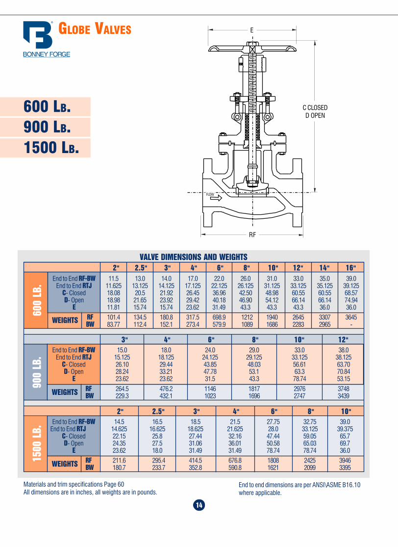
Home Table of Contents
Product Search
How To Order
PrintBack Next
Home Table of Contents
Product Search
How To Order
PrintBack Next
14
600 LB.900 LB.1500 LB.
2" 2.5" 3" 4" 6" 8" 10"End to End RF-BW 14.5 16.5 18.5 21.5 27.75 32.75 39.0
End to End RTJ 14.625 16.625 18.625 21.625 28.0 33.125 39.375C- Closed 22.15 25.8 27.44 32.16 47.44 59.05 65.7D- Open 24.35 27.5 31.06 36.01 50.58 65.03 69.7
E 23.62 18.0 31.49 31.49 78.74 78.74 36.0
RF 211.6 295.4 414.5 676.8 1808 2425 3946BW 180.7 233.7 352.8 590.8 1621 2099 3395
1500
LB.
VALVE DIMENSIONS AND WEIGHTS2" 2.5" 3" 4" 6" 8" 10" 12" 14" 16"
600
LB. End to End RF-BW 11.5 13.0 14.0 17.0 22.0 26.0 31.0 33.0 35.0 39.0
End to End RTJ 11.625 13.125 14.125 17.125 22.125 26.125 31.125 33.125 35.125 39.125C- Closed 18.08 20.5 21.92 26.45 36.96 42.50 48.98 60.55 60.55 68.57D- Open 18.98 21.65 23.92 29.42 40.18 46.90 54.12 66.14 66.14 74.94
E 11.81 15.74 15.74 23.62 31.49 43.3 43.3 43.3 36.0 36.0
RF 101.4 134.5 180.8 317.5 698.9 1212 1940 2645 3307 3645BW 83.77 112.4 152.1 273.4 579.9 1089 1686 2283 2965 -
3" 4" 6" 8" 10" 12"End to End RF-BW 15.0 18.0 24.0 29.0 33.0 38.0
End to End RTJ 15.125 18.125 24.125 29.125 33.125 38.125C- Closed 26.10 29.44 43.85 48.03 56.61 63.70D- Open 28.24 33.21 47.78 53.1 63.3 70.84
E 23.62 23.62 31.5 43.3 78.74 53.15
RF 264.5 476.2 1146 1817 2976 3748BW 229.3 432.1 1023 1696 2747 3439
900
LB.
FLOW
E
C CLOSEDD OPEN
RF
Materials and trim specifications Page 60All dimensions are in inches, all weights are in pounds.
End to end dimensions are per ANSI\ASME B16.10where applicable.
47
-20 to 100 3705 3470 3750 3470 3750 3750 3750 3750 3750 3600 3600 3600 3000200 3375 3280 3750 3395 3750 3560 3580 3750 3750 3000 3095 3180 2785300 3280 3190 3640 3260 3640 3365 3385 3640 3640 2640 2795 2940 2615400 3170 3085 3530 3200 3530 3290 3240 3530 3530 2350 2570 2770 2405500 2995 2910 3325 3105 3325 3210 3200 3325 3325 2185 2390 2590 2340
600 2735 2665 3025 3025 3025 3025 3025 3025 3025 2075 2255 2460 2275650 2685 2615 2940 2940 2940 2940 2940 2940 2940 2040 2220 2400 2250700 2665 2590 2840 2840 2840 2840 2840 2840 2840 2015 2160 2340 2225750 2520 2365 2520 2660 2660 2660 2660 2660 2660 1990 2110 2305 2200800 2060 1955 2060 2540 2540 2540 2540 2485 2540 1970 2075 2280 2160
850 1340 1340 1340 2435 2435 2435 2435 2195 2435 1945 2030 2220 -900 860 860 860 2245 2245 2245 2245 1765 2245 1920 1970 2160 -950 515 515 515 1405 1715 1885 1885 1305 1850 1870 1930 1930 -
1000 260 260 260 825 1065 1115 1340 960 1460 1610 1820 1820 -1050 - - - - 945 684 995 705 945 1545 1800 1800 -
1100 - - - - - 480 565 515 565 1285 1610 1610 -1150 - - - - - 260 515 345 380 980 1370 1370 -1200 - - - - - 170 275 225 260 770 1030 855 -1250 - - - - - - - - - 550 910 615 -1300 - - - - - - - - - 410 685 465 -
1350 - - - - - - - - - 310 515 345 -1400 - - - - - - - - - 240 380 255 -1450 - - - - - - - - - 170 290 205 -1500 - - - - - - - - - 120 205 170 -
1500
LB.
Temperature,°F
WorkingPressure
byClasses
-20 to 100 2220 2085 2250 2085 2250 2250 2250 2250 2250 2160 2160 2160 1800200 2025 1970 2250 2035 2250 2135 2150 2250 2250 1800 1860 1910 1670300 1970 1915 2185 1955 2185 2020 2030 2185 2185 1585 1680 1765 1570400 1900 1850 2115 1920 2115 1975 1945 2115 2115 1410 1540 1665 1445500 1795 1745 1995 1865 1995 1925 1920 1995 1995 1310 1435 1555 1405600 1640 1600 1815 1815 1815 1815 1815 1815 1815 1245 1355 1475 1365650 1610 1570 1765 1765 1765 1765 1765 1765 1765 1225 1330 1440 1350700 1600 1555 1705 1705 1705 1705 1705 1705 1705 1210 1295 1405 1335750 1510 1420 1510 1595 1595 1595 1595 1595 1595 1195 1270 1385 1320800 1235 1175 1235 1525 1525 1525 1525 1490 1525 1180 1245 1370 1295850 805 805 805 1460 1460 1460 1460 1315 1460 1165 1215 1330 -900 515 515 515 1350 1350 1350 1350 1060 1350 1150 1180 1295 -950 310 310 310 845 1030 1130 1130 780 1110 1125 1160 1160 -
1000 155 155 155 495 640 670 805 575 875 965 1090 1090 -1050 - - - - 565 410 595 420 565 925 1080 1080 -1100 - - - - - 290 340 310 340 770 965 965 -1150 - - - - - 155 310 205 225 585 825 825 -1200 - - - - - 105 165 135 155 465 620 515 -1250 - - - - - - - - - 330 545 370 -1300 - - - - - - - - - 245 410 280 -1350 - - - - - - - - - 185 310 205 -1400 - - - - - - - - - 145 225 155 -1450 - - - - - - - - - 105 175 125 -1500 - - - - - - - - - 70 125 105 -
A 217WC1(b)
A 352LC1(d)
A 352LCB(d)
A 217WC4(h)
A 217WC5(i)
A 217WC6(j)
A 217C5
A 217C12
A 351CF3(f)
A 351CF8
A 217WC9(j)
A 351CF3M(g)
A 351CF8M
A 351CF8C
A 351CN7M(l)
A 216WCB(a)
Working Pressures in PSI
A 216 WCC(a)A 352 LC2(d)A 352 LC3(d)A 352 LCC(e)
900
LB.
GLOBE VALVES
WEIGHTS
WEIGHTS
WEIGHTS
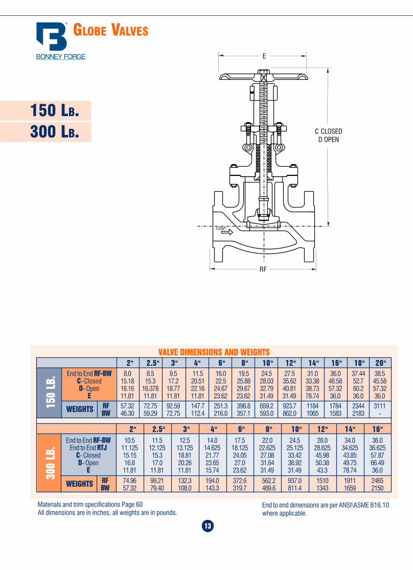
Home Table of Contents
Product Search
How To Order
PrintBack
Home Table of Contents
Product Search
How To Order
PrintBack Next
48
STANDARD CLASS PRESSURE TEMPERATURE RATINGS (CONT.)
Temperature,°F
WorkingPressure
byClasses
-20 to 100 6170 5785 6250 5785 6250 6250 6250 6250 6250 6000 6000 6000 5000200 5625 5470 6250 5660 6250 5930 5965 6250 6250 5000 5160 5300 4640300 5470 5315 6070 5435 6070 5605 5640 6070 6070 4400 4660 4900 4360400 5280 5145 5880 5330 5880 5485 5400 5880 5880 3920 4280 4620 4010500 4990 4850 5540 5180 5540 5350 5330 5540 5540 3640 3980 4320 3900600 4560 4440 5040 5040 5040 5040 5040 5040 5040 3460 3760 4100 3790650 4475 4355 4905 4905 4905 4905 4905 4905 4905 3400 3700 4000 3750700 4440 4320 4730 4730 4730 4730 4730 4730 4730 3360 3600 3900 3710750 4200 3945 4200 4430 4430 4430 4430 4430 4430 3320 3520 3840 3665800 3430 3260 3430 4230 4230 4230 4230 4145 4230 3280 3460 3800 3600850 2230 2230 2230 4060 4060 4060 4060 3660 4060 3240 3380 3700 -900 1430 1430 1430 3745 3745 3745 3745 2945 3745 3200 3280 3600 -950 860 860 860 2345 2860 3145 3145 2170 3085 3120 3220 3220 -
1000 430 430 430 1370 1770 1860 2230 1600 2430 2685 3030 3030 -1050 - - - - 1570 1145 1660 1170 1570 2570 3000 3000 -1100 - - - - - 800 945 860 945 2145 2685 2685 -1150 - - - - - 430 860 570 630 1630 2285 2285 -1200 - - - - - 285 460 370 430 1285 1715 1430 -1250 - - - - - - - - - 915 1515 1030 -1300 - - - - - - - - - 685 1145 770 -1350 - - - - - - - - - 515 860 570 -1400 - - - - - - - - - 400 630 430 -1450 - - - - - - - - - 285 485 345 -1500 - - - - - - - - - 200 345 285 -
A 217WC1(b)
A 352LC1(d)
A 352LCB(d)
A 217WC4(h)
A 217WC5(i)
A 217WC6(j)
A 217C5
A 217C12
A 351CF3(f)
A 351CF8
A 217WC9(j)
A 351CF3M(g)
A 351CF8M
A 351CF8C
A 351CN7M(l)
A 216WCB(a)
Working Pressures in PSI
A 216 WCC(a)A 352 LC2(d)A 352 LC3(d)A 352 LCC(e)
2500
LB.
ANSI/ASME B 16.34
NOTE:(1) For welding end valves only. Flanged end ratings terminate at 1000°F.
NOTES:(a) Permissable, but not recommended for prolonged usage above about 800°F.(b) Permissable, but not recommended for prolonged usage above about 850°F.(d) Not to be used over 650°F.(e) Not to be used over 700°F.(f) Not to be used over 800°F.(g) Not to be used over 850°F.(h) Not to be used over 1000°F.(i) Not to be used over 1050°F.(j) Not to be used over 1100°F.(l) Ratings apply for 300°F and lower.
FLOW
13
150 LB.300 LB.
GLOBE VALVES
VALVE DIMENSIONS AND WEIGHTS
End to End RF-BW 8.0 8.5 9.5 11.5 16.0 19.5 24.5 27.5 31.0 36.0 37.44 38.5C- Closed 15.18 15.3 17.2 20.51 22.5 25.88 28.03 35.62 33.38 48.58 52.7 45.58D- Open 16.16 16.378 18.77 22.16 24.67 29.67 32.79 40.81 38.73 57.32 60.2 57.32
E 11.81 11.81 11.81 11.81 23.62 23.62 31.49 31.49 78.74 36.0 36.0 36.0RF 57.32 72.75 92.59 147.7 251.3 396.8 659.2 923.7 1184 1784 2344 3111BW 46.30 59.29 72.75 112.4 216.0 357.1 593.0 862.0 1065 1583 2183 -WEIGHTS15
0 LB
.
2" 2.5" 3" 4" 6" 8" 10" 12" 14" 16" 18" 20"
300
LB.
2" 2.5" 3" 4" 6" 8" 10" 12" 14" 16"End to End RF-BW 10.5 11.5 12.5 14.0 17.5 22.0 24.5 28.0 34.0 36.0
End to End RTJ 11.125 12.125 13.125 14.625 18.125 22.625 25.125 28.625 34.625 36.625C- Closed 15.15 15.3 18.81 21.77 24.05 27.08 33.42 45.98 43.85 57.87D- Open 16.8 17.0 20.26 23.65 27.0 31.64 36.92 50.38 49.75 66.49
E 11.81 11.81 11.81 15.74 23.62 31.49 31.49 43.3 78.74 36.0
RF 74.96 99.21 132.3 194.0 372.6 562.2 937.0 1510 1911 2465BW 57.32 79.40 108.0 143.3 319.7 469.6 811.4 1343 1659 2150
FLOW
E
RF
Materials and trim specifications Page 60All dimensions are in inches, all weights are in pounds.
End to end dimensions are per ANSI\ASME B16.10where applicable.
C CLOSEDD OPEN
WEIGHTS
Home Table of Contents
Product Search
How To Order
Print Next
Home Table of Contents
Product Search
How To Order
PrintBack Next
50
STORAGE, INSTALLATION AND MAINTENANCE PROCEDURES
GATE VALVE “O.S.” & “Y”1.0 Periodic Inspections1.1 The valve stem packing should be inspected at least monthly. If the stem packing shows signs of leakage, simply tighten theadjusting nuts to compress the packing. Do not over-tighten the adjusting nuts as this will make operation of the valve moredifficult. If, after tightening the adjusting nuts to their fullest extent, the leakage does not stop , it is then necessary to replace thestem packing. It is not recommended that additional packing rings be added to the stuffing box as this may cause damage to thestem sealing system. Please contact Bonney Forge or it’s distributor for new stem packing sets. For packing replacement seeparagraphs 2.2 and 2.3.
1.2 The lubrication of the yokenut should be inspected at least monthly. A high pressure grease gun should be used for valvessupplied with ball type grease fittings. For valves supplied with a Stauffer type grease cup, the cup should be checked to assure thatit is full so that the grease can be injected by turning the screw cap.
1.3 Bonnet bolt tension should be checked periodically when valves are used in high temperature applications where creep mayoccur. Although leaks through ring joints are rare, erosion or corrosion could cause rings to fail. In these cases, a new ring gasket isrequired.
2.0 Extraordinary Maintenance or Replacement of Damaged Parts2.1 Stem. If the stem locks or "freezes", causes can generally be attributed to dry worn packing or a dry yoke nut. In either of thesecases, the following service is required:
*a) Unscrew gland nuts, remove the gland flange and bushing to expose stem packing and lantern ring. Replace stem packing if itis damaged. If the lantern ring is seized, completely disassemble the stem and replace the lantern ring.
b) Check lubrication of yoke nut. If it is dry, remove the yoke nut and determine if there is evidence of seizure marks. If so, replaceit with a new yoke nut.
*2.2 Disassembly of Stem Packing.
a) In those cases where the valve can not be removed from the piping system, it is important that prior to servicing, the valve beopened to its fullest extent. Partially unscrew nuts to reduce the compression load on the stuffing box. Next, if so equipped,remove the plug to check that there is no leakage. Remove the stem packing and, if so equipped, the lantern and bottom set ofstem packing then replace with new set(s) of packing. Finally, tighten nuts sufficiently while allowing the stem to operatesmoothly.
b) To replace the stem when the valve is completely disassembled for general maintenance follow this procedure:- Open valve half way then remove bonnet bolts and nuts.- Lift up the bonnet to remove wedge.- With the bonnet removed, unscrew the gland bolts then lift up gland flange exposing the stem packing.- Remove stem packing above the lantern ring (if so equipped) and then turn the handwheel to force the stem down.- Remove the stem through the stuffing box. Turn the bonnet up-side-down and remove lantern ring.- If so equipped, remove stem packing below the lantern ring.
*CAUTION: Always be sure that the valve is de-pressurized and isolated prior to performing any maintenance work.
G L O B E VA LV E S
11
Overview ........................................ 12
150 lb. valves ................................. 13
300 lb. valves ................................. 13
600 lb. valves ................................. 14
900 lb. valves ................................. 14
1500 lb. valves ............................... 14
Home Table of Contents
Product Search
How To Order
PrintBack Next

Home Table of Contents
Product Search
How To Order
PrintBack Next
Home Table of Contents
Product Search
How To Order
PrintBack Next
GATE VALVES
10
VALVE DIMENSIONS AND WEIGHTS
900
LB.
3" 4" 6" 8" 10" 12" 14" 16"
1500
LB.
End to End RF-BW 15.0 18.0 24.0 29.0 33.0 38.0 40.5 44.5End to End RTJ 15.125 18.125 24.125 29.125 33.125 38.125 40.875 44.875
C- Closed 24.2 29.9 37.8 47.0 52.56 54.7 60.8 72.44D- Open 27.94 34.62 44.69 55.66 62.79 66.9 73.8 87.99
E 15.75 19.7 31.5 43.3 43.3 78.7 78.7 78.7
RF 257.7 454.1 914.9 1689 2315 3197 3695 5789BW 220.4 396.8 776.0 1459 2006 2778 - 4841
14" 16" 18" 20" 24" 30" 36" 42"End to End RF-BW 35.0 39.0 43.0 47.0 55.0 65.0 82.0 96.0
End to End RTJ 35.125 39.125 43.125 47.25 55.375 65.5 82.625 -C- Closed 62.8 67.7 77.75 84.25 93.5 120.8 128.9 151.6D- Open 76.6 84.2 96.65 102.75 117.1 151.5 165.5 191.75
E 78.7 78.7 78.7 78.7 78.7 36.0 36.0 36.0
RF 3175 3968 5952 6856 10158 17786 16358 22884BW 2838 3406 5309 6029 9128 - 14727 -WEIGHTS
600
LB.
2" 2.5" 3" 4" 6" 8" 10" 12"End to End RF-BW 11.5 13.0 14.0 17.0 22.0 26.0 31.0 33.0
End to End RTJ 11.625 13.125 14.125 17.125 22.125 26.125 31.125 33.125C- Closed 18.3 17.6 23.2 27.0 32.1 41.4 42.8 49.1D- Open 20.74 20.8 26.98 32.0 38.8 50.06 53.43 61.1
E 11.81 10.0 15.75 15.75 23.62 31.5 43.3 43.3
RF 97.00 105.8 178.6 299.8 648.1 1122 1673 2282BW 79.37 85.98 156.6 246.9 540.0 965.4 1389 1993WEIGHTS
2" 2.5" 3" 4" 6" 8" 10" 12" 14" 16"End to End RF-BW 14 .5 16.5 18.5 21.5 27.75 32.75 39.0 44.5 49.5 54.5
End to End RTJ 14.625 16.625 18.625 21.625 28.0 33.125 39.375 45.125 50.25 55.375C- Closed 21.85 20.9 21.58 30.15 39.5 46.0 55.1 57.6 66.0 63.8D- Open 24.8 24.2 29.59 35.05 45.4 54.46 64.74 68.82 79.0 77.55
E 15.75 14.0 19.7 23.62 31.5 43.3 78.7 78.7 36.0 36.0
RF 213.8 242.5 392.4 634.9 1523 2566 4078 5787 4299 4542BW 167.5 198.4 321.9 560.0 1296 2271 3505 5225 - 3594
2500
LB.
2" 3" 4" 6" 8" 10" 12"End to End RF-BW 17.75 22.75 26.50 36.0 40.25 50.0 56.0
End to End RTJ 17.875 23.0 26.875 36.5 40.875 50.875 56.875C- Closed 24.8 28.97 30.11 44.88 - 66.53 76.77D- Open 27.47 32.71 33.92 51.17 - 74.99 85.62
E 15.74 31.49 31.49 43.30 - - -
RF 399.0 736.3 1829 2833 - - -BW - - - - - - -
E
RF
600 LB.900 LB.
1500 LB.2500 LB.
C CLOSEDD OPEN
Materials and trim specifications Page 60All dimensions are in inches, all weights are in pounds.
End to end dimensions are per ANSI\ASME B16.10where applicable.
51
2.3 The procedure to re-assembly the valve is as follows:Re-insert the stem through the stuffing box taking special care to reassemble parts in sequence. If so equipped, avoid allowing thelantern ring to slide into the stuffing box. If the valve is equipped with a lantern ring, first insert 3 packing rings into the stuffing boxfollowed by a lantern ring. Next, insert the remaining packing rings into the stuffing box and compress using the gland and flange.Then, reassemble nuts and tighten. Note, the stem must slide freely through the stuffing box without applying excessive force.Finally, install the bonnet gasket making sure it is not damaged. The gasket should be replaced if there is any question as to itsperformance.
2.4 Raise the bonnet, making sure the stem is in a half open position, then connect disc to stem. Lower bonnet on to the valve bodymaking sure that the disc fits exactly into body guides and the bonnet gasket is properly seated. Align holes and tighten bonnet nutstaking care that excessive force is not used, possibly damaging the gasket. Hydrostatically test the valve to assure that there is noleakage.
2.5 Disassembly of yoke nutWhen necessary use the following procedure for disassembling and replacing yoke nut:
a) direct hand-operated valves (handwheel)- remove set screw;- unscrew handwheel nut;- remove handwheel;- unscrew yoke nut retaining nut, removing spot welds if necessary;
Reverse the procedure for re-assembly.
b) bevel gear operated valves- to remove the bevel gear from the valve, unscrew nuts and turn the handwheel in the open direction indicated by the arrow until
the drive nuts are disengaged from the stem.- to check the condition of the drive nut or bearing, unscrew the retainer ring and remove drive the nut and bearing. If damaged, a
new drive nut or bearing is necessary.
2.6 Wedge and SeatsLeakage through seats and wedges are not always easy to spot when valves are in service. However, when leaks are identified,immediate action is necessary. Any delay can permanently damage seat or wedge seal surfaces.
To repair or replace wedges or seats, the valve must be removed from line then use the following procedure:
- make sure that the valve is not under pressure before unscrewing bonnet nuts;- remove bonnet, being careful not to damage the gasket;- remove bonnet when wedge is in half open position;- lift up bonnet until wedge is disconnected from guides;- release wedge from stem.
If seat surfaces show signs of seizing, pitting, grooves or other defects not deeper that 0.8 mm (1/32") it is possible to repairseating surfaces to its original conditions by relapping the surface with line grain abrasive paste, creating a perfect tightness onceagain.
Defects having a depth exceeding 0.8 mm (1/32") cannot be repaired by lapping. In this case, parts must be replaced.
It is recommended that the face of the disc be blued to check for contact of seating surface after final lapping. For re-assembly ofvalves use the procedure outlined under para. 2.4.
WEIGHTS
WEIGHTS
WEIGHTS
Home Table of Contents
Product Search
How To Order
PrintBack Next
Home Table of Contents
Product Search
How To Order
PrintBack Next
52
STORAGE, INSTALLATION AND MAINTENANCE PROCEDURES (CONT.)
GLOBE VALVES -“O.S.” & “Y”1.0 Periodic Inspections
1.1 The valve stem packing should be inspected at least monthly. If the stem packing shows signs of leakage, simply tighten theadjusting nuts to compress the packing. Do not over-tighten the adjusting nuts as this will make operation of the valve moredifficult. If, after tightening the adjusting nuts to their fullest extent, the leakage does not stop, it is then necessary to replace thestem packing. It is not recommended that additional packing rings be added to the stuffing box as this may cause damage to thestem sealing system. Please contact Bonney Forge or it’s distributor for new stem packing sets. For packing replacement seeparagraphs 2.2 and 2.3.
1.2 The lubrication of the yokenut should be inspected at least monthly. A high pressure grease gun should be used for valvessupplied with ball type grease fittings. For valves supplied with a Stauffer type grease cup, the cup should be checked to assure thatit is full so that the grease can be injected by turning the screw cap.
1.3 Bonnet bolt tension should be checked periodically when valves are used in high temperature applications where creep mayoccur. Although leaks through ring joints are rare, erosion or corrosion could cause rings to fail. In these cases, a new ring gasket isrequired.
2.0 Extraordinary Maintenance or Replacement of Damaged Parts
2.1 Stem. If the stem locks or freezes, causes can generally be attributed to dry worn packing or a dry yoke nut. In either of thesecases, the following service is required:
*a) Unscrew gland nuts, remove gland flange and bushing to expose stem packing and lantern ring. Replace stem packing if it isdamaged. If the lantern ring is seized, completely disassemble the stem and replace the lantern ring.
b) Check lubrication of yoke nut. If it is dry, remove the yoke nut and determine if there is evidence of seizure marks. If so, replaceit with a new yoke nut.
*2.2 Disassembly of Stem Packing.a) In those cases where the valve cannot be removed from the piping system, it is important that prior to servicing, the valve be
opened to its fullest extent. Partially unscrew nuts to reduce the compression load on the stuffing box. Next, if so equipped,remove the plug to check that there is no leakage. Remove the stem packing and, if so equipped, the lantern and bottom set ofstem packing then replace with new set(s) of packing. Reassemble plug and gland flange. Finally, tighten nuts sufficiently whileallowing the stem to operate smoothly.
b) To replace the stem when the valve is completely disassembled for general maintenance follow this procedure:- Open valve fully then remove bonnet bolts and nuts.- With the bonnet removed, unscrew the gland bolts then lift up gland flange exposing the stem packing.- Remove stem packing above the lantern ring (if so equipped).- Remove handwheel then turn stem to release it from yoke nut and remove from stuffing box.- Check condition of back-seat bushing for seizure marks. If apparent, order replacement parts.- If required, turn the bonnet up-side-down and remove lantern ring.- If so equipped, remove stem packing below the lantern ring.
*CAUTION: Always be sure that the valve is de-pressurized and isolated prior to performing any maintenance work.
9
150 LB.300 LB.
14" 16" 18" 20" 24" 30" 36" 42"End to End RF-BW 30.0 33.0 36.0 39.0 45.0 55.0 68.0 78.0
End to End RTJ 30.625 33.625 36.625 39.75 45.875 56.0 69.125 79.0C- Closed 53.9 62 69.7 77.9 82 115.3 129.1 136.0D- Open 67.68 78.53 87.5 98.76 105.9 145.6 165.5 177.6
E 31.5 43.3 43.3 78.7 78.7 78.7 78.7 36.0
RF 1764 2350 3137 5952 5974 10626 15785 18078BW 1478 2034 2777 5480 5284 9458 14110 16347WEIGHTS
300
LB.
2" 2.5" 3" 4" 6" 8" 10" 12"End to End RF-BW 8.5 9.5 11.125 12.0 15.875 16.5 18.0 19.75
End to End RTJ 9.125 10.125 11.75 12.625 16.5 17.125 18.625 20.375C- Closed 15.23 16.9 18.3 22.44 29.52 34.25 39.37 46.88D- Open 17.73 20.1 21.8 27.04 36.09 43.03 49.37 59.38
E 9.85 8.0 11.81 15.75 19.7 23.62 23.62 31.5
RF 63.93 90.39 123.4 180.8 363.8 579.8 855.4 1212BW 50.7 70.55 96.75 138.9 313.1 553.3 751.8 977.8WEIGHTS
Materials and trim specifications Page 60All dimensions are in inches, all weights are in pounds.
20" 24" 26" 28" 30" 32" 34" 36" 40" 42" 48"End to End RF 18.0 20.0 22.0 24.0 24.0 26.0 28.0 28.0 32.0 32.0 34.0End to End BW 28.0 32.0 34.0 36.0 36.0 38.0 40.0 40.0 46.0 55.0 50.0
C- Closed 72 83.5 90 103.7 102 115.7 105.9 130 138.2 150.4 160D- Open 92 107.85 115.6 133.6 131.1 148 140.0 166 178.7 190.16 208
E 43.3 78.7 78.7 78.7 78.7 78.7 36.0 78.7 78.7 78.7 36.0
RF 1907 2910 3327 4524 5320 5291 6043 7011 10785 10939 14330BW 1880 2857 3054 - 5095 5115 5875 6548 - 9682 -WEIGHTS
150
LB.
2" 2.5" 3" 4" 6" 8" 10" 12" 14" 16" 18"End to End RF 7.0 7.5 8.0 9.0 10.5 11.5 13.0 14.0 15.0 16.0 17.0End to End BW 8.5 9.5 11.125 12.0 15.875 16.5 18.0 19.75 22.5 24.0 26.0
C- Closed 15.23 16.3 18.42 22.44 26.77 33.26 38.6 44.1 52.36 56.9 64.17D- Open 17.79 19.3 21.97 27.12 33.37 42.06 49.8 56.77 66.8 73.35 82.07
E 9.85 8.0 11.81 11.81 15.75 19.7 23.62 23.62 31.5 31.5 43.3
RF 57.32 66.14 77.16 121.2 183.0 328.5 522.5 668.0 963.4 1155 1479BW 48.5 52.91 68.34 101.4 167.5 310.9 493.8 646.0 917.1 1010 1452WEIGHTS
VALVE DIMENSIONS AND WEIGHTS
GATE VALVES
RF
E
C CLOSEDD OPEN
End to end dimensions are per ANSI\ASME B16.10where applicable.
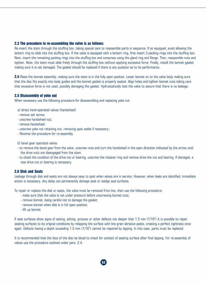
Home Table of Contents
Product Search
How To Order
PrintBack Next
Home Table of Contents
Product Search
How To Order
PrintBack Next
53
OVERVIEW
8
GATE VALVESCast Steel, outsidescrew and yoke, risingstem, non-rising hand-wheel, removable yokesleeve.
8. BONNET. The bonnet is in cast steel. It is machined to accept the yokesleeve and incorporates a stuffing box dimensioned in accordancewith the API standard.
9. BONNET BUSHING. The bonnet bushing or backseat is in forgedstainless steel and forms part of the trim. Special attention is givenboth to its machining and heat treatment.
10. STEM. The stem is in forged stainless steel and is part of the trim.The stem is provided with a T head. A ground backseat is provided toensure a perfectly tight seal to the stuffing box when the valve is fullyopen. The stem is ground to minimize friction and prevent damage togland packing. The threading is trapezoidal ACME type. Dimensionscomply with the API 600 standard.
11. SEAT RINGS. The rings are forged stainless steel and are part of thetrim. They are seal welded in place. Special attention is given to thesealing surfaces which are ground and lapped for a perfect seal.Threaded-in seat rings may be supplied upon request.
12. WEDGE. The wedge is part of the trim. It is forged stainless steel fordiameters up to 6" and in cast steel for larger valves. It is normallysupplied as the flexible wedge type. It is connected to the stem bymeans of a T joint. The guides on each side of the wedge aremachined. Special attention is given to the seating surfaces which areground and lapped.
1. HANDWHEEL. The five-spoked handwheel is fabricated from steel pipe.The hub has a hexagonal taper for coupling to the yoke sleeve.
2. YOKE SLEEVE. The yoke sleeve is made from cast Iron Ni resist D2 havinghigh resistance to wear and a high melting point, about 2000° F. It isdesigned to permit removal from the bonnet or the yoke while the valveis in service. Gate valves 6" 600 lb. Class and above are fitted with ballthrust bearing.
3. GLAND AND FLANGE. They are forged steel and are supplied in twopieces. The contact surfaces between gland and gland flange have aspherical profile to permit the gland to descend parallel to the stemeven if the eyebolts are unevenly tightened.
4. GLAND BOLTS AND NUTS. The forged steel gland bolts are of the eyebolttype which can be swung outward for ease of gland repacking. They arefixed to the bonnet by stud bolts and nuts.
5. LANTERN. Lantern rings are available upon request.6. BONNET BOLTING. Bonnet studs and nuts are manufactured from alloy
steel to the relevant ASTM standard.7. BODY. The body is in cast steel and is carefully designed in all its details.
The basic dimensions, i.e. wall thickness, face to face and flanges complywith the relevant API and ANSI standards. The body-to-bonnet flange isnormally circular, except in the 150 lb. Class which is oval. The sealingsurfaces for connection to the bonnet are flat finish in the 150 lb. Class,recessed in the 300 lb. Class and ring joint in the 600 lb. Class andabove. Bosses are provided for drain taps or by-pass piping.
1
2
4
3
5
6
7
8
9
10
11
12
Flex Wedge
Welded-in Seat Rings
2.3 The procedure to re-assembling the valve is as follows:Re-insert the stem through the stuffing box, taking special care to reassemble parts in sequence. If so equipped, avoid allowing thelantern ring to slide into the stuffing box. If the valve is equipped with a lantern ring, first insert 3 packing rings into the stuffing box.Next, insert the remaining packing rings into the stuffing box and compress using the gland ring and flange. Then, reassemble nuts andtighten. Note, the stem must slide freely through the stuffing box without applying excessive force. Finally, install the bonnet gasketmaking sure it is not damaged. The gasket should be replaced if there is any question as to its performance.
2.4 Raise the bonnet assembly, making sure the stem is in the fully open position. Lower bonnet on to the valve body making surethat the disc fits exactly into body guides and the bonnet gasket is properly seated. Align holes and tighten bonnet nuts taking carethat excessive force is not used, possibly damaging the gasket. Hydrostatically test the valve to assure that there is no leakage.
2.5 Disassembly of yoke nutWhen necessary use the following procedure for disassembling and replacing yoke nut:
a) direct hand-operated valves (handwheel)- remove set screw;- unscrew handwheel nut;- remove handwheel;- unscrew yoke nut retaining nut, removing spot welds if necessary;- Reverse the procedure for re-assembly.
b) bevel gear operated valves- to remove the bevel gear from the valve, unscrew nuts and turn the handwheel in the open direction indicated by the arrow until
the drive nuts are disengaged from the stem.- to check the condition of the drive nut or bearing, unscrew the retainer ring and remove drive the nut and bearing. If damaged, a
new drive nut or bearing is necessary.
2.6 Disk and SeatsLeakage through disk and seats are not always easy to spot when valves are in service. However, when leaks are identified, immediateaction is necessary. Any delay can permanently damage seat or wedge seal surfaces.
To repair or replace the disk or seats, the valve must be removed from line, then use the following procedure:- make sure that the valve is not under pressure before unscrewing bonnet nuts;- remove bonnet, being careful not to damage the gasket;- remove bonnet when disk is in full open position;- lift up bonnet
If seat surfaces show signs of seizing, pitting, grooves or other defects not deeper that 1.5 mm (1/16") it is possible to repairseating surfaces to its original conditions by relapping the surface with line grain abrasive paste, creating a perfect tightness onceagain. Defects having a depth exceeding 1.5 mm (1/16") cannot be repaired by lapping. In this case, parts must be replaced.
It is recommended that the face of the disc be blued to check for contact of seating surface after final lapping. For re-assembly ofvalves use the procedure outlined under para. 2.4.
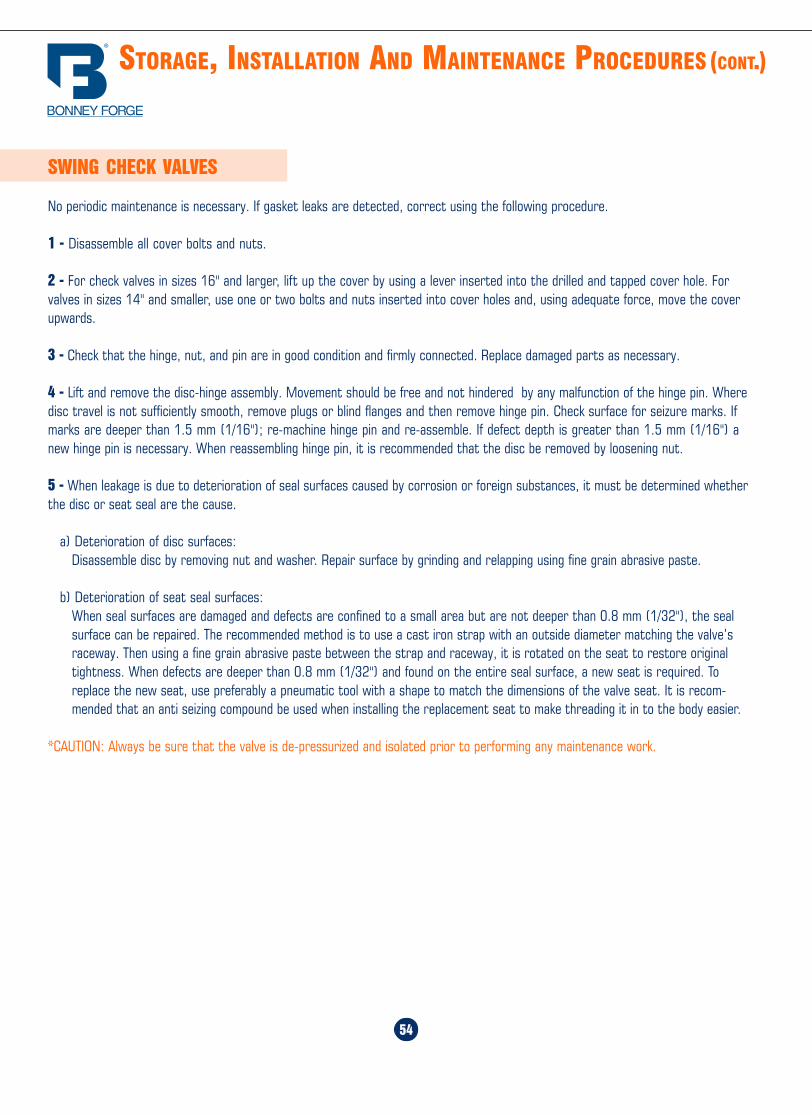
Home Table of Contents
Product Search
How To Order
PrintBack Next
Home Table of Contents
Product Search
How To Order
PrintBack Next
54
STORAGE, INSTALLATION AND MAINTENANCE PROCEDURES (CONT.)
SWING CHECK VALVES
No periodic maintenance is necessary. If gasket leaks are detected, correct using the following procedure.
1 - Disassemble all cover bolts and nuts.
2 - For check valves in sizes 16" and larger, lift up the cover by using a lever inserted into the drilled and tapped cover hole. Forvalves in sizes 14" and smaller, use one or two bolts and nuts inserted into cover holes and, using adequate force, move the coverupwards.
3 - Check that the hinge, nut, and pin are in good condition and firmly connected. Replace damaged parts as necessary.
4 - Lift and remove the disc-hinge assembly. Movement should be free and not hindered by any malfunction of the hinge pin. Wheredisc travel is not sufficiently smooth, remove plugs or blind flanges and then remove hinge pin. Check surface for seizure marks. Ifmarks are deeper than 1.5 mm (1/16"); re-machine hinge pin and re-assemble. If defect depth is greater than 1.5 mm (1/16") anew hinge pin is necessary. When reassembling hinge pin, it is recommended that the disc be removed by loosening nut.
5 - When leakage is due to deterioration of seal surfaces caused by corrosion or foreign substances, it must be determined whetherthe disc or seat seal are the cause.
a) Deterioration of disc surfaces:Disassemble disc by removing nut and washer. Repair surface by grinding and relapping using fine grain abrasive paste.
b) Deterioration of seat seal surfaces:When seal surfaces are damaged and defects are confined to a small area but are not deeper than 0.8 mm (1/32"), the sealsurface can be repaired. The recommended method is to use a cast iron strap with an outside diameter matching the valve’sraceway. Then using a fine grain abrasive paste between the strap and raceway, it is rotated on the seat to restore originaltightness. When defects are deeper than 0.8 mm (1/32") and found on the entire seal surface, a new seat is required. Toreplace the new seat, use preferably a pneumatic tool with a shape to match the dimensions of the valve seat. It is recom-mended that an anti seizing compound be used when installing the replacement seat to make threading it in to the body easier.
*CAUTION: Always be sure that the valve is de-pressurized and isolated prior to performing any maintenance work.
G A T E VA LV E S
Overview .......................................... 8
150 lb. valves ................................... 9
300 lb. valves ................................... 9
600 lb. valves ................................. 10
900 lb. valves ................................. 10
1500 lb. valves ............................... 10
2500 lb. valves ............................... 10
7
Home Table of Contents
Product Search
How To Order
PrintBack Next
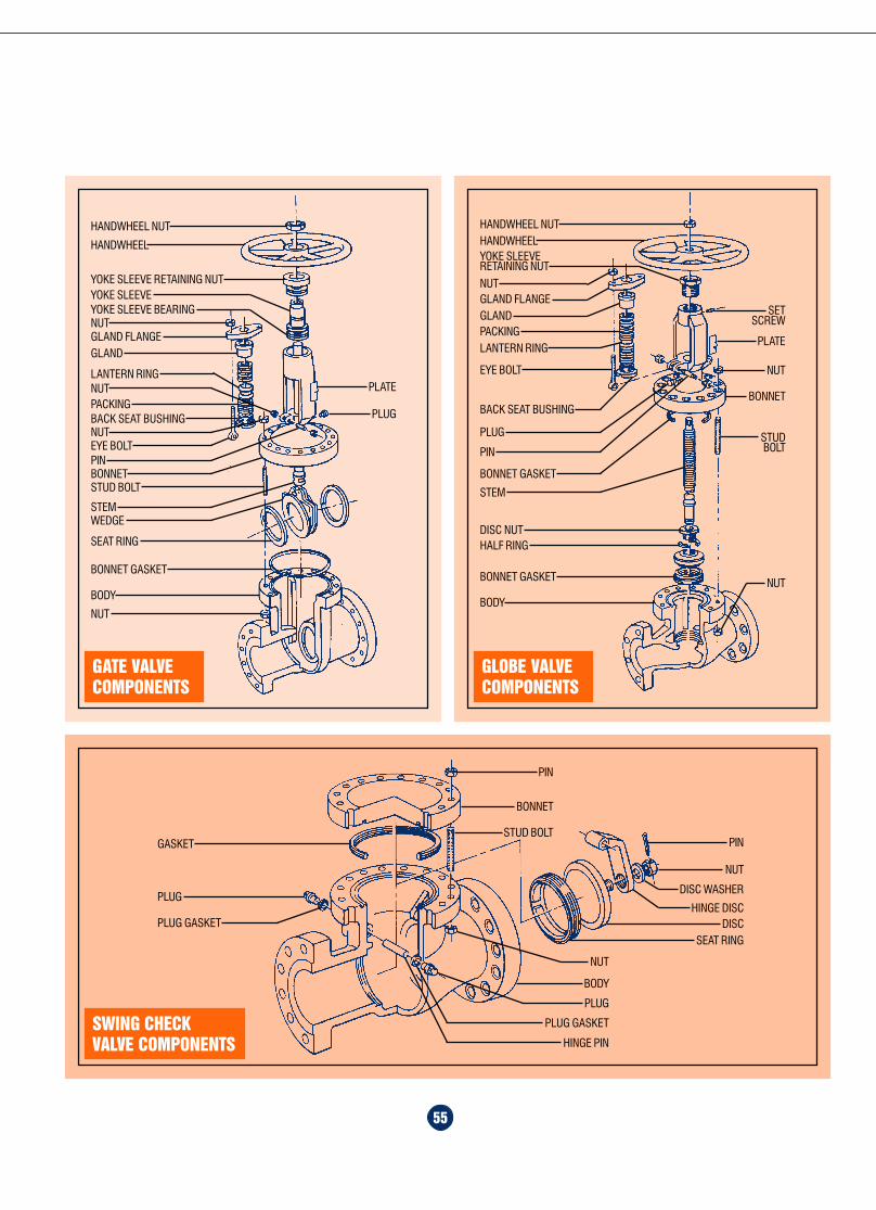
Home Table of Contents
Product Search
How To Order
PrintBack Next
Home Table of Contents
Product Search
How To Order
PrintBack Next
55
PLATE
PLUG
HANDWHEEL NUT
HANDWHEEL
YOKE SLEEVE RETAINING NUTYOKE SLEEVE
NUTYOKE SLEEVE BEARING
GLAND FLANGEGLAND
LANTERN RINGNUTPACKINGBACK SEAT BUSHINGNUTEYE BOLTPINBONNETSTUD BOLT
STEMWEDGE
SEAT RING
BONNET GASKET
NUT
BODY
GATE VALVECOMPONENTS
GLOBE VALVECOMPONENTS
PLATE
NUT
HANDWHEEL NUTHANDWHEELYOKE SLEEVERETAINING NUT
NUTGLAND FLANGEGLAND
LANTERN RINGPACKING
BACK SEAT BUSHING
PLUG
EYE BOLT
PIN
BONNET GASKET
STEM
DISC NUTHALF RING
BONNET GASKET
BODY
SETSCREW
BONNET
STUDBOLT
NUT
SWING CHECKVALVE COMPONENTS
PIN
NUT
DISC WASHER
HINGE DISCDISC
SEAT RING
PIN
BONNET
STUD BOLT
PLUG
PLUG GASKET
GASKET
NUT
BODY
PLUG GASKET
PLUG
HINGE PIN
HOW TO ORDER/SPECIFY CAST STEEL VALVES (CONT.)
High Alloy Special SteelsM35-1 A494M35-1 Monel Nickel/Nickel Alloy SteelN-12M A494N-12M Hastelloy B, Nickel/Nickel Alloy SteelCW-12M A494-CW-12M Hastelloy C, Nickel/Nickel Alloy SteelCY-40 A494CY-40 Inconel Nickel/Nickel Alloy SteelCZ-100 A494CZ-100 Nickel Alloy SteelF-51 UNS S 31803 Duplex Stainless SteelH Grade Materials also available
Special Trim/Trim Combinations(H) H Grade Trim(L) L Grade TrimHFS 1/2 StelliteFHF Full Hard Face (Full Stellite)MON Monel TrimA20 Alloy 20 Trim321 321 Stainless Steel Trim347 347 Stainless Steel Trim
6
SECTION E- OTHER BODY/BONNET OR TRIM MATERIALS
SL Bellow Seal BonnetBG Bevel Gear OperatorBYP BypassCWO Chainwheel OperatedCRY Cryogenic BonnetEMO Electric Motor OperatorGD Guided Disc (Globe Valves)NACE NACE Requirements to MR-01-75, latest editionPMI Positive Material Identification required
List as a suffix, by abbreviation if possible,any other requirement not shown on this list
Example: 3" 150# RF Flanged Gate Valve, Bolted Bonnet,ASTM A216WCB Body/Bonnet with 1/2 Stellite Trim
1 11 RF_________ ____________ ____________
Sec A Sec. B, Sec. C Sec. D
AS: 3" 1-11-RF
SECTION F- MODIFICATIONS/SPECIAL REQUIREMENTS
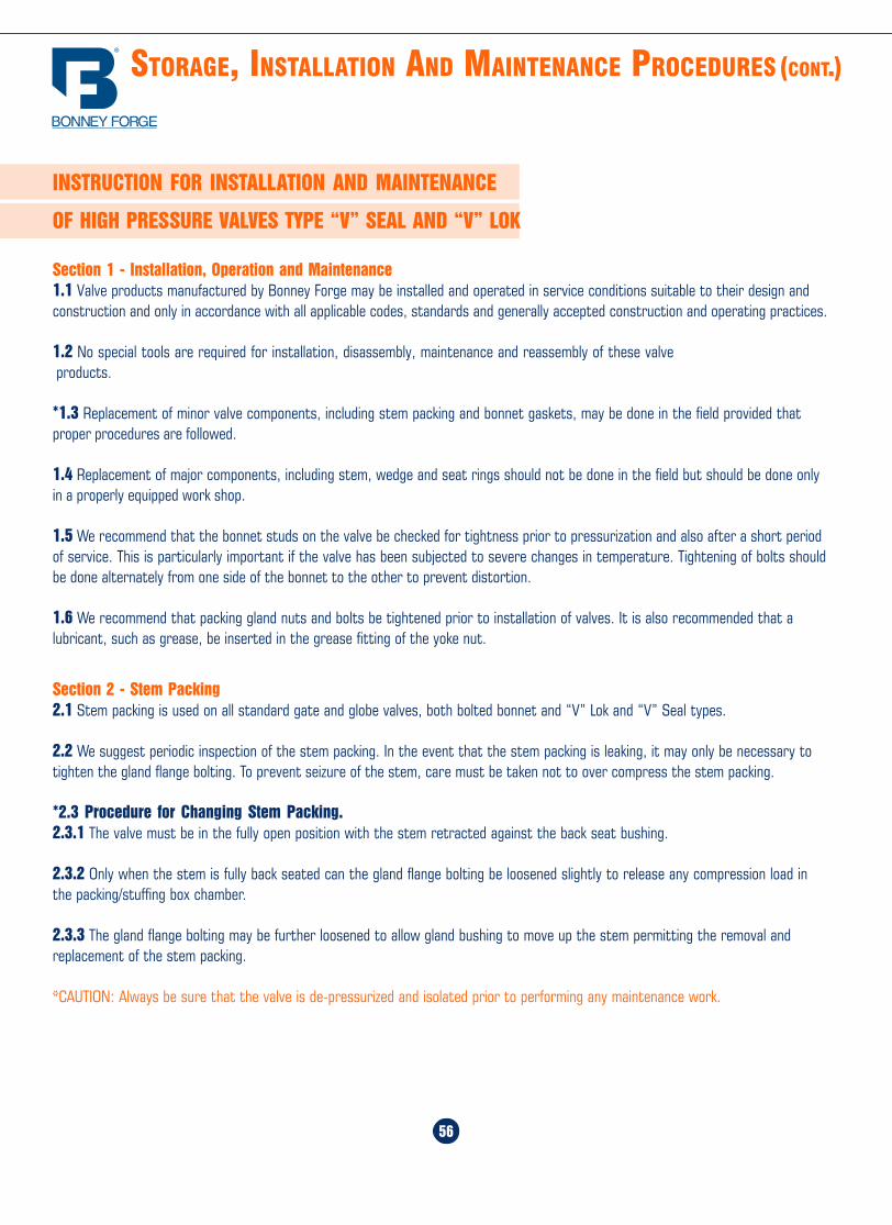
Home Table of Contents
Product Search
How To Order
PrintBack Next
Home Table of Contents
Product Search
How To Order
PrintBack Next
56
STORAGE, INSTALLATION AND MAINTENANCE PROCEDURES (CONT.)
INSTRUCTION FOR INSTALLATION AND MAINTENANCE
OF HIGH PRESSURE VALVES TYPE “V” SEAL AND “V” LOK
Section 1 - Installation, Operation and Maintenance1.1 Valve products manufactured by Bonney Forge may be installed and operated in service conditions suitable to their design andconstruction and only in accordance with all applicable codes, standards and generally accepted construction and operating practices.
1.2 No special tools are required for installation, disassembly, maintenance and reassembly of these valve products.
*1.3 Replacement of minor valve components, including stem packing and bonnet gaskets, may be done in the field provided thatproper procedures are followed.
1.4 Replacement of major components, including stem, wedge and seat rings should not be done in the field but should be done onlyin a properly equipped work shop.
1.5 We recommend that the bonnet studs on the valve be checked for tightness prior to pressurization and also after a short periodof service. This is particularly important if the valve has been subjected to severe changes in temperature. Tightening of bolts shouldbe done alternately from one side of the bonnet to the other to prevent distortion.
1.6 We recommend that packing gland nuts and bolts be tightened prior to installation of valves. It is also recommended that alubricant, such as grease, be inserted in the grease fitting of the yoke nut.
Section 2 - Stem Packing2.1 Stem packing is used on all standard gate and globe valves, both bolted bonnet and “V” Lok and “V” Seal types.
2.2 We suggest periodic inspection of the stem packing. In the event that the stem packing is leaking, it may only be necessary totighten the gland flange bolting. To prevent seizure of the stem, care must be taken not to over compress the stem packing.
*2.3 Procedure for Changing Stem Packing.2.3.1 The valve must be in the fully open position with the stem retracted against the back seat bushing.
2.3.2 Only when the stem is fully back seated can the gland flange bolting be loosened slightly to release any compression load inthe packing/stuffing box chamber.
2.3.3 The gland flange bolting may be further loosened to allow gland bushing to move up the stem permitting the removal andreplacement of the stem packing.
*CAUTION: Always be sure that the valve is de-pressurized and isolated prior to performing any maintenance work.
5
SECTION C- BODY/BONNET AND TRIM MATERIAL
1 A216WCB Body/Bonnet, Trim 13% Cr (F6/CA15) Hard FacedSeats (1/2 Stellite) API Trim #8
1N A216WCB Body/Bonnet, Trim 13% Cr (F6/CA15) API Trim #12 A216WCB Body/Bonnet, Trim 13% Cr (F6/CA15) Hard Faced
Seats & Disc (Full Stellite) API Trim #53 A216WCB Body/Bonnet, Trim 18% Cr-8NI (316/CF8M) API Trim # 104 A216WCB Body/Bonnet, Trim Ni-Cu Alloy, (Monel Metal) API Trim #95 A217WC9 Body/Bonnet, 2. 1/4% Cr 1% Mo, Trim 13% Cr
(F6/CA15) Hard Faced Seats (1/2 Stellite) API Trim #86 A217C5 Body/Bonnet, 5% Cr 1/2 % Mo, Trim 13% Cr
(F6/CA15) Hard Faced Seats (1/2 Stellite) API Trim #87 A351CF8 Body/Bonnet, Trim 18% Cr - 8 Ni(304/CF8)
Trim 304 Stainless Steel API Trim #28 A351CF8M Body/Bonnet, Trim 18% Cr - 8 Ni(316/CF8M)
Trim 316 Stainless Steel Api Trim #108S A351CF8M Body/Bonnet, Trim 18% Cr - 8 Ni(316/CF8M) Trim 316
Stainless Steel, Hard Faced Seats (1/2 Stellite) API Trim #129 A217WC6 Body/Bonnet, 1.1/4 Cr 1/2 Mo, Trim 13% Cr
(F6/CA15) Hard Faced Seats (1/2 Stellite) API Trim #80 Other Specify
SECTION D- END CONFIGURATION
RF Raised Face, Flanged End, 125-250 AARHRFSF Raised Face, Flanged End, 125 AARHRTJ Ring Type JointBW Butt Weld Ends (Specify Pipe Schedule)
SECTION E- OTHER BODY/BONNET OR TRIM MATERIALS
WCC A216WCC Carbon SteelWC1 A217WC1 Carbon/Moly SteelC12 A217C12 9% Cr 1% Moly SteelCA15 A217CA15 13% Cr1/2 Moly SteelLCB A352LCB Low Temp Carbon Steel - 50° FLC3 A352LC3 Low Temp Carbon Steel - 150° FCF3 A351CF3 Stainless Steel, Type 304LCF8M A351CF8M Stainless Steel, Type 316CN7M A351CN7M Stainless Steel, Type Alloy 20CF8C A351CF8C Stainless Steel, Type 347
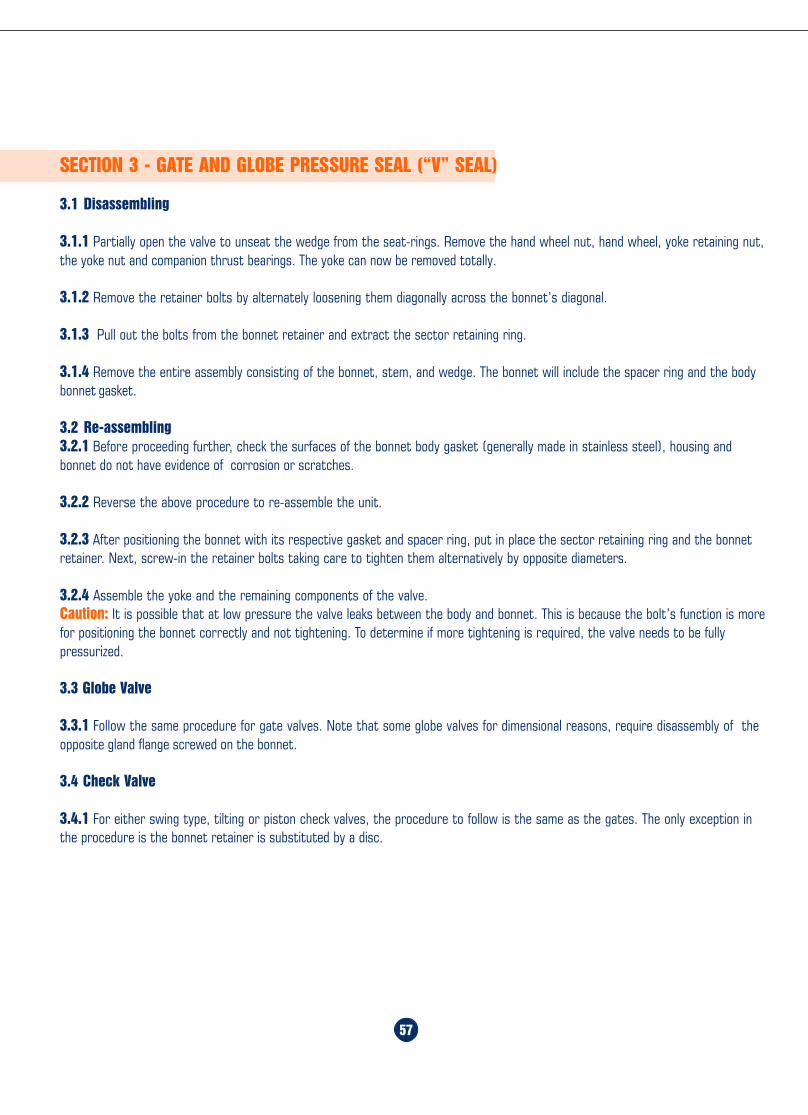
Home Table of Contents
Product Search
How To Order
PrintBack Next
Home Table of Contents
Product Search
How To Order
PrintBack Next
57
SECTION 3 - GATE AND GLOBE PRESSURE SEAL (“V” SEAL)
3.1 Disassembling
3.1.1 Partially open the valve to unseat the wedge from the seat-rings. Remove the hand wheel nut, hand wheel, yoke retaining nut,the yoke nut and companion thrust bearings. The yoke can now be removed totally.
3.1.2 Remove the retainer bolts by alternately loosening them diagonally across the bonnet’s diagonal.
3.1.3 Pull out the bolts from the bonnet retainer and extract the sector retaining ring.
3.1.4 Remove the entire assembly consisting of the bonnet, stem, and wedge. The bonnet will include the spacer ring and the bodybonnet gasket.
3.2 Re-assembling3.2.1 Before proceeding further, check the surfaces of the bonnet body gasket (generally made in stainless steel), housing andbonnet do not have evidence of corrosion or scratches.
3.2.2 Reverse the above procedure to re-assemble the unit.
3.2.3 After positioning the bonnet with its respective gasket and spacer ring, put in place the sector retaining ring and the bonnetretainer. Next, screw-in the retainer bolts taking care to tighten them alternatively by opposite diameters.
3.2.4 Assemble the yoke and the remaining components of the valve.Caution: It is possible that at low pressure the valve leaks between the body and bonnet. This is because the bolt’s function is morefor positioning the bonnet correctly and not tightening. To determine if more tightening is required, the valve needs to be fullypressurized.
3.3 Globe Valve
3.3.1 Follow the same procedure for gate valves. Note that some globe valves for dimensional reasons, require disassembly of theopposite gland flange screwed on the bonnet.
3.4 Check Valve
3.4.1 For either swing type, tilting or piston check valves, the procedure to follow is the same as the gates. The only exception inthe procedure is the bonnet retainer is substituted by a disc.
HOW TO ORDER/SPECIFY CAST STEEL VALVES
1. Specify valve size2. Designate Bonnet Style and Pressure Class from Section A3. Select Valve Type desired from Section B4. Indicate Body/Bonnet and Trim Material from Section C5. Select End Configuration from Section D6. Select other Body/Bonnet/Trim from Section E7. Select Special Requirement(s) from Section F8. Specify as a Suffix String, after Section D or E, any Body/Bonnet
Material, Trim Material or Special Requirements not listed below
SECTION A- BONNET STYLE AND PRESSURE CLASS
1 Bolted Bonnet Class 150#3 Bolted Bonnet Class 300#6 Bolted Bonnet Class 600#9 Bolted Bonnet Class 900#15 Bolted Bonnet Class 1500#25 Bolted Bonnet Class 2500#6PS Pressure Seal Bonnet Class 600#9PS Pressure Seal Bonnet Class 900#15PS Pressure Seal Bonnet Class 1500#25PS Pressure Seal Bonnet Class 2500#
SECTION B- TYPE OF VALVE
1 Gate Valve, Flexible Wedge2 Gate Valve, Plain Solid Wedge3 Globe Valve, T Pattern3Y Globe Valve, Y Pattern3A Globe Valve, Angle Pattern3SC Globe Stop Check Valve6 Check Valve, Swing Type7 Check Valve, Piston Type7Y Check Valve, Y Pattern Piston Type9 Check Valve, Tilting DiscTBV Ball Valve, Trunnion MountedTCG Thru-Conduit Gate
4
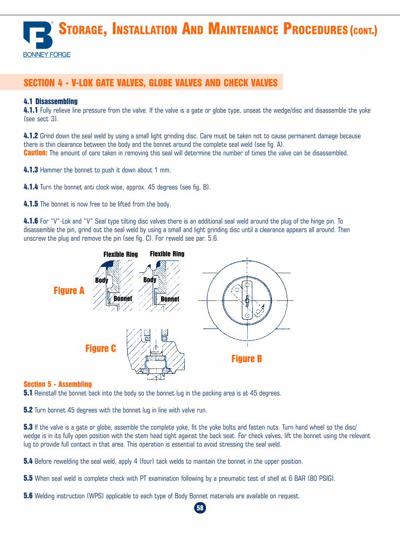
Home Table of Contents
Product Search
How To Order
PrintBack Next
Home Table of Contents
Product Search
How To Order
PrintBack Next
58
STORAGE, INSTALLATION AND MAINTENANCE PROCEDURES (CONT.)
3
SECTION 4 - V-LOK GATE VALVES, GLOBE VALVES AND CHECK VALVES
4.1 Disassembling4.1.1 Fully relieve line pressure from the valve. If the valve is a gate or globe type, unseat the wedge/disc and disassemble the yoke(see sect 3).
4.1.2 Grind down the seal weld by using a small light grinding disc. Care must be taken not to cause permanent damage becausethere is thin clearance between the body and the bonnet around the complete seal weld (see fig. A).Caution: The amount of care taken in removing this seal will determine the number of times the valve can be disassembled.
4.1.3 Hammer the bonnet to push it down about 1 mm.
4.1.4 Turn the bonnet anti clock wise, approx. 45 degrees (see fig. B).
4.1.5 The bonnet is now free to be lifted from the body.
4.1.6 For “V”-Lok and “V” Seal type tilting disc valves there is an additional seal weld around the plug of the hinge pin. Todisassemble the pin, grind out the seal weld by using a small and light grinding disc until a clearance appears all around. Thenunscrew the plug and remove the pin (see fig. C). For reweld see par. 5.6.
Section 5 - Assembling5.1 Reinstall the bonnet back into the body so the bonnet lug in the packing area is at 45 degrees.
5.2 Turn bonnet 45 degrees with the bonnet lug in line with valve run.
5.3 If the valve is a gate or globe, assemble the complete yoke, fit the yoke bolts and fasten nuts. Turn hand wheel so the disc/wedge is in its fully open position with the stem head tight against the back seat. For check valves, lift the bonnet using the relevantlug to provide full contact in that area. This operation is essential to avoid stressing the seal weld.
5.4 Before rewelding the seal weld, apply 4 (four) tack welds to maintain the bonnet in the upper position.
5.5 When seal weld is complete check with PT examination following by a pneumatic test of shell at 6 BAR (80 PSIG).
5.6 Welding instruction (WPS) applicable to each type of Body Bonnet materials are available on request.
Figure BFigure C
Figure A
Flexible Ring Flexible Ring
BodyBody
Bonnet Bonnet
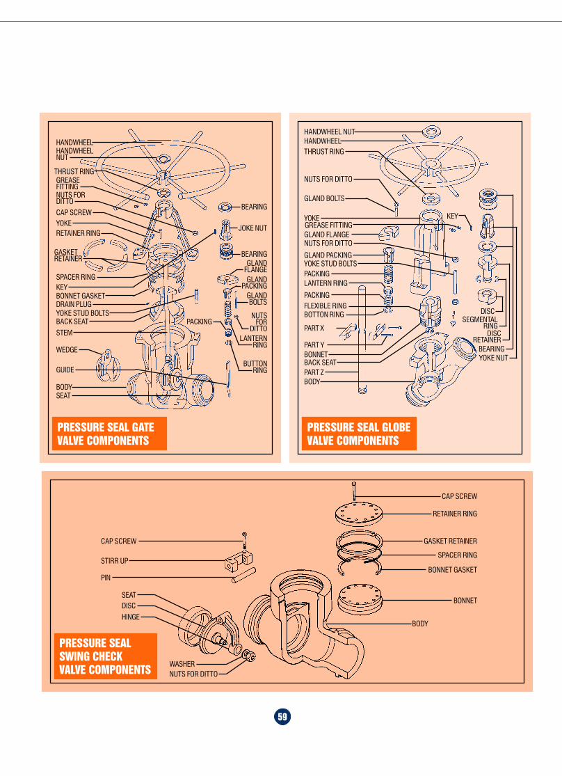
Home Table of Contents
Product Search
How To Order
PrintBack Next
Home Table of Contents
Product Search
How To Order
PrintBack
59
PRESSURE SEALSWING CHECKVALVE COMPONENTS
CAP SCREW
STIRR UP
PIN
CAP SCREW
RETAINER RING
GASKET RETAINER
SPACER RING
BONNET GASKET
BONNETSEATDISC
HINGE
WASHERNUTS FOR DITTO
BODY
HANDWHEEL
NUTS FOR DITTO
GLAND BOLTS
GLAND FLANGENUTS FOR DITTO
GLAND PACKING
PACKINGLANTERN RING
PACKINGFLEXIBLE RINGBOTTON RING
BACK SEATPART ZBODY
PRESSURE SEAL GLOBEVALVE COMPONENTS
HANDWHEEL NUT
THRUST RING
BEARING
DISCRETAINER
SEGMENTALRING
DISC
YOKE NUT
GREASE FITTINGYOKE
YOKE STUD BOLTS
PART X
PART YBONNET
KEY
PRESSURE SEAL GATEVALVE COMPONENTS
HANDWHEELNUT
HANDWHEEL
THRUST RINGGREASEFITTINGNUTS FORDITTO
YOKECAP SCREW
GASKETRETAINER
SPACER RING
RETAINER RING
KEYBONNET GASKET
WEDGE
GUIDE
BODY
STEM
BACK SEATYOKE STUD BOLTSDRAIN PLUG
SEAT
JOKE NUT
BEARINGGLAND
FLANGE
BEARING
GLANDPACKING
GLANDBOLTS
NUTSFOR
DITTOLANTERN
RING
PACKING
BUTTONRING
2
IntroductionFor more than eighty years, BonneyForge forged steel valves and pipingcomponents have defined the state-of-the-art in design and manufacturing.Now our cast steel valves are leadingthe way.
An investment in our customersWhile other companies have downsizedor closed their manufacturing facilities,Bonney Forge is committing to itscustomers and investing in the future.Our line of forged steel gate, globe,check and special purpose valves hasalways been extensive, and complete.With the addition of our new cast steelline, Bonney Forge is the single-sourcesolution.
It’s simple: one call, one purchase orderwill fill the largest order. Inside thiscatalog, you will find the full spectrumof cast steel gate, globe, and checkvalves in pressures as high as 2500#and at temperature ratings as low as-273oC. We also describe our widearray of specialty cast steel valves:Y-patterns, cryogenics, bellow seal,pressure seal gates, globes and checks,thru-conduit gates and trunnion-mounted ball valves.
Customized configurationsIf you need a custom configuration, ourtechnicians turn them around fast.Bonney Forge customers have acomplete choice of trim and bodymaterials, bypasses and connectors.
A SINGLE-SOURCESOLUTION
Stringent quality controlSince its inception, the Bonney Forgename has been synonymous with quality.Our manufacturing processes set the pacefor the industry; our workmanship setsthe benchmark. Throughout ourmanufacturing operations, stringentcontrols ensure a product that exceedsindustry standards.
Dependable performanceBonney Forge is a unique industryresource, founded on manufacturingexcellence, and driven by an unwaveringfocus on meeting our customers’ needs.The introduction of our cast steel linedeepens and broadens our long-standingcommitment to our customers, acommitment that has maintained ourleadership throughout most of this centuryand will guide us into the next.
Our catalog details many types ofaccessories and combinations, including:lift indicators, limit microswitches,pneumatic and electric actuators, bevelgearings, hand and chain wheels,extension stems, floor stands, leversand dashpots.
Advanced manufacturingAdvanced manufacturing processesensure consistent reliability andperformance in the most demandingapplications. Bonney Forge has earnedISO 9001 designation throughuncompromising, company-widecontrols. All of our valves strictlyadhere to applicable standards andindustry codes, and are fully traceable.

Home Table of Contents
Product Search
How To Order
Print Home Table of Contents
Product Search
How To Order
PrintBack Next
60
MATERIAL & TRIM SPECIFICATIONS
Material Type ASTM Symbol
Carbon Steel
AlloySteel
LowTemperatureSteel
NickelAlloy
StainlessSteel
Bolting
TrimMaterials
0.25 C Max A 216 WC BWC C
0.5 Mo A 217 - WC 1 WC 10.5 Cr - 0.5 Mo A 217 - WC 4 WC 40.75 Cr - 1 Mo - 0.75 Ni A 217 - WC 5 WC 51.25 Cr - 0.5 Mo A 217 - WC 6 WC 62.25 Cr - 1 Mo A 217 - WC 9 WC 95 Cr - 0.5 Mo A 217 - C 5 C 59 Cr - 1 Mo A 217 - C 12 C 12
13 Cr A 217 - CA 15 CA 1519 Cr - 9 Ni A 351 - CF 8 CF 819 Cr - 9 Ni - Low Carbon A 351 - CF 3 CF 319 Cr - 9 NI - 2 Mo A 351 - CF 8M CF 8M19 Cr - 9 Ni - 2 Mo - Low Carbon A 351 - CF 3M CF 3M19 Cr - 9 Ni - Cb A 351 - CF 8C CF 8C20 Cr - 30 NI - 2 Mo A 351 - CN 7M CN 7M
Ni - Cu A 494 M35 - 1 M35 - 1Ni - Mo A 494 N12M N12MNi - Mo - Cr A 494 CW12M CW12MNi - Cr - Fe A 494 CY40 CY40Nickel A 494 CZ100 CZ100
0.25 C Max A 352 - LC B LC B0.5 Mo A 352 - LC 1 LC 12 Ni A 352 - LC 2 LC 23.5 Ni A 352 - LC 3 LC 3
Cr - Ni - Mo UNS 531803
0.80 Cr - 0.15 Mo A 193 - B 7 B 70.80 Cr - 0.50 Mo - .025 V A 193 - B 16 B 1619 Cr - 9 Ni A 193 - B 8 B 8Carbon Steel A 194 - 2 H 2 H0.20 Mo A 194 - 4 419 Cr - 9 Ni A 194 - 8 80.8 Cr - 0.15 Mo A 320 - L 7 L 719 Cr - 9 Ni A 320 - B 8 B 8Carbon steel A 307 - B B
Co - Cr - A A 399 Stellite n°6Ni - Cu - alloy B 164 - B MonelBronze B 62 BronzeP.T.F.E. TF
TRIM
API 600 TRIM No. 1 2 5 6 8 9 10 12 13 15 16
Seat
ing
Surfa
ce Wedge - Check Disc
Seat Ring
Globe Disc
Seat RingF304F6
F304Back Seat
Stem - Hinge Pin
MATERIALS
Duplex Stainless Steel
Stellite
F6
StelliteMonel
F6 F6
F6 F6
Monel F316
F316
Stellite
F316
Stellite
F316
StelliteMonel
F6 F6 ALLOY20
TABLE OF CONTENTS
Overview ................................................................................................. 2,3
How To Order ........................................................................................... 4-6
Gate Valves............................................................................................ 7-10
Globe Valves ........................................................................................ 11-14
Check Valves ....................................................................................... 15-18
Pressure Seal Valves ............................................................................ 19-24
Ball Valves ........................................................................................... 25-30
Thru-Conduit Pipeline Gate Valves ........................................................ 31-34
Special Features .................................................................................. 36-38
Bypass & Drain Connection ...................................................................... 39
Flange Dimensions .............................................................................. 40,41
Ring Joints .......................................................................................... 42,43
Butt Welding Ends .................................................................................... 44
Standard Class Pressure Temperature Ratings ...................................... 45-48
Storage, Installation & Maintenance ..................................................... 50-59
Materials .................................................................................................. 60
Terms & Conditions .................................................................................. 61Stellite Stellite
F316