Embed Size (px)
Citation preview
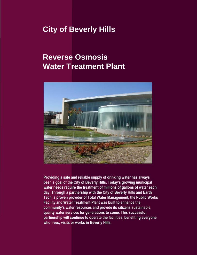
City of Beverly Hills
Reverse Osmosis
Water Treatment Plant
Providing a safe and reliable supply of drinking water has always
been a goal of the City of Beverly Hills. Today’s growing municipal
water needs require the treatment of millions of gallons of water each
day. Through a partnership with the City of Beverly Hills and Earth
Tech, a proven provider of Total Water Management, the Public Works
Facility and Water Treatment Plant was built to enhance the
community’s water resources and provide its citizens sustainable,
quality water services for generations to come. This successful
partnership will continue to operate the facilities, benefiting everyone
who lives, visits or works in Beverly Hills.
City of Beverly Hills Reverse Osmosis Water Treatment Plant
TABLE OF CONTENTS
Page
Definition of Terms .................................................................................................... 1
Purpose of Water Treatment System ........................................................................ 1
Principles of Operation of the Overall Water System ................................................ 1
System Description ................................................................................................... 2
Overview ............................................................................................................... 2
Antiscalant Chemical Dosing System................................................................ 4
Sulfuric Acid Chemical Dosing System ............................................................. 4
One-Micron Cartridge Filters ............................................................................. 4
RO High Pressure Pumps ................................................................................. 5
Reverse Osmosis System ................................................................................. 5
Hydrogen Sulfide Stripper System .................................................................... 5
Sulfuric Acid Chemical Dosing System ............................................................. 6
Hydrogen Sulfide Scrubber System .................................................................. 6
Caustic Soda Chemical Dosing System ............................................................ 7
Sodium Hypochlorite Chemical Dosing System ................................................ 7
R.O. Configuration............................................................................................. 8
Reverse Osmosis Membranes .......................................................................... 8
Permeate Tube.................................................................................................. 9
RO Element Housings (Pressure Vessels) ....................................................... 9
High Service Pumps # 3 .................................................................................... 9
Flushing/CIP System ....................................................................................... 10
Hydrogen Sulfide Stripping.............................................................................. 11
Hydrogen Sulfide Scrubbing............................................................................ 11
RO Cleaning Cycle .......................................................................................... 11
RO Cleaning Cycle – 1st Phase Shown .......................................................... 12
Finished Water Clearwell ................................................................................ 12
Plant Overview ................................................................................................ 13
Plant Flow Diagram ......................................................................................... 14
Pretreatment.................................................................................................... 15
Reverse Osmosis ............................................................................................ 16
Air Strippers & Scrubber.................................................................................. 17
Finished Water ................................................................................................ 18
i
City of Beverly Hills Reverse Osmosis Water Treatment Plant
1
Definition of Terms
Brine - (1) Reject - normally, the waste stream from reverse osmosis
system, which contains most of the dissolved solids in the feed in a
concentrated form. (2) Regenerant - water saturated or strongly
impregnated with salt.
Concentrate - The reject (waste) from a reverse osmosis element.
Membrane - A barrier, usually thin, that permits the passage only of
molecules up to a certain size range and/or certain charge characteristics.
Membrane Element - An individual membrane assembly, usually tubular,
must be housed in some type of pressure vessel.
Module - A single pressure vessel or housing containing membrane
elements.
Module Assembly - An array of membrane housings.
Osmosis - The passage of water molecules through a semi-permeable
membrane separating two solutions of different concentrations (the water
passes into the more concentrated solution).
Osmotic Pressure - Pressure required to prevent spontaneous flow of
solvent (water) into the more concentrated solution when a semi-
permeable membrane separates two solutions of different concentration.
Reverse Osmosis - Forced flow of solvent (water) from a solution
through a semi-permeable membrane by means of pressure in excess of
the osmotic pressure.
Purpose of Water Treatment System
Residents in the City of Beverly Hills presently receive their water service
from the Metropolitan Water District (MWD) of Southern California.
Through an agreement with MWD, the City has been developing
supplemental groundwater well supplies. The City of Beverly Hills Reverse
Osmosis Water Treatment Plant was designed to reduce total dissolved
solids (TDS), total hardness, hydrogen sulfide, iron, and manganese
concentrations in the groundwater supply wells that have been developed by
the City. The final goal is to provide water similar to the MWD water
supplied to the City of Beverly Hills.
Principles of Operation of the Overall Water System
The City operates and maintains the four water supply wells. Water from the
wells are collected in a common water main and transmitted to the water
plant. Well No. 6 is transmitted north separately. Both raw water
transmission mains combine outside the treatment plant, providing a blended
water supply. To initiate plant operations, the plant operator coordinates
City of Beverly Hills Reverse Osmosis Water Treatment Plant
2
with the City to select the desired combination of water supply wells to
provide the required influent water quality and quantity.
After treatment water discharges into a 16-inch dedicated water transmission
main which is connected to Sunset Reservoir where MWD water enters the
Beverly Hills system. The Beverly Hills Water Treatment Plant operates at a
constant rate, with the MWD influent varying to match the system demand.
System Description
Overview
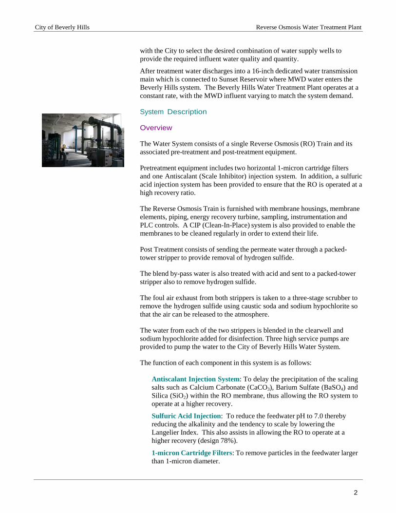
The Water System consists of a single Reverse Osmosis (RO) Train and its
associated pre-treatment and post-treatment equipment.
Pretreatment equipment includes two horizontal 1-micron cartridge filters
and one Antiscalant (Scale Inhibitor) injection system. In addition, a sulfuric
acid injection system has been provided to ensure that the RO is operated at a
high recovery ratio.
The Reverse Osmosis Train is furnished with membrane housings, membrane
elements, piping, energy recovery turbine, sampling, instrumentation and
PLC controls. A CIP (Clean-In-Place) system is also provided to enable the
membranes to be cleaned regularly in order to extend their life.
Post Treatment consists of sending the permeate water through a packed-
tower stripper to provide removal of hydrogen sulfide.
The blend by-pass water is also treated with acid and sent to a packed-tower
stripper also to remove hydrogen sulfide.
The foul air exhaust from both strippers is taken to a three-stage scrubber to
remove the hydrogen sulfide using caustic soda and sodium hypochlorite so
that the air can be released to the atmosphere.
The water from each of the two strippers is blended in the clearwell and
sodium hypochlorite added for disinfection. Three high service pumps are
provided to pump the water to the City of Beverly Hills Water System.
The function of each component in this system is as follows:
Antiscalant Injection System: To delay the precipitation of the scaling
salts such as Calcium Carbonate (CaCO3), Barium Sulfate (BaSO4) and
Silica (SiO2) within the RO membrane, thus allowing the RO system to
operate at a higher recovery.
Sulfuric Acid Injection: To reduce the feedwater pH to 7.0 thereby
reducing the alkalinity and the tendency to scale by lowering the
Langelier Index. This also assists in allowing the RO to operate at a
higher recovery (design 78%).
1-micron Cartridge Filters: To remove particles in the feedwater larger
than 1-micron diameter.
City of Beverly Hills Reverse Osmosis Water Treatment Plant
3
Reverse Osmosis System: To remove dissolved salts from the water.
Permeate Air Stripper: To remove hydrogen sulfide from the permeate
water.
Blend By-pass Air Stripper: To remove hydrogen sulfide from the by-
pass raw water.
Sulfuric Acid Injection: To reduce the by-pass raw water pH to 6.0
thereby increasing the fraction of the hydrogen sulfide in the gaseous
form and improving the efficiency of the stripper
Scrubber: To remove hydrogen sulfide from the foul air in order to
allow discharge to atmosphere.
Caustic Soda Injection to the first stage of the scrubber: To remove
most of the hydrogen sulfide as sodium sulfide.
Caustic Soda Injection to the second/third stages of the scrubber: To
remove most of the remainder of the hydrogen sulfide as sodium sulfide.
Sodium Hypochlorite Injection to the second/third stages of the
scrubber: To remove the last traces of hydrogen sulfide by oxidation to
sodium sulfate.
Twin Tank Softener System: To provide softened permeate for
scrubber circulating water make-up in order to avoid precipitation of
hardness after several cycles of concentration.
Sodium Hypochlorite Injection to the blended water to the clearwell:
To sanitize the treated water and maintain the clearwell and distribution
system free of biological activity.
Caustic Soda Injection to the high service water pumps discharge:
To increase the treated water pH to prevent corrosion in the distribution
system.
Ammonia Injection to the high service water pumps discharge: To
combine with a proportion of the free chlorine to form chloramines for
increased sanitizer stability in the distribution system.
CIP System: To clean the RO membranes after fouling has occurred.
Twin Tank Softener System: To provide softened treated water for
cleaning tank make-up during periods when no permeate is available.
Clearwell (40,000 gallons): To allow mixing and disinfection prior to
pumping to distribution system
Chemical Storage Area: To store and distribute chemicals to all process
related injection points
High Service Pumps (#1 and #2- Service to Sunset Reservoir and #3
Service to Zone 4): To pump treated water to the City of Beverly Hills
Water Distribution System.
Post production water analyzers: To monitor water parameters (quality
related) including pH, turbidity, conductivity and residual chlorine.
City of Beverly Hills Reverse Osmosis Water Treatment Plant
4
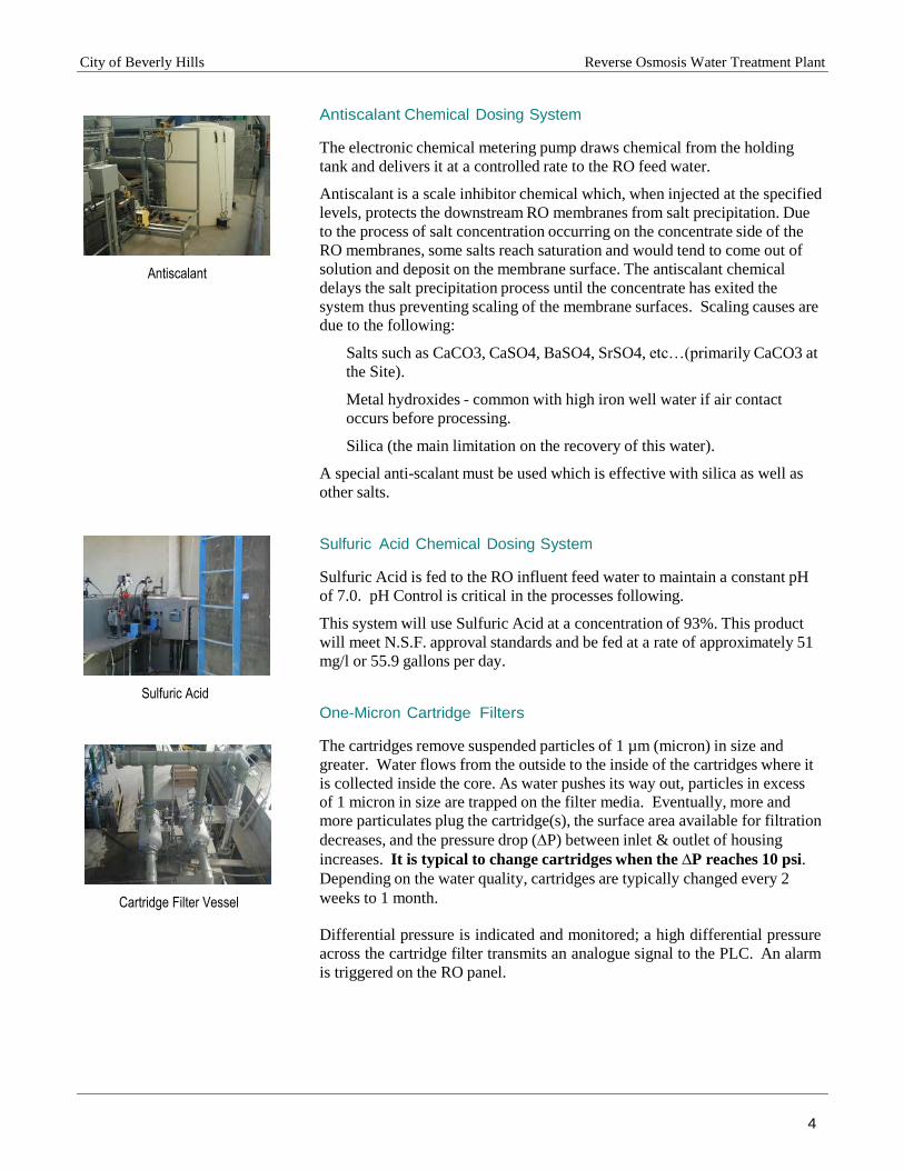
Antiscalant
Sulfuric Acid
Cartridge Filter Vessel
Antiscalant Chemical Dosing System
The electronic chemical metering pump draws chemical from the holding
tank and delivers it at a controlled rate to the RO feed water.
Antiscalant is a scale inhibitor chemical which, when injected at the specified
levels, protects the downstream RO membranes from salt precipitation. Due
to the process of salt concentration occurring on the concentrate side of the
RO membranes, some salts reach saturation and would tend to come out of
solution and deposit on the membrane surface. The antiscalant chemical
delays the salt precipitation process until the concentrate has exited the
system thus preventing scaling of the membrane surfaces. Scaling causes are
due to the following:
Salts such as CaCO3, CaSO4, BaSO4, SrSO4, etc…(primarily CaCO3 at
the Site).
Metal hydroxides - common with high iron well water if air contact
occurs before processing.
Silica (the main limitation on the recovery of this water).
A special anti-scalant must be used which is effective with silica as well as
other salts.
Sulfuric Acid Chemical Dosing System
Sulfuric Acid is fed to the RO influent feed water to maintain a constant pH
of 7.0. pH Control is critical in the processes following.
This system will use Sulfuric Acid at a concentration of 93%. This product
will meet N.S.F. approval standards and be fed at a rate of approximately 51
mg/l or 55.9 gallons per day.
One-Micron Cartridge Filters
The cartridges remove suspended particles of 1 µm (micron) in size and
greater. Water flows from the outside to the inside of the cartridges where it
is collected inside the core. As water pushes its way out, particles in excess
of 1 micron in size are trapped on the filter media. Eventually, more and
more particulates plug the cartridge(s), the surface area available for filtration
decreases, and the pressure drop (∆P) between inlet & outlet of housing
increases. It is typical to change cartridges when the ∆P reaches 10 psi.
Depending on the water quality, cartridges are typically changed every 2
weeks to 1 month.
Differential pressure is indicated and monitored; a high differential pressure
across the cartridge filter transmits an analogue signal to the PLC. An alarm
is triggered on the RO panel.
City of Beverly Hills Reverse Osmosis Water Treatment Plant
5
RO High Pressure Pumps
RO System
Strippers
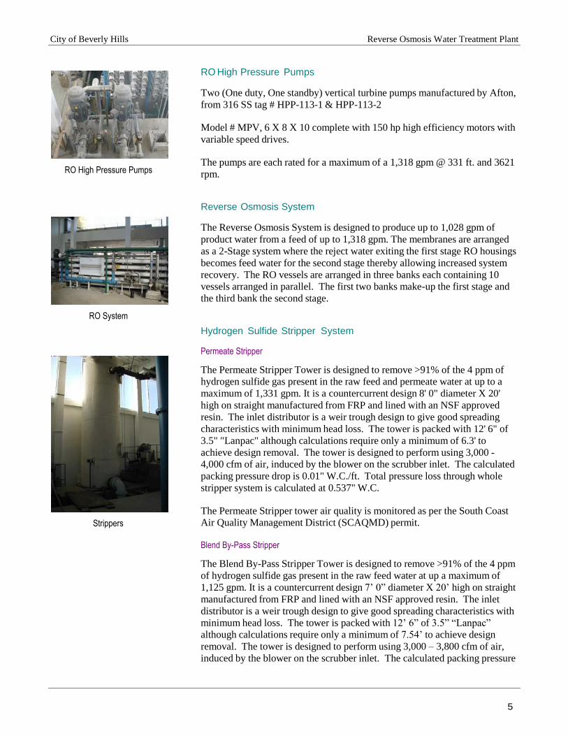
RO High Pressure Pumps
Two (One duty, One standby) vertical turbine pumps manufactured by Afton,
from 316 SS tag # HPP-113-1 & HPP-113-2 Model # MPV, 6 X 8 X 10 complete with 150 hp high efficiency motors with
variable speed drives.
The pumps are each rated for a maximum of a 1,318 gpm @ 331 ft. and 3621
rpm.
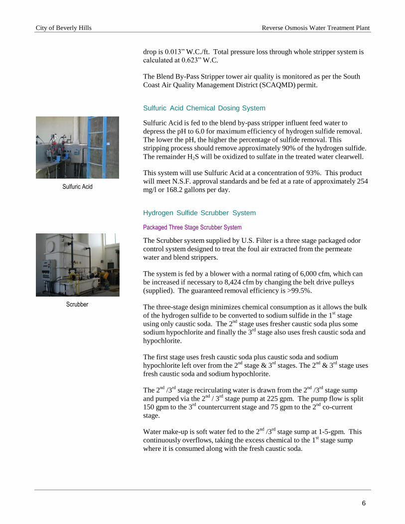
Reverse Osmosis System
The Reverse Osmosis System is designed to produce up to 1,028 gpm of
product water from a feed of up to 1,318 gpm. The membranes are arranged
as a 2-Stage system where the reject water exiting the first stage RO housings
becomes feed water for the second stage thereby allowing increased system
recovery. The RO vessels are arranged in three banks each containing 10
vessels arranged in parallel. The first two banks make-up the first stage and
the third bank the second stage.
Hydrogen Sulfide Stripper System Permeate Stripper
The Permeate Stripper Tower is designed to remove >91% of the 4 ppm of
hydrogen sulfide gas present in the raw feed and permeate water at up to a
maximum of 1,331 gpm. It is a countercurrent design 8' 0" diameter X 20'
high on straight manufactured from FRP and lined with an NSF approved
resin. The inlet distributor is a weir trough design to give good spreading
characteristics with minimum head loss. The tower is packed with 12' 6" of
3.5" "Lanpac" although calculations require only a minimum of 6.3' to
achieve design removal. The tower is designed to perform using 3,000 -
4,000 cfm of air, induced by the blower on the scrubber inlet. The calculated
packing pressure drop is 0.01" W.C./ft. Total pressure loss through whole
stripper system is calculated at 0.537" W.C.
The Permeate Stripper tower air quality is monitored as per the South Coast
Air Quality Management District (SCAQMD) permit. Blend By-Pass Stripper
The Blend By-Pass Stripper Tower is designed to remove >91% of the 4 ppm
of hydrogen sulfide gas present in the raw feed water at up a maximum of
1,125 gpm. It is a countercurrent design 7’ 0” diameter X 20’ high on straight
manufactured from FRP and lined with an NSF approved resin. The inlet
distributor is a weir trough design to give good spreading characteristics with
minimum head loss. The tower is packed with 12’ 6” of 3.5” “Lanpac”
although calculations require only a minimum of 7.54’ to achieve design
removal. The tower is designed to perform using 3,000 – 3,800 cfm of air,
induced by the blower on the scrubber inlet. The calculated packing pressure
City of Beverly Hills Reverse Osmosis Water Treatment Plant
6
drop is 0.013” W.C./ft. Total pressure loss through whole stripper system is
calculated at 0.623” W.C.
The Blend By-Pass Stripper tower air quality is monitored as per the South
Coast Air Quality Management District (SCAQMD) permit.
Sulfuric Acid Chemical Dosing System
Sulfuric Acid is fed to the blend by-pass stripper influent feed water to
depress the pH to 6.0 for maximum efficiency of hydrogen sulfide removal.
The lower the pH, the higher the percentage of sulfide removal. This
stripping process should remove approximately 90% of the hydrogen sulfide.
The remainder H2S will be oxidized to sulfate in the treated water clearwell.
Sulfuric Acid
Scrubber
This system will use Sulfuric Acid at a concentration of 93%. This product
will meet N.S.F. approval standards and be fed at a rate of approximately 254
mg/l or 168.2 gallons per day.
Hydrogen Sulfide Scrubber System Packaged Three Stage Scrubber System
The Scrubber system supplied by U.S. Filter is a three stage packaged odor
control system designed to treat the foul air extracted from the permeate
water and blend strippers.
The system is fed by a blower with a normal rating of 6,000 cfm, which can
be increased if necessary to 8,424 cfm by changing the belt drive pulleys
(supplied). The guaranteed removal efficiency is >99.5%. The three-stage design minimizes chemical consumption as it allows the bulk
of the hydrogen sulfide to be converted to sodium sulfide in the 1st
stage
using only caustic soda. The 2nd
stage uses fresher caustic soda plus some
sodium hypochlorite and finally the 3rd
stage also uses fresh caustic soda and
hypochlorite. The first stage uses fresh caustic soda plus caustic soda and sodium
hypochlorite left over from the 2nd
stage & 3rd
stages. The 2nd
& 3rd
stage uses
fresh caustic soda and sodium hypochlorite. The 2
nd /3
rd stage recirculating water is drawn from the 2
nd /3
rd stage sump
and pumped via the 2nd
/ 3rd
stage pump at 225 gpm. The pump flow is split
150 gpm to the 3rd
countercurrent stage and 75 gpm to the 2nd
co-current
stage. Water make-up is soft water fed to the 2
nd /3
rd stage sump at 1-5-gpm. This
continuously overflows, taking the excess chemical to the 1st
stage sump
where it is consumed along with the fresh caustic soda.

City of Beverly Hills Reverse Osmosis Water Treatment Plant
7
The 1st
stage water is drawn from the 1st
stage sump and is recirculated via
the first stage pump countercurrent to the incoming foul gas at 150 gpm.
This water overflows to waste to maintain the level constant. The cycles of
concentration are controlled by regulating the make-up rate, which is
normally in the 1-5 gpm range.
The caustic and hypochlorite additions are controlled by the analogue outputs
of the respective pH and ORP meters. The Scrubber emissions are monitored
as per the South Coast Air Quality Management District (SCAQMD) permit.
Twin Alternating Softeners for Scrubber Make-Up
The U.S. Filter model KF twin-alternating softeners are designed to remove
the last traces of hardness from the stripped permeate before being fed to the
scrubber as make-up. This will ensure that no hardness scale is formed
within the scrubber system, which is at a high pH and undergoes several
cycles of concentration in order to obtain minimum blow down.
Softener
Caustic Soda
Sodium Hypochlorite
In case of no permeate being available e.g. at start-up, the treated water
connection can be used which supplies water from the high service pumps
discharge. This will put a far higher load on the softener, which will reduce
the capacity between regenerations to about 22 hours.
Caustic Soda Chemical Dosing System
Caustic soda will be primarily used in the air scrubber. Up to 5 gpm of
makeup water is estimated to be required for the scrubber, and caustic soda
will be added to the solution for maintaining a pH of approximately 10.00.
At this pH most of the H2S will be removed. This system will use Caustic Soda at a concentration of 50%. This product
will meet N.S.F. approval standards and be fed at a rate of approximately
33.6 gallons per day. Sodium Hypochlorite Chemical Dosing System
Sodium Hypochlorite is fed to the 2nd
and 3rd
stage of the air scrubber system
to assist in the breakdown of H2S. Sodium hypochlorite is used to convert
H2S to elemental sulfur. Theoretical requirements: 2.1 parts of N2OCL to one
part H2S. This system uses Sodium Hypochlorite at a concentration of 12.5%. This
product meets N.S.F. approval standards and is fed at a rate of approximately
181.2 gallons per day.

City of Beverly Hills Reverse Osmosis Water Treatment Plant
8
Fe
ed
Wa
ter
Pe
rme
ate
Reje
ct
Pe
rme
ate
Reje
ct
R.O. Configuration
The RO is designed as two stages in series: The reject from the 1st
stage
becomes feed to the 2nd
stage.
RO Configuration
In the 1st
stage, there are twenty- (20) RO housings in parallel. In the 2nd
stage, there are ten (10) RO housings in parallel. Permeate from both stages
are collected in a common manifold. In every housing, there are five (4 + 1)
membranes (or elements) connected in series.
Reverse Osmosis Membranes
The Reverse Osmosis process can be regarded a filtration process on the
molecular scale. The membrane acts as a barrier to all dissolved salts and
inorganic molecules, as well as organic molecules with molecular weight
greater than 100. Dissolved salts of <100 MW are rejected according to their
ionization characteristics. Water molecules (H2O) and gases such as CO2 or
H2S pass freely through the membrane. This creates a purified product stream
known as permeate. Rejection of ionized dissolved salts is typically greater
than 98%; gases must be removed by degassing with a packed tower.

City of Beverly Hills Reverse Osmosis Water Treatment Plant
9
Permeate Tube
The permeate tube is a plastic pipe at the center of the membrane perforated
with rows of holes to which the membrane leaves are glued. Water that
spirals around the permeate flow channels inside the membrane enters the
tube through the holes. To connect permeate tubes of RO membranes in
series, interconnectors are provided for that purpose. To connect the 1st
&
last RO membranes inside RO housing, a permeate end adapter is used.
Feed Spacer Brine Seal (O'ring) Inside U-Cup
Permeate Tube
Sketch of RO Membranes
U-Cup Without Brine Seal
Feed Spacer
RO Element Housings (Pressure Vessels)
RO housings are designed to accommodate RO membranes on the inside of
the housings. At each end of a RO housing, there are two connections:
"Feed/Concentrate" and Permeate.
High Service Pumps 1 & 2
Feed water enters the housing under pressure through the "Feed/Concentrate"
connection on one side of the housing (in this case, 1½" 316 SS Victaulic
Connection). The "Feed/Concentrate" connection on the other side of the
housing is used to collect reject or concentrate water, which becomes feed to
the 2nd
stage housings. Reject of the last stage is sent to the sewer system. The water that permeates through the membranes into the center tube, called
the permeate water (or product), is collected and exits from each PVC
permeate port in the middle of the housing (in this case, 1" FNPT PVC
connection). High Service Pumps # 3
One vertical turbine pumps manufactured by Johnston Pump, from 316 SS
tag # HSP 603 Model # 5KS449ST6066P complete with 225 hp high efficiency motors with
variable speed drives.
The pumps are each rated for a maximum of a 2240 gpm @ 285 ft. and 1750
rpm.

City of Beverly Hills Reverse Osmosis Water Treatment Plant
10
Flushing/CIP System
Flushing/CIP System
A combined Flushing/CIP (“Clean-In-Place”) system is provided to flush &
clean the RO system. The system consists of a 316 SS CIP tank for the
preparation, mixing and recirculation of chemicals, a HDPE flushing tank
(by customer) for storing clean permeate or softened service water a HDPE
scavenger tank (by customer) for storing and neutralizing chemical cleaning
waste prior to discharge and a "cleaning skid" with pump and 5 micron
cartridge filter. The design flowrate for the CIP skid is 400 gpm. The
flushing system is used as part of the normal shutdown operation in order to
feed permeate water into the feed/concentrate side of the membrane and
eliminate any tendency to scale during shutdown.
Membrane
Interconnectors Permeate Tube
Feed
Last Membrane
Intermediate Membranes First Membrane
Permeate
Reject
Brine seal prevents brine from one side of the membranes
to mix with feed on the other side of the membranes
End Adapters
Flow Path Inside RO Housing
Permeate water travels through the permeate tubes connecting all membranes
and leaves the system from the permeate port of the RO housing where it is
collected and discharged through the permeate manifold. The water that does
not permeate the membranes, the Reject Water, is collected in the reject
Manifold and discharged to drain.
During service, the feed water enters the duty cartridge filter and is fed to the
H.P. pump suction where it is pressurized and fed to the RO system. The
pumping rate is controlled by the VFD which modulates the pump in order to
keep the permeate flow rate constant. The concentrate from the RO is also
modulated by the concentrate control valve which hold the concentrate flow
constant to achieve a recovery of 78%.
City of Beverly Hills Reverse Osmosis Water Treatment Plant
11
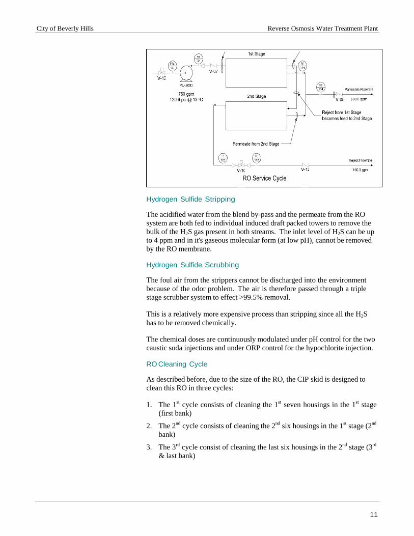
RO Service Cycle
Hydrogen Sulfide Stripping
The acidified water from the blend by-pass and the permeate from the RO
system are both fed to individual induced draft packed towers to remove the
bulk of the H2S gas present in both streams. The inlet level of H2S can be up
to 4 ppm and in it's gaseous molecular form (at low pH), cannot be removed
by the RO membrane.
Hydrogen Sulfide Scrubbing
The foul air from the strippers cannot be discharged into the environment
because of the odor problem. The air is therefore passed through a triple
stage scrubber system to effect >99.5% removal.
This is a relatively more expensive process than stripping since all the H2S
has to be removed chemically.
The chemical doses are continuously modulated under pH control for the two
caustic soda injections and under ORP control for the hypochlorite injection.
RO Cleaning Cycle
As described before, due to the size of the RO, the CIP skid is designed to
clean this RO in three cycles:
1. The 1st
cycle consists of cleaning the 1st
seven housings in the 1st
stage
(first bank)
2. The 2nd
cycle consists of cleaning the 2nd
six housings in the 1st
stage (2nd
bank)
3. The 3rd
cycle consist of cleaning the last six housings in the 2nd
stage (3rd
& last bank)
City of Beverly Hills Reverse Osmosis Water Treatment Plant
12
CIP
Fe
ed
40
0 g
pm
@ 1
25
ft
he
ad
Re
ject R
etu
rn L
ine
Pe
rmea
te R
etu
rn L
ine
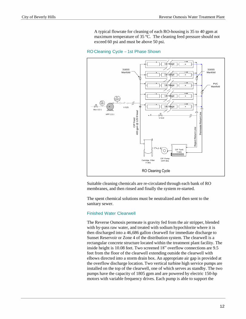
A typical flowrate for cleaning of each RO-housing is 35 to 40 gpm at
maximum temperature of 35 ºC. The cleaning feed pressure should not
exceed 60 psi and must be above 50 psi.
RO Cleaning Cycle – 1st Phase Shown
1st Stage
316SS
Manifold
1st Stage
316SS
Manifold
1st Stage PVC
Manifold
PSL
123
Mov-112-1
PI
113-1
V-525
1st Stage
1st Stage
HPP 113-1
V-510
CIP Tank
T-901
Cartridge Filter
F-901
CIP Pump
CFP-901
RO Cleaning Cycle
Suitable cleaning chemicals are re-circulated through each bank of RO
membranes, and then rinsed and finally the system re-started.
The spent chemical solutions must be neutralized and then sent to the
sanitary sewer.
Finished Water Clearwell
The Reverse Osmosis permeate is gravity fed from the air stripper, blended
with by-pass raw water, and treated with sodium hypochlorite where it is
then discharged into a 46,686 gallon clearwell for immediate discharge to
Sunset Reservoir or Zone 4 of the distribution system. The clearwell is a
rectangular concrete structure located within the treatment plant facility. The
inside height is 10.08 feet. Two screened 18” overflow connections are 9.5
feet from the floor of the clearwell extending outside the clearwell with
elbows directed into a storm drain box. An appropriate air gap is provided at
the overflow discharge location. Two vertical turbine high service pumps are
installed on the top of the clearwell, one of which serves as standby. The two
pumps have the capacity of 1805 gpm and are powered by electric 150-hp
motors with variable frequency drives. Each pump is able to support the
City of Beverly Hills Reverse Osmosis Water Treatment Plant
13
maximum flow requirements through a 16” ductile iron pipe, at the design
maximum distribution system pressure of 70 psi.
A third high service pump is installed on the top of the clearwell. This third
high service pump has the capacity of 2240 gpm and is powered by an
electric 250-hp motor with a variable frequency drive. This pump is designed
to delivery-finished water to Zone 4 of the distribution system.
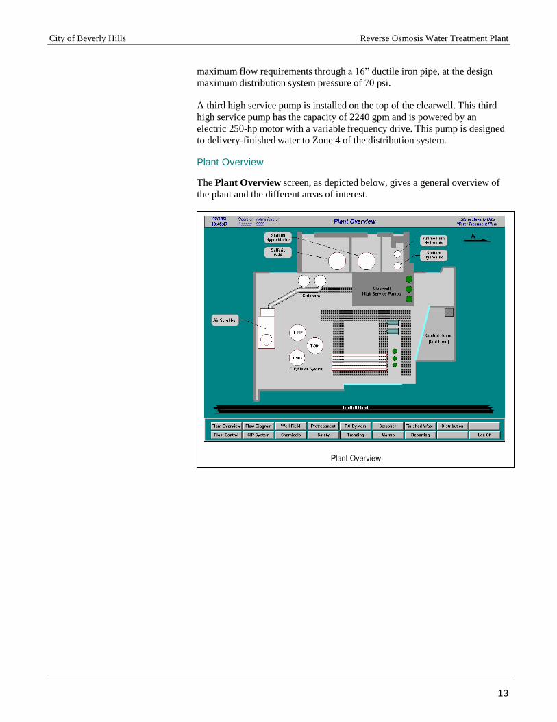
Plant Overview
The Plant Overview screen, as depicted below, gives a general overview of
the plant and the different areas of interest.
Plant Overview

City of Beverly Hills Reverse Osmosis Water Treatment Plant
14
Plant Flow Diagram
If the operator needs to view the plant overall operational functionality the
operator will need to access the Flow Diagram screen as depicted below.
Plant Flow Screen
In this screen the Treatment Plant Summary is available for the operator to
view. The treatment plant summary gives the operator the current measured
values of some of the key parameter for the water treatment system, such as
conductivity, product flow rate and tank levels.
City of Beverly Hills Reverse Osmosis Water Treatment Plant
15
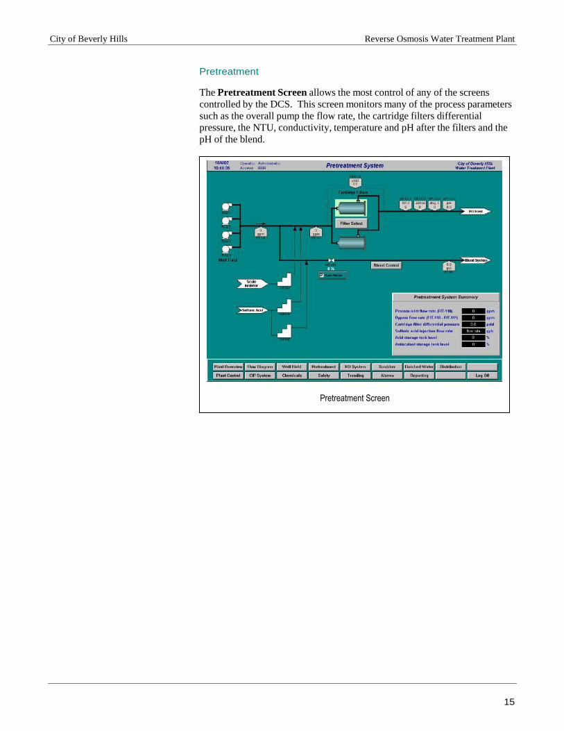
Pretreatment
The Pretreatment Screen allows the most control of any of the screens
controlled by the DCS. This screen monitors many of the process parameters
such as the overall pump the flow rate, the cartridge filters differential
pressure, the NTU, conductivity, temperature and pH after the filters and the
pH of the blend.
Pretreatment Screen

City of Beverly Hills Reverse Osmosis Water Treatment Plant
16
Reverse Osmosis
The Reverse Osmosis system processes can be monitored from the RO
System screen. However, no control is available from this monitor. To
access the controls for the RO System go to the control panel 103.
Reverse Osmosis Screen

City of Beverly Hills Reverse Osmosis Water Treatment Plant
17
Air Strippers & Scrubber
The Air stripper and Scrubber system processes can be monitored from the
system screen. However, no control is available from this monitor. To
access the controls for the system go to the scrubber control panel.
Air Strippers Screen
City of Beverly Hills Reverse Osmosis Water Treatment Plant
18
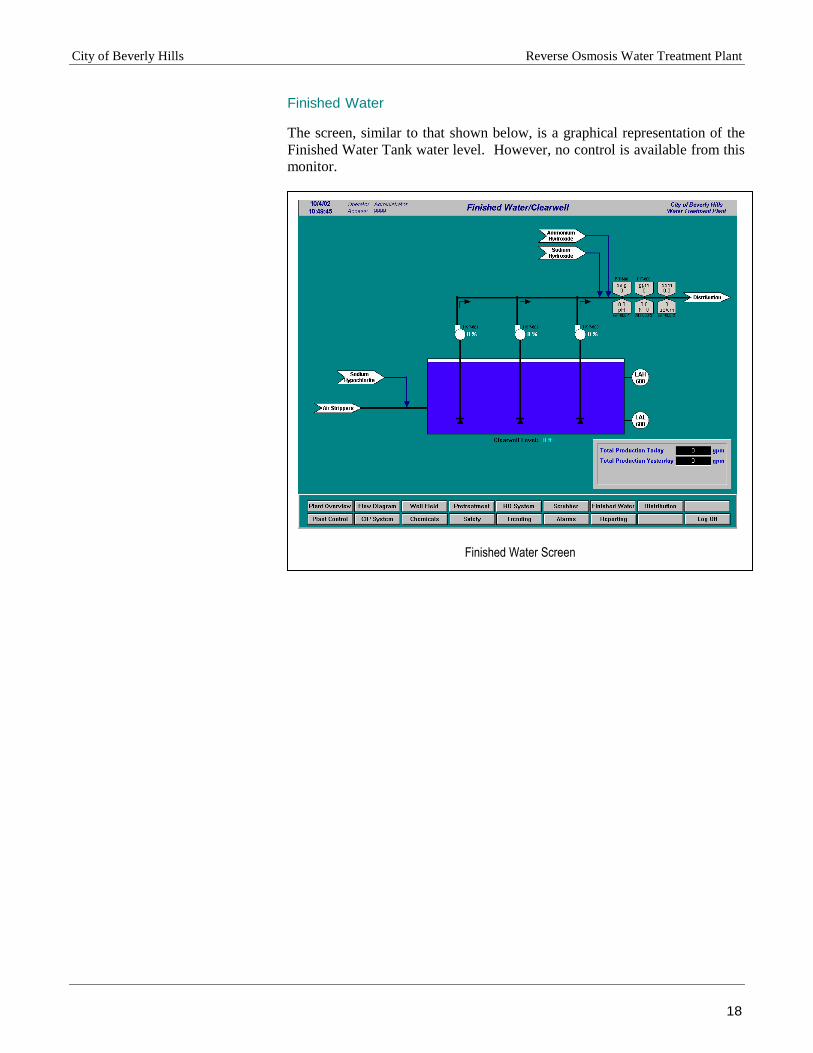
Finished Water
The screen, similar to that shown below, is a graphical representation of the
Finished Water Tank water level. However, no control is available from this
monitor.
Finished Water Screen