Embed Size (px)
Citation preview
Sawyer Manufacturing Company7799 S. Regency Dr., Tulsa, OK 74131 USA
We appreciate your business!
Congratulations on your new SAWYER product. We are proud to have you as our customer and will strive to provide you with the best service and reliability in the industry. This product is backed by our extensive warranty and world-wide service network. To locate your nearest distributor or service agency, please contact us at the phone number and address listed on the bottom of each page.
You are in good company!
Sawyer Manufacturing Company is the world leader in the design and manufacture of pipeline and welding equipment and has been since 1948. Sawyer equipment has become a standard in the industry and continues to set the benchmark for quality and durability.
This user operation manual has been made to instruct you for the best use and operation of your Sawyer product. Your satisfaction with our products is our main goal. Please read this entire manual carefully, noting all tips, notes and warnings. Safety always comes first.
About Us
WarrantyAll products manufactured by or for Sawyer Manufacturing Company are
guaranteed against defects due to faulty workmanship or materials for twelve months from the date of purchase.
This guarantee is limited to the repair or replacement of any parts found to be defective, and no other liability–expressed, implied, or contingent–is assumed.
Record the following information for warranty purposes:Where purchased:________________________________________________Purchase date:___________________________________________________Equipment Serial #:_______________________________________________
P 918.834.2550 sawyermfg.com
V1.2
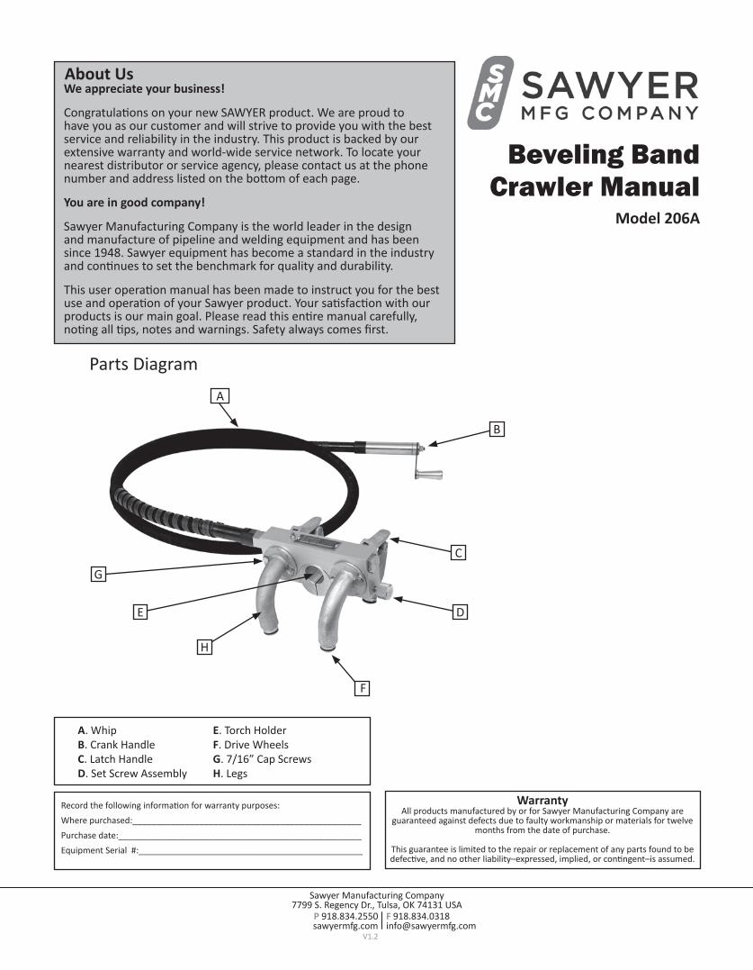
B
C
DE
G
H
F
A
A. WhipB. Crank HandleC. Latch HandleD. Set Screw Assembly
E. Torch HolderF. Drive WheelsG. 7/16” Cap ScrewsH. Legs
Beveling BandCrawler Manual
Model 206A
Parts Diagram

Sawyer Manufacturing Company7799 S. Regency Dr., Tulsa, OK 74131 USA
P 918.834.2550 sawyermfg.com
V1.2
Pipe Circumference Chart
1. Loosen (4) leg cap screws. (G, Fig.1)Tip: Use a 7/16” wrench.
2. Swing front and rear pairs of legs inward or outward to match band radius.
3. Mount crawler to band. (Fig. 3) A. Open the leg latch handles. (C, Fig. 4) B. Insert drive wheel assemblies (F, Fig. 5) onto band. C. Turn the wheels (F, Fig. 5) until they are centered onto the radius of the band.
4. Clamp leg latch handles (C) in down position. (Fig. 6)Note: To tighten tension, screw the 7/16” nut under the latch handles until the spring is tight.Note: Do not over-tighten as this can damage the band
Installation
Crawler Installation
Figure X1Note: This is an approximation (degrees may vary from castings by the foundry).
Note: Refer to band for installation of band.
GG
352
357
8
3
Pipe Diameter
Rotation Legs
6”–14” 352 Degrees Left
16”–26” 355 Degrees Left
28”–34” 357 Degrees Left
36”–60” 358 Degrees Left 6”–14” Pipe
28”–34” Pipe
355
358
5
2
36”–60” Pipe
16”–26” PipePipe
DiameterRotation Legs
6”–14” 8 Degrees Right
16”–26” 5 Degrees Right
28”–34” 3 Degrees Right
36”–60” 2 Degrees Right
Note: For a more precise adjustment, please follow these steps. A. Move legs (H, Fig.1) to most outward point (0|360 degrees).
Note: To find 0|360, Measure 13/8” from edge of block to top of leg.Make a tick mark. B. Turn the legs (H, Fig. X1) inward depending on the band chart.
C. Tighten cap screws. (G, Fig. 1)
Fig. 1
Fig. 6
Fig. 3
HFig. 2
Fig. 4C
F
Fig. 5F
C

Sawyer Manufacturing Company7799 S. Regency Dr., Tulsa, OK 74131 USA
P 918.834.2550 sawyermfg.com
V1.2
InstallationTools Needed For Operation/Cutting*
Torch Installation
Torch
Torch Tip
Safety Glasses
Oxygen/Fuel-Gas or Plasma Leak Detect
Striker
Gloves Hose
FR Clothing
Hose
FR ClothingTools Needed For Assembly*
7/16” Nut Drive
7/16” Wrench7/16” Wrench
1. Turn set screw assembly (D) counterclockwise to loosen torch holder. (E, Fig. 8)
2. Place torch inside torch holder. (E, Fig. 9, Fig. 10) Note: Use long barrel torch with angle head adapter.
3. Tighten set screw assembly (D) clockwise to tighten torch inside torch holder. (E, Fig. 11)
*Not Included
Fig. 8
Fig. 9
Fig. 11
Fig. 10
D
E
D WARNING: Refer to manufactures settings for safety settings.
! !WARNING

Sawyer Manufacuring Company7799 S. Regency Dr., Tulsa, OK 74131 USA
P 918.834.2550 sawyermfg.com
V1.2
CAUTION: Check for leaks! !CAUTION
2. Install fuel gas and oxygen hoses to torch. (Fig. 14)
Note: Refer to band for operation of band.1. Rotate Crawler around band (Fig. 12) by turning crank handle. (B, Fig. 13)Note: Band can travel either clockwise or counter clockwise.Tip: Preheat is recommended.
Note: Notches on hose end are for fuel gas only. (Fig. 15)Note: Red Hoses= Fuel Gas Green Hoses = Oxygen (Fig. 13)
3. Turn on oxygen and fuel gas at the cylinder. (Fig. 16)Note: Set pressures to manufactures settings.
4. To light torch, turn fuel gas knob. (Fig. 17)
5. Turn the oxygen knob on torch. (Fig. 18)Tip: For best cutting have a neutral flame. A. Open blow-through tab on torch.Tip: Keep hoses from binding.Tip: Preheat is recommended.
B. When finished turn off oxygen then fuel gas. C. Disassemble in opposite order of operation.
Operation
B
Fig. 12
Fig. 14
Fig. 16
Fig. 17
Fig. 18
Fig. 13
Fig. 15


![PowerPoint PresentationLet yourself shine With perfect tit . Frame Reader [ 8000X w/ step Bevel Cutter] «UBéùeling Semi- Normal Beveling Mini Beveling . Flat/ Bevel/ Grooving Shape](https://img.pdfslide.us/doc/110x75/5f10b8a77e708231d44a7f26/powerpoint-let-yourself-shine-with-perfect-tit-frame-reader-8000x-w-step-bevel.jpg)