Embed Size (px)
Citation preview

ENGLISH LANGUAGE
BETTIS
SERVICE INSTRUCTIONS
FOR MODELS
G01 THROUGH G13 SERIES
HYDRAULIC ACTUATORS
WITH POWER MODULE TIE
BAR CONSTRUCTION
PART NUMBER: 124839E
REVISION: “C”
DATE: 06 July 2006

Bettis P/N 124839E Revision “C” Page 1 of 31
CONTENTS
SECTION 1.0 – INTRODUCTION PAGE 1.1 General Service Information ....................................................................... 2 1.2 Definitions .................................................................................................... 3 1.3 General Safety Information ......................................................................... 3 1.4 Bettis Reference Materials .......................................................................... 3 1.5 Service Support Items ................................................................................. 3 1.6 Lubrication Requirements ........................................................................... 4 1.7 Fluid Requirements ..................................................................................... 4 1.8 General Tool Information ............................................................................ 4 SECTION 2.0 – ACTUATOR DISASSEMBLY 2.1 General Disassembly .................................................................................. 5 2.2 Hydraulic Power Module Disassembly ....................................................... 5 2.3 Drive Module Disassembly ......................................................................... 6 2.4 Blind End Cap Module Disassembly .......................................................... 9 SECTION 3.0 – ACTUATOR REASSEMBLY 3.1 General Reassembly .................................................................................. 9 3.2 Drive Module Reassembly .......................................................................... 9 3.3 Hydraulic Power Module Reassembly ....................................................... 13 3.4 Blind End Cap Module Reassembly ........................................................... 15 3.5 Actuator Testing .......................................................................................... 15 SECTION 4.0 - FIELD CONVERSIONS 4.1 Fail Mode Reversal (CW to CCW, etc.) ..................................................... 16 4.2 Convert Double Acting to Spring Return .................................................... 16 4.3 Convert Spring Return to Double Acting .................................................... 16 SECTION 5.0 – MODULE REMOVAL AND INSTALLATION 5.1 Spring Module Removal ............................................................................. 17 5.2 Spring Module Installation ........................................................................... 19 5.3 Hydraulic Power Module Removal ............................................................. 22 5.4 Hydraulic Power Module Installation .......................................................... 22 5.5 G2 Through G13 Powr Swivl Module Removal ......................................... 23 5.6 G2 Through G13 Powr Swivl Module Installation ...................................... 24 SECTION 6.0 – ACTUATOR SUPPORT INFORMATION 6.1 Module Weight Table .................................................................................. 25 6.2 G01 Tool Table ........................................................................................... 27 6.3 G2 Tool Table .............................................................................................. 27 6.4 G3 Tool Table .............................................................................................. 28 6.5 G4 Tool Table .............................................................................................. 28 6.6 G5 Tool Table .............................................................................................. 29 6.7 G7 Tool Table .............................................................................................. 29 6.8 G8 Tool Table .............................................................................................. 30 6.9 G10 Tool Table ........................................................................................... 30 6.10 G13 Tool Table ........................................................................................... 31

Bettis P/N 124839E Revision “C” Page 2 of 31
SECTION 1 - INTRODUCTION 1.1 GENERAL SERVICE INFORMATION
1.1.1 This service procedure is offered as a guide to enable general maintenance to be performed on Bettis G01X0X, G2X0X, G3X0X, G4X0X, G5X0X, G7X0X, G8X0X, G10X0X and G13X0X Double Acting and Spring Return Series Actuators with one single Hydraulic Power Module - power module utilizing tie bar construction. This procedure can also be used on Bettis GXX20X Double Acting Series Twin Power Modules Hydraulic Actuators.
1.1.2 Normal recommended service interval for this actuator series is five years.
NOTE: Storage time is counted as part of the service interval.
1.1.3 This procedure is applicable with the understanding that all electrical power and hydraulic pressure has been removed from the actuator.
1.1.4 Remove all piping and mounted accessories that will interfere with the module(s) that are to
be worked on.
1.1.5 This procedure should only be implemented by a technically competent technician who should take care to observe good workmanship practices.
1.1.6 Numbers in parentheses, ( ) indicate the bubble number (reference number) used on the
Bettis Assembly Drawing and Actuator Parts List. 1.1.7 This procedure is written using the stop screw side of the housing (1-10) as a reference and
this side will be considered the front side of the actuator. The housing cover (1-20) will be the top of the actuator.
1.1.8 Actuator Module weights are listed in Section 6 Table 6.1. 1.1.9 When removing seals from seal grooves, use a commercial seal removing tool or a small
screwdriver with sharp corners rounded off. 1.1.10 Use a non-hardening thread sealant on all pipe threads. CAUTION: Apply the thread sealant per the manufacture's instructions. 1.1.11 Bettis recommends that disassembly of the actuator modules should be done in a clean
area on a work bench.

Bettis P/N 124839E Revision “C” Page 3 of 31
1.2 DEFINITIONS
WARNING: If not observed, user incurs a high risk of severe damage to actuator and/or fatal injury to personnel.
CAUTION: If not observed, user may incur damage to actuator and/or injury to
personnel. NOTE: Advisory and information comments provided to assist maintenance
personnel to carry out maintenance procedures.
1.3 GENERAL SAFETY INFORMATION Products supplied by Bettis, in its "as shipped" condition, are intrinsically safe if the instructions contained within this Service Instruction are strictly adhered to and executed by well trained, equipped, prepared and competent personnel.
WARNING: For the protection of personnel working on Bettis actuators, this procedure
should be reviewed and implemented for safe disassembly and reassembly. Close attention should be noted to the WARNINGS, CAUTIONS and NOTES contained in this procedure.
WARNING: This procedure should not supersede or replace any customers plant safety
or work procedures. If a conflict arises between this procedure and the customers procedures the differences should be resolved in writing between an authorized customers representative and a authorized Bettis representative.
1.4 BETTIS REFERENCE MATERIALS
1.4.1 Assembly Drawing for G01 through G13 Double Acting One Power Module Hydraulic Series Actuators use part number 116423.
1.4.2 Assembly Drawing for G01 through G13 Double Acting Twin Power Module Hydraulic
Series Actuators use part number 115676.
1.4.3 Assembly Drawing for G01 through G13 Spring Return One Power Module Hydraulic Series Actuators use part number 115941.
1.5 SERVICE SUPPORT ITEMS 1.5.1 Bettis Module Service Kits.
1.5.2 For rod extension retainer nut tool, refer to the following table. NOTE: These tools are required only when extension rod assembly (1-50) or (9-50) is removed or when a new extension rod assembly is installed.

Bettis P/N 124839E Revision “C” Page 4 of 31
ACTUATOR MODEL
BETTIS PART NUMBER
ACTUATOR MODEL
BETTIS PART NUMBER
G01 None required G5/G7 117369 G2 123616 G8/G10 117368 G3/G4 117370 G13 122849
1.5.3 Non-hardening thread sealant. 1.6 LUBRICATION REQUIREMENTS
NOTE: Lubricants, other than listed in step 1.6.1 should not be used without prior written approval of Bettis Product Engineering.
1.6.1. All temperature services (-50°F to +350°F)/(-45.5°C to 176.6°C) use Bettis ESL-5 lubricant.
ESL-5 lubricant is contained in the Bettis Module Service Kit in tubes or cans and they are marked ESL-4,5 & 10 lubricant.
1.7 FLUID REQUIREMENTS
1.7.1 FLUID REQUIREMENTS: For use in the hydraulic power cylinder. The following listed fluids are recommended fluids only and does not limit the use of other hydraulic fluids compatible with supplied seals and coatings.
1.7.1.1 Standard temperature service (-20F to +350F)/(-28.9Cto +176.6C) use Dexron
II or Shell Tellus T-32 Automatic Transmission Fluid. 1.7.1.2 High temperature service (0F to +350F)/(-17Cto +176.6C) use Dexron II or
Shell Tellus T-32 Automatic Transmission Fluid. 1.7.1.3 Low temperature service (-50F to +150F)/(-45.6°C to 65.6°C) use Exxon Univis
J13 or HVI 13 Hydraulic Fluid.
1.8 GENERAL TOOL INFORMATION
1.8.1 Tools: All tools/Hexagons are American Standard inch. Large adjustable wrench, two (2) large screwdrivers, Allen wrench set, set of open/box-end wrenches, rubber or leather mallet, torque wrench (up to 1600 foot pounds / 1269 N-m), breaker bar, and a drive socket set. For recommended tool and wrench sizes refer to Section 6 Tables 6.2 through 6.10.
Bettis P/N 124839E Revision “C” Page 5 of 31
SECTION 2 - ACTUATOR DISASSEMBLY 2.1 GENERAL DISASSEMBLY WARNING: It is possible, that the actuator may contain a dangerous gas and/or liquids. Ensure
that all proper measures have been taken to prevent exposure or release of these types of contaminants before commencing any work.
2.1.1 Section 2 - Actuator Disassembly is written to either completely disassemble the entire
actuator or can be used to disassemble individual Modules as needed (Hydraulic Power Module or Drive module).
2.1.2 When the Spring Module is to be removed it should be removed from the Drive Module
prior to the Hydraulic Power Module removal or disassembly. 2.1.3 The Hydraulic Power Module can be disassembled while still attached to the Drive Module
or the Hydraulic Power Module can be removed from the Drive Module and disassembled separate to the actuator (refer to Section 5 - Module Removal And Installation).
NOTE: Use a means of capturing the hydraulic fluid that will be lost during the removal or
disassembly of the power module. Use a bucket, tub, and large container, ECT.
2.1.4 To ensure correct re-assembly; that is, with Hydraulic Power Module or Spring Module on same end of Drive Module as was, mark or tag right (or left) and mark mating surfaces.
2.1.5 For Spring Module removal refer to Section 5 step 5.1. 2.2 HYDRAULIC POWER MODULE DISASSEMBLY
NOTE: 1. Review Section 2 steps 2.1.1 through 2.1.5 General Disassembly before
proceeding with Hydraulic Power Module Disassembly.
2. If the actuator model is a GXX20X Series (two same size power modules mounted on both sides of the drive module) then do the following steps on both Power Modules simultaneously or complete one power module and then repeat section 2.2 on the second Power Module
WARNING: If not already removed disconnect all hydraulic pressure from actuator power
cylinders. WARNING: If the actuator is spring return then the spring cartridge must be checked to
verify that the spring(s) are in their extended position before the Hydraulic Power Module is disassembled from the Drive Module (refer to Section 5.1 through step 5.1.6).
2.2.1 Mark and record location of the ports on outer end cap (3-80) and inner end cap (3-10).

Bettis P/N 124839E Revision “C” Page 6 of 31
2.2.2 Remove NPT pipe plug or optional SAE o-ring plug (3-120) from outer end cap (3-80). 2.2.3 Remove hex nuts (3-90), with lockwashers (3-95), from tie bars (3-20). 2.2.4 Remove outer end cap (3-80) from cylinder (3-70). and tie bars (3-20). 2.2.5 Unscrew and remove tie bars (3-20) from inner end cap (3-10). 2.2.6 Remove cylinder (3-70) from inner end cap (3-10), piston (3-30) and piston rod (3-40). 2.2.7 Refer to assembly drawing page 2 of 2 Detail "D". Remove two split ring halves (3-50) and
one retainer ring (3-60) from piston rod (3-40). 2.2.8 Remove piston (3-30) from piston rod (3-40). 2.2.9 Remove o-ring seal (4-70) from piston rod (3-40). 2.2.10 Refer to assembly drawing page 2 of 2 Detail "D". Remove two split rings (3-50) and one
retainer ring (3-60) from piston rod (3-40). 2.2.11 Remove hex cap screws (3-115) with lockwashers (3-110) from inner end cap (3-10). 2.2.12 Remove hex nuts (3-105) from hex cap screws (3-100). 2.2.13 Remove hex cap screws (3-100) with lockwashers (3-110) from inner end cap (3-10) and
housing (1-10). 2.2.14 Remove inner end cap (3-10) off of piston rod (3-40). NOTE: The piston rod (3-40) removal as outlined in step 2.2.15 is only required when the piston rod
is being replaced or when the Drive Module is to be disassembled. 2.2.15 Unscrew and remove piston rod (3-40) from the Drive Module. 2.3 DRIVE MODULE DISASSEMBLY
NOTE: Review Section 2 steps 2.1.1 through 2.1.5 General Disassembly before proceeding with Drive Module Disassembly.
2.3.1 If not already removed remove piston rod (3-40) from drive module. NOTE: If the actuator is equipped with submerged stop screws with stop screw covers (1-195) then
proceed to and complete steps 2.3.2.1 and 2.3.2.2 prior to doing step 2.3.2. 2.3.2 Mark stop screws (1-180) left and right. The setting of stop screws (1-180) should be
checked and setting recorded before stop screws are loosened or removed. NOTE: Stop screws will be removed later in this procedure.
2.3.2.1 Hold stop screw cover (1-195) in place and remove pipe plug (1-260).

Bettis P/N 124839E Revision “C” Page 7 of 31
2.3.2.2 Hold submerged stop screw (1-180) in place and remove stop screw cover (1-195).
NOTE: For steps 2.3.3 through 2.3.10 refer to assembly drawing page 2 of 2 Section A-A and Detail “E”.
2.3.3 Before removing position indicator (1-220), record or mark it's position. Remove position
indicator (1-220). NOTE: Step 2.3.4 is used only on G01, G2 and G3 Drive Modules. Drive Modules for G4 through
G13 will skip steps 2.3.4 and continue with step 2.3.5. 2.3.4 Remove one vent check assembly (13) from top of housing cover (1-20).
2.3.5 Unscrew and remove hex cap screws (1-160) with lockwashers (1-170) from yoke cover
(1-150). 2.3.6 Remove yoke cover (1-150) from housing cover (1-20). 2.3.7 Mark and record the orientation of the position indicator assembly (1-140) in relation to the
top of yoke (1-70). 2.3.8 Remove position indicator assembly (1-140) from top of yoke (1-70). 2.3.9 Remove spring pin (1-100) from top of yoke (1-70).
2.3.10 Remove hex cap screws (1-110), with lockwashers (1-115) or with lockwashers (1-170), from housing cover (1-20).
NOTE: Steps 2.3.11 and 2.3.12 are used only on G7, G8 and G10 Drive Modules. Drive Modules
G01, G2, G3, G4 and G5 will skip steps 2.3.11 and 2.3.12 and continue with step 2.3.13. 2.3.11 Remove hex cap screws (1-120), with lockwashers (1-115), from housing cover (1-20). 2.3.12 Using hex cap screws (1-110), install into holes vacated by hex cap screws (1-120). Use
these hex cap screws to jack the housing cover up for removal. Alternately rotate the hex cap screw clockwise until housing cover (1-20) is clear of housing (1-10).
NOTE: G01, G2, G3 and G4 model housing cover (1-20) will have cast tabs for placing prying tools
to aid in cover removal. 2.3.13 Remove housing cover (1-20) from housing (1-10).
NOTE: Groove pins (1-130) will remain in housing cover (1-20) when housing cover is removed
from housing (1-10). Groove pins (1-130) should not be removed from housing cover (1-20) unless they are damaged and require new replacements.
2.3.14 Refer to assembly drawing page 2 of 2 Detail "B". Remove guide bar (1-90) from housing
(1-10). 2.3.15 Remove top yoke pin thrust bearing (2-10) from top of yoke pin (1-80).
Bettis P/N 124839E Revision “C” Page 8 of 31
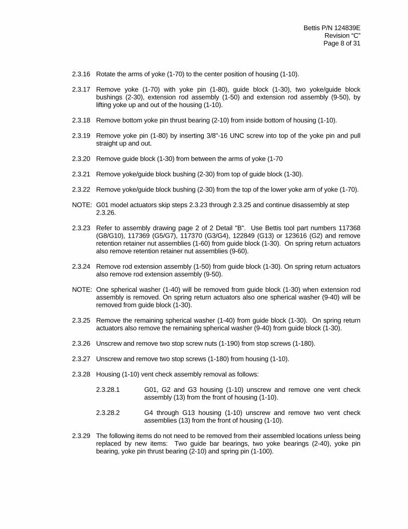
2.3.16 Rotate the arms of yoke (1-70) to the center position of housing (1-10). 2.3.17 Remove yoke (1-70) with yoke pin (1-80), guide block (1-30), two yoke/guide block
bushings (2-30), extension rod assembly (1-50) and extension rod assembly (9-50), by lifting yoke up and out of the housing (1-10).
2.3.18 Remove bottom yoke pin thrust bearing (2-10) from inside bottom of housing (1-10). 2.3.19 Remove yoke pin (1-80) by inserting 3/8"-16 UNC screw into top of the yoke pin and pull
straight up and out.
2.3.20 Remove guide block (1-30) from between the arms of yoke (1-70
2.3.21 Remove yoke/guide block bushing (2-30) from top of guide block (1-30). 2.3.22 Remove yoke/guide block bushing (2-30) from the top of the lower yoke arm of yoke (1-70). NOTE: G01 model actuators skip steps 2.3.23 through 2.3.25 and continue disassembly at step
2.3.26. 2.3.23 Refer to assembly drawing page 2 of 2 Detail "B". Use Bettis tool part numbers 117368
(G8/G10), 117369 (G5/G7), 117370 (G3/G4), 122849 (G13) or 123616 (G2) and remove retention retainer nut assemblies (1-60) from guide block (1-30). On spring return actuators also remove retention retainer nut assemblies (9-60).
2.3.24 Remove rod extension assembly (1-50) from guide block (1-30). On spring return actuators
also remove rod extension assembly (9-50). NOTE: One spherical washer (1-40) will be removed from guide block (1-30) when extension rod
assembly is removed. On spring return actuators also one spherical washer (9-40) will be removed from guide block (1-30).
2.3.25 Remove the remaining spherical washer (1-40) from guide block (1-30). On spring return
actuators also remove the remaining spherical washer (9-40) from guide block (1-30). 2.3.26 Unscrew and remove two stop screw nuts (1-190) from stop screws (1-180).
2.3.27 Unscrew and remove two stop screws (1-180) from housing (1-10).
2.3.28 Housing (1-10) vent check assembly removal as follows:
2.3.28.1 G01, G2 and G3 housing (1-10) unscrew and remove one vent check assembly (13) from the front of housing (1-10).
2.3.28.2 G4 through G13 housing (1-10) unscrew and remove two vent check
assemblies (13) from the front of housing (1-10).
2.3.29 The following items do not need to be removed from their assembled locations unless being replaced by new items: Two guide bar bearings, two yoke bearings (2-40), yoke pin bearing, yoke pin thrust bearing (2-10) and spring pin (1-100).

Bettis P/N 124839E Revision “C” Page 9 of 31
2.4 BLIND END CAP MODULE REMOVAL
2.4.1 Remove hex cap screws (5-20), with spring lockwashers (5-30), from blind end cap (5-10). 2.4.2 Remove blind end cap (5-10) from end of housing (1-10).
SECTION 3 - ACTUATOR REASSEMBLY 3.1 GENERAL REASSEMBLY
CAUTION: Only new seals, that are still within the seals expectant shelf life, should be install into actuator being refurbished.
3.1.1 Remove and discard all old seals and gaskets. 3.1.2 All parts should be cleaned to remove all dirt and other foreign material prior to inspection. 3.1.3 All parts should be thoroughly inspected for excessive wear, stress cracking, galling and
pitting. Attention should be directed to threads, sealing surfaces and areas that will be subjected to sliding or rotating motion. Sealing surfaces of the cylinder and piston rod must be free of deep scratches, pitting, corrosion and blistering or flaking coating.
CAUTION: Actuator parts that reflect any of the above listed characteristics should be
replaced with new parts. 3.1.4 Before installation coat all moving parts with a complete film of lubricant. Coat all seals with
a complete film of lubricant, before installing into seal grooves. NOTE: The parts and seals used in the actuator housing module will be assembled using lubricant
as identified in Section 1 step 1.6.1. The parts and seals used in the actuator cylinder module will be assembled using lubricant as identified in Section 1 step 1.7.1.
3.1.5 For Spring Module Installation refer to Section 5 step 5.2.
3.2 DRIVE MODULE REASSEMBLY
NOTE: Review section 3.1 General Reassembly before proceeding with Drive Module Reassembly.
NOTE: Refer to assembly drawing page 2 of 2 Detail "B" for section drawing of guide block.
3.2.1 If guide bar bearings (2-20) is being replaced install new bearings into guide block (1-30).

Bettis P/N 124839E Revision “C”
Page 10 of 31
NOTE: The guide bar bearing (2-20) must be press fit into guide block guide bar bore with the
seam located ±5 degrees of the top or bottom centerline as shown in section A-A. NOTE: G01 model actuators skip steps 3.2.2 through 3.2.13 and continue reassembly at step
3.2.14. 3.2.2 Lubricate guide block (1-30), two spherical washers (1-40), and one extension rod
assembly (1-50). 3.2.3 Install one spherical washer (1-40) into the side of guide block (1-30). NOTE: The
spherical side of washer (1-40) will be facing to the outside of guide block (1-30). 3.2.4 Install second spherical washer (1-40) over threaded end of extension rod assembly (1-50).
NOTE: The spherical side of the washer will go on the extension rod assembly facing the head of the extension rod assembly.
3.2.5 Install extension rod assembly (1-50) into guide block (1-30) and up against the first
spherical washer (1-40). 3.2.6 Install extension retainer nut (1-60) over extension rod assembly (1-50) and screw into
guide block (1-30). 3.2.7 Tighten extension retainer nut assembly (1-60) until extension rod assembly (1-50) can not
move. Back off the extension retainer nut assembly (1-60) just enough to allow for extension rod assembly (1-50) to move freely.
NOTE: Steps 3.2.8 through 3.2.13 are to be completed when the actuator is equipped with a Spring
Module. If the actuator is Double Acting then skip steps 3.2.8 through 3.2.13 and continue actuator reassembly starting with step 3.2.14.
3.2.8 Lubricate guide block (1-30), two spherical washers (9-40) and one extension rod assembly
(9-50). 3.2.9 Install one spherical washer (9-40) into the side of guide block (1-30). NOTE: The
spherical side of washer (9-40) will be facing to the outside of guide block (1-30). 3.2.10 Install second spherical washer (9-40) over threaded end of extension rod assembly (9-50).
NOTE: The spherical side of the washer will go on the extension rod assembly facing the head of the extension rod assembly.
3.2.11 Install extension rod assembly (9-50) into guide block (1-30) and up against the first
spherical washer (9-40). 3.2.12 Install extension retainer nut (9-60) over extension rod assembly (9-50) and screw into
guide block (1-30). 3.2.13 Tighten extension retainer nut assembly (9-60) until extension rod assembly (9-50) can not
move. Back off the extension retainer nut assembly (9-60) just enough to allow for extension rod assembly (9-50) to move freely.

Bettis P/N 124839E Revision “C”
Page 11 of 31
NOTE: Consult Waller Texas Bettis Service Coordinator for “yoke bearing, yoke pin bearing or
yoke/guide block bushing installation information. 3.2.14 If the two yoke bearings (2-40) are being replaced, install new bearing into housing cover
(1-20) and housing (1-10). NOTE: The yoke bearing (2-40) must be press fit into housing (1-10) and housing cover (1-20).
Install the yoke bearings with the bearing seam located 45 ±5 degrees from the yoke arm slot when yoke (1-70) is rotated to its full clockwise position.
3.2.15 If the two yoke pin thrust bearings (2-10) are being replaced install new bearing into
housing cover (1-20) and housing (1-10). 3.2.16 Lubricate two yoke/guide block bushings (2-30) and install onto top and bottom sides of
guide block (1-30). NOTE: The guide block (1-30) should be already pre-assembled with extension rod assembly and
associated parts assembled in the guide block. 3.2.17 Install guide block (1-30), with yoke/guide block bushings (2-30), between arms of yoke
(1-70). 3.2.18 Install o-ring seal (2-50) into inner diameter o-ring groove in the bottom of housing (1-10). 3.2.19 Coat the bearing surfaces of the yoke (1-70) with lubricant and install into housing (1-10). 3.2.20 Align hole in guide block (1-30) with the matching holes in the two yoke/guide block
bushings (2-30) and the slots in the arms of yoke (1-70). NOTE: The yoke pin can be held in place by installing a screw into the .375-16UNC tapped hole in
the upper end of yoke pin (1-80). 3.2.21 Install yoke pin (1-80) by inserting into the upper yoke arm, upper yoke/guide block bushing,
guide block, lower yoke/guide block bushing, lower yoke arm and resting on lower yoke pin thrust bearing (2-10).
3.2.22 Install guide bar (1-90) into either side of housing (1-10) by inserting through the housing,
through guide block and then insert the guide bar into the other side of housing (1-10). 3.2.23 Refer to assembly drawing page 2 of 2 Section A-A. Install spring pin (1-100) into the top of
yoke (1-70). 3.2.24 Install position indicator assembly (1-140) onto the top of yoke (1-70) and over spring pin
(1-100). NOTE: Refer to Section 2 step 2.3.7 for correct installation position. 3.2.25 Install o-ring (2-50) into housing cover (1-20). 3.2.26 Install housing cover o-ring (2-60) into housing cover (1-20).

Bettis P/N 124839E Revision “C”
Page 12 of 31
3.2.27 Install the housing cover (1-20), being careful not to damage o-ring seals (2-50) and (2-60).
3.2.28 Place lockwashers (1-115) onto hex cap screws (1-110). NOTE: On G7 through G13 model actuators apply thread adhesive, Locktite 242, to threads of hex
cap screws (1-110). Reference assembly drawing note number 9. 3.2.29 Install hex cap screws (1-110) with lockwashers (1-115) through housing cover (1-20) and
into housing (1-10). NOTE: Leave hex cap screws (1-110) finger tight - do not tighten. 3.2.30 NOTE: Do this step only if groove pins (1-130) have been pulled or if the pins are being
replaced. Drive groove pins (1-130) through housing cover (1-20) and into housing (1-10). The groove pins should be flush with the cover.
3.2.31 Torque tighten hex cap screws (1-110) until a final lubricated torque, as listed in the
following table, has been achieved.
HOUSING COVER SCREW QUANTITY AND TORQUE TABLE TORQUE (±5 % Percent) TORQUE (±5 % Percent) MODEL QTY
FT-lb N-m MODEL QTY
FT-lb N-m G01 4 40 54 G7 8 100 136 G2 6 40 54 G8 12 100 136 G3 8 40 54 G10 16 100 136 G4 8 40 54 G13 20 340 461 G5 8 100 136
NOTE: Complete step 3.2.32 on G5, through G13 model actuators. For G01 through G4 model
actuators skip step 3.2.32 and proceed to step 3.2.33.
3.2.32 On G5 through G13 models
3.2.32.1 Place lockwashers (1-115) onto hex cap screws (1-120). NOTE: Hex cap screws (1-120) are only used as "hole" fillers and to protect
threads from environment. 3.2.32.2 Install and tighten hex cap screws (1-120) with lockwashers (1-115).
3.2.33 Install thrust bearing (2-110) onto position indicator (1-140). 3.2.34 Install o-ring seal (2-100) onto position indicator (1-140). 3.2.35 Install upper bearing (2-120) into yoke cover (1-150). 3.2.36 Install rod wiper (2-80) into yoke cover (1-150). 3.2.37 Install o-ring seal (2-70) into yoke cover (1-150).

Bettis P/N 124839E Revision “C”
Page 13 of 31
3.2.38 Install yoke cover (1-150) onto housing cover (1-20) and over position indicator assembly
(1-140). NOTE: During yoke cover installation be careful not to damage o-ring seal (2-70) and rod wiper (2-80).
3.2.39 Place lockwashers (1-170) onto hex cap screws (1-160). 3.2.40 Install and tighten hex cap screws (1-160) with lockwashers through yoke cover (1-150)
and into housing cover (1-20).
3.2.41 Vent check assembly installation as follows:
3.2.41.1 G01, G2 and G3 housing (1-10) using pipe sealant install one vent check assembly (13) into the front of housing (1-10).
3.2.41.2 G2 and G3 housing (1-10) using pipe sealant install one vent check
assembly (13) into the top area of housing cover (1-20). 3.2.41.3 G4 through G13 housing (1-10) using pipe sealant install two vent check
assemblies (13) into the front of housing (1-10). 3.2.42 NOTE: Refer to Section 2 step 2.3.3 for correct position indicator placement. Install position
indicator (1-220) over the exposed shaft of position indicator assembly (1-140).
3.2.43 Install stop screw nuts (1-190) onto stop screws (1-180). 3.2.44 Install o-ring (2-90) onto stop screws (1-180). 3.2.45 Install two stop screws (1-180) into two stop screw holes on the front of housing (1-10). 3.2.46 Adjust both stop screws (1-180) back to settings recorded earlier in Section 2 at step 2.3.2. 3.2.47 Tighten both stop screw nuts (1-190) securely.
3.3 HYDRAULIC POWER MODULE REASSEMBLY
NOTE: Review section 3.1 General Reassembly before proceeding with Hydraulic Power Module Reassembly.
NOTE: In section 3.3 where the step indicates to "lubricate, coat or apply fluid", use hydraulic fluid
for lubricating the part being installed. 3.3.1 Lubricate piston rod (3-40) with fluid. 3.3.2 Install o-ring seal (4-70) into the seal groove in piston rod (3-40). 3.3.3 Install two split ring halves (3-50) into the inner most groove in piston rod (3-40) and retain
with one retainer ring (3-60). 3.3.4 Install piston (3-30) onto piston rod (3-40) and up against split rings install in step 3.3.3.

Bettis P/N 124839E Revision “C”
Page 14 of 31
3.3.5 Install two split ring halves (3-50) into the outer most groove in piston rod (3-40) and retain
with one retainer ring (3-60). 3.3.6 Apply fluid to the bore of cylinder (3-70). 3.3.7 Coat one piston bearing (4-45) with fluid and install into the piston external seal groove. 3.3.8 Install piston (3-30), with piston rod (3-40), into cylinder (3-70) leave the inner most piston
seal groove out side of the cylinder. 3.3.9 Coat one piston seal (4-60) with fluid and install into the piston external seal groove. CAUTION: Install the piston seal with energizer ring facing outside edge of piston (3-30). 3.3.10 Push the piston through the cylinder (3-70) until the outboard piston seal groove is exposed. NOTE: To move the piston (3-30) through the bore of cylinder (3-70) may require mechanical
assistance. 3.3.11 Coat one piston seal (4-60) with fluid and install into the piston external seal groove. CAUTION: Install the piston seal with energizer ring facing outside edge of piston (3-30). 3.3.12 Refer to assembly drawing page 2 of 2 Detail "C". Coat Polypak seal (4-30) with hydraulic
fluid and install, lip first, into inner end cap (3-10). CAUTION: Install the Polypak seal with energizer ring facing piston side of inner end
cap (3-10). 3.3.13 Install rod bushing (4-20) into inner end cap (3-10). 3.3.14 Install rod wiper (4-10) into inner end cap (3-10). 3.3.15 Install one o-ring seal (4-90) into inboard face of inner end cap (3-10). 3.3.16 Install inner end cap (3-10) onto piston rod (3-40). 3.3.17 Install two tie bars (3-20) into inner end cap (3-10). NOTE: the tie bars should be installed
across from each other. 3.3.18 Install one o-ring seal (4-40) into inboard face of outer end cap (3-80). 3.3.19 Install outer end cap (3-80) into open end of cylinder (3-70). NOTE: The pressure inlet ports of the inner and outer end caps should be positioned in the same
position as recorded in Section 2 step 2.2.1. 3.3.20 Install the remaining tie bars (3-20) through outer end cap (3-80) and into inner end cap
(3-10). Screw all tie bars (3-20) into inner end cap until dimension "A" (as shown on assembly drawing page 1 of 2) is achieved.

Bettis P/N 124839E Revision “C”
Page 15 of 31
3.3.21 Install lockwashers (3-95) onto tie bars (3-20) and up against outer end cap (3-80). 3.3.22 Install hex nuts (3-90) onto tie bars (3-20) and up against lockwashers (3-95). 3.3.23 Torque tighten hex nuts (3-90) until a final lubricated torque, as listed in the following table,
has been achieved.
TIE BAR NUTS (3-90) TORQUE TABLE TORQUE (±5 % Percent) TORQUE (±5 % Percent) HOUSING
MODEL FT-lb N-m HOUSING MODEL FT-lb N-m
G01 70 95 G7 580 786 G2 70 95 G8 580 786 G3 70 95 G10 1000 1356 G4 135 183 G13 1000 1356 G5 385 522
3.3.24 Torque tighten piston rod (3-40) per the chart in Section 5.4 step 5.4.4.
3.3.25 If the Power Module is reassembled off the actuator then refer to Section 5 step 5.4 for
Hydraulic Power Module installation instructions. 3.4 BLIND END CAP MODULE INSTALLATION 3.4.1 Install o-ring seal (6-10) into the o-ring groove in blind end cap (5-10). 3.4.2 Install lockwashers (5-30) onto hex cap screws (5-20). 3.4.3 Install blind end cap (5-10) onto end of housing (1-10).
3.4.4 Install and tighten hex cap screws (5-20) with lockwashers (5-30) through housing (1-10) and into blind end cap (5-10).
3.5 ACTUATOR TESTING
3.5.1 Leakage Test - All sources of leakage to atmosphere and across piston are to be checked, using hydraulic pressure.
3.5.2 Cycle the actuator five time at 10 % percent of the operating pressure, as listed on the
cylinder name tag under max. pressure. NOTE: If excessive leakage across the piston remains, the actuator must be disassembled and the
cause of leakage must be determined and corrected. 3.5.3 Apply operating pressure as listed in step 3.5.2 to one side of the piston and allow the
actuator to stabilize. 3.5.4 Repeat the above procedure for the opposite side of the piston.

Bettis P/N 124839E Revision “C”
Page 16 of 31
3.5.5 If an actuator was disassembled and repaired, the above leakage test must be performed
again. 3.5.6 Shell tests the actuator as follows: Apply 1.5 times the pressure listed on the cylinder name
tag to both sides of the piston simultaneously for a period of two (2) minutes. NOTE: If any leakage occurs during step 3.5.6 the actuator must be disassembled and the cause
of leakage must be determined and corrected. 3.5.7 If an actuator was disassembled and repaired, the above testing must be performed again. 3.5.8 After the actuator is installed on the valve all accessories should be hooked up and tested
for proper operation and replaced if found defective.
SECTION 4 - FIELD CONVERSIONS 4.1 FAIL MODE REVERSAL (CW TO CCW, OR CCW TO CW) 4.1.1 Remove Spring Module per Section 5.1.
4.1.2 Remove Hydraulic Power Module per Section 5.3. 4.1.3 Re-install the Spring Module onto the opposite end of housing (1-10) as it was previously
located per Section 5.2. 4.1.3 Re-install the Hydraulic Power Module onto the opposite end of housing (1-10) as it was
previously located per Section 5.4. 4.2 CONVERTING DOUBLE ACTING ACTUATOR TO SPRING RETURN 4.2.1 Remove Blind End Cap Module per Section 2.4.
4.2.2 If Hydraulic Power Module needs to be relocated due to fail mode requirements (fail counter-clockwise) use Section 5.3 for removal and Section 5.4 for installation.
4.2.3 Install Powr Swivl Module per Section 5.6.
4.2.4 Install the Spring Module onto the end of housing (1-10) per Section 5.2.
4.3 CONVERTING SPRING RETURN ACTUATOR TO DOUBLE ACTING 4.3.1 Remove the Spring Cartridge per Section 5.1

Bettis P/N 124839E Revision “C”
Page 17 of 31
4.3.2 If Hydraulic Power Module needs to be relocated due to fail mode requirements (fail
counter-clockwise) use Section 5.3 for removal and Section 5.4 for installation. NOTE: Skip step 4.3.3 when working on G01-SR models and continue at step 4.3.4. 4.3.3 Remove the Spring Cartridge Powr Swivl Module per Section 5.5.
4.3.4 Install the Blind End Cap Module per Section 3.4
SECTION 5 - MODULE REMOVAL AND INSTALLATION NOTE: When the Spring Module is to be removed it should be removed from the drive Module prior to the
Hydraulic Power Module removal or disassembly. WARNING: DO NOT REMOVE SPRING MODULE WHILE SPRING IS COMPRESSED WARNING: ACTUATORS EQUIPPED WITH A SPRING CARTRIDGE MOUNTED M3 JACKSCREW
OR AN EXTENDED STOP (ES) READ WARNING TAG WIRED TO THE SPRING CARTRIDGE COVER PLATE
5.1 SPRING MODULE REMOVAL
WARNING: DO NOT REMOVE SPRING MODULE WHILE SPRING IS COMPRESSED
NOTES: 1. Review section 2.1 General Disassembly before proceeding with Spring Module Disassembly.
2. The setting of stop screws (1-180) should be checked and setting recorded
before stop screws are loosened or removed. 3. G2-SRF and G3-SRF use step 5.1.1. G01-SR, G2-SR, G3-SR through
G13 skip step 5.1.1 and start at step 5.1.2. 5.1.1 G2-SRF and G3-SRF unscrew and remove pipe plug (7-10) from spring cartridge assembly
(5-10). Skip steps 5.1.2, 5.1.3 and start at step 5.1.4. WARNING: If an M3, M3HW jackscrew or extended stop (ES) is mounted in the spring
module cover plate (7-10), the M3, M3HW or ES assembly (7-40) should not contact the end of the spring module tension rod.
5.1.2 Unscrew hex cap screws (7-20) with lockwashers (7-30) from cover plate (7-10) or if spring
module has a ES or M3-SR adapter plate (7-10) remove safety wire from hex cap screws (7-20) and then remove hex cap screws (7-20).

Bettis P/N 124839E Revision “C”
Page 18 of 31
5.1.3 Remove cover plate (7-10) from spring cartridge assembly (5-10). 5.1.4 Apply hydraulic pressure to the pressure inlet port of inner end cap (3-10) to compress the
spring enough to move the yoke off the stop screw on the Spring Module side of the Drive Module.
5.1.5 Loosen the stop screw nut (1-190) located on the stop screw that is closest to or next to
Spring Module. 5.1.6 Unscrew stop screw (1-180) that is closest to or next to spring cartridge module (unscrew or
back out until the load is removed from the stop screw). 5.1.7 Remove hydraulic pressure from pressure inlet port of inner end cap (3-10).
CAUTION: Due to the weight and size of spring cartridge assembly (5-10), heavy-duty
support equipment will be required when removing spring cartridge assembly from the actuator housing. Refer to section 6 for spring cartridge module weights.
5.1.8 The spring cartridge "pre-load" must be removed before spring cartridge (5-10) is removed
from housing (1-10). Refer to steps 5.1.4 through 5.1.6 for spring cartridge "pre-load" removal.
CAUTION: The maximum pressure to be applied in step 5.1.9 is 25 PSIG.
5.1.9 Apply hydraulic pressure, not to exceed the maximum as indicated in the above
“CAUTION”, to the pressure inlet port of outer end cap (3-80) to move the spring cartridge tension rod hex nut out of it's cast hex seat.
NOTE: If hydraulic pressure is not available to apply to the pressure inlet port of outer end cap
(3-80) then remove hex plug (3-120). Using a long rod go through the outer end cap vacant pipe plug port hole and push on the piston rod so as to move the spring cartridge tension rod hex nut out of it's cast hex seat.
5.1.10 Unscrew the spring cartridge tension rod from the Drive Module. The tension rod can be
rotated for removal by going through the open end of spring cartridge assembly with a square male drive extension.
5.1.11 Remove hex cap screws (5-20) with lockwashers (5-30) from housing (1-10). 5.1.12 Remove spring cartridge assembly (5-10) from actuator housing (1-10). WARNING: Under no circumstances should the spring cartridge assembly (5-10) be cut
apart, as the spring is pre-loaded and the spring cartridge is a weld assembly.

Bettis P/N 124839E Revision “C”
Page 19 of 31
5.2 SPRING MODULE INSTALLATION
CAUTION: Due to the weight and size of Spring Module, heavy duty support equipment will be required when installing spring cartridge module to the actuator housing. For the approximate weight of the spring cartridge refer to Section 6.
WARNING ACTUATOR MUST BE IN THE APPROPRIATE OVERTRAVEL POSITION
(Refer to detail “A” on warning tag attached to Spring Module access hole cover or to Bettis drawing part number 130084 for G01 models or part number 123650 for G2 through G13 models). Confirm over-travel position by observing the guide block (1-30) is against the inner wall of housing (1-10).
NOTE: The setting of stop screws (1-180) should be checked and setting recorded before stop
screws are loosened or removed.
5.2.1 On stop screw (1-180), that is located on the same side of the housing as spring cartridge (5-10), loosen stop screw nut (1-190).
5.2.2 Unscrew or back out stop screw (1-180) to achieve over-travel as illustrated in detail “A” on
warning tag attached to Spring Module cover plate or to Bettis drawing part number 123650.
5.2.3 Install o-ring seal (6-20) into the o-ring groove in the inboard end of spring cartridge
assembly (5-10). 5.2.4 Using lifting equipment move Spring Module up to housing (1-10) and align spring cartridge
tension rod with extension rod assembly (9-50) for G2 through G13 models or G01 models align spring cartridge with tapped hole in guide block (1-30).
WARNING: COMPLETE STEP 5.2.5 TO AVOID SEVER INJURY TO PERSONNEL OR
INCUR MAJOR DAMAGE TO THE ACTUATOR. 5.2.5 SPRING CARTRIDGE TENSION ROD TO ROD EXTENSION INSTALLATION AS
FOLLOWS:
5.2.5.1 Using a male square drive extension, go through the open end of Spring Module (5-10) and rotate the tension rod nut until initial thread engagement is achieved.
NOTE: Confirm initial thread engagement of rod extension (9-50) to tension rod.
5.2.5.2 After confirming initial thread engagement rotate tension rod into extension rod assembly (9-50) per the following table.
WARNING: After initial thread engagement the tension rod must be rotated clockwise the minimum number of turns listed in the following table.
ACTUATOR MODEL TORQUE UNITS
G01 G2 G3 G4 G5 G7 G8 G10 G13
MINIMUM NO TURNS N/A 6 10 10 10 13 14 20 25 31
Bettis P/N 124839E Revision “C”
Page 20 of 31
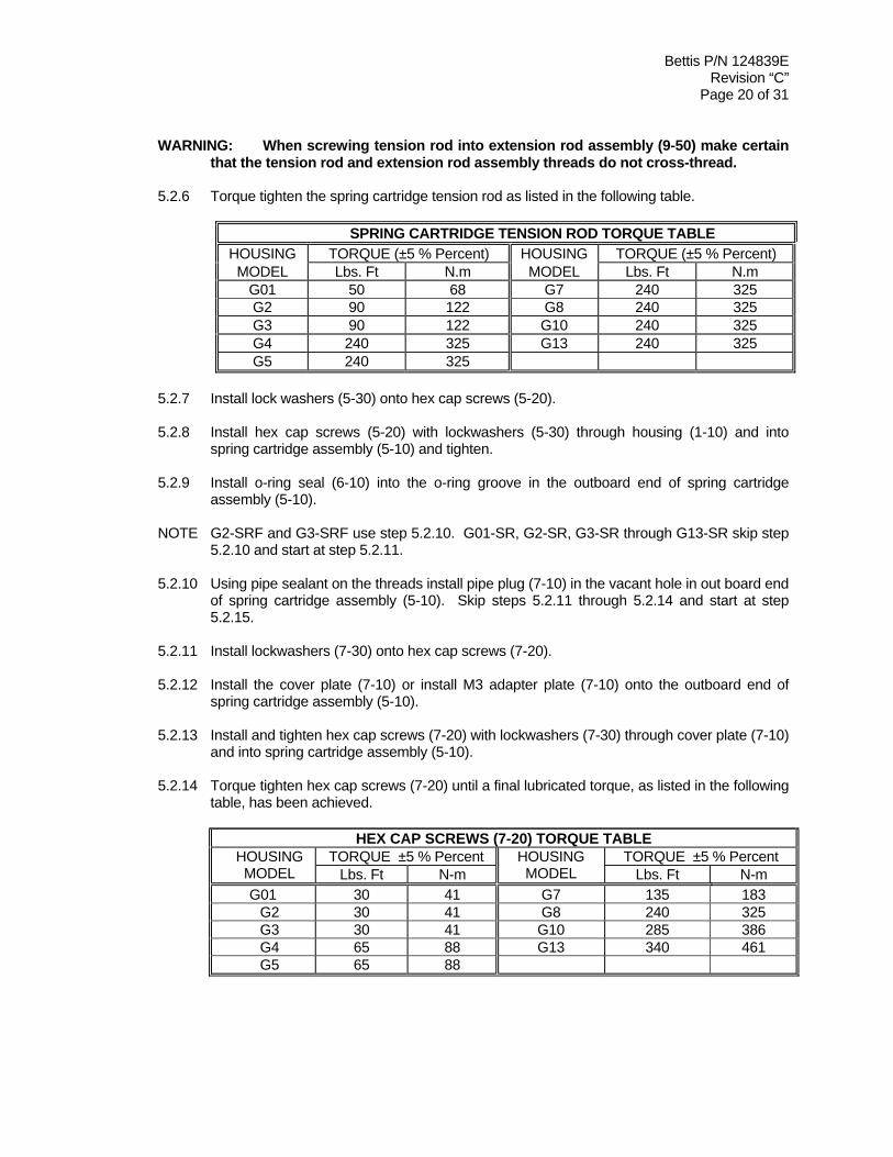
WARNING: When screwing tension rod into extension rod assembly (9-50) make certain that the tension rod and extension rod assembly threads do not cross-thread.
5.2.6 Torque tighten the spring cartridge tension rod as listed in the following table.
SPRING CARTRIDGE TENSION ROD TORQUE TABLE HOUSING TORQUE (±5 % Percent) HOUSING TORQUE (±5 % Percent) MODEL Lbs. Ft N.m MODEL Lbs. Ft N.m
G01 50 68 G7 240 325 G2 90 122 G8 240 325 G3 90 122 G10 240 325 G4 240 325 G13 240 325 G5 240 325
5.2.7 Install lock washers (5-30) onto hex cap screws (5-20). 5.2.8 Install hex cap screws (5-20) with lockwashers (5-30) through housing (1-10) and into
spring cartridge assembly (5-10) and tighten. 5.2.9 Install o-ring seal (6-10) into the o-ring groove in the outboard end of spring cartridge
assembly (5-10). NOTE G2-SRF and G3-SRF use step 5.2.10. G01-SR, G2-SR, G3-SR through G13-SR skip step
5.2.10 and start at step 5.2.11. 5.2.10 Using pipe sealant on the threads install pipe plug (7-10) in the vacant hole in out board end
of spring cartridge assembly (5-10). Skip steps 5.2.11 through 5.2.14 and start at step 5.2.15.
5.2.11 Install lockwashers (7-30) onto hex cap screws (7-20). 5.2.12 Install the cover plate (7-10) or install M3 adapter plate (7-10) onto the outboard end of
spring cartridge assembly (5-10). 5.2.13 Install and tighten hex cap screws (7-20) with lockwashers (7-30) through cover plate (7-10)
and into spring cartridge assembly (5-10). 5.2.14 Torque tighten hex cap screws (7-20) until a final lubricated torque, as listed in the following
table, has been achieved.
HEX CAP SCREWS (7-20) TORQUE TABLE TORQUE ±5 % Percent TORQUE ±5 % Percent HOUSING
MODEL Lbs. Ft N-m HOUSING MODEL Lbs. Ft N-m
G01 30 41 G7 135 183 G2 30 41 G8 240 325 G3 30 41 G10 285 386 G4 65 88 G13 340 461 G5 65 88

Bettis P/N 124839E Revision “C”
Page 21 of 31
5.2.15 On M3, M3HW and ES models install Monel wire (6-130) through each hex cap screw
(7-20) per the following steps:
NOTE: The following steps provides guidelines for wire locking hex cap screws to discourage screw loosening and removal in applications where screw removal could be hazardous.
5.2.15.1 Make sure hex cap screws are tightened to their specified torque. 5.2.15.2 Using required lengths of .31 diameter Monel wire as provided in the
Module ordered. When replacing Monel wire use the following table for wire length requirements.
LENGTH LENGTH MODEL
Inch mm MODEL
Inch Mm G01-SR 36 914.4 G5-SR 66 1676.4 G2-SR 44 1117.6 G7-SR 79 2006.6 G3-SR 48 1219.2 G8-SR 88 2235.2 G4-SR 55 1397.0 G10-SR 110 2794.0
5.2.15.3 Twist the end of both wires together and insert one through the drilled hole
in the hex cap screw head, pass the second wire over the screw head and twist it three (3) times around the first wire at a location where the first wire exits the screw head.
5.2.15.4 Repeat the procedure until the second wire is twist tied to the screw head
through wire of the last screw head. 5.2.15.5 Attach caution tag and twist tie the wires from the last screw head to the
twisted wires of the first screw head. See following for illustration.

Bettis P/N 124839E Revision “C”
Page 22 of 31
5.2.16 If removed install stop screw nuts (1-190) onto stop screws (1-180).
5.2.17 If removed install o-ring (2-90) onto stop screws (1-180).
5.2.18 If removed install two stop screws (1-180) into two stop screw holes on the front of housing (1-10).
5.2.19 Adjust both stop screws (1-180) back to settings recorded earlier in Section 5. 5.2.20 Tighten both stop screw nuts (1-190) securely.
5.3 HYDRAULIC POWER MODULE REMOVAL
WARNING: The spring cartridge must be checked to verify that the spring(s) are in their extended position before the power module is removed from the actuator.
NOTE: Review section 2.1 General Disassembly before proceeding with The Hydraulic Power
Module Disassembly. 5.3.1 Remove o-ring plug (3-120) from outer end cap (3-80). 5.3.2 Using a male square drive extension, go through outer end cap (3-80), unscrew piston rod
(3-40) from extension rod assembly (1-50). WARNING: Use suitable lifting equipment to support the cylinder assembly. 5.3.3 Remove hex cap screws (3-115), with lockwashers (3-110), from inner end cap (3-10). 5.3.4 Remove hex nuts (3-105) from hex cap screws (3-100). 5.3.5 Remove Hydraulic Power Module from actuator housing (1-10). 5.4 HYDRAULIC POWER MODULE INSTALLATION
NOTE: Review section 3.1 General Reassembly before proceeding with Hydraulic Power Module Installation.
5.4.1 Check to verify that o-ring seal (4-90) is properly seated in its seal groove located on the
housing side of inner end cap (3-10). 5.4.2 Using lifting equipment move the Power Module up to housing (1-10) and install as follows:
Use step 5.4.3 for G01 and step 5.4.4 for G2 through G10 model actuator s. 5.4.3 G01 MODEL ACTUATORS:
5.4.3.1 Align piston rod (3-40) with threads in the guide block (1-30).
5.4.3.2 Using a male square drive extension, go through outer end cap (3-80) and screw
piston rod (3-40) into guide block (1-30).

Bettis P/N 124839E Revision “C”
Page 23 of 31
WARNING: When screwing piston rod into guide block (1-30) make certain that
the piston rod and guide block threads do not cross-thread.
5.4.4 G2 THROUGH G10 MODEL ACTUATORS: 5.4.4.1 Align piston rod (3-40) with extension rod assembly (1-50).
5.4.4.2 Using a male square drive extension, go through outer end cap (3-80) and screw
piston rod (3-40) into extension rod assembly (1-50).
WARNING: When screwing piston rod into extension rod assembly (1-50) make certain that the piston rod and extension rod assembly threads do not cross-thread.
5.4.5 Torque tighten piston rod (3-40) per the following chart. 5.4.5.1 G01 model actuators torque to 50 foot pounds / 68 N-m lubricated. 5.4.5.2 G2 and G3 model actuators torque to 90 foot pounds / 122 N-m lubricated. 5.4.5.3 G4 through G13 model actuators torque to 240 foot pounds / 325 N-m lubricated. 5.4.6 Install lock washers (3-110) onto hex cap screws (3-115). 5.4.7 Install hex cap screws (3-115), with lockwashers (3-110), through inner end cap (3-10) and
screw into housing (1-10). 5.4.8 Install lock washers (3-110) onto hex cap screws (3-100). 5.4.9 Install hex cap screws (3-100), with lockwashers (3-110), through inner end cap (3-10) and
housing (1-10). 5.4.10 Install and tighten hex nuts (3-105) onto hex cap screws (3-100).
5.4.11 Using pipe dope, install standard NPT pipe plug (3-120) into outer end cap (3-80). If the
actuator uses SAE threads install SAE o-ring plug (3-120) into outer end cap (3-80).
5.5 G2 THRU G13 POWR SWIVL REMOVAL 5.5.1 Push the guide block to the side of housing (1-10) that will expose the extension rod
assembly (1-50). NOTE: The guide block can be moved by inserting a long non metallic rod through the hole where the blind end cap was removed and pushing on the guide block.
5.5.2 Refer to assembly drawing page 2 of 2 Detail "B". Use Bettis tool part number as listed in
chart in section 1 step 1.2.1 to remove retainer nut assembly (1-60) from the guide block (1-30).
CAUTION: When removing rod extension assembly from guide block be careful not to
drop one of the spherical washers inside the housing.

Bettis P/N 124839E Revision “C”
Page 24 of 31
5.5.3 Remove rod extension assembly (1-50) from guide block (1-30). NOTE: One spherical washer (1-40) will be removed from guide block (1-30) when extension rod
assembly is removed. 5.5.4 Remove the remaining spherical washer (1-40) from guide block (1-30).
5.6 G2 THRU G13 POWR SWIVL MODULE INSTALLATION
WARNING: The actuator must be in the appropriate overtravel position. Confirm overtravel position by observing the guide block (1-30) is against the inner wall of housing (1-10).
5.6.1 Push the guide block to the required side of the housing (1-10). NOTE: The guide block
can be moved by inserting a long rod through either end of the housing and pushing on the guide block.
5.6.2 Lubricate two spherical washers (1-40), and one extension rod assembly (1-50).
5.6.3 Install one spherical washer (1-40) into the side of guide block (1-30). NOTE: The
spherical side of washer (1-40) will be facing to the outside of guide block (1-30). 5.6.4 Install second spherical washer (1-40) over threaded end of extension rod assembly (1-50).
NOTE: The spherical side of the washer will go on the extension rod assembly facing the head of the extension rod assembly.
5.6.5 Install extension rod assembly (1-50) into right of guide block (1-30) and up against the first
spherical washer (1-40). 5.6.6 Install extension retainer nut assembly (1-60) over extension rod assembly (1-50) and
screw into guide block (1-30). 5.6.7 Tighten extension retainer nut assembly (1-60) until extension rod assembly (1-50) can not
move. Back off the extension retainer nut assembly (1-60) just enough to allow for extension rod assembly (1-50) to move freely.

Bettis P/N 124839E Revision “C”
Page 25 of 31
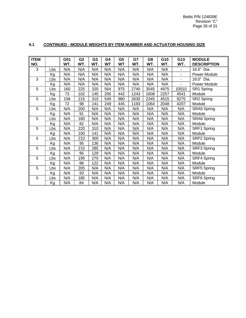
SECTION 6 - ACTUATOR SUPPORT INFORMATION 6.1 MODULE WEIGHTS BY ITEM NUMBER AND ACTUATOR HOUSING SIZE
ITEM NO.
G01 WT.
G2 WT.
G3 WT.
G4 WT.
G5 WT.
G7 WT.
G8 WT.
G10 WT.
G13 WT.
DESCRIPTION
1 Lbs 83 110 162 280 545 1025 1495 2550 4625 Drive Module Kg 38 50 73 127 247 465 678 1157 2098 1 Lbs 26 N/A N/A N/A N/A N/A N/A N/A N/A 1.5” Dia. Kg 12 N/A N/A N/A N/A N/A N/A N/A N/A Power Module 1 Lbs 25 30 N/A N/A N/A N/A N/A N/A N/A 1.7” Dia. Kg 11.4 13.6 N/A N/A N/A N/A N/A N/A N/A Power Module 3 Lbs 26 29 43 N/A N/A N/A N/A N/A N/A 2.0” Dia. Kg 11.7 13 19.5 N/A N/A N/A N/A N/A N/A Power Module 3 Lbs 27 30 45 N/A N/A N/A N/A N/A N/A 2.2” Dia. Kg 12.2 13.6 20.4 N/A N/A N/A N/A N/A N/A Power Module 3 Lbs 28 31 48 71 N/A N/A N/A N/A N/A 2.5” Dia. Kg 12.7 14.1 21.7 32 N/A N/A N/A N/A N/A Power Module 3 Lbs 29 35 48 84.5 N/A N/A N/A N/A N/A 3.0” Dia. Kg 13 15.8 21.7 38 N/A N/A N/A N/A N/A Power Module 3 Lbs 32 38 52 83 160 N/A N/A N/A N/A 3.5” Dia. Kg 14.5 17.2 23.5 37.6 73 N/A N/A N/A N/A Power Module 3 Lbs N/A 42 57 84 170 287 N/A N/A N/A 4.0” Dia. Kg N/A 19 25.8 38 77 130 N/A N/A N/A Power Module 3 Lbs N/A N/A 59 86 177.5 301 N/A N/A N/A 4.5” Dia. Kg N/A N/A 26.7 39 80.5 136 N/A N/A N/A Power Module 3 Lbs N/A N/A N/A 92 173 317 411 N/A N/A 5.0” Dia. Kg N/A N/A N/A 41.7 78 144 186 N/A N/A Power Module 3 Lbs N/A N/A N/A 106 184 303 475 729 N/A 6.0” Dia. Kg N/A N/A N/A 49 83 137 215 331 N/A Power Module 3 Lbs N/A N/A N/A N/A 194 331 485 783 N/A 7.0” Dia. Kg N/A N/A N/A N/A 88 150 220 255 N/A Power Module 3 Lbs N/A N/A N/A N/A 228 337 459 756 - 8.0” Dia. Kg N/A N/A N/A N/A 103 153 208 343 - Power Module 3 Lbs N/A N/A N/A N/A N/A 394 495 808 - 9.0” Dia. Kg N/A N/A N/A N/A N/A 179 225 367 - Power Module 3 Lbs N/A N/A N/A N/A N/A 400 501 862 - 10.0” Dia. Kg N/A N/A N/A N/A N/A 181 227 400 - Power Module 3 Lbs N/A N/A N/A N/A N/A N/A 599 959 1139 12.0” Dia. Kg N/A N/A N/A N/A N/A N/A 254 435 517 Power Module 3 Lbs N/A N/A N/A N/A N/A N/A N/A 1104 - 14.0” Dia. Kg N/A N/A N/A N/A N/A N/A N/A 501 - Power Module
Bettis P/N 124839E Revision “C”
Page 26 of 31
6.1 CONTINUED - MODULE WEIGHTS BY ITEM NUMBER AND ACTUATOR HOUSING SIZE
ITEM NO.
G01 WT.
G2 WT.
G3 WT.
G4 WT
G5 WT
G7 WT.
G8 WT.
G10 WT.
G13 WT.
MODULE DESCRIPTION
3 Lbs N/A N/A N/A N/A N/A N/A N/A N/A - 16.0” Dia. Kg N/A N/A N/A N/A N/A N/A N/A N/A - Power Module 3 Lbs N/A N/A N/A N/A N/A N/A N/A N/A - 18.0” Dia. Kg N/A N/A N/A N/A N/A N/A N/A N/A - Power Module 5 Lbs 160 225 320 564 975 2740 3545 4975 10010 SR1 Spring Kg 73 102 145 256 442 1243 1608 2257 4541 Module 5 Lbs 158 215 310 549 980 2630 2345 4515 9275 SR2 Spring Kg 72 98 141 249 445 1193 1064 2048 4207 Module 5 Lbs N/A 200 N/A N/A N/A N/A N/A N/A N/A SRA5 Spring Kg N/A 91 N/A N/A N/A N/A N/A N/A N/A Module 5 Lbs N/A 180 N/A N/A N/A N/A N/A N/A N/A SRA6 Spring Kg N/A 82 N/A N/A N/A N/A N/A N/A N/A Module 5 Lbs N/A 220 310 N/A N/A N/A N/A N/A N/A SRF1 Spring Kg N/A 100 141 N/A N/A N/A N/A N/A N/A Module 5 Lbs N/A 210 300 N/A N/A N/A N/A N/A N/A SRF2 Spring Kg N/A 95 136 N/A N/A N/A N/A N/A N/A Module 5 Lbs N/A 210 285 N/A N/A N/A N/A N/A N/A SRF3 Spring Kg N/A 95 129 N/A N/A N/A N/A N/A N/A Module 5 Lbs N/A 195 270 N/A N/A N/A N/A N/A N/A SRF4 Spring Kg N/A 88 122 N/A N/A N/A N/A N/A N/A Module 5 Lbs N/A 205 N/A N/A N/A N/A N/A N/A N/A SRF5 Spring Kg N/A 93 N/A N/A N/A N/A N/A N/A N/A Module 5 Lbs N/A 185 N/A N/A N/A N/A N/A N/A N/A SRF6 Spring Kg N/A 84 N/A N/A N/A N/A N/A N/A N/A Module

Bettis P/N 124839E Revision “C”
Page 27 of 31
6.2 G01 TOOL STYLE AND WRENCH SIZE
ITEM NO.
WRENCH SIZE
ITEM QTY
LOCATION OR DESCRIPTION
RECOMMENDED TOOL STYLE
1-110 9/16” 4 Cover Screws Socket 1-160 1/2” 4 Yoke Cover Screws Socket 1-180 3/8” Sq. 2 Stop Screws Open End or Adjustable 1-190 15/16” 2 Hex Jam Nuts Open End or Adjustable 3-40 3/8” Sq. 1 Piston Rod Male Drive 3-90 3/4 ” 4 Standard Hex Nuts Socket 3-100 9/16” 4 Hex Cap Screws Socket 3-105 9/16” 4 Standard Hex Nuts Socket 3-115 9/16” 4 Hex Cap Screws Socket 3-120 9/16” Sq. 1 Pipe Plug, Square Head Open End or Adjustable 3-210 7/16” Sq. 4 Pipe Plug, Square Head Open End or Adjustable 5-20 9/16” 4 Hex Cap Screws Socket 7-20 9/16” 4 Hex Cap Screw Socket 13 3/4” 2 Vent Check Assembly Open End - 3/8” 1 Pull Rod Male Drive
6.3 G2 TOOL STYLE AND WRENCH SIZE
ITEM NO.
WRENCH SIZE
ITEM QTY
LOCATION OR DESCRIPTION
RECOMMENDED TOOL STYLE
1-110 9/16” 6 Cover Screws Socket 1-160 9/16” 4 Yoke Cover Screws Socket 1-180 3/8” Sq. 2 Stop Screws Open End or Adjustable 1-190 1-1/8” 2 Hex Jam Nuts Open End or Adjustable 3-40 3/8” Sq. 1 Piston Rod Male Drive 3-90 3/4” 4 Standard Hex Nuts Socket 3-100 9/16” 4 Hex Cap Screws Socket 3-105 9/16” 4 Standard Hex Nuts Socket 3-115 9/16” 4 Hex Cap Screws Socket 3-120 9/16” Sq. 1 Pipe Plug, Square Head Open End or Adjustable 3-210 7/16” Sq. 4 Pipe Plug, Square Head Open End or Adjustable 5-20 9/16” 6 Hex Cap Screws Socket 7-20 9/16” 6 Hex Cap Screws Socket 13 3/4” 2 Vent Check Assembly Open End - 3/8” 1 Pull Rod Male Drive
Bettis P/N 124839E Revision “C”
Page 28 of 31
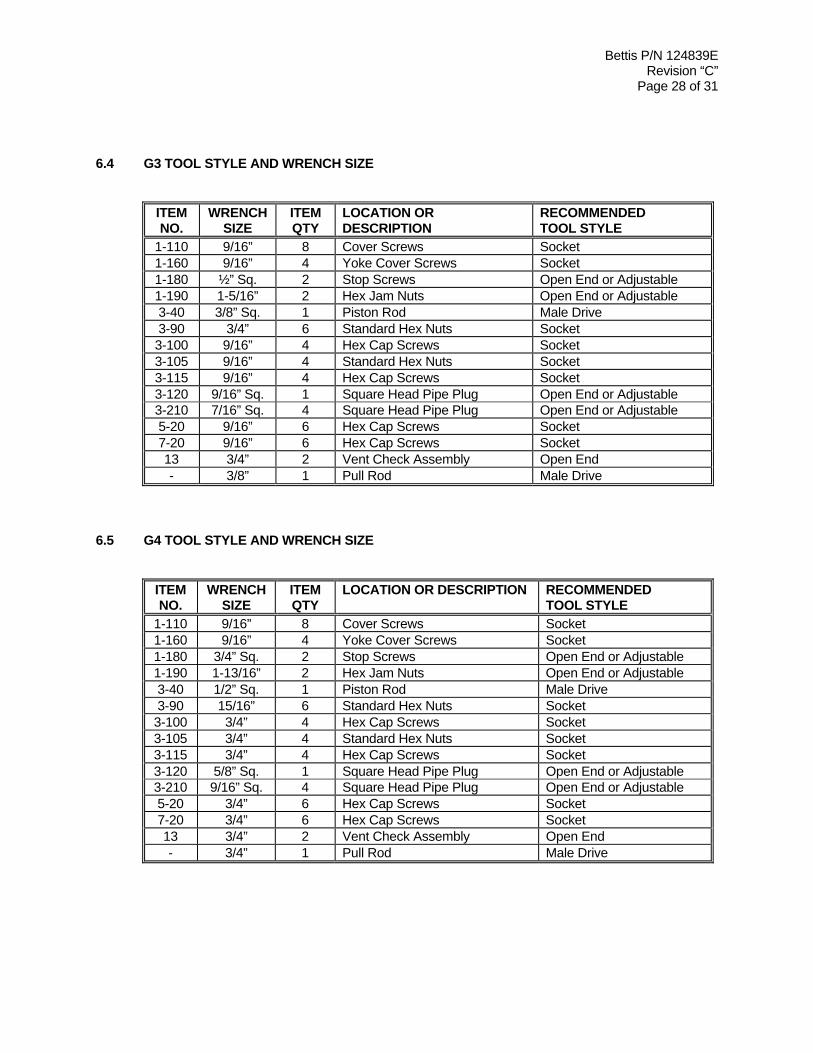
6.4 G3 TOOL STYLE AND WRENCH SIZE
ITEM NO.
WRENCH SIZE
ITEM QTY
LOCATION OR DESCRIPTION
RECOMMENDED TOOL STYLE
1-110 9/16” 8 Cover Screws Socket 1-160 9/16” 4 Yoke Cover Screws Socket 1-180 ½” Sq. 2 Stop Screws Open End or Adjustable 1-190 1-5/16” 2 Hex Jam Nuts Open End or Adjustable 3-40 3/8” Sq. 1 Piston Rod Male Drive 3-90 3/4” 6 Standard Hex Nuts Socket 3-100 9/16” 4 Hex Cap Screws Socket 3-105 9/16” 4 Standard Hex Nuts Socket 3-115 9/16” 4 Hex Cap Screws Socket 3-120 9/16” Sq. 1 Square Head Pipe Plug Open End or Adjustable 3-210 7/16” Sq. 4 Square Head Pipe Plug Open End or Adjustable 5-20 9/16” 6 Hex Cap Screws Socket 7-20 9/16” 6 Hex Cap Screws Socket 13 3/4” 2 Vent Check Assembly Open End - 3/8” 1 Pull Rod Male Drive
6.5 G4 TOOL STYLE AND WRENCH SIZE
ITEM NO.
WRENCH SIZE
ITEM QTY
LOCATION OR DESCRIPTION RECOMMENDED TOOL STYLE
1-110 9/16” 8 Cover Screws Socket 1-160 9/16” 4 Yoke Cover Screws Socket 1-180 3/4” Sq. 2 Stop Screws Open End or Adjustable 1-190 1-13/16” 2 Hex Jam Nuts Open End or Adjustable 3-40 1/2” Sq. 1 Piston Rod Male Drive 3-90 15/16” 6 Standard Hex Nuts Socket 3-100 3/4” 4 Hex Cap Screws Socket 3-105 3/4” 4 Standard Hex Nuts Socket 3-115 3/4” 4 Hex Cap Screws Socket 3-120 5/8” Sq. 1 Square Head Pipe Plug Open End or Adjustable 3-210 9/16” Sq. 4 Square Head Pipe Plug Open End or Adjustable 5-20 3/4” 6 Hex Cap Screws Socket 7-20 3/4” 6 Hex Cap Screws Socket 13 3/4” 2 Vent Check Assembly Open End - 3/4” 1 Pull Rod Male Drive

Bettis P/N 124839E Revision “C”
Page 29 of 31
6.6 G5 TOOL STYLE AND WRENCH SIZE
ITEM NO.
WRENCH SIZE
ITEM QTY
LOCATION OR DESCRIPTION RECOMMENDED TOOL STYLE
1-110 3/4” 8 Cover Screws Socket 1-120 3/4” 4 Yoke Cover Screws Socket 1-160 9/16” 6 Hex Cap Screws Socket 1-180 3/4” Sq. 2 Stop Screws Open End or Adjustable 1-190 2-3/8” 2 Heavy Hex Jam Nuts Open End or Adjustable 3-40 1/2” Sq. 1 Piston Rod Male Drive 3-90 15/16” 6 Hex Nuts Socket 3-100 3/4” 4 Hex Cap Screws Socket 3-105 3/4” 4 Standard Hex Nuts Socket 3-115 3/4” 4 Hex Cap Screws Socket 3-120 5/8” Sq. 1 Square Head Pipe Plug Open End or Adjustable 3-210 9/16” Sq. 4 Square Head Pipe Plug Open End or Adjustable 5-20 3/4” 8 Hex Cap Screws Socket 7-20 3/4” 8 Hex Cap Screws Socket 13 3/4” 2 Vent Check Assembly Open End - 3/4” 1 Pull Rod Male Drive
6.7 G7 TOOL STYLE AND WRENCH SIZE
ITEM NO.
WRENCH SIZE
ITEM QTY
LOCATION OR DESCRIPTION RECOMMENDED TOOL STYLE
1-110 3/4” 8 Cover Screws Socket 1-120 3/4” 4 Yoke Cover Screws Socket 1-160 9/16” 8 Hex Cap Screws Socket 1-180 1” 2 Stop Screws Open End or Adjustable 3-40 3/4” Sq. 1 Piston Rod Male Drive 3-90 1-1/2” 6 Hex Nuts Socket 3-100 15/16” 8 Hex Cap Screws Socket 3-105 15/16” 8 Standard Hex Nuts Socket 3-115 15/16” 8 Hex Cap Screws Socket 3-120 15/16” 1 Hex Head Pipe Plug Open End or Adjustable 3-210 9/16” Sq. 4 Square Head Pipe Plug Open End or Adjustable 5-20 15/16” 8 Hex Cap Screws Socket 7-20 15/16” 8 Hex Cap Screws Socket 13 3/4” 2 Vent Check Assembly Open End - 3/4” 1 Pull Rod Male Drive

Bettis P/N 124839E Revision “C”
Page 30 of 31
6.8 G8 TOOL STYLE AND WRENCH SIZE
ITEM NO.
WRENCH SIZE
ITEM QTY
LOCATION OR DESCRIPTION RECOMMENDED TOOL STYLE
1-110 3/4” 12 Cover Screws Socket 1-120 3/4” 4 Yoke Cover Screws Socket 1-160 9/16” 8 Hex Cap Screws Socket 1-180 1-1/4” 2 Stop Screws Open End or Adjustable 3-40 3/4” Sq. 1 Piston Rod Male Drive 3-90 1-1/2” 8 Hex Nuts Socket 3-100 1-1/8” 8 Hex Cap Screws Socket 3-105 1-1/8” 8 Standard Hex Nuts Socket 3-115 1-1/8” 8 Hex Cap Screws Socket 3-120 15/16” 1 Hex Head Pipe Plug Open End or Adjustable 3-210 9/16” Sq. 4 Square Head Pipe Plug Open End or Adjustable 5-20 1-1/8” 8 Hex Cap Screws Socket 7-20 1-1/8” 8 Hex Cap Screws Socket 13 3/4” 2 Vent Check Assembly Open End - 3/4” 1 Pull Rod Male Drive
6.9 G10 TOOL STYLE AND WRENCH SIZE
ITEM NO.
WRENCH SIZE
ITEM QTY
LOCATION OR DESCRIPTION RECOMMENDED TOOL STYLE
1-110 3/4” 16 Cover Screws Socket 1-120 3/4” 4 Yoke Cover Screws Socket 1-160 9/16” 8 Hex Cap Screws Socket 1-180 1-1/2” 2 Stop Screws Open End or Adjustable 3-40 3/4” Sq. 1 Piston Rod Male Drive 3-90 3-1/2” 8 Hex Nuts Socket 3-100 1-1/8” 8 Hex Cap Screws Socket 3-105 1-1/8” 8 Standard Hex Nuts Socket 3-115 1-1/8” 8 Hex Cap Screws Socket 3-120 15/16” 1 Hex Head Pipe Plug Open End or Adjustable 3-210 9/16” Sq. 4 Square Head Pipe Plug Open End or Adjustable 5-20 1-5/16” 8 Hex Cap Screws Socket 7-20 1-5/16” 8 Hex Cap Screws Socket 13 3/4” 2 Vent Check Assembly Open End - 3/4” 1 Pull Rod Male Drive

Bettis P/N 124839E Revision “C”
Page 31 of 31
6.10 G13 TOOL STYLE AND WRENCH SIZE
ITEM NO.
WRENCH SIZE
ITEM QTY
LOCATION OR DESCRIPTION RECOMMENDED TOOL STYLE
1-110 1-1/8” 20 Cover Screws Socket 1-120 1-1/8” 4 Yoke Cover Screws Socket 1-160 9/16” 12 Hex Cap Screws Socket 1-180 2” Sq. 2 Stop Screws Open End or Adjustable 3-40 7/8” Sq. 1 Piston Rod Male Drive 3-90 1-11/16” 8 Hex Nuts Socket 3-100 1-11/16” 8 Hex Cap Screws Socket 3-105 1-11/16” 8 Standard Hex Nuts Socket 3-115 1-11/16” 8 Hex Cap Screws Socket 3-120 15/16” Sq. 1 Square Head Pipe Plug Open End or Adjustable 3-210 13/16” Sq. 4 Square Head Pipe Plug Open End or Adjustable 5-20 1-13/16” 8 Hex Cap Screws Socket 7-20 1-13/16” 8 Hex Cap Screws Socket 13 3/4” 2 Vent Check Assembly Open End - 3/4” 1 Pull Rod Male Drive
ECN DATE REV BY * DATE Released 3 September 1998 A COMPILED COLBY 22 JUNE 06
17787 17 December 2001 B CHECKED JOHN R 6/22/06 19110 06 July 2006 C APPROVED DAVID MCGEE 7/18/06
* Signatures on file Bettis, Waller, Texas


![cMT-G01 Startup Guide - · PDF file[cMT Series] » [Maintenance] » [cMT-G01 OS Upgrade]. ... cMT Gateway Viewer can read from or write to PLC. ... cMT-G01 Startup Guide](https://img.pdfslide.us/doc/110x75/5ab85bac7f8b9ad13d8c70d9/cmt-g01-startup-guide-cmt-series-maintenance-cmt-g01-os-upgrade-cmt.jpg)