Embed Size (px)
DESCRIPTION
Bettis valve
Citation preview
ENGLISH LANUAGE
BETTIS
SERVICE INSTRUCTIONS
FOR MODELS
G01 THROUGH G10
SPRING RETURN
PNEUMATIC ACTUATORS
WITH M11 HYDRAULIC OVERRIDE
PART NUMBER: 127073E
REVISION: “A”
DATE: December 2001
Bettis P/N 127073ERevision “A”Page 1 of 37
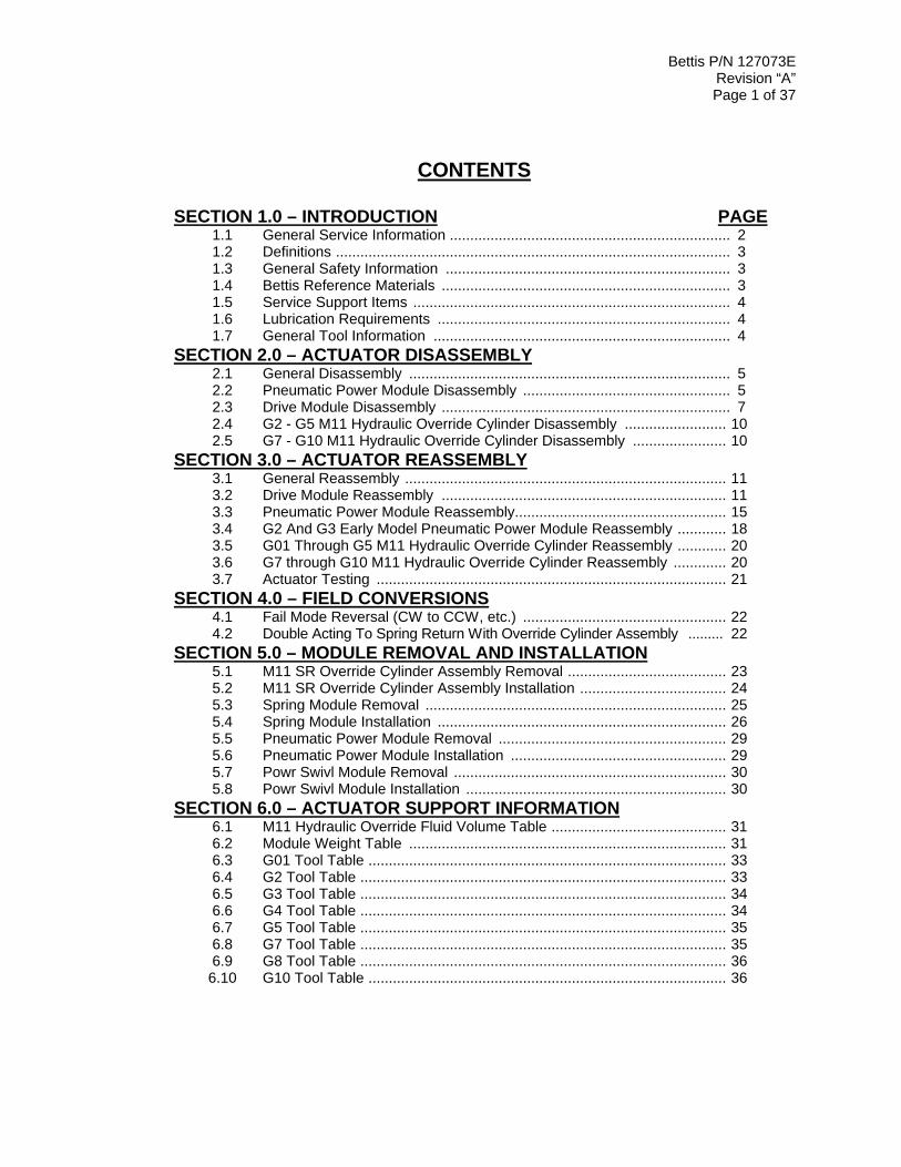
CONTENTS
SECTION 1.0 – INTRODUCTION PAGE1.1 General Service Information ..................................................................... 21.2 Definitions ................................................................................................. 31.3 General Safety Information ...................................................................... 31.4 Bettis Reference Materials ....................................................................... 31.5 Service Support Items .............................................................................. 41.6 Lubrication Requirements ........................................................................ 41.7 General Tool Information ......................................................................... 4
SECTION 2.0 – ACTUATOR DISASSEMBLY2.1 General Disassembly ............................................................................... 52.2 Pneumatic Power Module Disassembly ................................................... 52.3 Drive Module Disassembly ....................................................................... 72.4 G2 - G5 M11 Hydraulic Override Cylinder Disassembly ......................... 102.5 G7 - G10 M11 Hydraulic Override Cylinder Disassembly ....................... 10
SECTION 3.0 – ACTUATOR REASSEMBLY3.1 General Reassembly ............................................................................... 113.2 Drive Module Reassembly ...................................................................... 113.3 Pneumatic Power Module Reassembly.................................................... 153.4 G2 And G3 Early Model Pneumatic Power Module Reassembly ............ 183.5 G01 Through G5 M11 Hydraulic Override Cylinder Reassembly ............ 203.6 G7 through G10 M11 Hydraulic Override Cylinder Reassembly ............. 203.7 Actuator Testing ...................................................................................... 21
SECTION 4.0 – FIELD CONVERSIONS4.1 Fail Mode Reversal (CW to CCW, etc.) .................................................. 224.2 Double Acting To Spring Return With Override Cylinder Assembly ......... 22
SECTION 5.0 – MODULE REMOVAL AND INSTALLATION5.1 M11 SR Override Cylinder Assembly Removal ....................................... 235.2 M11 SR Override Cylinder Assembly Installation .................................... 245.3 Spring Module Removal .......................................................................... 255.4 Spring Module Installation ....................................................................... 265.5 Pneumatic Power Module Removal ........................................................ 295.6 Pneumatic Power Module Installation ..................................................... 295.7 Powr Swivl Module Removal ................................................................... 305.8 Powr Swivl Module Installation ................................................................ 30
SECTION 6.0 – ACTUATOR SUPPORT INFORMATION6.1 M11 Hydraulic Override Fluid Volume Table ........................................... 316.2 Module Weight Table .............................................................................. 316.3 G01 Tool Table ........................................................................................ 336.4 G2 Tool Table .......................................................................................... 336.5 G3 Tool Table .......................................................................................... 346.6 G4 Tool Table .......................................................................................... 346.7 G5 Tool Table .......................................................................................... 356.8 G7 Tool Table .......................................................................................... 356.9 G8 Tool Table .......................................................................................... 366.10 G10 Tool Table ........................................................................................ 36
Bettis P/N 127073ERevision “A”Page 2 of 37
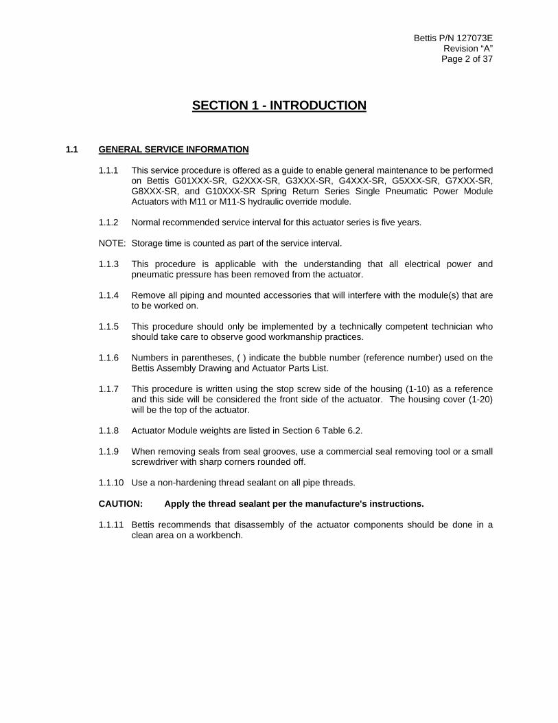
SECTION 1 - INTRODUCTION
1.1 GENERAL SERVICE INFORMATION
1.1.1 This service procedure is offered as a guide to enable general maintenance to be performedon Bettis G01XXX-SR, G2XXX-SR, G3XXX-SR, G4XXX-SR, G5XXX-SR, G7XXX-SR,G8XXX-SR, and G10XXX-SR Spring Return Series Single Pneumatic Power ModuleActuators with M11 or M11-S hydraulic override module.
1.1.2 Normal recommended service interval for this actuator series is five years.
NOTE: Storage time is counted as part of the service interval.
1.1.3 This procedure is applicable with the understanding that all electrical power andpneumatic pressure has been removed from the actuator.
1.1.4 Remove all piping and mounted accessories that will interfere with the module(s) that areto be worked on.
1.1.5 This procedure should only be implemented by a technically competent technician whoshould take care to observe good workmanship practices.
1.1.6 Numbers in parentheses, ( ) indicate the bubble number (reference number) used on theBettis Assembly Drawing and Actuator Parts List.
1.1.7 This procedure is written using the stop screw side of the housing (1-10) as a referenceand this side will be considered the front side of the actuator. The housing cover (1-20)will be the top of the actuator.
1.1.8 Actuator Module weights are listed in Section 6 Table 6.2.
1.1.9 When removing seals from seal grooves, use a commercial seal removing tool or a smallscrewdriver with sharp corners rounded off.
1.1.10 Use a non-hardening thread sealant on all pipe threads.
CAUTION: Apply the thread sealant per the manufacture's instructions.
1.1.11 Bettis recommends that disassembly of the actuator components should be done in aclean area on a workbench.
Bettis P/N 127073ERevision “A”Page 3 of 37
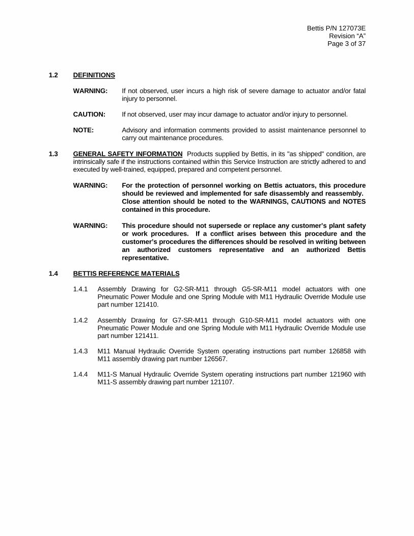
1.2 DEFINITIONS
WARNING: If not observed, user incurs a high risk of severe damage to actuator and/or fatalinjury to personnel.
CAUTION: If not observed, user may incur damage to actuator and/or injury to personnel.
NOTE: Advisory and information comments provided to assist maintenance personnel tocarry out maintenance procedures.
1.3 GENERAL SAFETY INFORMATION Products supplied by Bettis, in its "as shipped" condition, areintrinsically safe if the instructions contained within this Service Instruction are strictly adhered to andexecuted by well-trained, equipped, prepared and competent personnel.
WARNING: For the protection of personnel working on Bettis actuators, this procedureshould be reviewed and implemented for safe disassembly and reassembly. Close attention should be noted to the WARNINGS, CAUTIONS and NOTEScontained in this procedure.
WARNING: This procedure should not supersede or replace any customer’s plant safetyor work procedures. If a conflict arises between this procedure and thecustomer’s procedures the differences should be resolved in writing betweenan authorized customers representative and an authorized Bettisrepresentative.
1.4 BETTIS REFERENCE MATERIALS
1.4.1 Assembly Drawing for G2-SR-M11 through G5-SR-M11 model actuators with onePneumatic Power Module and one Spring Module with M11 Hydraulic Override Module usepart number 121410.
1.4.2 Assembly Drawing for G7-SR-M11 through G10-SR-M11 model actuators with onePneumatic Power Module and one Spring Module with M11 Hydraulic Override Module usepart number 121411.
1.4.3 M11 Manual Hydraulic Override System operating instructions part number 126858 withM11 assembly drawing part number 126567.
1.4.4 M11-S Manual Hydraulic Override System operating instructions part number 121960 withM11-S assembly drawing part number 121107.
Bettis P/N 127073ERevision “A”Page 4 of 37
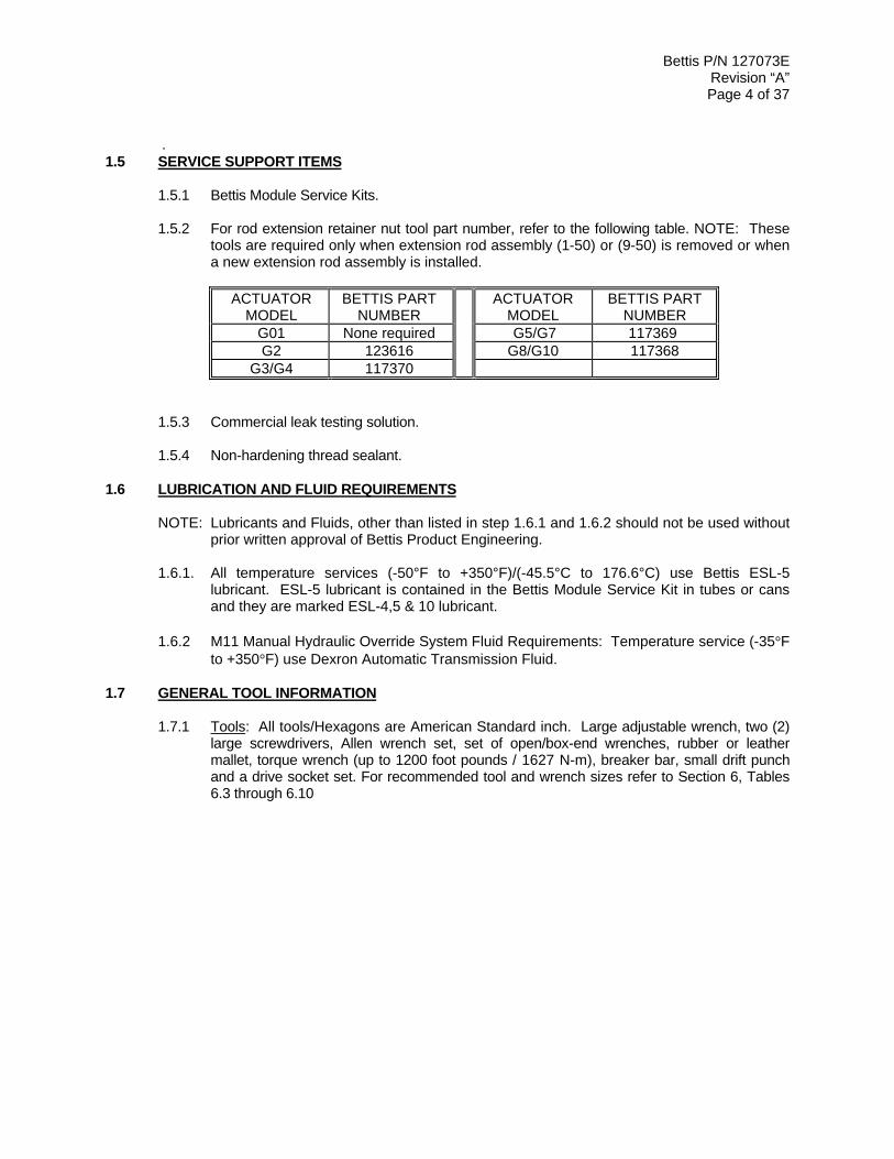
.1.5 SERVICE SUPPORT ITEMS
1.5.1 Bettis Module Service Kits.
1.5.2 For rod extension retainer nut tool part number, refer to the following table. NOTE: Thesetools are required only when extension rod assembly (1-50) or (9-50) is removed or whena new extension rod assembly is installed.
ACTUATOR MODEL
BETTIS PART NUMBER
ACTUATORMODEL
BETTIS PARTNUMBER
G01 None required G5/G7 117369G2 123616 G8/G10 117368
G3/G4 117370
1.5.3 Commercial leak testing solution.
1.5.4 Non-hardening thread sealant.
1.6 LUBRICATION AND FLUID REQUIREMENTS
NOTE: Lubricants and Fluids, other than listed in step 1.6.1 and 1.6.2 should not be used withoutprior written approval of Bettis Product Engineering.
1.6.1. All temperature services (-50°F to +350°F)/(-45.5°C to 176.6°C) use Bettis ESL-5lubricant. ESL-5 lubricant is contained in the Bettis Module Service Kit in tubes or cansand they are marked ESL-4,5 & 10 lubricant.
1.6.2 M11 Manual Hydraulic Override System Fluid Requirements: Temperature service (-35°Fto +350°F) use Dexron Automatic Transmission Fluid.
1.7 GENERAL TOOL INFORMATION
1.7.1 Tools: All tools/Hexagons are American Standard inch. Large adjustable wrench, two (2)large screwdrivers, Allen wrench set, set of open/box-end wrenches, rubber or leathermallet, torque wrench (up to 1200 foot pounds / 1627 N-m), breaker bar, small drift punchand a drive socket set. For recommended tool and wrench sizes refer to Section 6, Tables6.3 through 6.10
Bettis P/N 127073ERevision “A”Page 5 of 37
SECTION 2 - ACTUATOR DISASSEMBLY
2.1 GENERAL DISASSEMBLY
WARNING: It is possible, that the actuator may contain a dangerous gas and/or liquids. Ensure that all proper measures have been taken to prevent exposure or release ofthese types of contaminants before commencing any work.
2.1.1 Section 2 - Actuator Disassembly is written to either completely disassemble the entireactuator or can be used to disassemble individual Modules as needed (Pneumatic PowerModule or Drive module).
WARNING: DO NOT REMOVE SPRING MODULE WHILE SPRING IS COMPRESSED
2.1.2 When the Spring Module is to be removed it should be removed from the Drive Moduleprior to the Pneumatic Power Module removal or disassembly.
2.1.3 The Pneumatic Power Module can be disassembled while still attached to the DriveModule or the Pneumatic Power Module can be removed from the Drive Module anddisassembled separate to the actuator (refer to Section 5 - Module Removal AndInstallation).
2.1.4 To ensure correct re-assembly; that is, with Pneumatic Power Module or Spring Moduleon same end of Drive Module as was, mark or tag right (or left) and mark matingsurfaces.
2.1.5 For Spring Module removal and installation refer to Section 5 steps 5.3 and 5.4.
NOTE: Use a means of capturing the hydraulic fluid that will be lost during the removal ordisassembly of the override power module. Use a bucket, tub, and large container, ECT.
2.2 PNEUMATIC POWER MODULE DISASSEMBLY
NOTE: Review Section 2 steps 2.1.1 through 2.1.5 General Disassembly before proceeding withPneumatic Power Module Disassembly.
WARNING: If not already removed disconnect all operating pressure from actuatorpower cylinders.
WARNING: The Spring Cartridge must be checked to verify that the spring(s) are intheir extended position before the Pneumatic Power Module isdisassembled from the Drive Module (refer to Section 5.3 steps 5.3.7through 5.3.9).
2.2.1 Mark and record location of the ports on outer end cap (3-80) and inner end cap (3-10).
Bettis P/N 127073ERevision “A”Page 6 of 37
2.2.2 If actuator is equipped with a power module mounted extended stop (ES) then rotate the ESuntil clear of the piston rod (3-40).
2.2.3 Remove breather assembly (12) from outer end cap (3-80).
2.2.4 Refer to assembly drawing sheet 2 Detail "E". Remove two socket cap screws (3-130), withlockwasher (3-140), from outer end cap (3-80).
2.2.5 Remove two tie bar hex nuts (3-90) from outboard side of outer end cap (3-80).
2.2.6 The fit between cylinder (3-70) and outer end cap (3-80) is very tight. Break end cap free bytapping with a breaker bar on lip provided on the end cap. Remove outer end cap (3-80)from cylinder (3-70).
CAUTION: Do not damage o-ring groove when removing end cap from cylinder.
NOTE: When removing cylinder (3-70) off of piston (3-30), tilt the cylinder 15° to 30° degrees withrespect to actuator centerline.
2.2.7 Remove cylinder (3-70) from inner end cap (3-10).
CAUTION: Do not use pipe wrench to remove tie bars.
2.2.8 TIE BAR REMOVAL:
2.2.8.1 Remove G01, G2 and G3 tie bars (3-20) as follows:
NOTE: G01, G2 and G3 models have flats on outboard end of tie bars (3-20) for wrenchplacement.
2.2.8.1.1 Unscrew tie bars (3-20) from inner end cap (3-10). Pull the tie barsout of the inner end cap far enough to expose the o-ring seals(4-80).
2.2.8.1.2 Remove o-ring seals (4-80) from the inboard end of tie bars (3-20).
2.2.8.2.3 Remove tie bars (3-20) by pulling the tie bars out and throughpiston (3-30).
2.2.8.2 Remove G4 through G10 tie bars (3-20) as follows:
NOTE: 1. G4 models have flats on outboard end of tie bars (3-20) for wrench placement.
2. G5 through G10 models have a female square on the out board end of tie bars(3-20) for wrench placement.
2.2.8.2.1 Unscrew and remove tie bars (3-20) from inner end cap (3-10) andpiston (3-30).
Bettis P/N 127073ERevision “A”Page 7 of 37
2.2.9 Remove piston as follows: (On early G2 and G3 models equipped with outboard andinboard tie bar nuts skip this step and go to step 2.2.10).
2.2.9.1 Refer to assembly drawing page 2 of 2 Detail "D". Remove two split ringhalves (3-50) and one retainer ring (3-60) from outboard side of piston(3-30).
NOTE: Piston (3-30) acts as the retainer for inboard split ring halves (3-50). Whenremoving the piston be careful to not lose inboard split ring halves (3-50).
2.2.9.2 Remove piston (3-30) and two split ring halves (3-50) from piston rod(3-40).
NOTE: Steps 2.2.10 is used only on early G2 and G3 models equipped with outboard andinboard tie bar nuts.
2.2.10 Remove early model G2 and G3 pistons as follows:
2.2.10.1 Refer to assembly drawing page 2 of 2 Detail "D". Remove two split ringhalves (3-50) and one retainer ring (3-60) from inboard side of piston(3-30).
NOTE: Piston (3-30) acts as the retainer for outboard split ring halves (3-50).
2.2.10.2 Slide piston (3-30) toward the inner end cap (3-10) until the out board splitring halves are exposed enough for removal. Remove outboard split ringhalves from piston rod (3-40).
2.2.10.3 Remove piston (3-30) and two split ring halves (3-50) from piston rod(3-40).
2.2.11 Remove o-ring seal (4-70) from piston rod (3-40).
2.2.12 Remove hex cap screws (3-100) with lockwashers (3-110) from housing (1-10).
2.2.13 Remove inner end cap (3-10) off of piston rod (3-40).
NOTE: On early model G2 and G3 actuators remove two hex nuts (3-90) from housing (1-10). These two nuts will be loose after tie bars (3-20) are removed in step 2.2.8.1 and will belocated in the area where the piston rod passes through the housing (1-10).
NOTE: The piston rod (3-40) removal as outlined in step 2.2.14 is only required when the pistonrod is being replaced or when the Drive Module is to be disassembled.
2.2.14 Unscrew and remove piston rod (3-40) from drive module.
2.3 DRIVE MODULE DISASSEMBLY
NOTE: Review Section 2 steps 2.1.1 through 2.1.5 General Disassembly before proceeding withDrive Module Disassembly.
Bettis P/N 127073ERevision “A”Page 8 of 37
2.3.1 If not already removed remove piston rod (3-40) from drive module.
2.3.2 Mark stop screws (1-180) left and right. The setting of stop screws (1-180) should bechecked and setting recorded before stop screws are loosened or removed. NOTE: Stopscrews will be removed later in this procedure.
NOTE: For steps 2.3.3 through 2.3.10 refer to assembly drawing sheet 2 Section A-A and Detail “F”.
2.3.3 Before removing position indicator (1-220), record or mark it's position. Remove positionindicator (1-220).
NOTE: Step 2.3.4 is used only on G01, G2 and G3 Drive Modules. Drive Modules G4 throughG10 will skip step 2.3.4 and continue with step 2.3.5.
2.3.4 Remove one vent check assembly (13) from top of housing cover (1-20).
2.3.5 Unscrew and remove hex cap screws (1-160) with lockwashers (1-170) from yoke cover(1-150).
2.3.6 Remove yoke cover (1-150) from housing cover (1-20).
2.3.7 Mark and record the orientation of the position indicator assembly (1-140) in relation to thetop of yoke (1-70).
2.3.8 Remove position indicator assembly (1-140) from top of yoke (1-70).
2.3.9 Remove spring pin (1-100) from top of yoke (1-70).
2.3.10 Remove hex cap screws (1-110), with lockwashers (1-115) from housing cover (1-20).
NOTE: Steps 2.3.11 and 2.3.12 are used only on G7, G8 and G10 Drive Modules. Drive ModulesG01, G2, G3, G4 and G5 will skip steps 2.3.11 and 2.3.12 and continue with step 2.3.13.
2.3.11 Remove hex cap screws (1-120), with lockwashers (1-115), from housing cover (1-20).
2.3.12 Using hex cap screws (1-110), install into holes vacated by hex cap screws (1-120). Usethese hex cap screws to jack the housing cover up for removal. Alternately rotate the hexcap screws clockwise until housing cover (1-20) is clear of housing (1-10).
NOTE: G01, G2, G3 and G4 model housing cover will have cast tabs for placing prying tools toaid in cover removal.
2.3.13 Remove housing cover (1-20) from housing (1-10).
NOTE: Groove pins (1-130) will remain in housing cover (1-20) when housing cover is removedfrom housing (1-10). Groove pins (1-130) should not be removed from housing cover (1-20)unless they are damaged and require new replacements.
2.3.14 Refer to assembly drawing page 2 of 2 Detail "B". Remove guide bar (1-90) from housing(1-10).
Bettis P/N 127073ERevision “A”Page 9 of 37
2.3.15 Remove top yoke pin thrust bearing (2-10) from top of yoke pin (1-80).
2.3.16 Rotate the arms of yoke (1-70) to the center position of housing (1-10).
2.3.17 Remove yoke (1-70) with yoke pin (1-80), guide block (1-30), two yoke/guide blockbushings (2-30) by lifting yoke up and out of the housing (1-10).
2.3.18 Remove bottom yoke pin thrust bearing (2-10) from inside bottom of housing (1-10).
2.3.19 Remove yoke pin (1-80) by inserting 3/8"-16 UNC screw into top of the yoke pin and pullstraight up and out.
2.3.20 Remove guide block (1-30) from between the arms of yoke (1-70).
2.3.21 Remove yoke/guide block bushing (2-30) from the top of guide block (1-30).
2.3.22 Remove yoke/guide block bushing (2-30) from the top of the lower yoke arm of yoke(1-70).
NOTE: G01 model actuators skip steps 2.3.23 through 2.3.25 and continue disassembly at step2.3.26.
2.3.23 Refer to assembly drawing page 2 of 2 Detail "B". Use Bettis tool part numbers 117368(G8/G10), 117369 (G5/G7), 117370 (G3/G4) or 123616 (G2) and remove retentionretainer nut assemblies (1-60) and (9-60) from guide block (1-30).
2.3.24 Remove rod extension assemblies (1-50) and (9-50) from guide block (1-30).
NOTE: Spherical washers (1-40) and (9-40) will be removed from guide block (1-30) when theextension rod assemblies are removed.
2.3.25 Remove the remaining spherical washers (1-40) and (9-40) from guide block (1-30).
2.3.26 Unscrew and remove two stop screw nuts (1-190) from stop screws (1-180).
2.3.27 Unscrew and remove two stop screws (1-180) from front of housing (1-10).
2.3.28 Housing (1-10) vent check assembly removal as follows:
2.3.28.1 G01, G2 and G3 housing (1-10) unscrew and remove one vent checkassembly (13) from the front of housing (1-10).
2.3.28.2 G4 through G10 housing (1-10) unscrew and remove two vent checkassembly’s (13) from the front of housing (1-10).
Bettis P/N 127073ERevision “A”
Page 10 of 37
2.3.29 The following items do not need to be removed from their assembled locations unlessbeing replaced by new items: Two guide bar bearings, two yoke bearings (2-40), yoke pinbearing), yoke pin thrust bearing (2-10) and spring pin (1-100).
2.4 G01 THROUGH G5 M11 HYDRAULIC OVERRIDE CYLINDER DISASSEMBLY
NOTE: For M11 hydraulic override cylinder removal from spring cartridge refer to Section 5 step5.1.
2.4.1 Unscrew hydraulic ram cover (7-10) from hydraulic override end cap (7-70).
2.4.2 Remove hydraulic ram (7-20) from hydraulic ram cover (7-10).
2.5 G7 THROUGH G10 M11 HYDRAULIC OVERRIDE CYLINDER DISASSEMBLY
NOTE: For M11 hydraulic override cylinder removal from spring cartridge refer to Section 5 step5.1.
2.5.1 Unscrew and remove hex cap screws (7-80) with lockwashers (7-90) from outer end cap(7-70).
2.5.2 Remove outer end cap (7-70) from hydraulic cylinder assembly (7-10).
2.5.3 Remove piston rod (7-20) from hydraulic cylinder assembly (7-10).
2.5.4 Refer to assembly drawing sheet 1 Detail "G". Remove two split ring halves (7-30) and oneretainer ring (7-40) from one side of piston (7-50).
2.5.5 Refer to assembly drawing sheet 1 Detail "G". Remove two split ring halves (7-30) and oneretainer ring (7-40) from the other side of piston (7-50).
2.5.6 Remove piston (7-50) from piston rod (7-20).
2.5.7 Remove vent tube (7-60) from the hydraulic cylinder assembly.
2.5.8 Pipe plug (7-110) does not require removal for routine service.
2.5.9 Pipe plug (7-120) does not require removal for routine service.
Bettis P/N 127073ERevision “A”
Page 11 of 37
SECTION 3 - ACTUATOR REASSEMBLY
3.1 GENERAL REASSEMBLY
CAUTION: Only new seals, which are still within the seal’s expectant shelf life, shouldbe installed into the actuator being refurbished.
3.1.1 Remove and discard all old seals and gaskets.
3.1.2 All parts should be cleaned to remove all dirt and other foreign material prior to inspection.
3.1.3 All parts should be thoroughly inspected for excessive wear, stress cracking, galling andpitting. Attention should be directed to threads, sealing surfaces and areas that will besubjected to sliding or rotating motion. Sealing surfaces of the cylinder, tie bars andpiston rod must be free of deep scratches, pitting, corrosion and blistering or flakingcoating.
CAUTION: Actuator parts that reflect any of the above listed characteristics should bereplaced with new parts.
3.1.4 Before installation coat all moving parts with a complete film of lubricant. Coat all sealswith a complete film of lubricant, before installing into seal grooves.
NOTE: The parts and seals used in the actuator will be assembled using lubricant as identified inSection 1 step 1.6.1.
3.1.5 For Spring Module Installation refer to Section 5 step 5.4.
3.2 DRIVE MODULE REASSEMBLY
NOTE: Review section 3.1 General Reassembly before proceeding with Drive ModuleReassembly.
NOTE: Refer to assembly drawing page 2 of 2 Detail "B" for section drawing of guide block.
3.2.1 If guide bar bearings is being replaced install new bearings into guide block (1-30).
NOTE: The guide bar bearing must be press fit into guide block guide bar bore with the seamlocated 45 ±5° degrees of the top or bottom centerline as shown in section A-A.
NOTE: G01 model actuators skip steps 3.2.2 through 3.2.13 and continue reassembly at step3.2.14.
3.2.2 Lubricate guide block (1-30), two spherical washers (1-40), and one extension rodassembly (1-50).
3.2.3 Install one spherical washer (1-40) into the side of guide block (1-30). NOTE: Thespherical side of washer (1-40) will be facing to the outside of guide block (1-30).
Bettis P/N 127073ERevision “A”
Page 12 of 37
3.2.4 Install second spherical washer (1-40) over threaded end of extension rod assembly(1-50). NOTE: The spherical side of the washer will go on the extension rod assemblyfacing the head of the extension rod assembly.
3.2.5 Install extension rod assembly (1-50) into guide block (1-30) and up against the firstspherical washer (1-40).
3.2.6 Install extension retainer nut (1-60) over extension rod assembly (1-50) and screw intoguide block (1-30).
3.2.7 Tighten extension retainer nut assembly (1-60) until extension rod assembly (1-50) cannot move. Back off the extension retainer nut assembly (1-60) just enough to allow forextension rod assembly (1-50) to move freely.
NOTE: Steps 3.2.8 through 3.2.13 are to be completed when the actuator is equipped with aSpring Module. If the actuator is Double Acting then skip steps 3.2.8 through 3.2.13 andcontinue actuator reassembly starting with step 3.2.14.
3.2.8 Lubricate guide block (1-30), two spherical washers (9-40) and one extension rodassembly (9-50).
3.2.9 Install one spherical washer (9-40) into the side of guide block (1-30). NOTE: Thespherical side of washer (9-40) will be facing to the outside of guide block (1-30).
3.2.10 Install second spherical washer (9-40) over threaded end of extension rod assembly(9-50). NOTE: The spherical side of the washer will go on the extension rod assemblyfacing the head of the extension rod assembly.
3.2.11 Install extension rod assembly (9-50) into guide block (1-30) and up against the firstspherical washer (9-40).
3.2.12 Install extension retainer nut (9-60) over extension rod assembly (9-50) and screw intoguide block (1-30).
3.2.13 Tighten extension retainer nut assembly (9-60) until extension rod assembly (9-50) cannot move. Back off the extension retainer nut assembly (9-60) just enough to allow forextension rod assembly (9-50) to move freely.
NOTE: Consult Waller Texas Bettis Service Coordinator for “yoke bearing, yoke pin bearing oryoke/guide block bushing installation information.
3.2.14 If the two yoke bearings (2-40) are being replaced, install new bearing into housing cover(1-20) and housing (1-10).
NOTE: The yoke bearing (2-40) must be press fit into housing (1-10) and housing cover (1-20). Install the yoke bearings with the bearing seam located 45° ±5° degrees from the yokearm slot when yoke (1-70) is rotated to its full clockwise position.
3.2.15 If the two yoke pin thrust bearings (2-10) are being replaced install new bearing intohousing cover (1-20) and housing (1-10).
Bettis P/N 127073ERevision “A”
Page 13 of 37
3.2.16 Lubricate two yoke/guide block bushings (2-30) and install onto top and bottom sides ofguide block (1-30).
NOTE: The guide block (1-30) should be already pre-assembled with extension rod assemblyand associated parts assembled in the guide block.
3.2.17 Install guide block (1-30), with yoke/guide block bushings (2-30), between arms of yoke(1-70).
3.2.18 Install o-ring seal (2-50) into inner diameter o-ring groove in the bottom of housing (1-10).
3.2.19 Coat the bearing surfaces of the yoke (1-70) with lubricant and install into housing (1-10).
3.2.20 Align hole in guide block (1-30) with the matching holes in the two yoke/guide blockbushings (2-30) and the slots in the arms of yoke (1-70).
NOTE: The yoke pin can be held in place by installing a screw into the .375-16UNC tapped holein the upper end of yoke pin (1-80).
3.2.21 Install yoke pin (1-80) by inserting into the upper yoke arm, upper yoke/guide blockbushing, guide block, lower yoke/guide block bushing, lower yoke arm and resting onlower yoke pin thrust bearing (2-10).
3.2.22 Install guide bar (1-90) into either side of housing (1-10) by inserting through the housing,through guide block and then insert the guide bar into the other side of housing (1-10).
3.2.23 Refer to assembly drawing page 2 of 2 Section A-A. Install spring pin (1-100) into the topof yoke (1-70).
3.2.24 Install position indicator assembly (1-140) onto the top of yoke (1-70) and over spring pin(1-100). NOTE: Refer to Section 2 step 2.3.7 for correct installation position.
3.2.25 Install o-ring (2-50) into housing cover (1-20).
3.2.26 Install housing cover o-ring (2-60) into housing cover (1-20).
3.2.27 Install the housing cover (1-20), being careful not to damage o-ring seals (2-50) and(2-60).
3.2.28 Place lockwashers (1-115) onto hex cap screws (1-110).
NOTE: On G7 through G10 model actuators apply thread adhesive, Locktite 242, to threads ofhex cap screws (1-110). Reference assembly drawing note number 9.
3.2.29 Install hex cap screws (1-110) with lockwashers (1-115) through housing cover (1-20) andinto housing (1-10). NOTE: Leave hex cap screws (1-110) finger tight - do not tighten.
3.2.30 NOTE: Do this step only if groove pins (1-130) have been pulled or if the pins are beingreplaced. Drive groove pins (1-130) through housing cover (1-20) and into housing(1-10). The groove pins should be flush with the cover.
Bettis P/N 127073ERevision “A”
Page 14 of 37
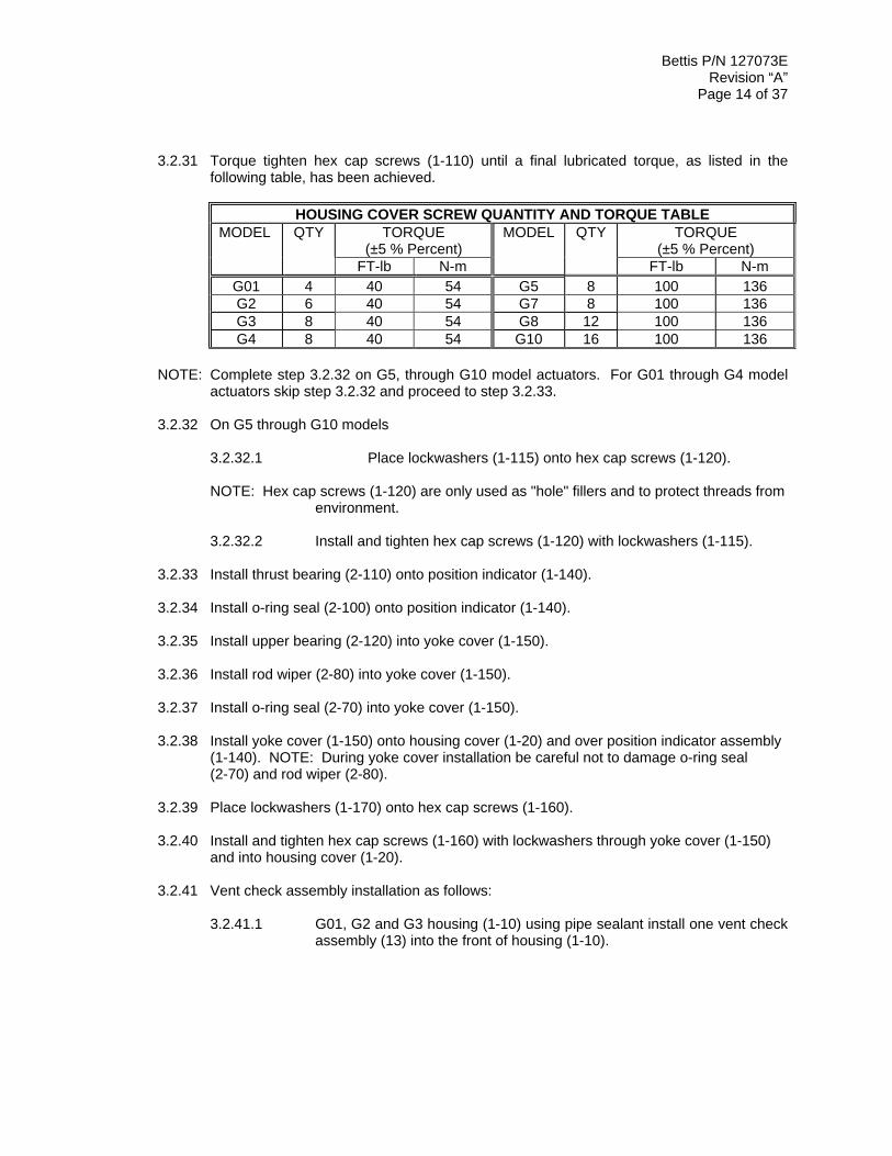
3.2.31 Torque tighten hex cap screws (1-110) until a final lubricated torque, as listed in thefollowing table, has been achieved.
HOUSING COVER SCREW QUANTITY AND TORQUE TABLETORQUE
(±5 % Percent)TORQUE
(±5 % Percent)MODEL QTY
FT-lb N-m
MODEL QTY
FT-lb N-mG01 4 40 54 G5 8 100 136G2 6 40 54 G7 8 100 136G3 8 40 54 G8 12 100 136G4 8 40 54 G10 16 100 136
NOTE: Complete step 3.2.32 on G5, through G10 model actuators. For G01 through G4 modelactuators skip step 3.2.32 and proceed to step 3.2.33.
3.2.32 On G5 through G10 models
3.2.32.1 Place lockwashers (1-115) onto hex cap screws (1-120).
NOTE: Hex cap screws (1-120) are only used as "hole" fillers and to protect threads fromenvironment.
3.2.32.2 Install and tighten hex cap screws (1-120) with lockwashers (1-115).
3.2.33 Install thrust bearing (2-110) onto position indicator (1-140).
3.2.34 Install o-ring seal (2-100) onto position indicator (1-140).
3.2.35 Install upper bearing (2-120) into yoke cover (1-150).
3.2.36 Install rod wiper (2-80) into yoke cover (1-150).
3.2.37 Install o-ring seal (2-70) into yoke cover (1-150).
3.2.38 Install yoke cover (1-150) onto housing cover (1-20) and over position indicator assembly(1-140). NOTE: During yoke cover installation be careful not to damage o-ring seal(2-70) and rod wiper (2-80).
3.2.39 Place lockwashers (1-170) onto hex cap screws (1-160).
3.2.40 Install and tighten hex cap screws (1-160) with lockwashers through yoke cover (1-150)and into housing cover (1-20).
3.2.41 Vent check assembly installation as follows:
3.2.41.1 G01, G2 and G3 housing (1-10) using pipe sealant install one vent checkassembly (13) into the front of housing (1-10).
Bettis P/N 127073ERevision “A”
Page 15 of 37
3.2.41.2 G2 and G3 housing (1-10) using pipe sealant install one vent checkassembly (13) into the top area of housing cover (1-20).
3.2.41.3 G4 through G10 housing (1-10) using pipe sealant install two vent checkassemblies (13) into the front of housing (1-10).
3.2.42 NOTE: Refer to Section 2 step 2.3.3 for correct position indicator placement. Installposition indicator (1-220) over the exposed shaft of position indicator assembly (1-140).
3.2.43 Install stop screw nuts (1-190) onto stop screws (1-180).
3.2.44 Install o-ring (2-90) onto stop screws (1-180).
3.2.45 Install two stop screws (1-180) into two stop screw holes on the front of housing (1-10).
3.2.46 Adjust both stop screws (1-180) back to settings recorded earlier in Section 2 at step2.3.2.
3.2.47 Tighten both stop screw nuts (1-190) securely.
3.3 PNEUMATIC POWER MODULE REASSEMBLY
NOTES: 1. For early model G2 and G3 actuators with double nuts on the powermodule use section 3.4 for reassembly.
2. Refer to Section 2 step 2.1.4 for the correct installation location for pistonrod (3-40).
3. THE ACTUATOR MUST BE IN THE APPROPRIATE OVERTRAVELPOSITION. Confirm over-travel position by observing the guide block(1-30) is against the inner wall of housing (1-10).
3.3.1 Lubricate piston rod (3-40) and insert through the side of housing (1-10).
3.3.1.1 G2 thru G10 screw piston rod (3-40) onto extension rod assembly (1-50).
3.3.1.2 G01 only screw piston rod (3-40) onto guide block (1-30).
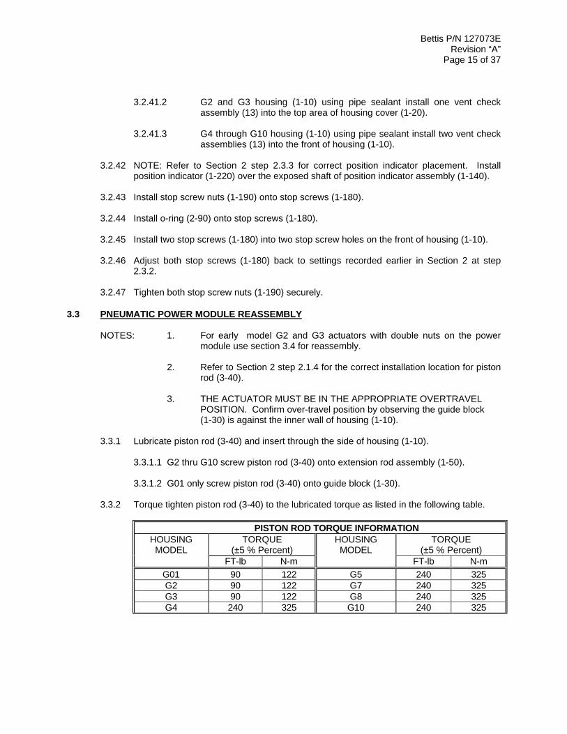
3.3.2 Torque tighten piston rod (3-40) to the lubricated torque as listed in the following table.
PISTON ROD TORQUE INFORMATIONTORQUE
(±5 % Percent)TORQUE
(±5 % Percent)HOUSINGMODEL
FT-lb N-m
HOUSINGMODEL
FT-lb N-m
G01 90 122 G5 240 325G2 90 122 G7 240 325G3 90 122 G8 240 325G4 240 325 G10 240 325
Bettis P/N 127073ERevision “A”
Page 16 of 37
3.3.3 Refer to assembly drawing page 2 of 2 Detail "C". Install one rod wiper (4-10) into innerend cap (3-10).
3.3.4 Install one rod bushing (4-20) into inner end cap (3-10).
3.3.5 Coat one Polypak seal (4-30) with lubricant and install, lip first, into inner end cap (3-10).
CAUTION: Install the Polypak seal with energizer ring facing outboard side (away fromhousing).
3.3.6 Install one o-ring seal (4-90) into seal groove located on the inboard face of inner end cap(3-10).
3.3.7 Install inner end cap (3-10) on to housing (1-10). NOTE: The pressure inlet port shouldbe positioned in the same position as recorded in section 2.2 step 2.2.1.
3.3.8 Place lockwashers (3-110) onto hex cap screws (3-100).
3.3.9 Install hex cap screws (3-100), with lockwashers, through housing (1-10) and into innerend cap (3-10).
3.3.10 Refer to assembly drawing page 2 of 2 Detail "D". Install one o-ring seal (4-70) into theseal groove in piston rod (3-40).
3.3.11 Apply lubricant to two sets of rod T-seal components (4-50).
NOTE: The T-seal is composed of one rubber seal and two split skive-cut back-up rings.
3.3.11.1 Install two sets of rod T-seals (4-50) into the internal diameter sealgrooves of piston (3-30).
3.3.11.2 Install a back-up ring on each side of the T-seal.
3.3.11.3 When installing the back-up rings, do not align the skive-cuts.
3.3.11.4 If the back-up rings are too long and the rings overlap beyond theskive-cuts, then the rings must be trimmed with a razor sharp instrument.
3.3.12 Install two split ring halves (3-50) into the inner most groove in piston rod (3-40) and retainby installing the recessed area of piston (3-30) onto the piston rod and over the two splitring halves (3-50).
3.3.13 Install two split ring halves (3-50) into the piston rod, in front of the piston installed in theprevious step, and retain with retainer ring (3-60).
3.3.14 Install one o-ring seal (4-40) onto the outer diameter seal groove of inner end cap (3-10).
3.3.15 Coat one D-ring seal (4-60) with lubricant and install into the piston external seal groove. NOTE: The flat side of the D-ring seal go down into the seal groove.
Bettis P/N 127073ERevision “A”
Page 17 of 37
3.3.16 Coat two tie bars (3-20) with lubricant and install by carefully pushing tie bars throughpiston (3-30) and rod T-seal (4-50).
3.3.17 Screw tie bars (3-20) into inner end cap (3-10) and tighten until the threads bottom out.
3.3.18 Refer to assembly drawing page 2 of 2 Detail "E". Coat two o-ring seals (4-80) withlubricant and install into outer end cap (3-80).
3.3.19 Apply lubricant to one o-ring seal (4-40) and install into the outer diameter o-ring groove ofouter end cap (3-80).
3.3.20 Apply lubricant to the bore of cylinder (3-70).
3.3.21 Install lubricated cylinder (3-70) over piston (3-30) and onto inner end cap (3-10). Wheninstalling the cylinder over the piston seal tilt cylinder 15° to 30° degrees to piston rod.
CAUTION: If needed, when installing the cylinder, hammer on the end of the cylinderonly with a non metallic object.
3.3.22 Install outer end cap (3-80) over tie bars (3-20) and into cylinder (3-70). NOTE: Thepressure inlet port should be positioned in the same position as recorded in section 2.2step 2.2.1.
3.3.23 Install tie bar nuts (3-90) onto tie bars (3-20). Torque tighten tie bar nuts, alternately in 100foot pound / N-m increments, until a final lubricated torque, as listed in the following table,has been achieved.
TIE BAR NUTSTORQUE (±5 % ) TORQUE (±5 %)HOUSING
MODEL FT-lb N-mHOUSINGMODEL FT-lb N-m
G01 120 163 G5 400 542G2 120 163 G7 500 678G3 150 203 G8 500 678G4 150 203 G10 1200 1627
3.3.24 Install lockwashers (3-140) onto socket cap screws (3-130) ).
3.3.25 Install and tighten socket cap screws (3-130), with lockwashers (3-140), into outer end cap(3-80).
3.3.26 If removed, using pipe dope, install pipe plug (3-120) into outer end cap (3-80).
3.3.27 Apply sufficient pneumatic pressure to outer end cap (3-80) pressure inlet port to movethe piston to its full inboard position(next to inner end cap).
3.3.28 Remove pneumatic pressure from outer end cap (3-80).
Bettis P/N 127073ERevision “A”
Page 18 of 37
3.3.29 Install breather assembly (12) in outer end cap (3-80).
NOTE: Individual actuators may not have reducer bushing (14) depending on port and breathersize.
3.4 G2 AND G3 EARLY MODEL PNEUMATIC POWER MODULE REASSEMBLY
NOTES: 1. Early G2 and G3 pneumatic power modules where equipped with tie barsthat had nuts on both ends of the tie bars (3-20) – double nuts.
2. Refer to Section 2 step 2.1.4 for the correct installation location for pistonrod (3-40).
3. THE ACTUATOR MUST BE IN THE APPROPRIATE OVERTRAVELPOSITION. Confirm over-travel position by observing the guide block(1-30) is against the inner wall of housing (1-10).
3.4.1 Refer to assembly drawing page 2 of 2 Detail "C". Install one rod wiper (4-10) into innerend cap (3-10).
3.4.2 Install one rod bushing (4-20) into inner end cap (3-10).
3.4.3 Coat one Polypak seal (4-30) with lubricant and install, lip first, into inner end cap (3-10).
CAUTION: Install the Polypak seal with energizer ring facing outboard side of innerend cap (3-10).
3.4.4 Install piston rod (3-40) through inner end cap (3-10). NOTE: The piston rod end withretainer grooves to be on the outboard side of inner end cap (3-10).
3.4.5 Apply lubricant to two sets of rod T-seal components (4-50).
NOTE: The T-seal is composed of one rubber seal and two split skive-cut back-up rings.
3.4.5.1 Install two sets of rod T-seals (4-50) into the internal diameter seal grooves ofpiston (3-30).
3.4.5.2 Install a back-up ring on each side of the T-seal.
3.4.5.3 When installing the back-up rings, do not align the skive-cuts.
3.4.5.4 If the back-up rings are too long and the rings overlap beyond the skive-cuts, thenthe rings must be trimmed with a razor sharp instrument.
3.4.6 Coat one D-ring seal (4-60) with lubricant and install into the piston external seal groove. NOTE: The flat side of the D-ring seal goes down into the seal groove.
3.4.7 Install piston (3-30) onto piston rod (3-40). NOTE: The cast rib side of the piston is to befacing away from the outboard side of inner end cap (3-10) or position piston (3-30) on thepiston rod so that the retainer grooves are on the out board side of the piston.
Bettis P/N 127073ERevision “A”
Page 19 of 37
3.4.8 Refer to assembly drawing page 2 of 2 Detail "D". Install o-ring seal (4-70) into the sealgroove in the outboard end of piston rod (3-40).
3.4.9 Install two split ring halves (3-50) into the outer most groove in piston rod (3-40) andretain by installing the recessed area of piston (3-30) over the two split halves (3-50).
3.4.10 Install two split ring halves (3-50) into the piston rod, in back of the piston and retain withretainer ring (3-60).
3.4.11 Coat two tie bars (3-20) with lubricant and install by carefully pushing tie bars throughpiston (3-30) and rod T-seal (4-50).
3.4.12 Install two tie bar o-ring seals (4-80) onto the inboard end of tie bars (3-20) and into theo-ring grooves provided.
3.4.13 Insert the tie bars through inner end cap (3-10) and screw hex nuts (3-90) onto inboard endof the tie bars. NOTE: Screw the tie bars through the hex nuts (3-90) until one completethread is exposed.
3.4.14 Refer to assembly drawing page 2 of 2 Detail "E". Install two tie bar o-ring seals (4-80) ontothe outboard end of tie bars (3-20) and into the o-ring grooves provided.
3.4.15 Apply lubricant to one o-ring seal (4-40) and install into the outer diameter o-ring groove ofouter end cap (3-80).
3.4.16 Apply lubricant to the bore of cylinder (3-70).
3.4.17 Install lubricated cylinder (3-70) over piston (3-30) and onto inner end cap (3-10). Wheninstalling the cylinder over the piston seal tilt cylinder 15° to 30° degrees to piston rod.
CAUTION: If needed, when installing the cylinder, hammer on the end of the cylinderonly with a non metallic object.
3.4.18 Install outer end cap (3-80) over tie bars (3-20) and into cylinder (3-70). NOTE: Thepressure inlet port should be positioned in the same position as recorded in section 2.2step 2.2.1.
3.4.19 Install tie bar nuts (3-90) onto tie bars (3-20). Torque tighten tie bar nuts, alternately in 100foot pound increments, until a final lubricated torque, as listed in the following table, hasbeen achieved.
TIE BAR NUTSTORQUE (±5 %) TORQUE (±5 %)HOUSING
MODEL FT-lb N-mHOUSINGMODEL FT-lb N-m
G2 120 163 G3 150 203
3.4.20 Install lockwashers (3-140) onto socket cap screws (3-130) ).
Bettis P/N 127073ERevision “A”
Page 20 of 37
3.4.21 Install and tighten socket cap screws (3-130), with lockwashers (3-140), into outer end cap(3-80).
3.4.22 Install Pneumatic Power Module per Section 5 steps 5.4.
3.5 G01 THROUGH G5 M11 HYDRAULIC OVERRIDE CYLINDER REASSEMBLY
NOTE: Review Section 3.1 General Reassembly before proceeding with G01 through G5 M11Hydraulic Override Cylinder Reassembly.
3.5.1 Install ram bushing (8-20) into hydraulic ram cover (7-10).
3.5.2 Install Polypak seal (8-30) into hydraulic ram cover (7-10). NOTE: The lip of Polypak seal(8-30) are to face toward the hydraulic override end cap when installed in the hydraulic ramcover.
3.5.3 Install rod wiper (8-10) into hydraulic ram cover (7-10).
3.5.4 Install hydraulic ram (7-20) into hydraulic ram cover (7-10). NOTE: When installing thehydraulic ram (7-20) push it through the hydraulic ram cover until the ram is at least flushwith the outboard ram cover.
3.5.5 Install o-ring seal (8-35) into inner diameter seal groove located at the outboard end of thethreads in the hydraulic override end cap (7-70).
3.5.6 Install hydraulic ram cover (7-10) into the hydraulic override end cap (7-70) by screwing theram cover into the end cap until the ram cover bottoms out into the end cap.
NOTE: For M11 hydraulic override cylinder installations refer to Section 5 step 5.2.
3.6 G7 THROUGH G10 M11 HYDRAULIC OVERRIDE CYLINDER REASSEMBLY
NOTE: Review Section 3 step 3.1 General Reassembly before proceeding with G7 through G10M11 Hydraulic Override Cylinder Reassembly.
3.6.1 Install Polypak seal (8-30) into hydraulic cylinder assembly (7-10). NOTE: The lip ofPolypak seal (8-30) will face toward the hydraulic override end cap when installed in thehydraulic cylinder assembly.
3.6.2 Install rod bushing (8-20) into hydraulic cylinder assembly (7-10).
3.6.3 Install rod wiper (8-10) into hydraulic cylinder assembly (7-10).
3.6.4 Install two split ring halves (7-30) into the inner most groove in piston rod (7-20) and retainby installing retainer ring (7-40) onto the split ring halves.
3.6.5 Apply hydraulic fluid to o-ring seal (8-50) and install it into the seal groove located betweenthe two split ring grooves on the piston rod (7-20).
3.6.6 Install the piston (7-50) onto the piston rod (7-20) and up against the split rings install in step3.5.4.
Bettis P/N 127073ERevision “A”
Page 21 of 37
3.6.7 Install two split ring halves (7-30) into the outboard groove in piston rod (7-20) and retainby installing retainer ring (7-40) onto the split ring halves.
3.6.8 Install Polypak seal (8-60) into outer diameter seal groove of piston (7-50). NOTE: The lipof Polypak seal (8-60) will face toward the hydraulic override outer end cap (7-70) wheninstalled in the hydraulic cylinder assembly.
3.6.9 Install piston bearing (8-40) into outer diameter bearing groove of piston (7-50).
3.6.10 Install o-ring seal (8-80) into inner diameter seal groove located in the piston (7-50).
3.6.11 Use pipe dope on the threads install pipe plug (7-110) into the vent tube hole in the inboardend of the hydraulic cylinder assembly (7-10).
3.6.12 Install vent tube (7-60) into the hydraulic cylinder assembly inboard end.
3.6.13 Install the assembled piston rod (7-20) with piston (7-50) into the open end of the hydrauliccylinder assembly and install the piston over the vent tube (7-60).
3.6.14 Install o-ring seal (8-90) into the vent tube port located in the outer end cap (7-70).
3.6.15 Install o-ring seal (8-70) into the o-ring groove located on the inner diameter of thehydraulic cylinder assembly flange opening.
3.6.16 Install the outer end cap (7-70) assembled piston rod (7-20) with piston (7-50) onto the openend of the hydraulic cylinder assembly and over the vent tube (7-60).
3.6.17 Install lockwashers (7-90) onto hex cap screws (7-80).
3.6.18 Install and tighten hex cap screws (7-80), with lockwashers (7-90) through outer end cap(7-70) and into hydraulic cylinder assembly.
NOTE: For M11 hydraulic override cylinder installations refer to Section 5 step 5.2.
3.7 ACTUATOR TESTING
3.7.1 Leakage Test - All areas where leakage to atmosphere may occur are to be checked,using a commercial leak testing solution.
CAUTION: Pressure applied to the actuator is not to exceed the maximum operatingpressure rating listed on the actuator name tag. Test the actuator using aproperly adjusted self relieving regulator, with gauge.
3.7.2 Cycle the actuator five times at the nominal operating pressure (NOP) as listed on theactuator’s name tag or the customers normal actuator supply pressure. If excessiveleakage across the pistons is noted, generally a bubble which breaks three seconds orless after starting to form, cycle the actuator five times as this will allow the seals to seektheir proper service condition.
NOTE: If excessive leakage across the piston remains, the actuator must be disassembled andthe cause of leakage must be determined and corrected.
Bettis P/N 127073ERevision “A”
Page 22 of 37
3.7.3 Apply NOP pressure to the pressure port in inner end cap (3-10) and allow the actuator tostabilize.
3.7.4 Apply a commercial leak testing solution to the following areas:
3.7.4.1 Joint between inner end cap (3-10) and cylinder (3-70). This checks cylinder toinner end cap o-ring seal.
3.7.4.2 The port hole in the outer end cap (3-80). This checks the piston D-seal tocylinder (3-70), o-ring seal (4-70), and rod T seal (4-50).
3.7.4.3 The vent check port hole in housing. This checks Polypak seal (4-30) that sealspiston rod (3-40) to inner end cap (3-10).
3.7.4.6 Remove pressure from the pressure inlet port.
3.7.5 If an actuator was disassembled and repaired, the above leakage test must be performedagain.
SECTION 4 - FIELD CONVERSIONS
4.1 FAIL MODE REVERSAL (CW TO CCW, OR CCW TO CW)
4.1.1 Remove Spring Module per Section 5.3.
4.1.2 Remove Pneumatic Power Module per Section 5.5.
4.1.3 Re-install the Spring Module onto the opposite end of housing (1-10) as it was previouslylocated per Section 5.4.
4.1.4 Re-install the Override Cylinder Assembly into Spring Module per Section 5.2.
4.2 CONVERTING DOUBLE ACTING ACTUATOR TO SPRING RETURN WITH OVERRIDECYLINDER ASSEMBLY
4.2.1 Remove Blind End Cap per steps 4.2.1.1 and 4.2.1.2.
4.2.1.1 Remove hex cap screws (5-20), with spring lockwashers (5-30), from blind endcap (5-10).
4.2.1.2 Remove blind end cap (5-10) from end of housing (1-10).
4.2.2 If Pneumatic Power Module needs to be relocated due to fail mode requirements (failcounter-clockwise) use Section 5.5 for removal and Section 5.6 for installation.
Bettis P/N 127073ERevision “A”
Page 23 of 37
4.2.3 Install Powr Swivl Module per Section 5.8.
4.2.4 Install the Spring Module onto the end of housing (1-10) per Section 5.4.
4.2.5 Install the Override Cylinder Assembly into Spring Module per Section 5.2.
SECTION 5 - MODULE REMOVAL AND INSTALLATION
5.1 M11 OVERRIDE CYLINDER REMOVAL
5.1.1 Shut off and exhaust the operating media from both sides of the actuator’s powercylinder.
5.1.2 Place the M11 pump control knob (20-320) in the Auto position. NOTE: Control knob(20-320) is located in front and at the bottom of the M11 pump manifold (20-10).
NOTE: Using a means of capturing the hydraulic fluid that will be lost during the following steps.Use a bucket, tub, and large container, ECT.
5.1.3 Remove all the piping from the M11 override cylinder end cap (7-70).
5.1.4 M11 Hydraulic override cylinder removal: For models G01 through G5 use step 5.1.5 andfor G7 through G10 use step 5.1.6..
WARNING: Confirm that the M11 pump control knob is in the auto position prior tocompleting step 5.1.5. DO NOT STAND DIRECTLY IN FRONT OF THE M11OVERRIDE CYLINDER WHEN COMPLETING STEP 5.1.5 - STAND TO ONESIDE OR THE OTHER.
5.1.5 G01 through G5 M11 override cylinder removal.
5.1.5.1 Unscrew and remove hex cap screws (7-80) with lockwashers (7-90) fromoverride cylinder end cap (7-70).
5.1.5.2 Remove override cylinder assembly from spring cartridge assembly (5-10).
5.1.6 G7 through G10 M11 override cylinder removal.
CAUTION: Do not remove hex cap screws (7-80) from M11 override cylinder at thistime. If hex cap screws (7-80) are removed at this time it is possible thathydraulic fluid will be dumped inside the spring cartridge.
Bettis P/N 127073ERevision “A”
Page 24 of 37
5.1.6.1 Unscrew and remove hex cap screws (7-100) with lockwashers (7-90) fromoverride cylinder end cap (7-70). NOTE: To identify hex cap screws (7-100) fromhex cap screws (7-80), hex cap screws (7-100) will be located to the left and rightof SR cartridge top dead center and will then be counted as every other hex capscrew. To verify correct hex cap screws check the following table for screwlength.
ITEM 7-80 LENGTH ITEM 7-100 LENGTHACTUATOR MODELInches mm Inches mm
G7 2 50.8 2.75 69.85G8 3 76.2 4.5 114.3G10 3.5 88.9 5.0 127
5.1.6.2 Remove override cylinder assembly from spring cartridge assembly (5-10).
5.2 M11 OVERRIDE CYLINDER INSTALLATION
5.2.1 Install o-ring seal (6-10) into the o-ring groove in the outboard end of spring cartridgeassembly (5-10).
5.2.2 M11 Hydraulic override cylinder installation: For models G01 through G5 use step 5.2.3and for G7 through G10 use step 5.2.4..
5.2.3 G01 through G5 M11 override cylinder installation.
5.2.3.1 Insert M11 hydraulic override cylinder assembly through spring cartridge outerend.
5.2.3.2 Install lockwashers (7-90) on to hex cap screws (7-80).
5.2.3.3 Install hex cap screws (7-80) with lockwashers (7-90) through hydraulic overrideend cap (7-70) and into outer end of spring cartridge (5-10).
5.2.4 G7 through G10 M11 override cylinder installation.
5.2.4.1 Insert M11 hydraulic override cylinder assembly into spring cartridge outer end.
5.2.4.2 Install lockwashers (7-90) on to eight hex cap screws (7-100).
5.2.4.3 Install hex cap screws (7-100) with lockwashers (7-90) through hydraulic overrideend cap (7-70) and into outer end of spring cartridge (5-10).
5.2.5 Torque tighten hex cap screws (7-100) and (7-80), alternately until a final lubricatedtorque, as listed in the following table, has been achieved.
Bettis P/N 127073ERevision “A”
Page 25 of 37
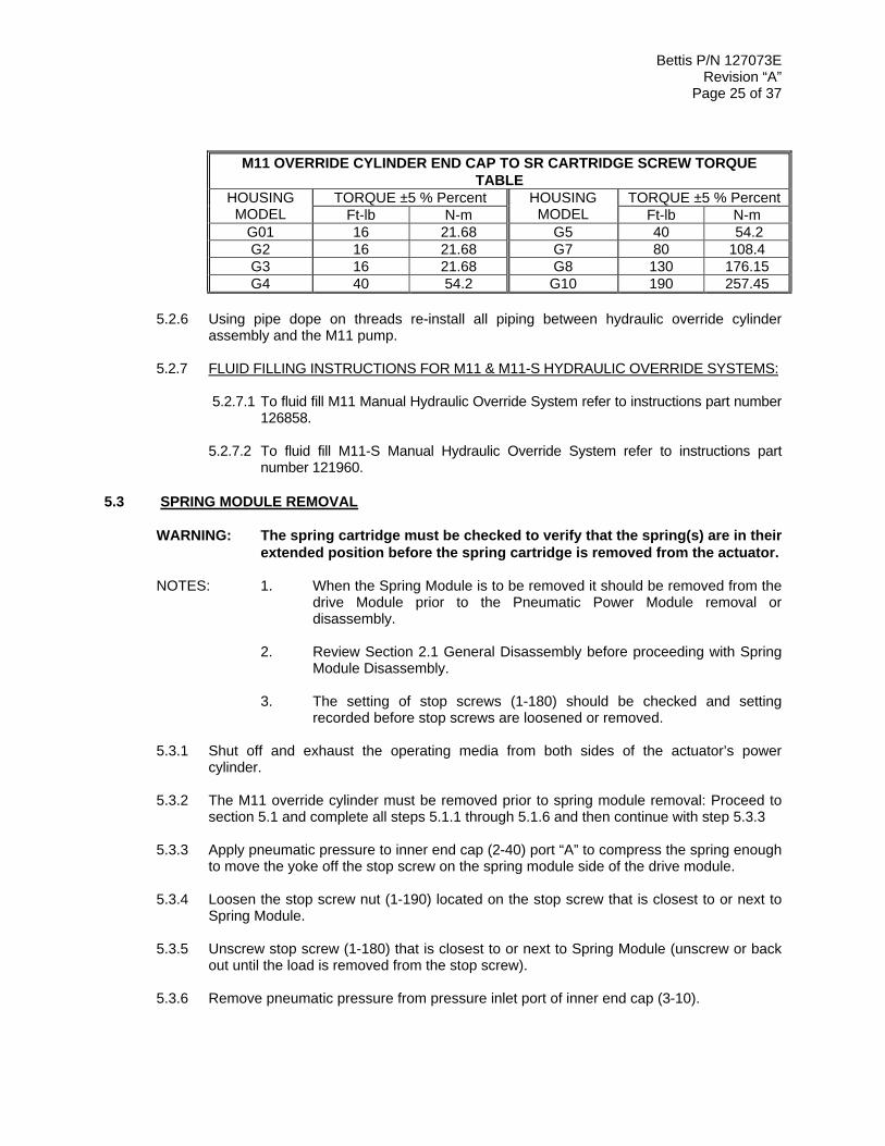
M11 OVERRIDE CYLINDER END CAP TO SR CARTRIDGE SCREW TORQUETABLE
TORQUE ±5 % Percent TORQUE ±5 % PercentHOUSINGMODEL Ft-lb N-m
HOUSINGMODEL Ft-lb N-m
G01 16 21.68 G5 40 54.2G2 16 21.68 G7 80 108.4G3 16 21.68 G8 130 176.15G4 40 54.2 G10 190 257.45
5.2.6 Using pipe dope on threads re-install all piping between hydraulic override cylinderassembly and the M11 pump.
5.2.7 FLUID FILLING INSTRUCTIONS FOR M11 & M11-S HYDRAULIC OVERRIDE SYSTEMS:
5.2.7.1 To fluid fill M11 Manual Hydraulic Override System refer to instructions part number126858.
5.2.7.2 To fluid fill M11-S Manual Hydraulic Override System refer to instructions partnumber 121960.
5.3 SPRING MODULE REMOVAL
WARNING: The spring cartridge must be checked to verify that the spring(s) are in theirextended position before the spring cartridge is removed from the actuator.
NOTES: 1. When the Spring Module is to be removed it should be removed from thedrive Module prior to the Pneumatic Power Module removal ordisassembly.
2. Review Section 2.1 General Disassembly before proceeding with SpringModule Disassembly.
3. The setting of stop screws (1-180) should be checked and settingrecorded before stop screws are loosened or removed.
5.3.1 Shut off and exhaust the operating media from both sides of the actuator’s powercylinder.
5.3.2 The M11 override cylinder must be removed prior to spring module removal: Proceed tosection 5.1 and complete all steps 5.1.1 through 5.1.6 and then continue with step 5.3.3
5.3.3 Apply pneumatic pressure to inner end cap (2-40) port “A” to compress the spring enoughto move the yoke off the stop screw on the spring module side of the drive module.
5.3.4 Loosen the stop screw nut (1-190) located on the stop screw that is closest to or next toSpring Module.
5.3.5 Unscrew stop screw (1-180) that is closest to or next to Spring Module (unscrew or backout until the load is removed from the stop screw).
5.3.6 Remove pneumatic pressure from pressure inlet port of inner end cap (3-10).
Bettis P/N 127073ERevision “A”
Page 26 of 37
CAUTION: Due to the weight and size of spring cartridge assembly (5-10), heavy dutysupport equipment will be required when removing spring cartridgeassembly from the actuator housing. Refer to section 6 for spring cartridgemodule weights.
5.3.7 The spring cartridge "pre-load" must be removed before spring cartridge assembly (5-10)is removed from housing (1-10). Refer to steps 5.3.4 through 5.3.6 for spring cartridge"pre-load" removal.
5.3.8 Remove breather assembly (12) from outer end cap (3-80) port “B”.
CAUTION: The maximum pressure to be applied in step 5.3.9 is 25 PSIG.
5.3.9 Apply pneumatic pressure, not to exceed the maximum as indicated in the above“CAUTION”, to the pressure inlet port “B” of outer end cap (3-80) to move the springcartridge tension rod hex nut out of it's cast hex seat.
NOTE: If pneumatic pressure is not available to apply to the pressure inlet port “B” located inouter end cap (3-80) then remove pipe plug (3-120) or if equipped with an extended stop(ES) remove the ES. Using a long rod go through the outer end cap pipe plug or ESvacant port hole and push on the piston rod so as to move the spring cartridge tension rodhex nut out of it's cast hex seat.
5.3.10 Unscrew the spring cartridge tension rod from the Drive Module. The tension rod can berotated for removal by going through the open end of spring cartridge assembly with asquare male drive extension.
5.3.11 Remove hex cap screws (5-20) with lockwashers (5-30) from housing (1-10).
5.3.12 Remove spring cartridge assembly (5-10) from actuator housing (1-10).
WARNING: Under no circumstances should the spring cartridge assembly (5-10) be cutapart, as the spring is pre-loaded and the spring cartridge is a weldassembly.
5.4 SPRING MODULE INSTALLATION
CAUTION: Due to the weight and size of Spring Module, heavy duty supportequipment will be required when installing spring cartridge module to theactuator housing. For the approximate weight of the spring cartridge referto Section 6.
WARNING ACTUATOR MUST BE IN THE APPROPRIATE OVERTRAVEL POSITION (seedetail “A” on warning tag attached to Spring Module access hole cover orto Bettis drawing part number 123650). Confirm overtravel position byobserving the guide block (1-30) is against the inner wall of housing (1-10).
NOTE: The setting of stop screws (1-180) should be checked and setting recorded before stopscrews are loosened or removed.
Bettis P/N 127073ERevision “A”
Page 27 of 37
5.4.1 On stop screw (1-180), that is located on the same side of the housing as spring cartridge(5-10), loosen stop screw nut (1-190).
5.4.2 Unscrew or back out stop screw (1-180) to achieve overtravel as illustrated in detail “A” onwarning tag attached to Spring Module cover plate or to Bettis drawing part number123650.
5.4.3 Install o-ring seal (6-20) into the o-ring groove in the inboard end of spring cartridgeassembly (5-10).
5.4.4 Using lifting equipment move Spring Module up to housing (1-10) and align springcartridge tension rod with extension rod assembly (9-50).
WARNING: COMPLETE STEP 5.4.5 TO AVOID SEVER INJURY TO PERSONNEL ORINCUR MAJOR DAMAGE TO THE ACTUATOR.
5.4.5 SPRING CARTRIDGE TENSION ROD TO ROD EXTENSION INSTALLATION ASFOLLOWS:
5.4.5.1 Using a male square drive extension, go through the open end of Spring Module(5-10) and rotate the tension rod nut until initial thread engagement is achieved.
NOTE: Confirm initial thread engagement of rod extension (9-50) to tension rod.
5.4.5.2 After confirming initial thread engagement rotate tension rod into extension rodassembly (9-50) per the following table.
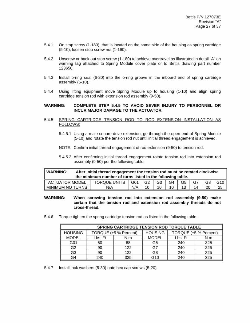
WARNING: After initial thread engagement the tension rod must be rotated clockwisethe minimum number of turns listed in the following table.
ACTUATOR MODEL TORQUE UNITS G01 G2 G3 G4 G5 G7 G8 G10MINIMUM NO TURNS N/A N/A 10 10 10 13 14 20 25
WARNING: When screwing tension rod into extension rod assembly (9-50) makecertain that the tension rod and extension rod assembly threads do notcross-thread.
5.4.6 Torque tighten the spring cartridge tension rod as listed in the following table.
SPRING CARTRIDGE TENSION ROD TORQUE TABLEHOUSING TORQUE (±5 % Percent) HOUSING TORQUE (±5 % Percent)
MODEL Lbs. Ft N.m MODEL Lbs. Ft N.mG01 50 68 G5 240 325G2 90 122 G7 240 325G3 90 122 G8 240 325G4 240 325 G10 240 325
5.4.7 Install lock washers (5-30) onto hex cap screws (5-20).
Bettis P/N 127073ERevision “A”
Page 28 of 37
5.4.8 Install hex cap screws (5-20) with lockwashers (5-30) through housing (1-10) and intospring cartridge assembly (5-10) and tighten.
5.4.9 Install o-ring seal (6-10) into the o-ring groove in the outboard end of spring cartridgeassembly (5-10).
5.4.10 M11 Hydraulic override cylinder installation: For models G2 through G5 use step 5.4.11and for G7 through G10 use step 5.4.12..
5.4.11 G2 through G5 M11 override cylinder installation.
5.4.11.1 Insert M11 hydraulic override cylinder assembly into spring cartridgeouter end.
5.4.11.2 Install lockwashers (7-90) on to eight hex cap screws (7-80).
5.4.11.3 Install eight hex cap screws (7-80) with lockwashers (7-90) through endcap (7-70) and into outer end of spring cartridge (5-10).
5.4.12 G7 through G10 M11 override cylinder installation.
5.4.12.1 Insert M11 hydraulic override cylinder assembly into spring cartridgeouter end.
5.4.12.2 Install lockwashers (7-80) on to eight hex cap screws (7-100).
5.4.12.3 Install eight hex cap screws (7-100) with lockwashers (7-90) through endcap (7-70) and into outer end of spring cartridge (5-10).
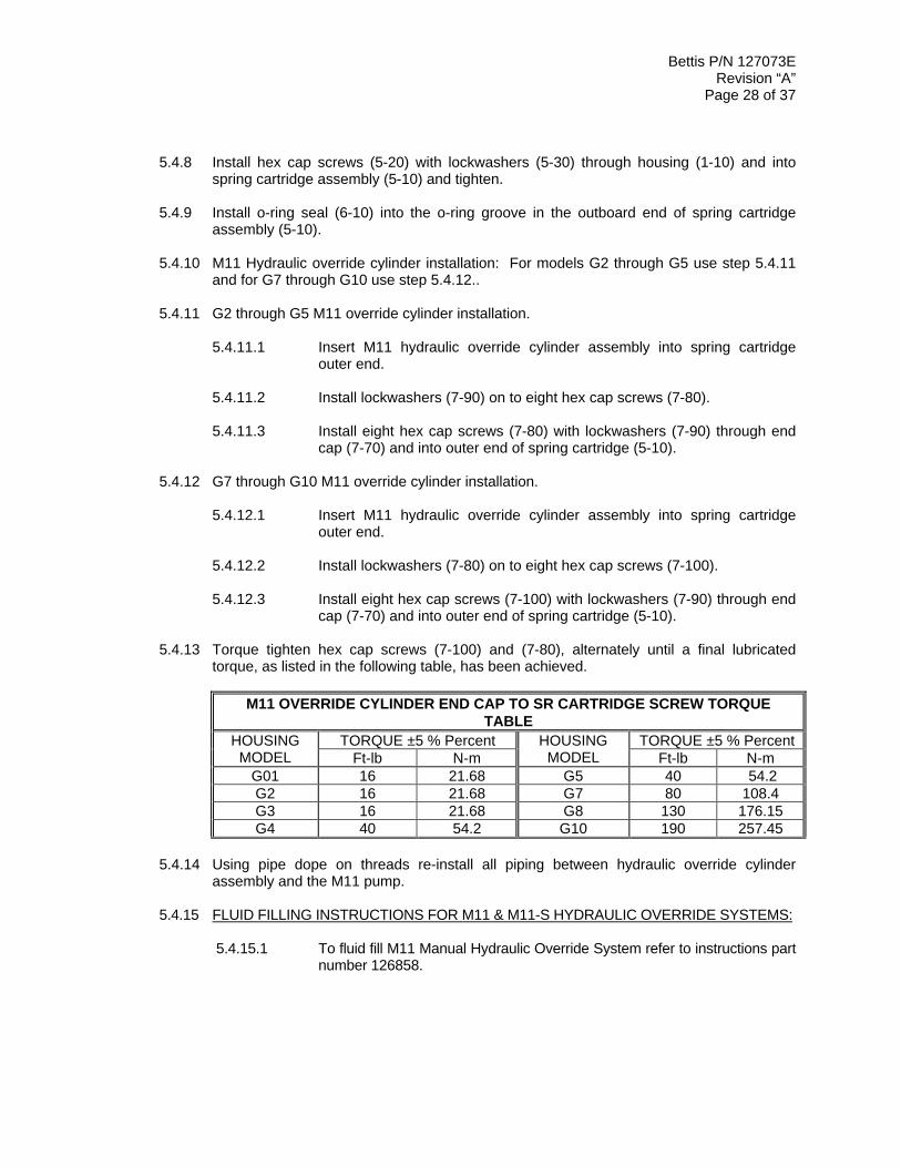
5.4.13 Torque tighten hex cap screws (7-100) and (7-80), alternately until a final lubricatedtorque, as listed in the following table, has been achieved.
M11 OVERRIDE CYLINDER END CAP TO SR CARTRIDGE SCREW TORQUETABLE
TORQUE ±5 % Percent TORQUE ±5 % PercentHOUSINGMODEL Ft-lb N-m
HOUSINGMODEL Ft-lb N-m
G01 16 21.68 G5 40 54.2G2 16 21.68 G7 80 108.4G3 16 21.68 G8 130 176.15G4 40 54.2 G10 190 257.45
5.4.14 Using pipe dope on threads re-install all piping between hydraulic override cylinderassembly and the M11 pump.
5.4.15 FLUID FILLING INSTRUCTIONS FOR M11 & M11-S HYDRAULIC OVERRIDE SYSTEMS:
5.4.15.1 To fluid fill M11 Manual Hydraulic Override System refer to instructions partnumber 126858.
Bettis P/N 127073ERevision “A”
Page 29 of 37
5.4.15.2 To fluid fill M11-S Manual Hydraulic Override System refer to instructionspart number 121960.
5.4.16 If removed install stop screw nuts (1-190) onto stop screws (1-180).
5.4.17 If removed install o-ring (2-90) onto stop screws (1-180).
5.4.18 If removed install two stop screws (1-180) into two stop screw holes on the front ofhousing (1-10).
5.4.19 Adjust both stop screws (1-180) back to settings recorded earlier in Section 5.
5.4.20 Tighten both stop screw nuts (1-190) securely.
5.5 PNEUMATIC POWER MODULE REMOVAL
CAUTION: Due to the weight and size of power module, heavy duty support equipmentwill be required when removing power module from the actuator housing. Refer to section 6 for Pneumatic Power Module weights.
5.5.1 Remove pipe plug (3-120) from outer end cap (3-80).
5.5.2 Remove hex cap screws (3-100) with lockwashers (3-110) from housing (1-10).
5.5.3 Using a male square drive extension, go through outer end cap (3-80) and unscrew pistonrod (3-40) from extension rod assembly (1-50).
NOTE: When removing power module from housing (1-10) be careful not to loose o-ring seal(4-90).
5.5.4 Remove power module from actuator housing (1-10).
5.6 PNEUMATIC POWER MODULE INSTALLATION
NOTE: Re-install the power module onto the opposite side of housing (1-10) as it was previouslylocated.
5.6.1 Check to verify that o-ring seal (4-90) is properly seated in its seal groove located on thehousing side of inner end cap (3-10).
NOTE: G2 and G3 models confirm that the two inboard hex nuts (3-90) flats are aligned to fit intothe slot located in the end of housing (1-10).
5.6.2 Using lifting equipment move the power module up to housing (1-10) and align piston rod(3-40) with extension rod assembly (1-50).
5.6.3 Using a male square drive extension, go through outer end cap (3-80) and screw piston rod(3-40) into extension rod assembly (1-50).
CAUTION: When screwing piston rod into extension rod assembly (1-50) make certainthat the piston rod and extension rod assembly threads do not cross-thread.
Bettis P/N 127073ERevision “A”
Page 30 of 37
5.6.4 Torque tighten piston rod (3-40) as follows:
5.6.4.1 G2 and G3 torque to 90 foot pounds lubricated.
5.6.4.2 G4 and G10 torque to 240 foot pounds lubricated.
5.6.5 Install lock washers (3-110) onto hex cap screws (3-100).
5.6.6 Install and tighten hex cap screws (3-100) with lockwashers (3-110) through housing (1-10)and screw into inner end cap (3-10).
5.6.7 Using pipe dope, install pipe plug (3-120) into outer end cap (3-80).
5.7 POWR SWIVL REMOVAL
5.7.1 Push the guide block to the side of housing (1-10) that will expose the extension rodassembly (1-50). NOTE: The guide block can be moved by inserting a long non metallicrod through the hole where the blind end cap was removed and pushing on the guideblock.
5.7.2 Refer to assembly drawing sheet 2 Detail "B". Use Bettis tool part number as listed inchart in section 1 step 1.5.2 to remove retainer nut assembly (1-60) from the guide block(1-30).
CAUTION: When removing rod extension assembly from guide block be careful not todrop one of the spherical washers inside the housing.
5.7.3 Remove rod extension assembly (1-50) from guide block (1-30).
NOTE: One spherical washer (1-40) will be removed from guide block (1-30) when extension rodassembly is removed.
5.7.4 Remove the remaining spherical washer (1-40) from guide block (1-30).
5.8 POWR SWIVL MODULE INSTALLATION
WARNING: The actuator must be in the appropriate overtravel position. Confirmovertravel position by observing the guide block (1-30) is against the innerwall of housing (1-10).
5.8.1 Push the guide block to the required side of the housing (1-10). NOTE: The guide blockcan be moved by inserting a long rod through either end of the housing and pushing onthe guide block.
5.8.2 Lubricate two spherical washers (1-40), and one extension rod assembly (1-50).
5.8.3 Install one spherical washer (1-40) into the side of guide block (1-30). NOTE: Thespherical side of washer (1-40) will be facing to the outside of guide block (1-30).
Bettis P/N 127073ERevision “A”
Page 31 of 37
5.8.4 Install second spherical washer (1-40) over threaded end of extension rod assembly(1-50). NOTE: The spherical side of the washer will go on the extension rod assemblyfacing the head of the extension rod assembly.
5.8.5 Install extension rod assembly (1-50) into right of guide block (1-30) and up against thefirst spherical washer (1-40).
5.8.6 Install extension retainer nut assembly (1-60) over extension rod assembly (1-50) andscrew into guide block (1-30).
5.8.7 Tighten extension retainer nut assembly (1-60) until extension rod assembly (1-50) cannot move. Back off the extension retainer nut assembly (1-60) just enough to allow forextension rod assembly (1-50) to move freely.
SECTION 6 - ACTUATOR SUPPORT INFORMATION
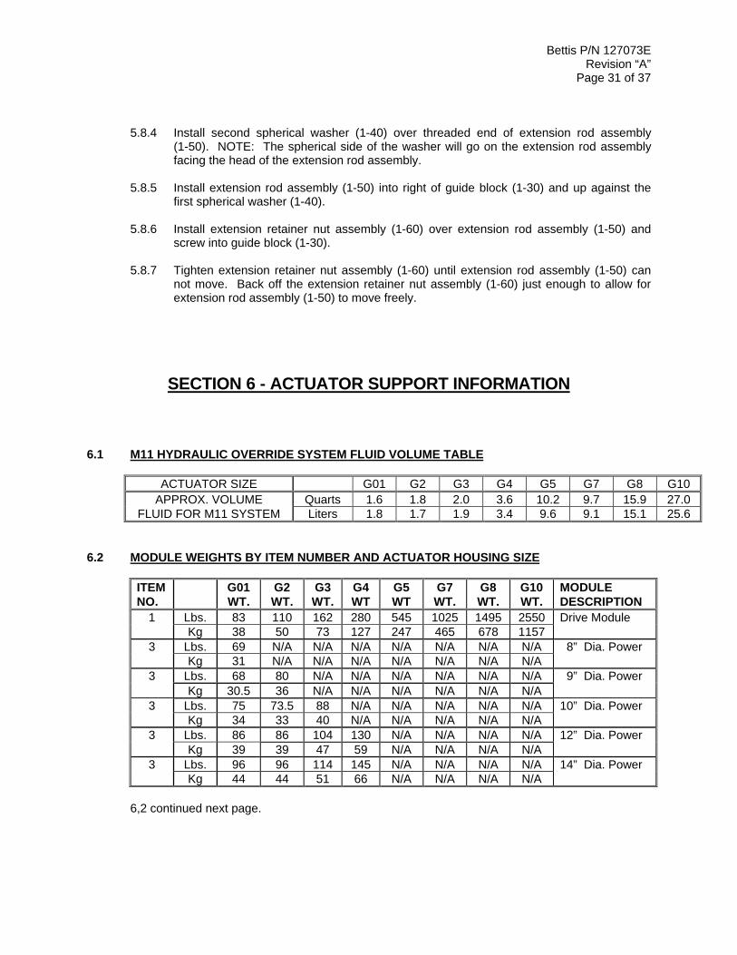
6.1 M11 HYDRAULIC OVERRIDE SYSTEM FLUID VOLUME TABLE
ACTUATOR SIZE G01 G2 G3 G4 G5 G7 G8 G10APPROX. VOLUME Quarts 1.6 1.8 2.0 3.6 10.2 9.7 15.9 27.0
FLUID FOR M11 SYSTEM Liters 1.8 1.7 1.9 3.4 9.6 9.1 15.1 25.6
6.2 MODULE WEIGHTS BY ITEM NUMBER AND ACTUATOR HOUSING SIZE
ITEMNO.
G01WT.
G2WT.
G3WT.
G4WT
G5WT
G7WT.
G8WT.
G10WT.
MODULEDESCRIPTION
1 Lbs. 83 110 162 280 545 1025 1495 2550 Drive ModuleKg 38 50 73 127 247 465 678 1157
3 Lbs. 69 N/A N/A N/A N/A N/A N/A N/A 8” Dia. PowerKg 31 N/A N/A N/A N/A N/A N/A N/A
Lbs. 68 80 N/A N/A N/A N/A N/A N/A3Kg 30.5 36 N/A N/A N/A N/A N/A N/A
9” Dia. Power
Lbs. 75 73.5 88 N/A N/A N/A N/A N/A3Kg 34 33 40 N/A N/A N/A N/A N/A
10” Dia. Power
3 Lbs. 86 86 104 130 N/A N/A N/A N/A 12” Dia. PowerKg 39 39 47 59 N/A N/A N/A N/A
3 Lbs. 96 96 114 145 N/A N/A N/A N/A 14” Dia. PowerKg 44 44 51 66 N/A N/A N/A N/A
6,2 continued next page.
Bettis P/N 127073ERevision “A”
Page 32 of 37
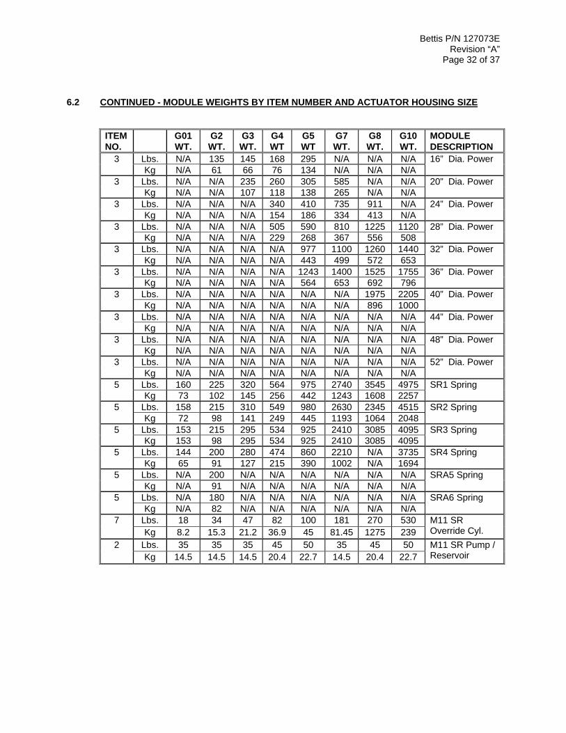
6.2 CONTINUED - MODULE WEIGHTS BY ITEM NUMBER AND ACTUATOR HOUSING SIZE
ITEMNO.
G01WT.
G2WT.
G3WT.
G4WT
G5WT
G7WT.
G8WT.
G10WT.
MODULEDESCRIPTION
3 Lbs. N/A 135 145 168 295 N/A N/A N/A 16” Dia. PowerKg N/A 61 66 76 134 N/A N/A N/A
3 Lbs. N/A N/A 235 260 305 585 N/A N/A 20” Dia. PowerKg N/A N/A 107 118 138 265 N/A N/A
3 Lbs. N/A N/A N/A 340 410 735 911 N/A 24” Dia. PowerKg N/A N/A N/A 154 186 334 413 N/A
3 Lbs. N/A N/A N/A 505 590 810 1225 1120 28” Dia. PowerKg N/A N/A N/A 229 268 367 556 508
3 Lbs. N/A N/A N/A N/A 977 1100 1260 1440 32” Dia. PowerKg N/A N/A N/A N/A 443 499 572 653
3 Lbs. N/A N/A N/A N/A 1243 1400 1525 1755 36” Dia. PowerKg N/A N/A N/A N/A 564 653 692 796
3 Lbs. N/A N/A N/A N/A N/A N/A 1975 2205 40” Dia. PowerKg N/A N/A N/A N/A N/A N/A 896 1000
3 Lbs. N/A N/A N/A N/A N/A N/A N/A N/A 44” Dia. PowerKg N/A N/A N/A N/A N/A N/A N/A N/A
3 Lbs. N/A N/A N/A N/A N/A N/A N/A N/A 48” Dia. PowerKg N/A N/A N/A N/A N/A N/A N/A N/A
3 Lbs. N/A N/A N/A N/A N/A N/A N/A N/A 52” Dia. PowerKg N/A N/A N/A N/A N/A N/A N/A N/A
5 Lbs. 160 225 320 564 975 2740 3545 4975 SR1 SpringKg 73 102 145 256 442 1243 1608 2257
5 Lbs. 158 215 310 549 980 2630 2345 4515 SR2 SpringKg 72 98 141 249 445 1193 1064 2048
5 Lbs. 153 215 295 534 925 2410 3085 4095 SR3 SpringKg 153 98 295 534 925 2410 3085 4095
5 Lbs. 144 200 280 474 860 2210 N/A 3735 SR4 SpringKg 65 91 127 215 390 1002 N/A 1694
5 Lbs. N/A 200 N/A N/A N/A N/A N/A N/A SRA5 SpringKg N/A 91 N/A N/A N/A N/A N/A N/A
5 Lbs. N/A 180 N/A N/A N/A N/A N/A N/A SRA6 SpringKg N/A 82 N/A N/A N/A N/A N/A N/A
7 Lbs. 18 34 47 82 100 181 270 530Kg 8.2 15.3 21.2 36.9 45 81.45 1275 239
M11 SROverride Cyl.
2 Lbs. 35 35 35 45 50 35 45 50Kg 14.5 14.5 14.5 20.4 22.7 14.5 20.4 22.7
M11 SR Pump /Reservoir
Bettis P/N 127073ERevision “A”
Page 33 of 37
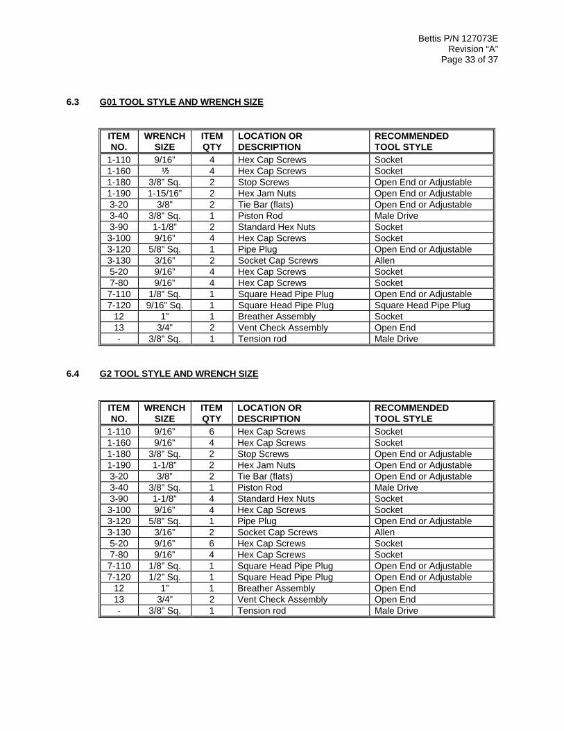
6.3 G01 TOOL STYLE AND WRENCH SIZE
ITEMNO.
WRENCHSIZE
ITEMQTY
LOCATION ORDESCRIPTION
RECOMMENDEDTOOL STYLE
1-110 9/16” 4 Hex Cap Screws Socket1-160 ½” 4 Hex Cap Screws Socket1-180 3/8” Sq. 2 Stop Screws Open End or Adjustable1-190 1-15/16” 2 Hex Jam Nuts Open End or Adjustable3-20 3/8” 2 Tie Bar (flats) Open End or Adjustable3-40 3/8” Sq. 1 Piston Rod Male Drive3-90 1-1/8” 2 Standard Hex Nuts Socket3-100 9/16” 4 Hex Cap Screws Socket3-120 5/8” Sq. 1 Pipe Plug Open End or Adjustable3-130 3/16” 2 Socket Cap Screws Allen5-20 9/16” 4 Hex Cap Screws Socket7-80 9/16” 4 Hex Cap Screws Socket7-110 1/8” Sq. 1 Square Head Pipe Plug Open End or Adjustable7-120 9/16” Sq. 1 Square Head Pipe Plug Square Head Pipe Plug
12 1” 1 Breather Assembly Socket13 3/4” 2 Vent Check Assembly Open End- 3/8” Sq. 1 Tension rod Male Drive
6.4 G2 TOOL STYLE AND WRENCH SIZE
ITEMNO.
WRENCHSIZE
ITEMQTY
LOCATION ORDESCRIPTION
RECOMMENDEDTOOL STYLE
1-110 9/16” 6 Hex Cap Screws Socket1-160 9/16” 4 Hex Cap Screws Socket1-180 3/8” Sq. 2 Stop Screws Open End or Adjustable1-190 1-1/8” 2 Hex Jam Nuts Open End or Adjustable3-20 3/8” 2 Tie Bar (flats) Open End or Adjustable3-40 3/8” Sq. 1 Piston Rod Male Drive3-90 1-1/8” 4 Standard Hex Nuts Socket3-100 9/16” 4 Hex Cap Screws Socket3-120 5/8” Sq. 1 Pipe Plug Open End or Adjustable3-130 3/16” 2 Socket Cap Screws Allen5-20 9/16” 6 Hex Cap Screws Socket7-80 9/16” 4 Hex Cap Screws Socket7-110 1/8” Sq. 1 Square Head Pipe Plug Open End or Adjustable7-120 1/2” Sq. 1 Square Head Pipe Plug Open End or Adjustable
12 1” 1 Breather Assembly Open End13 3/4” 2 Vent Check Assembly Open End- 3/8” Sq. 1 Tension rod Male Drive
Bettis P/N 127073ERevision “A”
Page 34 of 37
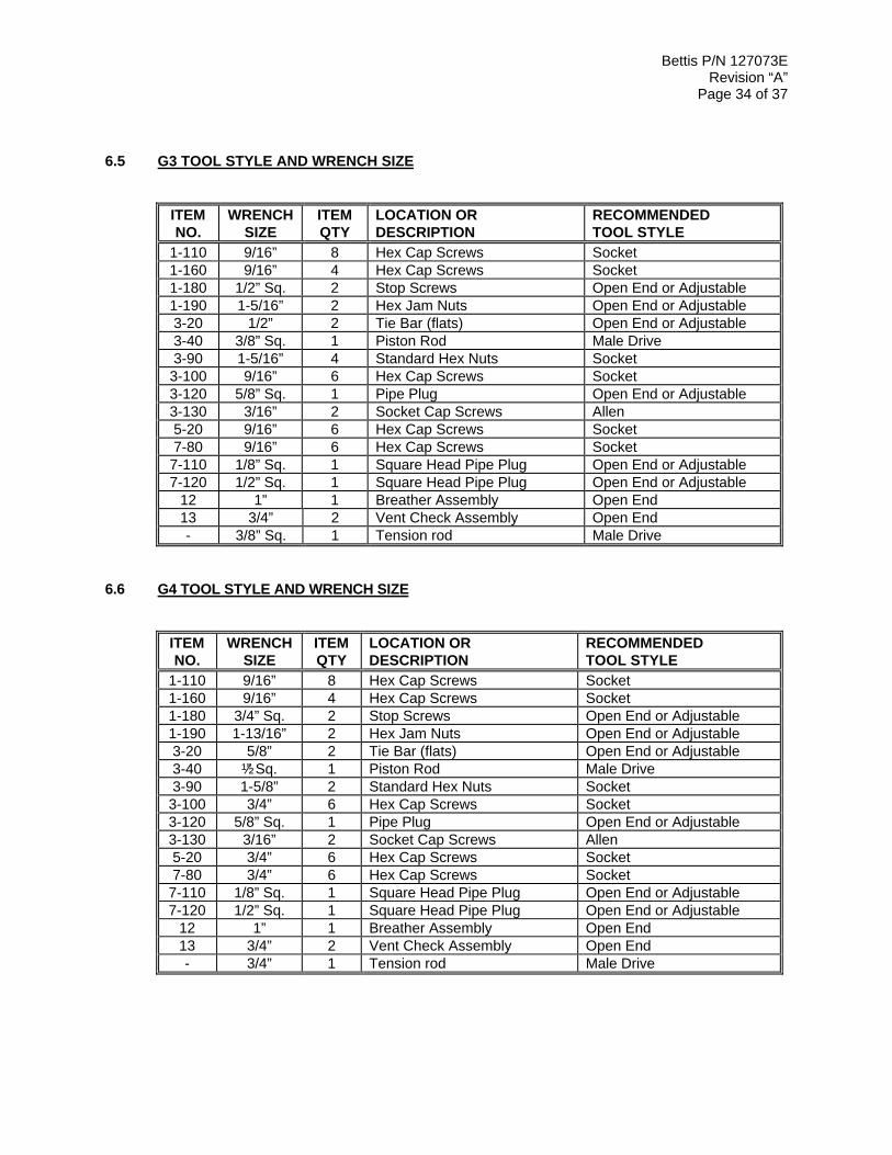
6.5 G3 TOOL STYLE AND WRENCH SIZE
ITEMNO.
WRENCHSIZE
ITEMQTY
LOCATION ORDESCRIPTION
RECOMMENDEDTOOL STYLE
1-110 9/16” 8 Hex Cap Screws Socket1-160 9/16” 4 Hex Cap Screws Socket1-180 1/2” Sq. 2 Stop Screws Open End or Adjustable1-190 1-5/16” 2 Hex Jam Nuts Open End or Adjustable3-20 1/2” 2 Tie Bar (flats) Open End or Adjustable3-40 3/8” Sq. 1 Piston Rod Male Drive3-90 1-5/16” 4 Standard Hex Nuts Socket3-100 9/16” 6 Hex Cap Screws Socket3-120 5/8” Sq. 1 Pipe Plug Open End or Adjustable3-130 3/16” 2 Socket Cap Screws Allen5-20 9/16” 6 Hex Cap Screws Socket7-80 9/16” 6 Hex Cap Screws Socket7-110 1/8” Sq. 1 Square Head Pipe Plug Open End or Adjustable7-120 1/2” Sq. 1 Square Head Pipe Plug Open End or Adjustable
12 1” 1 Breather Assembly Open End13 3/4” 2 Vent Check Assembly Open End- 3/8” Sq. 1 Tension rod Male Drive
6.6 G4 TOOL STYLE AND WRENCH SIZE
ITEMNO.
WRENCHSIZE
ITEMQTY
LOCATION ORDESCRIPTION
RECOMMENDEDTOOL STYLE
1-110 9/16” 8 Hex Cap Screws Socket1-160 9/16” 4 Hex Cap Screws Socket1-180 3/4” Sq. 2 Stop Screws Open End or Adjustable1-190 1-13/16” 2 Hex Jam Nuts Open End or Adjustable3-20 5/8” 2 Tie Bar (flats) Open End or Adjustable3-40 ½” Sq. 1 Piston Rod Male Drive3-90 1-5/8” 2 Standard Hex Nuts Socket3-100 3/4” 6 Hex Cap Screws Socket3-120 5/8” Sq. 1 Pipe Plug Open End or Adjustable3-130 3/16” 2 Socket Cap Screws Allen5-20 3/4” 6 Hex Cap Screws Socket7-80 3/4” 6 Hex Cap Screws Socket7-110 1/8” Sq. 1 Square Head Pipe Plug Open End or Adjustable7-120 1/2” Sq. 1 Square Head Pipe Plug Open End or Adjustable
12 1” 1 Breather Assembly Open End13 3/4” 2 Vent Check Assembly Open End- 3/4” 1 Tension rod Male Drive
Bettis P/N 127073ERevision “A”
Page 35 of 37
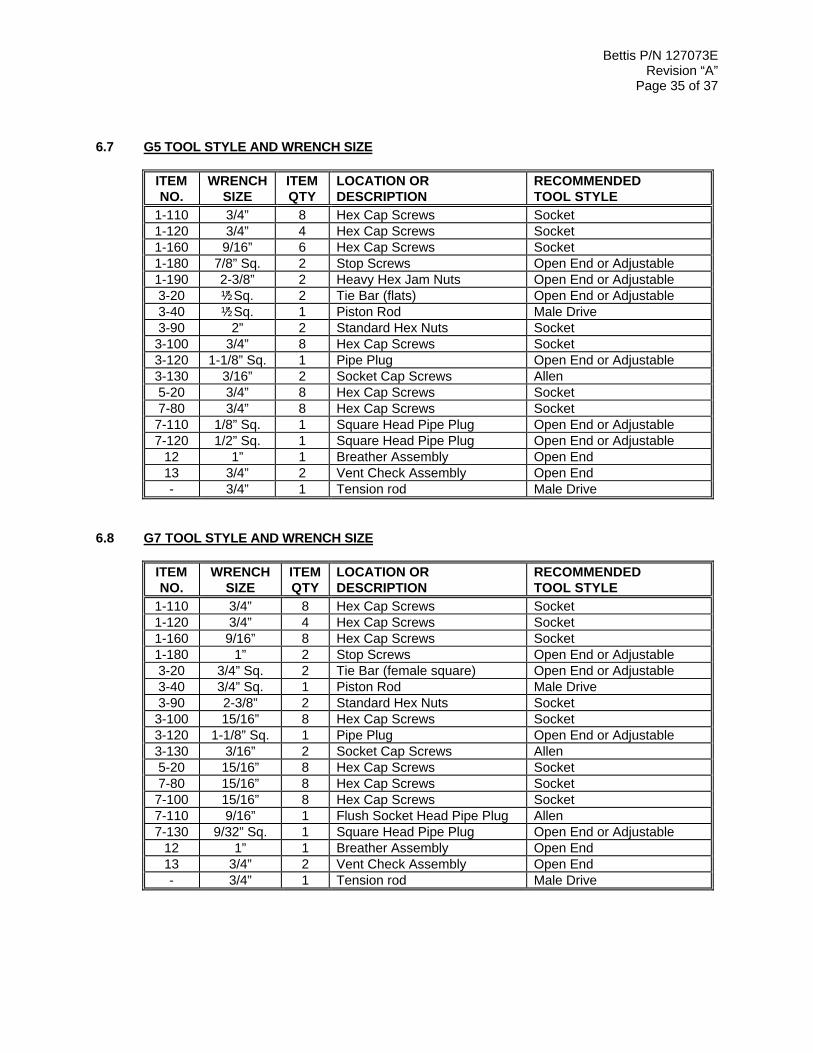
6.7 G5 TOOL STYLE AND WRENCH SIZE
ITEMNO.
WRENCHSIZE
ITEMQTY
LOCATION ORDESCRIPTION
RECOMMENDEDTOOL STYLE
1-110 3/4” 8 Hex Cap Screws Socket1-120 3/4” 4 Hex Cap Screws Socket1-160 9/16” 6 Hex Cap Screws Socket1-180 7/8” Sq. 2 Stop Screws Open End or Adjustable1-190 2-3/8” 2 Heavy Hex Jam Nuts Open End or Adjustable3-20 ½” Sq. 2 Tie Bar (flats) Open End or Adjustable3-40 ½” Sq. 1 Piston Rod Male Drive3-90 2” 2 Standard Hex Nuts Socket3-100 3/4” 8 Hex Cap Screws Socket3-120 1-1/8” Sq. 1 Pipe Plug Open End or Adjustable3-130 3/16” 2 Socket Cap Screws Allen5-20 3/4” 8 Hex Cap Screws Socket7-80 3/4” 8 Hex Cap Screws Socket7-110 1/8” Sq. 1 Square Head Pipe Plug Open End or Adjustable7-120 1/2” Sq. 1 Square Head Pipe Plug Open End or Adjustable
12 1” 1 Breather Assembly Open End13 3/4” 2 Vent Check Assembly Open End- 3/4” 1 Tension rod Male Drive
6.8 G7 TOOL STYLE AND WRENCH SIZE
ITEMNO.
WRENCHSIZE
ITEMQTY
LOCATION ORDESCRIPTION
RECOMMENDEDTOOL STYLE
1-110 3/4” 8 Hex Cap Screws Socket1-120 3/4” 4 Hex Cap Screws Socket1-160 9/16” 8 Hex Cap Screws Socket1-180 1” 2 Stop Screws Open End or Adjustable3-20 3/4” Sq. 2 Tie Bar (female square) Open End or Adjustable3-40 3/4” Sq. 1 Piston Rod Male Drive3-90 2-3/8” 2 Standard Hex Nuts Socket3-100 15/16” 8 Hex Cap Screws Socket3-120 1-1/8” Sq. 1 Pipe Plug Open End or Adjustable3-130 3/16” 2 Socket Cap Screws Allen5-20 15/16” 8 Hex Cap Screws Socket7-80 15/16” 8 Hex Cap Screws Socket7-100 15/16” 8 Hex Cap Screws Socket7-110 9/16” 1 Flush Socket Head Pipe Plug Allen7-130 9/32” Sq. 1 Square Head Pipe Plug Open End or Adjustable
12 1” 1 Breather Assembly Open End13 3/4” 2 Vent Check Assembly Open End- 3/4” 1 Tension rod Male Drive
Bettis P/N 127073ERevision “A”
Page 36 of 37
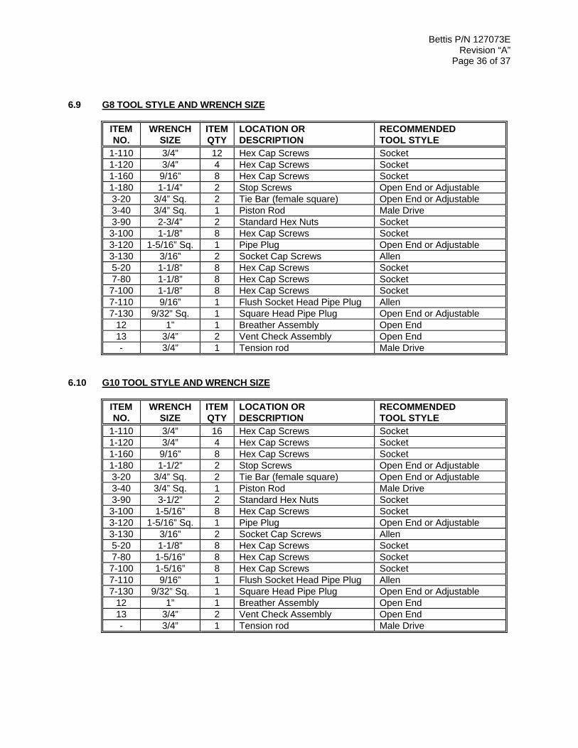
6.9 G8 TOOL STYLE AND WRENCH SIZE
ITEMNO.
WRENCHSIZE
ITEMQTY
LOCATION ORDESCRIPTION
RECOMMENDEDTOOL STYLE
1-110 3/4” 12 Hex Cap Screws Socket1-120 3/4” 4 Hex Cap Screws Socket1-160 9/16” 8 Hex Cap Screws Socket1-180 1-1/4” 2 Stop Screws Open End or Adjustable3-20 3/4” Sq. 2 Tie Bar (female square) Open End or Adjustable3-40 3/4” Sq. 1 Piston Rod Male Drive3-90 2-3/4” 2 Standard Hex Nuts Socket3-100 1-1/8” 8 Hex Cap Screws Socket3-120 1-5/16” Sq. 1 Pipe Plug Open End or Adjustable3-130 3/16” 2 Socket Cap Screws Allen5-20 1-1/8” 8 Hex Cap Screws Socket7-80 1-1/8” 8 Hex Cap Screws Socket7-100 1-1/8” 8 Hex Cap Screws Socket7-110 9/16” 1 Flush Socket Head Pipe Plug Allen7-130 9/32” Sq. 1 Square Head Pipe Plug Open End or Adjustable
12 1” 1 Breather Assembly Open End13 3/4” 2 Vent Check Assembly Open End- 3/4” 1 Tension rod Male Drive
6.10 G10 TOOL STYLE AND WRENCH SIZE
ITEMNO.
WRENCHSIZE
ITEMQTY
LOCATION ORDESCRIPTION
RECOMMENDEDTOOL STYLE
1-110 3/4” 16 Hex Cap Screws Socket1-120 3/4” 4 Hex Cap Screws Socket1-160 9/16” 8 Hex Cap Screws Socket1-180 1-1/2” 2 Stop Screws Open End or Adjustable3-20 3/4” Sq. 2 Tie Bar (female square) Open End or Adjustable3-40 3/4” Sq. 1 Piston Rod Male Drive3-90 3-1/2” 2 Standard Hex Nuts Socket3-100 1-5/16” 8 Hex Cap Screws Socket3-120 1-5/16” Sq. 1 Pipe Plug Open End or Adjustable3-130 3/16” 2 Socket Cap Screws Allen5-20 1-1/8” 8 Hex Cap Screws Socket7-80 1-5/16” 8 Hex Cap Screws Socket7-100 1-5/16” 8 Hex Cap Screws Socket7-110 9/16” 1 Flush Socket Head Pipe Plug Allen7-130 9/32” Sq. 1 Square Head Pipe Plug Open End or Adjustable
12 1” 1 Breather Assembly Open End13 3/4” 2 Vent Check Assembly Open End- 3/4” 1 Tension rod Male Drive
Bettis P/N 127073ERevision “A”
Page 37 of 37
ECN DATE REV BY * DATEReleased December 2001 A COMPILED B. Cornelius 17 December 2001
CHECKED B. Cornelius 17 December 2001APPROVED R. Smith 17 December 2001
* Signatures on file Bettis, Waller, Texas