Embed Size (px)
Citation preview
BETS-5Issue 1November 1, 1996
Spectrum Management
Broadcasting Equipment Technical Standard
Technical Standards andRequirements for AM BroadcastingTransmitters
Aussi disponible en français - NTMR-5
i
Purpose
This document contains the technical standards and requirements for the issuance of aTechnical Acceptance Certificate (TAC) for AM broadcasting transmitters.
A certificate issued for equipment classified as type approved or as technically acceptablebefore the coming into force of these technical standards and requirements is considered tobe a valid and subsisting TAC.
A Technical Acceptance Certificate is not required for equipment manufactured or importedsolely for re-export, prototyping, demonstration, exhibition or testing purposes.
ii
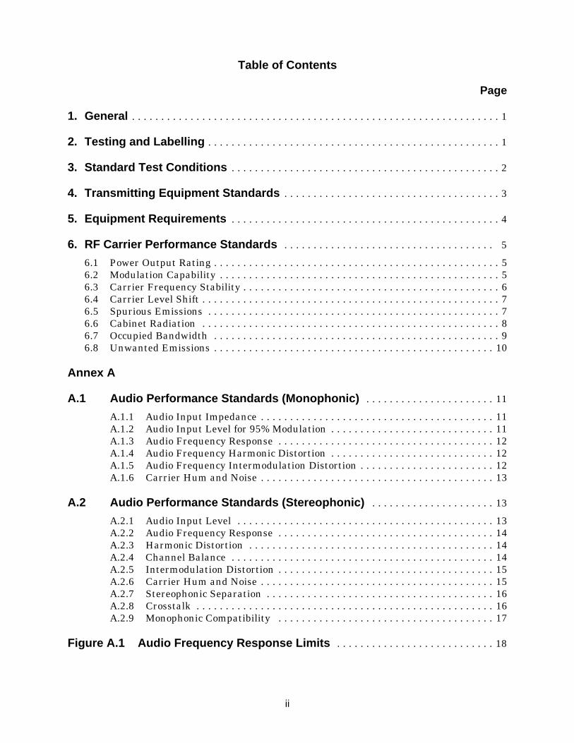
Table of Contents
Page
1. General . . . . . . . . . . . . . . . . . . . . . . . . . . . . . . . . . . . . . . . . . . . . . . . . . . . . . . . . . . . . . . . 1
2. Testing and Labelling . . . . . . . . . . . . . . . . . . . . . . . . . . . . . . . . . . . . . . . . . . . . . . . . . . 1
3. Standard Test Conditions . . . . . . . . . . . . . . . . . . . . . . . . . . . . . . . . . . . . . . . . . . . . . . 2
4. Transmitting Equipment Standards . . . . . . . . . . . . . . . . . . . . . . . . . . . . . . . . . . . . . 3
5. Equipment Requirements . . . . . . . . . . . . . . . . . . . . . . . . . . . . . . . . . . . . . . . . . . . . . . 4
6. RF Carrier Performance Standards . . . . . . . . . . . . . . . . . . . . . . . . . . . . . . . . . . . . 5
6.1 Power Output Rating . . . . . . . . . . . . . . . . . . . . . . . . . . . . . . . . . . . . . . . . . . . . . . . . . 56.2 Modulation Capability . . . . . . . . . . . . . . . . . . . . . . . . . . . . . . . . . . . . . . . . . . . . . . . . 56.3 Carrier Frequency Stability . . . . . . . . . . . . . . . . . . . . . . . . . . . . . . . . . . . . . . . . . . . . 66.4 Carrier Level Shift . . . . . . . . . . . . . . . . . . . . . . . . . . . . . . . . . . . . . . . . . . . . . . . . . . . 76.5 Spurious Emissions . . . . . . . . . . . . . . . . . . . . . . . . . . . . . . . . . . . . . . . . . . . . . . . . . . 76.6 Cabinet Radiation . . . . . . . . . . . . . . . . . . . . . . . . . . . . . . . . . . . . . . . . . . . . . . . . . . . 86.7 Occupied Bandwidth . . . . . . . . . . . . . . . . . . . . . . . . . . . . . . . . . . . . . . . . . . . . . . . . . 96.8 Unwanted Emissions . . . . . . . . . . . . . . . . . . . . . . . . . . . . . . . . . . . . . . . . . . . . . . . . 10
Annex A
A.1 Audio Performance Standards (Monophonic) . . . . . . . . . . . . . . . . . . . . . . 11
A.1.1 Audio Input Impedance . . . . . . . . . . . . . . . . . . . . . . . . . . . . . . . . . . . . . . . . 11A.1.2 Audio Input Level for 95% Modulation . . . . . . . . . . . . . . . . . . . . . . . . . . . . 11A.1.3 Audio Frequency Response . . . . . . . . . . . . . . . . . . . . . . . . . . . . . . . . . . . . . 12A.1.4 Audio Frequency Harmonic Distortion . . . . . . . . . . . . . . . . . . . . . . . . . . . . 12A.1.5 Audio Frequency Intermodulation Distortion . . . . . . . . . . . . . . . . . . . . . . . 12A.1.6 Carrier Hum and Noise . . . . . . . . . . . . . . . . . . . . . . . . . . . . . . . . . . . . . . . . 13
A.2 Audio Performance Standards (Stereophonic) . . . . . . . . . . . . . . . . . . . . . 13
A.2.1 Audio Input Level . . . . . . . . . . . . . . . . . . . . . . . . . . . . . . . . . . . . . . . . . . . . 13A.2.2 Audio Frequency Response . . . . . . . . . . . . . . . . . . . . . . . . . . . . . . . . . . . . . 14A.2.3 Harmonic Distortion . . . . . . . . . . . . . . . . . . . . . . . . . . . . . . . . . . . . . . . . . . 14A.2.4 Channel Balance . . . . . . . . . . . . . . . . . . . . . . . . . . . . . . . . . . . . . . . . . . . . . 14A.2.5 Intermodulation Distortion . . . . . . . . . . . . . . . . . . . . . . . . . . . . . . . . . . . . . 15A.2.6 Carrier Hum and Noise . . . . . . . . . . . . . . . . . . . . . . . . . . . . . . . . . . . . . . . . 15A.2.7 Stereophonic Separation . . . . . . . . . . . . . . . . . . . . . . . . . . . . . . . . . . . . . . . 16A.2.8 Crosstalk . . . . . . . . . . . . . . . . . . . . . . . . . . . . . . . . . . . . . . . . . . . . . . . . . . . 16A.2.9 Monophonic Compatibility . . . . . . . . . . . . . . . . . . . . . . . . . . . . . . . . . . . . . 17
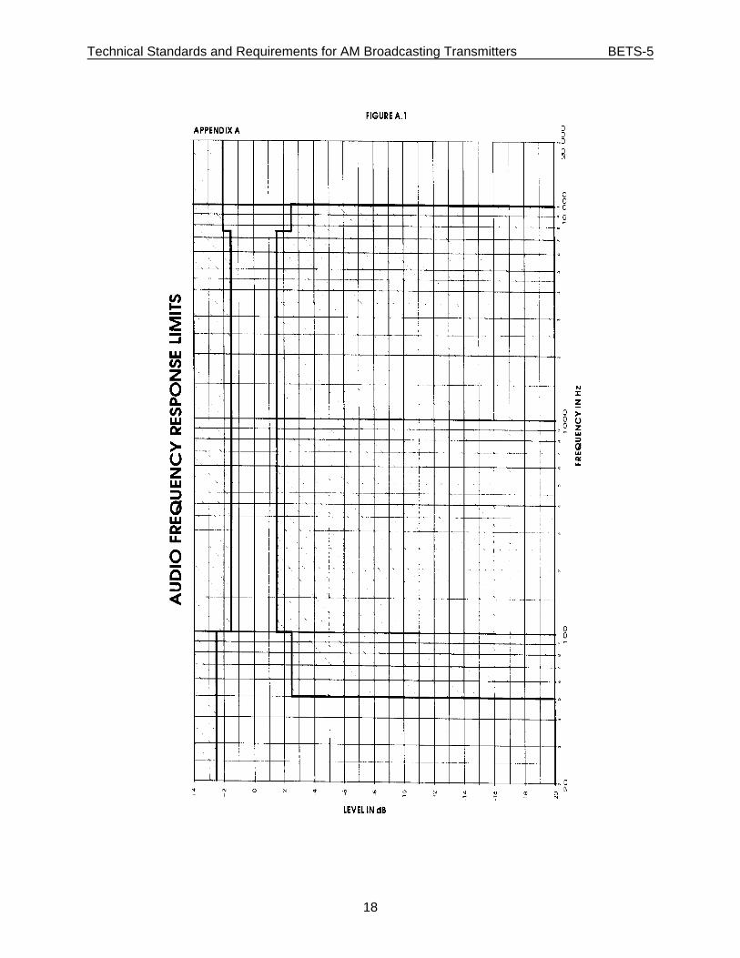
Figure A.1 Audio Frequency Response Limits . . . . . . . . . . . . . . . . . . . . . . . . . . . 18
Technical Standards and Requirements for AM Broadcasting Transmitters BETS-5
1
1. General
1.1 The standards and requirements in this document are the pre-requisite conditionsfor the issuance of a Technical Acceptance Certificate (TAC) for AM broadcastingtransmitters.
1.2 Those seeking to obtain a Technical Acceptance Certificate for AM broadcastingtransmitters shall, at their own expense, carry out the required tests and send tothe Department a certification submission and an engineering brief prepared inaccordance with Broadcasting Equipment Standards Procedure 100 (BESP-100).
1.3 The engineering brief, signed by a professional engineer licensed by a provincialassociation, shall demonstrate that the equipment meets the technical standards inthis document.
1.4 Notwithstanding the fact that a radio apparatus meets all applicable requirements,the Department reserves the right to require that adjustments be made to theequipment should it cause interference.
1.5 Any major design or component changes, other than the replacement of defectivecomponents by equivalent parts, will void the approval unless notified to andapproved by the Department.
1.6 This document replaces RSS-150, Issue 2.
2. Testing and Labelling
2.1 Sections 3 to 6 contain the general equipment standards and the emissionstandards which relate to the radiated signal of the AM transmitting equipment. Compliance to the standards of these sections shall be supported by an engineeringbrief stating measurement results in accordance with Broadcasting EquipmentStandards Procedure 100 (BESP-100).
2.2 Annex A contains the performance standards recognized by the industry to ensurequality operation of AM broadcasting equipment. Compliance with the standards ofAnnex A shall be supported by a statement certifying that the equipment meetsthe standards. The submission of test results for these performance measurementsis not required but the results shall be kept on file by the applicant.
2.3 This document covers the transmitting equipment proper: namely from audio inputterminals to the output terminals including any separate RF amplifiers and filters.
2.4 In the event that the equipment fails to function during the certification tests, alltests affected by the failure shall be repeated after the fault has been corrected.
Technical Standards and Requirements for AM Broadcasting Transmitters BETS-5
2
2.5 The transmitting equipment shall be capable of meeting the standards in thisdocument on any AM channel and at the rated power output for which it is designedto operate.
2.6 Each certified broadcasting equipment must display in a conspicuous location:
(a) the manufacturer's name, trade or brand name (if different from themanufacturer's name);
(b) the model identification;(c) the serial number;(d) the Technical Acceptance Certificate number;(e) the name of the certification assignee.
2.7 The identification label must be indelible, tamper-resistant and affixedpermanently or stamped in such a manner as not to be removable except bydestruction or defacing.
3. Standard Test Conditions
3.1 Definition
Standard test conditions are those conditions which shall apply to a transmittingequipment while it is being tested for minimum requirements. These conditionsapply unless otherwise specified. Where no special conditions are called for in thetests, the conditions shall be those specified by the manufacturer for normaloperation, and these shall be stated in the test report.
3.2 Standard Test Voltage
Standard test voltage shall be one of the rated power supply voltages specified bythe manufacturer.
3.3 Standard Temperature
Standard temperature shall be 20 C + 5 C. The temperature shall be recorded ino o
the test report.
3.4 Standard Test Load
Standard test load shall have a resistive impedance characteristic and be capable ofdissipating the output power of the transmitting equipment. At the test frequency,the resistive component of the test load shall be within 5% of the load impedanceinto which the transmitting equipment was designed to operate. The reactivecomponent of the test load shall not be greater than 5% of the resistive componentover the range of ±10 kHz from the test frequency.
Technical Standards and Requirements for AM Broadcasting Transmitters BETS-5
3
3.5 Standard Test Frequencies
Standard test frequencies shall be the carrier frequency of the channel for whichthe transmitting equipment is designed to operate. For transmitting equipmentcapable of operating on any one channel in 535 - 1,705 kHz band, tests shall bemade on two channels, one near each end of the band. The test frequencies shall bespecified in the test report.
3.6 Standard Test Input Signal
The standard audio test signal shall be a 400 Hz sine wave.
3.7 Standard Test Equipment
All measurements shall be made with instruments having sufficient accuracy toensure that no appreciable error occurs due to test equipment in the measurementsof the transmitter under test.
3.8 Standard Test Set-up
Unless otherwise specified, all tests shall be made with the carrier at rated poweroutput and modulated with the standard test input signal.
3.9 Warm-up Time
The transmitting equipment and test equipment shall be switched on at least30 minutes before any test is started, unless otherwise stated.
4. Transmitting Equipment Standards
4.1 Transmission System
An AM broadcasting transmitting equipment consists of all the apparatus necessaryto convert the audio input signal to an amplitude modulated RF carrier at a channelfrequency in the 535 to 1,705 kHz frequency band.
4.2 Type of Emission
The designation of modulation and emission refers to the manner in which thecarrier is modulated and transmitted. The transmitting equipment shall produceA3EGN emission.
Technical Standards and Requirements for AM Broadcasting Transmitters BETS-5
4
4.3 Carrier Frequency Adjustment
The transmitting equipment shall be capable of operation in accordance with thesestandards on any channel in the specified carrier frequency range without change inconstruction other than changing frequency determining components. Provisionshall be made for trimming the carrier frequency to the assigned frequency undernormal operating conditions.
4.4 Power Supply Rating
The AC voltage input shall be single phase or three phase, at a frequency of 60 Hz. Voltage, frequency and maximum kVA requirements shall be indicated on thetransmitting equipment.
4.5 Phase-to-Phase Loading
The transmitting equipment, if rated above 10 kVA input, shall present a balancedload to the AC mains such that the current in each phase shall be within 10% of theaverage of the three currents.
5. Equipment Requirements
5.1 Design
Transmitting equipment shall be designed according to good current engineeringpractice.
5.2 Nameplate
Labelling shall be according to the requirements in 2.6.
5.3 Protection of Personnel
The transmitting equipment shall be so constructed that all hazardous componentsare totally enclosed, or protected from accidental contact by personnel. Thetransmitting equipment enclosure shall be sufficient to provide adequate personnelsafety during operation.
5.4 Equipment Changes and Modifications
Any major design or equipment changes outside the replacement of defectivecomponents by equivalent parts made to an approved equipment will void theapproval unless notified to and approved by the Department. The notification mustprovide information demonstrating that the modification provides equal orimproved transmitting equipment performance.
Technical Standards and Requirements for AM Broadcasting Transmitters BETS-5
5
6. RF Carrier Performance Standards
6.1 Power Output Rating
6.1.1 Definition
The power output rating of a transmitting equipment is the carrier power atwhich the transmitting equipment may be operated into the test load.
6.1.2 Method of Measurement
The carrier shall be continuously modulated with the standard test inputsignal at a level producing 50% modulation for a period of 3 hours followedimmediately by 95% modulation for a period of 5 minutes. The output shallbe connected to the standard test load. The output power of the carrier shallbe measured by using a suitable power measuring device. The method shallbe described in the test report.
6.1.3 Standard
6.1.3.1 The standard rating of power output for the transmittingequipment shall be as specified by the individual manufacturer. Thetransmitting equipment shall be capable of delivering the standardoutput rating plus 10% for transmitting equipment rated below10 kW or the standard output rating plus 6% for transmittingequipment rated 10 kW or above. The transmitting equipmentshall be capable of being adjusted to deliver the rated power outputwhen the AC input voltage is 5% above or below rated value.
6.1.3.2 The test report shall state the power output limits over which thetransmitting equipment complies with this document.
6.2 Modulation Capability
6.2.1 Definition
Modulation capability is the extent to which the carrier can be modulated.
6.2.2 Method of Measurement
Using an oscilloscope, spectrum analyser, modulation monitor, or any othersuitable method, the modulation capability shall be measured. The methodshall be described in the test report.
Technical Standards and Requirements for AM Broadcasting Transmitters BETS-5
6
6.2.3 Standard
6.2.3.1 Standard (Monophonic Operation)
The transmitting equipment shall be capable of modulation to 95%on positive and negative peaks at any carrier frequency within thebroadcast band.
6.2.3.2 Standard (Stereophonic Operation)
The transmitting equipment shall be capable of amplitudemodulation to 85% on positive and negative peaks and capable ofphase modulation to 1.25 radians (71.5%) at any carrier frequencywithin the broadcast band.
6.3 Carrier Frequency Stability
6.3.1 Definition
The carrier frequency stability is the ability of the transmitter to maintain amean standard test frequency.
6.3.2 Method of Measurement
6.3.2.1 After a warm-up period of one hour at rated AC input voltage,measure the frequency of the carrier at one minute intervals duringa period of fifteen minutes. From those measurements determinethe mean test frequency for the carrier. Then at temperatures of5 C and 45 C measure the operating frequency at supply voltages ofo o
85, 100 and 115%. A period of 30 minutes should be allowed toenable the unit under test to achieve temperature stability beforeperforming the measurements.
6.3.2.2 Where it is not practical to subject the complete transmittingequipment to the specified test conditions, it is permissible toisolate and separately measure the stability of the frequency-determining elements of the transmitting equipment under thespecified conditions.
6.3.3 Standard
The frequency stability of the carrier shall remain within 10 Hz of the meantest frequency.
Technical Standards and Requirements for AM Broadcasting Transmitters BETS-5
7
6.4 Carrier Level Shift
6.4.1 Definition
The carrier level shift is the change in average carrier amplitude duringmodulation expressed as a percentage.
6.4.2 Method of Measurement
Carrier level shift shall be measured by a suitable modulation monitor.
6.4.3 Standard
The carrier level shift for 95% modulation shall not exceed 5%.
6.5 Spurious Emissions
6.5.1 Definition
Spurious emissions are radio frequency signals appearing at thetransmitting equipment output terminals on frequencies other than thespecified carrier frequency and modulation products.
6.5.2 Method of Measurement
The transmitting equipment shall be operated into the standard test load atrated power. The carrier shall be modulated with the standard test inputsignal at 95% modulation. Using a sampling device measure all spuriousemissions up to the third harmonic of the carrier frequency. The voltage ofthe emission shall be measured with a frequency selective instrument. Theattenuation versus frequency characteristics of the power sampling deviceand the load used in this test shall be known over the range of frequenciesinvolved. Record all spurious outputs in dB relative to rated power exceptthose more than 20 dB below the values in 6.5.3.
6.5.3 Standard
Spurious emissions of the transmitting equipment shall not exceed thevalues given in the following table:
Spurious Emission Maximum Value
(a) between 15 kHz and 30 kHz -25 dB*from the carrier frequency
(b) more than 30 kHz and up to -35 dB*and including 75 kHz fromthe carrier frequency
Technical Standards and Requirements for AM Broadcasting Transmitters BETS-5
8
(c) more than 75 kHz from the -(43 + 10 log P)*carrier frequency or - 80 dB*
whichever is the higher signal levelP = power in watts
* Referred to the power level of the unmodulated carrier.
In addition, when the oscillator crystal is removed or deactivated, spuriousradiation at any frequency including the assigned carrier frequency shall beno greater than the value specified in (c) above.
6.6 Cabinet Radiation
6.6.1 Definition
Cabinet radiation is any emission from the transmitting equipment housingor enclosure from sources other than a normal output port.
6.6.2 Method of Measurement
The transmitting equipment shall be operated at rated power output. Areceiving antenna, located alternately at a known distance between threeand ten metres from at least three sides of the transmitting equipment(i.e. front, back, left or right hand side), shall be connected to a calibratedfield strength metre or frequency selective voltmeter. Field strengthmeasurements shall be made of all emissions (including the fundamentaland harmonics of the carrier frequency) up the third harmonic of the carrierfrequency. For the measurement, the receiving antenna shall be rotated inall three planes and the maximum received field shall be noted (allowanceshall be made for antenna factor and transmission line loss of the measuringequipment). Using the free space formula below, calculate the referencefield strength.
E = 7 /P / r volts per metre
Where P is the rated output power in watts and r is the distance in metres.
6.6.3 Standard
Emissions at any frequency shall be at least 54 dB below the calculated fieldstrength reference level. Any radiation weaker than 70 dB below thereference level need not be recorded.
Technical Standards and Requirements for AM Broadcasting Transmitters BETS-5
9
6.7 Occupied Bandwidth
6.7.1 Definition
The bandwidth occupied by the carrier and associated modulation productssuch that they fall within the specified limits.
6.7.2 Methods of Measurement
Measurement of the occupied bandwidth shall be conducted using a standardnoise test signal. The test signal shall consist of a white noise source withUSASI (United States of America Standards Institute) weighting. Theweighting is produced by filtering white noise with a 100 Hz, 6 dB per octavehigh pass network and a 320 Hz, 6 dB per octave low pass network. TheUSASI noise signal is then passed through a pulser circuit wherein the ratioof the peak to average amplitude of the noise signal is set to 20 dB at theoutput of the pulser.
The pulser shall operate at a frequency of 2.5 Hz with a duty cycle of 12.5%. The noise test signal from the pulser shall be input to the transmittingequipment through a network providing a modified 75 microsecondpreemphasis and a 10 kHz low pass filter. The preemphasis is a modified75 microsecond curve with a high frequency break point at 8,700 Hz. Thelow pass filter is a sharp cutoff filter providing attenuation of 15 dB at10 kHz, 30 dB at 10.5 kHz, 40 dB at 11 kHz and 50 dB at 15 kHz andgreater. The noise source is split into two channels left and right that haveidentical spectral distributions. The individual level of each channel isadjusted to obtain the ratio of L + R (sum information) to L - R (differenceinformation) of 3 dB (i.e. a ratio of 1.4 to 1).
A suitable swept frequency RF spectrum analyser shall be used to measurethe spectrum emissions. The spectrum analyser setup shall consist of:
(a) 300 Hz resolution bandwidth;(b) 5, 10 or 20 kHz/horizontal division (as appropriate);(c) 10 dB/vertical division;(d) Reference: Carrier peak;(e) Peak hold: 10 minutes duration.
Using the appropriate scan width, measure the emission within ±30 kHz ofthe carrier.
6.7.3 Standard
Emissions from a stereophonic AM transmitting equipment consisting of thecarrier and associated modulation products shall be confined to frequencieswithin ±15 kHz of the carrier. Emissions appearing on any frequency morethan 15 kHz and up to 30 kHz shall be attenuated at least 25 dB below thelevel of the unmodulated carrier.
Technical Standards and Requirements for AM Broadcasting Transmitters BETS-5
10
6.8 Unwanted Emissions
6.8.1 Definition
Unwanted emissions are emissions on a frequency or frequencies outside theoccupied bandwidth which result from the modulation process but exclude spuriousemissions.
6.8.2 Method of Measurement
Using the same setup as in paragraph 6.7.2 and the appropriate scanwidth, measure the emissions within ±100 kHz of the carrier.
6.8.3 Standard
Any emissions appearing on a frequency removed by more than 30 kHz fromthe carrier shall be attenuated at least:
(a) 35 dB below the level of the unmodulated carrier for any frequency morethan 30 kHz and up to 75 kHz from the carrier;
(b) 43 + 10 log P (Power in Watts) dB or 80 dB, whichever is the lesserattenuation, below the level of the unmodulated carrier for any frequencymore than 75 kHz from the carrier.
Technical Standards and Requirements for AM Broadcasting Transmitters BETS-5
11
Annex A
Technical Standards
A.1 Audio Performance Standards (Monophonic)
A.1.1 Audio Input Impedance
A.1.1.1 Standard
The audio input impedance shall be a nominal 600 ohms balancedto ground, at all audio frequencies. Additional nominal impedancemay also be used as specified by the manufacturer.
A.1.2 Audio Input Level for 95% Modulation
A.1.2.1 Definition
The audio input level for 95% modulation is the audio input,expressed in dBm (0 dBm = 1 mW), necessary to obtain 95%modulation of the carrier, on both positive and negative peaks.
A.1.2.2 Method of Measurement
The standard test signal shall be adjusted to produce 95%modulation and this level shall be recorded.
A.1.2.3 Standard
The standard audio input level for 95% modulation shall be+10 dBm ±2 dBm.
A.1.3 Audio Frequency Response
A.1.3.1 Definition
The audio frequency response is the ratio of input voltages relativeto the voltage at 400 Hz, expressed in dB, required to maintain aconstant percentage of modulation across the audio frequencyrange.
Technical Standards and Requirements for AM Broadcasting Transmitters BETS-5
12
A.1.3.2 Method of Measurement
The standard test set up shall be used. The audio input tomaintain constant modulation levels of 25, 50 and 85% shall bedetermined at a sufficient number of points over the frequencyrange 50 Hz to 10 kHz to enable a curve to be plotted for eachmodulation level.
A.1.3.3 Standard
The audio frequency response curve shall be entirely within theunshaded area of the limits in Figure A1 for each modulation level.
A.1.4 Audio Frequency Harmonic Distortion
A.1.4.1 Definition
The audio frequency harmonic distortion is the harmonic content ofthe audio signal contributed by the transmitter.
A.1.4.2 Method of Measurement
The audio frequency harmonic distortion shall be measured bydemodulating a sample of the RF output of the transmittingequipment and feeding this to a wave analyser or distortion metre. If an average-reading instrument is used, it will be necessary totake into account possible errors due to the relative phase relationsof the harmonics. The audio frequency distortion shall be measuredat 50, 100, 400, 1,000, 2,500, 5,000, 7,500 and 10,000 Hz and at 25,50 and 85% modulation respectively.
A.1.4.3 Standard
The audio frequency distortion, including all harmonics up to24 kHz shall not exceed 3% from 50 Hz to 10,000 Hz.
A.1.5 Audio Frequency Intermodulation Distortion
A.1.5.1 Definition
The audio frequency intermodulation distortion is the nonlinearsignal contributed by the transmitting equipment resulting inmodulation components equal to the sums and differences ofintegral multiples of a complex audio input signal.
Technical Standards and Requirements for AM Broadcasting Transmitters BETS-5
13
A.1.5.2 Method of Measurement
A test signal consisting of a 60 Hz and a 7 kHz sine wave with arelative amplitude ratio of 4:1 respectively shall be applied to thetransmitting equipment audio input terminals. The audiofrequency intermodulation distortion shall be measured bydemodulating a sample of the RF output of the transmittingequipment and feeding this to a wave analyser or suitabledistortion metre. The distortion shall be measured at 25, 50 and85% modulation.
A.1.5.3 Standard
The RMS audio frequency intermodulation distortion shall notexceed 4% referenced to the larger of the two test signals.
A.1.6 Carrier Hum and Noise
A.1.6.1 Definition
The carrier hum and noise level is the ratio, expressed in dB, of thevalue of the amplitude modulation component at 100% modulationof the carrier envelope to the value of residual amplitudemodulation component when the carrier is unmodulated.
A.1.6.2 Method of Measurement
Measurement of the carrier hum and noise level may be made bythe use of an AM detector coupled to the output of the transmittingequipment. The output of the detector shall be fed through a10 kHz low pass filter to a distortion and noise metre. Readingsshall be without modulation but with the audio input terminatedwith a resistance equal to the audio input impedance.
A.1.6.3 Standard
The measured level of all hum and noise components appearing asmodulation on the carrier shall be at least 55 dB below 100%modulation.
A.2 Audio Performance Standards (Stereophonic)
A.2.1 Audio Input Level
A.2.1.1 Standard
The standard audio input level for 85% modulation shall be+10 dBm ±2 dBm.
Technical Standards and Requirements for AM Broadcasting Transmitters BETS-5
14
A.2.2 Audio Frequency Response
A.2.2.1 Definition
The audio frequency response is the ratio of the input voltagesrelative to the voltage at 1,000 Hz, expressed in dB, required tomaintain a constant percentage of modulation across the audiofrequency range.
A.2.2.2 Method of Measurement
The output of the transmitting equipment shall be sampled with astereo test demodulator with audio outputs for the left and rightchannels. Constant modulation levels shall be established bymaintaining constant output levels from the test demodulator. Theaudio input level to maintain constant modulation levels of 25, 50,and 85% shall be determined over the frequency range 50 Hz to10 kHz for each of the left and right channels.
A.2.2.3 Standard
The frequency response of either the left or right channel shallremain within 2 dB of the response at 1,000 Hz over the frequencyrange between 50 Hz and 10 kHz under all conditions of modulationof the left or right stereophonic channel up to 85%.
A.2.3 Harmonic Distortion
A.2.3.1 Method of Measurement
Using the method of paragraph A.1.4.2, measure the harmonicdistortion in each of the left and right channels.
A.2.3.2 Standard
The total harmonic distortion including harmonics up to 20,000 Hzmeasured separately in either the left or right channel shall notexceed 5% in the frequency range 50 Hz to 10,000 Hz under allconditions of modulation up to 85%.
A.2.4 Channel Balance
A.2.4.1 Definition
The channel balance is the difference in output level of the left andright channels for equal inputs.
Technical Standards and Requirements for AM Broadcasting Transmitters BETS-5
15
A.2.4.2 Method of Measurement
The channel balance shall be determined by comparing theresponse obtained in section A.2.2.
A.2.4.3 Standard
The balance between the response in the left and right channelsshall be within 1 dB from 50 Hz to 10,000 Hz at all levels ofmodulation up to 85%.
A.2.5 Intermodulation Distortion
A.2.5.1 Method of Measurement
Using the method of paragraph A.1.5.2 with the stereo testdemodulator measure the intermodulation distortion in the left andright channels.
A.2.5.2 Standard
The RMS audio frequency intermodulation distortion in either theleft or right channel shall not exceed 4% referenced to the larger ofthe two test signals.
A.2.6 Carrier Hum and Noise
A.2.6.1 Definition
Carrier hum and noise is the ratio in dB of a reference signalmodulation level to the residual modulation level caused by humand noise components.
A.2.6.2 Method of Measurement
Measurement of the carrier hum and noise level may be made bythe use of the stereo test demodulator coupled to the output of thetransmitting equipment. The output of the demodulator shall befed through a 10 kHz low pass filter to a distortion and noise metre. Readings shall be made of the output with standard testmodulation of 85% and without modulation but with the audioinput terminated with a resistance equal to the audio inputimpedance. The measurement shall be made in each of the left andright channels.
A.2.6.3 Standard
The level of hum and noise in either the left or right channel foraudio frequencies below 10,000 Hz shall be at least 48 dB below thereference level for 100% modulation at 1,000 Hz.
Technical Standards and Requirements for AM Broadcasting Transmitters BETS-5
16
A.2.7 Stereophonic Separation
A.2.7.1 Definition
The ratio in dB of the output of the left (or right) channel due to asignal intended for that channel to the output of the right (or left)channel due to the same signal.
A.2.7.2 Method of Measurement
Input a test signal to the left channel only at a level equivalent to85% modulation. Measure the demodulated output of the left andright channels and determine the separation for the range offrequencies from 400 Hz to 10,000 Hz. Repeat the above with thetest signal applied only to the right channel.
A.2.7.3 Standard
The separation between the left and right channels shall be at least20 dB in the frequency range from 400 Hz to 10,000 Hz at all levelsof modulation up to 85%.
A.2.8 Crosstalk
A.2.8.1 Definition
An undesired signal occurring in the sum channel from modulationof the difference channel or that occurring in the difference channelfrom modulation of the sum channel.
A.2.8.2 Method of Measurement
Using the standard test signals (L = R) to produce 85% modulationonly in the L + R channel, measure the components of the signalappearing in the L - R channel. Repeat the procedure with testsignals (L = R) to produce 85% modulation in the L - R channel andmeasure the components of the signal appearing in the L + Rchannel.
A.2.8.3 Standard
The sum channel (L + R) to the difference channel (L - R) crosstalkand the difference channel (L - R) to the sum channel (L + R)inverse crosstalk shall be at least 30 dB below the reference levelfor 100 % modulation at 1,000 Hz.
Technical Standards and Requirements for AM Broadcasting Transmitters BETS-5
17
A.2.9 Monophonic Compatibility
A.2.9.1 Definition
Monophonic compatibility is defined as the compatible reception ofstereophonic transmissions on a monophonic receiver with envelopedetection.
A.2.9.2 Method of Measurement
Using a test demodulator set for monophonic operation, measurethe audio frequency response, audio frequency harmonic distortion,and carrier hum and noise at the monophonic audio output of thedemodulator. The respective test methods of paragraphs A.2.2.2,A.2.3.2 and A.2.6.2 may be used. The output of the demodulatorshall be derived from an envelope detector with wideband response.
A.2.9.3 Standard-Audio Frequency Response
The frequency response shall remain within 2 dB of the response at1,000 Hz over the frequency range from 50 Hz to 10,000 Hz underall conditions of modulation of the stereophonic system up to 85%.
A.2.9.4 Standard-Audio Frequency Harmonic Distortion
The total harmonic distortion including harmonics up to 20,000 Hzshall not exceed 5% over the frequency range from 50 Hz to10,000 Hz under all conditions of modulation of the stereophonicsystem up to 85%.
A.2.9.5 Standard-Carrier Hum and Noise
The level of all hum and noise for audio frequencies below10,000 Hz shall be at least 55 dB below the reference level for 100%modulation at 1,000 Hz.
Technical Standards and Requirements for AM Broadcasting Transmitters BETS-5
18