Embed Size (px)
Citation preview
ASMNG-80 BETRIEBSANLEITUNG | OPERATING MANUAL
Technische Änderungen vorbehalten. Alle Angaben ohne Gewähr. Alle Rechte liegen bei der ASUTEC GmbH. Subject to technical modifications. No responsibility is accepted for the accuracy of this information. All rights are reserved by ASUTEC GmbH.
Document nr. 85000071 – Version A – 2019/07/15 – M. Pohle WWW.ASUTEC.EU | 1
BETRIEBSANLEITUNG
GERÄTETYPEN: ASMNG-80
GERÄTEBEZEICHNUNG: Vereinzeler mit Dämpfung, „Next Generation“ pneumatisch betätigt
DOKUMENTNUMMER: 85000071
OPERATING MANUAL
DEVICE TYPES: ASMNG-80
DEVICE DESIGNATION: Separator with damping, “Next Generation” pneumatically actuated
DOCUMENT NUMBER: 85000071
ASMNG-80-EW-08
ASMNG-80-EW-08-I
ASMNG-80 BETRIEBSANLEITUNG | OPERATING MANUAL
Technische Änderungen vorbehalten. Alle Angaben ohne Gewähr. Alle Rechte liegen bei der ASUTEC GmbH. Subject to technical modifications. No responsibility is accepted for the accuracy of this information. All rights are reserved by ASUTEC GmbH.
Document nr. 85000071 – Version A – 2019/07/15 – M. Pohle WWW.ASUTEC.EU | 2
INHALTSVERZEICHNIS
CONTENTS
1 Allgemeine Hinweise 1.1 Identifikationsdaten ............................................... 3 1.2 Bestimmungsgemäße Verwendung ........................ 3 1.3 Sachwidrige Verwendung / Vorhersehbarer Missbrauch .................................... 3 1.4 Haftung ................................................................. 3 1.5 Garantieausschluss ................................................. 3 1.6 Umweltschutz / Entsorgung .................................... 4
1 General information 1.1 Identification data ................................................. 3 1.2 Intended use ......................................................... 3 1.3 Improper use / Foreseeable misuse ......................... 3 1.4 Liability ................................................................. 3 1.5 Exclusion of warranty ............................................. 3 1.6 Environmental protection / Disposal........................ 4
2 Sicherheitshinweise 2.1 Warnhinweise in der Betriebsanleitung ................... 4 2.1.1 Erscheinungsbild und Struktur der Warnhinweise ........................................... 4 2.1.2 Kennzeichnung der Warnhinweise ............. 4 2.2 Sicherheitsvorschriften für das Personal ................... 5 2.3 Voraussetzungen für den Einbauort ........................ 5 2.4 Sicherheitsvorschriften für Pneumatik- komponenten ........................................................ 6 2.5 Sicherheitsvorschriften für Betriebselektrik .............. 6
2 Safety instructions 2.1 Warnings in this manual ........................................ 4 2.1.1 Appearances and structure of the warnings .................................................. 4 2.1.2 Labeling of warnings ................................. 4 2.2 Safety regulations for personnel ............................. 5 2.3 Requirements for the installation location ............... 5 2.4 Safety regulations for pneumatic components ........ 6 2.5 Safety regulations for operating electronics ............ 6
3 Technische Daten 3.1 Ausführung und Gewicht ....................................... 6 3.2 Arbeitsbereich........................................................ 6 3.3 Vortriebskraft ........................................................ 6 3.4 Staudruck .............................................................. 7 3.5 Wirksame Kolbenflächen, Kräfte ............................. 7 3.6 Funktion ................................................................ 7 3.7 Federkräfte ............................................................ 7 3.8 Temperaturbereich ................................................. 7 3.9 Betriebsdruck und Luftverbrauch ............................ 7
3 Technical details 3.1 Execution and weight ............................................ 6 3.2 Operating range .................................................... 6 3.3 Propulsive force ..................................................... 6 3.4 Ram pressure ........................................................ 7 3.5 Effective piston areas, forces .................................. 7 3.6 Function ................................................................ 7 3.7 Spring forces ......................................................... 7 3.8 Temperature range ................................................ 7 3.9 Operating pressure and air consumption ................ 7
4 Transport ........................................................................ 8
4 Transport ........................................................................ 8
5 Montage 5.1 Sicherheit bei der Montage .................................... 8 5.2 Montage am Einsatzort .......................................... 8 5.3 Druckluftanschluss ................................................. 8 5.4 Montage induktiver Sensoren ................................. 9 5.5 Einstellung der Dämpfung ...................................... 9 5.6 Abmessungen ........................................................ 9
5 Installation 5.1 Safety for installation ............................................. 8 5.2 Installation at the place of use ................................ 8 5.3 Air connection ....................................................... 8 5.4 Installation of inductive sensors .............................. 9 5.5 Adjustment of damping ......................................... 9 5.6 Dimensions ........................................................... 9
6 Funktionsablauf .............................................................. 10
6 Functional sequence ....................................................... 10
7 Wartung 7.1 Sicherheit bei der Wartung ..................................... 10 7.2 Wartungsarbeiten .................................................. 10
7 Installation 7.1 Safety during maintenance .................................... 10 7.2 Maintenance work................................................. 10
8 Typenschlüssel ................................................................ 11
8 Type codes ..................................................................... 11
9 Lieferumfang und Zubehör .............................................. 12
9 Scope of supply and accessories ...................................... 12
10 Einbauerklärung .............................................................. 13
10 Copy of the declaration of incorporation ......................... 13
ASMNG-80 BETRIEBSANLEITUNG | OPERATING MANUAL
Technische Änderungen vorbehalten. Alle Angaben ohne Gewähr. Alle Rechte liegen bei der ASUTEC GmbH. Subject to technical modifications. No responsibility is accepted for the accuracy of this information. All rights are reserved by ASUTEC GmbH.
Document nr. 85000071 – Version A – 2019/07/15 – M. Pohle WWW.ASUTEC.EU | 3
1 ALLGEMEINE HINWEISE 1 GENERAL INFORMATION
1.1 IDENTIFIKATIONSDATEN 1.1 IDENTIFICATION DATA Typ-Bezeichnung: Vereinzeler mit Dämpfung, pneumatisch betätigt Herstelleranschrift, Kundendienst und Ersatzteile: ASUTEC GmbH, Küferstraße 11, 73257 Köngen, Deutschland Dokumentnummer und Version: 85000071 – Version A
Type designation: Separator with damping, pneumatically actuated Manufacturer address, aftersales service and spare parts: ASUTEC GmbH, Küferstraße 11, 73257 Köngen, Germany Document number and version: 85000071 – Version A
1.2 BESTIMMUNGSGEMÄßE VERWENDUNG 1.2 INTENDED USE Der pneumatische Vereinzeler: - darf ausschließlich nur mit Druckluft betrieben werden! - ist konzipiert für den Betrieb in geschlossenen Räumen! - ist bestimmt für die Werkstückträgervereinzelung im Transfersystem ohne Mitnehmer (Stauförderer)! - stoppt einen oder mehrere auflaufende Werkstückträger an einer definierten Werkstückträger-Anschlagfläche! - ist bestimmt für den Einbau in eine Maschine – Die An- forderungen der zutreffenden gesetzlichen Richtlinien für Gesundheitsschutz und Maschinensicherheit müssen beachtet und eingehalten werden! - darf nur in der angegebenen Transportrichtung belastet werden! - darf nur im Originalzustand und mit Originalzubehör betrieben werden! - darf nur im Rahmen der definierten Einsatzparameter (siehe Kapitel 3 technische Daten) verwendet werden!
The pneumatically separator: - may only be operated with compressed air! - is designed for indoor operation! - is intended for stopping and for the separation of the workpiece carriers in the transfer system. In the stopping process the conveyor media continues moving under the workpiece carrier (accumulation conveyor). A positive connection between workpiece carrier and conveyor media is not allowed! - stops one or more accumulated workpiece carriers on a defined workpiece carrier stop surface! - is intended for installation in a machine - The requirements of the applicable legal directives for health protection and machine safety must be observed and complied with! - may only be loaded in the specified direction of transport! - may only be used in its original condition and with original accessories! - may only be used within the scope of the defined application parameters (see chapter 3 technical data)!
1.3 SACHWIDRIGE VERWENDUNG / 1.3 INPROPER USE /
VORHERSEHBARER MISSBRAUCH FORESEEABLE MISUSE Eine Sachwidrige Verwendung liegt vor, wenn der Vereinzeler: - nicht entsprechend den obigen Bestimmungen verwendet wird. - in vibrationsgefährdeten oder explosionsgefährdeten Bereichen betrieben wird. - als Sicherheitsschalter verwendet wird. - im Betrieb im direkten Kontakt mit verderblichen Gütern steht.
An improper use is when the separator: - is not used according to the above provisions. - is operated in vibration-prone or potentially explosive atmospheres. - is used as a safety switch. - is in direct contact with perishable goods.
1.4 HAFTUNG 1.4 LIABILITY Grundsätzlich gelten unsere Lieferungs- und Zahlungs-bedingungen. Diese stehen dem Betreiber spätestens seit Vertrags-abschluss zur Verfügung. Für Beistellungen von Fremdherstellern durch den Auftraggeber und/oder von Dritten übernimmt die Firma ASUTEC GmbH keine Haftung für deren Betriebssicherheit. Gewährleistungs- und Haftungsansprüche bei Personen- und Sachschäden sind ausgeschlossen, wenn sie auf eine oder mehrere der folgenden Ursachen zurückzuführen sind: - nicht bestimmungsgemäße Verwendung des Geräts, - Bedienungsfehler, - unsachgemäße Montage, Inbetriebnahme, Bedienung und Wartung der Maschine, - mangelnde Wartung, - Nichtbeachtung der Hinweise in der Betriebsanleitung bezüglich Transport, Lagerung, Montage, Inbetriebnahme, Betrieb, Wartung und Reinigung des Geräts, - eigenmächtige bauliche Veränderungen des Geräts, Verwendung von Ersatzteilen, Zubehör, Anbaugeräten und Sonderausstattungen, die von der Firma ASUTEC GmbH nicht geprüft und freigegeben sind, - eigenmächtige Veränderungen des Geräts - unsachgemäß durchgeführte Reparaturen, Katastrophenfälle durch Fremdkörpereinwirkung und höhere Gewalt.
Our delivery and payment terms apply in principle. These have been available to the operator at the latest since the conclusion of the contract. For materials provided by foreign manufacturers by the client and / or third parties, the company ASUTEC GmbH assumes no liability for their reliability. Warranty and liability claims for personal injury and property damage are excluded if they are attributable to one or more of the following causes: - improper use of the ASUTEC device, - operator error, - improper assembly, commissioning, operation and maintenance of the machine, - lack of maintenance, - failure to observe the instructions in the operating instructions regarding transport, storage, installation, commissioning, operation, maintenance and cleaning of the device, - unauthorized modifications of the device, use of spare parts, accessories, attachments and special equipment which have not been tested and approved by ASUTEC GmbH, - unauthorized modifications of the device (for example, drive conditions, power or speed), - improperly executed repairs, catastrophes caused by external forces and force majeure.
1.5 GARANTIEAUSSCHLUSS 1.5 EXCLUSION OF WARRANTY Bei Nichtverwendung von Originalersatzteilen, unsachgemäßer Bedienung und bei nicht bestimmungsgemäßer Verwendung erlischt der Gewährleistungsanspruch. Für Ersatzteile kontaktieren Sie bitte die ASUTEC GmbH.
In case of non-use of original spare parts, improper operation and in case of non-intended use, the warranty claim expires. For spare parts please contact ASUTEC GmbH.
ASMNG-80 BETRIEBSANLEITUNG | OPERATING MANUAL
Technische Änderungen vorbehalten. Alle Angaben ohne Gewähr. Alle Rechte liegen bei der ASUTEC GmbH. Subject to technical modifications. No responsibility is accepted for the accuracy of this information. All rights are reserved by ASUTEC GmbH.
Document nr. 85000071 – Version A – 2019/07/15 – M. Pohle WWW.ASUTEC.EU | 4
1.6 UMWELTSCHUTZ / ENTSORGUNG 1.6 ENVIRONMENTAL PROTECTION / DISPOSAL Beim Austausch von Bauteilen ist auf eine sachgerechte Ent-sorgung zu achten. Bitte beachten Sie die regional gültigen Entsorgungsvorschriften.
When replacing components, please ensure proper disposal. Please observe the regional disposal regulations.
2 SICHERHEITSHINWEISE 2 SAFETY INSTRUCTIONS
2.1 WARNHINWEISE IN DER BETRIEBSANLEITUNG 2.1 WARNINGS IN THIS MANUAL
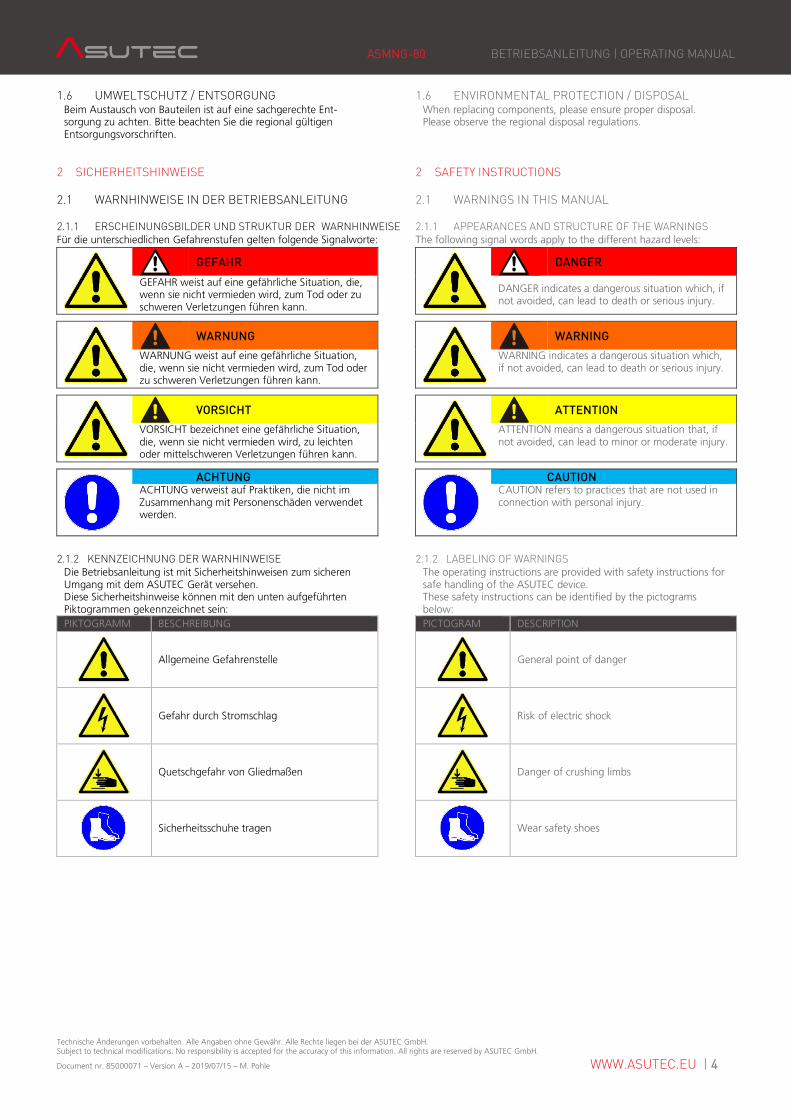
2.1.1 ERSCHEINUNGSBILDER UND STRUKTUR DER WARNHINWEISE 2.1.1 APPEARANCES AND STRUCTURE OF THE WARNINGS Für die unterschiedlichen Gefahrenstufen gelten folgende Signalworte: The following signal words apply to the different hazard levels:
GEFAHR
DANGER
GEFAHR weist auf eine gefährliche Situation, die, wenn sie nicht vermieden wird, zum Tod oder zu schweren Verletzungen führen kann.
DANGER indicates a dangerous situation which, if not avoided, can lead to death or serious injury.
WARNUNG
WARNING
WARNUNG weist auf eine gefährliche Situation, die, wenn sie nicht vermieden wird, zum Tod oder zu schweren Verletzungen führen kann.
WARNING indicates a dangerous situation which, if not avoided, can lead to death or serious injury.
VORSICHT
ATTENTION
VORSICHT bezeichnet eine gefährliche Situation, die, wenn sie nicht vermieden wird, zu leichten oder mittelschweren Verletzungen führen kann.
ATTENTION means a dangerous situation that, if not avoided, can lead to minor or moderate injury.
ACHTUNG
CAUTION ACHTUNG verweist auf Praktiken, die nicht im Zusammenhang mit Personenschäden verwendet werden.
CAUTION refers to practices that are not used in connection with personal injury.
2.1.2 KENNZEICHNUNG DER WARNHINWEISE 2.1.2 LABELING OF WARNINGS Die Betriebsanleitung ist mit Sicherheitshinweisen zum sicheren Umgang mit dem ASUTEC Gerät versehen. Diese Sicherheitshinweise können mit den unten aufgeführten Piktogrammen gekennzeichnet sein:
The operating instructions are provided with safety instructions for safe handling of the ASUTEC device. These safety instructions can be identified by the pictograms below:
PIKTOGRAMM BESCHREIBUNG PICTOGRAM DESCRIPTION
Allgemeine Gefahrenstelle
General point of danger
Gefahr durch Stromschlag
Risk of electric shock
Quetschgefahr von Gliedmaßen
Danger of crushing limbs
Sicherheitsschuhe tragen
Wear safety shoes
ASMNG-80 BETRIEBSANLEITUNG | OPERATING MANUAL
Technische Änderungen vorbehalten. Alle Angaben ohne Gewähr. Alle Rechte liegen bei der ASUTEC GmbH. Subject to technical modifications. No responsibility is accepted for the accuracy of this information. All rights are reserved by ASUTEC GmbH.
Document nr. 85000071 – Version A – 2019/07/15 – M. Pohle WWW.ASUTEC.EU | 5
2.2 SICHERHEITSVORSCHRIFTEN FÜR DAS PERSONAL 2.2 SAFETY REGULATIONS FOR PERSONNEL
VORSICHT
ATTENTION
Jede Person, die mit der Montage, Inbetriebnahme, Bedienung und Instandhaltung des ASUTEC Geräts befasst ist, muss bevor sie die ersten Handgriffe ausführt, die komplette Betriebsanleitung und besonders das Kapitel "Sicherheitshinweise" gelesen und verstanden haben.
Every person involved in the installation, commissioning, operation and maintenance of the ASUTEC device must read and understand the entire operating instructions, especially the chapter "Safety instructions", before carrying out the first hand operation.
Die Durchführung dieser Arbeiten darf nur durch geschultes und eingewiesenes Fachpersonal erfolgen. Das Fachpersonal muss Erfahrung im Umgang mit pneumatischen und elektrischen Systemen besitzen. Das Fachpersonal muss mindestens 18 Jahre alt sind und körperlich, sowie geistig zum Bedienen des ASUTEC Geräts geeignet sein. Zu schulendes, anzulernendes, einzuweisendes oder im Rahmen einer allgemeinen Ausbildung befindliches Personal darf nur unter ständiger Aufsicht einer erfahrenen Person am ASUTEC Gerät tätig sein.
This work may only be carried out by trained and trained personnel. The personnel must have experience in handling pneumatic and electrical systems. The personnel must be at least 18 years old and physically and mentally able to operate the ASUTEC device. Personnel who are in general training or who are in instruction are only allowed to work on the ASUTEC device under the permanent supervision of an experienced person.
2.3 VORAUSSETZUNGEN FÜR DEN EINBAUORT 2.3 REQUIREMENTS FOR THE INSTALLATION LOCATION
GEFAHR
Danger
Durch fehlerhafte elektrische Ausrüstung besteht die Gefahr eines Stromschlages, der schwere Verletzungen oder den Tod zur Folge haben kann. Elektrische Anschlüsse müssen den entsprechenden nationalen Sicherheitsvorschriften zur Betriebselektrik entsprechen. Nur Fachpersonal mit elektrischer/elektronischer Ausbildung darf an der elektrischen Ausrüstung arbeiten.
Faulty electrical equipment may result in a risk of electric shock which could result in serious injury or death. Electrical connections must comply with the relevant national safety regulations for the operational electrical system. Only electricians with electrical / electronic training are allowed to work on the electrical equipment.
WARNUNG
WARNING
Warnung vor unkontrollierten Bewegungen. Der Einbauort des ASUTEC Geräts muss den entsprechenden nationalen Sicherheitsvorschriften der Maschinensicherheit entsprechen.
Warning of uncontrolled movements. The installation location of the ASUTEC device must comply with the relevant national safety regulations for machine safety.
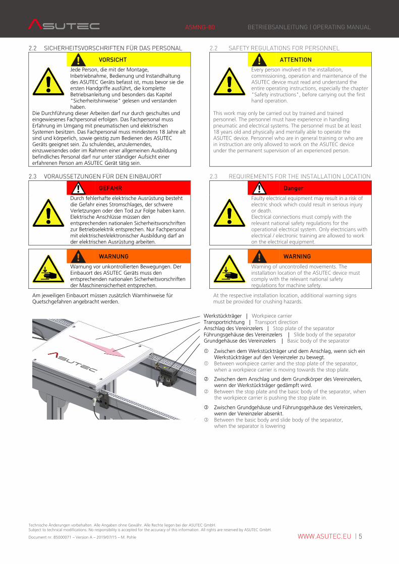
Am jeweiligen Einbauort müssen zusätzlich Warnhinweise für Quetschgefahren angebracht werden.
At the respective installation location, additional warning signs must be provided for crushing hazards.
Werkstückträger | Workpiece carrier Transportrichtung | Transport direction Anschlag des Vereinzelers | Stop plate of the separator Führungsgehäuse des Vereinzelers | Slide body of the separator Grundgehäuse des Vereinzelers | Basic body of the separator
� Zwischen dem Werkstückträger und dem Anschlag, wenn sich ein Werkstückträger auf den Vereinzeler zu bewegt. � Between workpiece carrier and the stop plate of the separator, when a workpiece carrier is moving towards the stop plate.
� Zwischen dem Anschlag und dem Grundkörper des Vereinzelers, wenn der Werkstückträger gedämpft wird. � Between the stop plate and the basic body of the separator, when the workpiece carrier is pushing the stop plate in.
3 Zwischen Grundgehäuse und Führungsgehäuse des Vereinzelers, wenn der Vereinzeler absenkt. 3 Between the basic body and slide body of the separator, when the separator is lowering
ASMNG-80 BETRIEBSANLEITUNG | OPERATING MANUAL
Technische Änderungen vorbehalten. Alle Angaben ohne Gewähr. Alle Rechte liegen bei der ASUTEC GmbH. Subject to technical modifications. No responsibility is accepted for the accuracy of this information. All rights are reserved by ASUTEC GmbH.
Document nr. 85000071 – Version A – 2019/07/15 – M. Pohle WWW.ASUTEC.EU | 6
2.4 SICHERHEITSVORSCHRIFTEN FÜR 2.4 SAFETY REGULATIONS FOR PNEUMATIC
PNEUMATIKKOMPONENTEN COMPONENTS
VORSICHT
ATTENTION
Es besteht die Möglichkeit von Verletzungen durch hohe Betriebsdrücke im Druckluftsystem der Maschine in die das ASUTEC Gerät eingebaut ist. An der pneumatischen Ausrüstung darf nur Fachpersonal arbeiten, welches eine spezielle Fachausbildung im Bereich Pneumatik hat und welches Erfahrung im Umgang mit Pneumatik-systemen hat.
There is the possibility of injuries due to high pneumatic operating pressures in the compressed air system of the machine in which the ASUTEC device is installed. Pneumatic equipment may only be operated by specialized personnel who have specialized training in pneumatics and who has experience in the handling of pneumatic systems. Before any work on the pneumatic equipment
Vor allen Arbeiten an der pneumatischen Ausrüstung muss die Gesamtmaschine drucklos geschaltet. Die pneumatische Ausrüstung des ASUTEC Geräts ist regelmäßig auf Dichtheit und äußere Beschädigungen zu überprüfen. Mängel müssen sofort beseitigt werden. Es befindet sich ein Absperrventil in der Wartungseinheit der Gesamtmaschine/Anlage. Dieses Ventil muss geschossen sein, bevor Arbeiten an der pneumatischen Ausrüstung des ASUTEC Geräts erfolgen.
the entire machine must be depressurized. The pneumatic equipment of the ASUTEC device must be regularly checked for leaks and external damage. Defects must be rectified immediately. There is a shut-off valve in the maintenance unit of the entire machine / system. This valve must be shot before working on the pneumatic equipment of the ASUTEC device.
2.5 SICHERHEITSVORSCHRIFTEN FÜR 2.5 SAFETY REGULATIONS FOR OPERATING
BETRIEBS ELEKTRIK ELECTRONICS
GEFAHR
Danger
Bei Arbeiten an elektrischer Ausrüstung besteht die Gefahr eines Stromschlages, der schwere Verletzungen oder den Tod zur Folge haben kann. Elektrische Betriebsmittel müssen den entsprechenden nationalen Sicherheitsvorschriften zur Betriebselektrik entsprechen. Nur Fachpersonal mit elektrischer/elektronischer Ausbildung darf an der elektrischen Ausrüstung arbeiten.
There is a risk of electric shock when working on electrical equipment that can result in serious injury or death. Electrical equipment must comply with the relevant national safety regulations for the operating electrical system. Only electricians with electrical / electronic training are allowed to work on the electrical equipment.
3 TECHNISCHE DATEN 3 TECHNICAL DETAILS
3.1 AUSFÜHRUNG UND GEWICHT 3.1 EXECUTION AND WEIGHT Geräteausführung: Gehäuse aus Kunststoff, Anschlag aus gehärtetem Stahl. Luftdämpfung, mit Drosselschraube einstellbar.
Gewicht der Geräte: ASMNG-80-EW-08: 0,27 kg ASMNG-80-EW-08-I: 0,42 kg
Device design: Basic housing made of plastic and stop plate made of hardened steel. Air damping system, adjustable with throttle screw.
Weights of the devices: ASMNG-80-EW-08: 0,27 kg ASMNG-80-EW-08-I: 0,42 kg
3.2 ARBEITSBEREICH 3.2 OPERATING RANGE
v = … [m/min]2) 6 9 12 15 18 24 30
ASMNG-80 Gewicht WT [kg]1)
Weight of WT [kg]1) 1 - 80 1 - 60 1 - 50 1 - 45 1 - 37 1 - 28 1 - 20
1) Minimal und maximal zu stoppende Massen. 2) Zulässige Fördergeschwindigkeit: Angaben gelten bei einer Fördermittelreibung von µ=0,07 zwischen Werkstückträger und Transferband und bei einem ASUTEC Standardanschlag aus Stahl. Generell wird von ASUTEC die Auslegung mit Hilfe des ASUTEC Online Produktfinders empfohlen.
1) minimal and maximum masses to be stopped. 2) Permissible conveying speed: The information applies to a conveyor media friction of μ = 0.07 between workpiece carrier and conveyor media and with an ASUTEC standard stop plate made of steel. It is generally recommended to use the ASUTEC online product finder for choosing the suitable separator.
3.3 VORTRIEBSKRAFT 3.3 PROPULSIVE FORCE Um ein einwandfreies Absenken zu gewährleisten, dürfen die Vortriebskräfte nicht überschritten werden: ASMNG-80: 110 N Dieser Wert gilt bei dem ASUTEC-Standardanschlag aus Stahl und einer Stahl-Anschlagfläche am Werkstückträger. Damit gewährleistet ist, dass der Anschlag die Dämpfungsendlage erreicht, dürfen folgende Mindestvortriebskräfte nicht unterschritten werden: ASMNG-80: 0,69 N
In order to ensure a perfect lowering movement of the separator, the following propulsive forces must not be exceeded: ASMNG-80: 110 N This value applies to the ASUTEC standard steel stop plate and a steel stop surface at the workpiece carrier. In order to ensure that the stop plate reaches the damping end position, the following minimum propulsive forces must not be less than: ASMNG-80: 0,69 N
ASMNG-80 BETRIEBSANLEITUNG | OPERATING MANUAL
Technische Änderungen vorbehalten. Alle Angaben ohne Gewähr. Alle Rechte liegen bei der ASUTEC GmbH. Subject to technical modifications. No responsibility is accepted for the accuracy of this information. All rights are reserved by ASUTEC GmbH.
Document nr. 85000071 – Version A – 2019/07/15 – M. Pohle WWW.ASUTEC.EU | 7
3.4 STAUDRUCK 3.4 RAM PRESSURE
ACHTUNG
CAUTION Wenn mehrere Werkstückträger in Transfersystemen aufgestaut und später vereinzelt werden, muss darauf geachtet werden, dass beim Freigeben des ersten Werkstückträgers, die Gesamtmasse der folgenden Werkstückträger das maximal zu stoppende Gewicht zu keiner Zeit überschreiten.
If several workpiece carriers in transfer systems get accumulated and get separated later, it must be ensured that when releasing the first workpiece carrier (WT) the total mass of the following work-piece carriers does not exceed the maximum weight to be stopped at any time.
Der maximale Staudruck ist abhängig von: - der Reibung zwischen WT und Transfersystem (Zahnriemen, Staurollenkette, Flachplattenkette, …) - der Reibung zwischen WT und Anschlag - der Position des WT Anschlags - den Umgebungsbedingungen (Staub, Anzahl der pneumatischen Verbraucher im System)
The maximal ram pressure depending on: - the friction between the WT and conveyor media (belt, accumulation roller chain, flat top chain, …) - the friction between the WT and stop plate - the position of the WT stop plate - the environmental conditions (Dust, pneumatic consumers in the system etc.)
3.5 WIRKSAME KOLBENFLÄCHEN, KRÄFTE 3.5 EFFECTIVE PISTON AREAS, FORCES Die Kräfte sind abhängig vom pneumatischen Druck, von der Kolbenfläche und von der Federkraft. Bei den jeweiligen Arbeitsbewegungen werden folgende Kolbenflächen mit Druckluft beaufschlagt: Kolbenfläche zum Absenken (EW-Version): 594 mm² Kolbenfläche zum Ausfahren des Dämpfungskolbens: 380 mm²
The forces are dependent on the pneumatic pressure, the piston surface and the spring force. During the respective working movements, the following piston surfaces are subjected to compressed air: Piston surface for lowering (EW-type): 594 mm² Piston surface for extending the damping piston: 380 mm²
3.6 FUNKTION 3.6 FUNCTION Der pneumatische Vereinzeler des Typs ASMNG ist ein gedämpfter Vereinzeler.
Wenn ein Werkstückträger gegen den Anschlag des Vereinzelers schlägt, so wird die Luftkammer komprimiert und die komprimierte Luft entweicht durch den Öffnungsspalt der Einstellschraube. Somit wird der Werkstückträger sanft bis zum Stillstand gedämpft.
Die Dämpfung ist eine Luftdämpfung und kann über eine Drosselschraube fein eingestellt werden.
Wenn ein Werkstückträger auf den Anschlag fährt, gedämpft wird und den Anschlag einfährt, so bleibt der Anschlag anschließend im eingefahrenen Zustand. Es wirkt keine Gegenkraft auf den Anschlag, die bewirken würde, dass der Anschlag ausfährt wenn zum Beispiel der Werkstückträger bei einer Bearbeitungsstation ausgehoben wird.
Das Ausfahren des Anschlags erfolgt durch eine interne Ventilsteuerung im Vereinzeler, beim Absenken, wenn der Vereinzeler die untere Position erreicht hat.
The pneumatically separator ASMNG is a separator with damping.
If a workpiece carrier strikes against the stop plate of the separator, the air chamber is compressed and the compressed air escapes through the opening gap of the adjusting screw. Thus, the workpiece carrier is gently damped to a stop.
The damping is with air and can be finely adjusted via a throttle screw.
If the workpiece carrier will be damped, the stop plate will be pushed in. The stop plate will stay in this position. There are no forces that would try to move the stop plate even the workpiece pallet is not pushing against the stop plate.
The extension of the stop plate is effected by an internal valve control in the separator, when lowering, when the separator has reached the lower position.
3.7 FEDERKRÄFTE 3.7 SPRING FORCES Der Vereinzeler ASMNG hat in seiner Grundausführung „EW“ = „Einfachwirkend“ eine Druckfeder, die den Vereinzeler in dessen obere, bzw. aufgestellte Position hält. Die Federkräfte betragen hierbei: Aufgestellte Position: F1 = 43 N Abgesenkte Position: F2 = 88 N
In its basic version "EW" = "single acting", the separator ASMNG has a compression spring which moves the separator into its upper or raised position. The spring forces are: Raised position: F1 = 43 N Lowered position: F2 = 88 N
3.8 TEMPERATURBEREICH 3.8 TEMPERATURE RANGE Temperaturbereich: + 5°C bis + 60°C (ohne Zubehör) Temperature range: +5°C up to + 60°C (without accessories)
3.9 BETRIEBSDRUCK UND LUFTVERBRAUCH 3.9 OPERATING PRESSURE AND AIR CONSUMPTION Betriebsdruck 4 – 8 bar Einfachwirkende Funktion: Zylindervolumen V beim Absenken + Ausfahren des Anschlags: ASMNG-80-EW-08: 4,8 cm³ + 9,1 cm³ = 13,9 cm³ Der Luftverbrauch Q in Normliter (Nl) kann mit folgender Formel
berechnet werden: Q �������,�
��
Hierbei ist: Q … Luftverbrauch in Normliter (Nl) V … Zylindervolumen (cm³) p … Pneumatischer Druck in MPa (6 bar = 0,6 MPa) Bei 6 bar pneumatischen Druck ergibt sich somit für den ASMNG-80-EW-08 ein Luftverbrauch von Q = 0,0973 Nl / Zyklus
Operating pressure 4 – 8 bar Single acting function: Cylinder volume V for lowering + extending the stop plate: ASMNG-80-EW-08: 4.8 cm³ + 9.1 cm³ = 13.9 cm³ The air consumption in liter (Nl) can be calculated by using a
formula: Q ��∙����,�
��
Here is: Q … air consumption in liter (Nl) V … Cylinder volume (cm³) p … Supply pressure in MPa (6 bar = 0,6 MPa) For 0,6 MPa pneumatic pressure the air consumption for the ASMNG-80-EW-08 is Q = 0.0973 Nl each cycle.
ASMNG-80 BETRIEBSANLEITUNG | OPERATING MANUAL
Technische Änderungen vorbehalten. Alle Angaben ohne Gewähr. Alle Rechte liegen bei der ASUTEC GmbH. Subject to technical modifications. No responsibility is accepted for the accuracy of this information. All rights are reserved by ASUTEC GmbH.
Document nr. 85000071 – Version A – 2019/07/15 – M. Pohle WWW.ASUTEC.EU | 8
4 TRANSPORT 4 TRANSPORT
VORSICHT
ATTENTION
Der Vereinzeler wird von Hand transportiert. Tragen Sie beim Transport Sicherheitsschuhe.
The separator is transported by hand. Wear safety shoes during transport.
5 MONTAGE 5 INSTALLATION
5.1 SICHERHEIT BEI DER MONTAGE 5.1 SAFETY FOR INSTALLATION
WARNUNG
WARNING
Warnung vor unkontrollierten Bewegungen. Während der Vereinzeler an einer Energiequelle angeschlossen ist, kann er unkontrollierte Bewegungen ausführen. Vor Montagearbeiten müssen Sie die elektrischen und pneumatischen Energiezuführungen abschalten und ein unbeabsichtigtes Wiedereinschalten verhindern, z. B. Hauptschalter der Gesamtmaschine abschließen und ein entsprechendes Warnschild anbringen.
While the separator is connected to an energy source, it can perform uncontrolled movements. Before starting the installation work, you must switch off the electrical and pneumatic power supply and prevent unintentional restarting. For example, switch off the entire machine on the main switch and lock the switch against re-activation. Attach an appropriate warning sign.
GEFAHR
Danger
Durch fehlerhafte elektrische Montage besteht die Gefahr eines Stromschlages, der schwere Verletzungen oder den Tod zur Folge haben kann. Nur Fachpersonal mit elektrischer / elektronischer Ausbildung darf an der elektrischen Ausrüstung Arbeiten.
Faulty electrical installation may result in a risk of electric shock which can result in serious injury or death. Only electricians with electrical / electronic training may work on electrical equipment.
5.2 MONTAGE AM EINSATZORT 5.2 INSTALLATION AT THE PLACE OF USE
ACHTUNG
CAUTION Befestigungselemente sind im Lieferumfang nicht enthalten und müssen getrennt beschafft werden. Der Vereinzeler wird üblicherweise seitlich an das Streckenprofil der Transportstrecke montiert. In Kapitel 9 werden passende Befestigungssätze aufgeführt, die für die Montage am Streckenprofil mit T-Profilnut geeignet sind.
Fastening elements are not included in the scope of delivery and must be procured separately. The separator is usually mounted on the side of the conveyor section. In chapter 9 the fastening sets are shown, which are suitable for mounting on the section profile with a T-slot
ASMNG-80 ASMNG-80
Profilnutgröße 10 mm Profile slot size 10 mm
Gewindegröße M8 Thread size M8
Befestigungssatz 75000001, 75000002, 75000036 Fastening set 75000001, 75000002, 75000036
Anziehmoment 20 Nm ± 2 Nm Mounting torque 20 Nm ± 2 Nm
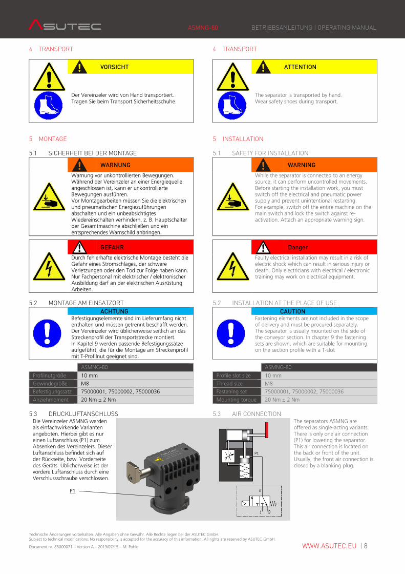
5.3 DRUCKLUFTANSCHLUSS 5.3 AIR CONNECTION Die Vereinzeler ASMNG werden als einfachwirkende Varianten angeboten. Hierbei gibt es nur einen Luftanschluss (P1) zum Absenken des Vereinzelers. Dieser Luftanschluss befindet sich auf der Rückseite, bzw. Vorderseite des Geräts. Üblicherweise ist der vordere Luftanschluss durch eine Verschlussschraube verschlossen.
P1
The separators ASMNG are offered as single-acting variants. There is only one air connection (P1) for lowering the separator. This air connection is located on the back or front of the unit. Usually, the front air connection is closed by a blanking plug.
ASMNG-80 BETRIEBSANLEITUNG | OPERATING MANUAL
Technische Änderungen vorbehalten. Alle Angaben ohne Gewähr. Alle Rechte liegen bei der ASUTEC GmbH. Subject to technical modifications. No responsibility is accepted for the accuracy of this information. All rights are reserved by ASUTEC GmbH.
Document nr. 85000071 – Version A – 2019/07/15 – M. Pohle WWW.ASUTEC.EU | 9
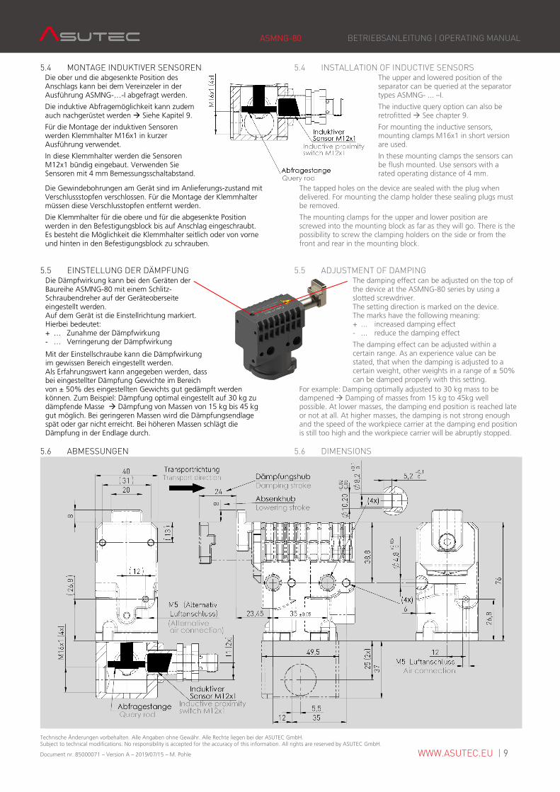
5.4 MONTAGE INDUKTIVER SENSOREN 5.4 INSTALLATION OF INDUCTIVE SENSORS Die ober und die abgesenkte Position des Anschlags kann bei dem Vereinzeler in der Ausführung ASMNG-…-I abgefragt werden.
Die induktive Abfragemöglichkeit kann zudem auch nachgerüstet werden � Siehe Kapitel 9.
Für die Montage der induktiven Sensoren werden Klemmhalter M16x1 in kurzer Ausführung verwendet.
In diese Klemmhalter werden die Sensoren M12x1 bündig eingebaut. Verwenden Sie Sensoren mit 4 mm Bemessungsschaltabstand.
The upper and lowered position of the separator can be queried at the separator types ASMNG- ... –I.
The inductive query option can also be retrofitted � See chapter 9.
For mounting the inductive sensors, mounting clamps M16x1 in short version are used.
In these mounting clamps the sensors can be flush mounted. Use sensors with a rated operating distance of 4 mm.
Die Gewindebohrungen am Gerät sind im Anlieferungs-zustand mit Verschlussstopfen verschlossen. Für die Montage der Klemmhalter müssen diese Verschlusstopfen entfernt werden.
Die Klemmhalter für die obere und für die abgesenkte Position werden in den Befestigungsblock bis auf Anschlag eingeschraubt. Es besteht die Möglichkeit die Klemmhalter seitlich oder von vorne und hinten in den Befestigungsblock zu schrauben.
The tapped holes on the device are sealed with the plug when delivered. For mounting the clamp holder these sealing plugs must be removed.
The mounting clamps for the upper and lower position are screwed into the mounting block as far as they will go. There is the possibility to screw the clamping holders on the side or from the front and rear in the mounting block.
5.5 EINSTELLUNG DER DÄMPFUNG 5.5 ADJUSTMENT OF DAMPING Die Dämpfwirkung kann bei den Geräten der Baureihe ASMNG-80 mit einem Schlitz-Schraubendreher auf der Geräteoberseite eingestellt werden. Auf dem Gerät ist die Einstellrichtung markiert. Hierbei bedeutet: + … Zunahme der Dämpfwirkung - … Verringerung der Dämpfwirkung
Mit der Einstellschraube kann die Dämpfwirkung im gewissen Bereich eingestellt werden. Als Erfahrungswert kann angegeben werden, dass bei eingestellter Dämpfung Gewichte im Bereich
The damping effect can be adjusted on the top of the device at the ASMNG-80 series by using a slotted screwdriver. The setting direction is marked on the device. The marks have the following meaning: + ... increased damping effect - ... reduce the damping effect
The damping effect can be adjusted within a certain range. As an experience value can be stated, that when the damping is adjusted to a certain weight, other weights in a range of ± 50% can be damped properly with this setting.
von ± 50% des eingestellten Gewichts gut gedämpft werden können. Zum Beispiel: Dämpfung optimal eingestellt auf 30 kg zu dämpfende Masse � Dämpfung von Massen von 15 kg bis 45 kg gut möglich. Bei geringeren Massen wird die Dämpfungsendlage spät oder gar nicht erreicht. Bei höheren Massen schlägt die Dämpfung in der Endlage durch.
For example: Damping optimally adjusted to 30 kg mass to be dampened � Damping of masses from 15 kg to 45kg well possible. At lower masses, the damping end position is reached late or not at all. At higher masses, the damping is not strong enough and the speed of the workpiece carrier at the damping end position is still too high and the workpiece carrier will be abruptly stopped.
5.6 ABMESSUNGEN 5.6 DIMENSIONS
ASMNG-80 BETRIEBSANLEITUNG | OPERATING MANUAL
Technische Änderungen vorbehalten. Alle Angaben ohne Gewähr. Alle Rechte liegen bei der ASUTEC GmbH. Subject to technical modifications. No responsibility is accepted for the accuracy of this information. All rights are reserved by ASUTEC GmbH.
Document nr. 85000071 – Version A – 2019/07/15 – M. Pohle WWW.ASUTEC.EU | 10
6 FUNKTIONSABLAUF 6 FUNCTIONAL SEQUENCE
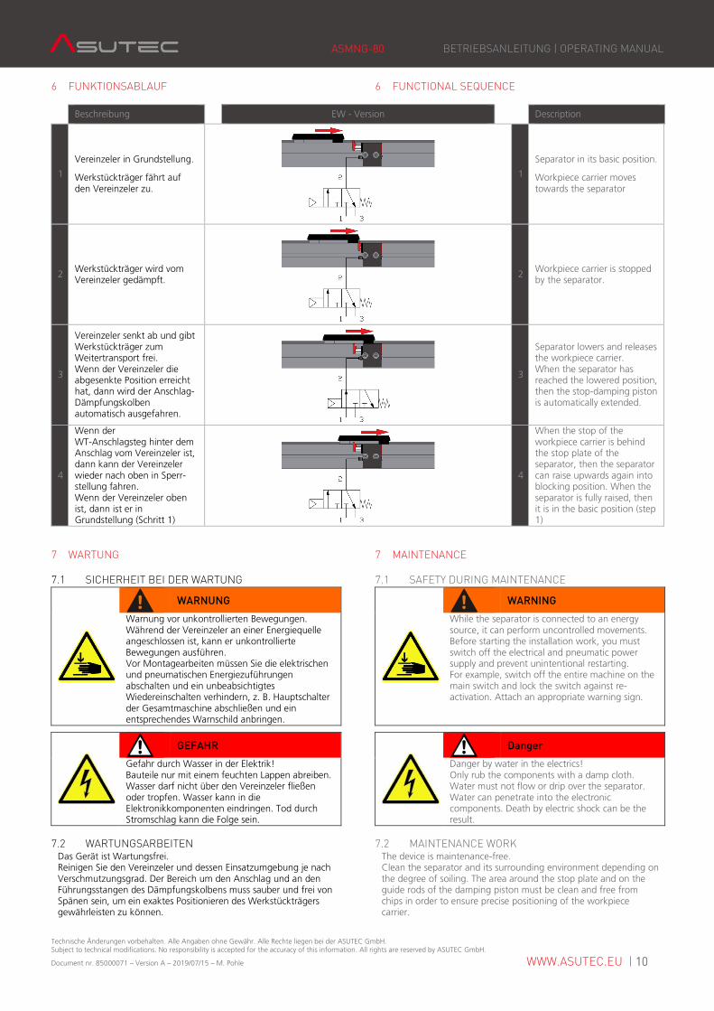
Beschreibung EW - Version Description
1
Vereinzeler in Grundstellung.
Werkstückträger fährt auf den Vereinzeler zu.
1
Separator in its basic position.
Workpiece carrier moves towards the separator
2 Werkstückträger wird vom Vereinzeler gedämpft.
2 Workpiece carrier is stopped by the separator.
3
Vereinzeler senkt ab und gibt Werkstückträger zum Weitertransport frei. Wenn der Vereinzeler die abgesenkte Position erreicht hat, dann wird der Anschlag-Dämpfungskolben automatisch ausgefahren.
3
Separator lowers and releases the workpiece carrier. When the separator has reached the lowered position, then the stop-damping piston is automatically extended.
4
Wenn der WT-Anschlagsteg hinter dem Anschlag vom Vereinzeler ist, dann kann der Vereinzeler wieder nach oben in Sperr-stellung fahren. Wenn der Vereinzeler oben ist, dann ist er in Grundstellung (Schritt 1)
4
When the stop of the workpiece carrier is behind the stop plate of the separator, then the separator can raise upwards again into blocking position. When the separator is fully raised, then it is in the basic position (step 1)
7 WARTUNG 7 MAINTENANCE
7.1 SICHERHEIT BEI DER WARTUNG 7.1 SAFETY DURING MAINTENANCE
WARNUNG
WARNING
Warnung vor unkontrollierten Bewegungen. Während der Vereinzeler an einer Energiequelle angeschlossen ist, kann er unkontrollierte Bewegungen ausführen. Vor Montagearbeiten müssen Sie die elektrischen und pneumatischen Energiezuführungen abschalten und ein unbeabsichtigtes Wiedereinschalten verhindern, z. B. Hauptschalter der Gesamtmaschine abschließen und ein entsprechendes Warnschild anbringen.
While the separator is connected to an energy source, it can perform uncontrolled movements. Before starting the installation work, you must switch off the electrical and pneumatic power supply and prevent unintentional restarting. For example, switch off the entire machine on the main switch and lock the switch against re-activation. Attach an appropriate warning sign.
GEFAHR
Danger
Gefahr durch Wasser in der Elektrik! Bauteile nur mit einem feuchten Lappen abreiben. Wasser darf nicht über den Vereinzeler fließen oder tropfen. Wasser kann in die Elektronikkomponenten eindringen. Tod durch Stromschlag kann die Folge sein.
Danger by water in the electrics! Only rub the components with a damp cloth. Water must not flow or drip over the separator. Water can penetrate into the electronic components. Death by electric shock can be the result.
7.2 WARTUNGSARBEITEN 7.2 MAINTENANCE WORK Das Gerät ist Wartungsfrei. Reinigen Sie den Vereinzeler und dessen Einsatzumgebung je nach Verschmutzungsgrad. Der Bereich um den Anschlag und an den Führungsstangen des Dämpfungskolbens muss sauber und frei von Spänen sein, um ein exaktes Positionieren des Werkstückträgers gewährleisten zu können.
The device is maintenance-free. Clean the separator and its surrounding environment depending on the degree of soiling. The area around the stop plate and on the guide rods of the damping piston must be clean and free from chips in order to ensure precise positioning of the workpiece carrier.
ASMNG-80 BETRIEBSANLEITUNG | OPERATING MANUAL
Technische Änderungen vorbehalten. Alle Angaben ohne Gewähr. Alle Rechte liegen bei der ASUTEC GmbH. Subject to technical modifications. No responsibility is accepted for the accuracy of this information. All rights are reserved by ASUTEC GmbH.
Document nr. 85000071 – Version A – 2019/07/15 – M. Pohle WWW.ASUTEC.EU | 11
8 TYPENSCHLÜSSEL 8 TYPE CODES
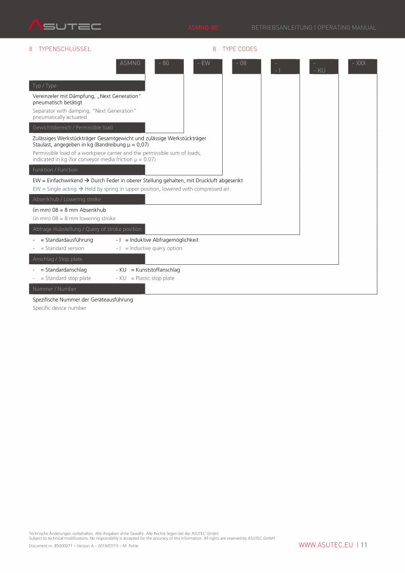
ASMNG - 80 - EW - 08 - - I
- - KU
- XXX
Typ / Type
Vereinzeler mit Dämpfung, „Next Generation“ pneumatisch betätigt
Separator with damping, “Next Generation” pneumatically actuated
Gewichtsbereich / Permissible load
Zulässiges Werkstückträger Gesamtgewicht und zulässige Werkstückträger Staulast, angegeben in kg (Bandreibung µ = 0,07)
Permissible load of a workpiece carrier and the permissible sum of loads, indicated in kg (for conveyor media friction μ = 0.07)
Funktion / Function
EW = Einfachwirkend � Durch Feder in oberer Stellung gehalten, mit Druckluft abgesenkt
EW = Single acting � Held by spring in upper position, lowered with compressed air.
Absenkhub / Lowering stroke
(in mm) 08 = 8 mm Absenkhub
(in mm) 08 = 8 mm lowering stroke
Abfrage Hubstellung / Query of stroke position
- = Standardausführung - I = Induktive Abfragemöglichkeit
- = Standard version - I = Inductive query option
Anschlag / Stop plate
- = Standardanschlag - KU = Kunststoffanschlag
- = Standard stop plate - KU = Plastic stop plate
Nummer / Number
Spezifische Nummer der Geräteausführung
Specific device number
ASMNG-80 BETRIEBSANLEITUNG | OPERATING MANUAL
Technische Änderungen vorbehalten. Alle Angaben ohne Gewähr. Alle Rechte liegen bei der ASUTEC GmbH. Subject to technical modifications. No responsibility is accepted for the accuracy of this information. All rights are reserved by ASUTEC GmbH.
Document nr. 85000071 – Version A – 2019/07/15 – M. Pohle WWW.ASUTEC.EU | 12
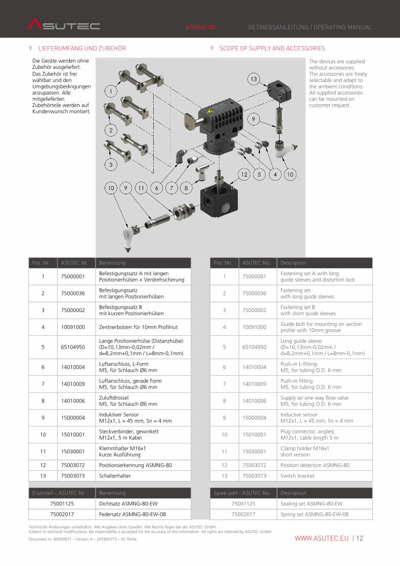
9 LIEFERUMFANG UND ZUBEHÖR 9 SCOPE OF SUPPLY AND ACCESSORIES
Die Geräte werden ohne Zubehör ausgeliefert. Das Zubehör ist frei wählbar und den Umgebungsbedingungen anzupassen. Alle mitgelieferten Zubehörteile werden auf Kundenwunsch montiert.
The devices are supplied without accessories. The accessories are freely selectable and adapt to the ambient conditions. All supplied accessories can be mounted on customer request.
Pos. Nr. ASUTEC Nr. Benennung Pos. No. ASUTEC No. Description
1 75000001 Befestigungssatz A mit langen Positionierhülsen + Verdrehsicherung
1 75000001 Fastening set A with long guide sleeves and distortion lock
2 75000036 Befestigungssatz mit langen Positionierhülsen
2 75000036 Fastening set with long guide sleeves
3 75000002 Befestigungssatz B mit kurzen Positionierhülsen
3 75000002 Fastening set B with short guide sleeves
4 10091000 Zentrierbolzen für 10mm Profilnut 4 10091000 Guide bolt for mounting on section profile with 10mm groove
5 65104950 Lange Positionierhülse (Distanzhülse) (D=10,13mm-0,02mm / d=8,2mm+0,1mm / L=8mm-0,1mm)
5 65104950 Long guide sleeve (D=10,13mm-0,02mm / d=8,2mm+0,1mm / L=8mm-0,1mm)
6 14010004 Luftanschluss, L-Form M5, für Schlauch Ø6 mm
6 14010004 Push-in L-fitting M5, for tubing O.D. 6 mm
7 14010009 Luftanschluss, gerade Form M5, für Schlauch Ø6 mm
7 14010009 Push-in fitting M5, for tubing O.D. 6 mm
8 14010006 Zuluftdrossel M5, für Schlauch Ø6 mm
8 14010006 Supply air one way flow valve M5, for tubing O.D. 6 mm
9 15000004 Induktiver Sensor M12x1, L = 45 mm, Sn = 4 mm
9 15000004 Inductive sensor M12x1, L = 45 mm, Sn = 4 mm
10 15010001 Steckverbinder, gewinkelt M12x1, 5 m Kabel
10 15010001 Plug connector, angled, M12x1, cable length 5 m
11 15030001 Klemmhalter M16x1 kurze Ausführung
11 15030001 Clamp holder M16x1 short version
12 75003072 Positionserkennung ASMNG-80 12 75003072 Position detection ASMNG-80
13 75003073 Schalterhalter 13 75003073 Switch bracket
Ersatzteil – ASUTEC Nr. Benennung Spare part - ASUTEC No. Description
75001125 Dichtsatz ASMNG-80-EW 75001125 Sealing set ASMNG-80-EW
75002017 Federsatz ASMNG-80-EW-08 75002017 Spring set ASMNG-80-EW-08
ASMNG-80 BETRIEBSANLEITUNG | OPERATING MANUAL
Technische Änderungen vorbehalten. Alle Angaben ohne Gewähr. Alle Rechte liegen bei der ASUTEC GmbH. Subject to technical modifications. No responsibility is accepted for the accuracy of this information. All rights are reserved by ASUTEC GmbH.
Document nr. 85000071 – Version A – 2019/07/15 – M. Pohle WWW.ASUTEC.EU | 13
10 EINBAUERKLÄRUNG 10 COPY OF THE DECLARATION OF INCORPORATION
Original der Erklärung für den Einbau einer unvollständigen Maschine im Sinne der EG Richtlinie Maschinen 2006/42/EG Anhang II 1 B. Typen: ASM, ASMHS, ASMK, ASMR, ASMS, ASMSI, ASMST, ASMU, ASMNG Typenbezeichnung: Vereinzeler mit Dämpfung, pneumatisch Fortlaufende Serien-Nr.: 1079 Die Maschine entspricht den einschlägigen Bestimmungen der:
- EG-Richtlinie 2006/42/EG Amtsblatt L157/24 Hersteller und Bevollmächtigter für die Zusammenstellung der relevanten technischen Unterlagen gemäß Anhang VII B: Asutec GmbH Küferstraße 11 73257 Köngen Folgende grundlegenden Anforderungen kommen zur Anwendung, soweit es im Rahmen des Lieferumfanges möglich ist: 2006/42/EG, Anhang I, allgemeine Grundsätze; 2006/42/EG, Anhang I 1, grundlegende Sicherheits- und Gesundheitsanforderungen Die speziellen Unterlagen, entsprechend EG-Richtlinie 2006/42/EG Anhang VII Teil B, werden auf begründetes Verlangen einzelstaatlichen Stellen per Post/E-Mail übermittelt. Angewandte Normen: DIN EN ISO 12100 Sicherheit von Maschinen, allgemeine Gestaltungsleitsätze 2011-3 Die Inbetriebnahme dieser Maschine/des Maschinenteils ist so lange untersagt, bis festgestellt wurde, dass die Maschine, in die sie eingebaut werden soll, den Bestimmungen den anwendbaren EG-Richtlinien, sowie den harmonisierten Normen, Europanormen oder den entsprechenden nationalen Normen entspricht.
Köngen, 08.07.2019 Manfred Mattersberger
Copy of the declaration of incorporation for partly complete machinery in the sense of the EC-directive for machines 2016/42/EC Annex II 1B. Types: ASM, ASMHS, ASMK, ASMR, ASMS, ASMSI, ASMST, ASMU, ASMNG Type designation: Separator with damping, pneumatically Continuous serial no.: 1079 The machine complies with the relevant provisions of the:
- EC Directive 2006/42 / EC Official Journal L157 / 24 Manufacturer and authorized representative for the compilation of the relevant technical documentation in accordance with Annex VII B: Asutec GmbH Küferstraße 11 73257 Köngen The following essential requirements are applied as far as is possible within the scope of supply: 2006/42 / EC, Annex I, general principles; 2006/42 / EC, Annex I 1, basic health and safety requirements The special documents, according to EC Directive 2006/42 / EC Annex VII, Part B shall be transmitted national authorities by post / email to a reasoned request. Applied standards: DIN EN ISO 12100 Safety of machinery, General design guidelines 2011-3 The commissioning of this machine / machine part is prohibited until it is determined that the machine in which it is to be installed complies with the applicable EC directives as well as the harmonized standards, European standards or the corresponding national standards.
Ort, Datum Name / Unterschrift Geschäftsführer