Embed Size (px)
Citation preview
Office of Research & Library ServicesWSDOT Research Report
Best Practices of Using Shotcretefor Wall Fascia and Slope Stabilization (Phase 1 Study)
WA-RD 870.1 June 2017
17-10-0397
Pizhong QiaoZhidong Zhou
Final Research Report
Agreement T1462, Task 9
WA-RD 870.1
BEST PRACTICES OF USING SHOTCRETE FOR WALL FASCIA AND SLOPE STABILIZATION
(Phase I Study)
by
Pizhong Qiao, Ph.D., P.E. Professor
Zhidong Zhou, Ph.D. Candidate
Graduate Research Assistant
Washington State Transportation Center (TRAC) Washington State University,
Department of Civil and Environmental Engineering Sloan Hall, Room 101
Pullman, WA 99164-2910
Washington State Department of Transportation
Mark Gaines, P.E., Lead Construction Engineer Marco Foster, P.E., Assistant State Construction Engineer
Brian Aldrich, P.E., S.E., State Bridge Construction Engineer Technical Contacts
Lu Saechao, P.E.
Research Manager
Prepared for
The State of Washington Washington State Department of Transportation
Roger Millar, Secretary
June 2017
ii
TECHNICAL REPORT STANDARD TITLE PAGE 1. REPORT NO. 2. GOVERNMENT ACCESSION NO. 3. RECIPIENT'S CATALOG NO.
WA-RD 870.1 4. TITLE AND SUBTITLE 5. REPORT DATE Best Practices of Using Shotcrete for Wall Fascia and Slope Stabilization (Phase I Study)
June 2017 6. PERFORMING ORGANIZATION CODE
7. AUTHOR(S) 8. PERFORMING ORGANIZATION REPORT NO. Pizhong Qiao and Zhidong Zhou
9. PERFORMING ORGANIZATION NAME AND ADDRESS 10. WORK UNIT NO. Washington State Transportation Center (TRAC) Washington State University 11. CONTRACT OR GRANT NO.
Department of Civil and Environmental Engineering Agreement T1462, Task 9 Pullman, WA 99164-2910 12. SPONSORING AGENCY NAME AND ADDRESS 13. TYPE OF REPORT AND PERIOD COVERED
Washington State Department of Transportation Final Report Transportation Building, MS: 47372
Olympia, WA 98504-7372 Research Manager: Lu Saechao by 360.705.7260
14. SPONSORING AGENCY CODE
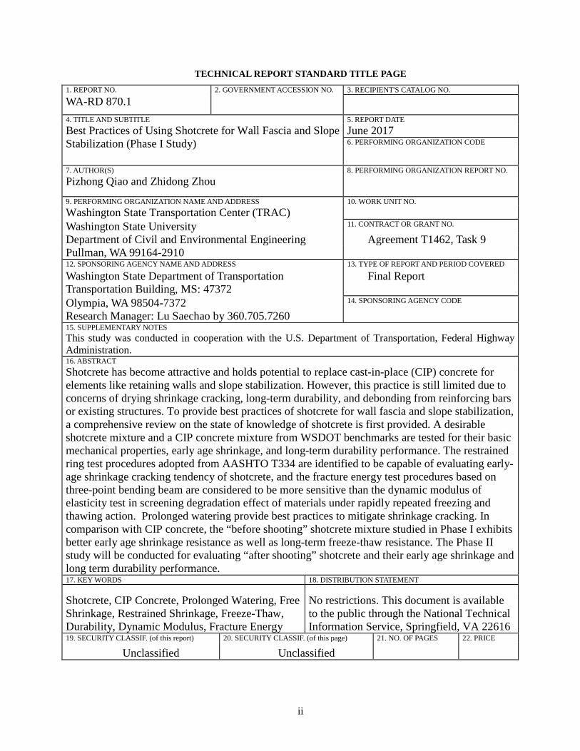
15. SUPPLEMENTARY NOTES This study was conducted in cooperation with the U.S. Department of Transportation, Federal Highway Administration. 16. ABSTRACT Shotcrete has become attractive and holds potential to replace cast-in-place (CIP) concrete for elements like retaining walls and slope stabilization. However, this practice is still limited due to concerns of drying shrinkage cracking, long-term durability, and debonding from reinforcing bars or existing structures. To provide best practices of shotcrete for wall fascia and slope stabilization, a comprehensive review on the state of knowledge of shotcrete is first provided. A desirable shotcrete mixture and a CIP concrete mixture from WSDOT benchmarks are tested for their basic mechanical properties, early age shrinkage, and long-term durability performance. The restrained ring test procedures adopted from AASHTO T334 are identified to be capable of evaluating early-age shrinkage cracking tendency of shotcrete, and the fracture energy test procedures based on three-point bending beam are considered to be more sensitive than the dynamic modulus of elasticity test in screening degradation effect of materials under rapidly repeated freezing and thawing action. Prolonged watering provide best practices to mitigate shrinkage cracking. In comparison with CIP concrete, the “before shooting” shotcrete mixture studied in Phase I exhibits better early age shrinkage resistance as well as long-term freeze-thaw resistance. The Phase II study will be conducted for evaluating “after shooting” shotcrete and their early age shrinkage and long term durability performance. 17. KEY WORDS 18. DISTRIBUTION STATEMENT Shotcrete, CIP Concrete, Prolonged Watering, Free Shrinkage, Restrained Shrinkage, Freeze-Thaw, Durability, Dynamic Modulus, Fracture Energy
No restrictions. This document is available to the public through the National Technical Information Service, Springfield, VA 22616
19. SECURITY CLASSIF. (of this report) 20. SECURITY CLASSIF. (of this page) 21. NO. OF PAGES 22. PRICE
Unclassified Unclassified
iii
DISCLAIMER
The contents of this report reflect the views of the authors, who are responsible for
the facts and accuracy of the data presented herein. The contents do not necessarily reflect
the official views or policies of the Washington State Department of Transportation or the
Federal Highway Administration. This report does not constitute a standard, specification,
or regulation.
iv
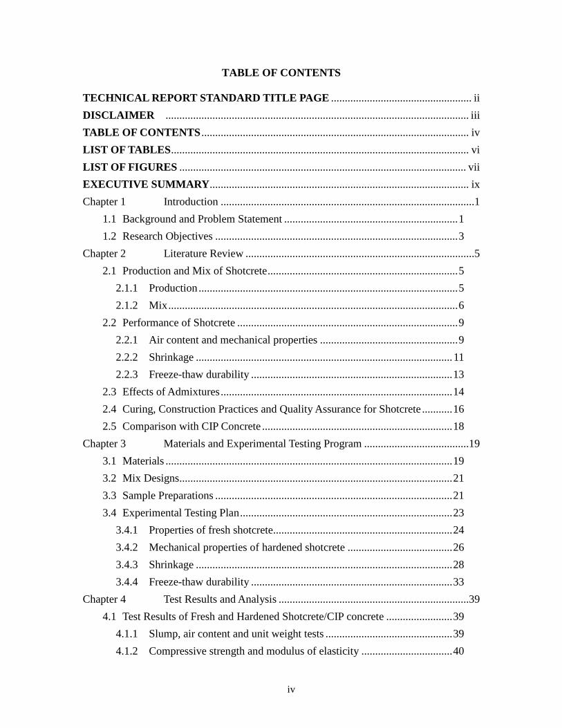
TABLE OF CONTENTS
TECHNICAL REPORT STANDARD TITLE PAGE ................................................... ii DISCLAIMER .............................................................................................................. iii TABLE OF CONTENTS ................................................................................................. iv
LIST OF TABLES ............................................................................................................ vi LIST OF FIGURES ........................................................................................................ vii EXECUTIVE SUMMARY .............................................................................................. ix
Chapter 1 Introduction ............................................................................................1
1.1 Background and Problem Statement ............................................................... 1
1.2 Research Objectives ........................................................................................ 3
Chapter 2 Literature Review ...................................................................................5
2.1 Production and Mix of Shotcrete ..................................................................... 5
2.1.1 Production .............................................................................................. 5
2.1.2 Mix ......................................................................................................... 6
2.2 Performance of Shotcrete ................................................................................ 9
2.2.1 Air content and mechanical properties .................................................. 9
2.2.2 Shrinkage ............................................................................................. 11
2.2.3 Freeze-thaw durability ......................................................................... 13
2.3 Effects of Admixtures .................................................................................... 14
2.4 Curing, Construction Practices and Quality Assurance for Shotcrete ........... 16
2.5 Comparison with CIP Concrete ..................................................................... 18
Chapter 3 Materials and Experimental Testing Program ......................................19
3.1 Materials ........................................................................................................ 19
3.2 Mix Designs ................................................................................................... 21
3.3 Sample Preparations ...................................................................................... 21
3.4 Experimental Testing Plan ............................................................................. 23
3.4.1 Properties of fresh shotcrete................................................................. 24
3.4.2 Mechanical properties of hardened shotcrete ...................................... 26
3.4.3 Shrinkage ............................................................................................. 28
3.4.4 Freeze-thaw durability ......................................................................... 33
Chapter 4 Test Results and Analysis .....................................................................39
4.1 Test Results of Fresh and Hardened Shotcrete/CIP concrete ........................ 39
4.1.1 Slump, air content and unit weight tests .............................................. 39
4.1.2 Compressive strength and modulus of elasticity ................................. 40
v
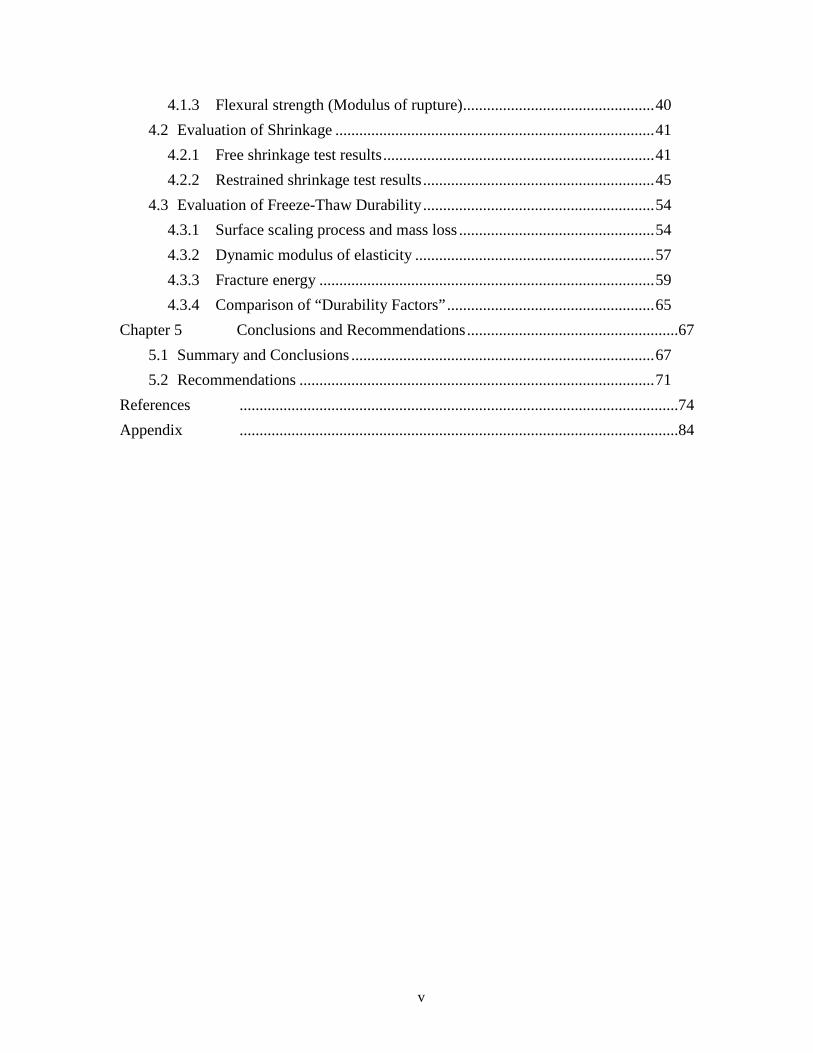
4.1.3 Flexural strength (Modulus of rupture) ................................................ 40
4.2 Evaluation of Shrinkage ................................................................................ 41
4.2.1 Free shrinkage test results .................................................................... 41
4.2.2 Restrained shrinkage test results .......................................................... 45
4.3 Evaluation of Freeze-Thaw Durability .......................................................... 54
4.3.1 Surface scaling process and mass loss ................................................. 54
4.3.2 Dynamic modulus of elasticity ............................................................ 57
4.3.3 Fracture energy .................................................................................... 59
4.3.4 Comparison of “Durability Factors” .................................................... 65
Chapter 5 Conclusions and Recommendations .....................................................67
5.1 Summary and Conclusions ............................................................................ 67
5.2 Recommendations ......................................................................................... 71
References ..............................................................................................................74
Appendix ..............................................................................................................84
vi
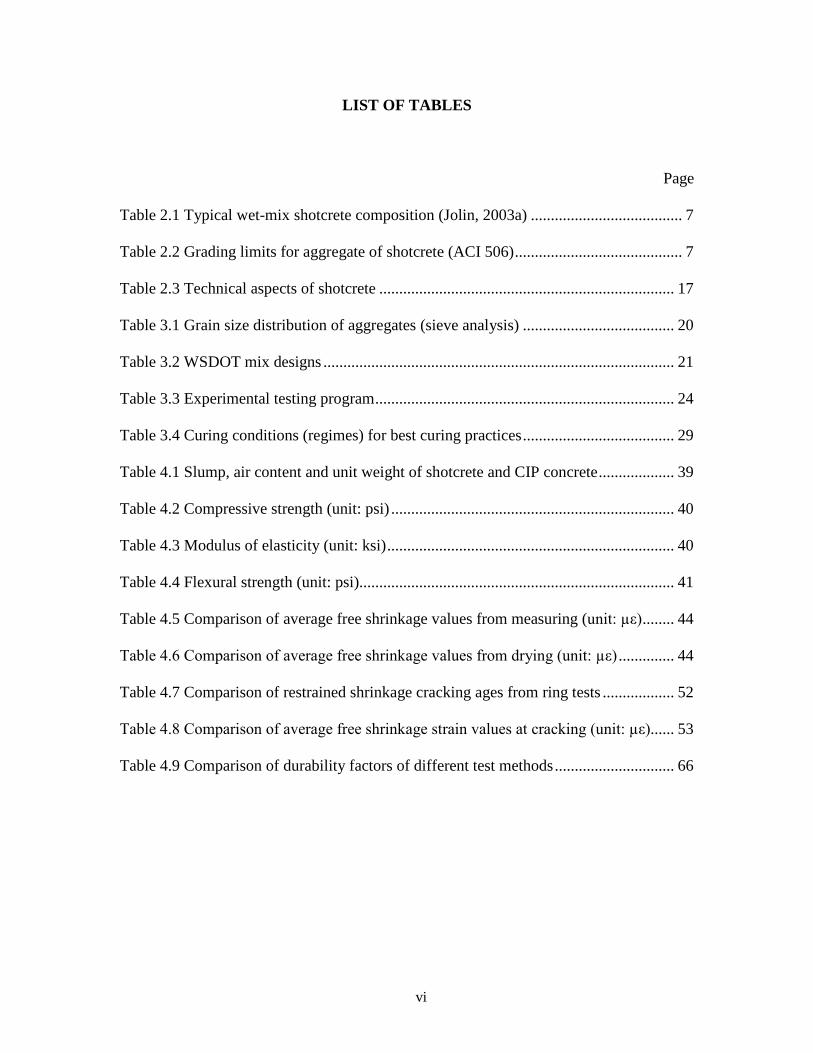
LIST OF TABLES
Page
Table 2.1 Typical wet-mix shotcrete composition (Jolin, 2003a) ...................................... 7
Table 2.2 Grading limits for aggregate of shotcrete (ACI 506) .......................................... 7
Table 2.3 Technical aspects of shotcrete .......................................................................... 17
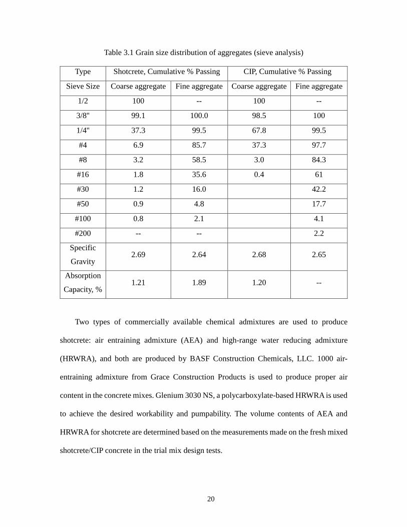
Table 3.1 Grain size distribution of aggregates (sieve analysis) ...................................... 20
Table 3.2 WSDOT mix designs ........................................................................................ 21
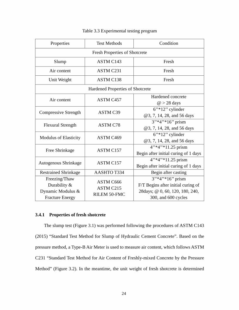
Table 3.3 Experimental testing program ........................................................................... 24
Table 3.4 Curing conditions (regimes) for best curing practices ...................................... 29
Table 4.1 Slump, air content and unit weight of shotcrete and CIP concrete ................... 39
Table 4.2 Compressive strength (unit: psi) ....................................................................... 40
Table 4.3 Modulus of elasticity (unit: ksi) ........................................................................ 40
Table 4.4 Flexural strength (unit: psi) ............................................................................... 41
Table 4.5 Comparison of average free shrinkage values from measuring (unit: µε) ........ 44
Table 4.6 Comparison of average free shrinkage values from drying (unit: µε) .............. 44
Table 4.7 Comparison of restrained shrinkage cracking ages from ring tests .................. 52
Table 4.8 Comparison of average free shrinkage strain values at cracking (unit: µε) ...... 53
Table 4.9 Comparison of durability factors of different test methods .............................. 66
vii
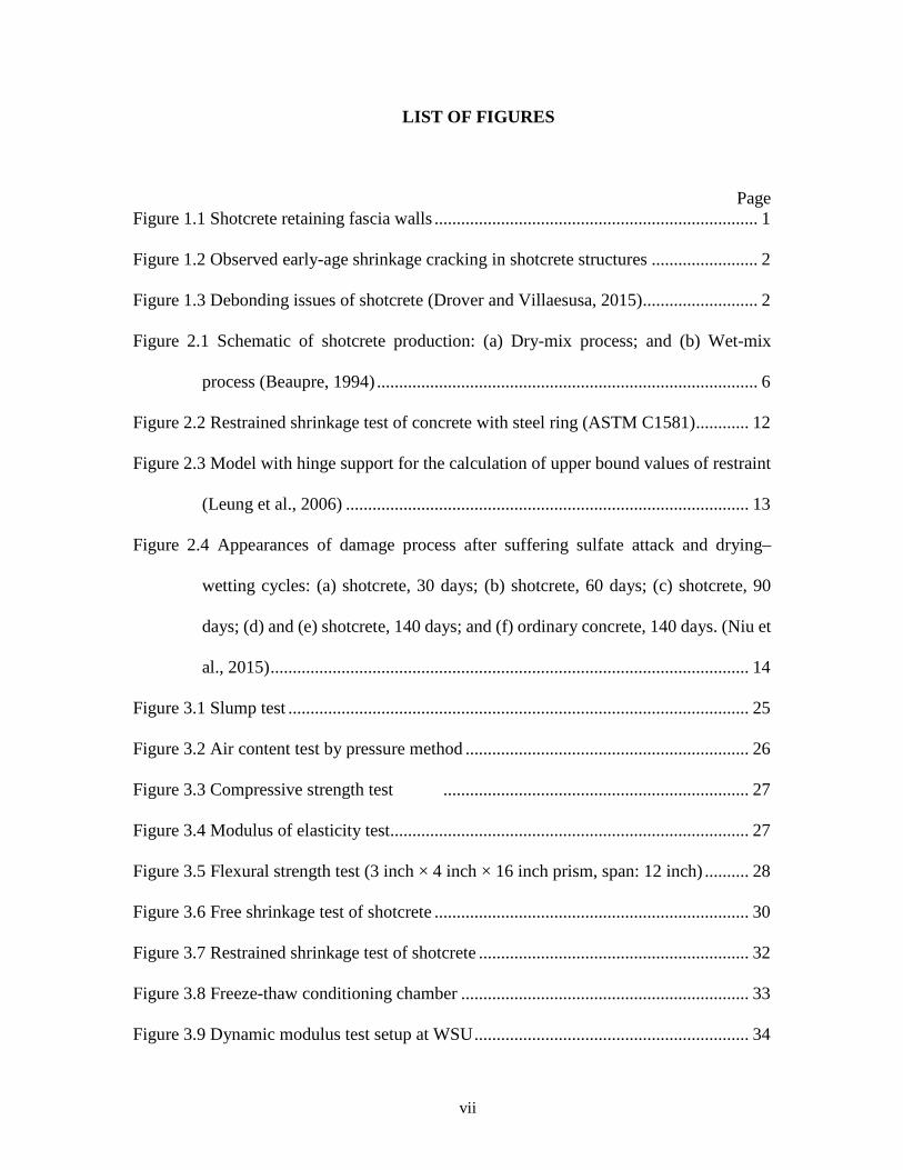
LIST OF FIGURES
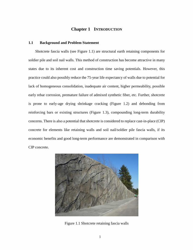
Page Figure 1.1 Shotcrete retaining fascia walls ......................................................................... 1
Figure 1.2 Observed early-age shrinkage cracking in shotcrete structures ........................ 2
Figure 1.3 Debonding issues of shotcrete (Drover and Villaesusa, 2015) .......................... 2
Figure 2.1 Schematic of shotcrete production: (a) Dry-mix process; and (b) Wet-mix
process (Beaupre, 1994) ...................................................................................... 6
Figure 2.2 Restrained shrinkage test of concrete with steel ring (ASTM C1581) ............ 12
Figure 2.3 Model with hinge support for the calculation of upper bound values of restraint
(Leung et al., 2006) ........................................................................................... 13
Figure 2.4 Appearances of damage process after suffering sulfate attack and drying–
wetting cycles: (a) shotcrete, 30 days; (b) shotcrete, 60 days; (c) shotcrete, 90
days; (d) and (e) shotcrete, 140 days; and (f) ordinary concrete, 140 days. (Niu et
al., 2015) ............................................................................................................ 14
Figure 3.1 Slump test ........................................................................................................ 25
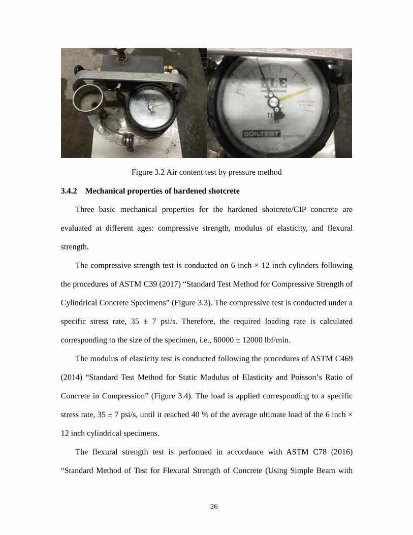
Figure 3.2 Air content test by pressure method ................................................................ 26
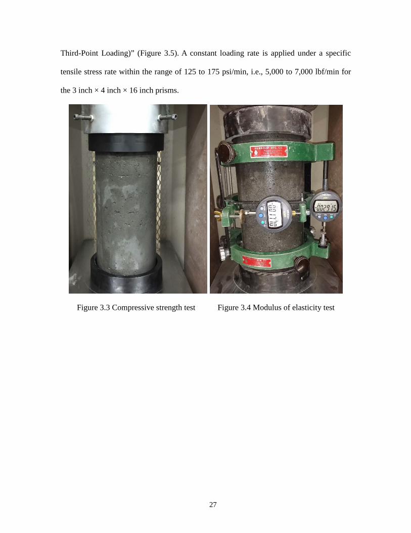
Figure 3.3 Compressive strength test ..................................................................... 27
Figure 3.4 Modulus of elasticity test................................................................................. 27
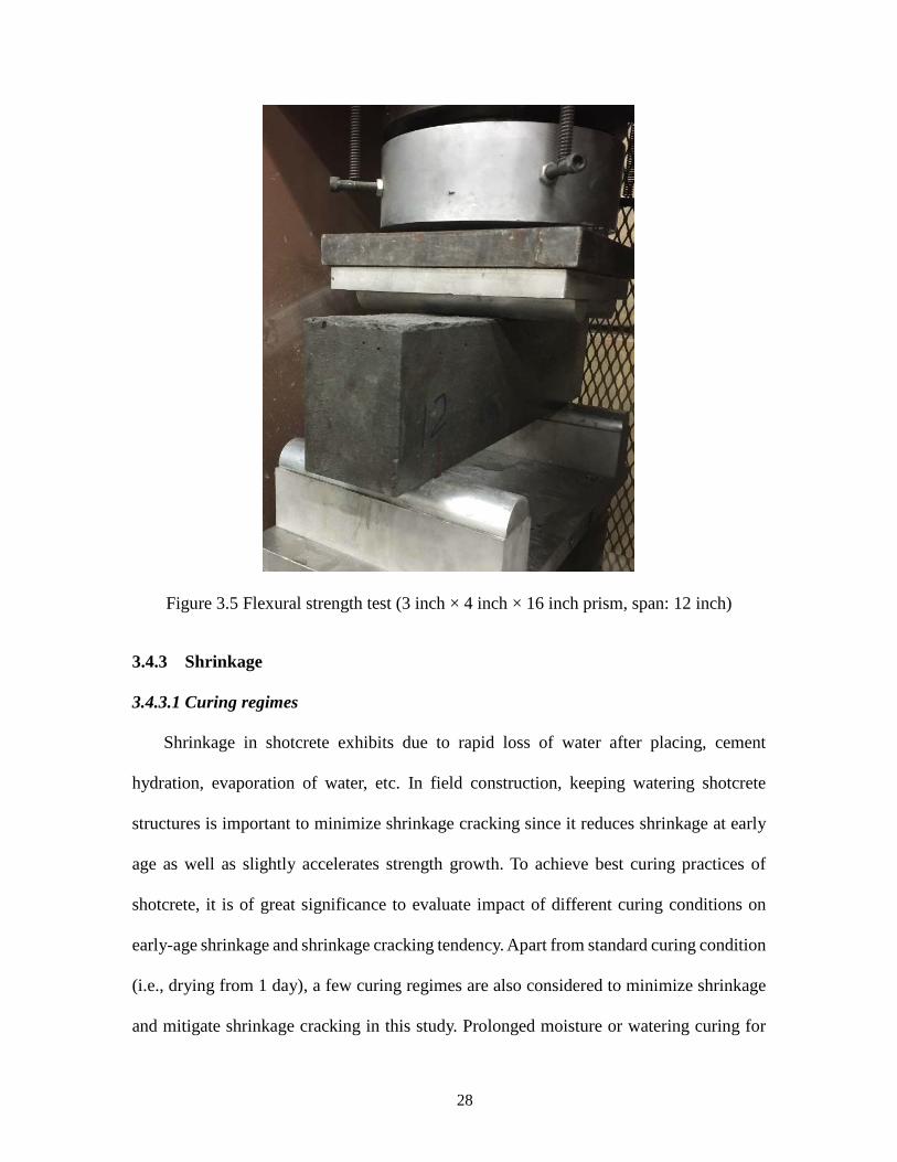
Figure 3.5 Flexural strength test (3 inch × 4 inch × 16 inch prism, span: 12 inch) .......... 28
Figure 3.6 Free shrinkage test of shotcrete ....................................................................... 30
Figure 3.7 Restrained shrinkage test of shotcrete ............................................................. 32
Figure 3.8 Freeze-thaw conditioning chamber ................................................................. 33
Figure 3.9 Dynamic modulus test setup at WSU .............................................................. 34
viii
Figure 3.10 Sketch diagram of cohesive fracture test under three point bending............. 36
Figure 3.11 Testing equipment setup for fracture test ...................................................... 37
Figure 3.12 Typical load-deflection curve of cohesive fracture test ................................ 38
Figure 4.1 Comparison of flexural strength ...................................................................... 41
Figure 4.2 Free shrinkage of shotcrete with different curing regimes and CIP concrete . 43
Figure 4.3 Comparison of free shrinkage ......................................................................... 44
Figure 4.4 Restrained shrinkage of shotcrete under curing regime I ................................ 46
Figure 4.5 Restrained shrinkage of shotcrete under curing regime II............................... 47
Figure 4.6 Restrained shrinkage of shotcrete under curing regime III ............................. 48
Figure 4.7 Restrained shrinkage of shotcrete under curing regime IV ............................. 49
Figure 4.8 Restrained shrinkage of shotcrete under curing regime V .............................. 50
Figure 4.9 Restrained shrinkage of CIP concrete under curing regime I .......................... 51
Figure 4.10 Comparison of restrained shrinkage cracking ages from ring tests ............... 53
Figure 4.11 Appearances of shotcrete under rapidly repeated freeze-thaw actions ......... 55
Figure 4.12 Comparison of mass loss due to freeze-thaw cycles ..................................... 56
Figure 4.13 Comparison of transverse frequency ............................................................. 57
Figure 4.14 Comparison of dynamic modulus .................................................................. 58
Figure 4.15 Load-deflection curves of shotcrete at different freeze-thaw cycles ............. 62
Figure 4.16 Comparison of modulus of elasticity ............................................................. 63
Figure 4.17 Comparison of fracture energy ...................................................................... 64
ix
EXECUTIVE SUMMARY
Shotcrete fascia walls are structural earth retaining components for soldier pile and
soil nail walls. This method of construction has become attractive and holds potential to
replace cast-in-place (CIP) concrete for elements like retaining walls and slope stabilization,
if its economic benefits and good long-term performance are demonstrated. However, this
practice could also possibly be limited due to early age drying shrinkage cracking and
debonding from reinforcing bars or existing structures, and long-term durability concerns.
Research including early age shrinkage and long term durability investigation, best curing
practices, and acceptance guides for shotcrete is highly needed.
The goal of this Phase I project aims to conduct some preliminary study on
performance characterization of shotcrete and compare their performance with those of CIP,
in order to shed some light on best practices of shotcrete for wall fascia and slope
stabilization. A comprehensive review on the state of the knowledge of shotcrete is first
presented, including its production and mix design, mechanical properties, short- and long-
term performance, related quality assurance methods, and comparisons with CIP concrete.
From the literature review, the critical issues related to early age shrinkage cracking and
long term durability are identified. Two types of mixtures (a desirable shotcrete mixture
and a CIP concrete mixture) are chosen for the following performance comparisons:
material properties in the fresh (e.g., slump, air content, and unit weight) and hardened
(e.g., compressive strength, modulus of elasticity, and flexural strength) states; early age
free shrinkage and restrained shrinkage performance; and long-term freeze-thaw resistance
through dynamic modulus of elasticity and fracture energy tests.
Based on the comparative evaluation of basic material properties, early age shrinkage,
x
and freeze-thaw resistance for shotcrete and CIP concrete, the following
finding/conclusions are drawn:
(1) From the literature review, the early age shrinkage and long-term durability issues
and their related test methods are identified when using shotcrete for wall fascia and slope
stabilization. The shrinkage cracking tendency of shotcrete is related to both its tensile
strength and free shrinkage properties. Watering shotcrete surface at early age is
remarkably important to minimize its shrinkage cracking since it presents relatively low
free shrinkage strain. Internal air-void system (air content and spacing factor) of hardened
shotcrete has significant influence on durability of shotcrete. Addition of air entraining
admixture results in well-distributed entrained air rather than entrapped air. Freeze-thaw
resistance of shotcrete is improved with increasing of air content and decreasing of spacing
factor. Inclusion of silica fume in the mix generally reduces the mass of scaling residues
and improves the durability of shotcrete due to lower permeability.
(2) Following the ASTM standard test procedures for concrete and cementitious
material characterization, the rheological property tests (e.g., slump, air content, and unit
weight) of freshly mixed shotcrete are conducted to achieve desirable mix design with
acceptable workability (i.e., pumpability and shootability) by adjusting the contents of air
entraining admixture (AEA) and high-range water reducing admixture (HRWRA). The
average slump and air content for the desirable “before shooting” shotcrete are 5 inch and
10.2%, respectively, which are much higher than those of CIP concrete.
(3) To achieve best curing practices of shotcrete to mitigate early age shrinkage
cracking, a few curing regimes are considered in terms of prolonged watering and curing
compound. In detail, four curing regimes with prolonged watering of 1 day (Regime I), 4
xi
days (Regime II), 7 days (Regime III) and 10 days (Regime IV) and one curing regime
with curing compound (Regime V) are applied for evaluation of shrinkage properties. Both
the early-age free shrinkage test using prismatic specimens with dimensions of 4 × 4 ×
11.25 inch in accordance with ASTM C157 and the restrained shrinkage test for cracking
tendency via rings in accordance with AASHTO T334 are performed. Based on the free
shrinkage test, the shotcrete with prolonged watering is found to shrink the most, followed
by CIP concrete, while the shotcrete with curing compound shrinks the least. CIP concrete
considerably exhibits lower free shrinkage than shotcrete since less cementitious materials
in CIP concrete are used. Using curing compound to seal all surface of shotcrete specimens
greatly prevents internal moisture from loss even without external moisture supply, and the
shotcrete exhibits 48% of free shrinkage compared to that without curing compound.
Prolonged watering also has significant influence on free shrinkage of shotcrete as drying
shrinkage is almost suspended/postponed till the stop of watering, and it is also found that
the longer the shotcrete is kept wet, the lower free shrinkage it has. From the restrained
shrinkage ring test, it is also observed that CIP concrete cracks the earliest (at 7.6 days),
followed by shotcrete with prolonged watering (at 12.73 days, 16.80 days, 31.97 days, and
40.47 days, respectively, for curing regimes I, II, III, and IV); while shotcrete with curing
compound does not crack (no cracking is observed up to 45 days). The cracking of a ring
specimen can be characterized as combined effects of free shrinkage and tensile strength.
Prolonged watering postpones shrinkage cracking due to lower free shrinkage at early age,
and the longer of watering action is applied to shotcrete rings, the longer it takes for
shrinkage cracking. Even though CIP concrete exhibited lower free shrinkage than that of
shotcrete, the ring specimens of CIP concrete crack earlier as it has lower tensile strength
xii
(as characterized by flexural strength) than shotcrete. Using curing compound (Regime V)
to prevent specimens from drying provides the best practice; however, it may be difficult
to be implemented thoroughly to structures in the field.
(4) Long-term freeze-thaw durability of shotcrete are evaluated based on standard and
non-standard approaches. The rapidly repeated freeze-thaw tests in accordance with ASTM
C666 Procedure A are performed on 3 × 4 × 16 inch prisms. The non-destructive method,
i.e., vibration-based dynamic modulus of elasticity test, is conducted following the ASTM
C215 on two groups of specimens subjected to freezing and thawing conditioning cycles.
In parallel, a destructive method, i.e., fracture energy test of shotcrete, is performed using
the three-point bend test of notched beams. It is demonstrated that both the dynamic
modulus of elasticity and fracture energy tests can evaluate concrete material deterioration
due to accumulative freeze-thaw damage. Mass loss due to frost action is visually observed
as scaling of paste and mortar at the bottom surfaces and ends of the specimens. Both the
dynamic modulus of elasticity and fracture energy for both shotcrete and CIP concrete
mixtures keep decreasing with the freeze-thaw conditioning cycles. After 300 (ASTM
benchmark) freeze-thaw cycles, the relative dynamic modulus of elasticity of shotcrete and
CIP concrete are 94.15% and 87.82%, respectively, of those of virgin samples; while the
fracture energy values of shotcrete and CIP concrete are 83.81% and 74.92%, respectively,
compared to those of virgin samples. Apparently, shotcrete is more durable than CIP
concrete based on the comparisons of relative dynamic modulus of elasticity and relative
fracture energy, and it deteriorates at a slower rate than CIP concrete under frost action. In
addition, the fracture energy of CIP concrete decreases faster than that of shotcrete, and the
decreasing rates of fracture energy for both shotcrete and CIP concrete are much faster than
xiii
those based on the dynamic modulus of elasticity test. In other words, the durability factors
determined from fracture energy test show larger changes from the benchmark values than
those from dynamic modulus of elasticity test, indicating that the fracture energy test is
more sensitive to screen the rate of aging or degradation and capable of capturing material
deterioration subjected to rapidly repeated freeze-thaw action as well as other types of
accumulative damage.
The results of this study are limited to the mix design and test methods used to explore
proper use of shotcrete for wall fascia and slope stabilization. In particular, early age
shrinkage and long-term durability related properties are mainly emphasized. Based on the
experimental program conducted in this study, the following recommendations are
suggested to better understand the performance of shotcrete:
(1) More viable mix designs of shotcrete by adjusting water/cement ratio, proportions
of cementitious materials (e.g., cement, silica fume, ground granulated blast-furnace slag,
fly ash, etc.) should be evaluated since only one shotcrete mixture with water/cement ratio
of 0.34 and compressive strength higher than 6,000 psi is used in the present study.
(2) All specimens of “before shooting” shotcrete are prepared for evaluation and
testing of shotcrete mechanical properties in this Phase I study; however, they cannot be
identically equal to those obtained from “after shooting” concrete. The comparisons of the
mechanical properties and durability of “before shooting” and “after shooting” types of
shotcrete should be more considered.
(3) More laboratory evaluations should be conducted to reveal air-void characteristics
since the air-void system in hardened shotcrete has significant influence on mechanical
properties and long-term durability performance. The comparisons and correlations of air-

xiv
void characteristics between “before shooting” and “after shooting” types of shotcrete are
needed.
(4) Early age shrinkage due to loss of moisture and shrinkage cracking tendency with
a risk of decreasing quality and durability of shotcrete should be completely understood.
Some other potential shrinkage-associated mitigation strategies, such as using shrinkage
reducing admixtures (SRA), accelerators, expansive cementitious materials, silica fume,
steel fiber, etc., should be proposed to reduce shrinkage cracking tendency.
(5) Other methods are recommended to screen internal damage process of pore
structures and reveal failure mechanisms of shotcrete subjected to freeze-thaw action, such
as micro/nano X-ray computed tomography (nano-CT) and scanning electron microscopy
(SEM), etc., so that long-term durability of shotcrete can be better understood at the small
scale of material characterization.
(6) Besides frost attack, combined frost and chemical attacks should be investigated
for durability evaluations of shotcrete due to frequent use of salty deicers to melt snow and
ice and improve traffic safety in cold regions.
(7) Bond strength and debonding mechanism at interface area between shotcrete and
substrate should be investigated to ensure application of shotcrete as a repairing material
and in slope stabilization application.
In summary, to provide best practices and durability evaluation of shotcrete for wall
fascia and slope stabilization, a desirable shotcrete mixture as well as a benchmark CIP
concrete mixture from WSDOT are tested for their related mechanical properties, with an
emphasis on evaluation of early age shrinkage and long term durability performance. The
restrained shrinkage ring test is identified to be capable of evaluating early-age shrinkage
xv
cracking tendency of shotcrete, and the fracture energy test is considered to be more
sensitive than the dynamic modulus of elasticity test in term of screening degradation/aging
effect of material under freezing and thawing cyclic conditioning. Prolonged watering
curing methods are beneficial to mitigate shrinkage cracking. Curing compound is
potentially beneficial to mitigate shrinkage cracking, but more field practice experience
and thorough application of curing compound in field are needed to achieve better
outcomes. As shown in this study, the shotcrete mixture exhibits better early age shrinkage
resistance and long-term freeze-thaw resistance than the evaluated CIP concrete.
1
Chapter 1 INTRODUCTION
1.1 Background and Problem Statement
Shotcrete fascia walls (see Figure 1.1) are structural earth retaining components for
soldier pile and soil nail walls. This method of construction has become attractive in many
states due to its inherent cost and construction time saving potentials. However, this
practice could also possibly reduce the 75-year life expectancy of walls due to potential for
lack of homogeneous consolidation, inadequate air content, higher permeability, possible
early rebar corrosion, premature failure of admixed synthetic fiber, etc. Further, shotcrete
is prone to early-age drying shrinkage cracking (Figure 1.2) and debonding from
reinforcing bars or existing structures (Figure 1.3), compounding long-term durability
concerns. There is also a potential that shotcrete is considered to replace cast-in-place (CIP)
concrete for elements like retaining walls and soil nail/soldier pile fascia walls, if its
economic benefits and good long-term performance are demonstrated in comparison with
CIP concrete.
Figure 1.1 Shotcrete retaining fascia walls
2
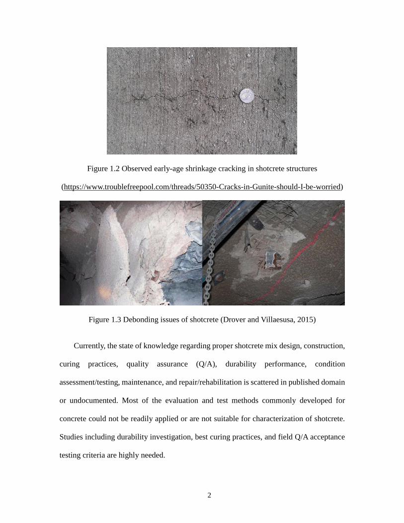
Figure 1.2 Observed early-age shrinkage cracking in shotcrete structures
(https://www.troublefreepool.com/threads/50350-Cracks-in-Gunite-should-I-be-worried)
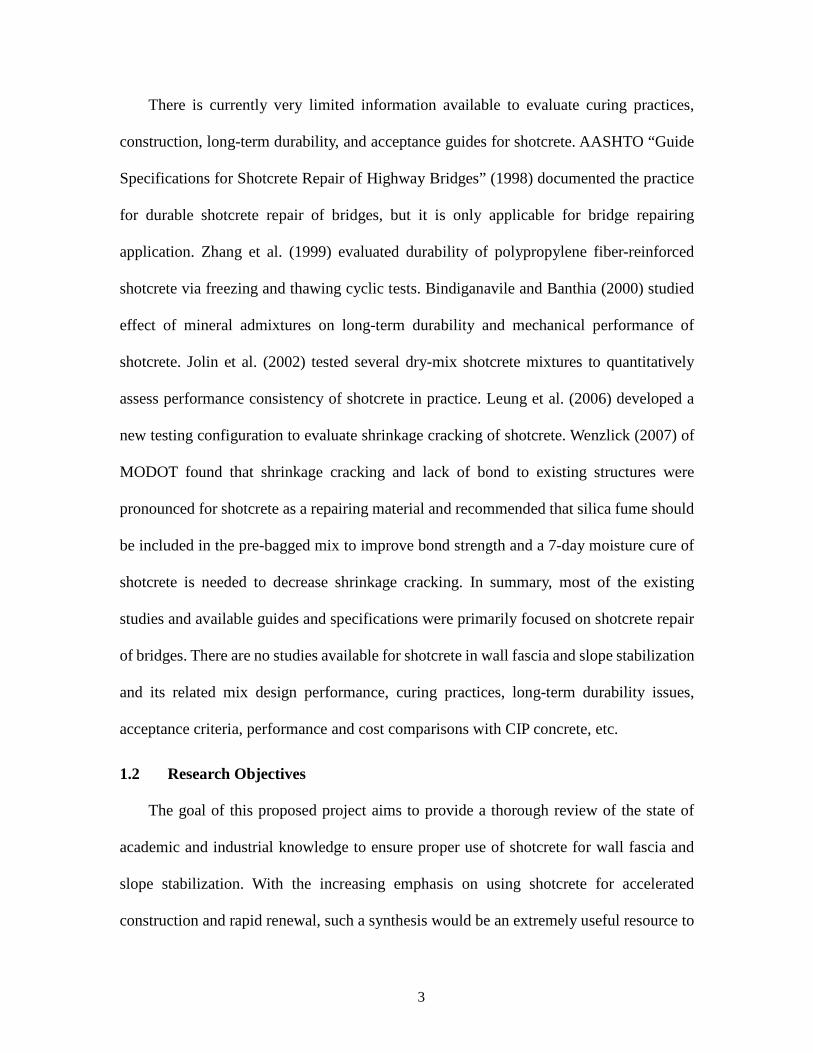
Figure 1.3 Debonding issues of shotcrete (Drover and Villaesusa, 2015)
Currently, the state of knowledge regarding proper shotcrete mix design, construction,
curing practices, quality assurance (Q/A), durability performance, condition
assessment/testing, maintenance, and repair/rehabilitation is scattered in published domain
or undocumented. Most of the evaluation and test methods commonly developed for
concrete could not be readily applied or are not suitable for characterization of shotcrete.
Studies including durability investigation, best curing practices, and field Q/A acceptance
testing criteria are highly needed.
3
There is currently very limited information available to evaluate curing practices,
construction, long-term durability, and acceptance guides for shotcrete. AASHTO “Guide
Specifications for Shotcrete Repair of Highway Bridges” (1998) documented the practice
for durable shotcrete repair of bridges, but it is only applicable for bridge repairing
application. Zhang et al. (1999) evaluated durability of polypropylene fiber-reinforced
shotcrete via freezing and thawing cyclic tests. Bindiganavile and Banthia (2000) studied
effect of mineral admixtures on long-term durability and mechanical performance of
shotcrete. Jolin et al. (2002) tested several dry-mix shotcrete mixtures to quantitatively
assess performance consistency of shotcrete in practice. Leung et al. (2006) developed a
new testing configuration to evaluate shrinkage cracking of shotcrete. Wenzlick (2007) of
MODOT found that shrinkage cracking and lack of bond to existing structures were
pronounced for shotcrete as a repairing material and recommended that silica fume should
be included in the pre-bagged mix to improve bond strength and a 7-day moisture cure of
shotcrete is needed to decrease shrinkage cracking. In summary, most of the existing
studies and available guides and specifications were primarily focused on shotcrete repair
of bridges. There are no studies available for shotcrete in wall fascia and slope stabilization
and its related mix design performance, curing practices, long-term durability issues,
acceptance criteria, performance and cost comparisons with CIP concrete, etc.
1.2 Research Objectives
The goal of this proposed project aims to provide a thorough review of the state of
academic and industrial knowledge to ensure proper use of shotcrete for wall fascia and
slope stabilization. With the increasing emphasis on using shotcrete for accelerated
construction and rapid renewal, such a synthesis would be an extremely useful resource to
4
help highway agencies achieve construction quality and durability of structures using
shotcrete. Thus, there is an urgent need to document the use of shotcrete for wall fascia and
slope stabilization by highway agencies, assess the condition of such existing inventory,
develop test methods to evaluate critical performance issues facing shotcrete, and identify
best practices during various stages of the life cycle of such structures. In particular, the
proposed research will investigate adequacy of shotcrete consolidation, permeability, early
age shrinkage and associated cracking, potential and long-term durability. Also,
development of best curing practices and Q/A test methods for field-placed shotcrete and
their cost and performance comparisons with cast-in-place (CIP) concrete will be addressed
by this study.
5
Chapter 2 LITERATURE REVIEW
The review focuses on the past studies on characterizing and understanding
performance and durability of shotcrete as well as the advantages of using admixtures and
their effects on properties of shotcrete. Recent developments regarding phenomena of
shrinkage has been also considered. In addition, studies on developing better curing
practices and other quality assurance methods are reviewed.
2.1 Production and Mix of Shotcrete
2.1.1 Production
Shotcrete is regarded as a special construction technique to place and compact concrete
rather than a special mixture design (Beaupre, 1994). Shotcrete is a concrete which is
conveyed through a pressurized hose to a nozzle at a high velocity onto the receiving
surface to form a structural or non-structural component of buildings, and it is a process of
simultaneous compaction, condensation and hardening of concrete. Shotcrete is possibly
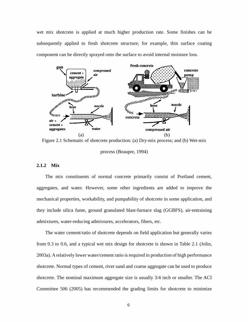
applied to surfaces using either dry or wet mix method. The dry mix process contains a
premixed blend of Portland cement and damp aggregate, which is pumped through the hose
to the nozzle. Water is added from a separate hose in the nozzle and completely mixed with
the dry mixture blend just as both streams are being sprayed onto receiving surface (Figure
2.1a). The final quality of shotcrete is strongly affected by experience of nozzleman (Crom,
1981). While in the wet mix concrete, all mix constituents are mixed with water and then
pumped through the hose (Figure 2.1b). To achieve a high speed of pumping, additional
compressed air is added in the nozzle. Compared with the dry mix process, the mixing
water of wet mix shotcrete is more accurately controlled by delivery equipment, and the
6
wet mix shotcrete is applied at much higher production rate. Some finishes can be
subsequently applied to fresh shotcrete structure; for example, thin surface coating
component can be directly sprayed onto the surface to avoid internal moisture loss.
(a) (b)
Figure 2.1 Schematic of shotcrete production: (a) Dry-mix process; and (b) Wet-mix
process (Beaupre, 1994)
2.1.2 Mix
The mix constituents of normal concrete primarily consist of Portland cement,
aggregates, and water. However, some other ingredients are added to improve the
mechanical properties, workability, and pumpability of shotcrete in some application, and
they include silica fume, ground granulated blast-furnace slag (GGBFS), air-entraining
admixtures, water-reducing admixtures, accelerators, fibers, etc.
The water cement/ratio of shotcrete depends on field application but generally varies
from 0.3 to 0.6, and a typical wet mix design for shotcrete is shown in Table 2.1 (Jolin,
2003a). A relatively lower water/cement ratio is required in production of high performance
shotcrete. Normal types of cement, river sand and coarse aggregate can be used to produce
shotcrete. The nominal maximum aggregate size is usually 3/4 inch or smaller. The ACI
Committee 506 (2005) has recommended the grading limits for shotcrete to minimize
7
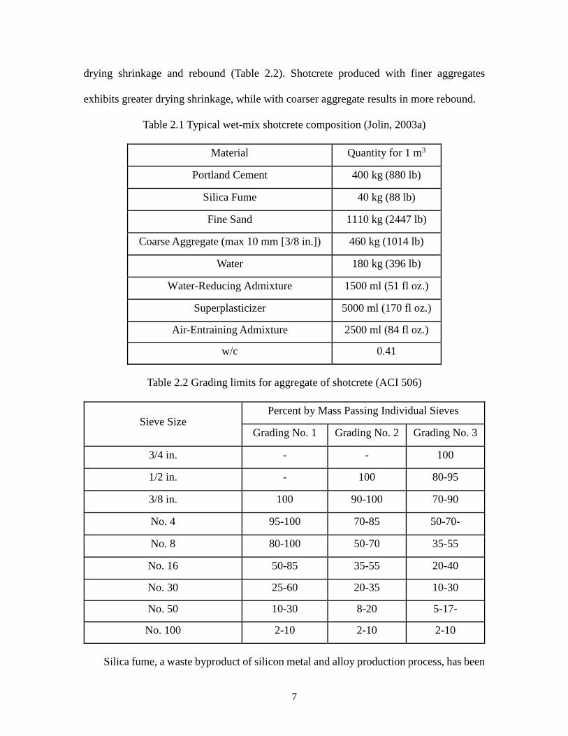
drying shrinkage and rebound (Table 2.2). Shotcrete produced with finer aggregates
exhibits greater drying shrinkage, while with coarser aggregate results in more rebound.
Table 2.1 Typical wet-mix shotcrete composition (Jolin, 2003a)
Material Quantity for 1 m3
Portland Cement 400 kg (880 lb)
Silica Fume 40 kg (88 lb)
Fine Sand 1110 kg (2447 lb)
Coarse Aggregate (max 10 mm [3/8 in.]) 460 kg (1014 lb)
Water 180 kg (396 lb)
Water-Reducing Admixture 1500 ml (51 fl oz.)
Superplasticizer 5000 ml (170 fl oz.)
Air-Entraining Admixture 2500 ml (84 fl oz.)
w/c 0.41
Table 2.2 Grading limits for aggregate of shotcrete (ACI 506)
Sieve Size Percent by Mass Passing Individual Sieves
Grading No. 1 Grading No. 2 Grading No. 3
3/4 in. - - 100
1/2 in. - 100 80-95
3/8 in. 100 90-100 70-90
No. 4 95-100 70-85 50-70-
No. 8 80-100 50-70 35-55
No. 16 50-85 35-55 20-40
No. 30 25-60 20-35 10-30
No. 50 10-30 8-20 5-17-
No. 100 2-10 2-10 2-10
Silica fume, a waste byproduct of silicon metal and alloy production process, has been
8
widely utilized to improve strength, durability and sustainability of concrete and shotcrete
(Morgan and Wolsiefer, 1992; Zhang et al., 1999; Sawoszczuk et al., 2013). The
replacement ranges from 7 to 15 percent by mass of cement (US Army Corps of Engineers,
1993).
GGBFS, a waste byproduct of iron production process, has been widely utilized to
achieve certain performance of shotcrete, including slower setting time, lower heat
generation during hydration, and higher chloride-ion resistance (Sawoszczuk et al., 2013).
Thus, the addition of GGBFS may exhibit some interaction issues with use of accelerators.
Air-entraining admixtures are essential to improve the pumpability and freeze-thaw
durability of shotcrete. Small air bubbles are initially created during mixing and most of
bubbles will be lost during pumping and shooting. Therefore, the air content of fresh
shotcrete after mixing is recommended higher than 12% to compensate these losses
(Morgan, 1989).
Water-reducing admixtures are important to improve workability of shotcrete,
especially for high performance shotcrete to allow lower water-cement ratio to be used
(Zaffaroni et al., 2000).
Accelerators (accelerating admixtures) are used extensively in shotcrete when rapid
section buildup and early strength development are required, such as in tunnel construction.
However, accelerators may decline due to increasing use of silica fume (Prudencio, 1998).
Fibers in shotcrete have been used to enhance its ductility, toughness, and fatigue
resistance and reduce crack propagation (Verma, 2015).
9
2.2 Performance of Shotcrete
2.2.1 Air content and mechanical properties
Pumpability and shootability of fresh wet-mix shotcrete are important rheological
parameters, and they can be determined by slump and air content tests (Yun et al., 2015a;
Yun et al., 2015b). Related air-void system is an essential parameter that affects the
mechanical properties and freeze-thaw durability of shotcrete (Morgan, 2003; Fonseca and
Scherer, 2015; Choi et al., 2016). The ingredients used in shotcrete can have a significant
effect on air content. From the point of view of fresh shotcrete, the pumpability and
shootability can be achieved by adjusting the amounts of water-reducing admixtures and
air-entraining admixtures from an optimal mix design test. It is usually considered that a
slump of 4-8 inch and an air content of 10-20% are acceptable. The air content of hardened
shotcrete is excessively affected by production procedures, construction practices and
weather, such as the method of batching, time and speed of mixing, transportation and
delivery, pumping and shooting, temperature, etc. (Portland Cement Association, 1998;
Choi, 2008; Zhang, 2012).
There are no specific testing methods for fresh or hardened shotcrete. All tests
considered for conventional concrete are applicable to be applied for shotcrete. Similar to
conventional concrete, the properties of shotcrete are mainly controlled by mixture design
parameters, i.e., water/cement ratio, content and type of cement, size and type of aggregate,
admixtures used, energy and duration of mixing process, and curing conditions (US Army
Corps of Engineers, 1993). The proper use of silica fume, GGBFS, accelerators, and fibers
can significantly improve certain properties of shotcrete. In addition, the shooting method
used (dry or wet mix) influences its properties, and the higher air content of shotcrete after
10
shooting, the lower strength it achieves.
Compressive strength ranges from 4,000 psi (27.5 MPa) to 10,000psi (68.9 MPa) at
28 days have been commonly reported in field construction (Zhang, 2014). The early age
strength of shotcrete can be higher than conventional concrete, reaching 1,000 psi in 5
hours and 3,000 psi in 24 hours (Heere et al., 2002; Jolin et al., 2003b). The strength of
shotcrete tends to increase with decreased air content and decreased spacing factor, when
compared the same mixture without shooting. The shotcrete after shooting exhibits 6~10%
loss of air content and 20-70% increase of strength (Choi et al., 2016). The addition of
silica fume and GGBFS usually improves the mechanical properties and durability since
they can improve bond strength between cement paste and aggregates. Won et al. (2013)
found that some mineral-based accelerator shows higher early-age strength while some
exhibit better long-term strength. Banthia et al. (1994), Zhang et al. (1999) and Verma (2015)
showed that the use of fibers in shotcrete significantly improves the ductility and flexural
strength, while slightly improves the compressive strength. Accelerators are commonly
used to increase early strength and achieve rapid set (Prudencio 1998). Hot environment
may benefit strength growth and subsequent integrity at early age (Lee et al., 2013).
Considering shotcrete is sprayed on existing structures (hard rock, slopes, rebar, etc.)
as a support system, adhesion strength between shotcrete and existing structures is one
critical property of shotcrete. Bryne et al. (2014a; 2014b) developed a pull-out test method
to evaluate early age adhesion strength from several hours after shooting. At very early
time after spraying, the physical properties and adhesion strength depend on the set
accelerator and the formed micro-structure. The failure location of the shotcrete layer is
another aspect to be considered. Malmgren et al. (2005) observed that failure is more likely
11
to occur where the shotcrete layer is thinner than or equal to 20 mm and with a low adhesion
strength. Karlsson (1980) found that among only 32% of the 238 tests the whole failure
occurred at the contact area from a field study. Malmgren et al. (2005) also found that
relatively less cracks occurred at the contact between shotcrete and substrates from the
restrained shrinkage tests, which indicated that restrained shrinkage could destroy the bond
between shotcrete and substrates. The type of surface preparation also has significant
influence on long-term bond strength of shotcrete (Talbot et al., 1994). Improvement of the
adhesion strength showed a reliable relation with the growth of compressive strength.
2.2.2 Shrinkage
Shrinkage in shotcrete exhibits due to loss of moisture from mixture. Several types of
shrinkage associated with shotcrete are plastic, autogenous, drying, and carbonation, which
are results of rapid loss of water after placing, cement hydration, evaporation of water, and
carbon-dioxide reactions, respectively. Shrinkage would not lead to any tensile stress if
without any restraints and has no effect on structure response. However, shotcrete is
commonly employed to produce layers or linings with large ratios of surface area to volume,
and restrained shrinkage cracking is hence an important concerning issue (Leung et al.,
2006). Watering is important to minimize shrinkage cracking tendency since it reduces the
shrinkage at early age but has no significant effect on strength development. Long waiting
without watering before producing a second layer will increase risk of shrinkage cracking
in shotcrete (Ansell, 2010). In cooperation with steel fibers in shotcrete can reduce
shrinkage cracking and develop crack distribution since it has better tensile strength
(Malmgren et al., 2005; Bryne et al., 2014c).
Several testing methods have been employed to investigate the restrained shrinkage
12
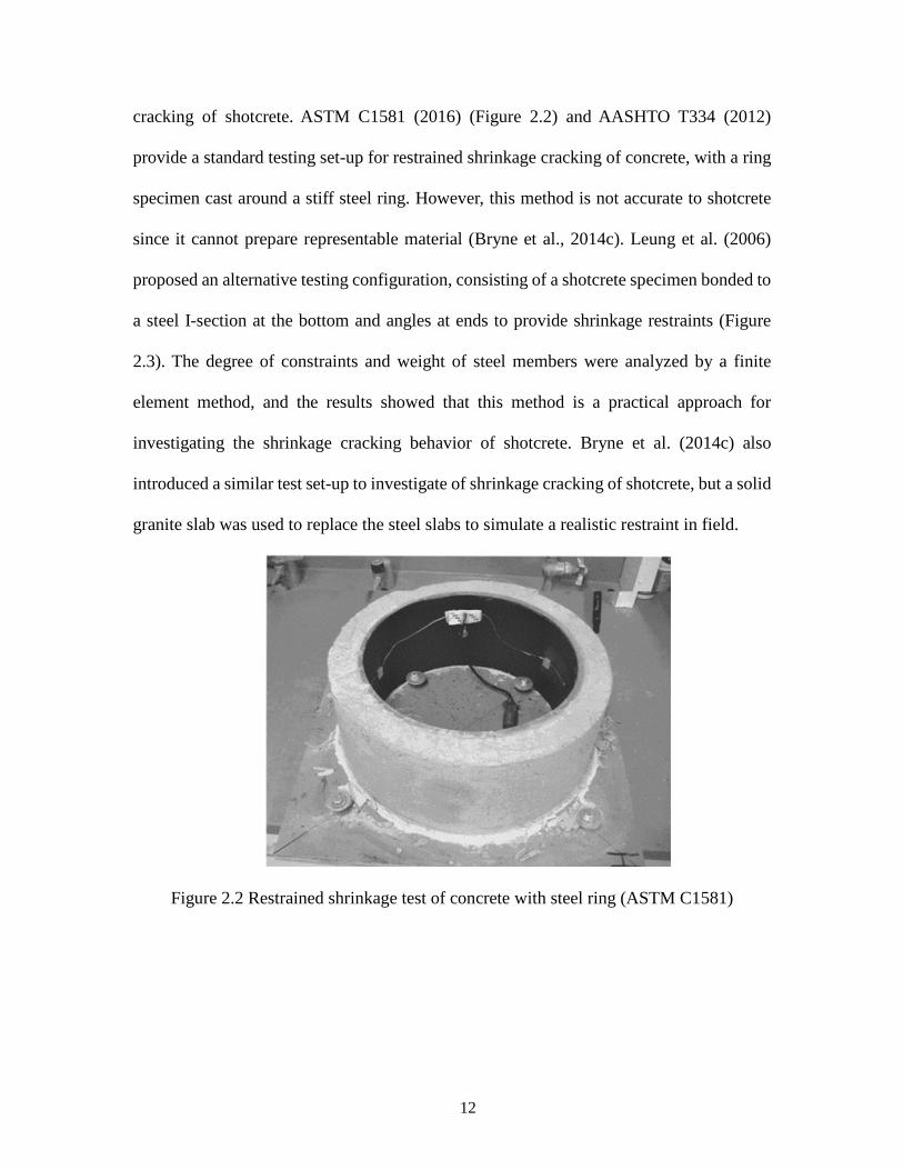
cracking of shotcrete. ASTM C1581 (2016) (Figure 2.2) and AASHTO T334 (2012)
provide a standard testing set-up for restrained shrinkage cracking of concrete, with a ring
specimen cast around a stiff steel ring. However, this method is not accurate to shotcrete
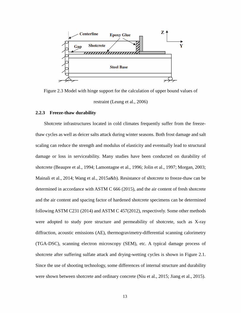
since it cannot prepare representable material (Bryne et al., 2014c). Leung et al. (2006)
proposed an alternative testing configuration, consisting of a shotcrete specimen bonded to
a steel I-section at the bottom and angles at ends to provide shrinkage restraints (Figure
2.3). The degree of constraints and weight of steel members were analyzed by a finite
element method, and the results showed that this method is a practical approach for
investigating the shrinkage cracking behavior of shotcrete. Bryne et al. (2014c) also
introduced a similar test set-up to investigate of shrinkage cracking of shotcrete, but a solid
granite slab was used to replace the steel slabs to simulate a realistic restraint in field.
Figure 2.2 Restrained shrinkage test of concrete with steel ring (ASTM C1581)
13
Figure 2.3 Model with hinge support for the calculation of upper bound values of
restraint (Leung et al., 2006)
2.2.3 Freeze-thaw durability
Shotcrete infrastructures located in cold climates frequently suffer from the freeze-
thaw cycles as well as deicer salts attack during winter seasons. Both frost damage and salt
scaling can reduce the strength and modulus of elasticity and eventually lead to structural
damage or loss in serviceability. Many studies have been conducted on durability of
shotcrete (Beaupre et al., 1994; Lamontagne et al., 1996; Jolin et al., 1997; Morgan, 2003;
Mainali et al., 2014; Wang et al., 2015a&b). Resistance of shotcrete to freeze-thaw can be
determined in accordance with ASTM C 666 (2015), and the air content of fresh shotcrete
and the air content and spacing factor of hardened shotcrete specimens can be determined
following ASTM C231 (2014) and ASTM C 457(2012), respectively. Some other methods
were adopted to study pore structure and permeability of shotcrete, such as X-ray
diffraction, acoustic emissions (AE), thermogravimetry-differential scanning calorimetry
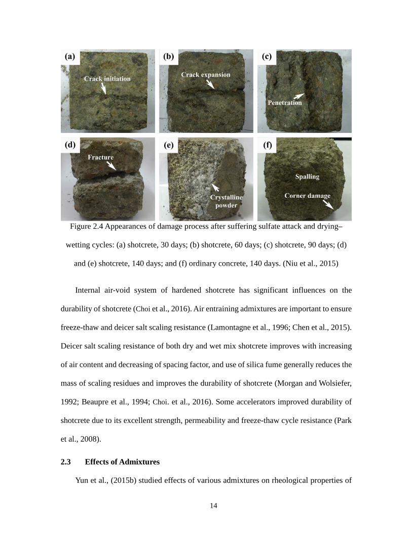
(TGA-DSC), scanning electron microscopy (SEM), etc. A typical damage process of
shotcrete after suffering sulfate attack and drying-wetting cycles is shown in Figure 2.1.
Since the use of shooting technology, some differences of internal structure and durability
were shown between shotcrete and ordinary concrete (Niu et al., 2015; Jiang et al., 2015).
14
Figure 2.4 Appearances of damage process after suffering sulfate attack and drying–
wetting cycles: (a) shotcrete, 30 days; (b) shotcrete, 60 days; (c) shotcrete, 90 days; (d)
and (e) shotcrete, 140 days; and (f) ordinary concrete, 140 days. (Niu et al., 2015)
Internal air-void system of hardened shotcrete has significant influences on the
durability of shotcrete (Choi et al., 2016). Air entraining admixtures are important to ensure
freeze-thaw and deicer salt scaling resistance (Lamontagne et al., 1996; Chen et al., 2015).
Deicer salt scaling resistance of both dry and wet mix shotcrete improves with increasing
of air content and decreasing of spacing factor, and use of silica fume generally reduces the
mass of scaling residues and improves the durability of shotcrete (Morgan and Wolsiefer,
1992; Beaupre et al., 1994; Choi. et al., 2016). Some accelerators improved durability of
shotcrete due to its excellent strength, permeability and freeze-thaw cycle resistance (Park
et al., 2008).
2.3 Effects of Admixtures
Yun et al., (2015b) studied effects of various admixtures on rheological properties of

15
high-performance wet-mix shotcrete (HPWMS), e.g., silica fume, air-entraining
admixtures, superplasticizer, synthetic fiber, powdered polymer, etc. The yield stress and
plastic viscosity of HPWMS with various types and amounts of admixtures were measured
using an IBB rheometer to determine pumpability and shootability. Air-entraining agent
tended to proportionally reduce both flow resistance and torque viscosity of HPWMS.
Superplasticizers showed a relatively greater influence on flow resistance than torque
viscosity. Silica fume increased flow resistance while slightly reduces torque viscosity.
Silica fume improved shootability and pumpability of shotcrete greatly.
Park et al. (2008), Won et al. (2013), Won et al. (2015) compared the mechanical
properties of shotcrete containing different content of high-strength cement based mineral
accelerator (HS-CM) with shotcrete containing 5% of normal cement-based mineral
accelerator (CM). They found that shotcrete containing more than 6% HS-CM with respect
to cement weight was slower at initial set but faster at final set than that made with CM.
HS-CM accelerated shotcrete had approximately the same compressive and flexural
strength at early age but higher compressive and flexural strength at 7 days and 28 days
than CM accelerated one. Based on microstructural analysis through scanning electron
microscope (SEM), X-ray diffraction (XRD) and nitrogen adsorption tests, they also found
that shotcrete made with HS-CM showed better frost and chemical resistance than that
made with CM. Alkali-silica reaction of accelerating admixtures for shotcrete is also
another phenomenon being investigated. Length change of cement pastes made with
various accelerating admixtures under sulfate solution were measured to characterize the
expansion caused by alkali-silica reaction. Paglia et al. (2003) observed that accelerated
cement pastes showed more expansion up to 6 months than unaccelerated ones. Won et al.
16
(2012) showed that expansion of accelerated shotcrete increased with the total equivalent
alkali content of the specimens.
2.4 Curing, Construction Practices and Quality Assurance for Shotcrete
The quality control and assurance procedures of shotcrete, regarding materials,
equipment, methods, etc., should be clearly conducted to assure performance of final
production. In general, the US Army Corps of Engineers (1993) discussed some technical
aspects of shotcrete that should be incorporated into shotcrete production, as shown in
Table 2.1. Quality assurance activities, such as submittals, mixture proportion evaluation,
nozzleman certification and performance testing should be assigned to a shotcrete
production.
Some preparatory work of substrate is required before applying shotcrete. For rock of
poor, loose, carbonated or penetrated by chlorides, they should be removed from substrate.
Pre-wet of substrate should be performed to improve bond strength before shotcrete is
sprayed.
Reduction of rebound material losses and improvement of material properties are the
major concerns of shotcrete industry due to its significant effects on costs and wastage of
materials (Ginouse and Jolin, 2016). Materials (i.e., air pressure, cement content, water
content, nominal maximum size and grading of aggregate, amount of reinforcement, etc.),
thickness of layer, nuzzling techniques and procedures of applying greatly affect the quality
of shotcrete and the amount and composition of rebound. Mixtures with small aggregates
result less rebound than those with large-aggregates. It was found that when shotcrete is
applied horizontally, no uniform distribution would be achieved, and poor nozzling
techniques lead to entrapment of rebound materials. Ginouse and Jolin (2014) and Ginouse

17
et al. (2014) found that wet mix process produces better uniformity than dry mix process.
Table 2.3 Technical aspects of shotcrete
Preproduction Phase Production Phase
(a) Submittals:
(1) Cementitious materials;
(2) Aggregates;
(3) Admixtures and curing
compound;
(4) Fibers and reinforcement;
(5) Mixture proportions;
(6) Accelerator compatibility test;
(7) Nozzleman certification;
(8) Equipment;
(9) Curing and protection.
(b) Test panel fabrication, testing,
and evaluation.
(a) Materials:
(1) Cementitious materials;
(2) Aggregates (Quality, Grading, and moisture
content);
(3) Admixtures and curing compound;
(4) Fibers and reinforcement;
(b) Surface preparation;
(c) Shotcrete:
(1) Strength (testing panels, in-place samples);
(2) Mixture proportions;
(3) Air content;
(4) In-place thickness;
(5) Rebound testing;
(6) Curing and protection;
(7) Nondestructive testing (impact hammers or
probes, ultrasonic equipment, and pull out
devices, etc.);
(8) Delamination testing;
(9) Surface tolerances;
(10) Visual inspection.
Proper curing of shotcrete is extremely important to assure strength gain and long-
term durability and to mitigate shrinkage cracking. The curing procedures of ACI 308R
(2001) should be followed, and the surface of shotcrete should be kept continuously moist
condition for at least 7 days after placement to ensure that the tensile strength gained is
18
sufficient to resist shrinkage-induced stress. Compound, cellulose, or membrane curing is
immediately carried out after initial moist curing, and they should be removed before
applying the next layer. Shehata and Klement (2005), and Shehata et al. (2006a; 2006b)
tested different curing methods: air-curing, curing compound, misting and curing
compound, and cellulose. Cellulose cured shotcrete showed enhanced pore structure and
higher quality of surface compared to other traditional methods. In addition, cellulose
curing mitigates shrinkage cracking.
2.5 Comparison with CIP Concrete
Shotcrete is pneumatically conveyed and sprayed at high velocity to existing structures
without external vibration. Processes of pumping and shooting greatly affect the behavior
and properties of shotcrete when compared with cast-in-place (CIP) concrete. These
properties include fresh concrete/shotcrete related properties (i.e., slump, air-void system,
setting time, etc.) and hardened concrete/shotcrete properties (strength, chloride
permeability, rate of water absorption, durability, etc.). Hover and Phares (1996) and Choi
(2016) concluded that shotcrete had lower air content and smaller spacing factor than CIP
concrete with the same mixture (e.g., approximate 10% of air content was loss after
shooting). Wang et al. (2015b), Choi (2016), and Zhang (2016) also found that shotcrete
exhibited higher compressive and splitting tensile strength, better permeability and
durability due to lower air content after shooting.
19
Chapter 3 MATERIALS AND EXPERIMENTAL TESTING PROGRAM
The goals of this study are to evaluate effect of curing practices on early shrinkage
behavior of shotcrete and develop test methods for long-term performance and durability,
in comparisons with cast-in-place (CIP) concrete. The testing results for CIP concrete can
be found from previous reports of WSDOT projects: WSDOT T4120-08 “Mitigation
Strategies for Early-Age Shrinkage Cracking in Bridge Decks” (Qiao et. al., 2010) and
WSDOT 13A-3815-5188 “Concrete Performance Using Low-Degradation Aggregates”
(Qiao et. al., 2012). In the following sections, the materials and experimental testing
program for both shotcrete and CIP concrete mixtures in this study are presented.
3.1 Materials
The cementitious materials, including Portland cement Type I-II, silica fume (SF), and
ground granulated blast-furnace slag (GGBFS), were provided by Lafarge NA-PNW
District. Coarse aggregate and fine sand were provided by the Pre-mix, Inc., a local
concrete company in Pullman, WA. The nominal maximum size of coarse aggregate is 3/8
inch in this study. The grain size distributions of coarse aggregate and fine sand from sieve
analysis in accordance with ASTM C136 (2014) are presented in Table 3.1. The coarse
aggregate and fine sand for shotcrete meet the requirements of AASHTO #8 and WSDOT
Class 2 Sand. The fine sand for CIP concrete meets the requirements of WSDOT Class 1
Sand. The corresponding specific gravity and water absorption are determined in
accordance with ASTM C127 (2015) and ASTM C128 (2015), respectively, and their
values are also given in Table 3.1.
20
Table 3.1 Grain size distribution of aggregates (sieve analysis)
Type Shotcrete, Cumulative % Passing CIP, Cumulative % Passing
Sieve Size Coarse aggregate Fine aggregate Coarse aggregate Fine aggregate
1/2 100 -- 100 --
3/8'' 99.1 100.0 98.5 100
1/4'' 37.3 99.5 67.8 99.5
#4 6.9 85.7 37.3 97.7
#8 3.2 58.5 3.0 84.3
#16 1.8 35.6 0.4 61
#30 1.2 16.0 42.2
#50 0.9 4.8 17.7
#100 0.8 2.1 4.1
#200 -- -- 2.2
Specific
Gravity 2.69 2.64 2.68 2.65
Absorption
Capacity, % 1.21 1.89 1.20 --
Two types of commercially available chemical admixtures are used to produce
shotcrete: air entraining admixture (AEA) and high-range water reducing admixture
(HRWRA), and both are produced by BASF Construction Chemicals, LLC. 1000 air-
entraining admixture from Grace Construction Products is used to produce proper air
content in the concrete mixes. Glenium 3030 NS, a polycarboxylate-based HRWRA is used
to achieve the desired workability and pumpability. The volume contents of AEA and
HRWRA for shotcrete are determined based on the measurements made on the fresh mixed
shotcrete/CIP concrete in the trial mix design tests.

21
3.2 Mix Designs
Two mix designs considered for this study for the shotcrete and CIP concrete batches
are summarized in Table 3.2 along with the benchmark mix design of shotcrete from the
WSDOT (See Appendix).
Table 3.2 WSDOT mix designs
Mixture Cement
(lb/yd3)
Silica Fume
(lb/yd3)
GGBFS
(lb/yd3)
Coarse
(lb/yd3)
Sand
(lb/yd3) w/cm
Water
(lbs)
Shotcrete 705 50 40 2120 790 0.34 267
CIP Concrete 564 -- -- 1830 1270 0.48 272
3.3 Sample Preparations
Pumping and shooting are two of basic operation procedures in shotcrete constructions,
whenever wet-mix shotcrete or dry-mix shotcrete is used. In previous studies, evaluation
of shotcrete usually regards two terms: known as “before shooting” and “after shooting”,
or known as “without shooting” and “with shooting”. Since the goals of this phase of the
study is to provide best practices for shotcrete mainly with emphasis on shrinkage and
durability issues, the effect of pumping and shooting is not investigated.
Mixing of constituents to produce shotcrete specimens is performed at the concrete
laboratory of Washington State University by a concrete drum mixer with a volume of 3.5
cubic feet. The mixing procedures are briefly described as follows:
1. All the materials are batched by weight.
2. Two pounds of water and two pounds of cement are mixed together and then used
to wet the inside drum of the concrete mixer. Then, the paste is dumped.
22
3. All the pre-weighted aggregates and sand are added into the mixer, and they are
mixed for 1/2 minute.
4. All the pre-weighted cementitious materials (cement, silica fume and/or GGBFS)
are added into the mixer. The air-entraining admixture (AEA) is added into half of the water,
and the water solution is then added into the mixer. They are mixed for 3 minutes.
5. The rest water is added, and they are mixed for 2 minutes.
6. High Range Water reducing admixture (HRWRA) and SRA are added separately,
and they are then mixed for 3 minutes.
7. The mix is rested for 2 minutes.
8. The mix is mixed for the final 2 minutes.
9. The slump test is first conducted.
10. The air content test is then conducted.
11. Necessary adjustments of HRWRA and AEA are made until the targeted slump and
air content are achieved.
As soon as the mixing is completed, the fresh shotcrete is poured into oiled
wooden/steel molds to cast specimens in accordance with ASTM C192 (2016). Specimens
are externally vibrated for approximately 10 seconds using a vibrating table. The curing of
all specimens consists of two phases: initial curing after casting and standard curing prior
to testing. All specimens in the molds are initially cured in a vibration-free fog room with
temperature 73.5 ± 3.5 °F (23.0 ± 2.0 °C) from the time of casting. After approximate 24
hours, specimens are demolded and began standard curing period. Specimens for
mechanical tests are soaked in lime-saturated water storage tanks until testing age, while
specimens for shrinkage tests are cured at a curing room with temperature of 73 ± 3°F (23
23
± 2°C) and relative humidity of 50 ± 4%.
3.4 Experimental Testing Plan
A series of tests are conducted to evaluate the properties of shotcrete/CIP concrete in
fresh and hardened states. Slump and air content are tested to evaluate workability and
pumpability of fresh shotcrete and ensure durability of hardened shotcrete. Similar or same
to the test methods in hardened concrete, the hardened shotcrete properties tests included
three categories. The Category 1 is related to the mechanical properties of shotcrete at
different ages, such as compressive strength, flexural strength, and modulus of elasticity,
etc. The Category 2 is related to the early-age shrinkage and shrinkage cracking tendency
of shotcrete under different curing conditions, which is one of critical concerns in field
construction and goals for producing best curing practices for shotcrete construction. The
corresponding tests include free shrinkage tests and restrained ring tests under different
curing methods. The Category 3 is related to the long-term durability of shotcrete under
rapid freeze-thaw (F/T) actions, and the corresponding tests include dynamic modulus of
elasticity test and cohesive fracture test to characterize degradation of material properties
after different numbers of F/T cycles. The procedures for each test in the three categories
above are briefly discussed in the following sections, and the tests considered in this study
are summarized in Table 3.3 along with their corresponding ASTM/AASHTO standard test
method designations. For all tests, at least three replicates are tested.
24
Table 3.3 Experimental testing program
Properties Test Methods Condition
Fresh Properties of Shotcrete
Slump ASTM C143 Fresh
Air content ASTM C231 Fresh
Unit Weight ASTM C138 Fresh
Hardened Properties of Shotcrete
Air content ASTM C457 Hardened concrete
@ > 28 days
Compressive Strength ASTM C39 6’’*12’’ cylinder @3, 7, 14, 28, and 56 days
Flexural Strength ASTM C78 3’’*4’’*16’’ prism @3, 7, 14, 28, and 56 days
Modulus of Elasticity ASTM C469 6’’*12’’ cylinder @3, 7, 14, 28, and 56 days
Free Shrinkage ASTM C157 4’’*4’’*11.25 prism Begin after initial curing of 1 days
Autogenous Shrinkage ASTM C157 4’’*4’’*11.25 prism Begin after initial curing of 1 days
Restrained Shrinkage AASHTO T334 Begin after casting Freezing/Thaw Durability &
Dynamic Modulus & Fracture Energy
ASTM C666 ASTM C215
RILEM 50-FMC
3’’*4’’*16’’ prism F/T Begins after initial curing of 28days; @ 0, 60, 120, 180, 240,
300, and 600 cycles
3.4.1 Properties of fresh shotcrete
The slump test (Figure 3.1) was performed following the procedures of ASTM C143
(2015) “Standard Test Method for Slump of Hydraulic Cement Concrete”. Based on the
pressure method, a Type-B Air Meter is used to measure air content, which follows ASTM
C231 “Standard Test Method for Air Content of Freshly-mixed Concrete by the Pressure
Method” (Figure 3.2). In the meantime, the unit weight of fresh shotcrete is determined
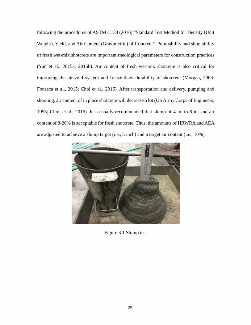
25
following the procedures of ASTM C138 (2016) “Standard Test Method for Density (Unit
Weight), Yield, and Air Content (Gravimetric) of Concrete”. Pumpability and shootability
of fresh wet-mix shotcrete are important rheological parameters for construction practices
(Yun et al., 2015a; 2015b). Air content of fresh wet-mix shotcrete is also critical for
improving the air-void system and freeze-thaw durability of shotcrete (Morgan, 2003;
Fonseca et al., 2015; Choi et al., 2016). After transportation and delivery, pumping and
shooting, air content of in place shotcrete will decrease a lot (US Army Corps of Engineers,
1993; Choi, et al., 2016). It is usually recommended that slump of 4 in. to 8 in. and air
content of 8-20% is acceptable for fresh shotcrete. Thus, the amounts of HRWRA and AEA
are adjusted to achieve a slump target (i.e., 5 inch) and a target air content (i.e., 10%).
Figure 3.1 Slump test
26
Figure 3.2 Air content test by pressure method
3.4.2 Mechanical properties of hardened shotcrete
Three basic mechanical properties for the hardened shotcrete/CIP concrete are
evaluated at different ages: compressive strength, modulus of elasticity, and flexural
strength.
The compressive strength test is conducted on 6 inch × 12 inch cylinders following
the procedures of ASTM C39 (2017) “Standard Test Method for Compressive Strength of
Cylindrical Concrete Specimens” (Figure 3.3). The compressive test is conducted under a
specific stress rate, 35 ± 7 psi/s. Therefore, the required loading rate is calculated
corresponding to the size of the specimen, i.e., 60000 ± 12000 lbf/min.
The modulus of elasticity test is conducted following the procedures of ASTM C469
(2014) “Standard Test Method for Static Modulus of Elasticity and Poisson’s Ratio of
Concrete in Compression” (Figure 3.4). The load is applied corresponding to a specific
stress rate, 35 ± 7 psi/s, until it reached 40 % of the average ultimate load of the 6 inch ×
12 inch cylindrical specimens.
The flexural strength test is performed in accordance with ASTM C78 (2016)
“Standard Method of Test for Flexural Strength of Concrete (Using Simple Beam with
27
Third-Point Loading)” (Figure 3.5). A constant loading rate is applied under a specific
tensile stress rate within the range of 125 to 175 psi/min, i.e., 5,000 to 7,000 lbf/min for
the 3 inch × 4 inch × 16 inch prisms.
Figure 3.3 Compressive strength test Figure 3.4 Modulus of elasticity test
28
Figure 3.5 Flexural strength test (3 inch × 4 inch × 16 inch prism, span: 12 inch)
3.4.3 Shrinkage
3.4.3.1 Curing regimes
Shrinkage in shotcrete exhibits due to rapid loss of water after placing, cement
hydration, evaporation of water, etc. In field construction, keeping watering shotcrete
structures is important to minimize shrinkage cracking since it reduces shrinkage at early
age as well as slightly accelerates strength growth. To achieve best curing practices of
shotcrete, it is of great significance to evaluate impact of different curing conditions on
early-age shrinkage and shrinkage cracking tendency. Apart from standard curing condition
(i.e., drying from 1 day), a few curing regimes are also considered to minimize shrinkage
and mitigate shrinkage cracking in this study. Prolonged moisture or watering curing for
29
more than one day and up to as long as 10 days are first recommended since the drying
shrinkage rate is very high at early age. In addition, sealing structure surface using curing
compound to prevent water evaporation is proposed due to its more convenient operation
than prolonged watering. More details are summarized in Table 3.4.
Table 3.4 Curing conditions (regimes) for best curing practices
Curing Regimes Condition
I: Drying from 1 day (Standard Curing) - Daily watering for 1 day from casting
II: Drying from 4th day - Daily watering for 4 days from casting
III: Drying from 7th day - Daily watering for 7 days from casting
IV: Drying from 10th day - Daily watering for 10 days from casting
V: Curing compound after 1 day - Daily watering for 1 day from casting
-Seal all surface with curing compound
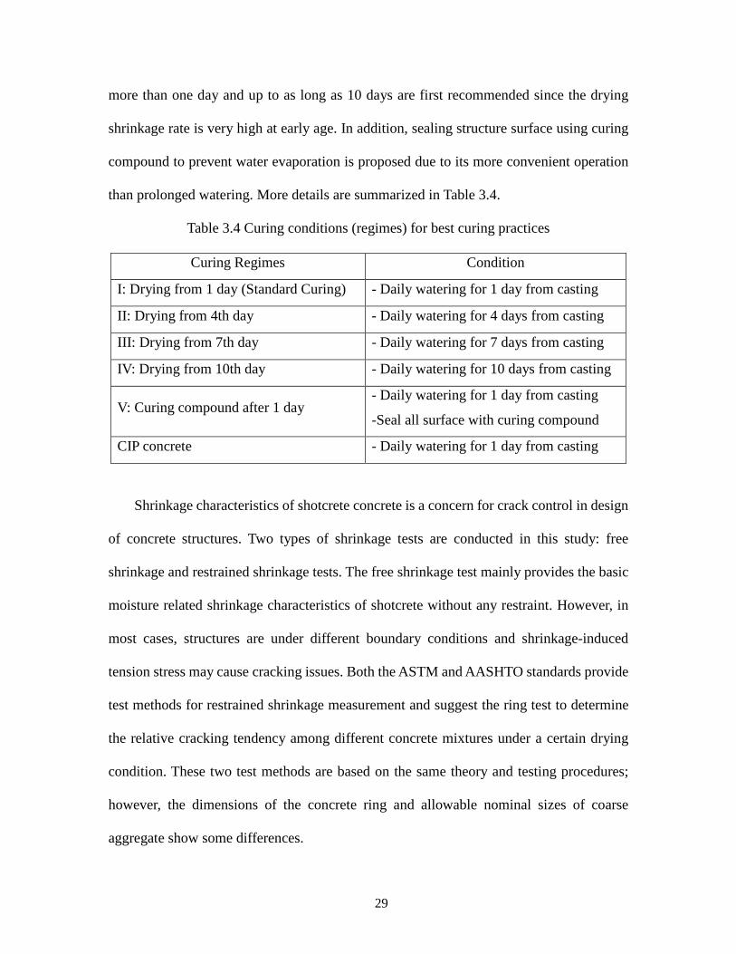
CIP concrete - Daily watering for 1 day from casting
Shrinkage characteristics of shotcrete concrete is a concern for crack control in design
of concrete structures. Two types of shrinkage tests are conducted in this study: free
shrinkage and restrained shrinkage tests. The free shrinkage test mainly provides the basic
moisture related shrinkage characteristics of shotcrete without any restraint. However, in
most cases, structures are under different boundary conditions and shrinkage-induced
tension stress may cause cracking issues. Both the ASTM and AASHTO standards provide
test methods for restrained shrinkage measurement and suggest the ring test to determine
the relative cracking tendency among different concrete mixtures under a certain drying
condition. These two test methods are based on the same theory and testing procedures;
however, the dimensions of the concrete ring and allowable nominal sizes of coarse
aggregate show some differences.
30
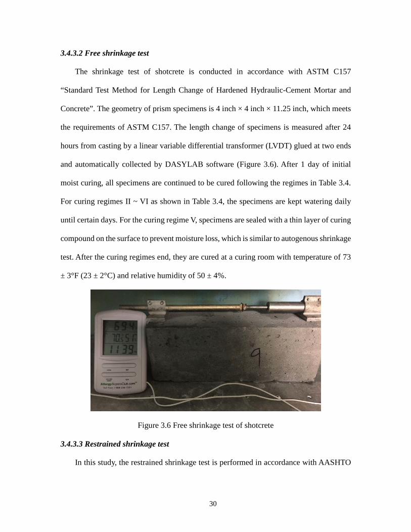
3.4.3.2 Free shrinkage test
The shrinkage test of shotcrete is conducted in accordance with ASTM C157
“Standard Test Method for Length Change of Hardened Hydraulic-Cement Mortar and
Concrete”. The geometry of prism specimens is 4 inch × 4 inch × 11.25 inch, which meets
the requirements of ASTM C157. The length change of specimens is measured after 24
hours from casting by a linear variable differential transformer (LVDT) glued at two ends
and automatically collected by DASYLAB software (Figure 3.6). After 1 day of initial
moist curing, all specimens are continued to be cured following the regimes in Table 3.4.
For curing regimes II ~ VI as shown in Table 3.4, the specimens are kept watering daily
until certain days. For the curing regime V, specimens are sealed with a thin layer of curing
compound on the surface to prevent moisture loss, which is similar to autogenous shrinkage
test. After the curing regimes end, they are cured at a curing room with temperature of 73
± 3°F (23 ± 2°C) and relative humidity of 50 ± 4%.
Figure 3.6 Free shrinkage test of shotcrete
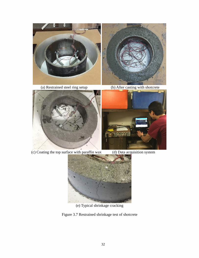
3.4.3.3 Restrained shrinkage test
In this study, the restrained shrinkage test is performed in accordance with AASHTO
31
T334 (2016) “Standard Method of Test for Estimating the Cracking Tendency of Concrete”.
The inside steel ring is cut from a steel tube with industry (allowable in AASHTO standard),
and it has an outer diameter of 12.75 inch, a wall thickness of 1/2 ± 1/64 inch, and a height
of 6 inch (Figure 3.7a). The outside ring is made of a plastic board with a thickness of 0.25
inch and an inner diameter of 18 inch, and it is supported around by plywood. The shotcrete
ring is cast intermediately after mixing and covered with wet burlap followed with plastic
sheet to prevent moisture loss from specimens for the first day. After this initial curing, the
outer plastic board is demolded and the top surface is coated with a thin layer of paraffin
wax to prevent moisture loss (see Figures 3.7b and 3.7c). The ring specimens are only
allowed to present water evaporation through the outside surface. The steel strains are
measured by four strain gages equidistantly mounted on the inner surface of the inside steel
ring and automatically recorded by SmartStrain software at an interval of 1 second (Figure
3.7d). Shrinkage-induced cracking is visually inspected every 12 hours. Figure 3.7e shows
a typical shrinkage-induced cracking of shotcrete after several days of drying.
32
(a) Restrained steel ring setup (b) After casting with shotcrete
(c) Coating the top surface with paraffin wax (d) Data acquisition system
(e) Typical shrinkage cracking
Figure 3.7 Restrained shrinkage test of shotcrete

33
3.4.4 Freeze-thaw durability
Evaluation of frost resistance of shotcrete includes both standard and non-standard
approaches to characterize material degradation. Apart from non-destructive standard test
protocol (e.g., ASTM C215 [2014]) to measure the dynamic modulus of elasticity of the
conditioned samples, fracture energy test is accordingly conducted at different defined
freeze-thaw cycles.
3.4.4.1 Rapid freeze and thaw test
The shotcrete prism samples are conditioned using the rapidly repeated freeze-thaw
test in accordance with ASTM C666 Procedure A (2015), which is originally designed to
evaluate the potential frost resistance of concrete in cold climates. The condition chamber
used in this study is shown in Figure 3.8. The temperature range of 0oF to 40oF of the
specimens is conditioned in the freeze-thaw cycles, and the conditioning machine runs six
freezing-thawing (F/T) cycles per day.
Figure 3.8 Freeze-thaw conditioning chamber
34
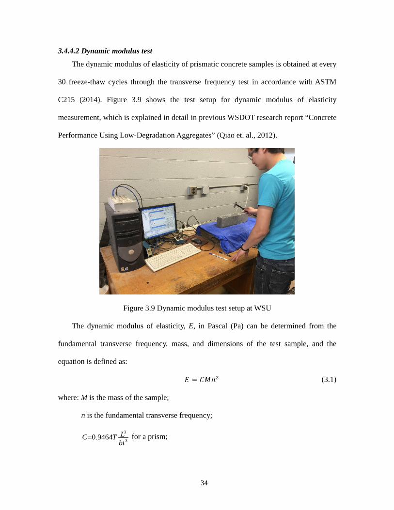
3.4.4.2 Dynamic modulus test
The dynamic modulus of elasticity of prismatic concrete samples is obtained at every
30 freeze-thaw cycles through the transverse frequency test in accordance with ASTM
C215 (2014). Figure 3.9 shows the test setup for dynamic modulus of elasticity
measurement, which is explained in detail in previous WSDOT research report “Concrete
Performance Using Low-Degradation Aggregates” (Qiao et. al., 2012).
Figure 3.9 Dynamic modulus test setup at WSU
The dynamic modulus of elasticity, E, in Pascal (Pa) can be determined from the
fundamental transverse frequency, mass, and dimensions of the test sample, and the
equation is defined as:
𝐸𝐸 = 𝐶𝐶𝐶𝐶𝑛𝑛2 (3.1)
where: M is the mass of the sample;
n is the fundamental transverse frequency;
for a prism; 3
30.9464 LC Tbt
=
35
L is the length of the sample;
t and b are the thickness and width of the sample, respectively.
T is a correction factor that depends on the ratio of the radius of gyration to the
length of the specimen and the Poisson’s ratio, 1.41 in this study.
The dynamic modulus of elasticity values of the concrete samples at different cycles
are compiled and compared. The relative dynamic modulus of elasticity is calculated as the
ratio of initial dynamic modulus at 0 cycle to that at certain number of freeze-thaw cycles.
The decrease of the dynamic modulus of elasticity over the accelerated freeze-thaw cyclic
conditioning indicates the degradation of concrete materials. It is not recommended that
samples be continued in the test after their relative dynamic modulus of elasticity has fallen
below 60%.
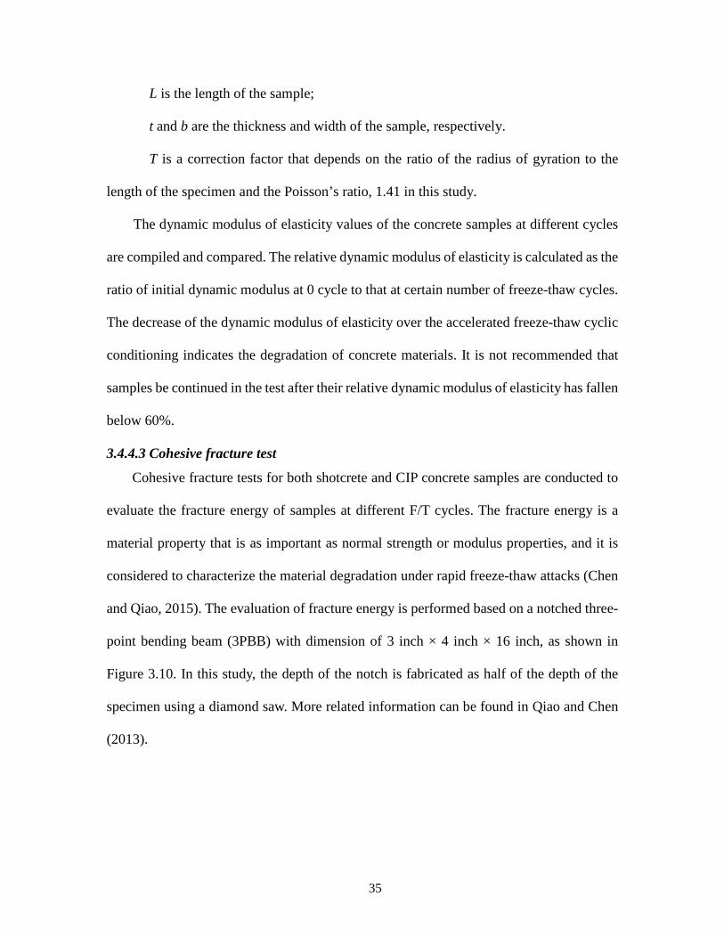
3.4.4.3 Cohesive fracture test
Cohesive fracture tests for both shotcrete and CIP concrete samples are conducted to
evaluate the fracture energy of samples at different F/T cycles. The fracture energy is a
material property that is as important as normal strength or modulus properties, and it is
considered to characterize the material degradation under rapid freeze-thaw attacks (Chen
and Qiao, 2015). The evaluation of fracture energy is performed based on a notched three-
point bending beam (3PBB) with dimension of 3 inch × 4 inch × 16 inch, as shown in
Figure 3.10. In this study, the depth of the notch is fabricated as half of the depth of the
specimen using a diamond saw. More related information can be found in Qiao and Chen
(2013).
36
Figure 3.10 Sketch diagram of cohesive fracture test under three point bending
All the fracture tests are performed on an MTS servo-hydraulic testing machine using
the test setup shown in Figure 3.11. The tests are conducted under displacement-controlled
mode, i.e., at a loading rate of 0.0236 in./min. Two Linear Variable Differential Transducers
(LVDTs) oppositely mounted in the beams are used to measure the mid-span deflection
(MSD, δ) of the test sample. The loading and mid-span deflections are simultaneously
recorded by the machine.

37
Figure 3.11 Testing equipment setup for fracture test
Figure 3.12 illustrates a typical load-deflection (P-δ) curve from a cohesive fracture
test, in which P is the measured load and δ is the average mid-span deflection of two LVDTs.
The additional load P1 is the self-weight of the specimen. Accordingly, the total work
energy W can be calculated using Equation 3.2.
(3.2)
where W0 is the area under the load-deflection curve; W1 = P1δ0 is the energy absorbed by
the sample’s self-weight, where is the deflection when the measured load is zero; and
W2 is the residual energy that need to fully separate the fractured sample into two halves
after the measured load drops to zero, approximately equal to W1. Therefore, the fracture
0 1 2W W W W= + +
0δ
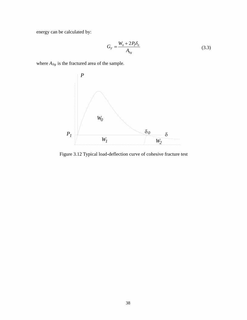
38
energy can be calculated by:
0 1 02F
lig
W PGA
δ+= (3.3)
where Alig is the fractured area of the sample.
Figure 3.12 Typical load-deflection curve of cohesive fracture test
W1
0W
W2
P
1P 0δ δ
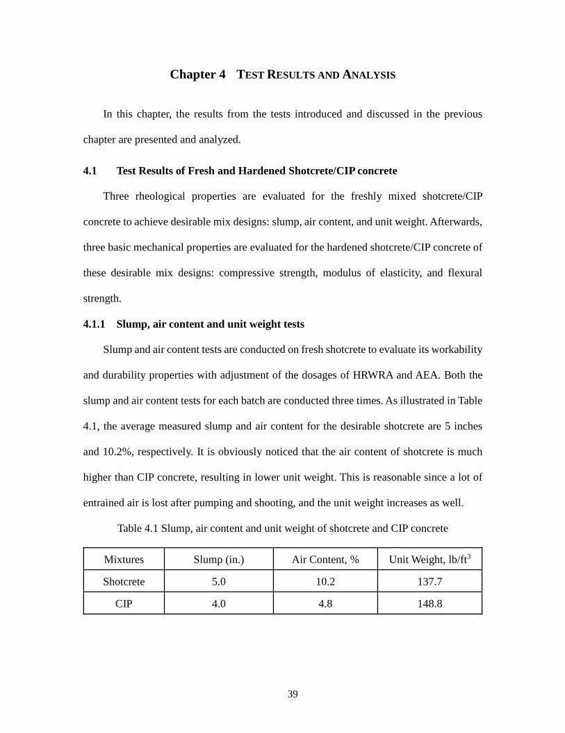
39
Chapter 4 TEST RESULTS AND ANALYSIS
In this chapter, the results from the tests introduced and discussed in the previous
chapter are presented and analyzed.
4.1 Test Results of Fresh and Hardened Shotcrete/CIP concrete
Three rheological properties are evaluated for the freshly mixed shotcrete/CIP
concrete to achieve desirable mix designs: slump, air content, and unit weight. Afterwards,
three basic mechanical properties are evaluated for the hardened shotcrete/CIP concrete of
these desirable mix designs: compressive strength, modulus of elasticity, and flexural
strength.
4.1.1 Slump, air content and unit weight tests
Slump and air content tests are conducted on fresh shotcrete to evaluate its workability
and durability properties with adjustment of the dosages of HRWRA and AEA. Both the
slump and air content tests for each batch are conducted three times. As illustrated in Table
4.1, the average measured slump and air content for the desirable shotcrete are 5 inches
and 10.2%, respectively. It is obviously noticed that the air content of shotcrete is much
higher than CIP concrete, resulting in lower unit weight. This is reasonable since a lot of
entrained air is lost after pumping and shooting, and the unit weight increases as well.
Table 4.1 Slump, air content and unit weight of shotcrete and CIP concrete
Mixtures Slump (in.) Air Content, % Unit Weight, lb/ft3
Shotcrete 5.0 10.2 137.7
CIP 4.0 4.8 148.8
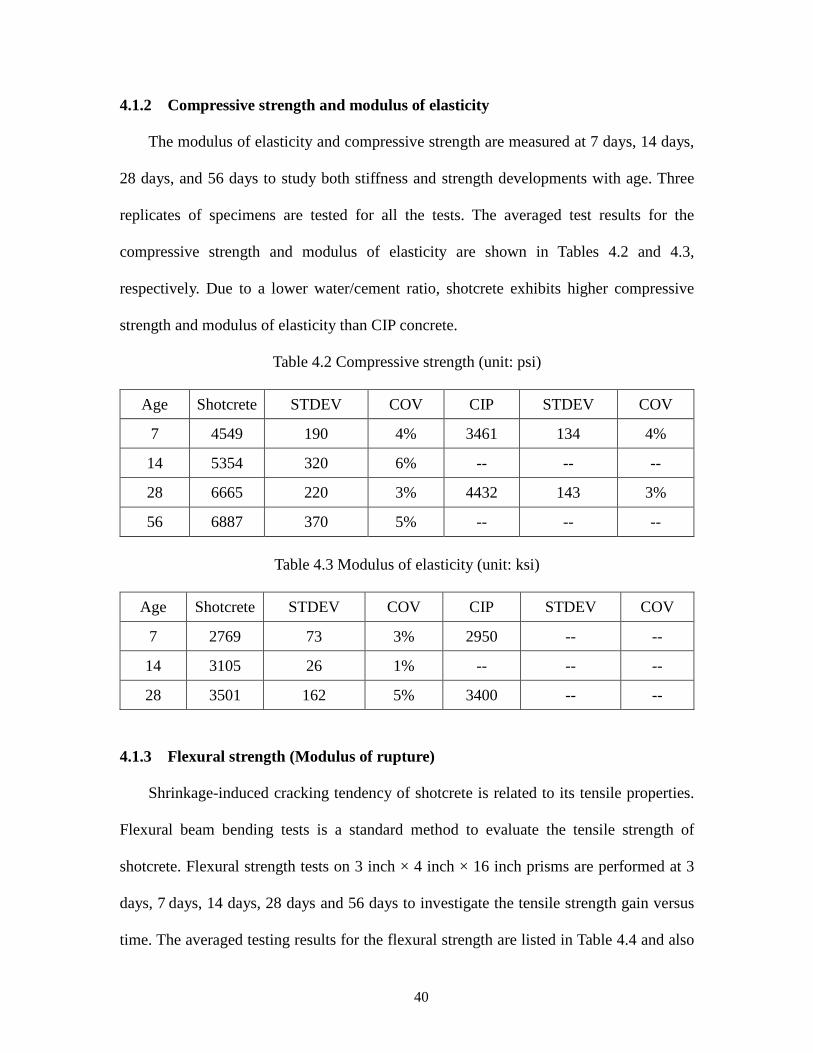
40
4.1.2 Compressive strength and modulus of elasticity
The modulus of elasticity and compressive strength are measured at 7 days, 14 days,
28 days, and 56 days to study both stiffness and strength developments with age. Three
replicates of specimens are tested for all the tests. The averaged test results for the
compressive strength and modulus of elasticity are shown in Tables 4.2 and 4.3,
respectively. Due to a lower water/cement ratio, shotcrete exhibits higher compressive
strength and modulus of elasticity than CIP concrete.
Table 4.2 Compressive strength (unit: psi)
Age Shotcrete STDEV COV CIP STDEV COV
7 4549 190 4% 3461 134 4%
14 5354 320 6% -- -- --
28 6665 220 3% 4432 143 3%
56 6887 370 5% -- -- --
Table 4.3 Modulus of elasticity (unit: ksi)
Age Shotcrete STDEV COV CIP STDEV COV
7 2769 73 3% 2950 -- --
14 3105 26 1% -- -- --
28 3501 162 5% 3400 -- --
4.1.3 Flexural strength (Modulus of rupture)
Shrinkage-induced cracking tendency of shotcrete is related to its tensile properties.
Flexural beam bending tests is a standard method to evaluate the tensile strength of
shotcrete. Flexural strength tests on 3 inch × 4 inch × 16 inch prisms are performed at 3
days, 7 days, 14 days, 28 days and 56 days to investigate the tensile strength gain versus
time. The averaged testing results for the flexural strength are listed in Table 4.4 and also
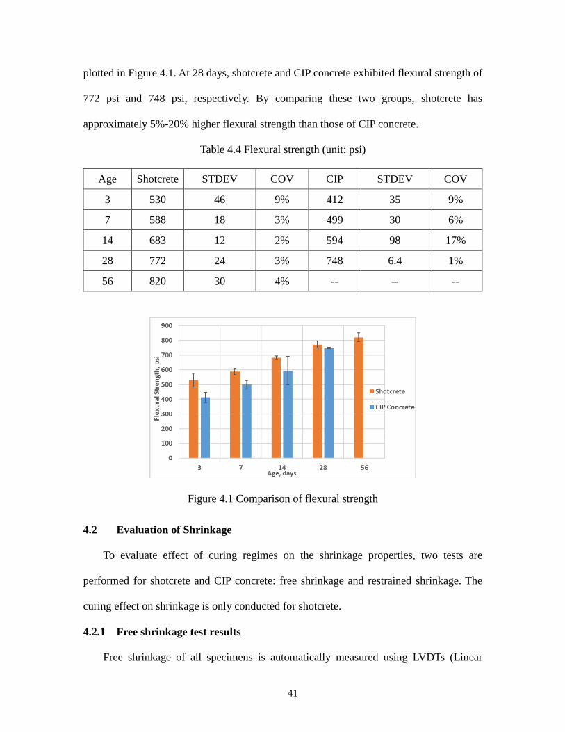
41
plotted in Figure 4.1. At 28 days, shotcrete and CIP concrete exhibited flexural strength of
772 psi and 748 psi, respectively. By comparing these two groups, shotcrete has
approximately 5%-20% higher flexural strength than those of CIP concrete.
Table 4.4 Flexural strength (unit: psi)
Age Shotcrete STDEV COV CIP STDEV COV
3 530 46 9% 412 35 9%
7 588 18 3% 499 30 6%
14 683 12 2% 594 98 17%
28 772 24 3% 748 6.4 1%
56 820 30 4% -- -- --
Figure 4.1 Comparison of flexural strength
4.2 Evaluation of Shrinkage
To evaluate effect of curing regimes on the shrinkage properties, two tests are
performed for shotcrete and CIP concrete: free shrinkage and restrained shrinkage. The
curing effect on shrinkage is only conducted for shotcrete.
4.2.1 Free shrinkage test results
Free shrinkage of all specimens is automatically measured using LVDTs (Linear
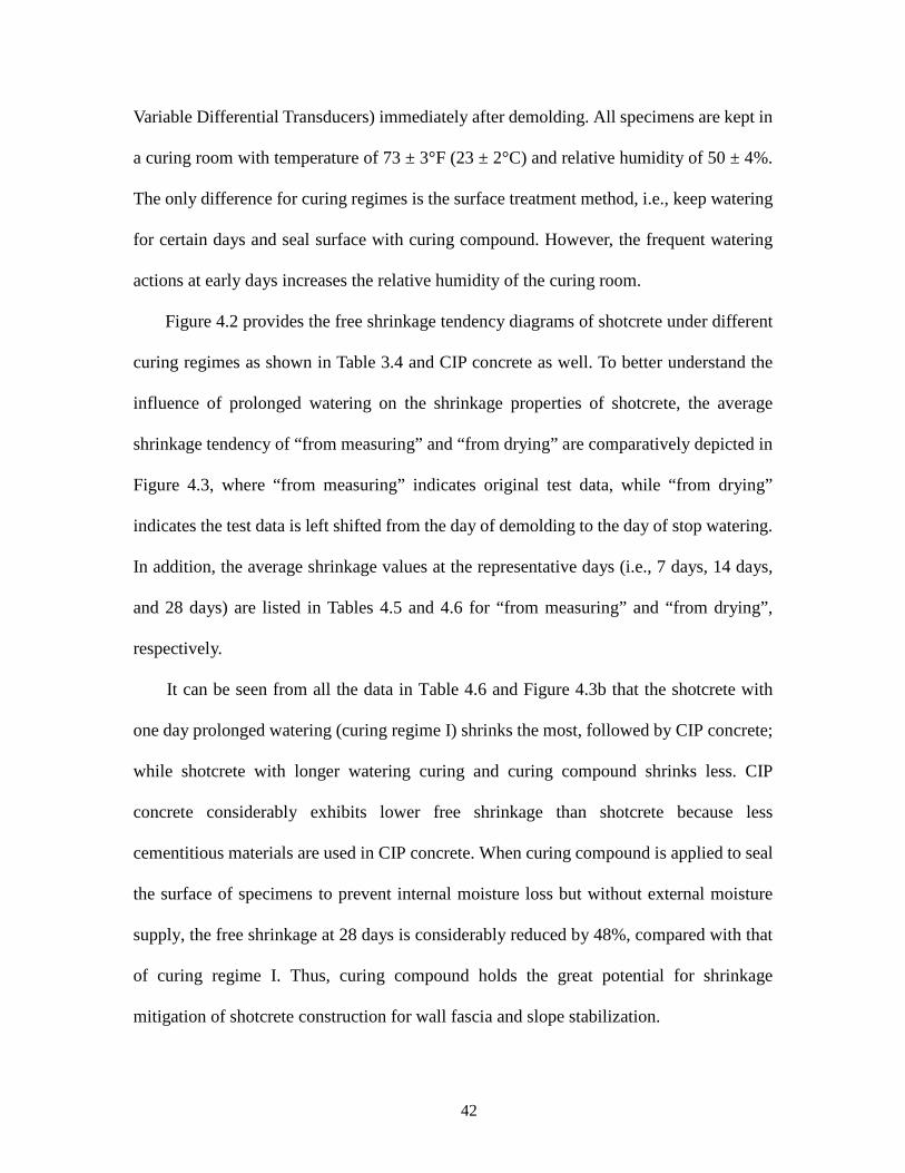
42
Variable Differential Transducers) immediately after demolding. All specimens are kept in
a curing room with temperature of 73 ± 3°F (23 ± 2°C) and relative humidity of 50 ± 4%.
The only difference for curing regimes is the surface treatment method, i.e., keep watering
for certain days and seal surface with curing compound. However, the frequent watering
actions at early days increases the relative humidity of the curing room.
Figure 4.2 provides the free shrinkage tendency diagrams of shotcrete under different
curing regimes as shown in Table 3.4 and CIP concrete as well. To better understand the
influence of prolonged watering on the shrinkage properties of shotcrete, the average
shrinkage tendency of “from measuring” and “from drying” are comparatively depicted in
Figure 4.3, where “from measuring” indicates original test data, while “from drying”
indicates the test data is left shifted from the day of demolding to the day of stop watering.
In addition, the average shrinkage values at the representative days (i.e., 7 days, 14 days,
and 28 days) are listed in Tables 4.5 and 4.6 for “from measuring” and “from drying”,
respectively.
It can be seen from all the data in Table 4.6 and Figure 4.3b that the shotcrete with
one day prolonged watering (curing regime I) shrinks the most, followed by CIP concrete;
while shotcrete with longer watering curing and curing compound shrinks less. CIP
concrete considerably exhibits lower free shrinkage than shotcrete because less
cementitious materials are used in CIP concrete. When curing compound is applied to seal
the surface of specimens to prevent internal moisture loss but without external moisture
supply, the free shrinkage at 28 days is considerably reduced by 48%, compared with that
of curing regime I. Thus, curing compound holds the great potential for shrinkage
mitigation of shotcrete construction for wall fascia and slope stabilization.
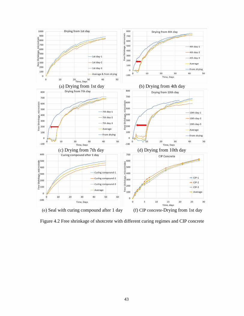
43
(a) Drying from 1st day (b) Drying from 4th day
(c) Drying from 7th day (d) Drying from 10th day
(e) Seal with curing compound after 1 day (f) CIP concrete-Drying from 1st day
Figure 4.2 Free shrinkage of shotcrete with different curing regimes and CIP concrete
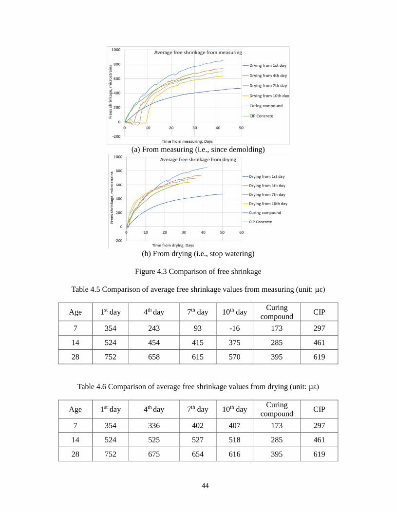
44
(a) From measuring (i.e., since demolding)
(b) From drying (i.e., stop watering)
Figure 4.3 Comparison of free shrinkage
Table 4.5 Comparison of average free shrinkage values from measuring (unit: µε)
Age 1st day 4th day 7th day 10th day Curing compound CIP
7 354 243 93 -16 173 297
14 524 454 415 375 285 461
28 752 658 615 570 395 619
Table 4.6 Comparison of average free shrinkage values from drying (unit: µε)
Age 1st day 4th day 7th day 10th day Curing compound CIP
7 354 336 402 407 173 297
14 524 525 527 518 285 461
28 752 675 654 616 395 619

45
Prolonged watering also had significant influence on free shrinkage of shotcrete. The
drying shrinkage is almost suspended/postponed until watering is stopped. From Figure
4.3a and Table 4.5, for curing regime I, II, III and IV, their free shrinkage at 28 days are
752, 658, 615, 570 macrostrains, respectively, indicating the longer shotcrete being kept
moist, the smaller free shrinkage it induces. Based on Figure 4.3b and Table 4.6, it could
be found that the longer moist cured specimens result in smaller ultimate shrinkage strains
at long period but slightly higher shrinkage rate at early days. Therefore, prolonged
watering to keep shotcrete from drying is highly recommended for practice.
4.2.2 Restrained shrinkage test results
In parallel with free shrinkage test, the restrained shrinkage test is conducted to
compare the shrinkage cracking tendency of shotcrete by different curing methods as well
as mixtures. Figures 4.4 to 4.8 depict the testing results of restrained shrinkage performed
on shotcrete following five different curing regimes in this study, where the measured steel
strain versus test age are plotted. Figure 4.9 presents the testing results of restrained
shrinkage performed on CIP concrete following the curing regime I in Table 3.4. Sudden
jump in a shrinkage strain-time curve indicates the time of cracking of ring taking place. If
no sudden jump is observed in the shrinkage strain curve in the given age (time), no
cracking then occurs in the ring.

46
(a) Drying from 1st day-ring#1
(b) Drying from 1st day-ring#2
(c) Drying from 1st day-ring#3
Figure 4.4 Restrained shrinkage of shotcrete under curing regime I
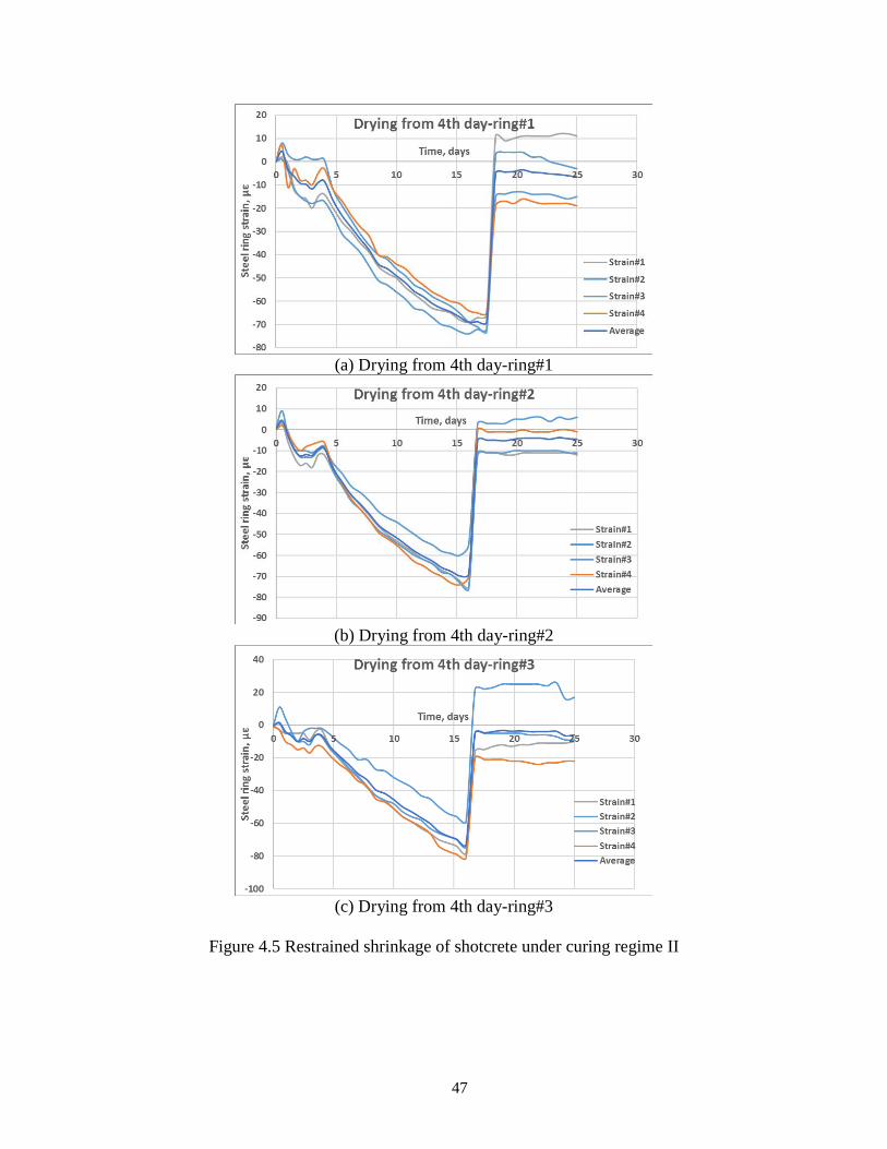
47
(a) Drying from 4th day-ring#1
(b) Drying from 4th day-ring#2
(c) Drying from 4th day-ring#3
Figure 4.5 Restrained shrinkage of shotcrete under curing regime II
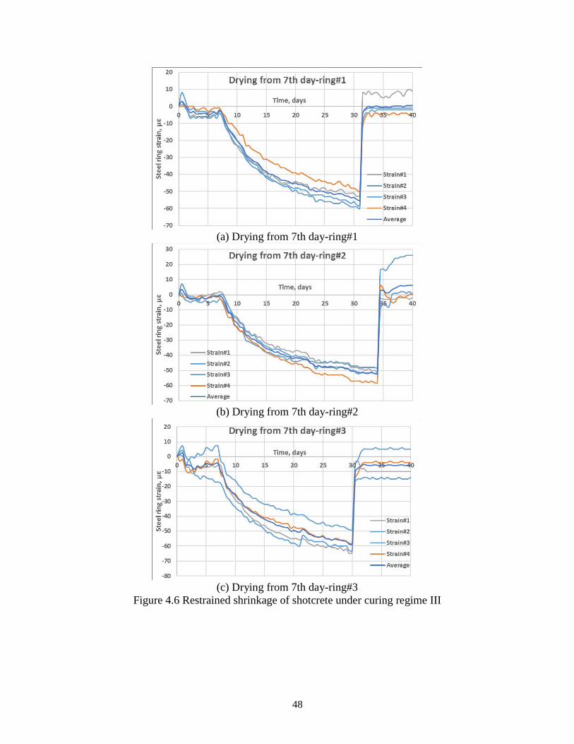
48
(a) Drying from 7th day-ring#1
(b) Drying from 7th day-ring#2
(c) Drying from 7th day-ring#3
Figure 4.6 Restrained shrinkage of shotcrete under curing regime III
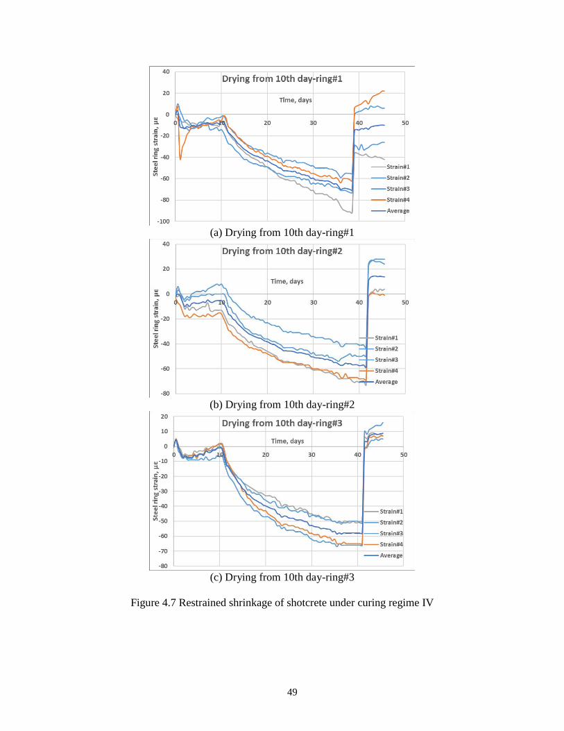
49
(a) Drying from 10th day-ring#1
(b) Drying from 10th day-ring#2
(c) Drying from 10th day-ring#3
Figure 4.7 Restrained shrinkage of shotcrete under curing regime IV
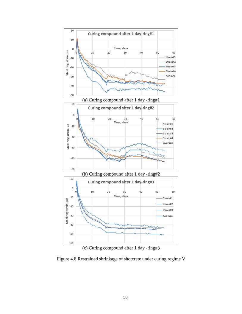
50
(a) Curing compound after 1 day -ring#1
(b) Curing compound after 1 day -ring#2
(c) Curing compound after 1 day -ring#3
Figure 4.8 Restrained shrinkage of shotcrete under curing regime V
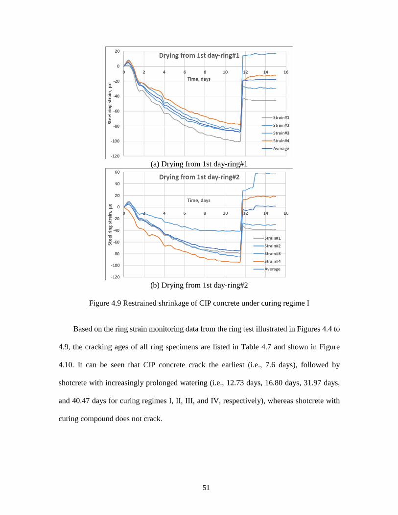
51
(a) Drying from 1st day-ring#1
(b) Drying from 1st day-ring#2
Figure 4.9 Restrained shrinkage of CIP concrete under curing regime I
Based on the ring strain monitoring data from the ring test illustrated in Figures 4.4 to
4.9, the cracking ages of all ring specimens are listed in Table 4.7 and shown in Figure
4.10. It can be seen that CIP concrete crack the earliest (i.e., 7.6 days), followed by
shotcrete with increasingly prolonged watering (i.e., 12.73 days, 16.80 days, 31.97 days,
and 40.47 days for curing regimes I, II, III, and IV, respectively), whereas shotcrete with
curing compound does not crack.
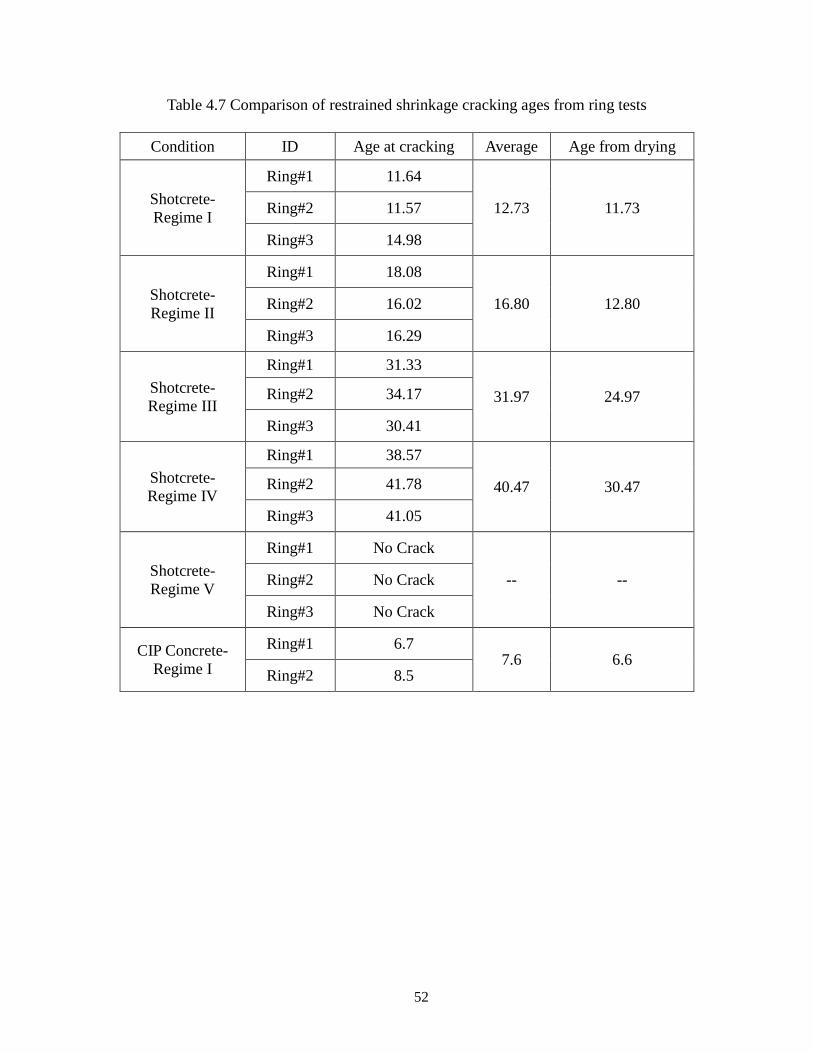
52
Table 4.7 Comparison of restrained shrinkage cracking ages from ring tests
Condition ID Age at cracking Average Age from drying
Shotcrete- Regime I
Ring#1 11.64
12.73 11.73 Ring#2 11.57
Ring#3 14.98
Shotcrete- Regime II
Ring#1 18.08
16.80 12.80 Ring#2 16.02
Ring#3 16.29
Shotcrete- Regime III
Ring#1 31.33
31.97 24.97 Ring#2 34.17
Ring#3 30.41
Shotcrete-Regime IV
Ring#1 38.57
40.47 30.47 Ring#2 41.78
Ring#3 41.05
Shotcrete- Regime V
Ring#1 No Crack
-- -- Ring#2 No Crack
Ring#3 No Crack
CIP Concrete- Regime I
Ring#1 6.7 7.6 6.6
Ring#2 8.5
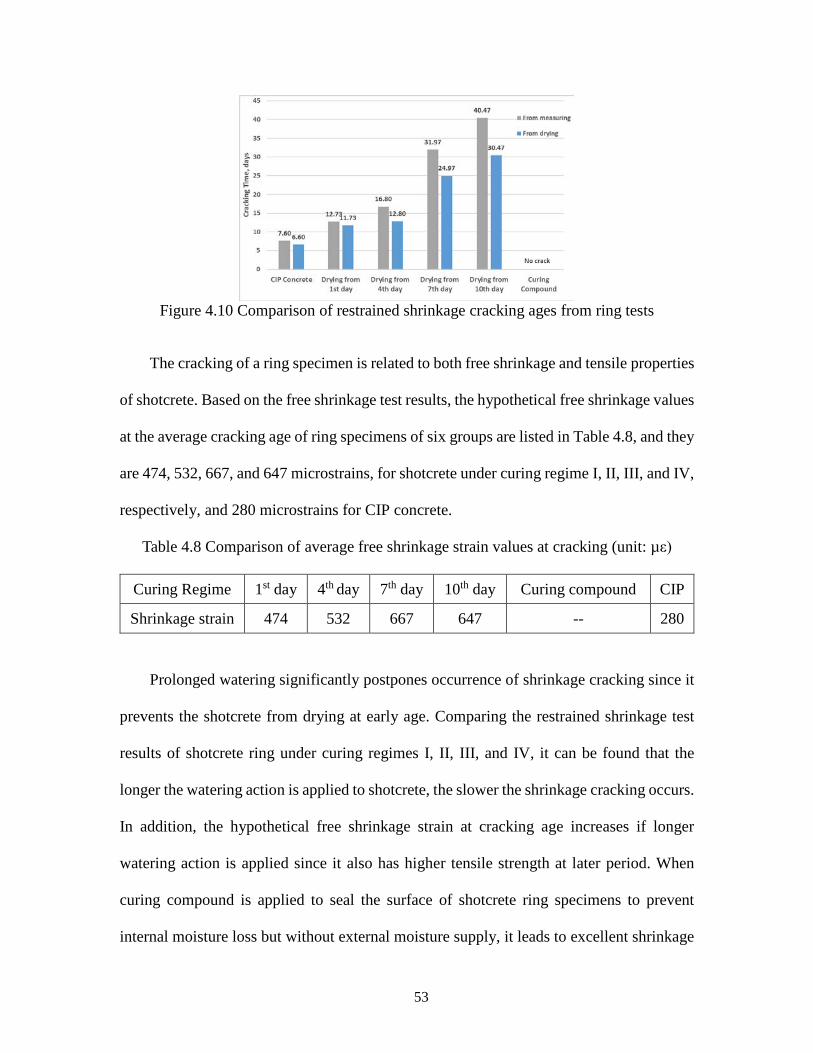
53
Figure 4.10 Comparison of restrained shrinkage cracking ages from ring tests
The cracking of a ring specimen is related to both free shrinkage and tensile properties
of shotcrete. Based on the free shrinkage test results, the hypothetical free shrinkage values
at the average cracking age of ring specimens of six groups are listed in Table 4.8, and they
are 474, 532, 667, and 647 microstrains, for shotcrete under curing regime I, II, III, and IV,
respectively, and 280 microstrains for CIP concrete.
Table 4.8 Comparison of average free shrinkage strain values at cracking (unit: µε)
Curing Regime 1st day 4th day 7th day 10th day Curing compound CIP
Shrinkage strain 474 532 667 647 -- 280
Prolonged watering significantly postpones occurrence of shrinkage cracking since it
prevents the shotcrete from drying at early age. Comparing the restrained shrinkage test
results of shotcrete ring under curing regimes I, II, III, and IV, it can be found that the
longer the watering action is applied to shotcrete, the slower the shrinkage cracking occurs.
In addition, the hypothetical free shrinkage strain at cracking age increases if longer
watering action is applied since it also has higher tensile strength at later period. When
curing compound is applied to seal the surface of shotcrete ring specimens to prevent
internal moisture loss but without external moisture supply, it leads to excellent shrinkage
54
cracking resistance in comparison with other curing regimes. Since the shrinkage-induced
tensile stress does not exceed the tensile strength, no crack is observed during the
measuring period. This phenomenon coincides well with the free shrinkage test results, that
is, when the free shrinkage values are low, the shrinkage-induced tensile stresses on
specimen due to restraints are low. Even though CIP concrete exhibits lower free shrinkage
than that of shotcrete, the ring specimens of CIP concrete still cracks earlier as it has lower
flexural strength than shotcrete. Among these curing regimes for shotcrete, prolonged
watering curing methods are beneficial to mitigate shrinkage cracking. Curing compound
is potentially beneficial to mitigate shrinkage cracking, but more field practice experience
and cost effect should be considered.
4.3 Evaluation of Freeze-Thaw Durability
A group of shotcrete beams are cast from the same batch for evaluation of freeze-thaw
durability. After initial wet curing of 28 days, they are conditioned to investigate its long-
term freeze-thaw durability in cold climates. The measured data, including mass loss and
visual inspection of specimen appearance, transverse frequency, and fracture energy, are
given in the following sections. The length change information of specimen is excluded
due to lack of measuring equipment.
4.3.1 Surface scaling process and mass loss
The appearances of a typical shotcrete sample at 0, 150, 300, 450, and 600 freeze-thaw
cycles are illustrated in Figure 4.11. The mass reduction due to frost actions is mainly
observed as the scaling of paste and mortar at the bottom surfaces and ends. The surface
scaling in shotcrete becomes more and more serious with the increasing freeze-thaw cycles.
Several small pieces of shotcrete at the ends are spalled after 600 cycles.
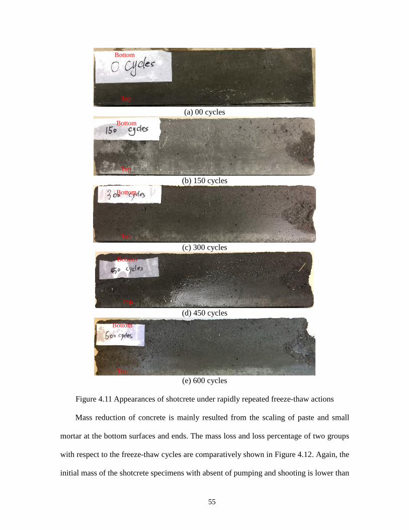
55
(a) 00 cycles
(b) 150 cycles
(c) 300 cycles
(d) 450 cycles
(e) 600 cycles
Figure 4.11 Appearances of shotcrete under rapidly repeated freeze-thaw actions
Mass reduction of concrete is mainly resulted from the scaling of paste and small
mortar at the bottom surfaces and ends. The mass loss and loss percentage of two groups
with respect to the freeze-thaw cycles are comparatively shown in Figure 4.12. Again, the
initial mass of the shotcrete specimens with absent of pumping and shooting is lower than
Top
Bottom
Top
Bottom
Top
Bottom
Top
Bottom
Top
Bottom

56
that of CIP concrete. It can be seen from Figure 4.12 that the mass of specimens keeps
decreasing due to accumulative frost actions. The mass loss percentage are 1.68% and
2.20% after 300 freeze-thaw cycles for shotcrete and CIP concrete, respectively, and they
are 2.81% and 2.90% after 600 freeze-thaw cycles for shotcrete and CIP concrete,
respectively. Shotcrete exhibits less mass loss and lower mass loss percentage than CIP
concrete, indicating that shotcrete has less severe frost damage.
(a) Mass loss
(b) Mass loss percentage
Figure 4.12 Comparison of mass loss due to freeze-thaw cycles

57
4.3.2 Dynamic modulus of elasticity
The vibration-based dynamic modulus of elasticity test using impact hammer is
conducted on two groups of specimens subjected to freezing and thawing conditioning
cycles. The natural frequencies from the transverse vibration test are initially measured at
every 30 freeze-thaw cycles, as shown in Figure 4.13. Subsequently, the dynamic modulus
of elasticity is calculated from the transverse frequencies through Equation 3.1. The
dynamic modulus of elasticity and the relative dynamic modulus of elasticity for both
groups with respect to the number of freeze-thaw cycles are comparatively illustrated in
Figure 4.14. As shown in Figure 4.13 and Figure 4.14a, it is unexpected that shotcrete
shows lower natural frequencies as well as smaller dynamic modulus of elasticity than
those of CIP concrete. However, the relative dynamic modulus is necessary to compare the
material degradation.
Figure 4.13 Comparison of transverse frequency
From Figure 4.14b, it can be observed that the relative dynamic modulus of shotcrete
is much higher than those of CIP concrete. The relative dynamic modulus of shotcrete and
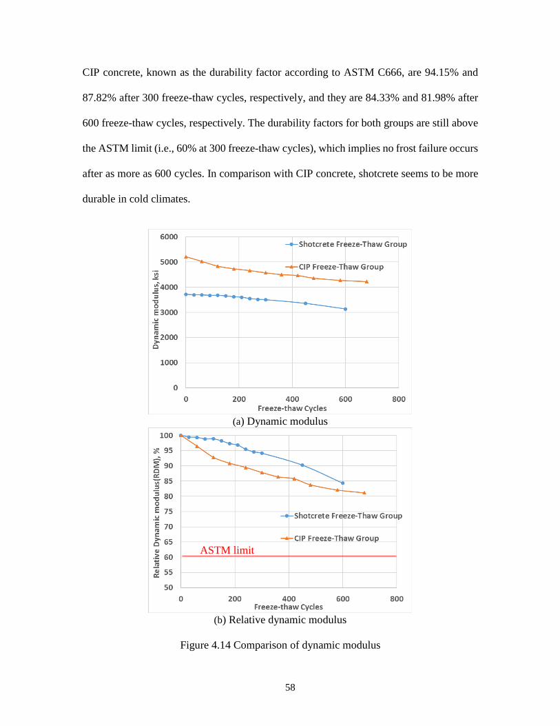
58
CIP concrete, known as the durability factor according to ASTM C666, are 94.15% and
87.82% after 300 freeze-thaw cycles, respectively, and they are 84.33% and 81.98% after
600 freeze-thaw cycles, respectively. The durability factors for both groups are still above
the ASTM limit (i.e., 60% at 300 freeze-thaw cycles), which implies no frost failure occurs
after as more as 600 cycles. In comparison with CIP concrete, shotcrete seems to be more
durable in cold climates.
(a) Dynamic modulus
(b) Relative dynamic modulus
Figure 4.14 Comparison of dynamic modulus
ASTM limit
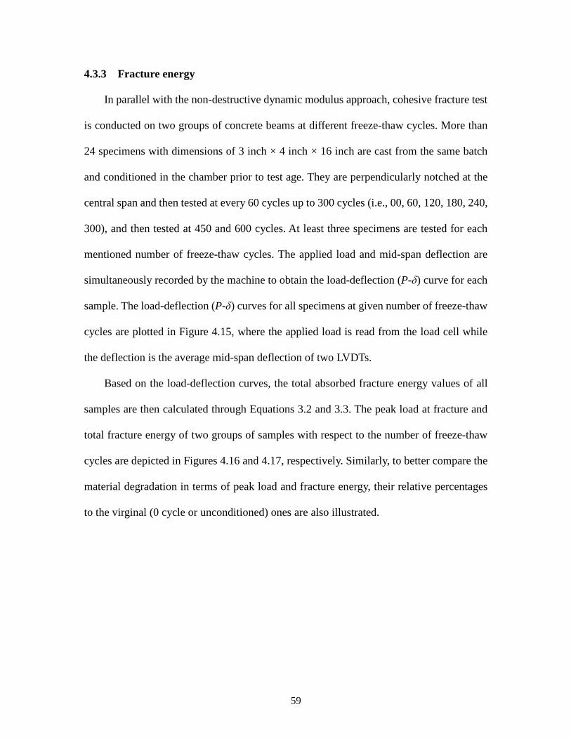
59
4.3.3 Fracture energy
In parallel with the non-destructive dynamic modulus approach, cohesive fracture test
is conducted on two groups of concrete beams at different freeze-thaw cycles. More than
24 specimens with dimensions of 3 inch × 4 inch × 16 inch are cast from the same batch
and conditioned in the chamber prior to test age. They are perpendicularly notched at the
central span and then tested at every 60 cycles up to 300 cycles (i.e., 00, 60, 120, 180, 240,
300), and then tested at 450 and 600 cycles. At least three specimens are tested for each
mentioned number of freeze-thaw cycles. The applied load and mid-span deflection are
simultaneously recorded by the machine to obtain the load-deflection (P-δ) curve for each
sample. The load-deflection (P-δ) curves for all specimens at given number of freeze-thaw
cycles are plotted in Figure 4.15, where the applied load is read from the load cell while
the deflection is the average mid-span deflection of two LVDTs.
Based on the load-deflection curves, the total absorbed fracture energy values of all
samples are then calculated through Equations 3.2 and 3.3. The peak load at fracture and
total fracture energy of two groups of samples with respect to the number of freeze-thaw
cycles are depicted in Figures 4.16 and 4.17, respectively. Similarly, to better compare the
material degradation in terms of peak load and fracture energy, their relative percentages
to the virginal (0 cycle or unconditioned) ones are also illustrated.
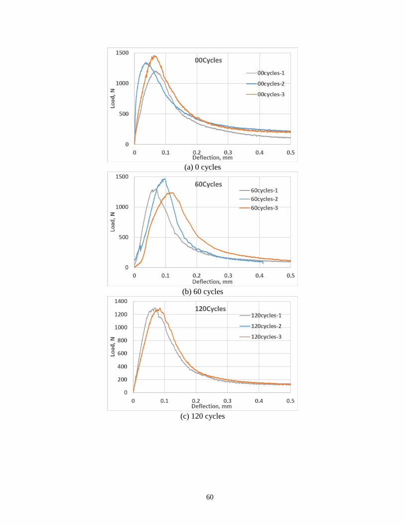
60
(a) 0 cycles
(b) 60 cycles
(c) 120 cycles
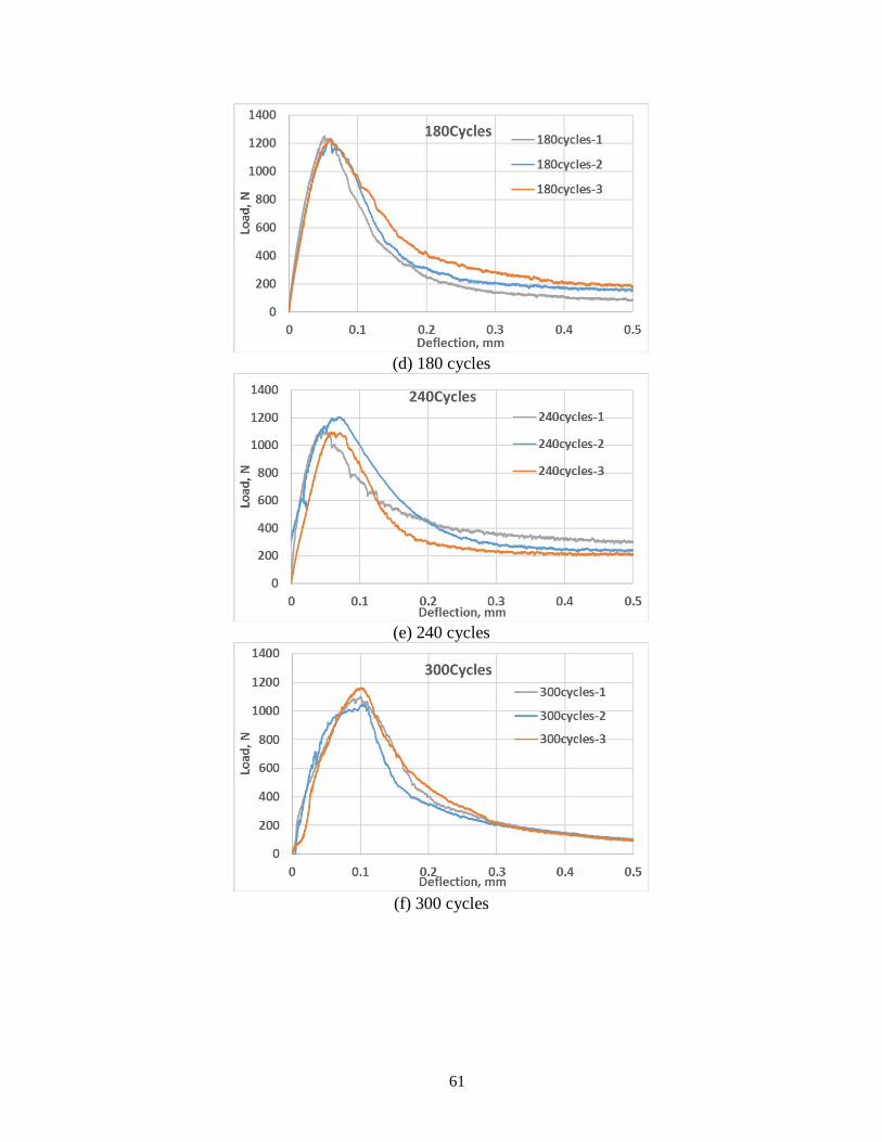
61
(d) 180 cycles
(e) 240 cycles
(f) 300 cycles
62
(g) 450 cycles
(h) 600 cycles
Figure 4.15 Load-deflection curves of shotcrete at different freeze-thaw cycles
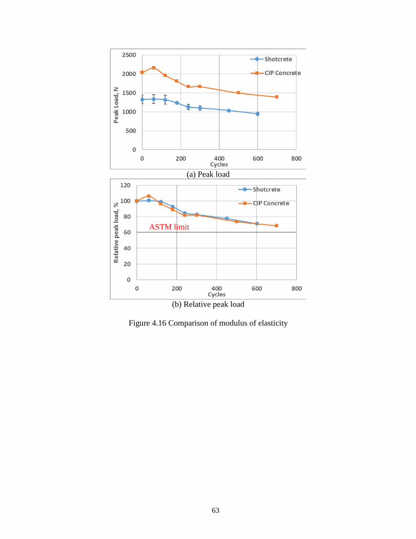
63
(a) Peak load
(b) Relative peak load
Figure 4.16 Comparison of modulus of elasticity
ASTM limit
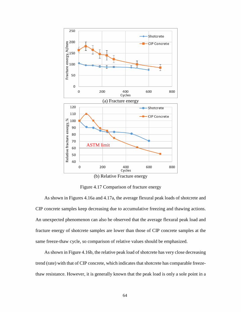
64
(a) Fracture energy
(b) Relative Fracture energy
Figure 4.17 Comparison of fracture energy
As shown in Figures 4.16a and 4.17a, the average flexural peak loads of shotcrete and
CIP concrete samples keep decreasing due to accumulative freezing and thawing actions.
An unexpected phenomenon can also be observed that the average flexural peak load and
fracture energy of shotcrete samples are lower than those of CIP concrete samples at the
same freeze-thaw cycle, so comparison of relative values should be emphasized.
As shown in Figure 4.16b, the relative peak load of shotcrete has very close decreasing
trend (rate) with that of CIP concrete, which indicates that shotcrete has comparable freeze-
thaw resistance. However, it is generally known that the peak load is only a sole point in a
ASTM limit
65
load-deflection curve while the total fracture energy considers the whole fracture work
process separating the specimen. Thus, the fracture energy may be more representative
than the peak load to characterize material degradation. It can be seen in Figure 2.17b that
the decreasing trend of the total fracture energy is quite different between shotcrete and
CIP concrete, that is, the relative decreasing ratio of fracture energy of CIP concrete is
much larger than those of shotcrete. At 300 (ASTM benchmark) freeze-thaw cycles, the
relative fracture energy decreasing ratios of shotcrete and concrete samples are 83.81% and
74.92%, respectively, compared to those of virginal samples. At 600 freeze-thaw cycles,
the relative fracture energy decreasing ratio of shotcrete and concrete samples are 70.71%
and 55.54%, respectively, compared to those of virginal samples. Obviously, shotcrete is
more durable than CIP concrete based on the comparison of relative fracture energy.
4.3.4 Comparison of “Durability Factors”
The durability factor of concrete is an important parameter for material design to
ensure its long-term life service. According to ASTM C666 (2015), the durability factor
refers to the relative dynamic modulus of elasticity at 300 cycles or the specified number
of cycles that freeze-thaw exposure is terminated. In this study, in comparison with
dynamic modulus of elasticity, the facture energy is also considered to evaluate the freeze-
thaw resistance of shotcrete and CIP concrete. Table 4.9 shows the durability factors of
both groups at 300 and 600 cycles as determined from the dynamic modulus and facture
energy tests.

66
Table 4.9 Comparison of durability factors of different test methods
Method Durability Factor
Shotcrete CIP Concrete
@300 Cycles
Dynamic Modulus 94.15% 87.82%
Fracture Energy 83.81% 74.92%
@600 Cycles
Dynamic Modulus 84.33% 81.98%
Fracture Energy 70.71% 55.54%
By comparing the durability factors from two test approaches in Table 4.9, it can be
obviously found that the durability factors from relative fracture energy are much smaller
than those from relative dynamic modulus, indicating that fracture energy test is a more
sensitive test method than the dynamic modulus of elasticity one to capture material
deterioration when subjected to rapidly repeated freezing and thawing actions as well as
other types of accumulative damage and manifest degradation and aging effect of materials.
More importantly, the fracture energy is associated with the full fracture of concrete cross
section, and it better represents damage or degradation taking place both inside and on/near
surface.
67
Chapter 5 CONCLUSIONS AND RECOMMENDATIONS
5.1 Summary and Conclusions
The goal of this proposed project aims to provide best practices of shotcrete for wall
fascia and slope stabilization. A comprehensive review of the state of academic and
industry knowledge of shotcrete is first conducted, including its production and mix design,
mechanical properties, short- and long-term performance, related quality assurance
methods, and comparisons with CIP concrete.
From the literature review, the shrinkage cracking and durability issues are identified
as two important performance aspects for best practices and quality assurance of shotcrete.
Two types of mixtures (a desirable shotcrete mixture and a CIP concrete mixture) from the
WSDOT are chosen for performance comparisons, including material properties in the
fresh (e.g., slump, air content, and unit weight) and hardened (e.g., compressive strength,
modulus of elasticity, flexural strength, shrinkage, and freeze-thaw actions) states. In
particular, early age shrinkage and restrained shrinkage performance, and long-term freeze-
thaw resistance through dynamic modulus of elasticity and fracture energy tests are
emphasized.
Based on the comparatively experimental evaluation of basic material and mechanical
properties, shrinkage and freeze-thaw resistance for shotcrete conducted in this study, the
following finding/conclusions are drawn.
(1) Based on the literature review, the early age shrinkage and long-term durability
issues and their related test approaches are identified when using shotcrete for wall fascia
and slope stabilization. The shrinkage cracking tendency of shotcrete depends on a
combined factor related to its tensile strength and free shrinkage property. As a key curing
68
regime, watering shotcrete surface at first several days is important to minimize its
shrinkage cracking since it presents relatively low free shrinkage strain. Internal air-void
system (air content and spacing factor) of hardened shotcrete has significant influences on
durability of shotcrete. Addition of air entraining admixture results in well-distributed
entrained air rather than entrapped air. Freeze-thaw resistance of shotcrete is improved with
the increasing of air content and decreasing of spacing factor. The participation of silica
fume in shotcrete mixture generally reduces mass of scaling residues and improves
durability of shotcrete due to lower permeability.
(2) Following the ASTM standard test procedures for concrete and cementitious
material characterization, the rheological properties tests (e.g., slump, air content, and unit
weight) of freshly mixed shotcrete are conducted to achieve desirable mix design with
acceptable workability (i.e., pumpability and shootability). Adjustment of the amount of
air entraining admixture (AEA) and high-range water reducing admixture (HRWRA) are
considered when producing shotcrete. The average slump and air content for the desirable
“before shooting” shotcrete are 5 inch and 10.2%, respectively, which are much higher than
those of considered CIP concrete.
(3) To achieve best curing practices of shotcrete to mitigate early age shrinkage
cracking, a few curing regimes are applied in terms of prolonged watering and curing
compound. In detail, four curing regimes with prolonged watering of 1 day, 4 days, 7 days
and 10 days and one curing regime with curing compound are considered for evaluation of
early-age shrinkage properties. The early-age free shrinkage test using prismatic specimens
with dimensions of 4 × 4 × 11.25 inch in accordance with ASTM C157 and shrinkage
cracking tendency test via rings in accordance with AASHTO T334 are performed.
69
(4) Based on the free shrinkage test, shotcrete with watering is found to shrink the
most, followed by CIP concrete, while shotcrete with curing compound shrink the least.
CIP concrete considerably exhibits a lower free shrinkage than shotcrete since less
cementitious materials are used, leading to a higher water/cement ratio. Using curing
compound to seal all surface of shotcrete specimens greatly prevents internal moisture loss
even without external moisture supply, and it exhibits only 48% of free shrinkage compared
to that without curing compound being applied. Prolonged watering also has significant
influence on free shrinkage of shotcrete as drying shrinkage is almost suspended/postponed
till the stop of watering, and it is also found that the longer shotcrete is kept wetting, the
smaller free shrinkage it has.
(5) From the restrained shrinkage ring test, it is also found that the CIP concrete ring
cracks the earliest (@ 7.6 days), followed by shotcrete with prolonged watering (at 12.73
days, 16.80 days, 31.97 days, and 40.47 days for curing regime I, II, III, and IV as shown
in Table 3.4, respectively); while shotcrete with curing compound does not crack at all.
Cracking of a ring specimen is characterized as the combined effects of free shrinkage and
tensile strength. As expected, prolonged period of watering postpones shrinkage cracking
due to lower free shrinkage at early age. The longer the watering action being performed
on shotcrete rings, the slower shrinkage cracking occurs. Even though CIP concrete
exhibits lower free shrinkage than that of shotcrete, the ring specimens of CIP concrete still
crack earlier as it has lower tensile strength than shotcrete. Using curing compound to
prevent specimens from drying provides the best practice; however, lack of field
application experience, cost reasons, etc. may deter its application in the field.
70
(6) The long-term freeze-thaw durability of shotcrete and CIP concrete are evaluated
using standard and non-standard approaches. The rapidly repeated freeze-thaw tests in
accordance with ASTM C666 Procedure A are performed on 3 × 4 × 16 inch prisms. The
non-destructive method, vibration-based dynamic modulus of elasticity test, is conducted
following the ASTM C215 on two groups of specimens subjected to freeze-thaw
conditioning cycles. In parallel, the destructive method, fracture energy test of shotcrete, is
conducted by means of three-point bend test on notched beams. It demonstrates that both
the dynamic modulus of elasticity and fracture energy tests are capable of determining the
material deterioration due to accumulative freeze-thaw damage.
(7) The mass loss due to frost actions is visually observed as the scaling of paste and
mortar at the bottom surfaces and ends. Both the dynamic modulus of elasticity and fracture
energy for both shotcrete and CIP concrete mixtures keep decreasing with the freeze-thaw
conditioning cycles. After 300 (ASTM benchmark) freeze-thaw cycles, the relative
dynamic modulus of shotcrete and CIP concrete are 94.15 and 87.82, respectively; while
the fracture energy of shotcrete and CIP concrete samples are 83.81% and 74.92%,
respectively, compared to those of virgin samples. Obviously, shotcrete is more durable
than CIP concrete based on the comparison of relative dynamic modulus and relative
fracture energy.
(8) The decreasing trends or relative ratios are quite different between the two test
methods, i.e., dynamic modulus of elasticity and fracture energy tests. The relative
decreasing ratios of fracture energy are much larger than those of dynamic modulus of
elasticity. In other words, the durability factors determined from relative fracture energy
are much smaller than those from relative dynamic modulus of elasticity, indicating that
71
the fracture energy test is a more sensitive test than the dynamic modulus of elasticity one
to screen material deterioration over time and capture accumulative material damage
subjected to rapidly repeated freezing and thawing actions.
In summary, to provide best practices of shotcrete for wall fascia and slope
stabilization, a desirable shotcrete mixture and a CIP concrete mixture from WSDOT
benchmarks are tested for their related mechanical properties and evaluation of shrinkage
and durability performance. The restrained ring test procedures follow AASHTO T334 are
identified to be capable of evaluating early-age shrinkage cracking tendency of shotcrete;
while the fracture energy test procedures are validated again to be more sensitive than the
dynamic modulus of elasticity test in screening material deterioration /aging effect under
freeze-thaw cyclic conditioning. As demonstrated in the laboratory testing, prolonged
watering curing methods are beneficial to mitigate shrinkage cracking. Curing compound
is potentially beneficial to mitigate shrinkage cracking, and more field practice experience
is needed. The “before shooting” shotcrete studied in Phase I exhibits better early age
shrinkage resistance and long-term freeze-thaw resistance than the considered CIP concrete.
5.2 Recommendations
The results of this study are limited to the mix designs and test methods used to explore
proper use of shotcrete for wall fascia and slope stabilization. In particular, the early age
shrinkage and long-term durability properties are mainly characterized. Based on the
experimental program conducted in this study, the following recommendations are
suggested for Phase II and/or future study to better understand performance of shotcrete:
(1) Only one mix design of shotcrete with water/cement ratio of 0.34 and compressive
strength higher than 6,000 psi is considered and tested in this study. More mix designs by
72
adjusting the water/cement ratio, proportions of cementitious materials (i.e., cement, silica
fume, GGBFS and Fly ash, etc.) are needed according to “Class of Concrete” in “Standard
Specifications for Road, Bridge, and Municipal Construction” by Washington State
Department of Transportation.
(2) All specimens of “before shooting” shotcrete are prepared for evaluation and
testing of shotcrete mechanical properties; however, it cannot be identically equal to those
from “after shooting” shotcrete. The comparisons of the mechanical properties and
durability of “before shooting” and “after shooting” types of shotcrete should be considered.
(3) It is well known that the air-void system in shotcrete has significant influence on
the mechanical properties and long-term durability performance. In this study, the air
content is controlled as 10.2% before shooting, and its air-void system of hardened
shotcrete, even after shooting, are still not clear. More laboratory evaluations should be
performed to reveal the air-void characteristics.
(4) Early age shrinkage due to loss of moisture and shrinkage cracking tendency on
shotcrete surface with a risk of decreasing quality and durability need to be completely
investigated. Some other potential mitigation strategies, such as using shrinkage reducing
admixtures (SRA), accelerators, expansive cementitious materials, silica fume, steel fiber,
etc., can be proposed to reduce shrinkage cracking tendency.
(5) To better characterize long-term durability of shotcrete, other methods are
recommended to screen damage process of pore structures and reveal failure mechanisms
of shotcrete subjected to freeze-thaw actions, such as micro/nano X-ray imaging scanning,
scanning electron microscopy (SEM), etc.
73
(6) In this study, only frost action is considered for durability evaluation of shotcrete.
However, salty deicers are commonly used in cold regions to melt snow and ice and
improve traffic safety, and resistance of shotcrete structures under more severe and
combined frost and chemical attacks should be investigated. In addition, possible corrosion
of reinforced bars cannot be neglected.
(7) Lack of bond to existing structures is pronounced for shotcrete as a repairing
material and for slope stabilization. The bond strength and debonding mechanism at the
interface area between shotcrete and substrates should be investigated.
(8) Most of the test methods commonly used to characterize shotcrete material
properties and performance are adopted from the standard test methods (either ASTM or
AASHTO or both) employed for concrete materials. There is a need to develop effective
test methods specifically for characterization of shotcrete. Due to relative lack of study for
shotcrete materials and structures, further study is needed to systematically develop best
curing practices, recommendations for Q/A test methods, and guide specifications for
shotcrete in retaining wall Fascias and slope stabilization.
(9) Based on laboratory accelerated test data (e.g., under rapidly cyclic freeze-thaw
actions) and correlating them with field data, there is a need to develop life prediction
methodologies for shotcrete using damage mechanics principles and statistical tools.
74
REFERENCES
AASHTO (1998). “Guide Specifications for Shotcrete Repair of Highway Bridges.” Task
Force 37 Report, American Association of State Highway and Transportation Officials,
Washington, DC.
AASHTO T334-08 (2016). “Standard Method of Test for Estimating the Cracking
Tendency of Concrete.” American Association of State Highway and Transportation
Officials, Washington, DC.
ACI Committee 506R-05. (2005). “Guide to Shotcrete.” American Concrete Institute,
Farmington Hills, Michigan.
ACI Committee 308R-01. (2001). “Guide to Curing Concrete.” American Concrete
Institute, Farmington Hills, Michigan.
Ansell A. (2010). “Investigation of shrinkage cracking in shotcrete on tunnel drains.”
Tunnelling and Underground Space Technology, 25, pp. 607-613.
ASTM C127-15. (2015). “Standard Test Method for Relative Density (Specific Gravity)
and Absorption of Coarse Aggregate.” ASTM International, West Conshohocken, PA.
ASTM C128-15. (2015). “Standard Test Method for Relative Density (Specific Gravity)
and Absorption of Fine Aggregate.” ASTM International, West Conshohocken, PA.
ASTM C136/C136M-14. (2014). “Standard Test Method for Sieve Analysis of Fine and
Coarse Aggregates.” ASTM International, West Conshohocken, PA.
ASTM C138/C138M-16a. (2016). “Standard Test Method for Density (Unit Weight), Yield,
and Air Content (Gravimetric) of Concrete.” ASTM International, West
Conshohocken, PA.
75
ASTM C143/C143M-15a. (2015). “Test Method for Slump of Hydraulic-Cement
Concrete.” ASTM International, West Conshohocken, PA.
ASTM C157/157M-08. (2014). “Standard Test Method for Length Change of Hardened
Hydraulic-Cement Mortar and Concrete.” ASTM International, West Conshohocken,
PA.
ASTM C1581/C1581M-16. (2016). “Standard Test Method for Determining Age at
Cracking and Induced Tensile Stress Characteristics of Mortar and Concrete under
Restrained Shrinkage.” ASTM International, West Conshohocken, PA.
ASTM C192/C192M-16a. (2016). “Standard Practice for Making and Curing Concrete
Test Specimens in the Laboratory.” ASTM International, West Conshohocken, PA.
ASTM C215-14. (2014). “Standard Test Method for Fundamental Transverse,
Longitudinal, and Torsional Resonant Frequencies of Concrete Specimens.” ASTM
International, West Conshohocken, PA.
ASTM C231/C231M-14. (2014). “Standard Test Method for Air Content of Freshly Mixed
Concrete by the Pressure Method.” ASTM International, West Conshohocken, PA.
ASTM C39/C39M-17. (2017). “Standard Test Method for Compressive Strength of
Cylindrical Concrete Specimens.” ASTM International, West Conshohocken, PA.
ASTM C457/C457M-12. (2012). “Standard Test Method for Microscopical Determination
of Parameters of the Air-Void System in Hardened Concrete.” ASTM International,
West Conshohocken, PA.
ASTM C469/C469M-14. (2014). “Standard Test Method for Static Modulus of Elasticity
and Poisson’s Ratio of Concrete in Compression.” ASTM International, West
76
Conshohocken, PA.
ASTM C666/C666M-15. (2015). “Standard Test Method for Resistance of Concrete to
Rapid Freezing and Thawing.” ASTM International, West Conshohocken, PA.
ASTM C78/C78M-16. (2016). “Standard Test Method for Flexural Strength of Concrete
(Using Simple Beam with Third-Point Loading).” ASTM International, West
Conshohocken, PA.
Banthia N., Trottier J. F., and Beaupre D. (1994). “Steel‐Fiber‐Reinforced Wet‐Mix
Shotcrete: Comparisons with Cast Concrete.” Journal of Materials in Civil
Engineering, 6(3), pp. 430-437.
Beaupre D. (1994). “Rheology of High Performance Shotcrete.” Ph.D. Dissertation, the
University of British Columbia, Canada.
Beaupre D., Trottier J. F., Gendreau M., et al. (1994). “Deicer Salt Scaling Resistance of
Dry- and Wet-Process Shotcrete.” ACI Materials Journal, 91(5), pp. 487-494.
Bindiganavile, V. and Banthia, N. (2000). “Rebound in Dry-Mix Shotcrete: Influence of
Type of Mineral Admixture.” ACI Materials Journal, 97(2), pp. 115-119.
Bryne L. E., Ansell A., and Holmgren J. (2014a). “Laboratory testing of early age bond
strength of shotcrete on hard rock.” Tunnelling and Underground Space Technology,
41, pp. 113-119.
Bryne L. E., Ansell A., and Holmgren J. (2014b). “Investigation of restrained shrinkage
cracking in partially fixed shotcrete linings.” Tunnelling and Underground Space
Technology, 42, pp. 136-143.
77
Bryne L. E., Ansell A., and Holmgren J. (2014c). “Shrinkage testing of end-restrained
shotcrete on granite slabs.” Magazine of Concrete Research, 66(17), pp. 859-869.
Chen F., and Qiao P. (2015). “Probabilistic damage modeling and service-life prediction
of concrete under freeze-thaw action.” Materials and Structures, 48(8), pp. 2697-2711.
Chen J., Deng X., Luo Y., et al. (2015). “Investigation of microstructural damage in
shotcrete under a freeze-thaw environment.” Construction and Building Materials, 83,
pp. 275-282.
Choi P., Yeon J. H., and Yun K. K. (2016). “Air-void structure, strength, and permeability
of wet-mix shotcrete before and after shotcreting operation: The influences of silica
fume and air-entraining agent.” Cement and Concrete Composites, 70, pp. 69-77.
Choi S. Y. (2008). “Rheology and Air Void Structures of Wet-mix Shotcrete.” Ph.D.
Dissertation, Kangwon National University, Korea.
Crom T. R. (1981). “Dry-Mix Shotcrete Nozzling.” Concrete International, 3(1), pp. 23-
26.
Drover C., and Villaesusa, C. (2015). “Performance of Shotcrete Surface Support
Following Dynamic Loading of Mining Excavations.” In Proceedings "Shotcrete for
Underground Support XII", Professor Ming Lu, Nanyang Technological University
Dr. Oskar Sigl, Geoconsult Asia Singapore PTE Ltd. Dr. GuoJun Li, Singapore Metro
Consulting Eds, ECI Symposium Series.
Fonseca P. C., and Scherer G. W. (2015). “An image analysis procedure to quantify the air
void system of mortar and concrete.” Materials and Structures, 45, pp. 3087-3098.
Ginouse N., and Jolin M. (2014). “Experimental and Numerical Investigation of Particle
78
Kinematics in Shotcrete.” Journal of Materials in Civil Engineering, 26(11), 06014023.
Ginouse N., Jolin M., and Bissonnette B. (2014). “Effect of equipment on spray velocity
distribution in shotcrete applications.” Construction and Building Materials, 70, pp.
362-369.
Ginouse N., and Jolin M. (2016). “Mechanisms of placement in sprayed concrete.”
Tunnelling and Underground Space Technology, 58, pp. 177-185.
Heere R., and Morgan D. R. (2002). “Determination of Early-Age Compressive Strength
of Shotcrete.” Shotcrete, Spring, pp. 28-31.
Hover K.C., and Phares R.J. (1996). “Impact of concrete placing method on air content, air
void system parameters, and freeze-thaw durability.” Transportation Research Record:
Journal of the Transportation Research Board, 1532, pp. 1-8.
Jiang L., Niu D., Yuan L., et al. (2015). “Durability of concrete under sulfate attack exposed
to freeze-thaw cycles.” Cold Regions Science and Technology, 112, pp. 112-117.
Jolin M., Beaupre D., Pigeon M., et al. (1997). “Freeze-Thaw Durability of Shotcrete.”
Journal of Materials in Civil Engineering, 9(4), pp. 180-184.
Jolin, M., Beaupre, D., and Mindess, S. (2002). “Quality Control of Dry-mix Shotcrete
During Construction.” Concrete International, 24(10), pp. 69-74.
Jolin M., Beaupre D. (2003a). “Use of Set Accelerating Admixtures in Dry-Mix Shotcrete.”
Concrete International, 11(8), pp. 86-93.
Jolin M., Beaupre D. (2003b). “Understanding Wet-Mix Shotcrete: Mix Design,
Specifications, and Placement.” Shotcrete, Summer, pp.6-12.
79
Karlsson, L. (1980). “Shotcrete on various rock surfaces.” Byggforskningsra det. Report
No. R69, in Swedish.
Lamontagne A., Pigeon M., Pleau R., et al. (1996). “Use of Air-Entraining Admixtures in
Dry-Mix Shotcrete.” ACI Materials Journal, 93(1), pp. 69-74.
Lee C. H., Wang T. T., and Chen H. J. (2013). “Experimental study of shotcrete and
concrete strength development in a hot spring environment.” Tunnelling and
Underground Space Technology, 38, pp. 390-397.
Leung K. Y., Lee Y. F., and Lai R. (2006). “A new testing configuration for shrinkage
cracking of shotcrete and fiber reinforced shotcrete.” Cement and Concrete Research,
36, pp. 740-748.
Mainali G., Dineva S., and Erling N. (2015). “Experimental study on debonding of
shotcrete with acoustic emission during freezing and thawing cycle.” Cold Regions
Science and Technology, 111, pp. 1-12.
Malmgren L., Nordlund E., and Rolund S. (2005). “Adhesion strength and shrinkage of
shotcrete.” Tunnelling and Underground Space Technology, 20, pp. 33-48.
Morgan D.R. (1989). “Wet-Mix Silica Fume Shotcrete: Effect of Silica Fume Form.”
CANMET/ACI International Conference on Fly Ash, Silica Fume, Slag, and Natural
Pozzolans and Natural Pozzolans in Concrete, pp. 1251-1271.
Morgan D.R., Wolsiefer J. (1992). “Wet-Mix Silica Fume Shotcrete: Effect of Silica Fume
Form.” CANMET/ACI International Conference on Fly Ash, Silica Fume, Slag, and
Natural Pozzolans and Natural Pozzolans in Concrete, pp. 1251-1272.
Morgan D. R. (2003). “Freeze-Thaw Durability of Shotcrete.” Shotcrete, Spring, pp.30-37.
80
Niu D., Wand Y., Ma. R., et al. (2015). “Experiment study on the failure mechanism of dry-
mix shotcrete under the combined actions of sulfate attack and drying–wetting cycles.”
Construction and Building Materials, 81, pp. 74-80.
Paglia, C., Wombacher, F., and Bohni, H. (2003). “The influence of alkali-free and alkaline
shotcrete accelerators within cement systems: Influence of the temperature on the
sulfate attack mechanisms and damage.” Cement and Concrete Research, 33(3), pp.
387-395.
Park H. G., Suang S. K., Park C. G., et al. (2008). “Influence of a C12A7 mineral-based
accelerator on the strength and durability of shotcrete.” Cement and Concrete
Research, 38, pp. 379-385.
Portland Cement Association. (1998). “Control of Air Content in Concrete.” Concrete
Technology Today, 19(1), pp. 1-3.
Prudencio L. R. (1998). “Accelerating Admixtures for Shotcrete.” Cement and Concrete
Composites, 20, pp. 213-219.
Qiao P., Mclean D., and Zhuang J. (2010). “Mitigation Strategies for Early-Age Shrinkage
Cracking in Bridge Decks.” Report No. WA-RD 747.1, Washington State Department
of Transportation, Olympia, WA.
Qiao P., Mclean D. I., and Chen F. (2012). “Concrete Performance Using Low-Degradation
Aggregates.” Report No. WA-RD 790.1, Washington State Department of
Transportation, Olympia, WA.
Qiao P., and Chen F. (2013). “Cohesive fracture and probabilistic damage analysis of
freezing–thawing degradation of concrete.” Construction and Building Materials, 47,
81
pp. 879-887.
RILEM TC-50 FMC. (1985). “Draft Recommendation: Determination of the fracture
energy of mortar and concrete by means of the three-point bend tests on notched
beams.” Materials and Structures, 18(106), pp. 285-290.
Sawoszczuk P., Nokken M., and Jolin M. (2013). “Sustainable Shotcrete Using Blast-
Furnace Slag.” Shotcrete, Fall, pp. 32-37.
Shehata M.and Klement T. (2005). “Curing Silica Fume Shotcrete with Wet-Sprayed
Cellulose.” Shotcrete, Spring, pp. 32-35.
Shehata M., Nevarra M., Klement T., et al. (2006a). “Use of wet cellulose to cure shotcrete
repairs on bridge soffits. Part 1: Field trial and observations.” Canadian Journal of
Civil Engineering, 33(7): pp. 807-814.
Shehata M., Nevarra M., Klement T., et al. (2006b). “Use of wet cellulose to cure shotcrete
repairs on bridge soffits. Part 2: Laboratory testing and analysis.” Canadian Journal of
Civil Engineering, 33(7): pp. 815-826.
Talbot C., Pigeon M., Beaupre D., et al. (1995). “Influence of Surface Preparation on Long-
Term Bonding of Shotcrete.” ACI Materials Journal, 91(6), pp. 560-566.
US Army Corps of Engineers. (1993). “ENGINEERING AND DESIGN: Standard Practice
for Shotcrete.” CECW-EG Engineer Manual 1110-2-2005, Washington, DC.
Verma B. (2015). “Use of Steel Fiber Reinforced Concrete (SFRC) over Plain Concrete
for Shotcrete in Underground Tunneling.” SSRG International Journal of Civil
Engineering (SSRG-IJCE), 2(7), pp. 9-12.
Wang J., Niu D., Ding S., et al. (2015a). “Microstructure, permeability and mechanical
82
properties of accelerated shotcrete at different curing age.” Construction and Building
Materials, 78, pp. 203-216.
Wang J., Niu D., Zhang Y., et al. (2015b). “Mechanical properties, permeability and
durability of accelerated shotcrete.” Construction and Building Materials, 95, pp. 312-
328.
Washington State Department of Transportation (WSDOT) M41-10. (2012). “Standard
Specifications for Road, Bridge, and Municipal Construction.”
Wenzlick, J. D. (2007). “Viability and Durability of Shotcrete for Repairing Bridges.”
Report No. OR07-014, Missouri Department of Transportation, Jefferson City, MO.
Won J. P., Choi B. R., Lee J. W. (2012). “Experimental and statistical analysis of the alkali–
silica reaction of accelerating admixtures in shotcrete.” Construction and Building
Materials, 30, pp. 330-339.
Won J. P., Hwang U. J., Kim, C. K., et al. (2013). “Mechanical performance of shotcrete
made with a high-strength cement-based mineral accelerator.” Construction and
Building Materials, 49, pp. 175-183.
Won J. P., Hwang U. J., and Lee S. J. (2015). “Enhanced long-term strength and durability
of shotcrete with high-strength C12A7 mineral-based accelerator.” Cement and
Concrete Research, 75, pp. 121-129.
Yun K. K., Choi S. Y., and Yeon J. H. (2015a). “Correlating rheological properties to the
pumpability and shootability of wet-mix shotcrete mixtures.” Construction and
Building Materials, 98, pp. 884-891.
Yun K. K., Choi S. Y., and Yeon J. H. (2015b). “Effects of admixtures on the rheological
83
properties of high-performance wet-mix shotcrete mixtures.” Construction and
Building Materials, 78, pp. 194-202.
Zaffaroni P., Pistolesi C., Dal Negro E., et al. (2000). “High Performance Shotcrete.” L’
Industria Italiana Del Cemento, 7(8), pp 598-602.
Zhang L. (2012). “Air Content in Shotcrete: As-Shot Versus As-Batched.” Shotcrete,
Winter, pp. 50-54.
Zhang L. (2014). “Variability of Compressive Strength of Shotcrete in a Tunnel-Lining
Project.” Shotcrete, Fall, pp. 22-27.
Zhang L., Morgan D., and Mindess S. (2016). “Comparative Evaluation of Transport
Properties of Shotcrete Compared to Cast-in-Place Concrete.” ACI Materials Journal,
113(3), pp. 373-384.
Zhang M. H., Mirza J., and Malhotra V. M. (1999). “Mechanical Properties and Freezing
and Thawing Durability of Polypropylene Fiber-Reinforced Shotcrete Incorporating
Silica Fume and High Volumes of Fly Ash.” Cement, Concrete, and Aggregates,
CCAGDP, 21(2), pp. 117-125.
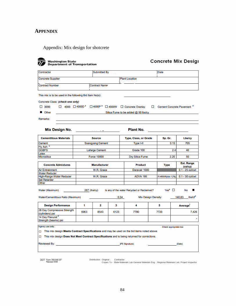
84
APPENDIX
Appendix: Mix design for shotcrete
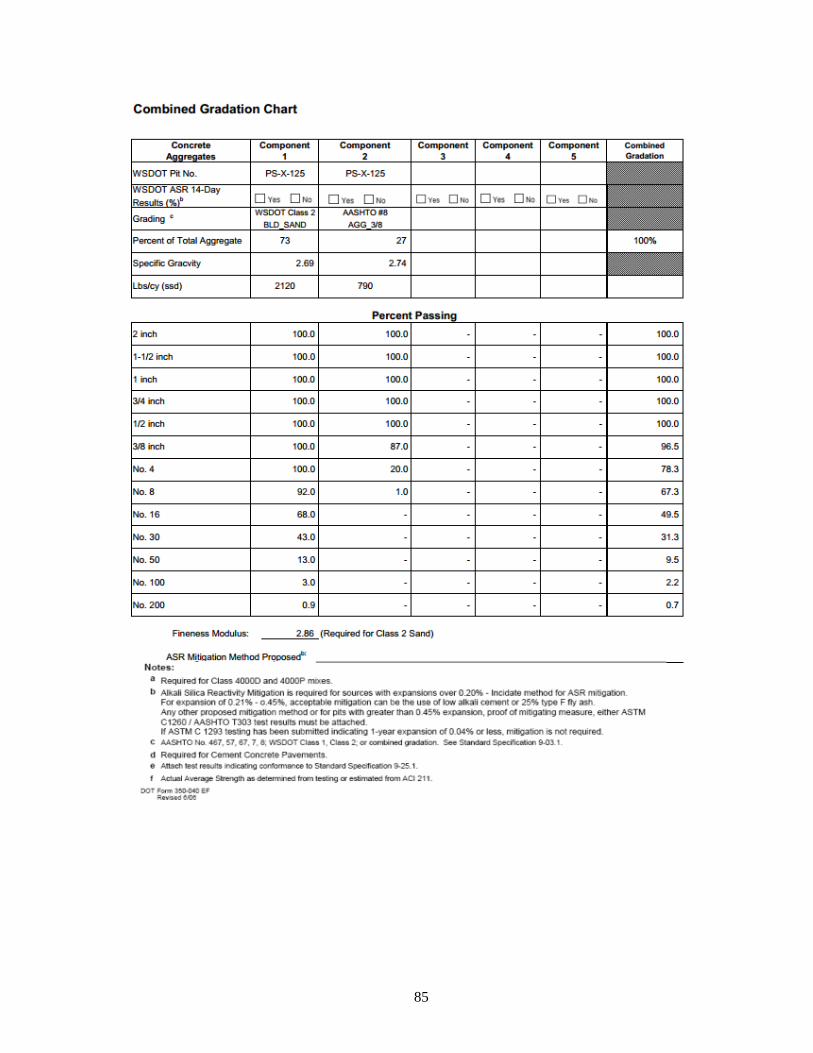
85
Americans with Disabilities Act (ADA) Information: This material can be made available in an alternate format by emailing the Office of Equal Opportunity at [email protected] or by calling toll free, 855-362-4ADA(4232). Persons who are deaf or hard of hearing may make a request by calling the Washington State Relay at 711.
Title VI Statement to Public: It is the Washington State Department of Transportation’s (WSDOT) policy to assure that no person shall, on the grounds of race, color, national origin or sex, as provided by Title VI of the Civil Rights Act of 1964, be excluded from participation in, be denied the benefits of, or be otherwise discriminated against under any of its federally funded programs and activities. Any person who believes his/her Title VI protection has been violated, may file a complaint with WSDOT’s Office of Equal Opportunity (OEO). For additional information regarding Title VI complaint procedures and/or information regarding our non-discrimination obligations, please contact OEO’s Title VI Coordinator at (360) 705-7082.