Embed Size (px)
Citation preview
Whit
e Pap
erBest Practices for Belt ConveyorsBelt Tracking Methodology
White Paper
Conveyor Belt Tracking |Best Practices and Methodology | www.mknorthamerica.com | 2
Conveyor Belt Tracking:Best Practices & Methodology
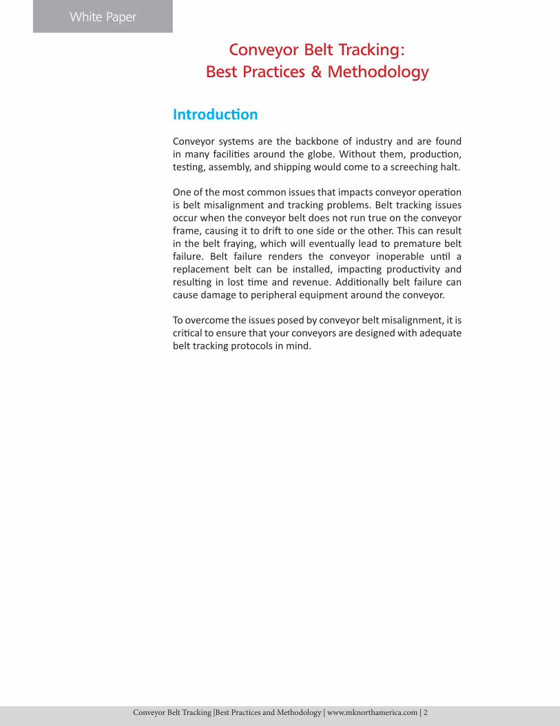
IntroductionConveyor systems are the backbone of industry and are found in many facilities around the globe. Without them, production, testing, assembly, and shipping would come to a screeching halt.
One of the most common issues that impacts conveyor operation is belt misalignment and tracking problems. Belt tracking issues occur when the conveyor belt does not run true on the conveyor frame, causing it to drift to one side or the other. This can result in the belt fraying, which will eventually lead to premature belt failure. Belt failure renders the conveyor inoperable until a replacement belt can be installed, impacting productivity and resulting in lost time and revenue. Additionally belt failure can cause damage to peripheral equipment around the conveyor.
To overcome the issues posed by conveyor belt misalignment, it is critical to ensure that your conveyors are designed with adequate belt tracking protocols in mind.
White Paper
Conveyor Belt Tracking |Best Practices and Methodology | www.mknorthamerica.com | 3
Types of Conveyor Drives
Many kinds of conveyors use belts as the conveyor surface. Conveyor belts fall into two very distinct categories:
1) Positive Drive Conveyor Belts
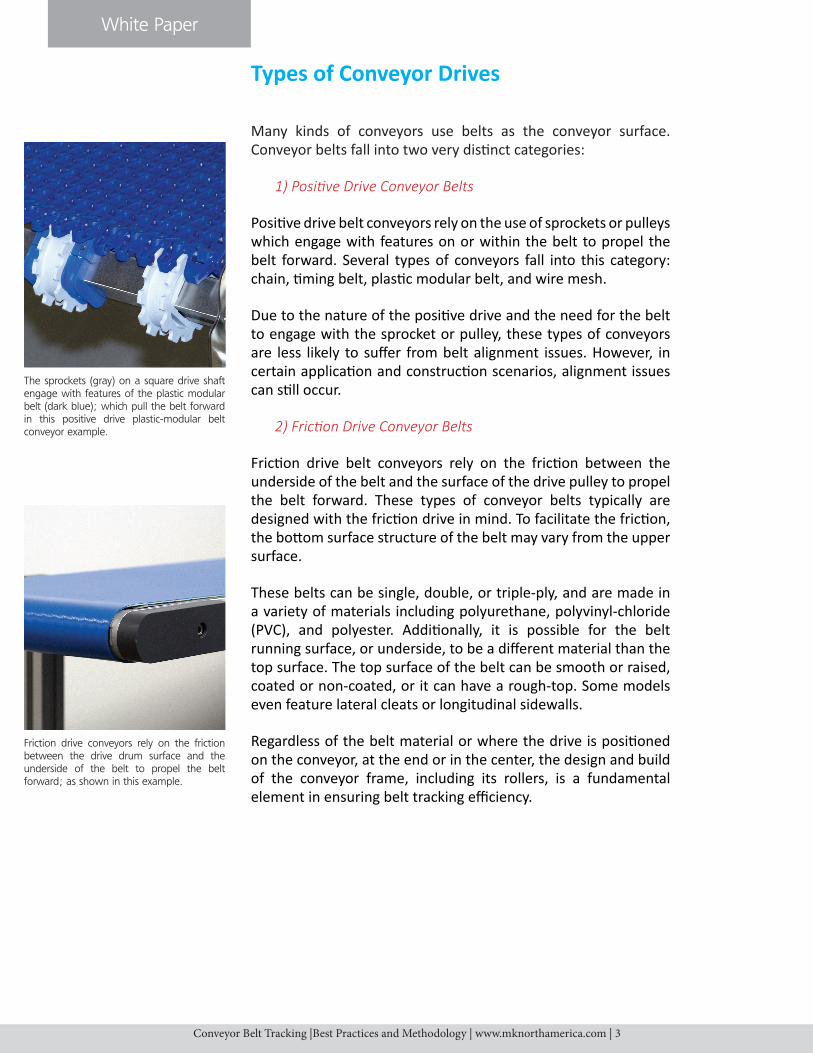
Positive drive belt conveyors rely on the use of sprockets or pulleys which engage with features on or within the belt to propel the belt forward. Several types of conveyors fall into this category: chain, timing belt, plastic modular belt, and wire mesh.
Due to the nature of the positive drive and the need for the belt to engage with the sprocket or pulley, these types of conveyors are less likely to suffer from belt alignment issues. However, in certain application and construction scenarios, alignment issues can still occur.
2) Friction Drive Conveyor Belts
Friction drive belt conveyors rely on the friction between the underside of the belt and the surface of the drive pulley to propel the belt forward. These types of conveyor belts typically are designed with the friction drive in mind. To facilitate the friction, the bottom surface structure of the belt may vary from the upper surface.
These belts can be single, double, or triple-ply, and are made in a variety of materials including polyurethane, polyvinyl-chloride (PVC), and polyester. Additionally, it is possible for the belt running surface, or underside, to be a different material than the top surface. The top surface of the belt can be smooth or raised, coated or non-coated, or it can have a rough-top. Some models even feature lateral cleats or longitudinal sidewalls.
Regardless of the belt material or where the drive is positioned on the conveyor, at the end or in the center, the design and build of the conveyor frame, including its rollers, is a fundamental element in ensuring belt tracking efficiency.
Friction drive conveyors rely on the friction between the drive drum surface and the underside of the belt to propel the belt forward; as shown in this example.
The sprockets (gray) on a square drive shaft engage with features of the plastic modular belt (dark blue); which pull the belt forward in this positive drive plastic-modular belt conveyor example.
White Paper
Conveyor Belt Tracking |Best Practices and Methodology | www.mknorthamerica.com | 4
Support Roller (Optional)
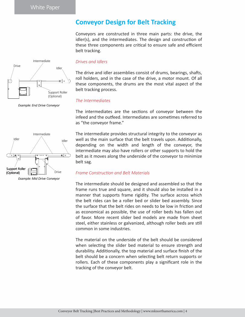
Conveyor Design for Belt TrackingConveyors are constructed in three main parts: the drive, the idler(s), and the intermediates. The design and constructi on of these three components are criti cal to ensure safe and effi cient belt tracking.
Drives and Idlers
The drive and idler assemblies consist of drums, bearings, shaft s, roll holders, and in the case of the drive, a motor mount. Of all these components, the drums are the most vital aspect of the belt tracking process.
The Intermediates
The intermediates are the secti ons of conveyor between the infeed and the outf eed. Intermediates are someti mes referred to as “the conveyor frame.”
The intermediate provides structural integrity to the conveyor as well as the main surface that the belt travels upon. Additi onally, depending on the width and length of the conveyor, the intermediate may also have rollers or other supports to hold the belt as it moves along the underside of the conveyor to minimize belt sag.
Frame Constructi on and Belt Materials
The intermediate should be designed and assembled so that the frame runs true and square, and it should also be installed in a manner that supports frame rigidity. The surface across which the belt rides can be a roller bed or slider bed assembly. Since the surface that the belt rides on needs to be low in fricti on and as economical as possible, the use of roller beds has fallen out of favor. More recent slider bed models are made from sheet steel, either stainless or galvanized, although roller beds are sti ll common in some industries.
The material on the underside of the belt should be considered when selecti ng the slider bed material to ensure strength and durability. Additi onally, the top material and surface fi nish of the belt should be a concern when selecti ng belt return supports or rollers. Each of these components play a signifi cant role in the tracking of the conveyor belt.
DriveIdler
Intermediate
Support Roller (Optional)
Example: End Drive Conveyor
Support Roller (Optional)
Idler Idler
Intermediate
Example: Mid Drive Conveyor
Drive
White Paper
Conveyor Belt Tracking |Best Practices and Methodology | www.mknorthamerica.com | 5
Belt Manufacturers Agree:Trapezoidal Crown Pulleys are the Way to Go
In a review of the technical resources put forth by the major US belti ng manufacturers, the overwhelming consensus as to the proper way to track a conveyor belt is by using trapezoidal crowned pulleys.
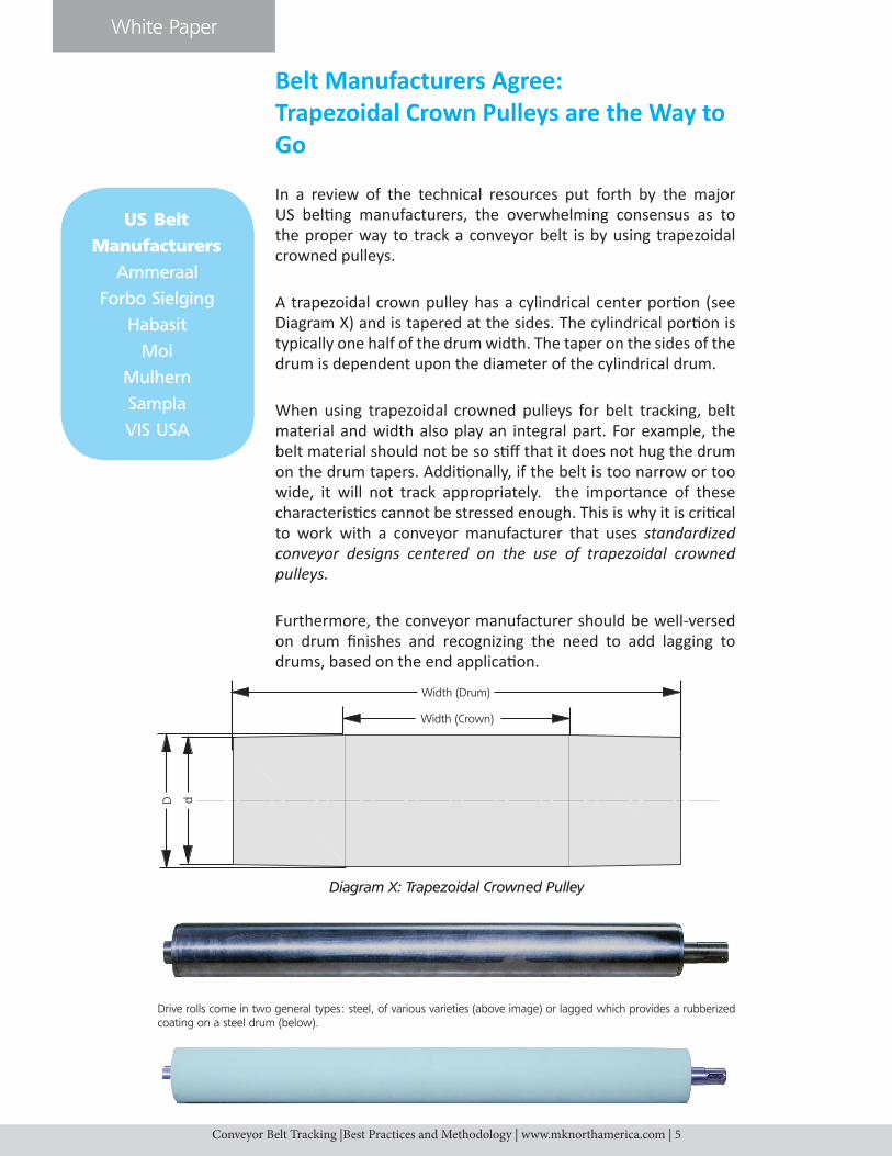
A trapezoidal crown pulley has a cylindrical center porti on (see Diagram X) and is tapered at the sides. The cylindrical porti on is typically one half of the drum width. The taper on the sides of the drum is dependent upon the diameter of the cylindrical drum.
When using trapezoidal crowned pulleys for belt tracking, belt material and width also play an integral part. For example, the belt material should not be so sti ff that it does not hug the drum on the drum tapers. Additi onally, if the belt is too narrow or too wide, it will not track appropriately. the importance of these characteristi cs cannot be stressed enough. This is why it is criti cal to work with a conveyor manufacturer that uses standardized conveyor designs centered on the use of trapezoidal crowned pulleys.
Furthermore, the conveyor manufacturer should be well-versed on drum fi nishes and recognizing the need to add lagging to drums, based on the end applicati on.
Width (Drum)
Width (Crown)
D d
Diagram X: Trapezoidal Crowned Pulley
US Belt
Manufacturers
Ammeraal
Forbo Sielging
Habasit
Mol
Mulhern
Sampla
VIS USA
Drive rolls come in two general types: steel, of various varieties (above image) or lagged which provides a rubberized coating on a steel drum (below).
White Paper
Conveyor Belt Tracking |Best Practices and Methodology | www.mknorthamerica.com | 6
Excepti on Cases: Non-Standard Belt Conveyor Applicati ons
To this point it’s been established that the preferred and most reliable way to track a belt conveyor is by using crowned pulleys. But what about tracking in applicati ons that are viewed as non-standard or nontraditi onal? These applicati ons include conveyors that may be wider than they are long, have lateral forces applied to the belt or product, or a combinati on of these conditi ons.
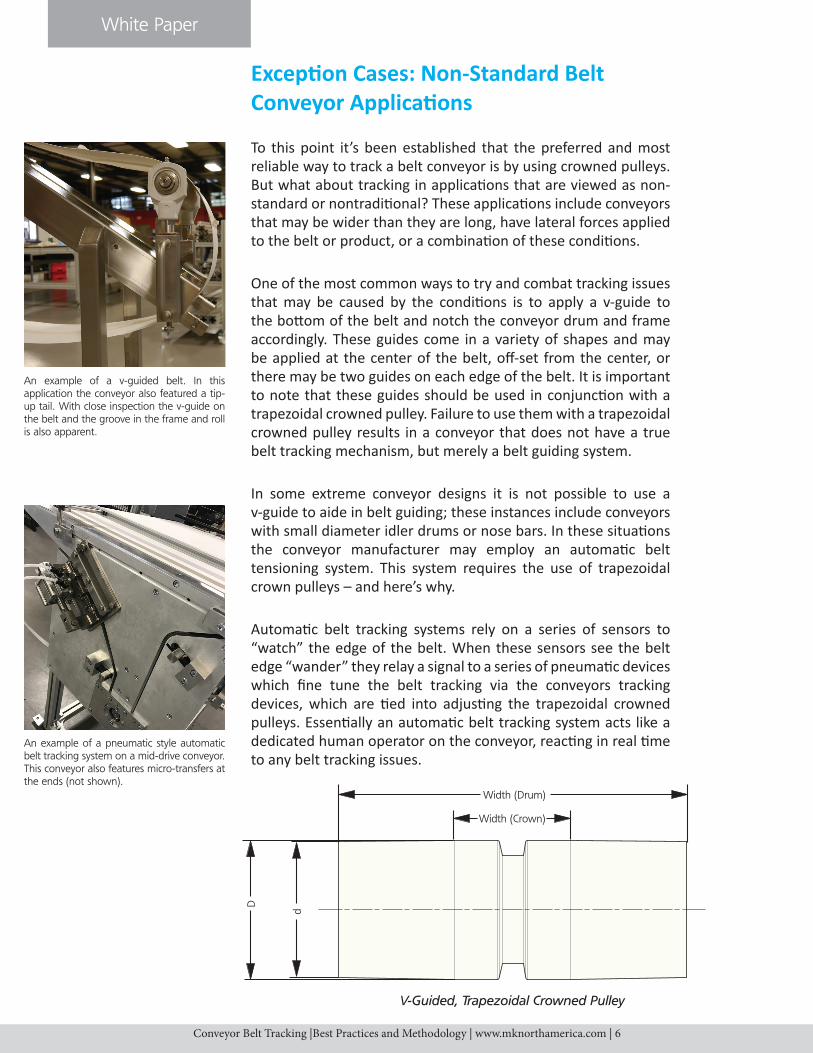
One of the most common ways to try and combat tracking issues that may be caused by the conditi ons is to apply a v-guide to the bott om of the belt and notch the conveyor drum and frame accordingly. These guides come in a variety of shapes and may be applied at the center of the belt, off -set from the center, or there may be two guides on each edge of the belt. It is important to note that these guides should be used in conjuncti on with a trapezoidal crowned pulley. Failure to use them with a trapezoidal crowned pulley results in a conveyor that does not have a true belt tracking mechanism, but merely a belt guiding system.
In some extreme conveyor designs it is not possible to use a v-guide to aide in belt guiding; these instances include conveyors with small diameter idler drums or nose bars. In these situati ons the conveyor manufacturer may employ an automati c belt tensioning system. This system requires the use of trapezoidal crown pulleys – and here’s why.
Automati c belt tracking systems rely on a series of sensors to “watch” the edge of the belt. When these sensors see the belt edge “wander” they relay a signal to a series of pneumati c devices which fi ne tune the belt tracking via the conveyors tracking devices, which are ti ed into adjusti ng the trapezoidal crowned pulleys. Essenti ally an automati c belt tracking system acts like a dedicated human operator on the conveyor, reacti ng in real ti me to any belt tracking issues.
Width (Drum)
Width (Crown)
D
d
V-Guided, Trapezoidal Crowned Pulley
An example of a pneumatic style automatic belt tracking system on a mid-drive conveyor. This conveyor also features micro-transfers at the ends (not shown).
An example of a v-guided belt. In this application the conveyor also featured a tip-up tail. With close inspection the v-guide on the belt and the groove in the frame and roll is also apparent.
White Paper
Conveyor Belt Tracking |Best Practices and Methodology | www.mknorthamerica.com | 7
Why Non-Standard Shouldn’t Be Standard
One may try and make the argument that if there are cases, albeit exceptional, when v-guide or automatic tracking devices are needed, then why not use them all the time? Simply put, they shouldn’t be used because they are not needed. Both of these additional means of tracking the belt require the use of trapezoidal crowned pulleys. Some may argue that in fact it’s the crowned pulley that is not needed. Those making this claim are not following design standards set forth by the belting manufacturers. Additionally these devices add cost, lead-time and potential points of failure to the conveyor system.
V-guided belts are more costly than conventional belts due to the added material and labor. Adding the v-guide is also a step which adds time to the manufacture of the belt. Aside from taking longer to obtain the initial conveyor with a v-guide, it will also take longer for a replacement belt to be obtained. This can result in costly downtime should a belt need to be replaced and a spare one is not on-hand.
Consider also the situation in which there is a belt failure involving a v-guided belt. In these instances, there is a real possibility of the v-guide separating from the belt. This loose piece of guide can cause damage to the conveyor and/or surrounding equipment; taking what might have been a simple belt replacement scenario to something far more intensive, costly and time consuming.
In applications where an automatic belt tracker is used, one of biggest areas of concern is the pneumatics. Industrial air supplies are notorious for their inefficiencies; which can negatively impact the performance of the automatic belt tracker. And should there ever be a failure in the air supply, the pneumatics would be inoperable – unable to assist as intended. In this case, if the conveyor was not designed with crowned pulleys, it would only be a matter of time before a catastrophe occurred. This also assumes that there is an airline readily available at the conveyors installation point. Bringing in “air” where there is none is cost prohibitive to many.
In order to keep the potential point of failure to an absolute minimum, and unnecessary costs down, the use of these devices should be saved for only those applications that absolutely demand them. In truth, these items are not “fail safe” methods of belt tracking and therefore should not be viewed that way.
Reasons to Not
Standardize
Non-Standards
• Cost
• Lead-time
• Increased risk to
equipment and
employees
White Paper
Conveyor Belt Tracking |Best Practices and Methodology | www.mknorthamerica.com | 8
In Conclusion
Conveyor system misalignment and malfunction can damage operations in a wide range of industries. But these issues are preventable. Working with a conveyor system manufacturer that adheres to the design and engineering standards set-forth by the belting manufacturer is one way to help mitigate problems. it is just as important to work with a conveyor manufacturer well versed in conveyor pulley and belt design, as this is the best way to ensure the conveyor will operate as intended. Following the manufacturer’s recommended maintenance schedule will also help keep the conveyor and its belt in good working order.
Conveyors built using designs outside the industry best practices for belt tracking can lead to a false sense of security; and unfortunately customers may be misled customers with regard to efficiency, durability, reliability and overall sense of security their system would provide. This can result in production delays, creating a domino effect of negative productivity and cost inefficiency.
This white paper seeks to outline current industry best practices, explaining why certain approaches are better, and dispel the myths around alternate belt tracking methods.
mk North America, Inc.Solutions Provider
At mk we design, engineer and manufacture aluminum conveyors, workpiece pallet-handling conveyor systems, stainless steel conveyors, and extruded aluminum framing (including guarding and linear motion systems). The variety and flexibility of our offering is unsurpassed, and our products have proven themselves worldwide in a broad variety of applications and industries.
better products. better solutions.mk North America strives to fulfill the company mission by offering not only a better product, but also a better solution. This means working with the customer in order to ensure that the solution provided meets and exceeds all expectations.
Whether that solution is a standard from the catalog or custom like the Engineered Solutions line of products, mk North America is sure to have a solution that keeps your business moving forward.
www.mknorthamerica.com