Embed Size (px)
Citation preview

Best Practices and
Performance Characteristics
of Running Oracle® RAC 11g
with Dell EqualLogic™ on
Oracle VM
Database Solutions Engineering By Roger Lopez Dell Product Group
October 2009

2
THIS WHITE PAPER IS FOR INFORMATIONAL PURPOSES ONLY, AND MAY CONTAIN
TYPOGRAPHICAL ERRORS AND TECHNICAL INACCURACIES. THE CONTENT IS PROVIDED AS IS,
WITHOUT EXPRESS OR IMPLIED WARRANTIES OF ANY KIND.
Dell, the Dell logo, OpenManage, and PowerEdge are trademarks of Dell Inc; Linux is the registered trademark of
Linus Torvalds in the United States and other countries. Oracle is a registered trademark of Oracle Corporation
and/or its affiliates. Other trademarks and trade names may be used in this document to refer to either the entities
claiming the marks and names or their products. Dell disclaims proprietary interest in the marks and names of
others.
©Copyright 2008 Dell Inc. All rights reserved. Reproduction in any manner whatsoever without the express written
permission of Dell Inc. is strictly forbidden. For more information, contact Dell.
THE INFORMATION IN THIS DOCUMENT IS SUBJECT TO CHANGE WITHOUT NOTICE AND IS
PROVIDED “AS IS” WITHOUT WARRANTY OF ANY KIND. THE ENTIRE RISK ARISING OUT OF THIS
INFORMATION REMAINS WITH THE USER OF THE INFORMATION. IN NO EVENT SHALL DELL BE
LIABLE FOR ANY DIRECT, CONSEQUENTIAL, INCIDENTAL, SPECIAL, PUNITIVE OR OTHER
DAMAGES, EVEN IF DELL HAS BEEN ADVISED OF THE POSSIBILITY OF SUCH DAMAGES.

3
Contents Introduction .................................................................................................................................................. 5
Audience and Scope ...................................................................................................................................... 5
Oracle VM Overview ..................................................................................................................................... 5
What is Oracle VM? .................................................................................................................................. 5
Fully Virtualized Systems and Paravirtualized Virtual Machine Operating Systems ............................... 5
Benefits of using Oracle VM ...................................................................................................................... 6
Dell EqualLogic Overview .............................................................................................................................. 6
Why choose EqualLogic? ........................................................................................................................... 6
Architectural Overview ................................................................................................................................. 6
Best Practices ................................................................................................................................................ 8
Importance of staying up to date using ULN network .............................................................................. 8
Overview of OVM network infrastructure ................................................................................................ 8
How to Bond multiple NICs in Oracle VM ............................................................................................. 8
Setting up your Dell EqualLogic iSCSI environment ................................................................................ 10
Creating Volumes ................................................................................................................................ 11
Configuring the iSCSI Network ............................................................................................................ 12
Setting up CHAP authentication ......................................................................................................... 12
Configuring Host Access to Volumes .................................................................................................. 14
Setting up Device Mapper Multipath ..................................................................................................... 15
Setting up your OCFS2 Cluster Configuration file ................................................................................... 17
Setting up your Oracle VM Server (OVS) repository ........................................................................... 18
Oracle VM Manager ................................................................................................................................ 20
Creating Server Pools & Virtual Machines .......................................................................................... 20
How to Modify a Virtual Machine’s Resources ................................................................................... 21
Oracle VM Server .................................................................................................................................... 22
How to modify the vm.cfg file to add Shared Physical Volumes to your Virtual Machine ................. 22
Performance ............................................................................................................................................... 24
CPU Utilization with 48 GB of RAM per Node ......................................................................................... 26
Memory Utilization with 48 GB of RAM per Node ............................................................................. 30
Dell EqualLogic Storage Performance ................................................................................................. 33
Overall Physical & Virtual Performance .............................................................................................. 35

4
Conclusion ................................................................................................................................................... 37
Solution Deliverables List for Oracle 11g on Dell EqualLogic PS4000XV iSCSI Storage .............................. 37
Acknowledgements ..................................................................................................................................... 38
References .................................................................................................................................................. 39

5
Introduction The adaptation of virtualization technology has risen tremendously and continues to grow due to the
rapid change and growth rate of IT infrastructures. Oracle® VM enables customers to deploy
applications with the ability to share server and storage resources to maximize utilization within the
grid. Combining Oracle VM with Dell EqualLogic™ PS Series Storage array provides ease of use and the
ability to evenly distribute workloads across each array within a server pool to achieve greater
performance and flexibility. This paper will provide a Dell solution that shows best practices around
Oracle VM with Dell EqualLogic iSCSI Storage array and present performance numbers to better quantify
the delta between running within a virtualized environment and a non-virtualized environment.
Audience and Scope This whitepaper is intended for technical users and researchers wanting to:
Learn best practices around Oracle VM
Learn best practices around Dell EqualLogic iSCSI storage
Analyze performance data between non-virtual and virtualized environments
Oracle VM Overview
What is Oracle VM? Oracle VM is server virtualization software composed of two components, Oracle® VM Server and
Oracle® VM Manager. Oracle VM server is a virtual infrastructure based on the open source Xen
technology used in creating virtualized environments. Oracle VM Manager, a web-based management
console, is used to simplify the usage of Oracle VM’s many features such as creating VMs, cloning, and
migration. Together, the components allow users to install applications in a virtualized environment
with an intuitive point and click strategy. The virtualized environment supports both Linux™ (x86 and
x86_64) and Windows® (x86 and x86_64) operating systems and has fully virtualized or paravirtualized
guest VMs.
Fully Virtualized Systems and Paravirtualized Virtual Machine Operating
Systems Oracle supports two types of virtual machines ‘Fully Virtualized’ and ‘Paravirtualized.’ Fully virtualized
VMs are unmodified guest operating systems that have no knowledge of the underlying hardware. As a
result, fully virtualized environments allow for ease in areas such as portability and migration but can
suffer a performance penalty. In contrast, paravirtualized guest operating systems have modifications to
the guest OS that make them aware that they are running on a virtual machine which in turn provides
near-native performance.

6
The best practice for this paper will be using paravirtualized guest OS virtual machines. The reason
behind this is to use near-native hardware performance in order to quantify the difference between
running Oracle Real Application Cluster within a virtual and non-virtual environment.
Benefits of using Oracle VM Oracle VM is a free product packed with features that include:
Use of Virtual Machine Templates
High Availability for each Virtual Machine
Live Migration
Use of Shared Virtual disk
Use of shared physical disk
Cloning
A key benefit of Oracle VM is that it is a free product backed by Oracle thus providing a single point of
support of your entire virtualized environment. This includes support for your Oracle databases, Linux
operating system, and other Oracle applications running in those environments.
Dell EqualLogic Overview
Why choose EqualLogic? The Dell EqualLogic™ PS Series storage arrays provide IT administrators with numerous benefits: • A feature-rich iSCSI based enterprise storage solution for a wide variety of applications • High performance • Low-cost ownership EqualLogic delivers the benefits of consolidated networked storage in a self-managing, iSCSI Storage Area Network (SAN) that is easy to use and affordable. EqualLogic is built on a peer storage architecture where all of the arrays are in a storage pool that is designed to work together to provide disk capacity and evenly distribute the load. The PS Series SAN offers high performance, reliability, scalability, intelligent automation, simplified deployment, and extensive data protection. The Dell EqualLogic PS Series iSCSI storage arrays are an ideal choice to deploy highly reliable and easy-to-manage VM environments.
Architectural Overview These reference configurations will both be supporting up to a four node Oracle Real Application Cluster
11g (11.1.0.7). One configuration will be with Oracle VM, while the other configuration is without Oracle
VM to compare performance results. The configurations will have the following components:
7
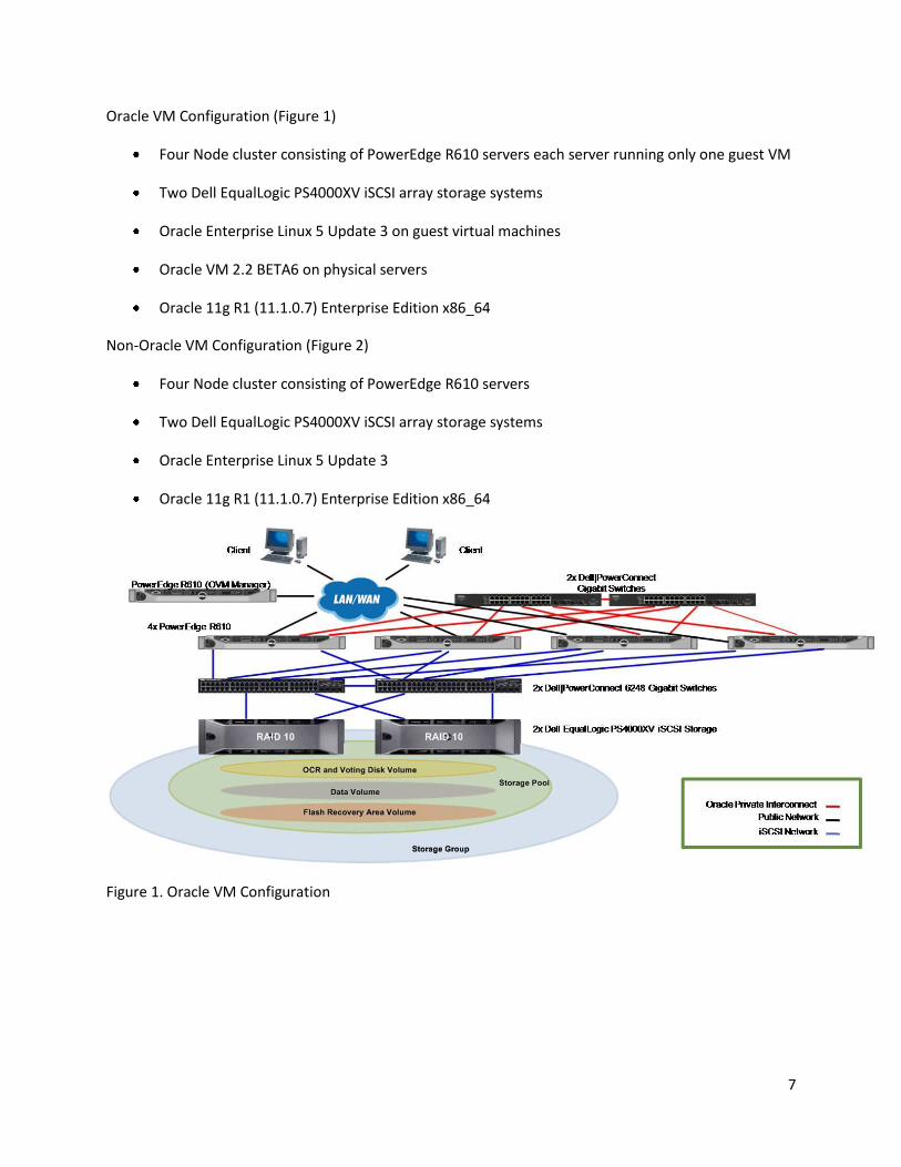
Oracle VM Configuration (Figure 1)
Four Node cluster consisting of PowerEdge R610 servers each server running only one guest VM
Two Dell EqualLogic PS4000XV iSCSI array storage systems
Oracle Enterprise Linux 5 Update 3 on guest virtual machines
Oracle VM 2.2 BETA6 on physical servers
Oracle 11g R1 (11.1.0.7) Enterprise Edition x86_64
Non-Oracle VM Configuration (Figure 2)
Four Node cluster consisting of PowerEdge R610 servers
Two Dell EqualLogic PS4000XV iSCSI array storage systems
Oracle Enterprise Linux 5 Update 3
Oracle 11g R1 (11.1.0.7) Enterprise Edition x86_64
Figure 1. Oracle VM Configuration

8
Figure 2. Non-Oracle VM Configuration
Best Practices
Importance of staying up to date using ULN network The Unbreakable Linux Network (ULN) provides subscribers easy access to all of Oracle VM’s updates,
patches, and fixes. It is very important to make sure that you have your system updated with the latest
patches and fixes before configuring your Oracle VM system to ensure best performance and most
enhanced features are used within your environment.
Overview of OVM network infrastructure Oracle VM Server (OVM) 2.2 is based on Xen’s network infrastructure that attaches each physical NIC
within the OVM Server to a bridge. A bridge is equivalent to a virtual switch consisting of a physical
interface. In the example below, you will notice that OVM Dom 0 shows the physical NIC adapter as eth#
and the bridge has xenbr#
[root@rl-r710-n1 ~]# brctl show
bridge name bridge id STP enabled interfaces
xenbr0 8000.0022193313d2 no eth0
How to Bond multiple NICs in Oracle VM
Oracle VM’s architecture provides the same native bonding module that is found in all Enterprise Linux
5.x distributions. Although bonding has several different modes which include modes such as the round
robin policy and load balancing policy, the active-backup policy (mode 1) is the preferred mode for
Oracle RAC interconnects. The active-backup policy has only one active slave and the remaining are

9
passive slaves. One of the other slaves will become active, if and only if, there is a failure with the
current active slave within the bond.
In order to setup bonding within the OVM environment, the first step is to stop any guest VMs that are
currently running. Once you have stopped all guest VMs, you must stop all network bridges within your
OVM environment using the following command
/etc/xen/scripts/./network-bridges stop
The network-bridges script controls the creation of your network bridges for each physical NIC. The
default behavior of OVM is to create a xen bridge for each physical NIC.
In the following example, we will start configuring our bond0 device and enslave two NIC adapters (eth1
and eth2) to our bond device.
1) Create a bond0 device file under /etc/sysconfig/network-scripts/ named ifcfg-bond0
The ifcfg bond0 file will look like the following:
DEVICE=bond0
BOOTPROTO=none
ONBOOT=yes
BRIDGE=xenbrb0
In this example it is important to note that a bridge is being created labeled ‘xenbrb0.’The xenbrb0
bridge will be the bonded bridge which will be exposed to your guest VMs (Dom Us).
2) Create a ifcfg-xenbrb0 file under /etc/sysconfig/network-scripts/
An example of the ifcfg xenbrb0 file will look like the following:
DEVICE=xenbrb0
BOOTPROTO=static
ONBOOT=yes
IPADDR=192.168.11.140
NETMASK=255.255.255.0
3) Enslave devices eth1 and eth2 to the bond0 device. The configuration of your eth1 and eth2 should
look like the following:
Edit the file /etc/sysconfig/network-scripts/ifcfg-eth1
DEVICE=eth1
BOOTPROTO=none
ONBOOT=no
MASTER=bond0
SLAVE=yes
Edit the file /etc/sysconfig/network-scripts/ifcfg-eth2

10
DEVICE=eth2
BOOTPROTO=none
ONBOOT=no
MASTER=bond0
SLAVE=yes
4) Edit your /etc/modprobe.conf file and add the following lines
alias bond0 bonding
options bond0 miimon=100 mode=1
In the next step we will be creating a network-dummy script which will be used to override the existing
network-bridges script that is called within your /etc/xend/xend-config.sxp. The Oracle best
practice is for all of your xen bridges to be created within your ifcfg network scripts using the ‘BRIDGE=’
command and not by the network-bridges script.
Example:
If you want eth0 to be available to your Dom Us, modify /etc/sysconfig/network-
scripts/ifcfg-eth0 and add the line “BRIDGE=xenbr0”. This will create a bridge labeled xenbr0
that is attached to your eth0 device.
5) Create a file called network-dummy under /etc/xen/scripts/ and edit with the following:
#!/bin/bash
/bin/true
6) Modify the script labeled ‘xend-config.sxp’ under /etc/xen/ and search for the line labeled:
(network-script network-bridges)
Replace this line with:
(network-script network-dummy)
7) Reboot the server for all changes to take effect.
8) Run the command ‘brctl show’ to make sure that your bridges have been created properly as in the
example below.
[root@rl-r710-n1 ~]# brctl show
bridge name bridge id STP enabled interfaces
xenbr0 8000.0022193313d2 no eth0
xenbrb0 8000.0022193313d4 no bond0
Setting up your Dell EqualLogic iSCSI environment The following terminology is used to describe the different aspects of a Dell EqualLogic array.
Member – is an EqualLogic array
Group – consists of one or more members
Pool – consists of the RAID configuration of disks belonging to one or several members
Volume – a virtual disk or LUN

11
Our EqualLogic environment consists of four host systems attached to two Dell EqualLogic PS4000XV
iSCSI arrays configured with RAID-10 on each member. Our best practice recommendation setup will
consist of each member connecting to two Dell PowerConnect™ 5400 series switches to ensure
maximum bandwidth and high availability. Each EqualLogic member consists of two controllers, one
active and one passive. The active controller should consist of one connection to switch A and the other
connection connected to switch B. The passive controller should consist of one connection to switch B
and the other connection connected to switch A. The two PowerConnect 5400 series switches should be
trunked together to minimize network congestion and ensure high speed network communication
between the two switches. Figure 3 below illustrates cabling configuration for one EqualLogic member
as described above. For information on how to initialize and configure your Dell EqualLogic iSCSI array
please refer to the EqualLogic PS4000XV Group Administration and CLI Reference Guide found at
http://www.equallogic.com
Figure 3. iSCSI Network configuration
Creating Volumes
Once the array has been successfully initialized, volumes can be created. Volume access is managed with an access control list (ACL). The volume’s ACL needs to be set up with the host system’s information in order to connect and initiate I/O traffic. This is accomplished by adding a CHAP user, an IP address, or an iSCSI Qualified Name (IQN) for all the initiators that require access to the desired volume. If multiple initiators are used in a cluster environment, please mark the checkbox that enables shared access to the iSCSI target from multiple initiators. Modification of the initiator’s details will need to be added to the access control list of the volume to ensure connectivity to the host. Once the volumes are created and configured, the host system can perform storage discovery. The steps on creating a volume once logged into the GUI group manager are:
1. Select ‘Volumes’ from the left navigation bar, right click and select ‘Create Volume’ 2. In the Volume Settings window, please enter your Volume name and an optional brief
description. 3. In the Space reserve window, please enter the appropriate Volume size. 4. In the iSCSI access window, please select the appropriate access. For example, CHAP, IP address,
or iSCSI initiator name. Make sure to enable shared access to the iSCSI target from multiple initiators when using a clustered environment.
5. In the Summary window, review your settings and click Finish.
12
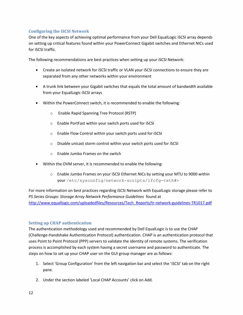
Configuring the iSCSI Network
One of the key aspects of achieving optimal performance from your Dell EqualLogic iSCSI array depends
on setting up critical features found within your PowerConnect Gigabit switches and Ethernet NICs used
for iSCSI traffic.
The following recommendations are best practices when setting up your iSCSI Network:
Create an isolated network for iSCSI traffic or VLAN your iSCSI connections to ensure they are
separated from any other networks within your environment
A trunk link between your Gigabit switches that equals the total amount of bandwidth available
from your EqualLogic iSCSI arrays
Within the PowerConnect switch, it is recommended to enable the following:
o Enable Rapid Spanning Tree Protocol (RSTP)
o Enable PortFast within your switch ports used for iSCSI
o Enable Flow Control within your switch ports used for iSCSI
o Disable unicast storm control within your switch ports used for iSCSI
o Enable Jumbo Frames on the switch
Within the OVM server, it is recommended to enable the following:
o Enable Jumbo Frames on your iSCSI Ethernet NICs by setting your MTU to 9000 within
your /etc/sysconfig/network-scripts/ifcfg-<eth#>
For more information on best practices regarding iSCSI Network with EqualLogic storage please refer to
PS Series Groups: Storage Array Network Performance Guidelines found at
http://www.equallogic.com/uploadedfiles/Resources/Tech_Reports/tr-network-guidelines-TR1017.pdf
Setting up CHAP authentication
The authentication methodology used and recommended by Dell EqualLogic is to use the CHAP
(Challenge-Handshake Authentication Protocol) authentication. CHAP is an authentication protocol that
uses Point to Point Protocol (PPP) servers to validate the identity of remote systems. The verification
process is accomplished by each system having a secret username and password to authenticate. The
steps on how to set up your CHAP user on the GUI group manager are as follows:
1. Select ‘Group Configuration’ from the left navigation bar and select the ‘iSCSI’ tab on the right
pane.
2. Under the section labeled ‘Local CHAP Accounts’ click on Add.

13
3. On the popup dialog box, please enter the username and password credentials for your CHAP
account and click OK.
4. (Optional) Under the section labeled ‘iSCSI Authentication’ click on modify under ‘Target
authentication’ and enter the username and password credentials for your target and click OK.
5. Before configuring CHAP access on the OVM Server, please ensure that your iscsi-initiator
version is 2.0-868 or higher. To verify your version use the command:
iscsiadm -–version
6. Once you have verified your version of the iSCSI initiator, you must modify the CHAP Settings
section under /etc/iscsi/iscsid.conf. Under the CHAP Settings section, please modify
the sections which reference the keyword “username” and “password” to the same credentials
used when setting up your CHAP users within the EqualLogic GUI Group Manager. An example
of the CHAP Settings section can be seen below. Sections in bold are required for
authentication. If you skipped step 4 please leave any references to “username_in” and
“password_in” commented out, otherwise please enter the credentials used from your
EqualLogic GUI Group Manager.
# *************
# CHAP Settings
# *************
# To enable CHAP authentication set node.session.auth.authmethod
# to CHAP. The default is None.
node.session.auth.authmethod = CHAP
# To set a CHAP username and password for initiator
# authentication by the target(s), uncomment the following lines:
node.session.auth.username = username
node.session.auth.password = password
# To set a CHAP username and password for target(s)
# authentication by the initiator, uncomment the following lines:
#node.session.auth.username_in = username_in
#node.session.auth.password_in = password_in
# To enable CHAP authentication for a discovery session to the target
# set discovery.sendtargets.auth.authmethod to CHAP. The default is
None.
discovery.sendtargets.auth.authmethod = CHAP
# To set a discovery session CHAP username and password for the
initiator
# authentication by the target(s), uncomment the following lines:
discovery.sendtargets.auth.username = username
discovery.sendtargets.auth.password = password
14
# To set a discovery session CHAP username and password for target(s)
# authentication by the initiator, uncomment the following lines:
#discovery.sendtargets.auth.username_in = username_in
#discovery.sendtargets.auth.password_in = password_in
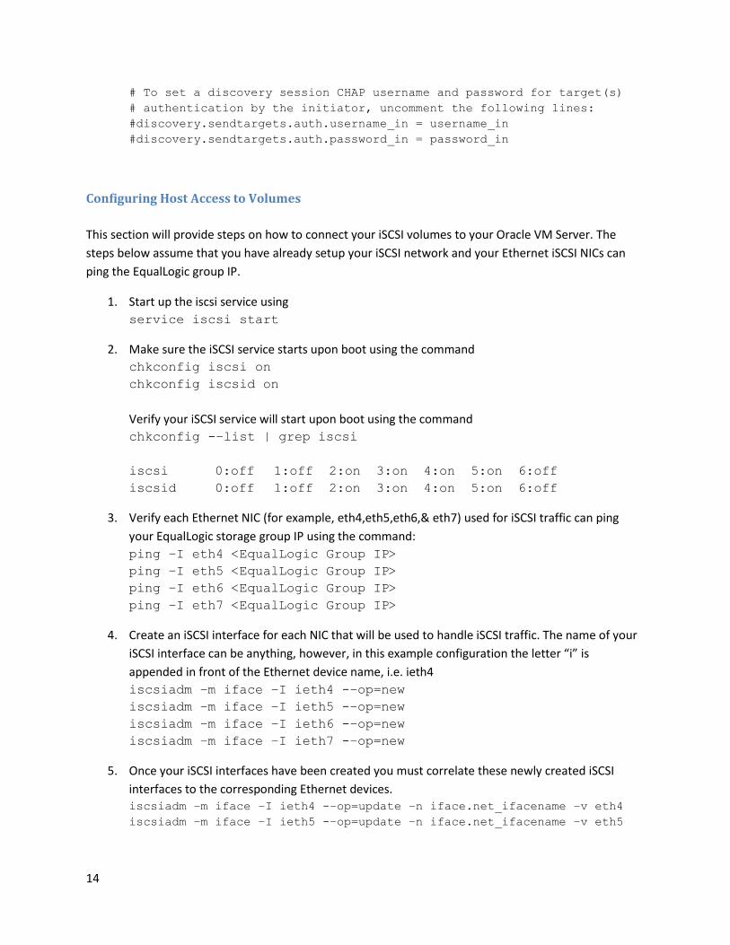
Configuring Host Access to Volumes
This section will provide steps on how to connect your iSCSI volumes to your Oracle VM Server. The
steps below assume that you have already setup your iSCSI network and your Ethernet iSCSI NICs can
ping the EqualLogic group IP.
1. Start up the iscsi service using
service iscsi start
2. Make sure the iSCSI service starts upon boot using the command
chkconfig iscsi on
chkconfig iscsid on
Verify your iSCSI service will start upon boot using the command
chkconfig -–list | grep iscsi
iscsi 0:off 1:off 2:on 3:on 4:on 5:on 6:off
iscsid 0:off 1:off 2:on 3:on 4:on 5:on 6:off
3. Verify each Ethernet NIC (for example, eth4,eth5,eth6,& eth7) used for iSCSI traffic can ping
your EqualLogic storage group IP using the command:
ping –I eth4 <EqualLogic Group IP>
ping –I eth5 <EqualLogic Group IP>
ping –I eth6 <EqualLogic Group IP>
ping –I eth7 <EqualLogic Group IP>
4. Create an iSCSI interface for each NIC that will be used to handle iSCSI traffic. The name of your
iSCSI interface can be anything, however, in this example configuration the letter “i” is
appended in front of the Ethernet device name, i.e. ieth4
iscsiadm –m iface –I ieth4 -–op=new
iscsiadm –m iface –I ieth5 -–op=new
iscsiadm –m iface –I ieth6 -–op=new
iscsiadm –m iface –I ieth7 -–op=new
5. Once your iSCSI interfaces have been created you must correlate these newly created iSCSI
interfaces to the corresponding Ethernet devices. iscsiadm –m iface –I ieth4 -–op=update –n iface.net_ifacename –v eth4
iscsiadm –m iface –I ieth5 -–op=update –n iface.net_ifacename –v eth5

15
iscsiadm –m iface –I ieth6 -–op=update –n iface.net_ifacename –v eth6
iscsiadm –m iface –I ieth7 -–op=update –n iface.net_ifacename –v eth7
6. Verify your iSCSI interfaces have been created correctly and are corresponding to the correct
Ethernet device.
iscsiadm –m iface
ieth4 tcp,default,eth4
ieth5 tcp,default,eth5
ieth6 tcp,default,eth6
ieth7 tcp,default,eth7
7. Discover your iSCSI targets on the EqualLogic array using the command:
iscsiadm –m discovery –t st –p <EqualLogic Group IP> -I ieth4 –I
ieth5 –I ieth6 –I ieth7
<EqualLogic group IP>:3260,1 iqn.2001-05.com.equallogic:0-8a0906-
de5c93e02-e2f000000344a8c4-volume-name
<EqualLogic group IP>:3260,1 iqn.2001-05.com.equallogic:0-8a0906-
de5c93e02-e2f000000344a8c4-volume-name
<EqualLogic group IP>:3260,1 iqn.2001-05.com.equallogic:0-8a0906-
de5c93e02-e2f000000344a8c4-volume-name
<EqualLogic group IP>:3260,1 iqn.2001-05.com.equallogic:0-8a0906-
de5c93e02-e2f000000344a8c4-volume-name
8. Once the targets have been discovered, please log in your targets using the command:
iscsiadm –m node -–login=all
9. Verify all your sessions have been correctly logged in by typing:
iscsiadm –m session
Setting up Device Mapper Multipath The purpose of Device Mapper Multipath is to enable multiple I/O paths between your OVM Servers and
Dell EqualLogic iSCSI Storage arrays in order to add high availability and improve performance.
Multipathing accomplishes this by combining your iSCSI paths into one device mapper path and properly
load balancing the I/O. This section will provide the best practices on how to setup your iSCSI with
device mapper multipathing within your OVM server. The steps below assume you have already logged
in your iSCSI targets on each of your Oracle VM Servers.
1. Verify that your device-mapper and multipath driver are at least the version shown below or
higher:
rpm -qa | grep device-mapper

16
device-mapper-1.02.28-2.el5
device-mapper-multipath-0.4.7-23.el5.4.0.1
device-mapper-event-1.02.28-2.el5
2. Identify your local disks i.e. /dev/sda. Once your local disk is determined run the following
command to obtain its scsi_id:
scsi_id –gus /block/sda
360024e805314c20011faf391033bdece
3. Once the scsi_id of your local disk has been retrieved, you must blacklist this scsi_id from being
used as a multipath device. Open the /etc/multipath.conf file and locate, uncomment,
and modify the section below:
blacklist {
wwid <enter your local disk scsi_id here>
devnode "^(ram|raw|loop|fd|md|dm-|sr|scd|st)[0-9]*"
devnode "^hd[a-z]"
}
4. Uncomment your defaults section within your /etc/multipath.conf defaults {
udev_dir /dev
polling_interval 10
selector "round-robin 0"
path_grouping_policy multibus
getuid_callout "/sbin/scsi_id -g -u -s
/block/%n"
prio_callout /bin/true
path_checker readsector0
rr_min_io 100
max_fds 8192
rr_weight priorities
failback immediate
no_path_retry fail
user_friendly_names yes
}
5. Locate the multipaths section within your /etc/multipath.conf file. In this section you will provide the scsi_id of each iSCSI volume and provide an alias in order to keep a consistent naming convention across all of your OVM Server nodes. An example is shown below: multipaths {
multipath {
wwid <scsi_id of volume1> alias alias_of_volume1 }
multipath { wwid <scsi_id of volume2> alias alias_of_volume2
}

17
}
Additional multipath subsections can be added to meet the number of volumes you need
exposed to each of your Oracle VM Server.
6. Restart your multipath daemon service using:
service multipathd restart
7. Verify that your multipath volumes alias are displayed properly:
multipath –ll
Alias_of_volume1 (scsi_id of volume1) dm-2 EQLOGIC,100E-00
[size=220G][features=0][hwhandler=0][rw]
\_ round-robin 0 [prio=0][active]
\_ 6:0:0:0 sdaj 66:48 [active][ready]
\_ 4:0:0:0 sdag 66:0 [active][ready]
\_ 3:0:0:0 sdd 8:48 [active][ready]
\_ 5:0:0:0 sdn 8:208 [active][ready]
8. Make sure the iSCSI service starts upon boot using the command
chkconfig multipathd on
9. Repeat steps 1-7 for each OVM Server node.
Setting up your OCFS2 Cluster Configuration file The Oracle® Cluster File System (OCFS2) is the file system used for setting up the Oracle® VM Server
(OVS) repository partition for shared disk access across all your OVM Server nodes. OCFS2 uses a
heartbeat mechanism across all your OVM nodes via the network to maintain data consistency. Due to
the OCFS2 heartbeat using the network traffic to keep data consistency, dedicate a physical Ethernet for
network heartbeat traffic.
An example of this Ethernet device configured is shown below:
DEVICE=eth2
BOOTPROTO=none
ONBOOT=yes
IPADDR=192.168.11.90
NETMASK=255.255.255.0
HWADDR=00:22:19:33:13:D8
Once one of your Ethernet devices on all your nodes has been setup for the OCFS2 heartbeat, you will
run from each node the OCFS2 setup script using the command:
/usr/lib/ovs/ovs-cluster-configure

18
This command will generate your /etc/ocfs2/cluster.conf file, if it doesn’t currently exist, and allow you
to configure your o2cb service. Once your cluster.conf is generated, please modify the settings to suit
your environment, for example, IP address.
An example of your cluster.conf file:
node:
ip_port=7777
ip_address=192.168.11.90
number=0
name=rl-r710-n1
cluster=ocfs2
node:
ip_port=7777
ip_address=192.168.11.91
number=1
name=rl-r710-n2
cluster=ocfs2
node:
ip_port=7777
ip_address=192.168.11.92
number=2
name=rl-r710-n3
cluster=ocfs2
node:
ip_port=7777
ip_address=192.168.11.93
number=3
name=rl-r710-n4
cluster=ocfs2
cluster:
node_count=4
name=ocfs2
Setting up your Oracle VM Server (OVS) repository
Oracle VM uses Oracle VM Server (OVS) repositories to store resources such as virtual machines,
templates, ISO images, and shared virtual disks. Once a storage repository has been created and
initialized, it will create storage repository directories to store these resources. One of these sub-
directories is the running_pool directory which will contain your virtual machines. Once you have
configured your cluster.conf and your o2cb service for each node, via your Server Pool Master you will
create an OVS repository following the steps below.

19
1) Create your OCFS2 filesystem on your partition
mkfs.ocfs2 –T datafiles –N 8 –L “OVS” source
Example: mkfs.ocfs2 –T datafiles –N 8 –L “OVS” /dev/mapper/mpath1p1
The –T datafiles parameter makes use of a large cluster size. This cluster size depends on the device size
and cannot be changed later. It is recommended allocate the –N option with at least 8 slots, even if
using non-shared storage. Increase the number of slots to greater than 8 if the cluster will have more
than 8 OVM Server nodes. The –L option is a label for our OCFS2 partition in which we have named OVS.
2) The command to create your OVS repository is the following:
/opt/ovs-agent-2.3/utils/repos.py –n source –t type
Example: /opt/ovs-agent-2.3/utils/repos.py –n /dev/mapper/mpath1p1 –t
OCFS2
The repos.py script is used to manage your storage repositories. It provides the flexibility of creating,
deleting and initializing one or more storage repositories. In the example above, the –n option creates a
new storage repository. The source is the block device path of our shared EqualLogic storage volume
used as our OVS partition. The –t option specifies the type of partition. In our example we used an
OCFS2 type partition.
3) Once your OVS repository has been created, you will make the newly created repository the cluster
root repository for your OVM Servers. From the Server Pool Master run the command:
/opt/ovs-agent-2.3/utils/repos.py –r uuid
NOTE: The UUID is the Universal Unique Identifier of the storage repository which can be found by using
the list command from the repos.py script. An example of optaining the UUID is shown below:
/opt/ovs-agent-2.3/utils/repos.py –l
The –l option or --list option shows the storage repository UUID and the block device path of your
shared EqualLogic storage volume.
4) Next, you must initialize the storage repository. The initialization of the repository will create the
storage repository sub-directories such as the running_pool directory which stores your virtual machines
and mount the repository to your other existing OVM Server nodes.
/opt/ovs-agent-2.3/utils/repos.py -i
5) Ensure that you can see all of your /OVS mounts across all your OVM Server nodes using the
command:
df -h

20
6) For more information on how to you use the repos.py script please use the –h or --help option.
Oracle VM Manager The Oracle VM Manager is a GUI web based management console used to simplify the usage of Oracle
VM’s many features such as creating VMs, cloning, and migration. The Oracle VM Manager’s main
purpose is to simplify usage of operational commands and pass them directly to your Oracle VM servers.
Creating Server Pools & Virtual Machines
Creation of virtual machines is the most elemental function you will use within your Oracle VM
Manager. However, in order to create virtual machines, a server pool must be created in order to host
your virtual machines. A server pool can be thought of as a container in which to hold one or more
physical servers. Once a server pool is created, virtual machines can be hosted by one of the servers
within the server pool. Virtual Machines by default are hosted in a round-robin fashion making sure the
servers within your pool are properly load balanced. However, if there is a particular need for a VM to
be hosted on a particular server within your server pool you can manually set this feature using the
‘Preferred Server’ section when creating a virtual machine.. Manually assigning a VM to a particular
server is not recommended because you will lose high availability.
The steps to create a Server Pool are as follows:
1. Select the tab labeled ‘Server Pools’
2. On the right corner select the button labeled ‘Create Pool’
3. On the section labeled ‘Create Server Pool’ please enter the name of your server pool, the
server pool virtual IP, and make sure to set High Availability Mode to ‘Enabled.’
The server pool virtual IP will allow the ability to enable high availability. If a virtual IP is not
entered, the High Availability Mode will be disabled.
NOTE: During the publication of this paper, the VIP functionality was not working with the OVM
2.2 Beta
4. On the section labeled ‘Server Details’ add the servers you wish to register within your server
pool. Once you have entered a server’s credentials select the ‘Add’ button on the right corner. It
is important to note that each server pool requires one Master node, at least one Utility Server,
and at least one Virtual Machine Server.

21
For more information on what exactly is a master, utility and virtual server please refer to the
master book list found at
http://download.oracle.com/docs/cd/E15458_01/nav/portal_booklist.htm
5. On the User information section please fill out the appropriate information and click Next.
6. On the Confirmation Summary, please review the server pool details and, if correct, click Finish.
The steps on creating a Virtual Machine are as follows:
1. Select the ‘Virtual Machines’ tab and click ‘Create Virtual Machine’ located on the right
corner.
2. Select the appropriate creation method to be used to create your virtual machines. For the
purposes of this paper, we will be selecting the ‘Create from installation media’ radio button
and click Next.
3. Select the appropriate Server Pool to be used and modify the ‘Preferred Server’ section
from Auto to Manual if this particular virtual machine needs to run on a particular server
located within your server pool. If not, please leave Auto as the default and click Next.
NOTE: Changing from Auto to Manual will disable high availability for that particular virtual
machine, not recommended.
4. Select the appropriate virtualization method for your particular VM. Within our best
practice configuration we used the Paravirtualized virtualization method for optimal
performance.
NOTE: When using the ‘Fully Virtualized’ method, you must first register and activate your
ISO Files located under the Resources -> ISO Files section. The ISO files can be registered
using an external source such as HTTP server or you can copy each of your ISO files to the
/OVS/iso_pool/<name_of_iso_dir>/ and select the appropriate server pool to
discover and register these ISO files.
NOTE: When using the ‘Paravirtualized’ method, please make sure to extract all of the files
found within your OS distribution ISOs and place them within your HTTP or FTP server.
5. Enter the virtual machine information with the specifications required for your particular
VM and click Next.
6. Verify that the information is correct and click Finish.
How to Modify a Virtual Machine’s Resources
One of the great feature sets of having a virtual environment is the ability to distribute resources on
your VMs to reflect your environment’s requirements. In this section you will learn how to alter your
memory size, virtual CPUs, add virtual NICs and how to create shared virtual disks via the OVM Manager.

22
It is important to note that resource changes to your environment cannot be done during runtime and
require your virtual machine to be powered off in order for any changes to take effect.
Once a VM has been created and is displayed under the Virtual Machine tab, you must do the following
to modify any resources within your VM:
1. Select the appropriate VM radio button and click the Power Off button to power down the
virtual machine that is to be modified.
2. Once the virtual machine is powered down, select the Configure tab. Within the Configure tab,
five other tabs will be available to allow different modifications of your virtual machine. These
tabs are the General tab, Network tab, Storage tab, Policies tab, and the Profiles tab.
3. Under the General tab, you can modify the Maximum Memory Size (MB) and the Memory Size
(MB). Once you have modified the memory setting, please click the Save button on the right
corner.
4. Under the Network tab, you can add, edit, or delete any virtual network interfaces. When
adding a virtual NIC, select the Add button and give a name to your virtual NIC along with the
bridge that virtual NIC should be associated with and click Next.
5. Under the Storage tab, you can create new virtual disk, attach/detach a shared virtual disk, edit
a virtual disk, or delete a virtual disk. Selecting the Add button will require you to give a name to
your virtual disk and assign it a disk size.
6. Under the Policies tab, you can change the number of virtual CPUs for your virtual machine.
Select the appropriate number from the drop-down list and click the Apply button.
Oracle VM Server
How to modify the vm.cfg file to add Shared Physical Volumes to your Virtual Machine
When working with Oracle databases, it is highly recommended to use physical volumes attached to
your virtual machines instead of shared virtual disks due to degraded performance when using virtual
disks. Unfortunately, within the Oracle VM Manager you cannot add physical volumes to your virtual
machine unlike shared virtual disks. In order to add physical disks to a virtual machine you must modify
a VM’s vm.cfg file located under /OVS/running_pool/<vm_name>/. This directory contains a
System.img file, a vm.cfg file, and a vm.cfg.orig file. An example of a basic vm.cfg file created by the
OVM Manager looks like the following:
bootloader = '/usr/bin/pygrub'
disk = ['file:/OVS/running_pool/28_rl-r710-n1/System.img,xvda,w']
keymap = 'en-us'
memory = '46000'
name = '28_rl-r710-n1'

23
on_crash = 'restart'
on_reboot = 'restart'
uuid = '3e9222d6-ec80-ad64-d70c-63d96a6b6e68'
vcpus = 4
vfb = ['type=vnc,vncunused=1,vnclisten=0.0.0.0,vncpasswd=matrix123']
vif = ['mac=00:16:3E:6E:82:6C, bridge=xenbr0',
'mac=00:16:3E:03:A9:C9, bridge=xenbrb0',
]
In order to add a physical disk, you must first verify that all the physical disks can be seen via the Oracle
VM Server. This step was handled when you setup your iSCSI connections and multipathing. Once
storage is properly setup you need to add the following line to the disk section of your vm.cfg file:
'phy:/dev/mapper/<alias_of_volume_from_device_mapper>,xvdb,w',
The prefix for a physical disk is the ‘phy’ followed by the location of your physical disk, which in this case
would be /dev/mapper/<alias_of_volume_from_device_mapper>, followed by the label given to the
physical disk when exposed to the virtual machine, in this case labeled ‘xvdb’, and the write permission
given to the physical disk annotated by the ‘w.’ Below is an example of a vm.cfg file that exposes an OCR
and voting disk volume, three database volumes and a flashback recovery area volume. The
modifications from the original file are highlighted in bold for easy distinction.
bootloader = '/usr/bin/pygrub'
disk = ['file:/OVS/running_pool/28_rl-r710-n1/System.img,xvda,w',
'phy:/dev/mapper/ocrvote,xvdb,w',
'phy:/dev/mapper/db1,xvdc,w',
'phy:/dev/mapper/db2,xvdd,w',
'phy:/dev/mapper/db3,xvde,w',
'phy:/dev/mapper/fra,xvdf,w',]
keymap = 'en-us'
memory = '46000'
name = '28_rl-r710-n1'
on_crash = 'restart'
on_reboot = 'restart'
uuid = '3e9222d6-ec80-ad64-d70c-63d96a6b6e68'
vcpus = 4
vfb = ['type=vnc,vncunused=1,vnclisten=0.0.0.0,vncpasswd=matrix123']
vif = ['mac=00:16:3E:6E:82:6C, bridge=xenbr0',
'mac=00:16:3E:03:A9:C9, bridge=xenbrb0',
]

24
Performance The main focus was to capture and analyze the performance of running Oracle Real Application Cluster
(RAC) scalability tests with two, three, and four node Oracle RAC environments in a paravirtualized and
non-virtualized environment. This comparison was accomplished by creating two identical physical
configurations with the same amount of physical resources available to both configurations. Table 1 &
Table 2 below show the ‘Hardware and Software Configurations’ for both environments.
Table 1. Oracle VM Hardware and Software Environment
Software Hardware
OVM Server Up to four Dell PowerEdge R610 Servers • Intel Xeon CPU X5560 @ 2.80 GHz • 48 GB of RAM • 4 X LAN on motherboard (LOM)
OVM Manager One Dell PowerEdge R610 Server • Intel Xeon CPU X5560 @ 2.80 GHz • 8 GB of RAM • Oracle VM Manager 2.2 BETA
Guest VM (DomU) Up to four Guest VMs running • 45 GB of RAM • Only one VM running per R610 server
External Storage Two Dell EqualLogic PS4000XV iSCSI storage arrays • 146GB disk capacity • 15K RPM • Total of 32 disks
Volume Configuration (All volumes exposed as physical devices to each VM)
• Three volumes of 220GB each for database • One volume of 150GB for flashback
recovery area • One volume of 2GB for OCR, votingdisk,
and spfile
Oracle VM OS and Device Driver Oracle VM 2.2 BETA6 (X86-64) • kernel 2.6.18-128.2.1.1.2.6 • iscsi-initiator-utils-6.2.0.868-0.18.el5 • device-mapper-multipath-0.4.7-23.el5
VM Guest OS (Paravirtualized) Oracle Enterprise Linux 5 Update 3 xen • 2.6.18-128.el5xen
iSCSI Network • Two PowerConnect 5448 switches with a 4GB trunk connection
Test Tools • Quest Benchmark Factory 5.7.1 • Oracle’s OS Watcher

25
• SAR • Dell EqualLogic SAN Headquarters 1.8.20.0
Database • Up to four Oracle 11.1.0.7 instances
Table 2. Oracle 5U3 Hardware and Software Environment
Software Hardware
Server Up to four Dell PowerEdge R610 Servers • Intel Xeon CPU X5560 @ 2.80 GHz • 48 GB of RAM • 4 X LAN on motherboard (LOM)
External Storage Two Dell EqualLogic PS4000XV iSCSI storage arrays • 146GB disk capacity • 15K RPM • Total of 32 disks
Volume Configuration • Three volumes of 220GB each for database • One volume of 150GB for flashback
recovery area • One volume of 2GB for OCR, votingdisk,
and spfile
OS and Device Driver • Oracle Enterprise Linux 5 Update 3 • iscsi-initiator-utils-6.2.0.868-0.18.el5 • device-mapper-multipath-0.4.7-23.el5
iSCSI Network • Two PowerConnect 5448 switches with a 4GB trunk connection
Test Tools • Quest Benchmark Factory 5.7.1 • Oracle’s OS Watcher • SAR • Dell EqualLogic SAN Headquarters 1.8.20.0
Database • Up to four Oracle 11.1.0.7 instances
The performance numbers noted were captured using one of the four following test tools to gather as
much information about the database, servers, and storage. The test tools were:
- Quest Benchmark Factory
- Oracle’s OS Watcher
- Dell EqualLogic SAN Headquarters
- System activity report (SAR)

26
Quest Benchmark Factory® was used to perform a series of performance test using the TPC-C
benchmark to measure and understand scalability characteristics using an online transaction processing
(OLTP) workload. For more information on Quest Benchmark factory please visit
http://www.quest.com/benchmark-factory/
Oracle’s OS Watcher is a diagnostic data utility used to capture data using the operating systems
diagnostic utilities. OS Watcher was specifically used to capture CPU utilization and memory utilization
for each server in our Oracle RAC cluster. The data collection intervals are configurable by the user. In
our test case examples we used the following command:
./startOSW.sh 5 216 &
The first argument is the seconds in which data will be collected and the second argument is the amount
of hours for data to be logged into the archive files. In the example above, data was collected every 5
seconds and the archive logs stored information for 216 hours.
Dell EqualLogic SAN Headquarters is a GUI based storage monitor application that allows the ability to
monitor your storage performance characteristics and capture your results in a csv file format. Key
features found in this tool are I/O utilization and Network utilization for your EqualLogic iSCSI storage
array.
System activity report (SAR) is a diagnostic utility found in your OS distribution to collect and report CPU
utilization. SAR command used for testing took two arguments. The first argument is the seconds in
which data will be collected and the second argument is the amount of time to collect data. In the
example test environment, data was collected every one second for 30,000 seconds (roughly 8 hours).
An example SAR command:
sar 1 30000 > /osw/rlr710n1_4_node_RAC_test1_CPU.txt
For more information about SAR, please review the manual by typing the command in your OS
distribution:
man sar
CPU Utilization with 48 GB of RAM per Node
Our Oracle® RAC scalability testing consisted of testing comparisons between two, three and four node
Oracle RAC clusters within a VM and physical environment. The goal of these tests was to examine the
overhead of running Oracle RAC in a VM environment. The graphs below will show CPU utilization of
each of our two, three, and four node tests in the VM environment with a comparison graph showing
the CPU utilization between a physical node and a virtual node.
Key observations from figures 4-6 is the decrease in CPU utilization when a node is added to the Oracle
RAC cluster showing Oracle’s ability to balance the workload. In figure 4, we see at 3000 userload a CPU

27
utilization of roughly 45-50%, figure 5 shows a 3000 userload at 30-33% CPU utilization, and figure 6
shows roughly 25% CPU utilization with a four node RAC.
Figure 4. CPU Utilization per VM Node within a 2 node RAC

28
Figure 5. CPU Utilization per VM Node within a 3 node RAC

29
Figure 6. CPU Utilization per VM Node within a 4 node RAC

30
Figure 7. Physical vs. Virtual CPU Utilization Graph
Figure 7 depicts the CPU utilization of one VM node and one physical node during a three node RAC test.
The results indicate that the CPU utilization in the VM node was actually lower than the physical CPU
utilization. Similar results can be seen throughout the two, three, and four node Oracle RAC. These
results suggest that there are situations were running particular applications within a VM environment
might better utilize your CPU. However, further testing must be done to understand CPU utilization in a
virtualized and non-virtualized environment.
Memory Utilization with 48 GB of RAM per Node
Figures 8-10 show the free physical memory utilization for each performance test with two, three, and
four VM node Oracle RAC instances. Key observations to notice in these graphs are when adding a node
the performance test load increased by an additional 1600 userload in the VM environment. This shows
linear scalability within Oracle RAC and shows Oracle’s ability to load balance the memory consumption
for the workload across all the systems making sure it utilizes the systems resources efficiently. The
performance test results show a linear downward slope of memory consumption as the userload
increased and a spike of all the resources being available once the performance test aborted due to lack
of free memory. However, the free memory resources never go below 1.5GB of free memory due to an
Oracle bug encountered with Automatic Memory Management (AMM) which did not allow the systems
to go below 1.5GB of free memory on the VM nodes. It is important to note this issue since it was not

31
encountered on the physical systems. A service request has been opened with Oracle to further
investigate the cause of this issue. Figure 11 shows the physical and virtual memory consumption
between the two that clearly shows the physical environment’s free memory can go as low as 250
megabytes before using the available swap space.
Figure 8. Memory Utilization of two VM node RAC test
Figure 9. Memory Utilization of three VM node RAC test

32
Figure 10. Memory Utilization of four VM node RAC test
Figure 11. Memory Utilization comparison between Physical Node and a Virtual Node

33
Dell EqualLogic Storage Performance
Each performance run scaling from two nodes to four nodes had two Dell EqualLogic PS4000XV iSCSI
storages in the backend. As nodes were added to the cluster, the results show an increase in IOPS since
the database was able to achieve higher userloads and transactions per second as shown in Figure 12.
The limiting factor between CPU utilization, memory utilization, and storage utilization was the memory
bottleneck since the client response time within all these performance tests was well below the one
second requirement. Figure’s 13-15 show the response time captured by benchmark factory during the
performance tests.
Figure 12. PS4000XV IOPS Performance
0
500
1000
1500
2000
2500
3000
3500
4000
IOP
S
PS4000XV IOPS
2 Node RAC 3 Node RAC 4 Node RAC

34
Figure 13. Response Time from Two VM Node RAC
Figure 14. Response Time from Three VM Node RAC

35
Figure 15. Response Time from Four VM Node RAC
Overall Physical & Virtual Performance
Figure 16. Benchmark Factory results 2-4 node VM RAC

36
The graph on Figure 16 illustrates Oracle’s linear scalability when adding a node. The benchmark factory
performance tests clearly show that adding an additional VM node allowed performance test to run an
additional 1600 userload or 30% increase in transactions per second. When analyzing Figure’s 8-10, you
can see the direct correlation with memory running low that memory consumption was the key
bottleneck for the systems.
Figure 17. Benchmark factory results 2-4 node physical Oracle RAC
The graph showing the physical performance shows a similar trend as in Figure 16 in the VM
environment. It was apparent that the physical environment also benefited greatly from adding an
additional node due to the increase of memory that came with each node. However, the physical
environment was able to reach much higher loads than found in the VM environment. A few of the key
reasons for this are:
VM nodes were given only 45GB of memory not 48GB, since the dom0 (OVM Server) was given
3 GB of memory. The goal was to stay consistent with the physical configuration of only having
48GB of memory available to the physical system.
Oracle’s Automatic Memory Management (AMM) did not allow the virtual nodes to run free
memory below 1.5GB. The physical systems were able to reach as low as 250MB of free memory
and use the available swap on the system which increased the userload and transactions per
second for the physical nodes.

37
Conclusion The performance characteristics show that Oracle RAC in a physical and virtualized environment scaled
linearly across each of the performance tests. In the OLTP tests, we note that the systems were memory
bound. This was apparent due to the low CPU utilization & storage utilization when scaling from two
nodes to four nodes.
The results between the physical versus virtual environment show that within a physical environment
Oracle outperformed the virtual environment in our test cases. This was expected as there is some
overhead in running within a virtualized environment. However, what was not expected was the issue of
not being able to allocate any more memory to the Oracle database below 1.5GB when running with
Automatic Memory Management. Because of this issue, further investigation must be done to
understand the true overhead of running within a virtual environment.
Solution Deliverables List for Oracle 11g on Dell EqualLogic PS4000XV
iSCSI Storage The Solution Deliverables List (SDL) contains the entire hardware and software component firmware,
driver, operating system, and database versions.
Recommended Hardware/Software Requirements (For details, see below) Validated Components Minimum Oracle RAC
Configuration
PowerEdge Nodes PowerEdge R610 2
Memory All valid PowerEdge R610 memory configurations
1 GB (per node)
PS Series Storage Array PS4000XV 1
Ethernet Ports Intel or Broadcom NICs 5
Ethernet Switches for Oracle Private Interconnect Network
Any Dell PowerConnect Gigabit Switch
2
Raid Controllers (Used for internal storage only)
PERC 6/i 1 (per node)
Internal Hard Drive All valid PowerEdge R610 internal storage configurations
2x 73 GB disks (per node)
Oracle Software & Licenses Oracle 11g R1 11.1.0.6 EE (Base) + Oracle patch set 11.1.0.7
RAC
Operating System Oracle VM 2.2 BETA6 (OVM Server) & Enterprise Linux 5 Update 3 (VM node)
Validated Servers PowerEdge Servers Model BIOS[*] iDRAC Firmware[*] Notes
R610 1.2.6 1.0.3.10

38
Internal Disks RAID PERC 6/i Firmware version = 6.2.0-0013
SAS/SATA Backplane 0:0 Backplane
Firmware version = 1.07 A00
Network Interconnect Intel PRO/1000 Network drivers
Driver version = igb v1.3.19.3ora
Broadcom NetXtreme II Gigabit Ethernet Driver
Driver version = bnx2 v1.8.7b-ora
iSCSI SAN Switches Dell PowerConnect 5448 Gigabit Switches
Firmware = 1.0.0.35
iSCSI Storage Dell EqualLogic iSCSI Storage
PS4000XV; Firmware = 4.1.4
Software Oracle
Operating Systems Oracle VM 2.2 Beta6; Enterprise Linux 5 Update 3
iSCSI initiator iscsi-initiator-utils-6.2.0.868-0.18.el5
Multipath Device-mapper-multipath-0.4.7-23.el5.4.0.1
Table 4: Detailed Firmware, Driver, and Software Versions
NOTES:
*: Minimum BIOS and iDRAC versions. For the latest BIOS updates please visit http://support.dell.com
Acknowledgements Wendy Chen, Systems Engineer at Dell
Guru Anabalagane, Oracle Engineer
Michele Resta, Senior Manager Alliances
Sandesh Rao, Oracle Engineer
Keshav Sharma, Oracle Engineer
Kurt Hackel, Oracle Engineer

39
References 1. “PS Series Groups: Storage Array Network Performance Guidelines”, Dell EqualLogic white
paper.
http://www.equallogic.com/uploadedfiles/Resources/Tech_Reports/tr-network-guidelines-
TR1017.pdf
2. “Maximizing Performance on a Cost Effective Oracle 11g SE RAC Database on Dell EqualLogic
PS4000XV iSCSI Storage”, a Dell Technical white paper.
http://www.dell.com/downloads/global/solutions/Oracle_SE_RAC.pdf?c=us&cs=555&l=en&s=bi
z
3. “Oracle Virtual Server FAQ”, a Oracle white paper
http://www.oracle.com/technologies/virtualization/docs/ovm-faq.pdf
4. “An Overview of Xen Virtualization”,Tim Abels, Puneet Dhawan, and Balasubramanian
Chandrasekaran
http://www.dell.com/downloads/global/power/ps3q05-20050191-Abels.pdf
5. “Storage and Networking Guide version 1.2”, a Dell| Oracle Deployment Guide
http://support.dell.com/support/edocs/software/appora11/r12_lin/LST_NW.pdf