Embed Size (px)
Citation preview
Best Practice Catalog
Flumes and Open Channels
Revision 2.0, 8/16/2012

HAP – Best Practice Catalog – Flumes and Open Channels
Rev. 2.0, 8/16/2012 2
Prepared by
MESA ASSOCIATES, INC.
Chattanooga, TN 37402
and
OAK RIDGE NATIONAL LABORATORY
Oak Ridge, Tennessee 37831-6283
managed by
UT-BATTELLE, LLC for the
U.S. DEPARTMENT OF ENERGY
under contract DE-AC05-00OR22725

HAP – Best Practice Catalog – Flumes and Open Channels
Rev. 2.0, 8/16/2012 3
Contents 1.0 Scope and Purpose.................................................................................................................4
1.1 Hydropower Taxonomy Position ...................................................................................4
1.1.1 Components ............................................................................................................4
1.2 Summary of Best Practices ............................................................................................6
1.2.1 Performance/Efficiency & Capability - Oriented Best Practices .........................6
1.2.2 Reliability/Operations & Maintenance - Oriented Best Practices ........................6
1.3 Best Practice Cross-references .......................................................................................6
2.0 Technology Design Summary ................................................................................................7
2.1 Material and Design Technology Evolution ...................................................................7
2.2 State of the Art Technology ...........................................................................................8
3.0 Operation and Maintenance Practices .................................................................................. 10
3.1 Condition Assessment.................................................................................................. 10
3.2 Operations ................................................................................................................... 11
3.3 Maintenance ................................................................................................................ 13
4.0 Metrics, Monitoring and Analysis ........................................................................................ 17
4.1 Measures of Performance, Condition, and Reliability................................................... 17
4.2 Data Analysis .............................................................................................................. 18
4.3 Integrated Improvements ............................................................................................. 19
5.0 Information Sources: ........................................................................................................... 20

HAP – Best Practice Catalog – Flumes and Open Channels
Rev. 2.0, 8/16/2012 4
1.0 Scope and Purpose
This best practice for flumes and open channels addresses how innovations in technology and
design, proper condition assessments, and improvements in operation and maintenance practices can contribute to maximizing overall plant performance and reliability.
1.1 Hydropower Taxonomy Position
Hydropower Facility → Water Conveyances → Flumes / Open Channels
1.1.1 Components
Flumes and open channels are free-flow water conveyance systems for hydroelectric
facilities. In certain hydro facilities the surface water reservoirs are not located directly
adjacent to the generating station and the topographical or geological condition is not
suitable for tunneling; therefore, necessitating the use of flumes or open channels to
divert flow from the reservoir and convey the water over long distances. The primary
purpose of flumes and open channels is to carry adequate water flows with minimized
hydraulic losses [5]. Both flumes and open channels operate under the laws of open
channel flow and have lower hydraulic gradients. They are used to typically transport water to either lower head stations or to higher gradient pressure conduits (i.e. penstock).
Flumes: A type of free-flow, man-made hydraulic channel generally square, rectangular,
or semicircle constructed primarily of wood, steel, concrete, or masonry. Flumes can be
supported on grade, piles, structural steel framing, concrete piers, or wood framing as
show in Figure 1. Typically flumes are costly to construct; therefore, they are generally
used to convey smaller quantities of water than open channels/canals or when the
surrounding terrain necessitates the use of flumes.
Figure 1: Wood Flume (Bull Run Hydro Project, Oregon)

HAP – Best Practice Catalog – Flumes and Open Channels
Rev. 2.0, 8/16/2012 5
Open Channels: An upstream open channel is a type of free-flow water conveyance
system used to transport water from its source (river, impounded lake, etc.) to the
powerhouse, which is also referred to as intake canal, power canal, or headrace channel.
A tailrace is often designed as an open channel (i.e., tailrace channel), rather than a
tailrace tunnel, for discharging the tailwater collected from the turbines back into the
original river/lake or to other rivers downstream. Open channels differ from flumes in
that they are hydraulic channels excavated in the earth or rock (see Figure 2) whereas
flumes are generally elevated man-made structures. Open channels can be constructed in
various shapes and sizes and may either be lined or unlined.
Figure 2: Open Channel (Sir Adam Beck #1 Power Station, Niagara River, Canada)
Forebay: The primary function of a forebay structure is to provide limited storage for
hydroelectric facilities during operational changes. These structures are typically sized to
provide the initial water supply needed for turbine load acceptance when increasing plant
output while water in conveyance components is being accelerated; as well as to accept
the rejection or surplus water due to a decrease in plant output, such as during load
rejection when the station is tripped off-line. Forebays may be a separate head pond or integral with the intake canal or open channel [5].
De-silting Chamber: A tank or chamber generally located upstream from water
conveyance systems used to trap suspended silt load, pebbles, etc. so as to minimize erosion damage to the turbine runner.

HAP – Best Practice Catalog – Flumes and Open Channels
Rev. 2.0, 8/16/2012 6
1.2 Summary of Best Practices
1.2.1 Performance/Efficiency & Capability - Oriented Best Practices
Routine monitoring and recording of head loss through flumes and open channels.
Trend head loss through flumes and open channels comparing Current Performance
Level (CPL) to Potential Performance Level (PPL) to trigger feasibility studies of major
upgrades.
Maintain documentation of Installed Performance Level (IPL) and update when
modifications to components are made (e.g., replacement of liner).
Include industry acknowledged “up-to-date” choices for flume and open channel design
component materials and maintenance practices to plant engineering standards.
1.2.2 Reliability/Operations & Maintenance - Oriented Best Practices
Develop a routine inspection and maintenance plan.
Routinely inspect flume supports for signs of settlement or erosion.
Regularly inspect structural joints for leakage, corroded or missing rivets or bolts,
cracked welds, damage, etc.
Routinely clean and remove debris from flumes and open channels.
Routinely inspect and maintain debris removing/collecting systems (i.e. trash boom).
Periodically remove sedimentation by dredging, flushing, vacuum extraction, or other
available methods.
Document any operational changes such as an increase in the Probable Maximum Flood
(PMF), changes in flow requirements due to unit upgrades, changes in seismic criteria, or changes in operational regimes to compare with the original design criteria to ensure that
the water conveyance component is functioning optimally and safely.
As compared with a headrace channel, a tailrace channel is usually shorter and flow
velocities are slower; therefore, head loss and water loss are less of a concern. However,
flow capacity and safety of tailrace operations should not be compromised (i.e., sudden
blockage of the tailrace might cause a severe accident).
1.3 Best Practice Cross-references
Civil – Trash Racks and Intakes Best Practice
Civil – Leakage and Releases Best Practice
Civil – Penstocks and Tunnels Best Practice
Civil – Draft Tube Gates Best Practice

HAP – Best Practice Catalog – Flumes and Open Channels
Rev. 2.0, 8/16/2012 7
2.0 Technology Design Summary
2.1 Material and Design Technology Evolution
Channel liners can be used to increase the hydraulic performance of open channels and
flumes. Historically, open channels have been unlined or lined with erodible material such as
sand or gravel. Unlined channels are plagued by several operational and maintenance-related
issues such as erosion of embankment slope material, water seepage, hydraulic losses due to
frictional resistance, and loss of hydraulic area due to vegetation growth or buildup of eroded
material. Linings can improve hydraulic performance by improving discharging capacity,
reducing frictional head losses, improving operational efficiency, extending channel life
expectancy, preventing buildup due to vegetation such as weeds, reducing maintenance costs,
and reducing seepage losses [1]. There have been recent innovations in liner materials and
application processes. The use of geo-membranes has been used in recent years due to its
ease of application and water-tightness.
The US Bureau of Reclamation conducted a 10 year study of various channel lining
arrangements and their effectiveness on reducing seepage [6]. The three primary
arrangements included concrete, exposed geomembranes, and a combination of concrete with
a geomembrane under-liner. The concrete liner proved to have excellent durability; however,
the long term effectiveness of preventing seepage was poor due to cracking. The installation
and maintenance of a concrete liner is generally cost effective since plants are familiar with
concrete and better equipped to provide routine maintenance such as crack repair. Figure 3
shows an example of a canal concrete lining project. The exposed geomembrane liner
proved to be very effective in reducing or eliminating water losses due to seepage; however,
they are more susceptible to damage than concrete and have a shorter service life (15 to 20
years) [6]. Geomembranes have a lower initial installation and maintenance cost, but the
long term maintenance costs can be almost twice as much as concrete. This is because
exposed geomembrane surfaces are more susceptible to damage and since plant personnel are
generally not familiar with the material, special equipment and training may be required for
even minor repairs. The third arrangement proved to be the most effective and easily
maintained. By providing a geomembrane under-liner for the concrete lining, they were able
to achieve the desired water tightness of a membrane while still having the durability and
surface protection of the concrete. The maintenance costs are also lower since only the
concrete top coat requires maintenance. Other material combinations that were tested
included geosynthetics, shotcrete, roller compacted concrete, grout mattresses, soil,
elastomeric coatings, and sprayed-in-place foam [6]. The appropriate channel liner should be
addressed on an individual plant basis. Factors to consider when determining the most
appropriate liner should include plant economics (maintenance and construction expenses),
availability of local materials, local terrain limitations (use of heavy construction equipment
may not be possible), amount of excavation or subgrade preparation necessary, environmental constraints, and desired hydraulic characteristics.

HAP – Best Practice Catalog – Flumes and Open Channels
Rev. 2.0, 8/16/2012 8
Figure 3: Coachella Canal Concrete Lining Project (Coachella County, California)
2.2 State of the Art Technology
For designing a new open channel system or considering replacement of an existing open
channel or flume when it is severely deteriorated or no longer meets the operational
requirements, computer-aided modeling can be used to develop the most efficient hydraulic
arrangement (channel shape, longitudinal slope, side slope, minimum and maximum
permissible velocities, type of lining, etc.) while balancing plant economics, site specific
limitations, and construction limitations. For example, from a hydraulics stand point, the
most efficient section for open channel flow is a semicircle since for a given area it has the
least wetted perimeter than any other shape; however, a semicircle shape may not be the most
economical solution since it costs more to excavate and line the curved surface, it may not be
feasible for the available natural condition, or the arrangement may be limited by the channel
slope. The use of scaled physical models has become standard procedure in recent years for
the design of open channels. Scaled hydraulic models allow for performance to be checked
while still in the design phase. Advances in computer technology can aid in the development
of hydraulic models for testing. Both the numerical model (e.g., HEC-RAS) and physical
model should simulate the unsteady flows with wave propagation and backwater effect along
the channel under either routine or emergency plant operations. By checking performance,
any necessary design changes or modifications that could potentially result in savings in
operating and construction costs can be identified [9]. Therefore, computer-aided modeling

HAP – Best Practice Catalog – Flumes and Open Channels
Rev. 2.0, 8/16/2012 9
can be beneficial in helping to balance hydraulic efficiency with plant requirements and economics.
In addition to advances in computer-aided modeling, construction techniques have also
advanced. Historically, channels have been trapezoidal in shape due to limitations in
constructability. As of recent years, advances in both lining and excavation techniques have
allowed for curved bottomed channels which are hydraulically more efficient [10].

HAP – Best Practice Catalog – Flumes and Open Channels
Rev. 2.0, 8/16/2012 10
3.0 Operation and Maintenance Practices
3.1 Condition Assessment
Since flumes and open channels (including the forebay, de-silting chamber and tailrace
channel) are periodically exposed to severe service conditions such as turbulent water or
severe weather, they are prone to the following maintenance issues:
Erosion of channel embankment slopes
Structural deterioration
Concrete spalling (canal linings, flumes, or guide walls)
Steel corrosion (flume structural components or linings)
Increased surface roughness due to aquatic growth/vegetation and erosion
Sedimentation
Water loss due to seepage through linings, joints, embankments, etc.
Ice and debris collection or blockage
Deterioration of linings
Foundation settlement or deterioration
Instability of adjacent slopes
It is important that flumes and open channels be routinely inspected for not only efficiency
related maintenance issues but also safety, since failure of a flume or channel can have dire
consequences. Condition assessments are primarily conducted by visual examination and
physical measurements. The purpose of any water conveyance condition assessment is to
determine the structural integrity of the components, the remaining life expectancy, and any
necessary upgrades to improve overall efficiency. A visual inspection typically includes
assessments of corrosion, lining deterioration, joint conditions (bolts, weld, etc.), evidence of
embankment erosion or instability, seepage, foundation conditions, stability of supporting
and adjacent earth slopes, and flow blockage due to debris or ice accumulation. It is also
important to determine the condition, particularly the controls and operators, of flume and
open channel headgates. The reliable operation of the headgates is critical to preventing
embankment overtopping. This is particularly important at the remote stations where the headgates are automatically operated.
Since the interiors of flumes and open channels are often underwater and difficult to inspect,
it is recommended that when components are required to be dewatered for other reasons, the
plant should inspect the interiors and remove any debris or buildup of sedimentation. Flume
exteriors should be visually inspected for any signs of leakage while in operation.

HAP – Best Practice Catalog – Flumes and Open Channels
Rev. 2.0, 8/16/2012 11
Data records from previous inspections, maintenance, and upgrades should be obtained. By
reviewing any previous records, potential problems can more easily be identified such as
worsening conditions or chronic issues. It is important to identify any previous repairs or
repair recommendations that might not have been implemented. Another key to an effective
inspection plan is to review the original design documents. This can help to identify if: 1)
obsolete construction methods that are known to have problems were used such as copper
waterstops or unlined channels, 2) there are any obsolete components, configurations,
equipment, or other features in use such as poor hydraulic shape for channels, 3) materials
are nearing the end of their life expectancy, 4) there were any problems encountered during
construction such as a fault zone across a channel or a soft zone in the foundation material,
and 5) foundation issues such as geologic faults or differential settlement [3].
Plants should schedule routine and thorough inspections of all flume and open channel
components. This will help to identify defects or other maintenance issues so that
unscheduled shutdowns for repairs can be minimized. When developing an inspection
program, it is also important to acquire information regarding operational records which
should show any changes in operation or upgrades. It will allow for comparison of current operating conditions with the original design criteria.
The frequency and extent of inspections and condition assessments will be based on various
plant and site specific factors including accessibility, age of structure or component, previous
maintenance or reliability issues, public safety or environmental concerns, changes in
operation, etc. Generally, cursory inspections should be performed at a minimum of once a
month or more often depending on plant specific issues. Cursory inspections shall include
periodic visual observations of the flume or open channel components for signs of obvious
distress such as leakage, movement of supports, slope instabilities or erosion, and sudden
changes in instrument readings or performance. Every 5 to 10 years the plant shall perform a
more comprehensive inspection which not only includes visual observations, but also non-
destructive examination and destructive testing. The role of a comprehensive inspection is to
identify the root cause of an identified problem or to verify the structural competency of the
flume or open channel. Comprehensive inspections may occur on a more frequent basis as
determined by previously identified issues or special events such as earthquakes, floods, or
unit load rejection that may have potentially resulted in damage.
3.2 Operations
Routine removal of debris and ice should be performed using trash/ice booms or similar. If
debris or ice buildup is a recurrent issue, it is recommended that the plant consider installing
permanent structures for aid in removal. Sedimentation can also have a negative impact on
plant operations. Sediment should be routinely removed using methods such as dredging,
vacuum extraction, flushing, mining dry while conveyance system is dewatered, or in more
severe instances the addition of a stilling basin upstream to allow settlement of sedimentation
or a sediment collection device. Also, increasing the flow velocity by reducing channel
cross-sectional area can help the flow achieve ‘flushing velocity’; however, this is generally
only a consideration in new design. By achieving the ‘flushing velocity’, accumulation of
sedimentation is reduced; however, the sediment is passed downstream where it might still
pose operational or maintenance issues such as turbine erosion. The addition of a de-silting

HAP – Best Practice Catalog – Flumes and Open Channels
Rev. 2.0, 8/16/2012 12
chamber can also be installed upstream to help trap suspended silt particles. Buildup of
sedimentation can increase surface roughness and reduce cross-sectional area, therefore
increasing head losses due to frictional resistance. In addition, the removal of debris or ice
buildup can increase flow. Thus routine cleaning practices can improve hydraulic
performance through water conveyance systems and increase overall plant efficiency.
In northern environments, the formation of anchor ice in shallower channels is often a
concern. A common technique for the prevention of anchor ice is to encourage the formation
of surface ice early in the season. This can be done by reducing the channel velocities the
first few nights of below freezing temperatures. The presence of surface sheet ice will reduce
thermal cooling and prevent anchor ice from forming.
Plants should routinely evaluate any changes in the Probable Maximum Flood (PMF) from
the original design criteria. If the PMF increases, structures should be re-evaluated through
hydraulic model tests to determine that the existing conveyance system is still adequate.
Miscalculation of PMF in the original design or failure to account for changes in PMF from
recent hydrological analysis of watershed, may lead to overtopping of the canal embankment
or failure. If the structural integrity of the system is not compromised, an increase in PMF
can be addressed by raising channel embankments or constructing parapet walls; however, in some cases construction of a new conveyance system may be necessary [5].
Another important phenomena to consider in channel operations is hydraulic jump or
hydraulic drop (fall). When high velocity flow (supercritical) is introduced to a section of
slow moving flow (subcritical) resulting in a rapid reduction of flow velocity over a short
length, the channel will experience an abrupt rise in water surface known as a hydraulic
jump. Alternatively, a hydraulic drop is caused by the introduction of subcritical flow to
supercritical flow causing a rapid increase in flow velocity and abrupt drop in water surface
level. Sudden changes in channel bed slope can result in hydraulic jumps or drops.
Hydraulic jumps and drops in the intake channel can negatively affect plant efficiency by
dissipating energy and leading to head loss. Hydraulic jumps can be avoided by ensuring
that transitions at the intake channel are gradual. Alternatively, hydraulic jumps may be
desirable at the discharge when erosion in the downstream channel or river is a concern.
Through hydraulic jump basins, the discharge energy can be dissipated before flow is
returned to the downstream channel limiting erosion problems [2]. If hydraulic jumps or
drops are observed, plants should consider further investigation into how the phenomena is
impacting operations and if corrective action is warranted. Generally, this occurrence is only
considered during the initial design or major rehabilitation projects since any upgrades to reduce jumps or drops are not economically feasible for improving efficiency alone.
Other operational considerations include increased flow requirements due to unit upgrades,
changes in seismic criteria, changes in operational regimes, or any condition changes
unaccounted for in the original design such as degradation conditions or increased surface
roughness; as well as potential emergency circumstances (e.g., load rejection causing wave
propagation and backwater effect) when the operational regimes and conditions have been
changed. Plant personnel should routinely evaluate flumes and open channels to ensure that they are functioning properly and efficiently for the current operational characteristics.

HAP – Best Practice Catalog – Flumes and Open Channels
Rev. 2.0, 8/16/2012 13
3.3 Maintenance
Flumes and open channels are designed to convey water from its source (river, lake,
reservoir, etc.) over a long distance to the intake or pressurized conduit (penstock or tunnel)
or discharge water from the powerhouse to the downstream river/lake, while limiting losses
due to hydraulic friction, seepage, and leakage. Reduction of these losses through
installation or repair of a liner or replacement of the conveyance system can help improve
plant efficiency and generation; however, these upgrades can be costly and not likely
justifiable on the grounds of reducing head losses alone [8]. Therefore, upgrade or
replacement of a water conveyance component such as flumes or open channels is generally
only viable if safety of the structure is a concern, the component no longer satisfies the
operating requirements, there is significant seepage or erosion, or the water conveyance has
severe degradation. Since upgrades or replacement can be costly, it is important to routinely
schedule and perform any necessary maintenance or life-extending repairs so as to limit unscheduled shutdowns which can affect plant availability and generation.
Foundations and supports should be regularly checked for signs of seepage. Seepage is the
slow percolation of water through an embankment or foundation [3]. Seepage not only
results in loss of water it can also saturate the supporting soil and either undermine the
foundation or cause it to shift or collapse. For canal earthen embankments focus seepage
observations at penetrations that provide more direct potential seepage paths that can lead to
piping [11]. Other foundation issues can include erosion, settlement which can lead to
misalignment, foundation faults, heaving due to expansive foundation material such as clay.
Erosion and stability of surrounding slopes are also a concern. Eroded material from
surrounding slopes can cause blockages in channels or increase the hydraulic roughness.
Failure of a surrounding slope can also negatively impact the structural integrity of flumes
and channels, as was the case with the Ocoee River Flume in Tennessee. In April 2010, a
rock slide destroyed a 70 ft section of the historic wood flume. The rock slope was stabilized
using 90 bolts, some 40 ft long as shown in Figure 4 [7]. Other means of slope stabilization
can include the addition of retaining structures or shotcrete. If large amounts of sloughed
materials from surrounding slopes are present in flumes and channels, further investigation of
slope stability is warranted.

HAP – Best Practice Catalog – Flumes and Open Channels
Rev. 2.0, 8/16/2012 14
Figure 4: Slope Stabilization (Ocoee River Flume, Ocoee, Tennessee)
Photo Courtesy of J. Miles Cary
Figure 5: Wood Flume Repair (Ocoee River Flume, Ocoee, Tennessee)
Photo Courtesy of Jason Huffine/TVA
HAP – Best Practice Catalog – Flumes and Open Channels
Rev. 2.0, 8/16/2012 15
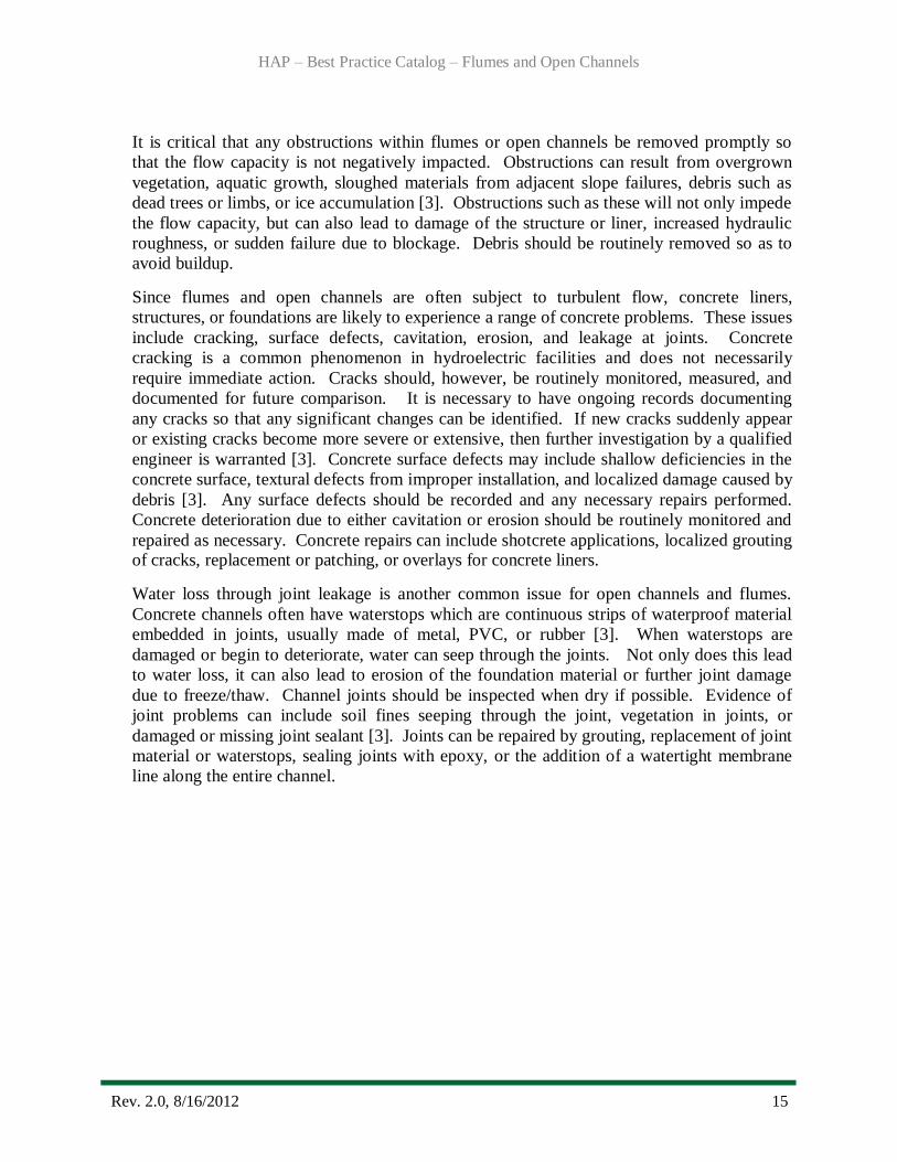
It is critical that any obstructions within flumes or open channels be removed promptly so
that the flow capacity is not negatively impacted. Obstructions can result from overgrown
vegetation, aquatic growth, sloughed materials from adjacent slope failures, debris such as
dead trees or limbs, or ice accumulation [3]. Obstructions such as these will not only impede
the flow capacity, but can also lead to damage of the structure or liner, increased hydraulic
roughness, or sudden failure due to blockage. Debris should be routinely removed so as to
avoid buildup.
Since flumes and open channels are often subject to turbulent flow, concrete liners,
structures, or foundations are likely to experience a range of concrete problems. These issues
include cracking, surface defects, cavitation, erosion, and leakage at joints. Concrete
cracking is a common phenomenon in hydroelectric facilities and does not necessarily
require immediate action. Cracks should, however, be routinely monitored, measured, and
documented for future comparison. It is necessary to have ongoing records documenting
any cracks so that any significant changes can be identified. If new cracks suddenly appear
or existing cracks become more severe or extensive, then further investigation by a qualified
engineer is warranted [3]. Concrete surface defects may include shallow deficiencies in the
concrete surface, textural defects from improper installation, and localized damage caused by
debris [3]. Any surface defects should be recorded and any necessary repairs performed.
Concrete deterioration due to either cavitation or erosion should be routinely monitored and
repaired as necessary. Concrete repairs can include shotcrete applications, localized grouting of cracks, replacement or patching, or overlays for concrete liners.
Water loss through joint leakage is another common issue for open channels and flumes.
Concrete channels often have waterstops which are continuous strips of waterproof material
embedded in joints, usually made of metal, PVC, or rubber [3]. When waterstops are
damaged or begin to deteriorate, water can seep through the joints. Not only does this lead
to water loss, it can also lead to erosion of the foundation material or further joint damage
due to freeze/thaw. Channel joints should be inspected when dry if possible. Evidence of
joint problems can include soil fines seeping through the joint, vegetation in joints, or
damaged or missing joint sealant [3]. Joints can be repaired by grouting, replacement of joint
material or waterstops, sealing joints with epoxy, or the addition of a watertight membrane
line along the entire channel.

HAP – Best Practice Catalog – Flumes and Open Channels
Rev. 2.0, 8/16/2012 16
Figure 6: Waterstop Repair in Concrete Channel
Steel can be used for flume supporting structures, channel liners, or flume liners. Since steel
in hydroelectric facilities is repeatedly exposed to moisture, corrosion is oftentimes a
recurrent problem. Evidence of steel corrosion can include scaling, flaking, pitting, or color
changes. If left unchecked, corrosion can lead to loss of material, leakage, and in some
instances failure of the structure. Corrosion can be limited or avoided by either painting the
steel or installing cathodic protection. Other steel problems include fatigue due to repetitive
loading, erosion by abrasive debris, tearing or rupture due to debris impact, cavitation due to
high flow velocities, cracking, and deformation [3]. Plant personnel should regularly inspect all steel surfaces for any signs of deterioration or problems.

HAP – Best Practice Catalog – Flumes and Open Channels
Rev. 2.0, 8/16/2012 17
4.0 Metrics, Monitoring and Analysis
4.1 Measures of Performance, Condition, and Reliability
The fundamental equations for evaluating efficiency through flumes and open channels are
Manning’s equation for open channel flow, the equations for head losses due to friction and
geometrical changes, and water losses due to seepage, leakage, or unexpected overflow
(water loss from evaporation is minimal and unavoidable) [2 and 10]. Losses due to leakages
or unexpected overflow are more difficult to quantify and require more detailed analysis
based on a plant specific basis. Avoidable head losses can be directly related to overall
power/energy loss and subsequent loss of revenue for the plant. These equations are defined as follows:
Flow quantity, Q (ft3/sec):
√
Where: · Q is the flow quantity (ft3/sec)
· n is the Manning roughness coefficient
· A is the cross-sectional area (ft2)
· R is the hydraulic radius (ft)
· S is the slope of energy line or energy gradient (ft/ft)
Head loss due to friction, hf (ft):
Where: · hf is the head loss due to friction through the conveyance component (ft)
· n is the difference in Manning roughness coefficients for existing roughness
conditions and roughness conditions after potential upgrades.
· L is the length of the conveyance component (ft)
· v is the average flow velocity or flow rate per cross-sectional area (ft/sec)
· R is the hydraulic radius (ft)
Head loss due to minor losses (e.g. channel bends, adjacent slopes), hm (ft):
Where: · hm is the head loss due to minor losses from geometrical changes (ft)
· Kb is the difference in the head loss coefficient for existing conditions and for
conditions after potential upgrades computed as follows for channel bends:

HAP – Best Practice Catalog – Flumes and Open Channels
Rev. 2.0, 8/16/2012 18
· W is the channel width (ft)
· Rc is the center-line radius of the channel curve (ft)
· V is the mean velocity or flow rate per cross-sectional area (ft/s)
· g is the acceleration due to gravity (ft/s2)
Moritz formula for water losses due to seepage in unlined channels, S (ft3/s/mile):
Where: · S is the losses due to seepage (ft3/s/mile)
· C is the rate of water loss (ft3/24 hours/1 ft
2 of wetted area). Average values of C
can range from 2.20 for sandy soils to 0.41 for clays.
· Q is the flow quantity (ft3/s)
· V is the mean velocity (ft/s)
Avoidable power loss, ΔP (MW), associated with head losses:
ΔP = 0.85(Q γ Δh+ ΔQ γ h) / 737,562
Where: · 0.85 is a factor to account for the water to wire efficiency of the turbines.
· Q is the average volumetric flow rate through the water conveyance component
(ft3/sec)
· γ is the specific weight of water (62.4 lb/ft3)
· Δh is the avoidable head loss
· 737,562 is the conversion from pound-feet per second to megawatts
Avoidable energy loss, ΔE (MWh):
ΔE = ΔPT
Where: · ΔP is the avoidable power loss (MWh)
· T is the measurement interval (hrs.)
Avoidable revenue loss, ΔR ($):
ΔR = ME ΔE
Where: · ME is the market value of energy ($/MWh)
· ΔE is the avoidable energy loss
4.2 Data Analysis
Determination of the Potential Performance Level (PPL) will require reference to the flow
characteristics of the modified geometry and/or surface roughness of the flume or open
channel components. The PPL will vary for each plant. However, the maximum PPL will be based on the flow characteristics of the most efficient available upgrade.

HAP – Best Practice Catalog – Flumes and Open Channels
Rev. 2.0, 8/16/2012 19
The Current Performance Level (CPL) is described by an accurate set of water conveyance
component performance characteristics determined by flow and head measurements and/or
hydraulic modeling of the system.
The Installed Performance Level (IPL) is described by the water conveyance component
performance characteristics at the time of commissioning or at the point when an upgrade or
addition is made. These may be determined from reports and records of efficiency and/or model testing at the time of commissioning or upgrade.
The CPL should be compared with the IPL to determine decreases in water conveyance
system efficiency over time. Additionally, the PPL should be identified when considering plant upgrades.
4.3 Integrated Improvements
The periodic field test results should be used to update the unit operating characteristics and
maintenance practices. Optimally, any test results or observations should be integrated into
an automated system, but if not, hard copies of the data should be made available to all
involved plant personnel (particularly unit operators). All necessary upgrades or
maintenance (channel lining, debris removal, slope stabilization, etc.) and methods to
routinely monitor unit performance should be implemented.

HAP – Best Practice Catalog – Flumes and Open Channels
Rev. 2.0, 8/16/2012 20
5.0 Information Sources:
Baseline Knowledge:
1. Professor B.S. Thandaveswara, Hydraulics: Design of Canals, Indian Institute of Technology
Madras.
2. Bureau of Reclamation, Design of Small Dams, A Water Resources Technical Publication, 3
rd Edition, 1987.
3. Bureau of Reclamation, Veesaert, Chris J., Inspection of Spillways, Outlet Works, and
Mechanical Equipment, National Dam Safety Program Technical Seminar Session XVI, February 2007.
4. Hydro Life Extension Modernization Guide, Volume 4-5 Auxiliary Mechanical and Electrical
Systems, EPRI, Palo Alto, CA: 2001. TR-112350-V4.
State of the Art:
5. American Society of Civil Engineers (ASCE), Civil Works for Hydroelectric Facilities – Guidelines for Life Extension and Upgrade, ASCE Hydropower Task Committee, 2007.
6. Bureau of Reclamation, Canal Lining Demonstration Project – Year 10 Final Report, R-02-
03, November 2002.
7. Tennessee Valley Authority (TVA), Ocoee Flume Resumes Operation, TVA News Release, April 22, 2011.
Standards:
8. Electric Power Research Institute (EPRI), Increased Efficiency of Hydroelectric Power, EM-
2407, Research Project 1745-1, Final Report, June 1982.
9. United States Army Corps of Engineers (USACE), Engineering and Design – Hydraulic Design of Flood Control Channels, EM 1110-2-1601, June 1994.
10. Zipparro, Vincent J. and Hans Hasen, Davis’ Handbook of Applied Hydraulics, 4th Edition,
1993.
11. Federal Emergency Management Agency (FEMA), Technical Manual: Conduits through Embankments Dams, September 2005.
It should be noted by the user that this document is intended only as a guide. Statements are of a
general nature and therefore do not take into account special situations that can differ significantly from those discussed in this document.

HAP – Best Practice Catalog – Flumes and Open Channels
Rev. 2.0, 8/16/2012 21
For overall questions
please contact:
Brennan T. Smith, Ph.D., P.E. Water Power Program Manager
Oak Ridge National Laboratory
865-241-5160 [email protected]
or
Qin Fen (Katherine) Zhang, Ph. D., P.E.
Hydropower Engineer
Oak Ridge National Laboratory 865-576-2921