Embed Size (px)
Citation preview
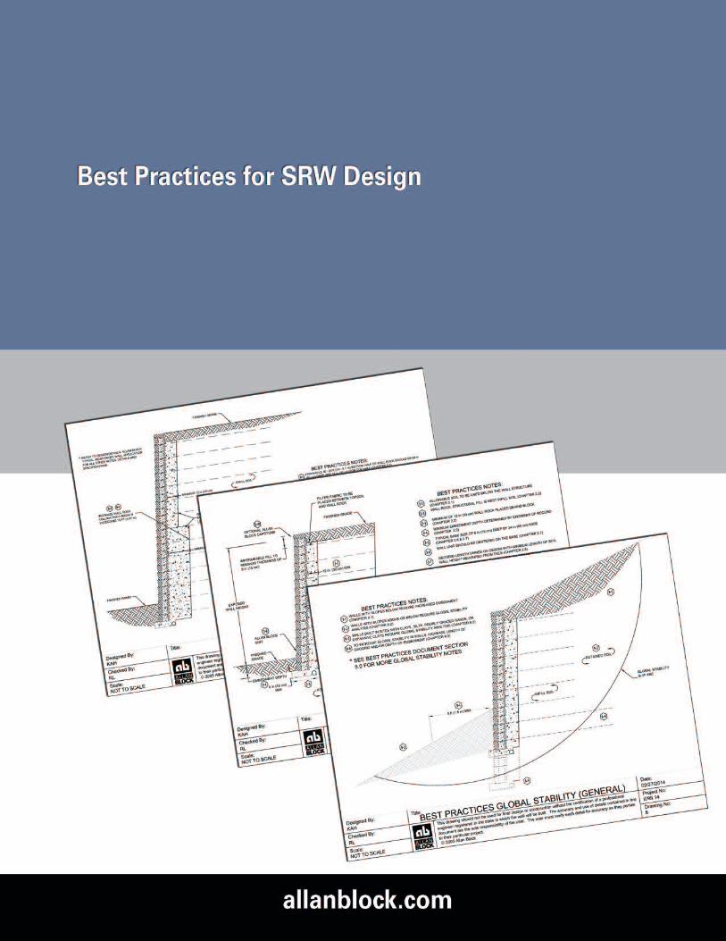

Best Practices for Allan Block Segmental Retaining Wall Design For Residential
and Commercial Applications
www.allanblock.com
Rev. 5/30/2018Page 1
The intent of this document is to communicate the best practices for design of Segmental Retaining Walls(SRW) as determined by Allan Block Corporation based on 25 plus years of research, design and field experi-ence. This is not meant to be a final authority as each project has their own set of unique situations. The localengineer of record must use their best engineering judgment to account for those situations that presentthemselves and provide a safe and efficient design for the customer. At no time does the contractor or localbuilding official have the authority to override the approved plans and specifications provided from the localengineer of record. It is the recommendation of Allan Block Corporation that the local engineer of record workfor and be paid by the project owner. It has been determined that the local engineer of record should be theProject Site Civil Engineer as they are best suited to take responsibility for the design, and how it affects thesite, whether they do the design in-house or use an outside consultant to do the design for the project. TheProject Site Civil Engineer has control of several of the overall aspects of the project and therefore is most ableto properly handle the integration and communication required to ensure the performance of the wall com-plies with the needs of the site. For wall design applications that are outside of the experience level of theProject Site Civil Engineer a wall designer with the appropriate knowledge and experience should be con-tracted with by the Project Site Civil Engineer. It is recommended that the wall contractor not be responsiblefor securing the engineering.
How to use this document: The Best Practice document contains drawings (Part 1) highlighting details associated with typical issues thatmay be present on any given project. Notes expanding on each topic are contained in the chapters that follow.Please refer to the Table of Contents Part 2 – Best Practice Considerations for a list of topics contained in thisdocument.
To find the most up-to-date information available, visit allanblock.com.
Table of Contents
Part 1 – List of Drawings
1.0 Typical Wall Construction 52.0 Water Management – Typical 63.0 Water Management – Alternate Drain 74.0 Water Application 85.0 Soil and Compaction 96.0 Geogrid, Curve and Corner Design 107.0 Tall Walls Considerations 118.0 Global Stability – General 129.0 Global Stability – Terraced 1310.0 Seismic Considerations 1411.0 Above Wall Considerations 15
Best Practices for Allan Block Segmental Retaining Wall Design For Residential
and Commercial Applications
www.allanblock.com
Rev. 5/30/2018Page 2
Table of Contents
Part 2 – Best Practice Considerations
Chapter 1.0 Design Guidelines and Pre-Construction Considerations1.1 Meeting with Owner 171.2 Determining when Engineering is Required 171.3 Existing and Proposed Utilities 171.4 Wall Layout, height and geometry 171.5 Geotechnical Report Considerations 171.6 Understanding sites soils 181.7 Site Visit 181.8 Temporary Load Considerations 191.9 Scope of Responsibility and Design Methodologies 191.10 Minimum Design Safety Factors 201.11 Coherent Gravity Mass and Connection Strength Considerations 201.12 Contractor Requirements 211.13 Manufactured Product Specifications 211.14 Freeze Thaw Durability 211.15 Pre-Construction Meeting 231.16 Visiting the Site During Construction 231.17 Construction Drawings 231.18 For the Bidding Process 241.19 Quality Control, Quality Assurance 24
Chapter 2.0 Typical Wall Construction2.1 Inspection of Materials 252.2 Allowable Foundation Soils 252.3 Allowable Infill Soils 252.4 Wall Rock Guidelines 262.5 Soil Parameter Verification 262.6 Typical Wall Embedment 262.7 Base Trench Requirements 262.8 Base Trench Considerations 262.9 Minimum Grid Lengths 272.10 Initial Grid Location 272.11 Maximum Grid Spacing 272.12 Minimum Wall Facing Depth 272.13 Capping the Wall 27
Best Practices for Allan Block Segmental Retaining Wall Design For Residential
and Commercial Applications
www.allanblock.com
Rev. 5/30/2018Page 3
Table of Contents
Part 2 – Best Practice Considerations (Continued)
Chapter 3.0 Water Management - Typical3.1 Identifying Potential Water Sources 283.2 Blanket and Chimney Drains 283.3 Venting of Drain Pipes 293.4 Above Grade Water Management 29
Chapter 4.0 Water Management – Alternate Drain4.1 Alternate Drain Locations 304.2 Heel Drain Recommendations 30
Chapter 5.0 Water Application5.1 Below Grade Water Management 315.2 Water Application Construction 31
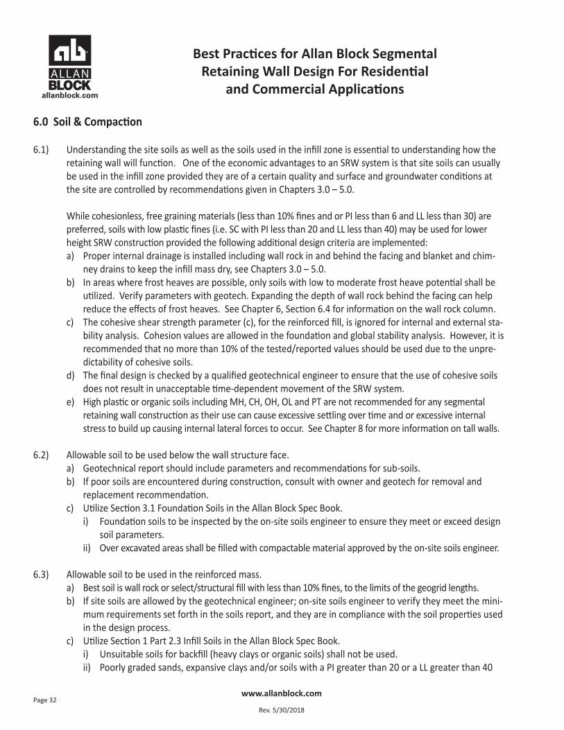
Chapter 6.0 Soil and Compaction6.1 Allowable Foundation Soils 326.2 Understanding sites soils 326.3 Allowable Infill Soils 336.4 Wall Rock Guidelines 336.5 Soil Parameter Verification 336.6 Inspection and Testing Recommendations 346.7 Compaction Requirements at the Face of Wall 346.8 Maximum Compaction Lift Spacing 356.9 Compaction Requirements for Backfill Soil 356.10 Testing Location and Frequencies 356.11 Water Management During Construction 356.12 Wall Step Ups in Base Course 356.13 Stair Considerations 35
Chapter 7.0 Geogrid Reinforcement Requirements, Corner and Radius Design Practices7.1 Geogrid Reinforcement Requirements and Certification 367.2 Proper Grid Orientation 367.3 Wall Rock Design for Corners and Curved Walls 37
Best Practices for Allan Block Segmental Retaining Wall Design For Residential
and Commercial Applications
www.allanblock.com
Rev. 5/30/2018Page 4
Table of Contents
Part 2 – Best Practice Considerations (Continued)
Chapter 8.0 Tall Walls Considerations8.1 Tall Wall Definition 388.2 Variable Rock Thickness at Face 388.3 Compaction and Soil Considerations 388.4 Increased Forces in Lower Portion of Walls 398.5 Global Stability of Tall Walls 398.6 Internal Compound Stability Calculations 398.7 Minimum Wall Facing Depth 39
Chapter 9.0 Global Stability – General9.1 Wall Embedment with Toe Slope 409.2 When to Analyze for Global Stability 409.3 Increasing Global Stability Options 419.4 Effect of Groundwater on Global Stability 41
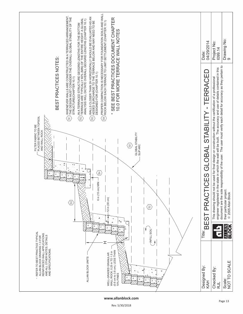
Chapter 10.0 Global Stability – Terraced10.1 Terraced Wall Considerations 42
Chapter 11.0 Seismic Considerations11.1 Recommendations Associated with Seismic Loading 4311.2 Slope Above Seismically Loaded Walls 4311.3 Mononobe-Okabe Slope Above Limitations 4311.4 Alternate Design Approach – Trial Wedge Method 43
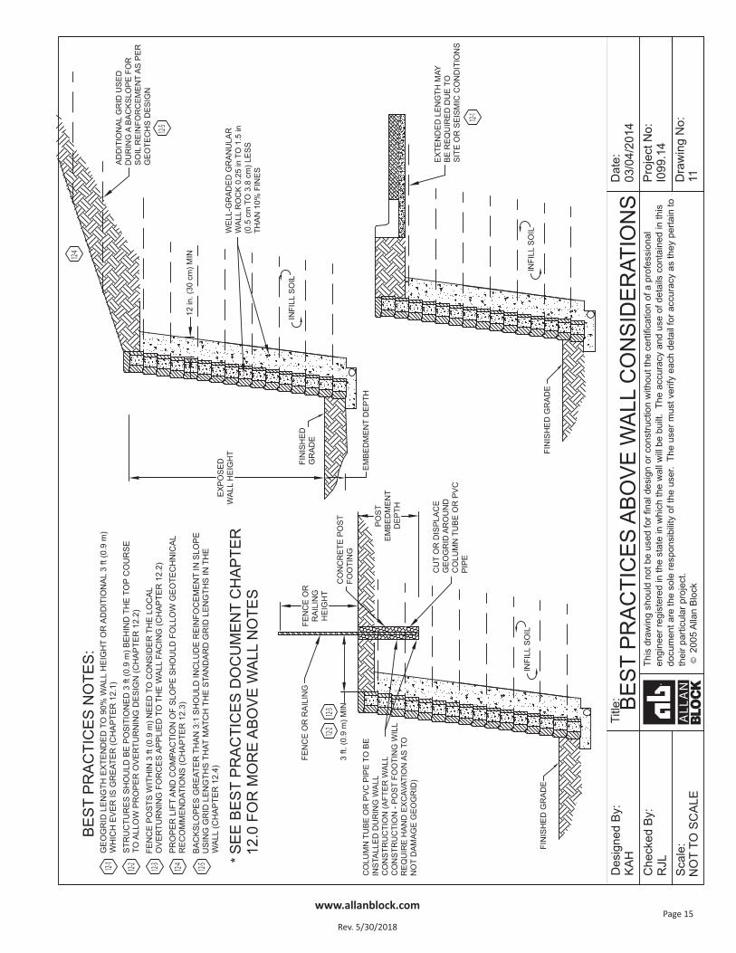
Chapter 12.0 Above Wall Considerations12.1 Minimum Grid Lengths at the Top of the Wall 4412.2 Fences and Railings 4412.3 Slopes Above the Wall 4412.4 Reinforcing the Slope 4512.5 Compaction Requirements for Slopes Above 4512.6 Reinforcing Slopes Above Walls 4512.7 Plantings 45
References 46
Best Practices for Allan Block Segmental Retaining Wall Design For Residential
and Commercial Applications
www.allanblock.com
Rev. 5/30/2018Page 16
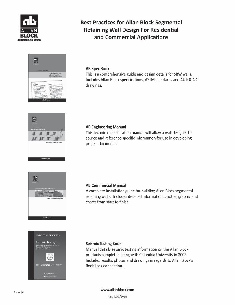
AB Spec BookThis is a comprehensive guide and design details for SRW walls. Includes Allan Block specifications, ASTM standards and AUTOCADdrawings.
AB Engineering ManualThis technical specification manual will allow a wall designer tosource and reference specific information for use in developing project document.
AB Commercial ManualA complete installation guide for building Allan Block segmental retaining walls. Includes detailed information, photos, graphic andcharts from start to finish.
Seismic Testing BookManual details seismic testing information on the Allan Block products completed along with Columbia University in 2003. Includes results, photos and drawings in regards to Allan Block’s Rock Lock connection.
Best Practices for Allan Block Segmental Retaining Wall Design For Residential
and Commercial Applications
www.allanblock.com
Rev. 5/30/2018Page 17
1.0 Design Guidelines and Pre-Construction Considerations
Design Guidelines Item(For this document the term owner refers to the property owner or their designated representative)
1.1) Meeting with owner to fully understand the basic needs for the site.a) What is the general use of the site? Know if the site will be used for commercial, residential, public, etc.b) Knowing the site use will often dictate design loading, design methodology and level of effort required to
complete the project so proper bidding can be provided.c) Identify miscellaneous items such as drop structures, light standards, building foundations and property
lines that may encroach into the geogrid zone.d) Engineer should determine if as-built documents will be required at the end of the project. If so, provi-
sions should be set in place to document changes during construction.
1.2) Determining when engineering is required.a) Local codes and municipalities will have minimum height requirements set for walls that require engi-
neering. However, height is not the only factor that should be considered. Engineering should be re-quired for walls of any height that have any of the special considerations within this manual such as butnot limited to the following: poor soils, multiple terrace arrangements, steep slopes above or below,high seismic loading, roadway surcharges, etc.
1.3) Make sure the site plans call out locations of all existing and proposed utilities.a) Have a process in place to verify location of existing utilities.b) Avoid placing utilities, especially storm sewer, sanitary sewer, water, landscape irrigation, and gas lines
within the reinforced zone of segmental walls. If no other alternatives exist, provisions should be set inplace for future maintenance.
1.4) Determine wall layout, wall heights, conditions above and below the wall, as well as live and dead loads (locations and levels).a) Wall layout should be approved by the owner.b) Utilize the Wall Design Checklist in the Allan Block Spec Book.
1.5) Obtain a thorough geotechnical report in the area where the wall will be located.a) Geotechnical report should be available to all parties doing design work and should be an all-encom-
passing document covering all aspects of the site such as the following:i.) Soil strength – preferably the tested friction angle of the on-site soils ii.) Clear description of on-site soilsiii.) Gradation of soilsiv.) Groundwater conditionsv.) Settlementvi.) Soil unit weightsvii.) Plasticity Index (PI) and Liquid Limit (LL)
Best Practices for Allan Block Segmental Retaining Wall Design For Residential
and Commercial Applications
www.allanblock.com
Rev. 5/30/2018Page 18
viii.) Site specific seismic coefficientsix.) Global stability recommendations
b) The geotechnical investigation and report should be paid for by the owner.c) If no other guidance has been provided, a geotechnical investigation should include soil borings with
sampling and logs at an interval of not more than 100 ft (30 m) along the centerline of the proposedretaining wall(s) and at 150 ft (46 m) along the back of the reinforced soil zone.
1.6) Understanding the site soils as well as the soils used in the infill zone is essential to understanding how theretaining wall will function. One of the economic advantages to an SRW system is that site soils can usually be used in the infill zone provided they are of a certain quality and surface and groundwater conditions at the site are controlled by recommendations given in Chapters 3.0 – 5.0.
While cohesionless, free draining materials (less than 10% fines and or PI less than 6 and LL less than 30) are preferred, soils with low plastic fines (i.e. SC with PI less than 20 and LL less than 40) may be used for lower height SRW construction provided the following additional design criteria are implemented:a) Proper internal drainage is installed including wall rock in and behind the facing and blanket and chim-
ney drains to keep the infill mass dry, see Chapters 3.0 – 5.0.b) In areas where frost heaves are possible, only soils with low to moderate frost heave potential shall be
utilized. Verify parameters with geotech. Expanding the depth of wall rock behind the facing can helpreduce the effects of frost heaves. See Chapter 6, Section 6.4 for information on the wall rock column.
c) The cohesive shear strength parameter (c), for the reinforced fill, is ignored for internal and external sta-bility analysis. Cohesion values are allowed in the foundation and global stability analysis. However, it isrecommended that no more than 10% of the tested/reported values should be used due to the unpre-dictability of cohesive soils.
d) The final design is checked by a qualified geotechnical engineer to ensure that the use of cohesive soilsdoes not result in unacceptable time-dependent movement of the SRW system.
e) High plastic or organic soils including MH, CH, OH, OL and PT are not recommended for any segmental re-taining wall construction as their use can cause excessive settling over time and or excessive internal stressto build up causing internal lateral forces to occur. See Chapter 8 for more information on tall walls.
1.7) Visit the site to ensure that the site plans adequately capture the important details of the site.a) Site drainageb) Surface water – lakes, rivers, ponds or detention basins, etc.c) Slopes above or belowd) Make determination that site soils appear to be similar to what is indicated in the geotechnical report.e) Proposed locations of structures, roadways and other surcharges.
1.8) Consider temporary construction loads and future snow and/or storage loads.a) Will construction loading govern design over final loading conditions?
Best Practices for Allan Block Segmental Retaining Wall Design For Residential
and Commercial Applications
www.allanblock.com
Rev. 5/30/2018Page 19
b) Snow loads are not only vertical but snowplows can provide lateral loading.c) Consider reinforced barriers to prevent the lateral loads.d) Magnitude of load will range depending on condition.
1.9) Establish scope of responsibility and required design methodology of project with owner including seismicdesign requirements.a) The owner should understand the limits of design responsibility. The SRW Engineer Suggested Roles as
provided in Section 3, Roles and Responsibilities in the National Concrete Masonry Association (NCMA)Design Manual are as follows:i.) Design of SRW for structural stability including external stability (sliding and overturning), internal
stability, internal compound stability and facial stability.ii.) Determination of the maximum unreinforced height of SRW.iii.) Design of geogrid layout for taller walls requiring soil reinforcement.iv.) Determination of minimum embedment of wall (except in the case of scour depth or erosion control
issues, which should be determined by site civil engineer).v.) Specification and/or approval of wall unit, geogrid reinforcement, drainage material within wall
structure, and reinforced soil properties.vi.) Determination of what structures can or cannot be placed within reinforced soil zone and wall face,
and detailing for SRWs to accommodate acceptable structures.vii.) Under the direction of geotechnical engineer, assist in the coordination of slope stability evaluation
around and through the SRW and the design of the geogrid in reinforced SRWs to address slope sta-bility in vicinity of SRW, as needed.
viii.) If contracted to and notified, construction observation of the overall wall structure installation andreview of SRW material submittals (generally on a time and materials basis, separate from the walldesign contract).
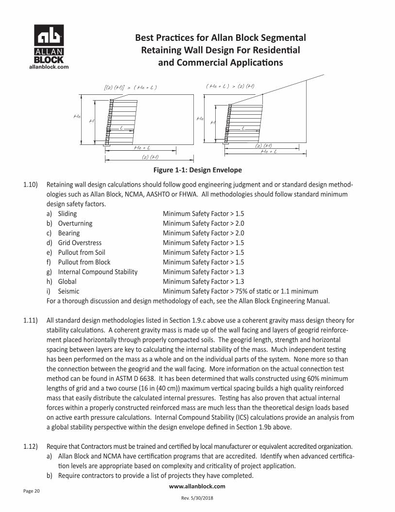
b) Unless other arrangements have been made between the owner and the wall design engineer, the walldesign engineer is responsible for the area in and around the wall known as the Design Envelope – Fig-ure 1-1. This Design Envelope is defined as follows: The horizontal distance, measured from the toe ofthe wall, is the greater of twice the height of the wall (2H) or, the height of the projection from the tail ofthe reinforcement layers to the surface (He) plus a distance equal to the length of the reinforcement (L).The vertical height is the height of the wall facing, measured from the top of the base to the top of thetop facing unit (H).
c) Agree upon the design method to be used, Allan Block, NCMA, AASHTO or FHWA. For information aboutthe Coulomb Design Methodology see the Allan Block Spec Book. A complete step by step descriptioncan be found in the AB Engineering Manual.
Best Practices for Allan Block Segmental Retaining Wall Design For Residential
and Commercial Applications
www.allanblock.com
Rev. 5/30/2018Page 20
1.10) Retaining wall design calculations should follow good engineering judgment and or standard design method-ologies such as Allan Block, NCMA, AASHTO or FHWA. All methodologies should follow standard minimumdesign safety factors.a) Sliding Minimum Safety Factor > 1.5b) Overturning Minimum Safety Factor > 2.0c) Bearing Minimum Safety Factor > 2.0d) Grid Overstress Minimum Safety Factor > 1.5e) Pullout from Soil Minimum Safety Factor > 1.5f) Pullout from Block Minimum Safety Factor > 1.5g) Internal Compound Stability Minimum Safety Factor > 1.3h) Global Minimum Safety Factor > 1.3i) Seismic Minimum Safety Factor > 75% of static or 1.1 minimumFor a thorough discussion and design methodology of each, see the Allan Block Engineering Manual.
1.11) All standard design methodologies listed in Section 1.9.c above use a coherent gravity mass design theory forstability calculations. A coherent gravity mass is made up of the wall facing and layers of geogrid reinforce-ment placed horizontally through properly compacted soils. The geogrid length, strength and horizontalspacing between layers are key to calculating the internal stability of the mass. Much independent testinghas been performed on the mass as a whole and on the individual parts of the system. None more so thanthe connection between the geogrid and the wall facing. More information on the actual connection testmethod can be found in ASTM D 6638. It has been determined that walls constructed using 60% minimumlengths of grid and a two course (16 in (40 cm)) maximum vertical spacing builds a high quality reinforcedmass that easily distribute the calculated internal pressures. Testing has also proven that actual internalforces within a properly constructed reinforced mass are much less than the theoretical design loads basedon active earth pressure calculations. Internal Compound Stability (ICS) calculations provide an analysis froma global stability perspective within the design envelope defined in Section 1.9b above.
1.12) Require that Contractors must be trained and certified by local manufacturer or equivalent accredited organization.a) Allan Block and NCMA have certification programs that are accredited. Identify when advanced certifica-
tion levels are appropriate based on complexity and criticality of project application. b) Require contractors to provide a list of projects they have completed.
Figure 1-1: Design Envelope
Best Practices for Allan Block Segmental Retaining Wall Design For Residential
and Commercial Applications
www.allanblock.com
Rev. 5/30/2018Page 21
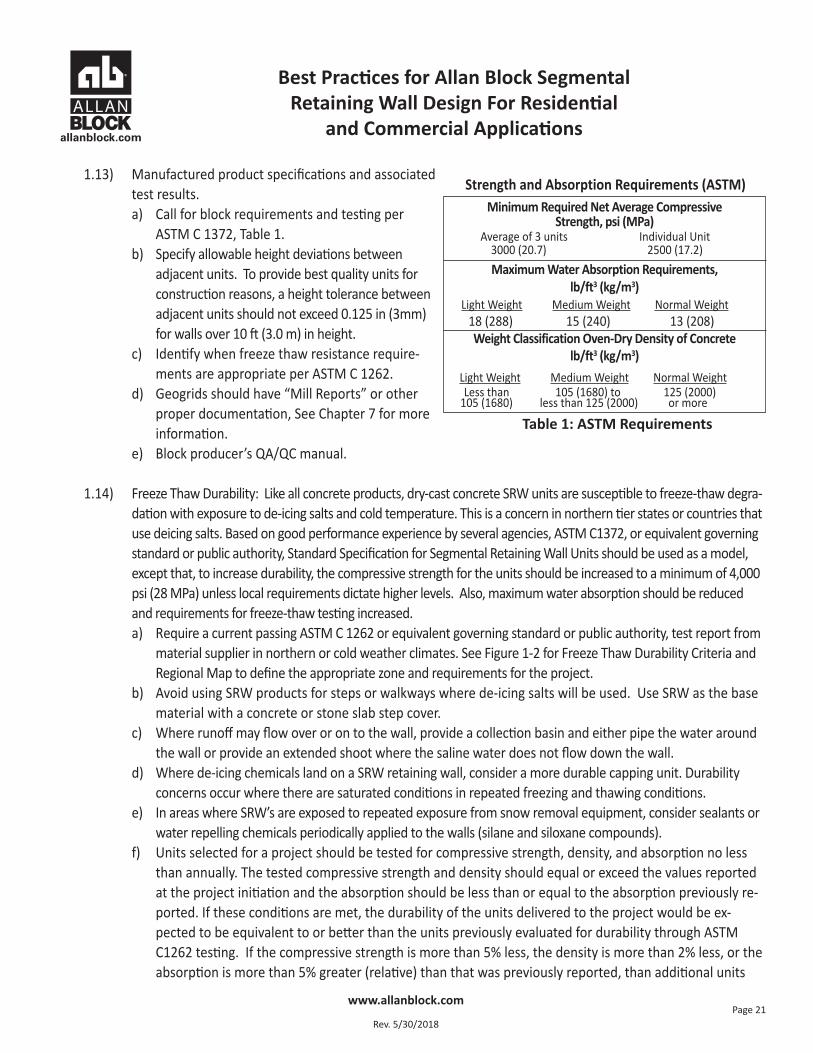
1.13) Manufactured product specifications and associatedtest results. a) Call for block requirements and testing per
ASTM C 1372, Table 1.b) Specify allowable height deviations between
adjacent units. To provide best quality units forconstruction reasons, a height tolerance betweenadjacent units should not exceed 0.125 in (3mm)for walls over 10 ft (3.0 m) in height.
c) Identify when freeze thaw resistance require-ments are appropriate per ASTM C 1262.
d) Geogrids should have “Mill Reports” or otherproper documentation, See Chapter 7 for moreinformation.
e) Block producer’s QA/QC manual.
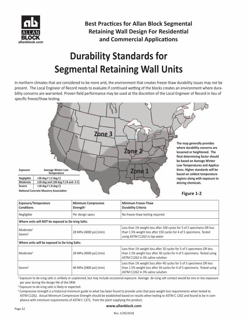
1.14) Freeze Thaw Durability: Like all concrete products, dry-cast concrete SRW units are susceptible to freeze-thaw degra-dation with exposure to de-icing salts and cold temperature. This is a concern in northern tier states or countries thatuse deicing salts. Based on good performance experience by several agencies, ASTM C1372, or equivalent governingstandard or public authority, Standard Specification for Segmental Retaining Wall Units should be used as a model,except that, to increase durability, the compressive strength for the units should be increased to a minimum of 4,000psi (28 MPa) unless local requirements dictate higher levels. Also, maximum water absorption should be reducedand requirements for freeze-thaw testing increased.a) Require a current passing ASTM C 1262 or equivalent governing standard or public authority, test report from
material supplier in northern or cold weather climates. See Figure 1-2 for Freeze Thaw Durability Criteria andRegional Map to define the appropriate zone and requirements for the project.
b) Avoid using SRW products for steps or walkways where de-icing salts will be used. Use SRW as the basematerial with a concrete or stone slab step cover.
c) Where runoff may flow over or on to the wall, provide a collection basin and either pipe the water aroundthe wall or provide an extended shoot where the saline water does not flow down the wall.
d) Where de-icing chemicals land on a SRW retaining wall, consider a more durable capping unit. Durabilityconcerns occur where there are saturated conditions in repeated freezing and thawing conditions.
e) In areas where SRW’s are exposed to repeated exposure from snow removal equipment, consider sealants orwater repelling chemicals periodically applied to the walls (silane and siloxane compounds).
f) Units selected for a project should be tested for compressive strength, density, and absorption no lessthan annually. The tested compressive strength and density should equal or exceed the values reportedat the project initiation and the absorption should be less than or equal to the absorption previously re-ported. If these conditions are met, the durability of the units delivered to the project would be ex-pected to be equivalent to or better than the units previously evaluated for durability through ASTMC1262 testing. If the compressive strength is more than 5% less, the density is more than 2% less, or theabsorption is more than 5% greater (relative) than that was previously reported, than additional units
Minimum Required Net Average Compressive Strength, psi (MPa)
Average of 3 units Individual Unit3000 (20.7) 2500 (17.2)Maximum Water Absorption Requirements,
lb/ft3 (kg/m3)Light Weight Medium Weight Normal Weight
18 (288) 15 (240) 13 (208)Weight Classification Oven-Dry Density of Concrete
lb/ft3 (kg/m3)Light Weight Medium Weight Normal WeightLess than 105 (1680) to 125 (2000)
105 (1680) less than 125 (2000) or more
Strength and Absorption Requirements (ASTM)
Table 1: ASTM Requirements
Best Practices for Allan Block Segmental Retaining Wall Design For Residential
and Commercial Applications
www.allanblock.com
Rev. 5/30/2018Page 22
The map generally provideswhere durability concerns arelessened or heightened. Thefinal determining factor shouldbe based on Average WinterLow Temperatures and Applica-tions. Higher standards will bebased on coldest temperatureregions along with exposure todeicing chemicals.
Zone 2
Zone 3
Zone 1Exposure Average Winter Low Temperature
Negligible >28 deg F (-2 deg C)Moderate ≥18 deg and ≤28 deg F (-8 and -2 C)Severe <18 deg F (-8 deg C)National Concrete Masonry Association
Figure 1-2
Exposure/TemperatureConditions
Minimum CompressiveStrength3
Minimum Freeze-ThawDurability Criteria
Negligible Per design specs No freeze-thaw testing required
Where units will NOT be exposed to De-Icing Salts:
Moderate1
Severe1 28 MPa (4000 psi) (min)Less than 1% weight loss after 100 cycles for 5 of 5 specimens OR lessthan 1.5% weight loss after 150 cycles for 4 of 5 specimens. Testedusing ASTM C1262 in tap water
Where units will be exposed to De-Icing Salts:
Moderate2 28 MPa (4000 psi) (min)Less than 1% weight loss after 20 cycles for 5 of 5 specimens OR lessthan 1.5% weight loss after 30 cycles for 4 of 5 specimens. Tested usingASTM C1262 in 3% saline solution
Severe2 40 MPa (5800 psi) (min)Less than 1% weight loss after 40 cycles for 5 of 5 specimens OR lessthan 1.5% weight loss after 50 cycles for 4 of 5 specimens. Tested usingASTM C1262 in 3% saline solution
1 Exposure to de-icing salts is unlikely or unplanned, but may include occasional exposure. Average de-icing salt contact would be one or less exposureper year during the design life of the SRW.
2 Exposure to de-icing salts is likely or expected.3 Compressive strength is a historical minimum guide to what has been found to provide units that pass weight loss requirements when tested to
ASTM C1262. Actual Minimum Compressive Strength should be established based on results when testing to ASTM C 1262 and found to be in com-pliance with minimum requirements of ASTM C 1372, from the plant supplying the product.
Durability Standards for Segmental Retaining Wall Units
In northern climates that are considered to be more arid, the environment that creates freeze thaw durability issues may not bepresent. The Local Engineer of Record needs to evaluate if continued wetting of the blocks creates an environment where dura-bility concerns are warranted. Proven field performance may be used at the discretion of the Local Engineer of Record in lieu ofspecific freeze/thaw testing.
Best Practices for Allan Block Segmental Retaining Wall Design For Residential
and Commercial Applications
www.allanblock.com
Rev. 5/30/2018Page 23
should be sampled and tested for freeze/thaw durability (either in water or saline, as appropriate) andverified in compliance with the project specifications.
1.15) Requirement for a pre-construction meeting with all parties associated with the project to approve designand best practice requirements.
a) A pre-construction meeting should be held with all parties attending so the entire construction plan can be dis-cussed from start to finish and any issues can be worked out with a plan in place to move forward successfully.
b) All parties are all of those that will be working on or around the wall site including but not limited to theowner, architect, site civil, geotech, wall designer, general contractor, excavation contractor, wall builder,Allan Block supplier representative, railing or fence installer, local utility representative, inspectors (pri-vate and government as appropriate) etc.
c) Language can be placed in the project specifications requiring a pre-construction meeting.d) Reference the AB Construction and Inspection Checklist in the AB Spec Book as a good agenda for the meeting.e) Meeting topics shall include, but not be limited to: contractor qualifications, schedule and phasing of
wall construction and inspection, coordination with other on-site construction activities, responsibilitiesof parties, and source, quality, and acceptance of materials.
1.16) Include in the scope of the project three additional site visits. a) The first at the beginning of the project to reinforce the need for the contractor to comply with the spec-
ifications in the approved design and to answer any questions. b) The second visit would be a random site inspection to ensure that the work methods are in agreement
with the approved plans and to answer any questions. c) The third visit to be at the conclusion of the project to verify that the details above and below the wall
structure have been completed as required. Additional inspections are available at the request of theowner based on a preset rate schedule. A written summary will be provided to the owner at the conclu-sion of the project for each visit made to the site.
1.17) A typical construction drawing submittal should include but is not limited to the following items (Size andcomplexity of project may lessen or increase this list):a) Front wall profile view which depicts the location of geogrid reinforcement, elevation of top and bottom
of wall and finished grade at bottom and top of wall.b) Wall station data with corresponding elevation for exposed grade at top and bottom of wall (i.e. profile data).c) Panel section markers depicting locations of design sections.d) Design sections showing:
i.) Geogrid locations, type and lengthii.) Thickness of wall rock material and infill depthiii.) Any surcharges iv.) Any required drain locations v.) Block typevi.) Base size
Best Practices for Allan Block Segmental Retaining Wall Design For Residential
and Commercial Applications
www.allanblock.com
Rev. 5/30/2018Page 24
e) Wall plan view depicting proper wall orientation should be provided. However, layout of walls should bedone using the site plans provided by the owner based on survey information.
f) Any required specialized or standard details that will provide guidance to the contractor, such as designspecifications, form work above, at the ends, or in front of the wall structure.
g) Detailed information and assumed on-site soil conditions, reinforced fill requirements, soil and com-paction testing, site visits from the local engineer of record, and documentation requirements before,during, and after construction.
h) Contractor training and certification requirements. i) Expected water conditions above and below grade.
1.18) For the bidding process, the owner is recommended to provide the following to ensure accurate and compa-rable bids between contractors. a) The owner should provide a complete design for all walls, unless the project is a negotiated design/build
contract on the front end. If design/build is used, the owner should ensure that a complete design is sub-mitted and construction verification is validated by an engineering firm working directly for the owner.
b) A complete bid package including items listed in Section 1.17, a complete geotechnical report includingitems listed in Section 1.5.
c) Any other information or details about the site and final requirements that are pertinent to the comple-tion of the project.
1.19) Provide detailed requirements for onsite inspection to ensure that specifications are complied with duringconstruction. The testing and inspection firm needs to evaluate conditions prior to construction and then todocument the construction process. This includes, but is not limited to:a) Confirmation that the foundation soils are suitable for support of the structure.b) Confirmation that the retained soils are as defined in the wall design.c) Verify the reinforced soils comply with the material specified in the wall design.d) Confirm reinforcement material is that specified in the wall design.e) Verify the wall unit is that specified in the wall design.f) Document the construction process, verifying the wall is constructed in general accordance to the plans
and specification.g) Perform the required soil testing in order to evaluate/validate that the soil placed meets the specified
gradation, shear strengths, weight, Atterberg limits and compaction requirements. h) A detailed construction log should be used with sign offs at incremental levels by the responsible parties.
Best Practices for Allan Block Segmental Retaining Wall Design For Residential
and Commercial Applications
www.allanblock.com
Rev. 5/30/2018Page 25
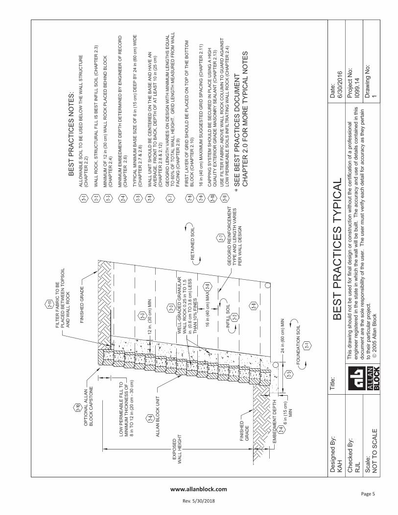
2.0 Typical Wall Construction
2.1) Contractors must inspect all materials upon delivery to the site to assure proper material has been received.Contractor must protect all materials from damage or contamination prior to use within the wall (ASTMC1372). Utilize Allan Block Product Standards in the Allan Block Spec Book.a) No substitutions in geogrid or SRW units should be allowed.b) Any changes in specified materials should be evaluated and approved by the SRW Designer and may
require redesign.
2.2) Allowable soil to be used below the wall structure face.a) Geotechnical report should include parameters and recommendations for sub-soils.b) If poor soils are encountered during construction, consult with owner and geotech for removal and
replacement recommendation.c) Utilize Section 3.1 Foundation Soils in the Allan Block Spec Book.
i.) Foundation soils to be inspected by the on-site soils engineer to ensure they meet or exceed designsoil parameters.
ii) Over excavated areas shall be filled with compactable material approved by the on-site soils engineer.
2.3) Allowable soil to be used in the reinforced mass.a) Best soil is wall rock or select/structural fill with less than 10% fines, to the limits of the geogrid lengths.b) If site soils are allowed by the geotechnical engineer; on-site soils engineer to verify they meet the mini-
mum requirements set forth in the soils report, and they are in compliance with the soil properties usedin the design process.
c) Utilize Section 1 Part 2.3 Infill Soils in the Allan Block Spec Book.i) Unsuitable soils for backfill (heavy clays or organic soils) shall not be used.ii) Poorly graded sands, expansive clays and/or soils with a PI greater than 20 or a LL greater than 40
should not be used in wall construction. iii) Fine grained cohesive soils with a friction angle of less than 31 degrees with a PI ranging between 6 and
20 and LL from 30 to 40, may be used in wall construction, but additional backfilling, compaction andwater management efforts, such as blanket drains and chimney drains are required.
iv) Soils with a PI of less than 6 and LL less than 30 are generally considered granular and can be used asinfill material.
d) The suggested gradation requirements for the reinforced (infill) soils in SRW’s are:
2.4) Wall rock column size and material used.a) The wall rock column is typically 12 in (30 cm) deep directly
behind the wall facing and consists of material summarizedin Section 1 Part 2.2 in the Allan Block Spec Book.i) Material must be well-graded compactible aggregate,
0.25 - 1.5 in, (0.6 – 3.8 cm) with no more than 10% passing the #200 sieve. (ASTM D422).b) At the top of the wall, above the wall rock column it is common to place a horizontal layer of landscape fabric
Sieve Size % Passing1 in (24 mm) 100 - 75
No. 4 (4.75 mm) 100 - 20No. 40 (0.425 mm) 0 - 60
No. 200 (0.075 mm) 0 - 35
Best Practices for Allan Block Segmental Retaining Wall Design For Residential
and Commercial Applications
www.allanblock.com
Rev. 5/30/2018Page 26
to protect the wall rock from being infiltrated by the topsoil placed to finish the wall. Topsoil is defined as lowpermeable soils ranging from 8 - 12 in. (20 – 30 cm) to minimize infiltration of surface water into the rein-forced mass.
c) When designing curved and radius wall segments the designer should provide details to the installer forwall rock placement.i) For inside curved and inside cornered walls, the minimum wall rock specified should follow Section
6.4 (paragraph a) and Section 8.2 for Tall Wall applications.ii) For outside curved and outside cornered walls, additional depth of wall rock should be specified to pro-
mote greater stability in these areas. Additional depth of wall rock is dependent on the total height ofthe wall and should be a minimum of H/2 as detailed in Drawing No. 6 in the front of this document.
2.5) Soil parameter verification. a) On-site soils engineer to verify and document that soils meet those specified in the soils report and wall
design.b) Minimum infill soils to meet requirements outlined in Section 1, Part 2.3 in the AB Spec Book: USCS Soil
types (GP, GW, SW, SP, GP-GM and SP-SM) are ideal select/structural fill, with PI less than 6 and LL lessthan 30, but if soils with friction angle less than 31 degrees are to be used (PI of less than 20 and LL ofless than 40) special installation and drainage details and specifications are required, see Chapter 1, Section 1.6 and Chapter 6 for more information.
2.6) Wall embedment depth should be determined by the wall design engineer based on typical industry standardand specific site requirements. a) A commonly used embedment depth calculation for walls with level ground below is 1 in (2.5 cm) of depth
per foot (30 cm) of wall height, with a typical minimum of 6 in (15 cm) for commercial projects.b) For walls with slopes above or below see Chapter 9.0 Global Stability – General.
2.7) Base trench verification and compaction requirements.a) Typical depth of the trench is based on a minimum 6 in (15 cm) deep compacted wall rock base and
buried block depth equal to 1 in (2.5 cm) of depth per foot (30 cm) of wall height, with a typical mini-mum of 6 in (15 cm) for commercial projects.
b) Design methodology used may require deeper wall trenches as would slopes below.c) Base trench to be compacted to the level specified in the geotechnical report and inspected by the
on-site soils engineer prior to any base material being placed.
2.8) Imported base material, size of base, compaction requirements of base and location of the base course uniton the base material.a) Typical base material used is consistent with wall rock. For more information on wall rock see Chapter
2.0, Section 2.4.b) 6 in (15 cm) deep by 24 in (60 cm) wide (or 12 in (30 cm) wider than the block depth) is the typical mini-
mum base size. A larger base may be required for poor foundation soils in order to meet minimum bear-ing factors of safety.
Best Practices for Allan Block Segmental Retaining Wall Design For Residential
and Commercial Applications
www.allanblock.com
Rev. 5/30/2018Page 27
c) Poor soils should be removed and replaced, unless the engineer provides guidance based on the application.d) Wall unit is typically centered on the base.e) For deeper facing units such as AB Fieldstone with the Long Anchoring unit, the typical base width would
be 36 in (90 cm).f) For walls with deeper than typical minimum sized base, it is common to add a continuous longitudinal
layer of geogrid, 3 in (7.5 cm) to 6 in (15 cm) above the bottom of the trench. This geogrid provides additional stability to the compacted base and helps to span lesser quality soils.
2.9) Minimum grid lengths.a) 60% of total wall height measured from the top of the base to the top of the top wall block. Example –
10 ft (3 m) wall, 6 ft (1.8 m) minimum long grids. Grid lengths are measured from the face of the wall.
2.10) Typical location of initial layer of grid. a) The first layer of geogrid should be placed on top of the base course of block and every other course
from that point, Figure 7-1.
2.11) Maximum suggested grid spacing.a) 16 in (40 cm) maximum spacing provides the best overall performance of the reinforced structure.
2.12) Minimum Wall Facing Depth.a) The recommendations contained within this guide, including those for geogrid spacing and length as
discussed in 2.9 – 2.11 above, are based on the use of a facing unit that has an average (front to back)depth of at least 10 in. (25 cm). The 10 in. (25 cm) minimum depth of facing unit is recommended be-cause SRW units of this depth or greater have a proven performance record while in service over manydecades. This recommendation also recognizes that as the unit depth decreases, so does the stability ofthe facing, particularly overturning resistance during construction or while in service.
b) Facing units having a minimum depth of less than 10 in. (25 cm) should be limited to walls not exceeding 10 ft (3 m) in total height.
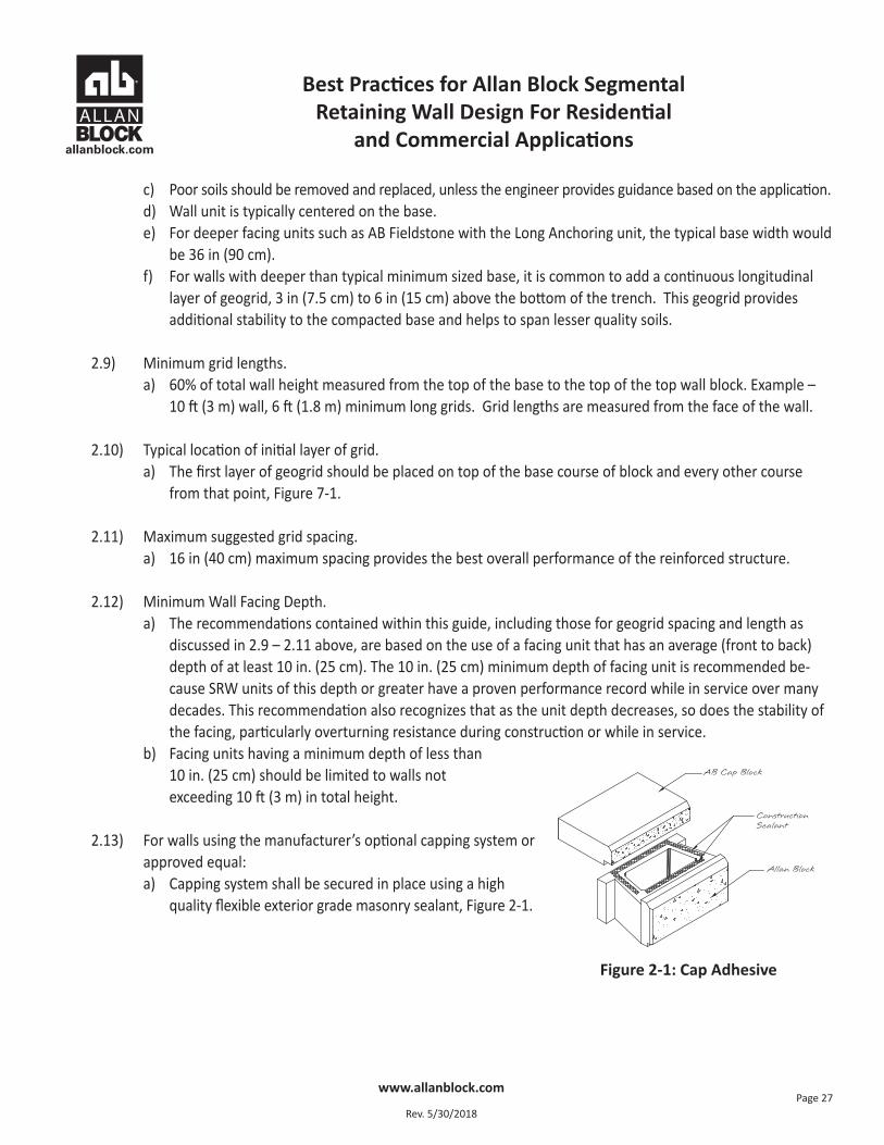
2.13) For walls using the manufacturer’s optional capping system orapproved equal:a) Capping system shall be secured in place using a high
quality flexible exterior grade masonry sealant, Figure 2-1.
Figure 2-1: Cap Adhesive
Best Practices for Allan Block Segmental Retaining Wall Design For Residential
and Commercial Applications
www.allanblock.com
Rev. 5/30/2018Page 28
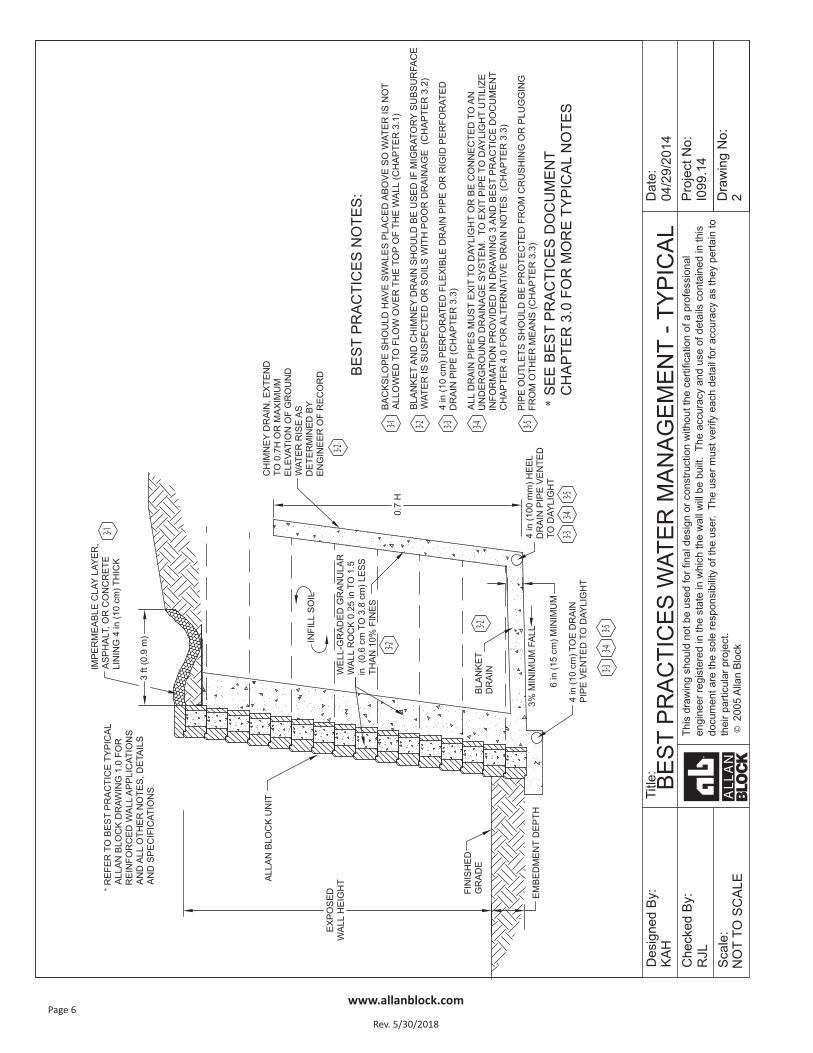
3.0 Water Management – Typical
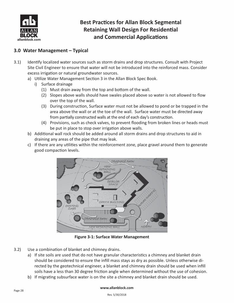
3.1) Identify localized water sources such as storm drains and drop structures. Consult with ProjectSite Civil Engineer to ensure that water will not be introduced into the reinforced mass. Considerexcess irrigation or natural groundwater sources.a) Utilize Water Management Section 3 in the Allan Block Spec Book.
i) Surface drainage (1) Must drain away from the top and bottom of the wall.(2) Slopes above walls should have swales placed above so water is not allowed to flow
over the top of the wall. (3) During construction, Surface water must not be allowed to pond or be trapped in the
area above the wall or at the toe of the wall. Surface water must be directed away from partially constructed walls at the end of each day’s construction.
(4) Provisions, such as check valves, to prevent flooding from broken lines or heads mustbe put in place to stop over irrigation above walls.
b) Additional wall rock should be added around all storm drains and drop structures to aid indraining any areas of the pipe that may leak.
c) If there are any utilities within the reinforcement zone, place gravel around them to generategood compaction levels.
3.2) Use a combination of blanket and chimney drains.a) If site soils are used that do not have granular characteristics a chimney and blanket drain
should be considered to ensure the infill mass stays as dry as possible. Unless otherwise di-rected by the geotechnical engineer, a blanket and chimney drain should be used when infillsoils have a less than 30 degree friction angle when determined without the use of cohesion.
b) If migrating subsurface water is on the site a chimney and blanket drain should be used.
Figure 3-1: Surface Water Management
Best Practices for Allan Block Segmental Retaining Wall Design For Residential
and Commercial Applications
www.allanblock.com
Rev. 5/30/2018Page 29
c) See Allan Block Chimney and Blanket Drain detail (Drawing No. 2.0).d) Drain material to be consistent with wall rock material. For more information on wall rock
material see Chapter 2.0 Typical Wall Construction. e) Manufactured chimney and blanket drains to be approved by the geotechnical and/or the
local engineer of record prior to use.
3.3) Location, type, and venting of drain pipes. a) Utilize Water Management Sections 1.4 and 1.5 in the Allan Block Spec Book.b) 4 in (10 cm) perforated flexible drain pipe or rigid perforated pipes are recommended. c) When a rigid perforated pipe is used, it should be placed with holes down.d) All drain pipes must exit to daylight or be connected to an underground drainage system. Use
Allan Block detail Alternate Drain (Drawing No. 3.0) for examples of venting to daylight.i) It is recommended that a minimum 1% gradient be maintained on the placement of the
pipe with outlets on 50 ft (15 m) centers, or 100 ft (30 m) centers if the pipe is crownedbetween the outlets.
ii) It is recommended that all pipe outlets be configured to be protected from crushing orplugging from other means.
e) Drain pipes existing to daylight through the wall should be installed with rodent screen to prevent nesting within the pipe. Cut adjoining block to allow for installation of a manufac-tured drain cover. Alternatively, Wall Drain Pro could be used without the requirement of cutting block. For more information on Wall Drain Pro see Allan Block’s website at allanblock.com.
3.4) Above grade water management plan and finishing of the compacted soil mass.a) Surface water that cannot be diverted from the wall must be collected with surface drainage
swales and drained laterally in order to disperse the water around the wall structure. Con-struction of a typical swale system shall be in accordance with Drawing No. 2.0. See alsoChapter 12 for further discussion on above wall considerations.
Best Practices for Allan Block Segmental Retaining Wall Design For Residential
and Commercial Applications
www.allanblock.com
Rev. 5/30/2018Page 30
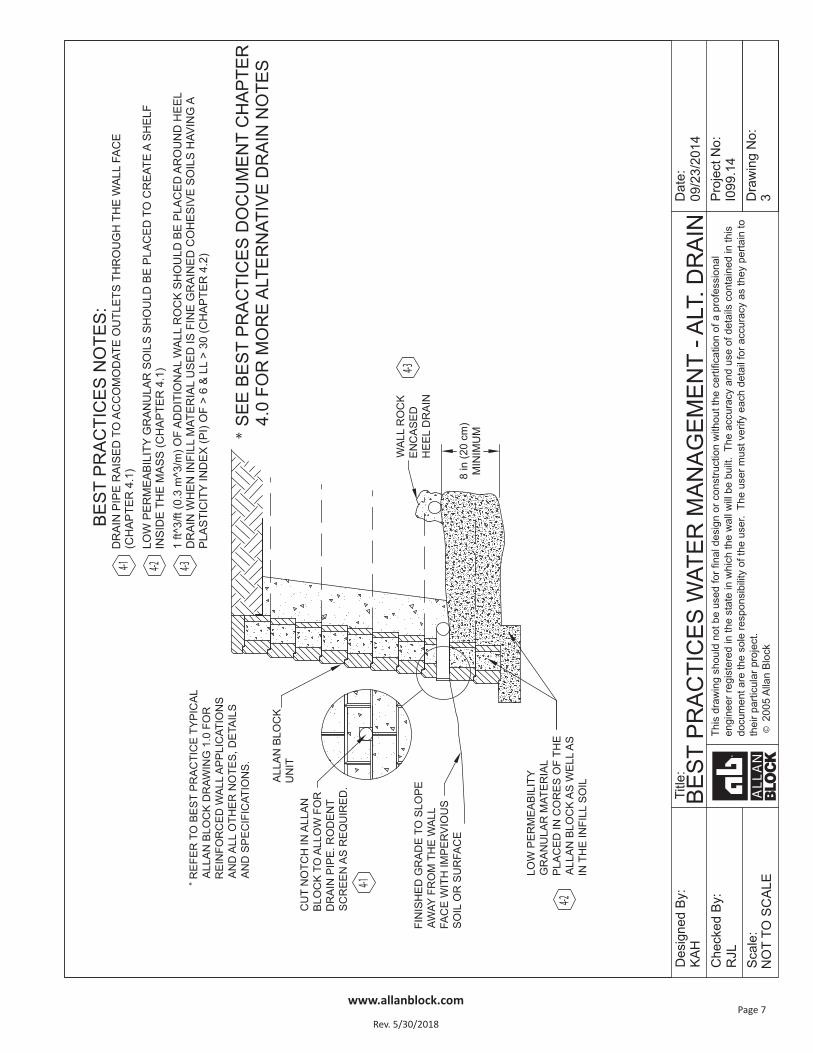
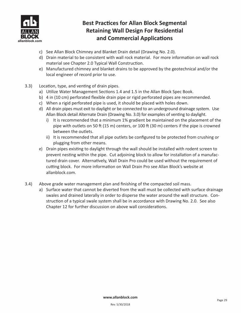
4.0 Water Management – Alternate Drain
4.1) Location, type, and venting of drain pipes. a) When the drain pipe must be raised to ac-
commodate outlets through the wall face.i) Low permeable granular soils should
be used to create a shelf inside themass, level to the height of the fin-ished grade outside the wall to pre-vent water from ponding below grade.See Allan Block Design Detail – Alter-nate Drain in the AB Spec Book or atallanblock.com.
b) Drain pipes existing to daylight through thewall should be installed with rodent screento prevent nesting within the pipe. Cut ad-joining block to allow for installation of amanufactured drain cover. Alternatively,Wall Drain Pro could be used without therequirement of cutting block. For more information on Wall Drain Pro see allanblock.com.
4.2) A heel drain should be specified for siteswhenever grid is used or where migratingwater from behind the mass is possible.a) The purpose of the heel drain is to pick up any water that migrates from behind the retaining
wall structure at the cut, and route the water away from the reinforced mass during construc-tion and for incidental water for the life of the structure.
b) The piping used at the back of the reinforced mass shall have a one percent minimum gradi-ent over the length, but it is not critical for it to be positioned at the very bottom of the cut.
c) The heel drain should be vented at 100 ft (30 m) intervals along the entire length of the walland should not be tied into the toe drain system.
d) The pipe may be a rigid pipe with holes at the bottom or a corrugated perforated flexible pipe.e) For infill soils with a high percentage of sand and/or gravel the heel drain pipe does not need
to be surrounded by wall rock. When working with soils containing fine grained cohesive soilshaving a PI of greater than 6 and LL of 30 or greater, 1 ft3 (.03 m3) of wall rock is requiredaround the pipe for each 1 ft (30 cm) of pipe length.
Figure 4-2: Typical Drain with Heel Drain
Figure 4-1: Alternate Drain
Best Practices for Allan Block Segmental Retaining Wall Design For Residential
and Commercial Applications
www.allanblock.com
Rev. 5/30/2018Page 31
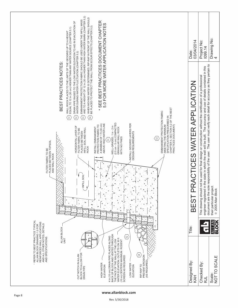
5.0 Water Application
5.1) Below grade water management plan for water application walls. a) When more than incidental groundwater is known to move through the retained soils.
i) The wall rock should be placed to the limits of the geogrid lengths up to a height equal to12 in (30 cm) higher than any water source.
5.2) When a wall is constructed to be a water application such as in a lake, stream or detention basin. a) The wall rock should be placed to the limits of the geogrid lengths up to a height equal to
12 in (30 cm) higher than the determined high water mark. If the high water mark is un-known, the entire infill zone should be constructed with wall rock.
b) The drain pipe should be raised to the low water elevation to aid in the evacuation of waterfrom the reinforced mass as water level fluctuates.
c) Embankment protection fabric should be used under the infill mass and up the back of the infill mass to a height of 12 in (30 cm) higher than the determined high water mark.i.) Embankment protection fabric is used to stabilize rip rap and foundation soils in water
applications and to separate infill materials from the retained soils. This fabric should per-mit the passage of fines to precludeclogging of the material. Embankmentprotection fabric shall be a high strengthpolypropylene monofilament materialdesigned to meet or exceed typicalNTPEP specifications; stabilized againstultraviolet (UV) degradation and typi-cally meets or exceeds the values inTable 2.
d) For walls having moving water or wave ac-tion, natural or manufactured rip-rap infront of the wall to protect the toe of thewall from scour effects is recommended.
Mechanical DeterminationProperty Method
Tensile Strength = 225 lbs/in (39.4 kN/m) ASTM D-4595Puncture Strength = 950 lbs (4228 N) ASTM D-6241Apparent Opening Size (AOS)= U.S. Sieve #70 (0.212 mm) Trapezoidal Tear = 100 lbs (445 N) ASTM D-4533Percent Open Area = 4% COE-02215Permeability = 0.01 cm/sec ASTM D-4491
ASTM D-4751
Table 2: Embankment Protection Fabric Specifications
Best Practices for Allan Block Segmental Retaining Wall Design For Residential
and Commercial Applications
www.allanblock.com
Rev. 5/30/2018Page 32
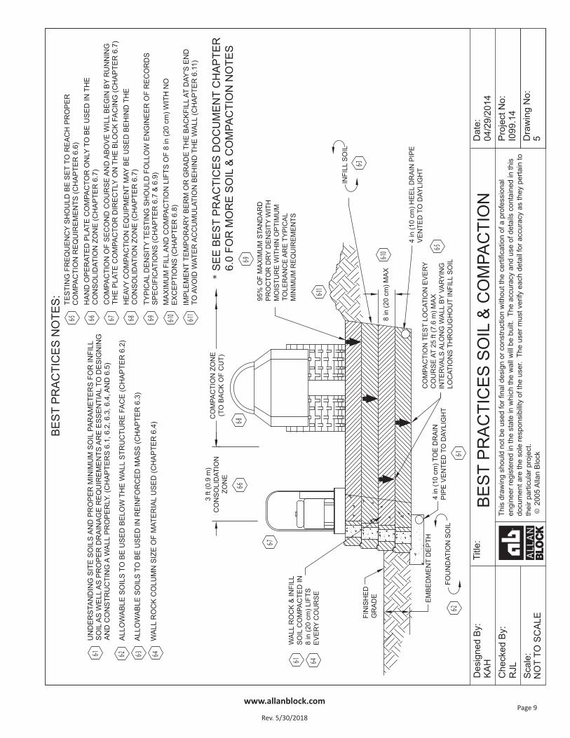
6.0 Soil & Compaction
6.1) Understanding the site soils as well as the soils used in the infill zone is essential to understanding how theretaining wall will function. One of the economic advantages to an SRW system is that site soils can usuallybe used in the infill zone provided they are of a certain quality and surface and groundwater conditions atthe site are controlled by recommendations given in Chapters 3.0 – 5.0.
While cohesionless, free graining materials (less than 10% fines and or PI less than 6 and LL less than 30) arepreferred, soils with low plastic fines (i.e. SC with PI less than 20 and LL less than 40) may be used for lowerheight SRW construction provided the following additional design criteria are implemented:a) Proper internal drainage is installed including wall rock in and behind the facing and blanket and chim-
ney drains to keep the infill mass dry, see Chapters 3.0 – 5.0.b) In areas where frost heaves are possible, only soils with low to moderate frost heave potential shall be
utilized. Verify parameters with geotech. Expanding the depth of wall rock behind the facing can help reduce the effects of frost heaves. See Chapter 6, Section 6.4 for information on the wall rock column.
c) The cohesive shear strength parameter (c), for the reinforced fill, is ignored for internal and external sta-bility analysis. Cohesion values are allowed in the foundation and global stability analysis. However, it isrecommended that no more than 10% of the tested/reported values should be used due to the unpre-dictability of cohesive soils.
d) The final design is checked by a qualified geotechnical engineer to ensure that the use of cohesive soilsdoes not result in unacceptable time-dependent movement of the SRW system.
e) High plastic or organic soils including MH, CH, OH, OL and PT are not recommended for any segmental retaining wall construction as their use can cause excessive settling over time and or excessive internalstress to build up causing internal lateral forces to occur. See Chapter 8 for more information on tall walls.
6.2) Allowable soil to be used below the wall structure face.a) Geotechnical report should include parameters and recommendations for sub-soils.b) If poor soils are encountered during construction, consult with owner and geotech for removal and
replacement recommendation.c) Utilize Section 3.1 Foundation Soils in the Allan Block Spec Book.
i) Foundation soils to be inspected by the on-site soils engineer to ensure they meet or exceed designsoil parameters.
ii) Over excavated areas shall be filled with compactable material approved by the on-site soils engineer.
6.3) Allowable soil to be used in the reinforced mass.a) Best soil is wall rock or select/structural fill with less than 10% fines, to the limits of the geogrid lengths.b) If site soils are allowed by the geotechnical engineer; on-site soils engineer to verify they meet the mini-
mum requirements set forth in the soils report, and they are in compliance with the soil properties usedin the design process.
c) Utilize Section 1 Part 2.3 Infill Soils in the Allan Block Spec Book.i) Unsuitable soils for backfill (heavy clays or organic soils) shall not be used.ii) Poorly graded sands, expansive clays and/or soils with a PI greater than 20 or a LL greater than 40
should not be used in wall construction. iii) Fine grained cohesive soils with a friction angle of less than 31 degrees with a PI ranging between 6 and
20 and LL from 30 to 40, may be used in wall construction, but additional backfilling, compaction andwater management efforts, such as blanket drains and chimney drains are required.
iv) Soils with a PI of less than 6 and LL less than 30 are generally considered granular and can be used asinfill material.
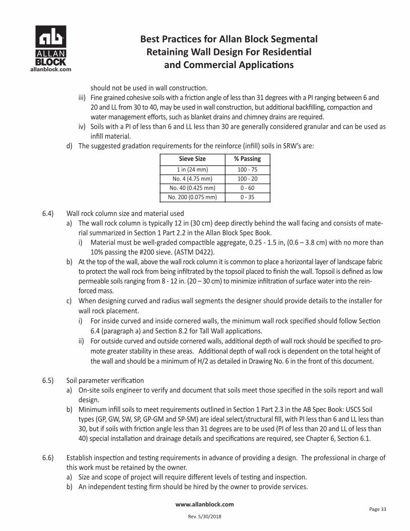
d) The suggested gradation requirements for the reinforce (infill) soils in SRW’s are:
6.4) Wall rock column size and material useda) The wall rock column is typically 12 in (30 cm) deep directly behind the wall facing and consists of mate-
rial summarized in Section 1 Part 2.2 in the Allan Block Spec Book.i) Material must be well-graded compactible aggregate, 0.25 - 1.5 in, (0.6 – 3.8 cm) with no more than
10% passing the #200 sieve. (ASTM D422).b) At the top of the wall, above the wall rock column it is common to place a horizontal layer of landscape fabric
to protect the wall rock from being infiltrated by the topsoil placed to finish the wall. Topsoil is defined as lowpermeable soils ranging from 8 - 12 in. (20 – 30 cm) to minimize infiltration of surface water into the rein-forced mass.
c) When designing curved and radius wall segments the designer should provide details to the installer forwall rock placement.i) For inside curved and inside cornered walls, the minimum wall rock specified should follow Section
6.4 (paragraph a) and Section 8.2 for Tall Wall applications.ii) For outside curved and outside cornered walls, additional depth of wall rock should be specified to pro-
mote greater stability in these areas. Additional depth of wall rock is dependent on the total height ofthe wall and should be a minimum of H/2 as detailed in Drawing No. 6 in the front of this document.
6.5) Soil parameter verification a) On-site soils engineer to verify and document that soils meet those specified in the soils report and wall
design.b) Minimum infill soils to meet requirements outlined in Section 1 Part 2.3 in the AB Spec Book: USCS Soil
types (GP, GW, SW, SP, GP-GM and SP-SM) are ideal select/structural fill, with PI less than 6 and LL less than30, but if soils with friction angle less than 31 degrees are to be used (PI of less than 20 and LL of less than40) special installation and drainage details and specifications are required, see Chapter 6, Section 6.1.
6.6) Establish inspection and testing requirements in advance of providing a design. The professional in charge ofthis work must be retained by the owner.a) Size and scope of project will require different levels of testing and inspection.b) An independent testing firm should be hired by the owner to provide services.
Best Practices for Allan Block Segmental Retaining Wall Design For Residential
and Commercial Applications
www.allanblock.com
Rev. 5/30/2018Page 33
Sieve Size % Passing1 in (24 mm) 100 - 75
No. 4 (4.75 mm) 100 - 20No. 40 (0.425 mm) 0 - 60
No. 200 (0.075 mm) 0 - 35
Best Practices for Allan Block Segmental Retaining Wall Design For Residential
and Commercial Applications
www.allanblock.com
Rev. 5/30/2018Page 34
c) Independent firm to keep inspection log and provide written reports at predetermined intervals to theowner.
d) Testing frequency should be set to establish a proper compaction protocol to consistently achieve theminimum compaction requirements set by the design requirements. If full time inspection and testing at8 in (20 cm) lifts is not provided, then the following testing frequency should be followed: i) One test for every 8 in (20 cm) of vertical fill placed and compacted, for every 25 lineal ft (7.6 m) of
retaining wall length, starting on the first course of block.ii) Vary compaction test locations to cover the entire area of reinforced zone; including the area com-
pacted by the hand-operated compaction equipment.iii) Once protocol is deemed acceptable, testing can be conducted randomly at locations and frequencies
determined by the on-site soils engineer.e) Slopes above the wall must be compacted and checked in a similar manner.
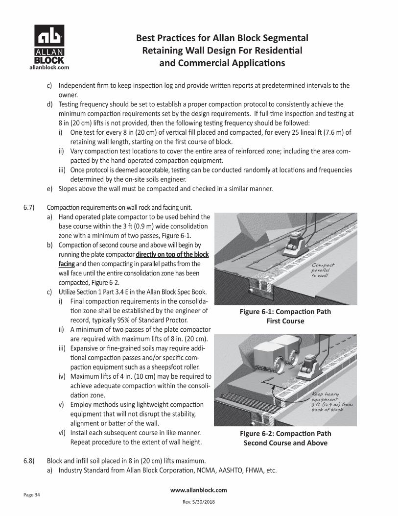
6.7) Compaction requirements on wall rock and facing unit.a) Hand operated plate compactor to be used behind the
base course within the 3 ft (0.9 m) wide consolidationzone with a minimum of two passes, Figure 6-1.
b) Compaction of second course and above will begin byrunning the plate compactor directly on top of the blockfacing and then compacting in parallel paths from thewall face until the entire consolidation zone has beencompacted, Figure 6-2.
c) Utilize Section 1 Part 3.4 E in the Allan Block Spec Book.i) Final compaction requirements in the consolida-
tion zone shall be established by the engineer ofrecord, typically 95% of Standard Proctor.
ii) A minimum of two passes of the plate compactorare required with maximum lifts of 8 in. (20 cm).
iii) Expansive or fine-grained soils may require addi-tional compaction passes and/or specific com-paction equipment such as a sheepsfoot roller.
iv) Maximum lifts of 4 in. (10 cm) may be required toachieve adequate compaction within the consoli-dation zone.
v) Employ methods using lightweight compactionequipment that will not disrupt the stability,alignment or batter of the wall.
vi) Install each subsequent course in like manner.Repeat procedure to the extent of wall height.
6.8) Block and infill soil placed in 8 in (20 cm) lifts maximum. a) Industry Standard from Allan Block Corporation, NCMA, AASHTO, FHWA, etc.
Figure 6-1: Compaction Path First Course
Figure 6-2: Compaction Path Second Course and Above
Compact parallel to wall
Keep heavyequipment 3 ft. (0.9 m) fromback of block
Best Practices for Allan Block Segmental Retaining Wall Design For Residential
and Commercial Applications
www.allanblock.com
Rev. 5/30/2018Page 35
6.9) Compaction requirements for all soils in areas in, above and behind the reinforced mass.a) Typical minimum requirements are: 95% of maximum Standard Proctor dry density (ASTM D698) with a
moisture content control of +1% to -3% of optimum. Section 13.5.3, NCMA TR 127 (Design Manual forSegmental Retaining Walls).
6.10) Compaction testing locations and frequencies. Documentation of on-site soil testing. a) See Section 6.6.
6.11) Water Management during construction.a) Utilize Section 3 Part 1.1 Surface Drainage in the Allan Block Spec Book.
i) At the end of each day’s construction and at final completion, grade the backfill to avoid water accumula-tion behind the wall or in the reinforced zone.
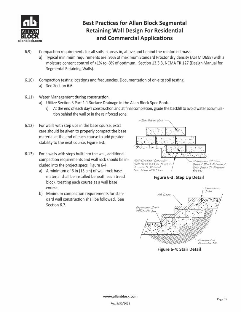
6.12) For walls with step ups in the base course, extracare should be given to properly compact the basematerial at the end of each course to add greaterstability to the next course, Figure 6-3.
6.13) For a walls with steps built into the wall, additionalcompaction requirements and wall rock should be in-cluded into the project specs, Figure 6-4.a) A minimum of 6 in (15 cm) of wall rock base
material shall be installed beneath each treadblock, treating each course as a wall basecourse.
b) Minimum compaction requirements for stan-dard wall construction shall be followed. SeeSection 6.7.
Figure 6-3: Step Up Detail
Figure 6-4: Stair Detail
Best Practices for Allan Block Segmental Retaining Wall Design For Residential
and Commercial Applications
www.allanblock.com
Rev. 5/30/2018Page 36
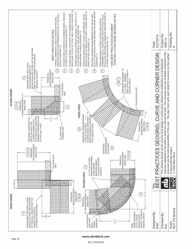
7.0 Geogrid Reinforcement Requirements, Corner and Radius Design Practices
7.1) Certification to ensure proper materials for the geogrid reinforcement. Most geogrids used for soil reinforce-ment are manufactured from polyester fiber. To ensure a high quality product, use a geosynthetic reinforce-ment that has obtained an NTPEP Report.
a) There are many different international manufacturers that are supplying geogrid reinforcement, andthey are not all equal. It is important to understand what influences the durability of the geogrid. TheU.S. Federal Highway Administration identified three key factors:
i) Soils that have a pH of 10 or more represent an environment that could potentially degrade the geogrid faster especially in the presence of sufficient water.
ii) Polyester molecular weight – the size of the polymer molecule has a significant influence on thechemical durability.
iii) Polyester carboxyl end group (CEG) – grids are less susceptible to degradation when they have fewerCEG in their molecular structure.
b) Establish minimum requirements when using polyester geogrids. NCMA adopted the guidelines that theFHWA set for geogrid reinforcement. All polyester geogrids submitted for approval must be made ofpolyester fiber that meets the following specifications:
i.) Molecular weight greater than 25,000 g/mol ii.) Caboxyl End Group less than 30 mmol/Kg
c) The certification, obtained from the geogrid manufacturer, must originate from the actual manufacturerof the fiber to show conformance with the specification.
d) Designer must consider soils that have a pH of 10 or more represent an environment that could poten-tially degrade the geogrid faster especially in the presence of sufficient water and may require additionaldesign criteria.
7.2) Proper orientation of grid and placement a) Typical commercial geogrid is uniaxial and strong in
the roll direction and should be placed in sheets perpendicular to the wall facing.
b) Utilize Section 2 – Part 3.3 Geogrid Installation in theAllan Block Spec Book.
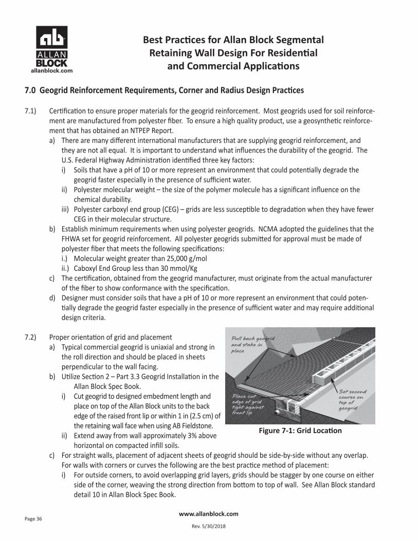
i) Cut geogrid to designed embedment length andplace on top of the Allan Block units to the backedge of the raised front lip or within 1 in (2.5 cm) ofthe retaining wall face when using AB Fieldstone.
ii) Extend away from wall approximately 3% abovehorizontal on compacted infill soils.
c) For straight walls, placement of adjacent sheets of geogrid should be side-by-side without any overlap.For walls with corners or curves the following are the best practice method of placement:
i) For outside corners, to avoid overlapping grid layers, grids should be stagger by one course on eitherside of the corner, weaving the strong direction from bottom to top of wall. See Allan Block standarddetail 10 in Allan Block Spec Book.
Figure 7-1: Grid Location
Pull back geogridand stake in place
Set secondcourse ontop of geogrid
Place cut edge of gridtight againstfront lip
Best Practices for Allan Block Segmental Retaining Wall Design For Residential
and Commercial Applications
www.allanblock.com
Rev. 5/30/2018Page 37
ii) For inside corner, extend the geogrid layer into the corner from one side a distance equal to 25% of thetotal wall height. Alternate extended geogrid layer from side to side per course to create a geogridweave as wall is built. See Allan Block standard detail 9 in Allan Block Spec Book.
iii) For outside curves, where grid tails overlap naturally, place roughly 3 in (7.5 cm) of wall rock or infillsoil between the overlapping layers. See Allan Block standard detail 12 in Allan Block Spec Book.
iv) For inside curves, where grid layers fan apart, place a secondary, equal length, layer of grid on thenext course above the fanned gap. See Allan Block standard detail 11 in Allan Block Spec Book.
7.3) Wall rock design for corners and curved walls.a) When designing curved and radius wall segments the designer should provide details to the installer for
wall rock placement. i) For inside curved and inside cornered walls, the minimum wall rock specified should follow Section
6.4 (paragraph a) and Section 8.2 for Tall Wall applications.ii) For outside curved and outside cornered walls, additional depth of wall rock should be specified to pro-
mote greater stability in these areas. Additional depth of wall rock is dependent on the total height ofthe wall and should be a minimum of H/2 as detailed in Drawing No. 6 in the front of this document.
Best Practices for Allan Block Segmental Retaining Wall Design For Residential
and Commercial Applications
www.allanblock.com
Rev. 5/30/2018Page 38
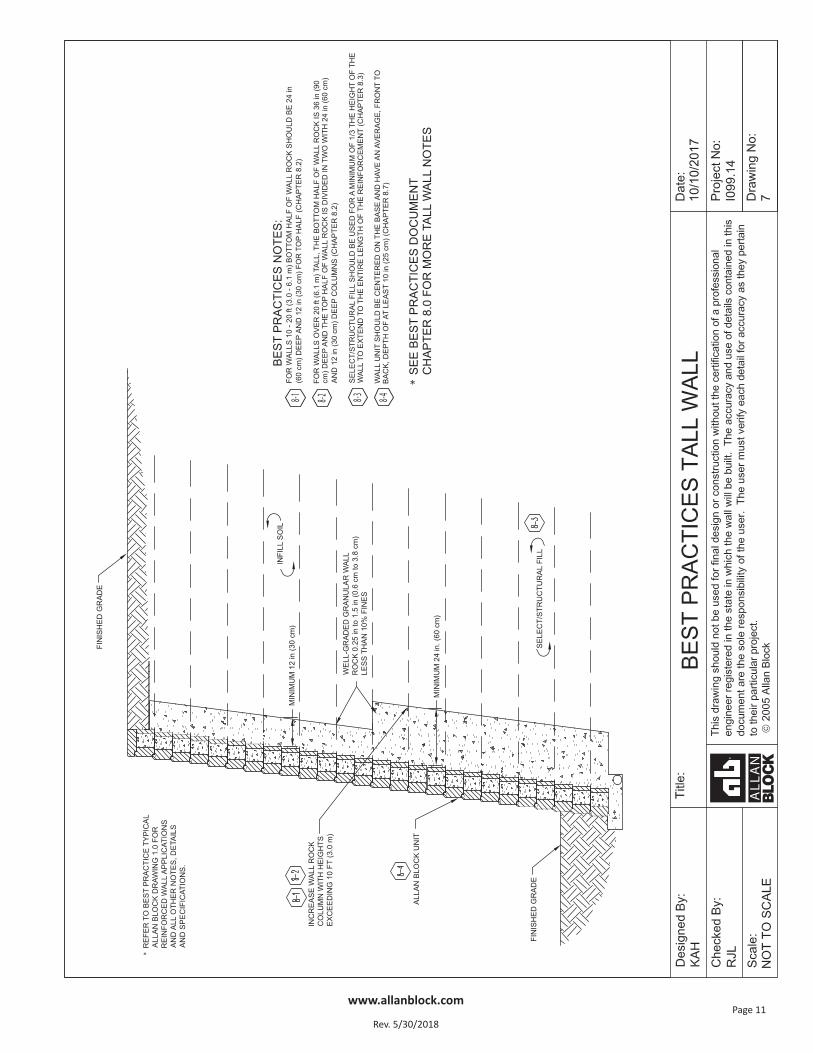
8.0 Tall Wall Considerations
8.1) Tall Wall Considerations are to be employed with structures rising to aheight of between 10 – 15 ft (3 – 4.6 m), depending on the application andthe discretion of the wall design engineer. A 10 ft (3 m) high wall structurewith a slope or structure above would be considered as a tall wall, while thesame wall height constructed with a level condition above the wall withoutany additional surcharge may not require consideration as a tall wall.
Several factors may change a typical design when structures reach thesedefined higher levels such as the depth of wall rock, increased design pa-rameters, enhanced structural fill and global stability analysis requirements.
8.2) Wall rock depth behind the block and material used.a) Site conditions and wall height should make the engineer consider
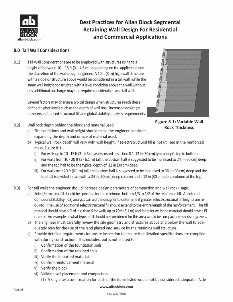
expanding the depth and or size of material used.b) Typical wall rock depth will vary with wall height, if select/structural fill is not utilized in the reinforced
mass, Figure 8-1.i) For walls up to 10 - 15 ft (3 - 4.6 m) as discussed in section 8.1, 12 in (30 cm) typical depth top to bottom.ii) For walls from 10 - 20 ft (3 - 6.1 m) tall, the bottom half is suggested to be increased to 24 in (60 cm) deep
and the top half to be the typical depth of 12 in (30 cm) deep.iii) For walls over 20 ft (6.1 m) tall, the bottom half is suggested to be increased to 36 in (90 cm) deep and the
top half is divided in two with a 24 in (60 cm) deep column and a 12 in (30 cm) deep column at the top.
8.3) For tall walls the engineer should increase design parameters of compaction and wall rock usage.a) Select/structural fill should be specified for the minimum bottom 1/3 to 1/2 of the reinforced fill. An Internal
Compound Stability (ICS) analysis can aid the designer to determine if greater select/structural fill heights are re-quired. The use of additional select/structural fill should extend to the entire length of the reinforcement. This fillmaterial should have a PI of less than 6 for walls up to 20 ft (6.1 m) and for taller walls the material should have a PIof zero. An example of what type of fill should be considered for this area would be compactable sands or gravels.
b) The engineer must carefully review the site geometry and structures above and below the wall to ade-quately plan for the use of the land placed into service by the retaining wall structure.
c) Provide detailed requirements for onsite inspection to ensure that detailed specifications are compliedwith during construction. This includes, but is not limited to:i) Confirmation of the foundation soils ii) Confirmation of the retained soilsiii) Verify the imported materialsiv) Confirm reinforcement material v) Verify the blockvi) Validate soil placement and compaction.
(1) A single test/confirmation for each of the items listed would not be considered adequate. A de-
Figure 8-1: Variable Wall Rock Thickness
Best Practices for Allan Block Segmental Retaining Wall Design For Residential
and Commercial Applications
www.allanblock.com
Rev. 5/30/2018Page 39
tailed construction log should be used with sign offs at incremental levels by the responsible parties.d) Consider how much potential settlement will impact structures above the reinforced soil mass. Consider
increasing compaction requirements from 95% of standard proctor to 98% to minimize settlement whereessential to the application.
e) A detailed review and implementation of a water management plan is essential. This should include a detaileddrawing for water collection and water flow diagrams for both above and below grade drainage. Below gradeutilities and above grade structures should be included in the overall site design to ensure that site details suchas storm drains and curb and gutters do not influence the overall wall envelope or effect performance. Unlessdesigned to accommodate hydrostatic loading, it is essential that the reinforced soil mass not be exposed to out-side water sources that would rise above the level of incidental water.
f) As walls get taller the internal stresses increase and depending on the soils used, can cause lateral loads push-ing on the back of the facing. To minimize internal lateral loads on the Allan Block facing, it is recommended toutilize the described soils above and to expand the depth of the wall rock column behind the facing, See Sec-tion 8.2.b for more information. Expanding the wall rock zone behind the wall also reduces down drag forceson the geogrid caused by localized settlement and allows for easier compaction directly behind the block.
g) In addition to the compaction and wall rock parameters, tall walls require the design engineer to evalu-ate the overall stability of the soil structure and the subsoils beneath the wall. The reinforced soil struc-ture should be evaluated for internal settlement which may require additional select fill to mitigate. Thesubsoils cannot be ignored due to similar reasons. The overburden of the tall wall can cause unwantedsettlements in the foundation material. Removal of the subsoils and replacement with quality select fillmay be required to mitigate these possible settlements.
8.4) As walls increase in height the active earth forces also increase in the lower portion of the wall. Therefore itis not uncommon in taller walls to increase the strength of the lower geogrid layers or decrease the gridspacing to accommodate the higher design forces.
8.5) The overall global stability of tall walls must be considered separately from the standard wall design to en-sure the stability of the entire project site. For more information on global stability see Chapter 9.0 GlobalStability - General and Chapter 10.0 Global Stability – Terraced Walls.
8.6) Internal Compound Stability (ICS) calculations provide insight into potential global or overall stability issues. Whenmore than 50% of the slip arcs originate at the back of the design envelope, as defined in Chapter 1, Section 1.9 b, a full global/overall stability analysis should be recommended to the owner by the owner’s geotechnical engineer.
8.7) Minimum Wall Facing Depth.a) The recommendations contained within this guide, including those for geogrid spacing and length as dis-
cussed in Sections 2.9 – 2.11, are based on the use of a facing unit that has an average (front to back)depth of at least 10 in. (25 cm). The 10 in. (25 cm) minimum depth of facing unit is recommended be-cause SRW units of this depth or greater have a proven performance record while in service over manydecades. This recommendation also recognizes that as the unit depth decreases, so does the stability ofthe facing, particularly overturning resistance during construction or while in service.
www.allanblock.com
Rev. 5/30/2018Page 40
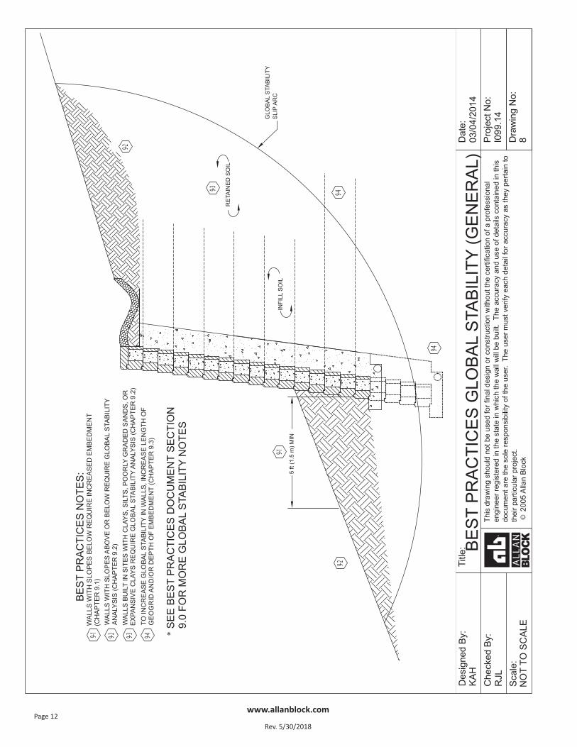
9.0 Global Stability – General
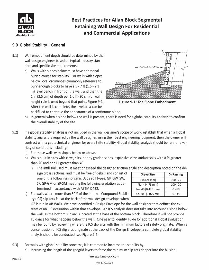
9.1) Wall embedment depth should be determined by thewall design engineer based on typical industry stan-dard and specific site requirements.a) Walls with slopes below must have additional
buried course for stability. For walls with slopesbelow, local ordinances commonly reference tobury enough blocks to have a 5 - 7 ft (1.5 - 2.1m) level bench in front of the wall, and then the1 in (2.5 cm) of depth per 1.0 ft (30 cm) of wallheight rule is used beyond that point, Figure 9-1.After the wall is complete, the level area can bebackfilled to continue the appearance of a continuous slope.
b) In general when a slope below the wall is present, there is need for a global stability analysis to confirmthe overall stability of the site.
9.2) If a global stability analysis is not included in the wall designer's scope of work, establish that when a globalstability analysis is required by the wall designer, using their best engineering judgment, then the owner willcontract with a geotechnical engineer for overall site stability. Global stability analysis should be run for a va-riety of conditions including:a) For those walls with slopes below or above.b) Walls built in sites with clays, silts, poorly graded sands, expansive clays and/or soils with a PI greater
than 20 and or a LL greater than 40. i) The infill soil used must meet or exceed the designed friction angle and description noted on the de-
sign cross sections, and must be free of debris and consist ofone of the following inorganic USCS soil types: GP, GW, SW,SP, GP-GM or SP-SM meeting the following gradation as de-termined in accordance with ASTM D422.
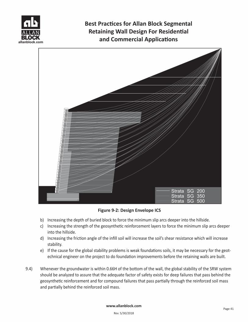
c) For walls where more than 50% of the Internal Compound Stabil-ity (ICS) slip arcs fall at the back of the wall design envelope whenICS is run in AB Walls. We have identified a Design Envelope for the wall designer that defines the ex-tents of an ICS evaluation within that envelope. An ICS analysis does not take into account a slope belowthe wall, as the bottom slip arc is located at the base of the bottom block. Therefore it will not provideguidance for what happens below the wall. One easy to identify guide for additional global evaluationmay be found by reviewing where the ICS slip arcs with the minimum factors of safety originate. When aconcentration of ICS slip arcs originate at the back of the Design Envelope, a complete global stabilityanalysis should be conducted, see Figure 9-2.
9.3) For walls with global stability concerns, it is common to increase the stability by:a) Increasing the length of the geogrid layers to force the minimum slip arcs deeper into the hillside.
Sieve Size % Passing1 in (24 mm) 100 - 75
No. 4 (4.75 mm) 100 - 20No. 40 (0.425 mm) 0 - 60
No. 200 (0.075 mm) 0 - 35
Figure 9-1: Toe Slope Embedment
Best Practices for Allan Block Segmental Retaining Wall Design For Residential
and Commercial Applications
Best Practices for Allan Block Segmental Retaining Wall Design For Residential
and Commercial Applications
www.allanblock.com
Rev. 5/30/2018Page 41
b) Increasing the depth of buried block to force the minimum slip arcs deeper into the hillside.c) Increasing the strength of the geosynthetic reinforcement layers to force the minimum slip arcs deeper
into the hillside.d) Increasing the friction angle of the infill soil will increase the soil’s shear resistance which will increase
stability.e) If the cause for the global stability problems is weak foundations soils, it may be necessary for the geot-
echnical engineer on the project to do foundation improvements before the retaining walls are built.
9.4) Whenever the groundwater is within 0.66H of the bottom of the wall, the global stability of the SRW systemshould be analyzed to assure that the adequate factor of safety exists for deep failures that pass behind thegeosynthetic reinforcement and for compound failures that pass partially through the reinforced soil massand partially behind the reinforced soil mass.
Figure 9-2: Design Envelope ICS
Best Practices for Allan Block Segmental Retaining Wall Design For Residential
and Commercial Applications
www.allanblock.com
Rev. 5/30/2018Page 42
10.0 Global Stability – Terraced Walls
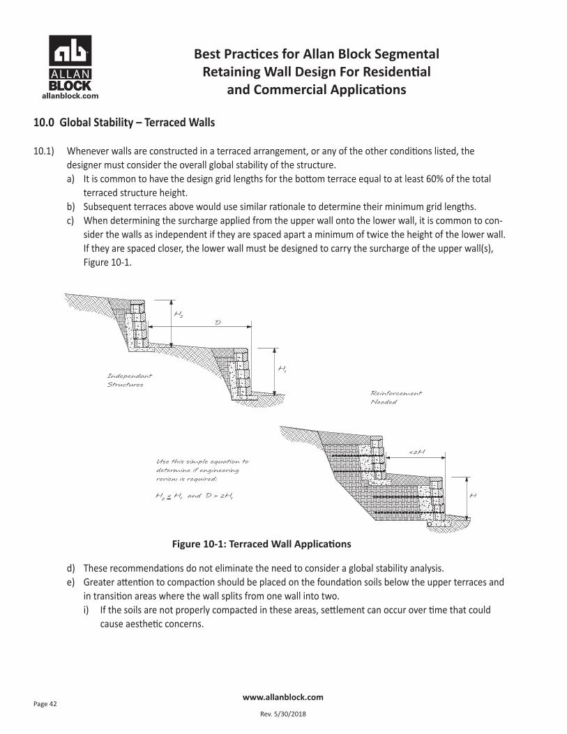
10.1) Whenever walls are constructed in a terraced arrangement, or any of the other conditions listed, the designer must consider the overall global stability of the structure.a) It is common to have the design grid lengths for the bottom terrace equal to at least 60% of the total
terraced structure height. b) Subsequent terraces above would use similar rationale to determine their minimum grid lengths.c) When determining the surcharge applied from the upper wall onto the lower wall, it is common to con-
sider the walls as independent if they are spaced apart a minimum of twice the height of the lower wall.If they are spaced closer, the lower wall must be designed to carry the surcharge of the upper wall(s),Figure 10-1.
d) These recommendations do not eliminate the need to consider a global stability analysis.e) Greater attention to compaction should be placed on the foundation soils below the upper terraces and
in transition areas where the wall splits from one wall into two.i) If the soils are not properly compacted in these areas, settlement can occur over time that could
cause aesthetic concerns.
Figure 10-1: Terraced Wall Applications
Best Practices for Allan Block Segmental Retaining Wall Design For Residential
and Commercial Applications
www.allanblock.com
Rev. 5/30/2018Page 43
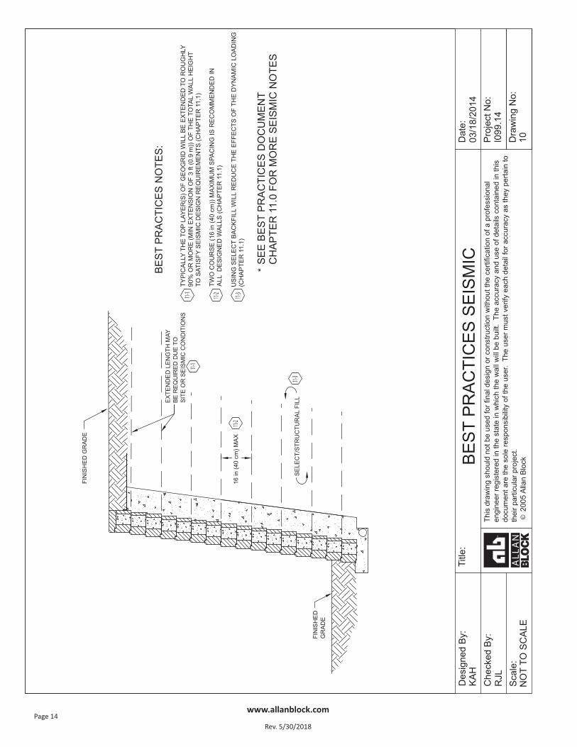
11.0 Seismic Considerations
11.1) For walls with dynamic loading: a) Designer must understand the local seismic code requirements before starting design.b) Closer spacing of geogrid is recommended, maximum 16 in (40 cm).c) Extension of the top layers of geogrid. Typically the top layers will be extended to roughly 90% or more
of the wall height to satisfy design requirements.d) Using select/structural backfill will reduce the effects of the dynamic loading.e) For more information on seismic design and the effects on segmental retaining walls, see the Allan Block
Executive Summary of the independent full-scale seismic testing conducted by Columbia University andthe National Research Institute of Japan.
11.2) When dealing with a slope above a wall with seismic loading applied to the wall, the same acceleration coef-ficient applied to the wall must also be applied to the stability calculations of the slope.
11.3) The Mononobe-Okabe (M-O) seismic methodology places limits on the steepness of any slope above thewall. If during the design phase it is determined that the desired slope is not allowed, the site grading shouldbe altered or the wall height should be increased to reduce the steepness of the slope above. See section12.4 for description of slope steepness.
11.4) While the M-O method is the standard used in the seismic design of segmental retaining wall, a trial wedgemethod may be utilized to investigate walls when the M-O method becomes limited due to slopes above.Using methods similar to a global stability model the trial wedge method determines the weight of the soilwedge above the failure plan and determines the active earth pressure of the soil wedge acting at the backof the soil mass. Using the trial wedge method is not without limitations as well. The solution it provides ispurely mathematical and understanding soil mechanics and the slope steepness limits is also important. Thelimitation to the steepness of a slope discussed in section 12.4 still apply, and if the designer chooses to uti-lize the trial wedge method for walls with slopes above that exceed the soil mechanic limits, they must re-view the slope stability in a global stability program and possibly reinforce the slope above the wall. For agreater discussion on the Trial wedge method see Chapter Five, Seismic Design, in the Allan Block Engineer-ing Manual.
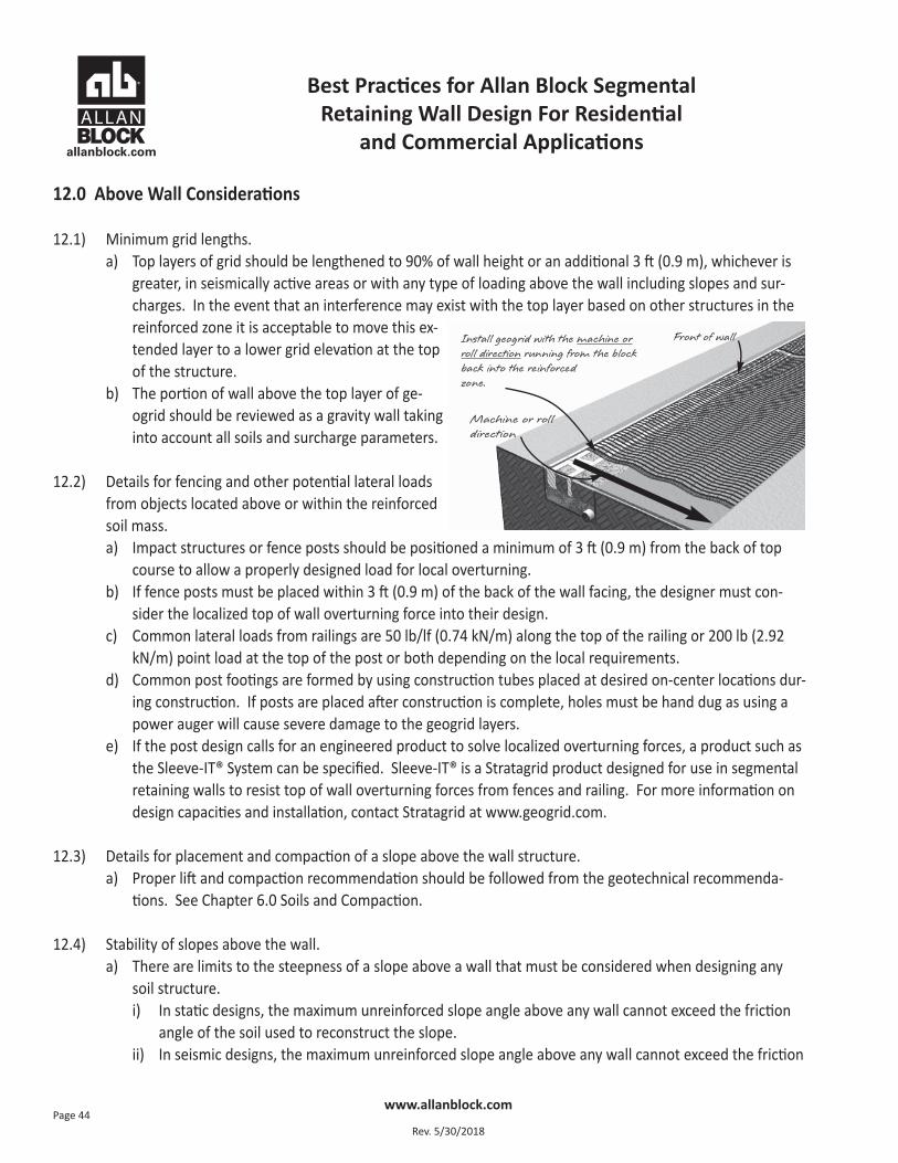
Best Practices for Allan Block Segmental Retaining Wall Design For Residential
and Commercial Applications
www.allanblock.com
Rev. 5/30/2018Page 44
12.0 Above Wall Considerations
12.1) Minimum grid lengths. a) Top layers of grid should be lengthened to 90% of wall height or an additional 3 ft (0.9 m), whichever is
greater, in seismically active areas or with any type of loading above the wall including slopes and sur-charges. In the event that an interference may exist with the top layer based on other structures in thereinforced zone it is acceptable to move this ex-tended layer to a lower grid elevation at the topof the structure.
b) The portion of wall above the top layer of ge-ogrid should be reviewed as a gravity wall takinginto account all soils and surcharge parameters.
12.2) Details for fencing and other potential lateral loadsfrom objects located above or within the reinforcedsoil mass.
a) Impact structures or fence posts should be positioned a minimum of 3 ft (0.9 m) from the back of topcourse to allow a properly designed load for local overturning.
b) If fence posts must be placed within 3 ft (0.9 m) of the back of the wall facing, the designer must con-sider the localized top of wall overturning force into their design.
c) Common lateral loads from railings are 50 lb/lf (0.74 kN/m) along the top of the railing or 200 lb (2.92kN/m) point load at the top of the post or both depending on the local requirements.
d) Common post footings are formed by using construction tubes placed at desired on-center locations dur-ing construction. If posts are placed after construction is complete, holes must be hand dug as using apower auger will cause severe damage to the geogrid layers.
e) If the post design calls for an engineered product to solve localized overturning forces, a product such asthe Sleeve-IT® System can be specified. Sleeve-IT® is a Stratagrid product designed for use in segmentalretaining walls to resist top of wall overturning forces from fences and railing. For more information ondesign capacities and installation, contact Stratagrid at www.geogrid.com.
12.3) Details for placement and compaction of a slope above the wall structure. a) Proper lift and compaction recommendation should be followed from the geotechnical recommenda-
tions. See Chapter 6.0 Soils and Compaction.
12.4) Stability of slopes above the wall. a) There are limits to the steepness of a slope above a wall that must be considered when designing any
soil structure. i) In static designs, the maximum unreinforced slope angle above any wall cannot exceed the friction
angle of the soil used to reconstruct the slope. ii) In seismic designs, the maximum unreinforced slope angle above any wall cannot exceed the friction
Machine or rolldirection
Front of wallInstall geogrid with the machine orroll direction running from the blockback into the reinforced zone.
Best Practices for Allan Block Segmental Retaining Wall Design For Residential
and Commercial Applications
www.allanblock.com
Rev. 5/30/2018Page 45
angle of the soil used to reconstruct the slope minus the seismic inertial angle. The seismic inertialangle is based on the horizontal and vertical seismic coefficients (kh and kv) determined by the soilsengineer for that specific project site.
If the desired slope above exceeds either of the two limits above, the designer must analyze the slope abovein a global stability program and provide slope reinforcement as required.
12.5) Slopes above the wall must be compacted following the proper lift and compaction recommendation fromthe geotechnical recommendations. See chapter 6.0, Soils and Compaction.
12.6) Reinforcing the slope above the wall may be necessary to provide adequate stability to the wall system. Ge-ogrid lengths typically matching the standard grid lengths in the wall along with their spacing are commonlyused in walls with steep slopes above, greater than 3:1, and/or any slopes with poor soils or walls with seis-mic requirements.
12.7) Details for plantings located above the wall structure. a) In general, plantings in the reinforced zone are acceptable and may in fact enhance the reinforced soil
mass provided: i) Engineer should review with the owner the planting plans from the landscape architect to verify size
of root balls and if any geogrid layers will be disrupted. ii) Language can be placed in the project specifications. iii) Augers should never be used within the reinforced grid zone. iv) Consider the effect of excess irrigation. See Water Management, Chapter 3.0.
Best Practices for Allan Block Segmental Retaining Wall Design For Residential
and Commercial Applications
www.allanblock.com
Rev. 5/30/2018Page 46
References
• Abramson, Lee W., Lee, Thomas S., Sharma, Sunil , Boyce, Glenn M., 2002, Slope Stability and Stabilization Methods, second edition, Wiley Publications, USA
• AISC Manual Committee, 1990, Manual of Steel Construction - Load and Resistance Factor Design, First Edition,3rd Printing, American Institute of Steel Construction Inc.
• Allan Block Corp., 2018, AB Walls, Design Software for Segmental Retaining Walls, Allan Block, Bloomington, MN• Allan Block Corp., 2018, Allan Block Engineering Manual, Allan Block, Bloomington, MN, USA• Allan Block Corp., 2015, Allan Block Spec Book, A Comprehensive Guide and Design Details for Segmental
Retaining Walls, Allan Block, Bloomington, MN, USA• Allan Block Corp., 2014, Commercial Installation Manual for Allan Block Retaining Walls, Allan Block,
Bloomington, MN, USA• American Association of State Highway and Transportation Officials (AASHTO) LRFD Bridge Design Specifications,
2012, Washington, D.C.• ASTM C1372, Standard Specification for Dry-Cast Segmental Retaining Wall Units, American Society for Testing
and Materials, West Conshohocken, Pennsylvania, USA• ASTM C1262, Standard Test Method for Evaluating the Freeze-Thaw Durability of Dry-Cast Segmental Retaining
Wall Units and Related Concrete Units, American Society for Testing and Materials, West Conshohocken, Pennsylvania, USA
• Carter, R. Lance and Bernardi, Michael, NCMA’s Design Manual For Segmental Retaining Walls, Submittal require-ments for polyester geogrid reinforcement, Geosynthetics, February 2014
• Columbia University in Cooperation with Allan Block Corporation and Huesker Geosynthetics, 2003, ExecutiveSummary - Seismic Testing - Geogrid Reinforced Soil Structures Faced with Segmental Retaining Wall Block, Allan Block, Bloomington, MN, USA
• Craig, R. F., 1992, Soil Mechanics, Fifth Edition, Chapman & Hall, London, ENGLAND• Das, Braja M, 1994, Principles of Geotechnical Engineering ,Third Edition, Chapter 10, PWS Pub Co., Boston, MA, USA• Duncan, J Michael, Wright, Stephen G, 2005, Soil Strength and Slope Stability, Wiley Publications, USA• Elias, Victor PE, Christopher, Barry, PhD and Berg, Ryan PE, 2001, Mechanically Stabilized Earth Walls and
Reinforced Soil Slopes Design and Construction Guide Lines, FHWA NHI-00-043• FHWA-HRT-10-077 Composite Behavior of Geosynthetic Reinforced Soil Mass, July 2013• FHWA-HRT-11-026 Geosynthetic Reinforced Soil Integrated Bridge System Interim Implementation Guide, June 2012• FHWA-HRT-13-066 Geosynthetic Reinforced Soil Performance Testing – Axial Load Deformation Relationships,
August 2013• FHWA-RD-01-118 Performance Test for Geosynthetic Reinforced Soil Including Effects of Preloading, June 2001• FHWA-HRT-12-051 Sample Guide Specifications for Construction of Geosynthetic Reinforced Soil – Integrated
Bridge System (GRS-IBS), August 2012• Kliethermes, J., K. Buttry, E. McCullough, and R. Wetzel. 1990 , Modular Concrete Retaining Wall and Geogrid
Performance and Laboratory Modeling, University of Wisconsin-Platteville, WI, USA• Leshchinsky, D. and E.B. Perry, 1987, A Design Procedure for Geotextile Reinforced Walls, Geotechnical Fabrics
Report. St. Paul: July/August
Best Practices for Allan Block Segmental Retaining Wall Design For Residential
and Commercial Applications
www.allanblock.com
Rev. 5/30/2018Page 47
• Ling, Hoe I, et al, 2005, Large Scale Shaking Table Tests on Modular-Block Reinforced Soil Retaining Walls, Journalof the Geotechnical and Geoenvironmental Engineering, Vol. 131, No. 4, ASCE
• Ling, Hoe I, et al, 2012, Earthquake Response of Reinforced Segmental Retaining Walls Backfilled with SubstantialPercentage of Fines, Journal of the Geotechnical and Geoenvironmental Engineering, ASCE
• McKittrick, D.P., 1978, Reinforced Earth: Application of Theory and Research to Practice, Reinforced Earth Techni-cal Services, Report 79-1. Arlington, VA: The Reinforced Earth Company
• Minnesota Department of Transportation, 1985, Walls, Section 9-4.0 in Road Design Manual - Part II., St. Paul,MN, USA
• National Concrete Masonry Associations, 2009, Design Manual for Segmental Retaining Walls, 3rd Edition,NCMA, VA
• Peck, Ralph, edited by T.W. Lambe and R.V. Whitman, 1969, Earth Retaining Structures and Slopes, Chapter 13 inSoil Science, John Wiley & Sons, Inc. New York, NY, USA
• Sowers, G.B., and G.F. Sowers, 1970, Problems in Earth Pressure, Chapter 8 in Introductory Soil mechanics andFoundations, The Macmillan Company, New York, NY, USA
• Shiwakoti D.R., T.B,S, Pradhan and Leshchinsky D., 1998, Vol 5, No 6, Performance of Geosynthetic – ReinforcesSoil Structures at Limit Equilibrium State
• Shukha, Robert, Baker, Rafael and Leshchinsky, Dov, 2005, Engineering Implications of the Relation betweenStatic and Pseudo-Static Slope Stability Analysis”, EJGE Paper
Always BetterAlways Allan Block